Embed Size (px)
Citation preview

Vol. 34 No. 2 December 2017
http://www.nafe.org ISSN: 2379-3252
Copyright © National Academy of Forensic Engineers (NAFE). Redistribution or resale is illegal. Originally published in the Journal of the NAFE volume indicated below.
NAFE 733S FORENSIC ENGINEERING COMPARISON OF TWO MASONRY CLADDING SYSTEMS PAGE 59
Forensic Engineering Comparison of Two Masonry Cladding SystemsBy Derek A. Hodgin, PE (NAFE 733S)
AbstractIn a recent construction litigation case, there was a disagreement between two qualified engineering
experts regarding the technical requirements of a masonry veneer cladding system that was installed on the exterior walls of a residential structure. The disagreement among the experts was related to the classifica-tion and function of the veneer cladding system. Specifically, the classification of the cladding system as cast stone or adhered masonry veneer directly impacted the functional requirements set forth by applicable codes and standards. Depending on this classification, the veneer system may or may not be subject to various aspects of the building code, industry standards, and code evaluation reports. The primary areas of con-cern included the attachment of the panels (i.e., anchored vs. adhered) to the masonry substrate, the extent of water intrusion, and the need for water management details (i.e., flashing and weep holes). Both expert witnesses relied on applicable building codes, industry standards, and manufacturer literature to form their opinions to a “reasonable degree of engineering certainty,” yet these technical differences remained. This paper presents the technical highlights of this case study and identifies the issues where building codes and applicable standards require further clarification.
KeywordsCladding, stone, masonry, adhered, anchored, barrier, drainage, weep, forensic engineering
IntroductionA large oceanfront home was constructed in Myrtle
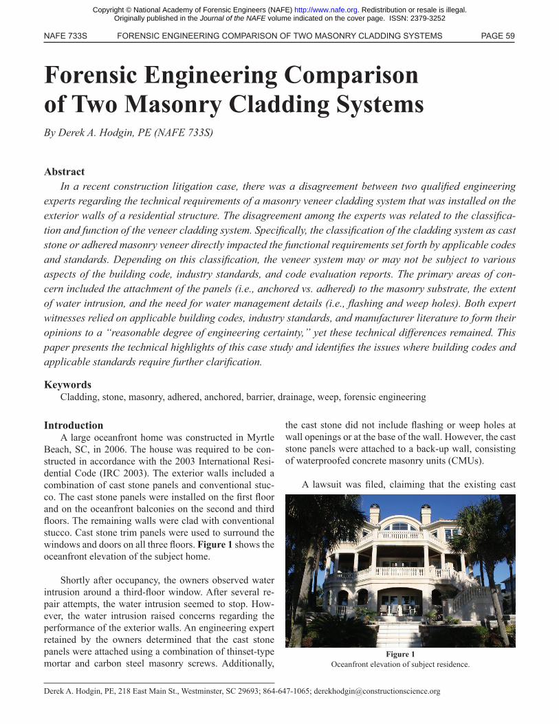
Beach, SC, in 2006. The house was required to be con-structed in accordance with the 2003 International Resi-dential Code (IRC 2003). The exterior walls included a combination of cast stone panels and conventional stuc-co. The cast stone panels were installed on the first floor and on the oceanfront balconies on the second and third floors. The remaining walls were clad with conventional stucco. Cast stone trim panels were used to surround the windows and doors on all three floors. Figure 1 shows the oceanfront elevation of the subject home.
Shortly after occupancy, the owners observed water intrusion around a third-floor window. After several re-pair attempts, the water intrusion seemed to stop. How-ever, the water intrusion raised concerns regarding the performance of the exterior walls. An engineering expert retained by the owners determined that the cast stone panels were attached using a combination of thinset-type mortar and carbon steel masonry screws. Additionally,
Derek A. Hodgin, PE, 218 East Main St., Westminster, SC 29693; 864-647-1065; [email protected]
the cast stone did not include flashing or weep holes at wall openings or at the base of the wall. However, the cast stone panels were attached to a back-up wall, consisting of waterproofed concrete masonry units (CMUs).
A lawsuit was filed, claiming that the existing cast
Figure 1Oceanfront elevation of subject residence.
Copyright © National Academy of Forensic Engineers (NAFE) http://www.nafe.org. Redistribution or resale is illegal. Originally published in the Journal of the NAFE volume indicated on the cover page. ISSN: 2379-3252

PAGE 60 DECEMBER 2017 NAFE 733S
stone veneer should be removed and replaced with a prop-erly constructed stone veneer system in accordance with building code requirements. An engineering expert was retained by the general contractor to review the allega-tions made in the lawsuit. This paper provides a summary of the testimony provided by the engineering experts and the basis of their testimony.
History of Stone UseThroughout history, solid stone and solid masonry
have been used as a building component on a variety of structures. Many historic structures are constructed ei-ther from solid stone or solid masonry. The walls of these structures are load-bearing and are relatively thick. From a building envelope perspective, these walls are referred to as “mass walls,” which allow water to penetrate the outer surface, but are so thick that water intrusion to the interior space is not an issue.
As construction technology has evolved, so has the use of solid stone and masonry. The use of stone in mod-ern construction is typically part of a veneer system. By definition, veneer cladding is not load-bearing; it only bears its own weight. Veneer cladding is designed as ei-ther a barrier or drainage system. Barrier wall systems are intended to prohibit water intrusion at the exterior sur-face. In contrast, a drainage wall system is designed with the expectation that incidental water will penetrate the ex-terior surface, and provisions behind the cladding manage and direct the water back to the exterior.
Definitions The definitions of cast stone and adhered masonry
veneer can be found in the building codes and industry standards. Figure 2 provides the definitions found in the International Residential Codes (IRC) and the Interna-tional Building Codes (IBC).
As shown in Figure 2, the IRC did not include a defi-nition for adhered masonry veneer until 2009. Additional-ly, the definition provided in the IRC for adhered masonry veneer is similar to the definition provided in the IBC. The IRC has never included a definition for cast stone. The definitions of cast stone and adhered masonry veneer have not changed in the IBC.
Adhered masonry veneer and cast stone are also de-fined by industry standards. For example, adhered ma-sonry veneer is defined as a “lightweight, architectural, non-load bearing product that is manufactured by wet cast blending cementitious material, aggregate, iron oxide pigments, and admixtures to simulate the appearance of natural stone” (MVMA 2009). Cast stone is defined as “a refined architectural concrete building unit manufactured to simulate natural cut stone, used in unit masonry ap-plications” (CSI 2011). There are no significant technical differences between these definitions that preclude them from being interchanged.
Building Codes and StandardsThe intent of the building code is to provide the design
professional and/or general contractor with the minimum requirements to which a building is to be constructed. The building code includes a combination of prescriptive- and performance-based requirements. Prescriptive require-ments specifically state how a building is to be construct-ed, while performance requirements outline a minimum level of building performance.
The IRC provides the minimum requirements for one- and two-family dwellings. Similarly, the IBC provides the minimum requirements for buildings and structures that are not addressed by the IRC. However, it should be noted that the IRC is fully compatible with the IBC. Specifical-ly, the IRC states that “Engineered design in accordance
Figure 2Summary of IBC and IRC definitions.
Building Code DefinitionsAdhered Masonry Veneer Cast Stone
2000 IRC2003 IRC2006 IRC2009 IRC2012 IRC
N/A
Stone or masonry veneer secured and supported through the adhe-sion of an approved bonding material applied to an approved backing.
N/A
2000 IBC2003 IBC2006 IBC2009 IBC2012 IBC
Veneer secured and supported through the adhesion of an approved bonding material applied to an approved backing.
A building stone manufactured from Portland cement concrete precast and used as a trim, veneer or facing on or in buildings or structures.
Copyright © National Academy of Forensic Engineers (NAFE) http://www.nafe.org. Redistribution or resale is illegal. Originally published in the Journal of the NAFE volume indicated on the cover page. ISSN: 2379-3252

NAFE 733S FORENSIC ENGINEERING COMPARISON OF TWO MASONRY CLADDING SYSTEMS PAGE 61
with the International Building Code is permitted for all buildings and structures, and parts thereof, included in the scope of this code” (IRC 2003). As described earlier, the IBC has provided definitions for adhered masonry veneer and cast stone, while the IRC only recently introduced a definition for adhered masonry veneer.
Additionally, the Building Code Requirements for Masonry Structures ACI 530-02/ASCE 5-02/TMS 402-02 (ACI 530) is the code-referenced standard for mason-ry structures referenced in the 2003 IBC. Other relevant standards are considered to represent a non-mandatory “best practices” guide. Therefore, the engineering experts for the litigation case study relied on the requirements provided in the 2003 IBC and ACI 530.
International Building CodeTypically, building codes and standards are changed
and modified as construction technology has evolved. However, there have been very few changes to adhered masonry veneer requirements in the building codes and industry standards. A summary of the changes in the IBC requirements regarding adhered masonry veneer is pro-vided in Figure 3.
As shown in Figure 3, few changes or modifications to the code requirements for adhered masonry veneer took place between the 2000 IBC and 2009 IBC. The building code essentially relies on the requirements set forth by ACI 530 for adhered masonry veneer. Additional require-ments were added to the adhered masonry veneer section of the 2012 IBC.
The IBC also includes water management require-ments to prevent incidental water from penetrating the building envelope. Specifically, the IBC requires that
Building Code Code Section Building Code Requirement
2000 IBC2003 IBC2006 IBC2009 IBC2012 IBC
1405.91405.91405.91405.101405.10
Adhered masonry veneer shall comply with the applicable requirements of Section [varies] and Section 6.1 and 6.3 of ACI 530/ASCE 5/TMS 402.
2000 IBC2003 IBC2006 IBC2009 IBC2012 IBC
1405.9.1————————
Adhesion developed between adhered veneer units and backing shall have a shear strength of at 50 pounds per square inch (0.34 Mpa) based on gross unit surface area or shall be adhered in compli-ance with Article 3.3C of ACI 530.1/ASCE 6/TMS 602.
2000 IBC2003 IBC2006 IBC2009 IBC2012 IBC
————————1405.10.1
Exterior adhered masonry veneer shall be installed in accordance with Section 1405.10 and in accor-dance with the manufacturer’s instructions.
2000 IBC2003 IBC2006 IBC2009 IBC2012 IBC
————————1405.10.1.1
Water-resistive barriers shall be installed as required in Section 2510.6.
2000 IBC2003 IBC2006 IBC2009 IBC2012 IBC
————————1405.10.1.2
A corrosion-resistant screed or flashing of a minimum 0.019-inch (0.48 mm) or 26 gauge galvanized or plastic with a minimum vertical attachment flange of 3 1/2 inches (89 mm) shall be installed to extend a minimum of 1 inch (25 mm) below the foundation plate line on exterior stud walls in accordance with Section 1405.4. The water-resistive barrier shall lap over the exterior of the attachment flange of the screed or flashing.
2000 IBC2003 IBC2006 IBC2009 IBC2012 IBC
————————1405.10.1.3
On exterior stud walls, adhered masonry veneer shall be installed a minimum of 4 inches (102 mm) above the earth, or a minimum of 2 inches (51 mm) above paved areas, or a minimum of 1/2 inch (12 mm) above exterior walking surface which are supported by the same foundation that supports the exterior wall.
Figure 3Summary of IBC requirements for adhered masonry veneer.
Copyright © National Academy of Forensic Engineers (NAFE) http://www.nafe.org. Redistribution or resale is illegal. Originally published in the Journal of the NAFE volume indicated on the cover page. ISSN: 2379-3252

PAGE 62 DECEMBER 2017 NAFE 733S
flashing be installed around penetrations (i.e., windows and doors), terminations, intersections and locations where moisture could penetrate the building envelope. The flashing has to allow any incidental water to exit the building envelope. Since the earliest IBC, the same provi-sions for water management, with minor modifications, have been required.
International Residential CodeSimilar to that of the IBC, the International Residential
Code (IRC) includes the minimum requirements to which a residential home is to be constructed. The minimum re-quirements for the attachment of adhered masonry veneer are covered in Table R703.4 “Weather-Resistant Siding At-tachment and Minimum Thickness” of the IRC codes [2000 through 2012 editions]. Similar to the IBC, few changes and modifications regarding the attachment of the adhered masonry veneer have been made (Figure 4).
As shown in Figure 4, beginning in the 2006 IRC, the ACI 530 is referenced by the footnotes of Table R703.4. Additionally, manufacturer installation instructions began
to be referenced in the 2009 IRC.
Similar to the IBC, the IRC provides water manage-ment requirements for the building envelope. Since the first IRC in 2000, flashing has been required to prevent the entry of water into the building envelope. If incidental water penetrates through the building envelope, then the flashing must allow the water to exit. The flashing should be installed around penetrations in the building envelope (i.e., windows and doors).
ACI 530/ASCE 5/TMS 402Similar to that of the IBC and IRC codes, the require-
ments set forth in the ACI 530 have seen few changes and modifications. Figure 5 shows the minor changes or mod-ifications with regard to the various editions of ACI 530 referenced by the IBC building code and later IRC codes.
As shown in Figure 5, there has been only one modi-fication between the 2000 IBC and 2012 IBC. Specifical-ly, Section 6.3.2.4 required that the adhesion developed between the adhered masonry veneer and backing wall
Figure 4Summary of IRC Table R703.4 requirements for masonry veneer.
Building Code Siding Material
Water-Resistive Barrier
Required
Type of Supports for Siding Material and Fasteners Footnotes
2000 IRCBrick Veneer, Concrete Ma-sonry Veneer
Yes See Section R703 and Figure R703.7
(h) All attachments shall be coated with a corrosion-resistant coating
2003 IRCBrick Veneer, Concrete Ma-sonry Veneer
Yes See Section R703 and Figure R703.7
(h) All attachments shall be coated with a corrosion-resistant coating
2006 IRCBrick Veneer, Concrete Ma-sonry Veneer
Yes See Section R703 and Figure R703.7
(g) All attachments shall be coated with a corrosion-resistant coating
----------------------------------------------------------------------------------(z) Adhered masonry veneer shall comply with the require-
ments of Section R703.6.3 and shall comply with the require-ments in Section 6.1 and 6.3 of ACI 530/ASCE 5/TMS-402
2009 IRCAdhered Veneer: Concrete, Stone
or MasonryYes
See Section R703.6.1 or in ac-cordance with the manufacturer’s
instructions
(g) All attachments shall be coated with a corrosion-resistant coating
----------------------------------------------------------------------------------(w) Adhered masonry veneer shall comply with the require-
ments of Section R703.6.3 and shall comply with the require-ments in Section 6.1 and 6.3 of ACI 530/ASCE 5/TMS-402
2012 IRCAdhered Veneer: Concrete, Stone
or MasonryYes
See Section R703.6.1 or in ac-cordance with the manufacturer’s
instructions
(g) All attachments shall be coated with a corrosion-resistant coating
----------------------------------------------------------------------------------(w) Adhered masonry veneer shall comply with the require-
ments of Section R703.6.3 and shall comply with the require-ments in Section 6.1 and 6.3 of ACI 530/ASCE 5/TMS-402
Note: Only selective portions of Table R703.4 are shown above for reference.
Copyright © National Academy of Forensic Engineers (NAFE) http://www.nafe.org. Redistribution or resale is illegal. Originally published in the Journal of the NAFE volume indicated on the cover page. ISSN: 2379-3252

NAFE 733S FORENSIC ENGINEERING COMPARISON OF TWO MASONRY CLADDING SYSTEMS PAGE 63
be tested in accordance with ASTM C482. This modifica-tion was initially included in the 2005 edition of ACI 530 (IBC 2006).
There are two ways to design the adhered masonry veneer using the ACI 530. Specifically, the design pro-fessional can design the adhered masonry veneer using the prescriptive requirements or use the alternative de-sign requirements. These design methods are described in Chapter 6 of ACI 530, which addresses masonry veneer. The design professional is allowed to use the alternative design method if certain conditions are met. Most impor-tantly, the alternate design must meet the general design requirements regarding flashing and weep holes.
Masonry Veneer Manufacturers AssociationThe Masonry Veneer Manufacturers Association
(MVMA) is an industry group that has published instal-lation guidelines for Adhered Concrete Masonry Veneer (ACMV). However, the MVMA is not referenced in the building codes. Therefore, the MVMA guidelines are con-sidered a non-mandatory “best practices” guide. According to the MVMA, flashing is required for adhered masonry veneer systems. Specifically, “all flashing and flashing ac-cessories must be corrosion resistant materials and integrat-ed with the WRB materials. Flashing must be installed at all through wall penetrations and at terminations of ACMV
installation” (MVMA 2009).
Case StudyAs previously introduced, the subject oceanfront resi-
dence in this case study was constructed in Myrtle Beach, SC, in 2006. The applicable building code was the 2003 IRC. The exterior walls of the subject residence were clad with a combination of cast stone panels and conventional stucco. The cast stone panels were installed on the first floor and on the oceanfront balconies on the second and third floors (Figure 6 and Figure 7). The remaining walls were clad with conventional stucco. Cast stone trim panels
Building Code Standard Section Standard Requirement
2000 IRC2003 IRC2006 IRC2009 IRC2012 IRC
ACI 530-99/ASCE 5-99/TMS 402-99 ACI 530-02/ASCE 5-02/TMS 402-02 ACI 530-05/ASCE 5-05/TMS 402-05ACI 530-08/ASCE 5-08/TMS 402-08ACI 530-11/ASCE 5-11/TMS 402-11
6.1.2.16.1.5.16.1.5.16.1.5.16.1.6.1
Design and detail the backing system of exterior veneer to resist water penetration. Exterior sheathing shall be covered with a water-resistant membrane unless the sheathing is water resistant and the joints are sealed.
2000 IRC2003 IRC2006 IRC2009 IRC2012 IRC
ACI 530-99/ASCE 5-99/TMS 402-99 ACI 530-02/ASCE 5-02/TMS 402-02 ACI 530-05/ASCE 5-05/TMS 402-05ACI 530-08/ASCE 5-08/TMS 402-08ACI 530-11/ASCE 5-11/TMS 402-11
6.3.2.1Adhered veneer units shall not exceed 25/8 inches (66.7 mm) in specified thickness, 36 inches (914 mm) in any face dimension, nor more that 5 ft2 (0.46 m2) in total face area, and shall not weight more than 15 lbs/ft2 (718 PA).
2000 IRC2003 IRC2006 IRC2009 IRC2012 IRC
ACI 530-99/ASCE 5-99/TMS 402-99 ACI 530-02/ASCE 5-02/TMS 402-02 ACI 530-05/ASCE 5-05/TMS 402-05ACI 530-08/ASCE 5-08/TMS 402-08ACI 530-11/ASCE 5-11/TMS 402-11
6.3.2.3Backing shall provide a continuous, moisture-resistant surface to receive the adhered veneer. Backing is permitted to be masonry or concrete, or steel or wood framing with metal lath and portland cement plaster.
2000 IRC2003 IRC2006 IRC2009 IRC2012 IRC
ACI 530-99/ASCE 5-99/TMS 402-99 ACI 530-02/ASCE 5-02/TMS 402-02 ACI 530-05/ASCE 5-05/TMS 402-05ACI 530-08/ASCE 5-08/TMS 402-08ACI 530-11/ASCE 5-11/TMS 402-11
6.3.2.4Adhesion developed between adhered veneer units and backing shall have a shear strength of at least 50 psi (345 kPa) based on gross unit surface area (when tested in accordance with ASTM C 482)*, or shall be adhered in compliance with Article 3.3 C of ACI 530.1/ASCE 6/TMS 602.
Note: Additional requirement included in the ACI 530/ASCE 5/TMS 402 2005, 2008 and 2011.Figure 5
Summary of ACI 530 / ASCE 5 / TMS 402 requirements.
Figure 6Cast stone panels installed on first floor.
Copyright © National Academy of Forensic Engineers (NAFE) http://www.nafe.org. Redistribution or resale is illegal. Originally published in the Journal of the NAFE volume indicated on the cover page. ISSN: 2379-3252

PAGE 64 DECEMBER 2017 NAFE 733S
were installed around the windows and doors on all three floors.
The size of the typical cast stone panels was measured to be approximately 24 inches by 36 inches and one inch in thickness. Custom cast stone panels were noted to have dimensions greater than 36 inches in some areas. The cast stone panels were adhered using thinset-type mortar over a waterproofed CMU wall. In some instances, the cast stone panels were observed to be attached to the exterior walls with a combination of thinset-type mortar and carbon steel masonry screws (Figure 8 and Figure 9). The thinset mor-tar did not cover the entire backside of the cast stone pan-els. It was installed using the “spot bonding” method. The spot bonding method is where the mortar provides only partial coverage of the cast stone panel (Goldberg 1998). The cast stone veneer did not include flashing or weep
holes at wall openings or at the base of the wall. However, the liquid-applied waterproofing was believed to turn into the wall openings.
Comparison of Engineering Opinions /Recommendations
The engineering experts had differing opinions re-garding the as-built exterior cladding system installed at the subject residence. Specifically, the primary areas of concern and disagreement included the attachment of the cast stone panels to the masonry substrate and the need for water management details. Because of these differenc-es, the recommended repair scopes were also different. A summary of the opinions offered, including the technical references cited by the plaintiff and defense experts, is provided below.
Cast Stone Panel AttachmentThe primary method of attachment for the subject cast
stone veneer units was adhesion via thinset-type mortar installed in a “spot bonding” method, supplemented by the installation of steel masonry screws. In Goldberg’s Tech-nical Design Manual for Direct Adhered Ceramic Tile, Stone and Thin Brick Facades, he describes limitations of the “spot bonding” method of attachment (Goldberg 1998). Specifically, the following “important principles” are outlined for the architect and contractor to consider:
• Spot bonding is only suitable when using adhe-sives with very high bonding strength and flexibility, such as new technology epoxies and structural silicone, and may require supplemental mechanical anchorage.
• Spot bonding should not be used in wet climates
Figure 7Vertical face of rear balconies.
Figure 8“Spot bonding” on backside of cast stone panel.
Figure 9Masonry screw used to attach a cast stone panel.
Copyright © National Academy of Forensic Engineers (NAFE) http://www.nafe.org. Redistribution or resale is illegal. Originally published in the Journal of the NAFE volume indicated on the cover page. ISSN: 2379-3252

NAFE 733S FORENSIC ENGINEERING COMPARISON OF TWO MASONRY CLADDING SYSTEMS PAGE 65
with cladding materials that have high water absorption or water sensitivity.
• Back-up wall construction must make provision for waterproofing and flashing the cavity between the substrate and the cladding surface.
• Spot bonding may not be suitable for extreme cli-mates or conditions (Goldberg 1998).
Summary of Cast Stone Attachment OpinionsPlaintiff Expert
• The code evaluation report for steel masonry screws did not allow for exterior use.
• The “spot bonding” adhesion method is not recommended for the coastal environmental (Goldberg 1998).
• The “spot bonding” adhesion method is inconsis-tent with code requirements and accepted standards that adhesive should “be forced out between the edges of the veneer units” (ACI 530-99/ASCE 5-99/TMS 402-99).
• The observed “spot bonding” pattern was noted to cover approximately 50 to 60 percent of the veneer sur-face, less than 95 percent described by an industry refer-ence (Goldberg 1998).
• The presence of waterproofing over the CMU wall, and the absence of data from component manufac-turers stating otherwise, precludes the use of an adhered attachment method (MVMA 2009).
Defense Expert• The veneer is not cast stone, but is an adhered
masonry veneer.
• The code evaluation report for the steel masonry screws did not allow for exterior use, but the steel ma-sonry screws were used for temporary attachment while the thinset mortar cured.
• The “spot bonding” adhesion method is sufficient for the coastal environmental.
• The “spot bonding” adhesion method is inconsis-tent with code requirements and accepted standards, but provides sufficient adhesion for the intended use.
• The presence of waterproofing over the CMU
wall does not compromise the adhesion of the veneer units such that a repair is warranted.
Discussion of Cast Stone Attachment IssuesPlaintiff Expert
• The cast stone veneer units were easily removed from the exterior wall assembly during destructive test-ing using a grinder to remove perimeter mortar joints and applying prying action with hand tools at the edge of the panel.
• The adhesive covered approximately 50 to 60 percent of the veneer surface.
• The adhesive failure occurred between the ad-hesive and the unidentified liquid-applied waterproofing product installed on the exterior surface of the CMU.
• The water intrusion that occurred during the short service life of the subject structure had resulted in local-ized areas of efflorescence.
• The water intrusion that occurred during the short service life of the subject structure had resulted in corro-sion of the steel masonry screws.
Defense Expert• The veneer units required significant effort to be
removed from the exterior wall assembly during destruc-tive testing. The use of a grinder to remove perimeter mortar joints and applying prying action with hand tools at the edge of the panel would exceed the code-prescribed loads that the veneer is required to resist.
• The adhesive covered a sufficient area of the ve-neer surface to resist code-prescribed loads. Additionally, no meaningful tests were performed by the plaintiff to prove otherwise.
• The water migration that occurred during the short service life of the subject structure had resulted in localized areas of efflorescence. However, these areas were limited and resulted in cosmetic issues only. The thinset mortar is not susceptible to moisture-related deg-radation.
• The water intrusion that occurred during the short service life of the subject structure had resulted in corro-sion of the steel masonry screws. However, these screws were installed for temporary support of the veneer units while the adhesive mortar was setting. Therefore, these
Copyright © National Academy of Forensic Engineers (NAFE) http://www.nafe.org. Redistribution or resale is illegal. Originally published in the Journal of the NAFE volume indicated on the cover page. ISSN: 2379-3252

PAGE 66 DECEMBER 2017 NAFE 733S
screws are unnecessary and because their continued pres-ence may cause aesthetic rust spots, they should be re-moved.
Water Management DetailsThe subject stone cladding did not include effective
water management details. While the waterproofing of the CMU backup wall should preclude water intrusion to the interior of the home, water was able to migrate in and out of the mortar joints surrounding the stone, collect in the air space behind the stone, corrode the steel masonry screws used for attachment, and cause efflorescence on the exterior wall surfaces.
Summary of Water Management Opinions Plaintiff Expert
• The subject wall is constructed as a drainage wall and should have included flashing and weepholes at wall openings and at the base of the wall (IRC 2003) (ACI 530-99).
• The presence of mortar joints around the cast stone units allows incidental water to penetrate the wall assembly.
• The water intrusion has caused efflorescence on the exterior surfaces of the cast stone units.
• The water intrusion, and the presence of efflores-cence, serve to compromise the adhesive bond between the cast stone veneer and the waterproofed CMU wall (Goldberg 1998).
• The water intrusion, and the presence of efflores-cence, serve to compromise the adhesive bond between the cast stone veneer and the waterproofed CMU wall (Goldberg 1998).
Defense Expert• The subject wall is constructed as a mass or barri-
er wall such that flashing and weepholes are not required.
• The presence of mortar joints around the adhered masonry veneer units does not allow sufficient water to penetrate the wall assembly to cause a problem that war-rants repair.
• Incidental water migration inboard of the veneer has caused efflorescence on the exterior surfaces of the veneer in localized areas, but this condition is cosmetic and does not warrant a wholesale repair.
• The incidental water migration between the ve-neer and CMU wall, and the presence of efflorescence in localized areas, was not been shown to compromise the adhesive bond between the veneer and the waterproofed CMU wall.
Discussion of Water Management Issues Plaintiff Expert
• The project plans called for the installation of flashing and weeps around the windows.
• The project specifications call for a moisture bar-rier of Portland Cement with an expanded galvanized metal lath.
• The applicable building code (IRC 2003) and rec-ognized industry standards requires exterior walls to pro-vide weather-resistance. This is typically accomplished by exterior cladding that includes flashing designed to allow the accumulation of incidental water that may get behind the exterior cladding to exit.
• The exterior cladding system is not a monolithic system (i.e., one solid precast panel) and was constructed with mortar joints between adjacent precast panels. Mor-tar is considered a porous material; therefore, water is able to migrate through the mortar joints and get behind the precast panels.
• A waterproofing membrane was installed over the CMU backing wall. The waterproofing membrane prevents incidental water to penetrate through the CMU backing wall. However, this incidental water requires an exit via flashing and weepholes so that water is not accu-mulated within the wall assembly.
Defense Expert• The existing cladding system at the subject resi-
dence is an adhered masonry veneer installed onto a CMU backing wall. As such, the 2003 IBC exempts flashing, water-resistive barrier and a drainage plane when the ex-terior walls are constructed with concrete or CMU. The waterproofing membrane on the face of the CMU is a back-up measure to prevent incidental water from pen-etrating the CMU.
• The water-resistant effectiveness of the barrier wall systems is proven by the lack of water intrusion through the wall system to the interior.
• Typical manufacturers of adhered masonry veneer
Copyright © National Academy of Forensic Engineers (NAFE) http://www.nafe.org. Redistribution or resale is illegal. Originally published in the Journal of the NAFE volume indicated on the cover page. ISSN: 2379-3252

NAFE 733S FORENSIC ENGINEERING COMPARISON OF TWO MASONRY CLADDING SYSTEMS PAGE 67
do not require a drainage system behind the adhered ma-sonry veneer system on a CMU wall. The flashing weep-hole and drainage provisions are intended for a wood or steel framed cavity wall system susceptible to water-related damage.
Recommended Repair ScopeBased on the differing interpretations described
above, the recommended repair scopes submitted by the plaintiff and defense experts were substantially different. A summary of the repair scopes is shown below.
Plaintiff Expert• The existing cast stone veneer system requires
complete removal and replacement to address attachment and water management issues.
• Removal and replacement of cast stone veneer will include the installation of metal lath to accomplish attachment of the new adhered veneer system.
• Flashing and weepholes will be installed at wall openings (i.e., windows and doors) and at the base of the wall.
Defense Expert• The existing steel masonry screws should be re-
moved from the existing cast stone veneer units.
Conclusions / RecommendationsThis case study highlights the conflicting require-
ments for masonry veneer as described by building codes, code-referenced standards, and industry standards. The conflicting requirements appear to be based entirely on how a cladding system is classified, rather than how it functions. For this reason, it may be possible to construct a “code-compliant” wall that fails to provide long-term function and/or adequate performance.
Codes and standards should be revised to reflect the current knowledge base regarding the function of mason-ry wall assemblies. Less focus should be given to how a wall system is identified or how the individual compo-nents are defined. The author’s attempt to classify vari-ous types of walls and provide prescriptive requirements resulted in conflicting interpretations when the wall does not specifically “fit” one description and/or definition.
While it appears that some changes have been made to more recent codes and standards (that post-date the case study described by this paper), additional work is
needed to clarify the details necessary for a functional and durable stone veneer system. The author recommends that unless a stone cladding system is installed as a true barrier system, adequate water management features should be included. When incidental water penetration is possible, these features should serve to protect the underlying sub-strate and manage the water in a manner that does not compromise the structural (i.e., attachment) or aesthetic integrity of the wall system.
All exterior cladding systems that include mortar joints should include water management details to address incidental water that enters the wall assembly. Building codes have slowly improved by recognizing that water management details are needed to protect the wall assem-bly itself, not just the occupied interior space. However, industry standards, manufacturer installation instructions and design professionals need to follow suit by providing details that not only comply with the building code, but also provide long-term durability and function.
ReferencesACI 530-1999. Building code requirements for ma-sonry structures: ACI 530-99/ASCE 5-99/TMS 402-99. The Masonry Standards Joint Committee.
ACI 530-2002. Building Code Requirements for Ma-sonry Structures: ACI 530-02/ASCE 5-02/TMS 402-02. The Masonry Standards Joint Committee.
ACI 530-2005. Building Code Requirements for Ma-sonry Structures: ACI 530-05/ASCE 5-05/TMS 402-05. The Masonry Standards Joint Committee.
ACI 530-2008. Building Code Requirements for Ma-sonry Structures: ACI 530-08/ASCE 5-08/TMS 402-08. The Masonry Standards Joint Committee.
ACI 530-2011. Building Code Requirements for Ma-sonry Structures: ACI 530-11/ASCE 5-11/TMS 402-11. The Masonry Standards Joint Committee.
ASTM C482-2002(r2014). Standard Test Method for Bond Strength of Ceramic Tile to Portland Cement Paste, West Conshohocken (PA). ASTM Internation-al.
Cast Stone Institute. Technical manual with case histo-ries. Lebanon (PA): Cast Stone Institute; 2011. pg. 2.
Goldberg RP. Direct adhered ceramic tile, stone and
Copyright © National Academy of Forensic Engineers (NAFE) http://www.nafe.org. Redistribution or resale is illegal. Originally published in the Journal of the NAFE volume indicated on the cover page. ISSN: 2379-3252

PAGE 68 DECEMBER 2017 NAFE 733S
thin brick facades – Technical design manual. Betha-ny (CT): Laticrete International, Inc.; 1998.
IBC 2000. 2000 International Building Code. Falls Church (VA): International Code Council, Inc.
IBC 2003. 2003 International Building Code. Coun-try Club Hills (IL): International Code Council, Inc.
IBC 2006. 2006 International Building Code. Coun-try Club Hills (IL): International Code Council, Inc.
IBC 2009. 2009 International Building Code. Coun-try Club Hills (IL): International Code Council, Inc.
IBC 2012. 2012 International Building Code. Coun-try Club Hills (IL): International Code Council, Inc.
IRC 2000. 2000 International Residential Code for One- and Two-Family Dwellings. Falls Church (VA): International Code Council, Inc.
IRC 2003. 2003 International Residential Code for One- and Two-Family Dwellings. Country Club Hills (IL): International Code Council, Inc.
IRC 2006. 2006 International Residential Code for One- and Two-Family Dwellings. Country Club Hills (IL): International Code Council, Inc.
IRC 2009. 2009 International Residential Code for One- and Two-Family Dwellings. Country Club Hills (IL): International Code Council, Inc.
IRC 2012. 2012 International Residential Code for One- and Two-Family Dwellings. Country Club Hills (IL): International Code Council, Inc.
Ma sonry Veneer Manufacturers Association. Installa-tion guidelines for adhered concrete masonry veneer. Washington (DC): Ma sonry Veneer Manufacturers Association; 2009. pp. 3, 8.
Copyright © National Academy of Forensic Engineers (NAFE) http://www.nafe.org. Redistribution or resale is illegal. Originally published in the Journal of the NAFE volume indicated on the cover page. ISSN: 2379-3252