Embed Size (px)
Citation preview
ISSN(Online) : 2319-8753 ISSN (Print) : 2347-6710
International Journal of Innovative Research in Science,
Engineering and Technology (An ISO 3297: 2007 Certified Organization)
Vol. 4, Issue 8, August 2015
Copyright to IJIRSET DOI:10.15680/IJIRSET.2015.0408173 6856
Parametric Study of the Behaviour of Reinforced Concrete Spandrel –Floor Beams
AnisA.Mohamad Ali1, Rasha M.Shareef Salman2 Professor, Department of Civil Engineering, University of Basrah, Iraq1
Ph.D. Student, Department of Civil Engineering, University of Basrah, Iraq.2
ABSTRACT:This paper studiessome parameters that affect the overall behaviour of reinforced concrete floor-spandrel beams using finite element method. A three-dimensional finite element models, using ANSYS14.0 program, have been established to provide a numerical solution as an alternativeapproach to the experimental methods, with some acceptable accuracy. At first, a verification of the finite element models, under static loads, has been established by comparing the numerical results with the available experimental results and very good agreement wasobtained. Second,several parameters were investigated to study their effect on the spandrel-floor behaviour.
KEYWORDS:spandrel beams, compatibility torsion,Static and Dynamic (harmonic) loads, Finite element analysis, ANSYS 14.0.
I. INTRODUCTION Spandrel beams are very command members in many building frames. Such members are subjected to twisting
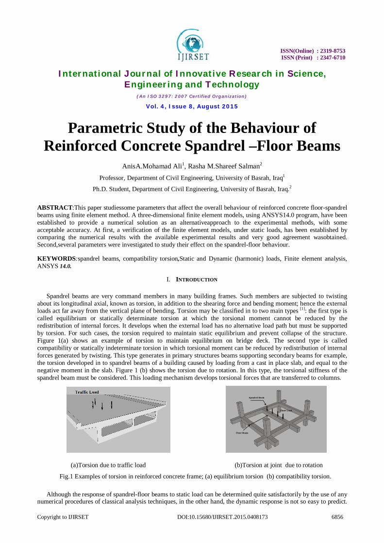
about its longitudinal axial, known as torsion, in addition to the shearing force and bending moment; hence the external loads act far away from the vertical plane of bending. Torsion may be classified in to two main types [1]: the first type is called equilibrium or statically determinate torsion at which the torsional moment cannot be reduced by the redistribution of internal forces. It develops when the external load has no alternative load path but must be supported by torsion. For such cases, the torsion required to maintain static equilibrium and prevent collapse of the structure. Figure 1(a) shows an example of torsion to maintain equilibrium on bridge deck. The second type is called compatibility or statically indeterminate torsion in which torsional moment can be reduced by redistribution of internal forces generated by twisting. This type generates in primary structures beams supporting secondary beams for example, the torsion developed in to spandrel beams of a building caused by loading from a cast in place slab, and equal to the negative moment in the slab. Figure 1 (b) shows the torsion due to rotation. In this type, the torsional stiffness of the spandrel beam must be considered. This loading mechanism develops torsional forces that are transferred to columns.
(a)Torsion due to traffic load (b)Torsion at joint due to rotation
Fig.1 Examples of torsion in reinforced concrete frame; (a) equilibrium torsion (b) compatibility torsion.
Although the response of spandrel-floor beams to static load can be determined quite satisfactorily by the use of any numerical procedures of classical analysis techniques, in the other hand, the dynamic response is not so easy to predict.

ISSN(Online) : 2319-8753 ISSN (Print) : 2347-6710
International Journal of Innovative Research in Science,
Engineering and Technology (An ISO 3297: 2007 Certified Organization)
Vol. 4, Issue 8, August 2015
Copyright to IJIRSET DOI:10.15680/IJIRSET.2015.0408173 6857
In fact, dynamic response may be the major factor influencing long-term behaviour and that is required more experimental and analytical studies. In practical field, in addition to dead loads, the spandrel-floor beams carry imposed loads which are supposed unvarying with time that is named '' STATIC LOADS" . In fact, no structural loads (except dead load ) are really static since they must be applied to the structure in some manner and this involves a time variation of force, dynamic effects, unless the magnitude of force varies slowly enough, it will have no dynamic effect and can be analysed as static. The distinction is made between the dynamic and the static analysis on the basis of whether the applied action has enough acceleration in comparison to the structure's natural frequency [2]. If a load is applied sufficiently slowly, the inertia forces (Newton's second law of motion) can be ignored and the analysis can be simplified as static analysis.
II. LITERATURE SURVEY Several methods of analysis [4,5,6] have been developed in order to obtain an economic design. Earlier researches
presented by Collins and Lampert[4] , 1973, showed that the design procedures could be simplified,if zero torsional stiffness is assumed and only minimum torsional reinforcement is required in order to ensure the ductility and the limit crack width. Hsu and Burton[5],1974, based on the elastic stiffness analysis , the torsional moment distribution to spandrel beam at the joint is calculated according to Eq.(1).
Eq.(1)
Abul Mansur and Rangan[6], concluded that the use of the conventional elastic method based on the gross stiffness is uneconomic and the steel remains under stressed. Despite the rigorous studies on spandrel beams, there have been few empirical and semi-empirical formulas for expressing the relation between the spandrel and floor beam under dynamic loads. Rudolph Szilard[7] in 1968 was one of the earliest investigators who studied the dynamic response of the reinforced concrete members subjected to torsion. Test results have indicated that plain concrete under dynamic torsion does not behave either linearly or fully plastically. Hsu's formulas gave good agreement with the measured ultimate torques as well as the angle of twist. Abdul Razzaq,7 and Khalaf, 8 studied the behaviour of reinforced concrete floor-spandrel members under repeated loads. The load was repeated at two stages; in the first stage the load increased continuously until the soft cracks appeared in the floor and spandrel beams; in the second stage the loading continuous until the plastic hinge formulated at the mid-span of floor beam. It was observed that the effect of repeated loads is to reduce the torsional resistance of the concrete, and this resistance could become zero when the load is repeated at so high maximum levels of load that they lead to yielding of the longitudinal steel of the floor beam. That resulted in increasing the twist, deflection and crack width and decreasing the torque. The torsional capacity of the section depends on the stirrups since the concrete lost its torsional resistance when the load was repeated for a considerable number of cycles after occurring of plastic hinge at floor beam, and transverse steel has no significant influence on the beam prior to cracking but it has a significant effect on the ultimate strength of specimens after cracking. It can be concluded that, excessive studies should be carried out to satisfy the above target. In the current study a three-dimensional finite element models are presented to give accurate simulation for geometry, loading condition (static load) and locations of reinforcement bars based on availableexperimental data. These models were used to study the effects of the dynamic loads on the overall behaviour of the members.
III. FINITE ELEMENT SIMULATIONAND ANSYS14.0 SOFTWARE
The finite element analysis is a reliable and usable means for analysing of civil structures with the availability of concrete technology [9]. It is an approximate numerical method that can make a realistic representation of reinforced
ISSN(Online) : 2319-8753 ISSN (Print) : 2347-6710
International Journal of Innovative Research in Science,
Engineering and Technology (An ISO 3297: 2007 Certified Organization)
Vol. 4, Issue 8, August 2015
Copyright to IJIRSET DOI:10.15680/IJIRSET.2015.0408173 6858
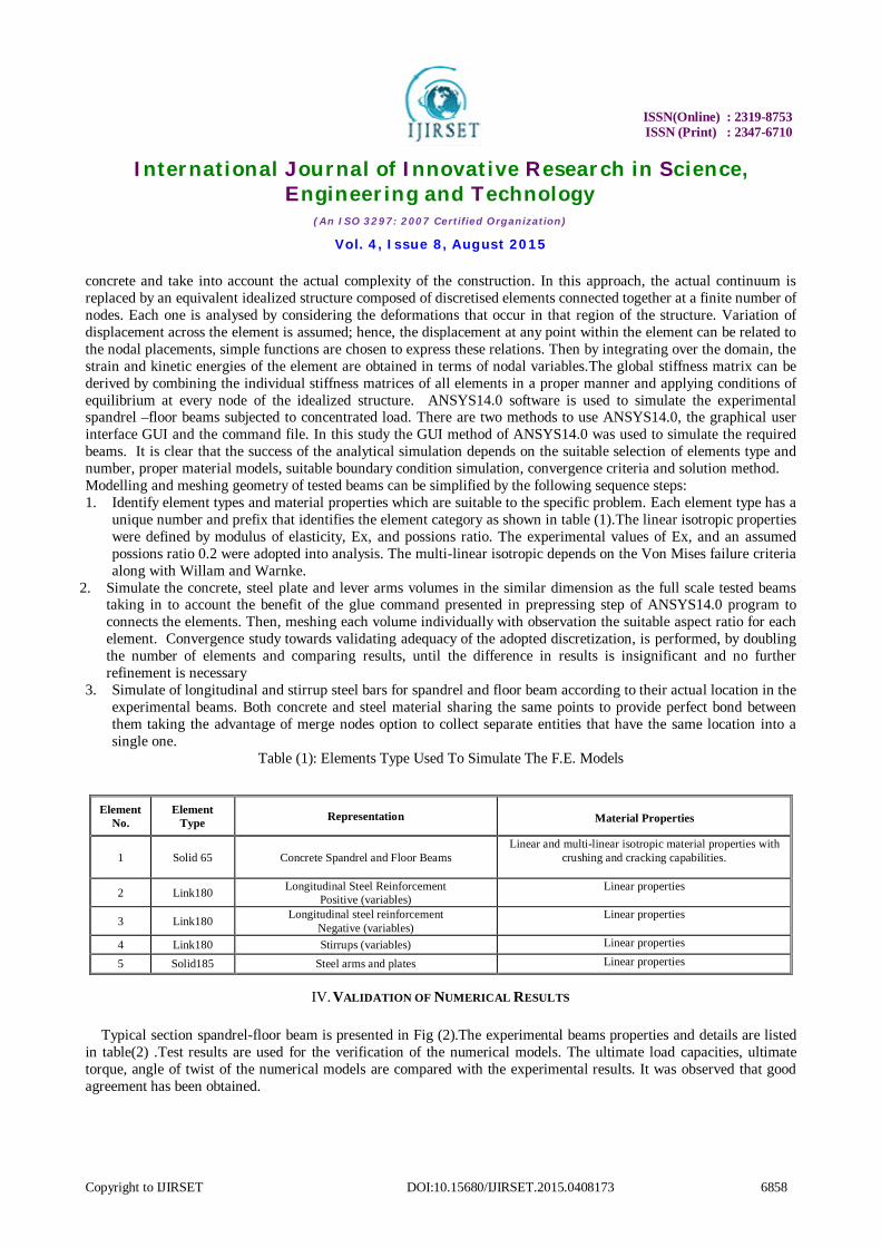
concrete and take into account the actual complexity of the construction. In this approach, the actual continuum is replaced by an equivalent idealized structure composed of discretised elements connected together at a finite number of nodes. Each one is analysed by considering the deformations that occur in that region of the structure. Variation of displacement across the element is assumed; hence, the displacement at any point within the element can be related to the nodal placements, simple functions are chosen to express these relations. Then by integrating over the domain, the strain and kinetic energies of the element are obtained in terms of nodal variables.The global stiffness matrix can be derived by combining the individual stiffness matrices of all elements in a proper manner and applying conditions of equilibrium at every node of the idealized structure. ANSYS14.0 software is used to simulate the experimental spandrel –floor beams subjected to concentrated load. There are two methods to use ANSYS14.0, the graphical user interface GUI and the command file. In this study the GUI method of ANSYS14.0 was used to simulate the required beams. It is clear that the success of the analytical simulation depends on the suitable selection of elements type and number, proper material models, suitable boundary condition simulation, convergence criteria and solution method. Modelling and meshing geometry of tested beams can be simplified by the following sequence steps: 1. Identify element types and material properties which are suitable to the specific problem. Each element type has a
unique number and prefix that identifies the element category as shown in table (1).The linear isotropic properties were defined by modulus of elasticity, Ex, and possions ratio. The experimental values of Ex, and an assumed possions ratio 0.2 were adopted into analysis. The multi-linear isotropic depends on the Von Mises failure criteria along with Willam and Warnke.
2. Simulate the concrete, steel plate and lever arms volumes in the similar dimension as the full scale tested beams taking in to account the benefit of the glue command presented in prepressing step of ANSYS14.0 program to connects the elements. Then, meshing each volume individually with observation the suitable aspect ratio for each element. Convergence study towards validating adequacy of the adopted discretization, is performed, by doubling the number of elements and comparing results, until the difference in results is insignificant and no further refinement is necessary
3. Simulate of longitudinal and stirrup steel bars for spandrel and floor beam according to their actual location in the experimental beams. Both concrete and steel material sharing the same points to provide perfect bond between them taking the advantage of merge nodes option to collect separate entities that have the same location into a single one.
Table (1): Elements Type Used To Simulate The F.E. Models
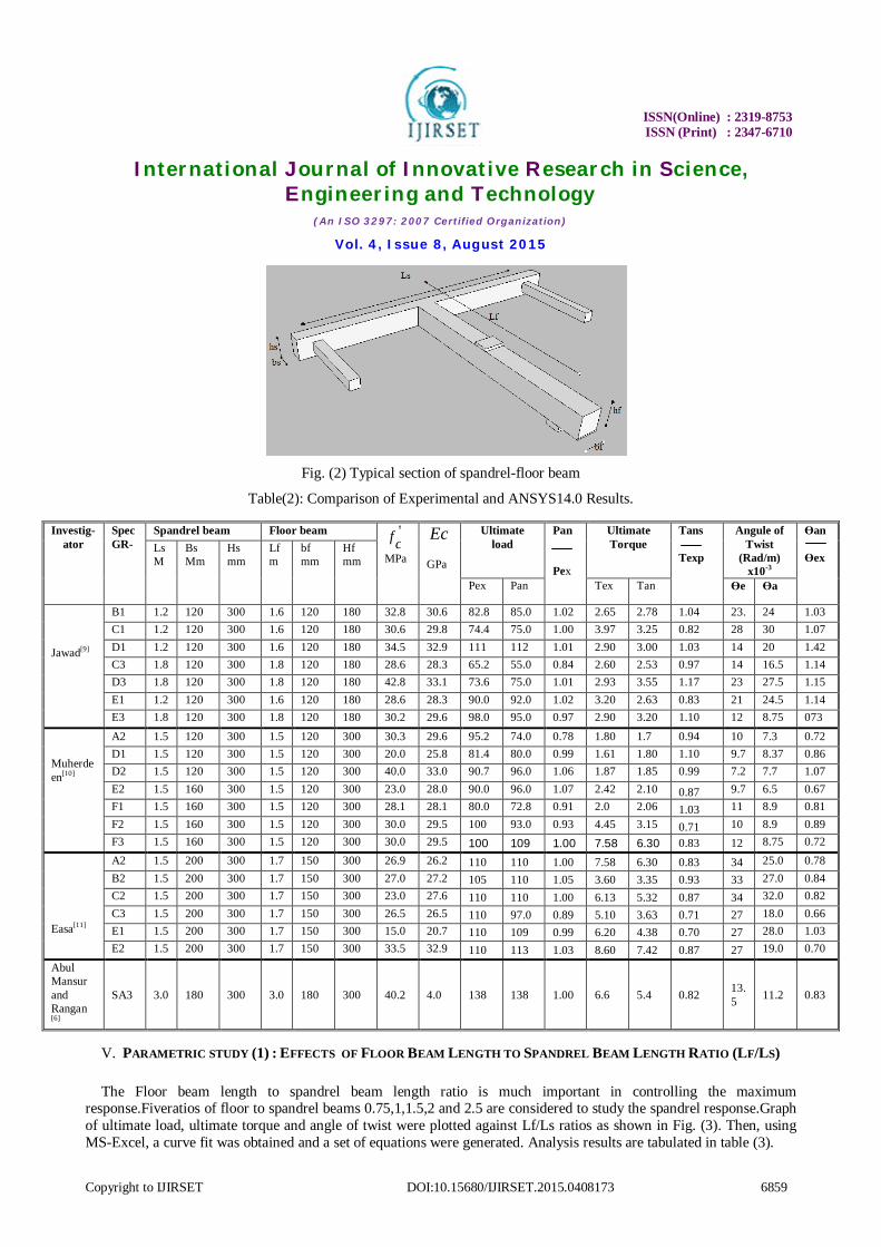
IV. VALIDATION OF NUMERICAL RESULTS Typical section spandrel-floor beam is presented in Fig (2).The experimental beams properties and details are listed
in table(2) .Test results are used for the verification of the numerical models. The ultimate load capacities, ultimate torque, angle of twist of the numerical models are compared with the experimental results. It was observed that good agreement has been obtained.
Element No.
Element Type Representation
Material Properties
1 Solid 65 Concrete Spandrel and Floor Beams Linear and multi-linear isotropic material properties with
crushing and cracking capabilities.
2 Link180 Longitudinal Steel Reinforcement Positive (variables)
Linear properties
3 Link180 Longitudinal steel reinforcement Negative (variables)
Linear properties
4 Link180 Stirrups (variables) Linear properties
5 Solid185 Steel arms and plates Linear properties
ISSN(Online) : 2319-8753 ISSN (Print) : 2347-6710
International Journal of Innovative Research in Science,
Engineering and Technology (An ISO 3297: 2007 Certified Organization)
Vol. 4, Issue 8, August 2015
Copyright to IJIRSET DOI:10.15680/IJIRSET.2015.0408173 6859
Fig. (2) Typical section of spandrel-floor beam
Table(2): Comparison of Experimental and ANSYS14.0 Results.
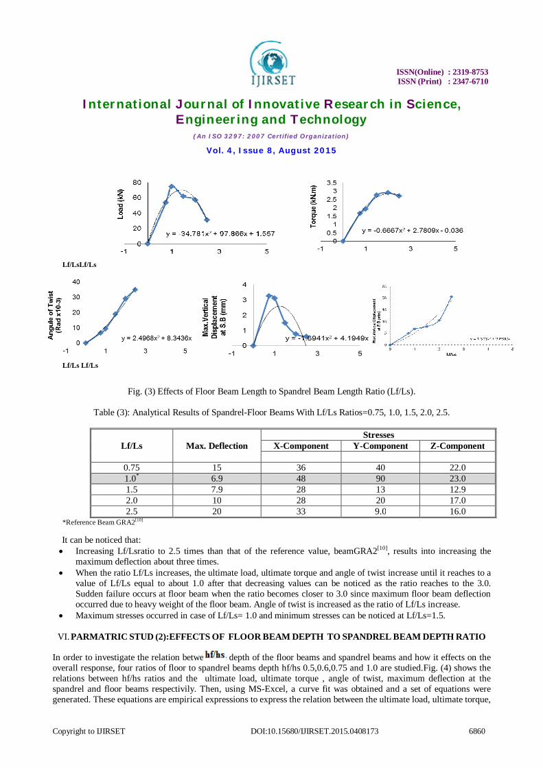
V. PARAMETRIC STUDY (1) : EFFECTS OF FLOOR BEAM LENGTH TO SPANDREL BEAM LENGTH RATIO (LF/LS) The Floor beam length to spandrel beam length ratio is much important in controlling the maximum
response.Fiveratios of floor to spandrel beams 0.75,1,1.5,2 and 2.5 are considered to study the spandrel response.Graph of ultimate load, ultimate torque and angle of twist were plotted against Lf/Ls ratios as shown in Fig. (3). Then, using MS-Excel, a curve fit was obtained and a set of equations were generated. Analysis results are tabulated in table (3).
Investig-ator
Spec GR-
Spandrel beam Floor beam 'cf
MPa
Ec GPa
Ultimate load
Pan Pex
Ultimate Torque
Tans Texp
Angule of Twist
(Rad/m) x10-3
Ɵan Ɵex
Ls M
Bs Mm
Hs mm
Lf m
bf mm
Hf mm
Pex Pan Tex Tan Ɵe Ɵa
Jawad[9]
B1 1.2 120 300 1.6 120 180 32.8 30.6 82.8 85.0 1.02 2.65 2.78 1.04 23. 24 1.03 C1 1.2 120 300 1.6 120 180 30.6 29.8 74.4 75.0 1.00 3.97 3.25 0.82 28 30 1.07 D1 1.2 120 300 1.6 120 180 34.5 32.9 111 112 1.01 2.90 3.00 1.03 14 20 1.42 C3 1.8 120 300 1.8 120 180 28.6 28.3 65.2 55.0 0.84 2.60 2.53 0.97 14 16.5 1.14 D3 1.8 120 300 1.8 120 180 42.8 33.1 73.6 75.0 1.01 2.93 3.55 1.17 23 27.5 1.15 E1 1.2 120 300 1.6 120 180 28.6 28.3 90.0 92.0 1.02 3.20 2.63 0.83 21 24.5 1.14 E3 1.8 120 300 1.8 120 180 30.2 29.6 98.0 95.0 0.97 2.90 3.20 1.10 12 8.75 073
Muherdeen[10]
A2 1.5 120 300 1.5 120 300 30.3 29.6 95.2 74.0 0.78 1.80 1.7 0.94 10 7.3 0.72 D1 1.5 120 300 1.5 120 300 20.0 25.8 81.4 80.0 0.99 1.61 1.80 1.10 9.7 8.37 0.86 D2 1.5 120 300 1.5 120 300 40.0 33.0 90.7 96.0 1.06 1.87 1.85 0.99 7.2 7.7 1.07 E2 1.5 160 300 1.5 120 300 23.0 28.0 90.0 96.0 1.07 2.42 2.10 0.87 9.7 6.5 0.67 F1 1.5 160 300 1.5 120 300 28.1 28.1 80.0 72.8 0.91 2.0 2.06 1.03 11 8.9 0.81 F2 1.5 160 300 1.5 120 300 30.0 29.5 100 93.0 0.93 4.45 3.15 0.71 10 8.9 0.89 F3 1.5 160 300 1.5 120 300 30.0 29.5 100 109 1.00 7.58 6.30 0.83 12 8.75 0.72
Easa[11]
A2 1.5 200 300 1.7 150 300 26.9 26.2 110 110 1.00 7.58 6.30 0.83 34 25.0 0.78 B2 1.5 200 300 1.7 150 300 27.0 27.2 105 110 1.05 3.60 3.35 0.93 33 27.0 0.84 C2 1.5 200 300 1.7 150 300 23.0 27.6 110 110 1.00 6.13 5.32 0.87 34 32.0 0.82 C3 1.5 200 300 1.7 150 300 26.5 26.5 110 97.0 0.89 5.10 3.63 0.71 27 18.0 0.66 E1 1.5 200 300 1.7 150 300 15.0 20.7 110 109 0.99 6.20 4.38 0.70 27 28.0 1.03 E2 1.5 200 300 1.7 150 300 33.5 32.9 110 113 1.03 8.60 7.42 0.87 27 19.0 0.70
Abul Mansur and Rangan [6]
SA3 3.0 180 300 3.0 180 300 40.2
4.0
138
138
1.00
6.6
5.4
0.82 13.
5 11.2 0.83
ISSN(Online) : 2319-8753 ISSN (Print) : 2347-6710
International Journal of Innovative Research in Science,
Engineering and Technology (An ISO 3297: 2007 Certified Organization)
Vol. 4, Issue 8, August 2015
Copyright to IJIRSET DOI:10.15680/IJIRSET.2015.0408173 6860
Lf/LsLf/Ls Lf/Ls Lf/Ls
Fig. (3) Effects of Floor Beam Length to Spandrel Beam Length Ratio (Lf/Ls).
Table (3): Analytical Results of Spandrel-Floor Beams With Lf/Ls Ratios=0.75, 1.0, 1.5, 2.0, 2.5.
Stresses Max. Deflection Lf/Ls Z-Component Y-Component X-Component
22.0 40 36 15 0.75 23.0 90 48 6.9 1.0*
12.9 13 28 7.9 1.5 17.0 20 28 10 2.0 16.0 9.0 33 20 2.5
*Reference Beam GRA2[10]
It can be noticed that: Increasing Lf/Lsratio to 2.5 times than that of the reference value, beamGRA2[10], results into increasing the
maximum deflection about three times. When the ratio Lf/Ls increases, the ultimate load, ultimate torque and angle of twist increase until it reaches to a
value of Lf/Ls equal to about 1.0 after that decreasing values can be noticed as the ratio reaches to the 3.0. Sudden failure occurs at floor beam when the ratio becomes closer to 3.0 since maximum floor beam deflection occurred due to heavy weight of the floor beam. Angle of twist is increased as the ratio of Lf/Ls increase.
Maximum stresses occurred in case of Lf/Ls= 1.0 and minimum stresses can be noticed at Lf/Ls=1.5.
VI. PARMATRIC STUD (2):EFFECTS OF FLOOR BEAM DEPTH TO SPANDREL BEAM DEPTH RATIO
In order to investigate the relation between the depth of the floor beams and spandrel beams and how it effects on the overall response, four ratios of floor to spandrel beams depth hf/hs 0.5,0.6,0.75 and 1.0 are studied.Fig. (4) shows the relations between hf/hs ratios and the ultimate load, ultimate torque , angle of twist, maximum deflection at the spandrel and floor beams respectivily. Then, using MS-Excel, a curve fit was obtained and a set of equations were generated. These equations are empirical expressions to express the relation between the ultimate load, ultimate torque,

ISSN(Online) : 2319-8753 ISSN (Print) : 2347-6710
International Journal of Innovative Research in Science,
Engineering and Technology (An ISO 3297: 2007 Certified Organization)
Vol. 4, Issue 8, August 2015
Copyright to IJIRSET DOI:10.15680/IJIRSET.2015.0408173 6861
maximum deflection and angle of twist with differenthf/hs ratios.Maximum values of the above analysis were tabulated in table (4).
Figure (4): Effects of Floor Beam Depth to Spandrel Beam Depth Ratio (hf/hs) on the ultimate load, torque, angle of
twist at the joint, vertical displacement at the spandrel and floor beams.
Table (4): Analytical Results (maximum vertical displacement, x-,y- and z-component of the stresses) For Spandrel-
Floor Beams With hf/hs Ratios=0.5, 0.6,0.75 and 1.0.
Stresses Max. Deflection hf/hs
Z-Component Y-Component X-Component
-11 -15 -27 6.3 0.5
-31 -39 -45 6.1 0.6
-26 -27 -34 3.8 0.75
-17 21 -21 1.73 1.0
It can be seen that:
Load capacity and the angle of twist increase as the ratio hf/hsincrease. Critical design ratio of hf/hs is about 0.6 where maximum deflections at the mid span of the floor beam and at the
joints occurred. Minimum floor and spandrel beam deflections sighted when the floor beam and the spandrel beams have the
same height. The maximum deflection decreases as the ratio hf/hs increases. Maximum axial, vertical and z-component
stresses occurred at ratio equal to 0.6 while the minimum stresses occurred at 0.5.
VII. PARAMETRIC STUDY (3): DYNAMIC EFFECTS (HARMONIC LOAD) Based on the principle of D'Alembert, the equation of motion has been established[2], which deals with all problems
in structural dynamic. Several analysis types of structural dynamics can be generated according to the representation of the applied load. Three structural dynamic problems are provided in ANSYS14.0, Transient analysis, model analysis
ISSN(Online) : 2319-8753 ISSN (Print) : 2347-6710
International Journal of Innovative Research in Science,
Engineering and Technology (An ISO 3297: 2007 Certified Organization)
Vol. 4, Issue 8, August 2015
Copyright to IJIRSET DOI:10.15680/IJIRSET.2015.0408173 6862
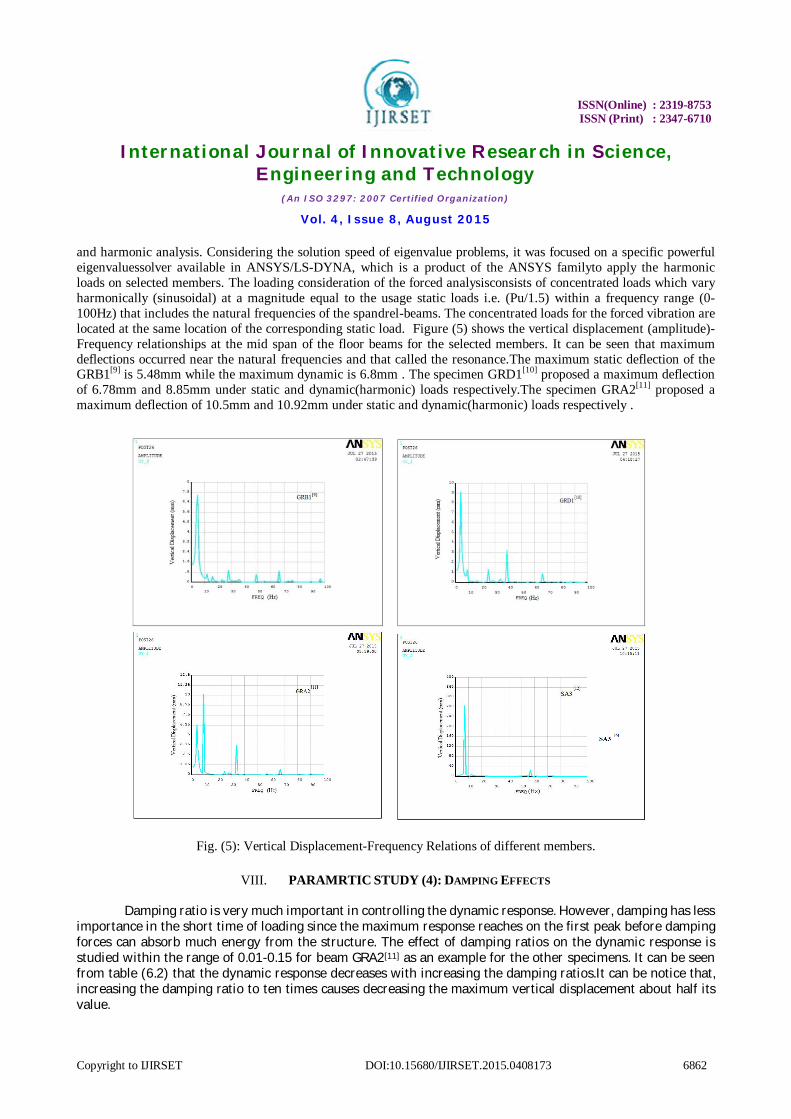
and harmonic analysis. Considering the solution speed of eigenvalue problems, it was focused on a specific powerful eigenvaluessolver available in ANSYS/LS-DYNA, which is a product of the ANSYS familyto apply the harmonic loads on selected members. The loading consideration of the forced analysisconsists of concentrated loads which vary harmonically (sinusoidal) at a magnitude equal to the usage static loads i.e. (Pu/1.5) within a frequency range (0-100Hz) that includes the natural frequencies of the spandrel-beams. The concentrated loads for the forced vibration are located at the same location of the corresponding static load. Figure (5) shows the vertical displacement (amplitude)-Frequency relationships at the mid span of the floor beams for the selected members. It can be seen that maximum deflections occurred near the natural frequencies and that called the resonance.The maximum static deflection of the GRB1[9] is 5.48mm while the maximum dynamic is 6.8mm . The specimen GRD1[10] proposed a maximum deflection of 6.78mm and 8.85mm under static and dynamic(harmonic) loads respectively.The specimen GRA2[11] proposed a maximum deflection of 10.5mm and 10.92mm under static and dynamic(harmonic) loads respectively .
Fig. (5): Vertical Displacement-Frequency Relations of different members.
VIII. PARAMRTIC STUDY (4): DAMPING EFFECTS
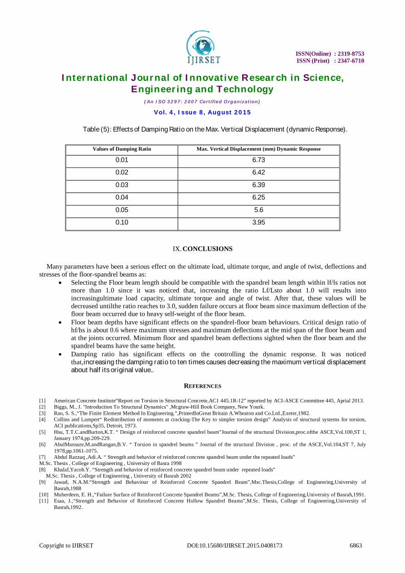
Damping ratio is very much important in controlling the dynamic response. However, damping has less importance in the short time of loading since the maximum response reaches on the first peak before damping forces can absorb much energy from the structure. The effect of damping ratios on the dynamic response is studied within the range of 0.01-0.15 for beam GRA2[11] as an example for the other specimens. It can be seen from table (6.2) that the dynamic response decreases with increasing the damping ratios.It can be notice that, increasing the damping ratio to ten times causes decreasing the maximum vertical displacement about half its value.
ISSN(Online) : 2319-8753 ISSN (Print) : 2347-6710
International Journal of Innovative Research in Science,
Engineering and Technology (An ISO 3297: 2007 Certified Organization)
Vol. 4, Issue 8, August 2015
Copyright to IJIRSET DOI:10.15680/IJIRSET.2015.0408173 6863
Table (5): Effects of Damping Ratio on the Max. Vertical Displacement (dynamic Response).
IX. CONCLUSIONS Many parameters have been a serious effect on the ultimate load, ultimate torque, and angle of twist, deflections and
stresses of the floor-spandrel beams as: Selecting the Floor beam length should be compatible with the spandrel beam length within lf/ls ratios not
more than 1.0 since it was noticed that, increasing the ratio Lf/Lsto about 1.0 will results into increasingultimate load capacity, ultimate torque and angle of twist. After that, these values will be decreased untilthe ratio reaches to 3.0, sudden failure occurs at floor beam since maximum deflection of the floor beam occurred due to heavy self-weight of the floor beam.
Floor beam depths have significant effects on the spandrel-floor beam behaviours. Critical design ratio of hf/hs is about 0.6 where maximum stresses and maximum deflections at the mid span of the floor beam and at the joints occurred. Minimum floor and spandrel beam deflections sighted when the floor beam and the spandrel beams have the same height.
Damping ratio has significant effects on the controlling the dynamic response. It was noticed that,increasing the damping ratio to ten times causes decreasing the maximum vertical displacement about half its original value..
REFERENCES
[1] American Concrete Institute“Report on Torsion in Structural Concrete,AC1 445.1R-12” reported by ACI-ASCE Committee 445, Aprial 2013. [2] Biggs, M., J. "Introduction To Structural Dynamics" ,Mcgraw-Hill Book Company, New Yourk. [3] Rao, S. S.,“The Finite Element Method In Engineering.”,PrintedInGreat Britain A.Wheaton and Co.Ltd.,Exeter,1982. [4] Collins and Lampert“ Redistribution of moments at cracking-The Key to simpler torsion design” Analysis of structural systems for torsion,
ACI publications,Sp35, Detroit, 1973. [5] Hsu, T.T.C.andBurton,K.T. “ Design of reinforced concrete spandrel beam”Journal of the structural Division,proc.ofthe ASCE,Vol.100,ST 1,
January 1974,pp.209-229. [6] AbulMansure,M.andRangan,B.V. “ Torsion in spandrel beams ” Journal of the structural Division , proc. of the ASCE,Vol.104,ST 7, July
1978,pp.1061-1075. [7] Abdul Razzaq ,Adi.A. “ Strength and behavior of reinforced concrete spandrel beam under the repeated loads” M.Sc. Thesis , College of Engineering , University of Basra 1998 [8] Khalaf,Yacob.Y. “Strength and behavior of reinforced concrete spandrel beam under repeated loads” M.Sc. Thesis , College of Engineering , University of Basrah 2002 [9] Jawad, N.A.M.“Strength and Behaviour of Reinforced Concrete Spandrel Beam”,Msc.Thesis,College of Engineering,University of
Basrah,1988 [10] Muherdeen, E. H.,“Failure Surface of Reinforced Concrete Spandrel Beams”,M.Sc. Thesis, College of Engineering,University of Basrah,1991. [11] Esaa, J.,“Strength and Behavior of Reinforced Concrete Hollow Spandrel Beams”,M.Sc. Thesis, College of Engineering,University of
Basrah,1992.
Values of Damping Ratio Max. Vertical Displacement (mm) Dynamic Response
0.01 6.73
0.02 6.42
0.03 6.39
0.04 6.25
0.05 5.6
0.10 3.95