Embed Size (px)
Citation preview

www.elsevier.com/locate/jvolgeores
Journal of Volcanology and Geothermal Research 136 (2004) 71–96
Volcanic and deformation history of the Bodrum resurgent
caldera system (southwestern Turkey)
I. Ulusoya,*, E. Cubukcua, E. Aydara,*, P. Labazuyb, A. Gourgaudb, P.M. Vincentb
aHacettepe University Department of Geological Engineering, 06532, Beytepe Ankara, TurkeybUniversity Blaise Pascal, UMR-CNRS 6524, 5 rue Kessler, 63038 Clermont-Ferrand, France
Received 9 May 2003; accepted 29 March 2004
Abstract
The volcanic rocks of the Bodrum Peninsula, in SW Turkey and NE of the Hellenic Arc, outcrop over an area of 138 km2. A
monzonitic intrusion is exposed in the western part of the peninsula. Upper Miocene volcanism is represented by high-K (HK)-
andesitic, andesitic lava flows and pillows, sparse HK-andesitic and dacitic lava domes and associated block-and-ash flows. A
HK-andesitic ignimbrite sequence with two stratigraphic units is associated with the collapse of a complex caldera system.
Breccias, formed as a result of slumping of the caldera walls are observed inside the caldera. Post-caldera activity is represented
by HK-andesitic, HK-basaltic andesitic lava flows, domes and associated block-and-ash flows. Numerous dykes, HK-andesitic
and shoshonitic in composition cut all volcanic units.
The structure of the Bodrum caldera was investigated using SPOT image, digital elevation model (DEM), aerial photographs
as well as field data. The Bodrum caldera is a NE–SW-elongated, semi-elliptical, deeply eroded caldera with dimensions of
18.7� 7.7 km. It is partly submerged in the SW part. The complex caldera system can be described in terms of two structural
domains. The collapse of the Dagbelen domain is interpreted as a piston type subsidence, while the Karakaya domain represents
a piecemeal collapse. Both domains exhibit two separate resurgence events. The elongation of the caldera may be related to pre-
existing regional tectonic structures. The caldera is also affected and cut by late stage faults related to regional extensional
events.
Moreover, pre-caldera volcanism is dispersed and cannot be related to a pre-existing stratovolcano. Bodrum volcanism is
therefore interpreted as a complex ignimbritic shield volcano.
D 2004 Elsevier B.V. All rights reserved.
Keywords: Bodrum; Turkey; caldera; resurgence; tectonics; remote sensing
1. Introduction
The Bodrum area is a peninsula located in SW
Turkey and NE of the Hellenic arc, covering 250 km2
(Fig. 1). It is historically well-known; Herodotus, the
0377-0273/$ - see front matter D 2004 Elsevier B.V. All rights reserved.
doi:10.1016/j.jvolgeores.2004.03.016
* Corresponding authors.
E-mail addresses: [email protected] (I. Ulusoy),
[email protected] (E. Aydar).
‘‘father of history’’, was born in Bodrum (Halicarnas-
sos) in about 484 BC. Bodrum is also the site of one of
the seven wonders of the world: the Mausoleum built
by Artemisia II in honour of her husband King
Mausolos. It is also a popular holiday resort region
where most of the geological features are hidden by
extensive construction.
The Aegean region exhibits strong seismic activity
and complex, rapidly changing tectonics (Dewey and

Fig. 1. Geological sketch map of the Bodrum peninsula (geochemical rock descriptions are taken from Cubukcu, 2002).
I.Ulusoyet
al./JournalofVolca
nologyandGeotherm
alResea
rch136(2004)71–96
72

I. Ulusoy et al. / Journal of Volcanology and Geothermal Research 136 (2004) 71–96 73
S�engor, 1979). Two main tectonic regimes occur in the
western Anatolian region. The first is a paleotectonic
regime characterized by N–S compression (Kurt et al.,
1999). The second is a neotectonic regime, defined by
N–S extension and collapse of E–W-directed grabens.
Dewey and S�engor (1979) offered a widely accept-
ed model for the cause of extension. Extension of the
Aegean region is related to the southwestern escape of
the Anatolian plate (McKenzie, 1972) in response to
convergent movement of the Arabia–Africa and Eur-
asian plates along the Bitlis collision zone (Dewey and
S�engor, 1979). This westward escape of the Anatolian
plate relative to Africa is compensated by the Hellenic
subduction (Dewey and S�engor, 1979). The south and
southwestern escape of Anatolia (30–35 mm/year,
Kahle et al., 1998), points to the western Aegean being
affected by a counterclockwise rotation (Walcott and
White, 1998; Rotstein, 1984; Reilinger et al., 1997).
While there is an agreement regarding an N–S
extensional regime, there are differing ideas on the
cause and onset time of the extension. Dewey and
S�engor (1979) proposed Upper Miocene and Kurt et
al. (1999) proposed Upper Miocene–Pliocene. How-
ever, Seyitoglu and Scott (1991) placed the extension
in the Early Miocene and Walcott and White (1998)
at Oligocene–Early Miocene.
Volcanic rocks outcrop in the west of the penin-
sula, while the eastern part is covered by limestone.
Previous works mainly focused on the petrology and
geochemistry of magmatic rocks (e.g., Ercan et al.,
1984; Robert et al., 1992; Kurt and Arslan, 2001;
Cubukcu, 2002). In addition, Robert et al. (1992)
doubted the formation of ‘‘resurgent dome-like’’
structures. Genc� et al. (2001) considered the Bodrum
area as a stratovolcano with secondary volcanic
centres. Altunkaynak and Yilmaz (2000) described
a stratovolcano, Kizilcamandira, 5� 5 km in size,
located in the SW of the peninsula. Moreover,
Altunkaynak and Yilmaz (2001) defined the Turgu-
treis stratovolcano as having five evolutionary
stages: pre-cone phase, cone-building phase, climac-
tic phase related to a very small caldera (300� 700
m), post-caldera phase and late phase.
Based on new data (SPOT image, DEM, aerial
photographs as well as field data), we focused our
work on a more complex caldera system than previ-
ously described, including its boundaries, resurgence
events and relation to tectonics.
2. Geological outlines
The volcanic rocks of the peninsula are distributed
over an area of 138 km2. Robert and Montigny (2001)
defined the peninsula as part of a chemical province
including the Kos and Patmos islands, called the
Dodecanese Province. Robert et al. (1992) defined
the mafics of Bodrum as two groups: ultrapotassic
and shoshonitic rocks. Cubukcu (2002) summarised
the characteristics of the peninsula’s chemical evolu-
tion as follows: magmatism commences with a mon-
zonitic I-type pluton followed by high-K (HK)
calcalkaline intermediate lava and associated block-
and-ash flows. The volcanism attains a shoshonitic
character with evacuation of the magma chamber by
caldera forming ignimbritic eruptions. Volcanism
ceases with medium-K calcalkaline intermediate prod-
ucts. All the geochemical volcanic descriptions are
taken from Cubukcu (2002).
Radiometric dating of the volcanism falls within
the range of 11.2–9.3 Ma (Pis�kin, 1980; Robert etal., 1992; Fahmi et al., 1997; Robert and Montigny,
2001), while some dykes and domes are younger
(7.8 and 7.5 Ma, respectively; Robert and Mon-
tigny, 2001). The contemporaneous emplacement of
volcanic rocks and monzonitic intrusions (11.2F 1.6
Ma; Pis�kin, 1980), located in the western tip of the
peninsula (Fig. 1), was demonstrated by radiometric
dating.
Although western Turkey has experienced crustal
extension since the lower Miocene, in the Bodrum
area, the extension-related E–W-trending structure
(Gokova graben, illustrated in Fig. 1) originated in
the late Miocene–Pliocene period (Kurt et al., 1999).
In the seismic reflection studies applied to the
Gokova graben, Kurt et al. (1999) found WNW–
ESE-oriented faults, younger than the E–W-oriented
faults which are graben-related. NW–SE faults in the
vicinity of the Bodrum Peninsula have also been
observed by previous researchers (i.e., Ercan et al.,
1984).
2.1. Pre-caldera activity
The volcanism of the Bodrum Peninsula started
with HK-andesitic, andesitic lava flows (sometimes
pillow facies), sparse HK-andesitic and dacitic lava
domes and associated block-and-ash flows, considered
I. Ulusoy et al. / Journal of Volcanology and Geothermal Research 136 (2004) 71–9674
as belonging to the pre-ignimbrite period. The radio-
metric age of this initial phase of volcanism is
11.2F 1.6 Ma (Pis�kin, 1980).Pre-caldera volcanism is not widely developed in
the Bodrum Peninsula. It is a dispersed volcanism,
poorly extended. Only four monogenetic dome-like
edifices, and sparce lava flows have been observed.
Such volcanism cannot be related to a previous
stratovolcano.
2.2. Caldera forming eruptions
Two stratigraphic sequences are associated with
ignimbritic emplacement: Kale ignimbrites and
Akvaryum ignimbrites (Ulusoy, 2002). They are
HK-andesitic in composition and fall approximately
within the same time span: 10.9F 0.3 Ma (Fahmi et
al., 1997).
2.2.1. Kale ignimbrites
The castle (meaning in Turkish ‘‘Kale’’) of Bod-
rum was built by the knights of St. John. The walls
of the castle were built with ignimbrite. The first
ignimbritic sequence outcrops within a limited area
between Koyunbaba bay and Sivrikaya (Fig. 1)
where it fills N-, NE- and W-oriented valleys. Kale
ignimbrite covers an area of 3 km2, with an estimat-
ed volume of 0.21 km3. The apparent thickness
reaches 70 m.
In the western part of the peninsula, in Koyun-
baba bay, a poorly sorted ignimbritic unit exhibits
medium to well-welded rheology (with 15% clasts)
with fiamme texture. Computed ‘‘flattening ratios—
FR’’ (height/length) for the pumices show that the
FR of coarse pumices (0.1) are higher than the fine
ones (0.2; 0.3). The welded texture of the ignim-
brite, lahar-like block-and-ash flow deposits overly-
ing the ignimbrite, the shallow sea sediments
overlying this block-and-ash flow deposits and the
pillow lavas near Geris village at 130 m altitude are
evidence of the submarine emplacement of the Kale
ignimbrite, at least, along the western shores.
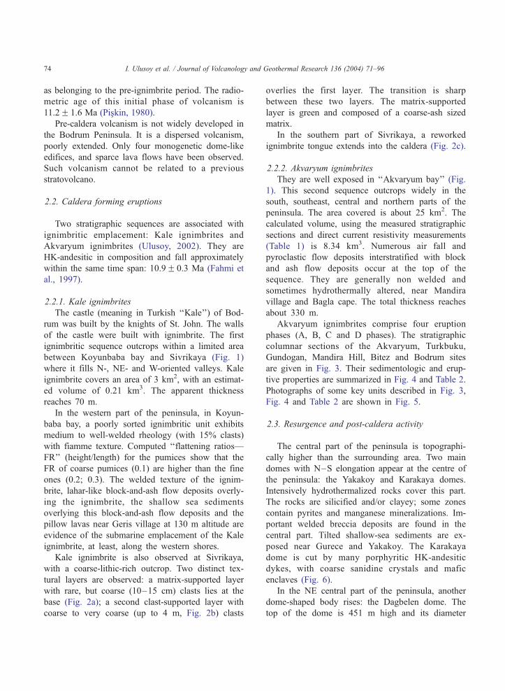
Kale ignimbrite is also observed at Sivrikaya,
with a coarse-lithic-rich outcrop. Two distinct tex-
tural layers are observed: a matrix-supported layer
with rare, but coarse (10–15 cm) clasts lies at the
base (Fig. 2a); a second clast-supported layer with
coarse to very coarse (up to 4 m, Fig. 2b) clasts
overlies the first layer. The transition is sharp
between these two layers. The matrix-supported
layer is green and composed of a coarse-ash sized
matrix.
In the southern part of Sivrikaya, a reworked
ignimbrite tongue extends into the caldera (Fig. 2c).
2.2.2. Akvaryum ignimbrites
They are well exposed in ‘‘Akvaryum bay’’ (Fig.
1). This second sequence outcrops widely in the
south, southeast, central and northern parts of the
peninsula. The area covered is about 25 km2. The
calculated volume, using the measured stratigraphic
sections and direct current resistivity measurements
(Table 1) is 8.34 km3. Numerous air fall and
pyroclastic flow deposits interstratified with block
and ash flow deposits occur at the top of the
sequence. They are generally non welded and
sometimes hydrothermally altered, near Mandira
village and Bagla cape. The total thickness reaches
about 330 m.
Akvaryum ignimbrites comprise four eruption
phases (A, B, C and D phases). The stratigraphic
columnar sections of the Akvaryum, Turkbuku,
Gundogan, Mandira Hill, Bitez and Bodrum sites
are given in Fig. 3. Their sedimentologic and erup-
tive properties are summarized in Fig. 4 and Table 2.
Photographs of some key units described in Fig. 3,
Fig. 4 and Table 2 are shown in Fig. 5.
2.3. Resurgence and post-caldera activity
The central part of the peninsula is topographi-
cally higher than the surrounding area. Two main
domes with N–S elongation appear at the centre of
the peninsula: the Yakakoy and Karakaya domes.
Intensively hydrothermalized rocks cover this part.
The rocks are silicified and/or clayey; some zones
contain pyrites and manganese mineralizations. Im-
portant welded breccia deposits are found in the
central part. Tilted shallow-sea sediments are ex-
posed near Gurece and Yakakoy. The Karakaya
dome is cut by many porphyritic HK-andesitic
dykes, with coarse sanidine crystals and mafic
enclaves (Fig. 6).
In the NE central part of the peninsula, another
dome-shaped body rises: the Dagbelen dome. The
top of the dome is 451 m high and its diameter
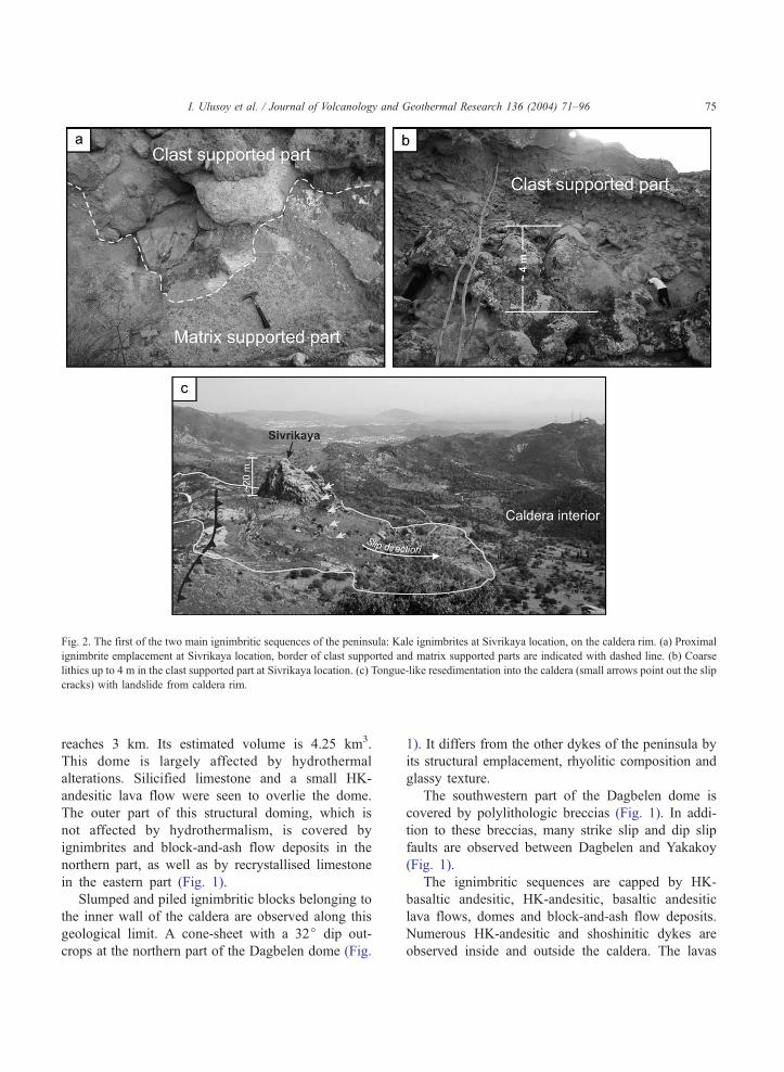
Fig. 2. The first of the two main ignimbritic sequences of the peninsula: Kale ignimbrites at Sivrikaya location, on the caldera rim. (a) Proximal
ignimbrite emplacement at Sivrikaya location, border of clast supported and matrix supported parts are indicated with dashed line. (b) Coarse
lithics up to 4 m in the clast supported part at Sivrikaya location. (c) Tongue-like resedimentation into the caldera (small arrows point out the slip
cracks) with landslide from caldera rim.
I. Ulusoy et al. / Journal of Volcanology and Geothermal Research 136 (2004) 71–96 75
reaches 3 km. Its estimated volume is 4.25 km3.
This dome is largely affected by hydrothermal
alterations. Silicified limestone and a small HK-
andesitic lava flow were seen to overlie the dome.
The outer part of this structural doming, which is
not affected by hydrothermalism, is covered by
ignimbrites and block-and-ash flow deposits in the
northern part, as well as by recrystallised limestone
in the eastern part (Fig. 1).
Slumped and piled ignimbritic blocks belonging to
the inner wall of the caldera are observed along this
geological limit. A cone-sheet with a 32j dip out-
crops at the northern part of the Dagbelen dome (Fig.
1). It differs from the other dykes of the peninsula by
its structural emplacement, rhyolitic composition and
glassy texture.
The southwestern part of the Dagbelen dome is
covered by polylithologic breccias (Fig. 1). In addi-
tion to these breccias, many strike slip and dip slip
faults are observed between Dagbelen and Yakakoy
(Fig. 1).
The ignimbritic sequences are capped by HK-
basaltic andesitic, HK-andesitic, basaltic andesitic
lava flows, domes and block-and-ash flow deposits.
Numerous HK-andesitic and shoshinitic dykes are
observed inside and outside the caldera. The lavas
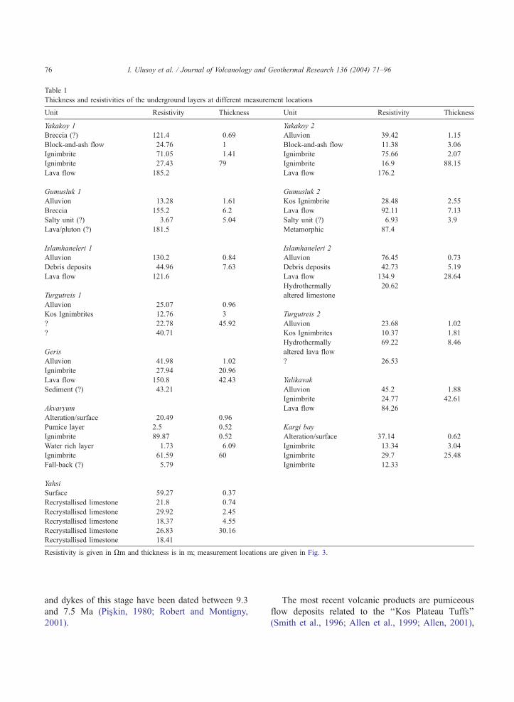
Table 1
Thickness and resistivities of the underground layers at different measurement locations
Unit Resistivity Thickness Unit Resistivity Thickness
Yakakoy 1 Yakakoy 2
Breccia (?) 121.4 0.69 Alluvion 39.42 1.15
Block-and-ash flow 24.76 1 Block-and-ash flow 11.38 3.06
Ignimbrite 71.05 1.41 Ignimbrite 75.66 2.07
Ignimbrite 27.43 79 Ignimbrite 16.9 88.15
Lava flow 185.2 Lava flow 176.2
Gumusluk 1 Gumusluk 2
Alluvion 13.28 1.61 Kos Ignimbrite 28.48 2.55
Breccia 155.2 6.2 Lava flow 92.11 7.13
Salty unit (?) 3.67 5.04 Salty unit (?) 6.93 3.9
Lava/pluton (?) 181.5 Metamorphic 87.4
Islamhaneleri 1 Islamhaneleri 2
Alluvion 130.2 0.84 Alluvion 76.45 0.73
Debris deposits 44.96 7.63 Debris deposits 42.73 5.19
Lava flow 121.6 Lava flow 134.9 28.64
Hydrothermally 20.62
Turgutreis 1 altered limestone
Alluvion 25.07 0.96
Kos Ignimbrites 12.76 3 Turgutreis 2
? 22.78 45.92 Alluvion 23.68 1.02
? 40.71 Kos Ignimbrites 10.37 1.81
Hydrothermally 69.22 8.46
Geris altered lava flow
Alluvion 41.98 1.02 ? 26.53
Ignimbrite 27.94 20.96
Lava flow 150.8 42.43 Yalikavak
Sediment (?) 43.21 Alluvion 45.2 1.88
Ignimbrite 24.77 42.61
Akvaryum Lava flow 84.26
Alteration/surface 20.49 0.96
Pumice layer 2.5 0.52 Kargi bay
Ignimbrite 89.87 0.52 Alteration/surface 37.14 0.62
Water rich layer 1.73 6.09 Ignimbrite 13.34 3.04
Ignimbrite 61.59 60 Ignimbrite 29.7 25.48
Fall-back (?) 5.79 Ignimbrite 12.33
Yahsi
Surface 59.27 0.37
Recrystallised limestone 21.8 0.74
Recrystallised limestone 29.92 2.45
Recrystallised limestone 18.37 4.55
Recrystallised limestone 26.83 30.16
Recrystallised limestone 18.41
Resistivity is given in Vm and thickness is in m; measurement locations are given in Fig. 3.
I. Ulusoy et al. / Journal of Volcanology and Geothermal Research 136 (2004) 71–9676
and dykes of this stage have been dated between 9.3
and 7.5 Ma (Pis�kin, 1980; Robert and Montigny,
2001).
The most recent volcanic products are pumiceous
flow deposits related to the ‘‘Kos Plateau Tuffs’’
(Smith et al., 1996; Allen et al., 1999; Allen, 2001),

Fig. 3. Correlation of the stratigraphic sections, locations of resistivity profiles and stratigraphic sections. Locations of resistivity profiles and stratigraphic sections are indicated in the
small map. Letters of the unit names indicated with small arrows are coded as follows: ‘‘Na’’, block-and-ash flow unit; ‘‘I’’, ignimbrite unit; ‘‘Fb’’, fall-back unit; ‘‘A,B,C,D’’,
eruption phases).
I.Ulusoyet
al./JournalofVolca
nologyandGeotherm
alResea
rch136(2004)71–96
77

Fig. 4. Eruption phases of Akvaryum ignimbrites in correlation with the physical stratigraphic properties: pumice and clast sizes in flow and fall units, resedimentation.
I.Ulusoyet
al./JournalofVolca
nologyandGeotherm
alResea
rch136(2004)71–96
78

Table 2
Sedimentologic and eruptive properties of the Akvaryum ignimbrites according to the eruption phases
Phases A B C D
Dating Cumulate sample
from Bagla cape
11F 0.7 Ma
(40Ar/39Ar; Robert
et al., 1992)
10.9F 0.3 Ma
(fission track ;
Fahmi et al., 1997)
Apparent
thickness
17 m 21 m 60 m 266 m
Rheology IA4 Well-welded,
colour changes
from red at
bottom to
white at top.
Generally medium
welded IB1 is white,
IB2 is faded pink and
IB5 is white coloured.
Generally medium welded.
Flow units are white in colour.
Generally medium
to well-welded
IA1, IA2,
AI3
Non- to
moderately
welded.
Pale-white,
pink coloured.
Sedimentology Four flow
units (IA1,
IA2, IA3,
IA4)
Similar grain
size distribution
except IA1
(1m for lithics).
IA1, IA2
and IA3 are
medium-sorted,
pumice poor
ignimbrites.
IA4 is a
well-sorted,
pumice-rich
ignimbrite.
Five flow
units
(IB1– IB5)
IB1 is poorly
sorted, reverse
graded. Pink
coloured fine
ash fall units
(FbB2) separate
IB1 and IB2.
IB2 is a coarse
(up to 1,2 m)
lithic bearing
ignimbrite. IB3
exhibits lapilli
size pumice and
lithic bearing
base level,
followed by a
matrix supported
layer. IB4 is
reverse graded.
Initial fall-back
units are followed
by four flow
units (IC1, IC2,
IC3 and IC4).
The lithic sizes
in IC3 and IC4
change in
different localities
and reach 10 cm
in Akvaryum,
36 cm in
Bodrum or
44 cm in
Turkbuku.
Variation in
pumice grain
size is roughly
constant and
reaches
maximum
25 cm in all
localities.
Phase D started
with pink coloured
fall-back products,
exposed mainly
in three localities:
Turkbuku,
Akvaryum,
Bodrum (FbD1).
They are 85, 120
and 425 cm thick,
respectively.
The ignimbritic
sequence of phase D
is composed of
interstratifications
of ignimbrite and
block-and-ash
flow deposits,
observed in
Numerous
thin fall-back
layers at
the base
Max 172 cm
total thickness,F
max,Pumice:
5 cm,F
max,Lithics:
3.3 cm
Fall-back
units at
the base
Up to 5.1 m
total thickness.F
max,Pumice:
1–5 cm,F
max,Lithics:
1–5 cm
northern area.
(continued on next page)
I. Ulusoy et al. / Journal of Volcanology and Geothermal Research 136 (2004) 71–96 79

Phases A B C D
Special
property
Well observed in Akvaryum
and Turkbuku outcrops.
Wide extension, most voluminous eruption products Ignimbrite and
block-and-ash flow
interstratifications.
Clearly recognisable
at the north of the
peninsula.
Reworked units clearly
visible at the bottom
of the Bodrum serie
separate phases A and B.
The reworked ash layers
between phase B and
phase C represent a break-
off period in eruptive activity
Observed
area
Southern and northern
parts of the peninsula
Southern, Northern,
Eastern parts.
Southern, Northern,
Eastern parts.
Especially
concentrated on
the northern half
of the peninsula.
Table 2 (continued)
I. Ulusoy et al. / Journal of Volcanology and Geothermal Research 136 (2004) 71–9680
exposed on the western and south western coastal
areas and emplaced 161 ka ago.
3. Image analysis
Information on the physical nature of terrains
and associated structures can be obtained from
digital elevation model (DEM) which enables a
morpho-structural analysis of the topography (Fro-
ger et al., 1998). Satellite images are commonly
used for detecting and analysing tectonic and vol-
canic structures (Bellier and Sebrier, 1994; De Silva
and Francis, 1991; Froger et al., 1998; Adıyaman et
al., 2001; Saintot et al., 1999). Satellite Pour
Observer la Terre (SPOT) satellite image, DEM
images (for both subaerial and submarine environ-
ment) and aerial photographs were used to investi-
gate the volcano-structural properties of the Bodrum
Peninsula where most of the geological features are
hidden by extensive construction. DEM images are
obtained by the digitisation of 2D topographic and
bathymetric maps.
The satellite image (SPOT-4 acquired in July 8,
1999 with a HRVIR instrument) has four bands
(spectral bandwidths are as follows: Band 1: 0.50–
0.59 Am, Band 2: 0.61–0.68 Am, Band 3: 0.79–
0.89 Am, Band 4: 1.58–1.75 Am) and a resolution
of 20 m (coordinates of the image centre: Latitude
37j11V29VV, Longitude 27j34V49VV). Twenty-four
possible combinations of the original four bands of
image were tested for display enhancement qualities.
Nine of the combinations provided valuable results
for structural analysis. A combination of the 4th,
2nd and 1st bands was used as red, green and blue
bands. The image was not originally georeferenced,
though we focused on a subset of 30.5� 32 km2
from the entire image and georeferenced the image
using ground control points. One of the basic
methods used for the image processing, was radio-
metric enhancement technique: ‘‘Look Up Table’’
(LUT) (Schott, 1997; Richards, 1993). Filtering
techniques for edge detection were applied to define
the lineaments.
Morphological analysis is the best method for de-
fining the structure of calderas, because calderas pres-
ent particular morphologies such as topographic rims.
Lipman (1984, 1997) successfully defined the widely
accepted major structural and morphological elements
of a simplified caldera model: a topographic rim, inner
topographic wall, bounding faults, a structural caldera
floor surrounded by these faults, intracaldera fill and
the underlying magma chamber or solidified pluton.
For young calderas with steep walls (i.e., Nemrut
caldera, Turkey, Aydar et al., 2003), it is easy to
detect the topographic rim. But for ancient calderas,
erosion highly affects the topographic rim, so pre-
served rims and flanks are not obvious. Generally,
topographic caldera rims exhibit elliptic and circular
structures.
The DEMs of the peninsula were obtained by
digitising the elevation contour lines of nine 1:25000
scaled topographic maps. The DEM was generated
using the Krigging (with linear interpolation) method.

Fig. 5. Photographs of some key units in the Akvaryum ignimbrites. (a, b) Flow and fall-back units of phase B located at Akvaryum bay.
(c, d) Pink-colored, last fall-back unit of phase C. (e) First ignimbrite unit of phase D, at Gundogan. (f) Same ignimbrite unit of phase D
at Mandira hill.
I. Ulusoy et al. / Journal of Volcanology and Geothermal Research 136 (2004) 71–96 81

Fig. 6. (a) Coarse sanidine crystals. (b) Mafic enclaves from a HK-andesitic dyke at Karakaya dome.
I. Ulusoy et al. / Journal of Volcanology and Geothermal Research 136 (2004) 71–9682
The slope image of DEM was generated for a geo-
morphologic approach. A final strong image showing
the slope and elevation relationship (Fig. 7a) was
obtained using the slope image combined with the
coloured image using the colour density slicing meth-
od. Circular features were defined with the final image.
We also used digital elevation model of bathym-
etry (DEMB), after digitising and interpolating the
depth points of a 1:100000 scaled bathymetry map
of the surrounding sea.
Finally, the stereoscopic analyses of 136 pairs of
1:25000 scaled aerial photos of the region were
carried out.
4. Bodrum caldera
The formation of ash-flow calderas by roof collapse
over an underlying shallow magma reservoir is now
widely admitted as accompanying explosive eruptions
that involve magmatic volumes of several cubic kilo-
meters (Lipman, 1997). The eruptions of Kale and
Akvaryum delivered about 8.5 km3 of ignimbrites s.l.
and triggered the collapse of the caldera. According to
our field data and image analysis, the Bodrum Penin-
Fig. 7. DEM, DEMB and SPOT satellite images. (a) The slope image deri
color density slicing method. (White arrows indicate the three main circu
(Black arrows and line indicate the fourth circular morphologic feature in th
the circular features on land.) (c) SPOT image of the peninsula with tw
geological features.
sula exhibits an ignimbritic caldera with complex
collapse and resurgence mechanisms.
Satellite images yield productive databases to
reveal hidden calderas, which are difficult to define
because of their large size and erosional factors.
Anguita et al. (1991) used Landsat images for the
semicircular features in the central part of the Trans-
Mexican Volcanic belt and nine collapse calderas
were defined in the same region (Anguita et al.,
2001).
Digital elevation models, SPOT4 image and the
aerial photos of the region were used to shed light on
the structural properties of the Bodrum caldera. Faults
and lineaments were determined by aerial photos and
SPOT (Fig. 7c) image. Field data are sketched on a
geological map (Fig. 1).
4.1. Caldera morphology and structure
4.1.1. Northeast segment: Dagbelen body
Three large, main circular features were defined
with DEM (Fig. 7a: white arrows) in the investigat-
ed area. The first, around the Dagbelen dome (Fig.
7a), characterises a semi-circular depression. The
NW flanks of this depression represent typical
ved from the DEM combined with the image of DEM colored with
lar feature on the land.) (b) Digital elevation model of bathymetry.
e sea delimited with the � 30 m isobath. Black dashed lines indicate
o main structural faults (dashed black lines) and some important

I. Ulusoy et al. / Journal of Volcanology and Geothermal Research 136 (2004) 71–96 83
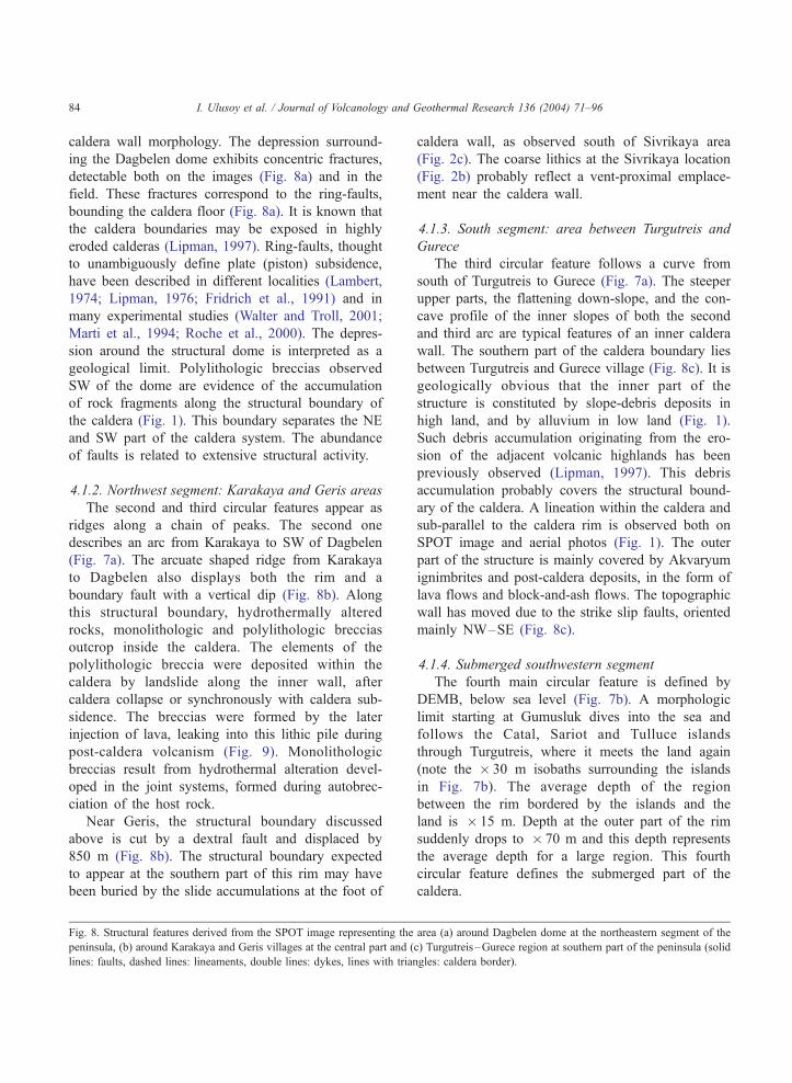
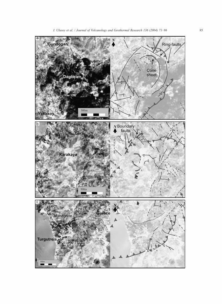
I. Ulusoy et al. / Journal of Volcanology and Geothermal Research 136 (2004) 71–9684
caldera wall morphology. The depression surround-
ing the Dagbelen dome exhibits concentric fractures,
detectable both on the images (Fig. 8a) and in the
field. These fractures correspond to the ring-faults,
bounding the caldera floor (Fig. 8a). It is known that
the caldera boundaries may be exposed in highly
eroded calderas (Lipman, 1997). Ring-faults, thought
to unambiguously define plate (piston) subsidence,
have been described in different localities (Lambert,
1974; Lipman, 1976; Fridrich et al., 1991) and in
many experimental studies (Walter and Troll, 2001;
Marti et al., 1994; Roche et al., 2000). The depres-
sion around the structural dome is interpreted as a
geological limit. Polylithologic breccias observed
SW of the dome are evidence of the accumulation
of rock fragments along the structural boundary of
the caldera (Fig. 1). This boundary separates the NE
and SW part of the caldera system. The abundance
of faults is related to extensive structural activity.
4.1.2. Northwest segment: Karakaya and Geris areas
The second and third circular features appear as
ridges along a chain of peaks. The second one
describes an arc from Karakaya to SW of Dagbelen
(Fig. 7a). The arcuate shaped ridge from Karakaya
to Dagbelen also displays both the rim and a
boundary fault with a vertical dip (Fig. 8b). Along
this structural boundary, hydrothermally altered
rocks, monolithologic and polylithologic breccias
outcrop inside the caldera. The elements of the
polylithologic breccia were deposited within the
caldera by landslide along the inner wall, after
caldera collapse or synchronously with caldera sub-
sidence. The breccias were formed by the later
injection of lava, leaking into this lithic pile during
post-caldera volcanism (Fig. 9). Monolithologic
breccias result from hydrothermal alteration devel-
oped in the joint systems, formed during autobrec-
ciation of the host rock.
Near Geris, the structural boundary discussed
above is cut by a dextral fault and displaced by
850 m (Fig. 8b). The structural boundary expected
to appear at the southern part of this rim may have
been buried by the slide accumulations at the foot of
Fig. 8. Structural features derived from the SPOT image representing the
peninsula, (b) around Karakaya and Geris villages at the central part and (
lines: faults, dashed lines: lineaments, double lines: dykes, lines with tria
caldera wall, as observed south of Sivrikaya area
(Fig. 2c). The coarse lithics at the Sivrikaya location
(Fig. 2b) probably reflect a vent-proximal emplace-
ment near the caldera wall.
4.1.3. South segment: area between Turgutreis and
Gurece
The third circular feature follows a curve from
south of Turgutreis to Gurece (Fig. 7a). The steeper
upper parts, the flattening down-slope, and the con-
cave profile of the inner slopes of both the second
and third arc are typical features of an inner caldera
wall. The southern part of the caldera boundary lies
between Turgutreis and Gurece village (Fig. 8c). It is
geologically obvious that the inner part of the
structure is constituted by slope-debris deposits in
high land, and by alluvium in low land (Fig. 1).
Such debris accumulation originating from the ero-
sion of the adjacent volcanic highlands has been
previously observed (Lipman, 1997). This debris
accumulation probably covers the structural bound-
ary of the caldera. A lineation within the caldera and
sub-parallel to the caldera rim is observed both on
SPOT image and aerial photos (Fig. 1). The outer
part of the structure is mainly covered by Akvaryum
ignimbrites and post-caldera deposits, in the form of
lava flows and block-and-ash flows. The topographic
wall has moved due to the strike slip faults, oriented
mainly NW–SE (Fig. 8c).
4.1.4. Submerged southwestern segment
The fourth main circular feature is defined by
DEMB, below sea level (Fig. 7b). A morphologic
limit starting at Gumusluk dives into the sea and
follows the Catal, Sariot and Tulluce islands
through Turgutreis, where it meets the land again
(note the � 30 m isobaths surrounding the islands
in Fig. 7b). The average depth of the region
between the rim bordered by the islands and the
land is � 15 m. Depth at the outer part of the rim
suddenly drops to � 70 m and this depth represents
the average depth for a large region. This fourth
circular feature defines the submerged part of the
caldera.
area (a) around Dagbelen dome at the northeastern segment of the
c) Turgutreis–Gurece region at southern part of the peninsula (solid
ngles: caldera border).
I. Ulusoy et al. / Journal of Volcanology and Geothermal Research 136 (2004) 71–96 85

Fig. 9. Breccia formations in the caldera, on the Karakaya dome (western central part). (a) Lenticular injection in the breccia (dashed lines
I. Ulusoy et al. / Journal of Volcanology and Geothermal Research 136 (2004) 71–9686
4.2. Widening of the caldera and resurgence
A NE–SW elongated caldera collapsed in the Bod-
rum Peninsula. A three-dimensional image of the
peninsula is proposed, combining DEM and satellite
image of the peninsula, showing the main structural
and morphological features of the caldera (Fig. 10).
Two main structural bodies are present within the
caldera: the Karakaya domain in the SW and the
Dagbelen domain in the NE (Fig. 10). They are
separated from each other by polylithologic breccias
and cross-cutting faults.
Some units of Akvaryum ignimbrites were found
on many outcrops of the peninsula, while some were
outline the injection) and (b, c) breccia– injection relationship.
found only in a limited location, interpreted as the
activation of many vents. Caldera forming eruptions
are generally associated with many syn-activated
vents (Allen, 2001). The ignimbrites outcrop on a
large arc-like area, indicating that they were erupted
from ring fractures. The deposits of the initial phases
of caldera forming are observed in southern, western
and northern parts of the peninsula, while the prod-
ucts of the last phase (phase D) outcrop only at the
northeastern half of the peninsula. The caldera col-
lapse in the western half, the Karakaya domain, is
related to the emplacement of Kale ignimbrites and
phases A, B, C of Akvaryum ignimbrites (Fig. 11b).
Furthermore, the eruption of the last phase (D) led to

Fig. 10. 3D image of the peninsula generated by combining the DEM and SPOT image of the peninsula (small block diagram at the upper left
shows the block resurgence near Yakakoy dome; a white dashed line borders the resurgent area and the undeformed area in the Karakaya
domain).
Fig. 11. Morphologic evolution of the volcanic edifice.
I. Ulusoy et al. / Journal of Volcanology and Geothermal Research 136 (2004) 71–96 87
I. Ulusoy et al. / Journal of Volcanology and Geothermal Research 136 (2004) 71–9688
the collapse of the Dagbelen area (Fig. 11c), thus
widening the caldera to the NE. Such nested calderas
have been previously observed (i.e., Campi Flegrei,
Orsi et al., 1996). Ongoing erosional processes as
well as tectonic events, such as uplift, collapse,
played a main role in the present morphology of
the peninsula (Fig. 11f).
4.2.1. Karakaya domain
The Karakaya domain exhibits the monzonite
body and two segments of a structural dome: the
Karakaya and Yakakoy dome segments (Figs. 10 and
11d). The caldera floor presents an uneven, rough
topographic surface. A monzonitic pluton, in the
middle of the Karakaya domain (Figs. 1, 8 and 10),
is probably outcropped due to erosion and tectonic
control. Magma chambers, preserved as solidified
plutons or batholiths, are exposed in many deeply
eroded ash-flow calderas, as evidenced by petrologic
and age correlations with erupted volcanics (Lipman,
1997). Such plutons are commonly emplaced at a
depth of a few kilometers.
Karakaya resurgence represents one of the two
main resurgence events of the peninsula, occupying
the western and the central parts of the caldera. A
NE–SW valley (Fig. 10) divides this resurgence into
two segments (Karakaya and Yakakoy). Doming of
Yakakoy resulted in the uplifting of shallow sea
sediments and recrystallized limestone in the caldera,
which slopes at up to 45j. The Karakaya dome is
formed of monolithologic and polylithologic brec-
cias. En-echelon emplacement of violet, lenticular
magmatic injections occur in the breccias from
bottom to top of the dome (Fig. 9a). Lenticules are
1.5 m thick and 10–80 m long. We consider these
lenticules as syn-generated with the upward driving
forces related to resurgence.
The western flanks of the Yakakoy dome consist
of valleys, sequentially arranged and oriented E–W
representing en-echelon uplifted caldera blocks (Fig.
10). Such structures have been observed in fault
controlled resurgent calderas such as the Ischia,
Pantelleria islands (Orsi et al., 1991; Acocella and
Funiciello, 1999) and Campi Flegrei in Italy (Orsi et
al., 1999). Orsi et al. (1991) defined a model of this
type of resurgence called simple-sheering block
resurgence. The model implies that at the beginning
of the deformation, high-angle inland-dipping mar-
ginal detachments—which may result from reacti-
vated caldera fractures—define the edges of the
resurgent block. To avoid physical instability, the
uplifting block has to tilt, causing an internal defor-
mation of the block through a simple-shear mecha-
nism (Orsi et al., 1991). The remaining part of the
floor of the Karakaya domain is not deformed (Fig.
10) as Orsi et al. (1991) shown in the Ischia and
Pantelleria islands.
The generation of resurgence in the form of
separate blocks highlights the piecemeal subsidence
of this part of the caldera (Karakaya domain).
Piecemeal subsidence of caldera blocks, which have
more than one collapse centre, is also observed on
the caldera floor morphology (Acocella and Funi-
ciello, 1999). The Karakaya domain is a thin and
long elliptical structure related to more than one
collapse centre. The abrupt changes in the grain size
of the ignimbrites and reworked layers between
eruption phases represent fluctuating eruption inten-
sity and break-off periods in eruptive activity. The
presence of numerous plinian fall-back units eviden-
ces the periodicity of the eruption column and cloud
generation during several volcanic phases. Several
sequential activities from multiple vents may also
lead to a piecemeal collapse.
4.2.2. Dagbelen domain
The Dagbelen domain is differs from Karakaya.
It rises as a dome-shaped body in the middle of
the surrounding depression (Fig. 10). This depres-
sion forms a structural zone with ring-faults and a
cone-sheet.
The doming of the area, following plate type
subsidence, represents the second resurgent activity
of the caldera.
After the collapse of the Karakaya domain, con-
tinuing eruptive activity led to the collapse of the
Dagbelen domain. Phase D products, observed only
at the northern part of the peninsula, are considered as
responsible for the collapse of the Dagbelen domain.
The relatively weak activity related to block-and-ash
flow and ignimbrite deposits of phase D can be
explained by sequential dome eruptions and ash col-
umns (Eichelberger and Westrich, 1981; Fink, 1983)
or by gas loss through the permeable conduit wall
(Eichelberger et al., 1986; Fink et al. 1992). More
stable conditions of eruptive intensity and the smaller

I. Ulusoy et al. / Journal of Volcanology and Geothermal Research 136 (2004) 71–96 89
circular structure of the collapsed area are taken as
evidence of plate type subsidence for the Dagbelen
domain.
Ring-faults can accommodate uplift as well as
subsidence (Lipman, 1997). Domical magmatic resur-
gence at the Lake City caldera in Colorado occurred
along the same faults that earlier accommodated cal-
dera collapse (Hon, 1987) with magma then being
partially injected as ring-dykes (Lipman, 1997). The
resurgence of the Dagbelen dome was accompanied by
ring-faults acting in the opposite direction to their
former direction. A cone-sheet in the northern part of
the dome is considered as contemporaneous with
resurgence. Strong resurgence processes may induce
newly formed and/or reactivated fractures, connected
to a regional and/or a local stress field (Acocella and
Funiciello, 1999). A ring-fault in the northern part of
the dome cuts the thickest dyke (N33E/67SE) of the
peninsula. Walter and Troll (2001), in their experimen-
tal study, proposed that the event of circular faults
cutting the radial fractures requires at least one caldera
subsidence followed by doming or resurgence. For-
mation of cone-sheets, ring-dykes and radial dykes is
generated as a function of the stress field near the
Fig. 12. Rose diagrams representing fault and dyke directions at
magma chamber, which is subjected to multiple intru-
sion and collapse stages (Lafrance and John, 2001).
5. Volcano-tectonics
5.1. Faults and lineaments
The faults and the lineaments were defined using
satellite images, aerial photos and field studies. Faults
and lineaments of the Bodrum Peninsula were inves-
tigated in three groups according to their directions:
caldera boundary faults, intra-caldera faults and outer
caldera faults.
Rose diagrams of the faults were drawn using the
frequency method (Fig. 12). Most of the boundary
faults are in NE–SW direction. Faults out of the
caldera are mainly in NW–SE, and are probably
related to the WNW–ESE-directed tectonic faults in
the Gokova graben.
The Rose diagram of intra-caldera faults and
lineaments defines two main groups of orientations
(Fig. 12). The first (NW–SE) group represents outer
caldera faults. We consider that they were formed by
the caldera boundary, out of the caldera and in the caldera.

I. Ulusoy et al. / Journal of Volcanology and Geothermal Research 136 (2004) 71–9690
post-caldera tectonic events. The second group is
directed E–W, ENE–WSW and WNW–ESE, and
we consider it to be related to the collapse and
resurgence events. The E–W-oriented dykes of the
Karakaya dome and E–W-oriented valleys at the
western side of the Yakakoy dome (Fig. 10) are
compatible with the E–W direction of the intra-
caldera faults and lineaments.
5.2. Fault striae investigations
Fault striae measurements were carried out on a
dyke, two lava flows and two consolidated fall-back
units. Such measurements permit an interpretation of
structural events according to Sparner et al. (1993).
Fault striae analyses were computed with Fault-
KinWin software, programmed by Allmendinger,
R.W. This method is detailed in Marrett and Allmen-
dinger (1990) and in Cladouhos and Allmendinger
(1993).
The results of fault striae analyses (Fig. 13) show
that the extensional tectonic regime affected the pen-
insula in a NNW–SSE direction. Kokkalas and Dout-
sos (2001), emphasized a NNW–SSE-directed, Upper
Miocene aged regional extensional regime on Kos
Island located f 35 km southeast of Bodrum. This
regime also explains the strike slip movements along
Fig. 13. Fault straie solutions. (a) Beach-ball illustration of the fault plan
Plunge: 61j). (b) Stereonet illustrations of faults and strikes (arrows show
the caldera boundary. Calculated r1, r2 and r3 values
(Fig. 13) are compatible with the values calculated on
Kos Island (Table 3) by Kokkalas and Doutsos (2001).
5.3. Dykes
The observed dykes were investigated in two
main groups: intracaldera dykes and dykes out of
caldera. These groups differ by texture, direction and
thickness.
Intracaldera dykes are light coloured rocks and
exhibit a porphyritic texture with coarse crystals. They
are mostly HK-andesitic rocks. Dykes intruded out of
the caldera are also porphyritic but no coarse crystals
are observed. They are mafic rocks characterised by
shoshonite, banakite, absarokite and HK-andesitic
composition.
Rose diagrams prepared using the frequency meth-
od were used to interpret the directions of the dykes.
Dykes out of the caldera are grouped in NNW–SSE
and NE–SW directions, indicating that the dykes
were intruded radially. In elliptical volcanic edifices,
radial dykes are expected to be numerous along the
long and small axes of the edifice (Nakamura, 1977).
Occurrence of similarly oriented faults in and out of
the caldera, with NNW–SSE-directed dykes (Fig.
12), emphasizes the effect of regional tectonics.
e solutions (nodal planes: Azi: 206j, Plunge: 51j and Azi: 322j,the movement of hanging wall) and main stress axes.

Table 3
Azimuth and dip values of principal stress axes calculated at
Bodrum peninsula and Kos Island by fault striae measurements
r1 (j) r2 (j) r3 (j)
Bodrum
Peninsula
82/6 347/38 180/52 This work
Kos Island 85/13 323/66 180/20 Kokkalas and
Doutsos (2001)
Values were given as azimuth/dip angle.
I. Ulusoy et al. / Journal of Volcanology and Geothermal Research 136 (2004) 71–96 91
Intracaldera dykes are oriented along WNW–ESE
and ENE–WSW directions (Fig. 12). Such directions
are similar to those of intracaldera faults, so these
directions are related to collapse and resurgence
events. Probably, the faults generated during piece-
meal subsidence were reactivated during resurgence
and acted as preferential pathways for dykes.
5.3.1. Dyke thickness
The thickness of the dykes was measured in the
field and plotted on a graph according to their dis-
Fig. 14. Illustration of thickness of the dykes of the peninsula, as a functio
and outer part of the caldera.
tances from the caldera boundary (Fig. 14). Dyke
thicknesses decrease away from the caldera boundary
both towards the interior and exterior of the caldera.
The decrease in thickness of dykes located outside the
caldera, away from the caldera boundary, denotes a
decrease in stress per unit volume, caused by tumes-
cence away from the edifice centre. Decrease in the
thickness of intra-caldera dykes away from the caldera
boundary may point to an increase in stress per unit
volume through the centre of a piecemeal caldera.
5.3.2. Using dykes to calculate crustal extension
Dykes are cracks opened and filled by magma.
Thus, the extension generated by dyke intrusion may
be calculated using the geometric parameters of
dykes (Marinoni and ve Gudmundsson, 2000). Most
methods concerning the extension generated by
dykes do not take account of dip angles. A new,
simple method proposed by Marinoni (2001) includ-
ing dips was applied to seven dykes whose geometric
properties were measured accurately. The computed
n of distance from the caldera boundary through the caldera interior

Fig. 15. Graph of the horizontal component of extension due to dyke injection.
I. Ulusoy et al. / Journal of Volcanology and Geothermal Research 136 (2004) 71–9692
maximum horizontal extension for the Bodrum Pen-
insula is 7.21 m, at a 140j azimuth defining N40W
direction (Fig. 15).
6. Discussion and conclusion
6.1. Volcanic events
The Bodrum Peninsula was previously described in
the Dodecanese Province as part of a shoshonitic serie
(Robert and Montigny, 2001; Cubukcu, 2002). More-
over, the volcanic vents were previously defined as
stratovolcanoes. But we consider it to be an ignimbritic
complex shield volcano (Vincent, 1960; Gourgaud and
Vincent, 2004). Of course, few dispersed lava domes,
related block-and-ash flows and lava flows are ob-
served and are considered as pre-caldera events. Two
major ignimbritic sequences can be distinguished: Kale
and Akvaryum. Akvaryum ignimbrite deposits com-
prised four phases (A, B, C, D). A, B and C phases are
widely represented throughout the peninsula and con-
sidered as responsible for the main pair of Bodrum
calderas, the Karakaya domain. Phase D deposits occur
in the northern and eastern areas. The Bodrum caldera
widened to the NE, forming the Dagbelen domain,
related to the eruption of phase D, and characterized by
block-and-ash flow, ignimbrite and fall deposits. Al-
ternation of eruptive styles, i.e., dome-forming and
plinian eruptions, is quite common in silicic volcanoes
(Martel et al., 2000). Moreover, two main resurgence
events are observed in the complex caldera. After the
collapse events, volcanism continued mainly with lava
flows, lava domes and block-and-ash flows. The inter-
nal part of the caldera was widely subjected to hydro-
thermal alteration.
6.2. Caldera and resurgence
Most of the large volume ignimbrite emplace-
ments can be directly or indirectly related to caldera
formation (Smith, 1979). Ignimbrites were erupted
from the ring fractures generated during caldera
collapse. The emplacement of two ignimbritic
sequences was responsible for the collapse of the
NE–SW, partially submerged elongated Bodrum cal-
dera complex, 18.7� 7.7 km wide. Many submerged
calderas are known around the world (such as
Rabaul, Papua New Ginea; Aira, Japan; Santorini,
Kos, Greece). The Bodrum caldera exhibits a com-
plex resurgence with two domains (Karakaya and
Dagbelen), separated by two crosscutting sinistral
faults and polylithologic breccias.
The Bodrum caldera system exhibits multiple-
block collapses and relevant resurgent doming, such
as the Dagbelen resurgent dome and the Karakaya
resurgence. The Dagbelen domain with its typical
radial-faults and peripheral concentric faults is inter-
preted as a plate type subsidence with resurgence
occurring as a central, near-perfect dome. Karakaya
resurgence occurs as an uplift of small plates, rather
like consecutive terraces, bounded by crosscutting

I. Ulusoy et al. / Journal of Volcanology and Geothermal Research 136 (2004) 71–96 93
small faults. Such resurgence is related to a previous
piecemeal type subsidence.
The interior of the caldera is widely affected by
hydrothermal alteration, related to the resurgence
event. The breccias are considered to be synchronous
with resurgence, as observed at Karakaya and SW of
Dagbelen. Block-and-ash flow deposits that have
been subjected to occasional hydrothermal alteration,
also occur within the caldera.
The topographic caldera area covers about 98 km2
and the collapsed area is estimated at 58 km2. The
average overall slope of the inner topographic walls
is 16j. Such lower slopes, dipping gently (10–15j),are the only parts preserved in many eroded calderas,
where the inner wall is expressed as an irregular
unconformity between pre-caldera and caldera-filling
rocks (Lipman, 1976, 1997).
The Bodrum caldera is a small–medium sized
caldera (Table 4) when compared with other calderas.
Low collapse and collar angle values demonstrate the
high erosional effects. An important volume of erup-
Table 4
Geometric properties of Bodrum caldera and some worldwide calderas in
Caldera Diameter
(km)
Topographic
area
(km2)
Structural
area
(km2)
Collaps
(m)
Bodrum caldera 7.7� 18.7 98 58 220
Acıgol caldera, Turkey 12.2� 12.3* 150 200
Gollu Dag caldera,
Turkey
f 10� 11* 113 300
Nemrut caldera, Turkey 8.5� 7 47 32.2 700
Nigorikava caldera,
Japan
2.5 4.9 0.2 1500
Crater Lake caldera, USA 9 64 20 1000
Aira caldera, Japan 20 314 113 2000
Creede caldera, USA 24 452 154 2000
La Garita, USA 50 1963 1256 2000
*Refer to the values calculated.
tive products is thought to be emplaced below the
sea. The difference between the topographic volume
and the caldera related ignimbrite volume (Table 4)
infers an underwater emplacement.
6.3. Caldera elongation and tectonics
Fault striae measurements indicate a NNW–SSE
extensional local regime. The NNW–SSE exten-
sional regime was effective during and after Upper
Miocene volcanism. Such results are compatible
with Kokkalas and Doutsos’s (2001) studies. The
NE–SW-elongated and semi-elliptic Bodrum calde-
ra is oblique in relation to the regional extensional
regime. Acocella et al. (2003), explained similar
observations in Ethiopia by pre-existing structural
features. A volcanic edifice grows in relation to an
extensional regime and the vents on its flanks are
expected to be aligned perpendicular to the exten-
sion axes (Nakamura, 1977; Adiyaman, 2000).
Structural features responsible for the elongation
different sizes
e Topographic
volume
(km3)
Structural
volume
(km3)
Caldera-related
ignimbrite
volume
(km3)
Collar
angle
(j)
From
21.6 12.8 >8.5 16 This work
30 28.2 Mouralis
et al. (2002)
33.9 21.7 Mouralis
et al. (2002)
32.9 22.5 37 *
3.9 1.2 7 56 Lipman (1997),
Aramaki (1984)
79 59 27 Lipman (1997),
Aramaki (1984)
636 452 300 27 Lipman (1997),
Aramaki (1984)
965 692 22 Lipman (1997),
Aramaki (1984)
6961 6280 22 Lipman (1997),
Aramaki (1984)

I. Ulusoy et al. / Journal of Volcanology and Geothermal Research 136 (2004) 71–9694
of the Bodrum caldera appear to have been formed
under the effect of a previous tectonic regime.
Some NE–SW-directed structural and topographic
features are observed in the Bodrum Peninsula and
its surroundings, which bear witness to such a pre-
existing local regime. Mes�hur and Yoldemir (1983)
also observed NE–SW-elongated faults, 80–90 km
in length, near the Gokova gulf. Kurttas� (1997)
emphasized the directional variations of tectonic
structures and lineaments near the Gokova gulf,
between N30E and N50E.
When calderic and structural features are evalu-
ated together, the effects of post-caldera tectonism
are obvious. Some faults observed both within and
outside of the caldera were active after caldera
collapse. Some intracaldera faults, linked to the
subsidence and resurgence events were later used
by dyke emplacements.
A N40W horizontal component of the extension
due to dyke intrusions was found. The thickness of the
dykes observed in the peninsula decreases away from
the caldera boundary towards the interior and exterior
of the caldera. This situation is interpreted as varia-
tions of stress within the edifice.
Acknowledgements
This work benefited from a research grant from the
French Ministry for Foreign Affairs and the French
Embassy in Ankara. The satellite image was supplied
by the French CNRS (UMR6524). The field expenses
for Turkish participants were financed by Hacettepe
University (Ankara, Turkey). The authors especially
thank to Prof. Dr. S.D. Weaver (Editor) and the
reviewers Prof. Dr. G. Orsi and Prof. Dr. F. Anguita for
their helpful comments on the manuscript and V.
O’Dwyer for improving the English expression.
References
Acocella, V., Funiciello, R., 1999. The interaction between re-
gional and local tectonics during resurgent doming: the case
of the island of Ischia, Italy. J. Volcanol. Geotherm. Res. 88,
109–123.
Acocella, V., Korme, T., Salvini, F., 2003. Elliptic calderas in the
Ethiopian Rift: control of the pre-existing structures. J. Volcanol.
Geotherm. Res. 119, 189–203.
Adiyaman, O., 2000. Relations entre volcanisme et tectonique en
contextes de collision et de decrochement (Turquie). Approche
par analyse structurale, geochimie, imagerie spatiale, modeles
numeriques de terrain et systemes d’information geographique.
PhD thesis, Univ. P. et M. Curie Paris VI, Paris, France.
Adiyaman, O., Chorowicz, J., Arnaud, O.N., Gundogdu, M.N.,
Gourgaud, A., 2001. Late Cenozoic tectonics and volcanism
along the North Anatolian Fault: new structural and geochemi-
cal data. Tectonophysics 338, 135–165.
Allen, S.R., 2001. Reconstruction of a major caldera-forming
eruption from pyroclastic deposit characteristics: Kos Plateau
Tuff, eastern Aegean Sea. J. Volcanol. Geotherm. Res. 105,
141–162.
Allen, S.R., Stadlbauer, E., Keller, J., 1999. Stratigraphy of the Kos
Plateau Tuff: product of a major Quaternary explosive rhyolitic
eruption in the eastern Aegean, Greece. Int. J. Earth Sci. 88,
132–156.
Altunkaynak, S�., Yilmaz, Y., 2000. The Kızılcamandıra stratovol-
cano of the Bodrum, SWAnatolia. International Earth Sciences
Colloquium on the Aegean Region, Dokur Eyliil University,
Izmir, Turkey, pp. 99.
Altunkaynak, S�., Yilmaz, Y., 2001. The Turgutreis stratovolcano of
the Bodrum, SW Anatolia. International Earth Sciences Collo-
quium on the Aegean Region, Dokur Eyliil University, Izmir,
Turkey, pp. 38–46.
Anguita, F., Verma, S.P., Garcıa-Cacho, L., Milan, M., Samaniego,
D., 1991. Mazahua: una nueva caldera en el Cinturon Volcanico
Mexicano. Geofıs. Int. 30, 135–148.
Anguita, F., Verma, S.P., Marquez, A., Vasconcelos-F, M.,
Lopez, I., Laurrieta, A., 2001. Circular features in the
Trans-Mexican Volcanic Belt. J. Volcanol. Geotherm. Res.
107, 265–274.
Aramaki, S., 1984. Formation of the Aira caldera, southern
Kyushu, f 22.000 years ago. J. Geophys. Res. 89, 8485–8501.
Aydar, E., Gourgaud, A., Ulusoy, I., Digonnet, F., Labazuy, P., Sen,
E., Bayhan, H., Kurttas, T., Tolluoglu, A.U., 2003. Morpholog-
ical analysis of active Mount Nemrut stratovolcano, eastern
Turkey: evidences and possible impact areas of future eruption.
J. Volcanol. Geotherm. Res. 123, 301–312.
Bellier, O., Sebrier, M., 1994. Relationship between tectonism and
volcanism along the great Sumatran Fault Zone deduced by
SPOT image analyses. Tectonophysics 233, 215–231.
Cladouhos, T.T., Allmendinger, R.W., 1993. Finite strain and rota-
tion from fault slip data. J. Struct. Geol. 15, 771–784.
Cubukcu, E., 2002. Bodrum volkanizmasının petrolojik incele-
mesi. MSc thesis, Hacettepe Univ. Ankara, Turkey (with En-
glish summary).
De Silva, S.L., Francis, P.W., 1991. Volcanoes of the Central Andes.
Springer-Verlag, Berlin.
Dewey, J.F., S�engor, A.M.C., 1979. Aegean and surrounding
regions: complex multiplate and continuum tectonics in a con-
vergent zone. Geol. Soc. Am. Bull., Part 1 90, 84–92.
Eichelberger, J.C., Westrich, H.R., 1981. Magmatic volatiles in
explosive rhyolitic eruptions. Geophys. Res. Lett. 8, 757–760.
Eichelberger, J.C., Carrigan, C.R., Westrich, H.R., Price, R.H.,
1986. Non-explosive silicic volcanism. Nature 323, 598–602.
Ercan, T., Gunay, E., Turcecan, A., 1984. Bodrum yarımadasındaki

I. Ulusoy et al. / Journal of Volcanology and Geothermal Research 136 (2004) 71–96 95
magmatik kayac� ların petrolojisi ve kokensel yorumu. Turkiye
Jeoloji Kurumu Bulteni 27, 85–98.
Fahmi, N.M., Rossy, M., Rebetez, M., Chambaudet, A.,
Abou El Kheir, A.A., 1997. Fission track dating and
thermal history of some volcanic and plutonic complex
rocks from Turkey and France. Radiat. Meas. 28 (1–6),
559–564.
Fink, J.H., 1983. Structure and emplacement of a Rhyolitic obsidian
flow: Little Glass mountain, Medicine Lake Highland, northern
California. Geol. Soc. Am. Bull. 94, 362–380.
Fink, J.H., Anderson, S.W., Manley, C.R., 1992. Textural constrains
on effusive silicic volcanism: beyond the permeable foammodel.
J. Geophys. Res. 97 (B6), 9073–9083.
Fridrich, C.J., Smith, R.P., DeWitt, E., McKee, E.H., 1991. Struc-
tural, eruptive, and intrusive evolution of the Grizzly Peak cal-
dera, Sawatch Range, Colorado. Geol. Soc. Am. Bull. 103,
1160–1177.
Froger, J.-L., Lenat, J.-F., Chorowicz, J., Le Pennec, J.-L., Bourdier,
J.-L., Kose, O., Zimitoglu, O., Gundogdu, N.M., Gourgaud, A.,
1998. Hidden calderas evidenced by multisource geophysical
data; example of Cappadocian Calderas, Central Anatolia. J.
Volcanol. Geotherm. Res. 185, 99–128.
Genc�, S�.C., Karacık, Z., Altunkaynak, S�., Yılmaz, Y., 2001. Geol-
ogy of a magmatic complex in the Bodrum peninsula, SW Tur-
key. International Earth Sciences Colloquium on the Aegean
Region, Izmir, Turkey, 63–68.
Gourgaud, A., Vincent, P.M., 2004. Petrology of two continental
alkaline intraplate series at Emi Koussi volcano, Tibesti, Chad.
J. Volcanol. Geotherm. Res. 129, 261–290.
Hon, K.A., 1987. Geologic and petrologic evolution of the Lake
City caldera, San Juan Mountains, Colorado. PhD thesis, Univ.
Colorado, Boulder, US.
Kahle, H.-G., Straub, C., Reilinger, R., McClusky, S., King, R.,
Hurst, K., Veis, G., Kastens, K., Cross, P., 1998. The strain rate
field in the eastern Mediterranean region, estimated by repeated
GPS measurements. Tectonophysics 294, 237–252.
Kokkalas, S., Doutsos, T., 2001. Strain-dependent stress field and
plate motions in the south-east Aegean region. J. Geodyn. 32,
311–332.
Kurt, H., Arslan, M., 2001. Bodrum (GB Anadolu) volkanik kayac�larının jeokimyasal ve petrolojik ozellikleri: fraksiyonel kris-
talles�me, magma karıs�ımı ve asimilasyona ilis�kin bulgular. Yer-
bilimleri 23, 15–32.
Kurt, H., Demirbag, E., Kus�c�u, I., 1999. Investigation of the
submarine active tectonism in the Gulf of Gokova, southwest
Anatolia—southeast Aegean Sea, by multi-channel seismic
reflection data. Tectonophysics 305, 477–496.
Kurttas�, T., 1997. Gokova (Mugla) karst kaynaklarının c�evreselizotop incelemesi. PhD thesis, Hacettepe Univ. Ankara,
Turkey.
Lafrance, B., John, B.E., 2001. Sheeting and dyking emplacement
of the Gunnison annular complex, SW Colorado. J. Struct. Geol.
23, 1141–1150.
Lambert, M.B., 1974. The Bennet Lake cauldron subsidance com-
plex, British Columbia and Yukon Territory. Geol. Surv. Can.
Bull. 227, 1–213.
Lipman, P.W., 1976. Caldera collapse breccias in the western
San Juan Mountains, Colorado. Geol. Soc. Am. Bull. 87,
1397–1410.
Lipman, P.W., 1984. The roots of ash flow calderas in North Amer-
ica: windows into the tops of granitic batholits. J. Geophys. Res.
89, 8801–8841.
Lipman, P.W., 1997. Subsidance of ash-flow calderas: relation to
caldera size and magma-chamber geometry. Bull. Volcanol. 59,
198–218.
Marinoni, L.B., 2001. Crustal extension from exposed sheet intru-
sions: review and method proposal. J. Volcanol. Geotherm. Res.
107, 27–46.
Marinoni, L.B., ve Gudmundsson, A., 2000. Dykes, faults and
paleostresses in the Teno and Anaga massifs of Tenerife (Canary
Islands). J. Volcanol. Geotherm. Res. 103, 83–103.
Marrett, R.A., Allmendinger, R.W., 1990. Kinematic analysis of
fault-slip data. J. Struct. Geol. 12, 973–986.
Martel, C., Bourdier, J.-L., Pichavant, M., Traineau, H., 2000. Tex-
tures, water content and degassing of silicic andesites from re-
cent plinian and dome-forming eruptions at Mount Pelee
volcano (Martinique, Lesser Antilles arc). J. Volcanol. Geo-
therm. Res. 96, 191–206.
Marti, J., Ablay, G.J., Redshaw, L.T., Sparks, R.S.J., 1994. Exper-
imental studies of collapse calderas. J. Geol. Soc. (Lond.) 151,
919–929.
McKenzie, D.P., 1972. Active tectonics of the Mediterranean re-
gion. R. Astron. Soc., Geophys. J. 30, 109–185.
Mes�hur, M., Yoldemir, O., 1983. Koycegiz (Mugla), Datc�a(Mugla), Yatagan (Mugla), Kale (Denizli) arasında kalan alanın
jeolojisi. TPAO, Rapor No: 1732. 185s.
Mouralis, D., Pastre, J.-F., Kuzucuoglu, C., Turkecan, A., Atici, Y.,
Slimak, L., Guillou, H., Et Kunesch, S., 2002. Les complexes
volcaniques rhyolitiques quaternaires d’Anatolie centrale (Gollu
dag et Acigol, Turquie): Genese, instabilite, contraintes envi-
ronnementales. Quaternaire 13 (3–4), 219–228.
Nakamura, K., 1977. Volcanoes as possible indicators of tectonic
stress orientation—Principle and proposal. J. Volcanol. Geo-
therm. Res. 2, 1–16.
Orsi, G., Gallo, G., Zanchi, A., 1991. Simple-shearing block resur-
gence in caldera depressions. A model from Pantelleria and
Ischia. J. Volcanol. Geotherm. Res. 47, 1–11.
Orsi, G., De Vita, S., di Vito, M., 1996. The restless, resurgent
Campi Flegrei nested caldera (Italy): constraints on its evo-
lution and configuration. J. Volcanol. Geotherm. Res. 74,
179–214.
Orsi, G., Civetta, L., Del Gaudio, C., De Vita, S., di Vito, M.A.,
Isaia, R., Petrazzuoli, S.M., Ricciardi, G.P., Ricco, C., 1999.
Short-term ground deformations and seismicity in the resurgent
Campi Flegrei caldera (Italy): an example of active block-resur-
gence in a densely populated area. J. Volcanol. Geotherm. Res.
91, 415–451.
Pis�kin, O., 1980. Kadıkalesi-Girelbelen (Bodrum yarımadası) hidro-
termal ve kontakt metasomatik Pb, Zn, Cu cevherlewmelerinin
mineralojik ve jeolojik incelenmesiDoc�entlik Tezi. Ege Univ.
Izmir, Turkey.
Reilinger, R.E., McClusky, S.C., Oral, M.B., King, R.W., Toksoz,
M.N., Barka, A.A., Kinik, I., Lenk, O., Sanli, I., 1997. Global
Positioning System measurements of present-day crustal move-
I. Ulusoy et al. / Journal of Volcanology and Geothermal Research 136 (2004) 71–9696
ments in the Arabia –Africa –Eurasia plate collision zone.
J. Geophys. Res. 102 (B5), 9983–9999.
Richards, J.A., 1993. Remote Sensing Digital Image Analysis: An
Introduction. Springer-Verlag, Berlin.
Robert, U., Montigny, R., 2001. A new age data set for the
Bodrum volcanic complex (SW Anatolia). Fourth International
Turkish Geology Symposium, Adana, Turkey, pp. 303.
Robert, U., Foden, J., Varne, R., 1992. The Dodocenase Province,
SE Aegean: a model for tectonic control on potassic magnetism.
Lithos 28, 241–260.
Roche, O., Druitt, T.H., Merle, O., 2000. Experimental study of
caldera formation. J. Geophys. Res. 105, 395–416.
Rotstein, Y., 1984. Counterclockwise rotation of the Anatolian
block. Tectonophysics 108, 71–91.
Saintot, A., Angelier, J., Chorowicz, J., 1999. Mechanical signifi-
cance of structural patterns identified by remote sensing studies:
a multiscale analysis of tectonic structures in Crimea. Tectono-
physics 313, 187–218.
Schott, J.R., 1997. Remote Sensing: The Image Chain Approach.
Oxford Univ. Press, London.
Seyitoglu, G., Scott, B., 1991. Late cenozoic crustal extension and
basin formation in west Turkey. Geol. Mag. 128, 155–166.
Smith, R.L., 1979. Ash-flow magmatism. Geol. Soc. Am. Sp. 180,
5–27.
Smith, P.E., York, D., Chen, Y., Evansen, N.M., 1996. Single
crystal 40Ar–30Ar dating of Late Quaternary paroxysm on
Kos, Greece: concordance of terrestrial and marine ages.
Geophys. Res. Lett. 23, 3047–3050.
Sparner, B., Ott, R., Ratschbacher, L., 1993. Fault-straie analysis: a
Turbo Pascal program package for graphical presentation and
reduced stress – tensor calculation. Comput. Geosci. 19 (9),
1361–1388.
Ulusoy, I., 2002. Bodrum kalderasının yapısal-volkanolojik ince-
lemesi. MSc thesis, Hacettepe Univ. Ankara, Turkey (with
English summary).
Vincent, P.-M., 1960. Les volcans tertiaires et quaternaires du
Tibesti occidental et central (Sahara du Tchad). These de l’Uni-
versite de Paris, 307 pp.
Walcott, C.R., White, S.H., 1998. Constraints on the kinematics of
post-orogenic extension imposed by stretching lineations in the
Aegean region. Tectonophysics 298, 155–175.
Walter, T.R., Troll, V.R., 2001. Formation of caldera periphery faults:
an experimental study. Bull. Volcanol. 63, 191–203.