Embed Size (px)
Citation preview

Voltage, Current and Temperature Measurement Concepts Enabling Intelligent Gate Drives
Yanick Lobsiger, Johann W. Kolar
Swiss Federal Institute of Technology (ETH) Zurich
Power Electronic Systems Laboratory
www.pes.ee.ethz.ch | [email protected]
ECPE Workshop Munich Electronics around the power switch: Gate drives, sensors and control 2011/06/29-30

Motivation
Intelligent Gate Drive
Digital control unit (FPGA, CPLD, DSP) with computing power close to the power semiconductor
Programmable output characteristics [Hemmer2009]
Advanced control (diC/dt, duCE/dt) [Kuhn2008]
Extended and adjustable protection functionality (short-circuit, over-current, overvoltage-limiting, health monitoring, …)
Extensive communication possibilities (digital transmission bus with control unit)
Need for measurements
Integratable in gate driver, external circuits and IGBT; typ. without galvanic isolation
Current measurement concepts
Collector current: iC
Collector current slope: diC/dt
Voltage measurement concepts
Collector-Emitter voltage: uCE
Collector-Emitter on-state voltage: uCE,on
Collector-Emitter voltage slope: duCE/dt
Temperature measurement concepts
Junction temperature: Tj
2
Y. Lobsiger | 2011/06/30 @ ECPE Workshop Munich
InPower digital gate driver
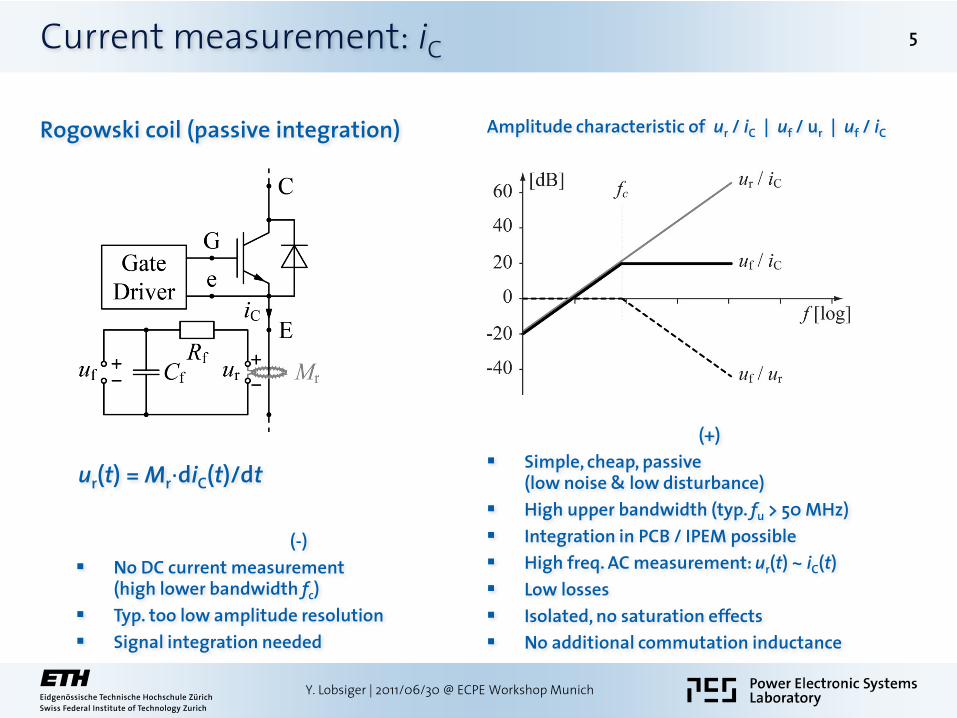
Shunt resistor
uS(t) ≈ RS·iC(t) + LS · diC(t)/dt
uS,f(t) = RS·iC(t) (for Rf· Cf = LS / RS)
Current measurement: iC 3
Y. Lobsiger | 2011/06/30 @ ECPE Workshop Munich
(–)
Losses: PL ≈ RS · iC2
Low losses = low amplitude resolution
Temperature drift
Parasitic (commutation) inductance LS
Accurate compensation needed
(+)
Simple, cheap, passive (low noise & low disturbance)
Possibility of integration in IGBT module (Infineon MIPAQ™, Semikron Semitrans®) or busbar (well dissipated losses)
DC & AC measurement uS,f(t) ~ iC(t) (high bandwidth due to compensation of LS)
Infineon MIPAQ™ IGBT module
with integrated shunts
(in the output phases)
Semikron Semitrans®
IGBT module with
integrated shunts
Current measurement: iC 4
Y. Lobsiger | 2011/06/30 @ ECPE Workshop Munich
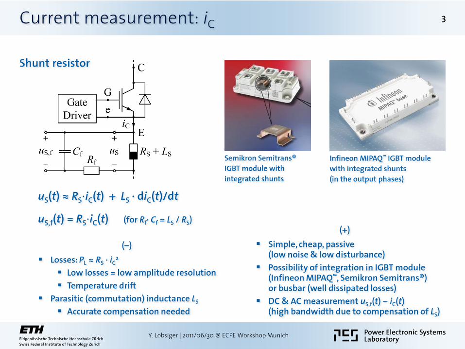
(–)
High accuracy = low resolution
Small RS is needed for right scaling
Cost, rarity
Only few types available
Often no alternatives
(+)
Simple, passive (low noise & low disturbance)
Integrated in IGBT module (Fuji Electric, Mitsubishi Electric)
High bandwidth
AC & DC measurement: uS(t) ~ iC(t)
Low losses
Mitsubishi Electric IGBT module with integrated
current sense IGBT and corresponding terminals
Current sense IGBT (split-cells: nS / ntot)
uS(t) = RS·iS(t)
≈ RS·iC(t) ·nS /ntot
(typ.: nS /ntot = 1/100 … 1/1000)
Current measurement: iC
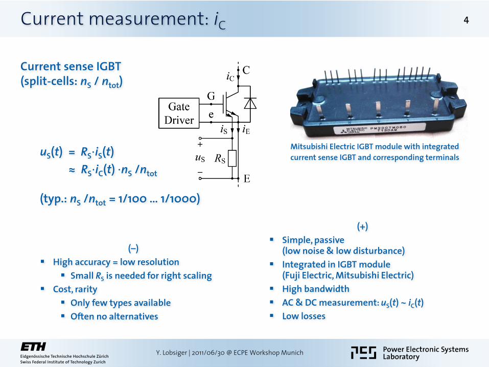
Rogowski coil (passive integration)
ur(t) = Mr·diC(t)/dt
5
Y. Lobsiger | 2011/06/30 @ ECPE Workshop Munich
Amplitude characteristic of ur / iC | uf / ur | uf / iC
(-)
No DC current measurement (high lower bandwidth fc)
Typ. too low amplitude resolution
Signal integration needed
(+)
Simple, cheap, passive (low noise & low disturbance)
High upper bandwidth (typ. fu > 50 MHz)
Integration in PCB / IPEM possible
High freq. AC measurement: ur(t) ~ iC(t)
Low losses
Isolated, no saturation effects
No additional commutation inductance

Current measurement: iC
Rogowski coil (activeintegration)
ui(t) ≈ Mr / (Ri·Ci) ·iC(t) (for fiC > fc)
6
Y. Lobsiger | 2011/06/30 @ ECPE Workshop Munich
Amplitude characteristic of ur / iC | ui / ur | ui / iC
(-)
Active (noise)
Parasitic effects of operational amplifier
Bias current, offset voltage (Rd avoids DC-drift)
Limited gain-bandwidth-product
Limited lower bandwidth fc, no DC
(+)
Simple, cheap
High upper bandwidth (typ. fu > 50 MHz)
Small lower bandwidth (typ. fc < 50 Hz)
Integration in PCB / IPEM possible
Low to high freq. AC measurement: ui(t) ~ iC(t)
Low losses
Isolated, no saturation effects
No additional commutation inductance

Current measurement: iC
Integration of Rogowski coil to
IPEM
PCB
7
Y. Lobsiger | 2011/06/30 @ ECPE Workshop Munich
[Xiao2003]
Prototype of IPEM embedded
Rogowski coil sensor
[Bortis2008]
PCB integrated Rogowski coils
around single screwed terminals
[Bortis2008]
PCB integrated Rogowski coil
around multiple screwed terminals

Current measurement: iC
IGBT bonding inductance
uEe(t) = -LE·diC(t)/dt
ui(t) ≈ (LE·iC(t) ) / (Ri·Ci)
si is used to minimize the influence of iG
(si closed during the gate current transients, i.e. before the switching transients of iC)
8
Y. Lobsiger | 2011/06/30 @ ECPE Workshop Munich
(-)
Auxiliary (kelvin) emitter terminal needed
Dependency on gate current
Resettable integrator circuit beneficial
Parasitic effects of operational amplifier & switch
Bias current, offset voltage (Rd or si to avoid DC-drift)
Limited gain-bandwidth-product
Limited lower bandwidth fc, no DC measurement
Parasitic inductance LE integrated in IGBT module
Depencency on tolerances of manufacturing process for accurate measurements without calibration
(+)
Simple, cheap
High upper bandwidth (typ. fu > 50 MHz)
Small lower bandwidth (typ. fc < 50 Hz)
Parasitic inductance LE integrated in IGBT module
no sensing hardware needed
Low to high freq. AC measurement: ui(t) ~ iC(t)
Low losses
No additional commutation inductance
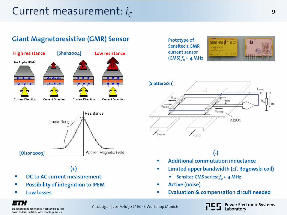
Current measurement: iC
Giant Magnetoresistive (GMR) Sensor
9
Y. Lobsiger | 2011/06/30 @ ECPE Workshop Munich
(-)
Additional commutation inductance
Limited upper bandwidth (cf. Rogowski coil)
Sensitec CMS series: fu ≈ 4 MHz
Active (noise)
Evaluation & compensation circuit needed
(+)
DC to AC current measurement
Possibility of integration to IPEM
Low losses
Prototype of
Sensitec’s GMR current sensor (CMS) fu ≈ 4 MHz
High resistance Low resistance [Shah2004]
[Olson2003]
[Slatter2011]

Current derivative measurement: diC/dt
Bonding inductance
uEe(t) = – LE·diC(t)/dt
(+)
Simple, cheap, no sensing hardware needed
Accurate (direct signal measurement)
(-)
Auxiliary (kelvin) emitter terminal needed
Dependency on manufacturing process
Rogowski coil
ur(t) =Mr·diC(t)/dt
(+)
Simple, cheap
Accurate (direct signal measurement)
(-)
Rogowski coil needed
Dependency on stray field
10
Y. Lobsiger | 2011/06/30 @ ECPE Workshop Munich

Current derivative measurement: diC/dt
Passive derivation of current signal uin
uf(t) = a · duin(t)/dt = b · diC(t)/dt (for fin < fc)
(+)
Simple, cheap
Passive (low noise)
(-)
Indirect measurement (derivation)
Low amplitude resolution
High amplitude = low bandwidth
Active derivation of current signal uin
ud(t) = a · duin(t)/dt = b · diC(t)/dt
(+)
Simple, cheap
High amplitude
(-)
Indirect measurement (derivation)
Active (noise)
High amplitude = high noise
11
Y. Lobsiger | 2011/06/30 @ ECPE Workshop Munich
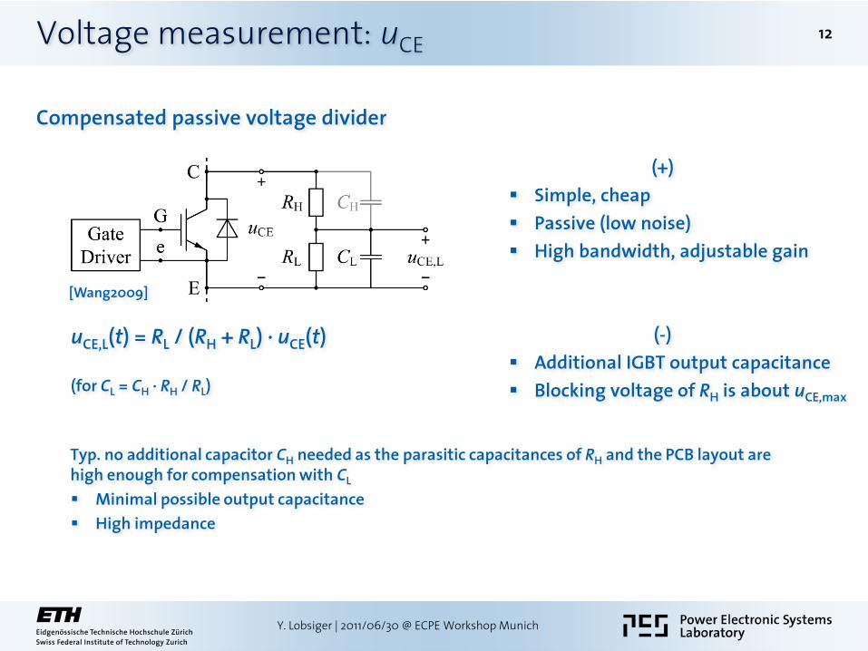
Compensated passive voltage divider
uCE,L(t) = RL / (RH + RL) ∙ uCE(t) (for CL = CH ∙ RH / RL)
Typ. no additional capacitor CH needed as the parasitic capacitances of RH and the PCB layout are high enough for compensation with CL
Minimal possible output capacitance
High impedance
Voltage measurement: uCE
(+)
Simple, cheap
Passive (low noise)
High bandwidth, adjustable gain
(-)
Additional IGBT output capacitance
Blocking voltage of RH is about uCE,max
12
Y. Lobsiger | 2011/06/30 @ ECPE Workshop Munich
[Wang2009]
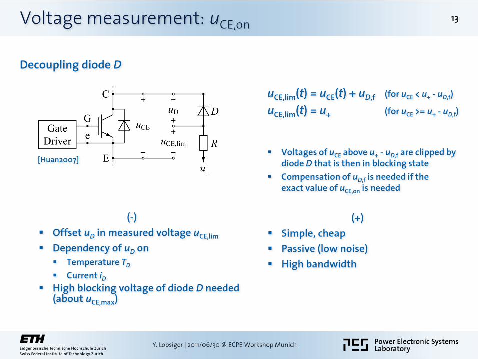
Decoupling diode D
(-)
Offset uD in measured voltage uCE,lim
Dependency of uD on
Temperature TD
Current iD
High blocking voltage of diode D needed (about uCE,max)
Voltage measurement: uCE,on
uCE,lim(t) = uCE(t) + uD,f (for uCE < u+ - uD,f)
uCE,lim(t) = u+ (for uCE >= u+ - uD,f)
Voltages of uCE above u+ - uD,f are clipped by diode D that is then in blocking state
Compensation of uD,f is needed if the exact value of uCE,on is needed
(+)
Simple, cheap
Passive (low noise)
High bandwidth
13
Y. Lobsiger | 2011/06/30 @ ECPE Workshop Munich
[Huan2007]

Limiting Z-diode
(-)
Low bandwidth (Z and D conducting before vCE drops below vZ + vD,f)
Charge recovery of diodes
Low-pass of R and diode’s capacitances
High voltage rating for R (about uCE,max)
Voltage measurement: uCE,on
uCE,lim(t) = uCE(t) (for uCE < uZ + uD,f)
uCE,lim(t) = uZ + uD,f (for uCE >= uZ + uD,f)
Voltages of uCE above uZ + uD,f are clipped by Z-diode Z and diode D
(+)
Simple, cheap
Passive (low noise)
No offset voltage in uCE,lim
Low blocking voltages of D & Z needed
14
Y. Lobsiger | 2011/06/30 @ ECPE Workshop Munich
[Carsten1995]
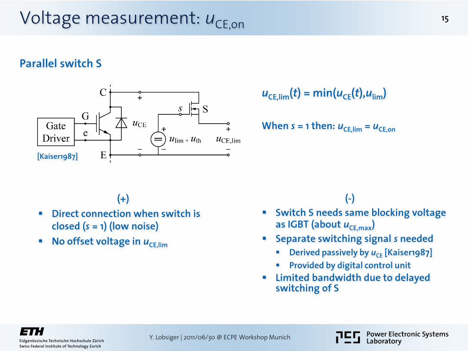
Parallel switch S
(+)
Direct connection when switch is closed (s = 1) (low noise)
No offset voltage in uCE,lim
Voltage measurement: uCE,on
uCE,lim(t) = min(uCE(t),ulim)
When s = 1 then: uCE,lim = uCE,on
(-)
Switch S needs same blocking voltage as IGBT (about uCE,max)
Separate switching signal s needed
Derived passively by uCE [Kaiser1987]
Provided by digital control unit
Limited bandwidth due to delayed switching of S
15
Y. Lobsiger | 2011/06/30 @ ECPE Workshop Munich
[Kaiser1987]
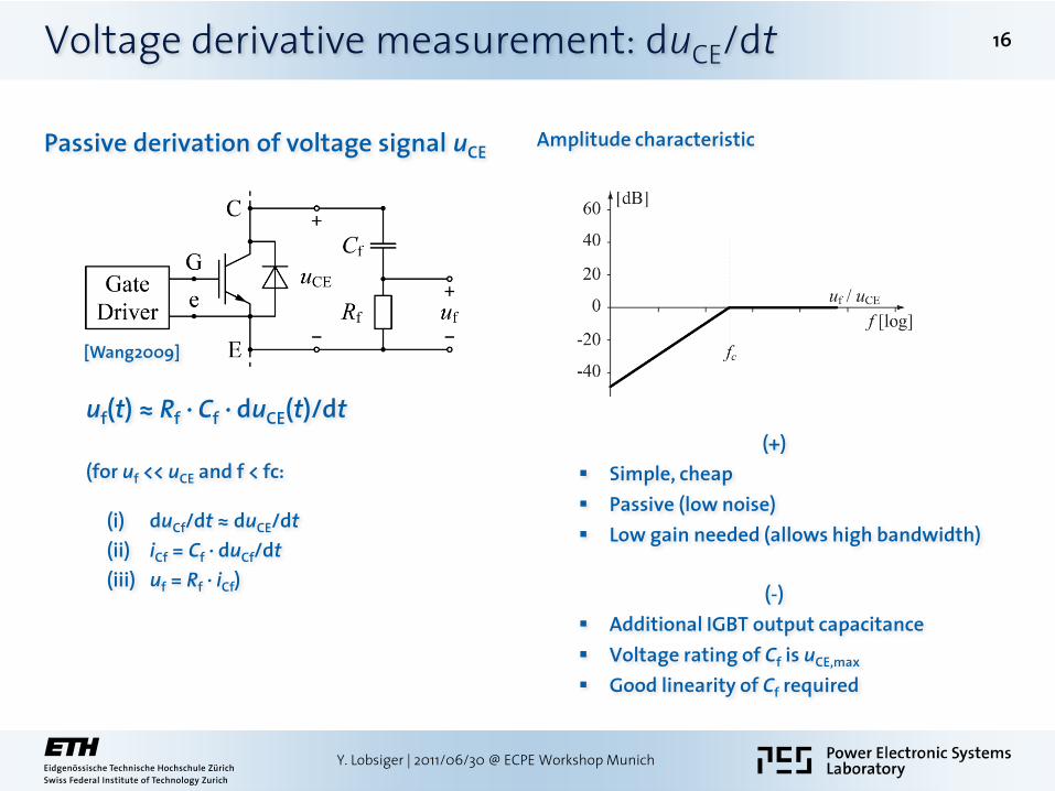
Voltage derivative measurement: duCE/dt
Passive derivation of voltage signal uCE
uf(t) ≈ Rf ∙ Cf ∙ duCE(t)/dt
(for uf << uCE and f < fc: (i) duCf/dt ≈ duCE/dt
(ii) iCf = Cf ∙ duCf/dt
(iii) uf = Rf ∙ iCf)
Amplitude characteristic
(+)
Simple, cheap
Passive (low noise)
Low gain needed (allows high bandwidth)
(-)
Additional IGBT output capacitance
Voltage rating of Cf is uCE,max
Good linearity of Cf required
16
Y. Lobsiger | 2011/06/30 @ ECPE Workshop Munich
[Wang2009]

NTC thermistor: Rt = f(T) On-chip integration
Distance to IGBT cell
Typ. resolution: Rt / T ≈ 10kΩ / 200 ºC
Temperature measurement: Tj
Sensing pn-diode: vf = f(T,if) On-chip integration
Arranged directly next to IGBT cell
Typ. resolution vf / T ≈ 1.7 mV / ºC
17
Y. Lobsiger | 2011/06/30 @ ECPE Workshop Munich
[Ichikawa2009]
Fuji Electric IGBT
module with int.
on-chip sensing diodes
Fuji Electric
[Ichikawa2009]
Powerex IGBT
module with
integrated NTC
thermistor
[Motto2005]
[Maxim AN3500,2005]
Infineon Datasheet
[Schmidt2009]
[Motto2005]

Temperature measurement: Tj
Gate driving characteristic: Tj = f(vGE,th) - resolution: typ. 1 V /100 ºC
(depending on IGBT)
f(td,on, td,off) - resolution: typ. < 2ns / ºC (depending on IGBT & gate current)
IGBT output characteristic: Tj = f(iC, vCE,on) Need for and dependency on
iC & vCE,on measurements
Evaluation by DSP / FPGA in interpolated 3D-table
Not usable around the crossover-point between positive and negative temperature coefficient, that is typ.
above nominal current for PT IGBTs
well below nominal current for NPT IGBTs
18
Y. Lobsiger | 2011/06/30 @ ECPE Workshop Munich
[Schmidt2009]
[Kim1998]
[Kuhn2009]
[Kuhn2009]
Infineon
datasheet

Temperature measurement: Tj
Internal gate resistor: Tj = f(RG,int) Integrated in IGBT module
No additional sensor needed
Very small distance to IGBT junction
Connection to int. gate terminal needed
Low temperature dependency of RG,int
Positive temp. coefficient
Precise acquisition system needed
Thermocouple (e.g. Pt100) Glued on the IGBT chip
Glue with low thermal impedance needed
Location close to IGBT chip center
Large time constant of thermocouple (≈ 200 ms)
Switching transients of Tj can not be measured
High accuracy for Tj,avg measurement
Opening of IGBT module needed
19
Y. Lobsiger | 2011/06/30 @ ECPE Workshop Munich
[Brekel2009]
[Brekel2009]
Literature
[Bortis2008] D. Bortis, J. Biela and J. W. Kolar, “Active gate control for current balancing of parallel-connected IGBT modules in solid-state modulators,” IEEE Transactions on Plasma Science, vol. 36, no. 5, pp. 2632—2637, Oct. 2008.
[Brekel2009] W. Brekel, Th. Duetemeyer, G. Puk and O. Schilling, “Time resolved in situ Tvj measurements of 6.5kV IGBTs during inverter operation,” Proc. of the Power Conversion Intelligent Motion Conf. (PCIM Europe), pp. 808—813, 2009.
[Carsten1995] B. Carsten, “A “clipping pre-amplifier” for accurate scope measurement of high voltage switching transistor and diode conduction voltages,” Proc. of the 31st Int. Power Conversion Electronics Conf. and Exhibit, pp. 335—342, 1995.
[Huan2007] F. Huang and F. Flett, “IGBT fault protection based on di/dt feedback control,” Proc. of the Annual IEEE Power Electronics Specialists Conf. (PESC), pp. 1478—1484, 2007.
[Ichikawa2009] H. Ichikawa, T. Ichimura and S. Soyano, “IGBT modules for hybrid vehicle motor driving,” Fuji electric review, vol. 55, no. 2, pp. 46—50, 2009.
[Kaiser1987] K. Kaiser, “Untersuchung der Verluste von Pulswechselrichterstrukturen mit Spannungszwischenkreis und Phasenstromregelung,” Diss. Vienna Univ. of Tech., pp. 41—45, 1987.
[Kim1998] Y.-S. Kim and S.-K. Sul, “On-line estimation of IGBT junction temperature using on-state voltage drop,” Proc. of the 33rd IEEE Industry Applications Society Annual Meeting (IAS), pp. 853—859, 1998.
[Kuhn2009] H. Kuhn and A. Mertens, “On-line junction temperature measurement of IGBTs based on temperature sensitive electrical parameters,” Proc. of the 13th European Conf. on Power Electronics and applications (EPE), 2009.
[Motto2005] E. R. Motto and J. F. Donlon, “New compact IGBT modules with integrated current and temperature sensors,” Powerex technical library, 2005.
[Musumeci2002] S. Musumeci, R. Pagano, A. Raciti, G. Belverde and A. Melito, “A new gate circuit performing fault protections of IGBTs during short circuit transients,” Proc. of the 37th IEEE Industry Applications Society Annual Meeting (IAS), pp. 2614—2621, 2002.
[Olson2003] E. R. Olson and R. D. Lorenz, “Integrating giant magnetoresistive current and thermal sensors in power electronic modules,” Proc. of the 18th Annual IEEE Applied Power Electronics Conf. and Exposition (APEC), pp. 773—777, 2003.
[Schmidt2009] R. Schmidt and U. Scheuermann, “Using the chip as a temperature sensor – the influence of steep lateral temperature gradients on the Vce(T)-measurement,” Proc. of the 13th European Conf. on Power Electronics and applications (EPE), 2009.
[Shah2004] H. N. Shah, Y. Xiao, T. P. Chow, R. J. Gutmann, E. R. Olson, S.-H. Park, W.-K. Lee, J. J. Connors, T. M. Jahns and R. D. Lorenz, “Power electronics modules for inverter applications using flip-chip on flex-circuit technology,” Proc. of the 39th IEEE Industry Applications Society Annual Meeting (IAS), pp. 1526—1533, 2004.
[Slatter2011] R. Slatter, J. Schmitt and G. von Manteuffel, “Highly dynamic current sensors based on magnetoresistive (MR) technology,” Proc. of the Power Conversion Intelligent Motion Conf. (PCIM Europe), pp. 616—620, 2011.
[Wang2009] Y. Wang, P. R. Palmer, A. T. Bryant, S. J. Finney, M. S. Abu-Khaizaran and G. Li, “An analysis of high-power IGBT switching under cascade active voltage control,” IEEE Transactions on Industry Applications, vol. 45, no. 2, pp. 861—870, Mar. / Apr. 2009.
[Xiao2003] C. Xiao, L. Zhao, T. Asada, W. G. Odendaal and J. D. van Wyk, “An overview of integratable current sensor technologies,” Proc. of the 38th IEEE Industry Applications Society Annual Meeting (IAS), pp. 1251—1258, 2003.
20
Y. Lobsiger | 2011/06/30 @ ECPE Workshop Munich