Embed Size (px)
Citation preview
Voltage Sensor Fault Detection and Reconfiguration for a Doubly Fed Induction Generator
Kai Rothenhagen Member, IEEE, Sönke Thomsen, Friedrich W. Fuchs, Senior Member, IEEE
Abstract— Fault detection and reconfiguration of the control loops of a Doubly-Fed Induction Generator are described in this paper. The stator voltage is measured as well as observed. During fault free operation, the measured signal is used for the field oriented control. In case of a voltage sensor fault, the faulty measurement is identified and the control is reconfigured using the observer output. Operation without measuring the stator voltage is possible. Laboratory measurements prove this concept.
Index Terms-- Observers, AC generators, State estimation
I. INTRODUCTION Doubly Fed Induction Generators (DFIG) have become a
widely used generator type in wind energy conversion [1]. This is not the only application, however, since DFIG are also used in pump storage plants [2] and flywheel energy storage [3].
Fault detection is becoming more and more important for variable speed drives to increase availability and reliability and reduce downtime. Typical elements of fault detection with subsequent reconfiguration are shown in figure 1. State observers, in this case also called soft sensors, can be used to observe a state that is already measured [4], [5], [6], [7].
In order to observe the inputs of a system, an input observer may be used [8]. Sensor faults can be detected by analysing the residual between measurement and observation.
Fault tolerance of induction machines has been covered by [9] and [10]. In both cases, model based fault methods are used. While an open loop induction drive is considered by [9], fault tolerant control of closed loop systems is examined by [10]. In this paper, a full reconfiguration is presented for a voltage oriented DFIG, as shown in figure 3, including all five necessary steps, as given in figure 1. The focus is on the change detection, fault diagnosis and reconfiguration. 1
Measure-ment
Residualgeneration
ChangeDetection
FaultDiagnosis
Recon-figuration
Figure 1: Necessary steps towards a fault tolerant control. Scope of this paper is Change Detection, Fault Diagnosis and Reconfiguration.
An Introduction was given in section I. The applied input observers described in section II, while section III gives a simulation analysis of the expected behaviour during stator voltage sensor faults and reconfiguration. Section IV shows measurements results from the laboratory. The paper is finished by a conclusion, an appendix and a list of references.
This work was in part funded by the Deutsche Forschungsgemeinschaft
(German Research Foundation). K. Rothenhagen, S. Thomsen and F. W. Fuchs are with the Institute of
Power Electronics and Electrical Drives, University of Kiel, Germany (e-mail: [email protected]; [email protected]; [email protected])
M3 ~
Rotor Position
Stator Voltage
Stator Current
PWM PWM
Grid Voltage
DC-LinkVoltage
Rotor Current
ReferenceValues
InverterCurrent
Inverter
Crowbar
Field Oriented Control
Fault Detection Observer
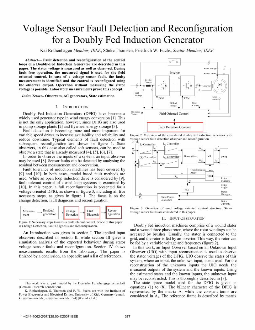
Figure 2: Overview of the considered doubly fed induction generator with voltage sensor fault detection observer and reconfiguration
Stator Currents
RotorCurrents
VR
i -ControllerRq
i -ControllerRd
P -ControllerS
Q -ControllerS
PLL
Rotor Angle
VR
iRd* uRd
*
iRd
iRq
PS
QS
StatorVoltages
Transformation Angle
uR*
Stator PowerCalculation
iRq*
uRq* uR
*
Figure 3: Overview of used voltage oriented control structure. Stator voltage sensor faults are considered in this paper.
II. INPUT OBSERVATION
Doubly fed induction machines comprise of a wound stator and a wound three phase rotor, where the rotor windings can be accessed by brushes. Usually, the stator is connected to the grid, and the rotor is fed by an inverter. This way, the rotor can be fed by a variable voltage and frequency (figure 2).
In this work, an Input Observer based on an Unknown Input Observer (UIO) with input reconstruction is used to observe the stator voltages of the DFIG. UIO observe the states of this system, where an input, the unknown input, is not used. For the reconstruction of the unknown inputs the UIO needs the measured outputs of the system and the known inputs. Using the estimated states and the known inputs, the unknown input may be reconstructed. This is thoroughly described in [8].
The state space model used for the DFIG is given in equations (1) to (8). The bilinear character of the DFIG is represented by the matrix A1 while the constant terms are considered in A0. The reference frame is described by matrix
1-4244-1062-2/07/$25.00 ©2007 IEEE 377
AA. The input is split up into known and unknown inputs (3), with their respective input matrices B and D. It is assumed that all currents are measurable, therefore C=I4 is unity.
x Ax Bu Dv; y Cx= + + =
(1) T
sd sq rd rq
T T
rd rq sd sq
x I I I I ;
u U U ; v U U
=
= =
(2) (3)
0 1 m A AA A A p A= + ω + ω
(4) S h R
S S R
S h R
S S R0
h S R
R S R
h S R
R S R
2h h
S R S
2h h
S R S1
h
R
h
R
A
R L R0 0
L L LR L R
0 0L L L
A = ;L R R
0 0L L L
L R R0 0
L L L
L L0 0L L L
L L0 0
L L LA = ;
L 10 0L
L 10 0L
0 1 0 01 0 0 0
A =0 0 0 10 0 1 0
− σ σ
− σ σ
− σ σ
− σ σ
σ σ − −
σ σ
− − σ σ
σ σ −
−
(5) (6) (7)
h
SR S
h
SR S
h
R SR
h
R R S
1L 00LL L
1L 00LL L
B ;D = ;C = IL1 00
L LLL10 0
L L L
− σσ − σσ = − σσ
− σ σ
(8)
The principle of UIO is the decoupling of the observer error e from the disturbances which are the unknown inputs. The structure of the UIO can be defined as:
z Nz Ky Gu;x z Ey.
= + += −
(9) (10)
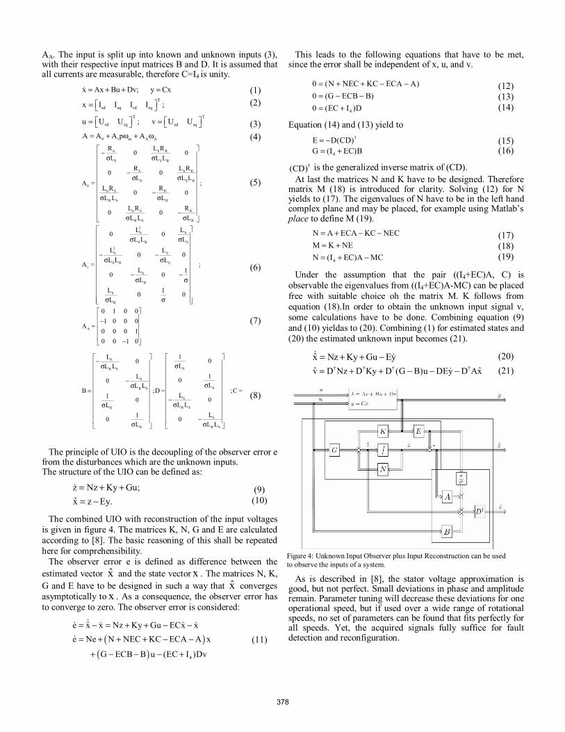
The combined UIO with reconstruction of the input voltages is given in figure 4. The matrices K, N, G and E are calculated according to [8]. The basic reasoning of this shall be repeated here for comprehensibility.
The observer error e is defined as difference between the estimated vector x and the state vector x . The matrices N, K, G and E have to be designed in such a way that x converges asymptotically to x . As a consequence, the observer error has to converge to zero. The observer error is considered:
( )( ) 4
ˆe x x Nz Ky Gu ECx xe Ne N NEC KC ECA A x
G ECB B u (EC I )Dv
= − = + + − −= + + + − −
+ − − − +
(11)
This leads to the following equations that have to be met, since the error shall be independent of x, u, and v.
4
0 (N NEC KC ECA A)0 (G ECB B)0 (EC I )D
= + + − −= − −= +
(12) (13) (14)
Equation (14) and (13) yield to
†E D(CD)= −4G (I EC)B= +
(15) (16)
†(CD) is the generalized inverse matrix of (CD).
At last the matrices N and K have to be designed. Therefore matrix M (18) is introduced for clarity. Solving (12) for N yields to (17). The eigenvalues of N have to be in the left hand complex plane and may be placed, for example using Matlab’s place to define M (19).
4
N A ECA KC NECM K NEN (I EC)A MC
= + − −= += + −
(17) (18) (19)
Under the assumption that the pair ((I4+EC)A, C) is observable the eigenvalues from ((I4+EC)A-MC) can be placed free with suitable choice oh the matrix M. K follows from equation (18).In order to obtain the unknown input signal v, some calculations have to be done. Combining equation (9) and (10) yieldas to (20). Combining (1) for estimated states and (20) the estimated unknown input becomes (21).
x Nz Ky Gu Ey= + + − (20) † † † †ˆ ˆv D Nz D Ky D (G B)u DEy D Ax= + + − − −
(21)
Figure 4: Unknown Input Observer plus Input Reconstruction can be used to observe the inputs of a system.
As is described in [8], the stator voltage approximation is good, but not perfect. Small deviations in phase and amplitude remain. Parameter tuning will decrease these deviations for one operational speed, but if used over a wide range of rotational speeds, no set of parameters can be found that fits perfectly for all speeds. Yet, the acquired signals fully suffice for fault detection and reconfiguration.
378
III. EFFECTS OF A STATOR VOLTAGE SENSOR FAULT The stator voltage is measured for two reasons. Firstly, the
stator power measurement (fig.4) needs the stator voltage of phase a and b. Secondly, the DFIG needs to be synchronised to the grid, which requires the generation of the stator voltage angle. This is done by a PLL using the phase a stator voltage measurement. Therefore a fault in the stator voltage sensor a will affect the stator power control loop and the stator voltage angle, as shown in figure 5. It is limited in its further path due to the bandwidth of the PLL and the power controllers. Stator voltage sensor b will only affect the power control loop, as seen in figure 6. The influence of the respective faults is greatly depending on the bandwidth of the involved control loops, e.g. power control loop and its filters, or the PLL.
A. Behaviour of the used PLL
The performance of the used PLL is demonstrated by simulation. Since exactly the same code is used on the DS1006 controller, the performance in reality is the same. Figure 7 shows the PLL generated angle in case of an input signal of zero instead of a sine. The error between actual angle and PLL output angle is shown. This is done for a 'slow' and a 'fast' PLL synchronisation. Since it is more comprehensible than an angle signal, the cosine of the angle is displayed together with the input signal. In case of a locked PLL, both signals will be the same. In case of a missing input signal, the cosine of the output signal will drift with respect to the original signal.
VR
i -ControllerRq
i -ControllerRd
P -ControllerS
Q -ControllerS
PLL
iRd* uRd
*
iRd
iRq
PS
QS
Transformation Angle
uRβ*
Stator PowerCalculation
iRq uRq* uRα
*
To Inverter
VR
PS
α β
IS IRRotor Position
α β
US
β αα β
a b
a b
α βa b
a b
α βa b
a b
Figure 5: Control scheme and fault propagation path of a distorted signal from voltage sensor a includes the PLL angle generation and the power calculation..
VR
i -ControllerRq
i -ControllerRd
P -ControllerS
Q -ControllerS
PLL
iRd* uRd
*
iRd
iRq
PS
QS
Transformation Angle
uRβ*
Stator PowerCalculation
iRq uRq* uRα
*
To Inverter
VR
PS
α β
IS IRRotor Position
α β
US
β αα β
a b
a b
α βa b
a b
α βa b
a b
Figure 6: The fault path of a distorted signal from voltage sensor b.
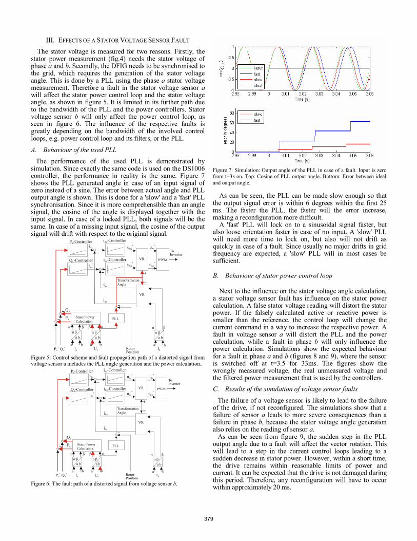
Figure 7: Simulation: Output angle of the PLL in case of a fault. Input is zero from t=3s on. Top: Cosine of PLL output angle. Bottom: Error between ideal and output angle.
As can be seen, the PLL can be made slow enough so that the output signal error is within 6 degrees within the first 25 ms. The faster the PLL, the faster will the error increase, making a reconfiguration more difficult.
A 'fast' PLL will lock on to a sinusoidal signal faster, but also loose orientation faster in case of no input. A 'slow' PLL will need more time to lock on, but also will not drift as quickly in case of a fault. Since usually no major drifts in grid frequency are expected, a 'slow' PLL will in most cases be sufficient.
B. Behaviour of stator power control loop
Next to the influence on the stator voltage angle calculation, a stator voltage sensor fault has influence on the stator power calculation. A false stator voltage reading will distort the stator power. If the falsely calculated active or reactive power is smaller than the reference, the control loop will change the current command in a way to increase the respective power. A fault in voltage sensor a will distort the PLL and the power calculation, while a fault in phase b will only influence the power calculation. Simulations show the expected behaviour for a fault in phase a and b (figures 8 and 9), where the sensor is switched off at t=3.5 for 33ms. The figures show the wrongly measured voltage, the real unmeasured voltage and the filtered power measurement that is used by the controllers.
C. Results of the simulation of voltage sensor faults
The failure of a voltage sensor is likely to lead to the failure of the drive, if not reconfigured. The simulations show that a failure of sensor a leads to more severe consequences than a failure in phase b, because the stator voltage angle generation also relies on the reading of sensor a.
As can be seen from figure 9, the sudden step in the PLL output angle due to a fault will affect the vector rotation. This will lead to a step in the current control loops leading to a sudden decrease in stator power. However, within a short time, the drive remains within reasonable limits of power and current. It can be expected that the drive is not damaged during this period. Therefore, any reconfiguration will have to occur within approximately 20 ms.
379
D. Structure to reconfigure the stator voltage sensors
In order to reconfigure the stator voltage sensors, a fault detection has to be implemented. Using the input observer outputs in α and β stator reference frame and subtracting the voltage sensor readings, one obtains two residuals. Residual α is affected by voltage sensor a only, while residual β is affected by both sensors.
The structure according to figure 10 is a possible way to obtain a flag which is used to switch from measured to observed voltage signals. A forgetting factor γ may be used, but does not change the behavior significantly if close to 1. The resulting overall control structure is depicted in figure 11, where the input observer outputs are available for stator power and stator voltage angle calculation.
Figure 8: Stator Real Power during a fault in voltage sensor b.
Figure 9: Stator active power during a fault in voltage sensor a.
Figure 10: The maximum of the residuals of α and β components is considered, using a maximum value with a forgetting factor γ. Using a threshold, the voltage signal is switched.
VR
i -ControllerRq
i -ControllerRd
P -ControllerS
Q -ControllerS
iRd* uRd
*
iRd
iRq
Transformation Angle
uRβ*
iRq uRq* uRα
*
To Inverter
VR
PLL
QS
U , obsS
PSStator PowerCalculation
PS
αβ
UIO
US
β
ISIR
Rotor PositionUR
*
α β α β
U , measS
αα β
a b
a b
α βa b
a b
α βa b
a b
Figure 11: Control scheme using an UIO to provide a replacement signal for the faulty voltage measurement. The switch includes the structure of fig. 10.
IV. USING AN UIO WITH INPUT RECONSTRUCTION INSTEAD OF A VOLTAGE MEASUREMENT
Experimental measurements were taken in the laboratory to support the concept of using an UIO to replace the voltage sensors after a reconfiguration. The used control scheme is shown in figure 11.
Measurements were taken via dSPACE-Controldesk® and then plotted using MATLAB-Simulink®. Sample intervals are indicated by circles around the actual values, interpolated by lines. Voltage sensor faults are implemented by setting the sensor signal to zero by software. The actual sensor reading is still used for comparison only, but it is not used by the control. The power is also calculated from the false voltage measurement and from the UIO replacement signal. The current measurements are not interrupted.
In order to separate the two influences of a stator voltage sensor fault in phase a, at first only the influence on the power loop is shown. Then, the influence on the PLL and the power control loop is analysed. The reconfiguration works in subsynchronous, synchronous and supersynchronous operation.
A. Reconfiguration of Power Control Loop
Figure 12 shows the reconfiguration of the stator voltage b sensor. The machine is operated supersynchronous at 1700 rpm. A fault is initiated at time t=2.25 ms. The fault is detected within one sample period, as can be seen in the top graph. The maximum value (cyan) of the residuals (black and magenta) crosses the threshold (blue). A forgetting factor of γ=0.995 is used. As expected, the α-residual is not affected by a fault in voltage measurement b.
As can be seen in the middle graph, the falsely measured stator active power (blue) decreases, while the actual fault free active power (green) stays the same. The signal, that is fed to the control loop (black) is switched from measured to observed (red), and operation is maintained. The stator active power, that is calculated from the observed voltage, is slightly larger than the actual power. The reactive power control loop is also reconfigured within one sample period. The resulting power factor is worsened from unity to around 0.995.
Figure 13 shows the reconfiguration of the stator voltage a sensor, excluding the effect on the PLL for better insight. The
380
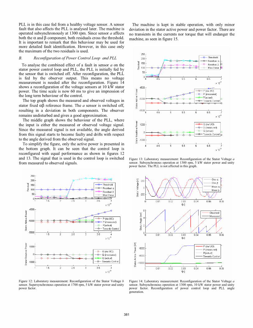
PLL is in this case fed from a healthy voltage sensor. A sensor fault that also affects the PLL is analysed later. The machine is operated subsynchronously at 1300 rpm. Since sensor a affects both the α and β component, both residuals cross the threshold. It is important to remark that this behaviour may be used for more detailed fault identification. However, in this case only the maximum of the two residuals is used.
B. Reconfiguration of Power Control Loop and PLL
To analyse the combined effect of a fault in sensor a on the stator power control loop and PLL, the PLL is initially fed by the sensor that is switched off. After reconfiguration, the PLL is fed by the observer output. This means no voltage measurement is needed after the reconfiguration. Figure 14 shows a reconfiguration of the voltage sensors at 10 kW stator power. The time scale is now 60 ms to give an impression of the long term behaviour of the control.
The top graph shows the measured and observed voltages in stator fixed αβ reference frame. The a sensor is switched off, resulting in a deviation in both components. The observer remains undisturbed and gives a good approximation.
The middle graph shows the behaviour of the PLL, where the input is either the measured or observed voltage signal. Since the measured signal is not available, the angle derived from this signal starts to become faulty and drifts with respect to the angle derived from the observed signal.
To simplify the figure, only the active power is presented in the bottom graph. It can be seen that the control loop is reconfigured with equal performance as shown in figures 12 and 13. The signal that is used in the control loop is switched from measured to observed signals.
Figure 12: Laboratory measurement: Reconfiguration of the Stator Voltage b sensor. Supersynchronous operation at 1700 rpm, 5 kW stator power and unity power factor.
The machine is kept in stable operation, with only minor deviation in the stator active power and power factor. There are no transients in the currents nor torque that will endanger the machine, as seen in figure 15.
Figure 13: Laboratory measurement: Reconfiguration of the Stator Voltage a sensor. Subsynchronous operation at 1300 rpm, 5 kW stator power and unity power factor. The PLL is not affected in this graph.
Figure 14: Laboratory measurement: Reconfiguration of the Stator Voltage a sensor. Subsynchronous operation at 1300 rpm, 10 kW stator power and unity power factor. Reconfiguration of power control loop and PLL angle generation.
381
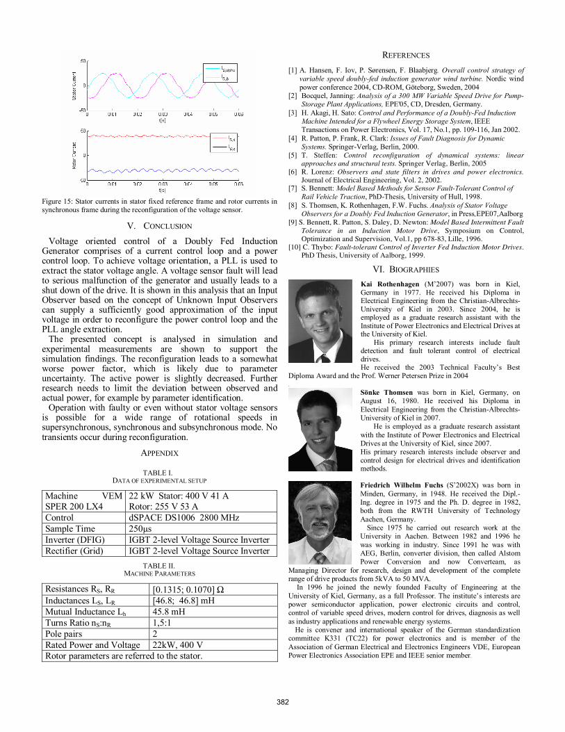
Figure 15: Stator currents in stator fixed reference frame and rotor currents in synchronous frame during the reconfiguration of the voltage sensor.
V. CONCLUSION Voltage oriented control of a Doubly Fed Induction
Generator comprises of a current control loop and a power control loop. To achieve voltage orientation, a PLL is used to extract the stator voltage angle. A voltage sensor fault will lead to serious malfunction of the generator and usually leads to a shut down of the drive. It is shown in this analysis that an Input Observer based on the concept of Unknown Input Observers can supply a sufficiently good approximation of the input voltage in order to reconfigure the power control loop and the PLL angle extraction.
The presented concept is analysed in simulation and experimental measurements are shown to support the simulation findings. The reconfiguration leads to a somewhat worse power factor, which is likely due to parameter uncertainty. The active power is slightly decreased. Further research needs to limit the deviation between observed and actual power, for example by parameter identification.
Operation with faulty or even without stator voltage sensors is possible for a wide range of rotational speeds in supersynchronous, synchronous and subsynchronous mode. No transients occur during reconfiguration.
APPENDIX
TABLE I. DATA OF EXPERIMENTAL SETUP
Machine VEM SPER 200 LX4
22 kW Stator: 400 V 41 A Rotor: 255 V 53 A
Control dSPACE DS1006 2800 MHz Sample Time 250µs Inverter (DFIG) IGBT 2-level Voltage Source Inverter Rectifier (Grid) IGBT 2-level Voltage Source Inverter
TABLE II. MACHINE PARAMETERS
Resistances RS, RR [0.1315; 0.1070] Ω Inductances LS, LR [46.8; 46.8] mH Mutual Inductance Lh 45.8 mH Turns Ratio nS:nR 1,5:1 Pole pairs 2 Rated Power and Voltage 22kW, 400 V Rotor parameters are referred to the stator.
REFERENCES [1] A. Hansen, F. Iov, P. Sørensen, F. Blaabjerg. Overall control strategy of
variable speed doubly-fed induction generator wind turbine. Nordic wind power conference 2004, CD-ROM, Göteborg, Sweden, 2004
[2] Bocquel, Janning: Analysis of a 300 MW Variable Speed Drive for Pump-Storage Plant Applications, EPE'05, CD, Dresden, Germany.
[3] H. Akagi, H. Sato: Control and Performance of a Doubly-Fed Induction Machine Intended for a Flywheel Energy Storage System, IEEE Transactions on Power Electronics, Vol. 17, No.1, pp. 109-116, Jan 2002.
[4] R. Patton, P. Frank, R. Clark: Issues of Fault Diagnosis for Dynamic Systems. Springer-Verlag, Berlin, 2000.
[5] T. Steffen: Control reconfiguration of dynamical systems: linear approaches and structural tests. Springer Verlag, Berlin, 2005
[6] R. Lorenz: Observers and state filters in drives and power electronics. Journal of Electrical Engineering, Vol. 2, 2002.
[7] S. Bennett: Model Based Methods for Sensor Fault-Tolerant Control of Rail Vehicle Traction, PhD-Thesis, University of Hull, 1998.
[8] S. Thomsen, K. Rothenhagen, F.W. Fuchs. Analysis of Stator Voltage Observers for a Doubly Fed Induction Generator, in Press,EPE07,Aalborg
[9] S. Bennett, R. Patton, S. Daley, D. Newton: Model Based Intermittent Fault Tolerance in an Induction Motor Drive, Symposium on Control, Optimization and Supervision, Vol.1, pp 678-83, Lille, 1996.
[10] C. Thybo: Fault-tolerant Control of Inverter Fed Induction Motor Drives. PhD Thesis, University of Aalborg, 1999.
VI. BIOGRAPHIES Kai Rothenhagen (M’2007) was born in Kiel, Germany in 1977. He received his Diploma in Electrical Engineering from the Christian-Albrechts-University of Kiel in 2003. Since 2004, he is employed as a graduate research assistant with the Institute of Power Electronics and Electrical Drives at the University of Kiel.
His primary research interests include fault detection and fault tolerant control of electrical drives. He received the 2003 Technical Faculty’s Best
Diploma Award and the Prof. Werner Petersen Prize in 2004 .
Sönke Thomsen was born in Kiel, Germany, on August 16, 1980. He received his Diploma in Electrical Engineering from the Christian-Albrechts-University of Kiel in 2007.
He is employed as a graduate research assistant with the Institute of Power Electronics and Electrical Drives at the University of Kiel, since 2007. His primary research interests include observer and control design for electrical drives and identification methods.
Friedrich Wilhelm Fuchs (S’2002X) was born in Minden, Germany, in 1948. He received the Dipl.-Ing. degree in 1975 and the Ph. D. degree in 1982, both from the RWTH University of Technology Aachen, Germany.
Since 1975 he carried out research work at the University in Aachen. Between 1982 and 1996 he was working in industry. Since 1991 he was with AEG, Berlin, converter division, then called Alstom Power Conversion and now Converteam, as
Managing Director for research, design and development of the complete range of drive products from 5kVA to 50 MVA.
In 1996 he joined the newly founded Faculty of Engineering at the University of Kiel, Germany, as a full Professor. The institute’s interests are power semiconductor application, power electronic circuits and control, control of variable speed drives, modern control for drives, diagnosis as well as industry applications and renewable energy systems.
He is convener and international speaker of the German standardization committee K331 (TC22) for power electronics and is member of the Association of German Electrical and Electronics Engineers VDE, European Power Electronics Association EPE and IEEE senior member.
382


![Shaping the Glitch: Optimizing Voltage Fault Injection Attacks · Voltage Fault Injection… The MOSFET Way The most widespread Voltage Fault Injection setup [OC14] Very easy to setup](https://img.pdfslide.net/doc/110x75/5f2863d108fdb706787d4422/shaping-the-glitch-optimizing-voltage-fault-injection-attacks-voltage-fault-injection.jpg)