Embed Size (px)
Citation preview
Voltage Source Inverter Switches Faults Analysis
Using S-Transform
M. Manap Faculty of Engineering Technology, Universiti Teknikal Malaysia Melaka, Malaysia
Email: [email protected]
A. R. Abdullah, N. Z. Saharuddin, N. A. Abidullah, N. S. Ahmad, and N. Bahari Faculty of Electrical Engineering, Universiti Teknikal Malaysia Melaka, Malaysia
Email: {abdulr, nurzawani, hazilina}@utem.edu.my, [email protected], [email protected]
Abstract—Nowadays, voltage source inverter (VSI) is
frequently used in power electronics system. This is due to
its ability that can offer higher efficiency, high torque,
simpler control system and improved power output. Thus,
to ensure safety and reliability of a system, the development
of appropriate fault detection technique for faults analysis is
a must. This paper proposes S-transform which is time-
frequency distribution (TFD) for analyzing VSI signal to
detect and identify switches and types of faults. By using the
TFD, the faults signal is translated into time-frequency
representation (TFR) and then, parameters of the signal are
estimated from the TFR. The signal parameters are such as
instantaneous of rms current, rms fundamental current,
average current, total waveform distortion (TWD), total
harmonic distortion (THD) and total non-harmonic
distortion (TnHD). Based on the signal parameters, the
characteristics of the faults are calculated and used as input
for faults detection and classification system. At the end of
this research, the results show that the proposed TFD give
better analysis for switches faults parameters estimation
and suitable for detection and identification system.
Index Terms—switches faults, S-transform, short time
fourier transform, voltage source inverter
I. INTRODUCTION
One of the critical systems that extremely important in
electronic system is voltage source inverter (VSI). The
structure of VSI have become more complex with
additional poles and switches [1] and a study shows that
38% of faults in associated with variable speed ac drive
industry are due to the failure of power devices [2]. The
most popular power devices in industry are insulated gate
bipolar transistors (IGBTs). Designed with high rating of
voltage and current capability, the IGBTs are able to
withstand short-circuit currents for periods exceeding
10μs [3]. But still, exposing to the electrical excess and
thermal stress for a period of time shall degraded the
IGBTs performance and lead to the component failure.
Therefore, it is vital to develop fault diagnostic and
protection methods for preventive maintenance and
Manuscript received December 1, 2014; revised July 24, 2015.
minimizing downtime schedule for component
replacement.
Generally, IGBTs switches fault can be classified as
short circuit faults and open circuit faults. Short circuit
faults may occur due to a wrong gate voltage, which may
be caused by driver circuit malfunction or auxiliary
power supply failure. Another short circuit faults is an
intrinsic failure, which may be caused by avalanche stress
or temperature overshoot [4]. The short-circuit faults are
difficult to deal with because the time between the fault
initiation and failure is very small. Therefore, most of the
existing IGBT short-circuit detection and protection
methods are hardware circuit based rather algorithm
based. The open circuit faults on the other hand occur due
to lifting of bonding wires which caused by thermic
cycling. It may be caused by a driver fault or a short-
circuit-fault-induced IGBT rupture. The voltages and
currents carry the fault signatures and hence can be
analyzed to detect and locate the fault. Open circuit faults
generally do not cause system shutdown, but reduce its
performance in the long run [5].
Conventional techniques that are currently used for
switches faults monitoring are based on visual of voltage
and current waveforms. The available equipment in the
market for the inspection can capture and print the
switches faults data only at the current time. Therefore, a
real time computerized and automated technique for
monitoring and analysis is implemented to improve the
switches faults signal. Many techniques were presented
by various researchers for analysis, detection and
classification VSI switches faults in real time. One of the
most widely used in signal processing is spectral analysis
using Fourier analysis which is Fourier transform [6]. The
Fourier transform is powerful technique for stationary
signal because the characteristics of the signal not change
with time but it not useful for non-stationary signal
because is inadequate to track the changes in the
magnitude, frequency or phase [1], [2]. Because of this
problem, the time-frequency analysis technique is
introduced. The STFT most often used but it cannot track
the signal dynamics properly for non-stationary signal
due to limitation of fixed window width [7]. Wavelet
transform is good to extract the information from both
International Journal of Electronics and Electrical Engineering Vol. 4, No. 2, April 2016
©2016 Int. J. Electron. Electr. Eng. 157doi: 10.18178/ijeee.4.2.157-161
time and frequency domains but wavelet transform is
sensitive to noise and cannot identify the sag and swell
and also transient condition [8]. S-transform proposed by
Stockwell [9] which is time frequency spectral
localization method that combine element of wavelet
transform and short time Fourier transform (STFT) [9]-
[11]. The S-transform has a frequency dependant
resolution of time- frequency domain and entirely refers
to phase information. The S-transform is required to
emphasize the time resolution in the beginning time and
frequency resolution in the later of beginning time. The
advantage of S-transform offer multi-resolution analysis
while retaining the absolute phase of each frequency.
In this paper, S-transform is used to represent the VSI
switches faults in jointly time-frequency representation
(TFR). From the TFR, parameters of the fault signals are
estimated such as instantaneous of rms current, rms
fundamental current, average current, total waveform
distortion (TWD), total harmonic distortion (THD) and
total non-harmonic distortion (TnHD). Then,
characteristics of the signals are calculated from the
signal parameters and will be used as input for detection
and identification system.
II. VSI SWITCHES FAULTS
III. S-TRANSFORM
Time-Frequency analysis techniques present a three-
dimensional plot of a signal in terms of the signal energy
or magnitude with respect to time and frequency. S-
transform is combination a frequency dependent
resolution with simultaneous localizing the real and
imaginary spectra. The general S-transform is defined by
the equation [10].
dt
ftjeftgthfS
2),()(),( (1)
where h(t) is the signal, t represent the time, f is the
frequency and g(t) is a window function. Windows
function is a modulated Gaussian function expressed by
)22/2(
2
1)(
teg
(2)
where is defined as
f
1 (3)
IV. SIGNAL PARAMETERS
Parameters of the signal are estimated from the TFR to
identify the signal information in time domain. This
information is important to detect and identify the VSI
switches faults [12]. The signal parameters have been
discussed in [14] to estimate instantaneous of rms current,
rms fundamental current, average current, total waveform
distortion (TWD), total harmonic distortion (THD) and
total non-harmonic distortion (TnHD).
V. RESULTS
In this section, the results of the switches faults
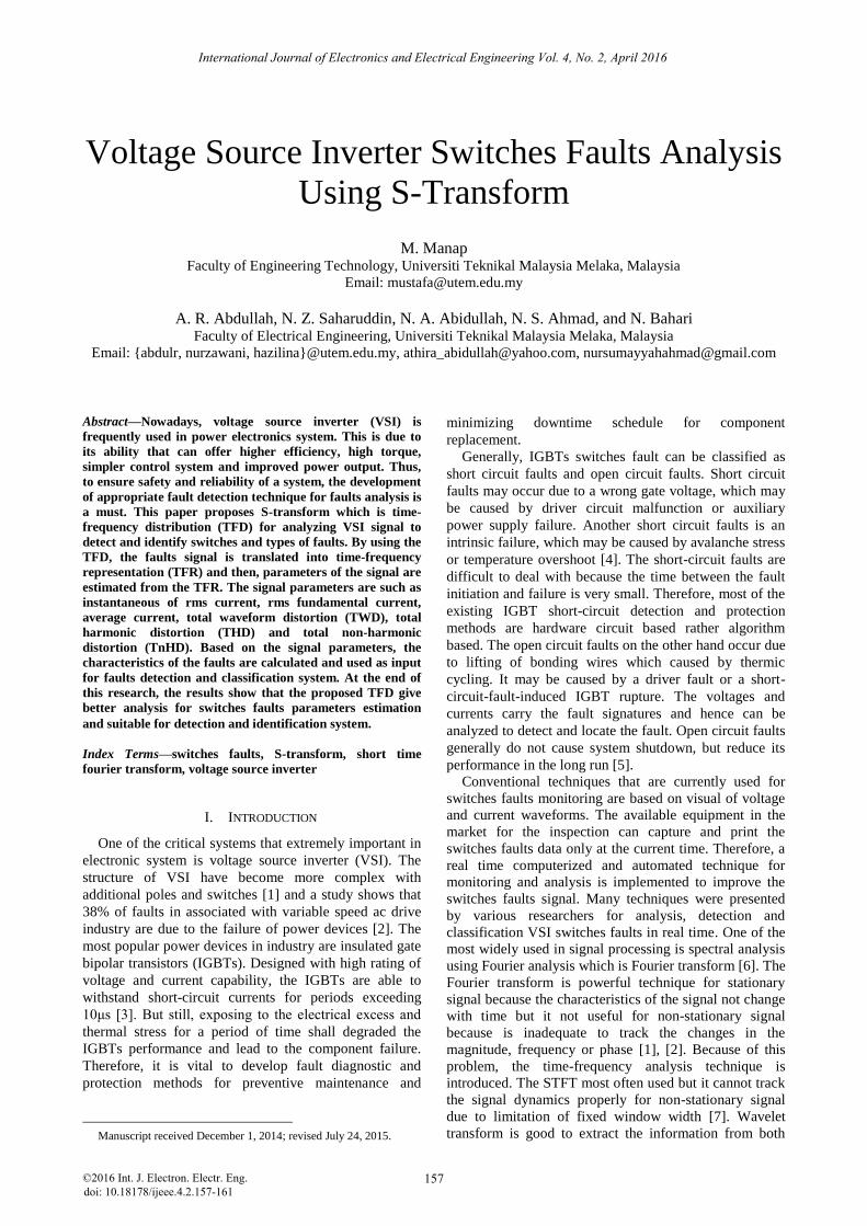
analysis are discussed. Fig. 1 shows the examples of
switches faults signals for three phase current for open
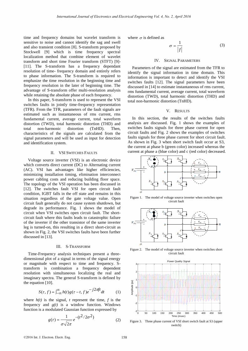
circuit faults and Fig. 2 shows the examples of switches
faults signals for three phase current for short circuit fault.
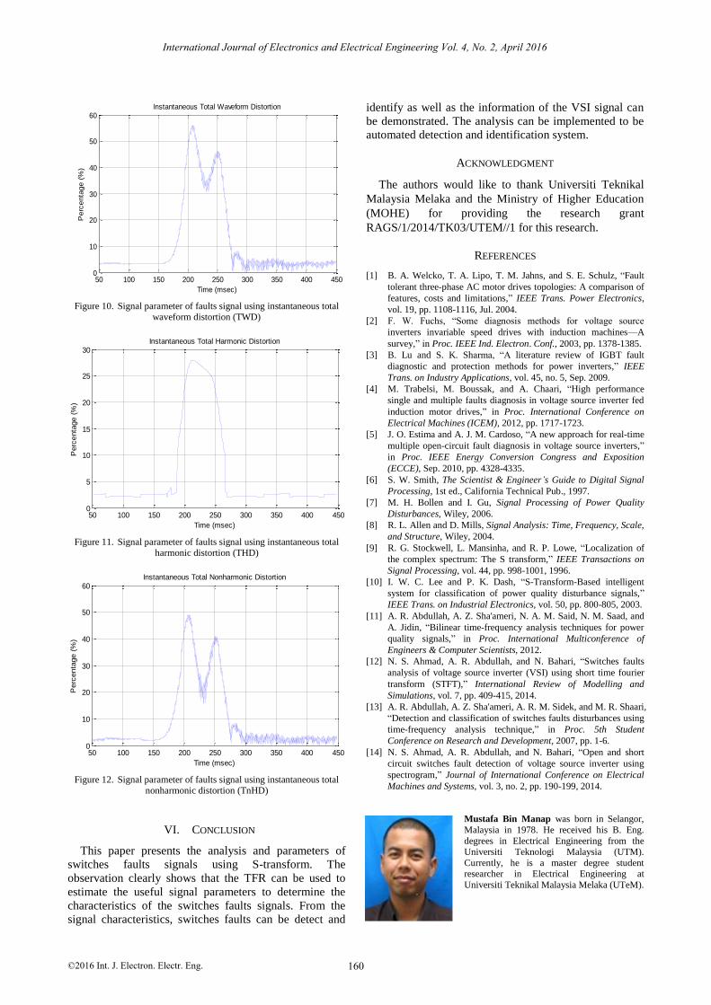
As shown in Fig. 3 when short switch fault occur at S3,
the current at phase b (green color) increased whereas the
current at phase a (blue color) and c (red color) decreased.
Figure 1. The model of voltage source inverter when switches open circuit fault
Figure 2. The model of voltage source inverter when switches short circuit fault
0 50 100 150 200 250 300 350 400 450 500-3
-2
-1
0
1
2
3Power Quality Signal
Time (msec)
Am
plit
ude (
pu)
Figure 3. Three phase current of VSI short switch fault at S3 (upper
switch)
International Journal of Electronics and Electrical Engineering Vol. 4, No. 2, April 2016
©2016 Int. J. Electron. Electr. Eng. 158
Voltage source inverter (VSI) is an electronic device
which converts direct current (DC) to Alternating current
(AC). VSI has advantages like higher efficiencies,
minimizing installation timing, elimination interconnect
power cabling costs and reducing building floor space.
The topology of the VSI operation has been discussed in
[12]. The switches fault VSI for open circuit fault
condition, IGBT falls in the off state and remains in this
situation regardless of the gate voltage value. Open
circuit fault generally do not cause system shutdown, but
degrade its performance. Fig. 1 shows the model of
circuit when VSI switches open circuit fault. The short-
circuit fault where this faults leads to catastrophic failure
of the inverter if the other transistor of the same inverter
leg is turned-on, this resulting in a direct short-circuit as
shown in Fig. 2, the VSI switches faults have been further
discussed in [13].
50 100 150 200 250 300 350 400 4500
10
20
30
40
50
60Instantaneous Total Waveform Distortion
Time (msec)
Perc
enta
ge (
%)
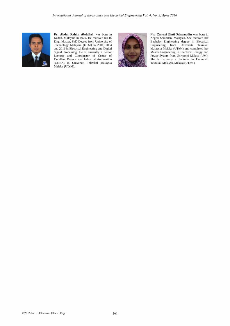
Figure 10. Signal parameter of faults signal using instantaneous total waveform distortion (TWD)
50 100 150 200 250 300 350 400 4500
5
10
15
20
25
30Instantaneous Total Harmonic Distortion
Time (msec)
Perc
enta
ge (
%)
Figure 11. Signal parameter of faults signal using instantaneous total harmonic distortion (THD)
50 100 150 200 250 300 350 400 4500
10
20
30
40
50
60Instantaneous Total Nonharmonic Distortion
Time (msec)
Perc
enta
ge (
%)
Figure 12. Signal parameter of faults signal using instantaneous total nonharmonic distortion (TnHD)
VI. CONCLUSION
This paper presents the analysis and parameters of
switches faults signals using S-transform. The
observation clearly shows that the TFR can be used to
estimate the useful signal parameters to determine the
characteristics of the switches faults signals. From the
signal characteristics, switches faults can be detect and
identify as well as the information of the VSI signal can
be demonstrated. The analysis can be implemented to be
automated detection and identification system.
ACKNOWLEDGMENT
The authors would like to thank Universiti Teknikal
Malaysia Melaka and the Ministry of Higher Education
(MOHE) for providing the research grant
RAGS/1/2014/TK03/UTEM//1 for this research.
REFERENCES
[1] B. A. Welcko, T. A. Lipo, T. M. Jahns, and S. E. Schulz, “Fault
tolerant three-phase AC motor drives topologies: A comparison of
features, costs and limitations,” IEEE Trans. Power Electronics,
vol. 19, pp. 1108-1116, Jul. 2004.
[2] F. W. Fuchs, “Some diagnosis methods for voltage source
inverters invariable speed drives with induction machines—A
survey,” in Proc. IEEE Ind. Electron. Conf., 2003, pp. 1378-1385.
[3] B. Lu and S. K. Sharma, “A literature review of IGBT fault
diagnostic and protection methods for power inverters,” IEEE
Trans. on Industry Applications, vol. 45, no. 5, Sep. 2009.
[4] M. Trabelsi, M. Boussak, and A. Chaari, “High performance
single and multiple faults diagnosis in voltage source inverter fed
induction motor drives,” in Proc. International Conference on
Electrical Machines (ICEM), 2012, pp. 1717-1723.
[5] J. O. Estima and A. J. M. Cardoso, “A new approach for real-time
multiple open-circuit fault diagnosis in voltage source inverters,”
in Proc. IEEE Energy Conversion Congress and Exposition
(ECCE), Sep. 2010, pp. 4328-4335.
[6] S. W. Smith, The Scientist & Engineer’s Guide to Digital Signal
Processing, 1st ed., California Technical Pub., 1997.
[7] M. H. Bollen and I. Gu, Signal Processing of Power Quality
Disturbances, Wiley, 2006.
[8] R. L. Allen and D. Mills, Signal Analysis: Time, Frequency, Scale,
and Structure, Wiley, 2004.
[9] R. G. Stockwell, L. Mansinha, and R. P. Lowe, “Localization of
the complex spectrum: The S transform,” IEEE Transactions on
Signal Processing, vol. 44, pp. 998-1001, 1996.
[10] I. W. C. Lee and P. K. Dash, “S-Transform-Based intelligent
system for classification of power quality disturbance signals,”
IEEE Trans. on Industrial Electronics, vol. 50, pp. 800-805, 2003.
[11] A. R. Abdullah, A. Z. Sha'ameri, N. A. M. Said, N. M. Saad, and
A. Jidin, “Bilinear time-frequency analysis techniques for power
quality signals,” in Proc. International Multiconference of
Engineers & Computer Scientists, 2012.
[12] N. S. Ahmad, A. R. Abdullah, and N. Bahari, “Switches faults
analysis of voltage source inverter (VSI) using short time fourier
transform (STFT),” International Review of Modelling and
Simulations, vol. 7, pp. 409-415, 2014.
[13] A. R. Abdullah, A. Z. Sha'ameri, A. R. M. Sidek, and M. R. Shaari,
“Detection and classification of switches faults disturbances using
time-frequency analysis technique,” in Proc. 5th Student
Conference on Research and Development, 2007, pp. 1-6.
[14] N. S. Ahmad, A. R. Abdullah, and N. Bahari, “Open and short
circuit switches fault detection of voltage source inverter using
spectrogram,” Journal of International Conference on Electrical
Machines and Systems, vol. 3, no. 2, pp. 190-199, 2014.
Mustafa Bin Manap was born in Selangor,
Malaysia in 1978. He received his B. Eng.
degrees in Electrical Engineering from the Universiti Teknologi Malaysia (UTM).
Currently, he is a master degree student researcher in Electrical Engineering at
Universiti Teknikal Malaysia Melaka (UTeM).
International Journal of Electronics and Electrical Engineering Vol. 4, No. 2, April 2016
©2016 Int. J. Electron. Electr. Eng. 160
Dr. Abdul Rahim Abdullah was born in Kedah, Malaysia in 1979. He received his B.
Eng., Master, PhD Degree from University of
Technology Malaysia (UTM) in 2001, 2004 and 2011 in Electrical Engineering and Digital
Signal Processing. He is currently a Senior Lecturer and Coordinator of Center of
Excellent Robotic and Industrial Automation
(CeRiA) in Universiti Teknikal Malaysia Melaka (UTeM).
Nur Zawani Binti Saharuddin was born in Negeri Sembilan, Malaysia. She received her
Bachelor Engineering degree in Electrical
Engineering from Universiti Teknikal Malaysia Melaka (UTeM) and completed her
Master Engineering in Electrical Energy and Power System from Universiti Malaya (UM).
She is currently a Lecturer in Universiti
Teknikal Malaysia Melaka (UTeM).
International Journal of Electronics and Electrical Engineering Vol. 4, No. 2, April 2016
©2016 Int. J. Electron. Electr. Eng. 161