Embed Size (px)
Citation preview

{Insert your office Rpt address found under Quick Parts; or follow project standard for Client.} 710 W. PINEDALE AVENUE, • FRESNO, CALIFORNIA 93711 • P. 559.436.6616 • F. 559.436.1191pw://Carollo/Documents/Client/CA/Tulare City of/10392A10/Specifications/00_00_01
CITY OF TULARE
TULARE, CALIFORNIA
TULARE WATER STORAGE TANKS IMPROVEMENT PROJECT
CLIENT PROJECT NO. 18-626
CONTRACT/TECHNICAL SPECIFICATIONS
BID SET SUBMITTAL
Volume 1 of 4
Divisions 00 through 23
July 2017


July 2017 - FINAL TOC-1 10392A10 pw:\\Carollo/Documents\Client/CA/Tulare City of/10392A10/Specifications\00_00_02 (FS100)
CITY OF TULARE
TULARE WATER STORAGE TANKS IMPROVEMENT PROJECT
TABLE OF CONTENTS
VOLUME 1 OF 4
PROCUREMENT AND CONTRACTING REQUIREMENTS SECTION NO. TITLE
00_11_13 ADVERTISEMENT FOR BIDS
00_21_13 INSTRUCTION TO BIDDERS
00_41_00 BID FORM
00_43_15 BID BOND
00_43_35 LIST OF EQUIPMENT MANUFACTURERS
00_43_36 PROPOSED SUBCONTRACTORS FORM
00_43_38 CONSTRUCTION EQUIPMENT LIST
00_45_14.01 CONSTRUCTION CONTRACTOR’S QUALIFICATION STATEMENT FOR ENGINEERED CONSTRUCTION
00_45_19 NON-COLLUSION AFFIDAVIT
00_51_00 NOTICE OF AWARD
00_52_00 AGREEMENT
00_54_03 ESCROW AGREEMENT FOR
00_55_00 NOTICE TO PROCEED
00_61_14 PERFORMANCE BOND
00_61_15 PAYMENT BOND
00_62_77 CONTRACTOR’S APPLICATION FOR PAYMENT
00_63_36 FIELD ORDER
00_63_49 WORK CHANGE DIRECTIVE
00_63_63 CHANGE ORDER
00_72_00 GENERAL CONDITIONS
00_73_00 SUPPLEMENTARY CONDITIONS
GENERAL REQUIREMENTS
SECTION NO. TITLE
01_11_00 SUMMARY OF WORK
01_11_02 CONTRACT DOCUMENT LANGUAGE
01_14_00 WORK RESTRICTIONS – DESIGN/BUILD
01_23_00 ALTERNATES
01_26_00 CONTRACT MODIFICATION PROCEDURES

SECTION NO. TITLE
July 2017 - FINAL TOC-2 10392A10 pw:\\Carollo/Documents\Client/CA/Tulare City of/10392A10/Specifications\00_00_02 (FS100)
01_29_00 PAYMENT PROCEDURES
01_29_73 SCHEDULE OF VALUES
01_29_77 APPLICATIONS FOR PAYMENT
01_31_19 PROJECT MEETINGS
01_31_24 WEB BASED CONSTRUCTION DOCUMENT MANAGEMENT
01_32_17 PROGRESS SCHEDULES AND REPORTS - MEDIUM PROJECTS
01_32_34 PHOTOGRAPHIC AND VIDEOGRAPHIC DOCUMENTATION
01_33_00 SUBMITTAL PROCEDURES
01_35_00 SPECIAL PROCEDURES
01_35_22 SAFETY PLAN
01_35_44 HAZARDOUS MATERIAL PROCEDURES
01_35_45 STORMWATER POLLUTION PREVENTION
01_35_61 WORK WITHIN PUBLIC RIGHT-OF-WAY – DESIGN/BUILD
01_41_00 REGULATORY REQUIREMENTS
01_42_13 ABBREVIATIONS AND ACRONYMS
01_45_00 QUALITY CONTROL
01_45_17 CONTRACTOR QUALITY CONTROL PLAN
01_45_24 SPECIAL INSPECTION, SPECIAL TESTS, AND STRUCTURAL OBSERVATION
01_50_00 TEMPORARY FACILITIES AND CONTROLS
01_55_26 TRAFFIC CONTROL
01_60_00 PRODUCT REQUIREMENTS
01_71_23 FIELD ENGINEERING
01_75_17 COMMISSIONING – DESIGN/BUILD
01_75_18 DISINFECTION
01_75_19 WATER LEAKAGE TEST FOR CONCRETE STRUCTURES
01_77_00 CLOSEOUT PROCEDURES
01_78_23 OPERATION AND MAINTENANCE DATA
01_78_36 WARRANTIES AND BONDS
01_81_01 PROJECT DESIGN CRITERIA
01_81_02 SEISMIC DESIGN CRITERIA
01_81_04 WIND DESIGN CRITERIA
CONCRETE
SECTION NO. TITLE
03_11_07 CONCRETE FORMWORK
03_15_00 CONCRETE ACCESSORIES

SECTION NO. TITLE
July 2017 - FINAL TOC-3 10392A10 pw:\\Carollo/Documents\Client/CA/Tulare City of/10392A10/Specifications\00_00_02 (FS100)
03_20_00 CONCRETE REINFORCING
03_21_17 ADHESIVE-BONDED REINFORCING BARS AND ALL THREAD RODS IN CONCRETE
03_30_00 CAST-IN-PLACE CONCRETE
03_35_29 TOOLED CONCRETE FINISHING
03_60_00 GROUTING
03_63_01 EPOXIES
03_63_02 EPOXY RESIN/PORTLAND CEMENT BONDING AGENT
03_64_24 EPOXY INJECTION SYSTEM
MASONRY
SECTION NO. TITLE
04_05_17 MORTAR AND MASONRY GROUT
04_05_18 ADHESIVE BONDING REINFORCING BARS AND ALL THREAD RODS IN MASONRY
04_05_23 MASONRY ACCESSORIES
04_22_00 CONCRETE UNIT MASONRY
METALS
SECTION NO. TITLE
05_05_24 MECHANICAL ANCHORING AND FASTENING TO CONCRETE AND MASONRY
05_12_00 STRUCTURAL STEEL
05_31_00 STEEL DECKING
05_50_00 METAL FABRICATIONS
WOOD, PLASTICS, AND COMPOSITES
SECTION NO. TITLE
06_10_00 ROUGH CARPENTRY
THERMAL AND MOISTURE PROTECTION
SECTION NO. TITLE
07_22_00 ROOF AND DECK INSULATION
07_51_20 ROOFING UNDERLAYMENT
07_60_00 FLASHING AND SHEET METAL
07_61_13 STANDING SEAM SHEET METAL ROOFING
07_90_00 JOINT SEALANTS FOR NON-POTABLE USE
07_92_21 PRECAST CONCRETE JOINT SEALER

SECTION NO. TITLE
July 2017 - FINAL TOC-4 10392A10 pw:\\Carollo/Documents\Client/CA/Tulare City of/10392A10/Specifications\00_00_02 (FS100)
OPENINGS
SECTION NO. TITLE
08_11_13 HOLLOW METAL DOORS AND FRAMES
08_31_14 FLOOR ACCESS DOORS
08_71_00 DOOR HARDWARE
FINISHES
SECTION NO. TITLE
09_91_00 PAINTING
09_96_01 HIGH-PERFORMANCE COATINGS
SPECIALTIES
SECTION NO. TITLE
10_14_00 SIGNAGE
10_44_00 FIRE PROTECTION SPECIALTIES
PLUMBING
SECTION NO. TITLE
22_45_17 EMERGENCY EYE/FACE WASH AND SHOWER EQUIPMENT
HEATING, VENTILATING, AND AIR CONDITIONING (HVAC)
SECTION NO. TITLE
23_05_93 TESTING, ADJUSTING, AND BALANCING FOR HVAC
23_07_13 DUCTWORK INSULATION
23_31_13 METAL DUCTS
23_33_00 DUCTWORK ACCESSORIES
23_81_14 AIR CONDITIONING UNITS
VOLUME 2 OF4
ELECTRICAL SECTION NO. TITLE
26_05_00 COMMON WORK RESULTS FOR ELECTRICAL
26_05_03 UTILITY COORDINATION
26_05_09 LOW VOLTAGE MOTORS UP TO 500 HORSEPOWER
26_05_18 600-VOLT OR LESS WIRES AND CABLES
26_05_21 LOW VOLTAGE WIRE CONNECTIONS

SECTION NO. TITLE
July 2017 - FINAL TOC-5 10392A10 pw:\\Carollo/Documents\Client/CA/Tulare City of/10392A10/Specifications\00_00_02 (FS100)
26_05_26 GROUNDING AND BONDING
26_05_29 HANGERS AND SUPPORTS
26_05_33 CONDUITS
26_05_34 BOXES
26_05_44 DUCT BANKS
26_05_53 IDENTIFICATION FOR ELECTRICAL SYSTEMS
26_05_74 ELECTRICAL SYSTEM STUDIES
26_08_50 FIELD ELECTRICAL ACCEPTANCE TESTS
26_22_14 DRY-TYPE TRANSFORMERS
26_24_16 PANELBOARDS
26_27_26 WIRING DEVICES
26_28_01 LOW VOLTAGE MOLDED CASE CIRCUIT BREAKERS
26_29_25 VARIABLE FREQUENCY DRIVES 60 – 500 HORSEPOWER
26_32_14 SINGLE DIESEL FUELED ENGINE GENERATOR ABOVE 200 KW
26_36_24 TRANSFER SWITCHES
26_41_01 LIGHTNING PROTECTION
26_43_14 SURGE PROTECTIVE DEVICES
26_50_10 LIGHTING: LED LUMINAIRES
EARTHWORK
SECTION NO. TITLE
31_00_00 EARTHWORK
31_05_15 SOILS AND AGGREGATES FOR EARTHWORK
31_10_00 SITE CLEARING
31_23_17 TRENCHING
31_23_24 CONTROLLED LOW STRENGTH MATERIAL (CLSM)
31_32_18.02 FILTER FABRIC
31_32_18.04 STABILIZATION FABRIC
31_50_00 EXCAVATION SUPPORT AND PROTECTION
EXTERIOR IMPROVEMENTS
SECTION NO. TITLE
32_01_15 PAVEMENT RESTORATION AND REHABILITATION
32_12_17 ASPHALTIC CONCRETE PAVING
32_16_14 CONCRETE CURBS, GUTTERS, AND SIDEWALKS
32_16_15 PRECAST CONCRETE CURBS
32_31_00 FENCES AND GATES
SECTION NO. TITLE
July 2017 - FINAL TOC-6 10392A10 pw:\\Carollo/Documents\Client/CA/Tulare City of/10392A10/Specifications\00_00_02 (FS100)
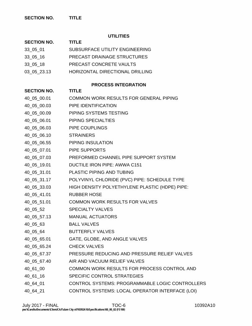
UTILITIES
SECTION NO. TITLE
33_05_01 SUBSURFACE UTILITY ENGINEERING
33_05_16 PRECAST DRAINAGE STRUCTURES
33_05_18 PRECAST CONCRETE VAULTS
03_05_23.13 HORIZONTAL DIRECTIONAL DRILLING
PROCESS INTEGRATION
SECTION NO. TITLE
40_05_00.01 COMMON WORK RESULTS FOR GENERAL PIPING
40_05_00.03 PIPE IDENTIFICATION
40_05_00.09 PIPING SYSTEMS TESTING
40_05_06.01 PIPING SPECIALTIES
40_05_06.03 PIPE COUPLINGS
40_05_06.10 STRAINERS
40_05_06.55 PIPING INSULATION
40_05_07.01 PIPE SUPPORTS
40_05_07.03 PREFORMED CHANNEL PIPE SUPPORT SYSTEM
40_05_19.01 DUCTILE IRON PIPE: AWWA C151
40_05_31.01 PLASTIC PIPING AND TUBING
40_05_31.17 POLYVINYL CHLORIDE (PVC) PIPE: SCHEDULE TYPE
40_05_33.03 HIGH DENSITY POLYETHYLENE PLASTIC (HDPE) PIPE:
40_05_41.01 RUBBER HOSE
40_05_51.01 COMMON WORK RESULTS FOR VALVES
40_05_52 SPECIALTY VALVES
40_05_57.13 MANUAL ACTUATORS
40_05_63 BALL VALVES
40_05_64 BUTTERFLY VALVES
40_05_65.01 GATE, GLOBE, AND ANGLE VALVES
40_05_65.24 CHECK VALVES
40_05_67.37 PRESSURE REDUCING AND PRESSURE RELIEF VALVES
40_05_67.40 AIR AND VACUUM RELIEF VALVES
40_61_00 COMMON WORK RESULTS FOR PROCESS CONTROL AND
40_61_16 SPECIFIC CONTROL STRATEGIES
40_64_01 CONTROL SYSTEMS: PROGRAMMABLE LOGIC CONTROLLERS
40_64_21 CONTROL SYSTEMS: LOCAL OPERATOR INTERFACE (LOI)

SECTION NO. TITLE
July 2017 - FINAL TOC-7 10392A10 pw:\\Carollo/Documents\Client/CA/Tulare City of/10392A10/Specifications\00_00_02 (FS100)
40_66_70 CONTROL SYSTEMS: WIRELESS COMMUNICATIONS
40_67_01 CONTROL SYSTEMS: PANELS, ENCLOSURES, AND PANEL COMPONENTS
40_67_26 CONTROL SYSTEMS: UNINTERRUPTIBLE POWER SUPPLIES 10 KVA AND BELOW
40_71_15 FLOW MEASUREMENT: MAGNETIC FLOWMETERS
40_72_13 LEVEL MEASUREMENT: ULTRASONIC
40_73_13 PRESSURE/VACUUM MEASUREMENT: GAUGES
40_73_23 PRESSURE/VACUUM MEASUREMENT: DIRECT
40_73_36 PRESSURE/VACUUM MEASUREMENT: SWITCHES
40_73_63 PRESSURE/VACUUM MEASUREMENT: DIAPHRAGM AND ANNULAR SEALS
40_73_64 PRESSURE/VACUUM MEASUREMENT: INSTRUMENT VALVES
40_73_65 PRESSURE MEASUREMENT: SUBMERSIBLE
40_75_23 ANALYZERS: RESIDUAL CHLORINE
40_80_01 TESTING, CALIBRATION, AND COMMISSIONING
PROCESS GAS AND LIQUID HANDLING, PURIFICATION, AND STORAGE EQUIPMENT
SECTION NO. TITLE
43_23_21.30 AXIALLY-SPLIT CENTRIFUGAL PUMPS
43_24_50.11 VERTICAL TURBINE DEEP WELL CENTRIFUGAL PUMPS
43_33_30.01 LIQUID CHEMICAL SOLENOID METERING PUMPS
43_41_65 STRAND-WOUND PRESTRESSED CONCRETE TANK WITH A TYPE I CORE WALL AND FLAT ROOF
WATER AND WASTEWATER EQUIPMENT
SECTION NO. TITLE
46_05_10 COMMON WORK RESULTS FOR MECHANICAL EQUIPMENT
46_05_11 EQUIPMENT IDENTIFICATION
46_05_94 MECHANICAL EQUIPMENT TESTING
VOLUME 3 OF 4
DRAWINGS
VOLUME 4 OF 4 TYPICAL DETAILS
END TABLE OF CONTENTS


July 2017 - FINAL 00_11_13-1 10392A10 pw://Carollo/Documents/Client/CA/Tulare City of/10392A10/Specifications/00_11_13 (FS100)
DOCUMENT 00_11_13
ADVERTISEMENT FOR BIDS
CITY OF TULARE
411 EAST KERN AVENUE
FRESNO, CALIFORNIA 93274
WATER STORAGE TANK IMPROVEMENTS PROJECT
RFB 18-626
ADVERTISEMENT FOR BIDS Sealed Bids for the construction of the Water Storage Tank Improvements Project will be received by the City of Tulare, at the office of the Office of the City Clerk (411 East Kern Avenue, Tulare, California 93274), until 3:00 PM local time on September 07, 2017, at which time the Bids received will publicly opened and read. The Project consists of constructing a 2 million gallon (MG) water storage tank, well, booster pump station, electrical building, generator, and other appurtenances at both the J Street and Alpine Vista sites. BIDDING DOCUMENTS The Issuing Office for the Bidding Documents is: City Clerk (411 East Kern Avenue, Tulare, California 93274. Prospective Bidders may examine the Bidding Documents at the Issuing Office on Mondays through Fridays between the hours of 9:00 AM and 4:00 PM, and may obtain copies of the Bidding Documents from the Issuing Office as described below.
Charge
(Non-refundable)
Complete set of reduced documents (specifications and half-size drawings) $250.00
Geotechnical Report $25.00 Bidding Documents also may be examined at Tulare and Kings Counties Building Exchange (1223 Lovers Lane, Visalia, California 93292); online at http://www.tulare.ca.gov/departments/community-development/development-services/engineering/city-projects and the office of the Engineer, (710 West Pindale Avenue, Fresno, California 93711) from Eric Casares [[email protected], (559) 490-4361], on Mondays through Fridays between the hours of 8:00 AM and 5:00 PM. PRE-BID CONFERENCE A pre-bid conference will be held at 2:00 PM local time on August 25, 2017 at the J Street tank site near the intersection of West Prosperity Avenue and North J Street south of the Dollar General. Attendance at the pre-bid conference is mandatory.

July 2017 - FINAL 00_11_13-2 10392A10 pw://Carollo/Documents/Client/CA/Tulare City of/10392A10/Specifications/00_11_13 (FS100)
BID SECURITY Bid security shall be furnished in accordance with Document 00_21_13 - Instructions to Bidders. CONTRACTOR REGISTRATION Contractor must provide proof of registration with the California Department of Industrial Relations (DIR) in the form of a PDF extract from DIR Public Works Registration website. Pursuant to California SB854, Contractor and subcontractor must submit certified payroll records (CPRs) to the Labor Commissioner. Project is subject to compliance monitoring and enforcement by the DIR. PREVAILING WAGE RATES Pursuant to Section 1770 et. seq., California Labor Code, the successful Bidder shall pay not less than the prevailing rate of per diem wages as determined by the Director of California Department of Industrial Relations. A copy of such prevailing rate is on file at the Owner's offices and will be made available for examination during business hours to any party on request. The project is subject to compliance monitoring and enforcement by the California Department of Industrial Relations.
CITY OF TULARE
By __________________________________ Trisha Whitfield/Public Works Director
Date: ________________________________
END OF SECTION

July 2017 - FINAL 00_21_13-1 10392A10 pw://Carollo/Documents/Client/CA/Tulare City of/10392A10/Specifications/00_21_13 (FS100)
DOCUMENT 00_21_13
INSTRUCTIONS TO BIDDERS
ARTICLE 1 - DEFINED TERMS
1.01 Terms used in this Document will have the meanings indicated in the General Conditions and Supplementary Conditions. Additional terms used in this Document have the meanings indicated below:
A. Issuing Office -- The office from which the Bidding Documents are to be issued.
B. Successful Bidder -- The lowest responsible Bidder submitting a responsive Bid to whom Owner (on the basis of Owner's evaluation as hereinafter provided) makes an award.
C. Responsive Bidder - Means a Bidder who has submitted a Bid which conforms in all material respects to the Bidding Documents.
D. Responsible Bidder - Means a Bidder who has the capacity and capability in all respects to perform fully the contract requirements and who has the integrity and reliability to assure good faith performance.
ARTICLE 2 - COPIES OF BIDDING DOCUMENTS
2.01 Complete sets of the Bidding Documents may be obtained from the Issuing Office in the number and format stated in the advertisement or invitation to bid.
2.02 Complete sets of Bidding Documents shall be used in preparing Bids; neither Owner nor Engineer assumes any responsibility for errors or misinterpretations resulting from the use of incomplete sets of Bidding Documents.
2.03 Owner and Engineer, in making copies of Bidding Documents available on the above terms, do so only for the purpose of obtaining Bids for the Work and do not authorize or confer a license for any other use.
ARTICLE 3 - QUALIFICATIONS OF BIDDERS
3.01 More than 1 Bid from an individual, firm, partnership, corporation, or association under the same or different names will not be considered. If the Owner believes that any Bidder submits more than 1 Bid for the Work contemplated, all Bids in which such Bidder is interested will be rejected. If the Owner believes that collusion exists among the Bidders, all Bids will be rejected.

July 2017 - FINAL 00_21_13-2 10392A10 pw://Carollo/Documents/Client/CA/Tulare City of/10392A10/Specifications/00_21_13 (FS100)
3.02 Provide proof of registration with the California Department of Industrial Relations (DIR) in the form of a PDF extract from DIR Public Works Registration website.
3.03 Pursuant to Section 4105, California Public Contract Code, Bidder may not circumvent the requirement to list subcontractors by the device of listing 1 subcontractor, who in turn sublets portions constituting the majority of the work covered by the contract.
3.04 No Contractor or Subcontractor may submit a Bid or perform Work on this Project who is found in violation of California Labor Code Division 2, Part 7, Chapter 1 by the Labor Commissioner. Subcontractors who have been disbarred may not receive public funds pursuant to California Public Contract Code §6109.
3.05 To demonstrate Bidder's qualifications to perform the Work, Bidder shall submit with its Bid written evidence establishing its qualifications such as financial data, previous experience, present commitments by submitting Document 00_45_14.01 - Construction Contractor's Qualification Statement.
3.06 A Bidder’s failure to submit required qualification information within the times indicated may disqualify Bidder from receiving an award of the Contract.
3.07 No requirement in this Article 3 to submit information will prejudice the right of Owner to seek additional pertinent information regarding Bidder’s qualifications.
3.08 Bidder is advised to carefully review those portions of the Bid Form requiring Bidder’s representations and certifications.
ARTICLE 4 - SITE AND OTHER AREAS; EXISTING SITE CONDITIONS; EXAMINATION OF SITE; OWNER’S SAFETY PROGRAM; OTHER WORK AT THE SITE
4.01 Site and Other Areas
A. The Site is identified in the Bidding Documents. By definition, the Site includes rights-of-way, easements, and other lands furnished by Owner for the use of the Contractor. Any additional lands required for temporary construction facilities, construction equipment, or storage of materials and equipment, and any access needed for such additional lands, are to be obtained and paid for by Contractor.
4.02 Existing Site Conditions
A. Subsurface and Physical Conditions; Hazardous Environmental Conditions: 1. The Supplementary Conditions identify:
a. those reports known to Owner of explorations and tests of subsurface conditions at or adjacent to the Site.
b. those drawings known to Owner of physical conditions relating to existing surface or subsurface structures at the Site (except Underground Facilities).
c. reports and drawings known to Owner relating to Hazardous Environmental Conditions that have been identified at or adjacent to the Site.
d. Technical Data contained in such reports and drawings.

July 2017 - FINAL 00_21_13-3 10392A10 pw://Carollo/Documents/Client/CA/Tulare City of/10392A10/Specifications/00_21_13 (FS100)
2. Owner will make copies of reports and drawings referenced above available at the cost of reproduction to any Bidder on request. These reports and drawings are not part of the Contract Documents, but the Technical Data contained therein upon whose accuracy Bidder is entitled to rely, as provided in the General Conditions, has been identified and established in the Supplementary Conditions. Bidder is responsible for any interpretation or conclusion Bidder draws from any Technical Data or any other data, interpretations, opinions, or information contained in such reports or shown or indicated in such drawings.
3. If the Supplementary Conditions do not identify Technical Data, the default definition of Technical Data set forth in Article 1 of the General Conditions will apply.
B. Underground Facilities: Information and data shown or indicated in the Bidding Documents with respect to existing Underground Facilities at or contiguous to the Site are set forth in the Contract Documents and are based upon information and data furnished to Owner and Engineer by owners of such Underground Facilities, including Owner, or others.
C. Adequacy of Data: Provisions concerning responsibilities for the adequacy of data furnished to prospective Bidders with respect to subsurface conditions, other physical conditions, and Underground Facilities, and possible changes in the Bidding Documents due to differing or unanticipated subsurface or physical conditions appear in Paragraphs 5.03, 5.04, and 5.05 of the General Conditions. Provisions concerning responsibilities for the adequacy of data furnished to prospective Bidders with respect to a Hazardous Environmental Condition at the Site, if any, and possible changes in the Contract Documents due to any Hazardous Environmental Condition uncovered or revealed at the Site which was not shown or indicated in the Drawings or Specifications or identified in the Contract Documents to be within the scope of the Work, appear in Paragraph 5.06 of the General Conditions.
4.03 Site Visit and Testing by Bidders
A. Bidder shall conduct the required Site visit during normal working hours, and shall not disturb any ongoing operations at the Site.
B. Bidder is not required to conduct any subsurface testing, or exhaustive investigations of Site conditions.
C. On request, and to the extent Owner has control over the Site, and schedule permitting, the Owner will provide Bidder access to the Site to conduct such additional examinations, investigations, explorations, tests, and studies as Bidder deems necessary for preparing and submitting a successful Bid. Owner will not have any obligation to grant such access if doing so is not practical because of existing operations, security or safety concerns, or restraints on Owner’s authority regarding the Site.
D. Bidder shall comply with all applicable Laws and Regulations regarding excavation and location of utilities, obtain all permits, and comply with all terms and conditions established by Owner or by property owners or other entities controlling the Site with respect to schedule, access, existing operations, security, liability insurance, and applicable safety programs.
July 2017 - FINAL 00_21_13-4 10392A10 pw://Carollo/Documents/Client/CA/Tulare City of/10392A10/Specifications/00_21_13 (FS100)
E. Bidder shall fill all holes and clean up and restore the Site to its former condition upon completion of such explorations, investigations, tests, and studies.
4.04 Owner’s Safety Program
A. Site visits and work at the Site may be governed by an Owner safety program. As the General Conditions indicate, if an Owner safety program exists, it will be noted in the Supplementary Conditions.
4.05 Other Work at the Site
A. Reference is made to Article 8 of the Supplementary Conditions for the identification of the general nature of other work of which Owner is aware (if any) that is to be performed at the Site by Owner or others (such as utilities and other prime contractors) and relates to the Work contemplated by these Bidding Documents. If Owner is party to a written contract for such other work, then on request, Owner will provide to each Bidder access to examine such contracts (other than portions thereof related to price and other confidential matters), if any.
ARTICLE 5 - BIDDER’S REPRESENTATIONS
5.01 It is the responsibility of each Bidder before submitting a Bid to:
A. examine and carefully study the Bidding Documents, and any data and reference items identified in the Bidding Documents;
B. visit the Site, conduct a thorough, alert visual examination of the Site and adjacent areas, and become familiar with and satisfy itself as to the general, local, and Site conditions that may affect cost, progress, and performance of the Work;
C. become familiar with and satisfy itself as to all Laws and Regulations that may affect cost, progress, and performance of the Work;
D. carefully study all: 1. reports of explorations and tests of subsurface conditions at or adjacent to the
Site and all drawings of physical conditions relating to existing surface or subsurface structures at the Site that have been identified in the Supplementary Conditions, especially with respect to Technical Data in such reports and drawings.
E. consider the information known to Bidder itself; information commonly known to contractors doing business in the locality of the Site; information and observations obtained from visits to the Site; the Bidding Documents; and the Site-related reports identified in the Bidding Documents, with respect to the effect of such information, observations, and documents on 1. the cost, progress, and performance of the Work; 2. the means, methods, techniques, sequences, and procedures of construction to
be employed by Bidder; and 3. Bidder’s safety precautions and programs;

July 2017 - FINAL 00_21_13-5 10392A10 pw://Carollo/Documents/Client/CA/Tulare City of/10392A10/Specifications/00_21_13 (FS100)
F. agree, based on the information and observations referred to in the preceding paragraph, that at the time of submitting its Bid no further examinations, investigations, explorations, tests, studies, or data are necessary for the determination of its Bid for performance of the Work at the price bid and within the times required, and in accordance with the other terms and conditions of the Bidding Documents;
G. become aware of the general nature of the work to be performed by Owner and others at the Site that relates to the Work as indicated in the Bidding Documents;
H. promptly give Engineer written notice of all conflicts, errors, ambiguities, or discrepancies that Bidder discovers in the Bidding Documents and confirm that the written resolution thereof by Engineer is acceptable to Bidder;
I. determine that the Bidding Documents are generally sufficient to indicate and convey understanding of all terms and conditions for the performance and furnishing of the Work; and
J. agree that the submission of a Bid will constitute an incontrovertible representation by Bidder that Bidder has complied with every requirement of this Article, that without exception the Bid and all prices in the Bid are premised upon performing and furnishing the Work required by the Bidding Documents.
ARTICLE 6 - PRE-BID CONFERENCE
6.01 A pre-Bid conference will be held at the time and location stated in the invitation or advertisement to bid. Representatives of Owner and Engineer will be present to discuss the Project. Bidders are encouraged to attend and participate in the conference. Engineer will transmit to all prospective Bidders of record such Addenda as Engineer considers necessary in response to questions arising at the conference. Oral statements may not be relied upon and will not be binding or legally effective.
ARTICLE 7 - INTERPRETATIONS AND ADDENDA
7.01 All questions about the meaning or intent of the Bidding Documents are to be submitted to Engineer in writing. Interpretations or clarifications considered necessary by Engineer in response to such questions will be issued by Addenda delivered to all parties recorded as having received the Bidding Documents. Questions received less than 5 days prior to the date for opening of Bids may not be answered. Only questions answered by Addenda will be binding. Oral and other interpretations or clarifications will be without legal effect.
7.02 Addenda may be issued to clarify, correct, supplement, or change the Bidding Documents.

July 2017 - FINAL 00_21_13-6 10392A10 pw://Carollo/Documents/Client/CA/Tulare City of/10392A10/Specifications/00_21_13 (FS100)
ARTICLE 8 - BID SECURITY
8.01 A Bid must be accompanied by Bid security made payable to Owner in an amount of 10 percent of Bidder's maximum Bid price (determined by adding the base bid and all alternates) and in the form of a certified check, bank money order, or Document 00_43_15 - Bid Bond issued by a surety meeting the requirements of Paragraphs 6.01 and 6.02 of the General Conditions.
8.02 The Bid security of the apparent Successful Bidder will be retained until Owner awards the contract to such Bidder, and such Bidder has executed the Contract Documents, furnished the required contract security, and met the other conditions of the Notice of Award, whereupon the Bid security will be released,
A. If the Successful Bidder fails to execute and deliver the Contract Documents and furnish the required contract security within 15 days after the Notice of Award, Owner may consider Bidder to be in default, annul the Notice of Award, and the Bid security of that Bidder will be forfeited. Such forfeiture shall be Owner’s exclusive remedy if Bidder defaults.
8.03 The Bid security of other Bidders that Owner believes to have a reasonable chance of receiving the award may be retained by Owner until the earlier of seven days after the Effective Date of the Contract or 61 days after the Bid opening, whereupon Bid security furnished by such Bidders will be released.
8.04 Bid security of other Bidders that Owner believes do not have a reasonable chance of receiving the award will be released within seven days after the Bid opening.
ARTICLE 9 - CONTRACT TIMES
9.01 The number of days within which, or the dates by which, the Work is to be substantially completed and ready for final payment are set forth in the Agreement.
ARTICLE 10 - LIQUIDATED DAMAGES
10.01 Provisions for liquidated damages, of any, for failure to timely attain a Milestone, Substantial Completion, or completion of the Work in readiness for final payment, are set forth in Document 00_52_00 - Agreement.
ARTICLE 11 - SUBSTITUTE AND "OR-EQUAL" ITEMS
11.01 The Contract for the Work, as awarded, will be on the basis of materials and equipment specified or described in the Bidding Documents without consideration during the bidding and Contract award process of possible substitute or “or-equal” items
A. In cases in which the Contract allows the Contractor to request that Engineer authorize the use of a substitute or “or-equal” item of material or equipment, application for such acceptance may not be made to and will not be considered by Engineer until after the Effective Date of the Contract.

July 2017 - FINAL 00_21_13-7 10392A10 pw://Carollo/Documents/Client/CA/Tulare City of/10392A10/Specifications/00_21_13 (FS100)
11.02 In accordance with Section 3400 of the California Public Contract Code, the successful Bidder is permitted a period of 30 days after the award of contract for submission of data substantiating a request for a substitution of an “or equal” item.
11.03 Prices that Bidder sets forth in its Bid shall be based on the presumption that the Contractor will furnish the materials and equipment specified or described in the Bidding Documents, as amended by Addenda.
A. Any assumptions regarding the possibility of post-Bid approvals of “or-equal” or substitution requests are made at Bidder’s sole risk.
ARTICLE 12 - SUBCONTRACTORS, SUPPLIERS, AND OTHERS
12.01 A Bidder shall be prepared to retain specific Subcontractors, Suppliers, or other individuals or entities for the performance of the Work if required by the Bidding Documents (most commonly in the Specifications) to do so. If a prospective Bidder objects to retaining any such Subcontractor, Supplier, or other individual or entity, and the concern is not relieved by an Addendum, then the prospective Bidder should refrain from submitting a Bid.
12.02 Subsequent to the submittal of the Bid, Owner may not require the Successful Bidder or Contractor to retain any Subcontractor, Supplier, or other individual or entity against which Contractor has reasonable objection.
12.03 Pursuant to California Public Contract Code §4106, Document 00434 - Proposed Subcontractors List shall list the Subcontractors or Suppliers proposed who will perform work or labor or render services in an amount in excess of 1/2 of 1 percent of Contractor’s total bid. Bidder shall attach to Document - Bid Form the Document 00434 - Proposed Subcontractors Form containing the following information: 1) the name, 2) the location of the business, 3) the California contractor license number, and 4) the Department of Industrial Relations registration number of each proposed subcontractor.
A. Owner may request additional subcontractor information from the apparent Successful Bidder and any other Bidder to be submitted within twenty-four hours after the deadline established by Owner for receipt of bids by Bidders pursuant to California Public Contract Code §4104.
B. If requested by Owner, such list shall be accompanied by an experience statement with pertinent information regarding similar projects and other evidence of qualification for each such Subcontractor, Supplier, or other individual or entity. If Owner or Engineer, after due investigation, has reasonable objection to any proposed Subcontractor, Supplier, individual, or entity, Owner may, before the Notice of Award is given, request apparent Successful Bidder to submit an acceptable substitute, in which case apparent Successful Bidder shall submit a substitute, Bidder’s Bid price will be increased (or decreased) by the difference in cost occasioned by such substitution, and Owner may consider such price adjustment in evaluating Bids and making the Contract award.

July 2017 - FINAL 00_21_13-8 10392A10 pw://Carollo/Documents/Client/CA/Tulare City of/10392A10/Specifications/00_21_13 (FS100)
12.04 If apparent Successful Bidder declines to make any such substitution, Owner may award the Contract to the next lowest Bidder that proposes to use acceptable Subcontractors, Suppliers, or other individuals or entities. Declining to make requested substitutions will constitute grounds for forfeiture of the Bid security of any Bidder. Any Subcontractor, Supplier, individual, or entity so listed and against which Owner or Engineer makes no written objection prior to the giving of the Notice of Award will be deemed acceptable to Owner and Engineer subject to subsequent revocation of such acceptance as provided in Paragraph 7.06 of the General Conditions.
ARTICLE 13 - PREPARATION OF BID
13.01 Document 00_41_00 - Bid Form is included with the Bidding Documents.
A. Complete each blank on Document 00_41_00 - Bid Form in ink and the Bid Form signed in ink.
B. The person signing the Bid Form must initialed in ink erasures or alterations.
C. Indicate Bid Price for each section, Bid item, alternative, adjustment unit price item, and unit price item listed therein.
D. If the Bid Form expressly indicates that submitting pricing on a specific alternate item is optional, and Bidder elects to not furnish pricing for such optional alternate item, then Bidder may enter the words “No Bid” or “Not Applicable.”
13.02 A Bid by a corporation shall be executed in the corporate name by a corporate officer (whose title must appear under the signature), accompanied by evidence of authority to sign. The corporate address and state of incorporation must be shown.
13.03 A Bid by a limited liability company shall be executed in the name of the firm by a member or other authorized person and accompanied by evidence of authority to sign. The state of formation of the firm and the official address of the firm must be shown.
13.04 A Bid by a partnership shall be executed in the partnership name and signed by a partner (whose title must appear under the signature), accompanied by evidence of authority to sign. The official address of the partnership shall be shown.
13.05 A Bid by an individual shall show the Bidder's name and official address.
13.06 A Bid by a joint venture shall be executed by an authorized representative of each joint venturer in the manner indicated on Document 00_41_00 - Bid Form. The official address of the joint venture shall be shown.
13.07 All names shall be printed in ink below the signatures.
13.08 The Bid shall contain an acknowledgment of receipt of all Addenda, the numbers of which shall be filled in on Document 00_41_00 - Bid Form.
13.09 Postal and e-mail addresses and telephone number for communications regarding the Bid shall be shown.

July 2017 - FINAL 00_21_13-9 10392A10 pw://Carollo/Documents/Client/CA/Tulare City of/10392A10/Specifications/00_21_13 (FS100)
13.10 The Bid shall contain evidence of Bidder's authority and qualification to do business in California, or Bidder shall covenant in writing to obtain such authority and qualification prior to award of the Contract and attach such covenant to the Bid. Bidder’s state contractor license number, if any, shall also be shown on Document 00_41_00 - Bid Form. Questions concerning a contractor may be referred to the Registrar, Contractors' State License Board, P.O. Box 26000, Sacramento, CA 95826.
13.11 Pursuant to the provisions of Section 6707, California Labor Code, Bids shall contain, as a Bid item, the cost for adequate sheeting, shoring and bracing, or equivalent method, for the protection of life and limb in trenches and open excavation, which shall conform to applicable safety orders.
13.12 Pursuant to the provisions of Section 7106 of the California Public Contract Code, Bidders shall submit with their Bids, a Non-Collusion Affidavit, Document 00_45_19 - Non-Collusion Affidavit.
13.13 Pursuant to Section 7105, California Public Contract Code, Bidder shall indicate, in the appropriate space provided in Document 00_41_00 - Bid Forms, the cost of insurance premiums for earthquake and tidal wave to indemnify Owner for damage to the Work caused by earthquake or tidal wave in an amount of at least 50 percent of the contract price. The determination of whether to require earthquake and tidal wave insurance will be made by Owner prior to award of contract.
ARTICLE 14 - BASIS OF BID
14.01 Base Bid with Alternates:
A. Bidders shall submit a Bid on a lump sum basis for the base Bid and include a separate price for each alternate described in the Bidding Documents and as provided for in Document 00_41_00 - Bid Form. The price for each alternate will be the amount added to or deleted from the base Bid if Owner selects the alternate.
14.02 Evaluation of bids containing alternates:
A. In the evaluation of Bids, the lowest Bid shall be the lowest Bid price on the Base Bid without consideration of the Bid Alternates additive or deductive items.
ARTICLE 15 - SUBMITTAL OF BID
15.01 With each copy of the Bidding Documents, a Bidder is furnished one separate unbound copy of the Bid Form, and, if required, the Bid Bond Form. The unbound copy of the Bid Form is to be completed and submitted with the Bid security and the other documents required to be submitted under the terms of Article 7 of the Bid Form.

July 2017 - FINAL 00_21_13-10 10392A10 pw://Carollo/Documents/Client/CA/Tulare City of/10392A10/Specifications/00_21_13 (FS100)
15.02 A Bid shall be received no later than the date and time prescribed and at the place indicated in the Document 00_11_13 – Advertisement for Bids and shall be enclosed in a plainly marked package with the Project title (and, if applicable, the designated portion of the Project for which the Bid is submitted), the name and address of Bidder, and shall be accompanied by the Bid security and other required documents.
A. If a Bid is sent by mail or other delivery system, the sealed envelope containing the Bid shall be enclosed in a separate package plainly marked on the outside with the notation “BID ENCLOSED.” A mailed Bid shall be addressed to Office of the City Clerk (411 East Kern Avenue, Tulare, California 93274).
15.03 Bids received after the date and time prescribed for the opening of bids, or not submitted at the correct location or in the designated manner, will not be accepted and will be returned to the Bidder unopened.
ARTICLE 16 - MODIFICATION AND WITHDRAWAL OF BID
16.01 A Bid may be withdrawn by an appropriate document duly executed in the same manner that a Bid must be executed and delivered to the place where Bids are to be submitted prior to the date and time for the opening of Bids. Upon receipt of such notice, the unopened Bid will be returned to the Bidder.
16.02 If a Bidder wishes to modify its Bid prior to Bid opening, Bidder must withdraw its initial Bid in the manner specified in Paragraph 16.01 and submit a new Bid prior to the date and time for the opening of Bids.
16.03 Unauthorized conditions, limitations, or modifications attached to the Bid will render it informal and may cause its rejection as being non-responsive. The completed Document 00_41_00 - Bid Forms shall be without interlineations, alterations, or erasures. Any changes or corrections shall be initialed by the Bidder. Alternative Bids will not be considered unless expressly called for in Document 00_11_16 - Invitation to Bid. Oral, telegraphic, faxed or telephone Bids or modifications will not be considered.
16.04 In accordance with Sections 5101 and 5103, California Public Contract Code, withdrawal of Bids may be permitted for mistakes made in filling out the Bid but will not be permitted for mistakes resulting from errors in judgment or carelessness in inspecting the site of the work or in reading the drawings, specifications, and other Contracts Documents.
16.05 In the event Bidder alleges that a clerical error has been made in the list of subcontractors, the procedures for substitution shall be provided in accordance with Section 4107.5, California Public Contract Code.
ARTICLE 17 - OPENING OF BIDS
17.01 Bids will be opened at the time and place indicated in Document 00_11_13 - Advertisement for Bids and, unless obviously non-responsive, read aloud publicly. An abstract of the amounts of the base Bids and major alternates, if any, will be made available to Bidders after the opening of Bids.

July 2017 - FINAL 00_21_13-11 10392A10 pw://Carollo/Documents/Client/CA/Tulare City of/10392A10/Specifications/00_21_13 (FS100)
ARTICLE 18 - BIDS TO REMAIN SUBJECT TO ACCEPTANCE
18.01 All Bids will remain subject to acceptance for the period of time stated in Document 00_41_00 - Bid Form, but Owner may, in its sole discretion, release any Bid and return the Bid security prior to the end of this period.
ARTICLE 19 - EVALUATION OF BIDS AND AWARD OF CONTRACT
19.01 Owner reserves the right to reject any or all Bids, including without limitation, nonconforming, nonresponsive, unbalanced, or conditional Bids. Owner will reject the Bid of any Bidder that Owner finds, after reasonable inquiry and evaluation, to not be responsible. If Bidder purports to add terms or conditions to its Bid, takes exception to any provision of the Bidding Documents, or attempts to alter the contents of the Contract Documents for purposes of the Bid, then the Owner will reject the Bid as nonresponsive; provided that Owner also reserves the right to waive all minor informalities not involving price, time, or changes in the Work. Owner may also reject the Bid of any Bidder if Owner believes that it would not be in the best interest of the Project to make an award to that Bidder.
19.02 If Owner awards the contract for the Work, such award shall be to the responsible Bidder submitting the lowest responsive Bid.
19.03 More than 1 Bid for the same Work from an individual or entity under the same or different names will not be considered. Reasonable grounds for believing that any Bidder has an interest in more than 1 Bid for the Work may be cause for disqualification of that Bidder and the rejection of all Bids in which that Bidder has an interest.
19.04 Evaluation of Bids
A. In evaluating Bids, Owner will consider whether or not the Bids comply with the prescribed requirements, and such alternates, unit prices and other data, as may be requested in Document 00_41_00 - Bid Form or prior to Document 00_51_00 - Notice of Award.
B. For the determination of the apparent low Bidder when unit price bids are submitted, Bids will be compared on the basis of the total of the products of the estimated quantity of each item and unit price Bid for that item, together with any lump sum items.
19.05 In evaluating whether a Bidder is responsible, Owner will consider the qualifications of Bidder and may consider the qualifications and experience of Subcontractors and Suppliers proposed for those portions of the Work for which the identity of Subcontractors and Suppliers must be submitted as provided in the Bidding Documents.
19.06 Owner may conduct such investigations as Owner deems necessary to establish the responsibility, qualifications, and financial ability of Bidders and any proposed Subcontractors or Suppliers.

July 2017 - FINAL 00_21_13-12 10392A10 pw://Carollo/Documents/Client/CA/Tulare City of/10392A10/Specifications/00_21_13 (FS100)
19.07 Additional requirements for award on projects with alternates:
A. After determining the designated Low Bidder for the project, Owner may award on the amount of the Low Bidder’s Base Bid alone or on any combination of alternates. 1. The combination of alternates may include substituting any of the alternates that
were included in the designated Low Bidder’s bid, provided: a. It is in the best interest of the Owner. b. Funds are available at the time of the award.
ARTICLE 20 - BONDS AND INSURANCE
20.01 Article 6 of the General Conditions, as may be modified by the Supplementary Conditions, sets forth Owner’s requirements as to performance and payment bonds and insurance. When the Successful Bidder delivers the Agreement (executed by Successful Bidder) to Owner, it shall be accompanied by required bonds and insurance documentation.
ARTICLE 21 - SIGNING OF AGREEMENT
21.01 When Owner issues a Notice of Award to the Successful Bidder, it shall be accompanied by the unexecuted counterparts of the Agreement along with the other Contract Documents as identified in the Agreement. Within 15 days thereafter, Successful Bidder shall execute and deliver the required number of counterparts of the Agreement (and any bonds and insurance documentation required to be delivered by the Contract Documents) to Owner. Within ten days thereafter, Owner shall deliver one fully executed counterpart of the Agreement to Successful Bidder, together with printed and electronic copies of the Contract Documents as stated in Paragraph 2.02 of the General Conditions.
ARTICLE 22 - SALES AND USE TAXES
22.01 Contractor shall pay all sales, use and other taxes as specified in paragraph 6.10 of the General Conditions.
ARTICLE 23 - RETAINAGE
23.01 Provisions concerning Contractor's rights to deposit securities in lieu of retainage are set forth in Document 00_52_00 - Agreement.

July 2017 - FINAL 00_21_13-13 10392A10 pw://Carollo/Documents/Client/CA/Tulare City of/10392A10/Specifications/00_21_13 (FS100)
ARTICLE 24 - LAWS AND REGULATIONS
24.01 Prevailing Wage Rates: Pursuant to Section 1770 et seq., California Labor Code, the successful Bidder shall pay not less than the prevailing rate of per diem wages as determined by the Director of California Department of Industrial Relations. A copy of such prevailing rate is on file at the offices of the Owner, which copy will be made available for examination during business hours to any party on request.
A. Pursuant to California SB854, Contractor and subcontractor must submit certified payroll records (CPRs) to the Labor Commissioner.
24.02 Contractor's License Classification: In accordance with the provisions of California Business and Professions Code, Section 7028, Owner has determined that Contractor shall possess a valid Class A Contractor License at the time of Bid and for the duration of the contract. Failure to possess the specified license shall render the Bid as non-responsive and shall act as a bar to award of the contract to any Bidder not possessing said license at the time of Bid opening.
24.03 The Contractors’ State License Board may be contacted at 9821 Business Park Drive, Sacramento, CA 95827; P.O. Box 26000, Sacramento, CA 95826; (800) 321-2752.
24.04 In accordance with California Civil Code, Section 3247, a payment bond is required.
24.05 In accordance with California Public Contract Code, Section 22300, Contractor may substitute securities in place of retained funds, as provided in Document 00_54_03 - Escrow Agreement for Security Deposits in Lieu of Retention.
ARTICLE 25 - PREVAILING WAGE RATES
25.01 Pursuant to Section 1770 et. seq., California Labor Code, the successful Bidder shall pay not less than the prevailing rate of per diem wages as determined by the Director of California Department of Industrial Relations.
25.02 A copy of such prevailing rate is on file at the Owner's offices.
A. A copy will be made available for examination during business hours to any party on request.
25.03 The project is subject to compliance monitoring and enforcement by the California Department of Industrial Relations.
END OF DOCUMENT


July 2017 - FINAL 00_41_00-1 10392A10 pw://Carollo/Documents/Client/CA/Tulare City of/10392A10/Specifications/00_41_00 (FS100)
DOCUMENT 00_41_00
BID FORM
ARTICLE 1 - BID RECIPIENT
1.01 WATER STORAGE TANK IMPROVEMENTS PROJECT
1.02 This Bid is submitted to:
CITY OF TULARE (OFFICE OF THE CITY CLERK)
411 EAST KERN AVENUE
TULARE, CALIFORNIA 93274
1.03 The undersigned Bidder proposes and agrees, if this Bid is accepted, to enter into an agreement with Owner in the form included in the Bidding Documents to perform all Work as specified or indicated in the Bidding Documents within the specified time and for the price indicated in this Bid and in accordance with the other terms and conditions of the Bidding Documents.
ARTICLE 2 - BIDDER’S ACKNOWLEDGMENT
2.01 Bidder accepts all of the terms and conditions of Document 00_21_13 - Instructions to Bidders, including without limitation those dealing with the disposition of Bid security. The Bid will remain subject to acceptance for 60 days after the Bid opening, or for such longer period of time that Bidder may agree to in writing upon request of Owner.
ARTICLE 3 - BIDDER’S REPRESENTATIONS
3.01 In submitting this Bid, Bidder represents that:
A. Bidder has examined and carefully studied the Bidding Documents, and any data and reference items identified in the Bidding Documents, and hereby acknowledges receipt of the following Addenda:
Addendum No. Addendum Date _____________ ________________ _____________ ________________ _____________ ________________ _____________ ________________ _____________ ________________ _____________ ________________ _____________ ________________

July 2017 - FINAL 00_41_00-2 10392A10 pw://Carollo/Documents/Client/CA/Tulare City of/10392A10/Specifications/00_41_00 (FS100)
B. Bidder has visited the Site, conducted a thorough, alert visual examination of the Site and adjacent areas, and become familiar with and satisfied itself as to the general, local, and Site conditions that may affect cost, progress, and performance of the Work
C. Bidder is familiar with and has satisfied itself as to all Federal, state, and local Laws and Regulations and Permits that may affect cost, progress, and performance of the Work.
D. Bidder has carefully studied all: 1. reports of explorations and tests of subsurface conditions at or adjacent to the Site
and all drawings of physical conditions relating to existing surface or subsurface structures at the Site that have been identified in the Supplementary Conditions, especially with respect to Technical Data in such reports and drawings, and
2. reports and drawings relating to Hazardous Environmental Conditions, if any, at or adjacent to the Site that have been identified in the Supplementary Conditions, especially with respect to Technical Data in such reports and drawings.
E. Bidder has considered the information known to Bidder itself; information commonly known to contractors doing business in the locality of the Site; information and observations obtained from visits to the Site; the Bidding Documents; and any Site-related reports and drawings identified in the Bidding Documents, with respect to the effect of such information, observations, and documents on 1. the cost, progress, and performance of the Work; 2. the means, methods, techniques, sequences, and procedures of construction to be
employed by Bidder; and 3. Bidder’s safety precautions and programs.
F. Bidder agrees, based on the information and observations referred to in the preceding paragraph, that no further examinations, investigations, explorations, tests, studies, or data are necessary for the determination of this Bid for performance of the Work at the price bid and within the times required, and in accordance with the other terms and conditions of the Bidding Documents.
G. Bidder is aware of the general nature of work to be performed by Owner and others at the Site that relates to the Work as indicated in the Bidding Documents.
H. Bidder has given Engineer written notice of all conflicts, errors, ambiguities, or discrepancies that Bidder has discovered in the Bidding Documents, and confirms that the written resolution thereof by Engineer is acceptable to Bidder.
I. The Bidding Documents are generally sufficient to indicate and convey understanding of all terms and conditions for the performance and furnishing the Work required by the Bidding Documents.
J. In accordance with Section 1861, California Labor Code, the Bidder states the following as its certification:
K. "I am aware of the provisions of Section 3700 of the California Labor Code which require every employer to be insured against liability for workers' compensation or to undertake self-insurance in accordance with the provisions of that code, and I will comply with such provisions before commencing the performance of the Work."

July 2017 - FINAL 00_41_00-3 10392A10 pw://Carollo/Documents/Client/CA/Tulare City of/10392A10/Specifications/00_41_00 (FS100)
ARTICLE 4 - BIDDER’S CERTIFICATION
4.01 Bidder further represents:
A. This Bid is genuine and not made in the interest of or on behalf of any undisclosed individual or entity and is not submitted in conformity with any agreement or rules of any group, association, organization or corporation;
B. Bidder has not directly or indirectly induced or solicited any other Bidder to submit a false or sham bid;
C. Bidder has not solicited or induced any individual or entity to refrain from bidding; and
D. Bidder has not engaged in corrupt, fraudulent, collusive, or coercive practices in competing for the Contract. For the purposes of this paragraph: 1. “corrupt practice” means the offering, giving, receiving, or soliciting of anything of
value likely to influence the action of a public official in the bidding process. 2. “fraudulent practice” means an intentional misrepresentation of facts made:
a. to influence the bidding process to the Owner’s detriment, b. to establish bid prices at artificial non-competitive levels, or c. to deprive Owner of the benefits of free and competitive bidding process.
3. “collusive practice” means a scheme or arrangement between two or more Bidders with or without the knowledge of Owner, a purpose of which is to establish bid prices at artificial, non-competitive levels; and
4. “coercive practice” means harming or threatening to harm, directly or indirectly, persons or their property to influence their participation in the bidding process or affect the execution of the Contract.
5. Pursuant to California Public Contract Code Section 7103.5(b), Contractor or Subcontractor shall offer and agree to assign to the awarding body all rights, title, and interest in and to all causes of action it may have under Section 4 of the Clayton Act (15 U.S.C. Sec. 15) or under the Cartwright Act (Chapter 2 (commencing with Section 16700) of Part 2 of Division 7 of the Business and Professions Code).
ARTICLE 5 - ASSIGNMENTS AND ALLOWANCES (NOT USED)
ARTICLE 6 - BASIS OF BID
6.01 Bidder will complete the Work in accordance with the Contract Documents for the following price(s):
Lump Sum Bid Price $_______________
A. The Bidder declares that the costs for labor, materials, equipment, and incidentals necessary for the following work are included in the Lump Sum Bid and that such costs are as indicated as follows: 1. Mobilization.
Bidder will complete the Work for not less than the percent of Contract Price as specified in Section 01_29_00 - Payment Procedures.
$____________________________________________ (Price in figures)

July 2017 - FINAL 00_41_00-4 10392A10 pw://Carollo/Documents/Client/CA/Tulare City of/10392A10/Specifications/00_41_00 (FS100)
2. Sheeting, shoring, and bracing, or equivalent method for the protection of life and limb in trenches and open excavation, pursuant to California Labor Code §6707.
Bidder will complete the Work for the Lump Sum Price of:
$____________________________________________ (Price in figures)
3. Commissioning and process start-up as specified in Section 01_75_17 - Commissioning, including planning, commissioning, and process start-up phases for the Project devices, components, equipment, and/or facility.
Bidder will complete the Work for not less than the percent of Contract Price as specified in Section 01_29_00 - Payment Procedures.
$____________________________________________ (Price in figures)
4. Demobilization.
Bidder will complete the Work for not less than the percent of Contract Price as specified in Section 01_29_00 - Payment Procedures.
$____________________________________________ (Price in figures)
B. Deduct Unit Prices: The Bidder will accept as adjustment to the Lump Sum Bid for quantities of work different than indicated in the Bidding Documents the amount resulting from applying to the difference the following unit prices. The acceptance or rejection of any or all Bid alternates is at the option of the Owner and will not necessarily be made on the basis of price alone. The contract price shall be the net amount determined by applying the net addition or net deduction specified to the Lump Sum Bid. 1. Bid Alternate A (deduct): Bidder will not furnish and install well pump, piping, valves,
and necessary appurtenances complete with concrete pads, electrical, and instrumentation for the Alpine Vista site as indicated on the Drawings and Section 01_11_00.
$____________________________________________ (Price in figures)
TIME OF COMPLETION
6.02 Bidder agrees that the Work will be substantially completed, and, completed and ready for final payment in accordance with Paragraph 15.06 of the General Conditions on or before the dates or within the number of calendar days as specified in Document 00_52_00 - Agreement.
6.03 Bidder accepts the provisions of the Agreement as to liquidated damages in the event of failure to complete the Work within the times specified above, which shall be as specified in Document 00_52_00 - Agreement.

July 2017 - FINAL 00_41_00-5 10392A10 pw://Carollo/Documents/Client/CA/Tulare City of/10392A10/Specifications/00_41_00 (FS100)
ARTICLE 7 - ATTACHMENTS TO THIS BID
7.01 The following documents are attached to and made a condition of this Bid:
A. Required Bid security in the form of cash, a certified or bank check, or a Bid Bond as specified in Document 00_43_15 - Bid Bond.
B. Document 00_43_36 - List of Subcontractors, Document 00_43_35 - List of Equipment Manufacturers, Document 00_43_38 - Construction Equipment List, and other individuals and entities required to be identified in this Bid.
C. Document 00_45_14.01 - Construction Contractor's Qualification Statement with supporting data.
D. Document 00_45_19 - Non-Collusion Affidavit.
ARTICLE 8 - DEFINED TERMS
8.01 The terms used in this Bid with initial capital letters or all capital letters have the meanings as specified in Document 00_21_13 - Instructions to Bidders, General Conditions, and Supplementary Conditions.
ARTICLE 9 - BID SUBMITTAL
SUBMITTED on _________, 2017.
State Contractor License Number _________. (If applicable)
If Bidder is:
An Individual
Name (typed or printed):
By: ________ (Individual's signature)
Doing business as:
Business address:
Phone Number: ( )___________________ FAX Number: ( )____________________
A Partnership
Partnership Name: ________
By: (Signature of general partner -- attach evidence of authority to sign)
Name (typed or printed):
Business address:

July 2017 - FINAL 00_41_00-6 10392A10 pw://Carollo/Documents/Client/CA/Tulare City of/10392A10/Specifications/00_41_00 (FS100)
Phone Number: ( )___________________ FAX Number: ( )____________________
A Corporation
Corporation Name: ________
State of Incorporation:
Type (General Business, Professional, Service, Limited Liability):
By: (Signature -- attach evidence of authority to sign)
Name (typed or printed):
Title:
Attest: (Signature of Corporate Secretary, Acting Secretary or other officer)
Business address:
Phone Number: ( )___________________ FAX Number: ( )____________________
Date of Qualification to do business is
A Joint Venture
Joint Venturer Name: ________
By: (Signature of joint venture partner -- attach evidence of authority to sign)
Name (typed or printed):
Title:
Business address:
Phone Number: ( )___________________ FAX Number: ( )____________________
Joint Venturer Name: ________

July 2017 - FINAL 00_41_00-7 10392A10 pw://Carollo/Documents/Client/CA/Tulare City of/10392A10/Specifications/00_41_00 (FS100)
By: (Signature of joint venture partner -- attach evidence of authority to sign)
Name (typed or printed):
Title:
Business address:
Phone Number: ( )___________________ FAX Number: ( )____________________
Phone and FAX Number, and Address for receipt of official communications:
(Each joint venturer must sign. The manner of signing for each individual, partnership, and corporation that is a party to the joint venture should be in the manner indicated above.)
END OF DOCUMENT


July 2017 - FINAL 00_43_15-1 10392A10 pw://Carollo/Documents/Client/CA/Tulare City of/10392A10/Specifications/00_43_15 (FS100)
DOCUMENT 00_43_15
BID BOND
PENAL SUM FORM
Any singular reference to Bidder, Surety, Owner, or other party shall be considered plural where applicable. BIDDER (Name and Address): SURETY (Name and Address of Principal Place of Business): OWNER (Name and Address): BID Bid Due Date: Description (Project Name and Include Location): BOND Bond Number: Date: (Not earlier than Bid due date): Penal Sum: $ (Figures)

July 2017 - FINAL 00_43_15-2 10392A10 pw://Carollo/Documents/Client/CA/Tulare City of/10392A10/Specifications/00_43_15 (FS100)
Surety and Bidder, intending to be legally bound hereby, subject to the terms set forth below, do each cause this Bid Bond to be duly executed by an authorized officer, agent, or representative. BIDDER SURETY
(SEAL)
(Bidder’s Name) (Surety’s Name and Corporate Seal) By: By:
Signature Signature (Attach Power of Attorney) Print Name Print Name Title Title Attest: Attest:
Signature Signature Title Title
Note: Above addresses are to be used for giving required notice. Provide execution by any additional parties, such
as joint venturers, if necessary. 1. Bidder and Surety, jointly and severally, bind themselves, their heirs, executors,
administrators, successors and assigns to pay to Owner upon default of Bidder the penal sum set forth on the face of this Bond. Payment of the penal sum is the extent of Bidder’s and Surety’s liability. Recovery of such penal sum under the terms of this Bond shall be Owner’s sole and exclusive remedy upon default of Bidder.
2. Default of Bidder shall occur upon the failure of Bidder to deliver within the time required by the Bidding Documents (or any extension thereof agreed to in writing by Owner) the executed Agreement required by the Bidding Documents and any performance and payment bonds required by the Bidding Documents.
3. This obligation shall be null and void if: a. Owner accepts Bidder's Bid and Bidder delivers within the time required by
the Bidding Documents (or any extension thereof agreed to in writing by Owner) the executed Agreement required by the Bidding Documents and any performance and payment bonds required by the Bidding Documents, or
b. All Bids are rejected by Owner, or c. Owner fails to issue a Document 00_51_00 - Notice of Award to Bidder within
the time specified in the Bidding Documents (or any extension thereof agreed to in writing by Bidder and, if applicable, consented to by Surety when required).
4. Payment under this Bond will be due and payable upon default of Bidder and within 30 calendar days after receipt by Bidder and Surety of written notice of default from Owner, which notice will be given with reasonable promptness, identifying this Bond and the Project and including a statement of the amount due.

July 2017 - FINAL 00_43_15-3 10392A10 pw://Carollo/Documents/Client/CA/Tulare City of/10392A10/Specifications/00_43_15 (FS100)
5. Surety waives notice of and any and all defenses based on or arising out of any time extension to issue Notice of Award agreed to in writing by Owner and Bidder, provided that the total time for issuing Notice of Award including extensions shall not in the aggregate exceed 120 days from Bid due date without Surety's written consent.
6. No suit or action shall be commenced under this Bond prior to 30 calendar days after the notice of default required is received by Bidder and Surety and in no case later than 1 year after Bid due date.
7. Any suit or action under this Bond shall be commenced only in a court of competent jurisdiction located in the state in which the Project is located.
8. Notices required hereunder shall be in writing and sent to Bidder and Surety at their respective addresses shown on the face of this Bond. Such notices may be sent by personal delivery, commercial courier, or by United States Registered or Certified Mail, return receipt requested, postage pre-paid, and shall be deemed to be effective upon receipt by the party concerned.
9. Surety shall cause to be attached to this Bond a current and effective Power of Attorney evidencing the authority of the officer, agent, or representative who executed this Bond on behalf of Surety to execute, seal, and deliver such Bond and bind the Surety thereby.
10. This Bond is intended to conform to all applicable statutory requirements. Any applicable requirement of any applicable statute that has been omitted from this Bond shall be deemed to be included in this Document as if set forth at length. If any provision of the Bond conflicts with any applicable provision of any applicable statute, then the provision of said statute shall govern and the remainder of this Bond that is not in conflict therewith shall continue in full force and effect.
11. The term "Bid" as used in this Document includes a Bid, offer, or proposal as applicable.
END OF DOCUMENT


July 2017 - FINAL 00_43_35-1 10392A10 pw://Carollo/Documents/Client/CA/Tulare City of/10392A10/Specifications/00_43_35 (FS100)
DOCUMENT 00_43_35
LIST OF EQUIPMENT MANUFACTURERS
ARTICLE 1 - SELECTED MANUFACTURER/SUPPLIER
1.01 Bidder shall indicate by circling the manufacturer/supplier that will furnish the respective item of equipment for the Work.
1.02 Bidder shall list only one manufacturer or supplier for each piece of equipment identified.
A. If Bidder fails to indicate which manufacturer/supplier their Bid is based on, or circles more than one listed manufacturer/supplier per equipment item, the Bidder shall provide the first listed (“A”) manufacturer/supplier for its Bid for the amount included in the Total Bid at no increase in the Contract amount.
ARTICLE 2 - SUBMITTAL REQUIREMENTS
2.01 Acceptance of a manufacturer or supplier listed by the Bidder shall not constitute a waiver of any provision of the Contract Documents.
2.02 Where manufacturer's or supplier's names are listed by the Bidder next to the specific item of equipment listed, this shall be interpreted to mean that such manufacturers and suppliers shall not be changed by the Bidder after the Bid opening, except as follows:
A. Failure by Bidder to list names of manufacturers or suppliers for every item of equipment in the space provided may be cause for rejection of the Bid.
B. Detailed shop drawings shall be required for equipment as specified in the Contract Documents.
Section Equipment Manufacturer/Supplier
26_29_25 Variable Frequency Drives 1. Schneider-Electric/Square D.
26_32_14 Diesel Engine Generators 1. Caterpillar. 2. Cummins Power Generation. 3. MTU Onsite Energy.
40_05_52 Reservoir (Altitude) Control Valves
1. Cla-Val Co.
40_05_52 Pump Control Valves 1. Cla-Val Co.
40_05_64 Butterfly Valves 1. DeZurik/Sartell. 2. Henry Pratt Company.

July 2017 - FINAL 00_43_35-2 10392A10 pw://Carollo/Documents/Client/CA/Tulare City of/10392A10/Specifications/00_43_35 (FS100)
Section Equipment Manufacturer/Supplier
40_64_01 Programmable Logic Controllers
1. Rockwell Automation. 2. Modicon. 3. General Electric.
40_71_15 Magnetic Flowmeters 1. Endress+Hauser. 2. Rosemount. 3. Krohne. 4. Yokogawa. 5. ABB.
40_75_23 Amperometric Residual Chlorine Analyzers
1. Endress+Hauser. 2. Prominent. 3. Rosemount Analytical.
43_23_21.30 Axially-Split Centrifugal Pumps 1. Aurora. 2. Fairbanks Nijhuis. 3. Peerless Pump.
43_24_50.11 Vertically Turbine Deep Well Centrifugal Pumps
1. Weir/Floway. 2. Simflo. 3. American-Turbine. 4. Flowserve. 5. Goulds Pumps. 6. National Pump Company.
43_33_20.01 Liquid Chemical Diaphragm-Type Metering Pumps
1. Walchem.
ARTICLE 3 - PROPOSED SUBSTITUTIONS (NOT USED) BIDDER
(Signature)
(Date)
END OF DOCUMENT

July 2017 - FINAL 00_43_36-1 10392A10 pw://Carollo/Documents/Client/CA/Tulare City of/10392A10/Specifications/00_43_36 (FS100)
DOCUMENT 00_43_36
PROPOSED SUBCONTRACTORS FORM
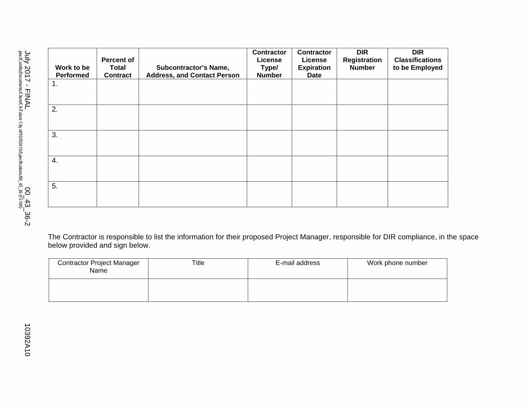
Pursuant to California Public Contract Code §4100, the Bidder shall list below the names and location of place of business of each subcontractor who will perform Work or labor or who will render service to the prime Contractor in or about the construction of the Work or improvement, or a subcontractor duly licensed who, under subcontract to the prime Contractor, specially fabricates and installs a portion of the Work or improvement according to detailed Drawings contained in the Contract Documents, in an amount in excess of 1/2 of 1 percent of the prime Contractor's total Bid or, in the case of Bids or offers for the construction of streets or highways, including bridges, in excess of 1/2 of 1 percent of the prime Contractor's total Bid or $10,000, whichever is greater. After the opening of Bids, no changes or substitutions will be allowed except as otherwise provided by law. The listing of more than one subcontractor for each item of Work to be performed with the words "and/or" will not be permitted. The Bidder's attention is directed to the provisions of paragraph 7.06.B.1 of the Supplementary Conditions, which stipulates the percent of the Work to be performed with the Bidder's own forces. Failure to comply with this requirement may render the Bid as non-responsive and may cause its rejection. Pursuant to Labor Code section 1725.5, this project is subject to compliance monitoring and enforcement by the Department of Industrial Relations. No contractor or subcontractor may be listed on a bid proposal for a public works project and no contractor or subcontractor may be awarded a contract for public work on a public works project unless registered with the Department of Industrial Relations (DIR). Each bidder is responsible to list their registered information with the DIR in the space below provided and sign below.
July 2017 - FIN
AL
00_43_36-2 10392A
10 pw
://Carollo/D
ocuments/C
lient/CA/Tulare C
ity of/10392A10/Specifications/00_43_36 (FS100)
Work to be Performed
Percent of Total
Contract Subcontractor’s Name,
Address, and Contact Person
Contractor License
Type/ Number
Contractor License
Expiration Date
DIR Registration
Number
DIR Classifications to be Employed
1.
2.
3.
4.
5.
The Contractor is responsible to list the information for their proposed Project Manager, responsible for DIR compliance, in the space below provided and sign below.
Contractor Project Manager Name
Title E-mail address Work phone number

July 2017 - FINAL 00_43_36-3 10392A10 pw://Carollo/Documents/Client/CA/Tulare City of/10392A10/Specifications/00_43_36 (FS100)
Add additional sheets, if necessary. BIDDER
(Signature)
(Date)
END OF DOCUMENT


July 2017 - FINAL 00_43_38-1 10392A10 pw://Carollo/Documents/Client/CA/Tulare City of/10392A10/Specifications/00_43_38 (FS100)
DOCUMENT 00_43_38
CONSTRUCTION EQUIPMENT LIST
Bidder shall list the equipment which will be used in the performance of the Work, including location, ownership, and how the equipment will be obtained, if not already owned or controlled by Bidder.
Number and Type
Capacity and Manufacturer
Age and Condition
Current Location
Date on Work Site

July 2017 - FINAL 00_43_38-2 10392A10 pw://Carollo/Documents/Client/CA/Tulare City of/10392A10/Specifications/00_43_38 (FS100)
BIDDER
(Signature)
(Date)
END OF DOCUMENT

July 2017 – FINAL 00_45_14.01-1 10392A10 pw://Carollo/Documents/Client/CA/Tulare City of/10392A10/Specifications/00_45_14.01 (FS100)
DOCUMENT 00_45_14.01
CONSTRUCTION CONTRACTOR’S QUALIFICATION STATEMENT
FOR ENGINEERED CONSTRUCTION
Issue Date: Effective Date:
Owner: City of Tulare Owner’s Contract No.: WT0023
Contractor:
Project: Water Storage Tank Design
Contract Name:
Qualifications Statement
THE INFORMATION SUPPLIED IN THIS DOCUMENT IS CONFIDENTIAL TO THE EXTENT PERMITTED BY LAWS AND REGULATIONS
1. FIRM INFORMATION:
Official Name of Firm:
Address:
2. TYPE OF WORK:
3. CONTRACTOR’S CONTACT INFORMATION
Contact Person;
Title:
Phone:
Email:
4. AFFILIATED COMPANIES:
Name:
Address:
5. TYPE OF ORGANIZATION:
SOLE PROPRIETORSHIP
Name of Owner:
Doing Business As:
Date of Organization:

July 2017 – FINAL 00_45_14.01-2 10392A10 pw://Carollo/Documents/Client/CA/Tulare City of/10392A10/Specifications/00_45_14.01 (FS100)
Qualifications Statement
PARTNERSHIP
Date of Organization:
Type of Partnership:
Name of General Partner(s):
CORPORATION
State of Organization:
Date of Organization:
Executive Officers:
President:
Vice President(s):
Treasurer:
Secretary:
LIMITED LIABILITY COMPANY
State of Organization:
Date of Organization:
Members:
JOINT VENTURE
State of Organization:
Date of Organization:
Form of Organization:
JV Managing Partner:
Name:
Address:
JV Managing Partner:
Name:
Address:

July 2017 – FINAL 00_45_14.01-3 10392A10 pw://Carollo/Documents/Client/CA/Tulare City of/10392A10/Specifications/00_45_14.01 (FS100)
Qualifications Statement
6. LICENSING:
Jurisdiction:
Type of License:
License Number:
Jurisdiction:
Type of License:
License Number:
7. CERTIFICATIONS CERTIFIED BY:
Disadvantaged Business Enterprise:
Minority Business Enterprise:
Woman Owned Business Enterprise:
Small Business Enterprise:
Other: ( ):
8. BONDING INFORMATION
Bonding Company:
Address:
Bonding Agent:
Address:
Contact Name:
Phone:
Aggregate Bonding Capacity:
Available Bonding Capacity as of date of this submittal:
9. FINANCIAL INFORMATION
Financial Institution:
Address:
Account Manager:
Phone:
INCLUDE AS AN ATTACHMENT AN AUDITED BALANCE SHEET FOR EACH OF THE LAST 3 YEARS.

July 2017 – FINAL 00_45_14.01-4 10392A10 pw://Carollo/Documents/Client/CA/Tulare City of/10392A10/Specifications/00_45_14.01 (FS100)
Qualifications Statement
10. CONSTRUCTION EXPERIENCE
Current Experience:
List on a Schedule A all uncompleted projects currently under contract (If Joint Venture, list each participant’s projects separately).
Bidder authorizes Owner's representative to verify any and all information contained in the Qualification Statement from references contained herein and hereby releases all those concerned providing information as a reference from any liability in connection with any information they give.
Previous Experience:
List on Schedule B all projects completed within the last 5 years (If Joint Venture, list each participant’s projects separately).
Bidder authorizes Owner's representative to verify any and all information contained in the Qualification Statement from references contained herein and hereby releases all those concerned providing information as a reference from any liability in connection with any information they give.
Key Personnel:
List on Schedule C qualifications and experience of Bidder’s key personnel who will be directly involved in this project (If Joint Venture, list each participant’s projects separately).
Bidder authorizes Owner's representative to verify any and all information contained in the Qualification Statement from references contained herein and hereby releases all those concerned providing information as a reference from any liability in connection with any information they give.
Has firm listed in Section 1 ever failed to complete a construction contract awarded to it?
Yes No
If YES, attach as an Attachment details including Project Owner’s contact information.
Has any Corporate Officer, Partner, Joint Venture participant or Proprietor ever failed to complete a construction contract awarded to them in their name or when acting as a principal of another entity?
Yes No
If YES, attach as an Attachment details including Project Owner’s contact information.
Are there any judgments, claims, disputes or litigation pending or outstanding involving the firm listed in Section 1 or any of its officers (or any of its partners if a partnership or any of the individual entities if a joint venture)?
Yes No
If YES, attach as an Attachment details including Project Owner’s contact information.

July 2017 – FINAL 00_45_14.01-5 10392A10 pw://Carollo/Documents/Client/CA/Tulare City of/10392A10/Specifications/00_45_14.01 (FS100)
Qualifications Statement
11. SAFETY PROGRAM
Name of Contractor’s Safety Officer:
Include the following as attachments:
Provide as an Attachment Contractor's (and Contractor's proposed Subcontractors and Suppliers furnishing or performing Work having a value in excess of 10 percent of the total amount of the Bid) OSHA No. 300- Log of Work-Related Injuries and Illnesses for the past 5 years.
Provide as an Attachment Contractor's (and Contractor's proposed Subcontractors and Suppliers furnishing or performing Work having a value in excess of 10 percent of the total amount of the Bid) list of all OSHA Citations & Notifications of Penalty (monetary or other) received within the last 5 years (indicate disposition as applicable) - IF NONE SO STATE.
Provide as an Attachment Contractor's (and Contractor's proposed Subcontractors and Suppliers furnishing or performing Work having a value in excess of 10 percent of the total amount of the Bid) list of all safety citations or violations under any state all received within the last 5 years (indicate disposition as applicable) - IF NONE SO STATE.
Provide the following for the firm listed in Section V (and for each proposed Subcontractor furnishing or performing Work having a value in excess of 10 percent of the total amount of the Bid) the following (attach additional sheets as necessary):
Workers' compensation Experience Modification Rate (EMR) for the last 5 years:
Year EMR
Year EMR
Year EMR
Year EMR
Year EMR
Total Recordable Frequency Rate (TRFR) for the last 5 years.
Year TRFR
Year TRFR
Year TRFR
Year TRFR
Year TRFR

July 2017 – FINAL 00_45_14.01-6 10392A10 pw://Carollo/Documents/Client/CA/Tulare City of/10392A10/Specifications/00_45_14.01 (FS100)
Qualifications Statement
Total number of man hours worked for the last 5 years.
Year TOTAL NUMBER OF MAN HOURS
Year TOTAL NUMBER OF MAN HOURS
Year TOTAL NUMBER OF MAN HOURS
Year TOTAL NUMBER OF MAN HOURS
Provide Contractor's (and Contractor's proposed Subcontractors and Suppliers furnishing or performing Work having a value in excess of 10 percent of the total amount of the Bid) Days Away From Work, Days of Restricted Work Activity or Job Transfer (DART) incidence rate for the particular industry or type of Work to be performed by Contractor and each of Contractor's proposed Subcontractors and Suppliers) for the last 5 years:
Year DART
Year DART
Year DART
Year DART
12. EQUIPMENT:
MAJOR EQUIPMENT
List on Schedule D all pieces of major equipment available for use on Owner’s Project.
I HEREBY CERTIFY THAT THE INFORMATION SUBMITTED HEREWITH, INCLUDING ANY ATTACHMENTS, IS TRUE TO THE BEST OF MY KNOWLEDGE AND BELIEF.
NAME OF ORGANIZATION:
BY:
TITLE:
DATED:

July 2017 – FINAL 00_45_14.01-7 10392A10 pw://Carollo/Documents/Client/CA/Tulare City of/10392A10/Specifications/00_45_14.01 (FS100)
Qualifications Statement
NOTARY ATTEST:
SUBSCRIBED AND SWORN TO BEFORE ME:
THIS DAY OF , 20
NOTARY PUBLIC – STATE OF
MY COMMISSION EXPIRES:
REQUIRED ATTACHMENTS
1. Schedule A (Current Experience).
2. Schedule B (Previous Experience).
3. Schedule C (Major Equipment).
4. Audited balance sheet for each of the last 3 years for firm named in Section 1.
5. Evidence of authority for individuals listed in Section 5 to bind organization to an agreement.
6. Resumes of officers and key individuals (including Safety Officer) of firm named in Section 1.
7. Required safety program submittals listed in Section 11.
8. Additional items as pertinent.
END OF SECTION


July 2017 - FINAL 00_45_19-1 10392A10 pw://Carollo/Documents/Client/CA/Tulare City of/10392A10/Specifications/00_45_19 (FS100)
DOCUMENT 00_45_19
NON-COLLUSION AFFIDAVIT
State of California ss. County of Tulare
The undersigned declares that this Bid is not made in the interest of, or on behalf of, any undisclosed person, partnership, company, association, organization, or corporation; that the Bid is genuine and not collusive or sham; that the Bidder has not directly or indirectly induced or solicited any other Bidder to put in a false or sham bid, and has not directly or indirectly colluded, conspired, connived, or agreed with any Bidder or anyone else to put in a sham bid, or that anyone shall refrain from bidding; that the Bidder has not in any manner, directly or indirectly, sought by agreement, communication, or conference with anyone to fix the bid price of the Bidder or any other Bidder, or to fix any overhead, profit, or cost element of the bid price, or of that of any other Bidder, or to secure any advantage against the public body awarding the contract of anyone interested in the proposed contract; that all statements contained in the Bid are true; and, further, that the Bidder has not, directly or indirectly, submitted his or her bid price or any breakdown thereof, or the contents thereof, or divulged information or data relative thereto, or paid, and will not pay, any fee to any corporation, partnership, company, association, organization, bid depository, or to any member or agent thereof to effectuate a collusive or sham bid.
Any person executing this declaration on behalf of a Bidder that is a corporation, partnership, joint venture, limited liability company, limited liability partnership, or any other entity herby represents that they have full power to execute, and does execute, this declaration on behalf of the Bidder.
I declare under penalty of perjury under state laws that the foregoing is true and correct.
BIDDER
(Signature)
(Date) Subscribed and sworn to before me on ___________ (date) at __________________ (location). (seal)
(Signature of Notary Public)

July 2017 - FINAL 00_45_19-2 10392A10 pw://Carollo/Documents/Client/CA/Tulare City of/10392A10/Specifications/00_45_19 (FS100)
END OF DOCUMENT

July 2017 - FINAL 00_51_00-1 10392A10 pw://Carollo/Documents/Client/CA/Tulare City of/10392A10/Specifications/00_51_00 (FS100)
DOCUMENT 00_51_00
NOTICE OF AWARD
Issue Date: MM/DD/YYYY Owner’s Contract No.: Enter Contract No.
Owner: City of Tulare Contractor’s Project No.:
Engineer: Carollo Engineer, Inc.
Project: Water Storage Tank Improvements Project
Bidder: Click here to enter text.
Bidder’s Address:: Click here to enter text.
Notice of Award To Bidder
You are notified that Owner has accepted your Bid dated , 2017, for the above Contract, and that you are the Successful Bidder and are awarded a contract for:
Construction of a 2 million gallon (MG) water storage tank, well, electrical building, booster pump station, standby generator, and associated appurtenances at both the J Street and Alpine Vista project sites.
(describe Work awarded)
The Contract Price of the awarded Contract is: $
Two unexecuted counterparts of the Document 00_52_00 - Agreement accompany this Notice of Award, and the Contract Documents have been made available to Bidder electronically.
You must comply with the following conditions precedent within 15 days of the date of receipt of this Notice of Award:
1. Deliver to Owner two counterparts of the Agreement, fully executed by Bidder.
2. Deliver with the executed Agreement(s) the Contract security [e.g., performance and payment bonds] and insurance documentation as specified in the Instructions to Bidders and General Conditions, Articles 2 and 6.
3. Other conditions precedent (if any):
Failure to comply with these conditions within the time specified will entitle Owner to consider you in default, annul this Notice of Award, and declare your Bid security forfeited.
Within ten days after you comply with the above conditions, Owner will return to you one fully executed counterpart of the Agreement, together with any additional copies of the Contract Documents as indicated in Paragraph 2.02 of the General Conditions.
Owner:
Authorized Signature:
By: Title:
Copy: Engineer

July 2017 - FINAL 00_51_00-2 10392A10 pw://Carollo/Documents/Client/CA/Tulare City of/10392A10/Specifications/00_51_00 (FS100)
END OF DOCUMENT

July 2017 - FINAL 00_52_00-1 10392A10 pw://Carollo/Documents/Client/CA/Tulare City of/10392A10/Specifications/00_52_00 (FS100)
DOCUMENT 00_52_00
AGREEMENT
THIS AGREEMENT is by and between the City of Tulare (Owner) and (Contractor).
Owner and Contractor hereby agree as follows:
ARTICLE 1 - WORK
1.01 Contractor shall complete all Work as specified or indicated in the Contract Documents The Work is generally described as follows:
ARTICLE 2 - THE PROJECT
2.01 The Project, of which the Work under the Contract Documents is a part, is generally described as follows: Construction of a 2 million gallon (MG) water storage tank, well, electrical building, booster pump station, standby generator, and associated appurtenances at both the J Street and Alpine Vista project sites.
ARTICLE 3 - ENGINEER
3.01 The Project has been designed by Carollo Engineers, Inc.
3.02 The Owner has retained Carollo Engineers, Inc. (“Engineer”) to act as Owner's representative, assume all duties and responsibilities, and have the rights and authority assigned to Engineer in the Contract Documents in connection with the completion of the Work in accordance with the Contract Documents.
ARTICLE 4 - CONTRACT TIMES
4.01 Time of the essence:
A. All time limits for Milestones, if any, Substantial Completion, and completion and readiness for final payment as stated in the Contract Documents are of the essence of the Contract.
4.02 Contract Times: Days:
A. The Work will be substantially completed within 240 days after the date when the Contract Times commence to run as provided in paragraph 4.01 of the General Conditions, and completed and ready for final payment in accordance with paragraph 15.06 of the General Conditions within 260 days after the date when the Contract Times commence to run.

July 2017 - FINAL 00_52_00-2 10392A10 pw://Carollo/Documents/Client/CA/Tulare City of/10392A10/Specifications/00_52_00 (FS100)
4.03 Liquidated damages:
A. Contractor and Owner recognize that time is of the essence as stated in t above and that Owner will suffer financial and other losses if the Work is not completed and Milestones not achieved within the times specified in Paragraph 4.02 above, plus any extensions thereof allowed in accordance with the Contract. The parties also recognize the delays, expense, and difficulties involved in proving in a legal or arbitration proceeding the actual loss suffered by Owner if the Work is not completed on time. Accordingly, instead of requiring any such proof, Owner and Contractor agree that as liquidated damages for delay (but not as a penalty): 1. Substantial Completion: Contractor shall pay Owner $1,500 for each day that expires
after the time (as duly adjusted pursuant to the Contract) specified in this Agreement for Substantial Completion until the Work is substantially complete.
2. Completion of Remaining Work: After substantial completion, if Contractor shall neglect, refuse, or fail to complete the remaining Work within the Contract Time (as duly adjusted pursuant to the Contract) for completion and readiness for final payment, Contractor shall pay Owner $1,500 for each day that expires after such time until the Work is completed and ready for final payment.
3. Liquidated damages for failing to timely attain Substantial Completion and final completion are not additive and will not be imposed concurrently.
4.04 Special Damages:
A. In addition to the amount provided for liquidated damages, Contractor shall reimburse Owner: 1. for any fines or penalties imposed on Owner as a direct result of the Contractor’s
failure to attain Substantial Completion according to the Contract Times, and 2. for the actual costs reasonably incurred by Owner for engineering, construction
observation, inspection, and administrative services needed after the time specified in this Agreement for Substantial Completion (as duly adjusted pursuant to the Contract), until the Work is substantially complete.
B. After Contractor achieves Substantial Completion, if Contractor shall neglect, refuse, or fail to complete the remaining Work within the Contract Times, Contractor shall reimburse Owner for the actual costs reasonably incurred by Owner for engineering, construction observation, inspection, and administrative services needed after the time specified in this Agreement for Work to be completed and ready for final payment (as duly adjusted pursuant to the Contract), until the Work is completed and ready for final payment.
ARTICLE 5 - CONTRACT PRICE
5.01 Owner shall pay Contractor for completion of the Work in accordance with the Contract Documents the amounts that follow, subject to adjustment under the Contract:
A. For all Work, a lump sum of:
$
(figure)

July 2017 - FINAL 00_52_00-3 10392A10 pw://Carollo/Documents/Client/CA/Tulare City of/10392A10/Specifications/00_52_00 (FS100)
ARTICLE 6 - PAYMENT PROCEDURES
6.01 Submittal and processing of payments:
A. Contractor shall submit Applications for Payment in accordance with Article 15 of the General Conditions. Applications for Payment will be processed by Construction Manager as provided in the General Conditions.
6.02 Progress payments; retainage:
A. Pursuant to Section 20104.50 of California Public Contract Code, Owner shall make progress payments on account of the Contract Price on the basis of Contractor's Applications for Payment within 30 days after receipt during performance of the Work as provided in paragraphs below, provided that such Applications for Payment have been submitted in a timely manner and otherwise meet the requirements of the Contract. All such payments will be measured by the Schedule of Values established as provided in the General Conditions (and in the case of Unit Price Work based on the number of units completed) or, in the event there is no Schedule of Values, as provided elsewhere in the Contract: 1. Pursuant to Section 22300 of California Public Contract Code, Contractor has the
option to deposit securities with an Escrow Agent as a substitute for retention of earnings required to be withheld by Owner. For Escrow Agreement see Document 00_54_03 - Escrow Agreement for Security Deposits in Lieu of Retention - California, Public Contract Code §22300.
2. Prior to Substantial Completion, progress payments will be made in an amount equal to the percentage indicated below but, in each case, less the aggregate of payments previously made and less such amounts as Owner may withhold, including but not limited to liquidated damages, in accordance with the Contract: a. 95 percent of Work completed (with the balance being retainage), pursuant to
California Public Contract Code §7201. If the Work has been 50 percent completed as determined by Engineer, and if the character and progress of the Work have been satisfactory to Owner and Engineer, then as long as the character and progress of the Work remain satisfactory to Owner and Engineer, there will be no additional retainage.
3. Upon Substantial Completion, Owner shall pay an amount sufficient to increase total payments to Contractor to 100 percent of the Work completed, less such amounts set off by Owner pursuant to Paragraph 15.01 of the General Conditions and less 200 percent of Engineer's estimate of the value of Work to be completed or corrected as shown on the punch list of items to be completed or corrected prior to final payment.
6.03 Final Payment:
A. Upon final completion and acceptance of the Work, in accordance with paragraph 15.06 of the General Conditions, Owner shall pay the remainder of the Contract Price as recommended by Engineer.
ARTICLE 7 - INTEREST
7.01 All amounts not paid when due shall bear interest at the legal rate unless otherwise specified according to California law.

July 2017 - FINAL 00_52_00-4 10392A10 pw://Carollo/Documents/Client/CA/Tulare City of/10392A10/Specifications/00_52_00 (FS100)
ARTICLE 8 - CONTRACTOR'S REPRESENTATIONS
8.01 In order to induce Owner to enter into this Agreement, Contractor makes the following representations:
A. Contractor has examined and carefully studied the Contract Documents and any data and reference items identified in the Bidding Documents.
B. Contractor has visited the Site, conducted a thorough, alert visual examination of the Site and adjacent areas, and become familiar with and is satisfied as to the general, local, and Site conditions that may affect cost, progress, and performance of the Work.
C. Contractor is familiar with and is satisfied as to all federal, state, and local Laws and Regulations that may affect cost, progress, and performance of the Work.
D. Contractor has carefully studied all: 1. Reports of explorations and tests of subsurface conditions at or adjacent to the Site
and all drawings of physical conditions in or relating to existing surface or subsurface structures at the Site that have been identified in the Supplementary Conditions, especially with respect to Technical Data in such reports and drawings.
E. Contractor has considered the information known to Contractor itself; information commonly known to contractors doing business in the locality of the Site; information and observations obtained from visits to the Site; the Contract Documents; and the Site-related reports and drawings identified in the Contract Documents, with respect to the effect of such information, observations, and documents on: 1. The cost, progress, and performance of the Work. 2. The means, methods, techniques, sequences, and procedures of construction to be
employed by Contractor, and 3. Contractor’s safety precautions and programs.
F. Based on the information and observations referred to in the preceding paragraph, Contractor agrees that no further examinations, investigations, explorations, tests, studies, or data are necessary for the performance of the Work at the Contract Price, within the Contract Times, and in accordance with the other terms and conditions of the Contract.
G. Contractor is aware of the general nature of work to be performed by Owner and others at the Site that relates to the Work as indicated in the Contract Documents.
H. Contractor has given Engineer written notice of all conflicts, errors, ambiguities, or discrepancies that Contractor has discovered in the Contract Documents, and the written resolution thereof by Engineer is acceptable to Contractor.
I. The Contract Documents are generally sufficient to indicate and convey understanding of all terms and conditions for performance and furnishing of the Work.
J. Contractor’s entry into this Contract constitutes an incontrovertible representation by Contractor that without exception, all prices in the Agreement are premised upon performing and furnishing the Work required by the Contract Documents.

July 2017 - FINAL 00_52_00-5 10392A10 pw://Carollo/Documents/Client/CA/Tulare City of/10392A10/Specifications/00_52_00 (FS100)
ARTICLE 9 - CONTRACT DOCUMENTS
9.01 Contents:
A. The Contract Documents consist of the following: 1. Document 00_52_00 - Agreement. 2. Document 00_61_14 - Performance Bond. 3. Document 00_61_15 - Payment Bond. 4. Document 00_72_00 - General Conditions. 5. Document 00_73_00 - Supplementary Conditions. 6. Specifications as listed in the table of contents of the Project Manual. 7. Drawings as listed on the sheet index. 8. Addenda (numbers _________ to ________, inclusive). 9. Exhibits to this Agreement (enumerated as follows):
a. Document 00_41_00 - Bid Form completed by the Contractor. 10. The following which may be delivered or issued on or after the Effective Date of the
Agreement and are not attached hereto: a. Document 00_55_00 - Notice to Proceed. b. Document 00_63_36 - Field Orders. c. Document 00_63_49 - Work Change Directives. d. Document 00_63_63 - Change Orders.
B. There are no Contract Documents other than those listed in this Document.
C. The Contract Documents may only be amended, modified, or supplemented as provided in paragraph 3.04 of the General Conditions.
ARTICLE 10 - MISCELLANEOUS
10.01 Terms:
A. Terms used in this Agreement will have the meanings indicated in the General Conditions and the Supplementary Conditions.
10.02 Assignment of Contract:
A. No assignment by a party hereto of any rights under or interests in the Contract will be binding on another party hereto without the written consent of the party sought to be bound; and, specifically but without limitation, money that may become due and money that is due may not be assigned without such consent (except to the extent that the effect of this restriction may be limited by law), and unless specifically stated to the contrary in any written consent to an assignment, no assignment will release or discharge the assignor from any duty or responsibility under the Contract Documents.
10.03 Successors and Assigns:
A. Owner and Contractor each binds itself, its successors, assigns, and legal representatives to the other party hereto, its successors, assigns, and legal representatives in respect to all covenants, agreements, and obligations contained in the Contract Documents.

July 2017 - FINAL 00_52_00-6 10392A10 pw://Carollo/Documents/Client/CA/Tulare City of/10392A10/Specifications/00_52_00 (FS100)
10.04 Severability:
A. Any provision or part of the Contract Documents held to be void or unenforceable under any Law or Regulation shall be deemed stricken, and all remaining provisions shall continue to be valid and binding upon Owner and Contractor, who agree that the Contract Documents shall be reformed to replace such stricken provision or part thereof with a valid and enforceable provision that comes as close as possible to expressing the intention of the stricken provision.
10.05 Contractor’s Certifications:
A. Contractor certifies that it has not engaged in corrupt, fraudulent, collusive, or coercive practices in competing for or in executing the Contract. 1. “Corrupt practice” means the offering, giving, receiving, or soliciting of anything of
value likely to influence the action of a public official in the bidding process or in the Contract execution.
2. “Fraudulent practice” means an intentional misrepresentation of facts made: a. To influence the bidding process or the execution of the Contract to the detriment
of Owner. b. To establish Bid or Contract prices at artificial non-competitive levels. c. To deprive Owner of the benefits of free and open competition.
3. “Collusive practice” means a scheme or arrangement between 2 or more Bidders, with or without the knowledge of Owner, a purpose of which is to establish Bid prices at artificial, non-competitive levels.
4. “Coercive practice” means harming or threatening to harm, directly or indirectly, persons or their property to influence their participation in the bidding process or affect the execution of the Contract.
10.06 In accordance with Section 1775, California Labor Code, Contractor shall forfeit to Owner, as a penalty, not more than $50 for each calendar day, or portion thereof, for each worker paid, either by Contractor or any subcontractor, less than the prevailing rates as determined by the Director of California Department of Industrial Relations for the Work.
10.07 In the performance of the Work, a day’s work shall be 8 hours of labor in any workday and 40 hours in any work week and any other work as required by Section 510, California Labor Code, and Contractor shall further conform to the requirements of Section 1813, California Labor Code, or forfeit to Owner, as a penalty, the sum of $25 for each worker employed in the execution of the Work by Contractor or any subcontractor, for each day during which any worker is required or permitted to labor more than 8 hours in any workday or more than 40 hours in any 1 calendar week in violation of Section 510.
10.08 Contractor shall carry workers' compensation insurance and require subcontractors to carry workers' compensation insurance as required by Section 3700, California Labor Code.
10.09 Pursuant to California Labor Code Section 6705, excavation of any trench or trenches 5 feet or more in depth, involving estimated expenditures in excess of $25,000 shall require, in advance of excavation, a detailed plan showing the design of shoring, bracing, sloping or other provisions to be made for worker protection prepared by a registered civil or structural engineer.

July 2017 - FINAL 00_52_00-7 10392A10 pw://Carollo/Documents/Client/CA/Tulare City of/10392A10/Specifications/00_52_00 (FS100)
10.10 Contractor registration:
A. Project is subject to compliance monitoring and enforcement by the California Department of Industrial Relations (DIR).
10.11 Pursuant to Section 1770 et seq., California Labor Code, the successful Bidder shall pay not less than the prevailing rate of per diem wages as determined by the Director of California Department of Industrial Relations. A copy of such prevailing rate is on file at the offices of the Owner, which copy will be made available for examination during business hours to any party on request.
10.12 Contractor, by signing this Agreement, certifies the following: "I am aware of the provisions of Section 3700 of the Labor Code which require every employer to be insured against liability for workers' compensation or to undertake self-insurance in accordance with the provisions of that code, and I will comply with such provisions before commencing the performance of the Work of this Contract."
10.13 Nothing in this Agreement shall prevent Contractor or any Subcontractor from employing properly registered apprentices in the execution of the Agreement. Contractor shall have responsibility for compliance with California Labor Code Section 1777.5 for all apprenticeable occupations.
10.14 Other Provisions
A. Owner stipulates that if the General Conditions that are made a part of this Contract are based on EJCDC® C-700, Standard General Conditions for the Construction Contract, published by the Engineers Joint Contract Documents Committee®, and if Owner is the party that has furnished said General Conditions, then Owner has plainly shown all modifications to the standard wording of such published document to the Contractor, in the Supplementary Conditions.

July 2017 - FINAL 00_52_00-8 10392A10 pw://Carollo/Documents/Client/CA/Tulare City of/10392A10/Specifications/00_52_00 (FS100)
IN WITNESS WHEREOF, Owner and Contractor have signed this Agreement in duplicate. One counterpart each has been delivered to Owner and Contractor. All portions of the Contract Documents have been signed or identified by Owner and Contractor or on their behalf. This Agreement will be effective on _________________________, 2017 (which is the Effective Date of the Agreement).
Owner:
Contractor:
By: By: Title: Title:
(If Contractor is a corporation, a partnership, or a joint venture, attach evidence of authority to sign.)
Attest: Attest: Title: Title: Address for giving notices: Address for giving notices:
License No.
(If Owner is a corporation, attach evidence of authority to sign. If Owner is a public body, attach evidence of authority to sign and resolution or other documents authorizing execution of this Agreement.)
(Where applicable)
July 2017 - FINAL 00_52_00-9 10392A10 pw://Carollo/Documents/Client/CA/Tulare City of/10392A10/Specifications/00_52_00 (FS100)
Agent for service of process:
Designated Representative: Designated Representative: Name: Name: Title: Title: Address: Address:
Phone: Phone:
END OF DOCUMENT


July 2017 - FINAL 00_54_03-1 10392A10 pw://Carollo/Documents/Client/CA/Tulare City of/10392A10/Specifications/00_54_03 (FS100)
DOCUMENT 00_54_03
ESCROW AGREEMENT FOR SECURITY DEPOSITS IN LIEU OF RETENTION - CALIFORNIA,
PUBLIC CONTRACT CODE §22300
This escrow agreement is made and entered into by and between City of Tulare whose address is 411 East Kern Avenue, Tulare, California, 93274 hereinafter called “Owner,” whose address is hereinafter called “Contractor,” and whose address is hereinafter called “Escrow Agent.”
For the consideration hereinafter set forth, the Owner, Contractor, and Escrow Agent agree as follows:
1. Pursuant to Section 22300 of the Public Contract Code of the State of California, the Contractor has the option to deposit securities with the Escrow Agent as a substitute for retention earnings required to be withheld by the Owner pursuant to the construction contract entered into between the Owner and Contractor for __FILL-IN__ in the amount of __FILL-IN__ dated __FILL-IN__ (hereafter referred to as the "contract"). Alternatively, on written request of the Contractor, the Owner shall make payments of the retention earnings directly to the Escrow Agent. When the Contractor deposits the securities as a substitute for the contract earnings, the Escrow Agent shall notify the Owner within ten days of the deposit. The market value of the securities at the time of the substitution shall be at least equal to the cash amount then required to be withheld as retention under the terms of the contract between the Owner and Contractor. Securities shall be held in the name of the __FILL-IN__ and shall designate the Contractor as the beneficial owner.
2. The Owner shall make progress payments to the Contractor for those funds which otherwise would be withheld from progress payments pursuant to the contract provisions, provided that the Escrow Agent holds securities in the form and amount specified above.
3. When the Owner makes payment of retentions earned directly to the Escrow Agent, the Escrow Agent shall hold them for the benefit of the Contractor until such time as the escrow created under this contract is terminated. The Contractor may direct the investment of the payments into securities. All terms and conditions of this Agreement and the rights and responsibilities of the parties shall be equally applicable and binding when the Owner pays the Escrow Agent directly.
4. Contractor shall be responsible for paying all fees for the expenses incurred by the Escrow Agent in administering the escrow account and all expenses of the Owner. These expenses and payment terms shall be determined by the Owner, Contractor, and Escrow Agent.
5. The interest earned on the securities or the money market accounts held in escrow and all interest earned on that interest shall be for the sole account of Contractor and shall be subject to withdrawal by Contractor at any time and from time to time without notice to the Owner.

July 2017 - FINAL 00_54_03-2 10392A10 pw://Carollo/Documents/Client/CA/Tulare City of/10392A10/Specifications/00_54_03 (FS100)
6. Contractor shall have the right to withdraw all or any part of the principal in the escrow account only by written notice to Escrow Agent accompanied by written authorization from the Owner to the Escrow Agent that the Owner consents to the withdrawal of the amount sought to be withdrawn by Contractor.
7. The Owner shall have a right to draw upon the securities in the event of default by the Contractor. Upon seven days' written notice to the Escrow Agent from the Owner of the default, the Escrow Agent shall immediately convert the securities to cash and shall distribute the cash as instructed by the Owner.
8. Upon receipt of written notification from the Owner certifying that the contract is final and complete, and that the Contractor has complied with all requirements and procedures applicable to the contract, the Escrow Agent shall release to the Contractor all securities and interest on deposit less escrow fees and charges of the escrow account. The escrow shall be closed immediately upon disbursement of all moneys and securities on deposit and payments of fees and charges.
9. Escrow Agent shall rely on the written notifications from the Owner and the Contractor pursuant to Sections (5) to (8), inclusive, of this Agreement and the Owner and Contractor shall hold Escrow Agent harmless from the Escrow Agent's release, and disbursement of the securities and interest as set forth above.
10. The names of the persons who are authorized to give written notice or to receive written notice on behalf of the Owner and on behalf of the Contractor in connection with the foregoing, and exemplars of their respective signatures are as follows:
On behalf of the Owner: On behalf of the Contractor:
Title Title
Name Name
Signature Signature
Address Address

July 2017 - FINAL 00_54_03-3 10392A10 pw://Carollo/Documents/Client/CA/Tulare City of/10392A10/Specifications/00_54_03 (FS100)
On behalf of the Escrow Agent:
Title
Name
Signature
Address
At the time the escrow account is opened, the Owner and Contractor shall deliver to the Escrow Agent a fully executed counterpart of this Agreement.
IN WITNESS WHEREOF, the parties have executed this Agreement by their proper officers on the date first set forth above. Owner Contractor
Title Title
Name Name
Signature Signature
END OF DOCUMENT


July 2017 - FINAL 00_55_00-1 10392A10 pw://Carollo/Documents/Client/CA/Tulare City of/10392A10/Specifications/00_55_00 (FS100)
DOCUMENT 00_55_00
NOTICE TO PROCEED
Owner: City of Tulare
Owner’s Contract No.: Click here to enter text. Effective Date of Contract: Click here to enter a date.
Contractor: Click here to enter text. Contractor’s Project No.: Click here to enter text.
Project Name: Water Storage Tank Improvements Project
Contract Name: Click here to enter text.
Engineer: Carollo Engineers, Inc. Engineer’s Project No.: 10392A.20
To Contractor
Owner hereby notifies Contractor that the Contract Times under the above Contract will commence to run on Enter Notice To Proceed Date.
On that date, Contractor shall start performing its obligations under the Contract Documents. No Work shall be done at the Site prior to such date. In accordance with the Contract, the number of days to achieve Substantial Completion is 240, and the number of days to achieve readiness for final payment is 260.
Before starting any Work at the Site, Contractor must comply with the following:
Submit a Construction Safety Plan in accordance with Section 01_35_22 (Safety Plan)
Owner Authorized Signature:
Printed Name:
Title:
Date Issued:
END OF DOCUMENT
Copy: Engineer


July 2017 - FINAL 00_61_14-1 10392A10 pw://Carollo/Documents/Client/CA/Tulare City of/10392A10/Specifications/00_61_14 (FS100)
DOCUMENT 00_61_14
PERFORMANCE BOND
CONTRACTOR (Name and Address): SURETY (Name and Address of Principal Place of Business): OWNER (Name and Address): City of Tulare 411 East Kern Avenue, Tulare, California, 93274
CONSTRUCTION CONTRACT
Effective Date of Agreement: Amount: Description (Name and Location):
BOND
Bond Number: Date (Not earlier than Effective Date of Agreement): Amount: Modifications to this Bond Form:

July 2017 - FINAL 00_61_14-2 10392A10 pw://Carollo/Documents/Client/CA/Tulare City of/10392A10/Specifications/00_61_14 (FS100)
Surety and Contractor, intending to be legally bound hereby, subject to the terms set forth below, do each cause this Performance Bond to be duly executed by an authorized officer, agent, or representative. CONTRACTOR AS PRINCIPAL SURETY
(SEAL)
Contractor’s Name Surety’s Name and Corporate Seal By: By: Signature Signature (Attach Power of Attorney) Print Name Print Name Title Title Attest: Attest: Signature Signature Title Title Notes: (1) Provide execution by any additional parties, such as joint venturers, if necessary. (2) Any singular reference to Contractor, Surety, Owner, or other party shall be considered plural where applicable.

July 2017 - FINAL 00_61_14-3 10392A10 pw://Carollo/Documents/Client/CA/Tulare City of/10392A10/Specifications/00_61_14 (FS100)
Whereas, the City Council of the City of Tulare, State of California, and __________ (hereinafter designated as "Principal") have entered into an Agreement whereby Principal agrees to install and complete certain designated public improvements, which said Agreement, dated __________, 2017, and identified as Water Storage Tank Improvements Project, is hereby referred to and made a part hereof; and
Whereas, said Principal is required under the terms of said Agreement to furnish a bond for the faithful performance of said Agreement.
Now, therefore, we, the Principal and __________, as Surety, are held and firmly bound unto the City of Tulare (hereinafter called "__________"), in the penal sum of __________ dollars ($____) lawful money of the United States, for the payment of which sum well and truly to be made, we bind ourselves, our heirs, successors, executors and administrators, jointly and severally, firmly by these presents.
The condition of this obligation is such that if the above bounded Principal, his or its heirs, executors, administrators, successors or assigns, shall in all things stand to and abide by, and well and truly keep and perform the covenants, conditions and provisions in the said Agreement and any alteration thereof made as therein provided, on his or their part, to be kept and performed at the time and in the manner therein specified, and in all respects according to their true intent and meaning, and shall indemnify and save harmless __________, its officers, agents, employees, and professional consultants, as therein stipulated, then this obligation shall become null and void; otherwise it shall be and remain in full force and effect.
As a part of the obligation secured hereby and in addition to the face amount specified therefor, there shall be included costs and reasonable expenses and fees, including reasonable attorney's fees, incurred by City in successfully enforcing such obligation, all to be taxed as costs and included in any judgment rendered, including a sum to complete construction according to the Contract Documents.
The Surety hereby stipulates and agrees that no change, extension of time, alteration or addition to the terms of the Agreement or to the Work to be performed thereunder or the Specifications accompanying the same shall in anywise affect its obligations on this bond, and it does hereby waive notice of any such change, extension of time, alteration or addition to the terms of the Agreement or to the Work or to the Specifications.
In witness whereof, this instrument has been duly executed by the Principal and Surety above named, on __________, 2017.
FOR INFORMATION ONLY — (Name, Address and Telephone)
Surety Agency or Broker:
Owner’s Representative (Engineer or other party):
END OF SECTION


July 2017 - FINAL 00_61_15-1 10392A10 pw://Carollo/Documents/Client/CA/Tulare City of/10392A10/Specifications/00_61_15 (FS100)
DOCUMENT 00_61_15
PAYMENT BOND
CONTRACTOR (Name and Address): SURETY (Name and Address of Principal Place of Business): OWNER (Name and Address): City of Tulare 411 East Kern Avenue, Tulare, California 93274
CONTRACT
Effective Date of Agreement: Amount: Description (Name and Location):
BOND
Bond Number: Date (Not earlier than Effective Date of Agreement): Amount: Modifications to this Bond Form:

July 2017 - FINAL 00_61_15-2 10392A10 pw://Carollo/Documents/Client/CA/Tulare City of/10392A10/Specifications/00_61_15 (FS100)
Surety and Contractor, intending to be legally bound hereby, subject to the terms set forth below, do each cause this Payment Bond to be duly executed by an authorized officer, agent, or representative. CONTRACTOR AS PRINCIPAL SURETY
(SEAL)
Contractor’s Name Surety’s Name and Corporate Seal By: By: Signature Signature (Attach Power of Attorney) Print Name Print Name Title Title Attest: Attest: Signature Signature Title Title Note: (1) Provide execution by any additional parties, such as joint venturers, if necessary.
_____(2)_Any singular reference to Contractor, Surety, Owner or other party shall be considered plural where applicable._____

July 2017 - FINAL 00_61_15-3 10392A10 pw://Carollo/Documents/Client/CA/Tulare City of/10392A10/Specifications/00_61_15 (FS100)
1. Contractor and Surety, jointly and severally, bind themselves, their heirs, executors, administrators, successors and assigns to Owner to pay for labor, materials, and equipment furnished by Claimants for use in the performance of the Contract, which is incorporated herein by reference.
2. With respect to Owner, this obligation shall be null and void if Contractor:
2.1 Promptly makes payment, directly or indirectly, for all sums due Claimants, and
2.2 Defends, indemnifies, and holds harmless Owner from all claims, demands, liens, or suits alleging non-payment by Contractor by any person or entity who furnished labor, materials, or equipment for use in the performance of the Contract, provided Owner has promptly notified Contractor and Surety (at the address described in Paragraph 12) of any claims, demands, liens, or suits and tendered defense of such claims, demands, liens, or suits to Contractor and Surety, and provided there is no Owner Default.
3. With respect to Claimants, this obligation shall be null and void if Contractor promptly makes payment, directly or indirectly, for all sums due.
4. Surety shall have no obligation to Claimants under this Bond until:
4.1 Claimants who are employed by or have a direct contract with Contractor have given notice to Surety (at the address described in Paragraph 12) and sent a copy, or notice thereof, to Owner, stating that a claim is being made under this Bond and, with substantial accuracy, the amount of the claim.
4.2 Claimants who do not have a direct contract with Contractor:
1. Have furnished written notice to Contractor and sent a copy, or notice thereof, to Owner, within 90 days after having last performed labor or last furnished materials or equipment included in the claim stating, with substantial accuracy, the amount of the claim and the name of the party to whom the materials or equipment were furnished or supplied, or for whom the labor was done or performed; and
2. Have either received a rejection in whole or in part from Contractor, or not received within 30 days of furnishing the above notice any communication from Contractor by which Contractor has indicated the claim will be paid directly or indirectly; and
3. Not having been paid within the above 30 days, have sent a written notice to Surety (at the address described in Paragraph 12) and sent a copy, or notice thereof, to Owner, stating that a claim is being made under this Bond and enclosing a copy of the previous written notice furnished to Contractor.
5. If a notice by Claimant required by Paragraph 4 is provided by Owner to Contractor or to Surety, that is sufficient compliance.
6. Reserved.
7. Surety's total obligation shall not exceed the amount of this Bond, and the amount of this Bond shall be credited for any payments made in good faith by Surety.
8. Amounts owed by Owner to Contractor under the Contract shall be used for the performance of the Contract and to satisfy claims, if any, under any performance bond. By

July 2017 - FINAL 00_61_15-4 10392A10 pw://Carollo/Documents/Client/CA/Tulare City of/10392A10/Specifications/00_61_15 (FS100)
Contractor furnishing and Owner accepting this Bond, they agree that all funds earned by Contractor in the performance of the Contract are dedicated to satisfy obligations of Contractor and Surety under this Bond, subject to Owner's priority to use the funds for the completion of the Work.
9. Surety shall not be liable to Owner, Claimants, or others for obligations of Contractor that are unrelated to the Contract. Owner shall not be liable for payment of any costs or expenses of any Claimant under this Bond, and shall have under this Bond no obligations to make payments to, give notices on behalf of, or otherwise have obligations to Claimants under this Bond.
10. Surety hereby waives notice of any change, including changes of time, to the Contract or to related subcontracts, purchase orders, and other obligations.
11. No suit or action shall be commenced by a Claimant under this Bond other than in a court of competent jurisdiction in the location in which the Work or part of the Work is located or after the expiration of one year from the date (1) on which the Claimant gave the notice required by Paragraph 4.1 or Paragraph 4.2.3, or (2) on which the last labor or service was performed by anyone or the last materials or equipment were furnished by anyone or the last materials or equipment were furnished by anyone under the Contract, whichever of (1) or (2) first occurs. If the provisions of this paragraph are void or prohibited by law, the minimum period of limitation available to sureties as a defense in the jurisdiction of the suit shall be applicable.
12. Notice to Surety, Owner or Contractor shall be mailed or delivered to the addresses shown on the signature page. Actual receipt of notice by Surety, Owner or Contractor, however accomplished, shall be sufficient compliance as of the date received at the address shown on the signature page.
13. When this Bond has been furnished to comply with a statutory requirement in the location where the Contract was to be performed, any provision in this Bond conflicting with said statutory requirement shall be deemed deleted herefrom and provisions conforming to such statutory requirement shall be deemed incorporated herein. The intent is that this Bond shall be construed as a statutory Bond and not as a common law bond.
14. Upon request by any person or entity appearing to be a potential beneficiary of this Bond, Contractor shall promptly furnish a copy of this Bond or shall permit a copy to be made.
15. Definitions.
15.1 Claimant: An individual or entity having a direct contract with Contractor or with a first-tier subcontractor of Contractor to furnish labor, materials, or equipment for use in the performance of the Contract. The intent of this Bond shall be to include without limitation in the terms “labor, materials or equipment” that part of water, gas, power, light, heat, oil, gasoline, telephone service or rental equipment used in the Contract, architectural and engineering services required for performance of the Work of Contractor and Contractor's subcontractors, and all other items for which a mechanic's lien may be asserted in the jurisdiction where the labor, materials, or equipment were furnished.
15.2 Contract: The agreement between Owner and Contractor identified on the signature page, including all Contract Documents and changes thereto.

July 2017 - FINAL 00_61_15-5 10392A10 pw://Carollo/Documents/Client/CA/Tulare City of/10392A10/Specifications/00_61_15 (FS100)
15.3 Owner Default: Failure of Owner, which has neither been remedied nor waived, to pay Contractor as required by the Contract or to perform and complete or otherwise comply with the other terms thereof.
FOR INFORMATION ONLY — (Name, Address, and Telephone)
Surety Agency or Broker:
Owner’s Representative (Engineer or other):
END OF SECTION


Owner: City of Tulare
Application Period:Contractor: Contractor's Project No.:
Project Name: Water Storage Tank Improvements Project
Contract Name:
Engineer's Project No: 10392A.20
1. ORIGINAL CONTRACT PRICE............................................................. $
2. Net change by Change Orders................................................................... $
3. Current Contract Price (Line 1 ± 2).......................................................... $
4. TOTAL COMPLETED AND STORED TO DATE
(Column F total on Progress Estimates)................................................... $
5. RETAINAGE:a. X $0.00 Work Completed.......... $
b. 0% X $0.00 Stored Material............ $
c. Total Retainage (Line 5.a + Line 5.b).............................. $
6. AMOUNT ELIGIBLE TO DATE (Line 4 - Line 5.c).............................. $
7. LESS PREVIOUS PAYMENTS (Line 6 from prior Application)......... $
8. AMOUNT DUE THIS APPLICATION................................................... $
9. BALANCE TO FINISH, PLUS RETAINAGE $ (Column G total on Progress Estimates + Line 5.c above)....................... $
Contractor's Certification
Payment of: $
is recommended by:
Payment of: $
is approved by:
Contractor Signature
By: Date: Approved by:
(1) All previous progress payments received from Owner on account of Work done under the Contract have been applied on account to discharge Contractor's legitimate obligations incurred in connection with the Work covered by prior Applications for Payment;
(Owner) (Date)
(3) All the Work covered by this Application for Payment is in accordance with the Contract Documents and is not defective.
(Line 8 or other - attach explanation of the other amount)
Document 00_62_77Contractor's Application for Payment
Funding or Financing Entity (if applicable) (Date)
$0.00
The undersigned Contractor certifies, to the best of its knowledge, the following:
$0.00
([Engineer] [Construction Manager]) (Date)
TOTALS $0.00 $0.00 $0.00
NET CHANGE BY $0.00CHANGE ORDERS
(2) Title to all Work, materials and equipment incorporated in said Work, or otherwise listed in or covered by this Application for Payment, will pass to Owner at time of payment free and clear of all Liens, security interests, and encumbrances (except such as are covered by a bond acceptable to Owner indemnifying Owner against any such Liens, security interest, or encumbrances); and
(Line 8 or other - attach explanation of the other amount)
$0.00
$0.00
$0.00
$0.00
Number Additions Deductions $0.00
$0.00
Contractor's Application for Payment No.
Change Order Summary
Approved Change Orders
Application Date:
Application for Payment
Construction Manager: XXX
Owner's Contract No.: XXX
July 2017 ‐ FINAL00_62_77.xlsx 00_62_77 ‐ 1 10392A10


July 2017 - FINAL 00_63_36-1 10392A10 pw://Carollo/Documents/Client/CA/Tulare City of/10392A10/Specifications/00_63_36 (FS100)
DOCUMENT 00_63_36
FIELD ORDER
Issue Date: MM/DD/YYYY Effective Date: MM/DD/YYYY.
Owner: City of Tulare Owner’s Contract No.:
Enter Contract No.
Contractor: Click here to enter text. Contractor’s Project No.: Enter ##
Engineer: Carollo Engineers, Inc. Engineer’s Project No.: 10392A.20
Project: Water Storage Tank Improvements Project
Contract Name: Click here to enter text.
Field Order Execution
Contractor is hereby directed to promptly execute this Field Order, issued in accordance with General Conditions Paragraph 11.01, for minor changes in the Work without changes in Contract Price or Contract Times. If Contractor considers that a change in Contract Price or Contract Times is required, submit a Change Proposal before proceeding with this Work.
Reference:
Specification(s) Drawing(s) / Detail(s)
Description:
Attachments:
By: By:
Engineer (Authorized Signature) Contractor (Authorized Signature)
Title: Title:
Date: Date:
END OF DOCUMENT
Copy to: Owner


July 2017 - FINAL 00_63_49-1 10392A10 pw://Carollo/Documents/Client/CA/Tulare City of/10392A10/Specifications/00_63_49 (FS100)
DOCUMENT 00_63_49
WORK CHANGE DIRECTIVE
Issue Date: MM/DD/YYYY Effective Date:
Owner: City of Tulare Owner’s Contract No.: MM/DD/YYYY.
Contractor: Click here to enter text. Contractor’s Project No.: MM/DD/YYYY.
Engineer: Carollo Engineers, Inc. Engineer’s Project No.: MM/DD/YYYY.
Project: Water Storage Tank Improvements Project
Contract Name: Click here to enter text.
Work Change Directive Execution
Contractor is directed to proceed promptly with the following change(s):
Description:
Attachments: [List documents supporting change]
Purpose for Work Change Directive: Directive to proceed promptly with the Work described herein, prior to agreeing to changes on Contract Price and Contract Time, is issued due to: [check one or both of the following]
Non-agreement on pricing of proposed changes.
Necessity to proceed for schedule or other Project reasons.
Estimated Change in Contract Price and Contract Times (non-binding, preliminary):
Contract Price $ [Increase] [Decrease]
Contract Time days [Increase] [Decrease]
Basis of estimated change in Contract Price:
Lump Sum Unit Price
Cost of the Work Other
RECOMMENDED: AUTHORIZED: RECEIVED:
By: By: By:
Engineer (Authorized
Signature) Owner (Authorized Signature) Contractor (Authorized
Signature)
Title: Title: Title:
Date: Date: Date:
Approved by Funding Agency (if applicable)
By: Date:
Title:

July 2017 - FINAL 00_63_49-2 10392A10 pw://Carollo/Documents/Client/CA/Tulare City of/10392A10/Specifications/00_63_49 (FS100)
END OF DOCUMENT
Copy to: Owner

July 2017 - FINAL 00_63_63-1 10392A10 pw://Carollo/Documents/Client/CA/Tulare City of/10392A10/Specifications/00_63_63 (FS100)
DOCUMENT 00_63_63
CHANGE ORDER
Issue Date: MM/DD/YYYY Effective Date: MM/DD/YYYY. Owner: City of Tulare Owner’s Contract No.: Enter Contract
No. Contractor: Contractor’s Project No.: Enter ## Engineer: Carollo Engineers, Inc. Engineer’s Project No.: 10392A.20 Construction Manager:
Construction Manager Project No.:
Project: Water Storage Tank Improvements Project Contract Name: Click here to enter text.
Change Order Execution
The Contract is modified as follows upon execution of this Change Order:
Description:
Attachments: [List documents supporting change]
CHANGE IN CONTRACT PRICE CHANGE IN CONTRACT TIMES
[note changes in Milestones if applicable]
Original Contract Price: Original Contract Times:
Substantial Completion:
$ Ready for Final Payment: (Final Completion) days or dates
Increase Decrease from previously approved Change Orders: No. to No. :
Increase Decrease from previously approved Change Orders: No. to No. :
Substantial Completion:
$ Ready for Final Payment: (Final Completion) days or dates
Contract Price prior to this Change Order: Contract Times prior to this Change Order:
Substantial Completion:
$ Ready for Final Payment: (Final Completion) days or dates

July 2017 - FINAL 00_63_63-2 10392A10 pw://Carollo/Documents/Client/CA/Tulare City of/10392A10/Specifications/00_63_63 (FS100)
Change Order Execution
Increase Decrease of this Change Order:
Increase Decrease of this Change Order:
Substantial Completion:
$ Ready for Final Payment: (Final Completion) days or dates
Contract Price Incorporating this Change Order: Contract Times with all approved Change Orders:
Substantial Completion:
$ Ready for Final Payment: (Final Completion) days or dates
In signing a Change Order, the Owner and Contractor acknowledge and agree that:
1. The Change Order constitutes full mutual accord and satisfaction for the change to the Work. The stipulated compensation (Contract Price or Contract Times, or both) set forth in the Change Order includes not only all direct costs of Contractor such as labor, material, job overhead, and profit markup, but also includes any costs for modifications or changes in sequence of work to be performed, delays rescheduling, disruptions, extended direct overhead or general overhead, acceleration, material, or other escalation which includes wages and other impact costs.
2. This Change Order will become a supplement to the Contract and all Contract provisions will apply hereto.
3. It is understood that this Change Order shall be effective on the date the Owner authorizes the Change Order by their signature.
4. No reservation of rights to pursue subsequent claims on the Change Order will be made by either party.
5. No subsequent claim or amendment of the Contract Documents will arise out of or as a result of the Change Order.
RECOMMENDED: AUTHORIZED: RECEIVED:
By: By: By:
Engineer (Authorized Signature) Owner (Authorized Signature) Contractor (Authorized Signature)
Title: Title: Title:
Date: Date: Date:
END OF DOCUMENT
Copy to: Owner

July 2017 - FINAL 00_72_00-1 10392A10 pw://Carollo/Documents/Client/CA/Tulare City of/10392A10/Specifications/00_72_00 (FS100)
DOCUMENT 00_72_00
GENERAL CONDITIONS
STANDARD GENERAL CONDITIONS OF THE CONSTRUCTION CONTRACT

July 2017 - FINAL 00_72_00-2 10392A10 pw://Carollo/Documents/Client/CA/Tulare City of/10392A10/Specifications/00_72_00 (FS100)
These General Conditions have been prepared for use with the Agreement Between Owner and Contractor for Construction Contract (EJCDC® C‐520, Stipulated Sum, or C‐525, Cost‐Plus, 2013 Editions). Their provisions are interrelated and a change in one may necessitate a change in the other.
To prepare supplementary conditions that are coordinated with the General Conditions, use EJCDC’s Guide to the Preparation of Supplementary Conditions (EJCDC® C‐800, 2013 Edition). The full EJCDC Construction series of documents is discussed in the Commentary on the 2013 EJCDC Construction Documents (EJCDC® C‐001, 2013 Edition).
Copyright © 2013:
National Society of Professional Engineers
1420 King Street, Alexandria, VA 22314‐2794
(703) 684‐2882
www.nspe.org
American Council of Engineering Companies
1015 15th Street N.W., Washington, DC 20005
(202) 347‐7474
www.acec.org
American Society of Civil Engineers
1801 Alexander Bell Drive, Reston, VA 20191‐4400
(800) 548‐2723
www.asce.org
The copyright for this document is owned jointly by the three sponsoring organizations listed above. The National Society of Professional Engineers is the Copyright Administrator for the EJCDC documents; please direct all inquiries regarding EJCDC copyrights to NSPE.
NOTE: EJCDC publications may be purchased at www.ejcdc.org, or from any of the sponsoring organizations above.

July 2017 - FINAL 00_72_00-1 10392A10 pw://Carollo/Documents/Client/CA/Tulare City of/10392A10/Specifications/00_72_00 (FS100)
STANDARD GENERAL CONDITIONS OF THE CONSTRUCTION CONTRACT
TABLE OF CONTENTS
Page DOCUMENT 00_72_00 ................................................................................................... 1 General Conditions.......................................................................................................... 1 ARTICLE 1 - Definitions and Terminology ....................................................................... 5
1.01 Defined Terms .......................................................................................................... 5 1.02 Terminology .............................................................................................................. 8
ARTICLE 2 - Preliminary Matters .................................................................................. 10 2.01 Delivery of Bonds and Evidence of Insurance ........................................................ 10 2.02 Copies of Documents ............................................................................................. 10 2.03 Before Starting Construction .................................................................................. 10 2.04 Preconstruction Conference; Designation of Authorized Representatives ............. 11 2.05 Initial Acceptance of Schedules ............................................................................. 11 2.06 Electronic Transmittals ........................................................................................... 12
ARTICLE 3 - Documents: Intent, Requirements, Reuse ............................................... 12 3.01 Intent ...................................................................................................................... 12 3.02 Reference Standards ............................................................................................. 12 3.03 Reporting and Resolving Discrepancies ................................................................ 13 3.04 Requirements of the Contract Documents ............................................................. 14 3.05 Reuse of Documents .............................................................................................. 14
ARTICLE 4 - Commencement and Progress of the Work ............................................. 15 4.01 Commencement of Contract Times; Notice to Proceed ......................................... 15 4.02 Starting the Work .................................................................................................... 15 4.03 Reference Points .................................................................................................... 15 4.04 Progress Schedule ................................................................................................. 15 4.05 Delays in Contractor’s Progress ............................................................................. 16
ARTICLE 5 - Availability of Lands; Subsurface and Physical Conditions; Hazardous Environmental Conditions ............................................................................................. 17
5.01 Availability of Lands ................................................................................................ 17 5.02 Use of Site and Other Areas .................................................................................. 17 5.03 Subsurface and Physical Conditions ...................................................................... 18 5.04 Differing Subsurface or Physical Conditions .......................................................... 19 5.05 Underground Facilities ........................................................................................... 20 5.06 Hazardous Environmental Conditions at Site ......................................................... 21
ARTICLE 6 - Bonds and Insurance ............................................................................... 24 6.01 Performance, Payment, and Other Bonds ............................................................. 24 6.02 Insurance—General Provisions .............................................................................. 24 6.03 Contractor’s Insurance ........................................................................................... 26 6.04 Owner’s Liability Insurance .................................................................................... 28 6.05 Property Insurance ................................................................................................. 28 6.06 Waiver of Rights ..................................................................................................... 30 6.07 Receipt and Application of Property Insurance Proceeds ...................................... 31
ARTICLE 7 - Contractor’s Responsibilities .................................................................... 31 7.01 Supervision and Superintendence ......................................................................... 31 7.02 Labor; Working Hours ............................................................................................ 31 7.03 Services, Materials, and Equipment ....................................................................... 32 7.04 “Or Equals” ............................................................................................................. 32

July 2017 - FINAL 00_72_00-2 10392A10 pw://Carollo/Documents/Client/CA/Tulare City of/10392A10/Specifications/00_72_00 (FS100)
7.05 Substitutes .............................................................................................................. 33 7.06 Concerning Subcontractors, Suppliers, and Others ............................................... 35 7.07 Patent Fees and Royalties ..................................................................................... 36 7.08 Permits ................................................................................................................... 37 7.09 Taxes ...................................................................................................................... 37 7.10 Laws and Regulations ............................................................................................ 37 7.11 Record Documents ................................................................................................. 38 7.12 Safety and Protection ............................................................................................. 38 7.13 Safety Representative ............................................................................................ 39 7.14 Hazard Communication Programs ......................................................................... 39 7.15 Emergencies .......................................................................................................... 40 7.16 Shop Drawings, Samples, and Other Submittals ................................................... 40 7.17 Contractor’s General Warranty and Guarantee ...................................................... 42 7.18 Indemnification ....................................................................................................... 43 7.19 Delegation of Professional Design Services .......................................................... 43
ARTICLE 8 - Other Work at the Site .............................................................................. 44 8.01 Other Work ............................................................................................................. 44 8.02 Coordination ........................................................................................................... 45 8.03 Legal Relationships ................................................................................................ 45
ARTICLE 9 - Owner’s Responsibilities .......................................................................... 46 9.01 Communications to Contractor ............................................................................... 46 9.02 Replacement of Engineer ....................................................................................... 46 9.03 Furnish Data ........................................................................................................... 46 9.04 Pay When Due ....................................................................................................... 47 9.05 Lands and Easements; Reports, Tests, and Drawings .......................................... 47 9.06 Insurance ................................................................................................................ 47 9.07 Change Orders ....................................................................................................... 47 9.08 Inspections, Tests, and Approvals ......................................................................... 47 9.09 Limitations on Owner’s Responsibilities ................................................................. 47 9.10 Undisclosed Hazardous Environmental Condition ................................................. 47 9.11 Evidence of Financial Arrangements ...................................................................... 47 9.12 Safety Programs ..................................................................................................... 48
ARTICLE 10 - Engineer’s Status During Construction .................................................. 48 10.01 Owner’s Representative ......................................................................................... 48 10.02 Visits to Site ............................................................................................................ 48 10.03 Project Representative ........................................................................................... 48 10.04 Rejecting Defective Work ....................................................................................... 49 10.05 Shop Drawings, Change Orders and Payments .................................................... 49 10.06 Determinations for Unit Price Work ........................................................................ 49 10.07 Decisions on Requirements of Contract Documents and Acceptability of Work .... 49 10.08 Limitations on Engineer’s Authority and Responsibilities ....................................... 49 10.09 Compliance with Safety Program ........................................................................... 50
ARTICLE 11 - Amending the Contract Documents; Changes in the Work .................... 50 11.01 Amending and Supplementing Contract Documents ............................................. 50 11.02 Owner-Authorized Changes in the Work ................................................................ 51 11.03 Unauthorized Changes in the Work ....................................................................... 51 11.04 Change of Contract Price ....................................................................................... 51 11.05 Change of Contract Times ..................................................................................... 52 11.06 Change Proposals .................................................................................................. 53 11.07 Execution of Change Orders .................................................................................. 53 11.08 Notification to Surety .............................................................................................. 54
ARTICLE 12 - Claims .................................................................................................... 54

July 2017 - FINAL 00_72_00-3 10392A10 pw://Carollo/Documents/Client/CA/Tulare City of/10392A10/Specifications/00_72_00 (FS100)
12.01 Claims .................................................................................................................... 54 ARTICLE 13 - Cost of the Work; Allowances; Unit Price Work ..................................... 55
13.01 Cost of the Work ..................................................................................................... 55 13.02 Allowances ............................................................................................................. 58 13.03 Unit Price Work ...................................................................................................... 58
ARTICLE 14 - Tests and Inspections; Correction, Removal or Acceptance of Defective Work .............................................................................................................................. 59
14.01 Access to Work ...................................................................................................... 59 14.02 Tests, Inspections, and Approvals ......................................................................... 59 14.03 Defective Work ....................................................................................................... 60 14.04 Acceptance of Defective Work ............................................................................... 61 14.05 Uncovering Work .................................................................................................... 61 14.06 Owner May Stop the Work ..................................................................................... 61 14.07 Owner May Correct Defective Work ....................................................................... 62
ARTICLE 15 - Payments to Contractor; Set-Offs; Completion; Correction Period ........ 62 15.01 Progress Payments ................................................................................................ 62 15.02 Contractor’s Warranty of Title ................................................................................. 65 15.03 Substantial Completion .......................................................................................... 65 15.04 Partial Use or Occupancy ....................................................................................... 66 15.05 Final Inspection ...................................................................................................... 67 15.06 Final Payment ........................................................................................................ 67 15.07 Waiver of Claims .................................................................................................... 68 15.08 Correction Period ................................................................................................... 68
ARTICLE 16 - Suspension of Work and Termination .................................................... 69 16.01 Owner May Suspend Work .................................................................................... 69 16.02 Owner May Terminate for Cause ........................................................................... 69 16.03 Owner May Terminate For Convenience ............................................................... 70 16.04 Contractor May Stop Work or Terminate ................................................................ 71
ARTICLE 17 - Final Resolution of Disputes .................................................................. 71 17.01 Methods and Procedures ....................................................................................... 71
ARTICLE 18 - Miscellaneous ........................................................................................ 72 18.01 Giving Notice .......................................................................................................... 72 18.02 Computation of Times ............................................................................................ 72 18.03 Cumulative Remedies ............................................................................................ 72 18.04 Limitation of Damages ............................................................................................ 72 18.05 No Waiver ............................................................................................................... 72 18.06 Survival of Obligations ............................................................................................ 72 18.07 Controlling Law ....................................................................................................... 73 18.08 Headings ................................................................................................................ 73


July 2017 - FINAL 00_72_00-5 10392A10 pw://Carollo/Documents/Client/CA/Tulare City of/10392A10/Specifications/00_72_00 (FS100)
ARTICLE 1 - DEFINITIONS AND TERMINOLOGY
1.01 Defined Terms
A. Wherever used in the Bidding Requirements or Contract Documents, a term printed with initial capital letters, including the term’s singular and plural forms, will have the meaning indicated in the definitions below. In addition to terms specifically defined, terms with initial capital letters in the Contract Documents include references to identified articles and paragraphs, and the titles of other documents or forms. 1. Addenda—Written or graphic instruments issued prior to the opening of Bids
which clarify, correct, or change the Bidding Requirements or the proposed Contract Documents.
2. Agreement—The written instrument, executed by Owner and Contractor, that sets forth the Contract Price and Contract Times, identifies the parties and the Engineer, and designates the specific items that are Contract Documents.
3. Application for Payment—The form acceptable to Engineer which is to be used by Contractor during the course of the Work in requesting progress or final payments and which is to be accompanied by such supporting documentation as is required by the Contract Documents.
4. Bid—The offer of a Bidder submitted on the prescribed form setting forth the prices for the Work to be performed.
5. Bidder—An individual or entity that submits a Bid to Owner. 6. Bidding Documents—The Bidding Requirements, the proposed Contract
Documents, and all Addenda. 7. Bidding Requirements—The advertisement or invitation to bid, Instructions to
Bidders, Bid Bond or other Bid security, if any, the Bid Form, and the Bid with any attachments.
8. Change Order—A document which is signed by Contractor and Owner and authorizes an addition, deletion, or revision in the Work or an adjustment in the Contract Price or the Contract Times, or other revision to the Contract, issued on or after the Effective Date of the Contract.
9. Change Proposal—A written request by Contractor, duly submitted in compliance with the procedural requirements set forth herein, seeking an adjustment in Contract Price or Contract Times, or both; contesting an initial decision by Engineer concerning the requirements of the Contract Documents or the acceptability of Work under the Contract Documents; challenging a set-off against payments due; or seeking other relief with respect to the terms of the Contract.
10. Claim—(a) A demand or assertion by Owner directly to Contractor, duly submitted in compliance with the procedural requirements set forth herein: seeking an adjustment of Contract Price or Contract Times, or both; contesting an initial decision by Engineer concerning the requirements of the Contract Documents or the acceptability of Work under the Contract Documents; contesting Engineer’s decision regarding a Change Proposal; seeking resolution of a contractual issue that Engineer has declined to address; or seeking other relief with respect to the terms of the Contract; or (b) a demand or assertion by Contactor directly to Owner, duly submitted in compliance with the procedural requirements set forth herein, contesting Engineer’s decision regarding a Change Proposal; or seeking resolution of a contractual issue that Engineer has declined to address. A demand for money or services by a third party is not a Claim.

July 2017 - FINAL 00_72_00-6 10392A10 pw://Carollo/Documents/Client/CA/Tulare City of/10392A10/Specifications/00_72_00 (FS100)
11. Constituent of Concern—Asbestos, petroleum, radioactive materials, polychlorinated biphenyls (PCBs), hazardous waste, and any substance, product, waste, or other material of any nature whatsoever that is or becomes listed, regulated, or addressed pursuant to (a) the Comprehensive Environmental Response, Compensation and Liability Act, 42 U.S.C. §§9601 et seq. (“CERCLA”); (b) the Hazardous Materials Transportation Act, 49 U.S.C. §§5501 et seq.; (c) the Resource Conservation and Recovery Act, 42 U.S.C. §§6901 et seq. (“RCRA”); (d) the Toxic Substances Control Act, 15 U.S.C. §§2601 et seq.; (e) the Clean Water Act, 33 U.S.C. §§1251 et seq.; (f) the Clean Air Act, 42 U.S.C. §§7401 et seq.; or (g) any other federal, state, or local statute, law, rule, regulation, ordinance, resolution, code, order, or decree regulating, relating to, or imposing liability or standards of conduct concerning, any hazardous, toxic, or dangerous waste, substance, or material.
12. Contract—The entire and integrated written contract between the Owner and Contractor concerning the Work.
13. Contract Documents—Those items so designated in the Agreement, and which together comprise the Contract.
14. Contract Price—The money that Owner has agreed to pay Contractor for completion of the Work in accordance with the Contract Documents. .
15. Contract Times—The number of days or the dates by which Contractor shall: (a) achieve Milestones, if any; (b) achieve Substantial Completion; and (c) complete the Work.
16. Contractor—The individual or entity with which Owner has contracted for performance of the Work.
17. Cost of the Work—See Paragraph 13.01 for definition. 18. Drawings—The part of the Contract that graphically shows the scope, extent, and
character of the Work to be performed by Contractor. 19. Effective Date of the Contract—The date, indicated in the Agreement, on which
the Contract becomes effective. 20. Engineer—The individual or entity named as such in the Agreement. 21. Field Order—A written order issued by Engineer which requires minor changes in
the Work but does not change the Contract Price or the Contract Times. 22. Hazardous Environmental Condition—The presence at the Site of Constituents of
Concern in such quantities or circumstances that may present a danger to persons or property exposed thereto. The presence at the Site of materials that are necessary for the execution of the Work, or that are to be incorporated in the Work, and that are controlled and contained pursuant to industry practices, Laws and Regulations, and the requirements of the Contract, does not establish a Hazardous Environmental Condition.
23. Laws and Regulations; Laws or Regulations—Any and all applicable laws, statutes, rules, regulations, ordinances, codes, and orders of any and all governmental bodies, agencies, authorities, and courts having jurisdiction.
24. Liens—Charges, security interests, or encumbrances upon Contract-related funds, real property, or personal property.
25. Milestone—A principal event in the performance of the Work that the Contract requires Contractor to achieve by an intermediate completion date or by a time prior to Substantial Completion of all the Work.
26. Notice of Award—The written notice by Owner to a Bidder of Owner’s acceptance of the Bid.
27. Notice to Proceed—A written notice by Owner to Contractor fixing the date on which the Contract Times will commence to run and on which Contractor shall start to perform the Work.

July 2017 - FINAL 00_72_00-7 10392A10 pw://Carollo/Documents/Client/CA/Tulare City of/10392A10/Specifications/00_72_00 (FS100)
28. Owner—The individual or entity with which Contractor has contracted regarding the Work, and which has agreed to pay Contractor for the performance of the Work, pursuant to the terms of the Contract.
29. Progress Schedule—A schedule, prepared and maintained by Contractor, describing the sequence and duration of the activities comprising the Contractor’s plan to accomplish the Work within the Contract Times.
30. Project—The total undertaking to be accomplished for Owner by engineers, contractors, and others, including planning, study, design, construction, testing, commissioning, and start-up, and of which the Work to be performed under the Contract Documents is a part.
31. Project Manual—The written documents prepared for, or made available for, procuring and constructing the Work, including but not limited to the Bidding Documents or other construction procurement documents, geotechnical and existing conditions information, the Agreement, bond forms, General Conditions, Supplementary Conditions, and Specifications. The contents of the Project Manual may be bound in one or more volumes.
32. Resident Project Representative—The authorized representative of Engineer assigned to assist Engineer at the Site. As used herein, the term Resident Project Representative or “RPR” includes any assistants or field staff of Resident Project Representative.
33. Samples—Physical examples of materials, equipment, or workmanship that are representative of some portion of the Work and that establish the standards by which such portion of the Work will be judged.
34. Schedule of Submittals—A schedule, prepared and maintained by Contractor, of required submittals and the time requirements for Engineer’s review of the submittals and the performance of related construction activities.
35. Schedule of Values—A schedule, prepared and maintained by Contractor, allocating portions of the Contract Price to various portions of the Work and used as the basis for reviewing Contractor’s Applications for Payment.
36. Shop Drawings—All drawings, diagrams, illustrations, schedules, and other data or information that are specifically prepared or assembled by or for Contractor and submitted by Contractor to illustrate some portion of the Work. Shop Drawings, whether approved or not, are not Drawings and are not Contract Documents.
37. Site—Lands or areas indicated in the Contract Documents as being furnished by Owner upon which the Work is to be performed, including rights-of-way and easements, and such other lands furnished by Owner which are designated for the use of Contractor.
38. Specifications—The part of the Contract that consists of written requirements for materials, equipment, systems, standards, and workmanship as applied to the Work, and certain administrative requirements and procedural matters applicable to the Work.
39. Subcontractor—An individual or entity having a direct contract with Contractor or with any other Subcontractor for the performance of a part of the Work.
40. Substantial Completion—The time at which the Work (or a specified part thereof) has progressed to the point where, in the opinion of Engineer, the Work (or a specified part thereof) is sufficiently complete, in accordance with the Contract Documents, so that the Work (or a specified part thereof) can be utilized for the purposes for which it is intended. The terms “substantially complete” and “substantially completed” as applied to all or part of the Work refer to Substantial Completion thereof.

July 2017 - FINAL 00_72_00-8 10392A10 pw://Carollo/Documents/Client/CA/Tulare City of/10392A10/Specifications/00_72_00 (FS100)
41. Successful Bidder—The Bidder whose Bid the Owner accepts, and to which the Owner makes an award of contract, subject to stated conditions.
42. Supplementary Conditions—The part of the Contract that amends or supplements these General Conditions.
43. Supplier—A manufacturer, fabricator, supplier, distributor, materialman, or vendor having a direct contract with Contractor or with any Subcontractor to furnish materials or equipment to be incorporated in the Work by Contractor or a Subcontractor.
44. Technical Data—Those items expressly identified as Technical Data in the Supplementary Conditions, with respect to either (a) subsurface conditions at the Site, or physical conditions relating to existing surface or subsurface structures at the Site (except Underground Facilities) or (b) Hazardous Environmental Conditions at the Site. If no such express identifications of Technical Data have been made with respect to conditions at the Site, then the data contained in boring logs, recorded measurements of subsurface water levels, laboratory test results, and other factual, objective information regarding conditions at the Site that are set forth in any geotechnical or environmental report prepared for the Project and made available to Contractor are hereby defined as Technical Data with respect to conditions at the Site under Paragraphs 5.03, 5.04, and 5.06.
45. Underground Facilities—All underground pipelines, conduits, ducts, cables, wires, manholes, vaults, tanks, tunnels, or other such facilities or attachments, and any encasements containing such facilities, including but not limited to those that convey electricity, gases, steam, liquid petroleum products, telephone or other communications, fiber optic transmissions, cable television, water, wastewater, storm water, other liquids or chemicals, or traffic or other control systems.
46. Unit Price Work—Work to be paid for on the basis of unit prices. 47. Work—The entire construction or the various separately identifiable parts thereof
required to be provided under the Contract Documents. Work includes and is the result of performing or providing all labor, services, and documentation necessary to produce such construction; furnishing, installing, and incorporating all materials and equipment into such construction; and may include related services such as testing, start-up, and commissioning, all as required by the Contract Documents.
48. Work Change Directive—A written directive to Contractor issued on or after the Effective Date of the Contract, signed by Owner and recommended by Engineer, ordering an addition, deletion, or revision in the Work.
1.02 Terminology
A. The words and terms discussed in the following paragraphs are not defined but, when used in the Bidding Requirements or Contract Documents, have the indicated meaning.

July 2017 - FINAL 00_72_00-9 10392A10 pw://Carollo/Documents/Client/CA/Tulare City of/10392A10/Specifications/00_72_00 (FS100)
B. Intent of Certain Terms or Adjectives: 1. The Contract Documents include the terms “as allowed,” “as approved,” “as
ordered,” “as directed” or terms of like effect or import to authorize an exercise of professional judgment by Engineer. In addition, the adjectives “reasonable,” “suitable,” “acceptable,” “proper,” “satisfactory,” or adjectives of like effect or import are used to describe an action or determination of Engineer as to the Work. It is intended that such exercise of professional judgment, action, or determination will be solely to evaluate, in general, the Work for compliance with the information in the Contract Documents and with the design concept of the Project as a functioning whole as shown or indicated in the Contract Documents (unless there is a specific statement indicating otherwise). The use of any such term or adjective is not intended to and shall not be effective to assign to Engineer any duty or authority to supervise or direct the performance of the Work, or any duty or authority to undertake responsibility contrary to the provisions of Article 10 or any other provision of the Contract Documents.
C. Day: 1. The word “day” means a calendar day of 24 hours measured from midnight to the
next midnight.
D. Defective: 1. The word “defective,” when modifying the word “Work,” refers to Work that is
unsatisfactory, faulty, or deficient in that it: 2. does not conform to the Contract Documents; or 3. does not meet the requirements of any applicable inspection, reference standard,
test, or approval referred to in the Contract Documents; or 4. has been damaged prior to Engineer’s recommendation of final payment (unless
responsibility for the protection thereof has been assumed by Owner at Substantial Completion in accordance with Paragraph 15.03 or 15.04).
E. Furnish, Install, Perform, Provide: 1. The word “furnish,” when used in connection with services, materials, or
equipment, shall mean to supply and deliver said services, materials, or equipment to the Site (or some other specified location) ready for use or installation and in usable or operable condition.
2. The word “install,” when used in connection with services, materials, or equipment, shall mean to put into use or place in final position said services, materials, or equipment complete and ready for intended use.
3. The words “perform” or “provide,” when used in connection with services, materials, or equipment, shall mean to furnish and install said services, materials, or equipment complete and ready for intended use.
4. If the Contract Documents establish an obligation of Contractor with respect to specific services, materials, or equipment, but do not expressly use any of the four words “furnish,” “install,” “perform,” or “provide,” then Contractor shall furnish and install said services, materials, or equipment complete and ready for intended use.

July 2017 - FINAL 00_72_00-10 10392A10 pw://Carollo/Documents/Client/CA/Tulare City of/10392A10/Specifications/00_72_00 (FS100)
F. Unless stated otherwise in the Contract Documents, words or phrases that have a well-known technical or construction industry or trade meaning are used in the Contract Documents in accordance with such recognized meaning.
ARTICLE 2 - PRELIMINARY MATTERS
2.01 Delivery of Bonds and Evidence of Insurance
A. Bonds: When Contractor delivers the executed counterparts of the Agreement to Owner, Contractor shall also deliver to Owner such bonds as Contractor may be required to furnish.
B. Evidence of Contractor’s Insurance: When Contractor delivers the executed counterparts of the Agreement to Owner, Contractor shall also deliver to Owner, with copies to each named insured and additional insured (as identified in the Supplementary Conditions or elsewhere in the Contract), the certificates and other evidence of insurance required to be provided by Contractor in accordance with Article 6.
C. Evidence of Owner’s Insurance: After receipt of the executed counterparts of the Agreement and all required bonds and insurance documentation, Owner shall promptly deliver to Contractor, with copies to each named insured and additional insured (as identified in the Supplementary Conditions or otherwise), the certificates and other evidence of insurance required to be provided by Owner under Article 6.
2.02 Copies of Documents
A. Owner shall furnish to Contractor four printed copies of the Contract (including one fully executed counterpart of the Agreement), and one copy in electronic portable document format (PDF). Additional printed copies will be furnished upon request at the cost of reproduction.
B. Owner shall maintain and safeguard at least one original printed record version of the Contract, including Drawings and Specifications signed and sealed by Engineer and other design professionals. Owner shall make such original printed record version of the Contract available to Contractor for review. Owner may delegate the responsibilities under this provision to Engineer.
2.03 Before Starting Construction
A. Preliminary Schedules: Within 10 days after the Effective Date of the Contract (or as otherwise specifically required by the Contract Documents), Contractor shall submit to Engineer for timely review: 1. a preliminary Progress Schedule indicating the times (numbers of days or dates)
for starting and completing the various stages of the Work, including any Milestones specified in the Contract;
2. a preliminary Schedule of Submittals; and

July 2017 - FINAL 00_72_00-11 10392A10 pw://Carollo/Documents/Client/CA/Tulare City of/10392A10/Specifications/00_72_00 (FS100)
3. a preliminary Schedule of Values for all of the Work which includes quantities and prices of items which when added together equal the Contract Price and subdivides the Work into component parts in sufficient detail to serve as the basis for progress payments during performance of the Work. Such prices will include an appropriate amount of overhead and profit applicable to each item of Work.
2.04 Preconstruction Conference; Designation of Authorized Representatives
A. Before any Work at the Site is started, a conference attended by Owner, Contractor, Engineer, and others as appropriate will be held to establish a working understanding among the parties as to the Work and to discuss the schedules referred to in Paragraph 2.03.A, procedures for handling Shop Drawings, Samples, and other submittals, processing Applications for Payment, electronic or digital transmittals, and maintaining required records.
B. At this conference Owner and Contractor each shall designate, in writing, a specific individual to act as its authorized representative with respect to the services and responsibilities under the Contract. Such individuals shall have the authority to transmit and receive information, render decisions relative to the Contract, and otherwise act on behalf of each respective party.
2.05 Initial Acceptance of Schedules
A. At least 10 days before submission of the first Application for Payment a conference, attended by Contractor, Engineer, and others as appropriate, will be held to review for acceptability to Engineer as provided below the schedules submitted in accordance with Paragraph 2.03.A. Contractor shall have an additional 10 days to make corrections and adjustments and to complete and resubmit the schedules. No progress payment shall be made to Contractor until acceptable schedules are submitted to Engineer. 1. The Progress Schedule will be acceptable to Engineer if it provides an orderly
progression of the Work to completion within the Contract Times. Such acceptance will not impose on Engineer responsibility for the Progress Schedule, for sequencing, scheduling, or progress of the Work, nor interfere with or relieve Contractor from Contractor’s full responsibility therefor.
2. Contractor’s Schedule of Submittals will be acceptable to Engineer if it provides a workable arrangement for reviewing and processing the required submittals.
3. Contractor’s Schedule of Values will be acceptable to Engineer as to form and substance if it provides a reasonable allocation of the Contract Price to the component parts of the Work.

July 2017 - FINAL 00_72_00-12 10392A10 pw://Carollo/Documents/Client/CA/Tulare City of/10392A10/Specifications/00_72_00 (FS100)
2.06 Electronic Transmittals
A. Except as otherwise stated elsewhere in the Contract, the Owner, Engineer, and Contractor may transmit, and shall accept, Project-related correspondence, text, data, documents, drawings, information, and graphics, including but not limited to Shop Drawings and other submittals, in electronic media or digital format, either directly, or through access to a secure Project website.
B. If the Contract does not establish protocols for electronic or digital transmittals, then Owner, Engineer, and Contractor shall jointly develop such protocols.
C. When transmitting items in electronic media or digital format, the transmitting party makes no representations as to long term compatibility, usability, or readability of the items resulting from the recipient’s use of software application packages, operating systems, or computer hardware differing from those used in the drafting or transmittal of the items, or from those established in applicable transmittal protocols.
ARTICLE 3 - DOCUMENTS: INTENT, REQUIREMENTS, REUSE
3.01 Intent
A. The Contract Documents are complementary; what is required by one is as binding as if required by all.
B. It is the intent of the Contract Documents to describe a functionally complete project (or part thereof) to be constructed in accordance with the Contract Documents.
C. Unless otherwise stated in the Contract Documents, if there is a discrepancy between the electronic or digital versions of the Contract Documents (including any printed copies derived from such electronic or digital versions) and the printed record version, the printed record version shall govern.
D. The Contract supersedes prior negotiations, representations, and agreements, whether written or oral.
E. Engineer will issue clarifications and interpretations of the Contract Documents as provided herein.
3.02 Reference Standards
A. Standards Specifications, Codes, Laws and Regulations 1. Reference in the Contract Documents to standard specifications, manuals,
reference standards, or codes of any technical society, organization, or association, or to Laws or Regulations, whether such reference be specific or by implication, shall mean the standard specification, manual, reference standard, code, or Laws or Regulations in effect at the time of opening of Bids (or on the Effective Date of the Contract if there were no Bids), except as may be otherwise specifically stated in the Contract Documents.

July 2017 - FINAL 00_72_00-13 10392A10 pw://Carollo/Documents/Client/CA/Tulare City of/10392A10/Specifications/00_72_00 (FS100)
2. No provision of any such standard specification, manual, reference standard, or code, or any instruction of a Supplier, shall be effective to change the duties or responsibilities of Owner, Contractor, or Engineer, or any of their subcontractors, consultants, agents, or employees, from those set forth in the part of the Contract Documents prepared by or for Engineer. No such provision or instruction shall be effective to assign to Owner, Engineer, or any of their officers, directors, members, partners, employees, agents, consultants, or subcontractors, any duty or authority to supervise or direct the performance of the Work or any duty or authority to undertake responsibility inconsistent with the provisions of the part of the Contract Documents prepared by or for Engineer.
3.03 Reporting and Resolving Discrepancies
A. Reporting Discrepancies: 1. Contractor’s Verification of Figures and Field Measurements: Before undertaking
each part of the Work, Contractor shall carefully study the Contract Documents, and check and verify pertinent figures and dimensions therein, particularly with respect to applicable field measurements. Contractor shall promptly report in writing to Engineer any conflict, error, ambiguity, or discrepancy that Contractor discovers, or has actual knowledge of, and shall not proceed with any Work affected thereby until the conflict, error, ambiguity, or discrepancy is resolved, by a clarification or interpretation by Engineer, or by an amendment or supplement to the Contract Documents issued pursuant to Paragraph 11.01.
2. Contractor’s Review of Contract Documents: If, before or during the performance of the Work, Contractor discovers any conflict, error, ambiguity, or discrepancy within the Contract Documents, or between the Contract Documents and (a) any applicable Law or Regulation, (b) actual field conditions, (c) any standard specification, manual, reference standard, or code, or (d) any instruction of any Supplier, then Contractor shall promptly report it to Engineer in writing. Contractor shall not proceed with the Work affected thereby (except in an emergency as required by Paragraph 7.15) until the conflict, error, ambiguity, or discrepancy is resolved, by a clarification or interpretation by Engineer, or by an amendment or supplement to the Contract Documents issued pursuant to Paragraph 11.01.
3. Contractor shall not be liable to Owner or Engineer for failure to report any conflict, error, ambiguity, or discrepancy in the Contract Documents unless Contractor had actual knowledge thereof.
B. Resolving Discrepancies: 1. Except as may be otherwise specifically stated in the Contract Documents, the
provisions of the part of the Contract Documents prepared by or for Engineer shall take precedence in resolving any conflict, error, ambiguity, or discrepancy between such provisions of the Contract Documents and: a. the provisions of any standard specification, manual, reference standard, or
code, or the instruction of any Supplier (whether or not specifically incorporated by reference as a Contract Document); or
b. the provisions of any Laws or Regulations applicable to the performance of the Work (unless such an interpretation of the provisions of the Contract Documents would result in violation of such Law or Regulation).

July 2017 - FINAL 00_72_00-14 10392A10 pw://Carollo/Documents/Client/CA/Tulare City of/10392A10/Specifications/00_72_00 (FS100)
3.04 Requirements of the Contract Documents
A. During the performance of the Work and until final payment, Contractor and Owner shall submit to the Engineer all matters in question concerning the requirements of the Contract Documents (sometimes referred to as requests for information or interpretation—RFIs), or relating to the acceptability of the Work under the Contract Documents, as soon as possible after such matters arise. Engineer will be the initial interpreter of the requirements of the Contract Documents, and judge of the acceptability of the Work thereunder.
B. Engineer will, with reasonable promptness, render a written clarification, interpretation, or decision on the issue submitted, or initiate an amendment or supplement to the Contract Documents. Engineer’s written clarification, interpretation, or decision will be final and binding on Contractor, unless it appeals by submitting a Change Proposal, and on Owner, unless it appeals by filing a Claim.
C. If a submitted matter in question concerns terms and conditions of the Contract Documents that do not involve (1) the performance or acceptability of the Work under the Contract Documents, (2) the design (as set forth in the Drawings, Specifications, or otherwise), or (3) other engineering or technical matters, then Engineer will promptly give written notice to Owner and Contractor that Engineer is unable to provide a decision or interpretation. If Owner and Contractor are unable to agree on resolution of such a matter in question, either party may pursue resolution as provided in Article 12.
3.05 Reuse of Documents
A. Contractor and its Subcontractors and Suppliers shall not: 1. have or acquire any title to or ownership rights in any of the Drawings,
Specifications, or other documents (or copies of any thereof) prepared by or bearing the seal of Engineer or its consultants, including electronic media editions, or reuse any such Drawings, Specifications, other documents, or copies thereof on extensions of the Project or any other project without written consent of Owner and Engineer and specific written verification or adaptation by Engineer; or
2. have or acquire any title or ownership rights in any other Contract Documents, reuse any such Contract Documents for any purpose without Owner’s express written consent, or violate any copyrights pertaining to such Contract Documents.
B. The prohibitions of this Paragraph 3.05 will survive final payment, or termination of the Contract. Nothing herein shall preclude Contractor from retaining copies of the Contract Documents for record purposes.

July 2017 - FINAL 00_72_00-15 10392A10 pw://Carollo/Documents/Client/CA/Tulare City of/10392A10/Specifications/00_72_00 (FS100)
ARTICLE 4 - COMMENCEMENT AND PROGRESS OF THE WORK
4.01 Commencement of Contract Times; Notice to Proceed
A. The Contract Times will commence to run on the thirtieth day after the Effective Date of the Contract or, if a Notice to Proceed is given, on the day indicated in the Notice to Proceed. A Notice to Proceed may be given at any time within 30 days after the Effective Date of the Contract. In no event will the Contract Times commence to run later than the sixtieth day after the day of Bid opening or the thirtieth day after the Effective Date of the Contract, whichever date is earlier.
4.02 Starting the Work
A. Contractor shall start to perform the Work on the date when the Contract Times commence to run. No Work shall be done at the Site prior to such date.
4.03 Reference Points
A. Owner shall provide engineering surveys to establish reference points for construction which in Engineer’s judgment are necessary to enable Contractor to proceed with the Work. Contractor shall be responsible for laying out the Work, shall protect and preserve the established reference points and property monuments, and shall make no changes or relocations without the prior written approval of Owner. Contractor shall report to Engineer whenever any reference point or property monument is lost or destroyed or requires relocation because of necessary changes in grades or locations, and shall be responsible for the accurate replacement or relocation of such reference points or property monuments by professionally qualified personnel.
4.04 Progress Schedule
A. Contractor shall adhere to the Progress Schedule established in accordance with Paragraph 2.05 as it may be adjusted from time to time as provided below. 1. Contractor shall submit to Engineer for acceptance (to the extent indicated in
Paragraph 2.05) proposed adjustments in the Progress Schedule that will not result in changing the Contract Times.
2. Proposed adjustments in the Progress Schedule that will change the Contract Times shall be submitted in accordance with the requirements of Article 11.
B. Contractor shall carry on the Work and adhere to the Progress Schedule during all disputes or disagreements with Owner. No Work shall be delayed or postponed pending resolution of any disputes or disagreements, or during any appeal process, except as permitted by Paragraph 16.04, or as Owner and Contractor may otherwise agree in writing.

July 2017 - FINAL 00_72_00-16 10392A10 pw://Carollo/Documents/Client/CA/Tulare City of/10392A10/Specifications/00_72_00 (FS100)
4.05 Delays in Contractor’s Progress
A. If Owner, Engineer, or anyone for whom Owner is responsible, delays, disrupts, or interferes with the performance or progress of the Work, then Contractor shall be entitled to an equitable adjustment in the Contract Times and Contract Price. Contractor’s entitlement to an adjustment of the Contract Times is conditioned on such adjustment being essential to Contractor’s ability to complete the Work within the Contract Times.
B. Contractor shall not be entitled to an adjustment in Contract Price or Contract Times for delay, disruption, or interference caused by or within the control of Contractor. Delay, disruption, and interference attributable to and within the control of a Subcontractor or Supplier shall be deemed to be within the control of Contractor.
C. If Contractor’s performance or progress is delayed, disrupted, or interfered with by unanticipated causes not the fault of and beyond the control of Owner, Contractor, and those for which they are responsible, then Contractor shall be entitled to an equitable adjustment in Contract Times. Contractor’s entitlement to an adjustment of the Contract Times is conditioned on such adjustment being essential to Contractor’s ability to complete the Work within the Contract Times. Such an adjustment shall be Contractor’s sole and exclusive remedy for the delays, disruption, and interference described in this paragraph. Causes of delay, disruption, or interference that may give rise to an adjustment in Contract Times under this paragraph include but are not limited to the following: 1. severe and unavoidable natural catastrophes such as fires, floods, epidemics,
and earthquakes; 2. abnormal weather conditions; 3. acts or failures to act of utility owners (other than those performing other work at
or adjacent to the Site by arrangement with the Owner, as contemplated in Article 8); and
4. acts of war or terrorism.
D. Delays, disruption, and interference to the performance or progress of the Work resulting from the existence of a differing subsurface or physical condition, an Underground Facility that was not shown or indicated by the Contract Documents, or not shown or indicated with reasonable accuracy, and those resulting from Hazardous Environmental Conditions, are governed by Article 5.
E. Paragraph 8.03 governs delays, disruption, and interference to the performance or progress of the Work resulting from the performance of certain other work at or adjacent to the Site.
F. Contractor shall not be entitled to an adjustment in Contract Price or Contract Times for any delay, disruption, or interference if such delay is concurrent with a delay, disruption, or interference caused by or within the control of Contractor.
G. Contractor must submit any Change Proposal seeking an adjustment in Contract Price or Contract Times under this paragraph within 30 days of the commencement of the delaying, disrupting, or interfering event.

July 2017 - FINAL 00_72_00-17 10392A10 pw://Carollo/Documents/Client/CA/Tulare City of/10392A10/Specifications/00_72_00 (FS100)
ARTICLE 5 - AVAILABILITY OF LANDS; SUBSURFACE AND PHYSICAL CONDITIONS; HAZARDOUS ENVIRONMENTAL CONDITIONS
5.01 Availability of Lands
A. Owner shall furnish the Site. Owner shall notify Contractor of any encumbrances or restrictions not of general application but specifically related to use of the Site with which Contractor must comply in performing the Work.
B. Upon reasonable written request, Owner shall furnish Contractor with a current statement of record legal title and legal description of the lands upon which permanent improvements are to be made and Owner’s interest therein as necessary for giving notice of or filing a mechanic’s or construction lien against such lands in accordance with applicable Laws and Regulations.
C. Contractor shall provide for all additional lands and access thereto that may be required for temporary construction facilities or storage of materials and equipment.
5.02 Use of Site and Other Areas
A. Limitation on Use of Site and Other Areas: 1. Contractor shall confine construction equipment, temporary construction facilities,
the storage of materials and equipment, and the operations of workers to the Site, adjacent areas that Contractor has arranged to use through construction easements or otherwise, and other adjacent areas permitted by Laws and Regulations, and shall not unreasonably encumber the Site and such other adjacent areas with construction equipment or other materials or equipment. Contractor shall assume full responsibility for (a) damage to the Site; (b) damage to any such other adjacent areas used for Contractor’s operations; (c) damage to any other adjacent land or areas; and (d) for injuries and losses sustained by the owners or occupants of any such land or areas; provided that such damage or injuries result from the performance of the Work or from other actions or conduct of the Contractor or those for which Contractor is responsible.
2. If a damage or injury claim is made by the owner or occupant of any such land or area because of the performance of the Work, or because of other actions or conduct of the Contractor or those for which Contractor is responsible, Contractor shall (a) take immediate corrective or remedial action as required by Paragraph 7.12, or otherwise; (b) promptly attempt to settle the claim as to all parties through negotiations with such owner or occupant, or otherwise resolve the claim by arbitration or other dispute resolution proceeding, or at law; and (c) to the fullest extent permitted by Laws and Regulations, indemnify and hold harmless Owner and Engineer, and the officers, directors, members, partners, employees, agents, consultants and subcontractors of each and any of them from and against any such claim, and against all costs, losses, and damages (including but not limited to all fees and charges of engineers, architects, attorneys, and other professionals and all court or arbitration or other dispute resolution costs) arising out of or relating to any claim or action, legal or equitable, brought by any such owner or occupant against Owner, Engineer, or any other party indemnified hereunder to the extent caused directly or indirectly, in whole or in part by, or based upon, Contractor’s performance of the Work, or because of other actions or conduct of the Contractor or those for which Contractor is responsible.

July 2017 - FINAL 00_72_00-18 10392A10 pw://Carollo/Documents/Client/CA/Tulare City of/10392A10/Specifications/00_72_00 (FS100)
B. Removal of Debris During Performance of the Work: During the progress of the Work the Contractor shall keep the Site and other adjacent areas free from accumulations of waste materials, rubbish, and other debris. Removal and disposal of such waste materials, rubbish, and other debris shall conform to applicable Laws and Regulations.
C. Cleaning: Prior to Substantial Completion of the Work Contractor shall clean the Site and the Work and make it ready for utilization by Owner. At the completion of the Work Contractor shall remove from the Site and adjacent areas all tools, appliances, construction equipment and machinery, and surplus materials and shall restore to original condition all property not designated for alteration by the Contract Documents.
D. Loading of Structures: Contractor shall not load nor permit any part of any structure to be loaded in any manner that will endanger the structure, nor shall Contractor subject any part of the Work or adjacent structures or land to stresses or pressures that will endanger them.
5.03 Subsurface and Physical Conditions
A. Reports and Drawings: The Supplementary Conditions identify: 1. those reports known to Owner of explorations and tests of subsurface conditions
at or adjacent to the Site; 2. those drawings known to Owner of physical conditions relating to existing surface
or subsurface structures at the Site (except Underground Facilities); and 3. Technical Data contained in such reports and drawings.
B. Reliance by Contractor on Technical Data Authorized: Contractor may rely upon the accuracy of the Technical Data expressly identified in the Supplementary Conditions with respect to such reports and drawings, but such reports and drawings are not Contract Documents. If no such express identification has been made, then Contractor may rely upon the accuracy of the Technical Data (as defined in Article 1) contained in any geotechnical or environmental report prepared for the Project and made available to Contractor. Except for such reliance on Technical Data, Contractor may not rely upon or make any claim against Owner or Engineer, or any of their officers, directors, members, partners, employees, agents, consultants, or subcontractors, with respect to: 1. the completeness of such reports and drawings for Contractor’s purposes,
including, but not limited to, any aspects of the means, methods, techniques, sequences, and procedures of construction to be employed by Contractor, and safety precautions and programs incident thereto; or
2. other data, interpretations, opinions, and information contained in such reports or shown or indicated in such drawings; or
3. any Contractor interpretation of or conclusion drawn from any Technical Data or any such other data, interpretations, opinions, or information.

July 2017 - FINAL 00_72_00-19 10392A10 pw://Carollo/Documents/Client/CA/Tulare City of/10392A10/Specifications/00_72_00 (FS100)
5.04 Differing Subsurface or Physical Conditions
A. Notice by Contractor: If Contractor believes that any subsurface or physical condition that is uncovered or revealed at the Site either: 1. is of such a nature as to establish that any Technical Data on which Contractor is
entitled to rely as provided in Paragraph 5.03 is materially inaccurate; or 2. is of such a nature as to require a change in the Drawings or Specifications; or 3. differs materially from that shown or indicated in the Contract Documents; or 4. is of an unusual nature, and differs materially from conditions ordinarily
encountered and generally recognized as inherent in work of the character provided for in the Contract Documents;
then Contractor shall, promptly after becoming aware thereof and before further disturbing the subsurface or physical conditions or performing any Work in connection therewith (except in an emergency as required by Paragraph 7.15), notify Owner and Engineer in writing about such condition. Contractor shall not further disturb such condition or perform any Work in connection therewith (except with respect to an emergency) until receipt of a written statement permitting Contractor to do so.
B. Engineer’s Review: After receipt of written notice as required by the preceding paragraph, Engineer will promptly review the subsurface or physical condition in question; determine the necessity of Owner’s obtaining additional exploration or tests with respect to the condition; conclude whether the condition falls within any one or more of the differing site condition categories in Paragraph 5.04.A above; obtain any pertinent cost or schedule information from Contractor; prepare recommendations to Owner regarding the Contractor’s resumption of Work in connection with the subsurface or physical condition in question and the need for any change in the Drawings or Specifications; and advise Owner in writing of Engineer’s findings, conclusions, and recommendations.
C. Owner’s Statement to Contractor Regarding Site Condition: After receipt of Engineer’s written findings, conclusions, and recommendations, Owner shall issue a written statement to Contractor (with a copy to Engineer) regarding the subsurface or physical condition in question, addressing the resumption of Work in connection with such condition, indicating whether any change in the Drawings or Specifications will be made, and adopting or rejecting Engineer’s written findings, conclusions, and recommendations, in whole or in part.
D. Possible Price and Times Adjustments: 1. Contractor shall be entitled to an equitable adjustment in Contract Price or
Contract Times, or both, to the extent that the existence of a differing subsurface or physical condition, or any related delay, disruption, or interference, causes an increase or decrease in Contractor’s cost of, or time required for, performance of the Work; subject, however, to the following: a. such condition must fall within any one or more of the categories described in
Paragraph 5.04.A; b. with respect to Work that is paid for on a unit price basis, any adjustment in
Contract Price will be subject to the provisions of Paragraph 13.03; and, c. Contractor’s entitlement to an adjustment of the Contract Times is
conditioned on such adjustment being essential to Contractor’s ability to complete the Work within the Contract Times.

July 2017 - FINAL 00_72_00-20 10392A10 pw://Carollo/Documents/Client/CA/Tulare City of/10392A10/Specifications/00_72_00 (FS100)
2. Contractor shall not be entitled to any adjustment in the Contract Price or Contract Times with respect to a subsurface or physical condition if: a. Contractor knew of the existence of such condition at the time Contractor
made a commitment to Owner with respect to Contract Price and Contract Times by the submission of a Bid or becoming bound under a negotiated contract, or otherwise; or
b. the existence of such condition reasonably could have been discovered or revealed as a result of any examination, investigation, exploration, test, or study of the Site and contiguous areas expressly required by the Bidding Requirements or Contract Documents to be conducted by or for Contractor prior to Contractor’s making such commitment; or
c. Contractor failed to give the written notice as required by Paragraph 5.04.A. 3. If Owner and Contractor agree regarding Contractor’s entitlement to and the
amount or extent of any adjustment in the Contract Price or Contract Times, or both, then any such adjustment shall be set forth in a Change Order.
4. Contractor may submit a Change Proposal regarding its entitlement to or the amount or extent of any adjustment in the Contract Price or Contract Times, or both, no later than 30 days after Owner’s issuance of the Owner’s written statement to Contractor regarding the subsurface or physical condition in question.
5.05 Underground Facilities
A. Contractor’s Responsibilities: The information and data shown or indicated in the Contract Documents with respect to existing Underground Facilities at or adjacent to the Site is based on information and data furnished to Owner or Engineer by the owners of such Underground Facilities, including Owner, or by others. Unless it is otherwise expressly provided in the Supplementary Conditions: 1. Owner and Engineer do not warrant or guarantee the accuracy or completeness
of any such information or data provided by others; and 2. the cost of all of the following will be included in the Contract Price, and
Contractor shall have full responsibility for: a. reviewing and checking all information and data regarding existing
Underground Facilities at the Site; b. locating all Underground Facilities shown or indicated in the Contract
Documents as being at the Site; c. coordination of the Work with the owners (including Owner) of such
Underground Facilities, during construction; and d. the safety and protection of all existing Underground Facilities at the Site, and
repairing any damage thereto resulting from the Work.
B. Notice by Contractor: If Contractor believes that an Underground Facility that is uncovered or revealed at the Site was not shown or indicated in the Contract Documents, or was not shown or indicated with reasonable accuracy, then Contractor shall, promptly after becoming aware thereof and before further disturbing conditions affected thereby or performing any Work in connection therewith (except in an emergency as required by Paragraph 7.15), identify the owner of such Underground Facility and give written notice to that owner and to Owner and Engineer.

July 2017 - FINAL 00_72_00-21 10392A10 pw://Carollo/Documents/Client/CA/Tulare City of/10392A10/Specifications/00_72_00 (FS100)
C. Engineer’s Review: Engineer will promptly review the Underground Facility and conclude whether such Underground Facility was not shown or indicated in the Contract Documents, or was not shown or indicated with reasonable accuracy; obtain any pertinent cost or schedule information from Contractor; prepare recommendations to Owner regarding the Contractor’s resumption of Work in connection with the Underground Facility in question; determine the extent, if any, to which a change is required in the Drawings or Specifications to reflect and document the consequences of the existence or location of the Underground Facility; and advise Owner in writing of Engineer’s findings, conclusions, and recommendations. During such time, Contractor shall be responsible for the safety and protection of such Underground Facility.
D. Owner’s Statement to Contractor Regarding Underground Facility: After receipt of Engineer’s written findings, conclusions, and recommendations, Owner shall issue a written statement to Contractor (with a copy to Engineer) regarding the Underground Facility in question, addressing the resumption of Work in connection with such Underground Facility, indicating whether any change in the Drawings or Specifications will be made, and adopting or rejecting Engineer’s written findings, conclusions, and recommendations in whole or in part.
E. Possible Price and Times Adjustments: 1. Contractor shall be entitled to an equitable adjustment in the Contract Price or
Contract Times, or both, to the extent that any existing Underground Facility at the Site that was not shown or indicated in the Contract Documents, or was not shown or indicated with reasonable accuracy, or any related delay, disruption, or interference, causes an increase or decrease in Contractor’s cost of, or time required for, performance of the Work; subject, however, to the following: a. Contractor did not know of and could not reasonably have been expected to
be aware of or to have anticipated the existence or actual location of the Underground Facility in question;
b. With respect to Work that is paid for on a unit price basis, any adjustment in Contract Price will be subject to the provisions of Paragraph 13.03;
c. Contractor’s entitlement to an adjustment of the Contract Times is conditioned on such adjustment being essential to Contractor’s ability to complete the Work within the Contract Times; and
d. Contractor gave the notice required in Paragraph 5.05.B. 2. If Owner and Contractor agree regarding Contractor’s entitlement to and the
amount or extent of any adjustment in the Contract Price or Contract Times, or both, then any such adjustment shall be set forth in a Change Order.
3. Contractor may submit a Change Proposal regarding its entitlement to or the amount or extent of any adjustment in the Contract Price or Contract Times, or both, no later than 30 days after Owner’s issuance of the Owner’s written statement to Contractor regarding the Underground Facility in question.
5.06 Hazardous Environmental Conditions at Site
A. Reports and Drawings: The Supplementary Conditions identify: 1. those reports and drawings known to Owner relating to Hazardous
Environmental Conditions that have been identified at or adjacent to the Site; and 2. Technical Data contained in such reports and drawings.

July 2017 - FINAL 00_72_00-22 10392A10 pw://Carollo/Documents/Client/CA/Tulare City of/10392A10/Specifications/00_72_00 (FS100)
B. Reliance by Contractor on Technical Data Authorized: Contractor may rely upon the accuracy of the Technical Data expressly identified in the Supplementary Conditions with respect to such reports and drawings, but such reports and drawings are not Contract Documents. If no such express identification has been made, then Contractor may rely on the accuracy of the Technical Data (as defined in Article 1) contained in any geotechnical or environmental report prepared for the Project and made available to Contractor. Except for such reliance on Technical Data, Contractor may not rely upon or make any claim against Owner or Engineer, or any of their officers, directors, members, partners, employees, agents, consultants, or subcontractors with respect to: 1. the completeness of such reports and drawings for Contractor’s purposes,
including, but not limited to, any aspects of the means, methods, techniques, sequences and procedures of construction to be employed by Contractor and safety precautions and programs incident thereto; or
2. other data, interpretations, opinions and information contained in such reports or shown or indicated in such drawings; or
3. any Contractor interpretation of or conclusion drawn from any Technical Data or any such other data, interpretations, opinions or information.
C. Contractor shall not be responsible for removing or remediating any Hazardous Environmental Condition encountered, uncovered, or revealed at the Site unless such removal or remediation is expressly identified in the Contract Documents to be within the scope of the Work.
D. Contractor shall be responsible for controlling, containing, and duly removing all Constituents of Concern brought to the Site by Contractor, Subcontractors, Suppliers, or anyone else for whom Contractor is responsible, and for any associated costs; and for the costs of removing and remediating any Hazardous Environmental Condition created by the presence of any such Constituents of Concern.
E. If Contractor encounters, uncovers, or reveals a Hazardous Environmental Condition whose removal or remediation is not expressly identified in the Contract Documents as being within the scope of the Work, or if Contractor or anyone for whom Contractor is responsible creates a Hazardous Environmental Condition, then Contractor shall immediately: (1) secure or otherwise isolate such condition; (2) stop all Work in connection with such condition and in any area affected thereby (except in an emergency as required by Paragraph 7.15); and (3) notify Owner and Engineer (and promptly thereafter confirm such notice in writing). Owner shall promptly consult with Engineer concerning the necessity for Owner to retain a qualified expert to evaluate such condition or take corrective action, if any. Promptly after consulting with Engineer, Owner shall take such actions as are necessary to permit Owner to timely obtain required permits and provide Contractor the written notice required by Paragraph 5.06.F. If Contractor or anyone for whom Contractor is responsible created the Hazardous Environmental Condition in question, then Owner may remove and remediate the Hazardous Environmental Condition, and impose a set-off against payments to account for the associated costs.

July 2017 - FINAL 00_72_00-23 10392A10 pw://Carollo/Documents/Client/CA/Tulare City of/10392A10/Specifications/00_72_00 (FS100)
F. Contractor shall not resume Work in connection with such Hazardous Environmental Condition or in any affected area until after Owner has obtained any required permits related thereto, and delivered written notice to Contractor either (1) specifying that such condition and any affected area is or has been rendered safe for the resumption of Work, or (2) specifying any special conditions under which such Work may be resumed safely.
G. If Owner and Contractor cannot agree as to entitlement to or on the amount or extent, if any, of any adjustment in Contract Price or Contract Times, or both, as a result of such Work stoppage or such special conditions under which Work is agreed to be resumed by Contractor, then within 30 days of Owner’s written notice regarding the resumption of Work, Contractor may submit a Change Proposal, or Owner may impose a set-off.
H. If after receipt of such written notice Contractor does not agree to resume such Work based on a reasonable belief it is unsafe, or does not agree to resume such Work under such special conditions, then Owner may order the portion of the Work that is in the area affected by such condition to be deleted from the Work, following the contractual change procedures in Article 11. Owner may have such deleted portion of the Work performed by Owner’s own forces or others in accordance with Article 8.
I. To the fullest extent permitted by Laws and Regulations, Owner shall indemnify and hold harmless Contractor, Subcontractors, and Engineer, and the officers, directors, members, partners, employees, agents, consultants, and subcontractors of each and any of them from and against all claims, costs, losses, and damages (including but not limited to all fees and charges of engineers, architects, attorneys, and other professionals and all court or arbitration or other dispute resolution costs) arising out of or relating to a Hazardous Environmental Condition, provided that such Hazardous Environmental Condition (1) was not shown or indicated in the Drawings, Specifications, or other Contract Documents, identified as Technical Data entitled to limited reliance pursuant to Paragraph 5.06.B, or identified in the Contract Documents to be included within the scope of the Work, and (2) was not created by Contractor or by anyone for whom Contractor is responsible. Nothing in this Paragraph 5.06.H shall obligate Owner to indemnify any individual or entity from and against the consequences of that individual’s or entity’s own negligence.
J. To the fullest extent permitted by Laws and Regulations, Contractor shall indemnify and hold harmless Owner and Engineer, and the officers, directors, members, partners, employees, agents, consultants, and subcontractors of each and any of them from and against all claims, costs, losses, and damages (including but not limited to all fees and charges of engineers, architects, attorneys, and other professionals and all court or arbitration or other dispute resolution costs) arising out of or relating to the failure to control, contain, or remove a Constituent of Concern brought to the Site by Contractor or by anyone for whom Contractor is responsible, or to a Hazardous Environmental Condition created by Contractor or by anyone for whom Contractor is responsible. Nothing in this Paragraph 5.06.J shall obligate Contractor to indemnify any individual or entity from and against the consequences of that individual’s or entity’s own negligence.
K. The provisions of Paragraphs 5.03, 5.04, and 5.05 do not apply to the presence of Constituents of Concern or to a Hazardous Environmental Condition uncovered or revealed at the Site.

July 2017 - FINAL 00_72_00-24 10392A10 pw://Carollo/Documents/Client/CA/Tulare City of/10392A10/Specifications/00_72_00 (FS100)
ARTICLE 6 - BONDS AND INSURANCE
6.01 Performance, Payment, and Other Bonds
A. Contractor shall furnish a performance bond and a payment bond, each in an amount at least equal to the Contract Price, as security for the faithful performance and payment of all of Contractor’s obligations under the Contract. These bonds shall remain in effect until one year after the date when final payment becomes due or until completion of the correction period specified in Paragraph 15.08, whichever is later, except as provided otherwise by Laws or Regulations, the Supplementary Conditions, or other specific provisions of the Contract. Contractor shall also furnish such other bonds as are required by the Supplementary Conditions or other specific provisions of the Contract.
B. All bonds shall be in the form prescribed by the Contract except as provided otherwise by Laws or Regulations, and shall be executed by such sureties as are named in “Companies Holding Certificates of Authority as Acceptable Sureties on Federal Bonds and as Acceptable Reinsuring Companies” as published in Circular 570 (as amended and supplemented) by the Financial Management Service, Surety Bond Branch, U.S. Department of the Treasury. A bond signed by an agent or attorney-in-fact must be accompanied by a certified copy of that individual’s authority to bind the surety. The evidence of authority shall show that it is effective on the date the agent or attorney-in-fact signed the accompanying bond.
C. Contractor shall obtain the required bonds from surety companies that are duly licensed or authorized in the jurisdiction in which the Project is located to issue bonds in the required amounts.
D. If the surety on a bond furnished by Contractor is declared bankrupt or becomes insolvent, or its right to do business is terminated in any state or jurisdiction where any part of the Project is located, or the surety ceases to meet the requirements above, then Contractor shall promptly notify Owner and Engineer and shall, within 20 days after the event giving rise to such notification, provide another bond and surety, both of which shall comply with the bond and surety requirements above.
E. If Contractor has failed to obtain a required bond, Owner may exclude the Contractor from the Site and exercise Owner’s termination rights under Article 16.
F. Upon request, Owner shall provide a copy of the payment bond to any Subcontractor, Supplier, or other person or entity claiming to have furnished labor or materials used in the performance of the Work.
6.02 Insurance—General Provisions
A. Owner and Contractor shall obtain and maintain insurance as required in this Article and in the Supplementary Conditions.
B. All insurance required by the Contract to be purchased and maintained by Owner or Contractor shall be obtained from insurance companies that are duly licensed or authorized, in the state or jurisdiction in which the Project is located, to issue insurance policies for the required limits and coverages. Unless a different standard is indicated in the Supplementary Conditions, all companies that provide insurance policies required under this Contract shall have an A.M. Best rating of A-VII or better.

July 2017 - FINAL 00_72_00-25 10392A10 pw://Carollo/Documents/Client/CA/Tulare City of/10392A10/Specifications/00_72_00 (FS100)
C. Contractor shall deliver to Owner, with copies to each named insured and additional insured (as identified in this Article, in the Supplementary Conditions, or elsewhere in the Contract), certificates of insurance establishing that Contractor has obtained and is maintaining the policies, coverages, and endorsements required by the Contract. Upon request by Owner or any other insured, Contractor shall also furnish other evidence of such required insurance, including but not limited to copies of policies and endorsements, and documentation of applicable self-insured retentions and deductibles. Contractor may block out (redact) any confidential premium or pricing information contained in any policy or endorsement furnished under this provision.
D. Owner shall deliver to Contractor, with copies to each named insured and additional insured (as identified in this Article, the Supplementary Conditions, or elsewhere in the Contract), certificates of insurance establishing that Owner has obtained and is maintaining the policies, coverages, and endorsements required of Owner by the Contract (if any). Upon request by Contractor or any other insured, Owner shall also provide other evidence of such required insurance (if any), including but not limited to copies of policies and endorsements, and documentation of applicable self-insured retentions and deductibles. Owner may block out (redact) any confidential premium or pricing information contained in any policy or endorsement furnished under this provision.
E. Failure of Owner or Contractor to demand such certificates or other evidence of the other party’s full compliance with these insurance requirements, or failure of Owner or Contractor to identify a deficiency in compliance from the evidence provided, shall not be construed as a waiver of the other party’s obligation to obtain and maintain such insurance.
F. If either party does not purchase or maintain all of the insurance required of such party by the Contract, such party shall notify the other party in writing of such failure to purchase prior to the start of the Work, or of such failure to maintain prior to any change in the required coverage.
G. If Contractor has failed to obtain and maintain required insurance, Owner may exclude the Contractor from the Site, impose an appropriate set-off against payment, and exercise Owner’s termination rights under Article 16.
H. Without prejudice to any other right or remedy, if a party has failed to obtain required insurance, the other party may elect to obtain equivalent insurance to protect such other party’s interests at the expense of the party who was required to provide such coverage, and the Contract Price shall be adjusted accordingly.
I. Owner does not represent that insurance coverage and limits established in this Contract necessarily will be adequate to protect Contractor or Contractor’s interests.
J. The insurance and insurance limits required herein shall not be deemed as a limitation on Contractor’s liability under the indemnities granted to Owner and other individuals and entities in the Contract.
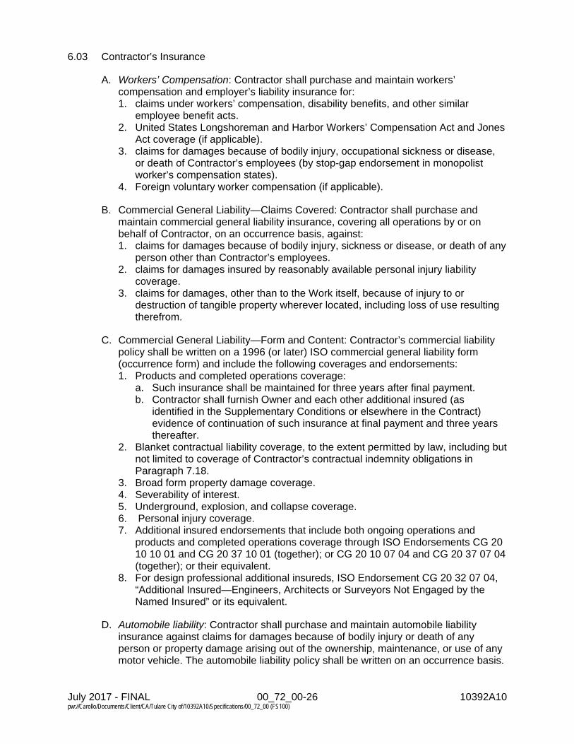
July 2017 - FINAL 00_72_00-26 10392A10 pw://Carollo/Documents/Client/CA/Tulare City of/10392A10/Specifications/00_72_00 (FS100)
6.03 Contractor’s Insurance
A. Workers’ Compensation: Contractor shall purchase and maintain workers’ compensation and employer’s liability insurance for: 1. claims under workers’ compensation, disability benefits, and other similar
employee benefit acts. 2. United States Longshoreman and Harbor Workers’ Compensation Act and Jones
Act coverage (if applicable). 3. claims for damages because of bodily injury, occupational sickness or disease,
or death of Contractor’s employees (by stop-gap endorsement in monopolist worker’s compensation states).
4. Foreign voluntary worker compensation (if applicable).
B. Commercial General Liability—Claims Covered: Contractor shall purchase and maintain commercial general liability insurance, covering all operations by or on behalf of Contractor, on an occurrence basis, against: 1. claims for damages because of bodily injury, sickness or disease, or death of any
person other than Contractor’s employees. 2. claims for damages insured by reasonably available personal injury liability
coverage. 3. claims for damages, other than to the Work itself, because of injury to or
destruction of tangible property wherever located, including loss of use resulting therefrom.
C. Commercial General Liability—Form and Content: Contractor’s commercial liability policy shall be written on a 1996 (or later) ISO commercial general liability form (occurrence form) and include the following coverages and endorsements: 1. Products and completed operations coverage:
a. Such insurance shall be maintained for three years after final payment. b. Contractor shall furnish Owner and each other additional insured (as
identified in the Supplementary Conditions or elsewhere in the Contract) evidence of continuation of such insurance at final payment and three years thereafter.
2. Blanket contractual liability coverage, to the extent permitted by law, including but not limited to coverage of Contractor’s contractual indemnity obligations in Paragraph 7.18.
3. Broad form property damage coverage. 4. Severability of interest. 5. Underground, explosion, and collapse coverage. 6. Personal injury coverage. 7. Additional insured endorsements that include both ongoing operations and
products and completed operations coverage through ISO Endorsements CG 20 10 10 01 and CG 20 37 10 01 (together); or CG 20 10 07 04 and CG 20 37 07 04 (together); or their equivalent.
8. For design professional additional insureds, ISO Endorsement CG 20 32 07 04, “Additional Insured—Engineers, Architects or Surveyors Not Engaged by the Named Insured” or its equivalent.
D. Automobile liability: Contractor shall purchase and maintain automobile liability insurance against claims for damages because of bodily injury or death of any person or property damage arising out of the ownership, maintenance, or use of any motor vehicle. The automobile liability policy shall be written on an occurrence basis.

July 2017 - FINAL 00_72_00-27 10392A10 pw://Carollo/Documents/Client/CA/Tulare City of/10392A10/Specifications/00_72_00 (FS100)
E. Umbrella or excess liability: Contractor shall purchase and maintain umbrella or excess liability insurance written over the underlying employer’s liability, commercial general liability, and automobile liability insurance described in the paragraphs above. Subject to industry-standard exclusions, the coverage afforded shall follow form as to each and every one of the underlying policies.
F. Contractor’s pollution liability insurance: Contractor shall purchase and maintain a policy covering third-party injury and property damage claims, including clean-up costs, as a result of pollution conditions arising from Contractor’s operations and completed operations. This insurance shall be maintained for no less than three years after final completion.
G. Additional insureds: The Contractor’s commercial general liability, automobile liability, umbrella or excess, and pollution liability policies shall include and list as additional insureds Owner and Engineer, and any individuals or entities identified in the Supplementary Conditions; include coverage for the respective officers, directors, members, partners, employees, agents, consultants, and subcontractors of each and any of all such additional insureds; and the insurance afforded to these additional insureds shall provide primary coverage for all claims covered thereby (including as applicable those arising from both ongoing and completed operations) on a non-contributory basis. Contractor shall obtain all necessary endorsements to support these requirements.
H. Contractor’s professional liability insurance: If Contractor will provide or furnish professional services under this Contract, through a delegation of professional design services or otherwise, then Contractor shall be responsible for purchasing and maintaining applicable professional liability insurance. This insurance shall provide protection against claims arising out of performance of professional design or related services, and caused by a negligent error, omission, or act for which the insured party is legally liable. It shall be maintained throughout the duration of the Contract and for a minimum of two years after Substantial Completion. If such professional design services are performed by a Subcontractor, and not by Contractor itself, then the requirements of this paragraph may be satisfied through the purchasing and maintenance of such insurance by such Subcontractor.
I. General provisions: The policies of insurance required by this Paragraph 6.03 shall: 1. include at least the specific coverages provided in this Article. 2. be written for not less than the limits of liability provided in this Article and in the
Supplementary Conditions, or required by Laws or Regulations, whichever is greater.
3. contain a provision or endorsement that the coverage afforded will not be canceled, materially changed, or renewal refused until at least 10 days prior written notice has been given to Contractor. Within three days of receipt of any such written notice, Contractor shall provide a copy of the notice to Owner, Engineer, and each other insured under the policy.
4. remain in effect at least until final payment (and longer if expressly required in this Article) and at all times thereafter when Contractor may be correcting, removing, or replacing defective Work as a warranty or correction obligation, or otherwise, or returning to the Site to conduct other tasks arising from the Contract Documents.

July 2017 - FINAL 00_72_00-28 10392A10 pw://Carollo/Documents/Client/CA/Tulare City of/10392A10/Specifications/00_72_00 (FS100)
5. be appropriate for the Work being performed and provide protection from claims that may arise out of or result from Contractor’s performance of the Work and Contractor’s other obligations under the Contract Documents, whether it is to be performed by Contractor, any Subcontractor or Supplier, or by anyone directly or indirectly employed by any of them to perform any of the Work, or by anyone for whose acts any of them may be liable.
J. The coverage requirements for specific policies of insurance must be met by such policies, and not by reference to excess or umbrella insurance provided in other policies.
6.04 Owner’s Liability Insurance
A. In addition to the insurance required to be provided by Contractor under Paragraph 6.03, Owner, at Owner’s option, may purchase and maintain at Owner’s expense Owner’s own liability insurance as will protect Owner against claims which may arise from operations under the Contract Documents.
B. Owner’s liability policies, if any, operate separately and independently from policies required to be provided by Contractor, and Contractor cannot rely upon Owner’s liability policies for any of Contractor’s obligations to the Owner, Engineer, or third parties.
6.05 Property Insurance
A. Builder’s Risk: Unless otherwise provided in the Supplementary Conditions, Contractor shall purchase and maintain builder’s risk insurance upon the Work on a completed value basis, in the amount of the full insurable replacement cost thereof (subject to such deductible amounts as may be provided in the Supplementary Conditions or required by Laws and Regulations). This insurance shall: 1. include the Owner and Contractor as named insureds, and all Subcontractors,
and any individuals or entities required by the Supplementary Conditions to be insured under such builder’s risk policy, as insureds or named insureds. For purposes of the remainder of this Paragraph 6.05, Paragraphs 6.06 and 6.07, and any corresponding Supplementary Conditions, the parties required to be insured shall collectively be referred to as “insureds.”
2. be written on a builder’s risk “all risk” policy form that shall at least include insurance for physical loss or damage to the Work, temporary buildings, falsework, and materials and equipment in transit, and shall insure against at least the following perils or causes of loss: fire; lightning; windstorm; riot; civil commotion; terrorism; vehicle impact; aircraft; smoke; theft; vandalism and malicious mischief; mechanical breakdown, boiler explosion, and artificially generated electric current; earthquake; volcanic activity, and other earth movement; flood; collapse; explosion; debris removal; demolition occasioned by enforcement of Laws and Regulations; water damage (other than that caused by flood); and such other perils or causes of loss as may be specifically required by the Supplementary Conditions. If insurance against mechanical breakdown, boiler explosion, and artificially generated electric current; earthquake; volcanic activity, and other earth movement; or flood, are not commercially available under builder’s risk policies, by endorsement or otherwise, such insurance may be provided through other insurance policies acceptable to Owner and Contractor.

July 2017 - FINAL 00_72_00-29 10392A10 pw://Carollo/Documents/Client/CA/Tulare City of/10392A10/Specifications/00_72_00 (FS100)
3. cover, as insured property, at least the following: (a) the Work and all materials, supplies, machinery, apparatus, equipment, fixtures, and other property of a similar nature that are to be incorporated into or used in the preparation, fabrication, construction, erection, or completion of the Work, including Owner-furnished or assigned property; (b) spare parts inventory required within the scope of the Contract; and (c) temporary works which are not intended to form part of the permanent constructed Work but which are intended to provide working access to the Site, or to the Work under construction, or which are intended to provide temporary support for the Work under construction, including scaffolding, form work, fences, shoring, falsework, and temporary structures.
4. cover expenses incurred in the repair or replacement of any insured property (including but not limited to fees and charges of engineers and architects).
5. extend to cover damage or loss to insured property while in temporary storage at the Site or in a storage location outside the Site (but not including property stored at the premises of a manufacturer or Supplier).
6. extend to cover damage or loss to insured property while in transit. 7. allow for partial occupation or use of the Work by Owner, such that those
portions of the Work that are not yet occupied or used by Owner shall remain covered by the builder’s risk insurance.
8. allow for the waiver of the insurer’s subrogation rights, as set forth below. 9. provide primary coverage for all losses and damages caused by the perils or
causes of loss covered. 10. not include a co-insurance clause. 11. include an exception for ensuing losses from physical damage or loss with
respect to any defective workmanship, design, or materials exclusions. 12. include performance/hot testing and start-up. 13. be maintained in effect, subject to the provisions herein regarding Substantial
Completion and partial occupancy or use of the Work by Owner, until the Work is complete.
B. Notice of Cancellation or Change: All the policies of insurance (and the certificates or other evidence thereof) required to be purchased and maintained in accordance with this Paragraph 6.05 will contain a provision or endorsement that the coverage afforded will not be canceled or materially changed or renewal refused until at least 10 days prior written notice has been given to the purchasing policyholder. Within three days of receipt of any such written notice, the purchasing policyholder shall provide a copy of the notice to each other insured.
C. Deductibles: The purchaser of any required builder’s risk or property insurance shall pay for costs not covered because of the application of a policy deductible.
D. Partial Occupancy or Use by Owner: If Owner will occupy or use a portion or portions of the Work prior to Substantial Completion of all the Work as provided in Paragraph 15.04, then Owner (directly, if it is the purchaser of the builder’s risk policy, or through Contractor) will provide notice of such occupancy or use to the builder’s risk insurer. The builder’s risk insurance shall not be canceled or permitted to lapse on account of any such partial use or occupancy; rather, those portions of the Work that are occupied or used by Owner may come off the builder’s risk policy, while those portions of the Work not yet occupied or used by Owner shall remain covered by the builder’s risk insurance.

July 2017 - FINAL 00_72_00-30 10392A10 pw://Carollo/Documents/Client/CA/Tulare City of/10392A10/Specifications/00_72_00 (FS100)
E. Additional Insurance: If Contractor elects to obtain other special insurance to be included in or supplement the builder’s risk or property insurance policies provided under this Paragraph 6.05, it may do so at Contractor’s expense.
F. Insurance of Other Property: If the express insurance provisions of the Contract do not require or address the insurance of a property item or interest, such as tools, construction equipment, or other personal property owned by Contractor, a Subcontractor, or an employee of Contractor or a Subcontractor, then the entity or individual owning such property item will be responsible for deciding whether to insure it, and if so in what amount.
6.06 Waiver of Rights
A. All policies purchased in accordance with Paragraph 6.05, expressly including the builder’s risk policy, shall contain provisions to the effect that in the event of payment of any loss or damage the insurers will have no rights of recovery against any insureds thereunder, or against Engineer or its consultants, or their officers, directors, members, partners, employees, agents, consultants, or subcontractors. Owner and Contractor waive all rights against each other and the respective officers, directors, members, partners, employees, agents, consultants, and subcontractors of each and any of them, for all losses and damages caused by, arising out of, or resulting from any of the perils or causes of loss covered by such policies and any other property insurance applicable to the Work; and, in addition, waive all such rights against Engineer, its consultants, all Subcontractors, all individuals or entities identified in the Supplementary Conditions as insureds, and the officers, directors, members, partners, employees, agents, consultants, and subcontractors of each and any of them, under such policies for losses and damages so caused. None of the above waivers shall extend to the rights that any party making such waiver may have to the proceeds of insurance held by Owner or Contractor as trustee or fiduciary, or otherwise payable under any policy so issued.
B. Owner waives all rights against Contractor, Subcontractors, and Engineer, and the officers, directors, members, partners, employees, agents, consultants and subcontractors of each and any of them, for: 1. loss due to business interruption, loss of use, or other consequential loss
extending beyond direct physical loss or damage to Owner’s property or the Work caused by, arising out of, or resulting from fire or other perils whether or not insured by Owner; and
2. loss or damage to the completed Project or part thereof caused by, arising out of, or resulting from fire or other insured peril or cause of loss covered by any property insurance maintained on the completed Project or part thereof by Owner during partial occupancy or use pursuant to Paragraph 15.04, after Substantial Completion pursuant to Paragraph 15.03, or after final payment pursuant to Paragraph 15.06.
C. Any insurance policy maintained by Owner covering any loss, damage or consequential loss referred to in Paragraph 6.06.B shall contain provisions to the effect that in the event of payment of any such loss, damage, or consequential loss, the insurers will have no rights of recovery against Contractor, Subcontractors, or Engineer, or the officers, directors, members, partners, employees, agents, consultants, or subcontractors of each and any of them.

July 2017 - FINAL 00_72_00-31 10392A10 pw://Carollo/Documents/Client/CA/Tulare City of/10392A10/Specifications/00_72_00 (FS100)
D. Contractor shall be responsible for assuring that the agreement under which a Subcontractor performs a portion of the Work contains provisions whereby the Subcontractor waives all rights against Owner, Contractor, all individuals or entities identified in the Supplementary Conditions as insureds, the Engineer and its consultants, and the officers, directors, members, partners, employees, agents, consultants, and subcontractors of each and any of them, for all losses and damages caused by, arising out of, relating to, or resulting from any of the perils or causes of loss covered by builder’s risk insurance and any other property insurance applicable to the Work.
6.07 Receipt and Application of Property Insurance Proceeds
A. Any insured loss under the builder’s risk and other policies of insurance required by Paragraph 6.05 will be adjusted and settled with the named insured that purchased the policy. Such named insured shall act as fiduciary for the other insureds, and give notice to such other insureds that adjustment and settlement of a claim is in progress. Any other insured may state its position regarding a claim for insured loss in writing within 15 days after notice of such claim.
B. Proceeds for such insured losses may be made payable by the insurer either jointly to multiple insureds, or to the named insured that purchased the policy in its own right and as fiduciary for other insureds, subject to the requirements of any applicable mortgage clause. A named insured receiving insurance proceeds under the builder’s risk and other policies of insurance required by Paragraph 6.05 shall distribute such proceeds in accordance with such agreement as the parties in interest may reach, or as otherwise required under the dispute resolution provisions of this Contract or applicable Laws and Regulations.
C. If no other special agreement is reached, the damaged Work shall be repaired or replaced, the money so received applied on account thereof, and the Work and the cost thereof covered by Change Order, if needed.
ARTICLE 7 - CONTRACTOR’S RESPONSIBILITIES
7.01 Supervision and Superintendence
A. Contractor shall supervise, inspect, and direct the Work competently and efficiently, devoting such attention thereto and applying such skills and expertise as may be necessary to perform the Work in accordance with the Contract Documents. Contractor shall be solely responsible for the means, methods, techniques, sequences, and procedures of construction.
B. At all times during the progress of the Work, Contractor shall assign a competent resident superintendent who shall not be replaced without written notice to Owner and Engineer except under extraordinary circumstances.
7.02 Labor; Working Hours
A. Contractor shall provide competent, suitably qualified personnel to survey and lay out the Work and perform construction as required by the Contract Documents. Contractor shall at all times maintain good discipline and order at the Site.

July 2017 - FINAL 00_72_00-32 10392A10 pw://Carollo/Documents/Client/CA/Tulare City of/10392A10/Specifications/00_72_00 (FS100)
B. Except as otherwise required for the safety or protection of persons or the Work or property at the Site or adjacent thereto, and except as otherwise stated in the Contract Documents, all Work at the Site shall be performed during regular working hours, Monday through Friday. Contractor will not perform Work on a Saturday, Sunday, or any legal holiday. Contractor may perform Work outside regular working hours or on Saturdays, Sundays, or legal holidays only with Owner’s written consent, which will not be unreasonably withheld.
7.03 Services, Materials, and Equipment
A. Unless otherwise specified in the Contract Documents, Contractor shall provide and assume full responsibility for all services, materials, equipment, labor, transportation, construction equipment and machinery, tools, appliances, fuel, power, light, heat, telephone, water, sanitary facilities, temporary facilities, and all other facilities and incidentals necessary for the performance, testing, start up, and completion of the Work, whether or not such items are specifically called for in the Contract Documents.
B. All materials and equipment incorporated into the Work shall be of good quality and new, except as otherwise provided in the Contract Documents. All special warranties and guarantees required by the Specifications shall expressly run to the benefit of Owner. If required by Engineer, Contractor shall furnish satisfactory evidence (including reports of required tests) as to the source, kind, and quality of materials and equipment.
C. All materials and equipment shall be stored, applied, installed, connected, erected, protected, used, cleaned, and conditioned in accordance with instructions of the applicable Supplier, except as otherwise may be provided in the Contract Documents.
7.04 “Or Equals”
A. Whenever an item of material or equipment is specified or described in the Contract Documents by using the name of a proprietary item or the name of a particular Supplier, the Contract Price has been based upon Contractor furnishing such item as specified. The specification or description of such an item is intended to establish the type, function, appearance, and quality required. Unless the specification or description contains or is followed by words reading that no like, equivalent, or “or equal” item is permitted, Contractor may request that Engineer authorize the use of other items of material or equipment, or items from other proposed suppliers under the circumstances described below. 1. If Engineer in its sole discretion determines that an item of material or equipment
proposed by Contractor is functionally equal to that named and sufficiently similar so that no change in related Work will be required, Engineer shall deem it an “or equal” item. For the purposes of this paragraph, a proposed item of material or equipment will be considered functionally equal to an item so named if: a. in the exercise of reasonable judgment Engineer determines that:
1) it is at least equal in materials of construction, quality, durability, appearance, strength, and design characteristics;
2) it will reliably perform at least equally well the function and achieve the results imposed by the design concept of the completed Project as a functioning whole;

July 2017 - FINAL 00_72_00-33 10392A10 pw://Carollo/Documents/Client/CA/Tulare City of/10392A10/Specifications/00_72_00 (FS100)
3) it has a proven record of performance and availability of responsive service; and
4) it is not objectionable to Owner. b. Contractor certifies that, if approved and incorporated into the Work:
1) there will be no increase in cost to the Owner or increase in Contract Times; and
2) it will conform substantially to the detailed requirements of the item named in the Contract Documents.
B. Contractor’s Expense: Contractor shall provide all data in support of any proposed “or equal” item at Contractor’s expense.
C. Engineer’s Evaluation and Determination: Engineer will be allowed a reasonable time to evaluate each “or-equal” request. Engineer may require Contractor to furnish additional data about the proposed “or-equal” item. Engineer will be the sole judge of acceptability. No “or-equal” item will be ordered, furnished, installed, or utilized until Engineer’s review is complete and Engineer determines that the proposed item is an “or-equal”, which will be evidenced by an approved Shop Drawing or other written communication. Engineer will advise Contractor in writing of any negative determination.
D. Effect of Engineer’s Determination: Neither approval nor denial of an “or-equal” request shall result in any change in Contract Price. The Engineer’s denial of an “or-equal” request shall be final and binding, and may not be reversed through an appeal under any provision of the Contract Documents.
E. Treatment as a Substitution Request: If Engineer determines that an item of material or equipment proposed by Contractor does not qualify as an “or-equal” item, Contractor may request that Engineer considered the proposed item as a substitute pursuant to Paragraph 7.05.
7.05 Substitutes
A. Unless the specification or description of an item of material or equipment required to be furnished under the Contract Documents contains or is followed by words reading that no substitution is permitted, Contractor may request that Engineer authorize the use of other items of material or equipment under the circumstances described below. To the extent possible such requests shall be made before commencement of related construction at the Site. 1. Contractor shall submit sufficient information as provided below to allow Engineer
to determine if the item of material or equipment proposed is functionally equivalent to that named and an acceptable substitute therefor. Engineer will not accept requests for review of proposed substitute items of material or equipment from anyone other than Contractor.
2. The requirements for review by Engineer will be as set forth in Paragraph 7.05.B, as supplemented by the Specifications, and as Engineer may decide is appropriate under the circumstances.
July 2017 - FINAL 00_72_00-34 10392A10 pw://Carollo/Documents/Client/CA/Tulare City of/10392A10/Specifications/00_72_00 (FS100)
3. Contractor shall make written application to Engineer for review of a proposed substitute item of material or equipment that Contractor seeks to furnish or use. The application: a. shall certify that the proposed substitute item will:
1) perform adequately the functions and achieve the results called for by the general design,
2) be similar in substance to that specified, and 3) be suited to the same use as that specified.
b. will state: 1) the extent, if any, to which the use of the proposed substitute item will
necessitate a change in Contract Times, 2) whether use of the proposed substitute item in the Work will require a
change in any of the Contract Documents (or in the provisions of any other direct contract with Owner for other work on the Project) to adapt the design to the proposed substitute item, and
3) whether incorporation or use of the proposed substitute item in connection with the Work is subject to payment of any license fee or royalty.
c. will identify: 1) all variations of the proposed substitute item from that specified, and 2) available engineering, sales, maintenance, repair, and replacement
services. d. shall contain an itemized estimate of all costs or credits that will result directly
or indirectly from use of such substitute item, including but not limited to changes in Contract Price, shared savings, costs of redesign, and claims of other contractors affected by any resulting change.
B. Engineer’s Evaluation and Determination: Engineer will be allowed a reasonable time to evaluate each substitute request, and to obtain comments and direction from Owner. Engineer may require Contractor to furnish additional data about the proposed substitute item. Engineer will be the sole judge of acceptability. No substitute will be ordered, furnished, installed, or utilized until Engineer’s review is complete and Engineer determines that the proposed item is an acceptable substitute. Engineer’s determination will be evidenced by a Field Order or a proposed Change Order accounting for the substitution itself and all related impacts, including changes in Contract Price or Contract Times. Engineer will advise Contractor in writing of any negative determination.
C. Special Guarantee: Owner may require Contractor to furnish at Contractor’s expense a special performance guarantee or other surety with respect to any substitute.
D. Reimbursement of Engineer’s Cost: Engineer will record Engineer’s costs in evaluating a substitute proposed or submitted by Contractor. Whether or not Engineer approves a substitute so proposed or submitted by Contractor, Contractor shall reimburse Owner for the reasonable charges of Engineer for evaluating each such proposed substitute. Contractor shall also reimburse Owner for the reasonable charges of Engineer for making changes in the Contract Documents (or in the provisions of any other direct contract with Owner) resulting from the acceptance of each proposed substitute.
E. Contractor’s Expense: Contractor shall provide all data in support of any proposed substitute at Contractor’s expense.

July 2017 - FINAL 00_72_00-35 10392A10 pw://Carollo/Documents/Client/CA/Tulare City of/10392A10/Specifications/00_72_00 (FS100)
F. Effect of Engineer’s Determination: If Engineer approves the substitution request, Contractor shall execute the proposed Change Order and proceed with the substitution. The Engineer’s denial of a substitution request shall be final and binding, and may not be reversed through an appeal under any provision of the Contract Documents. Contractor may challenge the scope of reimbursement costs imposed under Paragraph 7.05.D, by timely submittal of a Change Proposal.
7.06 Concerning Subcontractors, Suppliers, and Others
A. Contractor may retain Subcontractors and Suppliers for the performance of parts of the Work. Such Subcontractors and Suppliers must be acceptable to Owner.
B. Contractor shall retain specific Subcontractors, Suppliers, or other individuals or entities for the performance of designated parts of the Work if required by the Contract to do so.
C. Subsequent to the submittal of Contractor’s Bid or final negotiation of the terms of the Contract, Owner may not require Contractor to retain any Subcontractor, Supplier, or other individual or entity to furnish or perform any of the Work against which Contractor has reasonable objection.
D. Prior to entry into any binding subcontract or purchase order, Contractor shall submit to Owner the identity of the proposed Subcontractor or Supplier (unless Owner has already deemed such proposed Subcontractor or Supplier acceptable, during the bidding process or otherwise). Such proposed Subcontractor or Supplier shall be deemed acceptable to Owner unless Owner raises a substantive, reasonable objection within five days.
E. Owner may require the replacement of any Subcontractor, Supplier, or other individual or entity retained by Contractor to perform any part of the Work. Owner also may require Contractor to retain specific replacements; provided, however, that Owner may not require a replacement to which Contractor has a reasonable objection. If Contractor has submitted the identity of certain Subcontractors, Suppliers, or other individuals or entities for acceptance by Owner, and Owner has accepted it (either in writing or by failing to make written objection thereto), then Owner may subsequently revoke the acceptance of any such Subcontractor, Supplier, or other individual or entity so identified solely on the basis of substantive, reasonable objection after due investigation. Contractor shall submit an acceptable replacement for the rejected Subcontractor, Supplier, or other individual or entity.
F. If Owner requires the replacement of any Subcontractor, Supplier, or other individual or entity retained by Contractor to perform any part of the Work, then Contractor shall be entitled to an adjustment in Contract Price or Contract Times, or both, with respect to the replacement; and Contractor shall initiate a Change Proposal for such adjustment within 30 days of Owner’s requirement of replacement.
G. No acceptance by Owner of any such Subcontractor, Supplier, or other individual or entity, whether initially or as a replacement, shall constitute a waiver of the right of Owner to the completion of the Work in accordance with the Contract Documents.
H. On a monthly basis Contractor shall submit to Engineer a complete list of all Subcontractors and Suppliers having a direct contract with Contractor, and of all other Subcontractors and Suppliers known to Contractor at the time of submittal.

July 2017 - FINAL 00_72_00-36 10392A10 pw://Carollo/Documents/Client/CA/Tulare City of/10392A10/Specifications/00_72_00 (FS100)
I. Contractor shall be fully responsible to Owner and Engineer for all acts and omissions of the Subcontractors, Suppliers, and other individuals or entities performing or furnishing any of the Work just as Contractor is responsible for Contractor’s own acts and omissions.
J. Contractor shall be solely responsible for scheduling and coordinating the work of Subcontractors, Suppliers, and all other individuals or entities performing or furnishing any of the Work.
K. Contractor shall restrict all Subcontractors, Suppliers, and such other individuals or entities performing or furnishing any of the Work from communicating with Engineer or Owner, except through Contractor or in case of an emergency, or as otherwise expressly allowed herein.
L. The divisions and sections of the Specifications and the identifications of any Drawings shall not control Contractor in dividing the Work among Subcontractors or Suppliers or delineating the Work to be performed by any specific trade.
M. All Work performed for Contractor by a Subcontractor or Supplier shall be pursuant to an appropriate contractual agreement that specifically binds the Subcontractor or Supplier to the applicable terms and conditions of the Contract Documents for the benefit of Owner and Engineer.
N. Owner may furnish to any Subcontractor or Supplier, to the extent practicable, information about amounts paid to Contractor on account of Work performed for Contractor by the particular Subcontractor or Supplier.
O. Nothing in the Contract Documents: 1. shall create for the benefit of any such Subcontractor, Supplier, or other
individual or entity any contractual relationship between Owner or Engineer and any such Subcontractor, Supplier, or other individual or entity; nor
2. shall create any obligation on the part of Owner or Engineer to pay or to see to the payment of any money due any such Subcontractor, Supplier, or other individual or entity except as may otherwise be required by Laws and Regulations.
7.07 Patent Fees and Royalties
A. Contractor shall pay all license fees and royalties and assume all costs incident to the use in the performance of the Work or the incorporation in the Work of any invention, design, process, product, or device which is the subject of patent rights or copyrights held by others. If a particular invention, design, process, product, or device is specified in the Contract Documents for use in the performance of the Work and if, to the actual knowledge of Owner or Engineer, its use is subject to patent rights or copyrights calling for the payment of any license fee or royalty to others, the existence of such rights shall be disclosed by Owner in the Contract Documents.

July 2017 - FINAL 00_72_00-37 10392A10 pw://Carollo/Documents/Client/CA/Tulare City of/10392A10/Specifications/00_72_00 (FS100)
B. To the fullest extent permitted by Laws and Regulations, Owner shall indemnify and hold harmless Contractor, and its officers, directors, members, partners, employees, agents, consultants, and subcontractors from and against all claims, costs, losses, and damages (including but not limited to all fees and charges of engineers, architects, attorneys, and other professionals, and all court or arbitration or other dispute resolution costs) arising out of or relating to any infringement of patent rights or copyrights incident to the use in the performance of the Work or resulting from the incorporation in the Work of any invention, design, process, product, or device specified in the Contract Documents, but not identified as being subject to payment of any license fee or royalty to others required by patent rights or copyrights.
C. To the fullest extent permitted by Laws and Regulations, Contractor shall indemnify and hold harmless Owner and Engineer, and the officers, directors, members, partners, employees, agents, consultants and subcontractors of each and any of them from and against all claims, costs, losses, and damages (including but not limited to all fees and charges of engineers, architects, attorneys, and other professionals and all court or arbitration or other dispute resolution costs) arising out of or relating to any infringement of patent rights or copyrights incident to the use in the performance of the Work or resulting from the incorporation in the Work of any invention, design, process, product, or device not specified in the Contract Documents.
7.08 Permits
A. Unless otherwise provided in the Contract Documents, Contractor shall obtain and pay for all construction permits and licenses. Owner shall assist Contractor, when necessary, in obtaining such permits and licenses. Contractor shall pay all governmental charges and inspection fees necessary for the prosecution of the Work which are applicable at the time of the submission of Contractor’s Bid (or when Contractor became bound under a negotiated contract). Owner shall pay all charges of utility owners for connections for providing permanent service to the Work
7.09 Taxes
A. Contractor shall pay all sales, consumer, use, and other similar taxes required to be paid by Contractor in accordance with the Laws and Regulations of the place of the Project which are applicable during the performance of the Work.
7.10 Laws and Regulations
A. Contractor shall give all notices required by and shall comply with all Laws and Regulations applicable to the performance of the Work. Except where otherwise expressly required by applicable Laws and Regulations, neither Owner nor Engineer shall be responsible for monitoring Contractor’s compliance with any Laws or Regulations.

July 2017 - FINAL 00_72_00-38 10392A10 pw://Carollo/Documents/Client/CA/Tulare City of/10392A10/Specifications/00_72_00 (FS100)
B. If Contractor performs any Work or takes any other action knowing or having reason to know that it is contrary to Laws or Regulations, Contractor shall bear all resulting costs and losses, and shall indemnify and hold harmless Owner and Engineer, and the officers, directors, members, partners, employees, agents, consultants, and subcontractors of each and any of them from and against all claims, costs, losses, and damages (including but not limited to all fees and charges of engineers, architects, attorneys, and other professionals and all court or arbitration or other dispute resolution costs) arising out of or relating to such Work or other action. It shall not be Contractor’s responsibility to make certain that the Work described in the Contract Documents is in accordance with Laws and Regulations, but this shall not relieve Contractor of Contractor’s obligations under Paragraph 3.03.
C. Owner or Contractor may give notice to the other party of any changes after the submission of Contractor’s Bid (or after the date when Contractor became bound under a negotiated contract) in Laws or Regulations having an effect on the cost or time of performance of the Work, including but not limited to changes in Laws or Regulations having an effect on procuring permits and on sales, use, value-added, consumption, and other similar taxes. If Owner and Contractor are unable to agree on entitlement to or on the amount or extent, if any, of any adjustment in Contract Price or Contract Times resulting from such changes, then within 30 days of such notice Contractor may submit a Change Proposal, or Owner may initiate a Claim.
7.11 Record Documents
A. Contractor shall maintain in a safe place at the Site one printed record copy of all Drawings, Specifications, Addenda, Change Orders, Work Change Directives, Field Orders, written interpretations and clarifications, and approved Shop Drawings. Contractor shall keep such record documents in good order and annotate them to show changes made during construction. These record documents, together with all approved Samples, will be available to Engineer for reference. Upon completion of the Work, Contractor shall deliver these record documents to Engineer.
7.12 Safety and Protection
A. Contractor shall be solely responsible for initiating, maintaining, and supervising all safety precautions and programs in connection with the Work. Such responsibility does not relieve Subcontractors of their responsibility for the safety of persons or property in the performance of their work, nor for compliance with applicable safety Laws and Regulations. Contractor shall take all necessary precautions for the safety of, and shall provide the necessary protection to prevent damage, injury, or loss to: 1. all persons on the Site or who may be affected by the Work; 2. all the Work and materials and equipment to be incorporated therein, whether in
storage on or off the Site; and 3. other property at the Site or adjacent thereto, including trees, shrubs, lawns,
walks, pavements, roadways, structures, other work in progress, utilities, and Underground Facilities not designated for removal, relocation, or replacement in the course of construction.

July 2017 - FINAL 00_72_00-39 10392A10 pw://Carollo/Documents/Client/CA/Tulare City of/10392A10/Specifications/00_72_00 (FS100)
B. Contractor shall comply with all applicable Laws and Regulations relating to the safety of persons or property, or to the protection of persons or property from damage, injury, or loss; and shall erect and maintain all necessary safeguards for such safety and protection. Contractor shall notify Owner; the owners of adjacent property, Underground Facilities, and other utilities; and other contractors and utility owners performing work at or adjacent to the Site, when prosecution of the Work may affect them, and shall cooperate with them in the protection, removal, relocation, and replacement of their property or work in progress.
C. Contractor shall comply with the applicable requirements of Owner’s safety programs, if any. The Supplementary Conditions identify any Owner’s safety programs that are applicable to the Work.
D. Contractor shall inform Owner and Engineer of the specific requirements of Contractor’s safety program with which Owner’s and Engineer’s employees and representatives must comply while at the Site.
E. All damage, injury, or loss to any property referred to in Paragraph 7.12.A.2 or 7.12.A.3 caused, directly or indirectly, in whole or in part, by Contractor, any Subcontractor, Supplier, or any other individual or entity directly or indirectly employed by any of them to perform any of the Work, or anyone for whose acts any of them may be liable, shall be remedied by Contractor at its expense (except damage or loss attributable to the fault of Drawings or Specifications or to the acts or omissions of Owner or Engineer or anyone employed by any of them, or anyone for whose acts any of them may be liable, and not attributable, directly or indirectly, in whole or in part, to the fault or negligence of Contractor or any Subcontractor, Supplier, or other individual or entity directly or indirectly employed by any of them).
F. Contractor’s duties and responsibilities for safety and protection shall continue until such time as all the Work is completed and Engineer has issued a notice to Owner and Contractor in accordance with Paragraph 15.06.B that the Work is acceptable (except as otherwise expressly provided in connection with Substantial Completion).
G. Contractor’s duties and responsibilities for safety and protection shall resume whenever Contractor or any Subcontractor or Supplier returns to the Site to fulfill warranty or correction obligations, or to conduct other tasks arising from the Contract Documents.
7.13 Safety Representative
A. Contractor shall designate a qualified and experienced safety representative at the Site whose duties and responsibilities shall be the prevention of accidents and the maintaining and supervising of safety precautions and programs.
7.14 Hazard Communication Programs
A. Contractor shall be responsible for coordinating any exchange of material safety data sheets or other hazard communication information required to be made available to or exchanged between or among employers at the Site in accordance with Laws or Regulations.

July 2017 - FINAL 00_72_00-40 10392A10 pw://Carollo/Documents/Client/CA/Tulare City of/10392A10/Specifications/00_72_00 (FS100)
7.15 Emergencies
A. In emergencies affecting the safety or protection of persons or the Work or property at the Site or adjacent thereto, Contractor is obligated to act to prevent threatened damage, injury, or loss. Contractor shall give Engineer prompt written notice if Contractor believes that any significant changes in the Work or variations from the Contract Documents have been caused thereby or are required as a result thereof. If Engineer determines that a change in the Contract Documents is required because of the action taken by Contractor in response to such an emergency, a Work Change Directive or Change Order will be issued.
7.16 Shop Drawings, Samples, and Other Submittals
A. Shop Drawing and Sample Submittal Requirements: 1. Before submitting a Shop Drawing or Sample, Contractor shall have:
a. reviewed and coordinated the Shop Drawing or Sample with other Shop Drawings and Samples and with the requirements of the Work and the Contract Documents;
b. determined and verified all field measurements, quantities, dimensions, specified performance and design criteria, installation requirements, materials, catalog numbers, and similar information with respect thereto;
c. determined and verified the suitability of all materials and equipment offered with respect to the indicated application, fabrication, shipping, handling, storage, assembly, and installation pertaining to the performance of the Work; and
d. determined and verified all information relative to Contractor’s responsibilities for means, methods, techniques, sequences, and procedures of construction, and safety precautions and programs incident thereto.
2. Each submittal shall bear a stamp or specific written certification that Contractor has satisfied Contractor’s obligations under the Contract Documents with respect to Contractor’s review of that submittal, and that Contractor approves the submittal.
3. With each submittal, Contractor shall give Engineer specific written notice of any variations that the Shop Drawing or Sample may have from the requirements of the Contract Documents. This notice shall be set forth in a written communication separate from the Shop Drawings or Sample submittal; and, in addition, in the case of Shop Drawings by a specific notation made on each Shop Drawing submitted to Engineer for review and approval of each such variation.
B. Submittal Procedures for Shop Drawings and Samples: Contractor shall submit Shop Drawings and Samples to Engineer for review and approval in accordance with the accepted Schedule of Submittals. Each submittal will be identified as Engineer may require. 1. Shop Drawings:
a. Contractor shall submit the number of copies required in the Specifications. b. Data shown on the Shop Drawings will be complete with respect to quantities,
dimensions, specified performance and design criteria, materials, and similar data to show Engineer the services, materials, and equipment Contractor proposes to provide and to enable Engineer to review the information for the limited purposes required by Paragraph 7.16.D.
2. Samples: a. Contractor shall submit the number of Samples required in the Specifications.

July 2017 - FINAL 00_72_00-41 10392A10 pw://Carollo/Documents/Client/CA/Tulare City of/10392A10/Specifications/00_72_00 (FS100)
b. Contractor shall clearly identify each Sample as to material, Supplier, pertinent data such as catalog numbers, the use for which intended and other data as Engineer may require to enable Engineer to review the submittal for the limited purposes required by Paragraph 7.16.D.
3. Where a Shop Drawing or Sample is required by the Contract Documents or the Schedule of Submittals, any related Work performed prior to Engineer’s review and approval of the pertinent submittal will be at the sole expense and responsibility of Contractor.
C. Other Submittals: Contractor shall submit other submittals to Engineer in accordance with the accepted Schedule of Submittals, and pursuant to the applicable terms of the Specifications.
D. Engineer’s Review: 1. Engineer will provide timely review of Shop Drawings and Samples in
accordance with the Schedule of Submittals acceptable to Engineer. Engineer’s review and approval will be only to determine if the items covered by the submittals will, after installation or incorporation in the Work, conform to the information given in the Contract Documents and be compatible with the design concept of the completed Project as a functioning whole as indicated by the Contract Documents.
2. Engineer’s review and approval will not extend to means, methods, techniques, sequences, or procedures of construction or to safety precautions or programs incident thereto.
3. Engineer’s review and approval of a separate item as such will not indicate approval of the assembly in which the item functions.
4. Engineer’s review and approval of a Shop Drawing or Sample shall not relieve Contractor from responsibility for any variation from the requirements of the Contract Documents unless Contractor has complied with the requirements of Paragraph 7.16.A.3 and Engineer has given written approval of each such variation by specific written notation thereof incorporated in or accompanying the Shop Drawing or Sample. Engineer will document any such approved variation from the requirements of the Contract Documents in a Field Order.
5. Engineer’s review and approval of a Shop Drawing or Sample shall not relieve Contractor from responsibility for complying with the requirements of Paragraph 7.16.A and B.
6. Engineer’s review and approval of a Shop Drawing or Sample, or of a variation from the requirements of the Contract Documents, shall not, under any circumstances, change the Contract Times or Contract Price, unless such changes are included in a Change Order.
7. Neither Engineer’s receipt, review, acceptance or approval of a Shop Drawing, Sample, or other submittal shall result in such item becoming a Contract Document.
8. Contractor shall perform the Work in compliance with the requirements and commitments set forth in approved Shop Drawings and Samples, subject to the provisions of Paragraph 7.16.D.4.

July 2017 - FINAL 00_72_00-42 10392A10 pw://Carollo/Documents/Client/CA/Tulare City of/10392A10/Specifications/00_72_00 (FS100)
E. Resubmittal Procedures: 1. Contractor shall make corrections required by Engineer and shall return the
required number of corrected copies of Shop Drawings and submit, as required, new Samples for review and approval. Contractor shall direct specific attention in writing to revisions other than the corrections called for by Engineer on previous submittals.
2. Contractor shall furnish required submittals with sufficient information and accuracy to obtain required approval of an item with no more than three submittals. Engineer will record Engineer’s time for reviewing a fourth or subsequent submittal of a Shop Drawings, sample, or other item requiring approval, and Contractor shall be responsible for Engineer’s charges to Owner for such time. Owner may impose a set-off against payments due to Contractor to secure reimbursement for such charges.
3. If Contractor requests a change of a previously approved submittal item, Contractor shall be responsible for Engineer’s charges to Owner for its review time, and Owner may impose a set-off against payments due to Contractor to secure reimbursement for such charges, unless the need for such change is beyond the control of Contractor.
7.17 Contractor’s General Warranty and Guarantee
A. Contractor warrants and guarantees to Owner that all Work will be in accordance with the Contract Documents and will not be defective. Engineer and its officers, directors, members, partners, employees, agents, consultants, and subcontractors shall be entitled to rely on Contractor’s warranty and guarantee.
B. Contractor’s warranty and guarantee hereunder excludes defects or damage caused by: 1. abuse, modification, or improper maintenance or operation by persons other than
Contractor, Subcontractors, Suppliers, or any other individual or entity for whom Contractor is responsible; or
2. normal wear and tear under normal usage.
C. Contractor’s obligation to perform and complete the Work in accordance with the Contract Documents shall be absolute. None of the following will constitute an acceptance of Work that is not in accordance with the Contract Documents or a release of Contractor’s obligation to perform the Work in accordance with the Contract Documents: 1. observations by Engineer; 2. recommendation by Engineer or payment by Owner of any progress or final
payment; 3. the issuance of a certificate of Substantial Completion by Engineer or any
payment related thereto by Owner; 4. use or occupancy of the Work or any part thereof by Owner; 5. any review and approval of a Shop Drawing or Sample submittal; 6. the issuance of a notice of acceptability by Engineer; 7. any inspection, test, or approval by others; or 8. any correction of defective Work by Owner.

July 2017 - FINAL 00_72_00-43 10392A10 pw://Carollo/Documents/Client/CA/Tulare City of/10392A10/Specifications/00_72_00 (FS100)
D. If the Contract requires the Contractor to accept the assignment of a contract entered into by Owner, then the specific warranties, guarantees, and correction obligations contained in the assigned contract shall govern with respect to Contractor’s performance obligations to Owner for the Work described in the assigned contract.
7.18 Indemnification
A. To the fullest extent permitted by Laws and Regulations, and in addition to any other obligations of Contractor under the Contract or otherwise, Contractor shall indemnify and hold harmless Owner and Engineer, and the officers, directors, members, partners, employees, agents, consultants and subcontractors of each and any of them from and against all claims, costs, losses, and damages (including but not limited to all fees and charges of engineers, architects, attorneys, and other professionals and all court or arbitration or other dispute resolution costs) arising out of or relating to the performance of the Work, provided that any such claim, cost, loss, or damage is attributable to bodily injury, sickness, disease, or death, or to injury to or destruction of tangible property (other than the Work itself), including the loss of use resulting therefrom but only to the extent caused by any negligent act or omission of Contractor, any Subcontractor, any Supplier, or any individual or entity directly or indirectly employed by any of them to perform any of the Work or anyone for whose acts any of them may be liable.
B. In any and all claims against Owner or Engineer or any of their officers, directors, members, partners, employees, agents, consultants, or subcontractors by any employee (or the survivor or personal representative of such employee) of Contractor, any Subcontractor, any Supplier, or any individual or entity directly or indirectly employed by any of them to perform any of the Work, or anyone for whose acts any of them may be liable, the indemnification obligation under Paragraph 7.18.A shall not be limited in any way by any limitation on the amount or type of damages, compensation, or benefits payable by or for Contractor or any such Subcontractor, Supplier, or other individual or entity under workers’ compensation acts, disability benefit acts, or other employee benefit acts.
C. The indemnification obligations of Contractor under Paragraph 7.18.A shall not extend to the liability of Engineer and Engineer’s officers, directors, members, partners, employees, agents, consultants and subcontractors arising out of: 1. the preparation or approval of, or the failure to prepare or approve maps,
Drawings, opinions, reports, surveys, Change Orders, designs, or Specifications; or
2. giving directions or instructions, or failing to give them, if that is the primary cause of the injury or damage.
7.19 Delegation of Professional Design Services
A. Contractor will not be required to provide professional design services unless such services are specifically required by the Contract Documents for a portion of the Work or unless such services are required to carry out Contractor’s responsibilities for construction means, methods, techniques, sequences and procedures. Contractor shall not be required to provide professional services in violation of applicable Laws and Regulations.

July 2017 - FINAL 00_72_00-44 10392A10 pw://Carollo/Documents/Client/CA/Tulare City of/10392A10/Specifications/00_72_00 (FS100)
B. If professional design services or certifications by a design professional related to systems, materials, or equipment are specifically required of Contractor by the Contract Documents, Owner and Engineer will specify all performance and design criteria that such services must satisfy. Contractor shall cause such services or certifications to be provided by a properly licensed professional, whose signature and seal shall appear on all drawings, calculations, specifications, certifications, and other submittals prepared by such professional. Shop Drawings and other submittals related to the Work designed or certified by such professional, if prepared by others, shall bear such professional’s written approval when submitted to Engineer.
C. Owner and Engineer shall be entitled to rely upon the adequacy, accuracy, and completeness of the services, certifications, or approvals performed by such design professionals, provided Owner and Engineer have specified to Contractor all performance and design criteria that such services must satisfy.
D. Pursuant to this paragraph, Engineer’s review and approval of design calculations and design drawings will be only for the limited purpose of checking for conformance with performance and design criteria given and the design concept expressed in the Contract Documents. Engineer’s review and approval of Shop Drawings and other submittals (except design calculations and design drawings) will be only for the purpose stated in Paragraph 7.16.D.1.
E. Contractor shall not be responsible for the adequacy of the performance or design criteria specified by Owner or Engineer.
ARTICLE 8 - OTHER WORK AT THE SITE
8.01 Other Work
A. In addition to and apart from the Work under the Contract Documents, the Owner may perform other work at or adjacent to the Site. Such other work may be performed by Owner’s employees, or through contracts between the Owner and third parties. Owner may also arrange to have third-party utility owners perform work on their utilities and facilities at or adjacent to the Site.
B. If Owner performs other work at or adjacent to the Site with Owner’s employees, or through contracts for such other work, then Owner shall give Contractor written notice thereof prior to starting any such other work. If Owner has advance information regarding the start of any utility work at or adjacent to the Site, Owner shall provide such information to Contractor.
C. Contractor shall afford each other contractor that performs such other work, each utility owner performing other work, and Owner, if Owner is performing other work with Owner’s employees, proper and safe access to the Site, and provide a reasonable opportunity for the introduction and storage of materials and equipment and the execution of such other work. Contractor shall do all cutting, fitting, and patching of the Work that may be required to properly connect or otherwise make its several parts come together and properly integrate with such other work. Contractor shall not endanger any work of others by cutting, excavating, or otherwise altering such work; provided, however, that Contractor may cut or alter others' work with the written consent of Engineer and the others whose work will be affected.

July 2017 - FINAL 00_72_00-45 10392A10 pw://Carollo/Documents/Client/CA/Tulare City of/10392A10/Specifications/00_72_00 (FS100)
D. If the proper execution or results of any part of Contractor’s Work depends upon work performed by others under this Article 8, Contractor shall inspect such other work and promptly report to Engineer in writing any delays, defects, or deficiencies in such other work that render it unavailable or unsuitable for the proper execution and results of Contractor’s Work. Contractor’s failure to so report will constitute an acceptance of such other work as fit and proper for integration with Contractor’s Work except for latent defects and deficiencies in such other work.
8.02 Coordination
A. If Owner intends to contract with others for the performance of other work at or adjacent to the Site, to perform other work at or adjacent to the Site with Owner’s employees, or to arrange to have utility owners perform work at or adjacent to the Site, the following will be set forth in the Supplementary Conditions or provided to Contractor prior to the start of any such other work: 1. the identity of the individual or entity that will have authority and responsibility for
coordination of the activities among the various contractors; 2. an itemization of the specific matters to be covered by such authority and
responsibility; and 3. the extent of such authority and responsibilities.
B. Unless otherwise provided in the Supplementary Conditions, Owner shall have sole authority and responsibility for such coordination.
8.03 Legal Relationships
A. If, in the course of performing other work at or adjacent to the Site for Owner, the Owner’s employees, any other contractor working for Owner, or any utility owner causes damage to the Work or to the property of Contractor or its Subcontractors, or delays, disrupts, interferes with, or increases the scope or cost of the performance of the Work, through actions or inaction, then Contractor shall be entitled to an equitable adjustment in the Contract Price or the Contract Times, or both. Contractor must submit any Change Proposal seeking an equitable adjustment in the Contract Price or the Contract Times under this paragraph within 30 days of the damaging, delaying, disrupting, or interfering event. The entitlement to, and extent of, any such equitable adjustment shall take into account information (if any) regarding such other work that was provided to Contractor in the Contract Documents prior to the submittal of the Bid or the final negotiation of the terms of the Contract. When applicable, any such equitable adjustment in Contract Price shall be conditioned on Contractor assigning to Owner all Contractor’s rights against such other contractor or utility owner with respect to the damage, delay, disruption, or interference that is the subject of the adjustment. Contractor’s entitlement to an adjustment of the Contract Times is conditioned on such adjustment being essential to Contractor’s ability to complete the Work within the Contract Times.

July 2017 - FINAL 00_72_00-46 10392A10 pw://Carollo/Documents/Client/CA/Tulare City of/10392A10/Specifications/00_72_00 (FS100)
B. Contractor shall take reasonable and customary measures to avoid damaging, delaying, disrupting, or interfering with the work of Owner, any other contractor, or any utility owner performing other work at or adjacent to the Site. If Contractor fails to take such measures and as a result damages, delays, disrupts, or interferes with the work of any such other contractor or utility owner, then Owner may impose a set-off against payments due to Contractor, and assign to such other contractor or utility owner the Owner’s contractual rights against Contractor with respect to the breach of the obligations set forth in this paragraph.
C. When Owner is performing other work at or adjacent to the Site with Owner’s employees, Contractor shall be liable to Owner for damage to such other work, and for the reasonable direct delay, disruption, and interference costs incurred by Owner as a result of Contractor’s failure to take reasonable and customary measures with respect to Owner’s other work. In response to such damage, delay, disruption, or interference, Owner may impose a set-off against payments due to Contractor.
D. If Contractor damages, delays, disrupts, or interferes with the work of any other contractor, or any utility owner performing other work at or adjacent to the Site, through Contractor’s failure to take reasonable and customary measures to avoid such impacts, or if any claim arising out of Contractor’s actions, inactions, or negligence in performance of the Work at or adjacent to the Site is made by any such other contractor or utility owner against Contractor, Owner, or Engineer, then Contractor shall (1) promptly attempt to settle the claim as to all parties through negotiations with such other contractor or utility owner, or otherwise resolve the claim by arbitration or other dispute resolution proceeding or at law, and (2) indemnify and hold harmless Owner and Engineer, and the officers, directors, members, partners, employees, agents, consultants and subcontractors of each and any of them from and against any such claims, and against all costs, losses, and damages (including but not limited to all fees and charges of engineers, architects, attorneys, and other professionals and all court or arbitration or other dispute resolution costs) arising out of or relating to such damage, delay, disruption, or interference.
ARTICLE 9 - OWNER’S RESPONSIBILITIES
9.01 Communications to Contractor
A. Except as otherwise provided in these General Conditions, Owner shall issue all communications to Contractor through Engineer.
9.02 Replacement of Engineer
A. Owner may at its discretion appoint an engineer to replace Engineer, provided Contractor makes no reasonable objection to the replacement engineer. The replacement engineer’s status under the Contract Documents shall be that of the former Engineer.
9.03 Furnish Data
A. Owner shall promptly furnish the data required of Owner under the Contract Documents.

July 2017 - FINAL 00_72_00-47 10392A10 pw://Carollo/Documents/Client/CA/Tulare City of/10392A10/Specifications/00_72_00 (FS100)
9.04 Pay When Due
A. Owner shall make payments to Contractor when they are due as provided in the Agreement.
9.05 Lands and Easements; Reports, Tests, and Drawings
A. Owner’s duties with respect to providing lands and easements are set forth in Paragraph 5.01.
B. Owner’s duties with respect to providing engineering surveys to establish reference points are set forth in Paragraph 4.03.
C. Article 5 refers to Owner’s identifying and making available to Contractor copies of reports of explorations and tests of conditions at the Site, and drawings of physical conditions relating to existing surface or subsurface structures at the Site.
9.06 Insurance
A. Owner’s responsibilities, if any, with respect to purchasing and maintaining liability and property insurance are set forth in Article 6.
9.07 Change Orders
A. Owner’s responsibilities with respect to Change Orders are set forth in Article 11.
9.08 Inspections, Tests, and Approvals
A. Owner’s responsibility with respect to certain inspections, tests, and approvals is set forth in Paragraph 14.02.B.
9.09 Limitations on Owner’s Responsibilities
A. The Owner shall not supervise, direct, or have control or authority over, nor be responsible for, Contractor’s means, methods, techniques, sequences, or procedures of construction, or the safety precautions and programs incident thereto, or for any failure of Contractor to comply with Laws and Regulations applicable to the performance of the Work. Owner will not be responsible for Contractor’s failure to perform the Work in accordance with the Contract Documents.
9.10 Undisclosed Hazardous Environmental Condition
A. Owner’s responsibility in respect to an undisclosed Hazardous Environmental Condition is set forth in Paragraph 5.06.
9.11 Evidence of Financial Arrangements
A. Upon request of Contractor, Owner shall furnish Contractor reasonable evidence that financial arrangements have been made to satisfy Owner’s obligations under the Contract Documents (including obligations under proposed changes in the Work).

July 2017 - FINAL 00_72_00-48 10392A10 pw://Carollo/Documents/Client/CA/Tulare City of/10392A10/Specifications/00_72_00 (FS100)
9.12 Safety Programs
A. While at the Site, Owner’s employees and representatives shall comply with the specific applicable requirements of Contractor’s safety programs of which Owner has been informed.
B. Owner shall furnish copies of any applicable Owner safety programs to Contractor.
ARTICLE 10 - ENGINEER’S STATUS DURING CONSTRUCTION
10.01 Owner’s Representative
A. Engineer will be Owner’s representative during the construction period. The duties and responsibilities and the limitations of authority of Engineer as Owner’s representative during construction are set forth in the Contract.
10.02 Visits to Site
A. Engineer will make visits to the Site at intervals appropriate to the various stages of construction as Engineer deems necessary in order to observe as an experienced and qualified design professional the progress that has been made and the quality of the various aspects of Contractor’s executed Work. Based on information obtained during such visits and observations, Engineer, for the benefit of Owner, will determine, in general, if the Work is proceeding in accordance with the Contract Documents. Engineer will not be required to make exhaustive or continuous inspections on the Site to check the quality or quantity of the Work. Engineer’s efforts will be directed toward providing for Owner a greater degree of confidence that the completed Work will conform generally to the Contract Documents. On the basis of such visits and observations, Engineer will keep Owner informed of the progress of the Work and will endeavor to guard Owner against defective Work.
B. Engineer’s visits and observations are subject to all the limitations on Engineer’s authority and responsibility set forth in Paragraph 10.08. Particularly, but without limitation, during or as a result of Engineer’s visits or observations of Contractor’s Work, Engineer will not supervise, direct, control, or have authority over or be responsible for Contractor’s means, methods, techniques, sequences, or procedures of construction, or the safety precautions and programs incident thereto, or for any failure of Contractor to comply with Laws and Regulations applicable to the performance of the Work.
10.03 Project Representative
A. If Owner and Engineer have agreed that Engineer will furnish a Resident Project Representative to represent Engineer at the Site and assist Engineer in observing the progress and quality of the Work, then the authority and responsibilities of any such Resident Project Representative will be as provided in the Supplementary Conditions, and limitations on the responsibilities thereof will be as provided in Paragraph 10.08. If Owner designates another representative or agent to represent Owner at the Site who is not Engineer’s consultant, agent, or employee, the responsibilities and authority and limitations thereon of such other individual or entity will be as provided in the Supplementary Conditions.

July 2017 - FINAL 00_72_00-49 10392A10 pw://Carollo/Documents/Client/CA/Tulare City of/10392A10/Specifications/00_72_00 (FS100)
10.04 Rejecting Defective Work
A. Engineer has the authority to reject Work in accordance with Article 14.
10.05 Shop Drawings, Change Orders and Payments
A. Engineer’s authority, and limitations thereof, as to Shop Drawings and Samples, are set forth in Paragraph 7.16.
B. Engineer’s authority, and limitations thereof, as to design calculations and design drawings submitted in response to a delegation of professional design services, if any, are set forth in Paragraph 7.19.
C. Engineer’s authority as to Change Orders is set forth in Article 11.
D. Engineer’s authority as to Applications for Payment is set forth in Article 15.
10.06 Determinations for Unit Price Work
A. Engineer will determine the actual quantities and classifications of Unit Price Work performed by Contractor as set forth in Paragraph 13.03.
10.07 Decisions on Requirements of Contract Documents and Acceptability of Work
A. Engineer will render decisions regarding the requirements of the Contract Documents, and judge the acceptability of the Work, pursuant to the specific procedures set forth herein for initial interpretations, Change Proposals, and acceptance of the Work. In rendering such decisions and judgments, Engineer will not show partiality to Owner or Contractor, and will not be liable to Owner, Contractor, or others in connection with any proceedings, interpretations, decisions, or judgments conducted or rendered in good faith.
10.08 Limitations on Engineer’s Authority and Responsibilities
A. Neither Engineer’s authority or responsibility under this Article 10 or under any other provision of the Contract, nor any decision made by Engineer in good faith either to exercise or not exercise such authority or responsibility or the undertaking, exercise, or performance of any authority or responsibility by Engineer, shall create, impose, or give rise to any duty in contract, tort, or otherwise owed by Engineer to Contractor, any Subcontractor, any Supplier, any other individual or entity, or to any surety for or employee or agent of any of them.
B. Engineer will not supervise, direct, control, or have authority over or be responsible for Contractor’s means, methods, techniques, sequences, or procedures of construction, or the safety precautions and programs incident thereto, or for any failure of Contractor to comply with Laws and Regulations applicable to the performance of the Work. Engineer will not be responsible for Contractor’s failure to perform the Work in accordance with the Contract Documents.
C. Engineer will not be responsible for the acts or omissions of Contractor or of any Subcontractor, any Supplier, or of any other individual or entity performing any of the Work.

July 2017 - FINAL 00_72_00-50 10392A10 pw://Carollo/Documents/Client/CA/Tulare City of/10392A10/Specifications/00_72_00 (FS100)
D. Engineer’s review of the final Application for Payment and accompanying documentation and all maintenance and operating instructions, schedules, guarantees, bonds, certificates of inspection, tests and approvals, and other documentation required to be delivered by Paragraph 15.06.A will only be to determine generally that their content complies with the requirements of, and in the case of certificates of inspections, tests, and approvals, that the results certified indicate compliance with the Contract Documents.
E. The limitations upon authority and responsibility set forth in this Paragraph 10.08 shall also apply to the Resident Project Representative, if any.
10.09 Compliance with Safety Program
A. While at the Site, Engineer’s employees and representatives will comply with the specific applicable requirements of Owner’s and Contractor’s safety programs (if any) of which Engineer has been informed.
ARTICLE 11 - AMENDING THE CONTRACT DOCUMENTS; CHANGES IN THE WORK
11.01 Amending and Supplementing Contract Documents
A. The Contract Documents may be amended or supplemented by a Change Order, a Work Change Directive, or a Field Order. 1. Change Orders:
a. If an amendment or supplement to the Contract Documents includes a change in the Contract Price or the Contract Times, such amendment or supplement must be set forth in a Change Order. A Change Order also may be used to establish amendments and supplements of the Contract Documents that do not affect the Contract Price or Contract Times.
b. Owner and Contractor may amend those terms and conditions of the Contract Documents that do not involve (1) the performance or acceptability of the Work, (2) the design (as set forth in the Drawings, Specifications, or otherwise), or (3) other engineering or technical matters, without the recommendation of the Engineer. Such an amendment shall be set forth in a Change Order.
2. Work Change Directives: A Work Change Directive will not change the Contract Price or the Contract Times but is evidence that the parties expect that the modification ordered or documented by a Work Change Directive will be incorporated in a subsequently issued Change Order, following negotiations by the parties as to the Work Change Directive’s effect, if any, on the Contract Price and Contract Times; or, if negotiations are unsuccessful, by a determination under the terms of the Contract Documents governing adjustments, expressly including Paragraph 11.04 regarding change of Contract Price. Contractor must submit any Change Proposal seeking an adjustment of the Contract Price or the Contract Times, or both, no later than 30 days after the completion of the Work set out in the Work Change Directive. Owner must submit any Claim seeking an adjustment of the Contract Price or the Contract Times, or both, no later than 60 days after issuance of the Work Change Directive.
3. Field Orders: Engineer may authorize minor changes in the Work if the changes do not involve an adjustment in the Contract Price or the Contract Times and are compatible with the design concept of the completed Project as a functioning

July 2017 - FINAL 00_72_00-51 10392A10 pw://Carollo/Documents/Client/CA/Tulare City of/10392A10/Specifications/00_72_00 (FS100)
whole as indicated by the Contract Documents. Such changes will be accomplished by a Field Order and will be binding on Owner and also on Contractor, which shall perform the Work involved promptly. If Contractor believes that a Field Order justifies an adjustment in the Contract Price or Contract Times, or both, then before proceeding with the Work at issue, Contractor shall submit a Change Proposal as provided herein.
11.02 Owner-Authorized Changes in the Work
A. Without invalidating the Contract and without notice to any surety, Owner may, at any time or from time to time, order additions, deletions, or revisions in the Work. Such changes shall be supported by Engineer’s recommendation, to the extent the change involves the design (as set forth in the Drawings, Specifications, or otherwise), or other engineering or technical matters. Such changes may be accomplished by a Change Order, if Owner and Contractor have agreed as to the effect, if any, of the changes on Contract Times or Contract Price; or by a Work Change Directive. Upon receipt of any such document, Contractor shall promptly proceed with the Work involved; or, in the case of a deletion in the Work, promptly cease construction activities with respect to such deleted Work. Added or revised Work shall be performed under the applicable conditions of the Contract Documents. Nothing in this paragraph shall obligate Contractor to undertake work that Contractor reasonably concludes cannot be performed in a manner consistent with Contractor’s safety obligations under the Contract Documents or Laws and Regulations.
11.03 Unauthorized Changes in the Work
A. Contractor shall not be entitled to an increase in the Contract Price or an extension of the Contract Times with respect to any work performed that is not required by the Contract Documents, as amended, modified, or supplemented, except in the case of an emergency as provided in Paragraph 7.15 or in the case of uncovering Work as provided in Paragraph 14.05.
11.04 Change of Contract Price
A. The Contract Price may only be changed by a Change Order. Any Change Proposal for an adjustment in the Contract Price shall comply with the provisions of Paragraph 11.06. Any Claim for an adjustment of Contract Price shall comply with the provisions of Article 12.
B. An adjustment in the Contract Price will be determined as follows: 1. where the Work involved is covered by unit prices contained in the Contract
Documents, then by application of such unit prices to the quantities of the items involved (subject to the provisions of Paragraph 13.03); or
2. where the Work involved is not covered by unit prices contained in the Contract Documents, then by a mutually agreed lump sum (which may include an allowance for overhead and profit not necessarily in accordance with Paragraph 11.04.C.2); or
3. where the Work involved is not covered by unit prices contained in the Contract Documents and the parties do not reach mutual agreement to a lump sum, then on the basis of the Cost of the Work (determined as provided in Paragraph 13.01) plus a Contractor’s fee for overhead and profit (determined as provided in Paragraph 11.04.C).

July 2017 - FINAL 00_72_00-52 10392A10 pw://Carollo/Documents/Client/CA/Tulare City of/10392A10/Specifications/00_72_00 (FS100)
C. Contractor’s Fee: When applicable, the Contractor’s fee for overhead and profit shall be determined as follows: 1. a mutually acceptable fixed fee; or 2. if a fixed fee is not agreed upon, then a fee based on the following percentages
of the various portions of the Cost of the Work: a. for costs incurred under Paragraphs 13.01.B.1 and 13.01.B.2, the
Contractor’s fee shall be 15 percent; b. for costs incurred under Paragraph 13.01.B.3, the Contractor’s fee shall be
five percent; c. where one or more tiers of subcontracts are on the basis of Cost of the Work
plus a fee and no fixed fee is agreed upon, the intent of Paragraphs 11.01.C.2.a and 11.01.C.2.b is that the Contractor’s fee shall be based on: (1) a fee of 15 percent of the costs incurred under Paragraphs 13.01.A.1 and 13.01.A.2 by the Subcontractor that actually performs the Work, at whatever tier, and (2) with respect to Contractor itself and to any Subcontractors of a tier higher than that of the Subcontractor that actually performs the Work, a fee of five percent of the amount (fee plus underlying costs incurred) attributable to the next lower tier Subcontractor; provided, however, that for any such subcontracted work the maximum total fee to be paid by Owner shall be no greater than 27 percent of the costs incurred by the Subcontractor that actually performs the work;
d. no fee shall be payable on the basis of costs itemized under Paragraphs 13.01.B.4, 13.01.B.5, and 13.01.C;
e. the amount of credit to be allowed by Contractor to Owner for any change which results in a net decrease in cost will be the amount of the actual net decrease in cost plus a deduction in Contractor’s fee by an amount equal to five percent of such net decrease; and
f. when both additions and credits are involved in any one change, the adjustment in Contractor’s fee shall be computed on the basis of the net change in accordance with Paragraphs 11.04.C.2.a through 11.04.C.2.e, inclusive.
11.05 Change of Contract Times
A. The Contract Times may only be changed by a Change Order. Any Change Proposal for an adjustment in the Contract Times shall comply with the provisions of Paragraph 11.06. Any Claim for an adjustment in the Contract Times shall comply with the provisions of Article 12.
B. An adjustment of the Contract Times shall be subject to the limitations set forth in Paragraph 4.05, concerning delays in Contractor’s progress.

July 2017 - FINAL 00_72_00-53 10392A10 pw://Carollo/Documents/Client/CA/Tulare City of/10392A10/Specifications/00_72_00 (FS100)
11.06 Change Proposals
A. Contractor shall submit a Change Proposal to Engineer to request an adjustment in the Contract Times or Contract Price; appeal an initial decision by Engineer concerning the requirements of the Contract Documents or relating to the acceptability of the Work under the Contract Documents; contest a set-off against payment due; or seek other relief under the Contract. The Change Proposal shall specify any proposed change in Contract Times or Contract Price, or both, or other proposed relief, and explain the reason for the proposed change, with citations to any governing or applicable provisions of the Contract Documents. 1. Procedures: Contractor shall submit each Change Proposal to Engineer promptly
(but in no event later than 30 days) after the start of the event giving rise thereto, or after such initial decision. The Contractor shall submit supporting data, including the proposed change in Contract Price or Contract Time (if any), to the Engineer and Owner within 15 days after the submittal of the Change Proposal. The supporting data shall be accompanied by a written statement that the supporting data are accurate and complete, and that any requested time or price adjustment is the entire adjustment to which Contractor believes it is entitled as a result of said event. Engineer will advise Owner regarding the Change Proposal, and consider any comments or response from Owner regarding the Change Proposal.
2. Engineer’s Action: Engineer will review each Change Proposal and, within 30 days after receipt of the Contractor’s supporting data, either deny the Change Proposal in whole, approve it in whole, or deny it in part and approve it in part. Such actions shall be in writing, with a copy provided to Owner and Contractor. If Engineer does not take action on the Change Proposal within 30 days, then either Owner or Contractor may at any time thereafter submit a letter to the other party indicating that as a result of Engineer’s inaction the Change Proposal is deemed denied, thereby commencing the time for appeal of the denial under Article 12.
3. Binding Decision: Engineer’s decision will be final and binding upon Owner and Contractor, unless Owner or Contractor appeals the decision by filing a Claim under Article 12.
B. Resolution of Certain Change Proposals: If the Change Proposal does not involve the design (as set forth in the Drawings, Specifications, or otherwise), the acceptability of the Work, or other engineering or technical matters, then Engineer will notify the parties that the Engineer is unable to resolve the Change Proposal. For purposes of further resolution of such a Change Proposal, such notice shall be deemed a denial, and Contractor may choose to seek resolution under the terms of Article 12.
11.07 Execution of Change Orders
A. Owner and Contractor shall execute appropriate Change Orders covering: 1. changes in the Contract Price or Contract Times which are agreed to by the
parties, including any undisputed sum or amount of time for Work actually performed in accordance with a Work Change Directive;
2. changes in Contract Price resulting from an Owner set-off, unless Contractor has duly contested such set-off;
3. changes in the Work which are: (a) ordered by Owner pursuant to Paragraph 11.02, (b) required because of Owner’s acceptance of defective Work under

July 2017 - FINAL 00_72_00-54 10392A10 pw://Carollo/Documents/Client/CA/Tulare City of/10392A10/Specifications/00_72_00 (FS100)
Paragraph 14.04 or Owner’s correction of defective Work under Paragraph 14.07, or (c) agreed to by the parties, subject to the need for Engineer’s recommendation if the change in the Work involves the design (as set forth in the Drawings, Specifications, or otherwise), or other engineering or technical matters; and
4. changes in the Contract Price or Contract Times, or other changes, which embody the substance of any final and binding results under Paragraph 11.06, or Article 12.
B. If Owner or Contractor refuses to execute a Change Order that is required to be executed under the terms of this Paragraph 11.07, it shall be deemed to be of full force and effect, as if fully executed.
11.08 Notification to Surety
A. If the provisions of any bond require notice to be given to a surety of any change affecting the general scope of the Work or the provisions of the Contract Documents (including, but not limited to, Contract Price or Contract Times), the giving of any such notice will be Contractor’s responsibility. The amount of each applicable bond will be adjusted to reflect the effect of any such change.
ARTICLE 12 - CLAIMS
12.01 Claims
A. Claims Process: The following disputes between Owner and Contractor shall be submitted to the Claims process set forth in this Article: 1. Appeals by Owner or Contractor of Engineer’s decisions regarding Change
Proposals; 2. Owner demands for adjustments in the Contract Price or Contract Times, or
other relief under the Contract Documents; and 3. Disputes that Engineer has been unable to address because they do not involve
the design (as set forth in the Drawings, Specifications, or otherwise), the acceptability of the Work, or other engineering or technical matters.
B. Submittal of Claim: The party submitting a Claim shall deliver it directly to the other party to the Contract promptly (but in no event later than 30 days) after the start of the event giving rise thereto; in the case of appeals regarding Change Proposals within 30 days of the decision under appeal. The party submitting the Claim shall also furnish a copy to the Engineer, for its information only. The responsibility to substantiate a Claim shall rest with the party making the Claim. In the case of a Claim by Contractor seeking an increase in the Contract Times or Contract Price, or both, Contractor shall certify that the Claim is made in good faith, that the supporting data are accurate and complete, and that to the best of Contractor’s knowledge and belief the amount of time or money requested accurately reflects the full amount to which Contractor is entitled.
C. Review and Resolution: The party receiving a Claim shall review it thoroughly, giving full consideration to its merits. The two parties shall seek to resolve the Claim through the exchange of information and direct negotiations. The parties may extend the time for resolving the Claim by mutual agreement. All actions taken on a Claim shall be stated in writing and submitted to the other party, with a copy to Engineer.

July 2017 - FINAL 00_72_00-55 10392A10 pw://Carollo/Documents/Client/CA/Tulare City of/10392A10/Specifications/00_72_00 (FS100)
D. Mediation: 1. At any time after initiation of a Claim, Owner and Contractor may mutually agree
to mediation of the underlying dispute. The agreement to mediate shall stay the Claim submittal and response process.
2. If Owner and Contractor agree to mediation, then after 60 days from such agreement, either Owner or Contractor may unilaterally terminate the mediation process, and the Claim submittal and decision process shall resume as of the date of the termination. If the mediation proceeds but is unsuccessful in resolving the dispute, the Claim submittal and decision process shall resume as of the date of the conclusion of the mediation, as determined by the mediator.
3. Owner and Contractor shall each pay one-half of the mediator’s fees and costs.
E. Partial Approval: If the party receiving a Claim approves the Claim in part and denies it in part, such action shall be final and binding unless within 30 days of such action the other party invokes the procedure set forth in Article 17 for final resolution of disputes.
F. Denial of Claim: If efforts to resolve a Claim are not successful, the party receiving the Claim may deny it by giving written notice of denial to the other party. If the receiving party does not take action on the Claim within 90 days, then either Owner or Contractor may at any time thereafter submit a letter to the other party indicating that as a result of the inaction, the Claim is deemed denied, thereby commencing the time for appeal of the denial. A denial of the Claim shall be final and binding unless within 30 days of the denial the other party invokes the procedure set forth in Article 17 for the final resolution of disputes.
G. Final and Binding Results: If the parties reach a mutual agreement regarding a Claim, whether through approval of the Claim, direct negotiations, mediation, or otherwise; or if a Claim is approved in part and denied in part, or denied in full, and such actions become final and binding; then the results of the agreement or action on the Claim shall be incorporated in a Change Order to the extent they affect the Contract, including the Work, the Contract Times, or the Contract Price.
ARTICLE 13 - COST OF THE WORK; ALLOWANCES; UNIT PRICE WORK
13.01 Cost of the Work
A. Purposes for Determination of Cost of the Work: The term Cost of the Work means the sum of all costs necessary for the proper performance of the Work at issue, as further defined below. The provisions of this Paragraph 13.01 are used for two distinct purposes: 1. To determine Cost of the Work when Cost of the Work is a component of the
Contract Price, under cost-plus-fee, time-and-materials, or other cost-based terms; or
2. To determine the value of a Change Order, Change Proposal, Claim, set-off, or other adjustment in Contract Price. When the value of any such adjustment is determined on the basis of Cost of the Work, Contractor is entitled only to those additional or incremental costs required because of the change in the Work or because of the event giving rise to the adjustment.
B. Costs Included: Except as otherwise may be agreed to in writing by Owner, costs included in the Cost of the Work shall be in amounts no higher than those prevailing

July 2017 - FINAL 00_72_00-56 10392A10 pw://Carollo/Documents/Client/CA/Tulare City of/10392A10/Specifications/00_72_00 (FS100)
in the locality of the Project, shall not include any of the costs itemized in Paragraph 13.01.C, and shall include only the following items: 1. Payroll costs for employees in the direct employ of Contractor in the performance
of the Work under schedules of job classifications agreed upon by Owner and Contractor. Such employees shall include, without limitation, superintendents, foremen, and other personnel employed full time on the Work. Payroll costs for employees not employed full time on the Work shall be apportioned on the basis of their time spent on the Work. Payroll costs shall include, but not be limited to, salaries and wages plus the cost of fringe benefits, which shall include social security contributions, unemployment, excise, and payroll taxes, workers’ compensation, health and retirement benefits, bonuses, sick leave, and vacation and holiday pay applicable thereto. The expenses of performing Work outside of regular working hours, on Saturday, Sunday, or legal holidays, shall be included in the above to the extent authorized by Owner.
2. Cost of all materials and equipment furnished and incorporated in the Work, including costs of transportation and storage thereof, and Suppliers’ field services required in connection therewith. All cash discounts shall accrue to Contractor unless Owner deposits funds with Contractor with which to make payments, in which case the cash discounts shall accrue to Owner. All trade discounts, rebates, and refunds and returns from sale of surplus materials and equipment shall accrue to Owner, and Contractor shall make provisions so that they may be obtained.
3. Payments made by Contractor to Subcontractors for Work performed by Subcontractors. If required by Owner, Contractor shall obtain competitive bids from subcontractors acceptable to Owner and Contractor and shall deliver such bids to Owner, who will then determine, with the advice of Engineer, which bids, if any, will be acceptable. If any subcontract provides that the Subcontractor is to be paid on the basis of Cost of the Work plus a fee, the Subcontractor’s Cost of the Work and fee shall be determined in the same manner as Contractor’s Cost of the Work and fee as provided in this Paragraph 13.01.
4. Costs of special consultants (including but not limited to engineers, architects, testing laboratories, surveyors, attorneys, and accountants) employed for services specifically related to the Work.
5. Supplemental costs including the following: a. The proportion of necessary transportation, travel, and subsistence expenses
of Contractor’s employees incurred in discharge of duties connected with the Work.
b. Cost, including transportation and maintenance, of all materials, supplies, equipment, machinery, appliances, office, and temporary facilities at the Site, and hand tools not owned by the workers, which are consumed in the performance of the Work, and cost, less market value, of such items used but not consumed which remain the property of Contractor.
c. Rentals of all construction equipment and machinery, and the parts thereof, whether rented from Contractor or others in accordance with rental agreements approved by Owner with the advice of Engineer, and the costs of transportation, loading, unloading, assembly, dismantling, and removal thereof. All such costs shall be in accordance with the terms of said rental agreements. The rental of any such equipment, machinery, or parts shall cease when the use thereof is no longer necessary for the Work.
d. Sales, consumer, use, and other similar taxes related to the Work, and for which Contractor is liable, as imposed by Laws and Regulations.

July 2017 - FINAL 00_72_00-57 10392A10 pw://Carollo/Documents/Client/CA/Tulare City of/10392A10/Specifications/00_72_00 (FS100)
e. Deposits lost for causes other than negligence of Contractor, any Subcontractor, or anyone directly or indirectly employed by any of them or for whose acts any of them may be liable, and royalty payments and fees for permits and licenses.
f. Losses and damages (and related expenses) caused by damage to the Work, not compensated by insurance or otherwise, sustained by Contractor in connection with the performance of the Work (except losses and damages within the deductible amounts of property insurance established in accordance with Paragraph 6.05), provided such losses and damages have resulted from causes other than the negligence of Contractor, any Subcontractor, or anyone directly or indirectly employed by any of them or for whose acts any of them may be liable. Such losses shall include settlements made with the written consent and approval of Owner. No such losses, damages, and expenses shall be included in the Cost of the Work for the purpose of determining Contractor’s fee.
g. The cost of utilities, fuel, and sanitary facilities at the Site. h. Minor expenses such as communication service at the Site, express and
courier services, and similar petty cash items in connection with the Work. i. The costs of premiums for all bonds and insurance that Contractor is required
by the Contract Documents to purchase and maintain.
C. Costs Excluded: The term Cost of the Work shall not include any of the following items: 1. Payroll costs and other compensation of Contractor’s officers, executives,
principals (of partnerships and sole proprietorships), general managers, safety managers, engineers, architects, estimators, attorneys, auditors, accountants, purchasing and contracting agents, expediters, timekeepers, clerks, and other personnel employed by Contractor, whether at the Site or in Contractor’s principal or branch office for general administration of the Work and not specifically included in the agreed upon schedule of job classifications referred to in Paragraph 13.01.B.1 or specifically covered by Paragraph 13.01.B.4. The payroll costs and other compensation excluded here are to be considered administrative costs covered by the Contractor’s fee.
2. Expenses of Contractor’s principal and branch offices other than Contractor’s office at the Site.
3. Any part of Contractor’s capital expenses, including interest on Contractor’s capital employed for the Work and charges against Contractor for delinquent payments.
4. Costs due to the negligence of Contractor, any Subcontractor, or anyone directly or indirectly employed by any of them or for whose acts any of them may be liable, including but not limited to, the correction of defective Work, disposal of materials or equipment wrongly supplied, and making good any damage to property.
5. Other overhead or general expense costs of any kind and the costs of any item not specifically and expressly included in Paragraph 13.01.B.
D. Contractor’s Fee: When the Work as a whole is performed on the basis of cost-plus, Contractor’s fee shall be determined as set forth in the Agreement. When the value of any Work covered by a Change Order, Change Proposal, Claim, set-off, or other adjustment in Contract Price is determined on the basis of Cost of the Work, Contractor’s fee shall be determined as set forth in Paragraph 11.04.C.

July 2017 - FINAL 00_72_00-58 10392A10 pw://Carollo/Documents/Client/CA/Tulare City of/10392A10/Specifications/00_72_00 (FS100)
E. Documentation: Whenever the Cost of the Work for any purpose is to be determined pursuant to this Article 13, Contractor will establish and maintain records thereof in accordance with generally accepted accounting practices and submit in a form acceptable to Engineer an itemized cost breakdown together with supporting data.
13.02 Allowances
A. It is understood that Contractor has included in the Contract Price all allowances so named in the Contract Documents and shall cause the Work so covered to be performed for such sums and by such persons or entities as may be acceptable to Owner and Engineer.
B. Cash Allowances: Contractor agrees that: 1. the cash allowances include the cost to Contractor (less any applicable trade
discounts) of materials and equipment required by the allowances to be delivered at the Site, and all applicable taxes; and
2. Contractor’s costs for unloading and handling on the Site, labor, installation, overhead, profit, and other expenses contemplated for the cash allowances have been included in the Contract Price and not in the allowances, and no demand for additional payment on account of any of the foregoing will be valid.
C. Contingency Allowance: Contractor agrees that a contingency allowance, if any, is for the sole use of Owner to cover unanticipated costs.
D. Prior to final payment, an appropriate Change Order will be issued as recommended by Engineer to reflect actual amounts due Contractor on account of Work covered by allowances, and the Contract Price shall be correspondingly adjusted.
13.03 Unit Price Work
A. Where the Contract Documents provide that all or part of the Work is to be Unit Price Work, initially the Contract Price will be deemed to include for all Unit Price Work an amount equal to the sum of the unit price for each separately identified item of Unit Price Work times the estimated quantity of each item as indicated in the Agreement.
B. The estimated quantities of items of Unit Price Work are not guaranteed and are solely for the purpose of comparison of Bids and determining an initial Contract Price. Payments to Contractor for Unit Price Work will be based on actual quantities.
C. Each unit price will be deemed to include an amount considered by Contractor to be adequate to cover Contractor’s overhead and profit for each separately identified item.
D. Engineer will determine the actual quantities and classifications of Unit Price Work performed by Contractor. Engineer will review with Contractor the Engineer’s preliminary determinations on such matters before rendering a written decision thereon (by recommendation of an Application for Payment or otherwise). Engineer’s written decision thereon will be final and binding (except as modified by Engineer to reflect changed factual conditions or more accurate data) upon Owner and Contractor, subject to the provisions of the following paragraph.

July 2017 - FINAL 00_72_00-59 10392A10 pw://Carollo/Documents/Client/CA/Tulare City of/10392A10/Specifications/00_72_00 (FS100)
E. Within 30 days of Engineer’s written decision under the preceding paragraph, Contractor may submit a Change Proposal, or Owner may file a Claim, seeking an adjustment in the Contract Price if: 1. the quantity of any item of Unit Price Work performed by Contractor differs
materially and significantly from the estimated quantity of such item indicated in the Agreement;
2. there is no corresponding adjustment with respect to any other item of Work; and 3. Contractor believes that it is entitled to an increase in Contract Price as a result
of having incurred additional expense or Owner believes that Owner is entitled to a decrease in Contract Price, and the parties are unable to agree as to the amount of any such increase or decrease.
ARTICLE 14 - TESTS AND INSPECTIONS; CORRECTION, REMOVAL OR ACCEPTANCE OF DEFECTIVE WORK
14.01 Access to Work
A. Owner, Engineer, their consultants and other representatives and personnel of Owner, independent testing laboratories, and authorities having jurisdiction will have access to the Site and the Work at reasonable times for their observation, inspection, and testing. Contractor shall provide them proper and safe conditions for such access and advise them of Contractor’s safety procedures and programs so that they may comply therewith as applicable.
14.02 Tests, Inspections, and Approvals
A. Contractor shall give Engineer timely notice of readiness of the Work (or specific parts thereof) for all required inspections and tests, and shall cooperate with inspection and testing personnel to facilitate required inspections and tests.
B. Owner shall retain and pay for the services of an independent inspector, testing laboratory, or other qualified individual or entity to perform all inspections and tests expressly required by the Contract Documents to be furnished and paid for by Owner, except that costs incurred in connection with tests or inspections of covered Work shall be governed by the provisions of Paragraph 14.05.
C. If Laws or Regulations of any public body having jurisdiction require any Work (or part thereof) specifically to be inspected, tested, or approved by an employee or other representative of such public body, Contractor shall assume full responsibility for arranging and obtaining such inspections, tests, or approvals, pay all costs in connection therewith, and furnish Engineer the required certificates of inspection or approval.
D. Contractor shall be responsible for arranging, obtaining, and paying for all inspections and tests required: 1. by the Contract Documents, unless the Contract Documents expressly allocate
responsibility for a specific inspection or test to Owner; 2. to attain Owner’s and Engineer’s acceptance of materials or equipment to be
incorporated in the Work; 3. by manufacturers of equipment furnished under the Contract Documents; 4. for testing, adjusting, and balancing of mechanical, electrical, and other
equipment to be incorporated into the Work; and

July 2017 - FINAL 00_72_00-60 10392A10 pw://Carollo/Documents/Client/CA/Tulare City of/10392A10/Specifications/00_72_00 (FS100)
5. for acceptance of materials, mix designs, or equipment submitted for approval prior to Contractor’s purchase thereof for incorporation in the Work.
Such inspections and tests shall be performed by independent inspectors, testing laboratories, or other qualified individuals or entities acceptable to Owner and Engineer.
E. If the Contract Documents require the Work (or part thereof) to be approved by Owner, Engineer, or another designated individual or entity, then Contractor shall assume full responsibility for arranging and obtaining such approvals.
F. If any Work (or the work of others) that is to be inspected, tested, or approved is covered by Contractor without written concurrence of Engineer, Contractor shall, if requested by Engineer, uncover such Work for observation. Such uncovering shall be at Contractor’s expense unless Contractor had given Engineer timely notice of Contractor’s intention to cover the same and Engineer had not acted with reasonable promptness in response to such notice.
14.03 Defective Work
A. Contractor’s Obligation: It is Contractor’s obligation to assure that the Work is not defective.
B. Engineer’s Authority: Engineer has the authority to determine whether Work is defective, and to reject defective Work.
C. Notice of Defects: Prompt notice of all defective Work of which Owner or Engineer has actual knowledge will be given to Contractor.
D. Correction, or Removal and Replacement: Promptly after receipt of written notice of defective Work, Contractor shall correct all such defective Work, whether or not fabricated, installed, or completed, or, if Engineer has rejected the defective Work, remove it from the Project and replace it with Work that is not defective.
E. Preservation of Warranties: When correcting defective Work, Contractor shall take no action that would void or otherwise impair Owner’s special warranty and guarantee, if any, on said Work.
F. Costs and Damages: In addition to its correction, removal, and replacement obligations with respect to defective Work, Contractor shall pay all claims, costs, losses, and damages arising out of or relating to defective Work, including but not limited to the cost of the inspection, testing, correction, removal, replacement, or reconstruction of such defective Work, fines levied against Owner by governmental authorities because the Work is defective, and the costs of repair or replacement of work of others resulting from defective Work. Prior to final payment, if Owner and Contractor are unable to agree as to the measure of such claims, costs, losses, and damages resulting from defective Work, then Owner may impose a reasonable set-off against payments due under Article 15.
July 2017 - FINAL 00_72_00-61 10392A10 pw://Carollo/Documents/Client/CA/Tulare City of/10392A10/Specifications/00_72_00 (FS100)
14.04 Acceptance of Defective Work
A. If, instead of requiring correction or removal and replacement of defective Work, Owner prefers to accept it, Owner may do so (subject, if such acceptance occurs prior to final payment, to Engineer’s confirmation that such acceptance is in general accord with the design intent and applicable engineering principles, and will not endanger public safety). Contractor shall pay all claims, costs, losses, and damages attributable to Owner’s evaluation of and determination to accept such defective Work (such costs to be approved by Engineer as to reasonableness), and for the diminished value of the Work to the extent not otherwise paid by Contractor. If any such acceptance occurs prior to final payment, the necessary revisions in the Contract Documents with respect to the Work shall be incorporated in a Change Order. If the parties are unable to agree as to the decrease in the Contract Price, reflecting the diminished value of Work so accepted, then Owner may impose a reasonable set-off against payments due under Article 15. If the acceptance of defective Work occurs after final payment, Contractor shall pay an appropriate amount to Owner.
14.05 Uncovering Work
A. Engineer has the authority to require special inspection or testing of the Work, whether or not the Work is fabricated, installed, or completed.
B. If any Work is covered contrary to the written request of Engineer, then Contractor shall, if requested by Engineer, uncover such Work for Engineer’s observation, and then replace the covering, all at Contractor’s expense.
C. If Engineer considers it necessary or advisable that covered Work be observed by Engineer or inspected or tested by others, then Contractor, at Engineer’s request, shall uncover, expose, or otherwise make available for observation, inspection, or testing as Engineer may require, that portion of the Work in question, and provide all necessary labor, material, and equipment. 1. If it is found that the uncovered Work is defective, Contractor shall be responsible
for all claims, costs, losses, and damages arising out of or relating to such uncovering, exposure, observation, inspection, and testing, and of satisfactory replacement or reconstruction (including but not limited to all costs of repair or replacement of work of others); and pending Contractor’s full discharge of this responsibility the Owner shall be entitled to impose a reasonable set-off against payments due under Article 15.
2. If the uncovered Work is not found to be defective, Contractor shall be allowed an increase in the Contract Price or an extension of the Contract Times, or both, directly attributable to such uncovering, exposure, observation, inspection, testing, replacement, and reconstruction. If the parties are unable to agree as to the amount or extent thereof, then Contractor may submit a Change Proposal within 30 days of the determination that the Work is not defective.
14.06 Owner May Stop the Work
A. If the Work is defective, or Contractor fails to supply sufficient skilled workers or suitable materials or equipment, or fails to perform the Work in such a way that the completed Work will conform to the Contract Documents, then Owner may order Contractor to stop the Work, or any portion thereof, until the cause for such order has been eliminated; however, this right of Owner to stop the Work shall not give rise to

July 2017 - FINAL 00_72_00-62 10392A10 pw://Carollo/Documents/Client/CA/Tulare City of/10392A10/Specifications/00_72_00 (FS100)
any duty on the part of Owner to exercise this right for the benefit of Contractor, any Subcontractor, any Supplier, any other individual or entity, or any surety for, or employee or agent of any of them.
14.07 Owner May Correct Defective Work
A. If Contractor fails within a reasonable time after written notice from Engineer to correct defective Work, or to remove and replace rejected Work as required by Engineer, or if Contractor fails to perform the Work in accordance with the Contract Documents, or if Contractor fails to comply with any other provision of the Contract Documents, then Owner may, after seven days written notice to Contractor, correct or remedy any such deficiency.
B. In exercising the rights and remedies under this Paragraph 14.07, Owner shall proceed expeditiously. In connection with such corrective or remedial action, Owner may exclude Contractor from all or part of the Site, take possession of all or part of the Work and suspend Contractor’s services related thereto, and incorporate in the Work all materials and equipment stored at the Site or for which Owner has paid Contractor but which are stored elsewhere. Contractor shall allow Owner, Owner’s representatives, agents and employees, Owner’s other contractors, and Engineer and Engineer’s consultants access to the Site to enable Owner to exercise the rights and remedies under this paragraph.
C. All claims, costs, losses, and damages incurred or sustained by Owner in exercising the rights and remedies under this Paragraph 14.07 will be charged against Contractor as set-offs against payments due under Article 15. Such claims, costs, losses and damages will include but not be limited to all costs of repair, or replacement of work of others destroyed or damaged by correction, removal, or replacement of Contractor’s defective Work.
D. Contractor shall not be allowed an extension of the Contract Times because of any delay in the performance of the Work attributable to the exercise by Owner of Owner’s rights and remedies under this Paragraph 14.07.
ARTICLE 15 - PAYMENTS TO CONTRACTOR; SET-OFFS; COMPLETION; CORRECTION PERIOD
15.01 Progress Payments
A. Basis for Progress Payments: The Schedule of Values established as provided in Article 2 will serve as the basis for progress payments and will be incorporated into a form of Application for Payment acceptable to Engineer. Progress payments on account of Unit Price Work will be based on the number of units completed during the pay period, as determined under the provisions of Paragraph 13.03. Progress payments for cost-based Work will be based on Cost of the Work completed by Contractor during the pay period.
B. Applications for Payments: 1. At least 20 days before the date established in the Agreement for each progress
payment (but not more often than once a month), Contractor shall submit to Engineer for review an Application for Payment filled out and signed by Contractor covering the Work completed as of the date of the Application and

July 2017 - FINAL 00_72_00-63 10392A10 pw://Carollo/Documents/Client/CA/Tulare City of/10392A10/Specifications/00_72_00 (FS100)
accompanied by such supporting documentation as is required by the Contract Documents. If payment is requested on the basis of materials and equipment not incorporated in the Work but delivered and suitably stored at the Site or at another location agreed to in writing, the Application for Payment shall also be accompanied by a bill of sale, invoice, or other documentation warranting that Owner has received the materials and equipment free and clear of all Liens, and evidence that the materials and equipment are covered by appropriate property insurance, a warehouse bond, or other arrangements to protect Owner’s interest therein, all of which must be satisfactory to Owner.
2. Beginning with the second Application for Payment, each Application shall include an affidavit of Contractor stating that all previous progress payments received on account of the Work have been applied on account to discharge Contractor’s legitimate obligations associated with prior Applications for Payment.
3. The amount of retainage with respect to progress payments will be as stipulated in the Agreement.
C. Review of Applications: 1. Engineer will, within 10 days after receipt of each Application for Payment,
including each resubmittal, either indicate in writing a recommendation of payment and present the Application to Owner, or return the Application to Contractor indicating in writing Engineer’s reasons for refusing to recommend payment. In the latter case, Contractor may make the necessary corrections and resubmit the Application.
2. Engineer’s recommendation of any payment requested in an Application for Payment will constitute a representation by Engineer to Owner, based on Engineer’s observations of the executed Work as an experienced and qualified design professional, and on Engineer’s review of the Application for Payment and the accompanying data and schedules, that to the best of Engineer’s knowledge, information and belief: a. the Work has progressed to the point indicated; b. the quality of the Work is generally in accordance with the Contract
Documents (subject to an evaluation of the Work as a functioning whole prior to or upon Substantial Completion, the results of any subsequent tests called for in the Contract Documents, a final determination of quantities and classifications for Unit Price Work under Paragraph 13.03, and any other qualifications stated in the recommendation); and
c. the conditions precedent to Contractor’s being entitled to such payment appear to have been fulfilled in so far as it is Engineer’s responsibility to observe the Work.
3. By recommending any such payment Engineer will not thereby be deemed to have represented that: a. inspections made to check the quality or the quantity of the Work as it has
been performed have been exhaustive, extended to every aspect of the Work in progress, or involved detailed inspections of the Work beyond the responsibilities specifically assigned to Engineer in the Contract; or
b. there may not be other matters or issues between the parties that might entitle Contractor to be paid additionally by Owner or entitle Owner to withhold payment to Contractor.

July 2017 - FINAL 00_72_00-64 10392A10 pw://Carollo/Documents/Client/CA/Tulare City of/10392A10/Specifications/00_72_00 (FS100)
4. Neither Engineer’s review of Contractor’s Work for the purposes of recommending payments nor Engineer’s recommendation of any payment, including final payment, will impose responsibility on Engineer: a. to supervise, direct, or control the Work, or b. for the means, methods, techniques, sequences, or procedures of
construction, or the safety precautions and programs incident thereto, or c. for Contractor’s failure to comply with Laws and Regulations applicable to
Contractor’s performance of the Work, or d. to make any examination to ascertain how or for what purposes Contractor
has used the money paid on account of the Contract Price, or e. to determine that title to any of the Work, materials, or equipment has passed
to Owner free and clear of any Liens. 5. Engineer may refuse to recommend the whole or any part of any payment if, in
Engineer’s opinion, it would be incorrect to make the representations to Owner stated in Paragraph 15.01.C.2.
6. Engineer will recommend reductions in payment (set-offs) necessary in Engineer’s opinion to protect Owner from loss because: a. the Work is defective, requiring correction or replacement; b. the Contract Price has been reduced by Change Orders; c. Owner has been required to correct defective Work in accordance with
Paragraph 14.07, or has accepted defective Work pursuant to Paragraph 14.04;
d. Owner has been required to remove or remediate a Hazardous Environmental Condition for which Contractor is responsible; or
e. Engineer has actual knowledge of the occurrence of any of the events that would constitute a default by Contractor and therefore justify termination for cause under the Contract Documents.
D. Payment Becomes Due: 1. Ten days after presentation of the Application for Payment to Owner with
Engineer’s recommendation, the amount recommended (subject to any Owner set-offs) will become due, and when due will be paid by Owner to Contractor.
E. Reductions in Payment by Owner: 1. In addition to any reductions in payment (set-offs) recommended by Engineer,
Owner is entitled to impose a set-off against payment based on any of the following: a. claims have been made against Owner on account of Contractor’s conduct in
the performance or furnishing of the Work, or Owner has incurred costs, losses, or damages on account of Contractor’s conduct in the performance or furnishing of the Work, including but not limited to claims, costs, losses, or damages from workplace injuries, adjacent property damage, non-compliance with Laws and Regulations, and patent infringement;
b. Contractor has failed to take reasonable and customary measures to avoid damage, delay, disruption, and interference with other work at or adjacent to the Site;
c. Contractor has failed to provide and maintain required bonds or insurance; d. Owner has been required to remove or remediate a Hazardous
Environmental Condition for which Contractor is responsible; e. Owner has incurred extra charges or engineering costs related to submittal
reviews, evaluations of proposed substitutes, tests and inspections, or return visits to manufacturing or assembly facilities;

July 2017 - FINAL 00_72_00-65 10392A10 pw://Carollo/Documents/Client/CA/Tulare City of/10392A10/Specifications/00_72_00 (FS100)
f. the Work is defective, requiring correction or replacement; g. Owner has been required to correct defective Work in accordance with
Paragraph 14.07, or has accepted defective Work pursuant to Paragraph 14.04;
h. the Contract Price has been reduced by Change Orders; i. an event that would constitute a default by Contractor and therefore justify a
termination for cause has occurred; j. liquidated damages have accrued as a result of Contractor’s failure to
achieve Milestones, Substantial Completion, or final completion of the Work; k. Liens have been filed in connection with the Work, except where Contractor
has delivered a specific bond satisfactory to Owner to secure the satisfaction and discharge of such Liens;
l. there are other items entitling Owner to a set off against the amount recommended.
2. If Owner imposes any set-off against payment, whether based on its own knowledge or on the written recommendations of Engineer, Owner will give Contractor immediate written notice (with a copy to Engineer) stating the reasons for such action and the specific amount of the reduction, and promptly pay Contractor any amount remaining after deduction of the amount so withheld. Owner shall promptly pay Contractor the amount so withheld, or any adjustment thereto agreed to by Owner and Contractor, if Contractor remedies the reasons for such action. The reduction imposed shall be binding on Contractor unless it duly submits a Change Proposal contesting the reduction.
3. Upon a subsequent determination that Owner’s refusal of payment was not justified, the amount wrongfully withheld shall be treated as an amount due as determined by Paragraph 15.01.C.1 and subject to interest as provided in the Agreement.
15.02 Contractor’s Warranty of Title
A. Contractor warrants and guarantees that title to all Work, materials, and equipment furnished under the Contract will pass to Owner free and clear of (1) all Liens and other title defects, and (2) all patent, licensing, copyright, or royalty obligations, no later than seven days after the time of payment by Owner.
15.03 Substantial Completion
A. When Contractor considers the entire Work ready for its intended use Contractor shall notify Owner and Engineer in writing that the entire Work is substantially complete and request that Engineer issue a certificate of Substantial Completion. Contractor shall at the same time submit to Owner and Engineer an initial draft of punch list items to be completed or corrected before final payment.
B. Promptly after Contractor’s notification, Owner, Contractor, and Engineer shall make an inspection of the Work to determine the status of completion. If Engineer does not consider the Work substantially complete, Engineer will notify Contractor in writing giving the reasons therefor.
C. If Engineer considers the Work substantially complete, Engineer will deliver to Owner a preliminary certificate of Substantial Completion which shall fix the date of Substantial Completion. Engineer shall attach to the certificate a punch list of items to be completed or corrected before final payment. Owner shall have seven days

July 2017 - FINAL 00_72_00-66 10392A10 pw://Carollo/Documents/Client/CA/Tulare City of/10392A10/Specifications/00_72_00 (FS100)
after receipt of the preliminary certificate during which to make written objection to Engineer as to any provisions of the certificate or attached punch list. If, after considering the objections to the provisions of the preliminary certificate, Engineer concludes that the Work is not substantially complete, Engineer will, within 14 days after submission of the preliminary certificate to Owner, notify Contractor in writing that the Work is not substantially complete, stating the reasons therefor. If Owner does not object to the provisions of the certificate, or if despite consideration of Owner’s objections Engineer concludes that the Work is substantially complete, then Engineer will, within said 14 days, execute and deliver to Owner and Contractor a final certificate of Substantial Completion (with a revised punch list of items to be completed or corrected) reflecting such changes from the preliminary certificate as Engineer believes justified after consideration of any objections from Owner.
D. At the time of receipt of the preliminary certificate of Substantial Completion, Owner and Contractor will confer regarding Owner’s use or occupancy of the Work following Substantial Completion, review the builder’s risk insurance policy with respect to the end of the builder’s risk coverage, and confirm the transition to coverage of the Work under a permanent property insurance policy held by Owner. Unless Owner and Contractor agree otherwise in writing, Owner shall bear responsibility for security, operation, protection of the Work, property insurance, maintenance, heat, and utilities upon Owner’s use or occupancy of the Work.
E. After Substantial Completion the Contractor shall promptly begin work on the punch list of items to be completed or corrected prior to final payment. In appropriate cases Contractor may submit monthly Applications for Payment for completed punch list items, following the progress payment procedures set forth above.
F. Owner shall have the right to exclude Contractor from the Site after the date of Substantial Completion subject to allowing Contractor reasonable access to remove its property and complete or correct items on the punch list.
15.04 Partial Use or Occupancy
A. Prior to Substantial Completion of all the Work, Owner may use or occupy any substantially completed part of the Work which has specifically been identified in the Contract Documents, or which Owner, Engineer, and Contractor agree constitutes a separately functioning and usable part of the Work that can be used by Owner for its intended purpose without significant interference with Contractor’s performance of the remainder of the Work, subject to the following conditions: 1. At any time Owner may request in writing that Contractor permit Owner to use or
occupy any such part of the Work that Owner believes to be substantially complete. If and when Contractor agrees that such part of the Work is substantially complete, Contractor, Owner, and Engineer will follow the procedures of Paragraph 15.03.A through E for that part of the Work.
2. At any time Contractor may notify Owner and Engineer in writing that Contractor considers any such part of the Work substantially complete and request Engineer to issue a certificate of Substantial Completion for that part of the Work.
3. Within a reasonable time after either such request, Owner, Contractor, and Engineer shall make an inspection of that part of the Work to determine its status of completion. If Engineer does not consider that part of the Work to be substantially complete, Engineer will notify Owner and Contractor in writing giving the reasons therefor. If Engineer considers that part of the Work to be

July 2017 - FINAL 00_72_00-67 10392A10 pw://Carollo/Documents/Client/CA/Tulare City of/10392A10/Specifications/00_72_00 (FS100)
substantially complete, the provisions of Paragraph 15.03 will apply with respect to certification of Substantial Completion of that part of the Work and the division of responsibility in respect thereof and access thereto.
4. No use or occupancy or separate operation of part of the Work may occur prior to compliance with the requirements of Paragraph 6.05 regarding builder’s risk or other property insurance.
15.05 Final Inspection
A. Upon written notice from Contractor that the entire Work or an agreed portion thereof is complete, Engineer will promptly make a final inspection with Owner and Contractor and will notify Contractor in writing of all particulars in which this inspection reveals that the Work, or agreed portion thereof, is incomplete or defective. Contractor shall immediately take such measures as are necessary to complete such Work or remedy such deficiencies.
15.06 Final Payment
A. Application for Payment: 1. After Contractor has, in the opinion of Engineer, satisfactorily completed all
corrections identified during the final inspection and has delivered, in accordance with the Contract Documents, all maintenance and operating instructions, schedules, guarantees, bonds, certificates or other evidence of insurance, certificates of inspection, annotated record documents (as provided in Paragraph 7.11), and other documents, Contractor may make application for final payment.
2. The final Application for Payment shall be accompanied (except as previously delivered) by: a. all documentation called for in the Contract Documents; b. consent of the surety, if any, to final payment; c. satisfactory evidence that all title issues have been resolved such that title to
all Work, materials, and equipment has passed to Owner free and clear of any Liens or other title defects, or will so pass upon final payment.
d. a list of all disputes that Contractor believes are unsettled; and e. complete and legally effective releases or waivers (satisfactory to Owner) of
all Lien rights arising out of the Work, and of Liens filed in connection with the Work.
3. In lieu of the releases or waivers of Liens specified in Paragraph 15.06.A.2 and as approved by Owner, Contractor may furnish receipts or releases in full and an affidavit of Contractor that: (a) the releases and receipts include all labor, services, material, and equipment for which a Lien could be filed; and (b) all payrolls, material and equipment bills, and other indebtedness connected with the Work for which Owner might in any way be responsible, or which might in any way result in liens or other burdens on Owner's property, have been paid or otherwise satisfied. If any Subcontractor or Supplier fails to furnish such a release or receipt in full, Contractor may furnish a bond or other collateral satisfactory to Owner to indemnify Owner against any Lien, or Owner at its option may issue joint checks payable to Contractor and specified Subcontractors and Suppliers.
B. Engineer’s Review of Application and Acceptance: 1. If, on the basis of Engineer’s observation of the Work during construction and
final inspection, and Engineer’s review of the final Application for Payment and

July 2017 - FINAL 00_72_00-68 10392A10 pw://Carollo/Documents/Client/CA/Tulare City of/10392A10/Specifications/00_72_00 (FS100)
accompanying documentation as required by the Contract Documents, Engineer is satisfied that the Work has been completed and Contractor’s other obligations under the Contract have been fulfilled, Engineer will, within ten days after receipt of the final Application for Payment, indicate in writing Engineer’s recommendation of final payment and present the Application for Payment to Owner for payment. Such recommendation shall account for any set-offs against payment that are necessary in Engineer’s opinion to protect Owner from loss for the reasons stated above with respect to progress payments. At the same time Engineer will also give written notice to Owner and Contractor that the Work is acceptable, subject to the provisions of Paragraph 15.07. Otherwise, Engineer will return the Application for Payment to Contractor, indicating in writing the reasons for refusing to recommend final payment, in which case Contractor shall make the necessary corrections and resubmit the Application for Payment.
C. Completion of Work: The Work is complete (subject to surviving obligations) when it is ready for final payment as established by the Engineer’s written recommendation of final payment.
D. Payment Becomes Due: Thirty days after the presentation to Owner of the final Application for Payment and accompanying documentation, the amount recommended by Engineer (less any further sum Owner is entitled to set off against Engineer’s recommendation, including but not limited to set-offs for liquidated damages and set-offs allowed under the provisions above with respect to progress payments) will become due and shall be paid by Owner to Contractor.
15.07 Waiver of Claims
A. The making of final payment will not constitute a waiver by Owner of claims or rights against Contractor. Owner expressly reserves claims and rights arising from unsettled Liens, from defective Work appearing after final inspection pursuant to Paragraph 15.05, from Contractor’s failure to comply with the Contract Documents or the terms of any special guarantees specified therein, from outstanding Claims by Owner, or from Contractor’s continuing obligations under the Contract Documents.
B. The acceptance of final payment by Contractor will constitute a waiver by Contractor of all claims and rights against Owner other than those pending matters that have been duly submitted or appealed under the provisions of Article 17.
15.08 Correction Period
A. If within one year after the date of Substantial Completion (or such longer period of time as may be prescribed by the terms of any applicable special guarantee required by the Contract Documents, or by any specific provision of the Contract Documents), any Work is found to be defective, or if the repair of any damages to the Site, adjacent areas that Contractor has arranged to use through construction easements or otherwise, and other adjacent areas used by Contractor as permitted by Laws and Regulations, is found to be defective, then Contractor shall promptly, without cost to Owner and in accordance with Owner’s written instructions: 1. correct the defective repairs to the Site or such other adjacent areas; 2. correct such defective Work; 3. if the defective Work has been rejected by Owner, remove it from the Project and
replace it with Work that is not defective, and
July 2017 - FINAL 00_72_00-69 10392A10 pw://Carollo/Documents/Client/CA/Tulare City of/10392A10/Specifications/00_72_00 (FS100)
4. satisfactorily correct or repair or remove and replace any damage to other Work, to the work of others, or to other land or areas resulting therefrom.
B. If Contractor does not promptly comply with the terms of Owner’s written instructions, or in an emergency where delay would cause serious risk of loss or damage, Owner may have the defective Work corrected or repaired or may have the rejected Work removed and replaced. Contractor shall pay all claims, costs, losses, and damages (including but not limited to all fees and charges of engineers, architects, attorneys, and other professionals and all court or arbitration or other dispute resolution costs) arising out of or relating to such correction or repair or such removal and replacement (including but not limited to all costs of repair or replacement of work of others).
C. In special circumstances where a particular item of equipment is placed in continuous service before Substantial Completion of all the Work, the correction period for that item may start to run from an earlier date if so provided in the Specifications.
D. Where defective Work (and damage to other Work resulting therefrom) has been corrected or removed and replaced under this paragraph, the correction period hereunder with respect to such Work will be extended for an additional period of one year after such correction or removal and replacement has been satisfactorily completed.
E. Contractor’s obligations under this paragraph are in addition to all other obligations and warranties. The provisions of this paragraph shall not be construed as a substitute for, or a waiver of, the provisions of any applicable statute of limitation or repose.
ARTICLE 16 - SUSPENSION OF WORK AND TERMINATION
16.01 Owner May Suspend Work
A. At any time and without cause, Owner may suspend the Work or any portion thereof for a period of not more than 90 consecutive days by written notice to Contractor and Engineer. Such notice will fix the date on which Work will be resumed. Contractor shall resume the Work on the date so fixed. Contractor shall be entitled to an adjustment in the Contract Price or an extension of the Contract Times, or both, directly attributable to any such suspension. Any Change Proposal seeking such adjustments shall be submitted no later than 30 days after the date fixed for resumption of Work.
16.02 Owner May Terminate for Cause
A. The occurrence of any one or more of the following events will constitute a default by Contractor and justify termination for cause: 1. Contractor’s persistent failure to perform the Work in accordance with the
Contract Documents (including, but not limited to, failure to supply sufficient skilled workers or suitable materials or equipment or failure to adhere to the Progress Schedule);
2. Failure of Contractor to perform or otherwise to comply with a material term of the Contract Documents;

July 2017 - FINAL 00_72_00-70 10392A10 pw://Carollo/Documents/Client/CA/Tulare City of/10392A10/Specifications/00_72_00 (FS100)
3. Contractor’s disregard of Laws or Regulations of any public body having jurisdiction; or
4. Contractor’s repeated disregard of the authority of Owner or Engineer.
B. If one or more of the events identified in Paragraph 16.02.A occurs, then after giving Contractor (and any surety) ten days written notice that Owner is considering a declaration that Contractor is in default and termination of the contract, Owner may proceed to: 1. declare Contractor to be in default, and give Contractor (and any surety) notice
that the Contract is terminated; and 2. enforce the rights available to Owner under any applicable performance bond.
C. Subject to the terms and operation of any applicable performance bond, if Owner has terminated the Contract for cause, Owner may exclude Contractor from the Site, take possession of the Work, incorporate in the Work all materials and equipment stored at the Site or for which Owner has paid Contractor but which are stored elsewhere, and complete the Work as Owner may deem expedient.
D. Owner may not proceed with termination of the Contract under Paragraph 16.02.B if Contractor within seven days of receipt of notice of intent to terminate begins to correct its failure to perform and proceeds diligently to cure such failure.
E. If Owner proceeds as provided in Paragraph 16.02.B, Contractor shall not be entitled to receive any further payment until the Work is completed. If the unpaid balance of the Contract Price exceeds the cost to complete the Work, including all related claims, costs, losses, and damages (including but not limited to all fees and charges of engineers, architects, attorneys, and other professionals) sustained by Owner, such excess will be paid to Contractor. If the cost to complete the Work including such related claims, costs, losses, and damages exceeds such unpaid balance, Contractor shall pay the difference to Owner. Such claims, costs, losses, and damages incurred by Owner will be reviewed by Engineer as to their reasonableness and, when so approved by Engineer, incorporated in a Change Order. When exercising any rights or remedies under this paragraph, Owner shall not be required to obtain the lowest price for the Work performed.
F. Where Contractor’s services have been so terminated by Owner, the termination will not affect any rights or remedies of Owner against Contractor then existing or which may thereafter accrue, or any rights or remedies of Owner against Contractor or any surety under any payment bond or performance bond. Any retention or payment of money due Contractor by Owner will not release Contractor from liability.
G. If and to the extent that Contractor has provided a performance bond under the provisions of Paragraph 6.01.A, the provisions of that bond shall govern over any inconsistent provisions of Paragraphs 16.02.B and 16.02.D.
16.03 Owner May Terminate For Convenience
A. Upon seven days written notice to Contractor and Engineer, Owner may, without cause and without prejudice to any other right or remedy of Owner, terminate the Contract. In such case, Contractor shall be paid for (without duplication of any items): 1. completed and acceptable Work executed in accordance with the Contract
Documents prior to the effective date of termination, including fair and reasonable sums for overhead and profit on such Work;

July 2017 - FINAL 00_72_00-71 10392A10 pw://Carollo/Documents/Client/CA/Tulare City of/10392A10/Specifications/00_72_00 (FS100)
2. expenses sustained prior to the effective date of termination in performing services and furnishing labor, materials, or equipment as required by the Contract Documents in connection with uncompleted Work, plus fair and reasonable sums for overhead and profit on such expenses; and
3. other reasonable expenses directly attributable to termination, including costs incurred to prepare a termination for convenience cost proposal.
B. Contractor shall not be paid on account of loss of anticipated overhead, profits, or revenue, or other economic loss arising out of or resulting from such termination.
16.04 Contractor May Stop Work or Terminate
A. If, through no act or fault of Contractor, (1) the Work is suspended for more than 90 consecutive days by Owner or under an order of court or other public authority, or (2) Engineer fails to act on any Application for Payment within 30 days after it is submitted, or (3) Owner fails for 30 days to pay Contractor any sum finally determined to be due, then Contractor may, upon seven days written notice to Owner and Engineer, and provided Owner or Engineer do not remedy such suspension or failure within that time, terminate the contract and recover from Owner payment on the same terms as provided in Paragraph 16.03.
B. In lieu of terminating the Contract and without prejudice to any other right or remedy, if Engineer has failed to act on an Application for Payment within 30 days after it is submitted, or Owner has failed for 30 days to pay Contractor any sum finally determined to be due, Contractor may, seven days after written notice to Owner and Engineer, stop the Work until payment is made of all such amounts due Contractor, including interest thereon. The provisions of this paragraph are not intended to preclude Contractor from submitting a Change Proposal for an adjustment in Contract Price or Contract Times or otherwise for expenses or damage directly attributable to Contractor’s stopping the Work as permitted by this paragraph.
ARTICLE 17 - FINAL RESOLUTION OF DISPUTES
17.01 Methods and Procedures
A. Disputes Subject to Final Resolution: The following disputed matters are subject to final resolution under the provisions of this Article: 1. A timely appeal of an approval in part and denial in part of a Claim, or of a denial
in full; and 2. Disputes between Owner and Contractor concerning the Work or obligations
under the Contract Documents, and arising after final payment has been made.
B. Final Resolution of Disputes: For any dispute subject to resolution under this Article, Owner or Contractor may: 1. elect in writing to invoke the dispute resolution process provided for in the
Supplementary Conditions; or 2. agree with the other party to submit the dispute to another dispute resolution
process; or 3. if no dispute resolution process is provided for in the Supplementary Conditions
or mutually agreed to, give written notice to the other party of the intent to submit the dispute to a court of competent jurisdiction.

July 2017 - FINAL 00_72_00-72 10392A10 pw://Carollo/Documents/Client/CA/Tulare City of/10392A10/Specifications/00_72_00 (FS100)
ARTICLE 18 - MISCELLANEOUS
18.01 Giving Notice
A. Whenever any provision of the Contract Documents requires the giving of written notice, it will be deemed to have been validly given if: 1. delivered in person, by a commercial courier service or otherwise, to the
individual or to a member of the firm or to an officer of the corporation for which it is intended; or
2. delivered at or sent by registered or certified mail, postage prepaid, to the last business address known to the sender of the notice.
18.02 Computation of Times
A. When any period of time is referred to in the Contract by days, it will be computed to exclude the first and include the last day of such period. If the last day of any such period falls on a Saturday or Sunday or on a day made a legal holiday by the law of the applicable jurisdiction, such day will be omitted from the computation.
18.03 Cumulative Remedies
A. The duties and obligations imposed by these General Conditions and the rights and remedies available hereunder to the parties hereto are in addition to, and are not to be construed in any way as a limitation of, any rights and remedies available to any or all of them which are otherwise imposed or available by Laws or Regulations, by special warranty or guarantee, or by other provisions of the Contract. The provisions of this paragraph will be as effective as if repeated specifically in the Contract Documents in connection with each particular duty, obligation, right, and remedy to which they apply.
18.04 Limitation of Damages
A. With respect to any and all Change Proposals, Claims, disputes subject to final resolution, and other matters at issue, neither Owner nor Engineer, nor any of their officers, directors, members, partners, employees, agents, consultants, or subcontractors, shall be liable to Contractor for any claims, costs, losses, or damages sustained by Contractor on or in connection with any other project or anticipated project.
18.05 No Waiver
A. A party’s non-enforcement of any provision shall not constitute a waiver of that provision, nor shall it affect the enforceability of that provision or of the remainder of this Contract.
18.06 Survival of Obligations
A. All representations, indemnifications, warranties, and guarantees made in, required by, or given in accordance with the Contract, as well as all continuing obligations indicated in the Contract, will survive final payment, completion, and acceptance of the Work or termination or completion of the Contract or termination of the services of Contractor.

July 2017 - FINAL 00_72_00-73 10392A10 pw://Carollo/Documents/Client/CA/Tulare City of/10392A10/Specifications/00_72_00 (FS100)
18.07 Controlling Law
A. This Contract is to be governed by the law of the state in which the Project is located.
18.08 Headings
A. Article and paragraph headings are inserted for convenience only and do not constitute parts of these General Conditions.
END OF DOCUMENT


July 2017 - FINAL 00_73_00-1 10392A10 pw://Carollo/Documents/Client/CA/Tulare City of/10392A10/Specifications/00_73_00 (FS100)
DOCUMENT 00_73_00
SUPPLEMENTARY CONDITIONS
These Supplementary Conditions amend or supplement Document 00_72_00 - General Conditions. All provisions, which are not so amended or supplemented, remain in full force and effect.
The terms used in these Supplementary Conditions will have the meanings indicated in the General Conditions. Additional terms used in these Supplementary Conditions have the meanings indicated below, which are applicable to both the singular and plural thereof.
The address system used in these Supplementary Conditions is the same as the address system used in the General Conditions, with the prefix "SC" added thereto.
ARTICLE 1 - DEFINITIONS AND TERMINOLOGY
SC-1.01 Defined Terms
SC-1.01 Add to the list of definitions in Paragraph 1.01.A by inserting the following as numbered items in their proper alphabetical positions:
Construction Manager — Person or entity designated by the Owner to provide construction management services for the Project with duties, responsibilities, and limitations of the Engineer, unless stipulated otherwise. Owner has designated a third party engineer to provide construction management services with duties, responsibilities, and limitations therein as required by Contract.
Design Engineer — Carollo Engineers, Inc.
Final Completion - The Work is complete when it is ready for final payment as established by the Engineer’s written recommendation of final payment as set forth in Paragraph 15.06.
ARTICLE 2 - PRELIMINARY MATTERS
SC-2.01 Delivery of Bonds and Evidence of Insurance
SC-2.01 Delete Paragraphs 2.01 B. and C. in their entirety and insert the following in their place:
B. Evidence of Contractor’s Insurance: When Contractor delivers the executed counterparts of the Agreement to Owner, Contractor shall also deliver to Owner copies of the policies of insurance (including all endorsements, and identification of applicable self-insured retentions and deductibles) required to be provided by Contractor in Article 6. Contractor may block out (redact) any confidential premium or pricing information contained in any policy or endorsement furnished under this provision.
C. Evidence of Owner’s Insurance: After receipt from Contractor of the executed counterparts of the Agreement and all required bonds and insurance documentation, Owner shall promptly deliver to Contractor copies of the policies of insurance to be provided by Owner under Article 6 (if any). Owner may block out (redact) any confidential premium or pricing information contained in any policy or endorsement furnished under this provision.

July 2017 - FINAL 00_73_00-2 10392A10 pw://Carollo/Documents/Client/CA/Tulare City of/10392A10/Specifications/00_73_00 (FS100)
SC-2.02 Copies of Documents
SC-2.02 Delete Paragraph 2.02.A. in its entirety and insert the following in its place:
A. Owner shall furnish Contractor up to 15 printed copies of the Contract Documents (including 1 fully executed counterpart of the Agreement), and 1copy in electronic portable document format (PDF). Additional printed copies will be furnished upon request at the cost of reproduction.
SC-2.02 Delete Paragraph 2.02.B. and replace with the following:
B. Engineer shall maintain and safeguard at least one original printed record version of the Contract, including Drawings and Specifications signed and sealed by Engineer and other design professionals. Engineer shall make such original printed record version of the Contract available to Contractor for review.
ARTICLE 5 - AVAILABILITY OF LANDS; SUBSURFACE AND PHYSICAL CONDITIONS; HAZARDOUS ENVIRONMENTAL CONDITIONS; REFERENCE POINTS
SC-5.01 Availability of Lands
SC-5.01 Add the following requirement at the end of the last sentence of Paragraph 5.01.A:
Owner will obtain in a timely manner and pay for easements for permanent structures or permanent changes in existing facilities. If Contractor and Owner are unable to agree on entitlement to or on the amount or extent, if any, of any adjustment in the Contract Price or Contract Times, or both, as a result of any delay in Owner’s furnishing the Site or a part thereof, Contractor may request an amendment to the Contract Documents as provided in Article 11.
SC-5.01 Add the following new paragraph immediately after Paragraph 5.01.C:
D. Any Work performed in public rights-of-way, in addition to conforming to the Contract Documents, shall be done in accordance with the requirements of the permit issued by the public agency in whose right-of-way the Work is located.
SC-5.03 Subsurface and Physical Conditions
SC-5.03 Add the following new paragraphs immediately after Paragraph 5.03.B:
C. The following reports of explorations and tests of subsurface conditions at or adjacent to the Site are known to Owner
1. Report dated December 15, 2016, prepared by BSK Associates entitled "GEOTECHNICAL ENGINEERING INVESTIGATION REPORT PROPOSED WATER STORAGE TANKS TULARE, CALIFORNIA", consisting of 45 pages. The Technical Data contained in such report upon whose accuracy Contractor may rely are those indicated in the definition of Technical Data in the General Conditions.
D. Contractor may examine copies of the report identified in Document 00_73_00 Supplementary Conditions that were not included with the Bidding Documents at 710 West Pindale Avenue, Fresno, California 93711 during regular business hours, or may request copies from Engineer.

July 2017 - FINAL 00_73_00-3 10392A10 pw://Carollo/Documents/Client/CA/Tulare City of/10392A10/Specifications/00_73_00 (FS100)
SC-5.06 Hazardous Environmental Conditions at Site
SC-5.06 Delete Paragraphs 5.06.A and 5.06.B in their entirety and insert the following:
A. No reports or drawings related to Hazardous Environmental Conditions at the Site are known to Owner.
B. Not Used.
ARTICLE 6 - BONDS AND INSURANCE
SC-6.03 Contractor’s Insurance
SC-6.03 Add the following new paragraph immediately after Paragraph 6.03.J:
K. The limits of liability for the insurance required by Paragraph 6.03 of the General Conditions shall provide coverage for not less than the following amounts or greater where required by Laws and Regulations:
1. Workers’ Compensation, and related coverages under Paragraphs 6.03.A.1 and A.2 of the General Conditions:
State: Statutory
Federal, if applicable (e.g., Longshoreman’s): Statutory
Jones Act coverage, if applicable:
Bodily injury by accident, each accident $
Bodily injury by disease, aggregate $
Employer’s Liability:
Bodily injury, each accident $
Bodily injury by disease, each employee $
Bodily injury/disease aggregate $
For work performed in monopolistic states, stop-gap liability coverage shall be endorsed to either the worker’s compensation or commercial general liability policy with a minimum limit of: $
Foreign voluntary worker compensation Statutory

July 2017 - FINAL 00_73_00-4 10392A10 pw://Carollo/Documents/Client/CA/Tulare City of/10392A10/Specifications/00_73_00 (FS100)
2. Contractor’s Commercial General Liability under Paragraphs 6.03.B and 6.03.C of the General Conditions:
General Aggregate $
Products - Completed Operations Aggregate $
Personal and Advertising Injury $
Each Occurrence (Bodily Injury and Property Damage) $
3. Automobile Liability under Paragraph 6.03.D. of the General Conditions:
Bodily Injury:
Each person
Each accident
Property Damage:
Each accident
[or]
Combined Single Limit of
4. Excess or Umbrella Liability:
Per Occurrence $
General Aggregate $
5. Contractor’s Pollution Liability:
Each Occurrence $
General Aggregate $
If box is checked, Contractor is not required to provide Contractor’s Pollution Liability insurance under this Contract
6. Contractor’s Professional Liability:
Each Claim $
Annual Aggregate $

July 2017 - FINAL 00_73_00-5 10392A10 pw://Carollo/Documents/Client/CA/Tulare City of/10392A10/Specifications/00_73_00 (FS100)
L. Each policy shall contain a cross liability or severability of interest clause or endorsement. Insurance covering the specified additional insureds shall be primary insurance, and all other insurance carried by the additional insureds shall be excess insurance; and with respect to workers' compensation and employer's liability, comprehensive automobile liability, commercial general liability, and umbrella liability insurance, Contractor shall require Contractor's insurance carriers to waive all rights of subrogation against Owner, Engineer, Engineer's Consultants, and their respective officers, directors, partners, employees, and agents.
SC-6.05 Property Insurance
SC-6.05 Amend the first sentence of Paragraph 6.05.B to read as follows:
All the policies of insurance (and the certificates or other evidence thereof) required to be purchased and maintained in accordance with this Paragraph 6.05 will contain a provision or endorsement that the coverage afforded will not be canceled or materially changed or renewal refused until at least 30 days prior written notice has been given to the purchasing policyholder.
ARTICLE 7 – CONTRACTOR’S RESPONSIBILITIES
SC-7.02 Labor; Working Hours
SC-7.02 Add the following new subparagraphs immediately after Paragraph 7.02.B:
1. Regular working hours will be 6:00 AM to 6:00 PM.
2. Owner's legal holidays are:
a. New Year’s Day
b. Dr. Martin Luther King, Jr.
c. Lincoln’s Birthday
d. George Washington’s Birthday
e. Caesar Chavez Day
f. Memorial Day
g. Independence Day
h. Labor Day First
i. Columbus Day
j. Veterans Day
k. Thanksgiving Day
l. Thanksgiving Friday
m. Christmas

July 2017 - FINAL 00_73_00-6 10392A10 pw://Carollo/Documents/Client/CA/Tulare City of/10392A10/Specifications/00_73_00 (FS100)
SC-7.02 Add the following new subparagraph immediately after Paragraph 7.02.B:
C. For purposes of administering the foregoing requirement, additional overtime costs are defined as compensation of hours outside of regular working hours or during the Owner's legal holidays.
SC-7.06 Concerning Subcontractors, Suppliers, and Others
SC-7.06 Concerning Subcontractors, Suppliers, and Others: Add the following subparagraph immediately after 7.06.B:
1. Subcontracting: Contractor shall perform with Contractor's own organization work amounting to not less than 25 percent of the combined value of all items of the Work covered by the Contract.
SC-7.08 Permits
SC-7.08 Permits: Add the following paragraph immediately after paragraph 7.08.A:
B. Owner will provide the following permits:
1. State of California General Construction Activity Stormwater Permit.
2. City of Tulare Business License.
3. City of Tulare Building Permit.
4. City of Tulare Grading Permit.
SC-7.14 Hazard Communication Programs:
SC-7.14.B Add the following paragraphs immediately after 6.15.A:
B. Contractor shall promptly, and before the following conditions are disturbed, notify Owner and Engineer, in writing, of any: 1. Material that Contractor believes may be material that is hazardous waste, as
defined in Section 25117, California Health & Safety Code, that is required to be removed to a Class I, Class II, or Class III disposal site in accordance with provisions of existing law.
2. Subsurface or latent physical conditions at the site differing from those indicated in the Contract Documents.
3. Unknown physical conditions at the site of any unusual nature, different materially from those ordinarily encountered and generally recognized as inherent in work of the character provided for in the Contract Documents.
C. Owner will promptly investigate the conditions, and where Owner finds the conditions do materially so differ, or do involve hazardous waste, and cause a decrease or increase in the Contract Price, or in the Contract Time, or both, a Change Order will be issued in accordance with Document 00_72_00, General Conditions.
D. In the event a dispute arises as to whether the conditions materially differ, or involve hazardous waste, or cause a decrease or increase in the Contract Price, Contract Time, or both, Contractor shall not be excused from any scheduled completion date provided in the Contract Documents, but shall proceed with the Work.

July 2017 - FINAL 00_73_00-7 10392A10 pw://Carollo/Documents/Client/CA/Tulare City of/10392A10/Specifications/00_73_00 (FS100)
SC-7.16 Shop Drawings, Samples, and Other Submittals
SC-7.16 Delete the Paragraph 7.16.E.2 in its entirely and insert the following in its place:
2. Contractor shall furnish required submittals with sufficient information and accuracy to obtain required approval of an item with no more than two submittals. Engineer will record Engineer’s time for reviewing a third or subsequent submittal of a Shop Drawings, sample, or other item requiring approval, and Contractor shall be responsible for Engineer’s charges to Owner for such time. Owner may impose a set-off against payments due to Contractor to secure reimbursement for such charges.
ARTICLE 9 - OWNER'S RESPONSIBILITIES
SC-9.02 Replacement of Engineer
SC-9.02 Amend the first sentence of paragraph 9.02.A to read as follows:
Owner may at its discretion appoint an engineer to replace Engineer.
ARTICLE 10 - ENGINEER'S STATUS DURING CONSTRUCTION
SC-10.03 Project Representative
SC-10.03 Add the following new paragraphs immediately after Paragraph 10.03.A:
B. The Resident Project Representative (RPR) will be Engineer's representative at the Site, will act as directed by and under the supervision of Engineer, and will confer with Engineer regarding RPR's actions.
1. General: RPR's dealings in matters pertaining to the Work in general shall be with Engineer and Contractor. RPR's dealings with Subcontractors shall only be through or with the full knowledge and approval of Contractor. RPR shall generally communicate with Owner only with the knowledge of and under the direction of Engineer.
2. Schedules: Review the progress schedule, schedule of Shop Drawing and Sample submittals, and Schedule of Values prepared by Contractor and consult with Engineer concerning acceptability.
3. Conferences and Meetings: Attend meetings with Contractor, such as preconstruction conferences, progress meetings, job conferences, and other Project-related meetings, and prepare and circulate copies of minutes thereof.
4. Liaison:
a. Serve as Engineer’s liaison with Contractor. Working principally through Contractor’s authorized representative or designee, assist in providing information regarding the provisions and intent of the Contract Documents.
b. Assist Engineer in serving as Owner’s liaison with Contractor when Contractor’s operations affect Owner’s on-Site operations.
c. Assist in obtaining from Owner additional details or information, when required for proper execution of the Work.

July 2017 - FINAL 00_73_00-8 10392A10 pw://Carollo/Documents/Client/CA/Tulare City of/10392A10/Specifications/00_73_00 (FS100)
5. Interpretation of Contract Documents: Report to Engineer when clarifications and interpretations of the Contract Documents are needed and transmit to Contractor clarifications and interpretations as issued by Engineer.
6. Shop Drawings and Samples:
a. Record date of receipt of Samples and Contractor-approved Shop Drawings.
b. Receive Samples which are furnished at the Site by Contractor, and notify Engineer of availability of Samples for examination.
c. Advise Engineer and Contractor of the commencement of any portion of the Work requiring a Shop Drawing or Sample submittal for which RPR believes that the submittal has not been approved by Engineer.
7. Modifications: Consider and evaluate Contractor’s suggestions for modifications in Drawings or Specifications and report such suggestions, together with RPR’s recommendations, if any, to Engineer. Transmit to Contractor in writing decisions as issued by Engineer.
8. Review of Work and Rejection of Defective Work:
a. Conduct on-Site observations of Contractor’s work in progress to assist Engineer in determining if the Work is in general proceeding in accordance with the Contract Documents.
b. Report to Engineer whenever RPR believes that any part of Contractor’s work in progress is defective, will not produce a completed Project that conforms generally to the Contract Documents, or will imperil the integrity of the design concept of the completed Project as a functioning whole as indicated in the Contract Documents, or has been damaged, or does not meet the requirements of any inspection, test or approval required to be made; and advise Engineer of that part of work in progress that RPR believes should be corrected or rejected or should be uncovered for observation, or requires special testing, inspection or approval.
9. Inspections, Tests, and System Start-ups:
a. Verify that tests, equipment, and systems start-ups and operating and maintenance training are conducted in the presence of appropriate Owner’s personnel, and that Contractor maintains adequate records thereof.
b. Observe, record, and report to Engineer appropriate details relative to the test procedures and systems start-ups.
10. Records:
a. Prepare a daily report or keep a diary or log book, recording Contractor’s hours on the Site, Subcontractors present at the Site, weather conditions, data relative to questions of Change Orders, Field Orders, Work Change Directives, or changed conditions, Site visitors, deliveries of equipment or materials, daily activities, decisions, observations in general, and specific observations in more detail as in the case of observing test procedures; and send copies to Engineer.

July 2017 - FINAL 00_73_00-9 10392A10 pw://Carollo/Documents/Client/CA/Tulare City of/10392A10/Specifications/00_73_00 (FS100)
b. Record names, addresses, fax numbers, e-mail addresses, web site locations, and telephone numbers of all Contractors, Subcontractors, and major Suppliers of materials and equipment.
c. Maintain records for use in preparing Project documentation.
11. Reports:
a. Furnish to Engineer periodic reports as required of progress of the Work and of Contractor’s compliance with the Progress Schedule and schedule of Shop Drawing and Sample submittals.
b. Draft and recommend to Engineer proposed Change Orders, Work Change Directives, and Field Orders. Obtain backup material from Contractor.
c. Immediately notify Engineer of the occurrence of any Site accidents, emergencies, acts of God endangering the Work, force majeure or delay events, damage to property by fire or other causes, or the discovery of any Constituent of Concern or Hazardous Environmental Condition.
12. Payment Requests: Review applications for payment with Contractor for compliance with the established procedure for their submission and forward with recommendations to Engineer, noting particularly the relationship of the payment requested to the Schedule of Values, Work completed, and materials and equipment delivered at the Site but not incorporated in the Work.
13. Certificates, Operation and Maintenance Manuals: During the course of the Work, verify that materials and equipment certificates, operation and maintenance manuals and other data required by the Contract Documents to be assembled and furnished by Contractor are applicable to the items actually installed and in accordance with the Contract Documents, and have these documents delivered to Engineer for review and forwarding to Owner prior to payment for that part of the Work.
14. Completion:
a. Participate in Engineer’s visits to the Site to determine Substantial Completion, assist in the determination of Substantial Completion and the preparation of a punch list of items to be completed or corrected.
b. Participate in Engineer’s final visit to the Site to determine completion of the Work, in the company of Owner and Contractor, and prepare a final punch list of items to be completed and deficiencies to be remedied.
c. Observe whether all items on the final list have been completed or corrected and make recommendations to Engineer concerning acceptance and issuance of the notice of acceptability of the work.
D. The RPR shall not:
1. Authorize any deviation from the Contract Documents or substitution of materials or equipment (including “or-equal” items).
2. Exceed limitations of Engineer’s authority as set forth in the Contract Documents.

July 2017 - FINAL 00_73_00-10 10392A10 pw://Carollo/Documents/Client/CA/Tulare City of/10392A10/Specifications/00_73_00 (FS100)
3. Undertake any of the responsibilities of Contractor, Subcontractors, or Suppliers.
4. Advise on, issue directions relative to, or assume control over any aspect of the means, methods, techniques, sequences or procedures of Contractor’s work.
5. Advise on, issue directions regarding, or assume control over security or safety practices, precautions, and programs in connection with the activities or operations of Owner or Contractor.
6. Participate in specialized field or laboratory tests or inspections conducted off-site by others except as specifically authorized by Engineer.
7. Accept Shop Drawing or Sample submittals from anyone other than Contractor.
8. Authorize Owner to occupy the Project in whole or in part.
ARTICLE 11 - AMENDING THE CONTRACT DOCUMENTS; CHANGES IN THE WORK
SC-11.01 Amending and Supplementing Contract Documents
SC-11.01 Insert the following subparagraphs immediately following 11.02.A.1.b
c. In signing a Change Order, the Owner and Contractor acknowledge and agree that:
1) the stipulated compensation (Contract Price or Contract Times, or both) set forth in the Change Order includes not only all direct costs of Contractor such as labor, material, job overhead, and profit markup, but also includes any costs for modifications or changes in sequence of work to be performed, delays, rescheduling, disruptions, extended direct overhead or general overhead, acceleration, material or other escalation which includes wages and other impact costs. This document will become a supplement to the Contract and all Contract provisions will apply hereto. It is understood that this Change Order shall be effective on the date approved by the Owner’s Representative.
2) the Change Order constitutes full mutual accord and satisfaction for the change to the Work;
3) no reservation of rights to pursue subsequent claims on the Change Order will be made by either party; and
4) no subsequent claim or amendment of the Contract Documents will arise out of or as a result of the Change Order.
SC-11.05 Change of Contract Times
SC-11.05 Add the following new paragraphs immediately after 11.05.B:
C. Use of Float:
1. A request for adjustment of Contract Times (or Milestones), otherwise allowable under the Contract Documents, shall be granted only when the time lost or gained exceeds the float for the activity at the time of the event
July 2017 - FINAL 00_73_00-11 10392A10 pw://Carollo/Documents/Client/CA/Tulare City of/10392A10/Specifications/00_73_00 (FS100)
giving rise to the claim. Float, the amount of time between the early start date and the late start date, or the early finish date and the late finish date, is jointly owned by both Owner and Contractor whether expressly disclosed or implied in any manner.
2. Contractor shall not use float suppression techniques (including, but not limited to, preferential sequencing caused by late starts of follow-up trades, unreasonably small crews, extended durations, or imposed dates) in information provided to Engineer.
D. Weather Days:
1. The Contract Time includes a weather day allowance of 20 working days. No extension in Contract Time will be allowed for the first 20 working days lost due to weather conditions.
SC-11.06 Change Proposals
SC-11.06 Delete Paragraph 11.06.a.1 in its entirety and insert the following in its place:
1. Procedures: Contractor shall submit each Change Proposal to Engineer promptly (but in no event later than 15 days) after the start of the event giving rise thereto, or after such initial decision. The Contractor shall submit supporting data, including the proposed change in Contract Price or Contract Time (if any), to the Engineer and Owner within 15 days after the submittal of the Change Proposal. The supporting data shall be accompanied by a written statement that the supporting data are accurate and complete, and that any requested time or price adjustment is the entire adjustment to which Contractor believes it is entitled as a result of said event. Engineer will advise Owner regarding the Change Proposal, and consider any comments or response from Owner regarding the Change Proposal.
ARTICLE 12 - CLAIMS
SC-12.01 Claims
SC-12.01 Add the following subparagraph immediately following Paragraph 12.01.A.3:
4. Claims over $375,000 or less shall be resolved pursuant to California Public Contract Code Section 20104 et seq. unless Owner elects to resolve the dispute pursuant to California Public Contract Code Section 10240 et seq.
ARTICLE 13 - COST OF THE WORK; ALLOWANCES; UNIT PRICE WORK
SC-13.01 Cost of Work
SC-13.01 Delete Paragraph 13.01.B.5.c in its entirety and insert the following in its place:
c. Construction Equipment and Machinery:
1) Rentals of all construction equipment and machinery, and the parts thereof, in accordance with rental agreements approved by Owner with the advice of Engineer, and the costs of transportation, loading, unloading, assembly, dismantling, and removal thereof. All such costs shall be in accordance with the terms of said rental agreements. The rental of any such equipment, machinery, or
July 2017 - FINAL 00_73_00-12 10392A10 pw://Carollo/Documents/Client/CA/Tulare City of/10392A10/Specifications/00_73_00 (FS100)
parts shall cease when the use thereof is no longer necessary for the Work.
2) Costs for equipment and machinery owned by Contractor will be paid at a rate shown for such equipment in the CALTRANS Labor Surcharge and Equipment Rental Rates. An hourly rate will be computed by dividing the monthly rates by 176. These computed rates will include all operating costs. Costs will include the time the equipment or machinery is in use on the changed Work and the costs of transportation, loading, unloading, assembly, dismantling, and removal when directly attributable to the changed Work. The cost of any such equipment or machinery, or parts thereof, shall cease to accrue when the use thereof is no longer necessary for the changed Work. Equipment or machinery with a value of less than $1,000 will be considered small tools.
ARTICLE 15 - PAYMENTS TO CONTRACTOR; SET-OFFS; COMPLETION; CORRECTION PERIOD
SC-15.01 Progress Payments
SC-15.01 Delete Paragraph 15.01 in its entirety and insert the following in its place:
A. Measurement: Payment for work done under this contract shall be made on the basis of the sums as calculated from the finally measured quantities of work done and the agreed unit and lump sum prices as set forth on the Bidder's Sheet of the Proposal. Payments shall include full compensation for furnishing all labor, materials, tools, and equipment and doing all work necessary to construct the item for which payment is being made, complete in place as shown on the plans, drawings and as described in the Technical Specifications and Special Provisions.
B. Progress Payments: During the course of construction, the Contractor shall request payment for work actually performed during the preceding thirty (30) day time period or some other time period as mutually agreed to. Invoices or Requests for Payment shall be submitted to the Construction Manager. A schedule of values and an updated project schedule shall accompany the request for payment.
Contractor shall pay to the Contractor's subcontractors or material suppliers and each subcontractor shall pay to the subcontractor's subcontractor or material supplier, within seven (7) days of receipt of each progress payment, unless otherwise agreed between the parties, in writing.
If any periodic or final payment to a subcontractor is delayed by more than seven (7) days after receipt of the periodic or final payment by the Contractor or subcontractor, the Contractor or subcontractor shall pay the subcontractor or material supplier interest, beginning on the eighth day, at the rate of one percent (1%) per month or fraction of a month on the unpaid balance.

July 2017 - FINAL 00_73_00-13 10392A10 pw://Carollo/Documents/Client/CA/Tulare City of/10392A10/Specifications/00_73_00 (FS100)
The Owner may make progress payments on Contracts of less than ninety (90) days and shall make monthly progress payments on all other Contracts as provided for in this paragraph. Payment to the Contractor on the basis of a duly certified and approved invoice or request for payment for work performed during the preceding thirty (30) days may include payment for material and equipment, but to ensure the proper performance of the Contract, the Owner shall retain five percent (5%) of such estimated value of the work done and fifty percent (50%) of the value of the materials so estimated to have been furnished and delivered and unused, until final completion and acceptance of all material, equipment, and work covered by the Contract. The Owner may withhold an amount from any progress payment sufficient to pay expenses the Owner reasonably anticipates it will incur relating to necessary corrections of deficiencies. Withholding of the anticipated costs may only occur if the Owner provides written notice of the deficiency to the Contractor. The progress payments shall be paid within thirty (30) days following receipt by the Construction Manager.
No such estimate or payment shall be made, when, in the judgment of the Construction Manager, the work is not proceeding in accordance with the provisions of the contract.
Nothing in this Section prevents the Contractor or subcontractor from withholding application and certification for payment to the subcontractor or material supplier for unsatisfactory job progress, defective construction work or materials not remedied, disputed work or materials, third party claims filed, reasonable evidence that claims will soon be filed, failure of a subcontractor to make timely payments for labor, equipment and materials, damage to the Contractor or another subcontractor, reasonable evidence that the subcontract cannot be completed for the unpaid balance of the subcontract sum, or a reasonable amount for retention that does not exceed the actual percentage retained by the Owner.
When the Contract is fifty percent (50%) complete, one- half of the amount retained, including any substituted securities, shall be paid to the Contractor on the Contractor's request, provided the Contractor is making satisfactory progress on the Contract and there is no specific cause or claim requiring a greater amount to be retained.
On completion and acceptance of each separate building, public work, or other division of the Contract on which the price is stated separately in the Contract, payment may be made in full, including retained percentages, less authorized deductions.
The Construction Manager shall review the contents of any invoice or Request for Payment submitted by the Contractor, satisfy himself that the Owner has received full value, certify the estimate and submit it through normal channels for payment.
Neither the certification for payment, nor payment made to the Contractor, nor partial or entire use of the Work by the Owner shall constitute an acceptance of any portion of the Work.

July 2017 - FINAL 00_73_00-14 10392A10 pw://Carollo/Documents/Client/CA/Tulare City of/10392A10/Specifications/00_73_00 (FS100)
C. Payment Withheld: If the Construction Manager is unable to certify a request for payment in whole or in part because, after observing the Work and the data comprising the Invoice or Request for Payment, the Construction Manager determines that the Work has not progressed or the quality of the Work is not in accordance with the Contract, the Construction Manager shall promptly notify the Contractor. If the Construction Manager and the Contractor cannot agree on a revised amount, the Construction Manager will promptly issue a certificate for payment in an amount he/she determines is justified, given all circumstances.
The Construction Manager, as a result of subsequently discovered evidence, may withhold or nullify, in whole or in part, any certification of invoices or Requests for Payment to the extent necessary for protection of the Owner from loss on account of:
1. Defective work, not remedied; or
2. Third-party claims filed or reasonable evidence indicating probable filing of such claims; or
3. Contractor’s failure to make payments to subcontractors or other third parties for labor, materials, or equipment; or
4. Reasonable doubt the Work can be completed for the remaining unpaid contract balance; or
5. Reasonable evidence the Work will not be complete within contract completion time and the remaining unpaid contract balance will be insufficient to pay for actual or liquidated damages resulting from the anticipated delay; or
6. Damage to another contractor or to the Owner by the Contractor; or
7. Damage to the real or personal property of another and failure to repair or replace the same; or
8. Persistent failure to carry out the Work in accordance with the Contract.
When the grounds for withholding payment have been corrected to the satisfaction of the Construction Manager, the Owner shall immediately proceed to process any amounts due to the Contractor.
D. Final Payment: The Construction Manager shall, after the completion of the contract make a final estimate of the amount of work done hereunder, and the value of such work, and the Owner shall pay the entire sum so found to be due after deducting therefrom all previous payments and all amounts to be kept and all amounts to be retained under the provisions of the contract. All prior partial estimates and payments shall be subject to correction in the final estimate and payment. The final payment shall not be due and payable until the expiration of thirty-five days (35) from the date of acceptance of the work by the Owner.

July 2017 - FINAL 00_73_00-15 10392A10 pw://Carollo/Documents/Client/CA/Tulare City of/10392A10/Specifications/00_73_00 (FS100)
Retention of payments by the Owner longer than sixty (60) days after final completion and acceptance requires a specific written finding by the Owner of the reasons justifying the delay in payment. The Owner may not retain any monies after sixty (60) days that are in excess of the amount reasonably anticipated to be necessary for payment of remaining costs or miscellaneous expenses. In lieu of payment retention, as provide for in this section, and at the option of the Contractor, the Owner shall accept an assignment of Certificates of Deposit with banks licensed by the State of California, securities of or guaranteed by the United States of America, securities of this state, securities of counties, municipalities, and school districts within this state, or shares of savings and loan institutions authorized to transact business in this state. Any such substitute security shall be in an amount equal to five percent (5%) of all invoices submitted to the Owner and retained as a guarantee for complete performance of the Contract. Contractor is entitled to receive all interest or income earned by this security as it accrues and all such security in lieu of retention shall be returned to the Contractor by the Owner within sixty (60) days after final completion and acceptance of the Work by the Owner, if the Contractor has furnished the Owner satisfactory receipts for all labor and material billed and waivers of liens from any and all persons holding claims against the Work. In no event shall the Owner accept substitute securities unless they are accompanied by a signed waiver from the bank, savings and loan association, or any other interested party, of any right to set off against either the Owner or the Contractor in relationship to the securities.
In any instance where the Owner has accepted substitute security, any subcontractor undertaking to perform any part of this public work is entitled to provide substitute security to the Contractor on terms of this agreement.
It is mutually agreed between the parties to the contract that no certificate given or payments made under the contract, except the final certificate or final payment, shall be conclusive evidence of the performance of the contract, either wholly or in part, against any claim of the party of the first part, and no payment shall be construed to be an acceptance of any defective work or improper materials.
Neither the final payment, nor any part of the retained percentage, shall become due and payable until the Contractor provides to the Owner a Consent of Surety Certificate from the bonding company, any necessary lien waivers, and any as-built drawings requested by the Owner.
The Contractor further agrees that the payment of the final amount due under the contract, and the adjustment and payment for any work due in accordance with any alterations of the same, shall release the Owner from any and all claims, or liability on account of work performed under the contract or any alteration thereof.
E. Extra and Force Account Work: Extra work as hereinbefore defined, when ordered and accepted, shall be paid for under a written work order in accordance with the terms therein provided. Payment for extra work will be made at the unit price or lump sum previously agreed upon by the Contractor and the Construction Manager, or by force account.

July 2017 - FINAL 00_73_00-16 10392A10 pw://Carollo/Documents/Client/CA/Tulare City of/10392A10/Specifications/00_73_00 (FS100)
SC-15.03 Substantial Completion
SC-15.03 Add the following subparagraphs immediately after Paragraph 15.03.A:
1. The Work shall be Substantially Complete when the Work store and transmit in the quantity in accordance with the Contract Documents. All process and transmission equipment shall be installed and operational, or temporary arrangements satisfactory to Owner shall have been made. Operational testing must be completed prior to the date of Substantial Completion.
2. To be considered substantially complete, the following portions of the Work must be operational and ready for Owner's continuous use as intended:
a. Booster pumps at both the J Street and Alpine Vista project sites are operating at the capacity identified in Section 43_23_21.30 (Axially-Split Centrifugal Pumps) .
b. Well pumps at both the J Street and Alpine Vista project site are operating at the capacity identified in Section 43_24_50.11 (Vertical Turbine Deep Well Centrifugal Pumps).
c. Storage tanks leakage testing has been completed per Section 01_75_19 (Water Leakeg Test for Concrete Structures).
d. Clean Water Facility Testing has been completed for both the J Street and Alpine Vista sites.
3. Portions of the Work not essential to plant operation, which can be completed without interruption of plant operation, may be completed after the Work is accepted as Substantially Complete, and may include the following items:
a. Completion of punchlist items.
SC-15.03 Add the following new subparagraph to Paragraph 15.03.B:
1. If some or all of the Work has been determined not to be at a point of Substantial Completion and will require re-inspection or re-testing by Engineer, the cost of such re-inspection or re-testing, including the cost of time, travel and living expenses, shall be paid by Contractor to Owner. If Contractor does not pay, or the parties are unable to agree as to the amount owed, then Owner may impose a reasonable set-off against payments due under Article 15.
SC-15.05 Final Inspection
SC-15.05 Add the following new paragraph immediately after Paragraph 15.05.A:
B. If some or all of the Work has been determined not to be at a point of Final Completion and will require re-inspection or re-testing by Engineer, the cost of such re-inspection or re-testing, including the cost of time, travel and living expenses, shall be paid by Contractor to Owner. If Contractor does not pay, or the parties are unable to agree as to the amount owed, then Owner may impose a reasonable set-off against payments due under Article 15.
SC-17.01 Methods and Procedures
SC-17.01 Add the following subparagraphs immediately after Paragraph 17.01.B.3:

July 2017 - FINAL 00_73_00-17 10392A10 pw://Carollo/Documents/Client/CA/Tulare City of/10392A10/Specifications/00_73_00 (FS100)
4. resolve claims of $375,000 or less pursuant to California Public Contract Code Section 20104 et seq., unless Owner elects to resolve the dispute pursuant to California Public Contract Code Section 10240 et seq.
END OF DOCUMENT

July 2017 - FINAL 01_11_00-1 10392A10 pw://Carollo/Documents/Client/CA/Tulare City of/10392A10/Specifications/01_11_00 (FS100)
SECTION 01_11_00
SUMMARY OF WORK
PART 1 GENERAL
1.01 SUMMARY
A. Section includes: Detailed description of the Work.
B. Related section: 1. Section 01_23_00 - Alternates.
1.02 THE WORK
A. The Work consists of construction of two 2.0 MG prestressed concrete water storage tanks and two 6.0 MGD booster pump stations, equipping a new groundwater well, two buildings for electrical equipment and chemical storage, two generators, piping, grading, paving, controls and appurtenances for complete and usable facility.
B. Bid Alternate A (deduct): 1. Elimination of well pump, piping, valves, and necessary appurtenances
complete with concrete pads, electrical, and instrumentation for the Alpine Vista site. Elements are specifically identified below: a. Drawing C01 - Pump pad for well pump at the Alpine Vista site. b. Drawing C203 - Air gap structure used for blow-off of the well at the Alpine
Vista site. If Bid Alternate A is selected then the 15-inch SD pipeline from the catch basin in the north western portion of the site shall continue to the catch basin in the north eastern portion of the site.
c. Drawing M02 - If the Bid Alternate A is selected, a blind flange shall be installed on the 18-inch by 12-inch reducing tee as indicated in Section E as from well.
d. Drawing M03 - All items identified including the well pump (PMP-230), valves, piping, air gap structure, pump pad, piping support pad, and pump enclosure.
e. Drawing M04 - Chemical metering pumps (PMP-251 and PMP-252), free chlorine analyzer (AIT-255.2), and all piping, equipment, skids, valves and ancillary appurtenances needed to transfer sodium hypochlorite solution from the Owner-provided chemical storage tank to the well discharge at the Alpine Vista site.
f. Drawing E201 - Variable frequency drive (VFD-230) and associated conductors necessary to energize VFD-230 from the switchboard and power the well pump (PMP-230) from the electrical building.
g. Drawing E202 - If Bid Alternate A is selected, all conduits identified in duct bank Sections A, B, C, and E shall be installed without the conductors necessary to provide power and control to the well pump (PMP-230) and associated instrumentation (LT-230, PSH-232, PIT-232, HDR-233, SV2-201, FIT-233, and FIT-240).

July 2017 - FINAL 01_11_00-2 10392A10 pw://Carollo/Documents/Client/CA/Tulare City of/10392A10/Specifications/01_11_00 (FS100)
1.03 LOCATION OF PROJECT
A. The Work is located at: 1. Site 1:
a. 1258 N J Street Tulare, CA 93274
2. Site 2: a. 2655 East Alpine Avenue
Tulare, CA 93274
1.04 OWNER ASSIGNED SUBCONTRACTORS
A. Employ Owner-assigned subcontractors for: 1. TESCO
1.05 OWNER FURNISHED EQUIPMENT
A. Owner will furnish: 1. Sodium Hypochlorite Storage Tanks
B. Owner will: 1. Arrange for and deliver necessary shop drawings, product data, and samples
to Contractor. 2. Arrange and pay for product delivery to site in accordance with construction
schedule. 3. Deliver supplier's bill of materials to Contractor. 4. Inspect deliveries jointly with Contractor. 5. Submit claims for transportation damage. 6. Arrange for replacement of damaged, defective, or missing items. 7. Arrange for manufacturer's warranties, bonds, service, and inspections.
C. Contractor's responsibility for Owner-furnished products: 1. Designating delivery date for each Owner-furnished product. 2. Reviewing shop drawings, product data, and samples. 3. Submitting notification of discrepancies or anticipated problems. 4. Receiving and unloading products at site. 5. Promptly inspecting products jointly with Owner and recording shortages, and
damaged or defective items. 6. Handling products at site, including uncrating and storage. 7. Protecting products from damage. 8. Installing, including assembly, connections, adjustments, tests, and finish
products in accordance with Contract Documents. 9. Providing operating oils, lubricants, and incidental materials required for
complete installation. 10. Repairing or replacing items damaged after receipt until date of Substantial
Completion of the Work by Owner.
D. When Owner fails to deliver products in accordance with accepted Construction Schedule, adjustments will be made to Contract Times and Contract Price as stipulated in General Conditions.

July 2017 - FINAL 01_11_00-3 10392A10 pw://Carollo/Documents/Client/CA/Tulare City of/10392A10/Specifications/01_11_00 (FS100)
1.06 ACTIVITIES BY OTHERS
A. Activities by others which may affect performance of work include: 1. Construction of the tank site may overlap with the drilling of a new potable
water well on either the J Street or Alpine Vista site.
1.07 ALTERNATES
A. As specified in Section 01_23_00.
1.08 COORDINATION OF WORK
A. Contractor shall have a preconstruction video made that records the project sites (with the Engineer and Owner present) including all concrete and asphalt pavements, curb and gutter, fencing to remain, structures to be demolished, and existing structures and facilities that are to be modified. 1. The original and 2 copies of the DVD shall be turned over to Engineer and
Owner prior to beginning construction activities. 2. The format of the video file on the DVD shall be 1 file that can be played on a
desktop in the windows media player. 3. The video shall clearly identify existing site and structural conditions prior to
construction.
PART 2 PRODUCTS
Not Used.
PART 3 EXECUTION
Not Used.
END OF SECTION


July 2017 - FINAL 01_11_02-1 10392A10 pw://Carollo/Documents/Client/CA/Tulare City of/10392A10/Specifications/01_11_02 (FS100)
SECTION 01_11_02
CONTRACT DOCUMENT LANGUAGE
PART 1 GENERAL
1.01 SUMMARY
A. Section Includes: Explanation of arrangement, language, reference standards and format.
B. Related sections: 1. Section 01_60_00 - Product Requirements.
1.02 REFERENCES
A. Construction Specifications Institute (CSI): 1. MasterFormat™. 2. SectionFormat™. 3. PageFormat™.
1.03 PROJECT MANUAL ARRANGEMENT
A. Document and Section numbers used in Project Manual, and Project Manual arrangement are in accordance with CSI MasterFormat™, except where departures have been deemed necessary.
B. Sections are written in CSI SectionFormat™, Three-Part Section Format, except where departures have been deemed necessary.
C. Page format for Sections in the Project Manual is in PageFormat™, except where departures have been deemed necessary.
1.04 CONTRACT DOCUMENT LANGUAGE
A. Specification Section Paragraphs entitled "Section Includes" summarize briefly what is generally included in the section. 1. Requirements of Contract Documents are not limited by "Section Includes"
paragraphs.
B. Specifications have been partially streamlined by intentionally omitting words and phrases, such as "the Contractor shall," "in conformity therewith," "shall be" following "as indicated," "a," "an," "the" and "all." 1. Assume missing portions by inference.
C. Phrase "by Engineer" modifies words such as "accepted," "directed," "selected," "inspected," and "permitted," when they are unmodified.
D. Phrase "to Engineer" modifies words such as "submit," "report," and "satisfactory," when they are unmodified.

July 2017 - FINAL 01_11_02-2 10392A10 pw://Carollo/Documents/Client/CA/Tulare City of/10392A10/Specifications/01_11_02 (FS100)
E. Colons (:) are used to introduce a list of particulars, an appositive, an amplification, or an illustrative quotation: 1. When used as an appositive after designation of product, colons are used in
place of words "shall be."
F. Word "provide" means to manufacture, fabricate, deliver, furnish, install, complete, assemble, erect in place, test, render ready for use or operation, including necessary related material, labor, appurtenances, services, and incidentals.
G. Words "Contractor shall" are implied when direction is stated in imperative mood.
H. Term "products" includes materials and equipment as specified in Section 01_60_00.
PART 2 PRODUCTS Not Used.
PART 3 EXECUTION Not Used.
END OF SECTION

July 2017 - FINAL 01_14_00-1 10392A10 pw://Carollo/Documents/Client/CA/Tulare City of/10392A10/Specifications/01_14_00 (FS100)
SECTION 01_14_00
WORK RESTRICTIONS
PART 1 GENERAL
1.01 SUMMARY
A. Section includes: Requirements for sequencing and scheduling the Work affected by existing site and facility, work restrictions, and coordination between construction operations and plant operations.
B. Related sections: 1. Section 01_11_00 - Summary of Work. 2. Section 01_32_17 - Progress Schedules and Reports. 3. Section 01_50_00 - Temporary Facilities and Controls. 4. Section 01_75_17 - Commissioning. 5. Section 43_41_65 - Strand-Wound Prestressed Concrete Tank with a Type I
Core Wall and Flat Roof
1.02 GENERAL CONSTRAINTS ON SEQUENCE AND SCHEDULING OF WORK 1. Conduct commissioning and process start-up activities as specified in
Section 01_75_17 in a manner that will not impair capabilities of the existing water system throughout the contract time.
B. Instrumentation and controls process performance testing: 1. After the Process Operational Period, test PCIS system as specified in
Section 01_75_17.
1.03 SHUTDOWN AND CONSTRUCTION CONSTRAINTS
A. Tank Construction 1. The two 2.0 MG water storage tanks constructed as part of this project are
AWWA D110 Type 1. Alternate tank constructions will not be allowed. The Contractor shall identify the tank contractor in his bid.
B. Tank Contractor Experience 1. Contractor shall submit as part of his bid, the tank contractor’s experience and
qualifications as outlined in Specification Section 43_41_65. The Contractor shall supply documentation per this section that show the tank contractor is qualified to bid. Contractors failure to include or meet the minimum qualifications constitutes a non-responsive bid that will be rejected.
C. Coordination of Work 1. The work at each site may include equipping of a groundwater well. Contractor
will need to coordinate work with the well drilling Contractor. a. J Street Site
1) The test well has been completed and was determined to be adequate for a new production well.
2) The produiction well is currently being drilled in the location shown in the drawings.

July 2017 - FINAL 01_14_00-2 10392A10 pw://Carollo/Documents/Client/CA/Tulare City of/10392A10/Specifications/01_14_00 (FS100)
b. Alpine Site 1) The test well has been drilled. 2) Pending the final decision by the City, a production well will be
completed in the location shown in the drawings. 3) The Contractor shall include the price to equip the well complete as
shown in the drawings and specifcations as a separate line item in the bid form (Bid Alternate A [deduct])The bids will be evaluated without consideration of the add or deduct alternates. If the final decision is made by the City to forgoe drilling a production well at this time it will be removed from the scope of the work as a deductive alternative.
D. Staging Areas 1. The available staging area is identified in the drawings.
a. J Street Site 1) Staging at this site is only available on the project site itself. 2) The Contractor may look for additional staging area near the site
from an adjacent land owner at no cost to the Owner if deemed necessary.
b. Alpine Site 1) The Owner owns a 6 acre lot where the tank and booster pump
station is being constructed on a portion. 2) Staging at this site is available for both locations.
E. Connection to Existing Utilities 1. Contractor shall coordinate shutdowns with City staff, providing a minimum of
15 calendar days of prior notice. The Contractor shall schedule and coordinate the necessary shutdown of the existing facilities with the Engineer. The shutdown period shall be held to a minimum and the Contractor shall have all materials required for the work at the job site prior to requesting the action.
2. Contractor is required to prepare and submit a written plan detailing the plan of operation, the materials, methods, schedule, equipment to be used, hours of operation, number of workers, and type of work to be conducted within the time period allowed for the disruption to existing traffic and water conveyance facilities. The plan shall be submitted to the City staff for approval 20 calendar days prior to planned work. Shutdowns shall not proceed without the review and approval by the City of Modesto. No time extensions or damages will be considered for delays caused by failure of Contractor to plan, schedule and coordinate the work.
3. Contractor shall make all excavations and furnish, install and maintain such shoring, bracing, and sheeting, and all materials necessary for all footings, forms and conduits.
4. Organize work to be completed in a minimum number of shutdowns. 5. Final determination of the permitting of shutdowns will be the sole judgment of
the Owner. 6. Owner maintains the ability to abort on the day of the scheduled shutdown.
F. Shutdown activities: 1. Scheduling:
a. Perform during hours approved by Owner. 2. Unplanned shutdowns due to emergencies are not defined in this Section.

July 2017 - FINAL 01_14_00-3 10392A10 pw://Carollo/Documents/Client/CA/Tulare City of/10392A10/Specifications/01_14_00 (FS100)
1.04 UTILITIES
A. Provide advance notice to and utilize services of Underground Services Alert (U.S.A.) for location and marking of underground utilities operated by utility agencies other than the Owner.
B. New yard utilities were designed using existing drawings. 1. Field verification of utilities locations was not performed during design. 2. Services crossed or located nearby by new yard utilities may require relocation
and possible shutdowns. 3. Pipe alignments as indicated on the Drawings.
PART 2 PRODUCTS Not Used.
PART 3 EXECUTION Not Used.
END OF SECTION

July 2017 - FINAL 01_14_00-4 10392A10 pw://Carollo/Documents/Client/CA/Tulare City of/10392A10/Specifications/01_14_00 (FS100)
APPENDIX A “Method of Procedure” (MOP)
Instructions and Forms
Definition and Purpose
“Method of Procedure” (MOP) is a detailed document submitted by the Contractor to request process shutdown(s), utility tie-in(s), work in areas that may risk unanticipated outages, or flow diversions to accommodate site construction activities during a project. Such activities may include (but are not limited to) new tie-ins to utilities or structures, mechanical modifications to process piping or equipment, demolition, bulkhead installation, and cleaning processes.
The MOP provides a detailed plan to the Owner and Engineer that describes specific aspects of the work including purpose, time of execution, and anticipated impacts on treatment processes. The MOP also includes contingency measures and provisions for rapid closure in the event that shutdown or work progress difficulties are encountered. Information from relevant trades associated with the requested shutdown, diversion, or tie-in is also included.
The Owner should use the information within the MOP to define operational procedures and methods to safely and successfully assist the Contractor.
MOP Process Summary
WHO STEP TIMING
Contractor 1. Identify MOPs needed on MOP Log and Baseline Schedule.
7 days prior to Preconstruction Scheduling Meeting
Contractor, Owner, Engineer
2. Pre-MOP Meeting. More than 28 days prior to work
Contractor 3. Submits MOP. No later than 28 days prior to work
Owner 4. Reviews MOP.
Owner 5. MOP finalized. 7 days prior to work
Contractor 6. Complete Readiness Checklist. 5 days prior to work
Contractor 7. Complete Safety Checklist. Just prior to commencing work
Contractor 8. Complete Work.
Contractor 9. Update MOP Log and Progress Schedules.
Monthly

July 2017 - FINAL 01_14_00-5 10392A10 pw://Carollo/Documents/Client/CA/Tulare City of/10392A10/Specifications/01_14_00 (FS100)
MOP Process Detail
STEP 1. Identifies MOPs needed on MOP Log and Baseline Schedule.
Contractor submits a preliminary list of anticipated project MOPs on MOP Log. MOPs identified but not limited to those shutdowns, diversions, or tie-ins described in the Contract Documents. Incorporate MOPs as tasks in Baseline Schedule. Date scheduled MOPs to coincide with the appropriate construction activities.
STEP 2. Pre-MOP Meeting.
Contractor requests a Pre-MOP Meeting with the Owner and Engineer to discuss the nature of the shutdown, diversion, or tie-in, and to gather the information necessary to complete the MOP Form. The pre-MOP meeting may be waived by the Owner or Engineer if the work is deemed to be minor.
STEP 3. Submits MOP.
Contractor completes the MOP Form and submit 3 copies for approval to the Owner’s Project Manager (OPM).
STEP 4. Reviews MOP.
OPM distributes MOP Form for review by the Owner’s Construction Coordinator, O&M Representative, and Engineer’s Project Representative. Review MOP Form for completeness, accuracy, compliance with both the construction schedule, constraints defined in contract documents, and to ensure that the requested work does not negatively impact plant operations or other concurrent project activities. Additional information may be requested to better understand the nature of and method for completing the Work.
STEP 5. MOP finalized.
Once the MOP is agreed to by all parties, the MOP will be finalized by signature. Copies are distributed to the Owner, Engineer, and Contractor.
STEP 6. Complete Readiness Checklist.
Contractor verifies everything is ready for the work.
STEP 7. Complete Safety Checklist.
Contractor ensures safety.
STEP 8. Complete work.
Contractor complete work.
STEP 9. Update MOP Log and Progress Schedules.
Contractor updates MOP Log weekly and distributes at the regularly scheduled construction progress meetings.
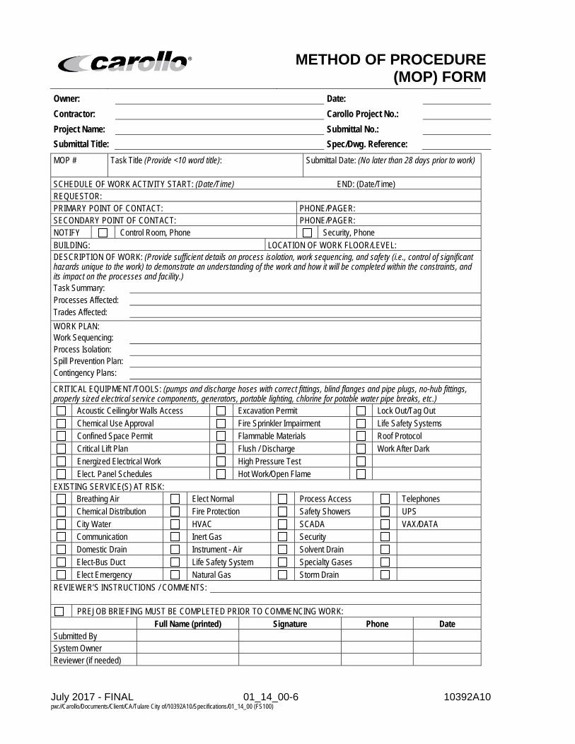
July 2017 - FINAL 01_14_00-6 10392A10 pw://Carollo/Documents/Client/CA/Tulare City of/10392A10/Specifications/01_14_00 (FS100)
METHOD OF PROCEDURE
(MOP) FORM Owner: Date:
Contractor: Carollo Project No.:
Project Name: Submittal No.:
Submittal Title: Spec/Dwg. Reference:
MOP # Task Title (Provide <10 word title): Submittal Date: (No later than 28 days prior to work) SCHEDULE OF WORK ACTIVITY START: (Date/Time) END: (Date/Time) REQUESTOR: PRIMARY POINT OF CONTACT: PHONE/PAGER: SECONDARY POINT OF CONTACT: PHONE/PAGER: NOTIFY Control Room, Phone Security, Phone BUILDING: LOCATION OF WORK FLOOR/LEVEL: DESCRIPTION OF WORK: (Provide sufficient details on process isolation, work sequencing, and safety (i.e., control of significant hazards unique to the work) to demonstrate an understanding of the work and how it will be completed within the constraints, and its impact on the processes and facility.) Task Summary: Processes Affected: Trades Affected:
WORK PLAN: Work Sequencing: Process Isolation: Spill Prevention Plan: Contingency Plans:
CRITICAL EQUIPMENT/TOOLS: (pumps and discharge hoses with correct fittings, blind flanges and pipe plugs, no-hub fittings, properly sized electrical service components, generators, portable lighting, chlorine for potable water pipe breaks, etc.)
Acoustic Ceiling/or Walls Access Excavation Permit Lock Out/Tag Out
Chemical Use Approval Fire Sprinkler Impairment Life Safety Systems
Confined Space Permit Flammable Materials Roof Protocol
Critical Lift Plan Flush / Discharge Work After Dark
Energized Electrical Work High Pressure Test
Elect. Panel Schedules Hot Work/Open Flame EXISTING SERVICE(S) AT RISK:
Breathing Air Elect Normal Process Access Telephones
Chemical Distribution Fire Protection Safety Showers UPS
City Water HVAC SCADA VAX/DATA
Communication Inert Gas Security
Domestic Drain Instrument - Air Solvent Drain
Elect-Bus Duct Life Safety System Specialty Gases
Elect Emergency Natural Gas Storm Drain REVIEWER’S INSTRUCTIONS / COMMENTS:
PREJOB BRIEFING MUST BE COMPLETED PRIOR TO COMMENCING WORK: Full Name (printed) Signature Phone Date Submitted By System Owner Reviewer (if needed)

July 2017 - FINAL 01_14_00-7 10392A10 pw://Carollo/Documents/Client/CA/Tulare City of/10392A10/Specifications/01_14_00 (FS100)
READINESS CHECKLIST (5 days prior to work)
Checklist provided as a guide but is not all inclusive. 1. Confirm all parts and materials are on site:
2. Review work plan:
3. Review contingency plan:

July 2017 - FINAL 01_14_00-8 10392A10 pw://Carollo/Documents/Client/CA/Tulare City of/10392A10/Specifications/01_14_00 (FS100)
SAFETY CHECKLIST (Just prior to commencing work)
Checklist provided as a guide but is not all inclusive. 1. Location awareness:
a. Emergency exits: b. Emergency shower and eyewash: c. Telephones and phone numbers: d. Shut-off valve: e. Electrical disconnects:
2. Inspect work area: a. Take time to survey the area you are working in. Ensure that what you want to do will
work. Do you have enough clearance? Is your footing secure? Do you have adequate lighting and ventilation? Are surrounding utilities out of the way for you to perform your work?
3. SDS (Safety Data Sheets): a. Understand the chemicals and substances in the area you are working in by reading
the SDS. 4. Lockout/Tagout Procedure:
a. Lockout/tagout energy sources before beginning work. b. Make sure all valves associated with the work are locked out and tagged out on each
side of the penetration. c. Make sure the lines are depressurized.
5. Overhead work: a. Use appropriate personal protective equipment; i.e., safety harness, lifeline, etc. b. Select appropriate tie-off points; i.e., structurally adequate, not a pipe or conduit, etc. c. Spotter assigned and in position. d. Pipe rack access; i.e., check design capacity, protective decking or scaffolding in
place, exposed valves or electrical switches identified and protected. 6. Safety equipment:
a. Shepherd's hook. b. ARC flash protection. c. Fire extinguisher. d. Other: .
7. Accidents: a. Should accidents occur, do not shut off and do not attempt to correct the situation,
unless you are absolutely positive that your action will correct the problem and not adversely affect other people or equipment.
8. Review process start-up documents: a. In the event the system is shutdown, the Control Center should have a working
knowledge of the process start-up procedures in order to deal effectively with unforeseen events.
9. Evacuation procedures: a. Do not obstruct evacuation routes. b. Take time to survey the area for evacuation routes.
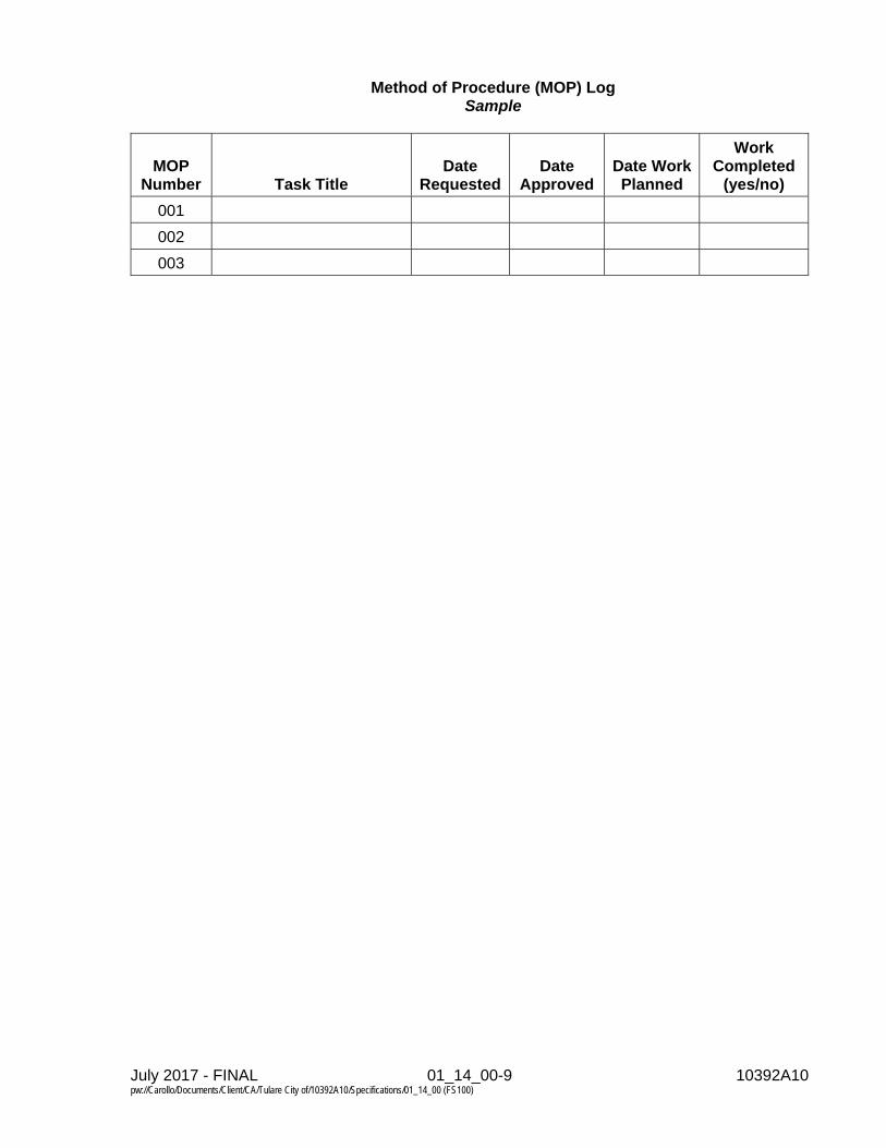
July 2017 - FINAL 01_14_00-9 10392A10 pw://Carollo/Documents/Client/CA/Tulare City of/10392A10/Specifications/01_14_00 (FS100)
Method of Procedure (MOP) Log Sample
MOP Number Task Title
Date Requested
Date Approved
Date Work Planned
Work Completed
(yes/no)
001
002
003


July 2017 - DRAFT 01_23_00-1 10392A1010392A10 pw://Carollo/Documents/Client/CA/Tulare City of/10392A10/Specifications/01_23_00 (FS100)
SECTION 01_23_00
ALTERNATES
PART 1 GENERAL
1.01 SUMMARY
A. Section includes: Identification and description of Alternates.
B. Related section: 1. Section 01_11_00 - Summary of Work.
1.02 PROCEDURES
A. Alternates will be exercised at Owner's option.
B. Coordinate related work and modify surrounding work as required to complete the Work, including changes under Alternates accepted by Owner in Notice of Award.
1.03 ALTERNATES
A. Bid Alternate A (deduct) - Installation of Well Pump and associated appurtenances at the Alpine Vista site: 1. Base Bid: As specified in Sections 00_21_13 and 00_41_00. 2. Alternate: As specified in Section 01_11_00.
PART 2 PRODUCTS Not Used.
PART 3 EXECUTION Not Used.
END OF SECTION


July 2017 - FINAL 01_26_00-1 10392A10 pw://Carollo/Documents/Client/CA/Tulare City of/10392A10/Specifications/01_26_00 (FS100)
SECTION 01_26_00
CONTRACT MODIFICATION PROCEDURES
PART 1 GENERAL
1.01 SUMMARY
A. Section Includes: 1. Administrative and procedural requirements for executing a change in the
Work.
B. Related section: 1. Not Used.
1.02 PRELIMINARY REQUIREMENTS
A. Change Order Cost Basis Summary Form: 1. Submit a sample to Engineer for review within 15 calendar days following
Notice to Proceed. a. Items will be reviewed and their value, percentage, or calculation method
mutually agreed to by the Contractor and Owner prior to executing a Change Order on the Project.
2. Used by the Contractor for pricing each Change Order required for additions, deletions, or revisions in the Work.
3. Include the following information: a. Agreed upon markups, percentages, and procedures for calculating all
surcharges, etc. associated with the Cost of the Change Order Work. b. References for unit price information and special unit price information. c. Attachments with the following information:
1) Certified labor rates breakdown. 2) Equipment rates. 3) Bond and insurance rates (PI&I).
1.03 REQUEST FOR INFORMATION OR INTERPRETATION (RFI)
A. Contractor may issue RFIs to request interpretation of the documents or to request for information that may be missing.
B. General Instructions: 1. Number RFIs consecutively.
a. Add a consecutive letter to the RFI number on modified submittals of the same RFI (i.e., RFI 4B).
2. Provide RFI for 1 item. a. There may be exceptions when multiple items are so functionally related
that expediency indicates review of the group of items as a whole. b. RFIs with multiple items will be rejected without review.
3. Contractor sign and date RFIs indicating review and approval. a. Contractor’s signature indicates that they have satisfied RFI review
responsibilities and constitutes Contractor's written approval of RFI.

July 2017 - FINAL 01_26_00-2 10392A10 pw://Carollo/Documents/Client/CA/Tulare City of/10392A10/Specifications/01_26_00 (FS100)
b. RFIs without Contractor's signature will be returned to the Contractor unreviewed. Subsequent submittal of this information will be counted as the first resubmittal.
C. Engineer will render a written clarification, interpretation, or decision on the issue submitted or initiate an amendment or supplement to the Contract within 21 days. 1. In the event the Contractor identifies an RFI as critical to the progress of the
project, Engineer will make every effort to reduce the RFI response time.
1.04 PRELIMINARY PROCEDURES
A. Owner or Engineer may initiate changes by submitting a Request for Proposal (RFP) to Contractor including the following information: 1. Detailed description of the Change, Products, and location of the change in the
Project. 2. Supplementary or revised drawings or specifications. 3. Projected time span for making the change, and a specific statement if
overtime work is authorized. 4. A specific period of time during which the requested price will be considered
valid. 5. Such request is for information only, and is not an instruction to execute the
changes, or to stop work in progress.
B. Contractor may initiate changes by submitting a Change Proposal to Engineer containing the following: 1. Description of proposed changes. 2. Reason for making changes. 3. Specific period of time during which requested price will be considered valid. 4. Effect on Total Contract Cost and/or Contract Time. 5. Documentation supporting any change in Total Contract Cost and/or Contract
Time, as appropriate.
1.05 WORK CHANGE DIRECTIVE AUTHORIZATION
A. In lieu of a Request for Proposal (RFP), Engineer may issue a Work Change Directive Authorization for Contractor to proceed with a change for subsequent inclusion in a Change Order.
B. Authorization will describe changes in the Work, both additions and deletions, with attachments of revised Contract Documents to define details of the change, and will designation method of determining any change in the Contract Sum and/or the Contract Time, as appropriate.
C. Owner and Engineer will sign and date the Work Change Directive Authorization as authorization for the Contractor to proceed with the changes.
D. Contractor may sign and date the Work Change Directive Authorization to indicate agreement with the terms.

July 2017 - FINAL 01_26_00-3 10392A10 pw://Carollo/Documents/Client/CA/Tulare City of/10392A10/Specifications/01_26_00 (FS100)
1.06 DOCUMENTATION OF CHANGE PROPOSALS
A. Change proposal: 1. Support with sufficient substantiating data to allow Engineer to evaluate the
quotation. a. Lump sum. b. Unit prices: Use previously established unit prices. c. Time-and-material/force account basis:
1) Name of the Owner’s authorized agent who ordered the work, and date of the order.
2) Dates and times work was performed, and by whom. 3) Time record, summary of hours worked, and hourly rates paid. 4) Receipts and invoices for:
a) Equipment used, listing dates and times of use. b) Products used, listing of quantities. c) Subcontracts.
2. Provide additional data to support time and cost computations: a. Labor required. b. Equipment required. c. Products required.
1) Recommended source of purchase and unit cost. 2) Quantities required.
d. Taxes, insurance, and bonds. e. Credit for work deleted from Contract, similarly documented. f. Overhead and profit. g. Justification for change to Contract Time.
1.07 PREPARATION OF CHANGE ORDERS AND FIELD ORDERS
A. Engineer will prepare each Change Order and Field Order.
B. Change Orders: 1. Will describe changes in the Work, both additions and deletions, with
attachments of revised Contract Documents to define details of the change. 2. Will provide an accounting of the adjustment in the Contract Sum and in the
Contract Time. 3. Recommendation of Change Proposal is indicated by Engineer's signature. 4. Upon signature and execution by Owner, the Change Proposal becomes a
Change Order altering the Contract Time and Total Contract Cost, as indicated. a. Owner’s Representative will transmit one signed copy each to Contractor
and Engineer. 5. Contractor may only request payment for changes in the Work against an
approved Change Order. 6. If either Engineer or Owner’s Representative disapproves the Change
Proposal, the reason for disapproval will be stated. a. A request for a revised proposal or cancellation of the proposal will be
shown.
C. Field Orders: 1. Order minor changes in the Work without changes in Contract Price or
Contract Times.

July 2017 - FINAL 01_26_00-4 10392A10 pw://Carollo/Documents/Client/CA/Tulare City of/10392A10/Specifications/01_26_00 (FS100)
1.08 LUMP-SUM/FIXED PRICE CHANGE ORDER
A. Content of Change Orders will be based on, either: 1. Engineer’s Proposal Request and Contractor’s responsive Change Proposal
as mutually agreed between Owner and Contractor. 2. Contractor’s Change Proposal for a change, as recommended by Engineer.
B. Owner and Engineer will sign and date the Change Order to establish the change in Contract Sum and in Contract Time and serve as authorization for the Contractor to proceed with the changes.
C. Contractor will sign and date the Change Order to indicate agreement with the terms.
1.09 UNIT PRICE CHANGE ORDER
A. Content of Change Orders will be based on, either: 1. Engineer’s definition of the scope of the required changes. 2. Contractor’s Change Proposal for a change, recommended by Engineer. 3. Survey of completed work.
B. The amounts of the unit prices to be: 1. Those stated in the Contract. 2. Those mutually agreed upon between Owner and Contractor.
C. When quantities of each of the items affected by the Change Order can be determined prior to start of the work: 1. Owner and Engineer will sign and date the Change Order as authorization for
Contractor to proceed with the changes. 2. Contractor will sign and date the Change Order to indicate agreement with the
terms.
D. When quantities of the items cannot be determined prior to start of the work: 1. Engineer or Owner will issue a Work Change Directive authorization directing
Contractor to proceed with the change on the basis of unit prices, and will cite the applicable unit prices.
2. At completion of the change, Engineer will determine the cost of such work based on the unit prices and quantities used.
3. Contractor shall submit documentation to establish the number of units of each item and any claims for a change in Contract Time.
E. Owner and Engineer will sign and date the Change Order to establish the change in Contract Sum and in Contract Time and serve as authorization for the Contractor to proceed with the changes.
F. Contractor will sign and date the Change Order to indicate their agreement with the terms.
1.10 TIME AND MATERIAL/FORCE ACCOUNT CHANGE ORDER/WORK CHANGE DIRECTIVE AUTHORIZATION
A. Engineer will issue a Work Change Directive for the Owner’s signature authorizing Contractor to proceed with the changes.

July 2017 - FINAL 01_26_00-5 10392A10 pw://Carollo/Documents/Client/CA/Tulare City of/10392A10/Specifications/01_26_00 (FS100)
B. At completion of the change, Contractor shall submit itemized accounting and supporting data as specified in this Section.
C. Engineer will determine the allowable cost of such work, as provided in the Contract Documents.
D. Owner and Engineer will sign and date the Change Order to establish the change in Contract Sum and in Contract Time and serve as authorization for the Contractor to proceed with the changes.
E. Contractor will sign and date the Change Order to indicate their agreement.
1.11 CORRELATION WITH CONTRACTOR’S SUBMITTALS
A. Periodically revise Schedule of Values and Applications for Payment forms to record each Change Order as a separate item of Work, and to record the adjusted Contract Sum.
B. Periodically revise the Construction Schedule to reflect each change in Contract Time. Revise subschedules to show changes for other items of work affected by the changes.
C. Upon completion of work under a Change Order, enter pertinent changes in Record Documents.
PART 2 PRODUCTS Not Used.
PART 3 EXECUTION Not Used.
END OF SECTION


July 2017 - FINAL 01_29_00-1 10392A10 pw://Carollo/Documents/Client/CA/Tulare City of/10392A10/Specifications/01_29_00 (FS100)
SECTION 01_29_00
PAYMENT PROCEDURES
PART 1 GENERAL
1.01 SUMMARY
A. Section includes: Procedures for submitting applications for payment and means used as a basis for Progress Payments, including: 1. Cost Summaries. 2. Payment for Mobilization. 3. Commissioning and Process Start-Up. 4. Demobilization.
1.02 REFERENCES
A. Occupational Safety and Health Administration (OSHA).
1.03 BASIS FOR PROGRESS PAYMENTS
A. Base Application for Payment on the breakdown of costs for each scheduled activity in the Progress Schedule and the Percentage of Completion for each activity. Generate Application for Payment by downloading cost data from the Progress Schedule to a spreadsheet type format. Identify each activity on the Progress Schedule that has a cost associated with it, the cost of each activity, the estimated Percent Complete for each activity, and the Value of Work Completed for both the payment period and job to date.
1.04 PAYMENT REQUESTS
A. Prepare progress payment requests on a monthly basis. Base requests on the breakdowns of costs for each scheduled activity and the percentage of completion for each activity.
B. Indicate total dollar amount of work planned for every month of the project. Equate sum of monthly amounts to Lump Sum Contract Price.
C. Generate Progress Payment request forms by downloading cost data from the schedule information to a spreadsheet type format. Identify each activity on the Progress Schedule that has a cost associated with it, the cost for each activity, the estimated percent complete for each activity, and the value of work completed for both the payment period and job to date.
D. Provide Summary of Cost Information.
1.05 COST SUMMARIES
A. Prepare Summary of Cost Information for each Major Item of Work listed in the Schedule of Values. Identify the Value of Work Completed for both the payment period and job to date.

July 2017 - FINAL 01_29_00-2 10392A10 pw://Carollo/Documents/Client/CA/Tulare City of/10392A10/Specifications/01_29_00 (FS100)
B. Cash flow summary: Prepare cash flow summary, indicating total dollar amount of work planned for each month of the project. Equate sum of monthly amounts to Lump Sum contract price.
1.06 PAYMENT FOR MOBILIZATION
A. Limit amounts included under mobilization to the following items: 1. Moving on the site any equipment required for first month operations. 2. Installing temporary construction power, wiring, and lighting facilities. 3. Establishing fire protection plan and safety program. 4. Developing construction water supply. 5. Providing field office trailers for the Contractor and the Engineer, complete with
all specified furnishings and utility services including telephones. 6. Providing on-site sanitary facilities and potable water facilities as specified. 7. Arranging for and erection of Contractor's work and storage yard, employee
parking facilities, and entrance road. 8. Submit all required insurance certificates and bonds. 9. Obtaining all required permits, licenses, and fees. 10. Submit preliminary schedule of values of the Work. 11. Submit preliminary schedule and develop baseline schedule. 12. Submit standardized traffic maintenance and control plans. 13. Submit cash flow in tabular and graphical formats. 14. Submit Contractor’s quality control plan. 15. Submit Schedule of Submittals. 16. Submit pre-construction photographs and videos. 17. Provide and erect the project sign. 18. Post all OSHA, (state agency), Department of Labor, and all other required
notices. 19. Location and flagging of construction and clearing. 20. Have Contractor’s project manager and/or general superintendent on job site
full-time.
B. Furnish data and documentation to substantiate the amounts claimed under mobilization.
C. Limit price for mobilization to no more than 5 percent of Contract Price.
D. No payment for mobilization, or any part thereof, will be recommended until all mobilization items listed above have been completed.
1.07 PAYMENT FOR COMMISSIONING AND PROCESS START-UP
A. Total Price for commissioning and process start-up shall not be less than 3 percent of Contract Price.
1.08 PAYMENT FOR DEMOBILIZATION
A. Total Price for demobilization shall not be less than 3 percent of Contract Price.
July 2017 - FINAL 01_29_00-3 10392A10 pw://Carollo/Documents/Client/CA/Tulare City of/10392A10/Specifications/01_29_00 (FS100)
PART 2 PRODUCTS Not Used.
PART 3 EXECUTION Not Used.
END OF SECTION


July 2017 - FINAL 01_29_73-1 10392A10 pw://Carollo/Documents/Client/CA/Tulare City of/10392A10/Specifications/01_29_73 (FS100)
SECTION 01_29_73
SCHEDULE OF VALUES
PART 1 GENERAL
1.01 SUMMARY
A. Section includes: Requirements for preparation, format, and submittal of Schedule of Values.
B. Related section: 1. Section 01_32_17- Progress Schedules and Reports 2. Section 26_05_00 – Common Work Results for Electrical.
1.02 PREPARATION
A. Prepare Schedule of Values identifying costs of Major Items of Work and other costs shown in sample included at end of this Section.
B. Divide the work into following major items of work: 1. Mobilization. 2. Site Civil. 3. Yard Piping. 4. Concrete Water Storage Tank. 5. Booster Pump Station. 6. Chemical Feed 7. Electrical Building. 8. Electrical. 9. Stand-by Generator. 10. Instrumentation and SCADA 11. Startup and Commissioning 12. Demobilization.
C. Assign prices to Major Items of Work which aggregate the Contract Price. Base prices on costs associated with scheduled activities based on the Project Schedule for each Major Item of Work.
1.03 SUBMITTALS
A. Submit preliminary schedule of values.
B. Submit corrected schedule of values within 10 days upon receipt of reviewed Schedule of Values, but no later than 10 days prior to anticipated submittal of first Application for Payment.
C. Upon request, support prices with data which will substantiate their correctness.
D. If activities are added or removed from the Progress Schedule revise the Schedule of Values and resubmit.

July 2017 - FINAL 01_29_73-2 10392A10 pw://Carollo/Documents/Client/CA/Tulare City of/10392A10/Specifications/01_29_73 (FS100)
1.04 SAMPLE SCHEDULE OF VALUES
A. Following is an acceptable form for Schedule of Values:
SCHEDULE OF VALUES
NO. DESCRIPTION OF ITEM LUMP SUM COST
1 Mobilization.
2 Site Civil.
3 Yard Piping.
4 Concrete Water Storage Tank.
5 Booster Pump Station.
6 Chemical Feed
7 Electrical Building.
8 Electrical.
9 Stand-by Generator.
10 Instrumentation and SCADA
11 Startup and Commissioning
12 Demobilization.
13 Mobilization.
TOTAL LUMP SUM BID
PART 2 PRODUCTS
Not Used.
PART 3 EXECUTION
Not Used.
END OF SECTION

July 2017 - FINAL 01_29_77-1 10392A10 pw://Carollo/Documents/Client/CA/Tulare City of/10392A10/Specifications/01_29_77 (FS100)
SECTION 01_29_77
APPLICATIONS FOR PAYMENT
PART 1 GENERAL
1.01 SUMMARY
A. Section includes: Procedures for preparation and submittal of Applications for Payment.
B. Related section: 1. Document 00_62_77 - Contractor’s Application for Payment.
1.02 FORMAT
A. Develop satisfactory spreadsheet-type form generated by downloading cost data from the Progress Schedule. 1. Submit payment requests using Document 00_62_77 and attach spreadsheet
with cost data related to Progress Schedule.
B. Fill in information required on form.
C. When Change Orders are executed, add Change Orders at end of listing of scheduled activities: 1. Identify change order by number and description. 2. Provide cost of change order in appropriate column.
D. After completing, submit Application for Payment.
E. Engineer will review application for accuracy. When accurate, Engineer will transmit application to Owner for processing of payment.
F. Execute application with signature of responsible officer of Contractor.
1.03 SUBSTANTIATING DATA
A. Provide Substantiating Data with cover letter identifying: 1. Project. 2. Application number and date. 3. Detailed list of enclosures. 4. For stored products with item number and identification on application,
description of specific material, and proof of insurance coverage for offsite stored products.
5. Submit “certified” payroll, if applicable.
1.04 SUBMITTALS
A. Submit 5 copies of Application for Payment and Substantiating Data with cover letter.

July 2017 - FINAL 01_29_77-2 10392A10 pw://Carollo/Documents/Client/CA/Tulare City of/10392A10/Specifications/01_29_77 (FS100)
1.05 PAYMENT REQUESTS
A. Prepare progress payment requests on a monthly basis. Base requests on the breakdowns of costs for each scheduled activity and the percentage of completion for each activity.
B. Indicate total dollar amount of work planned for every month of the project. Equate sum of monthly amounts to Lump Sum Contract Price.
C. Generate Progress Payment request forms by downloading cost data from the schedule information to a spreadsheet type format. Identify each activity on the Progress Schedule that has a cost associated with it, the cost for each activity, the estimated percent complete for each activity, and the value of work completed for both the payment period and job to date.
D. Prepare summary of cost information for each Major Item of Work listed in the Schedule of Values. Identify the value of work completed for both the payment period and job to date.
E. Payment period: 1. Monthly Application for Payment period shall begin on the 1st day of each
month, and end on the last day of each month. 2. Submit Application for Payment to Engineer no later than the 5th day of each
month for work completed the previous month. 3. Engineer will finalize and submit recommendation for Application for Payment
to Owner by the 15th day of each month to allow time for processing and approval.
PART 2 PRODUCTS Not Used.
PART 3 EXECUTION Not Used.
END OF SECTION

July 2017 - FINAL 01_31_19-1 10392A10 pw://Carollo/Documents/Client/CA/Tulare City of/10392A10/Specifications/01_31_19 (FS100)
SECTION 01_31_19
PROJECT MEETINGS
PART 1 GENERAL
1.01 SUMMARY
A. Section includes: Requirements for conducting conferences and meetings for the purposes of addressing issues related to the Work, reviewing and coordinating progress of the Work and other matters of common interest, and includes the following: 1. Qualifications of Meeting Participants. 2. Preconstruction Conference. 3. Progress Meetings. 4. Pre-Installation Meetings. 5. Schedule Update Meetings. 6. Quality Control Meetings. 7. Pre-Shutdown Meetings. 8. Pre-Process Start-up Meetings. 9. Electrical and Instrumentation Coordination Meetings. 10. Close-out meeting. 11. Post Construction Meeting.
B. Related sections: 1. Section 01_14_00 - Work Restrictions. 2. Section 26_05_00 - Common Work Results for Electrical. 3. Section 26_05_74 - Electrical System Studies. 4. Section 40_61_00 - Common Work Results for Process Control and
Instrumentation Systems. 5. Section 40_64_21 - Control Systems: Local Operator Interface (LOI).
1.02 QUALIFICATIONS OF MEETING PARTICIPANTS
A. Representatives of entities participating in meetings shall be qualified and authorized to act on behalf of entity each represents.
1.03 PRECONSTRUCTION CONFERENCE
A. Upon issuance of Notice to Proceed, or earlier when mutually agreeable, Engineer will arrange preconstruction conference in place convenient for most invitees.
B. Preconstruction Conference invitees: Contractor's project manager and superintendent, Owner, Engineer, representatives of utilities, major subcontractors and others involved in performance of the Work, and others necessary to agenda.
C. Engineer will preside at conference.
D. Purpose of conference: To establish working understanding between parties and to discuss Construction Schedule, shop drawing and other submittals, cost breakdown

July 2017 - FINAL 01_31_19-2 10392A10 pw://Carollo/Documents/Client/CA/Tulare City of/10392A10/Specifications/01_31_19 (FS100)
of major lump sum items, processing of submittals and applications for payment, and other subjects pertinent to execution of the Work.
E. Agenda will include: 1. Adequacy of distribution of Contract Documents. 2. Distribution and discussion of list of major subcontractors and suppliers. 3. Proposed progress schedules and critical construction sequencing. 4. Major equipment deliveries and priorities. 5. Project coordination. 6. Designation of responsible personnel. 7. Procedures and processing of:
a. Field decisions. b. Proposal requests. c. Submittals. d. Change Orders. e. Request for Information/Interpretations. f. Applications for Payment. g. Record Documents.
8. Use of premises: a. Office, construction, and storage areas. b. Owner's requirements.
9. Construction facilities, controls, and construction aids. 10. Temporary utilities. 11. Safety and first aid procedures. 12. Security procedures. 13. Housekeeping procedures.
F. Engineer will record minutes of meeting and distribute copies of minutes within 7 days of meeting to participants and interested parties.
1.04 PROGRESS MEETINGS
A. Engineer will schedule and administer meetings throughout progress of the Work at maximum weekly intervals.
B. Engineer will make arrangements for meetings, prepare agenda with copies for participants, and preside at meetings.
C. Attendance required: Owner, Engineer, Contractor, Contractor’s Project Manager, superintendent, quality control manager, project scheduler, major subcontractors, and suppliers as appropriate to agenda topics for each meeting.
D. Additional invitees: Owner utility companies when the Work affects their interests, and others necessary to agenda.
E. Agenda: 1. Review minutes of previous meeting/minutes. 2. Safety and security. 3. Construction schedule summary. 4. Review of 6 weeks schedule. 5. Review of off-site fabrication and delivery schedules. 6. Review of submittals schedule and status of submittals. 7. Request for information (RFI’s) status.

July 2017 - FINAL 01_31_19-3 10392A10 pw://Carollo/Documents/Client/CA/Tulare City of/10392A10/Specifications/01_31_19 (FS100)
8. MOP’s/shutdown coordination. 9. Change order management status. 10. Maintenance of quality standards (QA/QC). 11. Field observations, problems, and conflicts. 12. Commissioning and process start-up. 13. Partnering recognition status (optional). 14. General Items. 15. Action items. 16. Next meeting.
F. Engineer will record minutes and distribute copies within 5 calendar days after meeting to participants, with copies to Contractor, Owner, and those affected by decisions made.
1.05 PRE-INSTALLATION MEETINGS
A. When required in individual specification sections or requested by Engineer, convene pre-installation meeting at Project site before commencing work of specific section.
B. Require attendance of parties directly affecting, or affected by, Work of specific section.
C. Notify Engineer 7 calendar days in advance of meeting date.
D. Prepare agenda and preside at meeting: 1. Review conditions of installation, preparation and installation procedures. 2. Review coordination with related work.
E. Contractor will record minutes and distribute electronic copies within 7 calendar days after meeting to participants, with copies to Engineer, Owner, and those affected by decisions made.
1.06 SCHEDULE UPDATE MEETINGS
A. Engineer will schedule meetings throughout progress of the Work at maximum monthly intervals.
B. Engineer will make arrangements for meetings; Contractor will prepare agenda with copies for participants, and preside at meetings.
C. Attendance required: Owner, Engineer, Contractor, Contractor’s Project Manager, General Superintendent, project scheduler, major subcontractors, and suppliers as appropriate to agenda topics for each meetings.
D. Additional invitees: Owner utility companies when the Work affects their interests and others necessary to the agenda.
E. Agenda: 1. Review Monthly Schedule, (Actual Progress and Variance).
a. “Activities Started/Completed” this period. b. “Activities Started/Completed” “Variance” Baseline vs. current. c. “Added/Deleted Activities”.

July 2017 - FINAL 01_31_19-4 10392A10 pw://Carollo/Documents/Client/CA/Tulare City of/10392A10/Specifications/01_31_19 (FS100)
d. “Revised Activity Descriptions”. e. Any significant Proposed Logic Changes.
2. Review milestone “Substantial Completion” Schedule. a. “Critical” Activities – “Critical Area, Float and Vital Statistics”.
3. Review “Cumulative and Monthly Costs” graph. 4. Review “Budgeted Cost” indicating the Current Project Budgeted Cost.
F. Contractor will record changes for update and distribute electronic copies within 7 calendar days after meeting to participants and interested parties.
1.07 QUALITY CONTROL MEETINGS
A. Contractor will schedule and administer meetings throughout progress of the Work at maximum weekly intervals.
B. Contractor will make arrangements for meetings, prepare agenda with copies for participants, and preside at meetings.
C. Attendance Required: Construction Manager and staff, Contractor’s Quality Control Manager and staff.
D. Agenda: 1. Review minutes of previous meetings. 2. Review of Work progress and schedule. 3. Review of out-of-compliance inspection or test results. 4. Field observations, problems, and decisions. 5. Review of offsite fabrication and delivery schedules. 6. Planned progress during succeeding work period. 7. Coordination of required inspections and tests. 8. Review 6-week schedule report with upcoming inspections and special tests. 9. Maintenance of quality and work standards. 10. Other business relating to Work.
E. Contractor will record minutes and distribute electronic copies within 5 calendar days after meeting to participants, and those affected by decisions made.
1.08 PRESHUTDOWN MEETINGS
A. Follow Owner’s standard Construction Method of Procedure (MOP). See Appendix A of Section 01_14_00 for MOP format.
B. All short-term and longer-term shutdowns and other tie-ins that require an Owner approved MOP also require a pre-shutdown meeting at Project site prior to commencing shutdown for tie-in or modification of specific plant systems.
C. Require attendance of parties directly affecting, or affected by shutdown, including Engineer, specific work crews, Owner’s construction, operations, and maintenance staff.
D. Notify Engineer 7 calendar days in advance of meeting date.

July 2017 - FINAL 01_31_19-5 10392A10 pw://Carollo/Documents/Client/CA/Tulare City of/10392A10/Specifications/01_31_19 (FS100)
E. Prepare agenda and preside at meeting: 1. Review accepted MOP including conditions of shutdown, preparation, and
installation procedures. 2. Review timelines and sequences. 3. Review responsibilities. 4. Review dry run plan and schedule, as necessary. 5. Review coordination with related work.
F. Contractor will record minutes and distribute copies within 5 calendar days after meeting and prior to scheduled shutdown to participants, with copies to Engineer, Owner, and those affected by decisions made.
1.09 PRE-PROCESS START-UP MEETINGS
A. All processes and equipment that requires testing and process start-up also requires a pre-startup meeting at Project site before commencing process start-up of specific plant systems.
B. Require attendance of parties directly affecting, or affected by process start-up and testing, including Engineer, specific work crews, Owner’s construction operations, and maintenance staff.
C. Notify Engineer 7 calendar days in advance of meeting date.
D. Prepare agenda and preside at meeting: 1. Review accepted MOP including conditions of process start-up and testing,
preparation, and installation procedures. 2. Review timelines and sequences. 3. Review responsibilities. 4. Review dry run plan and schedule, as necessary. 5. Review coordination with related work.
E. Contractor will record minutes and distribute electronic copies within 5 calendar days after meeting and prior to scheduled process start-up to participants, with copies to Engineer, Owner, and those affected by decisions made.
F. Follow Owner’s standard Construction Method of Procedure (MOP). See Appendix A of Section 01_14_00 for MOP format.
1.10 ELECTRICAL AND INSTRUMENTATION COORDINATION MEETINGS
A. Electrical Meetings: 1. Pre-submittal review meeting as specified in Section 26_05_00. 2. Electrical System Study Meetings (3 separate meetings) as specified in
Section 26_05_74. 3. Other meetings as required and as otherwise specified.
B. Instrumentation and Control Meetings: 1. Pre-Submittal Conference as specified in Section 40_61_00. 2. System Configuration Meetings (3 separate meetings) as specified in
Section 40_61_00. 3. Graphics Meetings (2 separate meetings) as specified in Section 40_64_21. 4. Report Meetings (2 separate meetings) as specified in Section 40_64_21.

July 2017 - FINAL 01_31_19-6 10392A10 pw://Carollo/Documents/Client/CA/Tulare City of/10392A10/Specifications/01_31_19 (FS100)
5. Other meetings as required and as otherwise specified.
1.11 CLOSE-OUT MEETING
A. Engineer will schedule close-out meeting.
B. Engineer will make arrangements for meeting, prepare agenda with copies for participants, and preside at meeting.
C. Attendance required: Owner, Engineer, Contractor, Contractor’s Project Manager, and Superintendent.
D. Agenda: 1. Review punchlist completion. 2. Transfer of record documents. 3. Finalize payment.
E. Engineer will record minutes and within 5 calendar days after meeting distribute copies to participants.
1.12 POST CONSTRUCTION MEETING
A. Meet with and inspect the Work 11 months after date of Substantial Completion with Owner and Engineer.
B. Owner will arrange meeting at least 7 days before meeting.
C. Meet in Owner’s office or other mutually agreed upon place.
D. Inspect the Work and draft list of items to be completed or corrected.
E. Review service and maintenance contracts, and take appropriate corrective action when necessary.
F. Complete or correct defective work and extend correction period accordingly.
G. Require attendance of Contractor, Project Manager, or Superintendent, appropriate manufacturers and installers of major units of constructions, and affected subcontractors.
PART 2 PRODUCTS Not Used.
PART 3 EXECUTION Not Used.
END OF SECTION

July 2017 - FINAL 01_31_24-1 10392A10 pw://Carollo/Documents/Client/CA/Tulare City of/10392A10/Specifications/01_31_24 (FS100)
SECTION 01_31_24
WEB BASED CONSTRUCTION DOCUMENT MANAGEMENT
PART 1 GENERAL
1.01 SUMMARY
A. Section includes: 1. Requirements for web-based construction document management.
B. Related sections: 1. Section 01_26_00 - Contract Modification Procedures. 2. Section 01_33_00 - Submittal Procedures. 3. Section 01_78_23 - Operation and Maintenance Data.
1.02 REQUIREMENTS
A. Owner, Engineer, and Contractor shall utilize EADOC (EADOC is a registered trademark of EADOC LLC). For submission of all data and documents (unless specified otherwise in this Section) throughout the duration of the Contract. 1. EADOC is a web-based electronic media site hosted by EADOC LLC. 2. EADOC is available to all Contractor’s personnel, subcontractor personnel,
suppliers, consultants, Owner, and Engineer at no cost. 3. The joint use of this system is to facilitate electronic exchange of information,
automation of key processes, and overall management of Contract Documentation.
4. EADOC shall be the primary means of project information submission and management.
1.03 USER ACCESS LIMITATIONS
A. Provide a list of Contractor's key EADOC personnel for the Engineer’s acceptance. The Engineer reserves the right to perform a security check on all potential users. The Contractor will be allowed to add additional personnel and subcontractors to EADOC.
B. The Engineer will grant initial access to EADOC by creating user profiles to accepted Contractor personnel. User profiles will define levels of access into the system; determine assigned function based authorizations and user privileges. Subcontractors and suppliers will be given access to EADOC by and through the Contractor. Contractor is responsible for adding and removing users from the system after the initial setup by the Engineer.
1.04 JOINT OWNERSHIP OF DATA
A. Data entered in a collaborative mode (entered with the intent to share as determined by permissions and workflows within the EADOC system) by Engineer and Contractor will be jointly owned.

July 2017 - FINAL 01_31_24-2 10392A10 pw://Carollo/Documents/Client/CA/Tulare City of/10392A10/Specifications/01_31_24 (FS100)
1.05 AUTOMATED SYSTEM NOTIFICATION AND AUDIT LOG TRACKING
A. Review comments made (or lack thereof) by Owner on Contractor submitted documentation shall not relieve Contractor from compliance with requirements of the Contract Documents. Contractor is responsible for managing, tracking, and documenting the Work to comply with the requirements of the Contract Documents. Owner’s acceptance via automated system notifications or audit logs extends only to the face value of the submitted documentation and does not constitute validation of the Contractor's submitted information.
1.06 COMPUTER REQUIREMENTS
A. Contractor shall use computer hardware and software that meets the requirements of the EADOC system as recommended by EADOC LLC to access and utilize EADOC. As recommendations are modified by EADOC, Contractor will upgrade their system(s) to meet or exceed the recommendations. Upgrading of Contractor's computer systems will not be justification for a cost or time modification to the Contract.
B. Contractor shall ensure that connectivity to the EADOC system is accomplished through DSL, cable, T-1, or wireless communications systems. The minimum bandwidth requirements for using the system is 128 kb/s. It is recommended a faster connection be used when uploading pictures and files into the system.
C. EADOC supports the current and prior 2 major versions of Chrome, Mozilla's Firefox, Microsoft’s Internet Explorer and Apple’s Safari on a rolling basis. 1. Each time a new version of one of these browsers is released, EADOC will
begin supporting the update and stop supporting the fourth-oldest version.
1.07 CONTRACTOR RESPONSIBILITY
A. Contractor shall be responsible for the validity of their information placed in EADOC and for the abilities of their personnel.
B. Entry of information exchanged and transferred between the Contractor and its subcontractors and suppliers on EADOC shall be the responsibility of the Contractor.
C. Accepted users shall be knowledgeable in the use of computers, including Internet Browsers, email programs, cad drawing applications, and Adobe Portable Document Format (PDF) document distribution program.
D. Contractor shall utilize the existing forms in EADOC to the maximum extent possible. If a form does not exist in EADOC the Contractor must include a form of their own or provided by Engineer as an attachment to a submittal.
E. Adobe PDF documents will be created through electronic conversion rather than optically scanned whenever possible. Contractor is responsible for the training of their personnel in the use of EADOC (outside what is provided by Owner) and the other programs indicated above as needed.

July 2017 - FINAL 01_31_24-3 10392A10 pw://Carollo/Documents/Client/CA/Tulare City of/10392A10/Specifications/01_31_24 (FS100)
1.08 TRAINING
A. The Owner has arranged and paid for web-based training on EADOC for the Contractor.
B. Contractor shall arrange and pay for the facilities and hardware/software required to facilitate Contractor’s training.
PART 2 PRODUCTS
2.01 DESCRIPTION
A. EADOC project management application (no equal) Provided by EADOC LLC, www.EADOCsoftware.com
PART 3 EXECUTION
3.01 EADOC UTILIZATION
A. EADOC shall be utilized in connection with all document and information management required by these Contract Documents.
3.02 SUBMITTALS
A. Use EADOC for submittals.
B. Content: As specified in Section 01_33_00.
C. Format: As specified in Section 01_33_00.
D. Submit Portable Document Format (PDF) documents to the EADOC submittal work flow process and forms. 1. Consolidate electronic format submittals with multiples pages into a single file.
E. Hardcopy submittals: 1. Contractor shall provide hard copies of submittals if requested by the Owner or
Engineer.
F. Samples: 1. Contractor shall enter submittal data information into EADOC. 2. Attach a copy of the submittal form(s) to the sample.
G. Record And Closeout Submittals: 1. Operation and maintenance data as specified in Section 01_78_23. 2. Extra materials, spare parts, etc.
3.03 REQUESTS FOR INFORMATION/INTERPRETATION (RFI)
A. Use EADOC for RFIs as specified in Section 01_26_00.
July 2017 - FINAL 01_31_24-4 10392A10 pw://Carollo/Documents/Client/CA/Tulare City of/10392A10/Specifications/01_31_24 (FS100)
3.04 OFFICIAL CORRESPONDENCE
A. Use EADOC for memos, notices, change proposals, or any official correspondence.
3.05 INSPECTION REQUESTS
A. Use EADOC to request inspection for a portion of Work that is ready for inspection and prior to covering up the Work.
3.06 FINANCIAL SUBMITTALS
A. Not Used.
3.07 OTHER
A. Use EADOC for daily reports, meeting agendas and minutes, and other construction documents.
END OF SECTION

July 2017 - FINAL 01_32_17-1 10392A10 pw://Carollo/Documents/Client/CA/Tulare City of/10392A10/Specifications/01_32_17 (FS100)
SECTION 01_32_17
PROGRESS SCHEDULES AND REPORTS - MEDIUM PROJECTS
PART 1 GENERAL
1.01 SUMMARY
A. Section includes: Preparation, submittal, and maintenance of computerized progress schedule and reports, contract time adjustments, and payment requests, including the following: 1. Preliminary Schedule. 2. Baseline Schedule. 3. Monthly Schedule Updates. 4. Weekly Summary Schedule. 5. Schedule of Submittals. 6. Manpower Schedule. 7. Equipment Schedule. 8. Commissioning and Process Start-up Schedule. 9. As-built Schedule.
B. Related sections: 1. Document 00_72_00 - General Conditions. 2. Document 00_73_00 - Supplementary Conditions. 3. Section 01_29_73 - Schedule of Values. 4. Section 01_29_77 - Applications for Payment. 5. Section 01_75_17 - Commissioning.
1.02 SCHEDULER
A. Designate, in writing and within 5 calendar days after Notice of Award, person responsible for preparation, maintenance, updating, and revision of all schedules.
B. Qualifications of scheduler: 1. Authority to act on behalf of Contractor. 2. 5 years verifiable experience in preparation of complex construction schedules
for projects of similar value, size, and complexity. 3. Knowledge of critical path method (CPM) scheduling utilizing Primavera P6
Professional.
C. Owner reserves the right to disapprove scheduler when submitted by Contractor if not qualified. Owner reserves the right to remove scheduler from the project if found to be incompetent.
1.03 SCHEDULING FORMAT AND SOFTWARE
A. Schedule format: Utilize CPM format.
July 2017 - FINAL 01_32_17-2 10392A10 pw://Carollo/Documents/Client/CA/Tulare City of/10392A10/Specifications/01_32_17 (FS100)
B. Prepare computerized schedule utilizing Primavera P6 Professional, most current version. 1. Provide 1 licensed copy of the scheduling software to the Engineer, registered
in the Engineer’s name, for the duration of the project. 2. The provided copy of the software shall be a standalone version for installation
on a standalone computer.
1.04 PRECONSTRUCTION SCHEDULING MEETING
A. Engineer will conduct Preconstruction Scheduling Meeting with Contractor’s Project Manager, General Superintendent, and scheduler within 7 calendar days after Notice to Proceed. This meeting is separate from the Preconstruction Conference Meeting and is intended to cover schedule issues exclusively.
B. At the meeting, review scheduling requirements. These include schedule preparation, reporting requirements, updates, revisions, and schedule delay analysis. Present schedule methodology, planned sequence of operations, and proposed activity coding structure.
C. Coding structure: 1. Submit proposed coding structure, identifying the code fields and the
associated code values it intends to use in the project schedule. 2. A minimum, include code fields for Project Segment or Phase, Area of Work,
Type of Work. 3. Submittal/Procurement/Construction and Responsibility/Subcontractor. Refer to
NETWORK DETAILS AND GRAPHICAL OUTPUT for listing of activity categories to be included in the schedule.
D. Naming convention: Name schedule files with the year, month, and day of the data date, revision identifier, and a description of the schedule. 1. Example 1: 2014_07_30 rev 1 draft baseline schedule.xer. 2. Example 2: 2014_09_30 rev 2 sep final update.xer.
E. Filing: Post submitted files to Owner’s construction document control system.
1.05 SCHEDULE PREPARATION
A. Preparation and submittal of Progress Schedule represents Contractor's intention to execute the Work within specified time and constraints. Failure to conform to requirement may result in termination for cause as specified in Document 00_72_00, under Suspension of Work and Termination.
B. Contractor's bid covers all costs associated with the execution of the Work in accordance with the Progress Schedule.
C. During preparation of the preliminary Progress Schedule, Engineer will facilitate Contractor's efforts by being available to answer questions regarding sequencing issues, scheduling constraints, interface points, and dependency relationships.
D. Prepare schedule utilizing Precedence Diagramming Method (PDM).
E. Prepare schedule utilizing activity durations in terms of working days. Do not exceed 15 working day duration on activities except concrete curing, submittal review, and

July 2017 - FINAL 01_32_17-3 10392A10 pw://Carollo/Documents/Client/CA/Tulare City of/10392A10/Specifications/01_32_17 (FS100)
equipment fabrication and deliveries. Where duration of continuous work exceeds 15 working days, subdivide activities by location, stationing, or other sub-element of the Work. Coordinate holidays to be observed with the Owner and incorporate them into the schedule as non-working days.
F. Failure to include an activity required for execution of the Work does not excuse Contractor from completing the Work and portions thereof within specified times and at price specified in Contract. Contract requirements are not waived by failure of Contractor to include required schedule constraints, sequences, or milestones in schedule. Contract requirements are not waived by Owner’s acceptance of the schedule. In event of conflict between accepted schedule and Contract requirements, terms of Contract govern at all times, unless requirements are waived in writing by the Owner.
G. Reference schedule to working days with beginning of Contract Time as Day "1".
H. Baseline Schedule and Project Completion: Should Contractor submit a Baseline Schedule showing project completion more than 20 working days prior to Contract completion date Owner may issue Change Order, at no cost to Owner, revising time of performance of Work and Contract completion date to match Contractor’s schedule completion date. Adjust accordingly any Contract milestone dates.
I. Contract float is for the mutual benefit of both Owner and Contractor. Changes to the project that can be accomplished within this available period of float may be made by Owner without extending the Contract time, by utilizing float. Time extensions will not be granted nor delay damages owed until Work extends beyond currently accepted Contract completion date. Likewise, Contractor may utilize float to offset delays other than delays caused by Owner. Mutual use of float can continue until all available float shown by schedule has been utilized by either Owner or Contractor, or both. At that time, extensions of the Contract time will be granted by Owner for valid Owner-caused or third party-caused delays which affect the planned completion date and which have been properly documented and demonstrated by Contractor.
J. Schedule logic: Assembled to show order in which Contractor proposes to carry out Work, indicate restrictions of access, availability of Work areas, and availability and use of manpower, materials, and equipment. Form basis for assembly of schedule logic on the following criteria: 1. Which activities must be completed before subsequent activities can be
started? 2. Which activities can be performed concurrently? 3. Which activities must be started immediately following completed activities? 4. What major facility, equipment, or manpower restrictions are required for
sequencing these activities?
K. Non-sequestering of float: Pursuant to float sharing requirements of Contract, schedule submittals can be rejected for, use of float suppression techniques such as preferential sequencing or logic, special lead or lag logic restraints, extended activity durations or imposed dates.
L. Interim milestone dates, operational constraints: In event there are interim milestone dates and/or operational constraints set forth in Contract, show them on schedule. Do not use Zero Total Float constraint or Mandatory Finish Date on such Contract requirements.

July 2017 - FINAL 01_32_17-4 10392A10 pw://Carollo/Documents/Client/CA/Tulare City of/10392A10/Specifications/01_32_17 (FS100)
M. Schedule windows for owner-furnished, Contractor-installed equipment or materials: Immediately after Award of Contract, obtain from Engineer anticipated delivery dates of Owner furnished equipment or materials. Show these dates in the schedule in same manner indicated by Engineer.
N. Cost loading: All schedules: 1. Only on-site construction activities. 2. The sum total of all cost loaded activities equal the current value of the
Contract, including change orders, at all times. 3. Owner acceptance of the Baseline Schedule creates the Schedule of Values
required as specified in Section 01_29_73. 4. Provide updated Schedule of Values as the monthly Payment Application as
specified in Section 01_29_77. 5. Payments will not be made until updated Schedule of Values is accepted.
1.06 NETWORK DETAILS AND GRAPHICAL OUTPUT
A. Produce a clear, legible, and accurate calendar based, time scaled, and graphical network diagram. Group activities related to the same physical areas of the Work. Produce the network diagram based upon the early start of all activities.
B. Include for each activity, the description, activity number, estimated duration in working days, total float, and all activity relationship lines.
C. Illustrate order and interdependence of activities and sequence in which Work is planned to be accomplished. Incorporate the basic concept of the precedence diagram network method to show how the start of 1 activity is dependent upon the start or completion of preceding activities and its completion restricts the start of following activities.
D. Indicate the critical path for the project.
E. Delineate the specified contract duration and identify the planned completion of the Work as a milestone. Show the time period between the planned and Contract completion dates, if any, as an activity identified as project float unless a Change Order is issued to officially change the Contract completion date.
F. Identify system shutdown dates, system tie-in dates, specified interim completion or milestone dates and contract completion date as milestones.
G. Include, in addition to construction activities: 1. Submission dates and review periods for major equipment submittals, shoring
submittals, and indicator pile program: a. Shoring reviews: Allow 4-week review period for each shoring submittal. b. Pile indicator program: Allow 3-week review period for analysis of program.
2. Any activity by the Owner or the Engineer that may affect progress or required completion dates.
3. Equipment and long-lead material deliveries over 8 weeks. 4. Approvals required by regulatory agencies or other third parties.
H. Produce network diagram on 22-inch by 34-inch sheets with grid coordinate system on the border of all sheets utilizing alpha and numeric designations.

July 2017 - FINAL 01_32_17-5 10392A10 pw://Carollo/Documents/Client/CA/Tulare City of/10392A10/Specifications/01_32_17 (FS100)
I. Identify the execution of the following: 1. Mobilization. 2. All required submittals and submittal review times showing 30 calendar day
duration for such activities and equal amount of time for re-submittal reviews. 3. Equipment and materials procurement/fabrication/delivery. 4. Excavation. 5. Shoring design and submission of detailed shoring submittals. Identify
submission as a milestone. 6. Shoring review, shoring materials procurement, shoring installation, and
shoring removal. 7. Backfill and compaction. 8. Dewatering. 9. Grading, subbase, base, paving, and curb and gutters. 10. Fencing and landscaping. 11. Concrete, including installation of forms and reinforcement, placement of
concrete, curing, stripping, finishing, and patching. 12. Tests for leakage of concrete structures intended to hold water. 13. Masonry. 14. Metal fastenings, framing, structures, and fabrications. 15. Wood structures, finish carpentry, architectural woodwork, and plastic
fabrications. 16. Waterproofing and dampproofing, insulation, roofing and flashing, and sealants. 17. Doors and windows, including hardware and glazing. 18. Finishes including coating and painting, flooring, ceiling, and wall covering. 19. Process equipment, including identification of ordering lead-time, factory
testing, and installation. 20. Pumps and drives, including identification of ordering lead time, factory testing,
and installation. 21. Mechanical equipment including fans and heating, ventilating, and air
conditioning equipment. 22. Trenching, pipe laying, and trench backfill and compaction. 23. Piping, fittings, and appurtenances, including identification of ordering and
fabrication lead time, layout, installation and testing. 24. Valves, gates, and operators, including identification of order lead-time,
installation, and testing. 25. Plumbing specialties. 26. Electric transmission, service, and distribution equipment, including
identification of ordering lead-time, and factory testing. 27. Other electrical work including lighting, heating and cooling, and special
systems, including identification of ordering lead-time. 28. Instrumentation and controls, including identification of ordering lead-time. 29. Preliminary testing of equipment, instrumentation, and controls. 30. Commissioning Phase:
a. Source Testing. b. Owner Training. c. Installation Testing. d. Functional Testing. e. Clean Water Facility Testing.
31. Process Start-up Phase: a. Process Start-up. b. Process Operational Period. c. Instrumentation and Controls Performance Testing.

July 2017 - FINAL 01_32_17-6 10392A10 pw://Carollo/Documents/Client/CA/Tulare City of/10392A10/Specifications/01_32_17 (FS100)
32. Substantial completion. 33. Punch list work. 34. Demobilization.
1.07 SUBMITTAL OF PROGRESS SCHEDULES
A. Submit preliminary and baseline schedule.
B. Submit, on a monthly basis, updated schedules as specified.
C. Submit final schedule update as specified.
D. Submit revised schedules and time impact analyses as specified.
E. Submit schedules in the media and number of copies as follows: 1. Three sets of the CPM network and/or bar chart (as specified by the Owner) on
D-size sheets. Color-coding to be specified by the Owner. 2. Three sets of Tabular reports listing all activities sorted numerically identifying
duration, early start, late start, early finish, late finish, total float, and all predecessor/successor information.
3. Two sets of CPM Schedule data electronic files in a native backed-up file (.xer) stored on CD/DVD.
1.08 PRELIMINARY SCHEDULE
A. Submit Preliminary Schedule within 14 calendar days after Notice to Proceed. Include a detailed plan of operations for first 90 calendar days of Work after receipt of Notice to Proceed.
B. Meet with Engineer within 7 calendar days after receipt of Preliminary Schedule to review and make necessary adjustments. Submit revised preliminary schedule within 5 calendar days after meeting.
C. Submit schedule of costs for all activities on revised Preliminary Schedule.
D. Schedule of costs: 1. Schedule of Values required under Section 01_29_73 for first 90 calendar days
of Work. 2. Submittal and acceptance of Preliminary Schedule is condition precedent to
making of progress payments under Section 01_29_77 and payments for mobilization costs otherwise provided for in the Contract.
3. No pay item Work shall commence until Preliminary Schedule and schedule of costs have been accepted by Owner.
E. Incorporated unchanged, the accepted Preliminary Schedule as first 90 calendar days of activity in Contractor’s Baseline Schedule.
F. Updated monthly during first 90 calendar days after Notice to Proceed. Updated Preliminary Schedule shall be the payment application required under Section 01_29_77.
July 2017 - FINAL 01_32_17-7 10392A10 pw://Carollo/Documents/Client/CA/Tulare City of/10392A10/Specifications/01_32_17 (FS100)
1.09 BASELINE SCHEDULE
A. No more than 45 calendar days after Notice to Proceed, submit the Baseline Schedule for all Work of the project. Show sequence and interdependence of all activities required for complete performance of all Work, beginning with date of Notice to Proceed and concluding with date of final completion of Contract.
B. Acceptance of the Baseline Schedule by the Owner is a condition precedent to making payments as specified in Section 01_29_77 after the first 90 calendar days after Notice to Proceed.
1.10 WEATHER DAYS ALLOWANCE
A. Include as a separate identifiable activity on the critical path, an activity labeled "Weather Days Allowance." Insert this activity at the end of the schedule.
B. Weather Days are defined specified in Documents 00_72_00 and 00_73_00.
C. Duration of Weather Days Allowance is specified in Documents 00_72_00 and 00_73_00.
D. Insert an activity in critical path to reflect weather day occurrences when weather days are experienced and accepted by Engineer. Identify this activity as a weather delay.
E. Reduce duration of Weather Days Allowance activity as weather delays are experienced and inserted into the schedule. Remaining weather days in Weather Day Allowance at completion of project is considered float.
F. Weather conditions that prevent or inhibit the Contractor’s performance of the Work and affect the Critical Path indicated on the Schedule shall be referred to as a Weather Day. A Weather Day is defined as the Contractor being unable to perform at least 4 hours of work on the Critical Path. The Contractor shall provide a written notice to the Engineer of the occurrence of a weather day within 2 days after the onset of such weather and shall describe in reasonable detail the type of weather encountered and the Work interfered with or interrupted. A schedule update will not suffice as a written notice. The Engineer will determine if the weather day constitutes a use of a portion of the Weather Day Allowance. After use of all the Weather Day Allowance, the Engineer will determine if the Contractor is entitled to an extension of the Contract Time due to weather conditions. Weather days are considered excusable delay as defined in this Section.
1.11 REVIEW AND ACCEPTANCE OF SCHEDULES
A. Engineer will review Baseline Schedule, Schedule Updates, Schedule Revisions, and Time Impact Analyses to ascertain compliance with specified project constraints, compliance with milestone dates, reasonableness of durations and sequence, accurate inter-relationships and completeness.
B. Engineer and Owner will issue written comments following completion of review of Baseline Schedule within 21 calendar days after receipt.

July 2017 - FINAL 01_32_17-8 10392A10 pw://Carollo/Documents/Client/CA/Tulare City of/10392A10/Specifications/01_32_17 (FS100)
C. Written comments on review of Schedule Updates and Schedule Revisions and Time Impact Analyses will be returned to Contractor within 14 calendar days after receipt by Engineer.
D. Revise and resubmit schedule in accordance with Engineer’s comments within 7 calendar days after receipt of such comments, or request joint meeting to resolve objections.
E. If Engineer requests a meeting the Contractor and all major subcontractors must participate in the meeting with Engineer. 1. Revise and resubmit schedule within 7 calendar days after meeting.
F. Use accepted schedule for planning, organizing, and directing the work and for reporting progress.
G. Engineer’s submittal review response: 1. When schedule reflects Owner's and Contractor's agreement of project
approach and sequence, schedule will be accepted by Owner. 2. Engineer’s submittal review response for schedule submittal will be “Receipt
Acknowledged – Filed for Record” including applicable comments. 3. Acceptance of the schedules by the Owner is for general conformance with the
Contract Documents and for Owner’s planning information, and does not relieve the Contractor of sole responsibility for planning, coordinating, and executing the Work within the contract completion dates. Omissions and errors in the accepted schedules shall not excuse performance less than that required by the Contract Documents. Acceptance by the Owner in no way constitutes an evaluation or validation of the Contractor’s plan, sequence or means, methods, and techniques of construction.
1.12 SCHEDULE UPDATES
A. Any update: 1. Prepare update using most recent accepted version of schedule including:
a. Actual start dates of activities that have been started. b. Actual finish dates of activities that have been completed. c. Percentage of completion of activities that have been started but not
finished. d. Actual dates on which milestones were achieved. e. Update activities by inputting percent complete figures with actual dates. f. Use retained logic in preparing Schedule Updates. g. When necessary, input remaining durations for activities whose finish
dates cannot be calculated accurately with a percent complete figure only. h. Revisions to the schedule may be included that have been previously
approved as specified in this Section under Revisions to Schedule.
B. Monthly updates: 1. Submit written narrative report in conjunction with each Schedule Update
including descriptions of the following: a. Activities added to or deleted from the schedule are to adhere to cost and
other resource loading requirements. 1) Identify added activities in manner distinctly different from original
activity designations. b. Changes in sequence or estimated duration of activities.

July 2017 - FINAL 01_32_17-9 10392A10 pw://Carollo/Documents/Client/CA/Tulare City of/10392A10/Specifications/01_32_17 (FS100)
c. Current or anticipated problems and delays affecting progress, impact of these problems and delays and measures taken to mitigate impact.
d. Assumptions made and activities affected by incorporating change order work into the schedule.
2. Submit updated schedule and materials specified under Submittal of Progress Schedules, 5 calendar days before the monthly schedule update meeting.
3. Since Monthly Schedule Update is the application for progress payment required as specified in Section 01_29_77, submittal and acceptance of the monthly Schedule Update is a condition precedent to the making of any progress payments.
C. Weekly progress meeting: 1. Update the schedule prior to weekly progress meeting.
a. Identify overall progress of each Major Item of Work in the Summary Schedule.
b. If there are significant changes to the schedule, submit a written report at the weekly progress meeting.
2. Should monthly Schedule Update show project completion earlier than current Contract completion date, show early completion time as schedule activity, identified as “Project Float”.
3. Should monthly Schedule Update show project completion later than current Contract completion date, prepare and submit a Schedule Revision in accordance with the Revisions to Schedule.
1.13 REVISIONS TO SCHEDULE
A. Submit Revised Schedule within 5 calendar days: 1. When delay in completion of any activity or group of activities indicates an
overrun of the Contract time or milestone dates by 20 working days or 5 percent of the remaining duration, whichever is less.
2. When delays in submittals, deliveries, or work stoppages are encountered making necessary the replanning or rescheduling of activities.
3. When the schedule does not represent the actual progress of activities. 4. When any change to the sequence of activities, the completion date for major
portions of the work, or when changes occur which affect the critical path. 5. When Contract modification necessitates schedule revision, submit schedule
analysis of change order work with cost proposal.
B. Create a separate submittal for Schedule Revisions: 1. Comply with schedule updates as specified in this Section. 2. Do not submit with Schedule Updates.
C. Schedule Revisions will not be reflected in the schedule until after the revision is accepted by the Owner: 1. This includes Schedule Revisions submitted for the purpose of mitigating a
Contractor-caused project delay (Recovery Schedule).
1.14 PAYMENT REQUESTS AND CASH FLOW
A. After Baseline Schedule has been submitted and accepted by the Owner, submit on a monthly basis, a tabular and graphic report showing anticipated earnings each month of the contract period. This tabulation will be based on the summation of the

July 2017 - FINAL 01_32_17-10 10392A10 pw://Carollo/Documents/Client/CA/Tulare City of/10392A10/Specifications/01_32_17 (FS100)
cost-loaded activities each month. Submit an updated payment schedule each month showing actual earned amounts and anticipated remaining earnings.
B. Utilize cost loaded monthly Progress Schedule Updates as the applications for payment as specified in Section 01_29_77. List payment application in Excel format of all schedule activities showing cost and percentage completion during the current month for which payment is sought. The Owner will retain an amount equal to 10 percent of the estimated value of work performed during each estimate period in which the Contractor fails to submit an acceptable schedule conforming to the requirements of these Specifications as determined by the Engineer. Schedule retentions will be released for payment on the next monthly for partial payment following the date that acceptable schedules are submitted to the Engineer or as otherwise specified in this Section. Upon completion of all contract work and submittal of the final update schedule and certification, any remaining retained funds associated with this Section will be released for payment. Retentions held in conformance with this Section shall be in addition to other retentions provided for in the contract. No interest will be due the Contractor on retention amounts.
1.15 WEEKLY SCHEDULE
A. Submit to Engineer, at every weekly progress meeting, a 6-Week Schedule showing the activities completed during the previous week and the Contractor’s schedule of activities for following 5 weeks.
B. Use the logic and conform to the status of the current progress schedule when producing a Weekly Schedule in CPM schedule or a bar chart format. In the event that the Weekly Schedule no longer conforms to the current schedule, Contractor may be required to revise the schedule as specified in this Section.
C. The activity designations used in the Weekly Schedule must consistent with those used in the Baseline Schedule and the monthly Schedule Updates.
D. Contractor and Engineer must agree on the format of the Weekly Schedule.
1.16 SCHEDULE OF VALUES
A. Requirements for Schedule of Values are specified in Section 01_29_73.
B. Submit, in conjunction with the Progress Schedule, a Schedule of Values identifying costs of all on-site construction activities as generated by the cost loaded schedule. Equate the aggregate of these costs to the Lump Sum Contract Price.
1.17 ADJUSTMENT OF CONTRACT TIMES
A. Contract Time will be adjusted only for causes specified in Contract Documents. 1. Non-excusable delay: Non-excusable delays include actions or inactions of the
Contractor, or events for which the Contractor has assumed contractual responsibility (including actions or inactions of subcontractors, suppliers, or material manufacturers at any tier) that would independently delay the completion of the Work beyond the current Contract completion date). No time extensions will be granted for non-excusable delays.
2. Excusable delay: Events which are unforeseeable, outside the control of, and without the fault or negligence of either the Owner or the Contractor (or any

July 2017 - FINAL 01_32_17-11 10392A10 pw://Carollo/Documents/Client/CA/Tulare City of/10392A10/Specifications/01_32_17 (FS100)
party for whom either is responsible), which would independently delay the completion of the Work beyond the current Contract completion date. The Contractor is entitled to a time extension only. No other damages will be approved.
3. Compensable delay: Actions or inactions of the Owner, or events for which the Owner has assumed contractual responsibility, which would independently delay the completion of the Work beyond the current Contract completion date. The Contractor is entitled to a time extension and delay damages.
4. Concurrent delay: Concurrent delay is any combination of the above 3 types of delay occurring on the same calendar date. a. Exception to concurrent delay: Cases where the combination consists of
2 or more instances of the same type of delay occurring on the same calendar date. When one cause of delay is Owner-caused or caused by an event which is beyond the control and without the fault or negligence of either the Owner or the Contractor and the other Contractor-caused, the Contractor is entitled only to a time extension and no delay damages.
B. If the Contractor believes that the Owner has impacted its work, such that the project completion date will be delayed, the Contractor must submit proof demonstrating the delay to the critical path. This proof, in the form of a Time Impact Analysis, may entitle the Contractor to an adjustment of contract time.
C. The Time Impact Analysis: 1. Use the accepted schedule update that is current relative to the time frame of
the delay event (change order, third party delay, or other Owner-caused delay). Represent the delay event in the schedule by: a. Inserting new activities associated with the delay event into the schedule, b. Revising activity logic, or c. Revising activity durations.
2. If the project schedule’s critical path and completion date are impacted as a result of adding this delay event to the schedule, a time extension equal to the magnitude of the impact may be warranted.
3. The Time Impact Analysis submittal must include the following information: a. A fragnet of the portion of the schedule affected by the delay event. b. A narrative explanation of the delay issue and how it impacted the
schedule. c. A CD containing the schedule file used to perform the Time Impact
Analysis.
D. When a delay to the project as a whole can be avoided by revising preferential sequencing or logic, and the Contractor chooses not to implement the revisions, the Contractor will be entitled to a time extension and no compensation for extended overhead.
E. Indicate clearly that the Contractor has used, in full, all project float available for the work involved in the request, including any float that may exist between the Contractor's planned completion date and the Contract completion date. Utilize the latest version of the Schedule Update accepted at the time of the alleged delay, and all other relevant information, to determine the adjustment of the contract time.
F. Adjustment of the Contract Times will be granted only when the Contract Float has been fully utilized and only when the revised date of completion of the Work has been pushed beyond the contract completion date. Adjustment of the Contract

July 2017 - FINAL 01_32_17-12 10392A10 pw://Carollo/Documents/Client/CA/Tulare City of/10392A10/Specifications/01_32_17 (FS100)
Times will be made only for the number of days that the planned completion of the work has been extended.
G. Actual delays in activities which do not affect the critical path work or which do not move the Contractor's planned completion date beyond the Contract completion date will not be the basis for an adjustment to the contract time.
H. If completion of the project occurs within the specified contract time, the Contractor is not entitled to job-site or home office overhead beyond the Contractor's originally planned occupancy of the site.
I. Notify Engineer of a request for contract time adjustment. Submit request as specified in Document 00_72_00. In cases where the Contractor does not submit a request for contract time adjustment for a specific change order, delay, or Contractor request within the specified period of time, then it is mutually agreed that the particular change order, delay, or Contractor request has no time impact on the Contract completion date and no time extension is required.
J. The Engineer will, within 30 calendar days after receipt of a contract time adjustment, request any supporting evidence, review the facts, and advise the Contractor in writing. 1. Include the new Progress Schedule data, if accepted by the Owner, in the next
monthly Schedule Update.
1.18 SUMMARY SCHEDULE
A. Provide Summary Schedule, which consolidates groups of activities associated with Major Items of Work shown on Baseline Schedule. Summary Schedule is intended to give an overall indication of the project schedule without a large amount of detail.
B. Submit updated Summary Schedule at weekly progress meetings and after each Schedule Update or Schedule Revision.
1.19 SCHEDULE OF SUBMITTALS
A. Schedule of Submittals shall include submittals required in the Contract Documents but not limited to Commissioning and Process Start-up Plans, Training Plans, test procedures, operation and maintenance manuals, shop drawings, samples, record documents, and specifically required certificates, warranties, and service agreements.
B. Preliminary Schedule of Submittals: 1. Due date: After Preliminary Schedule has been submitted and accepted by
Owner. 2. Format:
a. Include submittals anticipated in the first 90 calendar days after Notice to Proceed using early start dates.
b. Indicate week and month anticipated for each submittal. c. Indicate “Priority” submittals where review time can impact Contractor’s
schedule. 1) “Priority” indication will not alter review times specified in
Section 01_33_00.

July 2017 - FINAL 01_32_17-13 10392A10 pw://Carollo/Documents/Client/CA/Tulare City of/10392A10/Specifications/01_32_17 (FS100)
2) Engineer will endeavor to provide early review of “Priority” submittals where possible.
3. Submittal of Preliminary Schedule of Submittals shall be a condition precedent to Owner making progress payments during the first 90 calendar days after Notice to Proceed.
C. Final Schedule of Submittals: 1. Due date: After Baseline Schedule has been submitted and accepted by
Owner. 2. Format:
a. Include submittals using early start dates. b. Include all submittals, including those required in the preliminary Schedule
of Submittals. c. Indicate week and month anticipated for each submittal. d. Indicate “Priority” submittals where review time can impact Contractor’s
schedule. 1) “Priority” indication will not alter review times specified in
Section 01_33_00. 2) Engineer will endeavor to provide early review of “Priority” submittals
where possible. 3. Submittal of Final Schedule of Submittals shall be a condition precedent to
Owner making progress payments after the first 90 calendar days after Notice to Proceed.
D. Provide updated Schedule of Submittals with updated schedules if schedule revisions change listing and timing of submittals.
1.20 MANPOWER SCHEDULES
A. Due date: After Baseline Schedule has been submitted and accepted by Owner.
B. Format: 1. Schedule histogram depicting total craft manpower and craft manpower for
Contractor’s own labor forces and those of each subcontractor. 2. Submit electronically on a computer disk in Excel format, with 1 paper copy.
C. Progress payments after the first 90 calendar days after Notice to Proceed will not be made until manpower schedule is provided.
1.21 EQUIPMENT SCHEDULE
A. Due date: After Baseline Schedule has been submitted and accepted by Owner.
B. Format: 1. Tabular report listing each major piece of construction equipment to be used in
performing the Work. 2. Include major equipment for Contractor and each subcontractor. 3. Submit electronically on a computer disk in Excel format with 1 paper copy.
C. Progress payments after the first 90 calendar days after Notice to Proceed will not be made until equipment schedule is provided.

July 2017 - FINAL 01_32_17-14 10392A10 pw://Carollo/Documents/Client/CA/Tulare City of/10392A10/Specifications/01_32_17 (FS100)
1.22 COMMISSIONING AND PROCESS START-UP SCHEDULE SUBMITTAL
A. Proposed Commissioning and Process Start-up Schedule: 1. Due date: As specified in Section 01_75_17. 2. Schedule requirements: As specified in Section 01_75_17. 3. Engineer response due within 20 calendar days of receipt. 4. Contractor responsible for updating schedule and resubmitting within
10 calendar days of receipt of Engineer and Owner comments.
B. The Commissioning and Process Start-up Schedule may not be combined with the Detailed Schedule until Engineer acceptance of the Proposed Commissioning and Process Start-up Schedule.
C. Commissioning and Process Start-up Schedule monthly update requirements: 1. Highlight percentages of completion, actual start and finish dates, and
remaining durations, as applicable. 2. Include activities not previously included in the previously accepted detail work
plan Commissioning and Process Start-up Schedule. 3. Change Order required for any change to contractual dates. 4. Reviews of these submittals by Engineer will not be construed to constitute
acceptance within the time frames, durations, or sequence of work for each added activity.
1.23 FINAL SCHEDULE SUBMITTAL
A. The final Schedule Update becomes the As-Built Schedule. 1. The As-Built Schedule reflects the exact manner in which the project was
constructed by reflecting actual start and completion dates for all activities accomplished on the project.
2. Contractor’s Project Manager and scheduler sign and certify the As-Built Schedule as being an accurate record of the way the project was actually constructed.
B. Retainage will not be released until final Schedule Update is provided.
PART 2 PRODUCTS
Not Used.
PART 3 EXECUTION
Not Used.
END OF SECTION

July 2017 - FINAL 01_32_34-1 10392A10 pw://Carollo/Documents/Client/CA/Tulare City of/10392A10/Specifications/01_32_34 (FS100)
SECTION 01_32_34
PHOTOGRAPHIC AND VIDEOGRAPHIC DOCUMENTATION
PART 1 GENERAL
1.01 SUMMARY
A. Section includes requirements for photographs and videos.
B. The purpose of the photographs and videos is to document the condition of the facilities prior to the Contractor beginning work at the Project site, the progress of the Work, and the Project site after Substantial Completion of the Work.
C. The scope of the photographic and videographic documentation shall be the sole responsibility of the Contractor, but shall be acceptable to the Engineer.
D. Related sections: 1. Section 01_31_19 - Project Meetings. 2. Section 01_77_00 - Closeout Procedures.
1.02 SUBMITTALS
A. Photographer qualifications.
B. Pre-construction photographs and videos: Submit prior to beginning work at the Project site or prior to the Preconstruction Conference specified in Section 01_31_19, whichever occurs earlier.
C. Construction photographs and videos: Submit with each application for payment.
D. Post-construction photographs and videos: Submit with project closeout documents as specified in Section 01_77_00.
1.03 PHOTOGRAPHER
A. Photographer qualified and equipped to photograph either interior or exterior exposures, with lenses ranging from wide angle to telephoto.
B. Submit example work of previous photographs and video recording meeting the requirements of this Section. 1. Provide to Engineer no later than the pre-construction conference. 2. Provide photographs used for site examination. 3. Provide video of site examination. 4. Provide samples that used same camera and lighting equipment proposed for
the Work. 5. Engineer will review work examples to determine if the quality of the images is
acceptable. 6. Contractor is responsible for modifications to equipment and/or inspection
procedures to achieve report material of acceptable quality. 7. Do not commence Work prior to approval of the material by the Engineer.
July 2017 - FINAL 01_32_34-2 10392A10 pw://Carollo/Documents/Client/CA/Tulare City of/10392A10/Specifications/01_32_34 (FS100)
8. Once accepted, the standard report material shall serve as a standard for the remaining work.
1.04 KEY PLAN
A. Submit key plan of Project site with notation of vantage points marked for location and direction of each photograph.
B. Include the same label information as the corresponding set of photographs.
1.05 PHOTOGRAPHS
A. Provide prints of each photograph for each area of Work.
B. Provide a digital copy of each photograph for each area of Work. 1. Monthly: Indexed digital CD. 2. Project record documents:
a. Catalog and index prints in chronological sequence. b. Include typed table of contents.
C. Provide flyover aerial digital photographs of each area of Work utilizing a drone mounted camera. 1. Prior to first flight, meet with Owner and Engineer to define required photo
views and Work areas to be photographed. 2. Take 5 photos from each view. 3. Views:
a. Take photos at oblique angles from the north, south, east, and west directions.
b. Take photos directly overhead. 4. Some shots may cover the entire site and some may detail the areas under
construction at the time of photography. 5. Submit 5 proofs of each view within 7 calendar days of the date the
photographs were taken. a. Engineer will select the preferred photograph from each view that will be
printed. 6. Frequency of flyover aerial digital photos: Monthly.
1.06 PRE-CONSTRUCTION PHOTOGRAPHS AND VIDEOS
A. Provide photographs and video of the condition entire site including each area of Work prior to the start of Work. 1. Areas to be photographed and videoed shall include the site of the Work and
all existing facilities, either on or adjoining the Project site, including the interior of existing structures, that could be damaged as a result of the Contractor’s Work.
2. Include general condition, structures, vegetation, staging, storing, working, parking areas and excavation areas.
1.07 CONSTRUCTION PHOTOGRAPHS AND VIDEOS
A. Provide photographs and videos of construction in each area of Work throughout progress of Work including a key plan designating where each photograph was taken.

July 2017 - FINAL 01_32_34-3 10392A10 pw://Carollo/Documents/Client/CA/Tulare City of/10392A10/Specifications/01_32_34 (FS100)
B. Take site and interior photographs and videos from differing directions of building demolition, pre-excavation, footing excavation, soil testing, utility crossings, installation of bypass piping, excavation of access pits, installation of lining system in pipes, rehabilitation of manholes, building modifications, utilities, electrical and instrumentation modifications, and other applicable activities indicating relative progress of the work.
C. Take photos a maximum of 7 calendar days prior to submittal.
1.08 POST-CONSTRUCTION PHOTOGRAPHS AND VIDEOS
A. Provide photographs of the entire site including each area of Work at the completion of Work. 1. Include general condition, structures, vegetation, staging, storing, working,
parking areas and excavation areas. 2. Take photos and video from same points in same direction as pre-construction
examination.
B. Submittal of photos and videos is a condition of final payment.
PART 2 PRODUCTS
2.01 MEDIA
A. Paper media: 1. Commercial grade, glossy surface, acid-free photographic paper. 2. Submit 3 prints of each photographic view within 7 days of taking photographs. 3. Format:
a. Ground photos: Color, matte finish, 8-1/2-inch by 11-inch size, mounted on soft card stock.
b. Aerial photos: Color, matte finish, 11-inch by 17-inch size, mounted on soft card stock.
c. Mount each print in a separate, archival type, non-glare, 3-hole punched protector.
4. Identification: On photograph, provide the following information: a. Name of project. b. Date stamp: Unless otherwise indicated, date and time stamp each
photograph as it is being taken so stamp is integral to photograph. c. Description of vantage point, indicating location and direction by compass
point. 5. Provide a suitably sized 3-ring binder for each set of prints.
a. Furnish binders in sufficient quantities to hold entire set of prints taken for the duration of the Contract.
b. Label binder spine and front with project name.
B. Digital media: 1. 120 millimeters, 700-MB, 80-minute CD compatible with current Microsoft
Windows. 2. Provide photos as individual, indexed JPG files with the following
characteristics: a. Compression shall be set to preserve quality over file size.

July 2017 - FINAL 01_32_34-4 10392A10 pw://Carollo/Documents/Client/CA/Tulare City of/10392A10/Specifications/01_32_34 (FS100)
b. Highest resolution JPG images shall be submitted. Resizing to a smaller size when high resolution JPGs are available shall not be permitted.
c. JPG image resolution shall be 5 megapixels at 2,400 by 1,800 or higher. d. Images shall have rectangular clean images. Artistic borders, beveling,
drop shadows, etc., are not permitted. 3. Identification: On photograph, provide the following information:
a. Name of project. b. Date stamp: Unless otherwise indicated, date and time stamp each
photograph as it is being taken so stamp is integral to photograph. c. Description of vantage point, indicating location and direction by compass
point.
C. Videos: 1. DVD compatible, 120 millimeters, formatted for use with PC systems. 2. Video quality shall be 720p HD or greater in MPG, AVCHD, AVI, or MP4
format. 3. Digital color video format. 4. Provide audio portion of the composite CD sufficiently free from electrical
interference and background noise to provide complete intelligibility of oral report.
5. Identification: On each copy provide a label with the following information: a. Name of project. b. Date video was recorded.
6. Submit 4 copies of each video within 7 days of recording.
PART 3 EXECUTION
3.01 GENERAL
A. Videos: 1. Display continuous running time. 2. At start of each video recording, record weather conditions from local
newspaper or television and the actual temperature reading at Project site.
END OF SECTION

July 2017 - FINAL 01_33_00-1 10392A10 pw://Carollo/Documents/Client/CA/Tulare City of/10392A10/Specifications/01_33_00 (FS100)
SECTION 01_33_00
SUBMITTAL PROCEDURES
PART 1 GENERAL
1.01 SUMMARY
A. Section includes: Requirements and procedures for submittals.
B. Related sections: 1. Section 01_26_00 - Contract Modification Procedures. 2. Section 01_29_73 - Schedule of Values. 3. Section 01_31_24 - Web Based Construction Document Management. 4. Section 01_32_17 - Progress Schedules and Reports. 5. Section 01_60_00 - Product Requirements. 6. Section 01_77_00 - Closeout Procedures. 7. Section 01_78_23 - Operation and Maintenance Data. 8. Section 26_05_09 - Low Voltage Motors Up to 500 Horsepower.
1.02 REFERENCES
A. NSF International: 1. NSF 61 - Drinking Water System Components – Health Effects. 2. NSF 372 - Drinking Water System Components - Lead Content
1.03 DEFINITIONS
A. Certificates: Describe certificates that document affirmations by the Contractor or other entity that the work is in accordance with the Contract Documents.
B. Extra stock materials: Describe extra stock materials to be provided for the Owner's use in facility operation and maintenance.
C. Maintenance material submittals: Use this article to categorize maintenance materials submittals requiring no Engineer action other than confirmation of receipt under an explanatory heading.
D. Manufacturer's instructions: Instructions, stipulations, directions, and recommendations issued in printed form by the manufacturer of a product addressing handling, installation, erection, and application of the product; manufacturer's instructions are not prepared especially for the Work.
E. Product data: Product data usually consists of manufacturers' printed data sheets or catalog pages illustrating the products to be incorporated into the project.
F. Samples: Samples are full-size actual products intended to illustrate the products to be incorporated into the project. Sample submittals are often necessary for such characteristics as colors, textures, and other appearance issues.

July 2017 - FINAL 01_33_00-2 10392A10 pw://Carollo/Documents/Client/CA/Tulare City of/10392A10/Specifications/01_33_00 (FS100)
G. Spare parts: Describe spare parts necessary for the Owner's use in facility operation and maintenance; identify the type and quantity here, but include the actual characteristics of the spare parts in Product as part of the specification of the product.
H. Shop drawings: Shop drawings are prepared specifically for the project to illustrate details, dimensions, and other data necessary for satisfactory fabrication or construction that are not shown in the contract documents. Shop drawings could include graphic line-type drawings, single-line diagrams, or schedules and lists of products and their application.
I. Submittals: Submittals are samples, product data, shop drawings, and others that demonstrate how Contractor intends to conform with the Contract Documents.
J. Tools: Tools are generally defined as items such as special wrenches, gauges, circuit setters, and other similar devices required for the proper operation or maintenance of a system that would not normally be in the Owner's tool kit.
1.04 GENERAL INSTRUCTIONS
A. Certification: Contractor is responsible to determine and verify all field measurements, field construction criteria, materials, dimensions, catalog numbers and similar data, and check and coordinate each item with other applicable approved shop drawings and all Contract requirements.
B. Provide submittals that are specified or reasonably required for construction, operation, and maintenance of the Work.
C. Where multiple submittals are required, provide a separate submittal for each specification section. 1. In order to expedite construction, the Contractor may make more than
1 submittal per specification section, but a single submittal may not cover more than 1 specification section:
2. The only exception to this requirement is when 1 specification section covers the requirements for a component of equipment specified in another section.
3. For example, circuit breakers are a component of switchgear. The switchgear submittal must also contain data for the associated circuit breakers, even though they are covered in a different specification section.
D. Edit all submittals so that the submittal specifically applies to only the equipment furnished. Neatly cross out all extraneous text, options, models, etc. that do not apply to the equipment being furnished, so that the information remaining is only applicable to the equipment being furnished.
E. Prepare submittals in the English language. Do not include information in other languages.
F. Present measurements in customary American units (feet, inches, pounds, etc.).
G. Must be clear and legible, and of sufficient size for presentation of information.
H. Minimum page size will be 8 1/2 inches by 11 inches: 1. Maximum page size will be 11 inches by 17 inches.

July 2017 - FINAL 01_33_00-3 10392A10 pw://Carollo/Documents/Client/CA/Tulare City of/10392A10/Specifications/01_33_00 (FS100)
I. Show dimensions, construction details, wiring diagrams, controls, manufacturers, catalog numbers, and all other pertinent details.
J. Provide submittal information from only 1 manufacturer for a specified product. Submittals with multiple manufacturers for 1 product will be rejected without review.
K. Indicate project designated equipment tag numbers from P&IDs for submittal of devices, equipment, and assemblies.
1.05 SUBMITTAL ORGANIZATION
A. Fully indexed with bookmarks for every section.
B. Sequentially number pages within the tabbed sections: 1. Submittals that are not fully indexed and tabbed with sequentially numbered
pages, or are otherwise unacceptable, will be returned without review.
C. Organize submittals in exactly the same order as the items are referenced, listed, and/or organized in the specification section.
D. For submittals that cover multiple devices used in different areas under the same specification section, the submittal for the individual devices must list the area where the device is used.
E. Attachments: 1. Specification section: Include with each submittal a copy of the relevant
specification section. a. Indicate in the left margin, next to each pertinent paragraph, either
compliance with a check (√) or deviation with a consecutive number (1, 2, 3).
b. Provide a list of all numbered deviations with a clear explanation and reason for the deviation.
2. Drawings: Include with each submittal a copy of the relevant Drawing, including relevant addendum updates. a. Indicate either compliance with a check (√) or deviation with a consecutive
number (1, 2, 3). b. Provide a list of all numbered deviations with a clear explanation and
reason for the deviation. c. Provide field dimensions and relationship to adjacent or critical features of
the Work or materials.
F. Contractor: Prepare submittal information in sufficient detail to show compliance with specified requirements. 1. Determine and verify quantities, field dimensions, product dimensions,
specified design and performance criteria, materials, catalog numbers, and similar data.
2. Coordinate submittal with other submittals and with the requirements of the Contract Documents.
3. Check, verify, and revise submittals as necessary to bring them into conformance with Contract Documents and actual field conditions.

July 2017 - FINAL 01_33_00-4 10392A10 pw://Carollo/Documents/Client/CA/Tulare City of/10392A10/Specifications/01_33_00 (FS100)
1.06 SUBMITTAL METHOD AND FORMAT
A. As specified in Section 01_31_24.
B. Submittals in electronic media format: 1. General: Provide all information in PC-compatible format using Windows®
operating system as utilized by the Owner and Engineer. 2. Text: Provide text documents and manufacturer’s literature in Portable
Document Format (PDF). 3. Graphics: Provide graphic submittals (drawings, diagrams, figures, etc.)
utilizing Portable Document Format (PDF).
1.07 SUBMITTAL PROCEDURE
A. Engineer: Review submittal and provide response: 1. Review description:
a. Engineer will be entitled to rely upon the accuracy or completeness of designs, calculations, or certifications made by licensed professionals accompanying a particular submittal whether or not a stamp or seal is required by Contract Documents or Laws and Regulations.
b. Engineer's review of submittals shall not release Contractor from Contractor's responsibility for performance of requirements of Contract Documents. Neither shall Engineer's review release Contractor from fulfilling purpose of installation nor from Contractor's liability to replace defective work.
c. Engineer's review of shop drawings, samples, or test procedures will be only for conformance with design concepts and for compliance with information given in Contract Documents.
d. Engineer's review does not extend to: 1) Accuracy of dimensions, quantities, or performance of equipment
and systems designed by Contractor. 2) Contractor's means, methods, techniques, sequences, or procedures
except when specified, indicated on the Drawings, or required by Contract Documents.
3) Safety precautions or programs related to safety which shall remain the sole responsibility of the Contractor.
e. Engineer can Approve or Not Approve any exception at their sole discretion.
2. Review timeframe: a. Except as may be provided in technical specifications, a submittal will be
returned within 30 days. b. When a submittal cannot be returned within the specified period, Engineer
will, within a reasonable time after receipt of the submittal, give notice of the date by which that submittal will be returned.
c. Engineer’s acceptance of progress schedule containing submittal review times less than those specified or agreed to in writing by Engineer will not constitute Engineer’s acceptance of review times.
d. Critical submittals: 1) Contractor will notify Engineer in writing that timely review of a
submittal is critical to the progress of Work.

July 2017 - FINAL 01_33_00-5 10392A10 pw://Carollo/Documents/Client/CA/Tulare City of/10392A10/Specifications/01_33_00 (FS100)
3. Schedule delays: a. No adjustment of Contract Times or Contract Price will be allowed due to
Engineer’s review of submittals, unless all of the following criteria are met: 1) Engineer has failed to review and return first submission within the
agreed upon time frame. 2) Contractor demonstrates that delay in progress of Work is directly
attributable to Engineer’s failure to return submittal within time indicated and accepted by Engineer.
4. Review response will be returned to Contractor with one of the following dispositions: a. Approved:
1) No Exceptions: a) There are no notations or comments on the submittal and the
Contractor may release the equipment for production. 2) Make Corrections Noted - See Comments:
a) The Contractor may proceed with the work, however, all notations and comments must be incorporated into the final product.
b) Resubmittal not required. 3) Make Corrections Noted - Confirm:
a) The Contractor may proceed with the work, however, all notations and comments must be incorporated into the final product.
b) Submit confirmation specifically addressing each notation or comment to the Engineer within 15 calendar days of the date of the Engineer’s transmittal requiring the confirmation.
b. Not approved: 1) Correct and resubmit:
a) Contractor may not proceed with the work described in the submittal.
b) Contractor assumes responsibility for proceeding without approval.
c) Resubmittal of complete submittal package is required within 30 calendar days of the date of the Engineer’s submittal review response.
2) Rejected - See Remarks: a) Contractor may not proceed with the work described in the
submittal. b) The submittal does not meet the intent of the Contract
Documents. Resubmittal of complete submittal package is required with materials, equipment, methods, etc. that meet the requirements of the Contract Documents.
c. Receipt acknowledged: Filed for record: 1) This is used in acknowledging receipt of informational submittals that
address means and methods of construction such as schedules and work plans, conformance test reports, health and safety plans, etc.
B. Contractor: Prepare resubmittal, if applicable: 1. Clearly identify each correction or change made. 2. Include a response in writing to each of the Engineer’s comments or questions
for submittal packages that are resubmitted in the order that the comments or

July 2017 - FINAL 01_33_00-6 10392A10 pw://Carollo/Documents/Client/CA/Tulare City of/10392A10/Specifications/01_33_00 (FS100)
questions were presented throughout the submittal and numbered consistent with the Engineer’s numbering. a. Acceptable responses to Engineer’s comments are listed below:
1) “Incorporated” Engineer’s comment or change is accepted and appropriate changes are made.
2) “Response” Engineer’s comment not incorporated. Explain why comment is not accepted or requested change is not made. Explain how requirement will be satisfied in lieu of comment or change requested by Engineer.
b. Reviews and resubmittals: 1) Contractor shall provide resubmittals which include responses to all
submittal review comments separately and at a level of detail commensurate with each comment.
2) Contractor responses shall indicate how the Contractor resolved the issue pertaining to each review comment. Responses such as “acknowledged” or “noted” are not acceptable.
3) Resubmittals which do not comply with this requirement may be rejected and returned without review.
4) Contractor shall be allowed no extensions of any kind to any part of their contract due to the rejection of non-compliant submittals.
5) Submittal review comments not addressed by the Contractor in resubmittals shall continue to apply whether restated or not in subsequent reviews until adequately addressed by the Contractor to the satisfaction of the reviewing and approving authority.
c. Any resubmittal that does not contain responses to the Engineer’s previous comments shall be returned for Revision and Resubmittal. No further review by the Engineer will be performed until a response for previous comments has been received.
3. Resubmittal timeframe: a. Contractor shall provide resubmittal within 15 days. b. When a resubmittal cannot be returned within the specified period,
Contractor shall notify Engineer in writing. 4. Review costs:
a. Costs incurred by Owner as a result of additional reviews of a particular submittal after the second time it has been reviewed shall be borne by Contractor.
b. Reimbursement to Owner will be made by deducting such costs from Contractor's subsequent progress payments.
1.08 SHOP DRAWINGS
A. Contractor to field verify elevation, coordinates, and pipe material for pipe tie-in to pipeline or structure prior to the preparation of shop drawings.
B. Details: 1. Fabrication drawings: Drawn to scale and dimensioned. 2. Front, side, and, rear elevations, and top and bottom views, showing all
dimensions. 3. Locations of conduit entrances and access plates. 4. Component layout and identification. 5. Weight. 6. Finish.

July 2017 - FINAL 01_33_00-7 10392A10 pw://Carollo/Documents/Client/CA/Tulare City of/10392A10/Specifications/01_33_00 (FS100)
7. Temperature limitations, as applicable. 8. Nameplate information.
C. Minor or incidental products and equipment schedules: 1. Details:
a. Shop Drawings of minor or incidental fabricated products will not be required, unless requested.
b. Submit tabulated lists of minor or incidental products showing the names of the manufacturers and catalog numbers, with Product Data and Samples as required to determine acceptability.
1.09 PRODUCT DATA
A. Details: 1. Supplier name and address. 2. Subcontractor name and address.
B. Include: 1. Catalog cuts. 2. Bulletins. 3. Brochures. 4. Manufacturer’s Certificate of Compliance: Signed by product manufacturer
along with supporting reference data, affidavits, and tests, as appropriate. 5. Manufacturer’s printed recommendations for installation of equipment. 6. Quality photocopies of applicable pages from manufacturer’s documents.
C. Motor Data Sheet: 1. Provide completed Motor Data Sheet as specified in Section 26_05_09, for
every motor furnished as part of the associated equipment submittal.
D. Test reports including the following information: 1. Test description. 2. List of equipment used. 3. Name of the person conducting the test. 4. Date and time the test was conducted. 5. Ambient temperature and weather conditions. 6. All raw data collected. 7. Calculated results. 8. Clear statement if the test passed or failed the requirements stated in Contract
Documents. 9. Signature of the person responsible for the test.
E. Certificates: 1. As specified in technical sections. 2. For products that will be in contact with potable water, submit evidence from a
nationally recognized laboratory that the products comply with the requirements of the NSF 61 and NSF 372 standard.
1.10 SAMPLES
A. Details: 1. Submit labeled samples. 2. Samples will not be returned.

July 2017 - FINAL 01_33_00-8 10392A10 pw://Carollo/Documents/Client/CA/Tulare City of/10392A10/Specifications/01_33_00 (FS100)
3. Provide samples from manufacturer’s standard colors, materials, products, or equipment lines. a. Clearly label samples to indicate any that represent non-standard colors,
materials, products, or equipment lines and that if selected, will require an increase in Contract Time or Contract Price.
4. Provide number of sample submittals as below: a. Total: 3 minimum.
1) Owner: 1. 2) Engineer: 2. 3) Contractor: None.
B. Field samples: 1. As specified in technical sections.
1.11 DESIGN CALCULATIONS
A. Defined in technical sections: 1. Calculations must bear the original seal and signature of a Professional
Engineer licensed in the state where the project is located and who provided responsible charge for the design.
1.12 SCHEDULES
A. Progress schedules: As specified in Section 01_32_17: 1. Each schedule submittal specified in these Contract Documents shall be
submitted as a native backed-up file (.xer) of the scheduling program as specified in Section 01_32_17.
2. The schedule and all required reports shall also be submitted as a PDF file. 3. Schedule of values: As specified in Section 01_29_73. 4. Schedule of submittals: As specified in Section 01_32_17.
A. Progress reports and quantity charts: 1. As specified in Section 01_32_17.
1.13 REQUESTS FOR SUBSTITUTIONS (RFS)
A. As specified in Section 01_60_00.
1.14 REQUESTS FOR INFORMATION (RFI)
A. As specified in Section 01_26_00.
1.15 CONTRACTOR’S PROFESSIONAL ENGINEER (P.E.) CERTIFICATION FORM
A. Submit a completed Contractor’s P.E. Certification Form, provided in this Section, to comply with technical sections requirement for a professional engineer’s certification from an engineer licensed in the state the project is located.
1.16 CLOSEOUT SUBMITTALS
A. Provide closeout submittals as specified in Section 01_77_00.

July 2017 - FINAL 01_33_00-9 10392A10 pw://Carollo/Documents/Client/CA/Tulare City of/10392A10/Specifications/01_33_00 (FS100)
B. Operation and Maintenance Manuals: final documents shall be submitted as specified in Section 01_78_23.
C. Extra materials, spare parts, etc.: Submittal forms shall indicate when actual materials are submitted.
PART 2 PRODUCTS Not Used.
PART 3 EXECUTION Not Used.
END OF SECTION

July 2017 - FINAL 01_33_00-10 10392A10 pw://Carollo/Documents/Client/CA/Tulare City of/10392A10/Specifications/01_33_00 (FS100)
APPENDIX A
CONTRACTOR’S P.E. CERTIFICATION FORM

July 2017 - FINAL 01_33_00-11 10392A10 pw://Carollo/Documents/Client/CA/Tulare City of/10392A10/Specifications/01_33_00 (FS100)
DOCUMENT 01_33_00 CONTRACTOR’S P.E. CERTIFICATION FORM
Owner: Click here to enter text. Date: MM/DD/YYYY.
Contractor: Click here to enter text. Registration State: Click here to enter text.
Project Name: Click here to enter text. Project No.: 00000.00.
Responsibilities: Click here to enter text.
Spec Section: Click here to enter text.
Statement of Certification
The undersigned hereby certifies that he/she is a professional engineer registered in the State of and that he/she has been employed by
The undersigned further certifies that he/she has performed the said design in conformance with all applicable local, state, and federal codes, rules, and regulations; and, that his/her signature and P.E. stamp have been affixed to all calculation and drawings used in, and resulting from, the design.
The undersigned hereby agrees to make all original design drawings and calculations available to:
Click here to enter text.
(Name of Owner, or Owner’s representative within 7 days of receiving a written request by the Owner.)
Prof. Engineer Signature: Date:
Printed Name: Company Name:
Contractor’s Signature: Date:
Printed Name:

July 2017 - FINAL 01_33_00-12 10392A10 pw://Carollo/Documents/Client/CA/Tulare City of/10392A10/Specifications/01_33_00 (FS100)
APPENDIX B
CONTRACTOR SUBMITTAL TRANSMITTAL FORM

July 2017 - FINAL 01_33_00-13 10392A10 pw://Carollo/Documents/Client/CA/Tulare City of/10392A10/Specifications/01_33_00 (FS100)
DOCUMENT 01_33_00 CONTRACTOR SUBMITTAL TRANSMITTAL FORM
Owner: Click here to enter text. Date: MM/DD/YYYY
Contractor: Click here to enter text. Project No.: XXXXX.XX
Project Name: Click here to enter text. Submittal Number: 000
Submittal Title: Click here to enter text.
To: Click here to enter text.
From: Click here to enter text. Click here to enter text.
Click here to enter text. Click here to enter text.
Specification No. and Subject of Submittal / Equipment Supplier
Spec ##: Spec ##. Subject: Click here to enter text.
Authored By: Click here to enter text. Date Submitted: XX/XX/XXXX
Submittal Certification
Check Either (A) or (B):
(A) We have verified that the equipment or material contained in this submittal meets all the requirements specified in the project manual or shown on the contract drawings with no exceptions.
(B) We have verified that the equipment or material contained in this submittal meets all the requirements specified in the project manual or shown on the contract drawings except for the deviations listed.
Certification Statement: By this submittal, I hereby represent that I have determined and verified all field measurements, field construction criteria, materials, dimensions, catalog numbers and similar data, and I have checked and coordinated each item with other applicable approved shop drawings and all Contract requirements.
General Contractor’s Reviewer’s Signature:
Printed Name:
In the event, Contractor believes the Submittal response does or will cause a change to the requirements of the Contract, Contractor shall immediately give written notice stating that Contractor considers the response to be a Change Order.
Firm: Click here to enter text. Signature: Date Returned: XX/XX/XXXX
PM/CM Office Use
Date Received GC to PM/CM:
Date Received PM/CM to Reviewer:
Date Received Reviewer to PM/CM:
Date Sent PM/CM to GC:


July 2017 - FINAL 01_35_00-1 10392A10 pw://Carollo/Documents/Client/CA/Tulare City of/10392A10/Specifications/01_35_00 (FS100)
SECTION 01_35_00
SPECIAL PROCEDURES
PART 1 GENERAL
1.01 SUMMARY
A. Section includes: Special procedures for locating and verifying concealed existing facilities.
1.02 CONCEALED EXISTING FACILITIES
A. Verify locations of utilities and facilities which may exist by consulting with the Owner, utility companies, and Underground Services Alert (USA) or other service available in area of Project: 1. Abide by easement and right-of-way restrictions.
B. Perform exploratory vacuum excavation potholing, as necessary to more accurately identify location, depth, configuration, and utility service in congested utility areas prior to preparation of shop drawings and subsequent excavation. 1. Potholing shall be backfilled immediately after purpose has been satisfied and
the surface restored and maintained in a manner satisfactory to Engineer. 2. Adjustments in construction methods shall be made to accommodate utility
location information gained from potholing as necessary to protect existing utilities and maintain plant in operations.
3. Note that installation of all underground yard piping and utilities in this project are considered to be installed in congested utility areas.
4. Some variation from the conditions indicated on the Drawings is to be expected.
C. Notify the Owner, owners of facilities when the Work will be in progress. Make arrangements for potential emergency repairs in accordance with requirements of owners of utility facilities, including individual or residential facilities.
D. Assume responsibility for repair of facilities damaged by performance of the Work.
E. Work required for raising, lowering, or relocating utilities not indicated will be performed by affected utility owners or as part of the Work at option of affected owners of utilities: 1. When part of the Work, perform work in accordance with standards of affected
utility owner, and adjustment to Contract Price and Contract Times will be made as stipulated in conditions of Contract.
PART 2 PRODUCTS Not Used.

July 2017 - FINAL 01_35_00-2 10392A10 pw://Carollo/Documents/Client/CA/Tulare City of/10392A10/Specifications/01_35_00 (FS100)
PART 3 EXECUTION Not Used.
END OF SECTION

July 2017 - FINAL 01_35_22-1 10392A10 pw://Carollo/Documents/Client/CA/Tulare City of/10392A10/Specifications/01_35_22 (FS100)
SECTION 01_35_22
SAFETY PLAN
PART 1 GENERAL
1.01 SUMMARY
A. Section includes: Development and maintenance of a Construction Safety Plan.
1.02 REFERENCES
A. California Labor Code, Section 6401.7.
B. National Fire Protection Association (NFPA): 1. 70E - Standard for Electrical Safety in the Workplace.
C. Occupational Safety and Health Administration (OSHA).
1.03 CONSTRUCTION SAFETY PLAN
A. Detail the Methods and Procedures to comply with California Labor Code Section 6401.7, NFPA 70E, Federal, and Local Health and Safety Laws, Rules and Requirements for the duration of the Contract Times. Methods and procedures must also comply with the Owner’s Safety Plan. Include the following: 1. Identification of the Certified or Licensed Safety Consultant who will prepare,
initiate, maintain and supervise safety programs, and procedures. 2. Procedures for providing workers with an awareness of safety and health
hazards expected to be encountered in the course of construction. 3. Safety equipment appropriate to the safety and health hazards expected to be
encountered during construction. Include warning devices, barricades, safety equipment in public right-of-way and protected areas, safety equipment used in multi-level structures, personal protective equipment (PPE) as required by NFPA 70E.
4. Methods for minimizing employees' exposure to safety and health hazards expected during construction.
5. Procedures for reporting safety or health hazards. 6. Procedures to follow to correct a recognized safety and health hazard. 7. Procedures for investigation of accidents, injuries, illnesses, and unusual
events that have occurred at the construction site. 8. Periodic and scheduled inspections of general work areas and specific
workstations. 9. Training for employees and workers at the jobsite. 10. Methods of communication of safe working conditions, work practices and
required personal protection equipment. 11. Provision of a site specific emergency action and evaluation plan. 12. Verify safety plan includes reference to and compliance with latest Owner
safety policies.

July 2017 - FINAL 01_35_22-2 10392A10 pw://Carollo/Documents/Client/CA/Tulare City of/10392A10/Specifications/01_35_22 (FS100)
B. Assume sole responsibility for every aspect of Health and Safety on the jobsite, including the health and safety of subcontractors, suppliers, and other persons on the jobsite: 1. Forward available information and reports to the Safety Consultant who shall
make the necessary recommendations concerning worker health and safety at the jobsite.
2. Employ additional health and safety measures specified by the Safety Consultant, as necessary, for workers in accordance with OSHA guidelines.
C. Transmit to Owner and Engineer copies of reports and other documents related to accidents or injuries encountered during construction.
PART 2 PRODUCTS
Not Used.
PART 3 EXECUTION
Not Used.
END OF SECTION

July 2017 - FINAL 01_35_44-1 10392A10 pw://Carollo/Documents/Client/CA/Tulare City of/10392A10/Specifications/01_35_44 (FS100)
SECTION 01_35_44
HAZARDOUS MATERIAL PROCEDURES
PART 1 GENERAL
1.01 SUMMARY
A. Section includes: Procedures required when encountering hazardous materials at the Work site.
1.02 REFERENCES
A. California Code of Regulations (CCR): 1. Title 8: Industrial Relations. 2. Title 22: Social Security:
B. California Occupational Safety and Health Administration (Cal-OSHA).
C. United States Code of Federal Regulation (CFR): 1. Title 29 - Labor:
a. 1926.62 - Lead. 2. Title 40 - Protection of Environment.
a. 261 - Identification and Listing Of Hazardous Waste.
1.03 SUBMITTALS
A. Submit laboratory reports, hazardous material removal plans, and certifications.
B. Submit the following work plan: 1. Removal and Legal Disposal of Asbestos Cement Pipe Plan.
a. Work plan shall include, but not be limited, to the following: 1) Schedule of work. 2) Security measures for work and disposal area. 3) Staff training: Contractor shall provide at least one competent person
who is capable of identifying asbestos hazards at the job site for the entire duration of the AC pipe removal and disposal operation.
4) Trenching and removal of pipe procedure.
1.04 DEFINITIONS
A. Adequately Wet: Penetration of the pipe wall with liquid to prevent release of particulates.
B. Asbestos Cement Pipe: Also commonly referred to as AC Transite Pipe, AC pipe or ACP. Pipe that is generally composed of cement and asbestos fibers.
C. Competent Person: A trained worker who is capable of identifying existing and predictable asbestos hazards, perform exposure assessment and monitoring, is qualified to train other workers, and has the authority to take immediate corrective action to eliminate a hazardous exposure.

July 2017 - FINAL 01_35_44-2 10392A10 pw://Carollo/Documents/Client/CA/Tulare City of/10392A10/Specifications/01_35_44 (FS100)
D. Non-friable Asbestos – Containing Material (NACM): Material containing more than 1 percent asbestos, that when dry, cannot be crumbled, pulverized, or reduced to powder by hand pressure.
E. Regulated Asbestos – Containing Material (RACM): Category II non-friable ACM that has a high probability of becoming or has become crumbled, pulverized, or reduced to powder in the course of work.
1.05 HAZARDOUS MATERIALS PROCEDURES
A. Hazardous materials are those defined by 40 CFR and State specific codes.
B. When hazardous materials have been found: 1. Prepare and initiate implementation of plan of action. 2. Notify immediately Owner, Engineer, and other affected persons. 3. Notify such agencies as are required to be notified by Laws and Regulations
with the times stipulated by such Laws and Regulations. 4. Designate a Certified Industrial Hygienist to issue pertinent instructions and
recommendations for protection of workers and other affected persons' health and safety.
5. Identify and contact subcontractors and licensed personnel qualified to undertake storage, removal, transportation, disposal, and other remedial work required by, and in accordance with, laws and regulations.
C. Forward to Engineer, copies of reports, permits, receipts, and other documentation related to remedial work.
D. Assume responsibility for worker health and safety, including health and safety of subcontractors and their workers. 1. Instruct workers on recognition and reporting of materials that may be
hazardous.
E. File requests for adjustments to Contract Times and Contract Price due to the finding of Hazardous Materials in the Work site in accordance with Contract Documents. 1. Minimize delays by continuing performance of the Work in areas not affected
by hazardous materials operations.
1.06 ASBESTOS MATERIALS
A. It is the specific intent of these Contract Documents to exclude from the Work any and all products or materials containing asbestos. No products containing asbestos shall be incorporated in the Work.

July 2017 - FINAL 01_35_44-3 10392A10 pw://Carollo/Documents/Client/CA/Tulare City of/10392A10/Specifications/01_35_44 (FS100)
PART 2 PRODUCTS
2.01 NOT USED.
PART 3 EXECUTION
3.01 Not Used
END OF SECTION


July 2017 - FINAL 01_35_45-1 10392A10 pw://Carollo/Documents/Client/CA/Tulare City of/10392A10/Specifications/01_35_45 (FS100)
SECTION 01_35_45
STORMWATER POLLUTION PREVENTION CONSTRUCTION ACTIVITIES: BEST MANAGEMENT PRACTICES
PART 1 GENERAL
1.01 SUMMARY
A. Section includes: 1. Requirements for the preparation and implementation of the Stormwater
Pollution Prevention Plan (SWPPP) for the Contractor's construction activities. This document (and other identified in this Section will be used for the purpose of applying for and obtaining so the Owner can apply and pay for and receive a State of California General Construction Activity Stormwater Permit. This permit authorizes the discharge of stormwater associated with construction activities from the construction site.
1.02 REFERENCES
A. National Pollutant Discharge Elimination System (NPDES).
B. State of California, State Water Resources Control Board, Regional Water Quality Control Board (SWRCB).
C. United States Code of Federal Regulation (CFR): 1. 40 - Protection of Environmental :
a. 117 - Determination of reportable quantities for hazardous substance. b. 302 - Designation, reportable quantities, and notification.
1.03 SUBMITTALS
A. Construction General Permit: 1. The Contractor shall prepare and submit all Permit Registration Documents
(PRD’s) to the Engineer for review, approval, and certification by the Legally Responsible Person (LRP) prior to start of work and mobilization. a. The LRP will electronically submit the PRDs to the Stormwater Multiple
Application and Report Tracking System (SMARTS) to obtain approval of the Construction General Permit (CGP).
2. The PRD’s shall include but are not limited to the Notice of Intent (NOI), Risk Determination Worksheet, Site Maps, Stormwater Pollution Prevention Plan (SWPPP), Annual Fee’s and Owner Certification. It shall also include all other reports, calculations, studies, exhibits, and documentation required to obtain the CGP.
3. The Contractor shall provide a Qualified SWPPP Practitioner (QSP), who will be responsible for maintaining the existing CGP active throughout the duration of the project. a. The Contractor shall be responsible for providing all reports required by
the CGP (monitoring, inspection, Rain Event Action Plans, sampling, exceedance reports, annual reports, etc) to the Engineer for review.
July 2017 - FINAL 01_35_45-2 10392A10 pw://Carollo/Documents/Client/CA/Tulare City of/10392A10/Specifications/01_35_45 (FS100)
b. Upon approval, the Contractor’s QSP shall upload the information to SMARTS.
c. Time sensitive reports involving monitoring data shall be provided as soon as the information is made available.
d. All other reports shall be provided to the Engineer a minimum of 2 weeks prior to their deadline for submittal to the SWRCB through SMARTS.
e. All CGP documents shall be submitted to the Owner for reference and a copy shall be located on site at all times.
B. Pollution Prevention Plan: 1. Prepare and submit a site-specific Stormwater Pollution Prevention Plan
(SWPPP) in accordance with Section A of the General Construction Activity Stormwater Permit to the Owner for reference.
2. Prepare and submit a monitoring program and reporting plan in accordance with Section B of the General Construction Activity Stormwater Permit to the Owner for reference.
3. Submit to the Owner for reference a Stormwater Pollution Prevention Plan detailing the placement of physical Best Management Practices (BMPs) required for installation and the methods used to comply with those BMPs directed at operational procedures, Monitoring Program, and Reporting Plan.
4. The plan shall specifically address and detail changes from the alternatives called out in this Section. The Contractor’s preferred techniques shall show how it will comply with the stated objectives of the program.
5. The SWPPP shall be prepared and amended by a Qualified SWPPP Developer (QSD), as defined by the CGP
C. The Contractor shall submit a copy of the BMP Handbook with each BMP to be utilized check marked to show compliance or marked to show deviation.
D. The entire plan shall be kept and maintained by the Contractor on the construction site during the duration of the project.
E. The Contractor shall be responsible for taking the proper actions to prevent contaminants and sediments from entering the storm sewer drainage system should any unforeseen circumstance occur. The Contractor shall take immediate action if directed by the Engineer, or if the Contractor observes contaminants and/or sediments entering the storm drainage system, to prevent further stormwater from entering the system.
1.04 REGULATORY REQUIREMENTS
A. The Contractor shall comply with the State Water Resources Control Board, Regional Water Quality Control Board, county, city, and other local agency requirements regarding stormwater discharges and management.
B. The Contractor shall not begin any construction work until the Owner receives the State of California General Construction Activity Stormwater Permit. The Contractor shall allow the Owner 30 days to obtain this permit after receipt of the information listed in this Section.

July 2017 - FINAL 01_35_45-3 10392A10 pw://Carollo/Documents/Client/CA/Tulare City of/10392A10/Specifications/01_35_45 (FS100)
C. The Contractor shall comply with the following prohibitions and limitations, which are contained in the Stormwater Permit: 1. Discharge prohibitions:
a. Discharges of materials other than stormwater, which are not otherwise regulated by a NPDES permit, to a separate stormwater sewer system or water of the nation are prohibited.
b. Stormwater discharges shall not cause or threaten to cause pollution, contamination (including sediment), or nuisance.
c. Stormwater discharges regulated by this general permit shall not contain a hazardous substance equal to or in excess of a reportable quantity listed in 40 CFR 117 and 40 CFR 302.
2. Receiving water limitations: a. Stormwater discharges to any surface or groundwater shall not adversely
impact human health or the environment. b. Stormwater discharge shall not cause or contribute to a violation of any
applicable water quality standards contained in the California Ocean Plan, Inland Surface Waters and Enclosed Bays and Estuaries Plan, or the applicable Regional Water Board’s Basin Plan.
D. Requirements: 1. In order to comply with the permit mandates Tulare County has developed a
County-Wide Stormwater Pollution Prevention Program and summary of Best Management Practices (BMPs) that are suggested to be utilized by the Contractor. BMPs are measures or practices used to reduce the amount of pollution entering surface water. BMPs may take the form of a process, activity, or physical structure. Some BMPs are simple and can be put into place immediately, while others are more complicated and require extensive planning or space. They may be inexpensive or costly to implement. No additional compensation shall be made for implementation of BMPs.
1.05 STORMWATER POLLUTION PREVENTION PLAN IMPLEMENTATION
A. The Contractor’s QSP shall implement all activities required by the General Permit and as detailed in the Stormwater Pollution Prevention Plan, Monitoring Program, and Reporting Plan.
1.06 NON-STORMWATER MANAGEMENT
A. The Stormwater Pollution Prevention Plan shall discuss any non-stormwater sources (i.e., landscaping irrigation, pipe flushing, street washing, and dewatering). In addition, the Plan shall include standard observation measures and best management practices, including best available technologies economically achievable and best conventional pollutant control technologies that are to be implemented in order to reduce the pollutant loading to the waters.
1.07 AMENDMENTS
A. The Contractor’s QSP shall amend the Stormwater Pollution Prevention Plan, Monitoring Program, and Reporting Plan whenever there is a change in construction or operations which may affect the discharge of pollutants to stormwater.

July 2017 - FINAL 01_35_45-4 10392A10 pw://Carollo/Documents/Client/CA/Tulare City of/10392A10/Specifications/01_35_45 (FS100)
B. The Stormwater Pollution Prevention Plan shall also be amended if it is in violation of any conditions of the general permit or has not achieved the general objective of reducing pollutants in stormwater discharges.
C. All amendments shall be completed at no additional cost to the Owner.
1.08 ANNUAL SUMMARY
A. Contractor: 1. Prepare an annual summary report (annual report) in accordance with all
Regional Water Quality Control Board requirements. 2. Utilize the annual report form available in the SMARTS, and submit it to the
Engineer a minimum of 2 weeks prior to the deadline for submittal. 3. Upon approval of the report by the Engineer, the LRP will review and certify
the report for final submittal via SMARTS.
1.09 NOTICE OF TERMINATION
A. The Contractor shall provide all necessary information for the completion of a Notice of Termination (NOT) upon completion of all construction activities (refer to Section C of the General Construction Activity Stormwater Permit for general requirements). Upon review of the information submitted, the LRP will certify and submit the NOT via SMARTS.
PART 2 PRODUCTS Not Used.
PART 3 EXECUTION Not Used.
END OF SECTION

July 2017 - FINAL 01_35_61-1 10392A10 pw://Carollo/Documents/Client/CA/Tulare City of/10392A10/Specifications/01_35_61 (FS100)
SECTION 01_35_61
WORK WITHIN PUBLIC RIGHT-OF-WAY
PART 1 GENERAL
1.01 SUMMARY
A. Section includes: Requirements for maintenance, support, protection, relocation, reconstruction and adjusting-to-grade, restoration, construction of temporary and new facilities, and abandonment of existing utilities affected by construction work within the public right-of-way.
1.02 DEFINITIONS
A. Utility: For purpose of this Section, utility means any public or private service, such as electric light and power systems; gas distribution systems; telephone, telegraph, cable television and other communication services; water distribution; storm drain and sanitary sewer services; police and fire communication systems; street lighting and traffic signs and signals; parking meters; and steam distribution systems.
B. Trenching: 1. Open trench:
a. General: Includes excavation, pipe laying, backfilling, and pavement replacement.
2. Any excavated areas shall be considered as "open trench" until all pavement replacement has been made, or until all trenches outside of pavement replacement areas have been backfilled and compacted in accordance with these Contract Documents.
1.03 DESIGN REQUIREMENTS
A. Trenching: 1. Except where otherwise specified, indicated on the Drawings, or accepted in
writing by the Engineer, the maximum length of open trench, where construction is in any stage of completion, shall not exceed the linear footage as set forth below. Descriptions under following area designations are general in nature and may be amended in writing by the Engineer due to particular or peculiar field conditions: a. Business District Areas maximum 100 linear feet: Store front areas. b. Commercial Areas maximum 400 linear feet: Industrial, shopping centers,
churches, schools, hotels, motels, markets, gas stations, government and private office buildings, hospitals, fire and police stations, and nursing homes.
c. Residential Areas maximum 1 Block or 600 linear feet, whichever is the least: Single and multi-family residences, apartments, and condominiums.
d. Undeveloped Areas maximum 1,000 linear feet: Parks, golf courses, farms, undeveloped subdivided land.
2. Completely backfill trenches across streets and install temporary or permanent pavement as soon as possible after pipe laying.

July 2017 - FINAL 01_35_61-2 10392A10 pw://Carollo/Documents/Client/CA/Tulare City of/10392A10/Specifications/01_35_61 (FS100)
B. Site conditions: 1. Use substantial steel plates with adequate trench bracing to bridge across
trenches at street and alley crossings, commercial driveways, and residential driveways where trench backfill and temporary patch have not been completed during regular working hours.
2. Provide safe and convenient passage for pedestrians. 3. Maintain access to fire stations, fire hydrant, and hospitals at all times. 4. Provide traffic control devices, barricades, and signage as required by the
regulating agency.
1.04 SUBMITTALS
A. Traffic control plan: Submit detailed traffic control plan for acceptance by jurisdictional agency.
PART 2 PRODUCTS Not Used.
PART 3 EXECUTION Not Used.
END OF SECTION

July 2017 - FINAL 01_41_00-1 10392A10 pw://Carollo/Documents/Client/CA/Tulare City of/10392A10/Specifications/01_41_00 (FS100)
SECTION 01_41_00
REGULATORY REQUIREMENTS
PART 1 GENERAL
1.01 SUMMARY
A. Section includes: Regulatory authorities and codes.
1.02 AUTHORITIES HAVING JURISDICTION
A. Building Department: City of Tulare.
B. Fire Department: City of Tulare.
1.03 APPLICABLE CODES
A. California Code of Regulations (CCR), California Building Standards Code, CCR Title 24: 1. Building code:
a. California Building Code (CBC), Title 24, Part 2 – 2013. 2. Electrical code:
a. California Electrical Code (CEC), Title 24, Part 3 – 2013. 3. Existing building code
a. California Existing Building Code (CEBC), Title 24, Part 10 – 2013. 4. Fire code:
a. California Fire Code (CFC), Title 24, Part 9 – 2013. 5. Green building standards code:
a. California Green Building Standards Code (Cal Green), Title 24, Part 11 – 2013.
6. Mechanical code: a. California Mechanical Code (CMC), Title 24, Part 4 – 2013.
7. Plumbing code: a. California Plumbing Code (CPC), Title 24, Part 5 – 2013.
8. Energy code: a. California Energy Code (CEC), Title 24, Part 6 – 2013.
PART 2 PRODUCTS
Not used
PART 3 EXECUTION
Not used
END OF SECTION

July 2017 - FINAL 01_42_13-1 10392A10 pw://Carollo/Documents/Client/CA/Tulare City of/10392A10/Specifications/01_42_13 (FS100)
SECTION 01_42_13
ABBREVIATIONS AND ACRONYMS
PART 1 GENERAL
1.01 SUMMARY
A. Section includes: Abbreviations and meanings.
1.02 INTERPRETATIONS
A. Interpret abbreviations by context in which abbreviations are used.
1.03 ABBREVIATIONS
A. Abbreviations used to identify reference standards:
AA Aluminum Association AABC Associated Air Balance Council AAMA Architectural Aluminum Manufacturers Association AAN American Association of Nurserymen AASHTO American Association of State Highway and Transportation Officials ABC Associated Air Balance Council AATCC American Association of Textile Chemists and Colorists. ABMA American Bearing Manufacturers' Association
(formerly AFBMA, Anti-Friction Bearing Manufacturers' Association) ABPA Acoustical and Board Products Association ACGIH American Conference of Government Industrial Hygienists ACI American Concrete Institute ACIL American Council of Independent Laboratories ADC Air Diffusion Council ABMA American Bearing Manufacturers' Association
(formerly AFBMA, Anti-Friction Bearing Manufacturers' Association) AGA American Gas Association AGC Associated General Contractors AGMA American Gear Manufacturers' Association AHRI Air-Conditioning, Heating, and Refrigeration Institute AI Asphalt Institute AIA American Institute of Architects AIMA Acoustical and Insulating Materials Association AISC American Institute of Steel Construction AISI American Iron and Steel Institute AITC American Institute of Timber Construction AMCA Air Moving and Conditioning Association International, Inc. AMG Arizona Masonry Guild ANSI American National Standards Institute APA American Plywood Association API American Petroleum Institute ASAHC American Society of Architectural Hardware Consultants ASCE American Society of Civil Engineers

July 2017 - FINAL 01_42_13-2 10392A10 pw://Carollo/Documents/Client/CA/Tulare City of/10392A10/Specifications/01_42_13 (FS100)
ASHRAE American Society of Heating, Refrigeration, and Air Conditioning Engineers
ASME American Society of Mechanical Engineers ASTM ASTM International AWI Architectural Woodwork Institute AWPA American Wood Protection Association AWPI American Wood Preservers Institute AWS American Welding Society AWSC American Welding Society Code AWWA American Water Works Association
BHMA Builders Hardware Manufacturers Association BIA Brick Institute of America BSI Building Stone Institute
Caltrans California Department of Transportation Cal-OSHA California Occupational Safety and Health Administration CCR California Code of Regulations CFR United States Code of Federal Regulations CLFMI Chain Link Fence Manufacturers Institute CPSC U.S. Consumer Product Safety Commission CRA California Redwood Association CRI Carpet and Rug Institute CRSI Concrete Reinforcing Steel Institute CS Commercial Standards CSA CSA International CSI Construction Specifications Institute CTI Ceramic Tile Institute
DHI Door and Hardware Institute
EIFS Exterior Insulation and Finish System EJCDC Engineers Joint Contract Documents Committee EPA United States Environment Protection Agency
FDA Food and Drug Administration FGMA Flat Glass Marketing Association FHWA Federal Highway Administration FIA Factory Insurance Association FM FM (Factory Mutual) Global FS Federal Specifications FTI Facing Tile Institute
GA Gypsum Association HI Hydraulic Institute HMMA Hollow Metal Manufacturers Association
IAPMO International Association of Plumbing and Mechanical Officials ICBO International Conference of Building Officials ICC International Code Council ICEA Insulated Cable Engineer’s Association

July 2017 - FINAL 01_42_13-3 10392A10 pw://Carollo/Documents/Client/CA/Tulare City of/10392A10/Specifications/01_42_13 (FS100)
ICRI International Concrete Repair Institute IEC International Electrotechnical Commission IEEE Institute of Electrical and Electronics Engineers ISA International Society of Automation ISO International Organization for Standardization JIC Joint Industrial Council
MAG Maricopa Association of Governments MIA Marble Institute of America ML/SFA Metal Lath/Steel Framing Association MS Military Specifications
NAAMM National Association of Architectural Metal Manufacturers NACE NACE International NAPA National Asphalt Pavement Association NAVFAC Department of the Navy Facilities Engineering Command NBHA National Builders Hardware Association NCMA National Concrete Masonry Association NEBB National Environmental Balancing Bureau NEC National Electrical Code NECA National Electrical Contractors Association NETA InterNational Electrical Testing Association NEMA National Electrical Manufacturers Association NFPA National Fire Protection Association NFPA National Forest Products Association NIOSH National Institute for Occupational Safety and Health NIST National Institute of Standards and Technology NMWIA National Mineral Wool Insulation Association NPCA National Paint and Coatings Association NRCA National Roofing Contractors Association NSF NSF International NTMA National Terrazzo and Mosaic Association NWMA National Woodwork Manufacturer's Association OSHA Occupational Safety and Health Administration
PCA Portland Cement Association PCI Prestressed Concrete Institute PDCA Paint and Decorating Contractors of America PDI Plumbing and Drainage Institute PEI Porcelain Enamel Institute PS Product Standard
RCSC Research Council on Structural Connections RILEM International Union of Testing and Research Laboratories for
Materials and Structures RTI Resilient Tile Institute
SAE SAE International SCPA Structural Clay Products Association SDI Steel Door Institute

July 2017 - FINAL 01_42_13-4 10392A10 pw://Carollo/Documents/Client/CA/Tulare City of/10392A10/Specifications/01_42_13 (FS100)
SIGMA Sealed Insulating Glass Manufacturers Association SJI Steel Joist Institute SMACNA Sheet Metal and Air Conditioning Contractors National Association SSPC Society for Protective Coatings
TABB Testing, Adjusting, and Balancing Bureau TCA Tile Council of America
UL Underwriters Laboratories, Inc. UNS Unified Numbering System USDA United States Department of Agriculture USACE U.S. Army Corps of Engineers USEPA U.S, Environmental Protection Agency
VA Vermiculite Association
WCLA West Coast Lumberman's Association WCLIB West Coast Lumber Inspection Bureau WPA Western Pine Association WPOA Western Plumbing Officials Association WRC Welding Research Council WSCPA Western States Clay Products Association WWPA Western Wood Products Association
B. Abbreviations used in Specifications and Drawings:
a year or years (metric unit) A ampere or amperes am ante meridian (before noon) ac alternating current ac-ft acre-foot or acre-feet atm atmosphere AWG American Wire Gauge
bbl barrel or barrels bd board bhp brake horsepower BIL basic impulse insulation level bil gal billion gallons BOD biochemical oxygen demand Btu British thermal unit or units Btuh British thermal units per hour bu bushel or bushels BV bed volume(s)
C degrees Celsius cal calorie or calories cap capita cd candela or candelas cfm cubic feet per minute Ci curie or curies

July 2017 - FINAL 01_42_13-5 10392A10 pw://Carollo/Documents/Client/CA/Tulare City of/10392A10/Specifications/01_42_13 (FS100)
CIPP Cured-in-Place Pipe cm centimeter or centimeters cmu concrete masonry unit CO carbon monoxide Co. Company CO2 carbon dioxide COD chemical oxygen demand Corp. Corporation counts/min counts per minute cu cubic cu cm cubic centimeter or centimeters cu ft cubic foot or feet cu ft/day cubic feet per day cu ft/hr cubic feet per hour cu ft/min cubic feet per minute cu ft/sec cubic feet per second cu in cubic inch or inches cu m cubic meter or meters cu yd cubic yard or yards
d day (metric units) day day (English units) db decibels D/d column diameter to particle diameter ratio DB dry bulb (temperature) dc direct current diam diameter DO dissolved oxygen DS dissolved solids
EBCT empty bed contact time EER energy efficiency ratio emf electromotive force
fpm feet per minute F degrees Fahrenheit ft feet or foot fc foot-candle or foot candles ft/day feet per day ft/hr feet per hour ft/min feet per minute ft/sec feet per second
g gram or grams G gravitational force gal gallon or gallons gal/day gallons per day gal/min gallons per minutes gal/sec gallons per second gfd gallons per square foot per day g/L grams per liter gpd gallons per day

July 2017 - FINAL 01_42_13-6 10392A10 pw://Carollo/Documents/Client/CA/Tulare City of/10392A10/Specifications/01_42_13 (FS100)
gpd/ac gallons per day per acre gpd/cap gallons per day per capita gpd/sq ft gallons per day per square foot gph gallons per hour gpm gallons per minute gpm/sq ft gallons per minute per square foot gps gallons per second g/cm3 grams per cubic centimeter
h hour or hours (metric units) ha hectare or hectares hp high point hp horsepower hp-hr horsepower-hour or horsepower-hours hr hour or hours (English units) Hz hertz
ID inside diameter ihp indicated horsepower Inc. Incorporated inch inch inches inches inches/sec inches per second I/O input/output
J joule or joules JTU Jackson turbidity unit or units
k kips K kelvin K thermal conductivity kA kiloampere kcal kilocalorie or kilocalories kcmil thousand circular mils kg kilogram or kilograms kip kilopound or kilopounds km kilometer or kilometers kN kilonewton or kilonewtons kPa kilopascal or kilopascals ksi kips per square inch kV kilovolt or kilovolts kVA kilovolt-ampere or kilovolt-amperes kW kilowatt or kilowatts kWh kilowatt hour
L liter or liters lb/1000 cu ft pounds per thousand cubic foot lb/acre-ft pounds per acre-foot lb/ac pounds per acre lb/cu ft pounds per cubic foot lb/day/cu ft pounds per day per cubic foot lb/day/acre pounds per day per acre

July 2017 - FINAL 01_42_13-7 10392A10 pw://Carollo/Documents/Client/CA/Tulare City of/10392A10/Specifications/01_42_13 (FS100)
lb/sq ft pounds per square foot L/D Ratio Ratio of filter height to filter media particle diameter lin linear, lineal lin ft linear foot or feet lm lumen or lumens lmh liters per square meter per hour log logarithm (common) ln logarithm (natural) lx lux
m meter or meters M molar (concentration) mA milliampere or milliamperes max maximum mCi millicurie or millicuries meq milliequivalent meq/mL milliequivalents per milliliter MFBM thousand feet board measure mfr manufacturer mg milligram or milligrams mgd/ac million gallons per day per acre mgd million gallons per day mg/L milligrams per liter mrem millirem F microfarad or microfarads Mil 0.001 inch (used for coating thickness) mile mile mil. gal million gallons miles miles min minimum min minute or minutes MLSS mixed liquor suspended solids MLVSS mixed liquor volatile suspended solids mm millimeter or millimeters mol wt molecular weight mol mole Mpa megapascal or megapascals mph miles per hour MPN most probable number MPT National Pipe Thread, male fitting mR milliroentgen or milliroentgens Mrad megarad or megarads mV millivolt or millivolts MW megawatt or megawatts g/L micrograms per liter m micrometer or micrometers µS/cm microSeimens per centimeter
N newton or newtons N normal (concentration) ND not detected nm nanometer

July 2017 - FINAL 01_42_13-8 10392A10 pw://Carollo/Documents/Client/CA/Tulare City of/10392A10/Specifications/01_42_13 (FS100)
No. number Nos numbers NPT National Pipe Thread NRC noise reduction coefficient NTU or ntu nephelometric turbidity unit
oc on center OD outside diameter ORP oxidation-reduction potential OT ortho-tolidine OTA ortha-tolidine-arsenite oz ounce or ounces oz/sq ft ounces per square foot Pa pascal or pascals pl plate or property line pm post meridiem (afternoon) ppb parts per billion ppm parts per million ppt parts per thousand pr pair psf/hr pounds per square foot per hour psf pounds per square foot psi pounds per square inch psia pounds per square inch absolute psig pounds per square inch gauge PVC polyvinyl chloride
qt quart or quarts
R radius R roentgen or roentgens rad radiation absorbed dose RH relative humidity rpm revolutions per minute rps revolutions per second
s second (metric units) S Siemens (mho) scfh standard cubic feet per hour scfm standard cubic feet per minute SDI sludge density index or silt density index sec second (English units) SI International System of Units sp static pressure sp gr specific gravity sp ht specific heat sq square cm2 or sq cm square centimeter or centimeters sq ft square feet or foot sq inch square inch sq inches square inches km2 or sq km square kilometer or kilometers

July 2017 - FINAL 01_42_13-9 10392A10 pw://Carollo/Documents/Client/CA/Tulare City of/10392A10/Specifications/01_42_13 (FS100)
m2 or sq m square meter or meters mm2 or sq mm square millimeter or millimeters sq yd square yard or yards SS suspended solids STC Sound Transmission Class SVI sludge volume index
TDS total dissolved solids TEFC totally enclosed, fan-cooled TKN total Kjeldahl nitrogen TLM median tolerance limit TOC total organic carbon TOD total oxygen demand TOW top of weir TS total solids TSS total suspended solids TVS total volatile solids
U U Factor/U Value U Coefficient of Heat Transfer U heat transfer coefficient UNS Uniform Numbering System US United States
V volt or volts VA volt-ampere or volt-amperes
W watt or watts WB wet bulb wg water gauge wk week or weeks WRT water remediation technologies wt weight
yd yard or yards yr year or years (English unit)
C. Abbreviations used on Drawings: As listed on Drawings or in Specifications.
PART 2 PRODUCTS Not Used.
PART 3 EXECUTION Not Used.
END OF SECTION


July 2017 - DRAFT 01_45_00-1 10392A10 pw://Carollo/Documents/Client/CA/Tulare City of/10392A10/Specifications/01_45_00 (FS100)
SECTION 01_45_00
QUALITY CONTROL
PART 1 GENERAL
1.01 SUMMARY
A. Section includes: 1. Quality control and control of installation. 2. Tolerances. 3. References. 4. Mock-up requirements. 5. Authority and duties of Owner’s representative or inspector. 6. Sampling and testing. 7. Testing and inspection services. 8. Contractor’s responsibilities.
B. Related sections: 1. Section 01_45_24 - Special Tests and Inspections.
1.02 QUALITY CONTROL AND CONTROL OF INSTALLATION
A. Monitor quality control over suppliers, manufacturers, products, services, site conditions, and workmanship, to produce Work of specified quality.
B. Comply with manufacturers' instructions, including each step in sequence.
C. When manufacturers' instructions conflict with Contract Documents, request clarification from Engineer before proceeding.
D. Comply with specified standards as minimum quality for the Work except where more stringent tolerances, codes, or specified requirements indicate higher standards or more precise workmanship.
E. Perform Work by persons qualified to produce required and specified quality.
F. Verify field measurements are as indicated on Shop Drawings or as instructed by manufacturer.
G. Secure products in place with positive anchorage devices designed and sized to withstand stresses, vibration, physical distortion, or disfigurement.
H. When specified, products will be tested and inspected either at point of origin or at Work site: 1. Notify Engineer in writing well in advance of when products will be ready for
testing and inspection at point of origin. 2. Do not construe that satisfactory tests and inspections at point of origin is final
acceptance of products. Satisfactory tests or inspections at point of origin do not preclude retesting or re-inspection at Work site.

July 2017 - DRAFT 01_45_00-2 10392A10 pw://Carollo/Documents/Client/CA/Tulare City of/10392A10/Specifications/01_45_00 (FS100)
I. Do not ship products which require testing and inspection at point of origin prior to testing and inspection.
1.03 TOLERANCES
A. Monitor fabrication and installation tolerance control of products to produce acceptable Work. Do not permit tolerances to accumulate.
B. Comply with manufacturers' tolerances. When Manufacturers' tolerances conflict with Contract Documents, request clarification from Engineer before proceeding.
C. Adjust products to appropriate dimensions; position before securing products in place.
1.04 REFERENCES
A. American Society for Testing and Materials (ASTM): E 329 - Standard for Agencies Engaged in the Testing and/or Inspection of Materials Used in Construction.
B. For products or workmanship specified by association, trade, or other consensus standards, comply with requirements of standard, except when more rigid requirements are specified or are required by applicable codes.
C. Conform to reference standard by date of issue current on date of Contract Documents, except where specific date is established by code.
D. Obtain copies of standards where required by product specification sections.
E. When specified reference standards conflict with Contract Documents, request clarification from Engineer before proceeding.
1.05 MOCK-UP REQUIREMENTS
A. Tests will be performed under provisions identified in this Section and identified in respective product specification sections.
B. Assemble and erect specified items with specified attachment and anchorage devices, flashings, seals, and finishes.
C. Accepted mock-ups shall be comparison standard for remaining Work.
D. Where mock-up has been accepted by Engineer and is specified in product specification sections to be removed; remove mock-up and clear area when directed to do so by Engineer.
1.06 AUTHORITY AND DUTIES OF OWNER'S REPRESENTATIVE OR INSPECTOR
A. Owner’s Project Representative employed or retained by Owner is authorized to inspect the Work.
B. Inspections may extend to entire or part of the Work and to preparation, fabrication, and manufacture of products for the Work.

July 2017 - DRAFT 01_45_00-3 10392A10 pw://Carollo/Documents/Client/CA/Tulare City of/10392A10/Specifications/01_45_00 (FS100)
C. Deficiencies or defects in the Work which have been observed will be called to Contractor’s attention.
D. Inspector will not: 1. Alter or waive provisions of Contract Documents. 2. Inspect Contractor’s means, methods, techniques, sequences, or procedures
for construction. 3. Accept portions of the Work, issue instructions contrary to intent of Contract
Documents, or act as foreman for Contractor. Supervise, control, or direct Contractor’s safety precautions or programs; or inspect for safety conditions on Work site, or of persons thereon, whether Contractor’s employees or others.
E. Inspector will: 1. Conduct on-site observations of the Work in progress to assist Engineer in
determining when the Work is, in general, proceeding in accordance with Contract Documents.
2. Report to Engineer whenever Inspector believes that Work is faulty, defective, does not conform to Contract Documents, or has been damaged; or whenever there is defective material or equipment; or whenever Inspector believes the Work should be uncovered for observation or requires special procedures.
1.07 SAMPLING AND TESTING
A. General: 1. Prior to delivery and incorporation in the Work, submit listing of sources of
materials, when specified in sections where materials are specified. 2. When specified in sections where products are specified:
a. Submit sufficient quantities of representative samples of character and quality required of materials to be used in the Work for testing or examination.
b. Test materials in accordance with standards of national technical organizations.
B. Sampling: 1. Furnish specimens of materials when requested. 2. Do not use materials which are required to be tested until testing indicates
satisfactory compliance with specified requirements. 3. Specimens of materials will be taken for testing whenever necessary to
determine quality of material. 4. Assist Engineer in preparation of test specimens at site of work, such as soil
samples and concrete test cylinders.
1.08 TESTING AND INSPECTION SERVICES
A. Contractor will employ and pay for specified services of an independent firm to perform Contractor quality control testing as required in the technical specifications for various work and materials.
B. Owner will employ and pay for specified services of an “Owner’s independent testing firm” to perform testing and inspection as required in the technical

July 2017 - DRAFT 01_45_00-4 10392A10 pw://Carollo/Documents/Client/CA/Tulare City of/10392A10/Specifications/01_45_00 (FS100)
specifications for various work and materials or stipulated in Section 01_45_24 to confirm Contractor’s compliance with Contract Documents. 1. If Engineer or Owner’s independent testing firm is not properly certified to
perform specialty inspections required by the building department, Owner will employ and pay for a quality specialty inspection firm to perform required testing and inspection.
C. The Owner’s independent testing firm will perform tests, inspections and other services specified in individual specification sections and as required by Owner and requested by the Engineer.
D. The qualifications of laboratory that will perform the testing, contracted by the Owner or by the Contractor, shall be as follows: 1. Has authorization to operate in the state where the project is located. 2. Meets “Recommended Requirements for Independent Laboratory
Qualification,” published by American Council of Independent Laboratories. 3. Meets requirements of ASTM E 329. 4. Laboratory Staff: Maintain full time specialist on staff to review services. 5. Testing Equipment: Calibrated at reasonable intervals with devices of
accuracy traceable to National Bureau of Standards (NBS) or accepted values of natural physical constants.
6. Will submit copy of report of inspection of facilities made by Materials Reference Laboratory of NBS during most recent tour of inspection, with memorandum of remedies of deficiencies reported by inspection.
E. Testing, inspections and source quality control may occur on or off project site. Perform off-site testing inspections and source quality control as required by Engineer or Owner.
F. Reports will be submitted by Owner’s independent testing firm to Engineer, Contractor, and Owner in triplicate, indicating observations and results of tests and indicating compliance or non-compliance with Contract Documents. Each report shall include: 1. Date issued. 2. Project title and number. 3. Testing laboratory name, address, and telephone number. 4. Name and signature of laboratory inspector. 5. Date and time of sampling or inspection. 6. Record of temperature and weather conditions. 7. Date of test. 8. Identification of product and specification section. 9. Location of sample or test in Project. 10. Type of inspection or test. 11. Results of tests and compliance with Contract Documents. 12. Interpretation of test results, when requested by Engineer.
G. Contractor shall cooperate with Owner’s independent testing firm, furnish samples of materials, design mix, equipment, tools, storage, safe access, and assistance by incidental labor as requested. 1. Notify Engineer and Owner’s independent testing firm 48 hours prior to
expected time for operations requiring testing.

July 2017 - DRAFT 01_45_00-5 10392A10 pw://Carollo/Documents/Client/CA/Tulare City of/10392A10/Specifications/01_45_00 (FS100)
2. Make arrangements with Owner’s independent testing firm and pay for additional samples and tests required for Contractor’s use.
H. Limitations of authority of testing Laboratory: Owner’s independent testing firm or Laboratory is not authorized to: 1. Agency or laboratory may not release, revoke, alter, or enlarge on
requirements of Contract Documents. 2. Agency or laboratory may not approve or accept any portion of the Work. 3. Agency or laboratory may not assume duties of Contractor. 4. Agency or laboratory has no authority to stop the Work.
I. Testing and employment of an Owner’s independent testing firm or laboratory shall not relieve Contractor of obligation to perform Work in accordance with requirements of Contract Documents.
J. Re-testing or re-inspection required because of non-conformance to specified requirements shall be performed by same Owner’s independent testing firm on instructions by Engineer. Payment for re-testing or re-inspection will be charged to Contractor by deducting testing charges from Contract Sum/Price.
K. The Owner’s independent testing firm responsibilities will include: 1. Test samples of mixes submitted by Contractor. 2. Provide qualified personnel at site. Cooperate with Engineer and Contractor in
performance of services. 3. Perform specified sampling and testing of products in accordance with
specified standards. 4. Ascertain compliance of materials and mixes with requirements of Contract
Documents. 5. Promptly notify Engineer and Contractor of observed irregularities or non-
conformance of Work or products. 6. Perform additional tests required by Engineer. 7. Attend preconstruction meetings and progress meetings.
L. Owner’s independent testing firm individual test reports: After each test, Owner’s independent testing firm will promptly submit electronically and three hard copies of report to Engineer and to Contractor. When requested by Engineer, the Owner’s independent testing firm will provide interpretation of test results. Include the following: 1. Date issued. 2. Project title and number. 3. Name of inspector. 4. Date and time of sampling or inspection. 5. Identification of product and specifications section. 6. Location in Project. 7. Type of inspection or test. 8. Date of test. 9. Certified test results stamped and signed by a registered Engineer in the State
of California. 10. Summary of conformance with Contract Documents.
M. Owner’s independent testing firm will provide monthly report of certification to identify all work performed for special inspections and other contract requirements

July 2017 - DRAFT 01_45_00-6 10392A10 pw://Carollo/Documents/Client/CA/Tulare City of/10392A10/Specifications/01_45_00 (FS100)
on this project. The following certified monthly report at a minimum will include but not limited to: 1. Results of testing. 2. Testing logs. 3. Outstanding deficiencies. 4. Various statistical data. 5. Testing curves (up to 4 types) as required by the Engineer.
1.09 CONTRACTOR'S RESPONSIBILITIES
A. Cooperate with Owner’s independent testing firm or laboratory personnel and provide access to construction and manufacturing operations.
B. Secure and deliver to Owner’s independent testing firm or laboratory adequate quantities of representative samples of materials proposed to be used and which require testing.
C. Provide to Owner’s independent testing firm or laboratory and Engineer preliminary mix design proposed to be used for concrete, and other materials mixes which require control by testing laboratory.
D. Furnish electronically and 5 hard copies of product test reports.
E. Furnish incidental labor and facilities: 1. To provide access to construction to be tested. 2. To obtain and handle samples at Work site or at source of product to be
tested. 3. To facilitate inspections and tests. 4. For storage and curing of test samples.
F. Notify Owner’s independent testing firm or laboratory 48 hours in advance of when observations, inspections, and testing is needed for laboratory to schedule and perform in accordance with their notice of response time.
PART 2 PRODUCTS
Not Used.
PART 3 EXECUTION
Not Used.
END OF SECTION

July 2017 - FINAL 01_45_17-1 10392A10 pw://Carollo/Documents/Client/CA/Tulare City of/10392A10/Specifications/01_45_17 (FS100)
SECTION 01_45_17
CONTRACTOR QUALITY CONTROL PLAN
PART 1 GENERAL
1.01 SUMMARY
A. Section includes: 1. Contractor Quality Control Plan.
1.02 SUBMITTALS
A. Qualifications of the Contractor’s Quality Control (CQC) Plan Manager must include all qualifying registrations and show that the candidate has had experience (minimum 10 years) on projects of similar type and size.
B. Contractor’s Daily Quality Control Report: Submit to Engineer within 1 day of completion of each inspection.
C. Daily Inspection Report: Submit to Engineer at the end of each working day or no later than prior to the beginning of the next working day.
1.03 CONTRACTOR’S INSPECTION OF THE WORK
A. Work performed by Contractor shall be inspected by the Contractor’s CQC Plan Manager. Non-conforming Work and any safety hazards in the Work area shall be noted and promptly corrected.
B. No materials or equipment shall be used in Work without inspection and acceptance by Contractor’s CQC Plan Manager.
1.04 QUALIFICATIONS
A. Contractor’s CQC Plan Manager: Demonstrate having performed similar CQC functions on similar type projects. Submit records of personnel experience, training, and qualifications.
1.05 COVERING WORK
A. Whenever Contractor intends to backfill, bury, cast in concrete, or otherwise cover any Work, notify Engineer not less than 24 hours in advance to request inspection before beginning any such Work of covering. Failure of Contractor to notify Engineer in accordance with this requirement shall be resolved according to Article 14 of the General Conditions.
1.06 REJECTED WORK
A. Failure to promptly remove and replace rejected Work will be considered a breach of this Contract, and Owner may proceed under provisions of the General Conditions.

July 2017 - FINAL 01_45_17-2 10392A10 pw://Carollo/Documents/Client/CA/Tulare City of/10392A10/Specifications/01_45_17 (FS100)
1.07 CONTRACTOR’S QUALITY CONTROL PROGRAM
A. General: Establish and execute a Quality Control (CQC) Plan for Work. The plan shall establish adequate measures for verification and conformance to defined requirements by Contractor personnel and lower-tier Subcontractors (including Fabricators, Suppliers, and Subcontractors). This program shall be described in a Plan responsive to this Section.
B. CQC personnel: 1. Contractor’s CQC Plan Manager shall report to a Senior Project Manager of
the Contractor and shall have no supervisory or managerial responsibility over the workforce.
2. The Contractor CQC Plan Manager shall be on-site as often as necessary, but not less than the daily working hours specified in the Contract Documents to remedy and demonstrate that Work is being performed properly and to make multiple observations of Work in progress.
3. The Contractor is to furnish personnel with assigned CQC functions reporting to the CQC Manager. Persons performing CQC functions shall have sufficient qualifications, authority, and organizational freedom to identify quality problems and to initiate and recommend solutions.
C. CQC Plan: 1. Contractor’s CQC Plan shall include a statement by the Senior Project
Manager designating the CQC Plan Manager and specifying the authority delegated to the CQC Plan Manager to direct cessation or removal and replacement of defective Work.
2. Describe the CQC program and include procedures, work instructions, and records. Describe methods relating to areas that require special testing and procedures as required by the specifications.
3. Include specific instructions defining procedures for observing Work in process and comparing this Work with the Contract requirements (organized by specifications section).
4. Describe procedures to ensure that equipment or materials that have been accepted at the Site are properly stored, identified, installed and tested.
5. Include procedures to verify that procured products and services conform to the requirements of the Specifications. Requirements of these procedures shall be applied, as appropriate, to lower-tier Suppliers and/or Subcontractors.
6. Startup and testing quality control: Include procedures to verify that the startup and testing requirements of the Contract Documents are integrated into the Contractor’s CQC Plan and conform to the requirements of the Specifications. Requirements of these procedures shall be applied, as appropriate, to the Contractor and the lower-tier Suppliers and/or Subcontractors.
7. Include instructions for recording inspections and requirements for demonstrating through the Daily Inspection Reports that Work inspected was in compliance or a deficiency was noted and action to be taken.
8. Procedures to preclude the covering of deficient or rejected Work. 9. Procedures for halting or rejecting Work. 10. Procedures for resolution of differences between the CQC Plan Manager and
the production personnel. 11. Identify contractual hold/inspection points as well as any Contractor-imposed
hold/inspection points.

July 2017 - FINAL 01_45_17-3 10392A10 pw://Carollo/Documents/Client/CA/Tulare City of/10392A10/Specifications/01_45_17 (FS100)
D. Daily Inspection Report: Include, at a minimum: 1. Inspection of specific work. 2. Quality characteristics in compliance. 3. Quality characteristics not in compliance. 4. Corrective/remedial actions taken. 5. Statement of certification. 6. CQC Manager’s signature. 7. Information provided on the daily report shall not constitute notice of delay or
any other notice required by the Contract Documents.
E. Deficient and Non-conforming Work and Corrective Action: Include procedures for handling deficiencies and non-conforming Work. Deficiencies and non-conforming Work are defined as documentation, drawings, material, equipment, or Work not conforming to the indicated requirements or procedures. The procedure shall prevent non-conformances by identification, documentation, evaluation, separation, disposition, and corrective action to prevent reoccurrence. Conditions having adverse effects on quality shall be promptly identified and reported to the senior level management. The cause of conditions adverse to quality shall be determined and documents and measures implemented to prevent recurrence. In addition, at a minimum, this procedure shall address: 1. Personnel responsible for identifying deficient and non-complying items within
Work. 2. How and by whom deficient and non-compliant items are documented “in the
field.” 3. The personnel and process utilized for logging deficient and non-compliant
Work at the end of each day onto a deficiency log. 4. Tracking processes and tracking documentation for deficient and non-
conforming Work. 5. Personnel responsible for achieving resolution of outstanding deficiencies. 6. Include detailed procedures for the performance and control of special process
(e.g., welding, soldering, heat treating, cleaning, plating, nondestructive examination, etc.).
F. Audits: The CQC program shall provide for regularly scheduled documented audits to verify that CQC procedures are being fully implemented by Contractor and its Subcontractors. Audit records shall be made available to Engineer upon request.
G. Documented control/quality records: 1. Establish methods for control of Contract Documents that describe how
Drawings and Specifications are received and distributed to assure the correct issue of the document being used. Describe how record document/drawing data are documented and furnished to Engineer.
2. Maintain evidence of activities affecting quality. Including operating logs, records of inspection, audit reports, personnel qualification, and certification records, procedures, and document review records.
3. Maintain quality records in a manner that provides for timely retrieval and traceability. Protect quality records from deterioration, damage, and destruction.
4. Develop a list of specific records as required by the Contract Documents that will be furnished to Engineer at the completion of activities.

July 2017 - FINAL 01_45_17-4 10392A10 pw://Carollo/Documents/Client/CA/Tulare City of/10392A10/Specifications/01_45_17 (FS100)
H. Acceptance of CQC Plan: Engineer’s acceptance of the CQC Plan shall not relieve Contractor from any of its obligations for performance of Work. Contractor’s CQC staffing is subject to Engineer’s review and continued acceptance. Owner, at its sole option, and without cause, may direct Contractor to remove and replace the CQC Plan Manager. 1. Acceptance of the CQC Plan by the Engineer is required prior to the start of
construction. Acceptance is conditional and will be predicated on satisfactory performance during the construction.
2. After acceptance of the CQC Plan, notify the Engineer in writing of any proposed change. Proposed changes are subject to acceptance by the Engineer.
PART 2 PRODUCTS Not Used.
PART 3 EXECUTION Not Used.
END OF SECTION

July 2017 - FINAL 01_45_24-1 10392A10 pw://Carollo/Documents/Client/CA/Tulare City of/10392A10/Specifications/01_45_24 (FS100)
SECTION 01_45_24
SPECIAL INSPECTION, SPECIAL TESTS, AND STRUCTURAL OBSERVATION
PART 1 GENERAL
1.01 SUMMARY
A. Section includes: This Section describes the requirements for providing special inspection, special tests, and structural observation.
B. Related sections: 1. Section 01_41_00 - Regulatory Requirements. 2. Section 01_45_00 - Quality Control. 3. Section 01_81_02 - Seismic Design Criteria.
1.02 REFERENCES
A. American Concrete Institute (ACI): 1. ACI 318 - Building Code Requirements for Structural Concrete. 2. ACI 530 - Building Code Requirements for Masonry Structures. 3. ACI 530.1 - Specification for Masonry Structures.
B. American Institute of Steel Construction (AISC): 1. AISC 360 - Specification for Structural Steel Buildings.
C. American Society of Civil Engineers (ASCE): 1. ASCE 7 - Minimum Design Loads for Buildings and Other Structures.
D. American Welding Society (AWS): 1. AWS D1.3 - Structural Welding Code - Sheet Steel. 2. AWS D1.4 - Structural Welding Code - Reinforcing Steel.
E. ASTM International (ASTM): 1. C 31 - Standard Practice for Making and Curing Concrete Test Specimens in
the Field. 2. C 140 - Standard Test Methods for Sampling and Testing Concrete Masonry
Units and Related Units. 3. C 172 - Standard Practice for Sampling Freshly Mixed Concrete. 4. C 270 - Standard Specification for Mortar for Unit Masonry. 5. C 780 - Standard Test Method for Preconstruction and Construction
Evaluation of Mortars for Plain and Reinforced Unit Masonry. 6. C 1019 - Standard Test Method for Sampling and Testing Grout. 7. C 1314 - Standard Test Method for Compressive Strength of Masonry Prisms.
1.03 DEFINITIONS
A. SPECIAL INSPECTION: Inspection of the materials, installation, fabrication, erection, or placement of components and connections requiring special expertise to ensure compliance with approved construction documents and referenced standards.

July 2017 - FINAL 01_45_24-2 10392A10 pw://Carollo/Documents/Client/CA/Tulare City of/10392A10/Specifications/01_45_24 (FS100)
B. SPECIAL INSPECTION, CONTINUOUS: The full-time observation of work requiring special inspection by an approved special inspector who is present in the area where the work is being performed.
C. SPECIAL INSPECTION, PERIODIC: The part-time or intermittent observation of work requiring special inspection by an approved special inspector who is present in the area where the work is being performed and at the completion of the work.
D. STRUCTURAL OBSERVATION: The visual observation of the structural system by a registered design professional for general conformance to the approved construction documents at significant construction stages and at completion of the structural system.
1.04 DESCRIPTION
A. This Section describes special tests, special inspections, and structural observation of structural assemblies and components to be performed in compliance with the regulatory building code specified in Section 01_41_00.
B. These special tests, special inspections, and structural observations are in addition to the requirements specified in Section 01_45_00, and by the individual Sections.
1.05 SPECIAL INSPECTION
A. The Owner will employ one or more special inspectors who will provide special inspections during construction. 1. Special inspectors shall be qualified for inspection of the particular type of
materials or operations requiring special inspection.
B. Duties of Special Inspector: 1. General: Required duties of the special inspector shall be as described in
Chapter 17 of the regulatory building code specified in Section 01_41_00 and as described in this Section.
2. Reporting: Special inspector shall provide reports of each inspection to the Construction Manager. Construction Manager shall distribute copies of inspection reports to the Owner. a. Reports shall, at a minimum, indicate the following items:
1) Date and time of inspection, and name(s) of individual(s) performing the inspection.
2) Structures and areas of the structure where work or testing was observed.
3) Discrepancies between the requirements of the CONTRACT DOCUMENTS and the work or testing observed.
4) Other areas of deficiency in the work.
C. Special inspections shall not be construed as fulfilling the requirements for structural observation.
1.06 TESTING
A. Testing Laboratory: Special tests will be performed by the Owner's testing laboratory as specified in Section 01_45_00.
July 2017 - FINAL 01_45_24-3 10392A10 pw://Carollo/Documents/Client/CA/Tulare City of/10392A10/Specifications/01_45_24 (FS100)
B. Selection of the material to be tested shall be by the Engineer and/or Construction Manager or by the Owner's testing laboratory, and not by the Contractor.
1.07 STRUCTURAL OBSERVATION
A. The Owner will employ 1 or more registered design professionals who will provide structural observation during construction. 1. The registered design professional shall be a civil or structural engineer
currently licensed as such in the state of California and regularly engaged in the structural design of structures equivalent or similar to those shown on the Drawings.
B. Structural observations shall not be construed as fulfilling the requirements for special inspections.
PART 2 PRODUCTS
Not Used.
PART 3 EXECUTION
3.01 SPECIAL TESTING AND INSPECTIONS
A. The following types of work require special inspection as described in Section 1705 of the regulatory building code specified in Section 01_41_00 and shall be provided wherever such work occurs unless otherwise specified. Refer to the following schedules: 1. Appendix A, Concrete Special Inspection Schedule. 2. Appendix B, Essential Architectural, Mechanical, and Electrical Special
Inspection Schedule. 3. Appendix C, Level B Masonry Special Inspection Schedule.
a. Provide for all masonry construction, unless otherwise specified. 4. Appendix D, Level C, Masonry Special Inspection Schedule.
a. Provide for all Risk Category IV structures where masonry construction occurs. Refer to Section 01_81_02 for Risk Category classification of structures/facilities.
5. Appendix E, Soils Verification and Inspection Schedule. 6. Appendix F, Structural Steel Welding Special Inspection Schedule. 7. Appendix G, Structural Steel Bolting Special Inspection Schedule. 8. Appendix H. Steel Construction other than Structural Steel Special Inspection
Schedules.
B. Testing and Qualification for Seismic Resistance (Section 1705.12 of the regulatory building code): 1. The following designated systems shall be subject to the testing and
qualification requirements of Section 1705.12.3 of the regulatory building code and shall require special certification as set forth in ASCE 7, Section 13.2: a. Mechanical equipment with an importance factor of 1.50 per
Section 01_81_02. b. All electrical equipment.

July 2017 - FINAL 01_45_24-4 10392A10 pw://Carollo/Documents/Client/CA/Tulare City of/10392A10/Specifications/01_45_24 (FS100)
2. Seismic certification requirements for designated systems: a. Submittals for mechanical and electrical equipment identified herein as
designated systems shall include certification that the equipment is seismically qualified. Certifications shall be subject to review and acceptance by the Construction Manager. 1) Certifications may be at least one of the following per ASCE 7,
Section 13.2: a) Analysis. b) Testing. c) Experience data.
b. The special inspector shall examine the designated seismic system and determine whether the designated system components, including anchorage, conform to the evidence of compliance submitted.
3.02 STRUCTURAL OBSERVATION
A. The following work requires structural observation in accordance with Section 1704.5 of the regulatory building code: 1. All Structures in all Areas:
a. Building foundations. b. Building walls and columns. c. Building roof framing and diaphragms. d. Tanks:
1) Wall Footing 2) Wall 3) Pre-stressing 4) Shotcrete 5) Roof Deck 6) Columns
3.03 OTHER SPECIFIC TESTS
A. Masonry shall be tested in accordance with the regulatory building code. 1. Minimum strength of units shall be tested in accordance with ASTM C 140. 2. Minimum strength of grout shall be tested in accordance with ASTM C 1019. 3. Prior to construction, obtain samples of the aggregates, additives, and water;
mix and test in laboratory in accordance with ASTM C 270. 4. During construction, sample and test masonry for consistency prior to use on
each structure in accordance with ASTM C 780. 5. When approved by the building official, if installed masonry does not meet
requirements, conduct prism tests in accordance with ASTM C 1314.
B. Plastic skylight assemblies and other unusual materials that are expected to support design live loads.
3.04 SCHEDULE
A. The Contractor shall allow time necessary for Special Inspections as listed above.
B. Sufficient notice shall be given so that the Special Inspections can be performed. This includes time for off-site Special Inspectors to plan the inspection and travel to site.

July 2017 - FINAL 01_45_24-5 10392A10 pw://Carollo/Documents/Client/CA/Tulare City of/10392A10/Specifications/01_45_24 (FS100)
3.05 PROCEDURE
A. The Special Inspector will immediately notify the Engineer of any corrections required and follow notification with appropriate documentation.
B. The Contractor shall not proceed until the work is satisfactory to the Engineer.
END OF SECTION

July 2017 - FINAL 01_45_24-6 10392A10 pw://Carollo/Documents/Client/CA/Tulare City of/10392A10/Specifications/01_45_24 (FS100)
APPENDIX A CONCRETE SPECIAL INSPECTION SCHEDULE
Type Reference Standard
Frequency of Inspection(1)
Continuous Special
Inspection
Periodic Special
Inspection 1. Inspection of reinforcing steel, including prestressing tendons, and placement.
ACI 318: Ch. 20, 25.2, 25.3, 26.5-1-
26.5.3
X
2. Reinforcing bar welding: a. Verify weldability of reinforcing bars other
than ASTM A706; b. Inspect single-pass fillet welds,
maximum 5/16"; c. Inspect all other welds.
AWS D1.4 ACI 318 26.5.4
X
X
X
3. Inspect anchors cast in concrete. ACI 318: 17.8.2 X 4. Inspect anchors post-installed in hardened concrete members.
a. Adhesive anchors installed in horizontally or upwardly inclined orientations to resist sustained tension loads.
b. Mechanical anchors and adhesive anchors not defined in 4a.
ACI 318: 17.8.2.4 ICC-ES Report(s)
ACI 318: 17.8.2
ICC-ES Report(s)
X
X
5. Verifying use of required design mix. ACI 318: Ch. 19, 26.4.3, 26.4.4
X
6. Prior to concrete placement, fabricate specimens for strength tests, perform slump and air content tests, and determine the temperature of the concrete.
ASTM C 172 ASTM C 31
ACI 318: 26.4.5, 26.12
X
7. Inspect concrete and shotcrete placement for proper application techniques.
ACI 318: 26.4.5 X
8. Verify maintenance of specified curing temperature and techniques.
ACI 318: 26.4.7-26.4.9
X
9. Inspect prestressed concrete for: a. Application of prestresssing forces; and b. Grouting of bonded prestressing
tendons.
ACI 318: 26.9.2.1 ACI 318: 26.9.2.3
X
10. Inspect erection of precast concrete members.
ACI 318: Ch 26.8
11. Verify in-situ concrete strength, prior to stressing of tendons in post-tensioned concrete and prior to removal of shores and forms from beams and structural slabs.
ACI 318: 26.10.2 X
13. Inspect formwork for shape, location, and dimensions of the concrete member being formed.
ACI 318: 26.10.1(b) X
(1) The "X" represents a required inspection activity for the project where it occurs.

July 2017 - FINAL 01_45_24-7 10392A10 pw://Carollo/Documents/Client/CA/Tulare City of/10392A10/Specifications/01_45_24 (FS100)
APPENDIX B ESSENTIAL ARCHITECTURAL, MECHANICAL, AND ELECTRICAL
SPECIAL INSPECTION SCHEDULE
Type Reference Standard
Frequency of Inspection(1)
Continuous Special
Inspection
Periodic Special
Inspection 1. Suspended ceiling system including anchorage.
2. Anchorage of electrical equipment. X 3. Anchorage of other electrical or mechanical equipment over 400 lb on floors or roofs.
X
4. Anchorage of ducts greater than 6 s.f. in cross-section.
X
5. Installation and anchorage of pipelines greater than 8 inches in diameter.
X
6. Installation and anchorage of pipelines carrying hazardous chemicals and their associated mechanical units/pumps.
X
7. Installation and anchorage of ductwork designed to carry hazardous materials.
8. Elevator installation. 9 Wall cladding/veneer for wind and seismic resistance.
(1) The "X" represents a required inspection activity for the project where it occurs.

July 2017 - FINAL 01_45_24-8 10392A10 pw://Carollo/Documents/Client/CA/Tulare City of/10392A10/Specifications/01_45_24 (FS100)
APPENDIX C LEVEL B - MASONRY SPECIAL INSPECTION SCHEDULE
Type Reference Standard
Frequency of Inspection(1)
Continuous Special
Inspection
Periodic Special
Inspection
1. Verify compliance with the approved submittals.
ACI 530.1: Art. 1.5
X
2. As masonry construction begins, verify that the following are in compliance:
a. Proportions of site-prepared mortar. ACI 530.1: Art. 2.1, 2.6A
X
b. Construction of mortar joints. ACI 530.1: Art. 3.3B
X
c. Grade and size of prestressing tendons and anchorage.
ACI 530.1: Art. 2.4B, 2.4H
d. Location of reinforcement, connectors, and prestressing tendons and anchorages.
ACI 530.1: Art. 3.4, 3.6A
X
e. Prestressing technique. ACI 530.1: Art. 3.6B
f. Properties of thin-bed mortar for AAC masonry.
ACI 530.1: Art. 2.1C
3. Prior to grouting, verify that the following are in compliance:
a. Grout space. ACI 530.1: Art. 3.2D, 3.2F
X
b. Grade, type, and size of reinforcement and anchor bolts, and prestressing tendons and anchorages.
ACI 530.1: Art. 2.4, 3.4
ACI 530: Sec. 1.16
X
c. Placement of reinforcement, connectors, and prestressing tendons and anchorages.
ACI 530.1: Art. 3.2E, 3.4, 3.6A
ACI 530: Sec. 1.16
X
d. Proportions of site-prepared grout and prestressing grout for bonded tendons.
ACI 530.1: Art. 2.6B, 2.4G.1.b
X
e. Construction of mortar joints. ACI 530.1: Art. 3.3B
X
4. Verify during construction:
a. Size and location of structural elements:
ACI 530.1: Art. 3.3F
X

July 2017 - FINAL 01_45_24-9 10392A10 pw://Carollo/Documents/Client/CA/Tulare City of/10392A10/Specifications/01_45_24 (FS100)
Type Reference Standard
Frequency of Inspection(1)
Continuous Special
Inspection
Periodic Special
Inspection
b. Type, size, and location of anchors, including other details of anchorage of masonry to structural members, frames, or other construction.
ACI 530: Sec. 1.16.4.3, 1.17.1
X
c. Welding of reinforcement. ACI 530: Sec. 2.1.7.7.2, 3.3.3.4(c), 8.3.3.4(b)
X
d. Preparation, construction, and protection of masonry during cold weather (temperature below 40 degrees F) or hot weather (temperature above 90 degrees F).
ACI 530.1: Art. 1.8C, 1.8D
X
e. Application and measurement of prestressing force.
ACI 530.1: Art. 3.6B
f. Placement of grout and prestressing grout for bonded tendons is in compliance.
ACI 530.1: Art. 3.5, 3.6C
X
g. Placement of AAC masonry units and construction of thin-bed mortar joints.
ACI 530.1: Art. 3.3 B.8
5. Observe preparation of grout specimens, mortar specimens, and/or prisms.
ACI 530.1: Art. 1.4 B.2.a.3, 1.4
B.2.b.3, 1.4 B.2.c.3, 1.4 B.3,
1.4 B.4
X
(1) The "X" represents a required inspection activity for the project where it occurs.

July 2017 - FINAL 01_45_24-10 10392A10 pw://Carollo/Documents/Client/CA/Tulare City of/10392A10/Specifications/01_45_24 (FS100)
APPENDIX D LEVEL C - MASONRY SPECIAL INSPECTION SCHEDULE
Type Reference Standard
Frequency of Inspection(1)
Continuous Special
Inspection
Periodic Special
Inspection
1. Verify compliance with the approved submittals.
ACI 530.1: Art. 1.5
X
2. Verify that the following are in compliance:
a. Proportions of site-mixed mortar, grout and prestressing grout for bonded tendons.
ACI 530.1: Art. 2.1, 2.6A, 2.6B, 2.6C, 2.4 G.1.b
X
b. Grade, type, and size of reinforcement and anchor bolts, and prestressing tendons and anchorages.
ACI 530.1: Art. 2.4, 3,4
ACI 530: Sec. 1.16
X
c. Placement of masonry units and construction of mortar joints.
ACI 530.1: Art. 3.3B
X
d. Placement of reinforcement, connectors, and prestressing tendons and anchorages.
ACI 530.1: Art. 3.2E, 3.4, 3.6A
ACI 530: Sec. 1.16
X
e. Grout space prior to grouting. ACI 530.1: Art. 3.2D, 3.2F
X
f. Placement of grout and prestressing grout for bonded tendons.
ACI 530.1: Art. 3.5, 3.6C
X
g. Size and location of structural elements.
ACI 530.1: Art. 3.3F
X
h. Type, size, and location of anchors including other details of anchorage of masonry to structural members, frames, or other construction.
ACI 530: Sec. 1.16.4.3, 1.17.1
X
i. Welding of reinforcement. ACI 530: Sec. 2.1.7.7.2, 3.3.3.4(c), 8.3.3.4(b)
X
j. Preparation, construction, and protection of masonry during cold weather (temperature below 40 degrees F) or hot weather (temperature above 90 degrees F).
ACI 530.1: Art. 1.8C, 1.8D
X

July 2017 - FINAL 01_45_24-11 10392A10 pw://Carollo/Documents/Client/CA/Tulare City of/10392A10/Specifications/01_45_24 (FS100)
Type Reference Standard
Frequency of Inspection(1)
Continuous Special
Inspection
Periodic Special
Inspection
k. Application and measurement of prestressing force.
ACI 530.1: Art. 3.6B
l. Placement of AAC masonry units and construction of thin-bed mortar joints.
ACI 530.1: Art. 3.3 B.8
m. Properties of thin-bed mortar for AAC masonry.
ACI 530.1: Art. 2.1 C.1
3. Observe preparation of grout specimens, mortar specimens, and/or prisms.
ACI 530.1: Art. 1.4 B.2.a.3, 1.4
B.2.b.3, 1.4 B.2.c.3, 1.4 B.3,
1.4 B.4
X
(1) The "X" represents a required inspection activity for the project where it occurs.

July 2017 - FINAL 01_45_24-12 10392A10 pw://Carollo/Documents/Client/CA/Tulare City of/10392A10/Specifications/01_45_24 (FS100)
APPENDIX E SOILS VERIFICATION AND INSPECTION SCHEDULE
Type Reference Standard
Frequency of Inspection(1)
Continuous Special
Inspection
Periodic Special
Inspection
1. Verify materials below shallow foundations are adequate to achieve the design bearing capacity.
X
2. Verify excavations are extended to proper depth/extent and have reached proper material.
X
3. Perform classification and testing of compacted fill materials.
X
4. Verify use of proper materials, densities, and lift thicknesses during placement and compaction of compacted fill.
X
5. Prior to placement of compacted fill, inspect subgrade and verify that site has been prepared properly.
X
(1) The "X" represents a required inspection activity for the project where it occurs.

July 2017 - FINAL 01_45_24-13 10392A10 pw://Carollo/Documents/Client/CA/Tulare City of/10392A10/Specifications/01_45_24 (FS100)
APPENDIX F STRUCTURAL STEEL WELDING SPECIAL INSPECTION SCHEDULE
Type Referenced
Standard
Frequency of Inspection(1)
Continuous Special
Inspection
Periodic Special
Inspection Inspection Tasks Prior to Welding AISC 360,
Table N5.4-1
1. Welding procedure specifications (WPSs) available.
X
2. Manufacturer certifications for welding consumables available.
X
3. Material identification (type/grade). X
4. Welder identification system. X
5. Fit-up groove welds (including joint geometry): Joint preparation. Dimensions (alignment, root opening, root
face, bevel). Cleanliness (condition of steel surfaces). Tacking (tack weld quality and location). Backing type and fit (if applicable).
X
6. Configuration and finish of access holes. X
7. Fit-up of fillet welds: Dimensions (alignment, gaps at root). Cleanliness (condition of steel surfaces). Tacking (tack weld quality and location).
X
8. Check welding equipment. X
Inspection Tasks During Welding AISC 360, Table N5.4-2
9. Use of qualified welders. X
10 Control and handling of welding consumables: Packaging. Exposure control.
X
11. No welding over cracked tack welds. X
12. Environmental conditions: Wind speed within limits. Precipitation and temperature.
X
13. WPS followed: Settings on welding equipment. Travel speed. Selected welding materials. Shielding gas type/flow rate. Preheat applied. Interpass temperature maintained
(min/max).
X

July 2017 - FINAL 01_45_24-14 10392A10 pw://Carollo/Documents/Client/CA/Tulare City of/10392A10/Specifications/01_45_24 (FS100)
Type Referenced
Standard
Frequency of Inspection(1)
Continuous Special
Inspection
Periodic Special
Inspection Proper position (F, V, H, OH).
14. Welding techniques: Interpass and final cleaning. Each pass within profile limitations. Each pass meets quality requirements.
X
Inspection Tasks After Welding AISC 360, Table N5.4-3
15. Welds cleaned. X
16. Size, length, and location of welds. X
17. Welds meet visual acceptance criteria: Crack prohibition. Weld/base-metal fusion. Crater cross section. Weld profiles. Weld size. Undercut. Porosity.
X
18. Arc strikes. X 19. k-area. X 20. Backing removed and weld tabs removed
(if required).
X
21. Repair activities. X 22. Document acceptance or rejection of welded
joint or member.
X
(1) The "X" represents a required inspection activity for the project where it occurs.
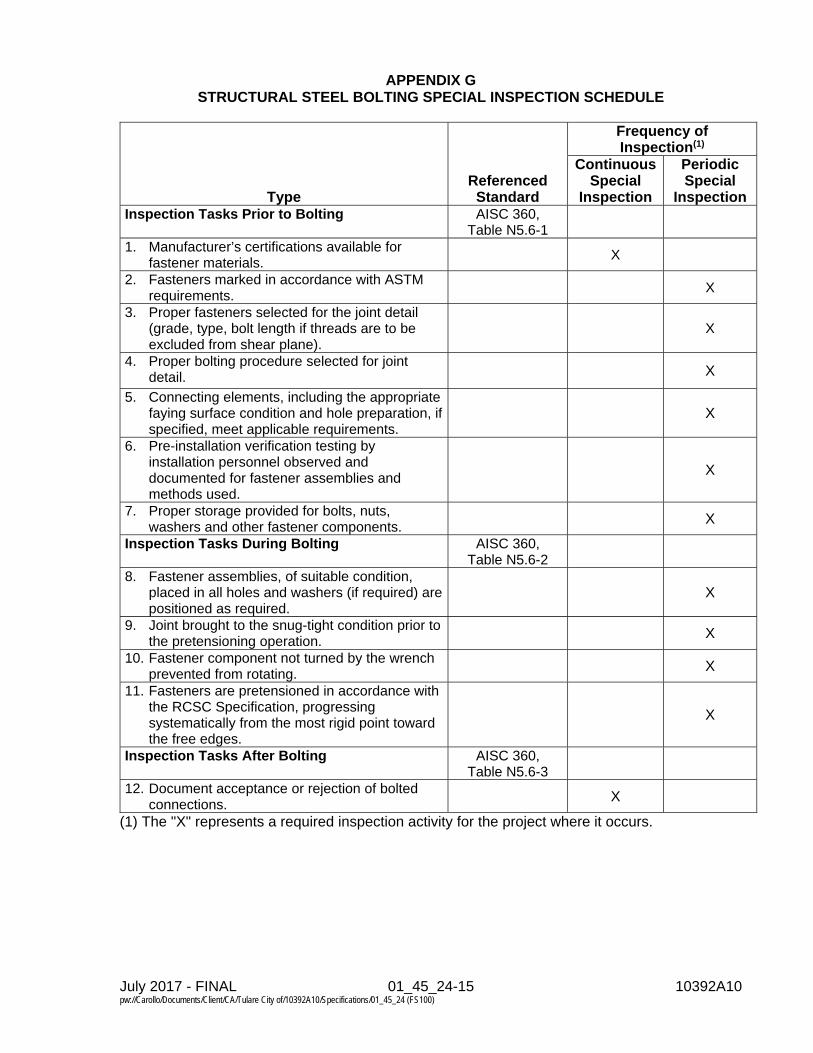
July 2017 - FINAL 01_45_24-15 10392A10 pw://Carollo/Documents/Client/CA/Tulare City of/10392A10/Specifications/01_45_24 (FS100)
APPENDIX G STRUCTURAL STEEL BOLTING SPECIAL INSPECTION SCHEDULE
Type Referenced
Standard
Frequency of Inspection(1)
Continuous Special
Inspection
Periodic Special
Inspection Inspection Tasks Prior to Bolting AISC 360,
Table N5.6-1
1. Manufacturer’s certifications available for fastener materials.
X
2. Fasteners marked in accordance with ASTM requirements.
X
3. Proper fasteners selected for the joint detail (grade, type, bolt length if threads are to be excluded from shear plane).
X
4. Proper bolting procedure selected for joint detail.
X
5. Connecting elements, including the appropriate faying surface condition and hole preparation, if specified, meet applicable requirements.
X
6. Pre-installation verification testing by installation personnel observed and documented for fastener assemblies and methods used.
X
7. Proper storage provided for bolts, nuts, washers and other fastener components.
X
Inspection Tasks During Bolting AISC 360, Table N5.6-2
8. Fastener assemblies, of suitable condition, placed in all holes and washers (if required) are positioned as required.
X
9. Joint brought to the snug-tight condition prior to the pretensioning operation.
X
10. Fastener component not turned by the wrench prevented from rotating.
X
11. Fasteners are pretensioned in accordance with the RCSC Specification, progressing systematically from the most rigid point toward the free edges.
X
Inspection Tasks After Bolting AISC 360, Table N5.6-3
12. Document acceptance or rejection of bolted connections.
X
(1) The "X" represents a required inspection activity for the project where it occurs.

July 2017 - FINAL 01_45_24-16 10392A10 pw://Carollo/Documents/Client/CA/Tulare City of/10392A10/Specifications/01_45_24 (FS100)
APPENDIX H STEEL CONSTRUCTION OTHER THAN STRUCTURAL STEEL
SPECIAL INSPECTION SCHEDULE
Type Referenced
Standard
Frequency of Inspection(1)
Continuous Special
Inspection
Periodic Special
Inspection 1. Material verification of cold-formed steel deck: a. Identification markings to conform to ASTM
standards specified in the approved construction documents.
Applicable ASTM material
standards
X
b. Manufacturer's certified test reports. X 2. Inspection of welding: a. Cold-formed steel deck: 1) Floor and roof deck welds. AWS D1.3 X b. Reinforcing steel: 1) Verification of weldability of reinforcing
steel other than ASTM A 706. AWS D1.4,
ACI 318: 3.5.2 X
2) Reinforcing steel-resisting flexural and axial forces in boundary elements of special structural walls and shear reinforcement.
X
3) Shear reinforcement. X 4) "Form Saver" (reinforcing couplers). X
(1) The "X" represents a required inspection activity for the project where it occurs.

July 2017 - FINAL 01_50_00-1 10392A10 pw://Carollo/Documents/Client/CA/Tulare City of/10392A10/Specifications/01_50_00 (FS100)
SECTION 01_50_00
TEMPORARY FACILITIES AND CONTROLS
PART 1 GENERAL
1.01 SUMMARY
A. Section includes: 1. Furnishing, maintaining, and removing construction facilities and temporary
controls, including temporary utilities, construction aids, barriers and enclosures, security, access roads, temporary controls, project sign, field offices and sheds, and removal after construction.
B. Related sections: 1. Section 01_14_00 - Work Restrictions. 2. Section 01_33_00 - Submittal Procedures. 3. Section 01_75_17 - Commissioning 4. Section 01_75_18 - Disinfection 5. Section 01_75_19 - Leak Testing for Concrete Structures. 6. Section 46_05_10 - Common Work Results for Mechanical Equipment.
1.02 REFERENCE
A. American National Standards Institute (ANSI).
B. Occupational Safety and Health Administration (OSHA).
1.03 SUBMITTALS
A. General: For products specified to be furnished under this Section, submit product data as specified in Section 01_33_00.
B. For temporary piping systems: 1. Submit layout drawings showing proposed routing of piping, including
proposed pipe support and pipe restraint locations. 2. Submit product data for piping, fittings, appurtenances, restraints, supports,
and all other components of the temporary piping system. 3. Submit all information at least 28 days prior to when each temporary piping
system is scheduled to be installed and allow 14 days for review and comment.
C. For temporary pumping systems: 1. Submit pump data, performance curves, and other operating information as
specified in Section 46_05_10. 2. Submit sketches showing layout of temporary pumping system, including
pump quantity, configuration, and proposed piping layout specified in this Section.
3. Submit piping headloss calculations based on proposed temporary piping system layout.

July 2017 - FINAL 01_50_00-2 10392A10 pw://Carollo/Documents/Client/CA/Tulare City of/10392A10/Specifications/01_50_00 (FS100)
D. Submit all information at least 28 days prior to when the temporary pumping system is scheduled to be installed and allow 14 days for review and comment.
1.04 TEMPORARY UTILITIES
A. Temporary electrical power: 1. Arrange with local utility to provide adequate temporary electrical service. 2. Provide and maintain adequate jobsite power distribution facilities conforming
to applicable Laws and Regulations. 3. Provide, maintain, and pay for electric power for performance of the Work
except for power required for the final 7-day operational test:
B. Temporary electrical lighting: 1. In work areas, provide temporary lighting sufficient to maintain lighting levels
during working hours not less than lighting levels required by OSHA and state agency which administers OSHA regulations where Project is located.
2. When available, permanent lighting facilities may be used in lieu of temporary facilities: a. Prior to Substantial Completion of the Work, replace bulbs, lamps, or
tubes used by Contractor for lighting.
C. Temporary heating, cooling, and ventilating: 1. Heat and ventilate work areas to protect the Work from damage by freezing,
high temperatures, weather, and to provide safe environment for workers. 2. Permanent heating system may be utilized when sufficiently completed to
allow safe operation.
D. Temporary water: 1. Pay for and construct facilities necessary to furnish potable water for human
consumption and non-potable water for use during construction. 2. Remove temporary piping and connections and restore affected portions of the
facility to original condition before Substantial Completion. 3. Pay for water used for construction prior to Substantial Completion. Owner will
provide water for 7-day operational testing. 4. Development of potable water supply:
a. Potable water is not available at construction site. b. Provide potable water for human consumption during construction period. c. Furnish potable water that meets requirements of Laws and Regulations.
E. Temporary sanitary facilities: 1. Provide suitable and adequate sanitary facilities that are in compliance with
applicable Laws and Regulations. 2. Existing facility use is not allowed. 3. At completion of the Work, remove sanitary facilities and leave site in neat and
sanitary condition.
F. Temporary fire protection: Provide sufficient number of fire extinguishers of type and capacity required to protect the Work and ancillary facilities.
G. First aid: Post first aid facilities and information posters conforming to requirements of OSHA and other applicable Laws and Regulations in readily accessible locations.
H. Utilities in existing facilities: As specified in Section 01_14_00.

July 2017 - FINAL 01_50_00-3 10392A10 pw://Carollo/Documents/Client/CA/Tulare City of/10392A10/Specifications/01_50_00 (FS100)
1.05 CONSTRUCTION AIDS
A. Provide railings, kick plates, enclosures, safety devices, and controls required by Laws and Regulations and as required for adequate protection of life and property.
B. Use construction hoists, elevators, scaffolds, stages, shoring, and similar temporary facilities of ample size and capacity to adequately support and move loads.
C. Design temporary supports with adequate safety factor to assure adequate load bearing capability: 1. When requested, submit design calculations by professional registered
engineer prior to application of loads. 2. Submitted design calculations are for information and record purposes only.
D. Accident prevention: 1. Exercise precautions throughout construction for protection of persons and
property. 2. Observe safety provisions of applicable Laws and Regulations. 3. Guard machinery and equipment, and eliminate other hazards. 4. Make reports required by authorities having jurisdiction, and permit safety
inspections of the Work. 5. Before commencing construction work, take necessary action to comply with
provisions for safety and accident prevention.
E. Barricades: 1. Place barriers at ends of excavations and along excavations to warn
pedestrian and vehicular traffic of excavations. 2. Provide barriers with flashing lights after dark. 3. Keep barriers in place until excavations are entirely backfilled and compacted. 4. Barricade excavations to prevent persons from entering excavated areas in
streets, roadways, parking lots, treatment plants, or other public or private areas.
F. Warning devices and barricades: Adequately identify and guard hazardous areas and conditions by visual warning devices and, where necessary, physical barriers: 1. Devices shall conform to minimum requirements of OSHA and State agency
which administers OSHA regulations where Project is located.
G. Hazards in public right-of-way: 1. Comply with local jurisdiction standards and requirements for right-of-way
barricades and other safety devices. 2. Mark at reasonable intervals, trenches, and other continuous excavations in
public right-of-way, running parallel to general flow of traffic, with traffic cones, barricades, or other suitable visual markers during daylight hours: a. During hours of darkness, provide markers with torches, flashers, or other
adequate lights. 3. At intersections or for pits and similar excavations, where traffic may
reasonably be expected to approach head on, protect excavations by continuous barricades: a. During hours of darkness, provide warning lights at close intervals.
H. Hazards in protected areas: Mark or guard excavations in areas from which public is excluded, in manner appropriate for hazard.

July 2017 - FINAL 01_50_00-4 10392A10 pw://Carollo/Documents/Client/CA/Tulare City of/10392A10/Specifications/01_50_00 (FS100)
I. Above grade protection: On multi-level structures, provide safety protection that meets requirements of OSHA and State agency which administers OSHA regulations where Project is located.
J. Protect existing structures, trees, shrubs, and other items to be preserved on Project site from injury, damage, or destruction by vehicles, equipment, worker or other agents with substantial barricades or other devices commensurate with hazards.
K. Fences: 1. Enclose site of the Work with fence adequate to protect the Work against acts
of theft, violence, and vandalism. 2. Enclose temporary offices and storage areas with fence adequate to protect
temporary facilities against acts of theft, violence, and vandalism. 3. When entire or part of site is to be permanently fenced, permanent fence may
be built to serve for both permanent and temporary protection of the work site, provided that damaged or defaced fencing is replaced prior to Substantial Completion.
4. Protect temporary and permanent openings and close openings in existing fences to prevent intrusion by unauthorized persons. a. Bear responsibility for protection of plant and material on site of the Work
when openings in existing fences are not closed. 5. During night hours, weekends, holidays, and other times when no work is
performed at site, provide temporary closures or enlist services of security guards to protect temporary openings.
6. Fence temporary openings when openings are no longer necessary.
1.06 SECURITY
A. Make adequate provision for protection of the work area against fire, theft, and vandalism, and for protection of public against exposure to injury.
1.07 ACCESS ROADS
A. General: 1. Build and maintain access roads to and on site of the Work to provide for
delivery of material and for access to existing and operating plant facilities on site.
2. Build and maintain dust free roads which are suitable for travel at 20 miles per hour.
B. Off-site access roads: 1. Build and maintain graded earth roads. 2. Build roads only in public right-of-way or easements obtained by Owner. 3. Obtain rights-of-way or easements when electing to build along other
alignment.
C. On-site access roads: 1. Maintain access roads to storage areas and other areas to which frequent
access is required. 2. Maintain similar roads to existing facilities on site of the Work to provide
access for maintenance and operation.

July 2017 - FINAL 01_50_00-5 10392A10 pw://Carollo/Documents/Client/CA/Tulare City of/10392A10/Specifications/01_50_00 (FS100)
3. Protect buried vulnerable utilities under temporary roads with steel plates, wood planking, or bridges.
4. Maintain on-site access roads free of mud. Under no circumstances shall vehicles leaving the site track mud off the site onto the public right-of-way.
1.08 TEMPORARY CONTROLS
A. Dust control: 1. Prevent dust nuisance caused by operations, unpaved roads, excavation,
backfilling, demolition, or other activities. 2. Control dust by sprinkling with water, use of dust palliatives, modification of
operations, or other means acceptable to agencies having jurisdiction.
B. Noise control: 1. Comply with noise and work hours regulations by local jurisdiction. 2. In or near inhabited areas, particularly residential, perform operations in
manner to minimize noise. 3. In residential areas, take special measures to suppress noise during night
hours.
C. Mud control: 1. Prevent mud nuisance caused by construction operations, unpaved roads,
excavation, backfilling, demolition, or other activities.
1.09 PROJECT SIGN
A. Provide and maintain Project identification sign consisting of painted 8-foot wide by 4-foot high exterior grade plywood and minimum 10-foot long, 4 by 4 lumber posts, set in ground at least 3 feet, with exhibit lettering by professional sign painter using no more than 5 sign colors: 1. List at least the title of the Project, and names of the Owner, Engineer, and
Contractor. 2. Contractor’s and Engineer’s names shall be identified in upper right hand
corner underneath the bid number.
B. On third and fourth lines of printing, paint appropriate dollar amounts.
C. Erect Project identification sign where directed.
1.10 FIELD OFFICES AND SHEDS
A. Contractor's field office: 1. Maintain on Project Site weather tight space in which to keep copies of
Contract Documents, progress schedule, shop drawings, and other relevant documents.
2. Provide field office with adequate space to examine documents, and provide lighting and telephone service in that space.
1.11 REMOVAL
A. Remove temporary buildings and furnishings before inspection for Substantial Completion or when directed.

July 2017 - FINAL 01_50_00-6 10392A10 pw://Carollo/Documents/Client/CA/Tulare City of/10392A10/Specifications/01_50_00 (FS100)
B. Clean and repair damage caused by installation or use of temporary facilities.
C. Remove underground installations to minimum depth of 24 inches and grade to match surrounding conditions.
D. Restore existing facilities used during construction to specified or original condition.
1.12 TEMPORARY PROCESS PIPING
A. Contractor shall provide all piping, appurtenances, and other materials as required to provide temporary piping systems as specified in this Section, as indicated on the Drawings, and as needed to perform the Work.
B. Contractor shall field route piping as needed and as field conditions dictate, unless otherwise indicated on the Drawings, and determine appropriate lengths of piping and quantity/type of pipe fittings needed to construct temporary piping system. Do not block access points such as stairs, doors, and walkways to existing facilities unless approved in writing by the Owner.
C. Restrain piping at valves and at fittings where piping changes direction, changes sizes, and at ends: 1. When piping is buried, use concrete thrust block or mechanical restraints. 2. When piping is exposed or under water, use mechanical or structural
restraints. 3. Determine thrust forces by multiplying the nominal cross sectional area of the
piping by the operating pressure of the piping.
D. Temporary piping systems shall be installed in a manner that will not damage existing or new facilities.
E. Unless indicated otherwise, piping material, including gaskets, shall be suitable for the process fluid requiring temporary piping.
F. Temporary piping includes, but is not limited to, the following piping services: Drain piping to empty water from the two water storage tanks during commissioning, startup and disinfection activities as specified in Sections 01_75_17, 01_75_18, and 01_75_19.
G. After temporary piping system is no longer required: 1. Remove temporary piping system. 2. Clean and repair damage caused by installation or use of temporary piping
system. 3. Restore existing facilities to original condition.
1.13 TEMPORARY PROCESS PUMPING
A. Contractor shall provide temporary pumping system to pump flow as needed from the two water storage tanks during commissioning, startup and disinfection activities as specified in Sections 01_75_17, 01_75_18, and 01_75_19: 1. Anticipated pressure will vary based on headlosses developed and the final
length of installed temporary piping. Contractor shall calculate headlosses and provide pump with sufficient pressure to meet flow requirements.
2. Pump shall be capable of passing a solid with a sphere size of 3 inches.

July 2017 - FINAL 01_50_00-7 10392A10 pw://Carollo/Documents/Client/CA/Tulare City of/10392A10/Specifications/01_50_00 (FS100)
3. Provide and pay for all power required to operate temporary pumps. 4. All electrical and instrumentation components will comply with applicable code
requirements for the area where the temporary pump is located. 5. All necessary spare equipment and appurtenances shall be available on-site to
allow immediate repair and/or replacement of any pumping system component that is not functioning properly.
B. Providing temporary piping systems as specified in this Section.
C. Temporary pumping of other process flows is not allowed unless approved in writing by the Owner.
D. After temporary process pumping system is no longer required: 1. Remove temporary process pumping system. 2. Clean and repair damage caused by installation or use of temporary process
pumping system. 3. Restore existing facilities to original condition.
PART 2 PRODUCTS Not Used.
PART 3 EXECUTION Not Used.
END OF SECTION


July 2017 - FINAL 01_55_26-1 10392A10 pw://Carollo/Documents/Client/CA/Tulare City of/10392A10/Specifications/01_55_26 (FS100)
SECTION 01_55_26
TRAFFIC CONTROL
PART 1 GENERAL
1.01 SUMMARY
A. Section includes: 1. Providing safe and effective work areas and to warn, control, protect, and
expedite vehicular and pedestrian traffic through the construction zone. It shall be the sole responsibility of the Contractor to provide for the safety of the traveling public within the limits of the project, including work in the public right-of-way and on private property.
2. Section includes temporary construction, barricades and enclosures, fences, security, temporary controls, and traffic regulation.
3. In this Section, reference to the “Public” also includes the Owner’s personnel and representatives.
4. Public Outreach.
1.02 REFERENCES 1. Comply with referenced sections and subsections of NDOT Standard
Specifications. 2. Contractual measurement and payment provisions do not apply.
B. California Manual on Uniform Traffic Control Devices, California Department of Transportation, (latest edition): In this Section it is referred to as CA MUTCD.
1.03 REQUIREMENTS
A. General: 1. Traffic control and lane closures must meet the requirements of Caltrans and
City of Tulare Encroachment Permits, and as specified in this Section. 2. The Contractor shall maintain all required traffic control devices and trenches
within the right-of-way at all times, 24 hours per day, 7 days per week including nights, holidays, and weekends.
3. Access for emergency vehicles shall be maintained at all times. 4. All signs and street marking damage caused by or related to the construction
of this project shall be replaced in kind by the Contractor. In the case of partial damage to lane stripes and traffic lettering the whole stripe or marking in its entirety shall be replaced.
B. Temporary surfaces: 1. The Contractor shall be required to provide temporary surfacing of all
excavated areas immediately after completing the backfilling of any section of the Work. If permitted by the government agency with jurisdiction of the right-of-way, the Contractor may be allowed to leave excavations open provided that traffic control devices, approved by the governmental agency maintaining the right-of-way, are in place and maintained, and excavations are covered with steel plates (nonskid surface type) at the close of each working

July 2017 - FINAL 01_55_26-2 10392A10 pw://Carollo/Documents/Client/CA/Tulare City of/10392A10/Specifications/01_55_26 (FS100)
day. The temporary steel plates shall comply with the requirements of the governmental agency controlling the right-of-way.
2. Temporary gravel surfaces shall not be permitted. 3. All temporary detours and/or bypasses shall be hard surfaced with a minimum
of 1-1/2 inches of asphalt-concrete pavement and maintained in a smooth and usable condition at all times for the duration of the detour and/or bypass.
C. Barricades and enclosures: 1. Contractor shall effect and maintain at all times during the prosecution of the
Work, barriers, and lights necessary for the protection of workmen and the public. Contractor shall provide suitable barricades, lights, signs, and watchmen at all places where the Work causes obstructions to the normal traffic or constitutes in any way a hazard to the public.
2. Statutory Requirements: Contractor shall install and maintain all barricades, signs, lights, and other protective devices within rights-of-way in strict conformity with applicable statutory requirements by the government agency having jurisdiction in accordance with an approved Traffic Control Plan.
D. Traffic control devices: 1. All traffic control devices not in use, or that will not be used for a period greater
than 24 hours, shall be removed by the Contractor from the work area. The sidewalk area shall not be used at any time to store unused traffic control devices unless the sidewalk is closed and an approved barricade plan is provided for rerouting pedestrians.
2. Contractor shall maintain all barricades and other traffic control devices in clean and effective condition and replace devices in poor condition immediately.
3. Contractor shall begin placing barricades in the direction of traffic and remove them in the direction of opposing traffic.
4. Text message boards: a. Fixed at each end of the project set and 2 moveable boards within the
project setup area.
1.04 SUBMITTALS
A. Project-specific traffic control plan (TCP) shall be prepared by the Contractor: 1. Plan shall include work hours. Including off peak hour work requirements. 2. Plan shall address pedestrian access. 3. For street closure, provide details related to the notification of all emergency
services, such as police and fire. Provide details related to the notification of services, such as mail and garbage collection.
B. The TCP must be submitted to the respective governmental agency with jurisdiction of the right-of-way for acceptance, as outlined in the City of Tulare encroachment permits.
C. A TCP shall be required for each phase or segment of the construction meeting the requirements of the CA MUTCD. Each TCP shall be considered separately.

July 2017 - FINAL 01_55_26-3 10392A10 pw://Carollo/Documents/Client/CA/Tulare City of/10392A10/Specifications/01_55_26 (FS100)
D. At a minimum, the TCP shall provide, for each phase of the work, the placement and spacing of all traffic control devices (including signs, markings, channelizing devices, lighting devices, flaggers, etc.) and spacing/location of these within the following traffic control areas: 1. Advance Warning Signs. 2. Transition Areas. 3. Buffer Spaces. 4. Work Areas. 5. Termination Areas.
E. Additionally, the TCP must clearly show the following minimum information. Include location, size, height, text height, and color of each sign: 1. Method for protecting excavations, work sites, and school zone crosswalks. 2. Method of barricading at intersections. 3. Driveway access plan. 4. Provisions for emergency vehicle access. 5. All set-up changes to accommodate different phasing of the work. 6. Lane widths and transitions. 7. Twenty-four-hour emergency contact information. 8. Business access signs. 9. Sidewalk “closed/cross here” signs. 10. No parking signs. 11. Project signs. 12. Fresh oil signs. 13. Duration of traffic control and barricade plan. 14. All advance warning signs. 15. Lane closures. 16. Placement of “double penalty in work zones” warning signs. 17. Detour locations. 18. Required signage and barricading associated with bus stop closures. 19. Required signage and barricading associated with school zone/safe route to
school. 20. Routing plan and signage for directing pedestrian around work area.
F. Submit 2 copies of the approved TCP to the Engineer within 48 hours of approval by government agencies.
G. After installation of new or modified control, Contractor shall inspect and certify that controls are installed and operating as intended. Certification shall consist of a signed affidavit stating that the traffic control has been inspected and found to be in conformance with the TCP and contract requirements provided to the government agency with jurisdiction of the right-of-way. A copy of the certification shall be provided to the Engineer within 48 hours of submittal to government agencies.
H. Review and comment on the TCP by the government agency with jurisdiction of the right-of-way shall in no way relieve the Contractor of the responsibility for traffic and safety requirements. Such acceptance shall in no way be construed as confirmation of the technical accuracy or adequacy of the contents of the TCP and shall not relieve the Contractor of the obligation to institute traffic control measures in full compliance with contract requirements and in conformance with local agency requirements.

July 2017 - FINAL 01_55_26-4 10392A10 pw://Carollo/Documents/Client/CA/Tulare City of/10392A10/Specifications/01_55_26 (FS100)
I. If, during the execution of the work, the Contractor determines that the traffic control is not functioning as intended, the Contractor may make revisions to the TCP as necessary, provided that the local agencies with jurisdiction have accepted the changes. Submit two (2) copies and digital files of the approved revised TCP to the Engineer within 48 hours of approval by government agencies.
PART 2 PRODUCTS
2.01 MATERIALS
A. Materials including temporary and permanent striping shall conform to the CA MUTCD as applicable, and as specified in this Section.
PART 3 EXECUTION
Not Used
END OF SECTION

July 2017 - FINAL 01_60_00-1 10392A10 pw://Carollo/Documents/Client/CA/Tulare City of/10392A10/Specifications/01_60_00 (FS100)
SECTION 01_60_00
PRODUCT REQUIREMENTS
PART 1 GENERAL
1.01 SUMMARY
A. Section includes: Product requirements; product selection; product options and substitutions; quality assurance; shipping, delivery, handling, and storage; and instructions for spare parts, maintenance products, and special tools.
B. Related sections: 1. Section 01_33_00 - Submittal Procedures. 2. Section 01_75_17 - Commissioning. 3. Section 01_78_23 - Operation and Maintenance Data. 4. Section 01_81_02 - Project Design Criteria. 5. Section 09_96_01 - High-Performance Coatings.
1.02 REFERENCES
A. American National Standards Institute (ANSI).
B. California Health and Safety Code.
C. NSF International (NSF): 1. 61 - Drinking Water System Components - Health Effects. 2. 372 - Drinking Water System Components – Lead Content.
1.03 DEFINITIONS
A. Products: Inclusive of raw materials, finished goods, equipment, systems, and shop fabrications.
B. Special tools: Tools that have been specifically made for use on a product for assembly, disassembly, repair, or maintenance.
1.04 SUBMITTALS
A. As specified in Section 01_33_00.
B. Calculations/certifications in accordance with NSF 61 and 372 for materials in contact with drinking water.
1.05 GENERAL REQUIREMENTS
A. Comply with Specifications and referenced standards as minimum requirements.
B. Provide products by same manufacturer when products are of similar nature, unless otherwise specified.

July 2017 - FINAL 01_60_00-2 10392A10 pw://Carollo/Documents/Client/CA/Tulare City of/10392A10/Specifications/01_60_00 (FS100)
C. Provide like parts of duplicate units that are interchangeable.
D. Provide equipment that has not been in service prior to delivery, except as required by tests.
E. When necessary, modify manufacturer's standard product to conform to specified requirements or requirements indicated on the Drawings.
1.06 SUBSTITUTIONS
A. Formal substitution request procedure. 1. Submit a written formal substitution request to Engineer for each proposed
substitution within 30 days of effective date of Contract. 2. Engineer will return initial opinion and request for additional information within
30 days. 3. Engineer will notify Contractor in writing of decision to accept or reject the substitution
request within 30 days of receiving required information.
B. Formal substitution request contents: 1. Provide Substitution Request Form as specified in this Section. 2. Manufacturer’s literature including:
a. Manufacturer’s name and address. b. Product name. c. Product description. d. Reference standards. e. Certified performance and test data. f. Operation and maintenance data.
3. Samples, if applicable. 4. Shop drawings, if applicable. 5. Reference projects where the product has been successfully used.
a. Name and address of project. b. Year of installation. c. Year placed in operation. d. Name of product installed. e. Point of contact: Name and phone number.
6. Itemized comparison of the proposed substitution with product specified including a list of significant variations. a. Design features. b. Design dimensions. c. Installation requirements. d. Operations and maintenance requirements.
7. Define impacts. a. Impacts to construction schedule. b. Impacts to other contracts. c. Impacts to other work or products. d. Impact to Contract Sum.
1) Do not include costs under separate contracts. 2) Do not include Engineer’s costs for redesign or revision of Contract
Documents. 3) Required license fees or royalties.
e. Availability of maintenance services and sources of replacement materials.

July 2017 - FINAL 01_60_00-3 10392A10 pw://Carollo/Documents/Client/CA/Tulare City of/10392A10/Specifications/01_60_00 (FS100)
8. Contractor represents the following: a. Contractor shall pay associated costs for the Engineer to evaluate the
substitution. b. Contractor bears the burden of proof of the equivalency of the proposed
substitution. c. Proposed substitution does not change the design intent and will have equal
performance to the specified product. d. Proposed substitution is equal or superior to the specified product. e. Contractor will provide the warranties or bonds that would be provided on the
specified product on the proposed substitution, unless Owner requires a Special Warranty.
f. Contractor will coordinate installation of accepted substitution into the Work and will be responsible for the costs to make changes as required to the Work.
g. Contractor waives rights to claim additional costs caused by proposed substitution which may subsequently become apparent.
C. Substitutions will not be considered for acceptance under the following conditions: 1. No formal substitution request is made. 2. The substitution is simply implied or indicated on shop drawings or product data
submittals. 3. The formal substitution request is submitted by a subcontractor or supplier.
D. Substitution requests submitted after the deadline will not be considered unless the following evidence is submitted to the Engineer: 1. Proof that the specified product is unavailable for reasons beyond the control of the
Contractor. a. Reasons may include manufacturing discontinued, bankruptcy, labor strikes, or
acts of God. b. Contractor placed or attempted to place orders for the specified products within
10 days after the effective date of the Agreement. c. The formal substitution request is submitted to Engineer within 10 days of the
Contractor discovering the specified product cannot be obtained.
E. Engineer’s decision on a substitution requests will be final and binding. 1. Approved substitutions will be incorporated into the Contract Documents with a
Change Order. 2. Requests for time extensions and additional costs based on submission of, approval
of, or rejection of substitutions will not be allowed.
PART 2 PRODUCTS
2.01 GENERAL
A. Material requirements: 1. Materials: Provide corrosion resistance suitable for project conditions as specified in
Section 01_81_02. 2. Dissimilar metals: Separate contacting surfaces with dielectric material.
B. Edge grinding: 1. Sharp projections of cut or sheared edges of ferrous metals which are not to be
welded shall be ground to a radius required to ensure satisfactory paint adherence.

July 2017 - FINAL 01_60_00-4 10392A10 pw://Carollo/Documents/Client/CA/Tulare City of/10392A10/Specifications/01_60_00 (FS100)
2.02 PRODUCTS IN CONTACT WITH DRINKING WATER
A. Materials in contact with drinking waters: In accordance with NSF 61 and NSF 372. 1. Certification by an independent ANSI accredited third party, including, but not limited
to, NSF International, as being lead free.
B. Materials in contact with drinking waters: In accordance with California Health and Safety Code, Section 116875.
2.03 PRODUCT SELECTION
A. When products are specified by standard or specification designations of technical societies, organizations, or associations only, provide products that meet or exceed reference standard and Specifications.
B. When products are specified with names of manufacturers but no model numbers or catalog designations, provide: 1. Products by one of named manufacturers that meet or exceed Specifications. 2. Engineer deemed "or equal" evidenced by an approved shop drawing or other written
communication.
C. When products are specified with names of manufacturers and model numbers or catalog designations, provide: 1. Products with model numbers or catalog designations by one of named
manufacturers. 2. Engineer deemed "or equal" evidenced by an approved shop drawing or other written
communication.
D. When products are specified with names of manufacturers, but with brand or trade names, model numbers, or catalog designations by one manufacturer only, provide: 1. Products specified by brand or trade name, model number, or catalog designation. 2. Products by one of named manufacturers proven, in accordance with requirements for
an "or equal", to meet or exceed quality, appearance and performance of specified brand or trade name, model number, or catalog designation.
3. Engineer deemed "or equal" evidenced by an approved shop drawing or other written communication.
E. When Products are specified with only one manufacturer followed by "or equal”, provide: 1. Products meeting or exceeding Specifications by specified manufacturer. 2. Engineer deemed "or equal" evidenced by an approved shop drawing or other written
communication.
2.04 SHIPMENT
A. Mandatory requirements prior to shipment of equipment: 1. Engineer approved shop drawings. 2. Engineer approved Manufacturer’s Certificate of Source Testing as specified in
Section 01_75_17, when required by specifications. 3. Draft operations and maintenance manuals, as specified in Section 01_78_23, when
required by specifications.
B. Prepare products for shipment by: 1. Tagging or marking products to agree with delivery schedule or shop drawings.

July 2017 - FINAL 01_60_00-5 10392A10 pw://Carollo/Documents/Client/CA/Tulare City of/10392A10/Specifications/01_60_00 (FS100)
2. Including complete packing lists and bills of material with each shipment. 3. Packaging products to facilitate handling and protection against damage during
transit, handling, and storage. 4. Securely attach special instructions for proper field handling, storage, and installation
to each piece of equipment before packaging and shipment.
C. Transport products by methods that avoid product damage.
D. Deliver products in undamaged condition in manufacturer's unopened containers or packaging.
2.05 SPARE PARTS, MAINTENANCE PRODUCTS, AND SPECIAL TOOLS
A. Provide spare parts and maintenance products as required by Specifications.
B. Provide one set of special tools required to install or service the equipment.
C. Box, tag, and clearly mark items.
D. Contractor is responsible for spare parts, maintenance products, and special tools until acceptance by Owner.
E. Store spare parts, maintenance products, and special tools in enclosed, weather-proof, and lighted facility during the construction period. 1. Protect parts subject to deterioration, such as ferrous metal items and electrical
components with appropriate lubricants, desiccants, or hermetic sealing.
F. Provide spare parts and special tools inventory list, see Appendix A: 1. Equipment tag number. 2. Equipment manufacturer. 3. Subassembly component, if appropriate. 4. Quantity. 5. Storage location.
G. Store large items individually: 1. Weight: Greater than 50 pounds. 2. Size: Greater than 24 inches wide by 18 inches high by 36 inches long. 3. Clearly labeled:
a. Equipment tag number. b. Equipment manufacturer. c. Subassembly component, if appropriate.
H. Store in spare parts box smaller items: 1. Weight: Less than 50 pounds. 2. Size: Less than 24 inches wide by 18 inches high by 36 inches long. 3. Clearly labeled
a. Equipment tag number. b. Equipment manufacturer. c. Subassembly component, if appropriate.
I. Spare parts and special tools box: 1. Wooden box:
a. Size: 24 inches wide by 18 inches high by 36 inches long.

July 2017 - FINAL 01_60_00-6 10392A10 pw://Carollo/Documents/Client/CA/Tulare City of/10392A10/Specifications/01_60_00 (FS100)
2. Hinged wooden cover. a. Strap type hinges. b. Locking hasp. c. Spare parts inventory list taped to underside of cover.
3. Coating: As specified in Section 09_96_01. 4. Clearly labeled:
a. The words “Spare Parts and/or Special Tools”. b. Equipment tag number. c. Equipment manufacturer.
PART 3 EXECUTION
3.01 DELIVERY AND HANDLING
A. Handle equipment in accordance with manufacturer's instructions.
B. Provide equipment and personnel to handle products by methods to prevent soiling or damage.
C. Upon delivery, promptly inspect shipments. 1. Verify compliance with Contract Documents, correct quantities, and undamaged
condition of products. 2. Acceptance of shipment does not constitute final acceptance of equipment.
3.02 STORAGE AND PROTECTION
A. Immediately store and protect products and materials until installed in Work.
B. Store products with seals and legible labels intact.
C. Maintain products within temperature and humidity ranges required or recommended by manufacturer.
D. Protect painted surfaces against impact, abrasion, discoloration, and other damage. 1. Repaint damaged painted surfaces.
E. Exterior storage of fabricated products: 1. Place on aboveground supports that allow for drainage. 2. Cover products subject to deterioration with impervious sheet covering. 3. Provide ventilation to prevent condensation under covering.
F. Store moisture sensitive products in watertight enclosures.
G. Furnish covered, weather-protected storage structures providing a clean, dry, noncorrosive environment for mechanical equipment, valves, architectural items, electrical and instrumentation equipment and special equipment to be incorporated into this project. 1. Storage of equipment shall be in strict accordance with the “instructions for storage” of
each equipment supplier and manufacturer including connection of heaters, placing of storage lubricants in equipment, etc.
2. The Contractor shall furnish a copy of the manufacturer’s instructions for storage to the Engineer prior to storage of all equipment and materials.
July 2017 - FINAL 01_60_00-7 10392A10 pw://Carollo/Documents/Client/CA/Tulare City of/10392A10/Specifications/01_60_00 (FS100)
H. Store loose granular materials on solid surfaces in well-drained area. 1. Prevent materials mixing with foreign matter. 2. Provide access for inspection.
I. Payment will not be made for equipment and materials improperly stored or stored without providing Engineer with the manufacturer's instructions for storage.
J. Provide an Equipment Log including, as a minimum, the equipment identification, date stored, date of inspection/maintenance, date removed from storage, copy of manufacturer’s recommended storage guidelines, description of inspection/maintenance activities performed, and signature of party performing inspection/maintenance.
3.03 PROTECTION AFTER INSTALLATION
A. Provide substantial coverings as necessary to protect installed products from damage from traffic and subsequent construction operations. 1. Remove covering when no longer needed. 2. Replace corroded, damaged, or deteriorated equipment and parts before acceptance
of the project.
B. Update Equipment Log on a monthly basis with description of maintenance activities performed in accordance with the manufacturer’s recommendation and industry standards and signature of party performing maintenance.
3.04 QUALITY ASSURANCE
A. Employ entities that meet or exceed specified qualifications to execute the Work.
B. Verify project conditions are satisfactory before executing subsequent portions of the Work.
3.05 COMMISSIONING
A. As specified in Section 01_75_17.
3.06 CLOSEOUT ACTIVITIES
A. Owner may request advanced delivery of spare parts, maintenance products, and special tools. 1. Deduct the delivered items from the inventory list and provide transmittal
documentation.
B. Immediately prior to the date of Substantial Completion, arrange to deliver spare parts, maintenance products, and special tools to Owner at a location on site chosen by the Owner. 1. Provide itemized list of spare parts and special tools that matches the identification
tag attached to each item. 2. Owner and Engineer will review the inventory and the itemized list to confirm it is
complete and in good condition prior to signing for acceptance.
3.07 ATTACHMENTS
A. Appendix A - Spare Parts, Maintenance Products, and Special Tools Inventory List.

July 2017 - FINAL 01_60_00-8 10392A10 pw://Carollo/Documents/Client/CA/Tulare City of/10392A10/Specifications/01_60_00 (FS100)
B. Appendix B - Sample Substitution Request Form.
END OF SECTION

July 2017 - FINAL 01_60_00-9 10392A10 pw://Carollo/Documents/Client/CA/Tulare City of/10392A10/Specifications/01_60_00 (FS100)
APPENDIX A SPARE PARTS, MAINTENANCE PRODUCTS, AND SPECIAL TOOLS INVENTORY LIST
Owner: Date:
Contractor: Project No.:
Project Name:
Inventory List
Spec Number: Spec Title
Equipment Tag No.: Equipment Manufacturer:
Quantity Subassembly Component Description
Manufacturer’s Part Number Storage Location

July 2017 - FINAL 01_60_00-10 10392A10 pw://Carollo/Documents/Client/CA/Tulare City of/10392A10/Specifications/01_60_00 (FS100)
APPENDIX B
SUBSTITUTION REQUEST FORM

July 2017 - FINAL 01_60_00-11 10392A10 pw://Carollo/Documents/Client/CA/Tulare City of/10392A10/Specifications/01_60_00 (FS100)
DOCUMENT 01_60_00 SUBSTITUTION REQUEST FORM
Owner: Date:
Contractor: Project No.:
Project Name:
To: From:
Re:
Contract For:
Engineering Project Number: Substitution Request Number:
Specification Information
Title:
Number: Page: Article/Paragraph:
Description:
Proposed Substitution
Product:
Manufacturer:
Address: Phone:
Trade Name: Model No.:
Installer:
Address: Phone:
History: New Product 2-5 years old 5-10 years old More than 10 years old
Differences between proposed substitution and specified product:
Point-by-point comparative data and impacts attached – REQUIRED BY ENGINEER

July 2017 - FINAL 01_60_00-12 10392A10 pw://Carollo/Documents/Client/CA/Tulare City of/10392A10/Specifications/01_60_00 (FS100)
Reason For Not Providing Specified Item
Reason:
Similar Installation:
Project:
Address: Date Installed:
Owner: Architect:
Proposed substitution affects other parts of Work:
No Yes, Explain:
Benefit to Owner For Accepting Substitution
Savings: ($)
Proposed substitution changes Contract Time:
No Yes (Add) (Deduct) days
Supporting Data Attached
Drawings Product Data Samples Tests Reports
Reference Projects Other:
Certifications
The undersigned certifies:
Proposed substitution has been fully investigated and determined to be equal or superior in all respects to specified product.
Same warranty will be furnished for proposed substitution as for specified product, unless Owner requires a Special Warranty.
Same maintenance service and source of replacement parts, as applicable, is available.
Proposed substitution will have no adverse effect on other trades and will not affect or delay progress schedule.
Cost data as stated above is complete. Claims for additional costs related to accepted substitution which may subsequently become apparent are to be waived.
Proposed substitution does not affect dimensions and functional clearances.
Payment will be made for changes to building design, including Engineer design, detailing, and construction costs caused by the substitution.
Coordination, installation, and changes in the Work as necessary for accepted substitution will be complete in all respects.

July 2017 - FINAL 01_60_00-13 10392A10 pw://Carollo/Documents/Client/CA/Tulare City of/10392A10/Specifications/01_60_00 (FS100)
Certifications
Submitted by:
Signed by:
Firm Name
Firm Address:
Phone:
Attachments:
Engineer’s Review And Action
Substitution accepted - Make submittals in accordance with Specification Section 01_33_00.
Substitution accepted as noted - Make submittals in accordance with Specification Section 01_33_00.
Substitution rejected - Use specified materials.
Substitution Request received too late - Use specified materials.
Signed by: Date:
Additional Comments
Additional Comments:
Contractor Subcontractor Supplier Manufacturer Engineer
Other:
Comments:


July 2017 - FINAL 01_71_23-1 10392A10 pw://Carollo/Documents/Client/CA/Tulare City of/10392A10/Specifications/01_71_23 (FS100)
SECTION 01_71_23
FIELD ENGINEERING
PART 1 GENERAL
1.01 SUMMARY
A. Section includes: Field engineering to establish lines and grades for the Work.
B. Related sections: 1. Section 01_33_00 - Submittal Procedures. 2. Section 01_77_00 - Closeout Procedures.
1.02 SUBMITTALS
A. Submit as specified in Section 01_33_00.
B. Qualifications of the professional land surveyor or registered civil engineer in California that will be performing the field engineering.
PART 2 PRODUCTS Not Used.
PART 3 EXECUTION
3.01 SURVEY REFERENCE POINTS
A. Basic reference line, a beginning point on basic reference line, and a benchmark will be provided by Owner.
B. From these reference points, establish other control and reference points as required to properly lay out the Work.
C. Locate and protect control points prior to starting site work, and preserve permanent reference points during construction: 1. Make no changes or relocations without prior written notice. 2. Replace Project control point, when lost or destroyed, in accordance with
original survey control.
D. Set monuments for principal control points and protect them from being disturbed and displaced: 1. Re-establish disturbed monuments. 2. When disturbed, postpone parts of the Work that are governed by disturbed
monuments until such monuments are re-established.

July 2017 - FINAL 01_71_23-2 10392A10 pw://Carollo/Documents/Client/CA/Tulare City of/10392A10/Specifications/01_71_23 (FS100)
3.02 PROJECT SITE SURVEY REQUIREMENTS
A. Establish minimum of 2 permanent benchmarks on site referenced to data established by survey control points.
B. Record permanent benchmark locations with horizontal and vertical data on Project Record Documents.
C. Perform verifications and checking in accordance with standard surveying practice.
D. Maintain complete, accurate log of control points and survey.
E. Affix civil engineer's or professional land surveyor's signature and registration number to Record Drawings to certify accuracy of information shown.
3.03 CONSTRUCTION STAKES, LINES, AND GRADES
A. Execute the Work in accordance with the lines and grades indicated.
B. Make distances and measurements on horizontal planes, except elevations and structural dimensions.
3.04 QUALITY CONTROL
A. Accuracy of stakes, alignments, and grades may be checked randomly by Engineer: 1. Notice of when checking will be conducted will be given. 2. When notice of checking is given, postpone parts of the Work affected by
stakes, alignments, or grades to be checked until checked. 3. Engineer's check does not substitute or complement required field quality
control procedures.
3.05 RECORD DOCUMENTS
A. Prepare and submit Record Documents as specified in Section 01_77_00.
B. Provide certified site survey in Imperial scale including buildings, benchmarks, and appurtenances sealed and signed by professional land surveyor or registered civil engineer. 1. File with permitting agency, as required.
END OF SECTION

July 2017 - FINAL 01_75_17-1 10392A10 pw://Carollo/Documents/Client/CA/Tulare City of/10392A10/Specifications/01_75_17 (FS100)
SECTION 01_75_17
COMMISSIONING
PART 1 GENERAL
1.01 SUMMARY
A. Section includes: Requirements for each Commissioning phase of, the Project equipment/system and/or facility.
B. Related sections: 1. Section 01_14_00 - Work Restrictions. 2. Section 01_78_23 - Operation and Maintenance Data. 3. Section 09_96_01 - High-Performance Coatings. 4. Section 23_05_93 - HVAC Systems Testing, Adjusting, and Balancing. 5. Section 26_05_74 - Electrical System Studies. 6. Section 26_08_50 - Field Electrical Acceptance Tests. 7. Section 40_05_00.09 - Piping Systems Testing. 8. Section 40_80_01 - Testing, Calibration, and Commissioning. 9. Section 46_05_10 - Common Work Results for Mechanical Equipment. 10. Section 46_05_94 - Mechanical Equipment Testing.
1.02 DEFINITIONS
A. Clean Water Facility Testing – Testing of complete facility utilizing clean water for purposes of confirming extended equipment/system operation prior to Process Start-up Phase.
B. Commissioning – The process of planning, testing, and process start-up of the installation for compliance with contract requirements and demonstrating, through documented verification, that the project has successfully met the Contractual requirements. It includes training the Owner's staff to operate the facility.
C. Commissioning Phases – The work activities of facility commissioning are grouped into the phases defined in the table below.
Commissioning
Planning Phase Testing and
Training Phase Process Start-Up Phase Owner Training Plan and Schedule
Source Testing Process Start-up
Commissioning Schedule Owner Training Process Operational Period Subsystem Testing Plan Installation Testing Instrumentation and
Controls Fine-Tuning Clean Water Facility Testing Plan
Functional Testing
Clean Water Facility Testing
Closeout Documentation

July 2017 - FINAL 01_75_17-2 10392A10 pw://Carollo/Documents/Client/CA/Tulare City of/10392A10/Specifications/01_75_17 (FS100)
D. Component – A basic building block of equipment, subsystems, and systems that requires installation or functional testing but does not have an electrical connection or internal electronics. (Examples: filter effluent piping and manual isolation valves).
E. Device – A basic building block of equipment, subsystems, and systems that requires installation or functional testing and does have an electrical connection or internal electronics. (Examples: filter level transmitter or water pump pressure transmitter).
F. Equipment – An assembly of component(s) and devices(s) that requires installation or functional testing. (Examples: Pump, motor, VFD, Ozone Generator, UV Disinfection System, etc.).
G. Facility – A grouping of process areas, systems, subsystems, equipment, components, and devices (Examples: treatment plant, pump station, etc.).
H. Functional Testing – Testing performed on a completed subsystem to demonstrate that equipment/system meets manufacturers’ calibration and adjustment requirements and other requirements as specified. Functional testing includes operating equipment/system manually in local, manually in remote (or remote manual), and automatically in remote (in remote auto).
I. Installation Testing – Testing to demonstrate that subsystem component (piping, power, networks, devices, etc.) is ready and meets the project requirements in advance of functional testing. Installation testing also includes manufacturers’ certification of installation and other requirements as specified to prepare equipment/system for Functional Testing. Also referred to as Field Acceptance Testing.
J. Manufacturer’s Certificate of Source Testing – When applicable, the form is used during Source Testing for the manufacturer to confirm that the applicable source tests have been performed and results conform to the Contract Documents. The form is provided at the end of this Section.
K. Manufacturer’s Certificate of Installation and Functionality Compliance – The form is used during Installation Testing and Functional Testing. It is submitted at the end of Functional Testing to confirm that the equipment/system is installed in conformance with the Contract Documents and that it meets the Functional Testing requirements defined in the Contract Documents. The form is provided at the end of this Section.
L. Process Area – A grouping of systems, subsystems, equipment, components, and devices that divide a facility into functional areas. (Examples: Filter Process Area or Chemical Area).
M. Process Operational Period – A period of time after completion of the process start-up set aside for final Operational Testing to verify facility performance meets the Contract Document requirements. This period may specifically limit other construction activities.
N. Process Start-up Phase - Operating the facility to verify performance meets the Contract Document requirements.

July 2017 - FINAL 01_75_17-3 10392A10 pw://Carollo/Documents/Client/CA/Tulare City of/10392A10/Specifications/01_75_17 (FS100)
O. Process Start-Up – Activities conducted after the testing and training phase that are necessary to place systems or process areas into operational service.
P. Product – A system, subsystem, or component.
Q. Subsystem – A building block of systems made up from a grouping of components, devices, and equipment that perform a definable function. (Examples: Filter No. 1 Backwash Subsystem, Sedimentation Basin No. 1 Hoseless Sludge Removal Subsystem).
R. System – A grouping of subsystems, equipment, components, and devices that perform a definable function. (Examples: Filter No. 1, Sedimentation Basin).
1.03 COMMISSIONING COORDINATOR (CC)
A. Designate and provide a CC for this project.
B. Submit summary of the CC’s qualifications within 30 days of NTP: 1. Include description of previous experience as a CC on similar projects for the
designated CC with a list of references including phone numbers for review and Owner approval.
C. CC responsibilities include the following: 1. Lead efforts relating to Commissioning. 2. Be thoroughly familiar with commissioning requirements in the Contract
Documents. 3. Be regularly engaged and experienced in all aspects of commissioning. 4. Provide technical instruction for commissioning. 5. Provide primary interface with Engineer and Owner for efforts relating to
Commissioning of Project facilities. 6. Coordinate training efforts.
D. Designate and provide CC assistants, as needed.
1.04 SERVICES OF MANUFACTURER’S REPRESENTATIVES
A. Qualification of manufacturer’s representative as specified in the Contract Documents technical Sections include the following: 1. Authorized representative of the manufacturer, factory trained and
experienced in the technical applications, installation, operation, and maintenance of respective equipment/system with full authority by the equipment/system manufacturer to issue the certifications required of the manufacturer.
2. Competent, experienced technical representative of equipment/system manufacturer for assembly, installation, testing guidance, and training.
3. Additional qualifications may be specified in the individual Sections. 4. Submit qualifications of the manufacturer’s representative no later than
30 days in advance of required observations. 5. Representative subject to approval by Owner and Engineer. 6. No substitute representatives will be allowed until written approval by Owner
and Engineer has been obtained.
B. Completion of manufacturer on-site services: Engineer approval required.

July 2017 - FINAL 01_75_17-4 10392A10 pw://Carollo/Documents/Client/CA/Tulare City of/10392A10/Specifications/01_75_17 (FS100)
C. Manufacturer is responsible for determining the time required to perform the specified services. 1. Minimum times specified in the Contract Documents are estimates. 2. No additional costs associated with performing the required services will be
approved. 3. Manufacturer required to schedule services in accordance with the
Contractor’s project schedule up to and including making multiple trips to project site when there are separate milestones associated with installation of each occurrence of manufacturer’s equipment.
D. Manufacturer’s on-site services as specified in the Contract Documents include the following: 1. Assistance during Commissioning Phase and Process Start-Up Phase. 2. Provide weekly copies of manufacturer's representatives’ field notes and data
to Engineer. 3. Other requirements as specified in the Contract Documents.
1.05 PLANNING PHASE
A. Overview of Planning Phase: 1. Define approach and timing for Commissioning.
B. Owner training plan and schedule: 1. Training outcomes:
a. Owner’s operations, maintenance, and engineering staff have the information needed to safely operate, maintain, and repair the equipment/systems provided in the Contract Documents.
2. Training objectives: a. To instruct personnel in the operation and maintenance of the
equipment/system. Instruction shall include step-by-step troubleshooting procedures with all necessary test equipment/system.
b. To instruct personnel in the removal, inspection, and cleaning of equipment/system as needed.
c. Training tailored to the skills and job classifications of the staff attending the classes (e.g., plant superintendent, treatment plant operator, maintenance technician, electrician, etc.).
d. Provide supporting documentation, such as vendor operation and maintenance manuals.
3. Training schedule: a. Schedule Owner’s staff training within the constraints of their workloads.
Those who will participate in this training have existing full-time work assignments, and training is an additional assigned work task, therefore, scheduling is imperative. Owner staff work schedules regularly shift, as treatment facilities are typically operated on an around-the-clock basis.
4. Training plan: a. Coordinate and arrange for manufacturer’s representatives to provide
both classroom-based learning and field (hands-on) training, based on training module content and stated learning objectives.
b. Conduct classroom training at location designated by Owner.

July 2017 - FINAL 01_75_17-5 10392A10 pw://Carollo/Documents/Client/CA/Tulare City of/10392A10/Specifications/01_75_17 (FS100)
c. Scope and sequence: 1) Plan and schedule training in the correct sequence to provide
prerequisite knowledge and skills to trainees. a) Describe recommended procedures to check/test
equipment/system following a corrective maintenance repair. 5. Training scheduling coordination:
a. CC is responsible for the following: 1) Coordinate schedule for training periods with the Owner’s personnel
and manufacturer's representatives (instructors). b. Complete Owner training no sooner than 15 calendar days prior to start of
process start-up of each system. 6. Meetings:
a. CC is responsible for setting commissioning coordination meeting dates and times, as well as preparing the agendas and meeting minutes.
b. CC shall meet with Engineer and Owner’s designated training coordinator to develop list of personnel to be trained and to establish expected training outcomes and objectives at least 60 calendar days prior to commissioning of equipment/system.
c. CC shall conduct commissioning progress meetings throughout construction, to plan, scope, coordinate, and schedule future activities, resolve problems, etc. 1) Frequency: Monthly minimum. Increase frequency as needed based
on complexity and quantity of commissioning activities. 7. Submittals:
a. Submit Training Plan Schedule 30 calendar days before the first scheduled training session, including but not limited to lesson plans, participant materials, instructor’s resumes, and training delivery schedules.
b. Submit training documentation including the following: 1) Training plan:
a) Training modules. b) Scope and sequence statement. c) Contact information for manufacturer’s instructors including
name, phone, and e-mail address. d) Instructor qualifications.
2) Training program schedule: a) Format: Bar chart.
(1) Additionally include in the Project Progress Schedule. b) Contents:
(1) Training modules and classes. 8. Training sessions:
a. Provide training sessions for equipment/system as specified in the individual equipment/system Section.
C. Commissioning Schedule: 1. Commissioning overview:
a. Comply with Commissioning Roles and Responsibilities Matrix specified at the end of this Section.
2. Submittal due date: a. Submit Commissioning Schedule not less than 30 calendar days prior to
planned initial commissioning of each subsystem or system.

July 2017 - FINAL 01_75_17-6 10392A10 pw://Carollo/Documents/Client/CA/Tulare City of/10392A10/Specifications/01_75_17 (FS100)
3. Schedule requirements: a. Schedule durations and float for commissioning activities to ensure Work
does not fall behind schedule due to complications or delays during commissioning.
b. Time-scaled network diagram detailing the work to take place in the period between 210 calendar days prior to planned initial commissioning of equipment and systems, and prior to the date of Substantial Completion, together with supporting narrative.
c. Provide detailed schedule of commissioning activities including durations and sequencing requirements. 1) Identify the following activities:
a) Testing and Training Phase: (1) Source Testing. (2) Owner Training. (3) Installation Testing. (4) Functional Testing. (5) Clean Water Facility Testing. (6) Closeout Documentation.
b) Process Start-Up Phase: (1) Process Start-Up. (2) Process Operational Period. (3) Instrumentation and Controls Fine-Tuning.
d. Schedule manufacturer’s services to avoid conflict with other on-site testing or other manufacturers’ on-site services.
e. Verify that conditions necessary to allow successful testing have been met before scheduling services.
D. Subsystem testing plans: 1. Provide separate testing plans for each individual subsystem and system that
include the following: a. Approach to testing including procedures, schedule, and recirculation
requirements. b. Test objective: Demonstrate subsystem meets the design requirements as
specified in the technical Sections. c. Test descriptions, forms, temporary systems (pumps, piping, etc.),
shutdown requirements for existing systems, test forms, test logs, witness forms, and checklists to be used to control and document the required tests.
d. Test forms: Include, but not limited to, the following information: 1) Tag and name of equipment/system to be tested. 2) Test date. 3) Names of persons conducting the test. 4) Names of persons witnessing the test, where applicable. 5) Test data. 6) Applicable project requirements. 7) Check offs for each completed test or test step. 8) Place for signature of person conducting tests and for the witnessing
person, as applicable. e. Define start-up sequencing of unit processes:
1) Include testing of alarms, interlocks, permissives, control circuits, capacities, speeds, flows, pressures, vibrations, sound levels, and other parameters.

July 2017 - FINAL 01_75_17-7 10392A10 pw://Carollo/Documents/Client/CA/Tulare City of/10392A10/Specifications/01_75_17 (FS100)
2) Provide detailed test procedures setting forth step-by-step descriptions of the procedures for systematic testing of equipment/system.
3) Demonstrate proper rotation, alignment, speed, flow, pressure, vibration, sound level, adjustments, and calibration. a) Perform initial checks in the presence of and with the assistance
of the manufacturer’s representative. 4) Demonstrate proper operation of each control loop function including
mechanical, electrical, alarms, local and remote controls, instrumentation, and other equipment/system functions. a) Generate signals with test equipment/system to simulate
operating conditions in each control mode. 2. Engineer approval of test plan is required prior to performing test.
a. Revise and update test plans based on review comments, actual progress, or to accommodate changes in the sequence of activities.
b. Submit test reports for each phase of testing for each equipment/system. c. Engineer approval of preceding test reports is required prior to start of
next test. d. Tests will be rescheduled if test plan is not approved by the required
deadline. 1) Contractor is responsible for any resulting delay.
3. Contractor is responsible to reproduce and distribute final test procedures. a. Provide 3 copies for Engineer.
4. Tests may commence only after Engineer has received approved test plan copies.
5. Submittals: a. Submit test plans not less than 15 calendar days prior to planned
installation testing of subsystem or system. b. Completed Manufacturer’s Certificate of Installation and Functionality
Compliance. c. Test procedures and forms: Provide signed-off copy of test forms and test
reports upon completion of the test. d. Test reports:
1) Submit preliminary copies within 1 day after testing completion. 2) Submit final copies and report within 14 days after testing
completion.
E. Clean Water Facility Testing Plan: 1. Submit a Clean Water Facility Testing Plan equivalent to the requirements of
the subsystem test plans a minimum of 30 calendar days prior to Clean Water Facility Testing.
1.06 TESTING AND TRAINING PHASE
A. Overview of Testing and Training Phase: 1. General:
a. Include specified Source Testing, Owner Training, Installation Testing, Functional Testing, Clean Water Facility Testing, and Closeout Documentation required by this Section and the technical Sections.

July 2017 - FINAL 01_75_17-8 10392A10 pw://Carollo/Documents/Client/CA/Tulare City of/10392A10/Specifications/01_75_17 (FS100)
2. Contractor responsibilities: a. Furnish labor, tools, equipment, instruments, and services required for
and incidental to completing commissioning activities in accordance with the approved Commissioning Plans.
b. Prior to testing, verify equipment protective devices and safety devices have been installed, calibrated, and tested.
c. Acceptable tests: Demonstrate the equipment/system performance meets the requirements stated in the Contract Documents. 1) When the equipment/system fails to meet the specified requirements,
perform additional, more detailed, testing to determine the cause, correct, repair, or replace the causative components and repeat the testing that revealed the deficiency.
B. Source testing: 1. Also referred to as factory testing or factory acceptance testing (FAT). 2. Test components, devices, and equipment/system for proper performance at
point of manufacture or assembly as specified in the technical Sections. 3. Notify the Engineer in writing when the equipment/system is ready for source
inspection and testing. 4. Source Test Plan:
a. As specified in this Section and other technical Sections. b. Source testing requirements as specified in technical Sections.
1) Non-witnessed: Provide Manufacturer’s Certificate of Source Testing. 2) Witnessed: 1 Owner's representative and 1 Engineer’s
representative present during testing, unless otherwise specified, and provide Manufacturer’s Certificate of Source Testing.
c. Prepared by Contractor as a result of discussions and planning emerging from regularly conducted commissioning meetings for source tests as specified in the Contract Documents.
d. Provide the following items for each Source Test: 1) Purpose and goals of the test. 2) Identification of each item of equipment/system, including system
designation, location, tag number, control loop identifier, etc. 3) Description of the pass/fail criteria that will be used. 4) Listing of pertinent reference documents (Contract Documents and
industry standards or Sections applicable to the testing). 5) Complete description, including drawings or photographs, of test
stands and/or test apparatus. 6) Credentials of test personnel. 7) Descriptions of test equipment to be used, product information, and
all appropriate calibration records for the test equipment. 8) Test set-up procedures. 9) Detailed step-by-step test procedures.
a) The level of detail shall be sufficient for any witness with a rudimentary technical aptitude to be able to follow the steps and develop confidence that the tests were being performed as planned.
b) All steps are significant, and all steps shall be included in the procedures.
10) Sample data logs and data recording forms.

July 2017 - FINAL 01_75_17-9 10392A10 pw://Carollo/Documents/Client/CA/Tulare City of/10392A10/Specifications/01_75_17 (FS100)
11) Sample computations or analyses with the results in the same format as the final report to demonstrate how data collected will be used to generate final results. a) Complete disclosure of the calculation methodologies. b) Include a sample for each type of computation required for the
test and analysis of the results. 12) Detailed outline of the Source Test report. 13) Sample test reports.
e. Submit Source Test Plan and forms as specified in the technical Sections. 1) Submit a copy of the Source Test Plan at least 21 days before any
scheduled test date. 2) Engineer approval of Source Test Plan required prior to beginning
source testing. 3) Schedule the testing after approval of the test procedures submittal.
f. Indicate the desired dates for source inspection and testing. 1) Notify the Engineer of the scheduled tests a minimum of 15 days
before the date of the test. 5. Test results:
a. Prepare and submit test results with collected data attached. 6. Contractor is responsible for costs associated with Owner's representatives
and Engineer’s representative witnessing Source Tests. a. Include costs for at least the following:
1) Transportation: a) Travel 1 day on commercial airline to site including air flight
costs and $1,600 allowance per person per day. b) Travel 1 day on commercial airline from site including air flight
costs and $1,600 allowance per person per day. c) Rental car from hotel to and from the test site.
2) Hotel costs at a facility with an American Automobile Association 4 star rating or equivalent for single occupancy room per person per day.
3) Meal allowance of $60 per person per day. 4) On-site time: 1 day at the site, unless specified otherwise, including
$1,600 allowance per person per day. b. If Source Test is not ready when the witnesses arrive or if the Source Test
fails, the witnesses will return home with Contractor responsible for costs associated with the trip including costs described above. Contractor is responsible for rescheduling the Source Test and witnesses’ costs associated with the second trip including costs described above.
c. Contractor is responsible for witnesses’ costs associated with retests including costs described above.
7. Contractor is responsible for providing fuel, chemicals, and other consumables needed for Source Testing.
C. Owner training: 1. Training instruction format:
a. The training for operations and maintenance personnel shall be provided as one entity.
b. Instructors shall apply adult education best practices, emphasizing learner participation and activity.
c. Training delivery may include problem solving, question/answer, hands-on instruction, practice, evaluation/feedback tools, and lecture.

July 2017 - FINAL 01_75_17-10 10392A10 pw://Carollo/Documents/Client/CA/Tulare City of/10392A10/Specifications/01_75_17 (FS100)
d. Visual aids and hands-on practice sessions must support training objectives.
e. Lecturing should be less than 30 percent of class time. f. Conduct hands-on instruction according to the following descriptions:
1) Present hands-on demonstrations of at least the following tasks: a) Proper start-up, shutdown, and normal and alternative operating
strategies. b) Common corrective maintenance repairs for each group. c) Describe recommended procedures to check/test
equipment/system following a corrective maintenance repair. 2) Use tools and equipment provided by manufacturer to conduct the
demonstrations. a) Submit requests for supplemental assistance and facilities with
the Contractor’s proposed lesson plans. 3) Contractor remains responsible for equipment disassembly or
assembly during hands-on training situations involving equipment disassembly or assembly by Owner’s personnel. a) Provide written certification of proper equipment/system
operation to Engineer after completion of hands-on training. 2. Class agenda:
a. Include the following information in the agenda: 1) Instructor name. 2) Listing of subjects to be discussed. 3) Time estimated for each subject. 4) Allocation of time for Owner staff to ask questions and discuss the
subject matter. 5) List of documentation to be used or provided to support training.
b. Owner may request that particular subjects be emphasized and the agenda be adjusted to accommodate these requests.
c. Distribute copies of the agenda to each student at the beginning of each training class.
3. Number of students: a. Estimated maximum class size: 10 persons.
1) Owner will determine the actual number of students. 2) Engineer will provide an estimated headcount 1 week prior to the
class, so that the instructor can provide the correct number of training aids for students.
4. Instructor qualifications: a. Provide instructors completely knowledgeable in the equipment/system for
which they are training. b. Provide instructors experienced in conducting classes. c. Provide instructor’s technical preparation and instructional technology
skills and experience. d. Sales representatives are not qualified instructors unless they possess the
detailed operating and maintenance knowledge required for proper class instruction.
e. If, in the opinion of the Owner, an appropriately knowledgeable person did not provide the scheduled training, such training shall be rescheduled and repeated with a suitable instructor.
5. Training aids: a. Instructors are encouraged to use audio-visual devices, P&IDs, models,
charts, etc. to increase the transfer of knowledge.

July 2017 - FINAL 01_75_17-11 10392A10 pw://Carollo/Documents/Client/CA/Tulare City of/10392A10/Specifications/01_75_17 (FS100)
b. Instructors shall provide such equipment (televisions, video recorder/player, computer, projectors, screens, easels, etc.), models, charts, etc. for each class.
c. Instructor is responsible for confirming with Engineer and Owner in advance of each class that the classroom will be appropriate for the types of audiovisual equipment to be employed.
6. Classroom documentation: a. Trainees will keep training materials and documentation after the session. b. Operations and maintenance manuals, as specified in technical Sections:
1) Provide a minimum of 2 copies of final Engineer-approved operations and maintenance manuals as specified in Section 01_78_23 for use during the classroom instruction.
2) Owner reserves the right to delay training for a particular equipment item if the operations and maintenance manuals for that equipment are incomplete, inaccurate, or otherwise unsuitable for use by the Owner’s staff.
3) No contract extensions or extra costs will be allowed for training delays due to operations and maintenance manual submittal delays.
c. Provide supplemental documentation handouts to support instruction. d. Digitally record audio and video of each training session.
1) Include classroom and field instruction with question and answering periods.
2) Engineer approval required for producer of video materials from one of the following options: a) Qualified, professional video production company. b) Contractor demonstrates satisfactory skill.
3) Record in digital format and recording shall become property of the Owner. a) Provide audio quality that is not degraded during the recording
of the field sessions due to background noise, space, distance or other factors.
4) Video files shall be file format and delivery medium as directed and approved by Owner.
5) Provide 2 complete sets of video materials fully indexed and cataloged with printed labels stating session content and dates recorded.
6) The Contractor shall provide a written release from all claims to the recorded training material produced, if required.
e. Training modules: 1) Provide a training module for each equipment category. 2) Divide each training module’s instructional content into discrete
lesson plans. f. Lesson plans:
1) Provide performance-based learning objectives. 2) State learning objectives in terms of what the trainees will be able to
do at the end of the lesson. 3) Define student conditions of performance and criteria for evaluating
instructional success. a) Provide the following information:
4) Instruction lesson plan outlines for each trade. a) Provide specific components and procedures.

July 2017 - FINAL 01_75_17-12 10392A10 pw://Carollo/Documents/Client/CA/Tulare City of/10392A10/Specifications/01_75_17 (FS100)
5) Minimum requirements: a) Hands-on demonstrations planned for the instructions. b) Cross-reference training aids. c) Planned training strategies such as whiteboard work, instructor
questions, and discussion points or other planned classroom or field strategies.
d) Attach handouts cross-referenced by section or topic in the lesson plan.
e) Indicate duration of outlined training segments. 6) Provide maintenance instruction lesson plans including mechanical,
HVAC, instrumentation, and electrical aspects: a) Equipment operation:
(1) Describe equipment’s operating (process) function and system theory.
(2) Describe equipment’s fundamental operating principles and dynamics.
(3) Identify equipment’s mechanical, electrical, and electronic components and features.
(4) Identify support equipment associated with the operation of subject equipment.
(5) Detail the relationship of each piece of equipment or component to the subsystems, systems, and process.
(6) Cite hazards associated with the operations, exposure to chemicals associated with the component, or the waste stream handled by the component.
(7) Specify appropriate safety precautions, equipment, and procedures to eliminate, reduce, or overcome hazards.
b) Detailed component description: (1) Define Preventative Maintenance (PM) inspection
procedures required on equipment in operation, spot potential trouble symptoms (anticipate breakdowns), and forecast maintenance requirements (predictive maintenance). (a) Review preventive maintenance frequency and task
analysis table. (2) Identify each component function and describe in detail. (3) Where applicable, group relative components into
subsystems. (4) Identify and describe in detail equipment safety features,
permissive and controls interlocks. 7) Provide the following information in equipment troubleshooting
lesson plans: a) Define recommended systematic troubleshooting procedures as
they relate to specific craft problems. b) Provide component specific troubleshooting checklists as they
relate to specific craft problems. 8) Provide the following information in equipment Corrective
Maintenance (CM) troubleshooting lesson: a) Describe recommended equipment preparation requirements as
they relate to specific craft problems.

July 2017 - FINAL 01_75_17-13 10392A10 pw://Carollo/Documents/Client/CA/Tulare City of/10392A10/Specifications/01_75_17 (FS100)
b) Identify and describe the use of any special tools required for maintenance of the equipment as they relate to specific craft problems.
c) Describe component removal/installation and disassembly/assembly procedures for specific craft repairs.
d) Perform at least 2 hands-on demonstrations of common corrective maintenance repairs. (1) Additional demonstrations may be required by the Owner.
e) Describe recommended measuring instruments and procedures, and provide instruction on interpreting alignment measurements, as appropriate.
7. Class logistics: a. Delivery time minimum: 2 hours. b. Delivery time maximum: 4 hours.
1) Longer time requires Engineer approval. c. Class agenda:
1) Refreshment break: One 10-minute break. 2) Meal break: One 45-minute break, unless otherwise specified. 3) Schedule refreshment breaks and meal breaks to meet the class
needs and Owner work rules. d. Schedule specific sessions:
1) Minimum of 30 days in advance to allow Owner staffing arrangements to take place.
2) At the times requested by the Owner, within the period 7 a.m. to 7 p.m. Monday through Friday. a) Times scheduled will be at Owner’s discretion.
3) Owner approval and confirmation required for session schedules. 4) Provide minimum of 2 sessions for each class unless otherwise
noted. a) The purpose of having multiple sessions on each class is to
accommodate the attendance of as many Owner personnel working different shifts as possible.
8. Distribute Training Evaluation Form following each training session. a. Training Evaluation Form is included in this Section. b. Return completed Training Evaluation Forms to Owner’s designated
training coordinator immediately after session is completed. c. Revise training sessions judged “Unsatisfactory” by a majority of
attendees. 1) Conduct training sessions again until a satisfactory rating is achieved
at no additional cost to Owner. 9. Submittals:
a. Prior to the training session: 1) Instructor qualifications: Due 30 calendar days prior to initial training
session. 2) Training course materials: Due 14 calendar days prior to initial
training session. a) Training agenda, lesson plan, presentation, and handouts. b) Other audio-visual aids utilized during each training course. c) Format: 2 electronic copies and 3 hard copies organized in
notebooks.

July 2017 - FINAL 01_75_17-14 10392A10 pw://Carollo/Documents/Client/CA/Tulare City of/10392A10/Specifications/01_75_17 (FS100)
b. Post training session: 1) Training course materials: Due 14 calendar days after class
completion. a) Video recordings. b) Class attendance sheet. c) Training agenda, final lesson plan, presentation, and handouts. d) Other audio-visual aids utilized during each training course. e) Provide materials for all sessions of the class in a single
transmittal. f) Format: 2 electronic copies and 3 hard copies organized in
notebooks.
D. Installation Testing: 1. Perform subsystem testing according to approved Subsystem Testing Plans. 2. Initiate the Manufacturer’s Certificate of Installation and Functionality
Compliance for all equipment. a. Manufacturer’s Certificate of Installation and Functionality Compliance
form is included in this Section. b. Manufacturer’s Certificate of Installation and Functionality Compliance
certifies the equipment meets the following requirements: 1) Has been properly installed, adjusted, aligned, and lubricated. 2) Is free of any stresses imposed by connecting piping or anchor bolts. 3) Is able to be operated as necessary for Functional Testing.
c. Form shall be submitted after completion of Functional Testing, as specified in this Section.
3. Coordinate Installation Testing with restrictions and requirements as specified in Section 01_14_00.
4. Perform coating holiday testing as specified in Section 09_96_01. 5. Perform pressure and leakage testing as specified in individual component
Sections and Section 40_05_00.09. 6. Perform mechanical equipment Installation Testing: As specified below and in
individual equipment Sections, such as Sections 23_05_93, 46_05_10, and 46_05_94: a. Remove rust preventatives and oils applied to protect equipment during
construction. b. Flush lubrication systems and dispose of flushing oils.
1) Recharge lubrication system with lubricant recommended by manufacturer.
c. Flush fuel system and provide fuel for testing and start-up. d. Install and adjust packing, mechanical seals, O-rings, and other seals.
Replace defective seals. e. Remove temporary supports, bracing, or other foreign objects installed to
prevent damage during shipment, storage, and erection. f. Check rotating machinery for correct direction of rotation and for freedom
of moving parts before connecting driver. g. Perform cold alignment and hot alignment to manufacturer's tolerances. h. Adjust V-belt tension and variable pitch sheaves. i. Inspect hand and motorized valves for proper adjustment.
1) Tighten packing glands to ensure no leakage, but permit valve stems to rotate without galling.
2) Verify valve seats are positioned for proper flow direction.
July 2017 - FINAL 01_75_17-15 10392A10 pw://Carollo/Documents/Client/CA/Tulare City of/10392A10/Specifications/01_75_17 (FS100)
j. Tighten leaking flanges or replace flange gasket. 1) Inspect screwed joints for leakage.
k. Install gratings, safety chains, handrails, shaft guards, and sidewalks prior to operational testing.
7. Electrical devices and subsystems Installation Testing: As specified below, in Section 26_08_50, and the technical Sections. a. Perform insulation resistance tests on all wiring except wiring and control
wiring inside electrical panels. b. Perform grounding resistance tests on grounding systems. c. Test and set relays and circuit breaker trip units for proper operation.
1) Settings as documented in approved electrical studies performed as specified in Section 26_05_74.
d. Perform direct-current high-potential tests on all cables that will operate at more than 2,000 volts.
e. Motors: 1) Windings energized to 1,000 volts DC for 1 minute.
a) Motor resistance measured at the end of the test and recorded. 2) Check motors for actual full-load amperage draw and proper rotation.
8. Instrumentation devices and subsystems Installation Testing: As specified below, in Section 40_80_01, and technical Sections.
9. Heating, ventilating, and air conditioning systems Installation Testing: As specified below, in Section 23_05_93, and technical Sections. a. Perform testing of heating, ventilating, and air conditioning equipment,
balancing of distribution systems, and adjusting of ductwork accessories. b. Test hydronic systems, if required by technical Sections.
E. Functional Testing: 1. Perform subsystem testing according to approved Subsystem Testing Plan. 2. Notify the Engineer 5 days prior to when the Work is ready for Functional
Testing. a. Perform testing in the presence of the Engineer.
3. Determine Functional Testing durations with Owner’s input. a. Durations will vary depending on the availability of water for testing. b. Target minimum Functional Test duration: 8 hours.
1) Identify equipment/system that cannot be tested for a minimum of 8 hours as specified in technical Sections.
4. Perform Functional Testing as specified in technical Sections. a. Perform Functional Testing in addition to the other tests specified in the
technical Sections. b. Perform Functional Testing to demonstrate that the component equipment
functions as an entire system in accordance with the design requirements. c. Perform Functional Testing to demonstrate that the unit process has
operated in a manner necessary to demonstrate equipment/system functions manually in local, manually in remote (or remote manual), and automatically in remote (in remote auto).
d. Perform testing with Contractor-provided water. e. Repair or replace parts that operate improperly and retest. f. Submit testing results as specified in the technical Sections to the Owner
and Engineer for approval of Functional Testing results.

July 2017 - FINAL 01_75_17-16 10392A10 pw://Carollo/Documents/Client/CA/Tulare City of/10392A10/Specifications/01_75_17 (FS100)
5. Provide completed Manufacturer’s Certificate of Installation and Functionality Compliance forms for all equipment. a. Manufacturer’s Certificate of Installation and Functionality Compliance
form is included in this Section. b. Manufacturer’s Certificate of Installation and Functionality Compliance
certifies the equipment/system meets the following requirements: 1) Is suitable for satisfactory full-time operation under full-load
conditions. 2) Operates within the allowable limits for vibration and noise. 3) Electrical and instrumentation requirements:
a) Electrical equipment, instrumentation, and control panels are properly installed, calibrated, and functioning.
b) Electrical Installation Testing is complete, and test results have been approved by the Engineer. (1) Noted deficiencies have been corrected. (2) Relays, circuit breakers, and other protective devices are
set. c) Control logic for start-up, shutdown, sequencing, interlocks,
control, and emergency shutdown has been tested and is properly functioning.
d) Motor control is calibrated and tested.
F. Clean Water Facility Testing: 1. Utilize potable water. 2. Do not begin Clean Water Facility Testing until Engineer has approved
submittals for Functional Testing requirements. 3. Test entire facility with recirculating water supply at the design flow for the
largest single process or system train to ensure proper complete facility (equipment/system) hydraulic performance.
4. Perform testing in the presence of the Engineer unless such presence is expressly waived in writing.
5. The purpose of Clean Water Facility Testing is to confirm extended equipment/system operation prior to process start-up. a. Testing shall occur for a minimum of 7 days with all systems operational
to the extent possible.
G. Closeout documentation: 1. Submittals:
a. Provide records generated during Commissioning Phase of Project. 1) Required documents include but are not limited to:
a) Training documentation. b) Manufacturer’s Certificate of Source Testing. c) Manufacturer’s Certificate of Installation and Functionality
Compliance. d) Daily logs of equipment/system testing identifying tests
conducted and outcome. e) Test forms and documentation. f) Functional Testing results. g) Logs of time spent by manufacturer's representatives performing
services on the job site. h) Equipment lubrication records. i) Electrical phase, voltage, and amperage measurements.

July 2017 - FINAL 01_75_17-17 10392A10 pw://Carollo/Documents/Client/CA/Tulare City of/10392A10/Specifications/01_75_17 (FS100)
j) Insulation resistance measurements. k) Bearing temperature measurements.
2) Data sheets of control loop testing including testing and calibration of instrumentation devices and setpoints. Format: 2 electronic copies and 3 hard copies organized in notebooks.
3) Due date: Within 14 calendar days of Substantial Completion.
1.07 PROCESS START-UP PHASE
A. Overview of Process Start-Up Phase: 1. Operating the facility to verify performance meets the Contract Document
requirements.
B. Process Start-Up: 1. Perform process start-up in the presence of the Engineer. 2. Pre-start-up activities:
a. Commissioning Documentation and Data Review. b. Start-Up Go/No-Go Decision Criteria. c. Building and Fire Inspection Compliance Check. d. Process Start-Up Sequence Review.
1) Submit a Process Start-Up plan for review by Engineer not less than 30 calendar days prior to planned commencement of process start-up activities.
2) Include the following: a) Pre-start-up activities. b) Process Start-Up. c) Process Operational Period.
e. Description of Temporary Testing Arrangement, if applicable. f. Final Process Start-Up Forms and Documentations. g. Final Operational Testing Plan.
3. Control loop tuning. a. Perform control loop tuning during system testing with water to the extent
possible. 4. Process area start-ups.
a. Process start-up individual process areas comprised of multiple interdependent systems where possible and beneficial to reduce complexity and risk of complete facility testing.
b. Process area test flows may be limited by upstream and downstream process constraints (i.e., tank and basin volumes) and/or localized recirculation capabilities.
5. Facility-wide process start-up. a. Upon approved completion of pre-start-up activities, perform entire facility
process start-up. 1) Complete control loop tuning during this phase of process start-up. 2) Continue process start-up operations until facility meets or exceeds
the Contract requirements. b. Process control systems testing.
1) Test complete system instrumentation, controls and PLC, HMI, and LOI programming for the facility.
c. HVAC systems start-up and testing. 1) Test complete HVAC system for the facility.

July 2017 - FINAL 01_75_17-18 10392A10 pw://Carollo/Documents/Client/CA/Tulare City of/10392A10/Specifications/01_75_17 (FS100)
d. Ancillary systems start-up and testing. 1) Test complete security system, phone system, fire alarm system, etc.
for the facility. e. Remaining equipment/system tests:
1) Conduct remaining specified equipment/system performance tests that could not be performed during the Testing and Training Phase due to inter-system and/or treatment process dependencies.
C. Process Operational Period: 1. Prior to beginning the Process Operational Period:
a. Conformance with treatment standards is required prior to Operational Testing, if applicable. 1) Biological processes require time to build up the necessary
population of organisms to meet treatment standards, as specified in Section 01_14_00.
b. Correct any outstanding punchlist items prior to the Operational Testing. 2. Duration: 7 calendar days. 3. Engineer will be present for process operational period unless such presence
is expressly waived in writing. 4. Prove facility conformance with Contract Document requirements. 5. Contractor to provide:
a. Specified start-up materials and operating supplies. b. Necessary craft of labor assistance, in the event of an emergency
equipment failure requiring immediate attention (emergency is defined as a failure of function which precludes the further operation of a critical segment of or the whole of the Work) with a response time of not more than 4 hours from the time of notification.
c. Manufacturer’s authorized representative to supervise placing equipment/systems in operation and provide guidance during Operational Testing per applicable Section.
d. Necessary manufacturer’s representatives and operating supplies for retesting systems that fail to pass the initial Operational Testing due to deficiencies in products of workmanship at no additional cost to the Owner.
e. List of 24-hour “on-call” representative supervisory persons who will monitor the Operational Testing and serve as liaison for the Engineer and Owner.
6. Owner will provide: a. Operations personnel for duration of test.
7. Prior to date of Substantial Completion of Installation, the Contractor’s CC shall oversee Process Operational Period. a. Owner staff will operate the completed Project construction. b. Entire system shall continuously meet performance requirements and
shall operate without fault, failure, or defect for a continuous period. c. Individual equipment/system failures that are corrected within 24 hours
and do not prevent the entire project from continuously satisfying the established operational requirements shall not require the consecutive day test to be restarted unless the failure recurs.
d. Restart the consecutive test period for any of the following conditions: 1) Any failure of the complete Project construction to meet operational
requirements.
July 2017 - FINAL 01_75_17-19 10392A10 pw://Carollo/Documents/Client/CA/Tulare City of/10392A10/Specifications/01_75_17 (FS100)
2) When malfunctions or deficiencies cause shutdown or partial operation of the facility, or results in failure of the complete Project construction to meet operational requirements.
3) Any individual equipment/system failure that meets any of the following conditions: a) Requires more than 24 hours to correct, unless otherwise
specified in Section 40_80_01. b) Recurs within the 24-hour correction period requiring further
correction. 4) Immediately correct defects in material, workmanship, or
equipment/system which became evident during Operational Testing.
1.08 INSTRUMENTATION AND CONTROLS FINE-TUNING:
A. After the Process Operational Period, test PCIS system for additional 60 days as specified in Section 40_80_01 to identify issues and make corrections, as needed.
PART 2 PRODUCTS Not Used.
PART 3 EXECUTION Not Used.
END OF SECTION

July 2017 - FINAL 01_75_17-20 10392A10 pw://Carollo/Documents/Client/CA/Tulare City of/10392A10/Specifications/01_75_17 (FS100)
MANUFACTURER’S CERTIFICATE OF SOURCE TESTING OWNER EQPT/SYSTEM PROJECT NAME EQPT TAG NO. PROJECT NO. EQPT SERIAL NO. SPECIFICATION NO. SPECIFICATION TITLE
Comments:
I hereby certify Source Testing has been performed on the above-referenced equipment/system as defined in the Contract Documents, and results conform to the Contract Document requirements. Testing data is attached.
Date of Execution: , 20
Manufacturer:
Manufacturer’s Authorized Representative Name (print):
(Authorized Signature)
If applicable, Witness Name (print):
(Witness Signature)

July 2017 - FINAL 01_75_17-21 10392A10 pw://Carollo/Documents/Client/CA/Tulare City of/10392A10/Specifications/01_75_17 (FS100)
MANUFACTURER’S CERTIFICATE OF INSTALLATION AND FUNCTIONALITY COMPLIANCE
OWNER EQPT/SYSTEM PROJECT NAME EQPT TAG NO. PROJECT NO. EQPT SERIAL NO. SPECIFICATION NO. SPECIFICATION TITLE I hereby certify that the above-referenced equipment/system has been: (Check Applicable) Installed in accordance with manufacturer’s recommendations.
Inspected, checked, and adjusted.
Serviced with proper initial lubricants.
Electrical/instrumentation and mechanical connections meet quality and safety standards.
All applicable safety equipment has been properly installed.
Functionally tested.
System has been performance tested, and meets or exceeds specified performance requirements.
NOTES: Attach test results with collected data and test report. Attach written certification report prepared by and signed by the electrical and/or instrumentation subcontractor.
Comments:
I, the undersigned manufacturer’s representative, hereby certify that I am (i) a duly authorized representative of the manufacturer, (ii) empowered by the manufacturer to inspect, approve, and operate this equipment/system, and (iii) authorized to make recommendations required to ensure that the equipment/system furnished by the manufacturer is complete and operational, except as may be otherwise indicated herein. I further certify that all information contained herein is true and accurate.
Date: , 20 Manufacturer: Manufacturer’s Authorized Representative Name (print): By Manufacturer’s Authorized Representative: (Authorized Signature)

July 2017 - FINAL 01_75_17-22 10392A10 pw://Carollo/Documents/Client/CA/Tulare City of/10392A10/Specifications/01_75_17 (FS100)
COMMISSIONING
TRAINING EVALUATION FORM
EQUIPMENT/SYSTEM ITEM:
VENDOR/MANUFACTURER:
DATE: NAME OF REPRESENTATIVE:
1. Was representative prepared? Acceptable Unacceptable or N/A
2. Was an overview description presented? Acceptable Unacceptable or N/A
3. Were specific details presented for system Acceptable Unacceptable or N/A
components?
4. Were alarm and shutdown conditions Acceptable Unacceptable or N/A
clearly presented?
5. Were step-by-step procedures for starting, Acceptable Unacceptable or N/A
stopping, and troubleshooting presented?
6. Were routine/preventative maintenance Acceptable Unacceptable or N/A
items clearly identified?
7. Was the lubrication schedule (if any) Acceptable Unacceptable or N/A
discussed?
8. Was the representative able to answer all Acceptable Unacceptable or N/A
questions?
9. Did the representative agree to research Acceptable Unacceptable or N/A
and answer unanswered questions?
10. Comments:
11. Overall Rating: Satisfactory Unsatisfactory Note:
Sessions judged “Unsatisfactory” by a majority of attendees shall be revised and conducted again until a satisfactory rating is achieved.

July 2017 - FINAL 01_75_17-23 10392A10 pw://Carollo/Documents/Client/CA/Tulare City of/10392A10/Specifications/01_75_17 (FS100)
COMMISSIONING ROLES AND RESPONSIBILITIES MATRIX
NO. TASK OWNER CONTRACTOR ENGINEER
Testing and Training Phase
Source Testing
1 Source Testing Witness Lead Witness, Review
Installation Testing
2 Electrical Conductor Testing No Action Lead Witness
3 Electrical Field Acceptance Tests No Action Lead Witness
4 Instrument Field Calibration No Action Lead Witness
5 Network Installation Testing Witness Lead Witness
6 Loop Testing No Action Lead Witness
7 Pressure Testing No Action Lead Witness
8 Leak Testing No Action Lead Witness
9 Holiday Testing No Action Lead Witness
10 HVAC Testing No Action Lead Witness
11 Motor Electrical Testing No Action Lead Witness
Functional Testing
12 Network Operational Testing Witness Lead Review
13 Preliminary Run Testing Local/Manual Control Witness Lead Review
14 PCIS Functional Demonstration Testing - Local/Auto Control Testing - Remote/Manual Contact Testing - Alarm Testing - Control Loop Testing
No Action Lead Review
15 Subsystem Start-Up and Testing Witness Lead Review
16 Equipment/System Start-Up and Testing Witness Lead Review
17 HVAC Start-Up and Testing Witness Lead Review
18 Corrosion Control Start-Up and Testing Witness Lead Review
19 Wide Area Network Communications Testing Support Lead Witness
20 Manufacturer’s Certificate of Installation and Functionality Compliance
No Action Lead Witness, Review
Clean Water Facility Testing
21 Test Water Management Plan Finalization Support Lead Review
22 Clean Water Facility Testing Witness Lead Witness, Review
Process Start-Up Phase
Process Start-Up
23 Commissioning Documentation and Data Review Review Support Lead
24 Start-Up Go/No-Go Decision Criteria Lead Support Review
25 Building and Fire Inspection Compliance Check No Action Lead Witness

July 2017 - FINAL 01_75_17-24 10392A10 pw://Carollo/Documents/Client/CA/Tulare City of/10392A10/Specifications/01_75_17 (FS100)
NO. TASK OWNER CONTRACTOR ENGINEER
26 HVAC Functionality Check No Action Lead Witness
27 Start-Up Sequence Review Support Lead Review
28 Temporary Testing Arrangement Finalization Support Lead Support
29 Start-Up Forms Finalization Support Lead Support
30 Operation Testing Plan Finalization Review Support Lead
31 Test Water Management Plan Finalization Support Lead Review
32 System Testing Support Lead Witness
33 Control Loop Tuning Support Lead Witness
34 Process Area Start-Ups Support Lead Witness
35 Facility-Wide Start-Up Support Lead Witness
36 Process Control Systems Testing Support Lead Witness
38 HVAC Final Testing, Adjust, and Balancing Witness Lead Witness, Review
Process Operational Period
39 Operational Testing Support Lead Witness, Review
40 Final Testing Reports Support Lead Review
41 Water Quality Testing and Documentation Support Lead Review
Instrumentation and Controls Reliability Phase
Instrumentation and Controls Reliability Period
42 As specified in Section 40_80_01
Legend: Lead: Primarily responsible for organization, coordination, and execution of task work product or result. Support: Assist the lead with organization, coordination, and execution of task work product or result. Witness: Observe and document completion of task work product or result. Review: As necessary to accept task work product result. No Action: Limited or no involvement.

July 2017 - FINAL 01_75_18-1 10392A10 pw://Carollo/Documents/Client/CA/Tulare City of/10392A10/Specifications/01_75_18 (FS100)
SECTION 01_75_18
DISINFECTION
PART 1 GENERAL
1.01 SUMMARY
A. Section includes: Cleaning and disinfection requirements for new and existing facilities affected by the Work.
1.02 REFERENCES
A. American Water Works Association (AWWA): 1. C651 - Disinfecting Water Mains. 2. C652 - Disinfection of Water Storage Facilities. 3. C653 - Disinfection of Water Treatment Plants.
B. U.S. Environmental Protection Agency (EPA): 1. Method 524.2 Measurement of Purgeable Organic Compounds in Water by
Capillary Column Gas Chromatography/Mass Spectrometry. 2. Safe Drinking Water Act (SDWA).
1.03 SUBMITTALS
A. Submit disinfection test plan which details procedure to be utilized to disinfect the facilities including: 1. Method and locations of disinfectant application. 2. Locations of sampling points. 3. Method of flushing and location of flushing ports (as appropriate for method of
chlorination). 4. Method of dechlorination (as appropriate for method of chlorination). 5. Disposal location for chlorinated water (as appropriate for method of
chlorination).
B. Submit disinfection reports and include the following: 1. Date issued. 2. Project name and location. 3. Treatment subcontractor's name, address, and phone number. 4. Type and form of disinfectant used. 5. Time and date of disinfectant injection start. 6. Time and date of disinfectant injection completion. 7. Test locations. 8. Initial and 24-hour disinfectant residuals in milligrams per liter for each outlet
tested. 9. Time and date of flushing start. 10. Time and date of flushing completion. 11. Disinfectant residual after flushing in milligrams per liter for each outlet tested.
C. Submit bacteriological reports and include the following: 1. Date issued.

July 2017 - FINAL 01_75_18-2 10392A10 pw://Carollo/Documents/Client/CA/Tulare City of/10392A10/Specifications/01_75_18 (FS100)
2. Project name and location. 3. Laboratory's name, certification number, address, and phone number. 4. Time and date of water sample collection. 5. Name of person collecting samples. 6. Test locations. 7. Time and date of laboratory test start. 8. Coliform bacteria test results for each outlet tested. 9. Certification that water conforms or fails to conform to bacterial standards of
SDWA. 10. Bacteriologist's signature and bacteriological laboratory's evidence of
certification.
1.04 QUALITY ASSURANCE
A. Bacteriological and physical chemistry laboratory: Certified by state in which Project is located.
1.05 PRODUCT DELIVERY, STORAGE, AND HANDLING
A. Protect chlorine and bacteriological samples against damage and contamination.
B. Maintain caution labels on hazardous materials.
C. Maintain storage room dry and with temperatures as uniform as possible between 60 degrees Fahrenheit and 80 degrees Fahrenheit.
1.06 PROTECTION
A. Provide necessary signs, barricades, and notices to prevent persons from accidentally consuming water or disturbing system being treated.
PART 2 PRODUCTS
2.01 MATERIALS
A. Disinfectant: Free chlorine in liquid, powder, tablet, or gas form in accordance with AWWA C653.
B. Dechlorination agent: Sulfur dioxide, sodium bisulfate, sodium sulfite, or sodium thiosulfite in accordance with AWWA C653.
PART 3 EXECUTION
3.01 PRELIMINARY CLEANING
A. Complete hydrostatic/leakage tests prior to disinfection.

July 2017 - FINAL 01_75_18-3 10392A10 pw://Carollo/Documents/Client/CA/Tulare City of/10392A10/Specifications/01_75_18 (FS100)
B. Clean all newly constructed and/or modified facilities, including filters and conveyance facilities, such as pipes and channels at the plant, in accordance with AWWA C653 and the following: 1. Remove all debris and material not associated with the structure or process
prior to disinfection. 2. Clean all wall, floor, ceiling, and attached surfaces by use of high-pressure
water jet, sweeping, scrubbing, or equally effective means. 3. Remove all water, paint flakes, sediment, dirt, and foreign material
accumulated during cleaning. 4. Remove by flushing or other means, soil and debris from water pipes and
channels in accordance with AWWA C651. 5. Protect surfaces from adverse environmental exposure between the
preliminary cleaning and the disinfection stages.
C. Prior to chlorination, clean all newly constructed and/or modified facilities to be disinfected in accordance with AWWA C651, C652, or C653, as applicable.
3.02 SURFACES TO BE DISINFECTED
A. Water storage reservoirs.
B. All wetted surfaces associated with conveyance elements, such as pipes and channels.
C. Piping systems that are used to convey water, solutions, or chemicals to potable water facilities.
3.03 DISINFECTION OF WATER LINES
A. Cleaning: 1. Remove by flushing or other means, soil and debris from the water tanks in
accordance with AWWA C652 prior to chlorination.
B. Inspection: 1. Verify that water system is completed and cleaned of soil and debris prior to
chlorination. 2. Start disinfection when conditions are satisfactory.
C. System treatment: 1. Perform disinfection of water lines and structures in accordance with
AWWA C651, C652, and C653, and as specified in this Section. 2. Starting at outlet closest to water source, bleed water from each outlet until
water produces odor of disinfectant. Repeat process at each outlet throughout system.
3. Test for disinfectant residual at each of following locations and other locations in accordance with submitted disinfection test plan: a. Ends of piping runs. b. Remote outlets. c. Tanks. d. At least 2 outlets on each building floor where directed. e. Drain lines. f. Filters and effluent channels and piping.

July 2017 - FINAL 01_75_18-4 10392A10 pw://Carollo/Documents/Client/CA/Tulare City of/10392A10/Specifications/01_75_18 (FS100)
4. Maintain disinfectant in system for appropriate 6-hour or 24-hour interval in accordance with AWWA C652.
5. When disinfectant residual is less than 10 milligrams per liter after 24 hours, repeat system treatment.
3.04 DISINFECTION OF WATER RESERVOIRS
A. Perform disinfection of water tank in accordance with AWWA C652 and as specified in this Section.
B. Test for disinfectant residual at locations as specified in Disinfection Test Plan. 1. Inlet and outlet piping. 2. Drain line.
C. Maintain disinfectant in system for appropriate 6-hour or 24-hour interval in accordance with AWWA C652.
D. When disinfectant residual is less than 2 parts per million after 24 hours, repeat system treatment.
3.05 REPAIRS OR CONNECTIONS TO EXISTING LINES
A. Clean and sterilize the interior surfaces of new piping, fittings, equipment, and appurtenances to be installed in an existing potable water system or connected to an existing system.
B. Clean and sterilize the existing pipe or facilities for a minimum distance of 3 pipe diameters back from the ends of the pipe. Plug the ends of the line when work is not being performed on the pipe.
C. Perform sterilization by swabbing each item with a concentrated chlorine solution. 1. Each piece is to be disinfected prior to being assembled for installation in the
existing pipe. 2. Disinfect each piece just prior to assembly to help prevent recontamination. 3. Plug the ends of the assembly until a new item is to be added to the assembly. 4. Store disinfected materials on blocks to prevent contact with the ground.
3.06 FLUSHING
A. Remove disinfection water from the facilities as appropriate for the type of disinfectant and method used for disinfection.
B. Flush facilities with potable water containing no more disinfectant residual than the active distribution system or 1.0 milligrams per liter, whichever is greater (as appropriate for method of chlorination).
C. Continue flushing until water at designated flushing ports contains disinfectant residual equal to concentration specified above.

July 2017 - FINAL 01_75_18-5 10392A10 pw://Carollo/Documents/Client/CA/Tulare City of/10392A10/Specifications/01_75_18 (FS100)
3.07 DISPOSAL OF CHLORINATED WATER
A. Dispose of chlorinated water in accordance with the submitted disinfection test plan and applicable requirements of federal, state, county, and city having jurisdiction over disposal of hazardous wastes in location of the Project and disposal site.
B. Chlorinated water may only be disposed of in a sanitary sewer system with the written permission of the Owner. If allowed, discharge the chlorinated water at a low rate so it does not surcharge the sewer line.
3.08 BACTERIOLOGICAL TEST
A. Instruct bacteriological laboratory to collect water samples no sooner than 24 hours after start of disinfection of each facility.
B. A minimum of 24 hours after flushing system and within 24 hours before the water main is placed in service, collect bacteriological quality samples at each of following locations and other locations in accordance with the submitted disinfection test plan and Standard Methods for the Examination of Water and Wastewater: 1. Where water enters system. 2. Inlet piping. 3. Ends of piping runs. 4. Drain lines. 5. Remote outlets. 6. Tanks. 7. At least 2 outlets on each building floor.
C. Analyze water samples in accordance with Standard Methods for Examination of Water and Wastewater.
D. When bacteriological test proves water quality to be unacceptable, repeat disinfection treatment process until water meets quality standards for disinfection.
END OF SECTION


July 2017 - FINAL 01_75_19-1 10392A10 pw://Carollo/Documents/Client/CA/Tulare City of/10392A10/Specifications/01_75_19 (FS100)
SECTION 01_75_19
WATER LEAKAGE TEST FOR CONCRETE STRUCTURES
PART 1 GENERAL
1.01 SUMMARY
A. Section includes: Hydrostatic leakage test for concrete water-holding structures.
B. Related sections: 1. Section 01_75_18 - Disinfection. 2. Section 03_30_00 - Cast-in-Place Concrete. 3. Section 31_00_00 - Earthwork.
1.02 REFERENCES
A. Abbreviations and acronyms.
B. Definitions. 1. Damp spots: Surfaces where visible moisture can be picked up by a dry hand. 2. Containment structure, lined: Liquid-containing structure with barrier coating or
membrane applied to the inside surfaces to prevent leaking of contents to the outside.
3. Containment structure, unlined: Liquid containing structure where only the concrete structure itself is used to prevent leaking of contents to the outside.
C. Reference standards.
1.03 ADMINISTRATIVE REQUIREMENTS
A. Coordination.
B. Pre-installation meetings.
C. Sequencing.
D. Scheduling.
1.04 SUBMITTALS
A. Product data.
B. Shop drawings: 1. Description and details of each evaporation/precipitation-measuring device
anticipated for use during the test.
C. Samples.
D. Certificates.

July 2017 - FINAL 01_75_19-2 10392A10 pw://Carollo/Documents/Client/CA/Tulare City of/10392A10/Specifications/01_75_19 (FS100)
E. Delegated design submittals.
F. Tests and evaluation reports: 1. Results of water leakage test for each structure and for each portion of a
structure designated for testing.
G. Manufacturer instructions.
H. Source quality control submittals.
I. Field/site quality control submittals.
J. Manufacturer reports.
K. Sustainable design submittals.
L. Special procedure submittals: 1. Testing plan for each structure, or portion thereof, required to be tested.
a. Describe methods of obtaining water for testing and of releasing water for disposal, including provisions for dechlorination if required.
b. Include plans showing locations where measurements will be made and locations of evaporation/precipitation-measuring device.
c. Indicate plans for filling and draining structure(s). d. Include schedule showing duration of test for each structure or cell to be
tested, date and time for start of each test, dates and times of observations and measurements during the test, dates and times for closeout of testing procedures, and date for submittal of final results.
2. Proposed procedures and products for repair of leaks.
M. Qualifications statements.
PART 2 PRODUCTS Not Used.
PART 3 EXECUTION
3.01 GENERAL
A. Test structures and portions of structures listed in the following paragraphs for water leakage. 1. Unless otherwise specified, the Contractor shall:
a. Obtain all required permits for discharging testing water. b. Provide dechlorination of such water if required by the permits. c. Prepare and fill the structures. d. Provide access and equipment required for testing and for recording test
results. e. Take measurements and make observations required for testing.
2. At all times during testing, the Engineer shall have access to observe measurements by others or to make independent measurements.

July 2017 - FINAL 01_75_19-3 10392A10 pw://Carollo/Documents/Client/CA/Tulare City of/10392A10/Specifications/01_75_19 (FS100)
B. Test the following concrete structures for water leakage: 1. J Street Prestressed Concrete Reservoir. 2. Alpine Prestressed Concrete Reservoir.
C. Required preparation for testing is designated in this Section. Waiver of, or failure to complete preparations shall not change the testing criteria or approval criteria for the areas tested.
D. Retest structures and portions of structures until the evaluation criteria are satisfied.
3.02 TEST WATER SOURCE AND DISPOSAL
A. Water used for the first filling of the tank will be furnished by Owner. 1. Contractor shall obtain water for leakage testing from the water system.
B. In the event that retesting is required, Contractor shall bear the cost of refilling the tank for subsequent tests at no cost to the Owner.
C. After leakage testing is complete, Contractor shall dispose of water to the adjacent storm drain pond. Water must be dechlorinated to a non-detectable residual level before disposal.
3.03 PREPARATION
A. For each structure to be tested, prepare and submit a plan showing schedule and sequence of activities, method of filling, and methods of disposing of test water.
B. Sequencing requirements: 1. Complete construction of concrete structure and cure concrete to obtain
minimum specified 28-day compressive strength as specified in Section 03_30_00. a. Do not begin tests until all portions of structure are complete and have
reached their minimum specified 28-day compressive strength. b. Do not begin tests until at least 14 days have passed since completion of
the last concrete placement. 2. Complete tests before:
a. Covering any surface of the structure with materials that might mask the location of leaks or obscure damp concrete surfaces. Such coverings include, but are not limited to basin bottom grout, masonry veneer, stucco, plaster, and other coatings.
b. Installation of equipment, unless otherwise approved by the Engineer. c. Backfilling structures to elevations above the limits indicated in the
following paragraphs. 3. Liners and coatings:
a. Install liners that are mechanically locked to the concrete surface during placement of plastic concrete and before leakage testing. 1) Examine liners for pinholes, tears, and partially fused splices,
complete all required liner integrity testing, and make required repairs before commencing leakage testing.
b. Unless otherwise specified, do not install surface-applied protective or decorative coatings and linings until leakage tests have been completed.
July 2017 - FINAL 01_75_19-4 10392A10 pw://Carollo/Documents/Client/CA/Tulare City of/10392A10/Specifications/01_75_19 (FS100)
C. Weather requirements: 1. Tests on structures with tops open to the atmosphere shall not be scheduled
for periods when the 10-day weather forecast indicates a substantial change in weather patterns.
2. Measurements of water surface levels in the structure shall not be scheduled for periods when the weather forecast indicates a difference of more than 35 degrees Fahrenheit between the ambient temperature readings at the times of initial and final measurements.
3. Tests shall not be scheduled for periods when the 10-day weather forecast indicates that the water surface may freeze before the test is complete.
D. Clean interior of structure: 1. Remove dirt, contaminants, and construction debris. 2. Flush floors and sumps to provide clean surfaces. 3. Remove standing water that would interfere with examination of surfaces,
cracks, or joints. 4. Disinfect interior of structures as specified in Section 01_75_18.
E. Observe the structure, or portions of the structure being tested, for potential leak locations: 1. Give particular attention to cracks, open joints, voids, and honeycombed and
repaired surfaces. 2. Visually observe openings, fitting, and pipe penetrations in the structure at
both faces, if possible. 3. Repair potential leak locations in accordance with these Specifications and as
approved by the Engineer. 4. Backfill excavations to the top of the structure foundation. Do not place backfill
against water-bearing walls or over footings unless approved in advance by the Engineer. a. If requesting backfilling of walls before testing, include a description of
methods that will be used to detect leakage in the backfilled areas. b. Engineer’s approval of backfilling before testing shall not relieve
Contractor of the responsibility to conduct leakage tests, to satisfy the leakage acceptance criteria for the structure, or to repair leaking portions of the structure, including those portions below or behind the backfill.
5. See Drawings and Section 31_00_00 for requirements to provide wall stability before backfilling.
F. Inlets to/outlets from the structure: 1. Make inlets to and outlets from the structure watertight.
a. Include valves; stop, sluice, and slide gates; and temporary bulkheads as required.
b. Inlets and outlets not required to be operable may be temporarily sealed before testing of the compartments to which they open.
c. Secure inlets used to fill the structure for testing to ensure that no water is entering or leaving the structure once it has been filled to the test level.
2. Adjustments to measured leakage at inlets and outlets based on manufacturer’s or Contractor’s estimates will not be allowed. a. Adjustments to measured leakage may be permitted by the Engineer,
and, at his/her discretion, only when the Contractor makes specific measurements of leakage at each individual inlet and outlet using methods approved by the Engineer.

July 2017 - FINAL 01_75_19-5 10392A10 pw://Carollo/Documents/Client/CA/Tulare City of/10392A10/Specifications/01_75_19 (FS100)
3.04 HYDROSTATIC LEAKAGE TEST FOR OPEN OR COVERED CONTAINMENT STRUCTURES (“HST-100”)
A. Isolate sections of water-holding structures that can be isolated in actual operation. Fill and test sections for leakage separately. 1. Fill structures and sections of structures scheduled for testing to 1 inch below
any fixed overflow level.
B. Initial rate for filling of structures shall not exceed 4 feet per hour.
C. HST-100 testing includes 2 parts, “Qualitative Testing”, and “Quantitative Testing”, as described in the following paragraphs: 1. HST-100, Part 1 - Qualitative Testing:
a. During the first 24 hours after structures are filled, examine exposed concrete surfaces for damp spots or flowing water. 1) Make observations in early morning, at midday, and in late afternoon. 2) Continue observations through the duration of the Quantitative
Testing period. 3) Pay particular attention to conditions at joints, honeycombed areas,
cracks, and repaired portions of the structure. b. Evaluation criteria:
1) The structure shall be considered to have failed these Qualitative Testing requirements if any of the following conditions are observed. a) Water droplets or moist areas on an outside surface that could
only have originated inside the structure. b) Water is flowing or seeping from joints, cracks, or surfaces.
(1) Exception: Dampness or wetness on top of a footing, in the absence of flowing water, shall not be considered as failure to meet this criterion.
c) Moisture can be transferred to a dry hand from the outside surfaces of the filled area.
c. Repairs and retesting: 1) Where damp spots or flowing water as described in the preceding
paragraphs are observed, mark locations, provide repairs, and retest the structure as specified in subsequent paragraphs.
2. HST-100 - Part 2: Quantitative Testing: a. If approved by the Engineer, Quantitative Testing may begin before
repairs are made to areas failing Part 1 of this test; however: 1) Adjustments to volume loss calculations of Quantitative Testing
based on observed leakage will not be permitted. 2) All defects identified for repair during Qualitative Testing shall be
repaired to the satisfaction of the Engineer before approval of the structure.
b. Report the results of Quantitative Testing on “Leakage Test Report” included as Figure A at the end of this Section, or similar form prepared by the Contractor and containing at least the information included in Figure A.
c. Unlined concrete structures: 1) Fill to the designated water surface elevation. Maintain that level for
at least 72 hours before recording initial water levels for leakage test.

July 2017 - FINAL 01_75_19-6 10392A10 pw://Carollo/Documents/Client/CA/Tulare City of/10392A10/Specifications/01_75_19 (FS100)
2) Duration of test: a) Theoretical time required to lower the water surface in the
structure by 3/8 inch when leakage is occurring at the maximum allowable rate specified in subsequent paragraphs of this Section.
b) The duration (“D”) of the test in days is determined by the following equation: D = 0.375 inches (0.005 in/in/day x H ft x 12 in/ft) Where: H = maximum liquid depth (1) Round results upward to the next full 24-hour period (day). (2) Minimum duration of test: 24 hours (1 day). (3) Maximum duration of test: 120 hours (5 days).
d. Lined concrete structures and secondary containment areas: 1) Fill to the designated water surface elevation. Recording of water
levels for leakage tests may begin as soon as the designated water surface level is reached and the water surface is calm.
2) Duration of test: 72 hours (3 days). e. Measurements: Water level:
1) Record water levels at 24-hour intervals for the full duration of the test period.
2) Measure water levels at not less than 2 locations on opposite ends of the structure, and preferably at 4 locations spaced equally around the structure. Mark locations on the structure and take measurements at the same locations throughout the duration of the test.
3) Measure, to an accuracy of 1/16 inch, the vertical distance to the water surface from a fixed point on the structure above.
f. Measurements: Temperatures: 1) As part of the first and last sets of level measurements, record water
temperature at a depth of 18 inches below the water surface. Measure temperature at the same locations where level measurements are taken.
2) Record ambient temperature at the time of each water level measurement.
g. Measurements: Evaporation and precipitation: 1) Measure evaporation and precipitation by floating pans inside the
structures during testing. a) For uncovered structures, measure both evaporation and
precipitation. b) For covered structures that are well ventilated, measure
evaporation. 2) Measure using specially constructed clear containers:
a) Provide clear plastic, calibrated, open-top containers not less than 18 inches in diameter and 18-inches deep.
b) Partially fill containers with water and float inside the structure. Make provisions to hold containers in place at each measurement location, but away from structure walls and items passing overhead, such as beams or pipes.

July 2017 - FINAL 01_75_19-7 10392A10 pw://Carollo/Documents/Client/CA/Tulare City of/10392A10/Specifications/01_75_19 (FS100)
c) Measure initial depth of water in each device. Measure changes in water level in each device at the same time measurements of the water level inside the structure are taken.
h. Restart of test: 1) The Engineer may order a restart of the test when, in the Engineer’s
opinion, measurements have become unreliable due to unusual precipitation or other factors.
2) If measurements or observed leakage during the testing period indicate that the allowable leakage requirements will be exceeded, the test may be terminated before completion of the full test period. Take appropriate actions to correct problems before restarting the test.
i. Calculations of leakage test results: 1) For each section of the structure tested, use water surface level
records to calculate average loss of volume per 24-hour interval. a) For each 24-hour interval during the test, calculate the average
of all measured drops in water level around the structure. b) Use the average drop thus determined to calculate an average
loss of volume for each 24-hour interval. 2) Adjustments to leakage calculations:
a) For uncovered basins, calculations shall be corrected for precipitation added to the structure.
b) Calculations may be corrected for evaporation and water temperature.
j. Evaluation criteria: 1) Unless otherwise specified, the average loss of volume during any
24-hour interval shall not exceed the limits shown in Table A.
Table A – Loss of Volume Criteria for Leakage Tests
Structure Type Maximum Loss of Water Volume
Structure fully lined prior to leakage test. Secondary containment areas.
No measurable loss over 72-hour test period.
Structure with monolithically placed membrane floor slab.
0.0125 percent of volume per 24-hour period.
Concrete paved canals, drying beds, lagoons, and similar structures.
0.100 percent of volume per 24-hour period.
Other containment structures. 0.050 percent of volume per 24-hour period.
k. Repairs and retesting: 1) Structures and portions of structures that have satisfied the
qualitative requirements of HST-100, but have failed to satisfy the quantitative requirements of HST-100 may be immediately retested for volume loss. a) If the structure fails the second test for volume loss, the
structure shall be drained, and the Contractor shall observe the interior for probable areas of leakage.
b) The structure shall not be retested until repairs to the probable areas of leakage are complete.

July 2017 - FINAL 01_75_19-8 10392A10 pw://Carollo/Documents/Client/CA/Tulare City of/10392A10/Specifications/01_75_19 (FS100)
3.05 REPAIRS FOR RETESTING
A. Locations showing damp spots or flowing water: 1. Mark locations of visible leaks and damp spots. 2. Drain structures for repair. 3. Repair defects causing damp spots and flowing water using methods specified
in Section 03_30_00 and approved by the Engineer. a. Repair both interior and exterior surfaces and make structures watertight. b. Submit proposed repair products and procedures for Engineer’s review. c. Refill structures for retesting.
4. Repeat filling, observations, and repairs until no leaks or damp spots appear.
B. Structures for which loss of water volume loss exceeds the limits specified after adjustments for evaporation, and precipitation: 1. Determine cause of volume loss. 2. Drain structures of water. 3. Repair defects causing loss of water volume using methods specified in
Section 03_30_00 and approved by the Engineer. a. Submit proposed repair products and procedures for Engineer’s review.
4. Refill water-holding structures. 5. Repeat testing and repairs until volume loss does not exceed specified limits.
END OF SECTION

July 2017 - FINAL 01_75_19-9 10392A10 pw://Carollo/Documents/Client/CA/Tulare City of/10392A10/Specifications/01_75_19 (FS100)
FIGURE A
WATERTIGHTNESS TEST REPORT
PROJECT: SUBMITTED BY:
STRUCTURE: WITNESSED BY:
AREA: TEST DATES:
TEST DURATION: TEST DURATION:
Surface area of structure tested: (square feet)
Volume of structure tested: (cubic feet)
Volume of structure tested: (gallons)
Measured loss through gates, etc.: (gallons / day)
Allowable loss of water volume: (per day)
Allowable loss of water volume: (% in 24 hours)
Allowable measured loss over test duration (inches):
Measured loss of water: (gallons / day – From E below)
Measured loss of water volume (%): (in 24 hours – From E below)
Water Temperature: Start of test: °F End of test: °F
Water Surface Elevation (top of structure to top of water)
Location #1 Location #2 Location #3 Location #4 Initials**
Day Date Time (inches) (inches) (inches) (inches)
1
2
3
4
5
Changes in Level:
A. Average change in level (feet): (Average of total charges for all locations)
B. Correction for precipitation: (Measured from pan)
C. Correction for evaporation: (Measured from pan)
D. Corrected change in level (CL):
E. Total days tested:
F. Average measured % water loss in 24 hours:
=
(CL) x (surface area) x 100
(initial water volume) x (number of test days)
Notes and field observations
Place date and initials at the beginning of each entry


July 2017 - FINAL 01_77_00-1 10392A10 pw://Carollo/Documents/Client/CA/Tulare City of/10392A10/Specifications/01_77_00 (FS100)
SECTION 01_77_00
CLOSEOUT PROCEDURES
PART 1 GENERAL
1.01 SUMMARY
A. Section includes: Contract closeout requirements including: 1. Final cleaning. 2. Waste disposal. 3. Touch-up and repair. 4. Disinfection of systems. 5. Preparation and submittal of closeout documents. 6. Certificate of Substantial Completion.
B. Related sections: 1. Section 01_32_17 - Progress Schedules and Reports.
1.02 REFERENCES
A. American Water Works Association (AWWA).
1.03 FINAL CLEANING
A. Perform final cleaning prior to inspections for Substantial Completion.
B. Employ skilled workers who are experienced in cleaning operations.
C. Use cleaning materials which are recommended by manufacturers of surfaces to be cleaned.
D. Prevent scratching, discoloring, and otherwise damaging surfaces being cleaned.
E. Clean roofs, gutters, downspouts, and drainage systems.
F. Broom clean exterior paved surfaces and rake clean other surfaces of site work: 1. Police yards and grounds to keep clean.
G. Remove dust, cobwebs, and traces of insects and dirt.
H. Clean grease, mastic, adhesives, dust, dirt, stains, fingerprints, paint, blemishes, sealants, plaster, concrete, and other foreign materials from sight-exposed surfaces, and fixtures and equipment.
I. Remove non-permanent protection and labels.
J. Polish waxed woodwork and finish hardware.
K. Wash tile.

July 2017 - FINAL 01_77_00-2 10392A10 pw://Carollo/Documents/Client/CA/Tulare City of/10392A10/Specifications/01_77_00 (FS100)
L. Wax and buff hard floors, as applicable.
M. Wash and polish glass, inside and outside.
N. Wash and shine mirrors.
O. Polish glossy surfaces to clear shine.
P. Vacuum carpeted and soft surfaces.
Q. Clean permanent filters and replace disposable filters when heating, ventilation, and air conditioning units were operated during construction.
R. Clean ducts, blowers, and coils when units were operated without filters during construction.
S. Clean light fixtures and replace burned-out or dim lamps.
T. Probes, elements, sample lines, transmitters, tubing, and enclosures have been cleaned and are in like-new condition.
1.04 WASTE DISPOSAL
A. Arrange for and dispose of surplus materials, waste products, and debris off-site: 1. Prior to making disposal on private property, obtain written permission from
Owner of such property.
B. Do not fill ditches, washes, or drainage ways which may create drainage problems.
C. Do not create unsightly or unsanitary nuisances during disposal operations.
D. Maintain disposal site in safe condition and good appearance.
E. Complete leveling and cleanup prior to Final Completion of the Work.
1.05 TOUCH-UP AND REPAIR
A. Touch-up or repair finished surfaces on structures, equipment, fixtures, and installations that have been damaged prior to inspection for Substantial Completion.
B. Refinish or replace entire surfaces which cannot be touched-up or repaired satisfactorily.
1.06 FINAL CLEANING AND DISINFECTION OF SYSTEMS OF PLANT FACILITIES
A. Clean channels, pipe, basins, reservoirs, and tanks, before running of 7-day test, or before facility goes on stream when 7-day test is not required, related to the membrane system before the membrane system functional testing. Membranes are to be installed after the sub-system function testing and before the membrane system functional testing.
B. Wash, wherever practicable, or broom sweep channels, pipe, basins, reservoirs, and tanks.
July 2017 - FINAL 01_77_00-3 10392A10 pw://Carollo/Documents/Client/CA/Tulare City of/10392A10/Specifications/01_77_00 (FS100)
C. Disinfect tanks, channels, and piping intended to carry potable water as follows or in accordance with AWWA Standards.
D. Provide ample sampling outlets in pipe for testing.
E. Fill pipe and other plant facilities with chlorine solution of sufficient strength to retain residual of not less than 10 parts per million at end of 24 hours.
F. When reservoirs and basins are too large to be economically disinfected by filling with chlorine solution, spray reservoirs and basins with solution containing 100 parts per million of chlorine.
G. After disinfection, rinse entire potable water system with potable water sufficient to reduce chlorine residual to not more than 0.6 parts per million throughout system before system is put into service.
1.07 FINAL CLEANING AND DISINFECTION OF SYSTEMS OF POTABLE WATER MAINS
A. Clean interior of pipe and fittings.
B. When pipe contains dirt that cannot be removed by flushing, swab pipe interiors with solution containing not less than 500 parts per million of chlorine until clean.
C. Flush 12-inch in diameter and smaller pipe as thoroughly as available water sources will permit.
D. Fill pipe with chlorine solution of sufficient strength to provide 10 parts per million chlorine residual at end of 24 hours.
E. Flush pipes with potable water until chlorine residual is less than 0.6 parts per million before pipe are put into service.
1.08 CLOSEOUT DOCUMENTS
A. Submit following Closeout Submittals before Substantial Completion: 1. Punchlist of items to be completed or corrected with the request for issuance
of Substantial Completion. 2. Evidence of Compliance with Requirements of Governing Authorities. 3. Project Record Documents. 4. Approved Operation and Maintenance Manuals. 5. Approved Warranties and Bonds. 6. Keys and Keying Schedule. 7. Completed contract requirements for commissioning and process start-up.
1.09 EVIDENCE OF COMPLIANCE WITH REQUIREMENTS OF GOVERNING AUTHORITIES
A. Submit the following: 1. Certificate of Occupancy. 2. Certificates of Inspection:
a. Electrical: 1) City of Tulare.

July 2017 - FINAL 01_77_00-4 10392A10 pw://Carollo/Documents/Client/CA/Tulare City of/10392A10/Specifications/01_77_00 (FS100)
1.10 PROJECT RECORD DOCUMENTS
A. Maintain at Project site, available to Owner and Engineer, 1 copy of the Contract Documents, shop drawings, and other submittals in good order: 1. Mark and record field changes and detailed information contained in submittals
and change orders. 2. Record actual depths, horizontal and vertical location of underground pipes,
duct banks, and other buried utilities. Reference dimensions to permanent surface features.
3. Identify specific details of pipe connections, location of existing buried features located during excavation, and the final locations of piping, equipment, electrical conduits, manholes, and pull boxes.
4. Identify location of spare conduits including beginning, ending, and routing through pull boxes and manholes. Record spare conductors, including number and size, within spare conduits and filled conduits.
5. Provide schedules, lists, layout drawings, and wiring diagrams. 6. Make annotations in electronic format. conforming to the following color code:
Additions: Red
Deletions: Green
Comments Blue
Dimensions: Graphite
B. Maintain documents separate from those used for construction: 1. Label documents "RECORD DOCUMENTS."
C. Keep documents current: 1. Record required information at the time the material and equipment is installed
and before permanently concealing. 2. Engineer will review Record Documents weekly to ascertain that changes
have been recorded.
D. Affix civil engineer's or professional land surveyor's signature and registration number to Record Drawings to certify accuracy of information shown.
E. Deliver Record Documents with transmittal letter containing date, Project title, Contractor's name and address, list of documents, and signature of Contractor.
F. Record Documents will be reviewed monthly to determine the percent complete for the monthly pay application.
G. Updated Record Documents are a condition for Engineer’s recommendation for progress payment.
H. Final Schedule Submittal as specified in Section 01_32_17.
1.11 MAINTENANCE SERVICE
A. Maintenance service as specified in technical specifications.

July 2017 - FINAL 01_77_00-5 10392A10 pw://Carollo/Documents/Client/CA/Tulare City of/10392A10/Specifications/01_77_00 (FS100)
1.12 SUBSTANTIAL COMPLETION
A. Obtain Certificate of Substantial Completion.
1.13 FINAL COMPLETION
A. When Contractor considers the Work is complete, submit written certification that: 1. Work has been completed in accordance with the Contract Document: 2. Punch list items have been completed or corrected. 3. Work is ready for final inspection.
B. Engineer will make an inspection to verify the status of completion with reasonable promptness.
C. Should the Engineer consider that the Work is incomplete or defective: 1. Engineer will promptly notify the Contractor in writing, listing the incomplete or
defective work. 2. Contractor shall take immediate steps to remedy the stated deficiencies, and
send a second written certification to the Engineer that the Work is complete. 3. Engineer shall re-inspect the Work.
1.14 FINAL ADJUSTMENT OF ACCOUNTS
A. Submit a final statement of accounting to the Engineer at least 7 days prior to final Application for Payment.
B. Statement shall reflect all adjustments to the Contract amount. 1. The original Contract amount. 2. Additions and deductions resulting from:
a. Change Orders. b. Units installed and unit prices. c. Set-offs for uncorrected or incomplete Work. d. Set-offs for liquidated damages. e. Set-offs for reinspection payments. f. Extended engineering and/or inspection services and inspection overtime. g. Excessive shop drawings review cost by the Engineer. h. Other adjustments.
3. Total Contract amount, as adjusted. 4. Previous payments. 5. Remaining payment due.
C. Engineer will prepare a final Change Order reflecting approved adjustments to the Contract amount which were not previously made by Change Orders.
1.15 FINAL APPLICATION FOR PAYMENT
A. Contractor shall submit the final Application for Payment reflecting the agreed upon information provided in the final statement of accounting.
PART 2 PRODUCTS Not Used.

July 2017 - FINAL 01_77_00-6 10392A10 pw://Carollo/Documents/Client/CA/Tulare City of/10392A10/Specifications/01_77_00 (FS100)
PART 3 EXECUTION Not Used.
END OF SECTION
July 2017 - FINAL 01_78_23-1 10392A10 pw://Carollo/Documents/Client/CA/Tulare City of/10392A10/Specifications/01_78_23 (FS100)
SECTION 01_78_23
OPERATION AND MAINTENANCE DATA
PART 1 GENERAL
1.01 SUMMARY
A. Section includes: Preparation and submittal of Operation and Maintenance Manuals.
1.02 GENERAL
A. Submit Operation and Maintenance Manuals as specified in technical sections.
B. Make approved manuals available at project site for use by construction personnel and Owner.
1.03 SUBMITTALS
A. Draft Operation and Maintenance Manuals: 1. Submit prior to shipment of equipment or system to site. 2. Shipment will be considered incomplete without the draft Operation and
Maintenance Manuals. 3. Quantity:
a. Hard copy: 4 sets. b. Electronic: 2 CD-ROM or DVD.
B. Final Operation and Maintenance Manuals: 1. Make additions and revisions in accordance with Owner's and Engineer's
review comments on draft manuals. 2. Submit approved Operation and Maintenance Manuals at least 30 days prior
to Functional Testing and at least 60 days prior to Owner Training. 3. Quantity:
a. Hard copy: 4 sets. b. Electronic: 2 CD-ROM or DVD.
1.04 PREPARATION
A. General requirements: 1. Provide dimensions in English units. 2. Assemble material, where possible, in the same order within each volume. 3. Reduce drawings and diagrams to 8 1/2 by 11-inch size, if possible unless
otherwise specified. 4. Complete forms on computer, handwriting not acceptable. 5. Delete items or options not provided in the supplied equipment or system. 6. Provide package control system annotated ladder logic for PLC, if applicable.
B. Hard copy requirements: 1. Binders: 3-ring with rigid covers.
a. Break into separate binders as needed to accommodate large size.
July 2017 - FINAL 01_78_23-2 10392A10 pw://Carollo/Documents/Client/CA/Tulare City of/10392A10/Specifications/01_78_23 (FS100)
2. Utilize numbered tab sheets to organize information. 3. Provide original and clear text on reproducible non-colored paper, 8-1/2 by
11-inch size, 24 pound paper. 4. Drawings larger than 8 1/2 by 11 inch:
a. Fold drawings separately and place in envelope bound into the manual. b. Label each drawing envelope on the outside regarding contents.
C. Electronic requirements: 1. File format:
a. Entire manual in PDF format. 1) Include text and drawing information. 2) Provide a single PDF file even if the hard copy version is broken into
separate binders due to being large. 3) Create PDF from the native format of the document (Microsoft Word,
graphics programs, drawing programs, etc.) a) If material is not available in native format and only available in
paper format, remove smudges, fingerprints, and other extraneous marks before scanning to PDF format.
b) Hard copy record drawing requirements: (1) Provide a single multipage PDF file of each set of the
scanned drawings. (2) Page 1 shall be the cover of the drawing set.
c) At file opening, display the entire cover. (1) Scan drawings at 200 to 300 dots per inch (DPI), black and
white, Group IV Compression, unless otherwise specified. (2) Scan drawings with photos in the background at 400 dots
per inch (DPI), black and white, Group IV Compression. 4) Pagination and appearance to match hard copy. 5) Searchable. 6) Scanned images are not acceptable. 7) Bookmarks:
a) Bookmarks shall match the table of contents. b) Bookmark each section (tab) and heading. c) Drawings: Bookmark at a minimum, each discipline, area
designation, or appropriate division. d) At file opening, display all levels of bookmarks as expanded.
8) Thumbnails optimized for fast web viewing. b. Drawing requirements.
1) Provide additional copy of drawings in most current version of AutoCAD format.
2) Drawings shall have a white background. 3) Drawing shapes shall not degrade when closely zoomed. 4) Screening effects intended to de-emphasize detail in a drawing must
be preserved. 5) Delete items or options not provided in the supplied equipment or
system. 2. Media:
a. CD-ROM or DVD-ROM compatible with Microsoft Windows. b. Flash drive. c. Secure Electronic File Transfer (SEFT).
3. Label media with the following information: a. Operation and Maintenance Manual.

July 2017 - FINAL 01_78_23-3 10392A10 pw://Carollo/Documents/Client/CA/Tulare City of/10392A10/Specifications/01_78_23 (FS100)
b. Equipment name. c. Specification Section Number d. Equipment tag number. e. Owner's name. f. Project number and name. g. Date.
4. If multiple submittals are made together, each submittal must have its own subdirectory that is named and numbered based on the submittal number.
1.05 CONTENTS
A. Label the spines: 1. Equipment name. 2. Tag number. 3. Project name. 4. Owner name.
B. Cover page: 1. Operation and Maintenance Manual. 2. Equipment name. 3. Specification Section Number 4. Equipment tag number. 5. Owner's name. 6. Project number and name. 7. Date.
C. Table of Contents: General description of information provided within each tab section.
D. Equipment Summary Form: Completed form as specified in Appendix A of this Section.
E. Equipment Maintenance Summary Form: Completed form as specified in Appendix B of this Section.
F. Electric Motor Technical Data Form: Completed form as specified in Appendix C of this Section.
G. Description of equipment function, normal operating characteristics, and limiting conditions.
H. Manufacturer's product data sheets: 1. Where printed material covers more than 1 specific model, indicate the model
number, calibrated range, and other special features.
I. Assembly, installation, alignment, adjustment, and checking instructions.
J. Storage instructions: Control diagrams: 1. Internal and connection wiring, including logic diagrams, wiring diagrams for
control panels, ladder logic for computer based systems, and connections between existing systems and new additions, and adjustments such as calibrations and set points for relays, and control or alarm contact settings.
2. Complete set of 11-inch by 17-inch drawings of the control system.

July 2017 - FINAL 01_78_23-4 10392A10 pw://Carollo/Documents/Client/CA/Tulare City of/10392A10/Specifications/01_78_23 (FS100)
3. Complete set of control schematics.
K. Programming: Copies of Contractor furnished programming.
L. Start-up procedures: Recommendations for installation, adjustment, calibration, and troubleshooting.
M. Operating procedures: 1. Step-by-step instructions including but not limited to the following:
a. Safety precautions. b. Guidelines. c. Manual keyboard entries. d. Entry codes. e. System responses. f. Other information as needed for safe system operation and maintenance.
2. Modes: a. Startup. b. Routine and normal operation. c. Regulation and control. d. Shutdown under specified modes of operation. e. Emergency operating shutdown.
N. Preventative maintenance procedures: 1. Recommended steps and schedules for maintaining equipment. 2. Troubleshooting.
O. Lubrication information: Required lubricants and lubrication schedules.
P. Overhaul instructions: Directions for disassembly, inspection, repair and reassembly of the equipment; safety precautions; and recommended tolerances, critical bolt torques, and special tools that are required.
Q. Parts list: 1. Complete parts list for equipment including but not limited to the following
information: 2. Catalog data: Generic title and identification number of each component part
of equipment. 3. Include bearing manufacturer, model and ball or roller pass frequencies for
every bearing. 4. Availability. 5. Service locations.
R. Spare parts list: Recommended number of parts to be stored at the site and special storage precautions.
S. Engineering data: 1. Drawings: Complete set of 11-inch by 17-inch equipment drawings. 2. Exploded view or plan and section views with detailed callouts. 3. Outline, cross-section, and assembly drawings. 4. System drawings: Provide interconnection and wiring diagrams, plan views,
panel layouts, bill of materials, etc.

July 2017 - FINAL 01_78_23-5 10392A10 pw://Carollo/Documents/Client/CA/Tulare City of/10392A10/Specifications/01_78_23 (FS100)
5. Packaged equipment system drawings: Provide instrumentation loop drawing, control schematic diagrams, interconnection and wiring diagrams, plan views, panel layouts, bill of materials, etc.
6. System drawings and data sheets: Include drawings and data furnished by the Engineer and the Supplier; provide "as installed" version.
7. Provide electrical and instrumentation schematic record drawings.
T. Test data and performance curves, when applicable.
U. Manufacturer's technical reference manuals.
V. Source (factory) Test results: Provide copies of Source Tests reports as specified in technical sections.
W. Functional Test results: After Functional Tests are completed, insert Functional Test reports as specified in technical sections.
1.06 ARCHIVAL DOCUMENTATION
A. Typically does not require updating to remain valid and should be stored in a format that preserves the document and limits one's ability to make changes.
B. Types of archival documents include the following: 1. Record drawings. 2. Reports. 3. Specifications. 4. Shop drawings. 5. Vendor Equipment O & M Manuals. 6. Photos. 7. Demonstration and training videos. 8. Other.
1.07 LIVING DOCUMENTATION
A. Requires periodic updates to remain valid and should be stored in formats that are easy to update.
B. Types of living documents include the following: 1. Facility O&M Manuals. 2. Standard Operating Procedures. 3. Other.
PART 2 PRODUCTS Not Used.
PART 3 EXECUTION Not Used.
END OF SECTION

July 2017 - FINAL 01_78_23-6 10392A10 pw://Carollo/Documents/Client/CA/Tulare City of/10392A10/Specifications/01_78_23 (FS100)
APPENDIX A EQUIPMENT SUMMARY FORM
1. EQUIPMENT ITEM 2. MANUFACTURER 3. EQUIPMENT IDENTIFICATION NUMBER(S)
(maps equipment number) 4. LOCATION OF EQUIPMENT 5. WEIGHT OF INDIVIDUAL COMPONENTS (OVER 100 POUNDS)
NAMEPLATE DATA - Horsepower
Amperage Voltage Service Factor (S.F.) Speed ENC Type Capacity Other
7. MANUFACTURER'S LOCAL REPRESENTATIVE
Name
Address
Telephone Number
8. MAINTENANCE REQUIREMENTS
9. LUBRICANT LIST
10. SPARE PARTS (recommendations)
11. COMMENTS

July 2017 - FINAL 01_78_23-7 10392A10 pw://Carollo/Documents/Client/CA/Tulare City of/10392A10/Specifications/01_78_23 (FS100)
APPENDIX B EQUIPMENT MAINTENANCE SUMMARY
1. Equipment Item:
2. Manufacturer:
3. Serial No. (if applicable):
4. Manufacturer’s Order No. (if applicable):
5. Nameplate Data (horsepower, voltage, speed, etc.):
6. Manufacturer’s Local Representative:
Name:
Address:
Telephone:
7. Maintenance Requirements:
Maintenance Operation Frequency
Lubricant (if applicable) Comments
(List each operation required. Refer to specific information in Manufacturer’s Manual, if applicable)
(List required frequency of each maintenance operation)
(Refer by symbol to lubricant list as required)
8. Lubricant List:
Reference Symbol
Conoco Phillips Exxon/Mobil BP/Amoco Other (List)
(Symbols used in Item 7 above)
(List equivalent lubricants, as distributed by each manufacturer for the specific use recommended)
9. Spare Parts: (Include recommendation on what spare parts should be kept on the job):
____________________________________________________________________________
____________________________________________________________________________

July 2017 - FINAL 01_78_23-8 10392A10 pw://Carollo/Documents/Client/CA/Tulare City of/10392A10/Specifications/01_78_23 (FS100)
APPENDIX C ELECTRIC MOTOR TECHNICAL DATA
Technical Data for Each Motor:
Application: ________________________________________________________________
Manufacturer: ________________________________________________________________
Frame No.: __________________________ Type: ______________________________
Code Letter: _______________________ Design Letter: _____________________________
Rating:
Horsepower: ____________________Voltage: _______________ Phase: ____________
Cycles: ________________________Full Load rpm: ____________________________ (wound rotor secondary)
Volts: __________________________ Amperes: _______________
Full Load Current: _____________________ amperes
Locked Rotor Current: __________________ amperes
Locked Rotor or Starting Torque (percent of full load): ________ percent
Full Load Torque: _____________________ ft-lb
Breakdown Torque: ___________________ percent
Efficiency: Power Factor:
Full Load: ________ percent Full Load ______ percent
3/4 Load: ________ percent 3/4 Load: ______ percent
1/2 Load: ________ percent 1/2 Load: ______ percent
Insulation:
Type: ________________________
Class: ________________________
Temperature Rise: _____________________ Above Ambient: _________________
Enclosure: ________________________
Net Weight: ________________________ lbs
Wk2: ________________________________ lbs/sq ft
Type of Bearings: ____________________
Service Factor: ____________________
Noise Level in Decibels: ________________
Heaters: ___________________________ kW, ________ Phase, ________ volts
Altitude: ___________________________

July 2017 - FINAL 01_78_36-1 10392A10 pw://Carollo/Documents/Client/CA/Tulare City of/10392A10/Specifications/01_78_36 (FS100)
SECTION 01_78_36
WARRANTIES AND BONDS
PART 1 GENERAL
1.01 SUMMARY
A. Section includes: Warranty and bonds requirements.
1.02 SUBMITTALS
A. For each item of material or equipment furnished under the Contract: 1. Submit form of manufacturer's warranty prior to fabrication and shipment of the
item from the manufacturer's facility. 2. Submit form of manufacturer's special warranty when specified.
B. Provide consolidated warranties and bonds within 15 calendar days of Substantial Completion. 1. Contents
a. Organize warranty and bond documents: 1) Include Table of Contents organized by specification Section number
and the name of the product or work item. b. Include each required warranty and bond in proper form, with full
information, are certified manufacturer as required, and are properly executed by Contractor, or subcontractor, supplier, or manufacturer.
c. Provide name, address, phone number, and point of contact of manufacturer, supplier, and installer, as applicable.
2. Hardcopy format: a. Submit 2 copies. b. Assemble in 3 D-side ring binders with durable cover. c. Identify each binder on the front and spine with typed or printed title
"Warranties and Bonds"; Project Name or Title, and the Name Address and Telephone Number of the Contractor.
3. Electronic copy in PDF format. a. Submit 1 copy.
1.03 OWNER'S RIGHTS
A. Owner reserves the right to reject warranties.
B. Owner reserves the right to refuse to accept Work for the project if the required warranties have not been provided.
1.04 RELATIONSHIP TO GENERAL WARRANTY AND CORRECTION PERIOD
A. Warranties specified for materials and equipment shall be in addition to, and run concurrent with, both Contractor's general warranty and the correction period requirements.

July 2017 - FINAL 01_78_36-2 10392A10 pw://Carollo/Documents/Client/CA/Tulare City of/10392A10/Specifications/01_78_36 (FS100)
B. Disclaimers and limitations in specific materials and equipment warranties do not limit Contractor's general warranty, nor does such affect or limit Contractor's performance obligations under the correction period.
1.05 MANUFACTURER'S WARRANTY MINIMUM REQUIREMENTS
A. Written warranty issued by item's manufacturer.
B. Project-specific information, properly executed by product manufacturer, and expressly states that its provisions are for the benefit of the Owner.
C. Covers all costs associated with the correction of the defect, including but not limited to removal of defective parts, new parts, labor, and shipping. 1. When correcting warranted Work that has failed, remove and replace other
Work that had been damaged as a result of such failure or that must be removed and replaced to provide access for correction of warranted Work.
D. Provides a timely response to correct the defect. 1. Manufacturer shall provide, in a timely fashion, temporary equipment as
necessary to replace warranted items requiring repair or replacement, when warranted items are in use and are critical to the treatment process, as defined by Owner.
2. In the case that Owner has to provide temporary equipment to replace function of warranted item requiring repair or replacement, manufacturer shall reimburse Owner for such costs associated with the temporary equipment.
E. Warranty commence running on the date of substantial completion. 1. For items of Work for which acceptance is delayed beyond Date of Substantial
Completion, submit warranty within 10 calendar days after acceptance, listing date of acceptance as beginning of warranty period.
F. Duration of Warranty: 1 year.
1.06 MANUFACTURER'S SPECIAL WARRANTY
A. Manufacturer's special warranty is a written warranty published by the manufacturer which includes the requirements specified in the Section where the item is specified. 1. Includes Project-specific information and requirements, properly executed by
product manufacturer, and expressly states that its provisions are for the benefit of the Owner. Technical sections indicate Project-specific requirements that differ from the minimum warranty requirements for that item. a. Examples include extending the duration of manufacturer's warranty or to
provide increased rights to Owner.
1.07 WARRANTY WORK
A. Contractor's responsibilities: 1. Manufacturer's disclaimers and limitations on product warranties do not relieve
the Contractor of the warranty on the work that incorporates the product, nor does it relieve suppliers, manufacturers, and subcontractors required to countersign special warranties with Contractor.

July 2017 - FINAL 01_78_36-3 10392A10 pw://Carollo/Documents/Client/CA/Tulare City of/10392A10/Specifications/01_78_36 (FS100)
B. Replacement cost: 1. Upon determination that work covered by warranty has failed, replace or
rebuild the work to an acceptable condition complying with requirement of the Contract Documents. a. Contractor is responsible for the cost of replacing or rebuilding defective
work regardless of whether Owner has benefited from the use of the work through a portion of its anticipated useful service life.
C. Related damages and losses: 1. When correcting warranted work that has failed, remove and replace other
work that has been damaged as a result of such failure or that must be removed and replaced to provide access for correction of warranted work.
D. Owner's recourse: 1. Written warranties are in addition to implied warranties, and shall not limit the
duties, obligations, rights, and remedies otherwise available under the law, nor shall warranty periods be interpreted as limitation on time in which Owner can enforce such other duties, obligations, rights, or remedies.
E. Reinstatement of warranty: 1. When work covered by a warranty has failed and has been corrected by
replacement or rebuilding, reinstate the warranty by written endorsement. a. The reinstated warranty shall be equal to the original warranty with an
equitable adjustment for depreciation.
1.08 IMPLIED WARRANTIES
A. Warranty of title and intellectual rights: 1. Except as may be otherwise indicated in the Contract Documents, implied
warranty of title required by Laws and Regulations is applicable to the Work and to materials and equipment incorporated therein.
2. Provisions on intellectual rights, including patent fees and royalties, are in the General Conditions, as may be modified by the Supplementary Conditions.
B. Implied warranties: Duration in accordance with Laws and Regulations.
1.09 BONDS
A. Bond requirements as specified in the technical sections.
B. Bonds commence running on the date of substantial completion. 1. For items of Work for which acceptance is delayed beyond Date of Substantial
Completion, submit warranty within 10 calendar days after acceptance, listing date of acceptance as beginning of bond period.
PART 2 PRODUCTS
Not Used

July 2017 - FINAL 01_78_36-4 10392A10 pw://Carollo/Documents/Client/CA/Tulare City of/10392A10/Specifications/01_78_36 (FS100)
PART 3 EXECUTION
Not Used
END OF SECTION

July 2017 - FINAL 01_81_01-1 10392A10 pw://Carollo/Documents/Client/CA/Tulare City of/10392A10/Specifications/01_81_01 (FS100)
SECTION 01_81_01
PROJECT DESIGN CRITERIA
PART 1 GENERAL
1.01 SUMMARY
A. Section includes: Project design criteria such as temperature and site elevation.
1.02 PROJECT DESIGN CRITERIA
A. All equipment and materials for the project are to be suitable for performance in domestic water pump station environment and under following conditions: 1. Design temperatures are:
a. Outdoor temperatures: 105 to 30 degrees Fahrenheit. b. Indoor temperatures set point for the electrical building:
1) 91 degrees Fahrenheit (no heating provided). 2. Design groundwater elevation: Not encountered. 3. Moisture conditions: Defined in individual equipment sections. 4. Site elevation: Approximately 290 feet above mean sea level.
PART 2 PRODUCTS
Not Used.
PART 3 EXECUTION
Not Used.
END OF SECTION


July 2017 - FINAL 01_81_02-1 10392A10 pw://Carollo/Documents/Client/CA/Tulare City of/10392A10/Specifications/01_81_02 (FS100)
SECTION 01_81_02
SEISMIC DESIGN CRITERIA
PART 1 GENERAL
1.01 SUMMARY
A. Section includes: Seismic design criteria for the following: 1. Anchorage of mechanical and electrical equipment. 2. Seismic design and design of anchorage for small tanks fabricated off site and
shipped to the Project site. 3. Other structures or items as specified or indicated on the Drawings.
B. Related sections: 1. Section 01_41_00 - Regulatory Requirements. 2. Section 03_21_17 - Adhesive-Bonded Reinforcing Bars and All-Thread Rods. 3. Section 05_05_24 - Mechanical Anchoring and Fastening to Concrete and
Masonry.
1.02 REFERENCES
A. American Society of Civil Engineers (ASCE): 1. 7-10 - Minimum Design Loads for Buildings and Other Structures.
1.03 SYSTEM DESCRIPTION
A. Design in accordance with the requirements of the building code as specified in Section 01410:
B. Design spectral accelerations applicable to both sites: 1. Short period spectral acceleration, SDS: 0.537g. 2. 1-sec period spectral acceleration, SD1: 0.321g.
C. Design of non-structural components and their connections to structures: 1. Component amplification factor, ap: In accordance with ASCE 7, Tables 13.5-1
and 13.6-1. 2. Component response modification factor, Rp: In accordance with ASCE 7,
Tables 13.5-1 and 13.6-1.

July 2017 - FINAL 01_81_02-2 10392A10 pw://Carollo/Documents/Client/CA/Tulare City of/10392A10/Specifications/01_81_02 (FS100)
3. Component importance factor, Ip:
Table 1: Component Importance Factor, Ip
Component Description Ip
Electrical Equipment, components, and distributed support systems provided and installed under Division 26.
1.5
Mechanical and Process
Equipment
Equipment, components, and distributed support systems provided and installed under Divisions 10-23 and 32-46.
1.5
Architectural Components
Components and distributed support systems provided and installed under Divisions 8 through 10.
1.5
D. Design of non-building structures: 1. In accordance with the seismic design criteria specified herein and within the
applicable Section. 2. Non-building structures shall be considered all self-supporting structures that
carry gravity loads and that may be required to resist the effects of earthquakes. Such structures include, but are not limited to, tanks (fabricated offsite), vessels, steel storage racks, pipe racks, storage bins, hoppers, stacks, flares, standpipes, telecommunication towers, poles, etc.
3. Component response modification factor, R: In accordance with ASCE 7, Tables 15.4-1 and 15.4-2 unless otherwise specified in the applicable specification Section for the non-building structure.
4. Seismic importance factor for non-building structures, Ie: As specified in the applicable specification Section for the non-building structure.
E. Seismic Design Category (SDC): D.
F. Seismic Design Category (SDC) for certification of mechanical and electrical equipment as required by ASCE 7: 1. Seismic Design Category D.
G. Risk Category: 1. Category IV.
H. Design requirements: Anchorage of equipment to structures. 1. Do not use friction to resist sliding due to seismic forces. Do not design or
provide connections that use friction to resist seismic loads. Resist seismic forces through direct tension and/or shear on anchors and fasteners.
2. Do not use more than 60 percent of the weight of the mechanical and electrical equipment for designing anchors for resisting overturning due to seismic forces.
3. Do not use more than 60 percent of the weight of the tank for resisting overturning due to seismic forces.
4. Anchoring and fastening to concrete and masonry. a. Provide anchors specified in Section 05_05_24. b. Use only cast-in anchors (anchor bolts or welded studs) for anchors at
connections that resist seismic forces. c. Do not use concrete anchors, flush shells, sleeve anchors, screw anchors,
powder actuated fasteners, or other types of post-installed mechanical

July 2017 - FINAL 01_81_02-3 10392A10 pw://Carollo/Documents/Client/CA/Tulare City of/10392A10/Specifications/01_81_02 (FS100)
anchors unless indicated on the Drawings or accepted in writing by the Engineer.
1.04 SUBMITTALS
A. Shop drawings and calculations: Complete shop drawings and seismic calculations.
B. Calculations shall be signed and stamped by a civil or structural engineer licensed in the state where the Project is located.
PART 2 PRODUCTS Not Used.
PART 3 EXECUTION Not Used.
END OF SECTION


July 2017 - FINAL 01_81_04-1 10392A10 pw://Carollo/Documents/Client/CA/Tulare City of/10392A10/Specifications/01_81_04 (FS100)
SECTION 01_81_04
WIND DESIGN CRITERIA
PART 1 GENERAL
1.01 SUMMARY
A. Section includes: Wind design criteria.
B. Related section: 1. Section 01_41_00 - Regulatory Requirements. 2. Section 03_21_17 - Adhesive-Bonded Reinforcing Bars and All-Thread Rods. 3. Section 05_05_24 - Mechanical Anchoring and Fastening to Concrete and
Masonry.
1.02 SYSTEM DESCRIPTION
A. Design requirements for both sites: 1. Building code criteria: Design for wind in accordance with building code as
specified in Section 01_41_00: a. Risk category: IV. b. Basic wind speed: 115 miles per hour. c. Exposure category: C d. Topographic factor, Kzt: 1.0 e. Wind importance factor, Iw:1.0.
2. Resist wind forces through direct bearing on anchors and fasteners. Do not design or provide connections that use friction to resist wind loads.
3. Anchoring and fastening to concrete and masonry a. Provide anchors specified in Sections 03_21_17 and 05_05_24. b. Use only cast-in and built-in anchors (anchor bolts and welded studs) for
anchors at connections that resist wind forces. c. Do not use concrete anchors, flush shells, sleeve anchors, screw anchors,
powder actuated fasteners, or other types of post-installed mechanical anchors unless indicated on the Drawings or accepted in writing by the Engineer.
1.03 SUBMITTALS
A. Shop drawings and calculations: Complete shop drawings and wind design calculations.
B. Calculations shall be signed and stamped by a civil or structural engineer licensed in the state where the Project is located.
PART 2 PRODUCTS Not Used.

July 2017 - FINAL 01_81_04-2 10392A10 pw://Carollo/Documents/Client/CA/Tulare City of/10392A10/Specifications/01_81_04 (FS100)
PART 3 EXECUTION Not Used.
END OF SECTION

July 2017 - FINAL 03_11_07-1 10392A10 pw://Carollo/Documents/Client/CA/Tulare City of/10392A10/Specifications/03_11_07 (FS100)
SECTION 03_11_07
CONCRETE FORMWORK
PART 1 GENERAL
1.01 SUMMARY
A. Section includes: Concrete formwork.
B. Related sections: 1. Section 03_30_00 - Cast-in-Place Concrete. 2. Section 03_60_00 - Grouting. 3. Section 07_90_00 - Joint Sealants.
1.02 REFERENCES
A. American Concrete Institute (ACI): 1. 117 - Specifications for Tolerances for Concrete Construction and Materials
and Commentary.
B. NSF International (NSF): 1. 61 - Drinking Water System Components - Health Effects.
C. Underwriters Laboratories (UL).
1.03 DEFINITIONS
A. Green concrete: Concrete with less than 100 percent of the minimum specified compressive strength (f’c).
1.04 SYSTEM DESCRIPTION
A. Design requirements: 1. Design of concrete forms, falsework, and shoring in accordance with local,
state, and federal regulations. 2. Design forms and ties to withstand concrete pressures without bulging,
spreading, or lifting of forms.
B. Performance requirements: 1. Construct forms so that finished concrete conforms to shapes, lines, grades,
and dimensions indicated on the Drawings. 2. It is intended that surface of concrete after stripping presents smooth, hard,
and dense finish that requires minimum amount of finishing. 3. Provide sufficient number of forms so that the work may be performed rapidly
and present uniform appearance in form patterns and finish. 4. Use forms that are clean and free from dirt, concrete, and other debris.
a. Coat with form release agent if required, prior to use or reuse.

July 2017 - FINAL 03_11_07-2 10392A10 pw://Carollo/Documents/Client/CA/Tulare City of/10392A10/Specifications/03_11_07 (FS100)
1.05 SUBMITTALS
A. Information on proposed forming system: 1. Submit in such detail as the Engineer may require to assure himself that intent
of the Specifications can be complied with by use of proposed system. 2. Alternate combinations of plywood thickness and stud spacing may be
submitted.
B. Form release agent. NSF 61 certification prepared by NSF, Underwriters Laboratories (UL) or other, similar, nationally recognized testing laboratory acceptable to the Engineer.
1.06 QUALITY ASSURANCE
A. Qualifications of formwork manufacturers: Use only forming systems by manufacturers having a minimum of 5 years-experience, except as otherwise specified, or accepted in writing by the Engineer.
B. Regulatory requirements: Install work of this Section in accordance with local, state, and federal regulations.
PART 2 PRODUCTS
2.01 MANUFACTURED UNITS
A. Forms: Built-up plywood: 1. Built-up plywood forms may be substituted for prefabricated forming system
subject to following minimum requirements: a. Size and material:
1) Use full size 4-foot by 8-foot plywood sheets, except where smaller pieces are able to cover entire area.
2) Sheet construction: 5-ply plywood sheets, 3/4-inch nominal, made with 100 percent waterproof adhesive, and having finish surface that is coated or overlaid with surface which is impervious to water and alkaline calcium and sodium hydroxide of cement.
b. Wales: Minimum 2-inch by 4-inch lumber. c. Studding and wales: Contain no loose knots and be free of warps, cups,
and bows.
B. Forms: Steel or steel framed: 1. Steel forms:
a. Rigidly constructed and capable of being braced for minimum deflection of finish surface.
b. Capable of providing finish surfaces that are flat without bows, cups, or dents.
2. Steel framed plywood forms: a. Provide forms that are rigidly constructed and capable of being braced. b. Plywood paneling: 5-ply, 5/8-inch nominal or 3/4-inch nominal, made with
100 percent waterproof adhesive, and having finish surface that is coated or overlaid with surface which is impervious to water and alkaline calcium and sodium hydroxide of cement.

July 2017 - FINAL 03_11_07-3 10392A10 pw://Carollo/Documents/Client/CA/Tulare City of/10392A10/Specifications/03_11_07 (FS100)
C. Form release agent. 1. Effective, non-staining, bond-breaking coating compatible with form surfaces
and concrete mixes used. 2. Certified for conformance to NSF 61 and leaving no taste or odor on the
concrete surface.
D. Form ties: 1. General:
a. Provide form ties for forming system selected that are manufactured by recognized manufacturer of concrete forming equipment.
b. Do not use wire ties or wood spreaders of any form. c. Provide ties of type that accurately tie, lock, and spread forms. d. Provide form ties of such design that when forms are removed, they
locate no metal or other material within 1-1/2 inches of the surface of the concrete.
e. Do not allow holes in forms for ties to allow leakage during placement of concrete.
2. Cone-snap ties: a. Cone-snap ties shall form a cone shaped depression in the concrete with
minimum diameter of 1 inch at the surface of the concrete and minimum depth of 1-1/2 inches.
b. Provide neoprene waterseal washer that is located near the center of the concrete.
3. Taper ties: a. Neoprene plugs for taper tie holes: Size so that after they are driven,
plugs are located in center third of wall thickness.
E. Incidentals: 1. External angles:
a. Where not otherwise indicated on the Drawings, provide with 3/4-inch bevel, formed by utilizing true dimensioned wood or solid plastic chamfer strip on walkways, slabs, walls, beams, columns, and openings.
b. Provide 1/4-inch bevel formed by utilizing true dimensioned wood or solid plastic chamfer strip on walkways, walls, and slabs at expansion and construction joints.
PART 3 EXECUTION
3.01 EXAMINATION
A. Site verification of conditions: 1. Do not place concrete until forms have been checked for alignment, level, and
strength, and mechanical and electrical inserts or other embedded items for correct location.
3.02 INSTALLATION
A. Forms: Built-up plywood: 1. Studding:
a. Spaced at 16 inches or 24 inches on center.

July 2017 - FINAL 03_11_07-4 10392A10 pw://Carollo/Documents/Client/CA/Tulare City of/10392A10/Specifications/03_11_07 (FS100)
b. Closer spacing may be required depending upon strength requirements of the forms, in order to prevent any bulging surfaces on faces of finished concrete work.
c. Install studs perpendicular to grain of exterior plys of plywood sheets. 2. Wales: Form wales of double lumber material with minimum size as specified
in this Section. 3. Number of form reuses: Depends upon durability of surface coating or overlay
used, and ability to maintain forms in condition such that they are capable of producing flat, smooth, hard, dense finish on concrete when stripped.
B. Forms: Steel or steel framed: 1. Steel forms:
a. Adequately brace forms for minimum deflection of finish surface. 2. Steel framed plywood forms:
a. Rigidly construct and brace with joints fitting closely and smoothly. b. Number of form reuses: Depends upon durability of surface coating or
overlay used. 3. Built-up plywood forms: As specified in this Section may be used in
conjunction with steel forms or steel framed plywood forms for special forming conditions such as corbels and forming around items which will project through forms.
C. Form bracing and alignment: 1. Line and grade: Limit deviations to tolerances which will permit proper
installation of structural embedded items or mechanical and electrical equipment and piping.
2. Formwork: a. Securely brace, support, tie down, or otherwise hold in place to prevent
movement. b. Make adequate provisions for uplift pressure, lateral pressure on forms,
and deflection of forms. 3. When second lift is placed on hardened concrete: Take special precautions in
form work at top of old lift and bottom of new lift to prevent: a. Spreading and vertical or horizontal displacement of forms. b. Grout "bleeding" on finish concrete surfaces.
4. Pipe stubs, anchor bolts, and other embedded items: Set in forms where required.
5. Cracks, openings, or offsets at joints in formwork: Close those that are 1/16-inch or larger by tightening forms or by filling with acceptable crack filler.
D. Forms: Incidentals: 1. Reentrant angles: May be left square. 2. Level strips: Install at top of wall concrete placements to maintain true line at
horizontal construction joints. 3. Inserts:
a. Encase pipes, anchor bolts, steps, reglets, castings, and other inserts, as indicated on the Drawings or as required, in concrete.
4. Pipe and conduit penetrations: a. Install pipe and conduit in structures as indicated on the Drawings, and
seal with materials as specified in Section 07_90_00.

July 2017 - FINAL 03_11_07-5 10392A10 pw://Carollo/Documents/Client/CA/Tulare City of/10392A10/Specifications/03_11_07 (FS100)
E. Form release agent: 1. Apply in accordance with manufacturer’s instructions.
F. Form ties: 1. Cone-snap ties: Tie forms together at not more than 2-foot centers vertically
and horizontally.
3.03 FORM REMOVAL
A. Keep forms in place for at least the periods indicated in the following paragraphs. 1. Vertical forms:
a. Keep vertical forms in place for a minimum of 24 hours after concrete is placed.
b. If, after 24 hours, concrete has sufficient strength and hardness to resist surface or other damage, forms may be removed.
2. Other forms and shoring: Keep in place: a. Sides of footings: 24 hours minimum. b. Vertical sides of beams, girders, and similar members: 48 hours minimum. c. Bottom of slabs, beams, and girders: Until concrete strength reaches
specified strength f’c or until shoring is installed. d. Shoring for slabs, beams, and girders: Shore until concrete strength
reaches specified strength. e. Wall bracing: Brace walls until concrete strength of beams and slabs
laterally supporting wall reaches specified strength.
B. Green concrete: 1. No heavy loading on green concrete will be permitted.
3.04 SURFACE REPAIRS AND FINISHING
A. Immediately after forms are removed, carefully examine concrete surfaces, and repair any irregularities in surfaces and finishes as specified in Section 03_30_00.
B. Form ties: Remove form ties from surfaces. Fill tie holes as follows: 1. Remove form ties from surfaces. 2. Roughen cone shaped tie holes by heavy sandblasting before repair. 3. Dry pack cone shaped tie holes with dry-pack mortar as specified in
Section 03_60_00. 4. Taper ties:
a. After forms and taper ties are removed from wall, plug tie holes with neoprene plug as follows: 1) Heavy sandblast and then clean tie holes. 2) After cleaning, drive neoprene plug into each of taper tie holes with
steel rod. Final location of neoprene plug shall be in center third of wall thickness. Bond neoprene plug to concrete with epoxy.
3) Locate steel rod in cylindrical recess and against middle of plug during driving. a) At no time are plugs to be driven on flat area outside cylindrical
recess.

July 2017 - FINAL 03_11_07-6 10392A10 pw://Carollo/Documents/Client/CA/Tulare City of/10392A10/Specifications/03_11_07 (FS100)
b. Dry-pack of taper tie holes: 1) After installing plugs in tie holes, coat tie hole surface with epoxy
bonding agent and fill with dry-pack mortar as specified in Section 03_60_00. a) Place dry-pack mortar in holes in layers with thickness not
exceeding tie hole diameter and heavily compact each layer. b) Dry-pack the outside of the hole no sooner than 7 days after the
inside of the hole has been dry packed. c) Wall surfaces in area of dry-packed tie holes: On the water side
of water containing structures and the outside of below grade walls: (1) Cover with minimum of 10 mils of epoxy gel. (2) Provide epoxy gel coating on wall surfaces that extend
minimum of 2 inches past dry-pack mortar filled tie holes. (3) Provide finish surfaces that are free from sand streaks or
other voids.
3.05 TOLERANCES:
A. Finished concrete shall conform to shapes, lines, grades, and dimensions indicated on the Drawings.
B. Construct work within the tolerances in accordance with ACI 117, except as modified in the following paragraphs or as indicated on the Drawings. 1. General:
a. At certain locations in the Work, tolerances required for equipment placement and operation may be more restrictive than the general tolerance requirements of this Section.
b. Confirm equipment manufacturers’ required tolerances for location and operation of equipment that will be installed, and construct concrete to satisfy those requirements.
2. Slabs: a. Slope: Uniformly sloped to drain when slope is indicated on the Drawings. b. Slabs indicated to be level: Have maximum vertical deviation of 1/8-inch in
10-foot horizontal length without any apparent changes in grade. 3. Inserts and embedments:
a. Set inserts and embedments to tolerances required for proper installation and operation of equipment or systems to which insert pertains.
b. Maximum tolerances: As follows:
Item Tolerance
Sleeves and inserts Plus 1/8 Minus 1/8 inches.
Anchor bolts:
Projected ends Plus 1/4 Minus 0.0 inches.
Axial alignment Not more than 2 degrees off the axis indicated on the Drawings.
Setting location Plus 1/16 Minus 1/16 inches.

July 2017 - FINAL 03_11_07-7 10392A10 pw://Carollo/Documents/Client/CA/Tulare City of/10392A10/Specifications/03_11_07 (FS100)
C. Remove and replace work that does not conform to required tolerances. Procedures and products employed in and resulting from such re-work shall be acceptable to the Engineer.
END OF SECTION


July 2017 - FINAL 03_15_00-1 10392A10 pw://Carollo/Documents/Client/CA/Tulare City of/10392A10/Specifications/03_15_00 (FS100)
SECTION 03_15_00
CONCRETE ACCESSORIES
PART 1 GENERAL
1.01 SUMMARY
A. Section includes: 1. Waterstops. 2. Joint fillers.
1.02 REFERENCES
A. ASTM International (ASTM): 1. D 570 - Standard Test Method for Water Absorption of Plastics. 2. D 624 - Standard Test Method for Tear Strength of Conventional Vulcanized
Rubber and Thermoplastic Elastomers. 3. D 638 - Standard Test Method for Tensile Properties of Plastics. 4. D 746 - Standard Test Method for Brittleness Temperature of Plastics and
Elastomers by Impact. 5. D 747 - Standard Test Method for Apparent Bending Modulus of Plastics by
Means of a Cantilever Beam. 6. D 792 - Standard Test Methods for Density and Specific Gravity (Relative
Density) of Plastics by Displacement. 7. D 1751 - Standard Specification for Preformed Expansion Joint Filler for
Concrete Paving and Structural Construction (Nonextruding and Resilient Bituminous Types).
8. D 1752 - Standard Specification for Preformed Sponge Rubber Cork and Recycled PVC Expansion Joint Fillers for Concrete Paving and Structural Construction.
9. D 2240 - Standard Test Method for Rubber Property – Durometer Hardness.
B. American National Standards Institute (ANSI): 1. A135.4 - Basic Hardboard.
C. U. S. Army Corps of Engineers (USACE): 1. CRD-C-572, Specification for Polyvinyl Chloride Waterstop.
1.03 SUBMITTALS
A. Product data: 1. Polyvinyl chloride waterstops: Complete physical characteristics. 2. Preformed expansion joint material: Sufficient information on each type of
material for review to determine conformance of material to requirements specified.
B. Samples: 1. Polyvinyl chloride waterstop.

July 2017 - FINAL 03_15_00-2 10392A10 pw://Carollo/Documents/Client/CA/Tulare City of/10392A10/Specifications/03_15_00 (FS100)
C. Laboratory test reports: Indicating that average properties of polyvinyl chloride waterstops material and finish conform to requirements specified in this Section.
D. Quality control submittals: 1. Certificates of Compliance:
a. Written certificates that polyvinyl chloride waterstops supplied on this Project meet or exceed physical property in accordance with USACE CRD-C-572 and the requirements of this Section.
2. Manufacturer's instructions: For materials specified in this Section that are specified to be installed with such instructions.
1.04 QUALITY ASSURANCE
A. Mock-ups: 1. Welding demonstration:
a. Demonstrate ability to weld acceptable joints in polyvinyl chloride waterstops before installing waterstop in forms.
B. Field joints: 1. Polyvinyl chloride waterstops field joints: Free of misalignment, bubbles,
inadequate bond, porosity, cracks, offsets, and other defects which would reduce the potential resistance of material to water pressure at any point. Replace defective joints. Remove faulty material from site and disposed of by Contractor at its own expense.
C. Inspections: 1. Quality of welded joints will be subject to acceptance of Engineer. 2. Polyvinyl chloride waterstop: Following defects represent partial list that will be
grounds for rejection: a. Offsets at joints greater than 1/16 inch or 15 percent of the material
thickness, at any point, whichever is less. b. Exterior crack at joint due to incomplete bond, which is deeper than
1/16 inch or 15 percent of material thickness, at any point, whichever is less.
c. Any combination of offset or crack that will result in net reduction in cross section of waterstop in excess of 1/16 inch or 15 percent of material thickness, at any point, whichever is less.
d. Misalignment of joint that will result in misalignment of waterstop in excess of 1/2 inch in 10 feet.
e. Porosity in welded joint as evidenced by visual inspection. f. Bubbles or inadequate bonding.
PART 2 PRODUCTS
2.01 JOINT FILLERS
A. General: 1. Use specific type in applications as indicated on the Drawings. 2. Do not use scrap or recycled materials to manufacture joint fillers.

July 2017 - FINAL 03_15_00-3 10392A10 pw://Carollo/Documents/Client/CA/Tulare City of/10392A10/Specifications/03_15_00 (FS100)
B. Preformed expansion joint materials: 1. Bituminous fiber expansion joint material:
a. Properties: 1) Thickness: To match joint width indicated on the Drawings. 2) Asphalt-impregnated fiber in accordance with ASTM D 1751.
b. Manufacturers: One of the following or equal: 1) Durajoint. 2) W.R. Meadows, SealTight Fibre Expansion Joint.
2. Synthetic sponge rubber expansion joint material: a. Properties:
1) Thickness: As recommended for width indicated on the Drawings. 2) Material in accordance with ASTM D 1752, Type I.
b. Manufacturers: One of the following or equal: 1) Durajoint. 2) W.R. Meadows, SealTight Sponge Rubber.
2.02 WATERSTOPS
A. Waterstops - polyvinyl chloride (PVC): 1. Manufactured from prime virgin polyvinyl chloride plastic compound containing
the plasticizers, resins, stabilizers, and other materials necessary to meet the requirements as specified in this Section.
2. Manufacturers: One of the following or equal: a. Vinylex Corporation. b. Greenstreak Plastic Products Company, Inc.
3. Type: Ribbed waterstop, unless otherwise specified elsewhere: a. Construction joints: 6-inch wide ribbed type. b. Expansion joint for wall penetrations for concrete encased electrical duct
banks: 6-inch ribbed type with hollow center bulb. c. Expansion joints: 9-inch wide ribbed type with hollow center bulb. d. Dumbbell-type waterstop will not be allowed unless otherwise specified or
indicated on the Drawings. e. No scrap or reclaimed material shall be used.
4. Properties as indicated in the following table:
Physical Characteristics Test Method Required Results
Specific Gravity ASTM D 792 Not less than 1.3.
Hardness ASTM D 2240 70 to 90 Type A15 Shore durometer.
Tensile Strength ASTM D 638 Not less than 2,000 pounds per square inch.
Ultimate Elongation ASTM D 638 Not less than 300 percent.
Alkali Extraction CRD-C-572 Change in weight after 7 days: Between minus 0.1 percent and plus 0.25 percent.
Change in hardness after 7 days: Not more than plus 5 points.
Low Temperature Brittle Point ASTM D 746 No sign of cracking or chipping at -35 degrees Fahrenheit.
Water Absorption ASTM D 570 Not more than 0.15 percent after 24 hours.

July 2017 - FINAL 03_15_00-4 10392A10 pw://Carollo/Documents/Client/CA/Tulare City of/10392A10/Specifications/03_15_00 (FS100)
Physical Characteristics Test Method Required Results
Accelerated Extraction Test CRD-C-572 Tensile strength: Not less than 1,600 pounds per square inch.
Elongation: Not less than 280 percent.
Stiffness in Flexure ASTM D 747 Not less than 600 pounds per square inch.
Tear Resistance ASTM D 624 Not less than 225 pounds per inch.
Thickness – 3/8 inch.
Center Bulb 6-inch Waterstops – 7/8 inch or 1-inch nominal outside
diameter. 9-inch Waterstops – For expansion joints 1 inch and
narrower: 1-inch nominal outside diameter.
For expansion joints wider than 1 inch: 2-inch nominal outside diameter.
Allowable Tolerances
Width – Plus or minus 3/16 inch.
Thickness – Plus or minus 1/32 inch.
PART 3 EXECUTION
3.01 INSTALLATION
A. Waterstops: 1. General:
a. Store waterstops so as to permit free circulation of air around waterstop material and prevent direct exposure to sunlight.
b. Install waterstops in concrete joints where indicated on the Drawings. c. Carry waterstops in walls into lower slabs and join to waterstops in slabs
with appropriate types of fittings. d. In waterbearing structures: Provide all joints with waterstops, whether
indicated on the Drawings or not. e. Provide waterstops that are continuous. f. Set waterstops accurately to position and line as indicated on the
Drawings. g. Hold and securely fix edges in position at intervals of not more than
24 inches so that they do not move during placing of concrete. h. Position the waterstop so that symmetrical halves of waterstop are equally
divided between concrete pours. Center axis of waterstop shall be coincident with centerline of the joint.
i. Do not drive nails, screws, or other fasteners through waterstops in vicinity of construction joints.
j. Use wires at not more than 24 inches on centers near outer edge of waterstop to tie waterstops into position.
k. Special clips may be used in lieu of wires, at Contractor's option.

July 2017 - FINAL 03_15_00-5 10392A10 pw://Carollo/Documents/Client/CA/Tulare City of/10392A10/Specifications/03_15_00 (FS100)
l. Terminate waterstops 3 inches from top of finish surfaces of walls and slabs unless otherwise specified or indicated on the Drawings.
m. When any waterstop is installed in concrete on one side of joint, while the other half or portion of the waterstop remains exposed to the atmosphere for more than 2 days, take suitable precautions to shade and protect exposed waterstop from direct rays of sunlight during entire exposure and until exposed portion is embedded in concrete.
n. When placing concrete at waterstops in slabs, lift edge of waterstop while placing concrete below the waterstop. Manually force waterstop against and into concrete, and then cover waterstop with fresh concrete.
2. Polyvinyl chloride waterstop: a. Install waterstops so that joints are watertight. b. Weld joints such as unions, crosses, ells, and tees, with thermostatically
controlled equipment recommended by waterstop manufacturer: 1) Do not damage material by heat sealing. 2) Make joints by overlapping, then simultaneously cut ends of sections
to be spliced so they will form smooth even joint. Heat cut ends with splicing tool until the plastic melts. Press 2 ends together until plastic cools.
3) Maintain continuity of waterstop ribs and tubular center axis. 4) The splices shall have tensile strength of not less than 60 percent of
unspliced materials tensile strength. c. Butt joints of ends of 2 identical waterstop sections may be made while
material is in forms. d. Manufacturer shall factory prefabricate joints for crosses and tees. e. Split-type waterstops will not be permitted except where specifically
indicated on the Drawings. f. Clean waterstop of concrete, laitance, and other contaminants.
B. Joints: 1. Construct construction and expansion joints as indicated on the Drawings. 2. Preformed expansion joint material: Fasten expansion joint strips to concrete,
masonry, or forms with adhesive. No nailing will be permitted, nor shall expansion joint strips be placed without fastening.
END OF SECTION


July 2017 - FINAL 03_20_00-1 10392A10 pw://Carollo/Documents/Client/CA/Tulare City of/10392A10/Specifications/03_20_00 (FS100)
SECTION 03_20_00
CONCRETE REINFORCING
PART 1 GENERAL
1.01 SUMMARY
A. Section includes: 1. Reinforcing bars.
a. Carbon steel. 2. Bar supports. 3. Tie wires. 4. Mechanical reinforcing bar couplers.
B. Related sections. 1. Section 01_33_00 - Submittal Procedures. 2. Section 01_41_00 - Regulatory Requirements. 3. Section 01_45_00 - Quality Control and Quality Assurance. 4. Section 01_45_24 - Special Inspection, Special Tests, and Structural
Observation.
1.02 REFERENCES
A. American Concrete Institute (ACI): 1. 318 - Building Code Requirements for Structural Concrete and Commentary. 2. SP-66 - ACI Detailing Manual.
B. American Iron and Steel Institute (AISI).
C. American Welding Society (AWS): 1. D1.4 - Structural Welding Code - Reinforcing Steel.
D. ASTM International (ASTM): 1. A493 Standard Specification for Stainless Steel Wire and Wire Rods for Cold
Heading and Cold Forging. 2. A615 - Standard Specification for Deformed and Plain Carbon Steel Bars for
Concrete Reinforcement. 3. A706 - Standard Specification for Low-Alloy Steel Deformed and Plain Bars for
Concrete Reinforcement.
E. Concrete Reinforcing Steel Institute (CRSI): 1. Manual of Standard Practice.
F. ICC Evaluation Service (ICC-ES): 1. AC133 - Acceptance Criteria for Mechanical Connector Systems for Steel
Reinforcing Bars.

July 2017 - FINAL 03_20_00-2 10392A10 pw://Carollo/Documents/Client/CA/Tulare City of/10392A10/Specifications/03_20_00 (FS100)
1.03 DEFINITIONS
A. Architectural concrete: Concrete surfaces that will be exposed to view in the finished work. For purposes of this Section, architectural concrete includes the following: 1. Concrete surfaces specified to receive paints or coatings. 2. Exposed concrete in open basins, channels, and similar liquid containing
structures, that is located above a line 2 feet below the normal operating water surface elevation in that structure.
B. Bars: Reinforcement or reinforcing bars as specified in this Section.
C. Evaluation Report. Report prepared by ICC-ES , or by other testing agency acceptable to the Engineer and to the Building Official, that documents testing and review of a product to confirm that it complies with the requirements of designated ICC-ES Acceptance Criteria, and its acceptance for use under the Building Code specified in Section 01_41_00.
D. Give away bars: Reinforcing bars that are not required by the Contract Documents, but are installed by the Contractor to provide support for the required reinforcing bars.
E. Wire supports: Metal reinforcing supports constructed of steel wire as specified. Includes individual high chairs, continuous high chairs, bolsters and other similar configurations and shapes.
1.04 SYSTEM DESCRIPTION
A. The drawings contain notes describing the size and spacing of reinforcement and its placement, details of reinforcement at wall corners and intersections, and details of extra reinforcement around openings in concrete, and other related information.
1.05 SUBMITTALS
A. General: 1. Submit in accordance with Section 01_33_00. 2. Changes to reinforcement in Contract Documents:
a. Indicate in a separate letter submitted with shop drawings any changes to reinforcement indicated on the Drawings or specified.
b. Such changes will not be acceptable unless Engineer has accepted them in writing.
B. Product data: 1. Bar supports:
a. Wire bar supports: 1) Schedule of support materials to be provided and locations of use.
b. Precast concrete bar supports ("dobies"): 1) Manufacturer's data indicating compression strength of concrete and
confirming dimensions and thickness(es).height(s) to be provided for each location where used.

July 2017 - FINAL 03_20_00-3 10392A10 pw://Carollo/Documents/Client/CA/Tulare City of/10392A10/Specifications/03_20_00 (FS100)
2. Mechanical reinforcing bar couplers. For each type and/or series to be provided: a. Evaluation Report documenting compliance with the requirements of
ICC-ES AC133. b. Details, properties, and dimensions of couplers. Include type or size
identification, and bar size(s) and grade(s) for which the coupler is suitable.
c. Manufactuer's installation and testing instructions. d. Manufacturer's statement that products installed in accordance with
manufacturer's recommended procedures will develop strengths and limit slip as specified in this Section.
C. Shop drawings: 1. Reinforcement shop drawings:
a. Submit drawings showing bending and placement of reinforcement required by the Contract Documents.
b. Clearly indicate structures or portions of structures covered by each submittal. 1) Submit reinforcement shop drawings for each structure as a
complete package. Submittals addressing only a portion of a structure will be rejected and returned without review, unless such presentation is accepted by Engineer in advance.
c. Shop drawings shall conform to the recommendations of the CRSI Manual of Standard Practice and ACI SP-66.
d. Use the same bar identification marks on bending detail drawings, placement drawings, and shipping tags.
e. Submittals consisting solely of reinforcing bar schedules, without accompanying placement drawings, will not be accepted unless accepted under prior written agreement with Engineer.
2. Reinforcement placement drawings: a. Clearly show placement of each bar listed in the bill of materials, including
additional reinforcement at corners and openings, and other reinforcement required by details in the Contract Documents.
b. Clearly identify locations of reinforcement with coatings (e.g. galvanized or epoxy) and with yield strength other than ASTM A615, Grade 60.
c. Show splice locations. d. Indicate locations of mechanical reinforcing couplers if used.
3. Reinforcement fabrication drawings. a. If bend types or nomenclature differs from that recommended in the CRSI
Manual of Standard Practice, provide details showing bend types and dimensional designations. Clearly identify reinforcement with coatings and with yield strength other than ASTM A615, Grade 60.
D. Samples (when requested by Engineer): 1. Bar supports / wire reinforcement supports: Samples of each type of chair and
bolster proposed for use. Submit with letter stating where each type will be used.
2. Precast Concrete Bar Supports: Samples of each type of precast support proposed for use. Submit with letter stating where each will be used.

July 2017 - FINAL 03_20_00-4 10392A10 pw://Carollo/Documents/Client/CA/Tulare City of/10392A10/Specifications/03_20_00 (FS100)
E. Test reports: 1. Certified copy of mill test for each steel used. Show physical properties and
chemical analysis. a. Mill test reports may be submitted as record documents at the time the
reinforcement from that heat of steel is shipped to the site. b. In such cases, submit certificates under the shop drawing submittal
number with the letter "R" (for record date) appended to the end (e.g., if the reinforcement was submitted as 03320-002-1, deliver the associated mill certificate as submittal 03320-002-1R).
2. Mechanical reinforcing bar couplers: a. Current Evaluation Report confirming that couplers provide specified
tension and compression strength and conform to specified limits on total slip within the coupler.
b. Certified copy of mill tests for heat(s) of steel incorporated into the reinforcing bar couplers shipped.
c. For threaded sleeve type couplers, heat treatment lot numbers for each shipment.
F. Manufacturer's instructions: 1. Mechanical reinforcing bar couplers:
a. Manufacturer's installation instructions. b. Manufacturer's instructions for confirmation testing of couplers after
reinforcing bars have been inserted into the couplers.
G. Special procedures: 1. Welding procedures conforming to AWS D1.4 for reinforcement to be field
welded. a. Procedures qualification record.
H. Qualifications statements: 1. Welder qualifications.
I. Closeout documents: 1. Field quality control and inspection reports. 2. Field quality assurance special inspection and testing reports.
1.06 DELIVERY, STORAGE, AND HANDLING
A. Packing and shipping: 1. Deliver bars bundled and tagged with identifying tags.
B. Acceptance at site: 1. Reinforcing bars: Deliver reinforcing bars lacking grade identification marks
with letter containing manufacturer's guarantee of grade.
1.07 SEQUENCING AND SCHEDULING
A. Bar supports: 1. Do not place concrete until samples and product data for bar supports have
been accepted by Engineer.

July 2017 - FINAL 03_20_00-5 10392A10 pw://Carollo/Documents/Client/CA/Tulare City of/10392A10/Specifications/03_20_00 (FS100)
PART 2 PRODUCTS
2.01 MATERIALS
A. Reinforcing bars: 1. Provide reinforcement of the grades and quality specified, fabricated from new
stock, free from excessive rust or scale, and free from unintended bends or other defects affecting its usefulness.
2. Reinforcing bars: a. ASTM A615 Grade 60 deformed bars, including the following
requirementsor ASTM A706 Grade 60 deformed bars. 1) Actual yield strength based on mil tests of reinforcement provided
shall not exceed the minimum yield strength specified in this Section by more than 18,000 pounds per square inch.
2) Ratio of actual ultimate tensile strength to actual tensile yield strength shall is not less than 1.25.
3. Reinforcing bars designated or required to be welded: a. Low-alloy, ASTM A706 Grade 60, deformed bars. b. ASTM A615 Grade 60 deformed bars may be used in lieu of ASTM A706
Grade 60 if following requirements are satisfied. 1) Welding procedures conforming to AWS D1.4 are submitted to
Engineer. 2) The specific location for proposed substitution is acceptable to
Engineer.
B. Bar Supports: 1. Wire supports:
a. All stainless steel bar supports: 1) Conforming to CRSI Manual of Standard Practice recommendations
for types and details, but custom fabricated entirely from stainless steel wire conforming to ASTM A493, AISI Type 316.
b. Stainless steel protected bar supports: 1) Conforming to CRSI Manual of Standard Practice Class 2, Type B,
and consisting of bright basic wire support fabricated from cold-drawn carbon steel wire with stainless steel ends attached at the bottom of each leg.
2) Stainless steel wire ends shall conform to ASTM A493, AISI Type 316 and shall extend at least 3/4 inch inward from the formed surface of the concrete.
c. Bright basic wire bar supports. 1) Conforming to CRSI Manual if Standard Practice, Class 3.
2. Plastic supports: a. Manufacturers: One of the following or equal:
1) Aztec Concrete Accessories. 3. Deformed steel reinforcing bar supports:
a. Fabricated of materials and to CRSI details recommended for typical reinforcement embedded in concrete and bent to dimensions required to provide specified clearances and concrete cover.
4. Precast concrete bar supports ("dobies"): a. Pre-manufactured, precast concrete blocks with cast-in annealed steel
wires, 16-gage or heavier. b. Bar supports shall not extend above the lower mat of reinforcing steel.

July 2017 - FINAL 03_20_00-6 10392A10 pw://Carollo/Documents/Client/CA/Tulare City of/10392A10/Specifications/03_20_00 (FS100)
c. Compression strength of concrete: Equal to or exceeding the compression strength of the surrounding concrete.
d. Block dimensions: 1) Height to provide specified concrete cover. 2) Footprint not less than 3 inches by 3 inches, and adequate to support
the weight of the reinforcement and maintain specified concrete cover without settling into the underlying surface.
C. Tie wires: 1. General use: Black annealed steel wire, 16-gage or heavier.
D. Mechanical reinforcing bar couplers: 1. General:
a. Only products conforming to the requirements of ACI 318 for mechanical splices, and holding a current Evaluation Report that documents the following performance characteristics, will be considered for use.
b. Strength of coupler: Capable of developing tension and compression strength not lower than the lesser of the following: 1) ACI 318 "Type 2" units: In static tension and compression:
a) Minimum 125 percent of the ASTM-specified minimum yield strength of the reinforcement being spliced or terminated.
b) Minimum 100 percent of the ASTM-specified minimum ultimate strength of the reinforcement being spliced or terminated.
c. Slip of reinforcing bars within coupler: Total slip of the reinforcing bars within the splice sleeve limited as follows: 1) For bar sizes #14 and smaller, elongation between gage points
measured clear of the splice sleeve not exceeding 0.010 inches after coupler has been loaded to a tension of 30,000 pounds per square inch and load relaxed to a tension of 3,000 pounds per square inch.
d. Fabrication: 1) Threaded joints:
a) Provide threaded ends designed so that cross-threading of bars will not occur during assembly.
b) Fabricate male ends for female couplers using coupler manufactuer's bar threading equipment to ensure proper taper and thread engagement.
2) Mark each sleeve with heat treatment lot number. 2. Couplers: Threaded - Reinforcing bar splice at construction joints.
a. Steel sleeve butt splice with tapered internal threads in forged or swaged head, and nailing flange for attaching to forms. Provide with matching, tapered male-threaded dowels for insertion and tightening into threaded sleeve after form removal. 1) Provide sleeve with factory-installed plugs to prevent concrete mortar
from entering internally threaded coupler. 2) Provide optional clipped nailing flanges as required to maintain
minimum specified concrete cover over all surfaces of coupler. b. Holding current Evaluation Report demonstrating acceptance under ICC
ES AC133. c. Manufacturers: One of the following, or equal:
1) Dayton Superior: DBDI Splice System. 2) ERICO-Pentair: Lenton Form Saver.

July 2017 - FINAL 03_20_00-7 10392A10 pw://Carollo/Documents/Client/CA/Tulare City of/10392A10/Specifications/03_20_00 (FS100)
3. Couplers: Threaded - Reinforcing bar splice: a. Steel sleeve butt splice with tapered internal threads at each end for
joining to matching tapered male threads on reinforcing bars. b. Holding current Evaluation Report demonstrating acceptance under ICC
ES AC133. c. Manufacturers: One of the following, or equal:
1) Dayton Superior: Taper-Lock System. 2) ERICO-Pentair: Lenton Taper Threaded Splicing System.
2.02 FABRICATION
A. Shop fabrication and assembly: 1. Cut and bend bars in accordance with provisions of ACI 318 and the CRSI
Manual of Standard Practice. 2. Bend bars cold. Use bending collars to develop the recommended bend
radius. 3. Provide bars free from defects and kinks and from bends not indicated on the
Drawings. 4. Circumferential and radiused reinforcement: Roll to the radius required for its
location in the structure before installation. 5. Bars to be fitted with mechanical couplers:
a. Fabricate threaded ends for connections in shop using manufactuer's recommended tools. Field fabrication is not allowed.
b. Cut ends square.
PART 3 EXECUTION
3.01 EXAMINATION
A. Verification of conditions: 1. Reinforcing bars:
a. Verify that reinforcement is new stock, free from rust scale, loose mill scale, excessive rust, dirt, oil, and other coatings that will adversely affect bonding capacity when placed in the Work.
3.02 PREPARATION
A. Surface preparation: 1. Reinforcing bars - uncoated:
a. Clean reinforcement of concrete, dirt, oil and other coatings that will adversely affect bond before embedding bars in subsequent concrete placements.
b. Thin coating of red rust resulting from short exposure will not be considered objectionable. Thoroughly clean bars having rust scale, loose mill scale, or thick rust coat.
c. Partially embedded reinforcement: Remove concrete or other deleterious coatings from dowels and other projecting bars by wire brushing or sandblasting before bars are embedded in subsequent concrete placements.

July 2017 - FINAL 03_20_00-8 10392A10 pw://Carollo/Documents/Client/CA/Tulare City of/10392A10/Specifications/03_20_00 (FS100)
3.03 INSTALLATION
A. Reinforcing bars: General: 1. Field-cutting of reinforcing bars is not permitted. 2. Field-bending of reinforcing bars, including straightening and rebending, is not
permitted.
B. Placing reinforcing bars: 1. Accurately place bars to meet position and cover requirements indicated on
the Drawings and specified. Secure bars in position. 2. Tolerances for placement and minimum concrete cover: As listed in Table 1.
Table 1 - Reinforcement Placing Tolerances Member Tolerance on
Reinforcement Location (1)
Tolerance on Minimum Concrete
Cover (1,2) Slabs, beams, walls and columns except as noted below:
10 inches thick and less + 3/8 inch - 3/8 inch
More than 10 inches thick + 1/2 inch - 1/2 inch
Formed soffits: As noted above - 1/4 inch
Longitudinal location of bends and ends of reinforcement:
Conditions not listed below: + 2 inches - 1/2 inch
At discontinuous ends of brackets and corbels
+ 1/2 inch - 1/4 inch
At discontinuous ends of other members:
+ 1 inch - 1/2 inch
Notes: (1) + indicates "plus or minus;" - indicates "minus;" + indicates "plus." (2) Tolerance on cover is limited as noted, but decrease in cover shall not exceed one third of the minimum cover indicated on the Drawings.
3. Spacing between bars: a. Minimum clear spacing between bars in a layer:
1) As indicated on the Drawings, but not less than the larger of 1.5 times the bar diameter or 1-1/2 inches.
b. Minimum clear spacing between bars in 2 or more parallel layers: 1) Place bars in upper layers directly above bars in lower layers. 2) Minimum spacing between layers: As indicated on the Drawings, but
not less than the larger of 1.5 times the bar diameter or 1-1/2 inches. c. Limits on minimum clear spacing between bars also applies to the clear
spacing between a lap splice and the adjacent bars and/or lap splices. 4. Lap splices for bars:
a. Lap splice locations and lap splice lengths: as indicated on the Drawings. Where lap lengths are not indicated, provide in accordance with ACI 318.
b. Unless otherwise specifically indicated on the Drawings (and noted as "non-contact lap splice"), install bars at lap splices in contact with each other and fasten together with tie wire.
c. Where bars are to be lap spliced at concrete joints, ensure that bars project from the first concrete placement a length equal to or greater than minimum lap splice length indicated on the Drawings.

July 2017 - FINAL 03_20_00-9 10392A10 pw://Carollo/Documents/Client/CA/Tulare City of/10392A10/Specifications/03_20_00 (FS100)
d. Stagger lap splices where indicated on the Drawings. e. Where lap splice lengths are not indicated on the Drawings, provide lap
splice lengths in accordance with ACI 318.
C. Reinforcing supports: 1. Provide supports of sufficient numbers, sizes, and locations to maintain
concrete cover, to prevent sagging and shifting, and to support loads during construction without displacement and without gouging or indentation into forming surfaces. a. Quantities and locations of supports shall not be less than those indicated
in ACI SP-66 and the CRSI Manual of Standard Practice. 2. Do not use brick, concrete masonry units, concrete spalls, rocks, wood, or
similar materials for supporting reinforcement. 3. Do not use "give away bars" that have less cover than that required by the
Contract Documents. Do not adjust the location of reinforcement required by the Contract Documents to provide cover for give away bars.
4. Provide bar supports of height required to maintain the clear concrete cover indicated on the Drawings.
5. Provide bar supports at formed vertical faces to maintain the clear concrete cover indicated on the Drawings.
6. Schedule of reinforcement support materials: Provide bar supports as indicated in Table 2.
Table 2 - Reinforcement Support Materials Case Location Material
a. Concrete placed over earth and concrete seal slabs ("mud mats"):
Precast concrete bar supports.
b. Concrete placed against forms and exposed to water or wastewater process liquids (whether or not such concrete received additional linings or coatings):
All stainless steel bar supports.
c. Concrete placed against forms and exposed to earth, weather, frequent washdown, or groundwater in the finished work
All stainless steel bar supports.
d. Concrete placed against forms and exposed to interior equipment/piping areas in the finished work
Stainless steel protected bars supports.
e. Between mats of reinforcement, and fully embedded within a concrete member
Bright basic wire bars supports, or deformed steel reinforcing bars.
D. Tying of reinforcing: 1. Fasten reinforcement securely in place with wire ties. 2. Tie reinforcement at spacings sufficient to prevent shifting.
a. Provide at least 3 ties in each bar length. (Does not apply to dowel lap splices or to bars shorter than 4 feet, unless necessary for rigidity).
3. Tie slab bars at every intersection around perimeter of slab.

July 2017 - FINAL 03_20_00-10 10392A10 pw://Carollo/Documents/Client/CA/Tulare City of/10392A10/Specifications/03_20_00 (FS100)
4. Tie wall bars and slab bar intersections other than around perimeter at not less than every fourth intersection, but at not more than the spacing indicated in Table 3:
Table 3 - Maximum Spacing of Tie Wires for Reinforcement
Bar Size Slab Bar Spacing
Inches Wall Bar Spacing
Inches
Bars Number 5 and Smaller 60 48
Bars Number 6 through Number 9 96 60
Bars Number 10 and Number 11 120 96
5. After tying: a. Bend ends of wires inward towards the center of the concrete section.
Minimum concrete cover for tie wires shall be the same as cover requirements for reinforcement.
b. Remove tie wire clippings from inside forms before placing concrete.
E. Welding reinforcing bars: 1. Weld reinforcing bars only where indicated on the Drawings or where
acceptance is received in writing from Engineer prior to welding. 2. Perform welding in accordance with AWS D1.4 and welding procedures
accepted by Engineer. a. Conform to requirements for minimum preheat and interpass
temperatures. 3. Submit:
a. Welding procedures specification. b. Procedures qualification record. c. Welder qualification test record.
4. Do not tack weld reinforcing bars except where specifically indicated on the Drawings.
F. Reinforcing bar mechanical couplers: 1. Install only at locations indicated on the Drawings or where prior approval has
been obtained from Engineer. 2. Install in accordance with manufacturer's instructions and requirements of
Evaluation Report. a. Make splices using manufacturer's standard equipment, jigs, clamps, and
other required accessories. b. After assembly of the splice, tighten using torque load not less than that
recommended by the manufacturer. 3. Unless greater cover is indicated on the Drawings, provide clear cover from
surface of concrete to outside face of couplers that is not less than the minimum concrete cover specified for typical reinforcement. a. If cover is less than required, contact Engineer for evaluation of conditions
before modifying locations of bars or placing concrete. b. Modifications to maintain or provide required concrete cover, such as
addition of concrete, re-positioning of stirrups, ties, etc., may be completed only after approval by Engineer.

July 2017 - FINAL 03_20_00-11 10392A10 pw://Carollo/Documents/Client/CA/Tulare City of/10392A10/Specifications/03_20_00 (FS100)
3.04 FIELD QUALITY CONTROL
A. Provide quality control for the Work of this Section as specified in Section 01_45_00.
B. Field inspections and testing: 1. Submit records of inspections and testing to Engineer in electronic format
within 24 hours after completion.
C. Manufacturer's services: 1. Furnish manufacturer's technical representative to conduct jobsite training
regarding proper storage, handling, and installation of mechanical reinforcing bar couplers for personnel who will perform the installation. Engineer may attend training session.
3.05 FIELD QUALITY ASSURANCE
A. Provide quality assurance as specified in Section 01_45_00.
B. Special inspections and tests: 1. Provide as specified in Section 01_45_24. 2. Frequency of inspections:
a. Unless otherwise indicated on the Drawings or in this Section, provide periodic special inspection as required by the Building Code specified in Section 01_41_00.
3. Preparation: a. Review Drawings and Specification for the Work to be observed. b. Review approved submittal sand shop drawings.
4. Inspections: Special inspection shall include, but is not limited to, the following items. a. Reinforcement: General:
1) Type (material) and location of reinforcement supports. 2) Bar material/steel grade and bar size. 3) Location, placement, and spacing of bars. 4) Clear concrete cover over reinforcement. 5) Lap splice: Location and lap length. Bars within tolerances for contact
(unless non-contact splice is indicated on the Drawings.) 6) Bar hooks and development lengths embedded within concrete
sections as indicated on the Drawings. 7) Reinforcement tired in position and tie wire legs turned inward toward
the center of the concrete section. b. Reinforcement: Welding.
Inspector qualification and inspections shall be in accordance with the requirements of AWS D1.4.
1) Provide periodic inspection for: a) Weldability of reinforcement other than ASTM A706. b) Single pass fillet welds with thickness less than or equal to 5/16
inch. 2) Provide continuous inspection for:
a) Other welds. b) Welds at mechanical reinforcing bar couplers and end anchors.

July 2017 - FINAL 03_20_00-12 10392A10 pw://Carollo/Documents/Client/CA/Tulare City of/10392A10/Specifications/03_20_00 (FS100)
3) In addition to visual inspection, Owner may inspect reinforcing bar welds by other methods, including radiographic inspection.
5. Mechanical reinforcing bar couplers. a. Special inspection shall include, but is not limited to, the following items:
1) Coupler model and identification. 2) Couplers are installed in accordance with the requirements of the
Engineering Report for each product. 3) Confirmation of the following:
a) Grade and size of reinforcing bars. b) Positon of couplers. c) Insertion length of reinforcement. d) Tightening of bars in the couplers.
6. Records of inspections. a. Provide a written record of each inspection using forms acceptable to the
Engineer and to the Building Official. b. Submit electronic copies of inspection reports to Engineer within 24 hours
after completion of inspections.
3.06 NON-CONFORMING WORK
A. Before placing concrete, adjust or remove and re-install reinforcement to conform to the requirements of the Contract Documents.
END OF SECTION

July 2017 - FINAL 03_21_17-1 10392A10 pw://Carollo/Documents/Client/CA/Tulare City of/10392A10/Specifications/03_21_17 (FS100)
SECTION 03_21_17
ADHESIVE-BONDED REINFORCING BARS AND ALL THREAD RODS IN CONCRETE
PART 1 GENERAL
1.01 SUMMARY
A. Section includes: Bonding reinforcing bars and all thread rods in concrete using adhesives.
B. Related sections: 1. Section 01_41_00 - Regulatory Requirements. 2. Section 01_45_00 - Quality Control. 3. Section 01_45_24 - Special Tests and Inspections. 4. Section 01_81_01 - Project Design Criteria. 5. Section 01_81_02 - Seismic Design Criteria. 6. Section 03_20_00 - Concrete Reinforcing. 7. Section 05_12_00 - Structural Steel.
1.02 REFERENCES
A. American Concrete Institute (ACI). 1. 355.4 - Qualification of Post-Installed Adhesive Anchors in Concrete and
Commentary.
B. American National Standards Institute (ANSI): 1. Standard B212.15 - Carbide Tipped Masonry Drills and Blanks for Carbide
Tipped Masonry Drills.
C. ASTM international (ASTM): 1. C881 - Standard Specification for Epoxy-Resin-Base Bonding Systems for
Concrete.
D. Concrete Reinforcing Steel Institute (CRSI).
E. ICC Evaluation Service, Inc. (ICC-ES): 1. AC308 - Acceptance Criteria for Post-Installed Adhesive Anchors in Concrete
Elements.
F. NSF International (NSF) 1. 61 - Drinking Water System Components - Health Effects.
G. Society for Protective Coatings (SSPC): 1. SP-1 - Solvent Cleaning.
1.03 DEFINITIONS
A. Evaluation Report: Report prepared by ICC-ES, or other testing agency acceptable to Engineer and to the Building Official, that documents testing and review of a product to confirm that it complies with the requirements of designated ICC-ES

July 2017 - FINAL 03_21_17-2 10392A10 pw://Carollo/Documents/Client/CA/Tulare City of/10392A10/Specifications/03_21_17 (FS100)
Acceptance Criteria, and to document its acceptance for use under the Building Code specified in Section 01_41_00.
1.04 SUBMITTALS
A. Product Data: Technical data for adhesives, including: 1. Manufacturer's printed installation instructions (MPII). 2. Independent laboratory test results indicating allowable loads in tension and
shear for concrete of the types included in this Work, with load modification factors for temperature, spacing, edge distance, and other installation variables.
3. Handling and storage instructions. 4. Evidence of current listing under NSF-61 for use in contact with potable water.
B. Quality control submittals: 1. Special inspection: Detailed step-by-step instructions for the special inspection
procedures required by the building code specified in Section 01_41_00. 2. For each adhesive to be used, Evaluation Report confirming that the product
complies with the requirements of AC308 for both un-cracked and cracked concrete and for use in Seismic Design Categories A through F.
3. Installer qualifications: a. Submit evidence of successful completion of adhesive manufacturer's
installation training program. b. Submit evidence of current certification for installation of inclined and
overhead anchors under sustained tension loading.
C. Inspection and testing reports: 1. Inspections - Field quality control: Reports of inspections and tests.
a. Inspections - Field quality assurance: Reports of special inspections and tests.
1.05 QUALITY ASSURANCE
A. Qualifications: 1. Installation requirements:
a. Have available at the site, and install anchors in accordance with, the adhesive manufacturer's printed installation instructions.
2. Installer qualifications: a. Demonstrating successful completion of adhesive manufacturer's on-site
training program for installation of adhesive-bonded anchors. b. Holding current certification for installation of adhesive-bonded anchors by
a qualified organization acceptable to the Engineer and to the Building Official. 1) Organizations/certification programs deemed to be qualified are:
a) ACI-CRSI Adhesive Anchor Installer Certification Program. b) Adhesive anchor manufacturer's certification program, subject to
acceptance by the Engineer and the Building Official.

July 2017 - FINAL 03_21_17-3 10392A10 pw://Carollo/Documents/Client/CA/Tulare City of/10392A10/Specifications/03_21_17 (FS100)
1.06 DELIVERY, STORAGE, AND HANDLING
A. Store and protect products as follows, unless more restrictive requirements are recommended by the manufacturer: 1. Store adhesives and adhesive components on pallets or shelving in a covered-
storage area protected from weather. 2. Control temperature to maintain storage within manufacturer's recommended
temperature range. a. If products have been stored at temperatures outside manufacturer's
recommended range, test by methods acceptable to the Engineer to confirm acceptability before installing in the Work.
3. Dispose of products that have passed their expiration date.
1.07 PROJECT CONDITIONS
A. Section 01_81_01 and Section 01_81_02.
B. Seismic Design Category (SDC) for structures is indicated on the Drawings.
PART 2 PRODUCTS
2.01 GENERAL
A. Like items of materials: Use end products of one manufacturer in order to achieve structural compatibility and singular responsibility.
B. Adhesives shall have a current Evaluation Report documenting testing and compliance with the requirements or ACI 355.4 and of ICC-ES AC308 for use with un-cracked concrete and with cracked concrete in the Seismic Design Category specified.
C. Bond reinforcing bars and all thread rods in concrete using epoxy adhesive unless other adhesives specified are specifically indicated on the Drawings or approved in writing by the Engineer.
D. For locations where adhesive will be in direct contact with potable water in the finished work, provide documentation of testing and listing under NSF-61. Testing shall be by a nationally recognized agency acceptable to the Engineer.
2.02 EPOXY ADHESIVE
A. Materials: 1. Meeting the physical requirements of ASTM C881, Type IV, Grade 3, Class B
or C depending on site conditions. 2. 2-component, 100 percent solids, insensitive to moisture. 3. Cure temperature, pot life, and workability: Compatible with intended use and
environmental conditions.
B. Packaging: 1. Disposable, self-contained cartridge system furnished in side-by-side
cartridges designed to fit into a manually or pneumatically operated caulking

July 2017 - FINAL 03_21_17-4 10392A10 pw://Carollo/Documents/Client/CA/Tulare City of/10392A10/Specifications/03_21_17 (FS100)
gun, and with resin and hardener components isolated until mixing through manufacturer's static mixing nozzle. a. Nozzle designed to dispense components in the proper ratio and to
thoroughly blend the components for injection from the nozzle directly into prepared hole.
b. Provide nozzle extensions as required to allow full-depth insertion and filing from the bottom of the hole.
2. Container markings: Include manufacturer's name, product name, batch number, mix ratio by volume, product expiration date, ANSI hazard classification, and appropriate ANSI handling precautions.
C. Manufacturers: One of the following or equal: 1. Hilti, Inc., Tulsa, OK: HIT-RE 500-V3. 2. Powers Fasteners, Inc, Towson MD: Powers Pure110+. 3. Simpson Strong-Tie Company, Inc., Pleasanton, CA: SET-XP.
2.03 ALL THREAD RODS
A. Materials: As specified in Section 05_12_00 for rods, nuts and washers.
2.04 REINFORCING BARS
A. As specified in Section 03_20_00.
PART 3 EXECUTION
3.01 GENERAL
A. Execution of this work is restricted to installers who have personally completed the adhesive manufacturer's on-site training for the products to be installed, and who are personally certified through a qualified certification program described under Quality Assurance and accepted by the Engineer and the Building Official. 1. Do not install holes or adhesive until training is complete.
B. Perform work in strict compliance with the accepted MPII and the following instructions. Where the accepted MPII and the instructions conflict, the MPII shall prevail.
C. Install reinforcing bars and all thread rods to embedment depth, and at spacing and locations indicated on the Drawings. 1. If embedment depth is not indicated, contact Engineer for requirements. 2. Do not install adhesive-bonded all thread rods or reinforcing bars in upwardly
inclined or overhead applications unless accepted in advance by Engineer.
3.02 PREPARATION
A. Do not begin installation of adhesive bonded anchors until: 1. Concrete has achieved an age of at least 21 days after placement. 2. On-site training in installation of adhesive bonded anchors by manufacturer's
technical representative is complete. Do not drill holes in concrete or install adhesive and embeds in holes.

July 2017 - FINAL 03_21_17-5 10392A10 pw://Carollo/Documents/Client/CA/Tulare City of/10392A10/Specifications/03_21_17 (FS100)
B. Review manufacturer's printed installation instructions (MPII) and "conditions of use" stipulated in the Evaluation Report before beginning work. 1. Bring to the attention of the adhesive manufacturer's technical representative
any discrepancies between these documents, and resolve before proceeding with installation.
C. Install adhesive bonded anchors in full compliance with manufacturer's printed installation instructions using personnel who have successfully completed manufacturer's on-site training for products to be used and who hold certifications specified in this Section.
D. Confirm that adhesive and substrate receiving adhesive are within manufacturer's recommended range for temperature and moisture conditions, and will remain so during the curing time for the product.
3.03 HOLE SIZING AND INSTALLATION
A. Drilling holes: 1. Determine location of reinforcing bars or other obstructions with a
nondestructive indicator device, and mark locations with construction crayon on the surface of the concrete.
2. Do not damage or cut existing reinforcing bars, electrical conduits, or other items embedded in the existing concrete without prior acceptance by Engineer.
B. Hole drilling equipment: 1. Electric or pneumatic rotary impact type with medium or light impact.
a. Installation of anchors in cored holes is not permitted. b. Set drill to "rotation only" mode, or to "rotation plus hammer" mode in
accordance with the manufacturer's installation instructions and the requirements of the Evaluation Report.
c. Where edge distances are less than 2 inches and "rotation plus hammer" mode is permitted, use lighter impact equipment to prevent micro-cracking and concrete spalling during the drilling process.
2. Drill bits: Carbide-tipped in accordance with ANSI B212-15 unless otherwise recommended by the manufacturer or required as a "condition of use" in the Evaluation Report. a. Hollow drill bits with flushing air systems are preferred. Air supplied to
hollow drill bits shall be free of oil, water, or other contaminants that will reduce bond.
C. Hole diameter: As recommended in the manufacturer's installation instructions and the Evaluation Report.
D. Hole depth: As recommended in the manufacturer's installation instructions to provide minimum effective embedment indicated on the Drawings.
E. Obstructions in drill path: 1. If an existing reinforcing bar or other obstruction is hit while drilling a hole,
unless otherwise accepted by Engineer, stop drilling. Prepare and fill the hole

July 2017 - FINAL 03_21_17-6 10392A10 pw://Carollo/Documents/Client/CA/Tulare City of/10392A10/Specifications/03_21_17 (FS100)
with dry-pack mortar. Relocate the hole to miss the obstruction and drill another hole to the required depth. a. Obtain Engineer's acceptance of distance between abandoned and
relocated holes before proceeding with the relocation. b. Allow dry-pack mortar to cure to a strength equal to that of the
surrounding concrete before resuming drilling in the area. c. Epoxy grout may be substituted for dry-pack mortar when accepted by
Engineer. 2. Avoid drilling an excessive number of holes in an area of a structural member,
which would excessively weaken the member and endanger the stability of the structure.
3. When existing reinforcing steel is encountered during drilling and when specifically accepted by Engineer, enlarge the hole by 1/8 inch, core through the existing reinforcing steel at the larger diameter, and resume drilling at original hole diameter using pneumatic rotary impact drill.
4. Bent bar reinforcing bars: Where edge distances are critical, and interference with existing reinforcing steel is likely, if acceptable to Engineer, drill hole at 10 degree (or less) angle from axis of reinforcing bar or all thread rod being installed.
F. Cleaning holes: 1. Insert air nozzle to bottom of hole and blow out loose dust.
a. Use compressed air that is free of oil, water, or other contaminants that will reduce bond.
b. Provide minimum air pressure of 90 pounds per square inch for not less than 4 seconds.
2. Using a stiff bristle brush with diameter that provides contact around the full perimeter of the hole, vigorously brush hole to dislodge compacted drilling dust. a. Insert brush to the bottom of the hole and withdraw using a simultaneous
twisting motion. b. Repeat at least 4 times.
3. Repeat the preceding steps as required to remove drilling dust or other material that will reduce bond, and in the number of cycles required by the MPII and the Evaluation Report.
4. Leave prepared holes clean and dry. 5. Protect prepared and cleaned holes from contamination and moisture until
adhesive is installed. 6. Re-clean and dry previously prepared holes if, in the opinion of the Engineer,
the hole has become contaminated after initial cleaning.
3.04 INSTALLATION OF ADHESIVE AND INSERTS
A. Clean and prepare inserts reinforcing bars and all thread rods: 1. Prepare embedded length of reinforcing bars and all thread rods by cleaning to
bare metal. Inserts shall be free of oil, grease, paint, dirt, mill scale, rust, or other coatings that will reduce bond.
2. Solvent clean prepared reinforcing bars and all thread rods over the embedment length in accordance with SSPC SP-1. Provide an oil and grease free surface for bonding of adhesive to steel.

July 2017 - FINAL 03_21_17-7 10392A10 pw://Carollo/Documents/Client/CA/Tulare City of/10392A10/Specifications/03_21_17 (FS100)
B. Fill holes with adhesive: 1. Starting at the bottom of the hole, fill hole with adhesive inserting the
reinforcing bar or all thread rod. 2. Fill hole as nozzle is withdrawn without creating air voids. 3. Unless otherwise indicated on the Drawings, fill hole with sufficient adhesive
so that excess adhesive is extruded out of the hole when the reinforcing bar or all thread rod is inserted.
4. Where necessary, seal hole at surface of concrete to prevent loss of adhesive during curing.
C. Installing reinforcing bars and all thread rods. 1. Unless otherwise indicated on the Drawings, install bars and rods
perpendicular to the concrete surface. 2. Insert reinforcing bars and all thread rods into adhesive in accordance with
manufacturer's recommended procedures. 3. Confirm that insert has reached the designated embedment in the concrete,
and that adhesive completely surrounds the embedded portion. 4. Securely brace bars and all thread rods in place to prevent displacement while
the adhesive cures. Bars and rods displaced during curing will be considered damaged and replacement will be required.
5. Clean excess adhesive from the mouth of the hole.
D. Curing and loading. 1. Provide and maintain curing conditions recommended by the adhesive
manufacturer for the period required to fully cure the adhesive at the temperature of the concrete.
2. Do not disturb or load bonded embeds until manufacturer's recommended cure time, based on temperature of the concrete, has elapsed.
3.05 POST-INSTALLATION ACTIVITIES
A. Do not bend bars or all-thread rods after bonding to the concrete, unless accepted in advance by the Engineer.
B. Attachments to all thread rods: 1. After assemblies to be connected are placed, install nuts and washers for
threaded rods as indicated on the Drawings. 2. Draw nuts down tight, using practices specified for "snug tight" installation of
bolts in steel to steel connections.
3.06 FIELD QUALITY CONTROL
A. Provide field quality control over the Work of this Section as specified in Section 01_45_00.
B. Do not allow work described in this Section to be performed by individuals who do not hold the specified certifications and who have not completed the specified job site training.
C. Manufacturer's services: 1. Before beginning installation, furnish adhesive manufacturer's technical
representative to conduct on-site training in proper storage and handling of

July 2017 - FINAL 03_21_17-8 10392A10 pw://Carollo/Documents/Client/CA/Tulare City of/10392A10/Specifications/03_21_17 (FS100)
adhesive, drilling and cleaning of holes, and preparation and installation of reinforcing bars and all thread rods. a. Provide notice of scheduled training to Engineer and to Special
Inspector(s) not less than 10 working days before training occurs. Engineer and Special Inspector may attend training sessions.
2. Submit record, signed by the manufacturer's technical representative, listing Contractor's personnel who completed the training. Only qualified personnel who have completed manufacturer's on-site training shall perform installations.
D. Field inspections and testing: 1. Hole drilling and preparation 2. Results: Submit records of inspections and testing to Engineer by electronic
copies within 24 hours after completion.
3.07 FIELD QUALITY ASSURANCE
A. Provide field quality assurance over the Work of this Section as specified in Section 01_45_00.
B. Special inspections, special tests, and structural observation 1. Provide as specified in Section 01_45_24. 2. Frequency of inspections:
a. Unless otherwise indicated on the Drawings or in this Section, provide periodic special inspection as required by the Evaluation Report for the product installed.
b. Provide continuous inspection for the initial installation of each type and size of adhesive bonded reinforcing bar and all thread rod. Subsequent installations of the same anchor may be installed with periodic inspection as defined in subsequent paragraphs.
c. Provide continuous special inspection of all drilling, cleaning and bonding activities for bars and rods installed in horizontal and upwardly inclined positions.
3. Preparation: a. Review Drawings and Specifications for the Work to be observed. b. Review adhesive manufacturer's MPII and recommended installation
procedures. c. Review Evaluation Report "Conditions of Use" and "Special Inspection"
requirements. 4. Inspection - Periodic:
a. Initial inspection. Provide an initial inspection for each combination of concrete and reinforcing bar strength or concrete strength and all thread rod material being installed. During initial inspection, observe the following for compliance with the installation requirements. 1) Concrete: Class (minimum specified compressive strength) and
thickness. 2) Environment: Temperature conditions at work area, and moisture
conditions of concrete and drilled hole. 3) Holes: Locations, spacing, and edge distances; verification of drill bit
compliance with requirements; cleaning equipment and procedures; cleanliness of hole. Before adhesive is placed, confirm that depth and preparation of holes conforms to the requirements of the

July 2017 - FINAL 03_21_17-9 10392A10 pw://Carollo/Documents/Client/CA/Tulare City of/10392A10/Specifications/03_21_17 (FS100)
Contract Documents, the MPII, and the "conditions of use" listed in the Evaluation Report.
4) Adhesive: Product manufacturer and name; lot number and expiration date; temperature of product at installation; installation procedure. Note initial set times observed during installation.
5) Reinforcing bars and all thread rods: Material diameter and length; steel grade and/or strength; cleaning and preparation; cleanliness at insertion; minimum effective embedment provided.
b. Subsequent inspections: Subsequent installations of the same reinforcing bars or all thread rods may be performed without the presence of the special inspector, provided that: 1) There is no change in personnel performing the installation, the
general strength and characteristics of the concrete receiving the inserts, or the reinforcing bars and all thread rods being used.
2) For ongoing installations, the special inspector visits the site at least once for every 4 hours of work during each day of installation to observe the work for compliance with material requirements and installation procedures.
5. Inspection - Continuous. a. Make observations as described under "Inspection - Periodic, Initial
Inspection" during all drilling, cleaning, and bonding activities for all bars and rods installed.
6. Records of inspections: a. Provide a written record of each inspection using forms acceptable to the
Engineer and to the Building Official. b. Submit electronic copies of inspection reports to Engineer within 24 hours
after completion of inspection.
END OF SECTION


July 2017 - FINAL 03_30_00-1 10392A10 pw://Carollo/Documents/Client/CA/Tulare City of/10392A10/Specifications/03_30_00 (FS100)
SECTION 03_30_00
CAST-IN-PLACE CONCRETE
PART 1 GENERAL
1.01 SUMMARY
A. Section includes: Cast-in-place concrete.
B. Related sections: 1. Section 03_15_00 - Concrete Accessories. 2. Section 03_35_29 - Tooled Concrete Finishing. 3. Section 03_60_00 - Grouting. 4. Section 03_63_01 - Epoxies. 5. Section 03_64_24 - Epoxy Injection System. 6. Section 07_90_00 - Joint Sealants.
1.02 REFERENCES
A. American Concrete Institute (ACI): 1. 305 - Hot Weather Concreting Standard. 2. 306 - Cold Weather Concreting Standard. 3. 318 - Building Code Requirements for Structural Concrete and Commentary. 4. 350 - Code Requirements for Environmental Engineering Concrete Structures
and Commentary. 5. Manual of Concrete Practice.
B. ASTM International (ASTM): 1. C31 - Standard Practice for Making and Curing Concrete Test Specimens in
the Field. 2. C33 - Standard Specification for Concrete Aggregates. 3. C39 - Standard Test Method for Compressive Strength of Cylindrical Concrete
Specimens. 4. C40 - Standard Test Method for Organic Impurities in Fine Aggregates for
Concrete. 5. C42 - Standard Test Method of Obtaining and Testing Drilled Cores and
Sawed Beams of Concrete. 6. C88 - Standard Test Method of Soundness of Aggregates by Use of Sodium
Sulfate or Magnesium Sulfate. 7. C94 - Standard Specification for Ready-Mixed Concrete. 8. C114 - Standard Test Methods for Chemical Analysis of Hydraulic Cement. 9. C117 - Standard Test Method for Materials Finer that 75-m (No. 200) Sieve in
Mineral Aggregates by Washing. 10. C123 - Standard Test Method for Lightweight Particles in Aggregate. 11. C131 - Standard Test Method for Resistance to Degradation of Small-Size
Coarse Aggregate by Abrasion and Impact in the Los Angeles Machine. 12. C136 - Standard Test Method for Sieve Analysis of Fine and Coarse
Aggregates. 13. C142 - Standard Test Method for Clay Lumps and Friable Particles in
Aggregate.

July 2017 - FINAL 03_30_00-2 10392A10 pw://Carollo/Documents/Client/CA/Tulare City of/10392A10/Specifications/03_30_00 (FS100)
14. C143 - Standard Test Method for Slump of Hydraulic-Cement Concrete. 15. C150 - Standard Specification for Portland Cement. 16. C156 - Standard Test Method for Water Loss [from a Mortar Specimen]
Through Liquid Membrane-Forming Curing Compounds for Concrete. 17. C157 - Standard Test Method for Length Change of Hardened Hydraulic-
Cement Mortar and Concrete. 18. C171 - Standard Specifications for Sheet Materials for Curing Concrete. 19. C172 - Standard Practice for Sampling Freshly Mixed Concrete. 20. C173 - Standard Test Method for Air Content of Freshly Mixed Concrete by the
Volumetric Method. 21. C227 - Standard Test Method for Potential Alkali Reactivity of Cement-
Aggregate Combinations (Mortar-Bar Method). 22. C260 - Standard Specification for Air-Entraining Admixtures for Concrete. 23. C295 - Standard Guide to Petrographic Examination of Aggregates for
Concrete. 24. C309 - Standard Specification for Liquid Membrane-Forming Compounds for
Curing Concrete. 25. C311 - Standard Test Methods for Sampling and Testing Fly Ash or Natural
Pozzolans for Use in Portland-Cement Concrete. 26. C494 - Standard Specification for Chemical Admixtures for Concrete. 27. C618 - Standard Specification for Coal Fly Ash and Raw or Calcined Natural
Pozzolan for Use in Concrete. 28. C856 – Standard Practice for Petrographic Examination of Hardened
Concrete. 29. C1260 - Standard Test Method of Potential Alkali Reactivity of Aggregates
(Mortar Bar Method). 30. C1293 - Standard Test Method for Determination of Length Change of
Concrete Due to Alkali-Silica Reaction. 31. D75 - Standard Practice for Sampling Aggregates. 32. D2103 - Standard Specification for Polyethylene Film and Sheeting.
1.03 DEFINITIONS
A. Alkali: Sum of sodium oxide and potassium oxide calculated as sodium oxide.
B. Cementitious materials: Portland cement and fly ash.
C. Cold weather: A period when for more than 3 consecutive days, the average daily outdoor temperature drops below 40 degrees Fahrenheit. The average daily temperature is the average of the highest and lowest temperatures during the period from midnight to midnight. When temperatures above 50 degrees Fahrenheit occur during more than half of any 24-hour duration, the period shall no longer be regarded as cold weather.
D. Cold weather concreting: Operations for placing, finishing, curing, and protection of concrete during cold weather.
E. Crazing: A network of inter-connected, random cracks, each thinner than a hairline crack.
F. Green concrete: Concrete with less than 100 percent of the specified strength.
G. Hairline crack: Crack with a crack width of less than 4 thousandths of an inch.

July 2017 - FINAL 03_30_00-3 10392A10 pw://Carollo/Documents/Client/CA/Tulare City of/10392A10/Specifications/03_30_00 (FS100)
H. Hot weather: A period when project conditions such as low humidity, high temperature, solar radiation, and high winds, promote rapid drying of freshly placed concrete.
I. Hot weather concreting: Operations for placing, finishing, curing, and protection of concrete during hot weather.
1.04 SYSTEM DESCRIPTION
A. Performance requirements: 1. General:
a. Except as otherwise specified, provide concrete composed of portland cement, fly ash, fine aggregate, coarse aggregate, admixtures and water so proportioned and mixed as to produce plastic, workable mixture in accordance with requirements as specified in this Section and suitable to specific conditions of placement.
b. Proportion materials in a manner that will secure lowest water-cementious materials ratio that is consistent with good workability, plastic and cohesive mixture, and a mixture that is within specified slump range.
c. Proportion fine and coarse aggregates in a manner such as not to produce harshness in placing or honeycombing.
2. It is the intent of this Section to secure for every part of the Work concrete with homogeneous mixture, which when hardened will have required strength, watertightness, and durability: a. It is recognized that some surface hairline cracks and crazing may
develop in the concrete surfaces. b. Construction and expansion joints have been specified and positioned in
structures as indicated on the Drawings, and curing methods specified, for purpose of reducing number and size of cracks, due to normal expansion and contraction expected from specified concrete mixes.
c. Repair cracks which develop in walls or slabs and repair cracks which show any signs of leakage until all leakage is stopped.
d. Pressure inject visible cracks, other than hairline cracks and crazing, in the following areas with epoxy as specified in Section 03_64_24: 1) Floors and walls of water bearing structures. 2) Walls and overhead slabs of passageways or occupied spaces,
outsides of which are exposed to weather or may be washed down and are not specified to receive separate waterproof membrane.
3) Other items not specified to receive separate waterproof membrane: Slabs over water channels, wet wells, reservoirs, and other similar surfaces.
e. Walls or slabs, as specified above, that leak or sweat because of porosity or cracks too small for successful pressure injection with epoxy: Seal on water or weather side by coatings of surface sealant system, as specified in this Section.
f. Pressure injection and sealing: Continue as specified above until structure is watertight and remains watertight for not less than 1 year after final acceptance or date of final repair, whichever occurs later in time.
3. Workmanship and methods: Provide concrete work, including detailing of reinforcing, conforming with best standard practices and as set forth in ACI 318, ACI 350, Manual of Concrete Practices, and recommended practices.

July 2017 - FINAL 03_30_00-4 10392A10 pw://Carollo/Documents/Client/CA/Tulare City of/10392A10/Specifications/03_30_00 (FS100)
1.05 SUBMITTALS
A. Cement mill tests: 1. Include alkali content representative of each shipment of cement for
verification of compliance with specified requirements. 2. Provide mill test reports dated not more than 90 days before the date of
submittal.
B. Cold weather concreting: 1. Procedures for the production, transportation, placement, protection, curing,
and temperature monitoring for concrete during cold weather. 2. Procedures to be implemented upon abrupt changes in weather conditions or
equipment failures.
C. Concrete mixes: Full details, including mix design calculations for concrete mixes proposed for use for each class of concrete: 1. Include information on correction of batching for varying moisture contents of
fine aggregate. 2. Source quality test records with mix design submittal:
a. Include calculations for required compressive strength (f'cr) based on source quality test records.
D. Concrete aggregate tests: Certified copies in triplicate of commercial laboratory tests not more than 90 days old of all samples of concrete aggregates: 1. Coarse aggregate:
a. Abrasion loss. b. Clay lumps and friable particles. c. Coal and lignite. d. Materials finer than 200 sieve. e. Reactivity. f. Shale and chert. g. Soundness.
2. Fine aggregate: a. Clay lumps. b. Color. c. Decantation. d. Reactivity. e. Shale and chert. f. Soundness.
E. Drying shrinkage test data, dated not more than 90 days before the initial date of the submittal.
F. Fine or coarse aggregate batched from more than 1 bin: Analyses for each bin, and composite analysis made up from these, using proportions of materials to be used in mix.
G. Fly ash Certificate of Compliance: Identify source of fly ash and certify compliance in accordance with ASTM C618.
H. For conditions that promote rapid drying of freshly placed concrete such as low humidity, high temperature, and wind: Corrective measures for use prior to placing concrete.

July 2017 - FINAL 03_30_00-5 10392A10 pw://Carollo/Documents/Client/CA/Tulare City of/10392A10/Specifications/03_30_00 (FS100)
I. Hot weather concreting: Procedures for production, placement, finishing, curing, protection, and temperature monitoring for concrete during hot weather and appropriate corrective measures.
J. Heating equipment for cold weather concreting: Information on type of equipment used for heating materials and new concrete in process of curing during excessively cold weather.
K. Product data: Submit data completely describing products and documentation of admixture compatibility test results as required.
L. Sequence of concrete placing: Submit proposed sequence of placing concrete showing proposed beginning and ending of individual placements.
M. Sieve analysis: Submit sieve analyses of fine and coarse aggregates being used in triplicate at least every 3 weeks and at any time there is significant change in grading of materials.
N. Trial batch test data: 1. Submit data for each test cylinder. 2. Submit data that identifies mix and slump for each test cylinder.
O. Weather monitoring: Records of: 1. Relative humidity. 2. Site ambient temperature. 3. Wind speed.
P. Temperature of freshly placed concrete.
1.06 DELIVERY, STORAGE, AND HANDLING
A. Packing and shipping: 1. Deliver, store, and handle concrete materials in manner that prevents damage
and inclusion of foreign substances. 2. Deliver and store packaged materials in original containers until ready for use. 3. Deliver aggregate to mixing site and handle in such manner that variations in
moisture content will not interfere with steady production of concrete of specified degree of uniformity and slump.
B. Acceptance at site: Reject material containers or materials showing evidence of water or other damage.
1.07 PROJECT CONDITIONS
A. Environmental requirements: 1. Monitoring weather conditions:
a. Install an outdoor weather station capable of measuring and recording ambient temperature, wind speed, and humidity. Furnish instruments accurate to within 2 degrees Fahrenheit, 5 percent relative humidity, and 1 mile per hour wind speed.
b. Measure and record temperature of fresh concrete. Furnish and use sufficient number of maximum and minimum self-recording thermometers to adequately measure temperature of concrete.
July 2017 - FINAL 03_30_00-6 10392A10 pw://Carollo/Documents/Client/CA/Tulare City of/10392A10/Specifications/03_30_00 (FS100)
c. Monitor and keep records of the weather forecast starting at least 48 hours prior to placing concrete in order to allow enough time for taking appropriate measures pertaining to Hot or Cold weather concreting.
2. Hot weather concreting: a. Initiate evaporation control measures when concrete and air
temperatures, relative humidity of the air, and the wind velocity have the capacity to evaporate water from a free surface at a rate that is equal to or greater than 0.2 pounds per square feet per hour. Determine evaporation rate using the Menzel Formula and monograph in ACI 305 3.1.3.
b. When ambient air temperature is above 85 degrees Fahrenheit: Prior to placing concrete, cool forms and reinforcing steel to below 90 degrees Fahrenheit.
c. Monitor weather conditions at the site including air temperature, humidity, and wind speed, to assess the need for evaporation control measures begin monitoring site conditions no later than 1 hour before the start of concrete placement. Continue to monitor site conditions at intervals of 30 minutes until concrete curing has begun.
d. Temperature of concrete mix at time of placement: Keep temperature below 90 degrees Fahrenheit by methods which do not impair quality of concrete.
e. For conditions that promote rapid drying of freshly placed concrete such as low humidity, high temperature, and wind: Take corrective measures to minimize rapid water loss from concrete:
f. Furnish and use sufficient number of maximum and minimum self-recording thermometers to adequately measure temperature around concrete.
3. Cold weather concreting: a. Concrete placed below ambient air temperature of 45 degrees Fahrenheit
and falling or below 40 degrees Fahrenheit: 1) Make provision for heating water.
b. Follow recommendations of ACI 306 for preparation, placement, and protection of concrete during cold weather.
c. If materials have been exposed to freezing temperatures to degree that any material is below 35 degrees Fahrenheit: Heat such materials.
d. Heating water, cement, or aggregate materials: 1) Do not heat in excess of 160 degrees Fahrenheit.
e. Protection of concrete in forms: 1) Do not remove forms from concrete when outside ambient air
temperature is below 50 degrees Fahrenheit until concrete has attained its minimum specified compressive strength. Evidence of strength shall be based on by testing of cylinders stored in the field under equivalent conditions to those at the concrete structure.
2) Protect by means of covering with tarpaulins, or other acceptable covering acceptable to Engineer.
3) Provide means for circulating warm moist air around forms in manner to maintain temperature of 50 degrees Fahrenheit for at least 5 days.
1.08 SEQUENCING AND SCHEDULING
A. Schedule placing of concrete in such manner as to complete any single placing operation to construction or expansion joint.

July 2017 - FINAL 03_30_00-7 10392A10 pw://Carollo/Documents/Client/CA/Tulare City of/10392A10/Specifications/03_30_00 (FS100)
PART 2 PRODUCTS
2.01 MATERIALS
A. Admixtures: 1. General:
a. Do not use admixtures of any type, except as specified, unless written acceptance has been obtained from the Engineer.
b. Admixtures shall be compatible with concrete and other admixtures. Admixtures other than pozzolans shall be the products of a single manufacture to ensure compatibility.
c. Do not use admixtures containing chlorides calculated as chloride ion in excess of 0.5 percent by weight of cement.
d. Use in accordance with manufacturer's recommendations. Add each admixture to concrete mix separately.
2. Air entraining admixture: a. Provide concrete with 5 percent, within 1 percent, entrained air of evenly
dispersed air bubbles at time of placement. b. In accordance with ASTM C260.
3. Mid-range water reducing admixture: a. May be used at the Contractor's option. b. In accordance with ASTM C494, Type A or Type D. c. Not contain air-entraining agents. d. Liquid form before adding to the concrete mix. e. No decrease in cement is permitted as result of use of water reducing
admixture. 4. High-range water reducing admixture (super-plasticizer): Are not to be used
without prior acceptance by the Engineer. 5. Shrinkage-reducing admixture (SRA):
a. May be used at the Contractor's option. b. Shall be compatible with air entraining admixtures proposed for use.
B. Aggregate: 1. General:
a. Provide concrete aggregates that are sound, uniformly graded, and free of deleterious material in excess of allowable amounts specified.
b. Grade aggregate in accordance with ASTM C136 and D75. c. Provide unit weight of fine and coarse aggregate that produces in place
concrete with weight of not less than 140 pounds per cubic foot. d. Do not use aggregate made from recycled materials such as crushed and
screened hydraulic-cement concrete, brick, and other construction materials.
2. Fine aggregate: a. Provide fine aggregate for concrete or mortar consisting of clean, natural
sand or of sand prepared from crushed stone or crushed gravel. b. Do not provide aggregate having deleterious substances in excess of
following percentages by weight of contaminating substances. 1) In no case shall total exceed percent listed.

July 2017 - FINAL 03_30_00-8 10392A10 pw://Carollo/Documents/Client/CA/Tulare City of/10392A10/Specifications/03_30_00 (FS100)
Item Test Method Percent
Removed by decantation (dirt, silt, etc.) ASTM C117 3
Shale or Chert ASTM C123 ASTM C295*
1 1
Clay Lumps ASTM C142 1
* Test Method C123 is used to identify particles in the sample lighter than 2.40 Specific Gravity. Test Method C295 is used to identify which of the lightweight particles are shale or chert. If the results of Test Method C123 are less than 1 percent, Test Method C295 is not required.
c. Except as otherwise specified, grade fine aggregate from coarse to fine in accordance with ASTM C33.
3. Coarse aggregate: a. Provide coarse aggregate consisting of gravel or crushed stone made up
of clean, hard, durable particles free from calcareous coatings, organic matter, or other foreign substances.
b. Not exceeding 15 percent by weight, of thin or elongated pieces having length greater than 5 times average thickness.
c. Deleterious substances: Not in excess of following percentages by weight, and in no case having total of all deleterious substances exceeding 2 percent.
Item Test Method Percent
Shale or chert ASTM C123 ASTM C295*
1.25 1
Coal and lignite ASTM C123 1/4
Clay lumps and friable particles ASTM C142 1/4
Materials finer than Number 200 sieve ASTM C117 1/2**
* Test Method C123 is used to identify particles in the sample lighter than 2.40 Specific Gravity. Test Method C295 is used to identify which of the lightweight particles are shale, chert, coal, or lignite. If the results of Test Method C123 are less than 1.25 percent (the minimum combined percentage of shale, chert, coal and lignite), Test Method C295 is not required.
** Except when material finer than Number 200 sieve consists of crusher dust, maximum amount shall be 1 percent.
d. Grading: 1) Aggregate for Class A, B, C, and D concrete: In accordance with
ASTM C33, Size Number 57, except as otherwise specified or authorized in writing by the Engineer.
2) Aggregate for Class CE concrete for encasement of electrical conduits: a) Graded in accordance with ASTM C33, Size Number 8.

July 2017 - FINAL 03_30_00-9 10392A10 pw://Carollo/Documents/Client/CA/Tulare City of/10392A10/Specifications/03_30_00 (FS100)
C. Concrete sealer: 1. Manufacturers: One of the following or equal:
a. Euclid Chemical Company: Diamond Hard. b. L&M Construction Chemicals: SealHard.
D. Conduit encasement coloring agent: 1. Color: Red color concrete used for encasement of electrical ducts, conduits,
and similar type items. 2. Manufacturers: One of the following or equal:
a. Davis Company, #100 Utility Red. b. I. Reiss Company, Inc., equivalent product. c. Euclid Chemical Company, Increte Division, “Colorcrete Brick Red.”
3. Conduit encasement concrete: Mix into each cubic yard of concrete 10 pounds of coloring agent.
E. Evaporation retardant: 1. Manufacturers: One of the following or equal:
a. BASF, Cleveland, Ohio, Confilm. b. Euclid Chemical Company, Cleveland, Ohio, Eucobar.
F. Fly ash: 1. Fly ash in accordance with ASTM C618, Class F, may be used in concrete
made with Type II portland cement. 2. Maximum of 15 percent by weight of fly ash to total weight of cementitious
materials. a. The total weight of cementitious materials shall not be less than minimum
cementitious materials listed in Table A. 3. Do not use in concrete made with portland-pozzolan cement. 4. Loss on ignition: Not exceed 4 percent.
G. Nonslip abrasive: 1. Aluminum oxide abrasive size 8/16, having structure of hard aggregate that is,
homogenous, nonglazing, rustproof, and unaffected by freezing, moisture, or cleaning compounds.
2. Manufacturers: One of the following or equal: a. Exolon Company, Tonawanda, New York. b. Abrasive Materials, Incorporated, Hillsdale, Michigan. c. “Non-Slip Aggregate”, Euclid Chemical Company, Cleveland, Ohio.
H. Portland cement: 1. Conform to specifications and tests in accordance with ASTM C150, Types II
or III, low alkali, except as specified otherwise. 2. Have total alkali containing not more than 0.60 percent. 3. Exposed concrete in any individual structure: Use only one brand of portland
cement. 4. Cement for finishes or repairs: Provide cement from same source and of same
type as concrete to be finished or repaired.
I. Sheet membrane for curing: 1. Polyethylene film:
a. In accordance with ASTM C171. b. Color: White.

July 2017 - FINAL 03_30_00-10 10392A10 pw://Carollo/Documents/Client/CA/Tulare City of/10392A10/Specifications/03_30_00 (FS100)
c. Thickness: Nominal thickness of polyethylene film shall not be less than 0.0040 inches when measured in accordance with ASTM D2103. Thickness of polyethylene film at any point shall not be less than 0.0030 inches.
d. Loss of moisture: Not exceed 0.055 grams per square centimeter of surface when tested in accordance with ASTM C156.
J. Sprayed membrane curing compound: Clear type with fugitive dye in accordance with ASTM C309, Type 1D.
K. Surface sealant system: 1. Manufacturers: One of the following or equal:
a. Euclid Chemical Co., Vandex Super. b. Kryton International, Inc., Krystol T1. c. Xypex Chemical Corp., Xypex Concentrate.
L. Water: 1. Water for concrete, washing aggregate, and curing concrete: Clean and free
from oil and deleterious amounts of alkali, acid, organic matter, or other substances.
2. Chlorides and sulfate ions: a. Water for conventional reinforced concrete: Use water containing not
more than 1,000 milligrams per liter of chlorides calculated as chloride ion, nor more than 1,000 milligrams per liter of sulfates calculated as sulfate ion.
b. Water for prestressed or post-tensioned concrete: Use water containing not more than 650 milligrams per liter of chlorides calculated as chloride ion, or more than 800 milligrams per liter of sulfates calculated as sulfate ion.
2.02 EQUIPMENT
A. Mixing concrete: 1. Mixers may be of stationary plant, paver, or truck mixer type. 2. Provide adequate equipment and facilities for accurate measurement and
control of materials and for readily changing proportions of material. 3. Mixing equipment:
a. Capable of combining aggregates, cementitious materials, and water within specified time into thoroughly mixed and uniform mass and discharging mixture without segregation.
b. Maintain concrete mixing plant and equipment in good working order and operated at loads, speeds, and timing recommended by manufacturer or as specified.
c. Proportion cementitious materials and aggregate by weight.
B. Machine mixing: 1. Batch plant shall be capable of controlling delivery of all material to mixer
within 1 percent by weight of individual material. 2. If bulk cementitious materials are used, weigh them on separate visible scale
which will accurately register scale load at any stage of weighing operation from zero to full capacity.

July 2017 - FINAL 03_30_00-11 10392A10 pw://Carollo/Documents/Client/CA/Tulare City of/10392A10/Specifications/03_30_00 (FS100)
3. Prevent cementitious materials from coming into contact with aggregate or with water until materials are in mixer ready for complete mixing with all mixing water.
4. Procedure of mixing cementitious materials with sand or with sand and coarse aggregate for delivery to project site for final mixing and addition of mixing water, will not be permitted.
5. Retempering of concrete will not be permitted. 6. Discharge entire batch before recharging. 7. Volume of mixed material per batch: Not exceed manufacturer's rated capacity
of mixer. 8. Mixers:
a. Perform mixing in batch mixers of acceptable type. b. Equip each mixer with device for accurately measuring and indicating
quantity of water entering concrete, and operating mechanism such that leakage will not occur when valves are closed.
c. Equip each mixer with device for automatically measuring, indicating, and controlling time required for mixing: 1) Interlock device to prevent discharge of concrete from mixer before
expiration of mixing period.
C. Transit-mixed concrete: 1. Mix and deliver in accordance with ASTM C94. 2. Total elapsed time between addition of water at batch plant and discharging
completed mix: a. Not to exceed 90 minutes. b. Elapsed time at project site shall not exceed 30 minutes.
3. Under conditions contributing to quick setting, total elapsed time permitted may be reduced by the Engineer.
4. Equip each truck mixer with device interlocked to prevent discharge of concrete from drum before required number of turns and furnish device that is capable of counting number of revolutions of drum.
5. Continuously revolve drum after it is once started until it has completely discharged its batch: a. Do not add water until drum has started revolving. b. Right is reserved to increase required minimum number of revolutions or
to decrease designated maximum number of revolutions allowed, if necessary, to obtain satisfactory mixing. The Contractor will not be entitled to additional compensation because of such increase or decrease.
D. Other types of mixers: In case of other types of mixers, mixing shall be as follows: 1. Mix concrete until there is uniform distribution of materials, and discharge
mixer completely before recharging. 2. Neither speed nor volume loading of mixer shall exceed manufacturer's
recommendations. 3. Continue mixing for minimum of 1-1/2 minutes after all materials are in drum,
and for batches larger than 1 cubic yard increase minimum mixing time 15 seconds for each additional cubic yard or fraction thereof.

July 2017 - FINAL 03_30_00-12 10392A10 pw://Carollo/Documents/Client/CA/Tulare City of/10392A10/Specifications/03_30_00 (FS100)
2.03 MIXES
A. Measurements of materials: 1. Measure materials by weighing, except as otherwise specified or where other
methods are specifically authorized in writing by the Engineer. 2. Furnish apparatus for weighing aggregates and cementitious materials that is
suitably designed and constructed for this purpose. 3. Accuracy of weighing devices: Furnish devices that have capability of
providing successive quantities of individual material that can be measured to within 1 percent of desired amount of that material.
4. Measuring or weighing devices: Subject to review by the Engineer. Shall bear valid seal of the Sealer of Weights and Measures having jurisdiction.
5. Weighing cementitious materials: a. Weigh cementitious materials separately. b. Cement in unbroken standard packages (sacks): Need not be weighed. c. Weigh bulk cementitious materials and fractional packages.
6. Measure mixing water by volume or by weight.
B. Concrete proportions and consistency: 1. Provide concrete that can be worked readily into corners and angles of forms
and around reinforcement without excessive vibration and without permitting materials to segregate or free water to collect on surface.
2. Prevent unnecessary or haphazard changes in consistency of concrete. 3. Ratio of coarse aggregate to fine aggregate: Not less than 1.0 or more than
2.0 for all concrete Classes, with exception of Class CE. 4. Aggregate:
a. Obtain aggregate from source that is capable of providing uniform quality, moisture content, and grading during any single day's operation.
5. Maximum concrete mix water to cementitious materials ratio, minimum cementitious materials content, and slump range: Conform to values specified in Table A in this Section.
6. Concrete batch weights: Control and adjust to secure maximum yield. At all times, maintain proportions of concrete mix within specified limits.
7. Mix modification: If required, by the Engineer, modify mixture within limits set forth in this Section.
C. Concrete mixes: 1. Proportioning of concrete mix: Proportion mixes based on required
compressive strength f'cr. 2. Mixes:
a. Adjusting of water: After acceptance, do not change mixes without acceptance by Engineer, except that at all times adjust batching of water to compensate for free moisture content of fine aggregate.
b. Total water content of each concrete class: Not exceed those specified in Table A in this Section.
c. Checking moisture content of fine aggregate: Furnish satisfactory means at batching plant for checking moisture content of fine aggregate.
3. Change in mixes: Submit new mix design and perform new trial batch and test program as specified in this Section.

July 2017 - FINAL 03_30_00-13 10392A10 pw://Carollo/Documents/Client/CA/Tulare City of/10392A10/Specifications/03_30_00 (FS100)
D. Classes of concrete: 1. Provide concrete consisting of 5 classes: Classes A, B, C, D, and CE. Use
where specified or indicated on the Drawings. 2. Weight of concrete classes: Provide classes of concrete having minimum
weight of 140 pounds per cubic foot. 3. Class B concrete: Class B concrete may be substituted for Class A concrete,
when high-early strength concrete is needed in areas specifically accepted by the Engineer and that do not require sulfate resistant concrete.
4. Class C concrete: Class C concrete may be used for fill for unauthorized excavation, for thrust blocks and ground anchors for piping, for bedding of pipe, and where indicated on the Drawings.
5. Class D concrete: Use Class D for precast concrete items. 6. Class CE concrete: Use Class CE for electrical conduit encasements. 7. All other concrete, unless specified or otherwise indicated on the Drawings:
Use Class A concrete.
TABLE A: CONCRETE
Class
Minimum Specified Compressive Strength f'c at
28 Days (Pounds per Square Inch)
Water-to-Cementitious
Materials Ratio
Cementitious Materials per Cubic Yard of Concrete by
Weight (Pounds)
Slump Range
(Inches)
A 4,000 0.40 to 0.45 564 to 658 2 to 4
B (Type III cement)
4,000 0.40 to 0.45 564 to 658 2 to 4
C 4,000 0.40 to 0.45 564 to 658 2 to 4
CE 2,500 Maximum 0.62 Minimum 423 3 to 6
D 5,000 0.40 to 0.45 564 to 658 2 to 4
8. Pumped concrete: Provide pumped concrete that complies with all requirements of this Section.
9. Do not place concrete with slump outside limits indicated in Table A. 10. Classes:
a. Classes A, C, D, and CE concrete: Make with Type II low alkali portland cement.
b. Class B concrete: Make with Type III low alkali portland cement. c. Admixtures: Provide admixtures as specified in this Section.
E. Air entraining admixture: 1. Add agent to batch in portion of mixing water. 2. Batch solution by means of mechanical batcher capable of accurate
measurement.

July 2017 - FINAL 03_30_00-14 10392A10 pw://Carollo/Documents/Client/CA/Tulare City of/10392A10/Specifications/03_30_00 (FS100)
2.04 SOURCE QUALITY CONTROL
A. Tests: 1. Trial batches:
a. After concrete mix designs have been accepted by Engineer, have trial batches of the accepted Class A, Class B, and Class D concrete mix designs prepared by testing laboratory acceptable to the Engineer.
b. Prepare trial batches using cementitious materials and aggregates proposed to be used for the Work.
c. Prepare trial batches with sufficient quantity to determine slump, workability, consistency, setting time, and finishing characteristics, and to provide sufficient test cylinders.
d. Test cylinders: Provide cylinders having 6-inch diameter by 12-inch length and that are prepared in accordance with ASTM C31 for tests specified in this Section.
e. Determine slump in accordance with ASTM C143. f. Test cylinders from trial batch:
1) Test 8 cylinders for compressive strength in accordance with ASTM C39: a) Test 4 cylinders at 7 days and 4 at 28 days. b) Establish ratio between 7 day and 28 day strength for mix. 7-day
strength may be taken as satisfactory indication of 28-day strength provided effects on concrete of temperature and humidity between 7 day and 28 day are taken into account.
2) Average compressive strength of 4 test cylinders tested at 28 days: Equal to or greater than required average compressive strength (f'cr) on which concrete mix design is based.
g. Drying shrinkage: 1) Prepare 5 drying shrinkage specimens in accordance with
ASTM C157, except as modified in this Section. 2) Remove drying shrinkage specimens from molds at age of 23 hours
within 1 hour after trial batching, then immediately place them in water at 73 degrees Fahrenheit within 3 degrees for at least 30 minutes and then measure specimens within 30 minutes thereafter to determine original length. a) Then submerge specimens in saturated limewater at 73 degrees
Fahrenheit within 3 degrees for moist curing. 3) Make measurement to determine expansion expressed as
percentage of original length at age 7 days. a) Use length at age 7 days as base length for drying shrinkage
calculations. 4) Immediately store specimens in humidity controlled room maintained
at 73 degrees Fahrenheit within 3 degrees and 50 percent within 4 percent relative humidity for remainder of test.
5) Make and report measurements to determine shrinkage expressed as percentage of base length separately for 7, 14, 21, and 28 days of drying after 7 days of moist curing.
6) Drying shrinkage deformation: a) Measure drying shrinkage deformation of each specimen as
difference between base length and length after drying at each test age.

July 2017 - FINAL 03_30_00-15 10392A10 pw://Carollo/Documents/Client/CA/Tulare City of/10392A10/Specifications/03_30_00 (FS100)
b) Measure average drying shrinkage deformation of specimens to nearest 0.0001 inch at each test age.
c) If drying shrinkage of any specimen departs from average of test age by more than 0.0004 inch, disregard results obtained from that specimen and test another specimen.
d) Shrinkage of trial batch concrete during 28 days drying age, after 7 days moist curing, shall not exceed 0.040 percent maximum.
h. Perform test batches and tests required to establish trial batches and acceptability of materials without change in Contract Price.
i. Do not place concrete until the concrete mix design and trial batch have been accepted by Engineer.
2. Required average compressive strength: a. Determine required average compressive strength (f'cr) for selection of
concrete proportions for mix design, for each class of concrete, using calculated standard deviation for its corresponding specified compressive strength (f'c,) in accordance with ACI 318 and ACI 350.
b. When test records of at least 30 consecutive tests that span period of not less than 45 calendar days are available, establish standard deviation as in accordance with ACI 318 and ACI 350 and as modified in this Section.
c. Provide test records from which to calculate standard deviation that represent materials, quality control procedures, and conditions similar to materials, quality control procedures, and conditions expected to apply in preparation of concrete for the Work.
d. Provide test records with materials and proportions that are more restricted than those for the Work.
e. Specified compressive strength (f'c) of concrete used in test records: Within 1,000 pounds per square inch of that specified for the Work.
f. When lacking adequate test records for calculation of standard deviation meeting requirements, determine required average compressive strength f'cr from following Table B.
TABLE B
REQUIRED AVERAGE COMPRESSION STRENGTH
Specified Compressive Strength f'c (pounds per square inch)
Required Average Compressive Strength f'cr (pounds per square inch)
Less than 3,000 f'c + 1,000
3,000 to 5,000 f'c + 1,200
Over 5,000 1.10f'c + 700 3. Aggregate:
a. Testing of concrete aggregate is at Contractor's expense. b. Provide test reports representing samples of materials taken and tested at
the following times: 1) Not more than 60 days prior to the date on the proposed materials for
concrete mixes. 2) Not more than 60 days prior to any change in the source of
aggregates, including suppliers and/or quarries.

July 2017 - FINAL 03_30_00-16 10392A10 pw://Carollo/Documents/Client/CA/Tulare City of/10392A10/Specifications/03_30_00 (FS100)
3) Whenever there is a significant change in aggregate quality or gradation from a previously submitted and accepted source.
c. Sample aggregate in accordance with ASTM D75. d. Fine and coarse aggregates:
1) Gradation: Test in accordance with ASTM C136. Use sieves with square openings for testing grading of aggregates.
2) Alkali-silica reactivity: a) Provide fine and coarse aggregate with expansion not greater
than 0.10 percent at 14 days when tested in accordance with ASTM C1260, unless the aggregate has been determined to be not deleteriously reactive based on testing in accordance with one of the following: (1) ASTM C227: Expansion not greater than 0.05 percent and
3 months, and not greater than 0.10 percent at 6 months. (2) ASTM C1293: Expansion not greater than 0.04 percent at
1 year. e. Fine aggregate:
1) Provide fine aggregate that does not contain strong alkali nor organic matter which gives color darker than standard color when tested in accordance with ASTM C40.
2) Provide aggregate having soundness in accordance with ASTM C33 when tested in accordance with ASTM C88.
f. Coarse aggregate: 1) Soundness when tested in accordance with ASTM C88: Have loss
not greater than 10 percent when tested with sodium sulfate. 2) Abrasion Loss: Not exceed 45 percent after 500 revolutions when
tested in accordance with ASTM C131. g. Fly ash:
1) Sampling and testing: Sample and test fly ash in accordance with ASTM C311.
h. Portland cement: 1) Determination of alkali content: In accordance with ASTM C114.
PART 3 EXECUTION
3.01 INSTALLATION
A. Liquid evaporation retardant: 1. Under conditions that result in rapid evaporation of moisture from the surface
of the concrete, immediately after the concrete has been screeded, coat the surface of the concrete with a liquid evaporation retardant.
2. Apply the evaporation retardant again after each work operation as necessary to prevent drying shrinkage cracks.
3. Conditions which result in rapid evaporation of moisture may include one or more of the following: a. Low humidity. b. Windy conditions. c. High temperature.
B. Surface sealant system: 1. Apply as recommended by manufacturer published instructions.

July 2017 - FINAL 03_30_00-17 10392A10 pw://Carollo/Documents/Client/CA/Tulare City of/10392A10/Specifications/03_30_00 (FS100)
2. Where concrete continues to sweat or leak, apply additional coats of surface sealant until the sweating or leaks stop.
C. Joints and bonding: 1. As far as practicable construct concrete work as monolith. 2. Locations of construction, expansion, and other joints are indicated on the
Drawings or as specified in this Section. 3. Time between placement of adjacent concrete separated by joints:
a. Provide not less than 3 days (72 hours) between placement of adjacent sections for the following: 1) Slabs. 2) Walls.
b. Provide not less than 7 days (168 hours) between placement of upper and lower pours for the following: 1) Walls over slabs. 2) Slabs over walls.
4. Construction joints: a. Where construction joints are not indicated on the Drawings, provide
construction joints in slabs and walls at intervals not greater than 35 feet. b. In order to preserve strength and watertightness of structures, make no
other joints, except as authorized the Engineer. c. At construction joints, thoroughly clean concrete of laitance, grease, oil,
mud, dirt, curing compounds, mortar droppings, or other objectionable matter by means of heavy sandblasting.
d. Cleaning of construction joints: 1) Wash construction joints free of sawdust, chips, and other debris
after forms are built and immediately before concrete or grout placement.
2) Should formwork confine sawdust, chips, or other loose matter in such manner that it is impossible to remove them by flushing with water, use vacuum cleaner for their removal, after which flush cleaned surfaces with water.
3) Provide cleanout hole at base of each wall and column for inspection and cleaning.
e. At horizontal joints: As initial placement over cold joints, thoroughly spread bed of cement grout as specified in Section 03_60_00 with a thickness of not less than 1/2 inch nor more than 1 inch.
5. Take special care to ensure that concrete is well consolidated around and against waterstops and waterstops are secured in proper position.
6. Construction and expansion joints: a. Constructed where and as indicated on the Drawings. b. Waterstops, expansion joint material, synthetic rubber sealing compound,
and other similar materials: As specified in Sections 03_15_00 and 07_90_00.
7. Repair of concrete: Where it is necessary to repair concrete by bonding mortar or new concrete to concrete which has reached its initial set, first coat surface of set concrete with epoxy bonding agent as specified in Section 03_63_01.
D. Conveying and placing concrete: 1. Convey concrete from mixer to place of final deposit by methods that prevent
separation or loss of materials.

July 2017 - FINAL 03_30_00-18 10392A10 pw://Carollo/Documents/Client/CA/Tulare City of/10392A10/Specifications/03_30_00 (FS100)
2. Use equipment for chuting, pumping, and conveying concrete of such size and design as to ensure practically continuous flow of concrete at delivery end without segregation of materials.
3. Design and use chutes and devices for conveying and depositing concrete that direct concrete vertically downward when discharged from chute or conveying device.
4. Keep equipment for conveying concrete thoroughly clean by washing and scraping upon completion of day's placement.
E. Placing concrete: 1. Place no concrete without prior authorization of the Engineer. 2. Do not place concrete until:
a. Reinforcement is secure and properly fastened in its correct position and loose form ties at construction joints have been retightened.
b. Dowels, bucks, sleeves, hangers, pipes, conduits, anchor bolts, and any other fixtures required to be embedded in concrete have been placed and adequately anchored.
c. Forms have been cleaned and oiled as specified. 3. Do not place concrete in which initial set has occurred, or that has been
retempered. 4. Do not place concrete during rainstorms or high velocity winds. 5. Protect concrete placed immediately before rain to prevent water from coming
in contact with such concrete or winds causing excessive drying. 6. Keep sufficient protective covering on hand at all times for protection of
concrete. 7. After acceptance, adhere to proposed sequence of placing concrete, except
when specific changes are requested and accepted by the Engineer. 8. Notify the Engineer in writing of readiness and intention to place concrete in
any portion of the work: a. Provide initial notification one week in advance of operations. Provide
notification as the Engineer deems necessary to make final inspection of preparations at location of proposed concrete placing, but not less than 24 hours before placing.
b. Place forms, reinforcement, screeds, anchors, ties, and inserts in place before notification of readiness is given to the Engineer.
c. Depositing concrete: 1) Deposit concrete at or near its final position to avoid segregation
caused by rehandling or flowing. 2) Do not deposit concrete in large quantities in one place and work
along forms with vibrator or by other methods. 3) Do not drop concrete freely into place from height greater than 5 feet. 4) Use tremies for placing concrete where drop is over 5 feet. 5) Commence placement of concrete on slopes, starting at bottom of
slope. 9. Place concrete in approximately horizontal layers not to exceed 24 inches in
depth and bring up evenly in all parts of forms. 10. Continue concrete placement without avoidable interruption, in continuous
operation, until end of placement is reached. 11. After concrete placement begins, continue concrete placement without
significant interruption. Plan and implement precautions to prevent any delay, between layers being placed from exceeding 20 minutes or the time until initial concrete set occurs, whichever is less.

July 2017 - FINAL 03_30_00-19 10392A10 pw://Carollo/Documents/Client/CA/Tulare City of/10392A10/Specifications/03_30_00 (FS100)
12. If concrete is to be placed over previously placed concrete and more than 20 minutes has elapsed or if concrete has already taken set, spread layer of cement grout not less than 1/2 inch in thickness nor more than 1 inch in thickness over surface before placing additional concrete.
13. Placement of concrete for slabs, beams, or walkways: a. If cast monolithically with walls or columns, do not commence until
concrete in walls or columns has been allowed to set and shrink. b. Allow set time of not less than 1 hour for shrinkage.
F. Consolidating concrete: 1. Place concrete with aid of acceptable mechanical vibrators. 2. Thoroughly consolidate concrete around reinforcement, pipes, or other shapes
built into the work. 3. Provide sufficiently intense vibration to cause concrete to flow and settle
readily into place and to visibly affect concrete over radius of at least 18 inches.
4. Vibrators: a. Keep sufficient vibrators on hand at all times to vibrate concrete as
placed. b. In addition to vibrators in actual use while concrete is being placed, have
on hand minimum 1 spare vibrator in serviceable condition. c. Do not place concrete until it has been ascertained that all vibrating
equipment, including spares, are in serviceable condition. 5. Take special care to place concrete solidly against forms to leave no voids. 6. Take every precaution to make concrete solid, compact, and smooth. If for any
reason surfaces or interiors have voids or are in any way defective, repair such concrete in manner acceptable to the Engineer.
G. Footings and slabs on grade: 1. Do not place concrete on ground or compacted fill until subgrade is in moist
condition acceptable to the Engineer. 2. If necessary, sprinkle subgrade with water not less than 6 or more than
20 hours in advance of placing concrete. 3. If subgrade becomes dry prior to concrete placement, sprinkle again, without
forming pools of water. 4. Do not place concrete if subgrade is muddy or soft.
H. Loading concrete: 1. Green concrete:
a. No heavy loading of green concrete will be permitted. 2. No backfill shall be placed against concrete walls, connecting slabs, or beams
until the concrete has reached the specified strength. 3. Use construction methods, sequencing, and allow time for concrete to reach
adequate strength to prevent overstress of the concrete structure during construction.
I. Curing concrete: 1. General:
a. Cure concrete by methods specified in this Section. b. Keep concrete continuously moist and at a temperature of at least
50 degrees Fahrenheit for minimum of 7 days after placement. c. Cure concrete to be painted with water or sheet membrane.

July 2017 - FINAL 03_30_00-20 10392A10 pw://Carollo/Documents/Client/CA/Tulare City of/10392A10/Specifications/03_30_00 (FS100)
d. Do not use sprayed membrane curing or sealing compounds on concrete surfaces that are to receive paint or upon which any material is to be bonded.
e. Water cure or sheet membrane cure concrete slabs that are specified to be sealed by concrete sealer.
f. Cure other concrete by water curing or sprayed membrane curing compound at the Contractor's option.
g. Floor slabs may be cured using sheet membrane curing. 2. Water curing:
a. Keep surfaces of concrete being water cured constantly and visibly moist day and night for period of not less than 7 days.
b. Each day forms remain in place count as 1 day of water curing. c. No further curing credit will be allowed for forms in place after contact has
once been broken between concrete surface and forms. d. Do not loosen form ties during period when concrete is being cured by
leaving forms in place. e. Flood top of walls with water at least 3 times per day, and keep concrete
surfaces moist at all times during 7 day curing period. 3. Sprayed membrane curing compound:
a. Apply curing compound to concrete surface after repairing and patching, and within 1 hour after forms are removed.
b. If more than 1 hour elapses after removal of forms, do not use curing compound, but use water curing for full curing period.
c. If surface requires repairing or painting, water cure such concrete surfaces.
d. Do not remove curing compound from concrete in less than 7 days. e. Curing compound may be removed only upon written request by
Contractor and acceptance by Engineer, stating what measures are to be performed to adequately cure concrete.
f. Take care to apply curing compound to construction joints. Apply to all surfaces along full profile of joints.
g. After curing period is complete, remove curing compound placed within construction joint profile by heavy sandblasting prior to placing any new concrete.
h. Contractor's Option: Instead of using curing compound for curing of construction joints, such joints may be water cured.
i. Apply curing compound by mechanical, power operated sprayer and mechanical agitator that will uniformly mix all pigment and compound.
j. Apply curing compound in at least 2 coats. k. Apply each coat in direction 90 degrees to preceding coat. l. Apply curing compound in sufficient quantity so that concrete has uniform
appearance and that natural color is effectively and completely concealed at time of spraying.
m. Continue to coat and recoat surfaces until specified coverage is achieved and until coating film remains on concrete surfaces.
n. Thickness and coverage of curing compound: Provide curing compound having film thickness that can be scraped from surfaces at any and all points after drying for at least 24 hours.
o. The Contractor is cautioned that method of applying curing compound specified in this Section may require more curing compound than normally suggested by manufacturer of curing compound and also more than is customary in the trade.

July 2017 - FINAL 03_30_00-21 10392A10 pw://Carollo/Documents/Client/CA/Tulare City of/10392A10/Specifications/03_30_00 (FS100)
p. Apply amounts specified in this Section, regardless of manufacturer's recommendations or customary practice.
q. If the Contractor desires to use curing compound other than specified curing compound, coat sample areas of concrete wall with proposed curing compound and also similar adjacent area with specified compound in specified manner for comparison: 1) If proposed sample is not equal or better, in opinion of the Engineer,
in all features, proposed substitution will not be allowed. r. Prior to final acceptance of the work, remove, by sandblasting or other
acceptable method, any curing compound on surfaces exposed to view, so that only natural color of finished concrete is visible uniformly over entire surface.
4. Sheet membrane curing: a. Install sheet membrane as soon as concrete is finished and can be
walked on without damage. b. Seal joints and edges with small sand berm. c. Keep concrete moist under sheet membrane.
J. Cold weather concreting: 1. Preparation before concreting:
a. Remove snow, ice, and frost from the surfaces, including reinforcement against which the concrete is to be placed.
b. The subgrade shall be free of frost before concrete placing begins. c. Do not place concrete around any embedment that is at a temperature
below freezing and is sufficiently massive as to cause the adjacent concrete to freeze.
2. Placement of concrete: a. Placement temperature:
1) The minimum temperature of concrete immediately after placement shall be as specified in Table C.
2) The temperature of concrete as placed shall not exceed the values shown in Table C by more than 20 degrees Fahrenheit.
b. Protection temperature: 1) Unless otherwise specified, the minimum temperature of concrete
during the protection period shall be as shown Table C. 2) Temperatures specified to be maintained during the protection period
shall be those measured at the concrete surface, whether the surface is in contact with formwork, insulation, or air.
3) Measure the temperature with a surface measuring device accurate to 2 degrees Fahrenheit.
4) Measure the temperature of concrete in each placement at regular time intervals as specified in the contract documents.
c. Termination of protection: 1) The maximum decrease in temperature measured at the surface of
the concrete in a 24-hour period shall not exceed the values listed in Table C.
2) Do not exceed these limits until the surface temperature of the concrete is within 20 degrees Fahrenheit of the ambient temperature of surrounding temperatures.
3) When the surface temperature of the concrete is within 20 degrees Fahrenheit of the ambient temperature, all protection may be removed.

July 2017 - FINAL 03_30_00-22 10392A10 pw://Carollo/Documents/Client/CA/Tulare City of/10392A10/Specifications/03_30_00 (FS100)
TABLE C CONCRETE TEMPERATURE REQUIREMENTS
Least dimension of section (inches)
Minimum temperature of concrete as placed and to be maintained during
the protection period (degrees Fahrenheit)
Maximum for gradual decrease in surface
temperature during any 24 hour period after end
of protection period (degrees Fahrenheit)
Less than 12 55 50 12 to less than 36 50 40 36 to 72 45 30 Greater than 72 40 20
3. Curing of concrete: a. Prevent concrete from drying during the required curing period. If water
curing is used, terminate use at least 24 hours before any anticipated exposure of the concrete to freezing temperatures.
4. Protection of concrete: a. Combustion heaters: Vent flue gases from combustion heating units to the
outside of the enclosures. b. Overheating and drying: Place and direct heaters and ducts to avoid
areas of overheating or drying of the concrete surface. c. Maximum air temperature: During the protection period, do not expose the
concrete surface to air having a temperature more than 20 degrees Fahrenheit above the values shown in Table C unless higher values are required by an accepted curing method.
d. Protection against freezing: 1) Cure and protect concrete against damage from freezing for a
minimum of 3 days, unless otherwise specified. a) Maintain the surface temperature of the concrete as specified in
Table C. 2) During periods not defined as cold weather, but when freezing
temperatures may occur, protect concrete surfaces against freezing for the first 24 hours after placing.
3.02 CONCRETE FINISHING
A. Provide concrete finishes as specified in Section 03_35_29.
B. Edges of joints: 1. Provide joints having edges as indicated on the Drawings. 2. Protect wall and slab surfaces at edges against concrete spatter and
thoroughly clean upon completion of each placement.
C. Concrete sealer: 1. Floors and slabs to receive concrete sealer: As specified in the Contract
Documents on finish schedule. 2. Apply concrete sealer:
a. Apply concrete sealer at coverage rate not to exceed 300 square feet per gallon.
b. Apply as soon as slab or floor will bear weight.
July 2017 - FINAL 03_30_00-23 10392A10 pw://Carollo/Documents/Client/CA/Tulare City of/10392A10/Specifications/03_30_00 (FS100)
c. Sealer: 1) Before applying concrete sealer, sweep entire surface clean with
very soft bristled brush that will not mark concrete finish and remove any standing water.
2) Apply concrete sealer with sprayer. 3) Use of paint rollers or mop is not acceptable. 4) Workmen shall wear flat soled shoes which will not mark or scar
concrete surface. 5) Do not allow traffic on floors and slabs until concrete sealer has dried
and hardened.
3.03 FIELD QUALITY CONTROL
A. Testing of concrete: 1. During progress of construction, the Owner will have tests made to determine
whether the concrete, as being produced, complies with requirements specified.
2. Tests will be performed in accordance with ASTM C 31, ASTM C 39, and ASTM C 172.
3. The Engineer will make and deliver test cylinders to the laboratory and testing expense will be borne by the Owner.
4. Furnish test equipment. 5. Make provisions for and furnish concrete for test specimens, and provide
manual assistance to the Engineer in preparing said specimens. 6. Assume responsibility for care of and providing of curing conditions for test
specimens in accordance with ASTM C 31.
B. Compressive strength tests: 1. Strength tests shall be defined as the average of the strengths of 2 cylinder
specimens made from the same sample of concrete and tested at 28 days. 2. Concrete cylinders shall be 6-inch diameter by 12-inch long. 3. Test not less than 3 cylinder specimens for each 100 cubic yards of each class
of concrete nor less than 3 cylinder specimens for each 5,000 square feet of surface area of walls or slabs.
4. Test not less than 9 cylinder specimens for each day concrete is placed. 5. For every group of 3 cylinder tests sampled from the same class of concrete,
one shall be tested at 7 days and two shall be tested at 28 days.
C. Slump tests: 1. Test slump of concrete using slump cone in accordance with ASTM C 143. 2. Do not use concrete that does not meet specification requirements in regards
to slump: a. Remove such concrete from project site. b. Test slump at the beginning of each placement, as often as necessary to
keep slump within the specified range, and when requested to do so by the Engineer.
D. Air entrainment tests: 1. Test percent of entrained air in concrete at beginning of each placement, as
often as necessary to keep entrained air within specified range, and when requested to do so by the Engineer.

July 2017 - FINAL 03_30_00-24 10392A10 pw://Carollo/Documents/Client/CA/Tulare City of/10392A10/Specifications/03_30_00 (FS100)
2. Do not use concrete that does not meet Specification requirements for air entrainment. a. Remove such concrete from project site.
3. Test air entrainment in concrete in accordance with ASTM C 173. 4. The Engineer may at any time test percent of entrained air in concrete
received on project site.
E. Enforcement of strength requirement: 1. Concrete is expected to reach higher compressive strength (f’c) than that
specified in Table A. 2. Strength level of concrete will be considered acceptable if following conditions
are satisfied: a. The arithmetic average of 3 consecutive strength tests made within the
same day is greater than or equal to the specified compressive strength (f'c).
b. No individual strength test shall fall below the specified compressive strength (f'c) by more than 500 pounds per square inch.
3. Acceptance of concrete strength shall be made for each day that concrete is cast. For the purpose of accepting concrete, average of strength tests that occurs over multiple days shall not be considered.
4. Non-compliant strength tests: a. Mark non-compliant strength test reports to highlight that they contain
non-complying results and immediately forward copies of test reports to all parties on the test report distribution list.
b. Provide treatment of non-compliant concrete at no additional cost to Owner and with no additional time added to project schedule:
c. Initial treatment may consist of additional curing and testing of the affected concrete. 1) Provide additional curing of concrete using means and duration
acceptable to the Engineer. 2) Upon completion of the additional curing, provide additional testing
designated by the Engineer. a) Obtain and test core samples for compression strength in
accordance with ASTM C 42, ACI 318, and ACI 350. b) Provide not less than 3 cores for each affected area. Obtain
Engineer’s acceptance of proposed coring locations before proceeding with that work.
c) Submit report of compression strength testing for Engineer’s review.
d) If required by the Engineer, provide additional cores and obtain petrographic examination in accordance with ASTM C 856. Submit report of petrographic analysis for Engineer’s review.
3) If additional curing does not bring average of 3 cores taken in affected area to at least the minimum specified compressive strength (f'c), designate such concrete in affected area as defective.
3.04 ADJUSTING
A. Provide repair of defective concrete at no additional cost to Owner and with no additional time added to the project schedule.

July 2017 - FINAL 03_30_00-25 10392A10 pw://Carollo/Documents/Client/CA/Tulare City of/10392A10/Specifications/03_30_00 (FS100)
B. Make repairs using approach and means acceptable to the Engineer. 1. Provide repairs having strength equal to or greater than specified concrete for
areas involved. 2. Do not patch, repair, or cover defective work without inspection by the
Engineer. 3. Acceptable means may include, but are not limited to strengthening, repair, or
removal and replacement.
C. Strengthening of defective concrete: 1. By addition of concrete. 2. By addition of reinforcing. 3. By addition of both concrete and reinforcing.
D. Repairs: 1. Methods of repair:
a. Dry pack method: 1) Use for holes having depth nearly equal to or greater than least
surface dimension of hole, for cone-bolt holes, and for narrow slots cut for repair.
2) Smooth holes: Clean and roughen by heavy sandblasting before repair.
b. Mortar replacement method: 1) Use for holes too wide to dry pack and too shallow for concrete
replacement. 2) Comparatively shallow depressions, large or small, which extend no
deeper than nearest surface reinforcement. c. Concrete replacement method:
1) Use when holes extend entirely through concrete section or when holes are more than 1 square foot in area and extend halfway or more through the section.
2. Preparation of concrete for repair: a. Chip out and key imperfections in the work and make them ready for
repair. b. Obtain Engineer’s acceptance of surface preparation methods and of
prepared surfaces prior to repair. c. Surfaces of set concrete to be repaired: First coat with epoxy bonding
agent as specified in Section 03_63_01.
E. Remove and replace defective concrete.
END OF SECTION


July 2017 - FINAL 03_35_29-1 10392A10 pw://Carollo/Documents/Client/CA/Tulare City of/10392A10/Specifications/03_35_29 (FS100)
SECTION 03_35_29
TOOLED CONCRETE FINISHING
PART 1 GENERAL
1.01 SUMMARY
A. Section includes: Tooled concrete finishes.
1.02 QUALITY ASSURANCE
A. Mock-ups: 1. Test panels for concrete finishes:
a. Prepare test panels for F4 and F5 finishes and tie-hole repairs for review by Engineer.
b. Accepted test panels serve as standard of quality and workmanship for project.
2. Prepare test panel showing horizontal and vertical joints proposed for project for review by the Engineer. Refer to finishes specified in this Section.
3. Test panels indicating methods for making concrete repairs: Prepare test panels for proposed repairs at beginning of project for review by Engineer: a. Accepted test panels serve as standard for repairs during the project.
1.03 DELIVERY, STORAGE, AND HANDLING
A. Packing and shipping: 1. Deliver and store packaged materials in original containers until ready for use.
PART 2 PRODUCTS
2.01 MIXES
A. Mortar mix for F4 finish: Consist of 1 part cement and 1-1/2 parts of fine sand passing Number 100 screen. Mix with enough water and emulsified bonding agent to have consistency of thick cream.
B. Mortar mix for F5 finish: Consist of 1 part cement to 1-1/2 parts of sand which passes Number 16 screen.
PART 3 EXECUTION
3.01 CONCRETE FINISHES
A. Cement for finishes: 1. Addition of white cement may be required to produce finish which matches
color of concrete to be finished.

July 2017 - FINAL 03_35_29-2 10392A10 pw://Carollo/Documents/Client/CA/Tulare City of/10392A10/Specifications/03_35_29 (FS100)
B. Finish vertical concrete surfaces with one of the following finishes as indicated in the Finish Schedule: 1. F1 finish: No special treatment other than repair defective work and fill
depressions 1 inch or deeper and tie holes with mortar after removal of curing compound.
2. F2 finish: No special treatment other than repair defective work, remove fins, fill depressions 1/2 inch or deeper and tie holes with mortar after removal of curing compound.
3. F3 finish: Repair defective work, remove fins, offsets, and grind projections smooth. Fill depressions 1/4 inch or larger in depth or width and tie holes with mortar after removal of curing compound.
4. F4 finish: Receive same finish as specified for F3 finish, and, in addition fill depressions and holes 1/16 inch or larger in width with mortar. a. "Brush-Off" sandblast surfaces prior to filling holes to expose all holes
near surface of the concrete. b. Thoroughly wet surfaces and commence filling of pits, holes, and
depressions while surfaces are still damp. c. Perform filling by rubbing mortar over entire area with clean burlap,
sponge rubber floats, or trowels. d. Do not let any material remain on surfaces, except that within pits and
depressions. e. Wipe surfaces clean and moist cure.
5. F5 finish: Receive same finish as specified for F3 finish, and, in addition, receive special stoned finish, in accordance with following requirements: a. Remove forms and perform required repairs, patching, and pointing as
specified in this Section. b. Wet surfaces thoroughly with brush and rub with hard wood float dipped in
water containing 2 pounds of portland cement per gallon. c. Rub surfaces until form marks and projections have been removed. d. Spread grindings from rubbing operations uniformly over surface with
brush in such manner as to fill pits and small voids. e. Moist cure brushed surfaces and allow to harden for 3 days:
1) After curing, obtain final finish by rubbing with carborundum stone of approximately Number 50 grit until entire surfaces have smooth texture and are uniform in color.
2) Continue curing for remainder of specified time. f. If any concrete surface is allowed to become too hard to finish in above
specified manner, sandblast and wash related surfaces exposed to view, whether finished or not. 1) While still damp, rub over surface, plastic mortar, as specified for
brushed surfaces and handstoned with Number 60 grit carborundum stone, using additional mortar for brushed surfaces until surface is evenly filled without an excess of mortar.
2) Continue stoning until surface is hard. 3) After moist curing for 3 days, make surface smooth in texture and
uniform in color by use of Number 50 or Number 60 grit carborundum stone.
4) After stoning, continue curing until 7 day curing period is completed.
C. Finish horizontal concrete surfaces with one of the following finishes as indicated in the Finish Schedule after proper and adequate vibration and tamping: 1. S1 finish: Screeded to grade and leave without special finish.

July 2017 - FINAL 03_35_29-3 10392A10 pw://Carollo/Documents/Client/CA/Tulare City of/10392A10/Specifications/03_35_29 (FS100)
2. S2 finish: Smooth steel trowel finish. 3. S3 finish: Steel trowel finish free from trowel marks. Provide smooth finish free
of all irregularities. 4. S4 finish: Steel trowel finish, without local depressions or high points, followed
by light hairbroom finish. Do not use stiff bristle brooms or brushes. Perform brooming parallel to slab-drainage. Provide resulting finish that is rough enough to provide nonskid finish. Finish is subject to review and acceptance by the Engineer.
5. S5 finish: Nonslip abrasive: After concrete has been screeded level and hardened enough to support man standing on a board, sprinkle abrasive from shake screen into surface at uniform rate of 25 pounds for each 100 square feet of surface area, wood float into finish, then trowel abrasive into surface with steel trowel properly exposing abrasive in surface as required to provide nonslip surface.
6. S6 finish: Roughened finish: After concrete has been screeded to grade, apply a roughened finish by use of a jitterbug roller or similar device.
D. Finish concrete floor surfaces to which surfacing material is applied: Finish smooth with tolerance within 1/8 inch in 10 feet in any direction from lines indicated on the Drawings.
3.02 CONCRETE FINISH SCHEDULE
A. Finish concrete surfaces as follows: 1. F4 finish for following vertical surfaces:
a. Concrete surfaces specified or indicated to be painted. b. Concrete surfaces, interior or exterior, exposed to view.
2. Surfaces in open channels, basins, and similar structures: a. F3 finish for vertical surfaces which are normally below water surface. b. F4 finish for vertical surfaces located above normal water surface and
exposed to view. c. Remove fins and fill tie holes from concrete surfaces located in closed
boxes or channels where there is normally no access or passageway. 3. S1 finish for following surfaces:
a. Projecting footings which are to be covered with dirt. b. Slab surfaces which are to be covered with concrete fill.
4. S2 finish for following surfaces: a. Tops of corbels. b. Tops of walls and beams not covered above in this Section. c. Tops of slabs not covered above in this Section. d. All other surfaces not specified to be finished otherwise.
5. S3 finish for following surfaces: a. Building and machine room floors which are not covered with surfacing
material: Provide floors that are free from trowel marks. 6. S4 finish for following surfaces:
a. Exterior walkways. b. Tops of exterior walls or beams which are to serve as walkways. c. Tops of exterior walls or beams which are to support gratings. d. Top surface of slabs for basins, channels, digesters, and similar
structures.

July 2017 - FINAL 03_35_29-4 10392A10 pw://Carollo/Documents/Client/CA/Tulare City of/10392A10/Specifications/03_35_29 (FS100)
7. S6 finish for following surfaces: a. Basin bottoms, or other similar slab surfaces, over which layer of basin
bottom grout will be applied.
END OF SECTION

July 2017 - FINAL 03_60_00-1 10392A10 pw://Carollo/Documents/Client/CA/Tulare City of/10392A10/Specifications/03_60_00 (FS100)
SECTION 03_60_00
GROUTING
PART 1 GENERAL
1.01 SUMMARY
A. Section includes: 1. Cement grout. 2. Cement mortar. 3. Dry-pack mortar. 4. Epoxy grout. 5. Grout. 6. Non-shrink epoxy grout. 7. Non-shrink grout.
B. Related sections: 1. The Contract Documents are complementary; what is called for by one is as
binding as if called for by all. 2. It is the Contractor’s responsibility for scheduling and coordinating the Work of
subcontractors, suppliers, and other individuals or entities performing or furnishing any of Contractor’s Work.
3. The following Sections are related to the Work described in this Section. This list of Related Sections is provided for convenience only and is not intended to excuse or otherwise diminish the duty of the Contractor to see that the completed Work complies accurately with the Contract Documents. a. Section 03_30_00 - Cast-in-Place Concrete. b. Section 03_63_01 - Epoxies. c. Section 46_05_10 - Basic Mechanical Materials and Methods.
1.02 REFERENCES
A. ASTM International (ASTM): 1. C 109 - Standard Test Method for Compressive Strength of Hydraulic Cement
Mortars (using 2-inch or [50-millimeter] cube specimens). 2. C 230 - Standard Specification for Flow Table for Use In Tests of Hydraulic
Cement. 3. C 531 - Standard Test Method for Liner Shrinkage and Coefficient of Thermal
Expansion of Chemical-Resistant Mortars, Grouts, Monolithic Surfacings, and Polymer Concretes.
4. C 579 - Standard Test Method for Compressive Strength of Chemical-Resistant Mortars, Grouts, and Monolithic Surfacings and Polymer Concretes.
5. C 939 - Standard Test Method for Flow of Grout for Preplaced-Aggregate Concrete (Flow Cone Method).
6. C 942 - Standard Test Method for Compressive Strength of Grouts for Preplaced-Aggregate Concrete in the Laboratory.
7. C 1107 - Standard Specification for Packaged Dry, Hydraulic-Cement Grout (Non-shrink).

July 2017 - FINAL 03_60_00-2 10392A10 pw://Carollo/Documents/Client/CA/Tulare City of/10392A10/Specifications/03_60_00 (FS100)
8. C 1181 - Standard Test Methods for Compressive Creep of Chemical-Resistant Polymer Machinery Grouts.
B. International Concrete Repair Institute (ICRI): 1. 310.2R – Selecting and specifying Concrete Surface Preparations for Sealers,
Coatings, Polymer Overlays, and Concrete Repair.
1.03 SUBMITTALS
A. Cement grout: 1. Mix design. 2. Material submittals.
B. Cement mortar: 1. Mix design. 2. Material submittals.
C. Non-shrink epoxy grout: 1. Manufacturer's literature.
D. Non-shrink grout: 1. Manufacturer's literature.
1.04 DELIVERY, STORAGE, AND HANDLING
A. Deliver materials to jobsite in their original, unopened packages or containers, clearly labeled with manufacturer's product identification and printed instructions.
B. Store materials in cool dry place and in accordance with manufacturer's recommendations.
C. Handle materials in accordance with the manufacturer's instructions.
PART 2 PRODUCTS
2.01 MANUFACTURED UNITS
A. Non-shrink epoxy grout: 1. Manufacturers: One of the following or equal:
a. Five Star Products, Inc., Five Star Epoxy Grout. b. BASF Construction Chemicals, Masterflow 648 CP Plus. c. L&M Construction Chemicals, Inc., EPOGROUT.
2. Non-shrink epoxy grout shall be 100 percent solid, premeasured, prepackaged system containing 2-component thermosetting epoxy resin and inert aggregate.
3. Maintain flowable consistency for at least 45 minutes at 70 degrees Fahrenheit.
4. Shrinkage or expansion: Less than 0.0006 inches per inch when tested in accordance with ASTM C 531.
5. Minimum compressive strength: 10,000 pounds per square inch at 24 hours and 14,000 pounds per square inch at 7 days when tested in accordance with ASTM C 579, Method B.

July 2017 - FINAL 03_60_00-3 10392A10 pw://Carollo/Documents/Client/CA/Tulare City of/10392A10/Specifications/03_60_00 (FS100)
6. Compressive creep: Not exceed 0.0027 inches/per inch when tested under 400 pounds per square inch constant load at 140 degrees Fahrenheit in accordance with ASTM C 1181.
7. Coefficient of thermal expansion: Not exceed 0.000018 inches per inch per degree Fahrenheit when tested in accordance with ASTM C 531, Method B.
B. Non-shrink grout: 1. Manufacturers: One of the following or equal:
a. Five Star Products, Inc, Five Star Grout. b. BASF Construction Chemicals, Masterflow 928. c. L&M Construction Chemicals, Inc., CRYSTEX.
2. In accordance with ASTM C 1107. 3. Preportioned and prepackaged cement-based mixture. 4. Contain no metallic particles such as aluminum powder and no metallic
aggregate such as iron filings. 5. Require only addition of potable water. 6. Water for pre-soaking, mixing, and curing: Potable water. 7. Free from emergence of mixing water from within or presence of water on its
surface. 8. Remain at minimum flowable consistency for at least 45 minutes after mixing
at 45 degrees Fahrenheit to 90 degrees Fahrenheit when tested in accordance with ASTM C 230. a. If at fluid consistency, verify consistency in accordance with ASTM C 939.
9. Dimensional stability (height change): a. In accordance with ASTM C 1107, volume-adjusting Grade B or C at
45 degrees Fahrenheit to 90 degrees Fahrenheit. b. Have 90 percent or greater bearing area under bases.
10. Have minimum compressive strengths at 45 degrees Fahrenheit to 90 degrees Fahrenheit in accordance with ASTM C 1107 for various periods from time of placement, including 5,000 pounds per square inch at 28 days when tested in accordance with ASTM C 109 as modified by ASTM C 1107.
2.02 MIXES
A. Cement grout: 1. Use same sand-to-cementitious materials ratio for cement grout mix that is
used for concrete mix. 2. Use same materials for cement grout that are used for concrete. 3. Use water-to-cementitious materials ratio that is no more than that specified
for concrete. 4. For spreading over surfaces of construction or cold joints.
B. Cement mortar: 1. Use same sand-to-cementitious materials ratio for cement mortar mix that is
used for concrete mix. 2. Use same materials for cement mortar that are used for concrete. 3. Use water-to-cementitious materials ratio that is no more than that specified
for concrete being repaired. 4. At exposed concrete surfaces not to be painted or submerged in water: Use
sufficient white cement to make color of finished patch match that of surrounding concrete.

July 2017 - FINAL 03_60_00-4 10392A10 pw://Carollo/Documents/Client/CA/Tulare City of/10392A10/Specifications/03_60_00 (FS100)
C. Dry-pack mortar: 1. Proportions by weight: 1 part portland cement to 2 parts concrete sand.
a. Portland cement: As specified in Section 03_30_00. b. Concrete sand: As specified in Section 03_30_00.
D. Epoxy grout: 1. Consist of mixture of epoxy or epoxy gel and sand.
a. Epoxy: As specified in Section 03_63_01. b. Epoxy gel: As specified in Section 03_63_01. c. Sand: Clean, bagged, graded, and kiln-dried silica sand.
2. Proportioning: a. For horizontal work: Consist of mixture of 1 part epoxy with not more than
2 parts sand. b. For vertical or overhead work: Consist of 1 part epoxy gel with not more
than 2 parts sand.
E. Grout: 1. Mix in proportions by weight: 1 part portland cement to 4 parts concrete sand.
a. Portland cement: As specified in Section 03_30_00. b. Concrete sand: As specified in Section 03_30_00.
F. Non-shrink epoxy grout: 1. Mix in accordance with manufacturer's installation instructions.
G. Non-shrink grout: 1. Mix in accordance with manufacturer's installation instructions such that
resulting mix has flowable consistency and is suitable for placing by pouring.
PART 3 EXECUTION
3.01 EXAMINATION
A. Inspect concrete surfaces to receive grout or mortar and verify that they are free of ice, frost, dirt, grease, oil, curing compounds, paints, impregnations, and loose material or foreign matter likely to reduce bond or performance of grout or mortar.
3.02 PREPARATION
A. Surface preparation for grouting other baseplates: 1. Remove grease, oil, dirt, dust, curing compounds, laitance, and other
deleterious materials that may affect bond to concrete and bottoms of baseplates.
2. Roughen concrete surfaces in contact with grout to ICRI CSP-6 surface profile or rougher. a. Remove loose or broken concrete.
3. Metal surfaces in contact with grout: Grit blast to white metal surface.
3.03 INSTALLATION
A. Mixing: 1. Cement grout:
a. Use mortar mixer with moving paddles.

July 2017 - FINAL 03_60_00-5 10392A10 pw://Carollo/Documents/Client/CA/Tulare City of/10392A10/Specifications/03_60_00 (FS100)
b. Pre-wet mixer and empty out excess water before beginning mixing. 2. Cement mortar:
a. Use mortar mixer with moving paddles. b. Pre-wet mixer and empty out excess water before beginning mixing.
3. Dry-patch mortar: a. Use only enough water so that resulting mortar will crumble to touch after
being formed into ball by hand. 4. Non-shrink epoxy grout:
a. Keep temperature of non-shrink epoxy grout from exceeding manufacturer's recommendations.
5. Non-shrink grout: a. May be drypacked, flowed, or pumped into place. Do not overwork grout. b. Do not retemper by adding more water after grout stiffens.
B. Placement: 1. Cement grout:
a. Exercise care in placing cement grout because it is required to furnish structural strength, impermeable water seal, or both.
b. Do not use cement grout that has not been placed within 30 minutes after mixing.
2. Cement mortar: a. Use mortar mixer with moving paddles. b. Pre-wet mixer and empty out excess water before beginning mixing.
3. Epoxy grouts: a. Wet surfaces with epoxy for horizontal work or epoxy gel for vertical or
overhead work prior to placing epoxy grout. 4. Non-shrink epoxy grout:
a. Mix in complete units. Do not vary ratio of components or add solvent to change consistency of mix.
b. Pour hardener into resin and mix for at least 1 minute and until mixture is uniform in color. Pour epoxy into mortar mixer wheelbarrow and add aggregate. Mix until aggregate is uniformly wetted. Over mixing will cause air entrapment in mix.
5. Non-shrink grout: a. Add non-shrink cement grout to premeasured amount of water that does
not exceed the manufacturer's maximum recommended water content. b. Mix in accordance with manufacturer's instructions to uniform consistency.
C. Curing: 1. Cement based grouts and mortars:
a. Keep continuously wet for minimum of 7 days. Use wet burlap, soaker hose, sun shading, ponding, and in extreme conditions, combination of methods.
b. Maintain above 40 degrees Fahrenheit until it has attained compressive strength of 3,000 pounds per square inch, or above 70 degrees Fahrenheit for minimum of 24 hours to avoid damage from subsequent freezing.
2. Epoxy based grouts: a. Cure grouts in accordance with manufacturers' recommendations.
1) Do not water cure epoxy grouts. b. Do not allow any surface in contact with epoxy grout to fall below
50 degrees Fahrenheit for minimum of 48 hours after placement.

July 2017 - FINAL 03_60_00-6 10392A10 pw://Carollo/Documents/Client/CA/Tulare City of/10392A10/Specifications/03_60_00 (FS100)
D. Grouting equipment bases, baseplates, soleplates, and skids: As specified in Section 46_05_10.
E. Grouting other baseplates: 1. General:
a. Use non-shrink grout as specified in this Section. b. Baseplate grouting shall take place from one side of baseplate to other in
continuous flow of grout to avoid trapping air in grout. c. Maintain hydrostatic head pressure by keeping level of grout in headbox
above bottom of baseplate. Fill headbox to maximum level and work grout down.
d. Vibrate, rod, or chain non-shrink grout to facilitate grout flow, consolidate grout, and remove trapped air.
2. Forms and headboxes: a. Build forms using material with adequate strength to withstand placement
of grouts. b. Use forms that are rigid and liquidtight. Caulk cracks and joints with
elastomeric sealant. c. Line forms with polyethylene for easy grout release. Coating forms with
2 coats of heavy-duty paste wax is also acceptable. d. Headbox shall be 4 to 6 inches higher than baseplate and shall be located
on one side of baseplate. e. After grout sets, remove forms and trim back grout at 45 degree angle
from bottom edges of baseplate.
3.04 FIELD QUALITY CONTROL
A. Non-shrink epoxy grout: 1. Test for 24-hour compressive strength in accordance with ASTM C 579,
Method B.
B. Non-shrink grout: 1. Test for 24-hour compressive strength in accordance with ASTM C 942.
END OF SECTION

July 2017 - FINAL 03_63_01-1 10392A10 pw://Carollo/Documents/Client/CA/Tulare City of/10392A10/Specifications/03_63_01 (FS100)
SECTION 03_63_01
EPOXIES
PART 1 GENERAL
1.01 SUMMARY
A. Section includes: 1. Epoxy. 2. Epoxy gel. 3. Epoxy bonding agent.
B. Related sections: 1. Section 01_33_00 - Submittal Procedures. 2. Section 03_63_02 - Epoxy Resin/Portland Cement Bonding Agent.
1.02 REFERENCES
A. ASTM International (ASTM): 1. C881 – Standard Specification for Epoxy-Resin-Base Systems for Concrete. 2. C882 – Standard Test Method for Bond Strength of Epoxy-Resin Systems
Used with Concrete by Slant Shear. 3. D638 - Standard Test Method for Tensile Properties of Plastics. 4. D695 - Standard Test Method for Compressive Properties of Rigid Plastics.
B. NSF International (NSF): 1. 61 - Drinking Water System Components - Health Effects.
1.03 SYSTEM DESCRIPTION
A. Performance requirements: 1. Provide epoxy materials that are new. 2. Store and use products within limitations set forth by manufacturer. 3. Perform and conduct work of this Section in neat orderly manner.
1.04 SUBMITTALS
A. General: Submit in accordance with Section 01_33_00.
B. Product Data: Submit manufacturer's data completely describing epoxy materials. 1. Submit evidence of conformance to ASTM C881. Include manufacturer’s
designations of Type Grade, Class, and Color. 2. Submit documentation that materials meet or exceed the specified strength
and performance characteristics. Indicate test methods and test results. 3. Submit documentation confirming certification under NSF-61.
C. Quality control submittals: 1. Manufacturer's installation instructions.

July 2017 - FINAL 03_63_01-2 10392A10 pw://Carollo/Documents/Client/CA/Tulare City of/10392A10/Specifications/03_63_01 (FS100)
PART 2 PRODUCTS
2.01 MATERIALS
A. General: 1. Moisture tolerant, water-insensitive, two-component epoxy resin adhesive
material containing 100 percent solids, and meeting or exceeding the performance properties specified when tested in accordance with the standards specified.
2. Certified NSF-61 for use in direct contact with potable water.
B. Epoxy: Low viscosity product in accordance with ASTM C881; Types I, II and IV; Grade 1; Class C. 1. Manufacturers: One of the following or equal:
a. Dayton Superior, Sure Inject J56. b. Sika Corporation, Sikadur 35 Hi-Mod LV.
2. Required properties:
Table 1: Material Properties – Epoxy.
Property Test Method Required Results (“neat”)
Tensile Strength (7-day)
ASTM D638 7,100 pounds per square inch, minimum.
Compressive Strength (7-day)
ASTM D695 11,000 pounds per square inch, minimum.
Bond Strength (2-day)
ASTM C882 1,500 pounds per square inch, minimum. Concrete failure before failure of epoxy.
Viscosity (mixed) 250-550 centipoise
Notes: Testing results are for materials installed and cured at a temperature between 72 and 78 degrees Fahrenheit for 7 days, unless otherwise noted.
C. Epoxy gel: Non-sagging product in accordance with ASTM C881, Types I and IV, Grade 3, Class C. 1. Manufacturers: One of the following or equal:
a. BASF, MasterEmaco ADH 327. b. Sika Corporation, Sikadur 31, Hi-Mod Gel.
2. Required properties:
Table 2 – Material Properties – Epoxy Gel.
Property Test Method Required Results (“neat”)
Tensile Strength (7-day) ASTM D638 2,000 pounds per square inch, minimum.
Compressive Yield Strength (7-day)
ASTM D695 8,000 pounds per square inch, minimum.
Bond Strength (14-day) ASTM C882 1,500 pounds per square inch, minimum.
Notes: Testing results are for materials installed and cured at a temperature between 72 and 78 degrees Fahrenheit for 7 days, unless otherwise noted.

July 2017 - FINAL 03_63_01-3 10392A10 pw://Carollo/Documents/Client/CA/Tulare City of/10392A10/Specifications/03_63_01 (FS100)
D. Epoxy bonding agent: Non-sagging product in accordance with ASTM C881, Type II, Grade 2, Class C. 1. Manufacturers: One of the following or equal:
a. BASF, MasterEmaco ADH 326. b. Sika Chemical Corp., Sikadur 32 Hi-Mod LPL.
2. Required properties.
Table 3 – Material Properties – Epoxy Bonding Agent
Property Test Method Required Results
Tensile Strength (7-day)
ASTM D638 3,300 pounds per square inch, minimum.
Compressive Yield Strength (7-day)
ASTM D695 8,300 pounds per square inch, minimum.
Bond Strength (14-days)
ASTM C882 1,800 pounds per square inch, minimum. Concrete failure before failure of epoxy bonding agent.
Pot Life - Approximately 90 minutes at 73 degrees Fahrenheit.
Approximately 60 mintues at 100 degrees Fahrenheit.
Notes: Testing results are for materials installed and cured at a temperature between 72 and 78 degrees Fahrenheit for 7 days, unless otherwise noted.
3. If increased contact time is required for concrete placement, epoxy resin/portland cement bonding agent as specified in Section 03_63_02 may be used instead of epoxy bonding agent.
PART 3 EXECUTION
3.01 INSTALLATION
A. Install and cure epoxy materials in accordance with manufacturer's installation instructions.
B. Epoxy: 1. Apply in accordance with manufacturer's installation instructions.
C. Epoxy gel: 1. Apply in accordance with manufacturer's installation instructions. 2. Use for vertical or overhead work, or where high viscosity epoxy is required. 3. Epoxy gel used for vertical or overhead work may be used for horizontal work.
D. Epoxy bonding agent: 1. Apply in accordance with manufacturer's installation instructions. 2. Bonding agent will not be required for filling form tie holes or for normal
finishing and patching of similar sized small defects.
END OF SECTION


July 2017 - FINAL 03_63_02-1 10392A10 pw://Carollo/Documents/Client/CA/Tulare City of/10392A10/Specifications/03_63_02 (FS100)
SECTION 03_63_02
EPOXY RESIN/PORTLAND CEMENT BONDING AGENT
PART 1 GENERAL
1.01 SUMMARY
A. Section includes: Epoxy resin/portland cement bonding agent.
1.02 REFERENCES
A. ASTM International (ASTM): 1. C 109 - Standard Test Method for Compressive Strength of Hydraulic Cement
Mortars (Using 2-in. or [50-mm] Cube Specimens). 2. C 348 - Standard Test Method for Flexural Strength of Hydraulic-Cement
Mortars. 3. C 496 - Standard Test Method for Splitting Tensile Strength of Cylindrical
Concrete Specimens. 4. C 882 - Standard Test Method for Bond Strength of Epoxy-Resin Systems
Used With Concrete by Slant Shear.
B. Federal Highway Administration (FHWA): 1. FHWA-RD-86-193 - Highway Concrete Pavement Technology Development
and Testing Volume V: Field Evaluation of SHRP C9206 Test Sites (Bridge Deck Overlays).
PART 2 PRODUCTS
2.01 MANUFACTURERS
A. Sika Corporation, Lyndhurst, New Jersey, Sika Armatec 110.
B. Substitutions: The use of other than the specified product will be considered, providing the Contractor requests its use in writing to the Engineer. This request shall be accompanied by: 1. A certificate of compliance from an approved independent testing laboratory
that the proposed substitute product meets or exceeds specified performance criteria, tested in accordance with the specified test standards.
2. Documented proof that the proposed substitute product has a 1-year proven record of performance of bonding portland cement mortar/concrete to hardened portland cement mortar/concrete, confirmed by actual field tests and 5 successful installations that the Engineer can investigate.
2.02 MATERIALS
A. Epoxy resin/portland cement adhesive: 1. Component "A" shall be an epoxy resin/water emulsion containing suitable
viscosity control agents. It shall not contain butyl glycidyl ether. 2. Component "B" shall be primarily a water solution of a polyamine.

July 2017 - FINAL 03_63_02-2 10392A10 pw://Carollo/Documents/Client/CA/Tulare City of/10392A10/Specifications/03_63_02 (FS100)
3. Component "C" shall be a blend of selected portland cements and sands. 4. The material shall not contain asbestos.
2.03 PERFORMANCE CRITERIA
A. Properties of the mixed epoxy resin/portland cement adhesive: 1. Pot life: 75 to 105 minutes. 2. Contact time: 24 hours. 3. Color: Dark gray.
B. Properties of the cured epoxy resin/portland cement adhesive: 1. Compressive strength in accordance with ASTM C 109:
a. 3 day: 4,500 pounds per square-inch minimum. b. 7 days: 6,500 pounds per square-inch minimum. c. 28 days: 8,500 pounds per square-inch minimum.
2. Splitting tensile strength in accordance with ASTM C 496: a. 28 days: 600 pounds per square-inch minimum.
3. Flexural strength: a. 1,100 pounds per square-inch minimum in accordance with ASTM C 348.
4. Bond strength in accordance with ASTM C 882 modified at 14 days: a. 0 hours open time: 2,800 pounds per square-inch minimum. b. 24 hours open time: 2,600 pounds per square-inch minimum.
5. The epoxy resin/portland cement adhesive shall not produce a vapor barrier. 6. Material must be proven to prevent corrosion of reinforcing steel when tested
under the procedures as set forth by the FHWA Program Report Number FHWA-RD-86-193. Proof shall be in the form of an independent testing laboratory corrosion report showing prevention of corrosion of the reinforcing steel.
PART 3 EXECUTION
3.01 INSTALLATION
A. Mixing the epoxy resin: Shake contents of Component "A" and Component "B." Empty all of both components into a clean, dry mixing pail. Mix thoroughly for 30 seconds with a jiffy paddle on a low-speed with 400 to 600 revolutions per minute drill. Slowly add the entire contents of Component "C" while continuing to mix for a minimum of 3 minutes and until uniform with no lumps. Mix only the quantity that can be applied within its pot life.
B. Placement procedure: 1. Apply to prepared surface with stiff-bristle brush, broom, or "hopper-type"
spray equipment: a. For hand applications: Place fresh plastic concrete/mortar while the
bonding bridge adhesive is wet or dry, up to 24 hours. b. For machine applications: Allow the bonding bridge adhesive to dry for
12 hours minimum.
C. Adhere to all limitations and cautions for the epoxy resin/portland cement adhesive in the manufacturer's current printed literature.

July 2017 - FINAL 03_63_02-3 10392A10 pw://Carollo/Documents/Client/CA/Tulare City of/10392A10/Specifications/03_63_02 (FS100)
3.02 CLEANING
A. Leave finished work and work area in a neat, clean condition without evidence of spillovers onto adjacent areas.
END OF SECTION


July 2017 - FINAL 03_64_24-1 10392A10 pw://Carollo/Documents/Client/CA/Tulare City of/10392A10/Specifications/03_64_24 (FS100)
SECTION 03_64_24
EPOXY INJECTION SYSTEM
PART 1 GENERAL
1.01 SUMMARY
A. Section includes: Epoxy injection system.
B. Related sections: 1. Section 01_33_00 - Submittal Procedures. 2. Section 01_45_00 - Quality Control.
1.02 REFERENCES
A. ASTM International (ASTM): 1. C881 - Standard Test Method for Epoxy-Resin-Base Bonding Systems for
Concrete. 2. C882 - Standard Test Method for Bond Strength of Epoxy-Resin Systems
Used With Concrete by Slant Shear. 3. D638 - Standard Test Method for Tensile Properties of Plastics. 4. D648 - Standard Test Method for Deflection Temperature of Plastics Under
Flexural Load in the Edgewise Position. 5. D695 - Standard Test Method for Compressive Properties of Rigid Plastics. 6. D790 - Standard Test Methods for Flexural Properties of Unreinforced and
Reinforced Plastics and Electrical Insulating Materials.
B. NSF International (NSF): 1. 61 - Drinking Water System Components - Health Effects.
1.03 SUBMITTALS
A. General: Submit as specified in Section 01_33_00.
B. Product data: 1. Manufacturer's data completely describing epoxy injection system materials,
and including test methods and results for strength in tension, flexure, compression and bond; flexural modulus of elasticity; coefficient of thermal expansion; and elongation.
2. Data demonstrating that products are NSF-61 certified for use in direct contact with potable water.
C. Quality control submittals: 1. Certificates of Compliance. 2. Manufacturer's Instructions.
D. Special procedure submittals: 1. Protection plan for surrounding areas and non-cementitious surfaces.

July 2017 - FINAL 03_64_24-2 10392A10 pw://Carollo/Documents/Client/CA/Tulare City of/10392A10/Specifications/03_64_24 (FS100)
1.04 QUALITY ASSURANCE
A. Products: 1. Provide materials that are new and use them within shelf life limitations set
forth by manufacturer.
B. Qualifications: 1. Installer:
a. Minimum 5 years' experience in concrete repair, with focus on application of similar systems and products to projects of similar size and scope.
C. Pre-installation meeting: 1. At least 1 week prior to commencing work of this Section, convene a meeting
at the project site to review and discuss the following: a. Surface preparation. b. Substrate conditioning and pre-treatment. c. Installation procedures. d. Environmental conditions (including weather forecast) and curing
requirements. e. Testing and inspection procedures. f. Protection of surrounding surfaces and equipment.
1.05 DELIVERY, STORAGE, AND HANDLING
A. Deliver materials in manufacturer's original, unopened, undamaged containers with identification labels intact. Labels shall include product identification, batch numbers, and shelf life information.
B. Store materials off the ground and away from moisture and direct sunlight, and at temperatures within manufacturer's recommended range.
C. Pre-condition materials to manufacturer's recommended temperatures before mixing and using.
1.06 PROJECT CONDITIONS
A. Take precautions to protect surfaces and equipment in the work area from damage and staining.
PART 2 PRODUCTS
2.01 MATERIALS
A. General: 1. Repair materials shall be free of chlorides or alkalis (except for those attributed
to water). 2. To ensure compatibility of materials and methods, a single manufacturer shall
produce and provide all products used together in a single area of concrete repair.
3. NSF-61 certified for use in direct contact with potable water.
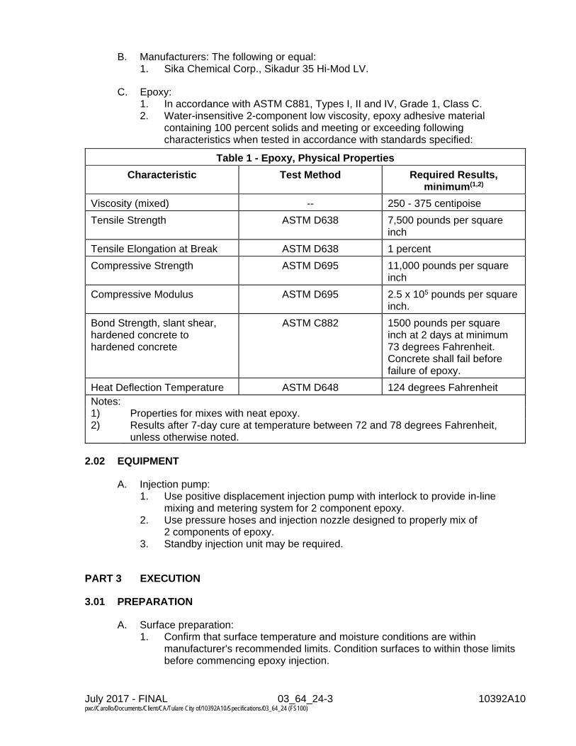
July 2017 - FINAL 03_64_24-3 10392A10 pw://Carollo/Documents/Client/CA/Tulare City of/10392A10/Specifications/03_64_24 (FS100)
B. Manufacturers: The following or equal: 1. Sika Chemical Corp., Sikadur 35 Hi-Mod LV.
C. Epoxy: 1. In accordance with ASTM C881, Types I, II and IV, Grade 1, Class C. 2. Water-insensitive 2-component low viscosity, epoxy adhesive material
containing 100 percent solids and meeting or exceeding following characteristics when tested in accordance with standards specified:
Table 1 - Epoxy, Physical Properties
Characteristic Test Method Required Results, minimum(1,2)
Viscosity (mixed) -- 250 - 375 centipoise
Tensile Strength ASTM D638 7,500 pounds per square inch
Tensile Elongation at Break ASTM D638 1 percent
Compressive Strength ASTM D695 11,000 pounds per square inch
Compressive Modulus ASTM D695 2.5 x 10⁵ pounds per square inch.
Bond Strength, slant shear, hardened concrete to hardened concrete
ASTM C882 1500 pounds per square inch at 2 days at minimum 73 degrees Fahrenheit. Concrete shall fail before failure of epoxy.
Heat Deflection Temperature ASTM D648 124 degrees Fahrenheit Notes: 1) Properties for mixes with neat epoxy. 2) Results after 7-day cure at temperature between 72 and 78 degrees Fahrenheit,
unless otherwise noted.
2.02 EQUIPMENT
A. Injection pump: 1. Use positive displacement injection pump with interlock to provide in-line
mixing and metering system for 2 component epoxy. 2. Use pressure hoses and injection nozzle designed to properly mix of
2 components of epoxy. 3. Standby injection unit may be required.
PART 3 EXECUTION
3.01 PREPARATION
A. Surface preparation: 1. Confirm that surface temperature and moisture conditions are within
manufacturer's recommended limits. Condition surfaces to within those limits before commencing epoxy injection.

July 2017 - FINAL 03_64_24-4 10392A10 pw://Carollo/Documents/Client/CA/Tulare City of/10392A10/Specifications/03_64_24 (FS100)
2. Sweep or clean area in vicinity of cracks that will be injected with epoxy. Leave area in generally clean condition after epoxy injection is complete.
3. Clean cracks so they are free from dirt, laitance, and other loose matter.
3.02 INSTALLATION
A. Install and cure epoxy materials in accordance with manufacturer's installation instructions.
B. Mixing: 1. Mix epoxy in accordance with manufacturer's installation instructions. 2. Do not use solvents to thin epoxy system materials introduced into cracks or
joints.
C. Injection: 1. Apply adequate surface seal to crack to prevent leakage of epoxy. 2. Establish injection points at distance along crack not less than thickness of
cracked member. 3. Crack injection sequence:
a. Inject epoxy into crack or joint at first port with sufficient pressure to advance epoxy to adjacent port. Start at lowest port along the injection line and work upwards.
b. Seal original port and shift injection to next adjacent port where epoxy appears.
c. Continue port-to-port injection until crack has been injected for its entire length.
d. For small amounts of epoxy, or where excessive pressure developed by injection pump might further damage structure, premixed epoxy and use hand caulking gun to inject epoxy if acceptable to the Engineer.
e. Seal ports, including adjacent locations where epoxy seepage occurs, as necessary to prevent drips or run out.
f. After epoxy injection is complete, remove surface seal material, and refinish concrete in area where epoxy was injected to match existing concrete. Leave finished work and work area in a neat, clean condition.
3.03 FIELD QUALITY ASSURANCE
A. Provide Contractor quality control as specified in Section 01_45_00.
B. Field inspections and testing: 1. Submit records of inspections and tests to Engineer within 24 hours after
completion.
C. Manufacturer's services. 1. Pre-installation meeting: Provide manufacturer's technical representative to
attend pre-installation meeting specified in this Section.
3.04 FIELD QUALITY CONTROL
A. Provide Owner's quality assurance for the Work of this Section as specified in Section 01_45_00.

July 2017 - FINAL 03_64_24-5 10392A10 pw://Carollo/Documents/Client/CA/Tulare City of/10392A10/Specifications/03_64_24 (FS100)
B. Special inspections special tests, and structural observation: 1. Not required.
C. Field inspections: 1. Preparation.
a. Review manufacturer's product data and installation instructions. 2. Required inspections.
a. Observe surfaces to be injected for temperature and moisture conditions and for surface preparation.
b. Observe conditioning and mixing of epoxy resin components. c. Observe injection procedures for filling cracks.
3. Records of inspections: a. Provide record of each inspection. b. Submit to Engineer upon request.
3.05 NON-CONFORMING WORK
A. Rework surface finishes that do not match surrounding concrete to the satisfaction of Engineer at no additional cost to Owner.
END OF SECTION


July 2017 - FINAL 04_05_17-1 10392A10 pw://Carollo/Documents/Client/CA/Tulare City of/10392A10/Specifications/04_05_17 (FS100)
SECTION 04_05_17
MORTAR AND MASONRY GROUT
PART 1 GENERAL
1.01 SUMMARY
A. Section includes: Mortar and grout for masonry construction.
B. Related sections: 1. The Contract Documents are complementary; what is called for by one is as
binding as if called for by all. 2. It is the Contractor’s responsibility for scheduling and coordinating the Work of
subcontractors, suppliers, and other individuals or entities performing or furnishing any of Contractor’s Work.
3. The following Sections are related to the Work described in this Section. This list of Related Sections is provided for convenience only and is not intended to excuse or otherwise diminish the duty of the Contractor to see that the completed Work complies accurately with the Contract Documents. a. Section 01_41_00 - Regulatory Requirements.
1.02 REFERENCES
A. ASTM International (ASTM): 1. C 144 - Standard Specification for Aggregate for Masonry Mortar. 2. C 150 - Standard Specification for Portland Cement. 3. C 207 - Standard Specification for Hydrated Lime for Masonry Purposes. 4. C 270 - Standard Specification for Mortar for Unit Masonry. 5. C 404 - Standard Specification for Aggregates for Masonry Grout. 6. C 476 - Standard Specification for Grout for Masonry. 7. C 780 - Standard Test Method for Preconstruction and Construction
Evaluation of Mortars for Plain and Reinforced Unit Masonry. 8. C 1019 - Standard Test Method for Sampling and Testing Grout.
B. National Concrete Masonry Association (NCMA): 1. TEK 19-7 - Characteristics of Concrete Masonry Units with Integral Water
Repellent.
1.03 DEFINITIONS
A. Alkali: Sum of sodium oxide and potassium oxide calculated as sodium oxide.
1.04 PERFORMANCE REQUIREMENTS
A. Compressive strength: 1. Mortar: Minimum 2,800 pounds per square inch at 28 days. 2. Grout: Minimum 2,000 pounds per square inchat 28 days.

July 2017 - FINAL 04_05_17-2 10392A10 pw://Carollo/Documents/Client/CA/Tulare City of/10392A10/Specifications/04_05_17 (FS100)
B. Water repellency: 1. The masonry assembly and mortared joints shall meet the performance criteria
set forth in NCMA TEK 19-7. 2. Use of an integral water repellent admixture that is capable of providing
masonry assembly performance of no visible dampness on backs of three wall specimens when evaluated using ASTM E 514.
1.05 SUBMITTALS
A. Product data.
B. Shop drawings.
C. Design Mixes for mortar and grout.
D. Test reports: 1. Mortar Strength Test Results. 2. Grout Strength Test Results. 3. Water repellency test results.
1.06 QUALITY ASSURANCE
A. Materials for mortar and grout: Do not change source of materials which will affect the appearance of finished work after the work has started unless acceptable to Engineer.
1.07 DELIVERY, STORAGE, AND HANDLING
A. Store integral water-repellent mortar admixture in an area where temperature is maintained between 40 degrees F (4 degrees C) and 105 degrees F (40 degrees C).
B. Do not allow integral water-repellent admixture to freeze; discard any frozen admixture.
1.08 PROJECT CONDITIONS
A. Environmental requirements: 1. Cold weather requirements:
a. Cold Weather Construction: In accordance with the building code as specified in Section 01_41_00.
b. Provide adequate equipment for heating mortar and grout materials when air temperature is below 40 degrees Fahrenheit. 1) Temperatures of separate materials, including water, shall not
exceed 140 degrees Fahrenheit when placed in mixer. 2) Maintain mortar temperature on boards above freezing.
2. Hot weather requirements: a. Wet mortar board before loading and cover mortar to retard drying when
not being used.

July 2017 - FINAL 04_05_17-3 10392A10 pw://Carollo/Documents/Client/CA/Tulare City of/10392A10/Specifications/04_05_17 (FS100)
PART 2 PRODUCTS
2.01 MATERIALS
A. Portland cement: 1. Type II, low alkali, containing maximum 0.6 percent total alkali in accordance
with ASTM C 150.
B. Hydrated lime: 1. Type S in accordance with ASTM C 207.
C. Aggregate for mortar: 1. Fine aggregate: Sand in accordance with ASTM C 144.
D. Aggregate for grout: 1. Fine aggregate: Size Number 2 in accordance with ASTM C 404. 2. Coarse aggregate: Size Number 8 in accordance with ASTM C 404.
E. Admixtures: 1. Grout admixture:
a. Manufacturers: One of the following or equal: 1) Sika Corp., Sika Grout Aid, Type II. 2) Concrete Emulsions, Grout Aid GA-II.
2. Integral water repellent admixture for mortar: a. Manufacturers: One of the following or equal:
1) W.R. Grace & Co., DRY-BLOCK Mortar Admixture. 2) BASF Corporation, MasterPel 240 MA (Rheopel Plus Mortar
Admixture) liquid mortar admixture or MasterPel 210D (Rheopel Plus D) powdered masonry water-repellent admixture.
b. The integral water repellent admixture used for the concrete masonry units and the mortar shall be produced by the same manufacturer.
c. Provide integral water repellent admixtures for the following block walls: 1) All exterior walls.
3. Other admixtures: a. Prohibited, unless accepted by the Engineer.
F. Water: Clean, clear, potable, free of oil, soluble salts, chemicals, and other deleterious substances.
G. Other materials: 1. Prohibited, unless acceptable to Engineer.
2.02 MIXES
A. Mortar mix: 1. Portland cement-lime mortar. 2. Integral water repellent admixture:
a. Add water repellent admixture for mortar during mixing in conformance with the product instructions and recommendations of the manufacturer.
3. Mortar mixing: a. Mix on jobsite in accordance with ASTM C 270. b. Mix in mechanical mixer and only in quantities needed for immediate use.

July 2017 - FINAL 04_05_17-4 10392A10 pw://Carollo/Documents/Client/CA/Tulare City of/10392A10/Specifications/04_05_17 (FS100)
c. Mix for minimum 3 minutes, and maximum of 5 minutes after materials have been added to mixer.
4. Measurement by volume: Measurement of constituents shall be accomplished by the use of a container of known capacity.
5. Water shall be mixed with the dry ingredients in sufficient amount to provide a workable mixture which will adhere to the vertical surfaces of masonry units. a. Use no mortar which has been standing for more than 1 hour after being
mixed. 6. Whenever 90 minutes has elapsed since last batch was mixed, completely
empty mixer drum of materials and wash down before placing next batch of materials.
B. Grout mix: 1. Grout mixing:
a. Mix on jobsite or in a transit mix in accordance with ASTM C 476 b. Slump: 8 to 11 inches, unless otherwise accepted by the Engineer. c. Use within 90 minutes after addition of mixing water. d. Mix for minimum of 5 minutes after ingredients are added and until
uniform mix is attained. Grout shall have sufficient water added to produce pouring consistency without segregation.
2. Use coarse grout for hollow cell masonry units with minimum 4-inch cell dimensions in both horizontal directions. a. Calculate cell dimension for this criterion by subtracting diameter(s) of any
horizontal reinforcement crossing the cell from clear cell dimensions of the masonry unit.
PART 3 EXECUTION
3.01 FIELD QUALITY CONTROL
A. Testing of grout and mortar: 1. During progress of construction, the Owner will have tests made to determine
whether the grout and mortar, as being produced, complies with Specifications.
2. Compressive strength test for grout: In accordance with ASTM C 1019. 3. The Engineer will make and deliver test specimens to the laboratory and
testing expense will be borne by the Owner. 4. Required number of tests:
a. At least 2 test specimens of grout will be made per week. 5. Do not use grout and mortar that does not meet specification.
a. Remove such mortar and grout from Project site. 6. Make provisions for and furnish grout and mortar for test specimens, and
provide manual assistance to the Engineer in preparing test specimens. 7. Assume responsibility for care of and providing proper curing conditions for
test specimens.
B. Testing of masonry assembly water repellency: 1. Perform field tests on the water repellency of the concrete masonry units and
the masonry unit assembly (including mortared joints) as required to verify conformance with the Specifications.

July 2017 - FINAL 04_05_17-5 10392A10 pw://Carollo/Documents/Client/CA/Tulare City of/10392A10/Specifications/04_05_17 (FS100)
3.02 ADJUSTING
A. Repair of defective masonry: 1. Remove and replace or repair defective work. 2. Do not patch, repair, or cover defective work without inspection by the
Engineer. 3. Provide repairs having strength equal to or greater than specified strength for
areas involved.
3.03 CLEANING
A. Promptly remove excess wet mortar containing integral water-repellent mortar admixture from the faces of the masonry as work progresses. Do not use strong acids, over-aggressive sandblasting or high-pressure cleaning methods.
END OF SECTION


July 2017 - FINAL 04_05_18-1 10392A10 pw://Carollo/Documents/Client/CA/Tulare City of/10392A10/Specifications/04_05_18 (FS100)
SECTION 04_05_18
ADHESIVE BONDING REINFORCING BARS AND ALL THREAD RODS IN MASONRY
PART 1 GENERAL
1.01 SUMMARY
A. Section includes: Bonding reinforcing bars and all thread rods in masonry using injectable, 2-component adhesive.
B. Related sections: 1. Section 01_41_00 - Regulatory Requirements. 2. Section 01_45_00 - Quality Control. 3. Section 01_45_24 - Special Tests and Inspections. 4. Section 01_81_01 - Project Design Criteria. 5. Section 04_05_23 - Masonry Accessories. 6. Section 05_12_00 - Structural Steel.
1.02 REFERENCES
A. American National Standards Institute (ANSI): 1. Standard B212.15 - Carbide Tipped Masonry Drills and Blanks for Carbide
Tipped Masonry Drills.
B. ICC Evaluation Service, Inc. (ICC-ES): 1. AC58 - Acceptance Criteria for Adhesive Anchors in Masonry Elements.
C. Society for Protective Coatings (SSPC): 1. Surface Preparation Standards (SP).
a. SP-1 - Solvent Cleaning.
1.03 DEFINITIONS
A. Evaluation Report: Report prepared by ICC-ES, or by other testing agency acceptable to the Engineer and to the Authority Having Jurisdiction, that documents testing and review of the adhesive product to confirm that it conforms to the requirements of ICC-ES AC58.
1.04 SUBMITTALS
A. Product Data: Furnish technical data for adhesives, including: 1. Independent testing laboratory results indicating allowable loads in tension and
shear for masonry walls of the types included in the Work, with load modification factors for temperature, spacing, edge distance, and other installation variables.
2. Handling and storage instructions. 3. Installation instructions.

July 2017 - FINAL 04_05_18-2 10392A10 pw://Carollo/Documents/Client/CA/Tulare City of/10392A10/Specifications/04_05_18 (FS100)
B. Quality control submittals: 1. Special inspection: Detailed instructions for special inspection to comply with
the building code specified in Section 01_41_00 and as required by the Evaluation Report for each product.
2. Evaluation Report confirming that the product complies with the requirements of ICC-ES AC58.
1.05 DELIVERY, STORAGE, AND HANDLING
A. Store and protect as follows, unless manufacturer has more stringent requirements. 1. Store adhesive components on pallets or shelving in a covered-storage area
protected from weather. 2. Control temperature to maintain storage within manufacturer’s recommended
temperature range. a. If products are stored at temperatures outside manufacturer’s
recommended range, test components prior to use by methods acceptable to the Engineer to determine if the products still meet specified requirements.
3. Dispose of products that have passed their expiration date.
1.06 PROJECT CONDITIONS
A. Seismic design category: As indicated on the Drawings.
PART 2 PRODUCTS
2.01 GENERAL
A. Like items of materials: Use end products of one manufacturer to achieve structural compatibility and single-source responsibility.
2.02 ADHESIVE FOR SELF-CONTAINED CARTRIDGE SYSTEM
A. Adhesive shall have a current Evaluation Report demonstrating compliance with the requirements of ICC-ES AC58.
B. Materials 1. 2-component structural adhesive, insensitive to moisture, and gray in color. 2. Cure temperature, pot life, and workability: Compatible with intended use and
environmental conditions.
C. Packaging. 1. Furnished in disposable, side-by-side cartridges with resin and hardener
components isolated until mixing through manufacturer’s static mixing nozzle. a. Nozzle designed to thoroughly blend the components, in the proper
mixing ratio, for injection from the nozzle directly into prepared hole. b. Provide nozzle extensions as required to allow full-depth insertion and
filling from the bottom of the hole. 2. Container markings: Include manufacturer's name, product name, batch
number, mix ratio by volume, product expiration date, ANSI hazard classification, and appropriate ANSI handling precautions.

July 2017 - FINAL 04_05_18-3 10392A10 pw://Carollo/Documents/Client/CA/Tulare City of/10392A10/Specifications/04_05_18 (FS100)
D. For installation in solid masonry and solid-grouted masonry (concrete or brick): 1. Manufacturers: One of the following or equal:
a. Hilti, Inc., Tulsa, OK: HY-70 Adhesive Anchor System. b. Simpson Strong-Tie Company, Inc., Pleasanton, CA: ET-HP Anchoring
Adhesive. c. USP Structural Connectors, Burnsville, MN: CIA-GEL 7000 Masonry
Epoxy Adhesive.
2.03 ALL THREAD RODS
A. Materials: As specified in Section 05_12_00.
2.04 REINFORCING BARS
A. As specified in Section 04_05_23.
PART 3 EXECUTION
3.01 GENERAL
A. Unless otherwise required for “conditions of use” in the Evaluation Report submitted, prepare and install holes, adhesive, and inserts (all thread rods or reinforcing bars) in accordance with the manufacturer’s recommendations and this Section. 1. In the event of conflicts, the more restrictive provisions shall govern.
B. Do not install adhesive-bonded all-thread rods or reinforcing bars in upwardly inclined and overhead applications.
3.02 PREPARATION
A. Prior to completing manufacturer’s on-site training specified in this Section, do not: 1. Drill holes for reinforcing bars or all thread rods. 2. Mix or install adhesive in holes.
B. Review manufacturer’s installation instructions and “conditions of use” stipulated in the Evaluation Report before beginning work.
C. Confirm that adhesive and substrate receiving adhesive are within manufacturer’s recommended temperature range, and will remain so during the cure time for the product.
3.03 HOLE LAYOUT AND INSTALLATION
A. Drilling holes: 1. Determine location of reinforcing bars or other obstructions with a
nondestructive indicator device. Mark locations with on the surface of the masonry using removable construction crayon, or other method acceptable to the Engineer.
2. Do not damage or cut existing reinforcing bars, electrical conduits, or other items embedded in the masonry without prior acceptance by Engineer.

July 2017 - FINAL 04_05_18-4 10392A10 pw://Carollo/Documents/Client/CA/Tulare City of/10392A10/Specifications/04_05_18 (FS100)
B. Hole drilling equipment: 1. Electric or pneumatic rotary impact type.
a. Set drill to “rotation only” mode, or to “rotation plus hammer” mode in accordance with manufacturer’s installation instructions and the requirements of the Evaluation Report.
2. Where edge distances are less than 2 inches and “rotation plus hammer” mode is permitted, use lighter impact equipment to prevent micro-cracking and spalling from drilling.
3. Drill bits: Carbide-tipped in accordance with ANSI B212-15. 4. Hollow drill bits with flushing air systems are preferred. Air supplied to hollow
drill bits shall be free of oil, water, or other contaminants that will reduce bond.
C. Hole diameter: As recommend in the manufacturer’s installation instructions and the Evaluation Report.
D. Hole depth: As recommended by the manufacturer’s installation instructions to provide minimum effective embedment indicated on the Drawings.
E. Obstructions in drill path: 1. If an existing reinforcing bar or other obstruction is hit while drilling hole, stop
drilling and fill the hole with dry-pack mortar. Relocate the hole to miss the obstruction and drill to the required depth. a. Allow dry-pack mortar to cure to strength equal to that of the surrounding
masonry before resuming drilling in that area. b. Epoxy grout may be substituted for dry-pack mortar when acceptable to
the Engineer. 2. Avoid drilling an excessive number of adjacent holes that would weaken the
structural member and endanger the stability of the structure. Obtain Engineer’s acceptance of distance between abandoned and relocated holes.
F. Cleaning holes: 1. Insert air nozzle to bottom of hole and blow out loose dust.
a. Use compressed air that is free of oil, water, or other contaminants. b. Provide minimum air pressure of 90 pounds per square inch for not less
than 4 seconds. 2. Using a stiff bristle brush of diameter that provides contact around the full
perimeter of the hole, vigorously brush the hole to dislodge compacted drilling dust. a. Insert brush to the bottom of the hole and withdraw using a simultaneous
twisting motion. b. Repeat at least 4 times.
3. Repeat the preceding steps as required to remove drilling dust or other material that will reduce bond, and as required by the manufacturer and the Evaluation Report.
4. Leave prepared hole clean and dry.
3.04 INSTALLATION OF ADHESIVE AND INSERTS
A. Clean and prepare inserts: 1. Prepare embedded length of reinforcing bars and all thread rods by cleaning to
bare metal. The inserts shall be free of oil, grease, paint, dirt, mill scale, rust, or other coatings that will reduce bond.

July 2017 - FINAL 04_05_18-5 10392A10 pw://Carollo/Documents/Client/CA/Tulare City of/10392A10/Specifications/04_05_18 (FS100)
2. Solvent-clean prepared reinforcing bars and all thread rods over their embedment length in accordance with SSPC SP-1. Provide an oil and grease-free surface for bonding of adhesive to steel.
B. Fill holes with adhesive: Solid or solid-grouted masonry: 1. Starting at the bottom of the hole, fill hole with adhesive before inserting the
reinforcing bar or all thread rod. 2. Fill hole without creating air voids as nozzle is withdrawn. 3. Fill hole with sufficient adhesive so that excess is extruded out of the hole
when the reinforcing bar or all thread rod is inserted into the hole. 4. Where metal or plastic screens are required for use in masonry (units with
hollow cells or holes, and multi-wythe brick walls), fill screen with adhesive and insert into hole in accordance with manufacturer’s recommendations.
C. Install reinforcing bars and all thread rods: 1. Install to depth, spacing, and locations as indicated on the Drawings. 2. Insert bars and all thread rods into hole in accordance with manufacturer’s
recommended procedures. Confirm that insert has reached the designated embedment in the hole and that adhesive completely surrounds the embedded portion.
3. Clean excess adhesive from the mouth of the hole.
D. Curing and loading: 1. Provide curing conditions recommended by the adhesive manufacturer for the
period required to fully cure the adhesive at the actual temperature of the masonry.
2. Do not disturb or load anchors until manufacturer’s recommended cure time has elapsed.
3.05 FIELD QUALITY CONTROL
A. Contractor shall provide field quality control as specified in Section 01_45_00.
B. Manufacturers' services: 1. Before beginning installation, commission adhesive manufacturer's
representative to conduct on-site training in proper storage and handling of adhesive, drilling and cleaning of holes, and preparation and installation of reinforcing bars and all thread rods. a. Provide notice of training to Engineer and Special Inspector not less than
10 working days before training occurs. Engineer and Special Inspector may attend training sessions.
2. Submit record, signed by the Engineer, listing Contractor’s personnel who completed the training. Only qualified personnel who have completed manufacturer’s on-site training shall perform installations.
3. Do not install holes or adhesive until training is complete.
3.06 FIELD QUALITY ASSURANCE
A. The Owner will provide on-site inspection and field quality assurance.
B. Special inspection: 1. As specified in Section 01_45_24.

July 2017 - FINAL 04_05_18-6 10392A10 pw://Carollo/Documents/Client/CA/Tulare City of/10392A10/Specifications/04_05_18 (FS100)
2. Unless otherwise indicated on the Drawings or in this Section, provide periodic special inspection as required by the “Conditions of Use” in the Evaluation Report for the product installed. a. Provide continuous inspection of placement of adhesive and insertion of
reinforcing bars and all thread rods into adhesive. 3. Provide a written record of each inspection using form acceptable to the
Engineer and the Authority Having Jurisdiction. 4. Preparation:
a. Review drawings and specifications for the Work being observed. b. Review adhesive manufacturer’s recommended installation and
evaluation report’s special inspection procedures. 5. Provide an initial inspection by for each combination of masonry type and
reinforcing bar or all thread rod being installed. During initial inspection, observe the following for compliance with installation requirements. Furnish report of inspection that includes the following items. a. Masonry construction: Type and thickness; whether fully or partially
grouted; locations and types of voids and holes in units. b. Environment: Temperature and moisture conditions of masonry base
material and work area. c. Holes: Locations, spacing, edge distances; verification of drill bit
compliance with ANSI B212.15; cleaning equipment and procedures; cleanliness of hole. Before placing adhesive, confirm that depth and preparation of holes conforms to requirements of the Contract Documents, installation recommendations of the manufacturer, and “conditions of use” specified in the Evaluation Report.
d. Adhesive: Product manufacturer and name; lot number and expiration date; temperature of product at installation; installation procedures. Note initial set times observed during installation.
e. Embedded reinforcing bars and all thread rods: Material diameter and length; steel grade and/or strength; cleaning and preparation; cleanliness at insertion; minimum effective embedment.
6. Subsequent installations of the same reinforcing bars or threaded rods in the same masonry may be performed without the presence of the special inspector, provided that: a. There is no change in the personnel performing the installation, the type
or details of the masonry receiving the insert, the adhesive or the reinforcing bars and all thread rods being used. Changes in any of these items shall require a new initial inspection.
b. For ongoing installations over a period of time, the special inspector visits the site at least once per day during each day of installation to observe the work for compliance with material requirements and installation procedures.
END OF SECTION

July 2017 - FINAL 04_05_23-1 10392A10 pw://Carollo/Documents/Client/CA/Tulare City of/10392A10/Specifications/04_05_23 (FS100)
SECTION 04_05_23
MASONRY ACCESSORIES
PART 1 GENERAL
1.01 SUMMARY
A. Section includes: 1. Control joint filler. 2. Reinforcing bars.
B. Related sections: 1. Section 01_41_00 - Regulatory Requirements. 2. Section 05_05_24 - Mechanical Anchoring and Fastening to Concrete and
Masonry.
1.02 REFERENCES
A. American Welding Society (AWS): 1. D1.4 - Structural Welding Code - Reinforcing Steel.
B. ASTM International (ASTM): 1. A 615 - Standard Specification for Deformed and Plain Carbon-Steel Bars for
Concrete Reinforcement.
2. D 2000 - Standard Classification System for Rubber Products in Automotive Applications.
3. D 2287 - Standard Specification for Nonrigid Vinyl Chloride Polymer and Copolymer Molding and Extrusion Compounds.
1.03 SYSTEM DESCRIPTION
A. The Drawings contain general notes concerning amount of reinforcement and placing, details of reinforcement at wall corners and intersections, and details of extra reinforcement around openings in masonry.
1.04 SUBMITTALS
A. Reinforcing bars: 1. Changes to reinforcing steel contract drawing requirements:
a. Indicate in separate letter submitted with shop drawings any changes of requirements indicated on the Drawings for reinforcing steel.
b. Such changes will not be acceptable unless the Engineer has accepted such changes in writing.
c. Reinforcement detail drawings: 1) Review of reinforcement shop drawings by the Engineer will be
limited to general compliance with the Contract Documents. d. Welding procedures.
B. Product data.

July 2017 - FINAL 04_05_23-2 10392A10 pw://Carollo/Documents/Client/CA/Tulare City of/10392A10/Specifications/04_05_23 (FS100)
1.05 DELIVERY, STORAGE, AND HANDLING
A. Packing and shipping: 1. Deliver bars bundled and tagged with identifying tags.
PART 2 PRODUCTS
2.01 MANUFACTURED UNITS
A. Anchor bolts: 1. Cast-in/built-in steel anchors: As specified in Section 05_05_24.
a. Includes: anchor bolts, anchor rods, deformed bar anchors, and welded studs).
2. Post-installed steel anchors: As specified in Section 05_05_24. a. Includes concrete anchors for concrete masonry, and screw anchors for
concrete masonry.
B. Control joint filler: The key shall be of the width and shape as indicated on the Drawings. In accordance with ASTM D 2000 or ASTM D 2287. 1. Manufacturers: One of the following or equal:
a. Hohmann & Barnard, VS Standard. b. Wire-Bond, No. 2901. c. Southern Metals and Plastics No. CJ1.
C. Reinforcing bars: 1. Deformed bars in accordance with ASTM A 615, Grade 60. 2. Provide reinforcing steel that is of quality specified, free from excessive rust or
scale or any defects affecting its usefulness.
2.02 FABRICATION
A. Reinforcing bars: 1. Cut and bend bars in accordance with building code as specified in
Section 01_41_00. 2. Bend bars cold. 3. Provide bars free from defects and kinks and from bends not indicated on the
Drawings.
PART 3 EXECUTION
3.01 EXAMINATION
A. Verification of conditions: 1. Reinforcing bars:
a. Verify that bars are new stock free from rust scale, loose mill scale, excessive rust, dirt, oil, and other coatings which adversely affect bonding capacity when placed in the work.

July 2017 - FINAL 04_05_23-3 10392A10 pw://Carollo/Documents/Client/CA/Tulare City of/10392A10/Specifications/04_05_23 (FS100)
3.02 PREPARATION
A. Reinforcing bars:1. Thin coating of red rust resulting from short exposure will not be considered
objectionable. Thoroughly clean any bars that have rust scale, loose mill scale,or thick rust coat.
2. Remove concrete or other deleterious coatings from dowels and otherprojecting bars by wire brushing or sandblasting before bars are embedded insubsequent masonry placement.
3.03 INSTALLATION
A. Reinforcing bars:1. No field bending of bars will be allowed.2. Welding:
a. Weld reinforcing bars where indicated on the Drawings or acceptable tothe Engineer.
b. Perform welding in accordance with AWS D1.4.c. Submit welding procedures.d. Do not tack weld reinforcing bars.
B. Placing reinforcing bars:1. Accurately place bars and adequately secure them in position.2. Overlap bars at splices as indicated on the Drawings or specified.3. If not indicated on the Drawings, lap splice bars in masonry in accordance with
the building code as specified in Section 01_41_00.
END OF SECTION


July 2017 - FINAL 04_22_00-1 10392A10 pw://Carollo/Documents/Client/CA/Tulare City of/10392A10/Specifications/04_22_00 (FS100)
SECTION 04_22_00
CONCRETE UNIT MASONRY
PART 1 GENERAL
1.01 SUMMARY
A. Section includes: Concrete masonry units and accessories.
B. Related sections: 1. Section 01_31_19 - Project Meetings. 2. Section 01_41_00 - Regulatory Requirements. 3. Section 01_45_24 - Special Inspection, Special Tests, and Structural
Observation. 4. Section 04_05_17 - Mortar and Masonry Grout. 5. Section 04_05_23 - Masonry Accessories. 6. Section 05_12_00 - Structural Steel. 7. Section 07_90_00 - Joint Sealants.
1.02 REFERENCES
A. American Concrete Institute (ACI): 1. ACI 530.1 - Specification for Masonry Structures.
B. ASTM International (ASTM): 1. C90 - Standard Specification for Loadbearing Concrete Masonry Units. 2. C140 - Standard Test Methods for Sampling and Testing Concrete Masonry
Units and Related Units. 3. C426 - Standard Test Method for Linear Drying Shrinkage of Concrete
Masonry Units. 4. E 514 - Standard Test Method for Water Penetration and Leakage through
Masonry.
C. National Concrete Masonry Association (NCMA): 1. TEK 19-7 - Characteristics of Concrete Masonry Units with Integral Water
Repellent.
1.03 DEFINITIONS
A. Custom Level of Quality: Top rank, nearly free of chips, cracks, or other imperfections detracting from appearance when discernible and identified from distance of 15 feet under diffused lighting, obtainable only by skilled journeymen. Five percent of shipment may contain slight cracks or small chips, not larger than 1/2 inch in any direction.
B. Standard Level of Quality: High quality, but conventional, nearly free of chips, cracks, or other imperfections detracting from appearance when discernible and identified from distance of 20 feet under diffused lighting. When level of quality is not specified, Standard Level of Quality shall be assumed.

July 2017 - FINAL 04_22_00-2 10392A10 pw://Carollo/Documents/Client/CA/Tulare City of/10392A10/Specifications/04_22_00 (FS100)
C. Economy Level of Quality: Low quality with slight mismatching of textures and colors on exposed surfaces with no reduction in structural integrity leading to cracking, leaking, collapse, or other failure of basic structural nature. Where units are used in exposed wall construction, faces that are exposed shall not show chips, cracks, or other imperfections when viewed from distance of 25 feet under diffused lighting. 10 percent of shipment may contain slight cracks or small chips, not larger than 1 inch in any direction.
D. Mortar Smears: Mortar paste smeared across the permanent masonry construction during construction and absorbed into the masonry pores.
E. Mortar Splash: Mortar dropped splashed onto the permanent masonry construction at the base of the wall or off the scaffolding.
F. Mortar Tag: Excess mortar between masonry units worked out of the joints during tooling or striking.
G. Mortar Stains: Mortar paste left after mortar tags are removed.
1.04 SUBMITTALS
A. Product data: 1. Submit manufacturer’s product data for split face block. 2. Submit manufacturers’ product data for proposed cleaning agent.
B. Shop drawings: Include elevations of each wall indicating type and layout of units, including type of mortar joints, bond pattern, reinforcing steel, connecting dowels, joint reinforcement, grouted cells, and control joints.
C. Samples: Include samples of stretcher units in sufficient quantity to illustrate color range.
D. Test reports: 1. Compressive strength. 2. Linear shrinkage. 3. Moisture content as a percentage of total absorption. 4. Total absorption. 5. Unit weight. 6. Water repellency.
E. Qualification Certificate: 1. Submit a qualification certificate that is issued by the integral water repellent
admixture manufacturer that documents the concrete masonry unit block manufacturer is qualified to produce block that is treated with the specified water repellent admixture.
F. Manufacturer’s instructions: 1. Submit printed or written recommendations from the masonry unit
manufacturer of the cleaning procedures and cleaning agents appropriate for each type of masonry unit included in the work.

July 2017 - FINAL 04_22_00-3 10392A10 pw://Carollo/Documents/Client/CA/Tulare City of/10392A10/Specifications/04_22_00 (FS100)
G. Quality assurance submittals: 1. If requested by the Engineer, submit a record of the Installer’s evidence of
qualifications. 2. If requested by the Engineer, submit a record of the Masonry Cleaner’s
evidence of qualifications.
1.05 QUALITY ASSURANCE
A. Qualifications: 1. Installer qualifications:
a. The mason shall hold an appropriate contractor’s license in the State where the work will be constructed.
b. The mason shall have not less than 5 years-experience and completed a minimum of 20 projects and at least 5 of which included the type of masonry units specified for this Work.
c. The mason shall hold current certification demonstrating successful completion of the quality certification program administered by the Rocky Mountain Masonry Institute or the Mason Contractors Association of America.
2. Masonry cleaner qualifications: a. The masonry cleaner shall have not less than 5 years-experience and
completed a minimum of 20 projects and at least 5 of which included the type of masonry units specified for this Work.
B. Mock-up: 1. A minimum 2 weeks to starting construction of masonry, construct minimum
4 foot inches by 4 foot inches square mock-up. 2. Mock-up is intended for use as the project standard of workmanship,
construction, quality, appearance, and material selection. 3. Use accepted materials containing each different kind and color of concrete
masonry units to illustrate wall design. 4. The mock-up shall be constructed by the mason who will be performing the
work. 5. The mock-up shall be cleaned with the exact equipment, products, and
methods submitted and cleaned by the individual who will perform the Work. 6. When accepted, mock-up will be standard of comparison for remainder of
masonry work. a. The mock-up may be accepted by the Engineer with exceptions that will
not be accepted in the final construction. 1) In such cases, those areas of the mock-up not accepted will be
clearly identified by the Engineer. 7. When not accepted by the Engineer, construct another mock-up. 8. Upon completion of Project, dispose of mock-ups in legal manner at offsite
location.
C. Pre-installation conference: Conduct as specified in Section 01_31_19.
1.06 DELIVERY, STORAGE, AND HANDLING
A. Transport and handle concrete masonry units as required to prevent discoloration, chipping, and breakage.

July 2017 - FINAL 04_22_00-4 10392A10 pw://Carollo/Documents/Client/CA/Tulare City of/10392A10/Specifications/04_22_00 (FS100)
B. Store masonry units off the ground in a dry location, covered and protected from absorbing moisture. 1. Locate storage piles, stacks, and bins to protect materials from heavy traffic. 2. If masonry units are delivered in shrink-wrapped packaging and condensation
develops, remove shrink-wrap packaging.
C. Remove masonry units that have absorbed moisture or are chipped, cracked, and otherwise defective from jobsite upon discovery.
1.07 ENVIRONMENTAL REQUIREMENTS
A. Cold weather requirements: 1. In accordance with building code as specified in Section 01_41_00, provide
adequate equipment for heating masonry materials when air temperature is below 40 degrees Fahrenheit.
B. Hot weather requirements: 1. In accordance with building code as specified in Section 01_41_00, when
ambient air temperature exceeds 100 degrees Fahrenheit, or when ambient air temperature exceeds 90 degrees Fahrenheit and wind velocity is greater than 8 miles per hour, implement hot weather protection procedures.
2. Wet mortarboard before loading and cover mortar to retard drying when not being used.
3. Do not spread mortar beds more than 48 inches ahead of placing masonry units.
4. Place masonry units within one minute of spreading mortar.
1.08 SEQUENCING AND SCHEDULING
A. Order concrete masonry units well before start of installation to ensure adequate time for manufacturing and minimum 28 days for curing and drying before start of installation. Protect from weather after curing period to avoid moisture increase.
B. Installation of concrete masonry units and mortar placement shall not begin until testing of water repellency specified herein has verified an acceptable water repellency performance for concrete masonry units and mortar.
PART 2 PRODUCTS
2.01 MANUFACTURED UNITS
A. Hollow load bearing concrete masonry units: 1. Class: Class 2 in accordance with ASTM C90, Standard Level of Quality with
minimum compressive strength of 2,000 pounds per square inch. 2. Surface texture: Standard and smooth face. 3. Color: Mission Tan. 4. Typical size: 8 inches wide by 8 inches high by 16 inches long, unless
otherwise indicated on the Drawings, or other sizes as needed to minimize cutting.

July 2017 - FINAL 04_22_00-5 10392A10 pw://Carollo/Documents/Client/CA/Tulare City of/10392A10/Specifications/04_22_00 (FS100)
5. Admixtures: a. Integral water repellent admixture:
1) Manufacturers: One of the following or equal: a) W.R. Grace & Co., DRY-BLOCK Block Admixture. b) BASF Corporation, MasterPel (Rheopel) Series Admixture.
2) The integral water repellent admixture shall be added to the concrete unit masonry at the time of manufacture.
3) The integral water repellent admixture used for the concrete masonry units and the mortar shall be produced by the same manufacturer.
4) Provide integral water repellent admixtures for the following block walls: a) All exterior walls.
6. Special sizes and shapes: As required for window and door openings, bond beams, piers, lintels, control joints, and other special applications to minimize cutting.
7. Manufacturers: One of the following or equal: a. Angelus Block Co., Inc. - Fontana, CA.
8. The manufacturer of the hollow load bearing concrete masonry units shall be a manufacturer that holds a current qualification certification with the selected water repellent admixture manufacturer.
9. Concrete masonry units with an integral water repellent shall comply with the following: a. Performance criteria set forth in NCMA TEK 19-7. b. No visible dampness on backs of three wall specimens when tested in
accordance with ASTM E 514. Coordinate testing with Section 04_05_17.
B. Anchor bolts: As specified in Section 05_12_00.
C. Steel reinforcement: As specified in Section 04_05_23.
PART 3 EXECUTION
3.01 PREPARATION
A. Protection: 1. Protect adjacent construction with appropriate means from mortar droppings
and other effects of laying of concrete masonry units.
B. Surface preparation: 1. Thoroughly clean foundations of laitance, grease, oil, mud, dirt, mortar
droppings, and other matter that will reduce bond.
3.02 INSTALLATION
A. Forms and shores: 1. Where required, construct forms to the shapes indicated on the Drawings:
a. Construct forms sufficiently rigid to prevent deflection which may result in cracking or other damage to supported masonry and sufficiently tight to prevent leakage of mortar and grout.

July 2017 - FINAL 04_22_00-6 10392A10 pw://Carollo/Documents/Client/CA/Tulare City of/10392A10/Specifications/04_22_00 (FS100)
b. Do not remove supporting forms or shores until the supported masonry has acquired sufficient strength to support safely its weight and any construction loads to which it may be subjected. 1) Wait at least 24 hours after grouting masonry columns or walls
before applying uniform loads. 2. Wait at least 72 hours before applying concentrated loads.
B. Concrete masonry units: 1. Provide Standard Level of Quality. Comply with the requirements of ACI 530.1
unless more restrictive requirements are contained in this Section. 2. Lay concrete masonry units dry. 3. Lay units in uniform and true courses, level, plumb, and without projections or
offset of adjacent units. 4. Lay units to preserve unobstructed vertical continuity of cells to be filled with
grout or insulation. 5. Align vertical cells to be filled with grout to maintain clear, unobstructed
continuous vertical cell measuring not less than 2 by 3 inches. 6. Place mortar with full coverage of joints at webs of all cells and face shells. 7. Butter vertical head joints for thickness equal to face shell thickness of units,
and shove joints tightly together so that mortar bonds to both masonry units. 8. Solidly fill joints from face of units to inside face of cells. 9. Lay units to desired height with joints of uniform thickness. 10. Bond shall be plumb throughout. 11. Lay units to avoid formation of cracks when units are placed. Keep cells of
units as free of mortar as possible as masonry wall height increases. 12. When positions of units shift after mortar has stiffened, bond is broken, or
cracks are formed, relay units in new mortar. 13. Remove mortar, mortar droppings, debris, and other obstructions and
materials from inside of cell walls. 14. Remove mortar tags and smears daily with a non-metallic tool.
a. Mortar tags and smears shall be removed after they initially set, but shall not be permitted to remain more than 24 hours.
15. Where practical, protect completed work from mortar splash by placing thin plastic sheeting around the base of walls. a. Place sand, straw, sawdust or other similar material on the floor around
the base of walls to protect floors and walls. 16. Turn scaffold planks over at the end of the workday to avoid mortar splashes
from wet weather. a. Cover tops of walls at the end of the workday and other work stoppages to
prevent entry of water into the partially completed masonry. 17. Seal cleanouts after inspection and before grouting.
C. Bond pattern: 1. Lay concrete masonry units in running bond pattern, unless otherwise
indicated on the Drawings.
D. Mortar joints: 1. Make joints straight, clean, smooth, and uniform in thickness. 2. Tool exposed joints, slightly concave. Strike concealed joints flush. 3. Make vertical and horizontal joints 3/8-inch thick. 4. Where fresh masonry joins totally or partially set masonry, clean and roughen
set masonry before laying new units.

July 2017 - FINAL 04_22_00-7 10392A10 pw://Carollo/Documents/Client/CA/Tulare City of/10392A10/Specifications/04_22_00 (FS100)
5. Remove mortar that protrudes more than 1/2 inch into the cells of units that are to be grouted.
E. Grouting and reinforcement: 1. The lap splice length shall be in accordance with the ACI 530.1 and as
indicated on the Drawings. Hold vertical reinforcing bars in position at top and bottom and at intervals not exceeding 200 bar diameters. Use steel wire bar positioners to position bars. Tie reinforcing bars to dowels with wire ties.
2. Obtain acceptance of reinforcement placement before grouting. 3. Fill all spaces and cells solidly with grout.
a. Low-lift grouting: 1) Hollow unit masonry to be grouted by the low lift method shall be
constructed and grouted in lifts not exceeding 5 feet. 2) Slushing with mortar will not be permitted.
b. High-lift grouting: 1) Hollow unit masonry shall be allowed to cure at least 24 hours before
grouting. 2) Grout shall be placed in lifts not to exceed 6 feet in depth. 3) Each lift shall be allowed to set for 10 minutes after initial
consolidation of grout before successive lift is placed. 4) The full height of each section of wall shall be grouted in 1 day.
4. Grout in cells shall have full contact with surface of concrete footings. 5. When grouting stops for 1 hour or longer, form horizontal construction joints by
stopping grout placement 1-1/2 inches below top of uppermost unit containing grout.
6. After placement, consolidate grout using mechanical immersion vibrators designed for consolidating grout.
7. Placement: a. Use a hand bucket, concrete hopper, or grout pump. b. Place grout in final position within 1-1/2 hours after mixing. Place grout so
as to completely fill the grout spaces without segregation of the aggregates.
c. Do not insert vibrators into lower grout placements that are in a semi-solidified state.
d. Remove grout spills immediately by hand washing with a bucket and brush.
F. Cutting concrete masonry units: 1. When possible, use full units of the proper size in lieu of cut units. Cut units as
required to form chases, openings, for anchorage, and for other appurtenances.
2. Cut and fit units with power-driven carborundum or diamond disc blade saw.
G. Control joints: 1. Provide in masonry walls at locations indicated on the Drawings. 2. Make full height and continuous in appearance. 3. Run bond beams and bond beam reinforcing bars continuously through control
joints. 4. Insert control joint filler in joints as wall is constructed. 5. Apply sealant as specified in Section 07_90_00.
July 2017 - FINAL 04_22_00-8 10392A10 pw://Carollo/Documents/Client/CA/Tulare City of/10392A10/Specifications/04_22_00 (FS100)
H. Steel door frames: 1. Anchor and fully grout jambs and head of steel doorframes connected to
concrete unit masonry. 2. Fill frames with grout as each 2 feet of concrete unit masonry is laid.
I. Anchor bolts: 1. Hold anchor bolts in place with template during grouting to assure precise
alignment. 2. Do not cut or ream members being anchored or use other means to
accommodate misaligned anchor bolts in roof deck support angles.
J. Enclosures: 1. Where concrete masonry units enclose conduit, pipes, stacks, ducts, and
similar items, construct chases, cavities, and similar spaces as required, whether or not such spaces are indicated on the Drawings.
2. Point openings around flush mounted electrical outlet boxes with mortar, including flush joints above boxes.
3. Do not cover enclosures until inspected and when appropriate, tested.
K. Other embedded items: 1. Build in wall plugs, accessories, flashings, pipe sleeves, and other items
required to be built-in as the masonry work progresses.
L. Patching: 1. Patch exposed concrete masonry units at completion of the Work and in such
manner that patching will be indistinguishable from similar surroundings and adjoining construction.
M. Protection: 1. Protect concrete masonry units from drying too rapidly by frequently fog
spraying until damp at least 3 times a day for a minimum of 3 days.
N. Miscellaneous: 1. Build in required items, such as anchors, flashings, sleeves, frames, structural
steel, lintels, anchor bolts, and metal fabrications, as required for complete installation.
O. Grouting equipment: 1. Grout pumps:
a. Do not pump grout through aluminum tubes. b. Operate pumps to produce a continuous stream of grout without air
pockets. c. Upon completion of each days pumping, eject grout from pipeline without
contamination or segregation of the grout: 1) Remove waste materials and debris from the equipment. 2) Dispose of waste materials, debris, and all flushing water outside the
masonry. 2. Vibrators:
a. Internal vibrators shall maintain a speed of not less than 5,000 impulses per minute when submerged in the grout.
b. Maintain at least 1 spare vibrator, at the site at all times. c. Apply vibrators at uniformly spaced points not further apart than the visible
effectiveness of the machine.
July 2017 - FINAL 04_22_00-9 10392A10 pw://Carollo/Documents/Client/CA/Tulare City of/10392A10/Specifications/04_22_00 (FS100)
d. Limit duration of vibration to time necessary to produce satisfactory consolidation without causing segregation.
3.03 CONSTRUCTION
A. Site tolerances: Lay masonry plumb, true to line, and with courses level. Keep bond pattern plumb throughout. Lay masonry within the following tolerances: 1. Maximum variation from the plumb in the lines and surfaces of columns, walls,
and in the flutes and surfaces of fluted or split faced blocks: a. In adjacent masonry units: 1/8 inch. b. In 10 feet: 1/4 inch. c. In any story or 20 feet maximum: 3/8 inch. d. In 40 feet or more: 1/2 inch.
2. Maximum variations from the plumb for external corners, expansion joints, and other conspicuous lines: a. In any story or 20 feet maximum: 1/4 inch. b. In 40 feet or more: 1/2 inch.
3. Maximum variations from the level or grades indicated on the Drawings for exposed lintels, sills, parapets, horizontal grooves, and other conspicuous lines: a. In any bay or 20 feet maximum: 1/4 inch. b. In 40 feet or more: 1/2 inch.
4. Maximum variations of the linear building lines from established position in plan and related portion of columns, walls, and partitions: a. In any bay or 20 feet maximum: 1/2 inch. b. In 40 feet or more: 3/4 inch.
5. Maximum variation in cross sectional dimensions of columns and in thickness of walls: a. Minus: 1/4 inch. b. Plus: 1/2 inch.
3.04 FIELD QUALITY CONTROL
A. Site tests: 1. Owner will have tests performed by an independent laboratory. 2. Have minimum 3 concrete masonry units of each type proposed for Project
tested in accordance with ASTM C90, C140, and C426 to verify conformance to Specifications.
3. Tests shall include compressive strength, linear shrinkage, and moisture content as percent of total absorption, total absorption, and unit weight.
4. Perform field tests on the water repellency of the concrete masonry units and the masonry unit assembly (including mortared joints) as required to verify conformance with the Specifications.
B. Special inspection: 1. Special inspection shall be as specified in Section 01_45_24. 2. Owner will employ a qualified masonry special inspector for continuous special
inspection of the masonry work. Acceptance by a state or municipality having a program of examining and certifying masonry inspectors will be considered
July 2017 - FINAL 04_22_00-10 10392A10 pw://Carollo/Documents/Client/CA/Tulare City of/10392A10/Specifications/04_22_00 (FS100)
adequate qualifications. The masonry inspector shall be at the site during all masonry construction and perform the following duties: a. Review Drawings and Specifications and meet with the Contractor to
discuss requirements before work commences. b. Before masonry work commences, Contractor and the Contractor's
Quality Control Representative shall attend meeting with Engineer to review the requirements for surveillance and quality control of the masonry work.
c. Check brand and type of cement, lime (if used), and source of sand. d. Verify that foundation is clean, rough, and ready to receive units. e. Check reinforcing steel dowels for correct location, straightness, proper
alignment, spacing, size, and length. f. Observe field proportioning of mortar. Visually check aggregate to
determine uniformity of grading, cleanliness, and moisture. g. Verify that joints are full of mortar and kept tight during work. Inspect grout
cells to verify that fins will not interfere with grouting. Verify that masons keep grout cells clean of mortar droppings and inspect to determine compliance.
h. Continuously observe placing of grout. i. Perform or supervise performance of required sampling and testing.
3. Keep complete record of inspections. Report daily to the Building Official, Contractor's Quality Control Representative, Engineer, and Owner the progress of the masonry inspection.
3.05 FINAL CLEANING
A. General: 1. Final cleaning shall be performed within 7 to 14 days after construction of
masonry work. 2. Protect adjacent materials and equipment that may be damaged by cleaning. 3. Pre-wet masonry before applying cleaning agent, but do not saturate masonry. 4. Remove mortar stains, smears, and splash, efflorescence, and grout stains on
exposed surfaces with the submitted cleaning agent as directed by the masonry unit manufacturer’s recommendations.
5. Do not use muriatic acid as cleaning agent. 6. Cleaning agents shall be applied when the masonry surface and air
temperatures are at least 50 degrees Fahrenheit. a. Dilute cleaning agents in accordance with manufacturer’s
recommendations. b. Do not allow cleaning agents to dry on the masonry.
7. Clean wall from the top to the bottom, without overlapping areas being cleaned for consistency.
8. If pressure cleaning equipment is used, the following limitations shall be observed: a. Apply cleaning agent to pre-wetted wall with low pressure (less than
50 pounds per square inch). b. Use a 25° to 50° flared-tip nozzle (not a pointed tip). c. Maintain a consistent distance from the spray nozzle to the masonry
surface no closer than 12 inches. 1) Masonry cleaner shall use a combination of pressure, nozzle, and
distance from tip to masonry that does not damage the masonry surface.

July 2017 - FINAL 04_22_00-11 10392A10 pw://Carollo/Documents/Client/CA/Tulare City of/10392A10/Specifications/04_22_00 (FS100)
9. Rinse cleaning agents off the wall with potable water. 10. Dispose of debris, refuse, and surplus material offsite legally.
3.06 PROTECTION
A. Provide temporary protection for exposed masonry corners subject to damage.
B. Bracing: 1. Unless wall is adequately supported by permanent supporting elements so
wall will not overturn or collapse, adequately brace masonry walls over 8 feet in height to prevent overturning and to prevent collapse.
2. Keep bracing in place until permanent supporting elements of structure are in place.
C. Limited access zone: 1. Establish limited access zone prior to start of masonry wall construction. 2. Zone shall be immediately adjacent to wall and equal to height of wall to be
constructed plus 4 feet by entire length of wall on unscaffolded side of wall. 3. Limit access to zone to workers actively engaged in constructing wall. Do not
permit other persons to enter zone. 4. Keep zone in place until wall is adequately supported or braced by permanent
supporting elements to prevent overturning and collapse.
END OF SECTION


July 2017 - FINAL 05_05_24-1 10392A10 pw://Carollo/Documents/Client/CA/Tulare City of/10392A10/Specifications/05_05_24 (FS100)
SECTION 05_05_24
MECHANICAL ANCHORING AND FASTENING TO CONCRETE AND MASONRY
PART 1 GENERAL
1.01 SUMMARY
A. Section includes: 1. Cast-in anchors and fasteners:
a. Anchor bolts. b. Anchor rods.
2. Post-installed steel anchors and fasteners: a. Concrete anchors.
3. Appurtenances for anchoring and fastening: a. Anchor bolt sleeves. b. Isolating sleeves and washers. c. Thread coating for threaded stainless steel fasteners.
B. Related sections: 1. Section 01_33_00 - Submittals. 2. Section 01_41_00 - Regulatory Requirements. 3. Section 01_45_00 - Quality Control. 4. Section 01_45_24 - Special Tests and Inspections. 5. Section 01_81_01 - Project Design Criteria. 6. Section 03_21_17 - Adhesive-Bonded Reinforcing Bars and All Thread Rods. 7. Section 03_60_00 - Grouting. 8. Section 04_05_18 - Adhesive Bonding Reinforcing Bars and All Thread Rods
in Masonry.
1.02 REFERENCES
A. American Concrete Institute (ACI): 1. 355.2 - Qualification of Post-Installed Mechanical Anchors in Concrete &
Commentary.
B. American National Standards Institute (ANSI): 1. B212.15 - Cutting Tools - Carbide-tipped Masonry Drills and Blanks for
Carbide-tipped Masonry Drills.
C. American Welding Society (AWS): 1. D1.1 - Structural Welding Code - Steel. 2. D1.6 - Structural Welding Code - Stainless Steel.
D. ASTM International (ASTM): 1. A36 - Standard Specification for Carbon Structural Steel. 2. A53 - Standard Specification for Pipe, Steel, Black and Hot-Dipped,
Zinc-Coated, Welded and Seamless. 3. A108 - Standard Specification for Steel Bars, Carbon and Alloy, Cold Finished. 4. A123 - Standard Specification for Zinc (Hot-Dip Galvanized) Coatings on Iron
and Steel Products.

July 2017 - FINAL 05_05_24-2 10392A10 pw://Carollo/Documents/Client/CA/Tulare City of/10392A10/Specifications/05_05_24 (FS100)
5. A153 - Standard Specification for Zinc Coating (Hot-Dip) on Iron and Steel Hardware.
6. A240 - Standard Specification for Chromium and Chromium Nickel Stainless Steel Plate, Sheet, and Strip for Pressure Vessels and for General Applications.
7. A308 - Standard Specification for Steel Sheet, Terne (Lead-Tin Alloy) Coated by the Hot-Dip Process.
8. A496 - Standard Specification for Steel Wire, Deformed, for Concrete Reinforcement.
9. A563 - Standard Specification for Carbon and Alloy Steel Nuts. 10. B633 - Standard Specification for Electrodeposited Coatings of Zinc on Iron
and Steel. 11. B695 - Standard Specification for Coatings of Zinc Mechanically Deposited on
Iron and Steel. 12. E488 - Standard Test Methods for Strength of Anchors in Concrete Elements. 13. F436 - Standard Specification for Hardened Steel Washers. 14. F593 - Standard Specification for Stainless Steel Bolts, Hex Cap Screws and
Studs. 15. F594 - Standard Specification for Stainless Steel Nuts. 16. F1554 - Standard Specification for Anchor Bolts, Steel, 36, 55 and 105-ksi
Yield Strength. 17. F2329 - Standard Specification for Zinc Coating, Hot-Dip, Requirements for
Application to Carbon and Alloy Steel Bolts, Screws, Washers, Nuts, and Special Threaded Fasteners.
E. International Code Council Evaluation Service, Inc. (ICC-ES): 1. AC01 - Acceptance Criteria for Expansion Anchors in Masonry Elements. 2. AC193 - Acceptance Criteria for Mechanical Anchors in Concrete Elements.
1.03 DEFINITIONS
A. Built-in anchor: Headed bolt or assembly installed in position before filling surrounding masonry units with grout.
B. Cast-in anchor: Headed bolt or assembly installed in position before placing plastic concrete around.
C. Overhead installations: Fasteners installed on overhead surfaces where the longitudinal axis of the fastener is more than 60 degrees above a horizontal line so that the fastener resists sustained tension loads.
D. Passivation: Chemical treatment of stainless steel with a mild oxidant for the purpose of enhancing the spontaneous formation of the steel’s protective passive film.
E. Post-installed anchor: Fastener or assembly installed in hardened concrete or finished masonry construction, typically by drilling into the structure and inserting a steel anchor assembly.

July 2017 - FINAL 05_05_24-3 10392A10 pw://Carollo/Documents/Client/CA/Tulare City of/10392A10/Specifications/05_05_24 (FS100)
F. Terms relating to structures or building environments as used with reference to anchors and fasteners: 1. Corrosive locations: Describes interior and exterior locations as follows:
a. Locations used for delivery, storage, transfer, or containment (including spill containment) of chemicals used for plant treatment processes.
b. Exterior and interior locations at the following treatment structures: 1) Water storage facilities:
a) Water Storage Tanks. 2. Wet and moist locations: Describes locations, other than “corrosive locations,”
that are submerged, are immediately above liquid containment structures, or are subject to frequent wetting, splashing, or wash down. Includes: a. Exterior portions of buildings and structures. b. Liquid-containing structures:
1) Locations at and below the maximum operating liquid surface elevation.
2) Locations above the maximum operating liquid surface elevation and: a) Below the top of the walls containing the liquid. b) At the inside faces and underside surfaces of a structure
enclosing or spanning over the liquid (including walls, roofs, slabs, beams, or walkways enclosing the open top of the structure).
c. Liquid handling equipment: 1) Bases of pumps and other equipment that handles liquids.
d. Indoor locations exposed to moisture, splashing, or routine wash down during normal operations, including floors with slopes toward drains or gutters.
e. Other locations indicated on the Drawings. 3. Other locations:
a. Interior dry areas where the surfaces are not exposed to moisture or humidity in excess of typical local environmental conditions.
1.04 SUBMITTALS
A. General: 1. Submit as specified in Section 01_33_00. 2. Submit information listed for each type of anchor or fastener to be used.
B. Action submittals: 1. Product data:
a. Cast-in anchors: 1) Manufacturer’s data including catalog cuts showing anchor sizes and
configuration, materials, and finishes. b. Post-installed anchors:
1) For each anchor type, manufacturer’s data including catalog cuts showing anchor sizes and construction, materials and finishes, and load ratings.
2. Samples: a. Samples of each type of anchor, including representative diameters and
lengths, if requested by the Engineer. 3. Certificates:
a. Cast-in anchors: 1) Mill certificates for steel anchors that will be supplied to the site.

July 2017 - FINAL 05_05_24-4 10392A10 pw://Carollo/Documents/Client/CA/Tulare City of/10392A10/Specifications/05_05_24 (FS100)
b. Post-installed anchors: 1) Manufacturer’s statement or certified test reports demonstrating that
anchors that will be supplied to the site comply with the materials properties specified.
4. Test reports: a. Post-installed anchors: For each anchor type used for the Work:
1) Current ICC-ES Report (ESR) demonstrating: a) Acceptance of that anchor for use under the building code
specified in Section 01_41_00. b) That testing of the concrete anchor included the simulated
seismic tension and shear tests of AC193, and that the anchor is accepted for use in Seismic Design Categories C, D, E, or F and with cracked concrete.
b. Concrete anchor pre-installation test report. 5. Manufacturer’s instructions:
a. Requirements for storage and handling. b. Recommended installation procedures including details on drilling, hole
size (diameter and depth), hole cleaning and preparation procedures, anchor insertion, and anchor tightening.
c. Requirements for inspection or observation during installation. 6. Qualification statements:
a. Post-installed anchors: Installer qualifications: 1) Submit list of personnel performing installations and include date of
manufacturer’s training for each.
1.05 QUALITY ASSURANCE
A. Qualifications: 1. Post installed anchors shall be in accordance with building code specified in
Section 01_41_00. 2. Installers: Post-installed mechanical anchors:
a. Installations shall be performed by trained installers having at least 3 years of experience performing similar installations with similar types of anchors.
B. Special inspection: 1. Provide special inspection of post-installed anchors as specified in
Section 01_45_24 and this Section.
1.06 DELIVERY, STORAGE, AND HANDLING
A. Deliver post-installed anchors in manufacturer’s standard packaging with labels visible and intact. Include manufacturer’s installation instructions.
B. Handle and store anchors and fasteners in accordance with manufacturer’s recommendations and as required to prevent damage.
C. Protect anchors from weather and moisture until installation.
1.07 PROJECT CONDITIONS
A. As specified in Section 01_81_01.

July 2017 - FINAL 05_05_24-5 10392A10 pw://Carollo/Documents/Client/CA/Tulare City of/10392A10/Specifications/05_05_24 (FS100)
B. Seismic Design Category (SDC) for structures is indicated on the Drawings.
PART 2 PRODUCTS
2.01 MANUFACTURED UNITS
A. General: 1. Furnish threaded fasteners with flat washers and hex nuts fabricated from
materials corresponding to the material used for threaded portion of the anchor. a. Cast-in anchors: Provide flat washers and nuts as listed in the ASTM
standard for the anchor materials specified. b. Post-installed anchors: Provide flat washers and nuts supplied for that
product by the manufacturer of each anchor. 2. Size of anchors and fasteners, including diameter and length or minimum
effective embedment depth: As indicated on the Drawings or as specified in this Section. In the event of conflicts, contact Engineer for clarification.
3. Where anchors and connections are not specifically indicated on the Drawings or specified, their material, size and form shall be equivalent in quality and workmanship to items specified.
B. Materials: 1. Provide and install anchors of materials as in this Section.
2.02 CAST-IN ANCHORS AND FASTENERS
A. Anchor bolts: 1. Description:
a. Straight steel rod having one end with an integrally forged head, and one threaded end. Embedded into concrete with the headed end cast into concrete at the effective embedment depth indicated on the Drawings or specified, and with the threaded end left to project clear of concrete face as required for the connection to be made.
b. Furnish anchor bolts with heavy hex forged head or equivalent acceptable to Engineer. 1) Rods or bars with angle bend for embedment in concrete (i.e., “L” or
“J” shaped anchor bolts) are not permitted in the Work. 2. Materials:
a. Ship anchor bolts with properly fitting nuts attached. b. Type 316 stainless steel:
1) Surfaces descaled, pickled, and passivated in accordance with ASTM A308.
2) Bolts: ASTM F593, Group 2, Condition CW, coarse threads. 3) Nuts: ASTM F594. Match alloy (group and UNS designation) and
threads of bolts. 4) Washers: Type 316 stainless steel.
c. Type 304 stainless steel: 1) Surfaces descaled, pickled, and passivated in accordance with
ASTM A308. 2) Bolts: ASTM F593, Group 1, Condition CW, coarse threads. 3) Nuts: ASTM F594. Match alloy (group and UNS designation) and
threads of bolts.

July 2017 - FINAL 05_05_24-6 10392A10 pw://Carollo/Documents/Client/CA/Tulare City of/10392A10/Specifications/05_05_24 (FS100)
4) Washers: Type 304 stainless steel. d. Galvanized steel:
1) Hot-dip galvanized coating in accordance with ASTM F2329. 2) Bolt: ASTM F1554, Grade 36, heavy hex, coarse thread. 3) Nuts: ASTM A563, Grade A, heavy hex, threads to match bolt. 4) Washers: ASTM F436, Type 1.
B. Anchor rods: 1. Description: Straight steel rod having threads on each end or continuously
threaded from end to end. One threaded end is fitted with nuts or plates and embedded in concrete to the effective depth indicated on the Drawings, leaving the opposite threaded end to project clear of the concrete face as required for the connection to be made at that location.
2. Materials: a. Stainless steel: Type 316:
1) Surfaces descaled, pickled, and passivated in accordance with ASTM A308.
2) Rod: ASTM F593, Group 2, Condition CW, coarse threads. 3) Nuts: ASTM F594. Match alloy (group and UNS designation) and
threads of rods. 4) Washers: Type 316 stainless steel. 5) Plates (embedded): ASTM A240.
b. Stainless steel: Type 304: 1) Surfaces descaled, pickled, and passivated in accordance with
ASTM A308. 2) Rod: ASTM F593, Group 1, Condition CW, coarse threads. 3) Nuts: ASTM F594. Match alloy (group and UNS designation) and
threads or rods. 4) Washers: Type 304 stainless steel. 5) Plates (embedded): ASTM A240.
c. Galvanized: steel: 1) Hot-dip galvanized with coating in accordance with ASTM F2329. 2) Rod: ASTM F1554, Grade 36, coarse thread. 3) Nuts: ASTM A563, Grade A, threads to match rod. 4) Washers: ASTM F436, Type 1. 5) Plates (embedded): ASTM A36.
2.03 POST-INSTALLED ANCHORS AND FASTENERS – ADHESIVE
A. Epoxy bonding of reinforcing bars, all thread rods, and threaded inserts in concrete: As specified in Section 03_21_17.
B. Epoxy bonding of reinforcing bars, all thread rods, and threaded inserts in masonry: As specified in Section 04_05_18.

July 2017 - FINAL 05_05_24-7 10392A10 pw://Carollo/Documents/Client/CA/Tulare City of/10392A10/Specifications/05_05_24 (FS100)
2.04 POST-INSTALLED ANCHORS AND FASTENERS – MECHANICAL
A. General: 1. Post-installed anchors used for the Work shall hold a current ICC Evaluation
Service Report demonstrating acceptance for use under the building code specified in Section 01_41_00. a. Conditions of use: The acceptance report shall indicate acceptance of the
product for use under the following conditions: 1) In regions of concrete where cracking has occurred or may occur. 2) To resist short-term loads due to wind forces. 3) To resist short-term loading due to seismic forces for the Seismic
Design Category of the structure where the product will be used. 2. Substitutions: When requesting product substitutions, submit calculations,
indicating the diameter, effective embedment depth and spacing of the proposed anchors, and demonstrating that the substituted product will provide load resistance that is equal to or greater than that provided by the anchors listed in this Section. a. Calculations shall be prepared by and shall bear the signature and seal of
a Civil or Structural Engineer licensed in the State of California. b. Decisions regarding the acceptability of proposed substitutions shall be at
the discretion of the Engineer.
B. Concrete anchors: 1. Description. Post-installed anchor assembly consisting of a threaded stud and
a surrounding wedge expansion sleeve that is forced outward by torqueing the center stud to transfer loads from the stud to the concrete through bearing, friction, or both. (Sometimes referred to as “expansion anchors” or “wedge anchors.”) a. Do not use slug-in, lead cinch, and similar systems relying on deformation
of lead alloy or similar materials to develop holding power. 2. Concrete anchors for anchorage to concrete:
a. Acceptance criteria: 1) Concrete anchors shall have a current ICC-ES Report demonstrating
that the anchors have been tested and qualified for performance in both cracked and un-cracked concrete, and for short-term loading due to wind and seismic forces for Seismic Design Categories A through F in accordance with ACI 355.2 and with ICC-ES AC193 (including all mandatory tests and optional tests for seismic tension and shear in cracked concrete).
2) Concrete anchor performance in the current ICC-ES Report shall be “Category 1” as defined in ACI 355.2.
b. Manufacturers: One of the following or equal: 1) Hilti: Kwik Bolt TZ Expansion Anchor. 2) Powers fasteners: PowerStud+ SD2. 3) Simpson Strong-Tie: Strong Bolt 2 Wedge Anchor.
c. Materials. Integrally threaded stud, wedge, washer, and nut: 1) Stainless steel: Type 316.
a) Type 304 stainless steel acceptable for use at wet and moist locations when accepted in writing by the Engineer.
2) Galvanized: Carbon steel, zinc plated in accordance with ASTM B633, minimum 5 microns (Fe/Zn 5).

July 2017 - FINAL 05_05_24-8 10392A10 pw://Carollo/Documents/Client/CA/Tulare City of/10392A10/Specifications/05_05_24 (FS100)
3. Concrete anchors for anchorage to concrete masonry (fully grouted cells): a. Acceptance criteria: Concrete anchors shall have a current
ICC-ES Report demonstrating that the anchors have been tested and qualified in accordance with ICC-ES AC01, including all mandatory tests and optional seismic tests.
b. Manufacturers: One of the following or equal: 1) Hilti: Kwik Bolt 3 Expansion Anchor. 2) Powers fasteners: Power-Stud+ SD1. 3) Simpson Strong-Tie: Wedge-All Anchor.
c. Materials. Integrally threaded stud, wedge, washer, and nut: 1) Stainless steel: Type 316.
a) Type 304 stainless steel acceptable for use at wet and moist locations when accepted in writing by the Engineer.
2) Galvanized: Carbon steel, zinc plated in accordance with ASTM B633, minimum 5 microns (Fe/Zn 5) or mechanically galvanized in accordance with ASTM B695, Class 55, Type 1.
C. Flush shells: 1. Description: Post-installed anchor assembly consisting of an internally
threaded mandrel that is forced into a pre-drilled concrete hole with a setting tool until the top of the anchor is flush with the face of the concrete. Once installed, a removable threaded bolt is installed in the mandrel.
2. Flush shell anchors are not permitted in the Work.
2.05 APPURTENANCES FOR ANCHORING AND FASTENING
A. Anchor bolt sleeves: 1. Having inside diameter approximately 2 inches greater than bolt diameter and
minimum 10-bolt diameters long. 2. Plastic sleeves:
a. High-density polyethylene, corrugated sleeve, threaded to provide adjustment of location on the anchor bolt.
3. Fabricated steel sleeves: a. Fabricate to the following dimensions unless otherwise indicated on the
Drawings. 1) Inside diameter: At least 2 inches greater than bolt diameter. 2) Inside length: Not less than 10 bolt diameters. 3) Bottom plate:
a) Square plate with dimensions equal to the outside diameter of the sleeve plus 1/2 inch each side.
b) Thickness equal to or greater than one-half of the anchor bolt diameter.
b. Carbon steel anchor bolts: 1) Fabricated from ASTM A 36 plate and ASTM A 53, Grade B pipe. 2) Welded connections: Conform to requirements of AWS D1.1. 3) Hot dip galvanized in accordance with ASTM A 153.
c. Stainless steel anchor bolts: 1) Fabricated from ASTM A 240 plate and pipe. Type 304L or Type
316L to match Type of the anchor bolt. 2) Welded connections: In accordance with AWS D1.6.

July 2017 - FINAL 05_05_24-9 10392A10 pw://Carollo/Documents/Client/CA/Tulare City of/10392A10/Specifications/05_05_24 (FS100)
B. Isolating sleeves and washers: 1. Manufacturers: One of the following or equal:
a. Central Plastics Company, Shawnee, Oklahoma. b. Corrosion Control Products, PSI Inc., Gardena, CA.
2. Sleeves: Mylar, 1/32-inch thick, 4,000 volts per mil dielectric strength, of proper size to fit bolts and extending half way into both steel washers.
3. One sleeve required for each bolt. 4. Washers: The inside diameter of all washers shall fit over the isolating sleeve,
and both the steel and isolating washers shall have the same inside diameter and outside diameter. a. Proper size to fit bolts. b. Two 1/8-inch thick steel washers for each bolt. c. G3 Phenolic: 2 insulating washers are required for each bolt:
1) Thickness: 1/8 inch. 2) Base material: Glass. 3) Resin: Phenolic. 4) Water absorption: 2 percent. 5) Hardness (Rockwell): 100. 6) Dielectric strength: 450 volts per mil. 7) Compression strength: 50,000 pounds per square inch. 8) Tensile strength: 20,000 pounds per square inch. 9) Maximum operating temperature: 350 degrees Fahrenheit.
C. Coating for repair of galvanized surfaces: 1. Manufacturers: One of the following or approved equal:
a. Galvinox. b. Galvo-Weld.
D. Thread coating: For use with threaded stainless steel fasteners: 1. Manufacturers: One of the following or equal:
a. Never Seez Compound Corporation, Never-Seez. b. Oil Research, Inc., WLR No. 111.
PART 3 EXECUTION
3.01 EXAMINATION
A. Examine Work in place to verify that it is satisfactory to receive the Work of this Section. If unsatisfactory conditions exist, do not begin this Work until such conditions have been corrected.
3.02 INSTALLATION: GENERAL
A. Where anchors and fasteners are not specifically indicated on the Drawings or specified, make attachments with materials specified in this Section.
B. Post-installed anchors shall not be installed into prestressed concrete tank walls without acceptance by the Engineer and the Tank Contractor.
C. Substitution of anchor types: 1. Post-installed anchors may not be used as an alternative to cast-in/built-in
anchors at locations where the latter are indicated on the Drawings.

July 2017 - FINAL 05_05_24-10 10392A10 pw://Carollo/Documents/Client/CA/Tulare City of/10392A10/Specifications/05_05_24 (FS100)
2. Cast-in/built-in anchors may be used as an alternative to post-installed mechanical anchors at locations where the latter are indicated on the Drawings.
D. Protect products from damage during installation. Take special care to protect threads and threaded ends.
E. Accurately locate and position anchors and fasteners: 1. Unless otherwise indicated on the Drawings, install anchors perpendicular to
the surfaces from which they project. 2. Install anchors so that at least 2 threads, but not more than 1/2 inch of
threaded rod, projects past the top nut.
F. Interface with other products: 1. Where steel anchors come in contact with dissimilar metals (aluminum,
stainless steel, etc.), use stainless steel anchors and separate or isolate dissimilar metals using isolating sleeves and washers.
2. Prior to installing nuts, coat threads of stainless steel fasteners with thread coating to prevent galling of threads.
3.03 INSTALLATION: CAST-IN ANCHORS
A. General: 1. Accurately locate cast-in and built-in anchors.
a. Provide anchor setting templates to locate anchor bolts and anchor rods. Secure templates to formwork.
b. Brace or tie off embedments as necessary to prevent displacement during placement of plastic concrete or of surrounding masonry construction.
c. Position and tie cast-in and built-in anchors in place before beginning placement of concrete or grout. Do not “stab” anchors into plastic concrete, mortar, or grout.
d. Do not allow cast-in anchors to touch reinforcing steel. Where cast-in anchors are within 1/4 inch of reinforcing steel, isolate the metals by wrapping the anchors with a minimum of 4 wraps of 10-mil polyvinyl chloride tape in area adjacent to reinforcing steel.
2. For anchoring at machinery bases subject to vibration, use 2 nuts, with 1 serving as a locknut.
3. Where anchor bolts or anchor rods are indicated on the Drawings as being for future use, thoroughly coat exposed surfaces that project from concrete or masonry with non-oxidizing wax. Turn nuts down full length of the threads, and neatly wrap the exposed thread and nut with a minimum of 4 wraps of 10-mil waterproof polyvinyl tape.
B. Anchor bolts: 1. Minimum effective embedment: 10-bolt diameters, unless a longer embedment
is indicated on the Drawings. 2. Where indicated on the Drawings, set anchor bolts in plastic, galvanized steel
or stainless steel sleeves to allow for adjustment. Fill sleeves with grout when a machine or other equipment is grouted in place.
C. Anchor rods: 1. Install as specified for anchor bolts.

July 2017 - FINAL 05_05_24-11 10392A10 pw://Carollo/Documents/Client/CA/Tulare City of/10392A10/Specifications/05_05_24 (FS100)
3.04 INSTALLATION: POST-INSTALLED ADHESIVE ANCHORS
A. Epoxy and acrylic adhesive bonding of reinforcing bars, all thread rods, and internally threaded inserts in concrete: As specified in Section 03_21_17.
B. Epoxy and acrylic adhesive bonding of reinforcing bars, all thread rods, and internally threaded inserts in masonry: As specified in Section 04_05_18.
3.05 INSTALLATION: POST-INSTALLED MECHANICAL ANCHORS
A. General: 1. Install anchors in accordance with the manufacturer’s instructions, ACI 355.2,
the anchor’s ICC-ES Report. Where conflict exists between the ICC-ES Report and the requirements in this Section, the requirements of the ICC-ES Report shall control.
2. Where anchor manufacturer recommends the use of special tools and/or specific drill bits for installation, provide and use such tools.
3. After anchors have been positioned and inserted into concrete or masonry, do not: a. Remove and reuse/reinstall anchors. b. Loosen or remove bolts or studs.
B. Holes drilled into concrete and masonry: 1. Do not drill holes in concrete or masonry until the material has achieved its
minimum specified compression strength (f’c or f’m). 2. Accurately locate holes:
a. Before drilling holes, use a reinforcing bar locator to identify the position of all reinforcing steel, conduit, and other embedded items within a 6-inch radius of each proposed hole.
b. If the hole depth exceeds the range of detection for the rebar locator, the Engineer may require radiographs of the area designated for investigation before drilling commences.
3. Exercise care to avoid damaging existing reinforcement and other items embedded in concrete and masonry. a. If embedments are encountered during drilling, immediately stop work and
notify the Engineer. Await Engineer’s instructions before proceeding. 4. Unless otherwise indicated on the Drawings, drill holes perpendicular to the
concrete surface into which they are placed. 5. Drill using anchor manufacturer’s recommended equipment and procedures.
a. Unless otherwise recommended by the manufacturer, drill in accordance with the following: 1) Drilling equipment: Electric or pneumatic rotary type with light or
medium impact. Where edge distances are less than 2 inches, use lighter impact equipment to prevent micro-cracking and concrete spalling during drilling process.
2) Drill bits: Carbide-tipped in accordance with ANSI B212-15. Hollow drills with flushing air systems are preferred.
6. Drill holes at manufacture’s recommended diameter and to depth required to provide the effective embedment indicated.

July 2017 - FINAL 05_05_24-12 10392A10 pw://Carollo/Documents/Client/CA/Tulare City of/10392A10/Specifications/05_05_24 (FS100)
7. Clean and prepare holes as recommended by the manufacturer and as required by the ICC-ES Report for that anchor. a. Unless otherwise recommended by anchor manufacturer, remove dust
and debris using brushes and clean compressed air. b. Repeat cleaning process as required by the manufacturer’s installation
instructions. c. When cleaning holes for stainless steel anchors, use only stainless steel
or non-metallic brushes.
C. Insert and tighten (or torque) anchors in full compliance with the manufacturer’s installation instructions. 1. Once anchor is tightened (torque), do not attempt to loosen or remove its bolt
or stud.
D. Concrete anchors: Minimum effective embedment lengths unless otherwise indicated on the Drawings:
Concrete Anchors
Nominal Diameter
Minimum Effective Embedment Length Minimum Member
Thickness In Concrete In Grouted Masonry
3/8 inch 2 1/2 inch 2 5/8 inch 8 inch
1/2 inch 3 1/2 inch 3 1/2 inch 8 inch
5/8 inch 4 1/2 inch 4 1/2 inch 10 inch
3/4 inch 5 inch 5 1/4 inch 12 inch
E. Flush shell anchors: 1. Flush shell anchors are not permitted in the Work. 2. If equipment manufacturer’s installation instructions recommend the use of
flush shell anchors, contact Engineer for instructions before proceeding.
3.06 FIELD QUALITY CONTROL
A. Contractor shall provide quality control over the Work of this Section as specified in Section 01_45_00. 1. Expenses associated with work described by the following paragraphs shall be
paid by the Contractor.
B. Post-installed anchors: 1. Review anchor manufacturer’s installation instructions and requirements of the
Evaluation Service Report (hereafter referred to as “installation documents”) for each anchor type and material.
2. Observe hole-drilling and cleaning operations for conformance with the installation documents.
3. Certify in writing to the Engineer that the depth and location of anchor holes, and the torque applied for setting the anchors conforms to the requirements of the installation documents.

July 2017 - FINAL 05_05_24-13 10392A10 pw://Carollo/Documents/Client/CA/Tulare City of/10392A10/Specifications/05_05_24 (FS100)
3.07 FIELD QUALITY ASSURANCE
A. The Owner will provide on-site observation and field quality assurance for the Work of this Section. 1. Expenses associated with work described by the following paragraphs shall be
paid by the Owner.
B. Field inspections and special inspections: 1. Required inspections: Observe construction for conformance to the approved
Contract Documents, the accepted submittals, and manufacturer’s installation instructions for the products used.
2. Record of inspections: a. Maintain record of each inspection. b. Submit copies to Engineer upon request.
3. Statement of special inspections: At the end of the project, prepare and submit to the Engineer and the authority having jurisdiction inspector’s statement that the Work was constructed in general conformance with the approved Contract Documents, and that deficiencies observed during construction were resolved.
C. Special inspections: Anchors cast into concrete and built into masonry. 1. Provide special inspection during positioning of anchors and placement of
concrete or masonry (including mortar and grout) around the following anchors: a. Anchor bolts. b. Anchor rods.
2. During placement, provide continuous special inspection at each anchor location to verify that the following elements of the installation conform to the requirements of the Contract Documents. a. Anchor:
1) Type and dimensions. 2) Material: Galvanized steel, Type 304 stainless steel, or Type 316
stainless steel as specified in this Section or indicated on the Drawings.
3) Positioning: Spacing, edge distances, effective embedment, and projection beyond the surface of the construction.
4) Reinforcement at anchor: Presence, positioning, and size of additional reinforcement at anchors indicated on the Drawings.
3. Following hardening and curing of the concrete or masonry surrounding the anchors, provide periodic special inspection to observe and confirm the following: a. Base material (concrete or grouted masonry):
1) Solid and dense concrete or grouted masonry material within required distances surrounding anchor.
2) Material encapsulating embedment is dense and well-consolidated.
D. Special Inspections: Post-installed mechanical anchors placed in hardened concrete and in grouted masonry. 1. Provide special inspection during installation of the following anchors:
a. Concrete anchors.

July 2017 - FINAL 05_05_24-14 10392A10 pw://Carollo/Documents/Client/CA/Tulare City of/10392A10/Specifications/05_05_24 (FS100)
2. Unless otherwise noted, provide periodic special inspection during positioning, drilling, placing, and torquing of anchors. a. Provide continuous special inspection for post-installed anchors in
“overhead installations” as defined in this Section. 3. Requirements for periodic special inspection:
a. Verify items listed in the following paragraphs for conformance to the requirements of the Contract Documents and the Evaluation Report for the anchor being used. Observe the initial installation of each type and size of anchor, and subsequent installation of the same anchor at intervals of not more than 4 hours. 1) Any change in the anchors used, in the personnel performing the
installation, or in procedures used to install a given type of anchor shall require a new “initial inspection.”
b. Substrate: Concrete or masonry surfaces receiving the anchor are sound and of a condition that will develop the anchor’s rated strength.
c. Anchor: 1) Manufacturer, type, and dimensions (diameter and length). 2) Material (galvanized, Type 304 stainless steel, or Type 316 stainless
steel). d. Hole:
1) Positioning: Spacing and edge distances. 2) Drill bit type and diameter. 3) Diameter, and depth. 4) Hole cleaned in accordance with manufacturer’s required
procedures. Confirm multiple repetitions of cleaning when recommended by the manufacturer.
5) Anchor’s minimum effective embedment. 6) Anchor tightening/installation torque.
4. Requirements for continuous special inspection: a. The special inspector shall observe all aspects of anchor installation,
except that holes may be drilled in his/her absence provided that he/she confirms the use of acceptable drill bits before drilling, and later confirms the diameter, depth, and cleaning of drilled holes.
E. Field tests: 1. Owner’s Representative may, at any time, request testing to confirm that
materials being delivered and installed conform to the requirements of the Specifications. a. If such additional testing shows that the materials do not conform to the
specified requirements, the Contractor shall pay the costs of these tests. b. If such additional testing shows that the materials do conform to the
specified requirements, the Owner shall pay the costs of these tests.
3.08 NON-CONFORMING WORK
A. Remove misaligned or non-performing anchors.
B. Fill empty anchor holes and repair failed anchor locations as specified in Section 03_60_00 using high-strength, non-shrink, non-metallic grout.
C. If more than 10 percent of all tested anchors of a given diameter and type fail to achieve their specified torque or proof load, the Engineer will provide directions for

July 2017 - FINAL 05_05_24-15 10392A10 pw://Carollo/Documents/Client/CA/Tulare City of/10392A10/Specifications/05_05_24 (FS100)
required modifications. Make such modifications, up to and including replacement of all anchors, at no additional cost to the Owner.
3.09 SCHEDULES
A. Provide and install anchor materials as scheduled in the following Table.
Table – Required Anchoring Materials by Location
Location/Exposure Materials Notes
1. Anchors into concrete and grouted masonry for attachment of carbon steel, including structural steel and other steel fabrications:
a) Interior dry areas Carbon steel – galvanized
b) Locations with galvanized steel structures or fabrications
Stainless steel – Type 304 or 316 1
c) Exterior and interior wet and moist locations
Stainless steel – Type 316 1
d) Corrosive locations Stainless steel – Type 316 1
2. Anchors into concrete and grouted masonry for attachment of aluminum, stainless steel, or fiber-reinforced plastic (FRP) shapes and fabrications:
a) Interior dry areas Stainless steel – Type 304 or 316 1
b) Exterior and interior wet and moist locations
Stainless steel – Type 316 1
c) Corrosive locations Stainless steel – Type 316 1
3. Anchors for attaching equipment and its appurtenances:
a) All locations Stainless steel – Type 316 (unless Type 304 is specifically indicated in the specifications for the equipment.)
1
Notes: (1) Where anchors are in contact with a metal that differs from that of the anchor, provide
isolation sleeves and washers.
END OF SECTION


July 2017 - FINAL 05_12_00-1 10392A10 pw://Carollo/Documents/Client/CA/Tulare City of/10392A10/Specifications/05_12_00 (FS100)
SECTION 05_12_00
STRUCTURAL STEEL
PART 1 GENERAL
1.01 SUMMARY
A. Section includes: 1. Structural steel shapes and plate. 2. Fasteners and structural hardware:
a. All thread rods. b. High-strength bolts.
3. Welding. 4. Bolting.
B. Related sections: 1. Section 01_45_00 - Quality Control. 2. Section 01_45_24 - Special Inspection, Special Tests, and Structural
Observation. 3. Section 03_21_17 - Adhesive-Bonded Reinforcing Bars and All Thread Rods
in Concrete. 4. Section 04_05_18 - Adhesive Bonding Reinforcing Bars and All Thread Rods
in Masonry. 5. Section 05_05_24 - Mechanical Anchoring and Fastening to Concrete and
Masonry. 6. Section 09_91_00 - Painting. 7. Section 09_96_01 - High-Performance Coatings.
1.02 REFERENCES
A. American Institute of Steel Construction (AISC): 1. 303 - Code of Standard Practice for Steel Buildings and Bridges. 2. 360 - Specification for Structural Steel Buildings.
B. American Iron and Steel Institute (AISI): 1. Steel alloys (“types”) as indicated.
C. American Welding Society (AWS): 1. A5.1 - Specification for Carbon Steel Electrodes for Shielded Metal Arc
Welding. 2. A5.17 - Specification for Carbon Steel Electrodes and Fluxes for Submerged
Arc Welding. 3. A5.20 - Specification for Carbon Steel Electrodes for Flux Cored Arc Welding. 4. D1.1 - Structural Welding Code - Steel.
D. ASTM International (ASTM): 1. A6 - Standard Specification for General Requirements for Rolled Structural
Steel Bars, Plates, Shapes, and Sheet Piling. 2. A36 - Standard Specification for Carbon Structural Steel.

July 2017 - FINAL 05_12_00-2 10392A10 pw://Carollo/Documents/Client/CA/Tulare City of/10392A10/Specifications/05_12_00 (FS100)
3. A53 - Standard Specification for Pipe, Steel, Black, and Hot-Dipped, Zinc-Coated, Welded, and Seamless.
4. A123 - Standard Specification for Zinc (Hot-Dip Galvanized) Coatings on Iron and Steel Products.
5. A153 - Standard Specification for Zinc Coating (Hot-Dip) on Iron and Steel Hardware.
6. A194 - Standard Specification for Carbon and Alloy Steel Nuts for Bolts for High Pressure or High Temperature Service, or Both.
7. A325 - Standard Specification for Structural Bolts, Steel, Heat Treated, 120/105 ksi Minimum Tensile Strength.
8. A500 - Standard Specification for Cold-Formed Welded and Seamless Carbon Steel Structural Tubing in Rounds and Shapes.
9. A501 - Standard Specification for Hot-Formed Welded and Seamless Carbon Steel Structural Tubing.
10. A563 - Standard Specification for Carbon and Alloy Steel Nuts. 11. A992 - Standard Specification for Structural Steel Shapes. 12. F436 - Standard Specification for Hardened Steel Washers. 13. F959 - Standard Specification for Compressible-Washer-Type Direct Tension
Indicators for Use with Structural Fasteners. 14. F2329 - Standard Specification for Zinc Coating, Hot-Dip, Requirements for
Application to Carbon and Alloy Steel Bolts, Screws, Washers, Nuts, and Special Threaded Fasteners.
E. Research Council on Structural Connections (RCSC): 1. Specification for Structural Joints Using High-Strength Bolts
(RCSC Specification).
1.03 DEFINITIONS
A. Snug-tight: At bolted joints, the tightness attained with a few impacts of an impact wrench, or by the full effort of an ironworker using a spud wrench to bring the connected plies into firm contact.
1.04 SUBMITTALS
A. Product data: 1. Welding electrodes for field welds: Electrode manufacturer's data.
B. Shop drawings: 1. Fabrication and erection drawings.
C. Quality control submittals: 1. Welding procedure specifications (WPS) in accordance with AWS D1.1.
a. Submit WPS for each type of welded joint used, whether prequalified or qualified by testing. 1) State electrode manufacturer and specific electrodes used. 2) Indicate required AWS qualification for joint.
b. Submit WPS with shop drawings that indicate those welds. c. Submit Procedure Qualification Record (PQR) in accordance with AWS
D1.1 for welding procedures qualified by testing. 2. Welder qualifications: For each welding process and position:
a. Welder's qualification certificates.

July 2017 - FINAL 05_12_00-3 10392A10 pw://Carollo/Documents/Client/CA/Tulare City of/10392A10/Specifications/05_12_00 (FS100)
b. Contractor's statement that certificate will be "in effect" at the time(s) welding will be performed based on the "Period of Effectiveness" provisions of AWS D1.1.
3. Steel fabricator's AISC certification.
D. Test reports: 1. Certified copies of mill tests and analyses made in accordance with applicable
ASTM standards, or reports from a recognized commercial laboratory, including chemical and tensile properties of each shipment of structural steel or part thereof having common properties.
1.05 QUALITY ASSURANCE
A. Certification: 1. Steel fabricators shall be certified by the AISC or other certification acceptable
to the Engineer and the building official having jurisdiction.
B. Welding: 1. Perform welding of structural metals in accordance with AWS D1.1 using
welders who have current AWS qualification certificate for the process, position, and joint configuration to be welded.
2. Make Welding Procedure Specifications available at the locations where welding is performed.
3. Notify Engineer at least 24 hours before starting shop or field welding. 4. Engineer may check materials, equipment, and qualifications of welders. 5. Remove welders performing unsatisfactory Work, or require requalification. 6. Engineer may use gamma ray, magnetic particle, dye penetrant, trepanning, or
other aids to visual inspection to examine any part of welds or all welds. 7. Contractor shall bear costs of retests on defective welds. 8. Contractor shall also bear costs in connection with qualifying welders.
1.06 DELIVERY, STORAGE, AND HANDLING
A. Packing and shipping: Deliver structural steel free from mill scale, rust, and pitting.
B. Storage and protection: Until erection and painting, protect from weather items not galvanized or protected by a shop coat of paint.

July 2017 - FINAL 05_12_00-4 10392A10 pw://Carollo/Documents/Client/CA/Tulare City of/10392A10/Specifications/05_12_00 (FS100)
PART 2 PRODUCTS
2.01 MATERIALS
A. Unless otherwise specified or indicated on the Drawings, materials shall conform to the following:
Item ASTM
Standard Class, Grade, Type, or
Alloy Number
Carbon Steel
Plate, bars, rolled shapes (except W and WT shapes), and miscellaneous items
A36 --
Rolled W and WT shapes A992 Grade 50
Hollow structural sections (HSS): Round, square, or rectangular
A500 Grade B
Steel pipe A53 Grade B
Stainless steel
Plate, sheet, and strip A240 Type 304* or 316**
Bars and shapes A276 Type 304* or 316**
* Use Type 304L (low-carbon stainless steel) if material will be welded.
** Use Type 316L (low carbon stainless steel) if material will be welded.
2.02 FASTENERS AND STRUCTURAL HARDWARE
A. General: 1. Materials: Of domestic manufacture. 2. Where fasteners and hardware are specified to be galvanized, galvanize in
accordance with ASTM A153 or ASTM F2329.
B. All thread rods: 1. Carbon steel:
a. In accordance with ASTM A36 unless otherwise indicated on the Drawings.
b. Nuts: ASTM A194. c. Washers: ASTM F436.
2. Galvanized carbon steel: a. In accordance with ASTM A36 unless otherwise indicated on the
Drawings, and hot dip galvanized in accordance with ASTM A153. b. Nuts: ASTM A194, hot-dip galvanized in accordance with ASTM A153. c. Washers: ASTM F436, hot-dip galvanized in accordance with ASTM
A153.
C. Anchor bolts, anchor rods, and post-installed steel anchors: As indicated on the Drawings and as specified in Section 05_05_24.

July 2017 - FINAL 05_12_00-5 10392A10 pw://Carollo/Documents/Client/CA/Tulare City of/10392A10/Specifications/05_12_00 (FS100)
D. High-strength bolts: 1. Provide high-strength bolt assembly, with nuts, hardened flat washers, and
compressible-washer-type direct tension indicators. Provide uncoated components unless galvanized coating is indicated on the Drawings.
2. Carbon steel - Uncoated: a. Bolts: Plain heavy hex structural bolts in accordance with ASTM A325
Type 1. b. Nuts: Heavy hex nuts in accordance with ASTM A563, Grade C. c. Washers: Flat:
1) Adjacent to normal, oversized, and short-slotted holes: Circular and square or rectangular beveled washers in accordance with ASTM F436.
2) Adjacent to long slotted holes: 5/16-inch thick plate washer fabricated from steel in accordance with ASTM A36.
d. Washers: Tension indicating: In accordance with ASTM F959. 3. Carbon steel - Galvanized:
a. Bolt and nut assemblies fabricated, galvanized, tested for rotational capacity, and shipped accordance with the provisions ASTM A325 and the RCSC Specification.
b. Bolts, nuts, and washers: Hot-dip galvanized and in accordance with ASTM A153, Class C or ASTM F2329.
c. Bolts: Plain heavy hex structural bolts in accordance with ASTM A325 Type 1 and galvanized as specified.
d. Nuts: Heavy hex nuts in accordance with ASTM A563, Grade DH, galvanized as specified, and lubricated in accordance with ASTM A563, Supplementary Requirement S1 to minimize galling.
e. Washers: 1) Adjacent to normal, oversized, and short-slotted holes: Circular and
square or rectangular beveled washers in accordance with ASTM F436 and galvanized as specified.
2) Adjacent to long slotted holes: 5/16-inch thick plate washer fabricated from steel in accordance with ASTM A36, and galvanized in accordance with ASTM A123.
2.03 ISOLATING SLEEVES AND WASHERS
A. As indicated on the Drawings and as specified in Section 05_05_24.
2.04 GALVANIZED SURFACE REPAIR
A. Manufacturers: One of the following or approved equal: 1. Galvinox. 2. Galvo-Weld.
2.05 THREAD COATING
A. Manufacturers: One of the following or approved equal: 1. Never Seez Compound Corporation, Never-Seez. 2. Oil Research, Inc., WLR No. 111.

July 2017 - FINAL 05_12_00-6 10392A10 pw://Carollo/Documents/Client/CA/Tulare City of/10392A10/Specifications/05_12_00 (FS100)
2.06 SUPPLEMENTARY PARTS
A. Furnish as required for complete structural steel erection, whether or not such parts and Work are specified or indicated on the Drawings.
2.07 FABRICATION
A. Shop assembly: 1. Fabricate structural steel in accordance with AISC 360 and AISC 303 unless
otherwise specified or modified by applicable regulatory requirements. 2. Where anchors, connections, or other details of structural steel are not
specifically indicated on the Drawings or specified, their material, size and form shall be equivalent in quality and workmanship to items specified.
3. Round off sharp and hazardous projections and grind smooth. 4. Take measurements necessary to properly fit work in the field. Take
responsibility for and be governed by the measurements and proper working out of all the details.
5. Take responsibility for correct fitting of metalwork. 6. Welded connections:
a. Comply with AWS requirements for the metals to be welded. b. Weld only in accordance with approved Welding Procedure
Specifications. c. Keep Welding Procedure Specifications readily available for welders and
inspectors during fabrication processes.
B. Galvanized carbon steel: 1. Where galvanizing is required, hot-dip structural steel after fabrication in
accordance with ASTM A123: 2. Do not electro-galvanize or mechanically-galvanize unless specified or
accepted by Engineer. 3. Re-straighten galvanized items that bend or twist during galvanizing.
PART 3 EXECUTION
3.01 EXAMINATION
A. Verification of conditions: Examine Work in place to verify that it is satisfactory to receive the Work of this Section. If unsatisfactory conditions exist, do not begin this Work until such conditions have been corrected.
3.02 ERECTION
A. General: 1. Fabricate structural and foundry items to true dimensions without warp or twist. 2. Form welded closures neatly, and grind off smooth where weld material
interferes with fit or is unsightly. 3. Install structural items accurately and securely, true to level, plumb, in correct
alignment and grade, with all parts bearing or fitting structure or equipment for which intended.
4. Do not shift out of alignment, re-drill, re-shape, or force fit fabricated items. 5. Place anchor bolts or other anchoring devices accurately and make surfaces
that bear against structural items smooth and level.

July 2017 - FINAL 05_12_00-7 10392A10 pw://Carollo/Documents/Client/CA/Tulare City of/10392A10/Specifications/05_12_00 (FS100)
6. Rigidly support and brace structural items needing special alignment to preserve straight, level, even, and smooth lines. Keep structural items braced until concrete, grout, or dry pack mortar has hardened for 48 hours minimum.
7. Erect structural steel in accordance with AISC 303 unless otherwise specified or modified by applicable regulatory requirements.
8. Where anchors, connections, and other details of structural steel erection are not specifically indicated on the Drawings or specified, form, locate, and attach with equivalent in quality and workmanship to items specified.
9. Round off sharp or hazardous projections and grind smooth. 10. Paint or coat steel items as specified in Sections 09_91_00 and 09_96_01.
B. Welding: General: 1. Make welds full penetration type, unless otherwise indicated on the Drawings. 2. Remove backing bars and weld tabs after completion of weld. Repair defective
welds observed after removal of backing bars and weld tabs.
C. Welding - carbon steel: 1. General: In accordance with AWS D1.1:
a. Weld ASTM A36 and A992 structural steel, ASTM A500 and A501 structural tubing, and ASTM A53 pipe with electrodes in accordance with AWS A5.1, using E70XX electrodes; AWS A5.17, using F7X-EXXX electrodes; or AWS A5.20, using E7XT-X electrodes:
b. Field repair cut or otherwise damaged galvanized surfaces to equivalent original condition using a galvanized surface repair.
D. Interface with other products: 1. Where steel members and fasteners come in contact with dissimilar metals
(aluminum, stainless steel, etc), separate or isolate the dissimilar metals with isolating sleeves and washers as specified in Section 05_05_24.
E. Fasteners: General: 1. Install bolts to project 2 threads minimum, but 1/2 inch maximum beyond nut. 2. Anchor bolts and anchor rods: Install as specified in Section 05_05_24.
a. Unless otherwise specified, tighten nuts on anchor bolts and anchor rods specified in Section 05_05_24 to the "snug-tight" condition.
3. All thread rods in drilled holes bonded to concrete with adhesive: Install as specified in Section 03_21_17.
4. All thread rods in drilled holes bonded to masonry with adhesive: Install as specified in Section 04_05_18.
F. Fasteners: High-strength carbon steel bolts: 1. Connections with high-strength bolts shall in accordance with RCSC
Specification for Structural Joints Using High-Strength Bolts. 2. Provide snug-tight connections. 5. Joints: Snug-tight:
a. Install bolts with washers where required in accordance with RCSC Specification.
b. Tighten bolts to bring the connected plies into firm contact. Tightening shall progress systematically beginning with the most rigid part of the joint. More than 1 cycle through the bolt pattern may be required to achieve this condition.

July 2017 - FINAL 05_12_00-8 10392A10 pw://Carollo/Documents/Client/CA/Tulare City of/10392A10/Specifications/05_12_00 (FS100)
c. Verify adequate tightening of bolts by visual observation to confirm that washers have been installed at locations required in accordance with RCSC Specification, and that the plies of the connected parts have been brought into firm contact.
3.03 FIELD QUALITY CONTROL
A. Provide quality control as specified in Section 01_45_00.
3.04 FIELD QUALITY ASSURANCE
A. Provide quality assurance as specified in Section 01_45_00.
B. Special inspections, special tests, and structural observation: 1. Provide as specified in Section 01_45_24.
END OF SECTION

July 2017 - FINAL 05_31_00-1 10392A10 pw://Carollo/Documents/Client/CA/Tulare City of/10392A10/Specifications/05_31_00 (FS100)
SECTION 05_31_00
STEEL DECKING
PART 1 GENERAL
1.01 SUMMARY
A. Section includes: Steel deck for roofs and associated accessories.
B. Related sections: 1. Section 01_33_00 - Submittal Procedures. 2. Section 01_45_24 - Special Inspection, Special Tests, and Structural
Observation.
1.02 REFERENCES
A. ASTM International (ASTM): 1. A 653 - Standard Specification for Steel Sheet, Zinc-Coated (Galvanized) or
Zinc-Iron Alloy-Coated (Galvannealed) by the Hot-Dip Process. 2. A 780 - Standard Practice for Repair of Damaged and Uncoated Areas of Hot-
Dip Galvanized Coatings. 3. A 1063 - Standard Specification for Steel Sheet, Twin-Roll Cast, Zinc-Coated
(Galvanized) by the Hot-Dip Process.
B. American Welding Society (AWS): 1. D1.3 - Structural Welding Code - Sheet Steel.
1.03 SUBMITTALS
A. General: Submit in accordance with Section 01_33_00.
B. Product data: 1. Details of fabrication for each type of deck included in the Work. Indicate deck
materials, thickness, profile, section properties, and finish. Provide manufacturer’s tables showing allowable loads and deflections for the spans required for the Project.
2. Roof deck: Manufacturer’s tables for resistance to horizontal loads. a. Tables for resistance to horizontal loads shall indicate diaphragm shear
load capacity for the spans and fastening type shown on the Drawings. 3. Fasteners: Materials and finishes for each type of fastener included in the
Work.
C. Shop drawings: 1. Submit layout and erection drawings for all steel deck.
a. Clearly indicate portion of the Work or structure covered by each submittal.
b. Erection drawings: 1) Provide plan view clearly showing placement of each piece on the
fabrication drawings or listed in the bill of materials.

July 2017 - FINAL 05_31_00-2 10392A10 pw://Carollo/Documents/Client/CA/Tulare City of/10392A10/Specifications/05_31_00 (FS100)
2) Indicate locations deck laps, and deck accessories including locations of filler strips or “make-up pieces” provided to fill spaces between flutes and deck supports.
3) Indicate location of openings through deck. 4) Indicate type and spacing of fasteners to be used.
a) For areas where Drawings show fastening patterns varying by location, clearly indicate type and spacing of fasteners to be used and areas where each occurs.
5) Provide details of accessories. c. Mark number painted on shop fabrications shall be the same mark
numbers shown in the layout and erection drawings.
D. Qualifications: 1. Steel deck installer: Record of qualifications and experience. 2. Welders. AWS qualification records that are no older than 12 months from the
time of submittal.
E. Manufacturer’s instructions: 1. Deck manufacturer’s installation instructions. 2. Mechanical fasteners. Installation procedures and installation tool .operations
manuals.
1.04 QUALITY ASSURANCE
A. Qualifications: 1. Installer:
a. Deck installation contractor. Having at least 5 years of experience in installation of steel deck, and including at least 10 projects with deck types and fastening systems as specified for this Project.
b. Welders. Field welding procedures and welders shall be qualified in accordance with AWS D1.3.
1.05 DELIVERY, STORAGE, AND HANDLING
A. Protect steel deck from damage during delivery, storage, and handling.
B. Storage and protection: 1. Store steel deck at the site stacked on platforms or pallets and covered with
waterproof material, ventilated to avoid condensation. 2. Elevate one end of stack to provide drainage.
C. Do not use steel deck for storage or working platform.
D. Do not install damaged or marred materials. Remove damaged, unlabeled, untagged, rusty, and deteriorated steel deck material from the job site.
PART 2 PRODUCTS
2.01 MANUFACTURERS
A. One of the following or equal: 1. ASC Profiles Inc., a BlueScope Steel Company, West Sacramento, CA.

July 2017 - FINAL 05_31_00-3 10392A10 pw://Carollo/Documents/Client/CA/Tulare City of/10392A10/Specifications/05_31_00 (FS100)
2. Verco Decking, Inc., a Nucor Company, Phoenix, AZ.
2.02 MATERIALS
A. Roof Deck: 1. Sheet steel for roof deck and accessories:
a. Galvanized steel deck conforming to ASTM A 653 or A 1063, Grade 50 Structural Quality; with G90 galvanized coating.
2. Deck type, gage, and finish as indicated on the Drawings. a. Shop primer: None. Provide uncoated galvanized. Treat exposed surfaces
with phosphate.
B. Deck accessories: 1. General.
a. Furnish all accessories indicated on the Drawings and required to provide a complete and finished installation.
b. Finish: Provide finish to match surrounding deck unless otherwise indicated on the Drawings.
2. Ridge plates, valley plates, and flat plates: a. Minimum 20 gauge design thickness (0.0358 inch).
3. Closures: Minimum 22 gage design thickness (0.0295 inch) plates. 4. Filler strips (filler sheets):
a. Minimum 20 gauge design thickness (0.0358 inch), fabricated to same height as deck corrugations, and with projecting flanges at top for lapping over adjacent deck ribs and at bottom for fastening to support structure.
5. Sump pans: a. Minimum 14 gauge design thickness (0.0747 inch) fabricated to same
height as deck corrugations and having minimum 3-inch projecting flange around the top perimeter for lapping over and fastening to surrounding deck ribs. Center sump minimum 16 inches square.
6. Wall/support closures: (for closing voids above beams, interior walls, and partitions that are perpendicular to the direction of deck flutes. a. At fire-resistant interior walls and partitions: Minimum 20 gage. b. Other locations: Compressible closed cell neoprene or vinyl synthetic
rubber. 7. Galvanizing repair materials. Conforming to ASTM A 780.
C. Weld materials: 1. In accordance with AWS D1.3.
2.03 FABRICATION
A. General: 1. Steel deck shall be formed:
a. So every sheet is identical and will register properly with the corrugation of adjacent sheets.
b. In lengths to minimize the number of splices. 2. Provide deck sections of nominal thickness, section modulus, and moment of
inertia as indicated on the Drawings and specified. a. Uncoated thickness of deck materials shall not be less than 95 percent of
the design thickness indicated.

July 2017 - FINAL 05_31_00-4 10392A10 pw://Carollo/Documents/Client/CA/Tulare City of/10392A10/Specifications/05_31_00 (FS100)
PART 3 EXECUTION
3.01 GENERAL
A. Furnish steel deck complete, including cutting, shaping, fitting, drilling, welding, ridge plates, valley plates, reinforcing plates for openings, and miscellaneous pieces necessary for proper installation.
3.02 EXAMINATION
A. Verification of conditions: Examine support framing and field conditions to verify that they are within required tolerances and free of debris, and that conditions are satisfactory to receive the work of this Section. If unsatisfactory conditions exist, do not begin this work until such conditions have been corrected.
3.03 INSTALLATION
A. Conform to all OSHA rules, and to any state or local regulations for erection of steel deck panels and accessories.
B. Place deck in accordance with accepted submittals, manufacturer’s instructions, the requirements of the Drawings and the requirements of this Section. 1. Position units on supports and adjust to final position before permanently
attaching to adjacent deck units and structural supports.
C. During installation: 1. Do not damage or overload steel deck or the structural framing that supports it. 2. After fastening deck may provide lateral stability for the top flange of the
supporting members. Determine weight of loads that may be placed on supporting members during erection considering the top flanges of supporting members to be unbraced.
3. Do not use steel deck for storage or as a working platform until sheets have been permanently fastened in position.
4. Prevent damage due to construction operations. a. Protect areas subject to heavy or repeated traffic, concentrated loads,
impact loads, wheel loads, or other construction operations using planking or other acceptable means.
D. Install deck in straight and continuous rows as far as practicable. 1. Install ribs at right angles to supporting members unless specifically shown
otherwise on the Drawings. 2. Mark supports at regular intervals to maintain alignment and proper spacing of
deck panels. 3. Install steel deck free of dents bends, and other damage. 4. Span deck panels over at least 3 spans wherever possible, and over 2 spans
as a minimum. 5. Position deck panels over supports and adjust to final position with ends and
sides aligned. 6. Provide specified bearing and overlap at panel ends.
a. Stagger laps at least one span between adjacent sheets. b. Provide minimum 3-inch bearing length over supports. c. Where panel ends lap, provide minimum 3-inch lap length and locate lap
over support.

July 2017 - FINAL 05_31_00-5 10392A10 pw://Carollo/Documents/Client/CA/Tulare City of/10392A10/Specifications/05_31_00 (FS100)
d. Panel ends shall not be allowed to abut unless accepted by the Engineer. 1) Where acceptable, panel ends may abut over supports, providing a
minimum 2-inch bearing length for each panel end. Weld ends of both deck sections to support without overlapping. Gaps up to 1-inch are permitted at panel ends if bearing length is maintained.
E. Neatly cut and fit deck around openings shown on the Drawings and around work projecting through or adjacent to the decking. 1. Reinforce holes that do not include structural deck supports around four sides
to provide full load carrying capacity around openings. 2. Trades that cut unscheduled openings through the deck shall be responsible
to reinforce those openings by means acceptable to the Engineer. 3. Roof deck.
a. For holes and openings up to 12 inches by 12 inches, reinforce deck with 18-gauge design thickness galvanized steel plate. Extend plate at least 12 inches beyond opening in all directions, and attach to top of deck ribs with 5/8-inch diameter puddle welds at corners and at 6-inches at on center around perimeter.
b. For holes and openings larger than 12 inches, reinforce deck with framing as shown on the Drawings.
F. Install all accessories required to complete work. Provide and install: 1. Ridge and valley plates and flat plates at changes in deck direction to provide
a flat finished surface for installing roof insulation and finished roof. 2. Deck closures. Install at locations where required.
a. Roof deck. End closures at open ends of openings through the roof and where deck terminates at exterior walls.
3. Filler strips at locations where bottom of flute at long edge of decking does not rest on structural supports.
4. Sump pans at locations to receive roof drains. 5. Wall / support closures at both faces of a wall or partition. 6. Fasten accessories to deck or supporting members using arc spot welds or
self-drilling screws spaced maximum 12-inches on center.
G. Provide finished installation free from dents, buckles, and irregularities.
3.04 FASTENING/ATTACHMENT
A. General: 1. Fasten steel deck panels to supporting structural framing, including perimeter
support steel and/or bearing walls, using methods designated on the Drawings and defined in the Specifications. a. Provide type, number, size, and spacing of fasteners as shown on the
Drawings. 2. Secure panels to supports immediately after they are placed and aligned to
form a secure working platform. 3. Fasten longitudinal joints between deck sections (“sidelaps”) together using
methods designated on the Drawings and defined in the Specifications. 4. During fastening of lapped joints at panel ends and sides, ensure that laps are
in tight contact with each other and with underlying supports.

July 2017 - FINAL 05_31_00-6 10392A10 pw://Carollo/Documents/Client/CA/Tulare City of/10392A10/Specifications/05_31_00 (FS100)
B. Welding: 1. Electric arc weld deck panels to bearing plates, to supports at butted or lapped
ends, to intermediate supports between panel ends, to side supports, and to end supports as indicated on the Drawings. a. Do not burn through the deck. b. Remove all slag. c. Button punching or crimping systems may not be substituted for welding.
2. Make provisions at point of welding to hold deck in firm contact with other deck sheets and structural supports. Provide weighting of top sheet with sand bags or other methods acceptable to the Engineer.
3. Provide welds conforming to AWS D1.3 specifications and made by qualified welders. a. Preheat or maintain environmental conditions as required to provide
fusion without burn-through. 4. Arc spot welds (“puddle welds”).
a. Provide welds of minimum visible outer diameter and spacing pattern as indicated on the Drawings.
b. Penetrate all layers of deck material and end laps and provide fusion to supporting members without holes or burn-through.
c. Use welding washers for all deck with design thickness less than 22 gauge (0.028 inches) and where required to provide fusion to supporting members.
5. Immediately after completing welds on a sheet of decking, clean welds with wire brush and coat with galvanizing repair product before welds are covered by successive sheets.
3.05 CLEANING, TOUCHUP, AND FINISHING
A. Immediately after erection, remove deck trimmings, screws, fasteners, welding washers, ends of welding rods, and other debris. Remove weld spatter, grease, and oil from deck.
B. Confirm that deck sheet is in place, properly and completely anchored, and accepted by the Engineer before any touch-up work is performed.
C. Clean field welds, rust spots and abraded areas and touch-up damage to coatings. 1. Restore coatings at cut edges, holes, and welds. 2. Galvanized surfaces: Touch up using zinc rich primer conforming to
ASTM A 780 with color to match deck finish a. Complete galvanizing repair on concrete side of floor deck before slab
concrete is placed. 3. Use magnetic gauge to confirm that thickness of repair is equal to or greater
than thickness of galvanized coating.
D. Prepare deck surfaces and provide finishes as shown on the Drawings and specified.
3.06 FIELD QUALITY CONTROL - CONTRACTOR FURNISHED
A. Site testing and inspection: 1. Welding:
a. Perform welding in accordance with AWS D1.3 requirements.

July 2017 - FINAL 05_31_00-7 10392A10 pw://Carollo/Documents/Client/CA/Tulare City of/10392A10/Specifications/05_31_00 (FS100)
b. Visually inspect welds for conformance to the acceptance criteria of AWS D1.3.
2. Repair or replace defective welds and fasteners.
3.07 FIELD QUALITY CONTROL - OWNER FURNISHED
A. Special inspection requirements: 1. See Section 01_45_24.
3.08 PROTECTION
A. Items suspended below deck: 1. Ceilings and ductwork:
a. Do not attach hangers to deck within the center 1/3 of span. b. Only 1 hanger may be attached to any 1 rib within 1 span. c. Attach wire hangers to deck with clips through hanger tabs.
2. Piping, conduit, equipment, and other services: a. Do not hang from deck.
END OF SECTION


July 2017 - FINAL 05_50_00-1 10392A10 pw://Carollo/Documents/Client/CA/Tulare City of/10392A10/Specifications/05_50_00 (FS100)
SECTION 05_50_00
METAL FABRICATIONS
PART 1 GENERAL
1.01 SUMMARY
A. Section includes: 1. Manhole frames and covers. 2. Metal gratings. 3. Metal tread plate. 4. Preformed channel pipe supports. 5. Miscellaneous metals. 6. Associated accessories to the above items.
B. Related sections: 1. Section 33_05_16 - Precast Drainage Structures. 2. Section 05_05_24 - Mechanical anchoring and Fastening to Concrete and
Masonry. 3. Section 09_96_01 - High Performance Coatings. 4. Section 40_05_07.01 - Pipe Supports. 5. Section 40_05_07.03 - Preformed Channel Pipe Support System.
1.02 REFERENCES
A. American Association of State Highway and Transportation Officials (AASHTO): 1. Standard Specifications for Highway Bridges.
B. ASTM International (ASTM): 1. A 36 - Standard Specification for Carbon Structural Steel. 2. A 48 - Standard Specification for Gray Iron Castings. 3. A 53 - Standard Specification for Pipe, Steel, Black and Hot-Dipped, Zinc-
Coated, Welded, and Seamless. 4. A 123 - Standard Specification for Zinc (Hot-Dip Galvanized) Coatings on Iron
and Steel Products. 5. A 240 - Standard Specification for Chromium and Chromium-Nickel Stainless
Steel Plate, Sheet, and Strip for Pressure Vessels for General Applications. 6. A 276 - Standard Specification for Stainless Steel Bars and Shapes. 7. A 307 - Standard Specification for Carbon Steel Bolts and Studs, 60,000 PSI
Tensile Strength. 8. A 325 - Standard Specification for Structural Bolts, Steel, Heat Treated,
120/105 ksi Minimum Tensile Strength. 9. A 380 - Standard Practice for Cleaning, Descaling, and Passivation of
Stainless Steel Parts, Equipment, and Systems. 10. A 489 - Standard Specification for Carbon Steel Lifting Eyes. 11. A 490 - Standard Specification for Structural Bolts, Alloy Steel, Heat-Treated,
150 ksi Minimum Tensile Strength. 12. A 500 - Standard Specification for Cold-Formed Welded and Seamless
Carbon Steel Structural Tubing in Rounds and Shapes.

July 2017 - FINAL 05_50_00-2 10392A10 pw://Carollo/Documents/Client/CA/Tulare City of/10392A10/Specifications/05_50_00 (FS100)
13. A 501 - Standard Specification for Hot-Formed Welded and Seamless Carbon Steel Structural Tubing.
14. A 635 - Standard Specification for Steel, Sheet and Strip, Heavy-Thickness Coils, Hot-Rolled, Alloy, Carbon, Structural, High-Strength Low-Alloy, and High-Strength Low-Alloy with Improved Formability, General Requirements for.
15. A 653 - Standard Specification for Steel Sheet, Zinc-Coated (Galvanized) or Zinc-Iron Alloy-Coated (Galvannealed) by the Hot-Dip Process.
16. A 992 - Standard Specification for Structural Steel Shapes. 17. B 209 - Standard Specification for Aluminum and Aluminum-Alloy Sheet and
Plate. 18. B 221 - Standard Specification for Aluminum and Aluminum-Alloy Extruded
Bars, Rods, Wire, Profiles, and Tubes. 19. B 308 - Standard Specification for Aluminum-Alloy 6061-T6 Standard
Structural Profiles.
1.03 DEFINITIONS
A. Passivation: Removal of exogenous iron or iron compounds from the surface of a stainless steel by means of chemical dissolution resulting from treatment with an acid solution that removes the surface contamination but does not significantly affect the stainless steel itself.
1.04 SUBMITTALS
A. Product Data: 1. Manhole frames and covers. 2. Metal grating.
B. Shop drawings: 1. Metal grating. 2. Metal tread plate. 3. Miscellaneous metals.
C. Quality control submittals: 1. Design data. 2. Test reports:
a. Gratings: 1) Grating manufacturers' calculations showing that gratings will meet
specified design load, stress, and deflection requirements for each size grating for each span.
2) Reports of tests performed.
PART 2 PRODUCTS
2.01 MATERIALS
A. General: Unless otherwise specified or indicated on the Drawings, structural and miscellaneous metals in accordance with the standards of the ASTM, including the following:

July 2017 - FINAL 05_50_00-3 10392A10 pw://Carollo/Documents/Client/CA/Tulare City of/10392A10/Specifications/05_50_00 (FS100)
Item
ASTM
Standard No.
Class, Grade
Type or Alloy No.
Steel
Galvanized sheet iron or steel A 653 Coating G90
Coil (plate) A 635 --
Structural plate, bars, rolled shapes, and miscellaneous items (except W shapes).
A 36 --
Rolled W shapes A 992 Grade 50
Standard bolts, nuts, and washers A 307 --
High strength bolts, nuts, and hardened flat washers
A 325
A 490
--
Eyebolts A 489 Type 1
Tubing, cold-formed A 500 --
Tubing, hot-formed A 501 --
Steel pipe A 53 Grade B
Stainless Steel
Plate, sheet, and strip A 240 Type 304* or 316**
Bars and shapes A 276 Type 304* or 316**
Bolts (Type 304) F593 Group 1 Condition CW
Bolts (Type 316) F593 Group 2 Condition CW
Aluminum
Flashing sheet aluminum B 209 Alloy 5005-H14, 0.032 inches minimum
thickness
Structural sheet aluminum- B 209 Alloy 6061-T6

July 2017 - FINAL 05_50_00-4 10392A10 pw://Carollo/Documents/Client/CA/Tulare City of/10392A10/Specifications/05_50_00 (FS100)
Item
ASTM
Standard No.
Class, Grade
Type or Alloy No.
Structural aluminum B 209
B 308
Alloy 6061-T6
Extruded aluminum B 221 Alloy 6063-T42
* Use Type 304L if material will be welded.
** Use Type 316L if material will be welded. 1. Stainless steels are designated by type or series defined by ASTM. 2. Where stainless steel is welded, use low-carbon stainless steel.
2.02 MANUFACTURED UNITS
A. Manhole frames and covers: 1. Material: Gray iron castings, in accordance with ASTM A 48, Class 30-B. 2. Type: Heavy-duty traffic type, with combined minimum set weight of
265 pounds. 3. Machine horizontal and vertical bearing surfaces to fit neatly, with easily
removable cover bearing firmly in frame without rocking. 4. Frame:
a. Bottom flange type. b. Approximately 4-1/2 inches frame height. c. Dimensions as indicated on the Drawings.
1) Minimum inside clear dimension may not be smaller than nominal diameter minus 2 inches.
5. Cover: a. Skid-resistant grid pattern design stamped with name of utility service
provided by manhole, such as "ELECTRICAL," "SEWER," "TELEPHONE," or "WATER."
b. Solid type without ventilation holes. 6. Finish: Unpainted.
B. Metal gratings: 1. General:
a. Fabricate grating to cover areas indicated on the Drawings. b. Unless otherwise indicated on the Drawings, grating over an opening shall
cover entire opening. c. Make cutouts in grating where required for equipment access or
protrusion, including valve operators or stems, and gate frames. d. Band ends of grating and edges of cutouts in grating:
1) End banding: 1/4 inch less than height of grating, with top of grating and top edge of banding flush.
2) Cutout banding: Full-height of grating. 3) Use banding of same material as grating. 4) Panel layout: Enable installation and subsequent removal of grating
around protrusions or piping. 5) Openings 6 inches and larger: Lay out grating panels with edges of
2 adjacent panels located on centerline of opening.
July 2017 - FINAL 05_50_00-5 10392A10 pw://Carollo/Documents/Client/CA/Tulare City of/10392A10/Specifications/05_50_00 (FS100)
6) Openings smaller than 6 inches: Locate opening at edge of single panel.
7) Where an area requires more than 1 grating section to cover area, clamp adjacent grating sections together at 1/4-points with fasteners acceptable to Engineer.
8) Fabricate metal grating sections in units weighing not more than 50 pounds each.
9) Gaps between adjacent grating sections shall not be more than the clear spacing between bearing bars.
e. When requested by Engineer, test 1 section of each size grating for each span length involved on the job under full load: 1) Furnish a suitable dial gauge for measuring deflections.
f. Grating shall be aluminum, unless otherwise specified or indicated on the Drawings.
2. Aluminum grating: a. Material for gratings, shelf angles, and rebates: 6061-T6 or
6063-T6 aluminum alloy, except crossbars may be 6063-T5 aluminum alloy.
b. Shelf angle concrete anchors: Type 304 or Type 316 stainless steel. c. Grating rebate rod anchors: 6061-T6 or 6063-T6 aluminum alloy. d. Bar size and spacing: As determined by manufacturer to enable grating to
support design load. e. Design live load: A minimum of 100 pounds per square foot uniform live
load on entire grating area, but not less than the live load indicated on the Drawings for the area where grating is located.
f. Maximum fiber stress for design load: 12,000 pounds per square inch. g. Maximum deflection due to design load: 1/240 of grating clear span. h. Maximum spacing of main grating bars: 1-1/8 inches clear between bars. i. Minimum grating height: 1-1/2 inches. j. Manufacturers: One of the following or equal:
1) IKG Borden Industries, grooved aluminum I-bar. 2) Brodhead Steel Products, Inc., grooved aluminum I-bar.
3. Heavy-duty steel grating: a. Heavy-duty type, fabricated from structural steel and designed in
accordance with AASHTO Standard Specifications for Highway Bridges, using H-20 loading.
b. Hot-dip galvanized after fabrication in accordance with ASTM A 123. c. Manufacturers: One of the following or equal:
1) Reliance Steel Products Company, Heavy-Duty Steel Grating. 2) Seidelhuber Metal Products, Inc., equivalent product.
C. Metal tread plate: 1. Plate having a raised figured pattern on 1 surface to provide improved traction.
D. Preformed channel pipe supports: 1. Preformed channel pipe supports for pipe supports and other applications are
specified in Section 40_05_07.03.
E. Miscellaneous aluminum: 1. Fabricate aluminum products, not covered separately in this Section, in
accordance with the best practices of the trade and field assemble by riveting or bolting.

July 2017 - FINAL 05_50_00-6 10392A10 pw://Carollo/Documents/Client/CA/Tulare City of/10392A10/Specifications/05_50_00 (FS100)
2. Do not weld or flame cut.
F. Miscellaneous stainless steel: 1. Provide miscellaneous stainless steel items not specified in this Section as
indicated on the Drawings or specified elsewhere. a. Fabricate and install in accordance with the best practices of the trade.
2. Cleaning and passivation: a. Following shop fabrication of stainless steel members, clean and
passivate fabrications. b. Finish requirements: Remove free iron, heat tint oxides, weld scale and
other impurities, and obtain a passive finished surface. c. Provide quality control testing to verify effectiveness of cleaning agents
and procedures and to confirm that finished surfaces are clean and passivated. 1) Conduct sample runs using test specimens with proposed cleaning
agents and procedures as required to avoid adverse effects on surface finishes and base materials.
d. Pre-clean, chemically descale (pickle), and final clean fabrications in accordance with the requirements of ASTM A 380 to remove deposited contaminants before shipping. 1) Passivation by citric acid treatment is not allowed.
a) If degreasing is required before cleaning to remove scale or iron oxide, cleaning (pickling) treatments with citric acid are permissible; however, these treatments shall be followed by inorganic cleaners such as nitric-hydrofluoric acid.
2) Provide acid descaling (pickling) in accordance with Table A1.1 of Annex A1 of ASTM A 380.
3) After pickling, final cleaning of stainless steel shall conform to Part II of Table A2.1 of Annex A2 of ASTM A 380.
e. After cleaning, inspect using methods specified for “gross inspection” in ASTM A 380.
f. Improperly or poorly cleaned and passivated materials shall not be shipped and will not be accepted at the job site.
G. Miscellaneous structural steel: 1. Provide miscellaneous steel items not specified in this Section as indicated on
the Drawings or specified elsewhere. a. Fabricate and install in accordance with the best practices of the trade.
H. Isolating sleeves and washers: 1. As indicated on the Drawings and as specified in Section 05_05_24.
PART 3 EXECUTION
3.01 EXAMINATION
A. Verification of conditions: 1. Examine work in place to verify that it is satisfactory to receive the work of this
Section. 2. If unsatisfactory conditions exist, do not begin this work until such conditions
have been corrected.

July 2017 - FINAL 05_50_00-7 10392A10 pw://Carollo/Documents/Client/CA/Tulare City of/10392A10/Specifications/05_50_00 (FS100)
3.02 INSTALLATION
A. General: 1. Install products as indicated on the Drawings, and in accordance with shop
drawings and manufacturer's printed instructions, as applicable except where specified otherwise.
2. Interface between materials: a. Dissimilar metals: Where steel comes in contact with dissimilar metals
(aluminum, stainless steel, etc.), separate or isolate the dissimilar metals. 1) Make application so that the isolating or protective barrier is not
visible in the completed construction. 2) Isolating sleeves and washers: As specified in Section 05_05_24.
b. Aluminum in contact with concrete or masonry: Coat aluminum surfaces as specified in Section 09_96_01.
c. Aluminum in contact with concrete or masonry.
B. Manhole frames and covers: 1. Installation: As specified in Section 33_05_16.
C. Metal gratings: 1. General:
a. Allow 1/8-inch maximum clearance between ends of grating and inside face of vertical leg of shelf angles.
b. Horizontal bearing leg of shelf angles shall be 2 inches minimum. c. Install aluminum plate or angles where necessary to fill openings at
changes in elevation and at openings between equipment and grating. d. Install angle stops at ends of grating. e. Installed grating shall not slide out of rebate or off support. f. Weld stops in place, unless otherwise specified or indicated on the
Drawings. g. Top surfaces of grating sections adjacent to each other shall lie in same
plane. 2. Aluminum grating:
a. Aluminum grating: Support on aluminum shelf angles or rebates. 3. Heavy-duty steel grating:
a. Support on hot-dip galvanized structural steel rebates embedded and anchored in concrete.
b. Use for roadways, traffic areas, and where indicated on the Drawings.
D. Stainless Steel: 1. Welding:
a. Passivate field-welded surfaces: 1) Provide cleaning, pickling, and passivating as specified in this
Section. 2) Clean using Derustit Stainless Steel Cleaner, or equal.
END OF SECTION


July 2017 - FINAL 06_10_00-1 10392A10 pw://Carollo/Documents/Client/CA/Tulare City of/10392A10/Specifications/06_10_00 (FS100)
SECTION 06_10_00
ROUGH CARPENTRY
PART 1 GENERAL
1.01 SUMMARY
A. Section includes: Carpentry normally not exposed to view, related metal items, and connectors.
B. Related sections: 1. Section 01_41_00 - Regulatory Requirements. 2. Section 01_60_00 - Product Requirements. 3. Section 05_12_00 - Structural Steel.
1.02 REFERENCES
A. American Society of Mechanical Engineers (ASME): 1. B18.2.1 - Square and Hex Bolts and Screws. 2. B18.6.1 - Wood Screws.
B. American Softwood Lumber Standard (ASLS): 1. PS 20 -Softwood Lumber, Product Standard.
C. ASTM International (ASTM): 1. D226 - Standard Specification for Asphalt-Saturated Organic Felt Used in
Roofing and Waterproofing. 2. F1667 - Standard Specification for Driven Fasteners: Nails, Spikes, and
Staples.
D. California Redwood Association (CRA): 1. Standard Specification for Grades of California Redwood Lumber. 2. Redwood Inspection Service (RIS).
E. U.S. Department of Commerce (DOC): 1. Voluntary Product Standard PS 1-07 - Structural Plywood.
F. West Coast Lumber Inspection Bureau (WCLIB): 1. Standard No. 17 - Grading Rules for West Coast Lumber.
G. Western Wood Products Association (WWPA): 1. Western Lumber Grading Rules.
1.03 SUBMITTALS
A. Shop drawings.
B. Product Data.

July 2017 - FINAL 06_10_00-2 10392A10 pw://Carollo/Documents/Client/CA/Tulare City of/10392A10/Specifications/06_10_00 (FS100)
1.04 QUALITY ASSURANCE
A. Grade lumber in accordance with following: 1. Douglas Fir and Larch Lumber:
a. WCLIB Grading Rules. b. WWPA Grading Rules. c. ASLS PS 20.
2. Redwood Lumber: CRA and RIS grading rules.
B. Stamp each piece of lumber with grade, species, and size.
C. Identify each panel of softwood plywood with appropriate APA grade-trademark. Plywood shall meet requirements DOC PS 1-07.
D. Grade lumber 2 inches, 3 inches, and 4 inches thick in accordance with ASLS PS 20. Identify with grade name and species only without reference to paragraph numbers.
E. Grade lumber 6 inches and larger under provisions of WWPA. Identify with grade, species, and size. Equivalent members graded by WCLIB will be accepted unless specifically excluded.
1.05 DELIVERY, STORAGE, AND HANDLING
A. Cover products for protection from damage and moisture.
B. Stack lumber to permit good air drying. Position separators at each layer and between soil and first layer.
PART 2 PRODUCTS
2.01 WOOD
A. Minimum lumber grade requirements for framing and sheathing:
Classification Nominal Size Species and Minimum Grade
Studs 2 by 3, 2 by 4 DF-L Number 2 or construction
2 by 6, 2 by 8 DF-L Number 2
Roof Joists 2 by 6 through 2 by 14 DF-L Number 2
Floor Joists and Planking 2 by 6 through 2 by 14 DF-L Number 2
Headers, Beams, and Stringers 4 by 4 through 4 by 14 DF-L Number 1
6 by 6 through 6 by 14 DF-L Number 1 (WWPA 70-11)
Posts and Timbers 6 by 6 and larger DF-L Number 1
Boards 1 by DF-L Construction
Framing Lumber All sizes DF-L Number 2
Blocking and Bridging 2 by 3 through 2 by 14 DF-L Number 3

July 2017 - FINAL 06_10_00-3 10392A10 pw://Carollo/Documents/Client/CA/Tulare City of/10392A10/Specifications/06_10_00 (FS100)
Classification Nominal Size Species and Minimum Grade
Miscellaneous All sizes DF-L Number 2
DF-L = Douglas Fir - Larch (North) Grouping
B. Species shall be as specified, or any combination of species allowed by grading rules.
C. Lumber 4 inches thick and less: Seasoned or kiln-dried with maximum 19 percent moisture.
D. Lumber thicker than 4 inches: Seasoned to minimize warping and twisting.
E. Lumber surfaces: Surfaced four sides (S4S), unless otherwise specified or indicated on the Drawings.
F. Lumber shall be free of bow, warp, or twist. Pieces with serious defects will be discarded regardless of grading.
G. Sills, cants, and nailers for fascia for roofing: Preservative pressure-treated Number 2 or better Douglas Fir.
H. Roof nailers: Use preservative pressure-treated Number 2 or better Douglas Fir nailers for gravel stops at edges of roof and at roof expansion joints. Match thickness of nailers and roof insulation.
2.02 PLYWOOD
A. Plywood: 1. DOC PS 1-09 for structural plywood.
B. Plywood with edges or surfaces permanently exposed to weather: Exterior type with exterior type glue, Grade A-C.
C. Plywood roof sheathing: Exterior type with exterior type glue, of thickness and grade as indicated on the Drawings.
D. Plywood sheathing exposed at overhangs: Exterior type plywood with exterior type glue, Grade A-C or better.
E. Miscellaneous plywood: Exterior type plywood of thickness indicated on the Drawings, Grade A-C, or as otherwise indicated on the Drawings.
F. Plywood for roof diaphragms and shear walls: As indicated on the Drawings.
2.03 ROUGH HARDWARE
A. Fasteners: 1. Nails: ASTM F1667 common wire nails or spikes with full head. 2. Bolts, nuts, and studs: ASME B18.2.1, hot-dip galvanized. 3. Washers: Hot-dip galvanized square or round steel plate washers, or
malleable iron washers with following dimensions:

July 2017 - FINAL 06_10_00-4 10392A10 pw://Carollo/Documents/Client/CA/Tulare City of/10392A10/Specifications/06_10_00 (FS100)
a. Hot-dip galvanized square steel washers:
Bolt Diameter Washer Dimensions
1/2 inch 2-1/2 by 2-1/2 by 1/4 inches
5/8 inch 2-1/2 by 2-1/2 by 1/4 inches
3/4 inch 2-3/4 by 2-3/4 by 5/16 inches
7/8 inch 3-1/4 by 3-1/4 by 5/16 inches
1 inch 3-3/4 by 3-3/4 by 3/8 inches b. Hot-dip galvanized round steel washers:
Bolt Diameter Washer Dimensions
1/2 inch 2-1/2 inch diameter by 1/4 inch
5/8 inch 2-3/4 inch diameter by 1/4 inch
3/4 inch 3 inch diameter by 5/16 inch
7/8 inch 3-1/2 inch diameter by 3/8 inch
1 inch 4 inch diameter by 7/16 inch c. Round malleable iron washers:
Bolt Diameter Washer Dimensions
1/2 inch 2-1/2 inch diameter by 1/4 inch
5/8 inch 2-3/4 inch diameter by 5/16 inch
3/4 inch 3 inch diameter by 7/16 inch
7/8 inch 3-1/2 inch diameter by 7/16 inch
1 inch 4 inch diameter by 1/2 inch 4. Lag screws: ASME B18.2.1, hot-dip galvanized. 5. Wood screws: ASME B18.6.1. 6. Nails, screws, bolts, plates, and other fasteners exposed to weather or on
building exteriors shall be hot-dip galvanized or of Series 300 stainless steel. 7. Anchor bolts, concrete anchors, flush shells, and powder actuated fasteners:
As specified in Section 05_12_00. 8. Sheet metal connectors:
a. Manufacturers: One of the following or equal: 1) Simpson Strong-Tie Company, Inc. 2) USP Structural Connectors.
b. Material: Sheet steel, hot-dip galvanized after fabrication. c. Model numbers: As indicated on the Drawings. d. Nails, typical: Common, hot-dip galvanized. e. Nails, joist hanger: Special, hot-dip galvanized, providing full building code
as specified in Section 01_41_00, lateral load resistance values for common nails.
B. Miscellaneous hardware: 1. Clamps, expansion screws, anchors, and plates: Standard products of
established manufacturers of proper size and strength to adequately fasten, support, and maintain members in place.
2. Hardware exposed to weather or on building exteriors: Hot-dip galvanized.
C. Building paper: ASTM D226; unperforated; No. 15 unless otherwise indicated.

July 2017 - FINAL 06_10_00-5 10392A10 pw://Carollo/Documents/Client/CA/Tulare City of/10392A10/Specifications/06_10_00 (FS100)
PART 3 EXECUTION
3.01 EXAMINATION
A. Verify that conditions are satisfactory for installation of products as specified in Section 01_60_00.
3.02 GENERAL
A. Notch, cope, and miter meeting members so meeting members have full bearing without overcutting or undercutting.
B. Accurately cut, fit, and frame lumber.
3.03 SILLS AND PLATES
A. Install 2 layers of building paper under sills and members fasten to concrete or masonry.
B. Secure sills to foundation as indicated on the Drawings. When not indicated on the Drawings, anchor sills with 1/2-inch diameter hot-dip galvanized anchor bolts at 4-foot centers and within a minimum of 6 inches from each end of each member.
C. Set plates on top of masonry and concrete walls level and in same plane.
D. Anchor plates to masonry or concrete with anchor bolts of size and spacing indicated on the Drawings. Install anchor bolt within 6 inches of member ends.
E. Use cement grout, when necessary, to assure full bedding and leveling of plates.
3.04 ROUGH HARDWARE
A. Provide nailing as indicated on the Drawings or in accordance with Fastening Schedule specified in building code, as specified in Section 01_41_00, whichever is more stringent. Do not use box and sinker nails.
B. Install bolts and other fastenings as indicated on the Drawings or in accordance with building code as specified in Section 01_41_00, whichever is more stringent.
C. Prebore nail holes where required to avoid splitting of wood members. Remove and replace split pieces.
D. Prebore holes for screws and lag screws, then screw into place. When wood screws and lag screws are defective because they have been driven into place with hammer, replace wood members involved with new members.
E. Drill holes for bolts 1/32-inch larger than bolt shank unless otherwise indicated on the Drawings.
F. Perform final bolting after structural members have been properly aligned.
G. Place washers under heads of bolts and nuts and heads of lag screws bearing on wood. Align exposed bolts.

July 2017 - FINAL 06_10_00-6 10392A10 pw://Carollo/Documents/Client/CA/Tulare City of/10392A10/Specifications/06_10_00 (FS100)
H. Power nailing will be permitted where nails are as specified and provided installation does not mar or damage wood members. Nails shall have full head. Do not overdrive nails.
I. Drive nail heads for plywood diaphragms flush with plywood surface. Where nails have been overdriven in plywood panel, remove and replace plywood, nails, and damaged supporting members. 1. Use common nails unless otherwise indicated on the Drawings.
END OF SECTION

July 2017 - FINAL 07_22_00-1 10392A10 pw://Carollo/Documents/Client/CA/Tulare City of/10392A10/Specifications/07_22_00 (FS100)
SECTION 07_22_00
ROOF AND DECK INSULATION
PART 1 GENERAL
1.01 SUMMARY
A. Section includes: Roof and deck insulation and associated accessories.
B. Related sections: 1. Section 01_31_19 - Project Meetings. 2. Section 07_51_20 - Roofing Underlayment 3. Section 07_61_13 - Standing Seam Sheet Metal Roofing.
1.02 REFERENCES
A. ASTM International (ASTM): 1. A 123 - Standard Specification for Zinc (Hot-Dip Galvanized) Coatings on Iron
and Steel Products. 2. D 41- Standard Specification for Asphalt Primer Used in Roofing,
Dampproofing, and Waterproofing. 3. D 312 - Standard Specification for Asphalt Used in Roofing.
B. FM Global (FM).
C. National Roofing Contractors Association (NRCA).
D. Underwriters Laboratories, Inc. UL.
1.03 SYSTEM DESCRIPTION
A. Roof insulation system: As follows with UL Class A and FM Class 1A fire classification and meeting FM 1-90 wind up-lift requirements. 1. Where 5-inch rigid foam roof insulation is indicated on the Drawings, insulation
shall be as follows: a. First layer: 3-inch thick foam insulation having an R-Value of 17.4. b. Second layer: 2.5-inch thick foam insulation having an R-Value of 12.0. c. Total system thickness shall be 5.5 inches and have a minimum R-Value
of 39.4.
1.04 SUBMITTALS
A. Product Data.
B. Samples. Include 6-inch square samples of each type and thickness of insulation required.
C. State thickness and R-value of insulation to be provided at each building.

July 2017 - FINAL 07_22_00-2 10392A10 pw://Carollo/Documents/Client/CA/Tulare City of/10392A10/Specifications/07_22_00 (FS100)
D. Manufacturer's Installation Instructions: Include the following: 1. Indicate special environmental conditions required for installation. 2. Indicate adhesive recommendations. 3. Indicate fastener recommendations and attachment pattern to meet specified
FM 1-90 requirements. 4. Indicate installation techniques.
E. Certificates: 1. Certify that products meet or exceed specified requirements. 2. Certify that insulation is approved by manufacturer for use with specified
roofing materials.
F. Manufacturer's Field Reports.
G. Warranty.
1.05 QUALITY ASSURANCE
A. Manufacturer qualifications: Manufacturer of proposed product for minimum 5 years with satisfactory performance record.
B. Installer qualifications: 1. Manufacturer-approved installer of products similar to specified products on
minimum 5 projects of similar scope as Project with satisfactory performance record.
2. Committed to complying with manufacturer's specifications and NRCA recommendations.
3. Committed to assuming undivided responsibility for roof insulation, roofing membrane and sheet metal flashing, and trim associated with roofing.
C. Product compatibility: Provide roofing manufacturer approved roof insulation.
D. Pre-installation conference: Conduct as specified in Section 01_31_19.
1.06 DELIVERY, STORAGE, AND HANDLING
A. Deliver, store, and handle products in accordance with manufacturer's instructions.
B. Label asphalt containers with certification of full compliance with requirements of ASTM D 312, Table 1, and indicating equiviscous temperature, finished flowing temperature, and flash point.
C. Store roof system materials on pallets or dunnage at least 4 inches above ground and suitably covered to protect from weather.
1.07 SEQUENCING AND SCHEDULING
A. Apply no more insulation than can be completely covered with roofing membrane on the same day.
B. When installation of insulation and roof membrane cannot be completed within same day, install temporary water cutoffs at end of day's work and remove cutoffs prior to resumption of work.

July 2017 - FINAL 07_22_00-3 10392A10 pw://Carollo/Documents/Client/CA/Tulare City of/10392A10/Specifications/07_22_00 (FS100)
1.08 WARRANTY
A. Furnished by roofing manufacturer, as specified in Section 07_61_13.
PART 2 PRODUCTS
2.01 MATERIALS
A. Base felt: ASTM D 4601, Type II; glass mat coated with filled asphalt and surfaced one side with mineral non-blocking agent; minimum 30 pounds per square foot. 1. Manufacturers: One of the following or equal:
a. John Manville, Inc., Denver, CO, GlasBase. b. Atlas Roofing Corporation, Atlanta, GA, equivalent product.
B. Roofing Underlayment: See Section 07_51_20.
C. Rigid foam roof insulation: 1. Closed cell polyisocyanurate foam core bonded to universal fiberglass
reinforced facers. 2. Utilizing environmentally compliant blowing agent. 3. Manufacturers: One of the following or equal:
a. Johns Manville, Inc., Denver, CO, ENRGY 3. b. Atlas Roofing Corporation, Atlanta, GA, ACFoam II.
D. Nailbase Insulation 1. Closed cell polyisocyanurate foam board bonded to 19/32-inch APA CDX
plywood on one side and a fiberglass reinforced facer on the other side. 2. Utilizing environmentally compliant blowing agent. 3. Manufacturers: One of the following or equal:
a. Atlas Energy Products, Atlanta, GA, AC Foam Nailbase Insulation. b. Johns Mansville, Inc., Denver, CO, ENRGY 3.
2.02 ACCESSORIES
A. Screw fastener system for steel decks: 1. Self-drilling and self-tapping, zinc plated or stainless steel screws, sized for
1/2- to 3/4-inch exposure on exposed to view underside of deck, with minimum 3-inch square or diameter ribbed steel stress plates, hot-dip galvanized with minimum G-60 coating in accordance with ASTM A 123.
2. Manufacturers: One of the following or equal: a. Tru Fast, Bryan, OH. b. TW Buildex, Itasca, IL.
PART 3 EXECUTION
3.01 EXAMINATION
A. Verify that deck is properly graded to outlets.
B. Verify that deck surfaces are clean, dry, and where required, coated with primer.

July 2017 - FINAL 07_22_00-4 10392A10 pw://Carollo/Documents/Client/CA/Tulare City of/10392A10/Specifications/07_22_00 (FS100)
3.02 PREPARATION
A. Embed 1 ply of roofing felt over roof drains and minimum 6 inches over adjacent surface in solid uniform layer of plastic cement.
3.03 INSTALLATION OVER STEEL DECK
A. Install roof insulation in accordance with manufacturer's specifications.
B. Secure wood nailers to roof deck adjoining eaves, at roof curbs for attachment of flashing and counterflashing, and at other locations indicated on the Drawings. 1. Nailers shall be built up of pressure treated wood to match the thickness of the
insulation.
C. Apply first layer of roof insulation with long joints continuous, either parallel or at right angles to ribs of deck.
D. Form joints parallel to ribs over solid bearing.
E. Stagger end joints.
F. Apply second layer of nailbase roof insulation with both long and short joints offset from joints of first layer.
G. Secure all with approved mechanical fasteners in FM I-90 pattern through the nailbase insulation to the structural metal deck below: 1. Space fasteners as recommended by insulation manufacturer. 2. Drive fasteners through tin caps or plastic fastener/cap assemblies, unless
they are provided with integral flat cap not less than 1 inch across. 3. Install screw fastener system in top rib of steel deck in accordance with
manufacturer's instructions. Where underside of metal deck is exposed to view, size fasteners to penetrate deck from 1/2- to 3/4-inch, unless otherwise recommended by fastener manufacturer.
H. Underlayment
I. Install roofing underlayment as specified in Section 07_51_20.
J. Do not leave assembly exposed to weather.
3.04 FIELD QUALITY CONTROL
A. Roof insulation which becomes wet or damaged shall be removed and replaced with solid, dry insulation, unless installer provides written acceptance of the damaged insulation from the roofing manufacturer, whose warranty shall cover the system.
B. Inspections: Roof membrane manufacturer, whose warranty shall cover complete roof assembly, shall provide supervision and inspection necessary to secure warranty.
END OF SECTION

July 2017 - FINAL 07_51_20-1 10392A10 pw://Carollo/Documents/Client/CA/Tulare City of/10392A10/Specifications/07_51_20 (FS100)
SECTION 07_51_20
ROOFING UNDERLAYMENT
PART 1 GENERAL
1.01 SUMMARY
A. Section Includes: Self-adhering sheet membrane as a sloped roof underlayment.
1.02 REFERENCES
A. ASTM International (ASTM): 1. D 412 - Test Methods for Vulcanized Rubber and Thermoplastic Elastomers-
Tension. 2. D 903 – Standard Test Methods for Peel or Stripping Strength of Adhesive
Bonds. 3. D 1970 - Standard Specification for Self-Adhering Polymer Modified
Bituminous Sheet Materials Used as Steep Roofing Underlayment for Ice Dam Protection.
4. D 3767 - Standard Practice for Rubber Measurement of Dimensions. 5. E 96 - Test Methods for Water Vapor Transmission of Materials.
1.03 SUBMITTALS
A. Manufacturer's product data sheet and product sample.
1.04 QUALITY ASSURANCE
A. Manufacturer qualifications: 1. Self-adhesive membrane roofing underlayment shall be manufactured and
marketed by W. R. Grace & Co.-Conn., Grace Construction Products, Cambridge, MA or a firm with a minimum of 25 years experience in the production and sales of self-adhered membrane roofing underlayments.
2. Underlayments shall be warranted for at least 25 years.
1.05 DELIVERY, STORAGE AND HANDLING
A. The membrane and accessory products must be handled properly. 1. Read all product labels and Material Safety Data Sheets (MSDSs) for proper
handling and disposal. 2. Deliver all materials in manufacturer's unopened packages and store all
materials under cover. 3. Do not double stack palletized material.
PART 2 PRODUCTS
2.01 MANUFACTURERS
A. W. R. Grace & Company, Grace Ice & Water Shield.

July 2017 - FINAL 07_51_20-2 10392A10 pw://Carollo/Documents/Client/CA/Tulare City of/10392A10/Specifications/07_51_20 (FS100)
2.02 MATERIALS
A. Grace Ice & Water Shield: 1. Cold-applied, self-adhering membrane composed of a high density, cross
laminated polyethylene film coated on one side with a layer of butyl rubber adhesive.
2. The polyethylene film is embossed with a slip resistant surface. 3. Product is interwound with a disposable silicone-coated release sheet. 4. Membrane shall conform to the following physical properties:
Property Value Test Method
Color Gray-Black
Thickness, Membrane 0.76 mm (30 mil) ASTM D 3767 Method A
Tensile Strength, Membrane 1,720 kN/m2 (250 psi) ASTM D 412 (Die C Modified)
Elongation, Membrane 250% ASTM D 412 (Die C Modified)
Low Temperature Flexibility Unaffected @ -29° C (-20° F) ASTM D 1970
Adhesion to Plywood 525 N/m (3.0 lb/in width) ASTM D 903
Permeance (Max) 2.9 ng/m2s Pa (0.05 Perms) ASTM E 96
Material Weight Installed (Max) 1.1 kg/m2 (0.22 lb/ft2
2.03 ACCESSORIES
A. Accessory Products: Bituthene Primer WP-3000.
PART 3 EXECUTION
3.01 PREPARATION
A. Install the membrane directly on a clean, dry, continuous structural deck. 1. Some suitable deck materials include plywood, wood composition, wood
plank, metal, concrete, or gypsum sheathing. 2. Remove dust, dirt, loose nails, and old roofing materials. 3. Protrusions from the deck area must be removed. 4. Decks shall have no voids, damaged, or unsupported areas. 5. Repair deck areas before installing the membrane.
B. Prime concrete and masonry surfaces with Bituthene Primer WP-3000 at a rate of 12-15 m2/L (500-600 ft2/gal). 1. Priming is not required for other suitable surfaces provided that they are clean
and dry.
3.02 INSTALLATION
A. Install in strict accordance with manufacturer's printed application procedures, precautions, and limitations.
END OF SECTION

July 2017 - FINAL 07_60_00-1 10392A10 pw://Carollo/Documents/Client/CA/Tulare City of/10392A10/Specifications/07_60_00 (FS100)
SECTION 07_60_00
FLASHING AND SHEET METAL
PART 1 GENERAL
1.01 SUMMARY
A. Section includes: flashing, sheet metal, and associated accessories.
B. Related sections: 1. Section 03_11_07 - Concrete Formwork. 2. Section 04_22_00 - Concrete Unit Masonry. 3. Section 06_10_00 - Rough Carpentry. 4. Section 07_61_13 - Standing Seam Metal Roofing 5. Section 07_90_00 - Joint Sealants.
1.02 REFERENCES
A. Aluminum Association (AA).
B. ASTM International (ASTM): 1. A 240 - Standard Specification for Chromium and Chromium-nickel Stainless
Steel Plate, Sheet, and Strip For Pressure Vessels and General Applications. 2. A 653 - Standard Specification for Steel Sheet, Zinc-Coated (Galvanized) or
Zinc-Iron Alloy-Coated (Galvannealed) by the Hot-Dip Process. 3. B 32 - Standard Specification for Solder Metal. 4. B 209 - Standard Specification for Aluminum and Aluminum-Alloy Sheet and
Plate. 5. B 221 - Standard Specification for Aluminum-Alloy Extruded Bars, Rods, Wire,
Profiles, and Tubes. 6. B 224 - Standard Classification of Coppers. 7. B 370 - Standard Specification for Copper Sheet and Strip for Building
Construction. 8. B 749 - Standard Specification for Lead and Lead Alloy Strip, Sheet, and Plate
Products. 9. D226 - Standard Specification for Asphalt-Saturated Organic Felt Used in
Roofing and Waterproofing. 10. D 4586 - Standard Specification for Asphalt Roof Cement, Asbestos-Free.
C. Sheet Metal and Air Conditioning Contractors National Association, Inc. (SMACNA).
1.03 SUBMITTALS
A. Product data.
B. Shop drawings: Show fabrication details, material profiles, connections, jointing pattern, jointing details, fastening methods, isolation methods, and installation details.
C. Manufacturer's Installation Instructions.

July 2017 - FINAL 07_60_00-2 10392A10 pw://Carollo/Documents/Client/CA/Tulare City of/10392A10/Specifications/07_60_00 (FS100)
1.04 SEQUENCING AND SCHEDULING
A. Coordinate sheet metal installation with installation of materials specified in Sections 04_22_00, 06_10_00, 07_61_13, and 07_90_00.
1.05 DELIVERY, STORAGE, AND HANDLING
A. Stack preformed material to prevent twisting, bending, or abrasion, and to provide ventilation.
B. Prevent contact with materials during storage which may cause discoloration, staining, or damage.
PART 2 PRODUCTS
2.01 MATERIALS
A. Aluminum extrusions: ASTM B 221, alloy 6063-T42.
B. Aluminum sheet: ASTM B 209, 5005-H14 alloy and temper; minimum 32 mils thick, finish and color to match roofing.
C. Galvanized steel sheet: ASTM A 653, G-90 minimum 24 gauge thick, with 1.25 ounce coating.
D. Galvanized steel sheet, precoated: ASTM A 653, G-90; 24 gauge core steel, pre-coated with finish and color to match roofing.
2.02 ACCESSORIES
A. Fasteners and metal washers: Types best suited for purpose, of same material as sheet metal being fastened or of composition that will not support electrolysis, such as Type 18-8 stainless steel for fastening aluminum.
B. Sealer washers: Rubber type, minimum 0.040 inch thick.
C. Underlayment: ASTM D 226; Number 30 asphalt saturated roofing felt.
D. Metal primer as recommended by manufacturer.
E. Protective backing paint: Bituminous.
F. Slip sheet: Rosin sized building paper.
G. Bedding compound: Bituminous type.
H. Roof cement: ASTM D 4586, plastic asphaltic cement.
I. Solder: ASTM B 32.

July 2017 - FINAL 07_60_00-3 10392A10 pw://Carollo/Documents/Client/CA/Tulare City of/10392A10/Specifications/07_60_00 (FS100)
2.03 FABRICATION
A. Form sheet metal true to shape, accurate in size, square, and free from distortion or defects.
B. Form rises and angles into flashing true and straight, with exposed surfaces free from waves and buckles.
C. Fabricate cleats and starter strips of same material as sheet, minimum 3 inches wide, interlockable with sheet.
D. Form pieces in longest practical lengths. Size and space joints to provide adequate movement for thermal expansion and contraction.
E. Hem exposed edges on underside 1/2 inch; miter and seam corners.
F. Form material with flat lock seams.
G. Solder and seal metal joints. After soldering, remove flux. Wipe and wash solder joints clean.
H. Fabricate corners from 1 piece with minimum 18 inch long legs; seam for rigidity, seal with sealant.
I. Fabricate vertical faces with bottom edge formed outward 1/4 inch and hemmed to form drip.
2.04 FINISH
A. Prepare and prime exposed ferrous metal surfaces.
B. Backpaint concealed metal surfaces with protective backing paint to minimum dry film thickness of 15 mil.
PART 3 EXECUTION
3.01 EXAMINATION
A. Verify roof openings, curbs, pipes, sleeves, ducts, or vents through roof are solidly set, cant strips and reglets in place, and nailing strips located.
B. Verify membrane termination and base flashings are in place, sealed, and secure.
3.02 INSTALLATION
A. Install flashing and sheet metal in accordance with AA and SMACNA references, and when in connection with roofing, roofing manufacturer's specifications.
B. Install sheet metal to even smooth, sound, thoroughly clean and dry surfaces, free from defects that could affect installation.
C. Install flashings where necessary to provide leakproof conditions.

July 2017 - FINAL 07_60_00-4 10392A10 pw://Carollo/Documents/Client/CA/Tulare City of/10392A10/Specifications/07_60_00 (FS100)
D. Isolate dissimilar metals from direct contact with protective backing paint.
E. Install starter, edge strips, and cleats before starting installation.
F. Perform cutting, fitting, drilling, and other operations in connection with sheet metal required to accommodate work of other sections.
G. Install sealer washers under metal washers or fastener heads where weathertightness is required.
H. Install surface mounted reglets true to lines and levels. Seal top of reglets withsealant.
I. Secure flashings in place using concealed fasteners. Use exposed fasteners only in locations acceptable to the Engineer.
J. Seam and seal joints. Make connections watertight and weathertight.
K. Apply roof cement compound between metal flashings and felt flashings. 1. Fit flashings tight in place. 2. Make corners square, surfaces true and straight in planes, and line accurate to
profiles.
L. Seal metal joints watertight.
END OF SECTION

July 2017 - FINAL 07_61_13-1 10392A10 pw://Carollo/Documents/Client/CA/Tulare City of/10392A10/Specifications/07_61_13 (FS100)
SECTION 07_61_13
STANDING SEAM SHEET METAL ROOFING
PART 1 GENERAL
1.01 SUMMARY
A. Section includes: Preformed metal roofing, fascia, and associated accessories.
B. Related sections: 1. Section 01_33_00 - Submittal Procedures. 2. Section 01_41_00 - Regulatory Requirements. 3. Section 01_81_04 - Wind Design Criteria. 4. Section 07_22_00 - Roof and Deck Insulation 5. Section 07_90_00 - Joint Sealants.
1.02 REFERENCES
A. Aluminum Association (AA): 1. Specification for Aluminum Structures.
B. American Architectural Manufacturer's Association (AAMA): 1. AAMA 620 - Voluntary Specification for High Performance Organic Coatings
on Coil Coated Architectural Aluminum Substrates. 2. AAMA 621 - Voluntary Specifications for High Performance Organic Coatings
on Coil Coated Architectural Hot Dipped Galvanized (HDG) & Zinc-Aluminum coated Steel Substrates.
C. American Iron and Steel Institute (AISI): 1. Specification for the Design of Cold-Formed Steel Structural Members.
D. American Society of Civil Engineers (ASCE): 1. ASCE 7 - Minimal Design Loads for Buildings and Other Structures.
E. ASTM International (ASTM): 1. A 653 - Standard Specification for Steel Sheet, Zinc-Coated (Galvanized) or
Zinc-Iron Alloy-Coated (Galvannealed) by the Hot-Dip Process. 2. A 666 - Standard Specification for Annealed or Cold Worked Austenitic
Stainless Steel Sheet, Strip, Plate, and Flat Bar. 3. A 755 - Specification for Steel Sheet, Metallic Coated by the Hot-Dip Process
and Prepainted by the Coil-Coating Process for Exterior Exposed Building Products.
4. A 792 - Specification for Steel Sheet, 55 percent Aluminum-Zinc Alloy Coated by the Hot Dip Process.
5. B 32 - Standard Specification for Solder Metal. 6. C 920 - Specification for Elastomeric Joint Sealants. 7. D 2244 - Test Method for Calculation of Color Differences from Instrumentally
Measured Color Coordinates. 8. D 4214 - Test Methods for Evaluating Degree of Chalking of Exterior Paint
Films.

July 2017 - FINAL 07_61_13-2 10392A10 pw://Carollo/Documents/Client/CA/Tulare City of/10392A10/Specifications/07_61_13 (FS100)
9. E 84 - Standard Test Methods for Surface Burning Characteristics of Building Materials.
10. E 119 - Test Methods for Fire Tests of Building Construction Materials. 11. E 1514 - Specification for Structural Standing Seam Steel Roof Panel. 12. E 1592 - Standard Test Method for Structural Performance of Sheet Metal
Roof and Siding Systems by Uniform Static Air Pressure Difference. 13. E 1637 - Specification for Structural Standing Seam Aluminum Roof Panel
Systems. 14. E 1646 - Standard Test Method for Water Penetration of Exterior Metal Roof
Panel Systems by Uniform Static Air Pressure Difference. 15. E 1680 - Standard Test Method for Rate of Air Leakage Through Exterior
Metal Roof Panel Systems. 16. E 1980 - Practice for Calculating Solar Reflectance Index of Horizontal and
Low-Sloped Opaque Surfaces.
F. Factory Mutual Global (FMG): 1. ANSI/FMG 4471 - Class I Panel Roofs.
G. Sheet Metal and Air Conditioning Contractors National Association, Inc. (SMACNA): 1. Architectural Sheet Metal Manual.
H. Underwriters Laboratories, Inc. (UL): 1. UL 580 - Test for Uplift resistance of Roof Assemblies. 2. UL Fire Resistance Directory. 3. UL roofing Materials Directory.
I. NSF International (NSF).
1.03 SYSTEM DESCRIPTION
A. Design requirements: Provide metal roof panels system meeting performance requirements as determined by application of specified tests by a qualified testing agency on manufacturer's warrantied assemblies.
B. Design and manufacture roof decking in accordance with the Building Code as specified in Section 01_41_00: 1. Live load design: 20 pounds per square foot. 2. Uplift for a wind: As specified in Section 01_81_04. 3. Roofing system shall be suitable for wet reservoir environment.
1.04 SUBMITTALS
A. Submit as specified in Section 01_33_00.
B. Shop drawings: Include thicknesses and dimensions of parts, fastening and anchoring methods, details and locations of seams, joints, and other provisions for thermal movement. Show plans and elevations at minimum scale of 1/4 inch to 1 foot, and details at minimum scale of 3 inches to 1 foot.
C. Product data: Include standard color and finish options.
D. Samples: Include 8-inch square samples of color and finish on specified substrate.

July 2017 - FINAL 07_61_13-3 10392A10 pw://Carollo/Documents/Client/CA/Tulare City of/10392A10/Specifications/07_61_13 (FS100)
E. Manufacturer's installation instructions.
F. Certificates: Manufacturer's approval of installer and shop drawings.
G. Maintenance data.
H. Warranty.
1.05 QUALITY ASSURANCE
A. Installer qualifications: Manufacturer-approved installer of products similar to specified products on minimum 5 projects of similar scope as Project with satisfactory performance record.
B. Exposed sheet metal material used for roofing including roofing panels, flashings, closures, and other trim shall be product of 1 manufacturer.
C. Other materials shall be products approved or recommended by roofing system manufacturer.
1.06 DELIVERY, STORAGE, AND HANDLING
A. Deliver, store, and handle products in accordance with manufacturer's recommendations.
1.07 WARRANTY
A. Metal Panel Warranty: Manufacturer's standard warranty to repair or replace metal panels that rupture or perforate due to corrosion within 20 years from date of Substantial Completion.
B. Weathertight Performance Warranty: Manufacturer's standard warranty to repair or replace components of metal roof panel system that fail to remain weathertight for a period of 20 years from date of Substantial Completion.
C. Panel Finish Warranty: Manufacturer's standard warranty to repair or replace metal roof panels that where the factory-applied finish has evidence of deterioration with the 20 years from the date of Substantial Completion.
PART 2 PRODUCTS
2.01 MANUFACTURERS
A. Preformed metal roofing: The following or equal: 1. CENTRIA Architectural Systems, Moon Township, PA, SRS3 Structural
Standing Seam Metal Roof Panel System.
2.02 PREFORMED METAL ROOFING
A. System: Batten type, sheet steel roofing system including fascia, flashing, and sealants.

July 2017 - FINAL 07_61_13-4 10392A10 pw://Carollo/Documents/Client/CA/Tulare City of/10392A10/Specifications/07_61_13 (FS100)
B. Batten spacing: 16 inches on center.
2.03 EXPOSED COMPONENTS
A. Sheet steel: ASTM A 653, G90 minimum coating designation, minimum 22 gauge.
B. Finish: 1. Top: Precoated, factory-finished aliphatic polyurethane over epoxy-based
primer, minimum total dry film thickness 1.5 mil within 0.20 mil. 2. Bottom: NSF approved 2 coat epoxy coating, minimum total dry film thickness
8.0 mil within 0.2 mil.
C. Surfaces must be prepared in accordance with coating manufacturer's recommendations.
D. Color: As selected by Owner from manufacturer's standard colors.
2.04 ACCESSORIES
A. Hold-down clips: Stainless steel of type that will allow thermal movement of roof panels.
B. Closures: System manufacturer's standard neoprene blocks shaped to fit roof metal profile.
C. Solder: ASTM B 32 alloy composition SN 50.
D. Fasteners: 1. Nails, screws, rivets, and other fasteners: Stainless steel or alloy appropriate
to roofing metal. 2. Nails: Ringed or twisted shank type, of lengths required. 3. Screws: Stainless steel pan head wood or sheet metal screws for use with
hold-down clips.
E. Sealant: As specified in Section 07_90_00, unless recommended otherwise by panel manufacturer.
F. Underlayment: base felt as specified per Section 07_22_00.
G. Rigid Insulation: as specified in Section 07_22_00.
2.05 FABRICATION
A. Panels: 1. Fabricate with upturned edges to form standing seam joints with minimum
1-1/2-inch high edges. 2. Fabricate to extend from eaves to ridge in a single length, with no end laps.
B. Battens: Approximately 1-1/2 inches square, and evenly spaced approximately 16 inches on center.
C. Ridge, hips, eaves, rakes, fascia, coping, and other exposed flashings: Form of sheet steel matching roofing to provide weathertight roofing system.

July 2017 - FINAL 07_61_13-5 10392A10 pw://Carollo/Documents/Client/CA/Tulare City of/10392A10/Specifications/07_61_13 (FS100)
D. Form sheets, battens, strips, cleats, valleys, ridges, edge treatments, integral flashings, gutters, downspouts, and other components to profiles indicated on the Drawings and required for permanent leak-proof construction.
PART 3 EXECUTION
3.01 EXAMINATION
A. Verify governing dimensions at building.
B. Verify that substrate is firm, dry, and free of foreign materials.
3.02 PREPARATION
A. Clean and repair adjoining surfaces when necessary for proper installation of preformed metal roofing panels.
3.03 UNDERLAYMENT
A. Apply base felt lapped shingle fashion, with paper side up, 3-inch head laps and 6-inch side laps, and cover with slip sheet similarly lapped.
B. Hold underlayment in place with minimum number of fasteners.
C. Install no more underlayment than can be covered by metal roofing in a single day.
3.04 ROOFING
A. Install roofing in accordance with manufacturer's recommendations.
B. Lay out pattern to place batten seams equidistant from corners and aligned with seams on other side of hip or ridge.
C. Start installation from eaves.
D. Secure roofing panels in place with concealed clips and fasteners. 1. Exposed fasteners through roof panels, batten covers, and flashings shall not
be used.
E. Locate clips in joints within 6 inches of panel ends.
F. At eaves, cut upturned edges and bend panel down to form fascia.
G. At intersections of roof slope with ridge and hips, turn up edges of roof panels 1 inch.
H. Form cross seams with 3/4-inch fold-under on lower end and 2-inch fold-over on upper end.
I. Slit folds in cross seams at each corner 1 inch in from batten to form tab.

July 2017 - FINAL 07_61_13-6 10392A10 pw://Carollo/Documents/Client/CA/Tulare City of/10392A10/Specifications/07_61_13 (FS100)
J. Hook hold-down cleats, fold on lower end of panel into fold on upper end of underlaying panel.
K. Exposed batten ends to have neoprene closures or watertight cap.
L. Form valleys of sheets not exceeding 10 feet in length.
M. Lap joints 6 inches in direction of drainage.
N. Extend valley sheet minimum of 6 inches under roofing sheets.
O. At valley, double fold valley and roofing sheets and secure with cleats spaced 18 inches on center.
P. Install ridge and hip covers securely in place using Z closer clips and fasteners.
Q. Seal joints where necessary for watertightness.
R. Completed roof shall be watertight.
S. Exposed surfaces shall be free of dents, scratches, abrasions, stains, and other visible defects.
END OF SECTION

July 2017 - FINAL 07_90_00-1 10392A10 pw://Carollo/Documents/Client/CA/Tulare City of/10392A10/Specifications/07_90_00 (FS100)
SECTION 07_90_00
JOINT SEALANTS FOR NON-POTABLE USE
PART 1 GENERAL
1.01 SUMMARY
A. Section includes joint sealants for use in applications that are not within a potable water storage tank: 1. Acrylic-Latex sealant. 2. Precast concrete joint sealant. 3. Silicone sealant. 4. Synthetic rubber sealing compound. 5. Synthetic sponge rubber filler. 6. Related materials.
1.02 REFERENCES
A. American Association of State Highway and Transportation Officials (AASHTO): 1. M 198 - Standard Specification for Joints for Concrete Pipe, Manholes, and
Precast Box Sections Using Preformed Flexible Joint Sealants.
B. ASTM International (ASTM): 1. C920 - Standard Specification for Elastomeric Joint Sealants. 2. C990 – Standard Specification for Joints for Concrete Pipe, Manholes, and
Precast Box Sections Using Preformed Flexible Joint Sealants. 3. C1330 - Standard Specification for Cylindrical Sealant Backing for Use with
Cold Liquid-Applied Sealants. 4. C1521 - Standard Practice for Evaluating Adhesion of Installed
Weatherproofing Sealant Joints. 5. D412 - Standard Test Methods for Vulcanized Rubber and Thermoplastic
Elastomers - Tension. 6. D624 - Standard Test Method for Tear Strength of Conventional Vulcanized
Rubber and Thermoplastic Elastomer.
1.03 SUBMITTALS
A. Product data.
B. Samples, include color selections.
C. Manufacturer's Installation Instructions.
D. Warranty.
1.04 QUALITY ASSURANCE
A. Manufacturer qualifications: Manufacturer of proposed product for minimum 5 years with satisfactory performance record.

July 2017 - FINAL 07_90_00-2 10392A10 pw://Carollo/Documents/Client/CA/Tulare City of/10392A10/Specifications/07_90_00 (FS100)
B. Installer qualifications: Manufacturer approved installer of products similar to specified products on minimum 5 projects of similar scope as Project with satisfactory performance record.
1.05 PROJECT/SITE CONDITIONS
A. Environmental requirements: Do not apply sealant on wet or frosty surfaces or when surface temperature is higher than 100 degrees Fahrenheit or lower than recommended by the manufacturer.
1.06 DELIVERY, STORAGE, AND HANDLING
A. Deliver, store, and handle products in accordance with manufacturer's recommendations.
B. Code date packages. Do not use material older than manufacturer’s published shelf life. Store materials at temperatures lower than 80 degrees Fahrenheit. Condition materials in accordance with manufacturer’s instructions prior to installation.
1.07 SEQUENCING AND SCHEDULING
A. Caulk joints prior to painting.
1.08 WARRANTY
A. Warrant to correct defective products for minimum 1 year in accordance with manufacturer's standard warranty.
PART 2 PRODUCTS
2.01 SEALANTS
A. General: 1. Provide colors matching materials being sealed. 2. Where compound is not exposed to view in finished work, provide
manufacturer's color which has best performance. 3. Nonsagging sealant for vertical and overhead horizontal joints. 4. Sealants for horizontal joints: Self-leveling pedestrian/traffic grade. 5. Joint cleaner, primer, bond breaker: As recommended by sealant
manufacturer. 6. Sealant backer rod and/or compressible filler made from closed cell
polyethylene, polyethylene jacketed polyurethane foam, or other flexible, nonabsorbent, non-bituminous material recommended by sealant manufacturer to: a. Control joint depth. b. Break bond of sealant at bottom of joint. c. Provide proper shape of sealant bead. d. Serve as expansion joint filler.

July 2017 - FINAL 07_90_00-3 10392A10 pw://Carollo/Documents/Client/CA/Tulare City of/10392A10/Specifications/07_90_00 (FS100)
2.02 ACRYLIC-LATEX SEALANT
A. Permanently flexible, nonstaining, and nonbleeding latex modified acrylic sealant compound, colors as selected by Engineer from manufacturer's standard options. Manufacturers: One of the following or equal: 1. Tremco, Tremflex 834. 2. Pecora Corp., Number AC-20. 3. Sonneborn, Sonolac.
2.03 PRECAST CONCRETE JOINT SEALANT
A. Preformed, cold-applied, ready-to-use, flexible joint sealant in accordance with ASTM C990 and AASHTO M 198. Manufacturers: One of the following or equal. 1. Henry Corporation, Ram-Nek. 2. Concrete Sealants Division, ConSeal.
2.04 SILICONE SEALANT
A. ASTM C920, Type S, Grade NS, Class 25, single component silicone sealant. Manufacturers: One of the following or equal: 1. Tremco, Proglaze. 2. Pecora Corp., Number 864. 3. Dow Corning, Number 795. 4. General Electric, Number 1200 Series.
2.05 SYNTHETIC RUBBER SEALING COMPOUND
A. Manufacturer: One of the following or equal: 1. Sika Corporation, Sikaflex 2c NS or SL 2. Pacific Polymers, Elastothane 227R.
B. Material: In accordance with ASTM C920 Type M, Grade P (pourable), Class 25 and Type M, Grade NS (non-sag), Class 25; multi-part polyurethane; able to cure at room temperature to firm, highly resilient polymer; able to perform satisfactory when continuously submerged in water or sewage and exposed to direct sunlight in dry condition; with the following properties determined at 75 degrees Fahrenheit and 50 percent relative humidity: 1. Base: Polyurethane rubber. 2. Application time: Minimum 2 hours. 3. Cure time: Maximum 3 days. 4. Tack free time: Maximum 24 hours. 5. Ultimate hardness: Non-sag 25, Pourable/SL 40, within 5 Shore A. 6. Tensile strength: Non-sag 95 pounds per square inch minimum and self-
leveling minimum 170 pounds per square inch when tested in accordance with ASTM D412.
7. Ultimate elongation: Minimum 340 percent when tested in accordance with ASTM D412.
8. Tear resistance: Non-sag 45 pounds per inch minimum and self-leveling minimum 85 pounds per inch when tested in accordance with ASTM D624, Die C.
9. Service temperature range: Minus 25 degrees to 158 degrees Fahrenheit.
C. Color: Gray to match concrete, unless indicated on the Drawings.

July 2017 - FINAL 07_90_00-4 10392A10 pw://Carollo/Documents/Client/CA/Tulare City of/10392A10/Specifications/07_90_00 (FS100)
2.06 SYNTHETIC SPONGE RUBBER FILLER
A. Closed-cell expanded sponge rubber manufactured from synthetic polymer neoprene base, or resilient polyethylene foam backer rod. In accordance with ASTM C1330, Type O. 1. Manufacturers: One of the following or equal:
a. Presstite, Number 750.3 Ropax Rod Stock.
B. Characteristics: 1. Suitable for application intended. 2. Strength: As necessary for supporting sealing compound during application. 3. Resiliency: Resistance to environmental conditions of installation. 4. Bonding: No bonding to the sealing compound. 5. Structure: Cellular, prevents absorption of water. 6. Compatibility with other materials in joint and acceptance by manufacturer of
sealing compound. 7. Size: Minimum 25 percent greater than nominal joint width.
2.07 RELATED MATERIALS
A. Primer: Nonstaining type, recommended by sealant manufacturer to suit application.
B. Joint cleaner: Noncorrosive, nonstaining, compatible with joint forming materials and as recommended by sealant manufacturer.
C. Bond breaker tape: Pressure-sensitive tape recommended by sealant manufacturer to suit application.
PART 3 EXECUTION
3.01 EXAMINATION
A. Verify acceptability of joint dimensions, physical, and environmental conditions.
B. Verify that surfaces are dry, clean, and free of dirt, grease, curing compound, and other residue which might interfere with adhesion of sealants.
3.02 PREPARATION
A. Allow concrete to cure thoroughly before caulking.
B. Synthetic sponge rubber filler: 1. Prepare surfaces designated to receive filler in accordance with
manufacturer's installation instructions. 2. Do not stretch filler beyond its normal length during installation.
C. Caulking: 1. Verify that surfaces are dry, clean, and free of dirt, grease, curing compounds,
and other residue that might interfere with adhesion of sealant. 2. Concrete, masonry, wood, and steel surfaces: Clean and prime in accordance
with manufacturer's instructions prior to caulking.

July 2017 - FINAL 07_90_00-5 10392A10 pw://Carollo/Documents/Client/CA/Tulare City of/10392A10/Specifications/07_90_00 (FS100)
D. Synthetic rubber sealing compound: 1. Ensure surfaces to which synthetic rubber must bond are dry and free of dust,
dirt, and other foreign residue. 2. Heavy sandblasted caulking groove to sound surface, and prime with
manufacturer's recommended primer for particular surface.
E. For sidewalks, pavements, and similar joints sealed with elastomeric sealants and subject to traffic and other abrasion and indentation exposures, fill joints to depth equal to 75 percent of joint width, but neither more than 5/8 inches deep nor less then 3/8 inches deep.
F. For normal moving building joints sealed with elastomeric sealants not subject to traffic, fill joints to depth equal to 50 percent of joint width, but neither more than 1/2 inch deep nor less than 1/4 inch deep.
G. For joints sealed with acrylic-latex sealants, fill joints to depth in range of 75 percent to 125 percent of joint width.
H. Use joint filler to achieve required joint depths, to allow sealants to perform properly.
I. Prepare surfaces and install synthetic sponge rubber filler in accordance with manufacturer's recommendations.
J. Do not stretch filler beyond normal length during installation.
K. Apply bond breaker when recommended by joint sealer manufacturer.
3.03 INSTALLATION
A. Synthetic sponge rubber filler: Install filler in accordance with manufacturer's installation instructions.
B. Caulking, joints, and sealing: 1. Construct expansion, contraction, and construction joints as indicated on the
Drawings. 2. Install pipe and conduit in structures as indicated on the Drawings. 3. Caulk doors, windows, louvers, and other items installed in or over concrete
openings inside and out. 4. Use synthetic rubber sealing compound for caulking where indicated on the
Drawings or as specified, except for masonry construction and where specified otherwise.
5. Complete caulking prior to painting. 6. Verify that concrete is thoroughly cured prior to caulking. 7. When filler compressible material is used, use untreated type. 8. Apply caulking with pneumatic caulking gun. 9. Use nozzles of proper shape and size for application intended. 10. Maintain continuous bond between caulking and sides of joint to eliminate
gaps, bubbles, or voids and fill joint in continuous operation without layering of compound.
11. Employ experienced applicators to caulk joints and seams in neat workmanlike manner.
12. To hasten curing of compound when used on wide joints subject to movement, apply heat with infrared lamps or other convenient means.

July 2017 - FINAL 07_90_00-6 10392A10 pw://Carollo/Documents/Client/CA/Tulare City of/10392A10/Specifications/07_90_00 (FS100)
13. Apply synthetic rubber sealing compound with pneumatic caulking tool or other acceptable method.
3.04 CLEANING
A. Clean surfaces adjacent to sealant as work progresses.
B. Remove excess uncured sealant by soaking and scrubbing with sealant cleaning solvent.
C. Remove excess cured sealant by sanding with Number 80 grit sandpaper.
D. Leave finished work in neat, clean condition.
3.05 SCHEDULE
A. Acrylic latex: 1. Use where indicated on the Drawings. 2. Interior joints with movement less than 7.5 percent and not subject to wet
conditions.
B. Silicone: 1. Use where indicated on the Drawings. 2. Joints and recesses formed where window, door, louver and vent frames, and
sill adjoin masonry, concrete, stucco, or metal surfaces. 3. Door threshold bedding. 4. Moist or wet locations, including joints around plumbing fixtures. 5. Stainless steel doors and frames, including joints between applied stops and
frames, and around anchor bolts. 6. Plenum joints.
C. Synthetic rubber sealing compound, non-sag Type II: 1. Use where indicated on the Drawings. 2. Water-bearing and earth-bearing concrete structures. 3. Joints in masonry, concrete vertical surfaces, and metal-faced panels in
vertical surfaces. 4. Joints between sheet metal flashing and trim. 5. Joints between sheet metal flashing and trim, and vertical wall surfaces. 6. Small voids between materials requiring filling for weathertight performance in
vertical surfaces. 7. Perimeters of frames of doors, windows, louvers, and other openings where
bonding is critical to airtight performance. 8. Expansion and control joints in masonry vertical surfaces.
D. Synthetic rubber sealing compound, self-leveling Type I: 1. Use where indicated on the Drawings. 2. Expansion and control joints in masonry, concrete horizontal surfaces, and
metal panels in horizontal surfaces. 3. Small voids between materials requiring filling for weathertight performance in
horizontal surfaces. 4. Pavement joints. 5. Perimeters of frames of doors, windows, louvers, and other openings in
horizontal surfaces where bonding is critical to airtight performance.

July 2017 - FINAL 07_90_00-7 10392A10 pw://Carollo/Documents/Client/CA/Tulare City of/10392A10/Specifications/07_90_00 (FS100)
3.06 FIELD QUALITY CONTROL
A. Adhesion testing: 1. Perform adhesion tests in accordance with ASTM C1521 per the following
criteria: a. Water bearing structures: 1 test per every 1,000 LF of joint sealed. b. Exterior precast concrete wall panels: 1 test per every 2,000 LF of joint
sealed. c. Chemical containment areas: 1 test per every 1,000 LF of joint sealed. d. Building expansion joints: 1 test per every 500 LF of joint sealed. e. All other type of joints except butt glazing joints: 1 test per every 3,000 LF
of joint sealed. f. Manufacturer's authorized factory representative provide written
recommendations for remedial measures on failing tests.
END OF SECTION


July 2017 - FINAL 07_92_21-1 10392A10 pw://Carollo/Documents/Client/CA/Tulare City of/10392A10/Specifications/07_92_21 (FS100)
SECTION 07_92_21
PRECAST CONCRETE JOINT SEALER
PART 1 GENERAL
1.01 SUMMARY
A. Section includes: Precast concrete joint sealer such as for manholes.
1.02 REFERENCES
A. American Association of State Highway and Transportation Officials (AASHTO): 1. M198 – Standard Specification for Joints for Concrete Pipe, Manholes, and
Precast Box Sections Using Preformed Flexible Joint Sealants.
1.03 SUBMITTALS
A. Product data.
B. Manufacturer's Installation Instructions.
PART 2 PRODUCTS
2.01 PRECAST CONCRETE JOINT SEALER
A. In accordance with AASHTO M198; as manufactured by one of the following or equal: 1. Associated Concrete Products Company, Quik-Seal. 2. Henry Company, Ram-Nek. 3. J-K Polysource, Inc., Polyseal.
B. Physical properties: As follows: 1. Hydrocarbon content: 50 to 70 percent. 2. Inert mineral filler: 30 to 50 percent by weight. 3. Volatile matter: 2.0 to 3.0 percent by weight lost when heated for 5 hours at
325 degrees Fahrenheit. 4. Specific gravity: 1.20 to 1.35 at 77 degrees Fahrenheit. 5. Ductility: 5.0 at 77 degrees Fahrenheit. 6. Softening point: 320 degrees Fahrenheit. 7. Sag or flow: None. 8. Chemical resistance: No reaction when exposed for 30 days by 5 percent
sulfuric acid, potassium hydroxide, caustic potash, and hydrochloric acid; and saturated hydrogen sulfide solution.
2.02 RELATED MATERIALS
A. Precast concrete joint sealer primer: As recommended by precast concrete joint sealer manufacturer.

July 2017 - FINAL 07_92_21-2 10392A10 pw://Carollo/Documents/Client/CA/Tulare City of/10392A10/Specifications/07_92_21 (FS100)
PART 3 EXECUTION
3.01 PREPARATION
A. Clean surface of dust, dirt, and other foreign matter including frost, snow, and ice. Proceed when surfaces are clean and dry.
B. Apply primer on joints of horizontally placed concrete pipe and precast box sections.
3.02 INSTALLATION
A. Place single coils of sealant on shoulder of grooves or recesses.
B. Press against joint surface and remove plastic separator.
END OF SECTION

July 2017 - FINAL 08_11_13-1 10392A10 pw://Carollo/Documents/Client/CA/Tulare City of/10392A10/Specifications/08_11_13 (FS100)
SECTION 08_11_13
HOLLOW METAL DOORS AND FRAMES
PART 1 GENERAL
1.01 SUMMARY
A. Section includes: Steel Fire Resistive Rated and Non-Fire Resistive Rated: 1. Doors. 2. Door frames. 3. Window frames. 4. Combination door frames and window frames with mullions, muntins, and
transom bars.
B. Related sections: 1. The Contract Documents are complementary; what is called for by one is as
binding as if called for by all. 2. It is the Contractor’s responsibility for scheduling and coordinating the Work of
subcontractors, suppliers, and other individuals or entities performing or furnishing any of Contractor’s Work.
3. The following Sections are related to the Work described in this Section. This list of Related Sections is provided for convenience only and is not intended to excuse or otherwise diminish the duty of the Contractor to see that the completed Work complies accurately with the Contract Documents. a. Section 01_41_00 - Regulatory Requirements. b. Section 04_22_00 - Concrete Unit Masonry. c. Section 08_71_00 - Door Hardware. d. Section 09_96_01 - High-Performance Coatings.
1.02 REFERENCES
A. American National Standards Institute (ANSI): 1. A250.6 - Hardware on Steel Doors (Reinforcement Application). 2. A250.8 - Recommended Specification for Standard Steel Doors and Frames.
B. ASTM International (ASTM): 1. A 653/A653M - Standard Specification for Sheet Steel, Zinc Coated
(Galvanized) or Zinc-Iron Alloy-Coated (Galvannealed) by the Hot-Dip Process.
2. A 924/A924M - Standard Specification for General Requirements for Steel Sheet, Metallic- Coated by the Hot-Dip Process.
3. A 1008 - Standard Specification for Steel, Sheet, Cold-Rolled, Carbon, Structural, High-Strength Low-Alloy, High-Strength Low-Alloy with Improved Formability, Solution Hardened, and Bake Hardenable.
4. A 1011 – Standard Specification for Steel, Sheet and Strip, Hot Rolled, Carbon, Structural, High Strength Low Alloy, High Strength Low Alloy with Improved Formability, and Ultra High Strength.
5. E 152 - Standard Methods of Fire Tests of Door Assemblies. 6. E 413 - Classification for Rating Sound Insulation.

July 2017 - FINAL 08_11_13-2 10392A10 pw://Carollo/Documents/Client/CA/Tulare City of/10392A10/Specifications/08_11_13 (FS100)
7. E 1408 - Standard Test Method for Laboratory Measurement of the Sound Transmission Loss of Door Panels and Door Systems.
8. E 2074 - Standard Test Method for Fire Tests of Door Assemblies, Including Positive Pressure Testing of Side-Hinged and Pivoted Swinging Door Assemblies.
C. National Association of Architectural Metal Manufacturers (NAAMM)/Hollow Metal Manufacturers Association (HMMA): 1. HMMA 861 - Guide Specifications For Commercial Hollow Metal Doors and
Frames.
D. National Fire Protection Association (NFPA): 1. 80 - Standard for Fire Doors and Other Opening Protectives.
E. Steel Door Institute (SDI): 1. SDI-111 - A Steel Doors and Frame Details. 2. SDI-117 - Manufacturing Tolerances Standard Steel Doors and Frames.
F. Underwriters’ Laboratories, Inc., (UL): 1. UL 10C - Positive Pressure Fire Tests of Door Assemblies.
1.03 SUBMITTALS
A. Product data.
B. Shop drawings: Show the following with references to the Engineer's door marks and hardware groups: 1. Location of door and frame types. 2. Details of fabrication, including core construction, glass lights, louvers,
weatherstripping, and factory finish for each door. 3. Cutouts and reinforcements for hardware. 4. Methods of installation and anchorage to adjacent construction.
C. Certificates documenting: 1. Fire-rated units have been successfully tested in accordance with paragraph
2.06.
D. Manufacturer's instructions: Submit manufacturer's installation instructions.
1.04 QUALITY ASSURANCE
A. Testing agency qualifications: Approved by ultimate enforcing authority for the Project; regularly engaged in inspection of materials and workmanship at factory.
1.05 DELIVERY, STORAGE, AND HANDLING
A. Before delivery, identify type and size of each door and frame in such a way that markings will not damage finish.
B. Preassemble doorframes in shop and deliver to Project site with spreader bar at sill or tie them in pairs to form box.

July 2017 - FINAL 08_11_13-3 10392A10 pw://Carollo/Documents/Client/CA/Tulare City of/10392A10/Specifications/08_11_13 (FS100)
C. Protect doors and frames with resilient packaging sealed with heat shrunk plastic. Break seal on-site to permit ventilation.
D. Protect doors and frames during shipment and storage to prevent warping, bending, and corrosion.
1.06 SEQUENCING AND SCHEDULING
A. Ensure timely delivery of reviewed hardware schedule and hardware templates such that no delay occurs in the work of the Contract.
PART 2 PRODUCTS
2.01 MATERIALS
A. Sheet steel: ASTM A 1008, commercial quality, level, cold rolled steel, or ASTM A 1011, hot rolled, pickled and oil rolled steel. Galvanize by hot-dip process with zinc-coating conforming to ASTM A 653 and A 924G 60, with a coating weight of not less than 0.60 ounces per square foot (0.30 ounces per square foot per side). Clips, bolts, screws, and rivets: sized as recommended by manufacturer.
B. Primer: Rust- inhibitive metal primer capable of being baked and compatible with finish painting system specified in Section 09_96_01.
C. Touch-up materials: Primer as recommended by manufacturer.
D. Door hardware: As specified in Section 08_71_00.
E. Grout: As specified in Section 04_22_00.
2.02 DOOR AND FRAME TYPES
A. Exterior doors: ANSI 250.8, Grade III, Model 3, or NAAMM HMMA 810 Type A and NAAMM HMMA 861, flush steel rib-stiffened, minimum 16 gauge face sheets.
B. Exterior frames: ANSI 250.8 or NAAMM HMMA 861, fully welded frames HMMA 861, except minimum 14 gauge sizes and shapes as indicated on the Drawings.
2.03 COMPONENTS
A. Door cores: 1. Stiffeners: Vertical steel ribs formed from minimum 22-gauge plain sheet steel,
spaced at maximum 6 inches apart and securely attached to face sheets by spot welds at maximum 5 inches on center.
2. Core fillers: Insulation, minimum 0.60 pound density noncombustible type, installed in spaces between stiffeners for full height of door; labeled door core material shall conform to requirements of labeling authority.
B. Glazing stops: Minimum 18 gauge sheet steel, mitered, square, or rectangular: 1. Outside of exterior doors: Fixed, integral to doors and frames. 2. Secure side of interior doors: Removable.

July 2017 - FINAL 08_11_13-4 10392A10 pw://Carollo/Documents/Client/CA/Tulare City of/10392A10/Specifications/08_11_13 (FS100)
C. Removable stop fasteners: Flat head, countersunk, tamperproof, self-tapping sheet metal screws.
D. Louvers: 1. Type: Flush with face, inverted Y blades, with UL approved fusible link type
louvers at fire rated doors. 2. Material: Steel sheet, same type sheet as door material. 3. Blade gauge: Minimum 24. 4. Frame gauge: Minimum 20. 5. Construction: Provide louvers that are welded to frame (except at fusible link
type). 6. Moldings: Secure and detachable type. Locate detachable moldings on room
or non-security side of doors.
E. Louver screens: 1. Use: At exterior door louvers. 2. Location: Locate screens on interior face of louver and secured to louvers in
rigid manner that permits easy removal. 3. Screens: Stainless steel insect screen mesh. 4. Frames: Stainless steel manufacturer's standard type and gauge.
2.04 FABRICATION OF FRAMES
A. Galvanize all frames installed in exterior openings.
B. Frames: Sheet steel, integral type, welded continuous to full depth of frames with minimum 5/8-inch deep stops, unless otherwise indicated on the Drawings.
C. Hardware reinforcement: Minimum 7 gauge at hinges; 12 gauge at strikes, bolts, closers, and other applied hardware.
D. Jamb Anchors: As required for adjacent wall construction, minimum 3 per jamb, unless otherwise indicated on the Drawings;
E. Floor anchors: Fixed type, except where adjustable anchors are indicated on the Drawings, 1 per jamb, with minimum 2 holes for anchorage. Where floor fill occurs, terminate bottom of frames at indicated finished floor level and support by adjustable extension clips resting on and anchored to structural slabs.
F. Anchors at masonry: Adjustable strap and stirrup, minimum 16 gauge corrugated or perforated steel at maximum of 30 inches on center and extending minimum 8 inches into masonry.
G. Anchors at previously placed concrete: Countersink machine screws through the frame into expansion devices spaced at maximum 30 inches on center.
H. Anchors at structural steel framing: Welded or otherwise securely fastened with stainless steel screws.
I. Anchors for fire resistive frames: Conform to requirements of labeling authority having jurisdiction.

July 2017 - FINAL 08_11_13-5 10392A10 pw://Carollo/Documents/Client/CA/Tulare City of/10392A10/Specifications/08_11_13 (FS100)
J. Masonry angle stiffeners: Factory welded into heads of frames for installation in openings more than 48 inches wide.
K. Mullions, muntins, and transom bars: Minimum 18 gauge, tubular sheet steel matching, and butt-welded to head and jamb members.
L. Removable stops: Fasten at approximately 12 to 16 inches on center.
2.05 FABRICATION OF DOORS
A. Galvanize all doors installed in exterior openings.
B. Reinforce face sheets with steel rib stiffeners, spaced at maximum 6 inches apart, and securely attached to face sheets by spot welds at maximum 5 inches on center.
C. Fill voids between face sheets and stiffeners with fiberglass insulation having a minimum density of 0.8 pounds per cubic foot.
D. Edges: Full weld without visible joints. Bevel striking edge 1/8 inch in 2 inches.
E. Tops and bottoms of doors: Close with continuous recess steel channel of minimum 16 gauge, extending full width of door and spot welded to both faces.
F. Tops and bottoms of exterior doors: Flush closing channels welded to make tops and bottoms waterproof with weep holes for escape of moisture.
G. Hinge reinforcement: 7 gauge.
H. Lock, closer, and flush bolt reinforcement: 12 gauge.
I. Astragals: 1. Install on active leaf of double doors in accordance with UL listing
requirements for fire resistive ratings as indicated on the Drawings, and for exterior pairs of doors.
2. Do not install on doors swinging in pairs with rating of 90 minutes or less in means of egress where both leaves are required to provide building code required exiting widths.
3. Do not provide astragal cutouts for hardware operations.
J. Astragal clearances for fire resistive rated doors: 1. Door bottoms at doors designated to receive non-combustible threshold: Not
to exceed 3/8 inch between threshold and door bottom. 2. Door bottoms where there is no threshold: Maximum clearance between door
and floor not to exceed 1/2 inch. 3. Door bottoms at doors designated to receive combustible floor coverings: Not
to exceed 1/2 inch between floor covering and door bottom. 4. Clearance between door and frame and between meeting edges of pairs of
doors: Not to exceed 1/8 inch.
K. Astragal clearances for non-fire resistive rated doors: Same as fire resistive rated doors, unless otherwise indicated on the Drawings.
L. Glazing: In accordance with fire labeling.

July 2017 - FINAL 08_11_13-6 10392A10 pw://Carollo/Documents/Client/CA/Tulare City of/10392A10/Specifications/08_11_13 (FS100)
2.06 FABRICATION OF FIRE RATED DOORS AND FRAMES
A. Fabricate to meet requirements of the building code as specified in Section 01_41_00, UL 10C, and ASTM E 2074, except hose stream test shall not be required for opposite swing double egress exit doors and for doors of fire endurance rating of less than 45 minutes with or without approved glass lites.
B. Temperature rise requirements of doors at exit enclosures and exit passageways: Maximum transmitted temperature end point of less than 450 degrees Fahrenheit above ambient at end of 30 minutes when tested in accordance with the building code as specified in Section 01_41_00.
C. Apply approved testing agency labels on fire rated doors and frames.
D. Fabricate oversized fire rated doors in accordance with requirements for ratings indicated on the Drawings.
2.07 HARDWARE PREPARATION
A. Cutout, drill, and reinforce frames and doors for hardware in accordance with hardware templates.
B. Install plaster guards or mortar boxes in back of hardware cutouts in and welded to frames.
C. Prepare fire resistive rated doors for hardware in accordance with requirements of labeling authority.
D. Do not weld hinges to doorframes.
E. Silencers: 1. Drill single leaf doorframe jamb stops for minimum 3 silencers. 2. Drill double-leaf doorframe head stops for minimum 2 silencers. 3. Do not drill doorframes for silencers when weatherstripping is to be installed.
2.08 FINISHING
A. Thoroughly clean surfaces of oil, grease, and other impurities; touch-up abraded galvanizing; and chemically etch.
B. Fill irregularities and sand smooth finish surface. Apply 1 coat of manufacturer's standard rust inhibitive baked-on primer.
C. Finish painting: As specified in Section 09_96_01.
PART 3 EXECUTION
3.01 EXAMINATION
A. Examine reviewed hardware schedules and verify proper coordination of hardware and doors and frames.

July 2017 - FINAL 08_11_13-7 10392A10 pw://Carollo/Documents/Client/CA/Tulare City of/10392A10/Specifications/08_11_13 (FS100)
B. Examine opening locations and verify the following: 1. Correctness of dimensions, backing, or support conditions. 2. Absence of defects that would adversely affect frame or door installation.
3.02 INSTALLATION
A. Install doors and frames in accordance with approved shop drawings and manufacturer's instructions.
B. Frames: 1. Set accurately in position, plumb, align, and attach securely to structure. 2. Set in place before construction of adjacent masonry or framed walls. 3. Anchor frames to previously placed concrete. 4. Set frames before removing spreader bars. 5. Fully grout frames in masonry as the Work progresses. 6. Grout frames at concrete through keyways provided at head and jambs.
C. Doors: Install at correct openings, ensure smooth swing and proper closure with frame.
D. Fire resistive frames and doors: Install to conform to NFPA 80 for fire resistive rated class as indicated on the Drawings.
E. Door hardware: Install in accordance with Section 08_71_00.
F. Separate or isolate dissimilar metals with neoprene gaskets, sleeves, and washers, or with coatings acceptable to the Engineer.
3.03 TOLERANCES
A. Manufacturing and installation tolerances: As indicated on the Drawings or in conformance to SDI 117 as minimum.
3.04 ADJUSTING AND CLEANING
A. Prime coat touch-up: Immediately after installation, sand smooth and touch-up rust areas, and other areas where primer has been damaged, with prime touch-up paint.
B. Make adjustments as required for correct, proper, and free function and smooth operation without binding of hardware or doors and frames.
C. Protect doors and frames from damage to surface or profile.
END OF SECTION


July 2017 - FINAL 08_31_14-1 10392A10 pw://Carollo/Documents/Client/CA/Tulare City of/10392A10/Specifications/08_31_14 (FS100)
SECTION 08_31_14
FLOOR ACCESS DOORS
PART 1 GENERAL
1.01 SUMMARY
A. Section includes: Non-fire-rated floor access doors.
1.02 REFERENCES
A. American Association of State Highway and Transportation Officials (AASHTO).
B. Occupational Safety and Health Administration (OSHA): 1. 29 CFR 1910 – Occupational Safety and Health Standards.
1.03 SUBMITTALS
A. Product data.
B. Shop drawings: Show the following: 1. Floor access door installation recommendations. 2. Locations of floor access doors. 3. Door size and configuration. 4. Live load capacity. 5. Materials of construction and finishes provided.
1.04 DELIVERY, STORAGE, AND HANDLING
A. Identify type and size of each floor access door in way not to damage finish prior to delivery.
B. Deliver products only after proper facilities are available.
C. Deliver and store packaged products in original containers with seals unbroken and labels intact until time of use.
D. Handle carefully to prevent damage and store on clean concrete surface or raised platform in safe, dry area. 1. Do not dump onto ground.
E. Protect floor access doors during shipment and storage to prevent warping, bending, and corrosion.
1.05 WARRANTY
A. Provide manufacturer’s warranty against defects in material and workmanship for a period of 5 years.

July 2017 - FINAL 08_31_14-2 10392A10 pw://Carollo/Documents/Client/CA/Tulare City of/10392A10/Specifications/08_31_14 (FS100)
1.06 MAINTENANCE
A. Deliver 2 keys for each cylinder lock to Owner.
PART 2 PRODUCTS
2.01 HEAVY-DUTY OFF-STREET FLOOR ACCESS DOORS
A. Manufacturers: One of the following or equal: 1. The Bilco Co., Model JH-20 or JDH-20 (double leaf). 2. Babcock Davis Associates, Inc., Model BFDDH-SAL or BFDDH-DAL
(double leaf).
B. Style: Single leaf or double leaf as indicated on the Drawings, galvanized steel, capable of withstanding minimum AASHTO H-20 wheel load with a maximum deflection of 1/150 of the span, live load channel frame, with drainage couplings.
C. Door leaf: Minimum 1/4 inch, diamond-pattern plate reinforced with stiffeners as required to meet specified live load.
D. Frame: 1/4-inch channel with anchor flange around perimeter.
E. Hardware: 1. Hinges: Each leaf equipped with a minimum of 2 heavy forged-brass hinges
with stainless steel pins. 2. Lock: Snap lock with removable handle mounted on door leaf. 3. Grip handle: Provide vinyl grip handle designed to release cover for closing. 4. Operating mechanism: Spring operators designed for ease of operation and
automatic hold-open arm with release handle. 5. Drainage assembly: Provide 1-1/2-inch drainage coupling located in corner of
the channel frame.
2.02 FINISHES
A. Floor access door finishes: 1. Aluminum: Manufacturer's standard mill finish. 2. Aluminum in contact with dissimilar metals and concrete: Manufacturer's
standard bituminous coating. 3. Steel: Manufacturer's standard red oxide primer.
B. Hardware finishes: 1. Provide optional Type 316 stainless steel hardware throughout, including parts
of the latch and lifting mechanism assemblies, hold-open arms, and all brackets, hinges, pins, and fasteners.
PART 3 EXECUTION
3.01 EXAMINATION
A. Examine construction to receive floor access door and verify correctness of dimensions and other supporting or adjoining conditions.

July 2017 - FINAL 08_31_14-3 10392A10 pw://Carollo/Documents/Client/CA/Tulare City of/10392A10/Specifications/08_31_14 (FS100)
3.02 PREPARATION
A. Coordinate details with other work supporting, adjoining, or requiring floor access doors.
B. Verify dimensions and profiles for each opening.
C. Verify that location will serve portion of work to which access is required. 1. Where proposed functional location conflicts with other work, notify the
Engineer before installation.
D. Apply coating to aluminum surfaces that will be in contact with dissimilar metals or concrete when there is none.
3.03 INSTALLATION
A. Install floor access doors in accordance with manufacturer's instructions.
B. Ensure correct types and adequate sizes at proper locations.
C. Securely attach frames to supporting work and ensure doors, frames, and hardware operate smoothly and are free from warp, twist, and distortion.
D. Attach drain pipe to coupling provided. 1. Drainage shall be routed as indicated on the Drawings.
3.04 ADJUSTING
A. Adjust doors, frames, and hardware to operate smoothly, freely, and properly without binding.
3.05 CLEANING
A. Thoroughly clean surfaces of grease, oil, or other impurities; touch up abraded prime coat where applicable.
END OF SECTION


July 2017 - FINAL 08_71_00-1 10392A10 pw://Carollo/Documents/Client/CA/Tulare City of/10392A10/Specifications/08_71_00 (FS100)
SECTION 08_71_00
DOOR HARDWARE
PART 1 GENERAL
1.01 SUMMARY
A. Section includes: Door hardware.
B. Related sections: 1. The Contract Documents are complementary; what is called for by one is as
binding as if called for by all. 2. It is the Contractor’s responsibility for scheduling and coordinating the Work of
subcontractors, suppliers, and other individuals or entities performing or furnishing any of Contractor’s Work.
3. The following Sections are related to the Work described in this Section. This list of Related Sections is provided for convenience only and is not intended to excuse or otherwise diminish the duty of the Contractor to see that the completed Work complies accurately with the Contract Documents. a. Section 08_11_13 - Hollow Metal Doors and Frames.
1.02 REFERENCES
A. ASTM International (ASTM): 1. E 90 - Standard Test Method for Laboratory Measurement of Airborne Sound
Transmission Loss of Building Partitions and Elements. 2. E 283 - Standard Test Method for Determining the Rate of Air Leakage
Through Exterior Windows, Curtain Walls, and Doors Under Specified Pressure Differences Across the Specimen.
B. Builders Hardware Manufacturers Association (BHMA): 1. A156.7 - Template Hinge Dimensions. 2. A156.18 - Materials and Finishes.
C. Underwriters Laboratories, Inc.
1.03 SUBMITTALS
A. Product Data.
B. Hardware schedule: Include references to Engineer's hardware group number, door type designations, locations, other pertinent data, and manufacturer names or suitable abbreviation opposite items scheduled.
C. Samples: Include for each different type and manufacturer for review of finish.
D. Construction key distribution list: Submit upon Owner's request.

July 2017 - FINAL 08_71_00-2 10392A10 pw://Carollo/Documents/Client/CA/Tulare City of/10392A10/Specifications/08_71_00 (FS100)
E. Templates: 1. Furnish hardware templates to fabricators of doors, frames, and other work to
be factory-prepared for hardware. 2. Check shop drawings of other work to confirm that adequate hardware backing
is available.
F. Project record documents: Include corrected hardware schedule.
1.04 REGULATORY REQUIREMENTS
A. Provide hardware for fire-resistive rated openings that complies with UL and listed by UL.
B. Provide State Fire Marshall approved fire-rated cross-corridor assemblies and panic devices.
1.05 DELIVERY, STORAGE, AND HANDLING
A. Deliver hardware where directed in unopened packages with items packed separately, complete and ready for installation with necessary fittings, trim, fasteners, and accessories.
B. Provide packages bearing the manufacturers' labels with each item or group of items identified according to the accepted hardware schedule.
1.06 MAINTENANCE
A. Require lockset manufacturers to deliver permanent removable cylinder cores and keys to Owner directly.
1.07 SCHEDULING AND SEQUENCING
A. Upon receipt of accepted hardware schedule, coordinate accepted hardware schedule, templates, reinforcing units, and template instructions to door and frame sections.
B. Restrict distribution of construction keys to superintendents and foremen. Maintain record of persons who have received keys on construction distribution list.
PART 2 PRODUCTS
2.01 FASTENERS
A. Types: 1. To concrete, marble, or masonry: Machine screws and flush shells. 2. To wood: Wood screws. 3. On gypsum board or plaster: Screws of sufficient length to provide solid
connection to framing or backing behind gypsum board or plaster. 4. To mineral and hollow core doors: Sex bolts. 5. Of exit devices to doors: Thru-bolts, unless otherwise specified.
B. Screws, exposed: Phillips-head type, full-threaded screws, not combination type.

July 2017 - FINAL 08_71_00-3 10392A10 pw://Carollo/Documents/Client/CA/Tulare City of/10392A10/Specifications/08_71_00 (FS100)
C. Sizes: Suitable for heavy use.
D. Finish: Stainless steel, unless otherwise required to match material and hardware finish.
2.02 HINGES
A. Manufacturers: One of the following or equal: 1. Stanley. 2. Hager. 3. McKinney. 4. Ives.
B. Material: 1. Interior fire resistive rated doors: Steel. 2. Interior doors in corrosive environments: Stainless steel. 3. Interior office doors: Brass. 4. Interior doors in operation areas: Brass. 5. Exterior doors: Stainless steel.
C. Knuckles, number of: Minimum 5.
D. Ball bearings: Concealed with interior self-lubricating bushings.
E. Type for doors with closers: Ball bearing.
F. Material for fire-resistive rated doors: Steel.
G. Pins for interior doors: Non-rising.
H. Pins for exterior doors: Non-removable.
I. Template hinges: BHMA A156.7.
J. Tips: Flat button.
K. Height: As follows, unless otherwise specified: 1. Doors 1-3/8-inch thick: 3-1/2 inches. 2. Doors 1-3/4-inch thick and up to 41 inches wide: 4-1/2 inches. 3. Doors 1-3/4-inch thick and from 41 to 48 inches wide: 4-1/2 inches, extra
heavy. 4. Doors 2 inches thick or over 48 inches wide: 5 inches, extra heavy.
L. Widths: Sufficient to clear trim projection when door swings 180 degrees, unless otherwise specified.
M. Number per door leaf: As follows, unless otherwise specified: 1. 3 hinges on door to 7 feet, 6 inches in height. 2. 1 additional hinge for each additional 2 feet, 6 inches of height or fraction
thereof.

July 2017 - FINAL 08_71_00-4 10392A10 pw://Carollo/Documents/Client/CA/Tulare City of/10392A10/Specifications/08_71_00 (FS100)
2.03 LOCKSETS
A. Manufacturers typical: One of the following or equal: 1. Schlage ND Series Rhodes design with removable core cylinders. 2. Sargent, Division of Essex Industries, Inc., Model 10-Line with removable core
cylinders, and Model L levers and roses.
B. Cylinders: 1. Number of pins: Minimum 6. 2. Cases: Steel, cylindrical. 3. Interior parts: Non-corrosive with non-plastic, non-die-cast, non-aluminum
mechanisms. 4. Accessibility to key-in-knob type cylinders: Not requiring removal of lockset
from door. 5. Plugs: Extruded brass bar material fully round without flattened areas. 6. Cores: Removable.
C. Strikes: 1. Material: Same as lock trim. 2. Lock and latch boxes: Wrought. 3. Lips: Extended, able to protect trim from marring by latch bolt. 4. Cutouts at metal frames: In accordance with ANSI, unless otherwise specified.
D. Levers: Type that returns to within 1/2 inch of door.
E. Backset: 2-3/4 inches.
F. Trim materials: As follows, unless otherwise specified: 1. Typical: Stainless steel. 2. Corrosive environments: Stainless steel.
2.04 CONSTRUCTION KEYING
A. Type: Removable core system.
B. Key to match District Standard Construction Key.
2.05 PERMANENT KEYING AND KEYS
A. Identification: 1. Emboss face of each cylinder plug and key with minimum 3-digit visual key
control system. 2. Emboss DO NOT DUPLICATE on keys.
2.06 CLOSERS
A. Manufacturers: 1. Features:
a. Heavy-duty. b. Non-handed and non-sized. c. Adjustable spring power from size 1 through 4. d. Hold open feature where specified.

July 2017 - FINAL 08_71_00-5 10392A10 pw://Carollo/Documents/Client/CA/Tulare City of/10392A10/Specifications/08_71_00 (FS100)
2. One of the following or equal: a. Sargent, 351 Series. b. LCN, Super Smoothee Model 4041 Series. c. Norton Door Controls, Multi-Size Door Closers Model 7500BF Series.
B. Type: Full rack and pinion type with steel spring and non-gumming, non-freezing hydraulic fluid.
C. Controls: Separate set for regulating sweep speed, latch speed, backcheck and backcheck positioning, or where schedules, spring power.
D. Sizes: As recommended by accepted manufacturer.
E. Covers: Metal, capable of receiving finishes to match adjacent hardware finishes, unless otherwise specified.
F. Narrow frame provisions: Drop plates.
G. Effort to operate: As follows: 1. Exterior: Maximum 8-1/2 pounds. 2. Interior: Maximum 5 pounds. 3. Fire-resistive rated doors: Maximum 15 pounds.
H. Adjust closers in accordance with manufacturer's directions for size of door.
2.07 EXIT DEVICES
A. Lever design: 1. Manufacturers: The following or equal:
a. Von Duprin, Lever Model 06.
B. Mortise lock device, fire-resistive rated: 1. Manufacturers: The following or equal:
a. Von Duprin Inc., Model Series 9875L-F.
C. Material: As scheduled.
D. Corrosive environment provisions: Zinc dichromate coated internal parts.
2.08 MISCELLANEOUS DOOR HARDWARE
A. Wall stops: As scheduled. 1. Manufacturers: One of the following or equal:
a. Ives. b. Trimco. c. Rockwood.
B. Floor stops: As scheduled with strike of suitable height to compensate for clearance between door and floor. 1. Manufacturers: One of the following or equal:
a. Ives. b. Trimco. c. Rockwood.

July 2017 - FINAL 08_71_00-6 10392A10 pw://Carollo/Documents/Client/CA/Tulare City of/10392A10/Specifications/08_71_00 (FS100)
C. Mechanical holders: Foot-operated plunger with instant release by touch of toe and integral spring to keep constant shoe pressure against floor; brass. 1. Manufacturers: The following or equal:
a. Glynn-Johnson.
D. .050-inch thick, beveled edges, 10 inches high, 1-1/2 inches narrower than single doors, 1 inch narrower than leaf of door pairs. 1. Manufacturers: One of the following or equal:
a. Ives. b. Trimco.
E. Weatherstripping for exterior doors and smoke, light, and sound seals for interior doors. 1. Manufacturers: One of the following or equal:
a. Pemko Mfg. Co. b. National Guard Products Inc. c. Reese.
F. Thresholds: As scheduled, extruded aluminum, maximum 1/2-inch high, maximum slope of 1 foot in 2 feet. 1. Manufacturers: One of the following or equal:
a. National Guard Products Inc. b. Pemko Mfg. Co.
G. Dustproof strike: As scheduled. 1. Manufacturers: One of the following or equal:
a. Ives. b. Trimco.
H. Door bottoms: As scheduled, extruded aluminum with vinyl insert, surface mounted, length equal to door width minus 2 inches, automatic, recessed in bottom of door. 1. Manufacturers: One of the following or equal:
a. Pemko. b. Reese.
I. Astragals: As specified in Sections 08_11_13.
J. Silencers: As scheduled, pneumatic gray rubber. 1. Manufacturers: One of the following or equal:
a. Trimco. b. Ives. c. Rockwood.
2.09 FINISHES
A. Brass and bronze: BHMA A156.18 626 (US26D), satin chrome.
B. Steel: BHMA A156.18 652 (US26D), satin chrome.
C. Stainless steel: BHMA A156.18 630 (US32D), satin stainless steel.

July 2017 - FINAL 08_71_00-7 10392A10 pw://Carollo/Documents/Client/CA/Tulare City of/10392A10/Specifications/08_71_00 (FS100)
D. Aluminum: BHMA A156.18 628 (US28).
E. Plastic closer covers: Spray paint to match typical door hardware finish.
F. Metal closer covers: Plate covers to match typical door hardware finish.
G. Electromagnetic hold open devices: Manufacturer's standard brushed zinc finish.
PART 3 EXECUTION
3.01 EXAMINATION
A. Inspect doors and door frames for damage or defects and examine hardware for compatibility with receiving conditions and suitable to intended use.
B. Verify that required wall backing has been installed.
3.02 INSTALLATION
A. Install finish hardware in accordance with manufacturer's templates and instructions.
B. Accurately and properly fit hardware.
C. Securely fasten fixed parts for smooth, trouble-free, non-binding operation.
D. Fit faces of mortise parts snug and flush.
E. Ensure that operating parts move freely and smoothly without binding, sticking, or excessive clearance.
F. Protection: 1. Protect door hardware from damage or marring of finish during construction,
use strippable coatings, removable tapes, or other acceptable means. 2. Ensure door hardware displays no evidence of finish paint after final building
cleanup.
G. Latch guard and dead bolts: Install so that bolts automatically engage in keeper, whether activated by closer or by manual pressure.
H. Closers: 1. Mount on opposite sides of corridors or vestibules, except at exterior doors. 2. Mount for 180-degree swing wherever possible. 3. Mount with drop plates at narrow top rail doors. 4. Adjust to operate noiselessly and evenly. 5. Have closer manufacturer regulate closers prior to final acceptance of project.
I. Kick plates: Screw on push side of doors, unless otherwise indicated on the Drawings.
J. Gasketing: Mount to provide complete contact between door and frame, finished floor, or both; and weather tighten closure.

July 2017 - FINAL 08_71_00-8 10392A10 pw://Carollo/Documents/Client/CA/Tulare City of/10392A10/Specifications/08_71_00 (FS100)
K. Thresholds: 1. Install immediately before inspection for Substantial Completion or protect
from heavy traffic damage during construction. 2. Cope to fit door frame profile and drill to suit required flush bolts and panic
bolts. 3. Unless indicated on the Drawings to be set in grout, set in double bead of
sealant, tightly fit at jambs, and make waterproof. 4. Fasten to concrete slab with 5/16-inch stainless steel flat head countersunk
machine screws and concrete anchors at 8-inch centers.
L. Silencers: Insert into predrilled holes in frames.
3.03 CONSTRUCTION KEYING
A. Insert construction cores in cylinders of exterior doors, and doors requiring security and access for workman, unless otherwise directed by the Engineer.
3.04 ADJUSTING
A. Examine hardware in place for complete and proper installation. Lubricate bearing surfaces for proper function.
B. Replace, rework, or otherwise correct defective door hardware, including incorrect hand or function.
3.05 CLEANING
A. Remove protective materials and devices and thoroughly clean exposed surfaces of hardware.
B. Check for surface damage prior to final cleaning for acceptance of project.
3.06 HARDWARE SCHEDULE
A. LOCKSETS: 1. L-1: Sargent, cylinder only, for associated device.
B. HINGES: 1. H-1: Stanley, FBB 199 NRP, US32D.
C. CLOSERS: 1. C-1: Sargent, EN-351, parallel arm, EDA.
D. THRESHOLDS: 1. T-1: Pemko, 170A
E. WEATHERSTRIPPING: 1. W-1: Pemko, 303AS
F. RAIN DRIP: 1. R-1: Pemko, P346C

July 2017 - FINAL 08_71_00-9 10392A10 pw://Carollo/Documents/Client/CA/Tulare City of/10392A10/Specifications/08_71_00 (FS100)
G. ASTRAGALS: 1. A-1: By Door manufacturer.
H. DOOR BOTTOMS: 1. D-1: Pemko, 216AV
I. EXIT DEVICES: 1. E-1: Von Duprin, 9875L, mortised type, US26D (active leaf only at pairs).
J. STOPS: 1. S-1: Ives, FS18L floor stop or WS401 wall stop, US26D, to suit field
conditions.
END OF SECTION


July 2017 - FINAL 09_91_00-1 10392A10 pw://Carollo/Documents/Client/CA/Tulare City of/10392A10/Specifications/09_91_00 (FS100)
SECTION 09_91_00
PAINTING
PART 1 GENERAL
1.01 SUMMARY
A. Section includes: 1. Field applied paints and coatings for normal exposures. 2. Painting Accessories.
B. Related sections: 1. The Contract Documents are complementary; what is called for by one is as
binding as if called for by all. 2. It is the Contractor’s responsibility for scheduling and coordinating the Work of
subcontractors, suppliers, and other individuals or entities performing or furnishing any of Contractor’s Work.
3. The following Sections are related to the Work described in this Section. This list of Related Sections is provided for convenience only and is not intended to excuse or otherwise diminish the duty of the Contractor to see that the completed Work complies accurately with the Contract Documents. a. Section 01_33_00 - Submittal Procedures. b. Section 01_60_00 - Product Requirements. c. Section 01_77_00 - Closeout Procedures.
1.02 DEFINITIONS
A. Paints: Manufacturer's best ready-mixed coatings, except when field catalyzed, with fully ground pigments having soft paste consistency and capable of being readily and uniformly dispersed to complete homogeneous mixture, having good flowing and brushing properties, and capable of drying or curing free of streaks or sags.
B. Volatile Organic Compound (VOC): Content of air polluting hydrocarbons in uncured coating product measured in units of grams per liter or pounds per gallon.
1.03 SUBMITTALS
A. General: Submit as specified in Section 01_33_00.
B. Shop drawings: Include schedule of where and for what use coating materials are proposed in accordance with requirements for Product Data.
C. Product data: Include description of physical properties of coatings including solids content and ingredient analysis, VOC content, temperature resistance, typical exposures and limitations, and manufacturer's standard color chips.
D. Samples: Include 8-inch square draw-downs or brush-outs of topcoat finish when requested. Identify each sample as to finish, formula, color name and number and sheen name and gloss units.
July 2017 - FINAL 09_91_00-2 10392A10 pw://Carollo/Documents/Client/CA/Tulare City of/10392A10/Specifications/09_91_00 (FS100)
E. Manufacturer's instructions: Submit in accordance with requirements for Product Data. Include: 1. Special requirements for transportation and storage. 2. Mixing instructions. 3. Shelf life. 4. Pot life of material. 5. Precautions for applications free of defects. 6. Surface preparation. 7. Method of application. 8. Recommended number of coats. 9. Recommended thickness of each coat. 10. Recommended total thickness. 11. Drying time of each coat, including prime coat. 12. Required prime coat. 13. Compatible and non-compatible prime coats. 14. Recommended thinners, when recommended. 15. Limits of ambient conditions during and after application. 16. Time allowed between coats. 17. Required protection from sun, wind and other conditions. 18. Touch-up requirements and limitations.
F. Submit notarized certificate that: 1. All paints and coatings to be used on this project comply with the State of
California Air Resources Board Rule 1113 VOC Regulations effective as of January 1, 2004; and that
2. All paints and coatings to be used on this project comply with the VOC regulations of the State of California Air Management District in which the coatings will be used, effective January 1, 2004.
1.04 QUALITY ASSURANCE
A. Products: First line or best grade.
B. Materials for each paint system: By single manufacturer.
C. Applicator qualifications: Applicator of products similar to specified products with minimum 3 years experience.
D. Regulatory requirements: Comply with by using paints that do not exceed governing agency's VOC limits or do not contain lead.
E. Field samples: 1. Paint 1 complete surface of each color scheme to show colors, finish texture,
materials, and workmanship. 2. Obtain approval before painting other surfaces.
1.05 PRODUCT DELIVERY, STORAGE, AND HANDLING
A. Deliver, store, and handle products as specified in Section 01_60_00.
B. Remove unspecified and unapproved paints from Project site immediately.

July 2017 - FINAL 09_91_00-3 10392A10 pw://Carollo/Documents/Client/CA/Tulare City of/10392A10/Specifications/09_91_00 (FS100)
C. Deliver containers with labels identifying: 1. Manufacturer's name. 2. Brand name. 3. Product type. 4. Batch number. 5. Date of manufacturer. 6. Expiration date or shelf life. 7. Color. 8. Mixing and reducing instructions.
D. Store coatings in well-ventilated facility that provides protection from the sun weather, and fire hazards. 1. Maintain ambient storage temperature between 45 and 90 degrees
Fahrenheit, unless otherwise recommended by the manufacturer.
E. Take precautions to prevent fire and spontaneous combustion.
1.06 ENVIRONMENTAL CONDITIONS
A. Surface moisture contents: Do not paint surfaces that exceed manufacturer specified moisture contents, or when not specified by the manufacturer, the following moisture contents: 1. Plaster and gypsum wallboard: 12 percent. 2. Masonry, concrete and concrete block: 12 percent. 3. Interior located wood: 15 percent. 4. Concrete floors: 7 percent.
B. Do not paint or coat: 1. Under dusty conditions. 2. When light on surfaces measures less than 15 foot-candles. 3. When ambient or surface temperature is less than 50 degrees Fahrenheit or
unless manufacturer allow a lower temperature. 4. When relative humidity is higher than 85 percent, unless manufacturer allows
a higher relative humidity. 5. When surface temperature is less than 5 degrees Fahrenheit above dew point. 6. When surface temperature exceeds the manufacturer's recommendation. 7. When ambient temperature exceeds 90 degrees Fahrenheit, unless
manufacturer allows a higher temperature. 8. Apply clear finishes at minimum 65 degrees Fahrenheit.
C. Provide fans, heating devices, or other means recommended by coating manufacturer to prevent formation of condensate or dew on surface of substrate, coating between coats and within curing time following application of last coat.
D. Provide adequate continuous ventilation and sufficient heating facilities to maintain minimum 50 degrees Fahrenheit for 24 hours before, during and 48 hours after application of finishes.
1.07 PROTECTION
A. Protect adjacent surfaces from paint and damage. Repair damage resulting from inadequate or unsuitable protection.

July 2017 - FINAL 09_91_00-4 10392A10 pw://Carollo/Documents/Client/CA/Tulare City of/10392A10/Specifications/09_91_00 (FS100)
B. Furnish sufficient drop cloths, shields, and protective equipment to prevent spray or droppings from fouling surfaces not being painted and in particular, surfaces within storage and preparation area.
C. Place cotton waste, cloths, and material that may constitute fire hazard in closed metal containers and remove daily from site.
D. Remove electrical plates, surface hardware, fittings and fastenings, prior to painting operations. 1. Carefully store, clean and replace on completion of painting in each area. 2. Do not use solvent or degreasers to clean hardware that may remove
permanent lacquer finish.
1.08 EXTRA MATERIALS
A. Extra materials: Deliver as specified in Section 01_77_00. Include minimum 1 gallon of each type and color of coating applied: 1. When manufacturer packages material in gallon cans, deliver unopened
labeled cans as comes from factory. 2. When manufacturer does not package material in gallon cans, deliver material
in new gallon containers, properly sealed and identified with typed labels indicating brand, type, and color.
PART 2 PRODUCTS
2.01 MANUFACTURERS
A. Paints: One of the following or equal: 1. Carboline: Carboline, St. Louis, MO. 2. ICI/Devoe: ICI/Devoe/AkzoNobel, Strongsville, OH. 3. Rustoleum: Rustoleum Corp., Sommerset, NJ. 4. S/W: Sherwin-Williams Co., Cleveland, OH. 5. Tnemec: Tnemec Co., Kansas City, MO.
B. Submit requests for substitutions as specified in Section 01_60_00: 1. Include certified ingredient analyses. 2. Provide colors that match specified colors.
2.02 PRETREATMENT, PRIMERS, PRIMER-SEALERS, AND WOOD STAIN
A. Aluminum primer: One of following or equal: 1. Carboline: Carbocrylic 120. 2. ICI/Devoe: Devflex 4020 DTM. 3. S/W: DTM Wash Primer.
B. Concrete masonry filler/primer: One of following or equal: 1. Carboline: Sanitile 100. 2. ICI/Devoe: Bloxfill 4000. 3. S/W: HD Block Filler, B42W46. 4. Tnemec:
a. Series 130, Envirofill. b. Series 180, Tneme-crete.

July 2017 - FINAL 09_91_00-5 10392A10 pw://Carollo/Documents/Client/CA/Tulare City of/10392A10/Specifications/09_91_00 (FS100)
C. Concrete, porous, filler/primer: One of following or equal: 1. Carboline: Sanitile 100. 2. ICI/Devoe: Bloxfill 4000. 3. S/W: HD Block Filler, B42W46. 4. Tnemec:
a. Series 130, Envirofill. b. Series 180, Tneme-crete.
D. Concrete, smooth, filler/primer: One of following or equal: 1. Carboline: Sanitile 100. 2. Carboline: Carbocrylic 120. 3. ICI/Devoe:
a. Bloxfill 4000. b. Prep & Prime, Bond Prep 3030.
4. S/W: a. HD Block Filler, B42W46. b. Epoxy Masonry Tilt Primer White B42WW49.
5. Tnemec: Series 180, Tneme-Crete.
E. Ferrous metal primer: One of following or equal: 1. Carboline: Carbocrylic 890. 2. ICI/Devoe: Barrust 233. 3. S/W: Macropoxy 646. 4. Tnemec: Series 104.
F. Galvanized metal surface pretreatment materials: One of following or equal: 1. Carboline: Surface Cleaner 3. 2. ICI/Devoe: Devprep 88.
G. Galvanized metal surface primer: One of following or equal: 1. Carboline: Carbocrylic 890. 2. ICI/Devoe: Barrust 233. 3. S/W: Macropoxy 646. 4. Tnemec: Series 104.
H. Plaster sealer: One of following or equal: 1. Carboline:Sanitile 120. 2. ICI/Devoe: Prep & Prime, Bond Prep 3030. 3. S/W:
a. Promar 200 Primer B28W8200. b. Loxon Masonry Primer A24W300.
I. Plywood, latex finishes: One of following or equal: 1. Carboline: Sanitile 120. 2. ICI/Devoe:
a. Exterior: Prep & Prime, Hydrosealer 6001. b. Interior: Prep & Prime, Hi Hide Wall 1000.
3. S/W: A100 Latex Primer B42W8041.
J. Wood primer for opaque finish paint, interior exposure: One of following or equal: 1. Carboline: Sanitile 120. 2. ICI/Devoe: Prep & Prime, Gripper 3210. 3. S/W: PrepRite Latex Primer B28W111.

July 2017 - FINAL 09_91_00-6 10392A10 pw://Carollo/Documents/Client/CA/Tulare City of/10392A10/Specifications/09_91_00 (FS100)
K. Wood primer for opaque finish paint, exterior exposure: One of following or equal: 1. Carboline: Sanitile 120. 2. S/W: A-100 Primer B42W. 3. ICI/Devoe: Prep & Prime, Hydrosealer 6001.
2.03 PAINTS, INTERIOR EXPOSURE
A. Acrylic, semi-gloss: One of following or equal: 1. Carboline: Carbocrylic 3359. 2. PPG:
a. Ultra 1407. 3. S/W: Promar 200, B77W3402D. 4. Tnemec: Series 1029, Enduratone.
2.04 PAINTS, EXTERIOR EXPOSURE
A. Acrylic latex, semi-gloss: One of following or equal: 1. Carboline: Carbocrylic 3359 flat. 2. PPG:
a. 2406V. 3. S/W: A-100, Flat Exterior Latex A6-100. 4. Tnemec: 1028 Enduratone.
PART 3 EXECUTION
3.01 INSPECTION
A. Thoroughly examine surfaces scheduled to be painted before starting work.
B. Start painting when unsatisfactory conditions have been corrected.
3.02 SURFACE PREPARATION
A. Prepare surfaces in accordance with paint manufacturer's instructions or when none, the following: 1. Aluminum:
a. Remove surface contamination by steam, high-pressure water, or degreasers.
b. Abrade surface by abrasive blasting, power tool cleaning or hand tool cleaning.
c. Apply etching primer. 2. Reinforced concrete panels:
a. Remove dirt, powdery residue, and foreign matter. b. Paint immediately; both sides when applicable.
3. Canvas and cotton insulation coverings: Remove dirt, grease, and oil. 4. Concrete floors:
a. Remove contamination, abrasive blast or acid etch and rinse with clear water.
b. Ensure required acid-alkali balance is achieved. Allow to dry thoroughly. 5. Copper for paint finish:
a. Remove contamination by steam, high-pressure water, or degreasers.

July 2017 - FINAL 09_91_00-7 10392A10 pw://Carollo/Documents/Client/CA/Tulare City of/10392A10/Specifications/09_91_00 (FS100)
b. Abrade surface by abrasive blasting, power tool cleaning or hand tool cleaning.
c. Apply vinyl etch primer. 6. Copper for oxidized finish:
a. Remove contamination. b. Apply oxidizing solution of copper acetate and ammonium chloride in
acetic acid. c. Rub on repeatedly for correct effect. d. Once attained rinse surfaces well with clear water and allow to dry.
7. Gypsum wallboard: a. Remove contamination and prime to show defects. b. Repair and prime defects.
8. Galvanized surfaces: a. Remove surface contamination and oils and wash with degreasers. b. Apply coat of etching type primer.
9. Zinc coated surfaces: Remove surface contamination and oils and prepare for priming in accordance with metal manufacturer's recommendations.
10. Concrete and concrete masonry: a. Remove dirt, loose mortar, scale, powder and other foreign matter. b. Remove oil and grease with solution of tri-sodium phosphate. c. Remove stains caused by weathering of corroding metals with solution of
sodium metasilicate. d. Rinse well and allow to thoroughly dry. e. Spot prime exposed metal with alkyd primer.
11. Plaster: a. Fill hairline cracks, small holes, and imperfections with patching plaster. b. Smooth off to match adjacent surfaces. c. Wash and neutralize high alkali surfaces where they occur.
12. Unprimed steel and iron: Remove grease, rust, scale, dirt and dust by wire brushing, sandblasting, or other necessary method.
13. Shop primed steel: a. Sand and scrape to remove loose primer and rust. b. Feather out edges to make touch-up patches inconspicuous. c. Clean surfaces. d. Prime bare steel surfaces.
14. Wood and millwork: a. Sandpaper to smooth even surface. b. Wipe off dust and grit prior to priming. c. Spot coat knots, pitch streaks, and sappy sections with sealer. d. Fill nail holes and cracks after primer has dried and sand between coats.
15. Exterior wood siding: a. Remove dust, grit, and foreign matter. b. Seal knots, pitch streak, and sappy sections. c. Fill nail holes with exterior caulking compound after prime coat has been
applied. 16. Mildew:
a. Remove by scrubbing with solution of tri-sodium phosphate and chlorine bleach.
b. Rinse with clean water and allow surface to dry completely. 17. Glue laminated woods:
a. Remove grease and dirt. b. Wash down surfaces with degreasers.

July 2017 - FINAL 09_91_00-8 10392A10 pw://Carollo/Documents/Client/CA/Tulare City of/10392A10/Specifications/09_91_00 (FS100)
3.03 APPLICATION
A. Apply each coat at proper consistency.
B. Tint each coat of paint slightly darker than preceding coat.
C. Sand lightly between coats to achieve required finish.
D. Do not apply finishes on surfaces that are not sufficiently dry.
E. Allow each coat of finish to dry before following coat is applied, unless directed otherwise by manufacturer.
F. Where clear finishes are required ensure tint fillers match wood. 1. Work fillers well into grain before set. 2. Wipe excess from surface.
G. Backprime exterior woodwork, which is to receive paint finish, with exterior primer paint.
H. Backprime interior woodwork, which is to receive paint or enamel finish, with enamel undercoat paint.
I. Backprime interior and exterior woodwork, which is to receive stain or varnish finish, with gloss varnish reduced 25 percent with mineral spirits.
J. Prime top and bottom edges of wood and metal doors with enamel undercoat when they are to be painted.
K. Prime top and bottom edges of wood doors with gloss varnish when they are to receive stain or clear finish.
3.04 MECHANICAL AND ELECTRICAL EQUIPMENT
A. Identify equipment, ducting, piping, and conduit in accordance with Related Sections.
B. Remove grilles, covers, and access panels for mechanical and electrical system from location and paint separately.
C. Finish paint primed equipment with color selected by the Engineer.
D. Prime and paint insulated and bare pipes, conduits, boxes, insulated and bare ducts, hangers, brackets, collars, and supports, except where items are plated or covered with prefinished coating.
E. Replace identification markings on mechanical or electrical equipment when painted over or spattered.
F. Paint interior surfaces of air ducts, convector, and baseboard heating cabinets that are visible through grilles and louvers with 1 coat of flat black paint, to limit of sight line.

July 2017 - FINAL 09_91_00-9 10392A10 pw://Carollo/Documents/Client/CA/Tulare City of/10392A10/Specifications/09_91_00 (FS100)
G. Paint dampers exposed immediately behind louvers, grilles, convector, and baseboard cabinets to match face panels.
H. Paint exposed conduit and electrical equipment occurring in finished areas with color and texture to match adjacent surfaces.
I. Paint both sides and edges of plywood backboards for electrical equipment before installing backboards and mounting equipment on them.
J. Color code equipment, piping, conduit, exposed ductwork, and apply color banding and identification, such as flow arrows, naming and numbering, in accordance with the Contract Documents.
3.05 SURFACES NOT REQUIRING FINISHING
A. Stainless steel, brass, bronze, copper, monel, chromium, anodized aluminum: Specially finished articles such as porcelain enamel, plastic coated fabrics, and baked enamel.
B. Finished products such as ceramic tile, windows, glass, brick, resilient flooring, acoustical tiles, board and metal tees; other architectural features, such as finish hardware, furnished in aluminum, bronze or plated ferrous metal, prefinished panels, or other items that are installed prefinished.
C. Items completely finished at factory, such as preformed metal roof and wall panels, aluminum frames, toilet compartments, sound control panels, acoustical tiles, shower compartments, folding partition, and flagpole.
3.06 CLEANING
A. As work proceeds and upon completion, promptly remove paint where spilled, splashed, or spattered.
B. During progress of work, keep premises free from unnecessary accumulation of tools, equipment, surplus materials, and debris.
C. Upon completion of work, leave premises neat and clean.
3.07 INTERIOR PAINT SCHEDULE
A. Aluminum: 2 coats of following finish paints over specified primer: 1. Acrylic, semi-gloss:
a. Surfaces not scheduled otherwise.
B. Concrete masonry: 2 coats of following finish paints over block filler: 1. Acrylic, semi-gloss:
a. Surfaces not scheduled otherwise.
C. Concrete, porous: 2 coats of following finish paints over block filler: 1. Acrylic, semi-gloss:
a. Surfaces not scheduled otherwise.

July 2017 - FINAL 09_91_00-10 10392A10 pw://Carollo/Documents/Client/CA/Tulare City of/10392A10/Specifications/09_91_00 (FS100)
D. Concrete, smooth: 2 coats of following finish paints over specified sealer: 1. Acrylic, semi-gloss:
a. Surfaces not scheduled otherwise.
E. Metal, non-galvanized ferrous: 2 coats of following finish paints over specified primer: 1. Acrylic, semi-gloss.
a. Surfaces not scheduled otherwise.
F. Metal, interior doors and frames, non-galvanized ferrous: 2 coats of following finish paints over specified primer: 1. Acrylic, semi-gloss.
a. Surfaces not scheduled otherwise.
G. Surfaces not scheduled otherwise. Plaster: 2 coats of following finish paints over specified sealer: 1. Acrylic, semi-gloss:
a. Surfaces not scheduled otherwise.
H. Plywood: 2 coats of following finish paints over specified primer: 1. Acrylic, semi-gloss:
a. Surfaces not scheduled otherwise.
I. Wood: 2 coats of following finish paints: 1. Acrylic, semi-gloss:
a. Surfaces not scheduled otherwise.
3.08 EXTERIOR PAINT SCHEDULE
A. Aluminum: 2 coats of following finish paints over specified primer: 1. Acrylic, semi-gloss.
a. Surfaces not scheduled otherwise.
B. Concrete, porous: 2 coats of following finish paints over specified primer. 1. Acrylic, semi-gloss:
a. Surfaces not scheduled otherwise.
C. Concrete, smooth: 2 coats of following finish paints over specified primer: 1. Acrylic, semi-gloss:
a. Surfaces not scheduled otherwise.
END OF SECTION

July 2017 - FINAL 09_96_01-1 10392A10 pw://Carollo/Documents/Client/CA/Tulare City of/10392A10/Specifications/09_96_01 (FS100)
SECTION 09_96_01
HIGH-PERFORMANCE COATINGS
PART 1 GENERAL
1.01 SUMMARY
A. Section includes: Field-applied coatings.
B. Related sections: 1. Section 01_14_00 - Work Restrictions. 2. Section 01_31_19 - Project Meetings. 3. Section 01_33_00 - Submittal Procedures. 4. Section 01_60_00 - Product Requirements. 5. Section 01_77_00 - Closeout Procedures. 6. Section 26_05_53 - Identification for Electrical Systems. 7. Section 46_05_11 - Equipment Identification.
1.02 REFERENCES
A. ASTM International (ASTM): 1. D16 - Standard Terminology for Paint, Related Coatings, Materials, and
Applications. 2. D4541 - Standard Test Method for Pull-Off Strength of Coatings Using
Portable Adhesion Testers.
B. International Concrete Repair Institute (ICRI): 1. Guideline 310.2R - Selecting and Specifying Concrete Surface Preparation for
Sealers, Coatings, Polymer Overlays, and Concrete Repair.
C. NACE International (NACE): 1. SP0178 - Design, Fabrication, and Surface Finish Practices for Tanks and
Vessels to Be Lined for Immersion Service. 2. SP0188 - Discontinuity (Holiday) Testing of Protective Coatings.
D. National Association of Pipe Fabricators (NAPF): 1. 500-03 - Surface Preparation Standard for Ductile Iron Pipe and Fittings
Receiving Special External Coatings and/or Special Internal Linings.
E. NSF International (NSF): 1. 61 - Drinking Water System Components - Health Effects.
F. Society for Protective Coatings (SSPC): 1. SP COM - Surface Preparation Commentary for Steel and Concrete
Substrates. 2. SP 1 - Solvent Cleaning. 3. SP 2 - Hand Tool Cleaning. 4. SP 3 - Power Tool Cleaning. 5. SP 5 - White Metal Blast Cleaning. 6. SP 6 - Commercial Blast Cleaning. 7. SP 7 - Brush-Off Blast Cleaning.

July 2017 - FINAL 09_96_01-2 10392A10 pw://Carollo/Documents/Client/CA/Tulare City of/10392A10/Specifications/09_96_01 (FS100)
8. SP 10 - Near-White Blast Cleaning. 9. SP 13 - Surface Preparation of Concrete.
G. United States Environmental Protection Agency (EPA): 1. Method 24 - Surface Coatings.
1.03 DEFINITIONS
A. Submerged metal: Steel or iron surfaces below tops of channel or structure walls that will contain water even when above expected water level.
B. Submerged concrete and masonry surfaces: Surfaces that are or will be: 1. Underwater. 2. In structures that normally contain water. 3. Below tops of walls of water-containing structures.
C. Exposed surface: Any metal or concrete surface, indoors or outdoors, that is exposed to view.
D. Dry film thickness (DFT): Thickness of fully cured coating, measured in mils.
E. Volatile organic compound (VOC): Content of air polluting hydrocarbons in uncured coating product measured in units of grams per liter or pounds per gallon, as determined by EPA Method 24.
F. Ferrous: Cast iron, ductile iron, wrought iron, and all steel alloys except stainless steel.
G. Where SSPC surface preparation standards are specified or implied for ductile iron pipe or fittings, the equivalent NAPF surface preparation standard shall be substituted for the SSPC standard.
1.04 PERFORMANCE REQUIREMENTS
A. Coating materials shall be especially adapted for use in water treatment plants.
B. Coating materials used in contact with potable water supply systems shall be certified to NSF 61.
1.05 SUBMITTALS
A. General: Submit as specified in Section 01_33_00.
B. Shop drawings: 1. Schedule of proposed coating materials. 2. Schedule of surfaces to be coated with each coating material.
C. Product data: Include description of physical properties of coatings including solids content and ingredient analysis, VOC content, temperature resistance, typical exposures and limitations, and manufacturer's standard color chips: 1. Regulatory requirements: Submit data concerning the following:
a. VOC limitations. b. Coatings containing lead compounds and polychlorinated biphenyls.
July 2017 - FINAL 09_96_01-3 10392A10 pw://Carollo/Documents/Client/CA/Tulare City of/10392A10/Specifications/09_96_01 (FS100)
c. Abrasives and abrasive blast cleaning techniques, and disposal. d. NSF certification of coatings for use in potable water supply systems.
D. Samples: Include 8-inch square drawdowns or brush-outs of topcoat finish when requested. Identify each sample as to finish, formula, color name and number, sheen name, and gloss units.
E. Certificates: Submit in accordance with requirements for Product Data.
F. Manufacturer's instructions: Include the following: 1. Special requirements for transportation and storage. 2. Mixing instructions. 3. Shelf life. 4. Pot life of material. 5. Precautions for applications free of defects. 6. Surface preparation. 7. Method of application. 8. Recommended number of coats. 9. Recommended DFT of each coat. 10. Recommended total DFT. 11. Drying time of each coat, including prime coat. 12. Required prime coat. 13. Compatible and non-compatible prime coats. 14. Recommended thinners, when recommended. 15. Limits of ambient conditions during and after application. 16. Time allowed between coats (minimum and maximum). 17. Required protection from sun, wind, and other conditions. 18. Touch-up requirements and limitations. 19. Minimum adhesion of each system submitted in accordance with ASTM
D4541.
G. Manufacturer's Representative’s Field Reports.
H. Operations and Maintenance Data: Submit as specified in Section 01_77_00. 1. Reports on visits to project site to view and approve surface preparation of
structures to be coated. 2. Reports on visits to project site to observe and approve coating application
procedures. 3. Reports on visits to coating plants to observe and approve surface preparation
and coating application on items that are “shop coated.”
I. Quality Assurance Submittals: 1. Quality assurance plan. 2. Qualifications of coating applicator including List of Similar Projects.
J. Certifications: 1. Submit notarized certificate that:
a. All paints and coatings to be used on this project comply with current federal, state, and local VOC regulations.
2. California certifications: a. All paints and coatings to be used on this project comply with the current
VOC regulations of the State of California Air Management District in which the coatings will be used.

July 2017 - FINAL 09_96_01-4 10392A10 pw://Carollo/Documents/Client/CA/Tulare City of/10392A10/Specifications/09_96_01 (FS100)
b. All paints and coatings to be used on this project comply with the South Coast Air Quality Management District Rule 1113 VOC Regulations.
1.06 QUALITY ASSURANCE
A. Applicator qualifications: 1. Minimum of 5 years of experience applying specified type or types of coatings
under conditions similar to those of the Work: a. Provide qualifications of applicator and references listing 5 similar projects
completed in the past 2 years. 2. Manufacturer-approved applicator when manufacturer has approved applicator
program. 3. Approved and licensed by polymorphic polyester resin manufacturer to apply
polymorphic polyester resin coating system. 4. Approved and licensed by elastomeric polyurethane (100-percent solids)
manufacturer to apply 100-percent solids elastomeric polyurethane system. 5. Applicator of off-site application of coal-tar epoxy shall have successfully
applied coal-tar epoxy on similar surfaces in material, size, and complexity as on the Project.
B. Regulatory requirements: Comply with governing agencies regulations by using coatings that do not exceed permissible State of California VOC limits and do not contain lead: 1. Do not use coal-tar epoxy in contact with drinking water or exposed to
ultraviolet radiation.
C. Certification: Certify that applicable pigments are resistant to discoloration or deterioration when exposed to hydrogen sulfide and other sewage gases and product data designates coating as suitable for wastewater service.
D. Field samples: 1. Prepare and coat a minimum 100-square-foot area between corners or limits
such as control or construction joints of each system. 2. Approved field sample may be part of the Work. 3. Obtain approval before painting other surfaces.
E. Pre-installation conference: Conduct as specified in Section 01_31_19.
F. Compatibility of coatings: Use products by same manufacturer for prime coats, intermediate coats, and finish coats on same surface, unless specified otherwise.
G. Services of coating manufacturer’s representative: Arrange for coating manufacturer’s representative to attend pre-installation conferences. Make periodic visits to the project site to provide consultation and inspection services during surface preparation and application of coatings, and to make visits to coating plants to observe and approve surface preparation procedures and coating application of items to be “shop-primed and coated.”
1.07 PRODUCT DELIVERY, STORAGE, AND HANDLING
A. Deliver, store, and handle products as specified in Section 01_60_00.
B. Remove unspecified and unapproved paints from Project site immediately.

July 2017 - FINAL 09_96_01-5 10392A10 pw://Carollo/Documents/Client/CA/Tulare City of/10392A10/Specifications/09_96_01 (FS100)
C. Deliver new unopened containers with labels identifying the manufacturer's name, brand name, product type, batch number, date of manufacturer, expiration date or shelf life, color, and mixing and reducing instructions. 1. Do not deliver materials aged more than 12 months from manufacturing date.
D. Store coatings in well-ventilated facility that provides protection from the sun weather, and fire hazards. Maintain ambient storage temperature between 45 and 90 degrees Fahrenheit, unless otherwise recommended by the manufacturer.
E. Take precautions to prevent fire and spontaneous combustion.
1.08 PROJECT CONDITIONS
A. Surface moisture contents: Do not coat surfaces that exceed manufacturer-specified moisture contents, or when not specified by the manufacturer, with the following moisture contents: 1. Plaster and gypsum wallboard: 12 percent. 2. Masonry, concrete, and concrete block: 12 percent. 3. Interior located wood: 15 percent. 4. Concrete floors: 7 percent.
B. Do not apply coatings: 1. Under dusty conditions or adverse environmental conditions, unless tenting,
covers, or other such protection is provided for structures to be coated. 2. When light on surfaces measures less than 15 foot-candles. 3. When ambient or surface temperature is less than 55 degrees Fahrenheit
unless manufacturer allows a lower temperature. 4. When relative humidity is higher than 85 percent. 5. When surface temperature is less than 5 degrees Fahrenheit above dew point. 6. When surface temperature exceeds the manufacturer's recommendation. 7. When ambient temperature exceeds 90 degrees Fahrenheit, unless
manufacturer allows a higher temperature. 8. Apply clear finishes at minimum 65 degrees Fahrenheit.
C. Provide fans, heating devices, dehumidifiers, or other means recommended by coating manufacturer to prevent formation of condensate or dew on surface of substrate, coating between coats and within curing time following application of last coat.
D. Provide adequate continuous ventilation and sufficient heating facilities to maintain minimum 55 degrees Fahrenheit for 24 hours before, during, and 48 hours after application of finishes.
E. Dehumidification and heating for coating of digester interiors, wet wells, and high humidity enclosed spaces: 1. Provide dehumidification and heating of digester interior spaces in which
surface preparation, coating application, or curing is in progress according to the following schedule: a. October 1 to April 30: Provide continuous dehumidification and heating as
required to maintain the tanks within environmental ranges as specified in this Section and as recommended by the coating material manufacturer. For the purposes of this Section, “continuous” is defined as 24 hours per day and 7 days per week.

July 2017 - FINAL 09_96_01-6 10392A10 pw://Carollo/Documents/Client/CA/Tulare City of/10392A10/Specifications/09_96_01 (FS100)
b. May 1 to September 30: Provide temporary dehumidification and heating as may be required to maintain the tanks within the specified environmental ranges in the event of adverse weather or other temporary condition. At Contractor’s option and at his sole expense, Contractor may suspend work until such time as acceptable environmental conditions are restored, in lieu of temporary dehumidification and heating. Repair or replace any coating or surface preparation damaged by suspension of work, at Contractor’s sole expense.
2. Equipment requirements: a. Capacity: Provide dehumidification, heating, and air circulation equipment
with minimum capacity to perform the following: 1) Maintain the dew point of the air in the tanks at a temperature at least
5 degrees Fahrenheit less than the temperature of the coldest part of the structure where work is underway.
2) Reduce dew point temperature of the air in the tanks by at least 10 degrees Fahrenheit in 20 minutes.
3) Maintain air temperature in the tanks at 60 degrees Fahrenheit minimum.
b. Systems: 1) Internal combustion engine generators: May be used; Contractor
shall obtain all required permits and provide air pollution and noise control devices on equipment as required by permitting agencies.
2) Dehumidification: Provide desiccant or refrigeration drying. Desiccant types shall have a rotary desiccant wheel capable of continuous operation. No liquid, granular, or loose lithium chloride drying systems will be allowed.
3) Heating: Electric, indirect combustion, or steam coil methods may be used. Direct-fired combustion heaters will not be allowed during abrasive blasting, coating application, or coating cure time.
3. Design and submittals: a. Contractor shall prepare dehumidification and heating plan for this project,
including all equipment and operating procedures. b. Suppliers of services and equipment shall have not less than 3 years
experience in similar applications. 1) Supplier: The following or equal:
a) Cargocaire Corporation (Munters) or equal. c. Submit dehumidification and heating plan for Engineer’s review.
4. Monitoring and performance: a. Measure and record relative humidity and temperature of air, and
structure temperature twice daily (beginning and end of work shifts) to verify that proper humidity and temperature levels are achieved inside the work area after the dehumidification equipment is installed and operational. Test results shall be made available to the Engineer upon request.
b. Interior space of the working area and tank(s) shall be sealed, and a slight positive pressure maintained as recommended by the supplier of the dehumidification equipment.

July 2017 - FINAL 09_96_01-7 10392A10 pw://Carollo/Documents/Client/CA/Tulare City of/10392A10/Specifications/09_96_01 (FS100)
c. The filtration system used to remove dust from the air shall be designed so that it does not interfere with the dehumidification equipment’s ability to control the dew point and relative humidity inside the reservoir. 1) The air from the tank, working area, or dust filtration equipment shall
not be recirculated through the dehumidifier during coating application or when solvent vapors are present.
1.09 SEQUENCING AND SCHEDULING
A. Sequence and Schedule: As specified in Section 01_14_00.
1.10 MAINTENANCE
A. Extra materials: Deliver as specified in Section 01_77_00. Include minimum 1 gallon of each type and color of coating applied: 1. When manufacturer packages material in gallon cans, deliver unopened
labeled cans as comes from factory. 2. When manufacturer does not package material in gallon cans, deliver material
in new gallon containers, properly sealed and identified with typed labels indicating brand, type, and color.
PART 2 PRODUCTS
2.01 MANUFACTURERS
A. Special coatings: One of the following or equal: 1. Carboline: Carboline, St. Louis, MO. 2. Ceilcote: International Protective Coatings, Berea, OH. 3. Dampney: The Dampney Company, Everett, MA. 4. Devoe: International Protective Coatings, Louisville, KY. 5. Dudick: Dudick, Inc., Streetsboro, OH. 6. GET: Global Eco Technologies, Pittsburg, CA. 7. Henkel: Henkel North America, Madison Heights, MI. 8. IET: Integrated Environmental Technologies, Santa Barbara, CA. 9. PPC: Polymorphic Polymers Corp., North Miami, FL. 10. PPG Amercoat: PPG Protective & Marine Coatings, Brea, CA. 11. Rustoleum: Rustoleum Corp., Sommerset, NJ. 12. Sanchem: Sanchem, Chicago, IL. 13. Superior: Superior Environmental Products, Inc., Addison, TX. 14. S-W: Sherwin-Williams Co., Cleveland, OH. 15. Tnemec: Tnemec Co., Kansas City, MO. 16. Wasser: Wasser High Tech Coatings, Kent, WA. 17. ZRC: ZRC Worldwide Innovative Zinc Technologies, Marshfield, MA.
2.02 PREPARATION AND PRETREATMENT MATERIALS
A. Metal pretreatment: As manufactured by one of the following or equal: 1. Henkel: Galvaprep 5. 2. International: AWLGrip Alumiprep 33.
B. Surface cleaner and degreaser: As manufactured by one of the following or equal: 1. Carboline Surface Cleaner No. 3.

July 2017 - FINAL 09_96_01-8 10392A10 pw://Carollo/Documents/Client/CA/Tulare City of/10392A10/Specifications/09_96_01 (FS100)
2. Devoe: Devprep 88. 3. S-W: Clean and Etch.
2.03 COATING MATERIALS
A. Alkali Resistant Bitumastic: As manufactured by one of the following or equal: 1. Carboline: Bitumastic Super Service Black. 2. S-W: Corothane I Coal Tar, B65B11. 3. Tnemec: 46-465. 4. Wasser: MC-Tar.
B. Wax coating: As manufactured by the following or equal: 1. Sanchem: No-Ox-Id A special.
C. High solids epoxy (self-priming) not less than 67 percent solids by volume: As manufactured by one of the following or equal: 1. Carboline: Carboguard 891. 2. Devoe: Bar Rust 233H. 3. PPG Amercoat: Amerlock 2. 4. S-W: Macropoxy 646. 5. Tnemec: HS Epoxy Series N140 Pota-Pox (NSF Approved).
D. Aliphatic or aliphatic-acrylic polyurethane: As manufactured by one of the following or equal: 1. Euclid: Dural 1004-C. 2. Carboline: Carbothane 134HG. 3. Devoe: Devthane 379. 4. Non-submerged: S-W High Solids Polyurethane CA. 5. Tnemec: Endura-Shield II Series 1075 (U).
E. Polymorphic polyester resin coating system: 2-component, modified styrene based thermoset resin, EPA approved for potable water, with 100 percent solids and maximum 10 grams per liter VOC. As manufactured by one of the following or equal: 1. IET: IET Prime Coat DS-101, Intermediate Coat DS-301, and Finish Coat DS
401. 2. PPC: PPC Prime Coat, IC-Filler Coat, and FC-Final Coat.
F. High-temperature coating 150 to 350 degrees Fahrenheit: As manufactured by one of the following or equal: 1. Carboline: Thermaline 4900. 2. PPG Amercoat: Amerlock 2/400 GFK.
G. High-temperature coating 400 to 1,000 degrees Fahrenheit (dry): As manufactured by one of the following or equal: 1. Carboline: Thermaline 4700. 2. Devoe: HT-12, High Heat Silicone.
H. Asphalt varnish: AWWA C 500.
I. Coal-tar epoxy: As manufactured by one of the following or equal: 1. Carboline: 300-M, Bitumastic. 2. PPG Amercoat: 78HB.

July 2017 - FINAL 09_96_01-9 10392A10 pw://Carollo/Documents/Client/CA/Tulare City of/10392A10/Specifications/09_96_01 (FS100)
3. S-W: Tar Guard 100. 4. Tnemec: Series 46H-413.
J. Concrete floor coatings: As manufactured by one of the following or equal: 1. Carboline: Semstone 140SL. 2. Devoe: Devran 124. 3. Dudick: Polymer Alloy 1000. 4. Tnemec: Tneme-Glaze Series 282.
K. Waterborne acrylic emulsion: As manufactured by one of the following or equal: 1. S-W: DTM Acrylic B66W1. 2. Tnemec: Tneme-Cryl Series 6.
L. Galvanizing zinc compound: As manufactured by one of the following or equal: 1. ZRC: Cold Galvanizing Compound.
M. Alkali-resistant bitumastic: As manufactured by one of the following or equal: 1. Carboline: Bitumastic No. 50 WB. 2. S-W: Targuard 100. 3. As specified for Coal Tar Epoxy Substitute.
N. Wax coating: As manufactured by one of the following or equal: 1. Sanchem: No-Ox-Id A special.
O. High solids epoxy (self-priming) not less than 72-percent solids by volume with a mixed applied flash point of 140 degrees Fahrenheit or less: As manufactured by one of the following or equal: 1. Carboline:
a. Non-submerged: Carboguard 890 VOC. b. Submerged: Phenoline 341 (100-percent solids, 2-component epoxy).
2. Devoe: a. Bar Rust 233 Low VOC. b. Devran 133 (100-percent solids, 2-component epoxy).
3. Non-submerged: S-W Macropoxy 646-100. 4. PPG Amercoat: Amerlock 2 VOC.
P. Aliphatic or aliphatic-acrylic polyurethane not less than 80-percent solids with a mixed flash point of 140 degrees Fahrenheit or less: As manufactured by one of the following or equal: 1. Carboline: Carbothane 134MC. 2. Devoe: Devthane 379 H. 3. S-W: High Solids Polyurethane 100. 4. PPG Amercoat: Amershield VOC.
Q. Polymorphic polyester resin coating system: 2-component, modified styrene based thermoset resin, EPA approved for potable water, with 100 percent solids and maximum 10 grams per liter VOC. As manufactured by one of the following or equal: 1. IET: IET Prime Coat DS-101, Intermediate Coat DS-301, and Finish Coat DS
401. 2. PPC: PPC Prime Coat, IC-Filler Coat, and FC-Final Coat.

July 2017 - FINAL 09_96_01-10 10392A10 pw://Carollo/Documents/Client/CA/Tulare City of/10392A10/Specifications/09_96_01 (FS100)
R. High-temperature coating 150 to 350 degrees Fahrenheit: As manufactured by one of the following or equal: 1. Carboline: Thermaline 4900. 2. Dampney: Thermalox 245 Silicone - Zinc Dust. 3. PPG Amercoat: Amerlock 2/400 GFK.
S. High-temperature coating 400 to 1,000 degrees Fahrenheit (Dry): As manufactured by one of the following or equal: 1. Carboline: Thermaline 4700 VOC. 2. Dampney: Thermolox 230C Series Silicone. 3. Devoe: HT-12, High Heat Silicone.
T. High-temperature coating up to 1,400 degrees Fahrenheit: As manufactured by the following or equal: 1. Dampney: Thermalox 240 Silicone Ceramix.
U. Asphalt varnish: AWWA C 500.
V. Coal-tar epoxy substitute: As manufactured by one of the following or equal: 1. Devoe: Devtar 5A HS. 2. S-W: Macropoxy 646 Black.
W. Vinyl ester: Glass mat reinforced, total system 125 mils DFT, manufacturer’s recommended topcoat. As manufactured by one of the following or equal: 1. Carboline: Semstone 870. 2. Euclid: Dural 360
X. Elastomeric polyurethane 100-percent solids, ASTM D16, Type V, (Urethane P): As manufactured by the following or equal: 1. Dudick Protecto-Flex 805. 2. Sika: Sikagard 62. 3. Carboline: Polibrid 705.
Y. Concrete floor coatings: As manufactured by one of the following or equal: 1. Devoe: Devran 124. 2. Dudick: Polymer Alloy 1000. 3. Tnemec: Tneme-Glaze Series 282.
Z. Prestressed Concrete Tank Shotcrete Finish Painting: Non-Cementitious, high build, 100-percent acrylic resin polymer: 1. Tnemec: Envirocrete 156 2. Sherwin Williams: Loxon XP WP
AA. Prestressed Concrete Tank Roof Coating: Type II asphalt conforming to ASTM D449 and gravel.
2.04 MIXES
A. Mix in accordance with manufacturer's instructions.

July 2017 - FINAL 09_96_01-11 10392A10 pw://Carollo/Documents/Client/CA/Tulare City of/10392A10/Specifications/09_96_01 (FS100)
PART 3 EXECUTION
3.01 GENERAL PROTECTION
A. Protect adjacent surfaces from coatings and damage. Repair damage resulting from inadequate or unsuitable protection.
B. Protect adjacent surfaces not to be coated from spatter and droppings with drop cloths and other coverings: 1. Mask off surfaces of items not to be coated or remove items from area.
C. Furnish sufficient drop cloths, shields, and protective equipment to prevent spray or droppings from fouling surfaces not being coated and, in particular, surfaces within storage and preparation areas.
D. Place cotton waste, cloths, and material that may constitute a fire hazard in closed metal containers and remove daily from site.
E. Remove electrical plates, surface hardware, fittings, and fastenings prior to application of coating operations. Carefully store, clean, and replace on completion of coating in each area. Do not use solvent or degreasers to clean hardware that may remove permanent lacquer finish.
3.02 GENERAL PREPARATION
A. Prepare surfaces in accordance with coating manufacturer's instructions, unless more stringent requirements are specified in this Section.
B. Protect the following surfaces from abrasive blasting by masking or other means: 1. Threaded portions of valve and gate stems, grease fittings, and identification
plates. 2. Machined surfaces for sliding contact. 3. Surfaces to be assembled against gaskets. 4. Surfaces of shafting on which sprockets are to fit. 5. Surfaces of shafting on which bearings are to fit. 6. Machined surfaces of bronze trim, including slide gates. 7. Cadmium-plated items except cadmium-plated, zinc-plated, or sherardized
fasteners used in assembly of equipment requiring abrasive blasting. 8. Galvanized items, unless scheduled to be coated.
C. Protect installed equipment, mechanical drives, and adjacent coated equipment from abrasive blasting to prevent damage caused by entering sand or dust.
D. Concrete: 1. Allow new concrete to cure for minimum of 28 days before coating. 2. Clean concrete surfaces of dust, mortar, fins, loose concrete particles, form
release materials, oil, and grease. Fill voids so that surface is smooth. Prepare concrete surface for coating in accordance with SSPC SP 13. Provide ICRI 310.2 CSP-3 surface profile, or as recommended by coating manufacturer. All concrete surfaces shall be vacuumed clean prior to coating application.
E. Ferrous metal surfaces: 1. Remove grease and oil in accordance with SSPC SP 1.

July 2017 - FINAL 09_96_01-12 10392A10 pw://Carollo/Documents/Client/CA/Tulare City of/10392A10/Specifications/09_96_01 (FS100)
2. Remove rust, scale, and welding slag and spatter, and prepare surfaces in accordance with appropriate SSPC standard as specified.
3. Abrasive blast surfaces prior to coating. a. When abrasive blasted surfaces rust or discolor before coating, abrasive
blast surfaces again to remove rust and discoloration. b. When metal surfaces are exposed because of coating damage, abrasive
blast surfaces and feather in to a smooth transition before touching up. c. Ferrous metal surfaces not to be submerged: Abrasive blast in
accordance with SSPC SP 10, unless blasting may damage adjacent surfaces, prohibited, or specified otherwise. Where not possible to abrasive blast, power tool clean surfaces in accordance with SSPC SP 3.
d. Ferrous metal surfaces to be submerged: Unless specified otherwise, abrasive blast in accordance with SSPC SP 5 to clean and provide roughened surface profile of not less than 2 mils and not more than 4 mils in depth when measured with Elcometer 123, or as recommended by the coating manufacturer.
4. All abrasive blast cleaned surfaces shall be blown down with clean dry air and/or vacuumed.
F. Ductile iron pipe and fittings to be lined or coated: Abrasive blast clean in accordance with NAPF 500-03.
G. Sherardized, aluminum, copper, and bronze surfaces: Prepare in accordance with coating manufacturer's instructions.
H. Galvanized surface: 1. Degrease or solvent clean (SSPC SP 1) to remove oily residue. 2. Power tool or hand tool clean or whip abrasive blast. 3. Test surface for contaminants using copper sulfate solution. 4. Apply metal pretreatment within 24 hours before coating galvanized surfaces
that cannot be thoroughly abraded physically, such as bolts, nuts, or preformed channels.
I. Shop-primed metal: 1. Certify that primers applied to metal surfaces in the shop are compatible with
coatings to be applied over such primers in the field. 2. Remove shop primer from metal to be submerged by abrasive blasting in
accordance with SSPC SP 10, unless greater degree of surface preparation is required by coating manufacturer’s representative.
3. Correct abraded, scratched, or otherwise damaged areas of prime coat by sanding or abrasive blasting to bare metal in accordance with SSPC SP 2, SP 3, or SP 6, as directed by the Engineer. When entire shop priming fails or has weathered excessively (more than 25 percent of the item), or when recommended by coating manufacturer’s representative, abrasive blast shop prime coat to remove entire coat and prepare surface in accordance with SSPC SP 10.
4. When incorrect prime coat is applied, remove incorrect prime coat by abrasive blasting in accordance with SSPC SP 10.
5. When prime coat not authorized by Engineer is applied, remove unauthorized prime coat by abrasive blasting in accordance with SSPC SP 10.

July 2017 - FINAL 09_96_01-13 10392A10 pw://Carollo/Documents/Client/CA/Tulare City of/10392A10/Specifications/09_96_01 (FS100)
6. Shop applied bituminous paint or asphalt varnish: Abrasive blast clean shop applied bituminous paint or asphalt varnish from surfaces scheduled to receive non-bituminous coatings.
J. Cadmium-plated, zinc-plated, or sherardized fasteners: 1. Abrasive blast in the same manner as unprotected metal when used in
assembly of equipment designated for abrasive blasting.
K. Abrasive blast components that are to be attached to surfaces that cannot be abrasive blasted before components are attached.
L. Grind sharp edges to approximately 1/16-inch radius before abrasive blast cleaning.
M. Remove and grind smooth all excessive weld material and weld spatter before blast cleaning in accordance with NACE SP0178.
N. Poly vinyl chloride (PVC) and FRP surfaces: 1. Prepare surfaces to be coated by light sanding (de-gloss) and wipe-down with
clean cloths, or by solvent cleaning in strict accordance with coating manufacturer's instructions.
O. Cleaning of previously coated surfaces: 1. Utilize cleaning agent to remove soluble salts such as chlorides and sulfates
from concrete and metal surfaces: a. Cleaning agent: Biodegradable non-flammable and containing no VOC. b. Manufacturer: The following or equal:
1) CHLOR*RID International, Inc. 2. Cleaning of surfaces utilizing the decontamination cleaning agent may be
accomplished in conjunction with abrasive blast cleaning, steam cleaning, high-pressure washing, or hand washing as approved by the coating manufacturer's representative and the Engineer.
3. Test cleaned surfaces in accordance with the cleaning agent manufacturer's instructions to ensure all soluble salts have been removed. Additional cleaning shall be carried out as necessary.
4. Final surface preparation prior to application of new coating system shall be made in strict accordance with coating manufacturer's printed instructions.
3.03 MECHANICAL AND ELECTRICAL EQUIPMENT PREPARATION
A. Identify equipment, ducting, piping, and conduit as specified in Section 26_05_53 and Section 46_05_11.
B. Remove grilles, covers, and access panels for mechanical and electrical system from location and coat separately.
C. Prepare and finish coat primed equipment with color selected by the Engineer.
D. Prepare and prime and coat insulated and bare pipes, conduits, boxes, insulated and bare ducts, hangers, brackets, collars, and supports, except where items are covered with prefinished coating.
E. Replace identification markings on mechanical or electrical equipment when coated over or spattered.

July 2017 - FINAL 09_96_01-14 10392A10 pw://Carollo/Documents/Client/CA/Tulare City of/10392A10/Specifications/09_96_01 (FS100)
F. Prepare and coat interior surfaces of air ducts, and convector and baseboard heating cabinets that are visible through grilles and louvers with 1 coat of flat black paint, to limit of sight line.
G. Prepare and coat dampers exposed immediately behind louvers, grilles, and convector and baseboard heating cabinets to match face panels.
H. Prepare and coat exposed conduit and electrical equipment occurring in finished areas with color and texture to match adjacent surfaces.
I. Prepare and coat both sides and edges of plywood backboards for electrical equipment before installing backboards and mounting equipment on them.
J. Color code equipment, piping, conduit, and exposed ductwork and apply color banding and identification, such as flow arrows, naming, and numbering, in accordance with the Contract Documents.
3.04 GENERAL APPLICATION REQUIREMENTS
A. Apply coatings in accordance with manufacturer's instructions.
B. Coat metal unless specified otherwise: 1. Aboveground piping to be coated shall be empty of contents during application
of coatings.
C. Verify metal surface preparation immediately before applying coating in accordance with SSPC SP COM.
D. Allow surfaces to dry, except where coating manufacturer requires surface wetting before coating.
E. Wash coat and prime sherardized, aluminum, copper, and bronze surfaces, or prime with manufacturers’ recommended special primer.
F. Prime shop-primed metal surfaces. Spot prime exposed metal of shop-primed surfaces before applying primer over entire surface.
G. Multiple coats: 1. Apply minimum number of specified coats. 2. Apply additional coats when necessary to achieve specified thicknesses. 3. Apply coats to thicknesses specified, especially at edges and corners. 4. When multiple coats of same material are specified, tint prime coat and
intermediate coats with suitable pigment to distinguish each coat. 5. Lightly sand and dust surfaces to receive high-gloss finishes, unless instructed
otherwise by coating manufacturer. 6. Dust coatings between coats.
H. Coat surfaces without drops, overspray, dry spray, runs, ridges, waves, holidays, laps, or brush marks.
I. Remove spatter and droppings after completion of coating.

July 2017 - FINAL 09_96_01-15 10392A10 pw://Carollo/Documents/Client/CA/Tulare City of/10392A10/Specifications/09_96_01 (FS100)
J. Apply coating by brush, roller, trowel, or spray, unless particular method of application is required by coating manufacturer's instructions or these Specifications.
K. Spray application: 1. Stripe coat edges, welds, nuts, bolts, and difficult-to-reach areas by brush
before beginning spray application, as necessary, to ensure specified coating thickness along edges.
2. When using spray application, apply coating to thickness not greater than that recommended in coating manufacturer's instructions for spray application.
3. Use airless spray method, unless air spray method is required by coating manufacturer's instruction or these Specifications.
4. Conduct spray coating under controlled conditions. Protect adjacent construction and property from coating mist, fumes, or overspray.
L. Drying and recoating: 1. Provide fans, heating devices, or other means recommended by coating
manufacturer to prevent formation of condensate or dew on surface of substrate, coating between coats and within curing time following application of last coat.
2. Limit drying time to that required by these Specifications or coating manufacturer's instructions.
3. Do not allow excessive drying time or exposure, which may impair bond between coats.
4. Recoat epoxies within time limits recommended by coating manufacturer. 5. When time limits are exceeded, abrasive blast clean and de-gloss clean prior
to applying another coat. 6. When limitation on time between abrasive blasting and coating cannot be met
before attachment of components to surfaces that cannot be abrasive blasted, coat components before attachment.
7. Ensure primer and intermediate coats of coating are unscarred and completely integral at time of application of each succeeding coat.
8. Touch-up suction spots between coats and apply additional coats where required to produce finished surface of solid, even color, free of defects.
9. Leave no holidays. 10. Sand and feather in to a smooth transition and recoat scratched,
contaminated, or otherwise damaged coating surfaces so damages are invisible to the naked eye.
M. Concrete: 1. Apply first coat (primer) only when surface temperature of concrete is
decreasing in order to eliminate effects of off-gassing on coating. a. Apply at least 2 coats, 8 to 14 mils DFT each.
3.05 WAX COATING
A. Preparation: 1. Prepare surfaces in accordance with general preparation requirements.
B. Application: 1. Apply in accordance with general application requirements and as follows:
a. Apply at least 1/32-inch thick coat with 2-inch or shorter bristle brush.

July 2017 - FINAL 09_96_01-16 10392A10 pw://Carollo/Documents/Client/CA/Tulare City of/10392A10/Specifications/09_96_01 (FS100)
b. Thoroughly rub coating into metal surface with canvas covered wood block or canvas glove.
3.06 HIGH SOLIDS EPOXY SYSTEM
A. Preparation: 1. Prepare surfaces in accordance with general preparation requirements and as
follows: a. Abrasive blast ferrous metal surfaces to be submerged at jobsite in
accordance with SSPC SP 5 prior to coating. When cleaned surfaces rust or discolor, abrasive blast surfaces in accordance with SSPC SP 10.
b. Abrasive blast non-submerged ferrous metal surfaces at jobsite in accordance with SSPC SP 10, prior to coating. When cleaned surfaces rust or discolor, abrasive blast surfaces in accordance with SSPC SP 6.
c. Abrasive blast clean ductile iron surfaces at jobsite in accordance with SSPC SP 7.
B. Application: 1. Apply coatings in accordance with general application requirements and as
follows: a. Apply minimum 2-coat system with minimum total DFT of 12 mils. b. Recoat or apply succeeding epoxy coats within time limits recommended
by manufacturer. Prepare surfaces for recoating in accordance with manufacturer's instructions.
c. Coat metal to be submerged before installation when necessary, to obtain acceptable finish, and to prevent damage to other surfaces.
d. Coat entire surface of support brackets, stem guides, pipe clips, fasteners, and other metal devices bolted to concrete.
e. Coat surface of items to be exposed and adjacent 1 inch to be concealed when embedded in concrete or masonry.
3.07 HIGH SOLIDS EPOXY AND POLYURETHANE COATING SYSTEM
A. Preparation: 1. Prepare surfaces in accordance with general preparation requirements and as
follows: a. Prepare concrete surfaces in accordance with general preparation
requirements. b. Touch up shop-primed steel and miscellaneous iron. c. Abrasive blast ferrous metal surfaces at jobsite prior to coating. Abrasive
blast clean rust and discoloration from surfaces. d. Degrease or solvent clean, whip abrasive blast, power tool, or hand tool
clean galvanized metal surfaces. e. Lightly sand (de-gloss) fiberglass and PVC pipe to be coated and wipe
clean with dry cloths, or solvent clean in accordance with coating manufacturer's instructions.
f. Abrasive blast clean ductile iron surfaces.

July 2017 - FINAL 09_96_01-17 10392A10 pw://Carollo/Documents/Client/CA/Tulare City of/10392A10/Specifications/09_96_01 (FS100)
B. Application: 1. Apply coatings in accordance with general application requirements and as
follows: a. Apply a 3-coat system consisting of:
1) Primer: 4 to 5 mils DFT high solids epoxy. 2) Intermediate coat: 4 to 5 mils DFT high solids epoxy. 3) Topcoat: 2.5 to 3.5 mils DFT aliphatic or aliphatic-acrylic
polyurethane topcoat. 2. Recoat or apply succeeding epoxy coats within 30 days or within time limits
recommended by manufacturer, whichever is shorter. Prepare surfaces for recoating in accordance with manufacturer's instructions.
3.08 POLYMORPHIC POLYESTER RESIN SYSTEM
A. Preparation: 1. Prepare surfaces in accordance with general preparation requirements and as
follows: a. Prepare concrete to obtain clean, open pore with exposed aggregate in
accordance with manufacturer's instructions. b. Prepare ferrous metal surfaces in accordance with SSPC SP 5, with
coating manufacturer's recommended anchor pattern. c. Complete abrasive blast cleaning within 6 hours of applying prime coat.
Dew point shall remain 5 degrees above dew point 8 hours after application of coating. When cleaned surfaces rust or discolor, abrasive blast surfaces in accordance with SSPC SP 5.
d. When handling steel, wear gloves to prevent hand printing. e. Adjust pH of concrete to within 5.5 to 8.0 before applying prime coat.
B. Application: 1. Apply coatings in accordance with general application requirements and as
follows: a. Apply minimum DFT system consisting of primer, tie coat and top coat in
accordance with manufacturer's instructions as follows: Steel: 35 mils. Concrete: 45 mils.
3.09 HIGH-TEMPERATURE COATING
A. Preparation: 1. Prepare surfaces in accordance with general preparation requirements and as
follows: a. Abrasive blast surface in accordance with SSPC SP 10.
B. Application: 1. Apply coatings in accordance with general application requirements and as
follows: a. Apply number of coats in accordance with manufacturer's instructions.
3.10 ASPHALT VARNISH
A. Preparation: 1. Prepare surfaces in accordance with general preparation requirements.

July 2017 - FINAL 09_96_01-18 10392A10 pw://Carollo/Documents/Client/CA/Tulare City of/10392A10/Specifications/09_96_01 (FS100)
B. Application: 1. Apply coatings in accordance with general application requirements and as
follows: a. Apply minimum 2 coats.
3.11 COAL-TAR EPOXY SUBSTITUTE
A. Preparation: 1. Prepare surfaces in accordance with general preparation requirements and in
accordance with the coating manufacturer's printed instructions.
B. Application: 1. Apply 2 coats at 6 mils to 8 mils each, for a minimum total DFT of 12 mils.
3.12 VINYL ESTER
A. Preparation: 1. Prepare surfaces in accordance with coating manufacturer's recommendations
and as directed and approved by coating manufacturer's representative.
B. Application: 1. Apply prime coat, as required by coating manufacturer, base coat, glass mat,
and topcoat to total dry film thickness of 125 mils minimum: a. Final topcoat on floors shall include non-skid surface, applied in
accordance with manufacturer's instructions. 2. Perform high-voltage holiday detection test in accordance with NACE SP0188,
over 100 percent of coated surface areas to ensure pinhole-free finished coating system.
3. All work shall be accomplished in strict accordance with coating manufacturer's instructions and under direction of coating manufacturer's representative.
3.13 ELASTOMERIC POLYURETHANE (100 PERCENT SOLIDS)
A. Preparation: 1. Prepare surfaces in strict accordance with coating manufacturer's instructions
and as directed and approved by coating manufacturer's representative.
B. Application: 1. Apply epoxy primer in strict accordance with manufacturer's instructions. 2. Apply polyurethane coating at minimum total DFT as follows:
a. Steel: 60 mils DFT. b. Ductile iron and ductile iron pipe coating and lining: 30 mils DFT. c. Concrete: 120 mils DFT. d. Or as recommended by the coating manufacturer and accepted by the
Engineer. 3. For concrete application, provide saw cutting for coating terminations in strict
accordance with manufacturer's instructions. 4. Perform high voltage holiday detection test in accordance with NACE SP0188,
over 100 percent of coated surface areas to ensure pinhole free finished coating system.

July 2017 - FINAL 09_96_01-19 10392A10 pw://Carollo/Documents/Client/CA/Tulare City of/10392A10/Specifications/09_96_01 (FS100)
3.14 CONCRETE FLOOR COATINGS
A. Preparation: 1. Prepare surfaces in accordance with general application requirements and in
strict accordance with coating manufacturer’s instructions.
B. Application: 1. Apply primer if required by coating manufacturer. 2. Apply 1 or more coats as recommended by coating manufacturer to receive a
minimum total DFT of 25 mils; color as selected by the Owner.
C. Final topcoat shall include non-skid surface, applied in strict accordance with coating manufacturer's instructions.
3.15 PRESTRESSED CONCRETE TANK SHOTCRETE FINISH PAINTING 1. Preparation: Prepare surfaces in accordance with general application
requirements and in strict accordance with coating manufacturer’s instructions.
B. Application: 1. Apply primer if required by coating manufacturer. 2. Apply 2 or more coats as recommended by coating manufacturer to receive a
minimum total DFT of 12 mils; color as selected by the Owner. 3. Apply finish paint to a depth of one foot below finish grade.
3.16 PRESTRESSED CONCRETE ROOF COATING
A. Preparation: 1. Prepare surfaces in accordance with general application requirements and in
strict accordance with coating manufacturer’s instructions.
B. Application: 1. Apply suitable concrete primer. 2. Cover with Type II asphalt, conforming to ASTM D449, at a minimum rate of
60 lbs per 100 sqft. 3. While the asphalt is still hot embed an approved gravel or small rock at the
rate of approximately 10 psf.
3.17 FIELD QUALITY CONTROL
A. Each coat will be inspected. Strip and remove defective coats, prepare surfaces, and recoat. When approved, apply next coat.
B. Control and check DFT and integrity of coatings.
C. Measure DFT with calibrated thickness gauge.
D. DFT on ferrous-based substrates may be checked with Elcometer Type 1 Magnetic Pull-Off Gauge or PosiTector® 6000.
E. Verify coat integrity with low-voltage sponge or high-voltage spark holiday detector.. Allow Engineer to use detector for additional checking.

July 2017 - FINAL 09_96_01-20 10392A10 pw://Carollo/Documents/Client/CA/Tulare City of/10392A10/Specifications/09_96_01 (FS100)
F. Check wet film thickness before coal-tar epoxy coating cures on concrete or nonferrous metal substrates.
G. Arrange for services of coating manufacturer's field representative to provide periodic field consultation and inspection services to ensure proper surface preparation of facilities and items to be coated, and to ensure proper application and curing: 1. Notify Engineer 24 hours in advance of each visit by coating manufacturer's
representative. 2. Provide Engineer with a written report by coating manufacturer's
representative within 48 hours following each visit.
3.18 SCHEDULE OF ITEMS NOT REQUIRING COATING
A. General: Unless specified otherwise, the following items do not require coating: 1. Items that have received final coat at factory and are not listed to receive
coating in field. 2. Aluminum, brass, bronze, copper, plastic (except PVC pipe), rubber, stainless
steel, chrome, Everdur, or lead. 3. Buried or encased piping or conduit. 4. Exterior concrete. 5. Galvanized roof decking, galvanized electrical conduits, galvanized pipe trays,
galvanized cable trays, and other galvanized items: a. Areas on galvanized items or parts where galvanizing has been damaged
during handling or construction shall be repaired as follows: 1) Clean damaged areas by SSPC SP 1, SP 2, SP 3, or SP 7 as
required. 2) Apply 2 coats of a galvanizing zinc compound in strict accordance
with manufacturer’s instructions. 6. Grease fittings. 7. Fiberglass ducting or tanks in concealed locations. 8. Steel to be encased in concrete or masonry.
3.19 SCHEDULE OF SURFACES TO BE COATED IN THE FIELD
A. In general, apply coatings to steel, iron, galvanized surfaces, and wood surfaces unless specified or otherwise indicated on the Drawings. Coat concrete surfaces and anodized aluminum only when specified or indicated on the Drawings. Color coat all piping as specified in Section 46_05_11.
B. The following schedule is incomplete. Coat unlisted surfaces with same coating system as similar listed surfaces. Verify questionable surfaces.
C. Concrete: 1. High solids epoxy:
a. Safety markings. 2. Polymorphic polyester resin system. 3. Coal-tar epoxy substitute. 4. Elastomeric polyurethane (100-percent solids).Concrete floor coating:
a. As indicated on drawings.
D. Prestressed Concrete Tanks 1. External Walls

July 2017 - FINAL 09_96_01-21 10392A10 pw://Carollo/Documents/Client/CA/Tulare City of/10392A10/Specifications/09_96_01 (FS100)
E. Metals: 1. Alkali-resistant bitumastic:
a. Aluminum surfaces to be placed in contact with wood, concrete, or masonry.
2. Wax coating: a. Sliding faces of sluice and slide gates and threaded portions of gate
stems. 3. High solids epoxy and polyurethane system: Interior and exterior non
immersed ferrous metal surfaces including: a. Doors, doorframes, ventilators, louvers, grilles, exposed sheet metal, and
flashing. b. Pipe, valves, pipe hangers, supports and saddles, conduit, cable tray
hangers, and supports. c. Motors and motor accessory equipment. d. Drive gear, drive housing, coupling housings, and miscellaneous gear
drive equipment. e. Valve and gate operators and stands. f. Structural steel including galvanized structural steel.
1) Exposed metal decking. g. Crane and hoist rails. h. Exterior of tanks and other containment vessels. i. Mechanical equipment supports, drive units, and accessories. j. Pumps not submerged. k. Degritters, grit classifiers, frames, supports, and associated equipment. l. Other miscellaneous metals. m. Grit separation and washer, frames, supports, and associated equipment.
4. High solids epoxy system: a. Field priming of ferrous metal surfaces with defective shop-prime coat
where no other prime coat is specified; for non-submerged service. b. Bell rings, underside of manhole covers and frames. c. Sump pumps and grit pumps, including underside of base plates and
submerged suction and discharge piping. d. Chlorine diffuser supports. e. Exterior of submerged piping and valves other than stainless steel or PVC
piping. f. Submerged pipe supports and hangers. g. Stem guides. h. Vertical shaft mixers and aerators below supports. i. Other submerged iron and steel metal unless specified otherwise. j. Interior surface of suction inlet and volute of submersible influent pumps.
Apply coating prior to pump testing. k. Submerged piping. l. Exterior of influent pumps and influent pump submerged discharge piping. m.
5. Polymorphic polyester resin system: 6. Surfaces where indicated on the Drawings. High-temperature coating 150 to
350 degrees Fahrenheit. 7. High-temperature coating 400 to 1,000 degrees Fahrenheit.
a. High-temperature coatings up to 1,400 degrees Fahrenheit. 8. Asphalt varnish:
a. Underground valve boxes.

July 2017 - FINAL 09_96_01-22 10392A10 pw://Carollo/Documents/Client/CA/Tulare City of/10392A10/Specifications/09_96_01 (FS100)
F. Fiberglass and PVC pipe surfaces: 1. Waterborne acrylic emulsion.
a. Exterior of fiberglass ducting and fan housings. b. Fiberglass expose to sunlight. c. PVC piping exposed to view. d. ABS piping as determined by Engineer.
END OF SECTION

July 2017 - FINAL 10_14_00-1 10392A10 pw://Carollo/Documents/Client/CA/Tulare City of/10392A10/Specifications/10_14_00 (FS100)
SECTION 10_14_00
SIGNAGE
PART 1 GENERAL
1.01 SUMMARY
A. Section includes: Plastic and metal signs for building and site use.
1.02 REFERENCES
A. National Fire Protection Association (NFPA): 1. 704 - Standard System for the Identification of the Hazards of Materials for
Emergency Response.
B. Occupational Safety and Health Administration OSHA.
1.03 SUBMITTALS
A. Product data:
B. Shop drawings: Include lists of sign types, sizes, text, and colors; mounting details; locations; and cast metal plaque rubbings and templates.
C. Samples: Include actual materials.
D. Manufacturer's installation instructions.
1.04 QUALITY ASSURANCE
A. Manufacturer qualifications: Manufacturer of proposed products for minimum 5 years with satisfactory performance record of minimum 5 years.
B. Installer qualifications: Manufacturer approved installer of products similar to specified products on minimum 10 projects of similar scope as Project with satisfactory performance record.
C. Regulatory requirements: Provide signage in accordance with Americans with Disabilities Act as published in the Federal Register, Volume 56, No. 144, Friday, July 26, 1991.
PART 2 PRODUCTS
2.01 PLASTIC SIGNAGE SYSTEM
A. Manufacturers: 1. One of the following or equal:
a. Best Manufacturing Sign Systems, Montrose, CO; System 900013. b. Andco Industries Corp., Greensboro, NC; equivalent product.

July 2017 - FINAL 10_14_00-2 10392A10 pw://Carollo/Documents/Client/CA/Tulare City of/10392A10/Specifications/10_14_00 (FS100)
c. Vomar Products, Inc., Sepulveda, CA; equivalent product.
B. Attachment: 1. Vinyl tape, self-adhering.
C. Lettering: 1. Helvetica medium, 3/4 inches high.
D. Material for interior use: 1. Plastic 1/8-inch thick raised letters.
E. Material for exterior use: 1. Fiberglass 1/4 inch thick with high gloss finish, raised letters, blasted from
single piece of fiberglass for integral letter and background. 2. No adhesive as mechanical fastening of letters shall be allowed.
F. Colors: 1. As selected by Engineer from manufacturer's standard colors.
G. See Schedule A for specific sign size, location, text, pictogram, and quantity.
2.02 METAL SAFETY SIGNS
A. Manufacturer: Meeting OSHA Requirements; 40-mil thick aluminum with baked enamel finish. One of the following or equal: 1. Seton Name Plate Co., Branford, Connecticut, Special Wording. 2. Emedco, Buffalo, New York.
B. Danger sign colors: 1. Background: White. 2. Heading: White lettering on red oval with white border in black rectangular
panel. 3. Message: Black lettering on white. 4. Size: As scheduled.
C. Caution sign colors: 1. Background: Yellow. 2. Heading: Yellow lettering on black rectangular panel. 3. Message: Black lettering on yellow. 4. Size: As scheduled.
D. Safety instruction signs: 1. Background: White. 2. Heading: White lettering on green rectangular panel. 3. Message: Black lettering. 4. Size: As scheduled.
E. Warning sign colors: 1. Background: Orange. 2. Heading: Black lettering on orange diamond in black rectangular panel. 3. Message: Flack lettering on orange. 4. Size: As scheduled.

July 2017 - FINAL 10_14_00-3 10392A10 pw://Carollo/Documents/Client/CA/Tulare City of/10392A10/Specifications/10_14_00 (FS100)
F. Notice information signs: 1. Background: White. 2. Heading: White lettering on blue rectangular panel. 3. Message: Black lettering. 4. Size: As scheduled.
G. Fasteners: Round head stainless steel bolts or screws.
H. See Schedule B for specific sign size, location, text, and quantity.
2.03 HAZARD MATERIAL SIGNALS
A. Manufacturer: One of the following or equal: 1. Seton Name Plate Co., Branford, Connecticut. 2. Emedco, Buffalo, New York.
B. Hazard material signals: In accordance with NFPA 704; 40-mil thick aluminum with baked enamel finish panels, letters, and symbols with pressure sensitive adhesive, sizes as required for viewing distances, letters and symbols in accordance with Schedule C.
PART 3 EXECUTION
3.01 PREPARATION
A. Protect adjacent surfaces which may be damaged by installation of signs.
B. Prepare substrates in accordance with sign manufacturer's instructions.
C. Remove scale, dirt, grease, and other contaminates from substrates.
3.02 INSTALLATION
A. Install signs in accordance with sign manufacturer's instructions.
B. Fasten signs securely in level, plumb, and true to plane positions.
C. Install signs where indicated in the following schedules.
3.03 SCHEDULES
A. Plastic Signage System Schedule.
B. Metal Safety Sign Schedule.
C. Hazard Material Signals.
END OF SECTION

July 2017 - FINAL 10_14_00-4 10392A10 pw://Carollo/Documents/Client/CA/Tulare City of/10392A10/Specifications/10_14_00 (FS100)
SCHEDULE A
PLASTIC SIGNAGE SYSTEM SCHEDULE
A. Room Names: 1. Location: On wall outside room adjacent to latch side of doors or when not enough
space on latch side, on nearest adjacent wall. 2. Height: 60 inches above floor to center or sign. 3. Size: 6 inches square. 4. Colors: As selected by Engineer. 5. Text: Sign per door of the following rooms at both the J Street and Alpine Vista
Electrical Buildings: ELECTRICAL ROOM
END OF SCHEDULE A PLASTIC SIGNAGE SYSTEM SCHEDULE

July 2017 - FINAL 10_14_00-5 10392A10 pw://Carollo/Documents/Client/CA/Tulare City of/10392A10/Specifications/10_14_00 (FS100)
SCHEDULE B
METAL SAFETY SIGN SCHEDULE
A. SODIUM HYPOCHLORITE STORAGE AREA: 1. Location: Mounted on the fence of the chemical enclosure attached to the
Electrical Building at both the J Street and Alpine Vista sites. 2. Height: 60 inches above floor to center or sign. 3. Size: 20 inches wide by 14 inches high. 4. Heading: NOTICE 5. Wording: SODIUM HYPOCHLORITE STORAGE AREA
END OF SCHEDULE B
METAL SAFETY SIGN SCHEDULE

July 2017 - FINAL 10_14_00-6 10392A10 pw://Carollo/Documents/Client/CA/Tulare City of/10392A10/Specifications/10_14_00 (FS100)
SCHEDULE C
HAZARD MATERIAL SIGNALS
A. HAZARD SIGNAL FOR SODIUM HYPOCHLORITE 12 PERCENT: 1. Location: Mounted on the fence of the chemical enclosure attached to the
Electrical Building at both the J Street and Alpine Vista sites. 2. Height: 60 inches above concrete slab. 3. View Distance: 10 feet. 4. Health: 3 5. Flammability: 0 6. Reactivity: 0 7. Special: COR
END OF SCHEDULE C
IDENTIFICATION DEVICE SCHEDULE

July 2017 - FINAL 10_44_00-1 10392A10 pw://Carollo/Documents/Client/CA/Tulare City of/10392A10/Specifications/10_44_00 (FS100)
SECTION 10_44_00
FIRE PROTECTION SPECIALTIES
PART 1 GENERAL
1.01 SUMMARY
A. Section includes: Fire extinguishers and cabinets.
B. Related sections: 1. The Contract Documents are complementary; what is called for by one is as
binding as if called for by all. 2. It is the Contractor’s responsibility for scheduling and coordinating the Work of
subcontractors, suppliers, and other individuals or entities performing or furnishing any of Contractor’s Work.
3. The following Sections are related to the Work described in this Section. This list of Related Sections is provided for convenience only and is not intended to excuse or otherwise diminish the duty of the Contractor to see that the completed Work complies accurately with the Contract Documents. a. Section 04_22_00 - Concrete Unit Masonry. b. Section 06_10_00 - Rough Carpentry.
1.02 REFERENCES
A. National Fire Protection Association (NFPA).
B. Underwriters Laboratories, Inc. (UL).
1.03 SUBMITTALS
A. Product Data.
B. Manufacturer's Installation Instructions.
1.04 QUALITY ASSURANCE
A. Manufacturer qualifications: Manufacturer of proposed products for minimum 5 years with satisfactory performance record of minimum 5 years.
B. Regulatory requirements: 1. Comply with UL requirements for classification type.
1.05 SEQUENCING AND SCHEDULING
A. Coordinate installation of blocking for anchoring of accessories in accordance with Sections 04_22_00 and 06_10_00.

July 2017 - FINAL 10_44_00-2 10392A10 pw://Carollo/Documents/Client/CA/Tulare City of/10392A10/Specifications/10_44_00 (FS100)
PART 2 PRODUCTS
2.01 MANUFACTURERS
A. Fire extinguisher and cabinets: One of the following or equal: 1. J.L. Industries, Bloomington, MN. 2. Larsen's Manufacturing Company, Minneapolis, MN. 3. Modern Metal Products by Muckle, Owatonna, MN. 4. Watrous, Incorporated, Northbrook, IL.
2.02 FIRE EXTINGUISHERS
A. Type FXE10: UL 1A:10B:C with 10-pound capacity of colorless, odorless, electrically non-conductive liquefied gas, or clean agent as defined by NFPA , for extinguishing electrical fires without leaving residue.
2.03 WALL BRACKETS
A. Type: Standard as manufactured by fire extinguisher manufacturer.
2.04 FIRE EXTINGUISHER CABINETS
A. Manufacturers: One of the following or equal: 1. J. L. Industries.
B. Cabinets: surface mounted as indicated; stainless steel at wet areas, steel elsewhere: 1. Tub:
a. Trim: Recessed, 1-1/4-inch face trim. b. Material: Cold-rolled steel. c. Finish: Semi-gloss epoxy, white.
C. Door: 1. Type: Clear Vu Series. 2. Style: Full acrylic. 3. Glazing: Clear bubble, 1/8-inch thick. 4. Stiles and rails: 1 inch wide. 5. Metal material: Same as for tub. 6. Metal finish: Same as for tub. 7. Pull: Manufacturer's standard. 8. Catch: Self-adjusting roller type.
2.05 OPERATING HARDWARE
A. Hinges: Continuous heavy duty hinge.
B. Lock: 1. Five pin-tumbler Special Purpose Cabinet Lock with solid cam that will not
break or bend away. Key shall be removable in locked position only.

July 2017 - FINAL 10_44_00-3 10392A10 pw://Carollo/Documents/Client/CA/Tulare City of/10392A10/Specifications/10_44_00 (FS100)
2.06 ACCESSORIES
A. Extinguisher brackets: Formed steel, corrosion resistant finish, size, and type to suit extinguisher.
B. Cabinet mounting hardware: Appropriate to cabinet.
C. Fasteners: Fasteners exposed in the final installation, with the door open and closed, shall be tamper-proof fasteners.
2.07 FABRICATION
A. Form cabinet enclosure with right angle inside corners and seams. Form perimeter trim.
B. Pre-drill for anchors.
C. Hinge doors for 180-degree opening.
D. Weld, fill, and grind components smooth.
PART 3 EXECUTION
3.01 INSTALLATION
A. Install products in accordance with manufacturer's recommendations.
B. Install products plumb, square, and level.
C. Place extinguishers: Locate extinguishers as indicated.
3.02 SCHEDULE
A. Install fire extinguisher on wall brackets when fire extinguisher are indicated on drawings with and without cabinets.
END OF SECTION


July 2017 - FINAL 22_45_17-1 10392A10 pw://Carollo/Documents/Client/CA/Tulare City of/10392A10/Specifications/22_45_17 (FS100)
SECTION 22_45_17
EMERGENCY EYE/FACE WASH AND SHOWER EQUIPMENT
PART 1 GENERAL
1.01 SUMMARY
A. Section includes: Emergency shower and eyewash.
B. Related section: 1. Section 01_33_00 - Submittal Procedures. 2. Section 01_75_17 - Commissioning. 3. Section 01_78_36 - Warranties and Bonds. 4. Section 26_05_00 - Common Work Results for Electrical. 5. Section 40_80_01 - Testing, Calibration, and Commissioning. 6. Section 46_05_10 - Common Work Results for Mechanical Equipment.
1.02 REFERENCES
A. American National Standards Institute (ANSI): 1. Z358.1 - Emergency Eyewash and Shower Equipment.
B. American Society of Mechanical Engineers (ASME).
C. California Department of Occupational Safety and Health Administration (Cal-OSHA).
D. National Electrical Manufacturers Association (NEMA): 1. 250 - Enclosures for Electrical Equipment (1000 V Maximum).
E. National Fire Protection Association (NFPA).
F. Underwriters Laboratories, Inc. (UL).
1.03 DEFINITIONS
A. NEMA: 1. Type 4 enclosure in accordance with NEMA 250.
1.04 SUBMITTALS
A. Submit as specified in Section 01_33_00.
B. Product data: As specified in Section 46_05_10.
C. Shop drawings: As specified in Section 46_05_10.
D. Provide warranty as specified in Section 01_78_36.

July 2017 - FINAL 22_45_17-2 10392A10 pw://Carollo/Documents/Client/CA/Tulare City of/10392A10/Specifications/22_45_17 (FS100)
1.05 QUALITY ASSURANCE
A. Regulatory requirements: 1. As applicable, equipment of this Section shall comply with requirements of
public agencies of the state where the project is located including ASME, Cal-OSHA, NFPA UL.
1.06 DELIVERY, STORAGE, AND HANDLING
A. Packing and shipping: Deliver to the job site in manufacturer's original containers.
B. Delivery: After wet operations in building are completed.
C. Storage and protection: 1. Store materials in original, unopened containers in compliance with
manufacturer's printed instructions. 2. Keep materials dry until ready for use. 3. Keep packages of material off the ground, under cover, and away from
sweating walls and other damp surfaces. 4. Protect finished surfaces from soiling and damage during handling and
installation. Keep covered with a protective covering.
PART 2 PRODUCTS
2.01 EMERGENCY SHOWERS AND EYE/FACE WASHES
A. General design requirements: 1. Combination unit emergency shower with eye/face wash:
a. Floor mounted fixture consisting of pipe standard, showerhead assembly, and eyewash assembly.
b. Provide stanchion and floor flange, with interconnecting piping. 2. Showerhead flow: 20.0 gallons per minute flow, minimum. 3. Eye/face wash flow: 3.0 gallons per minute flow, minimum. 4. Meet or exceed all requirements of ANSI Z358.1. 5. Provide ANSI compliant identification sign and markings.
B. Combination unit emergency shower and eye/face wash: 1. Manufacturers: One of the following or equal:
a. Haws, Model No. 8309. b. Guardian Equipment, Model No. G1950HFC. c. Bradley, Model No. S19-310AC.
2. Pipe standard: a. 1-1/4 inch hot-dip galvanized steel pipe, and fittings with interconnecting
piping, stanchion, and 9-inch diameter floor flange. b. Corrosion protection: Provide Haws “-CRP” or Guardian Equipment “-GC”
epoxy protective coating in corrosive environments. 3. Shower head:
a. Material and size: ABS plastic, 10-inch diameter with 20 GPM flow control. b. Valve and actuator: Stay open chrome plated brass ball valve equipped
with stainless steel ball and stem operated by a rigid stainless steel pull rod.

July 2017 - FINAL 22_45_17-3 10392A10 pw://Carollo/Documents/Client/CA/Tulare City of/10392A10/Specifications/22_45_17 (FS100)
4. Eye/face wash receptor: a. Valve and actuator: Stay open chrome plated brass ball valve with
stainless steel ball and stem operated by a stainless steel or epoxy coated aluminum push handle and foot treadle.
b. Spray head(s): ABS plastic or polypropylene eye/face wash type heads, with integral flip top protective dust covers releasing with water pressure.
c. Receptor bowl: Stainless steel; 11 inches diameter. 5. Supply: 1-1/4 inch Industrial Piping Systems (IPS). 6. Waste: 1-1/4 inch IPS.
C. Safety shower tester: 1. Manufacturers: One of the following or equal:
a. Haws, Model No. 9010 with No. 9009. b. Guardian Equipment, Model No. AP250-005. c. Bradley, Model No. S19-330ST.
2. Kit includes: a. Minimum 5 gallon plastic bucket. b. 7 foot long watertight 12-gallon translucent vinyl plastic bag for attaching
over drench showerhead. 1) Bag shall have drawstring at top and be hemmed at bottom.
c. Testing record card.
PART 3 EXECUTION
3.01 INSTALLATION
A. Install products in accordance with manufacturers' recommendations.
B. Install products in accordance with code requirements and ANSI Z358.1.
C. Plumbing and mechanical work as specified in Section 46_05_10.
D. Electrical connections and distribution as specified in Section 26_05_00.
3.01 COMMISSIONING
A. As specified in Section 01_75_17 and this Section.
B. Functional testing: 1. Shower/eyewash unit with integral controls:
a. Test witnessing: Witnessed. b. Electrical Instrumentation and Controls:
1) Test witnessing: Witnessed. 2) Conduct testing as specified in Section 40_80_01.
END OF SECTION

July 2017 - FINAL 23_05_93-1 10392A10 pw://Carollo/Documents/Client/CA/Tulare City of/10392A10/Specifications/23_05_93 (FS100)
SECTION 23_05_93
TESTING, ADJUSTING, AND BALANCING FOR HVAC
PART 1 GENERAL
1.01 SUMMARY
A. Section includes: 1. Heating, ventilation, and air conditioning systems testing, adjusting, and
balancing.
B. Related sections: 1. Section 01_75_17 - Commissioning.
1.02 REFERENCES
A. Associated Air Balance Council (AABC): 1. National Standards for Field Measurements and Instrumentation, Total System
Balance, Air Distribution-Hydronic Systems.
B. National Environmental Balancing Bureau (NEBB): 1. Procedural Standards for Testing, Adjusting, and Balancing Environmental
Systems.
C. Sheet Metal and Air Conditioning Contractors' National Association (SMACNA): 1. Heating, Ventilating, and Air Conditioning Systems - Testing, Adjusting, and
Balancing.
D. Testing, Adjusting, and Balancing Bureau (TABB): 1. International Standards for Environmental Systems Balance.
1.03 TESTING, ADJUSTING, AND BALANCING WORK REQUIREMENTS
A. Procure the services of an independent air balance and testing agency belonging to and in good standing with the AABC, NEBB, or the TABB to perform air and hydronic balancing, testing, and adjustment of building and process air conditioning, heating, and ventilating air systems.
B. The Work includes: Balancing new air and hydronic systems installed as part of this contract and existing air and hydronic systems affected by the installation of new equipment.
C. Perform testing of heating, ventilating, and air conditioning equipment, balancing of distribution systems, and adjusting of air terminal units and ductwork accessories to ensure compliance with Specifications and Drawings. Perform tests for following: 1. Air conditioning units. 2. Ductwork accessories. 3. Ducting. 4. HVAC controls.

July 2017 - FINAL 23_05_93-2 10392A10 pw://Carollo/Documents/Client/CA/Tulare City of/10392A10/Specifications/23_05_93 (FS100)
D. Test each mode of operation of thermostats, electronic controllers, and pneumatic, electric or electronic heating, ventilating, and air conditioning instruments to ensure operation as specified.
E. Test and adjust room distribution patterns at air outlets.
F. Provide instruments required for testing, adjusting, and balancing operations; retain possession of instruments; remove instruments from site at completion of services.
G. Make instruments available to the Engineer to facilitate spot checks during testing.
H. Provide test holes for pressure and pitot flow measurements; provide plugs for all test holes after testing.
1.04 QUALITY ASSURANCE
A. Test, balance, and adjust environmental systems in accordance with either: 1. AABC: National Standards for Field Measurements and Instrumentation, Total
Systems Balance, Air Distribution-Hydronics System. 2. NEBB: Procedural Standards for Testing, Adjusting, and Balancing of
Environmental Systems. 3. TABB: International Standards for Environmental Systems Balance.
B. Perform services under direction of AABC, NEBB, or TABB certified supervisor.
C. Calibrate and maintain instruments in accordance with requirements of standards. Make calibration histories of instruments available for examination.
D. Make measurements in accordance with accuracy requirements of standards.
E. Testing, adjusting, and balancing performance requirements: 1. Comply with procedural standards of certifying association. 2. Execute each step of prescribed testing, balancing, and adjusting procedures
without omission. 3. Accurately record required data. 4. Make measurements in accordance with recognized procedures and practices
of certifying association. 5. Measure air volume discharged at each outlet and adjust air outlets to design
air volumes within 5 percent over.
1.05 SUBMITTALS
A. Resumes of proposed supervisor and personnel showing training and qualifications.
B. Interim reports: At least 30 days prior to starting field work, submit the following: 1. Set of report forms filled out as to design flow values and installed equipment
pressure drops, and required cubic feet per minute for air terminals. 2. Develop heating, ventilating, and air conditioning system schematic similar to
Figure 6-1 in SMACNA Testing, Adjusting, and Balancing. 3. Complete list of instruments proposed to be used, organized in appropriate
categories, with data sheets for each showing: a. Manufacturer and model number. b. Description and use when needed to further identify instrument.

July 2017 - FINAL 23_05_93-3 10392A10 pw://Carollo/Documents/Client/CA/Tulare City of/10392A10/Specifications/23_05_93 (FS100)
c. Size or capacity range. d. Latest calibration date.
C. Final report: At least 15 days prior to Contractor's request for final inspection, submit 3 copies of final reports, on applicable reporting forms. Include: 1. Identify instruments which were used and last date of calibration of each. 2. Procedures followed to perform testing, adjusting, and balancing. 3. Identification and succinct description of systems included in report. 4. Initial balance test results made with all dampers and air control devices in full
open positions. 5. Description of final locations and sizes, including opening area and
dimensioned configuration of orifices and other restrictions used to achieve final balanced flows.
6. Description of final location and opening positions of dampers, registers, louvers, and valves.
7. Schematics of systems included in report; use schematics as part of testing, adjusting, and balancing report to summarize design and final balanced flows.
8. Testing, adjusting, and balancing report forms. 9. Final field results established for system balancing including airflow, fan
speeds, and fan static pressures at the fan inlet and outlet. 10. Appendices. 11. Include appendices for:
a. Raw field data taken during testing. b. Sample calculation sheet for each type of calculation made to convert raw
field data to final results. c. Initial air balance results with dampers and registers in full open position;
include airflow at all inlets and outlet, initial fan speed and fan suction and discharge pressures.
D. Proposed schedule for testing and balancing.
E. Provide Manufacturer’s Certificate of Installation and Functionality Compliance as specified in Section 01_75_17.
1.06 SITE CONDITIONS
A. Prior to start of testing, adjusting, and balancing, verify that: 1. Systems installation is complete and in full operation. 2. Outside conditions are within reasonable range relative to design conditions. 3. Lighting fixtures are energized. 4. Special equipment such as computers, laboratory equipment, and electronic
equipment are in full operation. 5. Requirements for preparation for testing and balancing have been met for
elements of each system which require testing.
PART 2 PRODUCTS Not Used.

July 2017 - FINAL 23_05_93-4 10392A10 pw://Carollo/Documents/Client/CA/Tulare City of/10392A10/Specifications/23_05_93 (FS100)
PART 3 EXECUTION
3.01 FIELD QUALITY CONTROL
A. Perform Functional Tests as specified in Section 01_75_17.
B. Testing, adjusting, and balancing acceptance criteria: Consider testing, adjusting, and balancing procedures successful and complete when heating, ventilating, and air conditioning systems and components are functioning properly and system air and water flows are within specified tolerances of design flows.
3.02 TESTING, ADJUSTING, AND BALANCING
A. Test, adjust, and balance separate complete heating, ventilating, and air conditioning systems.
B. Include in testing, adjusting, and balancing related existing heating, ventilating, and air conditioning components.
C. Perform testing, adjusting, and balancing cycles until airflows meet acceptance criteria. 1. Ascertain airflow balance between overall requirements and flow in individual
supply and exhaust grilles.
D. Initial testing, adjusting, and balancing: Perform first test on each system with dampers, grilles, orifices, and other variable airflow devices in their full open position; measure and report initial airflows, fan speed, and fan static pressures at fan inlet and outlet. 1. Adjust total system flow downward or upward by adjusting fan speed until
1 inlet or outlet is at indicated flow and all other flows exceed indicated flows. 2. Adjust fan speed by changing fan drives or sheaves as necessary.
E. Subsequent testing, adjusting, and balancing: Perform adjustments in subsequent testing, adjusting, and balancing by adjusting dampers, louvers, or size of orifices or plates. 1. Measure and record air volume discharged at each inlet and outlet and adjust
air inlets and outlets to design air volumes within 0 to 5 percent over design rates.
2. Adjust fan speeds and motor drives within drive limitations, for required air volume.
3. Measure cubic feet per minute and static pressures and adjust air supply and exhaust fan units to deliver at least 100 to 105 percent of the design air volume.
4. Measure and record static air pressure conditions on fans, including filter and coil pressure drops, and total pressure across the fan.
5. Evaluate building and room pressure conditions to determine adequate supply and return air conditions.
6. Evaluate space and zone temperature of conditions to determine adequate performance of the systems to maintain temperatures without draft.
7. Permanently mark final balance positions of balancing dampers.
F. Develop heating, ventilating, and air conditioning system schematics similar to Figure 6-1 in SMACNA Testing, Adjusting, and Balancing.
July 2017 - FINAL 23_05_93-5 10392A10 pw://Carollo/Documents/Client/CA/Tulare City of/10392A10/Specifications/23_05_93 (FS100)
G. Accurately record the required data on AABC, NEBB, or TABB test and balance report forms.
H. Measure amperage draw of fan and pump motors for final balance.
I. Test primary source equipment in accordance with AABC, NEBB, or TABB procedures. 1. Primary source equipment includes items listed in this Section not previously
tested as part of this testing, adjusting, and balancing work. 2. Complete appropriate AABC, NEBB, or TABB equipment test forms for each
piece of equipment. 3. Calculate cooling and heating capacities to show conformance with specified
capacities. 4. Adjust equipment as needed to deliver specified cooling and heating loads. 5. Record final equipment performing characteristics and adjustment settings in
the final design report.
END OF SECTION


July 2017 - FINAL 23_07_13-1 10392A10 pw://Carollo/Documents/Client/CA/Tulare City of/10392A10/Specifications/23_07_13 (FS100)
SECTION 23_07_13
DUCTWORK INSULATION
PART 1 GENERAL
1.01 SUMMARY
A. Section includes: Internal acoustical insulation and external thermal insulation for metal air ductwork systems.
B. Related sections: 1. Section 01_33_00 - Submittal Procedures. 2. Section 01_41_00 - Regulatory Requirements. 3. Section 40_05_00.01 - Common Work Results for General Process Piping.
1.02 REFERENCES
A. ASTM International (ASTM): 1. E84 - Standard Test Method for Surface Burning Characteristics of Building
Materials. 2. G21 - Standard Practice for Determining Resistance of Synthetic Polymeric
Materials to Fungi.
B. Sheet Metal and Air Conditioning Contractor's National Association (SMACNA).
C. California Code of Regulations (CCR): 1. Title 24 - Building Standard Code.
1.03 SUBMITTALS
A. Submit as specified in Section 01_33_00.
B. Product data: As specified in Section 40_05_00.01.
C. Certification of compliance with CCR Title 24 energy and approval by the California Energy Commission.
1.04 QUALITY ASSURANCE
A. Comply with SMACNA ducting construction standards and the specified requirement, whichever is more stringent.
B. Compliance with CCR Title 24.

July 2017 - FINAL 23_07_13-2 10392A10 pw://Carollo/Documents/Client/CA/Tulare City of/10392A10/Specifications/23_07_13 (FS100)
PART 2 PRODUCTS
2.01 INTERNAL DUCTWORK INSULATION
A. Manufacturers: One of the following or equal: 1. Owens Corning, QuietR flexible duct liner or Fiberglass rigid duct liner. 2. Johns Manville, Linacoustic RC flexible duct liner.
B. Type: Flexible or board type duct liner with 1 coated surface meeting the following: 1. Thickness: As required to achieve the following R-values:
a. For ducting exterior to weather protected spaces provide 2 inches minimum thickness to meet an installed value of R6; comply with minimum R-value requirements in accordance with CCR Title 24; provide additional weatherproof exterior barrier covering.
b. For interior ducting in ceiling plenums, attics or other unconditioned spaces provide 1-1/2 inches minimum thickness to meet an installed value of R4.2 comply with minimum R-value requirements in accordance with CCR Title 24.
2. Temperature range: 40 to 250 degrees Fahrenheit. 3. Density: 1.5 pounds per cubic foot. 4. Thermal conductivity: 0.25 Btu-inch per hour per square foot per degree
Fahrenheit at 75 degrees Fahrenheit. 5. Fire hazard classification in accordance with ASTM E84:
a. Flame spread: 25. b. Smoke developed: 50.
6. Service conditions: Velocities to 2,500 feet per minute. 7. Acoustical performance: NRC of 0.55 minimum. 8. Bacterial growth: None in accordance with ASTM G21.
C. Edge treatment: Provide leading edges with galvanized metal nosing; seal other edges with manufacturer's recommended edge treatment.
PART 3 EXECUTION
3.01 INTERNAL DUCTWORK INSULATION
A. Provide insulation on rectangular ducts carrying conditioned air.
B. Install with coated surface facing inside of duct; attach with adhesive to duct and provide fasteners spaced at not to exceed 12 inches transverse (perpendicular) to flow and 18 inches parallel (longitudinal) to flow; provide fasteners within 3 inches of transverse edges and 4 inches of longitudinal edges.
C. Follow manufacturers’ published installation instructions.
D. Install metal nosing on leading edges and seal other exposed edges with manufacturer's edge treatment.
END OF SECTION

July 2017 - FINAL 23_31_13-1 10392A10 pw://Carollo/Documents/Client/CA/Tulare City of/10392A10/Specifications/23_31_13 (FS100)
SECTION 23_31_13
METAL DUCTS
PART 1 GENERAL
1.01 SUMMARY
A. Section includes: Aluminum ductwork.
B. Related section: 1. The Contract Documents are complementary; what is called for by one is as
binding as if called for by all. 2. It is the Contractor’s responsibility for scheduling and coordinating the Work of
subcontractors, suppliers, and other individuals or entities performing or furnishing any of Contractor’s Work.
3. The following Sections are related to the Work described in this Section. This list of Related Sections is provided for convenience only and is not intended to excuse or otherwise diminish the duty of the Contractor to see that the completed Work complies accurately with the Contract Documents: a. Section 01_33_00 - Submittal Procedures. b. Section 01_75_17 - Commissioning and Process Start-Up. c. Section 01_81_02 - Seismic Design Criteria. d. Section 23_07_13 - Ductwork Insulation. e. Section 23_05_93 - Testing, Adjusting, and Balancing for HVAC. f. Section 23_33_00 - Ductwork Accessories.
1.02 REFERENCES
A. ASTM International (ASTM): 1. B 209 - Standard Specification for Aluminum and Aluminum-Alloy Sheet and
Plate.
B. Sheet Metal and Air Conditioning Contractors' National Association (SMACNA): 1. HVAC Systems-Duct Design. 2. Seismic Restraint Manual Guidelines for Mechanical Systems.
C. Underwriters Laboratories, Inc. (UL): 1. 181A – Closure Systems for Use With Rigid Air Ducts.
1.03 SYSTEM DESCRIPTION
A. Design requirements: 1. Custom design and fabricate metal ductwork for the applications indicated on
the Drawings and for the conditions specified. 2. In accordance with SMACNA Manual for gauge of sheet metal, joint types,
reinforcement, bracing, hangers and supports, fabrication, and installation. a. Sheet metal thicknesses: The greater of that thickness required to in
accordance with SMACNA for the design pressure specified and the following minimum thicknesses:

July 2017 - FINAL 23_31_13-2 10392A10 pw://Carollo/Documents/Client/CA/Tulare City of/10392A10/Specifications/23_31_13 (FS100)
Diameter or Largest Dimension of Rectangular Duct (Inches)
Minimum Sheet Thickness, Inches (B&S Gauge)
Up to 12 0.025 (22)
13 to 30 0.032 (20)
Larger than 31 0.040 (18)
b. Spacing of hangers and supports: 1) Provide supports as indicated on the Drawings. 2) When supports are not shown, provide supports as required in
accordance with SMACNA but no greater than the spacing indicated on the Drawings or the following requirements; whichever is less:
3) Ducts 18 inches and smaller in largest dimension: 8 feet on center. 4) Ducts over 18 inches in largest dimension: 4 feet on center.
c. Support connections: 1) Provide as indicated on the Drawings. 2) When not indicated on the Drawings, provide in accordance with
SMACNA. 3) As a minimum, all support connections to metal or wood roofs shall
be located at roof framing members only. 4) No penetrations through roof deck, roof membrane, or connections to
roof membrane are acceptable. 3. Design pressure: 2 inches water column unless otherwise indicated on the
Drawings or specified. 4. Seismic design criteria: As specified in Section 01_81_02 and in accordance
with SMACNA Seismic Restraint Manual Guidelines for Mechanical Systems. 5. Hanger reinforcement:
a. Ducts 18 inches and smaller in largest dimension: None. b. Ducts over 18 inches and under 30 inches in largest dimension:
1-1/2 inches by 1-1/2 inches by 1/8-inch angles, 8 feet on center. c. Ducts 30 inches and larger in largest dimension: 1-1/2 inches by
1-1/2 inches by 1/8-inch angles, 4 feet on center. 6. When ducts are specified with insulation on interior walls, size duct to provide
clear inside dimensions indicated on the Drawings.
B. Miscellaneous design details: 1. Changes in duct size:
a. Use uniformly tapering sections. b. Taper not more than 1 inch in 5 inches of run unless otherwise indicated
on the Drawings. 2. Bends: With the exception of miter bends, design bends with inside radii equal
to duct width or diameter. a. Install turning vanes at miter bends.
3. Duct sleeves: Install duct sleeve when ducts pass through concrete or masonry walls, slabs, or ceilings.
4. Access openings: Install in locations that allow access to dampers, fusible links, controllers, and similar devices.
5. Flexible connections: Install at connections to air handling equipment and at locations indicated on the Drawings.

July 2017 - FINAL 23_31_13-3 10392A10 pw://Carollo/Documents/Client/CA/Tulare City of/10392A10/Specifications/23_31_13 (FS100)
1.04 SUBMITTALS
A. Submit as specified in Section 01_33_00.
B. Product data: 1. Duct and component material and details of construction. 2. System layout including floor and wall penetrations. 3. Supports and anchoring details. 4. Components used in the duct system including turning vanes, dampers,
flexible connections, and access doors.
C. Design data - seismic design calculations. 1. Design calculations for duct construction as specified in Section 01_81_02 and
in accordance with SMACNA.
D. Provide Manufacturer’s Certificate of Source Testing as specified in Section 01_75_17.
PART 2 PRODUCTS
2.01 MATERIALS
A. Ducts: Aluminum alloy 3003 H14 in accordance with ASTM B 209.
B. Flexible connectors: As specified in Section 23_07_13.
C. Turning vanes: Match duct material.
D. Reinforcing: Formed or extruded aluminum angles.
E. Ductwork insulation: As specified in Section 23_07_13.
2.02 COMPONENTS
A. Duct sleeves: 1. Sleeve flanges: 4 inches wide. 2. Size: 2 inches larger than the duct or duct with external insulation.
B. Access openings: 1. Size: 2 inches less than duct size. 2. Doors:
a. Gauge not less than duct sheet. b. Provide continuous hinge and latch on outside.
3. Gasket: Along door periphery. 4. Visual panel: 1/8-inch thick, clear plexiglass.
C. Turning vanes: 1. Material: Same as ductwork. 2. Type:
a. Single-blade vanes for duct widths less than 36 inches. b. Airfoil type vanes for duct widths of 36 inches and greater.
1) No trailing edge.

July 2017 - FINAL 23_31_13-4 10392A10 pw://Carollo/Documents/Client/CA/Tulare City of/10392A10/Specifications/23_31_13 (FS100)
3. Mounted in side rails. 4. Provide turning vanes for square-turn elbows and splitters. 5. Size: 2-inch blades for ducts up to 18 inches, 4-1/2 inch blades for larger
ducts.
D. Splitter dampers: Provide at branch take-offs where necessary for balancing system.
E. Extractors: 1. Components:
a. Synchronized steel curved blades. b. Heavy side rails. c. Screw operator.
2. Provide extractors at take-off from main supply duct adjacent to diffusers, registers, or grilles where splitter is not used.
2.03 FABRICATION
A. Fabricate ductwork to the configuration and dimensions indicated on the Drawings.
B. Dimensions indicate net free area. Increase duct dimensions by thickness of insulation when internal insulation is specified.
C. Do not utilize S clips, duct tape, or externally applied mastic on medium pressure duct systems.
D. Do not use snap lock seams.
E. Provide flexible duct connectors at all connections to fans and other air movement equipment.
PART 3 EXECUTION
3.01 EXAMINATION
A. Examine and verify that Work is in condition to receive metallic ductwork as specified in this Section. 1. Take measurements and verify dimensions on shop drawings to verify fit of
installation. 2. Verify that supports and openings are correctly located.
B. Examine and verify structural details and determine conflicts in dimensions and clearances.
3.02 INSTALLATION
A. Cover ductwork openings with tape, plastic, or sheet metal to reduce the amount of dust or debris which may collect in the system at each of the following times: 1. At the time of rough installation. 2. During storage on the construction site. 3. Until final start-up of the heating and cooling equipment.

July 2017 - FINAL 23_31_13-5 10392A10 pw://Carollo/Documents/Client/CA/Tulare City of/10392A10/Specifications/23_31_13 (FS100)
B. Before installation remove dust and debris from ducts.
C. Adjust duct alignment where necessary to resolve conflicts with architectural features or to resolve conflicts with the work of other trades.
D. Install ductwork to provide a system free of buckling, warping, or vibration.
E. Hangers: 1. Install hangers as indicated on the Drawings. 2. When hangers are not detailed, conform to SMACNA HVAC System Duct
Design and Seismic Restraint Manual standards and the following requirements: a. Rectangular ducts concealed in ceiling spaces:
1) Use metal strap hangers. 2) Fasten to sides of duct with 2 screws. 3) Fasten to bottom of duct with 1 screw.
b. Rectangular ducts in exposed areas: 1) Install shelf angle trapeze hangers or Unistrut type hangers. 2) Install sway bracing as required by seismic calculations, minimum 1
brace at right angle to each duct run. c. Round ducts in exposed areas:
1) Install 2 half-round bands with rods bolted to panels. 2) Install sway bracing as required by seismic calculations, minimum 1
brace at right angle to each duct run. 3. Flexible connections: As specified in Section 23_07_13.
F. Provide closed-cell neoprene gaskets at flanged joints.
G. Tapes and mastics used to seal ductwork shall be listed and labeled in accordance with UL 181A and shall be marked.
3.03 FIELD QUALITY CONTROL
A. Inspect ductwork under operating conditions. 1. Correct audible leaks and leaks that can be felt with the hand.
B. Test and balance ducting systems as specified in Section 23_05_93.
END OF SECTION


July 2017 - FINAL 23_33_00-1 10392A10 pw://Carollo/Documents/Client/CA/Tulare City of/10392A10/Specifications/23_33_00 (FS100)
SECTION 23_33_00
DUCTWORK ACCESSORIES
PART 1 GENERAL
1.01 SUMMARY
A. Section includes: 1. Dampers and damper operators. 2. Diffusers, grilles, and registers. 3. Screens. 4. Flexible duct connectors. 5. Other ductwork accessories.
B. Related sections: 1. Section 01_33_00 - Submittal Procedures. 2. Section 23_05_93 - Testing, Adjusting, and Balancing for HVAC. 3. Section 46_05_10 - Common Work Results for Mechanical Equipment.
1.02 REFERENCES
A. National Electrical Manufacturers Association (NEMA): 1. 250 - Enclosures for Electrical Equipment (1000 V Maximum).
B. National Fire Protection Association (NFPA): 1. 90B - Standard for the Installation of Warm Air Heating and Air-Conditioning
Systems. 2. 255 - Standard Method of Test of Surface Burning Characteristics of Building
Materials.
C. Uniform Building Code (UBC).
D. Underwriters Laboratories, Inc. (UL): 1. 555 - Fire Dampers. 2. 555S - Smoke Dampers.
1.03 DEFINITIONS
A. Dampers, diffusers, grilles, and registers specified are indicated on the Drawings by the abbreviations listed below. Each abbreviation is followed by a hyphen and a number to designate the required style of unit: 1. BD: Balancing Damper. 2. BDD: Backdraft Damper. 3. DG: Door Grille. 4. FD: Fire Damper. 5. FL: Flexible Duct Connector. 6. RR: Return Register or Grille. 7. SD: Smoke Damper. 8. SFD: Smoke and Fire Damper combination. 9. SR: Supply Register, Grille, or Diffuser.

July 2017 - FINAL 23_33_00-2 10392A10 pw://Carollo/Documents/Client/CA/Tulare City of/10392A10/Specifications/23_33_00 (FS100)
B. NEMA Type 1 enclosure in accordance with NEMA 250.
C. Return registers: 1. RR designation includes wall, ceiling, and duct mounted air exhaust or return
devices including diffusers and grilles with or without control dampers. 2. When no return register style is indicated on the Drawings, provide Style RR-4;
provide 4 inch flanged drop frame when duct mounting indicated.
D. Supply registers: 1. SR designation includes wall, ceiling, and duct mounted air supply devices
including diffusers and grilles with or without control dampers. 2. When no supply register style is indicated on the Drawings, provide Style
SR-4; provide 4 inch flanged drop frame when duct mounting indicated.
1.04 SUBMITTALS
A. Submit as specified in Section 01_33_00.
B. Product data: As specified in Section 46_05_10.
PART 2 PRODUCTS
2.01 DAMPERS
A. Manufacturers: 1. Provide dampers manufactured by the same manufacturer. 2. Dampers:
a. Manufacturer’s: One of the following or equal: 1) One manufacturer's model is listed with each style, similar models
from other listed vendors are acceptable: a) Ruskin Manufacturing. b) American Warming and Ventilating. c) Swartwout.
B. Materials: 1. Metallic ductwork: Aluminum for aluminum duct work; aluminum or galvanized
steel for galvanized steel ductwork unless specified otherwise with styles. 2. Fiberglass reinforced plastic ductwork: Fiberglass reinforced plastic where not
otherwise specified.
C. Components: Include specified damper type with frame actuators, clips, connectors, and other accessories necessary for mounting; provide locking quadrant manual actuator or electric actuator as indicated on the Drawings.
D. Volume control and balancing dampers (BD): 1. BD-1, Style 1 Balancing Damper, Commercial Rectangular Balancing Damper:
a. Service: Manual balancing of office or laboratory air distribution systems; suitable for up to 1,500 feet per minute velocity and 1 inch water column pressure.
b. Size and installation: Size as indicated on the Drawings suitable for mounting in rectangular ducting.
July 2017 - FINAL 23_33_00-3 10392A10 pw://Carollo/Documents/Client/CA/Tulare City of/10392A10/Specifications/23_33_00 (FS100)
c. Frame: 22 gauge minimum galvanized steel suitable for in-line duct mounting.
d. Blade: Single 22 gauge minimum galvanized steel. e. Blade axle: Square plated steel with molded synthetic bearings; provide
factory mounted locking hand quadrant. f. Finish: Mill galvanized. g. Manufacturers: One of the following or equal:
1) Ruskin, Model MD25. 2) Greenheck, similar model.
2.02 DIFFUSERS, GRILLES, AND REGISTERS
A. Manufacturers: 1. Provide diffusers, grilles, and registers manufactured by the same
manufacturer. 2. Diffusers, grilles, and registers: One of the following or equal. One
manufacturer's model is listed with each style, similar models from other listed vendors are acceptable: a. Titus Manufacturing Corp. b. Tuttle and Bailey. c. Kees, Inc. d. Metal Industries, Inc. (MetalAire). e. Krueger.
B. Materials: 1. For metallic ductwork: Aluminum for aluminum duct work; aluminum or
galvanized steel for galvanized steel ductwork unless specified otherwise with styles.
2. For fiberglass reinforced plastic ductwork: Fiberglass reinforced plastic where not otherwise specified.
C. Components: Include specified style with frame, clips, connectors, and other accessories necessary for mounting.
D. Appearance: Similar for units in same room or space.
E. Finishes: 1. In chlorine, hypochlorite, or sodium bisulfite storage or pumping rooms and
building exhaust systems for these areas: Coat with two 1-1/2 mils thick coats of synthetic vinyl plastic coating suitable for use in gas contaminated exhaust system including chlorine, sulfur dioxide, ozone, or a combination thereof of such gases: a. Manufacturers: One of the following or equal:
1) Bisonite M, Amercoat Number 23 and 55. 2) Plasite, 2441.
2. In laboratory room exhaust systems: Coat with 2 finish coats of synthetic resin over prime applied on clean surface suitable for use in a laboratory exhaust system: a. Manufacturers: The following or equal:
1) Carboline Eisen-Heiss. 3. In other locations, specified factory standard with the style requirements of a
color selected by Engineer from standard manufacturer's colors.

July 2017 - FINAL 23_33_00-4 10392A10 pw://Carollo/Documents/Client/CA/Tulare City of/10392A10/Specifications/23_33_00 (FS100)
F. Supply diffuser, grille, and register styles: 1. SR-3, Supply Register Style 3:
a. Size and installation: Rectangular grille size as indicated on the Drawings framed for surface mounting on gypsum or directly mounted on exposed ducting; provide 4 inch flanged drop frame when duct mounted.
b. Faceplate: Removable grille with double deflection blades spaced at 3/4 inch; front blades parallel to long dimension; provide gasket at frame for sealing.
c. Core: Adjustable vanes with rectangular or round neck to match ducting. d. Damper: Provide opposed blade volume control damper suitable for use
with ducting type; damper to be adjustable through the face of the unit. e. Materials: Aluminum frame, core, damper, and faceplate. f. Manufacturers: The following or equal:
1) Titus, Model 272FL. 2) Krueger, Model 5880H.
G. Return diffuser, grille, and register styles: 1. RR-3, Return Register Style 3:
a. Size and installation: Rectangular grille with size as indicated on the Drawings framed for surface mounting on gypsum or directly mounted on exposed ducting; provide 4 inch flanged drop frame when duct mounted.
b. Faceplate: Removable grille with fixed blades spaced at 3/4 inch; front blades parallel to long dimension with 35 degree deflection; provide gasket at frame for sealing.
c. Core: When connected to ducting, provide suitable rectangular or round neck to match ducting; when filter indicated on the Drawings, provide 1 inch deep filter frame and hinged face with 1/4 turn fasteners.
d. Damper: When connected to ducting, provide opposed blade volume control damper suitable for use with ducting type; damper to be adjustable through the face of the unit.
e. Materials: Aluminum frame, core, damper, and faceplate. f. Manufacturers: The following or equal:
1) Titus, Model 350FL or Model 350FF1.
2.03 SCREENS
A. Characteristics and features: 1. Bird screen: 1/2-inch mesh by 14 gauges. 2. Insect screens: 18 by 14 mesh. 3. Screens and frames, same material as ductwork, hood, louver, fan, or
equipment connected to screen. 4. Screens secured in frames.
2.04 FLEXIBLE CONNECTIONS
A. Provide flexible duct connectors at all connections to fans and other air movement equipment as indicated on the Drawings.
B. FL-1, Duct to Duct Flexible Connection: 1. Fabric shall be fire resistant, waterproof, mildew-resistant, and airtight. At least
4 inches of fabric shall be exposed. Flexible connections shall be in accordance with the requirements of UL and NFPA.

July 2017 - FINAL 23_33_00-5 10392A10 pw://Carollo/Documents/Client/CA/Tulare City of/10392A10/Specifications/23_33_00 (FS100)
2. Exterior locations: a. Fabric for flexible connections exposed to sunlight or the weather shall be
glass fabric coated with chlorosulfurated polyethylene suitable for a temperature range of -10 degrees Fahrenheit to 250 degrees Fahrenheit and shall have a weight of at least 24 ounces per square yard and a thickness of 0.019 inches.
b. Manufacturers: The following or equal: 1) Ventfabrics “Ventlon”.
PART 3 EXECUTION
3.01 PREPARATION
A. Before installation, remove dust and debris from ducts and accessories.
3.02 INSTALLATION
A. Install items in accordance with manufacturer’s instructions.
B. FL-1, Flexible Connections: 1. Install with collar and metal band to form airtight joints. 2. Install with minimum 4 inches of slack in fabric. 3. Exterior locations: Install sheet metal weather cover over fabric. 4. Duct alignment shall be a maximum of 1/2 inch offset. 5. The minimum/maximum gap shall be 2-inches and 6-inches. 6. Lap longitudinal joints and glue per manufacturer’s recommendations.
3.03 FIELD QUALITY CONTROL
A. Set grilles, dampers, and diffusers to achieve flows and flow patterns indicated on the Drawings and test finished system as specified in Section 23_05_93.
B. Mark final balance positions on all manual damper actuators with paint pen in a distinctive color.
END OF SECTION


July 2017 - FINAL 23_81_14-1 10392A10 pw://Carollo/Documents/Client/CA/Tulare City of/10392A10/Specifications/23_81_14 (FS100)
SECTION 23_81_14
AIR CONDITIONING UNITS
PART 1 GENERAL
1.01 SUMMARY
A. Section includes: 1. Package electric cool air conditioning units.
B. Related sections: 1. Section 01_33_00 - Submittal Procedures. 2. Section 01_41_00 - Regulatory Requirements. 3. Section 01_60_00 - Product Requirements. 4. Section 01_75_17 - Commissioning. 5. Section 01_78_23 - Operation and Maintenance Data. 6. Section 01_78_36 - Warranties and Bonds. 7. Section 01_81_01 - Project Design Criteria. 8. Section 01_81_02 - Seismic Design Criteria. 9. Section 01_81_04 - Wind Design Criteria. 10. Section 23_05_93 - Testing, Adjusting, and Balancing for HVAC. 11. Section 23_33_00 - Ductwork Accessories. 12. Section 26_05_09 - Low Voltage Motors up to 500 Horsepower. 13. Section 40_80_01 - Testing, Calibration, and Commissioning. 14. Section 46_05_10 - Common Work Results for Mechanical Equipment. 15. Section 46_05_94 - Mechanical Equipment Testing.
1.02 REFERENCES
A. Air-Conditioning, Heating, and Refrigeration Institute (AHRI): 1. 210-240 - Performance Rating of Unitary Air-Conditioning and Air-Source Heat
Pump Equipment. 2. 270 - Sound Rating of Outdoor Unitary Equipment. 3. 340/360 - Performance Rating of Commercial and Industrial Unitary
Air-Conditioning and Heat Pump Equipment.
B. Air Movement and Control Association International, Inc. (AMCA): 1. 210 - Laboratory Methods for Testing Fans for Certified Aerodynamic
Performance Rating.
C. American Society of Heating, Refrigerating, and Air Conditioning Engineers (ASHRAE): 1. Standard 15 - Safety Standard for Refrigeration System. 2. Standard 52.2 - Methods of Testing General Ventilation Air-Cleaning Devices
for Removal Efficiency by Particle Size. 3. Standard 62.1 - Ventilation for Acceptable Indoor Air Quality.
D. American National Standards Institute (ANSI): 1. Z21.47 - Gas Fired Central Furnaces (except Direct Vent Central Furnaces)
with Addenda.

July 2017 - FINAL 23_81_14-2 10392A10 pw://Carollo/Documents/Client/CA/Tulare City of/10392A10/Specifications/23_81_14 (FS100)
E. California Code of Regulations (CCR): 1. Title 24 - Building Standards Code.
F. Federal Specification (FS): 1. Standard 141 - Paint, Varnish, Lacquer, and Related Materials: Methods of
Inspection, Sampling and Testing.
G. National Electrical Code (NEC).
H. National Electrical Manufacturers Association (NEMA): 1. 250 - Enclosures for Electrical Equipment (1000 V Maximum).
I. National Fire Protection Association (NFPA): 1. 54 - National Fuel Gas Code. 2. 90A - Standard for the Installation of Air Conditioning and Ventilating Systems.
J. National Roofing Contractors Association (NRCA).
K. Underwriters’ Laboratories, Inc. (UL).
1.03 DEFINITIONS
A. NEMA Type 3R enclosure in accordance with NEMA 250.
1.04 SYSTEM DESCRIPTION
A. Design requirements: 1. Seismic supports: Design support to meet criteria as specified in
Section 01_81_02. 2. Wind supports: For exterior units, design supports that meet the criteria as
specified in Section 01_81_04. 3. Electrical components: UL listed and met the design and installation
requirements of the NEC. 4. Gas, water piping, drains, and venting: In accordance with building code,
mechanical code, and plumbing code a specified in Section 01_41_00 and in accordance with NFPA 90A.
5. Motors: As specified in Section 26_05_09. 6. Fans: Rated in accordance with AMCA 210. 7. Unit air conditioners: Rated in accordance with AHRI Standards 210-240 or
340/360 and AHRI 270. Conform to the latest version of ASHRAE 15. 8. Unit air conditioners with heating options: Certified in accordance with ANSI
Z21.47. 9. Refrigerant: HFC R-410A. 10. For projects located in California, comply with energy efficiency requirements
of CCR Title 24.
B. Performance requirements: 1. As specified and as listed on the Air Conditioning Unit Schedule at the end of
this Section. 2. Outdoor noise levels: Outdoor noise levels in the 8 octave band range as
measured in accordance with AHRI Standard 270 for unit air conditioners and split system condensers shall not exceed the following:

July 2017 - FINAL 23_81_14-3 10392A10 pw://Carollo/Documents/Client/CA/Tulare City of/10392A10/Specifications/23_81_14 (FS100)
Unit Nominal Capacity (Tons)
OCTAVE BANDS, hertz
63 125 250 500 1,000 2,000 4,000 8,000
3 to 5 64 70 71 74 74 71 67 61
6 79 85 78 74 71 73 66 59
7-1/2 to 10 64 70 73 79 82 78 74 67
12-1/2 and larger 84 88 84 83 84 78 72 68
3. Units shall be capable of starting and running at 125 degrees Fahrenheit ambient outdoor air temperature and exceeding the maximum load criteria of AHRI Standard 210-240 or 340/360.
4. Cooling capacities and energy efficiency ratios: Provide units with the following cooling capacities and energy efficiency ratios (EER) as rated in accordance with AHRI 210-240 or 340/360 and 270, unless scheduled otherwise.
Equipment Type Net Cooling Cap (Btuh) EER(1)
Air Cooled >65,000 and <135,000 11.2
Air Cooled >135,000 and < 240,000 11.0
Air Cooled >240,000 and < 760,000 10.0
Air Cooled > 760,000 9.7
Water Cooled >65,000 and <135,000 12.1
Water Cooled >135,000 and < 240,000 12.5
Water Cooled >240,000 and < 760,000 12.4
Water Cooled > 760,000 12.2
(1) Deduct 0.2 from the required EERs for units with a heating section other than electric resistance heat.
5. Units with heating capabilities: Meet or exceed the following efficiencies: a. Annual fuel utilization efficiency: 80 percent. b. Steady state efficiency: 80 percent. c. For projects located in California, California seasonal efficiency:
76.9 percent. 6. Unit air flows for cooling: A minimum of 300 cubic feet per minute per ton but
not exceeding 500 cubic feet per minute per ton of cooling unless scheduled otherwise.
7. Air filters: 25 to 30 percent efficiency when rated in accordance with ASHRAE Standard 52.2.
C. Electrical and control system design: 1. Design and supply necessary electrical power and control systems,
thermostats, components, and wiring to make a complete functioning system.
1.05 SUBMITTALS
A. Submit as specified in Section 01_33_00 and Section 46_05_10.

July 2017 - FINAL 23_81_14-4 10392A10 pw://Carollo/Documents/Client/CA/Tulare City of/10392A10/Specifications/23_81_14 (FS100)
B. Product data: Cut sheets on all primary and ancillary equipment.
C. Shop drawings: 1. System layout, mechanical, electrical power, and control diagrams. 2. Materials. 3. Supports and seismic bracing detail.
D. Calculations: Supports and seismic bracing calculations.
E. Quality control submittals: 1. Noise levels in 8 octave bands showing compliance with specified levels. 2. For projects located in California, provide certification of compliance with CCR
Title 24 energy efficiency standards and approval by the California Energy Commission.
F. Manufacturer's installation instructions and Contractor's details for any required cutting and patching.
G. Vendor operation and maintenance manual as specified in Section 01_78_23. 1. Separate set for each type of unit.
H. Commissioning submittals: 1. Provide Manufacturer’s Certificate of Source Testing. 2. Provide Manufacturer’s Certificate of Installation and Functionality
Compliance.
1.06 SITE CONDITIONS
A. As specified in Section 01_81_01.
B. Units shall be capable of starting and operating in ambient temperatures as specified in this Section.
1.07 WARRANTY
A. Provide warranty as specified in Section 01_78_36.
B. Special warranties: 1. Refrigerant compressors and closed or sealed refrigerant systems warranty
duration: Provide 5 year warranty. 2. Evaporator and condensing coils warranty duration: Provide 5 year warranty.
1.08 MAINTENANCE
A. Spare parts: 1. Provide 2 extra sets of filters per unit installed. 2. Provide 1 extra set of drive belts for each size belt system provided.

July 2017 - FINAL 23_81_14-5 10392A10 pw://Carollo/Documents/Client/CA/Tulare City of/10392A10/Specifications/23_81_14 (FS100)
PART 2 PRODUCTS
2.01 PACKAGED ELECTRIC-COOL AIR CONDITIONING UNITS
A. Manufacturers: One of the following or equal: 1. AAON, Model RQ 2. Engineered Air, Model FW 62
B. Compressors: 1. Fully hermetically sealed, high efficiency, reciprocating, or scroll type, with
internal and external vibration isolation. 2. Equipped with high-pressure relief.
C. Fans: 1. Evaporator (supply) fan:
a. Direct or belt driven, forward curved, double inlet, centrifugal type, steel with corrosion resistant finish, statically and dynamically balanced.
b. Permanently sealed ball bearings and permanently lubricated. c. Adjustable pitch motor pulley. d. Where the evaporator fan is 7.5 horsepower or larger, 2 speed fan.
2. Condenser fan: a. Propeller type, direct drive, aluminum blades, dynamically balanced, and
vertical discharge. b. Permanently sealed ball bearings and permanently lubricated.
3. Induced draft blower: a. Direct or belt drive, single inlet, forward curved centrifugal type, statically
and dynamically balanced. b. Made from steel with corrosion resistant finish.
D. Coils: 1. Evaporator and condenser coils, seamless copper tubes with mechanically
bonded aluminum plate fins. 2. Evaporator and condenser coils, internal piping, and appurtenances: Factory
applied phenol-formaldehyde thermosetting resinous coating.
E. Refrigerant components: Refrigerant circuit including: 1. Accumulator. 2. Filter drier. 3. Expansion device. 4. Gauge ports. 5. Flow control valves. 6. Circuit feed system. 7. Service gauge connections on suction, discharge, and liquid lines to charge,
evacuate and contain refrigerant.
F. Controls and equipment safety features: 1. Provide system controls for a complete and properly functioning system, as a
minimum, the following: a. Condenser fan controls. b. Evaporator fan controls. c. Motor contactors. d. 24-volt control circuit and transformer if 24-volt control is specified in the
Air Conditioning Unit Schedule.

July 2017 - FINAL 23_81_14-6 10392A10 pw://Carollo/Documents/Client/CA/Tulare City of/10392A10/Specifications/23_81_14 (FS100)
e. Manually resettable circuit breakers. f. Power disconnect switch. g. Electronic thermostat. h. 5-minute compressor cycle delay. i. Differential enthalpy economizer control. Provide VFD relief fan sized for
100% of supply air j. Check filter switch suitable for field connection remote alarm. k. 2 stage cooling.
2. Equipment safety features, include: a. High-pressure switches. b. Compressor overtemperature and overcurrent. c. Loss of charge/low pressure switch. d. Freeze stat on evaporator. e. Lock out protection.
G. Electrical: 1. Unit power and control wiring entering unit cabinet at 1 location.
H. Unit casing: 1. Manufactured of minimum 22-gauge galvanized steel, bonderized, corrosion
protected, and exterior coated with a baked enamel finish interior primer coated. Coating shall withstand FS Test Method Standard 141 (Method 6061) 500-hour salt spray test.
2. Weatherproof design, reinforced, and braced for maximum rigidity. 3. Indoor air section compartment: Insulated with minimum 1/2-inch thick,
permanent, fireproof, odorless glass fiber material, and coated on the air side. 4. Provide gasketed removable panels or access doors to service equipment
components and connections. 5. Provide with:
a. Filter rack for 2-inch filters accessible through hinged access door. b. Non-corrosive drain pan in accordance with ASHRAE Standard 62.1. c. Minimum 3/4-inch horizontal drain connection. d. Knockouts for utility and control connections. e. Minimum 14 gauge steel roll formed base rail with lifting holes.
I. Filter section: 1. Provide filter with at least a MERV 8 rating. 2. Low velocity 2-inch thick pleated filters of commercially available sizes. 3. Filter face velocity: Not to exceed 350 feet per minute nominal flow. 4. All filters for any 1 unit shall be the same size. 5. Manufacturers: The following or equal:
a. American Air Filter.
J. Motors: 1. As specified in Section 26_05_09, except as modified in this Section:
a. Compressor motors: Cooled by refrigerant gas passing through windings and with line break thermal and current overload protection.
b. Evaporator fan motor, condenser fan motor, and induced draft blower motor: Permanently lubricated ball bearings and inherent automatic reset thermal overload protection.

July 2017 - FINAL 23_81_14-7 10392A10 pw://Carollo/Documents/Client/CA/Tulare City of/10392A10/Specifications/23_81_14 (FS100)
K. Accessories: 1. Economizer:
a. Integrated type capable of compressor operation while modulating to utilize up to 100 percent outdoor air for cooling when outdoor air and humidity are at set acceptable levels.
b. Including: 1) Differential bulb enthalpy control. 2) Damper drive motor. 3) VFD relief fan sized for 100% of supply air. 4) Low leakage dampers, not to exceed 3 percent leakage at 1-inch
static pressure. 2. Thermostat and subbase: When control system is not specified, provide:
a. 1-stage heating and 2-stage cooling. b. Automatic changeover with heat-cool-auto-off settings. c. Fan control on-off-auto settings. d. Digital temperature and setpoint indication. e. Indicator light for unit failure. f. Programmable electronic programming capability. Comply with
requirements of Title 24 to maintain room indoor temperature as required for and "unconditioned space".
g. Wall mounted. h. Necessary contacts for unit operation. i. Adjustable heating and cooling setpoints.
3. Compressor cycle delay to prevent compressor from a minimum of 5 minutes after shutdown.
4. Differential enthalpy sensor for economizer control. 5. Hail guard to protect against damage from hail and other flying debris. 6. Check filter switch with contacts for field installed remote light or alarm. 7. Unit mounted disconnect switch. 8. Coil guard grill to protect condenser coil from penetration by large objects. 9. 15-amp convenience outlet, ground fault interrupter receptacle, factory
installed transformer, and independent fuse protection. 10. Provide flexible duct connectors where duct connects to the unit.
2.02 SOURCE TESTING, SPARE PARTS, AND SHIPPING
A. As specified in Section 01_60_00 and 46_05_10.
B. Spare parts. 1. Provide 2 extra sets of filters per unit installed. 2. Provide 1 extra set of drive belts for each size belt system provided.
C. Shipping. 1. Ship as single assembled (internally piped and wired), charged with refrigerant
and compressor oil, and source tested.
PART 3 EXECUTION
3.01 GENERAL
A. Inspect all components for shipping damage, conformance to specifications, and proper torques and tightness of fasteners, as specified in Section 46_05_10.

July 2017 - FINAL 23_81_14-8 10392A10 pw://Carollo/Documents/Client/CA/Tulare City of/10392A10/Specifications/23_81_14 (FS100)
B. Prior to installation, protect equipment from dust and atmospheric exposure as recommended by the unit manufacturer. 1. Provide temporary closures for equipment openings designed for airflow.
C. During installation and until equipment is operated, protect equipment and ducts from dust and debris by covering openings with tape or plastic.
D. Examine and verify details and sections indicated on the Drawings, ascertain adequacy, and determine conflicts in dimensions and clearances. 1. Take measurements and verify dimensions to ascertain fit of installation. 2. Ascertain structural sufficiency to support installation. 3. Ascertain that supports and openings are correctly located; otherwise cut new
openings where required. 4. Confirm specified thermostat or other controls are compatible with specified
equipment.
3.02 INSTALLATION
A. As specified in Section 46_05_10: 1. Before installation, remove dust and debris from equipment and ducts.
B. Anchoring and support: 1. Provide anchoring and support designed in accordance with current
engineering practice for equipment and appurtenances by attaching or connecting to supporting members or by providing other supports.
C. Adjust alignment of ducts where necessary to resolve conflicts with architectural features or to resolve conflicts with the work of other trades.
D. Install and wire unit air conditioners, controls, and thermostats in accordance with manufacturer's recommendations. 1. Provide local disconnect switches.
E. Provide flexible duct and flexible piping connections at connections to unit air conditioners.
F. Install roof curb and unit as recommended by unit manufacturer.
G. Install NRCA approved flashing and counterflashing.
H. Provide venting in accordance with building code, mechanical code, and plumbing code as specified in Section 01_41_00 and in accordance with NFPA 54.
I. Upon completion of installation, clean duct, and debris from ductwork, and equipment.
3.03 FIELD QUALITY CONTROL
A. Test equipment and installation to verify tightness, operation, and outdoor sound power at levels.
B. Test equipment performance and balance equipment as specified in Section 23_05_93.

July 2017 - FINAL 23_81_14-9 10392A10 pw://Carollo/Documents/Client/CA/Tulare City of/10392A10/Specifications/23_81_14 (FS100)
3.04 COMMISSIONING
A. As specified in this Section.
B. Manufacturer services: 1. Provide certificates:
a. Manufacturer’s Certificate of Source Testing. b. Manufacturer’s Certificate of Installation and Functionality Compliance.
2. Training: a. Packaged electric-cool air conditioning units
1) Maintenance: 1 hours. 2) Operation: 1 hours.
3.05 SCHEDULES
A. Air Conditioning Unit Schedule.

Conditioning Unit Schedule
Equip. No. Location
Evaporator Condense
r Heatin
g Unit
Power
OSA (cfm
)
Other Requirements
Total/ Sensible
(MBH) Air Fan
CFM
Fan ESP, "WC
Inlet DB/WB
(°F)
Outlet DB/WB (°F)
Inlet Air DB (°F)
Gas Btu/hr
Volts/ Phases/ MOCP
See Notes at end of Schedule for
Requirements
ACU-001
Elec Building
47/47 1,600 0.5 92/68 65/59 105 NA 460/3/20 100 1, 5, 6,13,15,18,21
ACU-002
Elec Building
47/47 1,600 0.5 92/68 65/59 105 NA 460/3/20 100 1, 5, 6,13,15,18,21
Notes: 1. Roof Mounted Single Unit Package. 2. Base/floor Mounted Single Unit Package. 3. Roof Mounted Condenser Split System. 4. Base/floor Mounted Condenser Split System. 5. Side/Top Supply Discharge Connection. 6. Side Return Connection. 7. Bottom Supply Discharge Connection. 8. Bottom Return Connection. 9. Provide Electric Heating. 10. Provide Natural Gas Heating. 11. Provide LPG Gas Heating. 12. 120 Volt Control Voltage. 13. 24 Volt Control Voltage. 14. Provide Indoor Air Handling Unit with Direct Drive Fan.
15. Provide Indoor Air Handling Unit with Belt Drive Fan and Adjustable Sheaves. 16. Provide duct mounted Fan Coil Unit. 17. Provide Outside Air Manual Damper. 18. Provide Economizer. 19. Provide blank off plate. 20. Thermostat Provided by Contractor. 21. Thermostat Provided by AC Unit Manufacturer. 22. Control system. 23. Provide condensing unit sized per air handler manufacturer to provide cooling
requirements as indicated for associated air handler. 24. Provide condensing unit sized per air handler manufacturer to provide cooling
requirements as indicated for associated air handler. 25. Wall mounted unit with self-contained controls 26. Supply/return grilles and ductwork provided by air conditioning manufacturer. 27. Include service option with return-air smoke detector sensor to be wired in field to
shut down unit upon detection of smoke.
END OF SECTION
July 2017 - FIN
AL
23_81_14-10
10392A10
pw://C
arollo/Docum
ents/Client/C
A/Tulare City of/10392A10/Specifications/23_81_14 (FS100)