Embed Size (px)
Citation preview


CITY OF PHOENIX: Water Services Department
PROJECT NAME: West Anthem Gravity Sewer Improvements – Phase 1
PROJECT NUMBER: WS90500276
01110-1 10/11/2018
SECTION 01110
SUMMARY OF WORK
PART 1 - GENERAL
1.1 LOCATION AND DESCRIPTION OF WORK
A. The Work is located in Phoenix, Arizona. A portion of the Work will be completed
within the City of Phoenix Right-of-Way, Maricopa County Right-of-Way, and
Arizona Department of Transportation (ADOT) Right-of-Way.
B. The Contract Documents include the following:
• Volume 1 of 3 Division 0 Specifications
• Volume 2 of 3 Divisions 1 Through 15 Specifications
• Volume 3 of 3 Drawings
C. Hazardous Environmental Condition: The responsibility for clean-up of Hazardous
Environmental Conditions, in which conditions are described in reports referenced in
the Supplementary Conditions, is within the Scope of Work, belongs to
CONTRACTOR and shall be coordinated with the General Conditions,
Supplementary Conditions and Section 01413, CONTRACTOR’S Hazardous
Materials Management Program.
1.2 CONTRACT
A. The Work shall be constructed under one prime contract. The Drawings and
Specifications for the Work include the following:
• Approximately 9,700 linear feet of 18”, and 20” or 21” gravity sewer
• Approximately 33 sanitary sewer manholes
• Steel casing structure crossings under existing storm drains, Carefree Highway and
ADOT’s I-17
• Approximately 20 linear feet of 10” HDPE single barrel force main and 26” HDPE
double barrel force main
• An acid resistant polymer force main discharge structure
• Pavement removal and replacement along the gravity sewer alignment
1.3 OTHER CONSTRUCTION CONTRACTS
A. Other construction contracts have been or will be awarded by the OWNER that are in
close proximity to or border on the Work of this Contract. Work under these other
contracts is briefly described as follows:
1. City of Phoenix West Anthem Lift Station No. 76 and Force Main Project Nos.
WS90400067 and WS90501005.

CITY OF PHOENIX: Water Services Department
PROJECT NAME: West Anthem Gravity Sewer Improvements – Phase 1
PROJECT NUMBER: WS90500276
01110-2 10/11/2018
1.4 CONTRACTOR'S USE OF PREMISES
A. Sole responsibility for obtaining and paying all costs in connection with any
additional work area, storage sites, access to the site or temporary right-of-way which
may be required for proper completion of the Work, belongs to CONTRACTOR.
B. It shall be understood that responsibility for protection and safe-keeping of
equipment and materials on or near the site will be entirely that of CONTRACTOR
and that no claim shall be made against the OWNER or his authorized
representatives by reason of any act. It shall be further understood that should any
occasion arise necessitating access to the sites occupied by these stored materials or
equipment, the ENGINEER shall direct CONTRACTOR owning or responsible for
the stored materials and equipment to immediately move the same. No materials or
equipment may be placed upon the property of the OWNER, other than in the
designated areas as shown on the Drawings, or as described in the specifications,
unless the ENGINEER has agreed to the location contemplated by CONTRACTOR
to be used for storage. All stored materials shall be labeled according to the
appropriate contractor or subcontractor with the manufacturer's label as well.
Appropriate material safety data sheets (e.g., MSDS) shall be provided.
C. Required to share use of the premises with other contractors whose services the
OWNER has obtained or will obtain for construction of other facilities on the site.
1.5 EASEMENTS AND RIGHTS-OF-WAY
A. Easements and rights-of-way determined by the OWNER to be required to perform
the Work will be provided by OWNER. Confine construction operations within the
limits indicated on the Drawings. Use due care in placing construction tools,
equipment, excavated materials, and pipeline materials and supplies in order to avoid
damage to property and interference with traffic. Do not enter any private property
outside the designated construction easement boundaries without written permission
from the ENGINEER and the owner of the property. Any private property or rights-
of-way owned by other than the OWNER, which CONTRACTOR wishes to utilize
during the performance of the Work, shall be provided by CONTRACTOR.
B. Within Highway and Railroad Rights-of-Way: Permits will be obtained by
CONTRACTOR. All Work performed and all operations of CONTRACTOR, its
employees, or subcontractors within the limits of railroad and highway rights-of-way
shall conform to the requirements and be under the control of the railroad or highway
authority owning, or having jurisdiction over and control of, the right-of-way.

CITY OF PHOENIX: Water Services Department
PROJECT NAME: West Anthem Gravity Sewer Improvements – Phase 1
PROJECT NUMBER: WS90500276
01110-3 10/11/2018
1.6 NOTICES TO OWNERS AND AUTHORITIES OF PROPERTIES ADJACENT TO
THE WORK
A. Notify owners of adjacent properties and utilities when prosecution of the Work may
affect them.
B. When it is necessary to temporarily obstruct access to property, or when any utility
service connection must be interrupted, give notices sufficiently in advance to enable
the affected persons to provide for their needs. Conform notices to any applicable
local ordinance and, whether delivered orally or in writing, include appropriate
information concerning the interruption and instructions on how to limit
inconvenience caused thereby.
C. Utilities and other concerned agencies shall be notified at least 5 days prior to
cutting or closing streets or other traffic areas or excavating near underground
utilities or pole lines.
1.7 SALVAGE OF EQUIPMENT AND MATERIALS
A. Existing equipment and materials removed, and not shown or specified to be reused
as a part of the Work, shall become CONTRACTOR’S property, except the items
which shall remain OWNER’S property as indicated in Contract Documents.
B. Existing equipment and materials removed by CONTRACTOR shall not be reused in
the Work, except where so specified or indicated.
C. Carefully remove, in a manner to prevent damage, all equipment and materials
specified or indicated to be salvaged and reused or to remain the property of
OWNER. Store and protect salvaged items specified or indicated to be reused in the
Work. Replace in kind or with new items any items damaged in removal, storage, or
handling through carelessness or improper procedures.
D. Furnish and install new items, with ENGINEER’S approval, instead of those
specified by OWNER or indicated to be salvaged and reused, in which case such
removed items will become CONTRACTOR’S property.
1.8 COMPLIANCE WITH SECTION 404 PERMIT AND SECTION 401
CERTIFICATION
A. The CONTRACTOR shall comply with the permit/ certification. The Section 404
permit and Section 401 certification requirements included in Appendix A of the
technical specifications.
B. The permit must be on site during any activities in Waters of the U.S. and all
applicable conditions must be followed.

CITY OF PHOENIX: Water Services Department
PROJECT NAME: West Anthem Gravity Sewer Improvements – Phase 1
PROJECT NUMBER: WS90500276
01110-4 10/11/2018
PART 2 - PRODUCTS (NOT USED)
PART 3 - EXECUTION (NOT USED)
+ + END OF SECTION + +

CITY OF PHOENIX: Water Services Department
PROJECT NAME: West Anthem Gravity Sewer Improvements – Phase 1
PROJECT NUMBER: WS90500276
01111-1 10/15/2018
SECTION 01111
SCHEDULE OF COMPLETION
PART 1 - GENERAL
1.1 DESCRIPTION
A. Commence the Work promptly upon the date established in the Notice to Proceed
and shall pursue it to completion in accordance with the Agreement (Section 00500)
as described in this Section.
B. The Schedule of Completion describes selected project components only and is not
intended to describe all project Work or constraints, interrelationships, or
sequentially required Work.
D. Contract times, as well as liquidated damages for failure to Substantially Complete
the Schedule of Completion specified in this Section, are defined in the Agreement
(Section 00500).
1.2 SCHEDULE OF COMPLETION
A. Submit Shop Drawings in accordance with Section 01332, Shop Drawing
Procedures, and the individual specification Sections. Submit early Shop Drawings
as noted and as required to meet the Schedule of Completion.
B. The Schedule of Completion for the West Anthem Gravity Sewer Improvements –
Phase 1 Project shall be as follows:
SCHEDULE OF COMPLETION
Areas Work/Work Sequence Completion Calendar
Day/Date
West Anthem Gravity Sewer
Improvements – Phase 1
Construct gravity sewer,
sanitary sewer manholes,
steel casing, force main,
acid resistant polymer
discharge structure, and
pavement removal and
replacement.
310 Days
CITY OF PHOENIX: Water Services Department
PROJECT NAME: West Anthem Gravity Sewer Improvements – Phase 1
PROJECT NUMBER: WS90500276
01111-2 10/9/2018
PART 2 - PRODUCTS (NOT USED)
PART 3 - EXECUTION (NOT USED)
+ + END OF SECTION + +
CITY OF PHOENIX: Water Services Department
PROJECT NAME: West Anthem Gravity Sewer Improvements – Phase 1
PROJECT NUMBER: WS90500276
01141-1 9/12/2018
SECTION 01141
WORK IN HIGHWAY RIGHTS-OF-WAY
PART 1 - GENERAL
1.1 SCOPE
A. Conform with all applicable Maricopa County Department of Transportation and
Arizona Department of Transportation Standards, Rules, and Regulations.
B. Work may be installed by the jacking method, however, traffic flow shall be
maintained. A minimum of two lanes of traffic shall be kept flowing.
C. Take all means necessary to prevent accidents. Sufficient flagmen, barricades, lights,
signs and all other precautions necessary shall be furnished to provide safe
conditions at all times.
D. Work shall be located as shown, and install materials, pipe, fittings, and adapters that
are required to implement crossings of existing pipe lines, utilities or other
structures. A supply of pipe fittings, adapters and short lengths shall be on hand to
expedite the crossings.
E. Pavement: When backfill is stabilized in accordance with Arizona Department of
Transportation requirements and these Specifications, replace the street pavement
and base per contract requirements. Pavement and base shall be constructed in
complete accordance with the requirements of Contract documents.
PART 2 - PRODUCTS (NOT USED)
PART 3 - EXECUTION (NOT USED)
+ + END OF SECTION + +

CITY OF PHOENIX: Water Services Department
PROJECT NAME: West Anthem Gravity Sewer Improvements – Phase 1
PROJECT NUMBER: WS90500276
01271-1 10/11/2018
SECTION 01271
MEASUREMENT AND PAYMENT
PART 1 - GENERAL
1.1 DESCRIPTION
A. The items listed below, beginning with Article 1.4, refer to and are the same pay
items listed in the Bid Form. They constitute all of the pay items for the completion
of the Work. No direct or separate payment shall be made for providing
miscellaneous temporary or accessory works, plant services, CONTRACTOR’S or
ENGINEER’S field offices, layout surveys, job signs, sanitary requirements, testing,
safety devices, approval and Record Drawings, water supplies, power, traffic
maintenance, removal of waste, watchmen, bonds, insurance, or all other
requirements of the General Conditions, Supplementary Conditions, and the Contract
Requirements. Compensation for all such services, items and materials shall be
included in the prices stipulated for the lump sum and unit price pay items listed
herein.
B. Each lump sum and unit bid price shall be deemed to include an amount considered
by CONTRACTOR to be adequate to cover CONTRACTOR’S overhead and profit
for each separately identified item.
1.2 ENGINEER’S ESTIMATE OF QUANTITIES
A. ENGINEER’S estimated quantities for unit price pay items, as listed in the Bid
Form, are approximate only and are included solely for the purpose of comparison of
Bids. OWNER does not expressly or by implication agree that the nature of the
materials encountered below the surface of the ground or the actual quantities of
material encountered or required shall correspond therewith and reserves the right to
increase or decrease any quantity or to eliminate any quantity as OWNER may deem
necessary. Not entitled to any adjustment in a unit bid price as a result of any
change in an estimated quantity and agrees to accept the aforesaid unit bid prices as
complete and total compensation for any additions or deductions caused by changes
or alterations in the Work directed by OWNER.
1.3 RELATED PROVISIONS
A. Payments to CONTRACTOR: Refer to General Conditions and Agreement.
B. Changes in Contract Price: Refer to General Conditions.

CITY OF PHOENIX: Water Services Department
PROJECT NAME: West Anthem Gravity Sewer Improvements – Phase 1
PROJECT NUMBER: WS90500276
01271-2 10/11/2018
C. Schedule of Values: Refer to Section 01291, Schedule of Values.
D. Pay Application: Refer to Section 01331, Reference Forms.
1.4 GENERAL
A. Item 1.0 - All Work under the Bid Documents, except those items listed separately
below:
1. A lump sum (LS) payment for Item 1.0 will be full compensation for
completing the Work, as shown and specified. Not included in Item 1.0 are
Items 2.0 through 24.0, and Alternate Items 1.1 and 2.1.
B. Item 2.0 - Mobilization / Demobilization:
1. A lump sum (LS) payment for Item 2.0 includes Mobilization and
Demobilization, insurance and bonds complete in every detail and all inclusive,
as specified in Bid Documents. A maximum payment of 4% of total extended
prices will be made for this item.
C. Item 3.0 – Furnish and Install Temporary Traffic Control:
1. A lump sum (LS) payment for Item 3.0 will be full compensation for installing
and removing all temporary traffic control materials and devices (including off-
duty Police Officers), as specified in Bid Documents.
D. Item 4.0 – Furnish and Install Asphalt (Type A Pavement Replacement – City of
Phoenix Right-of-Way):
1. A per square yard (SY) payment for Item 4.0 will be full compensation for
asphalt installation. This item includes sawcut, removal, and disposal of
existing asphalt and related earthwork such as compaction of subgrade and fill
as specified in Bid Documents
E. Item 5.0 – Furnish and Install Asphalt (Type B Pavement Replacement – City of
Phoenix Right-of-Way):
1. A per square yard (SY) payment for Item 5.0 will be full compensation for
asphalt installation. This item includes sawcut, removal, and disposal of
existing asphalt and related earthwork such as compaction of subgrade and fill
as specified in Bid Documents
F. Item 6.0 - Furnish and Install Asphalt (Pavement Replacement – MCDOT ROW):
1. A per square yard (SY) payment for Item 6.0 will be full compensation for
asphalt installation. This item includes sawcut, removal, and disposal of
existing asphalt and related earthwork such as compaction of subgrade and fill
as specified in Bid Documents.

CITY OF PHOENIX: Water Services Department
PROJECT NAME: West Anthem Gravity Sewer Improvements – Phase 1
PROJECT NUMBER: WS90500276
01271-3 10/11/2018
G. Item 7.0 – Furnish and Install Micro Seal:
1. A per square yard (SY) payment for Item 7.0 will be full compensation for
micro seal installation. Crack seal costs are included with this item and
payment to be as specified in Bid Documents.
H. Item 8.0- Furnish and Install 10-inch Force Main:
1. A per linear foot (LF) payment for Item 8.0 will be full compensation for pipe
materials, fittings, appurtenances, excavation, bedding, backfill, compaction,
bypassing, and testing as specified in Bid Documents.
I. Item 9.0 – Furnish and Install 26-inch Force Main:
1. A per linear foot (LF) payment for Item 9.0 will be full compensation for pipe
materials, fittings, appurtenances, excavation, bedding, backfill, compaction,
bypassing, and testing as specified in Bid Documents.
J. Item 10.0 – Furnish and Install 18-inch Sanitary Sewer Pipe:
1. A per linear foot (LF) payment for Item 10.0 will be full compensation for pipe
materials, fittings, appurtenances, excavation, bedding, backfill, compaction,
bypassing, and testing as specified in Bid Documents.
K. Item 11.0 – Furnish and Install 20-inch or 21-inch Sanitary Sewer Pipe:
1. A per linear foot (LF) payment for Item 11.0 will be full compensation for pipe
materials, fittings, appurtenances, excavation, bedding, backfill, compaction,
bypass, and testing as specified in Bid Documents.
L. Item 12.0 – Furnish and Install 36-inch Steel Casing:
1. A per linear foot (LF) payment for Item 12.0 will be full compensation for all
labor, equipment, materials, submittals, casing, spacers, end seals, excavation of
jacking/receiving pits (complete in place), bedding, backfill and compaction,
disposal of excess materials, surface restoration, and surveying information as
specified in Bid Documents. Measurement for installation of steel casing shall
be made horizontally, on a linear foot basis from casing end to end.
M. Item 13.0 – Furnish and Install 54-inch Steel Casing:
1. A per linear foot (LF) payment for Item 13.0 will be full compensation for all
labor, equipment, materials, submittals, casing, spacers, end seals, excavation of
jacking/receiving pits (complete in place), bedding, backfill and compaction,
disposal of excess materials, and surveying information as specified in Bid
Documents. Measurement for installation of steel casing shall be made
horizontally, on a linear foot basis from casing end to end.
CITY OF PHOENIX: Water Services Department
PROJECT NAME: West Anthem Gravity Sewer Improvements – Phase 1
PROJECT NUMBER: WS90500276
01271-4 10/11/2018
N. Item 14.0 – Adjust Existing Manhole Frame & Covers:
1. A per each (EA) payment for Item 14.0 will be full compensation for all costs
for labor, equipment, and materials to adjust existing manholes as specified in
Bid Documents.
O. Item 15.0 – Adjust Existing Type “A” Water Valve:
1. A per each (EA) payment for Item 15.0 will be full compensation for all costs
for labor, equipment, and materials to adjust existing Type “A” water valves as
specified in Bid Documents.
P. Item 16.0 – Furnish and Install Connection to Existing Sanitary Sewer Pipe:
1. A lump sum (LS) payment for Item 16.0 will be full compensation for all costs
for labor, equipment, and materials to connect to existing sewer pipe as
specified in Bid Documents (does not include manhole).
Q. Item 17.0 – Furnish and Install Thermoplastic Striping in MCDOT ROW
1. A per linear foot (LF) payment for Item 17.0 will be full compensation for
thermoplastic striping (exclusive of gaps, legends, symbols) as specified in Bid
Documents.
R. Item 18.0 – Native Plant Salvage:
1. A lump sum (LS) payment for Item 18.0 will be full compensation for all
native plant salvage work as specified in Bid Documents. Price includes
clearing, grubbing, grading, excavation, fencing, piping, watering, metering,
permits, tagging, plant storage, security, lighting, plant removal, plant
relocation, and plant protection as specified in Bid Documents.
S. Item 19.0 – Furnish and Install 5-Foot Diameter Concrete Sanitary Sewer Manhole:
1. A per each (EA) payment for Item 19.0 will be full compensation for furnishing
and installing concrete sewer manholes as specified in the Bid Documents.
Price includes dewatering, excavation, temporary supports, grading, bedding,
backfill, compaction, sheeting and shoring, utility repairs, protective coating
system, adjustment rings, frame, cover, and all appurtenances within manhole
footprint as shown and specified in Bid Documents.
T. Item 20.0 – Furnish and install 5-Foot Diameter Acid Resistant Polymer Manhole:
1. A per each (EA) payment for Item 20.0 will be full compensation for furnishing
and installing sewer acid resistant polymer manholes as specified in the Bid
Documents. Price includes dewatering, excavation, temporary supports,
grading, bedding, backfill, compaction, sheeting and shoring, utility repairs,
adjustment rings, frame, cover, and all appurtenances within manhole footprint
as shown and specified in the Bid Documents.

CITY OF PHOENIX: Water Services Department
PROJECT NAME: West Anthem Gravity Sewer Improvements – Phase 1
PROJECT NUMBER: WS90500276
01271-5 10/11/2018
U. Item 21.0 – Furnish and Install 5-Foot Diameter Manhole Drop Connections:
1. A per each (EA) payment for Item 21.0 will be full compensation for furnishing
and installing deep (5-foot or greater) 5-foot diameter manhole drop connection
as specified in the Bid Documents. Price includes dewatering, excavation,
temporary supports, grading, bedding, backfill, compaction, sheeting and
shoring, protective coating system, utility repairs, paving, and all appurtenances
within manhole drop connection footprint as shown and specified in Bid
Documents.
V. Item 22.0 – Furnish and Install Acid Resistant Polymer Discharge Structure:
1. A lump sum (LS) payment for Item 22.0 will be full compensation for
furnishing and installing discharge structure as specified in the Bid Documents.
Price includes dewatering, excavation, concrete, temporary supports, grading,
bedding, backfill, compaction, sheeting and shoring, protective coating system,
utility repairs, adjustment rings, frame, cover, and all appurtenances within
discharge structure footprint as shown and specified in Bid Documents.
W. Item 23.0 – Remove and Replace Guardrail System
1. A per linear foot (LF) payment for Item 23.0 will be full compensation for all
work, personnel, materials, and equipment necessary to remove and replace
guardrail system as specified in Bid Documents.
X. Item 24.0 – Furnish and Install Pipe Encasement
1. A per linear foot (LF) payment for Item 24.0 will be full compensation for all
work, personnel, materials, and equipment necessary to provide pipe
encasement as specified in Bid Documents.
A.1 Item 1.1 – Furnish and Install Acid Resistant Polymer Manhole
1. A per each (EA) payment for Item 1.1 will be the increase/decrease cost for
furnishing and installing acid resistant polymer manholes in place of the precast
concrete manholes as specified in the Bid Documents. Price includes
dewatering, excavation, temporary supports, grading, bedding, backfill,
compaction, sheeting and shoring, utility repairs, adjustment rings, frame,
cover, cleaning, testing, and all appurtenances within manhole footprint as
shown and specified in Bid Documents.
A.2 Item 2.1 – Furnish and Install Concrete Discharge Structure
1. A per each (EA) payment for Item 2.1 will be the increase/decrease cost for
furnishing a concrete discharge structure in place of the acid resistant polymer
discharge structure as specified in the Bid Documents. Price includes
dewatering, excavation, temporary supports, grading, bedding, backfill,
compaction, sheeting and shoring, utility repairs, protective coating, frame,
cover, cleaning testing, and all appurtenances within discharge structure
footprint as shown and specified in the Bid Documents.

CITY OF PHOENIX: Water Services Department
PROJECT NAME: West Anthem Gravity Sewer Improvements – Phase 1
PROJECT NUMBER: WS90500276
01271-6 10/11/2018
PART 2 - PRODUCTS (NOT USED)
PART 3 - EXECUTION (NOT USED)
+ + END OF SECTION + +

CITY OF PHOENIX: Water Services Department
PROJECT NAME: West Anthem Gravity Sewer Improvements – Phase 1
PROJECT NUMBER: WS90500276
01291-1 9/12/2018
SECTION 01291
SCHEDULE OF VALUES
PART 1 - GENERAL
1.1 DESCRIPTION
A. The Preliminary Schedule of Values is an itemized list that establishes the value or
cost of each major part of the Work and the division of Work between
CONTRACTOR and subcontractors.
B. The Preliminary Schedule of Values shall include all items of Work in the Contract
Documents.
C. The Schedule of Values is a detailed itemized list that establishes the value or cost of
each detailed part of the Work. It and the Progress Schedule updates specified in
Section 01321, Progress Schedule, shall be used as the basis for preparing progress
payments. The Schedule of Values may be used as a basis for negotiations,
concerning additional work or credits, which may arise during the construction.
Quantities and unit prices shall be included in the schedule, when approved by or
required by the ENGINEER.
1.2 PREPARATION
A. The Preliminary Schedule of Values:
1. Preliminary Schedule of Values shall show all work. 2. Preliminary Schedule
of Values shall show the division of Work between CONTRACTOR and
subcontractors by two methods, one for each Section of the Specifications and
also one for each structure.
2. Preliminary Schedule of Values shall show breakdown of labor, materials
equipment and other costs used in preparation of the Bid for CONTRACTOR
and subcontractors.
3. Costs shall be in sufficient detail to indicate separate amounts for each Section
of the Specifications and for each structure.
4. May include an item for bond, insurance, and temporary facilities.
5. Preliminary Schedule of Values shall be prepared on 8-1/2-inch by 11-inch
white paper.
6. Use Table of Contents of the Specifications as basis for Preliminary Schedule of
Values format and identify each item with number and title in the Table of
Contents. Also, use each structure as basis for Schedule of Value format. List
sub-items of major products or systems, as appropriate or when requested by
ENGINEER.

CITY OF PHOENIX: Water Services Department
PROJECT NAME: West Anthem Gravity Sewer Improvements – Phase 1
PROJECT NUMBER: WS90500276
01291-2 9/12/2018
7. When requested by ENGINEER, support values with data that will substantiate
their correctness.
8. The sum of the individual values shown on the Preliminary Schedule of Values
shall equal the total Contract Price.
9. Each item shall include a directly proportional amount of CONTRACTOR'S
overhead and profit.
B. The Schedule of Values:
1. Schedule of Values shall show breakdown of quantities, labor, materials,
equipment, and other costs used in preparation of the Bid for each item in the
Schedule of Values.
2. Costs shall be prepared by two methods, one for each Section of the
Specifications and one for each structure. They shall be in sufficient detail to
indicate separate amounts for each Section of the Specifications and subsections
therein and also separate amounts for each structure. Amounts shall be included
for each type of Work specified, in a manner approved by the ENGINEER.
3. Include separate pay items for Mobilization and Demobilization, as specified in
the Contract Documents.
4. Fifteen percent of the total cost of each item is allotted to the cost of Shop
Drawing preparation, Operation and Maintenance Manuals, Testing and
Training. This amount will be released upon approval, by the ENGINEER,
three percent is apportioned to Testing and four percent each to the remaining
items.
5. Schedule of Values shall be prepared on 8-1/2-inch by 11-inch white paper.
6. Use Table of Contents of the Specifications and the form included with Section
01330, Submittals, as basis for Schedule of Values format and identify each item
with number and title in the Table of Contents. Also, use each structure as basis
for schedule format. List sub-items of major products or systems, as appropriate
or when requested by ENGINEER.
7. When requested by ENGINEER, support values with data that will substantiate
their correctness.
8. The sum of the individual values shown on the Schedule of Values shall equal
the total Contract Price.
9. Each item shall include a directly proportional amount of CONTRACTOR'S
overhead and profit.
10. Schedule of Values shall show the purchase and delivery costs for materials and
equipment that CONTRACTOR anticipates he shall request payment for prior to
their installation.
11. Include a separate pay item for Maintenance of Plant Operations (MOPO) Work
for each major Work area.
12. Include a separate pay item for: Construction Photographs; Temporary
Facilities; Temporary Controls; Progress Schedule; General Conditions; and
Field Engineering.
13. Include a separate pay item for all Allowances and Extra Unit quantities.

CITY OF PHOENIX: Water Services Department
PROJECT NAME: West Anthem Gravity Sewer Improvements – Phase 1
PROJECT NUMBER: WS90500276
01291-3 9/12/2018
14. The Schedule of Values shall be prepared to a level of detail equal to or greater
than required by the Supplementary Conditions.
1.3 SUBMITTALS
A. Submit two copies of the Preliminary Schedule of Values to ENGINEER for review
within (--10--) days after the Notice to Proceed.
B. Submit two copies of the Schedule of Values to ENGINEER for review within (--15--)
days after the Notice to Proceed.
PART 2 - PRODUCTS (NOT USED)
PART 3 - EXECUTION (NOT USED)
+ + END OF SECTION + +

CITY OF PHOENIX: Water Services Department
PROJECT NAME: West Anthem Gravity Sewer Improvements – Phase 1
PROJECT NUMBER: WS90500276
01301-1 9/12/2018
SECTION 01301
PRE-CONSTRUCTION CONFERENCE
PART 1 - GENERAL
1.1 DESCRIPTION
A. Date, Time and Location: Conference will be held after notice of award of the
Contract. ENGINEER will fix the date, time and location of the meeting, within
seven days of notice of award.
B. ENGINEER shall prepare agenda, preside at meeting, and prepare and distribute a
transcript of proceedings to all parties.
C. Provide data required, contribute appropriate items for discussion, and be prepared to
discuss all items on agenda.
D. Unless previously submitted to ENGINEER, bring to the conference a preliminary
schedule of each of the following:
1. Progress Schedule.
2. Shop Drawing and Sample submittals.
3. Schedule of Values.
1.2 REQUIRED ATTENDANCE
A. Conference shall be attended by CONTRACTOR’S Project Manager, its
superintendent and its major subcontractors and major equipment suppliers as
CONTRACTOR deems appropriate.
B. OWNER'S representative.
C. ENGINEER.
D. Representatives of governmental agencies having any degree of control or
responsibility, if available.
E. Utility company representatives.

CITY OF PHOENIX: Water Services Department
PROJECT NAME: West Anthem Gravity Sewer Improvements – Phase 1
PROJECT NUMBER: WS90500276
01301-2 9/12/2018
1.3 PURPOSE
A. The purpose of the Pre-construction conference is to designate responsible personnel
and establish working relationships. Matters requiring coordination will be discussed
and procedures for handling such matters will be established. A complete agenda
will be furnished to CONTRACTOR prior to the Pre-construction conference date.
However, be prepared to discuss all of the following; but will not necessarily be
limited to the following:
1. Designation of responsible personnel.
2. Subcontractors.
3. Coordination with other contractors and projects.
4. Progress schedule.
5. Processing of Shop Drawing Submittals.
6. Schedule of Shop Drawing submittals.
7. Processing of Field Orders, Requests for Information and Clarification and
Change Orders.
8. Requirements for copies of Contract Documents.
9. Insurance in force.
10. Schedule of values.
11. Processing and Schedule of Payments.
12. Use of premises.
13. CONTRACTOR responsibility for safety and first aid procedures.
14. Site Security.
15. Housekeeping.
16. Field Offices.
17. Maintaining Record Drawings.
18. Letter of Notice to Proceed.
19. Permits.
20. Emergency Telephone Numbers.
21. Operation and Maintenance Manuals.
22. Temporary Utilities.
23. I&C Inspection & Testing Services Coordination
24. Electrical Arc Flash Coordination
25. Any other project related items.
PART 2 - PRODUCTS (NOT USED)
PART 3 - EXECUTION (NOT USED)
+ + END OF SECTION + +

CITY OF PHOENIX: Water Services Department
PROJECT NAME: West Anthem Gravity Sewer Improvements – Phase 1
PROJECT NUMBER: WS90500276
01311-1 10/11/2018
SECTION 01311
PROJECT COORDINATION
PART 1 - GENERAL
1.1 DESCRIPTION
A. As more fully set forth in of the General Conditions, sole responsibility for
coordination of all of the Work, belongs to CONTRACTOR. Supervise, direct and
cooperate fully with all subcontractors, manufacturers, fabricators, suppliers,
distributors, installers, testing agencies and all others whose services, materials or
equipment are required to ensure completion of the Work within the Contract Time.
B. As more fully set forth in of the General Conditions, Cooperate with and coordinate
the Work with the work of any other contractor, including the following, utility
service companies or OWNER'S employees performing work at the site.
C. Not be responsible for damage done by contractors not under CONTRACTOR’S
jurisdiction. Will not be liable for any such loss or damage, unless it is through the
negligence of CONTRACTOR.
D. Coordinate the Work with the work of others to assure compliance with schedules.
E. Attend and participate in all project coordination or progress meetings and report on
the progress of all Work and compliance with schedules.
F. Maintain sufficient competent personnel, drafting and CADD equipment and
supplies at the site for the purpose of preparing layout, coordination and Record
Drawings. These drawings shall supplement the Contract Documents, and the
working and Shop Drawings as necessary to correlate the Work of various trades.
Where such drawings are to be prepared by the mechanical, electrical, plumbing, or
heating and ventilating subcontractors, ensure that each subcontractor maintains the
required personnel and facilities at the site.
G. It is the duty of the CONTRACTOR to determine that all necessary permits have
been obtained. The CONTRACTOR, at his own expense, obtain, maintain and
close all the required permits which have not been furnished. Permits include
MCDOT permit and any other permits required for the project.

CITY OF PHOENIX: Water Services Department
PROJECT NAME: West Anthem Gravity Sewer Improvements – Phase 1
PROJECT NUMBER: WS90500276
01311-2 10/11/2018
PART 2 - PRODUCTS (NOT USED)
PART 3 - EXECUTION (NOT USED)
+ + END OF SECTION + +

CITY OF PHOENIX: Water Services Department
PROJECT NAME: West Anthem Gravity Sewer Improvements – Phase 1
PROJECT NUMBER: WS90500276
01312-1 9/12/2018
SECTION 01312
PROGRESS MEETINGS
PART 1 - GENERAL
1.1 DESCRIPTION
A. Date and Time:
1. Regular Meetings: Every week on a day and time agreeable to OWNER,
ENGINEER and CONTRACTOR.
2. Other Meetings: As needed and/or required in other specific specification
sections.
B. Place: CONTRACTOR'S field office at Project site, or other mutually agreed upon
location.
C. The ENGINEER shall conduct weekly progress meetings, record and distribute
minutes of the meeting to all attendees and others as requested. At a minimum, the
agenda will include: Requests for Information (RFI) and submittal status, past week’s
progress and a 3-week look-ahead schedule to include upcoming inspections, current
issues, long lead items, critical issues and the next scheduled meeting date.
D. Provide data required and be prepared to discuss all items on agenda.
1.2 MINIMUM ATTENDANCE
A. CONTRACTOR:
1. When needed for the discussion of a particular agenda item, require
representatives of subcontractors or suppliers to attend a meeting.
B. ENGINEER.
C. OWNER'S representative, if required.
D. Others, as appropriate.
E. Representatives present for each party shall be authorized to act on their behalf.
1.3 AGENDA
A. Agenda will include, but will not necessarily be limited to the following:
1. Transcript of previous meeting.
CITY OF PHOENIX: Water Services Department
PROJECT NAME: West Anthem Gravity Sewer Improvements – Phase 1
PROJECT NUMBER: WS90500276
01312-2 9/12/2018
2. Progress since last meeting.
a. CONTRACTOR’S.
b. Subcontractors’.
3. Completion status.
4. Planned progress for next period including a 3-week look-ahead schedule to
include upcoming inspections.
5. Document and track to correction and closure any problems, conflicts, issues,
and observations that are voiced by anyone of the project team.
6. Status of Shop Drawings, submittals, long lead items, RFI and RFAs.
7. Change Orders (Work Change Directives).
8. Pay Requests.
9. Quality Standards and Control.
10. Schedules, updated Project Schedules, including off-site fabrication and
delivery schedules; corrective measures, if required.
11. Coordination between parties.
12. Permits.
13. Safety concerns.
14. Construction Photographs.
15. Record Drawings.
16. Warranty Requests.
17. Punch List Status.
18. Other business.
19. Next meeting date.
20. Instruction to Contractor Log
21. Traffic Control Plans and Permits
22. Utility Conflicts and Scheduled Shutdowns and/or Relocates
PART 2 - PRODUCTS (NOT USED)
PART 3 - EXECUTION (NOT USED)
+ + END OF SECTION + +

CITY OF PHOENIX: Water Services Department
PROJECT NAME: West Anthem Gravity Sewer Improvements – Phase 1
PROJECT NUMBER: WS90500276
01321-1 9/12/2018
SECTION 01321
PROGRESS SCHEDULE (CPM)
PART 1 - GENERAL
1.1 DESCRIPTION
A. This Section describes the Progress Schedule requirements to ensure that interim
milestone dates will be met and completion of the Work will be accomplished within
the time established. ENGINEER’S opinions concerning the various scheduling
documents and reports are not controlling CONTRACTOR’S independent judgement
concerning means, methods, and sequences of construction CONTRACTOR
employs. Sole responsibility for meeting the Contract time(s) given in these Contract
Documents, belongs to CONTRACTOR.
B. No later than 30 calendar days after the Notice to Proceed, submit a Preliminary
Progress Schedule. The Preliminary Progress Schedule shall be referenced to time.
The balance of Work leading to Substantial Completion of the Project shall be
included, in a summary format.
C. No later than 14 calendar days after the Notice to Proceed, submit to the ENGINEER
a 90-day Bar Chart Schedule prepared in accordance with Article 1.1 through 1.6,
herein. The 90-day Bar Chart Schedule shall detail the first 90 calendar days of the
Project.
D. No later than 45 calendar days after the Notice to Proceed, submit to the ENGINEER
a full Progress Schedule prepared in accordance with Articles 1.1 through 1.7, herein.
Upon review and acceptance, the CONTRACTOR’S submitted full progress
schedule, described in this paragraph, will be deemed to be the “Baseline Schedule”.
(The use of the term “Baseline Schedule” refers to the early dates; the late dates are
for the purpose of calculating float, and do not represent the schedule). This Baseline
Schedule shall be used by the CONTRACTOR for planning, scheduling and
executing the Work and for monitoring and reporting progress to the ENGINEER.
No changes to the Baseline Schedule may be made by the CONTRACTOR without
the approval of the ENGINEER.
E. To ensure completion of the Work within the contract times established, all of
CONTRACTOR’S activities shall be scheduled and monitored by use of a Critical
Path Method (CPM) Progress Schedule. Provide a CPM Schedule for Work done
under this Contract, in accordance with this Section, and the sequence and progress
of Work requirements included under Section 01110, Summary of Work, and Section

CITY OF PHOENIX: Water Services Department
PROJECT NAME: West Anthem Gravity Sewer Improvements – Phase 1
PROJECT NUMBER: WS90500276
01321-2 9/12/2018
01111, Schedule of Completion, the Supplementary Conditions and the Construction
Sequence Diagram.
F. The Progress Schedule shall be prepared by CONTRACTOR using the Critical Path
Method (CPM) utilizing the latest version of Primavera Project Planner software with
Primavision (Primavera Project Planner and Primavision are U.S. registered
trademarks of Primavera Systems, Inc., Bala Cynwyd, PA), or approved equal as
determined by the OWNER and ENGINEER, conforming to the requirements
hereinafter described.
1.2 SCHEDULING CONSULTANT
A. Engage, at his expense, a Scheduling Consultant or a qualified CONTRACTOR’S
employee who has experience and is skilled in the time and cost application of CPM
network techniques using Primavera on 5 construction projects to assist in the
preparation of the Project Schedule. Prior to engaging a Scheduling Consultant or a
qualified CONTRACTOR’S employee, Submit to the ENGINEER:
1. The name and address of the proposed Scheduling Consultant or qualified
CONTRACTOR’S employee and the names of those persons who would be
dedicated to this Project.
2. Sufficient information to show that the proposed Scheduling Consultant or
qualified CONTRACTOR’S employee and the persons dedicated to this Project,
have the qualifications to meet the Progress Schedule requirements.
B. The ENGINEER shall have the right to approve or disapprove the proposed
Scheduling Consultant or qualified CONTRACTOR’S employee and will notify
CONTRACTOR of his decision within 14 calendar days from receipt of information.
In case of rejection, CONTRACTOR shall submit qualifications of another
consultant within 14 calendar days for renewed considerations. Such approval or
disapproval does not release CONTRACTOR from his obligations under this
Contract.
1.3 LOGIC DIAGRAM
A. CONTRACTOR’S Scheduling Consultant or qualified CONTRACTOR’S employee
shall prepare and submit a complete reproducible set of pure logic diagrams as
generated by Primavera on 24-inch by 36-inch, or 11-inch by 17-inch drawings. The
logic diagrams shall be grouped by Area and show the order and interdependence of
activities and the sequence and quantities in which the Work is to be accomplished.
Interrelationships to or from activities outside the area shown will be depicted by an
activity symbol with activity number and description shown from the Primavera
program. The basic concept of Precedence Diagramming Method (PDM) network
scheduling shall be followed to show how the start of a given activity is dependent on
the completion of preceding activities and how its completion may affect the start of

CITY OF PHOENIX: Water Services Department
PROJECT NAME: West Anthem Gravity Sewer Improvements – Phase 1
PROJECT NUMBER: WS90500276
01321-3 9/12/2018
following activities. The level of schedule detail shall define the day-to-day activities
of the construction Work. No construction activity duration shall be longer than Ten
(10) working days without prior approval.
B. The critical path shall be distinguished from other paths on the network. The logic
diagrams shall be banded by major work systems, including one system for
procurement and by specific area within each system. Logic diagrams shall include
the following:
1. Activity number.
2. Activity description.
3. Activity duration (work days).
4. Critical path denoted.
5. Slack or float of each activity.
6. System designation.
7. Area code.
8. Responsibility code (e.g., CONTRACTOR, subcontractors, trades, operations,
suppliers, ENGINEER, or other party responsible for accomplishment of an
activity).
9. Shift number (if more than one shift per day is to be employed).
C. In addition to construction activities, network activities shall include the submittal
and approval of samples of materials, shop and working drawings, and fabrication of
special materials. It shall include all documents and proofs of compliance required
by the Contract Documents for Final Inspection and Acceptance of the Work.
D. The Schedule Document shall include a System and Acceptance schedule within the
project CPM schedule. This schedule will identify all equipment and systems that
require testing, training and acceptance by the City of Phoenix. The durations and
sequences of the systems testing and acceptance must be as specified in the various
sections of the contract specification. Each system will contain, but will not be
limited to, all of the following activities and constraints:
1. Interface between the construction activities and their respective system.
2. CONTRACTOR’S pre-testing work.
3. Submittal and Approval of the CONTRACTOR’S Pre-testing Data and checklist,
as appropriate.
4. Sufficient notification time to the City of Phoenix prior to system testing.
5. Submittal and Approval of the Preliminary and Final As-Built Drawings.
6. Submittal and Approval of the Preliminary and Final O&M Manuals.
7. Submittal and Approval of Testing Procedures.
8. All other systems that are required to be tested and accepted prior to the specific
system being tested.
9. System Testing by the City of Phoenix.
10. Other outside agencies, utilities, etc., that are required to test, witness and accept
the system.

CITY OF PHOENIX: Water Services Department
PROJECT NAME: West Anthem Gravity Sewer Improvements – Phase 1
PROJECT NUMBER: WS90500276
01321-4 9/12/2018
11. Submittal and Approval of the Training Syllabus, Training Manual, and Training
Video.
12. Performance of Training.
E. All activities of the ENGINEER/OWNER that affect progress and special dates
required by the Contract shall be shown.
1.4 MATHEMATICAL TABULATIONS
A. The mathematical tabulation of the network diagram shall include tabulation of each
activity shown on the detailed network diagram.
B. The information listed below shall be furnished as a minimum for each activity. All
submittal and updates shall consist of Three (3) copies of the reports described below
and two sets of compact discs (CD’s) containing Primavera schedule backups. The
minimum required information includes:
1. Activity number.
2. Activity description.
3. Activity duration (work days).
4. Earliest start date (calendar date).
5. Earliest finish date (calendar date).
6. Latest start date (calendar date).
7. Latest finish date (calendar date).
8. Slack or float of each activity.
9. Quantities involved for each construction activity with manhour requirements
and dollar values.
10. Critical path activities denoted.
11. Work days calendar which extends for not less than the length of the contract,
plus six months.
C. The mathematical tabulation shall be in the form of computer-generated reports. The
reports shall be bound in booklet form, indexed, and separated by tabbed dividers.
Computer-generated reports, of the following sorts, provided by CONTRACTOR:
1. Milestone Report.
2. Critical Path Activities Report by Early Start.
3. Area Schedule Report for each System by Area/Early Start/Total Float.
4. Responsibility Schedule Report for each System by Responsibility/Early
Start/Total Float.
5. 60-Day Look-Ahead Report by Area for Each System, then by activity number
(with update line).
6. Man-hour Resource Reports:
a. Man-hour Summary by Responsibility.
b. Monthly Projected Man-hour Flow Report (Tabular) with Manpower
Resource Graphic on 24-inch by 36-inch, or 11-inch by 17-inch Sheet.

CITY OF PHOENIX: Water Services Department
PROJECT NAME: West Anthem Gravity Sewer Improvements – Phase 1
PROJECT NUMBER: WS90500276
01321-5 9/12/2018
c. Man-hour Summary by Area.
d. Detailed Man-hour by Area/by Activity Report.
1.5 NARRATIVE REPORT
A. Prepare, and include with his original Progress Schedule submission, a narrative
report describing the contract requirements and objectives and CONTRACTOR’S
plan and schedule for achieving those requirements and objectives. The narrative
shall describe the methods of operation, the resources to be employed, time frames
for the construction of each of the major systems on the project, and time frames for
accomplishment of the specified milestones and project completion.
B. It shall also include, but not be limited to:
1. A justification and identification of activities that were worked out of sequence.
2. A description of problem areas.
3. Current and/or anticipated delaying factors and their potential impact.
4. An explanation of corrective action (recovery plan) either taken or proposed for all
critical areas.
5. A listing of al intermediate contractual milestones with their respective float and
schedule analysis.
6. Define activities that were not started or completed as scheduled and provide
explanation.
7. Identify and discuss planned manpower versus actual manpower usage and
provide projections by Subcontractor.
8. Identify outstanding “Requests for Information (RFI’s)” and discuss their schedule
impact.
1.6 MAN-HOURS LOADING REPORTS
A. After acceptance of the original Progress Schedule, assign labor resources to each
construction activity within each responsibility code in man-hours. Resource
schedule reports will be required and resource leveling may be employed as required.
1.7 PROGRESS SCHEDULE SUBMITTAL
A. No later than 14 calendar days after the Notice to Proceed, submit to the ENGINEER
a 90-day Bar Chart Schedule. During this period CONTRACTOR and the Scheduling
Consultant shall meet with the ENGINEER and the OWNER for a minimum of a 1
day workshop session to review technical requirements and schedule development
methods and procedures. The 90-day Bar Chart Schedule will be reviewed by the
ENGINEER within 14 calendar days of receipt or request for adjustment. A meeting,
or meetings, may be required with CONTRACTOR’S Scheduling Consultant during
this period in order to expedite acceptance or adjustment. Any adjustments required
after this period shall be made and resubmitted by CONTRACTOR within 14

CITY OF PHOENIX: Water Services Department
PROJECT NAME: West Anthem Gravity Sewer Improvements – Phase 1
PROJECT NUMBER: WS90500276
01321-6 9/12/2018
calendar days.
B. No later than 30 calendar days after the Notice to Proceed, 15 calendar days after the
complete Progress Schedule has been accepted by the ENGINEER, CONTRACTOR
submit to the ENGINEER a full Progress Schedule prepared in accordance with
Articles 1.1 through 1.5, above. During this period the ENGINEER,
CONTRACTOR and CONTRACTOR’S Scheduling Consultant shall meet biweekly
to review the progress of the development of the full Progress Schedule. Lack of
progress in the development of the Progress Schedule shall be cause for suspension
of any Progress Payment. The complete Progress Schedule will be reviewed by the
ENGINEER within 14 calendar days of receipt or request for adjustment. A meeting,
or meetings, may be required with CONTRACTOR’S Scheduling Consultant during
this period in order to expedite acceptance or adjustment. Any adjustments required
after this period shall be made and resubmitted by CONTRACTOR within 14
calendar days.
C. No later than 30 calendar days after the complete Progress Schedule has been
accepted by the ENGINEER, CONTRACTOR submit to the ENGINEER a CPM
Progress Schedule with man-hours in accordance with Articles 1.4 and 1.6, above.
The Progress Schedule shall be reviewed by the ENGINEER within 14 calendar days
of receipt or request for adjustment. Any adjustments required after this period shall
be made and resubmitted by CONTRACTOR within 14 calendar days.
D. If, in the preparation of the Progress Schedule, CONTRACTOR reflects a completion
date or milestone date different than that specified in the Contract, this in no way
voids the dates set therein. The dates as specified in the Contract govern. Where the
Progress Schedule reflects a completion date or milestone date earlier than specified,
the ENGINEER may accept such schedule with CONTRACTOR specifically
understanding that no claim for additional Contract Time or compensation shall be
brought against the OWNER as the result of failure to complete the Work by the
earlier date shown on the Progress Schedule.
1.8 FAILURE TO SUBMIT
A. Should CONTRACTOR fail to submit the Progress Schedule in the form indicated
within the required time frames shall be cause for suspension of any Progress
Payment.
1.9 UPDATING THE PROGRESS SCHEDULE
A. Updates:
1. Monthly updates to the mathematical tabulation are the CONTRACTOR’S
responsibility. The updated mathematical tabulation shall include the following
data for each activity:
CITY OF PHOENIX: Water Services Department
PROJECT NAME: West Anthem Gravity Sewer Improvements – Phase 1
PROJECT NUMBER: WS90500276
01321-7 9/12/2018
a. Actual start date (for started activities).
b. Actual finish date (for completed activities).
c. Percent complete.
d. Current projected early/late start/finish dates (for activities not started).
e. Current early/late finish dates (for uncompleted activities).
f. Current Total float.
g. Critical path activities noted.
2. CONTRACTOR’S Schedule Update shall include a narrative report which
shall include a description of the current progress/status of each area of the
project, a description of the progress for the period, a description of the critical
path, a discussion of current or potential delays, Change Orders (pending or
approved), or other problems.
3. Provide the ENGINEER with five updated hard copies of schedule data and
two software backup copies on CD’s. Network diagrams shall be submitted
with the tabulation if there are any proposed revisions to network logic, interim
milestones, contract completion, or as directed by the ENGINEER. The
updated tabulations shall reflect the current status of activities, as outlined on
the baseline network diagram. The updated tabulation reports shall reflect all
changes in dates, remaining durations, and float time. If any delays have
occurred, these shall be noted for time consideration.
B. Monthly Schedule Meeting:
1. Recording the start and completion dates of each scheduled work activity with
the remaining duration for activities started but not completed, including
procurement activities is the CONTRACTOR’S responsibility. On one day
each month, at least one week prior to the monthly progress meeting,
CONTRACTOR and the Scheduling Consultant shall meet with the
ENGINEER to tour the site and review and updated information gathered by
CONTRACTOR during the month. After acceptance of CONTRACTOR’S
updated data, CONTRACTOR’S Scheduling Consultant shall use this
information to update the mathematical tabulations and to generate a Monthly
Schedule Update.
C. Network Revisions:
1. Conditions may develop that require revisions to logic or durations of the
original network. If during the progress of the Work events develop that
necessitate changes in the original Progress Schedule, propose such changes so
as to depict the current mode of operation and provide the ENGINEER with a
revised network diagram. Any revision to the original logic or original
durations must be accepted by the ENGINEER, in writing. After acceptance,
logic/duration revisions will be incorporated into the Progress Schedule and
will be addressed in the monthly narrative report by means of both a description
of the revisions and a listing of those network elements affected by such
change. All changes resulting from Change Order(s), additions or deletions,

CITY OF PHOENIX: Water Services Department
PROJECT NAME: West Anthem Gravity Sewer Improvements – Phase 1
PROJECT NUMBER: WS90500276
01321-8 9/12/2018
will be fully incorporated into the Progress Schedule on the first update after
the Change Order approval, including all adjustments to the man-hours.
2. Revisions and additions to the accepted network diagrams and mathematical
tabulations shall be submitted in three (3) copies of the reports, two (2)
software back-up copies on CD of the schedule and a reproducible set of the
24-inch by 36-inch pure logic diagrams.
3. The list of revisions and additions will include the following, when applicable:
a. Addition and deletion of activities.
b. Addition and deletion of relationships.
c. Changes to activity descriptions and durations.
d. Changes to relationship types and lag codes.
e. Changes to contract milestone dates and approved constraint dates.
f. Changes to dollar values resulting from approved Change Orders.
g. All other revisions to the network logic.
1.10 TIME IMPACT ANALYSIS FOR CHANGE ORDERS, DELAYS, AND TIME
EXTENSIONS
A. Change Orders, Delays, and Time Extensions:
1. When a Change Order(s) is (are) proposed by the ENGINEER or
CONTRACTOR, or delays are experienced, submit a Time Impact Analysis
(TIA) illustrating the influence of each Change Order or delay on any specified
intermediate milestone date(s) or contract completion date. Each TIA shall
include a sketch (fragnet) demonstrating how CONTRACTOR proposes to
incorporate the change(s) or delay(s) into the current Progress Schedule. The
fragnet will include all logic changes and additions required as a result of said
Change Order(s) or delay(s).
2. This fragnet will show all CPM Logic revisions for the Work in question and
its relationship to other activities in the network plan. Additionally, the
analysis shall demonstrate the time impact, based on the date the change was
given to CONTRACTOR, the status of construction at that point in time, and
the activity duration of all affected activities. The activity duration used in this
analysis shall be those included in the latest update of the Progress Schedule,
closest to the time of delay as adjusted by mutual agreement in writing.
B. Submission:
1. Each Time Impact Analysis shall be submitted within 10 calendar days after a
delay occurs or a notice of change or Change Order is given to
CONTRACTOR. In cases where CONTRACTOR does not submit a Time
Impact Analysis for a specific change or delay within the specified period of
time, it shall be mutually agreed that no time extension is required.
C. Evaluation:
1. Final evaluation of each Time Impact Analysis by the ENGINEER shall be

CITY OF PHOENIX: Water Services Department
PROJECT NAME: West Anthem Gravity Sewer Improvements – Phase 1
PROJECT NUMBER: WS90500276
01321-9 9/12/2018
made within 10 calendar days after receipt, unless subsequent meetings and
negotiations are necessary. Adjustments in the Contract time for performance
shall be made only by written Change Order. Upon acceptance by the
ENGINEER, fragnets illustrating the influence of changes and delays shall be
incorporated into the current schedule by CONTRACTOR during the first
update after agreement is reached.
2. The time difference between the Early Finish date and the Late Finish date is
defined as “float.” The “float” belongs to the Project and may be used by
CONTRACTOR or the OWNER to benefit the Project. Changes or delays that
influence activities in the network with “float” and do not extend the Critical
Path (the sequence of activities with zero days float) shall not be justification
for an extension of Contract time for performance.
1.11 RECOVERY SCHEDULE
A. In the event that the Progress Schedule update mathematical analysis indicates that
the Project, or progress towards any interim milestone requirement, falls 45 or more
work days behind schedule and there is no excusable delay or change to support a
time extension, prepare and submit a Recovery Schedule for acceptance by the
ENGINEER. Also, revise logic or durations to cause the mathematical analysis to
show the Project on schedule. The Recovery Schedule shall be submitted five (5)
calendar days after the Progress Schedule Update is submitted.
B. Provide additional manpower, equipment, or materials or work additional shifts, or
expedite procurement to complete activities within the accepted intermediate or
Contract completion dates, at no additional cost the OWNER. Upon acceptance of
the Recovery Schedule by the ENGINEER, incorporate the Recovery Schedule into
the current Progress Schedule.
C. Lack of Action:
1. CONTRACTOR’S refusal, failure, or neglect to take appropriate recovery
action or to submit a written recovery statement shall constitute reasonable
evidence that CONTRACTOR is not prosecuting the Work, or separable part,
with the diligence that will ensure its completion within the applicable Contract
time. Such lack of action shall constitute sufficient basis for the ENGINEER to
recommend the withholding of some or all of any payment due, or shall be
considered grounds for termination by the OWNER.

CITY OF PHOENIX: Water Services Department
PROJECT NAME: West Anthem Gravity Sewer Improvements – Phase 1
PROJECT NUMBER: WS90500276
01321-10 9/12/2018
PART 2 - PRODUCTS (NOT USED)
PART 3 - EXECUTION (NOT USED)
+ + END OF SECTION + +

CITY OF PHOENIX: Water Services Department
PROJECT NAME: West Anthem Gravity Sewer Improvements – Phase 1
PROJECT NUMBER: WS90500276
01323-1 9/12/2018
SECTION 01323
CONSTRUCTION PHOTOGRAPHS
PART 1 - GENERAL
1.1 DESCRIPTION
A. Retain a professional photographer or an acceptable person, as determined by the
ENGINEER, to perform the services specified below.
B. General
1. It is the CONTRACTORS responsibility to provide pre-construction
photographs so as to resolve any disputes which may arise regarding the
considerations prior to and subsequent to construction, belongs to
CONTRACTOR.
2. If a dispute arises where no Pre-construction photographs were provided, the
disputed area shall be restored to the extent directed by the ENGINEER and to
the complete satisfaction of the ENGINEER.
3. A high quality video of the site in digital format shall be made and submitted
by the CONTRACTOR prior to any ground disturbance or construction
activities. The CONTRACTOR shall video of the entire project area and
submit (3) DVD’s or electronic files of pre-construction video to ENGINEER
for approval. Recording shall be done by walking construction limits.
Recording is not to be done while driving motor vehicles. Pre-Construction
video to include still shots and panning to allow viewers adequate time to view
general areas and specific details. CONTRACTOR to conduct video recording
during lighted conditions. CONTRACTOR to obtain written authorization
prior to encroaching on any private properties for video recording purposes.
CONTRACTOR to notify each residence or property OWNER prior to
obtaining video. All costs associated with pre-construction video shall be
considered incidental to the cost of project.
PART 2 - PRODUCTS (NOT USED)
PART 3 - EXECUTION (NOT USED)
+ + END OF SECTION + +

CITY OF PHOENIX: Water Services Department
PROJECT NAME: West Anthem Gravity Sewer Improvements – Phase 1
PROJECT NUMBER: WS90500276
01330-1 9/12/2018
SECTION 01330
SUBMITTALS
PART 1 - GENERAL
1.1 DESCRIPTION
A. Submittal of documents described in the General Conditions, Supplementary
Conditions and hereinafter are required prior to, during and at the end of the
construction period. The submittals shall conform to the requirements described in
this Section and all referenced Sections or Articles.
1.2 GENERAL SUBMITTAL REQUIREMENTS
A. A submittal shall be made for each complete system. Piece-meal submittals will not
be accepted.
B. Submittals requiring ENGINEER review only will be processed within (--14--)
calendar days after receipt from CONTRACTOR. Submittals requiring ENGINEER
and OWNER review will be processed within (--14--) calendar days after receipt from
CONTRACTOR.
C. CONTRACTOR shall maintain a file of all approved submittal documents at the work
site.
D. CONTRACTOR shall show his executed internal review and approval marking.
Submittals which are received from sources other than through CONTRACTOR’S
Office or which have not undergone CONTRACTOR review will be returned
“Rejected”.
1.3 PROCEDURE
A. Submit the following items at the pre-construction conference:
1. Preliminary Schedule of Values: Prepare and submit in accordance with Section
01291, Schedule of Values.
2. Preliminary Schedule of Shop Drawings and Sample Submittal in accordance
with the General Conditions and Section 01332, Shop Drawing Procedures.
3. Preliminary Progress Schedule: Prepare and submit in accordance with Section
(01321), Progress Schedule.
4. Emergency Contact List: Prepare and submit at pre-construction conference.
B. Submit the following items within (--14--) days after the Notice to Proceed. Location
of information concerning each submittal is referenced.
1. Schedule of Values: Prepare and submit in accordance with Section 01291,
Schedule of Values.

CITY OF PHOENIX: Water Services Department
PROJECT NAME: West Anthem Gravity Sewer Improvements – Phase 1
PROJECT NUMBER: WS90500276
01330-2 9/12/2018
2. Submittal Schedule: Prepare and submit schedule of all Shop Drawings in
accordance with Section 01332, Shop Drawing Procedures.
3. Monthly payment schedule.
4. Ninety-day Bar Chart Schedule: Prepare and submit a 90-day Bar Chart Schedule
in accordance with Section 01321, Progress Schedule.
C. Submit the following items within (--30--) days after the Notice to Proceed. Location
of information concerning each submittal is referenced.
1. Progress Schedule: Prepare and submit a Progress Schedule within (--30--) days,
in accordance with Section 01321, Progress Schedule.
D. Submit the following items at the Pre-construction Conference: Refer to Sections
01332, Shop Drawing Procedures, and Section 01521, ENGINEER’S Field Office.
E. Submittals Prior to Beginning the Work: Refer to the Contract Documents.
F. Submittals During Construction: During progress of the construction, provide the
following submittals in a timely manner to prevent any delay in the Work schedule:
1. Updates to Progress Schedule: Provide an assessment of Work progress in
relation to the Progress Schedule in accordance with Contract Documents.
2. Shop Drawings, Product Data and Samples: Submit Shop Drawings, product
data and samples in accordance with Section 01332, Shop Drawing Procedures,
and as required in various Sections of the Contract Documents.
3. Progress Payments: Submit applications for partial payments as specified in the
General Conditions. MBE/WBE Utilization Form, included in Section 01331,
Reference Forms, shall be submitted with each progress payment.
4. Request for Information: Submit a Request for Information (RFI), included in
Section 01331, Reference Forms, when any of the following are required: an
interpretation of the Specifications; additional details; information not shown on
the Drawings or in the Specifications; or clarification of discrepancies is needed.
Retain one copy and submit one electronic PDF format copy to the ENGINEER
for response. Once the RFI is commented on by the ENGINEER, an electronic
PDF format copy will be returned to CONTRACTOR and OWNER.
5. Change Orders: A proposal for a Change Order may be submitted by
CONTRACTOR in accordance with the General Conditions. The Change Order
Proposal must be in writing and must include sufficient information to assess the
need for a change in the Work, the Contract time or the Contract amount.
Whenever the ENGINEER determines the need for a Change Order, a Request
for Change Order Proposal will be issued to CONTRACTOR. Upon receipt of a
Request for Change Order Proposal Form or when CONTRACTOR determines
the need for a Change Order, prepare and submit 1 electronic .PDF copy of a
Change Order Proposal. The Change Order Proposal must be approved by
CONTRACTOR, ENGINEER, and OWNER. When a Change Order Proposal
CITY OF PHOENIX: Water Services Department
PROJECT NAME: West Anthem Gravity Sewer Improvements – Phase 1
PROJECT NUMBER: WS90500276
01330-3 9/12/2018
has been accepted, a Work Change Directive shall be submitted. Each Work
Change Directive shall include a Change Order Pricing Sheet.. After the Work
Change Directive has been accepted by the OWNER, a Change Order will be
prepared and executed. CONTRACTOR is not authorized to begin work on a
Change Order until it is fully executed. Any Work done by CONTRACTOR
prior to execution of a Change Order is entirely at his own risk.
6. Use of CONTRACTOR’S Contingency: Submit the CONTRACTOR’S
Contingency Usage Request including a description for use of the contingency
and costs associated for review by the ENGINEER and acknowledgement by the
OWNER. CONTRACTOR’S Contingency Usage Requests to be included with
all applicable monthly pay application requests.
7. CONTRACTOR’S Daily Report: CONTRACTOR and each subcontractor shall
prepare and submit a daily report on forms approved by ENGINEER. The report
shall contain, as a minimum, information on the location and description of the
Work being performed, size, quantity and description of materials and equipment
installed or delivered, coordination or scheduling concerns, requests for
clarifications, and any discrepancies noted in the Contract Documents or on the
as-built conditions. The report shall also contain CONTRACTOR’S daily
workforce count by craft, general weather conditions, any Work performed other
than during established working hours, and any other pertinent items relative to
the Work, and as required by ENGINEER. The report is due at the ENGINEER’S
office by 9:00 a.m. on the following Work day and shall be signed by a
responsible member of CONTRACTOR’S staff.
8. Submittal Schedule: Submit an updated Shop Drawing, Product Data and
Sample Submittal Schedule with each Progress Payment Request.
9. Construction Photographs: Submit Construction Photographs with each month’s
Progress Payment Request
H. Submittal At Project Closeout: With a written Notice of Completion, submit the
following items in the proper form as a condition of Final Acceptance of the Work:
1. Project Record Documents (Red-Line Drawings), Survey Notes, Construction
Photographs, Warranties, Guarantees, and Bonds as required by Contract
Documents
PART 2 - PRODUCTS (NOT USED)
PART 3 - EXECUTION (NOT USED)
+ + END OF SECTION + +

CITY OF PHOENIX: Water Services Department
PROJECT NAME: West Anthem Gravity Sewer Improvments – Phase 1
PROJECT NUMBER: WS90500276
01331-1 9/12/2018
SECTION 01331
REFERENCE FORMS
PART 1 - GENERAL
1.1 DESCRIPTION
A. This Section contains the required forms for CONTRACTOR use in documenting
testing Work and other Work required under this Contract. This Section
supplements but does not supersede specific testing requirements found elsewhere
in the Contract Documents.
B. The forms listed below are included in this Section are referenced from other
Sections in the Contract Documents. Forms will include, but will not necessarily
be limited to the list below. The forms provided indicate minimum requirements.
If desired to use a supplemental form the document must be submitted for review
and approval by the ENGINEER.
Form No. Title
00800-A Certificate of Substantial Completion
00800-B Contractor’s Affidavit Regarding Settlement of Claims
01143-A Extended Construction Work Hours Permit Application
01330-A Schedule of Values
01330-B Shop Drawings, Product Data and Sample Submittal
Schedule
01330-C Authorized Signatures Form
01330-D Application for Payment
01330-E MBE/WBE Utilization Form
01330-F Request for Change Order Proposal
01330-G Change Order Proposal
01330-H Work Change Directive
01330-I Change Order Pricing Sheet
01330-J Change Order
01330-K Request for Information
01330-L Request for Alteration
01330-M Contractor’s Daily Construction Report
01330-N TV Inspection Request
01330-O Contractor Submittal Review Checklist
01330-P Submittal Review Form
01330-Q Contractors Contingency Usage Request
01332-A Submittal Transmittal Form
01332-B Shop Drawing Review Checklist
01415-A Confined Space Data Sheet
01415-B Confined Space Entry Permit

CITY OF PHOENIX: Water Services Department
PROJECT NAME: West Anthem Gravity Sewer Improvments – Phase 1
PROJECT NUMBER: WS90500276
01331-2 9/12/2018
01415-C Confined Space Hot Work Permit
01600-A Equipment Information Form Instructions
01600-A Equipment Information Form
01600-B Unit Responsibility Certification Form
01600-C Equipment Manufacturer Vendor Installer Information Form
01620-A Manufacturer’s Installation Certification Form
01620-B Delivery Inspection Form
01752-A Equipment Test Report
01781-A Operation & Maintenance Manual Review Checklist
01781-B Operations & Maintenance Manual Data Review Checklist
01783-A Spare Parts Receiver Form
01785-A Preventive Maintenance Data Submittal Form
01821-A Manufacturer’s Instruction Certification Form
01821-B Training Request Form
11000-A Motor Data Form
15142-A Request for Bacteriological Samples
16000-A Wire and Cable Resistance Test Data Form
16000-B Installed Motor Test Data Form
16000-C Dry Transformer Test Data Form
16000-D Motor Control Center Test Form
16000-E Medium Voltage Motor Starter Test Form
16000-F Medium Voltage Switchgear Test Form
16000-G Protective Relay Test Form
16000-H Low Voltage Switchgear Test Form
16000-I Medium Voltage Load Interrupter Switch Test Form
16000-J Liquid-Filled Transformer Test Form
16000-K Automatic Transfer Switch Test Form
16000-L Neutral Grounding Resistor Test
16000-M Conduit and Wire Termination Sheet
16000-N Ground Test Point Data Form
16215-A Power System / Arc Flash Analysis Sign-off Form
16231-A Add Generator to Fleet – Inspection Checklist
17001-A Instrument Tubing Leak Test Form
17001-B Calibration Test Data Form.
17001-C Functional Acceptance Test
17260-A Factory Acceptance Test Report
PART 2 - PRODUCTS (NOT USED)
PART 3 - EXECUTION (NOT USED)
+ + END OF SECTION + +

CITY OF PHOENIX: Water Services Department
PROJECT NAME: West Anthem Gravity Sewer Improvements – Phase 1
PROJECT NUMBER: WS90500276
01330-D 9/12/2018
Form 01330-D
CITY OF PHOENIX WATER SERVICES DEPARTMENT
APPLICATION FOR PAYMENT
Progress Payment No. __
Payment Period: From mm/dd/yy to mm/dd/yy
Project No.
WSXXXXXXXX-1 Project Name
NAME OF PROJECT
Contract No.
XXXXX
Name of Contractor
NAME OF CONTRACTOR
Telephone
(XXX) XXX-XXXX Fax
(XXX) XXX-XXXX
Address
CONTRACTOR’S ADDRESS
Notice To Proceed Date
MM/DD/YY
ITEM NO.
DESCRIPTION List Contract Items, Change Order Items, and Deductions, Each with
Subtotals CONTRACT
AMOUNT
ESTIMATED AMOUNT
THIS PERIOD
AMOUNT PREVIOUSLY
INVOICED
AMOUNT COMPLETED
TO DATE
xxxxx Xxxxxxxxxxxxxxxxxxxxxxxxxxxx $xx,xxx,xxx.xx $xx,xxx,xxx.xx $xx,xxx,xxx.xx $xx,xxx,xxx.xx
ATTACHMENTS: SCHEDULE OF VALUES GROSS AMOUNT DUE: $xx,xxx,xxx.xx
RETAINAGE - 10% $xx,xxx,xxx.xx
SECURITIES - 10% $xx,xxx,xxx.xx
NET AMOUNT DUE TO DATE: $xx,xxx,xxx.xx
LESS AMOUNT PREVIOUSLY PAID: $xx,xxx,xxx.xx
AMOUNT DUE THIS APPLICATION: $xx,xxx,xxx.xx
DISTRIBUTION:
ACCOUNTS PAYABLE CENTRAL FILES PAYMENT FILE
To: Project Manager 200 W. Washington Street, 8th Floor Phoenix, Arizona 85003
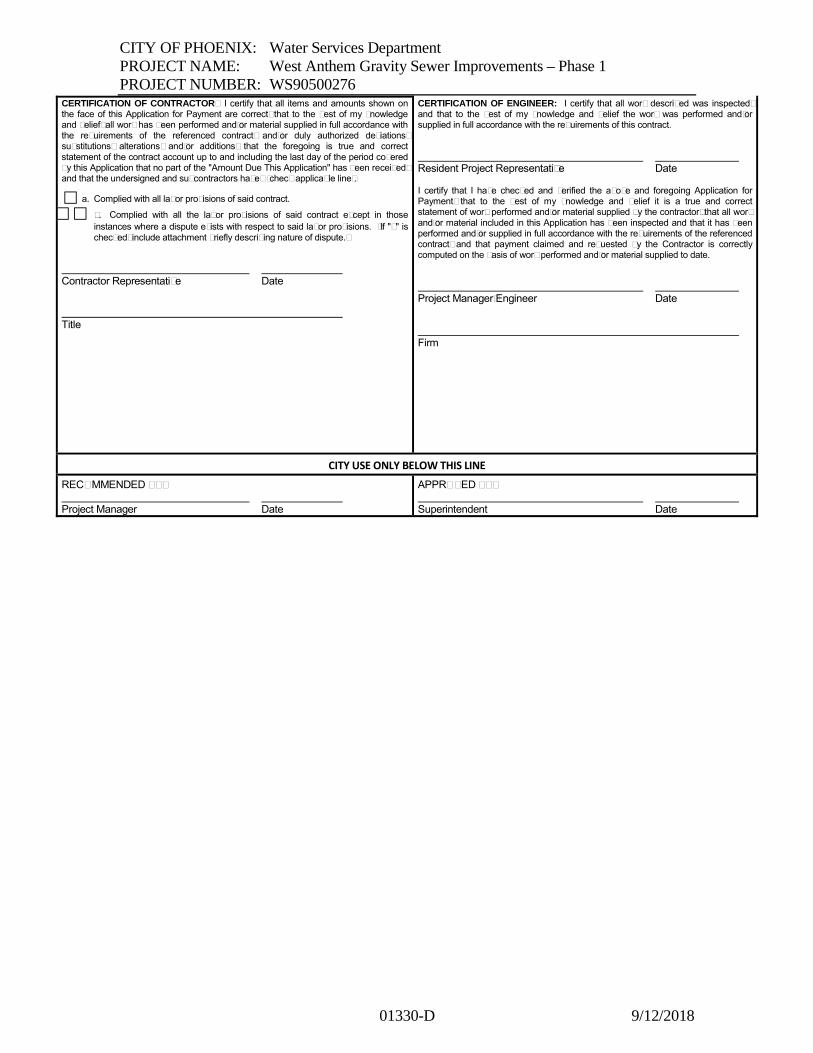
CITY OF PHOENIX: Water Services Department
PROJECT NAME: West Anthem Gravity Sewer Improvements – Phase 1
PROJECT NUMBER: WS90500276
01330-D 9/12/2018
CERTIFICATION OF CONTRACTOR: I certify that all items and amounts shown on the face of this Application for Payment are correct, that to the best of my knowledge and belief, all work has been performed and/or material supplied in full accordance with the requirements of the referenced contract, and/or duly authorized deviations, substitutions, alterations, and/or additions; that the foregoing is true and correct statement of the contract account up to and including the last day of the period covered by this Application that no part of the "Amount Due This Application" has been received, and that the undersigned and subcontractors have: (check applicable line).
a. Complied with all labor provisions of said contract.
b. Complied with all the labor provisions of said contract except in those
instances where a dispute exists with respect to said labor provisions. (If "b" is checked, include attachment briefly describing nature of dispute.)
Contractor Representative Date
Title
CERTIFICATION OF ENGINEER: I certify that all work described was inspected, and that to the best of my knowledge and belief the work was performed and/or supplied in full accordance with the requirements of this contract.
Resident Project Representative Date
I certify that I have checked and verified the above and foregoing Application for Payment; that to the best of my knowledge and belief it is a true and correct statement of work performed and/or material supplied by the contractor; that all work and/or material included in this Application has been inspected and that it has been performed and/or supplied in full accordance with the requirements of the referenced contract; and that payment claimed and requested by the Contractor is correctly computed on the basis of work performed and/or material supplied to date.
Project Manager/Engineer Date
Firm
CITY USE ONLY BELOW THIS LINE
RECOMMENDED BY: Project Manager Date
APPROVED BY: Superintendent Date

CITY OF PHOENIX: Water Services Department
PROJECT NAME: West Anthem Gravity Sewer Improvements – Phase 1
PROJECT NUMBER: WS90500276
01330-D 9/12/2018
CITY OF PHOENIX WATER SERVICES DEPARTMENT
CONTINUATION OF APPLICATION FOR PAYMENT
PROGRESS PAYMENT NO. 1
Project No.
WSXXXXXXXX-1 Project Name
NAME OF PROJECT
Contract No.
XXXXX
ITEM NO.
DESCRIPTION List Contract Items, Change Order Items, and Deductions, Each with
Subtotals CONTRACT
AMOUNT
ESTIMATED AMOUNT
THIS PERIOD
AMOUNT PREVIOUSLY
INVOICED
AMOUNT COMPLETED
TO DATE
xxxxx xxxxxxxxxxxxxxxxxxxxxxxxxxxx $xx,xxx,xxx.xx $xx,xxx,xxx.xx $xx,xxx,xxx.xx $xx,xxx,xxx.xx

CITY OF PHOENIX: Water Services Department
PROJECT NAME: West Anthem Gravity Sewer Improvements – Phase 1
PROJECT NUMBER: WS90500276
01330-K 9/12/2018
Form 01330-K
REQUEST FOR INFORMATION
CONTRACTOR RFI#
Requested By Directed to
Subject Date Received
Spec. Section Date Transmitted
Drawing References Date Reply Received
Date Reply Needed Date Reply Transmitted
INFORMATION NEEDED:
Date Signature
REPLY:
Date Signature .

CITY OF PHOENIX: Water Services Department
PROJECT NAME: West Anthem Gravity Sewer Improvements – Phase 1
PROJECT NUMBER: WS90500276
01330-N 9/12/2018
Form 01330-N TV INSPECTION REQUEST
CITY OF PHOENIX
WATER SERVICES DEPARTMENT DATE: REQUESTOR:
PHONE #: LOCATION: REASON FOR INSPECTION: Q.S.: (PLEASE PROVIDE COPY OF SECTION TO BE INSPECTED) LINEAL FT. TO INSPECT: C/O-MH#: TO C/O-MH#: PIPE DIAM.: PIPE TYPE: DEPTH OF FLOW: IN. MH DEPTH: DATE WHEN LAST CLEANED: MH=S: MAIN: COMMENTS:
FOR TV SECTION ONLY
DATE RECEIVED: ASSIGNED TO: DATE: EQUIP: COMPLETED: DATE: COMMENTS:

CITY OF PHOENIX: Water Services Department
PROJECT NAME: West Anthem Gravity Sewer Improvements – Phase 1
PROJECT NUMBER: WS90500276
01415-C 9/12/2018
Form 01415-C
Confined Space Hot Work Permit
Division: Facility:
Specific Confined Space Being Entered:
Date: Time:
Expected Job Duration (days/hours):
Purpose of Entry (Describe the Work):
Explain Why Work Cannot Be Done Outside Of The Confined Space:
Safety Equipment Required:
Fire Extinguishers: Yes No Number: Type:
Respirators: Yes No Number: Type:
Other Equipment:
Authorizing Supervisor:
Print Name:
Signature:
Date Signed:

CITY OF PHOENIX: Water Services Department
PROJECT NAME: West Anthem Gravity Sewer Improvements – Phase 1
PROJECT NUMBER: WS90500276
01332-1 9/12/2018
SECTION 01332
SHOP DRAWING PROCEDURES
PART 1 - GENERAL
1.1 DESCRIPTION
A. The submittal of Shop Drawings shall conform to requirements of General
Conditions and procedures described in this Section. A separate transmittal form
shall be used for each specific item or class of material or equipment for which a
submittal is required. Transmittal of Shop Drawings on various items using a single
transmittal form shall be permitted only when the items taken together constitute a
manufacturer’s “package” or are so functionally related that expediency indicates
review of the group or package as a whole.
B. The term “Shop Drawings” as used herein shall be understood to include detailed
design calculations, fabrication and installation drawings, lists, graphs, test data,
operating instructions, preventive maintenance tasks instructions, and other items
which shall include, but are not necessarily limited to:
1. Drawings and catalog information and cuts.
2. Specifications, parts list, suggested spare parts lists, and equipment drawings.
3. Applicable certifications.
4. Anchor bolt templates, mounting instructions and mounting design calculations
as required.
5. Other technical, installation, and maintenance data as applicable.
6. Unloading and handling methods and storage requirements.
7. Note, highlight, and explain proposed changes to the Contract Documents.
8. Paint submittal showing type of paint and the mils thickness of coating system
used. Drawings showing CONTRACTOR field verifications illustrating all
field dimensions. Field verify all dimensions and existing materials shown on
the Drawings. Any modifications required shall be at CONTRACTOR’S
expense.
9. A Certificate of Compliance with NSF/ANSI 61 STANDARD or with Arizona
Administrative Code R18-4-213 for materials or products which can contact
drinking water as part of a Water Treatment Process or Water Supply System.
C. Preliminary Submittal Schedule: CONTRACTOR, shall prepare and submit to the
ENGINEER a Preliminary Submittal Schedule at the Pre-Construction conference.
Identify on his Preliminary Submittal Schedule all of the submittal items required by
the Contract Documents governing the Work.
CITY OF PHOENIX: Water Services Department
PROJECT NAME: West Anthem Gravity Sewer Improvements – Phase 1
PROJECT NUMBER: WS90500276
01332-2 9/12/2018
D. Submittal Schedule: CONTRACTOR, within 14 days after the Notice to Proceed,
shall prepare and submit to the ENGINEER a comprehensive Submittal Schedule.
Identify on his Submittal Schedule all of the submittal items required by the Contract
Documents governing his Work. Indicate, for each submittal item on his Submittal
Schedule the following:
1. The date by which that item will be submitted to the ENGINEER.
2. Whether the submittal is for a substitute or “equal” item. Complete submittal
for all substitute or “equal” items shall be made to the ENGINEER, in
accordance with the Contract requirements. Identification by the
CONTRACTOR of substitute or “equal” items does not relieve
CONTRACTOR of his responsibility to furnish equipment and materials that
meet all the requirements of the Contract Documents. Items of manufacturers’
equipment listed with CONTRACTOR’S Bid Proposal shall not be replaced
with any substitute or “equal” items as part of this Submittal Schedule process.
Procedure for substitutions is specified under the General Conditions.
3. Whether the submittal is for review or “for record only”.
4. The date by which response is required.
5. The date by which the material or equipment must be on site in order not to
delay the progress of the Work.
E. In preparing his Submittal Schedule, consider the nature and complexity of each
submittal item and shall allow ample time for review, revision or correction.
Submittal will normally be returned to CONTRACTOR within 14 calendar days
following receipt of the submittal. Complex submittals may require additional
review time. Identify submittal(s) for which long review periods are anticipated.
F. The ENGINEER will review CONTRACTOR’S Submittal Schedule to determine its
completeness and compatibility with the Progress Schedule. A Submittal Schedule
which is incompatible with the Progress Schedule or a review schedule which places
extraordinary manpower demands on the ENGINEER will be sufficient reason(s) to
reject the Submittal Schedule. It shall be understood that certain submittals will take
longer than 14 days to review and that these particular submittals will be identified
during the review of the Submittal Schedule, by the ENGINEER to allow for very
complex submittal reviews. Also, identify submittal for which he anticipates long
review periods.
G. CONTRACTOR’S Submittal Schedule shall be consistent with the Progress
Schedule as described in Section 01321 , Progress Schedule.
H. Approval of the Submittal Schedule shall be required prior to processing of the first
progress payment.

CITY OF PHOENIX: Water Services Department
PROJECT NAME: West Anthem Gravity Sewer Improvements – Phase 1
PROJECT NUMBER: WS90500276
01332-3 9/12/2018
1.2 PROCEDURE
A. Submit Shop Drawings to ENGINEER
B. A letter of transmittal shall accompany each submittal. If data for more than one
Section of the Specifications is submitted, a separate transmittal letter shall
accompany the data submitted for each Section.
C. All letters of transmittal shall be submitted in duplicate.
D. At the beginning of each letter of transmittal, provide a reference heading indicating
the following:
1. OWNER’S Name
2. Project Name
3. Contract No.
4. Transmittal No.
5. Section No.
E. If a Shop Drawing deviates from the requirements of the Contract Documents,
specifically note each variation in his letter of transmittal.
F. All Shop Drawings submitted for approval shall have a title block with complete
identifying information satisfactory to ENGINEER.
G. All Shop Drawings submitted shall bear the stamp of approval and signature of
CONTRACTOR as evidence that they have been reviewed and verified to the
completeness of the submittal by CONTRACTOR. Submittal without this stamp of
approval will not be reviewed by ENGINEER and will be returned to
CONTRACTOR. CONTRACTOR’S stamp contain the following minimum
information:
Project Name:
CONTRACTOR’S Name:
Date:
Item:
Specifications:
Section: _________________________
Page No.: _________________________
Para. No.:
Drawing No.: ____________________ of
Location:
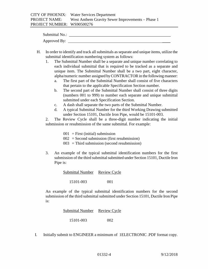
CITY OF PHOENIX: Water Services Department
PROJECT NAME: West Anthem Gravity Sewer Improvements – Phase 1
PROJECT NUMBER: WS90500276
01332-4 9/12/2018
Submittal No.:
Approved By: ____
H. In order to identify and track all submittals as separate and unique items, utilize the
submittal identification numbering system as follows:
1. The Submittal Number shall be a separate and unique number correlating to
each individual submittal that is required to be tracked as a separate and
unique item. The Submittal Number shall be a two part, eight character,
alpha/numeric number assigned by CONTRACTOR in the following manner:
a. The first part of the Submittal Number shall consist of five characters
that pertain to the applicable Specification Section number.
b. The second part of the Submittal Number shall consist of three digits
(numbers 001 to 999) to number each separate and unique submittal
submitted under each Specification Section.
c. A dash shall separate the two parts of the Submittal Number.
d. A typical Submittal Number for the third Working Drawing submitted
under Section 15101, Ductile Iron Pipe, would be 15101-003.
2. The Review Cycle shall be a three-digit number indicating the initial
submission or resubmission of the same submittal. For example:
001 = First (initial) submission
002 = Second submission (first resubmission)
003 = Third submission (second resubmission)
3. An example of the typical submittal identification numbers for the first
submission of the third submittal submitted under Section 15101, Ductile Iron
Pipe is:
Submittal Number Review Cycle
15101-003 001
An example of the typical submittal identification numbers for the second
submission of the third submittal submitted under Section 15101, Ductile Iron Pipe
is:
Submittal Number Review Cycle
15101-003 002
I. Initially submit to ENGINEER a minimum of 1ELECTRONIC .PDF format copy.

CITY OF PHOENIX: Water Services Department
PROJECT NAME: West Anthem Gravity Sewer Improvements – Phase 1
PROJECT NUMBER: WS90500276
01332-5 9/12/2018
J. After ENGINEER completes his review, Shop Drawings will be affixed with a stamp
and marked with one of the following notations:
1. Approved.
2. Approved as Corrected.
3. Approved as Corrected, Resubmit.
4. Revise and Resubmit.
5. Not Approved.
6. Not Reviewed.
7. For Information Only.
K. If a submittal is acceptable, the ENGINEER will mark it “Approved” or “Approved
as Corrected” and will forward 1 electronic PDF format copy of the submittal to the
CONTRACTOR and OWNER.
L. Upon return of a submittal marked “Approved” or “Approved as Corrected”,
CONTRACTOR may order, ship or fabricate the materials included on the submittal,
provided it is in accordance with the corrections indicated.
M. If a Shop Drawing marked “Approved as Corrected” has extensive corrections or
corrections affecting other Shop Drawings or Work, ENGINEER may require that
CONTRACTOR make the corrections indicated thereon and resubmit the Shop
Drawings for record purposes. Such Shop Drawings will have the notation,
“Approved as Corrected - Resubmit.” The corrected Shop Drawing shall be a pre-
condition for payment for the work item of the Shop Drawing.
N. If a submittal is unacceptable, 1 electronic .pdf copy will be returned to
CONTRACTOR with one of the following notations:
1. “Revise and Resubmit”
2. “Not Approved”
O. Upon return of a submittal marked “Revise and Resubmit”, make the corrections
indicated and repeat the initial approval procedure. The “Not Approved” notation is
used to indicate material or equipment that is not acceptable. Upon return of a
submittal so marked, repeat the initial approval procedure utilizing acceptable
material or equipment.
P. Any related Work performed or equipment installed without an “Approved” or
“Approved as Corrected” Shop Drawing will be at the sole responsibility of
CONTRACTOR.
Q. Shop Drawings shall be submitted well in advance of the need for the material or
equipment for construction and with ample allowance for the time required to make
delivery of material or equipment after data covering such is approved. Assume the
risk for all materials or equipment which are fabricated or delivered prior to the

CITY OF PHOENIX: Water Services Department
PROJECT NAME: West Anthem Gravity Sewer Improvements – Phase 1
PROJECT NUMBER: WS90500276
01332-6 9/12/2018
approval of Shop Drawings. Materials or equipment will not be included in periodic
progress payments until approval thereof has been obtained in the specified manner.
R. ENGINEER will review and process all submittals promptly; a reasonable time shall
be allowed for this, for the Shop Drawings being revised and resubmitted, and for
time required to return the approved Shop Drawings to CONTRACTOR.
S. Responsibility belongs to CONTRACTOR to review submittals made by his
suppliers and subcontractors before transmitting them to the ENGINEER to assure
proper coordination of the Work and to determine that each submittal is in
accordance with CONTRACTOR’S desires and that there is sufficient information
about materials and equipment for ENGINEER to determine compliance with the
Contract Documents. Incomplete or inadequate submittals will be returned for
revision without review.
T. Furnish required submittals with complete information and accuracy in order to
achieve required approval of an item within one submittal. Backcharges for
resubmittals that account for a number greater than 20 percent of the total number of
first time submittals and will be backcharged for all third submittals. The number of
first time submittals shall be equal to the number of submittals agreed to by
ENGINEER and CONTRACTOR. All costs to ENGINEER involved with
subsequent submittal of Shop Drawings, Samples or other items requiring approval
will be backcharged to CONTRACTOR at the rate of 3.0 times direct technical labor
cost by deducting such costs from payments due CONTRACTOR for Work
completed. In the event that CONTRACTOR requests a substitution for a previously
approved item, all of ENGINEER’S costs in the reviewing and approval of the
substitution will be backcharged to CONTRACTOR, unless the need for such
substitution is beyond the control of CONTRACTOR.
U. The OWNER reserves the right to withhold monies, identified in the General
Conditions, for Shop Drawing reviews beyond those described herein.
V. The ENGINEER will implement, if requested by CONTRACTOR, one special Shop
Drawing Review Meeting. The purpose of the meeting is to expedite Shop Drawing
reviews for the equipment and materials required for the first document of the Work.
Requirements of this Section will not be waived, but could be expedited.
W. Mark each page of a submittal and each individual component submitted with the
specification number, paragraph, and subparagraph. Arrange submittal information
presentation to appear in the sequence in the Specification Section.

CITY OF PHOENIX: Water Services Department
PROJECT NAME: West Anthem Gravity Sewer Improvements – Phase 1
PROJECT NUMBER: WS90500276
01332-7 9/12/2018
PART 2 - PRODUCTS (NOT USED)
PART 3 - EXECUTION (NOT USED)
+ + END OF SECTION + +

CITY OF PHOENIX: Water Services Department
PROJECT NAME: West Anthem Gravity Sewer Improvements – Phase 1
PROJECT NUMBER: WS90500276
01412-1 9/12/2018
SECTION 01412
STORMWATER POLLUTION PREVENTION PLAN AND PERMIT
PART 1 - GENERAL
1.1 DESCRIPTION
A. Comply with the terms and conditions of the Arizona Pollutant Discharge
Elimination System (AZPDES) requirements under the Arizona Department of
Environmental Quality (ADEQ) General Permit. Under provisions of that permit,
CONTRACTOR is designated as permittee and responsible for providing necessary
material and for taking appropriate measures to minimize pollutants in stormwater
runoff from the Project. Obtain a DeMinimus discharge permit from ADEQ for any
discharge that is to Waters of the U.S., and comply with the requirements of the
permit.
B. The Contract Price shall include all material, labor and other permits and incidental
costs related to:
1. Preparing, updating and revising the Stormwater Construction Pollution
Prevention Plan (SWPPP).
2. Installing and maintaining all structural and non-structural items chosen by
CONTRACTOR to comply with the construction SWPPP.
3. Clean-up and disposal costs associated with clean-up and repair following
storm events or CONTRACTOR caused spills on the Project.
4. Implementing and maintaining Best Management Practices to comply with
ADEQ and the OWNER'S stormwater codes.
5. Preparing the Notice of Intent and Notice of Termination shall be covered by
the AZPDES General Permit for Arizona.
6. Obtaining and complying with DeMinimus permit requirements.
7. Comply with City of Phoenix Environmental Services Department SWPPP and
SWMP Requirements (see Exhibit A) within Contract Documents.
C. Coordinate the requirements under this Section with Section 02315, Excavation and
Backfill, permit requirements. All necessary SWPPP controls and practices must be
implemented prior to commencement of any construction activity.
1.2 SUBMITTALS
A. Submit at pre-construction conference completed and signed Notice of Intent forms
to the State of Arizona at the following addresses:

CITY OF PHOENIX: Water Services Department
PROJECT NAME: West Anthem Gravity Sewer Improvements – Phase 1
PROJECT NUMBER: WS90500276
01412-2 9/12/2018
1. Stormwater Program – Water Permits Section / NOI
Arizona Department of Environmental Quality
1110 West Washington, 5415B-3
Phoenix, AZ 85007
B. Submit the following to the ENGINEER at pre-construction conference:
1. Notice of Intent (NOI) to be covered by the AZPDES General Permit for
Arizona, including certifications of signature.
2. SWPPP for the Project, including certification of signature. Stormwater
Pollution Prevention Plan shall include CONTRACTOR'S proposed temporary
means for stormwater control during all phases of construction and include
stormwater pumping/retention plans. This submittal shall be coordinated with
CONTRACTOR'S Excavation Plan submittal, specified in Section 02315,
Excavation and Backfill.
3. A manual has been prepared by the Maricopa County Flood Control District to
aid in CONTRACTOR'S preparation of the SWPPP. This manual, "Drainage
Design Manual for Maricopa County Arizona, Volume III, Erosion Control" is
available at the Flood Control District Office, 2801 West Durango Street,
Phoenix, Arizona. The complete Construction General Permit is in the
December 8, 1999, Federal Register available at local libraries and is also
available from the ADEQ website at www.adeq.state.az.us/environ/water/
permits/download/constgp.pdf.
C. Submit to the ENGINEER, , as part of the Construction SWPPP a construction site
inspection report that includes the following:
1. Inspection scope.
2. Inspector qualifications.
3. Observations of SWPPP non-compliance and corrective steps taken.
4. Certificate of Compliance with SWPPP and the AZPDES General Permit for
Stormwater Discharge in the event of no incidents. Inspection reports shall be
submitted to ENGINEER with monthly progress payment requests, throughout
the Contract duration.
D. Submit to ENGINEER,, upon project completion the Notice of Termination (NOT)
of coverage under AZPDES General Permit.
PART 2 - PRODUCTS (NOT USED)
PART 3 - EXECUTION (NOT USED)
+ + END OF SECTION + +

CITY OF PHOENIX: Water Services Department
PROJECT NAME: West Anthem Gravity Sewer Improvements – Phase 1
PROJECT NUMBER: WS90500276
01413-1 9/12/2018
SECTION 01413
CONTRACTOR’S HAZARDOUS MATERIALS MANAGEMENT PROGRAM
PART 1 – GENERAL
1.1 DESCRIPTION
A. Comply with all Federal, State, and local Laws and Regulations related to
environmental protection and environmental safety including, but not limited, to the
following:
1. Title 29 Code of Federal Regulations Parts 1910, Occupational Safety and
Health.
2. Title 40 Code of Federal Regulations, Environmental Protections.
3. Title 49 Code of Federal Regulations, Transportation.
4. State Occupational Safety and Health Administration (OSHA).
5. Arizona Department of Environmental Quality (ADEQ).
6. Arizona Department of Water Resources (ADWR).
7. Maricopa County Air Pollution Control Regulations.
B. In order to ensure the OWNER that CONTRACTOR is complying with the intent of
the regulations stated in Paragraph 1.1.A, above, as they relate to the on site use of
hazardous materials, hazardous wastes and other substances similarly defined in
those regulations, develop and maintain a CONTRACTOR’S Hazardous Materials
Management Program that includes as a minimum, but is not limited to the
requirements specified herein. The interests of the OWNER are that accidental spills,
site contamination, and injury of personnel on the site are avoided. OWNER will not
enforce suspected violations of the rules and regulations referenced in Paragraph
1.1.A, above, however the OWNER will notify CONTRACTOR of suspected
violations. If in the opinion of the OWNER, CONTRACTOR fails to address the
suspected violations in a timely and appropriate manner, OWNER will notify
Federal, State, or local regulatory agencies, report the suspected violations to them,
and request that they inspect CONTRACTOR’S operations. Any fines that may be
levied against OWNER for violations committed on the site by CONTRACTOR, as
well as any costs to OWNER associated with cleanup of materials, shall be
reimbursed immediately by CONTRACTOR. All documents required by the program
shall be made available to the OWNER’S Environmental Representative
immediately, upon request.
(The remainder of this page was left blank intentionally.)

CITY OF PHOENIX: Water Services Department
PROJECT NAME: West Anthem Gravity Sewer Improvements – Phase 1
PROJECT NUMBER: WS90500276
01413-2 9/12/2018
C. Responsibility for any hazardous waste, as defined in any of the above listed
regulations, and those generated by the CONTRACTOR, belongs to
CONTRACTOR. If CONTRACTOR is going to generate, or has generated, a
substance that qualifies as a hazardous waste, must obtain an EPA identification
number, listing CONTRACTOR’S name and construction site address as the
generator of the hazardous waste. Responsibility for the identification, analysis,
profiling, transport and disposal of hazardous wastes generated, belongs to
CONTRACTOR. The identification number can be obtained from the Arizona
Department of Environmental Quality (ADEQ). This number shall be provided to the
ENGINEER at the pre-construction conference, , or before any hazardous materials
are brought onto the site.
1.2 HAZARDOUS MATERIALS PROGRAM REQUIREMENTS
A. Within the regulations listed in Paragraph 1.1.A, above, terms such as hazardous
material, hazardous wastes, and similar terms have varying definitions. To dispel
confusion regarding what materials fall under the Program Requirements and for the
purposes of this Article, Hazardous Material is defined as “any material, whether
solid, semi-solid, liquid, or gas, which, if not stored or used properly, may cause
harm or injury to persons through inhalation, ingestion, absorption or injection, or
which may negatively impact the environment through the use or discharge of the
material on the ground, in the water (including groundwater), or to the air.”
B. All chemicals brought onto the site must be approved by OWNER. Prior to bringing
any chemical on site, request approval from OWNER’S Environmental
Representative for each chemical CONTRACTOR proposes to bring on site. At the
time of request, OWNER’S Environmental Representative may request and receive
from CONTRACTOR, specific information associated with each chemical. The
specific information may include, but is not limited to, MSDS, manufacture, vendor,
container size(s), number of containers, minimum and maximum volume of material
intended to be stored on site, as well a description to the process or procedures in
which any requested chemical is to be used. OWNER, within 10 working days from
receipt of the specific chemical information, will inform CONTRACTOR as to
whether the chemical has been approved for use on site.
C. Maintain on site two notebooks containing (1) a chemical inventory, and (2) current
(dated within the past two years) Material Safety Data Sheets for all materials being
used on site, whether or not they are defined as a Hazardous Material in Paragraph
1.2.A, above. One notebook shall be kept in CONTRACTOR’S on-site office and the
other shall be kept in a location specified by the OWNER’S Environmental
Representative. These notebooks must be kept up-to-date as materials are brought
onto and removed from the site. Copies of MSDS sheets for chemicals removed from
the site shall be provided to the OWNER’S Environmental Representative.

CITY OF PHOENIX: Water Services Department
PROJECT NAME: West Anthem Gravity Sewer Improvements – Phase 1
PROJECT NUMBER: WS90500276
01413-3 9/12/2018
D. Develop an emergency/spill response plan, for each hazardous material or class/group
of materials. Emergency/Spill Response Plan to be submitted at pre-construction
conference. As a minimum, the response plan must address the following:
1. Provide a description of equipment on site available to contain or respond to an
emergency/spill of the material.
2. Notification procedures.
3. Response coordination procedures between CONTRACTOR, OWNER, and
ENGINEER.
4. Provide a Site Plan showing the location of stored hazardous materials and
location of spill containment/response equipment.
5. Provide a description of the hazardous material handling and spill response
training provided to CONTRACTOR’S employees.
E. In accordance with applicable Laws and Regulations, properly and safely store all
hazardous materials, which shall include as a minimum, the following:
1. Have a designated storage site for hazardous materials that includes secondary
containment. The site must include barriers to prevent vehicles from colliding
with the storage containers and offer protection from environmental factors such
as weather.
2. Provide signage in accordance with applicable Laws and Regulations, clearly
identifying the hazardous materials storage site.
3. All hazardous materials containers must bear the applicable Hazard Diamonds.
F. Properly label all containers of consumable materials, whether or not they are
classified as Hazardous Materials under this Section. The name of CONTRACTOR
or subcontractor shall be stenciled on any container containing a hazardous material
and on any container over five-gallon capacity containing a non-hazardous material.
Any container must have a label clearly identifying the contents. If any such
unlabeled containers are discovered on the site, the OWNER’S Environmental
Representative will notify CONTRACTOR. Responsibility to remove such
containers belongs to CONTRACTOR. Containers will be properly labeled or
removed from the site within one hour. Any containers that are filled from larger
containers must also be properly labeled.
G. OWNER encourages storage of hazardous materials off site until the materials are
needed on site.
H. Provide all documentation required herein available immediately upon request of
OWNER’S Environmental Representative. CONTRACTOR’S Safety Representative
will meet at least monthly with OWNER’S Environmental Representative to review
CONTRACTOR’S Hazardous Materials Management Program documents,
procedures, and inspect the storage site and job site to ensure the requirements
specified herein are being complied with. Also, provide OWNER’S Environmental
Representative and the ENGINEER with copies of all permits obtained from
environmental regulatory agencies.

CITY OF PHOENIX: Water Services Department
PROJECT NAME: West Anthem Gravity Sewer Improvements – Phase 1
PROJECT NUMBER: WS90500276
01413-4 9/12/2018
I. Provide documentation to ENGINEER and OWNER’s Environmental Representative
that CONTRACTOR, subcontractors, or others hired by CONTRACTOR making
deliveries of hazardous Materials (as defined in Title 49 CFR) to the site are in
compliance with Title 49 CFR 172.800 – 172.804, which requires each person who
offers for transportation in commerce or transports in commerce one or more of the
following hazardous materials, as defined by Title 49 CFR, must develop and adhere
to a security plan for hazardous materials that conforms to the requirements of this
subpart.
PART 2 – PRODUCTS (NOT USED)
PART 3 – EXECUTION (NOT USED)
++ END OF SECTION ++

CITY OF PHOENIX: Water Services Department
PROJECT NAME: West Anthem Gravity Sewer Improvements – Phase 1
PROJECT NUMBER: WS90500276
01414-1 9/12/2018
SECTION 01414
EARTHMOVING AND DUST CONTROL
PART 1 - GENERAL
1.1 DESCRIPTION
A. Obtain all earthmoving permits and any other permits required for earthmoving
and dust generating operations related to the Work as required by the Maricopa
County Air Pollution Control Regulations.
B. Not cause or allow any dust generating operation, earthmoving operation, use of
property, or any other operation which causes fugitive dust emissions that exceed
the 20 percent visible emission opacity limit in Rule 300 of Maricopa County’s
Air Pollution Control Regulations.
C. If requested by the OWNER, ENGINEER, or Maricopa County representative,
shall conduct opacity observations for visible emissions of fugitive dust in
accordance with techniques specified in USEPA Reference Method 9.
D. In addition to earthmoving permits, obtain an approved Dust Control Plan from
Maricopa County. At a minimum, the Dust Control Plan shall include the
following information:
1. Name(s), address(es) and phone number(s) of the person(s) responsible for
the preparation, submittal, and implementation of the Dust Control Plan and
responsible for the dust generating operations.
2. A site plan that describes the total area of land surface to be disturbed (in
acres); the operations and activities to be performed on the site; actual and
potential sources of fugitive dust emissions; and the delivery, transportation,
and storage areas for the site (including types of materials stored and
appropriate size of material stock piles).
3. Description of the Reasonably Available Control Measures (RACM) to be
applied during all periods of dust generating operations at all actual and
potential sources of fugitive dust.
4. Description of dust suppressants to be applied including product
specifications; method, frequency, and intensity of application; type,
number, and capacity of application equipment; and certifications related to
the suppressant’s appropriate and safe use.
5. Description of specific surface treatment(s) or RACM used to control
material track-out where unpaved or access points join paved surfaces.
6. Description of at least one alternative RACM for each actual and potential
fugitive dust source shall be designated as a contingency measure.
CITY OF PHOENIX: Water Services Department
PROJECT NAME: West Anthem Gravity Sewer Improvements – Phase 1
PROJECT NUMBER: WS90500276
01414-2 9/12/2018
E. Post a copy of all earthmoving permits as well as the approved Dust Control Plan
in a conspicuous location at the worksite and provide a copy of each to the
ENGINEER.
F. Maintain a daily written log that records the actual application or implementation
of the RACMS described in the approved Dust Control Plan. Maintain this
written log and supporting documentation on site and shall make available for
review on request by ENGINEER, OWNER, or Maricopa County representative.
Retain copies of the Dust Control Plan, RACM implementation records, and all
supporting documentations for a minimum of three years.
G. At a minimum, provide all necessary equipment and materials to apply sufficient
dust suppressants (e.g., water, etc.), properly clean (sweep, etc.) all track-out
areas, and provide adequate physical stabilizations (e.g., gravel, recycled asphalt,
etc.) to meet all requirements of the earthmoving permit and approved Dust
Control Plan. Use these methods to control fugitive dust generation from all
CONTRACTOR operations on all CONTRACTOR areas including, but not
limited to:
1. Construction areas.
2. Vehicle and equipment parking areas.
3. Material storage areas.
4. Office and trailer areas.
5. Haul and access roadways.
6. Track-out areas.
7. All other areas where CONTRACTOR work, storing, or parking of vehicles,
equipment, and materials.
H. Pay all fines issued to the OWNER by the USEPA, ADEQ, or Maricopa County
due to violation of CONTRACTOR’S earthmoving permit and Dust Control Plan.
PART 2 - PRODUCTS (NOT USED)
PART 3 - EXECUTION (NOT USED)
+ + END OF SECTION + +

CITY OF PHOENIX: Water Services Department
PROJECT NAME: West Anthem Gravity Sewer Improvements – Phase 1
PROJECT NUMBER: WS90500276
01415-1 9/12/2018
SECTION 01415
CONFINED SPACE ENTRY PLAN
PART 1 - GENERAL
1.1 DESCRIPTION
A. OWNER has determined that portions of the Work site may constitute “confined
spaces” as defined in 29 CFR §1926.21(b)(2) and 1910.146. Accordingly, incorporate
into its Safety Plan for the Work site appropriate measures to protect the health and
safety of all persons on the Work site or who may be affected by the Work, including,
without limitation thereby, employees and representatives of CONTRACTOR, any
subcontractor, OWNER, or ENGINEER while they are present and engaged in the
performance of their duties on the Work site.
B. Comply with all local, State and Federal rules and regulations related to the protection
of persons working or entering into confined spaces including, but not limited to the
following:
1. 29 United States Code §654.
2. Title 29 Code of Federal Regulations Parts 1910 and 1926, Occupational Safety
and Health.
3. Ariz. Rev. Stat. §23-403.
4. City of Phoenix, Confined Space Program
C. To assure OWNER that CONTRACTOR is complying with the intent of the
regulations stated in Paragraph 1.1.A, above, as they relate to the protection of all
persons on the Work site, CONTRACTOR’S Safety Plan, at a minimum, respond to
the following requirements as they relate to Work in confined spaces:
1. Conducting a Site-specific hazard assessment to identify confined spaces that
should be characterized as “Permit Required Confined Spaces” within the
meaning of 29 CFR §1926.21 (b)(6)(i) and 29 CFR §1910.146.
2. Adopting as an element of its Safety Plan appropriate requirements for
safeguarding access to “Permit Required Confined Spaces”.
3. Providing training, personal protective or safety equipment and personnel as
needed to perform the Safety Plan’s requirements for “Permit Required
Confined Spaces.”
4. Performing all record-keeping required for “Permit Required Confined Spaces”,
including the required permits and confined space data sheets located in Section
01331, Reference Forms.

CITY OF PHOENIX: Water Services Department
PROJECT NAME: West Anthem Gravity Sewer Improvements – Phase 1
PROJECT NUMBER: WS90500276
01415-2 9/12/2018
1.2 CONFINED SPACES SAFETY PLAN REQUIREMENTS
A. For purposes of the Safety Plan requirements listed in Article 1.1, above, “confined
spaces” are those areas on or about the Work site that fall within OSHA’s definition
as “any space having limited means of egress, which is subject to the accumulation
of toxic or flammable contaminants or has an oxygen deficient atmosphere.
Confined or enclosed spaces include, but are not limited to, storage tanks, process
vessels, bins, boilers, ventilation or exhaust ducts, sewers, underground utility
vaults, tunnels, pipelines, and open top spaces more than four feet in depth such as
pits, tubs, vaults, and vessels.”
B. Ensure that those persons who are required to enter a confined space are trained
according to OSHA requirements set forth in 29 CFR §1926.21 (b)(6)(i).
C. If the confined space is a “Permit Required Confined Space”, then comply with the
standards set forth in 29 CFR §1910.146. and the City of Phoenix, Confined Space
Program.
D. “Permit Required Confined Space” means a confined space that has one or more of
the following characteristics:
1. Contains or has the potential to contain a hazardous atmosphere.
2. Contains a material that has the potential for engulfing an entrant.
3. Has an internal configuration such that an entrant could be trapped or
asphyxiated by inwardly converging walls or floors, or by a floor that slopes
downward and tapers to a smaller cross-section.
4. Contains any other recognized serious safety or health hazard.
1.3 SUBMITTALS
A. Prepare and submit a site-specific Confined Space Entry Plan as a portion of the
CONTRACTOR’S site-specific Health and Safety Plan.
PART 2 – PRODUCTS (NOT USED)
PART 3 – EXECUTION (NOT USED)
+ + END OF SECTION + +

CITY OF PHOENIX: Water Services Department
PROJECT NAME: West Anthem Gravity Sewer Improvements – Phase 1
PROJECT NUMBER: WS90500276
01416-1 9/12/2018
SECTION 01416
SPECIAL INSPECTIONS
PART 1 - GENERAL
1.1 DESCRIPTION
A. The following types of Work will be subject to Special Inspections, which may be
performed by the ENGINEER or the Resident Project Representative, or by such
other special inspector as the OWNER may employ:
1. High-Strength Bolting: During all bolt installations and tightening operations.
a. Exceptions:
1) The special inspector need not be present during the entire installation
and tightening operation, provided he has:
a) Inspected the surfaces and bolt type for conformance to plans and
specifications prior to start of bolting, and "will, upon completion
of all bolting, verify the minimum specified bolt tension for ten
percent of the bolts for each connection, with a minimum of two
bolts per connection".
2) In bearing-type connections when threads are not required by design to
be excluded from the shear plane, inspection prior to or during
installation will not be required.
2. Concrete.
3. Reinforcing Steel.
4. Structural Welding.
5. Structural masonry.
6. Epoxy Anchors.
7. Polyvinyl chloride liner and epoxy systems for concrete.
1.2 SPECIAL INSPECTOR
A. The special inspector shall be a qualified person who shall demonstrate his
competence to the satisfaction of the regulatory authorities for inspection of the
particular type of construction or operation requiring special inspection.
1.3 DUTIES AND RESPONSIBILITIES OF SPECIAL INSPECTOR
A. The special inspector shall observe the Work assigned to be certain it conforms to the
Contract Documents.
CITY OF PHOENIX: Water Services Department
PROJECT NAME: West Anthem Gravity Sewer Improvements – Phase 1
PROJECT NUMBER: WS90500276
01416-2 9/12/2018
B. The special inspector shall furnish inspection reports to the regulatory authorities, the
ENGINEER and other designated persons. All discrepancies shall be brought to the
immediate attention of CONTRACTOR for correction, then, if uncorrected, to the
ENGINEER and regulatory authorities.
C. The special inspector shall submit a final signed report stating whether the Work
requiring special inspection was, to the best of his knowledge, in conformance with
the Contract Documents and the applicable workmanship provision of these codes.
1.4 PERIODIC SPECIAL INSPECTIONS
A. Some inspections may be made on a periodic basis and satisfy the requirements of
continuous inspection, provided this periodic scheduled inspection is performed as
outlined in the Contract Documents and approved by the regulatory authorities.
PART 2 PRODUCTS (NOT USED)
PART 3 EXECUTION (NOT USED)
+ + END OF SECTION + +

CITY OF PHOENIX: Water Services Department
PROJECT NAME: West Anthem Gravity Sewer Improvements – Phase 1
PROJECT NUMBER: WS90500276
01420-1 9/12/2018
SECTION 01420
REFERENCES
PART 1 - GENERAL
1.1 DEFINITIONS
A. General: Definitions of basic Contract terms are included in the General
Conditions.
B. Definitions of terms commonly found in the SSppeecciiffiiccaattiioonnss are as follows:
1. Indicated: The term indicated refers to graphic representations, notes, or
schedules on the Drawings, or to other paragraphs or schedules in the
Specifications and similar locations in the other Contract Documents.
Terms such as “shown”, “noted”, “scheduled”, and “specified” are used to
help the user locate the reference. There is no limitation on the location.
2. Installer (or applicator, or erector): An installer is CONTRACTOR or
another entity engaged by CONTRACTOR, either as an employee or
subcontractor to perform a particular construction activity, including
installation, erection, application or similar operations. Installers are
required to be experienced in the operations they are engaged to perform.
a. The term “experienced”, when used with the term “installer”, means
having successfully completed a minimum of five previous projects
similar in size and scope to this Project; being familiar with the special
requirements indicated; and having complied with the requirements of
authorities having jurisdiction and of the Supplier of the product being
installed.
3. Trades: Use of a term such as “carpentry” does not imply that certain
construction activities must be performed by accredited or unionized
individuals of a corresponding generic name, such as “carpenter”. It also
does not imply that requirements specified apply exclusively to trades
persons of the corresponding generic name.
4. Assigned Specialists: Certain Sections of the Specifications require that
specific construction activities shall be performed by specialists who are
recognized experts in those operations. Said specialists shall be engaged for
those activities, and their engagement is a requirement over which
CONTRACTOR has no option. These requirements shall not be interpreted
to conflict with the enforcement of building codes and similar regulations
governing the Work. Also, they are not intended to interfere with local
trade-union jurisdictional settlements and similar conventions. Such
assignments shall not relieve CONTRACTOR of its responsibility for
fulfilling the requirements of the Contract Documents.
CITY OF PHOENIX: Water Services Department
PROJECT NAME: West Anthem Gravity Sewer Improvements – Phase 1
PROJECT NUMBER: WS90500276
01420-2 9/12/2018
5. Equipment Identification: Several terms define the information attached to
equipment.
a. The term “CMMS Tag” means information attached to equipment
pertaining to the City of Phoenix Water Services Department
Computerized Maintenance Management System. CMMS Tags shall
be provided by the CONTRACTOR. Refer to Section 01630,
Equipment Identification Tag System for specifications regarding
CMMS Tags.
b. The term “Manufacturer Nameplate” means information attached to
equipment by the manufacturer pertaining to equipment criteria, such
as capacity, power supply requirement, model number, etc.
1.2 ABBREVIATIONS
A. Common abbreviations, which may be found in the Specifications, are:
alternating current
AC
Ampere
A
ante meridiem
am
Average
avg.
biochemical oxygen demand
BOD
brake horsepower
BHP
British thermal unit
BTU
Centigrade
C
Company
Co.
cubic inch
cu. in.
cubic foot
cu. ft.
cubic yard
cu. yd.
cubic feet per minute
cfm
cubic feet per second
cfs
Decibel
DB
degree Centigrade (or Celsius) (Say)
20°C
degree Fahrenheit (Say)
68°F
Diameter
dia.

CITY OF PHOENIX: Water Services Department
PROJECT NAME: West Anthem Gravity Sewer Improvements – Phase 1
PROJECT NUMBER: WS90500276
01420-3 9/12/2018
direct current
DC
Dollars
$
Each
ea
Efficiency
eff
Fahrenheit
F
feet per hour
fph
Feet
ft.
feet per minute
fpm
feet per second
fps
Figure
Fig.
Flange
flg
foot-pound
ft-lb
gallon
gal
gallons per minute
gpm
gallons per second
gps
gram
g
Hertz
Hz
horsepower
hp
hour
hr
inch
in.
inch-pound
in.-lb
inside diameter
id
kilovolt-ampere
kva
kilowatt
KW
kilowatt-hour
kwhr
linear foot
lin. ft.
liter
l
maximum
max.

CITY OF PHOENIX: Water Services Department
PROJECT NAME: West Anthem Gravity Sewer Improvements – Phase 1
PROJECT NUMBER: WS90500276
01420-4 9/12/2018
mercury
Hg
milligram
mg
milligrams per liter
mg/l
milliliter
ml
millimeter
mm
million gallons per day
mgd
million gallon
mil
minimum
min.
National Pipe Threads
NPT
net positive suction head
npsh
number
No.
ounce
oz
outside diameter
OD
parts per million
ppm
post meridiem
pm
pound
lb
pounds per square inch
psi
pounds per square inch absolute
psia
pounds per square inch gage
psig
pounds per square foot
psf
revolutions per minute
rpm
second
sec.
specific gravity
sp gr
square
sq
square foot
sq ft
square inch
sq in
square yard
sq yd
standard
std
CITY OF PHOENIX: Water Services Department
PROJECT NAME: West Anthem Gravity Sewer Improvements – Phase 1
PROJECT NUMBER: WS90500276
01420-5 9/12/2018
standard cubic feet per minute
scfm
total dynamic head
tdh
totally-enclosed-fan-cooled
tefc
volt
V
1.3 APPLICABLE CODES
A. When a reference standard is specified, comply with requirements and
recommendations stated in that standard, except when they are modified by the
Contract Documents, or when applicable laws, ordinances, rules, regulations or
codes establish stricter standards. The latest provisions of applicable standards
shall apply to the Work, unless otherwise specified. Reference standards include,
but are not necessarily limited to, the following:
1. American Association of State Highway and Transportation Officials
(AASHTO).
2. American Concrete Institute (ACI).
3. American Gear Manufacturers Association (AGMA).
4. American Institute of Steel Construction (AISC).
5. American Iron and Steel Institute (AISI).
6. American National Standards Institute (ANSI).
7. American Society of Heating, Refrigerating and Air Conditioning Engineers
(ASHRAE).
8. American Society of Mechanical Engineers (ASME).
9. American Society for Testing and Materials (ASTM).
10. American Water Works Association (AWWA).
11. American Welding Society (AWS).
12. Concrete Reinforcing Steel Institute (CRSI).
13. Factory Mutual (FM).
14. Institute of Electrical and Electronics Engineers (IEEE).
15. National Electrical Manufacturer’s Association (NEMA).
16. National Electrical Code (NEC) current adoption.
17. City of Phoenix – Amendments to the National Electric Code.
18. Occupational Safety and Health Administration (OSHA).
19. National Fire Protection Association (NFPA).
20. Prestressed Concrete Institute (PCI).
21. Underwriters’ Laboratories, Inc. (UL).
22. All other applicable standards listed in the Specifications and the standards
of utility service companies, where applicable.
23. Maricopa Association of Governments (MAG), Uniform Standard
Specifications for Public Works Construction, as supplemented by the City
of Phoenix. References to MAG Standard Details refer to the “Uniform
Standard Details for Public Works Construction” sponsored and distributed
by the Maricopa Association of Governments 2015, Arizona.
24. International Building Code, with City of Phoenix Amendments.

CITY OF PHOENIX: Water Services Department
PROJECT NAME: West Anthem Gravity Sewer Improvements – Phase 1
PROJECT NUMBER: WS90500276
01420-6 9/12/2018
25. National Electric Code – NFPA 70, with City of Phoenix Amendments.
26. American Petroleum Institute (API).
27. Uniform Building Code as supplemented by the City of Phoenix, Building
Construction Code.
28. International Energy Conservation Code, with City of Phoenix
Amendments.
29. Phoenix Fire Code.
30. International Fuel and Gas Code, with City of Phoenix Amendments.
31. International Mechanical Code, with City of Phoenix Amendments.
32. Uniform Plumbing Code, with City of Phoenix Amendments.
33. National Sanitation Foundation (NSF-61) and Arizona Administration Code
(AAC # 18-4-213)
a. Incorporate the requirements NSF-61, Drinking Water System
Components Health Effects and AAC # 18-4-213, Standards for
Additives, Materials and Equipment on all potable water systems,
water treatment facilities and water distribution facilities.
B. To ensure consistent application of standards and codes the following
terminology definitions shall be applicable throughout the contract documents.
Term Definition
Phoenix Building Code International Building Code with City
of Phoenix Amendments
Phoenix Electrical Code National Electric Code – NFPA 70 with
City of Phoenix Amendments
Phoenix Energy Conservation Code International Energy Conservation Code
with City of Phoenix Amendments
Phoenix Fire Code Phoenix Fire Code based on
International Fire Code
Phoenix Fuel and Gas Code International Fuel and Gas Code with
City of Phoenix Amendments
Phoenix Mechanical Code International Mechanical Code with
City of Phoenix Amendments
Phoenix Plumbing Code Uniform Plumbing Code with City of
Phoenix Amendments
Phoenix Construction Code All of the Codes Listed Above
1.4 OWNER’S REFERENCE SPECIFICATIONS

CITY OF PHOENIX: Water Services Department
PROJECT NAME: West Anthem Gravity Sewer Improvements – Phase 1
PROJECT NUMBER: WS90500276
01420-7 9/12/2018
B. Maintain a complete copy of the Reference Specifications on the site.
1.5 INDUSTRY STANDARDS
A. Applicability of Standards: Except where the Contract Documents include more
stringent requirements, applicable construction industry standards have the same
force and effect as if bound or copied directly into the Contract Documents to the
extent referenced. Such standards are made a part of the Contract Documents by
reference.
B. Publication Dates: For applicable publication dates, refer to General Conditions.
C. Conflicting Requirements: Where compliance with two or more standards is
specified and the standards establish different or conflicting requirements for
minimum quantities or quality levels, refer to ENGINEER for a decision before
proceeding.
D. Copies of Standards: Each entity engaged in construction on the Project is
required to be familiar with industry standards applicable to its construction
activity. Copies of applicable standards are not bound with the Contract
Documents. Where standards are required to perform a required construction
activity, obtain copies of same from the publication source.
E. Abbreviations and Names: Whenever in these Specifications or the other
Contract Documents references are made to the standards, specifications, or other
published data of international, national, regional or local organizations, such
organizations may be referred to by their acronym or abbreviation only. The
following acronyms or abbreviations, which may appear in the Specifications,
shall have the meanings indicated herein.
1.
AA
Aluminium Association
2.
AABC
Associated Air Balance Council
3.
AAMA
American Architectural Manufacturers Association
4.
AASHTO
American Association of State Highway and Transportation Officials
5.
ACI
American Concrete Institute
6.
ACS
American Chemical Society
7.
AFBMA
Anti-Friction Bearing Manufacturers’ Association
8.
AGMA
American Gear Manufacturers Association

CITY OF PHOENIX: Water Services Department
PROJECT NAME: West Anthem Gravity Sewer Improvements – Phase 1
PROJECT NUMBER: WS90500276
01420-8 9/12/2018
9.
AI
Asphalt Institute
10.
AIChE
American Institute of Chemical Engineers
11.
AISC
American Institute of Steel Construction
12.
AISI
American Iron and Steel Institute
13.
AITC
American Institute of Timber Construction
14.
ALS
American Lumber Standards
15.
AMA
Acoustical Materials Association
16.
AMCA
Air Movement and Control Association
17.
ANSI
American National Standards Institute
18.
APA
American Plywood Association
19.
API
American Petroleum Institute
20.
APHA
American Public Health Association
21.
AREA
American Railway Engineering Association
22.
ARI
Air Conditioning and Refrigeration Institute
23.
ASA
American Standards Association
24.
ASAE
American Society of Agricultural Engineers
25.
ASTM
American Society for Testing and Materials
26.
ASCE
American Society of Civil Engineers
27.
ASHRAE
American Society of Heating, Refrigerating and Air Conditioning
28.
ASME
American Society of Mechanical Engineers
29.
AWI
Architectural Woodwork Institute
30.
AWPA
American Wood Preservers’ Association
31.
AWPB
American Wood Preservers Bureau
32.
AWPI
American Wood Preservers’ Institute
33.
AWS
American Welding Society
34.
AWWA
American Water Works Associations
35.
BHMA
Builders Hardware Manufacturers’ Association
36.
CBMA
Certified Ballast Manufacturers’ Association

CITY OF PHOENIX: Water Services Department
PROJECT NAME: West Anthem Gravity Sewer Improvements – Phase 1
PROJECT NUMBER: WS90500276
01420-9 9/12/2018
37.
CDA
Copper Development Association
38.
CGA
Compressed Gas Association
39.
CISPI
Cast Iron Soil Pipe Institute
40.
CMAA
Crane Manufacturers’ Association of America
41.
CRSI
Concrete Reinforcing Steel Institute
42.
EPA
Environmental Protection Agency
43.
ETL
Engineering Test Laboratories
44.
FCC
Federal Communications Commission
45.
FEMA
Federal Emergency Management Agency
46.
FGMA
Flat Glass Marketing Association
47.
FM
Factory Mutual Association
48.
FS
Federal Specification
49.
GA
Gypsum Association
50.
HEW
Department of Health, Education and Welfare
51.
HI
Hydraulic Institute
52.
HMI
Hoist Manufacturers’ Institute
53.
HUD
Department of Housing and Urban Development
54.
ICBO
International Conference of Building Officials
55.
ICEA
Insulated Cable Engineers’ Association
56.
IEEE
Institute of Electrical and Electronic Engineers
57.
IES
Illuminating Engineering Society
58.
IFI
Industrial Fasteners Institute
59.
IRI
Industrial Risk Insurers
60.
ISA
The Instrumentation Systems and Automation Society
61.
ISO
Insurance Services Office
62.
MAG
Maricopa Association of Governments
63.
MIA
Marble Institute of America
64.
MS
Military Specifications

CITY OF PHOENIX: Water Services Department
PROJECT NAME: West Anthem Gravity Sewer Improvements – Phase 1
PROJECT NUMBER: WS90500276
01420-10 9/12/2018
65.
MMA
Monorail Manufacturers’ Association
66.
NAAMM
National Association of Architectural Metal Manufacturers
67.
NACE
National Association of Corrosion Engineers
68.
NARUC
National Association of Railroad and Utilities Commissioners
69.
NBHA
National Builders Hardware Association
70.
NEC
National Electrical Code
71.
NEMA
National Electrical Manufacturers Association
72.
NESC
National Electrical Safety Code
73.
NFPA
National Fire Protection Association
74.
NHLA
National Hardwood Lumber Association
75.
NHPMA
Northern Hardwood and Pine Manufacturer’s Association
76.
NLMA
National Lumber Manufacturers’ Association
77.
NRCA
National Roofing Contractors Association
78.
NSF
National Sanitation Foundation
79.
NTMA
National Terrazzo and Mosaic Association
80.
NWWDA
National Wood Window and Door Association
81.
OECI
Overhead Electrical Crane Institute
82.
OSHA
Occupational Safety and Health Administration
83.
PCI
Precast Concrete Institute
84.
PEI
Porcelain Enamel Institute
85.
PPI
Plastic Pipe Institute
86.
PS
Product Standards Section-U.S. Department of Commerce
87.
RMA
Rubber Manufacturers’ Association
88.
SAE
Society of Automotive Engineers
89.
SCPRF
Structural Clay Products Research Foundation
90.
SDI
Steel Deck Institute
91.
SDI
Steel Door Institute
92.
SIGMA
Sealed Insulating Glass Manufacturing Association

CITY OF PHOENIX: Water Services Department
PROJECT NAME: West Anthem Gravity Sewer Improvements – Phase 1
PROJECT NUMBER: WS90500276
01420-11 9/12/2018
93.
SJI
Steel Joist Institute
94.
SMACNA
Sheet Metal and Air Conditioning National Association
95.
SPI
Society of the Plastics Industry
96.
SSPC
The Society for Protective Coatings
97.
SWI
Steel Window Institute
98.
TEMA
Tubular Exchanger Manufacturers’ Association
99.
TCA
Tile Council of America
100.
UL
Underwriters’ Laboratories, Inc.
101.
USGS
United States Geological Survey
102.
USPHS
United States Public Health Service
103.
WCLIB
West Coast Lumber Inspection Bureau
104.
WWEMA
Water and Wastewater Equipment Manufacturers Association
105.
WWPA
Western Wood Products Association
PART 2 - PRODUCTS (NOT USED)
PART 3 - EXECUTION (NOT USED)
+ + END OF SECTION + +
CITY OF PHOENIX: Water Services Department
PROJECT NAME: West Anthem Gravity Sewer Improvements – Phase 1
PROJECT NUMBER: WS90500276
01451-1 10/10/2018
SECTION 01451
TESTING LABORATORY SERVICES FURNISHED BY OWNER
PART 1 - GENERAL
1.1 DESCRIPTION
A. The OWNER will, through the ENGINEER, employ and pay for an independent
testing laboratory to perform the specified services.
B. The OWNER will pay for the testing, except for repeat testing which results from
CONTRACTOR’S negligence or his repeated failure to meet Contract Document
requirements.
C. CONTRACTOR shall pay for:
1. Quality Control sampling and testing of asphalt materials by independent
Certified Laboratory during paving operations per MAG Section 321.
2. Tests made for CONTRACTOR’S convenience.
3. Repeat tests required because of CONTRACTOR’S negligence or repeated
failure, three or more tests for the same item, to meet Contract Document
requirements.
D. The testing laboratory is not authorized to approve or accept any portion of the
Work; rescind, alter or augment the requirements of the Contract Documents; or
perform any duties of CONTRACTOR.
1.2 QUALIFICATIONS OF LABORATORY
A. Where applicable, the testing laboratory will meet “Recommended Requirements for
Independent Laboratory Qualification”, latest edition, published by American
Council of Independent Laboratories and the basic requirements of ASTM E 329
“Standards of Recommended Practice for Inspection and Testing Agencies for
Concrete and Steel as Used in Construction”.
B. Testing equipment used by the laboratory will be calibrated at maximum twelve
month intervals by devices of accuracy traceable to either National Bureau of
Standards or accepted values of natural physical constants.
(The remainder of this page was left blank intentionally.)

CITY OF PHOENIX: Water Services Department
PROJECT NAME: West Anthem Gravity Sewer Improvements – Phase 1
PROJECT NUMBER: WS90500276
01451-2 10/10/2018
1.3 LABORATORY DUTIES
A. The testing laboratory shall:
1. Cooperate with CONTRACTOR and provide qualified personnel promptly on
notice.
2. Perform specified inspections, sampling and testing of materials and methods
of construction; comply with applicable standards; and ascertain compliance
with requirements of Contract Documents. Comply with City of Phoenix Street
Department ACCEPTANCE SAMPLING/TESTING REQUIREMENTS (see
EXHIBIT A in Contract Documents).
3. Promptly notify ENGINEER and CONTRACTOR of irregularities or
deficiencies of Work that are observed during performance of services.
4. Promptly submit 1 electronic .pdf copy of reports, inspections, and tests to
ENGINEER, including:
a. Date issued.
b. Project title and number.
c. Testing laboratory name and address.
d. Date of inspection or sampling.
e. Record of temperature and weather.
f. Date of test.
g. Identification of product and Specification Section.
h. Location in Project.
i. Type of inspection or test.
j. Results of tests and observations regarding compliance with Contract
Documents.
k. Approximate station, offset, and depth of test.
5. Perform additional tests and services, as required by OWNER.
1.4 CONTRACTOR’S RESPONSIBILITIES
A. CONTRACTOR:
1. Cooperate with laboratory personnel and provide access to Work and to
manufacturer’s operations.
2. Provide to ENGINEER the laboratory the preliminary design mix proposed for
concrete and other material mixes that require testing by the testing laboratory.
3. Furnish labor and facilities:
a. To provide access to Work to be tested.
b. To obtain and handle samples at the site.
c. To facilitate inspections and tests.
4. Notify ENGINEER 72 hours in-advance of operations to allow for assignment
of personnel and scheduling of tests.

CITY OF PHOENIX: Water Services Department
PROJECT NAME: West Anthem Gravity Sewer Improvements – Phase 1
PROJECT NUMBER: WS90500276
01451-3 10/10/2018
5. Arrange with laboratory and pay for additional samples and tests required for
CONTRACTOR’S convenience.
PART 2 - PRODUCTS (NOT USED)
PART 3 - EXECUTION (NOT USED)
+ + END OF SECTION + +

CITY OF PHOENIX: Water Services Department
PROJECT NAME: West Anthem Gravity Sewer Improvements – Phase 1
PROJECT NUMBER: WS90500276
01452-1 10/10/2018
SECTION 01452
TESTING LABORATORY SERVICES FURNISHED BY CONTRACTOR
PART 1 - GENERAL
1.1 DESCRIPTION
A. Employ and pay for an independent testing laboratory to perform the specified
services. Laboratory selected shall be subject to approval by the ENGINEER.
1.2 QUALIFICATIONS OF LABORATORY
A. Where applicable, meet “Recommended Requirements for Independent Laboratory
Qualification,” latest edition, published by American Council of Independent
Laboratories and the basic requirements of ASTM E 329, “Standards of
Recommended Practice for Inspection and Testing Agencies for Concrete and Steel
as Used in Construction.” Laboratory shall be authorized to operate in the State of
Arizona.
B. Submit 1 electronic copy of report of inspection of facilities made by Materials
Reference Laboratory of National Bureau of Standards, for the most recent tour of
inspection, with memorandum of remedies of any deficiencies reported by
inspection.
C. Testing Equipment:
1. Calibrated, at maximum 12-month intervals by devices of accuracy traceable to
either National Bureau of Standards or accepted values of natural physical
constants.
2. Submit copy of certificate of calibration made by an accredited calibration
agency.
1.3 LABORATORY DUTIES
A. Perform specified inspections, sampling and testing of asphalt paving materials
during construction; comply with applicable standards; and ascertain compliance
with requirements of Contract Documents. Comply with City of Phoenix Street
Department ACCEPTANCE SAMPLING/TESTING REQUIREMENTS (see
EXHIBIT A in Contract Documents).
B. Promptly notify ENGINEER and CONTRACTOR of any irregularities or
deficiencies of Work that are observed during performance of services.

CITY OF PHOENIX: Water Services Department
PROJECT NAME: West Anthem Gravity Sewer Improvements – Phase 1
PROJECT NUMBER: WS90500276
01452-2 10/10/2018
C. Promptly submit 1 electronic copy of reports of asphalt paving inspections and tests
to ENGINEER, including:
1. Date issued.
2. Project title and number.
3. Testing laboratory name and address.
4. Name and signature of inspector.
5. Date of inspection or sampling.
6. Record of temperature and weather.
7. Date of test.
8. Identification of product and Specification Section.
9. Location in Work.
10. Type of inspection or test.
11. Results of tests and observations regarding compliance with Contract
Documents.
D. Perform additional tests and services as required by CONTRACTOR to ensure
compliance with the Contract Documents.
1.4 CONTRACTOR’S COORDINATION WITH LABORATORY
A. Cooperate with laboratory personnel, and provide access to Work and to
manufacturer’s plant operations for sampling and testing of materials.
B. Provide to laboratory representative samples of materials to be tested, in quantities
required by the laboratory for testing.
C. Furnish labor and facilities:
1. To provide access to Work to be tested.
2. To obtain and handle samples at the site.
3. To facilitate inspections and tests.
4. For laboratory’s exclusive use for storage and curing of test samples.
5. Forms for preparing concrete test beams and cylinders.
D. Notify laboratory and ENGINEER sufficiently in advance of operations to allow for
assignment of personnel and scheduling of tests.
E. Arrange with laboratory and pay for, additional samples and tests required for
CONTRACTOR’S convenience.
1.5 PRODUCT TEST REPORTS
A. Furnish copies of product test reports where required by the Specifications or
requested by ENGINEER.

CITY OF PHOENIX: Water Services Department
PROJECT NAME: West Anthem Gravity Sewer Improvements – Phase 1
PROJECT NUMBER: WS90500276
01452-3 10/10/2018
PART 2 - PRODUCTS (NOT USED)
PART 3 - EXECUTION (NOT USED)
+ + END OF SECTION + +

MAG/COP
SUPPLEMENTSMATERIAL
TYPE OF TEST(S)
REQUIREDSAMPLING POINT MINIMUM SAMPLING/TESTING FREQUENCY
Volumetrics,
Marshall, Rice &
Air Voids
Hot Plant or In
PlaceOne per day’s production
Oil Content
(Nuclear/ Ignition)
Hot Plant or In
Place
One per 350 tons or fraction thereof.
Minimum one sample per day
Compaction
(Nuclear)Roadway
One per 500 linear feet or fraction thereof for
each lift and lane or paver passCompaction
(Nuclear)Parking Lot One per 2500 ft² per lift per day
Compaction
(Core)In place
Cores will be taken at the discretion of the City
of Phoenix Engineer or their representativeCold Feed Gradation Hot Plant One sample per day’s production
Volumetrics,
Marshall, Rice &
Air Voids
Hot Plant or In
PlaceOne per day’s production
Oil Content
(Nuclear/ Ignition)
Hot Plant or In
Place
One per 350 tons or fraction thereof.
Minimum one sample per day
Compaction
(Nuclear)Roadway
One per 500 linear feet or fraction thereof for
each lift and lane or paver passCompaction
(Nuclear)Parking Lot One per 2500 ft² per lift per day
Compaction
(Core)In place
Cores will be taken at the discretion of the City
of Phoenix Engineer or their representative
Cold Feed Gradation Hot Plant One sample per day’s production
6. Asphalt is full time observation (CIP projects only): Technician must verify mix code, test asphalt temperatures, perform
nuclear compaction tests and sample asphalt in accordance to appropriate testing and sampling proceedures.
4. Minimum sampling and testing is required for each mix/plant per day.
3. Asphalt deficient in oil content and/or density shall be cored 50' maximum on both sides of failed section when deemed
necessary by the City of Phoenix. The results of the 2 cores shall be averaged with the previous test results.
2. All Planning and Development Department (PDD) projects will have a Hot Plant Inspector provided by The City of Phoenix
Materials Lab for plant sampling when the cumulative quantity for the project is 350 tons or more per day.
5. The City of Phoenix Engineer or their representative reserve the right to modify sampling and testing requirements as
needed to ensure quality of materials.
325, 326, 711,
717, 719
Asphalt Rubber
Asphalt Concrete
(ARAC), Polymer
Modified Asphalt
Concrete (PMAC)
Remarks:
1. All asphalt trench placement under 350 tons shall be sampled and tested at the discretion of a City of Phoenix
representative. All asphalt trench placement 350 tons or more will be sampled at the asphalt plant by a City of Phoenix
representative. Asphalt trench placement, regardless of tonnage, shall be tested for temperature and compaction during the
duration of asphalt placement.
EXHIBIT A - ACCEPTANCE SAMPLING/TESTING REQUIREMENTS
BITUMINOUS MIXTURESTABLE 1
321, 710, 711
Asphalt Concrete
Pavement
MATERIALS LAB
DESIGN AND CONSTRUCTION MANAGEMENT
STREET TRANSPORTATION DEPARTMENT
CITY OF PHOENIX
Revised Date: 6/23/18

MAG/COP
SUPPLEMENTSMATERIAL
TYPE OF TEST(S)
REQUIREDSAMPLING POINT MINIMUM SAMPLING/TESTING FREQUENCY
Compressive
StrengthAt discharge
One set of six cylinders per 50 cubic yards or
fraction thereofSlump, Time &
TemperatureAt discharge One per set of cylinders
Compressive
StrengthAt discharge
One set of six cylinders per structure per 50
cubic yards or fraction thereofSlump, Time &
TemperatureAt discharge One per set of cylinders
604, 728
Controlled Low
Strength Material
(CLSM)
Compressive
StrengthAt discharge One set of two cylinders
4
Compressive
StrengthAt discharge One set of four prisms
Slump, Time &
TemperatureAt discharge One per set of prisms
776 MortarCompressive
StrengthAt batch site One set of 6 cylinder or cubes
525 ShotcreteCompressive
StrengthAt discharge
One panel per 50 cubic yards, nozzle man
and/or shift (whichever is greater)
DESIGN AND CONSTRUCTION MANAGEMENT
MATERIALS LAB
CITY OF PHOENIXSTREET TRANSPORTATION DEPARTMENT
6. Concrete is full time observation (CIP projects only): Technician must verify mix code and plant on every load.
1. Concrete Specifications: Time in mixer (from batch time to finish unloading) is 90 minutes max; Allowable maximum
concrete temperature is 95 degrees Fahrenheit.
EXHIBIT A - ACCEPTANCE SAMPLING/TESTING REQUIREMENTS
TABLE 2
CEMENTITIOUS MIXTURES
Remarks:
2. If in the opinion of the City of Phoenix engineer or their representative, there is sufficient cause to question the quality of
the mortar or grout being utilized, random field sampling and testing may be required.
3. Shotcrete test panel forms should be wood or steel and a minimum of 24" x 24" x 4", generally shot in a vertical position.
4. Minimum sampling and testing is required for each mix design/plant per day.5. The City of Phoenix engineer or their representative reserve the right to modify sampling and testing requirements as
needed to ensure quality of materials.
340, 725
Portland Cement
Concrete
(Flatwork)
505, 725
Portland Cement
Concrete
(Structures)
776 Grout
Revised Date: 5/31/18

MAG/COP
SUPPLEMENTSMATERIAL
TYPE OF TEST(S)
REQUIREDSAMPLING POINT MINIMUM SAMPLING/TESTING FREQUENCY
601
Trench Backfill
(including lateral
trenches)
Compaction &
Moisture ContentIn-Place
One per 8” lift for every 500 linear feet, per
pipe run, or day’s production.
301, 304
Subgrade
(Including
Sidewalks)
Compaction &
Moisture ContentIn-Place One per 500 linear feet or fraction thereof.
301Subgrade (Parking
Lot)
Compaction &
Moisture ContentIn-Place One per 2500 ft² or fraction thereof.
340, 206
Slab on Grade
(Including
Driveways and
Ramps)
Compaction &
Moisture ContentIn-Place
One per 1000 ft² or fraction thereof per slab per
lift.
Gradation & P.I. In-Place One per soil type.
Compaction &
Moisture ContentIn-Place
One per 500 linear ft. or fraction thereof per 8”
lift per structure.
211Roadway Fill &
Embankments
Compaction &
Moisture ContentIn-Place One per 500 ft. or fraction thereof per 8” lift.
Proctor Density,
Gradation & P.I. Onsite One per soil type.
Specific Gravity OnsiteAt the start of project and as material changes,
per supplier/source and/or plant.Proctor Density,
Gradation & P.I. Onsite One per soil type.
Specific Gravity Onsite At the start of project and as material changes.
c) Valley
CITY OF PHOENIXSTREET TRANSPORTATION DEPARTMENT
DESIGN AND CONSTRUCTION MANAGEMENT
MATERIALS LAB
Remarks:1. Import material shall meet the "X" value requirement (Shown in MAG Section 210.2).
Native210, 211, 301
EXHIBIT A - ACCEPTANCE SAMPLING/TESTING REQUIREMENTS
TABLE 3
SOIL
210
Structure Backfill206, 301, 601
Import1
2. Asphalt millings are not acceptable for use unless approved by engineer or their representative.
d) Dry Utility, Fire Hydrant, Fire Line and Storm Drain (100%)
5. For Planning and Development Department (PDD) projects only, testing frequencies are as follows: a) Sewer Services & Water Services (30%)
4. The City of Phoenix engineer or their representative reserve the right to modify sampling and testing requirements as
needed to ensure quality of materials.
3. For material containing 25% or more rock larger than 6", refer to MAG Section 211.3.
Revised Date: 5/31/18

MAG/COP
SUPPLEMENTSMATERIAL
TYPE OF TEST(S)
REQUIREDSAMPLING POINT MINIMUM SAMPLING/TESTING FREQUENCY
Proctor Density OnsiteAt the start of project and as material changes,
per supplier and/or plant.
Gradation, PI OnsiteOne per project, per source, and/or one per
1000 tons or fraction thereof.
Specific Gravity OnsiteAt the start of project and as material changes,
per supplier and/or plant.
206, 301, 306,
601, 701, 702
Roadway, Pipe
Bedding, Trench
Backfill
Compaction &
Moisture ContentOnsite
One per 500’ or fraction thereof per lift per
lane.
211, 301, 310, 702 Parking Lot
Compaction
& Moisture
Content
In-Place One per 2500 ft² or fraction thereof per lift.
206, 340, 701, 702
Slab on Grade
(Including
Driveways and
Ramps)
Compaction &
Moisture ContentIn-Place
One per 1000 ft² or fraction thereof per slab per
lift.
Compaction &
Moisture ContentIn-Place One per 8” lift per structure.
Gradation, PI OnsiteOne per project, per source, and/or one per
1000 tons or fraction thereof.
DESIGN AND CONSTRUCTION MANAGEMENT
MATERIALS LAB
CITY OF PHOENIXSTREET TRANSPORTATION DEPARTMENT
1. Asphalt millings are not acceptable for use as AB.
2. The City of Phoenix engineer or their representative reserve the right to modify sampling and testing requirements as
needed to ensure quality of materials.
EXHIBIT A - ACCEPTANCE SAMPLING/TESTING REQUIREMENTS
TABLE 4
AGGREGATE BASE (AB)
701, 702Aggregate Base
Coarse (ABC)
Structure Backfill 206, 301, 601
Remarks:
Revised Date: 5/31/18

MAG/COP
SUPPLEMENTSMATERIAL
TYPE OF TEST(S)
REQUIREDSAMPLING POINT MINIMUM SAMPLING/TESTING FREQUENCY
Proctor Density,
SA, & PI
Point of
Placement At start of production and as material changes
Compaction &
Moisture Content In‐Place
One every 500 L.F. per lift and per lane pass
or one per day's production
Compressive
Strength
Point of
Placement
One set of 3 per 1500 Cubic Yards or 1 set of 3
per day's production
DESIGN AND CONSTRUCTION MANAGEMENT
CITY OF PHOENIXSTREET TRANSPORTATION DEPARTMENT
Remarks:
1. Maximum of 90 minutes between time of mixing and final mold fabrication.
2. A rock correction shall be used for + #4 material, greater than 10%, to obtain Max Proctor Density.
3. City of Phoenix reserves the right to modify sampling and testing requirements as needed to ensure quality of materials.
MATERIALS LAB
EXHIBIT A - ACCEPTANCE SAMPLING/TESTING REQUIREMENTS
TABLE 5
CEMENT STABILIZED ALLUVIUM (CSA)
ADOT 241
Cement
Stabilized
Alluvium (CSA)
Revised Date: 5/31/18

MAG/COP
SUPPLEMENTSMATERIAL
TYPE OF TEST(S)
REQUIREDSAMPLING POINT MINIMUM SAMPLING/TESTING FREQUENCY
727
Steel
Reinforcement
Certificate
and/or Tests Onsite
One sample for each size, grade & heat number
per shipment &
manufacturer. Certificate required.
Project Plans &
Specifications
Post‐Tensioned
Steel
Certificate
and/or Tests On-Site
One sample for each size, grade & heat number
per shipment &
manufacturer. Certificate required.
Project Plans &
Specifications Pre‐Stressed Steel
Certificate
and/or Tests
Project
or
Fabrication Plant
One sample for each size, grade & heat number
per shipment &
manufacturer. Certificate required.
DESIGN AND CONSTRUCTION MANAGEMENT
CITY OF PHOENIXSTREET TRANSPORTATION DEPARTMENT
Remarks:
1. All steel and iron incorporated into Federal‐Aid projects must conform to requirements of "Buy America" per
23 CFR 635.410.
2. The City of Phoenix engineer or their representative reserve the right to modify sampling and testing requirements as
needed to ensure quality of materials.
MATERIALS LAB
EXHIBIT A - ACCEPTANCE SAMPLING/TESTING REQUIREMENTS
TABLE 6
REINFORCEMENT
Revised Date: 5/31/18

MAG/COP
SUPPLEMENTSMATERIAL
TYPE OF TEST(S)
REQUIREDSAMPLING POINT MINIMUM SAMPLING/TESTING FREQUENCY
ADOT 1013‐2
Elastomeric
Bearing Pad
(Grade 0)
ASTM D2240,
D412, D573,
D395‐B, D1149,
D746‐B, D1043,
D429
On-Site
Two Sample Bearing Pads Selected at
Random by Engineer from every 100
Bearing Pads or Portion Thereof. Minimum of
One Sample per Lot
ADOT 1013‐2
Elastomeric
Bearing Pad
(Grade 2)
ASTM D2240,
D412, D573,
D395‐B, D1149,
D746‐B, D1043,
D429, D4014
On-Site
Two Sample Bearing Pads Selected at
Random by Engineer from every 100
Bearing Pads or Portion Thereof. Minimum of
One Sample per Lot
ADOT 1013‐2
Elastomeric
Bearing Pad
(Grade 3)
ASTM D2240,
D412, D573,
D395‐B, D1149,
D746‐B, D1043,
D429, D4014
On-Site
Two Sample Bearing Pads Selected at
Random by Engineer from every 100
Bearing Pads or Portion Thereof. Minimum of
One Sample per Lot
1. Two sample bearing pads may be needed to complete the specified testing for smaller bearing pads.
2. Bearing pads will be selected at random by the Engineer at the project site for testing.
3. Bearing pads marked or otherwise presented as test bearing pads will not be tested.
4. Bearing pads must be made available for testing at least four weeks in advance of intended use.
5. Each bearing pad is to be marked in indelible ink or flexible paint. The marking shall consist of the order number, lot number,
bearing identification number, and elastomer type and grade number. The marking shall be on the face that is visible after
erection of the bridge.
6. City of Phoenix reserves the right to modify sampling and testing requirements as needed to ensure quality of materials.
CITY OF PHOENIXSTREET TRANSPORTATION DEPARTMENT
DESIGN AND CONSTRUCTION MANAGEMENT
MATERIALS LAB
EXHIBIT A - ACCEPTANCE SAMPLING/TESTING REQUIREMENTS
TABLE 7
ELASTOMERIC BEARING PADS
Remarks:
Revised Date: 5/31/18

MAG/COP
SUPPLEMENTSMATERIAL
TYPE OF TEST(S)
REQUIREDSAMPLING POINT MINIMUM SAMPLING/TESTING FREQUENCY
Visual Inspection Pipe Plant Each pipe
Hydro Static Pipe Plant 1 per year, per size and/or at the engineers
discretion
Shear Load Pipe Plant 1 per year, per size and/or at the engineers
discretion
Visual Inspection On-Site / Plant Per shop drawings
Certification Pipe Plant Per lot
Hydro Static Pipe Plant 1 per year, per size and/or at the engineers
discretion
Visual Inspection Pipe Plant Each pipe & reinforcing cages
D‐Load Pipe Plant 1 per 100 pipes cast, per size, per day's
production
Compressive
Strength Pipe Plant
One set of 6 cylinders when
required by engineer or their representative.
Slump, Time &
Temperature Pipe Plant
When required by engineer or their
representative.
DESIGN AND CONSTRUCTION MANAGEMENT
CITY OF PHOENIXSTREET TRANSPORTATION DEPARTMENT
MATERIALS LAB
EXHIBIT A - ACCEPTANCE SAMPLING/TESTING REQUIREMENTS
TABLE 8
PIPE
743 (ASTM C‐700) Vitrified Clay Pipe
(VCP)
735 (ASTM C‐76)
Remarks:
1. All concrete/clay pipe shall be inspected, tested and marked with the City of Phoenix stamp, before shipment to site.
2. Annual plant inspection by City of Phoenix Materials Lab is required for each production plant.
3. Quarterly quality control inspection by City of Phoenix Materials Lab is required for each production plant.
4. City of Phoenix reserves the right to modify sampling and testing requirements as needed to ensure quality of materials.
759
(AWWA Standard)
Steel Cylinder Pipe
(SCP)
Reinforced
Concrete Pipe
RGRCP
Revised Date: 5/31/18

MAG/COP
SUPPLEMENTSMATERIAL
TYPE OF TEST(S)
REQUIREDSAMPLING POINT MINIMUM SAMPLING/TESTING FREQUENCY
LA AbrasionSource or
Stockpile One per source.
SoundnessSource or
Stockpile One per source.
Bulk Specific
Gravity
Source or
Stockpile One per source.
Fracture FacesSource or
Stockpile One per source.
Gradation Stockpile One per weeks production
Moisture Content Stockpile One per weeks production
Application Rate Surface One per weeks production
Bituminous
MaterialTruck One per weeks production
Yield Truck One per days production
DESIGN AND CONSTRUCTION MANAGEMENT
CITY OF PHOENIXSTREET TRANSPORTATION DEPARTMENT
MATERIALS LAB
EXHIBIT A - ACCEPTANCE SAMPLING/TESTING REQUIREMENTS
TABLE 9
CHIP SEAL and ALLEY COVER MATERIAL
Aggregates
Chip Seal
(Roadway)
MC‐800TR
Aggregates
Cover Material
(Alley)
712‐1
SPECIAL
PROVISIONS
Remarks:
1. Yield to be determined by the City of Phoenix inspector or their designated representative.
2. A split sample of all materials may be required at an interval of one every four weeks.
3. City of Phoenix reserves the right to modify sampling and testing requirements as needed to ensure quality of materials.
330, 716
SPECIAL
PROVISIONS
Revised Date: 5/31/18

MAG/COP
SUPPLEMENTSMATERIAL
TYPE OF TEST(S)
REQUIREDSAMPLING POINT MINIMUM SAMPLING/TESTING FREQUENCY
Gradation Stockpile One per days production.
Moisture Content Stockpile One per days production.
Rotational
Viscosity Blending Plant One per batch/blend.
Resilience @ 77
Degrees F Blending Plant One per days production.
Cone Penetration
@ 77 Degrees F Blending Plant One per days production.
Softening Point Blending Plant One per days production.
PG Grade Asphalt Blending Plant One per weeks production or lot.
CRM Blending Plant One per weeks production or lot.
Polymer Additive Blending Plant One per weeks production or lot.
DESIGN AND CONSTRUCTION MANAGEMENT
CITY OF PHOENIXSTREET TRANSPORTATION DEPARTMENT
MATERIALS LAB
EXHIBIT A - ACCEPTANCE SAMPLING/TESTING REQUIREMENTS
TABLE 10
FRACTURED AGGREGATE SURFACE TREATMENT F.A.S.T. (FIELD)
Uncoated
&
Coated
Aggregates
330, 331,
714, 716,
SPECIAL
PROVISIONS
Asphalt Cement,
Virgin Asphalt &
Admixtures
Remarks:
1. Design reviewing shall be completed prior to production.
2. A split sample of all materials may be required at an interval of one every four weeks.
3. City of Phoenix reserves the right to modify sampling and testing requirements as needed to ensure quality of materials.
330, 331, 712,
714, 716,
SPECIAL
PROVISIONS
711, 712, 713,
714, 716,
SPECIAL
PROVISIONS
Scrub Seal
&
Modified Asphalt
Rubber Binder
Revised Date: 5/31/18

MAG/COP
SUPPLEMENTSMATERIAL
TYPE OF TEST(S)
REQUIREDSAMPLING POINT MINIMUM SAMPLING/TESTING FREQUENCY
Gradation Supplier Stockpile Sampled daily, tested weekly, while in
production.
Moisture Content Production
Stockpile
Sampled daily, tested weekly, while in
production.
Resilience @ 77
degrees F Blending Plant
Sampled daily, 1 sample tested weekly, while in
production.
Cone Penetration
@ 77 degrees F Blending PlantSampled daily, 1 sample tested weekly, while in
production.
Softening Point Blending PlantSampled daily, 1 sample tested weekly, while in
production.
Kinematic
Viscosity Blending Plant
Sampled daily, 1 sample tested weekly, while in
production.
Penetration @ 39
degrees CBlending Plant
Sampled daily, 1 sample tested weekly, while in
production.
Application Rate Roadway Daily, while in production (on-site)
Bituminous Liquid Truck Daily, while in production (on-site)
Yield Truck Daily, while in production (on-site)
DESIGN AND CONSTRUCTION MANAGEMENT
CITY OF PHOENIXSTREET TRANSPORTATION DEPARTMENT
1. Design reviewing shall be completed prior to production.
2. A split sample of all materials may be required at an interval of one every four weeks.
3. City of Phoenix reserves the right to modify sampling and testing requirements as needed to ensure quality of materials.
MATERIALS LAB
EXHIBIT A - ACCEPTANCE SAMPLING/TESTING REQUIREMENTS
TABLE 11
SLURRY SEAL / MICRO SEAL AND APPLICATION OF A PAVEMENT PRESERVATION
PROCESS
330, 331, 714,
715, 716,
Special
Provisions
Aggregates
Asphaltic Emulsion
330, 331, 714,
715, 716,
Special
Provisions
330, 331, 714,
715, 716,
Special Provisions
Application of
Material
Remarks:
Revised Date:5/31/18

Yes No
Notes:
Equipment to dig sand cone hole (spoon, screw driver, brush, hammer)
Screens (with acceptable opening tolerances): #10, #4, ¾”, 3" for rock corrections
Calibrated thermometers (asphalt and concrete)
DESIGN AND CONSTRUCTION MANAGEMENT
MATERIALS LAB
Calibrated concrete equipment (slump cone, slump plate, 5/8” diameter rod, 3/8” diameter rod,
measuring device, small and large scoop)
Calibrated one-point Proctor equipment (4” & 6”(if applicable) diameter mold, 5-lb & 10-lb (if applicable)
Proctor hammer, metal straight edge, family of curves)
Calibrated nuclear density gauge (calibrated against sand cone and asphalt cores as required)
Shovels (square and spade)
Calibrated scale(s)
TESTING EQUIPMENT REQUIREMENTS
EXHIBIT B - EQUIPMENT, FIELD TESTING & REPORTING REQUIREMENTSTABLE 1
Calibrated sand cone equipment (sand and cone, jar, plate, calibrated sand)
Calibrated Speedy moisture gauge equipment (Speedy scale and reagent)
CITY OF PHOENIXSTREET TRANSPORTATION DEPARTMENT
Date:
Technician Name:
Private Lab Name:
Personal Protective Equipment: hard hat (ANSI/ISEA Z89.1), steel-toed boots (OSHA 1910.136), safety vest
(ANSI/ISEA Z107-2004, Class 2 or 3), safety glasses (ANSI/ISEA Z87.1), gloves
Technician Signature:
City of Phoenix Representative:
Wheelbarrow
Sample containers (metal buckets for asphalt, plastic buckets/sample bags for soils, cylinder molds)
Sample plate for asphalt
Technician Expectations Packet
Current City of Phoenix card
At all times, technician must have the following:
Revised Date: 8/3/18

DESIGN AND CONSTRUCTION MANAGEMENT
CITY OF PHOENIXSTREET TRANSPORTATION DEPARTMENT
Calibrated concrete equipment (slump cone, slump plate, 5/8” diameter rod, 3/8” diameter rod, measuring device, small and
large scoop)
MATERIALS LAB
EXHIBIT B - EQUIPMENT REQUIREMENTS
TABLE 2
TESTING EQUIPMENT REQUIREMENTSAt all times, technician must have the following:
Calibrated sand cone equipment (sand and cone, jar, plate, calibrated sand)
Calibrated Speedy moisture gauge equipment (Speedy scale and reagent)
Calibrated scale(s)
Equipment to dig sand cone hole (spoon, screw driver, brush, hammer)
Screens (with acceptable opening tolerances): #10, #4, ¾”, 3" for rock corrections
Technician Expectations Packet
Current City of Phoenix card
Personal Protective Equipment: hard hat (ANSI/ISEA Z89.1), steel-toed boots (OSHA 1910.136), safety vest (ANSI/ISEA Z107-
2004, Class 2 or 3), safety glasses (ANSI/ISEA Z87.1), gloves
Calibrated one-point Proctor equipment (4” & 6”(when applicable) diameter mold, 5-lb & 10-lb (when applicable) Proctor
hammer, metal straight edge, family of curves)
Calibrated nuclear density gauge (calibrated against sand cone and asphalt cores as required)
Shovels (square and spade)
Calibrated thermometers (asphalt and concrete)
Wheelbarrow
Sample containers (metal buckets for asphalt, plastic buckets/sample bags for soils, cylinder molds)
Sample plate for asphalt
Revised Date: 8/3/18

Concrete Lab: (602) 534-7076
City of Phoenix Materials Lab contact information:
Asphalt Lab: (602) 495-2074 Soils Lab: (602) 495-5318
Rob Duvall, Materials Supervisor (Field): Cell (602) 448-9191 [email protected]
Inform the contractor, in the event of a concrete failure, that concrete will be placed at their own risk.
Any changes made to specifications by the City of Phoenix inspection team shall be noted on your daily report. Provide the
name of City Inspector and the directive that was given.
When sampling Soils/ABC, Asphalt, etc. provide enough sample for appropriate lab testing. (Verify source product code is
approved by City of Phoenix Materials Lab).
When sampling concrete, a minimum of 6 cylinders are required. If early breaks are requested, cast the appropriate amount in
addition to the standard 6 cylinders. (Verify source product code is approved by City of Phoenix Materials Lab & verify slump
spec from approved supplier list).
Andrea Lynch, Materials Supervisor (Lab): Desk (602) 495-2070 Cell (602) 819-3201 [email protected]
The same technician shall be maintained on a project. The City of Phoenix Materials Lab is to be notified of any substitutions
prior to reassignments.
At all times keep City of Phoenix Materials Lab staff informed and involved as to what is happening on your projects either by
phone, face to face communications, or on your daily reports.
Handwritten and/or incomplete paperwork submissions will not be accepted and shall be returned.
The technician's responsibility is to test the material being placed. Technicians will never provide recommendations for
construction methods. If Inspection team is not available, contact the City of Phoenix Materials Lab for further construction
recommendations.
REPORTING REQUIREMENTS
Daily inpsection report is to include what was observed, means and methods used by the contractor to perform the work.
(Example: what type of equipment, how many passes, moisture processing, concrete consolidation and placement methods,
etc.)
The daily inspection report is to include the number of hours on site and the type of tests performed and shall be turned in by
the next working day. Paperwork shall be filled out completely & correctly, (including sample cards).
It is the technician's responsibility to inform the inspector, the contractor, or the City of Phoenix Materials Lab immediately of
any non-compliance item(s) during testing and all testing results each day.
A new 1-Point proctor per material type is required until a full proctor is completed. Speedy moisture tests required for
monitoring moisture content.
Establish new rock correction values each day per material type.
A correlated nuclear gauge shall be used for acceptance testing. Any failed tests shall be re-tested by sand cone test ONLY.
Any nuclear density tests disputed by the contractor or City inspector shall be verified by a sand cone test.When a nuclear density gauge is operated within 24 inches of a vertical projection such as a trench wall, a Trench Correction is
necessary.
DESIGN AND CONSTRUCTION MANAGEMENT
MATERIALS LAB
EXHIBIT B - FIELD TESTING & REPORTING REQUIREMENTS
TABLE 3
TESTING REQUIREMENTS
A nuclear density gauge correlated with a sand cone test at least one per day per material type.
It is each technician's responsibility to ensure all equipment is calibrated and running properly.
Test per City of Phoenix procedures/ frequencies and all applicable ASTM, AASHTO, MAG, FAA, ADOT test methods.
CITY OF PHOENIXSTREET TRANSPORTATION DEPARTMENT
Revised Date: 8/3/18

A Minimum Testing Schedule is to be created and submitted to the City of Phoenix Materials Lab within 3 business days of
project assignment. Testing frequencies are to be calculated using an approved set of plans in conjunction with the bid tab
items to create an accurate representation of the minimum testing needed for the project. Any notes, comments, special
circumstances and/or assumptions made for quantity calculations should be listed at the bottom of the page.
CITY OF PHOENIXSTREET TRANSPORTATION DEPARTMENT
DESIGN AND CONSTRUCTION MANAGEMENT
MATERIALS LAB
EXHIBIT B - FIELD TESTING & REPORTING REQUIREMENTS
TABLE 4A
MINIMUM TEST SCHEDULE & FINAL REPORTMinimum Testing Schedule:
Minimum Testing Schedule:
PLANNING & DEVELOPMENT DEPARTMENT (PDD) PROJECTS ONLY
MINIMUM TEST SCHEDULE & FINAL REPORT
A Minimum Testing Schedule shall be created and submitted to the City of Phoenix PDD Inspector, during the pre-construction
meeting. Testing frequencies are to be calculated using an approved set of plans, in conjunction with the bid tab items, to
create an accurate representation of the minimum testing needed for the project. Any notes, comments, special
circumstances and/or assumptions made for quantity calculations, should be listed at the bottom of the page.
Final Report Should Include the Following:
All laboratories must submit a Final Report at the completion of each project. A spiral bound copy of the Final
Report must be delivered to the City of Phoenix PDD Inspector along with final record drawings of the project.
Final Reports shall include all field and lab tests/results (including any acceptance/deficiency test results from the
City of Phoenix Materials Lab), daily reports and samples taken for the entire project. All Final Reports must be stamped and
signed by a registered professional engineer and shall verify that all materials, sampled and tested, were found to be in
compliance with the latest City of Phoenix Standards and Specifications. Construction materials that fail to meet specification
requirements, but were incorporated in the project, must be summarized
in the final report with a detailed explanation listing penalties, corrective actions, or justification for acceptance.
TABLE 4B
Final Report Should Include the Following:
All laboratories must submit a Final Report after the completion of each project. Laboratories will be notified by the City of
Phoenix Materials Lab, via email, that the project is complete and all lab results for soils, concrete & asphalt will be attached. A
CD or USB drive and a hard copy of the final report must be delivered to the City of Phoenix Materials Lab within 5 business
days from the date of the email notification.
Final reports are to include all field and lab tests/results, daily reports and samples taken for the entire project. All final
reports must be stamped and signed by a registered professional engineer and shall verify that all materials, sampled and
tested, were found to be in compliance with the latest City of Phoenix Standards and Specifications. Construction materials
that fail to meet specification requirements, but were incorporated in the project, must be summarized in the final report with
a detailed explanation listing penalties, corrective actions, or justification for acceptance.
Revised Date: 8/3/18

CITY OF PHOENIX: Water Services Department
PROJECT NAME: West Anthem Gravity Sewer Improvements – Phase 1
PROJECT NUMBER: WS90500276
01521-1 9/12/2018
SECTION 01521
ENGINEER’S FIELD OFFICE
PART 1 - GENERAL
1.1 DESCRIPTION
A. Furnish, install, and maintain the field office, furnishings, and equipment for
ENGINEER. Locate office near CONTRACTOR’S office in a location approved by
ENGINEER. Provide office complete within 2 weeks after the Notice-to-Proceed.
B. Allocate 4 reserved parking spaces marked for use by the ENGINEER and OWNER.
Reserved parking spaces shall be adjacent to ENGINEER’S field office and shall be
graded and topped with gravel or paved.
C. The office shall be separate from all CONTRACTOR’S offices.
D. Pay for any permits that may be required.
E. Complete layout of office shall be submitted to the ENGINEER for approval.
F. Field office security shall be the responsibility of CONTRACTOR. Deliver 4 field
office door keys and all furniture keys to ENGINEER upon installation of field office
to site.
1.2 MINIMUM CONSTRUCTION
A. Mobile 1 office trailer in first class, , new, condition acceptable to ENGINEER,
which is specifically designed for this type of use and conforms to requirements
above and below. Provide trailer by Pac-Van, GE Modular Space, or approved
equal.
B. Concrete or boardwalk steps, landings and sidewalks of four feet minimum width for
complete access to field office. Access to the office must comply with ADA
(Americans with Disabilities Act) Standards, as applicable. Access doors shall be
furnished with locking security bar doors as approved by the ENGINEER.

CITY OF PHOENIX: Water Services Department
PROJECT NAME: West Anthem Gravity Sewer Improvements – Phase 1
PROJECT NUMBER: WS90500276
01521-2 9/12/2018
C. Completely weather tight and insulated.
D. Exterior finish acceptable to ENGINEER.
E. All interior finishes acceptable to ENGINEER.
F. Resilient floor covering in new condition.
G. Area: consisting of 2 offices, conference room, lavatories and work areas. Interior
layout shall be as directed by the ENGINEER.
Windows: Ten percent of floor area with operable sash and screens. Windows shall
be furnished with locks and exterior security bars approved by the ENGINEER. All
windows shall be equipped with operable venetian blinds. All offices shall be
furnished with a window.
1.3 MINIMUM SERVICES
A. Interior lighting of 50 foot candles at desktop height.
B. Exterior light at entrance(s) and at parking areas.
C. Automatic heating to maintain 75°F in winter. Furnish and pay for all fuel/electric.
D. Automatic cooling to maintain 70°F in summer. Furnish and pay for all fuel/electric.
E. Continuous electric service required and pay all charges.
F. A minimum of 12 electric duplex receptacle wall outlets that are accessible from six
feet along any wall.
G. Provide continuous Internet and DSL service with all associated equipment within
14 days after Notice to Proceed), and configure Internet and DSL so service is
available by all workstations.
H. One bottled water coolers with chilled and hot drinking water and cups. Supply
bottled water and cups as required for the duration of the Contract.
I. Private sanitary facilities with one water closet, one lavatory, with hot and cold
running water, medicine cabinet with mirror, one tissue paper holder and one paper
towel holder. Supply tissue paper, hand soap and paper towels as required for the
duration of the Contract.
J. All plumbing facilities and sewers required in accordance with local codes. Protect
from freezing.

CITY OF PHOENIX: Water Services Department
PROJECT NAME: West Anthem Gravity Sewer Improvements – Phase 1
PROJECT NUMBER: WS90500276
01521-3 9/12/2018
K. One new color copy machine, with document feeder, or approved equal, with
reduction, enlargement, auto-document feed, auto stapler function, high capacity
feeder, bypass tray, four paper trays, top tray, stacker tray, sorting capability. Provide
service, warranty (including toner and replacement cartridges) and maintenance for
the duration of the Contract. Provide 8-1/2-inch by 11-inch, and 11-inch by 17-inch
copy paper for the duration of the Contract. Copier shall make copies and produce
scanned color .PDF documents up to 11-inch by 17-inch copies. Copier shall copy at
a rate no slower than 40 copies per minute.
L. Potable water hose bibb with 20 feet of hose and nozzle connected to potable water
supply near main entrance to ENGINEER’S trailer.
M. For parking lot security lighting: Provide two pole mounted fixtures, 1000W each
with photo cell control. Location to be determined by ENGINEER.
1.4 MINIMUM FURNISHINGS (NEW)
A. Field Office Furniture: Lease (or purchase) and install the following equipment for
the duration of the Contract:
1. Furnishings for each individual office (--2--) offices total):
a. One desk, 36-inches wide by 72-inches long table top with locking lap
and 5-side drawers.
b. One computer workstation, 29-inches high by 30-inches wide by 60-
inches long, similar to Lit-Ning Adjustable Workstations, or approved
equal.
c. One 4-drawer locking legal size filing cabinet.
d. One 6-shelve bookcase, 36-inches wide by 84-inches high by 12-inches
deep.
e. One cushioned swivel arm chair and two cushioned folding chairs.
f. One 48-inches by 36-inches liquid marking board with two sets of
compatible markers (six colors and one eraser per set).
g. One standard size wastepaper basket.
2. Furnishings to be provided with conference room shall include:
a. Two 30-inches by 96-inches folding tables.
b. Two 30-inches by 72-inches folding tables.
c. Twelve upholstered executive high-back chairs with cushioned seat and
back, five-star base, wheels, arms, swivel, tilt control conference chairs.
d. Two 48-inches by 60-inches liquid marking board with two sets of
compatible markers (four colors and one eraser per set).
e. One 48-inches by 60-inches cork bulletin board.
f. One metal plan rack roller mounted, with 12 top mounted swivel type plan
holders for 36-inches by 24-inches plan sheets.
g. Two standard size wastepaper baskets.

CITY OF PHOENIX: Water Services Department
PROJECT NAME: West Anthem Gravity Sewer Improvements – Phase 1
PROJECT NUMBER: WS90500276
01521-4 9/12/2018
3. General furnishings to be provided for hallways and other areas:
a. Two folding reference tables, 30-inches wide by 72-inches long.
b. Three standard size wastepaper baskets.
c. Ten-pound ABC approved fire extinguishers (number as required by
Phoenix Building Code).
d. One OSHA approved first aid kit, Johnson & Johnson Model No. 8161,
or approved equal.
e. One standard size wastepaper basket.
f. One water closet accessible to handicap with grab bars.
g. One toilet paper and paper towel dispenser.
h. One 8-inch ceiling mounted exhaust fan, 60 cfm, Marlite.
i. Vinyl cove base on wall.
j. One wastebasket.
k. Provide paper products and sanitizing soap for the duration of the
Contract.
B. Smoke detectors (number as required by Phoenix Building Code).
C. Identifying exterior sign, professionally lettered, at least 24-inches by 36-inches, with
wording acceptable to ENGINEER.
D. Maximum-Minimum outdoor thermometer mounted in shade, but visible for easy
reading from inside office. Location to be determined by ENGINEER. Provide
Fischer Scientific Model No. 15-091, or approved equal.
E. Lockable closet for storing instruments.
F. Walk-off mats at all entrances.
G. Furnish and install a new complete computer system ready to operate. This system
will consist of 1 new complete IBM compatible personal computers and 1 printer
connected in a network. Each computer shall be able to access the other computers.
They shall be able to share files and make use of the phone lines and printers.
Provide continuous Internet and DSL service with all associated equipment.
Configure Internet and DSL so service is available by all workstations.
H. Furnish office supplies, consumables, and service contracts for office and
communications equipment for the duration of the Contract.
CITY OF PHOENIX: Water Services Department
PROJECT NAME: West Anthem Gravity Sewer Improvements – Phase 1
PROJECT NUMBER: WS90500276
01521-5 9/12/2018
1.5 MAINTENANCE
A. Continuous maintenance of office and services. Cleaned not less than once per
week.
B. Provide soap, paper towels, toilet tissues, cleansers, sanitary supplies, janitorial
service (including vacuuming, washing floors, and cleaning toilets weekly) and
implements.
C. Repair immediately any damage, leaks or defective service.
D. Maintenance shall be for the duration of the Contract.
E. Provide maintenance contract for the items described in Paragraphs 1.3.G., 1.3.K.,
and 1.6 for the duration of the Contract. Also, provide a 24-hour response, service
contract, for equipment with a minimum of eight hours pre-paid service per month.
1.6 PROVISIONS
A. All items shall be furnished and maintained by CONTRACTOR from two weeks
following Notice to Proceed to the date of Final Acceptance. The cost of these items
shall be considered incidental to the cost of the Project. No separate measurement of
payment shall be made for these items.
1.7 REMOVAL
A. The office, together with the equipment, furnishings and facilities thereof, except
miscellaneous small supplies shall become the property of CONTRACTOR and shall
be removed from the site of the Work upon OWNER Acceptance of the Project or
when directed by ENGINEER.
B. At the completion of the Project, filing cabinets shall become the property of the
CONTRACTOR..
C. At the completion of the Project, the ENGINEER and OWNER will return field
office keys to CONTRACTOR.
D. Remove underground installations to minimum depth of 24-inches and grade to
match surrounding conditions.
E. Restore existing facilities used during construction to specified or original condition.
CITY OF PHOENIX: Water Services Department
PROJECT NAME: West Anthem Gravity Sewer Improvements – Phase 1
PROJECT NUMBER: WS90500276
01521-6 9/12/2018
PART 2 - PRODUCTS (NOT USED)
A. All materials or products which can contact drinking water or a water treatment
chemical furnished and installed under this section, shall require NSF/ANSI 61,
drinking water system components health effects, ,approval or comply with Arizona
Administrative Code R18-4-119, standards for additives, materials, and equipment.
PART 3 - EXECUTION (NOT USED)
+ + END OF SECTION + +

CITY OF PHOENIX: Water Services Department
PROJECT NAME: West Anthem Gravity Sewer Improvements – Phase 1
PROJECT NUMBER: WS90500276
01521-7 9/12/2018
CITY OF PHOENIX: Water Services Department
PROJECT NAME: West Anthem Gravity Sewer Improvements – Phase 1
PROJECT NUMBER: WS90500276
01550-1 9/12/2018
SECTION 01550
ACCESS ROADS AND PARKING AREAS
PART 1 - GENERAL
1.1 DESCRIPTION
A. Provide all temporary construction roads, walks and parking areas required during
the construction and for use of emergency vehicles. Temporary roads and parking
areas shall be designed and maintained by CONTRACTOR so as to be fully usable
in all weather conditions.
B. Prevent interference with traffic and the OWNER’S operations on existing roads.
Indemnify and save harmless the OWNER from any expenses caused by
CONTRACTOR’S operations over these roads.
C. Roadway damage shall be restored to the original condition by CONTRACTOR
subject to approval of the OWNER or ENGINEER.
D. Temporary roads, walks and parking areas shall be removed by CONTRACTOR,
prior to Final Acceptance, and the ground returned to its original condition, unless
otherwise required by the Contract Documents.
1.2 DESIGNATED PARKING
A. All CONTRACTOR’S employee vehicles shall park in an area specifically
designated for that purpose, as more fully described in Section 01561, Security.
1.3 MAINTENANCE OF ROADS
A. At all times maintain approved access for trucks to loading areas of the plant and
parking facilities for plant personnel. All parking of construction vehicles shall be in
approved lots.
B. Have all paved roads swept by mechanical sweeper, a minimum 5 times a week or
as directed by the ENGINEER. Keep roads serviceable at all times. Specific roads
include:
1. All roads within the limits of this Contract.
2. Plant roads from entrance to work parking and work sites.
CITY OF PHOENIX: Water Services Department
PROJECT NAME: West Anthem Gravity Sewer Improvements – Phase 1
PROJECT NUMBER: WS90500276
01550-2 9/12/2018
C. Dust resulting from construction shall be controlled by CONTRACTOR to prevent a
nuisance on the site or in adjacent areas. Apply water or use other methods subject to
the ENGINEER’S approval, which will keep dust in the air to a minimum. Use of
water will not be permitted when it results in hazardous or objectionable conditions
such as ice, mud, ponds and pollution, refer to Section 01414, Earthmoving and Dust
Control.
D. Provide temporary heavy duty steel roadway plates to protect existing manholes,
handholes, valve boxes and vaults.
PART 2 - PRODUCTS (NOT USED)
PART 3 - EXECUTION (NOT USED)
+ + END OF SECTION + +

CITY OF PHOENIX: Water Services Department
PROJECT NAME: West Anthem Gravity Sewer Improvements – Phase 1
PROJECT NUMBER: WS90500276
01551-1 10/11/2018
SECTION 01551
MAINTENANCE AND PROTECTION OF TRAFFIC
PART 1 - GENERAL
1.1 SEQUENCE OF CONSTRUCTION
A. The sequence of construction will conform to the requirements of the Special Traffic
Regulations.
B. The project will follow a phasing plan approved by the Engineer. All lanes will be
maintained on a paved surface at all times during construction. This may be
accomplished by using existing, new, or temporary asphalt pavement. Trenches will
be completely backfilled and either paved with temporary asphalt pavement, or
covered with metal plating as necessary to comply with this requirement and the
"Special Traffic Regulations".
C. Night work will not be allowed on this project.
D. The right to direct the sequence of construction is a function vested solely with the
Engineer. Prior to commencement of the work, the Contractor will prepare and
submit to the Engineer, a written phasing plan and work schedule for the project.
This plan and work schedule will be submitted to the Engineer at the Preconstruction
Conference for review.
E. When approved, the phasing plan and work schedule will not be changed without the
written consent of the Engineer. Orderly procedure of all work to be performed under
this contract will be the full responsibility of the Contractor. The work schedule will
include the hours per day and the days per week that the Contractor plans to work on
the project site.
1.2 TRAFFIC REGULATIONS
A. The following will be considered major streets:
W. CAREFREE HIGHWAY
NORTH VALLEY PARKWAY
N. GAVILAN PEAK PARKWAY
The following will be considered collector streets:
W. CLOUD ROAD
W. PIONEER ROAD

CITY OF PHOENIX: Water Services Department
PROJECT NAME: West Anthem Gravity Sewer Improvements – Phase 1
PROJECT NUMBER: WS90500276
01551-2 10/11/2018
B. All traffic and/or traffic control devices on this project will be provided, maintained
and/or controlled as specified in the City of Phoenix Traffic Barricade Manual, 2007
edition, Maricopa County Department of Transportation Traffic Control Manual, and
addendums thereof.
C. Permission to restrict City streets, sidewalks and alleys (street closure permits) will
be requested as specified in Chapter 2 of the City of Phoenix Traffic Barricade
Manual, 2007 edition, Maricopa County Department of Transportation Traffic
Control Manual, and addendums thereof.
D. Unless otherwise provided for in the following "Special Traffic Regulations", all
traffic on this project will be regulated as specified in Chapter 2 of the City of
Phoenix Traffic Barricade Manual, 2007 edition, Maricopa County Department of
Transportation Traffic Control Manual, and addendums thereof.
E. No deviation from the "Special Traffic Regulations" will be allowed or implemented
unless submitted to the Engineer for review and approval at least 14 days prior to
proposed work.
F. Only City of Phoenix certified contractors can set, move or remove temporary traffic
control devices (signs, barricades, etc.). This annual certification can be scheduled
by calling 602-262-6235.
G. Civil sanctions for temporary traffic control violations apply as follows:
Civil Sanction
Per Day
Violation Description
$1,500
Creating an eminent risk of death or injury to the public within the
public right-of-way
$1,000
Restricting the right-of-way without proper certification or a
right-of-way temporary use permit
$1,000
Restricting traffic during peak traffic hours as described in the Traffic
Barricade Manual without authorization
$1,000
Failing to correct or cure a violation, as listed in this table, within the
time period stated on the warning notice
$1,000
Restricting traffic at signalized intersections without any work
occurring
$500
Closing a sidewalk improperly or closing a sidewalk without proper

CITY OF PHOENIX: Water Services Department
PROJECT NAME: West Anthem Gravity Sewer Improvements – Phase 1
PROJECT NUMBER: WS90500276
01551-3 10/11/2018
certification or closing a sidewalk without a right-of-way temporary use
permit
$500
Violating the restriction limits, times and locations, of the right-of-way
temporary use permit
$500 Missing or improper use of advance warning signs
$500 Missing or improper use of barricades and channelizing devices
$250
Leaving advanced warning signs facing traffic after restriction has been
removed – per one traffic direction
$250
Leaving traffic control devices in the right-of-way twenty-four hours
after right-of-way temporary use permit expires, unless a request for a
permit extension is received by the City prior to the expiration of such
permit
$250 Use of “unacceptable” quality traffic control devices as described in the
Traffic Barricade Manual
$250 Rendering a bus stop inaccessible without relocating it or making other
accommodations
H. The City has the authority to remove and store temporary traffic control devices in
emergency situations or as a last resort if the barricade owner will not pick them up.
The City will assess removal and storage fees accordingly.
1.3 SPECIAL TRAFFIC REGULATIONS
The Contractor shall be responsible to submit the traffic control plan to the Engineer for
approval a minimum of 72 hours prior to the date of restriction. The traffic control plan shall
be coordinated with sewer installation operations and project schedule. No two adjacent
major signalized intersections shall be restricted at the same time. The following major
streets on this project can be restricted as follows:
A. W. CAREFREE HIGHWAY: N. VIA PUZZOLA TO BLACK CANYON
FREEWAY
W. CAREFREE HIGHWAY can be reduced, when construction requires, during the
times indicated below: Maintain two lanes (one each way) plus left and right turn
lanes at signalized intersections from 8:30 a.m. to 4:00 p.m. weekdays and during
working hours on weekends.
B. N. GAVILAN PEAK PARKWAY: APPROXIMATELY STATION 39+40 TO
W. PIONEER ROAD
N. GAVILAN PEAK PARKWAY can be reduced, when construction requires,
during the times indicated below:

CITY OF PHOENIX: Water Services Department
PROJECT NAME: West Anthem Gravity Sewer Improvements – Phase 1
PROJECT NUMBER: WS90500276
01551-4 10/11/2018
Maintain two lanes (one each way) from 8:30 a.m. to 4:00 p.m. weekdays and during
working hours on weekends.
C. N. VALLEY PARKWAY: W. CAREFREE HIGHWAY TO
APPROXIMATELY STATION 39+40
N. VALLEY PARKWAY can be reduced, when construction requires, during the
times indicated below:
Maintain two lanes (one each way) plus left and right turn lanes at signalized
intersections from 8:30 a.m. to 4:00 p.m. weekdays and during working hours on
weekends.
D. W. CLOUD ROAD: N. VALLEY PARKWAY TO N. 34th AVENUE
W. CLOUD ROAD can be reduced, when construction requires, during the times
indicated below:
Maintain two lanes (one each way) from 8:30 a.m. to 4:00 p.m. weekdays and during
working hours on weekends.
W. PIONEER ROAD:
W. PIONEER ROAD. Two-way traffic shall be maintained at all times. Flagging
operation allows 8:30 a.m. to 4:00 p.m. weekdays or 7 A.M. – 5 P.M. weekends. All
other times maintain 1 lane in each direction.
E. W. CAREFREE HIGHWAY AND N. VALLEY PARKWAY INTERSECTION
Intersection work requiring major restrictions will be required to be performed on
weekends, (when permitted) and/or on extended weekends. Type of traffic
restrictions for this work will be as directed by City of Phoenix Street Transportation
Department during this time period.
1.4 PORTABLE VARIABLE MESSAGE BOARDS
Portable Variable Message Boards (VMB) will be provided on this project 24 hours
per day, from at least 14 days prior to any roadway restrictions until all roadway
traffic restrictions are removed. Portable Variable Message Boards (VMB) shall be
placed as indicated on the Contractor’s required traffic control plan and as directed
by City of Phoenix Street Transportation Department, Maricopa County Department
of Transportation Department (MCDOT), and Arizona Department of Transportation
(ADOT).
1.5 POLICE OFFICER REQUIREMENTS
The Contractor will provide one off-duty police officer, as defined in the City of
Phoenix Traffic Barricade Manual, 2007 edition, at signalized intersections affected
from 6:00 a.m. to 7:00 p.m. weekdays, and during working hours nights and

CITY OF PHOENIX: Water Services Department
PROJECT NAME: West Anthem Gravity Sewer Improvements – Phase 1
PROJECT NUMBER: WS90500276
01551-5 10/11/2018
weekends when traffic is restricted (as described in the City of Phoenix Traffic
Barricade Manual, 2007 edition).
When construction activities do not restrict traffic through the intersections, police
officer hours may be reduced or suspended at the direction of the Engineer.
1.6 SIGNALIZED INTERSECTION REQUIREMENTS
The Contractor will notify the Engineer and the City Traffic Signal Shop (262-6021)
at least 72 hours prior to the start of any construction in the vicinity of a signalized
intersection where traffic signals may be affected. The Contractor will provide the
Engineer and the Traffic Signal Shop a written schedule indicating days, times and
specific locations where traffic signals will be interrupted or modified. When work
has been completed, the Contractor will immediately notify the Traffic Signal
Shop.
1.7 TRAFFIC SIGNAL HEAD VISIBILITY REQUIREMENTS
The Contractor will maintain a 40-degree “cone of vision” at all signalized
intersections for full view of intended traffic and signal indication. Motorists driving
through signalized intersections in a construction zone must always be able to see at
least two (2) traffic signal heads within an angle no greater than 20-degrees either
side of the straight-ahead position (40-degree cone of vision). If the traffic control
setup cannot provide the required 20-degree cone of vision, the Contractor will
immediately contact the City Traffic Signal Engineer at (602) 262-4693 for
instructions prior to initiation of any work.

CITY OF PHOENIX: Water Services Department
PROJECT NAME: West Anthem Gravity Sewer Improvements – Phase 1
PROJECT NUMBER: WS90500276
01551-6 10/11/2018

CITY OF PHOENIX: Water Services Department
PROJECT NAME: West Anthem Gravity Sewer Improvements – Phase 1
PROJECT NUMBER: WS90500276
01551-7 10/11/2018
1.8 LOCAL ACCESS REQUIREMENTS
The Contractor will maintain local access to all side streets, access roads driveways,
alleys, and parking lots at all times and will notify residents 72 hours in advance of
any restrictions which will affect their access. The Contractor will restore the access
as soon as possible. If the primary access cannot be restored in a timely manner, the
Contractor will provide an alternative which will be pre-determined with the
residents prior to imposing any restrictions. Any local street restrictions imposed will
be such that local area traffic circulation is maintained.
HOLIDAY SEASON TRAFFIC:
During the Holiday season from Thanksgiving day through the 1st of January, it is
imperative that traffic restrictions be minimized or eliminated to the great extent
possible.
On all major streets, adjacent to, or serving as primary access to large regional
shopping centers, work that restricts traffic should be minimized. In addition, work
within the entire Central Phoenix area should be curtailed.
Careful planning of work schedules to avoid operations that restrict traffic flow can
do much to benefit the traveling public and decrease traffic accidents.
1.9 BUSINESS ACCESS REQUIREMENTS
Access will be maintained to adjacent businesses at all times during their hours of
operation. Access may be maintained by such measures as constructing driveways in
half sections, or by providing bridging over new concrete. Properties with multiple
driveway access will not have more than one driveway access restricted at any given
time. While the one driveway is restricted, access to the other adjacent driveways
will be maintained and unrestricted. Each individual driveway access restriction will
be no more than fourteen (14) calendar days. Any business restrictions will be
coordinated with the affected business in writing at least fourteen (14) days prior to
imposing restrictions.
2.0 PEDESTRIAN ACCESS REQUIREMENTS
The Contractor shall ensure that all sidewalks on this project remain in compliance
with all the issues outlined by the American Disabilities Act of 1990, including all
changes made by ADA Amendments to-date. All pedestrian-walking areas, whether
paved or unpaved, shall be maintained open and safely or a suitable pedestrian detour
route will be provided. Such measures as backfilling or ramping at a 12:1 slope to
existing sidewalks, or providing alternate sidewalk areas adjacent to existing
sidewalks may be used. In high pedestrian use areas, the Engineer may request
temporary hard-surface walkways, and/or covered pedestrian walkways to be
installed at no additional cost to the City. Right-of-Way Management

CITY OF PHOENIX: Water Services Department
PROJECT NAME: West Anthem Gravity Sewer Improvements – Phase 1
PROJECT NUMBER: WS90500276
01551-8 10/11/2018
representative(s) may also request an ADA/Pedestrian plan for any proposed
sidewalk restrictions or closures. In addition, diversions shall conform to Figure
401-1.
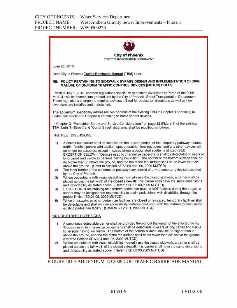
CITY OF PHOENIX: Water Services Department
PROJECT NAME: West Anthem Gravity Sewer Improvements – Phase 1
PROJECT NUMBER: WS90500276
01551-9 10/11/2018
FIGURE 401-1 ADDENDUM TO 2009 COP TRAFFIC BARRICADE MANUAL

CITY OF PHOENIX: Water Services Department
PROJECT NAME: West Anthem Gravity Sewer Improvements – Phase 1
PROJECT NUMBER: WS90500276
01551-10 10/11/2018
FIGURE 401-1 ADDENDUM TO 2007 TRAFFIC BARRICADE MANUAL
CITY OF PHOENIX: Water Services Department
PROJECT NAME: West Anthem Gravity Sewer Improvements – Phase 1
PROJECT NUMBER: WS90500276
01551-11 10/11/2018
2.1 FRONTAGE ROAD ACCESS REQUIREMENTS
Local access will be maintained at all times on frontage roads. Frontage roads will
not be used for through traffic, equipment parking, material storage, or spoil
stockpile area. Frontage road closures will follow the same special provisions as
described in "Local Access Requirements".
2.2 SCHOOL ACCESS REQUIREMENTS
The Contractor will provide clean and safe school zones, crosswalks, and walkways
for students attending nearby schools during all hours of school use. This may
require backfilling trenches, temporary pavement, shoring, plating, or pedestrian
bridges with handrails across open trenches. In addition to school zones and
crosswalks, the Contractor will maintain accessibility to all school bus routes during
all hours of school use. The Contractor will notify the school principal(s) and the
school Transportation Director at least fourteen (14) days prior to any restrictions,
and will restore access as soon as possible.
2.3 CHURCH ACCESS REQUIREMENTS
The Contractor will maintain a high level of access to churches during all hours of
church use. The Contractor will coordinate any access restrictions with the clergy at
least fourteen (14) days prior to any restrictions, and will restore access as soon as
possible.
2.4 HOSPITAL ACCESS REQUIREMENTS
The Contractor will maintain the Emergency entrance to nearby Hospital by way of a
paved lane for emergency vehicles at all times for the duration of the project. The
Contractor will coordinate any access restrictions with the hospital administrator at
least fourteen (14) days prior to any restrictions, and will restore access as soon as
possible.
2.5 FIRE STATION AND POLICE STATION ACCESS REQUIREMENTS
The Contractor will maintain paved emergency vehicle access to and from all fire
stations and police stations at all times. The Contractor will coordinate with the Fire
Station and/or Police Station Commander at least fourteen (14) calendar days prior to
any restrictions, and again at least 72 hours prior to any restrictions, and will restore
full access as soon as possible.
2.6 CITY PARK ACCESS REQUIREMENTS
The Contractor will maintain access to all nearby parks during all hours of park use.
Any restrictions will be coordinated with the appropriate Parks District Supervisor at

CITY OF PHOENIX: Water Services Department
PROJECT NAME: West Anthem Gravity Sewer Improvements – Phase 1
PROJECT NUMBER: WS90500276
01551-12 10/11/2018
least fourteen (14) days in advance of any restrictions, and full access will be
restored as soon as possible.
2.7 RECREATIONAL TRAIL CROSSING
The Contractor will maintain trail crossings at all times, and will maintain all special
trail signs required.
2.8 CANAL ACCESS ROAD REQUIREMENTS
Canal access and maintenance roads will remain open at all times. Contractor shall
coordinate any work that may impact this project with appropriate Agency contact as
least fourteen (14) working days in advance of operations.
2.9 COORDINATION WITH OTHER AGENGY PROJECTS
The Contractor will coordinate and schedule work to minimize disruption or conflicts
with other Agency projects. Any work that may affect this project will be
coordinated with the appropriate Agency contact at least fourteen (14) days in
advance.
3.0 SANITATION PICK-UP
The Contractor will provide sanitation pick-up for affected residents by relocating
trash containers, or by providing alternative measures acceptable to the Public Works
Department, Sanitation Division (602) 256-3310.
3.1 US POSTAL SERVICE
Contractor shall maintain mail delivery vehicle access at all times. Any restrictions
shall be coordinated with the mail stations prior to implementing restriction.
3.2 SPECIAL EVENTS
There are no known special events scheduled to take place during the construction of
this project. However, Contractor will coordinate any events with the construction
schedule. No additional compensation for delays associated with special events will
be considered.
3.3 SPECIAL SIGN REQUIREMENTS
The Contractor will provide, install and maintain advance notification; public
informational; and directional access signs (for businesses, churches, hospitals,
schools, etc.) that may be required by the Engineer. These signs may include, but are
not limited to portable changeable message signs, radar/speed sensing trailers and

CITY OF PHOENIX: Water Services Department
PROJECT NAME: West Anthem Gravity Sewer Improvements – Phase 1
PROJECT NUMBER: WS90500276
01551-13 10/11/2018
other applicable Intelligent Transportation System type devices. The cost will be
included in the bid item for Traffic Control Devices.
3.4 BUS STOPS
The Contractor will maintain all existing bus stop locations on this project in a safe
manner, or provide alternate bus stop locations and related directional signage as
required by the Engineer. Not fulfilling this requirement can lead to civil sanctions.
3.5 FLAGGING OF TRAFFIC
If construction requires, flagging may be allowed from 8:30 a.m. to 4:00 p.m.
weekdays or 7 A.M. – 5 P.M. Weekends on W. Cloud Road and Pioneer Road,
(Collector Streets).
3.6 TRAFFIC CONTROL PLAN
The Contractor will submit a traffic control plan for approval, showing placement of
all traffic control devices, including all conflicting signs to be covered/removed or
relocated, or other features that may conflict with the placement of temporary
signage. This plan will be professionally drawn on a 24” x 36” reproducible medium,
and will be submitted to the Engineer at the Pre-Construction meeting or before. The
Contractor will allow the Engineer fourteen (14) calendar days for review and
approval of an acceptable plan.
3.7 TEMPORARY TRAFFIC CONTROL ZONE AND SAFETY
At the Pre-Construction conference, the Contractor will designate an employee, other
than the Project Superintendent, who is knowledgeable in the principles and methods
of proper traffic control and safety. This employee will be available on the project
site during all periods of construction to coordinate and maintain safe, acceptable and
effective temporary barricading whenever construction affects traffic. This person
will be authorized to receive and fulfill instructions from the Engineer and will
supervise and direct traffic control. Instructions and information given by the
Engineer to this person will be considered as having been given to the Contractor.
Failure to maintain temporary traffic control devices in accordance with the
City of Phoenix Traffic Barricade Manual, 2007 edition, the approved Traffic
Control Plan, and directives by the Engineer will result in suspension of work
and/or civil sanctions until deficiencies are corrected to the satisfaction of the
Engineer.
CITY OF PHOENIX: Water Services Department
PROJECT NAME: West Anthem Gravity Sewer Improvements – Phase 1
PROJECT NUMBER: WS90500276
01551-14 10/11/2018
3.8 SAFETY FENCING REQUIREMENTS FOR TRENCHES AND
EXCAVATIONS
The Contractor will provide safety construction fencing around all open trenches and
excavations during all non-working hours. The Contractor will provide for the safety
and welfare of the general public by adequately fencing all excavations and trenches
that are permitted by the Engineer to remain open when construction is not in
progress. Fencing will be securely anchored to approved steel posts located six (6)
feet on centers, having a minimum height of six (6) feet, and will consist of wire
mesh fabric of sufficient weight and rigidity to adequately span a maximum
supporting post separation of six (6) feet. The fencing, when installed about the
periphery of excavations and trenches, will form an effective barrier against intrusion
by the general public into areas of construction. Fencing will not create sight distance
restrictions or visual obstructions. At all times when construction is not in progress,
the Contractor will be responsible for maintaining the fencing in good repair, and
upon notification by the Engineer, will take immediate action to rectify any
deficiency. Prior to the start of any excavating or trenching required for the execution
of the proposed work, the Contractor will submit to the Engineer for approval,
detailed plans showing types of materials and methods of fabrication for the
protective fencing. There will be no separate measurement or payment for
furnishing, installing, or maintaining protective fencing. The cost will be considered
incidental to the cost of the pipe and/or structures.
3.9 FINAL SIGNING AND STRIPING OF THE ROADWAY
The Contractor, through the City project inspector, shall notify the Street
Transportation Department, Traffic Operations Division (602-262-6456), at least
thirty (30) days prior to the desired level of completion of final roadway signing
and lane striping. This will allow adequate time for the City crews to schedule and
complete the task on time. The Contractor shall coordinate with the City of
Phoenix to replace signing and striping within the City of Phoenix right-of-way.
Contractor shall coordinate and complete all signing and roadway marking work
within Maricopa County Right-of-Way limits in full compliance with Maricopa
County Department of Transportation requirements.
4.0 ALLOWANCE FOR UNIFORMED, OFF-DUTY LAW ENFORCEMENT
OFFICER
This project includes a lump sum “ALLOWANCE FOR UNIFORMED, OFF-DUTY
LAW ENFORCEMENT OFFICER. The amount of this allowance is determined by
the Engineer, and is not subject to individual bid pricing. All bidders will incorporate
the amount pre-entered in the bid proposal and will reflect the same in the total
amount bid for this project.
Payment for uniformed, off-duty law enforcement officers will be made from this
allowance based on approved invoiced cost plus taxes, and a maximum 10 percent
markup for overhead and profit.

CITY OF PHOENIX: Water Services Department
PROJECT NAME: West Anthem Gravity Sewer Improvements – Phase 1
PROJECT NUMBER: WS90500276
01551-15 10/11/2018
Payment for uniformed, off-duty law enforcement officers will be made from this
allowance based on approved invoiced cost plus taxes, and a maximum 10 percent
markup for overhead and profit.
4.1 TRAFFIC CONTROL PAYMENT
Payment for traffic control will be on a lump sum basis for Traffic Control Devices.
4.2 TRENCH PLATING
In Paved areas where vehicles will be driving over trench plating, the plates shall be
set to match flush with existing pavement on all sides. Setting plates on top of the
pavement surface and installing temporary asphalt ramps around them will not be
allowed.
4.3 TRENCHING IN THE RIGHT OF WAY
The Contractor shall not be allowed to stockpile trench material or store any other
than the mainline track hoe within the right-of-way. The Contractor shall secure
temporary 6’ chain link fence around the track hoe during non-working hours.
4.4 MAXIMUM OPEN TRENCH
No more than 300 linear feet of open trench shall be allowed. Trenches across
driveways shall be plated to maintain access. The cost of these plates shall be
considered incidental to the project.
PART 2 - PRODUCTS (NOT USED)
PART 3 - EXECUTION (NOT USED)
+ + END OF SECTION +

CITY OF PHOENIX: Water Services Department
PROJECT NAME: West Anthem Gravity Sewer Improvements – Phase 1
PROJECT NUMBER: WS90500276
01561-1 9/12/2018
SECTION 01561
SECURITY
PART 1 - GENERAL
1.1 DESCRIPTION
A. Safely guard all Work, materials, equipment and property from loss, theft, damage
and vandalism. CONTRACTOR’S duty to safely guard property shall include the
OWNER’S property and other private property from injury or loss in connection with
the performance of the Work.
B. Employ watchmen as required to provide the required security and prevent
unauthorized entry and/or theft.
C. Make no claim against the OWNER for damage or injury resulting from trespass.
D. Responsible for security and shall make good all damage to property of OWNER and
others arising from failure to provide adequate security. The standard for security
shall be, at a minimum, equivalent to the OWNER’S standards.
E. If the existing fencing or barriers are breached or removed for purposes of
construction, provide and maintain temporary security fencing equal to the existing
in a manner satisfactory to the ENGINEER and OWNER. Provide additional
security staff, if required, to maintain the security of the facility.
F. Security measures taken shall be at least equal to those usually provided by OWNER
to protect his existing facilities during normal operation.
G. Maintain security program throughout the Work until OWNER’S acceptance and
occupancy precludes need for CONTRACTOR’S security program.
H. Comply with all aspects of OWNER’S site specific Security Guard Protocol. This
shall include background checks equivalent to those conducted by the OWNER.
I. All costs for security as specified in this Section shall be borne by CONTRACTOR.
1.2 CONTRACTOR’S ACCESS TO THE SITE
A. Access to the site for CONTRACTOR’S employees, material, tools and equipment
shall be from the designated construction entrance.

CITY OF PHOENIX: Water Services Department
PROJECT NAME: West Anthem Gravity Sewer Improvements – Phase 1
PROJECT NUMBER: WS90500276
01561-2 9/12/2018
B. Ensure that each of his employees, representatives, delivery persons, suppliers and
others acting for CONTRACTOR, shall be subject to the following regulations:
1. CONTRACTOR’S subcontractor’s, suppliers and manufacturer’s employee’s
shall not park anywhere other than CONTRACTOR Employee’s Parking Area.
The Area shall be designated by the ENGINEER. Prepare and maintain this area,
as required.
2. Personal vehicles shall not be allowed outside CONTRACTOR’S Employee
Parking Area.
3. Delivery vehicles shall access the site from the designated construction entrance
road.
4. Access to the site from any other entrance is strictly prohibited, unless prior
approval is obtained from the OWNER. Violators shall be banned from the site.
5. Firearms are not allowed on City property.
PART 2 - PRODUCTS (NOT USED)
PART 3 - EXECUTION (NOT USED)
+ + END OF SECTION + +

CITY OF PHOENIX: Water Services Department
PROJECT NAME: West Anthem Gravity Sewer Improvements – Phase 1
PROJECT NUMBER: WS90500276
01570-1 9/12/2018
SECTION 01570
TEMPORARY CONTROLS
PART 1 - GENERAL
1.1 DESCRIPTION
A. Provide and maintain methods, equipment, and temporary construction, as necessary
to provide controls over environmental conditions at the construction site and
adjacent areas. Remove physical evidence of temporary facilities at completion of
Work.
B. Obtain all City, County and State permits required for the construction of all Work,
including Hazardous Material Management, Earth Moving/ Dust Control and
Stormwater/Stormwater Pollution Prevention Permits.
1.2 NOISE CONTROL
A. CONTRACTOR’S vehicles and equipment shall be such as to minimize noise to the
greatest degree practicable. Noise levels shall conform to the latest OSHA standards
and in no case will noise levels be permitted which interfere with the Work of the
OWNER or others.
1.3 PEST AND RODENT CONTROL
A. Provide rodent and pest control as necessary to prevent infestation of construction or
storage areas.
1. Employ methods and use materials that will not adversely affect conditions at
the site or on adjoining properties.
1.4 WATER CONTROL
A. Provide methods to control surface water and water from excavations and structures
to prevent damage to the Work, the site, or adjoining properties.
1. Control fill, grading and ditching to direct water away from excavations, pits,
tunnels and other construction areas and to direct drainage to proper runoff
courses so as to prevent any erosion, damage or nuisance.
1.5 EROSION CONTROL
A. Plan and execute construction and earth work by methods to control surface drainage
from cuts and fills, and from borrow and waste disposal areas, to prevent erosion and
sedimentation.

CITY OF PHOENIX: Water Services Department
PROJECT NAME: West Anthem Gravity Sewer Improvements – Phase 1
PROJECT NUMBER: WS90500276
01570-2 9/12/2018
1. Hold the areas of bare soil exposed at one time to a minimum.
2. Provide temporary control measures such as berms, dikes and drains.
B. Construct fills and waste areas by selective placement to eliminate surface silts or
clays which will erode.
C. Periodically inspect earthwork to detect any evidence of the start of erosion; apply
corrective measures as required to control erosion.
D. Coordinate erosion control requirements with the requirements of Article 1.4, above.
PART 2 - PRODUCTS (NOT USED)
PART 3 - EXECUTION (NOT USED)
+ + END OF SECTION + +
CITY OF PHOENIX: Water Services Department
PROJECT NAME: West Anthem Gravity Sewer Improvements – Phase 1
PROJECT NUMBER: WS90500276
01580-1 10/9/2018
SECTION 01580
PROJECT IDENTIFICATION AND SIGNS
PART 1 GENERAL
1.1 DESCRIPTION
A. Furnish, install and maintain temporary project identification and informational
signs.
B. The following signs shall be provided:
1. Provide 3 project signs. See attached sketch.
C. No signs, except those specified, shall be displayed, unless approved by OWNER.
1.2 SUBMITTALS
A. Submit for approval the following:
1. Type of grade of materials.
2. Layout, size, trim, framing, supports and coatings.
3. Size and style of lettering.
4. Samples of colors.
5. Proposed sign installation location
1.3 CONSTRUCTION
A. Use 3/4-inch exterior grade plywood, unless shown otherwise.
B. Use, trim, mitered on all edges.
C. Design signs and supports to withstand 100 mile per hour wind.
D. Paint with exterior gloss-finish enamel. Sign painter shall be a professional in the
type work required.
1.4 INSTALLATION AND MAINTENANCE
A. Location of signs shall be as shown or directed by ENGINEER.
B. Maintain signs so they are clean, legible and upright. Keep grass and weeds cut
away from signs.

CITY OF PHOENIX: Water Services Department
PROJECT NAME: West Anthem Gravity Sewer Improvements – Phase 1
PROJECT NUMBER: WS90500276
01580-2 10/9/2018
C. Repair and repaint damaged signs. Relocate signs as required by progress of the
Work.
D. Remove signs when project is completed or when directed by ENGINEER.
PART 2 - PRODUCTS (NOT USED)
PART 3 - EXECUTION (NOT USED)

CITY OF PHOENIX: Water Services Department
PROJECT NAME: West Anthem Gravity Sewer Improvements – Phase 1
PROJECT NUMBER: WS90500276
01580-3 10/12/2018
+ + END OF SECTION + +

CITY OF PHOENIX: Water Services Department
PROJECT NAME: West Anthem Gravity Sewer Improvements – Phase 1
PROJECT NUMBER: WS90500276
01651-1 9/12/2018
SECTION 01651
TRANSPORTATION AND HANDLING OF MATERIALS AND EQUIPMENT
PART 1 - GENERAL
1.1 DESCRIPTION
A. Make all arrangements for transportation, delivery and handling of equipment and
materials required for prosecution and completion of the Work.
B. Shipments of materials to CONTRACTOR or subcontractors shall be delivered to
the site only during regular working hours and shall conform to the requirements of
Section 01413, CONTRACTOR’S Hazardous Materials Management Program.
Shipments shall be addressed and consigned to the proper party giving name of
Project, street number and city. Shipments shall not be delivered to OWNER, except
where otherwise directed.
C. If necessary to move stored materials and equipment during construction, move
materials and equipment without any additional compensation.
1.2 PREPARATION FOR SHIPMENT
A. When practical, factory assemble products. Matchmark or tag separate parts and
assemblies to facilitate field assembly. Cover machined and unpainted parts that may
be damaged by the elements with a strippable protective coating.
B. Package products to facilitate handling and protect from damage during shipping,
handling, and storage. Mark or label outside of each package or crate to indicate its
purchase order number, bill of lading number, contents by name, OWNER’S contract
name and number, CONTRACTOR, equipment number, and approximate weight.
Include complete packing lists and bills of materials with each shipment.
C. Protect products from exposure to the elements and keep thoroughly dry and dust
free at all times. Protect painted surfaces against impact, abrasion, discoloration, or
other damage. Grease or oil all bearings and similar items.
D. Do not have products shipped until:
1. Related Shop Drawings have been approved by ENGINEER.
2. Related factory test results, required in the individual Specification Sections,
have been reviewed and accepted by ENGINEER.
3. Required storage facilities have been provided.
CITY OF PHOENIX: Water Services Department
PROJECT NAME: West Anthem Gravity Sewer Improvements – Phase 1
PROJECT NUMBER: WS90500276
01651-2 9/12/2018
E. Items shall be supported, packaged and stored per product manufacturers
recommendations.
1.3 DELIVERY
A. Arrange, with the United States Postal Service, a special address for the Project. All
deliveries shall be made to that address.
B. Arrange deliveries of products in accordance with construction schedules and in
ample time to facilitate inspection prior to installation.
C. Coordinate deliveries to avoid conflict with Work and conditions on site and to
accommodate the following:
1. Work of other contractors, or OWNER.
2. Limitations of storage space.
3. Availability of equipment and personnel for handling products.
4. OWNER’S use of premises.
D. Do not have products delivered to Project site until related Shop Drawings have been
approved by the ENGINEER.
E. Do not have products delivered to Project site until required storage facilities have
been provided.
F. Have products delivered to site in manufacturer’s original, unopened, labeled
containers. Keep ENGINEER informed of delivery of all equipment to be
incorporated in the Work to facilitate stored material observations and inspections.
G. Partial deliveries of component parts of equipment shall be clearly marked to identify
the equipment, to permit easy accumulation of parts and to facilitate assembly.
H. Immediately on delivery, inspect shipment to assure:
1. Product complies with requirements of Contract Documents and reviewed
submittal.
2. Quantities are correct.
3. Containers and packages are intact, and labels are legible.
4. Products are properly protected and undamaged.
5. Verify that the accelerometer recordings were made during shipment.
I. Promptly remove damaged products from the Project site and expedite delivery of
new undamaged products, and remedy incomplete or lost products to provide that
specified, so as not to delay progress of the Work. Inform ENGINEER of all
damaged products prior to removal.

CITY OF PHOENIX: Water Services Department
PROJECT NAME: West Anthem Gravity Sewer Improvements – Phase 1
PROJECT NUMBER: WS90500276
01651-3 9/12/2018
1.4 PRODUCT HANDLING
A. Provide equipment and personnel necessary to handle products, including those
provided by OWNER, by methods to prevent soiling or damage to products or
packaging.
B. Provide additional protection during handling as necessary to prevent scraping,
marring or otherwise damaging products or surrounding surfaces.
C. Handle products by methods to prevent bending or overstressing.
D. Lift heavy components only at designated lifting points.
E. Materials and equipment shall at all times be handled in a safe manner and as
recommended by manufacturer or supplier so that no damage will occur to them. Do
not drop, roll or skid products off delivery vehicles. Hand carry or use suitable
materials handling equipment.
PART 2 - PRODUCTS (NOT USED)
PART 3 - EXECUTION (NOT USED)
+ + END OF SECTION + +

CITY OF PHOENIX: Water Services Department
PROJECT NAME: West Anthem Gravity Sewer Improvements – Phase 1
PROJECT NUMBER: WS90500276
01721-1 9/12/2018
SECTION 01721
PROTECTION OF THE WORK AND PROPERTY
PART 1 - GENERAL
1.1 DESCRIPTION
A. Be responsible for taking all precautions, providing all programs, and taking all
actions necessary to protect the Work and all public and private property and
facilities from damage as specified in the General Conditions and herein.
B. In order to prevent damage, injury or loss, CONTRACTOR’S actions shall include,
but not be limited to, the following:
1. Store apparatus, materials, supplies, and equipment in an orderly, safe manner
that will not unduly interfere with the progress of the Work or the work of any
other contractor or utility service company.
2. Provide suitable storage facilities for all materials which are subject to injury by
exposure to weather, theft, breakage, or otherwise.
3. Place upon the Work or any part thereof only such loads as are consistent with
the safety of that portion of the Work.
4. Clean up frequently all refuse, rubbish, scrap materials, and debris caused by
his operations, to the end that at all times the site of the Work shall present a
safe, orderly and workmanlike appearance.
5. Provide barricades and guard rails around openings, for scaffolding, for
temporary stairs and ramps, around excavations, elevated walkways and other
hazardous areas.
C. Shall not, except after written consent from proper parties, enter or occupy privately-
owned land with personnel, tools, materials or equipment, except on easements
provided herein.
D. Assume full responsibility for the preservation of all public and private property or
facility on or adjacent to the site. If any direct or indirect damage is done by or on
account of any act, omission, neglect or misconduct in the execution of the Work by
CONTRACTOR, it shall be restored by CONTRACTOR, at his expense, to a
condition equal to that existing before the damage was done.
E. CONTRACTOR shall be responsible for any staking/roping needed to identify the
contractual limits of construction activities, including easements.
1.2 BARRICADES AND WARNING SIGNALS

CITY OF PHOENIX: Water Services Department
PROJECT NAME: West Anthem Gravity Sewer Improvements – Phase 1
PROJECT NUMBER: WS90500276
01721-2 9/12/2018
A. Where Work is performed on or adjacent to any roadway, right-of-way, or public
place, provide barricades, fences, lights, warning signs, danger signals, watchmen,
and shall take other precautionary measures for the protection of persons or property
and of the Work. Barricades shall be painted to be visible at night. From sunset to
sunrise, furnish and maintain at least one light at each barricade. Sufficient
barricades shall be erected to keep vehicles from being driven on or into Work under
construction. Furnish watchmen in sufficient numbers to protect the Work.
CONTRACTOR’S responsibility for the maintenance of barricades, signs, lights, and
for providing watchmen shall continue until the Project is accepted by OWNER.
1.3 TREE AND PLANT PROTECTION
A. Protect existing trees, shrubs and plants on or adjacent to the site that are shown or
designated to remain in place against unnecessary cutting, breaking or skinning of
trunk, branches, bark or roots.
B. Materials or equipment shall not be stored or parked within the drip line.
C. Temporary fences or barricades shall be installed to protect trees and plants in areas
subject to traffic.
D. Fires shall not be permitted.
E. Within the limits of the Work, water trees and plants that are to remain, in order to
maintain their health during construction operations.
F. Cover all exposed roots with burlap which shall be kept continuously wet. Cover all
exposed roots with earth as soon as possible. Protect root systems from mechanical
damage and damage by erosion, flooding, run-off or noxious materials in solution.
G. If branches or trunks are damaged, prune branches immediately and protect the cut or
damaged areas with emulsified asphalt compounded specifically for horticultural use
in a manner approved by the ENGINEER.
H. All damaged trees and plants that die or suffer permanent injury shall be removed
and disposed of off-site when ordered by the ENGINEER and replaced by a
specimen of equal or better quality.
I. Coordinate Work in this Section with requirements of Section 02230, Clearing, and
Section 02901, Planting.
J. Erect and maintain temporary construction fence to protect areas from construction
traffic and activities.

CITY OF PHOENIX: Water Services Department
PROJECT NAME: West Anthem Gravity Sewer Improvements – Phase 1
PROJECT NUMBER: WS90500276
01721-3 9/12/2018
1.4 PROTECTION OF EXISTING STRUCTURES
A. Underground Structures:
1. Underground structures are defined to include, but are not limited to, all sewer,
water, gas, and other piping, and manholes, chambers, electrical and
communication conduits, tunnels and other existing subsurface work located
within or adjacent to the limits of the Work.
2. All underground structures known to ENGINEER, except water, gas, sewer,
electric, and telephone service connections, are shown. This information is
shown for the assistance of CONTRACTOR, in accordance with the best
information available, but is not guaranteed to be correct or complete.
3. CONTRACTOR shall uncover all obstructing underground structures
sufficiently to determine their location and elevation, to prevent damage to
them and to prevent interruption to the services which such structures provide a
minimum of 14 Days in-advance of trench and excavation Work. If
CONTRACTOR damages an underground structure, he shall restore it to
original condition at his expense.
4. Necessary changes in the location of the Work may be made by ENGINEER to
avoid unanticipated underground structures.
5. If permanent relocation of an existing underground structure or other subsurface
facility is required and is not otherwise provided for in the Contract
Documents, ENGINEER will direct CONTRACTOR, in writing, to perform the
Work, which shall be paid for under the provisions of the General Conditions.
B. Surface Structures:
1. Surface structures are defined as all existing buildings, structures and other
facilities above the ground surface. Included with such structures are their
foundations or any extension below the surface. Surface structures include, but
are not limited to, buildings, tanks, walls, bridges, roads, dams, channels, open
drainage, piping, poles, wires, posts, signs, markers, curbs, walks and all other
facilities that are visible above the ground surface.
C. Protection of Underground and Surface Structures:
1. Sustain in their places and protect from direct or indirect injury all underground
and surface structures located within or adjacent to the limits of the Work.
Such sustaining and supporting shall be done carefully and as required by the
party owning or controlling such structure. Before proceeding with the Work
of sustaining and supporting such structure, satisfy the ENGINEER that the
methods and procedures to be used have been approved by the party owning
same.
2. Assume all risks attending the presence or proximity of all underground and
surface structures within or adjacent to the limits of the Work. Be responsible

CITY OF PHOENIX: Water Services Department
PROJECT NAME: West Anthem Gravity Sewer Improvements – Phase 1
PROJECT NUMBER: WS90500276
01721-4 9/12/2018
for all damage and expense for direct or indirect injury caused by his Work to
any structure. Repair immediately all damage caused by his Work, to the
satisfaction of the Owner of the damaged structure.
D. All other existing surface facilities, including but not limited to, guard rails, posts,
guard cables, signs, poles, markers, and curbs, which are temporarily removed to
facilitate installation of the Work, shall be replaced and restored to their original
condition at CONTRACTOR’S expense.
1.5 PROTECTION OF FLOORS AND ROOFS
A. Protect floors and roofs during entire construction period.
B. Proper protective covering shall be used when moving heavy equipment, handling
materials or other loads, when painting, handling mortar and grout
C. Use metal pans to collect all oil and cuttings from pipe, conduit, or rod threading
machines and under all metal cutting operations.
D. Concrete floors less than 28 days old shall not be loaded without written permission
of the ENGINEER. No floor, roof or slab shall be loaded in excess of its design
loading.
1.6 PROTECTION OF INSTALLED PRODUCTS AND LANDSCAPING
A. Provide protection of installed products to prevent damage from subsequent
operations. Remove protection facilities when no longer needed prior to completion
of Work.
B. Control traffic to prevent damage to equipment, materials and surfaces.
C. Provide coverings to protect equipment and materials from damage.
1. Cover projections, wall corners and jambs, sills and soffits of openings, in areas
used for traffic and for passage of products in subsequent work.
PART 2 - PRODUCTS (NOT USED)
PART 3 - EXECUTION (NOT USED)
+ + END OF SECTION + +

CITY OF PHOENIX: Water Services Department
PROJECT NAME: West Anthem Gravity Sewer Improvements – Phase 1
PROJECT NUMBER: WS90500276
01722-1 9/12/2018
SECTION 01722
FIELD ENGINEERING
PART 1 - GENERAL
1.1 DESCRIPTION
A. The ENGINEER will establish a base line for the Project and two benchmarks for use
by CONTRACTOR. The ENGINEER and CONTRACTOR will coordinate the
location of the benchmarks and base line to suit the Work.
B. CONTRACTOR:
1. Provide civil, structural and other professional engineering services specified, or
required to execute CONTRACTOR’S construction methods.
2. Develop and make all detail surveys and measurements needed for construction
including slope stakes, batter boards, and all other working lines, elevations and
cut sheets.
3. Provide all material required for bench marks, control points, batter boards, grade
stakes, structure and pipeline elevation stakes, and other items.
4. Be solely responsible for all locations, dimensions and levels. No data other than
written orders of the ENGINEER shall justify departure from the dimensions and
levels required by the Contract Documents.
5. Safeguard all points, stakes, grade marks, monuments and bench marks made or
established on the Work. Re-establish same with the exception of primary
control monuments if disturbed and rectify all Work improperly installed because
of not maintaining, not protecting or removing without authorization established
points, stakes, marks and monuments.
6. Provide such facilities and assistance as may be necessary for ENGINEER to
check line and grade points placed by CONTRACTOR. Do not perform any
excavation or embankment work until all cross-sectioning necessary for
determining pay quantities has been completed and checked by ENGINEER.
7. CONTRACTOR shall provide notices and comply with all laws, ordinances,
rules and regulations bearing on the conduct of the Work. If CONTRACTOR
observes that the Contract Documents are at variance therewith, promptly notify
the ENGINEER, in writing within 24 hours.
1.2 CONTRACTOR’S FIELD ENGINEER
A. Employ and retain at the site of the Work a field engineer with the experience and
capability of performing all engineering tasks required of CONTRACTOR. Tasks
included are:

CITY OF PHOENIX: Water Services Department
PROJECT NAME: West Anthem Gravity Sewer Improvements – Phase 1
PROJECT NUMBER: WS90500276
01722-2 9/12/2018
1. Provide daily reports of Project activity. Reports to be submitted to the
ENGINEER with all pertinent information pertaining to the project as follows:
a. Number of employees.
b. Subcontractor employees.
c. Breakdown of employees by trades.
d. Major equipment and materials installed.
e. Major construction equipment utilized.
f. Location of all areas in which construction was done.
g. Materials and equipment received.
h. Work and tests performed.
i. Weather conditions.
j. Safety.
k. Delays.
l. Instructions received.
2. Submit 1 copy of CONTRACTOR’S daily report electronically in .PDF format.
The daily report is due at the ENGINEER’S field office by 9:00 a.m. the next
working day after the Work was performed and shall be signed by a responsible
member of CONTRACTOR’S staff.
3. Check all formwork, reinforcing, inserts, structural steel, bolts, sleeves, piping,
other materials and equipment.
4. Maintain field office files and drawings, Record Drawings, and coordinate
engineering services with subcontractors. Prepare layout and coordination
drawings for construction operations.
5. Check and coordinate Work for conflicts and interferences and immediately
advise ENGINEER of all discrepancies noted.
6. Cooperate with ENGINEER in field inspections, as required.
7. Review and coordinate Shop Drawings and other submittals.
1.3 CONTRACTOR’S SURVEYOR
A. Employ and retain, as needed, at the Work site a surveyor with the experience and
capability of performing all surveyor and layout tasks required of CONTRACTOR.
The surveyor shall be a land surveyor registered in the State of Arizona. Tasks
included are:
1. Provide all surveying equipment required including transit, level, stakes and
required surveying accessories.
2. Furnish all required lines and grades for construction of all facilities, structures,
pipelines and site improvements.
3. Keep professional, accurate, well organized, and legible notes of all
measurements and calculations made while surveying and laying out the Work.
4. Survey, locate, and record and redline Drawings to accurately represent all
existing and newly installed utilities and buried structures prior to backfilling.
CITY OF PHOENIX: Water Services Department
PROJECT NAME: West Anthem Gravity Sewer Improvements – Phase 1
PROJECT NUMBER: WS90500276
01722-3 9/12/2018
B. Any primary control survey monuments damaged or destroyed, will be re-established
by the ENGINEER, at CONTRACTOR’S expense.
C. Perform such surveys and computations as are necessary to determine quantities of
Work performed or placed during each progress payment period, and shall perform all
surveys necessary for the ENGINEER to determine final quantities of Work in place.
D. Notify the ENGINEER at least 24 hours before performing a quantity survey and,
unless waived in writing by the ENGINEER, quantity surveys shall be performed in
the presence of the ENGINEER.
E. From established primary control points, establish all lines and grades, and elevations
necessary to control the Work, and shall be responsible for all measurements that may
be required for execution of the Work to the tolerances prescribed in the Contract
Documents.
F. Establish, place, and replace as required, such additional stakes, markers, and other
controls as may be necessary for control, intermediate checks, and guidance of
construction operations.
1.4 SURVEYING
A. Follow the following construction surveying guidelines for this project:
1. Alignment Staking: Each 50 feet on tangent; each 25 feet on curves.
2. Slope Staking: Each 50 feet on tangent; each 25 feet on curves; restake every 10
feet in elevation.
3. Structure: Stake out structures, including elevations; checkouts prior to and
during construction.
4. Pipeline: Stake out pipelines including elevations; checkout prior to and during
construction.
5. Road: Tops each 50 feet on tangent and each 25 feet on curves.
6. Cross-Section: Original, final and intermediate as required, for the structure sites
and other locations as necessary for quantity surveys.
7. Easement Staking: Each 50 feet on tangent; each 25 feet on curves. Also
wooden laths with flagging at 100 feet maximum spacing.
8. Record Staking: Provide permanent stake where blind flanges or caps are
provided for future connecting, with a material acceptable to the ENGINEER.
B. Temporary survey references set by CONTRACTOR for CONTRACTOR’S own use
shall be established to at least second order accuracy (e.g., 1:10000). Construction
staking used as a guide for the actual Work shall be set at least third order accuracy
(e.g., 1:5000). The basis on which such orders are established shall be sufficient to
provide the absolute margin for error specified below.

CITY OF PHOENIX: Water Services Department
PROJECT NAME: West Anthem Gravity Sewer Improvements – Phase 1
PROJECT NUMBER: WS90500276
01722-4 9/12/2018
C. The horizontal accuracy of easement staking shall be plus or minus 0.1 feet. The
accuracy of all other staking shall be plus or minus 0.04 feet horizontally and plus or
minus 0.02 feet vertically.
D. Survey calculations shall include an error analysis sufficient to demonstrate the
required accuracy.
E. Survey Records:
1. Maintain a complete, accurate log of all control and survey Work as it progresses.
2. All survey data shall be in accordance with recognized professional surveying
standards. All original field notes, computations, and other surveying data shall
be recorded by CONTRACTOR’S surveyor in CONTRACTOR furnished hard-
bound field books, and shall be signed and sealed by CONTRACTOR’S
surveyor. The completeness and accuracy of all survey Work, and the
completeness and accuracy of the survey records, including the field books, shall
be the responsibility of CONTRACTOR. Failure to organize and maintain survey
records in a professional manner to allow reasonable and independent verifica-
tion of all calculations by the ENGINEER, and to allow reasonable identification
by the ENGINEER of all elevations, dimensions, and grades of the Work shall be
cause for rejection of the survey records, including the field books.
3. Illegible notes or data, or erasures on any page of the field books is not
acceptable. Copied notes or data shall not be permitted. Corrections by ruling or
lining out errors will be satisfactory only if initialed by the surveyor. Violation of
the above may require resurveying the data in question.
F. Survey Submittal:
1. Survey submittal shall be made as described herein. Submittal shall be signed
and sealed by CONTRACTOR’S surveyor and shall include:
a. A complete survey plan that shall be submitted ten days prior to beginning
survey Work.
b. Resumes shall be submitted of the Registered Land Surveyors conducting
the Work ten days prior to beginning survey Work. During the course of the
Work, a resume shall be submitted for each new Registered Land Surveyor
working on the project at least ten days prior to the beginning of Work by
such new Registered Land Surveyor.
c. A sample of the proposed survey field books to be maintained by
CONTRACTOR’S surveyor. The sample shall have sufficient information
and detail, including example calculations and notes, to demonstrate that the
field books will be organized and maintained in a professional manner,
meeting the requirements of Article 1.3 and Article 1.4 of this Section.
d. The original field books shall be submitted within two days upon completion
of the Work.

CITY OF PHOENIX: Water Services Department
PROJECT NAME: West Anthem Gravity Sewer Improvements – Phase 1
PROJECT NUMBER: WS90500276
01722-5 9/12/2018
PART 2 - PRODUCTS (NOT USED)
PART 3 - EXECUTION (NOT USED)
+ + END OF SECTION) + +

CITY OF PHOENIX: Water Services Department
PROJECT NAME: West Anthem Gravity Sewer Improvements – Phase 1
PROJECT NUMBER: WS90500276
01723-1 9/12/2018
SECTION 01723
CUTTING AND PATCHING
PART 1 - GENERAL
1.1 DESCRIPTION
A. This Section includes administrative and procedural requirements for the cutting and
coring, and rough and finish patching of holes and openings in existing construction.
B. All cutting, coring and rough patching shall be performed by CONTRACTOR
requiring the opening. Finish patching shall be the responsibility of CONTRACTOR
and shall be performed by the trade associated with the application of the particular
finish.
C. Provide cutting, coring, fitting and patching, including attendant excavation and
backfill required to complete the Work, or to:
1. Remove and replace defective Work or Work not conforming to requirements
of the Contract Documents.
2. Remove samples of installed Work as specified or required for testing.
3. Remove all constructions required to provide for specified alterations or
addition to existing work.
4. Uncover Work to provide for ENGINEER'S observation of covered Work or
observation by regulatory agencies having jurisdiction.
5. Connect to completed Work that was not accomplished in the proper sequence.
6. Remove or relocate existing utilities and pipes that obstruct the Work in
locations where connections must be made.
7. Make connections or alterations to existing or new facilities.
D. Coordinate the requirements of the Work in this Section along with the requirements
of the Sections listed below which includes Work that is directly related to this
Section.
1. Division 2, Site Work, through 17, Instrumentation, Sections for specific
requirements and limitations applicable to cutting and patching individual parts
of the Work.
1.2 QUALITY ASSURANCE
A. Structural Work: Do not cut or patch structural elements in a manner that would
change their load-carrying capacity as load-deflection ratio.

CITY OF PHOENIX: Water Services Department
PROJECT NAME: West Anthem Gravity Sewer Improvements – Phase 1
PROJECT NUMBER: WS90500276
01723-2 9/12/2018
B. Operating Elements: Do not cut or patch operating elements in a manner that would
result in reducing their capacity to perform as intended. Do not cut or patch
operating elements or related components in a manner that would result in increased
maintenance or decreased operational life or safety.
1.3 SUBMITTALS
A. Submit a written request to ENGINEER well in advance of executing any cutting or
alteration which affects:
1. Design function or intent of Project.
2. Work of OWNER or any other contractor.
3. Structural value or integrity of any element of the Project.
4. Integrity or effectiveness of weather-exposed or moisture-resistant elements or
systems.
5. Efficiency, operational life, maintenance or safety of operational elements.
6. Visual qualities of sight-exposed elements.
B. Request shall include:
1. Identification of Project.
2. Description of affected Work of CONTRACTOR and work of others.
3. Necessity for cutting.
4. Effect on work of OWNER or any other contractor, or on structural or
weatherproof integrity of Project.
5. Description of proposed Work, describing:
a. Scope of cutting and patching.
b. Trades who will be executing the Work.
c. Products proposed to be used.
d. Extent of refinishing.
e. Schedule of operations.
6. Alternatives to cutting and patching, if any.
7. Designation of party responsible for cost of cutting and patching, when
applicable.
8. Written permission of any other contractor whose work will be affected.
C. Should conditions of Work, or schedule, indicate a change of materials or methods,
submit written recommendation to ENGINEER, including:
1. Conditions indicating change.
2. Recommendations for alternative materials or methods.
3. Submittals as required for substitutions.
D. Submit written notice to ENGINEER, designating time Work will be uncovered, to
provide for observation. Do not begin cutting or patching operations until authorized
by ENGINEER.
CITY OF PHOENIX: Water Services Department
PROJECT NAME: West Anthem Gravity Sewer Improvements – Phase 1
PROJECT NUMBER: WS90500276
01723-3 9/12/2018
E. Conform to all applicable specifications for application and installation of materials
used for patching.
1.4 WARRANTY
A. Replace, patch and repair materials and surfaces cut or damaged during cutting and
patching operations, by methods and with materials in such a manner as to not void
required or existing warranties.
PART 2 - PRODUCTS
2.1 MATERIALS, GENERAL
A. Use materials identical to existing materials. For exposed surfaces, use materials
that visually match existing adjacent surfaces to fullest extent possible. If identical
materials are unavailable or cannot be used, use materials whose installed
performance will equal or surpass that of existing materials.
PART 3 - EXECUTION
3.1 GENERAL
A. Perform all cutting and coring in such a manner as to limit the extent of patching.
B. Core drill all holes to be cut through concrete and masonry walls, slabs or arches,
unless otherwise approved by the ENGINEER.
3.2 INSPECTION
A. Examine surfaces to be cut and patched and conditions under which cutting and
patching are to be performed before cutting.
B. Report unsatisfactory or questionable conditions to ENGINEER, in writing. Do not
proceed with Work until the ENGINEER has provided further instructions.
3.3 PREPARATION
A. Provide temporary support as required to maintain structural integrity of Project, to
protect adjacent Work from damage during cutting, and to support the Work to be
cut.

CITY OF PHOENIX: Water Services Department
PROJECT NAME: West Anthem Gravity Sewer Improvements – Phase 1
PROJECT NUMBER: WS90500276
01723-4 9/12/2018
B. Protect existing construction during cutting and patching to prevent damage. Provide
protection from adverse weather conditions for portions of the Project that will be
exposed during cutting and patching operations.
1. Avoid interference with use of adjoining areas or interruption of free passage to
adjoining areas.
2. Do not cut existing pipe, conduit or ductwork serving facilities scheduled to be
removed or relocated until provisions have been made to bypass them.
3.4 CORING
A. Perform coring with a non-impact rotary tool using diamond core drills. Size holes
for pipe, cylinders, conduit, sleeves, equipment or mechanical seals, as required.
B. Protect existing equipment, utilities and adjacent areas from water and other damage
covered by drilling operations.
C. Vacuum or otherwise remove slurry or tailings from the Work area following
drilling.
3.5 CUTTING
A. Cut existing construction using methods least likely to damage elements retained or
adjoining construction and that will provide proper surfaces to receive installation or
repair.
1. In general, use hand or small power tools designed for sawing or grinding, not
hammering and chopping.
2. Cut through concrete and masonry using a concrete wall saw with diamond saw
blades.
a. Provide for control, on both sides of walls, of slurry generated by sawing.
B. Cut holes and slots as small as possible, neatly to size required, and with minimum
disturbance of adjacent surfaces. Provide temporary covering over openings where
not in use.
C. To avoid marring existing finished surfaces, cut or drill from exposed or finished side
into concealed side.
D. Provide adequate bracing of area to be cut prior to start of cutting.
E. Provide equipment of adequate size to remove cut panel.

CITY OF PHOENIX: Water Services Department
PROJECT NAME: West Anthem Gravity Sewer Improvements – Phase 1
PROJECT NUMBER: WS90500276
01723-5 9/12/2018
3.6 PATCHING
A. Patch construction by filling, repairing, refinishing, closing-up and similar operations
following performance of other Work. Patch with durable seams that are as invisible
as possible. Provide materials and comply with installation requirements specified,
in other Sections of these Specifications.
B. Where feasible, test patched areas to demonstrate integrity of installation.
C. Fit Work airtight to pipes, sleeves, ducts, conduit and other penetrations through
surfaces.
D. Restore exposed finishes of patched areas and extend finish restoration into retained
adjoining construction in a manner that will eliminate evidence of patching and
refinishing.
1. For continuous surfaces, refinish to nearest intersection.
2. For an assembly, refinish entire unit.
E. Patch, repair or rehang existing ceilings as necessary to provide an even-plane
surface of uniform appearance.
3.7 CLEANING
A. Clean areas and spaces where cutting, coring and patching are performed. Clean
piping, conduit or similar constructions before applying paint or other finishing
materials. Restore damaged pipe covering to original condition.
PART 2 - PRODUCTS (NOT USED)
PART 3 - EXECUTION (NOT USED)
+ + END OF SECTION + +
CITY OF PHOENIX: Water Services Department
PROJECT NAME: West Anthem Gravity Sewer Improvements – Phase 1
PROJECT NUMBER: WS90500276
01724-1 9/12/2018
SECTION 01724
CONNECTIONS TO EXISTING FACILITIES
PART 1 - GENERAL
1.1 DESCRIPTION
A. Perform all construction necessary to complete connections and tie-ins to existing
facilities.
B. Keep existing facilities in operation unless otherwise specifically permitted in these
Specifications or approved by OWNER.
C. Perform all construction activities so as to avoid interference with operations of the
facility and the work of others.
1.2 BYPASSING
A. Bypassing of plant flow will be permitted only for brief intermittent periods
necessary to make the connections.
1.3 SEQUENCING AND OPERATIONS
A. All operations of existing valves and gates required for the Work shall be done by
OWNER.
B. Insofar as possible, all equipment shall be tested and in operating condition before
the final tie-ins are made to connect equipment to the existing facility.
C. Carefully coordinate all Work and schedules and shall provide OWNER written
notice at least 1 week before shut-downs or by-passes are required.
D. Work Sequence: Sequence of Work and Schedule of Completion is specified under
Section 01111, Schedule of Completion, and shown on the Construction Sequence
Diagrams included in the Drawings.
1.5 SUBMITTALS
A. For any tie-ins/connections or required shutdowns to existing mains and systems, the
CONTRACTOR shall submit a shutdown/tie-in plan to Water Distribution personnel
and Engineering and shall be approved at least two weeks prior to the start of the
event. The plan shall include dates, durations, procedures, staffing, and any other
information pertinent to shutting down the system and connecting to a new system.

CITY OF PHOENIX: Water Services Department
PROJECT NAME: West Anthem Gravity Sewer Improvements – Phase 1
PROJECT NUMBER: WS90500276
01724-2 9/12/2018
PART 2 - PRODUCTS (NOT USED)
PART 3 - EXECUTION (NOT USED)
+ + END OF SECTION + +

CITY OF PHOENIX: Water Services Department
PROJECT NAME: West Anthem Gravity Sewer Improvements – Phase 1
PROJECT NUMBER: WS90500276
01782-1 9/12/2018
SECTION 01782
RECORD DOCUMENTS
PART 1 - GENERAL
1.1 DESCRIPTION
A. Maintain and provide the ENGINEER with Record Documents as by Contract
Documents.
B. Definitions
1. Contract Documents: The contract documents include the drawings,
specifications, and addenda developed and furnished to the CONTRACTOR at
the beginning of construction.
2. As-Built Drawings: As-built drawings are an annotated set of drawings
prepared by the CONTRACTOR. They show, in red, as-constructed changes to
the original Contract Documents that have been made during the construction
process. The As-Built Drawings may include supplemental drawings to
provide the necessary detail, comply with project standards or where annotation
would otherwise be impractical.
3. Record Drawings: Record Drawings are prepared by the ENGINEER and
reflect as-constructed changes that the CONTRACTOR annotated in the As-
Built Drawings.
4. Record Documents: The Record Documents include Record Drawings,
specifications, addenda, approved shop drawings, samples, photographs,
change orders, other modifications to the Contract Documents, test records,
survey data, field orders, Request for Information, Instruction to Contractor,
Work Change Directives, submittals, Warranty certificates, and all other
documents pertinent to the CONTRACTOR’S Work.
C. Maintenance of Documents:
1. Three sets of black line sets of plans, including any Addenda, of the Drawings
will be furnished to CONTRACTOR by the OWNER.
2. Maintain in CONTRACTOR’S field office in clean, dry, legible condition
complete sets of the following: Drawings, Specifications, Addenda, approved
Shop Drawings, Samples, Photographs, Change Orders, other modifications of
Contract Documents, test records, survey data, Field Orders, and all other
documents pertinent to CONTRACTOR’S Work.
3. Provide files and racks for proper storage and easy access. File in accordance
with filing format of Construction Specification Institute (CSI), unless
otherwise approved by ENGINEER.
4. Make documents available at all times for inspection by ENGINEER and
OWNER.
CITY OF PHOENIX: Water Services Department
PROJECT NAME: West Anthem Gravity Sewer Improvements – Phase 1
PROJECT NUMBER: WS90500276
01782-2 9/12/2018
5. Record Documents shall not be used for any other purpose and shall not be
removed from CONTRACTOR’S office without ENGINEER’S approval.
6. Any contractually required testing provided by others shall be thoroughly
documented by the CONTRACTOR and maintained with the project Record
Documents. All testing results shall be maintained in their own separate log for
the project; being kept current weekly and made readily available for viewing at
any time.
D. Marking System: Changes, revisions, additions and deletions, to the record set of
Drawings shall be marked in Red.
E. Recording:
1. Submit as-built drawings and make a record of the locations of all work
completed as part of the project. The as-builts must indicate the locations of
the beginning(s) and end(s) of the construction, and all valves, fire hydrants,
pipe fittings, service connections and appurtenances. They must also show
locations and elevations where significant elevation changes occur or changes
in direction in all pipe alignments. Their locations must be shown by stationing
and dimensioning from appropriate monument lines or in their absence
appropriate lot lines, property lines or easement line references.
2. Global Positioning System (GPS) Recording: For construction projects located
in the Right-Of-Way, certain assets locations are required to be recorded with
survey-grade GPS device such as Trimble GSA-6000 GeoXH (or equivalent)
currently used by CITY staff to locate assets. The contractor shall coordinate
with the ENGINEER to identify assets requiring GPS coordinates (northing and
easting) and elevation to the top of the buried asset. The following GPS
coordinate set up shall be followed by the CONTRACTOR:
a. Coordinate System: US State Plane 1983
b. Zone: Arizona Central 0202 (Grid)
c. Datum: NAD 1983 (2011)
d. Elevation: NGVD 29
e. Altitude Units: feet
f. Coordinate Unit: International feet
g. Coordinate order: North/East
h. Projection: Transverse Mercator
The GPS coordinates shall be recorded on a spreadsheet provided by the
ENGINEER. The ENGINEER will review the GPS coordinates provided by
the CONTRACTOR and confirm their accuracy by navigating to the assets
using the provided coordinates to ensure the accuracy tolerance is met. The
confirmation process shall be performed before the assets are buried to ensure
accuracy compliance. The coordinates will be submitted to the CITY at the
project completion to be loaded into the CITY’s asset registry system. In
general, GPS coordinates are required for but not limited to:
a. Valves for Water pipes, Reclaimed Water pipes, and sewage forcemains,
CITY OF PHOENIX: Water Services Department
PROJECT NAME: West Anthem Gravity Sewer Improvements – Phase 1
PROJECT NUMBER: WS90500276
01782-3 9/12/2018
b. Fire Hydrants
c. Tap for Water Service Line, Reclaimed Water Service, and Lateral tap for
sewer service
d. Manholes
e. Cleanouts
3. Label the Cover Sheet, Index and each supplemental sheets of each document
“PROJECT RECORD” in 2-inch high printed letters.
4. Keep the As-Built Drawings current. CONTRACTOR’S refusal, failure or
neglect to maintain current As-Built Drawings shall constitute sufficient basis
for the ENGINEER to recommend the withholding of some or all of any
payment due.
5. Do not permanently conceal any Work until required information has been
recorded.
6. Drawings: Legibly mark to record actual construction including:
a. Depths of various elements of foundation in relation to datum.
b. Horizontal and vertical location of underground utilities and
appurtenances referenced to permanent surface improvements.
c. Location of internal utilities and appurtenances concealed in construction
referenced to visible and accessible features of structure.
d. Field changes of dimensions and details.
e. Changes made by Change Order or Field Order.
f. Details not on original Drawings.
7. Specifications and Addenda: Legibly mark up each Section to record:
a. Manufacturer, trade name, catalog number, and supplier of each product
and item of equipment actually installed.
b. Changes made by Change Order or Field Order.
c. Other matters not originally specified.
F. Record Drawings:
1. As-Built Drawings shall be prepared for all the Work included in the Contract.
On a weekly basis, furnish to the ENGINEER a full size annotated copy of the
As-Built Drawings that include changes from the previous week’s As-Built
Drawing submittal. Annotations shall include redlined “clouds” of only those
changes from the previous week’s submittal. The redlined As-Built Drawings
shall show the actual in-place installation of the items installed under this
Contract. The redlined As-Built Drawings shall show the Work in plan and
sections as required for clarity with reference dimensions and elevations that
will be used to develop complete Record Drawings.
2. Develop and furnish to the ENGINEER, redlined Instrumentation and Control
and Electrical Drawings showing one line diagrams with all conduit and wire
sizes shown of the distribution systems and the actual in-place grounding
system, lighting arrangement, motor control centers, corrected wiring diagrams,
equipment and conduit and cable plans.
a. The Contract Drawings may be used as a starting point in developing
these Instrumentation and Control and Electrical As-Built Drawings.

CITY OF PHOENIX: Water Services Department
PROJECT NAME: West Anthem Gravity Sewer Improvements – Phase 1
PROJECT NUMBER: WS90500276
01782-4 9/12/2018
Subcontractor and manufacturer drawings may be included in this drawing
package. The drawing package must be fully integrated and include the
necessary cross references between drawings. The drawing package shall
include interconnection and termination details to equipment furnished
under this Contract.
b. All As-Built Drawings must be submitted on a weekly basis for approval
of the ENGINEER.
3. Survey results shall be posted to the as-builts on a weekly basis.
G. Submittals:
1. Acceptance of CONTRACTOR’S monthly application for payment shall be
dependent on the ENGINEER’S acceptance and agreement that
CONTRACTOR’S As-Built Drawings and weekly submittals are complete,
thorough and acceptable in showing all Work up through and including such
work as CONTRACTOR is claiming for completion and payment on
CONTRACTOR’S application for payment. Any items which do not appear on
the As-Built Drawings in complete and acceptable form shall not be paid for in
CONTRACTOR’S monthly payment.
2. Examination by the ENGINEER of CONTRACTOR’S As-Built Drawings will
be made on a weekly basis to determine completion for consideration of
monthly pay application. Also, make available all As-Built Drawings at all
times to the ENGINEER for examination.
3. Prior to Completion of the Work, deliver final As-Built Drawings to
ENGINEER. Substantial completion will not be made until satisfactory final
As-Built Drawings are current and received by ENGINEER.
4. Accompany final and weekly submittals with transmittal letter containing:
a. Date.
b. Project title and number.
c. CONTRACTOR’S name and address.
d. Title and number of each As-Built Drawings.
e. Certification that each document as submitted is complete and accurate.
f. Signature of CONTRACTOR, or his authorized representative.
PART 2 - PRODUCTS (NOT USED)
PART 3 -EXECUTION (NOT USED)
+ + END OF SECTION + +

CITY OF PHOENIX: Water Services Department
PROJECT NAME: West Anthem Gravity Sewer Improvements – Phase 1
PROJECT NUMBER: WS90500276
01784-1 9/12/2018
SECTION 01784
POST FINAL INSPECTION
PART 1 - GENERAL
1.1 DESCRIPTION
A. Approximately one year after issuance of final completion, ENGINEER will make
arrangements with OWNER and CONTRACTOR for a Post-Final Inspection and
will send a written notice to OWNER and CONTRACTOR advising of the date and
time of the inspection.
B. After the inspection, ENGINEER will inform CONTRACTOR of any corrections
required.
PART 2 - PRODUCTS (NOT USED)
PART 3 - EXECUTION (NOT USED)
+ + END OF SECTION + +

CITY OF PHOENIX: Water Services Department
PROJECT NAME: West Anthem Gravity Sewer Improvements – Phase 1
PROJECT NUMBER: WS90500276
02145-1 9/12/2018
SECTION 02145
DIVERSION OF WATER OR SEWAGE FLOW AND DEWATERING
PART 1 – GENERAL
1.1 DESCRIPTION
A. Scope:
1. This section describes the existing conditions for temporary bypassing
and dewatering of water systems or sewers for internal television
inspection (CCTV), cleaning operations and/or rehabilitation of project
pipelines. Temporary bypass pumping is very important for the project,
including the maintenance of service to customer connections or making
alternative arrangements acceptable to customers.
B. Requirements:
1. Provide all labor, materials and supervision to temporary bypass flow
around the work in accordance with the specified needs of the
rehabilitation method being utilized and dewater the pipelines in
preparation for cleaning and rehabilitation.
2. Provide the design of the bypass arrangement and describe the means and
methods of accomplishing the bypassing and submit to the ENGINEER
to determine conformance to project objectives.
3. Prior to placing the bypass system into operation, successfully test the
system to 1.5 times the maximum operating pressure of the system.
4. Notify the ENGINEER 48 hours prior to shutting down or operating the
bypass. Provide continuous manned monitoring of the bypass flow.
5. Should a spill occur, immediately contact the ENGINEER and provide
immediate and proper cleanup.
1.2 SUBMITTALS
1. At the Preconstruction Conference, submit drawings and complete design
data showing methods and equipment proposed to be utilized in the water
piping or sewer bypassing for review by the ENGINEER. Include the
following information in the submittal.
a. Drawings indicating the scheme and location of temporary water or
sewer line plugs, bypass discharge lines and the method and
location for discharging the bypass lines.
b. Capacities of pumps, prime movers and standby equipment.

CITY OF PHOENIX: Water Services Department
PROJECT NAME: West Anthem Gravity Sewer Improvements – Phase 1
PROJECT NUMBER: WS90500276
02145-2 9/12/2018
c. Design calculations proving adequacy of the system and selected
equipment sealed by a Professional Civil Engineer, registered in the
State of Arizona.
d. Standby Power Source
e. Staffing Plan
f. Secondary Containment Provisions
g. Spill Response Plan
h. Odor Control Plan
1.3 JOB CONDITIONS
A. Available Flow Data:
1. Available flow data for the water systems or sewers to be rehabilitated at
the projects is located in Part 3, Section 3.1 of this specification. Flow
data for the service laterals is not available. Determine the flow in
service laterals and submit the data to the ENGINEER.
B. Protection:
1. Bypassing to the ground surface, receiving waters, storm drains or
bypassing which results in soil or groundwater contamination or any
potential health hazards is not permitted.
C. Scheduling:
1. The bypassing system is not allowed to be shut down between shifts, on
holidays, weekends or during work stoppage without written permission
from the ENGINEER. Provide an attendant, around the clock, whose
only duty is to maintain the bypass pumping system until the bypassing
of that specific pipeline is no longer required.
D. Service Lines:
1. Water or sanitary sewers to be bypassed may have service lines
connected to adjacent users. The known service lines have been shown
on the construction drawings. Verify the locations of these lines and any
other service lines not shown on the drawings.
PART 2 - PRODUCTS
2.1 MATERIALS
A. Provide temporary pumps, conduits and other equipment to bypass flow
around the work area. Furnish all necessary labor and supervision to set up
and operate the pumping and bypass system.
1. Provide critical grade sound attenuated pumps capable of achieving an
operating noise level of 70 decibels or less measured at a distance of 50
feet from the operating pump for the bypass pumping. Conduct sound

CITY OF PHOENIX: Water Services Department
PROJECT NAME: West Anthem Gravity Sewer Improvements – Phase 1
PROJECT NUMBER: WS90500276
02145-3 9/12/2018
measurement tests in accordance with the American National Standards S.
13-1971.
2. Provide pumps and bypass lines of adequate capacity and size to handle
the required capacity.
3. Each internal combustion engine, used for any purpose on the job or
related to the job, shall be equipped with a muffler of a type recommended
by the manufacturer. No internal combustion engine shall be operated on
the project without said muffler.
B. Maintain on site, sufficient equipment and materials to ensure continuous and
successful operation of the bypass system. Unless otherwise approved by
ENGINEER, provide standby pumps on site for a minimum 50% redundancy
of the bypass system flow except at least 100% redundant capacity must be
provided if only one pump is being used to bypass flows. Provide, install in-
place, make fully operational and be fueled at all times the standby pumps,
equipment and piping. Maintain on site a sufficient number of valves, tees,
elbows, connections, tools, water line or sewer plugs, piping and other parts
or system hardware to ensure immediate repair or modifications of any part of
the system as necessary.
C. Unless otherwise approved by ENGINEER, provide and install fully
operational redundant bypass line(s) so they can be placed in service in the
event one of the bypass lines develops a leak. Provide 33% redundancy in the
bypass piping for design flows, except at least one redundant bypass line must
be provided when less that three bypass lines are provided by design. Provide
and install independent valves on all lines for the bypass pump system so they
can be quickly activated or removed from service if necessary.
D. Install all pumps, generators and other equipment with sufficient secondary
containment to protect against gasoline, oil and hydraulic fluid spills. Provide
a berm at the edge of the containment to prevent direct runoff of spills.
PART 3 - EXECUTION
3.1 ESTIMATED FLOWS IN THE PROJECT PIPELINE
A. The following paragraph provides estimated peak daily dry weather flow
information for the project pipeline. The information was obtained from the
City of Phoenix. For questions pertaining to this information contact the City
of Phoenix, Water Services Department, 200 West Washington Street,
Phoenix, Arizona, during normal business hours.
B. The approximate estimated dry weather low flow, average daily dry weather
flow and peak dry weather flow for Project Segment West Anthem Gravity
Sewer Improvements – Phase 1 (WS90500276) are listed below in Table 1.

CITY OF PHOENIX: Water Services Department
PROJECT NAME: West Anthem Gravity Sewer Improvements – Phase 1
PROJECT NUMBER: WS90500276
02145-4 9/12/2018
Use of this flow data in no way relieves responsibilities for design,
construction and operation of an adequate and properly functioning bypass
system. Rain events may result in significantly larger flow rates. Make own
determination of bypass capacity needs. The bypass design must provide
sufficient capacity to handle this increase.
TABLE 1
Dry Weather Flow Estimates
Project Low Flow Average Flow Peak Flow
WS90500276 n/a 0.5 MGD 0.8 MGD
C. Monitoring Flows:
1. Monitor flows and bypass operations during the course of the project to
ensure proper operation and ensure against upstream surcharges and/or
spills.
D. Service Lines:
1. Water or sewer service to customers must be maintained during the
course of the work, unless other acceptable arrangements are made with
the customer.
2. The ENGINEER shall provide a public information representative to
accompany the CONTRACTOR when visiting customers to discuss
bypass pumping of services or making alternate arrangements with the
customer to discuss bypass pumping of services or making alternate
arrangements with the customer for service outages.
a. No matter what arrangement is made, cooperate with the
ENGINEER to provide the City of Phoenix documentation that all
affected customers have been contacted and arrangements made for
continuous service or alternate accommodations. This document
must be submitted prior to start of work on the section of line
affected.
E. Notifications;
1. Cooperate fully in providing the ENGINEER with advance notice and
details pertaining to work schedule and individual service arrangements.
2. Notify the ENGINEER and City of Phoenix of any planned service
interruptions at least two weeks prior to the event.
3. The ENGINEER or local public involvement firm retained by the
ENGINEER shall perform notification of the work to the public.
Notification shall be made door to door with printed handouts or door
hangers. The information provided includes, at a minimum, the reason
for the interruption, the time period of the interruption and a local 24
hour telephone hotline number for project information.

CITY OF PHOENIX: Water Services Department
PROJECT NAME: West Anthem Gravity Sewer Improvements – Phase 1
PROJECT NUMBER: WS90500276
02145-5 9/12/2018
a. The first notification is to be five days before interruption of service.
Much grater advance notice may be required if an alternate to
pumping the customer’s service is proposed.
b. The second notification is to be 24 hours prior to interruption of
service.
3.2 PROTECTION
A. Water or wastewater spills, overflows and backups into customer’s properties
are not allowed. Bypassing to the ground surface, receiving waters, storm
drains or bypassing which results in groundwater contamination or potential
health hazards are not allowed.
B. Inspect the entire bypass pumping and piping system for leaks or spills on an
hourly basis. Create an inspection log and enter the time of the inspections
and the conditions of the piping and the name of the inspector into the log for
review by the ENGINEER.
C. Provide ENGINEER a copy of an emergency spill response plan. Plan shall
address notification and clean up procedures. Immediately take action to halt
and clean up all spills and immediately notify ENGINEER of any/all spills.
D. Perform all work in compliance with OSHA standards and in no case will
noise levels be permitted which would interfere with the work of the City or
others. Noise levels shall be in accordance with City of Phoenix noise
ordinance. Utilize sound attenuated bypass pumps with a maximum decibel
rating of 70 db @ 50 feet.
E. Odor Control:
1. Employ methods and procedures that mitigate the generation and
discharge of objectionable odors to the surface environment at all times.
2. Add ferric chloride to the wastewater flow upstream of bypass pumping
operations to reduce odor. Make determination of flow characteristic for
required dosing.
a. Add the ferric chloride from a location upstream that will allow 10 to
15 minutes reaction time before the flow enters the work area. The
chemical dosing shall reduce odors generated from the wastewater
stream to a level acceptable to the City. If this is not accomplished
by adding the ferric chloride only, an additional control may be
required. Add hydrogen peroxide downstream to the flow that has
been dosed with ferric chloride. The Hydrogen peroxide shall be
added to allow a 5 – minute reaction time before the flow enters the
work area. Any dosage combination of the two chemicals may be
used to ensure continuous control of odors acceptable to the City.

CITY OF PHOENIX: Water Services Department
PROJECT NAME: West Anthem Gravity Sewer Improvements – Phase 1
PROJECT NUMBER: WS90500276
02145-6 9/12/2018
3.3 DAMAGES
A. Repairs for any damage that may result from negligence, inadequate or
improper installation, maintenance, insufficient and operation of bypass
system, including mechanical or electrical failures are the responsibility of the
CONTRACTOR.
+ + END OF SECTION + +

CITY OF PHOENIX: Water Services Department
PROJECT NAME: West Anthem Gravity Sewer Improvements
PROJECT NUMBER: WS90500276
02230-1 9/12/2018
SECTION 02230
CLEARING
PART 1 - GENERAL
1.1 DESCRIPTION
A. Scope:
1. Provide all labor, materials, equipment and incidentals required to perform all
clearing and grubbing as shown on the Drawings and specified.
2. Coordination with Landscape Contractor on plants to be Moved Once or
Remain in Place per Section 02906.
B. The Work covered by this Section consists of removing and disposing of all trees,
stumps, bush, roots, shrubs, vegetation, logs, rubbish, and other objectionable
material from the site, as required to perform the Work.
1.2 QUALITY ASSURANCE
A. Codes and Standards: State and local laws and code requirements shall govern the
hauling and disposal of trees, shrubs, stumps, roots, rubbish, debris and other matter.
1.3 JOB CONDITIONS
A. Protection:
1. Streets, roads, adjacent property and other works and structures shall be
protected throughout the entire Project. Return to original condition,
satisfactory to the ENGINEER, damaged facilities caused by CONTRACTOR'S
operations.
2. Trees, shrubs, grassed and landscaped areas, which are to remain, shall be
protected by fences, barricades, wrapping or other methods as shown on the
Drawings, specified or approved by the ENGINEER. Equipment, stockpiles,
etc. shall not be permitted within tree branch spread. Trees shall not be
removed without approval of the ENGINEER, unless shown or specified.
B. Salvable Improvements:
1. Unless specified elsewhere, carefully remove items to be salvaged and store on
premises in approved location, all in accordance with recommendations of
specialists recognized in the Work involved.

CITY OF PHOENIX: Water Services Department
PROJECT NAME: West Anthem Gravity Sewer Improvements
PROJECT NUMBER: WS90500276
02230-2 9/12/2018
1.4 GUARANTEE
A. Guarantee that Work performed under this Section will not permanently damage
trees, shrubs, or plants designated to remain, or other adjacent work or facilities. If
damage resulting from CONTRACTOR'S operations appears during the period up to
18 months after completion of the Project, replace damaged items, at no additional
cost to OWNER.
PART 2 – PRODUCTS (NOT USED)
PART 3 - EXECUTION
3.1 CLEARING AND GRUBBING
A. Limits of clearing shall be all areas within the Contract limit lines, except as
otherwise shown on the Drawings. Damage outside these limits caused by
CONTRACTOR'S operations shall be corrected at CONTRACTOR'S expense.
B. Remove from the site and satisfactorily dispose of all trees, shrubs, stumps, roots,
brush, masonry, rubbish, scrap, debris, pavement, curbs, fences and miscellaneous
other structures not covered under other Sections as shown on the Drawings,
specified or otherwise required to permit construction of the Work.
C. No cleared or grubbed material may be used in backfills or structural embankments.
Comply with requirements of Section 02315, Structural Excavation and Backfill.
D. Burning on the site will not be allowed.
E. In order to avoid additional removal or damage, existing trees and shrubs shall be
trimmed as required. Trimmed or damaged trees shall be treated and repaired by
persons with experience in this specialty who are approved by ENGINEER. Trees
and shrubs intended to remain in place, which are damaged beyond repair or
removed, shall be replaced by CONTRACTOR at no additional cost to OWNER at
like caliper size and species as found on Salvage List.
F. Control air pollution caused by dust and dirt and comply with governing regulations.
+ + END OF SECTION + +

CITY OF PHOENIX: Water Services Department
PROJECT NAME: West Anthem Gravity Sewer Improvements – Phase 1
PROJECT NUMBER: WS90500276
02306-1 9/12/2018
SECTION 02306
GEOTECHNICAL INSTRUMENTATION AND MONITORING
PART 1 - GENERAL
1.1 SUMMARY
A. Section includes general information, products, and execution for geotechnical
instrumentation and monitoring for the I-17 crossing.
B. Contractor is responsible for:
1. Installing all instruments and establishing baseline readings.
2. Monitoring the following instruments:
a. Surface Settlement Points,
b. Settlement Monitoring Points,
c. Reflective Targets,
d. Utility Monitoring Points, and
e. Extensometers or Deep Settlement Point.
1.2 RELATED DOCUMENTS
A. Drawings and general provisions of the Contract, including General and
Supplementary Conditions and Division 01 Specification Sections, apply to this
Section.
1.3 INFORMATIONAL SUBMITTALS
A. Submit to the Engineer the following a minimum of 4 weeks before the scheduled
start of the applicable activity:
1. Qualifications: Submit instrumentation specialist and instrumentation
surveyor qualifications per Paragraph 1.6-D.
2. Description of methods and materials for installing and protecting the
instruments.
3. Product Data and Samples: Submit all applicable Manufacturer's literature
describing operation and maintenance procedures for the instrumentation,
including probes. Provide Manufacturer's brochures on each product. Provide
product description and Drawings, along with samples where applicable.
4. Certificates: For each instrument to be installed, submit, as applicable, a
certificate issued by the instrument's Manufacturer stating that the
Manufacturer has inspected and tested each instrument before it leaves the
factory to see that the instrument is working correctly and has no defects or
missing parts.
5. Permits: List permits, third party approvals, and approval Contract Submittals
required to perform the Work.

CITY OF PHOENIX: Water Services Department
PROJECT NAME: West Anthem Gravity Sewer Improvements – Phase 1
PROJECT NUMBER: WS90500276
02306-2 9/12/2018
6. Prior to starting shaft or tunnel excavation, submit:
a. Initial readings for the surface settlement points, settlement monitoring
points, utility monitoring points, extensometers, inclinometers, and
piezometers within the timeframe specified herein.
b. Results of the preconstruction survey in accordance with Section 01323
– Construction Photographs.
1.4 ACTION SUBMITTALS
A. Submit the following to the Engineer during construction within the specified time
restrictions:
1. Installation records. Within 5 days of installation of each instrument, submit
drawings showing the installed location, the instrument identification number,
the instrument type, the installation date and time, established elevations,
initial elevations, offset and stationing, initial coordinates, boring logs, and
the anchor to tip elevation and instrument length, when applicable. Also
furnish details of installed instruments showing all dimensions and materials
used, a separate statement describing installation procedures for each
instrument, and As-Built Drawings of each instrument including depths,
lengths, elevations and dimensions of key elements.
2. Reporting: Provide data from readings of all surface settlement points,
settlement monitoring points, and utility monitoring point instruments to the
Engineer within one day of obtaining the information. The data will include,
but are not limited to, the following:
a. A copy of the data sheets containing a cumulative history of readings
and proximity of the excavation to the instrument location itself at the
time of each reading.
b. A copy of the plot of measured values versus time, including a time
history of construction activity likely to influence such readings.
3. Interpretation: Provide interpretations of monitoring data and submit them to
the Engineer along with the data. Data or interpretations will not be published
or disclosed to other parties without advance written permission of the
Engineer. The Engineer may make his/her interpretations of the data available
to the Contractor.
1.5 QUALITY ASSURANCE
A. Perform Work in the presence of the Engineer, unless the Engineer has granted
prior approval in writing to perform such Work in Engineer’s absence.
B. Installation:
1. A written notice will be provided to the Engineer not less than 24 hours before
installing geotechnical instrumentation.
2. Install all instruments within 3 feet of the horizontal location shown on the
Drawings or as approved or directed by the Engineer.

CITY OF PHOENIX: Water Services Department
PROJECT NAME: West Anthem Gravity Sewer Improvements – Phase 1
PROJECT NUMBER: WS90500276
02306-3 9/12/2018
3. Should actual field conditions prevent installation of instruments at the
location and elevations shown on the Drawings or specified herein, obtain
prior acceptance from the Engineer for new instrument location and elevation.
C. Requirements:
1. Provide the Engineer a minimum of 10 days advance notice of the start of
Work.
2. Designate an instrumentation specialist to be in charge of instrumentation
installation. The instrumentation specialist will develop the instrumentation
plan then supervise and be responsible for the instrument installation. The
instrumentation specialist will be in charge of procurement and installation.
3. Surveys associated with the geotechnical instrumentation will be under the
direction of and reviewed by the instrumentation surveyor.
4. Minimum instrumentation and monitoring requirements are presented herein.
Conduct additional instrumentation and monitoring as necessary to control
the work and ensure the safety of the Work.
5. Obtain applicable encroachment permits and traffic control permits to
perform the Work.
6. Remove or abandon in place instrumentation in accordance with applicable
laws, regulations and guidelines and restore the ground at the completion of
the project. As a minimum, instrumentation will be demolished within 5 feet
of the ground surface and a record made of the type and location of any
materials left in the ground on the as-built drawings.
7. See Final Disposition Requirements per Paragraph 3.6.
D. Qualifications:
1. Instrumentation Specialist Qualifications: A minimum of 3 years of
documented experience in the Work of this Section.
2. Instrumentation Surveyor Qualifications: Will have previous similar
experience surveying for the detection of structural or surface deformations.
The surveyor will be a licensed Professional Surveyor in the State of Arizona.
PART 2 - PRODUCTS
2.1 GENERAL
A. Surface protection will be flush with the ground surface in areas where the
instrument may be damaged or be an impediment to other activities. Roadway or
lock boxes will be provided for inclinometers, extensometers, and utility
monitoring points.
2.2 PRODUCTS
A. Surface Settlement Points: Surface settlement points will be in accordance with the
Contract Drawings. Surface settlement points installed in pavement will be PK
nails that are driven or drilled and grouted into the pavement. Surface settlement

CITY OF PHOENIX: Water Services Department
PROJECT NAME: West Anthem Gravity Sewer Improvements – Phase 1
PROJECT NUMBER: WS90500276
02306-4 9/12/2018
points shall consist of a ¼-inch diameter, 1-inch long stainless steel bolt with an
identification tag. It shall also have an indent in the center of its rounded head to
receive a surveyor’s plumb bob. The identification tag shall be 1-1/2-inch diameter
by 3/32 inch thick with a punched number for identification. The bolt shall be
placed through the central hole in the identification tag and driven into a surface
on the facility such that the identification tag lies directly between the instrumented
surface and the head of the bolt with the identification number facing up so it can
be read. Bonded survey targets are an acceptable alternative, provided that they are
capable of delivering the required accuracy of measurement. Each surface survey
point will have a tag or marking indicating the identification number, tunnel station
and offset from centerline. Unless otherwise specified on the Drawings, surface
settlement points will be spaced on 10 foot centers.
1. Settlement Monitoring Points: Settlement monitoring points installed in soil
will be rebar placed in a shallow pre excavated hole and encased in cement.
Each settlement monitoring point will have a tag or marking indicating the
identification number, tunnel station and offset from centerline. Unless
otherwise specified on the Drawings, surface settlement points will be spaced
on 10 foot centers.
2. Utility Monitoring Points: Utility monitoring points will be in accordance
with the Drawings. Each utility monitoring point will consist of a pipe casing
that exposes the utility and retains the ground to allow for multiple readings
throughout the Work. Provide a protective cover (road box) as necessary to
protect the monitoring point from disturbance.
3. Extensometers: Extensometers shall be vertical multiple position borehole
extensometers (MPBX) as shown on the Contract Drawings. Extensometers
shall have multiple point rods with either hydraulic or groutable anchors as
recommended by the manufacturer for the ground conditions present. Anchor
depths shall be as shown on the Instrumentation Schedule in the Contract
Drawings.
a. Provide extensometers manufactured by:
i. Geo-Slope Indicator
ii. Geokon
iii. Or approved equal
b. Requirements for extensometers include the following:
i. Outputs suitable for reading both with a mechanical readout and
with transducers for remote readout, and shall include the
following components:
(a) Anchors
(b) Rods
(c) Protective sleeving
(d) Reference head with displacement transducers
(e) Electric cable
(f) Mechanical readout unit
ii. Portable readout unit as recommended by the manufacturer.
iii. Extensometer drill holes shall be of a diameter recommended by
the manufacturer to accommodate the number of anchors and
CITY OF PHOENIX: Water Services Department
PROJECT NAME: West Anthem Gravity Sewer Improvements – Phase 1
PROJECT NUMBER: WS90500276
02306-5 9/12/2018
reference head scheduled for each instrument. Reduction in hole
diameter with increasing depth may be considered. Anchors shall
be suitable for grouting in place.
iv. Rods shall be ¼-inch diameter stainless steel.
v. Reference heads shall conform to the following requirements: (a) The reference head shall accommodate the number of anchors
identified for each extensometer. (b) The reference head shall be fully waterproof.
c. Displacement transducers shall be vibrating wire Low-Definition
Television (LDTV) type. They shall be fully waterproof with a range of
not less than plus or minus 4 inches. Range adjusters shall be used to
increase the range, if necessary. Accuracy shall be plus or minus 0.1
percent of the range. The transducers shall be attached to the rods in a
way that permit easy installation and adjustment of the transducers.
Provisions shall be made for temperature measurements in each
extensometer head for use in making corrections to the transducer
readings. A facility to check the instruments shall be included using a
mechanical readout unit consisting of a depth micrometer or an analog
dial gauge. Each mechanical readout until shall be provided with a
calibration standard.
d. The transducers shall be wired so that they can be read by a portable
readout unit.
e. It shall be possible to establish baseline readings and take periodic
readings with a mechanical readout device, such as a depth probe
micrometer without having to disconnect, change, or disrupt the
electrical readings.
f. Provide a protective cover (road box) as necessary to protect the
extensometer from disturbance.
g. Electrical cable shall be as recommended by the manufacturer of the
extensometers and shall be a shielded twisted pair with a waterproof
jacket.
PART 3 – EXECUTION
3.1 GENERAL
A. Instrumentation Installation: Instrumentation will be installed at the locations
shown on the Drawings, or as directed or approved by the Engineer.
B. Ensure that instrumentation is installed, fully functional, calibrated, consistent
baseline readings are collected, and that the instrumentation is ready for monitoring
at least 7 days prior to start of excavation.
C. Initial reading of all instrumentation will be taken a minimum of 7 days prior to
start of excavation.

CITY OF PHOENIX: Water Services Department
PROJECT NAME: West Anthem Gravity Sewer Improvements – Phase 1
PROJECT NUMBER: WS90500276
02306-6 9/12/2018
D. Provide specified readout units for the extensometers and inclinometers, together
with associated calibration devices and software to the Engineer a minimum of 7
days prior to start of excavation.
E. Access: Provide and facilitate safe access to the instrumentation to the Engineer
including keys for lock boxes.
F. Existing Conditions: Locate conduits and underground utilities in all areas where
subsurface geotechnical instrumentation is to be drilled and installed. Subsurface
geotechnical instrumentation locations will be modified, as approved by the
Engineer, to avoid interference with existing conduits, utilities, and foundation
elements.
G. Identification: Instruments will be clearly marked, labeled, and protected to avoid
being obstructed or otherwise damaged by construction operations or the general
public. Both protective housing and box or vault covers will be marked.
H. Instrument Designation: A unique instrument identification number will be
assigned to each instrument and each point. The instrument identification number
will be clearly marked on each instrument in a nondestructive manner. Both
protective housing and box or vault covers will be marked.
I. Instrument Protection: Instruments and markings will be protected to avoid being
obstructed or otherwise damaged by construction operations or the general public.
J. Surveying: Immediately following installation, the location of the top of all
instruments will be surveyed to provide horizontal and vertical coordinates. Data
will be provided to the Engineer. Re-surveying from control points will be required
monthly or more frequently to address potential disturbance or resolve conflicting
data.
K. Drilling from the Ground Surface: Instrumentation holes drilled from the ground
surface will be subject to the same permitting and drilling requirements as those
for geotechnical exploration boreholes. Obtain necessary permits for each such
instrument and conform to the permit requirements during drilling, installation,
monitoring, and abandonment.
3.2 INSTALLATION
A. Project survey datum will be as noted on the Drawings.
B. Surface Settlement Points: Surface settlement points will be located as shown on
the Drawings and the Instrumentation Schedule. After completion of installation,
the As-Built location in horizontal position will be determined to an accuracy of
±1 foot and the elevation to an accuracy of ±0.01 foot.
C. Settlement Monitoring Points:

CITY OF PHOENIX: Water Services Department
PROJECT NAME: West Anthem Gravity Sewer Improvements – Phase 1
PROJECT NUMBER: WS90500276
02306-7 9/12/2018
1. Settlement monitoring points shall typically be installed into vertical surfaces
of building/structure. Drilled holes shall be located to avoid historically and
architecturally significant design features of the structure. Holes for anchor
sleeves shall be drilled into horizontal mortar joints where possible.
2. The carriage bolt in column/building movement points shall be kept
permanently fixed in anchor with thread-locking compound.
3. Settlement monitoring points shall be installed 3 to 5 feet above grade when
affixed to buildings or structures.
D. Utility Monitoring Points:
1. Utility monitoring points will be installed on utilities as shown on the
Drawings and the Instrumentation Schedule.
2. The location of the top, center of the utility in the field will be determined
using nondestructive methods such as vacuum excavation. Be responsible for
any damage to the utility during installation of the utility monitoring point.
Drill casing may be used during the installation.
3. After completion of installation, the as-built location in horizontal position
will be determined to an accuracy of ±0.1 foot and the elevation of the top of
the utility to an accuracy of ±0.01 foot.
4. Install protective housing consisting of flush-mounted roadway box or vault
so as not to obstruct vehicle or foot traffic with locking cap and padlock, and
provide Engineer with a key.
E. Extensometers:
1. Extensometers shall be installed at as close as practical to the locations and
with anchor point locations as shown on the Instrumentation Schedule in the
Contract Drawings.
2. Conduct drilling operations using appropriate methods that are consistent
with subsurface conditions presented. Provide drill casing if required to hold
drill hole open. Drill hole or inside of casing, if applicable, shall provide a
clear opening as recommended by the manufacturer. A log of the soils
encountered during drilling shall be accurately documented, and a copy shall
be provided to the Engineer.
3. Boreholes for the extensometers shall penetrate to a depth that will not
encroach into the tunnel horizon. Demonstrate that no part of the completed
drill hole has deviated from vertical by more than 4 percent of the depth to
that part.
4. The initial settings of the vibrating wire transducers shall be as determined by
the Contractor.
5. Install extensometers and anchors in accordance with the manufacturer’s
recommendations and per the Contract Drawings. Backfill the annulus
between extensometer rod sheaths and the ground in accordance with the
manufacturer’s recommendations.
6. Grouting and filling shall be done with a grout tube inside the casing
beginning at the bottom and working up to assure complete backfilling.

CITY OF PHOENIX: Water Services Department
PROJECT NAME: West Anthem Gravity Sewer Improvements – Phase 1
PROJECT NUMBER: WS90500276
02306-8 9/12/2018
7. After completion of installation, but before the grout has set, verify that there
is no grout or other material on the head that would obstruct the smooth
movement of the rods within their protective sleeving and perform a post-
installation acceptance test by taking an initial reading on each rod, and a
vibrating wire transducer reading on each rod, to ensure correct functioning.
8. Protection: Install protective housing consisting of flush-mounted roadway
box or vault so as not to obstruct vehicle or foot traffic with locking cap and
padlock, and provide Engineer with a key.
9. After completion of installation, perform post-installation acceptance test by
reading the extensometer to ensure correct functioning.
10. After completion of installation, the as-built location in the horizontal position
shall be determined to an accuracy of ±0.3 foot and the elevation of the top of
the reference head to an accuracy of ±0.1 foot.
3.3 MONITORING
A. Initial Readings: Take initial readings of all instruments to establish a baseline and
provide the Engineer with this data.
1. A minimum of 10 baseline readings showing consistent elevations.
Consecutive baseline readings to be taken a minimum of 6 hours apart.
B. Frequency:
1. Read required instrumentation and provide the Engineer with these data.
2. As a minimum, follow the following schedule:
a. Active zone/period for tunnels is within 100 feet horizontally of active
excavation or tunnel face either direction.
b. Active zone/period for shafts is for the instruments within 100 feet of
the shaft and spans the time period between the beginning of shaft
excavation and 2 weeks following the end of shaft excavation.
c. Weekly until any movement above the background baseline
measurements stops and monthly thereafter.
3. Perform additional monitoring as necessary to control construction and to
ensure the safety of the Work.
Instrument Type Responsible
Party
Active
Zone/Period(a,b)
Outside Active
Zone(c)
Surface Settlement Points Contractor Daily Weekly/Monthly
Settlement Monitoring Points Contractor Daily Weekly/Monthly
Utility Monitoring Points Contractor Daily Weekly/Monthly
Extensometers/MPBX Contractor Daily Weekly/Monthly

CITY OF PHOENIX: Water Services Department
PROJECT NAME: West Anthem Gravity Sewer Improvements – Phase 1
PROJECT NUMBER: WS90500276
02306-9 9/12/2018
C. Reporting: Provide final data from readings of instruments Contractor is
responsible for monitoring to the Engineer within one working day of obtaining the
information. Copies of field instrumentation data will be provided to the Engineer
immediately after the data are collected in the field. The data will include, but are
not limited to, the following:
1. A copy of the data sheets containing a cumulative history of readings and
proximity of the excavation to the instrument location itself at the time of each
reading.
2. A copy of the plot of measured values versus time, including a time history
of construction activity likely to influence such readings.
D. Interpretation: Provide interpretations of monitoring data and submit them to the
Engineer along with the data. Data or interpretations will not be published or
disclosed to other parties without advance written permission of the Engineer. The
Engineer may make his/her interpretations of the data available to the Contractor.
3.4 RESPONSIVE VALUES
A. Abide by the following response values:
Instrument Threshold Value Shutdown Value
Surface survey points –
Pavement/Soil (not part of
monitoring array)
0.5 inch vertical 1 inch vertical
Surface survey points –
Pavement/Soil (part of
monitoring array)2
Settlement: 0.5 inch
vertical
Angular Distortion: L/750
Settlement: 1 inch vertical
Angular Distortion: L/375
Extensometers/
Sondex Settlement System
1 inch 2 inches
Note:
1. Threshold and shutdown values may vary based on requirements of individual
property/structure Owners. Values provided herein will govern in the absence
of a more restrictive requirement from the utility Owner.
2. L is the distance between surface survey points, or major structure elements
in inches.
B. Notification:
1. If the Threshold Value is reached, the party responsible for
monitoring the instrument will notify the other party within 12 hours
of the discovery.
2. If the Shutdown Value is reached, the party responsible for
monitoring the instrument will notify the other party immediately.

CITY OF PHOENIX: Water Services Department
PROJECT NAME: West Anthem Gravity Sewer Improvements – Phase 1
PROJECT NUMBER: WS90500276
02306-10 9/12/2018
C. When a given response value is reached, it is the Contractor’s responsibility to
respond in accordance with the following:
1. Threshold value:
a. Meet with the Engineer and any affected parties including the property
Owner(s) to:
i. Review interpretation of the data and results
ii. Review the construction means and methods
iii. Determine what changes, if any, will be made to better control
movement.
b. Install additional surface survey points and extensometers/Sondex
settlement systems at 250 ft intervals until measured values are above
threshold values.
i. Install three surface survey points perpendicular to the tunnel
alignment at tunnel centerline and 30 ft to the north and south of
tunnel centerline.
ii. Install extensometers or Sondex settlement systems on tunnel
centerline at same location as each row of surface survey points.
iii. Submit proposed instrumentation plan to the Engineer prior to
installation.
D. Shutdown Value: Stop all Work potentially causing settlement immediately and
meet with the Engineer and any affected parties including the property Owner(s)
to develop a plan of action and mitigation as necessary before work can be resumed.
3.5 MAINTENANCE
A. Keep the site clean and tidy at all times. Site improvements will be protected from
damage or becoming soiled through suitable temporary covering.
B. Upon completion of the Work, waste will be removed from the site and the site
restored to as near its original condition as possible. Any remnants of drilling fluid
or grout that may have splattered on improvements will be completely removed.
C. Damaged Installations: Protect the instruments from damage. Damaged
installations will be replaced or repaired prior to continuing excavation.
D. Maintenance: Maintain the instruments by draining water and flushing debris from
under protective covers and keeping covers locked and sealed.
3.6 FINAL DISPOSITION
A. All portable readout units used during installation, during pre- and post- installation
acceptance testing, and for collecting data shall become the property of the
Contractor.
CITY OF PHOENIX: Water Services Department
PROJECT NAME: West Anthem Gravity Sewer Improvements – Phase 1
PROJECT NUMBER: WS90500276
02306-11 9/12/2018
B. Surface Survey Points in Pavement: Points in pavement may remain or be removed
and the pavement patched, at the option of the Governing Agency.
C. Surface Survey Point on Building/Structure: Where instruments have to be
removed from buildings/structures, restore the surface to its original condition to
the satisfaction of the property owner and the Engineer by use of solvents, infilling,
spackling, polish, paint, or replacement.
D. For all underground instrumentation and instrumentation installed in bore holes:
1. Remove protective housings and caps.
2. Restore surface to the conditions existing prior to installation of the
instruments.
3. Drill out and grout, or backfill grout in accordance with permits, and
environmental laws and regulations.
+ + END OF SECTION + +

CITY OF PHOENIX: Water Services Department
PROJECT NAME: West Anthem Gravity Sewer Improvements – Phase 1
PROJECT NUMBER: WS90500276
02310-1 9/12/2018
SECTION 02310
TUNNEL CONSTRUCTION
PART 1 - GENERAL
1.1 SUMMARY
A. The Work under this Section includes furnishing all labor, tools, equipment and
materials to construct the tunnel for the I-17 crossing. Tunneling activities shall
include, but not be limited to: excavation; handling, removal and disposal of
materials encountered in the tunnel; installation of initial support; groundwater
control and disposal; ventilation, lighting and electrical; safety facilities; and all
other appurtenant work.
B. Determine the excavated size of the tunnel based on tunneling methods, the
specified line and grade tolerances, requirements for installing pipeline or other
linings, and other limitations as shown on the PLANS.
C. The tunnel shall be excavated using a Tunnel Boring Machine in conformance with
specifications.
D. Anticipated ground conditions are as described in “Geotechnical Baseline Report”.
1.2 RELATED REQUIREMENTS
A. Other related work as called for on PLANS or specified elsewhere in this or other
TECHNICAL SPECIFICATION Sections.
1.3 REFERENCES
The publications listed below form a part of this Specification to the extent referenced.
The publications are referred to in the text by basic designation only.
A. American Society for Testing and Materials (ASTM)
1. ASTM A569 - Tunnel Liner Plates
2. ASTM A307 - Bolts and Nuts
3. ASTM A123 - Galvanized Liner Plates
4. ASTM A153 - Galvanized Bolts and Nuts
B. Occupational Safety and Health Administration (OSHA)
1. 29 CFR Part 1926 - Subpart S - OSHA Regulations and Standards for
Underground Construction

CITY OF PHOENIX: Water Services Department
PROJECT NAME: West Anthem Gravity Sewer Improvements – Phase 1
PROJECT NUMBER: WS90500276
02310-2 9/12/2018
1.4 – 1.5 (NOT USED)
1.6 SUBMITTALS
A. Furnish the following in accordance with Specification Section 01300,
“Submittals”.
1. In addition to the items specified in Section 01300 “Submittals”, furnish the
following information.
a. Qualifications. Submit within 60 days of the Notice to Proceed,
qualifications and experience of individuals to be involved in tunnel
construction including the proposed Tunnel Project Manager, Tunnel
Engineer, Superintendents Shield Operators and TBM Operators that
meet the requirements as specified herein. Owner’s representative will
approve or reject the Contractor’s qualifications and staff within 15
working days after receipt of the submission. Work shall not be started
on any ground support method nor materials ordered until approval of
the qualifications is given. Owner may suspend the work if unqualified
personnel are substituted for approved personnel during construction. If
work is suspended due to the substitution of unqualified personnel, the
Contractor shall be fully liable for additional costs resulting from the
suspension of work and no adjustment in contract time resulting from
the suspension of work will be allowed.
b. Working Drawings. Submit within 30 days of the Notice to Proceed,
detailed description, data, or calculation of proposed facilities,
equipment to be utilized, and method of construction, including, but not
limited to, the following:
i. Ground water control measures during tunneling, including
grouting in advance of excavation.
ii. Sequence of excavation and support installation including
number, location, direction, and timing of all tunnel headings,
including details of size, length and support system design for
starter tunnels for shield operations.
iii. Tunnel ventilation, lighting, communications and draining
systems.
iv. Methods of controlling line and grade, and survey protocols.
v. Method of protecting tunnel invert during construction of the
tunnel.
vi. Detailed list and description of all equipment to be used for tunnel
excavation and installation of support.
c. Documentation.
i. Permits for the disposal of excavated material. The Contractor
shall obtain and submit written permits from the owners of
property where excavated material (muck) will be deposited off-
site if different than the approved disposal areas. Permits shall
absolve the Owner from responsibility in connection with
disposal of such material.

CITY OF PHOENIX: Water Services Department
PROJECT NAME: West Anthem Gravity Sewer Improvements – Phase 1
PROJECT NUMBER: WS90500276
02310-3 9/12/2018
ii. Temporary ventilation plan. The Contractor shall submit details
of the ventilation fans and ducting and computations showing
ventilation volumes that meet the ventilation requirements
specified herein.
iii. A schedule of the estimated delivery time, assembly time, and
start-up time for shield excavation.
iv. Estimated overall average daily advance rate for tunnel
excavation, in feet/day, from start of shield excavation to finish of
shield excavation. Estimated average excavation rate in feet/hour
for tunnel excavation should be included.
d. Tunnel excavation equipment. No more than ten working days after
Notice to Proceed, submit schedule of design, manufacture, and delivery
of equipment for proposed tunnel excavation. Contractor shall submit
all documentation and drawings needed to clearly demonstrate that the
all tunnel excavation augment be anticipated to be utilized and
supporting equipment is adequate to excavate the ground types and
conditions indicated in the Geotechnical Baseline Reports (GBR).
Include description of all mechanical and electrical systems, system for
installing ground support, back-up systems, dust suppression and
ventilation systems, environmental control systems, air monitoring, and
documentation of complete muck handling system including types and
capacities of equipment to be used for muck loading and transport
underground and above ground.
e. Maintain and submit on a daily basis shift records, including:
i. Starting and ending stations for each shift.
ii. Crew size and allocations for each shift.
iii. Type, quantity, and location of support installed.
iv. For Each Excavation and Support Cycle:
• Time of beginning and end of cycle; and
• Horizontal and vertical alignment from theoretical
centerline at the end of each cycle.
v. Air quality reports of tests for dust, toxic and hazardous gases, and
other atmospheric impurities in the working environment
including the time, location and gas levels.
vi. Record of water inflow, and corrective/preventative measures
implemented if required.
f. Submit all down-time, to account for 24 hours of each day from the first
day of tunnel excavation. Reasons for and activities during down-times
must be described in detail. Submit on a weekly basis.
g. Submit on a daily basis records of any unusual occurrences, including
rock falls, unstable ground, ground water problems, equipment
malfunction, power outages, damage to tunnel ground support systems
and the location and time of each such occurrence.
h. Maintain and submit weekly a progress chart showing tunnel advance
on a time scale, annotated with significant events and activities.

CITY OF PHOENIX: Water Services Department
PROJECT NAME: West Anthem Gravity Sewer Improvements – Phase 1
PROJECT NUMBER: WS90500276
02310-4 9/12/2018
2. The CONTRACTOR shall design the initial support and additional support
required for working safety. Design submittals sealed and signed by a
Professional Engineer registered in the State of Arizona, will be required for
initial support and any additional support required for working as safety.
Submit shop drawings and information showing initial support systems for
tunnel construction that conforms to plans and specified in the Contract
Documents. Show detailed method of construction; detailed installation
procedures; method of expansion, shim, connection, or mechanical
connection, gasket, compression packing, non-shrink grout, and necessary
design calculations.
3. The Owner’s Representative review of the submitted material shall, in no
way, relieve the CONTRACTOR of the responsibility for making a
satisfactory installation meeting the requirements of these Documents.
1.7 QUALITY ASSURANCE
A. Tolerances to line and grade shall be as follows:
1. Horizontal Alignment. Maximum departure of 4 inches at any point along the
theoretical tunnel centerline.
2. Elevation. Maximum departure of 4 inches at any point along the theoretical
tunnel grade line.
B. Tunnel Project Manager. The Contractor’s Tunnel Project Manager must have at
least 10 years of experience in rock tunnel construction with the methods specified
herein, and have successfully managed a similar tunnel project to completion
within the last 6 years.
C. Tunnel Engineer. The Contractor’s staff shall include an engineer meeting the
following requirements:
1. Education. Graduate civil, mining or geological engineer.
2. Registration. Licensed Professional Engineer in the State of Arizona.
3. Experience. Both office and field experience in tunnel engineering of closely
controlled and monitored tunnel excavations utilizing similar excavation
equipment, pre-grouting techniques, and steel sets and lagging as ground
support.
4. Duties shall include the following:
a. Plan and supervise tunnel excavation and ground support installation
procedures.
b. Plan and supervise ground water control measures, including grouting
in advance of the heading, and implementation of corrective measures
if initial pre-grouting measures are not sufficient to adequately control
ground water infiltration rates into the heading.
c. Assess ground conditions and corresponding tunnel ground support as
the tunnel is advanced and documented on a daily basis.
d. Interpret instrumentation readings and correlate them with observed
ground conditions and excavation methods.

CITY OF PHOENIX: Water Services Department
PROJECT NAME: West Anthem Gravity Sewer Improvements – Phase 1
PROJECT NUMBER: WS90500276
02310-5 9/12/2018
e. Hold discussions with the Owner’s Representative regarding ground
and ground water conditions, ground support requirements,
instrumentation readings, and excavation and ground support
procedures.
f. Participate in all pertinent coordination meetings with the Owner and
Owner’s Representative.
D. The Contractor’s proposed Tunnel Supervisor, and TBM/Shield Operator on each
shift shall each have a minimum of five years’ experience in tunnel excavation with
the methods specified herein.
E. During the tunnel construction, the CONTRACTOR’s project manager shall be
assigned to the job and shall be on-site as needed during the week while work is in
progress, and the CONTRACTOR’s field superintendent shall be present full-time
at the job site whenever work is in progress.
F. The operator(s) of the tunneling equipment shall have technical training in the
operation of the proposed equipment and shall have completed at least one tunnel
project with similar equipment in the last five years.
1.8 DELIVERY, STORAGE AND HANDLING
A. Handle, ship and store material in a manner that will prevent distortion or other
damage. Store material in a clean, properly drained location out of contact with
the ground. Replace all damaged material with new material or repair the damaged
material in a manner approved by the ENGINEER.
1.9 PROJECT CONDITIONS
A. There shall be no classification for payment of the various materials encountered
in shaft or tunnel construction, except as otherwise indicated in the Contract
Documents.
B. The Geotechnical Baseline Report contains geotechnical data and predictions of
geologic conditions and ground behavior during the construction of the Work.
C. The CONTRACTOR shall use the predicted conditions of the Geotechnical
Baseline Report to plan and bid the Work.
D. The ENGINEER will use the Geotechnical Baseline Report to identify and quantify
Differing Site Conditions that may be encountered during the Work.
E. Coordinate tunneling activities with other work being performed so as not to cause
any interruption in construction operations under this or other Contracts.

CITY OF PHOENIX: Water Services Department
PROJECT NAME: West Anthem Gravity Sewer Improvements – Phase 1
PROJECT NUMBER: WS90500276
02310-6 9/12/2018
F. The requirement for probing and pressure grouting in front of the tunnel excavation
face is defined on construction plans. This requirement is defined as the minimum
amount of probing and pressure grouting to be performed. Contractor shall perform
additional probing and pressure grouting, as required, for encountered conditions.
G. The Contractor shall remove the tunnel excavation equipment at the end of the
tunnel drive.
1.10 WARRANTY (NOT USED)
PART 2 - PRODUCTS
2.1 MANUFACTURERS (NOT USED)
2.2 MATERIALS AND/OR EQUIPMENT
A. Tunnel Shoring:
1. Construction drawings providing details to stabilize the excavated tunnel.
2. Metal liner plates shall be non-coated steel in accordance with ASTM A569.
The plates shall consist of two or four flanges. The thickness of the plates
and the sizes of bolts and nuts shall be as determined by the CONTRACTOR.
The CONTRACTOR shall submit a structural analysis that indicates the
required thickness of the plates as prepared by a Professional Engineer
registered in the State of Arizona.
3. Ribs and laggings shall consist of radial steel ribs and longitudinal steel or
wood supports. The steel ribs shall be H-shaped, non-coated structural steel
members. The wood lagging shall be at least 4″ × 4″ oak timbers, no more than 3 feet long, designed to span between steel ribs. The size of the structural
steel members and wood lagging shall be determined by the
CONTRACTOR. Steel laggings shall be designed to span between the ribs
and to support soil loads. The CONTRACTOR shall submit a structural
analysis that indicates the required thickness of the ribs and lagging
prepared by a Professional Engineer registered in the State of Arizona.
B. Carrier Pipe
1. When shown on plans the carrier pipe installed in the initial support shall
conform to contract specifications.
C. Tunnel Boring Machine
1. In accordance with Specification Section 02312.
2.3 – 2.4 (NOT USED)

CITY OF PHOENIX: Water Services Department
PROJECT NAME: West Anthem Gravity Sewer Improvements – Phase 1
PROJECT NUMBER: WS90500276
02310-7 9/12/2018
PART 3 – EXECUTION
3.01 GENERAL
A. OWNER shall establish survey controls for construction. CONTRACTOR shall
check these controls and report any errors or discrepancies to ENGINEER prior to
the start of the work. CONTRACTOR shall use these controls to furnish and
maintain all grades. CONTRACTOR shall submit to ENGINEER copies of field
notes used to establish line and grade.
3.02 PREPARATION
A. Ground Classification and Typical Ground Support
1. Generally, the determination of tunnel type shall be made by the Contractor
through his Tunnel Engineer, in association with the Owner’s Representative.
2. Evaluation of the ground conditions and of the appropriate ground support
shall be made immediately following the completion of one excavation cycle
and under consideration of the anticipated subsurface conditions immediately
ahead of the face.
3. The approval of the proposed tunnel type by the Owner’s Representative or
his failure to call attention to improper ground support or to require a
respective change will not relieve the Contractor of his responsibility for the
integrity of the tunnel excavation, the ground support system and the proper
execution of the work.
3.3 ERECTION/INSTALLATION/APPLICATION AND/OR CONSTRUCTION
A. General
1. CONTRACTOR shall select method(s) most appropriate for excavation of
tunnel and installation of initial support of the tunnel, subject to any
restrictions or constraints set forth in the Contract Documents.
CONTRACTOR shall be fully responsible for the success of construction
methods in complying with all requirements of the PLANS and
Specifications.
2. The methods and equipment shall be such that loss of ground from outside
the periphery of the initial support is positively prevented. Stability of the
working face shall be maintained at all times. Ground shall be positively
prevented from running or flowing into the tunnel, through any element of the
initial support, or through joints between such elements, except for material
excavated from the face during normal operation. Soil particles shall be
positively excluded from any water entering the tunnel from surrounding
ground.
3. The CONTRACTOR shall control and report immediately to the Owner’s
Representative any water from any source entering the tunnel.
4. Where necessary to control ground during removal of obstructions or to cope
with other conditions, CONTRACTOR shall within 24 hours apply other
CITY OF PHOENIX: Water Services Department
PROJECT NAME: West Anthem Gravity Sewer Improvements – Phase 1
PROJECT NUMBER: WS90500276
02310-8 9/12/2018
measures of ground control.
5. No gasoline-powered equipment shall be permitted in the tunneling
operations. Diesel, electrical, or air-powered equipment will be acceptable,
subject to applicable Federal and State regulations. Any diesel engines used
shall be equipped with scrubbers.
B. Ventilation System
1. The ventilation system should be designed in accordance with Federal State
and local regulations provide a minimum of 10,000 cfm of fresh air at the
face.
2. Provide, operate and maintain for duration of the project a temporary
ventilation system which conforms to specified safety requirements and those
of jurisdictional authorities and the requirements of contract specifications.
3. Review by the Owner’s Representative of the Contractor’s proposed
ventilation scheme shall not relieve the Contractor of his responsibility to
provide an adequate ventilation system in accordance with this specification.
4. Written Records of Readings. The Contractor shall provide air testing devices
for flammable, toxic, and carbon dioxide gases. Written records of all
readings shall be kept by the Contractor. Testing frequency and location shall
be determined according to 29 CFR 1926.
C. Ground Water Control
1. Groundwater control for tunnel construction may include sump dewatering,
well dewatering, fissure and cavity grouting, or a combination of these control
measures. It is the CONTRACTOR’s responsibility to design and operate, as
applicable, his selected groundwater control measures. The CONTRACTOR
is responsible for maintaining a dewatered condition during tunnel
construction. The design of the dewatering system shall consider the potential
for damage to adjacent facilities due to settlement by lowering of the
groundwater table. CONTRACTOR shall submit the proposed dewatering
plan(s) prior to construction.
2. All groundwater seepage and other water removed from the work site shall be
filtered/treated and approved by the OWNER prior to discharge. Discharge
method and location shall be approved by the OWNER. Dewatering system
shall be designed and constructed so as to prevent washing of native or in situ
materials. Dispose of groundwater in accordance with all applicable local,
State and Federal regulations, and the requirements specified in other
Contract Documents. CONTRACTOR shall note the expected components of
the sediment in the muck and water, as indicated in the Geotechnical Baseline
Report. The OWNER has strict requirements for treatment/filtration of this
water prior to disposal.
3. Discharge of groundwater from the construction area must be treated to
achieve a water quality with particles no larger than 30 microns in diameter.
Vendors with equipment available to achieve this degree of treatment include
the following: Deltank Filter Press, Rain for Rent, Baker Corporation, or
equal. Contractor to submit shop drawings of selected equipment for

CITY OF PHOENIX: Water Services Department
PROJECT NAME: West Anthem Gravity Sewer Improvements – Phase 1
PROJECT NUMBER: WS90500276
02310-9 9/12/2018
review and approval in accordance with the contract documents.
4. Construction water that is discharged off-site shall meet local, state and
federal water quality requirements and shall be discharged in the location
shown on plans.
5. Equipment used to achieve water quality shall be operated and maintained to
meet the specified effluent requirements. Filter bags, filter media, backwash
fluid, removed debris, etc. shall be contained on-site until removal from the
site and disposal at a location approved by the Owner.
D. Lighting
1. All work areas, including all shafts and tunnel sections under construction,
shall be lighted with a sufficient number of electric lights to ensure proper
safety, work and inspection, and shall comply with all OSHA requirements.
Lighting of the surface work areas during “after dark” operations (when
allowed by the OWNER) is also required. All lighting shall be thoroughly
insulated and shall be kept separate from power circuits.
E. Ground movement
1. The CONTRACTOR shall be responsible for monitoring ground movement
associated with the work in accordance with Specification 02306
Instrumentation and Monitoring and making suitable changes in construction
methods to control ground movements and prevent damage to the work, the
overlying highway and adjacent structures. Areas where movements exceed
these requirements shall be repaired to the satisfaction of the owning agency
and as directed by the Owner’s Representative.
2. Perform tunnel excavation in a manner that will minimize the movement of
the ground in front of, above, and surrounding the tunneling excavation.
Support the ground in a manner to prevent loss of ground and keep the
perimeter and face of the tunnel stable at all times, including shutdown
periods. CONTRACTOR shall, at his expense, repair any damage caused by
ground movement.
F. Geological Mapping
1. The Owner’s Representative will conduct geological mapping and visual
inspection of the excavated surface of the tunnel. The Contractor shall
provide the tunnel station reference and access for geologic mapping,
including ventilation, lighting, pumping or any other support requirements.
2. Prior to mapping, the Contractor shall clean the excavated surface of all debris
and dust.
3. Where steel ribs and full perimeter lagging are to be applied, the excavated
surface shall be mapped and inspected prior to installation of the initial ground
support.

CITY OF PHOENIX: Water Services Department
PROJECT NAME: West Anthem Gravity Sewer Improvements – Phase 1
PROJECT NUMBER: WS90500276
02310-10 9/12/2018
G. Geotechnical Instrumentation
1. Install geotechnical instrumentation at locations in accordance with plans and
Specification 02306 Instrumentation and Monitoring to monitor ground
deformation following excavation.
2. Instrumentation shall be installed as shown on the Contract Drawings and in
accordance with contract requirements.
H. Face control
1. Upon shut-down of tunnel excavation for more than 2 hour, or immediately if
site conditions warrant, the CONTRACTOR shall provide complete face
control. Face control shall be defined as positive measures to prevent
movement or loss of soil or water at the excavated face.
2. If face control is not maintained and face movement occurs or voids are
created, the CONTRACTOR shall stabilize the ground and fill any holes or
voids created prior to continuing normal tunnel excavation. The
CONTRACTOR shall have on hand at all times, equipment, labor and
materials necessary to immediately address and stabilize these occurrences.
I. Enlargements
1. Enlargements of the tunnel opening for the CONTRACTOR’s convenience
may be performed when approved in writing by the Owner’s Representative
prior to the start of excavation. Provide shop drawings completely describing
the proposed work, including dimensions of the enlargement, excavation,
support and concrete backfilling methods.
J. Emergency Measures
1. Whenever there is a condition that is likely to endanger the stability of the
excavation or adjacent structures, the CONTRACTOR shall operate with a
full crew for 24 hours a day, including weekends and holidays, without
intermission, until those conditions no longer jeopardize the stability of the
Work.
K. Tunnel Access
1. Provide access for the Owner’s Representative and/or his designees to
observe the work, to perform independent line and grade surveys, for geologic
mapping, and for monitoring of geotechnical instrumentation, as deemed
necessary by Owner’s Representative.
L. Safety Requirements
1. Methods of construction for tunneling shall be such to ensure the safety of the
work, project participants, the public, third parties, and adjacent property,
whether public or private. As a minimum, all work shall conform to the
requirements of OSHA. The CONTRACTOR is solely and completely
responsible for maintaining safe-working conditions at the site at all times.

CITY OF PHOENIX: Water Services Department
PROJECT NAME: West Anthem Gravity Sewer Improvements – Phase 1
PROJECT NUMBER: WS90500276
02310-11 9/12/2018
2. Provide lighting and ventilation to ensure proper performance and inspection
of work. Provide ventilation equipment and ductwork as close to the
excavated face as practicable.
3. Control noise and dust in accordance with applicable Federal, State and local
laws, safety codes, regulations and ordinances.
4. Equip muck trains with acceptable braking systems and safety chains to
prevent runaway trains. Provide safety equipment necessary to prevent trains
from rolling out of the work area and for conducting safe muck transporting
operations.
5. Maintain clean working conditions within the tunnel at all times. All muck,
slush, grout spills, ponded water, and other material not required for tunneling
shall be removed from the tunnel in a timely manner.
M. Carrier Pipe Installation
1. When shown on plans, install the carrier pipe in such a way as to provide full
and complete support of carrier pipe, to prevent flotation until completion of
the annulus grouting operation, and to achieve final alignment and grade of
carrier pipe as required on the PLANS.
2. Grout the annulus between the initial support and the carrier pipe with a
procedure that ensures complete filling of the annulus, the carrier pipe is
undamaged by grouting, and the carrier pipe is on design line and grade.
N. Electrical System
1. Temporary power systems and electrical equipment installation shall be in
conformance with applicable portions of the National Electric Code (NEC)
and all OSHA requirements. All system and equipment shall be suitable for
installation in wet locations. All metallic parts shall be properly grounded.
Power circuits shall be separate from lighting and ventilating circuits. The
construction site shall have standby generators of sufficient capacity to
operate at least the lighting and ventilating systems. The standby generators
shall be operated at not less than weekly intervals to ensure their performance
and reliability. The standby power shall automatically and immediately
provide power to the lighting and ventilating system. In lieu of standby
generators for lights, the CONTRACTOR may use emergency battery lights
in the tunnel.
O. Communications
1. A three-way voice communications system and an independent electric bell
or buzzer system between any manned location within the tunnel, the shaft
bottom, and the ground surface shall be installed and kept in operation at all
times.
3.4 REPAIR/RESTORATION (NOT USED)

CITY OF PHOENIX: Water Services Department
PROJECT NAME: West Anthem Gravity Sewer Improvements – Phase 1
PROJECT NUMBER: WS90500276
02310-12 9/12/2018
3.5 FIELD QUALITY CONTROL
A. Perform work so as to minimize safety hazards and exposure of workers and
equipment to hazardous and potentially hazardous conditions in accordance with
specified safety requirements.
B. In the event methane or other flammable, toxic gases are encountered during tunnel
construction, the Contractor shall notify the Engineer and immediately take steps
to control gas concentrations as described in 29 CFR 1926.
C. In case of emergency likely to endanger excavation or adjacent structures,
continuously maintain full work force 24 hours per day including weekends and
holidays until emergency or hazardous conditions no longer jeopardize stability
and safety of the work.
3.6 ADJUSTING (NOT USED)
3.7 CLEANING AND INSPECTION
A. Dispose of tunnel muck in accordance with the contract requirements.
3.8 – 3.11 (NOT USED)
+ + END OF SECTION + +

CITY OF PHOENIX: Water Services Department
PROJECT NAME: West Anthem Gravity Sewer Improvements – Phase 1
PROJECT NUMBER: WS90500276
02312-1 10/9/2018
SECTION 02312
TUNNEL BORING MACHINE
PART 1 GENERAL
1.01 SUMMARY
A. The work includes design, procurement, installation, and execution of tunnel excavation by Tunnel
Boring Machine for the West Anthem Gravity Sewer improvements - Phase 1 in Phoenix, Arizona,
for the I-17 crossing only.
B. All work specified is the responsibility of the Contractor, subject to the approval of the Engineer.
Perform work in accordance with all current applicable regulations and codes of Federal, State, and
local agencies. In the event of conflict, comply with the strictest requirements. No part of this
specification shall be construed as a relaxation of any of these rules, laws, and regulations.
C. The tunnel has been classified as potentially gassy in accordance with the Code of Federal Regulations,
29 CFR 1926 Safety and Health Regulations for Construction (OSHA). All operations including, but
not limited to, excavation, support installation, and ventilation shall be performed following OSHA
and all other local, State, and Federal laws and regulations for work in a potentially gassy underground
environment.
D. Furnish all labor, materials, and equipment required to excavate the tunnel to the minimum dimensions
and grades as shown on the Drawings and as required to perform the work by use of a Tunnel Boring
Machine (TBM).
E. Construction methods shall satisfy the requirements of the section while utilizing and preserving the
inherent strength of the rock mass surrounding the tunnel. The strength of the rock mass forms the
foundation of the permanent support for this tunnel.
F. Excavated dimensions and arrangements shown on the Drawings for the tunnel are approximate
dimensions. Subject to the approval of the Engineer, the Contractor may select such dimensions as he
may require to conduct the work, based on space requirements for the equipment used, installation of
components, handling of excavated material, methods of construction, and ancillary services.
G. Furnish all labor, materials and equipment to install tunnel ground support, as shown on the Drawings,
for the tunnel ground support type determined during construction. The Contractor’s methods of
excavation shall be compatible with the requirements for the initial tunnel support, as indicated in the
referenced specification items or on the Drawings. If the selected tunnel ground support type fails to
provide satisfactory performance within the encountered ground conditions, the Contractor shall
provide another support type with no additional cost to the Owner.
H. Furnish all material and labor to install and maintain pumps, piping, drains, and other facilities for the
control, collection, and disposal of groundwater from inside the tunnel excavation. Water collected in
the tunnel shall be disposed of per requirements in Section 01412 Stormwater Pollution Prevention
Plan and Permit.
I. The Contractor shall be responsible for furnishing and installing all electrical equipment required to
complete the tunnel construction activities both on the surface and underground at the construction
sites. The Contractor shall also furnish the electrical equipment for all of the auxiliary systems which
shall include but not be limited to transformers, panel boards, security lighting, grounding, power for
vent fans, sump pumps, disconnect switches, voice communication equipment, office trailer, etc. The
work shall include the following:
1. Electric lines shall be sized for the loads and rated properly for the delivery voltage.
CITY OF PHOENIX: Water Services Department
PROJECT NAME: West Anthem Gravity Sewer Improvements – Phase 1
PROJECT NUMBER: WS90500276
02312-2 10/9/2018
2. Lighting along the length of the tunnel, in the shaft areas, and in the vicinity of all operating
equipment.
3. The Contractor as required will provide communication equipment.
1.02 RELATED REQUIREMENTS
A. The Contractor shall have the sole responsibility for maintenance and protection of existing utilities,
structures, and facilities within the zone impacted by the shafts. The zone of impact shall include the
zone of ground movement in the vicinity of this work.
B. The Contractor shall have the sole responsibility for sizing shafts within the limits specified and shown
on the Drawings. The size of the excavations shall be adequate to construct all structures required and
to gain access to tunneling operations for all materials, equipment, and personnel.
C. The Contractor shall allow the Engineer and Owner’s representatives access to the shafts, and to use
the shafts to assess tunnel operations.
D. Other related work as called for on PLANS or specified elsewhere in this or other TECHNICAL
SPECIFICATION Sections.
1.03 – (NOT USED)
1.04 DESIGN CRITERIA
A. Definitions
1. Full-Faced Shielded TBM: A machine that excavates a full-face tunnel utilizing a
rotating cutterhead. The cutterhead generally is equipped with disc cutters, picks or other
excavation tools. The machine is fitted out with equipment for installing the initial
support system and connected to a backup trailing gear equipped with a system of
conveyors and related devices for muck removal.
2. Open-Faced Shield Machine: A machine consisting of a full shield with an open face.
Excavation is carried out with a roadheader arm. The shield is fitted out with equipment
for installing the initial support system and connected to a backup trailing gear equipped
with a system of conveyors and related devices for muck removal.
3. Clast: A rock fragment resulting from the breakdown of larger rocks.
B. Performance Requirements
1. Excavated dimensions and arrangements shown on the Plans for the tunnel and shafts are
minimum dimensions. Subject to review by the Engineer and within the constraints of
any maximum dimensions shown on the drawings
2. The methods of excavation shall be compatible with the requirements for the initial
tunnel support, as indicated in Section 02310 or on the Plans.
3. For an Open-Faced Shield Machine blasting will not be allowed for tunnel construction.
Therefore the equipment will need to be equipped with a excavation tool suited for
excavating the ground and/or use rock splitting techniques to excavate higher strength
ground.

CITY OF PHOENIX: Water Services Department
PROJECT NAME: West Anthem Gravity Sewer Improvements – Phase 1
PROJECT NUMBER: WS90500276
02312-3 10/9/2018
1.05 DESIGN AND PERFORMANCE CRITERIA
A. The geological formation along the alignment of the Tunnel is shown in the Geotechnical Baseline
Report (GBR).
B. Control water infiltration into the tunnel in accordance with the requirements of Contract
Specifications.
C. All excavated material from the tunnel must be removed from the starting point of the tunnel.
D. Maintain an adequate supply of all ground support elements on site to prevent delays to the work.
1.06 SUBMITTALS
A. Furnish the following in accordance with Specification Section 01300, “Submittals”.
1. Submit to the Engineer the following a minimum of eight weeks before the scheduled start
of the applicable activity.
a. Name and qualifications of person responsible for initial support and any
additional tunnel support system design. This work shall be prepared and sealed
by a Professional Engineer registered in the State of Arizona.
b. Shop drawings and design calculations indicating arrangement of supports and
construction sequence for proposed Tunnel support system(s). Calculations shall
include estimates of likely deflections or deformations of the supports and
maximum tolerable values.
c. Breakout plans indicating type of support installed to transfer loads and maintain
excavation support and stability of the excavation during tunneling.
d. Provisions for protecting adjacent facilities and utilities.
2. Submit to the Engineer the following:
a. Qualification of TBM staff: Submit within 60 days of the Notice to Proceed,
qualifications and experience of individuals to be involved in tunnel construction
including the proposed Tunnel Project Manager, Tunnel Engineer, and TBM
Operators that meet the requirements as specified.
b. Tunnel Boring Machine: No more than ten working days after Notice to Proceed,
submit schedule of design, manufacture, and delivery of TBM. Contractor shall
submit all documentation and drawings needed to clearly demonstrate that the
TBM and supporting equipment is adequate to excavate the excavated material
types and conditions indicated in the GDR and GBR. Include description of thrust
and steering system, cutter-head design, drive system, system for installing
ground support, back-up systems, dust suppression and ventilation systems,
environmental control systems, air monitoring, and documentation of complete
much handling system including types and capacities of equipment to be used for
much loading and transport underground and above ground.
c. Maintain and submit on a daily basis shift records, including:
i. Starting and ending stations for each shift.

CITY OF PHOENIX: Water Services Department
PROJECT NAME: West Anthem Gravity Sewer Improvements – Phase 1
PROJECT NUMBER: WS90500276
02312-4 10/9/2018
ii. Crew size and allocations for each shift.
iii. Starting and ending TBM clock reading for each shift.
iv. Type, quantity, and location of support installed.
v. Horizontal and vertical alignment from theoretical centerline at the end
of each push.
vi. Air quality reports of tests for dust, toxic and hazardous gases, and other
atmospheric impurities in the working environment including the time,
location, and gas levels.
vii. Record water inflow.
d. Submit all down time to account for 24 hours of each day from the first day of
tunnel excavation. Reasons for and activities during down times must be
described in detail. Submit on a weekly basis.
e. Submit on a daily basis records of any unusual occurrences, including excavated
material falls, unstable ground, groundwater problems, equipment malfunction,
power outages, damage to tunnel ground support systems and the location and
time of each such occurrence.
f. Maintain and submit weekly a progress chart showing tunnel advance on a time
scale, annotated with significant events and activities.
1.07 QUALITY ASSURANCE
In accordance with Specification Section 02310 – Tunnel Construction.
1.08 – 1.10 (NOT USED)
PART 2 PRODUCTS
2.01 MANUFACTURER(S) (NOT USED)
2.02 MATERIALS AND/OR EQUIPMENT
A. Tunnel Boring Machine (TBM)
1. The TBM shall be full-face shielded or open face shield designed and built or rebuilt for the
ground conditions on this project by a recognized TBM manufacturer with at least 10 years
experience in the design and manufacture of TBMs of this type. All of the various components
and systems, which make up the TBM shall be new or reconditioned so that the machine is
ready to operate upon installation at the site. It shall be able, with excess capacity, to handle the
range of ground and groundwater conditions and ground support requirements indicated in the
Contract Documents and GBR.
2. Design TBM with cutting tools, thrust and torque that will enable it to excavated the tunnel on
alignment and grade to minimum diameter excavation lines in the formations indicated by the
GBR. Design TBM to handle ground conditions described in GBR. The TBM shall have
adequate thrust, torque, and cutter-head rotational speed to maintain advance rates that will
permit completion of the work within the allowed schedule, with appropriate excess capacity
as recommended by the TBM manufacturer. Select gauge-cutting diameter so as to permit
ground support to be placed within tolerances, considering also the wear on the gauge cutters.
3. Provide a propulsion system capable of moving the TBM in a forward direction while
maintaining the construction tolerances with respect to line, grade, and direction.
CITY OF PHOENIX: Water Services Department
PROJECT NAME: West Anthem Gravity Sewer Improvements – Phase 1
PROJECT NUMBER: WS90500276
02312-5 10/9/2018
4. Design TBM and supporting equipment with capacity to steer as necessary to maintain
specified tolerances without delays.
5. Provisions shall be included in the design of the TBM for installation of ground support as
shown on the Drawings and as described in Specifications. The trailing gear shall be able to
advance through all ground types without delay and without damaging the ground support.
6. Provisions shall be included in the design of the TBM for grouting ahead of the tunnel face, in
compliance with the requirements of Construction Plans and Specifications.
7. Provide a dust suppression and environmental control system, which when combined with the
ventilation system, is capable of meeting OSHA or Project requirements, whichever is more
rigorous.
8. For guidance and control during operation, the TBM shall include an automatic system capable
of maintaining the excavation to the tolerances specified herein.
B. Accessories
1. Rock Bolts: In accordance with Construction Plans and Specifications.
2.03 – 2.04 (NOT USED)
PART 3 EXECUTION
3.01 GENERAL
A. Prior to commencement of TBM excavation, the Contractor shall furnish all labor, materials, and
equipment to excavate and support the excavation. If Contractor elects to construct a TBM starter
tunnel to initiate TBM operations, Contractor must be aware of the requirement to completely fill and
seal starter upon completion of the work.
B. The Contractor shall determine the size, length, and appropriate support system for any required starter
tunnel.
C. Perform tunnel excavation as shown on the Contract Drawings and as specified herein.
D. Following determination of the required tunnel ground support type, install the necessary rock bolts,
wire mesh, chain link, steel sets, in accordance with Construction Plans and Specifications.
3.02 PREPARATION (NOT USED)
3.03 ERECTION/INSTALLATION/APPLICATION AND/OR CONSTRUCTION
A. Ground Classification and Ground Support
1. Generally, the determination of tunnel type shall be made by the Contractor through his Tunnel
Engineer, in association with the Engineer.
2. Evaluation of the ground conditions and of the any additional ground support shall be made
immediately following the completion of a thrust cycle and under consideration of the
anticipated subsurface conditions immediately ahead of the face.
3. The approval of the proposed tunnel support type by the Engineer or his failure to call attention
to improper ground support or to require a respective change will not relieve the Contractor of
his responsibility for the integrity of the tunnel excavation, the ground support system and the
proper execution of the work.
B. Ventilation System:

CITY OF PHOENIX: Water Services Department
PROJECT NAME: West Anthem Gravity Sewer Improvements – Phase 1
PROJECT NUMBER: WS90500276
02312-6 10/9/2018
1. The ventilation system should be designed to provide a minimum fresh air at the face of all
TBM excavated tunnels with accordance to Construction Plans and Specifications.
2. Provide, operate, and maintain for duration of the project a temporary ventilation system, which
conforms to specified safety requirements and hose of jurisdictional authorities, and the
requirements shown in Contract Documents. Review by the Engineer of the Contractor’s
proposed ventilation scheme shall not relieve the Contractor of his responsibility to provide an
adequate ventilation system in accordance with this specification.
3. Written Records of Readings: The Contractor shall provide air-testing devices for flammable,
toxic, and carbon dioxide gases. The Contractor shall keep written records of all readings.
Testing frequency and location shall be determined according to 29 CFR 1926.
C. Groundwater Control:
D. Illumination
1 In accordance with 02310 – Tunnel Construction.
E Geological Mapping
1. The Engineer will conduct geological mapping and visual inspection of the excavated surface
of the tunnel and take photographs at appropriate locations. The Contractor shall provide the
tunnel station reference and access for geological mapping, including ventilation, washing of
the sidewalls, lighting, pumping, or any other support requirements.
2. Prior to mapping, the Contractor shall clean the excavated surface of all debris and dust and
take photographs at appropriate locations.
F. Geotechnical Instrumentation.
1. Install geotechnical instrumentation at locations directed by the Engineer to monitor ground
deformation following excavation.
2. Instrumentation shall be installed as shown on the Contract Drawings and as specified in
Contract specifications.
3.04 – 3.06 (NOT USED)
3.07 CLEANING AND PROTECTION
A. Dispose of tunnel muck in accordance with the requirements of Construction.
3.08 TESTING AND INSPECTION (NOT USED)
3.09 PROTECTION
A. Perform work such as to minimize safety hazards and exposure of workers and equipment to hazardous
and potentially hazardous conditions in accordance with specified safety requirements.
B. In the event methane or other flammable or toxic gases are encountered during tunnel construction,
the Contractor shall notify the Engineer and immediately take steps to control gas concentrations as
described in 29 CFR 1926.
C. In case of emergency likely to endanger excavation or adjacent structures, continuously maintain full
work force 24 hours per day including weekends and holidays until emergency or hazardous
conditions no longer jeopardize stability and safety of the work.
3.10 SCHEDULES (NOT USED)
CITY OF PHOENIX: Water Services Department
PROJECT NAME: West Anthem Gravity Sewer Improvements – Phase 1
PROJECT NUMBER: WS90500276
02312-7 10/9/2018
3.11 MEASUREMENT AND PAYMENT
Unless otherwise indicated, no separate measurement or payment for work performed under this Section.
Include cost of same in Contract price bid for work of which this is a component part.
++END OF SECTION++
CITY OF PHOENIX: Water Services Department
PROJECT NAME: West Anthem Gravity Sewer Improvements – Phase 1
PROJECT NUMBER: WS90500276
02315-1 10/10/2018
SECTION 02315
STRUCTURAL EXCAVATION AND BACKFILL
PART 1 - GENERAL
1.1 DESCRIPTION
A. Scope:
1. Provide all labor, materials, equipment and incidentals required to perform all
excavating, backfilling, filling and grading, and disposing of earth materials as
shown on the Drawings, specified, and required for construction of retaining
walls, manholes, vaults, structure foundations, underground ductbanks,
electrical manholes and handholes, and other structures and facilities required to
complete the Work in every respect.
2. All necessary preparation of subgrade for slabs, foundations and pavements is
included.
3. All temporary means required to prevent discharge of sediment to water courses
from dewatering systems or erosion are included.
4. No classification of excavated materials will be made. Excavation includes all
materials regardless of type, character, composition, moisture, or condition
thereof, except rock.
5. On-site excavated material will be classified for use as backfill material.
Excavation materials include all materials regardless of type, character,
composition, moisture, or condition thereof.
6. Perform all earthwork as specified in this Section.
1.2 QUALITY ASSURANCE
A. Testing Services:
1. General: Testing of materials, testing for moisture content during placement
and compaction of fill materials, and of compaction requirements for
compliance with technical requirements of the Specifications shall be performed
by a testing laboratory as designated in Section 01451, Testing Laboratory
Services Furnished by OWNER.
2. OWNER'S Testing Agency Scope:
a. Test CONTRACTOR'S proposed materials in the laboratory and/or field
for compliance with the Specifications.
b. Perform field moisture content and density tests to assure that the specified
compaction of backfill materials has been obtained.
c. Report all test results to the ENGINEER and CONTRACTOR.
3. Authority and Duties of OWNER'S Testing Agency: Technicians representing
the testing laboratory shall inspect the materials in the field and perform tests
and shall report their findings to the ENGINEER and CONTRACTOR. When
the materials furnished or Work performed fails to fulfill Specification

CITY OF PHOENIX: Water Services Department
PROJECT NAME: West Anthem Gravity Sewer Improvements – Phase 1
PROJECT NUMBER: WS90500276
02315-2 10/10/2018
requirements, the technician will direct the attention of the ENGINEER and
CONTRACTOR to such failure.
a. The technician shall not act as foreman or perform other duties for
CONTRACTOR. Work will be checked as it progresses, but failure to
detect any defective Work or materials shall not in any way prevent later
rejection when such defect is discovered, nor shall it obligate the
ENGINEER for final acceptance. Technicians are not authorized to
revoke, alter, relax, enlarge, or release any requirements of the Contract
Documents, nor to approve or accept any portion of the Work.
4. Responsibilities and Duties of CONTRACTOR:
a. The use of testing services shall in no way relieve CONTRACTOR of the
responsibility to furnish materials and construction in full compliance with
the Contract Documents.
2) Furnish such casual labor as is necessary to obtain and handle samples
at the Work site or at other sources of material.
3) Advise the OWNER'S testing agency at least two days in advance of
any backfill operations to allow for completion of quality tests and for
the assignment of personnel.
b. Responsibility belongs to CONTRACTOR to accomplish the specified
compaction for backfill, fill, and other earthwork, and to control his
operations by confirmation tests to verify and confirm that
CONTRACTOR has complied, and is complying at all times, with the
requirements of these Specifications concerning compaction, control, and
testing.
c. The frequency of CONTRACTOR'S confirmation tests shall be per City of
Phoenix Street Transportation Department, Design and Construction
Management Materials Laboratory (EXHIBIT A – ACCEPTANCE
SAMPLING/TESTING REQUIREMENTS)
d. Copies of the test reports shall be submitted promptly to the ENGINEER.
e. Demonstrate the adequacy of compaction equipment and procedures before
exceeding any of the following amounts of earthwork quantities:
1) 200 linear feet of trench backfill.
2) 10 cubic yards of structural backfill.
3) 100 cubic yards of embankment work.
4) 50 cubic yards of base material.
f. Until the specified degree of compaction on the previously specified
amounts of earthwork is achieved, no additional earthwork of the same
kind shall be performed.
g. Periodic compliance tests will be made by the ENGINEER to verify that
compaction is conforming to the requirements previously specified, at no
cost to CONTRACTOR. Remove the overburden above the level at which
the ENGINEER wishes to test and shall backfill and recompact the
excavation after the test is complete.
h. If compaction fails to conform to the specified requirements, remove and
replace the backfill at proper density or shall bring the density up to
specified level by other means acceptable to the ENGINEER.

CITY OF PHOENIX: Water Services Department
PROJECT NAME: West Anthem Gravity Sewer Improvements – Phase 1
PROJECT NUMBER: WS90500276
02315-3 10/10/2018
B. Permits and Regulations:
1. Obtain all necessary permits for Work in roads, rights-of-way, railroads, etc.
Also, obtain permits as required by local, state and federal agencies for
discharging water from excavations.
2. Perform excavation Work in compliance with applicable requirements of
governing authorities having jurisdiction.
C. Reference Standards: Comply with applicable provisions and recommendations of
the following, except as otherwise shown or specified.
1. ASTM A 36, Specification for Structural Steel.
2. ASTM A 328, Specification for Steel Sheet Piling.
3. ASTM D 422, Method for Particle-Size Analysis of Soils.
4. ASTM D 427, Test Methods for Shrinkage Factors of Soils by the Mercury
Method.
5. ASTM D 698, Test Method for Laboratory Compaction Characteristics of Soil.
6. ASTM D 1556, Test Method for Density and Unit Weight of Soil in Place by
the Sand-Cone Method.
7. ASTM D 2166, Test Method for Unconfined Compressive Strength Of
Cohesive Soils.
8. ASTM D 2922, Test Methods for Density of Soil and Soil-Aggregate in Place
by Nuclear Methods (Shallow Depth).
9. ASTM D 4318, Test Method for Liquid Limit, Plastic Limit and Plasticity Index
of Soils.
10. AISC Specifications for the Design, Fabrication, and Erection of Structural Steel
for Buildings.
11. OSHA Standard, Title 29, Code of Federal Regulations, Part 1926, Section .650
(Subpart P - Excavations).
12. Phoenix Building Code.
13. Uniform Standard Specifications for Public Work Construction by the Maricopa
Association of Governments (MAG) as supplemented by the City of Phoenix,
Section 206, Structure Excavation and Backfill, Section 604, Placement of
Controlled Low Strength Material, Section 702, Base Materials, Section 725,
Portland Cement Concrete, Section 728, Controlled Low Strength Material.
Where there is a conflict between MAG Standard Specifications as
supplemented by the City of Phoenix and this Specification, provisions of this
Specification shall govern.
14. City of Phoenix Street Transportation Department ACCEPTANCE
SAMPLING/TESTING REQUIREMENTS (EXHIBIT A)
1.3 SUBMITTALS
A. Shop Drawings: Submit for approval the following:
1. Excavation and Backfill Submittals:
a. Excavation Plan: Prior to start of excavation operations, a written plan
shall be submitted to demonstrate compliance with OSHA Standard 29
CFR Part 1926.650. As a minimum, excavation plan shall include:
1) Name of competent person.
CITY OF PHOENIX: Water Services Department
PROJECT NAME: West Anthem Gravity Sewer Improvements – Phase 1
PROJECT NUMBER: WS90500276
02315-4 10/10/2018
2) Excavation method(s) or protective system(s) to be used.
3) Copies of "manufacturer's data" or other tabulated data if protective
system(s) are designed on the basis of such data.
b. Excavation and backfill requirements detailing sheeting and bracing, or
other protective system(s), dewatering systems, cofferdams, and
underpinning.
c. Shop Drawings shall be prepared by a Registered Professional Engineer,
licensed in the State of Arizona, recognized as an expert in the specialty
involved. Drawings shall be submitted to ENGINEER for record purposes
only. Calculations shall not be submitted. Drawing submittals will not be
checked and will not imply approval by ENGINEER of the Work
involved. Sole responsibility for designing, installing, operating and
maintaining whatever system is necessary to satisfactorily accomplish all
necessary sheeting, bracing, protection, underpinning and dewatering
belongs to CONTRACTOR.
d. Shop Drawings shall be submitted to Engineer for all materials, including
select backfill, general backfill, crushed stone and sand.
1.4 JOB CONDITIONS
A. Subsurface Information: Refer to Section 00700, General Conditions, and Section
00800, Supplementary Conditions, for available data on subsurface conditions. The
data is not intended as a representation or warranty of continuity of conditions
between soil borings nor of groundwater levels at dates and times other than date and
time when measured. OWNER will not be responsible for interpretations or
conclusions by CONTRACTOR. Data is solely made available for the convenience
of CONTRACTOR.
1. Additional test borings and other exploratory operations may be made by
CONTRACTOR, at no additional cost to OWNER.
B. Existing Structures: The Drawings show certain surface and underground structures
adjacent to the Work. This information has been obtained from existing records. It
is not guaranteed to be correct or complete and is shown on the Drawings for the
convenience of CONTRACTOR. Explore ahead of the required excavation to
determine the exact location of all existing structures. Structures shall be supported
and protected from damage by CONTRACTOR. If they are broken or damaged,
restore them immediately, at no additional cost to the OWNER.
C. Existing Utilities: Locate existing underground utilities in the areas of the Work. If
utilities are to remain in place, provide adequate means of protection during all
operations.
1. Should uncharted or incorrectly charted piping or other utilities be encountered
during excavation, consult piping or utility owner and ENGINEER immediately
for directions as to procedure. Cooperate with OWNER and utility owner in
keeping services and facilities in operation. Repair damaged utilities to
satisfaction of utility owner.

CITY OF PHOENIX: Water Services Department
PROJECT NAME: West Anthem Gravity Sewer Improvements – Phase 1
PROJECT NUMBER: WS90500276
02315-5 10/10/2018
2. In general, service lines to individual houses and businesses are not shown on
the Drawings, however, assume that a service exists for each utility to each
house or business.
3. Do not interrupt existing utilities serving facilities occupied and used by
OWNER or others, except when permitted in writing by ENGINEER and then
only after acceptable temporary utility services have been provided.
4. Completely remove from site existing underground utilities indicated to be
removed. Coordinate with utility companies for shut-off of services if lines are
active.
D. Use of Explosives:
1. The use of explosives will not be permitted.
2. Do not bring explosives onto site or use in the Work without prior written
permission from authorities having jurisdiction. Provide copy of authorization
to ENGINEER. Sole responsibility for handling, storage, and use of explosive
materials when their use is permitted belongs to CONTRACTOR.
E. Protection of Persons and Property: Barricade open excavations occurring as part of
the Work and post with warning lights. Operate warning lights during hours from
dusk to dawn each day and as otherwise required.
1. Protect structures, utilities, sidewalks, pavements, and other facilities from
damage caused by settlement, lateral movement, undermining, washout and
other hazards created by earthwork operations.
F. Dust Control: Conduct all operations meeting the requirements specified in Section
01414, Earthmoving and Dust Control.
G. Roadways and Walks: Unless otherwise approved by ENGINEER, excavated
material and materials of construction shall be so deposited, and the Work shall be so
conducted, as to leave open and free for pedestrian traffic all crosswalks, and for
vehicular traffic a roadway not less than ten feet in width. All hydrants, valves, fire
alarm boxes, letter boxes, and other facilities which may require access during
construction shall be kept accessible for use. During the progress of the Work,
maintain such crosswalks, sidewalks, and roadways in satisfactory condition and the
Work shall at all times be so conducted as to cause a minimum of inconvenience to
public travel, and to permit safe and convenient access to private and public property
along the line of the Work.
PART 2 - PRODUCTS
2.1 SOIL MATERIALS
A. Backfill and Fill Materials:
1. Materials acceptable for use as backfill against walls, foundations, underground
ductbanks, and other structures shall be stockpiled native sandy clay or granular
soils obtained from on-site excavations and which are uniformly mixed, contain

CITY OF PHOENIX: Water Services Department
PROJECT NAME: West Anthem Gravity Sewer Improvements – Phase 1
PROJECT NUMBER: WS90500276
02315-6 10/10/2018
no organic matter, nor contain rocks or fragments greater than 4-inches in size,
nor have greater than 40 percent passing the 200 sieve. The maximum
expansion of on-site materials shall be 1.5 percent as performed on a sample
remolded to approximately 95 percent of the maximum dry density as
determined in accordance with ASTM D 698 at two percent below optimum
moisture content under a 100 psf surcharge pressure.
2. Backfill and fill materials from off-site sources shall consist of silty or clayey
sand soils which are uniformly mixed, contain no organic matter and which
have a Plasticity Index less than ten. The maximum particle size of imported
soils shall be 4-inches or less, if required to satisfy trenching, landscaping, or
other requirements. The maximum expansion of off-site materials shall be 1.5
percent as performed on a sample remolded to approximately 95 percent of the
maximum dry density as determined in accordance with ASTM D 698 at two
percent below optimum moisture content under a 100 psf surcharge pressure.
3. All materials for use as backfill and fill material shall be tested by the laboratory
and approved by the ENGINEER.
4. If on-site material is unsuitable as determined by the ENGINEER, select backfill
or approved off-site fill shall be used.
5. Fill adjacent to structures is classified as backfill to a distance measured
horizontally from the structure that is equal to the depth from the finished grade.
Outside these limits the fill is classified as embankments, unless otherwise
specified.
B. Select Backfill: Select Backfill (Aggregate Base Course (ABC)) for use beneath
concrete slabs and asphaltic pavements shall be crushed aggregate conforming to the
requirements below:
Sieve Sizes (Square Openings) Percentage by Weight Passing Sieve
1-1/4-inch 100
No. 4 38 to 65
No. 8 25 to 60
No. 30 10 to 40
No. 200 3 to 12
C. Fill Material for Embankments:
1. Fill materials for use as embankments, and as miscellaneous landscaping
materials exterior to plant facilities, shall consist of soils obtained from on-site
excavations or off-site sources that are uniformly mixed, contain no organic
material, rocks or fragments greater than 3-inches in size.
2. All materials for use as described above shall be tested by the laboratory and
approved by the ENGINEER.
D. Drainage Fill: Washed, uniformly graded mixture of crushed stone, or crushed or
uncrushed gravel, with 100 percent passing a 1-1/2 inch sieve and not more than five
percent passing a No. 4 sieve. Crushed stone or gravel shall be crushed rock or
gravel conforming to the requirements of Section 02318, Crushed Stone and Gravel.

CITY OF PHOENIX: Water Services Department
PROJECT NAME: West Anthem Gravity Sewer Improvements – Phase 1
PROJECT NUMBER: WS90500276
02315-7 10/10/2018
E. General Backfill and Fill Materials: Provide approved soil materials for backfill and
fill, free of clay, rock or gravel larger than 6-inches in any dimension, debris, waste,
frozen materials, vegetable and other organic matter and other deleterious materials.
Previously excavated materials meeting these requirements may be used for backfill.
PART 3 -EXECUTION
3.1 INSPECTION
A. Provide ENGINEER with sufficient notice and with means to examine the areas and
conditions under which excavating, filling, and grading are to be performed. The
CONTRACTOR to call for a final inspection by the ENGINEER of all components
to be buried and comply with the inspection recommendations. ENGINEER will
notify CONTRACTOR if conditions are found that may be detrimental to the proper
and timely completion of the Work. Do not proceed with the Work until
unsatisfactory conditions have been corrected in an acceptable manner.
3.2 SITE PREPARATION
A. Clear all areas to be occupied by permanent construction or embankments of all trees,
brush, roots, stumps, logs, wood and other materials and debris. Clean and strip
subgrades for fills and embankments of vegetation, sod, topsoil and organic matter.
All waste materials shall be removed from site and properly disposed of by
CONTRACTOR. Burning is not be permitted. Refer to and comply with the
requirements of Section 02230, Clearing.
3.3 TEST PITS
A. Payment for test pits ordered by ENGINEER will be paid for under the unit price bid.
B. No separate payment will be made for test pits made by CONTRACTOR for his own
use.
3.4 EXCAVATION
A. Perform all excavation required to complete the Work as shown on the Drawings,
specified and required. Excavations shall include earth, sand, clay, gravel, hardpan,
boulders not requiring drilling and blasting for removal, decomposed rock,
pavements, rubbish and all other materials within the excavation limits, except rock.
B. Excavations for structures and underground ductbanks shall be open excavations.
Provide excavation protection system(s) required by ordinances, codes, law and
regulations to prevent injury to workmen and to prevent damage to new and existing
structures or pipelines. Unless shown on the Drawings or specified otherwise,
protection system(s) shall be utilized under the following conditions.

CITY OF PHOENIX: Water Services Department
PROJECT NAME: West Anthem Gravity Sewer Improvements – Phase 1
PROJECT NUMBER: WS90500276
02315-8 10/10/2018
1. Excavation Less Than Five Feet Deep: Excavations in stable rock or in soil
conditions where there is no potential for a cave-in may be made with vertical
sides. Under all other conditions, excavations shall be sloped and benched,
shielded, or shored and braced.
2. Excavations More Than Five Feet Deep: Excavations in stable rock where there
is no potential for a cave-in may be made with vertical sides. Under all other
conditions, excavations shall be sloped and benched, shielded or shored and
braced.
3. Excavation protection system(s) shall be installed and maintained in accordance
with drawings submitted under Article 1.3, above.
C. Where the structure or ductbank is to be placed below the ground water table, well
points, cofferdams or other acceptable methods shall be used to permit construction
of said structure under dry conditions. Dry conditions shall prevail until concrete has
reached sufficient strength to withstand earth and hydrostatic loads. In addition,
protect excavation from flooding until all walls and floor framing up to and
including grade level floors are in place and backfilling has begun. Water level shall
be maintained below top of backfill at all times.
D. Pumping of water from excavations shall be done in such a manner to prevent the
carrying away of unsolidified concrete materials, and to prevent damage to the
existing subgrade.
E. The elevation of the bottom of footings shown on the Drawings shall be considered
as approximate only and ENGINEER may order such changes in dimensions and
elevations as may be required to secure a satisfactory footing. All structure
excavations shall be hand-trimmed to permit the placing of full widths, and lengths
of footings on horizontal beds. Rounded and undercut edges will not be permitted.
F. When excavations are made below the required grades, without the written order of
ENGINEER, they shall be backfilled with select backfill material, as directed by
ENGINEER, at the expense of CONTRACTOR.
G. Excavations shall be extended sufficiently on each side of structures, footings, etc., to
permit setting of forms, installation of shoring or bracing or the safe sloping of
banks.
H. Subgrades for roadways and structures shall be firm, dense, and thoroughly
compacted and consolidated; shall be free from mud, muck, and other soft or
unsuitable materials; and shall remain firm and intact under all construction
operations. Subgrades which are otherwise solid, but which become soft or mucky
on top due to construction operations, shall be reinforced with select backfill
material. The finished elevation of stabilized subgrades shall not be above subgrade
elevations shown on the Drawings. Proof roll all subgrades prior to placing of select
fill and general fill material.

CITY OF PHOENIX: Water Services Department
PROJECT NAME: West Anthem Gravity Sewer Improvements – Phase 1
PROJECT NUMBER: WS90500276
02315-9 10/10/2018
I. Material Storage: Stockpile satisfactory excavated materials in approved areas, until
required for backfill or fill. Place, grade and shape stockpiles for proper drainage.
1. Locate and retain soil materials away from edge of excavations.
2. Dispose of excess soil material and waste materials as specified hereinafter.
3. Stockpiled excavated soils for use as subsequent fill shall be classified by
laboratory as on-site granular or sandy clay soils. Use and placement of fill
shall be performed as specified for each class.
4. Excess soil from excavations shall be disposed of off-site. Disposal shall be in
accordance with state and local regulatory requirements.
J. Where ENGINEER considers the existing material beneath the bedding material
unsuitable, CONTRACTOR remove same and replace it with select backfill.
3.5 UNAUTHORIZED EXCAVATION
A. All excavation outside the lines and grades shown on the Drawings, and which is not
approved by ENGINEER, together with the removal and disposal of the associated
material shall be at CONTRACTOR'S expense. Unauthorized excavations shall be
filled and compacted with select backfill by CONTRACTOR at his expense.
3.6 DRAINAGE, EROSION CONTROL AND DEWATERING
A. Erosion Control:
1. In general, the construction procedures outlined herein shall be implemented to
assure minimum damage to the environment during construction. Take any and
all additional measures required to conform to the requirements of applicable
codes and regulations, and the requirements specified in Section 01412,
Stormwater Pollution Prevention Plan and Permit.
2. Whenever possible, access and temporary roads shall be located and constructed
to avoid environmental damage. Provisions shall be made to regulate drainage,
avoid erosion and minimize damage to vegetation.
3. Where areas must be cleared for storage of materials or temporary structures,
provisions shall be made for regulating drainage and controlling erosion, subject
to the ENGINEER'S approval.
4. Temporary measures shall be applied to control erosion and to minimize the
silting of the existing waterways, and natural ponding areas. Such measures
shall include, but are not limited to, the use of berms, baled straw silt barriers,
gravel or crushed stone, mulch, slope drains and other methods. These
temporary measures shall be applied to erodible materials exposed by any
activities associated with the construction of this Work.
a. Special care shall be taken to eliminate depressions that could serve as
mosquito pools.
b. Temporary measures shall be coordinated with the construction of
permanent drainage facilities and other Work to the extent practicable to
assure economical, effective, and continuous erosion and silt control.
c. Provide special care in areas with steep slopes. Disturbance of vegetation
shall be kept to a minimum to maintain stability.

CITY OF PHOENIX: Water Services Department
PROJECT NAME: West Anthem Gravity Sewer Improvements – Phase 1
PROJECT NUMBER: WS90500276
02315-10 10/10/2018
5. Remove only those shrubs and grasses that must be removed for construction.
Protect the remainder to preserve their erosion-control value.
6. Install erosion and sediment control practices where shown on the Drawings and
according to applicable standards, codes and specifications. The practices shall
be maintained in effective working condition during construction and until the
drainage area has been permanently stabilized.
7. Mulching to be used for temporary stabilization.
a. Suitable Materials for Mulching:
1) Unrotted straw or salt hay: 1-1/2 to 2 tons/acre.
2) Asphalt emulsion or cutback asphalt: 600 to 1200 gal. /acre.
3) Wood-fiber or paper-fiber (hydroseeding): 1500 lbs./ acre.
4) Mulch netting (paper, jute, excelsior, cotton or plastic).
b. Straw or salt hay mulches should be immediately anchored using peg and
twine netting or a mulch anchoring tool or liquid mulch binders.
8. After stabilization, remove all straw bale dikes, debris, etc., from the site.
9. In the event of any temporary Work stoppage, take steps any temporary or
environmental damage to the area undergoing construction.
10. In the event CONTRACTOR repeatedly fails to satisfactorily control erosion
and siltation, the OWNER reserves the right to employ outside assistance or to
use its own forces to provide the corrective measures indicated. The cost of
such work, plus engineering costs, will be deducted from monies due
CONTRACTOR.
11. Prevent blowing and movement of dust from exposed soil surfaces and access
roads to reduce on and off-site damage and health hazards. Control may be
achieved by irrigation in which the site shall be sprinkled with water until the
surface is moist. The process shall be repeated as needed.
B. Drainage and Dewatering:
1. Provide and maintain adequate drainage and dewatering equipment to remove
and dispose of all surface water and ground water entering excavations, or other
parts of the Work. Each excavation shall be kept dry during subgrade
preparation and continually thereafter until the structure to be built, therein is
inspected by the ENGINEER and backfill operations have been completed and
approved.
a. The different working areas on the site shall be kept free of surface water at
all times. Install drainage ditches and dikes and shall perform all pumping
and other Work necessary to divert or remove rainfall and all other
accumulations of surface water from the excavations and fill areas. The
diversion and removal of surface water shall be performed in a manner that
will prevent the accumulation of water behind temporary structures or at
any other locations within the construction area where it may be
detrimental.
b. Water used for working or processing, resulting from dewatering
operations, or containing oils or sediments that will reduce the quality of
the water downstream of the point of discharge, shall not be directly
discharged. Such waters shall be diverted through a settling basin or filter
before being discharged.

CITY OF PHOENIX: Water Services Department
PROJECT NAME: West Anthem Gravity Sewer Improvements – Phase 1
PROJECT NUMBER: WS90500276
02315-11 10/10/2018
c. Responsibility belongs to CONTRACTOR for the condition of any pipe,
conduit or channel used for drainage purposes and all such pipes, conduits
or channels shall be left clean and free of sediment.
d. Remove water from excavations as fast as it collects.
2. Provide, install and operate sufficient trenches, sumps, pumps, hose, piping,
well points, deep wells, etc., necessary to depress and maintain the ground water
level below the base of the excavations during all stages of construction
operations. The ground water table shall be lowered in advance of excavation,
for a sufficient period of time so as to permit dewatering of fine grain soils, and
maintained two feet below the lowest subgrade excavation made until the
structure has sufficient strength and weight to withstand horizontal and vertical
soil and water pressures from natural ground water. The system shall be
operated on a 24-hour basis and standby pumping facilities and personnel shall
be provided to maintain the continued effectiveness of the system. If, in the
opinion of the ENGINEER, the water levels are not being lowered or
maintained as required by these Specifications, install additional or alternate
dewatering devices as necessary, at no additional cost to the OWNER.
a. Elements of the system shall be located so as to allow a continuous
dewatering operation without interfering with the construction of the
permanent Work. Where portions of the dewatering system are located in
the area of permanent construction, submit details of the methods he
proposes to construct the permanent Work in this location for the approval
of the ENGINEER. Controls of ground water shall continue until the
permanent construction provides sufficient dead load to withstand the
hydrostatic uplift of the normal ground water, until concrete has attained
sufficient strength to withstand earth and hydrostatic loads, and until all
waterproofing Work has been completed. Dispose of all water removed
from the excavation in such a manner so as not to endanger any portion of
the Work under construction or completed. Convey water from the
excavations in a closed conduit. Before discontinuing dewatering
operations or permanently permitting the rise of the ground water level,
computations shall be made to show that any structure affected by the water
level rise is protected by backfill or other means to sustain uplift. Use a
safety factor of 1.25 when making these computations.
b. Dewatering operations shall not be discontinued without the prior
authorization of the ENGINEER.
c. Design of dewatering system, including both drawings and calculations,
shall be performed by a Registered Professional Engineer in the State of
Arizona and shall be employed by CONTRACTOR. Dewatering system
shall be designed so as to avoid settlement or damage to existing structures
and utilities.
3. SRP may release water from upstream dams into the Salt and Gila Rivers which
may affect ground water levels on the project site.
C. Disposal of Water Removed by Dewatering System:
1. CONTRACTOR'S Dewatering System will discharge to a location in
accordance with State and Federal regulations.

CITY OF PHOENIX: Water Services Department
PROJECT NAME: West Anthem Gravity Sewer Improvements – Phase 1
PROJECT NUMBER: WS90500276
02315-12 10/10/2018
2. Dispose of all water removed from the excavation in such a manner as not to
endanger public health, property, or any portion of the Work under construction
or completed.
3. Dispose of water in such a manner as to cause no inconvenience to OWNER,
ENGINEER, or others involved in Work about the site.
4. Convey water from the construction site in a closed conduit. Do not use trench
excavations as temporary drainage ditches
5. Meter the quantity of water discharged in a manner acceptable to the Arizona
Department of Water Resources.
6. The discharged water from the Dewatering System shall be purchased from the
Arizona Department of Water Resources at the prevailing rate.
3.7 SHEETING, SHORING AND BRACING FOR STRUCTURE EXCAVATIONS
A. General:
1. Used material shall be in good condition, not damaged or excessively pitted.
All steel or wood sheeting designated to remain in place shall be new. New or
used sheeting may be used for temporary work.
2. All timber used for breast boards (lagging) shall be new or used, meeting the
requirements for Douglas Fir Dense Construction grade with a bending strength
not less than 1500 psi or Southern Pine No. 2 Dense.
3. All steel work for sheeting, shoring, bracing, cofferdams etc., shall be designed
in accordance with the provisions of the "Specifications for the Design,
Fabrication and Erection of Structural Steel for Buildings", of the AISC except
that field welding will be permitted.
4. Steel sheet piling shall be manufactured from steel conforming to ASTM A 328.
Steel for soldier piles, wales and braces shall be new or used and shall conform
to ASTM A 36.
5. Maintain shoring and bracing in excavations regardless of time period
excavations will be open. Carry down shoring and bracing as excavation
progresses.
6. Unless otherwise shown on the Drawings, specified, or ordered, all materials
used for temporary construction shall be removed when Work is completed.
Such removal shall be made in a manner not injurious to the structure or its
appearance or to adjacent Work.
7. Provide permanent steel sheet piling or pressure creosoted timber sheet piling
wherever subsequent removal of sheet piling might permit lateral movement of
soil under adjacent structures. Cut off tops as required, but at least three feet
below grade, and leave permanently in place.
8. The clearances and types of the temporary structures, insofar as they affect the
character of the finished Work, and the design of sheeting to be left in place,
will be subject to the approval of ENGINEER; but responsibility for the
adequacy of all sheeting, shoring, bracing, coffer-damming, etc., belongs to
CONTRACTOR.
9. Safe and satisfactory sheeting, shoring and bracing shall be the entire
responsibility of CONTRACTOR.

CITY OF PHOENIX: Water Services Department
PROJECT NAME: West Anthem Gravity Sewer Improvements – Phase 1
PROJECT NUMBER: WS90500276
02315-13 10/10/2018
10. All municipal, County, State and Federal ordinances, codes, regulations and
laws shall be observed.
B. Removal of Sheeting and Bracing:
1. Remove sheeting and bracing from excavations, unless otherwise directed in
writing by ENGINEER. Removal shall be done so as to not cause injury to the
Work. Removal shall be equal on both sides of excavation to ensure no unequal
loads on pipe or structure.
2. Defer removal of sheeting and bracing, where removal may cause soil to come
into contact with concrete, until the following conditions are satisfied:
a. Concrete has cured a minimum of seven days.
b. Wall and floor framing up to and including grade level floors are in place.
3.8 TRENCH SHIELDS
A. Excavation of earth material below the bottom of a shield shall not exceed the limits
established by ordinances, codes, laws and regulations.
B. When using a shield for the installation of structures, the bottom of the shield shall
not extend below the top of the bedding for the structures.
C. When a shield is removed extreme care shall be taken to prevent damage to the
structures or the disturbance of the bedding for structures. Structures that are
disturbed shall be removed and reinstalled as specified.
3.9 PLACEMENT OF FILL AND BACKFILL
A. General:
1. All select backfill and backfill required for structures, embankments, and
ductbanks and required to provide the finished grades shown on the Drawings
and as described herein shall be furnished, placed and compacted by
CONTRACTOR. Refer to and comply with the requirements of Section 02318,
Crushed Stone and Gravel.
2. Backfill excavations as promptly as Work permits, but not until completion of
the following:
a. Acceptance by the ENGINEER of construction below finish grade,
including dampproofing, waterproofing and perimeter insulation.
b. Inspection, testing, approval, and recording of locations of underground
ductbanks.
c. Removal of concrete formwork.
d. Removal of shoring and bracing, and backfilling of voids with satisfactory
materials.
e. Removal of trash and debris.
3. Fill containing organic materials or other unacceptable material shall be
removed and replaced with approved fill material as specified.
B. Placement of Select Backfill, Backfill and Fill:

CITY OF PHOENIX: Water Services Department
PROJECT NAME: West Anthem Gravity Sewer Improvements – Phase 1
PROJECT NUMBER: WS90500276
02315-14 10/10/2018
1. Select backfill shall be placed to the grades shown on the Drawings. The lift
thickness and compaction moisture content range given herein are approximate.
These values shall be finally determined from the laboratory test results on the
fill materials. Testing requirements shall be as specified in Paragraph 3.9.E.,
below.
2. All select backfill shall be placed in horizontal loose lifts, not exceeding 8-
inches in thickness, and shall be mixed and spread in a manner assuring uniform
lift thickness after placing. Each lift shall be compacted by not less than two
complete coverages of the specified compactor. Select backfill shall be placed
to the underside of all concrete slabs. The fill material shall extend a minimum
of two feet outside the face of each structure and be 12-inches below finished
grade on all structures. The maximum slope of select backfill to the subgrade
shall be one vertical to one horizontal.
3. Backfill and fill around and outside of structures and over select backfill shall be
deposited in layers not to exceed 8-inches in uncompacted thickness and
mechanically compacted, using platform type tampers. Compaction of
structures backfilled by rolling will be permitted provided the desired
compaction is obtained and damage to the structure is prevented. Compaction
of select backfill and/or backfill by inundation with water will not be permitted.
All materials shall be deposited as specified herein and as shown on the
Drawings.
4. The material shall be placed at a moisture content and density as specified under
Paragraph 3.9.E., below. Provide equipment capable of adding measured
amounts of water to the backfill and/or select backfill material to bring it to a
condition within the range of the required moisture content. Provide equipment
capable of discing, aerating, and mixing the soil to ensure reasonable uniformity
of moisture content throughout the fill material and to reduce the moisture
content of the borrow material by air drying, if necessary. If the subgrade or lift
of earth material must be moisture conditioned before compaction, the fill
material shall be sufficiently mixed or worked on the subgrade to ensure a
uniform moisture content throughout the lift of material to be compacted.
Materials at moisture content in excess of the specified limit shall be dried by
aeration or stockpiled for drying.
5. No backfill or fill material shall be placed when free water is standing on the
surface of the area where the fill is to be placed. No compaction of fill will be
permitted with free water on any portion of the fill to be compacted. No fill
shall be placed or compacted in a frozen condition or on top of frozen material.
Any fill containing organic materials or other unacceptable material previously
described shall be removed and replaced with approved fill material prior to
compaction.
6. Compaction shall be performed with equipment suitable for the type of fill
material being placed. Select equipment that is capable of providing the
minimum density required by these Specifications. Hand operated compacting
equipment shall be used within a distance of ten feet from the wall of any
completed below grade structure. Equipment shall be provided that is capable
of compacting in restricted areas next to structures and around piping. The
effectiveness of the equipment selected shall be tested at the commencement of

CITY OF PHOENIX: Water Services Department
PROJECT NAME: West Anthem Gravity Sewer Improvements – Phase 1
PROJECT NUMBER: WS90500276
02315-15 10/10/2018
compacted fill Work by construction of a small section of fill within the area
where fill is to be placed. If tests on this section of fill show that the specified
compaction is not obtained, increase the amount of coverages, decrease the lift
thicknesses and/or obtain a different type of compactor.
7. Levels of backfill against concrete walls shall not differ by more than two feet
on either side of walls, unless walls are adequately braced or all floor framing is
in place up to and including grade level slabs. Particular care shall be taken to
compact structure backfill, which will be beneath pipes, roads, or other surface
construction or structures. In addition, wherever a trench passes through
structure backfill, the structure backfill shall be placed and compacted to an
elevation 12-inches above the top of the pipe before the trench is excavated.
Compacted areas, in each case, shall be adequate to support the item to be
constructed or placed thereon.
8. The compaction requirements specified are predicated on the use of normal
materials and compaction equipment. In order to establish criteria for the
placement of a controlled fill so that it will have compressibility and strength
characteristics compatible with the proposed structural loadings, a series of
laboratory compaction and/or compressive strength tests shall be performed on
the samples of materials submitted by CONTRACTOR. From the results of the
laboratory tests, the final values of the required percent compaction, the
acceptable compaction moisture content range, and the maximum permissible
lift thickness will be established for the fill material and construction equipment
proposed.
9. Control the water content of fill material during placement within the range
necessary to obtain the compaction specified. In general, the moisture content
of the fill shall be within three percent of the optimum moisture content for
compaction as determined by laboratory tests. Perform all necessary work to
adjust the water content of the material to within the range necessary to permit
the compaction specified. Do not place fill material when free water is standing
on the surface of the area where the fill is to be placed. No compaction of fill
will be permitted with free water on any portion of the fill to be compacted.
10. Compact fill shall be compacted by at least two coverages of all portions of the
surface of each lift by compaction equipment. One coverage is defined as the
condition obtained when all portions of the surface of the fill material have been
subjected to the direct contact of the compactor.
11. If the specified densities are not obtained because of improper control of
placement or compaction procedures, or because of inadequate or improperly
functioning compaction equipment, perform whatever Work is required to
provide the required densities. This Work shall include complete removal of
unacceptable fill areas, and replacement and recompaction until acceptable fill is
provided.
12. If any settlement occurs, repairs will be at CONTRACTOR’S expense. Make
all repairs and replacements necessary within 30 days after notice from
ENGINEER or OWNER.
13. Special attention is required to assure compaction under all piping to spring line,
if the compaction process is not satisfactory to the ENGINEER. The
CONTRACTOR shall use half-sack slurry for backfill to spring line.

CITY OF PHOENIX: Water Services Department
PROJECT NAME: West Anthem Gravity Sewer Improvements – Phase 1
PROJECT NUMBER: WS90500276
02315-16 10/10/2018
C. Backfill in Electrical Ductbank Trenches:
1. Compacted backfill shall be required for the full depth of the trench, below and
above the electrical ductbank. Where the trench for one ductbank passes
beneath the trench for another pipe or ductbank select backfill shall be placed to
the level of the bottom of the upper trench.
2. Placement and compaction of backfill in electrical ductbank trenches shall
conform to the requirements of Paragraph 3.9.B., above.
D. Crushed Stone Placement:
1. Crushed stone shall be placed where shown on the Drawings to the limits
shown.
2. Crushed stone shall be place in hand tamped lifts, not to exceed 6-inches.
E. Compaction Density Requirements:
1. The degree of compaction required for all types of fills shall be as listed below.
Material shall be moistened or aerated as necessary to provide the moisture
content that will facilitate obtaining the specified compaction.
Required Minimum Density- *Maximum
Percent Compaction Uncompacted
Material (ASTM D 698) Lift (inches)
Thick.(in)
Subgrade and Subbase Fill:
Below concrete slabs on grade 95 8
Below base of footings or mats,
structural slabs and tank floors 95 8
Below asphalt concrete paving 95 12
**Structural Backfill:
More than 5 feet below final grade 100 8
Less than 5 feet below grade 95 8
Aggregate Base Course:
Below concrete slabs or mats 95 8
Below asphalt paving 100 8
Trench Backfill, below and above ductbanks 95 12
* Where applicable.
** Structural backfill shall not be used for support of facilities which are
susceptible to damage from differential settlement of the fill section
relative to walls.
All fill must be wetted and thoroughly mixed to achieve optimum moisture
content, ±three percent, with the following exceptions: On site clayey soils
optimum to plus three percent.

CITY OF PHOENIX: Water Services Department
PROJECT NAME: West Anthem Gravity Sewer Improvements – Phase 1
PROJECT NUMBER: WS90500276
02315-17 10/10/2018
Natural undisturbed soils or compacted soil subsequently disturbed or removed
by construction operations shall be replaced with materials compacted as
specified above.
2. If the tests indicate unsatisfactory compaction, provide the additional
compaction necessary to obtain the specified degree of compaction. All
additional compaction Work shall be performed by CONTRACTOR, at no
additional cost to the OWNER, until the specified compaction is obtained. This
Work shall include complete removal of unacceptable (as determined by the
ENGINEER) fill areas and replacement and recompaction until acceptable fill is
provided.
F. Replacement of Unacceptable Excavated Materials: In cases where over-excavation
for the replacement of unacceptable soil materials is required, the excavation shall be
backfilled to the required subgrade with select backfill material and thoroughly
compacted as specified in Paragraph 3.9.E., above. Sides of the excavation shall be
sloped in accordance to the maximum inclinations specified for each structure
location.
3.10 GRADING
A. General: Uniformly grade areas within limits of grading under this Section,
including adjacent transition areas. Smooth subgrade surfaces within specified
tolerances, compact with uniform levels or slopes between points where elevations
are shown on the Drawings, or between such points and existing grades.
B. Grading Outside Building Lines: Grade areas adjacent to building lines to drain
away from structures and to prevent ponding. Finish surfaces free from irregular
surface changes, and as follows:
1. Turfed Areas or Areas Covered with Gravel, Stone, Wood Chips, or Other
Special Cover: Finish areas to receive topsoil or special cover to within not
more than 1-inch above or below the required subgrade elevations.
2. Walks: Shape surface of areas under walks to line, grade and cross-section,
with finish surface not more than 1-inch above or below the required subgrade
elevation.
3. Pavements: Shape surface of areas under pavement to line, grade and
cross-section, with finish surface not more than 1/2-inch above or below the
required subgrade elevation.
C. Grading Surface of Fill Under Building Slabs: Grade smooth and even, free of voids,
compacted as specified, and to required elevation. Provide final grades within a
tolerance of 1/2-inch when tested with a ten foot straightedge.
D. Compaction:
1. After grading, compact subgrade surfaces to the depth and percentage of
maximum density for each area classification.
CITY OF PHOENIX: Water Services Department
PROJECT NAME: West Anthem Gravity Sewer Improvements – Phase 1
PROJECT NUMBER: WS90500276
02315-18 10/10/2018
3.11 PAVEMENT SUBBASE COURSE
A. General: Place subbase material, in layers of specified thickness, over ground
surface to support pavement base course.
1. Refer to Section 02742, Bituminous Paving, for paving Specifications.
B. Grade Control: During construction, maintain lines and grades including crown and
cross-slope of subbase course.
C. Shoulders: Place shoulders along edges of base course to prevent lateral movement.
Construct shoulders of acceptable soil materials, placed in such quantity to compact
to thickness of each base course layer. Compact and roll at least a 12-inch width of
shoulder simultaneously with compacting and rolling of each layer of base course.
D. Placing: Place base course material on prepared subgrade in layers of uniform
thickness, conforming to indicated cross-section and thickness. Maintain optimum
moisture content for compacting base material during placement operations.
1. When a compacted base course is shown on the Drawings to be 6-inches thick
or less, place material in a single layer. When shown on the Drawings to be
more than 6-inches thick, place material in equal layers, except no single layer
more than 6-inches or less than 3-inches in thickness when compacted.
3.12 DISPOSAL OF EXCAVATED MATERIALS
A. Material removed from the excavations which does not conform to the requirements
for fill or is in excess of that required for backfill shall be hauled away from the
project site by CONTRACTOR and disposed of in compliance with ordinances,
codes, laws and regulations at no additional cost to the OWNER. Refer to and
comply with the requirements of Section 02230, Clearing.
3.13 RESTORING AND RESURFACING EXISTING ROADWAYS AND FACILITIES
A. Place 1-1/2 inches of temporary bituminous pavement immediately after backfilling
trenches in paved roadways which are to be retained for permanent use. Maintain
the surface of the paved area over the trench in good and safe condition during
progress of the entire Work, and promptly fill all depressions over and adjacent to
the trench caused by settlement of backfilling. The permanent replacement
pavement shall be equal to that of the existing roadways, unless otherwise specified.
B. Pavement, gutters, curbs, sidewalks or roadways disturbed or damaged by the
CONTRACTOR'S operations, except areas designated "New Pavement" or
"Proposed Pavement", shall be restored by CONTRACTOR at his own expense to as
good condition as they were previous to the commencement of the Work and in
accordance with applicable local and state highway specifications.

CITY OF PHOENIX: Water Services Department
PROJECT NAME: West Anthem Gravity Sewer Improvements – Phase 1
PROJECT NUMBER: WS90500276
02315-19 10/10/2018
3.14 TEMPORARY FENCING
A. Furnish and install a temporary fence surrounding his excavations and Work area,
including the stockpile and storage areas. Fence shall have openings only at
vehicular, equipment and worker access points.
B. Furnish and install a temporary screening fence as shown on the Drawings.
3.15 ENVIRONMENTAL PROTECTION AND RESTORATION
A. Refer to and comply with the requirements of Section 01412, Stormwater Pollution
Prevention Plan and Permits.
+ + END OF SECTION + +

CITY OF PHOENIX: Water Services Department
PROJECT NAME: West Anthem Gravity Sewer Improvements – Phase 1
PROJECT NUMBER: WS90500276
02318-1 9/12/2018
SECTION 02318
CRUSHED STONE, GRAVEL AND DECOMPOSED GRANITE
PART 1 - GENERAL
1.1 DESCRIPTION
A. Scope:
1. Provide all labor, materials, equipment and incidentals required to furnish and
install crushed stone, gravel and decomposed granite of the types specified at
locations shown on the Drawings and as directed by the ENGINEER.
1.2 QUALITY ASSURANCE
A. Conform to all applicable requirements of Section 701 of the Uniform Standard
Specifications for Public Works Construction by the Maricopa Association of
Government (MAG) as supplemented by the City of Phoenix. Where there is a
conflict between MAG Standard Specifications as supplemented by the City of
Phoenix and these Specifications, the provisions of these Specifications shall govern.
B. Sampling and sieve analysis shall be performed in accordance with ASTM D 75 and
ASTM C 136.
1.3 SUBMITTALS
A. Submit for approval the following:
1. Furnish representative samples of the crushed stone and gravel to the
ENGINEER and advise of the source location.
2. Test reports, including sieve analyses, showing material compliance with
specified requirements.
PART 2 - PRODUCTS
2.1 MATERIALS
A. General:
1. Furnish and place crushed stone or screened gravel fill under pipe or structures
where shown on the Drawings in addition to that required under other Sections.
Comply with requirements of Section 15051, Buried Piping Installation.
2. Crushed stone and gravel shall be clean, hard, sound, durable, uniform in
quality, and free of any detrimental quantity of soft, friable, thin elongated, or
laminated pieces, disintegrated material, organic matter, oil, alkali, or other
deleterious substance.

CITY OF PHOENIX: Water Services Department
PROJECT NAME: West Anthem Gravity Sewer Improvements – Phase 1
PROJECT NUMBER: WS90500276
02318-2 9/12/2018
3. The loss by abrasion in the Los Angeles abrasion machine, determine as
prescribed in ASTM C 131, Grading A, shall not exceed ten percent, by weight,
after 100 revolutions nor 40 percent after 500 revolutions.
B. Crushed Stone:
1. Crushed stone shall consist of the product obtained by crushing rock, stone, or
gravel so that at least 50 percent by weight of aggregate retained on the No. 4
sieve for 3/4-inch or larger maximum sizes, and 50 percent retained on the No. 8
sieve for maximum sizes less than 3/4-inch shall consist of particles which have
at least one rough, angular surface produced by crushing.
2. The gradation of crushed stone shall comply with ASTM D 448.
C. Gravel:
1. Material designated herein as gravel shall be composed entirely of particles that
are either fully or partially rounded and water-worn.
2. Crushed rock obtained by crushing rock which exceeds ASTM D 448 maximum
gradation sizes may be combined provided it is uniformly distributed throughout
and blended with the gravel. The quality and gradation requirements shall be as
stated in this specification.
D. Decomposed Granite:
1. Decomposed granite shall be ¾-inch minus, supplied form a single supply
source, for a uniform appearance throughout the Project. It shall be free from
lumps or balls of clay and shall not contain any calcareous coatings, caliches,
organic matter of foreign substances.
PART 3 - EXECUTION
3.1 PLACING
A. Gravel shall be spread in layers of uniform thickness not exceeding 8-inches and
shall be thoroughly compacted with suitable power driven tampers or other power
driven equipment. The placing of crushed stone or gravel shall conform to applicable
requirements of Section 02315, Structural Excavation and Backfill, except as noted
above.
B. Prior to placing decomposed granite, all areas to receive it shall be sprayed with a
pre-emergent herbicide according to the manufacturer’s recommendations within
Maricopa Association of Governments (civil) requirements. Do not spray herbicide
on any areas designated to receive seeding. Decomposed granite shall be rolled
uniformly for depth and compacted to all areas designated on the DRAWINGS to a
minimum depth of 2 – inches.
+ + END OF SECTION + +

CITY OF PHOENIX: Water Services Department
PROJECT NAME: West Anthem Gravity Sewer Improvements – Phase 1
PROJECT NUMBER: WS90500276
02530-1 9/12/2018
SECTION 02530
POLYETHYLENE PIPE
PART 1 - GENERAL
1.01 DESCRIPTIONS
A. Provide all labor, materials, equipment and incidentals as shown on the Drawings, specified and
required to furnish high-density polyethylene (HDPE) pipe, fittings, and joints.
1.02 DEFINITIONS
A. Ring deflection: Ratio of vertical change in diameter to pipe original diameter. Deflection is
often expressed as percentage.
B. Bent strap test: A field performance destructive test of fusion welded joints to confirm joint
integrity on wall thickness less than 1-inch.
C. Guided side bend test: A field performance destructive test of fusion welded joints to confirm
joint integrity on wall thickness greater than 1-inch.
1.03 SUBMITTALS
A. Shop Drawings: Submit for approval the following:
1. Submit detailed drawings and data on pipe, alignment of pipes layouts and schedule,
location of fittings and joints, connections to ductile iron pipe, and appurtenances as
required. Refer to and comply with the requirements of Section 15051, Buried Piping
Installation.
2. Within 14 days of the Date of Agreement, submit the name of the pipe manufacturer and a
list of materials to be furnished by said manufacturer. Also, include information on local
representative for manufacturer, if product is sold through a distributor.
3. Submit manufacturer's catalog data and descriptive literature for all material items listed
below.
4. Detectable Warning Tape.
5. Fusion technician training certifications.
6. Fusion equipment.
7. Weld bead removal equipment and process.
8. Pipe Repair Components: Contractor shall furnish City of Phoenix for storage the following
listed items including three (3) repair clamps for each diameter of HDPE pipe furnished on
this project. Full circumferential stainless steel single band repair clamps, complete with
gaskets, nuts, and bolts; JCM 131 or equal; and one (1) ten feet length of pipe for each
diameter of HDPE pipe furnished on this project. The ends (plain) shall be prepared for
thermal-butt fusion.
B. Certificates: Submit certificates of compliance with referenced standards.

CITY OF PHOENIX: Water Services Department
PROJECT NAME: West Anthem Gravity Sewer Improvements – Phase 1
PROJECT NUMBER: WS90500276
02530-2 9/12/2018
1.04 QUALITY ASSURANCE
A. Welder’s qualifications:
1. Personnel involved with fusion welding shall have received proper training in accordance
with Manufacturer’s recommended procedure. All personnel performing fusion welding to
receive training and certification by factory qualified and experienced HDPE fusion joining
technician as designated by pipe manufacturer. Training to include 8 hours of training and
certification on performance of heat fusion joints and operation of heat fusion machine and
datalogger. All training and certifications to take place in presence of Engineer. Contractor
to submit employee welding certifications to Engineer for record. All personnel performing
fusion welding to maintain certified fusion welding status throughout duration of all fusion
welding operations. All labor, equipment, and material costs associated with this training
and certification is incidental to furnishing and installation of HDPE materials.
2. Maintain records of training. Training dates shall not exceed 12 months from date of
construction, and training and certification records shall be submitted to Engineer.
B. Material and Equipment Furnished:
1. All materials and equipment furnished under this Section shall be of a manufacturer who has
been fully engaged in design and manufacturer of materials and equipment for at least five
years. Manufacturer to also demonstrate to Engineer that quality of materials and equipment
produced by manufacturers specifically named herein is equal, if an alternate product
manufacturer is proposed.
1.05 DELIVERY, STORAGE AND HANDLING
A. Pipes shall be packaged in manner designed to deliver pipe to project neatly, intact, and without
physical damage.
B. Store pipe in manner to prevent undue scratching or gouging of pipe. If pipe must be stacked for
storage, stack in accordance with pipe manufacturer’s recommendations. Handling of pipe shall
be done in such manner that it is not damaged by dragging over sharp objects or cut by chokers
or lifting equipment.
C. Sections of pipe having been discovered with cuts or gouges in excess of 10% of wall thickness
of pipe shall be cut out and removed at no additional cost to the Owner. Undamaged portions of
pipe shall be rejoined using approved methods specified herein.
D. Handle fused segments of pipe to avoid damage to pipe. When lifting fused sections of pipe,
chains or cable chokers are not allowed. Nylon slings or other nonabrasive material shall be
used. Exercise care to avoid cutting or gouging pipe.
1.06 REFERENCE STANDARDS: Comply with applicable provisions and recommendations of the
following, except as otherwise shown or
A. ASTM D698, Standard Test Methods for Laboratory Compaction Characteristics of Soil Using
Standard Effort (12400 ft-Ibf/ft3(600 kN-m/m3).

CITY OF PHOENIX: Water Services Department
PROJECT NAME: West Anthem Gravity Sewer Improvements – Phase 1
PROJECT NUMBER: WS90500276
02530-3 9/12/2018
B. ASTM F714, Standard Specification for Polyethylene (PE) Plastic Pipe (DR-PR) Based on
Outside Diameter.
C. ASTM F2206, Standard Specification for Fabricated Fittings of Butt-Fused Polyethylene (PE).
D. ASTM F2620, Standard Practice for Heat Fusion Joining of Polyethylene Pipe and Fittings.
E. ASTM D2774, Standard Practice for Underground Installation of Thermoplastic Pressure Piping.
F. ASTM F3183, Standard Practice for Guided Side Bend Evaluation of Polyethylene Pipe Butt
Fusion Joint.
G. ASTM D3261, Standard Specification for Butt Heat Fusion Polyethylene (PE) Plastic Fittings for
Polyethylene (PE) Plastic Pipe and Tubing.
H. ASTM D3350, Standard Specification for Polyethylene Plastics Pipe and Fittings Materials.
I. AASHTO T 99, Standard Method of Test for Moisture-Density Relations of Soils Using a 2.5-kg
(5.5-Ib) Rammer and a 305-mm (12-in).
J. AWWA C906, Polyethylene (PE) Pressure Pipe and Fittings, 4 in. Through 63 in (100mm
Through 1,600 mm), for Water Distribution and Transmission.
PART 2 - PRODUCTS
2.01 PIPE TRENCH DESIGN REQUIREMENTS
A. Bedding: Applies from bottom of pipe to 4” (150 mm) below pipe, fine graded, and compacted
and tested to 95% of AASTO T-99 Bedding materials shall be deposited as specified in Section
15051, Buried Piping Installation, and as shown on the Drawings.
B. Pipe zone: Applies to full trench width from bottom of trench to 1’ (300 mm) above top of pipe.
Pipe zone shall be compacted to 95% of AASHTO T-99.
C. Remaining backfill: Applies to backfill above pipe zone. Remaining backfill shall be
mechanically compacted in accordance Section 15051, Buried Piping Installation.
D. Plastic Tracer Tape and Magnetic Tracer Tape Marking shall conform to the requirements
specified in Section 15051, Buried Piping Installation.
2.02 PIPE AND FITTINGS
A. Pipe and fittings with standard thermoplastic material designation code of PE4710 in accordance
with ASTM D3350; W.L. Plastics, JM Eagle, ISCO Industries, or equal:
1. Cell Classification: PE445574C/E, Type III, Grade,
2. Standard Dimension Ratio (SDR): 11 maximum,
3. Minimum pressure rating of 200 psi at 73.4°F,

CITY OF PHOENIX: Water Services Department
PROJECT NAME: West Anthem Gravity Sewer Improvements – Phase 1
PROJECT NUMBER: WS90500276
02530-4 9/12/2018
4. Nominal inside diameter of 8.68 inches and 10 inches OD, and
5. Nominal inside diameter of 20.99 inches and 26 inches OD.
6. Submit manufacture certification that pipe complies with Specifications.
B. Materials shall be listed under manufacturer’s name in Plastic Pipe Institute (PPI) TR-4.
Manufacturer shall supply product with standard grade hydrostatic design basis (HDB) rating of
1,600 psi (minimum) at 73ºF (23°C) and 1,000 psi (minimum) for 140ºF (60ºC). Upon request,
manufacturer shall supply certification that materials used to manufacture pipe and fittings meet
above requirements.
C. Homogenous throughout; free of visible cracks, holes, foreign inclusions, blisters, dents or other
injurious defects.
D. Uniform as commercially practicable in color, capacity, density and other physical properties.
HDPE pipe and fittings to be manufactured with coextruded light color interior surface.
E. Pipe and tubing shall be manufactured using compounds complying with dimensional
requirements. Dimensional and performance characteristics shall conform to requirements of
ASTM F714.
2.03 MARKING
A. Permanently mark pipe in accordance with AWWA C906.
B. Indent marking may be used provided:
1. Marking does not reduce wall thickness to less than minimum value for pipe.
2. Demonstrate that marks have no effect on long-term strength of pipe or tubing.
3. Marks do not provide leakage channels when elastomeric gasket compression fittings are
used to make joints.
C. Marking shall remain legible under normal handling and installation practices.
D. Mark fittings on body or hub. Marking shall be in accordance with applicable standard depending
upon fitting type. Mechanical fittings shall be marked with size, body material designation code,
pressure rating and manufacturer’s name or trademark.
2.04 JOINTS
A. Ductile iron pipe to HDPE pipe joints: Flanged joints.
1. HDPE flanged adaptor/stub end, fusion welded to HDPE pipe.
2. Back-up ring: Ductile Iron.
3. Gaskets: As specified by product manufacturer at specified pressure rating.
B. Pipe and fittings shall be joined by the following type of thermal fusion in accordance with
manufacturer’s recommended procedures:
1. Butt fusion.
a. Melt beads produced during butt fusion process shall be removed from inside of pipe.

CITY OF PHOENIX: Water Services Department
PROJECT NAME: West Anthem Gravity Sewer Improvements – Phase 1
PROJECT NUMBER: WS90500276
02530-5 9/12/2018
C. Contractor shall assume responsibility for restrained joint thrust restraint system design.
2.05 FITTINGS
A. Fabricate from HDPE pipe sections butt fusion welded together. Fabricated fittings shall be of
the same material and pressure rating as the pipe. Fabricated fitting SDR to be no greater than
pipe, unless specified otherwise. Fittings shall be butt fusion welded to the pipe unless called for
otherwise on the drawings. Internal dimensions of all fused fittings to match HDPE pipe section
internal diameters to facilitate future cleaning and pigging operations.
B. Working pressure: Equal to or greater than adjacent pipe.
C. Joint type: Same as associated piping.
2.06 DATALOGGER
A. Butt fusion welds shall be logged and recorded. Datalogger shall record approximate pipeline
station, date, time, heat fusion properties, and parameters of each butt fusion joint.
B. Manufacturer: McElroy Manufacturing or equal.
PART 3 - EXECUTION
3.01 INSTALLATION
A. Install in accordance with ASTM D2774 and PPI procedures and guidelines. All pipe is to be
laid to the lines and slopes depicted in the Drawings. Allowable variation from the specified
values include the following: Vertical Position – plus or minus 3.0 inches, Horizontal Position –
plus or minus 4.0 inches.
B. Take necessary precautions and design considerations necessary to effectively mitigate effects of
thermal expansion and contraction. Measures shall include allowing pipe to cool to
approximately ground temperature before backfilling and before making final connection to rigid
members (fittings or structures).
C. Trenches and backfill:
1. Trench requirements and limitations: As specified in Section, 15051, Buried Pipe
Installation.
2. Backfill material shall be in accordance with specification Section 02315 Structural
Excavation and Backfill and Section 15051 Buried Pipe Installation.
3. Compaction shall be in accordance with this specification. Water consolidation not allowed
for HDPE pipe.
D. Joints:
1. Contractor shall be responsible for field set-up and performance of fusion equipment and
fusion procedure used by operator. Upon request, verify fusion quality by making and

CITY OF PHOENIX: Water Services Department
PROJECT NAME: West Anthem Gravity Sewer Improvements – Phase 1
PROJECT NUMBER: WS90500276
02530-6 9/12/2018
testing joints in accordance with manufacturer’s recommended qualification procedure and
bent test strap method specified herein.
2. Adjust set-up, equipment, operation, and fusion procedure. Joints that fail qualification
procedure or tests shall be cut out of pipe section and new joint shall be constructed at no
cost to Owner.
3. Construct joints in accordance with PPI Handbook of Polyethylene Pipe.
3.02 FIELD QUALITY CONTRL
A. Butt fusion joint quality:
1. Joints shall be visually inspected to ensure proper bonding for all sizes of conventionally
extruded polyethylene pipe.
2. Visual inspection criteria for butt fusion joints shall be obtained from pipe manufacturer.
B. Butt fusion joint destructive testing: Fusion joining may be destructively tested to confirm joint
integrity, operator procedure, and fusion machine set-up. Field-performed destructive test used
on Project shall be bent strap test-and guided side bend test. Contractor to perform bent strap
tests on HDPE pipe with wall thickness of 1-inch or less. Perform guided side bend tests on
HDPE pipe with wall thicknesses greater than 1-inch. These applicable tests shall be completed
on the first weld of each new pipe diameter or standard dimension ratio or at Engineer’s
direction.
1. Bent strap test specimen shall be prepared by making trial butt fusion weld and allowing it
to cool to ambient temperature.
2. Test strap that is at least 6" (150 mm) or 15 pipe wall thicknesses long, whichever is greater,
on each side of fusion weld, and about 1" (25 mm) or 1-1/2 wall thicknesses wide,
whichever is greater, shall be cut out of trial fusion pipe. Strap shall be bent so that ends of
strap touch. Dis-bonding at fusion weld shall be unacceptable, and shall indicate poor
fusion quality.
3. If failure occurs, fusion procedures or machine set-up shall be changed, and new trial fusion
and bent strap test specimen shall be prepared and tested.
4. Field fusion shall not proceed until test joint has passed both bent strap and guided side bend
tests.
C. Allowable ring deflection:
DR 11
Allowable Ring Deflection 2.7%
D. Hydrostatic testing:
1. Submit detailed plan indicating procedure and schedule for pipe testing. Plan shall:
a. Indicate pump(s) utilized.
b. Means to measure make-up water.
c. Pressure gages utilized.
d. Drawing showing pipe sections to be tested.
2. HDPE piping system shall be hydrostatically pressure tested before being put into service.
Provide necessary equipment and manpower to perform required tests.

CITY OF PHOENIX: Water Services Department
PROJECT NAME: West Anthem Gravity Sewer Improvements – Phase 1
PROJECT NUMBER: WS90500276
02530-7 9/12/2018
3. Pretest inspection:
a. Test equipment and pipeline shall be examined before pressure is applied to ensure that
connections are tight, necessary restraints are in place and secure, and components that
should be isolated or disconnected are isolated or disconnected.
b. Low-pressure pipes and other items not subject to test pressure shall be disconnected or
isolated.
4. Test procedure consists of initial pressurization and expansion phase and test phase. Total
test time including initial pressurization and expansion, and time at test pressure, shall not
exceed 8 hours. If pressure test is not completed within 8-hours test section shall be de-
pressurized, and allowed to “relax” for at least 8 hours before bringing test section up to test
pressure again.
5. Initial pressurization and expansion phase:
a. Free air shall be removed from test section prior to raising pressure in section above
static head.
b. Raise pressure at steady rate to required test pressure of 46-psi, plus or minus 2-psi.
This pressure shall be measured as close as possible to lowest point of test section.
Sufficient make-up water shall be added each hour for 3 hours to maintain test pressure.
6. Test phase:
a. Begin only after completion of pretest inspection and initial pressurization and
expansion phase.
b. Duration: 2 hours, after which Contractor shall add measured amount of make-up
water to pipe system to return test section to pressure of 46 psi..
1) If amount of make-up water added does not exceed values shown on table below,
test section passes hydrostatic test.
2) If amount of make-up water added exceeds values shown on table below, test
section fails hydrostatic test.
7. Remediate and retest pipe sections that fail hydrostatic testing.
Allowable Make-Up Water
(gallons per 100’ of pipe @ 73.4ºF)
Nominal Pipe Size
(in.) 2-Hour Test
3 0.15
4 0.25
6 0.60
8 1.00
10 1.30
12 2.30
14 2.70
16 3.30
18 4.30
20 5.50
22 7.00
24 8.90

CITY OF PHOENIX: Water Services Department
PROJECT NAME: West Anthem Gravity Sewer Improvements – Phase 1
PROJECT NUMBER: WS90500276
02530-8 9/12/2018
Allowable Make-Up Water
(gallons per 100’ of pipe @ 73.4ºF)
Nominal Pipe Size
(in.) 2-Hour Test
26 10.0
E. Deflection Test: The inside diameter of an installed section of flexible pipe shall not be allowed
to deflect more than five (5%) percent. The pipe deflection shall be checked by means of the
deflection gauge in the presence of the Engineer after the placement of all trench backfill. Pipe
deflection gauge shall be fabricated to permit passage through installed sections of pipelines
within the specified tolerances applicable for flexible pipe. Any section or sections of flexible
pipe that does not permit deflection gauge passage will not be accepted and said section or
sections shall be replaced and rechecked as directed by the Engineer. Rerounding a damaged
section is not permitted.
F. Camera Inspection: Final testing shall be in full compliance with City of Phoenix Supplements
to MAG Section 615. Closed Circuit T.V. (CCTV) inspection is required after backfilling has
been completed. Prior to testing, the inside of each completed piping system shall be thoroughly
cleaned of all dirt, loose scale, sand, and all foreign material. Cleaning shall be by sweeping,
flushing with water or blowing with compressed air, as appropriate for the size and type of pipe.
Contractor to notify Engineer 5 days prior to requested CCTV testing to allow scheduling of City
of Phoenix CCTV inspection crews. Initial CCTV inspection to be paid by Owner. If additional
CCTV inspections are required due to failure of initial inspection, CCTV inspection costs shall
be paid by Contractor. All CCTV inspections will be completed by Water Services Department.
+ + END OF SECTION + +

CITY OF PHOENIX: Water Services Department
PROJECT NAME: West Anthem Gravity Sewer Improvements – Phase 1
PROJECT NUMBER: WS90500276
02531-1 9/12/2018
SECTION 02531
MANHOLES
PART 1 - GENERAL
1.1 DESCRIPTION
A. Scope:
1. Provide all labor, materials, equipment and incidentals as shown on the
Drawings, specified and required to furnish and install all precast and cast-in-
place manholes.
B. General:
1. Manholes shall conform in shape, size, dimensions, material, and other respects
to the details shown on the Drawings or as directed by ENGINEER.
2. Cast iron frames, grates and covers shall be the standard frame and grate or
cover, unless otherwise shown on the Drawings, and shall be as specified in
Section 05501, Miscellaneous Metal Fabrications, and Section 05561, Castings.
3. Concrete for cast-in-place manholes and for inverts in precast manholes shall be
Type "1" and shall conform to the requirements specified under Section 03305,
Concrete.
4. All concrete sanitary or process manholes including the Bid Alternate discharge
structure carrying untreated wastewater shall be coated, tested and inspected in
accordance with all applicable City of Phoenix Supplement to MAG
Specifications 625 and 626, instructions, SSPC SP-13/NACE No. 6 “Surface
Preparation of Concrete”, and manufacturer’s recommendation to meet its
expected service life.
5. All manholes shall be clean, dry, and free of sewage and debris during all
inspections.
1.2 QUALITY ASSURANCE
A. Standard Specifications and Details:
1. Conform to all applicable requirements of Section 625 of the Uniform Standard
Specifications for Public Works Construction by the Maricopa Association of
Governments (MAG) as supplemented by the City of Phoenix. If there is a
conflict between MAG Standard Specifications as supplemented by the City of
Phoenix and these Specifications, the provision of these Specifications shall
govern.
B. Reference Standards: Comply with the applicable provisions and recommendations
of the following, unless otherwise shown or specified.

CITY OF PHOENIX: Water Services Department
PROJECT NAME: West Anthem Gravity Sewer Improvements – Phase 1
PROJECT NUMBER: WS90500276
02531-2 9/12/2018
1. ASTM C 139, Specification for Concrete Masonry Units for Construction of
Catch Basins and Manholes.
2. ASTM C 140, Test Methods for Sampling and Testing Concrete Masonry Units
and Related Units.
3. ASTM C 207, Specification for Hydrated Lime for Masonry Purposes.
4. ASTM C 478, Specification for Precast Reinforced Concrete Manhole Sections.
5. AWWA C 302, Reinforced Concrete Pressure Pipe, Noncylinder Type, for
Water and Other Liquids.
6. MAG Section 625, as supplemented by the City of Phoenix.
7. City of Phoenix Supplement to MAG, Section 626.
1.3 SUBMITTALS
A. Shop Drawings: Submit for approval the following:
1. Drawings showing design and construction details of all precast and cast-in-
place manhole components, including details of joints between the manhole
bases and riser sections and stubs or openings for connections.
PART 2 - PRODUCTS
2.1 PRECAST CONCRETE MANHOLES
A. Manholes, including the concrete bid alternate discharge structure, shall conform to
the details shown on the Drawings.
B. Except where otherwise specified, precast manhole components shall consist of
reinforced concrete pipe sections especially designed for manhole construction and
manufactured in accordance with ASTM C 478, except as modified herein.
C. Reinforced concrete manhole bases, riser sections, flat slabs and other components
shall be manufactured by wet cast methods only, using forms which will provide
smooth surfaces free from irregularities, honeycombing or other imperfections.
D. Joints between manhole components shall be the tongue and groove type employing a
single, continuous rubber O-ring gasket and shall conform to AWWA C302. The
circumferential and longitudinal steel reinforcement shall extend into the bell and
spigot ends of the joint without breaking the continuity of the steel. Joints between
the base sections, riser sections and top slabs of manholes 72-inches in diameter and
less shall be rubber and concrete joints. Joints for manhole components greater than
72-inches in diameter shall be provided with steel bell and spigot rings.
E. All precast manhole components shall be of approved design and of sufficient
strength to withstand the loads imposed upon them. They shall be designed for a
minimum earth cover loading of 130 pounds per cubic foot, an H-20 wheel loading,
and an allowance of 30 percent in roadways and 15 percent in rights-of-way for

CITY OF PHOENIX: Water Services Department
PROJECT NAME: West Anthem Gravity Sewer Improvements – Phase 1
PROJECT NUMBER: WS90500276
02531-3 9/12/2018
impact. Manhole bases shall have two cages of reinforcing steel in their walls, each
of the area equal to that required in the riser sections. Wall thickness shall not be less
than 5-inches. Concrete top slabs shall not be less than 8-inches thick.
F. Lifting holes, if used in manhole components, shall be tapered, and no more than two
shall be cast in each section. Tapered, solid rubber plugs shall be furnished to seal
the lifting holes. The lifting holes shall be made to be sealed by plugs driven from
the outside face of the section only.
G. The point of intersection (P.I.) of the sewer pipe centerlines shall be marked with 1/4-
inch diameter steel pin firmly enclosed in the floor of each manhole base and
protruding approximately 1-inch above the finished floor of the base.
H. Mark date of manufacture and name or trademark of manufacturer on inside of barrel.
I. The barrel of the manhole shall be constructed of various lengths of riser pipe
manufactured in increments of one foot to provide the correct height with the fewest
joints. Openings in the barrel of the manholes for sewers or drop connections will
not be permitted closer than one foot from the nearest joint. All openings in precast
cylinders are to be manufactured or cored to accommodate sewer pipe penetrations.
Special manhole base or riser sections shall be furnished as necessary to meet this
requirement.
J. A precast or cast-in-place slab or precast eccentric cone, as shown on the Drawings
or approved by the ENGINEER, shall be provided at the top of the manhole barrel to
receive the cast iron frame and cover.
K. No ladder or steps shall be installed / casted inside of a manhole.
2.2 MISCELLANEOUS METALS
A. Metal frames, covers, and similar required items shall be provided as shown on the
Drawings and in accordance with Division 5, Metals.
2.3 DROP CONNECTIONS
A. Drop connections for manholes shall be constructed where shown on the Drawings or
directed by the ENGINEER and shall conform to the design and details shown on the
Drawings. Pipe and fittings shall be ductile iron or reinforced concrete, as shown on
the Drawings or otherwise approved by the ENGINEER. Concrete for pipe
encasement shall be Type "2" as specified under Section 03305 Concrete. Concrete
shall be bonded to manhole in the manner shown on the Drawings or otherwise
approved by ENGINEER. Manhole drop connections shall be formed utilizing rigid
forming material in conformance with MAG Section 505.

CITY OF PHOENIX: Water Services Department
PROJECT NAME: West Anthem Gravity Sewer Improvements – Phase 1
PROJECT NUMBER: WS90500276
02531-4 9/12/2018
PART 3 - EXECUTION
3.1 PLASTERING
A. The outside of grading rings shall be neatly plastered with 1/2-inch of cement mortar
as the Work progresses.
3.2 MANHOLE BASES
A. Cast-in-place bases shall be placed on suitable foundations after the pipes are laid.
They shall be cast monolithically to an elevation at least 12-inches above the top of
the highest pipe entering the manhole, except where a drop connection is to be
installed. Base, walls and bottom shall be at least of the thickness shown on the
Drawings and reinforced to withstand the loads to be expected. Connections for
sewer pipes shall conform to the details shown on the Drawings. Manhole bases
shall be formed utilizing rigid forming material in conformance with MAG Section
505.
B. Precast bases shall be set on a concrete or crushed stone foundation, as shown on the
Drawings. Precast bases shall be set at the proper grade and carefully leveled and
aligned.
3.3 PRECAST MANHOLE SECTIONS
A. Set sections vertical and in true alignment. The base of the bell or groove end at
joints between components shall be buttered with 1:2 cement-sand mortar to provide
a uniform bearing between components. All joints shall be sealed with cement
mortar inside and out and troweled smooth to the contour of the wall surface. Raised
or rough joint finishes will not be accepted.
B. Install sections, joints and gaskets in accordance with manufacturer's
recommendations.
C. Lifting holes shall be sealed tight with a solid rubber plug driven into the hole from
the outside of the barrel and the remaining void filled with 1 to 2 cement-sand
mortar.
3.4 MANHOLE CHANNELS
A. Channels shall be properly formed to the sizes, cross sections, grades and shapes
shown on the Drawings or as directed by the ENGINEER. Benches shall be built up
to the heights shown on the Drawings or as directed by the ENGINEER and given a
uniform wood float finish. Care shall be taken to slope all benches for proper
drainage to the invert channel.

CITY OF PHOENIX: Water Services Department
PROJECT NAME: West Anthem Gravity Sewer Improvements – Phase 1
PROJECT NUMBER: WS90500276
02531-5 9/12/2018
3.5 GRADING RINGS
A. Grading rings shall be used for all precast manholes, where required. Grade rings
shall be a maximum of 12- inches in height, constructed on the roof slab or cone
section on which the manhole frame and cover shall be placed. The height of the
grade rings shall be such as is necessary to bring the manhole frame to the proper
grade.
B. Each grading ring shall be laid in a full bed of mortar and shall be thoroughly
bonded.
3.6 STUBS FOR FUTURE CONNECTIONS
A. As shown on the Drawings or required for connections, cast iron sleeves, ductile iron
or reinforced concrete pipe stubs with approved watertight plugs shall be installed in
manholes. Where pipe stubs, sleeves or couplings for future connections are shown
on the Drawings or directed by the ENGINEER, provide all materials and labor in
order to complete the Work.
3.7 GRADING AT MANHOLES
A. All manholes in unpaved areas shall be built, as shown on the Drawings or directed
by the ENGINEER, to an elevation higher than the original ground. The ground
surface shall be graded to drain away from the manhole. Fill shall be placed around
manholes to the level of the upper rim of the manhole frame, and the surface evenly
graded on a 1 to 5 slope to the existing surrounding ground, unless otherwise shown
on the Drawings or directed by the ENGINEER. The slope shall be covered with 4-
inches of top soil, seeded and maintained until a satisfactory growth of grass is
obtained.
B. Manholes in paved areas and areas receiving gravel shall be constructed to meet the
final surface grade as shown on the Drawings.
C. Sole responsibility for the proper height of all manholes necessary to reach the final
grade at all locations belongs to CONTRACTOR. Caution: ENGINEER'S review
of Shop Drawings for manhole components will be general in nature, provide an
adequate supply of random length precast manhole riser sections and adjustment
rings to adjust any manhole to meet field conditions for final grading.
3.8 MANHOLE WATERTIGHTNESS
A. All manholes shall be free of visible leakage. Each manhole shall be tested for leaks
and inspected, and all leaks shall be repaired in a manner subject to ENGINEER'S
approval. Manhole testing shall conform with the requirements of Section 15051,
Buried Piping Installation, and City of Phoenix Supplement to MAG Section 625.

CITY OF PHOENIX: Water Services Department
PROJECT NAME: West Anthem Gravity Sewer Improvements – Phase 1
PROJECT NUMBER: WS90500276
02531-6 9/12/2018
All manholes shall be vacuum tested prior to application of epoxy coating system.
Epoxy coating system shall be in accordance with City of Phoenix Supplement to
MAG Section 626.
3.9 FLEXIBLE PIPE JOINT AT MANHOLE BASE
A. An approved flexible joint shall be provided between each pipe entering and exiting
the manhole. This may be accomplished by the installation in the manhole base of
the bell end of a pipe or by other means subject to approval of ENGINEER. Joints
shall be similar to the approved pipe joints. The joint into the manhole base shall be
completely watertight.
+ + END OF SECTION + +

CITY OF PHOENIX: Water Services Department
PROJECT NAME: West Anthem Gravity Sewer Improvements – Phase 1
PROJECT NUMBER: WS90500276
02656-1 9/12/2018
SECTION 02656
INSTALLATION OF PIPE IN TUNNEL
PART 1 - GENERAL
1.1 DESCRIPTION OF WORK
A. This section specifies requirements for installing welded steel pipe at the I-17
crossing. Pipe fabrication, placement of backfill around the pipe, and field pressure
testing of the pipe are specified elsewhere.
1.2 SYSTEM DESCRIPTION
A. Design Criteria:
1. Pipe support systems within the tunnel and shafts shall hold the pipes securely
in position within the alignment tolerances specified herein during
installation, backfilling, and operation.
2. Pipe length: As indicated on the drawings.
3. Refer to the Plans for additional criteria.
B. Performance Requirements:
1. Maintain personnel for which qualifications have been specified herein
assigned to the project on a full-time basis for the duration of work for which
they are responsible.
C. Tolerances:
1. Pipe Circularity: (Dh-Dv)/Dv ≤ 0.01, where Dv is the pipe diameter measured
vertically and Dh is the pipe diameter measured horizontally, immediately
prior to encasement in backfill. When pipe sections are not horizontal,
measure Dv and Dh in mutually perpendicular axes that yield the maximum
and minimum dimensions for diameters.
2. Pipe Alignment in Tunnel:
a. Line: Within 0.25-inches of theoretical alignment.
b. Grade: Within 0.25-inches of theoretical grade.
3. Pipe Alignment in Shafts:
a. Within 0.25-degrees of vertical.
b. Corrections to verticality: No greater than 0.5-inches in 10 feet.
1.3 SUBMITTALS
A. General: Make submittals in accordance with Section 01300.

CITY OF PHOENIX: Water Services Department
PROJECT NAME: West Anthem Gravity Sewer Improvements – Phase 1
PROJECT NUMBER: WS90500276
02656-2 9/12/2018
B. Product Data: Manufacturer’s technical information and recommendations for
materials incorporated into the work that is not covered by product data submitted
in connection with the fabrication of the pipe.
C. Shop Drawings: Pipe laying diagram for tunnel and each shaft showing pipe for
each pipe section the length deflection, pipe identification number, joints and
special fittings. Demonstrate that proper clearances for pipe installation exist and
that the minimum annular space, shown on the Plans, will be provided.
D. Working Drawings and Methods Statements: Detailed means and methods for
transporting, handling, storing, protecting, installing, supporting and blocking the
pipe in place at its final location. Include:
1. Calculations demonstrating the pipe’s ability to handle transportation,
handling, and construction loads without damage.
2. Preparations for installing pipe sections, including details of mock-up pipe
section assembly.
3. Methods for cleaning areas where pipe is to be placed and maintaining such
areas free of objectionable materials and standing or running water.
4. Panning details, drain pipes, and other methods for controlling groundwater
inflows. Provide details to seal edges of panning to prevent backfill intrusion
into drainage system.
5. Means and methods for filling voids, overbreak areas, blockouts and
depressions in initial tunnel support systems and shaft excavation support
systems where required.
6. Details of cradles, pipe supports, and methods for preventing flotation and
buckling while placing backfill. Submit calculations demonstrating that pipe
will not be damaged by proposed backfill sequences.
7. Sequence and methods for installing and securing gravity sewer pipe sections
in the tunnel where the wedge blocking alternative is used. Provide details
indicating the methods proposed to secure the wedge blocks and hold them in
place for both the initial and final phases of the installation.
8. Sequence and methods for subsequently encasing pipe sections in backfill
concrete. Show method, locations, and repair requirements used to monitor
the advance of backfill.
E. Quality Control:
1. Qualifications:
a. Contractor’s design engineer.
b. Pipe installation superintendent.
2. Certifications: From pipe manufacturer and Contractor that pipe sections are
capable of handling transportation, handling, installation, and construction
loads without damage or distortion.
3. Quality Control Plans:
a. For Pipe:

CITY OF PHOENIX: Water Services Department
PROJECT NAME: West Anthem Gravity Sewer Improvements – Phase 1
PROJECT NUMBER: WS90500276
02656-3 9/12/2018
i. Methods for achieving minimum specified tolerances for line and
grade, restricting pipe ovalization to specified limits, and
providing the minimum annular clearance.
4. Recordkeeping: Daily records submitted no later than the beginning of the
following working day:
a. Number and classification of men and equipment.
b. Beginning and ending stations or elevations of pipe lining, and station
or elevation where joint work has been completed.
c. Testing, including time, location, and results of tests.
d. Notation of any downtime or interruption to production, including
length of time and reason.
5. As-Built Data:
a. As built survey of tunnel indicating the tunnel crown and invert
elevations and centerline of tunnel at 50-foot intervals throughout
tunnel. Superimpose design line-and-grade of pipeline on the as-built
survey drawing.
b. Prior to initiating pipe installation operations, survey data indicating
that all ground movements around the tunnel and shafts have stabilized.
c. Alignment of each pipe section taken at pipe centerline.
d. Survey data for each joint on the pipe interior at the pipe centerline and
springline.
1.4 QUALITY ASSURANCE
A. Qualifications:
1. Contractor’s design engineer: Registered Arizona Civil or Structural
Engineer with at least five years of experience in steel lining installation in
tunnels and shafts.
2. Superintendent in charge of pipe installation: In responsible charge of similar
work on a minimum of two projects of equivalent size and complexity within
the past ten years.
B. Preconstruction Meeting:
1. Hold separate meetings for each location at least five calendar days but not
more than 30 calendar days prior to commencing pipe installation where pipe
will be installed. Provide minimum five calendar days advance notification
of meeting time.
2. Review and discuss the following items at each meeting:
a. Construction methods and constraints overview.
b. Equipment operating parameters.
c. Safety procedures.
d. Quality control procedures and quality assurance requirements.
e. Reporting requirements.
f. Other issues as may be raised by either party.
C. Testing: In accordance with pipe specifications.

CITY OF PHOENIX: Water Services Department
PROJECT NAME: West Anthem Gravity Sewer Improvements – Phase 1
PROJECT NUMBER: WS90500276
02656-4 9/12/2018
1.5 SEQUENCING AND SCHEDULING
A. For Pipe: Install pipe in tunnel, place backfill and encasement concrete around
pipe, and complete contact grouting and skin grouting.
1.6 PRODUCT DELIVERY, STORAGE AND HANDLING
A. Handle, transport, and store pipe sections in accordance with manufacturer’s
recommendations, subject to the following:
1. Do not use cables or chains.
2. Support stored pipe at a minimum on the quarter points along the pipe length.
3. Do not drag or skid pipe.
4. Align pipe sections using jacks or other suitable devices without hammering,
the use of sledges, and the use of dogs or equivalent devices attached to the
pipe.
PART 2 - PRODUCTS
2.1 MATERIALS
A. Pipe: Refer to Sections 15050 and 15076.
B. Timber for stulls and braces:
1. Construction Grade Douglas Fir, graded in accordance with WCLIB rules and
especially selected for straightness.
2. The Contractor may utilize used timber conforming to the above, provided
however that it is sound, free from decay, torn grain, or other defects that may
impair its serviceability.
C. Blocking:
1. Precast concrete.
2. Untreated, hardwood timber conforming to requirements for stulls and braces.
3. Steel shapes with corrosion protection.

CITY OF PHOENIX: Water Services Department
PROJECT NAME: West Anthem Gravity Sewer Improvements – Phase 1
PROJECT NUMBER: WS90500276
02656-5 9/12/2018
PART 3 – EXECUTION
3.01 PREPARATION
A. Control groundwater in the tunnel so that at no time during placement or initial
hardening of the backfill concrete shall excessive water wash, mix with, or seep
into the backfill concrete. Control and isolate water from the tunnel by erecting
panning, and diverting with invert drain pipes, by pumping from sumps, or a
combination thereof. Install sheeting, panning, and invert drains as needed to
control groundwater inflows into the tunnel that shall be detrimental to backfill
concrete quality. Demonstrate with survey data taken from tunnel initial support
systems and shaft excavation support systems that ground movements have been
stabilized.
B. Clean surfaces to receive backfill of muck, grout, debris, and other objectionable
materials in each reach where pipe is to be installed.
C. All surfaces of tunnel initial support systems and shaft excavation support systems
shall be inspected and approved in writing by the Engineer prior to installation of
pipe.
D. The Engineer will inspect tunnel support systems and shaft excavation support
systems to identify voids, openings, blockouts, and depressions which could hinder
the complete infilling of backfill where required behind pipe, subject to specified
criteria. Fill such voids, blockouts, and depressions determined by the Engineer to
require filling using cellular concrete, concrete, or other materials approved in
writing by the Engineer.
E. Temporary drain pipes no longer needed for groundwater control shall be removed
or permanently backfilled with grout prior to installation of pipe.
F. Remove all rock, nonessential timber lagging or blocking, and other wood or
degradable materials to provide the minimum thickness of low density cellular
concrete indicated.
G. Clean-up of the tunnel and shafts shall be completed prior to pipe installation.
Clean-up shall include the removal of material as follows:
1. All loose, disturbed rock soil or rock in the tunnel or shaft inverts and along
the tunnel or shaft sidewalls.
2. Remove timber lagging, timber blocking, and timber wedges as much as
practical without endangering the stability of the excavation. Immediately
prior to pipe installation, all blocking and lagging shall be checked and made
tight.
H. Pipe installation shall not commence until the Engineer approves in writing that
tunnel preparation, clean-up, and groundwater control measures have been
properly completed.

CITY OF PHOENIX: Water Services Department
PROJECT NAME: West Anthem Gravity Sewer Improvements – Phase 1
PROJECT NUMBER: WS90500276
02656-6 9/12/2018
3.02 INSTALLATION
A. Immediately prior to moving a pipe section into the tunnel or shaft:
1. Inspect sections and appurtenances. Remove or repair damage as directed by
the Engineer. Replace damaged items that cannot be repaired as determined
by the Engineer. Perform this work at no additional cost. Verify that sections
can be transported to their required location without interference with or
damage to initial tunnel support systems.
2. Check threaded connections attached to the pipe section and equip with plugs.
3. Remove foreign matter and contaminants from the pipe surfaces.
B. Install required supports and devices for aligning and positioning each pipe section
to the required line and grade. Furnish and install necessary pipe supports,
blocking, and stulling to eliminate pipe flotation and buckling and prevent other
movement during backfill placement, and to securely hold the pipe in position in
such manner as not to interfere with required work at the joints.
+ + END OF SECTION + +

CITY OF PHOENIX: Water Services Department
PROJECT NAME: West Anthem Gravity Sewer Improvements – Phase 1
PROJECT NUMBER: WS90500276
02742-1 10/10/2018
SECTION 02742
BITUMINOUS PAVING
PART 1 - GENERAL
1.1 DESCRIPTION
A. Scope:
1. Provide all labor, materials, equipment and incidentals as shown on the Drawings, specified
and required to furnish and install hot mix hot-laid bituminous paving.
2. The Work includes the following:
a. Preparation of subgrade.
b. Coarse graded base course.
c. Fine graded surface course.
d. Pavement marking.
e. Microseal (Type III)
f. Crack Seal
g. Tack Coat
h. Testing as specified.
1.2 QUALITY ASSURANCE
A. Standard Specifications and Details:
1. Conform to all applicable requirements of the Uniform Standard Specifications For Public
Works Construction by the Maricopa Association of Governments (MAG) as supplemented
by the City of Phoenix as follows:
a. Section 321, Placement and Construction of Asphalt Concrete Pavement.
b. Section 332, Micro Surfacing Specification (Type III) (Microseal)
c. Section 702, Base Materials.
d. Section 713, Emulsified Asphalt Materials.
e. Section 710, Asphalt Concrete.
f. Section 714, Microsurfacing Materials (Type III) (Microseal)
g. Section 337, Crack Sealing
h. Section 329, Tack Coat
i. Section 401, Temporary Traffic Control
2. Conform to all applicable requirements of the Maricopa County Department of
Transportation (MCDOT) Supplement to MAG Uniform Standard Specifications & Details
for Public Works as follows:
a. Section 461, Painted Pavement Markers.
b. Section 462, Thermoplastic and Preformed Pavement Markings.

CITY OF PHOENIX: Water Services Department
PROJECT NAME: West Anthem Gravity Sewer Improvements – Phase 1
PROJECT NUMBER: WS90500276
02742-2 10/10/2018
c. Section 463, Raised Pavement Markers.
d. Section 464, Roadside Sign Support.
3. Construction in Maricopa County shall follow the MCDOT Pavement Marking Manual.
4. If there is a conflict between the MAG Standard Specifications as supplemented by the City
of Phoenix and these Specifications, the provisions of these Specifications shall govern.
5. City of Phoenix, Streets and Traffic Department Standard Specifications.
a. COP Supplement to MAG Section 401.
B. Reference Standards: Comply with the applicable provisions and recommendations of the
following, unless otherwise shown or specified.
1. ASTM C 117, Test Method for Materials Finer than No. 200 Sieve in Mineral Aggregates By
Washing.
2. ASTM C 136, Test Method for Sieve Analysis of Fine And Coarse Aggregates.
3. ASTM D 698, Test Methods for Laboratory Compaction Characteristics of Soil using
Standard Effort (12,400 ft-lbf/ft3).
4. MAG Standard Specifications, Section 321, as supplemented by the City of Phoenix.
5. MAG Standard Specifications, Section 702, as supplemented by the City of Phoenix.
6. MAG Standard Specifications, Section 710, as supplemented by the City of Phoenix.
7. Standard Specification S.S.P.-2, City of Phoenix Streets and Traffic Department.
8. MAG Standard Specifications, Section 714.
9. MAG Standard Specifications, Section 337.
10. MAG Standard Specifications, Section 401, as supplemented by the City of Phoenix.
11. MAG Standard Specifications, Section 713
12. MAG Standard Specifications, Section 331.
13. MAG Standard Specifications, Section 329, as supplemented by City of Phoenix.
14 MCDOT 2017 Supplement to MAG Standard Specifications, Section 461.
15. MCDOT 2017 Supplement to MAG Standard Specifications, Section 462.
16. MCDOT 2017 Supplement to MAG Standard Specifications, Section 463.
17. MCDOT 2017 Supplement to MAG Standard Specifications, Section 464.
18. MCDOT Pavement Marking Manual.
C. Testing Services:
1. General: Testing of materials and of compaction requirements for compliance with technical
requirements of the Specifications shall be the duty of a testing laboratory provided by the
OWNER, as described in Section 01451, Testing Laboratory Services Furnished by
OWNER. Determination and testing of the proposed design mix for the hot-mix course shall
be performed by a testing laboratory provided by CONTRACTOR, as described in Section
01452, Testing Laboratory Services Furnished by CONTRACTOR.
2. Testing Services: The OWNER'S testing laboratory shall:

CITY OF PHOENIX: Water Services Department
PROJECT NAME: West Anthem Gravity Sewer Improvements – Phase 1
PROJECT NUMBER: WS90500276
02742-3 10/10/2018
a. Test CONTRACTOR'S proposed materials in the laboratory and field for compliance
with the requirements of these Specifications.
b. Perform field density tests to assure that the specified compaction of base course
materials has been obtained.
c. Report all test results to the ENGINEER and CONTRACTOR.
3. Authority and Duties of OWNER'S Testing Laboratory: Technicians representing the testing
laboratory shall inspect the materials in the field and perform compaction tests, and shall
report their findings to the ENGINEER and CONTRACTOR. When the materials furnished
or Work performed by the CONTRACTOR fails to fulfill Specifications requirements, the
technician shall direct the attention of the ENGINEER and CONTRACTOR to such failure.
a. The technician shall not act as foreman or perform other duties for CONTRACTOR.
Work will be checked as it progresses, but failure to detect any defective Work or
materials shall not in any way prevent later rejection when such defect is discovered,
nor shall it obligate the ENGINEER for final acceptance. Technicians are not
authorized to revoke, alter, relax, enlarge, or release any requirements of the
Specifications, nor to approve or accept any portion of the Work.
4. Responsibilities and Duties of CONTRACTOR: The use of testing services shall in no way
relieve CONTRACTOR of his responsibility to furnish materials and construction in full
compliance with the Contract Documents. To facilitate testing services:
a. Secure and deliver to the ENGINEER and the testing laboratory representative samples
of the materials he proposes to use and which are required to be tested.
b. Furnish such casual labor as is necessary to obtain and handle samples at the project or
at other sources of material.
c. Advise the testing laboratory and ENGINEER sufficiently in advance of operations to
allow for completion of quality tests and for the assignment of personnel.
d. Utilize Contractor’s Testing Laboratory to provide sampling and testing during paving
operations.
D. Pre-Paving Meeting:
1. Prior to the placement of Bituminous Paving, arrange a meeting at the job-site with the
paver and its foreman, general CONTRACTOR and its foreman, ENGINEER and other
representatives directly concerned with placement. Record the discussions of the
conference and the decisions and agreements (or disagreements) and furnish a copy of the
record to each party attending. Review foreseeable methods and procedures relating to the
paving work, including but not necessarily limited to, the following:
a. Review Project requirements, including Contract Documents, Project Schedule,
approved Shop Drawings, pending and approved Change Orders and requests for
information that may have been submitted by CONTRACTOR to ENGINEER.
b. Review required samples, submittals, and documentation procedures.
c. Review sub grade preparation
d. Review availability of materials, tradesman, equipment and facilities needed to make
progress, avoid delays and protect the Work from damaging conditions.

CITY OF PHOENIX: Water Services Department
PROJECT NAME: West Anthem Gravity Sewer Improvements – Phase 1
PROJECT NUMBER: WS90500276
02742-4 10/10/2018
e. Review required inspection, testing, certifying and quality control and quality assurance
procedures.
f. Review weather and forecasted weather conditions, and procedures for coping with
unfavorable conditions.
1.3 SUBMITTALS
A. Shop Drawings: Submit for approval the following:
1. City of Phoenix mixes as depicted in Contract Drawings, giving complete data on materials,
including source, location, percentages, temperatures and all other pertinent data.
2. Base and Surface Materials
3. Microseal Materials (Type III).
4. Crack Seal Materials
5 Tack Coating Materials
6. The submittals shall be reviewed by the ENGINEER and OWNER.
B. Material Certificates:
1. In lieu of laboratory reports required in the State Standards, CONTRACTOR may submit
certificates of compliance for the following:
a. Coarse and fine aggregates from each material source and each required grading.
b. Asphalt for each penetration grade.
c. Job-mix design mixtures for each material or grade.
d. Density of uncompacted bituminous concrete.
e. Density of compacted bituminous concrete.
f. Density and voids analysis for each series of bituminous concrete mixture test
specimens.
g. Bituminous concrete plant inspection.
2. Certificates that materials, mixtures and plant comply with Specification requirements.
3. Certificates signed by CONTRACTOR.
1.4 JOB CONDITIONS
A. Weather Limitations:
1. For base paving 2-inches thick or greater, atmospheric temperature shall be 40°F and rising.
For surface paving or pavement less than 2-inches thick, the surface temperature shall be
50°F or greater.
2. No asphalt concrete shall be placed when the weather is foggy or rainy, or when the base on
which the material is to be placed contains moisture in excess of the optimum. Asphalt
concrete shall be placed only when the ENGINEER deter-mines that weather conditions are
suitable.
B. Grade Control: Establish and maintain the required lines and grades, including crown and
cross-slope for each course during construction operations.

CITY OF PHOENIX: Water Services Department
PROJECT NAME: West Anthem Gravity Sewer Improvements – Phase 1
PROJECT NUMBER: WS90500276
02742-5 10/10/2018
PART 2 - PRODUCTS
2.1 PAVEMENT THICKNESS
A. Provide a minimum of 3-inch compacted premixed base course and minimum of 2-inch
compacted surface course for a total compacted depth of 8.0-inches or according to thickness
detailed on the Drawings for pavement where shown on the Drawings.
B. All sides of the asphalt area shall be curbed flush with edge of asphalt, unless otherwise shown on
the drawings, to retain the asphalt during placement and protect edges from damage by heavy
equipment.
2.2 MATERIALS
A. Base Course:
1. Base course material shall be a A-1-1/2-inch hot mix asphalt concrete, consisting of a
mixture of mineral aggregate and paving asphalt conforming to Section 710 of the MAG
Standard Specifications. Gradation of the aggregate shall comply with the City of Phoenix
Supplements Section 710.
2. The City of Phoenix Type A-1-1/2-inch asphalt concrete to be provided by City of Phoenix
approved supplier (see FIGURE 1.0).
B. Surface Course:
1. Surface course material shall be a D-1/2-inch hot mix asphalt concrete, consisting of mineral
aggregate and paving asphalt conforming to Section 710 of the MAG Specifications.
Gradation of the aggregate shall comply with the City of Phoenix Supplements Section 710.
2. The City of Phoenix Type D-1/2-inch asphalt concrete to be provided by City of Phoenix
approved supplier (see FIGURE 1.0).
C. Tack Coat: The tack coat shall be emulsified asphalt Type SS-1h according to MAG 329, unless
directed otherwise by the ENGINEER.
D. Crack Seal: Crack seal materials to comply with City of Phoenix Supplements to MAG Section
337. Crack seal to be installed a minimum of 30-calander days prior to micro seal installations.
E. Microseal: Microseal (Type III) materials to comply with MAG Section 714.
F. Striping:
1. Within the City of Phoenix, pavement marking materials to comply with City of Phoenix
Supplements to MAG Section 401.

CITY OF PHOENIX: Water Services Department
PROJECT NAME: West Anthem Gravity Sewer Improvements – Phase 1
PROJECT NUMBER: WS90500276
02742-6 10/10/2018
2. In Maricopa County, pavement marking materials to comply with MCDOT 2017
Supplement to MAG Standard Specifications Sections 461, 462, 463, and 464.
2.3 TRAFFIC AND PARKING MARKING MATERIALS
A. Traffic and parking marking materials within the City of Phoenix shall be a water based paint
conforming to the COP Supplement to MAG Section 401. Refer to paragraph 1.2.A.3.
B. In the Maricopa County, Match existing stripping and pavement markers in accordance with
MCDOT Supplement to MAG Standard Specification as noted in Paragraph 2.2.F.2.
PART 3 - EXECUTION
3.1 INSPECTION
A. Examine the subgrade on which bituminous concrete will be installed. Notify ENGINEER, in
writing, of conditions detrimental to the proper and timely completion of the Work. Do not
proceed with the Work until unsatisfactory conditions have been corrected in a manner acceptable
to ENGINEER.
B. No materials shall be placed on subgrades, which are muddy or have water thereon.
3.2 CONSTRUCTION OF ROADWAYS
A. General:
1. The roadways shall be constructed to the lines, grades, and typical sections shown on the
Drawings.
B. Base and Surface Course:
1. Base and surface course to comply with the requirements of MAG Standard Specifications
Section 321, as supplemented by City of Phoenix.
C. Tack Coat:
1. A tack coat shall be applied to all existing and to each new course of bituminous surfaces
prior to the placing of a succeeding layer of bituminous mixed material. The tack coat may
be deleted when a succeeding layer of asphalt concrete is being applied within 24 hours over
a freshly laid course that has been subjected to very little traffic and clean when approved by
the ENGINEER.
2. The same material that is specified above for the tack coat shall be applied to the vertical
surfaces of existing pavements, curbs, and gutters, against which asphalt concrete is to be
placed.
3. Tack coat shall be diluted in the proportion of 50 percent emulsion and applied at the rate of
0.05 to 0.10 gallons per square yard. Application shall be made in advance of subsequent
construction as directed by the ENGINEER.
CITY OF PHOENIX: Water Services Department
PROJECT NAME: West Anthem Gravity Sewer Improvements – Phase 1
PROJECT NUMBER: WS90500276
02742-7 10/10/2018
4. Tack coat shall be applied by pressure-type distributor trucks with insulated tanks. Hand
spray by means of hose or bar through a gear pump or air tank shall be acceptable for
resurface work, corners or tacking of vertical edges. Care shall be taken to provide uniform
coverage. Equipment that performs unsatisfactory shall be removed from the job.
D. Construction Joints:
1. Construction joints shall be made in such a manner as to ensure a neat junction, thorough
compaction and bond throughout.
2. A transverse joint extending over the full width of the strip being laid and at right angles to
its centerline shall be constructed at the end of each day's work and at any other times when
the operations of placing the hot mixture are suspended for a period of time which will
permit the mixture to chill. The forward end of a freshly laid strip shall be thoroughly
compacted by rolling before the mixture has become chilled. When Work is resumed, the
end shall be cut vertically for the full depth of the layer.
E. Joining of Pavements: When pavement is to join existing or previously laid pavement, the
existing or previously laid pavement shall be neatly and carefully edged to allow for overlapping
and feathering of the surface course material. A tack coat of bituminous prime coat material shall
be placed at the interface of pavement and existing or previously laid pavement.
F. Curing: The pavement shall not be opened to traffic until directed by the ENGINEER.
Construction traffic on the pavement shall be held to a minimum as allowed by the ENGINEER.
Accelerating pavement cooling by means of adding water is prohibited.
3.3 FRAME ADJUSTMENT
A. Set frames and covers to final grade in an approved manner. Include existing frames and frames
furnished under other Sections of these Specifications. Comply with requirements of City of
Phoenix Supplement to the Latest Edition MAG Uniform Standard Specifications Section 345.
3.4 PAVEMENT QUALITY REQUIREMENTS
A. General: In addition to other specified conditions, comply with the following minimum
requirements:
1. Provide final surfaces of uniform texture, conforming to required grades and cross sections.
2. Repair holes from test specimens with hot asphalt as specified for patching defective Work.
B. Density:
1. If directed by ENGINEER, compare density of in-place material against laboratory specimen
or certificates on same bituminous concrete mixture. Use nuclear devices.
2. Pavement densities to comply with MAG and COP Supplements to MAG Section 321.10.5.
CITY OF PHOENIX: Water Services Department
PROJECT NAME: West Anthem Gravity Sewer Improvements – Phase 1
PROJECT NUMBER: WS90500276
02742-8 10/10/2018
C. Thickness: In-place compacted thicknesses to comply with MAG and COP Supplements to MAG
Section 321.10.4.
D. Surface Smoothness:
1. Test finished surface of each bituminous concrete course for smoothness, using a ten foot
straightedge applied parallel to and at right angles to centerline of paved areas.
2. Check surfaced areas at intervals as directed by ENGINEER.
3. Surfaces will not be acceptable if exceeding the following:
a. Base Course: 3/8-inch in ten feet.
b. Surface Course: 1/4-inch in ten feet.
c. Crowned Surfaces:
1) Test crowned surfaces with a crown template, centered and at right angles to the
crown.
2) Surfaces will not be acceptable if varying more than 1/4-inch from the template.
3.5 PATCHING
A. As directed by ENGINEER, remove and replace all defective areas. Cut-out such areas and fill
with fresh bituminous concrete. Compact to the required density.
3.6 CLEANING AND PROTECTION
A. Cleaning: After completion of paving operations, clean surfaces of excess or spilled bituminous
materials and all foreign matter. Diesel fuel is prohibited from use during paving operations to
clean tools and equipment.
B. Protect newly finished pavement until it has become properly hardened by cooling. Use of water
or other liquids to accelerate cooling of pavement is prohibited.
C. Cover openings of drainage structures in the area of paving until permanent coverings are placed.
3.7 MARKING PAVEMENT
A. Cleaning:
1. Sweep surface with power broom supplemented by hand brooms to remove loose material
and dirt.
2. Do not begin marking bituminous concrete pavement until approved by ENGINEER.
B. Application:
1. City of Phoenix – conform to City of Phoenix Supplement to MAG Standard Specifications
Section 401.
2. Maricopa County – conform to MCDOT 2017 Supplement to MAG Standard Specifications
Sections 461, 462, 463, 464, and MCDOT Pavement Marking Manual.

CITY OF PHOENIX: Water Services Department
PROJECT NAME: West Anthem Gravity Sewer Improvements – Phase 1
PROJECT NUMBER: WS90500276
02742-9 10/10/2018
3. Stripping and pavement marking to match existing.
FIGURE 1.0

CITY OF PHOENIX: Water Services Department
PROJECT NAME: West Anthem Gravity Sewer Improvements – Phase 1
PROJECT NUMBER: WS90500276
02742-10 10/10/2018
FIGURE 1.0 (cont.)
+ + END OF SECTION + +

CITY OF PHOENIX: Water Services Department
PROJECT NAME: West Anthem Gravity Sewer Improvements – Phase 1
PROJECT NUMBER: WS90500276
02771-1 9/12/2018
SECTION 02771
CONCRETE CURBS, GUTTERS AND SIDEWALKS
PART 1 - GENERAL
1.1 DESCRIPTION
A. Scope:
1. Provide all labor, materials, equipment and incidentals as shown on the
Drawings, specified and required to furnish and install concrete curbs, gutters
and sidewalks.
2. Types of Work covered by this Section are as follows:
a. Conventionally formed or machine formed curb.
b. Conventionally formed or machine formed curb and gutter.
c. Conventionally formed or machine formed curb and sidewalk.
d. Conventionally formed or machine formed curb, gutter and sidewalk.
3. The thickness and extent of curb, gutter and sidewalk as shown on the
Drawings.
1.2 QUALITY ASSURANCE
A. Standard Specifications and Details:
1. Conform to all applicable requirements of Section 340 of the Uniform Standard
Specifications to Public Works Construction by the Maricopa Association of
Governments (MAG) as supplemented by the City of Phoenix. If there is a
conflict between MAG Standard Specifications as supplemented by the City of
Phoenix and these Specifications, the Provisions of these Specifications shall
govern.
B. Reference Standards: Comply with applicable provisions and recommendations of
the following, except as otherwise shown or specified.
1. ASTM D 1190, Specification for Concrete Joint Sealer, Hot Poured Elastic
Type.
C. Applicator Qualifications: Minimum of two years installing curbs, gutters and
sidewalks.
1.3 SUBMITTALS
A. Samples: Submit for approval the following:
1. Samples, manufacturer's product data, test reports and material certifications as
required in referenced Sections for concrete Work.

CITY OF PHOENIX: Water Services Department
PROJECT NAME: West Anthem Gravity Sewer Improvements – Phase 1
PROJECT NUMBER: WS90500276
02771-2 9/12/2018
B. Certificates: Manufacturer's certification that sealer meets Specification
requirements.
PART 2 - PRODUCTS
2.1 MATERIALS
A. Reinforcing Bars and Welded Wire Fabric: Deformed steel bars and smooth wire
fabric shall comply with requirements of Section 03200, Concrete Reinforcement.
1. Furnish wire fabric in flat sheets, not rolls.
B. Concrete Materials: Comply with requirements of applicable Sections of Division 3,
Concrete, for formwork, concrete materials, admixtures, bonding materials, curing
materials and others as required.
C. Expansion Joint Material: Comply with requirements of Section 03251, Concrete
Joints, for preformed expansion joint fillers.
2.2 CONCRETE MIX, DESIGN AND TESTING
A. Comply with requirements of applicable provisions of Section 03305, Concrete, for
concrete mix design, sampling and testing, and quality control.
B. Design the mix to produce concrete having properties of compressive strength, slump
range and air content as specified in Section 03305, Concrete.
PART 3 - EXECUTION
3.1 INSPECTION
A. Examine the substrate and the conditions under which Work is to be performed and
notify ENGINEER, in writing, of unsatisfactory conditions. Do not proceed with the
Work until unsatisfactory conditions have been corrected in a manner acceptable to
ENGINEER.
B. Verify that earthwork is completed to correct line and grade.
C. Check that subgrade is smooth, compacted, and free of frost and excessive moisture.
D. Do not commence Work until conditions are satisfactory, and approved by
ENGINEER.
3.2 POROUS FILL

CITY OF PHOENIX: Water Services Department
PROJECT NAME: West Anthem Gravity Sewer Improvements – Phase 1
PROJECT NUMBER: WS90500276
02771-3 9/12/2018
A. Porous Fill Under Sidewalk: Furnish fill consisting of crushed stone, gravel, sand, or
other approved material. Properly wet and compact fill to the thickness as shown on
the Drawings. Comply with requirements of Section, 02318, Crushed Stone and
Gravel.
3.3 FORM CONSTRUCTION
A. Set forms to line and grade. Install forms over full length of curb, gutter and
sidewalk.
3.4 REINFORCEMENT
A. Locate, place, and support reinforcement as specified in Section 03200, Concrete
Reinforcement, unless otherwise shown on the Drawings. Size of reinforcement
shall be as shown on the Drawings.
3.5 CONCRETE PLACEMENT
A. General: Comply with the requirements of Section 03305, Concrete, for mixing and
placing concrete, and as specified.
B. Place concrete for curbs and gutters using methods which prevent segregation of the
mix. Consolidate concrete along the face of forms with an internal vibrator.
C. For sidewalks, place concrete in one course, monolithic construction, for the full
width and depth of walks.
D. Machine Formed: Automatic curb, gutter and sidewalk machine may be used for
forming, at CONTRACTOR'S option. Concrete shall have properties as specified in
Section 03305, Concrete, except that maximum slump shall be 2-1/2-inches and air
content shall be two percent of design. Machine forming shall produce curbs, gutters
and sidewalks to the required cross-section, lines, grades, finish, and jointing, as
specified for conventionally formed concrete. If results do not conform to
requirements remove and replace, at no additional cost to the OWNER.
3.6 JOINTS
A. General: Construct expansion, contraction, and construction joints with faces
perpendicular to surface of the curb, gutter and sidewalk. Construct transverse joints
at right angles to the Work centerline and as shown on the Drawings.
B. Contraction Joints: Provide these joints at ten feet on centers for curbs and gutters
and five feet on centers for sidewalks.

CITY OF PHOENIX: Water Services Department
PROJECT NAME: West Anthem Gravity Sewer Improvements – Phase 1
PROJECT NUMBER: WS90500276
02771-4 9/12/2018
C. Construction Joints: Place joints at locations where placement operations are stopped
for a period of more than 1/2-hour, except where such pours terminate at expansion
joints.
D. Expansion Joints: Provide 1/2-inch expansion joint filler where Work abuts
structures; at returns; and at 30 foot spacing for straight runs. If curb, gutter, and
sidewalk are not poured monolithically, provide expansion joints where each abuts
the other.
1. Place top of expansion joint material not less than 1/2-inch or more than 1-inch
below concrete surface. Apply joint sealer on top of expansion joint material
flush with concrete surface, and in accordance with manufacturer's instructions.
3.7 CONCRETE FINISHING
A. Smooth the exposed surface by screeding and floating.
B. Work edges of gutter and sidewalks back top edge of curb, and transverse joints; and
round to 1/4-inch radius.
C. Complete surface finishing by drawing a fine-hair broom across surface,
perpendicular to line of traffic.
3.8 CURING
A. Protect and cure finished concrete curbs, gutters and sidewalks, complying with
applicable requirements of Section 03305, Concrete.
3.9 REPAIR AND CLEANING
A. Repair or replace broken or defective curbs, gutters and sidewalk as directed by the
ENGINEER.
B. Sweep Work and wash free of stains, discolorations, dirt and other foreign material.
+ + END OF SECTION + +

CITY OF PHOENIX: Water Services Department
PROJECT NAME: West Anthem Gravity Sewer Improvements – Phase 1
PROJECT NUMBER: WS90500276
02901-1 9/12/2018
SECTION 02901
PLANTING
PART 1 - GENERAL
1.1 DESCRIPTION
A. Scope:
1. Provide all materials, equipment, labor, and incidentals required for the re-
planting and move once of all trees, shrubs, cactus, and groundcover as shown
on the Drawings and specified herein.
2. All Work shall conform to the Maricopa Association of Governments Uniform
Standard Specifications for Public Works Construction, Section 430,
Landscaping and Planting.
3. Types of products required include the following:
a. Fertilizers.
b. Mulches and weed-control barriers.
c. Accessories.
B. Coordination:
1. Review the procedures described under the other Sections, and shall coordinate
all Work required for the planting operation with that of other trades.
1.2 QUALITY ASSURANCE
A. A single firm specializing in landscape installation and maintenance, with the
appropriate State of Arizona Contractor’s license in force, and a minimum of five
years of experience in the type of Work described in this Section.
B. Assign a least one person to serve as Project Supervisor. This person shall be
thoroughly familiar with the materials, equipment, and techniques of the planting
operation, and shall be on site at all times to direct the Work described in this
Section.
1.3 SUBMITTALS
A. Shop Drawings: Submit for approval the following:
1. Planting schedule showing scheduled start and finish dates for each type of
planting in each area of the site.
2. Manufacturer's specifications and installation instructions for all materials
required.
3. Composition and analysis of commercial fertilizers and all purchase receipts
showing the total quantity actually purchased for this Project.
4. Qualifications Data: Submit qualifications data for the following:
CITY OF PHOENIX: Water Services Department
PROJECT NAME: West Anthem Gravity Sewer Improvements – Phase 1
PROJECT NUMBER: WS90500276
02901-2 9/12/2018
a. Landscape installer.
b. Landscape supervisor.
c. Testing agency.
B. Certificates: Submit for approval the following:
1. Certificates of inspection as may be required to accompany shipments, and
manufacturer's certified analysis for soil amendments and fertilizer materials.
2. For standard products, submit other data certifying that materials comply with
specified requirements.
C. Warranty: Submit written warranty, signed by CONTRACTOR and landscape
installer, as specified.
1.4 QUALITY ASSURANCE
A. Installer Qualifications:
1. Engage a single landscape installer skilled, trained and with successful and
documented experience in the planting of exterior plants and in the installation
of the types of materials required; and who agrees to employ only tradesmen
with specific skill and successful experience in this type of Work. Submit
names and qualification to ENGINEER along with the following information
on a minimum of three successful projects:
a. Names and telephone numbers of owner, architects or engineers
responsible for projects.
b. Approximate contract cost of the plants.
c. Amount and kinds of exterior plants installed.
2. Installer’s Site Supervisor: Require installer to maintain an experienced full-
time landscape supervisor on-site during the time of preparation for, and
planting of, exterior plants. Supervisor shall have achieved landscape or
horticultural certification acceptable to the OWNER and ENGINEER.
3. Ratio of laborers to certified landscape supervisors shall not exceed 12 to 1.
Certified landscape supervisor shall be on-site throughout the day-to-day
performance of the Work of this Section.
4. Application of herbicides, chemicals and insecticides shall be done by
personnel licensed to perform such applications and in accordance with each
manufacturer’s instructions provided on each product label.
1.5 PRODUCT DELIVERY, STORAGE AND HANDLING
A. Delivery of Materials:
1. Deliver packaged materials in original, unopened containers, legibly showing
weight, analysis and name of manufacturer. Protect materials from
deterioration during delivery. Provide protective covering.
2. Immediately remove unacceptable material from site.
B. Storage of Materials:
CITY OF PHOENIX: Water Services Department
PROJECT NAME: West Anthem Gravity Sewer Improvements – Phase 1
PROJECT NUMBER: WS90500276
02901-3 9/12/2018
1. Store and cover materials to prevent deterioration. Remove packaged
materials that have become wet, or show deterioration or water marks, from site.
C. Handling of Materials:
1. Do not lift or drag plants by stems or trunks. Handle plants by lifting root ball
or container.
2. Water as necessary to maintain plant root systems in a moist condition.
1.6 PROJECT CONDITIONS
A. Existing Conditions:
1. Obstructions Below Ground and Utilities: Exercise extreme caution in all
planting operations, as there are underground electric and telephone cables,
sewer lines and water lines throughout the entire site. Study and be familiar
with the location of these obstructions and underground utilities. Place
plantings, where shown on the Drawings in the proximity of these obstructions
and underground utilities, clear of any interference. Repair all damages to
obstructions and underground utilities caused by the Work of this Section.
B. Environmental Requirements:
1. Proceed with and complete the Work as rapidly as portions of the site become
available, working within the seasonal limitations for each kind of plant
shown.
2. Herbicides, chemicals and insecticides shall not be used on areas bordering
wetlands.
3. Do not resort to chemical control measures at the first sign of insect or disease
attack. Make an attempt to determine the environmental cause of the attack
and take corrective measures.
4. Apply chemical insect and disease measures locally and specifically to the area
and type of planting in need of such insect and disease control, so as not to
damage plantings, or endanger the environment. Select natural chemical
controls specific to the type of insect or disease encountered, or provide
naturally controlling insect predators and bacterial controls for release at the
Site.
5. Plantings exhibiting a broad and heavy infestation of insects or diseases, or
where insects or diseases have disfigured plantings such that they no longer
provide their intended aesthetic effect, shall be replaced with new plantings.
C. Scheduling:
1. Do not begin planting until water, acceptable for use and adequate in supply,
is available on-site and can be successfully transported to the areas of Work.
Coordinate provision of adequate and acceptable water supply with Project
Schedule.
2. Do not proceed with installation of plants until all subgrade utility services
have been installed, are operating successfully and have been approved by
ENGINEER.

CITY OF PHOENIX: Water Services Department
PROJECT NAME: West Anthem Gravity Sewer Improvements – Phase 1
PROJECT NUMBER: WS90500276
02901-4 9/12/2018
3. Plant only after final grades are established, unless otherwise acceptable to
ENGINEER.
4. Apply anti-desiccant to trees and shrubs using power spray to provide an
adequate film over trunks, branches, stems, twigs and foliage to protect during
digging, handling, and transportation.
a. One week before evergreen trees and deciduous trees and shrubs in full
leaf are to be dug, spray with anti-desiccant at nursery before moving and
again two weeks after planting.
b. Apply anti-desiccant to evergreens, again, immediately after the first
frost.
1.7 WARRANTY
A. General Warranty: The special warranties specified in this Article shall not deprive
OWNER of other rights or remedies OWNER may otherwise have under the
Contract Documents and shall be in addition to, and run concurrent with, other
warranties made by CONTRACTOR under the Contract Documents.
B. Special Warranty: Warrant the following exterior plants, for the warranty period
indicated, against defects including death and unsatisfactory growth, except for
defects resulting from lack of adequate care and maintenance, or abuse by
OWNER, or incidents that are beyond CONTRACTOR’S control.
1. Warranty Period for Trees and Shrubs: One year from date of end of extended
service period.
2. Warranty Period for Vines and Ground Cover and Plants: One year from date
of end of extended service period.
1.8 EXTENDED SERVICE
A. Extended Landscape Service:
1. Begin extended service immediately after each planted area, including Seeding
and Decorative Stone Landscaping Work, is acceptably completed. Provide
extended service for not less than the following periods:
a. Trees and Cacti: Ninety days after trees and shrub plantings are acceptably
completed.
2. Prune, cultivate, water, weed, fertilize, shade, mist, restore planting saucers,
tighten and repair stakes and guy supports, and reset plantings to proper grades
or vertical position, as required to establish healthy, viable plantings.
a. Do not allow plantings to wilt or show other signs of environmental stress.
Visit the site twice a week during the extended service periods, to inspect
the condition of the plantings and immediately provide required care.
b. Provide landscape installer who shall be available on-call if notified
between regular visits that plants require critical care or maintenance,
throughout the time of extended service periods.

CITY OF PHOENIX: Water Services Department
PROJECT NAME: West Anthem Gravity Sewer Improvements – Phase 1
PROJECT NUMBER: WS90500276
02901-5 9/12/2018
3. Check and observe plantings for signs of insect and disease attack. Take
corrective measures immediately upon notice of such attack. Control
damaging insects and diseases, as specified.
4. Remove dead plants immediately. Replace immediately unless required to
plant in the succeeding planting season.
B. Any decline in the condition of plants shall require CONTRACTOR to take
immediate action to identify potential problems and undertake corrective measures.
If required, engage professional arborists or horticulturists to inspect plants,
identify problems and recommend correctives procedures. Advise ENGINEER of
all such actions and submit inspection and recommendation reports.
PART 2 - PRODUCTS
2.2 CHEMICAL FERTILIZER
A. Agriform fertilizer tablets at the following rates:
Plant Size No. of Tablets
Boxed 6
15 Gallon 4
5 Gallon 2
1 Gallon 1
B. Additional fertilizer/amendments, as recommended by CONTRACTOR’S soils
laboratory.
2.4 TREE STAKES, GUYS, AND TIES
A. Unless otherwise shown on the Drawings, the following criteria shall be used to
stake, guy, tie and brace trees:
1. Stakes:
Trunk Height Stake Size Stake Type Min./Max. Exposed
7 feet or less 8 feet Lodge Pole 6 feet/6 feet
6 feet-9 feet 10 feet Lodge Pole, 7 feet/8 feet
Redwood,
Douglas Fir
9 feet or more 12 feet Lodge Pole, 9 feet/10 feet
Redwood,
Douglas Fir
B. Tree ties shall consist of heavy gauge solid wire (min. 12 gauge) inserted through
3/8-inch or 3/4-inch garden hose.

CITY OF PHOENIX: Water Services Department
PROJECT NAME: West Anthem Gravity Sewer Improvements – Phase 1
PROJECT NUMBER: WS90500276
02901-6 9/12/2018
C. All trees must be staked or guyed, unless written approval is given to exempt any
tree.
D. The ENGINEER has the final approval of all staking, guying and tying procedures.
PART 3 - EXECUTION
3.1 GENERAL
A. Prior to all Work of this Section, carefully inspect the installed Work of all other
trades and verify that all such Work is complete to the point where this installation
may commence. In addition, CONTRACTOR shall verify the location and depth
below ground level of all utilities, footing, underground piping and conduit. All
existing debris shall be removed from the site.
B. Verify that planting may be completed in accordance with the original design and
the referenced standards.
C. All plants shall be in containers and placed in a cool area protected from sun and
drying winds while in temporary storage prior to planting.
D. Planting areas shall not be cultivated when they are so dry as to cause excessive
dust or so wet as to cause the formation of large clods.
E. Finish grade for these areas shall not vary more than 1-inch from the specified grade
and cross-section and shall be smooth uniform surface, free of any abrupt grade
changes or depressions. Unless otherwise specified, finish grade below adjacent
paving, curbs, or headers shall be 2-inches.
3.2 PREPARATION
A. Protect structures, utilities, sidewalks, pavements, and other facilities and existing
exterior plants from damage caused by planting operations.
B. Provide erosion-control measures to prevent erosion or displacement of soils and
discharge of soil-bearing water runoff or airborne dust to adjacent properties and
walkways.
C. Lay out individual tree and cacti locations and areas for multiple exterior plantings.
Stake locations, outline areas, adjust locations when requested, and obtain
ENGINEER’S acceptance of layout before planting. Make minor adjustments as
required.
D. Lay out exterior plants at locations directed by ENGINEER. Stake locations of
individual trees and shrubs and outline areas for multiple plantings.

CITY OF PHOENIX: Water Services Department
PROJECT NAME: West Anthem Gravity Sewer Improvements – Phase 1
PROJECT NUMBER: WS90500276
02901-7 9/12/2018
3.3 TREE AND SHRUB EXCAVATION
A. Pits and Trenches: Excavate circular pits with sides sloped inward. Trim base
leaving center area raised slightly to support root ball and assist in drainage. Do
not further disturb base. Scarify sides of plant pit smeared or smoothed during
excavation. Dispose of subsoil removed from pits and trenches in a legal manner,
off-site.
1. Excavate approximately three times as wide as ball diameter for (--1--) stock.
2. Excavate at least 12-inches wider than root spread and deep enough to
accommodate vertical roots for bare-root stock.
B. Obstructions: Notify ENGINEER if unexpected rock or obstructions detrimental
to trees or shrubs are encountered in excavations.
1. Hardpan Layer: Drill 6-inch diameter holes into free-draining strata or to a
depth of ten feet, whichever is less, and backfill with free-draining material.
C. Drainage: Notify ENGINEER if subsoil conditions evidence unexpected water
seepage or retention in tree or shrub pits.
D. Fill excavations with water and allow to percolate away before positioning trees
and shrubs.
3.4 TREE AND SHRUB PLANTING
A. Set plants plumb and in center of pit or trench with top of root ball set such that it
will be 1-inch above adjacent finish grades, at plant stem, after planting soil mix
has settled.
1. Remove burlap and wire baskets from tops of root balls and partially from
sides, but do not remove from under root balls. Remove pallets, if any, before
setting. Do not use plant if root ball is cracked or broken before or during
planting operation.
2. Place planting soil mix around root ball in layers. Each layer shall not be more
than 6-inch deep. Tamp to settle mix and eliminate voids and air pockets.
When pit is approximately one-half backfilled, water thoroughly before
placing remainder of backfill. Repeat watering until no more water is
absorbed. Water again after placing and tamping final layer of planting soil
mix.
3. Remove all soil from around the root flare of the stem of each plant and from
the top of the root ball to determine the true depth of the root flare. Plant with
root flare at surface of finish planting soil mix.
B. Carefully remove root ball from container without damaging root ball or plant.
1. After removal of plant from container, or sides from box, tease out feeder roots
to assure positive contact and embedment into planting soil.

CITY OF PHOENIX: Water Services Department
PROJECT NAME: West Anthem Gravity Sewer Improvements – Phase 1
PROJECT NUMBER: WS90500276
02901-8 9/12/2018
C. Organic Mulching: Apply 2-inch average thickness of organic mulch extending
12-inches beyond edge of planting pit or trench. Do not place mulch within 3-
inches of trunks or stems.
D. Wrap trees of 2-inch caliper and larger with trunk-wrap tape. Start at base of trunk
and spiral cover trunk to height of first branches. Overlap wrap, exposing half the
width, and securely attach without causing girdling. Inspect tree trunks for injury,
improper pruning, and insect infestation; take corrective measures required before
wrapping.
E. Perform complete sequence of planting steps for each plant within the same day.
F. Dish top of backfill to allow for mulching. Provide dish four feet in diameter
approximately 4-inches deep around each tree, with planting soil berm around edge
of excavations to form shallow saucer to collect water.
G. After watering, any settlement within basins shall be refilled to required grade with
planting soil mix.
3.5 BACKFILLING
A. Prepared backfill material shall consist of the following:
1. 100% percent on-site Soil.
2. Agriform fertilizer tabs, as specified.
B. Sufficiently tamp backfill in 12-inch lifts to eliminate air pockets. Water in when
initial backfilling is complete and add additional backfill, as required, to fill any
noticeable depressions or voids.
3.6 TREE AND SHRUB PRUNING
A. Prune, thin out and shape trees in accordance with standard horticultural practice.
Prune trees to retain required height and spread. Unless otherwise directed by
ENGINEER, do not cut tree leaders. Remove only injured or dead branches from
ornamental flowering trees, if any. Prune to retain natural character and accomplish
their use in the landscape design. Required tree sizes are the size after pruning.
1. Remove all dead wood and suckers, and all broken and badly bruised branches.
B. Remove and replace excessively pruned or misformed stock resulting from
improper pruning.
C. Paint cuts over 1/2-inch in size with standard tree wound compound, covering
exposed, living tissue.
D. All pruning wounds shall show vigorous bark on all edges at the time of harvest.

CITY OF PHOENIX: Water Services Department
PROJECT NAME: West Anthem Gravity Sewer Improvements – Phase 1
PROJECT NUMBER: WS90500276
02901-9 9/12/2018
3.7 GUYING AND STAKING
A. Guy and stake trees immediately after planting.
B. Upright Staking and Tying: Stake trees of 2-inches through 5-inch caliper. Stake
trees of less than 2-inch caliper only as required to prevent wind tip-out. Use a
minimum of two stakes of length required to penetrate at least 18-inches below
bottom of backfilled excavation and to extend at least 72-inches above grade. Set
vertical stakes and space to avoid penetrating root balls or root masses. Support
trees with two strands of tie wire encased in hose sections at contact points with
tree trunk. Allow enough slack to avoid rigid restraint of tree. Use the number of
stakes as follows:
1. Use two stakes for trees up to 12 feet high and 2-1/2-inches or less in caliper.
2. Use three stakes for trees greater than 12 feet, but less than 14 feet high and up
to 4-inches in caliper. Space stakes equally around trees.
C. Guying and Staking: Guy and stake trees exceeding 14 feet in height and more than
3-inches in caliper, unless otherwise indicated. Securely attach no fewer than three
guys to stakes 30-inches long, driven to grade.
1. For trees more than 6-inches in caliper, anchor guys to pressure-preservative-
treated deadmen 8-inches in diameter and 48-inches long buried at least 36-
inches below grade. Provide turnbuckles for each guy wire and tighten
securely.
2. Attach flags to each guy wire, 30-inches above finish grade.
3. Paint turnbuckles with luminescent white paint.
3.9 ACCEPTANCE CRITERIA FOR PLANTS
A. Planting Work will be considered acceptable when:
1. Broadleaf Evergreen Trees: When firmly planted, properly located and
vertically upright with all mulches and saucers formed and in-place; with plant
showing no signs of environmental stress, disease, insect infestations,
chlorosis, sun or wind scald, disfigurement or areas of missing or dead foliage,
and with expanding buds or other indications of vigorous, healthy growth.
3.10 CLEANUP AND PROTECTION
A. Protect plants from damage due to landscape operations, operations by other
contractors and trades, and others. Maintain protection during installation and
extended service periods. Treat, repair, or replace damaged exterior planting.
B. Protection includes all temporary fences, barriers and signs and other Work
incidental to proper maintenance.
3.11 INSPECTION AND ACCEPTANCE

CITY OF PHOENIX: Water Services Department
PROJECT NAME: West Anthem Gravity Sewer Improvements – Phase 1
PROJECT NUMBER: WS90500276
02901-10 9/12/2018
A. Where plants do not comply with specified acceptance criteria, replace plants and
continue extended service period until plants comply with criteria for acceptance.
+ + END OF SECTION + +

CITY OF PHOENIX: Water Services Department
PROJECT NAME: West Anthem Gravity Sewer Improvements
PROJECT NUMBER: WS90400067
02906-1 9/12/2018
SECTION 02906
NATIVE PLANT SALVAGE
PART 1 - GENERAL
1.1 DESCRIPTION
A. Provide all labor, materials, equipment and incidentals required to protect, salvage
and maintain all native plants as shown on the Drawings, and as directed by the
ENGINEER. This includes plants marked as:
1. Move Once
2. Protect (or Remain) In Place
3. Salvage
4. Care and Maintenance of all plants until Final Acceptance, including protective
fencing.
B. Coordination
1. Review the procedures described under the other Sections and coordinate all
Work required for the native plant salvage operation with that of the other
trades.
1.2 QUALITY ASSURANCE
A. Assign one person to serve as Project Supervisor. This person shall have a minimum
of five years of experience in this specific type of Work and shall be thoroughly
familiar with the materials, equipment, and techniques of salvaging native plants.
This person shall be on site at all times to direct the Work described in this Section.
1.3 SUBMITTALS
A. Shop Drawings: Submit for approval the following:
1. Prior to the start of any salvage or Move Once Work, submit to the ENGINEER
documentation of experience in this type of Work along with three copies of
documentation of the Salvage Feasibility Survey Results.
a. Include proposed methods and inspection procedures of watering or
dewatering for each species.
b. Include proposed methods of determining continuing viability for each
species of tree and cactus. Minimum viability reporting shall be monthly. Final
determination of viability of plant shall be by the ENGINEER at any time until
Substantial Completion. Any plants deemed non-viable by ENGINEER will be
replaced with like kind and size at no cost to OWNER. Replacement plants will
be reviewed same as transplanted plants.
CITY OF PHOENIX: Water Services Department
PROJECT NAME: West Anthem Gravity Sewer Improvements
PROJECT NUMBER: WS90400067
02906-2 9/12/2018
PART 2 - PRODUCTS
2.1 ACCEPTABLE TREE SALVAGE COMPANIES
A. Provide one of the following tree salvage companies:
1. Company approved by City of Phoenix
2. Arizona Best Native Plant Care, Inc.
3. Desierto Verde, Inc.
2.2 BOXING LUMBER
A. Boxing lumber shall conform to the following:
1. Horizontal Members:
a. One-inch material up to 60-inch box.
b. Two inches material over 60-inch box.
2. Vertical Members:
a. One-inch material up to 48-inch box.
b. Two inches material over 48-inch box.
c. One-inch material shall be 1-inch by 12-inches, #5 pine.
d. Two inches material shall be 2-inches by 6-inches or 2-inches by 12-inches
economy grade.
2.3 BANDING STEEL
A. Banding steel shall be 3/4-inch by 0.025-inch.
PART 3 - EXECUTION
3.1 SALVAGE FEASIBILITY SURVEY
A. Walk the project site noting all plants previously identified by the ENGINEER and
Landscape Architect as plants to be salvaged, moved once, and those to remain in
place. Based on their experience as well as on the results of any specific field testing,
make a final determination of feasibility to salvage or move once plants shown on
Drawings and specified herein.
B. Submit schedule and methods for accomplishing “Move Once” type salvage,
including providing sufficient water and protection for Move Once plants.
3.2 PRUNING
A. General: The objective of pruning is to remove a certain amount of foliage which is
proportionate to the amount of root system to be eliminated during the boxing
CITY OF PHOENIX: Water Services Department
PROJECT NAME: West Anthem Gravity Sewer Improvements
PROJECT NUMBER: WS90400067
02906-3 9/12/2018
operation, and to provide an aesthetic framework of branches that preserves the size
and character of the plant.
B. Procedure: Identify the major limbs to be retained and remove approximately 60
percent to 80 percent of the remaining medium and smaller sized branches.
3.3 SIDE BOXING
A. General:
1. After pruning, determine the size of box to be used based on the following
guidelines:
Trunk Diameter (inches) Box Size (inches)
0 to 6 24 to 42
6 to 12 48 to 60
12 to 18 66 to 84
18 and up 90 and up
2. Write the box size on flagging tape to alert boxing crew.
B. Procedure:
1. Measure the top of the root ball to be exposed and mark the outline to facilitate
digging.
2. Begin digging a trench around the plant using the outline established in the
previous step as the inside dimensions.
3. Carefully cut roots flush with the side of the root ball as they are encountered.
4. As trench progresses, gradually cut the root ball inward to accommodate the
taper of the box.
5. When trench reaches the depth of the box, place box sides in trench and check
fit around root ball. Trim root ball as necessary.
6. Attach box sides around root ball with nails.
7. Secure box sides with banding.
8. Pack dirt tightly into any space between box sides and root ball.
9. Water thoroughly and repack dirt as needed for one to two weeks before
bottoming.
3.4 PLACING SUPPORTING TOPWOOD
A. General: The objective of this procedure is to minimize movement of the plant and
its root system during transportation.
B. Procedure:
1. Measure 2-inches by 4-inches or 2-inches by 6-inches wood to fit the width of
box and cut.
2. Place wood on each side of trunk. Nail wood to tree trunk and box sides.
CITY OF PHOENIX: Water Services Department
PROJECT NAME: West Anthem Gravity Sewer Improvements
PROJECT NUMBER: WS90400067
02906-4 9/12/2018
3. Place cross members and additional supporting wood as necessary based on size
and orientation of tree.
4. Nail 1-inch material across top of root ball (at least two boards in each
direction).
3.5 BOTTOMING
A. General: The objective of the bottoming operation is to cut the remaining roots while
minimizing loss of soil from the bottom of root ball.
B. Procedure:
1. Place stake a safe distance from trench in the direction plant is to be tipped.
Attach "come along" and one end of chain. Wrap other end of chain around box
and secure. Cinch chain until taut.
2. Gradually undercut beneath the root ball. Cut tap roots cleanly as encountered.
3. Frequently test tautness of chain. When possible begin to tip box over in
direction of stake. When box begins to tip, place safety brace against bottom of
box to prevent box from falling in case of stake or chain failure.
4. As box is tipped back, nail bottom strips to box sides. When tree is fully tipped
and bottom completely covered, nail boards across others. Depending on soil
conditions, pre-assembled bottoms may be feasible.
5. Place banding underneath cross members.
6. Lower box down to its original orientation.
7. Bring banding up along sides and other top of box. Tighten banding and secure
with crimper.
3.6 REMOVAL AND TRANSPORTATION
A. General: The goal of this operation is to move boxed plant to holding area or
designated move once site without damaging box or plant.
B. Procedure:
1. Determine equipment required based on accessibility, estimated weight of plant
and distance to holding or new planting area.
2. If using backhoe or front loader, place chain around box and secure to bucket of
machine. Tilt bucket back and lift out of hole.
3. If using crane, place two cables cross-wise around box and attach to hook. Lift
out of hole.
4. Move Salvage plants to a secured temporary holding area. Location to be as
shown on the Drawings or determined by ENGINEER.
5. Move the “Move Once” Plants to new permanent Location as determined by
Drawings or by ENGINEER.

CITY OF PHOENIX: Water Services Department
PROJECT NAME: West Anthem Gravity Sewer Improvements
PROJECT NUMBER: WS90400067
02906-5 9/12/2018
3.7 TEMPORARY STORAGE AND MAINTENANCE
A. General: The objective here is to provide optimum conditions for the plants to
overcome transplant shock and maintain viability throughout the storage period or
until Final Acceptance in the case of Move Once plants.
B. Nursery Procedure:
1. Attach plants to drip watering system. Soak thoroughly according to regular
schedule based on weather conditions.
2. After first few soakings, check root ball for excessive run-off caused by cavities
in soil and holes in box sides. Repack soil and repair box as necessary.
3. Apply slow-release fertilizer every 25 days throughout maintenance period.
4. Check for insect activity at least once a week. Use foliar systematic spray for
sucking insects such as thrips and mites. Use trunk spray for wood borers.
C. Move Once Plants:
1. Place protective fencing around plant as shown on Drawings until Final
Acceptance.
2. Water plants as needed according to approved methods in the Contractor’s
Salvage Feasibility Study.
3. Review periodically the health of the plant and adjust watering accordingly and
report viability monthly as approved in the Contractor’s Salvage Feasibility
Report.
+ + END OF SECTION + +

CITY OF PHOENIX: Water Services Department
PROJECT NAME: West Anthem Gravity Sewer Improvements – Phase 1
PROJECT NUMBER: WS90500276
03200-1 9/12/2018
SECTION 03200
CONCRETE REINFORCEMENT
PART 1 - GENERAL
1.1 DESCRIPTION
A. Scope:
1. Provide all labor, materials, equipment and incidentals as shown, specified and
required to furnish and install concrete reinforcement.
2. The extent of concrete reinforcement is shown.
3. The Work includes fabrication and placement of reinforcement including bars,
ties and supports, and welded wire fabric for concrete, encasements and
fireproofing.
1.2 QUALITY ASSURANCE
A. Reference Standards: Comply with applicable provisions and recommendations of
the following, except as otherwise shown or specified:
1. ASTM A82, Specification for Steel Wire, Plain, for Concrete Reinforcement.
2. ASTM A184, Specification for Fabricated Deformed Steel Bar Mats for
Concrete Reinforcement.
3. ASTM A185, Specification for Steel Welded Wire Fabric, Plain, for Concrete
Reinforcement.
4. ASTM A496, Specification for Steel Wire, Deformed, for Concrete
Reinforcement.
5. ASTM A497, Specification for Steel Welded Wire Fabric, Deformed, for
Concrete Reinforcement.
6. ASTM A615, Specification for Deformed and Plain Billet-Steel Bars for
Concrete Reinforcement.
7. ASTM A706, Specification for Low-Alloy Steel Deformed Bars for Concrete
Reinforcement.
8. ASTM A775, Specification for Epoxy-Coated Reinforcing Steel Bars.
9. ACI 315, Manual of Standard Practice for Detailing Reinforced Concrete
Structures.
10. ACI 318, Building Code Requirements for Structural Concrete.
11. ACI SP66, Detailing Manual.
12. ANSI/AWS D1.4, Structural Welding Code - Reinforcing Steel.
13. CRSI 1MSP, Concrete Reinforcing Steel Institute (CRSI) Manual of Standard
Practice.

CITY OF PHOENIX: Water Services Department
PROJECT NAME: West Anthem Gravity Sewer Improvements – Phase 1
PROJECT NUMBER: WS90500276
03200-2 9/12/2018
B. Allowable Placing Tolerances: Comply with ACI 318, Chapter 7 - Details of
Reinforcement except as specified below:
1. Concrete surfaces which are in contact with liquids: 2-inches minimum
coverage.
1.3 SUBMITTALS
A. Shop Drawings: Submit for approval the following:
1. Manufacturer's specifications and installation instructions for all materials and
reinforcement accessories. Comply with the requirements of Section 01332,
Shop Drawing Procedures.
2. Drawings for fabrication, bending, and placement of concrete reinforcement.
Comply with ACI 315, Parts A and B. For walls, show elevations to a minimum
scale of 1/4-inch to one foot. For slabs, show top and bottom reinforcing on
separate plan views. Show bar schedules, stirrup spacing, diagrams of bent bars,
arrangements and assemblies, as required for the fabrication and placement of
concrete reinforcement unless otherwise noted. Splices shall be kept to a
minimum. Splices in regions of maximum tension stresses shall be avoided
whenever possible.
3. Drawings detailing the location of all construction and expansion joints as
required under Section 03251, Concrete Joints, shall be submitted and approved
before Shop Drawings for reinforcing steel are submitted.
4. Description of reinforcing weld locations and weld procedures.
B. Certificates:
1. Submit one copy of steel producer's certificates of mill analysis, tensile and bend
tests for reinforcing steel.
2. Submit certification of welders and weld procedures for splices in accordance
with ANSI/AWS D1.4 requirements.
1.4 DELIVERY, HANDLING AND STORAGE
A. Deliver concrete reinforcement materials to the site bundled, tagged and marked.
Use metal tags indicating bar size, lengths, and other information corresponding to
markings shown on placement diagrams. Comply with the requirements of Section
01651, Transportation and Handling of Materials and Equipment.
B. Store concrete reinforcement material at the site to prevent damage and accumulation
of dirt or excessive rust. Store on heavy wood blocking so that no part of it will
come in contact with the ground.
PART 2 - PRODUCTS

CITY OF PHOENIX: Water Services Department
PROJECT NAME: West Anthem Gravity Sewer Improvements – Phase 1
PROJECT NUMBER: WS90500276
03200-3 9/12/2018
2.1 MATERIALS
A. Reinforcing Bars: ASTM A 615, and as follows:
1. Provide Grade 60 for all bars, unless indicated otherwise.
2. At beams and columns forming frames and wall boundary elements, where
indicated on the Drawings, provide ASTM A 706 or ASTM A 615, Grade 60,
with a maximum yield stress of 78,000 psi.
B. Mechanical Couplers: Reinforcement bars may be spliced with a mechanical
connection. This connection shall be a full mechanical connection which shall
develop in tension or compression, as required, at least 125 percent of specified yield
strength (fy) of the bar in accordance with ACI 318.
C. Steel Wire: ASTM A 82.
D. Welded Smooth Wire Fabric: ASTM A 185.
1. Furnish in flat sheets, not rolls.
E. Supports for Reinforcement: Bolsters, chairs, spacers and other devices for spacing,
supporting and fastening reinforcement in place.
1. Use wire bar type supports complying with CRSI “Manual of Standard Practice”
recommendations, except as specified below. Do not use wood, brick, or other
unacceptable materials.
2. For slabs on grade, use precast concrete blocks, 4-inch square in plan, with
embedded tie wire as specified by CRSI, “Manual of Standard Practice”. The
precast concrete blocks shall have the same or higher compressive strength as
specified for the concrete in which they are located.
3. For all concrete surfaces, where legs of supports are in contact with forms,
provide supports complying with CRSI "Manual of Standard Practice" as
follows:
a. At formed surfaces in contact with soil, weather, or liquid or located above
liquid, supports shall be CRSI Class 1 for maximum protection. The plastic
coating on the legs shall extend at least 1/2-inch upward from the form
surface.
b. At interior dry surfaces (not located above liquid), supports shall be either
Class 1 or Class 2 for moderate protection.
c. At formed surfaces with an architectural finish, use stainless steel protected
legs (Type B).
4. Over waterproof membranes, use precast concrete chairs.
F. Drilled Dowels
1. Adhesive material for drilled dowels shall be a vinylester resin, epoxy resin,
urethane methacrylate, or vinyl urethane resin. Polyester resin shall not be used.

CITY OF PHOENIX: Water Services Department
PROJECT NAME: West Anthem Gravity Sewer Improvements – Phase 1
PROJECT NUMBER: WS90500276
03200-4 9/12/2018
The resin shall be a high modulus, moisture insensitive type. The resin shall be
packaged in a cartridge type dispensing system with a mixing nozzle. The resin
shall be formulated to maintain its bond and integrity under continuous
submergence by water. The adhesive anchoring systems shall have an ultimate
capacity in excess of 125 percent of the yield strength of the reinforcing steel at
an embedment of 12 bar diameters.
2. Adhesive systems shall be:
a. HIT HY150, manufactured by Hilti Corporation.
b. HSE 2411, manufactured by Hilti Corporation.
c. Epcon System Ceramic 6, manufactured by ITW Ramset/Redhead.
d. Powerfast, manufactured by Powers/Rawl Fastening System.
e. Or equal.
2.2 FABRICATION
A. General: Fabricate reinforcing bars to conform to required shapes and dimensions,
with fabrication tolerances complying with CRSI, “Manual of Standard Practice”. In
case of fabricating errors, do not re-bend or straighten reinforcement in a manner that
will injure or weaken the material.
B. Unacceptable Materials: Reinforcement with any of the following defects will not be
permitted in the Work:
1. Bar lengths, bends, and other dimensions exceeding specified fabrication
tolerances.
2. Bends or kinks not shown on approved Shop Drawings.
3. Bars with reduced cross-section due to excessive rusting or other cause.
PART 3 - EXECUTION
3.1 INSPECTION
A. Examine the substrate and the conditions under which concrete reinforcement is to be
placed, and notify ENGINEER, in writing, of unsatisfactory conditions. Do not
proceed with the Work until unsatisfactory conditions have been corrected in a
manner acceptable to ENGINEER.
3.2 INSTALLATION
A. Comply with the applicable recommendations of specified codes and standards, and
CRSI, “Manual of Standard Practice”, for details and methods of reinforcement
placement and supports.
B. Clean reinforcement to remove loose rust and mill scale, earth, ice, and other
materials which reduce or destroy bond with concrete.

CITY OF PHOENIX: Water Services Department
PROJECT NAME: West Anthem Gravity Sewer Improvements – Phase 1
PROJECT NUMBER: WS90500276
03200-5 9/12/2018
C. Position, support, and secure reinforcement against displacement during formwork
construction or concrete placement operations. Locate and support reinforcing by
metal chairs, runners, bolsters, spacers and hangers, as required.
1. Place reinforcement to obtain the minimum concrete coverages as shown and as
specified in ACI 318. Arrange, space, and securely tie bars and bar supports
together with 16 gage wire to hold reinforcement accurately in position during
concrete placement operations. Set wire ties so that twisted ends are directed
away from exposed concrete surfaces.
2. Prior to placement of concrete, demonstrate to ENGINEER that the specified
cover of reinforcement has been attained, by using a surveying level or string
line.
3. Reinforcing steel shall not be secured to forms with wire, nails or other ferrous
metal. Metal supports subject to corrosion shall not touch formed or exposed
concrete surfaces.
D. Install welded wire fabric in as long lengths as practical. Lap adjoining pieces at
least one full mesh and lace splices with 16-gage wire. Do not make end laps
midway between supporting beams, or directly over beams of continuous structures.
Offset end laps in adjacent widths to prevent continuous laps.
E. Provide sufficient numbers of supports of strength required to carry reinforcement.
Do not place reinforcing bars more than 2-inches beyond the last leg of any
continuous bar support. Do not use supports as bases for runways for concrete
conveying equipment and similar construction loads.
F. Lap Splices:
1. Provide standard reinforcement splices by lapping ends, placing bars in contact,
and tying tightly with wire. Comply with requirements shown for minimum lap
of spliced bars, shall be as shown on the Drawings.
G. Mechanical Couplers:
1. Mechanical butt splices shall be in accordance with the recommendation of the
manufacturer of the mechanical splicing device. Butt splices shall develop 125
percent of the specified minimum yield tensile strength of the spliced bars or of
the smaller bar in transition splices. Bars shall be flame dried before butt
splicing. Adequate jigs and clamps or other devices shall be provided to
support, align, and hold the longitudinal centerline of the bars to be butt spliced
in a straight line.
H. Welded Splices
1. When permitted by the ENGINEER, in writing, all welding of reinforcing bars
shall conform to ANSI/AWS D1.4. Preheating and rate of cooling requirements
shall be based on bar steel chemistry and ANSI/AWS D1.4 requirements.

CITY OF PHOENIX: Water Services Department
PROJECT NAME: West Anthem Gravity Sewer Improvements – Phase 1
PROJECT NUMBER: WS90500276
03200-6 9/12/2018
Welded splices shall be sized and constructed to transfer a minimum of 125
percent of the specified minimum yield tensile strength of the spliced bars or of
the smaller bar in transition splices. Unless otherwise permitted by the
Engineer, welding of crossing bars (tack welding) for assembly of reinforcement
is prohibited.
2. Welding of wire to wire, and of wire or welded wire fabric to reinforcing bars or
structural steels, shall conform to applicable provisions of ANSI/AWS D1.4 and
any supplementary requirements by the ENGINEER for the particular
application.
3. After completion of welding on coated reinforcing bars, coating damage shall be
repaired as specified herein. All welds and all steel splice members when used
to splice bars shall be coated with the same material used for repair of coating
damage.
I. Drilled Dowels
1. Drilled dowels shall be reinforcing dowels set in a resin adhesive in a hole
drilled into hardened concrete.
2. Holes shall be drilled to the adhesive anchor system manufacturer’s recom-
mended diameter and depth to develop the required pullout resistance but shall
not be greater in diameter than 1/4-inch more than the nominal bar diameter nor
less than 12 times the nominal bar diameter in depth.
3. The hole shall be drilled by methods which do not interfere with the proper
bonding of the resin. Only masonry type drill bits shall be used.
4. Existing reinforcing steel in the vicinity of proposed holes shall be located prior
to drilling. The location of holes to be drilled shall be adjusted to avoid drilling
through or nicking any existing reinforcing bars only after approval by the
ENGINEER.
5. The hole shall be brushed (non-metallic bristle brush only) and blown clean with
clean, dry compressed air to remove all dust and loose particles.
6. Resin shall be injected into the hole through the injection system-mixing nozzle
(and any necessary extension tubes) placed to the bottom of the hole. The
discharge end shall be withdrawn as resin is placed but kept immersed to
prevent formation of air pockets. The hole shall be filled to a depth that ensures
that excess material is expelled from the hole during dowel placement.
7. Dowels shall be twisted during insertion into the partially filled hole so as to
guarantee full wetting of the bar surface with resin. The bar shall be inserted
slowly enough to avoid developing air pockets.
3.3 INSPECTION OF REINFORCEMENT
A. Concrete shall not be placed until the reinforcing steel is inspected and permission
for placing concrete is granted by ENGINEER. All concrete placed in violation of
this provision will be rejected.

CITY OF PHOENIX: Water Services Department
PROJECT NAME: West Anthem Gravity Sewer Improvements – Phase 1
PROJECT NUMBER: WS90500276
03200-7 9/12/2018
B. Formwork for walls and other vertical members will not be closed up until the
reinforcing steel is inspected and permission for placing concrete is granted by
ENGINEER. All concrete placed in violation of this provision will be rejected.
C. Testing of Drilled Dowels: Employ a testing agency to perform field quality control
testing of the drilled dowel installation. After completion of the manufacturer’s
recommended curing period and prior to placement of connecting reinforcing, ten
percent of drilled dowels installed shall be proof tested for pullout. The drilled
dowels shall be tensioned to 60 percent of the specified yield strength. Where dowels
are located less than six bar diameters from the edge of concrete, the ENGINEER
will determine the tensile load required for the test. If any dowels fail, all installed
dowels shall be tested. Dowels that fail shall be reinstalled and retested at
CONTRACTOR’S expense.
D. Inspection of Welded Splices: Employ a testing agency to perform field quality
control testing of the welded splices. All welded splices shall be visually inspected.
A minimum of five percent of butt splice welds shall be radiographically tested. Any
weld which is deficient in any way shall be repaired to be completely sound at the
CONTRACTOR’S expense.
+ + END OF SECTION + +

CITY OF PHOENIX: Water Services Department
PROJECT NAME: West Anthem Gravity Sewer Improvements – Phase 1
PROJECT NUMBER: WS90500276
03251-1 9/12/2018
SECTION 03251
CONCRETE JOINTS
PART 1 - GENERAL
1.1 DESCRIPTION
A. Scope:
1. Provide all labor, materials, equipment and incidentals as shown, specified and
required to furnish and install concrete joints.
2. The types of concrete joints required include the following:
a. Construction joints.
b. Expansion joints.
c. Control joints.
d. Isolation joints.
e. Waterstops.
B. General: All joints subject to hydrostatic pressure or in contact with soil, except non-
water bearing slabs-on-grade, shall be provided with continuous waterstop.
1.2 QUALITY ASSURANCE
A. Standard Specifications Details:
1. Conform all applicable requirements of Sections No. 505 and 729 of the
Uniform Standard Specifications for Public Works Construction by the
Maricopa Association of Governments (MAG) as supplemented by the City of
Phoenix. Where there is a conflict between MAG Standard Specifications as
supplemented by the City of Phoenix and this Specification, provisions of this
Specification shall govern.
B. Reference Standards: Comply with applicable provisions and recommendations of
the following, except as otherwise shown or specified:
1. ACI 301, Standard Specifications for Structural Concrete.
2. ASTM C 920, Standard Specification for Elastomeric Joint Sealants.
3. ASTM D 412, Test Methods for Vulcanized Rubber and Thermoplastic Rubbers
and Thermoplastic Elastomers-Tension.
4. ASTM D 624, Test Method for Tear Strength of Conventional Vulcanized
Rubber and Thermoplastic Elastomers.
5. ASTM D 1752, Standard Specification for Preformed Sponge Rubber and Cork
Expansion Joint Fillers for Concrete Paving and Structural Construction.
6. ASTM D 2240, Test Method for Rubber Property – Durometer Hardness.
7. CRD-C572, U.S. Army Corps of Engineers Specifications for Polyvinyl-
Chloride Waterstop.

CITY OF PHOENIX: Water Services Department
PROJECT NAME: West Anthem Gravity Sewer Improvements – Phase 1
PROJECT NUMBER: WS90500276
03251-2 9/12/2018
C. All manufactured items shall be installed in accordance with manufacturer's
instructions.
1.3 SUBMITTALS
A. Shop Drawings: Submit for approval the following:
1. Manufacturer's specifications and installation instructions for all materials
required.
2. Layout of all construction and expansion joint locations prior to the submittal of
steel reinforcement Shop Drawings. Comply with the requirements of Section
01332, Shop Drawing Procedures.
B. Samples: Submit for approval the following:
1. Polyvinyl chloride waterstops for joints for each cross section type used.
2. Foam rubber and cork expansion joint fillers.
1.4 PRODUCT DELIVERY, STORAGE AND HANDLING
A. All materials used for joints in concrete shall be stored on platforms or in enclosures
and covered to prevent contact with the ground and exposure to the weather and
direct sunlight. Storage and handling requirements of the manufacturer shall also be
followed.
PART 2 - PRODUCTS
2.1 WATERSTOPS
A. Polyvinyl Chloride:
1. Material Requirements:
a. Waterstops shall be extruded from an elastomeric polyvinyl chloride
compound containing the plasticizers, resins, stabilizers, and other
materials necessary to meet the requirements of these Specifications and the
requirements of CRD-C572. No reclaimed or scrap material shall be used.
b. Tensile strength of finished waterstop: 1400 psi, minimum.
c. Ultimate elongation of finished waterstop: 280 percent, minimum.
d. Minimum thickness shall be 3/8-inch.
e. Waterstops shall be provided with a minimum of seven ribs equally spaced
at each end on each side. The first rib shall be at the edge. Ribs shall be a
minimum of 1/8-inch in height.
2. Construction Joints: Waterstops shall be flatstrip ribbed type and 6-inches
minimum in width, unless shown otherwise.
3. Expansion Joints: Waterstops shall be centerbulb ribbed type and 9-inches
minimum in width, unless shown otherwise. The centerbulb shall have a
minimum outside diameter of 7/8-inch.

CITY OF PHOENIX: Water Services Department
PROJECT NAME: West Anthem Gravity Sewer Improvements – Phase 1
PROJECT NUMBER: WS90500276
03251-3 9/12/2018
4. Product and Manufacturer: Provide one of the following:
a. W.R. Meadows, Incorporated.
b. A.C. Horn, Incorporated.
c. Greenstreak Plastic Products Company
d. Water Seals, Inc.
e. Paul Murphy Plastics Company.
f. Or equal.
2.2 HYDROPHILIC WATERSTOP MATERIALS
A. General Material Properties
1. Hydrophilic waterstop materials shall be bentonite-free and shall expand by a
minimum of 80 percent of dry volume in the presence of water to form a
watertight joint seal without damaging the concrete in which it is cast. Provide
only where indicated in the Contract Documents.
2. The material shall be composed of resins and polymers which absorb water and
cause an increase in volume in a completely reversible and repeatable process.
The waterstop material shall be dimensionally stable after repeated wet-dry
cycles with no deterioration of swelling potential.
3. Select materials which are recommended by the manufacturer for the type of
liquid to be contained.
B. Hydrophilic Rubber Waterstop
1. The minimum cross sectional dimensions shall be 3/16-inch by 3/4-inch.
2. Product and Manufacturer: Provide one of the following:
a. Duroseal Gasket, by BBZ USA, Inc.
b. Adeka Ultraseal MC-2010M, by Asahi Denka Kogyo K.K.
c. Or equal.
C. Hydrophilic Sealant:
1. The hydrophilic sealant shall adhere firmly to concrete, metal, and PVC in dry or
damp condition. When cured it shall be elastic indefinitely.
2. Product and Manufacturer: Provide one of the following:
a. Duroseal Paste, by BBZ USA, Inc.
b. Adeka Ultraseal P-201, by Asahi Denka Kogyo K.K.
c. SikaSwell S, by Sika Corporation.
d. Or equal.
D. Hydrophilic Injection Resin
1. Hydrophilic injection resin shall be acrylate-ester based. The viscosity shall be
less than 50 cps. The resin shall be water soluble in its uncured state, solvent
free, and non-water reactive. In the cured state it shall form a solid hydrophilic
flexible material which is resistant to permanent water pressure and shall not
attack bitumen, joint sealants, or concrete.
2. Product and Manufacturer: Provide one of the following:

CITY OF PHOENIX: Water Services Department
PROJECT NAME: West Anthem Gravity Sewer Improvements – Phase 1
PROJECT NUMBER: WS90500276
03251-4 9/12/2018
a. Duroseal Inject 1K/2K, by BBZ USA, Inc.
b. Sika Injection 29, by Sika Corporation.
c. Or equal.
2.3 PREFORMED EXPANSION JOINT FILLER
A. Provide preformed expansion joint filler complying with ASTM D 1752, Type I
(sponge rubber) or Type II (cork).
2.4 CONCRETE CONSTRUCTION JOINT ROUGHENER
A. Provide a water-soluble non-flammable, surface-retardant roughener.
B. Product and Manufacturer: Provide one of the following:
1. Rugasol-S, as manufactured by Sika Corporation for horizontal joints only.
2. Concrete Surface Retarder-Formula S, as manufactured by Euclid Chemical
Company, for horizontal joints only.
3. Concrete Surface Retarder-Formula F, as manufactured by Euclid Chemical
Company, for vertical joints only.
4. Or equal.
2.5 EPOXY BONDING AGENT
A. Provide a two-component epoxy-resin bonding agent.
B. Product and Manufacturer: Provide one of the following:
1. Sikadur 32 Hi-Mod LPL, as manufactured by Sika Corporation.
2. Eucopoxy LPL, as manufactured by the Euclid Chemical Company.
3. Or equal.
2.6 EPOXY-CEMENT BONDING AGENT
A. Provide a three component epoxy resin-cement blended formulated as a bonding
agent.
B. Product and Manufacturer: Provide one of the following:
1. Sika Armatec 110 EpoCem, as manufactured by Sika Corporation.
2. Corr-Bond, as manufactured by the Euclid Chemical Company.
3. Or equal.
2.7 RUBBER BONDING AGENT
A. Product and Manufacturer: Provide one of the following:
1. Scotch-Grip 1300 Rubber Adhesive, as manufactured by 3M Company.
2. Or equal.

CITY OF PHOENIX: Water Services Department
PROJECT NAME: West Anthem Gravity Sewer Improvements – Phase 1
PROJECT NUMBER: WS90500276
03251-5 9/12/2018
2.8 NEOPRENE BEARING PADS
A. Product and Manufacturer: Provide one of the following:
1. 65 Durometer, Sheet Neoprene No. 1200, as manufactured by Williams Products
Company.
2. Or equal.
2.9 JOINT SEALANT
A. Sealant used in expansion joints and other locations where it is shown and which will
be subject to being submerged by water for any period of time shall be a two part
polyurethane type sealant meeting the requirements of ASTM C 920, Type M, Class
25. The sealant shall be specially formulated for continuous submerged conditions.
The manufacturer's recommended primer must be used with the sealant.
B. The sealant shall meet the following requirements (measured at 73 degrees F and 50
percent RH):
1. Ultimate hardness (ASTM D 2240, Type A, Shore): 20 to 45.
2. Tensile strength (ASTM D 412): 200 psi, minimum.
3. Ultimate elongation (ASTM D 412): 400 percent, minimum.
4. Tear strength (ASTM D 624, die C): 75 pounds per inch of thickness, minimum.
5. Color: light gray.
C. Product and Manufacturer: Provide one of the following:
1. Permapol RC-270 Reservoir Sealant, as manufactured by Products Research and
Chemical Corporation.
2. Sikaflex-2c, as manufactured by Sika Corporation.
3. Or equal.
2.10 SEALANT ACCESSORIES
A. Backer Rod: Backer rod shall be an extruded closed-cell polyethylene foam rod. The
material shall be compatible with the sealant material used and shall have a tensile
strength of not less than 40 psi and a compression deflection of approximately 25
percent at 8 psi. The rod shall be 1/8-inch larger in diameter than the joint width at
joints less than 3/4-inch wide and 1/4-inch larger in diameter at joints 3/4-inch and
wider.
B. Bond Breaker Tape: Bond breaker shall be polyethylene or TFE-fluorocarbon self
adhesive tape, as recommended by the manufacturer.
PART 3 - EXECUTION
3.1 INSPECTION

CITY OF PHOENIX: Water Services Department
PROJECT NAME: West Anthem Gravity Sewer Improvements – Phase 1
PROJECT NUMBER: WS90500276
03251-6 9/12/2018
A. Examine the substrate and the conditions under which Work is to be performed and
notify ENGINEER, in writing, of unsatisfactory conditions. Do not proceed with the
Work until unsatisfactory conditions have been corrected in a manner acceptable to
ENGINEER.
3.2 CONSTRUCTION JOINTS
A. Comply with the requirements of ACI 301 and as specified below.
B. Locate and install construction joints as shown on the Drawings. Additional
construction joints shall be located as follows:
1. In walls locate joints at a spacing of 40 feet maximum and approximately 12 feet
from corners.
2. In foundation slabs and slabs on grade locate joints at a spacing of
approximately 40 feet. Place concrete in a strip pattern, unless otherwise
indicated on the Drawings.
3. In mats and structural slabs and beams, at a spacing of approximately 40 feet.
Locate joints in compliance with ACI 301, unless otherwise indicated on the
Drawings.
4. Provide other additional construction joints as required to satisfactorily complete
all Work.
C. Horizontal Joints:
1. Roughen concrete at the interface of construction joints by abrasive blasting,
hydroblasting, or the use of surface retardants and water jets to expose the
aggregate and remove accumulated concrete on projecting rebar immediately
subsequent to form stripping, unless otherwise approved by ENGINEER.
Immediately before placing fresh concrete, thoroughly clean the existing contact
surface using a stiff brush or other tools and a stream of water under pressure.
The surface shall be clean and wet, but free from pools of water at the moment
the fresh concrete is placed.
2. Remove laitance, waste mortar or any other substance which may prevent
complete adhesion. Where joint roughening was performed more than seven
days prior to concrete placement or where dirt or other bond reducing
contaminants are on the surface, additional light abrasive blasting or
hydroblasting shall be done to remove laitance and all bond reducing materials
just prior to concrete placement.
3. Place a 2-inch thick coat of mortar, one part sand and one part cement with
water added to a flowable consistency or a 6-inch layer of Construction Joint
Grout, as specified in Section 03305, Concrete, over the contact surface of the
old concrete. Place fresh concrete before the mortar or grout has attained its
initial set. If the concrete mix has the slump increased to at least 6-inches by
addition of a high range water reducer, the placement of mortar or grout may be
omitted.

CITY OF PHOENIX: Water Services Department
PROJECT NAME: West Anthem Gravity Sewer Improvements – Phase 1
PROJECT NUMBER: WS90500276
03251-7 9/12/2018
D. Vertical Joints:
1. Apply roughener to the form in a thin, even film by brush, spray or roller in
accordance with the manufacturer's instructions. After roughener is dry,
concrete may be placed.
2. When concrete has been placed, remove joint surface forms as early as is
necessary to allow for removal of the surface retarded concrete. Forms covering
member surfaces shall remain in place as required by Section 03305, Concrete.
Wash loosened material off with high-pressure water spray to obtain roughened
surface subject to approval by ENGINEER. Alternately, the surface shall be
roughened by abrasive blasting or hydroblasting to expose aggregate. The outer
1-inch of each side of the joint face shall be masked and protected from the
blasting to avoid damage to the member surface.
3.3 EXPANSION JOINTS
A. Comply with the requirements of ACI 301 and as specified below.
B. Locate and install expansion joints as shown. Install joint filler in accordance with
manufacturer's instructions. Sealants shall be installed as specified herein.
3.4 CONTROL JOINTS
A. Control joints shall be provided in non-water bearing slabs on grade only where
specifically shown. A groove, with a depth of at least 25 percent of the member
thickness, shall be formed or saw-cut in the concrete. This groove shall be filled with
joint sealant material as specified in Section 03305, Concrete.
B. Where the control joint is formed by sawcutting, the cut shall be made immediately
after the concrete has set enough to support the saw and be cut without being
damaged. The concrete shall be kept continually moist until the cutting operation.
C. Control joints may be formed with a tool or by insertion of a joint forming strip.
After the concrete has gained its design strength, the upper portion of the joint
forming strip shall be removed and the void filled with sealant.
3.5 ISOLATION JOINTS
A. Wherever a sidewalk or other slab on grade abuts a concrete structure and is not
shown doweled into that structure, an isolation joint shall be provided. Such joint
shall be formed by a 1/2-inch joint filler with the upper 1/2-inch of the joint filled
with sealant.
3.6 WATERSTOPS
CITY OF PHOENIX: Water Services Department
PROJECT NAME: West Anthem Gravity Sewer Improvements – Phase 1
PROJECT NUMBER: WS90500276
03251-8 9/12/2018
A. General:
1. Comply with the requirements of ACI 301 and as specified below. All joints
shall be made in accordance with manufacturer's instructions.
2. Obtain ENGINEER'S approval for waterstop locations not shown.
3. Provide polyvinyl chloride waterstops in all joints in concrete which are
intended to retain liquid or are located below grade up to an elevation at least
12-inches above grade or to an elevation at least 12-inches above overflow
liquid level in tanks, whichever is higher, except where otherwise shown or
noted.
B. Polyvinyl Chloride Waterstop:
1. Tie waterstop to reinforcement, at a maximum spacing of 18-inches, so that it is
securely and rigidly supported in the proper position during concrete placement.
Continuously inspect waterstops during concrete placement to ensure their
proper positioning.
2. Splices in waterstops shall be performed by heat sealing the adjacent waterstop
sections in accordance with the manufacturer's printed recommendations. It is
required that:
a. The material shall not be damaged by heat sealing.
b. The splices shall have a tensile strength of not less than 60 percent of the
unspliced materials tensile strength.
c. The continuity of the waterstop ribs and of its tubular center axis shall be
maintained.
3. Only butt type joints of the ends of two identical waterstop sections shall be
allowed to be made while the material is in the forms.
4. All joints with waterstops involving more than two ends to be jointed together,
and all joints which involve an angle cut, alignment change, or the joining of
two dissimilar waterstop sections shall be prefabricated by CONTRACTOR or
manufacturer prior to placement in the forms, allowing not less than 24-inch
long strips of waterstop material beyond the joint. Upon being inspected and
approved, such prefabricated waterstop joint assemblies shall be installed in the
forms and the ends of the 24-inch strips shall be butt welded to the straight run
portions of waterstop in place in the forms.
5. Where a centerbulb waterstop intersects and is jointed with a non-centerbulb
waterstop, care shall be taken to seal the end of the centerbulb, using additional
PVC material, if required.
6. The symmetrical halves of the waterstops shall be equally divided between the
concrete placements at the joints and centered within the joint width, unless
shown otherwise. Centerbulb waterstops shall be placed in expansion joints so
that the centerbulb is centered on the joint filler material.
7. When any waterstop is installed in the forms or is embedded in the first concrete
placement and the waterstop remains exposed to the atmosphere for more than
four days, suitable precautions shall be taken to shade and protect the exposed
waterstop from direct rays of the sun during the entire exposure and until the
exposed portion of the waterstop is embedded in concrete.
CITY OF PHOENIX: Water Services Department
PROJECT NAME: West Anthem Gravity Sewer Improvements – Phase 1
PROJECT NUMBER: WS90500276
03251-9 9/12/2018
8. Waterstop placed in joints intended for future concrete placement shall be
protected from direct rays of the sun by temporary means until a permanent
cover is installed so that the waterstop is not exposed to the direct rays of the sun
for more than a total of four days.
C. Hydrophilic Rubber Waterstop and Sealant
1. Where a hydrophilic rubber waterstop or sealant is called for in the Contract
Documents, or where approved by the ENGINEER, it shall be installed with the
manufacturer's instructions and recommendations; except, as modified herein.
2. When requested by the ENGINEER, the manufacturer shall provide technical
assistance in the field.
3. The waterstop or sealant shall be located as near as possible to the center of the
joint and it shall be continuous around the entire joint. The minimum distance
from the edge of the waterstop to the face of the member shall be 3-inches.
4. Where a hydrophilic rubber waterstop is used in combination with PVC
waterstop, the hydrophilic rubber waterstop shall overlap the PVC waterstop for
a minimum of 6-inches. The contact surface between the hydrophilic rubber
waterstop the PVC waterstop shall be filled with hydrophilic sealant.
5. Where wet curing methods are used, hydrophilic rubber waterstop and sealant
shall be applied after curing water is removed and just prior to the closing up of
the forms for the concrete placement. Hydrophilic rubber waterstop and sealant
shall be protected from the direct rays of the sun and from becoming wet prior to
concrete placement. If the material does become wet and expands, it shall be
allowed to dry until it has returned to its original cross sectional dimensions
before concrete is placed.
6. The hydrophilic rubber waterstop shall be installed in a bed of hydrophilic
sealant, before skinning and curing begins, so that any irregularities in the
concrete surface are completely filled and the waterstop is bonded to the sealant.
After the sealant has cured, concrete nails, with washers of a diameter equal to
the waterstop width, shall be placed to secure the waterstop to the concrete at a
maximum spacing of 18-inches.
7. Prior to installation of hydrophilic sealant, the concrete surface shall be wire
brushed or sand blasted to remove any laitance or other materials that may
interfere with the bonding. Surfaces of metal or PVC to receive sealant shall be
cleaned of paint and any material that may interfere with bond. When sealant
alone is shown on the Contract Documents, it shall be placed in a built up bead
which has a triangular cross section with each side of the triangle at least 3/4-
inch in length, unless indicated otherwise. Concrete shall not be placed until the
sealant has cured as recommended by the manufacturer.
3.7 BONDING AGENT
A. Use epoxy bonding agent for bonding of fresh concrete to concrete that has been in
place for at least 60 days or to existing concrete.

CITY OF PHOENIX: Water Services Department
PROJECT NAME: West Anthem Gravity Sewer Improvements – Phase 1
PROJECT NUMBER: WS90500276
03251-10 9/12/2018
B. Use epoxy-cement bonding agent for the following:
1. Bonding toppings and concrete fill to concrete that has been in place for at least
60 days or to existing concrete.
2. For all locations where bonding agent is required and concrete cannot be placed
within the open time period of epoxy bonding agent.
3. Bonding of horizontal construction joints where these are required by the
Drawings or approved by ENGINEER for foundation mats that are five feet
thick or greater.
C. Use a cement-water slurry as a bonding agent for toppings and concrete fill to new
concrete. The cement water slurry shall be worked into the surface with a stiff bristle
broom and concrete shall be placed before the cement-water slurry dries.
D. Handle and store bonding agent in compliance with the manufacturer's printed
instructions, including safety precautions.
E. Mix the bonding agent in complete accordance with the instructions of the
manufacturer.
F. Before placing fresh concrete, thoroughly roughen and clean hardened concrete
surfaces and coat with bonding agent not less than 1/16-inch thick. Place fresh
concrete while the bonding agent is still tacky (within its open time), without
removing the in-place bonding agent coat, and as directed by the manufacturer.
3.8 SEALANT INSTALLATION
A. Sealants shall be installed according to the manufacturer’s recommendations for
sealant which is to be subjected to continuous submerged conditions and the
following requirements. Prior to sealant installation, arrange to have a representative
of the sealant manufacturer instruct the crew doing the Work as to the proper
methods of surface preparation, mixing, and application of the sealant.
B. Surfaces to receive sealant shall be cleaned of all materials which could interfere with
proper bonding. Concrete surfaces shall have all fins or other defects removed or
repaired and shall receive a light abrasive blasting prior to priming and sealant
application. All surfaces to receive sealant shall be completely dry.
C. Spaces to receive sealant shall be filled with joint filler as shown. Where not shown,
the space shall be filled with joint filler or a backer rod so that the depth of sealant
does not exceed the width of the space. Where the bottom of the space to receive
sealant is formed by a material other than backer rod, a bond breaker tape shall be
placed. The maximum sealant depth, at middle of the joint width, shall be 1/2-inch.
D. The primer and sealant used shall be supplied by the same manufacturer. No sealant
shall be placed without the use of a primer.
CITY OF PHOENIX: Water Services Department
PROJECT NAME: West Anthem Gravity Sewer Improvements – Phase 1
PROJECT NUMBER: WS90500276
03251-11 9/12/2018
E. Self-leveling sealants shall only be used in joints with a slope less than 0.5 percent
and where maximum and minimum sealant depths can be maintained. Non-sag
sealant shall be used at all other locations and may be used instead of self-leveling
sealant. All non-sag sealant shall be tooled to a uniform concave surface before
skinning and curing begins.
F. Sealant material shall be conditioned to be within the optimum temperature range
recommended by the manufacturer for installation for a minimum of 16 hours prior to
installation. Installation shall proceed only when the substrate is at a temperature
recommended by the manufacturer. Sealant shall not be placed if there is a threat of
imminent rainfall. Submit a letter certifying that the applied sealants were installed
in accordance with the manufacturer’s recommendations, including temperature,
relative humidity, etc.
G. All joints to receive sealant shall be inspected by the ENGINEER prior to sealant
placement.
H. All sealant shall achieve final cure at least seven days before the structure is filled
with water.
I. Any sealant which, after the manufacturer's recommended curing time for the job
conditions, fails to fully and properly cure shall be completely removed. The
surfaces to receive sealant shall be completely cleaned of all traces of the improperly
cured sealant and primer. The specified sealant shall then be reinstalled. All costs of
such removal, surface treatment, and reinstallation shall be at the expense of
CONTRACTOR.
3.9 BEARING PAD INSTALLATION
A. Neoprene Bearing Pad: Install with water insensitive adhesive in accordance with
manufacturer's instructions.
+ + END OF SECTION + +

CITY OF PHOENIX: Water Services Department
PROJECT NAME: West Anthem Gravity Sewer Improvements – Phase 1
PROJECT NUMBER: WS90500276
03305-1 9/12/2018
SECTION 03305
CONCRETE
PART 1 - GENERAL
1.1 DESCRIPTION
A. Scope:
1. Provide all labor, materials, equipment, and incidentals as shown, specified, and
required to furnish and install concrete, reinforcement, and related materials.
2. The Work includes:
a. Providing concrete consisting of portland cement, fine and coarse
aggregates, water, and approved admixtures; combined, mixed, transported
placed, finished, and cured.
b. Fabrication and placement of reinforcement, including ties and supports.
c. Design, erection, and removal of formwork.
d. Building into the concrete all sleeves, frames, anchors, inserts, and other
items required to be embedded in the concrete.
e. Providing openings in the concrete as required to accommodate Work
under this and other Sections.
B. Coordination:
1. Review installation procedures under other Sections and coordinate the
installation of items that must be installed in the concrete.
C. Classifications of Concrete:
1. Type "1" concrete shall be steel reinforced and includes all concrete, unless
indicated otherwise.
2. Type "2" concrete shall be placed without forms or with simple forms, with little
or no reinforcing and includes the following:
a. Concrete fill.
b. Duct banks.
c. Unreinforced encasements.
d. Curbs and gutters.
e. Sidewalks.
f. Thrust blocks.
1.2 QUALITY ASSURANCE
A. Source Quality Control:
1. Concrete Testing Service:
a. Employ acceptable testing laboratory to perform materials evaluation,
testing, and design of concrete mixes.

CITY OF PHOENIX: Water Services Department
PROJECT NAME: West Anthem Gravity Sewer Improvements – Phase 1
PROJECT NUMBER: WS90500276
03305-2 9/12/2018
b. OWNER will employ a separate testing laboratory to perform field quality
control sampling and testing on concrete delivered to and placed at the site.
Full access shall be provided by CONTRACTOR to personnel of
OWNER’S testing laboratory to Work and shall provide all assistance,
including labor and equipment, necessary to facilitate testing and sampling.
2. Certificates, signed by concrete producer and CONTRACTOR, may be
submitted in lieu of material testing when acceptable to ENGINEER.
3. OWNER'S testing laboratory will perform field quality control sampling and
testing during concrete placement, as follows:
a. Sampling: ASTM C 172.
b. Slump: ASTM C 143, one test for each load at point of discharge.
c. Air Content: ASTM C 231.
d. Compressive Strength: ASTM C 39, one set of compression strength
specimens for each 50 cubic yards or fraction thereof or for each 2,500
square feet of surface area or fraction thereof for each class of concrete
placed in any one day.
1) Test one specimen at seven days and two specimens at 28 days.
2) When the total quantity of concrete is less than 50 cubic yards, the
strength tests may be waived by ENGINEER following review and
acceptance of submitted field experience indicating evidence of
satisfactory strength.
3) Slump and air content testing shall be conducted on each sample from
which compressive strength specimens are taken.
4. Report test results in writing to ENGINEER on same day tests are made.
B. Standard Specifications and Details:
1. Conform to all applicable requirements of Sections Nos. 505, 725 and 726 of the
Uniform Standard Specifications for Public Works Construction by the
Maricopa Association of Governments (MAG) as supplemented by the City of
Phoenix. Where there is a conflict between MAG Standard Specifications as
supplemented by the City of Phoenix and this Specification, provisions of this
Specification shall govern.
C. Reference Standards: Comply with applicable provisions and recommendations of
the latest editions of the following, except as otherwise shown or specified.
1. ACI 224, Control of Cracking in Concrete Structures.
2. ACI 301, Specifications for Structural Concrete.
3. ACI 304, Guide for Measuring, Mixing, Transporting, and Placing Concrete.
4. ACI 305, Hot Weather Concreting.
5. ACI 306, Cold Weather Concreting.
6. ACI 309, Guide for Consolidation of Concrete.
7. ACI 315, Details and Detailing of Concrete Reinforcement.
8. ACI 318, Building Code Requirements for Structural Concrete.
9. ACI 347, Guide to Formwork for Concrete.
10. ACI SP-66, ACI Detailing Manual.
CITY OF PHOENIX: Water Services Department
PROJECT NAME: West Anthem Gravity Sewer Improvements – Phase 1
PROJECT NUMBER: WS90500276
03305-3 9/12/2018
11. ASTM A 82, Specification for Steel Wire, Plain, for Concrete Reinforcement.
12. ASTM A 185, Specification for Steel Welded Wire Fabric, Plain, for Concrete
Reinforcement.
13. ASTM A 307, Specification for Carbon Steel Bolts and Studs, 60 000 PSI
Tensile Strength.
14. ASTM A 615, Specification for Deformed and Plain Billet-Steel Bars for
Concrete Reinforcement.
15. ASTM C 33, Specification for Concrete Aggregates.
16. ASTM C 39, Test Method for Compressive Strength of Cylindrical Concrete
Specimens.
17. ASTM C 94, Specification for Ready-Mixed Concrete.
18. ASTM C 143, Test Method for Slump of Hydraulic Cement Concrete.
19. ASTM C 150, Specification for Portland Cement.
20. ASTM C 172, Practice for Sampling Freshly Mixed Concrete.
21. ASTM C 231, Test Method for Air Content of Freshly Mixed Concrete by the
Pressure Method.
22. ASTM C 260, Specification for Air-Entraining Admixtures for Concrete.
23. ASTM C 309, Specification for Liquid Membrane-Forming Compounds for
Curing Concrete.
24. ASTM C 494, Specification for Chemical Admixtures for Concrete.
25. ASTM C 579, Test Method for Compressive Strength of Chemical-Resistant
Mortars, Grouts, Monolithic Surfacings and Polymer Concretes.
26. ASTM C 920, Specification for Elastomeric Joint Sealants.
27. ASTM D 1752, Specification for Preformed Sponge Rubber and Cork
Expansion Joint Fillers for Concrete Paving and Structural Construction.
28. ASTM E 154, Test Method for Water Vapor Retarders Used in Contact with
Earth Under Concrete Slabs, on Walls, or as Ground Cover.
29. CRD-C 572, U. S. Army Corps of Engineers Specification for Polyvinylchloride
Waterstops.
30. Concrete Reinforcing Steel Institute (CRSI) 1MSP, Manual of Standard
Practice.
31. ASTM C 1116, Standard Specification for Fiber-Reinforced Concrete,
Paragraph 4.1.3, Type III.
32. ASTM D 3822 – 01, Standard Test Method for Tensile Properties of Single
Textile Fibers.
1.3 SUBMITTALS
A. Samples: Submit samples of materials as specified and as otherwise may be
requested by ENGINEER, including names, sources, and descriptions.
B. Submit the following Shop Drawings:
1. Manufacturer's specifications with application and installation instructions for
proprietary materials and items, including admixtures and bonding agents.
2. Concrete placement plans showing the location and type of all joints.

CITY OF PHOENIX: Water Services Department
PROJECT NAME: West Anthem Gravity Sewer Improvements – Phase 1
PROJECT NUMBER: WS90500276
03305-4 9/12/2018
3. Drawings for fabrication, bending and placement of concrete reinforcement.
Comply with ACI 315 and ACI SP-66. For walls, show elevations to a minimum
scale of 1/4-inch to 1 foot. Show bar schedules, stirrup spacing, splice lengths,
diagrams of bent bars, arrangements and assemblies, as required for the
fabrication and placement of concrete reinforcement.
4. List of concrete materials and concrete mix designs proposed for use. Include
the results of all tests performed to qualify the materials and to establish the mix
designs in accordance with ACI 301, Section 4. Submit written report to
ENGINEER for each proposed concrete mix at least 15 days prior to start of
Work. Do not begin concrete production until mixes have been reviewed and are
acceptable to ENGINEER. Mix designs may be adjusted when material
characteristics, job conditions, weather, test results, or other circumstances
warrant. Do not use revised concrete mixes until submitted to and accepted by
ENGINEER.
C. Laboratory Test Reports: Submit copies of laboratory test reports for concrete
cylinders, materials and mix design tests. ENGINEER’S review will be for general
information only. Production of concrete to comply with specified requirements is the
responsibility of CONTRACTOR.
1.4 PRODUCT DELIVERY, STORAGE AND HANDLING
A. Deliver concrete reinforcement materials to the site bundled, tagged and marked. Use
metal tags indicating bar size, lengths, and other information corresponding to
markings shown on placement diagrams.
B. All materials used for concrete must be kept clean and free from all foreign matter
during transportation and handling and kept separate until measured and placed in the
mixer. Bins or platforms having hard clean surfaces shall be provided for storage.
Suitable means shall be taken during hauling, piling, and handling to ensure that
segregation of the coarse and fine aggregate particles does not occur and the grading
is not affected.
C. Store concrete reinforcement materials to prevent damage and accumulation of
foreign material including dirt and excessive rust. Store on framework or blocking
such that no materials come in contact with ground. Space framework or blocking
supports to prevent excessive deformation of stored materials.
PART 2 - PRODUCTS
2.1 CONCRETE MATERIALS
A. Portland Cement: ASTM C 150, Type II.

CITY OF PHOENIX: Water Services Department
PROJECT NAME: West Anthem Gravity Sewer Improvements – Phase 1
PROJECT NUMBER: WS90500276
03305-5 9/12/2018
B. Aggregates: ASTM C 33.
1. Fine Aggregate: Clean, sharp, natural sand free from loam, clay, lumps or other
deleterious substances. Dune sand, bank run sand, and manufactured sand are
not acceptable.
2. Course Aggregate: Clean, uncoated, processed aggregate containing no clay,
mud, loam, or foreign matter, as follows:
a. Crushed stone, processed from natural rock or stone.
b. Washed gravel, either natural or crushed. Use of slag and pit or bank run
gravel is not permitted.
C. Coarse Aggregate Size: ASTM C 33, Nos. 57 or 67, unless permitted otherwise by
ENGINEER.
D. Water: Clean, potable.
E. Air-Entraining Admixture: ASTM C 260.
F. Water-Reducing Admixture: ASTM C 494, Type A. Only admixtures which have
been tested and accepted in mix designs shall be used.
G. Water Reducing and Set Adjusting Admixtures: ASTM C 494, Type D and E. Only
admixtures which have been tested and accepted in mix designs shall be used.
H. High Range Water-Reducing Admixture: ASTM C 494, Type F/G. Only admixtures
which have been tested and accepted in mix designs shall be used.
I. Calcium Chloride or admixtures containing chloride ions shall not be used.
J. Macro Fiber Reinforced Concrete shall meet the requirements Portland Cement
Concrete in accordance with MAG Section 725, Class A Concrete, except as
modified herein. Synthetic Macro Fiber Reinforcement shall be added to the concrete
mix design indicated below:
1. Synthetic macro fibers shall be added at a dosage rate of 5 lbs/CY.
2. Synthetic macro fibers shall meet the requirements of ASTM C 1116,
Paragraph 4.1.3, Type III.
3. Synthetic macro fibers shall be monofilament, non-fibrillating, made of
virgin Polyelofin.
4. Synthetic macro fibers shall have a minimum length of 1.38” (35 mm).
5. Synthetic macro fibers shall have a maximum length of 2.00” (50 mm).
CITY OF PHOENIX: Water Services Department
PROJECT NAME: West Anthem Gravity Sewer Improvements – Phase 1
PROJECT NUMBER: WS90500276
03305-6 9/12/2018
6. Synthetic macro fibers shall have an L/D aspect ratio (length divided by the
equivalent diameter of the fiber) between 85 and 100.
7. Synthetic macro fibers shall have a minimum tensile strength of 90 ksi
(620 Mpa).
8. Synthetic macro fibers shall have a minimum chord modulus or elastic
modulus (calculated using the slope between 0% and 25% of the ultimate
stress on the stress versus strain curve) of 1,378 ksi (9.5 GPa) measured
according to ASTM D3822-01.
9. 7.5% of the cementitious material shall be replaced with Silica Fume.
2.2 CONCRETE MIX
A. General
1. Normal weight: 145 pounds per cubic foot.
2. Use air-entraining admixture in all concrete: provide not less than four percent
nor more than eight percent entrained air for concrete exposed to freezing and
thawing, and from three percent to five percent for other concrete.
B. Proportioning and Design of Type “1” Mix:
1. Minimum compressive strength at 28 days: 4,000 psi.
2. Maximum water cement ratio by weight: 0.45.
3. Minimum cement content: 564 pounds per cubic yard.
C. Proportioning and Design of Type “2” Mix:
1. Minimum compressive strength at 28 days: 3,000 psi.
2. Maximum water cement ratio by weight: 0.50.
3. Minimum cement content: 517 pounds per cubic yard.
D. Proportioning and Design of Type “3” Mix:
1. The requirements for Type “1” concrete shall be met except that slump shall be
increased by the use of a high range water-reducer.
E. Slump Limits:
1. Proportion and design mixes to result in concrete slump at the point of
placement of not less than 1-inch and not more than 4-inches.
2. Where high range water reducers are used, slump prior to addition of admixture
shall not exceed 3-inches. Slump after addition of admixture shall not exceed 8-
inches at point of placement.
F. Adjustment to Concrete Mixes:

CITY OF PHOENIX: Water Services Department
PROJECT NAME: West Anthem Gravity Sewer Improvements – Phase 1
PROJECT NUMBER: WS90500276
03305-7 9/12/2018
1. Concrete mix design adjustments may be requested by CONTRACTOR when
warranted by characteristics of materials, job conditions, weather, test results, or
other similar circumstances.
2. Laboratory test data for adjusted concrete mix designs, including compressive
strength test results, shall be submitted to ENGINEER for review.
3. Adjusted mix designs shall be implemented only with the approval of the
ENGINEER.
4. Adjustments to the concrete mix designs shall result in no additional costs to the
OWNER.
2.3 FORM MATERIALS
A Provide form materials with sufficient stability to withstand pressure of placed
concrete without bow or deflection. Responsible for design of the formwork system
to resist all applied loads including pressures from fluid concrete and construction
loads.
B. Smooth Form Surfaces: Acceptable panel-type to provide continuous, straight,
smooth, as-cast surfaces as required by ACI 301.
C. Unexposed Concrete Surfaces: Material to suit project conditions.
D. Provide 3/4-inch chamfer at all external corners. Not required at re-entrant corners,
unless indicated otherwise.
E. Form Ties
1. Provide factory-fabricated, removable or snapoff metal form ties, designed to
prevent form deflection, and to prevent spalling of concrete surfaces upon
removal. Materials used for tying forms will be subject to approval of
ENGINEER.
2. Unless otherwise shown, provide ties so that portion remaining within concrete
after removal of exterior parts is at least 1.5-inches from the outer concrete
surface. Unless otherwise shown, provide form ties that will leave a uniform,
circular hole no larger than 1-inch diameter in the concrete surface when
removed.
3. Ties for exterior walls, below grade walls, and walls subject to hydrostatic
pressure shall have waterstops.
4. Wire ties are not acceptable.
2.4 REINFORCING MATERIALS
A. Reinforcing Bars: ASTM A 615, Grade 60 deformed bars.
B. Welded Wire Fabric: ASTM A 185.
CITY OF PHOENIX: Water Services Department
PROJECT NAME: West Anthem Gravity Sewer Improvements – Phase 1
PROJECT NUMBER: WS90500276
03305-8 9/12/2018
C. Steel Wire: ASTM A 82.
D. Supports for reinforcement including bolsters, chairs, spacers and other devices for
spacing, supporting and fastening reinforcement in place.
1. Use wire bar-type supports complying with CRSI, “Manual of Standard
Practice,” recommendations, except as specified below. Do not use wood, brick,
or other unacceptable materials.
2. For slabs on grade, use precast concrete blocks (4-inches square minimum with
compressive strength equal to or greater than the surrounding concrete) or
supports with sand plates or horizontal runners where base materials will not
support chair legs.
3. For all concrete surfaces, where legs of supports are in contact with forms,
provide supports having either hot-dip galvanized, plastic protected or stainless
steel legs complying with the requirements of CRSI, “Manual of Standard
Practice”.
4. Provide precast concrete supports over waterproof membranes.
E. Drilled Dowels:
1. Adhesive material for drilled dowels shall be a vinylester resin, epoxy resin,
urethane methacrylate or vinyl urethane resin specifically formulated for the
application, moisture condition, application temperature, and orientation of the
hole to be filled. Polyester resins shall not be used. The resin shall be a high
modulus, moisture insensitive type packaged in a cartridge dispensing system
with a mixing nozzle.
2. The adhesive system shall be certified by test to develop a pullout resistance in
the specified concrete equal to 125 percent of the yield strength of the dowel bar
when embedded to the manufacturer’s recommended depth. Drilled dowels shall
be embedded a minimum of 12 times the nominal bar diameter into sound
concrete.
3. Products and Manufacturers: Provide one of the following:
a. HIT HY150, by Hilti.
b. HSE 2421 System, by Hilti.
c. Epcon System Ceramic 6 or Acrylic 7, by ITW Ramset/Redhead.
d. Power-Fast, by Powers/Rawl Fastening System.
e. Or equal.
2.5 RELATED MATERIALS
A. Waterstops:
1. Polyvinyl Chloride Waterstops:
a. Waterstops shall meet the requirements of CRD-C 572. No reclaimed or
scrap material shall be used.
b. Minimum Thickness: 3/8-inch.

CITY OF PHOENIX: Water Services Department
PROJECT NAME: West Anthem Gravity Sewer Improvements – Phase 1
PROJECT NUMBER: WS90500276
03305-9 9/12/2018
c. Provide waterstops with a minimum of seven ribs equally spaced at each
end on each side with the first rib located at the edge. Each rib shall be a
minimum 1/8-inch in height.
d. Construction Joints: Waterstops shall be 6-inch wide flatstrip type.
e. Expansion Joints: Waterstops shall be 9-inch wide centerbulb type.
f. Products and Manufacturers: Provide one of the following:
1) W.R. Meadows, Inc.
2) A.C. Horn, Inc.
3) Or equal.
2. Hydrophilic Waterstops:
a. Hydrophilic waterstop materials shall be Bentonite-free and shall expand by
a minimum of 80 percent of dry volume in the presence of water to form a
watertight joint seal without damaging the concrete in which it is cast.
b. Waterstop material shall be composed of resins and polymers which absorb
water and cause a completely reversible and repeatable increase in volume.
c. Waterstop material shall be dimensionally stable after repeated wet-dry
cycles with no deterioration of swelling potential.
d. Select material in accordance with manufacturer’s recommendations for the
type of liquid to be contained.
e. Minimum cross-sectional dimensions: 3/16-inch by 3/4-inch.
f. Location of the hydrophilic waterstops shall be as shown on the Drawings
or where approved by the ENGINEER.
g. Products and Manufacturers: Provide one of the following:
1) Duroseal Gasket, by BBZ USA, Inc.
2) Adeka Ultraseal MC-2010M, by Asahi Denka Kogyo K.K.
3) Or equal.
h. Hydrophilic Sealant shall adhere firmly to concrete, metal and PVC in dry
or damp condition and be indefinitely elastic when cured.
1) Products and Manufacturers: Provide one of the following:
a) Duroseal Paste, by BBZ USA, Inc.
b) Adeka Ultraseal P-201, by Asahi Denka Kogyo K.K.
c) SikaSwell S, by Sika Corp.
d) Or equal.
B. Moisture Barrier: Minimum 8 mil thick clear polyethylene membrane meeting the
requirements of ASTM E 154. Provide moisture barrier as shown on the Drawings.
Provide minimum 9-inch overlaps at joints.
C. Liquid Chemical Floor Hardener: Provide a clear chemical hardener of the
fluorosilicate family.
1. Products and Manufacturers: Provide one of the following:
a. Lapidolith, by Sonneborn ChemRex, Inc.
b. Hornolith by A.C. Horn, Inc.
c. Or equal.

CITY OF PHOENIX: Water Services Department
PROJECT NAME: West Anthem Gravity Sewer Improvements – Phase 1
PROJECT NUMBER: WS90500276
03305-10 9/12/2018
D. Membrane-Forming Curing compound: ASTM C 309, Type I.
E. Epoxy Bonding Agent:
1. Two-component epoxy resin bonding agent.
2. Products and Manufacturers: Provide one of the following:
a. Sikadur 32, Hi-Mod LPL, by Sika Corp.
b. Eucopoxy LPL, by the Euclid Chemical Company.
c. Or equal.
F. Epoxy-Cement Bonding Agent:
1. Three component blended epoxy resin-cement bonding agent.
2. Products and Manufacturers: Provide one of the following:
a. Sika Armatec 110 EpoCem, by Sika Corp.
b. Corr-Bond, by the Euclid Chemical Company.
c. Or equal.
G. Joint Fillers, Sealant and Backer Rod:
1. Preformed Expansion Joint Filler: ASTM D 1752, Type II Cork.
2. Joint Sealant: Where expansion joints are indicated to be subject to being
submerged by water, joint sealant shall be a two part polyurethane type sealant
conforming to the requirements of ASTM C 920, Type M, Class 25. The sealant
shall be formulated for use in continuously submerged conditions and shall be
used only with the manufacturer’s recommended primer.
a. Products and Manufacturer’s: Provide one of the following:
1) Permapol RC-270 Reservoir Sealant by Products Research and
Chemical Corp.
2) Sikaflex-2c by the Sika Corp.
3) Or Equal.
3. Backer Rod: Extruded closed-cell polyethylene foam rod compatible with the
sealant material. The backer rod shall be 1/8-inch larger in diameter than the
joint width for joints less than 3/4-inch wide and 1/4-inch larger in diameter than
the joint width for joints 3/4-inch wide and wider.
2.6 GROUT
A. Non-shrink Grout:
1. Prepackaged, non-metallic, cementitious grout requiring only the addition of
water at the job site.
2. Minimum 28-day compressive strength: 7000 psi.
3. Products and Manufacturers: Provide one of the following:
a. NS Grout by the Euclid Chemical Company.
b. Set Grout by Master Builders, Inc.
c. NBEC Grout by Five Star Products, Inc.
d. Or equal.

CITY OF PHOENIX: Water Services Department
PROJECT NAME: West Anthem Gravity Sewer Improvements – Phase 1
PROJECT NUMBER: WS90500276
03305-11 9/12/2018
B. Epoxy Grout:
1. Prepackaged, non-shrink, non-metallic, 100 percent solids, solvent-free,
moisture-insensitive, three-component epoxy grouting system.
2. Minimum seven-day compressive strength: 14,000 psi, when tested in
accordance with ASTM C 579.
3. Products and Manufacturers: Provide one of the following:
a. Euco High Strength Grout by the Euclid Chemical Company.
b. Sikadur 42, Grout Pak by the Corp.
c. Five Star Epoxy Grout by Five Star Products, Inc.
d. Or equal.
C. Cement-Sand Grout:
1. Grout mix shall consist of cement, fine and coarse aggregates, water and
admixtures meeting the requirements previously specified for similar materials
in concrete.
2. Proportion and mix grout as follows:
a. Minimum cement content: 564 pounds per cubic yard .
b. Maximum water-cement ratio: 0.45.
c. Maximum coarse aggregate size: 1/2-inch, unless indicated otherwise.
d. Minimum 28-day compressive strength: 4,000 psi.
PART 3 - EXECUTION
3.1 INSPECTION
A. Examine the substrate and the conditions under which Work is to be performed and
notify ENGINEER, in writing, of unsatisfactory conditions. Do not proceed with the
Work until unsatisfactory conditions have been corrected in a manner acceptable to
ENGINEER.
3.2 FORMWORK
A. Construct formwork in accordance with ACI 347 such that concrete members and
structures are of correct size, shape, alignment, elevation and position.
B. Provide openings in formwork to accommodate Work of other trades. Accurately
place and securely support items required to be built into formwork.
C. Clean and adjust forms prior to concrete placement. Apply form release agents or wet
forms, as required. Retighten forms during and after concrete placement if required to
eliminate cement paste leaks.
D. Removal of Formwork:

CITY OF PHOENIX: Water Services Department
PROJECT NAME: West Anthem Gravity Sewer Improvements – Phase 1
PROJECT NUMBER: WS90500276
03305-12 9/12/2018
1. Conform to the requirements of ACI 301 and ACI 347, except as otherwise
specified.
2. Formwork or shoring shall not be removed until supported concrete members
have acquired a minimum of 90 percent of specified compressive strength.
Results of suitable quality control tests of field cured specimens may be
submitted to ENGINEER for review as evidence that concrete has attained
sufficient strength for removal of supporting formwork and shoring prior to
removal times indicated herein.
3. Removal time for all formwork will be subject to approval of ENGINEER.
4. Form tie holes shall be repaired following the requirements of ACI 301.
3.3 REINFORCEMENT, JOINTS, AND EMBEDDED ITEMS
A. Comply with the applicable recommendations of specified codes and standards, and
CRSI “Manual of Standard Practice”, for details and methods of reinforcement
placement and support.
B. Clean reinforcement to remove loose rust and mill scale, earth, ice and other
materials which act to reduce or destroy bond with concrete.
C. Position, support, and secure reinforcement against displacement during formwork
construction or concrete placement. Locate and support reinforcing by means of
metal chairs, runners, bolsters, spacers and hangers, as required.
1. Place reinforcement to obtain the minimum concrete coverages as shown and as
specified in ACI 318. Arrange, space, and securely tie bars and bar supports
together with 16 gage wire to hold reinforcement accurately in position during
concrete placement operations. Set with ties so that twisted ends are directed
away from exposed concrete surfaces.
2. Reinforcement shall not be secured to formwork with wire, nails or other ferrous
metal. Metal supports subject to corrosion shall not be in contact with formed or
exposed concrete surfaces.
D. Provide sufficient numbers of supports of strength required to carry reinforcement.
Do not place reinforcement more than 2-inches beyond the last leg of any continuous
bar support. Do not use supports as bases for runways for concrete conveying
equipment and similar construction loads.
E. Splices: Provide standard reinforcement splices by lapping ends, placing bars in
contact, and tying tightly with wire. Comply with requirements shown for minimum
lap of spliced bars.
F. Install welded wire fabric in as long lengths as practical, lapping adjoining sections a
minimum of one mesh.

CITY OF PHOENIX: Water Services Department
PROJECT NAME: West Anthem Gravity Sewer Improvements – Phase 1
PROJECT NUMBER: WS90500276
03305-13 9/12/2018
G. Concrete shall not be placed until the reinforcement is inspected and permission for
placing concrete is granted by ENGINEER. All concrete placed in violation of this
provision will be rejected. Notify ENGINEER a minimum of two working days prior
to proposed concrete placement.
H. Joints:
1. Provide construction, isolation, expansion, and control joints as indicated or
required. Locate construction joints so as to not impair the strength and
appearance of the structure. Place isolation and control joints in slabs-on-grade
to stabilize differential settlement and random cracking.
2. In walls locate joints at a maximum spacing of 40 feet and approximately 12 feet
from corners.
3. In foundation slabs and slabs-on-grade locate joints at a spacing of
approximately 40 feet.
4. In mats and structural slabs and beams, locate joints in compliance with ACI
224.
5. The location of all joints shall be as approved by the ENGINEER.
6. Where construction joints are indicated to be roughened, intentionally roughen
surfaces of previously placed concrete to a full amplitude of 1/4-inch.
I. Installation of Embedded Items: Set and build into the Work anchorage devices and
embedded items required for other Work that is attached to, or supported by
cast-in-place concrete. Use setting diagrams, templates and instructions provided
under other Sections for locating and setting. Refer also to Paragraph 1.1.B, above.
Uncoated aluminum items shall not be embedded in concrete. Where aluminum
items come in contact with concrete surfaces, coat aluminum to prevent direct contact
with concrete.
J. Drilled Dowels
1. Drilled dowels shall consist of reinforcing dowels set in an epoxy adhesive in a
hole drilled into hardened concrete.
2. Holes shall be drilled to the epoxy manufacturer’s recommended diameter and
depth to develop the required pullout resistance but shall not be greater in
diameter than 1/4-inch more than the nominal bar diameter nor less than 12
times the nominal bar diameter in depth.
3. The hole shall be drilled by methods which do not interfere with the proper
bonding of epoxy.
4. Existing reinforcement in the vicinity of proposed holes shall be located prior to
drilling. The location of holes to be drilled shall be adjusted to avoid drilling
through or nicking any existing reinforcement. Adjusted hole locations shall be
subject to ENGINEER’S approval.
5. The hole shall be cleaned using a non-metallic fiber bristle brush and blown out
with clean, dry compressed air to remove all dust and loose particles.
6. Epoxy shall be injected into the hole through the injection system-mixing nozzle
(and any necessary extension tubes) placed to the bottom of the hole. The

CITY OF PHOENIX: Water Services Department
PROJECT NAME: West Anthem Gravity Sewer Improvements – Phase 1
PROJECT NUMBER: WS90500276
03305-14 9/12/2018
discharge end shall be withdrawn as epoxy is placed but kept immersed to
prevent formation of air pockets. The hole shall be filled to a depth that ensures
that excess material is expelled from the hole during dowel placement.
7. Dowels shall be twisted during insertion into the partially filled hole so as to
guarantee full wetting of the bar surface with epoxy. The bar shall be inserted
slowly enough to avoid developing air pockets.
8. Drill holes, install epoxy and dowels and cure epoxy in accordance with epoxy
manufacturer’s recommendations and using epoxy manufacturers standard tools
and accessories.
3.4 CONCRETE PLACEMENT
A. Job-Site Mixing: Use drum type batch machine mixer, mixing not less than 1-1/2
minutes for one cubic yard or smaller capacity. Increase mixing time a minimum of
15 seconds for each additional cubic yard or fraction thereof.
B. Ready-Mixed Concrete: Comply with the requirements of ASTM C 94.
C. Concrete Placement:
1. Place concrete in a continuous operation within planned joints or sections
complying with the requirements of ACI 304.
2. Do not begin placement until work of other trades affecting concrete is
completed.
3. Wet concrete and subgrade surfaces to a saturated surface dry condition
immediately prior to placement of concrete.
4. Deposit concrete as near its final location as practical to avoid segregation due to
re-handling or flowing.
5. Take care to avoid separation of the concrete mixture during transportation and
placement. Concrete shall not be permitted to free fall for a distance greater than
four feet during placement.
6. Concrete placement shall be completed within 90 minutes of the addition of
water to the dry ingredients.
D. Consolidate placed concrete in accordance with ACI 309 using mechanical vibrating
equipment supplemented with hand rodding and tamping, such that concrete is
worked around reinforcement and other embedded items and into all parts of
formwork. Insert and withdraw vibrators vertically at uniformly spaced locations. Do
not use vibrators to transport concrete within the formwork. Vibration of formwork
or reinforcement shall not be permitted.
E. Protect concrete from physical damage or reduced strength due to weather extremes
during mixing, placement, and curing.
1. In hot weather comply with the requirements of ACI 305.
2. In cold weather comply with the requirements of ACI 306.

CITY OF PHOENIX: Water Services Department
PROJECT NAME: West Anthem Gravity Sewer Improvements – Phase 1
PROJECT NUMBER: WS90500276
03305-15 9/12/2018
3.5 QUALITY OF CONCRETE WORK
A. Make all concrete solid, compact, smooth and free of laitance, cracks and cold joints.
B. All concrete for liquid retaining structures, and all concrete in contact with earth,
water or exposed directly to the elements shall be watertight.
C. Cut out and properly replace to the extent directed by ENGINEER, or repair to the
satisfaction of ENGINEER, surfaces which contain cracks or voids, are unduly rough
or are in any way defective. Patches or plastering will not be acceptable.
D. Repair, removal and replacement of defective concrete as ordered by ENGINEER
shall be at no additional cost to OWNER.
3.6 CURING
A. Begin initial curing as soon as free water has disappeared from exposed surfaces.
Where possible, keep continuously moist for not less than 72 hours. Continue curing
by use of moisture-retaining cover or membrane-forming curing compound. Cure
formed surfaces by moist curing until formwork is removed. Provide protection as
required to prevent damage to exposed concrete surfaces. The total curing period
shall not be less than seven days. Curing methods and materials shall be compatible
with scheduled finishes.
3.7 FINISHES
A. Slab Finish:
1. After placing concrete slabs, do not work the surface further until ready for
floating. Begin floating when the surface water has disappeared or when the
concrete has stiffened sufficiently. Use a wood float only. Check and level the
surface plane to a tolerance not exceeding 1/4-inch in ten feet when tested with a
ten foot straightedge placed on the surface at not less than two different angles.
Cut down high spots and fill all low spots. Uniformly slope surfaces to drains.
Immediately after leveling, re-float the surface to a uniform, smooth, granular
texture. All slab surfaces shall receive a float finish. Provide additional trowel
finishing as required below.
2. After floating, begin the first trowel finish operation using a power-driven
trowel. Begin final troweling when the surface produces a ringing sound as the
trowel is moved over the surface.
3. Consolidate the concrete surface by the final hand troweling operation. Finish
shall be free of trowel marks, uniform in texture and appearance, and with a
surface plane tolerance not exceeding 1/8-inch in ten feet when tested with a ten
foot straight edge. Grind smooth surface defects which would telegraph through
applied floor covering system.
4. Use trowel finish for the following:

CITY OF PHOENIX: Water Services Department
PROJECT NAME: West Anthem Gravity Sewer Improvements – Phase 1
PROJECT NUMBER: WS90500276
03305-16 9/12/2018
a. Interior exposed slabs, unless otherwise shown or specified.
b. Apply non-slip broom finish, after troweling, to exterior concrete slab and
elsewhere as shown on the Drawings.
B. Apply chemical floor hardener to exposed interior concrete floor areas when cured
and dry, in accordance with manufacturer's instructions.
C. Formed Finish:
1. Provide a smooth form concrete finish at all exposed surfaces. Use largest
practical form panel sizes to minimize form joints. Exposed surfaces also
include all interior water bearing surfaces of tanks, whether directly visible or
not. All surfaces shall be considered as exposed, unless buried or covered with a
permanent structural or architectural material. After form removal, patch all
form tie holes and defects in accordance with the requirements of ACI 301.
Remove all fins exceeding 1/8-inch in height. Where surface is to be coated or
to receive further treatment, remove all fins flush with concrete surface.
2. Provide rough form finish at all unexposed surfaces. After form removal, patch
all form tie holes and defects in accordance with the requirements of ACI 301.
Remove all fins exceeding 1/2-inch in height.
3.8 GROUT PLACEMENT
A. Place grout as shown and in accordance with manufacturer's instructions. If
manufacturer's instructions conflict with the specified requirements do not proceed
until ENGINEER provides clarification.
B. Dry-packing will not be permitted, unless indicated otherwise.
C. Manufacturers of proprietary products shall make available upon 72 hours
notification the services of qualified, full-time employee to aid in assuring proper use
of the product under job conditions.
D. Placing grout shall conform to the temperature and weather limitations described in
Article 3.4, above.
3.9 MISCELLANEOUS CONCRETE ITEMS
A. Temporary Openings
1. Openings in concrete walls and/or slabs required for passage of Work or
installation of equipment and not shown on the Drawings shall be provided, but
only with approval of the ENGINEER.
2. All temporary openings made in concrete shall be provided with waterstop in
below grade or water retaining members. Continuity of required reinforcement
shall be provided in a manner acceptable to the ENGINEER.

CITY OF PHOENIX: Water Services Department
PROJECT NAME: West Anthem Gravity Sewer Improvements – Phase 1
PROJECT NUMBER: WS90500276
03305-17 9/12/2018
3. Temporary openings left in concrete structures shall be filled with concrete after
the Work causing the need for the opening is in place, unless otherwise shown
or directed. Mix, place and cure concrete as specified herein, to blend with
in-place construction. Provide all other miscellaneous concrete filling shown or
required to complete the Work.
B. Equipment Bases:
1. Unless specifically shown otherwise, provide concrete bases for all pumps and
other equipment. Coordinate and construct bases to the dimensions shown, or as
required to meet manufacturers; requirements and Drawing elevations. Where
no specific elevations are shown, bases shall be 6-inches thick and extend 3-
inches outside the metal equipment base or supports. Bases shall have smooth
trowel finish, unless a special finish such as terrazzo, ceramic tile or heavy duty
concrete topping is required. In those cases, provide appropriate concrete finish.
2. Include all concrete equipment base work not specifically included under other
Sections.
3. In general, place bases up to 1-inch below the metal base. Properly shim
equipment to grade and fill 1-inch void with non-shrink grout as specified in this
section.
C. Curbs:
1. Provide monolithic finish to interior curbs by stripping forms while concrete is
still green and steel-troweling surfaces to a hard, dense finish with corners,
intersections, and terminations slightly rounded.
2. Exterior curbs shall have rubbed finish for vertical surfaces and a broomed
finish for top surfaces.
D. Steel Pan Stairs:
1. Provide concrete fill for steel pan stair treads and landings and associated items.
Screed, tamp, and finish concrete surfaces as shown.
a. Cast-in safety inserts and accessories as shown.
E. Slabs/Foundations:
1. All mechanical pipe and electrical conduit penetrations through concrete slabs
must be sleeved.
+ + END OF SECTION + +

CITY OF PHOENIX: Water Services Department
PROJECT NAME: West Anthem Gravity Sewer Improvements – Phase 1
PROJECT NUMBER: WS90500276
03310-1 9/12/2018
SECTION 03310
LOW DENSITY CELLULAR CONCRETE BACKFILL
PART 1 - GENERAL
1.1 SUMMARY
A. This section specifies requirements for developing and preparing mix designs,
testing and verifying mixes, and batching, transporting, and placing low density
cellular concrete, as specified around pipe installed in the tunnel for the I-17
crossing. Requirements for furnishing and installing the pipe, and for performing
contact grouting are specified elsewhere.
1.2 RELATED REQUIREMENTS
A. Other related work as called for on PLANS or specified elsewhere in this or other
TECHNICAL SPECIFICATION Sections.
1.3 REFERENCES
A. American Concrete Institute
1. ACI 214 Recommended Practice for Evaluation of Strength Test Results of
Concrete.
B. American Society for Testing and Materials (ASTM)
1. ASTM C33 Specification for Concrete Aggregates.
2. ASTM C94 Standard Specification for Ready-Mixed Concrete.
3. ASTM C109 Standard Test Method for Compressive Strength of
Hydraulic Cement Mortars.
4. ASTM C311 Standard Test Methods for Sampling and Testing Fly Ash or
Natural Pozzolans for Use as a Mineral Admixture in Portland Cement
Concrete.
5. ASTM C403 Standard Test Method for Time of Setting of Concrete
Mixtures by Penetration Resistance.
6. ASTM C494 Specification for Chemical Admixtures for Concrete.
7. ASTM C495 Standard Test Method for Compressive Strength of
Lightweight Insulating Concrete.
8. ASTM C567 Standard Test Method for Unit Weight of Structural
Lightweight Concrete.
9. ASTM C618 Standard Specification for Fly Ash and Raw or Calcined
Natural Pozzolan for Use as a Mineral Admixture in Portland Cement
Concrete.

CITY OF PHOENIX: Water Services Department
PROJECT NAME: West Anthem Gravity Sewer Improvements – Phase 1
PROJECT NUMBER: WS90500276
03310-2 9/12/2018
10. ASTM C796 Standard Test Method for Foaming Agents for Use in
Producing Cellular Concrete Using Preformed Foam.
11. ASTM C869 Standard Specification for Foaming Agents Used in Making
Preformed Foam for Cellular Concrete.
1.4 DESIGN CRITERIA
A. Design criteria:
1. Refusal: When the total amount of contact grout injected into a hole is less
than 0.5-cubic feet measured over a continuous two-minute period at the
maximum specified pressure.
2. Annulus: The space between concrete backfill or cast-in-place concrete and
excavated ground.
3. Final Lining: The Cast-In Place concrete lining or steel pipe lining in the
tunnel
1.5 DESIGN AND PERFORMANCE AND CRITERIA
A. Design Criteria:
1. Application:
a. Cellular Concrete: Concrete placed around the pipe installed in the
tunnel, where indicated on Plans.
2. Materials:
a. Cellular Concrete:
i. Cement content: Not less than 500-lb/cy.
ii. Flyash: No greater than 15 percent of cement by weight.
iii. Fine Aggregate: No more than 1,200-lb/cy.
iv. Water content: No more than 55 percent.
v. Wet Density: Not less than 50-lb/cubic ft.
vi. Minimum compressive strength:
(a) Seven calendar days: 150-psi.
(b) 28 calendar days: 375-psi.
B. Tolerances: Minimum backfill thickness as shown on Plans.
1.6 SUBMITTALS
A. General: Make submittals in accordance with Section 01300.
B. Product Data: Refer to Section 03300 for submittal requirements.
C. Working Drawings and Methods Statements:
1. Means and methods for proportioning, mixing, batching, and delivering
cellular concrete, including the storage of raw materials.
2. Details for transporting and placing cellular concrete. Integrate with and
describe the sequencing of this work with the installation of steel pipe as

CITY OF PHOENIX: Water Services Department
PROJECT NAME: West Anthem Gravity Sewer Improvements – Phase 1
PROJECT NUMBER: WS90500276
03310-3 9/12/2018
specified in Section 02656 or where required to backfill behind reinforced
concrete cylinder pipe. Augment with:
a. Lift drawings showing details of delivery pipes, slicklines, injection
ports, bulkheads, and other materials.
b. Calculations for preventing flotation and deformation of the final lining.
Provide calculation for each lift planned to place backfill.
c. Descriptions of labor, equipment and supplies required to perform the
work.
d. Cross-sections and profiles showing the arrangement of transportation,
handling, and placing equipment including passing clearances.
e. Layout of surface facilities and details for transporting cellular concrete
to placement areas.
f. Details of pumping pressures and rates, placement sequences and
volumes, lift thicknesses, including the theoretical quantity for each
placement.
g. Methods for diverting construction water and groundwater and
protecting cellular concrete.
D. Mix Designs: Refer to Section 03300 for submittal requirements.
E. Quality Control:
1. Qualifications:
a. Proposed specialty firm for batching and pumping cellular concrete.
b. Individual providing engineering field services on behalf of foaming
agent material manufacturer.
c. Concreting supervisor responsible for developing mix designs and
overseeing placement of backfill concrete and cellular concrete.
d. Field sampling and testing personnel, including qualifications of
employer.
2. Certifications:
a. Certificates of compliance for materials incorporated into the Work.
b. Calibration certificates for gauges, scales, and meters in accordance
with ANSI B40.1.
c. Written certification from the manufacturer and Contractor that the pipe
is capable of handling the proposed pumping and hydrostatic pressures.
d. Written certification from the manufacturer of the foaming agent
material manufacturer that:
i. Flyash proposed for use is compatible with the proposed foaming
agent.
ii. Proposed admixtures are compatible with the proposed foaming
agent.
iii. Proposed mix designs in conjunction with batching, transporting,
and placing means and methods are compatible with the foaming
agent.
iv. Acceptability of the method whereby the foaming agent is
introduced to the batching system.

CITY OF PHOENIX: Water Services Department
PROJECT NAME: West Anthem Gravity Sewer Improvements – Phase 1
PROJECT NUMBER: WS90500276
03310-4 9/12/2018
3. Quality Control Plans:
a. Procedures for producing cellular concrete, including procedures for
verifying mix proportioning, mix ingredient quality, and procedures for
sampling, testing, and record keeping.
b. Methods for controlling critical mix parameters, such as cellular
concrete density.
c. Methods for assuring that the annular space between the pipe and the
initial supports or unexcavated materials are completely filled.
d. Methods for assuring that injection pressures do not damage the pipe or
adjacent work.
e. Method for determining when pipe bracing and supports may be
removed from steel pipe installations.
4. Recordkeeping: Daily records submitted no later than the end of each
working day:
a. Scale weights for batched loads.
b. Mix design tickets.
c. Delivery tickets or print outs provided to the Engineer for each batch
before placement indicating the weight of each material in each batch
when a field batch is utilized.
d. Daily reports and records of cellular concrete placement, including:
i. Number and classification of men and equipment.
ii. Beginning and ending stations or elevations of placements,
beginning and ending time for the pour, type of mix and volume.
iii. Test information, including time, location, and results of tests.
iv. Notation of any downtime or interruption to production, including
length of time and reason.
5. Notifications: One working day in advance of all placements.
1.7 QUALITY ASSURANCE
A. Qualifications:
1. Cellular Concrete Specialty Contractor: Minimum of 10 years of recent,
successful experience in batching and placing cellular concrete for at least
three tunnel projects of the general type, size, and diameter as required for
this project.
2. Concreting Supervisor: Experienced in similar tunnel conditions and
knowledgeable in the formulation and adjustment of mix designs.
3. Field Sampling and Testing Personnel: Qualified employees of an ACI-
certified testing laboratory.
B. Acceptance Criteria:
1. Cellular Concrete:
a. Compression Tests: Evaluate and accept in accordance with ACI 214.
b. Density: Within 10% percent of the design value.
C. Preconstruction Meeting: Coordinate meetings with preconstruction meeting

CITY OF PHOENIX: Water Services Department
PROJECT NAME: West Anthem Gravity Sewer Improvements – Phase 1
PROJECT NUMBER: WS90500276
03310-5 9/12/2018
specified under Section 02656 to review details of the backfill operation, including
mixing, placement procedures and sequencing, and testing and inspection.
D. Testing:
1. General:
a. Test cellular concrete compressive strength in accordance with ASTM
C495, and mimicking in-situ pressures except:
i. Cast cylinders using styrofoam moulds; do not use
plastic molds.
ii. Do not oven cure test specimens.
iii. Cap specimens with plaster of Paris; do not use sulfur
caps.
b. Test cellular concrete wet densities in accordance with ASTM C567.
2. Pre-Production Testing:
a. Take one set comprising four cylinders for each proposed mix.
b. Perform compressive strength tests on one set of samples at 28 calendars
days.
3. Production Testing:
a. At batch plant: Refer to part 2 of this Section.
4. At placement location: Refer to Part 3 of this Section.
1.8 – 1.22 (NOT USED)
PART 2 - PRODUCTS
2.1 MANUFACTURER(S) (NOT USED)
2.2 MATERAILS AND/OR EQUIPMENT
A. Cellular Concrete:
1. Foaming Agent:
a. Conforming to ASTM C869 when tested in accordance with ASTM
C796.
b. Capable of generating foam, which maintains stability until the cement
sets to form a self-supporting matrix comprising closed cells and low
water absorptive characteristics.
c. Comprising Mearl Geofoam Liquid Concentrate (the Mearl
Corporation, Roselle Park, New Jersey); Rheocell 15 (Master Builders
Inc., Cleveland, Ohio); WF 304 Foam Concentrate (Cellufoam Concrete
Systems, Scarborough, Ontario); MaxFlow Foaming Agent Concentrate
(MaxFlow Environmental Corp., Black Mountain, North Carolina); or
approved equal.
d. Furnish equipment of sufficient size to batch and pump the required
volume of low-density cellular concrete backfill over the distance

CITY OF PHOENIX: Water Services Department
PROJECT NAME: West Anthem Gravity Sewer Improvements – Phase 1
PROJECT NUMBER: WS90500276
03310-6 9/12/2018
required and through injection ports at a uniform flow rate and under
the required constant pressure in an underground environment.
e. Configure equipment to flush system with intake valves closed, with
water supply valve open, and with pump running at full speed.
f. Provide a system capable of generating a non-foamed slurry meeting
specified acceptance criteria.
g. Maintain equipment in good operating condition and provide an
adequate inventory of spare parts and backup equipment on site to
assure that the equipment is available at all times.
h. Batching equipment shall utilize mechanical system to ensure
consistency of the mix.
i. Batching Equipment shall provide digital printout record of batch scale
readings, accurate to one pound of dry mix ingredients before delivery
to mixer.
j. Foam generator shall generate foam by combining controlled quantities
of air, water, and foaming agent under pressure in accordance with the
foaming agent manufacturer’s recommendations.
k. Foam generator shall maintain the temperature of water used in
generating the foam below 80ºF, or as recommended by the foaming
agent manufacturer.
l. Foam generator shall provide timer controls to repetitively discharge a
pre-selected quantity, or to continuously discharge at a fixed rate.
m. Foam generator shall discharge foam into the mixer and blend with the
cement slurry.
n. Configure mixer to be compatible with the pump to assure continuous
and uniform flow at the point of placement.
o. Provide a mixer capable of providing a super-wetted, homogenized mix.
p. Equip mixer with a water meter with an accuracy of plus or minus1
gallon for measuring the amount of mixing water to be added to the dry
mix ingredients.
q. Provide pumping equipment capable of pumping the amounts of low-
density cellular concrete to be conveyed without pulsation or
segregation.
r. Operate pump to uniformly convey a continuous stream of low-density
cellular concrete, without air pockets.
s. Pumping Equipment shall be equip with pressure limit device to limit
pumping pressure as required to prevent damage to pipe and initial
support systems.
t. Convey cellular concrete to the point of placement in steel piping or
rubber hoses.
u. Provide piping, injection hoses, valves and connections of no less than
two-inch I.D.
v. Furnish a system of valves in the line at or near the points of injection
to facilitate collecting samples.
w. Incorporate suitable stop valves at injection points for use in venting air
or maintaining pressure, as required

CITY OF PHOENIX: Water Services Department
PROJECT NAME: West Anthem Gravity Sewer Improvements – Phase 1
PROJECT NUMBER: WS90500276
03310-7 9/12/2018
x. Pressure gauges displaying up to 150 percent of the maximum allowable
pressure, and accurate to within 0.5 percent over the full range of the
gauge.
y. Certified and calibrated pressure gauges in accordance with ANSI
B40.1, Grade 2A.
z. Pressure gauges shall be oil-filled type gauges attached to a saddle-type
diaphragm seal.
2. Admixtures:
a. Do not use admixtures containing chlorides, that promote corrosion, or
that have not been certified for use with foaming agent by foaming agent
manufacturer.
b. Retarder/Water Reducer: Conforming to ASTM C494, Type D.
c. Plasticizer/Water Reducer: Conforming to ASTM C494, Type A.
3. Cement: Conforming to ASTM C150, Type II.
4. Fly Ash: Conforming to ASTM C618, Class F, except that fly ash with carbon
content greater than six percent may be used when approved by the foaming
agent manufacturer.
5. Fine Aggregate: Conforming to ASTM C33.
6. Water: Conforming to ASTM C94 with pH not less than 6.7.
2.3 SOURCE QUALITY CONTROL
A. Provide delivery and measurement of materials from batching equipment to within
the accuracies specified in ASTM C94. Test scales periodically in a manner and at
intervals set forth in the approved Quality Control Plan.
B. Sample and test fine aggregate, when used, in accordance with ASTM C33 and at
the frequency specified in the approved Quality Control Plan.
C. Sample and test fly ash in accordance with ASTM C311 once daily.
D. Test and calibrate equipment to generate foam for cellular concrete each day for
density and volume output.
E. Sample and test wet density of cellular concrete prior to introduction of the foaming
agent and noting the time and temperature:
1. Every 30 minutes.
2. For each batch mixed.
3. Whenever compression test cylinders are made.
2.4 (NOT USED)
PART 3 – EXECUTION
3.1 GENERAL

CITY OF PHOENIX: Water Services Department
PROJECT NAME: West Anthem Gravity Sewer Improvements – Phase 1
PROJECT NUMBER: WS90500276
03310-8 9/12/2018
A. Establish the limits of each cellular concrete placement based on size and capacity
of batching and placing equipment, and mix parameters such as initial set time.
B. Limit lift heights to prevent pipe flotation and to maintain cellular concrete
parameters within specified limits.
C. Arrange and route utilities to provide ready and available services during backfill
placement.
D. The non-timber elements of the track system used during tunnel construction may
be abandoned in place provided that the minimum indicated clearances shown on
the plans are maintained.
3.2 PREPARATION
A. Verify that locations where cellular concrete is to be placed are clean and free of
standing water.
B. Verify that the pipe has been installed as specified in Section 02656.
C. Bulkheads:
1. Erect full-height vertical bulkheads snug between tunnel initial support and
pipe, no closer than 12-inches from the leading edge of the pipe.
3.3 PLACEMENT
A. Use multiple lifts as required to avoid pipe flotation and damage to the pipe, and
collapsing of the cellular concrete. Complete each lift prior to beginning the next
lift.
B. Inject cellular concrete on either side of the pipe simultaneously.
C. If only part of the tunnel length is being backfilled, complete all lifts for that
particular section of tunnel prior to beginning the first lift of the succeeding
length of tunnel.
3.4 CLEANUP (NOT USED)

CITY OF PHOENIX: Water Services Department
PROJECT NAME: West Anthem Gravity Sewer Improvements – Phase 1
PROJECT NUMBER: WS90500276
03310-9 9/12/2018
3.5 FIELD QUALITY CONTROL
A. General:
1. Collect samples of cellular concrete at the injection point or discharge point,
as the case may be.
2. Measure and record the volume of concrete placed. Compare actual volume
placed for each length of tunnel being backfilled with the theoretical volume
for that length of tunnel being backfilled. Use grout hole connections in the
pipe to monitor the backfill placement operations.
B. Compression Tests:
1. Take two sets of two cylinders for every 200-cy batched, but no less than two
sets per day.
2. Test two cylinders at 28 calendar days. Test the additional two cylinders
taken at 28 calendar days.
C. Air Entrainment Test: In accordance with Section 03001.
D. Wet Density Test – Sample at the injection point:
1. Every 30 minutes.
2. After a change in the mix batched.
3. Whenever compression test cylinders are made.
3.6 – 3.11 (NOT USED)
+ + END OF SECTION + +

CITY OF PHOENIX: Water Services Department
PROJECT NAME: West Anthem Gravity Sewer Improvements – Phase 1
PROJECT NUMBER: WS90500276
03435-1 9/12/2018
SECTION 03435
ACID RESISTANT POLYMER STRUCTURES
PART 1 - GENERAL
1.1 DESCRIPTION
A. Scope:
1. Provide all labor, materials, equipment and incidentals as shown on the
Contract Drawings, specified, and required to design, furnish and install acid
resistant manholes and discharge structure intended for use in sanitary sewer
systems.
2. Design, construction, testing, and commissioning of acid resistant manholes
and discharge structure and related work including foundations, mechanical,
and appurtenances.
B. General:
1. Manholes and discharge structure shall conform in shape, size, dimensions,
material, and other respects to the details shown on the Drawings or as directed
by ENGINEER.
2. Excavation and backfill required to install acid resistant manholes and
discharge structure shall conform to the requirements of Section 02315,
Structural Excavation and Backfill.
1.2 QUALITY ASSURANCE
A. Reference Standards: Comply with the applicable provisions and recommendations
of the following, unless otherwise shown or specified:
1. ASTM C 33 Standard specification for concrete aggregates.
2. ASTM C 443 Standard specification for joints for concrete pipe and
manholes using rubber gaskets.
3. ASTM C478 Standard specification for precast reinforced concrete manhole
sections.
4. ASTM C497 Test methods for concrete pipe, manhole sections, or tile.
5. ASTM D648 Test method for deflection temperature of plastics under flexural
load in edgewise position.
6. ASTM C857 Standard practice for minimum structural design loading for
underground utility structures.
7. ASTM C923 Standard specifications for resilient connectors between concrete
manholes structures and pipe.
8. ASTM D6783 Standard specification for polymer concrete pipe.
9. ASTM D 2584 Test method for ignition loss of cured reinforced resins.
10. AASHTO LRFD Bridge design specifications.

CITY OF PHOENIX: Water Services Department
PROJECT NAME: West Anthem Gravity Sewer Improvements – Phase 1
PROJECT NUMBER: WS90500276
03435-2 9/12/2018
1.3 SUBMITTALS
A. Shop Drawings: Submit for approval the following:
1. Drawings shall include station number, manhole number, location, rim and
invert elevations, materials, dimensions, structural elements, reinforcing details,
joint details, base slab and top slab, stubs or openings for connections, and
component parts.
2. Summary of criteria used in manhole and discharge structure design including
as a minimum, material properties, loadings, load combinations, and
dimensions. Include certification from manufacturer that acid resistant polymer
manhole and discharge structure design meets or exceeds the load and strength
requirements of ASTM C 478 and ASTM C 857. Include design basis, loads
and load combinations and results.
3. Manufacturer’s reports including documentation of required tests, inspections,
certifications and qualifications.
4. Frames, grates, rings, and covers.
5. Materials used in fabricating drop connections.
6. Materials used for pipe connections at manhole walls.
7. Materials for stubs and stub plugs, if required.
8. Materials for pipe penetration patch work.
9. Access hatch and safety hatch fall protection.
10. Submit calculations demonstrating the manhole and discharge structure meets
the design criteria and established design standards. Design drawings and
calculations shall be sealed by a professional engineer registered in the State of
Arizona.
PART 2 - PRODUCTS
2.1 MANUFACTURERS
A. Armorock
B. US Composites Pipes, Inc.
2.2 ACID RESISTANT POLYMER STRUCTURES-ARMOROCK
A. Manholes and Discharge Structure:
1. The manholes and discharge structure shall be designed to resist all soil and
hydraulic pressures, including both lateral pressure and hydraulic uplift.
Components shall be designed for a minimum lateral saturated soil pressure of
120 pounds per square foot per foot of depth, a minimum unbalanced live load
surcharge on surrounding soil of 250 pounds per cubic foot, an H-20 wheel
loading, and an impact allowance of 15 percent.
2. Acid resistant polymer manhole and discharge sections, manhole and discharge
risers, transition slabs, conical tops, grade rings, base sections and related
components shall be designed by the manufacturer to meet the intent of ASTM
CITY OF PHOENIX: Water Services Department
PROJECT NAME: West Anthem Gravity Sewer Improvements – Phase 1
PROJECT NUMBER: WS90500276
03435-3 9/12/2018
C 478 with allowable compositional and sizing differences required by a
polymer product.
3. Provide base riser section with integral floors, unless shown otherwise.
4. Provide riser sections joined with bell and spigot / ship-lap design seamed with
butyl mastic so that on assembly, manhole and discharge structure base, riser
and top section make a continuous and uniform structure.
5. Construct riser sections for polymer manholes, and discharge structure from
standard polymer manhole sections of the diameter indicated on Drawings.
6. Use various lengths of manhole and discharge sections in combination to
provide correct height with the fewest joints.
7. Design wall sections for depth and loading conditions with wall thickness as
required by polymer manufacturer.
8. Provide tops to support HL-93 vehicle loading and receiving cast iron frame
covers as indicated on Drawings.
9. Where polymer transition slabs are required, provide precast base sections with
flat polymer slab top sections used to transition to 48-inch diameter manhole
access riser sections. Transition can be concentric or eccentric as shown on
Drawings. Locate transition to provide minimum of 7-foot head clearance from
base to underside of transition unless otherwise approved by ENGINEER.
10. Elastomeric Gaskets: Gaskets shall be suitable for the service intended. All
gaskets shall meet the requirement of ASTM C 443.
11. The dimensions of the manholes and discharge structure shall be as shown on
the Drawings.
B. Design
1. Polymer Mixture - the mixture shall consist solely of thermosetting resin sand
and aggregate. No cementitious materials will be allowed. Resin content shall
be a minimum of 7% by weight.
2. Filler: All aggregate, sand and quartz powder shall meet the requirements of
ASTM C 33, where applicable.
3. Additives: Resin additives, such as curing agents, pigments, dyes, fillers and
thixotropic agents, when used, shall not be detrimental to the manhole or
discharge structure.
4. The required wall thickness for all members shall be that stated by the polymer
manufacturer based upon loading conditions and material properties. The wall
thickness of risers and conical tops shall be not less than that prescribed by the
manufacturer’s design by more than 5%. A wall greater than the prescribed
design shall not be cause for rejection.
5. Thermosetting Resin - The resin shall have a minimum of deflection
temperature of 158° F when tested at 264 psi (1.820 mPa) following Test
Method D 648. The resin content shall not be less than 7% of the weight of the
sample as determined by test method D 2584. Resin selection shall be suitable
for applications in the corrosive conditions sanitary sewer wastewater which
the structures will be exposed.

CITY OF PHOENIX: Water Services Department
PROJECT NAME: West Anthem Gravity Sewer Improvements – Phase 1
PROJECT NUMBER: WS90500276
03435-4 9/12/2018
6. Each manhole and discharge structure component shall be free of all defects,
including indentations, cracks, foreign inclusions and resin starved areas that,
due to their nature and degree or extent, detrimentally affect the strength and
serviceability of the component part. The internal diameter of manhole or
discharge structure components shall not vary more than 1%. Variations in
height of two opposite sides of risers and conical tops shall not be more the 5/8
inch. The under run in height of a riser or conical top shall not be more than 1/4
inch per foot of height with a maximum of ½ inch in any one section.
7. Marking and Identification - Each manhole and discharge structure shall be
marked on the inside and outside with the following information -
Manufacturer’s name or trademark, Manufacturer’s location and Production
Date.
8. Manhole or discharge structure joints shall be assembled with a bell/spigot or
shiplap butyl mastic joint so that on assembly, manhole and discharge base,
riser and top section make a continuous and uniform structure. Joint sealing
surfaces shall be free of dents, gouges and other surface irregularities that
would affect joint integrity.
9. Minimum clear distance between two wall penetrations shall be a minimum of
6 inches on 48-inch to 72-inch diameter manholes and a minimum of 8 inches
on the discharge structure. A clearance of 6 inches is required between wall
penetration and joint locations.
10. Construct invert channels to provide smooth flow transition waterway with no
disruption of flow at pipe-manhole connections. Provide invert slope through
manholes and discharge structure as indicated on the Drawings. Provide curves
for side inlets and smooth invert fillets for flow transition between pipe inverts.
Polymer bench and channel shall be provided with all resin aggregate material.
No alternative fill material is allowed. Provide extended cementitious concrete
base footer where required for buoyancy concerns.
11. Provide resilient connectors conforming to requirements of ASTM C 923 or as
a required by ENGINEER. All connectors shall be water tight. Install approved
resilient connectors at each pipe entering and exiting manholes or discharge
structure in accordance with manufacturer’s instructions.
12. Exceptions to ASTM C 478- components shall be designed for the intended
combinations of manufacturing materials. Component designs may be as non-
reinforced members or reinforced members as recommended by the
manufacturer. Steel reinforcement is not required for circumferential
reinforcement, joint reinforcement, base slab reinforcement or hoop
reinforcement, but may be placed for the purpose of product handling.
C. GROUTING
1. All materials needed for grouting and patching will be a polyester mortar
compound provided by the manufacturer or an approved equal by the
manufacture.

CITY OF PHOENIX: Water Services Department
PROJECT NAME: West Anthem Gravity Sewer Improvements – Phase 1
PROJECT NUMBER: WS90500276
03435-5 9/12/2018
2.3 ACID RESISTANT POLYMER STRUCTURE – US COMPOSITES
A. Materials (per ASTM D 6783)
1. Resin: The manufacturer shall use only polymer or vinyl ester resin systems
designed for use with this particular application. Resin content shall be a
minimum of 7% by weight.
2. Filler: All aggregate, sand and quartz power shall meet the requirements shall
meet the requirements of ASTM C33, where applicable.
3. Additives: Resin additives, such as curing agents, pigments, dyes, fillers and
thixotropic agents, when used, shall not be detrimental to the manholes.
4. Elastomeric Gaskets: Gaskets shall be suitable for the service intended. All
gaskets shall meet the requirements of ASTM C443.
B. Manufacturing and Production Construction
1. Manholes and Discharge Structures: Manholes and discharge structure
components shall be manufactured by the vibrator vertical casting process
resulting in a dense, non-porous, corrosion-resistant, homogeneous, composite
structure, Manholes and discharge structure shall be steel reinforced per ASTM
C478. Per ASTM C478, hoop reinforcement shall only be allowed in 48”
diameter manhole risers with no openings. Larger diameter manholes and
discharge structures shall not use hoop reinforcement. Manholes and discharge
structures shall have monolithic base slab unless otherwise approved. Manholes
and discharge structures shall be engineered and rated lifting devices that shall
not penetrate through the wall.
2. Section Joints: Round manhole and discharge structure components shall be
connected with an elastomeric sealing gasket as the sole means to maintain
joint water-tightness and both the gasket material and the manhole and
discharge structure joint shall meet the requirements of ASTM C443. Round
manholes and discharge structures shall utilize spigot and bell type joints
incorporating either a confined O-ring or single step profile joint. Square and
rectangular structures shall utilize a ship-lap joint and be sealed with butyl rope
sealant per ASTM C990 as recommended by the manufacturer.
3. Pipe to Manhole Connections: Pipes shall be directly connected to all structures
using resilient flexible pipe to manhole and discharge connector per ASTM
C923. Cold joint pipe stub grouting shall not be allowed unless shown on the
plans as such. In cases where cold joint pipe stubs are shown, they shall be
grouted using a corrosion resistant grout and rubber water stop grout ring.
4. Fittings: Cones, reducer slabs and adjusting rings shall be of the same
material.as adjoining riser sections.
5. Invert Manhole Channels: Invert channels shall be factory built with polymer
concrete.
C. Design.
1. Manholes and discharge structures shall be designed to withstand all live loads
and dead loads as described in the project plans and specifications. Dead loads
shall include overburden load, soil side pressure and hydrostatic load

CITY OF PHOENIX: Water Services Department
PROJECT NAME: West Anthem Gravity Sewer Improvements – Phase 1
PROJECT NUMBER: WS90500276
03435-6 9/12/2018
conditions Manhole shop drawings shall be sealed by a licensed Professional
Engineer licensed in the state of Arizona.
2. Manholes and discharge structure wall thickness shall be designed to resist
hydrostatic pressures with a safety factor of 2.0 for full depth conditions from
grade to invert. In no cases shall the wall thickness be less than 4-inches for 60”
and larger and 3-inch for 48” diameter.
3. Manholes and discharge structure shall be design with sufficient bottom
anchorage and side friction to resist buoyancy. Field cast floatation collars are
acceptable.
4. The manholes and discharge structures shall be manufactured in one class of
load rating. This class shall be H-20-wheel load (minimum 16,000 pounds
dynamic wheel load).
D. Testing
1. Manholes and Discharge Structures: Manholes and discharge structures shall be
manufactured in accordance with ASTM C478.
2. Joints: Joints shall meet the requirements of ASTM C443.
3. Compressive Strength: Polymer concrete shall have a minimum unconfined
compressive strength of 9,000 psi when measured in accordance with ASTM
C497.
4. Manhole and Discharge Structure Leakage: Manhole and discharge structure
shall be tested in accordance with ASTM C1244 Standard Test Method for
Concrete Sewer Manholes by Negative Air Pressure (Vacuum) Test.
E. Handling and Shipping:
1. Handling and shipping shall be performed in accordance with the
manufacturer’s instruction.
PART 3 - EXECUTION
3.1 INSTALLATION
A. The installation shall be in accordance with the project plans and specifications and
the manufacturer’s recommended practices.
B. Handling: Properly rated slings and spreader bar shall be used for lifting. The type of
rigging used shall be as recommended by the manufacturer’s instructions:
1. Sealing surfaces and joint components shall be inspected for damage and
cleaned of all debris.
2. Apply joint lubricant to elastomeric seals. Use only lubricants approved by the
manufacturer.
3. Use suitable equipment handle and set structure components.
4. Placement and compaction of surrounding backfill material shall provide
sufficient and equal side pressure on the manhole and discharge structure
during installation.

CITY OF PHOENIX: Water Services Department
PROJECT NAME: West Anthem Gravity Sewer Improvements – Phase 1
PROJECT NUMBER: WS90500276
03435-7 9/12/2018
3.2 GRADING AT MANHOLES AND DISCHARGE STRUCTURE
A. All manholes and discharge structure in unpaved areas shall be built as shown on the
Drawings. This shall include a concrete collar around the manhole rim to protect
from off-road vehicles. The ground surface shall be graded to drain away from the
manhole and discharge structure. Fill shall be placed around manholes to the level 6
inches below the top of the concrete collar and upper rim of the manhole frame, and
the surface evenly graded on a 1 to 5 slope to the existing surrounding ground, unless
otherwise shown on the Drawings or directed by the ENGINEER.
B. Manholes in paved areas and areas receiving gravel shall be constructed to meet the
final surface grade as shown on the Drawings.
C. Sole responsibility for the proper height of all manholes necessary to reach the final
grade at all locations belongs to CONTRACTOR. Caution: ENGINEER'S review of
Shop Drawings for manhole components will be general in nature, provide an
adequate supply of random length precast manhole riser sections and adjustment
rings to adjust any manhole to meet field conditions for final grading.
3.3 MANHOLE AND DISCHARGE STRUCTURE WATERTIGHTNESS
A. All manholes and discharge structure shall be free of visible leakage. Each manhole
and structure shall be tested for leaks and inspected. All leaks shall be repaired in a
manner subject to ENGINEER'S approval. Manhole structure testing shall conform
with the requirements of Section 15051, Buried Piping Installation, and City of
Phoenix Supplement to MAG Section 625.
+ + END OF SECTION + +

CITY OF PHOENIX: Water Services Department
PROJECT NAME: West Anthem Gravity Sewer Improvements – Phase 1
PROJECT NUMBER: WS90500276
05561-1 9/12/2018
SECTION 05561
CASTINGS
PART 1 - GENERAL
1.1 DESCRIPTION
A. Scope:
1. Provide all labor, materials, equipment and incidentals as shown on the
Drawings, specified and required to furnish and install castings.
2. Castings include metal items, which are not a part of the miscellaneous metal
fabrications or metal systems in other Sections of these Specifications.
B. Castings shall be for the following types of construction:
1. Manholes frames with covers.
2. Trench grate with frame.
1.2 QUALITY ASSURANCE
A. Standard Specifications and Details:
1. Conform to all applicable requirements of Part Nos. 600 and 700 of the Uniform
Standard Specifications for Public Works Construction and all applicable
requirements of the Uniform Standard Details for Public Works Construction by
the Maricopa Association of Governments (MAG) as supplemented by the City
of Phoenix. If there is a conflict between MAG Standards as supplemented by
the City of Phoenix and these Specifications, the provisions of these
Specifications shall govern.
B. Reference Standards: Comply with applicable provisions and recommendations of
the following, except as otherwise shown or specified.
1. ASTM A 48, Specification for Gray Iron Castings.
2. ASTM B 26, Specification for Aluminum-Alloy Sand Castings.
C. Shop Assembly:
1. Preassemble items in the shop to the greatest extent possible, so as to minimize
field splicing and assembly of units at the site. Disassemble units only to the
extent necessary for shipping and handling limitations. Clearly mark units for
reassembly and coordinated installation.
1.3 SUBMITTALS
A. Shop Drawings: Submit for approval the following:
1. Fabrication and erection of all casting assemblies. Include plans, elevations, and
details of sections and connections. Show anchorage and accessory items.

CITY OF PHOENIX: Water Services Department
PROJECT NAME: West Anthem Gravity Sewer Improvements – Phase 1
PROJECT NUMBER: WS90500276
05561-2 9/12/2018
a. Include setting drawings for location and installation of castings and
anchorage devices.
2. Copies of manufacturer's specifications, load tables, dimension diagrams, anchor
details and installation instructions.
PART 2 - PRODUCTS
2.1 MATERIALS
A. Gray Iron Castings: ASTM A 48, Class 30A.
B. Aluminum Castings: ASTM B 26, Alloy 713 Temper T5.
C. Manhole Frames with Covers:
1. Roadway standard with 24-inch opening and cast covers conforming to the
MAG Uniform Standard Details for Public Works Construction, Detail No. 424,
except where otherwise shown on the Drawings.
2. Provide lettering as shown on Drawings.
D. Cast iron trench grate and frame shall be designed for H-20 truck loading. Frame and
grate shall be as manufactured by:
1. Neenah Foundry Co., R-4999.
2. Or equal.
E. Product and Manufacturer: Provide one of the following:
1. Neenah Foundry Company.
2. Flockhart Foundry Company.
3. Or equal.
2.2 DESIGN AND FABRICATION
A. Design round frames and covers to prevent rocking and rattling under traffic.
B. Fabricate castings true to pattern so that component parts fit together.
2.3 FINISH
A. Iron: Coat with asphaltic paint standard with the manufacturer.
B. Aluminum: Provide mill finish.
PART 3 - EXECUTION

CITY OF PHOENIX: Water Services Department
PROJECT NAME: West Anthem Gravity Sewer Improvements – Phase 1
PROJECT NUMBER: WS90500276
05561-3 9/12/2018
3.1 INSTALLATION
A. Follow manufacturer's printed instructions and approved Shop Drawings.
B. Set castings accurately to required location, alignment and elevation, plumb, level,
true and free of rack, measured from established lines and levels. Brace temporarily
or anchor temporarily in formwork.
C. Protection from Dissimilar Materials:
1. Coat all aluminum surfaces in contact with dissimilar materials such as concrete,
masonry, steel and other metals.
+ + END OF SECTION + +

CITY OF PHOENIX: Water Services Department
PROJECT NAME: West Anthem Gravity Sewer Improvements – Phase 1
PROJECT NUMBER: WS90500276
15050-1 9/12/2018
SECTION 15050
PIPING SYSTEMS
PART 1 - GENERAL
1.1 DESCRIPTION
A. Scope:
1. This Section specifies systems of process piping and general requirements for
piping systems. Detailed Specifications for the components listed on the Piping
System Specification Sheets are found in the applicable Sections of Division
15, Mechanical. This Section shall be used in conjunction with those Sections.
2. Provide all labor, materials, equipment and incidentals as shown on the
Drawings, specified and required to furnish, install and test all piping, fittings
and specials. The Work includes, but is not limited to, the following:
a. All types and sizes of piping, except those specified under other Sections.
b. Piping beneath, embedded or within structures.
c. Supports, restraints and thrust blocks.
d. Pipe encasements.
e. Work on or affecting existing piping.
f. Testing.
g. Cleaning.
h. Installation of all jointing and gasket materials, specials, flexible
couplings, mechanical couplings, harnessed and flanged adapters,
sleeves, tie rods and all other Work required to complete the piping
installation.
1) Gasket materials shall comply with National Sanitation Foundation
(NSF-61) and Arizona Administration Code requirements as stated
in Specification Section 01420 – References.
i. Incorporation of valves, meters and special items shown on the Drawings
or specified into the piping systems as required and as specified in the
appropriate Division 15, Mechanical, Sections.
j. Unless otherwise specifically shown on the Drawings, specified, or
included under other Sections, all buried piping Work required begins at
the outside face of structures or structure foundations and extending
away from structure.
B. Coordination:
1. Review installation procedures under other Sections and coordinate with the
Work that is related to this Section.
C. Definitions:
1. Pressure terms used in this Section and elsewhere in Division 15, Mechanical,
are defined as follows:
CITY OF PHOENIX: Water Services Department
PROJECT NAME: West Anthem Gravity Sewer Improvements – Phase 1
PROJECT NUMBER: WS90500276
15050-2 9/12/2018
a. Maximum: The greatest continuous pressure at which piping system
operates.
b. Test: The hydrostatic pressure used to determine system acceptance.
1.2 QUALITY ASSURANCE
A. Conform to all applicable requirements of Parts 600 and 700 of the Uniform
Standard specifications for Public Work Construction by the Maricopa Association
of Governments (MAG) and COP Supplement to MAG. If there is a conflict
between MAG Standard specifications and these Specifications, the Provisions of
these Specifications shall govern.
B. Requirements of Regulatory Agencies:
1. Comply with requirements of NFPA Standard No. 24 for "Outside Protection"
where applicable to water pipe systems used for fire protection.
2. Comply with applicable requirements of NFPA Standard No. 14 for "Standpipe
and Hose Systems" used for fire protection.
3. Comply with requirements of UL, FM and other jurisdictional authorities,
where applicable.
4. Refer to the General and Supplementary Conditions regarding permit
requirements for this Work.
5. Comply with requirements of Phoenix Construction Code.
C. Reference Standards: Comply with applicable provisions and recommendations of
the following, except as otherwise shown or specified.
1. AASHTO M36/M36M, Metallic (Zinc or Aluminum) Coated Corrugated Steel
Culverts and Underdrains.
2. ANSI A13.1, Scheme for the Identification of Piping Systems.
3. ANSI B1.20.1, Pipe Threads, General Purpose (Inch).
4. ANSI B16.1, Cast Iron Pipe Flanges and Flanged Fittings Class 25, 125, 250,
and 800.
5. ANSI B16.3, Malleable Iron Threaded Fittings Class 150 and 300.
6. ANSI B16.5, Pipe Flanges and Flanged Fittings.
7. ANSI B16.9, Factory-Made Wrought Steel Buttwelding Fittings.
8. ANSI B16.11, Forged Steel Fittings, Socket Welding and Threaded.
9. ANSI B16.12, Cast Iron Threaded Drainage Fittings.
10. ANSI B16.22, Wrought Copper and Copper Alloy Solder Joint Pressure
Fittings.
11. ANSI B16.26, Cast Copper Alloy Fittings for Flared Copper Tubes.
12. ANSI B31.1, Power Piping.
13. ANSI B31.3, Chemical Plant and Petroleum Refinery Piping.
14. ASME SECTION IX, Boiler and Pressure Vessel Code; Welding and Brazing
Qualifications.
15. ASTM A 47, Specification for Ferritic Malleable Iron Castings.
16. ASTM A 53, Specification for Pipe, Steel, Black and Hot Dipped, Zinc-Coated
Welded and Seamless.
17. ASTM A 74, Specification for Cast Iron Soil Pipe and Fittings.

CITY OF PHOENIX: Water Services Department
PROJECT NAME: West Anthem Gravity Sewer Improvements – Phase 1
PROJECT NUMBER: WS90500276
15050-3 9/12/2018
18. ASTM A 105/A105M, Specification for Carbon Steel Forgings for Piping
Components.
19. ASTM A 106, Specification for Seamless Carbon Steel Pipe for High-
Temperature Service.
20. ASTM A 126, Specification for Gray Iron Castings for Valves, Flanges, and
Pipe Fittings.
21. ASTM A 197, Specification for Cupola Malleable Iron.
22. ASTM A 234/A234M, Specification for Pipe Fittings of Wrought Carbon Steel
and Alloy Steel for Moderate and Elevated Temperatures.
23. ASTM A 312/A312M, Specification for Seamless and Welded Austenitic
Stainless Steel Pipe.
24. ASTM A 403/A403M, Specification for Wrought Austenitic Stainless Steel
Piping Fittings.
25. ASTM A 536, Specification for Ductile Iron Castings.
26. ASTM A 570/A570M, Specification for Steel, Sheet and Strip, Carbon, Hot-
Rolled, Structural Quality.
27. ASTM B 88, Specification for Seamless Copper Water Tube.
28. ASTM C 76, Specification for Reinforced Concrete Culvert, Storm Drain, and
Sewer Pipe.
29. ASTM C 296, Specification for Asbestos-Cement Pressure Pipe.
30. ASTM C 443-REV A, Specification for Joints for Circular Concrete Sewer and
Culvert Pipe, Using Rubber Gaskets.
31. ASTM C 564, Specification for Rubber Gaskets for Cast Iron Soil Pipe and
Fittings.
32. ASTM D 1248, Specification for Polyethylene Plastics Molding and Extrusion
Materials.
33. ASTM D 1784, Specification for Rigid Poly (Vinyl Chloride) (PVC)
Compounds and Chlorinated Poly(Vinyl Chloride) (CPVC) Compounds.
34. ASTM D 2241, Specification for Poly (Vinyl Chloride) (PVC) Plastic Pipe
(SDR-PR).
35. ASTM D 2513, Specification for Thermoplastic Gas Pressure Pipe, Tubing, and
Fittings.
36. ASTM D 2665, Specification for Poly (Vinyl Chloride) (PVC) Plastic Drain,
Waste, and Vent Pipe and Fittings.
37. ASTM D 2996, Specification for Filament-Wound Reinforced Thermosetting
Resin Pipe.
38. ASTM D 3034, Specification for Type PSM Poly (Vinyl Chloride) (PVC)
Sewer Pipe and Fittings.
39. ASTM D 3261, Specification for Butt Fusion Polyethylene (PE) Plastic Fittings
for Polyethylene (PE) Plastic Pipe and Tubing.
40. ASTM D 3262, Specification for "Fiberglass" (Glass-Fiber-Reinforced
Thermosetting-Resin) Sewer Pipe.
41. ASTM D 4174, Practice for Cleaning, Flushing, and Purification of Petroleum
Fluid Hydraulic Systems.
42. ASTM D 4101, Specification for Propylene Plastic Injection and Extrusion
Materials.
CITY OF PHOENIX: Water Services Department
PROJECT NAME: West Anthem Gravity Sewer Improvements – Phase 1
PROJECT NUMBER: WS90500276
15050-4 9/12/2018
43. ASTM F 441, Specification for Chlorinated Poly (Vinyl Chloride) (CPVC)
Plastic Pipe, Schedules 40 and 80.
44. AWWA C105, Polyethylene Encasement for Ductile-Iron Piping for Water and
Other Liquids.
45. AWWA C110, Ductile-Iron and Gray-Iron Fittings, 3 Inch Through 48 Inch,
for Water and Other Liquids.
46. AWWA C111, Rubber-Gasket Joints for Ductile-Iron and Gray-Iron Pressure
Pipe and Fittings.
47. AWWA C115, Flanged Ductile-Iron and Gray-Iron Pipe with Threaded
Flanges.
48. AWWA C151, Ductile-Iron Pipe, Centrifugally Cast in Metal Molds or Sand-
Lined Molds, for Water or Other Liquids.
49. AWWA C200, Steel Water Pipe 6 Inches and Larger.
50. AWWA C205, Cement-Mortar Protective Lining and Coating for Steel Water
Pipe--4 In. and Larger--Shop Applied.
51. AWWA C206, Field Welding of Steel Water Pipe.
52. AWWA C207, Steel Pipe Flanges for Waterworks Services--Sizes 4 In. through
144 In.
53. AWWA C208, Dimensions for Fabricated Steel Water Pipe Fittings.
54. AWWA C209, Cold-Applied Tape Coating for special sections, Connections,
and Fittings for Steel Water Pipelines.
55. AWWA C210, Liquid Epoxy Coating Systems for the Interior and Exterior of
Steel Water Pipe.
56. AWWA C214, Tape Coating Systems for the Exterior of Steel Water Pipelines.
57. AWWA C301, Prestressed Concrete Pressure Pipe, Steel Cylinder Type, for
Water and Other Liquids.
58. AWWA C303, Reinforced Concrete Pressure Pipe-Steel Cylinder Type,
Pretensioned, for Water and Other Liquids.
59. AWWA C600, Installation of Ductile-Iron Water Mains and Their
Appurtenances.
60. AWWA C651, Disinfecting Water Mains.
61. AWWA C900, Polyvinyl Chloride (PVC) Pressure Pipe, 4 Inches Through 12
Inches, for Water.
62. AWWA M11, Steel Pipe-A Guide for Design and Installation.
63. CISPI 301, specification Data for Hubless Cast Iron Sanitary System with No-
Hub Pipe and Fittings.
64. FEDSPEC L-C-530B(1), Coating, Pipe, Thermoplastic Resin or Thermosetting
Epoxy.
65. MIL-H-13528B, Hydrochloric Acid, Inhibited, Rust Removing.
66. MIL-STD-810C, Environmental Test Methods.
67. SAE J1227, Assessing Cleanliness of Hydraulic Fluid Power Components and
Systems.
68. Phoenix Plumbing Code.
69. Phoenix Construction Code.
70. National Sanitation Foundation (NSF-61) and Arizona Administration Code
requirements as stated in Specification Section 01420 – References.

CITY OF PHOENIX: Water Services Department
PROJECT NAME: West Anthem Gravity Sewer Improvements – Phase 1
PROJECT NUMBER: WS90500276
15050-5 9/12/2018
D. Fitting and Coupling Compatibility:
1. To assure uniformity and compatibility of piping components, fittings and
couplings for grooved end piping systems shall be furnished by the same
manufacturers.
1.3 SUBMITTALS
A. Shop Drawings: Submit for approval the following:
1. Detailed drawings and data on pipe, fittings, gaskets and appurtenances.
Submit these with Shop Drawings required under Section 15050, Piping
Systems, and Section 15051, Buried Piping Installation.
B. Certificates: Submit certificates of compliance with Referenced Standards.
1.4 PRODUCT DELIVERY, STORAGE AND HANDLING
A. General:
1. Deliver materials to the site to ensure uninterrupted progress of the Work.
2. Handle all pipe, fittings, specials and accessories carefully with approved
handling devices. Do not drop or roll material off trucks. Do not otherwise
drop, roll or skid piping.
3. Store pipes and fittings on heavy wood blocking or platforms so they are not in
contact with the ground. Store all material per manufacturer recommendations.
4. Unload pipe, fittings and specials opposite to or as close to the place where they
are to be installed as is practical to avoid unnecessary handling. Keep pipe
interiors completely free from dirt and foreign matter.
5. Inspect delivered pipe for cracked, gouged, chipped, dented or other damaged
material and immediately remove defective pipe from site.
PART 2 - PRODUCTS
2.1 PIPING MATERIALS
A. Unless otherwise specified, piping materials, including pipe, gaskets, fittings,
connection and joint assemblies, linings and coatings, shall be selected from those
listed on the Piping System Specification Sheets. Piping materials shall conform to
detailed Specifications for each type of pipe and piping appurtenances specified in
the applicable Sections of Division 15, Mechanical.
B. Materials or products which can contact drinking water as part of a water treatment
process or water supply system including but not limited to pipe, gaskets, fittings,
linings, coatings, etc., must comply with National Sanitation Foundation (NSF-
61) and Arizona Administration Code requirements as stated in Specification
Section 01420 – References.
2.2 PIPING IDENTIFICATION

CITY OF PHOENIX: Water Services Department
PROJECT NAME: West Anthem Gravity Sewer Improvements – Phase 1
PROJECT NUMBER: WS90500276
15050-6 9/12/2018
A. Marking Piping:
1. Clearly mark each piece of pipe or fitting with a designation conforming to that
shown on the approved Shop Drawings.
2. Cast or paint material, type and pressure designation on each piece of pipe or
fitting 4-inches in diameter and larger.
3. Pipe and fittings smaller than 4-inches in diameter shall be clearly marked by
manufacturer as to material, type and rating.
4. Markers bearing the legends on the background colors shall be provided in the
following letter heights:
Outside Pipe Diameter,a
(inches)
Letter Height,
(inches)
Less than 1-1/2 1/2
1-1/2 through 3 1-1/8
Greater than 3 2-1/4 a Outside pipe diameter shall include insulation and jacketing.
In addition, pipe markers shall include uni- and bi-directional arrows in the
same sizes as the legend. Legends and arrows shall be white on blue or red
backgrounds and black on other specified backgrounds.
B. Plastic Tracer Tape: Tracer tape shall be 6-inches wide, gray colored with black
lettering and made of inert plastic material suitable for direct burial. Tape shall be
capable of stretching to twice its original length and shall be as manufactured by
Allen Systems, W. H. Brady Co., Seton Name Plate Corporation, Marking Services
Inc., or equal.
Two messages shall be printed on the tape. The first message shall read "CAUTION
CAUTION CAUTION _________ PIPE BURIED BELOW" with bold letters
approximately 2-inches high. The blank shall be filled with the particular system
fluid either FORCE MAIN OR SANITARY SEWER. The second message shall
read, "CALL " with letters approximately 3/4-inch high. The blank shall be
filled in with the plant telephone number (--1--). Both messages shall be printed at
maximum intervals of two feet.
C. Magnetic Tracer Tape: Polyethylene magnetic tracer tape shall be as manufactured
by Allen Systems, W.H. Brady Co., Seton Name Plate Corporation, Marking
Services, Inc., or equal. Tape shall be acid and alkali-resistant, 3-inches wide,
0.005-inch thick, and have 1500-psi strength and 140 percent elongation value. The
tape shall be inscribed with the word "CAUTION – PIPE BURIED BELOW" and
the name of the piping system.
PART 3 - EXECUTION
3.1 INSTALLATION - GENERAL

CITY OF PHOENIX: Water Services Department
PROJECT NAME: West Anthem Gravity Sewer Improvements – Phase 1
PROJECT NUMBER: WS90500276
15050-7 9/12/2018
A. Location:
1. Piping shall be provided as specified, except for adjustments to avoid
architectural and structural features and shall be coordinated with electrical
construction.
B. Piping Sizes:
1. Where the size of piping is not shown on the Drawings or specified, provide
piping of the sizes required by UPC. Unless specified otherwise, small piping
(less than 1-inch in diameter) required for services not described by UPC shall
be 1/2-inch.
C. Pipe Support, Anchorage and Seismic Bracing:
1. Piping shall be supported by anchor brackets, guides, saddles or hangers.
Acceptable types of supports, guides, saddles, hangers and structure
attachments for general pipe support, expansion/contraction and for seismic
bracing, as well as anchorage details, are shown on the Drawings. Minimum
spacing shall be as specified for supports and for seismic bracing. Where a
specific type of support or anchorage is shown on the Drawings, then only that
type shall be used there. Piping shall be vertically supported by anchor
brackets, guides, saddles or hangers and shall be seismically braced where
indicated to resist lateral load. Supports shall be provided on each run at each
change of direction. Pipe supports, components and hardware shall be Type
304L stainless steel. Unless otherwise specified, existing pipes and supports
shall not be used to support new piping.
2. Pipe shall be supported, alignment and installed in such a way so as not to
impose undue stress/forces to couplings, connections, supports, valves,
equipment and instruments.
D. Thrust Restraint:
1. General: All ductile iron pipe plugs, caps, tees and bends in buried pressure
piping systems shall be anchored by restrained joints as specified.
2. Restrained Pipe Joints: Pipe joints shall be restrained by means suitable to the
type of pipe being installed.
a. Ductile-iron push on joints and mechanical joints shall be restrained
utilizing a proprietary restrained joint system such as:
1) American Loc-Ring or Flex-Ring
2) Clow Super-Lock Joint
3) EBBA Iron Sales Inc. Megalug
4) U.S. Pipe TR Flex Joint
5) Or Equal
b. Harnessed lengths for pipe shall be determined by the pipe manufacturer in
accordance with the formula in Section 15051, Buried Piping Installation,
for determination of harnessed lengths.

CITY OF PHOENIX: Water Services Department
PROJECT NAME: West Anthem Gravity Sewer Improvements – Phase 1
PROJECT NUMBER: WS90500276
15050-8 9/12/2018
c. Restrain ductile iron pipe connected to flexible couplings or flanged
coupling adapters by harnessing across the coupling or adapter using tie
rods or extended bolts connecting between flanges.
d. Vitrified Clay Pipe joints shall be flexible compression type for bell and
spigot pipe or flexible compression couplings for plain-end pipe.
Compression joints and couplings shall conform to MAG Section 743 and
requirements of ASTM C425.
3. Concrete Thrust Blocks and Anchor Blocks:
a. Thrust blocks and anchors shall be constructed of Class B concrete.
b. Blocks shall be placed against undisturbed soil and sized as shown on the
Drawings or as directed by the ENGINEER. Concrete shall be placed so
that pipe joints and fitting joints will be accessible for repair.
E. Manufacturer's Installation Specialist:
1. Provide the services of a competent installation specialist of the pipe
manufacturer when pipe laying begins, if CONTRACTOR is not experienced in
laying and jointing a particular type of pipe.
2. Retain installation specialist at the site for a minimum of two days or until
competency of the pipe laying crew has been satisfactorily demonstrated.
F. Bedding and Backfill:
1. Bedding and backfill for buried piping shall conform to the requirements of
Section 15051, Buried Piping Installation.
3.2 PIPING IDENTIFICATION
A. Pipe Coding:
1. After application of the specified coating and insulation systems, exposed
piping, interior and exterior, and piping in ceiling spaces, pipe trenches, pipe
chases and valve boxes shall be identified with painted bonding and lettering as
specified in Article 2.2, above. Legend markers and directional arrows shall be
located at each side of walls, floors and ceilings, at one side of each piece of
equipment, at piping intersections, and at approximately 25-foot centers.
B. Plastic Tracer Tape:
1. A single line of tape as specified in Paragraph 2.2.B., above, shall be provided
2.5 feet above the centerline of buried ferrous pipe. For pipelines buried eight
feet or greater below finished grade, provide a second line of tape 12-inches
below finished grade, above and parallel to each buried pipe. Tape shall be
spread flat with message side up before backfilling.
C. Magnetic Tracer Tape: Polyethylene magnetic tracer tape shall be buried 12 to 18-
inches below finished grade and shall be above and parallel to buried non-ferrous,
plastic and reinforced thermosetting resin pipe lines. For pipelines buried eight feet
or greater below finished grade, provide a second line of tape 2.5 feet above and
parallel to each buried pipe.
CITY OF PHOENIX: Water Services Department
PROJECT NAME: West Anthem Gravity Sewer Improvements – Phase 1
PROJECT NUMBER: WS90500276
15050-9 9/12/2018
3.3 WORK AFFECTING EXISTING PIPING
A. Location of Existing Piping:
1. Locations of existing piping shown on the Drawings should be considered
approximate.
2. Determine the true locations of existing piping to which connections are to be
made, and locations of other facilities which could be disturbed during
earthwork operations, or which may be affected by CONTRACTOR'S Work
already installed.
3. Conform to applicable requirements of Division 1, General Requirements,
pertaining to cutting and patching and connections to existing facilities.
B. Taking Existing Pipelines Out of Service:
1. Do not take pipelines out of service, unless specifically listed below, or
approved by ENGINEER.
2. Notify ENGINEER at least 48 hours prior to taking pipeline out of service.
C. Work on Existing Pipelines:
1. Cut or tap pipes as shown on the Drawings or required, with machines
specifically designed for this Work.
2. Install temporary plugs to prevent entry of mud, dirt, water and debris.
3. Provide all necessary adapters, fittings, pipe and appurtenances required to
complete the Work.
4. Existing pipelines which are cut and abandoned shall be adequately capped or
filled with grout.
3.4 TESTING
A. General:
1. Upon completion of piping, but prior to application of insulation on exposed
piping, test the piping systems. Pressures, media and test durations shall be as
specified in Article 3.7, below. Equipment which may be damaged by the
specified test conditions shall be isolated. Testing shall be performed using
calibrated test gages and calibrated volumetric measuring equipment to
determine leakage rates. Each test gage shall be selected so that the specified
test pressure falls within the upper half of the gage's range. Unless otherwise
specified, notify the ENGINEER 24 hours prior to each test.
2. Unless otherwise specified, testing, as specified herein, shall include existing
piping systems which connect with new piping systems. Existing pipe shall be
tested to the nearest existing valve. Any piping which fails the test shall be
repaired. Repair of existing piping will be considered and paid for as extra
work.
3. Where testing existing chlorine and sulfur dioxide systems to the nearest
isolation valve, provide a tee in the line adjacent to the valve. The branch outlet
on the tee shall have a valve and used for cleaning, pressure testing, draining,
and drying the line. Unless otherwise indicated, the existing chlorine or sulfur
dioxide system shall not be shut down during testing or connecting the tee and
CITY OF PHOENIX: Water Services Department
PROJECT NAME: West Anthem Gravity Sewer Improvements – Phase 1
PROJECT NUMBER: WS90500276
15050-10 9/12/2018
valve. Prior to placing the line in service, the valve on the branch outlet shall be
plugged or sealed with a blind flange or threaded plug. Responsibility belongs
to CONTRACTOR for all damage to the existing system as a result of this
work.
4. Potable Water Systems Additional Requirements:
a. The CONTRACTOR shall provide all vents, piping, plugs, bulkheads,
valves, bracing, blocking, pump, including measuring device and all
other equipment necessary for making the tests, except pressure gages.
b. The pipe shall be tested between each valve or between a valve and the
closed end of the pipe.
c. Pipe test section shall be limited to 1/2 linear mile, or less, unless
otherwise approved in writing by the Engineer. Testing cannot be done
against an existing valve. The new pipeline must be separated from any
potable system in such a way to prevent any potential for cross-
contamination between the existing potable water system and the new
pipeline.
d. The test shall be made after the backfilling is completed or compacted,
regardless of the compaction method.
e. All connections, blow-offs, hydrants and valves shall be tested with the
main, where practical.
f. The test section shall be slowly filled with potable water and all air shall
be vented from the line. The rate of filling shall be as approved by the
Superintendent of Water Distribution, with at least 24-hour notice
required before filling is scheduled.
B. Liquid Systems:
1. Leakage shall be zero at the specified test pressure throughout the specified
duration for the following systems: Exposed piping, buried piping, and buried
or exposed piping carrying liquid chemicals. Unless otherwise specified,
leakage from other buried liquid piping systems shall be less than 0.02 gallon
per hour per inch diameter per 100 feet of buried piping.
3.5 CLEANING AND FLUSHING
A. General:
1. Piping systems shall be cleaned following completion of testing and prior to
connection to operating, control, and regulating or instrumentation equipment.
At CONTRACTOR’S option, may clean and test sections of the buried or
exposed piping systems. Use of this procedure; however, will not waive the
requirement for a full pressure test of the completed system. Unless specified
otherwise, piping 24-inches in diameter and smaller shall first be cleaned by
pulling a tightly fitting cleaning ball or swab through the system. Piping larger
than 24-inches in diameter may be cleaned manually or with a cleaning ball or
swab.

CITY OF PHOENIX: Water Services Department
PROJECT NAME: West Anthem Gravity Sewer Improvements – Phase 1
PROJECT NUMBER: WS90500276
15050-11 9/12/2018
B. Temporary Screens:
1. Upon completion of the cleaning, connect the piping systems to related process
equipment. Temporary screens, provided with locator tabs which remain
visible from the outside when the screens are in place, shall be inserted in
pipelines at the suction of pumps and compressors in accordance with the
following table:
Equipment Suction Or Piping Size,
(Inches)
Maximum Screen Opening,
(Inches)
0 to 1 1/16
1-1/4 to 3 1/4
3-1/2 to 6 1/2
Over 6 1
2. Maintain the screens during testing, initial start-up, and initial operating phases
of the commissioning process. In special cases, screens may be removed as
required for performance tests. Remove the temporary screens and make the
final piping connections after the screens have remained clean for at least 24
consecutive hours of operation. Systems handling solids are exempted.
C. Liquid Systems:
1. After completion of cleaning, liquid systems, unless otherwise specified, shall
be flushed with clean water. With temporary screens in place, the liquid shall
be circulated through the piping system using connected equipment for a
minimum period of 15 minutes and until no debris is collected on the screens.
3.6 PIPING SPECIFICATION SHEET
A. General:
1. Piping and valves for groupings of similar plant processes or types of service
lines are specified on individual Piping Specification Sheets. Piping systems
are grouped according to the chemical and physical properties of the fluid
conveyed and/or by the temperature or pressure requirements. Each grouping
of systems is identified by a piping system number. Piping systems specified
on the Drawings are numerically arranged by system as shown in Table A.
Table A also indicates the system number and fluid category for each service.
a. Manual air vents shall be provided at the high points of each reach of
pipeline where specified. Air vents shall consist of bronze cock and
copper tubing return. Air vents shall be taken to the nearest floor with
cock mounted four feet above the floor. Vents in piping systems for
fluids containing solids shall be 1-inch nonlubricated eccentric plug
valves fitted with quick couplers.
b. Drains shall be piped to a sump, gutter, floor drain or other collection
point with a valve mounted four feet above the floor. Drain valves shall be
threaded end gate valves of the size specified or as shown on the

CITY OF PHOENIX: Water Services Department
PROJECT NAME: West Anthem Gravity Sewer Improvements – Phase 1
PROJECT NUMBER: WS90500276
15050-12 9/12/2018
Drawings. When drains cannot be run to collection points, they shall be
routed to a point of easy access and shall have hose gate valves of the size
specified.
(The remainder of this page was left blank intentionally.)

CITY OF PHOENIX: Water Services Department
PROJECT NAME: West Anthem Gravity Sewer Improvements – Phase 1
PROJECT NUMBER: WS90500276
15050-13 9/12/2018
Table A - Piping Systems
Article No. System
No. Symbol Service Descriptions
Fluid
Category
3.24 1 SS Sanitary Sewer Wastewater
3.50 2 FM Force Main Wastewater
(The remainder of this page was left blank intentionally.)

CITY OF PHOENIX: Water Services Department
PROJECT NAME: West Anthem Gravity Sewer Improvements – Phase 1
PROJECT NUMBER: WS90500276
15050-14 9/12/2018
3.24 SYSTEM - 12
Piping Symbol/Service: SS Sanitary Sewer
Test Requirements: Medium: Water: Refer to Paragraph 3.5.C., above.
Pressure: 10 psig.
Duration: Refer to MAG Section 743.
Gasket Requirements: Bell and Spigot : Vitrified Clay Pipe: Refer to specification section
15051 and MAG Section 743.
Fiberglass Reinforced Polymer Mortar Pipe: Refer
to specification section 15076.
Flush Type Joints
Flexible
Compression
Coupling
Sleeve Coupling
No Dig Vitrified Clay Pipe, Refer to ASTM C1208
Vitrified Clay Pipe and Joints for Use in
Microtunneling, Sliplining, Pipe Bursting, and
Tunnels. Resilient gasket forms watertight seal.
Refer to specification section 15051 and MAG
Section 743.
Fiberglass reinforced polymer mortar pipe
(FRPMP) Refer to specification Section 15076 with
elastomeric sealing gaskets. For tunneling or
jacking use low profile, flush sleeve couplings.
Buried and Encased Pipe/Valves:
30-inches and smaller Pipe: VCP: Extra strength in accordance with
ASTM C700.
Conn: Bell and spigot.
Ftgs: Refer to MAG specification section
743, Vitrified Clay Pipe.
FRPM
Fiberglass reinforced polymer mortar
pipe in accordance specification
Section 15076.
30-inches and smaller
Valves:
Conn Fiberglass sleeve couplings
N/A.

CITY OF PHOENIX: Water Services Department
PROJECT NAME: West Anthem Gravity Sewer Improvements – Phase 1
PROJECT NUMBER: WS90500276
15050-15 9/12/2018
Piping Symbol/Service: SS Sanitary Sewer
Remarks:
1. Refer to Drawings for pipe size. Omit coating on encased pipe.
(The remainder of this page was left blank intentionally.)

CITY OF PHOENIX: Water Services Department
PROJECT NAME: West Anthem Gravity Sewer Improvements – Phase 1
PROJECT NUMBER: WS90500276
15050-16 9/12/2018
3.50 SYSTEM - 24
Piping Symbol/Service: FM Force Main
Test Requirements: Medium: Water: Refer to Paragraph 3.5.C., above.
Pressure: FM: Test at 188 psig.
Duration: 120 minutes.
Pipe Requirements: Refer to Section 02530, Polyethylene Pipe
Buried and Encased Pipe/Valves:
10-inches and larger Pipe: HDPE: Refer to Section 02530, Polyethylene
Pipe.
Conn: Refer to Section 02530, Polyethylene
Pipe.
Ftgs: Refer to Section 02530, Polyethylene
Pipe.
Remarks:
1. Refer to Drawings for pipe size and valve type. Omit coating on encased pipe.
(The remainder of this page was left blank intentionally.)
+ + END OF SECTION + +

CITY OF PHOENIX: Water Services Department
PROJECT NAME: West Anthem Gravity Sewer Improvements – Phase 1
PROJECT NUMBER: WS90500276
26866 15051-1 9/12/2018
SECTION 15051
BURIED PIPING INSTALLATION
PART 1 - GENERAL
1.1 DESCRIPTION
A. Scope:
1. Provide all labor, materials, equipment and incidentals as shown on the Drawings,
specified and required to perform all excavating, backfilling, filling, grading and disposing
of earth materials and to furnish, install and test all buried piping, fittings, and specials.
The Work includes, but is not limited to, the following:
a. Excavation and backfill.
b. All temporary means required to prevent discharge of sediment to water courses from
dewatering systems or erosion.
c. All types and sizes of buried piping, except those specified under other Sections.
d. Piping beneath structures.
e. Restraints and thrust blocks.
f. Pipe encasements.
g. Work on or affecting existing piping.
h. Testing.
i. Cleaning.
j. Installation of all joint and gasket materials and all other Work required to complete
the buried piping installation.
k. Unless otherwise specifically shown on the Drawings, specified, or included under
other Sections, all buried piping Work required, beginning at the outside face of
structures or structure foundations and extending away from structure.
2. No classification of excavated materials will be made. Excavation includes all materials
regardless of type, character, composition, moisture, or condition thereof.
B. Coordination:
1. Review installation procedures under other Sections and coordinate with the Work that is
related to this Section.
1.2 QUALITY ASSURANCE
A. Conform to all requirements of Section 601 of the Uniform Standard Specifications for Public
Work Construction by the Maricopa Association of Governments (MAG), as supplemented by
the City of Phoenix. If there is a conflict between MAG Standard Specifications and these
Specifications, the Provisions of these Specifications shall govern.
B. Testing Services:

CITY OF PHOENIX: Water Services Department
PROJECT NAME: West Anthem Gravity Sewer Improvements – Phase 1
PROJECT NUMBER: WS90500276
26866 15051-2 9/12/2018
1. General: Testing of materials, testing for moisture content during placement and
compaction of fill materials, and of compaction requirements for compliance with
technical requirements of the Specifications shall be performed by a testing laboratory as
designated in Section 01451, Testing Laboratory Services Furnished by OWNER.
2. OWNER'S Testing Agency Scope:
a. Test CONTRACTOR'S proposed materials in the laboratory and/or field for
compliance with the Specifications.
b. Perform field moisture content and density tests to assure that the specified
compaction of backfill materials has been obtained.
c. Sample and test concrete, slurry, soils, grout, aggregate, asphalt, and micro surfacing
materials for compliance with referenced standards and specifications.
d. Report all test results to the ENGINEER and CONTRACTOR.
3. Authority and Duties of OWNER'S Testing Agency: Technicians representing the testing
laboratory shall inspect the materials in the field and perform tests and shall report their
findings to the ENGINEER and CONTRACTOR. When the materials furnished or Work
performed fails to fulfill Specification requirements, the technician will direct the attention
of the ENGINEER and CONTRACTOR to such failure.
a. The technician shall not act as foreman or perform other duties for CONTRACTOR.
Work will be checked as it progresses, but failure to detect any defective Work or
materials shall not in any way prevent later rejection when such defect is not
discovered, nor shall it obligate the ENGINEER for final acceptance. Technicians are
not authorized to revoke, alter, relax, enlarge, or release any requirements of the
Contract Documents, nor to approve or accept any portion of the Work.
4. Responsibilities and Duties of CONTRACTOR:
a. The use of testing services shall in no way relieve CONTRACTOR of the
responsibility to furnish materials and construction in full compliance with the
Contract Documents.
b. To facilitate testing services:
1) Advise the OWNER'S testing agency sufficiently in advance of operations to
allow for completion of quality tests and for the assignment of personnel.
c. Responsibility belongs to CONTRACTOR to accomplish the specified compaction
for backfill and to control the operations by confirmation tests to verify and confirm
compliance, and is complying at all times, with the requirements of these
Specifications concerning compaction, control, and testing.
d. The Contractor shall perform all excavation of every description and of whatever
substances encountered to the depths indicated on the plans, and including excavation
ordered by the Engineer of compacted backfill for the purpose of making density tests
on any portion of the backfill. Contractor shall comply with MAG section 601 and
City of Phoenix Supplement to the MAG Specifications.
e. Demonstrate the adequacy of compaction equipment and procedures before exceeding
any of the following amounts of earthwork quantities:
1) 100 linear feet of trench backfill.
f. Until the specified degree of compaction on the previously specified amounts of
earthwork is achieved, no additional earthwork of the same kind shall be performed.

CITY OF PHOENIX: Water Services Department
PROJECT NAME: West Anthem Gravity Sewer Improvements – Phase 1
PROJECT NUMBER: WS90500276
26866 15051-3 9/12/2018
g. Periodic compliance tests will be made by the ENGINEER to verify that compaction
is conforming to the requirements previously specified, at no cost to CONTRACTOR.
Remove the overburden above the level at which the ENGINEER wishes to test and
shall backfill and recompact the excavation after the test is complete.
h. If compaction fails to conform to the specified requirements, remove and replace the
backfill at proper density or shall bring the density up to specified level by other
means acceptable to the ENGINEER. Subsequent tests required to confirm and verify
that the reconstructed backfill has been brought up to specified density shall be paid
by CONTRACTOR. CONTRACTOR'S confirmation tests shall be performed in a
manner acceptable to the ENGINEER. Frequency of confirmation tests for remedial
Work shall be double that amount specified for initial confirmation tests.
C. Requirements of Regulatory Agencies:
1. Comply with requirements of NFPA Standard No. 24 for “Outside Protection” where
applicable to water pipe systems used for fire protection.
2. Comply with requirements of UL, FM and other jurisdictional authorities, where
applicable.
3. Refer to the General and Supplementary Conditions regarding permit requirements for this
Project.
4. Comply with requirements of Phoenix Building Code.
5. Obtain all necessary permits for Work in roads, rights-of-way, railroads, etc. Also, obtain
permits as required by local, state and federal agencies for discharging water from
excavations.
6. Perform excavation Work in compliance with applicable requirements of governing
authorities having jurisdiction.
D. Reference Standards: Comply with applicable provisions and recommendations of the
following, except as otherwise shown or specified.
1. Excavation and Backfill:
a. ASTM D 422, Standard Test Method for Particle-Size Analysis of Soils.
b. ASTM D 427, Test Method for Shrinkage Factors of Soils by the Mercury Method.
c. ASTM D 698, Standard Test Method for Laboratory Compaction Characteristics of
Soil.
d. ASTM D 1556, Standard Test Method for Density and Unit Weight of Soil in Place
by the Sand-Cone Method.
e. ASTM D 2166, Standard Test Method for Unconfined Compression Strength of
Cohesive Soil.
f. ASTM D 2922, Standard Test Methods for Density of Soil and Soil-Aggregate in
Place by Nuclear Methods (Shallow Depth).
g. ASTM D 3017, Standard Test Method for Water Content of Soil and Rock in Place
by Nuclear Methods (Shallow Depth).
h. ASTM D 4318, Method of Test for Liquid Limit of Soils.
i. AISC Specifications for the Design, Fabrication, and Erection of Structural Steel for
Buildings.
CITY OF PHOENIX: Water Services Department
PROJECT NAME: West Anthem Gravity Sewer Improvements – Phase 1
PROJECT NUMBER: WS90500276
26866 15051-4 9/12/2018
j. OSHA Standard, Title 29, Code of Federal Regulations, Part 1926, Section .650
(Subpart P - Excavations).
k. AASHTO T-99, The Moisture-Density Relations of Soils Using a (2.5 kg) 5.5 lb
Rammer and a (305 mm) 12 in. Drop {Proctor}
l. ASSHTO-T-191, Density of Soil in Place by the Sand Cone Method.
m. Uniform Standard Specifications for Public Work Construction by the Maricopa
Association of Governments (MAG), as supplemented by the City of Phoenix,
Section 601.
2. Piping Materials and Installation:
a. ASTM D 2321, Practice for Underground Installation of Flexible Thermoplastic Pipe.
b. ASTM D 2774, Practice for Underground Installation of Thermoplastic Pressure
Piping.
c. AWWA C105, Polyethylene Encasement for Ductile-Iron Piping for Water and Other
Liquids.
d. AWWA C111, Rubber-Gasket Joints for Ductile-Iron Pressure Pipe and Fittings.
e. AWWA C206, Field Welding of Steel Water Pipe.
f. AWWA C600, Installation of Ductile-Iron Water Mains and Their Appurtenances.
g. AWWA C606, Grooved and Shouldered Joints.
h. ASCE MOP No. 37, Design and Construction of Sanitary and Storm Sewers.
i. NFPA 24, Private Fire Service Mains and Their Appurtenances.
j. NFPA 54, National Fuel Gas Code.
1.3 SUBMITTALS
A. Shop Drawings: Submit for approval the following:
1. Excavation and Backfill Submittals:
a. Excavation Plan: Prior to start of excavation operations, a written plan shall be
submitted to demonstrate compliance with OSHA Standard 29 CFR Part 1926.650.
As a minimum, excavation plan shall include:
1) Name of competent person.
2) Excavation method(s) or protective system(s) to be used.
3) Copies of "manufacturer's data" or other tabulated data if protective system(s) are
designed on the basis of such data.
b. Excavation and backfill requirements detailing sheeting and bracing, or other
protective system(s), dewatering systems, cofferdams, and under-pinning.
c. Shop Drawings shall be prepared by a Registered Professional Engineer, licensed in
the State of Arizona, recognized as an expert in the specialty involved. Drawings
shall be submitted to ENGINEER for record purposes only. Calculations shall not be
submitted. Drawing submittals will not be checked and will not imply approval by
ENGINEER of the Work involved. Responsibility belongs to CONTRACTOR for
designing, installing, operating and maintaining whatever system is necessary to
satisfactorily accomplish all necessary work involved.
d. Samples of all materials shall be sampled and tested by Owner’s testing service.
Samples of the proposed material shall be submitted at least 14 days in advance of its
anticipated use.

CITY OF PHOENIX: Water Services Department
PROJECT NAME: West Anthem Gravity Sewer Improvements – Phase 1
PROJECT NUMBER: WS90500276
26866 15051-5 9/12/2018
2. Piping Materials and Installation Submittals:
a. Laying schedules for all piping
b. Full details of piping, specials, manholes, joints, and connections to existing piping,
structures, equipment and appurtenances.
c. Certificates of compliance with referenced Standards for proposed pipe material.
d. Descriptions of proposed pipe testing methods, procedures and apparatus. Prepare
and submit a report for each test conducted.
3. Field Test Reports:
a. Owner’s Testing laboratory shall submit copies of test reports for Field Density of
Backfill directly to ENGINEER, with copy to CONTRACTOR
4. Record Drawings:
a. During progress of the Work, keep an up-to-date set of Record Drawings showing
field and Shop Drawing modifications.
b. Submit Record Drawings prior to the time of Substantial Completion.
1.4 JOB CONDITIONS
A. Subsurface Information: Refer to Section 00700, General Conditions, and Section 00800,
Supplementary Conditions, for available data on subsurface conditions. The data is not
intended as a representation or warranty of continuity of conditions between soil borings nor of
groundwater levels at dates and times other than date and time when measured. OWNER will
not be responsible for interpretations or conclusions drawn there from by CONTRACTOR.
Data is solely made available for the convenience of CONTRACTOR.
1. Additional test borings and other exploratory operations may be made by
CONTRACTOR, at no additional cost to OWNER.
B. Existing Structures: The Drawings show certain surface and underground structures adjacent to
the Work. This information has been obtained from existing records. It is not guaranteed to be
correct or complete and is shown on the Drawings for the convenience of CONTRACTOR.
CONTRACTOR shall explore and verify 14 calendar days ahead of the required excavation to
determine the exact location of all existing structures. Structures shall be supported and
protected from damage by CONTRACTOR. If they are broken or damaged, restore them
immediately at no additional cost to the OWNER.
C. Existing Utilities: Locate existing underground utilities in the areas of the Work. If utilities are
to remain in place, provide adequate means of protection during all operations. The subsurface
utility information depicted on the plans is for information only. The Contractor shall be fully
responsible for the utility investigation and shall perform all necessary utility investigations
required to determine actual utility locations prior to the Work. CONTRACTOR shall
verify through potholing means all utility information depicted in the contract drawings at a
minimum of 14 days in advance of excavation and installation. All potholing work completed
by CONTRACTOR shall be considered incidental to the Work Item.
1. Should uncharted or incorrectly charted piping or other utilities be encountered during
excavation, notify utility owner and ENGINEER immediately.. Cooperate with OWNER
CITY OF PHOENIX: Water Services Department
PROJECT NAME: West Anthem Gravity Sewer Improvements – Phase 1
PROJECT NUMBER: WS90500276
26866 15051-6 9/12/2018
and utility owner in keeping services and facilities in operation. Repair damaged utilities
to satisfaction of utility owner. The Contractor will make whatever investigation it
deems necessary to locate all known existing underground utility facilities that may
impact this project. If such facilities are not depicted in the drawings, then (regardless
of whether this is discovered prior to or during construction) the Contractor's remedies,
if any, pursuant to Art. 6.3, Chapter 2, Title 40, A.R.S. (A.R.S. 40-360.21 through 40-
360.32, "Underground Facilities"), shall be the Contractor's sole remedy for extra work,
delays and disruption of the job, or any other claim based on the location of utility
facilities. Locations of utility facilities shown on drawings are to be regarded as
preliminary information only, subject to further investigation by the Contractor. The
OWNER does not warrant the accuracy of these locations, and the Contractor, by
entering into this contract, expressly waives and disclaims any claim or action against the
OWNER under any theory for damages resulting from location of utility facilities.
2. In general, service lines to individual houses and businesses are not shown on the
Drawings, however, assume that a service exists for each utility to each house or business.
3. Do not interrupt existing utilities serving facilities occupied and used by OWNER or
others, except when permitted in writing by ENGINEER and then only after acceptable
temporary utility services have been provided.
4. Demolish and completely remove from site existing underground utilities indicated to be
removed. Coordinate with utility companies for shut-off of services if lines are active.
D. Use of Explosives:
1. The use of explosives will not be permitted.
2. Do not bring explosives onto site or use in the Work without prior written permission from
authorities having jurisdiction. Provide copy of authorization to ENGINEER.
CONTRACTOR is soley responsible for handling, storage and use of explosive materials,
when their use is permitted.
E. Protection of Persons and Property: Barricade open excavations occurring as part of the Work
and post with protective fencing and warning lights. Operate warning lights during hours from
dusk to dawn each day and as otherwise required.
1. Protect structures, utilities, sidewalks, pavements, and other facilities from damage caused
by settlement, lateral movement, undermining, washout and other hazards created by
earthwork operations.
F. Dust Control: Conduct all operations meeting the requirements specified in Section 01414,
Earthmoving and Dust Control.
G. Roadways and Walks: Unless otherwise approved by ENGINEER, excavated material and
materials of construction shall be so deposited, and the Work shall be so conducted, as to leave
open and free for pedestrian traffic all crosswalks, and for vehicular traffic a roadway not less
than ten feet in width. All hydrants, valves, fire alarm boxes, letter boxes, and other facilities
which may require access during construction shall be kept accessible for use. During the
progress of the Work, maintain such crosswalks, sidewalks, and roadways in satisfactory
condition and the Work shall at all times be so conducted as to cause a minimum of

CITY OF PHOENIX: Water Services Department
PROJECT NAME: West Anthem Gravity Sewer Improvements – Phase 1
PROJECT NUMBER: WS90500276
26866 15051-7 9/12/2018
inconvenience to public travel, and to permit safe and convenient access to private and public
property along the line of the Work.
1.5 PRODUCT DELIVERY, STORAGE AND HANDLING
A. Deliver materials to the site to ensure uninterrupted progress of the Work.
B. Handle all pipe, fittings, specials and accessories carefully with approved handling devices. Do
not drop or roll material off trucks. Do not otherwise drop, roll or skid piping.
C. Store all pipes, fittings, and related materials per manufacturer recommendations.
D. Unload pipe, fittings and specials opposite to or as close to the place where they are to be
installed as is practical to avoid unnecessary handling. Keep pipe interiors completely free
from dirt and foreign matter at all times.
E. Inspect delivered pipe for cracked, gouged, chipped, dented or otherwise damaged material.
Notify ENGINEER of any damaged materials, prior to removing damaged materials from site.
PART 2 - PRODUCTS
2.1 EMBEDMENT AND BACKFILL MATERIALS
A. Pipe Bedding/Granular Embedment:
1. Bedding is the material placed in the area from the bottom of the trench to one foot above
the top of the pipe. Pipe bedding shall be Select Material Type B or Aggregate Base
Course having the following gradation. Open graded rock will not be used without the
written approval of the ENGINEER.
Sieve Sizes
(Square Opening) Percentage by Weight Passing Sieve
Select Material Type B Aggregate Base Course
1-1/2-inch 100
1-1/4-inch 100
No. 4 30 – 70 38 - 65
No. 8 20 – 60 25 – 60
No. 30 10 – 40 10 – 40
No. 200 0 - 12 3 - 12
2. Unless otherwise noted, the Plasticity Index as tested in accordance with AASHTO T-146,
T-89 and T-90 shall not be more than five.
B. Sand:

CITY OF PHOENIX: Water Services Department
PROJECT NAME: West Anthem Gravity Sewer Improvements – Phase 1
PROJECT NUMBER: WS90500276
26866 15051-8 9/12/2018
1. No sand shall be placed without the approval of the ENGINEER.
C. Encasement Material:
1. Pipe encasement material shall be Type 2 Portland cement concrete as specified in Section
03305, Concrete, unless otherwise shown on the Drawings.
D. Backfill Material:
1. Materials acceptable for use as backfill above the pipe embedment shall be:
a. Stockpiled native sandy clay or granular soils obtained from on-site excavations and
which are uniformly mixed, contain no organic matter, nor contain rocks or fragments
greater than 3-inches in size, nor have greater than 40 percent passing the 200 sieve.
The maximum expansion of on-site materials shall be 1.5 percent as performed on a
sample remolded to approximately 95 percent of the maximum dry density as
determined in accordance with ASTM D 698 at two percent below optimum moisture
content under a 100 pound per square foot (psf) surcharge pressure.
b. Materials from off-site sources shall consist of silty or clayey sand soils which are
uniformly mixed, contain no organic matter and which have a Plasticity Index less
than ten. The maximum particle size of imported soils shall be 3-inches or less, if
required to satisfy trenching, landscaping, or other requirements. The maximum
expansion of off-site materials shall be 1.5 percent as performed on a sample
remolded to approximately 95 percent of the maximum dry density as determined in
accordance with ASTM D 698 at two percent below optimum moisture content under
a 100 psf surcharge pressure.
c. All materials for use as backfill material shall be tested by the laboratory and
approved by the ENGINEER.
d. If on-site material is unsuitable as determined by the ENGINEER, select backfill or
approved off-site fill shall be used.
2.2 PIPING MATERIALS
A. Unless otherwise specified, all piping materials shall be selected from those listed in Section
15050, Piping Systems. Piping materials shall conform to detailed Specifications as specified
within Contract documents.
2.3 PIPING IDENTIFICATION
A. Plastic Tracer Tape and Magnetic Tracer Tape Marking shall conform to the requirements
specified in Section 15050, Piping Systems.
PART 3 – EXECUTION
3.1 EXCAVATION

CITY OF PHOENIX: Water Services Department
PROJECT NAME: West Anthem Gravity Sewer Improvements – Phase 1
PROJECT NUMBER: WS90500276
26866 15051-9 9/12/2018
A. Provide ENGINEER with sufficient notice and with means to examine the areas and conditions
under which excavation is to be performed. ENGINEER will notify CONTRACTOR if
conditions are found that may be detrimental to the proper and timely completion of the Work.
Do not proceed with the Work until unsatisfactory conditions have been corrected in an
acceptable manner.
B. Perform all excavation required to complete the Work as shown on the Drawings, specified and
required. Excavations shall include earth, sand, clay, gravel, hardpan, boulders not requiring
drilling and blasting for removal, decomposed rock, pavements, rubbish and all other materials
within the excavation limits.
C. Excavations for pipelines shall be open excavations. Provide excavation protection system(s)
required by ordinances, codes, law and regulations to prevent injury to workmen and to prevent
damage to new and existing structures or pipelines.
D. Where the pipeline is to be placed below the ground water table, well points, cofferdams or
other acceptable methods shall be used to permit construction of said pipeline under dry
conditions. Dry conditions shall prevail until the pipelines are properly jointed, tested and
backfilled. Water level shall be maintained below top of backfill at all times.
E. Pumping of water from excavations shall be done in such a manner to prevent the carrying
away of unsolidified concrete materials, and to prevent damage to the existing subgrade.
F. Except where otherwise noted on the Drawings, or approved, in writing, by the ENGINEER, no
more than 50 feet of trench may be opened in advance of pipe laying.
G. Material Storage: Stockpile satisfactory excavated materials in approved areas, until required
for backfill or fill. Place, grade and shape stockpiles for proper drainage.
1. Locate and retain soil materials away from edge of excavations.
2. Dispose of excess soil material and waste materials as specified hereinafter.
3. Stockpiled excavated soils for use as subsequent fill shall be classified by laboratory as on-
site granular or sandy clay soils. Use and placement of fill shall be performed as specified
for each class.
4. Excess soil from excavations shall be disposed of off-site. Disposal shall be in accordance
with state and local regulatory requirements
H. Trench width shall be minimized to greatest extent practical but shall conform to the following:
1. Sufficient to provide room for installing, jointing and inspecting piping. Trenches for
other than cast-in-place concrete pipe shall conform to the dimensions listed below, unless
otherwise shown on the Drawings, and/or approved by the ENGINEER.
Size of Pipe (I.D.)
(Inches)
Maximum Width at Top of
Pipe Greater than
O.D. of Barrel
Minimum Width at
Springline Each
Side of Pipe

CITY OF PHOENIX: Water Services Department
PROJECT NAME: West Anthem Gravity Sewer Improvements – Phase 1
PROJECT NUMBER: WS90500276
26866 15051-10 9/12/2018
Size of Pipe (I.D.)
(Inches)
Maximum Width at Top of
Pipe Greater than
O.D. of Barrel
Minimum Width at
Springline Each
Side of Pipe
Less than 18 16-inches 6-inches
18 to 24 inclusive 19-inches 7-1/2”-inches
27 to 39 inclusive 28-inches 12-inches
42 to 60 inclusive 1/2 of Pipe O.D. 12-inches
Over 60 36-inches 12-inches
2. The width of the trench shall not be greater than the maximum indicated above, at and
below the level of the top of the pipe. If the maximum width as specified above is
exceeded at the top of the pipe, provide, at no additional cost to the OWNER, the
necessary loading bearing capacity by means of bedding, having a higher bedding factor
than specified, higher strength pipe a concrete cradle, cap or encasement, or by other
means approved in writing by the ENGINEER.
3. The width of the trench above that level may be made as wide as necessary for shoring or
other wall support measures necessary for a safe and proper installation. In all cases,
responsibility belongs to CONTRACTOR for all costs incurred as a result of increased
trench width.
4. Enlargements at pipe joints may be made if required and approved by ENGINEER.
5. Sufficient for shoring and bracing, or shielding and dewatering.
6. Sufficient to allow thorough compaction of embedment material adjacent to bottom half of
pipe.
I. Depth of trench shall be as required to install the piping at the elevations shown on the
Drawings. For all pipe 12-inches or greater in diameter, excavate for and provide an initial
granular bedding at least 4-inches thick or 1/2 the outside diameter of the pipe whichever is
greater. The bedding material shall be placed at a uniform density with a minimum compaction
to provide uniform bearing and support along the bottom of pipe, except where it is necessary
to excavate for bells and/or joint couplings. If required and approved by ENGINEER, depths
may be revised. Remove all loose and unsuitable material from the trench bottom.
J. Subgrades for trench bottoms shall be firm, dense, and thoroughly compacted and consolidated;
shall be free from mud, muck, and other soft or unsuitable materials; and shall remain firm and
intact under all construction operations. Where ENGINEER considers the existing subgrades
unsuitable, remove same and replace it with granular embedment material. Subgrades which are
otherwise solid, but which become soft or mucky on top due to construction operations, shall be
reinforced with granular embedment material. The finished elevation of stabilized subgrades
shall not be above subgrade elevations required for the piping installation as herein specified.
Proof roll all subgrades prior to placing of select fill and general fill material.
K. Except at locations where excavation of rock from the bottom of the trench is required, care
shall be taken not to excavate below the required depth. Unauthorized excavation below the
specified grade line shall be refilled at CONTRACTOR’S expense with aggregate base material

CITY OF PHOENIX: Water Services Department
PROJECT NAME: West Anthem Gravity Sewer Improvements – Phase 1
PROJECT NUMBER: WS90500276
26866 15051-11 9/12/2018
compacted to a uniform density of not less than 95 percent of the maximum density as
determined by AASHTO T-99 and T-191 or ASTM D-2922 and D-3017. When AASHTOT-99,
Method A or B, and T-191 are used for density determination.
L. Whenever rock is encountered in the trench bottom, it shall be over excavated to a minimum
depth of 6-inches below the O.D. of the pipe. This over excavation shall be filled with granular
embedment material and compacted to a uniform density of not less than 95 percent of the
maximum density as determined by AASHTOT-99 and T-191 or ASTM D-2922 and D-3017.
M. Where pipe is laid in rock excavation, crushed stone as specified in Section 02318, Crushed
Stone and Gravel, shall be carefully placed and tamped over the rock before the pipe is laid.
Depth of crushed stone shall be at least 6-inches for pipe 16-inches and smaller and 9-inches for
pipe 18-inches and larger. After laying pipe, the balance of the embedment and backfill shall
be placed as described herein.
3.2 EXCAVATION DRAINAGE AND DEWATERING
A. General:
1. Prevent surface and subsurface water from flowing into excavations and from flooding
adjacent areas.
2. Remove water from excavations as fast as it collects.
3. Maintain the ground water level at approximately three feet below the bottom of the
excavation to provide a stable surface for construction operations, a stable subgrade for
permanent work and to prevent damage to Work during all stages of construction.
4. Provide and maintain pumps, sumps, suction and discharge lines and other dewatering
system components necessary to convey water away from excavations. Adequate
operational standby equipment shall be maintained on the site.
5. Provide approved sediment traps when water is conveyed into water courses.
6. Obtain ENGINEER'S approval before shutting down dewatering system for any reason.
B. Standby Requirements for Dewatering:
1. Provide standby equipment to ensure continuity of dewatering operations.
C. Disposal of Water Removed by Dewatering System:
1. Dispose of all water removed from the excavation in such a manner as not to endanger
public health, property, or any portion of the Work under construction or completed.
2. Dispose of water in such a manner as to cause no inconvenience to OWNER, ENGINEER
or others involved in work about the site.
3. Convey water from the excavation in a closed conduit. Do not use trench excavations as
temporary drainage ditches.
3.3 PIPE BEDDING/GRANULAR EMBEDMENT
A. Bedding/Granular Embedment shall be placed in the trench from the bottom of the trench to
one foot above the top of the pipe.

CITY OF PHOENIX: Water Services Department
PROJECT NAME: West Anthem Gravity Sewer Improvements – Phase 1
PROJECT NUMBER: WS90500276
26866 15051-12 9/12/2018
B. Carefully place and thoroughly compact all pipe bedding as construction progresses.
C. Granular embedment shall be spread and the surface graded to provide a uniform and
continuous support beneath the pipe at all points between bell holes or pipe joints. It will be
permissible to slightly disturb the finished subgrade surface by withdrawal of pipe slings or
other lifting tackle. After each pipe has been graded, aligned, placed in final position on the
bedding material and shoved home, sufficient pipe embedment material shall be deposited and
compacted under and around each side of the pipe and back of the bell or end thereof to hold
the pipe in proper position and to maintain alignment during subsequent pipe jointing and
embedment operations. Embedment material shall be deposited and compacted uniformly and
simultaneously on each side of the pipe to prevent lateral displacement.
3.4 PIPE INSTALLATION
A. General:
1. All bedding shall be inspected by ENGINEER prior to laying pipe. Notify ENGINEER in
advance of excavating, bedding and pipe laying operations.
2. The ENGINEER prior to installation shall inspect all piping. ENGINEER'S inspection
will not relieve CONTRACTOR or manufacturer from responsibility for damaged
products.
3. All piping shall be carefully examined for cracks, damage or other defects before
installation. Any piping that is defective, including but not limited to, cracked, damaged,
in poor condition, or with damaged linings or improper markings shall be rejected, unless
the product can be repaired in a manner acceptable to the manufacturer and ENGINEER.
Any piping found to be broken or defective after it has been installed shall be removed,
replaced or repaired at CONTRACTOR'S expense.
4. Take field measurements, where required, prior to installation to ensure proper fitting of
the Work. Responsibility to obtain whatever information is required to complete the
connections of the proposed pipelines to the existing pipelines belongs to
CONTRACTOR.
5. Present all conflicts between piping systems and equipment, structures or facilities to
ENGINEER for determination of corrective measures before proceeding.
6. Request instructions from ENGINEER before proceeding if there is a conflict between the
manufacturer's recommendations and the Contract Documents.
7. Installation of all pipe, fittings, valves, specials and appurtenances shall be subject to the
review and approval of the ENGINEER.
8. Install piping as shown on the Drawings, specified and as recommended by the
manufacturer and in conformance with referenced standards and approved Shop Drawings.
9. No pipe shall be brought into position until the preceding length has been bedded and
secured in its final position.
10. Minimum earth cover over the piping shall be as shown on the Drawings, specified or
directed by the ENGINEER, but in no case shall the earth cover be less than 7 feet for all
piping unless shown otherwise on Drawings, except drains.

CITY OF PHOENIX: Water Services Department
PROJECT NAME: West Anthem Gravity Sewer Improvements – Phase 1
PROJECT NUMBER: WS90500276
26866 15051-13 9/12/2018
11. Interior of all piping and mating surfaces shall be inspected and all dirt, gravel, sand,
debris or other foreign material shall be completely removed from the interior and mating
surfaces before installation. Measures shall be taken to maintain the interior of all piping
clean until acceptance of the completed Work. Care shall be taken to prevent foreign
matter from entering joint space. Bell and spigot mating surfaces shall be wiped clean
immediately before piping is laid.
12. Install piping accurately to line and grade shown on the Drawings, specified or directed,
unless otherwise approved by the ENGINEER. Accurate means of determining and
checking the alignment and grade shall be used, which shall be subject to the approval of
the ENGINEER. Any modifications to the Contract Documents to suit the pipe
manufacturer's standard shall be approved by the ENGINEER. Remove and relay piping
that is incorrectly installed, at CONTRACTOR'S expense. All pipe joint gap thicknesses
are not to exceed pipe product manufacturer requirements.
13. Do not lay piping in water, unless otherwise specified in these Specifications or approved
by the ENGINEER. Ensure that the water level in the trench is at least 6-inches below the
bottom of piping. Maintain a dry trench until jointing and backfilling are complete, unless
otherwise specified in these Specifications or approved by the ENGINEER.
14. Where unforeseen conditions will not permit the installation of piping as shown on the
Drawings or specified, no piping shall be installed without approval of the ENGINEER.
Do not modify structures or facilities without approval of the ENGINEER.
15. Start laying piping at lowest point and proceed toward the higher elevations, unless
otherwise approved by the ENGINEER. Slope piping uniformly between elevations
shown on the Drawings or as otherwise directed by the ENGINEER.
16. Place bell and spigot piping so that the bells face the direction of laying, unless otherwise
approved by the ENGINEER.
17. Piping shall be installed so that the barrel of the piping, and not the joints, receives the
bearing pressure from the trench bottom or other bedding condition.
18. No piping shall be brought into position until the preceding length and or fitting has been
bedded and secured in place.
19. Whenever pipe laying is not actively in progress, the open ends of the piping shall be
closed by a temporary plug or cap to prevent soil, water and other foreign matter from
entering the piping.
20. Field cutting of metallic piping, where required, shall be made with a machine specially
designed for cutting piping and in accordance with the manufacturer's instructions. Cuts
shall be carefully done, without damage to piping. Flame cutting shall not be permitted.
Any piping damaged by CONTRACTOR due to improper or careless methods of cutting
shall be replaced at his expense.
21. Blocking under piping shall not be permitted, unless specifically approved by ENGINEER
for special conditions. Sandbags and other deleterious materials are not allowed within
trench excavation and backfill zones
22. Protective linings and coatings shall be touched up prior to installation, where required.
23. Except where bends are used, changes in alignment and grade of the piping shall be made
by deflecting joints or with beveled pipe. Permissible joint deflection shall not exceed 75
percent of the amount allowed by the manufacturer.

CITY OF PHOENIX: Water Services Department
PROJECT NAME: West Anthem Gravity Sewer Improvements – Phase 1
PROJECT NUMBER: WS90500276
26866 15051-14 9/12/2018
24. All joints shall be made in the presence of the ENGINEER or his duly authorized
representative, except as otherwise approved.
25. Special care shall be taken to ensure that each section of piping abuts against the next in
such a manner that there will be not shoulder or unevenness of any kind along the piping
invert.
26. Piping shall be rotated as required to place outlets in proper position.
27. Blind flanges and cleanouts shall be provided at locations shown on the Drawings,
specified or required. Cleanouts on buried piping shall include all pipe, fittings and
appurtenances required to bring cleanout to finished grade and terminate in a flange and
blind flange or suitably capped piping as shown on the Drawings. Cleanout piping shall be
same as that specified for the main run.
28. All gravity lines shall pitch uniformly at the grade shown on the Drawings or as specified
or approved by the ENGINEER.
29. Short pipe stubs, maximum 4-feet-0-inch in length, shall be used at all manholes and other
wall faces, except as otherwise specified.
30. Field painting shall be accomplished after joints are made.
31. All piping shall be plugged watertight with a suitable cap or plug securely fastened to the
end of the piping at all contact interfaces.
32. On steep slopes, take measures acceptable to ENGINEER to prevent movement of the pipe
during installation.
B. Manufacturer's Installation Specialist:
1. Provide the services of a competent installation specialist of the pipe manufacturer when
pipe laying commences for the following:
a. HDPE Pipe
b. Vitrified Clay Pipe
2. Retain installation specialist at the site for a minimum of 2 days or until competency of the
pipe laying crew has been satisfactorily demonstrated.
C. Separation of Sewers and Potable Water Pipe Lines:
1. Conform to requirements of MAG Specification Section 610
D. Plugs:
1. Temporarily plug installed pipe at the end of each day's Work or other interruption to the
installation of any pipeline. Plugging shall prevent the entry of animals, liquids or persons
into the pipe or the entrance or insertion of deleterious materials.
2. Install standard plugs into all bells at dead ends. Cap all spigot ends.
3. Fully secure and block all plugs and caps installed for pressure testing to withstand the
specified test pressure.
4. Where plugging is required for phasing of the Work or for subsequent connection of
piping, install watertight, permanent type plugs.
E. Laying Pipe:
1. Conform to manufacturer's instructions and requirements of the standards listed below,
where applicable:

CITY OF PHOENIX: Water Services Department
PROJECT NAME: West Anthem Gravity Sewer Improvements – Phase 1
PROJECT NUMBER: WS90500276
26866 15051-15 9/12/2018
a. Ductile Iron Pipe: AWWA C600, AWWA C105.
b. Concrete Pipe: AWWA M9, Concrete Pipe Handbook.
c. Steel Pipe: AWWA M11, AWWA C206.
d. Thermoplastic Pipe: ASTM D 2774.
e. Fiberglass Reinforced Polymer Mortar Pipe: AWWA C950.
f. ASCE Manual of Practice No. 37.
g. Vitrified Clay Pipe: ASTM C425.
h. Polyethylene Pipe: Standard Guide for Construction Procedures for Buried Plastic
Pipe, ASTM F 1668.
i. Fiberglass Reinforced Polymer Mortar Pipe, Contract Specification Section 15076.
F. Polyethylene Encasement:
1. Provide polyethylene encasement for ductile iron piping to prevent contact between the
pipe and surrounding bedding material and backfill.
2. Polyethylene may be supplied in tubes or in sheet material.
3. Polyethylene encasement materials and installation shall be in accordance with the
requirements of City of Phoenix Supplements to MAG Section 610.
G. Jointing Pipe:
1. Ductile Iron Mechanical Joint Pipe:
a. Comply with requirements of Section 15101, Ductile Iron Pipe.
b. Wipe clean the socket, plain end and adjacent areas immediately before making joint.
Make certain that cut ends are tapered and sharp edges are filed off smooth.
c. Lubricate the plain ends and gasket with soapy water or an approved pipe lubricant, in
accordance with AWWA C111, just prior to slipping the gasket onto the plain end of
the joint assembly.
d. Place the gland on the plain end with the lip extension toward the plain end, followed
by the gasket with the narrow edge of the gasket toward the plain end.
e. Insert the pipe into the socket and press the gasket firmly and evenly into the gasket
recess. Keep the joint straight during assembly.
f. Push gland toward socket and center it around pipe with the gland lip against the
gasket.
g. Insert bolts and hand tighten nuts.
h. Make deflection after joint assembly, if required, but prior to tightening bolts.
Alternately tighten bolts 180 degrees apart to seat the gasket evenly. The bolt torque
shall be as follows:
Pipe Size
(inches)
Bolt Size
(inches)
Range of Torque
(ft-lbs)
3 5/8 45 to 60
4 to 24 3/4 75 to 90
30 to 36 1 100 to 120
42 to 48 1-1/4 120 to 150

CITY OF PHOENIX: Water Services Department
PROJECT NAME: West Anthem Gravity Sewer Improvements – Phase 1
PROJECT NUMBER: WS90500276
26866 15051-16 9/12/2018
i. All bolts and nuts shall be heavily coated with two 10-mil minimum coats of coal-tar
epoxy coating as manufactured by Tnemec, or equal.
j. Restrained mechanical joints shall be in accordance with Section 15101, Ductile Iron
Pipe.
2. Ductile Iron Push-On Joint Pipe:
a. Comply with requirements of Section 15101, Ductile Iron Pipe.
b. Prior to assembling the joints, the last 8-inches of the exterior surface of the spigot
and the interior surface of the bell shall be thoroughly cleaned with a wire brush,
except where joints are lined or coated with a special protective lining or coating.
c. Rubber gaskets shall be wiped clean and flexed until resilient. Refer to
manufacturer's instructions for procedures to ensure gasket resiliency when
assembling joints in cold weather.
d. Insert gasket into joint recess and smooth out the entire circumference of the gasket to
remove bulges and to prevent interference with the proper entry of the spigot of the
entering pipe.
e. Immediately prior to joint assembly, apply a thin film of approved lubricant to the
surface of the gasket which will come in contact with the entering spigot end of pipe.
Option, apply a thin film of lubricant to the outside of the spigot of the entering pipe.
f. For assembly, center spigot in the pipe bell and push pipe forward until it just makes
contact with the rubber gasket. After gasket is compressed and before pipe is pushed
or pulled all the way home, carefully check the gasket for proper position around the
full circumference of the joint. Final assembly shall be made by forcing the spigot
end of the entering pipe past the rubber gasket until it makes contact with the base of
the bell. When more than a reasonable amount of force is required to assemble the
joint, the spigot end of the pipe shall be removed to verify the proper positioning of
the rubber gasket. Gaskets which have been scoured or otherwise damaged shall not
be used.
g. Maintain an adequate supply of gaskets and joint lubricant at the site at all times when
pipe jointing operations are in progress.
3. Proprietary Joints:
a. Pipe which utilizes proprietary joints such as Megalug, by EBBA Iron, Inc.; Lok-
Ring, by American Cast Iron Pipe Company; restrained joints described under Article
3.4, or other such joints shall be installed in strict accordance with the manufacturer's
instructions.
4. Flanged Joints:
a. Assemble flanged joints using 1/8-inch ring-type gaskets for raised face flanges. Use
full face gaskets for flat face flanges, unless otherwise approved by ENGINEER.
Gaskets shall be suitable for the service intended in accordance with the
manufacturer's ratings and instructions. Gaskets shall be properly centered.
b. Bolts shall be tightened in a sequence which will ensure equal distribution of bolt
loads.
c. The length of bolts shall be uniform, and they shall not project beyond the nut more
than 1/4-inch or fall short of the nut when fully taken up. The ends of bolts shall be
machine cut so as to be neatly rounded. No washers shall be used.
d. Bolt threads and gasket faces for flanged joints shall be lubricated prior to assembly.

CITY OF PHOENIX: Water Services Department
PROJECT NAME: West Anthem Gravity Sewer Improvements – Phase 1
PROJECT NUMBER: WS90500276
26866 15051-17 9/12/2018
e. After assembly, coat all bolts and nuts with two 8-mil coats of a high-build epoxy or
bituminous coating as manufactured by Tnemec, or equal.
5. Mechanical Coupling Joints:
a. Prior to the installation and assembly of mechanical couplings, the joint ends shall be
cleaned thoroughly with a wire brush to remove foreign matter. Following this
cleaning, lubricant shall be applied to the rubber gasket or inside of the coupling
housing and to the joint ends. After lubrication, the gasket shall be installed around
the joint end of the previously installed piece and the joint end of the subsequent
piece shall be mated to the installed piece. The gasket shall be positioned and the
coupling housing placed around the gasket and over the grooved or shouldered joint
ends. The bolts shall be inserted and the nuts screwed up tightly by hand. The bolts
shall then be tightened uniformly in order to produce an equal pressure on all parts of
the housing. When the housing clamps meet metal to metal, the joint is complete and
further tightening is not required.
6. Vitrified Clay Pipe Joints:
a. Acceptable joints shall be flexible compression type for bell and spigot pipe or
flexible compression couplings for plain-end pipe. Compression joints and couplings
shall conform to the requirements of ASTM C425.
7. HDPE Pipe:
a. Joints of HDPE piping system shall be installed in strict accordance with the
manufacturer's instructions and shall be of the butt fusion process.
8. Fiberglass Reinforced Polymer Mortar Pipe
a. Refer to Specification Section 15076.
I. Transitions from One Type of Pipe to Another:
1. Provide all necessary adapters, specials and connection pieces required when connecting
different types and sizes of pipe or connecting pipe made by different manufacturers.
J. Closures:
1. Provide all closure pieces shown on the Drawings or required to complete the Work.
3.5 THRUST RESTRAINT
A. Provide thrust restraint on all pressure piping systems and where otherwise shown on the
Drawings and specified.
B. Thrust restraint shall be accomplished by means of restrained pipe joints. Concrete thrust
blocks shall be used only when specifically shown on the Drawings or as directed by the
ENGINEER.
3.6 BACKFILL

CITY OF PHOENIX: Water Services Department
PROJECT NAME: West Anthem Gravity Sewer Improvements – Phase 1
PROJECT NUMBER: WS90500276
26866 15051-18 9/12/2018
A. General
1. Backfill begins after the placement of the pipe bedding/granular embedment. Pipeline
trenches may be backfilled prior to pressure testing, but no structure shall be constructed
over any pipeline until it has been tested.
2. Place and compact backfill as construction progresses.
3. Compacted backfill shall be required for the full depth of the trench above the granular
pipe embedment material. Where the trench for one pipe passes beneath the trench for
another pipe or electrical duct bank, the lower trench shall be compacted to the level of the
bottom of the upper trench.
4. Each layer of backfill material shall be compacted by at least two complete coverages of
all portions of the surface of each lift using approved compaction equipment. One
coverage is defined as the conditions reached when all portions of the fill lift have been
subjected to the direct contact of the compacting surface of the compactor.
5. The method of compaction and the equipment used shall be appropriate for the material to
be compacted and shall not transmit damaging shocks to the pipe.
6. The degree of compaction required for all types of fills shall be as listed below. Material
shall be moistened or aerated as necessary to provide the moisture content that will
facilitate obtaining the specified compaction.
7. The trench backfill shall be thoroughly compacted to no less than the following densities
when tested and determined by ASSHTO T-99 and T-191 or ASTM D 2922 and D 3017.
When ASSHTO T-99, Method A or B, and T-191 are used for density determination. The
minimum density required is identified below:
Required Minimum Density- Maximum
Percent Compaction Uncompacted
Material (ASTM D 698) Lift (inches)
Thick. (in)
Aggregate Base Course:
Below asphalt paving 100 8
Trench Backfill above pipe: 95 12
Granular Pipe Embedment Material: 100 6
All fill must be wetted and thoroughly mixed to achieve optimum moisture content per
Contract requirements.
Natural undisturbed soils or compacted soil subsequently disturbed or removed by
construction operations shall be replaced with materials compacted as specified above.
3.7 GRADING
A. General: Uniformly grade areas within limits of grading shown on the Drawings or specified,
including adjacent transition areas. Smooth subgrade surface within specified tolerances,
compact with uniform levels or slopes between points where elevations are shown on the
Drawings, or between such points and existing grades.

CITY OF PHOENIX: Water Services Department
PROJECT NAME: West Anthem Gravity Sewer Improvements – Phase 1
PROJECT NUMBER: WS90500276
26866 15051-19 9/12/2018
B. Turfed Areas: Finish areas to receive topsoil to within not more than 1-inch above or below the
required subgrade elevations.
C. Walks: Shape surface of areas under walks to line, grade and cross-section, with finish surface
not more than 1-inch above or below the required subgrade elevation.
D. Pavements: Shape surface of areas under pavements to line, grade and cross-section, with
finish surface not more than 1/2-inch above or below the required subgrade elevation.
E. Slabs: Grade smooth and even, free of voids, compacted as specified, and to required
elevation. Provide final grades within a tolerance of 1/2-inch when tested with a 10-foot
straightedge.
F. Compaction: After grading, compact subgrade surfaces to the depth and percentage of
maximum density required.
3.8 PAVEMENT SUBBASE COURSE
A. General: Place subbase material, in layers of specified thickness, over ground surface to
support pavement base course.
1. Refer to Section 02742, Bituminous Paving.
B. Grade Control: During construction, maintain lines and grades including crown and
cross-slope of subbase course.
C. Shoulders: Place shoulders along edges of subbase course to prevent lateral movement.
Construct shoulders of acceptable soil materials, placed in such quantity to compact to
thickness of each subbase course layer. Compact and roll at least a 12-inch width of shoulder
simultaneously with compacting and rolling of each layer of subbase course.
D. Placing: Place subbase course material on prepared subgrade in layers of uniform thickness,
conforming to indicated cross-section and thickness. Maintain optimum moisture content for
compacting subbase material during placement operations.
1. When a compacted subbase course is shown on the Drawings to be 6-inches thick or less,
place material in a single layer. When shown on the Drawings to be more than 6-inches
thick, place material in equal layers, except no single layer more than 6-inches or less than
3-inches in thickness when compacted.
3.9 DISPOSAL OF EXCAVATED MATERIALS
A. Material removed from the excavations which does not conform to the requirements for fill or
is in excess of that required for backfill shall be hauled away by CONTRACTOR and disposed
of in compliance with municipal, county, state, federal or other applicable regulations at no
additional cost to OWNER.

CITY OF PHOENIX: Water Services Department
PROJECT NAME: West Anthem Gravity Sewer Improvements – Phase 1
PROJECT NUMBER: WS90500276
26866 15051-20 9/12/2018
3.10 RESTORING AND RESURFACING EXISTING ROADWAYS AND FACILITIES
A. Place 1-1/2 inches of temporary bituminous pavement immediately after backfilling trenches in
paved roadways. Maintain the surface of the paved area over the trench in good and safe
condition during progress of the entire Work, and promptly fill all depressions over and
adjacent to the trench caused by settlement of backfill. Immediately prior to constructing the
permanent paving and base, remove and dispose of temporary pavement. Permanent
replacement pavement shall be equal to that of the existing roadways unless otherwise shown
on the Drawings or specified.
B. Pavement, gutters, curbs, walks, driveways and roadways disturbed or damaged by
CONTRACTOR'S operations, except areas designated "New Pavement" or "Proposed
Pavement", shall be restored or replaced at CONTRACTOR’S expense to as good condition as
they were previous to the commencement of the Work and in accordance with applicable local
and state highway specifications.
3.11 WORK AFFECTING EXISTING PIPING
A. Location of Existing Piping:
1. Locations of existing piping shown on the Drawings should be considered approximate.
2. Determine the true location of existing piping to which connections are to be made, and
location of other facilities which could be disturbed during earthwork operations, or which
may be affected by CONTRACTOR'S Work already installed. CONTRACTOR to
determine connection locations and elevations at primary connection points prior to any
mainline pipe installations.
3. Conform to applicable requirements of Division 1, General Requirements, pertaining to
cutting and patching, and connections to existing facilities.
B. Taking Existing Pipelines Out of Service:
1. Do not take pipelines out of service unless specifically listed below, or approved by
ENGINEER.
2. Notify ENGINEER at least 48 hours prior to taking any pipeline out of service.
C. Work on Existing Pipelines:
1. Cut or tap pipes as shown on the Drawings or required with machines specifically
designed for this Work.
2. Install temporary plugs to prevent entry of mud, dirt, water and debris.
3. Provide all necessary adapters, fittings, pipe and appurtenances required to complete the
Work.
4. Existing pipelines which are cut and abandoned shall be adequately capped or filled with
grout, as specified within Contract drawings.
3.12 TESTING OF PIPING

CITY OF PHOENIX: Water Services Department
PROJECT NAME: West Anthem Gravity Sewer Improvements – Phase 1
PROJECT NUMBER: WS90500276
26866 15051-21 9/12/2018
A. General:
1. Test all piping, except as otherwise authorized by ENGINEER.
2. Notify ENGINEER and local authorities having jurisdiction at least 48 hours in advance of
testing if their presence is required.
3. Conduct all tests in the presence of the ENGINEER.
4. Remove or protect any pipeline-mounted devices which may be damaged by the test
pressure.
5. Provide all apparatus and services required for testing, including but not limited to, the
following:
a. Test pumps, bypass pumps, hoses, calibrated gauges, meters, test containers, valves
and fittings.
b. Temporary bulkheads, bracing, blocking and thrust restraints.
6. Provide air if an air test is required and power if pumping is required.
7. Unless otherwise specified, CONTRACTOR to provide all water required for testing.
8. Repair and retest pipelines that fail to hold specified test pressure or which exceed the
allowable leakage rate.
9. Unless otherwise noted, pipelines shall be tested in accordance with City of Phoenix
Supplements to MAG Standards.
10. Unless otherwise specified, test pressures required are at the lowest elevation of the
pipeline section being tested.
B. Schedule of Pipeline Tests:
1. Refer to Section 15050, Piping Systems, for the type of test required..
D. Required Tests for Gravity Sewer and Storm Drains:
1. Elect to test piping, using either air or water test procedures. Notify ENGINEER, in
writing, in advance of all testing, which method he plans to utilize and must follow
through with the same method on all pipeline testing.
a. Gravity sewers shall be tested with either air or water testing; however, storm drains
may only be water tested.
b. Tests shall be performed after backfilling is completed, but shall be performed before
final cleanup and acceptance of Work.
c. Tests shall be performed prior to final acceptance.
d. Prior to making tests, submit details of his testing procedures, with a description of
methods and equipment CONTRACTOR proposes to use, to the ENGINEER for
approval. Furnish all necessary labor, equipment, water, watertight bulkheads,
rodding machine, generator, pumps and all else necessary to carry out the required
tests.
2. Air Test:
a. Wet and thoroughly clean the inside of the pipe before test is performed.
b. Insert test plugs in ends of pipe to be tested.
c. Securely brace test plugs.
d. Measure and record groundwater height above the pipe invert. All gage pressures in
the test shall be increased by the amount of the back pressure due to groundwater
submergence.

CITY OF PHOENIX: Water Services Department
PROJECT NAME: West Anthem Gravity Sewer Improvements – Phase 1
PROJECT NUMBER: WS90500276
26866 15051-22 9/12/2018
e. Slowly fill the pipe with air to a pressure of four psig. Maintain pressure between 4
and 3.5 psig for at least two minutes for temperature stabilization.
f. Check all plugs for tightness.
g. With a pressure of approximately four psig in pipe, disconnect air supply.
h. Allow pressure to decrease to 3.5 psig.
i. When the pressure reaches 3.5 psig, record the time required to decrease to 2.5 psig
using a stopwatch.
j. The line is considered acceptable if the time for the pressure to decrease from 3.5 psig
to 2.5 psig is not less than the amount depicted in MAG Section 611.
k. If the leakage in the section tested exceeds the specified amount, make the necessary
repairs or replacements required to reduce the leakage to within the specified limits
and the test shall be repeated until the leakage requirement is met.
l. No one shall be allowed in the manhole during air testing.
4. Visual Inspection:
a. Prior to final acceptance, a visual inspection by ENGINEER of all appurtenant
structures, (e.g., manholes, chambers, etc.), shall be required. Any visual leaks,
regardless of their magnitude shall be repaired by CONTRACTOR.
5. Watertight Sewers:
a. It is imperative that all sewers and appurtenant structures be constructed as watertight
as practicable. Adhere rigidly to all requirements of the Contract Documents and
follow all directions of the ENGINEER to secure a watertight sewer. If, during the
Work or after its completion, any leaks are discovered, they shall be repaired in a
satisfactory manner at the expense of CONTRACTOR even though the pipe and
appurtenant structures may have already successfully passed the leakage tests.
3.13 DISPOSAL OF WATER
A. Provide suitable means for disposal of test and flushing water so that no damage results to
facilities or waterways.
B. Means of disposal of test and flushing water shall be subject to the approval of ENGINEER,
local governing authorities and regulatory agencies.
C. Responsibility belongs to CONTRACTOR for any damage caused by water disposal
operations.
3.14 CLEANING
A. Cleaning:
1. Thoroughly clean all piping and flush in a manner approved by ENGINEER, prior to
placing in service.
2. Piping 12-inches in diameter and larger shall be C.C.T.V inspected from inside and all
debris, dirt and foreign matter removed.
3. If piping has not been kept clean during installation, additional pipe cleaning may be
required by CONTRACTOR. The Owner will pay for and perform the initial CCTV

CITY OF PHOENIX: Water Services Department
PROJECT NAME: West Anthem Gravity Sewer Improvements – Phase 1
PROJECT NUMBER: WS90500276
26866 15051-23 9/12/2018
inspection for final acceptance. Any additional inspection required due to failure of the
initial inspection, shall be paid by the Contractor.
3.15 INSTALLATION OF DETECTABLE PIPE LOCATING TAPE
A. Underground Pipe Locating Tape:
1. Refer to paragraph 2.3.A of this Section, and Section 15050, Piping Systems.
2. Detectable pipe locating tape shall be placed above all underground pipelines.
Tape shall be buried 12-inches below finished grade directly above entire
pipeline length.
3. Detectable pipe locating tape for reuse water shall be buried on top and in
contact with the pipe in addition to 12-inches below finished grade.
(The remainder of this page was left blank intentionally.)

CITY OF PHOENIX: Water Services Department
PROJECT NAME: West Anthem Gravity Sewer Improvements – Phase 1
PROJECT NUMBER: WS90500276
15076-1 10/11/2018
SECTION 15076
FIBERGLASS-REINFORCED POLYMER MORTAR PIPE
PART 1 - GENERAL
1.1 DESCRIPTION
A. Scope:
1. Provide all labor, materials, equipment and incidentals as shown on the
Drawings, as specified and as required to furnish and install centrifugally cast,
fiberglass-reinforced polymer mortar piping.
2. The extent of centrifugally cast, fiberglass-reinforced polymer mortar pipe to be
furnished is shown on the Drawings.
1.2 QUALITY ASSURANCE
A. Manufacturer's Qualifications:
1. Manufacturers of centrifugally cast, fiberglass-reinforced polymer mortar pipe
and fittings shall have a minimum of five years experience of producing
centrifugally cast, fiberglass-reinforced polymer mortar pipe and fittings, and
shall be able to show evidence of at least five installations in satisfactory
operation.
B. Reference Standards: Comply with applicable provisions and recommendations of
the following, except as otherwise shown or specified.
1. ASTM D 2412, Test Method for Determination of External Loading Character-
istics of Plastic Pipe by Parallel-Plate Loading.
2. ASTM D 3262, Specification for "Fiberglass" (Glass-Fiber-Reinforced Thermo-
setting-Resin) Sewer Pipe.
3. ASTM D 3681, Test Method for Chemical Resistance of "Fiberglass" (Glass-
Fiber-Reinforced Thermosetting-Resin Pipe) in a Deflected Condition.
4. ASTM D 4161, Specification for "Fiberglass" (Glass-Fiber-Reinforced Thermo-
setting-Resin) Pipe Joints Using Flexible Elastomeric Seals.
C. Shop Tests:
1. Manufacturer shall maintain a continuous quality control program and shall
furnish the ENGINEER with certified test reports.
2. Tests shall be witnessed by a Registered Professional Engineer or a member of
ASTM, who may be an employee of the manufacturer. The Registered
Professional Engineer shall seal and sign all test reports.
3. Cut a three-foot section from each 5,000 feet of each size pipe furnished, and
perform the following tests using methods recommended by the ASTM:
a. ASTM D 2412, Test Method for Determination of External Loading
Characteristics of Plastic Pipe by Parallel-Plate Loading.

CITY OF PHOENIX: Water Services Department
PROJECT NAME: West Anthem Gravity Sewer Improvements – Phase 1
PROJECT NUMBER: WS90500276
15076-2 10/11/2018
b. ASTM D 3262, Specification for "Fiberglass" (Glass-Fiber-Reinforced
Thermosetting-Resin) Sewer Pipe.
c. ASTM D 3681, Test Method for Chemical Resistance of "Fiberglass"
(Glass-Fiber-Reinforced Thermosetting-Resin) Pipe in a Deflected
Condition.
1.3 SUBMITTALS
A. Shop Drawings: Submit for approval the following:
1. Details of construction, fabrication, and specifications for pipe laminate
construction.
2. Details of piping system including: Location of supports, fittings, anchors, and
all accessories necessary for piping system.
3. Pipe laying schedules.
4. Submit these with Shop Drawings required under Section 15051, Buried Piping
Installation.
5. Product data including design, details, and testing procedures for the mandrels
to be used for deflection testing of both 18” and 20” piping.
B. A sample piece of pipe approximately three-foot long of each diameter, if requested
by ENGINEER.
C. Test Reports: Submit reports for any tests required above with test specimens.
D. Certificates: Submit certificates of compliance with referenced standards.
1.4 PRODUCT DELIVERY, STORAGE AND HANDLING
A. Refer to Sections 15051, Buried Piping Installation.
PART 2 - PRODUCTS
2.1 SERVICE CONDITIONS
A. Centrifugally cast, fiberglass-reinforced polymer mortar piping system shall be
specifically designed, constructed, and installed for the service intended and shall
comply with the following service conditions.
(The remainder of this page was left blank intentionally.)
B. Service Conditions:

CITY OF PHOENIX: Water Services Department
PROJECT NAME: West Anthem Gravity Sewer Improvements – Phase 1
PROJECT NUMBER: WS90500276
15076-3 10/11/2018
Location: North Phoenix
Nominal Pipe Size: 18” & 20”
Pipe Stiffness: psi 46
Min. Wall Thickness/Pipe Size: in/in 0.042 & 0.040
Reinforced Wall Thickness: in 0.75 & 0.80
Joint Length: ft 20
Fluid Temperature: °F max 85
Fluid Flow: gpm 3,000
Fluid Chemical Composition: Raw Sewage
Fluid: pH 6 to 9
Fluid Concentration: % 0.02% (220mg/l)
Fluid Specific Gravity: 0.99
2.2 MATERIALS
A. Resin Systems: The manufacturer shall use only polyester resin systems.
B. Glass Reinforcements: The reinforcing glass fibers used to manufacture the
components shall be of the highest quality commercial grade E-glass filaments with
binder and sizing compatible with impregnating resins.
C. Silica Sand: Sand shall be minimum 98 percent silica with a maximum moisture
content of 0.2 percent.
D. Additives: Resin additives, such as curing agents, pigments, dyes, fillers, thixotropic
agents, etc., when used, shall not detrimentally affect the performance of the product.
E. Elastomeric Gaskets: Gaskets shall be supplied by qualified gasket manufacturers
and shall be suitable for the service intended.
2.3 DETAILS OF CONSTRUCTION
A. Pipe shall be manufactured to meet the applicable requirements of ASTM D 3262,
Type: centrifugally cast, Liner: flexibilized polymer resin, Grade: gravity sewer pipe
Pipe stiffness: 46 psi .
B. Pipes: Manufacture pipe by the centrifugal casting process to result in a dense,
nonporous, corrosion-resistant, consistent composite structure.

CITY OF PHOENIX: Water Services Department
PROJECT NAME: West Anthem Gravity Sewer Improvements – Phase 1
PROJECT NUMBER: WS90500276
15076-4 10/11/2018
C. Joints: Unless otherwise specified, the pipe shall be field connected with fiberglass
sleeve couplings that utilize elastomeric sealing gaskets made of EPDM rubber
compound as the sole means to maintain joint watertightness. The joints must meet
the performance requirements of ASTM D 4161. The restraint system shall be
provided in accordance with the manufacturer’s recommendations. Joints at tie-ins,
where required, may utilize fiberglass gasket-sealed closure couplings.
D. Fittings: Flanges, elbows, reducers, tees, wyes, laterals and other fittings shall be
capable of withstanding all operating conditions when installed. They may be
contact molded or manufactured from mitered sections of pipe joined by glass-fiber-
reinforced overlays. Properly protected standard ductile iron, fusion-bonded epoxy-
coated steel and stainless steel fittings may also be used.
E. Diameters: The actual outside diameter of the pipes shall be in accordance with
ASTM D 3262.
F. Lengths: Pipe shall be supplied in nominal lengths of 20 feet.
G. Wall thickness: The minimum wall thickness shall be the stated design thickness.
H. End Squareness: Pipe ends shall be square to the pipe axis with a maximum
tolerance of 1/8-inch.
I. Guides, Anchors and Supports: Guides, anchors and supports shall be as shown on
the Drawings and in accordance with the manufacturer's recommendations. Provide
saddle bands and FRP buildup. Support spacing shall not exceed six feet, unless
otherwise shown on the Drawings.
J. Expansion Compensation: Have the pipe manufacturer review the piping layout
shown on the Drawings to determine the requirement for expansion joints in the
piping system. Submit written certification from manufacturer that expansion joints
are not required.
K. Product and Manufacturer: Provide one of the following:
1. Hobas Pipe USA, Inc.
2. Or equal.
2.4 MAINTENANCE TOOLS AND SPARE MATERIALS
A. Furnish and deliver the following tools and maintenance materials carefully boxed or
packaged and plainly marked for recording:
1. One set of special tools required to maintain and repair the piping.
2. All materials in kit form to make or repair joints. Kits shall be in a number
sufficient to repair ten percent of the joints.
3. Pipe and fittings equal to ten percent of the installed system.
CITY OF PHOENIX: Water Services Department
PROJECT NAME: West Anthem Gravity Sewer Improvements – Phase 1
PROJECT NUMBER: WS90500276
15076-5 10/11/2018
4. Names and addresses of all manufacturers of fiberglass reinforcements, resins,
hardeners and components used to repair and maintain centrifugally cast,
fiberglass-reinforced polymer mortar piping system.
B. Store and safeguard tools and materials until completion of the Work, at which time
they shall be inventoried, delivered and placed in an area designated by OWNER.
2.5 MARKING FOR IDENTIFICATION
A. All pipe line materials shall be permanently marked with the following:
1. Name or trademark of manufacturer.
2. Pipe class and specification designation.
3. Size and length dimensions.
4. Date and place of manufacture.
PART 3 - EXECUTION
3.1 INSTALLATION
A. For buried piping installation, refer to Section 15051, Buried Piping Installation.
B. For pipe testing, refer to Section 15050, Piping Systems.
C. Pipe testing shall be conducted per manufacture’s recommendations. All pipe joints
shall be tested.
D. Acceptance testing (deflection, low pressure air, and infiltration testing) shall be
performed at least 30 days after installation and backfill. This shall include fill,
grading, road base, paving, concrete, landscaping,manhole completion, gravity sewer
cleaning, visual testing with CCTV, and all superimposed loads in place. Air testing
and infiltration testing shall take place after the mandrel testing of the pipeline.
3.2 PIPE TESTS
A. For buried piping leakage tests, refer to Section 15051, Buried Piping Installation.
Contractor shall at its own expense locate and repair the cause of leakage and retest
pipeline, and all leakage shall be repaired.
B. Pipe Deflection: After installation including completion of backfilling, removal of
stulls, and before acceptance of Work, all pipes shall be tested for excessive
deflection by pulling a mandrel through the pipe, or other acceptable methods
acceptable to the Engineer. Diametrical deflection shall not exceed three percint
(3%) up to 30 days followings installation. Testing for pipe acceptance shall be
performed at or after 30 days. Contractor may wish to perform testing immediately
following installation to ensure themselves that their installation methods are
successful. Pipe with diametrical deflection exceeding three percent (3%) of the

CITY OF PHOENIX: Water Services Department
PROJECT NAME: West Anthem Gravity Sewer Improvements – Phase 1
PROJECT NUMBER: WS90500276
15076-6 10/11/2018
nominal inside diameter shall be uncovered and the bedding and backfill replaced as
required to prevent excessive deflection. Retesting shall be performed at least 30
days after installation and re-backfilling.
C. The maximum allowable diametrical deflection after the 12 months shall not exceed
five percent (5%).
+ + END OF SECTION + +

CITY OF PHOENIX: Water Services Department
PROJECT NAME: West Anthem Gravity Sewer Improvements – Phase 1
PROJECT NUMBER: WS90500276
10/11/2018
APPENDIX A
NATIONWIDE PERMIT (NWP) VERIFICATION

DEPARTMENT OF THE ARMY LOS ANGELES DISTRICT, U.S. ARMY CORPS OF ENGINEERS
3636 N CENTRAL AVE, SUITE 900 PHOENIX, ARIZONA 85012-1939
August 20, 2018
SUBJECT: Nationwide Permit (NWP) Verification
Patty Kennedy
City of Phoenix Water Services Department
200 W. Washington St
Phoenix, Arizona 85003
Dear Ms. Kennedy:
I am responding to your request (SPL-2018-00252), dated July 9, 2018, for a Department of
the Army permit for your proposed project, West Anthem Water and Wastewater Infrastructure.
The proposed project (33.863834/-112.150624) is within Sections 15, 22, 27, and 34 of
Township 6 North, Range 2 East, and Sections 3 and 11 of Township 5 North, Range 2 East and
Sections 15 and 22 of Township 6 North, Range 2 East, and Section 2 of Township 5 North,
Range 2 East in the City of Phoenix, Maricopa County, Arizona.
Because this project would result in a discharge of dredged and/or fill material into waters of
the U.S., a Department of the Army permit is required pursuant to Section 404 of the Clean
Water Act (33 USC 1344; 33 CFR parts 323 and 330).
I have determined construction of your proposed project, if constructed as described in your
application, would comply with NWP 12 Utility Line Activities. Specifically, and as shown in
the enclosed figures, you are authorized to:
1. UNW-B (upstream segment): Permanently impact 0.001acre for access road construction,
temporarily impact 0.005 acre for wastewater sewer and waterline installation and
construction access
2. UNW-B (downstream segment): Permanently impact 0.001 acre for access road
construction, temporarily impact 0.005 acre for wastewater sewer and waterline
installation and construction access
3. UNW-C: Temporarily impact 0.003 acre for construction access
4. Deadman Wash: Permanently impact 0.004 acre for access road construction and
temporarily impact 0.017 acre for wastewater sewer installation and construction access
5. UNW-E: Temporarily impact 0.008 acre for in-kind culvert replacement and waterline
installation
- 2 -
For this NWP verification letter to be valid, you must comply with all of the terms and
conditions in Enclosure 1. Furthermore, you must comply with the non-discretionary Special
Conditions listed below:
Cultural Resources:
Pursuant to 36 C.F.R. section 800.13, in the event of any discoveries during construction of
either human remains, archeological deposits, or any other type of historic property, the
Permittee shall notify the Corps' Archeology Staff within 24 hours (Danielle Storey at 213-
452-3855 OR Meg McDonald at 213-452-3849). The Permittee shall immediately suspend
all work in any area(s) where potential cultural resources are discovered. The Permittee shall
not resume construction in the area surrounding the potential cultural resources until the
Corps Regulatory Division re-authorizes project construction, per 36 C.F.R. section 800.13.
This verification is valid through March 18, 2022. If on March 18, 2022 you have
commenced or are under contract to commence the permitted activity you will have an additional
twelve (12) months to complete the activity under the present NWP terms and conditions.
However, if I discover noncompliance or unauthorized activities associated with the permitted
activity I may request the use of discretionary authority in accordance with procedures in 33
CFR part 330.4(e) and 33 CFR part 330.5(c) or (d) to modify, suspend, or revoke this specific
verification at an earlier date. Additionally, at the national level the Chief of Engineers, any time
prior to March 18, 2022, may choose to modify, suspend, or revoke the nationwide use of a
NWP after following procedures set forth in 33 CFR part 330.5. It is incumbent upon you to
comply with all of the terms and conditions of this NWP verification and to remain informed of
any change to the NWPs.
A NWP does not grant any property rights or exclusive privileges. Additionally, it does not
authorize any injury to the property, rights of others, nor does it authorize interference with any
existing or proposed Federal project. Furthermore, it does not obviate the need to obtain other
Federal, state, or local authorizations required by law.

- 3 -
Thank you for participating in the Regulatory Program. If you have any questions, please
contact Leanne Van Tuyl at (602) 230-6991 or via e-mail at [email protected].
Please help me to evaluate and improve the regulatory experience for others by completing the
form at http://corpsmapu.usace.army.mil/cm_apex/f?p=regulatory_survey.
Sincerely,
Sallie Diebolt
Chief, Arizona Branch
Regulatory Division
Enclosures:
Certificate of Compliance
Fig. 1: State Location Map
Fig 2. Project Location Map
Fig 3. Floodplain Map
Figs 4A-4D: Impact Maps
Enclosure 1: NWP 12 Utility Line Activities

LOS ANGELES DISTRICT
U.S. ARMY CORPS OF ENGINEERS
CERTIFICATE OF COMPLIANCE WITH
DEPARTMENT OF THE ARMY NATIONWIDE PERMIT
Permit Number: SPL-2018-00252
Name of Permittee: Patty Kennedy, City of Phoenix Water Services Department
Date of Issuance: August 20, 2018
Upon completion of the activity authorized by this permit and the mitigation required by this
permit, sign this certificate, and return it by ONE of the following methods;
1) Email a digital scan of the signed certificate to [email protected]
OR
2) Mail the signed certificate to
U.S. Army Corps of Engineers
ATTN: Regulatory Division SPL-2018-00252
3636 N CENTRAL AVE, SUITE 900
PHOENIX, ARIZONA 85012-1939
I hereby certify that the authorized work and any required compensatory mitigation has been
completed in accordance with the NWP authorization, including all general, regional, or activity-
specific conditions. Furthermore, if credits from a mitigation bank or in-lieu fee program were
used to satisfy compensatory mitigation requirements I have attached the documentation required
by 33 CFR 332.3(l)(3) to confirm that the appropriate number and resource type of credits have
been secured.
___________________________________ ________________________________
Signature of Permittee Date

£¤89
£¤60
G R A H A MG R A H A MC O U N T YC O U N T Y
§̈¦10
G I L AG I L AC O U N T YC O U N T Y
§̈¦8
§̈¦10
§̈¦17
P I M AP I M AC O U N T YC O U N T Y
S A N T AS A N T AC R U ZC R U Z
C O U N T YC O U N T Y
C O C H I S EC O C H I S EC O U N T YC O U N T Y
M A R I C O P AM A R I C O P AC O U N T YC O U N T Y
Y A V A P A IY A V A P A IC O U N T YC O U N T Y
M O H A V EM O H A V EC O U N T YC O U N T Y
C O C O N I N OC O C O N I N OC O U N T YC O U N T Y
N A V A J ON A V A J OC O U N T YC O U N T Y
A P A C H EA P A C H EC O U N T YC O U N T Y
Y U M AY U M AC O U N T YC O U N T Y
GR
EEN
LEE
GR
EEN
LEE
CO
UN
TYC
OU
NTYSalt
Gila River
PHOENIX
TUCSON
FLAGSTAFF
§̈¦10
Yuma
§̈¦40
§̈¦40
Verde
Colorado
Colorado
River
LittleSan
PedroRiver
£¤93
Gila BendCasa
Grande
ShowLow
Winslow
Kingman
Quartzsite
Prescott
Payson
Page
£¤160
River
River
River
P I N A LP I N A LC O U N T YC O U N T Y
§̈¦19
0 50Miles
Figure 1. State Location MapWest Anthem Water & Wastewater InfrastructurePhoenix, Arizona
Project Location

§̈¦17
DAISY MOUNTAIN DR
OPPORTUNITY WAY
GAVILAN PEAK PKWY
ROCKAWAY HILLS RD
PIONE
ER R
D
SHERIFFS PISTOL RANGE RD
ClineTank
CLOUD RD
NORTHVALLEY PKWY
GAVILAN PEAK PKWY
CAREFREE HWY
DEAD
MAN
WASH
T 5 N
T 6 N
R 2 E
33.798139-112.129293Source: USGS Quad.
Biscuit Flat, Ariz. (1983)0 2000Feet
Project Location
Figure 2. Project Location MapWest Anthem Water & Wastewater InfrastructurePhoenix, Arizona
LegendProject LimitsBLMGame and FishPrivateState Trust
33.863834-112.150624
3
11
UNW-CUNW-B
UNW-B
DEADMAN WASH
UNW-E

§̈¦17
DAISY MOUNTAIN DR
OPPORTUNITY WAY
GAVILAN
ROCKAWAY
PIONE
ER R
D
SHERIFFS PISTOL RANGE RD
CLOUD RD
NORTHVALLEY PKWY
HILLS RD
PEAK PKWY
PANEL04013C0855Leff. 10/16/2013
PANEL04013C0865Leff. 10/16/2013
PANEL04013C0835Leff. 10/16/2013
GAVILAN PEAK PKWY
CAREFREE HWY
PANEL04013C0845Leff. 10/16/2013
Source: FEMA NationalFlood Hazard Layer
GIS Web Mapping Service
0 2000Feet
LegendProject Limits
Figure 3. Floodplain MapWest Anthem Water & Wastewater InfrastructurePhoenix, Arizona
National Flood Hazard LegendFIRM Panels
Flood Hazard ZonesZone Type
1% Annual Chance Flood HazardRegulatory FloodwaySpecial FloodwayArea of Undetermined Flood Hazard0.2% Annual Chance Flood HazardFuture Conditions 1% Annual ChanceFlood HazardArea with Reduced Risk Due to Levee
(Zone AE)(Zone AE)
(Zone X)

1
7
8
5
1785
N
LEGEND
Flow Direction
Waters of the U.S.
FIGURE 4A IMPACTS MAP Sta 249+00 - 253+50
West Anthem Water &
Wastewater Infrastructure
0 4020
Feet
Permanent Impact UNW-B (upstream segment)
0.001 Acres. Due to construction of decomposed
granite maintenance road
Temporary Impact UNW-B (upstream segment)
0.005 Acres. Due to construction zone access
UNW-B
Photo Point Number and Direction
Project Limits
13
14

1760
1
7
6
0
SCATTERED
BRUSH
1760
1
7
6
0
SCATTERED
BRUSH
N
Flow Direction
Waters of the U.S.
FIGURE 4B IMPACTS MAP Sta 16+40 - 21+00
West Anthem Water &Wastewater Infrastructure
0 4020
Feet
Permanent Impact UNW-C - 0.000 Acres
Temporary Impact UNW-C - 0.003 Acres. Due to
construction zone access
Project Limits
UNW-C
UNW-B
LEGEND
Permanent Impact UNW-B (downstream segment)
0.001 Acres. Due to construction of decomposed
granite maintenance road
Temporary Impact UNW-B (downstream segment)
0.005 Acres. Due to construction zone access

1
7
2
0
1
7
2
0
17
2
5
1725
N
LEGEND
Flow Direction
Waters of the U.S.
FIGURE 4C IMPACTS MAP Sta 198+00 - 202+50
West Anthem Water &Wastewater Infrastructure
0 4020
Feet
Permanent Impact Deadman Wash - 0.004 Acres
Due to construction of decomposed granite
maintenance road
Temporary Impact Deadman Wash - 0.017 Acres
Due to construction zone access
Project Limits
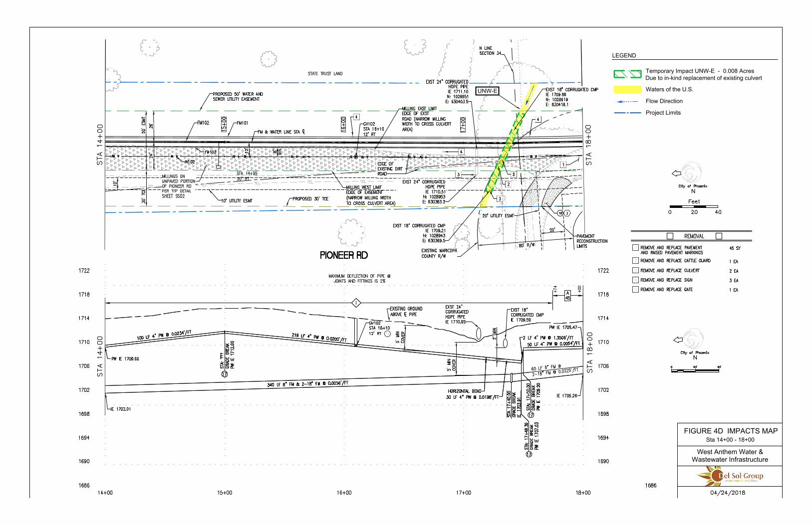
N
N
LEGEND
Flow Direction
Waters of the U.S.
FIGURE 4D IMPACTS MAP Sta 14+00 - 18+00
West Anthem Water &
Wastewater Infrastructure
Temporary Impact UNW-E - 0.008 Acres
Due to in-kind replacement of existing culvert
Project Limits
UNW-E

NATIONWIDE PERMIT NUMBER 12
UTILITY LINE ACTIVITIES
Enclosure 1(dated March 19, 2017) NWP 12– Utility Line Activities Page 1 of 11
US Army Corps of Engineers Los Angeles District
Regulatory Division/Arizona Branch
A. General Information
This document is an aid to understanding the terms and conditions of your nationwide permit (NWP) by bringing together information
issued separately in; (1) the Federal Register (82 FR 1860-2008)*, (2) the Special Public Notice for NWP "Reissuance of the Nationwide
Permits and Issuance of Final Regional Conditions for the Los Angeles District"*, and (3) the Clean Water Act Section 401 water quality
certification decisions (401 WQCs)* issued by the White Mountain Apache Tribe, Hopi Tribe, Hualapai Tribe, Navajo Nation, U.S.
Environmental Protection Agency, and Arizona Department of Environmental Quality. Please note that website addresses enclosed herein
may have been changed and updated since publication of the original document.
1) Pursuant to Section 404 of the Clean Water Act (33 U.S.C. 1344) and/or Section 10 of the Rivers and Harbors Act of 1899 (33
U.S.C. 401 et seq) the U.S. Army Corps of Engineers (Corps) published the "Issuance and Reissuance of Nationwide Permits" in
the Federal Register (82 FR 1860-2008) on January 6, 2017. These NWPs are in effect from March 19, 2017 through March 18,
2022 unless modified, reissued, or revoked before that time. It is incumbent upon the permittee to remain informed of changes to
the NWPs.
2) The Los Angeles District of the Corps issued a Special Public Notice (March 22, 2017) announcing final regional conditions for
NWPs to ensure protection of high value waters within the State of Arizona.
3) The Los Angeles District of the Corps requested and obtained for the entire State of Arizona the 401 WQC decision for all NWPs
on all tribal lands from the White Mountain Apache Tribe, Hopi Tribe, Hualapai Tribe, Navajo Nation, and U.S. Environmental
Protection Agency and on all non-tribal lands from the Arizona Department of Environmental Quality.
A description of all NWPs and 401 WQCs can be found in the "Nationwide Permits for Arizona" Special Public Notice.*
*Note: The Federal Register can be accessed at https://www.gpo.gov/fdsys/pkg/FR-2017-01-06/pdf/2016-31355.pdf
Key Sections: B. Nationwide Permit Terms (page 1) C. Nationwide Permit General Conditions (page 2)
D. District Engineer’s Decision (page 8) E. Nationwide Permit Regional Conditions (page 9)
F. 401 Water Quality Certifications (page 10)
B. Nationwide Permit Terms
12. Utility Line Activities. Activities required for the construction, maintenance, repair, and removal of utility lines and associated
facilities in waters of the United States, provided the activity does not result in the loss of greater than 1/2-acre of waters of the United States
for each single and complete project.
Utility lines: This NWP authorizes discharges of dredged or fill material into waters of the United States and structures or work in
navigable waters for crossings of those waters associated with the construction, maintenance, or repair of utility lines, including outfall and
intake structures. There must be no change in pre-construction contours of waters of the United States. A “utility line” is defined as any pipe
or pipeline for the transportation of any gaseous, liquid, liquescent, or slurry substance, for any purpose, and any cable, line, or wire for the
transmission for any purpose of electrical energy, telephone, and telegraph messages, and internet, radio, and television communication. The
term “utility line” does not include activities that drain a water of the United States, such as drainage tile or french drains, but it does apply to
pipes conveying drainage from another area.
Material resulting from trench excavation may be temporarily sidecast into waters of the United States for no more than three
months, provided the material is not placed in such a manner that it is dispersed by currents or other forces. The district engineer may extend
the period of temporary side casting for no more than a total of 180 days, where appropriate. In wetlands, the top 6 to 12 inches of the trench
should normally be backfilled with topsoil from the trench. The trench cannot be constructed or backfilled in such a manner as to drain
waters of the United States (e.g., backfilling with extensive gravel layers, creating a french drain effect). Any exposed slopes and stream
banks must be stabilized immediately upon completion of the utility line crossing of each waterbody.
Utility line substations: This NWP authorizes the construction, maintenance, or expansion of substation facilities associated with a
power line or utility line in non-tidal waters of the United States, provided the activity, in combination with all other activities included in one
single and complete project, does not result in the loss of greater than 1/2-acre of waters of the United States. This NWP does not authorize
discharges into non-tidal wetlands adjacent to tidal waters of the United States to construct, maintain, or expand substation facilities.
Foundations for overhead utility line towers, poles, and anchors: This NWP authorizes the construction or maintenance of
foundations for overhead utility line towers, poles, and anchors in all waters of the United States, provided the foundations are the minimum
size necessary and separate footings for each tower leg (rather than a larger single pad) are used where feasible.
Access roads: This NWP authorizes the construction of access roads for the construction and maintenance of utility lines,
including overhead power lines and utility line substations, in non-tidal waters of the United States, provided the activity, in combination

Enclosure 1(dated March 19, 2017) NWP 12– Utility Line Activities Page 2 of 11
with all other activities included in one single and complete project, does not cause the loss of greater than 1/2-acre of non-tidal waters of the
United States. This NWP does not authorize discharges into non-tidal wetlands adjacent to tidal waters for access roads. Access roads must
be the minimum width necessary (see Note 2, below). Access roads must be constructed so that the length of the road minimizes any adverse
effects on waters of the United States and must be as near as possible to pre-construction contours and elevations (e.g., at grade corduroy
roads or geotextile/gravel roads). Access roads constructed above pre-construction contours and elevations in waters of the United States
must be properly bridged or culverted to maintain surface flows.
This NWP may authorize utility lines in or affecting navigable waters of the United States even if there is no associated discharge
of dredged or fill material (See 33 CFR Part 322). Overhead utility lines constructed over section 10 waters and utility lines that are routed in
or under section 10 waters without a discharge of dredged or fill material require a section 10 permit.
This NWP authorizes, to the extent that Department of the Army authorization is required, temporary structures, fills, and work
necessary for the remediation of inadvertent returns of drilling fluids to waters of the United States through sub-soil fissures or fractures that
might occur during horizontal directional drilling activities conducted for the purpose of installing or replacing utility lines. These
remediation activities must be done as soon as practicable, to restore the affected waterbody. District engineers may add special conditions to
this NWP to require a remediation plan for addressing inadvertent returns of drilling fluids to waters of the United States during horizontal
directional drilling activities conducted for the purpose of installing or replacing utility lines.
This NWP also authorizes temporary structures, fills, and work, including the use of temporary mats, necessary to conduct the
utility line activity. Appropriate measures must be taken to maintain normal downstream flows and minimize flooding to the maximum
extent practicable, when temporary structures, work, and discharges, including cofferdams, are necessary for construction activities, access
fills, or dewatering of construction sites. Temporary fills must consist of materials, and be placed in a manner, that will not be eroded by
expected high flows. After construction, temporary fills must be removed in their entirety and the affected areas returned to pre-construction
elevations. The areas affected by temporary fills must be revegetated, as appropriate.
Notification: The permittee must submit a pre-construction notification to the district engineer prior to commencing the activity if
any of the following criteria are met: (1) the activity involves mechanized land clearing in a forested wetland for the utility line right-of-way;
(2) a section 10 permit is required; (3) the utility line in waters of the United States, excluding overhead lines, exceeds 500 feet; (4) the utility
line is placed within a jurisdictional area (i.e., water of the United States), and it runs parallel to or along a stream bed that is within that
jurisdictional area; (5) discharges that result in the loss of greater than 1/10-acre of waters of the United States; (6) permanent access roads
are constructed above grade in waters of the United States for a distance of more than 500 feet; or (7) permanent access roads are constructed
in waters of the United States with impervious materials. (See general condition 32.) (Authorities: Sections 10 and 404)
Note 1: Where the utility line is constructed or installed in navigable waters of the United States (i.e., section 10 waters) within the
coastal United States, the Great Lakes, and United States territories, a copy of the NWP verification will be sent by the Corps to the National
Oceanic and Atmospheric Administration (NOAA), National Ocean Service (NOS), for charting the utility line to protect navigation.
Note 2: For utility line activities crossing a single waterbody more than one time at separate and distinct locations, or multiple
waterbodies at separate and distinct locations, each crossing is considered a single and complete project for purposes of NWP authorization.
Utility line activities must comply with 33 CFR 330.6(d).
Note 3: Utility lines consisting of aerial electric power transmission lines crossing navigable waters of the United States (which are
defined at 33 CFR part 329) must comply with the applicable minimum clearances specified in 33 CFR 322.5(i).
Note 4: Access roads used for both construction and maintenance may be authorized, provided they meet the terms and conditions
of this NWP. Access roads used solely for construction of the utility line must be removed upon completion of the work, in accordance with
the requirements for temporary fills.
Note 5: Pipes or pipelines used to transport gaseous, liquid, liquescent, or slurry substances over navigable waters of the United
States are considered to be bridges, not utility lines, and may require a permit from the U.S. Coast Guard pursuant to Section 9 of the Rivers
and Harbors Act of 1899. However, any discharges of dredged or fill material into waters of the United States associated with such pipelines
will require a section 404 permit (see NWP 15).
Note 6: This NWP authorizes utility line maintenance and repair activities that do not qualify for the Clean Water Act section
404(f) exemption for maintenance of currently serviceable fills or fill structures.
Note 7: For overhead utility lines authorized by this NWP, a copy of the PCN and NWP verification will be provided to the
Department of Defense Siting Clearinghouse, which will evaluate potential effects on military activities.
Note 8: For NWP 12 activities that require pre-construction notification, the PCN must include any other NWP(s), regional general
permit(s), or individual permit(s) used or intended to be used to authorize any part of the proposed project or any related activity, including
other separate and distinct crossings that require Department of the Army authorization but do not require pre-construction notification (see
paragraph (b) of general condition 32). The district engineer will evaluate the PCN in accordance with Section D, “District Engineer’s
Decision.” The district engineer may require mitigation to ensure that the authorized activity results in no more than minimal individual and
cumulative adverse environmental effects (see general condition 23).
C. Nationwide Permit General Conditions
Note: To qualify for NWP authorization, the prospective permittee must comply with the following general conditions, as applicable, in
addition to any regional or case-specific conditions imposed by the division engineer or district engineer. Prospective permittees should
contact the appropriate Corps district office to determine if regional conditions have been imposed on an NWP. Prospective permittees
should also contact the appropriate Corps district office to determine the status of Clean Water Act Section 401 water quality certification
and/ or Coastal Zone Management Act consistency for a NWP. Every person who may wish to obtain permit authorization under one or more
NWPs, or who is currently relying on an existing or prior permit authorization under one or more NWPs, has been and is on notice that all of
the provisions of 33 CFR 330.1 through 330.6 apply to every NWP authorization. Note especially 33 CFR 330.5 relating to the modification,
suspension, or revocation of any NWP authorization.
1. Navigation. (a) No activity may cause more than a minimal adverse effect on navigation. (b) Any safety lights and signals prescribed
by the U.S. Coast Guard, through regulations or otherwise, must be installed and maintained at the permittee's expense on authorized
facilities in navigable waters of the United States. (c) The permittee understands and agrees that, if future operations by the United States
require the removal, relocation, or other alteration, of the structure or work herein authorized, or if, in the opinion of the Secretary of the

Enclosure 1(dated March 19, 2017) NWP 12– Utility Line Activities Page 3 of 11
Army or his authorized representative, said structure or work shall cause unreasonable obstruction to the free navigation of the navigable
waters, the permittee will be required, upon due notice from the Corps of Engineers, to remove, relocate, or alter the structural work or
obstructions caused thereby, without expense to the United States. No claim shall be made against the United States on account of any such
removal or alteration.
2. Aquatic Life Movements. No activity may substantially disrupt the necessary life cycle movements of those species of aquatic life
indigenous to the waterbody, including those species that normally migrate through the area, unless the activity's primary purpose is to
impound water. All permanent and temporary crossings of waterbodies shall be suitably culverted, bridged, or otherwise designed and
constructed to maintain low flows to sustain the movement of those aquatic species. If a bottomless culvert cannot be used, then the crossing
should be designed and constructed to minimize adverse effects to aquatic life movements.
3. Spawning Areas. Activities in spawning areas during spawning seasons must be avoided to the maximum extent practicable.
Activities that result in the physical destruction (e.g., through excavation, fill, or downstream smothering by substantial turbidity) of an
important spawning area are not authorized.
4. Migratory Bird Breeding Areas. Activities in waters of the United States that serve as breeding areas for migratory birds must be
avoided to the maximum extent practicable.
5. Shellfish Beds. No activity may occur in areas of concentrated shellfish populations, unless the activity is directly related to a
shellfish harvesting activity authorized by NWPs 4 and 48, or is a shellfish seeding or habitat restoration activity authorized by NWP 27.
6. Suitable Material. No activity may use unsuitable material (e.g., trash, debris, car bodies, asphalt, etc.). Material used for
construction or discharged must be free from toxic pollutants in toxic amounts (see Section 307 of the Clean Water Act).
7. Water Supply Intakes. No activity may occur in the proximity of a public water supply intake, except where the activity is for the
repair or improvement of public water supply intake structures or adjacent bank stabilization.
8. Adverse Effects from Impoundments. If the activity creates an impoundment of water, adverse effects to the aquatic system due to
accelerating the passage of water, and/or restricting its flow must be minimized to the maximum extent practicable.
9. Management of Water Flows. To the maximum extent practicable, the preconstruction course, condition, capacity, and location of
open waters must be maintained for each activity, including stream channelization, storm water management activities, and temporary and
permanent road crossings, except as provided below. The activity must be constructed to withstand expected high flows. The activity must
not restrict or impede the passage of normal or high flows, unless the primary purpose of the activity is to impound water or manage high
flows. The activity may alter the preconstruction course, condition, capacity, and location of open waters if it benefits the aquatic
environment (e.g., stream restoration or relocation activities).
10. Fills Within 100-Year Floodplains. The activity must comply with applicable FEMA-approved state or local floodplain
management requirements.
11. Equipment. Heavy equipment working in wetlands or mudflats must be placed on mats, or other measures must be taken to
minimize soil disturbance.
12. Soil Erosion and Sediment Controls. Appropriate soil erosion and sediment controls must be used and maintained in effective
operating condition during construction, and all exposed soil and other fills, as well as any work below the ordinary high water mark or high
tide line, must be permanently stabilized at the earliest practicable date. Permittees are encouraged to perform work within waters of the
United States during periods of low-flow or no-flow, or during low tides.
13. Removal of Temporary Fills. Temporary fills must be removed in their entirety and the affected areas returned to pre-construction
elevations. The affected areas must be revegetated, as appropriate.
14. Proper Maintenance. Any authorized structure or fill shall be properly maintained, including maintenance to ensure public safety
and compliance with applicable NWP general conditions, as well as any activity-specific conditions added by the district engineer to an NWP
authorization.
15. Single and Complete Project. The activity must be a single and complete project. The same NWP cannot be used more than once
for the same single and complete project.
16. Wild and Scenic Rivers. (a) No NWP activity may occur in a component of the National Wild and Scenic River System, or in a
river officially designated by Congress as a ‘‘study river’’ for possible inclusion in the system while the river is in an official study status,
unless the appropriate Federal agency with direct management responsibility for such river, has determined in writing that the proposed
activity will not adversely affect the Wild and Scenic River designation or study status. (b) If a proposed NWP activity will occur in a
component of the National Wild and Scenic River System, or in a river officially designated by Congress as a ‘‘study river’’ for possible
inclusion in the system while the river is in an official study status, the permittee must submit a pre-construction notification (see general
condition 32). The district engineer will coordinate the PCN with the Federal agency with direct management responsibility for that river.
The permittee shall not begin the NWP activity until notified by the district engineer that the Federal agency with direct management
responsibility for that river has determined in writing that the proposed NWP activity will not adversely affect the Wild and Scenic River
designation or study status. (c) Information on Wild and Scenic Rivers may be obtained from the appropriate Federal land management
agency responsible for the designated Wild and Scenic River or study river (e.g., National Park Service, U.S. Forest Service, Bureau of Land
Management, U.S. Fish and Wildlife Service). Information on these rivers is also available at: http://www.rivers.gov/.
17. Tribal Rights. No NWP activity may cause more than minimal adverse effects on tribal rights (including treaty rights), protected
tribal resources, or tribal lands.
18. Endangered Species. (a) No activity is authorized under any NWP which is likely to directly or indirectly jeopardize the continued
existence of a threatened or endangered species or a species proposed for such designation, as identified under the Federal Endangered
Species Act (ESA), or which will directly or indirectly destroy or adversely modify the critical habitat of such species. No activity is
authorized under any NWP which “may affect” a listed species or critical habitat, unless ESA section 7 consultation addressing the effects of
the proposed activity has been completed. Direct effects are the immediate effects on listed species and critical habitat caused by the NWP
activity. Indirect effects are those effects on listed species and critical habitat that are caused by the NWP activity and are later in time, but
still are reasonably certain to occur. (b) Federal agencies should follow their own procedures for complying with the requirements of the
ESA. If pre-construction notification is required for the proposed activity, the Federal permittee must provide the district engineer with the
appropriate documentation to demonstrate compliance with those requirements. The district engineer will verify that the appropriate
documentation has been submitted. If the appropriate documentation has not been submitted, additional ESA section 7 consultation may be
necessary for the activity and the respective federal agency would be responsible for fulfilling its obligation under section 7 of the ESA. (c)

Enclosure 1(dated March 19, 2017) NWP 12– Utility Line Activities Page 4 of 11
Non-federal permittees must submit a pre-construction notification to the district engineer if any listed species or designated critical habitat
might be affected or is in the vicinity of the activity, or if the activity is located in designated critical habitat, and shall not begin work on the
activity until notified by the district engineer that the requirements of the ESA have been satisfied and that the activity is authorized. For
activities that might affect Federally-listed endangered or threatened species or designated critical habitat, the pre-construction notification
must include the name(s) of the endangered or threatened species that might be affected by the proposed activity or that utilize the designated
critical habitat that might be affected by the proposed activity. The district engineer will determine whether the proposed activity “may
affect” or will have “no effect” to listed species and designated critical habitat and will notify the non-Federal applicant of the Corps’
determination within 45 days of receipt of a complete pre-construction notification. In cases where the non-Federal applicant has identified
listed species or critical habitat that might be affected or is in the vicinity of the activity, and has so notified the Corps, the applicant shall not
begin work until the Corps has provided notification that the proposed activity will have “no effect” on listed species or critical habitat, or
until ESA section 7 consultation has been completed. If the non-Federal applicant has not heard back from the Corps within 45 days, the
applicant must still wait for notification from the Corps. (d) As a result of formal or informal consultation with the FWS or NMFS the district
engineer may add species-specific permit conditions to the NWPs. (e) Authorization of an activity by an NWP does not authorize the “take”
of a threatened or endangered species as defined under the ESA. In the absence of separate authorization (e.g., an ESA Section 10 Permit, a
Biological Opinion with “incidental take” provisions, etc.) from the FWS or the NMFS, the Endangered Species Act prohibits any person
subject to the jurisdiction of the United States to take a listed species, where "take" means to harass, harm, pursue, hunt, shoot, wound, kill,
trap, capture, or collect, or to attempt to engage in any such conduct. The word “harm” in the definition of “take'' means an act which actually
kills or injures wildlife. Such an act may include significant habitat modification or degradation where it actually kills or injures wildlife by
significantly impairing essential behavioral patterns, including breeding, feeding or sheltering. (f) If the non-federal permittee has a valid
ESA section 10(a)(1)(B) incidental take permit with an approved Habitat Conservation Plan for a project or a group of projects that includes
the proposed NWP activity, the non-federal applicant should provide a copy of that ESA section 10(a)(1)(B) permit with the PCN required by
paragraph (c) of this general condition. The district engineer will coordinate with the agency that issued the ESA section 10(a)(1)(B) permit
to determine whether the proposed NWP activity and the associated incidental take were considered in the internal ESA section 7
consultation conducted for the ESA section 10(a)(1)(B) permit. If that coordination results in concurrence from the agency that the proposed
NWP activity and the associated incidental take were considered in the internal ESA section 7 consultation for the ESA section 10(a)(1)(B)
permit, the district engineer does not need to conduct a separate ESA section 7 consultation for the proposed NWP activity. The district
engineer will notify the non-federal applicant within 45 days of receipt of a complete pre-construction notification whether the ESA section
10(a)(1)(B) permit covers the proposed NWP activity or whether additional ESA section 7 consultation is required. (g) Information on the
location of threatened and endangered species and their critical habitat can be obtained directly from the offices of the FWS and NMFS or
their World Wide Web pages at http://www.fws.gov/ or http://www.fws.gov/ipac and http://www.nmfs.noaa.gov/pr/species/esa/ respectively.
(Note: Arizona endangered species information is available at http://www.fws.gov/southwest/es/arizona/Threatened.htm#CountyList)
19. Migratory Birds and Bald and Golden Eagles. The permittee is responsible for ensuring their action complies with the Migratory
Bird Treaty Act and the Bald and Golden Eagle Protection Act. The permittee is responsible for contacting appropriate local office of the
U.S. Fish and Wildlife Service to determine applicable measures to reduce impacts to migratory birds or eagles, including whether
“incidental take” permits are necessary and available under the Migratory Bird Treaty Act or Bald and Golden Eagle Protection Act for a
particular activity.
20. Historic Properties. (a) In cases where the district engineer determines that the activity may have the potential to cause effects to
properties listed, or eligible for listing, in the National Register of Historic Places, the activity is not authorized, until the requirements of
Section 106 of the National Historic Preservation Act (NHPA) have been satisfied. (b) Federal permittees should follow their own procedures
for complying with the requirements of section 106 of the National Historic Preservation Act. If pre-construction notification is required for
the proposed NWP activity, the Federal permittee must provide the district engineer with the appropriate documentation to demonstrate
compliance with those requirements. The district engineer will verify that the appropriate documentation has been submitted. If the
appropriate documentation is not submitted, then additional consultation under section 106 may be necessary. The respective federal agency
is responsible for fulfilling its obligation to comply with section 106. (c) Non-federal permittees must submit a pre-construction notification
to the district engineer if the NWP activity might have the potential to cause effects to any historic properties listed on, determined to be
eligible for listing on, or potentially eligible for listing on the National Register of Historic Places, including previously unidentified
properties. For such activities, the pre-construction notification must state which historic properties might have the potential to be affected
by the proposed NWP activity or include a vicinity map indicating the location of the historic properties or the potential for the presence of
historic properties. Assistance regarding information on the location of, or potential for, the presence of historic properties can be sought
from the State Historic Preservation Officer, Tribal Historic Preservation Officer, or designated tribal representative, as appropriate, and the
National Register of Historic Places (see 33 CFR 330.4(g)). When reviewing pre-construction notifications, district engineers will comply
with the current procedures for addressing the requirements of section 106 of the National Historic Preservation Act. The district engineer
shall make a reasonable and good faith effort to carry out appropriate identification efforts, which may include background research,
consultation, oral history interviews, sample field investigation, and field survey. Based on the information submitted in the PCN and these
identification efforts, the district engineer shall determine whether the proposed NWP activity has the potential to cause effects on the historic
properties. Section 106 consultation is not required when the district engineer determines that the activity does not have the potential to cause
effects on historic properties (see 36 CFR 800.3(a)). Section 106 consultation is required when the district engineer determines that the
activity has the potential to cause effects on historic properties. The district engineer will conduct consultation with consulting parties
identified under 36 CFR 800.2(c) when he or she makes any of the following effect determinations for the purposes of section 106 of the
NHPA: no historic properties affected, no adverse effect, or adverse effect. Where the non-Federal applicant has identified historic properties
on which the activity might have the potential to cause effects and so notified the Corps, the non-Federal applicant shall not begin the activity
until notified by the district engineer either that the activity has no potential to cause effects to historic properties or that NHPA section 106
consultation has been completed. (d) For non-federal permittees, the district engineer will notify the prospective permittee within 45 days of
receipt of a complete pre-construction notification whether NHPA section 106 consultation is required. If NHPA section 106 consultation is
required, the district engineer will notify the non-Federal applicant that he or she cannot begin the activity until section 106 consultation is
completed. If the non-Federal applicant has not heard back from the Corps within 45 days, the applicant must still wait for notification from
the Corps. (e) Prospective permittees should be aware that section 110k of the NHPA (54 U.S.C. 306113) prevents the Corps from granting a
permit or other assistance to an applicant who, with intent to avoid the requirements of section 106 of the NHPA, has intentionally

Enclosure 1(dated March 19, 2017) NWP 12– Utility Line Activities Page 5 of 11
significantly adversely affected a historic property to which the permit would relate, or having legal power to prevent it, allowed such
significant adverse effect to occur, unless the Corps, after consultation with the Advisory Council on Historic Preservation (ACHP),
determines that circumstances justify granting such assistance despite the adverse effect created or permitted by the applicant. If
circumstances justify granting the assistance, the Corps is required to notify the ACHP and provide documentation specifying the
circumstances, the degree of damage to the integrity of any historic properties affected, and proposed mitigation. This documentation must
include any views obtained from the applicant, SHPO/THPO, appropriate Indian tribes if the undertaking occurs on or affects historic
properties on tribal lands or affects properties of interest to those tribes, and other parties known to have a legitimate interest in the impacts to
the permitted activity on historic properties.
21. Discovery of Previously Unknown Remains and Artifacts. . If you discover any previously unknown historic, cultural or
archeological remains and artifacts while accomplishing the activity authorized by this permit, you must immediately notify the district
engineer of what you have found, and to the maximum extent practicable, avoid construction activities that may affect the remains and
artifacts until the required coordination has been completed. The district engineer will initiate the Federal, Tribal, and state coordination
required to determine if the items or remains warrant a recovery effort or if the site is eligible for listing in the National Register of Historic
Places.
22. Designated Critical Resource Waters. Critical resource waters include, NOAA-managed marine sanctuaries and marine
monuments, and National Estuarine Research Reserves. The district engineer may designate, after notice and opportunity for public
comment, additional waters officially designated by a state as having particular environmental or ecological significance, such as outstanding
national resource waters or state natural heritage sites. The district engineer may also designate additional critical resource waters after notice
and opportunity for public comment. (a) Discharges of dredged or fill material into waters of the United States are not authorized by NWPs
7, 12, 14, 16, 17, 21, 29, 31, 35, 39, 40, 42, 43, 44, 49, 50, 51, and 52 for any activity within, or directly affecting, critical resource waters,
including wetlands adjacent to such waters. (b) For NWPs 3, 8, 10, 13, 15, 18, 19, 22, 23, 25, 27, 28, 30, 33, 34, 36, 37, 38, and 54,
notification is required in accordance with general condition 32, for any activity proposed in the designated critical resource waters including
wetlands adjacent to those waters. The district engineer may authorize activities under these NWPs only after it is determined that the
impacts to the critical resource waters will be no more than minimal.
23. Mitigation. The district engineer will consider the following factors when determining appropriate and practicable mitigation
necessary to ensure that the individual and cumulative adverse environmental effects are no more than minimal: (a) The activity must be
designed and constructed to avoid and minimize adverse effects, both temporary and permanent, to waters of the United States to the
maximum extent practicable at the project site (i.e., on site). (b) Mitigation in all its forms (avoiding, minimizing, rectifying, reducing, or
compensating for resource losses) will be required to the extent necessary to ensure that the individual and cumulative adverse environmental
effects are no more than minimal. (c) Compensatory mitigation at a minimum one-for-one ratio will be required for all wetland losses that
exceed 1/10-acre and require pre-construction notification, unless the district engineer determines in writing that either some other form of
mitigation would be more environmentally appropriate or the adverse environmental effects of the proposed activity are no more than
minimal, and provides an activity-specific waiver of this requirement. For wetland losses of 1/10-acre or less that require pre-construction
notification, the district engineer may determine on a case-by-case basis that compensatory mitigation is required to ensure that the activity
results in only minimal adverse environmental effects. (d) For losses of streams or other open waters that require pre-construction
notification, the district engineer may require compensatory mitigation to ensure that the activity results in no more than minimal adverse
environmental effects. Compensatory mitigation for losses of streams should be provided, if practicable, through stream rehabilitation,
enhancement, or preservation, since streams are difficult-to-replace resources (see 33 CFR 332.3(e)(3)). (e) Compensatory mitigation plans
for NWP activities in or near streams or other open waters will normally include a requirement for the restoration or enhancement,
maintenance, and legal protection (e.g., conservation easements) of riparian areas next to open waters. In some cases, the restoration or
maintenance/protection of riparian areas may be the only compensatory mitigation required. Restored riparian areas should consist of native
species. The width of the required riparian area will address documented water quality or aquatic habitat loss concerns. Normally, the riparian
area will be 25 to 50 feet wide on each side of the stream, but the district engineer may require slightly wider riparian areas to address
documented water quality or habitat loss concerns. If it is not possible to restore or maintain/protect a riparian area on both sides of a stream,
or if the waterbody is a lake or coastal waters, then restoring or maintaining/protecting a riparian area along a single bank or shoreline may be
sufficient. Where both wetlands and open waters exist on the project site, the district engineer will determine the appropriate compensatory
mitigation (e.g., riparian areas and/or wetlands compensation) based on what is best for the aquatic environment on a watershed basis. In
cases where riparian areas are determined to be the most appropriate form of minimization or compensatory mitigation, the district engineer
may waive or reduce the requirement to provide wetland compensatory mitigation for wetland losses. (f) Compensatory mitigation projects
provided to offset losses of aquatic resources must comply with the applicable provisions of 33 CFR part 332. (1) The prospective permittee
is responsible for proposing an appropriate compensatory mitigation option if compensatory mitigation is necessary to ensure that the activity
results in no more than minimal adverse environmental effects. For the NWPs, the preferred mechanism for providing compensatory
mitigation is mitigation bank credits or in-lieu fee program credits (see 33 CFR 332.3(b)(2) and (3)). However, if an appropriate number and
type of mitigation bank or in-lieu credits are not available at the time the PCN is submitted to the district engineer, the district engineer may
approve the use of permittee-responsible mitigation. (2) The amount of compensatory mitigation required by the district engineer must be
sufficient to ensure that the authorized activity results in no more than minimal individual and cumulative adverse environmental effects (see
33 CFR 330.1(e)(3)). (See also 33 CFR 332.3(f)). (3) Since the likelihood of success is greater and the impacts to potentially valuable
uplands are reduced, aquatic resource restoration should be the first compensatory mitigation option considered for permittee-responsible
mitigation. (4) If permittee-responsible mitigation is the proposed option, the prospective permittee is responsible for submitting a mitigation
plan. A conceptual or detailed mitigation plan may be used by the district engineer to make the decision on the NWP verification request, but
a final mitigation plan that addresses the applicable requirements of 33 CFR 332.4(c)(2) through (14) must be approved by the district
engineer before the permittee begins work in waters of the United States, unless the district engineer determines that prior approval of the
final mitigation plan is not practicable or not necessary to ensure timely completion of the required compensatory mitigation (see 33 CFR
332.3(k)(3)). (5) If mitigation bank or in-lieu fee program credits are the proposed option, the mitigation plan only needs to address the
baseline conditions at the impact site and the number of credits to be provided.(6) Compensatory mitigation requirements (e.g., resource type
and amount to be provided as compensatory mitigation, site protection, ecological performance standards, monitoring requirements) may be
addressed through conditions added to the NWP authorization, instead of components of a compensatory mitigation plan (see 33 CFR
332.4(c)(1)(ii)). (g) Compensatory mitigation will not be used to increase the acreage losses allowed by the acreage limits of the NWPs. For
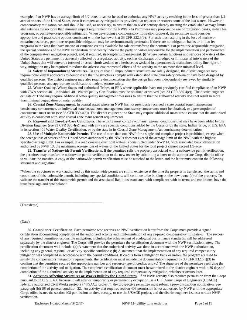
Enclosure 1(dated March 19, 2017) NWP 12– Utility Line Activities Page 6 of 11
example, if an NWP has an acreage limit of 1/2-acre, it cannot be used to authorize any NWP activity resulting in the loss of greater than 1/2-
acre of waters of the United States, even if compensatory mitigation is provided that replaces or restores some of the lost waters. However,
compensatory mitigation can and should be used, as necessary, to ensure that an NWP activity already meeting the established acreage limits
also satisfies the no more than minimal impact requirement for the NWPs. (h) Permittees may propose the use of mitigation banks, in-lieu fee
programs, or permittee-responsible mitigation. When developing a compensatory mitigation proposal, the permittee must consider
appropriate and practicable options consistent with the framework at 33 CFR 332.3(b). For activities resulting in the loss of marine or
estuarine resources, permittee-responsible mitigation may be environmentally preferable if there are no mitigation banks or in-lieu fee
programs in the area that have marine or estuarine credits available for sale or transfer to the permittee. For permittee-responsible mitigation,
the special conditions of the NWP verification must clearly indicate the party or parties responsible for the implementation and performance
of the compensatory mitigation project, and, if required, its long-term management. (i) Where certain functions and services of waters of the
United States are permanently adversely affected by a regulated activity, such as discharges of dredged or fill material into waters of the
United States that will convert a forested or scrub-shrub wetland to a herbaceous wetland in a permanently maintained utility line right-of-
way, mitigation may be required to reduce the adverse environmental effects of the activity to the no more than minimal level.
24. Safety of Impoundment Structures. To ensure that all impoundment structures are safely designed, the district engineer may
require non-Federal applicants to demonstrate that the structures comply with established state dam safety criteria or have been designed by
qualified persons. The district engineer may also require documentation that the design has been independently reviewed by similarly
qualified persons, and appropriate modifications made to ensure safety.
25. Water Quality. Where States and authorized Tribes, or EPA where applicable, have not previously certified compliance of an NWP
with CWA section 401, individual 401 Water Quality Certification must be obtained or waived (see 33 CFR 330.4(c)). The district engineer
or State or Tribe may require additional water quality management measures to ensure that the authorized activity does not result in more
than minimal degradation of water quality.
26. Coastal Zone Management. In coastal states where an NWP has not previously received a state coastal zone management
consistency concurrence, an individual state coastal zone management consistency concurrence must be obtained, or a presumption of
concurrence must occur (see 33 CFR 330.4(d)). The district engineer or a State may require additional measures to ensure that the authorized
activity is consistent with state coastal zone management requirements.
27. Regional and Case-By-Case Conditions. The activity must comply with any regional conditions that may have been added by the
Division Engineer (see 33 CFR 330.4(e)) and with any case specific conditions added by the Corps or by the state, Indian Tribe, or U.S. EPA
in its section 401 Water Quality Certification, or by the state in its Coastal Zone Management Act consistency determination.
28. Use of Multiple Nationwide Permits. The use of more than one NWP for a single and complete project is prohibited, except when
the acreage loss of waters of the United States authorized by the NWPs does not exceed the acreage limit of the NWP with the highest
specified acreage limit. For example, if a road crossing over tidal waters is constructed under NWP 14, with associated bank stabilization
authorized by NWP 13, the maximum acreage loss of waters of the United States for the total project cannot exceed 1/3-acre.
29. Transfer of Nationwide Permit Verifications. If the permittee sells the property associated with a nationwide permit verification,
the permittee may transfer the nationwide permit verification to the new owner by submitting a letter to the appropriate Corps district office
to validate the transfer. A copy of the nationwide permit verification must be attached to the letter, and the letter must contain the following
statement and signature:
“When the structures or work authorized by this nationwide permit are still in existence at the time the property is transferred, the terms and
conditions of this nationwide permit, including any special conditions, will continue to be binding on the new owner(s) of the property. To
validate the transfer of this nationwide permit and the associated liabilities associated with compliance with its terms and conditions, have the
transferee sign and date below.”
_____________________________________________
(Transferee)
_____________________________________________
(Date)
30. Compliance Certification. Each permittee who receives an NWP verification letter from the Corps must provide a signed
certification documenting completion of the authorized activity and implementation of any required compensatory mitigation. The success
of any required permittee-responsible mitigation, including the achievement of ecological performance standards, will be addressed
separately by the district engineer. The Corps will provide the permittee the certification document with the NWP verification letter. The
certification document will include: (a) A statement that the authorized activity was done in accordance with the NWP authorization,
including any general, regional, or activity-specific conditions; (b) A statement that the implementation of any required compensatory
mitigation was completed in accordance with the permit conditions. If credits from a mitigation bank or in-lieu fee program are used to
satisfy the compensatory mitigation requirements, the certification must include the documentation required by 33 CFR 332.3(l)(3) to
confirm that the permittee secured the appropriate number and resource type of credits; and (c) The signature of the permittee certifying the
completion of the activity and mitigation. The completed certification document must be submitted to the district engineer within 30 days of
completion of the authorized activity or the implementation of any required compensatory mitigation, whichever occurs later. 31. Activities Affecting Structures or Works Built by the United States. If an NWP activity also requires permission from the Corps
pursuant to 33 U.S.C. 408 because it will alter or temporarily or permanently occupy or use a U.S. Army Corps of Engineers (USACE)
federally authorized Civil Works project (a “USACE project”), the prospective permittee must submit a pre-construction notification. See
paragraph (b)(10) of general condition 32. An activity that requires section 408 permission is not authorized by NWP until the appropriate
Corps office issues the section 408 permission to alter, occupy, or use the USACE project, and the district engineer issues a written NWP
verification.

Enclosure 1(dated March 19, 2017) NWP 12– Utility Line Activities Page 7 of 11
32. Pre-Construction Notification. (a) Timing: Where required by the terms of the NWP, the prospective permittee must notify the
district engineer by submitting a pre-construction notification (PCN) as early as possible. The district engineer must determine if the PCN is
complete within 30 calendar days of the date of receipt and, if the PCN is determined to be incomplete, notify the prospective permittee
within that 30 day period to request the additional information necessary to make the PCN complete. The request must specify the
information needed to make the PCN complete. As a general rule, district engineers will request additional information necessary to make the
PCN complete only once. However, if the prospective permittee does not provide all of the requested information, then the district engineer
will notify the prospective permittee that the PCN is still incomplete and the PCN review process will not commence until all of the requested
information has been received by the district engineer. The prospective permittee shall not begin the activity until either: (1) He or she is
notified in writing by the district engineer that the activity may proceed under the NWP with any special conditions imposed by the district or
division engineer; or (2) 45 calendar days have passed from the district engineer’s receipt of the complete PCN and the prospective permittee
has not received written notice from the district or division engineer. However, if the permittee was required to notify the Corps pursuant to
general condition 18 that listed species or critical habitat might be affected or are in the vicinity of the activity, or to notify the Corps
pursuant to general condition 20 that the activity might have the potential to cause effects to historic properties, the permittee cannot begin
the activity until receiving written notification from the Corps that there is “no effect” on listed species or “no potential to cause effects” on
historic properties, or that any consultation required under Section 7 of the Endangered Species Act (see 33 CFR 330.4(f)) and/or section 106
of the National Historic Preservation Act (see 33 CFR 330.4(g)) has been completed. Also, work cannot begin under NWPs 21, 49, or 50
until the permittee has received written approval from the Corps. If the proposed activity requires a written waiver to exceed specified limits
of an NWP, the permittee may not begin the activity until the district engineer issues the waiver. If the district or division engineer notifies
the permittee in writing that an individual permit is required within 45 calendar days of receipt of a complete PCN, the permittee cannot
begin the activity until an individual permit has been obtained. Subsequently, the permittee’s right to proceed under the NWP may be
modified, suspended, or revoked only in accordance with the procedure set forth in 33 CFR 330.5(d)(2). (b) Contents of Pre-Construction
Notification: The PCN must be in writing and include the following information: (1) Name, address and telephone numbers of the
prospective permittee; (2) Location of the proposed activity; (3) Identify the specific NWP or NWP(s) the prospective permittee wants to use
to authorize the proposed activity; (4) A description of the proposed activity; the activity’s purpose; direct and indirect adverse environmental
effects the activity would cause, including the anticipated amount of loss of wetlands, other special aquatic sites, and other waters expected to
result from the NWP activity, in acres, linear feet, or other appropriate unit of measure; a description of any proposed mitigation measures
intended to reduce the adverse environmental effects caused by the proposed activity; and any other NWP(s), regional general permit(s), or
individual permit(s) used or intended to be used to authorize any part of the proposed project or any related activity, including other separate
and distant crossings for linear projects that require Department of the Army authorization but do not require pre-construction notification.
The description of the proposed activity and any proposed mitigation measures should be sufficiently detailed to allow the district engineer to
determine that the adverse environmental effects of the activity will be no more than minimal and to determine the need for compensatory
mitigation or other mitigation measures. For single and complete linear projects, the PCN must include the quantity of anticipated losses of
wetlands, other special aquatic sites, and other waters for each single and complete crossing of those wetlands, other special aquatic sites, and
other waters. Sketches should be provided when necessary to show that the activity complies with the terms of the NWP. (Sketches usually
clarify the activity and when provided results in a quicker decision. Sketches should contain sufficient detail to provide an illustrative
description of the proposed activity (e.g., a conceptual plan), but do not need to be detailed engineering plans); (5) The PCN must include a
delineation of wetlands, other special aquatic sites, and other waters, such as lakes and ponds, and perennial, intermittent, and ephemeral
streams, on the project site. Wetland delineations must be prepared in accordance with the current method required by the Corps. The
permittee may ask the Corps to delineate the special aquatic sites and other waters on the project site, but there may be a delay if the Corps
does the delineation, especially if the project site is large or contains many wetlands, other special aquatic sites, and other waters.
Furthermore, the 45 day period will not start until the delineation has been submitted to or completed by the Corps, as appropriate;(6) If the
proposed activity will result in the loss of greater than 1/10-acre of wetlands and a PCN is required, the prospective permittee must submit a
statement describing how the mitigation requirement will be satisfied, or explaining why the adverse environmental effects are no more than
minimal and why compensatory mitigation should not be required. As an alternative, the prospective permittee may submit a conceptual or
detailed mitigation plan. (7) For non-Federal permittees, if any listed species or designated critical habitat might be affected or is in the
vicinity of the activity, or if the activity is located in designated critical habitat, the PCN must include the name(s) of those endangered or
threatened species that might be affected by the proposed activity or utilize the designated critical habitat that might be affected by the
proposed activity. For NWP activities that require pre-construction notification, Federal permittees must provide documentation
demonstrating compliance with the Endangered Species Act; (8) For non-Federal permittees, if the NWP activity might have the potential to
cause effects to a historic property listed on, determined to be eligible for listing on, or potentially eligible for listing on, the National
Register of Historic Places, the PCN must state which historic property might have the potential to be affected by the proposed activity or
include a vicinity map indicating the location of the historic property. For NWP activities that require pre-construction notification, Federal
permittees must provide documentation demonstrating compliance with section 106 of the National Historic Preservation Act; (9) For an
activity that will occur in a component of the National Wild and Scenic River System, or in a river officially designated by Congress as a
“study river” for possible inclusion in the system while the river is in an official study status, the PCN must identify the Wild and Scenic
River or the “study river” (see general condition 16); and (10) For an activity that requires permission from the Corps pursuant to 33 U.S.C.
408 because it will alter or temporarily or permanently occupy or use a U.S. Army Corps of Engineers federally authorized civil works
project, the pre-construction notification must include a statement confirming that the project proponent has submitted a written request for
section 408 permission from the Corps office having jurisdiction over that USACE project. (c) Form of Pre-Construction Notification: The
standard individual permit application form (Form ENG 4345) may be used, but the completed application form must clearly indicate that it
is an NWP PCN and must include all of the applicable information required in paragraphs (b)(1) through (10) of this general condition. A
letter containing the required information may also be used. Applicants may provide electronic files of PCNs and supporting materials if the
district engineer has established tools and procedures for electronic submittals. (d) Agency Coordination: (1) The district engineer will
consider any comments from Federal and state agencies concerning the proposed activity’s compliance with the terms and conditions of the
NWPs and the need for mitigation to reduce the activity’s adverse environmental effects so that they are no more than minimal. (2) Agency
coordination is required for: (i) all NWP activities that require pre-construction notification and result in the loss of greater than 1/2-acre of
waters of the United States; (ii) NWP 21, 29, 39, 40, 42, 43, 44, 50, 51, and 52 activities that require pre-construction notification and will
result in the loss of greater than 300 linear feet of stream bed; (iii) NWP 13 activities in excess of 500 linear feet, fills greater than one cubic

Enclosure 1(dated March 19, 2017) NWP 12– Utility Line Activities Page 8 of 11
yard per running foot, or involve discharges of dredged or fill material into special aquatic sites; and (iv) NWP 54 activities in excess of 500
linear feet, or that extend into the waterbody more than 30 feet from the mean low water line in tidal waters or the ordinary high water mark
in the Great Lakes. (3) When agency coordination is required, the district engineer will immediately provide (e.g., via e-mail, facsimile
transmission, overnight mail, or other expeditious manner) a copy of the complete PCN to the appropriate Federal or state offices (FWS, state
natural resource or water quality agency, EPA, and, if appropriate, the NMFS). With the exception of NWP 37, these agencies will have 10
calendar days from the date the material is transmitted to notify the district engineer via telephone, facsimile transmission, or e-mail that they
intend to provide substantive, site-specific comments. The comments must explain why the agency believes the adverse environmental
effects will be more than minimal. If so contacted by an agency, the district engineer will wait an additional 15 calendar days before making
a decision on the pre-construction notification. The district engineer will fully consider agency comments received within the specified time
frame concerning the proposed activity’s compliance with the terms and conditions of the NWPs, including the need for mitigation to ensure
the net adverse environmental effects of the proposed activity are no more than minimal. The district engineer will provide no response to the
resource agency, except as provided below. The district engineer will indicate in the administrative record associated with each pre-
construction notification that the resource agencies’ concerns were considered. For NWP 37, the emergency watershed protection and
rehabilitation activity may proceed immediately in cases where there is an unacceptable hazard to life or a significant loss of property or
economic hardship will occur. The district engineer will consider any comments received to decide whether the NWP 37 authorization should
be modified, suspended, or revoked in accordance with the procedures at 33 CFR 330.5. (4) In cases of where the prospective permittee is not
a Federal agency, the district engineer will provide a response to NMFS within 30 calendar days of receipt of any Essential Fish Habitat
conservation recommendations, as required by section 305(b)(4)(B) of the Magnuson-Stevens Fishery Conservation and Management Act.
(5) Applicants are encouraged to provide the Corps with either electronic files or multiple copies of pre-construction notifications to expedite
agency coordination.
D. District Engineer’s Decision
1. In reviewing the PCN for the proposed activity, the district engineer will determine whether the activity authorized by the NWP will
result in more than minimal individual or cumulative adverse environmental effects or may be contrary to the public interest. If a project
proponent requests authorization by a specific NWP, the district engineer should issue the NWP verification for that activity if it meets the
terms and conditions of that NWP, unless he or she determines, after considering mitigation, that the proposed activity will result in more
than minimal individual and cumulative adverse effects on the aquatic environment and other aspects of the public interest and exercises
discretionary authority to require an individual permit for the proposed activity. For a linear project, this determination will include an
evaluation of the individual crossings of waters of the United States to determine whether they individually satisfy the terms and conditions
of the NWP(s), as well as the cumulative effects caused by all of the crossings authorized by NWP. If an applicant requests a waiver of the
300 linear foot limit on impacts to streams or of an otherwise applicable limit, as provided for in NWPs 13, 21, 29, 36, 39, 40, 42, 43, 44, 50,
51, 52, or 54, the district engineer will only grant the waiver upon a written determination that the NWP activity will result in only minimal
individual and cumulative adverse environmental effects. For those NWPs that have a waivable 300 linear foot limit for losses of
intermittent and ephemeral stream bed and a 1/2-acre limit (i.e., NWPs 21, 29, 39, 40, 42, 43, 44, 50, 51, and 52), the loss of intermittent and
ephemeral stream bed, plus any other losses of jurisdictional waters and wetlands, cannot exceed 1/2-acre.
2. When making minimal adverse environmental effects determinations the district engineer will consider the direct and indirect effects
caused by the NWP activity. He or she will also consider the cumulative adverse environmental effects caused by activities authorized by
NWP and whether those cumulative adverse environmental effects are no more than minimal. The district engineer will also consider site
specific factors, such as the environmental setting in the vicinity of the NWP activity, the type of resource that will be affected by the NWP
activity, the functions provided by the aquatic resources that will be affected by the NWP activity, the degree or magnitude to which the
aquatic resources perform those functions, the extent that aquatic resource functions will be lost as a result of the NWP activity (e.g., partial
or complete loss), the duration of the adverse effects (temporary or permanent), the importance of the aquatic resource functions to the region
(e.g., watershed or ecoregion), and mitigation required by the district engineer. If an appropriate functional or condition assessment method is
available and practicable to use, that assessment method may be used by the district engineer to assist in the minimal adverse environmental
effects determination. The district engineer may add case-specific special conditions to the NWP authorization to address site-specific
environmental concerns.
3. If the proposed activity requires a PCN and will result in a loss of greater than 1/10-acre of wetlands, the prospective permittee should
submit a mitigation proposal with the PCN. Applicants may also propose compensatory mitigation for NWP activities with smaller impacts,
or for impacts to other types of waters (e.g., streams). The district engineer will consider any proposed compensatory mitigation or other
mitigation measures the applicant has included in the proposal in determining whether the net adverse environmental effects of the proposed
activity are no more than minimal. The compensatory mitigation proposal may be either conceptual or detailed. If the district engineer
determines that the activity complies with the terms and conditions of the NWP and that the adverse environmental effects are no more than
minimal, after considering mitigation, the district engineer will notify the permittee and include any activity-specific conditions in the NWP
verification the district engineer deems necessary. Conditions for compensatory mitigation requirements must comply with the appropriate
provisions at 33 CFR 332.3(k). The district engineer must approve the final mitigation plan before the permittee commences work in waters
of the United States, unless the district engineer determines that prior approval of the final mitigation plan is not practicable or not necessary
to ensure timely completion of the required compensatory mitigation. If the prospective permittee elects to submit a compensatory mitigation
plan with the PCN, the district engineer will expeditiously review the proposed compensatory mitigation plan. The district engineer must
review the proposed compensatory mitigation plan within 45 calendar days of receiving a complete PCN and determine whether the proposed
mitigation would ensure the NWP activity results in no more than minimal adverse environmental effects. If the net adverse environmental
effects of the NWP activity (after consideration of the mitigation proposal) are determined by the district engineer to be no more than
minimal, the district engineer will provide a timely written response to the applicant. The response will state that the NWP activity can
proceed under the terms and conditions of the NWP, including any activity-specific conditions added to the NWP authorization by the district
engineer.
4. If the district engineer determines that the adverse environmental effects of the proposed activity are more than minimal, then the
district engineer will notify the applicant either: (a) that the activity does not qualify for authorization under the NWP and instruct the
applicant on the procedures to seek authorization under an individual permit; (b) that the activity is authorized under the NWP subject to the

Enclosure 1(dated March 19, 2017) NWP 12– Utility Line Activities Page 9 of 11
applicant’s submission of a mitigation plan that would reduce the adverse environmental effects so that they are no more than minimal; or (c)
that the activity is authorized under the NWP with specific modifications or conditions. Where the district engineer determines that
mitigation is required to ensure no more than minimal adverse environmental effects, the activity will be authorized within the 45-day PCN
period (unless additional time is required to comply with general conditions 18, 20, and/or 31, or to evaluate PCNs for activities authorized
by NWPs 21, 49, and 50), with activity-specific conditions that state the mitigation requirements. The authorization will include the
necessary conceptual or detailed mitigation plan or a requirement that the applicant submit a mitigation plan that would reduce the adverse
environmental effects so that they are no more than minimal. When compensatory mitigation is required, no work in waters of the United
States may occur until the district engineer has approved a specific mitigation plan or has determined that prior approval of a final mitigation
plan is not practicable or not necessary to ensure timely completion of the required compensatory mitigation.
E. Nationwide Permit Regional Conditions
Of the ten regional conditions effective within the Los Angeles District of the Corps, six apply to projects within Arizona (1-4, 9 and
10). The remaining four regional conditions apply to specific geographic areas, resources, or species not located in Arizona.
The following regional conditions must be complied with for any authorization by a NWP to be valid in the State of Arizona:
Regional Condition 1. For all activities in waters of the U.S. that are suitable habitat for federally listed fish species, including
designated critical habitat for such species, the permittee shall design all new or substantially reconstructed linear transportation crossings
(e.g. roads, highways, railways, trails, bridges, culverts) to ensure that the passage and/or spawning of fish is not hindered. In these areas, the
permittee shall employ bridge designs that span the stream or river, including pier- or pile-supported spans, or designs that use a bottomless
arch culvert with a natural stream bed, unless determined to be impracticable by the Corps.
Regional Condition 2. Nationwide Permits (NWP) 3, 7, 12-15, 17-19, 21, 23, 25, 29, 35, 36, or 39-46, 48-54 cannot be used to
authorize structures, work, and/or the discharge of dredged or fill material that would result in the "loss" of wetlands, mudflats, vegetated
shallows or riffle and pool complexes as defined at 40 CFR Part 230.40-45. The definition of "loss" for this regional condition is the same as
the definition of "loss of waters of the United States" used for the Nationwide Permit Program. Furthermore, this regional condition applies
only within the State of Arizona and within the Mojave and Sonoran (Colorado) desert regions of California. The desert regions in California
are limited to four USGS Hydrologic Unit Code (HUC) accounting units (Lower Colorado -150301, Northern Mojave-180902, Southern
Mojave- 181001, and Salton Sea-181002).
Regional Condition 3. When a pre-construction notification (PCN) is required, the appropriate U.S. Army Corps of Engineers
(Corps) District shall be notified in accordance with General Condition 32 using either the South Pacific Division PCN Checklist or a signed
application form (ENG Form 4345) with an attachment providing information on compliance with all of the General and Regional
Conditions. The PCN Checklist and application form are available at:
http://www.spl.usace.army.mil/Missions/Regulatory/PermitProcess.aspx. In addition, unless specifically waived by the Los Angeles District,
the PCN shall include: a) A written statement describing how the activity has been designed to avoid and minimize adverse effects, both
temporary and permanent, to waters of the United States; b) Drawings, including plan and cross-section views, clearly depicting the location,
size and dimensions of the proposed activity as well as the location of delineated waters of the U.S. on the site. The drawings shall contain a
title block, legend and scale, amount (in cubic yards) and area (in acres) of fill in Corps jurisdiction, including both permanent and temporary
fills/structures. The ordinary high water mark or, if tidal waters, the mean high water mark and high tide line, should be shown (in feet),
based on National Geodetic Vertical Datum (NGVD) or other appropriate referenced elevation. All drawings shall follow the Updated Map
and Drawing Standards for the South Pacific Division Regulatory Program (Feb 2016), or most recent update (available at the South Pacific
Division website at: http://www.spd.usace.army.mil/Missions/Regulatory/PublicNoticesandReferences.aspx); c) Numbered and dated pre-
project color photographs showing a representative sample of waters proposed to be impacted on the project site, and all waters proposed to
be avoided on and immediately adjacent to the project site. The compass angle and position of each photograph shall be documented on the
plan-view drawing required in subpart b of this regional condition. d) Delineation of aquatic resources in accordance with the current Los
Angeles District’s Minimum Standards for Acceptance of Aquatic Resources Delineation Reports (available at:
http://www.spl.usace.army.mil/Missions/Regulatory/Jurisdictional-Determination/).
Regional Condition 4. Submission of a PCN pursuant to General Condition 32 and Regional Condition 3 shall be required for
specific regulated activities in the following locations: a) All perennial waterbodies and special aquatic sites throughout the Los Angeles
District as well as intermittent waters within the State of Arizona for any regulated activity that would result in a loss of waters of the United
States. The definition of “loss of waters of the United States” for this regional condition is the same as the definition used for the Nationwide
Permit Program. b) All areas designated as Essential Fish Habitat (EFH) by the Pacific Fishery Management Council, and that would result
in an adverse effect to EFH, in which case the PCN shall include an EFH assessment and extent of proposed impacts to EFH. EFH
Assessment Guidance and other supporting information can be found at:
http://www.westcoast.fisheries.noaa.gov/habitat/fish_habitat/efh_consultations_go.html. c) All watersheds in the Santa Monica Mountains in
Los Angeles and Ventura counties bounded by Calleguas Creek on the west, by Highway 101 on the north and east, and by Sunset Boulevard
and Pacific Ocean on the south. d) The Santa Clara River watershed in Los Angeles and Ventura counties, including but not limited to Aliso
Canyon, Agua Dulce Canyon, Sand Canyon, Bouquet Canyon, Mint Canyon, South Fork of the Santa Clara River, San Francisquito Canyon,
Castaic Creek, Piru Creek, Sespe Creek and the main-stem of the Santa Clara River. e) The Murrieta and Temecula Creek watersheds in
Riverside County, California for any regulated activity that would result in a loss of waters of the U.S. The definition of “loss of waters of the
United States” for this regional condition is the same as the definition used for the Nationwide Permit Program. f) All waterbodies designated
by the Arizona Department of Environmental Quality as Outstanding Arizona Waters (OAWs), within 1600 meters (or 1 mile) upstream
and/or 800 meters (1/2 mile) downstream of a designated OAW, and on tributaries to OAWs within 1600 meters of the OAW (see
http://www.azdeq.gov/index.html). g) All waterbodies designated by the Arizona Department of Environmental Quality as 303(d)-impaired
surface waters, within 1600 meters (or 1 mile) upstream and/or 800 meters (1/2 mile) downstream of a designated impaired surface water,
and on tributaries to impaired waters within 1600 meters of the impaired water (see http://www.azdeq.gov/index.html).
Regional Condition 9. Any requests to waive the applicable linear foot limitations for NWPs 13, 21, 29, 39, 40 and 42, 43, 44, 51, 52,
and 54, must include the following: a) A narrative description of the affected aquatic resource. This should include known information on:
volume and duration of flow; the approximate length, width, and depth of the waterbody and characters observed associated with an Ordinary
High Water Mark (e.g. bed and bank, wrack line, or scour marks) or Mean High Water Line; a description of the adjacent vegetation
Enclosure 1(dated March 19, 2017) NWP 12– Utility Line Activities Page 10 of 11
community and a statement regarding the wetland status of the associated vegetation community (i.e. wetland, non- wetland); surrounding
land use; water quality; issues related to cumulative impacts in the watershed, and; any other relevant information. b) An analysis of the
proposed impacts to the waterbody in accordance with General Condition 32 and Regional Condition 3; c) Measures taken to avoid and
minimize losses, including other methods of constructing the proposed project; and d) A compensatory mitigation plan describing how the
unavoidable losses are proposed to be compensated, in accordance with 33 CFR Part 332.
Regional Condition 10. The permittee shall complete the construction of any compensatory mitigation required by special condition(s)
of the NWP verification before or concurrent with commencement of construction of the authorized activity, except when specifically
determined to be impracticable by the Corps. When mitigation involves use of a mitigation bank or in-lieu fee program, the permittee shall
submit proof of payment to the Corps prior to commencement of construction of the authorized activity.
F. 401 Water Quality Certification (401 WQC)
A 401 WQC is mandatory for any activity that requires a Clean Water Act Section 404 permit. A 401 WQC is required prior to
discharging any dredged or fill material into a water of the United States. Only one of the following 401 WQCs listed below will apply to
your project. The geographical location of your project will determine which 401 WQC is applicable. The 401 WQCs issued for this NWP
will remain in effect through March 18, 2022.
On all "Non-Tribal Lands", lands that are not part of federally recognized Indian Reservation, the Arizona Department of Environmental
Quality (ADEQ) is the agency responsible for issuing the 401 WQC.
On all "Tribal Lands", lands that are part of a federally recognized Indian Reservation, the U.S. Environmental Protection Agency
(EPA) is responsible for issuing the 401 WQC except where EPA has delegated the 401 WQC authority to the White Mountain Apache Tribe
(Fort Apache Indian Reservation), Hopi Tribe (Hopi Indian Reservation), Hualapai Tribe (Hualapai Indian Reservation), or Navajo Nation
(Navajo Indian Reservation).
If "Individual Certification" is required you must apply for, receive, and comply with the 401 WQC issued by ADEQ, EPA, or the
appropriate Tribe.
Non-tribal Lands - 401 ADEQ WQCs*
ADEQ 401 WQC definitions:
Not Attaining Waters are surface waters that are identified pursuant to CWA Section 305(b) as not attaining (e.g. not meeting
surface water quality standards) and as a result, merit special consideration. The current list of Not Attaining Waters (Category
4A, 4B and 4C) is available on the ADEQ website at www.azdeq.gov.
Native Fill means soil, sand, gravel and other natural materials that are similar in physical, chemical and biological composition to
existing natural materials in the project area; and which are free from pollutants in quantities and concentrations that can cause or
contribute to an exceedance of applicable Surface Water Quality Standards (SWQS).
ADEQ requires that an applicant submit an application to ADEQ for a Water Quality Certification if the proposed activity will
occur within the ordinary high water mark of any of the following: An Outstanding Arizona Water; an impaired water; a water that
is listed as not attaining; or a lake.
The following 401 water quality conditions apply to regulated discharges of dredged or fill material occurring within the ordinary
high water mark (OHWM) of Waters of the US (WUS) under all applicable NWPs (hereinafter referred to as "certified activities"):
1. Submission of a PCN pursuant to General Condition 32 and Regional Condition 3 shall be required for all waterbodies
designated by ADEQ as Not Attaining, within 1600 meters (or 1 mile) upstream and/or 800 meters (or 1/2 mile) downstream of a
not attaining water.
2. Any discharge occurring as a result of certified activities of the project shall not cause an exceedance of any Surface Water
Quality Standard (SWQS). Applicability of this condition is as defined in A.A.C. Rl 8-11-102.
3. This certification does not authorize the discharge of wastewater, process residues or other waste to any WUS.
4. Runoff of water used for irrigation or dust control for certified activities within WUS shall be limited to the extent practicable
and shall not cause downstream erosion, flooding or an exceedance of applicable surface water quality standards (SWQS) in any
WUS.
5. Clearing, grubbing, scraping or otherwise exposing erodible surfaces in WUS shall be minimized to the extent necessary for each
construction phase or location.
6. Dredged or fill material in WUS shall be placed so that it is stable, meaning after placement, the material does not show signs of
excessive erosion, such as gullying, head cutting, caving, block slippage, material sloughing, etc. Dredged or fill material placed in
WUS shall not discharge (e.g., via leaching, runoff) pollutants into streams or wetlands at levels exceeding any applicable SWQS.
7. The effectiveness of all pollution control measures, including sediment and erosion control measures, shall be inspected,
maintained and modified (as necessary) to reduce pollutants and ensure compliance with SWQS in any WUS.
8. Except where certified activities are intended to permanently alter any WUS, all disturbed areas within WUS shall be restored
and (re)vegetated or stabilized. Vegetation shall be maintained on unarmored banks and slopes to stabilize soil and prevent erosion.
9. Silt laden or turbid water resulting from certified activities shall managed in a manner to reduce sediment load prior to
discharging so as not to exceed SWQS in any WUS.
10. Any washing or dewatering of fill material must occur outside of any WUS prior to placement.
11. Acceptable fill material that can be placed in any WUS includes: untreated logs and lumber; natural stone (crushed or not),
crushed clean concrete (recycled concrete); native fill; precast, sprayed or cast-in-place concrete (including soil cement and
unmodified grouts); steel (including galvanized); plastic; aluminum; and other material that is free from pollutants in quantities or
combinations that can cause an exceedance of applicable SWQS. Other fill materials may be placed in WUS with prior written
approval from ADEQ.

Enclosure 1(dated March 19, 2017) NWP 12– Utility Line Activities Page 11 of 11
12. Upon completion of the certified activities, areas within any WUS shall be promptly cleared of all forms, pilings, construction
residues, equipment, debris and other obstructions, including temporary structures.
13. If fully, partially or occasionally submerged structures in WUS are constructed of cast-in- place concrete instead of pre-cast
concrete, applicant will take steps; e.g., sheet piling or temporary dams, to prevent contact between water (instream and runoff)
and the concrete until it cures and until any curing agents have evaporated or otherwise cease to be available; i.e., are no longer a
pollutant source.
14. Any permanent WUS crossings other than fords, shall be equipped with conveyances that direct untreated runoff away from
WUS.
15. Permanent and temporary pipes and culvert crossings in WUS shall be adequately sized to handle expected flow and properly
set with end section, splash pads, headwalls or other structures that dissipate water energy to control erosion.
16. Debris will be cleared as needed from culverts, ditches, dips and other drainage structures in any WUS to prevent clogging or
conditions that may lead to washout.
17. All temporary structures in WUS constructed of imported materials and all permanent structures, including but not limited to,
access roadways; culvert crossings; staging areas; material stockpiles; berms, dikes and pads, shall be constructed so as to
accommodate overtopping and resist washout by streamflow.
18. Any temporary WUS crossing, other than fords on native material, shall be constructed in such a manner so as to provide
armoring of the stream channel. Materials used to provide this armoring shall not include anything easily transportable by flow.
Tribal Lands - 401 WQCs
Fort Apache Indian Reservation (White Mountain Apache Tribe): Individual Certification required for all projects.*
Hopi Indian Reservation (Hopi Tribe): Individual Certification required for all projects.*
Hualapai Indian Reservation (Hualapai Tribe): Individual Certification required for all projects.*
Navajo Indian Reservation (Navajo Nation): Individual Certification required for all projects.*
All other Indian Reservations (EPA): 401 WQCs issued by EPA: Contact PM
401 WQC Contact Information
Elizabeth Goldmann Lionel Puhuyesva Daniel Pusher
Region IX Hopi Water Resources Program Water Resources
U.S. Environmental Protection Agency Hopi Tribe White Mountain Apache Tribe
75 Hawthorne Street (WTR-8) P.O. Box 123 P.O. Box 816
San Francisco, California 94105 Kykotsmovi, Arizona 86309 Ft. Apache, Arizona 85926
Telephone: 415- 972-3398 Telephone: 928-734-3711 Telephone: 928-338-2472
Fax: 415-747-3537 Fax: 928-734-3609 Fax: 928-338-3933
E-mail: [email protected] E-mail: [email protected] E-mail: [email protected]
Lee Anna Silversmith Alex Cabillo Laurie (Rosi) Sherrill
Water Quality Program Water Resource Program Manager Water Quality Division
Navajo Nation Environmental Protection Agency Hualapai Dept. of Natural Resources Arizona Department of Environmental Quality
P.O. Box 339 P.O. Box 300 110 West Washington Street
Window Rock, Arizona, 86515 Peach Springs, Arizona 86434 Phoenix, Arizona 85007
Telephone: 928-871-7700 Telephone: 928-769-2254 Telephone: 602-771-4409
Fax: 928-871-7996 Fax: 928-769-2309 Fax: Not available
E-mail: [email protected] E-mail: [email protected] E-mail: [email protected]