Embed Size (px)
Citation preview

ISSN: 2277-3754
ISO 9001:2008 Certified International Journal of Engineering and Innovative Technology (IJEIT)
Volume 3, Issue 10, April 2014
286
Abstract— This paper proposes an in-pipe inspection robot that
can adapt to changes in pipe diameter. The sophisticated design
and configuration of the robot enables it to travel autonomously
through pipes and adapt to diameters changing from 65mm to
220mm. It consists of two clamping modules and one module for
steering and locomotion. The clamping modules utilize flexible
spring sheets to enable the robot to dynamically adjust its radial
dimension and clamping force to attach to pipes of different inner
diameters and handle sudden or smooth changes in pipe
diameters. A middle module is engineered to enable the robot to
not only propel through the pipeline, but also to steer into the
desired direction when approaching elbows or junctions . The
robot finds its obstacle-free path using a set of sensors mounted on
the robot nose.
Index Terms—Autonomous robot, adaptation to pipe diameter,
pipeline inspection, steering.
I. INTRODUCTION
Pipelines are extensively used to carry natural gas and oil to
destinations throughout the world. They range from
high-pressure transmission lines to low-pressure distribution
lines. In order to prevent a failure/leakage in a pipeline due to
corrosion and/or high pressure, the interiors of the pipes need
to be routinely monitored and inspected to evaluate the need
to maintain or repair the pipeline, and to decide the most
effective means of doing so. Although cutting one or more
samples of the pipe is one of the most common methods used
for diagnosing a pipeline, its main disadvantage is attributed
to the high cost and downtime associated with the method,
other than the fact that this method does not provide a
comprehensive picture about the status of the whole pipe
because of the variations in corrosion rate or deposit buildup
found in different sections of a pipe. Moreover, many pipes
are located either underground or under water, or even in
places difficult to access. Therefore, many concepts of Pipe
Inspection Robots (PIR) have been utilized as alternative
methods [1-24] to access pipes from inside.
* This work was supported by Research Affairs at the
United Arab Emirates University under Research Grant #
1605-07-01-10 (PI: Basem F. Yousef). Features of the design
are reported and claimed in US provisional patent file No.
61577020. † Basem F. Yousef. Tel.: +971-50-1121 683; fax:
+971-3-762 3158. [email protected].
Since space availability is one of the challenges that face
in-pipe robots[1], many concepts have been adopted to tackle
this challenge and resulted in developing different kinds of
in-pipe robots such as pig type , wheel type, caterpillar type,
wall-press type, walking type, inchworm type and screw
types, and the development of other robots that adopt
combinations of those concepts [1-24]. Moreover, pipe radii
vary by the usage and flow conditions of the pipes, hence
another main challenge that may pose technical difficulties to
PIRs is the ability to navigate inside a pipe of changing
diameter e.g. a pipe comprising segments of different
diameters. This challenge becomes more difficult when the
change in pipe diameter is 1) in step (not smooth) and; 2) the
diameter change is considerably large e.g., more than double
the smaller section. In these scenarios, when the robot passes
from a larger pipe to a smaller pipe diameter, it has to be able
to: a) find the hole location at the cross-section where the
pipes mate (e.g. up, down, right or left of the center of the
hosting pipe segment); b) steer into the hole direction; c)
change its radial dimension to negotiate the receiving pipe
diameter; and d) propel/move autonomously forward and
backward in a limited and constrained space.
Several concepts of PIRs have been developed to move
through a pipeline [2-7] with propulsion mechanisms that
depend on friction force which may not be always sufficient
to cause the motion. Other mechanisms were designed to
overcome those difficulties by utilizing sets of front and rear
rollers/wheels which are pushed against the interior wall of
the pipe and used to drive the robot [8-13]. Although some of
those PIRs could travel only in pipes of constant diameters
[8,9], others could handle only small changes in pipe
diameters since their wheels are pushed radially against the
pipe walls using compression springs of small strokes. Also
their springs usually exert smaller forces towards the end of
the spring stroke causing slipping of the wheels [10-15]. one
notable example on a PIR that can adapt to large changes in
pipe diameters is [13], which could handle a pipe change of
400-700 mm. It uses 3 pantograph mechanisms distributed
radially at 120 degrees to push the wheels against the pipe
walls, thus belongs to the wheel-driven robots. Its
configuration allows to maintain 3 contact points between the
wall and each of the 3 the drive mechanisms. However, the
contact points location pose constraints on the length of the
robot and its diameter, and it may cause collisions when
passing through pipe of large diameter to a smaller one
through a step connection.
Moreover, inch-worm robots [16-18] and snake-like robots
[19-21] utilize a serpentine motion to travel through
horizontal and curved pipes, but their designs allow for
Worm Robot with Dynamic Adaptation to Pipe
Diameter for In-Pipe Inspection1 1Basem F. Yousef
† and
2Nabil Bastaki
1Mechanical Engineering, United Arab Emirates University, [email protected]
2Electrical Engineering, United Arab Emirates University, [email protected]

ISSN: 2277-3754
ISO 9001:2008 Certified International Journal of Engineering and Innovative Technology (IJEIT)
Volume 3, Issue 10, April 2014
287
limited radial and axial extension-contraction to provide
clamping force against pipe walls. Also, pipe crawlers
demonstrated good ability in dealing with the change in pipe
diameters [22, 23]. In spite of the advanced designs of those
robots, their intricate designs showed deficiencies in meeting
one or more of the intended tasks when navigating through a
pipeline especially when dealing with sudden changes in pipe
diameter.
In addition, magnetic wheels were utilized in [24] to
provide a wall climbing robot that may be used for inspecting
the interior of surfaces of gas-tanks in oversea ships, however
it lacks the ability to adapt to pipe diameter and it is material
dependent.
In this paper, we continue the effort of designing a
sophisticated engineering solution of a pipe inspection robot
that can efficiently adapt to changes of pipe diameter,
whether step or smooth, and to pass easily through elbows.
The initial conceptual design was reported in [25]. The novel
design of the proposed robot adopts an inchworm locomotion
concept to navigate autonomously through a pipeline.
Detailed description, performance analysis and testing is
explained in the subsequent sections.
II. ROBOT DESCRIPTION
The robot consists of three main segments, two identical
end clamps and a middle segment, in addition to a sensor
assembly to enable the path-realizing feature. The clamps
enable the robot to firmly attach to the inner walls of the pipe
exerting a preset constant clamping force in both straight pipe
segments and in elbows regardless of the diameter of the pipe
or elbow, while the middle segment provides means to a)
move and to b) steer the robot inside elbows or into the
direction of a clear path, as explained later. (Figs. 1 and 2).
The modules are connected by two ball joints to provide
flexibility needed to allow the robot to pass through turns. All
batteries and control drives are kept in a special compartment
connected to the middle segment.
Fig. 1. A 3D CAD model of the robot showing the different
modules
A. The Clamps
The main function of the clamps (Fig. 3a) is to provide
temporary contact with the inner walls of the pipe. Each
clamp assembly is built around a motor and consists of 6
flexible spring sheets connected at their ends to hexagonal
flanges by hinges. The flanges are connected with a power
screw and a DC motor which both are aligned to form the
clamp’s axis. While one hexagonal flange is fixed at the end
of the clamp, the other flange slides along the power screw
when the motor rotates. This movement causes the flexible
spring sheets to straighten or bend outwards to change the
radial dimension of the clamp, thus causing the sheets to
come in contact with the inner wall of the pipe. The closer the
flanges are, the wider the opening of the spring sheets is and
hence, the stronger the clamping force to the pipe will be
(Fig. 3b).
Controller and
power compartment
Steering and
drive module
End clamp
Front clamp
Sensor
assembly
Universal
joints
Micro DC
motors
Custom
ball joint
Fig. 2. Prototype of the PIR with inflated clamps for
attach-to-pipe pose.

ISSN: 2277-3754
ISO 9001:2008 Certified International Journal of Engineering and Innovative Technology (IJEIT)
Volume 3, Issue 10, April 2014
288
Fig. 3a. Components of a “Clamp”.
Fig. 3b. When slide flange moves from A to B, a wider radial
dimension for the clamp can be achieved.
However, since the robot is designed to move through
pipes of different diameters and/or, through a pipe of
changing diameter, this maximum clamping force can be
chosen to be constant regardless of the pipe diameter by
installing a mechanical torque limiter between the power
screw and the motor (Fig. 3a). When the torque limiter is
engaged, i.e., the torque on the shaft is less than a preset value
that depends on its specifications, the motor and the power
screw will be in direct drive. Once the motor torque exceeds
the limiter’s preset torque value, the torque limiter
disengages and disconnects the motor from the power screw
causing the motor to continue spinning but not the power
screw. Therefore, the hexagonal flange that slides along the
power screw will stop at a certain distance along the power
screw causing the spring sheets to apply a constant clamping
force to the pipe without the need to know the diameter of the
hosting pipe, and will set the clamping force at its maximum
value.
The controller, in turn, receives two encoder readings, one
from motor encoder 1 and the second is from encoder 2 that is
installed at the end of the power screw (Fig. 3a). When the
motor is engaged with the power screw, both encoders will
read the same angular velocity, but once disconnected, the
angular velocity of the power screw encoder will drop to
“zero” thus, the controller realizes that the clamp is tightened
with its maximum force to the pipe and ends the “clamping
task” and starts the “move task”.
Another feature of the clamp is the hole-finding sensor
assembly which is mounted on the frontal clamp (Figs. 2 and
4). The sensor assembly is designed to identify the existence
of obstacles and/or to realize the clear path during the robot’s
movement especially when the robot passes through an
elbow, or through local variations like a step change in pipe
diameter, eccentric sections, or connection into a network of
pipes through T-junctions.
Fig. 4. Ultrasound assembly set for hole- finding feature
The path-finding sensor assembly (Fig. 4) consists of three
parallel circular discs with an ultrasonic sensor placed on the
top disc, with the base plate attached to the nose of the frontal
clamp. Using a micro servo-motor, the top disc spins 270
degrees clockwise and counter-clockwise searching for a
clear path while the robot is in motion. The other two discs
are separated by 3 helical springs separated by 120 degrees to
keep the plates parallel, and each is concentric with a contact
sensor to detect any compression in the spring if it occurs. If
the robot fails to realize the clear path by the ultrasonic
sensors, signals from the contact sensors when the robot nose
hits an obstacle will guide the middle segment to steer the
robot to the appropriate path.
B. Middle Segment
This segment (Figs. 1 and 2) is responsible for two important
tasks, propulsion and steering. As shown in Fig. 5a, it
consists of three polymeric rods connected from one end to
universal joints which are fixed to an end flange, while at the
other end, the nylon rods connects to aluminum blocks that
can travel along motor-driven power screws. When the
blocks travel along the power screws, the nylon rods can
extend and retract, causing the middle segment to push/pull
its end flange along the robot’s length (Fig.5a). When the
driving micro-motors spin with the same speed, the nylon
rods extend or retract with the same linear rate which
pushes/pulls the end flange along a linear path. This enables
the robot, with the aid of the clamping segments to propel
along a linear path. On the other hand, if one of the rods
extends faster than the other two, the nylon rod bends causing
the end flange to steer (Fig. 5b). Hence, the middle module
enables the robot to propel and to steer to the desired
direction as instructed by the controller based on the direction
feedback obtained from the sensor assembly.
Fig. 5a. Middle segment’s details
ISSN: 2277-3754
ISO 9001:2008 Certified International Journal of Engineering and Innovative Technology (IJEIT)
Volume 3, Issue 10, April 2014
289
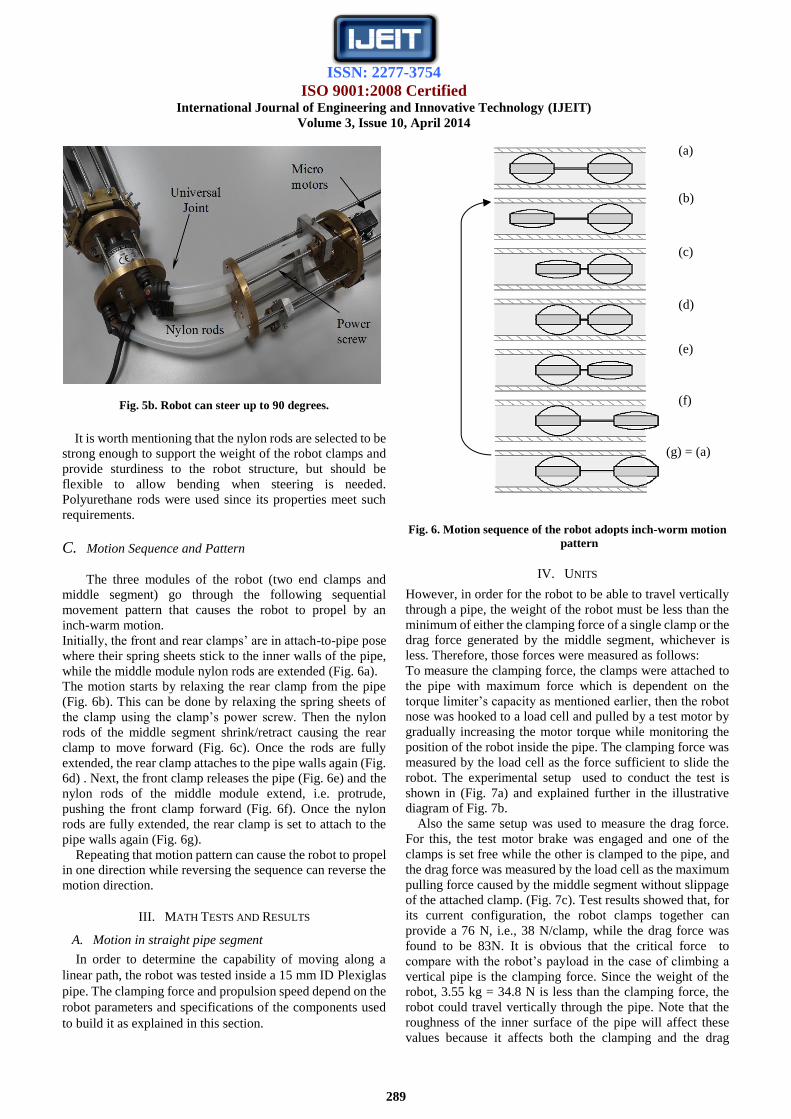
Fig. 5b. Robot can steer up to 90 degrees.
It is worth mentioning that the nylon rods are selected to be
strong enough to support the weight of the robot clamps and
provide sturdiness to the robot structure, but should be
flexible to allow bending when steering is needed.
Polyurethane rods were used since its properties meet such
requirements.
C. Motion Sequence and Pattern
The three modules of the robot (two end clamps and
middle segment) go through the following sequential
movement pattern that causes the robot to propel by an
inch-warm motion.
Initially, the front and rear clamps’ are in attach-to-pipe pose
where their spring sheets stick to the inner walls of the pipe,
while the middle module nylon rods are extended (Fig. 6a).
The motion starts by relaxing the rear clamp from the pipe
(Fig. 6b). This can be done by relaxing the spring sheets of
the clamp using the clamp’s power screw. Then the nylon
rods of the middle segment shrink/retract causing the rear
clamp to move forward (Fig. 6c). Once the rods are fully
extended, the rear clamp attaches to the pipe walls again (Fig.
6d) . Next, the front clamp releases the pipe (Fig. 6e) and the
nylon rods of the middle module extend, i.e. protrude,
pushing the front clamp forward (Fig. 6f). Once the nylon
rods are fully extended, the rear clamp is set to attach to the
pipe walls again (Fig. 6g).
Repeating that motion pattern can cause the robot to propel
in one direction while reversing the sequence can reverse the
motion direction.
III. MATH TESTS AND RESULTS
A. Motion in straight pipe segment
In order to determine the capability of moving along a
linear path, the robot was tested inside a 15 mm ID Plexiglas
pipe. The clamping force and propulsion speed depend on the
robot parameters and specifications of the components used
to build it as explained in this section.
Fig. 6. Motion sequence of the robot adopts inch-worm motion
pattern
IV. UNITS
However, in order for the robot to be able to travel vertically
through a pipe, the weight of the robot must be less than the
minimum of either the clamping force of a single clamp or the
drag force generated by the middle segment, whichever is
less. Therefore, those forces were measured as follows:
To measure the clamping force, the clamps were attached to
the pipe with maximum force which is dependent on the
torque limiter’s capacity as mentioned earlier, then the robot
nose was hooked to a load cell and pulled by a test motor by
gradually increasing the motor torque while monitoring the
position of the robot inside the pipe. The clamping force was
measured by the load cell as the force sufficient to slide the
robot. The experimental setup used to conduct the test is
shown in (Fig. 7a) and explained further in the illustrative
diagram of Fig. 7b.
Also the same setup was used to measure the drag force.
For this, the test motor brake was engaged and one of the
clamps is set free while the other is clamped to the pipe, and
the drag force was measured by the load cell as the maximum
pulling force caused by the middle segment without slippage
of the attached clamp. (Fig. 7c). Test results showed that, for
its current configuration, the robot clamps together can
provide a 76 N, i.e., 38 N/clamp, while the drag force was
found to be 83N. It is obvious that the critical force to
compare with the robot’s payload in the case of climbing a
vertical pipe is the clamping force. Since the weight of the
robot, 3.55 kg = 34.8 N is less than the clamping force, the
robot could travel vertically through the pipe. Note that the
roughness of the inner surface of the pipe will affect these
values because it affects both the clamping and the drag
(a)
(b)
(c)
(d)
(e)
(f)
(g) = (a)

ISSN: 2277-3754
ISO 9001:2008 Certified International Journal of Engineering and Innovative Technology (IJEIT)
Volume 3, Issue 10, April 2014
290
forces. Also note that the drag and clamping forces that
suffice travelling through a vertical pipe will be adequate to
enable travelling through a horizontal pipe.
Fig. 7. (a) Test bed used for clamping force measurement (b)
Clamping force measurement, (c) Drag force measurement.
Moreover, the clamping force to the walls can be adjusted or
changed by changing one or more of the following
parameters/specifications: 1) the spring sheets’ thickness,
width and/or material; 2) the torque limiter’s set-torque. The
robot’s current configuration uses 0.63 mm thick x 10 mm
wide stainless steel spring sheets, and the selected torque
limiter’s capacity is 392 mN・m. Furthermore, the length of
the spring sheets controls the robot’s capability to handle
larger pipe diameters. Fig. 8 shows the increase in the contact
surface between the spring sheets of the clamp and the pipe
surface as a result of using a torque limiter of higher capacity.
Fig. 8. Flat spring sheet with larger surface of contact with the
pipe results from using a torque limiter of larger capacity.
The propulsion speed was calculated based on the total
time required to complete the full cycle of an inch-worm
motion pattern as described in the previous section and found
to be 2 mm/s. However, the speed can be improved by
minimizing the controller’s wasted time. For instance,
attaching/releasing the clamps to the pipe can be performed
by spinning the clamp motor few spins sufficient to apply
release the necessary force or to release the clamp instead of
completely flattening the spring sheets. Also, this speed can
be improved further by using micro-motors with higher RPM
to drive the elastic rods of the middle segment and/or by
selecting power screws with larger pitch or lead. Also power
transmission gears will be considered in future versions.
Table I summarizes the specifications of the robot based on
its current configuration.
Table I. Specifications of the Robot.
Requirement considered Specification
Weight < 3.6 kg
Material Brass and aluminum
Architecture Modular: Clamp- steering/propulsion
segment- Clamp
Motion type Inch-worm
No. of Actuators 5
Power supply Self-powered , 8-AA batteries+ 2X 9V
batteries
Dimensions: (Length)
(Outer diameter)
109 cm (fully retracted)
117.5 cm (fully extended)
(min) 6.5 cm- fully collapsed clamps (max) 22 cm- fully expanded clamps
Max linear stroke 8.5 cm
Linear propulsion speed
(tested in 15 cm ID pipe)
2 mm/s
Clamping force (tested in a
15 cm ID Plexiglas pipe )
76 N
Max turning angle 90 degrees
Operating mode Autonomous
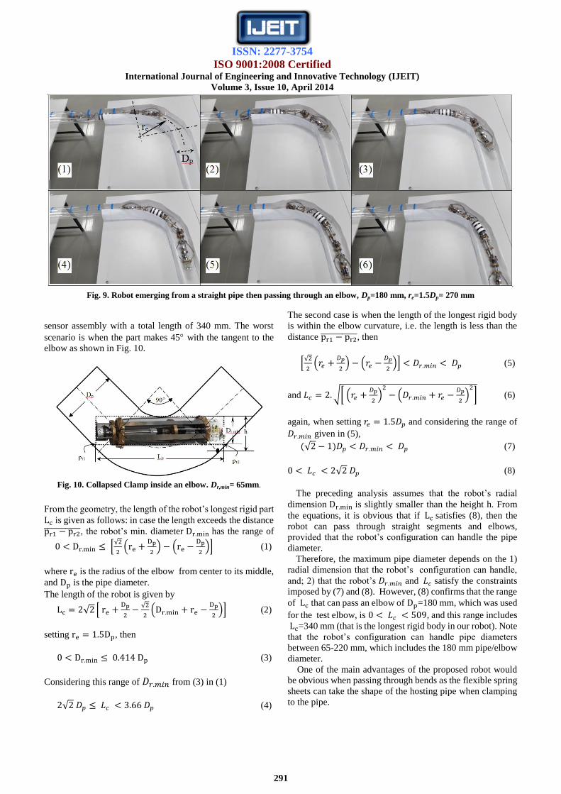
B. Motion in turns
The motion pattern can be briefed as follows: the middle
module is responsible for pushing the front of the robot, to
steer it, and to drag the rear section forward by active
actuators. However, the rear section comprises two passive
ball joints (Figs. 1 and 2) to allow the robot body to bend
when passing through turns. Fig. 9 shows the robot
immerging from a straight pipe to pass through an elbow
during experimental test of the capability of the robot to
handle turns. For this experiment, a pipe/elbow diameter of
Dp=180 mm and an elbow radius re= 270 mm where used
(in urban gas pipelines, is usually 1.5 ).
Pipeline configurations and dimensions impose
geometrical constraints on the robot dimensions. S Roh and
H Choi provided detailed analysis on such restrictions [12].
The analysis for the proposed robot provided in this section is
based on their approach.
Since the robot comprises a series of rigid bodies, the
analysis will consider the longest rigid part which, if passes
the elbow, all other parts can pass successfully. Referring to
Fig. 2, our target part is the frontal clamp that includes the
(a)
(b)
(c)
ISSN: 2277-3754
ISO 9001:2008 Certified International Journal of Engineering and Innovative Technology (IJEIT)
Volume 3, Issue 10, April 2014
291
sensor assembly with a total length of 340 mm. The worst
scenario is when the part makes 45 with the tangent to the
elbow as shown in Fig. 10.
Fig. 10. Collapsed Clamp inside an elbow. Dr,min= 65mm.
From the geometry, the length of the robot’s longest rigid part
is given as follows: in case the length exceeds the distance
, the robot’s min. diameter has the range of
[√
(
) (
)] (1)
where is the radius of the elbow from center to its middle,
and is the pipe diameter.
The length of the robot is given by
√ [
√
(
)] (2)
setting , then
(3)
Considering this range of from (3) in (1)
√ (4)
The second case is when the length of the longest rigid body
is within the elbow curvature, i.e. the length is less than the
distance , then
[√
(
) (
)] (5)
and √[ (
)
(
)
] (6)
again, when setting and considering the range of
given in (5),
√ (7)
√ (8)
The preceding analysis assumes that the robot’s radial
dimension is slightly smaller than the height h. From
the equations, it is obvious that if satisfies (8), then the
robot can pass through straight segments and elbows,
provided that the robot’s configuration can handle the pipe
diameter.
Therefore, the maximum pipe diameter depends on the 1)
radial dimension that the robot’s configuration can handle,
and; 2) that the robot’s and satisfy the constraints
imposed by (7) and (8). However, (8) confirms that the range
of that can pass an elbow of =180 mm, which was used
for the test elbow, is , and this range includes
=340 mm (that is the longest rigid body in our robot). Note
that the robot’s configuration can handle pipe diameters
between 65-220 mm, which includes the 180 mm pipe/elbow
diameter.
One of the main advantages of the proposed robot would
be obvious when passing through bends as the flexible spring
sheets can take the shape of the hosting pipe when clamping
to the pipe.
Fig. 9. Robot emerging from a straight pipe then passing through an elbow, Dp=180 mm, re=1.5Dp= 270 mm

ISSN: 2277-3754
ISO 9001:2008 Certified International Journal of Engineering and Innovative Technology (IJEIT)
Volume 3, Issue 10, April 2014
292
V. CONCLUSION
A novel in-pipe inspection robot has been designed and
constructed. The robot’s features enable it to navigate
autonomously through a pipeline. The robot that is
configured with three main modules, two clamps and one
drive segment adopts inch-worm motion pattern. Its
clamping modules enable the robot to dynamically adjust its
radial dimension between 65-220 mm, and clamping force to
attach to pipes of different inner diameters and overcome the
obstacles associated with changes in pipe diameters, thus it
can travel through pipelines that comprise segments of
varying inner diameters. It comprises a sophisticated middle
module that enables it to propel, and to steer into the desired
direction when approaching an elbow or a junction. In
addition, the robot is equipped with a hole-finding sensor
assembly that allows it to realize the clear path along turns
and T-junctions.
REFERENCES
[1] N. Saga, T. Nakamura, “Development of a peristaltic crawling
robot using magnetic fluid on the basis of the locomotion
mechanism of the earthworm”, Smart Materials and Structures,
2004,13, pp.566–569.
[2] F. Kirchner and J. Hertzberg “A Prototype Study of an
Autonomous Robot Platform for Sewerage System”,
Maintenance Autonomous Robots, 1997; 4(4), p. 319-331.
[3] HB. Kuntze and H. Haffner, “Experiences with the development
of a robot for smart multisensoric pipe inspection”, Proc. IEEE
International Conf. on Robotic and Automation, 1998. p.
1773-8.
[4] SG Roh and HR Choi, “Differential-drive in-pipe robot for
moving inside urban gas pipelines”, IEEE Transactions on
Robotics, 2005; 21(1), pp. 1-17.
[5] M. Muramatsu, N. Namiki and R. Koyama, “Autonomous
mobile robot in pipe for piping operations”, Proc. IEEE/RSJ
International Conf. on Intelligent Robots and Systems, 2000.
pp. 2166-71.
[6] M. Moghaddam and M. R. Tafti, "Design, modeling and
prototyping of a pipe inspection robot", 22nd Int. Symp. on
Automation and Robotics in Construction (ISARC), 2005.
[7] Yunwei Zhang, and Guozheng Yan, "In-pipe inspection robot
with active pipe-diameter adaptability and automatic tractive
force adjusting",Mechanism and Machine Theory, 2007, 42,
pp. 1618-1631.
[8] HR. Choi and SM. Ryew “Robotic system with active steering
capability for internal inspection of urban gas pipelines”,
Mechatronics, 2002; 16(12), pp. 713-36.
[9] Z. Zhu and Z. Pan, “Miniature pipe robots”, Industrial Robot:
An International Journal, 2003; 30(6), pp. 575–83.
[10] I. Hayashi, N. Iwatsuki, K. Morikawa and M. Ogata, “An
in-pipe operation microrobot based on the principle of screw”,
International Symposium on Micromechatronics and Human
Science, 1997, pp. 125-9.
[11] M. Horodinca, I. Dorftei, E. Mignon and A. Preumont, “A
simple architecture for in-pipe inspection robots”, Proc.
International Colloquium on Mobile and Autonomous
Systems, 2002, pp. 61-4.
[12] S. Roh and H. R. Choi, "Differential-drive in-pipe robot for
moving inside urban gas pipelines", IEEE Transactions on
Robotics, 2005, 21(1), pp 1-17.
[13] J. Park, T. Kim, H. Yang, “Development of an actively
adaptable in-pipe robot”, Proc. IEEE International Conference
on Mechatronics (ICM), 2009.
[14] K. Suzumori, T. Miyagawa, M. Kimura, Y. Hasegawa, “Micro
Inspection Robot for 1-in Pipes”,IEEE/ASME Transactions on
Mechatronics, 4(3), 1999, pp.286-292.
[15] S. Hirose, H. Ohno, T. Mitsui and K. Suyama, “Design of
In-Pipe Inspection Vehicles for ø25, ø 50, ø150 Pipes”, Journal
of Robotics and Mechatronics, 12(3), 2000, pp. 310-317.
[16] T. Fukuda, H. Hosokai, M. Uemura, “Rubber gas actuator
driven by hydrogen storage alloy for in-pipe inspection mobile
robot with flexible structure”, Proc. IEEE International Conf.
on Robotics and Automation, 1989, p. 1847–52.
[17] S. Aoshima, T. Tsujimura and Yabuta “A miniature mobile
robot using piezo vibration for mobility in a thin tube”,
Transactions of ASME, Journal of Dynamic Systems,
Measurements and Control, 1993, 115, p. 270-8.
[18] C. Anthierens, A. Ciftci and M. Betemps, “Design of an
electro pneumatic micro robot for in-pipe inspection”, Proc.
IEEE International Symposium on Industrial Electronics, 2,
1999, pp. 968-72.
[19] KU. Scholl, V. Kepplin, K. Berns and R. Dillmann,
“Controlling a multi-joint robot for autonomous sewer
inspection”, Proc. IEEE International Conf. on Robotics and
Automation, 2000, 2, p. 1701-6.
[20] S. Wakimoto, J. Nakajima and M. Takata, “ A micro snake-like
robot for small pipe inspection. Proc. International Symposium
on Micro Mechatronics and Human Science, 2003, pp. 303-8.
[21] J. Borenstein, G. Granosik and M. Hansen, “The OmniTread
serpentine robot for industrial inspection and surveillance”,
International Journal on Industrial Robots, Special Issue on
Mobile Robots, 2005, 32(2), pp.139-48.
[22] A. Zagler and F. Pfeiffer, “MORITZ” a pipe crawler for tube
junctions”. Proc. IEEE International Conf. on Robotics and
Automation, 2003, pp. 2954-60.
[23] W. Neubauer, “A spider-like robot that climbs vertically in
ducts or pipes”, Proc. IEEE/RSJ International Conference on
Intelligent Robots and Systems, 1994, pp. 1178-85.
[24] W. Fischer, F. Tâche, and R. Siegwart, “Inspection system for
very thin and fragile surfaces, based on a pair of wall climbing
robots with magnetic wheels,” in Proc. IEEE/RSJ Int. Conf.
Intelligent Robots and Systems, San Diego, CA, USA, 2007,
pp. 1216-1221.
[25] Basem F. Yousef, et. al., “IN-PIPE INSPECTION ROBOT”.
In Proc. of the 15th Int. Conf. on Climbing and Walking Robots
and the Support Technologies for Mobile Machines, BA, USA,
2012, pp. 289-296.