Embed Size (px)
Citation preview

International Journal of Advance Research in Engineering, Science & Technology
e-ISSN: 2393-9877, p-ISSN: 2394-2444 Volume 4, Issue 3, March-2017
All Rights Reserved, @IJAREST-2017
Impact Factor (SJIF): 3.632
62
Development of New Coating Technology by Friction Technique
Ch. Ramakrishna*1
, S. Rajashekar2 , N. Sivateja
3,
P. Bhaskar Rao
4
1, 3 Assistant Professor, Department of Mechanical Engineering, KL University, Guntur, AP, India-522502. 2 Assistant Professor, Mechanical Department, KITS,Singapur Huzurabad, Karimnagar,TS- 505468
4 Assistant Professor, Mechanical Department, CMR Engg College, Kondlakoya,Medchal Hyderabad, TS- 505468
Abstract: A new approach in development of coating technology by “Friction stir technique”. The research goal
focuses on the development and application of new technologies in establishing new piping materials and coatings
to improve corrosion resistance there by increasing the ease of fluid flow in pipes. Focus is on achieving operating
cost reductions in the transport of gas and oil through pipelines. The outcome of the research is a newly developed
pipe line system for transportation of gas and oil. This project helps to improve the surface smoothness and anti-
corrosion of inside pipe without using the chemicals or coating for the usage in petro chemical industries, marine
applications, wear and abrasion resistant ship structures. The proper tool is selected according to pipe material and
fixed in continuous drive friction welding machine. The tool is fixed in a rotating member while pipe is fixed in a
stationary member. A tool material is inserted into the pipe and rotated inside the pipe to get sufficient temperature
due to friction. So that a thin layer is formed between tool and pipe. Then the tool is slowly removed from the pipe. This thin layer (intermetallics) is formed inside the pipe material. This intermetallics act as anti-corrosion material.
The friction factor and viscosity of the fluid inside the pipe/tube depends on surface roughness. Keywords: Coating, Friction Technique, Zink billet and tool, Coating Thickness and Hardness rate.
I. INTRODUCTION
Coating is a covering that is applied to the surface of an object, usually referred to as the substrate. In many
cases coatings are applied to improve surface properties of the substrate, such as appearance, adhesion, wet ability,
corrosion resistance, wear resistance, and scratch resistance. In other cases, in particular in printing processes and
semiconductor device fabrication (where the substrate is a wafer), the coating forms an essential part of the finished
product. The most common use of industrial coatings is for corrosion control of steel structures such as offshore
platforms, bridges and underground pipelines. Other functions include intumescing coatings for fire resistance. The
most common polymers used in industrial coatings are polyurethane, epoxy and moisture cure urethane. Another highly common polymer used in industrial coating is a fluoropolymer. There are many types of industrial coatings
including inorganic zinc, phosphate, and Xylan and PVD coatings. A typical coating system may include a primer, a
intermediate coat, and a top-coat. The polymer film acts as a physical barrier between the steel substrate and the
corrosive environment such as atmosphere, water and soil. Types of coatings are,
Chemical vapor deposition
Physical vapor deposition
Chemical and electrochemical techniques
Optical coatings
Roll-to-roll coatings
II. EXPERIMENTAL WORK
Material Selection: The material is selected based on mechanical, thermal and physical properties of metals. The
intension of this process is to select the tool as low melting point material compared to pipe material and the tool is
low hardness material where as pipe material is high hard material. The deposited material on internal surface of the
pipe material is selected as zinc (Pure Zinc) where as pipe material is selected as aluminum (Pure Aluminum) as
shown in table 1. The following are the composition of tool and pipe materials are:
International Journal of Advance Research in Engineering, Science & Technology (IJAREST) Volume 4, Issue 3, March 2017, e-ISSN: 2393-9877, print-ISSN: 2394-2444
All Rights Reserved, @IJAREST-2017 63
Table 1: Composition of Tool material and pipe material
Sl.No Composition of parent metals
Tool material (Zinc) Pipe material (Aluminum)
1 99.9% Zn, 0.06P, 0.04S 99.9% Al, 0.05P, 0.05S
Tool Design: The tool is made up with zinc material and designed according to dimensions required for fitting
inside the pipe material to deposit the zinc as coating inside the aluminum pipe. The tool is prepared from zinc billet
(Fig. 3.1) and is converted into cylindrical rod (Fig. 3.2) then it is prepared into required tool shape as shown in Fig. 3.3.
Fig. 3.1: Zinc billetFig. 3.2: Zinc cylindrical rodFig. 3.3: Zinc tool material
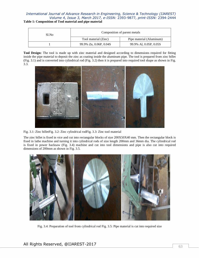
The zinc billet is fixed in vice and cut into rectangular blocks of size 200X50X40 mm. Then the rectangular block is
fixed in lathe machine and turning it into cylindrical rods of size length 200mm and 36mm dia. The cylindrical rod
is fixed in power hacksaw (Fig. 3.4) machine and cut into tool dimensions and pipe is also cut into required dimensions of 200mm as shown in Fig. 3.5.
Fig. 3.4: Preparation of tool from cylindrical rod Fig. 3.5: Pipe material is cut into required size

International Journal of Advance Research in Engineering, Science & Technology (IJAREST) Volume 4, Issue 3, March 2017, e-ISSN: 2393-9877, print-ISSN: 2394-2444
All Rights Reserved, @IJAREST-2017 64
III. Experimental Setup
The All Geared Lathe machine is selected to do the operation for coating by friction technique. The aluminum pipe
is fixed in rotating member (i.e. chuck) while tool is fixed in stationary member (Tool is fixed in horizontal
rectangular rod which is fixed in tool post). The tool is adjusted to the center of the pipe with the adjusting of tool
post and set the external curvature of tool matches with internal curvature of the pipe. The tool always contacts with
the pipe and start the rotation with given speed to the pipe. The tool is feeding slowly according to the selected
parameters in forward direction after some time then the tool is slowly in reverse direction. The following parameters are selected and list of parameters are shown in Table 3.1.
Table 3.2: Parameters are used in this process
Sl. No. Speed, N (rpm) Forward time, FT (min) Reverse time, RT (min)
1 1000 20 5
2 1000 20 10
3 1000 30 5
4 1000 30 10
5 1200 20 5
6 1200 20 10
7 1200 30 5
8 1200 30 10
3.4 Corrosion test
The corrosion test is conducted on internal surface of coated aluminum pipe for corrosion. The sample is
according to corrosion test dimensions as shown in Fig. 3.7.
Fig. 3.7: Sample prepared for corrosion test Fig. 3.8: Corrosion testing machine

International Journal of Advance Research in Engineering, Science & Technology (IJAREST) Volume 4, Issue 3, March 2017, e-ISSN: 2393-9877, print-ISSN: 2394-2444
All Rights Reserved, @IJAREST-2017 65
Fig. 3.8 shows corrosion testing machine used for sample kept inside the machine for long time. The corrosion is
observed with respect to time. In the chamber the chemicals (NaCl) are sprayed inside the pipe and external of the
pipe is covered as shown in Fig. 3.9.
Fig. 3.9: Corrosion testing chamber
Micro hardness : Vickers hardness test
The Vickers hardness test was developed by Smith and Sandland (1922) at Vickers Ltd. as an alternative to
the Brinell method to measure the hardness of materials. The Vickers test is easier to use than other hardness tests
since the required calculations are independent of the size of the indenter, and the indenter can be used for all
materials irrespective of hardness. In this method, micro indentation is made on the surface of a specimen with the help of diamond pyramidal indenter. It is a square pyramid with an angle of 136o±30′ between the faces as shown in
Fig 3.10. The faces meet at a sharp point and the faces of the pyramidal indenter are optically flat. The hardness is
calculated from the relation:
Hv = 1854.4(P/d2)
where P is the load applied on the indenter in g and d is mean diagonal length of the square impression formed on
the sample surface in µm. Hardness is measured in units of kg/mm2. Figures 3.11 show the photograph and
schematic representation of the instrument used in the present studies.
Fig 3.10: Geometry of the Vickers indenter Fig. 3.11: Photograph of Leitz-Wetzlar (miniload2)
microhardness tester.

International Journal of Advance Research in Engineering, Science & Technology (IJAREST) Volume 4, Issue 3, March 2017, e-ISSN: 2393-9877, print-ISSN: 2394-2444
All Rights Reserved, @IJAREST-2017 66
IV. RESULTS AND DISCUSSIONS
Hardness: The parameters are plays a greater role to improve the hardness of coating, which is deposited inside the
aluminum pipe. The parameters used in the experimentation are pipe speed, forward time for tool and reverse time
for tool as shown in table 4.1.
Pipe speed (N) in rpm – 1000 and 1200 Forward time for tool (FT) in min – 20 and 30
Reverse time for tool (RT) in min – 5 and 10
Base metal: Aluminum pipe - 46.812 Hv
Zinc - 57.937 Hv
Table 4.1: Hardness varies with the Parameters
Sample. No.
Parameters
Hardness, Hv Speed in forward Reverse
rpm time in min time in min
1 1000 20 5 56.515
2 1000 20 10 52.551
3 1000 30 5 106.521
4 1000 30 10 42.872
5 1200 20 5 118.239
6 1200 20 10 302.693
7 1200 30 5 50.135
8 1200 30 10 99.650
At 1000 rpm:
At the lower speed and lower forward time, the hardness is approximately equal but a slightly difference in
hardness with an decreasing order due to low time is not enough to create coating. This leads to lower hardness which is equal to base metals.
The lower speed and higher forward time, the hardness is higher (Double value) than the base metal with the
lower value of reverse time due to higher amount of zinc is deposited inside the internal surface of the
aluminum pipe. In reverse time, the deposited zinc redistributed equal into the internal surface due to less time,
which leads to more axial compressive forces acting onto the internal surface of the pipe.
1000 20 5 56.515
1000 20 10 52.551
1000 30 5 106.521
1000 30 10 42.872

International Journal of Advance Research in Engineering, Science & Technology (IJAREST) Volume 4, Issue 3, March 2017, e-ISSN: 2393-9877, print-ISSN: 2394-2444
All Rights Reserved, @IJAREST-2017 67
The hardness is increases with an increase in forward time at low speed and low reverse time. Lower
reverse time allowed more axial compressive forces acting inside the surface of pipe. The hardness is higher at
higher forward time and lower reverse time due to more amount of zinc deposition due to more axial compressive
forces.
The hardness is decreases with an increase in forward time at higher reverse time and low speed due to
higher reverse time results lower deposition of the zinc.
At 1200 rpm:
The hardness increases with an increase in reverse time at high speed and lower forward time. The maximum hardness is observed at higher speed due to more plastic deformation between tool and pipe. More plastic
deformation happens due to higher speed.
The hardness increases with an increase in reverse time at high speed of the pipe and higher forward time
but there is a difference in hardness at lower forward time and higher forward time.
The hardness is decreases with an increase in forward time at the condition of higher pipe speed and at
lower reverse time. The hardness is higher due to lower forward time results higher friction generated between tool
and pipe then the more deposition of the zinc sticks with internal surface of the pipe.
The hardness is decreases with an increase in forward time at the condition of higher pipe speed and at higher reverse time. The hardness is higher due to lower forward time results higher friction generated between tool
and pipe due to more deposition of the zinc stick with internal surface of the pipe.
At 1000 &1200 rpm:
The hardness of the internal surface of the pipe varies with the speed of the pipe at the constant forward
time and reverse time. This happens due to higher speed and at lower forward and reverse time results higher friction leads to more deposition.
1000 20 5 56.515
1000 30 5 106.521
1000 20 10 52.551
1000 30 10 42.872
1200 20 5 118.239
1200 20 10 302.693
1200 30 5 50.135
1200 30 10 99.650
1200 20 5 118.239
1200 30 5 50.135
1200 20 10 302.693
1200 30 10 99.650
1000 20 5 56.515
1200 20 5 118.239
International Journal of Advance Research in Engineering, Science & Technology (IJAREST) Volume 4, Issue 3, March 2017, e-ISSN: 2393-9877, print-ISSN: 2394-2444
All Rights Reserved, @IJAREST-2017 68
The hardness of the internal surface of the pipe varies with the speed of the pipe at the constant forward
time and reverse time. This happens due to higher speed and at lower forward and higher reverse time results to high
friction leads to higher deposition.
The hardness of the internal surface of the pipe varies with the speed of the pipe at the constant forward
time and reverse time. These happen due to lower speed and at higher forward and lower reverse time results higher
friction leads to more deposition.
The hardness of the internal surface of the pipe varies with the speed of the pipe at the constant forward
time and reverse time. This happens due to higher speed and at higher forward and reverse time results higher
friction leads to more deposition. This trend is different from at lower reverse time.
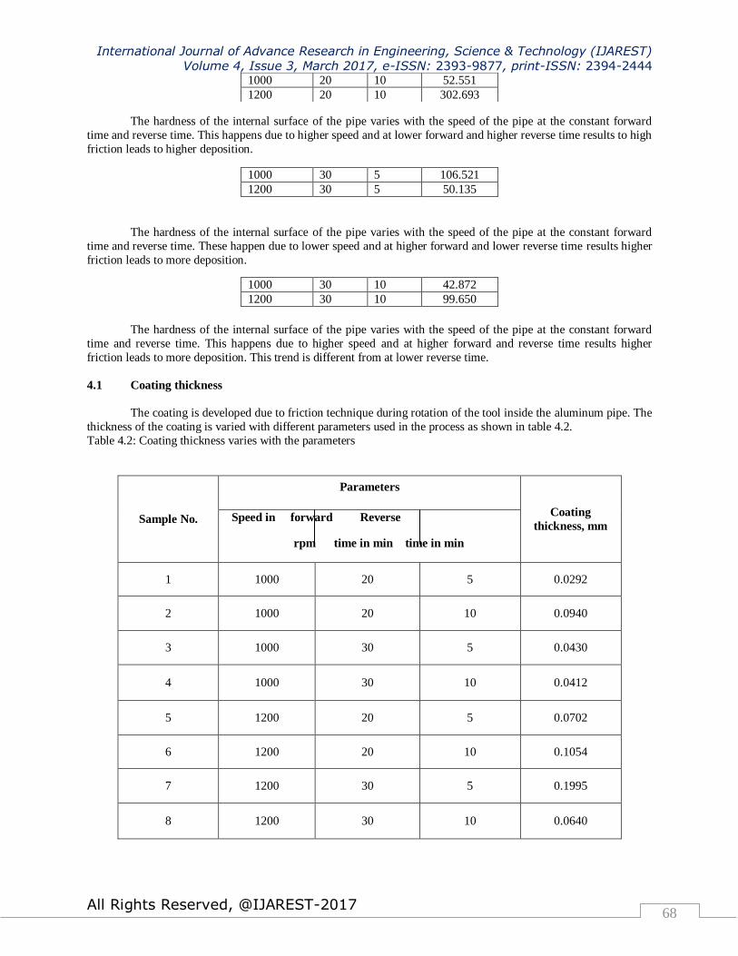
4.1 Coating thickness
The coating is developed due to friction technique during rotation of the tool inside the aluminum pipe. The
thickness of the coating is varied with different parameters used in the process as shown in table 4.2.
Table 4.2: Coating thickness varies with the parameters
Sample No.
Parameters
Coating
thickness, mm Speed in forward Reverse
rpm time in min time in min
1 1000 20 5 0.0292
2 1000 20 10 0.0940
3 1000 30 5 0.0430
4 1000 30 10 0.0412
5 1200 20 5 0.0702
6 1200 20 10 0.1054
7 1200 30 5 0.1995
8 1200 30 10 0.0640
1000 20 10 52.551
1200 20 10 302.693
1000 30 5 106.521
1200 30 5 50.135
1000 30 10 42.872
1200 30 10 99.650

International Journal of Advance Research in Engineering, Science & Technology (IJAREST) Volume 4, Issue 3, March 2017, e-ISSN: 2393-9877, print-ISSN: 2394-2444
All Rights Reserved, @IJAREST-2017 69
At 1000rpm:
At the lower speed and lower forward time, the coating thickness is increases with an increasing reverse time due to
more deposition of zinc in reverse time as shown in Fig. 4.1 and Fig. 4.2.
Fig. 4.1: Sample 1 Fig. 4.2: Sample 2
The lower speed and higher forward time, the coating thickness is approximately equal but a slightly
difference with respect to reverse time. The higher forward time and lower reverse time results higher coating
thickness due to higher amount of zinc is deposited inside the internal surface of the aluminum pipe.
Fig. 4.3: Sample 3 Fig. 4.4: Sample 4
1000 20 5 0.0292
1000 20 10 0.0940
1000 30 5 0.0430
1000 30 10 0.0412

International Journal of Advance Research in Engineering, Science & Technology (IJAREST) Volume 4, Issue 3, March 2017, e-ISSN: 2393-9877, print-ISSN: 2394-2444
All Rights Reserved, @IJAREST-2017 70
The coating thickness is increases with an increase in forward time at low speed and low reverse time. The
coating thickness is higher at higher forward time and lower reverse time due to more amount of zinc deposition due
to more axial compressive forces.
Fig. 4.5: Sample 5 Fig. 4.6: Sample 6
The coating thickness is decreases with an increase in forward time at higher reverse time and low speed
due to higher reverse time results lower deposition of the zinc.
Fig. 4.7: Sample 7 Fig. 4.8: Sample 8
1000 20 5 0.0292
1000 30 5 0.0430
1000 20 10 0.0940
1000 30 10 0.0412

International Journal of Advance Research in Engineering, Science & Technology (IJAREST) Volume 4, Issue 3, March 2017, e-ISSN: 2393-9877, print-ISSN: 2394-2444
All Rights Reserved, @IJAREST-2017 71
At 1200 rpm:
The coating thickness increases with an increase in reverse time at high speed and lower forward time. The
maximum thickness is observed at higher speed due to more plastic deformation between tool and pipe. More plastic
deformation happens due to higher speed.
The coating thickness decreases with an increase in reverse time at high speed of the pipe and higher
forward time but there is a difference in hardness at lower forward time and higher forward time.
The coating thickness is increases with an increase in forward time at the condition of higher pipe speed
and at lower reverse time due to higher plastic deformation which results coarse grain structure.
The coating thickness is decreases with an increase in forward time at the condition of higher pipe speed and at
higher reverse time. The coating thickness is higher due to lower forward time results higher friction generated
between tool and pipe due to more deposition of the zinc stick with internal surface of the pipe.
At 1000 &1200 rpm:
The coating thickness of the internal surface of the pipe varies with the speed of the pipe at the constant
forward time and reverse time. This happens due to higher speed and at lower forward and reverse time results
higher friction leads to more deposition.
The coating thickness of the internal surface of the pipe varies with the speed of the pipe at the constant
forward time and reverse time. This happens due to higher speed and at lower forward and higher reverse time results to high friction leads to higher deposition.
The coating thickness of the internal surface of the pipe varies with the speed of the pipe at the constant
forward time and reverse time. This happens due to lower speed and at higher forward and lower reverses time
results higher friction leads to more deposition.
1200 20 5 0.0702
1200 20 10 0.1054
1200 30 5 0.1995
1200 30 10 0.0640
1200 20 5 0.0702
1200 30 5 0.1995
1200 20 10 0.1054
1200 30 10 0.0640
1000 20 5 0.0292
1200 20 5 0.0702
1000 20 10 0.0940
1200 20 10 0.1054
1000 30 5 0.0430
1200 30 5 0.1995
1000 30 10 0.0412
1200 30 10 0.0640

International Journal of Advance Research in Engineering, Science & Technology (IJAREST) Volume 4, Issue 3, March 2017, e-ISSN: 2393-9877, print-ISSN: 2394-2444
All Rights Reserved, @IJAREST-2017 72
The coating thickness of the internal surface of the pipe varies with the speed of the pipe at the constant
forward time and reverse time. This happens due to higher speed and at higher forward and reverse time results
higher friction leads to more deposition. The similar trend is observed even at lower reverse time also.
Corrosion
White Rust Observed inside the Tube at 12Hours and further intensifies at 24Hours. No damage is observed to the
Base Material. The sample 1 and 2 are shown in Fig. 4.9 and Fig.4.10 that the intensity of corrosion increases if the
sample kept in chemical for 24 hours.
Fig. 4.9: Coated sample after corrosion test during 24 Hrs Fig. 4.10: Base metal after corrosion test during 24 Hrsl
V. CONCLUSION
At the lower speed and lower forward time, the hardness is approximately equal but a slightly difference in
hardness.
The hardness increases with an increase in reverse time at high speed of the pipe and higher forward time
but there is a difference in hardness at lower forward time and higher forward time.
The hardness of the internal surface of the pipe varies with the speed of the pipe at the constant forward
time and reverse time. This happens due to lower speed and at higher forward and lower reverse time results higher friction leads to more deposition.
The coating thickness is increases with an increase in forward time at low speed and low reverse time. The
coating thickness is higher at higher forward time and lower reverse time due to more amount of zinc
deposition due to more axial compressive forces.
The coating thickness is increases with an increase in forward time at the condition of higher pipe speed
and at lower reverse time due to higher plastic deformation which results coarse grain structure.
The coating thickness of the internal surface of the pipe varies with the speed of the pipe at the constant
forward time and reverse time. This happens due to lower speed and at higher forward and lower reverse
time results higher friction leads to more deposition.

International Journal of Advance Research in Engineering, Science & Technology (IJAREST) Volume 4, Issue 3, March 2017, e-ISSN: 2393-9877, print-ISSN: 2394-2444
All Rights Reserved, @IJAREST-2017 73
VI. REFERENCES
1. Interfacial heating during low-pressure cold-gas dynamic spraying of aluminum coatings
M. P. Dewar, A. G. McDonald and A. P. Gerlich Journal of Materials Science, 2012, Volume 47, Number 1, Pages 184-198
2. Effects of Gas Pressure of Cold Spray on the Formation of Al-Based Intermetallic Compound H. Lee, H. Shin and K. Ko Journal of Thermal Spray Technology, 2010, Volume 19, Numbers 1-2, Pages 102-109
3. Structural Analysis of Cold-Sprayed Nickel-Based Metallic and Metallic-Ceramic Coatings Heli Koivuluoto and Petri Vuoristo Journal of Thermal Spray Technology, 2010, Volume 19, Number 5, Pages 975-989
4. Effect of Substrate Temperature on the Formation Mechanism of Cold-Sprayed Aluminum, Zinc and Tin
Coatings J. G. Legoux, E. Irissou and C. Moreau Journal of Thermal Spray Technology, 2007, Volume 16, Numbers 5-6, Pages 619-626
5. Characterization of Low-Pressure Cold-Sprayed Aluminum Coatings K. Ogawa, K. Ito, K. Ichimura, Y. Ichikawa and S. Ohno, et al. Journal of Thermal Spray Technology, 2008, Volume 17, Numbers 5-6, Pages 728-735
6. The Repair of Magnesium Rotorcraft Components by Cold Spray JOURNAL OF THERMAL SPRAY TECHNOLOGY Volume 16, Number 2, 306-317, DOI: 10.1007/s11666-007-9039-2
7. Microstructural Development and Deposition Behavior of Titanium Powder Particles in Warm Spraying
Process: From Single Splat to Coating KeeHyun Kim, Seiji Kuroda and Makoto Watanabe Journal of Thermal Spray Technology, 2010, Volume 19, Number 6, Pages 1244-1254
8. Quo vadis thermal spraying P. Fauchais, A. Vardelle and B. Dussoubs Journal of Thermal Spray Technology, 2001, Volume 10, Number 1, Pages 44-66
9. Advanced cold spray technology XiangKun Wu, JiShan Zhang, XiangLin Zhou, Hua Cui and JingChun Liu
SCIENCE CHINA Technological Sciences, Online First™, 17 December 2011
10. In vitro degradation behaviour of a friction stir processed magnesium alloy M. Bobby Kannan, W. Dietzel and R. Zettler Journal of Materials Science: Materials in Medicine, 2011, Volume 22, Number 11, Pages 2397-2401.
![Cleaning Before Coating - SMTA · Deposition Me Men+ + ne* ne* + Men+ Me ... PU-coating AY-coating , Wax coating ed m 2] ... Cleaning Before Coating](https://img.pdfslide.net/doc/110x75/5ad9e7b37f8b9a53618bdbed/cleaning-before-coating-smta-me-men-ne-ne-men-me-pu-coating-ay-coating.jpg)


![International Journal of Advance Research in Engineering ...ijarest.com/papers/finished_papers/150615095838.pdfPublic auditing scheme for the regenerating-code-based cloud storage[8]](https://img.pdfslide.net/doc/110x75/5e00f00de1b53d41a57dc9aa/international-journal-of-advance-research-in-engineering-auditing-scheme-for.jpg)