Embed Size (px)
Citation preview
Page Tool Bonus Issue 2014
John Tarpley, Editor
Tool Bonus Issue 2014 Volume 4 Number 2
A Letter From David
Several weeks back we introduced the expanding pen mandrels. With their introduction we put together an
instructional document showing the procedures for various traditional engine turning patterns cut in wood
using the drills from Jon Spencer. When I submitted it to John Tarpley for publication he told me that the
current newsletter was all but done and would have to be re-worked or lengthened to include it. On top of that
the extra time meant we could add more examples, describe more patterns, and avoid delaying publication. Not
wanting to postpone this information to our next edition, John suggested publishing a bonus issue and
suggested that it include an updated product list. We’ve received enough good material for recent issues that
we’ve not devoted much space to the product list recently. Also, since we’ve not kept the website up to date
some of you have not seen some of our newer products. Given that we were organizing the material for the
website update it seemed meant to be. This bonus issue will allow you to have a catalog of all the tooling for
the Lindow Rose Engine. Perhaps some of the tools will inspire you to explore new areas of rose engine
turning. We hope you will keep the issue handy for reference.
For quite some time people have expressed an interest in making pens however, the work holding devices on
the market have proved inadequate for the tolerances of ornamental turning. Additionally, the typical cutting
frames though offering endless possibilities did not open the door to many of the traditional designs. When we
figured out how to make a producible drilling cutter that would make a cut similar to the cut of an engine
turning tool, it was time to produce the high precision expansion pen mandrels as well. Mike Stacey and his
crew at Columbus Machine stepped up to the plate and made it happen.
The final ingredient left to making pen design limitless was an index head with more control, one with a worm
indexer as opposed to a simple latch plate. This indexer has now been prototyped, has gone out for testing, and
will soon be in production. This indexer retains the original indexing gear and can be used as it was originally
intended or with the worm. Interchangeable detents will be added for easier fractional indexing as well.
Additional information can be found in the Coming Soon section of the tool list.
Thanks goes to John Tarpley for putting all of this together as well as Brian Clarry and Jeff Cheramie who
helped me with the instructions. I hope you enjoy reading and making the projects as well as catching up on
the newer items we’re offering.
Thanks for your interest,
David
Page 2 Tool Bonus Issue 2014
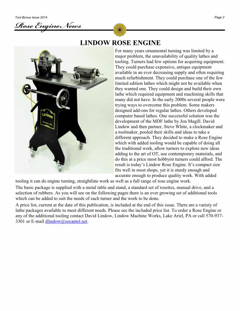
LINDOW ROSE ENGINE For many years ornamental turning was limited by a
major problem, the unavailability of quality lathes and
tooling. Turners had few options for acquiring equipment.
They could purchase expensive, antique equipment
available in an ever decreasing supply and often requiring
much refurbishment. They could purchase one of the few
limited edition lathes which might not be available when
they wanted one. They could design and build their own
lathe which required equipment and machining skills that
many did not have. In the early 2000s several people were
trying ways to overcome this problem. Some makers
designed add-ons for regular lathes. Others developed
computer based lathes. One successful solution was the
development of the MDF lathe by Jon Magill. David
Lindow and then partner, Steve White, a clockmaker and
a toolmaker, pooled their skills and ideas to take a
different approach. They decided to make a Rose Engine
which with added tooling would be capable of doing all
the traditional work, allow turners to explore new ideas
adding to the art of OT, use contemporary materials, and
do this at a price most hobbyist turners could afford. The
result is today’s Lindow Rose Engine. It’s compact size
fits well in most shops, yet it is sturdy enough and
accurate enough to produce quality work. With added
tooling it can do engine turning, straightline work as well as a full range of rose engine work.
The basic package is supplied with a metal table and stand, a standard set of rosettes, manual drive, and a
selection of rubbers. As you will see on the following pages there is an ever growing set of additional tools
which can be added to suit the needs of each turner and the work to be done.
A price list, current at the date of this publication, is included at the end of this issue. There are a variety of
lathe packages available to meet different needs. Please see the included price list. To order a Rose Engine or
any of the additional tooling contact David Lindow, Lindow Machine Works, Lake Ariel, PA or call 570-937-
3301 or E-mail [email protected].
Page 3 Tool Bonus Issue 2014
Rosettes
The Rose Engine is supplied with a basic set of rosettes to allow you to begin to explore a variety of patterns
and shapes. There are several additional sets available for advanced or different types of work. All rosettes are
made from 1/4 inch Plexiglas and are milled on a CNC machine to ensure the smoothest edges which produce
clean, accurate cuts.
Sine Wave Rosette Set
The set comes with 12,18,24,36,48,96 bump
rosettes.
Standard Rosette Set
This set of 20 rosettes includes a broad selection of rosettes that
allows a range of operations. The styles vary in amplitudes and
counts. This selection gives the inexperienced practitioner the
ability to experiment with options that might otherwise not be
considered.
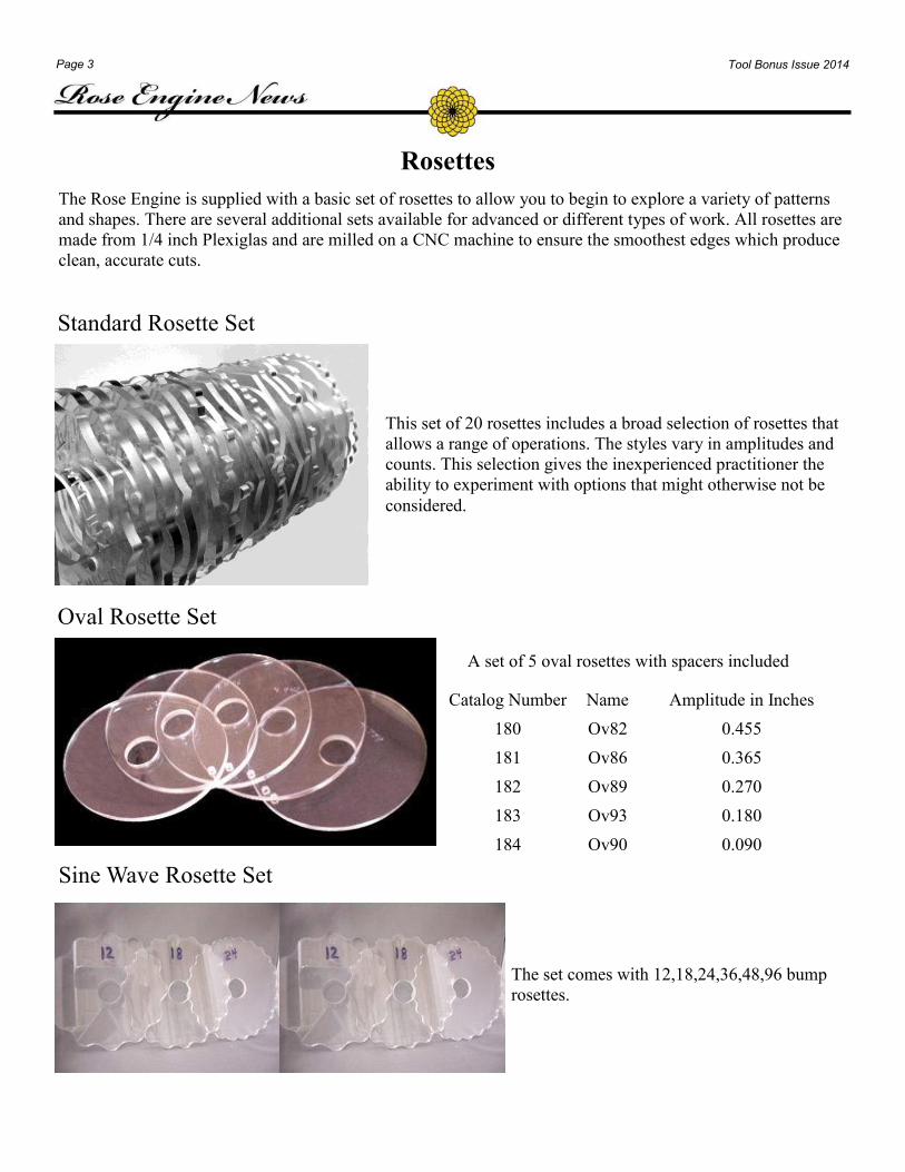
Oval Rosette Set
A set of 5 oval rosettes with spacers included
Catalog Number Name Amplitude in Inches
180 Ov82 0.455
181 Ov86 0.365
182 Ov89 0.270
183 Ov93 0.180
184 Ov90 0.090
Page 4 Tool Bonus Issue 2014
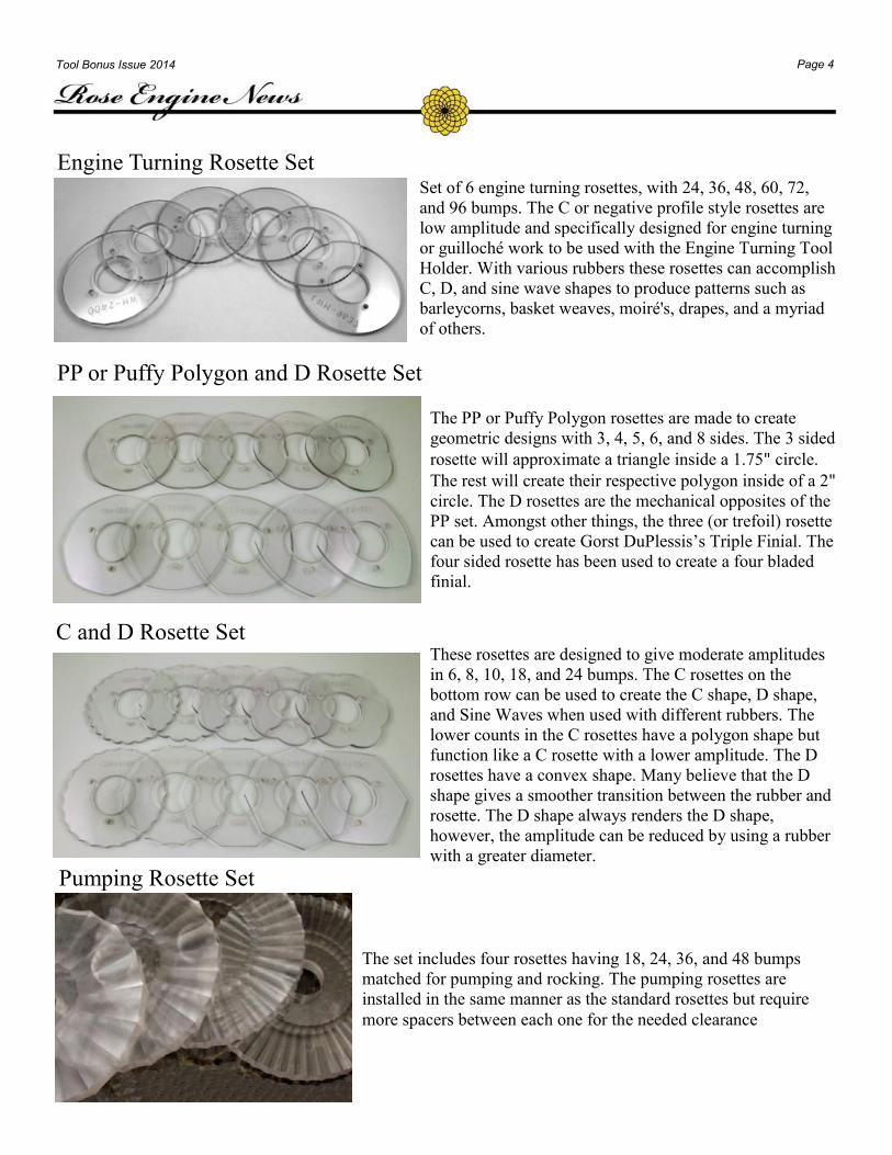
PP or Puffy Polygon and D Rosette Set
The PP or Puffy Polygon rosettes are made to create
geometric designs with 3, 4, 5, 6, and 8 sides. The 3 sided
rosette will approximate a triangle inside a 1.75" circle.
The rest will create their respective polygon inside of a 2"
circle. The D rosettes are the mechanical opposites of the
PP set. Amongst other things, the three (or trefoil) rosette
can be used to create Gorst DuPlessis’s Triple Finial. The
four sided rosette has been used to create a four bladed
finial.
C and D Rosette Set These rosettes are designed to give moderate amplitudes
in 6, 8, 10, 18, and 24 bumps. The C rosettes on the
bottom row can be used to create the C shape, D shape,
and Sine Waves when used with different rubbers. The
lower counts in the C rosettes have a polygon shape but
function like a C rosette with a lower amplitude. The D
rosettes have a convex shape. Many believe that the D
shape gives a smoother transition between the rubber and
rosette. The D shape always renders the D shape,
however, the amplitude can be reduced by using a rubber
with a greater diameter.
Engine Turning Rosette Set Set of 6 engine turning rosettes, with 24, 36, 48, 60, 72,
and 96 bumps. The C or negative profile style rosettes are
low amplitude and specifically designed for engine turning
or guilloché work to be used with the Engine Turning Tool
Holder. With various rubbers these rosettes can accomplish
C, D, and sine wave shapes to produce patterns such as
barleycorns, basket weaves, moiré's, drapes, and a myriad
of others.
The set includes four rosettes having 18, 24, 36, and 48 bumps
matched for pumping and rocking. The pumping rosettes are
installed in the same manner as the standard rosettes but require
more spacers between each one for the needed clearance
Pumping Rosette Set
Page 5 Tool Bonus Issue 2014
Rubbers
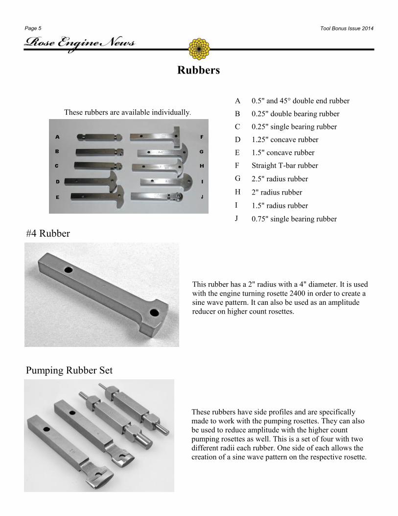
A 0.5" and 45° double end rubber
B 0.25" double bearing rubber
C 0.25" single bearing rubber
D 1.25" concave rubber
E 1.5" concave rubber
F Straight T-bar rubber
G 2.5" radius rubber
H 2" radius rubber
I 1.5" radius rubber
J 0.75" single bearing rubber
These rubbers are available individually.
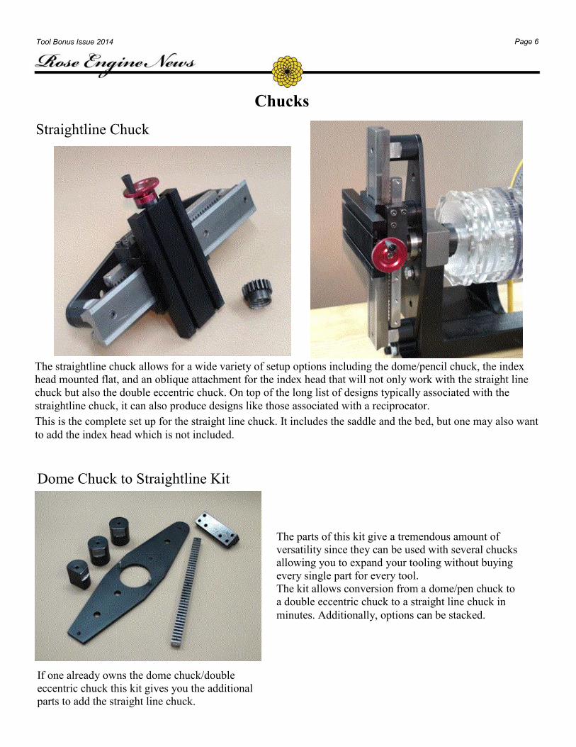
#4 Rubber
This rubber has a 2" radius with a 4" diameter. It is used
with the engine turning rosette 2400 in order to create a
sine wave pattern. It can also be used as an amplitude
reducer on higher count rosettes.
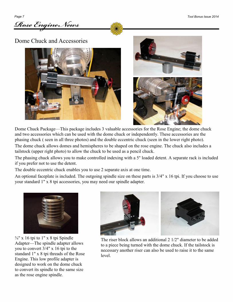
Pumping Rubber Set
These rubbers have side profiles and are specifically
made to work with the pumping rosettes. They can also
be used to reduce amplitude with the higher count
pumping rosettes as well. This is a set of four with two
different radii each rubber. One side of each allows the
creation of a sine wave pattern on the respective rosette.
Page 6 Tool Bonus Issue 2014
Chucks
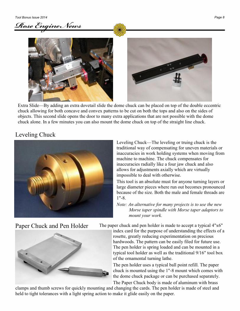
Straightline Chuck
The straightline chuck allows for a wide variety of setup options including the dome/pencil chuck, the index
head mounted flat, and an oblique attachment for the index head that will not only work with the straight line
chuck but also the double eccentric chuck. On top of the long list of designs typically associated with the
straightline chuck, it can also produce designs like those associated with a reciprocator.
This is the complete set up for the straight line chuck. It includes the saddle and the bed, but one may also want
to add the index head which is not included.
Dome Chuck to Straightline Kit
The parts of this kit give a tremendous amount of
versatility since they can be used with several chucks
allowing you to expand your tooling without buying
every single part for every tool.
The kit allows conversion from a dome/pen chuck to
a double eccentric chuck to a straight line chuck in
minutes. Additionally, options can be stacked.
If one already owns the dome chuck/double
eccentric chuck this kit gives you the additional
parts to add the straight line chuck.
Page 7 Tool Bonus Issue 2014
Dome Chuck and Accessories
Dome Chuck Package—This package includes 3 valuable accessories for the Rose Engine; the dome chuck
and two accessories which can be used with the dome chuck or independently. These accessories are the
phasing chuck ( seen in all three photos) and the double eccentric chuck (seen in the lower right photo).
The dome chuck allows domes and hemispheres to be shaped on the rose engine. The chuck also includes a
tailstock (upper right photo) to allow the chuck to be used as a pencil chuck.
The phasing chuck allows you to make controlled indexing with a 5° loaded detent. A separate rack is included
if you prefer not to use the detent.
The double eccentric chuck enables you to use 2 separate axis at one time.
An optional faceplate is included. The outgoing spindle size on these parts is 3/4" x 16 tpi. If you choose to use
your standard 1" x 8 tpi accessories, you may need our spindle adapter.
¾" x 16 tpi to 1" x 8 tpi Spindle
Adapter—The spindle adapter allows
you to convert 3/4" x 16 tpi to the
standard 1" x 8 tpi threads of the Rose
Engine. This low profile adapter is
designed to work on the dome chuck
to convert its spindle to the same size
as the rose engine spindle.
The riser block allows an additional 2 1/2" diameter to be added
to a piece being turned with the dome chuck. If the tailstock is
necessary another riser can also be used to raise it to the same
level.
Page 8 Tool Bonus Issue 2014
Extra Slide—By adding an extra dovetail slide the dome chuck can be placed on top of the double eccentric
chuck allowing for both concave and convex patterns to be cut on both the tops and also on the sides of
objects. This second slide opens the door to many extra applications that are not possible with the dome
chuck alone. In a few minutes you can also mount the dome chuck on top of the straight line chuck.
Leveling Chuck
Leveling Chuck—The leveling or truing chuck is the
traditional way of compensating for uneven materials or
inaccuracies in work holding systems when moving from
machine to machine. The chuck compensates for
inaccuracies radially like a four jaw chuck and also
allows for adjustments axially which are virtually
impossible to deal with otherwise.
This tool is an absolute must for anyone turning layers or
large diameter pieces where run out becomes pronounced
because of the size. Both the male and female threads are
1"-8.
Note: An alternative for many projects is to use the new
Morse taper spindle with Morse taper adaptors to
mount your work.
The paper chuck and pen holder is made to accept a typical 4"x6"
index card for the purpose of understanding the effects of a
rosette, greatly reducing experimentation on precious
hardwoods. The pattern can be easily filed for future use.
The pen holder is spring loaded and can be mounted in a
typical tool holder as well as the traditional 9/16" tool box
of the ornamental turning lathe.
The pen holder uses a typical ball point refill. The paper
chuck is mounted using the 1"-8 mount which comes with
the dome chuck package or can be purchased separately.
The Paper Chuck body is made of aluminum with brass
clamps and thumb screws for quickly mounting and changing the cards. The pen holder is made of steel and
held to tight tolerances with a light spring action to make it glide easily on the paper.
Paper Chuck and Pen Holder
Page 9 Tool Bonus Issue 2014
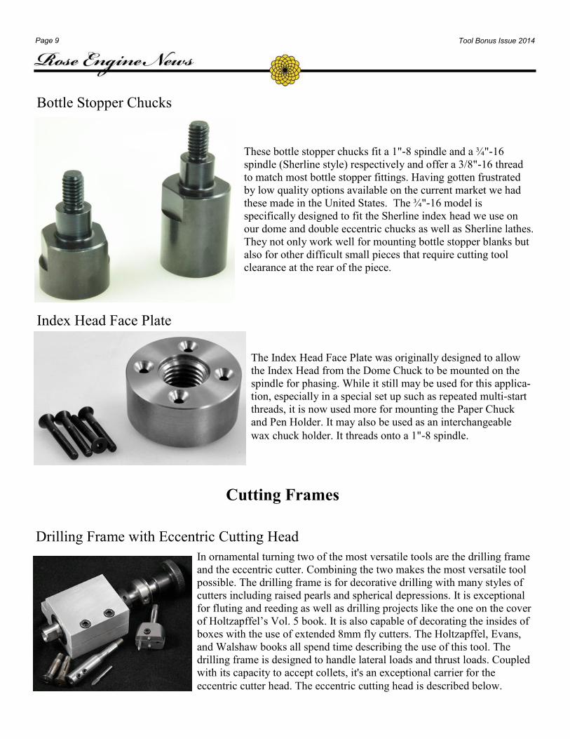
Bottle Stopper Chucks
These bottle stopper chucks fit a 1"-8 spindle and a ¾"-16
spindle (Sherline style) respectively and offer a 3/8"-16 thread
to match most bottle stopper fittings. Having gotten frustrated
by low quality options available on the current market we had
these made in the United States. The ¾"-16 model is
specifically designed to fit the Sherline index head we use on
our dome and double eccentric chucks as well as Sherline lathes.
They not only work well for mounting bottle stopper blanks but
also for other difficult small pieces that require cutting tool
clearance at the rear of the piece.
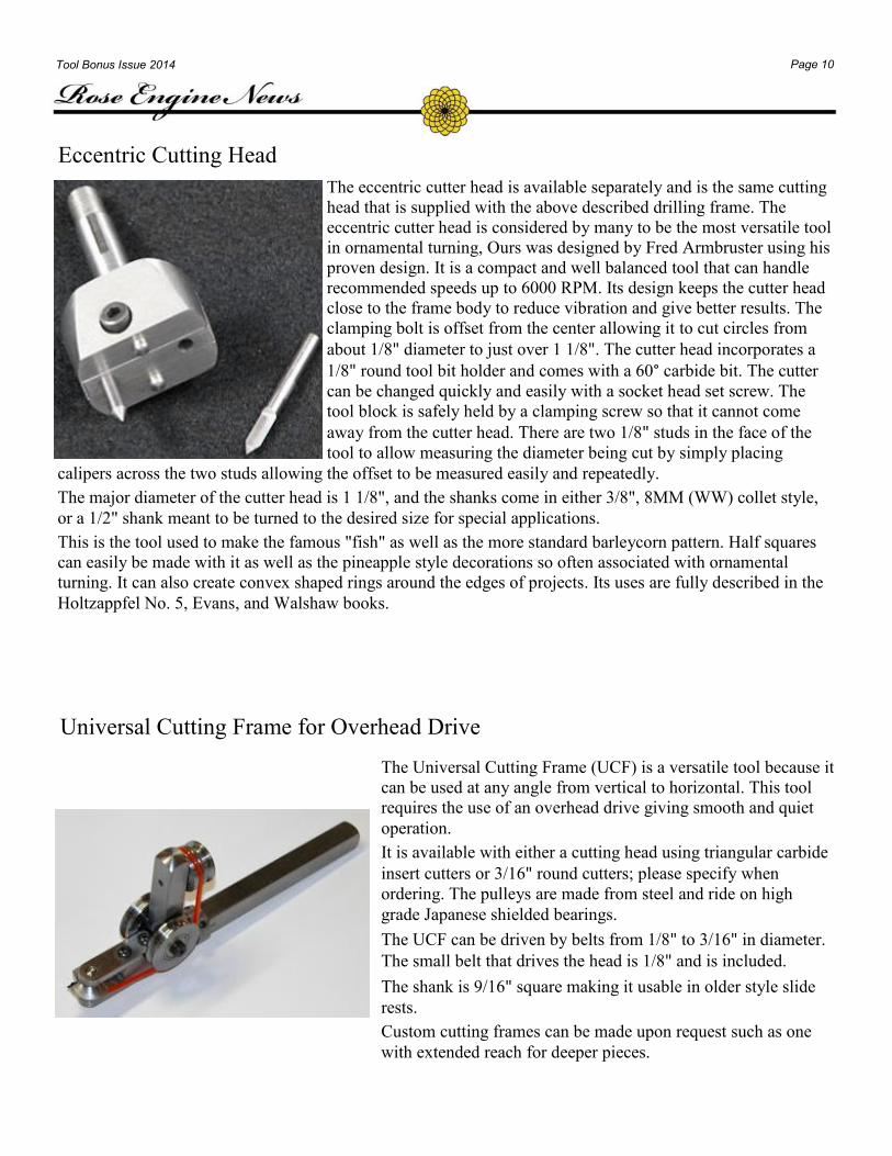
Index Head Face Plate
The Index Head Face Plate was originally designed to allow
the Index Head from the Dome Chuck to be mounted on the
spindle for phasing. While it still may be used for this applica-
tion, especially in a special set up such as repeated multi-start
threads, it is now used more for mounting the Paper Chuck
and Pen Holder. It may also be used as an interchangeable
wax chuck holder. It threads onto a 1"-8 spindle.
Cutting Frames
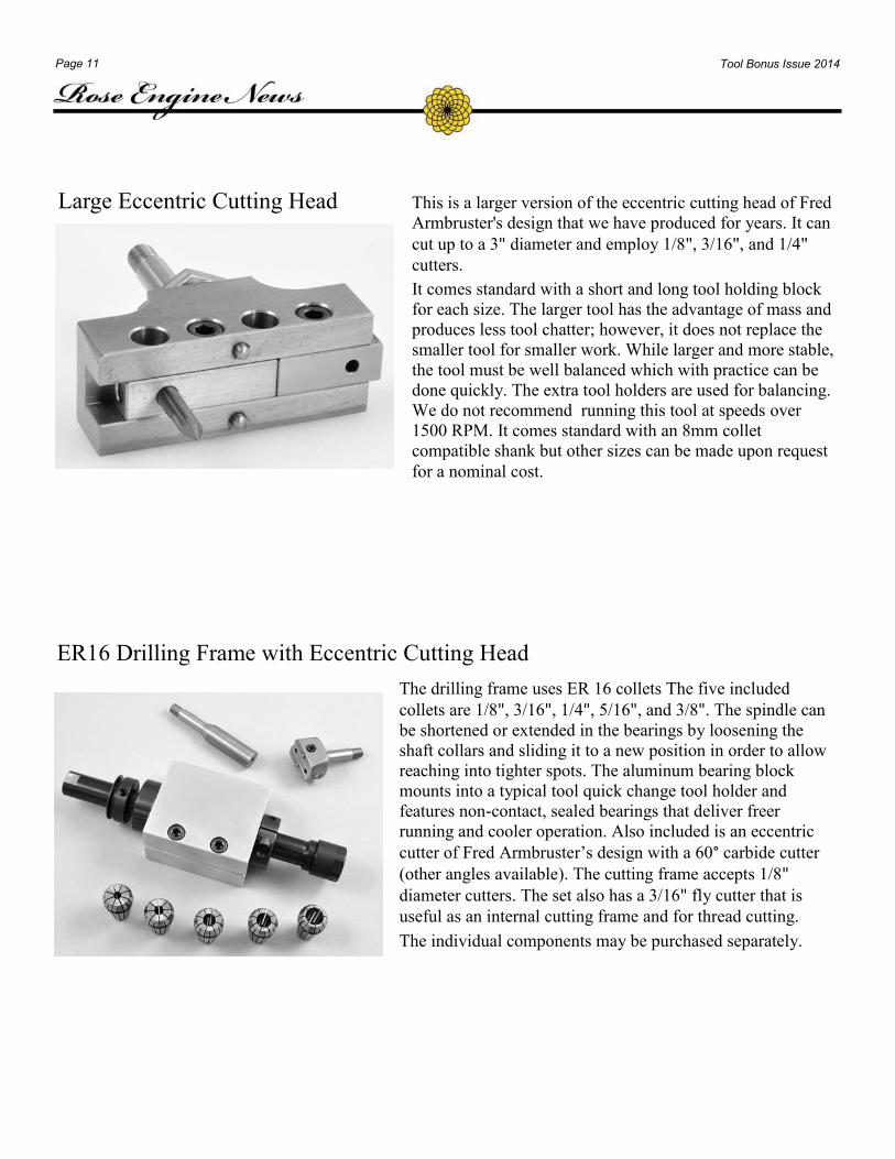
Drilling Frame with Eccentric Cutting Head
In ornamental turning two of the most versatile tools are the drilling frame
and the eccentric cutter. Combining the two makes the most versatile tool
possible. The drilling frame is for decorative drilling with many styles of
cutters including raised pearls and spherical depressions. It is exceptional
for fluting and reeding as well as drilling projects like the one on the cover
of Holtzapffel’s Vol. 5 book. It is also capable of decorating the insides of
boxes with the use of extended 8mm fly cutters. The Holtzapffel, Evans,
and Walshaw books all spend time describing the use of this tool. The
drilling frame is designed to handle lateral loads and thrust loads. Coupled
with its capacity to accept collets, it's an exceptional carrier for the
eccentric cutter head. The eccentric cutting head is described below.
Page 10 Tool Bonus Issue 2014
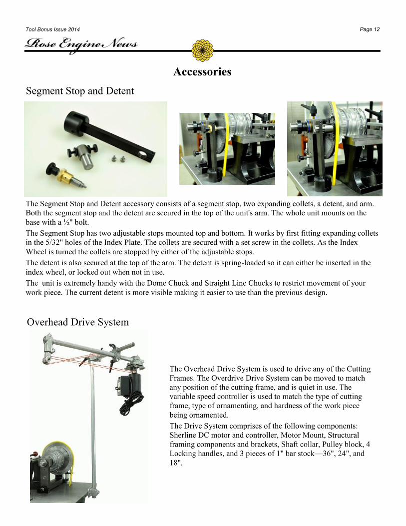
The eccentric cutter head is available separately and is the same cutting
head that is supplied with the above described drilling frame. The
eccentric cutter head is considered by many to be the most versatile tool
in ornamental turning, Ours was designed by Fred Armbruster using his
proven design. It is a compact and well balanced tool that can handle
recommended speeds up to 6000 RPM. Its design keeps the cutter head
close to the frame body to reduce vibration and give better results. The
clamping bolt is offset from the center allowing it to cut circles from
about 1/8" diameter to just over 1 1/8". The cutter head incorporates a
1/8" round tool bit holder and comes with a 60° carbide bit. The cutter
can be changed quickly and easily with a socket head set screw. The
tool block is safely held by a clamping screw so that it cannot come
away from the cutter head. There are two 1/8" studs in the face of the
tool to allow measuring the diameter being cut by simply placing
calipers across the two studs allowing the offset to be measured easily and repeatedly.
The major diameter of the cutter head is 1 1/8", and the shanks come in either 3/8", 8MM (WW) collet style,
or a 1/2" shank meant to be turned to the desired size for special applications.
This is the tool used to make the famous "fish" as well as the more standard barleycorn pattern. Half squares
can easily be made with it as well as the pineapple style decorations so often associated with ornamental
turning. It can also create convex shaped rings around the edges of projects. Its uses are fully described in the
Holtzappfel No. 5, Evans, and Walshaw books.
Eccentric Cutting Head
Universal Cutting Frame for Overhead Drive
The Universal Cutting Frame (UCF) is a versatile tool because it
can be used at any angle from vertical to horizontal. This tool
requires the use of an overhead drive giving smooth and quiet
operation.
It is available with either a cutting head using triangular carbide
insert cutters or 3/16" round cutters; please specify when
ordering. The pulleys are made from steel and ride on high
grade Japanese shielded bearings.
The UCF can be driven by belts from 1/8" to 3/16" in diameter.
The small belt that drives the head is 1/8" and is included.
The shank is 9/16" square making it usable in older style slide
rests.
Custom cutting frames can be made upon request such as one
with extended reach for deeper pieces.
Page 11 Tool Bonus Issue 2014
Large Eccentric Cutting Head This is a larger version of the eccentric cutting head of Fred
Armbruster's design that we have produced for years. It can
cut up to a 3" diameter and employ 1/8", 3/16", and 1/4"
cutters.
It comes standard with a short and long tool holding block
for each size. The larger tool has the advantage of mass and
produces less tool chatter; however, it does not replace the
smaller tool for smaller work. While larger and more stable,
the tool must be well balanced which with practice can be
done quickly. The extra tool holders are used for balancing.
We do not recommend running this tool at speeds over
1500 RPM. It comes standard with an 8mm collet
compatible shank but other sizes can be made upon request
for a nominal cost.
The drilling frame uses ER 16 collets The five included
collets are 1/8", 3/16", 1/4", 5/16", and 3/8". The spindle can
be shortened or extended in the bearings by loosening the
shaft collars and sliding it to a new position in order to allow
reaching into tighter spots. The aluminum bearing block
mounts into a typical tool quick change tool holder and
features non-contact, sealed bearings that deliver freer
running and cooler operation. Also included is an eccentric
cutter of Fred Armbruster’s design with a 60° carbide cutter
(other angles available). The cutting frame accepts 1/8"
diameter cutters. The set also has a 3/16" fly cutter that is
useful as an internal cutting frame and for thread cutting.
The individual components may be purchased separately.
ER16 Drilling Frame with Eccentric Cutting Head
Page 12 Tool Bonus Issue 2014
Overhead Drive System
The Overhead Drive System is used to drive any of the Cutting
Frames. The Overdrive Drive System can be moved to match
any position of the cutting frame, and is quiet in use. The
variable speed controller is used to match the type of cutting
frame, type of ornamenting, and hardness of the work piece
being ornamented.
The Drive System comprises of the following components:
Sherline DC motor and controller, Motor Mount, Structural
framing components and brackets, Shaft collar, Pulley block, 4
Locking handles, and 3 pieces of 1" bar stock—36", 24", and
18".
Accessories
Segment Stop and Detent
The Segment Stop and Detent accessory consists of a segment stop, two expanding collets, a detent, and arm.
Both the segment stop and the detent are secured in the top of the unit's arm. The whole unit mounts on the
base with a ½" bolt.
The Segment Stop has two adjustable stops mounted top and bottom. It works by first fitting expanding collets
in the 5/32" holes of the Index Plate. The collets are secured with a set screw in the collets. As the Index
Wheel is turned the collets are stopped by either of the adjustable stops.
The detent is also secured at the top of the arm. The detent is spring-loaded so it can either be inserted in the
index wheel, or locked out when not in use.
The unit is extremely handy with the Dome Chuck and Straight Line Chucks to restrict movement of your
work piece. The current detent is more visible making it easier to use than the previous design.
Page 13 Tool Bonus Issue 2014
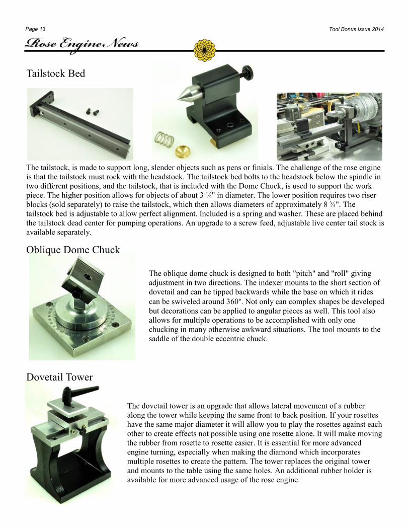
Tailstock Bed
The tailstock, is made to support long, slender objects such as pens or finials. The challenge of the rose engine
is that the tailstock must rock with the headstock. The tailstock bed bolts to the headstock below the spindle in
two different positions, and the tailstock, that is included with the Dome Chuck, is used to support the work
piece. The higher position allows for objects of about 3 ¼" in diameter. The lower position requires two riser
blocks (sold separately) to raise the tailstock, which then allows diameters of approximately 8 ¾". The
tailstock bed is adjustable to allow perfect alignment. Included is a spring and washer. These are placed behind
the tailstock dead center for pumping operations. An upgrade to a screw feed, adjustable live center tail stock is
available separately.
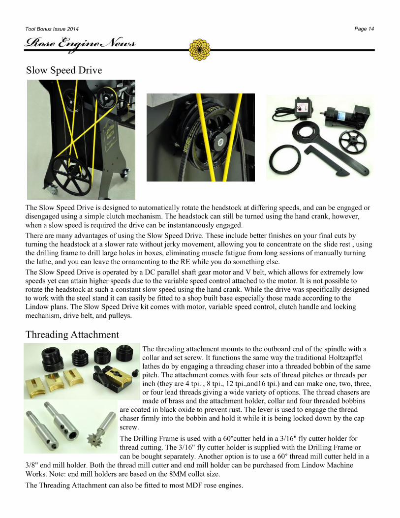
Oblique Dome Chuck
The oblique dome chuck is designed to both "pitch" and "roll" giving
adjustment in two directions. The indexer mounts to the short section of
dovetail and can be tipped backwards while the base on which it rides
can be swiveled around 360°. Not only can complex shapes be developed
but decorations can be applied to angular pieces as well. This tool also
allows for multiple operations to be accomplished with only one
chucking in many otherwise awkward situations. The tool mounts to the
saddle of the double eccentric chuck.
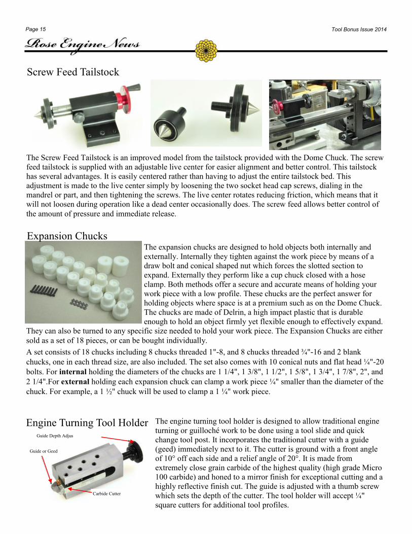
Dovetail Tower
The dovetail tower is an upgrade that allows lateral movement of a rubber
along the tower while keeping the same front to back position. If your rosettes
have the same major diameter it will allow you to play the rosettes against each
other to create effects not possible using one rosette alone. It will make moving
the rubber from rosette to rosette easier. It is essential for more advanced
engine turning, especially when making the diamond which incorporates
multiple rosettes to create the pattern. The tower replaces the original tower
and mounts to the table using the same holes. An additional rubber holder is
available for more advanced usage of the rose engine.
Page 14 Tool Bonus Issue 2014
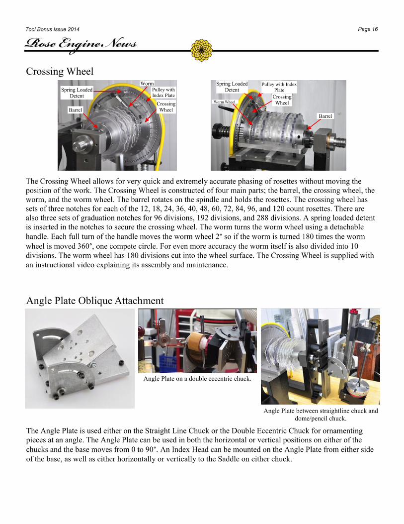
Slow Speed Drive
The Slow Speed Drive is designed to automatically rotate the headstock at differing speeds, and can be engaged or
disengaged using a simple clutch mechanism. The headstock can still be turned using the hand crank, however,
when a slow speed is required the drive can be instantaneously engaged.
There are many advantages of using the Slow Speed Drive. These include better finishes on your final cuts by
turning the headstock at a slower rate without jerky movement, allowing you to concentrate on the slide rest , using
the drilling frame to drill large holes in boxes, eliminating muscle fatigue from long sessions of manually turning
the lathe, and you can leave the ornamenting to the RE while you do something else.
The Slow Speed Drive is operated by a DC parallel shaft gear motor and V belt, which allows for extremely low
speeds yet can attain higher speeds due to the variable speed control attached to the motor. It is not possible to
rotate the headstock at such a constant slow speed using the hand crank. While the drive was specifically designed
to work with the steel stand it can easily be fitted to a shop built base especially those made according to the
Lindow plans. The Slow Speed Drive kit comes with motor, variable speed control, clutch handle and locking
mechanism, drive belt, and pulleys.
Threading Attachment
The threading attachment mounts to the outboard end of the spindle with a
collar and set screw. It functions the same way the traditional Holtzapffel
lathes do by engaging a threading chaser into a threaded bobbin of the same
pitch. The attachment comes with four sets of thread pitches or threads per
inch (they are 4 tpi. , 8 tpi., 12 tpi.,and16 tpi.) and can make one, two, three,
or four lead threads giving a wide variety of options. The thread chasers are
made of brass and the attachment holder, collar and four threaded bobbins
are coated in black oxide to prevent rust. The lever is used to engage the thread
chaser firmly into the bobbin and hold it while it is being locked down by the cap
screw.
The Drilling Frame is used with a 60°cutter held in a 3/16" fly cutter holder for
thread cutting. The 3/16" fly cutter holder is supplied with the Drilling Frame or
can be bought separately. Another option is to use a 60° thread mill cutter held in a
3/8" end mill holder. Both the thread mill cutter and end mill holder can be purchased from Lindow Machine
Works. Note: end mill holders are based on the 8MM collet size.
The Threading Attachment can also be fitted to most MDF rose engines.
Page 15 Tool Bonus Issue 2014
Screw Feed Tailstock
The Screw Feed Tailstock is an improved model from the tailstock provided with the Dome Chuck. The screw
feed tailstock is supplied with an adjustable live center for easier alignment and better control. This tailstock
has several advantages. It is easily centered rather than having to adjust the entire tailstock bed. This
adjustment is made to the live center simply by loosening the two socket head cap screws, dialing in the
mandrel or part, and then tightening the screws. The live center rotates reducing friction, which means that it
will not loosen during operation like a dead center occasionally does. The screw feed allows better control of
the amount of pressure and immediate release.
The expansion chucks are designed to hold objects both internally and
externally. Internally they tighten against the work piece by means of a
draw bolt and conical shaped nut which forces the slotted section to
expand. Externally they perform like a cup chuck closed with a hose
clamp. Both methods offer a secure and accurate means of holding your
work piece with a low profile. These chucks are the perfect answer for
holding objects where space is at a premium such as on the Dome Chuck.
The chucks are made of Delrin, a high impact plastic that is durable
enough to hold an object firmly yet flexible enough to effectively expand.
They can also be turned to any specific size needed to hold your work piece. The Expansion Chucks are either
sold as a set of 18 pieces, or can be bought individually.
A set consists of 18 chucks including 8 chucks threaded 1"-8, and 8 chucks threaded ¾"-16 and 2 blank
chucks, one in each thread size, are also included. The set also comes with 10 conical nuts and flat head ¼"-20
bolts. For internal holding the diameters of the chucks are 1 1/4", 1 3/8", 1 1/2", 1 5/8", 1 3/4", 1 7/8", 2", and
2 1/4".For external holding each expansion chuck can clamp a work piece ¼" smaller than the diameter of the
chuck. For example, a 1 ½" chuck will be used to clamp a 1 ¼" work piece.
Expansion Chucks
The engine turning tool holder is designed to allow traditional engine
turning or guilloché work to be done using a tool slide and quick
change tool post. It incorporates the traditional cutter with a guide
(geed) immediately next to it. The cutter is ground with a front angle
of 10° off each side and a relief angle of 20°. It is made from
extremely close grain carbide of the highest quality (high grade Micro
100 carbide) and honed to a mirror finish for exceptional cutting and a
highly reflective finish cut. The guide is adjusted with a thumb screw
which sets the depth of the cutter. The tool holder will accept ¼"
square cutters for additional tool profiles.
Engine Turning Tool Holder Guide Depth Adjus
Guide or Geed
Carbide Cutter
Page 16 Tool Bonus Issue 2014
Angle Plate on a double eccentric chuck.
Angle Plate between straightline chuck and
dome/pencil chuck.
Angle Plate Oblique Attachment
The Angle Plate is used either on the Straight Line Chuck or the Double Eccentric Chuck for ornamenting
pieces at an angle. The Angle Plate can be used in both the horizontal or vertical positions on either of the
chucks and the base moves from 0 to 90°. An Index Head can be mounted on the Angle Plate from either side
of the base, as well as either horizontally or vertically to the Saddle on either chuck.
Crossing Wheel
The Crossing Wheel allows for very quick and extremely accurate phasing of rosettes without moving the
position of the work. The Crossing Wheel is constructed of four main parts; the barrel, the crossing wheel, the
worm, and the worm wheel. The barrel rotates on the spindle and holds the rosettes. The crossing wheel has
sets of three notches for each of the 12, 18, 24, 36, 40, 48, 60, 72, 84, 96, and 120 count rosettes. There are
also three sets of graduation notches for 96 divisions, 192 divisions, and 288 divisions. A spring loaded detent
is inserted in the notches to secure the crossing wheel. The worm turns the worm wheel using a detachable
handle. Each full turn of the handle moves the worm wheel 2° so if the worm is turned 180 times the worm
wheel is moved 360°, one compete circle. For even more accuracy the worm itself is also divided into 10
divisions. The worm wheel has 180 divisions cut into the wheel surface. The Crossing Wheel is supplied with
an instructional video explaining its assembly and maintenance.
Spring Loaded
Detent
Barrel
Worm Pulley with
Index Plate
Crossing
Wheel
Spring Loaded
Detent
Crossing
Wheel Worm Wheel
Barrel
Pulley with Index
Plate
Page 17 Tool Bonus Issue 2014
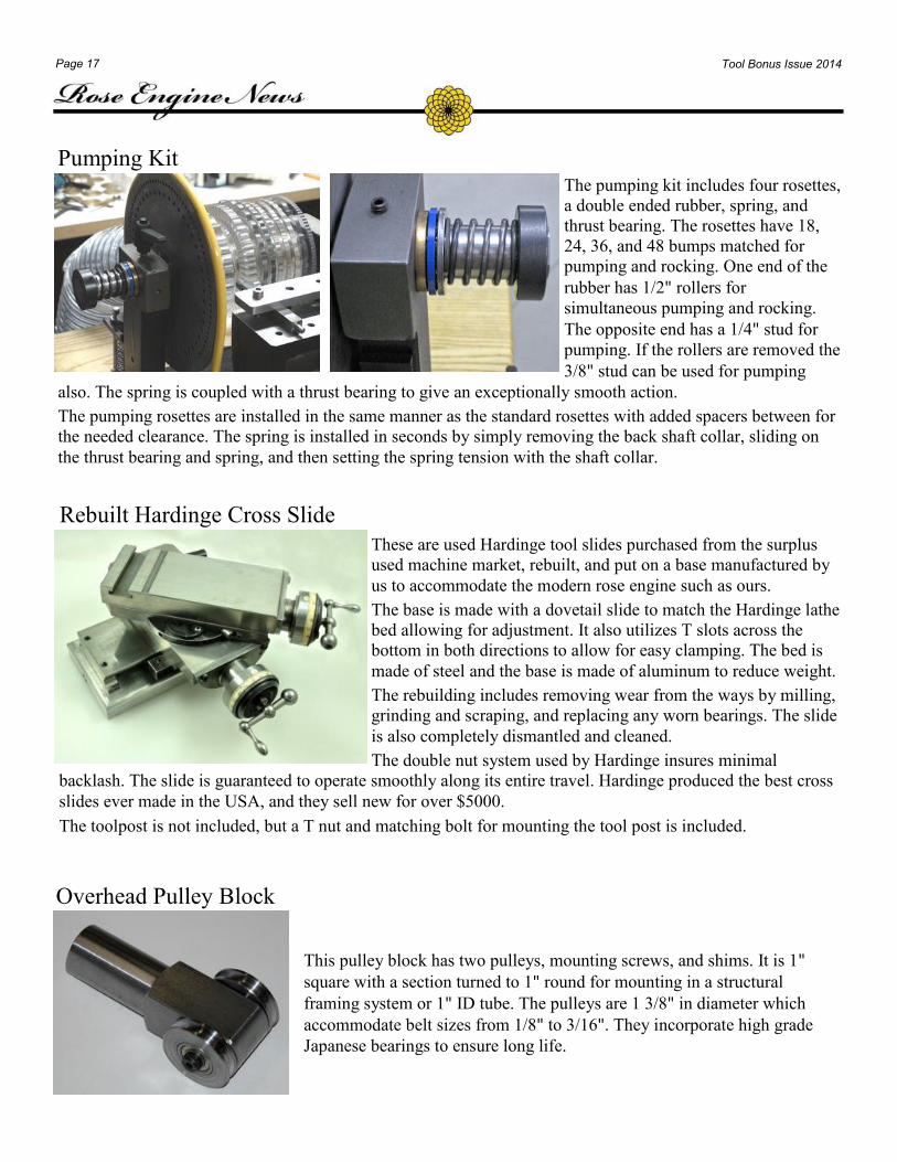
Pumping Kit The pumping kit includes four rosettes,
a double ended rubber, spring, and
thrust bearing. The rosettes have 18,
24, 36, and 48 bumps matched for
pumping and rocking. One end of the
rubber has 1/2" rollers for
simultaneous pumping and rocking.
The opposite end has a 1/4" stud for
pumping. If the rollers are removed the
3/8" stud can be used for pumping
also. The spring is coupled with a thrust bearing to give an exceptionally smooth action.
The pumping rosettes are installed in the same manner as the standard rosettes with added spacers between for
the needed clearance. The spring is installed in seconds by simply removing the back shaft collar, sliding on
the thrust bearing and spring, and then setting the spring tension with the shaft collar.
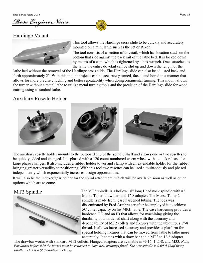
Rebuilt Hardinge Cross Slide
These are used Hardinge tool slides purchased from the surplus
used machine market, rebuilt, and put on a base manufactured by
us to accommodate the modern rose engine such as ours.
The base is made with a dovetail slide to match the Hardinge lathe
bed allowing for adjustment. It also utilizes T slots across the
bottom in both directions to allow for easy clamping. The bed is
made of steel and the base is made of aluminum to reduce weight.
The rebuilding includes removing wear from the ways by milling,
grinding and scraping, and replacing any worn bearings. The slide
is also completely dismantled and cleaned.
The double nut system used by Hardinge insures minimal
backlash. The slide is guaranteed to operate smoothly along its entire travel. Hardinge produced the best cross
slides ever made in the USA, and they sell new for over $5000.
The toolpost is not included, but a T nut and matching bolt for mounting the tool post is included.
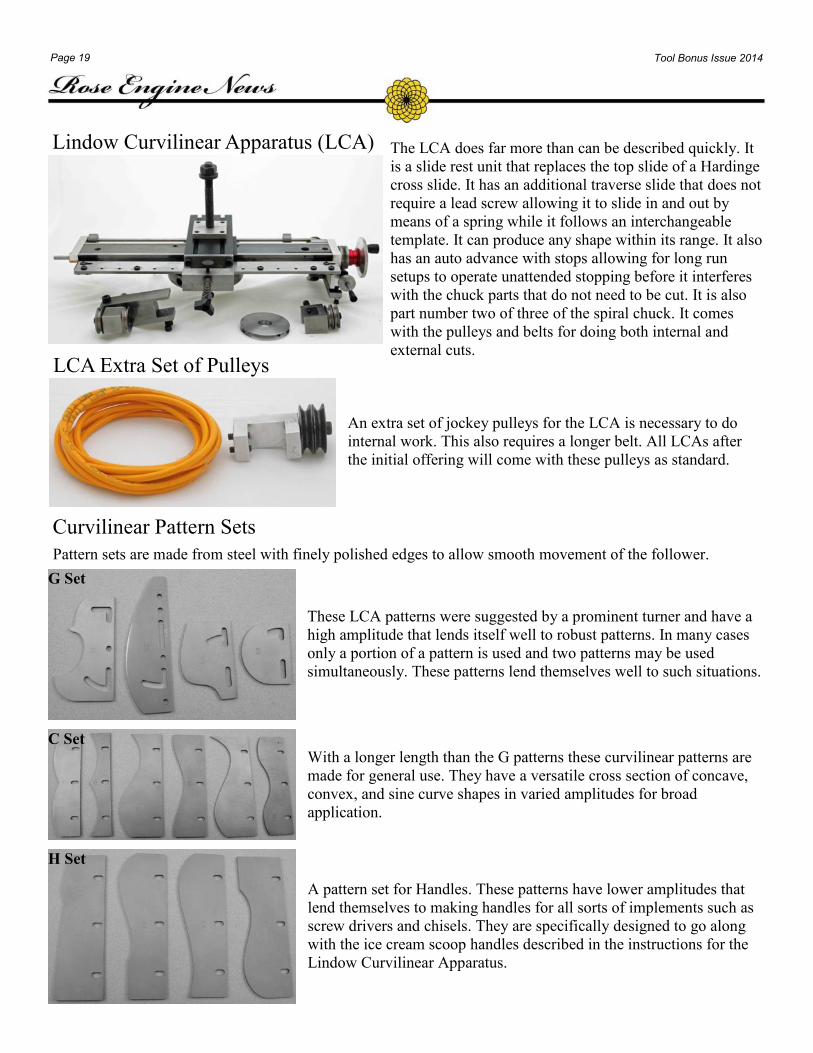
Overhead Pulley Block
This pulley block has two pulleys, mounting screws, and shims. It is 1"
square with a section turned to 1" round for mounting in a structural
framing system or 1" ID tube. The pulleys are 1 3/8" in diameter which
accommodate belt sizes from 1/8" to 3/16". They incorporate high grade
Japanese bearings to ensure long life.
Page 18 Tool Bonus Issue 2014
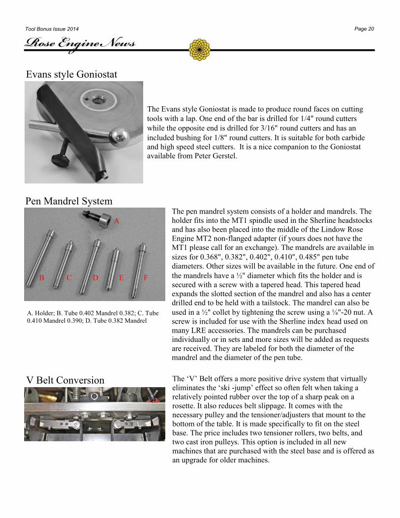
Hardinge Mount
This tool allows the Hardinge cross slide to be quickly and accurately
mounted on a mini lathe such as the Jet or Rikon.
The tool consists of a section of dovetail, which has location studs on the
bottom that ride against the back rail of the lathe bed. It is locked down
by means of a cam, which is tightened by a hex wrench. Once attached to
the lathe the entire dovetail can be slid up and down the length of the
lathe bed without the removal of the Hardinge cross slide. The Hardinge slide can also be adjusted back and
forth approximately 2". With this mount projects can be accurately turned, faced, and bored in a manner that
allows for more precise chucking and better repeatability when doing ornamental turning. This mount allows
the turner without a metal lathe to utilize metal turning tools and the precision of the Hardinge slide for wood
cutting using a standard lathe.
Auxiliary Rosette Holder
The auxiliary rosette holder mounts to the outboard end of the spindle shaft and allows one or two rosettes to
be quickly added and changed. It is phased with a 120 count numbered worm wheel with a quick release for
large phase changes. It also includes a rubber holder tower and clamp with an extendable holder for the rubber
bringing greater versatility to positioning. With this tool two rosettes can be used simultaneously and phased
independently which exponentially increases design opportunities.
It will also be the indexer/gear holder for the spiral attachment, which will be available soon as well as other
options which are to come.
MT2 Spindle The MT2 spindle is a hollow 18" long Headstock spindle with #2
Morse Taper, draw bar, and 1"-8 adapter. The Morse Taper 2
spindle is made from case hardened tubing. The idea was
disseminated by Fred Armbruster after he employed it to achieve
5C collet capacity on his MKII lathe. The case hardening provides a
hardened OD and an ID that allows for machining giving the
durability of a hardened shaft along with the accuracy and
dependability of MT2 collets and fixtures with the ubiquitous 1"-8
thread. It allows increased accuracy and provides a platform for
special holding fixtures that can be moved from lathe to lathe more
accurately. It comes with a draw bar and a MT2 to 1"-8 adapter.
The drawbar works with standard MT2 collets. Flanged adapters are available in ¾-16, 1 ¼-8, and M33. Note:
For lathes before #70 the barrel must be returned to have new bushings fitted. The new spindle is 0.0005" (half thou)
smaller. This is a $50 additional charge.
Page 19 Tool Bonus Issue 2014
Lindow Curvilinear Apparatus (LCA) The LCA does far more than can be described quickly. It
is a slide rest unit that replaces the top slide of a Hardinge
cross slide. It has an additional traverse slide that does not
require a lead screw allowing it to slide in and out by
means of a spring while it follows an interchangeable
template. It can produce any shape within its range. It also
has an auto advance with stops allowing for long run
setups to operate unattended stopping before it interferes
with the chuck parts that do not need to be cut. It is also
part number two of three of the spiral chuck. It comes
with the pulleys and belts for doing both internal and
external cuts. LCA Extra Set of Pulleys
An extra set of jockey pulleys for the LCA is necessary to do
internal work. This also requires a longer belt. All LCAs after
the initial offering will come with these pulleys as standard.
Curvilinear Pattern Sets
Pattern sets are made from steel with finely polished edges to allow smooth movement of the follower.
These LCA patterns were suggested by a prominent turner and have a
high amplitude that lends itself well to robust patterns. In many cases
only a portion of a pattern is used and two patterns may be used
simultaneously. These patterns lend themselves well to such situations.
G Set
With a longer length than the G patterns these curvilinear patterns are
made for general use. They have a versatile cross section of concave,
convex, and sine curve shapes in varied amplitudes for broad
application.
C Set
A pattern set for Handles. These patterns have lower amplitudes that
lend themselves to making handles for all sorts of implements such as
screw drivers and chisels. They are specifically designed to go along
with the ice cream scoop handles described in the instructions for the
Lindow Curvilinear Apparatus.
H Set
Page 20 Tool Bonus Issue 2014
Evans style Goniostat
The Evans style Goniostat is made to produce round faces on cutting
tools with a lap. One end of the bar is drilled for 1/4" round cutters
while the opposite end is drilled for 3/16" round cutters and has an
included bushing for 1/8" round cutters. It is suitable for both carbide
and high speed steel cutters. It is a nice companion to the Goniostat
available from Peter Gerstel.
A
A. Holder; B. Tube 0.402 Mandrel 0.382; C. Tube
0.410 Mandrel 0.390; D. Tube 0.382 Mandrel
Pen Mandrel System The pen mandrel system consists of a holder and mandrels. The
holder fits into the MT1 spindle used in the Sherline headstocks
and has also been placed into the middle of the Lindow Rose
Engine MT2 non-flanged adapter (if yours does not have the
MT1 please call for an exchange). The mandrels are available in
sizes for 0.368", 0.382", 0.402", 0.410", 0.485" pen tube
diameters. Other sizes will be available in the future. One end of
the mandrels have a ½" diameter which fits the holder and is
secured with a screw with a tapered head. This tapered head
expands the slotted section of the mandrel and also has a center
drilled end to be held with a tailstock. The mandrel can also be
used in a ½" collet by tightening the screw using a ¼"-20 nut. A
screw is included for use with the Sherline index head used on
many LRE accessories. The mandrels can be purchased
individually or in sets and more sizes will be added as requests
are received. They are labeled for both the diameter of the
mandrel and the diameter of the pen tube.
C D E F B
A
V Belt Conversion The ‘V’ Belt offers a more positive drive system that virtually
eliminates the ‘ski -jump’ effect so often felt when taking a
relatively pointed rubber over the top of a sharp peak on a
rosette. It also reduces belt slippage. It comes with the
necessary pulley and the tensioner/adjusters that mount to the
bottom of the table. It is made specifically to fit on the steel
base. The price includes two tensioner rollers, two belts, and
two cast iron pulleys. This option is included in all new
machines that are purchased with the steel base and is offered as
an upgrade for older machines.
Page 21 Tool Bonus Issue 2014
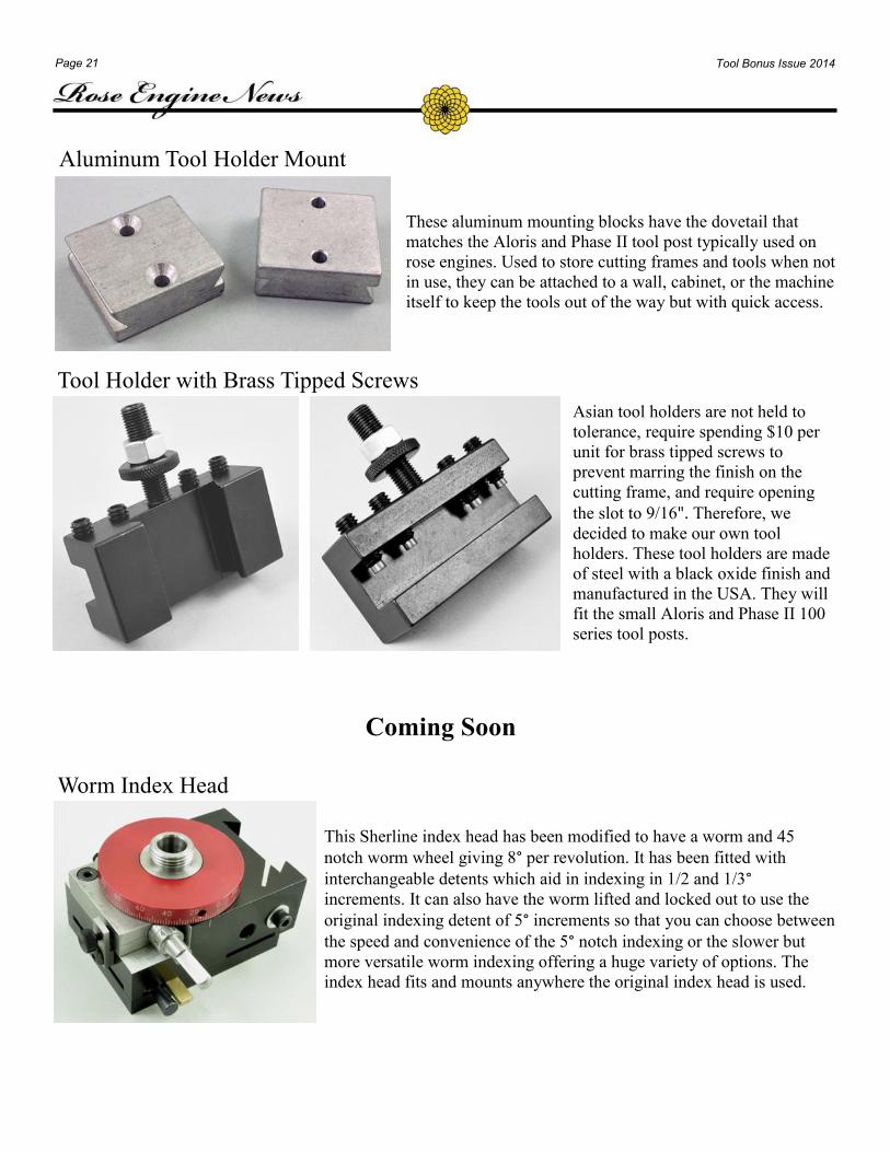
Aluminum Tool Holder Mount
These aluminum mounting blocks have the dovetail that
matches the Aloris and Phase II tool post typically used on
rose engines. Used to store cutting frames and tools when not
in use, they can be attached to a wall, cabinet, or the machine
itself to keep the tools out of the way but with quick access.
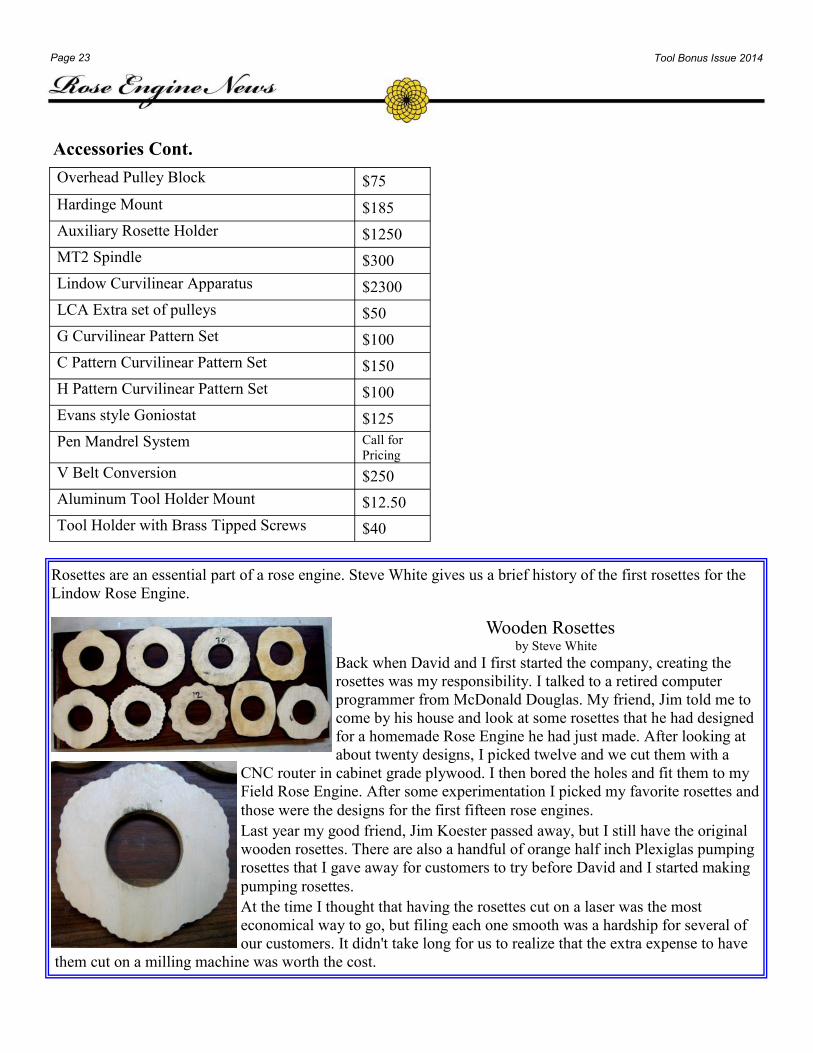
Tool Holder with Brass Tipped Screws
Asian tool holders are not held to
tolerance, require spending $10 per
unit for brass tipped screws to
prevent marring the finish on the
cutting frame, and require opening
the slot to 9/16". Therefore, we
decided to make our own tool
holders. These tool holders are made
of steel with a black oxide finish and
manufactured in the USA. They will
fit the small Aloris and Phase II 100
series tool posts.
Coming Soon
Worm Index Head
This Sherline index head has been modified to have a worm and 45
notch worm wheel giving 8° per revolution. It has been fitted with
interchangeable detents which aid in indexing in 1/2 and 1/3° increments. It can also have the worm lifted and locked out to use the
original indexing detent of 5° increments so that you can choose between
the speed and convenience of the 5° notch indexing or the slower but
more versatile worm indexing offering a huge variety of options. The
index head fits and mounts anywhere the original index head is used.

Page 22 Tool Bonus Issue 2014
PRICE LIST
Rose Engine $4,350
Basic Lathe Package $8,475
Complete Lathe Package $14,250
Engine Turning Lathe Package $7,950
Rose Engine
Rosettes
Set of 20 Rosettes $325
Oval Rosette set $135
Sine Wave Rosette set $135
Engine Turning Rosettes $135
PP&D Rosettes $150
C & D Rosettes $150
Pumping Rosettes $150
Rubbers
0.5" and 45° $35
Straight $35
0.250" single roller $45
0.750" roller $45
0.250" double roller $50
1.5" $45
2.0" $45
2.5" $45
1.25" Concave $45
1.5" Concave $45
#4 Rubber $45
Engine Turning Rubber Set $150
Chucks
Straightline Chuck $500
Modular Chuck—Straightline Kit $250
Dome Chuck with accessories
including double eccentric chuck $775
Dome Chuck Riser Block (If used
with the tailstock, two blocks are
needed.)
$65
Accessories
Segment Stop and Detent $350
Overhead Drive System $625
Tailstock Bed $185
Oblique Dome Chuck $250
Dovetail Tower— as an upgrade to a new
machine or with exchange on an existing
machine
Extra Rubber Holder
$475
$150
Slow Speed Drive $675
The Screw Feed Tailstock $155
Expansion Chucks-set of 18 with nuts and
bolts
Individual Chucks, without nut and bolt
Nut and Bolt set of 5 each
$350
$25
$20
Engine Turning Tool Holder $150
Crossing Wheel Call
Angle Plate Oblique Attachment $150
Pumping Kit $225
Rebuilt Hardinge Cross Slide $1,450
¾" x 16 tpi to 1" x 8 tpi spindle adapter $25
Cutting Frames
Drilling Frame with Eccentric Cutter
Head $600
Eccentric Cutter Head $185
Universal Cutting Frame (overhead
drive) $385
Large Eccentric Cutter Head $275
ER 16 Drilling Frame with ECF $600
Extra Slide $200
Leveling Chuck $275
Paper Chuck and Pen Holder
Face Plate
$225
$50
Bottle Stopper Chucks $25
Index Head Face Plate $50
Chucks Cont.
Page 23 Tool Bonus Issue 2014
Rosettes are an essential part of a rose engine. Steve White gives us a brief history of the first rosettes for the
Lindow Rose Engine.
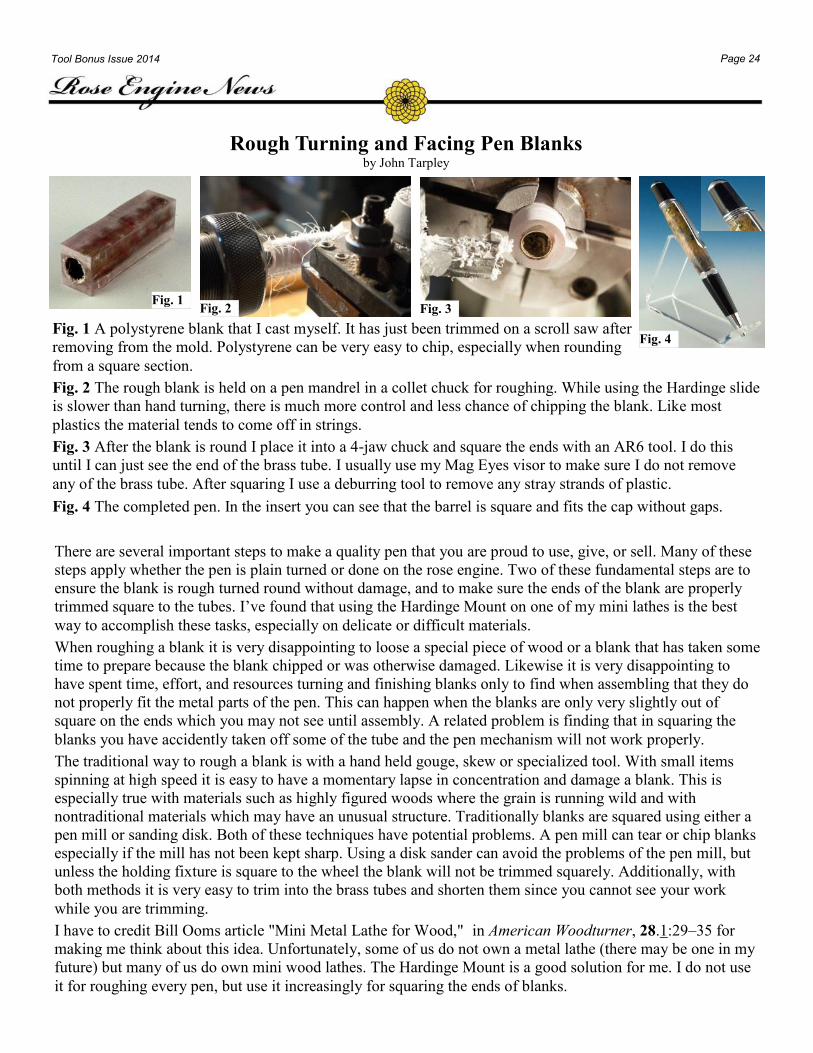
Wooden Rosettes by Steve White
Back when David and I first started the company, creating the
rosettes was my responsibility. I talked to a retired computer
programmer from McDonald Douglas. My friend, Jim told me to
come by his house and look at some rosettes that he had designed
for a homemade Rose Engine he had just made. After looking at
about twenty designs, I picked twelve and we cut them with a
CNC router in cabinet grade plywood. I then bored the holes and fit them to my
Field Rose Engine. After some experimentation I picked my favorite rosettes and
those were the designs for the first fifteen rose engines.
Last year my good friend, Jim Koester passed away, but I still have the original
wooden rosettes. There are also a handful of orange half inch Plexiglas pumping
rosettes that I gave away for customers to try before David and I started making
pumping rosettes.
At the time I thought that having the rosettes cut on a laser was the most
economical way to go, but filing each one smooth was a hardship for several of
our customers. It didn't take long for us to realize that the extra expense to have
them cut on a milling machine was worth the cost.
Overhead Pulley Block $75
Hardinge Mount $185
Auxiliary Rosette Holder $1250
MT2 Spindle $300
Lindow Curvilinear Apparatus $2300
LCA Extra set of pulleys $50
G Curvilinear Pattern Set $100
C Pattern Curvilinear Pattern Set $150
H Pattern Curvilinear Pattern Set $100
Evans style Goniostat $125
Pen Mandrel System Call for
Pricing
V Belt Conversion $250
Aluminum Tool Holder Mount $12.50
Tool Holder with Brass Tipped Screws $40
Accessories Cont.
Page 24 Tool Bonus Issue 2014
Rough Turning and Facing Pen Blanks by John Tarpley
There are several important steps to make a quality pen that you are proud to use, give, or sell. Many of these
steps apply whether the pen is plain turned or done on the rose engine. Two of these fundamental steps are to
ensure the blank is rough turned round without damage, and to make sure the ends of the blank are properly
trimmed square to the tubes. I’ve found that using the Hardinge Mount on one of my mini lathes is the best
way to accomplish these tasks, especially on delicate or difficult materials.
When roughing a blank it is very disappointing to loose a special piece of wood or a blank that has taken some
time to prepare because the blank chipped or was otherwise damaged. Likewise it is very disappointing to
have spent time, effort, and resources turning and finishing blanks only to find when assembling that they do
not properly fit the metal parts of the pen. This can happen when the blanks are only very slightly out of
square on the ends which you may not see until assembly. A related problem is finding that in squaring the
blanks you have accidently taken off some of the tube and the pen mechanism will not work properly.
The traditional way to rough a blank is with a hand held gouge, skew or specialized tool. With small items
spinning at high speed it is easy to have a momentary lapse in concentration and damage a blank. This is
especially true with materials such as highly figured woods where the grain is running wild and with
nontraditional materials which may have an unusual structure. Traditionally blanks are squared using either a
pen mill or sanding disk. Both of these techniques have potential problems. A pen mill can tear or chip blanks
especially if the mill has not been kept sharp. Using a disk sander can avoid the problems of the pen mill, but
unless the holding fixture is square to the wheel the blank will not be trimmed squarely. Additionally, with
both methods it is very easy to trim into the brass tubes and shorten them since you cannot see your work
while you are trimming.
I have to credit Bill Ooms article "Mini Metal Lathe for Wood," in American Woodturner, 28.1:29–35 for
making me think about this idea. Unfortunately, some of us do not own a metal lathe (there may be one in my
future) but many of us do own mini wood lathes. The Hardinge Mount is a good solution for me. I do not use
it for roughing every pen, but use it increasingly for squaring the ends of blanks.
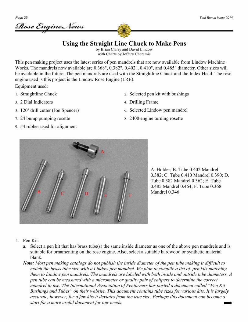
Fig. 1 A polystyrene blank that I cast myself. It has just been trimmed on a scroll saw after
removing from the mold. Polystyrene can be very easy to chip, especially when rounding
from a square section.
Fig. 2 The rough blank is held on a pen mandrel in a collet chuck for roughing. While using the Hardinge slide
is slower than hand turning, there is much more control and less chance of chipping the blank. Like most
plastics the material tends to come off in strings.
Fig. 3 After the blank is round I place it into a 4-jaw chuck and square the ends with an AR6 tool. I do this
until I can just see the end of the brass tube. I usually use my Mag Eyes visor to make sure I do not remove
any of the brass tube. After squaring I use a deburring tool to remove any stray strands of plastic.
Fig. 4 The completed pen. In the insert you can see that the barrel is square and fits the cap without gaps.
Fig. 1 Fig. 2 Fig. 3
Fig. 4
Page 25 Tool Bonus Issue 2014
Using the Straight Line Chuck to Make Pens by Brian Clarry and David Lindow
with Charts by Jeffery Cheramie
This pen making project uses the latest series of pen mandrels that are now available from Lindow Machine
Works. The mandrels now available are 0.368", 0.382", 0.402", 0.410", and 0.485" diameter. Other sizes will
be available in the future. The pen mandrels are used with the Straightline Chuck and the Index Head. The rose
engine used is this project is the Lindow Rose Engine (LRE).
Equipment used:
1. Straightline Chuck 2. Selected pen kit with bushings
3. 2 Dial Indicators 4. Drilling Frame
5. 120° drill cutter (Jon Spencer) 6. Selected Lindow pen mandrel
7. 24 bump pumping rosette 8. 2400 engine turning rosette
9. #4 rubber used for alignment
1. Pen Kit.
a. Select a pen kit that has brass tube(s) the same inside diameter as one of the above pen mandrels and is
suitable for ornamenting on the rose engine. Also, select a suitable hardwood or synthetic material
blank.
Note: Most pen making catalogs do not publish the inside diameter of the pen tube making it difficult to
match the brass tube size with a Lindow pen mandrel. We plan to compile a list of pen kits matching
them to Lindow pen mandrels. The mandrels are labeled with both inside and outside tube diameters. A
pen tube can be measured with a micrometer or quality pair of calipers to determine the correct
mandrel to use. The International Association of Penturners has posted a document called “Pen Kit
Bushings and Tubes” on their website. This document contains tube sizes for various kits. It is largely
accurate, however, for a few kits it deviates from the true size. Perhaps this document can become a
start for a more useful document for our needs.
A. Holder; B. Tube 0.402 Mandrel
0.382; C. Tube 0.410 Mandrel 0.390; D.
Tube 0.382 Mandrel 0.362; E. Tube
0.485 Mandrel 0.464; F. Tube 0.368
Mandrel 0.346 C D E F B
A
Page 26 Tool Bonus Issue 2014
b. Preparing the pen blank
i. Use the correct size drill, or a drill plus a reamer that is 0.004"-0.005" larger than the tube to drill a
hole in the pen blank so that the tube will slide snugly into the blank with room for glue. The reamer
gives a more predictable result. The important point is to drill an accurate hole that is just slightly
larger than the outside diameter of the tube.
ii. Glue the brass tube in the blank using the glue of your choice. Make sure you have a good glue joint.
If the glue joint is weak it may allow the blank to move or flex on the tube which will produce an
inaccurate turning. If the glue joint should fail the pen may become useless.
c. Turning the pen blank round.
i. After allowing the glue to dry use a regular lathe with a pen mandrel and correctly sized bushings to
round the pen blank.
ii. If using a metal lathe, or a mini-woodturning lathe with the Lindow Hardinge Mount, it is necessary
to measure the diameter of the pen part to which the blank will be attached to turn the blank to the
proper diameter. Remember that you may want to allow for the thickness of any finish you may
choose to use.
Note: It is important to ensure the finished diameter of the pen blank fits the pen kit hardware piece
that fits adjacent to the blank. You may be able to achieve this fit by using accurate bushings, but it
is better to use a micrometer and measure the diameter of each actual piece that attaches to the
blank.
When turning down a pen blank that will be used on a pattern that does not completely cut the OD
of the pen blank, close accuracy must be maintained so that the pattern looks consistent. The
finished pen blank must also be polished to a fine finish in advance of ornamentation.
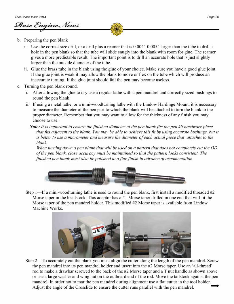
Step 1—If a mini-woodturning lathe is used to round the pen blank, first install a modified threaded #2
Morse taper in the headstock. This adaptor has a #1 Morse taper drilled in one end that will fit the
Morse taper of the pen mandrel holder. This modified #2 Morse taper is available from Lindow
Machine Works.
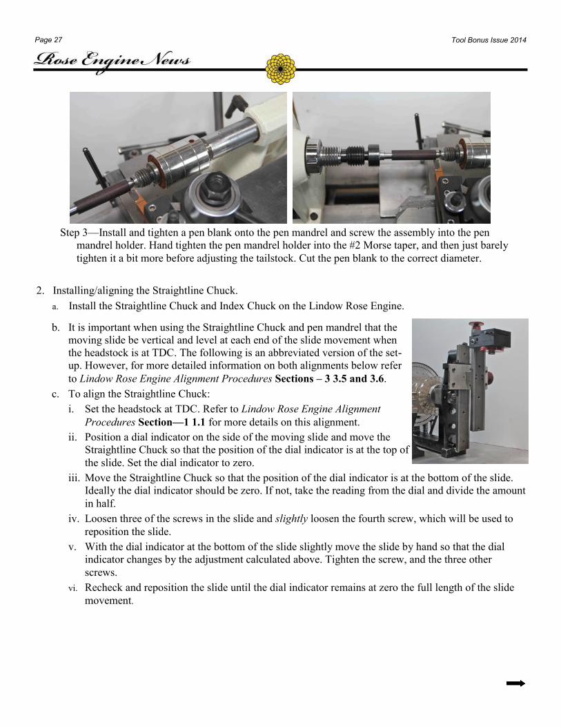
Step 2—To accurately cut the blank you must align the cutter along the length of the pen mandrel. Screw
the pen mandrel into its pen mandrel holder and insert into the #2 Morse taper. Use an ‘all-thread’
rod to make a drawbar screwed to the back of the #2 Morse taper and a T nut handle as shown above
or use a large washer and wing nut on the outboard end of the rod. Move the tailstock against the pen
mandrel. In order not to mar the pen mandrel during alignment use a flat cutter in the tool holder.
Adjust the angle of the Crosslide to ensure the cutter runs parallel with the pen mandrel.
Page 27 Tool Bonus Issue 2014
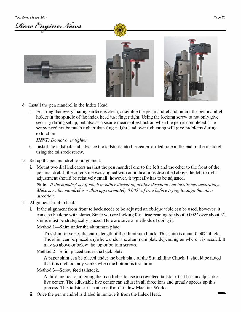
Step 3—Install and tighten a pen blank onto the pen mandrel and screw the assembly into the pen
mandrel holder. Hand tighten the pen mandrel holder into the #2 Morse taper, and then just barely
tighten it a bit more before adjusting the tailstock. Cut the pen blank to the correct diameter.
2. Installing/aligning the Straightline Chuck.
a. Install the Straightline Chuck and Index Chuck on the Lindow Rose Engine.
b. It is important when using the Straightline Chuck and pen mandrel that the
moving slide be vertical and level at each end of the slide movement when
the headstock is at TDC. The following is an abbreviated version of the set-
up. However, for more detailed information on both alignments below refer
to Lindow Rose Engine Alignment Procedures Sections – 3 3.5 and 3.6.
c. To align the Straightline Chuck:
i. Set the headstock at TDC. Refer to Lindow Rose Engine Alignment
Procedures Section—1 1.1 for more details on this alignment.
ii. Position a dial indicator on the side of the moving slide and move the
Straightline Chuck so that the position of the dial indicator is at the top of
the slide. Set the dial indicator to zero.
iii. Move the Straightline Chuck so that the position of the dial indicator is at the bottom of the slide.
Ideally the dial indicator should be zero. If not, take the reading from the dial and divide the amount
in half.
iv. Loosen three of the screws in the slide and slightly loosen the fourth screw, which will be used to
reposition the slide.
v. With the dial indicator at the bottom of the slide slightly move the slide by hand so that the dial
indicator changes by the adjustment calculated above. Tighten the screw, and the three other
screws.
vi. Recheck and reposition the slide until the dial indicator remains at zero the full length of the slide
movement.
Page 28 Tool Bonus Issue 2014
d. Install the pen mandrel in the Index Head.
i. Ensuring that every mating surface is clean, assemble the pen mandrel and mount the pen mandrel
holder in the spindle of the index head just finger tight. Using the locking screw to not only give
security during set up, but also as a secure means of extraction when the pen is completed. The
screw need not be much tighter than finger tight, and over tightening will give problems during
extraction.
HINT: Do not over tighten.
ii. Install the tailstock and advance the tailstock into the center-drilled hole in the end of the mandrel
using the tailstock screw.
e. Set up the pen mandrel for alignment.
i. Mount two dial indicators against the pen mandrel one to the left and the other to the front of the
pen mandrel. If the outer slide was aligned with an indicator as described above the left to right
adjustment should be relatively small; however, it typically has to be adjusted.
Note: If the mandrel is off much in either direction, neither direction can be aligned accurately.
Make sure the mandrel is within approximately 0.005" of true before trying to align the other
direction.
f. Alignment front to back.
i. If the alignment from front to back needs to be adjusted an oblique table can be used, however, it
can also be done with shims. Since you are looking for a true reading of about 0.002" over about 3",
shims must be strategically placed. Here are several methods of doing it.
Method 1—Shim under the aluminum plate.
This shim traverses the entire length of the aluminum block. This shim is about 0.007" thick.
The shim can be placed anywhere under the aluminum plate depending on where it is needed. It
may go above or below the top or bottom screws.
Method 2—Shim placed under the back plate.
A paper shim can be placed under the back plate of the Straightline Chuck. It should be noted
that this method only works when the bottom is too far in.
Method 3—Screw feed tailstock.
A third method of aligning the mandrel is to use a screw feed tailstock that has an adjustable
live center. The adjustable live center can adjust in all directions and greatly speeds up this
process. This tailstock is available from Lindow Machine Works.
ii. Once the pen mandrel is dialed in remove it from the Index Head.
Page 29 Tool Bonus Issue 2014
g. Setting up the Cutting Frame and Cutter.
i. Install the 120° cutter in the Drilling Frame and center the cutter tip by eye so the cutter tip is in line
and nearly touching the tailstock point. This is not an accurate set-up, but it will get it close enough
to make a test cut.
Note: Be careful not to knock the tip off of the cutter when doing this.
ii. Install a test pen blank on the pen mandrel and reinstall in the Index Head. Reposition the tailstock
against the pen mandrel.
iii. For this alignment install a 2400 engine turning rosette with a #4 rubber that will cut a sine wave
pattern.
Note: Other rosettes can be used as long as they are combined with a rubber to produce a sine
wave. Either the 24 pumping rubber can be used with a 1" diameter rubber or the 18 pumping
rubber can be used with a 2" diameter rubber. If it is not producing a sine wave the center will not
be easily seen.
iv. The headstock must be set up with the amplitude divided equally on either
side of top dead center (TDC).
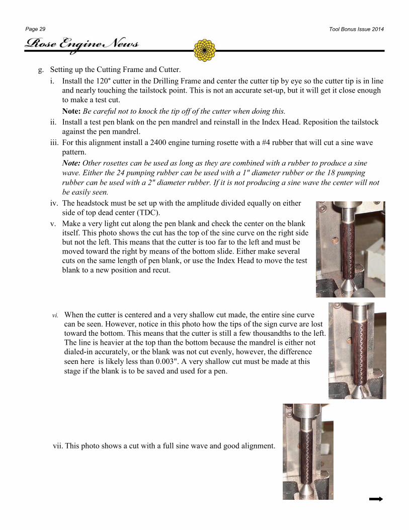
v. Make a very light cut along the pen blank and check the center on the blank
itself. This photo shows the cut has the top of the sine curve on the right side
but not the left. This means that the cutter is too far to the left and must be
moved toward the right by means of the bottom slide. Either make several
cuts on the same length of pen blank, or use the Index Head to move the test
blank to a new position and recut.
vi. When the cutter is centered and a very shallow cut made, the entire sine curve
can be seen. However, notice in this photo how the tips of the sign curve are lost
toward the bottom. This means that the cutter is still a few thousandths to the left.
The line is heavier at the top than the bottom because the mandrel is either not
dialed-in accurately, or the blank was not cut evenly, however, the difference
seen here is likely less than 0.003". A very shallow cut must be made at this
stage if the blank is to be saved and used for a pen.
vii. This photo shows a cut with a full sine wave and good alignment.
Page 30 Tool Bonus Issue 2014
h. Setting the cutter for the bottom and top of the pen blank.
Note: If the pattern is to be centered either on a single tube or aligned with a second tube the cutter
must be set top to bottom on the pen blank.
i. Bottom of the pen blank—with the headstock at top dead center position the cutter with the
bottom of the blank.
ii. Top of the pen blank—the Straightline Chuck slide is then moved to the last TDC position that
would still have the cutter in the blank. The distance between this position and the top of the
blank is noted.
iii. If the pattern is to be centered, loosen the tailstock and move the index head by means of the
lead screw and red hand wheel half the distance from the cutter to the end of the piece. The
tailstock should be repositioned into the end of the pen mandrel.
Note: Often it’s desired on a two-piece pen to have the patterns align on the top and bottom
piece. This can be done by setting the TDC at the top of the blank for the bottom piece and the
bottom of the blank for the top piece.
i. Set the cutter depth.
Note: The cutter depth is set to depth depending on the pattern selected and how it looks. If it’s too
shallow on a pattern such as a drape, moiré, or even a true barleycorn the entire original surface
will not show.
If a rough cut is going to be cut one direction and a finish cut the second direction then make your
last cut at minimum 0.004" in order to take up the backlash between the rack and pinion. Also,
make certain that the gib on the Sherline lathe saddle is tight enough that it won’t drop without
coercion from the rack and pinion system.
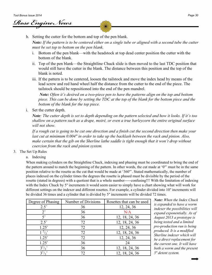
3. The Set Up Rules
a. Indexing
When making cylinders on the Straightline Chuck, indexing and phasing must be coordinated to bring the end of
the pattern around to match the beginning of the pattern. In other words, the cut made at ‘0°’ must be in the same
position relative to the rosette as the cut that would be made at ‘360°’. Stated mathematically, the number of
places indexed on the cylinder times the degrees the rosette is phased must be divisible by the period of the
rosette (stated in degrees) with a quotient that is a whole number-----confusing!!! With the limitation of indexing
with the Index Chuck by 5° increments it would seem easier to simply have a chart showing what will work for
different settings on the indexer and different rosettes. For example, a cylinder divided into 10° increments will
be divided 36 times and a cylinder that is divided by 5° increments will be divided 72 times.
Note: When the Index Chuck
is expanded to have a worm
indexer the possibilities will
expand exponentially. As of
August 2013 a prototype is
being tested and a limited
pre-production run is being
produced. It is a modified
Sherline indexer which will
be a direct replacement for
the current one. It will have
both a worm and the present
5° detent system.
Degree of Phasing Number of Divisions Rosettes that can be used
2.5˚ 36 12, 24, 36
2˚ 36 N/A
5˚ 36 12, 18, 24, 36
2.5˚ 72 12, 18, 24, 36
1.25˚ 72 12, 24, 36
1 2/3˚ 72 12, 18, 24, 36
1.25˚ 72 12, 24, 36
1.25˚ 36 24
31/3˚ 36 12, 18, 24, 36
31/3˚ 72 12, 18, 24, 36
Page 31 Tool Bonus Issue 2014
The Cutting charts that are provided for each pattern are written in a similar format. Each has the phasing
listed first and should be done with the clock key. The index is listed second, and should be done using the
indexing chuck. All rosettes are installed on the Crossing Wheel.
4. The Ornamented Patterns.
Note: The following patterns were cut for a Magnetic Vertex Roller Pen Kit from Penn State.
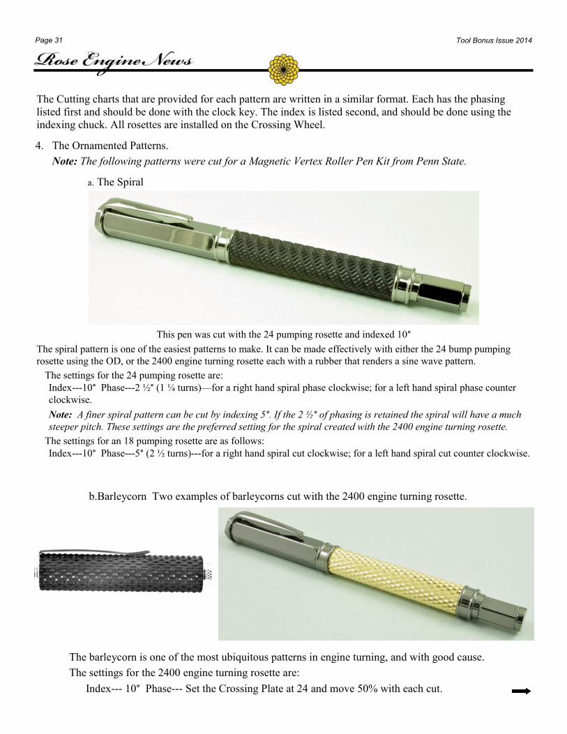
a. The Spiral
This pen was cut with the 24 pumping rosette and indexed 10°
The spiral pattern is one of the easiest patterns to make. It can be made effectively with either the 24 bump pumping
rosette using the OD, or the 2400 engine turning rosette each with a rubber that renders a sine wave pattern.
The settings for the 24 pumping rosette are:
Index---10° Phase---2 ½° (1 ¼ turns)—for a right hand spiral phase clockwise; for a left hand spiral phase counter
clockwise.
Note: A finer spiral pattern can be cut by indexing 5°. If the 2 ½° of phasing is retained the spiral will have a much
steeper pitch. These settings are the preferred setting for the spiral created with the 2400 engine turning rosette.
The settings for an 18 pumping rosette are as follows:
Index---10° Phase---5° (2 ½ turns)---for a right hand spiral cut clockwise; for a left hand spiral cut counter clockwise.
b.Barleycorn Two examples of barleycorns cut with the 2400 engine turning rosette.
The barleycorn is one of the most ubiquitous patterns in engine turning, and with good cause.
The settings for the 2400 engine turning rosette are:
Index--- 10° Phase--- Set the Crossing Plate at 24 and move 50% with each cut.
Page 32 Tool Bonus Issue 2014
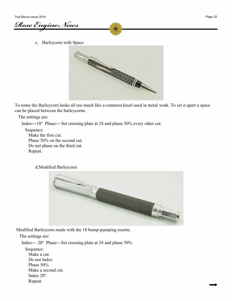
c. Barleycorn with Space
To some the Barleycorn looks all too much like a common knurl used in metal work. To set it apart a space
can be placed between the barleycorns.
The settings are:
Index---10° Phase--- Set crossing plate at 24 and phase 50% every other cut.
Sequence:
Make the first cut.
Phase 50% on the second cut.
Do not phase on the third cut.
Repeat.
d.Modified Barleycorn
Modified Barleycorn made with the 18 bump-pumping rosette.
The settings are:
Index--- 20° Phase---Set crossing plate at 24 and phase 50%
Sequence:
Make a cut.
Do not Index
Phase 50%
Make a second cut.
Index 20°. Repeat.
Page 33 Tool Bonus Issue 2014
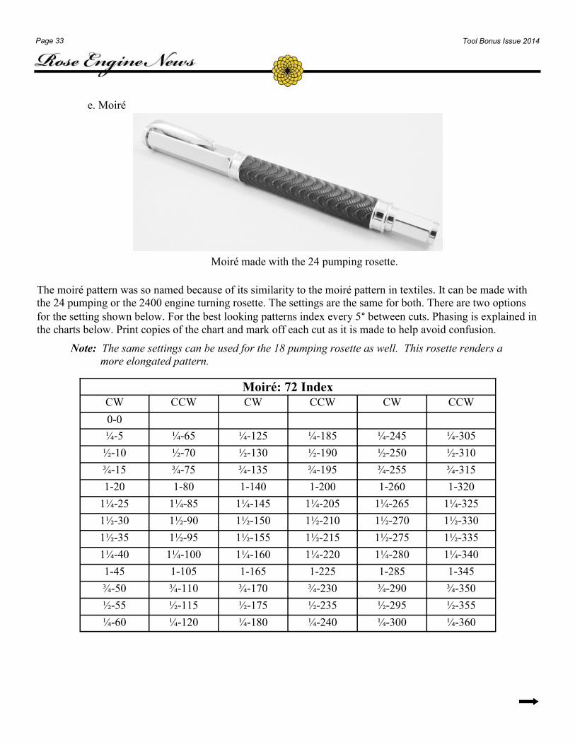
e. Moiré
Moiré made with the 24 pumping rosette.
The moiré pattern was so named because of its similarity to the moiré pattern in textiles. It can be made with
the 24 pumping or the 2400 engine turning rosette. The settings are the same for both. There are two options
for the setting shown below. For the best looking patterns index every 5° between cuts. Phasing is explained in
the charts below. Print copies of the chart and mark off each cut as it is made to help avoid confusion.
Note: The same settings can be used for the 18 pumping rosette as well. This rosette renders a
more elongated pattern.
Moiré: 72 Index
CW CCW CW CCW CW CCW
0-0
¼-5 ¼-65 ¼-125 ¼-185 ¼-245 ¼-305
½-10 ½-70 ½-130 ½-190 ½-250 ½-310
¾-15 ¾-75 ¾-135 ¾-195 ¾-255 ¾-315
1-20 1-80 1-140 1-200 1-260 1-320
1¼-25 1¼-85 1¼-145 1¼-205 1¼-265 1¼-325
1½-30 1½-90 1½-150 1½-210 1½-270 1½-330
1½-35 1½-95 1½-155 1½-215 1½-275 1½-335
1¼-40 1¼-100 1¼-160 1¼-220 1¼-280 1¼-340
1-45 1-105 1-165 1-225 1-285 1-345
¾-50 ¾-110 ¾-170 ¾-230 ¾-290 ¾-350
½-55 ½-115 ½-175 ½-235 ½-295 ½-355
¼-60 ¼-120 ¼-180 ¼-240 ¼-300 ¼-360
Page 34 Tool Bonus Issue 2014
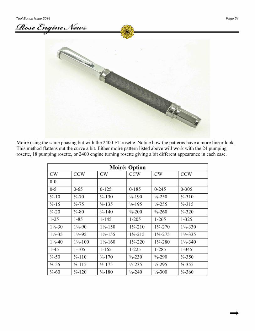
Moiré using the same phasing but with the 2400 ET rosette. Notice how the patterns have a more linear look.
This method flattens out the curve a bit. Either moiré pattern listed above will work with the 24 pumping
rosette, 18 pumping rosette, or 2400 engine turning rosette giving a bit different appearance in each case.
Moiré: Option
CW CCW CW CCW CW CCW
0-0
0-5 0-65 0-125 0-185 0-245 0-305
¼-10 ¼-70 ¼-130 ¼-190 ¼-250 ¼-310
½-15 ½-75 ½-135 ½-195 ½-255 ½-315
¾-20 ¾-80 ¾-140 ¾-200 ¾-260 ¾-320
1-25 1-85 1-145 1-205 1-265 1-325
1¼-30 1¼-90 1¼-150 1¼-210 1¼-270 1¼-330
1½-35 1½-95 1½-155 1½-215 1½-275 1½-335
1¼-40 1¼-100 1¼-160 1¼-220 1¼-280 1¼-340
1-45 1-105 1-165 1-225 1-285 1-345
¾-50 ¾-110 ¾-170 ¾-230 ¾-290 ¾-350
½-55 ½-115 ½-175 ½-235 ½-295 ½-355
¼-60 ¼-120 ¼-180 ¼-240 ¼-300 ¼-360
Page 35 Tool Bonus Issue 2014
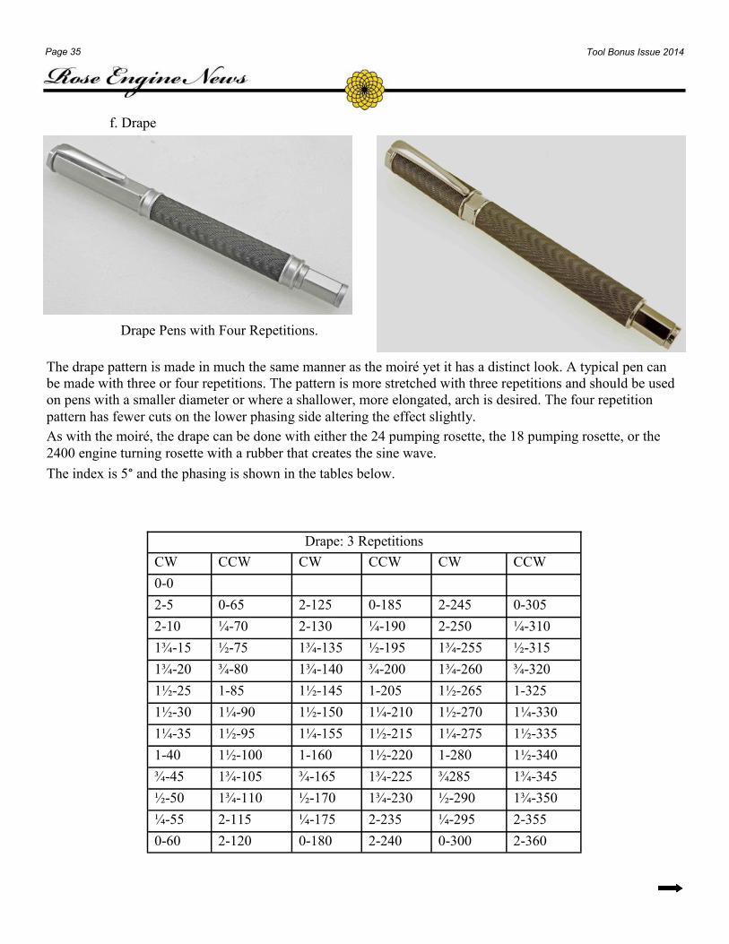
f. Drape
Drape Pens with Four Repetitions.
The drape pattern is made in much the same manner as the moiré yet it has a distinct look. A typical pen can
be made with three or four repetitions. The pattern is more stretched with three repetitions and should be used
on pens with a smaller diameter or where a shallower, more elongated, arch is desired. The four repetition
pattern has fewer cuts on the lower phasing side altering the effect slightly.
As with the moiré, the drape can be done with either the 24 pumping rosette, the 18 pumping rosette, or the
2400 engine turning rosette with a rubber that creates the sine wave.
The index is 5° and the phasing is shown in the tables below.
Drape: 3 Repetitions
CW CCW CW CCW CW CCW
0-0
2-5 0-65 2-125 0-185 2-245 0-305
2-10 ¼-70 2-130 ¼-190 2-250 ¼-310
1¾-15 ½-75 1¾-135 ½-195 1¾-255 ½-315
1¾-20 ¾-80 1¾-140 ¾-200 1¾-260 ¾-320
1½-25 1-85 1½-145 1-205 1½-265 1-325
1½-30 1¼-90 1½-150 1¼-210 1½-270 1¼-330
1¼-35 1½-95 1¼-155 1½-215 1¼-275 1½-335
1-40 1½-100 1-160 1½-220 1-280 1½-340
¾-45 1¾-105 ¾-165 1¾-225 ¾285 1¾-345
½-50 1¾-110 ½-170 1¾-230 ½-290 1¾-350
¼-55 2-115 ¼-175 2-235 ¼-295 2-355
0-60 2-120 0-180 2-240 0-300 2-360
Page 36 Tool Bonus Issue 2014
Drape: 4 Repetitions
CW
0
CCW CW CCW CW CCW CW CCW
2-5 0-50 2-95 ½-140 2-185 0-230 2-275 ½-320
2-10 ½-55 2-100 1-145 2-190 ½-235 2-280 1-325
1¾-15 1-60 1¾-105 1¼-150 1¾-195 1-240 1¾-285 1¼-330
1¾-20 1¼-65 1¾-110 1½-155 1¾-200 1¼-245 1¾-290 1½-335
1½-25 1½-70 1½-115 1½-160 1½-205 1½-250 1½-295 1½-340
1½-30 1¾-75 1¼-120 1¾-165 1½-210 1¾-255 1¼-300 1¾-345
1¼-35 1¾-80 1-125 1¾-170 1¼-215 1¾-260 1-305 1¾-350
1-40 2-85 ½-130 2-175 1-220 2-265 ½-310 2-355
½-45 2-90 0-135 2-180 ½-225 2-270 0-315 2-360
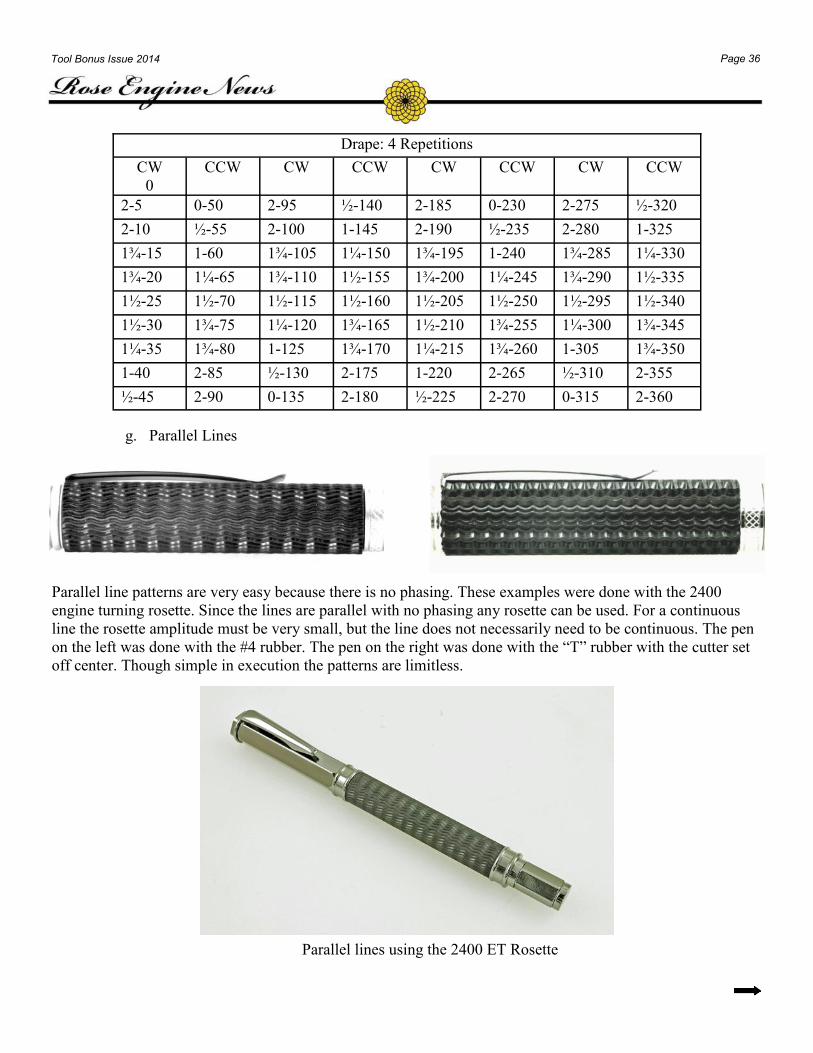
g. Parallel Lines
Parallel line patterns are very easy because there is no phasing. These examples were done with the 2400
engine turning rosette. Since the lines are parallel with no phasing any rosette can be used. For a continuous
line the rosette amplitude must be very small, but the line does not necessarily need to be continuous. The pen
on the left was done with the #4 rubber. The pen on the right was done with the “T” rubber with the cutter set
off center. Though simple in execution the patterns are limitless.
Parallel lines using the 2400 ET Rosette
Page 37 Tool Bonus Issue 2014
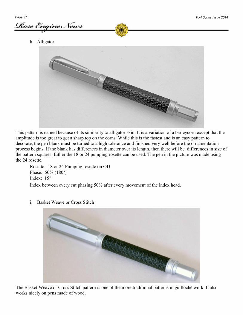
h. Alligator
This pattern is named because of its similarity to alligator skin. It is a variation of a barleycorn except that the
amplitude is too great to get a sharp top on the corns. While this is the fastest and is an easy pattern to
decorate, the pen blank must be turned to a high tolerance and finished very well before the ornamentation
process begins. If the blank has differences in diameter over its length, then there will be differences in size of
the pattern squares. Either the 18 or 24 pumping rosette can be used. The pen in the picture was made using
the 24 rosette.
Rosette: 18 or 24 Pumping rosette on OD
Phase: 50% (180°) Index: 15°
Index between every cut phasing 50% after every movement of the index head.
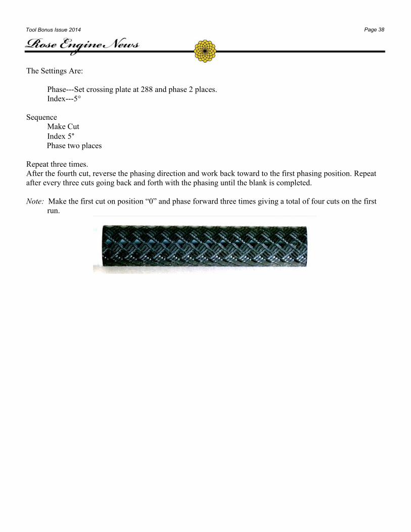
i. Basket Weave or Cross Stitch
The Basket Weave or Cross Stitch pattern is one of the more traditional patterns in guilloché work. It also
works nicely on pens made of wood.
Page 38 Tool Bonus Issue 2014
The Settings Are:
Phase---Set crossing plate at 288 and phase 2 places.
Index---5°
Sequence
Make Cut
Index 5° Phase two places
Repeat three times.
After the fourth cut, reverse the phasing direction and work back toward to the first phasing position. Repeat
after every three cuts going back and forth with the phasing until the blank is completed.
Note: Make the first cut on position “0” and phase forward three times giving a total of four cuts on the first
run.

DAVID LINDOW
527 GRAVITY ROAD
LAKE ARIEL, PA18436
570-937-3301
Submit Articles for future Issues of the Rose Engine News to
John Tarpley
2169 Highland Acres Way
Gatlinburg, TN 37738
WWW.ROSEENGINE1.COM