Embed Size (px)
Citation preview
DESIGN MANUAL FOR ROADS AND BRIDGES
February 2016
VOLUME 7 PAVEMENT DESIGN AND MAINTENANCE
SECTION 2 PAVEMENT DESIGN AND CONSTRUCTION
PART 5
HD 39/16
FOOTWAY AND CYCLEWAY DESIGN
SUMMARY
This part sets out the requirements and advice for new footway construction. It covers footways constructed from common materials that are subject to a range of pedestrian traffic and some overrun by vehicular traffic.
INSTRUCTIONS FOR USE
This is a new document to be incorporated into the Manual.
1. Insert HD 39/16 into Volume 7, Section 2, Part 5.
2. Archive this sheet as appropriate.
Note: A quarterly index with a full set of Volume Contents Pages is available separately from The Stationery Office Ltd.
DESIGN MANUAL FOR ROADS AND BRIDGES HD39
FOOTWAY AND CYCLEWAY DESIGN
SUMMARY
This part sets out the requirements and advice for new footway construction. It covers footways constructed from common materials that are subject to a range of pedestrian traffic and some overrun by vehicular traffic.
HIGHWAYS ENGLAND
TRANSPORT SCOTLAND
WELSH GOVERNMENTLLYWODRAETH CYMRU
THE DEPARTMENT FOR REGIONAL DEVELOPMENTNORTHERN IRELAND
HD 39/16Volume 7, Section 4,Part 5


February 2016
Registration of AmendmentsVolume 7 Section 2Part 5 HD 39/16
Amend No Page No Signature & Date of incorporation of amendments
Amend No Page No Signature & Date of incorporation of amendments
REGISTRATION OF AMENDMENTS

February 2016
Registration of AmendmentsVolume 7 Section 2
Part 5 HD 39/16
Amend No Page No Signature & Date of incorporation of amendments
Amend No Page No Signature & Date of incorporation of amendments
REGISTRATION OF AMENDMENTS
DESIGN MANUAL FOR ROADS AND BRIDGES
February 2016
VOLUME 7 PAVEMENT DESIGN AND MAINTENANCE
SECTION 2 PAVEMENT DESIGN AND CONSTRUCTION
PART 5
HD 39/16
FOOTWAY AND CYCLEWAY DESIGN
Contents
Chapter
1. Introduction
2. Design Considerations
3. Structural Design
4. Materials
5. References
6. Enquiries
Annex A Not used
B Laying course sand and jointing material
C Compaction specification by air voids
D Compaction by method specification
E Worked Examples

DESIGN MANUAL FOR ROADS AND BRIDGES
February 2016

February 2016 1/1
Chapter 1Introduction
Volume 7 Section 2Part 5 HD 39/16
1. INTRODUCTIONGeneral
1.1 This part provides guidance on new footway and cycleway construction. It covers footways and cycleways constructed from common materials and subject to a range of pedestrian traffic and some overrun by vehicular traffic. The design of pedestrianised areas is not covered since the number of delivery vehicles usually means that a road pavement design will be required.
1.2 Guidance is provided on the construction of footways surfaced with bituminous material, concrete or clay pavers, precast concrete flags and in-situ concrete. Designs for paver and flag footways, in the situation where there is overrun by heavy vehicles, remain to be validated.
Implementation
1.3 This document shall be implemented in accordance with GD 1. Safety risk assessments shall be carried out in accordance with GD 4. An assessment as to the applicability of an equality impact assessment (EqIA) shall be carried out for all designs. Where the assessment indicates that an EqIA is required, then the designer shall carry out an EqIA.
This part has been updated for the purposes of EU compliance with additional minor changes throughout. Attention is also drawn to the change in clause 4.11 for construction topped by natural stone slabs.
Mutual Recognition
1.4 Where there is a requirement in this specification for compliance with any part of a British Standard or other technical specification, that requirement may be met by compliance with the Mutual Recognition clause in GD 1.

1/2 February 2016
Chapter 1Introduction
Volume 7 Section 2Part 5 HD 39/16
February 2016 2/1
Chapter 2Design Considerations
Volume 7 Section 2Part 5 HD 39/16
2. DESIGN CONSIDERATIONSIntroduction
2.1 Maintaining Agents and Local Authorities spend a significant amount of their highway maintenance budgets on footways and cycleways in order that all pedestrians, including those with mobility difficulties, and cyclists can travel in comfort. Footway and cycleway surfaces deteriorate for a variety of reasons and it is important that the initial construction is such that subsequent deterioration is minimised. Although it is expected that the upper layers will need attention because of general wear, it is recommended that the foundations of footways and cycleways should be sufficiently robust to give good performance over a design life of 40 years.
2.2 Research has been carried out at the Transport Research Laboratory (TRL) to identify the causes of failure in footways and thus to recommend suitable designs to improve the surface condition of footways over their design life. Vehicle overrun and works by Statutory Undertakers have been identified as the most common causes of failure in footways. It is hoped that adherence to the New Roads and Street Works Act 1991 (Specification for the reinstatement of openings in highways), or the NIRAUC Specification for the Reinstatement of Openings in Roads (1995) in Northern Ireland, will ensure improvement in reinstatements after utility works and consequently in the ensuing condition of the footway surface. Growth of vegetation, natural ageing of bituminous material, and poor design and construction have also been identified as significant causes of deterioration.
Selection of Footway and Cycleway Category
2.3 To choose the appropriate footway/cycleway design it is necessary to consider the pedestrian and vehicular traffic which the surface may have to support and the characteristics of the ground on which it is to be constructed. Designs are given for three construction categories, the appropriate category being chosen according to the risk and type of vehicle overrun and on the amount of pedestrian usage.
2/2 February 2016
Chapter 2Design Considerations
Volume 7 Section 2Part 5 HD 39/16
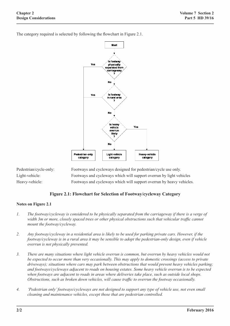
The category required is selected by following the fl owchart in Figure 2.1.
Pedestrian/cycle-only: Footways and cycleways designed for pedestrian/cycle use only.Light-vehicle: Footways and cycleways which will support overrun by light vehiclesHeavy-vehicle: Footways and cycleways which will support overrun by heavy vehicles.
Figure 2.1: Flowchart for Selection of Footway/cycleway Category
Notes on Figure 2.1
1. The footway/cycleway is considered to be physically separated from the carriageway if there is a verge of width 3m or more, closely spaced trees or other physical obstructions such that vehicular traffi c cannot mount the footway/cycleway.
2. Any footway/cycleway in a residential area is likely to be used for parking private cars. However, if the footway/cycleway is in a rural area it may be sensible to adopt the pedestrian-only design, even if vehicle overrun is not physically prevented.
3. There are many situations where light vehicle overrun is common, but overrun by heavy vehicles would not be expected to occur more than very occasionally. This may apply to domestic crossings (access to private driveways); situations where cars may park between obstructions that would prevent heavy vehicles parking; and footways/cycleways adjacent to roads on housing estates. Some heavy vehicle overrun is to be expected when footways are adjacent to roads in areas where deliveries take place, such as outside local shops. Obstructions, such as broken down vehicles, will cause traffi c to overrun the footway occasionally.
4. ‘Pedestrian only’ footways/cycleways are not designed to support any type of vehicle use, not even small cleaning and maintenance vehicles, except those that are pedestrian controlled.
February 2016 2/3
Chapter 2Design Considerations
Volume 7 Section 2Part 5 HD 39/16
Site Investigation
2.4 To perform satisfactorily, a footway or cycleway must be constructed on an adequate foundation. A soft subgrade provides insufficient support for compaction of the layers above, which may subsequently deteriorate rapidly. For road pavement construction the subgrade is conventionally assessed in terms of its California Bearing Ratio (CBR) and as footways and cycleways are associated with road pavements it is convenient to use the same measure.
2.5 Methods for measuring CBR are described in HD25. If, because of site investigations prior to constructing structures, the Modulus of Subgrade Reaction (k) of the soil is known, this can be related to the CBR by the relationship given in HD 25.
2.6 Tests should not be carried out on the soil near the surface as the moisture content will not be representative of the equilibrium condition at depth. It is very important to remember that Design CBR’s relate to equilibrium conditions. A prolonged dry spell may distort the results and lead to failure in wetter conditions. If a cone penetrometer is used to assess CBR, care must be taken in case services are present; the use of a Cable Avoidance Tool (CAT) is recommended.
2.7 The CBR chosen for design purposes should be the minimum measured value, not the average, otherwise local failure will occur at soft spots. Alternatively, soft spots can be removed and replaced with better material to improve the subgrade CBR value. If it is not possible to estimate the CBR because the condition of the subgrade is extremely variable then a default of 2% should be assumed, unless the material is granular in which case the CBR can be assumed to be over 5%.
2.8 For a footway or cycleway subject to vehicle loading the estimate of CBR should normally relate to the moisture content which is expected to be present in the subgrade under the completed footway/cycleway, when any change in the water table due to construction and the installation of drainage has taken place. However, if the in situ CBR at the time of measurement is less than the expected equilibrium CBR, then the in situ value should be used for design, otherwise failure may occur before equilibrium is reached.
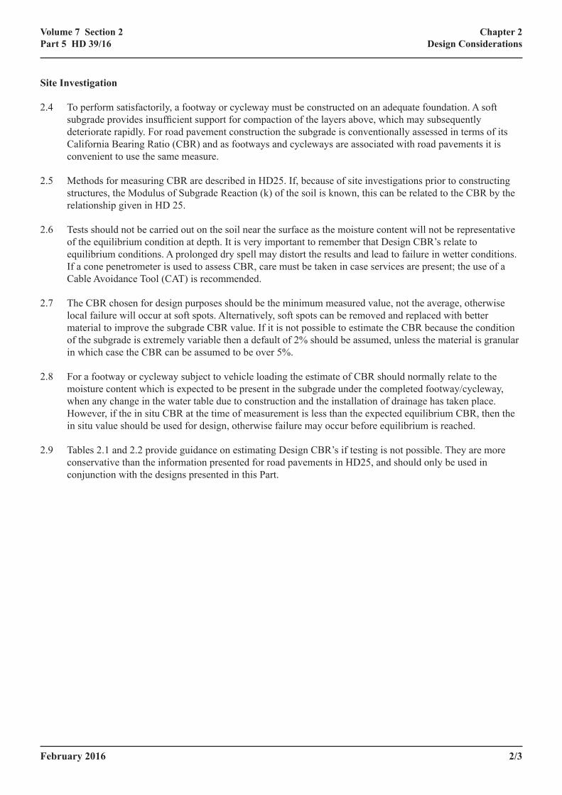
2.9 Tables 2.1 and 2.2 provide guidance on estimating Design CBR’s if testing is not possible. They are more conservative than the information presented for road pavements in HD25, and should only be used in conjunction with the designs presented in this Part.
2/4 February 2016
Chapter 2Design Considerations
Volume 7 Section 2Part 5 HD 39/16
Soil Type Plasticity Index
Design CBR%
Plastic Clay 50 or greater 2+
Silty Clay 40 2
Silty Clay 30 3
Sandy Clay 20 3
Sandy Clay 10 2+
Silt - Less than 2
Sand (poorly graded) - 7*
Sand (well graded) - 10*
Sandy Gravel (well graded) - 15*
Notes: + CBR may be less than 2 if construction conditions are poor.
* Indicates estimated values assuming some probability of the material saturating in service.
Table 2.1 Equilibrium CBR Values
Soil Condition CBRVery soft, exudes between fingers when squeezed Less than 1%
Can be moulded by light finger pressure Between 1 and 2%
Can be moulded by strong finger pressure Between 2 and 3%
Can be indented by a thumbnail but not by a thumb More than 6%
Table 2.2 Rough Guide to CBR
Geometry
2.10 When assigning geometric parameters to footways, the comfort of the user shall be taken into account, together with the necessity for providing adequate surface drainage. Steep gradients or crossfalls make it difficult for elderly or encumbered pedestrians to walk on the footway, while insufficient gradients would not facilitate the removal of surface water. The geometry and gradients for footways shall be in accordance with published DfT inclusive mobility guidance. Where possible the footway width should be sufficient to allow two wheelchairs or double buggies to pass. Shared footway and cycleways should follow the geometrical requirements for footways.
2.11 Crossfall should be limited to that absolutely necessary to dispose of surface water. Crossfalls steeper than about 3% are uncomfortable to walk on and if the slope runs towards a road it can be dangerous, as wheeled users will tend to edge down the crossfall.
February 2016 2/5
Chapter 2Design Considerations
Volume 7 Section 2Part 5 HD 39/16
2.12 The direction of the crossfall should take surface water away from buildings. However, if backfall towards buildings is unavoidable then covered drainage channels can be used to remove the surface water.
Drainage
2.13 The strength of the construction and of the subgrade can vary considerably with moisture content, so it is extremely important to keep the structure well drained during its service life. Issues of drainage relate to ensuring adequate longitudinal falls, grips/gullies and level tolerances to prevent surface water ponding and to aid its disposal. The drainage system should be designed to last the life of the footway/cycleway and it should be easy to maintain. Drainage should be kept away from the centre of the footway/cycleway because of the likelihood of works by Statutory Undertakers. Any potential problems which may be caused by tree and hedge roots should be considered.
2.14 Generally footway/cycleway drainage will be the same as that of the adjacent highway, which should ensure a low water table and efficient disposal of surface water. Where a footway or cycleway is separated from the highway the main consideration should be to ensure that surface water drains away from the footway/cycleway into the highway. If a separate drainage system is required it should be simple and robust; it should keep the water table below formation level and deal satisfactorily with storm water. Regular maintenance of the drainage system will be necessary for long-term performance. Drainage is especially important if there is any risk of vehicle overrun, as a sub-base can lose a considerable proportion of its load spreading properties if it becomes waterlogged.
Statutory Undertakers
2.15 Where possible, footways/cycleways should be designed so that services can run in the verge rather than under the footway/cycleway. If this is not possible the provision of service ducts minimises any disruption during maintenance work. On new footways and cycleways all Statutory Undertakers’ equipment must be placed before the footway/cycleway is formed. Any trenches excavated before construction of the footway/cycleway should be backfilled with suitable material and fully compacted. Compaction of the backfill to any trenches should be carried out in compliance with New Roads and Street Works Act 1991 (Specification for the reinstatement of openings in highways) or the NIRAUC Specification for the Reinstatement of Openings in Roads (1995) for Northern Ireland to ensure that the reinstatement will have a bearing capacity at least as good as the natural subgrade.
Environmental Considerations
2.16 The position of the footway/cycleway and the choice of surfacing will be affected by environmental factors. The footway/cycleway should complement the surrounding environment and natural features should be disturbed as little as possible. The roots of large trees can cause problems and ideally footways and cycleways should not be positioned close to such trees. If footways/cycleways must be built near to existing trees then material around the existing roots should be excavated carefully by hand, any sub-base or other granular material should be placed by hand and non-toxic sand should be placed around the roots. If necessary the vertical alignment of the footway/cycleway can be lifted to facilitate this.
2.17 In a new development, trees should be carefully chosen to have deep rather than spreading roots and sufficient space must be provided for root growth. Planting verges with low shrubs discourages parking and removes the need for grass cutting, while maintaining sight distances. For ease of maintenance trees can also be underplanted with such shrubs.
2.18 The footway/cycleway surface should be even and have adequate slip resistance and abrasion resistance. The type of surfacing chosen will depend on the required appearance, the usage of the footway/cycleway, the available budget and the loading to which the footway/cycleway is subjected. The recommended and most

2/6 February 2016
Chapter 2Design Considerations
Volume 7 Section 2Part 5 HD 39/16
commonly used types of surfacing are bituminous materials (asphalt concrete, stone mastic asphalt or hot rolled asphalt), concrete or clay pavers and precast concrete (PCC) flags. It is not recommended that in situ concrete is used due to the difficulties caused when works by Statutory Undertakers are carried out, although concrete may be used locally for corner reinforcement against overrun and for vehicle crossovers. Natural stone flags, cobbles and setts are not commonly used for new footways as they tend to be both expensive and difficult to lay, though they are used in conservation areas.
2.19 If the pedestrian or cycle usage is very high, mastic asphalt can provide a very tough surface and it also provides a useful thin waterproof surface over cellars. In some areas, tactile surfacing may be required to assist those pedestrians who have impaired sight. (Refer to DETR publication “Guidance on the use of Tactile Paving Surfaces”. In Northern Ireland refer to “Roads Service’s Policy and Procedures Guide, RSPPG_E010”). Pavers, even when well laid, may not provide ride quality as good as bituminous or flag surfaces, which is a disadvantage for users of small wheeled buggies and cycles.
2.20 A series of worked examples are provided in Annex E of this Part to demonstrate the design methods and the use of the Tables.
February 2016 3/1
Chapter 3Structural Design
Volume 7 Section 2Part 5 HD 39/16
3. STRUCTURAL DESIGNIntroduction
3.1 For most soils, other than silt, the CBR of the subgrade at the time of construction will be at least 2%, which should provide an adequate surface for compaction of the sub-base. If the CBR of the subgrade is lower than this, the soil can be stabilised, usually with lime (which should achieve a CBR of at least 5%), or some soil can be removed and replaced with extra granular sub-base/capping material.
3.2 Alternatively, if construction is being carried out in poor conditions, on a clay soil which is expected to have an equilibrium CBR of at least 2%, there may be a case for using a geosynthetic separating layer as a construction expedient. The geosynthetic does not improve the CBR, but prevents soft ground contaminating the sub-base, which would weaken the structure and lead to inadequate support for compaction of the upper layers. Construction layers above the sub-base would consequently not be properly compacted and would deteriorate faster than would otherwise be the case, with subsequent increase in maintenance costs. The subgrade should be levelled and compacted before placing the geosynthetic or the sub-base.
3.3 If the sub-base is required to support construction traffic, then the sub-base thickness will need to be designed accordingly, even if the footway is a pedestrian-only design.
3.4 For prevention of frost damage all material within 450mm of the surface should be non-frost-susceptible, unless the mean annual frost index is less than 50, in which case the requirement can be reduced to 350mm. Advice on the frost index for any particular area can be obtained from the Meteorological Advisory Services. The frost index is defined as the product of the number of days of continuous freezing and the average amount of frost, in degrees Celsius, on those days. If the subgrade is frost susceptible then it should be protected by a blanket of suitable non-frost susceptible materials.
3.5 Soils which are most likely to be frost susceptible are low plasticity clays, silts, and clayey and silty sands and gravels. Medium and high plasticity clays are normally insufficiently permeable to be susceptible to frost heave, and clean sands and gravels cannot generate sufficient suction to draw water to the ice front. Well drained soils where the water table is well below the construction are less likely to be damaged by frost in any situation, because footways and cycleways are usually alongside road pavements and the road drainage would tend to ensure a low water table. It is unlikely to be cost effective to build the footway/cycleway deep enough to totally prevent frost damage. Modular construction less susceptible to frost damage as the elements can move without cracking.
Pedestrian-only Design
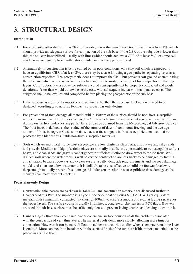
3.6 Construction thicknesses are as shown in Table 3.1, and construction materials are discussed further in Chapter 5 of this Part. The sub-base is a Type 1, see Specification Series 800 (MCHW 1) or equivalent material with a minimum compacted thickness of 100mm to ensure a smooth and regular laying surface for the upper layers. The surface course is usually bituminous, concrete or clay pavers or PCC flags. If pavers are used the sub-base surface must be sufficiently dense to prevent laying course sand leaking down into it.
3.7 Using a single 60mm thick combined binder course and surface course avoids the problems associated with the compaction of very thin layers. The material cools down more slowly, allowing more time for compaction. However, it can be more difficult to achieve a good ride quality when a separate regulating layer is omitted. More care needs to be taken with the surface finish of the sub-base if bituminous material is to be placed in a single layer.
3/2 February 2016
Chapter 3Structural Design
Volume 7 Section 2Part 5 HD 39/16
Surface Options
Layer
Bituminous Pavers Flags
Surfacing(2) 20mm surface course(4)
40mm binder course(1)
≥50mm clay pavers
≥60mm concrete blocks ≥50mm
30mm laying course sand (compacted)25mm laying course sand (compacted) or
mortar
Sub-base(2) 100mm
Subgrade(3) −
Table 3.1 Pedestrian-only Footways and Cycle-only Cycleways
Surface Options
Layer
Bituminous Pavers Flags Concrete
Surfacing(2)
20mm surface course(4)
40mm binder course(1)
≥50mm clay pavers
≥60mm concrete blocks
300mm x 300mm x 60mmor 400mm x 400mm x 65mmor 450mm x 450mm x 70mm
150mm unreinforced, Grade C30P30mm laying course sand
(compacted)25mm laying course sand
(compacted) or mortar
Sub-base(2) 150mm 250mm 200mm 150mm 250mm 200mm 150mm 75mm
Subgrade(3) − CBR ≤2%
2% ≤ CBR ≤5%
CBR >5%
CBR ≤2%
2% ≤ CBR ≤5%
CBR >5% −
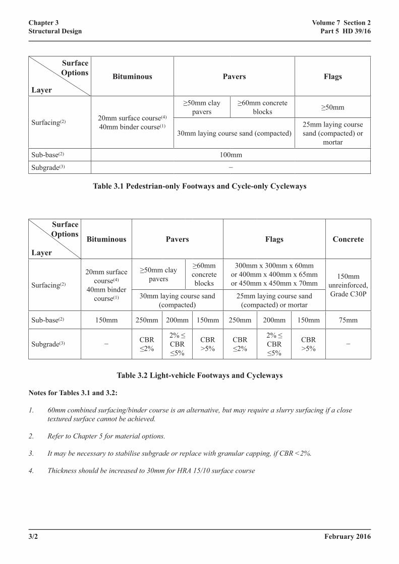
Table 3.2 Light-vehicle Footways and Cycleways
Notes for Tables 3.1 and 3.2:
1. 60mm combined surfacing/binder course is an alternative, but may require a slurry surfacing if a close textured surface cannot be achieved.
2. Refer to Chapter 5 for material options.
3. It may be necessary to stabilise subgrade or replace with granular capping, if CBR <2%.
4. Thickness should be increased to 30mm for HRA 15/10 surface course
February 2016 3/3
Chapter 3Structural Design
Volume 7 Section 2Part 5 HD 39/16
3.8 Slurry surfacing can be used to provide a fine textured surface if it is considered that the bituminous material used in a single 60mm layer would give a surface that is too open textured. However, this surface treatment will have a shorter life than surfacing and more frequent replacement will be required within the overall design life.
Light-vehicle Design
3.9 This design is used for cross-overs to private driveways and wherever light vehicle overrun is likely. Construction thicknesses are shown in Table 3.2. The designs for segmental footways/cycleways are thicker than the equivalent designs for bituminous footways/cycleways since experimental work has shown that segmental constructions do not exhibit equivalent load spreading ability to bituminous constructions.
3.10 In situ concrete can be used for vehicle crossovers using an unreinforced concrete, class C30P, laid 150mm thick over 75mm of sub-base, as illustrated in Table 3.2.
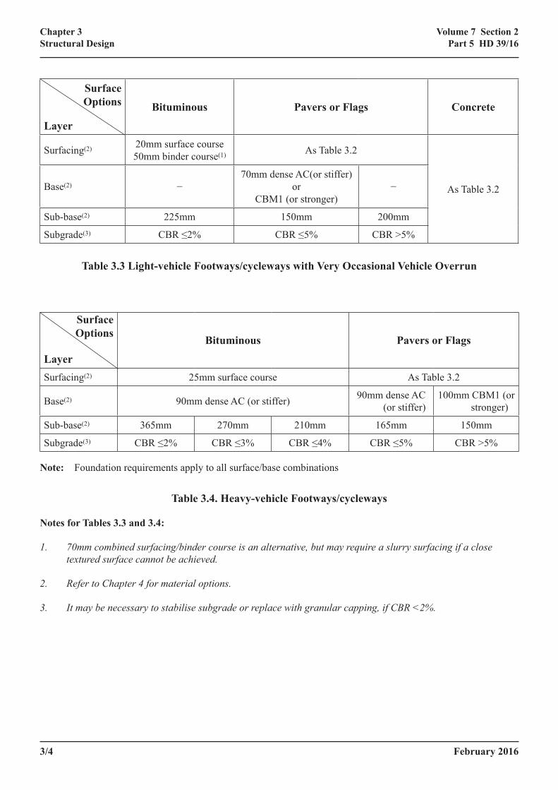
3.11 If there is a possibility of very occasional heavy vehicle overrun, such as might occur two or three times a year with occasional delivery vehicles to private houses, and if the footway/cycleway is being constructed on a weak subgrade, it is recommended that the constructions are strengthened to those illustrated in Table 3.3. Under bituminous surfacing, if the subgrade CBR is less than 2%, the sub-base thickness should be increased to 225mm. If the surface course is flags or pavers, a 70mm thick dense asphalt concrete or Cement Bound Material (CBM) layer (CBM1 or stronger) should be incorporated between the sub-base and the laying course sand where the subgrade CBR is 5% or less. Where the subgrade CBR is above 5% a sub-base thickness of 200mm should be sufficient to permit very occasional heavy vehicle overrun. No strengthening is necessary if the surface course is of concrete construction.
Heavy-vehicle Design
3.12 If there is uncertainty about the type of overrun, or if the footway/cycleway is adjacent to a busy road and overrun is not prevented by some physical means, then the footway/cycleway should be designed to sustain heavy vehicle overrun.
This does not include pedestrian areas that generally see a significant amount of delivery or maintenance vehicles. For such areas a road pavement design, as given in HD26, is more appropriate.
3.13 For this category of footway/cycleway the design traffic is assumed to be 50,000 standard axles. This allows for approximately one vehicle per working day over a design life of 40 years, equal to the design life of associated road pavements (assuming that one heavy vehicle is, on average, equivalent to one standard axle). The number of standard axles has been multiplied by 3 to take channelisation into account and some allowance has been made for dynamic loading due to the vehicle mounting the footway/cycleway.
3.14 Recommended design thicknesses are given in Table 3.4, with a minimum sub-base thickness of 150mm. This does not allow for the sub-base to be used as a platform for construction traffic. If the sub-base is to be trafficked the thickness must be increased to the values in HD25. It is advisable that all footways/cycleways subject to possible trafficking by heavy vehicles include a bound base.
3/4 February 2016
Chapter 3Structural Design
Volume 7 Section 2Part 5 HD 39/16
Surface Options
Layer
Bituminous Pavers or Flags Concrete
Surfacing(2) 20mm surface course50mm binder course(1) As Table 3.2
As Table 3.2Base(2) −70mm dense AC(or stiffer)
orCBM1 (or stronger)
−
Sub-base(2) 225mm 150mm 200mm
Subgrade(3) CBR ≤2% CBR ≤5% CBR >5%
Table 3.3 Light-vehicle Footways/cycleways with Very Occasional Vehicle Overrun
Surface Options
Layer
Bituminous Pavers or Flags
Surfacing(2) 25mm surface course As Table 3.2
Base(2) 90mm dense AC (or stiffer) 90mm dense AC (or stiffer)
100mm CBM1 (or stronger)
Sub-base(2) 365mm 270mm 210mm 165mm 150mm
Subgrade(3) CBR ≤2% CBR ≤3% CBR ≤4% CBR ≤5% CBR >5%
Note: Foundation requirements apply to all surface/base combinations
Table 3.4. Heavy-vehicle Footways/cycleways
Notes for Tables 3.3 and 3.4:
1. 70mm combined surfacing/binder course is an alternative, but may require a slurry surfacing if a close textured surface cannot be achieved.
2. Refer to Chapter 4 for material options.
3. It may be necessary to stabilise subgrade or replace with granular capping, if CBR <2%.
February 2016 3/5
Chapter 3Structural Design
Volume 7 Section 2Part 5 HD 39/16
Edge Restraints
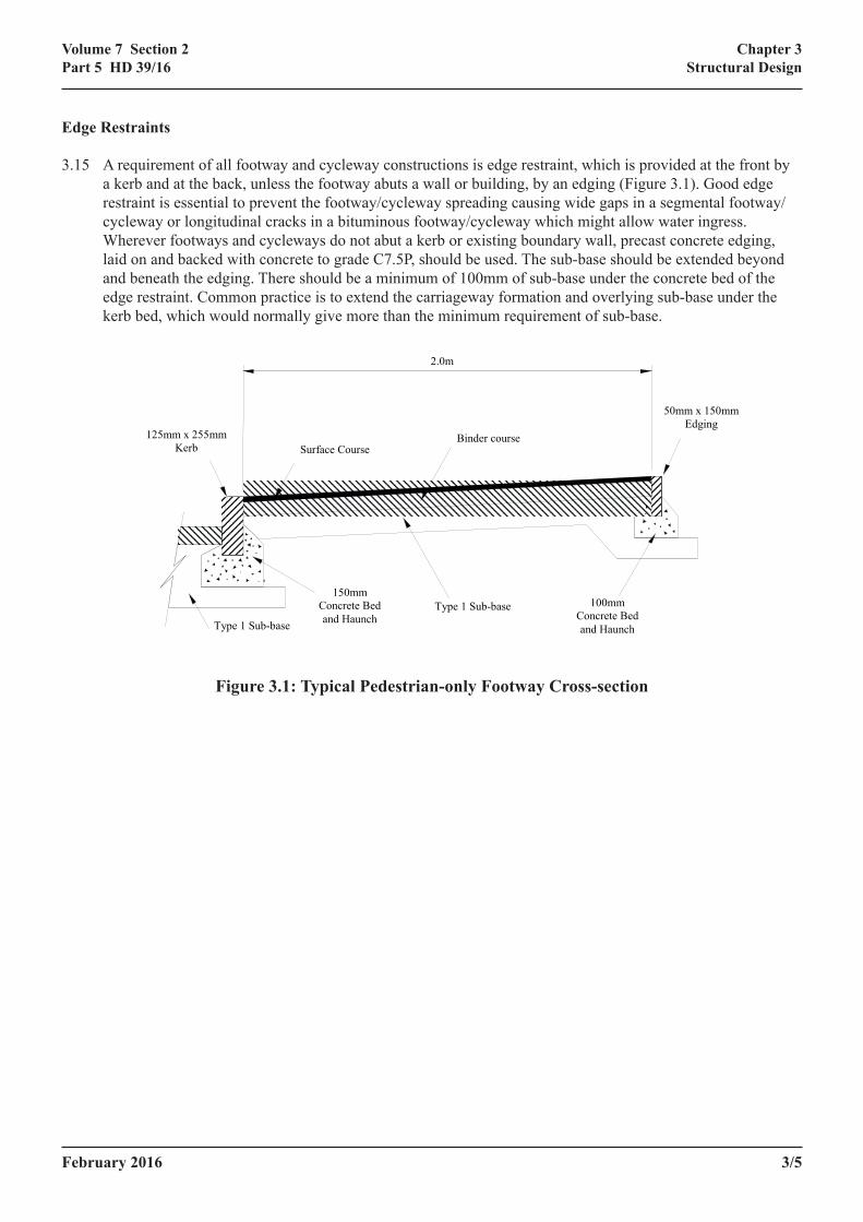
3.15 A requirement of all footway and cycleway constructions is edge restraint, which is provided at the front by a kerb and at the back, unless the footway abuts a wall or building, by an edging (Figure 3.1). Good edge restraint is essential to prevent the footway/cycleway spreading causing wide gaps in a segmental footway/cycleway or longitudinal cracks in a bituminous footway/cycleway which might allow water ingress. Wherever footways and cycleways do not abut a kerb or existing boundary wall, precast concrete edging, laid on and backed with concrete to grade C7.5P, should be used. The sub-base should be extended beyond and beneath the edging. There should be a minimum of 100mm of sub-base under the concrete bed of the edge restraint. Common practice is to extend the carriageway formation and overlying sub-base under the kerb bed, which would normally give more than the minimum requirement of sub-base.
2.0m
Surface Course Binder course
Type 1 Sub-base
150mm Concrete Bed and Haunch
100mm Concrete Bed and Haunch
Type 1 Sub-base
125mm x 255mm Kerb
50mm x 150mm Edging
Figure 3.1: Typical Pedestrian-only Footway Cross-section

3/6 February 2016
Chapter 3Structural Design
Volume 7 Section 2Part 5 HD 39/16
February 2016 4/1
Chapter 4Materials
Volume 7 Section 2Part 5 HD 39/16
4. MATERIALSIntroduction
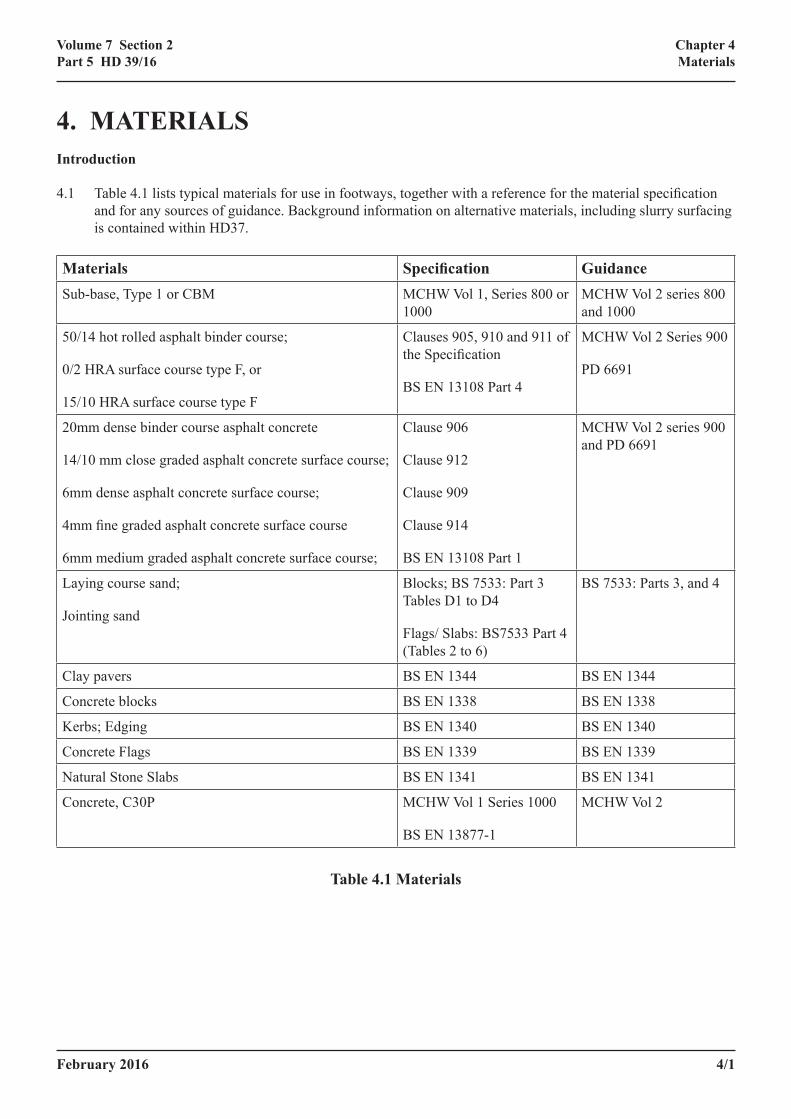
4.1 Table 4.1 lists typical materials for use in footways, together with a reference for the material specification and for any sources of guidance. Background information on alternative materials, including slurry surfacing is contained within HD37.
Materials Specification GuidanceSub-base, Type 1 or CBM MCHW Vol 1, Series 800 or
1000MCHW Vol 2 series 800 and 1000
50/14 hot rolled asphalt binder course;
0/2 HRA surface course type F, or
15/10 HRA surface course type F
Clauses 905, 910 and 911 of the Specification
BS EN 13108 Part 4
MCHW Vol 2 Series 900
PD 6691
20mm dense binder course asphalt concrete
14/10 mm close graded asphalt concrete surface course;
6mm dense asphalt concrete surface course;
4mm fine graded asphalt concrete surface course
6mm medium graded asphalt concrete surface course;
Clause 906
Clause 912
Clause 909
Clause 914
BS EN 13108 Part 1
MCHW Vol 2 series 900 and PD 6691
Laying course sand;
Jointing sand
Blocks; BS 7533: Part 3 Tables D1 to D4
Flags/ Slabs: BS7533 Part 4 (Tables 2 to 6)
BS 7533: Parts 3, and 4
Clay pavers BS EN 1344 BS EN 1344
Concrete blocks BS EN 1338 BS EN 1338
Kerbs; Edging BS EN 1340 BS EN 1340
Concrete Flags BS EN 1339 BS EN 1339
Natural Stone Slabs BS EN 1341 BS EN 1341
Concrete, C30P MCHW Vol 1 Series 1000
BS EN 13877-1
MCHW Vol 2
Table 4.1 Materials
4/2 February 2016
Chapter 4Materials
Volume 7 Section 2Part 5 HD 39/16
Sub-base
4.2 Type 1, see Specification Series 800 (MCHW 1), is the most commonly used sub-base material and generally originates from a primary aggregate source. For good compaction it should have a moisture content of +1% to -2% of optimum. If Type 1 is delivered too dry it can be prone to segregation. Although all materials should be protected from the weather when stored on site, providing Type 1 is not close to the fine limit of grading it will not retain water significantly above its optimum moisture content and any excess will rapidly drain from stockpiled material.
4.3 Type 1 was designed to be placed using large plant, in relatively thick layers and rolled using 8-10 tonne dead-weight rollers. Footways and cycleways are constructed using small plant and are often laid in thin layers (100mm) for which the nominal size of Type 1 is too large. Alternative locally available materials may be suitable which fall into the category of secondary or recycled aggregates; for example:-
• Initial sweepings from 10mm and 14mm surface dressing
• Bituminous planings
• 20mm and 28mm nominal single sized aggregates
• Spent railway ballast screened to remove the 20mm down material (and thus any contaminants)
• China clay sand
• Crushed kerbstones
• Slate waste
The single sized nature of some of these sources may make them difficult to compact, so blending of aggregates may be beneficial. Bituminous planings exhibit considerable resistance to compaction due to friction of the bitumen coated aggregate. They must be compacted at optimum moisture content, to a maximum compacted layer thickness of 150mm.
4.4 If secondary aggregates are to be used, the requirements for durability set down in the Specification (MCHW1) for sub-bases should still apply. For example, materials used in the construction of the footway and cycleway must be resistant to frost heave. If it cannot be guaranteed that the sub-base will remain well drained throughout its design life then the material should be stabilised. Local experience can be a useful guide particularly where materials have a long history of satisfactory performance. Secondary aggregates may be suitable for use after stabilisation, for example by cement, foamed bitumen, or other binders. If it cannot be guaranteed that the sub-base will remain well drained throughout its design life then the material should be stabilised.
4.5 A permeable sub-base may be useful under modular surfacing, which is, to some extent, porous. It may therefore be better to provide the drainage at a lower level and have a more “free-draining” sub-base. A suitable material is included in Clause 805 of the Specification. Precautions, such as the inclusion of a membrane separation layer, may be required to prevent loss of laying course sand into the subbase.
February 2016 4/3
Chapter 4Materials
Volume 7 Section 2Part 5 HD 39/16
Bituminous Materials
4.6 The decision on which bituminous materials to use will depend on appearance, durability, initial cost, maintenance requirements, total thickness, ease of laying and likelihood of disturbance by Statutory Undertakers. Where bituminous materials abut kerbs, manholes, small areas of tactile paving flags etc, the vertical faces of these should be cleaned and painted with a uniform coating of hot bitumen, before the bituminous material is laid. Advice can be found in Clause 903 of the specification.
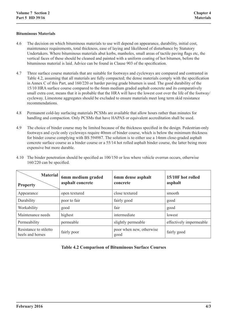
4.7 Three surface course materials that are suitable for footways and cycleways are compared and contrasted in Table 4.2, assuming that all materials are fully compacted; the dense materials comply with the specification in Annex C of this Part, and 160/220 or harder paving grade bitumen is used. The good durability of the 15/10 HRA surface course compared to the 6mm medium graded asphalt concrete and its comparatively small extra cost, means that it is probable that the HRA will have the lowest cost over the life of the footway/cycleway. Limestone aggregates should be excluded to ensure materials meet long term skid resistance recommendations.
4.8 Permanent cold-lay surfacing materials PCSMs are available that allow hours rather than minutes for handling and compaction. Only PCSMs that have HAPAS or equivalent accreditation shall be used.
4.9 The choice of binder course may be limited because of the thickness specified in the design. Pedestrian-only footways and cycle only cycleways require 40mm of binder course, which is below the minimum thickness for binder course complying with BS 594987. The solution is to either use a 14mm close-graded asphalt concrete surface course as a binder course or a 55/14 hot rolled asphalt binder course, the latter being more expensive but more durable.
4.10 The binder penetration should be specified as 100/150 or less where vehicle overrun occurs, otherwise 160/220 can be specified.
Material
Property
6mm medium graded asphalt concrete
6mm dense asphalt concrete
15/10F hot rolled asphalt
Appearance open textured close textured smooth
Durability poor to fair fairly good good
Workability good fair good
Maintenance needs highest intermediate lowest
Permeability permeable slightly permeable effectively impermeable
Resistance to stiletto heels and horses fairly poor poor when new, otherwise
good fairly good
Table 4.2 Comparison of Bituminous Surface Courses
4/4 February 2016
Chapter 4Materials
Volume 7 Section 2Part 5 HD 39/16
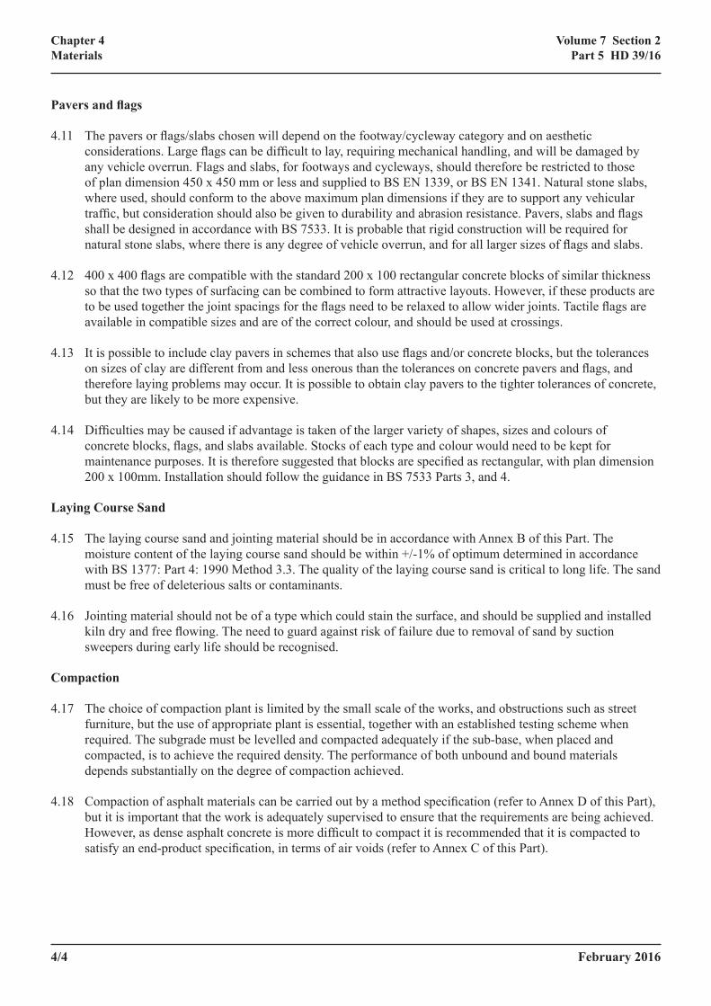
Pavers and flags
4.11 The pavers or flags/slabs chosen will depend on the footway/cycleway category and on aesthetic considerations. Large flags can be difficult to lay, requiring mechanical handling, and will be damaged by any vehicle overrun. Flags and slabs, for footways and cycleways, should therefore be restricted to those of plan dimension 450 x 450 mm or less and supplied to BS EN 1339, or BS EN 1341. Natural stone slabs, where used, should conform to the above maximum plan dimensions if they are to support any vehicular traffic, but consideration should also be given to durability and abrasion resistance. Pavers, slabs and flags shall be designed in accordance with BS 7533. It is probable that rigid construction will be required for natural stone slabs, where there is any degree of vehicle overrun, and for all larger sizes of flags and slabs.
4.12 400 x 400 flags are compatible with the standard 200 x 100 rectangular concrete blocks of similar thickness so that the two types of surfacing can be combined to form attractive layouts. However, if these products are to be used together the joint spacings for the flags need to be relaxed to allow wider joints. Tactile flags are available in compatible sizes and are of the correct colour, and should be used at crossings.
4.13 It is possible to include clay pavers in schemes that also use flags and/or concrete blocks, but the tolerances on sizes of clay are different from and less onerous than the tolerances on concrete pavers and flags, and therefore laying problems may occur. It is possible to obtain clay pavers to the tighter tolerances of concrete, but they are likely to be more expensive.
4.14 Difficulties may be caused if advantage is taken of the larger variety of shapes, sizes and colours of concrete blocks, flags, and slabs available. Stocks of each type and colour would need to be kept for maintenance purposes. It is therefore suggested that blocks are specified as rectangular, with plan dimension 200 x 100mm. Installation should follow the guidance in BS 7533 Parts 3, and 4.
Laying Course Sand
4.15 The laying course sand and jointing material should be in accordance with Annex B of this Part. The moisture content of the laying course sand should be within +/-1% of optimum determined in accordance with BS 1377: Part 4: 1990 Method 3.3. The quality of the laying course sand is critical to long life. The sand must be free of deleterious salts or contaminants.
4.16 Jointing material should not be of a type which could stain the surface, and should be supplied and installed kiln dry and free flowing. The need to guard against risk of failure due to removal of sand by suction sweepers during early life should be recognised.
Compaction
4.17 The choice of compaction plant is limited by the small scale of the works, and obstructions such as street furniture, but the use of appropriate plant is essential, together with an established testing scheme when required. The subgrade must be levelled and compacted adequately if the sub-base, when placed and compacted, is to achieve the required density. The performance of both unbound and bound materials depends substantially on the degree of compaction achieved.
4.18 Compaction of asphalt materials can be carried out by a method specification (refer to Annex D of this Part), but it is important that the work is adequately supervised to ensure that the requirements are being achieved. However, as dense asphalt concrete is more difficult to compact it is recommended that it is compacted to satisfy an end-product specification, in terms of air voids (refer to Annex C of this Part).
February 2016 4/5
Chapter 4Materials
Volume 7 Section 2Part 5 HD 39/16
4.19 The durability of dense bituminous materials of all types is heavily dependent on reducing the permeability of the material to a level which will restrict weather and oxygen attack to the top surface. The level of compaction is best characterised by air voids content which is generally recommended to be in the region of 2-8%. Void contents less than 2% are not recommended for heavy-vehicle footways (Table 3.4), else deformation may occur under trafficking.
Skidding Resistance
4.20 The footway/cycleway surface course must not become slippery when wet. It is unlikely that this will be a problem with bituminous or concrete materials, but care should be taken when specifying clay pavers or natural stone. The skidding resistance of concrete products is always adequate for use in footways, as the BS EN 1338 requirement for acid soluble content precludes the use of limestone for both coarse and fine aggregates. Some clay pavers in areas of heavy pedestrian use can become slippery when wet. Specialist advice should be sought where there is the possibility of horse traffic on modular paving.
Tolerances
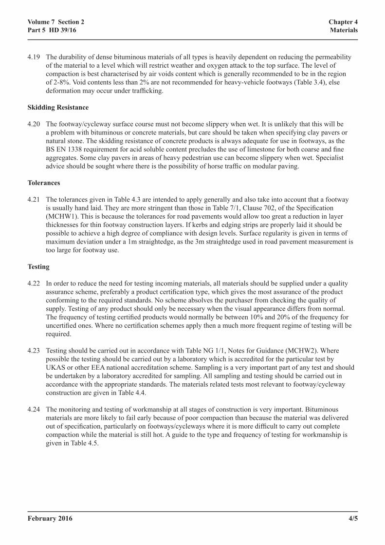
4.21 The tolerances given in Table 4.3 are intended to apply generally and also take into account that a footway is usually hand laid. They are more stringent than those in Table 7/1, Clause 702, of the Specification (MCHW1). This is because the tolerances for road pavements would allow too great a reduction in layer thicknesses for thin footway construction layers. If kerbs and edging strips are properly laid it should be possible to achieve a high degree of compliance with design levels. Surface regularity is given in terms of maximum deviation under a 1m straightedge, as the 3m straightedge used in road pavement measurement is too large for footway use.
Testing
4.22 In order to reduce the need for testing incoming materials, all materials should be supplied under a quality assurance scheme, preferably a product certification type, which gives the most assurance of the product conforming to the required standards. No scheme absolves the purchaser from checking the quality of supply. Testing of any product should only be necessary when the visual appearance differs from normal. The frequency of testing certified products would normally be between 10% and 20% of the frequency for uncertified ones. Where no certification schemes apply then a much more frequent regime of testing will be required.
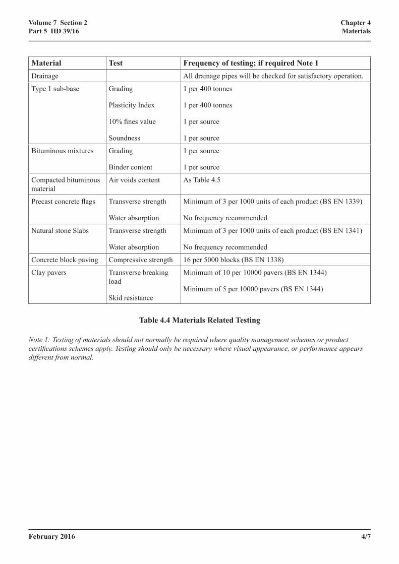
4.23 Testing should be carried out in accordance with Table NG 1/1, Notes for Guidance (MCHW2). Where possible the testing should be carried out by a laboratory which is accredited for the particular test by UKAS or other EEA national accreditation scheme. Sampling is a very important part of any test and should be undertaken by a laboratory accredited for sampling. All sampling and testing should be carried out in accordance with the appropriate standards. The materials related tests most relevant to footway/cycleway construction are given in Table 4.4.
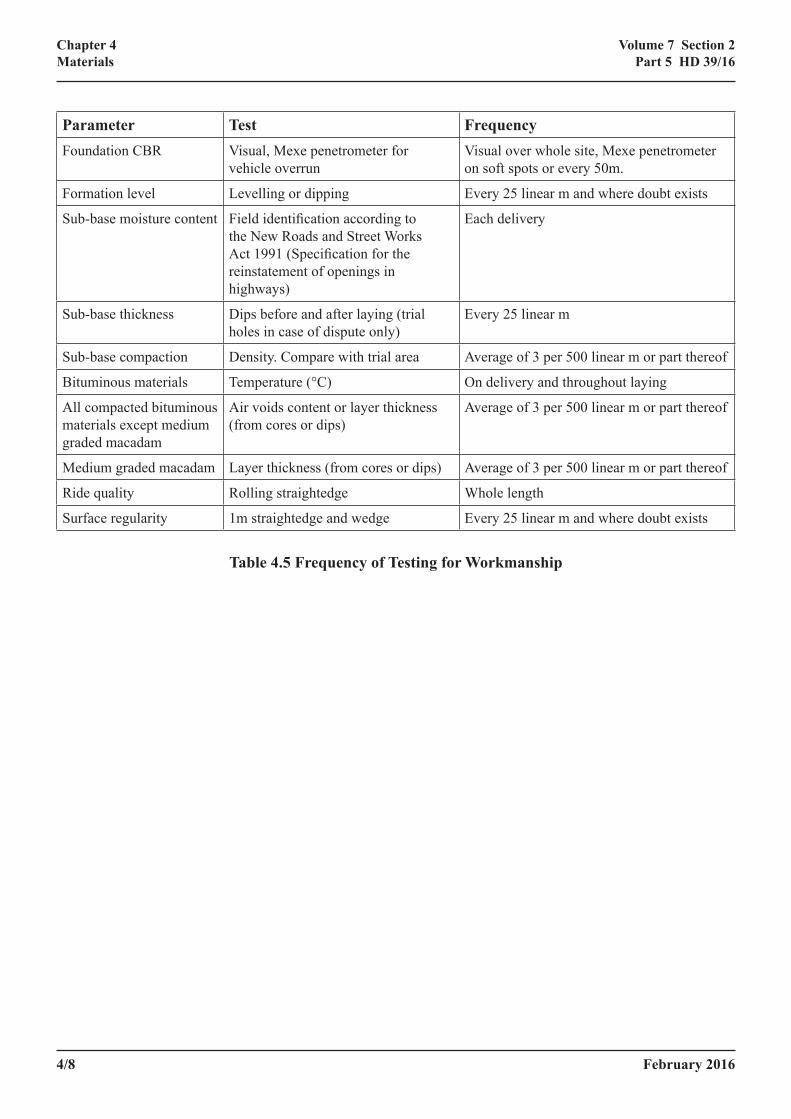
4.24 The monitoring and testing of workmanship at all stages of construction is very important. Bituminous materials are more likely to fail early because of poor compaction than because the material was delivered out of specification, particularly on footways/cycleways where it is more difficult to carry out complete compaction while the material is still hot. A guide to the type and frequency of testing for workmanship is given in Table 4.5.
4/6 February 2016
Chapter 4Materials
Volume 7 Section 2Part 5 HD 39/16
Parameter TolerancesHorizontal alignment accuracy
Horizontal alignments shall be correct to within 25mm, except for kerbs, channels and edge strips which shall be correct to within ±13mm.
Formation level After completion of any drainage and immediately before laying sub-base the subgrade surface shall be within + 10mm and –30mm of its design level.
Sub-base level If the footway is surfaced in bituminous material the compacted sub-base surface shall be within +10mm and –20mm of its design level. If segmental surfacing is used the sub-base must be within ± 10mm of its design level.
Sub-base thickness The thickness shall not be more than 10mm less than specified.
Bituminous binder course
The compacted binder course level shall be within ± 10mm of the design level.
Surface course The surface course level shall be within + 5mm and –0mm of the adjacent kerb, edging strip or any ironwork.
Bituminous thickness The total thickness of bituminous material shall not be more than 5mm less than specified.
Laying course sand The compacted laying course sand level shall be within ± 5mm of the design level and the layer shall not be less than 25mm thick.
Kerbs and edging strips
The surface level shall be within ±6mm of the design level.
Joints between flags and pavers
Joints should be not less than 2mm and not more than 5mm wide. For pedestrian-only footways flags can be laid with wide (6-10mm) joints filled with compacted mortar.
Surface regularity The maximum deviation of the footway surface under a 1m straightedge shall not exceed 3mm.
Table 4.3 Tolerances
February 2016 4/7
Chapter 4Materials
Volume 7 Section 2Part 5 HD 39/16
Material Test Frequency of testing; if required Note 1Drainage All drainage pipes will be checked for satisfactory operation.
Type 1 sub-base Grading
Plasticity Index
10% fines value
Soundness
1 per 400 tonnes
1 per 400 tonnes
1 per source
1 per source
Bituminous mixtures Grading
Binder content
1 per source
1 per source
Compacted bituminous material
Air voids content As Table 4.5
Precast concrete flags Transverse strength
Water absorption
Minimum of 3 per 1000 units of each product (BS EN 1339)
No frequency recommended
Natural stone Slabs Transverse strength
Water absorption
Minimum of 3 per 1000 units of each product (BS EN 1341)
No frequency recommended
Concrete block paving Compressive strength 16 per 5000 blocks (BS EN 1338)
Clay pavers Transverse breaking load
Skid resistance
Minimum of 10 per 10000 pavers (BS EN 1344)
Minimum of 5 per 10000 pavers (BS EN 1344)
Table 4.4 Materials Related Testing
Note 1: Testing of materials should not normally be required where quality management schemes or product certifications schemes apply. Testing should only be necessary where visual appearance, or performance appears different from normal.
4/8 February 2016
Chapter 4Materials
Volume 7 Section 2Part 5 HD 39/16
Parameter Test FrequencyFoundation CBR Visual, Mexe penetrometer for
vehicle overrunVisual over whole site, Mexe penetrometer on soft spots or every 50m.
Formation level Levelling or dipping Every 25 linear m and where doubt exists
Sub-base moisture content Field identification according to the New Roads and Street Works Act 1991 (Specification for the reinstatement of openings in highways)
Each delivery
Sub-base thickness Dips before and after laying (trial holes in case of dispute only)
Every 25 linear m
Sub-base compaction Density. Compare with trial area Average of 3 per 500 linear m or part thereof
Bituminous materials Temperature (°C) On delivery and throughout laying
All compacted bituminous materials except medium graded macadam
Air voids content or layer thickness (from cores or dips)
Average of 3 per 500 linear m or part thereof
Medium graded macadam Layer thickness (from cores or dips) Average of 3 per 500 linear m or part thereof
Ride quality Rolling straightedge Whole length
Surface regularity 1m straightedge and wedge Every 25 linear m and where doubt exists
Table 4.5 Frequency of Testing for Workmanship
February 2016 5/1
Chapter 5References
Volume 7 Section 2Part 5 HD 39/16
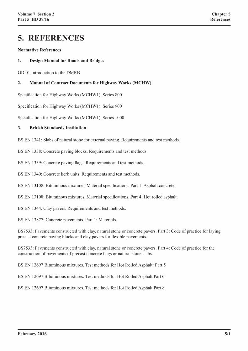
5. REFERENCESNormative References
1. Design Manual for Roads and Bridges
GD 01 Introduction to the DMRB
2. Manual of Contract Documents for Highway Works (MCHW)
Specification for Highway Works (MCHW1). Series 800
Specification for Highway Works (MCHW1). Series 900
Specification for Highway Works (MCHW1). Series 1000
3. British Standards Institution
BS EN 1341: Slabs of natural stone for external paving. Requirements and test methods.
BS EN 1338: Concrete paving blocks. Requirements and test methods.
BS EN 1339: Concrete paving flags. Requirements and test methods.
BS EN 1340: Concrete kerb units. Requirements and test methods.
BS EN 13108: Bituminous mixtures. Material specifications. Part 1: Asphalt concrete.
BS EN 13108: Bituminous mixtures. Material specifications. Part 4: Hot rolled asphalt.
BS EN 1344: Clay pavers. Requirements and test methods.
BS EN 13877: Concrete pavements. Part 1: Materials.
BS7533: Pavements constructed with clay, natural stone or concrete pavers. Part 3: Code of practice for laying precast concrete paving blocks and clay pavers for flexible pavements.
BS7533: Pavements constructed with clay, natural stone or concrete pavers. Part 4: Code of practice for the construction of pavements of precast concrete flags or natural stone slabs.
BS EN 12697 Bituminous mixtures. Test methods for Hot Rolled Asphalt: Part 5
BS EN 12697 Bituminous mixtures. Test methods for Hot Rolled Asphalt Part 6
BS EN 12697 Bituminous mixtures. Test methods for Hot Rolled Asphalt Part 8
5/2 February 2016
Chapter 5References
Volume 7 Section 2Part 5 HD 39/16
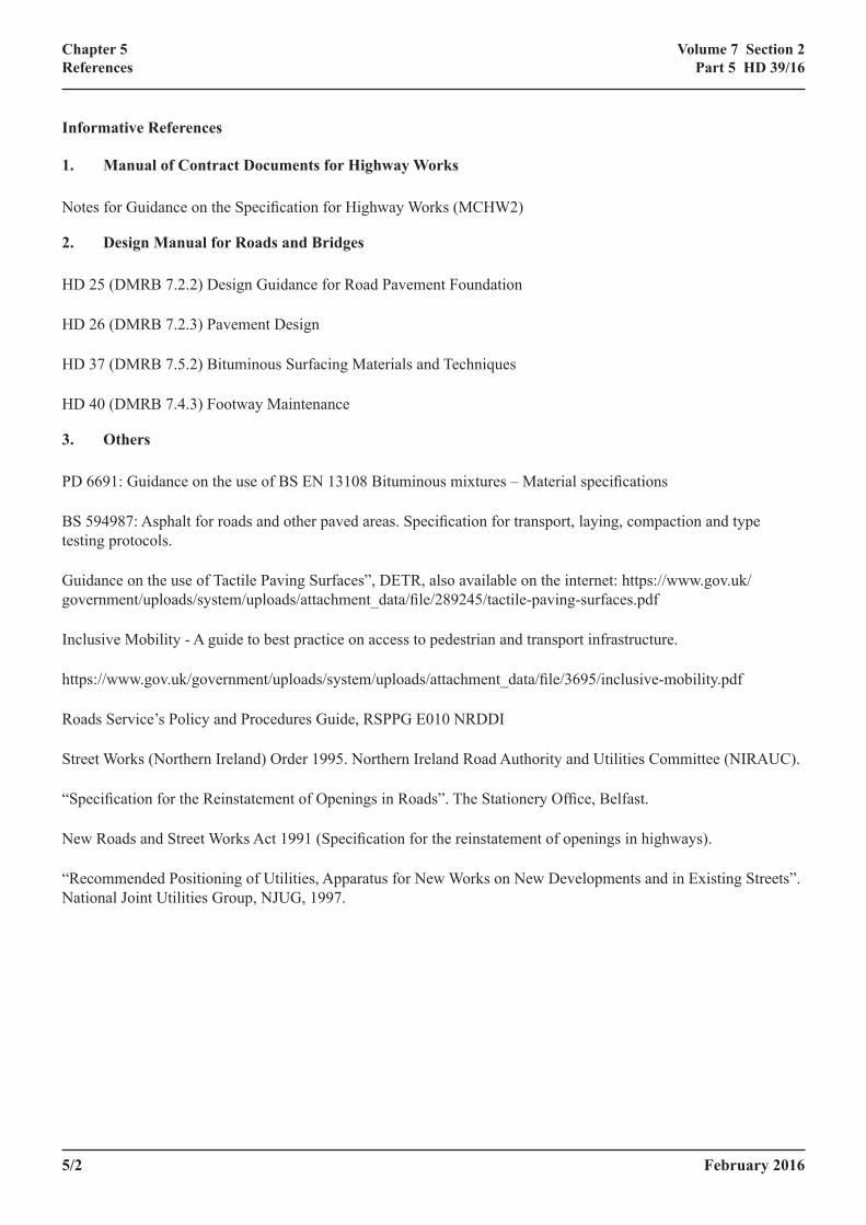
Informative References
1. Manual of Contract Documents for Highway Works
Notes for Guidance on the Specification for Highway Works (MCHW2)
2. Design Manual for Roads and Bridges
HD 25 (DMRB 7.2.2) Design Guidance for Road Pavement Foundation
HD 26 (DMRB 7.2.3) Pavement Design
HD 37 (DMRB 7.5.2) Bituminous Surfacing Materials and Techniques
HD 40 (DMRB 7.4.3) Footway Maintenance
3. Others
PD 6691: Guidance on the use of BS EN 13108 Bituminous mixtures – Material specifications
BS 594987: Asphalt for roads and other paved areas. Specification for transport, laying, compaction and type testing protocols.
Guidance on the use of Tactile Paving Surfaces”, DETR, also available on the internet: https://www.gov.uk/government/uploads/system/uploads/attachment_data/file/289245/tactile-paving-surfaces.pdf
Inclusive Mobility - A guide to best practice on access to pedestrian and transport infrastructure.
https://www.gov.uk/government/uploads/system/uploads/attachment_data/file/3695/inclusive-mobility.pdf
Roads Service’s Policy and Procedures Guide, RSPPG E010 NRDDI
Street Works (Northern Ireland) Order 1995. Northern Ireland Road Authority and Utilities Committee (NIRAUC).
“Specification for the Reinstatement of Openings in Roads”. The Stationery Office, Belfast.
New Roads and Street Works Act 1991 (Specification for the reinstatement of openings in highways).
“Recommended Positioning of Utilities, Apparatus for New Works on New Developments and in Existing Streets”. National Joint Utilities Group, NJUG, 1997.

February 2016 6/1
Volume 7 Section 2Part 5 HD 39/16
6. ENQUIRIESApproval of this document for publication is given by:
Highways England Temple Quay House The Square Temple Quay Bristol M WILSONBS1 6HA Chief Highways Engineer
Transport Scotland 8th Floor, Buchanan House 58 Port Dundas Road Glasgow R BRANNENG4 0HF Director, Trunk Road and Bus Operations
Welsh Government Transport S HAGUE Cardiff Deputy Director CF10 3NQ Network Management Division
Department for Regional Development TransportNI Clarence Court 10-18 Adelaide Street Belfast P B DOHERTY BT2 8GB Director of Engineering
All technical enquiries or comments on this Standard should be sent to standards_ [email protected]
This document was notified in draft to the European Commission in accordance with Directive 98/34/EC, as amended by Directive 98/48/EC.
Chapter 6Enquiries

6/2 February 2016
Volume 7 Section 2Part 5 HD 39/16
Chapter 6Enquiries

February 2016 A/1
Volume 7 Section 2Part 5 HD 39/16
Annex A
ANNEX ANot Used

A/2 February 2016
Volume 7 Section 2Part 5 HD 39/16
Annex A
February 2016 B/1
Volume 7 Section 2Part 5 HD 39/16
Annex B Specification of laying course sand and jointing material for small element paving
ANNEX B – SPECIFICATION OF LAYING COURSE SAND AND JOINTING MATERIAL FOR SMALL ELEMENT PAVING
Flags and Slabs: BS 7533 Part 4; Tables 5 and 6
Concrete and Clay Paving Blocks: BS 7533 Part 3 Tables D1 to D4

B/2 February 2016
Volume 7 Section 2Part 5 HD 39/16
Annex B Specification of laying course sand and jointing material for small element paving
February 2016 C/1
Volume 7 Section 2Part 5 HD 39/16
Annex C Compaction Specification
ANNEX C – COMPACTION SPECIFICATION
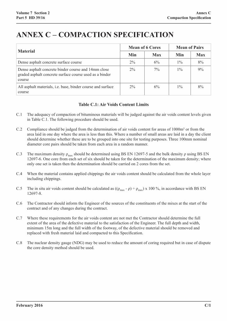
MaterialMean of 6 Cores Mean of PairsMin Max Min Max
Dense asphalt concrete surface course 2% 6% 1% 8%
Dense asphalt concrete binder course and 14mm close graded asphalt concrete surface course used as a binder course
2% 7% 1% 9%
All asphalt materials, i.e. base, binder course and surface course
2% 6% 1% 8%
Table C.1: Air Voids Content Limits
C.1 The adequacy of compaction of bituminous materials will be judged against the air voids content levels given in Table C.1. The following procedure should be used.
C.2 Compliance should be judged from the determination of air voids content for areas of 1000m² or from the area laid in one day where the area is less than this. Where a number of small areas are laid in a day the client should determine whether these are to be grouped into one site for testing purposes. Three 100mm nominal diameter core pairs should be taken from each area in a random manner.
C.3 The maximum density ρmax should be determined using BS EN 12697-5 and the bulk density ρ using BS EN 12697-6. One core from each set of six should be taken for the determination of the maximum density; where only one set is taken then the determination should be carried on 2 cores from the set.
C.4 When the material contains applied chippings the air voids content should be calculated from the whole layer including chippings.
C.5 The in situ air voids content should be calculated as ((ρmax - ρ) ÷ ρmax) x 100 %, in accordance with BS EN 12697-8.
C.6 The Contractor should inform the Engineer of the sources of the constituents of the mixes at the start of the contract and of any changes during the contract.
C.7 Where these requirements for the air voids content are not met the Contractor should determine the full extent of the area of the defective material to the satisfaction of the Engineer. The full depth and width, minimum 15m long and the full width of the footway, of the defective material should be removed and replaced with fresh material laid and compacted to this Specification.
C.8 The nuclear density gauge (NDG) may be used to reduce the amount of coring required but in case of dispute the core density method should be used.

C/2 February 2016
Volume 7 Section 2Part 5 HD 39/16
Annex C Compaction Specification
February 2016 D/1
Volume 7 Section 2Part 5 HD 39/16
Annex D Compaction by Method Specification
ANNEX D – COMPACTION BY METHOD SPECIFICATION
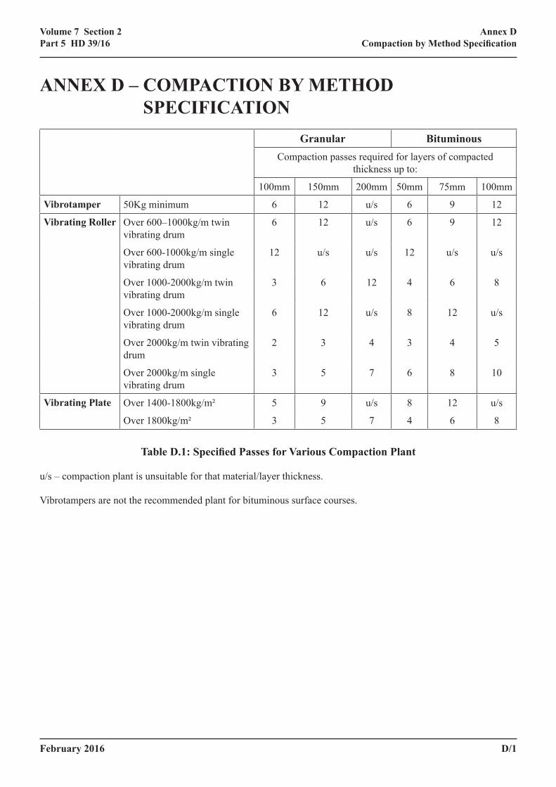
Granular BituminousCompaction passes required for layers of compacted
thickness up to:
100mm 150mm 200mm 50mm 75mm 100mm
Vibrotamper 50Kg minimum 6 12 u/s 6 9 12
Vibrating Roller Over 600–1000kg/m twin vibrating drum
6 12 u/s 6 9 12
Over 600-1000kg/m single vibrating drum
12 u/s u/s 12 u/s u/s
Over 1000-2000kg/m twin vibrating drum
3 6 12 4 6 8
Over 1000-2000kg/m single vibrating drum
6 12 u/s 8 12 u/s
Over 2000kg/m twin vibrating drum
2 3 4 3 4 5
Over 2000kg/m single vibrating drum
3 5 7 6 8 10
Vibrating Plate Over 1400-1800kg/m² 5 9 u/s 8 12 u/s
Over 1800kg/m² 3 5 7 4 6 8
Table D.1: Specified Passes for Various Compaction Plant
u/s – compaction plant is unsuitable for that material/layer thickness.
Vibrotampers are not the recommended plant for bituminous surface courses.

D/2 February 2016
Volume 7 Section 2Part 5 HD 39/16
Annex D Compaction by Method Specification
February 2016 E/1
Volume 7 Section 2Part 5 HD 39/16
Annex E Worked Examples
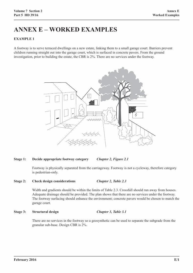
ANNEX E – WORKED EXAMPLESEXAMPLE 1
A footway is to serve terraced dwellings on a new estate, linking them to a small garage court. Barriers prevent children running straight out into the garage court, which is surfaced in concrete pavers. From the ground investigation, prior to building the estate, the CBR is 2%. There are no services under the footway.
Stage 1: Decide appropriate footway category Chapter 2, Figure 2.1
Footway is physically separated from the carriageway. Footway is not a cycleway, therefore category is pedestrian-only.
Stage 2: Check design considerations Chapter 2, Table 2.3
Width and gradients should be within the limits of Table 2.3. Crossfall should run away from houses. Adequate drainage should be provided. The plan shows that there are no services under the footway. The footway surfacing should enhance the environment; concrete pavers would be chosen to match the garage court.
Stage 3: Structural design Chapter 3, Table 3.1
There are no services in the footway so a geosynthetic can be used to separate the subgrade from the granular sub-base. Design CBR is 2%.
E/2 February 2016
Volume 7 Section 2Part 5 HD 39/16
Annex E Worked Examples
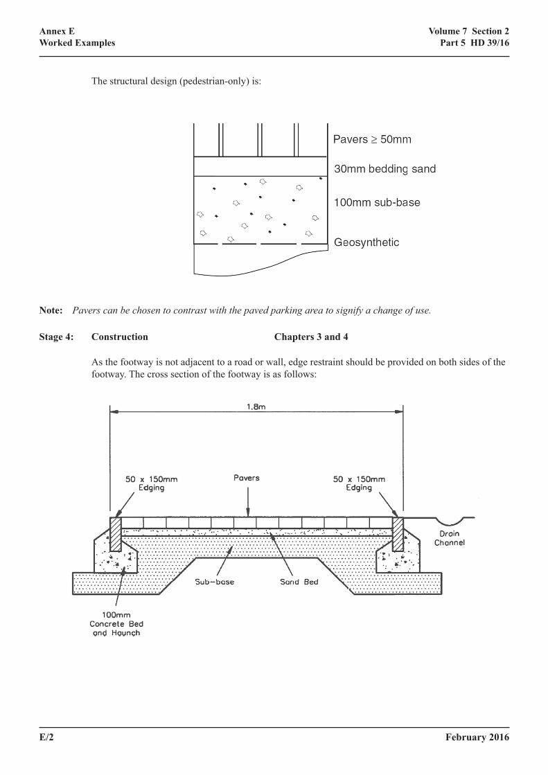
The structural design (pedestrian-only) is:
Note: Pavers can be chosen to contrast with the paved parking area to signify a change of use.
Stage 4: Construction Chapters 3 and 4
As the footway is not adjacent to a road or wall, edge restraint should be provided on both sides of the footway. The cross section of the footway is as follows:
February 2016 E/3
Volume 7 Section 2Part 5 HD 39/16
Annex E Worked Examples
EXAMPLE 2
A new school has been built on the outskirts of a rural village. A footway/cycleway is required to connect the school to the neighbouring village so that pupils can cycle or walk to school safely. The road running past the school is a rural lane, but there is ample parking and delivery space in the school grounds. At present the lane has a 3m wide grass verge bounded by a hedge. The soil along the verge is a soft clay. The length for which a footway/cycleway is required is approximately 1 km.
Stage 1: Decide appropriate footway/cycleway category Chapter 2, Figure 2.1
Footway is not physically separated from the carriageway and may be considered to be lightly used. However, footway is also to be used as a cycleway, which may require the use of clearing and maintenance vehicles, so it would be wise to design for light-vehicle category.
Stage 2: Estimate subgrade CBR Chapter 2, Table 2.2
Soil is very soft clay. A quick test shows that it “exudes from the fingers when squeezed”. According to Table 2.2, this indicates a CBR of less than 1%.
Stage 3: Check design considerations Chapter 2, Table 2.3
Width and gradients should be within the limits of Table 2.3. A minimum of 2m width is required which could usefully be increased to 2.5m to provide space for cyclists to overtake pedestrians. The gradient will be as for the road. The crossfall will be towards the road utilising existing drainage. The length and situation of the footway make a bituminous construction the best option. If there are services in the verge they may need to be moved or made deeper.
Stage 4: Structural design Chapter 3, Table 3.3
CBR < 1%. Assume lime stabilisation is used to raise the design subgrade CBR to over 5%.
Very occasional heavy vehicle overrun may occur, but the treated subgrade now has a CBR > 5% so the designs in Table 3.3 can be used. The structural design is 70mm of bituminous material on 150mm of sub-base.
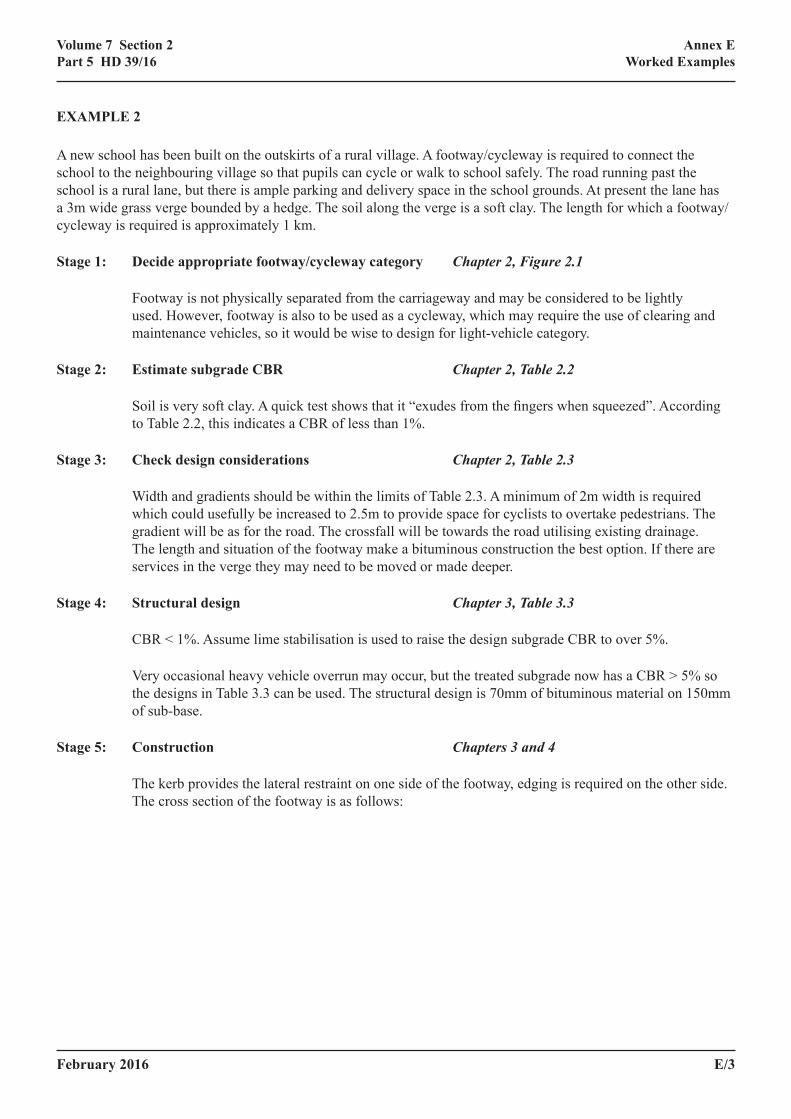
Stage 5: Construction Chapters 3 and 4
The kerb provides the lateral restraint on one side of the footway, edging is required on the other side. The cross section of the footway is as follows:
E/4 February 2016
Volume 7 Section 2Part 5 HD 39/16
Annex E Worked Examples
EXAMPLE 3
A footway/cycleway is to be built alongside an existing road, which now receives some pedestrian traffic due to construction of an out-of-town shopping area. There will be no verge between the footway/cycleway and the carriageway, as the existing verge, on which the footway/cycleway is to be constructed, is only 2m wide. There is a brick wall along the whole length of verge. It has been decided that concrete blocks will be used as the surfacing. The soil is sandy clay. Delivery vehicles may overrun the footway/cycleway occasionally if, for example, the road is partly blocked by a broken down vehicle.
Stage 1: Decide appropriate footway/cycleway category Chapter 2, Figure 2.1
The footway/cycleway is not physically separated from the carriageway, and is not very lightly used. Heavy vehicle overrun is likely to occur. Therefore the footway/cycleway category is heavy-vehicle.
Stage 2: Estimate subgrade CBR Chapter 2, Table 2.1
Soil is a sandy clay. From Table 2.1 the subgrade CBR is likely to be approximately 3%. Testing is required to confirm this.
Stage 3: Check design considerations Chapter 2, Table 2.3
Width and gradients should be within the limits of Table 2.3. The gradient will be as for the road. The crossfall will run towards the road utilising existing drainage.
Stage 4: Structural design Chapter 3, Table 3.4
The subgrade CBR = 3%, so no treatment is necessary.
February 2016 E/5
Volume 7 Section 2Part 5 HD 39/16
Annex E Worked Examples
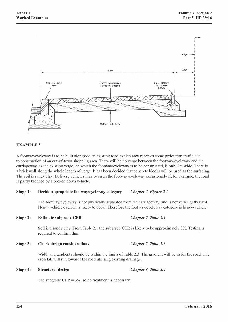
The required sub-base thickness for heavy-vehicle design is 270mm. Concrete blocks should be at least 60mm thick and should be placed on 30mm compacted thickness of laying course sand. A base of 90mm dense binder course asphalt concrete or 100mm CBM1 or stronger, is required between the sub-base and the laying course sand.
Stage 5: Construction Chapters 3 and 4
The brick wall provides lateral restraint on one side of the footway/cycleway and the kerb provides lateral restraint on the other side. Edging is not required.


![Energy Conservation in Road Pavement Design, Maintenance ......EIE/06/039/SI2.448265 ECRPD [Type text] Energy Conservation in Road Pavement Design, Maintenance and Utilisation ECRPD](https://img.pdfslide.net/doc/110x75/613170e01ecc51586944bcae/energy-conservation-in-road-pavement-design-maintenance-eie06039si2448265.jpg)