Embed Size (px)
Citation preview
WELMEC 8.12-2 Issue 1
WELMEC European cooperation in legal metrology
Volume conversion devices Cross Reference Table 2004/22/EC vs. OIML R 140 - 2007
April 2009
2 / 35
WELMEC European cooperation in legal metrology
Published by: WELMEC Secretariat MIRS Grudnovo nabrežje 17 SI – 1000 Ljubljana Tel: +386 1 244 27 21 Fax: +386 1 244 27 14
WELMEC is a cooperation between the legal metrology services of the Member States of the European Union and EFTA. This document is one of a number of Guides published by WELMEC. The Guides are purely advisory and do not themselves impose any restrictions or additional technical requirements beyond those contained in relevant EC Directives. Alternative approaches may be acceptable, but the guidance provided in this document represents the considered view of WELMEC as to the best practice to be followed.
3 / 35
Notes:
1. The column “Comments” indicates when necessary the relevant text of OIML R 140 and related explanations concerning the compliance with relevant MID requirement.
2. The column “Conclusion” gives the conclusion on the compliance between MID and OIML R 140
for the relevant requirement. The indication “Covered” means that:
- the requirement of OIML R 140 is identical to the one of MID; or - the requirement of OIML R 140 is more severe than the one of MID; or - All the requirement of OIML R 140 fulfils MID requirements (even when MID allows other
alternatives), - In case the requirement is not fully covered, a short statement explains what is covered.
The indication “Not Covered” means that the MID requirement is either not compatible with the
relevant OIML R 140 requirement or not included in OIML R 140. The indication “Not relevant” means that the MID Annex 1 requirement is not relevant for
conversion devices. The text in italic is an extract from the relevant clause of the OIML Recommendation.
4 / 35
Directive 2004/22/EC
Essential requirements of Annex 1 and Annex MI-002
OIML R 140 (2007)
Comments Conclusion
ANNEX 1
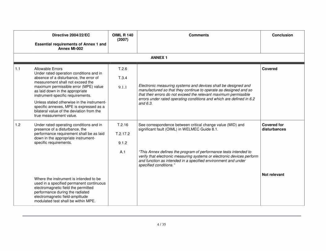
1.1 Allowable Errors Under rated operation conditions and in absence of a disturbance, the error of measurement shall not exceed the maximum permissible error (MPE) value as laid down in the appropriate instrument-specific requirements.
Unless stated otherwise in the instrument-specific annexes, MPE is expressed as a bilateral value of the deviation from the true measurement value.
T.2.6
T.3.4
9.1.1
Electronic measuring systems and devices shall be designed and manufactured so that they continue to operate as designed and so that their errors do not exceed the relevant maximum permissible errors under rated operating conditions and which are defined in 6.2 and 6.3.
Covered
1.2 Under rated operating conditions and in presence of a disturbance, the performance requirement shall be as laid down in the appropriate instrument-specific requirements.
Where the instrument is intended to be used in a specified permanent continuous electromagnetic field the permitted performance during the radiated electromagnetic field-amplitude modulated test shall be within MPE.
T.2.16
T.2.17.2
9.1.2
A.1
See correspondence between critical change value (MID) and significant fault (OIML) in WELMEC Guide 8.1.
“This Annex defines the program of performance tests intended to verify that electronic measuring systems or electronic devices perform and function as intended in a specified environment and under specified conditions.”
Covered for disturbances
Not relevant
5 / 35
Directive 2004/22/EC
Essential requirements of Annex 1 and Annex MI-002
OIML R 140 (2007)
Comments Conclusion
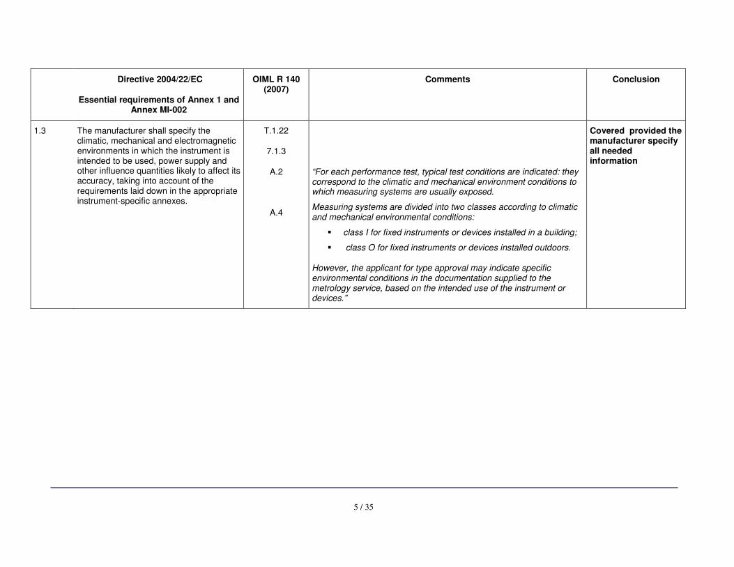
1.3 The manufacturer shall specify the climatic, mechanical and electromagnetic environments in which the instrument is intended to be used, power supply and other influence quantities likely to affect its accuracy, taking into account of the requirements laid down in the appropriate instrument-specific annexes.
T.1.22
7.1.3
A.2
A.4
“For each performance test, typical test conditions are indicated: they correspond to the climatic and mechanical environment conditions to which measuring systems are usually exposed.
Measuring systems are divided into two classes according to climatic and mechanical environmental conditions:
� class I for fixed instruments or devices installed in a building;
� class O for fixed instruments or devices installed outdoors.
However, the applicant for type approval may indicate specific environmental conditions in the documentation supplied to the metrology service, based on the intended use of the instrument or devices.”
Covered provided the manufacturer specify all needed information
6 / 35
Directive 2004/22/EC
Essential requirements of Annex 1 and Annex MI-002
OIML R 140 (2007)
Comments Conclusion
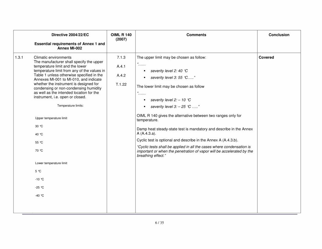
1.3.1 Climatic environments The manufacturer shall specify the upper temperature limit and the lower temperature limit from any of the values in Table 1 unless otherwise specified in the Annexes MI-001 to MI-010, and indicate whether the instrument is designed for condensing or non-condensing humidity as well as the intended location for the instrument, i.e. open or closed.
Temperature limits:
Upper temperature limit
30 °C
40 °C
55 °C
70 °C
Lower temperature limit
5 °C
-10 °C
-25 °C
-40 °C
7.1.3
A.4.1
A.4.2
T.1.22
The upper limit may be chosen as follow:
“……
� severity level 2: 40 °C
� severity level 3: 55 °C…..”
The lower limit may be chosen as follow
“……
� severity level 2: – 10 °C
� severity level 3: – 25 °C …..”
OIML R 140 gives the alternative between two ranges only for temperature.
Damp heat steady-state test is mandatory and describe in the Annex A (A.4.3.a).
Cyclic test is optional and describe in the Annex A (A.4.3.b).
“Cyclic tests shall be applied in all the cases where condensation is important or when the penetration of vapor will be accelerated by the breathing effect.”
Covered
7 / 35
Directive 2004/22/EC
Essential requirements of Annex 1 and Annex MI-002
OIML R 140 (2007)
Comments Conclusion
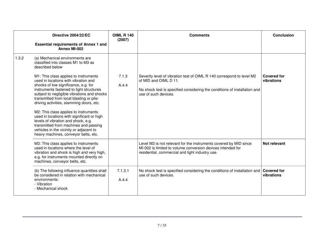
1.3.2 (a) Mechanical environments are classified into classes M1 to M3 as described below
M1: This class applies to instruments used in locations with vibration and shocks of low significance, e.g. for instruments fastened to light structures subject to negligible vibrations and shocks transmitted from local blasting or pile-driving activities, slamming doors, etc.
M2: This class applies to instruments used in locations with significant or high levels of vibration and shock, e.g. transmitted from machines and passing vehicles in the vicinity or adjacent to heavy machines, conveyor belts, etc.
7.1.3
A.4.4
Severity level of vibration test of OIML R 140 correspond to level M2 of MID and OIML D 11.
No shock test is specified considering the conditions of installation and use of such devices.
Covered for vibrations
M3: This class applies to instruments used in locations where the level of vibration and shock is high and very high, e.g. for instruments mounted directly on machines, conveyor belts, etc.
Level M3 is not relevant for the instruments covered by MID since MI-002 is limited to volume conversion devices intended for residential, commercial and light industry use.
Not relevant
(b) The following influence quantities shall be considered in relation with mechanical environments: - Vibration - Mechanical shock
7.1.3.1
A.4.4
No shock test is specified considering the conditions of installation and use of such devices.
Covered for vibrations
8 / 35
Directive 2004/22/EC
Essential requirements of Annex 1 and Annex MI-002
OIML R 140 (2007)
Comments Conclusion
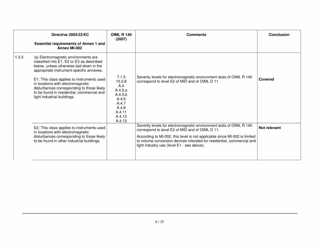
1.3.3 (a) Electromagnetic environments are classified into E1, E2 or E3 as described below, unless otherwise laid down in the appropriate instrument-specific annexes.
E1: This class applies to instruments used in locations with electromagnetic disturbances corresponding to those likely to be found in residential, commercial and light industrial buildings.
7.1.3 10.2.8
A.4 A.4.5.a A.4.5.b A.4.6 A.4.7 A.4.8 A.4.11 A.4.12 A.4.13
Severity levels for electromagnetic environment tests of OIML R 140 correspond to level E2 of MID and of OIML D 11.
Covered
E2: This class applies to instruments used in locations with electromagnetic disturbances corresponding to those likely to be found in other industrial buildings.
Severity levels for electromagnetic environment tests of OIML R 140 correspond to level E2 of MID and of OIML D 11.
According to MI-002, this level is not applicable since MI-002 is limited to volume conversion devices intended for residential, commercial and light industry use (level E1 - see above).
Not relevant
9 / 35
Directive 2004/22/EC
Essential requirements of Annex 1 and Annex MI-002
OIML R 140 (2007)
Comments Conclusion
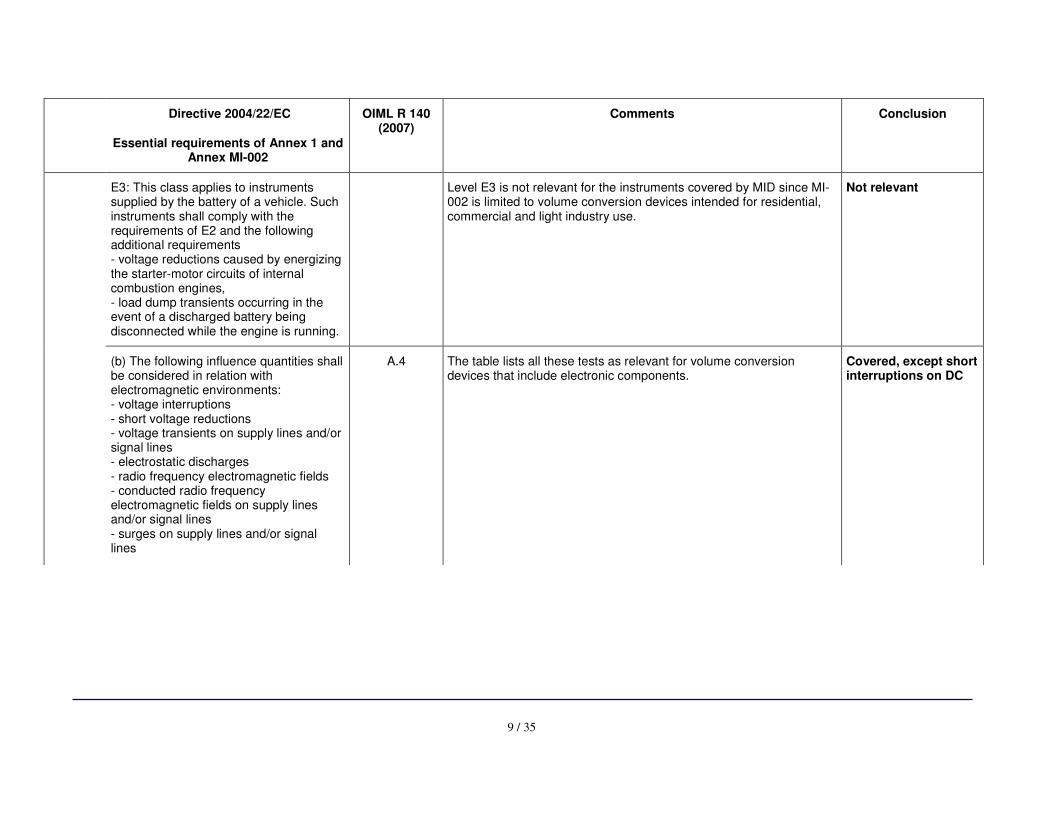
E3: This class applies to instruments supplied by the battery of a vehicle. Such instruments shall comply with the requirements of E2 and the following additional requirements - voltage reductions caused by energizing the starter-motor circuits of internal combustion engines, - load dump transients occurring in the event of a discharged battery being disconnected while the engine is running.
Level E3 is not relevant for the instruments covered by MID since MI-002 is limited to volume conversion devices intended for residential, commercial and light industry use.
Not relevant
(b) The following influence quantities shall be considered in relation with electromagnetic environments: - voltage interruptions - short voltage reductions - voltage transients on supply lines and/or signal lines - electrostatic discharges - radio frequency electromagnetic fields - conducted radio frequency electromagnetic fields on supply lines and/or signal lines - surges on supply lines and/or signal lines
A.4 The table lists all these tests as relevant for volume conversion devices that include electronic components.
Covered, except short interruptions on DC
10 / 35
Directive 2004/22/EC
Essential requirements of Annex 1 and Annex MI-002
OIML R 140 (2007)
Comments Conclusion
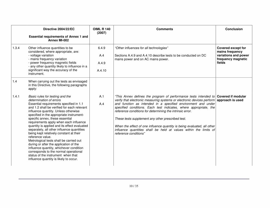
1.3.4 Other influence quantities to be considered, where appropriate, are: - voltage variation - mains frequency variation - power frequency magnetic fields - any other quantity likely to influence in a significant way the accuracy of the instrument.
6.4.9
A.4
A.4.9
A.4.10
“Other influences for all technologies”
Sections A.4.9 and A.4.10 describe tests to be conducted on DC mains power and on AC mains power.
Covered except for mains frequency variations and power frequency magnetic fields
1.4
When carrying out the tests as envisaged in this Directive, the following paragraphs apply:
1.4.1 Basic rules for testing and the determination of errors Essential requirements specified in 1.1 and 1.2 shall be verified for each relevant influence quantity. Unless otherwise specified in the appropriate instrument-specific annex, these essential requirements apply when each influence quantity is applied and its effect evaluated separately, all other influence quantities being kept relatively constant at their reference value. Metrological tests shall be carried out during or after the application of the influence quantity, whichever condition corresponds to the normal operational status of the instrument when that influence quantity is likely to occur.
A.1
A.4
“This Annex defines the program of performance tests intended to verify that electronic measuring systems or electronic devices perform and function as intended in a specified environment and under specified conditions. Each test indicates, where appropriate, the reference conditions for determining the intrinsic error.
These tests supplement any other prescribed test.
When the effect of one influence quantity is being evaluated, all other influence quantities shall be held at values within the limits of reference conditions”
Covered if modular approach is used

11 / 35
Directive 2004/22/EC
Essential requirements of Annex 1 and Annex MI-002
OIML R 140 (2007)
Comments Conclusion
1.4.2 Ambient humidity - According to the climatic operating environment in which the instrument is intended to be used either the damp heat-steady state (non-condensing) or damp heat cyclic (condensing) test may be appropriate. - The damp heat cyclic test is appropriate where condensation is important or when penetration of vapour will be accelerated by the effect of breathing. In conditions where non-condensing humidity is a factor the damp-heat steady state is appropriate.
A.4.3
Two tests are defined:
� Steady-state (non condensing) � cyclic (condensing) damp heat.
“The steady-state test should always be used where adsorption or absorption play the main part. When diffusion but not breathing is involved, either the steady-state or the cyclic test shall be applied depending on the type of EUT and its application.” “Cyclic tests shall be applied in all the cases where condensation is important or when the penetration of vapor will be accelerated by the breathing effect.”
Covered
2 Reproducibility The application of the same measurand in a different location or by different user, all other conditions being the same, shall result in the close agreement of successive measurements. The difference between the measurement results shall be small when compared with the MPE.
Not relevant
3 Repeatability The application of the same measurand under the same conditions of measurement shall result in the close agreement of successive measurements. The difference between the measurement results shall be small when compared with the MPE.
Not Covered
12 / 35
Directive 2004/22/EC
Essential requirements of Annex 1 and Annex MI-002
OIML R 140 (2007)
Comments Conclusion
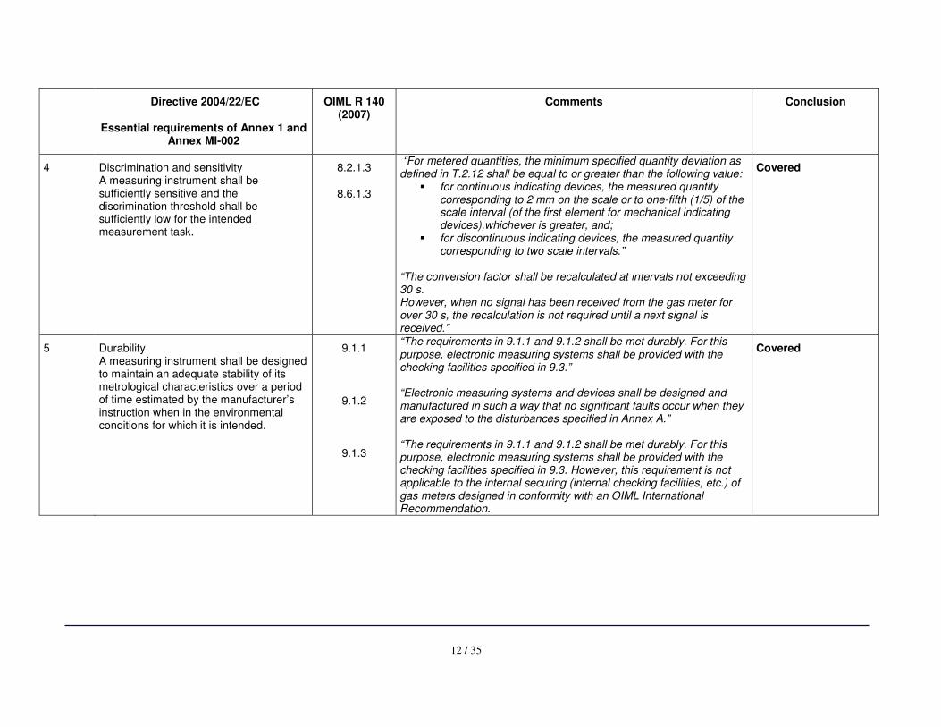
4 Discrimination and sensitivity A measuring instrument shall be sufficiently sensitive and the discrimination threshold shall be sufficiently low for the intended measurement task.
8.2.1.3
8.6.1.3
“For metered quantities, the minimum specified quantity deviation as defined in T.2.12 shall be equal to or greater than the following value:
� for continuous indicating devices, the measured quantity corresponding to 2 mm on the scale or to one-fifth (1/5) of the scale interval (of the first element for mechanical indicating devices),whichever is greater, and;
� for discontinuous indicating devices, the measured quantity corresponding to two scale intervals.”
“The conversion factor shall be recalculated at intervals not exceeding 30 s. However, when no signal has been received from the gas meter for over 30 s, the recalculation is not required until a next signal is received.”
Covered
5 Durability A measuring instrument shall be designed to maintain an adequate stability of its metrological characteristics over a period of time estimated by the manufacturer’s instruction when in the environmental conditions for which it is intended.
9.1.1
9.1.2
9.1.3
“The requirements in 9.1.1 and 9.1.2 shall be met durably. For this purpose, electronic measuring systems shall be provided with the checking facilities specified in 9.3.” “Electronic measuring systems and devices shall be designed and manufactured in such a way that no significant faults occur when they are exposed to the disturbances specified in Annex A.” “The requirements in 9.1.1 and 9.1.2 shall be met durably. For this purpose, electronic measuring systems shall be provided with the checking facilities specified in 9.3. However, this requirement is not applicable to the internal securing (internal checking facilities, etc.) of gas meters designed in conformity with an OIML International Recommendation.
Covered
13 / 35
Directive 2004/22/EC
Essential requirements of Annex 1 and Annex MI-002
OIML R 140 (2007)
Comments Conclusion
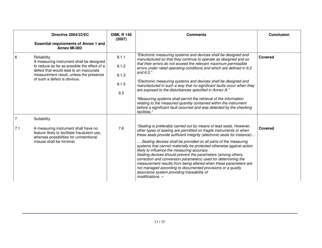
6 Reliability A measuring instrument shall be designed to reduce as far as possible the effect of a defect that would lead to an inaccurate measurement result, unless the presence of such a defect is obvious.
9.1.1
9.1.2
9.1.3
9.1.5
9.3
“Electronic measuring systems and devices shall be designed and manufactured so that they continue to operate as designed and so that their errors do not exceed the relevant maximum permissible errors under rated operating conditions and which are defined in 6.2 and 6.3.” “Electronic measuring systems and devices shall be designed and manufactured in such a way that no significant faults occur when they are exposed to the disturbances specified in Annex A.” “Measuring systems shall permit the retrieval of the information relating to the measured quantity contained within the instrument before a significant fault occurred and was detected by the checking facilities.”
Covered
7 Suitability
7.1 A measuring instrument shall have no feature likely to facilitate fraudulent use, whereas possibilities for unintentional misuse shall be minimal.
7.6
“Sealing is preferably carried out by means of lead seals. However, other types of sealing are permitted on fragile instruments or when these seals provide sufficient integrity (electronic seals for instance)…
….Sealing devices shall be provided on all parts of the measuring systems that cannot materially be protected otherwise against action likely to influence the measuring accuracy. Sealing devices should prevent the parameters (among others, correction and conversion parameters) used for determining the measurement results from being altered when these parameters are not managed according to documented provisions or a quality assurance system providing traceability of modifications. »
Covered
14 / 35
Directive 2004/22/EC
Essential requirements of Annex 1 and Annex MI-002
OIML R 140 (2007)
Comments Conclusion
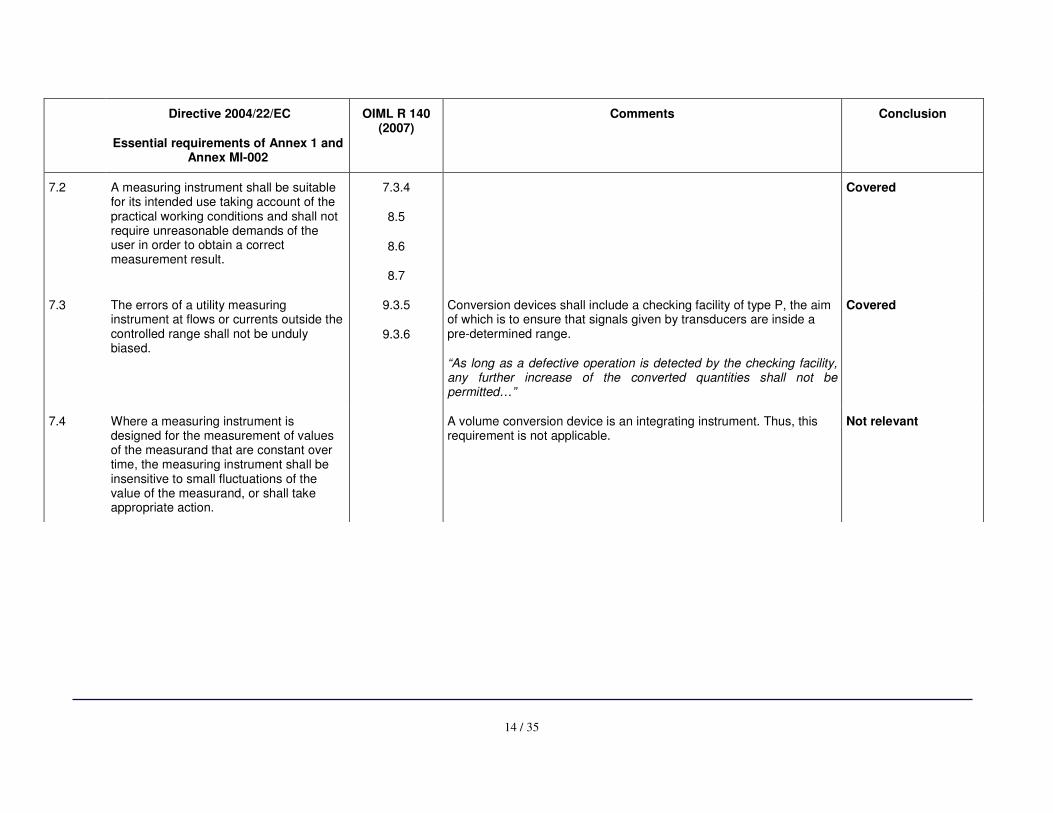
7.2 A measuring instrument shall be suitable for its intended use taking account of the practical working conditions and shall not require unreasonable demands of the user in order to obtain a correct measurement result.
7.3.4
8.5
8.6
8.7
Covered
7.3 The errors of a utility measuring instrument at flows or currents outside the controlled range shall not be unduly biased.
9.3.5
9.3.6
Conversion devices shall include a checking facility of type P, the aim of which is to ensure that signals given by transducers are inside a pre-determined range.
“As long as a defective operation is detected by the checking facility, any further increase of the converted quantities shall not be permitted…”
Covered
7.4 Where a measuring instrument is designed for the measurement of values of the measurand that are constant over time, the measuring instrument shall be insensitive to small fluctuations of the value of the measurand, or shall take appropriate action.
A volume conversion device is an integrating instrument. Thus, this requirement is not applicable.
Not relevant
15 / 35
Directive 2004/22/EC
Essential requirements of Annex 1 and Annex MI-002
OIML R 140 (2007)
Comments Conclusion
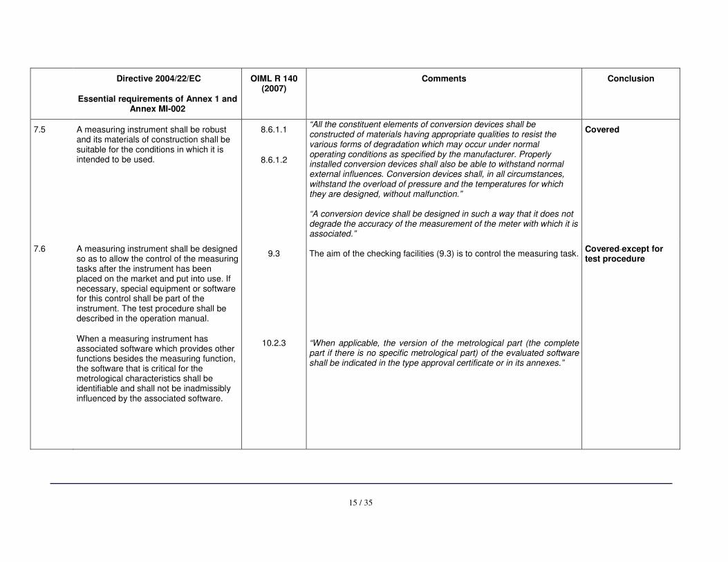
7.5 A measuring instrument shall be robust and its materials of construction shall be suitable for the conditions in which it is intended to be used.
8.6.1.1
8.6.1.2
“All the constituent elements of conversion devices shall be constructed of materials having appropriate qualities to resist the various forms of degradation which may occur under normal operating conditions as specified by the manufacturer. Properly installed conversion devices shall also be able to withstand normal external influences. Conversion devices shall, in all circumstances, withstand the overload of pressure and the temperatures for which they are designed, without malfunction.” “A conversion device shall be designed in such a way that it does not degrade the accuracy of the measurement of the meter with which it is associated.”
Covered
7.6 A measuring instrument shall be designed so as to allow the control of the measuring tasks after the instrument has been placed on the market and put into use. If necessary, special equipment or software for this control shall be part of the instrument. The test procedure shall be described in the operation manual.
When a measuring instrument has associated software which provides other functions besides the measuring function, the software that is critical for the metrological characteristics shall be identifiable and shall not be inadmissibly influenced by the associated software.
9.3
10.2.3
The aim of the checking facilities (9.3) is to control the measuring task. “When applicable, the version of the metrological part (the complete part if there is no specific metrological part) of the evaluated software shall be indicated in the type approval certificate or in its annexes.”
Covered except for test procedure
16 / 35
Directive 2004/22/EC
Essential requirements of Annex 1 and Annex MI-002
OIML R 140 (2007)
Comments Conclusion
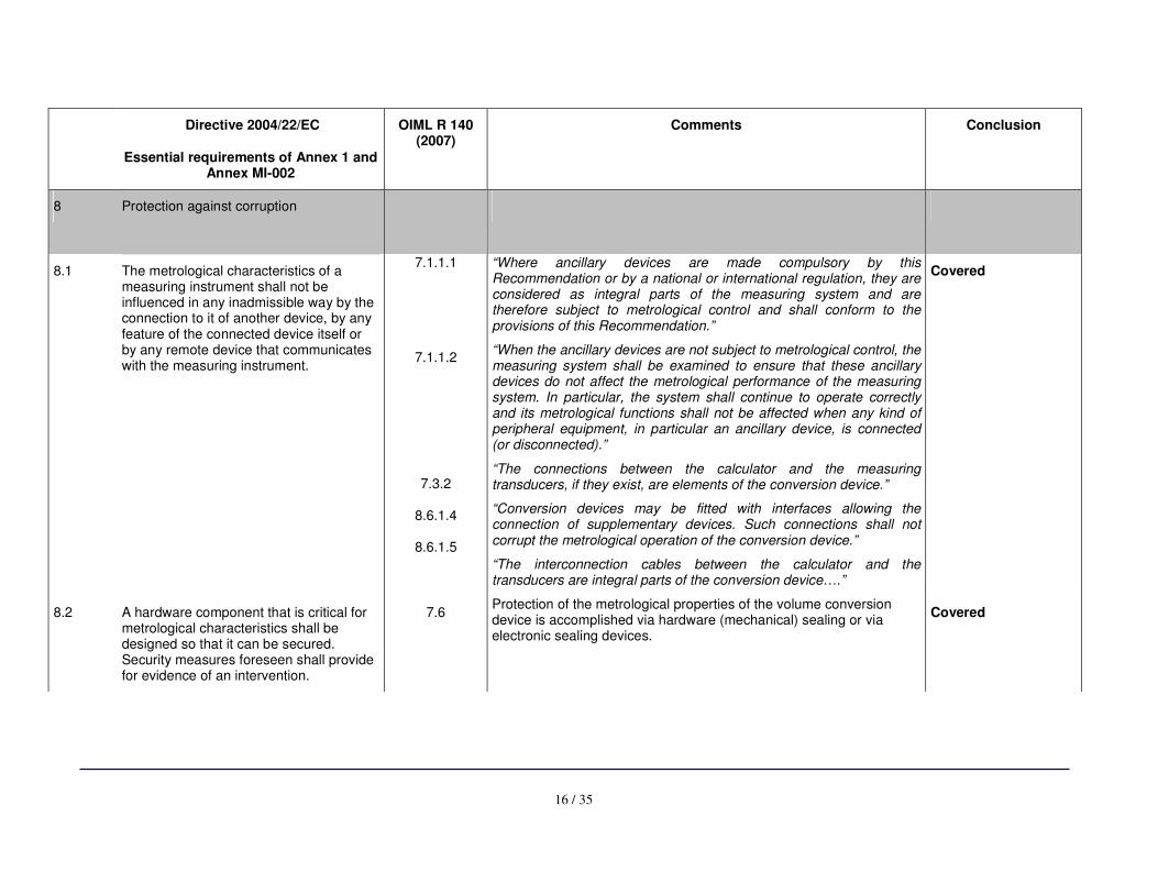
8 Protection against corruption
8.1 The metrological characteristics of a measuring instrument shall not be influenced in any inadmissible way by the connection to it of another device, by any feature of the connected device itself or by any remote device that communicates with the measuring instrument.
7.1.1.1
7.1.1.2
7.3.2
8.6.1.4
8.6.1.5
“Where ancillary devices are made compulsory by this Recommendation or by a national or international regulation, they are considered as integral parts of the measuring system and are therefore subject to metrological control and shall conform to the provisions of this Recommendation.”
“When the ancillary devices are not subject to metrological control, the measuring system shall be examined to ensure that these ancillary devices do not affect the metrological performance of the measuring system. In particular, the system shall continue to operate correctly and its metrological functions shall not be affected when any kind of peripheral equipment, in particular an ancillary device, is connected (or disconnected).”
“The connections between the calculator and the measuring transducers, if they exist, are elements of the conversion device.”
“Conversion devices may be fitted with interfaces allowing the connection of supplementary devices. Such connections shall not corrupt the metrological operation of the conversion device.”
“The interconnection cables between the calculator and the transducers are integral parts of the conversion device….”
Covered
8.2 A hardware component that is critical for metrological characteristics shall be designed so that it can be secured. Security measures foreseen shall provide for evidence of an intervention.
7.6 Protection of the metrological properties of the volume conversion device is accomplished via hardware (mechanical) sealing or via electronic sealing devices.
Covered
17 / 35
Directive 2004/22/EC
Essential requirements of Annex 1 and Annex MI-002
OIML R 140 (2007)
Comments Conclusion
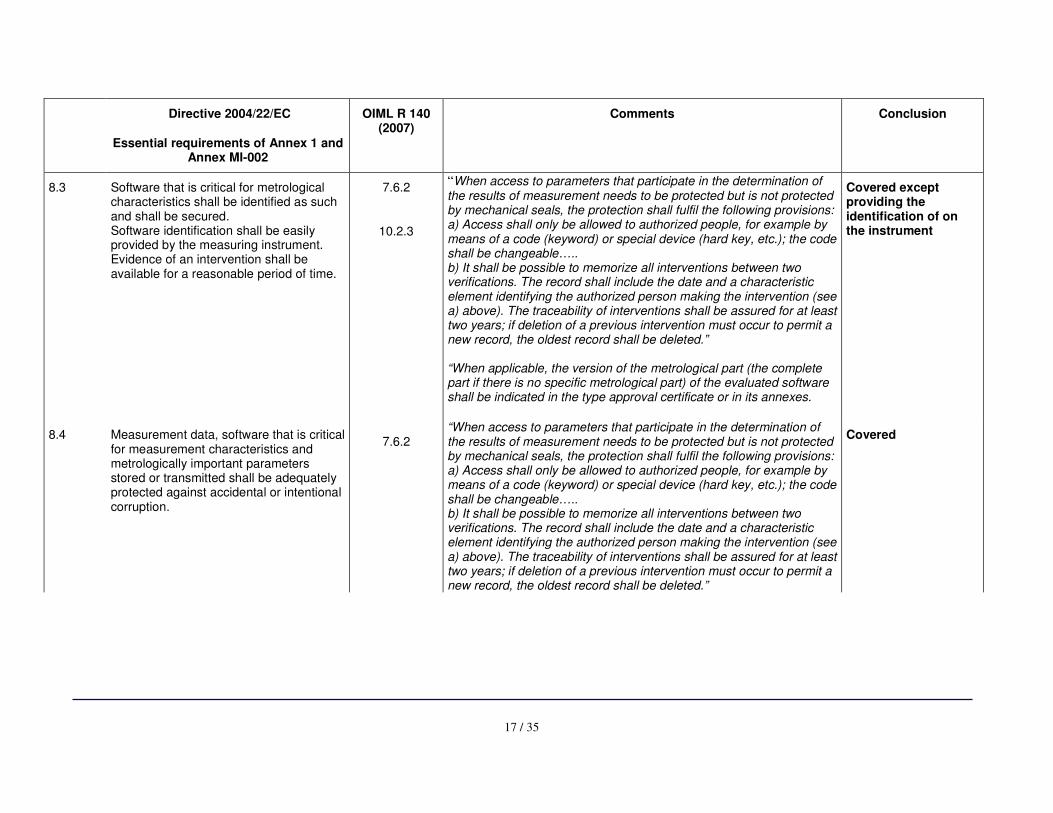
8.3 Software that is critical for metrological characteristics shall be identified as such and shall be secured. Software identification shall be easily provided by the measuring instrument. Evidence of an intervention shall be available for a reasonable period of time.
7.6.2
10.2.3
“When access to parameters that participate in the determination of the results of measurement needs to be protected but is not protected by mechanical seals, the protection shall fulfil the following provisions: a) Access shall only be allowed to authorized people, for example by means of a code (keyword) or special device (hard key, etc.); the code shall be changeable….. b) It shall be possible to memorize all interventions between two verifications. The record shall include the date and a characteristic element identifying the authorized person making the intervention (see a) above). The traceability of interventions shall be assured for at least two years; if deletion of a previous intervention must occur to permit a new record, the oldest record shall be deleted.” “When applicable, the version of the metrological part (the complete part if there is no specific metrological part) of the evaluated software shall be indicated in the type approval certificate or in its annexes.
Covered except providing the identification of on the instrument
8.4 Measurement data, software that is critical for measurement characteristics and metrologically important parameters stored or transmitted shall be adequately protected against accidental or intentional corruption.
7.6.2
“When access to parameters that participate in the determination of the results of measurement needs to be protected but is not protected by mechanical seals, the protection shall fulfil the following provisions: a) Access shall only be allowed to authorized people, for example by means of a code (keyword) or special device (hard key, etc.); the code shall be changeable….. b) It shall be possible to memorize all interventions between two verifications. The record shall include the date and a characteristic element identifying the authorized person making the intervention (see a) above). The traceability of interventions shall be assured for at least two years; if deletion of a previous intervention must occur to permit a new record, the oldest record shall be deleted.”
Covered
18 / 35
Directive 2004/22/EC
Essential requirements of Annex 1 and Annex MI-002
OIML R 140 (2007)
Comments Conclusion
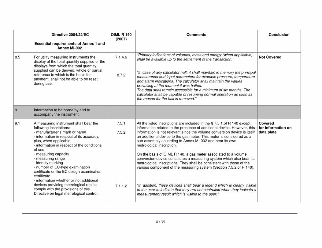
8.5 For utility measuring instruments the display of the total quantity supplied or the displays from which the total quantity supplied can be derived, whole or partial reference to which is the basis for payment, shall not be able to be reset during use.
7.1.4.6
8.7.2
“Primary indications of volumes, mass and energy (when applicable) shall be available up to the settlement of the transaction.” “In case of any calculator halt, it shall maintain in memory the principal measurands and input parameters for example pressure, temperature and alarm indications. The calculator shall maintain the values prevailing at the moment it was halted. The data shall remain accessible for a minimum of six months. The calculator shall be capable of resuming normal operation as soon as the reason for the halt is removed.”
Not Covered
9 Information to be borne by and to accompany the instrument
9.1 A measuring instrument shall bear the following inscriptions: - manufacturer’s mark or name - information in respect of its accuracy, plus, when applicable - information in respect of the conditions of use - measuring capacity - measuring range - identity marking - number of EC-type examination certificate or the EC design examination certificate - information whether or not additional devices providing metrological results comply with the provisions of this Directive on legal metrological control.
7.5.1
7.5.2
7.1.1.2
All the listed inscriptions are included in the § 7.5.1.of R 140 except information related to the presence of additional device. However, this information is not relevant since the volume conversion device is itself an additional device to the gas meter. This meter is considered as a sub-assembly according to Annex MI-002 and bear its own metrological inscription.
On the basis of OIML R 140, a gas meter associated to a volume conversion device constitutes a measuring system which also bear its metrological inscriptions. They shall be consistent with those of the various component of the measuring system (Section 7.5.2 of R 140).
“In addition, these devices shall bear a legend which is clearly visible to the user to indicate that they are not controlled when they indicate a measurement result which is visible to the user.”
Covered for information on data plate
19 / 35
Directive 2004/22/EC
Essential requirements of Annex 1 and Annex MI-002
OIML R 140 (2007)
Comments Conclusion
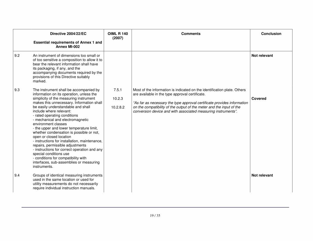
9.2 An instrument of dimensions too small or of too sensitive a composition to allow it to bear the relevant information shall have its packaging, if any, and the accompanying documents required by the provisions of this Directive suitably marked.
Not relevant
9.3 The instrument shall be accompanied by information on its operation, unless the simplicity of the measuring instrument makes this unnecessary. Information shall be easily understandable and shall include where relevant: - rated operating conditions - mechanical and electromagnetic environment classes - the upper and lower temperature limit, whether condensation is possible or not, open or closed location - instructions for installation, maintenance, repairs, permissible adjustments - instructions for correct operation and any special conditions use - conditions for compatibility with interfaces, sub-assemblies or measuring instruments.
7.5.1
10.2.3
10.2.8.2
Most of the information is indicated on the identification plate. Others are available in the type approval certificate.
“As far as necessary the type approval certificate provides information on the compatibility of the output of the meter and the input of the conversion device and with associated measuring instruments”.
Covered
9.4 Groups of identical measuring instruments used in the same location or used for utility measurements do not necessarily require individual instruction manuals.
Not relevant
20 / 35
Directive 2004/22/EC
Essential requirements of Annex 1 and Annex MI-002
OIML R 140 (2007)
Comments Conclusion
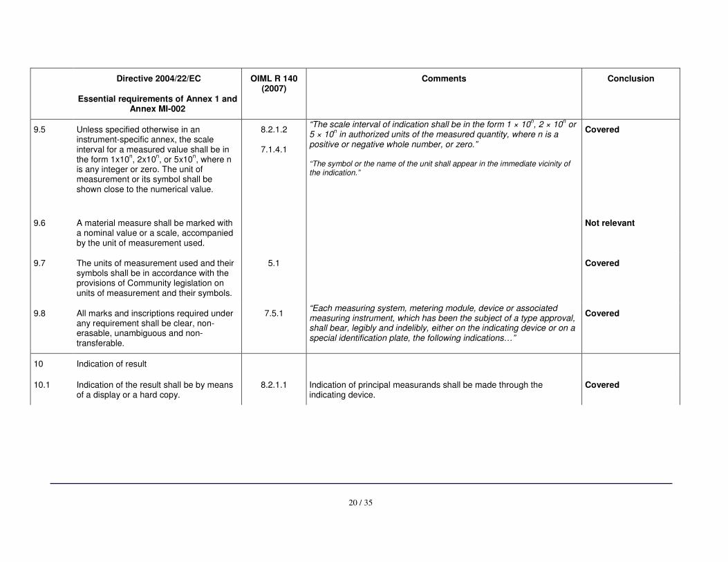
9.5 Unless specified otherwise in an instrument-specific annex, the scale interval for a measured value shall be in the form 1x10
n, 2x10
n, or 5x10
n, where n
is any integer or zero. The unit of measurement or its symbol shall be shown close to the numerical value.
8.2.1.2
7.1.4.1
“The scale interval of indication shall be in the form 1 × 10n, 2 × 10
n or
5 × 10n in authorized units of the measured quantity, where n is a
positive or negative whole number, or zero.” “The symbol or the name of the unit shall appear in the immediate vicinity of the indication.”
Covered
9.6 A material measure shall be marked with a nominal value or a scale, accompanied by the unit of measurement used.
Not relevant
9.7 The units of measurement used and their symbols shall be in accordance with the provisions of Community legislation on units of measurement and their symbols.
5.1 Covered
9.8 All marks and inscriptions required under any requirement shall be clear, non-erasable, unambiguous and non-transferable.
7.5.1 “Each measuring system, metering module, device or associated measuring instrument, which has been the subject of a type approval, shall bear, legibly and indelibly, either on the indicating device or on a special identification plate, the following indications…”
Covered
10 Indication of result
10.1 Indication of the result shall be by means of a display or a hard copy.
8.2.1.1 Indication of principal measurands shall be made through the indicating device.
Covered
21 / 35
Directive 2004/22/EC
Essential requirements of Annex 1 and Annex MI-002
OIML R 140 (2007)
Comments Conclusion
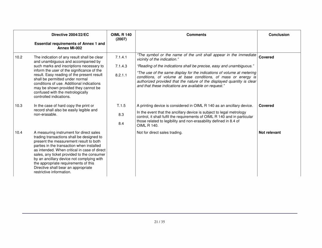
10.2 The indication of any result shall be clear and unambiguous and accompanied by such marks and inscriptions necessary to inform the user of the significance of the result. Easy reading of the present result shall be permitted under normal conditions of use. Additional indications may be shown provided they cannot be confused with the metrologically controlled indications.
7.1.4.1
7.1.4.3
8.2.1.1
“The symbol or the name of the unit shall appear in the immediate vicinity of the indication.”
“Reading of the indications shall be precise, easy and unambiguous.”
“The use of the same display for the indications of volume at metering conditions, of volume at base conditions, of mass or energy is authorized provided that the nature of the displayed quantity is clear and that these indications are available on request.”
Covered
10.3 In the case of hard copy the print or record shall also be easily legible and non-erasable.
T.1.5
8.3
8.4
A printing device is considered in OIML R 140 as an ancillary device.
In the event that the ancillary device is subject to legal metrology control, it shall fulfil the requirements of OIML R 140 and in particular those related to legibility and non-erasability defined in 8.4 of OIML R 140.
Covered
10.4 A measuring instrument for direct sales trading transactions shall be designed to present the measurement result to both parties in the transaction when installed as intended. When critical in case of direct sales, any ticket provided to the consumer by an ancillary device not complying with the appropriate requirements of this Directive shall bear an appropriate restrictive information.
Not for direct sales trading. Not relevant
22 / 35
Directive 2004/22/EC
Essential requirements of Annex 1 and Annex MI-002
OIML R 140 (2007)
Comments Conclusion
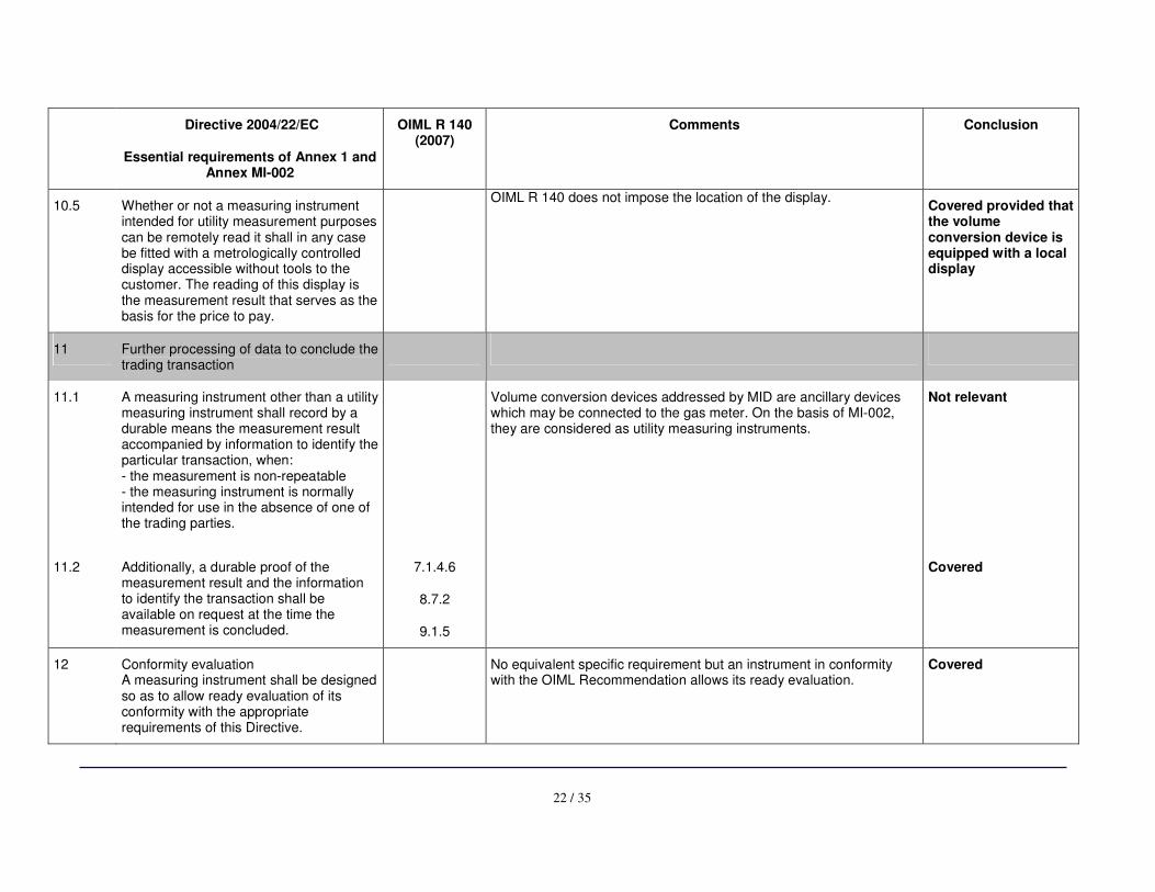
10.5 Whether or not a measuring instrument intended for utility measurement purposes can be remotely read it shall in any case be fitted with a metrologically controlled display accessible without tools to the customer. The reading of this display is the measurement result that serves as the basis for the price to pay.
OIML R 140 does not impose the location of the display.
Covered provided that the volume conversion device is equipped with a local display
11 Further processing of data to conclude the trading transaction
11.1 A measuring instrument other than a utility measuring instrument shall record by a durable means the measurement result accompanied by information to identify the particular transaction, when: - the measurement is non-repeatable - the measuring instrument is normally intended for use in the absence of one of the trading parties.
Volume conversion devices addressed by MID are ancillary devices which may be connected to the gas meter. On the basis of MI-002, they are considered as utility measuring instruments.
Not relevant
11.2 Additionally, a durable proof of the measurement result and the information to identify the transaction shall be available on request at the time the measurement is concluded.
7.1.4.6
8.7.2
9.1.5
Covered
12 Conformity evaluation A measuring instrument shall be designed so as to allow ready evaluation of its conformity with the appropriate requirements of this Directive.
No equivalent specific requirement but an instrument in conformity with the OIML Recommendation allows its ready evaluation.
Covered
23 / 35
Directive 2004/22/EC
Essential requirements of Annex 1 and Annex MI-002
OIML R 140 (2007)
Comments Conclusion
ANNEX MI-002
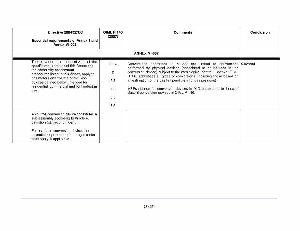
The relevant requirements of Annex I, the specific requirements of this Annex and the conformity assessment procedures listed in this Annex, apply to gas meters and volume conversion devices defined below, intended for residential, commercial and light industrial use.
1.1 2
2
6.3
7.3
8.5
8.6
Conversions addressed in MI-002 are limited to conversions performed by physical devices (associated to or included in the conversion device) subject to the metrological control. However OIML R 140 addresses all types of conversions (including those based on an estimation of the gas temperature and gas pressure).
MPEs defined for conversion devices in MID correspond to those of class B conversion devices in OIML R 140.
Covered
A volume conversion device constitutes a sub-assembly according to Article 4, definition (b), second indent.
For a volume conversion device, the essential requirements for the gas meter shall apply, if applicable.
24 / 35
Directive 2004/22/EC
Essential requirements of Annex 1 and Annex MI-002
OIML R 140 (2007)
Comments Conclusion
De
finitio
ns
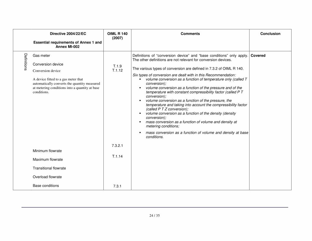
Gas meter
Conversion device
Conversion device
A device fitted to a gas meter that
automatically converts the quantity measured
at metering conditions into a quantity at base
conditions.
Minimum flowrate
Maximum flowrate
Transitional flowrate
Overload flowrate
Base conditions
T.1.9 T.1.12
7.3.2.1
T.1.14
7.3.1
Definitions of “conversion device” and “base conditions” only apply. The other definitions are not relevant for conversion devices.
The various types of conversion are defined in 7.3.2 of OIML R 140.
Six types of conversion are dealt with in this Recommendation: � volume conversion as a function of temperature only (called T
conversion); � volume conversion as a function of the pressure and of the
temperature with constant compressibility factor (called P T conversion);
� volume conversion as a function of the pressure, the temperature and taking into account the compressibility factor (called P T Z conversion);
� volume conversion as a function of the density (density conversion);
� mass conversion as a function of volume and density at metering conditions;
� mass conversion as a function of volume and density at base conditions.
Covered
25 / 35
Directive 2004/22/EC
Essential requirements of Annex 1 and Annex MI-002
OIML R 140 (2007)
Comments Conclusion
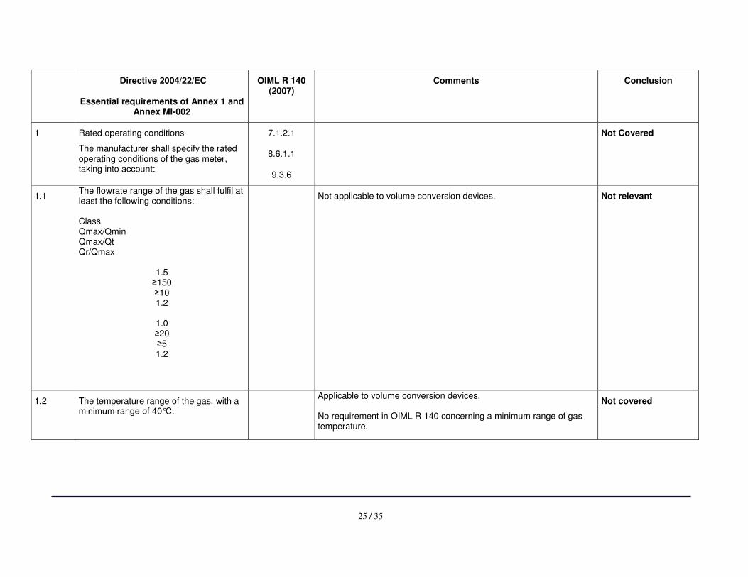
1 Rated operating conditions
The manufacturer shall specify the rated operating conditions of the gas meter, taking into account:
7.1.2.1
8.6.1.1
9.3.6
Not Covered
1.1 The flowrate range of the gas shall fulfil at least the following conditions: Class Qmax/Qmin Qmax/Qt Qr/Qmax
1.5 ≥150 ≥10 1.2
1.0 ≥20 ≥5 1.2
Not applicable to volume conversion devices. Not relevant
1.2 The temperature range of the gas, with a minimum range of 40°C.
Applicable to volume conversion devices. No requirement in OIML R 140 concerning a minimum range of gas temperature.
Not covered
26 / 35
Directive 2004/22/EC
Essential requirements of Annex 1 and Annex MI-002
OIML R 140 (2007)
Comments Conclusion
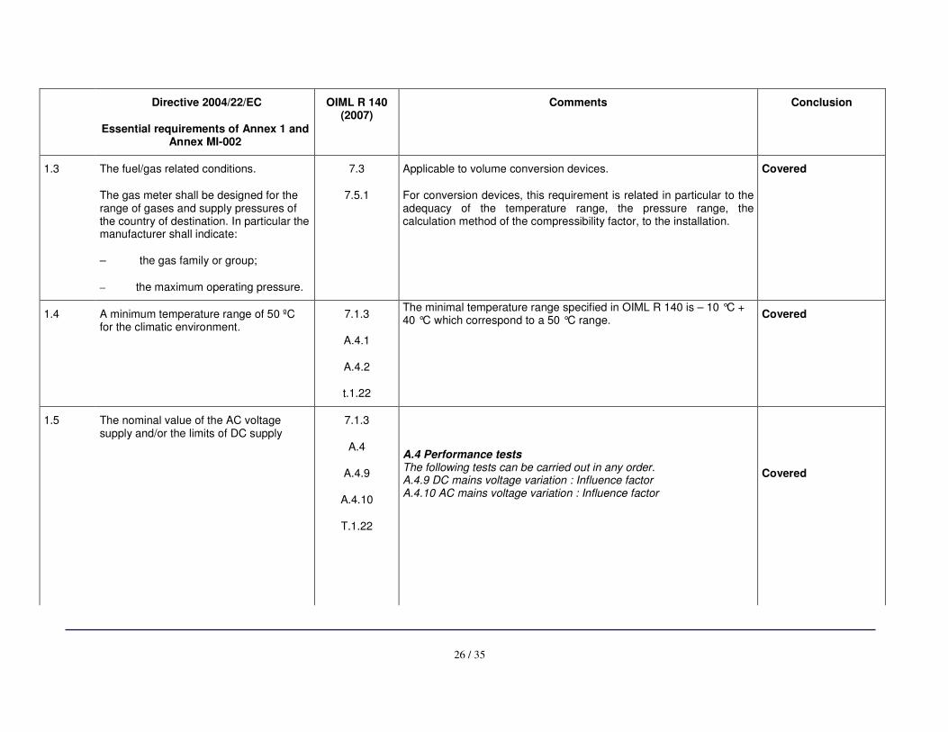
1.3 The fuel/gas related conditions.
The gas meter shall be designed for the range of gases and supply pressures of the country of destination. In particular the manufacturer shall indicate:
– the gas family or group;
– the maximum operating pressure.
7.3
7.5.1
Applicable to volume conversion devices.
For conversion devices, this requirement is related in particular to the adequacy of the temperature range, the pressure range, the calculation method of the compressibility factor, to the installation.
Covered
1.4 A minimum temperature range of 50 ºC for the climatic environment.
7.1.3
A.4.1
A.4.2
t.1.22
The minimal temperature range specified in OIML R 140 is – 10 °C + 40 °C which correspond to a 50 °C range.
Covered
1.5 The nominal value of the AC voltage supply and/or the limits of DC supply
7.1.3
A.4
A.4.9
A.4.10
T.1.22
A.4 Performance tests The following tests can be carried out in any order. A.4.9 DC mains voltage variation : Influence factor A.4.10 AC mains voltage variation : Influence factor
Covered
27 / 35
Directive 2004/22/EC
Essential requirements of Annex 1 and Annex MI-002
OIML R 140 (2007)
Comments Conclusion
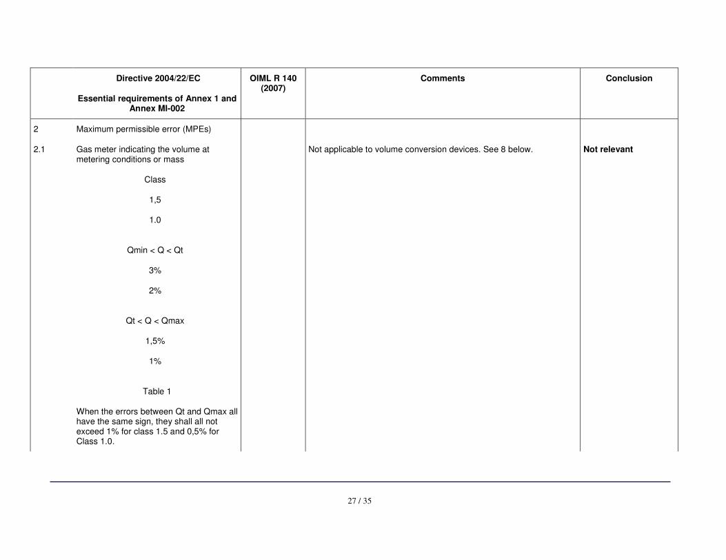
2 Maximum permissible error (MPEs)
2.1 Gas meter indicating the volume at metering conditions or mass
Class
1,5
1.0
Qmin < Q < Qt
3%
2%
Qt < Q < Qmax
1,5%
1%
Table 1
When the errors between Qt and Qmax all have the same sign, they shall all not exceed 1% for class 1.5 and 0,5% for Class 1.0.
Not applicable to volume conversion devices. See 8 below. Not relevant
28 / 35
Directive 2004/22/EC
Essential requirements of Annex 1 and Annex MI-002
OIML R 140 (2007)
Comments Conclusion
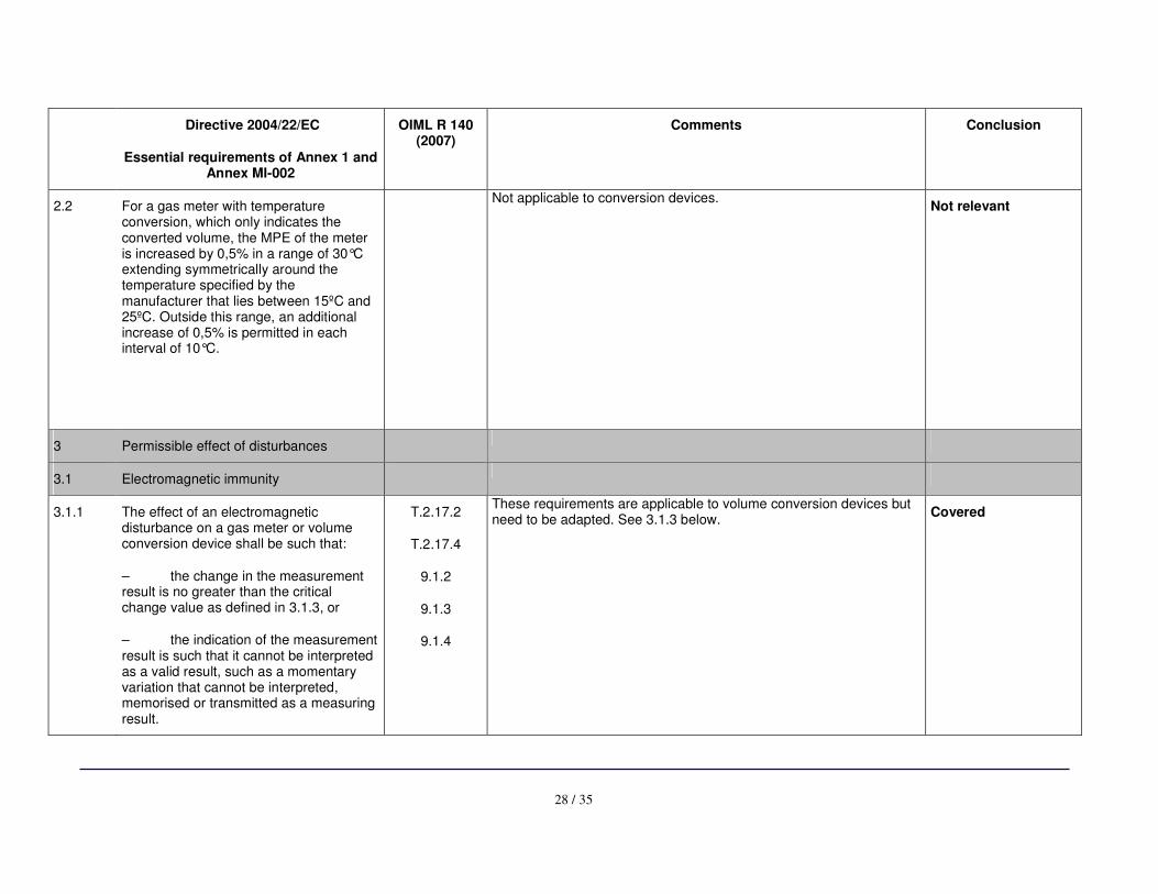
2.2 For a gas meter with temperature conversion, which only indicates the converted volume, the MPE of the meter is increased by 0,5% in a range of 30°C extending symmetrically around the temperature specified by the manufacturer that lies between 15ºC and 25ºC. Outside this range, an additional increase of 0,5% is permitted in each interval of 10°C.
Not applicable to conversion devices.
Not relevant
3 Permissible effect of disturbances
3.1 Electromagnetic immunity
3.1.1 The effect of an electromagnetic disturbance on a gas meter or volume conversion device shall be such that:
– the change in the measurement result is no greater than the critical change value as defined in 3.1.3, or
– the indication of the measurement result is such that it cannot be interpreted as a valid result, such as a momentary variation that cannot be interpreted, memorised or transmitted as a measuring result.
T.2.17.2
T.2.17.4
9.1.2
9.1.3
9.1.4
These requirements are applicable to volume conversion devices but need to be adapted. See 3.1.3 below.
Covered
29 / 35
Directive 2004/22/EC
Essential requirements of Annex 1 and Annex MI-002
OIML R 140 (2007)
Comments Conclusion
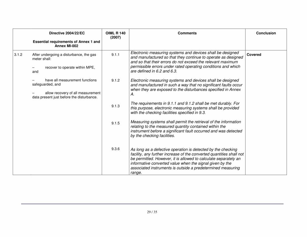
3.1.2 After undergoing a disturbance, the gas meter shall:
– recover to operate within MPE, and
– have all measurement functions safeguarded, and
– allow recovery of all measurement data present just before the disturbance.
9.1.1
9.1.2
9.1.3
9.1.5
9.3.6
Electronic measuring systems and devices shall be designed and manufactured so that they continue to operate as designed and so that their errors do not exceed the relevant maximum permissible errors under rated operating conditions and which are defined in 6.2 and 6.3. Electronic measuring systems and devices shall be designed and manufactured in such a way that no significant faults occur when they are exposed to the disturbances specified in Annex A. The requirements in 9.1.1 and 9.1.2 shall be met durably. For this purpose, electronic measuring systems shall be provided with the checking facilities specified in 9.3. Measuring systems shall permit the retrieval of the information relating to the measured quantity contained within the instrument before a significant fault occurred and was detected by the checking facilities. As long as a defective operation is detected by the checking facility, any further increase of the converted quantities shall not be permitted. However, it is allowed to calculate separately an informative converted value when the signal given by the associated instruments is outside a predetermined measuring range.
Covered
30 / 35
Directive 2004/22/EC
Essential requirements of Annex 1 and Annex MI-002
OIML R 140 (2007)
Comments Conclusion
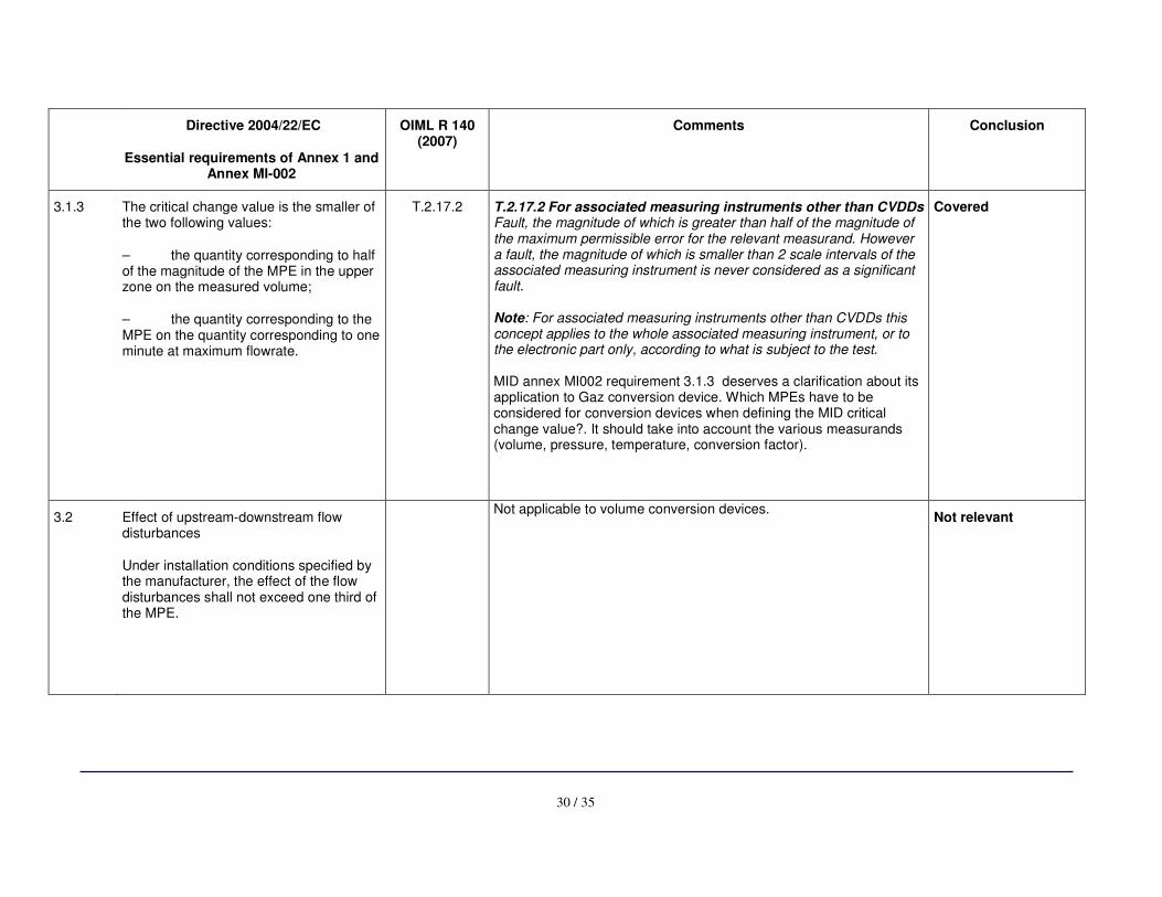
3.1.3 The critical change value is the smaller of the two following values:
– the quantity corresponding to half of the magnitude of the MPE in the upper zone on the measured volume;
– the quantity corresponding to the MPE on the quantity corresponding to one minute at maximum flowrate.
T.2.17.2 T.2.17.2 For associated measuring instruments other than CVDDs Fault, the magnitude of which is greater than half of the magnitude of the maximum permissible error for the relevant measurand. However a fault, the magnitude of which is smaller than 2 scale intervals of the associated measuring instrument is never considered as a significant fault. Note: For associated measuring instruments other than CVDDs this concept applies to the whole associated measuring instrument, or to the electronic part only, according to what is subject to the test. MID annex MI002 requirement 3.1.3 deserves a clarification about its application to Gaz conversion device. Which MPEs have to be considered for conversion devices when defining the MID critical change value?. It should take into account the various measurands (volume, pressure, temperature, conversion factor).
Covered
3.2 Effect of upstream-downstream flow disturbances
Under installation conditions specified by the manufacturer, the effect of the flow disturbances shall not exceed one third of the MPE.
Not applicable to volume conversion devices.
Not relevant
31 / 35
Directive 2004/22/EC
Essential requirements of Annex 1 and Annex MI-002
OIML R 140 (2007)
Comments Conclusion
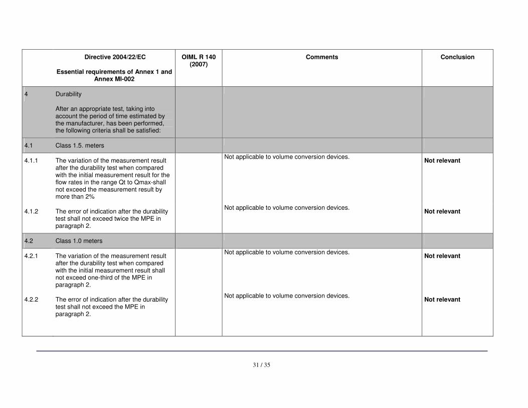
4 Durability
After an appropriate test, taking into account the period of time estimated by the manufacturer, has been performed, the following criteria shall be satisfied:
4.1 Class 1.5. meters
4.1.1 The variation of the measurement result after the durability test when compared with the initial measurement result for the flow rates in the range Qt to Qmax-shall not exceed the measurement result by more than 2%
Not applicable to volume conversion devices.
Not relevant
4.1.2 The error of indication after the durability test shall not exceed twice the MPE in paragraph 2.
Not applicable to volume conversion devices.
Not relevant
4.2 Class 1.0 meters
4.2.1 The variation of the measurement result after the durability test when compared with the initial measurement result shall not exceed one-third of the MPE in paragraph 2.
Not applicable to volume conversion devices.
Not relevant
4.2.2 The error of indication after the durability test shall not exceed the MPE in paragraph 2.
Not applicable to volume conversion devices.
Not relevant
32 / 35
Directive 2004/22/EC
Essential requirements of Annex 1 and Annex MI-002
OIML R 140 (2007)
Comments Conclusion
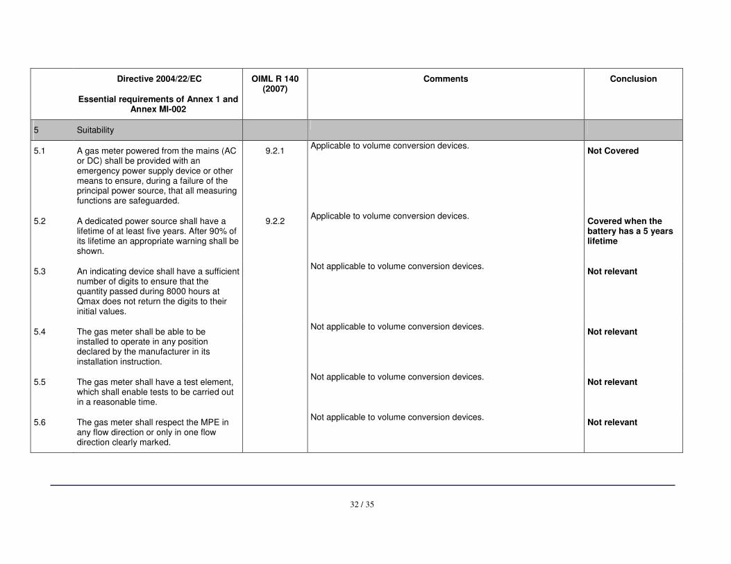
5 Suitability
5.1 A gas meter powered from the mains (AC or DC) shall be provided with an emergency power supply device or other means to ensure, during a failure of the principal power source, that all measuring functions are safeguarded.
9.2.1 Applicable to volume conversion devices.
Not Covered
5.2 A dedicated power source shall have a lifetime of at least five years. After 90% of its lifetime an appropriate warning shall be shown.
9.2.2 Applicable to volume conversion devices.
Covered when the battery has a 5 years lifetime
5.3 An indicating device shall have a sufficient number of digits to ensure that the quantity passed during 8000 hours at Qmax does not return the digits to their initial values.
Not applicable to volume conversion devices.
Not relevant
5.4 The gas meter shall be able to be installed to operate in any position declared by the manufacturer in its installation instruction.
Not applicable to volume conversion devices. Not relevant
5.5 The gas meter shall have a test element, which shall enable tests to be carried out in a reasonable time.
Not applicable to volume conversion devices.
Not relevant
5.6 The gas meter shall respect the MPE in any flow direction or only in one flow direction clearly marked.
Not applicable to volume conversion devices.
Not relevant
33 / 35
Directive 2004/22/EC
Essential requirements of Annex 1 and Annex MI-002
OIML R 140 (2007)
Comments Conclusion
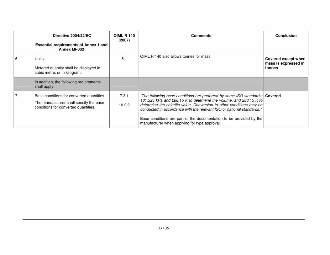
6 Units
Metered quantity shall be displayed in cubic metre, or in kilogram.
5.1 OIML R 140 also allows tonnes for mass.
Covered except when mass is expressed in tonnes
In addition, the following requirements shall apply:
7 Base conditions for converted quantities
The manufacturer shall specify the base conditions for converted quantities.
7.3.1
10.2.2
“The following base conditions are preferred by some ISO standards: 101.325 kPa and 288.15 K to determine the volume, and 288.15 K to determine the calorific value. Conversion to other conditions may be conducted in accordance with the relevant ISO or national standards.”
Base conditions are part of the documentation to be provided by the manufacturer when applying for type approval.
Covered
34 / 35
Directive 2004/22/EC
Essential requirements of Annex 1 and Annex MI-002
OIML R 140 (2007)
Comments Conclusion
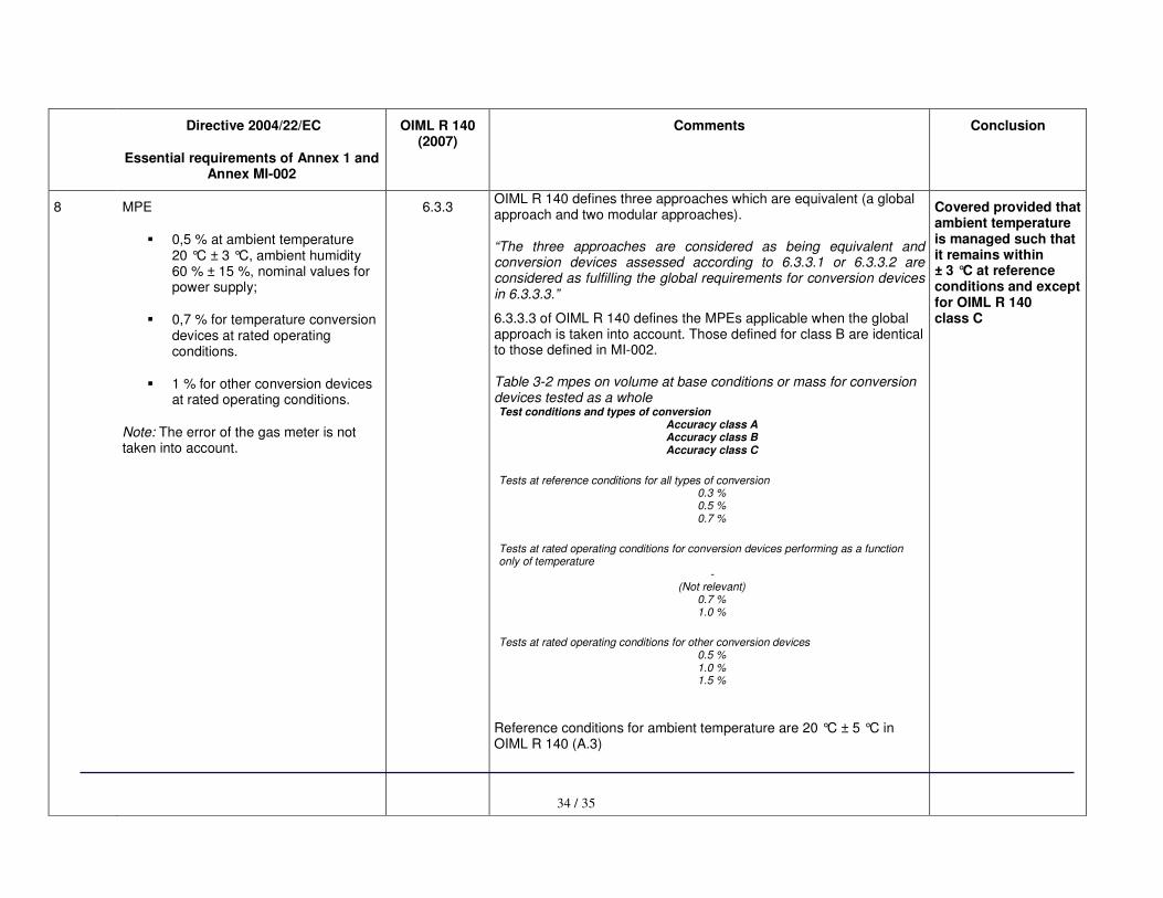
8 MPE
� 0,5 % at ambient temperature 20 °C ± 3 °C, ambient humidity 60 % ± 15 %, nominal values for power supply;
� 0,7 % for temperature conversion devices at rated operating conditions.
� 1 % for other conversion devices at rated operating conditions.
Note: The error of the gas meter is not taken into account.
6.3.3
OIML R 140 defines three approaches which are equivalent (a global approach and two modular approaches). “The three approaches are considered as being equivalent and conversion devices assessed according to 6.3.3.1 or 6.3.3.2 are considered as fulfilling the global requirements for conversion devices in 6.3.3.3.”
6.3.3.3 of OIML R 140 defines the MPEs applicable when the global approach is taken into account. Those defined for class B are identical to those defined in MI-002. Table 3-2 mpes on volume at base conditions or mass for conversion devices tested as a whole Test conditions and types of conversion
Accuracy class A Accuracy class B Accuracy class C
Tests at reference conditions for all types of conversion
0.3 % 0.5 % 0.7 %
Tests at rated operating conditions for conversion devices performing as a function only of temperature
- (Not relevant)
0.7 % 1.0 %
Tests at rated operating conditions for other conversion devices
0.5 % 1.0 % 1.5 %
Reference conditions for ambient temperature are 20 °C ± 5 °C in OIML R 140 (A.3)
Covered provided that ambient temperature is managed such that it remains within ± 3 °C at reference conditions and except for OIML R 140 class C
35 / 35
Directive 2004/22/EC
Essential requirements of Annex 1 and Annex MI-002
OIML R 140 (2007)
Comments Conclusion
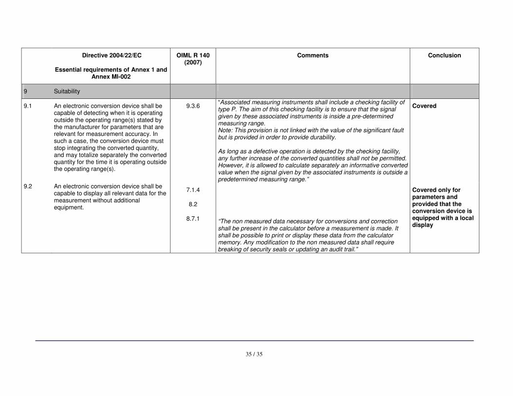
9 Suitability
9.1 An electronic conversion device shall be capable of detecting when it is operating outside the operating range(s) stated by the manufacturer for parameters that are relevant for measurement accuracy. In such a case, the conversion device must stop integrating the converted quantity, and may totalize separately the converted quantity for the time it is operating outside the operating range(s).
9.3.6 “Associated measuring instruments shall include a checking facility of type P. The aim of this checking facility is to ensure that the signal given by these associated instruments is inside a pre-determined measuring range. Note: This provision is not linked with the value of the significant fault but is provided in order to provide durability. As long as a defective operation is detected by the checking facility, any further increase of the converted quantities shall not be permitted. However, it is allowed to calculate separately an informative converted value when the signal given by the associated instruments is outside a predetermined measuring range.”
Covered
9.2 An electronic conversion device shall be capable to display all relevant data for the measurement without additional equipment.
7.1.4
8.2
8.7.1
“The non measured data necessary for conversions and correction shall be present in the calculator before a measurement is made. It shall be possible to print or display these data from the calculator memory. Any modification to the non measured data shall require breaking of security seals or updating an audit trail.”
Covered only for parameters and provided that the conversion device is equipped with a local display


![Optical frequency conversion in integrated devices [Invited]photonics.light.utoronto.ca/~wagner/Caspani, L... · Optical frequency conversion in integrated devices [Invited] Lucia](https://img.pdfslide.net/doc/110x75/6015ae775ebb53273450d430/optical-frequency-conversion-in-integrated-devices-invited-wagnercaspani-l.jpg)