Embed Size (px)
Citation preview

Property Services
Design Standard
Volume Three: Electrical Systems
Issue 7 2015
August 2015

Property Services
Status: FINAL Issue: 7.0
Save Date: 18/08/2015
Document: Design Standards – Volume Three Electrical Systems
Author: Property Services Approved :EDPS
Page 2 of 17
RMIT University
Design Standards – Volume Three Electrical Systems August 2015
Version Control This document will be updated and re-issues to reflect approved change to content, and is subject to version control. The version record and status is documented below
Document Change History 1 :
Version Date Author Comments 7.0 31/07/2015 Property Services Complete review of standards
Owner The overall responsibility for these standards resides with RMIT University Property Services
Review This Document is reviewed every two years
1 Printed copies of this document are considered uncontrolled and may not reflect the most recent revision

Property Services
Status: FINAL Issue: 7.0
Save Date: 18/08/2015
Document: Design Standards – Volume Three Electrical Systems
Author: Property Services Approved :EDPS
Page 3 of 17
Table of Contents
Introduction 4
1.1 Background 4
1.2 Purpose 4
1.3 Demonstrating Compliance with the Standards 4
2. Electrical Design Standards 5
2.1 General 5
2.2 Power Supply 6
2.3 Mains, Submains and Sub-circuit Reticulation 7
2.4 Main Switchboards 8
2.5 Mechanical & Electrical Distribution Switchboards 9
2.6 General Purpose Power Wiring, Accessories and Outlets 9
2.7 Lighting 10
2.8 Emergency Lighting and EXIT Signs 12
2.9 UPS 13
2.10 Preferred Manufacturers 13
3. Appendix A - Asset Numbering 14
4. Appendix B - Letter Code Identification 16

Property Services
Status: FINAL Issue: 7.0
Save Date: 18/08/2015
Document: Design Standards – Volume Three Electrical Systems
Author: Property Services Approved :EDPS
Page 4 of 17
1. Introduction
1.1 Background
This document details the minimum RMIT design requirements for electrical systems. It forms part of the suite of RMIT Design Standards set out below. All volumes of the standards are available on the RMIT Property Services Design Standards web page.
Volume One Introduction
Volume Two Architecture and Planning
Volume Three Electrical Systems
Volume Four Fire Protection Systems
Volume Five Hydraulic Systems
Volume Six Mechanical HVAC Systems
Volume Seven Vertical Transportation Systems
Volume Eight Building Management Systems
Volume Nine Electronic Security
Volume Ten Communications
Volume Eleven Audio Visual
Volume Twelve Landscape
Design Standards Checklist
This document should be read in conjunction with Volume One - Introduction, which provides context on the organisational and governance arrangements that apply to the design and construction of new facilities and describes the key principles that underpin the requirements of the Standards:
Safety
Accessibility
Innovation
Student Experience
Maintainability and Serviceability
Modularity and Standardisation
Reliability
Compatibility
Sustainability
Heritage
Life Cycle
Precinct Wide Solutions
1.2 Purpose
The purpose of this brief is to set out the minimum requirements for the design of electrical services. The aim is to achieve the maximum possible consistency and standardisation across the electrical services systems on the RMIT University campuses. Any design aspects not specifically addressed by this brief shall be identified by the consultant during the design process and shall be brought to RMIT University’s attention for resolution.
1.3 Demonstrating Compliance with the Standards
Designers are required to confirm compliance and justify any proposed deviations by completing the Design Standards Checklist. All deviations must be approved by RMIT prior to commencing design. Unless a robust justification is provided for deviations from the Standards, it is unlikely that approval will be given. Design Standards compliance is achieved through completion of the Design Standards Checklist and endorsement by RMIT of any proposed non- compliances.

Property Services
Status: FINAL Issue: 7.0
Save Date: 18/08/2015
Document: Design Standards – Volume Three Electrical Systems
Author: Property Services Approved :EDPS
Page 5 of 17
2. Electrical Design Standards
2.1 General
2.1.1 An electrical load study is to be conducted and the adequacy of network infrastructure to provide peak load shall be confirmed with the electrical retailer and power distributor.
2.1.2 The electrical specification requires high frequency ballasts in fluorescent luminaires in at least 95% of the useable floor area.
2.1.3 Fluorescent luminaires to be fitted with high frequency ballasts over at least 95% of the useable floor area
2.1.4 Lighting levels to provide a maintenance illuminance of no greater than 25% above the recommended values in Table E1 of AS1680.2.3 for 95% of the useable area at the working plane.
2.1.5 Energy sub metering is connected to the BMS for all mechanical switch boards, main cooling source, main heating source, air systems and water systems.
2.1.6 Shared or precinct wide energy systems have been adopted.
2.1.7 The electrical supply originates from Supply Authority sub-stations distributed around the campus.
2.1.8 Substations should be located on grade as opposed to basement or elevated locations.
2.1.9 RMIT requires that an arc flash study be carried out for each switchboard in every system.
2.1.10 Provide PPE guidance information and notices at each switchboard location.
2.1.11 Main Switchboards are located on grade as opposed to basement or elevated locations.
2.1.12 Main Switchboards are located in dedicated air conditioned plant rooms separate from other plant and equipment. Equipment such as power factor correction can occupy the same space.
2.1.13 Ancillary equipment such as UPS and generators are housed separately from Main Switchboards.
2.1.14 Dust entry to Main Switchboards is minimised.
2.1.15 The design shall incorporate adequate enclosed space for:
Supply Authority metering equipment
University BAS connections
Termination of incoming and outgoing circuits University kWh check metering and for nominated outgoing sub-mains
Future extensions or additions
Surge protection devices
Connection of power factor correction equipment
Challenger security and access control equipment
CCTV equipment
2.1.16 Switchboards are located in dedicated lockable ventilated rooms or closets separate from other plant and equipment. Equipment such as lighting controllers can occupy the same space. Access is provided from a public corridor or similar accessible space, not an office or teaching space.
2.1.17 Switchboards supplying a particular floor/level are located on that floor/level.
2.1.18 Switchboards supplying a particular building or substructure shall be located in that building or substructure.
2.1.19 Mechanical switchboards are located in plant rooms (refer also to HVAC section).
2.1.20 Generators are located in dedicated lockable ventilated rooms separate from other plant and equipment. Equipment such as bulk fuel tanks must not occupy the same space.

Property Services
Status: FINAL Issue: 7.0
Save Date: 18/08/2015
Document: Design Standards – Volume Three Electrical Systems
Author: Property Services Approved :EDPS
Page 6 of 17
2.1.21 Generators are located on grade.
2.1.22 Fuel tanks shall be above ground types and shall be suitably bunded.
2.1.23 Exhaust and ventilation cooling complete with sound attenuation, with due regard to AS 1668, shall be provided.
2.1.24 UPS units greater than 30 kVA shall be located in dedicated lockable conditioned rooms separate from other plant and equipment. Equipment such as battery banks must not occupy the same space.
2.1.25 UPS equipment shall be hardwired and not connected via a standard GPO.
2.1.26 Power factor correction equipment shall generally be located as close as possible to the main switchboard.
2.1.27 Heat dissipation to Power factor correction equipment shall be provided.
2.1.28 An LED luminaire and power point shall be provided in every switchboard, riser, data, telephone and AV cupboard.
2.1.29 No shunt trip on power emergency shut off. Button key re- set only.
2.2 Power Supply
2.2.1 Substation installed transformer capacity shall be designed to accommodate at least 125% of the anticipated building maximum demand.
2.2.2 Substation space: shall be designed to accommodate one additional transformer and associated switchgear.
2.2.3 Spare capacity shall be included in the Main Switchboard and cable design as follows:
Electrical load spare capacity 25%
Minimum physical space spare capacity 25% on both sides
Equipped Spares: 2 x 100 A
Equipped Spares: 1 x 200 A. Note: Spare circuit space: minimum 20% number of circuits on every busbar section.
2.2.4 Note that at the City campus and Bundoora campus, connection to and interaction with the local cogeneration and tri-generation systems must be taken into account in the design of new projects.
2.2.5 Main switchboards shall have the capacity to withstand the prospective fault level at the point of supply when the corresponding substations are fitted out with transformers at their possible maximum capacity, or as advised by the Supply Authority.
2.2.6 Spare capacity shall be included in the Distribution Switchboard design as follows:
Electrical load spare capacity;
Base building 50%
Tenancy fit outs 25%
Minimum physical space spare capacity 25%
2.2.7 Generators shall be gas fired.
2.2.8 Generators shall be installed with at least 30% spare capacity.
2.2.9 Generator controllers shall be equipped with a high level interface connected to the RMIT BAS system and be fully compliant with the published RMIT Standard.
2.2.10 Acoustic attenuation shall be fitted to generators.
Property Services
Status: FINAL Issue: 7.0
Save Date: 18/08/2015
Document: Design Standards – Volume Three Electrical Systems
Author: Property Services Approved :EDPS
Page 7 of 17
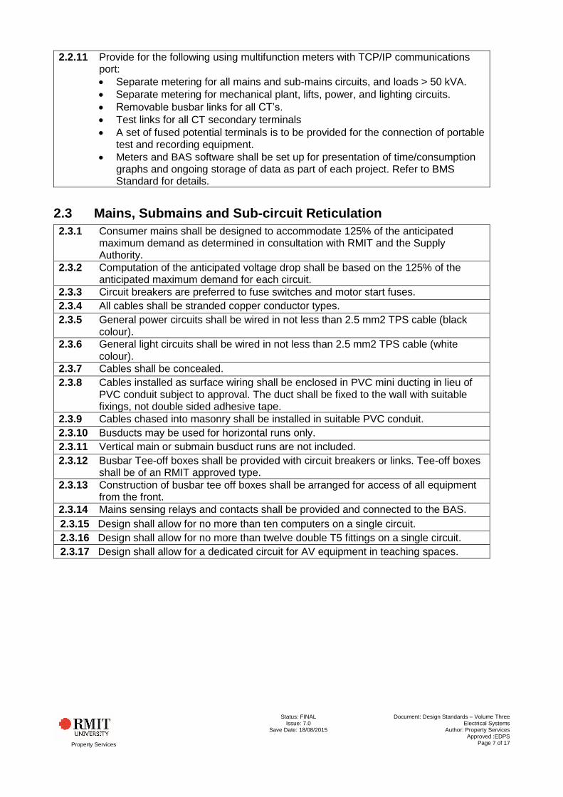
2.2.11 Provide for the following using multifunction meters with TCP/IP communications port:
Separate metering for all mains and sub-mains circuits, and loads > 50 kVA.
Separate metering for mechanical plant, lifts, power, and lighting circuits.
Removable busbar links for all CT’s.
Test links for all CT secondary terminals
A set of fused potential terminals is to be provided for the connection of portable test and recording equipment.
Meters and BAS software shall be set up for presentation of time/consumption graphs and ongoing storage of data as part of each project. Refer to BMS Standard for details.
2.3 Mains, Submains and Sub-circuit Reticulation
2.3.1 Consumer mains shall be designed to accommodate 125% of the anticipated maximum demand as determined in consultation with RMIT and the Supply Authority.
2.3.2 Computation of the anticipated voltage drop shall be based on the 125% of the anticipated maximum demand for each circuit.
2.3.3 Circuit breakers are preferred to fuse switches and motor start fuses.
2.3.4 All cables shall be stranded copper conductor types.
2.3.5 General power circuits shall be wired in not less than 2.5 mm2 TPS cable (black colour).
2.3.6 General light circuits shall be wired in not less than 2.5 mm2 TPS cable (white colour).
2.3.7 Cables shall be concealed.
2.3.8 Cables installed as surface wiring shall be enclosed in PVC mini ducting in lieu of PVC conduit subject to approval. The duct shall be fixed to the wall with suitable fixings, not double sided adhesive tape.
2.3.9 Cables chased into masonry shall be installed in suitable PVC conduit.
2.3.10 Busducts may be used for horizontal runs only.
2.3.11 Vertical main or submain busduct runs are not included.
2.3.12 Busbar Tee-off boxes shall be provided with circuit breakers or links. Tee-off boxes shall be of an RMIT approved type.
2.3.13 Construction of busbar tee off boxes shall be arranged for access of all equipment from the front.
2.3.14 Mains sensing relays and contacts shall be provided and connected to the BAS.
2.3.15 Design shall allow for no more than ten computers on a single circuit.
2.3.16 Design shall allow for no more than twelve double T5 fittings on a single circuit.
2.3.17 Design shall allow for a dedicated circuit for AV equipment in teaching spaces.

Property Services
Status: FINAL Issue: 7.0
Save Date: 18/08/2015
Document: Design Standards – Volume Three Electrical Systems
Author: Property Services Approved :EDPS
Page 8 of 17
2.4 Main Switchboards
2.4.1 As a minimum main switchboard shall be provided with a degree of protection of IP44, as per AS1939 and shall be of smoke proof construction.
2.4.2 Main switchboards shall be:
800A or more back connected, free standing
Less than 800A front connected, may be wall mounted
No less than Form 3(b)
2.4.3 Mechanical services are to be separated from the other light and power supplies.
2.4.4 Power supplies for equipment of sensitive nature, such as Computers and audio-visual equipment shall be provided with dedicated supplies separated from mechanical services supplies.
2.4.5 Protection equipment shall be of CB, MCCB or ACB type, to be selected as appropriate for the magnitude of the corresponding power supply.
2.4.6 Supply Authority metering shall be integrated with the main switchboard.
2.4.7 Provide Infra-Red transparent clear shrouds and barriers to permit thermo graphic scanning without the need to remove shrouds and barriers.
2.4.8 The main switchboard shall incorporate separate check metering and for selected major power supplies, lighting and power circuits.
2.4.9 The design of the main switchboard shall provide for the RMIT BAS system to be safely integrated in the board in a separate enclosure to monitor and control designated supplies and status signals.
2.4.10 The main switchboard shall be provided with surge protection with local operation/health indication and replaceable cartridges.
2.4.11 ACB’s and any approved CFS units shall be withdrawable.
2.4.12 Engraved Traffolyte labels shall be installed on the front door of protection devices enclosures and shall indicate the capacity of the unit and the protection settings or rating of installed fuse cartridges.
2.4.13 Labels shall also be installed adjacent to the load terminals.
2.4.14 Lift-off panels shall be labelled to identify their location on the main switchboard.
2.4.15 Labels shall be provided for Essential Supplies, which are:
Fire protection equipment
Fire indicating panel
Passenger elevators
Circuits supplying computer LAN, WAN or computer equipment
Circuits controlling emergency luminaires
Circuits controlling security and building access control equipment
2.4.16 A separate, wall-mounted, steel, lockable cabinet, keyed to a CL001 key shall be provided in a suitable location in each main switchboard room.
2.4.17 The cabinet shall be labelled “SPARE FUSES AND EQUIPMENT” and shall contain spare parts, tools, and a full set of spare HRC fuse cartridges for all CFS units installed on the main switchboard.
2.4.18 A laminated and framed copy of the schematic wiring drawing, shall be prominently displayed in a suitable enclosure inside the main switch room.

Property Services
Status: FINAL Issue: 7.0
Save Date: 18/08/2015
Document: Design Standards – Volume Three Electrical Systems
Author: Property Services Approved :EDPS
Page 9 of 17
2.4.19 A schematic wiring diagram of the complete as-constructed switchboard shall be supplied. The wiring diagram shall include, but shall not be limited to:
Circuit breaker capacities and trip settings
Fuse sizes
Capacity of protection units installed
Size and capacity of installed busbar
Capacity of incoming supply
Capacity of outgoing circuits
Destination of sub-main supplies
Size of main earth conductor and location of main earth electrode
Type test rating of the main switchboard.
2.4.20 Supply both design and workshop soft copies (pdf and CAD) of the switchboard drawings.
2.4.21 Where required, control equipment shall:
Be located and mounted in dedicated control cubicles / panels
Generally be located in the vicinity of corresponding switchboards on the same level as the equipment being controlled.
2.4.22 Control panels shall be sized as required for 100% spare capacity (panel should be 50% full).
2.4.23 For switchboards with multiple supplies a bus tie arrangement is to be included.
2.5 Mechanical & Electrical Distribution Switchboards
2.5.1 Mechanical and electrical distribution switchboards shall be provided with a main switch mounted separate to the distribution and controls chassis.
2.5.2 Switchboards shall be easily expandable to permit another chassis to be added.
2.5.3 Escutcheon panels on switchboards shall be hinged.
2.5.4 Switchboard doors shall be fitted with dust and smoke proof seals.
2.5.5 Switchboard enclosures shall be a minimum width of 580mm.
2.5.6 The protective device for electrical distribution switchboards (and load centres) serving final sub-circuits, shall be, as a minimum, rated at 63A. All upstream and downstream devices shall discriminate with these protective devices.
2.5.7 Excluding the main switch, there shall be no less than 12No poles in electrical distribution switchboards.
2.5.8 Mechanical switchboards shall form part of the overall electrical design including arc flash and fault level studies.
2.6 General Purpose Power Wiring, Accessories and Outlets
2.6.1 General purpose power circuits shall be protected by 20A RCD and shall be loaded to no more than:
Base building 20%
Tenancy fit out 80%
The maximum number of double GPOs per circuit shall be 5 double GPOs for air-conditioned spaces.
2.6.2 GPO’s to be installed, as a minimum, as follows:
Office spaces- 1No duo GPO for every 5m²;
Lecture theatres- 1No double GPO per student chair plus 1No double GPO every 20 m²;
Study spaces- 1No double GPO per student chair
Internal circulation spaces- 1No double GPO every 10 linear meters.
2.6.3 Double power outlet combinations are required: no single power outlets.

Property Services
Status: FINAL Issue: 7.0
Save Date: 18/08/2015
Document: Design Standards – Volume Three Electrical Systems
Author: Property Services Approved :EDPS
Page 10 of 17
2.6.4 All outdoor plant area shall be equipped with at least two weather proof GPO’s, one at the plant and one adjacent to each switchboard.
2.6.5 Lighting sub-circuits shall be protected by RCD and:
Shall have a rating of 20 Amps
Shall be limited to a maximum of 2,000 W connected load or 25 lighting points per 2.5mm² circuit
Shall retain facility to add further lights to each circuit up to 80% of the capacity of the circuit breaker controlling each final sub-circuit
Circuits shall be no less than 2.5 mm² black TPS.
2.6.6 Provide dedicated power sub-circuits for:
Each item of permanently connected equipment.
Each 15 A switched socket outlet.
Circuits shall be no less than 2.5 mm2 white TPS
2.6.7 Combined lighting and power loads in a single circuit are not permitted.
2.6.8 Provide USB charging points based on one per 10 m2 in general foyer and lounge spaces and as called for on room data sheets. Label “Charging Only”.
2.6.9 USB charging points shall be flush mounted and with cover plates matching the local GPO’s.
2.6.10 Emergency stop buttons shall be installed for safety control for laboratory power outlets.
2.6.11 Label emergency stop buttons: “For Emergency Use Only”
2.6.12 Emergency stop buttons shall be latching large Red Mushroom Head types.
2.6.13 RCD’s and ELCB’s shall be installed in the local switchboard and not in the field.
2.6.14 Power to automatic sliding doors at entrance(s) to a building shall be key switch operated.
2.6.15 Sliding door(s) must remain in an open position during normal hours when Fire Indicator Panel (FIP) is in alarm mode.
2.6.16 An approved electronic lock and mounting position is required where security access control systems are installed.
2.6.17 At each light switch, fan switch, equipment power isolator switch and all GPOs provide identification labels.
2.6.18 Labels shall be installed either at the top of fixing screws or on the face plate of removable front plates.
2.6.19 Labels shall be engraved with the DB number and the circuit number of the circuit relating to the switch and/or GPO. UPS/generator connections shall be identified.
2.6.20 The base colour of the identification labels shall match the colour of the switch and/or GPO.
2.7 Lighting
2.7.1 The design of the lighting zone allows for all individual and enclosed places to be individually switched. Each switched zone does not exceed 100m2 for 95% of useable floor area.
2.7.2 100% of outdoor spaces meet or exceed the minimum requirements of AS1158 for illuminance levels. All externally lit spaces use a light source with efficacy of at least 50 lumens/watt and are connected to a daylight sensor.
2.7.3 Daylight shall maximise in internal spaces to reduce the required lighting load and to assist in the achievement of Green Star points.
2.7.4 RMIT requires all project lighting system to achieve an overall building or project lighting energy density of 8 watts / m² or 20% less than the requirements of Part J of the current NCC whichever is the lesser.
2.7.5 All luminaires shall have photometric and thermal performance testing to be done by a NATA registered laboratory or other approved laboratory.

Property Services
Status: FINAL Issue: 7.0
Save Date: 18/08/2015
Document: Design Standards – Volume Three Electrical Systems
Author: Property Services Approved :EDPS
Page 11 of 17
2.7.6 Solid state lighting is preferred. Metal halide and T5 fluorescent lamps will be considered.
2.7.7 Incandescent, compact fluorescent, mercury vapour and high pressure sodium lamps are not permitted.
2.7.8 All control gear shall be internally corrected to better than 0.9 power factor.
2.7.9 Galvanised Loxins, dynabolts or approved metal expansion devices shall be used for securing light fittings to concrete ceilings. Wooden or plastic plugs will not be accepted.
2.7.10 The minimum number of fixings per light fitting shall be:
0 to 300 mm wide linear LED or fluorescent light fitting — 2 fixings
300 mm wide linear LED or fluorescent light fitting — 4 fixings.
2.7.11 Luminaires selected for computer laboratories or office areas shall be the low brightness type.
2.7.12 All luminaires shall be installed using the plug in method.
2.7.13 Provide uniform lighting levels, measured at a task height of 720mm, with the ratio of minimum to average being 0.7 or more.
2.7.14 Lighting in toilet areas shall be controlled only by ultrasonic movement sensors located at strategic locations.
2.7.15 Stair wells shall be provided with two lighting circuits.
2.7.16 One of the stair lighting circuits shall be arranged to operate as a 24 hour circuit (or as a circuit switched OFF by a movement sensor or a PE cell only where adequate natural lighting is available.
2.7.17 The other stair lighting circuit shall be controlled by either motion sensors or PE cell.
2.7.18 All stair lighting shall be readily accessible by maintenance staff without requiring scaffolding or similar access equipment.
2.7.19 External security lighting shall be provided at all doors, entrances and exits.
2.7.20 Security lighting shall be PE Cell controlled. External lighting shall:
Provide safe circulation space around the building.
Have a manual override switch installed in switchboard
External lighting designs shall comply with the obtrusive light spill standard AS 4282
Cables shall be suspended from catenary cables and not ceilings.
2.7.21 Lighting control systems shall be Dynalite or the installed BAS linked existing system either:
Option 1 - Dali ballasts fitted to all light fittings; lighting control system for full monitoring of fitting status for maintenance; daylight harvesting and light depreciation compensation; ultrasonic movement sensors for presence detection.
Option 2 - Dali ballasts without connection to a lighting control system; daylight harvesting and light depreciation compensation; ultrasonic movement sensors for presence detection.
Option 3 - Controls to provide daylight and light depreciation compensation. Movement sensors also to be connected.
Option 4 - 240 Volt controls wiring with sensors in fittings for daylight compensation only. Acoustic / movement sensors also to be connected.
2.7.22 The designer shall investigate and propose the lighting control system most appropriate for the project.
2.7.23 Group Light fittings located near windows onto a separately switched circuit.
2.7.24 In all other areas, control shall be circuited to alternate luminaires for 50/100% switching.
2.7.25 Provide Security lighting at corridors and intersections.
2.7.26 Security lights shall be spaced at least every 25 m.

Property Services
Status: FINAL Issue: 7.0
Save Date: 18/08/2015
Document: Design Standards – Volume Three Electrical Systems
Author: Property Services Approved :EDPS
Page 12 of 17
2.7.27 The number of light fittings on security lighting shall be no more than 5% of the total number of light fittings.
2.7.28 Plant rooms, corridors, foyers, lobbies and other service areas control shall be circuited to alternate luminaires.
2.7.29 Stair lighting: provide separate circuits for luminaires located on each main landing and luminaires located on each intermediate landing.
2.7.30 Provide time switching, manual switching and occupant sensor switching for office areas, lecture theatres, libraries and classrooms.
2.7.31 In single offices, meeting rooms and related areas arrange lighting controls so that lighting is manually switched ON, but automatically switched OFF.
2.7.32 Rooms and areas anticipated to be occupied infrequently; lighting shall be controlled by lighting motion sensors.
2.7.33 Where four or more switches are located adjacent to each other, they shall be ganged under a common stainless steel plate.
2.7.34 Lighting motion sensors shall be provided with an isolator/lighting switch located next to the main entry door to the room.
2.7.35 Ceiling pull cord switches are not acceptable.
2.7.36 All external security and street lighting shall be controlled by individual photo cell switching.
2.7.37 By-pass switches shall be provided on all PE controlled external and street light circuits.
2.7.38 Each street light pole shall be separately protected with local means of isolation.
2.7.39 Light switches in tunnels shall be fitted with continuously operating amber coloured indicators.
2.7.40 Light switches in tunnels and all service areas shall be the splash proof protected type.
2.7.41 Where trunking with multiple lights are specified Dynabolts or similar must be used to fix to concrete slabs.
2.7.42 Light switches to be stainless steel push button control type.
2.8 Emergency Lighting and EXIT Signs
2.8.1 Where only part of a floor area is affected by the project works, the design of the emergency lighting system shall include the entire floor area for compliance. Particular emphasis shall be the path of escape to fire escape stairs, within the stairs and to the final building exit.
2.8.2 Cabled versions are preferred.
2.8.3 The system shall be integrated into the campus wide network and set up for remote automatic monitoring and statutory testing and reporting.
2.8.4 Malfunction both in normal and emergency modes of operation shall be reported automatically.
2.8.5 This system shall be set up to display and print faults, test results, malfunctions, with reference to dates, time and address of the relevant luminaires.
2.8.6 System shall be adjustable when new luminaires are added or deleted.
2.8.7 The system controller shall be interfaced with the Lantronics monitoring system.
2.8.8 Computerised monitoring shall be carried out via a Lantronix system controller back to the centralized monitoring office located in:
City Campus Building 14, Level 3
Bundoora Campus Building 202, Level 1, Room 20
Brunswick Campus Building 512, Level 1, Room 101
2.8.9 A datapoint and double power point is to be installed in the main electrical switchboard of the building.

Property Services
Status: FINAL Issue: 7.0
Save Date: 18/08/2015
Document: Design Standards – Volume Three Electrical Systems
Author: Property Services Approved :EDPS
Page 13 of 17
2.8.10 Multi-level buildings shall have a communications cable run as a backbone spine to one centralized Lantronix unit with an individual area controller located on each level.
2.8.11 The Lantronix system shall incorporate its own battery on mains failure.
2.8.12 Emergency exit signs shall be of the pictograph type and illuminated by an LED light source for both emergency and 240 V operation.
2.8.13 Emergency luminaires shall not be used for normal lighting.
2.8.14 All exit signs shall be installed at a minimum of 2200 mm above floor level to the bottom of the luminaires.
2.8.15 Exit sign luminaires shall be circuited separately from the local distribution board. A lockable 20A switch on the distribution switchboard shall be provided for the normal control of these exit signs.
2.8.16 Protected type emergency luminaires shall be provided in all toilets.
2.9 UPS
2.9.1 UPS equipment shall only be installed when specifically required by RMIT in writing.
2.9.2 Prepare and issue for approval a design report outlining:
Number and size of the UPS
Location of each UPS unit
Location of each battery unit
UPS reticulation system
Testing strategy proposed
Proposed Equipment type and list of manufacturers suitable for the project.
2.9.3 All BAS equipment, remote Input/Output panels and field controllers shall be connected to a UPS.
2.9.4 Each UPS > 30 kVA shall be equipped with a high level interface connected to the BAS.
2.10 Preferred Manufacturers
2.10.1 ACB’s and any approved CFS units shall be Nilsen (ACB’s D-PRO series).
2.10.2 Emergency luminaires and exit signs shall be the LEGRAND Minitronics Monitored Commander or Axiom System type.
2.10.3 Major equipment items shall be of one of the following preferred manufacturers:
Schneider
Terasaki
Sprecher and Schuh
Siemens
2.10.4 The Preferred manufacturer of Automatic doors is Dorma Automatics Pty Ltd.
2.10.5 Cables shall be of one of the preferred manufacturers:
Olex
Prismium
Pirelli

Property Services
Status: FINAL Issue: 7.0
Save Date: 18/08/2015
Document: Design Standards – Volume Three Electrical Systems
Author: Property Services Approved :EDPS
Page 14 of 17
3. Appendix A - Asset Numbering
ANT Acid Neutralising Tank
ACC Air Cooled Refrigeration Condensing Unit
ACR Air Compressor
ACU Self- contained packaged air conditioned unit, window units with or without condenser
ADR Aid Drier
AHU Air Handling Unit, including duct connected fan coil units
ALC Air Cool Liquid Chiller
ARY Automatic Water Refill Unit
BCC BAS Control Cubicle
BPD Backflow Prevention Device
BWU Boiling Water Unit
CAR Compressed Air Receiver
CCP Condenser Water Pump
CON Evaporative, air or water cooled refrigeration Condenser
CTR Cooling Tower
CWP Chilled Water Pump
CWV Open or closed Chilled Water expansion tank or vessel
DHP Domestic Hot Water Pump
DHU Domestic Hot Water Unit, gas, oil or electric fired storage or instantaneous Unit
EAF Exhaust Fan
ECO Evaporative Cooler
EFH Electric Fan Heater
FAD Fire Damper
FCB Fume Cupboard
FCH Fan Convector
FCU Fan Coli Unit- Non duct connected
FCW Indoor wall, floor, or ceiling mounted component, refrigeration provided by chilled water
FCX Indoor wall, floor, or ceiling mounted component, refrigeration provided by direct expansion
FHD Fire Hydrant
FHR Fire Hose Reel
FIP Fire Indicator Panel
FRB Fire Blanket
FRD Fire Rated Door
FSP Fire Services Pump
FXT Fire Extinguisher
GDX Gas Detecting System
HCU Heating and Cooling Unit
HEE Heating Element
HEX Heat Exchanger
HUM Duct or Space Humidifier
HWB Heating, Hot Water, gas or electric fired boiler

Property Services
Status: FINAL Issue: 7.0
Save Date: 18/08/2015
Document: Design Standards – Volume Three Electrical Systems
Author: Property Services Approved :EDPS
Page 15 of 17
HWP Heating Hot Water Pump
HWV Heating Hot Water open or closed expansion tank or vessel
MCD Motorised Control Damper (Only if not a BAS field device)
MCH Modular Chiller
MSS Mechanical Services Switchboard
OAF Outdoor Air Fan
RAF Return Air Fan
RCR Refrigeration Compressor
SAF Supply Air Fan
SCD Smoke Control Damper
VPP Vacuum Pump
WAF Warm Air Furnace (ducted or non- ducted)
WCCC Water Cooled Condensing Unit
WLC Water Cooled Liquid Chiller
WMU Water Make up Unit

4. Appendix B - Letter Code Identification
LETTER CODE FOR IDENTIFICATION OF INSTRUMENT FUNCTION
1 2 3 4 5
Letter First letter or initiated variable Modifier Succeeding letter (display or output
function)
User’s Choice (final modifier)
A Analysis Alarm
B Burner, Flame State or Status Display
C Control Cooling
D Density Difference
E All electrical variables Sensing Element
F Flow Rate Ratio
G Gauging position or length Glass
H Manually initiated (hand) operated High (alarm) Heating
I Indicating
J Power Scan
K Time or time program Barrier
L Level Low (alarm)
M Moisture or humidity User’s choice
N User’s choice choice User’s choice
O User’s choice User’s choice
P Pressure or vacuum Test point connection
Q Integrating or
totalise
Integrating or summating
R Radiation Recording

Resources/Property
Services
Status: FINAL Issue: 7.0
Save Date: 18/08/2015
Document: RMIT Design Standard Vol 3 Electrical Systems Issue 7.docx
Author: Property Services Approved :EDPS
Page 17 of 17
LETTER CODE FOR IDENTIFICATION OF INSTRUMENT FUNCTION
1 2 3 4 5
Letter First letter or initiated variable Modifier Succeeding letter (display or output
function)
User’s Choice (final modifier)
S Speed or frequency Switching and/ or status
T Temperature Transmitting
U Multivariable Multifunctional unit
V Vibration Valve, damper, louver, acting
element, unspecified connecting or
final control element.
W Weight or force Well temperature sensor
X Unclassified variables e.g. TV
camera
Cathode ray tube etc.
Y User’s choice Computing relay, relay
Z Position Emergency or safety acting
Defined User’s Choice
C Chiller
N Pump or fan
Y Fire
i.e. NC- Fan control start/ stop command
NB- Fan status FV- Air flow valve/ damper OC- Packaged Unit TVH- temperature control valve (heating) TVC- temperature control valve (cooling)


![JJ102 Electrical Technology CHAPTER 3 Three Phase Systems [Compatibility Mode]](https://img.pdfslide.net/doc/110x75/55cf8f0c550346703b9864ec/jj102-electrical-technology-chapter-3-three-phase-systems-compatibility-mode.jpg)