Embed Size (px)
Citation preview
1
VOLUMETRIC BLEND SYSTEM OPERATION MANUAL
YARGUS MANUFACTURING 12285 E MAIN STREET MARSHALL IL 62441
PHONE: 217-826-6352
FAX: 217-826-8551
LARRY D YARGUS PRESIDENT
MIKE WHEELER PRODUCTION MANAGER
CHRIS WHITE ENGINEERING
RANDY DAVISON PARTS
VIST US ONLINE AT WWW.YARGUS.COM
2
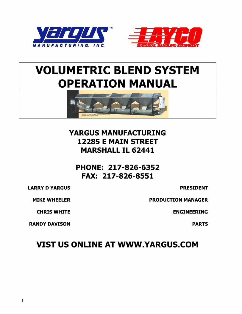
OVERVIEW SYSTEM OVERVIEW
The LAYCO volumetric blend system is designed to accurately blend free flowing
materials with very high accuracies. The Mitsubishi VFD obtains these accuracies
through precise calculations. The input to the VFD’s is a 4-20ma signal derived from
floating point math calculations from the 205 PLC. Also with the scale option, the system
can accurately enter in bulk densities for the materials, which you will be using, by only
entering in the cubic inches of the container used. These values can be automatically
entered or manually entered through the operator interface panel. This is the heart and
soul of the LAYCO blending system and how we can obtain such high accuracies.
Through the following setup procedures, the system can be up and running within an
hour. Once set up, all the operator will have to do is enter in the desired poundage of
each material. The system will automatically calculate the correct blend ratios and speed
for each rotary valve. Simply pressing the START key after each batch run can then
make multiple batches of the same blend.
Ease of setup and operation with built in protection to prevent a bad batch from ever
coming out is what is behind the LAYCO blend system.
3
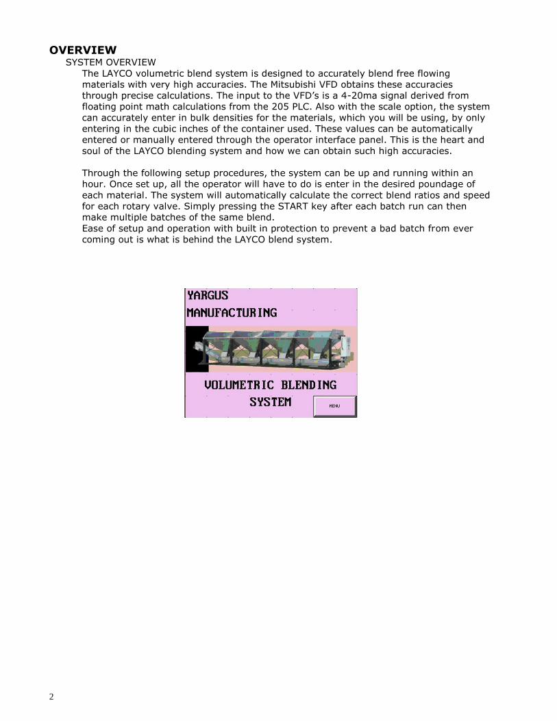
MAIN MENU SCREEN
The main screen is where you can navigate to any of the
other screens. Pressing the MENU button in the opening
screen accesses this screen. By touching the screen, the
following screen is displayed.
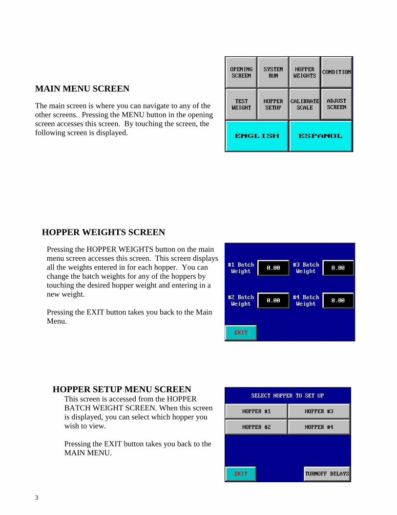
HOPPER WEIGHTS SCREEN
Pressing the HOPPER WEIGHTS button on the main
menu screen accesses this screen. This screen displays
all the weights entered in for each hopper. You can
change the batch weights for any of the hoppers by
touching the desired hopper weight and entering in a
new weight.
Pressing the EXIT button takes you back to the Main
Menu.
HOPPER SETUP MENU SCREEN This screen is accessed from the HOPPER
BATCH WEIGHT SCREEN. When this screen
is displayed, you can select which hopper you
wish to view.
Pressing the EXIT button takes you back to the
MAIN MENU.
4
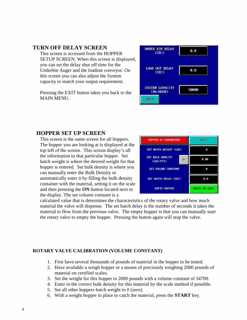
TURN OFF DELAY SCREEN This screen is accessed from the HOPPER
SETUP SCREEN. When this screen is displayed,
you can set the delay shut off time for the
Underbin Auger and the loadout conveyor. On
this screen you can also adjust the System
capacity to match your output requirement.
Pressing the EXIT button takes you back to the
MAIN MENU.
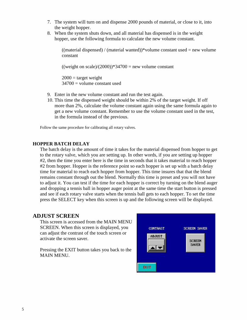
HOPPER SET UP SCREEN
This screen is the same screen for all hoppers.
The hopper you are looking at is displayed at the
top left of the screen. This screen display’s all
the information to that particular hopper. Set
batch weight is where the desired weight for that
hopper is entered. Set bulk density is where you
can manually enter the Bulk Density or
automatically enter it by filling the bulk density
container with the material, setting it on the scale
and then pressing the ON button located next to
the display. The set volume constant is a
calculated value that is determines the characteristics of the rotary valve and how much
material the valve will dispense. The set batch delay is the number of seconds it takes the
material to flow from the previous valve. The empty hopper is that you can manually start
the rotary valve to empty the hopper. Pressing the button again will stop the valve.
ROTARY VALVE CALIBRATION (VOLUME CONSTANT)
1. First have several thousands of pounds of material in the hopper to be tested.
2. Have available a weigh hopper or a means of preciously weighing 2000 pounds of
material on certified scales.
3. Set the weight for this hopper to 2000 pounds with a volume constant of 34700.
4. Enter in the correct bulk density for this material by the scale method if possible.
5. Set all other hoppers batch weight to 0 (zero).
6. With a weight hopper in place to catch the material, press the START key.
5
7. The system will turn on and dispense 2000 pounds of material, or close to it, into
the weight hopper.
8. When the system shuts down, and all material has dispensed is in the weight
hopper, use the following formula to calculate the new volume constant.
((material dispensed) / (material wanted))*volume constant used = new volume
constant
((weight on scale)/(2000))*34700 = new volume constant
2000 = target weight
34700 = volume constant used
9. Enter in the new volume constant and run the test again.
10. This time the dispensed weight should be within 2% of the target weight. If off
more than 2%, calculate the volume constant again using the same formula again to
get a new volume constant. Remember to use the volume constant used in the test,
in the formula instead of the previous.
Follow the same procedure for calibrating all rotary valves.
HOPPER BATCH DELAY
The batch delay is the amount of time it takes for the material dispensed from hopper to get
to the rotary valve, which you are setting up. In other words, if you are setting up hopper
#2, then the time you enter here is the time in seconds that it takes material to reach hopper
#2 from hopper. Hopper is the reference point so each hopper is set up with a batch delay
time for material to reach each hopper from hopper. This time insures that that the blend
remains constant through out the blend. Normally this time is preset and you will not have
to adjust it. You can test if the time for each hopper is correct by turning on the blend auger
and dropping a tennis ball in hopper auger point at the same time the start button is pressed
and see if each rotary valve starts when the tennis ball gets to each hopper. To set the time
press the SELECT key when this screen is up and the following screen will be displayed.
ADJUST SCREEN This screen is accessed from the MAIN MENU
SCREEN. When this screen is displayed, you
can adjust the contrast of the touch screen or
activate the screen saver.
Pressing the EXIT button takes you back to the
MAIN MENU.
6
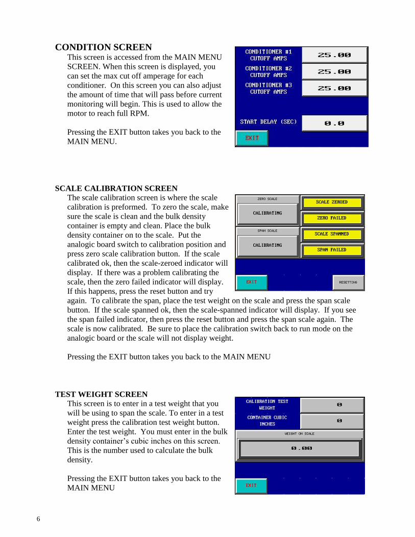
CONDITION SCREEN This screen is accessed from the MAIN MENU
SCREEN. When this screen is displayed, you
can set the max cut off amperage for each
conditioner. On this screen you can also adjust
the amount of time that will pass before current
monitoring will begin. This is used to allow the
motor to reach full RPM.
Pressing the EXIT button takes you back to the
MAIN MENU.
SCALE CALIBRATION SCREEN
The scale calibration screen is where the scale
calibration is preformed. To zero the scale, make
sure the scale is clean and the bulk density
container is empty and clean. Place the bulk
density container on to the scale. Put the
analogic board switch to calibration position and
press zero scale calibration button. If the scale
calibrated ok, then the scale-zeroed indicator will
display. If there was a problem calibrating the
scale, then the zero failed indicator will display.
If this happens, press the reset button and try
again. To calibrate the span, place the test weight on the scale and press the span scale
button. If the scale spanned ok, then the scale-spanned indicator will display. If you see
the span failed indicator, then press the reset button and press the span scale again. The
scale is now calibrated. Be sure to place the calibration switch back to run mode on the
analogic board or the scale will not display weight.
Pressing the EXIT button takes you back to the MAIN MENU
TEST WEIGHT SCREEN
This screen is to enter in a test weight that you
will be using to span the scale. To enter in a test
weight press the calibration test weight button.
Enter the test weight. You must enter in the bulk
density container’s cubic inches on this screen.
This is the number used to calculate the bulk
density.
Pressing the EXIT button takes you back to the
MAIN MENU
7
BINDICATORS
LOW LEVEL INDICATOR
Each hopper is equipped with 2 bindicators. The bindicator in the main hopper is a LOW
LEVEL indicator. When this trips, the indicator light will illuminate on the main control
panel and will remain on until the hopper is refilled. To reset the panel alarm, press the
RESET ALARMS button on the SYSTEM RUN screen. If the problem has been
corrected, the alarm will go out.
BRIDGED INDICATOR
The bridged indicator is right above the rotary valve. This bindicator is to sense a bridged
condition. As soon as this condition is detected, the system goes into an emergency
shutdown condition. All rotary valves as well as the main auger will shut down
immediately. This prevents the batch from being corrupted and maintains the integrity of
the batch. To fix this condition, the operator must rap the side of the bin with a rubber
mallet. When the bridge has been broken. Pressing the RESET ALARMS button can reset
the Alarm. Once reset, the START button can be pressed to resume the batch cycle.
ROTARY VALVE INDICATOR
Each rotary valve is equipped with a proximity switch that senses if the valve is turning
when the system is running. If for some reason the valve stops during a batch cycle, the
system will go into an emergency shutdown. Once the problem has been corrected, and the
Alarm has been reset on the main panel, the START button can be pressed to resume the
batch cycle.
UNDER BIN AUGER INDICATOR
The Under Bin auger is equipped with a Zero Speed switch, which senses if the auger is
turning when the system is running. If for some reason the auger stops during a batch cycle,
the system will go into an emergency shutdown. Once the problem has been corrected, and
the Alarm has been reset on the main panel, the START button can be pressed to resume
the batch cycle.
LOAD OUT CONVEYOR INDICATOR
The Load out Conveyor is equipped with a Zero Speed switch, which senses if the auger is
turning when the system is running. If for some reason the Conveyor stops during a batch
cycle, the system will go into an emergency shutdown. Once the problem has been
corrected, and the Alarm has been reset on the main panel, the START button can be
pressed to resume the batch cycle.

8
Valve Alarms An * denotes alarm will not stop a run or prevent a blend from being made
Alarm Diagnostic Solution
Standard Volumetric Valve Bridged Indicates that there is no material that is ready to be distributed by the valve.
Usually caused by an air pocket or clumped/stuck material to hopper.
Low Level Hopper * Material in hopper is below sensor level Fill hopper before it runs out of product
Valve Motion Valve is not turning Something is preventing valve from moving or is a VFD issue
Blend Ratio One or more weights is too low or high VFD's cannot turn valves slow enough to compensate for weight, adjust blend
E-Stop Emergency Stop Button was pressed. Pull out E-stop and reset alarms
BE Pressure Switch Spout is plugged Unplug the spout and reset alarms
Bucket Elevator Zero speed switch detects no motion or not enough RPM's
Make sure conveyor is running/running at required speed
The Touchscreen is locked. Sign out of the HMI to have touchscreen control
Declining Weight/Gain-Weight Master GSE Lost Connection lost to GSE Cycle Power
Weight in Tank There is already a weight in a tank Empty tank or switch tanks so blends are not mixed.
GSE Menu Mode GSE is in MENU mode Cycle Power
HMI Bad Batch Number Number does not exist Re-enter the number
HMI Connection Lost No connection to HMI Reset connection
HMI- Information Will Not Be Saved Running from Touchscreen Ignore, can log back into HMI to transfer control
Chemicals Needed are Not Loaded
HMI cannot find chemicals in correct hopper
Check/setup HMI hopper configuration
Short Run Time* The run time is too short to run in gain/weight mode
Switches to volumetric mode
Impregnation IM Flowrate AL Cannot Reach GPS Flowrate Check connection
9
12285 EAST MAIN STREET
MARSHALL, IL 62441
217-826-6352
WWW.YARGUS.COM
VOLUMETRIC AND
DW MANUAL
SENSORS AND
ADJUSTMENT
PROCEDURES
10
Volumetric and DW Manual Sensors and
Adjustment procedures
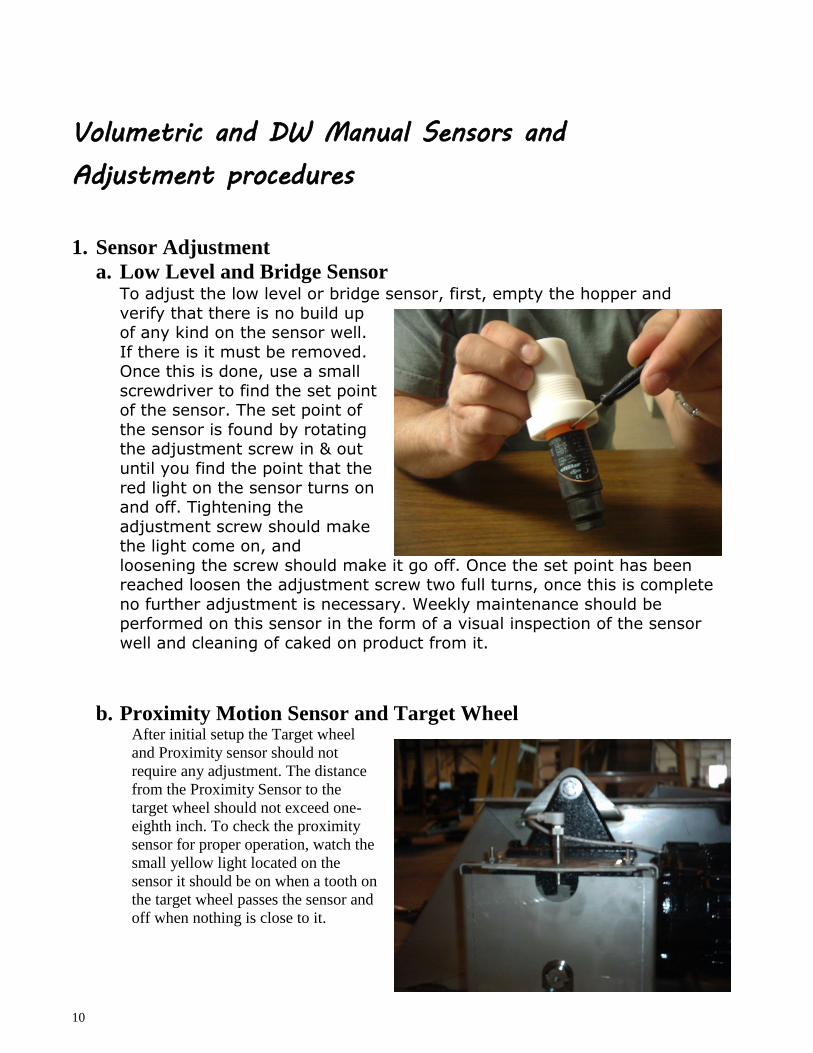
1. Sensor Adjustment
a. Low Level and Bridge Sensor To adjust the low level or bridge sensor, first, empty the hopper and
verify that there is no build up of any kind on the sensor well.
If there is it must be removed. Once this is done, use a small
screwdriver to find the set point of the sensor. The set point of
the sensor is found by rotating the adjustment screw in & out
until you find the point that the
red light on the sensor turns on and off. Tightening the
adjustment screw should make the light come on, and
loosening the screw should make it go off. Once the set point has been reached loosen the adjustment screw two full turns, once this is complete
no further adjustment is necessary. Weekly maintenance should be performed on this sensor in the form of a visual inspection of the sensor
well and cleaning of caked on product from it.
b. Proximity Motion Sensor and Target Wheel After initial setup the Target wheel
and Proximity sensor should not
require any adjustment. The distance
from the Proximity Sensor to the
target wheel should not exceed one-
eighth inch. To check the proximity
sensor for proper operation, watch the
small yellow light located on the
sensor it should be on when a tooth on
the target wheel passes the sensor and
off when nothing is close to it.
11
Fig. 3
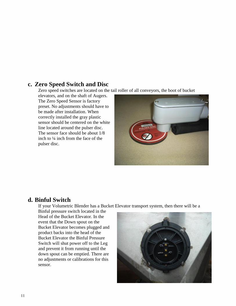
c. Zero Speed Switch and Disc Zero speed switches are located on the tail roller of all conveyors, the boot of bucket
elevators, and on the shaft of Augers.
The Zero Speed Sensor is factory
preset. No adjustments should have to
be made after installation. When
correctly installed the gray plastic
sensor should be centered on the white
line located around the pulser disc.
The sensor face should be about 1/8
inch to ¼ inch from the face of the
pulser disc.
d. Binful Switch If your Volumetric Blender has a Bucket Elevator transport system, then there will be a
Binful pressure switch located in the
Head of the Bucket Elevator. In the
event that the Down spout on the
Bucket Elevator becomes plugged and
product backs into the head of the
Bucket Elevator the Binful Pressure
Switch will shut power off to the Leg
and prevent it from running until the
down spout can be emptied. There are
no adjustments or calibrations for this
sensor.
12
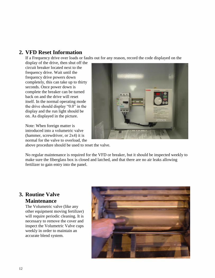
2. VFD Reset Information If a Frequency drive over loads or faults out for any reason, record the code displayed on the
display of the drive, then shut off the
circuit breaker located next to the
frequency drive. Wait until the
frequency drive powers down
completely, this can take up to thirty
seconds. Once power down is
complete the breaker can be turned
back on and the drive will reset
itself. In the normal operating mode
the drive should display “0.0” in the
display and the run light should be
on. As displayed in the picture.
Note: When foreign matter is
introduced into a volumetric valve
(hammer, screwdriver, or 2x4) it is
normal for the valve to overload, the
above procedure should be used to reset the valve.
No regular maintenance is required for the VFD or breaker, but it should be inspected weekly to
make sure the fiberglass box is closed and latched, and that there are no air leaks allowing
fertilizer to gain entry into the panel.
3. Routine Valve
Maintenance The Volumetric valve (like any
other equipment moving fertilizer)
will require periodic cleaning. It is
necessary to remove the cover and
inspect the Volumetric Valve cups
weekly in order to maintain an
accurate blend system.

13