Embed Size (px)
Citation preview
1Iwa4wwsddptb
emMmaaqawhtNdcebeamwnpmt
A. K. Iyer and G. V. Eleftheriades Vol. 23, No. 3 /March 2006/J. Opt. Soc. Am. B 553
Volumetric layered transmission-line metamaterialexhibiting a negative refractive index
Ashwin K. Iyer and George V. Eleftheriades
Edward S. Rogers Sr., Department of Electrical and Computer Engineering, University of Toronto10 King’s College Road, Toronto, M5S 3G4 Canada
Received July 11, 2005; accepted August 21, 2005; posted October 3, 2005 (Doc. ID 63358)
We examine a new class of volumetric metamaterials based on two-dimensional (2D) transmission-line layersthat exhibit a negative refractive index (NRI). The dispersion characteristics of a single 2D layer are revealedthrough a periodic analysis, and the effective-medium response of the volumetric layered topology is predictedby an intuitive equivalent circuit model. Dispersion and transmission characteristics are also obtained for vari-ous designs by using full-wave finite-element method (FEM) simulations, including one design meeting therequirements of Veselago’s slab lens in free space, and suggest an isotropic NRI over bandwidths anywherefrom 25% to 45%. Finally, the potential to implement these metamaterials from terahertz to near-infrared andoptical frequencies is discussed. © 2006 Optical Society of America
OCIS codes: 160.0160, 220.3630, 230.3990, 350.4010.
nlmtt
ttmpemndaktspTrCdpcqwmcmbmfbtsts
. INTRODUCTIONn the 1950’s and 1960’s, there was a great impetus to-ard the realization of artificial dielectrics (see, for ex-mple, Refs. 1–3 and the list of works referenced in Ref.). These works sought to synthesize effective materialsith electromagnetic scatterers, or artificial molecules,hich could be designed to produce a particular macro-
copic response at long wavelengths. Recently, artificialielectrics have experienced a resurgence of interest un-er the guise of metamaterials, effective media whoseroperties transcend those available in nature. Arguably,he most interesting of these transcendent properties haseen the negative refractive index (NRI).In the late 1960’s, the Russian physicist Victor Veselago
nvisioned materials in which the permeability and per-ittivity were simultaneously negative.5 He proved thataxwell’s equations permitted wave solutions in suchedia for which the electric and magnetic field vectors,
long with the wave vector, formed a left-handed tripletnd, accordingly, termed these media left-handed. Conse-uently, the phase and group velocities for these solutionsre oppositely directed, as in the well-known backwardave. This allowed him to show, in a general and compre-ensive way, that materials with both a negative permit-ivity and a negative permeability could be described by aRI. Conditions for a negative permittivity, as in over-ense plasmas, were well known in the domain of artifi-ial dielectrics; indeed, plasmalike conditions can be mod-led by an array of thin metallic wires6–8 or, equivalently,y inductively loading free space.9 For many years, how-ver, the obstacle to realizing negative refraction was thebsence of any direct analog for the negation of the per-eability. This was eventually achieved by Pendry et al.,ho introduced the split-ring resonator, an electromag-etic scatterer designed to synthesize a strong negativeermeability through a resonance mechanism.10 The twoetamaterials, one an array of wires designed for a nega-
ive permittivity and the other an array of split-ring reso-
0740-3224/06/030553-18/$15.00 © 2
ators exhibiting a negative permeability over a particu-ar range of frequencies, were combined into a composite
etamaterial by Shelby et al., who succeeded in verifyinghe phenomenon of negative refraction, over 30 years af-er Veselago’s initial postulates were published.11
Following these seminal works, other realizations ofhe NRI metamaterial were considered. One example ishe negative-refractive-index transmission-line (NRI-TL)edium, consisting of a transmission-line (TL) network
eriodically loaded using inductors and capacitors and op-rating in the long-wavelength regime.12,13 The concept ofodeling dielectrics using distributed L–C networks isot new; in fact, it was rigorously studied for conventionalielectrics as early as the 1940’s by Kron14 and Whinnerynd Ramo,15 when it effectively generalized the well-nown low-pass lumped-element distributed representa-ion of the familiar TL in which the series inductance andhunt capacitance represented, respectively, the positiveermeability and permittivity of the intrinsic medium.he novelty of the NRI-TL approach, however, was in theealization that the reversal of the positions of the L and
elements in the conventional topology, which yields aual topology, successfully negates its effective-mediumarameters and produces the correct causal dispersionharacteristics associated with NRI media.12,13 Subse-uently, a comprehensive theory for these dual structuresas developed, and both simulations and experiments aticrowave frequencies established that such TL networks
ould be used not only for the modeling of conventionalaterials, as employed by Kron, Ramo, and Whinnery,
ut also for the realization of new materials. Further-ore, since these designs are completely scalable with
requency, it is entirely foreseeable that metamaterialsased on TL-equivalent perspectives can be fabricated inhe terahertz or far-infrared range, limited only by the on-et of plasmonic resonances in the metals. In fact, even inhe optical regime, some recent work has revealed thatimilar TL concepts can be employed for particular ar-
006 Optical Society of America

rgi
poiBtittbdmm1wHT
Nptgtetrmmispsucpv
tsmapdsr
tpncFpradblepsFldtw
it cell
Flrrt
554 J. Opt. Soc. Am. B/Vol. 23, No. 3 /March 2006 A. K. Iyer and G. V. Eleftheriades
angements of plasmonic materials such as silver andold.16,17 We shall avail ourselves of these concepts latern this work.
The results of Kron, Ramo, and Whinnery were em-loyed by Brewitt-Taylor and Johns in their formulationf the transmission-line matrix (TLM) method of model-ng electromagnetic phenomena in the time domain.18
rewitt-Taylor and Johns identified the specific unit-cellopologies for such networks for both TE and TM polar-zations. The former is known as the series TLM node andhe latter as the shunt TLM node; they are depicted forhe two-dimensional (2D) case in Figs. 1(a) and 1(b). Inoth cases, the capacitive and inductive elements directlyetermine the constitutive parameters—the desired per-ittivity and permeability, respectively—of the effectiveedium. In a realized form with TLs, it is clear that Fig.
(a) is simply the series interconnection of four TLs,hereas Fig. 1(b) is a shunt interconnection of four TLs.ence, we shall refer to the two topologies as the seriesL unit cell and the shunt TL unit cell, respectively.A completely 3D physical realization of an isotropic
RI-TL medium based on Kron’s topology has been pro-osed and designed in Refs. 19–21. Unfortunately, this 3Dopology is complex and not easily fabricated by litho-raphic techniques. These technologies are ideally suitedo the fabrication of planar or stratified structures. How-ver, if we restrict our polarization and limit our direc-ions of propagation, practical structures that can beeadily fabricated with prevalent lithographic techniquesay become available. Moreover, certain 3D topologiesay, conceivably, be realized by appropriately interlock-
ng these 2D layers in orthogonal planes. Thus, bothtructures can be based on the 2D topologies already em-loyed for planar phenomena. For example, we may envi-ion a 3D network constructed by layering planes of 2Dnit cells, as shown in Fig. 2. Such a network could, underertain conditions, be designated an effective medium forropagation along the planes and would best be termed aolumetric layered 2D medium.
Although the shunt NRI-TL topology can be symme-rized by distributing the series inductances across theignal and return paths, it is evident that these two pathsust be noncoplanar. As shown in Fig. 1(a), this is
voided in the series TL unit cell, making it an ideal to-ology with which to construct a volumetric layered me-ium. Consider Fig. 3, which depicts a periodic array oferies TL unit cells. In comparing a single cell in the ar-ay (lightly shaded region) to Fig. 1(a), the reader will no-
Fig. 1. (a) Two-dimensional series TL un
ice that we have generalized the lumped loading inreparation for the analysis to follow. Previously, it wasoted that this unit cell may be perceived as the seriesonnection of four TL segments. It is also evident fromig. 3 that the unit cell for this array may alternatively beerceived as a ring of impedances connected to adjacentings via admittances (darkly shaded region). The volt-ges along the TLs and the opposite currents on the con-uctors of each two-wire TL segment could alternativelye visualized as a potential difference in the gaps betweenoops and circulating current induced in each ring by thelectric and magnetic fields, respectively, of an impinginglane wave. We shall find it useful to refer to both per-pectives throughout the course of the following analysis.rom either perspective, it is evident that the effective po-
arization is that for which the magnetic field lies perpen-icular to the ring plane and the electric field lies withinhe plane (the propagation vector also lies in the plane),hich we shall hereafter refer to as the TE polarization.
. (b) Two-dimensional shunt TL unit cell.
Fig. 2. Creating a volumetric medium by layering 2D planes.
ig. 3. Array of 2D series TL unit cells with generalized lumpedoading. The lightly shaded region views the unit cell as the se-ies interconnection of four two-wire lines, and the darkly shadedegion views the unit cell as a loaded ring. The magnetic field ofhe impinging plane wave is normal to the plane of the page.

homaiodesdnirVbfoc
2IoTtmatamaRaw
AWlo
FtFttcrcBp
ua�
Fn
Fs
A. K. Iyer and G. V. Eleftheriades Vol. 23, No. 3 /March 2006/J. Opt. Soc. Am. B 555
We may now ask: does the 2D series TL unit cell alsoave a dual topology capable of producing a left-handed,r NRI, response? Furthermore, can a volumetric NRIedium be created by stacking layers of dual series TL
rrays? This paper addresses these questions by develop-ng the dispersion theory and effective-medium responsef the single-layer series NRI-TL network, followed by theesign of practical volumetric layered 2D structures thatxhibit a NRI. Full-wave simulations showing the disper-ion characteristics of an infinite periodic volumetric me-ium and transmission properties of a slab of finite thick-ess are presented. An intuitive equivalent circuit model
s used to verify the results and also to design a volumet-ic NRI-TL structure meeting the requirements ofeselago’s slab lens in free space. Finally, the possi-ility of scaling these media for operation at terahertzrequencies or employing plasmonic concepts forperation at near-infrared or optical frequencies, is dis-ussed.
. SINGLE-LAYER 2D NRI-TL MEDIUMn this section, we develop the dispersion characteristicsf the single-layer 2D NRI-TL medium based on the seriesL network of Fig. 3, which will constitute the layers ofhe proposed volumetric medium. Although this structureay be analyzed in a number of ways, the most simple
nd instructive way employs the TL series junction pic-ure. The following development, a variation of which haslso been reported in Ref. 22, is based on a transfer-atrix (ABCD) analysis of periodic networks entirely
nalogous to that presented for the shunt TL unit cell inef. 23. An effective-medium regime will be identified,nd the constitutive parameters of the effective mediumill be determined in this regime.
. Periodic Analysise begin with the transfer-matrix definition, which re-
ates the input and output terminal voltages and currentsf a two-port network, as shown in Fig. 4:
�Vin
Iin� = �A B
C D��Vout
Iout� . �1�
ollowing the development reported in Ref. 22, we depicthe four-port unit cell for the structure to be analyzed inig. 5; in the present case, the transmission matrix orien-ations and current reference directions have been choseno exploit symmetry. The input and output voltage andurrent quantities (ports {1,2} and {3,4}, respectively) areelated through an overall phase shift represented by theomplex exponential exp�−j�pd�, where �p is the Floquet–loch wave vector in the direction p= �x ,y� and d is thehysical cell dimension. That is,
�V1
I1� = �Vx
Ix� ,
�V2
I2� = �Vy
Iy� ,
�V3
I3� = �Vx
Ix�exp�− j�xd�,
�V4
I4� = �Vy
Iy�exp�− j�yd�. �2�
We now specify the branches making up the series TLnit cell. As shown in Fig. 6, each branch shall consist ofTL of characteristic impedance Z0 and electrical length
/2 separating a series impedance Z /4 (distributed across
ig. 4. Definition of the ABCD transfer matrix for a two-portetwork.
Fig. 5. Periodic analysis of the generalized series TL unit cell.
ig. 6. Specification of the constituents of the branches of theeries TL unit cell depicted in Fig. 5.
byZsmt
wuteaet
u−
Amwcitt
Wt
TtT7s1stctpcl
Rm�s
Tpcnc
SP
�
XYM
C
IA
Fd
556 J. Opt. Soc. Am. B/Vol. 23, No. 3 /March 2006 A. K. Iyer and G. V. Eleftheriades
oth branches of the TL as two elements of value Z /8 andielding a total series impedance around the unit cell of) and a shunt admittance Y /2 (which, combined with thehunt admittance of the adjacent cell, yields a total ad-ittance of Y). The cascade of these networks possesses a
ransmission matrix with the following elements:
Ai = cos�
2,
Bi =Zi
4cos
�
2+ jZ0 sin
�
2,
Ci =Yi
2cos
�
2+ jY0 sin
�
2,
Di = �1 +ZiYi
8 �cos�
2+
j
2� Z
2Z0+
Y
Y0�sin
�
2, �3�
here we have assumed that all branches are constructedsing TLs of the same characteristic impedance and elec-rical length. It is also clear from Eqs. (3) that the param-ters B and C are concerned solely with the impedance Znd admittance Y, respectively, and A is independent ofither. The parameter D may be obtained from the otherhree parameters by using the reciprocity condition.
In what is to follow, we shall specify the analysis for aniaxial network consisting of reciprocal branches �AiDiBiCi=1�; that is,
�A1 B1
C1 D1� = �A3 B3
C3 D3� = �Ax Bx
Cx Dx� ,
�A2 B2
C2 D2� = �A4 B4
C4 D4� = �Ay By
Cy Dy� . �4�
pplying Kirchhoff ’s current and voltage laws at the ter-inal intersections yields four independent equations,hose solution gives both the Floquet–Bloch propagation
onstant and the Bloch impedances—the characteristicmpedances seen by Floquet–Bloch waves propagating inhe x and y directions. The 2D uniaxial dispersion rela-ion can, therefore, be written as follows:
�AyCy�1 − cos �xd� + 2BxCx + AxCx�1 − cos �yd�
+ 2ByCy� = 0. �5�
e are also in a position to derive general expressions forhe Bloch impedances:
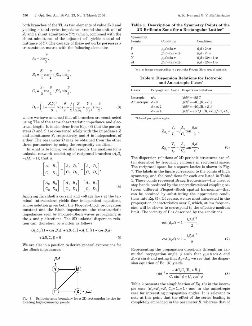
ig. 7. Brillouin-zone boundary for a 2D rectangular lattice in-icating high-symmetry points.
ZBx=
Vx
Ix= j
Ax
Cxtan
�xd
2,
ZBy=
Vy
Iy= j
Ay
Cytan
�yd
2. �6�
he dispersion relations of 2D periodic structures are of-en described by frequency contours in reciprocal space.he reciprocal space for a square lattice is shown in Fig.. The labels in the figure correspond to the points of highymmetry, and the conditions for each are listed in Table. These points represent Bragg frequencies—the onset oftop bands produced by the contradirectional coupling be-ween different Floquet–Bloch spatial harmonics—thatan be obtained by substituting the appropriate condi-ions into Eq. (5). Of course, we are most interested in theropagation characteristics near �, which, at low frequen-ies, will be shown to correspond to the effective-mediumimit. The vicinity of � is described by the conditions
cos��xd� � 1 −��xd�2
2,
cos��yd� � 1 −��yd�2
2. �7�
epresenting the propagation directions through an azi-uthal propagation angle � such that �x=� cos � and
y=� sin � and noting that Ax=Ay, we see that the disper-ion equation of Eq. (5) yields
��d�2 =− 4CxCy�Bx + By�
Cx sin2 � + Cy cos2 �. �8�
able 2 presents the simplification of Eq. (8) in the isotro-ic case �Bx=By=B , Cx=Cy=C� and in the anisotropicase for interesting propagation angles. It is relevant toote at this point that the effect of the series loading isompletely embedded in the parameter B, whereas that of
Table 1. Description of the Symmetry Points of the2D Brillouin Zone for a Rectangular Latticea
ymmetryoints Condition Condition
�xd=2n� �yd=2n�
�xd= �2n+1�� �yd=2n�
�xd=2n� �yd= �2n+1���xd= �2n+1�� �yd= �2n+1��
an is an integer corresponding to a particular Floquet–Bloch spatial harmonic.
Table 2. Dispersion Relations for Isotropicand Anisotropic Casesa
ases Propagation Angle Dispersion Relation
sotropic n/a ��d�2=−8BCnisotropic �=0 ��d�2=−4Cx�Bx+By�
�=� /2 ��d�2=−4Cy�Bx+By��=� /4 ��d�2= −8CxCy�Bx+By�� �Cx+Cy�
aSelected propagation angles.

tiwipirgm
sETr
Tnos
f
w
s
Ta
BWiFf
sp
Mtw
TtpicosscFecss
W
wtpii
A. K. Iyer and G. V. Eleftheriades Vol. 23, No. 3 /March 2006/J. Opt. Soc. Am. B 557
he shunt loading is embedded in C. When the network issotropic, it is clear that all directions of Floquet–Blochave propagation possess the same dispersion character-
stics near �. The dispersion characteristics for axialropagation (�=0 and �=� /2) depend on the shunt load-ng corresponding to that axis but also depend on the se-ies loading on both axes. Finally, propagation along therid diagonals is affected by the series and shunt ele-ents on both axes.We now simplify the results for the isotropic case. Sub-
tituting the appropriate expressions for B and C fromqs. (3) into the isotropic dispersion relation listed inable 2 and factoring yield the complete axial dispersionelation in the vicinity of �:
��d�2 = �4 sin�
2− j
Z
Z0cos
�
2��2 sin�
2− j
Y
Y0cos
�
2� . �9�
he zeros of this function identify the edges of stop bandsear �, of which there are an infinite number. The edgesf these stop bands are given by the solutions to the tran-cendental equations corresponding to each factor:
tan�
2= j
Z
4Z0,
tan�
2= j
Y
2Y0. �10�
In this regime, the Bloch impedances also have reducedorms,
ZBx= j
A
C
�xd
2= j
A�d
2Ccos �,
ZBy= j
A
C
�yd
2= j
A�d
2Csin �, �11�
hich suggests the effective Bloch impedance
ZB = ± �ZBx
2 + ZBy
2 = ± jA�d
2C, �12�
o that
ZBx= ZB cos �,
ZBy= ZB sin �.
hus, it is clear that ZB is also the Bloch impedance forxial propagation (i.e., �=0 or �=� /2).
. Effective-Medium Parameterse may directly obtain the per-unit-length (distributed)
nductance and capacitance of the medium from theloquet–Bloch wave vector � and Bloch impedance ZB as
ollows:
�2 = �2Leff� Ceff� ,
ZB2 =
Leff�
Ceff�Þ Leff� =
�ZB
�Þ Ceff� =
�
�ZB. �13�
The Bloch impedance, along with the isotropic disper-ion relation listed in Table 2, can be rearranged to ex-ress the desired quantities:
Leff� =4AB
j�d,
Ceff� =2C
j�Ad. �14�
aking these substitutions and inserting the appropriateransmission matrix parameter expressions from Eqs. (3),e have
Leff� = cos2�
2�4Z0
�dtan
�
2−
jZ
�d� ,
Ceff� = �2Y0
�dtan
�
2−
jY
�d� . �15�
hese expressions describe the per-unit-length induc-ance and capacitance of an effective TL representingropagation in an isotropic TL network near each one ofnfinitely many � points at successively higher frequen-ies. They may be related to the constitutive parametersf an effective medium when the unit cells are muchmaller than the applied wavelength. This condition isatisfied only at low frequencies, where the dispersionharacteristics are dominated by the lowest-order �n=0�loquet–Bloch spatial harmonic, and is known as theffective-medium regime. At these frequencies, the inter-onnecting TLs can be considered to be electrically smallo that ��1. Applying this to Eqs. (15) and retaining onlyecond-order terms in the Taylor expansion yields
Leff� =2Z0�
�d−
jZ
�d,
Ceff� =Y0�
�d−
jY
�d. �16�
e may also write the host TL parameters as
� = ��ppd,
Z0 = Y0−1 = gp�p
p, �17�
here p and p are the material parameters of the in-rinsic medium filling the host TL segments and gp is theositive geometric constant that relates the characteristicmpedance of the host TLs to the wave impedance of thentrinsic medium. Inserting Eqs. (17) into Eqs. (16) yields

wpoLptp
Ethotwspermslmstsa
thitFt
Emuafietd
pm
LemcntCCdfissrt
ImsonNfntt
Fa
558 J. Opt. Soc. Am. B/Vol. 23, No. 3 /March 2006 A. K. Iyer and G. V. Eleftheriades
Leff� = 2pgp −jZ
�d,
Ceff� =p
gp−
jY
�d, �18�
here the quantities 2pgp and p /gp are seen to be theer-unit-length inductance and capacitance, respectively,f the host TL. Finally, in this effective-medium regime,eff and Ceff can also be related to the effective-mediumarameters eff��� and eff��� through a geometrical fac-or, which we shall denote geff. Thus, the effective-mediumarameters of our network can be written as follows:
eff��� =Leff�
geff= 2p
gp
geff− p
jZ
geff�d,
eff��� = Ceff� geff =pgeff
gp−
jYgeff
�d. �19�
ach effective-medium parameter expression consists ofwo terms: the first is contributed by the (nondispersive)ost TL medium alone, whereas the second is dependentn the loading. Furthermore, it is evident that the effec-ive permeability is determined by the series loading,hereas the effective permittivity is determined by the
hunt loading. Revisiting Table 2 and recalling from therevious discussion that the transmission matrix param-ters B and C were, respectively, associated with the se-ies and shunt loading, it can be seen that the effectiveedium can be made anisotropic only by varying the
hunt loading between the axes. However, since the shuntoading on a particular axis determines the effective per-
ittivity for propagation along that axis, it is clear thatuch a network would be electrically anisotropic, in con-rast to the shunt NRI-TL network, for which varying theeries loading between the axes yields magneticnisotropy.24
In the unloaded case—that is, for Z=Y=0—we restorehe parameters of the unloaded medium. The difference,owever, lies in the factor of 2 in the effective permeabil-
ty, resulting from the restrictions in propagation direc-ion in the 2D geometry. This will be elucidated shortly.or simplicity, let us assume that the two geometrical fac-ors are identical—that is, gp=geff=g—which yields
eff��� = 2p −jZ
g�d,
eff��� = p −jYg
�d. �20�
ssentially, this is equivalent to saying that the fieldappings associated with propagation in the loaded and
nloaded networks are identical; that is, we have takenn effective TL filled with 2p and p and substituted thelling medium with eff��� and eff���. For purely realffective-medium parameters, both Z and Y are requiredo be purely reactive. If we load the lines with a series in-uctance L and shunt capacitance C (that is, in a low-
0 0ass configuration), we arrive at the following effective-edium parameters:
eff��� = 2p −j�j�L0�
g�d= 2p +
L0
gd,
eff��� = p −j�j�C0�g
�d= p +
C0g
d. �21�
oading in this manner yields positive, nondispersiveffective-medium parameters, where the loading haserely been distributed through the length of the unit
ell, d. This topology can be used to model conventional,ondispersive, lossless dielectrics and, excepting the in-erconnecting TLs, is identical to the series TLM model.onsider now loading the lines with a series capacitance0 and shunt inductance L0 (that is, in a high-pass, orual, configuration), as shown in Fig. 8. The arrows in thegure indicate the equal and opposite currents in the TLegments assumed in the preceding analysis. This per-pective also enables one to see the current loops in theing perspective. The effective-medium parameters forhis configuration are strikingly different:
eff��� = 2p −j
g�j�C0��d= 2p −
1
�2gC0d,
eff��� = p −jg
�j�L0��d= p −
g
�2L0d. �22�
t is evident that the second term of each effective-edium parameter is now negative and strongly disper-
ive, the latter property consistent with the requirementsf causality.4,5 When the parameters are simultaneouslyegative, this effective medium can be said to possess aRI. In anticipation of this result, we shall hereafter re-
er to this array as the 2D series NRI-TL network. Weow return to the factor of 2 in the first term of the effec-ive permeability expression. Previously, it was noted thathis was due to the fact that propagation in the grid is re-
ig. 8. Series TL node array loaded in a dual configuration. Therrows indicate the current directions.

s2aatRattstaetFr=Fim
tfnalL(fpca
btt
sEeem
Bmborguent
CCANmq[tNs
waFgsitoccsri(Fbpicc�
FC
Fa(L
A. K. Iyer and G. V. Eleftheriades Vol. 23, No. 3 /March 2006/J. Opt. Soc. Am. B 559
tricted to the two orthogonal grid axes. The effect of theD nature of the grid is most easily seen for the case ofxial propagation, as shown in Fig. 9 for propagationlong the x axis (i.e., with �y=0). From Eqs. (6), we seehat, if �y=0, the Bloch impedance ZBy
=0. As noted inef. 22, this implies from Eqs. (6) that Vy=0, whichmounts to short circuiting the dual series NRI-TL nodeerminals transverse to the direction of propagation. Inhis case, the transverse branches of the unit cell act likehorted series TL stubs. In the effective-medium limit,hese stubs can be shown to double the effective perme-bility of the host medium in a manner contrasting, butntirely analogous to, the doubling of the effective permit-ivity of the host medium in the 2D shunt NRI-TL grid.12
or the unloaded medium, whose effective-medium pa-ameters can be obtained from Eqs. (20) by setting Z=Y0, it is clear that the phase velocity of propagatingloquet–Bloch waves is reduced by a factor of �2 from the
ntrinsic, a result that is also analogous to that deter-ined for the 2D shunt NRI-TL medium.12,23
The complete axial dispersion relation for a represen-ative series NRI-TL design is shown in Fig. 10(a) in theorm of an �–� diagram. At low frequencies, the intercon-ecting TLs may be regarded as electrically infinitesimal,nd all that remains of the series NRI-TL unit cell are theoading elements. Such a structure behaves like a 2D–C filter and, therefore, possesses a Bragg resonance
labeled �B), below which propagation is forbidden. Theundamental mode supported by this structure, which ap-ears thereafter, clearly possesses the left-handed or NRIharacteristic, and the effective-medium condition ischieved in the approach toward the edge of the first stop
ig. 9. Axial propagation in the 2D series NRI-TL node array. S.., short-circuit planes.
ig. 10. Representative series NRI-TL dispersion relations forxial propagation �p=0 ,p=30 ,g=0.325,C0=1 pF,d=5 mm�:a) L0=3 nH, impedance-mismatched (open-stop-band) case; (b)0=10 nH, impedance-matched (closed-stop-band) case.
and at �C,1. Propagation is restored beyond �C,2, wherehe concavity of the band structure exhibits (conven-ional) right handedness.
These dispersion characteristics may also be under-tood in terms of the material parameter expressions ofqs. (22). The edges of the stop band shown in Fig. 10(a)ffectively correspond to the zeros of the material param-ter expressions. Hence, we may refer to �C,1 and �C,2 asagnetic and electric plasma frequencies,
�C,1 =� 1
2pgC0deff��C,1� = 0,
�C,2 =� g
pL0deff��C,2� = 0. �23�
elow their respective plasma frequencies, the effective-edium parameters are individually negative. The stop
and, therefore, corresponds to the situation in whichnly one of the two parameters is negative (the frequencyegion between �C,1 and �C,2), where the effective propa-ation constant is imaginary. In the frequency range withpper bound min��C,1 ,�C,2�, the effective-medium param-ters are simultaneously negative, and it is here that theegative effective refractive index, or left-handed charac-eristic, is observed.
. Closure of the Stop Band: the Impedance-Matchedonditionsimilar dispersion relation was obtained for the shuntRI-TL node,12 in which it was shown that the stop banday actually be closed by equating the two plasma fre-
uencies, resulting in an impedance-matched conditionsee Eq. (29) of Ref. 12] It is evident from Eqs. (23) thathere may be an analogous condition for the seriesRI-TL node. Equating the two plasma frequencies re-
ults in the condition
�C,1 = �C,2 Þ�L0
C0= g�2p
p= �2Z0 = Z0,2D, �24�
here Z0 is the characteristic of a single host TL segmentnd Z0,2D=�2Z0 is the characteristic impedance seen by aloquet–Bloch wave propagating in the 2D unloaded TLrid in the homogeneous limit. Thus, expression (24)tates that the stop band may be closed simply by choos-ng the loading elements L0 and C0 such that the charac-eristic impedance of the 2D host medium is equal to thatf the underlying purely left-handed distributed mediumonsisting of the loading elements alone, which is identi-al to the impedance-matched condition reported for thehunt NRI-TL unit cell in Eq. (29) of Ref. 12 and later alsoeported in Ref. 25. Appropriately adjusting the loadingnductance L0 employed in Fig. 10(a) to satisfy expression24) results in the impedance-matched design shown inig. 10(b). One consequence of the closure of the stopand is the restoration of a nonzero group velocity at theoint of closure.25 It was shown in Ref. 26 that thempedance-matched condition for the shunt NRI-TL nodelosed not only the lowest �-point stop band but, in fact,losed each one of the infinite stop bands in the vicinity of, whose edges are described by the solutions of Eqs. (10).

TNd
DWN3swTWma
wim
WtorulamT
ls
ctors, (
560 J. Opt. Soc. Am. B/Vol. 23, No. 3 /March 2006 A. K. Iyer and G. V. Eleftheriades
he reader may verify that this is also true of the seriesRI-TL node by substituting the impedance-matched con-ition (24) into Eqs. (10).
. Practical Realizatione now consider a practical realization of the 2D seriesRI-TL layers proposed above in preparation for Section, in which a volumetric layered NRI-TL medium is de-igned and simulated. With ease of fabrication in mind,e select for our planar host medium the coplanar-stripL, consisting of two flat, edge-coupled strips (strip width, separation S), and assume it to be embedded in a ho-ogeneous medium of relative permittivity r. The char-
cteristic impedance of the coplanar-strip TL is given by27
Z0 =�0
�r
K�k��
K�k�,
k = �1 − � S
S + 2W�2�1/2
,
Fig. 11. Series TL unit cells: (a) unloaded, (b) shunt indu
k� =S
S + 2W, �25�
here �0=377� is the free-space wave impedance and Ks the complete elliptic integral of the first kind. The geo-
etric factor g can also be identified as follows:
g = Z0 � �0
�r� =
K�k��
K�k�. �26�
e employ wide strips with small gap spacings and placehem in a periodic array with period d. As noted previ-usly, such an arrangement may also be viewed as an ar-ay of square metallic rings, as shown in Fig. 11(a). Thenit cell is shown in black. Other ring shapes, e.g., circu-
ar, triangular, or hexagonal, may also be described by thebove theory, provided that appropriate modifications areade to the geometry-dependent parameters of the hostL medium.The loading may be achieved using either discrete
umped elements or printed lumped elements, as in thehunt NRI-TL structure. Discrete lumped elements have
c) series capacitors, (d) composite series NRI-TL unit cell.

tqpcacwpor(saN
3MWdttntttvTsqcaatae
AMOpt
vfttoti1mts1si
gLgfiitw2
Fnt
Fpmo
A. K. Iyer and G. V. Eleftheriades Vol. 23, No. 3 /March 2006/J. Opt. Soc. Am. B 561
he benefit that they permit small structures at low fre-uencies and are easier to model. On the other hand,rinted lumped elements allow scalability and lower theost of fabrication significantly. This will be a particulardvantage in the construction of a volumetric mediumonsisting of multiple layers of series NRI-TL arrays, forhich a discrete lumped-element realization would berohibitively expensive. Figure 11(b) shows the placementf the shunt inductive connections between the metallicings, and Fig. 11(c) depicts the series capacitive loadingthe individual capacitors on the intersecting coplanar-trip lines shown in Fig. 8 have been combined in seriest the corners of the rings). The resulting planar seriesRI-TL unit cell is shown in Fig. 11(d).
. VOLUMETRIC LAYERED 2D NRI-TLEDIUMe now apply the results of the previous sections to the
esign and characterization of a volumetric layered struc-ure consisting of stacked series NRI-TL arrays. It is,herefore, important to make the transition from the pla-ar network discussed thus far to the volumetric mediumo be studied. By layering unit cells periodically both inhe xy plane (with horizontal lattice spacing d) and alonghe z axis (with vertical lattice spacing p), we produce theolumetric unit cell depicted in Fig. 12. When excited by aEz-polarized plane wave propagating in the xy plane, thetacked rings exhibit identical current patterns; conse-uently, the top and bottom faces of the unit cell of Fig. 12an be regarded as magnetic walls. For simplicity, we maylso restrict our study to the highly representative case ofxial propagation (normal incidence), in which the elec-ric field remains in the x direction. In this case, we maydditionally replace the faces of the cube normal to x withlectric walls.
. Two-Port TL Model for Volumetric Layered NRI-TLediumn the basis of the assumptions described above, weresent an intuitive TL model that attempts to capturehe essential dispersion characteristics of the effective
ig. 12. (Color online) Volumetric NRI-TL unit cell for an infi-ite array excited by a TEz-polarized plane wave propagating inhe y direction.
olumetric layered medium by using an equivalent circuitor the cell depicted in Fig. 12. The dispersion relation ofhe volumetric layered NRI-TL medium may then be ob-ained as that of an infinite periodic structure consistingf such unit cells via a periodic analysis. The interpreta-ion of this equivalent circuit will be made easier by view-ng the volumetric unit cell from the top, as shown in Fig.3(a), where the electric walls are as indicated and theagnetic walls are parallel to the page. The orientation of
he incident field quantities is also indicated. The corre-ponding equivalent circuit unit cell is shown in Fig.3(b); in the following discussion, we shall justify its con-tituent elements by using the schematic representationn Fig. 13(a).
When unloaded by the series NRI-TL layers, the wave-uide can be described by a distributed inductancewg/d=0gwg and capacitance Cwg/d=r0 /gwg, wherewg=d /p and r is the relative permittivity of the mediumlling the waveguide. When the layers are introduced, the
mpinging magnetic field induces currents in the capaci-ively loaded rings and, thus, alters the inductance of theaveguide. This can be modeled (as described in Refs.8–30 for the split-ring resonator) by one’s coupling L to
ig. 13. Interactions between a normally incident TE-polarizedlane wave and the volumetric layered NRI-TL medium: (a) sche-atic representation of the unit cell, (b) equivalent circuit model
f the unit cell.
wg

tsws
oenemcirtttdtttnt
BLTmtsNtdcrgbss=gmt
CSTeiteppcl�srvcH
atbuamwimcs
1TcpTstturdSmdfpseCctfifsgp
Q
HVSSCRTT
562 J. Opt. Soc. Am. B/Vol. 23, No. 3 /March 2006 A. K. Iyer and G. V. Eleftheriades
he rings (described by the total capacitive loading C0 andelf-inductance Lr) via a mutual inductance M=LwgF,here F is the effective (area) filling factor of the rings in-
ide the unit cell.The electric field is also perturbed by the introduction
f the layers. Currents are produced in the ring when thelectric field excites the gap between the horizontal copla-ar strips (through which the electric wall runs), where itxperiences the inductive loading L0. In these regions, theodel employs the distributed capacitance of the
oplanar-strip TLs, Cx=r0 /g [g is as given in Eq. (26)],n shunt with the loading inductance, L0. However, cur-ents can also be produced when the electric field exciteshe loading capacitors, C0. These currents see the effec-ive series inductance Lr�=Lr−M2 /Lwg, which is simplyhe self-inductance of the ring, less the image inductanceue to coupling to the external waveguide. In Fig. 13(a),he total capacitive loading and effective series induc-ance have been divided evenly across the two halves ofhe ring. Because the impinging electric field simulta-eously excites both sides of the ring, Fig. 13(b) placeshem in parallel.
. Effective-Medium Parameters of the Volumetricayered NRI-TL Mediumhe per-unit-length series impedance �Z�� and shunt ad-ittance �Y�� of Fig. 13(b), respectively, represent the dis-
ributed inductance and capacitance of an effective TL de-cribing axial propagation in the volumetric layeredRI-TL medium. As with the equivalent circuit models of
he single-layer series and shunt NRI-TL nodes,12,22 theseistributed parameters describe the magnetic and electri-al characteristics of the network and, therefore, can beelated to the effective-medium parameters, v��� andv���, of the volumetric layered NRI-TL medium via aeometrical factor, gv. One establishes this relationshipy noting that the effective-medium parameters in the ab-ence of the 2D layers must reduce to those of the intrin-ic medium filling the waveguide, v���=0 and v���r0, which insists that gv is, in fact, gwg of the wave-uide. Thus, the effective-medium parameters of the volu-etric layered NRI-TL medium may be obtained using
he following expressions:
v��� = −jZ�
�gwg,
Table 3. Design Parameters Employed for aVolumetric Layered NRI-TL Medium by Using
Discrete Lumped Elements
uantity Symbol Value
orizontal lattice spacing d 5.5 mmertical lattice spacing p 4.572 mm (180 mil)trip width W 1.1 mmtrip spacing S 500 mopper thickness t 17 melative permittivity r 3otal loading inductance L0 5.6 nHotal loading capacitance C0 1 pF
v��� = −jY�gwg
�. �27�
. Discrete Lumped-Element Design and Full-Waveimulationso gain a full appreciation of the intricacies of this geom-try, as well as the ability of the above theory to predictts dispersion features, it should be instructive to examinehe axial dispersion characteristics of the volumetric lay-red medium for the various stages in the evolution of thelanar unit cell depicted in Figs. 11(a)–11(d). For this pur-ose, we consider a representative design employing dis-rete lumped elements whose design parameters areisted in Table 3. The metal used is copper � =5.8
107 S/m� with finite thickness t; the host dielectric pos-esses a relative permittivity of 3 and also includes mate-ial losses through a loss tangent of 0.0013. With thesealues, the dispersion relations corresponding to eachase in Figs. 11(a)–11(d) were obtained using Ansoft’sFSS finite-element full-wave electromagnetic solver andre shown in Figs. 14(a)–14(d). Owing to the thickness ofhe coplanar strips, and the resulting nonuniform distri-ution of current on the rings, it is difficult to define anique ring size. Therefore, we have assigned the ringsn effective size d�=3.66 mm, which we employ to esti-ate the capacitive contribution of the TL segments, asell as the effective filling factor F= �d� /d�2. Although d�
s selected to achieve the best matching between the TLodel and full-wave dispersion data, it is, nevertheless,
lose to the center-to-center distance between coplanartrips across the ring.
. Unloaded Casehe dispersion of the unloaded series NRI-TL network,onsisting of the host coplanar-strip medium alone, is de-icted in Fig. 14(a). The full-wave dispersion data and theL model (in the absence of the loading, i.e., L0, C0→�)how good correspondence at low frequencies, after whichhe latter begins to diverge. Nevertheless, it should be in-eresting to examine the equivalent unit cell of Fig. 13(b)nder these conditions. Since currents are induced in theing by the impinging magnetic field, the total series in-uctance of the waveguide, Lwg, is diminished by a factor1−M2 / �LwgLr�, which remains between nil and unity.ince the total per-unit-length series inductance deter-ines v���, it is clear that the volumetric layered me-
ium consisting of unloaded rings possesses a positive ef-ective permeability and, furthermore, is diamagnetic, aroperty that is typical of simple artificial dielectrics con-isting of metallic inclusions.4 The shunt branch of thequivalent unit cell consists of the waveguide capacitancewg in parallel with the series combination of the
oplanar-strip capacitance and the effective ring induc-ance, suggestive of what is seen by the impinging electriceld looking at the unloaded rings edge on. Thus, at lowrequencies, the shunt branch appears to describe thehunt capacitive loading of the waveguide, which sug-ests an effective permittivity greater than unity; thisroperty is also expected of simple artificial dielectrics.

2WlrtTeccltptFioltbooaaecem
3LF
dttit=1ppectbsc
wct�bZs
Foi ies NR
A. K. Iyer and G. V. Eleftheriades Vol. 23, No. 3 /March 2006/J. Opt. Soc. Am. B 563
. Inductively Loaded Casehen the constituent coplanar-strip TL segments are
oaded in shunt with inductors or, equivalently, when theings are connected to each other as shown in Fig. 11(b),he dispersion relation takes the form shown in Fig. 14(b).he forbiddance of propagation at low frequencies can bexplained by the fact that the inductive loading creates aontinuous conducting path at low frequencies thatauses each layer to behave like a ground plane. Stackedayers of such planes are unable to support the propaga-ion of a TEz-polarized plane wave. Moreover, from a TLerspective, the inductors can be said to effectively cut offhe TL mode at low frequencies. This is also evident fromig. 13(b), where, in the absence of C0, the shunt branch
s essentially shorted by the inductive loading (consistingf L0 as well as the inductive contribution of the ring) atow frequencies. Propagation is eventually restored whenhe capacitance between the coplanar strips supersedesoth the inductive loading and the inductive contributionf the ring—that is, at the resonance frequency of theverall shunt branch in Fig. 13(b)—where the total shuntdmittance Y�d=0 (open circuit). In Fig. 14(b), this occurst approximately 3.64 GHz, and is labeled �ep. From theffective-medium perspective, this frequency yields theondition v��ep�=0 and, thus, corresponds to an effectivelectric plasma frequency below which the effective per-ittivity of the medium is negative.
. Capacitively Loaded Caseoading the host TL medium with capacitors as shown inig. 11(c) yields the dispersion relation of Fig. 14(c). This
ig. 14. Axial dispersion relations corresponding to the series ubtained using the HFSS finite-element solver (dots) and equivalennductors, (c) discrete lumped series capacitors, (d) composite ser
ispersion characteristic may be expected of any capaci-ively loaded ring structure and, therefore, is similar tohat obtained for arrays of split-ring resonators.10 Accord-ngly, we have employed the same notation in identifyinghe resonance frequencies �0=2.30 GHz and �mp2.83 GHz. At low frequencies, the series branch of Fig.3(b) is purely inductive (representing a positive effectiveermeability), while the shunt branch remains capacitive,ermitting conventional right-handed propagation. How-ver, the ring resonates at �0, after which it contributesapacitively to the series branch (strongly negative effec-ive permeability). This capacitance dominates the seriesranch and forbids propagation until it resonates with theeries inductor, which occurs at �mp. These two frequen-ies may be given by the following expressions:
�0 =1
�LrC0
,
�mp =1
�Lr�C0
=1
��Lr − F2Lwg�C0
, �28�
here we have employed the relation M=LwgF. Thus, it islear that the region of negative permeability correspondso the frequency region enclosed by �0 and �mp. In fact,mp is the resonance frequency of the overall seriesranch in Fig. 13(b), at which the total series impedance�d=0 (short circuit). This implies that v��mp�=0 anduggests that � can be regarded as an effective mag-
ll topologies of Figs. 11(a)–11(d) and values reported in Table 3,it model (dashed curves): (a) unloaded, (b) discrete lumped shuntI-TL unit cell.
nit-cet circu
mp

nt
4Wnpisihinitpr=twsiatdfvpuotiwscsssa
msfwos
DTrt�ttC�erLaoz
ttL
EIrcpwTwsoao8rsouqptf
wce
Ibqvi4bbgtimcm(st
FINfoc
564 J. Opt. Soc. Am. B/Vol. 23, No. 3 /March 2006 A. K. Iyer and G. V. Eleftheriades
etic plasma frequency, analogous to �ep in the induc-ively loaded case.
. Dual L–C Loaded Case: Composite Series NRI-TLe recall here that the inductive loading alone provides a
egative effective permittivity below �ep, whereas the ca-acitive loading provides a negative effective permeabil-ty between �0 and �mp. Thus, when the rings are loadedimultaneously using inductors and capacitors, as shownn Fig. 11(d), we may reasonably expect a region of left-anded propagation enclosed by the range of frequencies
n which the effective-medium parameters are simulta-eously negative. The dispersion relation for the compos-
te structure takes the form shown in Fig. 14(d). Indeed,he most interesting feature of the composite NRI-TL dis-ersion relation is the restoration of propagation in theegion enclosed exactly by the frequencies �0 and �C,1�mp, where both the inductively loaded and the capaci-
ively loaded cases were previously cut off. As expected,e observe that the dispersion relation in this region pos-
esses a left-handed characteristic. When the permeabil-ty once again becomes positive (at �C,1=�mp), a stop bandppears and is maintained until �C,2, after which conven-ional right-handed propagation is restored. However, theispersion data in Fig. 14(d) also indicate a region of low-requency propagation below the ring resonance �0. Pre-iously, we noted that the inductive loading preventedropagation at low frequencies. However, although thenit cells remain connected by the inductors, the continu-us conducting path is now broken by the ring capaci-ance, C0, which, as we noted, may also be excited by thempinging electric field. The appearance of C0 in seriesith the loading inductance in Fig. 13(b) ensures that the
hunt branch is capacitive at low frequencies and be-omes inductive near �B in Fig. 14(d), where the totalhunt admittance Y�d→� (short circuit). Thus, strictlypeaking, the effective permittivity of the compositetructure can be regarded as negative only between �Bnd �ep.The correspondence between the equivalent circuitodel of Fig. 13(b) and the full-wave simulation results is
atisfactory in all the above cases. We now discuss someeatures of the obtained dispersion relations, particularlyith reference to the NRI bandwidth, and the possibilityf designing the volumetric layered medium for a closedtop band.
. Bandwidth of the Negative-Refractive-Index Regionhe NRI bandwidth, which corresponds to the frequencyegion in which v��� and v��� are simultaneously nega-ive, can be increased by decreasing �0 while increasingC,1=�mp and �C,2=�ep. For the moment, let us assume
hat the inductive loading is fixed. We see from Eqs. (28)hat the reduction in �0 is easily achieved by increasing0; although this results in a commensurate decrease inC,1, we can enhance the latter either by increasing theffective filling factor F (as observed for the split-ringesonator10,31) or by increasing the waveguide inductancewg. One way to increase Lwg is to increase gwg, which isccomplished by either shrinking the plane separation, p,r increasing the width of the unit cell, d. These optimi-ations may cause � to overshoot � , in which case
C,1 C,2he upper bound of the NRI region is dictated by the lat-er and can be tuned by varying the loading inductance,0.
. Closure of the Stop Bandt was previously shown that the stop band for the 2D se-ies NRI-TL network in the homogeneous limit could belosed by equating the expressions for the band edges, orlasma frequencies, of the effective media, analogous tohat was reported for the shunt NRI-TL node in Ref. 12.his represented an impedance-matched condition inhich the characteristic impedance of the network con-
isting of the loading elements alone was matched to thatf the layer in the absence of the loading. We now considerpplying the same concept to the equivalent circuit modelf the volumetric layered NRI-TL medium shown in Fig.. It was shown that v��ep�=0 and v��mp�=0 representesonance conditions in which the overall series andhunt branches were, respectively, short circuited andpen circuited. Thus, setting Z���p�=Y���p�=0 produces anit cell that appears, at the common resonance fre-uency �p, to be a direct, zero-phase connection from in-ut to output, as described in Refs. 32 and 26. Performinghe relevant calculations leads to the following conditionor closing the stop band:
�L0
C0=� Lr�
Cwg + Cxd�, �29�
hich has been cast in the form of expression (24) foromparison. Alternatively, this may be written as thequality of two resonance frequencies:
�mp =1
�Lr�C0
=1
�L0�Cwg + Cxd��= �x. �30�
ndeed, �mp is the resonance frequency of the seriesranch, but �x is not generally equal to the resonance fre-uency of the shunt branch, �ep. The origin of �x is re-ealed by examination of the shunt branch of Fig. 13(b),n which the series L–C resonator consisting of Lr� /4 andC0 (representing the loaded ring) also resonates (i.e., itecomes a short circuit) at �mp. Thus, when the seriesranch resonates, the shunt branch reduces to the wave-uide capacitance loaded by the coplanar-strip capaci-ance, in shunt with the loading inductance. To put thesedeas to the test, we adapt the design given in Table 3 to
eet the impedance-matched condition of Eq. (29) by in-reasing the loading inductance from 5.6 nH to approxi-ately 10 nH. Figure 15 presents the results of the theory
dashed curve) as well as the corresponding full-waveimulation results using HFSS (dots), which demonstratehat the stop band is, indeed, closed.
. Fully Printed Design and Full-Wave Simulationst was previously noted that the volumetric layeredRI-TL medium is ideally fabricated in a fully printed
orm to avoid the cost and effort of placing large numbersf discrete inductors and capacitors. In this section, weonsider a design employing printed lumped capacitors

aswccsil
pivclatpeutc(srsspnpNcbalsvsat
lcwcnFTscvtareustlsdp�ptcmid[tp
Q
ICC
FNciH(
Fi
A. K. Iyer and G. V. Eleftheriades Vol. 23, No. 3 /March 2006/J. Opt. Soc. Am. B 565
nd inductors rather than discrete elements. For thehunt inductive loading, we employ a metal strip of widthL connecting the coplanar-strip TLs, and, for the series
apacitive loading, we propose the use of interdigitatedapacitors with finger width wf and gap width wg. The re-ulting geometry of the complete, printed planar unit cells shown in Fig. 16. For comparison with the discreteumped-element geometry, we now examine the axial dis-
Table 4. Design Parameters for InterdigitatedCapacitors and Strip Inductors Employed in the
Fully Printed NRI-TL Planar Unit CellDepicted in Fig. 16
uantity SymbolValue�m�
nductor width wL 200apacitor finger width wf 100apacitor gap width wg 100
ig. 15. Axial dispersion relation for a volumetric layeredRI-TL structure based on the design in Table 3 but with L0 in-
reased from 5.6 nH to approximately 10 nH to meet thempedance-matched condition of Eq. (29); obtained using theFSS finite-element solver (dots) and equivalent circuit model
dashed curves).
ig. 16. Fully printed composite series NRI-TL unit cell employ-ng interdigitated capacitors and strip inductors.
ersion characteristics of the volumetric medium consist-ng of layers of fully printed series NRI-TL arrays, for thearious stages in the evolution of the printed planar unitell (that is, the unloaded ring, shunt loading with metal-ic strips, series loading with interdigitated capacitors,nd composite loading using both metallic strips and in-erdigitated capacitors). The printed geometry shall em-loy the design values listed in Table 3, with the discretelements replaced by printed elements employing the val-es introduced in Table 4. The resulting dispersion rela-ions, which should be compared with the correspondingases in Figs. 14(a)–14(d), are shown in Figs. 17(a)–17(d)dots). Generally, the dispersion features in each case re-emble those of the discrete-element design: the unloadeding is common to both designs; the inductively loadedtructure forbids propagation at low frequencies and re-tores propagation above a cutoff frequency �ep; the ca-acitively loaded case exhibits a stop band between reso-ance frequencies �0 and �mp, above and below whichropagation is permitted; and the composite fully printedRI-TL structure shows a backward-wave passband en-
losed by the frequencies �0 and �C,1=�mp, where it cane surmised the effective permittivity and permeabilityre simultaneously negative. The design parametersisted in Tables 3 and 4 have been determined throughimulations to maximize the NRI bandwidth, which isalued at 25%–30%. Simulations of other such printed de-igns, not presented here, indicate that the stop band maylso be closed in these structures without compromisinghe NRI bandwidth.
Thus, the fully printed realization of the volumetricayered NRI-TL layered medium, like its discrete-loadedounterpart, is capable of producing a region of backward-ave propagation in which the effective refractive index
an be said to be negative. However, it is also important toote some of the differences between the two designs.irst, although the geometry of the host coplanar-stripLs is common to both designs, all the observed disper-ion features in the printed case occur at higher frequen-ies. This is, undoubtedly, due to the fact that the loadingalues realized by the printed elements are much smallerhan those of the discrete elements listed in Table 3. Thislso affects the electrical size of the unit cells, which weequire to be smaller than the wavelength; that is, theffective-medium approximation is valid so long as thenloaded rings are nonresonant. From Fig. 17(a), the firstuch resonant condition appears to occur near 10 GHz. Al-hough the backward-wave band in Fig. 17(d) remains be-ow this frequency, its proximity to the resonant conditionuggests that the effective-medium approximation may beifficult (however, not impossible) to enforce with a fullyrinted volumetric layered medium. Second, althoughC,2 corresponds to �ep in the discrete-element design, therinted structure indicates a shift of approximately 10%hat may be attributed, at least partially, to the appre-iable electrical size of the host medium and printed ele-ents at these frequencies. Third, the stop band separat-
ng the low-frequency and backward-wave bands in theiscrete-element design at the edge of the Brillouin zonei.e., the region enclosed by �B and �0 in Fig. 14(d)] tendso be much smaller in the printed-element designs. In theresent case, which has been optimized for bandwidth,

twftbwodosfis
tqstaadtng
pwtttftsw
esaAaslNl
Fdl
Fbin
566 J. Opt. Soc. Am. B/Vol. 23, No. 3 /March 2006 A. K. Iyer and G. V. Eleftheriades
he stop band has been minimized to such an extent thate choose to omit the label identifying the lower cutoff
requency, �B. We believe that this optimization also con-ributes to the intriguing reversal of concavity of theackward-wave band away from the � point, as comparedith that of the discrete-element design. Last, we havebserved that that the equivalent circuit-based theory hasifficulty in accurately predicting the dispersion featuresf structures in which the loading element values aremall, as in the printed case. Consequently, a more re-ned theory may be required to fully characterize thesetructures and aid in their design.
One can ascertain the isotropy of the metamaterial inhe effective-medium limit by examining the equifre-uency contours in the 2D reduced Brillouin zone corre-ponding to the backward-wave band. These were ob-ained for the volumetric NRI-TL unit cell by using HFSS
nd are presented in Fig. 18; the equifrequency contoursre projected to the zero-frequency plane. As expected, theispersion contours become circular in the approach tohe edge of the stop band, or the � point, where homoge-eity is achieved. Thus, in this frequency region, propa-ating Floquet–Bloch waves see an isotropic NRI.
It has also been observed that increasing the series ca-acitance loading the ring increases the percentage band-idth. The ring capacitance, the reader will recall, helps
o determine both the ring resonance frequency �0 andhe magnetic plasma frequency �mp, the two frequencieshat generally decide the bandwidth of the left-handedrequency region. Therefore, increasing the ring capaci-ance depresses both resonances by approximately theame amount and, thus, increases the percentage band-idth. One could achieve the increase in capacitance by
ig. 17. Dispersion relations corresponding to the series unit-ceiscrete elements, obtained using the HFSS finite-element solverumped series capacitors, (d) composite fully printed series NRI-
liminating some of the capacitors in series, but such atrategy would render the unit cell of Fig. 16 asymmetricnd hence anisotropic even in the effective-medium limit.lternatively, we may consider using a unit cell based ontriangular ring, which reduces the number of required
eries capacitors to the minimum of three. The rectangu-ar unit cell studied for a lattice of triangular seriesRI-TL rings is shown in Fig. 19(a), and its dispersion re-
ation, obtained using HFSS, is shown in Fig. 19(b). This
logies of Figs. 11(a)–11(d) employing printed elements instead of: (a) unloaded, (b) printed lumped shunt inductors, (c) printedt cell.
ig. 18. Two-dimensional reduced Brillouin zone for the NRIand obtained using HFSS. The dispersion contours indicate thatsotropy is achieved in the approach to the � point (the homoge-eous limit).
ll topo(dots)
TL uni

d4f
GSToNtrtiwvuiiimAfm
TrstprtctTcfp(f1tdscemopsmetdstmspf
HOgac
Fsrr
Ftma
FtddS
A. K. Iyer and G. V. Eleftheriades Vol. 23, No. 3 /March 2006/J. Opt. Soc. Am. B 567
esign also employs the parameters listed in Tables 3 andbut produces a NRI at lower frequencies and with a
ractional NRI bandwidth of nearly 45%.
. Transmission Characteristics of a Volumetric NRI-TLlabhe previous simulations suggest the existence of a NRI,r left-handed, band for the infinite volumetric layeredRI-TL structure; however, to study transmission proper-
ies, we must consider a structure that is finite in the di-ection of propagation, or, in other words, possesses ahickness. This slab of metamaterial would be insertednto a surrounding medium and illuminated with a planeave. Figure 20(a) illustrates such an arrangement; theolumetric layered NRI-TL metamaterial slab is threenit cells thick and infinite in all other directions and is
lluminated by a normally incident TE plane wave polar-zed as shown. When the slab is illuminated in this fash-on, we can isolate its unit cell, as shown in Fig. 20(b), and
ake use of image theory to produce the rest of the slab.s before, electric walls are placed on the left and right
aces to simulate conditions of normal incidence, andagnetic walls are placed on the upper and lower faces.
ig. 19. (Color online) (a) Rectangular unit cell for a triangulareries NRI-TL medium. (b) Axial dispersion relation for volumet-ic layered medium based on the unit cell in (a), taken in the di-ection of its long axis.
ig. 20. (Color online) (a) Volumetric layered NRI-TL slab ofhickness three cells. (b) Representation of infinite slab for illu-ination by a TE plane wave at normal incidence using electric
nd magnetic walls.
he front and back faces are designated port 1 and port 2,espectively. The rings are designed as in the previousection, and the medium external to the slab (from whichhe plane wave is incident) is a dielectric with relativeermittivity r=3 (identical to the filling medium sur-ounding the 2D series NRI-TL layers). The choice ofhree unit cells for the slab thickness was influenced byomputational limitations resulting from the fine struc-ure in the capacitor interdigitations and inductive strips.he field transmission �S21� and reflection �S11� coeffi-ients were obtained using HFSS, over roughly the samerequency range shown in Figs. 17(a)–17(d). Figure 21(a)resents the transmission phase for the finite structureblack dots) superimposed on the dispersion data obtainedor the infinite structure [gray dots—taken from Fig.7(d)] and illustrates that a semi-infinite slab of justhree cells’ thickness is sufficient to reproduce the generalispersion features of the infinite structure. Figure 21(b)hows the magnitude of the transmission (S21—blackurve) and reflection (S11—gray curve) coefficients. It isvident from Fig. 21(b) that this structure is not wellatched; in fact, as previously noted, the design was not
ptimized for matching and instead was focused on im-roving the NRI bandwidth. Nevertheless, the transmis-ion amplitudes are reasonable; for example, near theiddle of the NRI passband at 7.8 GHz, the transmission
xhibits a peak value of −1.5 dB (71%), where the reflec-ion is −8.0 dB (16%). This mismatch can, conceivably, beetermined as that between the wave impedance of theurrounding space and the effective wave impedance ofhe volumetric medium. For an example of how the twoedia can be matched, we revert to a discrete-element de-
ign that, in addition to possessing an effective wave im-edance equal to that of free space, is designed for a re-ractive index of −1.
. Discrete-Element Design Matched to Free Spacene of the many intriguing ideas associated with Vesela-o’s NRI medium was the flat lens, which, if embedded inir, would cause the rays emanating from a source toome to a focus by virtue of negative refraction at the lens
ig. 21. (Color online) Printed lumped element design: (a) HFSSransmission phase for the slab arrangement of Fig. 20(a) (blackots) compared with the dispersion of the infinite structure (grayots); (b) HFSS transmission (S21—black curve) and reflection (11—gray curve) magnitudes.

f�=tswtroarls
bfcmtsddinomrstida=(cabmtp
sid
IFWtpi
ptt�fgac
uaaitnitmstpsNsbt
Ftmt(fl(
Faa
568 J. Opt. Soc. Am. B/Vol. 23, No. 3 /March 2006 A. K. Iyer and G. V. Eleftheriades
aces.5 He noted that designing the effective permeabilityeff� and permittivity �eff� of the lens such that eff−0 and eff=−0 would yield two important results: (1)
he relative refractive index would be exactly −1 in freepace, rendering this focusing aberration free, and (2) theave impedance in such a medium would be matched to
hat in free space. Pendry later noted that, in addition toestoring the phase of the complete propagating spectrumf the source, such a lens would also be able to recover themplitudes of the evanescent spectrum,33 offering a theo-etically unlimited resolution ability. A superresolving 2Dens employing these ideas was designed using a 2Dhunt NRI-TL array and is described in Ref. 34.
The volumetric NRI-TL medium may be characterizedy the effective-medium parameters of Eqs. (27), obtainedrom the equivalent circuit model of Fig. 13(b). We nowonsider a design based on discrete lumped elements thateets the above two conditions for Veselago’s lens. Set-
ing v=−0 and v=−0 and retaining as many of the de-ign values in Table 3 as possible, we find that this con-ition, although quite sensitive to small variations in theesign, can be met at a frequency of 2.52 GHz simply byncreasing the loading inductance L0 from 5.6 to 11.37H. Figure 22(a) presents the dispersion characteristicsf this design as obtained using the equivalent circuitodel (dashed curve), HFSS simulations of the infinite pe-
iodic structure (gray dots), and HFSS simulations of thelab arrangement of Fig. 20(a) employing this design. Inhis case, the slab is embedded in vacuum. The light conen vacuum (not shown) is found to intersect the full-waveispersion data near the predicted 2.52 GHz (between �0nd �C,1), where Eqs. (27) simultaneously produce v /0v /0=−1. Figure 22(b) shows the transmission
S21—black curve) and reflection (S11—gray curve) coeffi-ients. The transmission in this frequency region exhibits
peak value of −0.16 dB (96%), where the reflection isetter than −15 dB (3%). Thus, the volumetric NRI-TLedium can be designed to meet the conditions required
o realize Veselago’s lens for plane-wave componentsropagating in the plane of the rings. Essentially, this
ig. 22. (Color online) Discrete lumped element design matchedo free space: (a) HFSS transmission phase for the slab arrange-ent of Fig. 20(a) (black dots) compared with the dispersion of
he infinite structure (gray dots) and equivalent circuit modedashed curve); (b) HFSS transmission (S21—black curve) and re-ection
S —gray curve) magnitudes.
11uggests that the appropriate source for such a lens is annfinite line source, making this volumetric layered me-ium akin to the planar media studied previously.12,34,35
. Volumetric NRI-TL Medium at Terahertz to Opticalrequenciese now revisit the idea of scaling such layered metama-
erials for operation at terahertz frequencies and considerlasmonic implementations that may yield a NRI at near-nfrared or optical frequencies.
At terahertz frequencies, we are restricted to the use ofrinted lumped elements; as an example, let us considerhe printed design of Tables 3 and 4, whose minimum fea-ure size is the finger width of the interdigitated capacitor100 m�. Current lithographic techniques can produceeatures that are typically 50 nm across or less. This sug-ests that the unit cells may be scaled down by a factor ofpproximately 2000, implying that this particular designan be fabricated to operate above 15 THz.
The ability to model plasmonic materials–resonancessing TL analogies, as described in Refs. 16,17, may en-ble the design of similar printed, volumetric structurest near-infrared or even optical frequencies. It was shownn Ref. 16 that nanometer-scale plasmonic metallic par-icles, which can exhibit a negative permittivity in theear-infrared or visible region, respond to applied fields
n a manner akin to an inductor. Similarly, we can iden-ify a capacitance in the fringing fields between adjacentetallic particles. Using these two concepts, we can envi-
ion the optical equivalents of the series NRI-TL struc-ure formed by replacing the inductive elements withlasmonic nanoparticles, as shown in Fig. 23(a) for aquare NRI-TL unit cell and in Fig. 23(b) for a triangularRI-TL unit cell. The particles themselves are repre-
ented in the diagrams as spheres, but their shapes maye chosen to suit particular unit-cell geometries. It is in-eresting to note that the two resulting lattices of par-
ig. 23. Possible optical implementations of the series NRI-TLrray by using plasmonic nanoparticles for (a) square unit cellsnd (b) triangular unit cells.

ttsasitbsR2ec
mNcisii
4ArrucevepscbissbslcfdTtiw
@
R
1
1
1
1
1
1
1
1
1
1
2
2
2
2
2
A. K. Iyer and G. V. Eleftheriades Vol. 23, No. 3 /March 2006/J. Opt. Soc. Am. B 569
icles, representing the series NRI-TL topology, resemblehose proposed by Shvets in Figs. 1(c)–1(d) of Ref. 36 toupport left-handed surface waves and, therefore, exhibitNRI at optical frequencies. Further support for the fea-
ibility of such arrangements of plasmonic nanoparticless given in the analytical treatment and finite-differenceime-domain simulations of a chain of plasmonic spheresy Maier et al.,37 who have shown that such a structureupports a transverse backward-wave mode (see Fig. 2 ofef. 37). We note that the arrangements of Figs. 23(a) and3(b) may possibly be extended to a volumetric structureither by layering these 2D lattices or by treating them asross sections of an array of plasmonic cylinders.
On this note, it is evident that the particular arrange-ent of particles depicted in Fig. 23(a) for the squareRI-TL array corresponds to the face of a face-centered-
ubic (FCC) lattice, so that, whereas layering such planesn an aligned fashion would result in a multilayeredtructure similar to that described in this work, misalign-ng alternating layers by half the cell period would resultn a true 3D FCC lattice of plasmonic nanoparticles.
. CONCLUSIONnew class of volumetric metamaterials based on 2D se-
ies NRI-TL layers has been shown to exhibit a negativeefractive index. A periodic analysis of the 2D arrays wassed to determine their effective-medium response, in-luding expressions for their effective-medium param-ters. A volumetric medium, constructed by stacking indi-idual series NRI-TL layers, was proposed, and anquivalent circuit model was developed to produce its dis-ersion characteristics. Full-wave phase and transmis-ion simulations for various designs employing both dis-rete and printed lumped elements revealed isotropicackward-wave propagation, hence a negative refractivendex, over bandwidths anywhere from 25%–45%. Pre-criptions for increasing the bandwidth and closing thetop band were also presented. The equivalent circuit-ased theory was used to design a volumetric NRI-TLtructure meeting the requirements of Veselago’s slabens in free space, for which transmission and reflectionoefficients measured −0.16 and −15 dB, respectively, at arequency at which the medium possesses a refractive in-ex of −1 and a wave impedance equal to that of vacuum.he possibility of scaling the volumetric layered mediumo terahertz frequencies, as well as possible plasmonicmplementations at near-infrared or optical frequencies,as also discussed.
The authors can be reached by e-mail at gelefthwaves.utoronto.edu.
EFERENCES1. W. E. Kock, “Metallic delay lenses,” Bell Syst. Tech. J. 27,
58–82 (1948).2. W. E. Kock, “Radio lenses,” Bell Lab. Rec. 24, 177–216
(1946).3. W. E. Kock, “Metal lens antennas,” in Proceedings of IRE
and Waves and Electrons (Institute of Radio Engineers,1946), pp. 828–836.
4. R. E. Collin, Field Theory of Guided Waves, 2nd ed.
(Wiley–IEEE, 1990).5. V. G. Veselago, “The electrodynamics of substances with
simultaneously negative values of and ,” Sov. Phys. Usp.10, 509–514 (1968) [translation based on the originalRussian document, dated 1967].
6. W. Rotman, “Plasma simulation by artificial dielectrics andparallel-plate media,” IRE Trans. Antennas Propag. AP-10,82–85 (1962).
7. J. B. Pendry, A. J. Holden, W. J. Stewart, and I. Youngs,“Extremely low frequency plasmons in metallicmesostructures,” Phys. Rev. Lett. 76, 4773–4776 (1996).
8. D. F. Sievenpiper, M. E. Sickmiller, and E. Yablonovitch,“3D wire mesh photonic crystals,” Phys. Rev. Lett. 76,2480–2483 (1996).
9. R. N. Bracewell, “Analogues of an ionized medium:applications to the ionosphere,” Wirel. Eng. 31, 320–326(1954).
0. J. B. Pendry, A. J. Holden, D. J. Robbins, and W. J.Stewart, “Magnetism from conductors and enhancednonlinear phenomena,” IEEE Trans. Microwave TheoryTech. 47, 2075–2084 (1999).
1. R. A. Shelby, D. R. Smith, and S. Schultz, “Experimentalverification of a negative index of refraction,” Science 292,77–79 (2001).
2. G. V. Eleftheriades, A. K. Iyer, and P. C. Kremer, “Planarnegative refractive index media using periodically L–Cloaded transmission lines,” IEEE Trans. Microwave TheoryTech. 50, 2702–2712 (2002).
3. A. Sanada, C. Caloz, and T. Itoh, “Planar distributedstructures with negative refractive index,” IEEE Trans.Microwave Theory Tech. 52, 1252–1263 (2004).
4. G. Kron, “Equivalent circuit of the field equations ofMaxwell,” Proc. IRE 32, 289–299 (1944).
5. J. R. Whinnery and S. Ramo, “A new approach to thesolution of high-frequency field problems,” Proc. IRE 32,284–288 (1944).
6. N. Engheta, A. Salandrino, and A. Alù, “Circuit elements atoptical frequencies: nanoinductors, nanocapacitors, andnanoresistors,” Phys. Rev. Lett. 95, 095504 (2005).
7. A. K. Sarychev and V. M. Shalaev, “Plasmonic nanowirematerials,” in Negative-Refraction Metamaterials:Fundamental Principles and Applications, G. V.Eleftheriades and K. G. Balmain, eds. (Wiley–IEEE, 2005),pp. 313–338.
8. C. R. Brewitt-Taylor and P. B. Johns, “On the constructionand numerical solution of transmission-line and lumpednetwork models of Maxwell’s equations,” Int. J. Numer.Methods Eng. 15, 13–30 (1980).
9. A. Grbic and G. V. Eleftheriades, “An isotropic three-dimensional negative-refractive-index transmission-linemetamaterial,” J. Appl. Phys. 98, 043106 (2005).
0. A. Grbic and G. V. Eleftheriades, “Super-resolvingnegative-refractive-index transmission-line lenses,” inNegative-Refraction Metamaterials: FundamentalPrinciples and Applications, G. V. Eleftheriades and K. G.Balmain, eds. (Wiley–IEEE, 2005), pp. 93–170.
1. W. J. Hoefer, P. P. So, D. Thompson, and M. M. Tentzeris,“Topology and design of wideband 3D metamaterials madeof periodically loaded transmission line arrays,” presentedat the IEEE Microwave Theory and Techniques SocietyInternational Microwave Symposium, Long Beach, Calif.,June 12–17, 2005.
2. F. Elek and G. V. Eleftheriades, “A two-dimensionaluniplanar transmission-line metamaterial with a negativeindex of refraction,” New J. Phys. 7, 163 (2005).
3. A. Grbic and G. V. Eleftheriades, “Periodic analysis of a 2-Dnegative refractive index transmission line structure,”Special Issue on Metamaterials, IEEE Trans. AntennasPropag. 51, 2604–2611 (2003).
4. A. K. Iyer, K. G. Balmain, and G. V. Eleftheriades,“Dispersion analysis of resonance cone behaviour inmagnetically anisotropic transmission-line metamaterials,”in 2004 IEEE Antennas and Propagation SocietyInternational Symposium Digest (IEEE, 2004), pp.3147–3150.

2
2
2
2
2
3
3
3
3
3
3
3
3
570 J. Opt. Soc. Am. B/Vol. 23, No. 3 /March 2006 A. K. Iyer and G. V. Eleftheriades
5. A. Sanada, C. Caloz, and T. Itoh, “Characteristics of thecomposite right/left-handed transmission lines,” IEEEMicrow. Wirel. Compon. Lett. 14, 68–70 (2004).
6. A. K. Iyer and G. V. Eleftheriades, “Negative-refractive-index transmission-line metamaterials,” in Negative-Refraction Metamaterials: Fundamental Principles andApplications, G. V. Eleftheriades and K. G. Balmain, eds.(Wiley-IEEE, 2005), pp. 1–52.
7. R. Simons, Coplanar Waveguide Circuits, Components, andSystems (Wiley, 2001).
8. J. D. Baena, J. Bonache, F. Martin, R. Marqués Sillero, F.Falcone, T. Lopetegi, M. A. G. Laso, J. García-García, I. Gil,M. F. Portillo, and M. Sorolla, “Equivalent-circuit modelsfor split-ring resonators and complementary split-ringresonators coupled to planar transmission lines,” IEEETrans. Microwave Theory Tech. 53, 1451–1461 (2005).
9. M. Shamonin, E. Shamonina, V. Kalinin, and L. Solymar,“Resonant frequencies of a split-ring resonator: analyticalsolutions and numerical simulations,” Microwave Opt.Technol. Lett. 44, 133–136 (2005).
0. G. V. Eleftheriades, O. Siddiqui, and A. K. Iyer,“Transmission line models for negative refractive indexmedia and associated implementations without excessresonators,” IEEE Microw. Wirel. Compon. Lett. 13, 51–53(2003).
1. D. R. Smith, W. J. Padilla, D. C. Vier, S. C. Nemat-Nasser,and S. Schultz, “Composite medium with simultaneouslynegative permeability and permittivity,” Phys. Rev. Lett.84, 4184–4187 (2000).
2. A. Alù and N. Engheta, “Pairing an epsilon-negative slabwith a mu-negative slab: resonance, tunneling, andtransparency,” Special Issue on Metamaterials, IEEETrans. Antennas Propag. 51, 2558–2571 (2003).
3. J. B. Pendry, “Negative refraction makes a perfect lens,”Phys. Rev. Lett. 85, 3966–3969 (2000).
4. A. Grbic and G. V. Eleftheriades, “Overcoming thediffraction limit with a planar left-handed transmission-line lens,” Phys. Rev. Lett. 92, 117403 (2004).
5. A. K. Iyer, P. C. Kremer, and G. V. Eleftheriades,“Experimental and theoretical verification of focusing in alarge, periodically loaded transmission line negativerefractive index metamaterial,” Opt. Express 11, 696–708(2003), http://www.opticsexpress.org/abstract.cfm?URI�OPEX-11-7-696.
6. G. Shvets, “Photonic approach to making a material with anegative index of refraction,” Phys. Rev. B 67, 035109(2003).
7. S. A. Maier, P. G. Kik, and H. A. Atwater, “Optical pulsepropagation in metal nanoparticle chain waveguides,”Phys. Rev. B 67, 205402 (2003).


![by William Chou...Figure 1.4: Blueprint for metamaterial antenna [8] 1.2 Metamaterial Antenna This thesis is motivated by the potential use of closely spaced metamaterial antennas](https://img.pdfslide.net/doc/110x75/60933e3a3ab2c65ff317d896/by-william-chou-figure-14-blueprint-for-metamaterial-antenna-8-12-metamaterial.jpg)