Embed Size (px)
Citation preview
Vrije Universiteit Brussel - BelgiumFaculty of Sciences
In Collaboration withUniversidad Nacional de La Plata (Argentina)
andEcole des Mines de Nantes (France)
ECOLE DES MINES DE NANTES
Towards a Scalable and Collaborative InformationIntegration Platform and Methodology
2007
A Thesis submitted in partial fulfillment of the requirementsfor the degree of Master of Science in Computer Science(Thesis research conducted in the EMOOSE exchange)
Author: Felix Van de Maele
Promoter: Prof. Dr. Robert Meersman (Vrije Universiteit Brussel)Co-Promoter: Prof. Dr. Alicia Diaz (Universidad Nacional de La Plata)
Abstract
The need to integrate heterogeneous and distributed data sources and models is a problemthat is faced in almost any area of computer science. In our global, real-time, and constantlychanging information society this need is growing fast. In this thesis, we identify a number oflimitation of existing work on information integration. Furthermore, the recent trend towardsand acceptance of the need for collaboration have led us to propose a novel methodology andplatform to address the increased need for information integration.
In this thesis, we present a two-step methodology that splits up the traditional integration pro-cess into two completely separated phases. In the first phase, the Mapping phase, heterogeneousmodels are matched and mappings are created between the corresponding entities. The map-pings are stored on a remote server in an application-neutral manner. We further introduce acommunity and contextual dimension for each mapping. In the second phase of our methodol-ogy, the Commitment phase, a final, application-specific alignment is created in a certain integra-tion format or model.
We argue that this methodology enables a more scalable, efficient and collaborative integrationprocess. We develop a platform that allows a user to integrate heterogeneous models using thismethodology. We furthermore present a preliminary evaluation of our work by going througha real use case: Using our tool, we integrate two real ontologies by following our methodol-ogy.
1
Acknowledgments
First and foremost I would like to thank Professor Diaz for giving me the opportunity to conductmy research and thesis at Lifia and making my experience abroad so enjoyable. I also want tothank her for the numerous insights and the many proof readings and corrections. Withoutthem, this thesis would never be what it is now. My thanks goes also out to all members ofLifia for being so friendly and making my stay in Argentina an unforgettable and invaluableone.
I would also like to thank Professor Meersman and the other members of STARLab for support-ing me and giving me the opportunity to finish my thesis in such a fun and exciting environ-ment.
A special thanks goes out to my family and my girlfriend Isabelle for believing in me andsupporting my studies. My apologies for the many many lonely days when I spent all mytime working on this thesis.
2
Contents
1 Introduction 11.1 Problem Statement and Motivation . . . . . . . . . . . . . . . . . . . . . . . . . . . 11.2 Proposed Solution . . . . . . . . . . . . . . . . . . . . . . . . . . . . . . . . . . . . . 2
1.2.1 Research Questions & Objectives . . . . . . . . . . . . . . . . . . . . . . . . 21.2.2 Research Methodology . . . . . . . . . . . . . . . . . . . . . . . . . . . . . . 3
1.3 Outline of this Thesis . . . . . . . . . . . . . . . . . . . . . . . . . . . . . . . . . . . 3
2 Background 52.1 Semantics . . . . . . . . . . . . . . . . . . . . . . . . . . . . . . . . . . . . . . . . . 5
2.1.1 From Vocabulary to Ontology . . . . . . . . . . . . . . . . . . . . . . . . . . 62.1.2 The Dogma Approach . . . . . . . . . . . . . . . . . . . . . . . . . . . . . . 10
2.2 Semantics on the Web: The Semantic Web . . . . . . . . . . . . . . . . . . . . . . . 142.2.1 The Semantic Web Technology Stack . . . . . . . . . . . . . . . . . . . . . . 15
2.3 Semantics in Software Engineering . . . . . . . . . . . . . . . . . . . . . . . . . . . 212.3.1 The OMGs Model Driven Architecture . . . . . . . . . . . . . . . . . . . . 212.3.2 The Ontology Definition Model . . . . . . . . . . . . . . . . . . . . . . . . . 22
2.4 Semantic Integration . . . . . . . . . . . . . . . . . . . . . . . . . . . . . . . . . . . 242.4.1 Terminology . . . . . . . . . . . . . . . . . . . . . . . . . . . . . . . . . . . . 252.4.2 Semantic Heterogeneity . . . . . . . . . . . . . . . . . . . . . . . . . . . . . 262.4.3 Ontology Matching . . . . . . . . . . . . . . . . . . . . . . . . . . . . . . . . 282.4.4 Ontology Alignment & Merging . . . . . . . . . . . . . . . . . . . . . . . . 332.4.5 Existing Integration Frameworks . . . . . . . . . . . . . . . . . . . . . . . . 34
3 Approach & Methodology 353.1 Introduction . . . . . . . . . . . . . . . . . . . . . . . . . . . . . . . . . . . . . . . . 35
3.1.1 Mapping Reuse . . . . . . . . . . . . . . . . . . . . . . . . . . . . . . . . . . 363.1.2 Application-specific mappings . . . . . . . . . . . . . . . . . . . . . . . . . 37
3.2 Methodology . . . . . . . . . . . . . . . . . . . . . . . . . . . . . . . . . . . . . . . 383.2.1 Mapping phase . . . . . . . . . . . . . . . . . . . . . . . . . . . . . . . . . . 403.2.2 Commitment phase . . . . . . . . . . . . . . . . . . . . . . . . . . . . . . . . 41
3.3 Mapping Approach . . . . . . . . . . . . . . . . . . . . . . . . . . . . . . . . . . . . 423.3.1 Uniform Mappings . . . . . . . . . . . . . . . . . . . . . . . . . . . . . . . . 43
i
CONTENTS ii
3.3.2 Community-driven Mappings . . . . . . . . . . . . . . . . . . . . . . . . . 443.3.3 Context-aware Mappings . . . . . . . . . . . . . . . . . . . . . . . . . . . . 47
3.4 Mapping Semantics . . . . . . . . . . . . . . . . . . . . . . . . . . . . . . . . . . . . 493.4.1 Model & Entities . . . . . . . . . . . . . . . . . . . . . . . . . . . . . . . . . 503.4.2 Mapping Element . . . . . . . . . . . . . . . . . . . . . . . . . . . . . . . . . 513.4.3 Mapping Relations . . . . . . . . . . . . . . . . . . . . . . . . . . . . . . . . 53
3.5 Motivation . . . . . . . . . . . . . . . . . . . . . . . . . . . . . . . . . . . . . . . . . 543.5.1 Scalability . . . . . . . . . . . . . . . . . . . . . . . . . . . . . . . . . . . . . 543.5.2 Efficiency . . . . . . . . . . . . . . . . . . . . . . . . . . . . . . . . . . . . . 553.5.3 Evolution . . . . . . . . . . . . . . . . . . . . . . . . . . . . . . . . . . . . . 57
3.6 Conclusions . . . . . . . . . . . . . . . . . . . . . . . . . . . . . . . . . . . . . . . . 58
4 The Platform 594.1 Overview . . . . . . . . . . . . . . . . . . . . . . . . . . . . . . . . . . . . . . . . . . 59
4.1.1 Remote Layer . . . . . . . . . . . . . . . . . . . . . . . . . . . . . . . . . . . 614.1.2 Client Layer . . . . . . . . . . . . . . . . . . . . . . . . . . . . . . . . . . . . 64
4.2 Mapping Server . . . . . . . . . . . . . . . . . . . . . . . . . . . . . . . . . . . . . . 674.2.1 Data Tier . . . . . . . . . . . . . . . . . . . . . . . . . . . . . . . . . . . . . . 674.2.2 Business Tier . . . . . . . . . . . . . . . . . . . . . . . . . . . . . . . . . . . 704.2.3 Scalability . . . . . . . . . . . . . . . . . . . . . . . . . . . . . . . . . . . . . 74
4.3 Mapping Client . . . . . . . . . . . . . . . . . . . . . . . . . . . . . . . . . . . . . . 744.3.1 Mapping Client Base . . . . . . . . . . . . . . . . . . . . . . . . . . . . . . . 764.3.2 Mapping phase . . . . . . . . . . . . . . . . . . . . . . . . . . . . . . . . . . 784.3.3 Commitment phase . . . . . . . . . . . . . . . . . . . . . . . . . . . . . . . . 83
4.4 Evaluation . . . . . . . . . . . . . . . . . . . . . . . . . . . . . . . . . . . . . . . . . 854.4.1 Scenario . . . . . . . . . . . . . . . . . . . . . . . . . . . . . . . . . . . . . . 854.4.2 Mapping phase . . . . . . . . . . . . . . . . . . . . . . . . . . . . . . . . . . 864.4.3 Commitment phase . . . . . . . . . . . . . . . . . . . . . . . . . . . . . . . . 88
4.5 Conclusions . . . . . . . . . . . . . . . . . . . . . . . . . . . . . . . . . . . . . . . . 91
5 Conclusions 925.1 Research Questions and Objectives . . . . . . . . . . . . . . . . . . . . . . . . . . . 925.2 Results and Contributions . . . . . . . . . . . . . . . . . . . . . . . . . . . . . . . . 93
5.2.1 Background . . . . . . . . . . . . . . . . . . . . . . . . . . . . . . . . . . . . 935.2.2 Approach & Methodology . . . . . . . . . . . . . . . . . . . . . . . . . . . . 935.2.3 The Platform . . . . . . . . . . . . . . . . . . . . . . . . . . . . . . . . . . . 93
5.3 Discussion . . . . . . . . . . . . . . . . . . . . . . . . . . . . . . . . . . . . . . . . . 945.4 Future Work . . . . . . . . . . . . . . . . . . . . . . . . . . . . . . . . . . . . . . . . 95
List of Figures
2.1 Semantics in relation to other branches of metaphysics . . . . . . . . . . . . . . . 62.2 The meaning triangle [53] . . . . . . . . . . . . . . . . . . . . . . . . . . . . . . . . 92.3 Illustartion of the two levels in DOGMA ontology. (Reproduced from [20]) . . . . 132.4 Illustration of two terms (within their resp. contexts), being articulated (via the
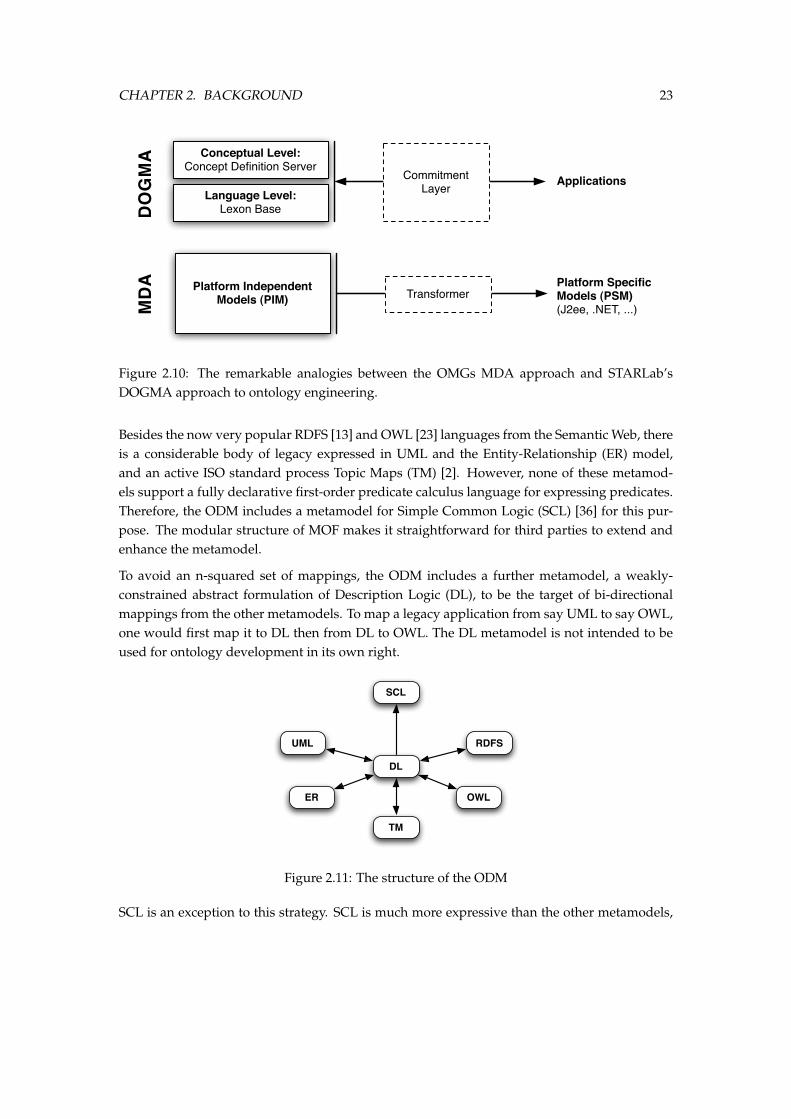
mapping ct) to their appropriate concept definition. (Inspired by [20]) . . . . . . 142.5 The Semantic Web layers . . . . . . . . . . . . . . . . . . . . . . . . . . . . . . . . . 152.6 An RDF example. . . . . . . . . . . . . . . . . . . . . . . . . . . . . . . . . . . . . . 172.7 An RDF-Schema example. . . . . . . . . . . . . . . . . . . . . . . . . . . . . . . . . 182.8 The Onion Model. . . . . . . . . . . . . . . . . . . . . . . . . . . . . . . . . . . . . 202.9 Illustration of the 4-layers of the OMGs Model Driven Architecture . . . . . . . . 222.10 The remarkable analogies between the OMGs MDA approach and STARLab’s
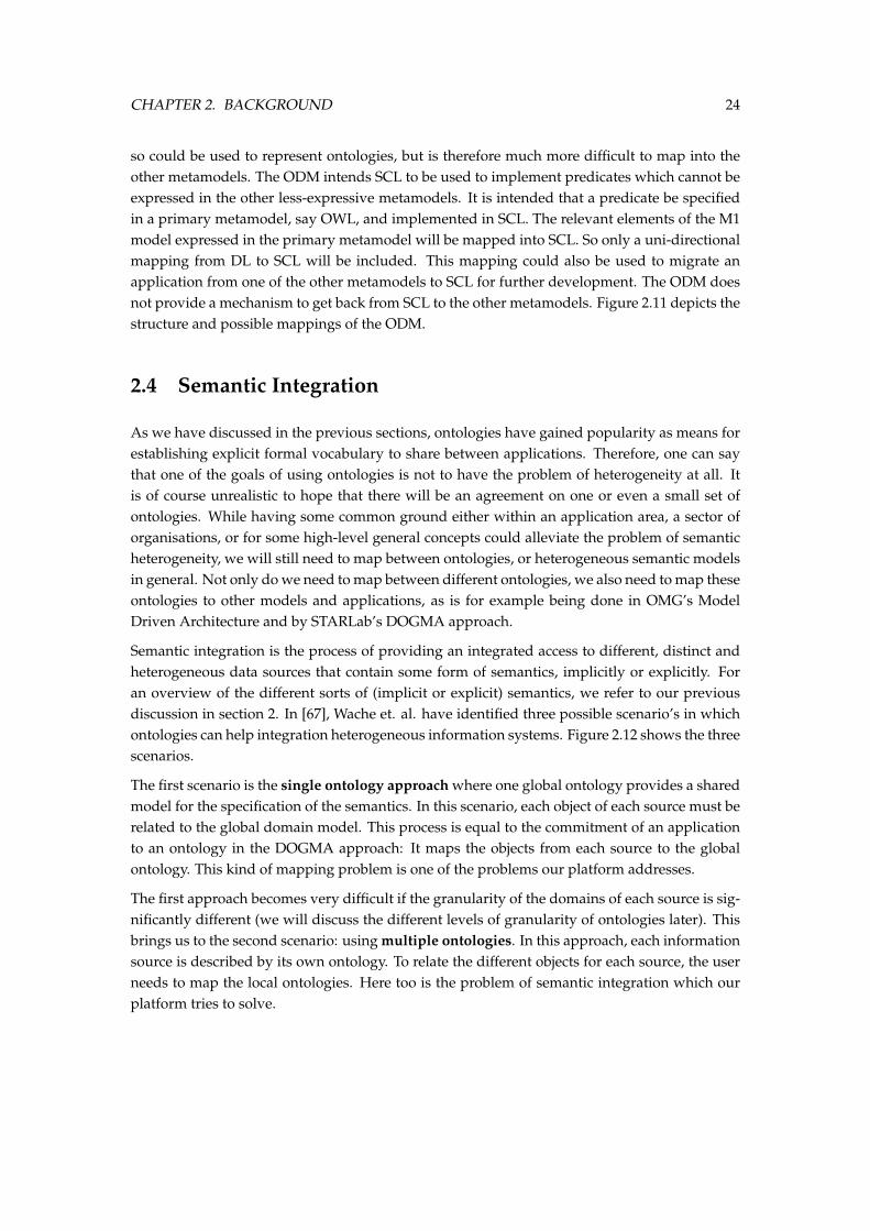
DOGMA approach to ontology engineering. . . . . . . . . . . . . . . . . . . . . . 232.11 The structure of the ODM . . . . . . . . . . . . . . . . . . . . . . . . . . . . . . . . 232.12 Three possible approaches for integrating heterogeneous sources using ontologies. 252.13 The three dimensions of heterogeneity at the conceptual level, reproduced from
[12] . . . . . . . . . . . . . . . . . . . . . . . . . . . . . . . . . . . . . . . . . . . . . 272.14 The Match Operator . . . . . . . . . . . . . . . . . . . . . . . . . . . . . . . . . . . 282.15 Matching typology, based on [59] and [62] . . . . . . . . . . . . . . . . . . . . . . . 292.16 Semantic Intensity Spectrum, reproduced from [38] . . . . . . . . . . . . . . . . . 312.17 Structure Awareness . . . . . . . . . . . . . . . . . . . . . . . . . . . . . . . . . . . 322.18 The alignment process . . . . . . . . . . . . . . . . . . . . . . . . . . . . . . . . . . 33
3.1 The Match Operator by [59] (left) and the Alignment Process by [12] (right) . . . . 363.2 A high-level view, from top to bottom, of Dogma’s ontology engineering ap-
proach, OMGs model driven architecture paradigm, and on the bottom, our ap-proach to semantic integration, our mapping platform. . . . . . . . . . . . . . . . 39
3.3 An example of committing a conceptual mapping to an application specific align-ment. In this example, the alignment is an instance of the Alignment API [26]model. . . . . . . . . . . . . . . . . . . . . . . . . . . . . . . . . . . . . . . . . . . . 42
3.4 An example of a community-driven mapping elicitation and creation process. . . 45
iii
LIST OF FIGURES iv
3.5 An example of a communication and negotiation process in which the commu-nity can express its confidence and thrust in the existing mappings. . . . . . . . . 46
3.6 An example of a communication and negotiation process in which the commu-nity can express its confidence and thrust in the existing mappings. . . . . . . . . 48
3.7 Different scenarios in which existing mappings can be reused in Ontology match-ing to create new ones. . . . . . . . . . . . . . . . . . . . . . . . . . . . . . . . . . . 56
3.8 A possible evolution scenario where one model changes and the mappings needto be updated accordingly. . . . . . . . . . . . . . . . . . . . . . . . . . . . . . . . . 58
4.1 The two orthogonal dimensions of separation in our platform architecture . . . . 604.2 The different parts of the remote layer. . . . . . . . . . . . . . . . . . . . . . . . . . 624.3 Different applications from the Client Layer supporting our two-step methodol-
ogy connecting to the Remote Layer. . . . . . . . . . . . . . . . . . . . . . . . . . . 644.4 The different methodological steps of the Mapping Phase. . . . . . . . . . . . . . 654.5 The methodological steps of the Commitment phase and the necessary tool-support. 664.6 The architecture and technology stack of the integration platform implementing
our approach and methodology. . . . . . . . . . . . . . . . . . . . . . . . . . . . . . 684.7 The Entity-Relational Model of the persistent data stored in the PostgreSQL DBMS. 694.8 The patterns and best-practices used in the Database Logic layer. . . . . . . . . . 704.9 The domain Model in UML, implemented using the DTO pattern. . . . . . . . . . 714.10 The Data Access Objects Model interfaces in UML. . . . . . . . . . . . . . . . . . . 724.11 The JPA-specific Data Access Objects Model implementations in UML. . . . . . . 724.12 A sequence diagram showing the Session Facade pattern applied in the Business
Tier. . . . . . . . . . . . . . . . . . . . . . . . . . . . . . . . . . . . . . . . . . . . . . 734.13 A class diagram showing the classes and interfaces from the Business Tier rele-
vant to the Mapping Service. . . . . . . . . . . . . . . . . . . . . . . . . . . . . . . 734.14 A sequence diagram showing the Business Delegate pattern applied in the Busi-
ness Tier. . . . . . . . . . . . . . . . . . . . . . . . . . . . . . . . . . . . . . . . . . . 734.15 The high-level architecture of our mapping Client and its location and role within
our integration platform. . . . . . . . . . . . . . . . . . . . . . . . . . . . . . . . . . 754.16 The domain objects in the Mapping Client Base. . . . . . . . . . . . . . . . . . . . 774.17 The different figures from the Base plugin. . . . . . . . . . . . . . . . . . . . . . . 784.18 The different methodological steps of the Mapping Phase. . . . . . . . . . . . . . 784.19 The traditional Eclipse-workbench with our Mapping Project Navigator. . . . . . 794.20 The traditional Eclpse-workbench with our Mapping Project Navigator. . . . . . 804.21 The Mapping Editor window with the Mappings tab selected. . . . . . . . . . . . . 814.22 A selected mapping in the Mapping Editor with the properties view showing the
Relation Definition assigned to the mapping. . . . . . . . . . . . . . . . . . . . . . 824.23 The Mapping Editor window with the Editor tab selected. . . . . . . . . . . . . . . 834.24 The methodological steps of the Commitment phase and the necessary tool-support. 83
LIST OF FIGURES v
4.25 The perspective enabling the user to commit a meaningful set of mappings to afinal alignment. . . . . . . . . . . . . . . . . . . . . . . . . . . . . . . . . . . . . . . 84
4.26 Importing an RDF Ontology using an import wizard (left). The imported ontol-ogy is now available as a Model with its entities in the Mapping Navigator (right). 86
4.27 The result of opening an Editor View and drag and dropping the two models intothe Editor tab. . . . . . . . . . . . . . . . . . . . . . . . . . . . . . . . . . . . . . . . 87
4.28 Drawing mappings between the entities of both models. . . . . . . . . . . . . . . 884.29 The Mapping tab where the detailed mappings are shown and their properties
can be edited. . . . . . . . . . . . . . . . . . . . . . . . . . . . . . . . . . . . . . . . 884.30 The Selected Mappings tab from the Alignment API Committer plug-in. . . . . . . 894.31 The Alignment Source tab from the Alignment API Committer plug-in. . . . . . . 90
List of Tables
2.1 The SPARQL query result . . . . . . . . . . . . . . . . . . . . . . . . . . . . . . . . 21
3.1 A number of possible model / entity combinations . . . . . . . . . . . . . . . . . 44
vi
List of Definitions
Definition 1 Ontology by Gruber . . . . . . . . . . . . . . . . . . . . . . . . . . . . . . . 9
Definition 2 Ontology by Ushold and Gruninger . . . . . . . . . . . . . . . . . . . . . . 9
Definition 3 Lexon . . . . . . . . . . . . . . . . . . . . . . . . . . . . . . . . . . . . . . . 10
Definition 4 The Lexon Base . . . . . . . . . . . . . . . . . . . . . . . . . . . . . . . . . . 11
Definition 5 Concept Definition Server . . . . . . . . . . . . . . . . . . . . . . . . . . . . 12
Definition 6 Meta-Lexon Base . . . . . . . . . . . . . . . . . . . . . . . . . . . . . . . . . 13
Definition 7 Alignment Process by Bouquet et. al. [12] . . . . . . . . . . . . . . . . . . . 33
Definition 8 Entity Model . . . . . . . . . . . . . . . . . . . . . . . . . . . . . . . . . . . 50
Definition 9 Entity . . . . . . . . . . . . . . . . . . . . . . . . . . . . . . . . . . . . . . . . 50
Definition 10 Community . . . . . . . . . . . . . . . . . . . . . . . . . . . . . . . . . . . . 51
Definition 11 Context . . . . . . . . . . . . . . . . . . . . . . . . . . . . . . . . . . . . . . 51
Definition 12 Mapping Element . . . . . . . . . . . . . . . . . . . . . . . . . . . . . . . . 52
Definition 13 Relation Articulation . . . . . . . . . . . . . . . . . . . . . . . . . . . . . . . 53
Definition 14 Relation Definition . . . . . . . . . . . . . . . . . . . . . . . . . . . . . . . . 54
vii
1Introduction
In our so-called information society we constantly demand and require access to available andhigh-quality information. This information is stored in all corners of our society, be it on theWorld Wide Web, in government agencies, in public libraries, in the information systems ofcompanies or implicitly in the computer programs we use. These information sources are storedand maintained by different stakeholders, and are heterogeneous and distributed by nature.However, as the need for high-quality information continues to grow, the need to integrate theseenormous amounts of distributed and heterogeneous data is becoming ever more important.Furthermore, while these information sources have been developed and deployed with a certainintended use in mind, they may now or in the future be used for very different purposes, forexample:
• for governance, to comply with governmental regulations (e.g. Sarbanes-Oxley);
• for intelligence, to be able to make well-informed decisions (e.g. Business Intelligence);
• for engineering new kinds of systems (e.g. context-aware and mobile applications).
1.1 Problem Statement and Motivation
The need to integrate heterogeneous and distributed data sources and models is a problem thatis faced in almost any area of computer science. Since long, a lot of research has been done
1
CHAPTER 1. INTRODUCTION 2
to allow us to cope with the enormous overflow of information around us. However, in ourever more connected society, the needs for information integration have shifted. Nowadays,a much more dynamic, adaptive and agile approach is needed to support the rapidly chang-ing requirements of the different stakeholders. Within enterprises, existing solutions like data-warehousing are no longer sufficient for the real-time and extended enterprise. These trendshave led enterprises to increasingly adopt a Service Oriented Architecture (SOA) to addressthe agile and dynamic nature of our society. However, while such an architecture does enableefficient application integration, it does not provide an efficient and scalable way to integrateinformation. The same trends can be witnessed in the general software engineering field: Moreand more systems are developed using a model-driven approach in order to cope with the fastchanging requirements and (un)intended use of these systems. Furthermore, the recent trendtowards and acceptance of the need for collaboration and what is often referred to as ”TheWisdom of Crowds”[65] and ”Collective Intelligence”1 have led us to believe new approachesshould be explored to address the increased need for information integration.
We believe that more research is needed to explore these new techniques and trends in orderto address the increased and changed integration needs. Our earlier experience with seman-tic integration frameworks, algorithms, and methodologies has helped us to identify certainshortcomings in existing approaches. More specifically, the lack of a scalable methodology andplatform that enables the integration of a very large amount of heterogeneous data sources bya very large number of stakeholders made us question the efficiency and effectiveness of theseapproaches for real-world scenarios, now and in the future. The lack of support for collabora-tion and evolution in existing works has furthermore motivated us to propose a novel approachand methodology for data integration.
1.2 Proposed Solution
Given our previous experience with semantic integration frameworks and our interest in thepower of collaboration between a large number of actors and communities has led us to thisthesis in which we ask ourselves if and how we can address the shortcomings of previouswork. Therefore, we propose and present in this thesis an integration approach that adoptsa uniform, context-aware and collaborative methodology enabling efficient reuse to come to ascalable integration platform.
1.2.1 Research Questions & Objectives
In this thesis we ask ourselves the following questions which are also the objectives we want totackle:
1”Collective intelligence is the capacity of human communities to evolve towards higher order complexity and harmony, throughsuch innovation mechanisms as differentiation and integration, competition and collaboration.” [55]
CHAPTER 1. INTRODUCTION 3
1. What kinds of information heterogeneity exist and where does this heterogeneity comefrom?
2. What is the existing work on integration methodologies, algorithms and frameworks?
3. Can we propose a methodology based on the notions of collaboration, context-awarenessand reuse to attain a scalable integration approach?
4. What would the advantages and disadvantages of such an approach be?
5. Can we develop an platform that implements and support this methodology?
These five questions define the scope of this thesis.
1.2.2 Research Methodology
To answer these research questions and reach our objectives we took a methodological ap-proach. These are the steps we followed:
1. start a literature study on the origin of heterogeneity, the role of semantics and ontologies,and the existing work on information integration;
2. propose a solution by presenting our methodology with its specific and distinct propertiesand advantages;
3. construct a platform that implements this methodology and do a preliminary evaluationof this platform.
1.3 Outline of this Thesis
The outline of this thesis closely follows our research methodology:
Chapter 2: Background This chapter gives an introduction to semantics in general, the Seman-tic Web and the OMG’s model-driven-architecture initiative. Furthermore it discusses thedifferent types of heterogeneity, the terminology used in the literature on semantic in-tegration and the different methodologies, algorithms and frameworks that have beenproposed in the current literature.
Chapter 3: Approach & Methodology In this chapter we present our methodology and ap-proach for a scalable and collaborative integration process. We propose our two-stepmethodology and discuss the specific and distinct properties of this approach. Next, wepresent the reader with the semantics of the elements used in our methodology. We con-clude this chapter by reviewing the advantages our methodology brings to the integrationprocess.
CHAPTER 1. INTRODUCTION 4
Chapter 4: The Platform In chapter 4 we present the integration platform implementing themethodology and conceptual framework we proposed in the previous chapter. We discusshow we have mapped our two-step methodology on the platform and discuss the twolayers of the platform, the remote and client layer, in more detail. We conclude this chapterwith a preliminary evaluation of the platform and show how it can be used to integratetwo ontologies using our proposed methodology.
Chapter 5: Conclusions Chapter 5 is the last and final chapter that concludes the main contri-butions of this thesis by discussing the research questions and answers. Based on the workin the previous chapters a number of issues are discussed and a number of opportunitiesfor future research are highlighted.
2Background
In this chapter, we give an introduction to semantics in general, the Semantic Web and theOMG’s model-driven-architecture initiative. Furthermore we discuss the different types ofheterogeneity, the terminology on semantic integration used in the literature and the differentmethodologies, algorithms and frameworks that have been proposed in existing works.
2.1 Semantics
Semantics is usually defined as the study of meaning. Depending on the field in which it is used,a more restricted definition may be used. For example, in linguistics, semantics is often definedas the study of the meaning of words. On the other hand, in computer science semantics usuallyrefers to the meaning of programs or functions. We will use the broader definition throughout thisthesis.
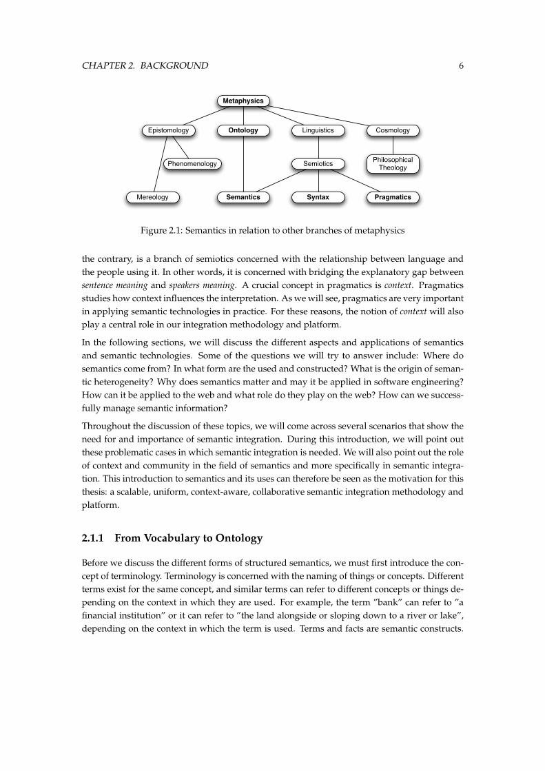
It is interesting to mention two terms that are related to semantics: Syntax and Pragmatics. Thethree find themselves adjacent to each other in the domain of metaphysics which is the branchof philosophy concerned with explaining the nature of reality, being, and the world. Figure 2.1depicts the different branches in metaphysics. Syntax, as a philosophical study, is concernedwith first-order logic, or how to construct very basic grammars. In linguistics, syntax refersto the rules that make op the structure of the sentence. In computer science, syntax may referto the structure and grammar of the language in which programs are written. Pragmatics, on
5
CHAPTER 2. BACKGROUND 6
Metaphysics
Epistomology Ontology Linguistics Cosmology
Phenomenology
Mereology Semantics
Semiotics
Syntax
Philosophical Theology
Pragmatics
Figure 2.1: Semantics in relation to other branches of metaphysics
the contrary, is a branch of semiotics concerned with the relationship between language andthe people using it. In other words, it is concerned with bridging the explanatory gap betweensentence meaning and speakers meaning. A crucial concept in pragmatics is context. Pragmaticsstudies how context influences the interpretation. As we will see, pragmatics are very importantin applying semantic technologies in practice. For these reasons, the notion of context will alsoplay a central role in our integration methodology and platform.
In the following sections, we will discuss the different aspects and applications of semanticsand semantic technologies. Some of the questions we will try to answer include: Where dosemantics come from? In what form are the used and constructed? What is the origin of seman-tic heterogeneity? Why does semantics matter and may it be applied in software engineering?How can it be applied to the web and what role do they play on the web? How can we success-fully manage semantic information?
Throughout the discussion of these topics, we will come across several scenarios that show theneed for and importance of semantic integration. During this introduction, we will point outthese problematic cases in which semantic integration is needed. We will also point out the roleof context and community in the field of semantics and more specifically in semantic integra-tion. This introduction to semantics and its uses can therefore be seen as the motivation for thisthesis: a scalable, uniform, context-aware, collaborative semantic integration methodology andplatform.
2.1.1 From Vocabulary to Ontology
Before we discuss the different forms of structured semantics, we must first introduce the con-cept of terminology. Terminology is concerned with the naming of things or concepts. Differentterms exist for the same concept, and similar terms can refer to different concepts or things de-pending on the context in which they are used. For example, the term ”bank” can refer to ”afinancial institution” or it can refer to ”the land alongside or sloping down to a river or lake”,depending on the context in which the term is used. Terms and facts are semantic constructs.
CHAPTER 2. BACKGROUND 7
They are meant to have meaning that is shared by anyone who uses them. Unless producersand consumers of information agree, the information will be meaningless.
Semantic information comes in various forms. The first distinction can be made between un-structured and structured information. Every unstructured form of data has a form of seman-tics attached to it, albeit implicitly in the human interpretation of this data. In structured orsemi-structured data sources, the form of semantics attached to this data range form implicitto explicit as the expressiveness and complexity of the data increases. The simplest and mostused form of structured semantics is as a vocabulary which is simply an agreement on terms.The most complex form of semantics are found in ontologies which allow relations betweenconcepts and tries to conceptualize the world. We will now give a brief overview of the differ-ent forms of semantics, from their simplest form as vocabularies to their most complex form asontologies.
Vocabulary
A Vocabulary is the set of symbols to which a given language has ascribed a shared meaning.Each community (in the sense of ”a group of people”) creates its own vocabulary. On the highestlevel, the group of people speaking the same language have created a vocabulary for that lan-guage (note however that in average each of us understands only between 2% and 4% of the vo-cabulary we supposedly share [47]). Underneath the language level, several sub-communitiescreate their own vocabulary on top of this. For example, each industry traditionally has its ownvocabulary. Similarly, each business within this industry typically creates its own vocabularywhich is added to the vocabulary of its industry.
Communities have several techniques to construct new vocabularies [47]:
1. Overloading of common words: Different communities can overload existing words andgive them a special meaning specific to that community. This is a large source of misun-derstanding between communities and creates a lot of the integration problems we ad-dress in this thesis. Similar terms that have a different meaning are called homonyms. Letsillustrate this with an example. Take the term ”router”. Depending on the community, thisterm means: A device that carves rounded edges on molding for woodworkers, a personwho lays out a circuit board in the electronics industry, an electronic device that dispatchespackets in the data communications industry, and a person who stocks vending machinesin the snack food industry.
The problem of homonyms is where pragmatics and more specifically context comes in toplay. The context in which a term is used is crucial to be able to infer to which concept orthing the term refers. As we will see, in most of the existing semantic technologies, thenotion of context does not exist, at least not explicitly.
2. Creating new words: To reduce the number of overloaded words, communities also cre-ate new words to denote community-specific concepts. Created words come in different
CHAPTER 2. BACKGROUND 8
forms, many are acronyms, some are technical terms, some are borrowed from foreignlanguages, etc. Interestingly, many technical terms are borrowed from dead languagessuch as Greek and Latin. This trend is also community-dependent, for example, in themedical and law domain many terms come from Latin, while in the computer sciencedomain many acronyms are used.
3. Nonword identifiers: A technique that is typically seen in industries is the use of nonwordidentifiers. In industry and company-specific vocabularies, many concepts or things arereferred to by an identifier. This technique is used more in small communities. For ex-ample, companies often refer to their products using the product identifiers. Only whenthese concepts are widely used outside the company will they become more commonlyused.
4. Compounds: Another tricky area is the use of compounds. Compounds are two or moreexisting words combined to create a new meaning. Similarly to the technique of over-loading existing words, this can create the illusion of understanding where there is none.The problem, both for humans and for systems attempting to interpret language, is de-termining when a phrase is really a word or, more correctly, determining when severalwords together stand for one semantic thought[47]. For example, a ”claim check” appearsto mean ”review of a claim”, but it actually means ”a piece of paper that lets you retrieveyour property”. For a more detailed treatment of this subject, we refer to [61].
A traditional way to specify vocabularies and their meanings is through definitions. A commu-nity may create a glossary to define the terms in a vocabulary and how they will be used in aparticular system. However, there are several issues with capturing semantics using only defi-nitions [47]: First, glossaries may suffer from ”design time” artefacts: A design time artefact isone that is used while the system is being developed but generally ignored by users and main-tainers of the system. Secondly, the glossary may suffer because it is created by inexperiencedworkers. Third, the glossary may suffer for the same reason that more general-purpose glos-saries fall short. Glossaries and vocabularies are not designed to distinguish or group closelyrelated concepts; they are designed to ”define”. As a result, most are full of ambiguity andoverlap. In effect, this leaves much of the defining to the reader.
Taxonomy
A taxonomy is the next step from vocabulary towards more explicit and formal semantics. It isa form of organized vocabulary. It is generally composed of a hierarchical parent-child classifi-cation.
CHAPTER 2. BACKGROUND 9
Ontology
The notion of ontology was first used in the field of Philosophy. The term Ontology (with anuppercase ’O’) was later used by AI practitioners 1. Ontologies are becoming increasingly pop-ular in the domain of computer science. Recently they have been moving from the realm ofAI-laboratories to the desktops of knowledge experts and are now one of the fundaments of theSemantic Web.
Several definitions have been proposed in literature 2. One of the most cited definitions of anontology is defined by Gruber [32]
Definition 1 (Ontology by Gruber) :An ontology is a specification of a shared conceptualization.
Another, closely related definition by Ushold and Gruninger in [66] is:
Definition 2 (Ontology by Ushold and Gruninger) :Ontologies are agreements about shared conceptualizations
The latter definition is less strict: In this definition, ontologies and conceptualisations are keptclearly distinct. An ontology in this sense is not a specification of a conceptualisations, it is a(possibly incomplete) agreement about a conceptualisation [63].
Concept
Symbol Thingstands for
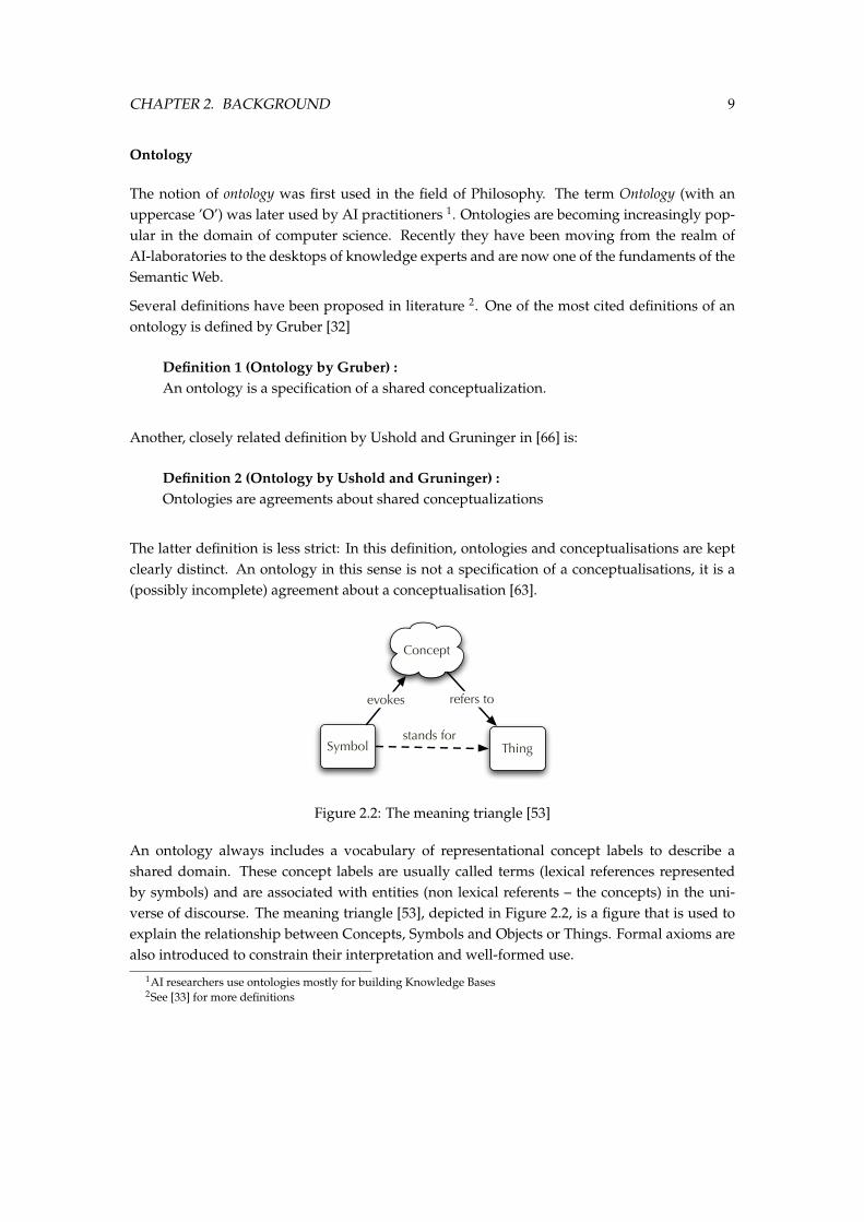
evokes refers to
Figure 2.2: The meaning triangle [53]
An ontology always includes a vocabulary of representational concept labels to describe ashared domain. These concept labels are usually called terms (lexical references representedby symbols) and are associated with entities (non lexical referents – the concepts) in the uni-verse of discourse. The meaning triangle [53], depicted in Figure 2.2, is a figure that is used toexplain the relationship between Concepts, Symbols and Objects or Things. Formal axioms arealso introduced to constrain their interpretation and well-formed use.
1AI researchers use ontologies mostly for building Knowledge Bases2See [33] for more definitions
CHAPTER 2. BACKGROUND 10
An ontology is in principle a formalisation of a shared understanding of a domain that is agreedupon by a number of agents [63]. In order for this domain knowledge to be shared amongstagents, they must have a shared understanding of the domain and therefore, agreement mustexist on the topics about which to communicate. This raises the issue of ontological commitmentwhich Gruber [32] describes as ”the agreements about the objects and relations being talked aboutamong agents”. In other words, in order to facilitate meaningful communication, an agent mustcommit to the semantics of the terms and relationships in the common ontology [56]. Thisincludes axioms about properties of objects and how they are related, also called the semanticrelationships of the ontology.
2.1.2 The Dogma Approach
DOGMA3 is a research initiative of VUB STARLab where various theories, methods, and toolsfor ontology engineering are studied and prototypes developed. Our description of the DOGMAframework has been inspired by several previous papers such as [10, 58, 63, 17, 21]. A full for-malisation of DOGMA can be found in De Leenheer, Meersman, and de Moor [20, 19].
The DOGMA approach to ontology engineering aims to satisfy real world needs by developinga useful and scalable ontology engineering approach. A DOGMA ontology is inspired by a clas-sical model-theoretic perspective [60] and articulates an ontology in two distinct layers. This iscalled the principle of double articulation [64]. DOGMA is a representation model and frameworkthat separates the specification of the conceptualisation (i.e. the lexical representation of conceptsand their interrelationships, see the ontology definitions 1 and 2) from its axiomatisation (i.e. thesemantic constraints).
In DOGMA’s double articulation principle, an ontology is decomposed into a lexon base and acommitment layer
The Lexon Base
The Lexon Base is an uninterpreted, extensive, and reusable pool of elementary building blocksfor constructing an ontology [18]. These building blocks are defined as Lexons, formalised indefinition 3.
Definition 3 (Lexon) :A lexon is an ordered 5-tuple of the form < γ, ζ, t1, r1, r2, t2 > with γ ∈ Γ, ζ ∈ Z, t1 ∈ T ,t2 ∈ T , r1 ∈ R and r2 ∈ R. Where:
• T and R are sets of strings;
• t1 is called the head-term of the lexon and t2 is called the tail-term of the lexon;3Developing Ontology-Grounded Methods for Applications
CHAPTER 2. BACKGROUND 11
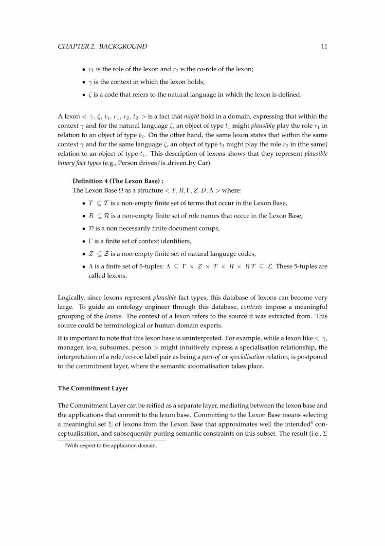
• r1 is the role of the lexon and r2 is the co-role of the lexon;
• γ is the context in which the lexon holds;
• ζ is a code that refers to the natural language in which the lexon is defined.
A lexon < γ, ζ, t1, r1, r2, t2 > is a fact that might hold in a domain, expressing that within thecontext γ and for the natural language ζ, an object of type t1 might plausibly play the role r1 inrelation to an object of type t2. On the other hand, the same lexon states that within the samecontext γ and for the same language ζ, an object of type t2 might play the role r2 in (the same)relation to an object of type t1. This description of lexons shows that they represent plausiblebinary fact types (e.g., Person drives/is driven by Car).
Definition 4 (The Lexon Base) :The Lexon Base Ω as a structure < T, R,Γ, Z,D,Λ > where:
• T ⊆ T is a non-empty finite set of terms that occur in the Lexon Base,
• R ⊆ R is a non-empty finite set of role names that occur in the Lexon Base,
• D is a non necessarily finite document corups,
• Γ is a finite set of context identifiers,
• Z ⊆ Z is a non-empty finite set of natural language codes,
• Λ is a finite set of 5-tuples: Λ ⊆ Γ × Z × T × R × R T ⊆ L. These 5-tuples arecalled lexons.
Logically, since lexons represent plausible fact types, this database of lexons can become verylarge. To guide an ontology engineer through this database, contexts impose a meaningfulgrouping of the lexons. The context of a lexon refers to the source it was extracted from. Thissource could be terminological or human domain experts.
It is important to note that this lexon base is uninterpreted. For example, while a lexon like < γ,manager, is-a, subsumes, person > might intuitively express a specialisation relationship, theinterpretation of a role/co-roe label pair as being a part-of or specialisation relation, is postponedto the commitment layer, where the semantic axiomatisation takes place.
The Commitment Layer
The Commitment Layer can be reified as a separate layer, mediating between the lexon base andthe applications that commit to the lexon base. Committing to the Lexon Base means selectinga meaningful set Σ of lexons from the Lexon Base that approximates well the intended4 con-ceptualisation, and subsequently putting semantic constraints on this subset. The result (i.e., Σ
4With respect to the application domain.
CHAPTER 2. BACKGROUND 12
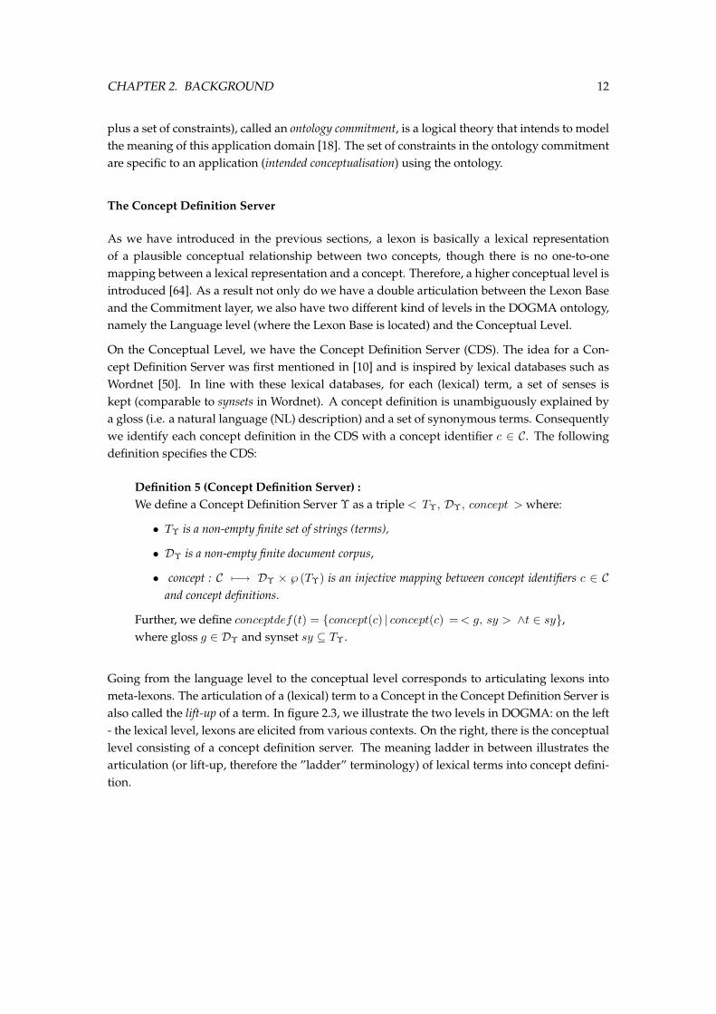
plus a set of constraints), called an ontology commitment, is a logical theory that intends to modelthe meaning of this application domain [18]. The set of constraints in the ontology commitmentare specific to an application (intended conceptualisation) using the ontology.
The Concept Definition Server
As we have introduced in the previous sections, a lexon is basically a lexical representationof a plausible conceptual relationship between two concepts, though there is no one-to-onemapping between a lexical representation and a concept. Therefore, a higher conceptual level isintroduced [64]. As a result not only do we have a double articulation between the Lexon Baseand the Commitment layer, we also have two different kind of levels in the DOGMA ontology,namely the Language level (where the Lexon Base is located) and the Conceptual Level.
On the Conceptual Level, we have the Concept Definition Server (CDS). The idea for a Con-cept Definition Server was first mentioned in [10] and is inspired by lexical databases such asWordnet [50]. In line with these lexical databases, for each (lexical) term, a set of senses iskept (comparable to synsets in Wordnet). A concept definition is unambiguously explained bya gloss (i.e. a natural language (NL) description) and a set of synonymous terms. Consequentlywe identify each concept definition in the CDS with a concept identifier c ∈ C. The followingdefinition specifies the CDS:
Definition 5 (Concept Definition Server) :We define a Concept Definition Server Υ as a triple < TΥ, DΥ, concept > where:
• TΥ is a non-empty finite set of strings (terms),
• DΥ is a non-empty finite document corpus,
• concept : C 7−→ DΥ × ℘ (TΥ) is an injective mapping between concept identifiers c ∈ Cand concept definitions.
Further, we define conceptdef(t) = concept(c) | concept(c) = < g, sy > ∧t ∈ sy,where gloss g ∈ DΥ and synset sy ⊆ TΥ.
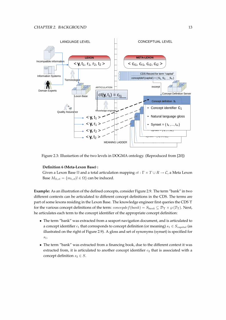
Going from the language level to the conceptual level corresponds to articulating lexons intometa-lexons. The articulation of a (lexical) term to a Concept in the Concept Definition Server isalso called the lift-up of a term. In figure 2.3, we illustrate the two levels in DOGMA: on the left- the lexical level, lexons are elicited from various contexts. On the right, there is the conceptuallevel consisting of a concept definition server. The meaning ladder in between illustrates thearticulation (or lift-up, therefore the ”ladder” terminology) of lexical terms into concept defini-tion.
CHAPTER 2. BACKGROUND 13
Concept definition s i
• Concept identifier c 1
• Natural language gloss
• Synset = tk ,..., tm
Concept definition s i
• Concept identifier c 1
• Natural language gloss
• Synset = tk ,..., tm
Concept definition s i
• Concept identifier c 1
• Natural language gloss
• Synset = tk ,..., tm
Terminologist
LANGUAGE LEVEL CONCEPTUAL LEVEL
Information Systems
Incompatible information < γγγγ, , , , t1, r1, r2, t2 >
< γγγγ, , , , t1 >< γγγγ, , , , r1 >
< γγγγ, , , , t2 >
< ct1, cr1, cr2, ct2 >
Concept definition si
• Concept identifier c1
• Natural language gloss
• Synset = tk ,..., tm
MEANING LADDER
LEXON META-LEXON
Concept Definition Server
Quality Assurance
Lexon Base
Domain Experts
Knowledge engineer
excerpt
ct(γγγγ, , , , t1) = ct1
ARTICULATION
< γγγγ, , , , r2 >
CDS Record for term “capital”
conceptdef (capital) = s1, s2, ....,sn
Figure 2.3: Illustartion of the two levels in DOGMA ontology. (Reproduced from [20])
Definition 6 (Meta-Lexon Base) :Given a Lexon Base Ω and a total articulation mapping ct : Γ × T ∪ R → C, a Meta LexonBase MΩ,ct = ml,ct|l ∈ Ω can be induced.
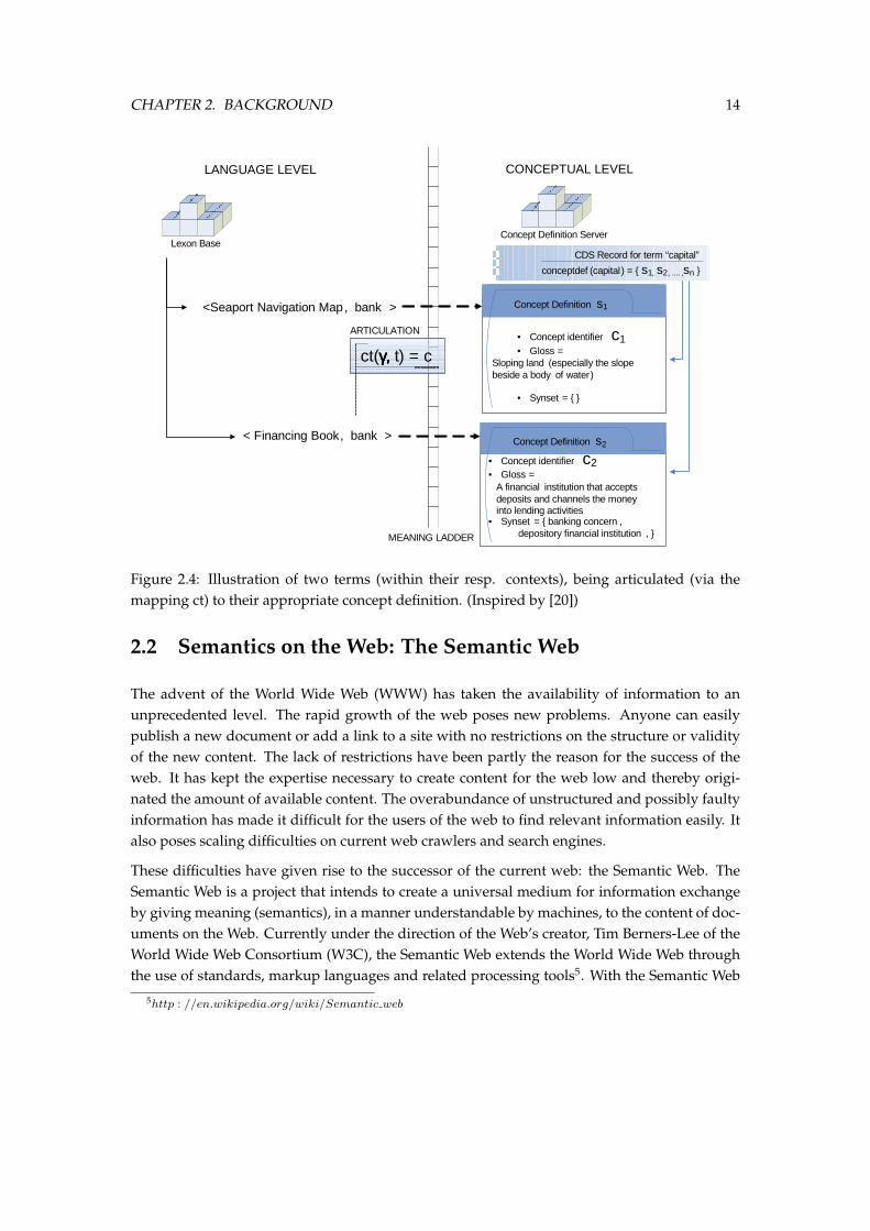
Example: As an illustration of the defined concepts, consider Figure 2.9. The term ”bank” in twodifferent contexts can be articulated to different concept definitions in the CDS. The terms arepart of some lexons residing in the Lexon Base. The knowledge engineer first queries the CDS Υfor the various concept definitions of the term: concepdef(bank) = Sbank ⊆ DΥ × ℘ (TΥ). Next,he articulates each term to the concept identifier of the appropriate concept definition:
• The term ”bank” was extracted from a seaport navigation document, and is articulated toa concept identifier c1 that corresponds to concept definition (or meaning) s1 ∈ Scapital (asillustrated on the right of Figure 2.9). A gloss and set of synonyms (synset) is specified fors1.
• The term ”bank” was extracted from a financing book, due to the different context it wasextracted from, it is articulated to another concept identifier c2 that is associated with aconcept definition s2 ∈ S.
CHAPTER 2. BACKGROUND 14
LANGUAGE LEVEL CONCEPTUAL LEVEL
<Seaport Navigation Map, bank > Concept Definition s1
• Concept identifier c1• Gloss =
• Synset =
MEANING LADDER
Concept Definition ServerLexon Base
CDS Record for term “capital”
conceptdef (capital) = s1, s2, .... ,sn
ct(γγγγ, , , , t) = c
ARTICULATION
< Financing Book, bank >
Sloping land (especially the slope beside a body of water)
Concept Definition s2
• Concept identifier c2• Gloss =
• Synset = banking concern ,depository financial institution ,
A financial institution that accepts deposits and channels the money into lending activities
Figure 2.4: Illustration of two terms (within their resp. contexts), being articulated (via themapping ct) to their appropriate concept definition. (Inspired by [20])
2.2 Semantics on the Web: The Semantic Web
The advent of the World Wide Web (WWW) has taken the availability of information to anunprecedented level. The rapid growth of the web poses new problems. Anyone can easilypublish a new document or add a link to a site with no restrictions on the structure or validityof the new content. The lack of restrictions have been partly the reason for the success of theweb. It has kept the expertise necessary to create content for the web low and thereby origi-nated the amount of available content. The overabundance of unstructured and possibly faultyinformation has made it difficult for the users of the web to find relevant information easily. Italso poses scaling difficulties on current web crawlers and search engines.
These difficulties have given rise to the successor of the current web: the Semantic Web. TheSemantic Web is a project that intends to create a universal medium for information exchangeby giving meaning (semantics), in a manner understandable by machines, to the content of doc-uments on the Web. Currently under the direction of the Web’s creator, Tim Berners-Lee of theWorld Wide Web Consortium (W3C), the Semantic Web extends the World Wide Web throughthe use of standards, markup languages and related processing tools5. With the Semantic Web
5http : //en.wikipedia.org/wiki/Semantic web
CHAPTER 2. BACKGROUND 15
we not only receive more exact results when searching for information, but also know when wecan integrate information from different sources, know what information to compare, and canprovide all kinds of automated services in different domains from future home appliances anddigital libraries to electronic business and health services[8].
2.2.1 The Semantic Web Technology Stack
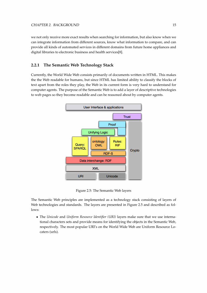
Currently, the World Wide Web consists primarily of documents written in HTML. This makesthe the Web readable for humans, but since HTML has limited ability to classify the blocks oftext apart from the roles they play, the Web in its current form is very hard to understand forcomputer agents. The purpose of the Semantic Web is to add a layer of descriptive technologiesto web pages so they become readable and can be reasoned about by computer agents.
Figure 2.5: The Semantic Web layers
The Semantic Web principles are implemented as a technology stack consisting of layers ofWeb technologies and standards. The layers are presented in Figure 2.5 and described as fol-lows:
• The Unicode and Uniform Resource Identifier (URI) layers make sure that we use interna-tional characters sets and provide means for identifying the objects in the Semantic Web,respectively. The most popular URI’s on the World Wide Web are Uniform Resource Lo-caters (urls).
CHAPTER 2. BACKGROUND 16
• The XML layer with namespace and schema definitions enables the integration of the Seman-tic Web definitions with the other XML based standards. XML provides a surface syntaxfor structured documents, but imposes no semantic constraints on the meaning of thesedocumentes. XML Schema is a language for restricting the structure of XML documents.
• The ontology layer supports the evolution of vocabularies as it can define relations betweenthe different concepts. The structure is simple: knowledge is expressed as descriptivestatements, stating some relationship exists between one thing and another. The tech-nologies to represent that structure are already in place6:
– The Resource Description Framework (RDF) is a simple data model for referring toobjects (”resources”) and their relations to each other. An RDF-based model can berepresented in XML syntax classes or in n3-notation.
– RDF Schema is a vocabulary for describing properties and classes of RDF resources,with a semantics for generalization-hierarchies of such properties and classes.
– The Web Ontology Language (OWL) adds more vocabulary for describing propertiesand classes: among others, relations between classes (e.g. disjointness), cardinality(e.g. ”exactly one”), equality, richer typing of properties, characteristics of properties(e.g. symmetry), and enumerated classes.
– SPARQL [57] is a query language for RDF and is a W3C candidate recommendationsince 2006. It has a similar syntax as the well-known SQL but operates on triplesinstead of on relational tables.
– Early 2005, the W3C formed the Rule Interchange Format (RIF) working group7 withthe task of standardizing the rules that propel data across the Web, regardless offormat. RIF will provide a way to allow rules written for one application to be pub-lished, shared, merged and re-used in other applications and by other rule engines.
• The top layers Logic, Proof and Trust, are currently being researched and simple applica-tion demonstrations are being constructed. The Logic layer enables the writing of ruleswhile the Proof layer executes the rules and evaluates together with the Trust layer mech-anism for applications whether to trust the given proof or not.
RDF
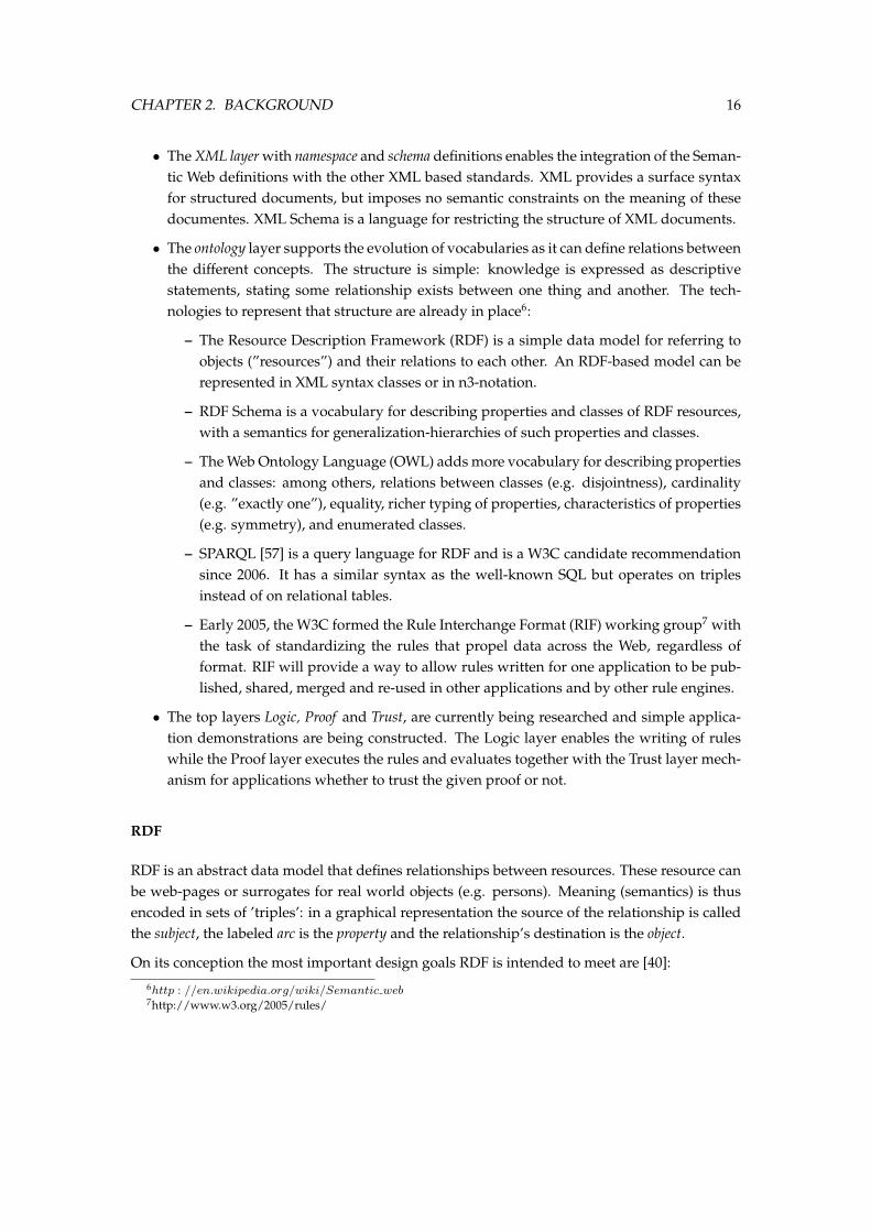
RDF is an abstract data model that defines relationships between resources. These resource canbe web-pages or surrogates for real world objects (e.g. persons). Meaning (semantics) is thusencoded in sets of ’triples’: in a graphical representation the source of the relationship is calledthe subject, the labeled arc is the property and the relationship’s destination is the object.
On its conception the most important design goals RDF is intended to meet are [40]:
6http : //en.wikipedia.org/wiki/Semantic web7http://www.w3.org/2005/rules/
CHAPTER 2. BACKGROUND 17
http://www.felixvandemaele.net
Felix Van de Maele
DC: Creator
Felix' Blog
DC: Creator
Figure 2.6: An RDF example.
• A simple data model. RDF has a simple data model that is easy for applications to processand manipulate. Note that the term “model” used here has a completely different sensethan that in the term “model theory”, where a model is a satisfying interpretation [34].
• Formal Semantics and Inference. Because the Semantic Web is all about machine processablecontent, RDF has a formal semantics which provides a dependable basis for reasoningabout the meaning of an RDF expression and allow inferencing.
• Extensible URI-based vocabulary. Based on URI it allows for naming all kinds of things inRDF. Besides the URIs there is one other kind of value that appears in RDF data which isa literal.
• Anyone can make statements about any resource.
In the RDF data model we distinguish between resources, which are objects represented by URIs,and literals which are strings. These resources may be related to each other or to literal valuesvia properties. Such a relationship may also be considered as a resource, which makes it possibleto make statements about statements.
The Dublin Core is one standard for a set of descriptors (such as the title, publisher, subjects,etc.) that are used to catalog a wide range of networked resources, such as digitized text docu-ments, photographs and audiovisual media. The following is an RDF example that makes useof The Dublin Core8.
<rdf:RDF>
<rdf:Description rdf:href=Ohttp://www.felixvandemaele.netO>
<dc:Creator>Felix Van de Maele</dc:Creator>
<dc:Title>Felix’ Blog</dc:Title>
</rdf:Description>
</rdf:RDF>
Figure 2.6 gives a graphical representation of this example. For more details about RDF we referto [42].
8http://www.dublincore.org/
CHAPTER 2. BACKGROUND 18
application specific schema and namespace
application specific actual data
RDF/RDFS representation vocabulary
rdfs:Resource
Chateau Cheval BlancMerlot
rdfs:Class rdfs:Property
ww:Wine
ww:Red-Wine ww:White-Wine
ww:Grape
S S
TT
S S
ww:madeWith
TR
D
ww:name
T
ww:madeWithhttp://www.foograpes.com/Merlot
http://www.chateau-cheval-blanc.com
ww:name ww:name
S: subClassOfR: rangeD: domainT: instanceOf
Figure 2.7: An RDF-Schema example.
RDFS
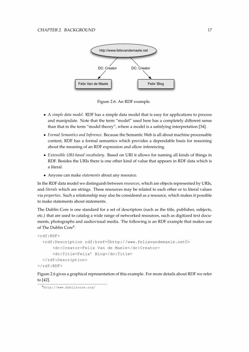
RDF-Schema is an RDF application that introduces an extensible type system to RDF. WithRDFS we can define class hierarchies and domain and range restrictions for properties.
Figure 2.7 shows an example ontology (wine-world) modeled with RDFS9.
• The most general class is rdf:Resource, which has two subclasses rdfs:Class andrdf:property. When specifying a domain specific schema for RDF(S), the classes andproperties defined in this schema will become instances of these two resources.
• The resource rdfs:Class denotes the set of all classes in an object-oriented sense. Thismeans that the classes ww:Grape and ww:Wine are instances of the meta-class rdfs:Class.
• Likewise, each property defined in an application specific RDFS is an instance of rdf:Property(e.g. ww:madeWith).
• RDFS provides rdfs:subClassOf, which is a special property, that defines the subclassrelationship between classes. Likewise there is rdfs:subPropertyOf that defines a hierar-chy of properties.
9The figure falsely indicates that Chateau Cheval Blanc consists entirely of Merlot. Correct would be an encepage-ment of 50% Cabernet Franc and 50% Merlot [46].
CHAPTER 2. BACKGROUND 19
• RDFS allows to define domain and range restrictions associated with properties. In ourexample only ww:Wines can only be made with ww:Grapes.
The following is a simple illustration of the RDFS syntax. It declares three classes. The classes”red wine” and ”white wine” are declared to be subclasses of the class ”wine”.
<rdf:RDF xmlns:rdf="http://www.w3.org/1999/02/22-rdf-syntax-ns#"
xmlns:rdfs="http://www.w3.org/2000/01/rdf-schema#"
xml:base="http://www.wine-world.uto/wines">
<rdfs:Class rdf:ID="wine" />
<rdfs:Class rdf:ID="red wine">
<rdfs:subClassOf rdf:resource="#wine" />
</rdfs:Class>
<rdfs:Class rdf:ID="white wine">
<rdfs:subClassOf rdf:resource="#wine" />
</rdfs:Class>
</rdf:RDF>
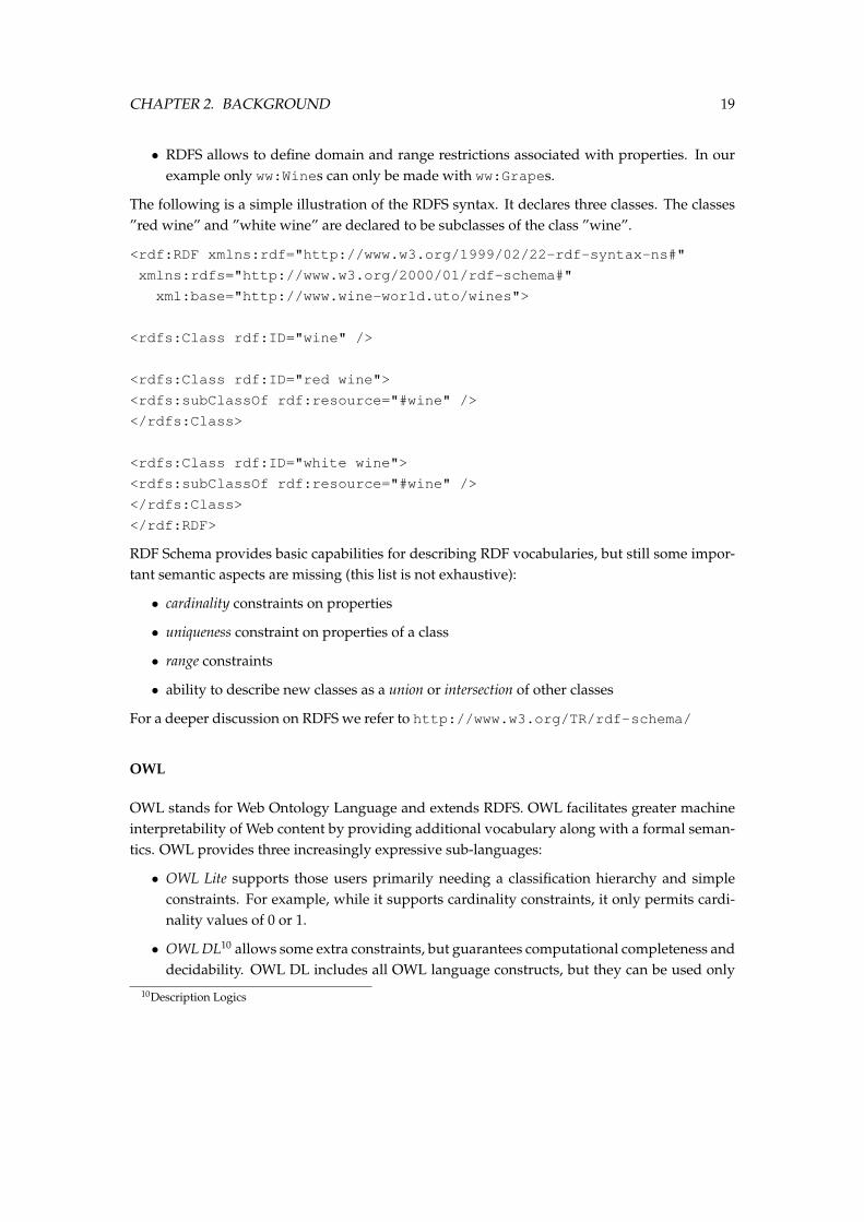
RDF Schema provides basic capabilities for describing RDF vocabularies, but still some impor-tant semantic aspects are missing (this list is not exhaustive):
• cardinality constraints on properties
• uniqueness constraint on properties of a class
• range constraints
• ability to describe new classes as a union or intersection of other classes
For a deeper discussion on RDFS we refer to http://www.w3.org/TR/rdf-schema/
OWL
OWL stands for Web Ontology Language and extends RDFS. OWL facilitates greater machineinterpretability of Web content by providing additional vocabulary along with a formal seman-tics. OWL provides three increasingly expressive sub-languages:
• OWL Lite supports those users primarily needing a classification hierarchy and simpleconstraints. For example, while it supports cardinality constraints, it only permits cardi-nality values of 0 or 1.
• OWL DL10 allows some extra constraints, but guarantees computational completeness anddecidability. OWL DL includes all OWL language constructs, but they can be used only
10Description Logics
CHAPTER 2. BACKGROUND 20
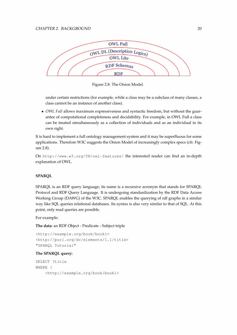
Figure 2.8: The Onion Model.
under certain restrictions (for example, while a class may be a subclass of many classes, aclass cannot be an instance of another class).
• OWL Full allows maximum expressiveness and syntactic freedom, but without the guar-antee of computational completeness and decidability. For example, in OWL Full a classcan be treated simultaneously as a collection of individuals and as an individual in itsown right.
It is hard to implement a full ontology management system and it may be superfluous for someapplications. Therefore W3C suggests the Onion Model of increasingly complex specs (cfr. Fig-ure 2.8).
On http://www.w3.org/TR/owl-features/ the interested reader can find an in-depthexplanation of OWL.
SPARQL
SPARQL is an RDF query language; its name is a recursive acronym that stands for SPARQLProtocol and RDF Query Language. It is undergoing standardization by the RDF Data AccessWorking Group (DAWG) of the W3C. SPARQL enables the querying of rdf graphs in a similarway like SQL queries relational databases. Its syntax is also very similar to that of SQL. At thispoint, only read queries are possible.
For example:
The data: an RDF Object - Predicate - Subject triple
<http://example.org/book/book1>
<http://purl.org/dc/elements/1.1/title>
"SPARQL Tutorial"
The SPARQL query:
SELECT ?title
WHERE
<http://example.org/book/book1>
CHAPTER 2. BACKGROUND 21
<http://purl.org/dc/elements/1.1/title>
?title .
The result:
title”SPARQL Tutorial”
Table 2.1: The SPARQL query result
2.3 Semantics in Software Engineering
2.3.1 The OMGs Model Driven Architecture
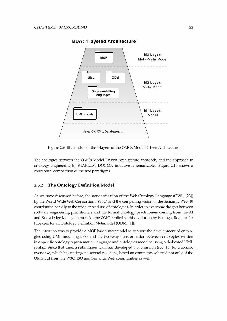
The Object Management Group (OMG), a standardization consortium for various aspects ofsoftware engineering including the well-established Unified Modeling Language (UML, [4])has introduced, not so long ago, the Model Driven Architecture (MDA, [14]) paradigm. Thisapproach has the ability to create (using metamodeling) a family of languages [25] that aredefined in a similar way as UML.
Since the definition of UML, there has been a new wave of proposals at the OMG which is ev-idence of a new era and a new vision. At the center of this vision is the Meta-Object Facility(MOF, [3]), a unique and self-defined meta-meta-model. It acts as a framework to define anduse meta-models [28, 16]. The need for MOF resulted from the fact that UML was only oneof the meta-models in the software development landscape. Because of the risk posed by thepresence of a variety of different, incompatible meta-models being defined and evolving in-dependently (data warehouse, workflow, software process, etc.) there was an urgent need fora global integration framework for all the meta-models in the software development industry[9].
The MDA defines an approach whereby you can separate the system functionality specifica-tion from its implementation on any specific technology platform. That way you can have anarchitecture that will be language, vendor and middleware neutral. For creating MDA-basedapplications, the first step will be to create a Platform Independent Model (PIM), which youshould express in UML. Such a PIM can then be mapped to a Platform Specific Model (PSM)to target platforms like the CORBA Component Model (CCM), Enterprise JavaBeans (EJB) orMicrosoft Transaction Server (MTS). Standard mappings should allow tools to automate someof the conversion. Such a PSM, again expressed in UML, can then be actually implemented onthat particular platform.
CHAPTER 2. BACKGROUND 22
MOFM3 Layer:
Meta-Meta Model
UML ODMM2 Layer:
Meta Model
UML modelsUML modelsUML modelsUML models
Java, C#, XML, Databases, ....
MDA: 4 layered Architecture
M1 Layer:Model
Ohter modelling languages
Figure 2.9: Illustration of the 4-layers of the OMGs Model Driven Architecture
The analogies between the OMGs Model Driven Architecture approach, and the approach toontology engineering by STARLab’s DOGMA initiative is remarkable. Figure 2.10 shows aconceptual comparison of the two paradigms.
2.3.2 The Ontology Definition Model
As we have discussed before, the standardization of the Web Ontology Language (OWL, [23])by the World Wide Web Consortium (W3C) and the compelling vision of the Semantic Web [8]contributed heavily to the wide-spread use of ontologies. In order to overcome the gap betweensoftware engineering practitioners and the formal ontology practitioners coming from the AIand Knowledge Management field, the OMG replied to this evolution by issuing a Request forProposal for an Ontology Definition Metamodel (ODM, [1]).
The intention was to provide a MOF based metamodel to support the development of ontolo-gies using UML modeling tools and the two-way transformation between ontologies writtenin a specific ontology representation language and ontologies modeled using a dedicated UMLsyntax. Since that time, a submission team has developed a submission (see [15] for a conciseoverview) which has undergone several revisions, based on comments solicited not only of theOMG but from the W3C, ISO and Semantic Web communities as well.
CHAPTER 2. BACKGROUND 23
Conceptual Level:Concept Definition Server
Language Level:Lexon Base
ApplicationsCommitment Layer
Platform Independent Models (PIM)
Platform Specific Models (PSM)(J2ee, .NET, ...)
Transformer
DO
GM
AM
DA
Figure 2.10: The remarkable analogies between the OMGs MDA approach and STARLab’sDOGMA approach to ontology engineering.
Besides the now very popular RDFS [13] and OWL [23] languages from the Semantic Web, thereis a considerable body of legacy expressed in UML and the Entity-Relationship (ER) model,and an active ISO standard process Topic Maps (TM) [2]. However, none of these metamod-els support a fully declarative first-order predicate calculus language for expressing predicates.Therefore, the ODM includes a metamodel for Simple Common Logic (SCL) [36] for this pur-pose. The modular structure of MOF makes it straightforward for third parties to extend andenhance the metamodel.
To avoid an n-squared set of mappings, the ODM includes a further metamodel, a weakly-constrained abstract formulation of Description Logic (DL), to be the target of bi-directionalmappings from the other metamodels. To map a legacy application from say UML to say OWL,one would first map it to DL then from DL to OWL. The DL metamodel is not intended to beused for ontology development in its own right.
RDFS
OWL
DL
SCL
UML
ER
TM
Figure 2.11: The structure of the ODM
SCL is an exception to this strategy. SCL is much more expressive than the other metamodels,
CHAPTER 2. BACKGROUND 24
so could be used to represent ontologies, but is therefore much more difficult to map into theother metamodels. The ODM intends SCL to be used to implement predicates which cannot beexpressed in the other less-expressive metamodels. It is intended that a predicate be specifiedin a primary metamodel, say OWL, and implemented in SCL. The relevant elements of the M1model expressed in the primary metamodel will be mapped into SCL. So only a uni-directionalmapping from DL to SCL will be included. This mapping could also be used to migrate anapplication from one of the other metamodels to SCL for further development. The ODM doesnot provide a mechanism to get back from SCL to the other metamodels. Figure 2.11 depicts thestructure and possible mappings of the ODM.
2.4 Semantic Integration
As we have discussed in the previous sections, ontologies have gained popularity as means forestablishing explicit formal vocabulary to share between applications. Therefore, one can saythat one of the goals of using ontologies is not to have the problem of heterogeneity at all. Itis of course unrealistic to hope that there will be an agreement on one or even a small set ofontologies. While having some common ground either within an application area, a sector oforganisations, or for some high-level general concepts could alleviate the problem of semanticheterogeneity, we will still need to map between ontologies, or heterogeneous semantic modelsin general. Not only do we need to map between different ontologies, we also need to map theseontologies to other models and applications, as is for example being done in OMG’s ModelDriven Architecture and by STARLab’s DOGMA approach.
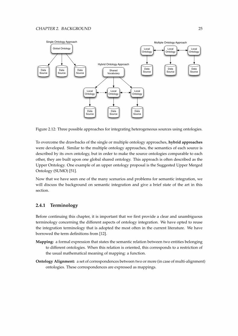
Semantic integration is the process of providing an integrated access to different, distinct andheterogeneous data sources that contain some form of semantics, implicitly or explicitly. Foran overview of the different sorts of (implicit or explicit) semantics, we refer to our previousdiscussion in section 2. In [67], Wache et. al. have identified three possible scenario’s in whichontologies can help integration heterogeneous information systems. Figure 2.12 shows the threescenarios.
The first scenario is the single ontology approach where one global ontology provides a sharedmodel for the specification of the semantics. In this scenario, each object of each source must berelated to the global domain model. This process is equal to the commitment of an applicationto an ontology in the DOGMA approach: It maps the objects from each source to the globalontology. This kind of mapping problem is one of the problems our platform addresses.
The first approach becomes very difficult if the granularity of the domains of each source is sig-nificantly different (we will discuss the different levels of granularity of ontologies later). Thisbrings us to the second scenario: using multiple ontologies. In this approach, each informationsource is described by its own ontology. To relate the different objects for each source, the userneeds to map the local ontologies. Here too is the problem of semantic integration which ourplatform tries to solve.
CHAPTER 2. BACKGROUND 25
Global Ontology
Data Source
Data Source
Data Source
Local Ontology
Local Ontology
Local Ontology
Data Source
Data Source
Data Source
Local Ontology
Local Ontology
Local Ontology
Data Source
Data Source
Data Source
Shared Vocabulary
Single Ontology Approach Multiple Ontology Approach
Hybrid Ontology Approach
Figure 2.12: Three possible approaches for integrating heterogeneous sources using ontologies.
To overcome the drawbacks of the single or multiple ontology approaches, hybrid approacheswere developed. Similar to the multiple ontology approaches, the semantics of each source isdescribed by its own ontology, but in order to make the source ontologies comparable to eachother, they are built upon one global shared ontology. This approach is often described as theUpper Ontology. One example of an upper ontology proposal is the Suggested Upper MergedOntology (SUMO) [51].
Now that we have seen one of the many scenarios and problems for semantic integration, wewill discuss the background on semantic integration and give a brief state of the art in thissection.
2.4.1 Terminology
Before continuing this chapter, it is important that we first provide a clear and unambiguousterminology concerning the different aspects of ontology integration. We have opted to reusethe integration terminology that is adopted the most often in the current literature. We haveborrowed the term definitions from [12].
Mapping: a formal expression that states the semantic relation between two entities belongingto different ontologies. When this relation is oriented, this corresponds to a restriction ofthe usual mathematical meaning of mapping: a function.
Ontology Alignment: a set of correspondences between two or more (in case of multi-alignment)ontologies. These correspondences are expressed as mappings.
CHAPTER 2. BACKGROUND 26
Ontology Coordination: broadest term that applies whenever knowledge from two or moreontologies must be used at the same time in a meaningful way (e.g. to achieve a singlegoal).
Ontology Transformation: a general term for referring to any process which leads to a newontology o′ from an ontology o by using a transformation function t.
Ontology Merging: the creation of a new ontology om from two (possibly overlapping) sourceontologies o′ and o′′. This concept is closely related to that of integration in the databasecommunity.
Ontology Reconciliation: a process that harmonizes the content of two (or more) ontologies,typically requiring changes on one of the two sides or even on both sides.
Meaning Negotiation: the protocol through which two agents (either human or artificial) agreeon the changes required to reconciliate their ontologies.
2.4.2 Semantic Heterogeneity
In the distributed and open systems that is IT today, heterogeneity can not be avoided. Differentactors have different interests and habits, use different tools, and use knowledge at differentlevels of detail. These various reasons for heterogeneity lead to different forms of heterogeneitythat are considered below.
Heterogeneity may occur at many different levels, and a detailed list of all the forms of possiblemismatches is beyond the scope of this document. We refer to [31, 7, 39, 37] for a more completediscussion on this matter. However, for the sake of the definition of our conceptual framework,we provide a classification into four main levels, based on [12].
The syntactic level
At the syntactic level, we encounter all forms of heterogeneity that depend on the choice ofthe representation format. Indeed, the semantic models come in several formats (UML, RDF,OWL, DB-Schema, ...), and each of them is based on a different syntax. In this thesis, we are notstrongly concerned about the syntactic level. In general, transformations on the syntactic levelare well understood in the computer science domain (e.g. XSLT).
The terminological level
The terminological level addresses all forms of mismatches that are related to the process ofnaming the entities (e.g. individuals, classes, properties, relations) that occur in models. Nam-ing is the process of associating a linguistic object from a public language (or vocabulary – the
CHAPTER 2. BACKGROUND 27
one that is used to exchange information with other parties) to entities described in the ontol-ogy. In section 2.1.1 we have addressed how communities come up with new vocabularies,namely by (i) overloading common words, (ii) creating new words, (iii) non-word identifiersand (iv) compounds. This results in typical terminological mismatches:
• different words are used to name the same entity: synonyms;
• the same word is used to name different entities: polysemy and homonyms;
• words from different languages are used to name entities;
• syntactical variations of the same word (different spelling, abbreviations, prefixes andsuffixes, etc.).
These terminological mismatches may occur in situations where the models or entities are con-ceptually equivalent. While mismatches at the terminological level are not as deep as thoseoccurring at the conceptual level (see below), they are very common and real in most cases andtherefore this level is just as important as the other one.
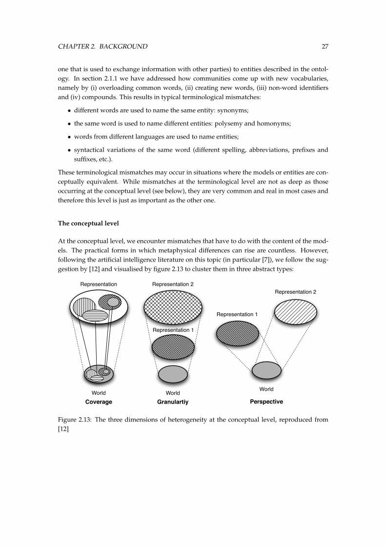
The conceptual level
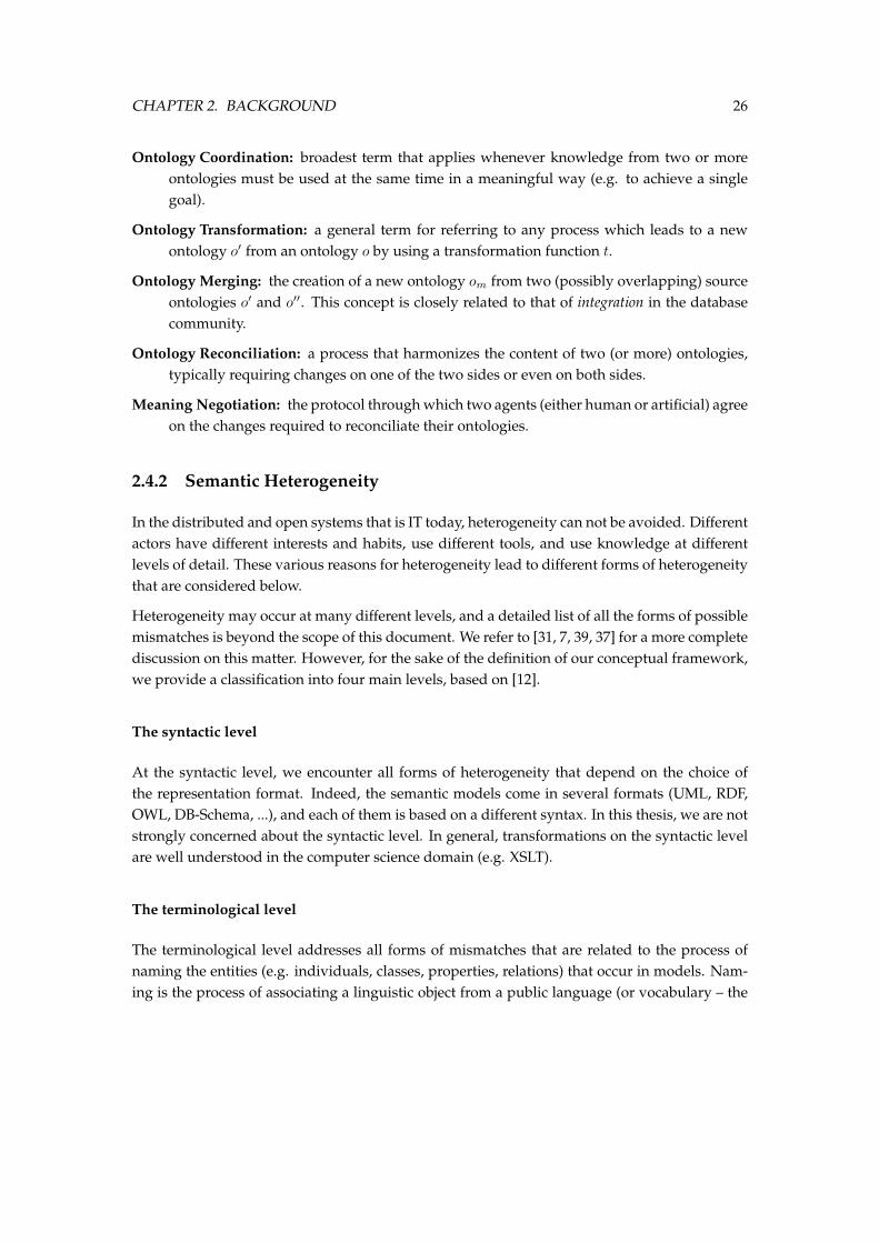
At the conceptual level, we encounter mismatches that have to do with the content of the mod-els. The practical forms in which metaphysical differences can rise are countless. However,following the artificial intelligence literature on this topic (in particular [7]), we follow the sug-gestion by [12] and visualised by figure 2.13 to cluster them in three abstract types:
Representation
WorldCoverage
Representation 2
WorldGranulartiy
Representation 1
World
Perspective
Representation 2
Representation 1
Figure 2.13: The three dimensions of heterogeneity at the conceptual level, reproduced from[12]
CHAPTER 2. BACKGROUND 28
Coverage : an ontology may differ from another as they cover different portions - possiblyoverlapping - of the world or domain. For example, an ontology on planes may containproperties of fighter jets while another ontology might only cover passenger planes.
Granularity : an ontology may differ from another as the first provides a more (or less) detaileddescription of the same entities. For example, an ontology concerned with accountingand taxes, or delivery, would only consider the generic concept of document, while anontology for libraries or scholars would distinguish between types of documents.
Perspective : an ontology may provide a viewpoint on some domain which is different fromthe viewpoint adopted in another ontology. For example, two ontologies may representthe same domain at the same level of coverage and granularity, but as different points intime (which means that the same property can hold at the time when the first ontologywas designed and do not hold at the time when the other was designed.
2.4.3 Ontology Matching
Schema matching has become a much debated topic in today’s research agenda, especially withthe advent of the Semantic Web. Its roots, however, can be found in the database literature ofthe eighties. Due to the widespread importance of integration and matching, many disparatecommunities have tackled this problem.
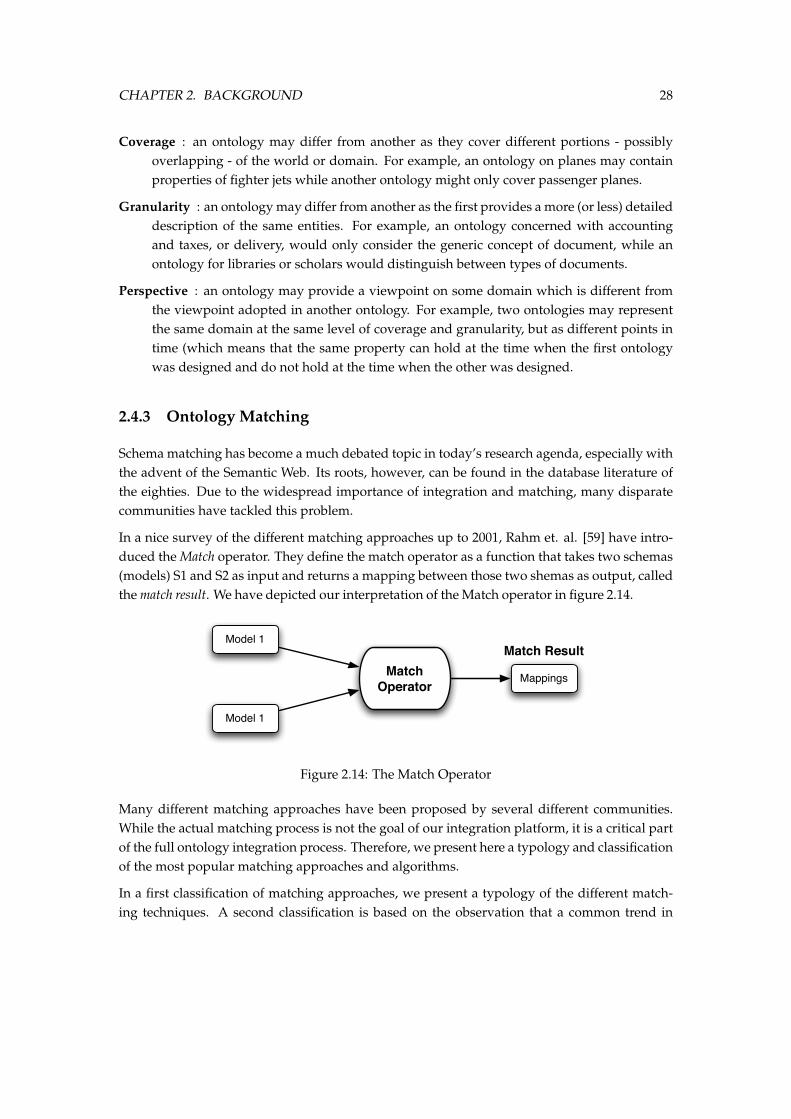
In a nice survey of the different matching approaches up to 2001, Rahm et. al. [59] have intro-duced the Match operator. They define the match operator as a function that takes two schemas(models) S1 and S2 as input and returns a mapping between those two shemas as output, calledthe match result. We have depicted our interpretation of the Match operator in figure 2.14.
Match Operator
Model 1
Model 1
Mappings
Match Result
Figure 2.14: The Match Operator
Many different matching approaches have been proposed by several different communities.While the actual matching process is not the goal of our integration platform, it is a critical partof the full ontology integration process. Therefore, we present here a typology and classificationof the most popular matching approaches and algorithms.
In a first classification of matching approaches, we present a typology of the different match-ing techniques. A second classification is based on the observation that a common trend in
CHAPTER 2. BACKGROUND 29
semantic integration is to progress from semantically-poor to semantically-rich solutions ([38]).This classification, described in [38], ranks the different techniques along a semantic intensityspectrum.
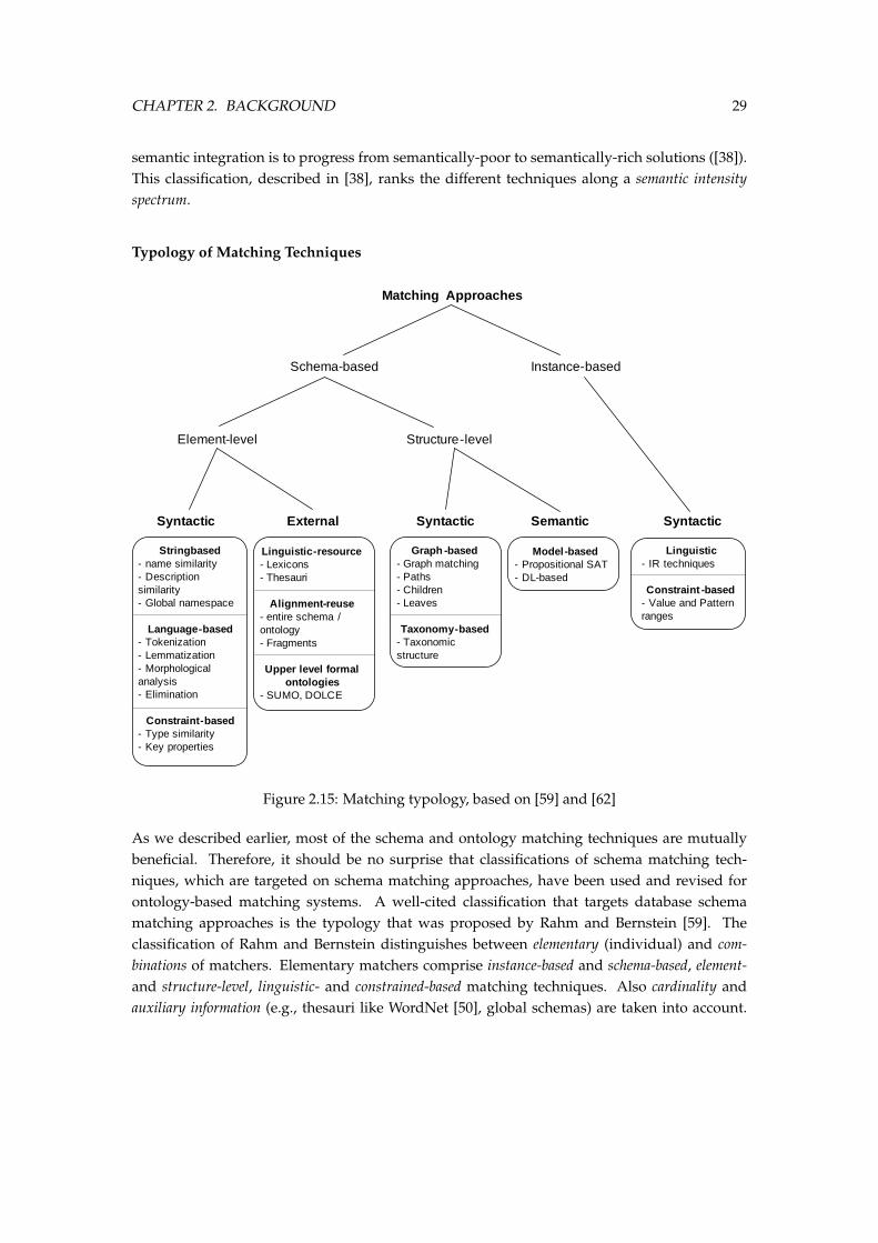
Typology of Matching Techniques
Matching Approaches
Schema-based Instance-based
Element-level Structure-level
Syntactic External Syntactic Semantic Syntactic
Stringbased- name similarity- Description similarity- Global namespace
Language-based- Tokenization- Lemmatization- Morphological analysis- Elimination
Constraint-based- Type similarity- Key properties
Linguistic-resource- Lexicons- Thesauri
Alignment-reuse- entire schema / ontology- Fragments
Upper level formal ontologies
- SUMO, DOLCE
Graph -based- Graph matching- Paths- Children- Leaves
Taxonomy-based- Taxonomic structure
Model-based- Propositional SAT- DL-based
Linguistic- IR techniques
Constraint -based- Value and Pattern ranges
Figure 2.15: Matching typology, based on [59] and [62]
As we described earlier, most of the schema and ontology matching techniques are mutuallybeneficial. Therefore, it should be no surprise that classifications of schema matching tech-niques, which are targeted on schema matching approaches, have been used and revised forontology-based matching systems. A well-cited classification that targets database schemamatching approaches is the typology that was proposed by Rahm and Bernstein [59]. Theclassification of Rahm and Bernstein distinguishes between elementary (individual) and com-binations of matchers. Elementary matchers comprise instance-based and schema-based, element-and structure-level, linguistic- and constrained-based matching techniques. Also cardinality andauxiliary information (e.g., thesauri like WordNet [50], global schemas) are taken into account.
CHAPTER 2. BACKGROUND 30
This typology has been used and revised by Shvaiko and Euzenat in [62]. In their revision, theyhave introduced two synthetic classifications: a Granularity/Input Interpretation classification isbased on (i) the granularity of a match, i.e., element- or structure-level, and then (ii) on howthe techniques generally interpret the input information. The second classification is the Kind ofInput which is concerned with the type of input considered by a particular technique.
The resulting typology can be seen in Figure 2.15.
Element-level vs Structure level Two alternatives can be distinguished for the granularity ofa match: element-level and structure-level matching. This criterium was first introducedin [59]: ”For each element of the first schema, element-level matching determines the matchingelements in the second input schema. [...] Structure-level matching, on the other hand, refers tomatching combinations of elements that appear together in a structure.
Syntatic vs external vs semantic This criteria is the Input Interpretation classification proposedby Shvaiko and Euzenat in [62]: ”The key characteristics of the syntactic techniques is thatthey interpret the input in function of its sole structure following some clearly stated algorithm.External are the techniques exploiting auxiliary (external) resources of a domain and commonknowledge in order to interpret the input. These resources might be human input or some thesaurusexpressing the relationships between terms. The key characteristic of the semantic techniques is thatthey use some formal semantics (e.g. model-theoretic semantics) to interpret the input and justifytheir results. In case of semantic based matching system, exact algorithms are complete.”
Semantic Intensity Spectrum
Another interesting classification is described in [38]. This classification is based on the observa-tion that a common trend for DB and AI semantic integration practitioners is to progress fromsemantically-poor to semantically-rich solutions. This metaphor of semantic richness is usedto classify works from both communities along a semantic intensity spectrum. Along this spec-trum are several interim points to address string similarity, structure, context, extension andintension awareness as different layers of semantic intensity (see Figure 2.16).
This classification is interesting for us as, in general, semantically-rich solutions are more com-plex then semantically-poor solutions.
We will now give an overview of the different interim points on the spectrum, based on [38].We refer to the full text ([38]) for a complete and detailed discussion.
String similarity , occupying the semantically-poor end of the spectrum, compares names ofelements from different semantic models. These techniques consider strings as sequencesof letters in an alphabet. They are typically based on the following assumption: The moresimilar the strings of the concepts or nodes, that is, the syntactic similarity, the highertheir semantic similarity. Usually, the string is first normalized, then token-based distancefunctions are used to map the pair of strings to a real number. Some examples of such
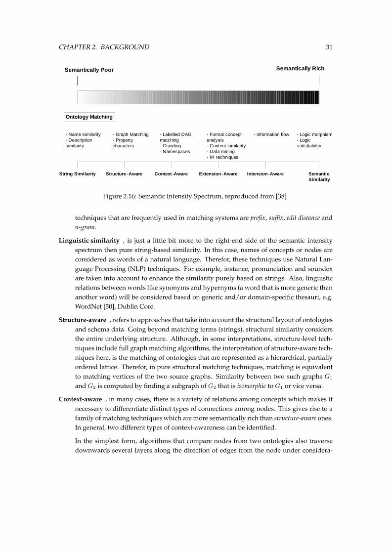
CHAPTER 2. BACKGROUND 31
Semantically Poor Semantically Rich
Ontology Matching
String Similarity Structure -Aware Context -Aware Extension -Aware Intension-Aware Semantic Similarity
- Name similarity- Description similarity
- Graph Matching- Property characters
- Labelled DAG matching- Crawling- Namespaces
- Formal concept analysis- Content similarity- Data mining- IR techniques
- information flow - Logic morphism- Logic satisfiability
Figure 2.16: Semantic Intensity Spectrum, reproduced from [38]
techniques that are frequently used in matching systems are prefix, suffix, edit distance andn-gram.
Linguistic similarity , is just a little bit more to the right-end side of the semantic intensityspectrum then pure string-based similarity. In this case, names of concepts or nodes areconsidered as words of a natural language. Therefor, these techniques use Natural Lan-guage Processing (NLP) techniques. For example, instance, pronunciation and soundexare taken into account to enhance the similarity purely based on strings. Also, linguisticrelations between words like synonyms and hypernyms (a word that is more generic thananother word) will be considered based on generic and/or domain-specific thesauri, e.g.WordNet [50], Dublin Core.
Structure-aware , refers to approaches that take into account the structural layout of ontologiesand schema data. Going beyond matching terms (strings), structural similarity considersthe entire underlying structure. Although, in some interpretations, structure-level tech-niques include full graph matching algorithms, the interpretation of structure-aware tech-niques here, is the matching of ontologies that are represented as a hierarchical, partiallyordered lattice. Therefor, in pure structural matching techniques, matching is equivalentto matching vertices of the two source graphs. Similarity between two such graphs G1
and G2 is computed by finding a subgraph of G2 that is isomorphic to G1 or vice versa.
Context-aware , in many cases, there is a variety of relations among concepts which makes itnecessary to differentiate distinct types of connections among nodes. This gives rise to afamily of matching techniques which are more semantically rich than structure-aware ones.In general, two different types of context-awareness can be identified.
In the simplest form, algorithms that compare nodes from two ontologies also traversedownwards several layers along the direction of edges from the node under considera-
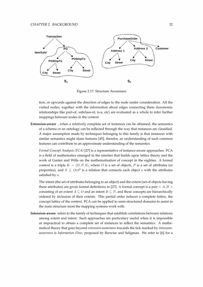
CHAPTER 2. BACKGROUND 32
Transaction
ItemSoldPO
POShipTo
City Street
POShipTo
City Street
PurchaseOrder
Address 1
City Street
Address 2
City Street
Customer
S1 S2
Figure 2.17: Structure Awareness
tion, or upwards against the direction of edges to the node under consideration. All thevisited nodes, together with the information about edges connecting them (taxonomicrelationships like part-of, subclass-of, is-a, etc) are evaluated as a whole to infer furthermappings between nodes in the context.
Extension-aware , when a relatively complete set of instances can be obtained, the semanticsof a schema or an ontology can be reflected through the way that instances are classified.A major assumption made by techniques belonging to this family is that instances withsimilar semantics might share features [45], therefor, an understanding of such commonfeatures can contribute to an approximate understanding of the semantics.
Formal Concept Analysis (FCA) [27] is a representative of instance-aware approaches. FCAis a field of mathematics emerged in the nineties that builds upon lattice theory and thework of Ganter and Wille on the mathematisation of concept in the eighties. A formalcontext is a triple K = (O, P, S), where O is a set of objects, P is a set of attributes (orproperties), and S ⊆ OxP is a relation that connects each object o with the attributessatisfied by o.
The intent (the set of attributes belonging to an object) and the extent (set of objects havingthese attributes) are given formal definitions in [27]. A formal concept is a pair < A,B >
consisting of an extent A ⊆ O and an intent B ⊆ P , and these concepts are hierarchicallyordered by inclusion of their extents. This partial order induces a complete lattice, theconcept lattice of the context. FCA can be applied to semi-structured domains to assist inthe main structure most the mapping systems work with.
Intension-aware refers to the family of techniques that establish correlations between relationsamong extent and intent. Such approaches are particulary useful when it is impossibleor impractical to obtain a complete set of instances to reflect the semantics. A mathe-matical theory that goes beyond extension-awareness towards the tick marked by intension-awareness is Information Flow, proposed by Barwise and Seligman. We refer to [6] for a
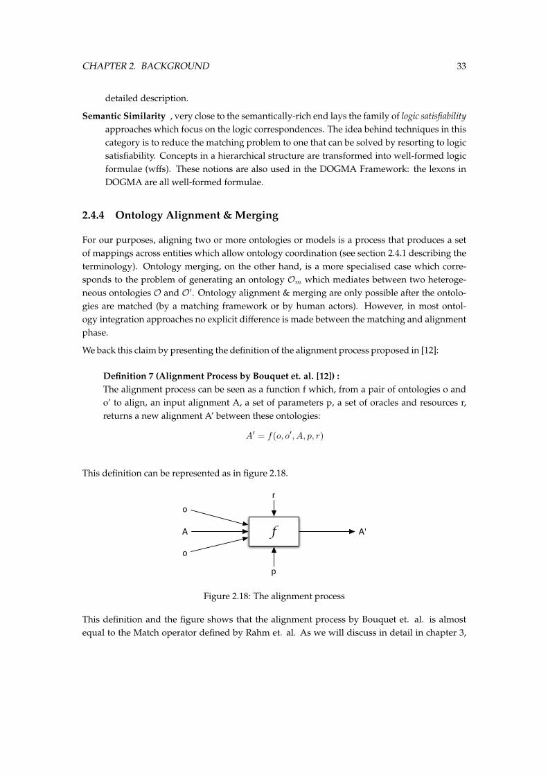
CHAPTER 2. BACKGROUND 33
detailed description.
Semantic Similarity , very close to the semantically-rich end lays the family of logic satisfiabilityapproaches which focus on the logic correspondences. The idea behind techniques in thiscategory is to reduce the matching problem to one that can be solved by resorting to logicsatisfiability. Concepts in a hierarchical structure are transformed into well-formed logicformulae (wffs). These notions are also used in the DOGMA Framework: the lexons inDOGMA are all well-formed formulae.
2.4.4 Ontology Alignment & Merging
For our purposes, aligning two or more ontologies or models is a process that produces a setof mappings across entities which allow ontology coordination (see section 2.4.1 describing theterminology). Ontology merging, on the other hand, is a more specialised case which corre-sponds to the problem of generating an ontology Om which mediates between two heteroge-neous ontologies O and O′. Ontology alignment & merging are only possible after the ontolo-gies are matched (by a matching framework or by human actors). However, in most ontol-ogy integration approaches no explicit difference is made between the matching and alignmentphase.
We back this claim by presenting the definition of the alignment process proposed in [12]:
Definition 7 (Alignment Process by Bouquet et. al. [12]) :The alignment process can be seen as a function f which, from a pair of ontologies o ando’ to align, an input alignment A, a set of parameters p, a set of oracles and resources r,returns a new alignment A’ between these ontologies:
A′ = f(o, o′, A, p, r)
This definition can be represented as in figure 2.18.
f
o
o
A
r
p
A'
Figure 2.18: The alignment process
This definition and the figure shows that the alignment process by Bouquet et. al. is almostequal to the Match operator defined by Rahm et. al. As we will discuss in detail in chapter 3,
CHAPTER 2. BACKGROUND 34
our approach separates these two processes. We will also argue that this two-step methodologyhas many benefits to the existing single-step approach.
2.4.5 Existing Integration Frameworks
In light of our classification and typology of matching approaches, we discuss here a shortoverview of different matching systems that implement one or more of these algorithms. Thebig difference with these systems and our mapping platform, is that the systems below actuallycompute the mapping using a combination of matching algorithms. The goal of our platformon the other hand, is to store language independent mappings (which might come from thesystems described here) and put them within a certain context and community.
This is a brief overview of the best-known matching systems, we refer to [62] for a more in-depthoverview and description:
Cupid Cupid [44] implements a hybrid matching algorithm comprising linguistic and struc-tural schema matching techniques, and computes similarity coefficients with the assis-tance of a domain specific thesauri.
COMA COMA (COmbination of MAtching algorithms) [24] is a composite schema matchingtool. It provides an extensible library of matching algorithms; a framework for combiningthe obtained results, and a platform for the evaluation of the effectiveness of the differentmatchers. The features that set COMA apart from CUPID are a more flexible architectureand a possibility of performing iterations in the matching process.
Anchor-PROMPT Anchor-PROMPT [52] is an ontology merging and alignment tool with a so-phisticated prompt mechanism for possible matching terms. In this respect, this system ismore likely to ours compared to the other matching systems discussed here, in that it al-lows human suggestions and feedback. The other systems here are completely automatic.
S-Match S-Match [29, 30] is a schema-based matching system. It takes two graph-like struc-tures and returns semantic relations (e.g. XML schemas or ontologies) and returns se-mantic relations (eg. equivalence, subsumption) between the nodes of the graphs thatcorrespond semantically to each other.
3Approach & Methodology
In this chapter, we will discuss our approach and methodology towards semantic integration.In the first section, we will briefly summarise, from the previous chapter, the need for seman-tic integration and why the existing approaches are not sufficient. In the methodology sectionwe discuss and elaborate on our specific, multi-step approach to semantic integration. In thefollowing section we describe in more detail our approach. More specifically, we discuss theuniformness of our proposed mapping platform, its context-awareness and its support for theinfluences of different communities. Furthermore, we provide an overview of the specific se-mantics of our integration platform. We elaborate on the specific meaning of a community, acontext, a mapping, etc. within our framework by providing the reader with a set of definitions.In the last section of this chapter we provide the reader with the motivation for our choices. Weprovide a number of significant advantages of our approach compared to existing platformsand we discuss how our proposed methodology achieves the goals for this thesis.
3.1 Introduction
As we have discussed in detail in section 2.4 on semantic integration, integrating two heteroge-neous models corresponds to finding a set of mappings between the entities of the first modeland the entities of the second model that enable the first model to be translated into the other,and/or the other way around. In the current literature, the integration process of finding a fi-
35
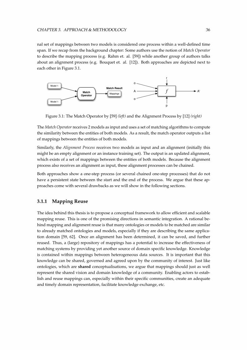
CHAPTER 3. APPROACH & METHODOLOGY 36
nal set of mappings between two models is considered one process within a well-defined timespan. If we recap from the background chapter: Some authors use the notion of Match Operatorto describe the mapping process (e.g. Rahm et. al. [59]) while another group of authors talksabout an alignment process (e.g. Bouquet et. al. [12]). Both approaches are depicted next toeach other in Figure 3.1.
Match Operator
Model 1
Model 1
Mappings
Match Resultf
o
o
A
r
p
A'
Figure 3.1: The Match Operator by [59] (left) and the Alignment Process by [12] (right)
The Match Operator receives 2 models as input and uses a set of matching algorithms to computethe similarity between the entities of both models. As a result, the match operator outputs a listof mappings between the entities of both models.
Similarly, the Alignment Process receives two models as input and an alignment (initially thismight be an empty alignment or an instance training set). The output is an updated alignment,which exists of a set of mappings between the entities of both models. Because the alignmentprocess also receives an alignment as input, these alignment processes can be chained.
Both approaches show a one-step process (or several chained one-step processes) that do nothave a persistent state between the start and the end of the process. We argue that these ap-proaches come with several drawbacks as we will show in the following sections.
3.1.1 Mapping Reuse
The idea behind this thesis is to propose a conceptual framework to allow efficient and scalablemapping reuse. This is one of the promising directions in semantic integration. A rational be-hind mapping and alignment reuse is that many ontologies or models to be matched are similarto already matched ontologies and models, especially if they are describing the same applica-tion domain [59, 62]. Once an alignment has been determined, it can be saved, and furtherreused. Thus, a (large) repository of mappings has a potential to increase the effectiveness ofmatching systems by providing yet another source of domain specific knowledge. Knowledgeis contained within mappings between heterogeneous data sources. It is important that thisknowledge can be shared, governed and agreed upon by the community of interest. Just likeontologies, which are shared conceptualisations, we argue that mappings should just as wellrepresent the shared vision and domain knowledge of a community. Enabling actors to estab-lish and reuse mappings can, especially within their specific communities, create an adequateand timely domain representation, facilitate knowledge exchange, etc.
CHAPTER 3. APPROACH & METHODOLOGY 37
Most of the existing integration frameworks do not explicitly support mapping reuse. As wehave presented the advantages of having a shared and agreed upon set of mappings, the limi-tations and drawbacks of integration platforms and framework that lack such an approach areevident: Currently, a mapping is the interpretation of a single individual for a certain integra-tion problem. There are no processes in place for the mapping to represent the interpretationof a group of individuals that are affected by the particular integration problem. There is noway the community of interest can represent its confidence or thrust in the mappings. Theseare very important issues that are overlooked in the current integration frameworks. Further-more, as mappings are not shared, every individual must redo the entire mapping process forintegration scenarios that may be very similar to already solved problems. Because of theselimitations, the integration problem is still a very labour-intensive problem that does not scalewell. As it happens, the efficiency and scalability of mapping frameworks will become evermore important while we are moving more and more towards model-driven architectures andmethodologies in a lot of application areas of computer science and Information Technology, aswe have shown in the Semantic Web and OMGs Model Driven Architecture initiatives.
One framework, COMA++ [5] does support mapping reuse, but only privately: Access to thesystem is limited to individual users, who usually do not know each other, hence, they donot communicate with each other. While this private reuse solves some issues on the practicalside of the integration problem, it does not address our proposition that the mappings shouldrepresent the shared knowledge of the community of interest. In this private reuse of mappingsapproach, shared knowledge of the community with its negotiation processes can not be fullyleveraged.
3.1.2 Application-specific mappings
Not only does the current work on semantic integration not account for shared mapping reuse,it does also make no distinction between the conceptual meaning of a mapping and its applica-tion specific representation. Using the definition of semantic integration, mappings must allowone model to be translated into the other. To allow models to be translated into each other, themappings between the entities of these models need to be described in a specific integrationlanguage or integration model that can be interpreted and executed by a specific application fora specific purpose. We give a few examples of how this issue can present itself:
Map an SQL schema to an ontology In this scenario, we want to map an SQL schema from arelation database to an ontology. Using this mapping, we want to be able to query theontology for the content of the relational database.
Let’s say that there are two applications that can translate queries on the concepts andproperties from the ontology to standard SQL queries. To do that, both programs need amapping file that precisely specifies how the ontology is translated to relation tables andcolumns. However, both these applications are developed by distinct software vendorsand use their own proprietary language to describe these mappings. Currently, there is
CHAPTER 3. APPROACH & METHODOLOGY 38
no integration framework that enables the actors to save the mappings from the ontologyto the relational tables in an application-neutral format. This clearly shows the need toseparate the conceptual meaning of the mapping (matching a relation table to a conceptfrom the ontology for example) from the application- or language-specific representationof these mappings.
Translate instance data from one model into another model In this scenario, the actors needto translate instance data that is represented in one model into another given model. Thisis a very well known problem in the enterprise-IT market. One example in which this sce-nario often occurs is data warehousing. A data warehouse is a decision support databasethat is extracted from a set of data sources. The extraction process requires transform-ing data from the source format into the warehouse format. As shown in [54], the matchoperator is useful for designing transformations. However, these transformations againhave to be interpreted and executed. For example, a concatenate transformation needs tobe executed when the instance data is actually transformed into the other model, in thiscase the data warehouse.
Another drawback of directly working on language- or application-specific mappings is thatthese mappings can only be created by an actor that is familiar with the language or application.However, mappings between different models often require a more high-level and conceptualview of the data and models. The information that is needed to create valid mappings is oftencontained by users with a managerial role in the organisation while these users often have noknowledge of the specific, low level integration language used.
While these limitations are not so serious on integration platforms that don’t support map-ping reuse, on our platform, where we aim to provide the actors with a platform on whichthey can establish their shared and reusable mappings, this constraint is much more severe:To be able to establish such a shared knowledge, the involved actors must be able to com-municate in a manner that all of them understand. Therefore, it is important that the sharedmappings are expressed in a conceptual manner which also non-technical knowledge expertsunderstand.
3.2 Methodology
As we have discussed in the previous section, semantic integration is traditionally a one-stepprocess that, given two heterogeneous models, returns a set of mappings that can translateone model into the other. We have also argued that this approach comes with a number ofdrawbacks such as dealing with application-specific mappings, no conceptual framework toreason, discuss and approve the mappings, hard to reuse existing mappings, etc.
In this thesis we propose a possible solution for these problems: We introduce an integrationapproach that splits up the integration process into two distinct phases: the Mapping Phase and
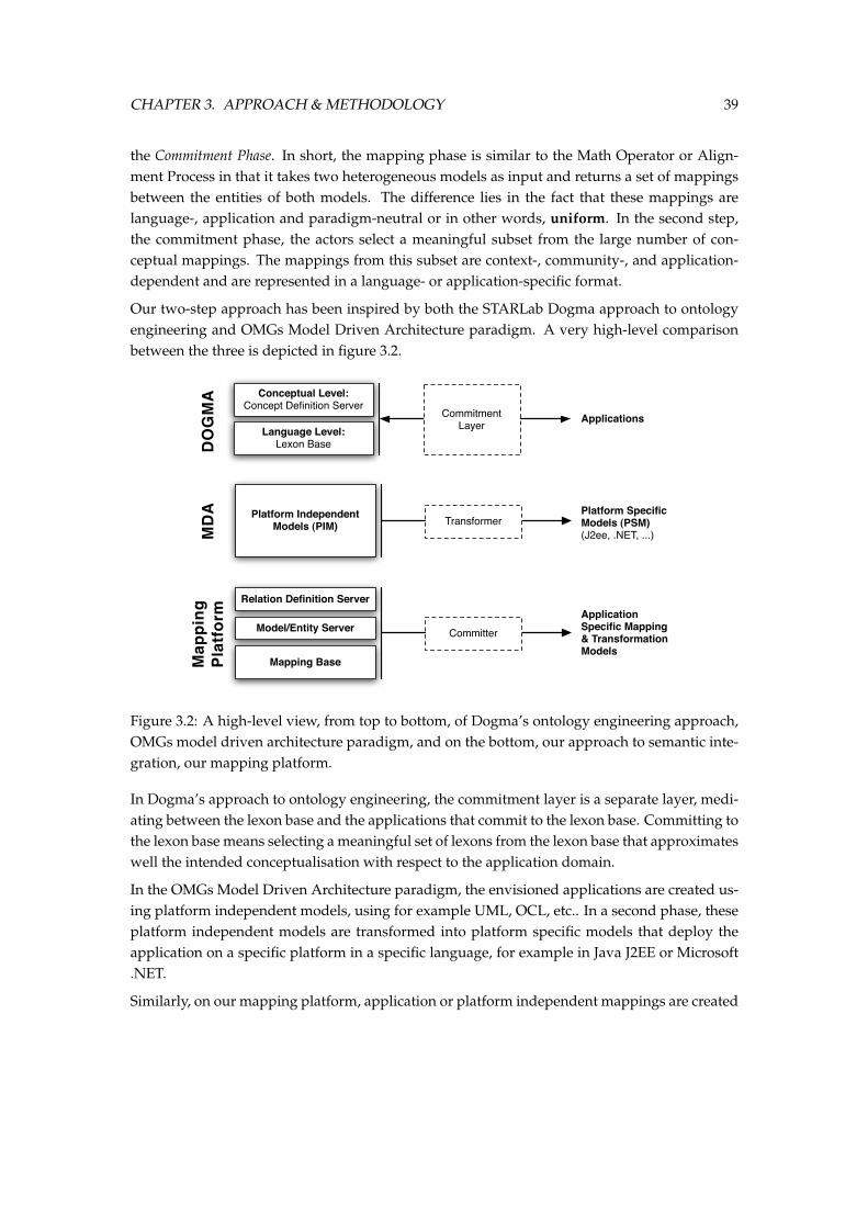
CHAPTER 3. APPROACH & METHODOLOGY 39
the Commitment Phase. In short, the mapping phase is similar to the Math Operator or Align-ment Process in that it takes two heterogeneous models as input and returns a set of mappingsbetween the entities of both models. The difference lies in the fact that these mappings arelanguage-, application and paradigm-neutral or in other words, uniform. In the second step,the commitment phase, the actors select a meaningful subset from the large number of con-ceptual mappings. The mappings from this subset are context-, community-, and application-dependent and are represented in a language- or application-specific format.
Our two-step approach has been inspired by both the STARLab Dogma approach to ontologyengineering and OMGs Model Driven Architecture paradigm. A very high-level comparisonbetween the three is depicted in figure 3.2.
Conceptual Level:Concept Definition Server
Language Level:Lexon Base
ApplicationsCommitment Layer
Platform Independent Models (PIM)
Platform Specific Models (PSM)(J2ee, .NET, ...)
Transformer
DO
GM
AM
DA
Application Specific Mapping & Transformation Models
Committer
Map
ping
Pl
atfo
rm
Model/Entity Server
Relation Definition Server
Mapping Base
Figure 3.2: A high-level view, from top to bottom, of Dogma’s ontology engineering approach,OMGs model driven architecture paradigm, and on the bottom, our approach to semantic inte-gration, our mapping platform.
In Dogma’s approach to ontology engineering, the commitment layer is a separate layer, medi-ating between the lexon base and the applications that commit to the lexon base. Committing tothe lexon base means selecting a meaningful set of lexons from the lexon base that approximateswell the intended conceptualisation with respect to the application domain.
In the OMGs Model Driven Architecture paradigm, the envisioned applications are created us-ing platform independent models, using for example UML, OCL, etc.. In a second phase, theseplatform independent models are transformed into platform specific models that deploy theapplication on a specific platform in a specific language, for example in Java J2EE or Microsoft.NET.
Similarly, on our mapping platform, application or platform independent mappings are created
CHAPTER 3. APPROACH & METHODOLOGY 40
in the mapping phase. We call these mappings plausible mappings as they might be valid in a cer-tain context and community, but not necessarily in another. In the second phase, a meaningfulsubset is chosen from this large set of conceptual, plausible mappings depending on the context,the involved community, and the application domain of the integration scenario in the commit-ment phase. We call this process ”committing” . For this process, platform or language-specificcommitters must be created that will help the actor to interpret the conceptual mappings andtranslate them to a language-specific, executable alignment. Next, we will go into more detailon both steps of our integration methodology.
3.2.1 Mapping phase
The goal of the mapping phase is to identify plausible mappings between entities from theheterogeneous models. The result of this process is a set of uniform, plausible mappings that areadded to a large mapping store. This process is split up into two methodological steps:
1. Preintegration: In this step, the syntactical heterogeneities of the models are overcome byparsing the entities of both models into our uniform mapping data model. We will discussour mapping data model in the coming sections of this thesis.
2. Matching: In the second step, the different entities are matched and mappings are createdbetween similar entities. This matching process can be completely automated by using aset of matching algorithms we reviewed in our first chapter, but more realistically, match-ing algorithms will create a number of mappings after which a human actor or actorsshould validate these. The resulting mappings are stored in a large mapping repository.
Each mapping process is executed within a certain context and is executed by a certain com-munity. Therefore, each mapping stored in the mapping store has a context and communityidentifier attached to it.
The context of the mapping models the environmental settings in which the mapping has beendeducted. A mapping might be plausible in a certain context, while the same mapping mightnot be valid in another. The context also enables the actor to provide a well-defined and context-specific definition of the relation of the mapping. For example, a relation between two entities inone context might be transitive, while the same relation in another context might not be.
The community of a mapping contains the actors, processes and goals of the actors that havecreated the mapping. Again, a mapping might be relevant to one community but not to another.Furthermore, reuse of mappings created by different actors implies resolving, among others,such challenges as the appropriateness of mappings when using them in applications and thrustissues. We will review the context and community aspects of our integration platform in moredetail in the coming sections.
The mappings that are created in the mapping phase should be viewed as conceptual mappings,that is, they are not meant to be used in applications, but should be used by the communities of
CHAPTER 3. APPROACH & METHODOLOGY 41
interest to negotiate and share the implicit knowledge that they contain: How does one modelor ontology relate to another within a certain given context through the eyes of a certain commu-nity. Because each mapping has a context and community aspect, these can be fully leveragedin the next phase, the commitment phase, of the integration process. To conclude: The result ofthe mapping process is a set of uniform, conceptual mappings with a well-defined relation thatare plausible in a certain context and are created by a certain community.
3.2.2 Commitment phase
The goal of the commitment phase is to create an application-specific alignment that best ap-proximates the intended use of the alignment. The alignment is modelled in an alignmentmodel described in a certain language to be used by a specific application.
During the commitment process a (group of) actor(s) selects a meaningful set of mappings thatbest approximates their intended alignment. This selection and reuse process of committinga mapping to an alignment corresponds to augmenting the representation-neutral mappingelement to a commitment rule that is valid in this particular alignment described in a partic-ular language. The validity of the commitment-rule is dependent on the intended use of thealignment, which will be domain-, community-, organisation-, or application-specific. Hence, acommitment or alignment can be seen as an interpretation of a set of mappings.
The resulting alignment corresponds to an instance of an alignment model which is described ina specific language. For example, when integrating two OWL-ontologies, the alignment may bean instance of an OWL Alignment Ontology which provides a language-specific interpretationof the mappings from the alignment. Figure 3.3 depicts the process of committing a plausible,conceptual mapping from the mapping phase to an instance of the Aligment API integrationmodel1 [26]. The resulting alignment is language specific and should be created with a certainapplication scenario in mind. It is also the interpretation of the conceptual mapping from whichit originated. In the example, the conceptual relation of the mapping, equals, is interpreted to thelanguage specific relation =. When committing to other formats, the conceptual relation maybe interpreted to rules in a certain rule language (for example, RuleML [11], SWRL [35], etc.) orit may interpreted as an owl:SameAs relation, etc.
By adopting this clear separation and distinction between the matching and alignment phase,the actors of the system can reuse the existing mappings to create an alignment that best ap-proximates its intended use - which will be domain-, community-, organisation-, or application-specific. We will further elaborate on the advantages of our methodology after we have fullypresented our methodology and the semantics of our platform in the following sections.
1The Alignment API is a format for expressing alignments in RDF, so that they can be published on the web.
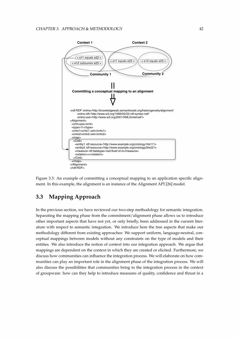
CHAPTER 3. APPROACH & METHODOLOGY 42
< e11 equals e22 >
Context 1 Context 2
Community 1 Community 2
< e12 subsumes e23 >< e11 equals e23 > < e13 equals e23 >
<rdf:RDF xmlns='http://knowledgeweb.semanticweb.org/heterogeneity/alignment' xmlns:rdf='http://www.w3.org/1999/02/22-rdf-syntax-ns#' xmlns:xsd='http://www.w3.org/2001/XMLSchema#'><Alignment> <xml>yes</xml> <type>11</type> <onto1>onto1.owl</onto1> <onto2>onto2.owl</onto2> <map> <Cell> <entity1 rdf:resource='http://www.example.org/ontology1#e11'/> <entity2 rdf:resource='http://www.example.org/ontology2#e22'/> <measure rdf:datatype='xsd:float'>0.0</measure> <relation>=</relation> </Cell> </map></Alignment></rdf:RDF>
Committing a conceptual mapping to an alignment
Figure 3.3: An example of committing a conceptual mapping to an application specific align-ment. In this example, the alignment is an instance of the Alignment API [26] model.
3.3 Mapping Approach
In the previous section, we have reviewed our two-step methodology for semantic integration.Separating the mapping phase from the commitment/alignment phase allows us to introduceother important aspects that have not yet, or only briefly, been addressed in the current liter-ature with respect to semantic integration. We introduce here the tree aspects that make ourmethodology different from existing approaches: We support uniform, language-neutral, con-ceptual mappings between models without any constraints on the type of models and theirentities. We also introduce the notion of context into our integration approach. We argue thatmappings are dependent on the context in which they are created or elicited. Furthermore, wediscuss how communities can influence the integration process. We will elaborate on how com-munities can play an important role in the alignment phase of the integration process. We willalso discuss the possibilities that communities bring to the integration process in the contextof groupware: how can they help to introduce measures of quality, confidence and thrust in a
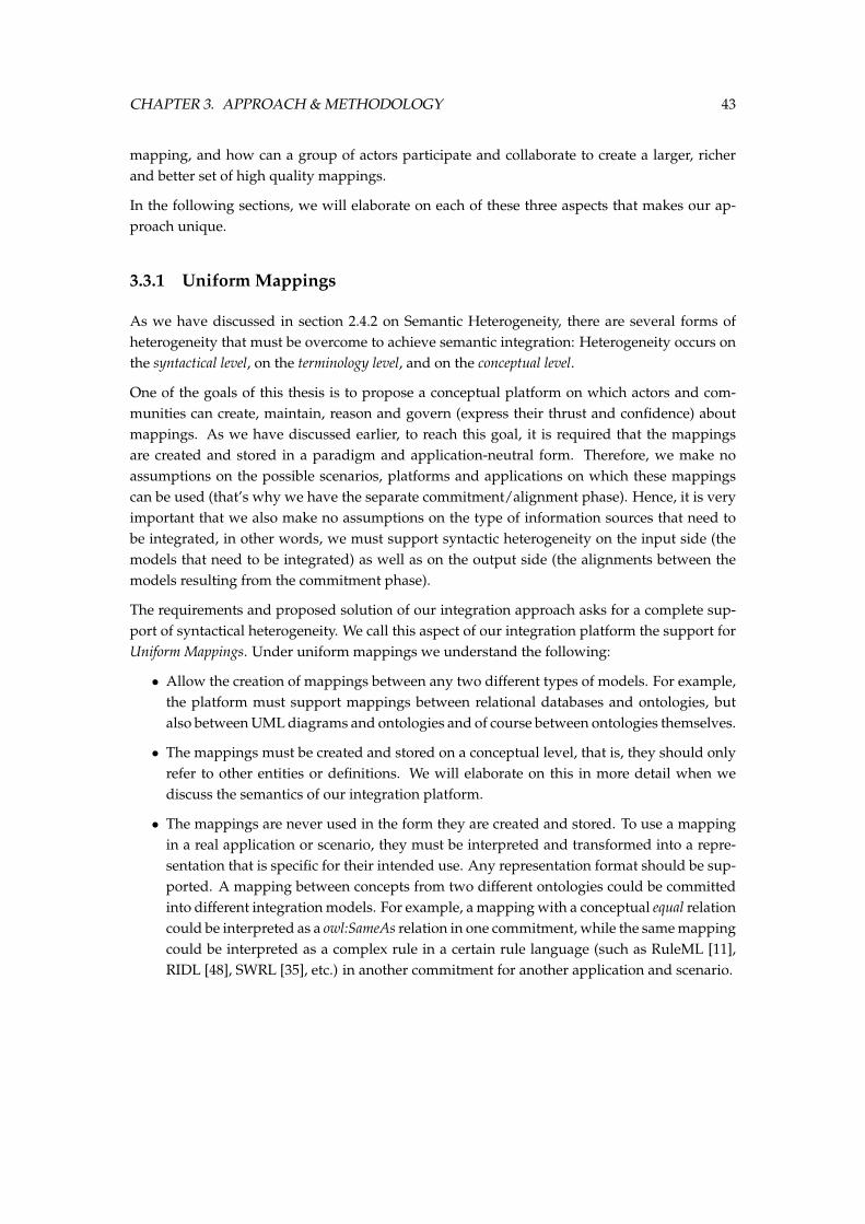
CHAPTER 3. APPROACH & METHODOLOGY 43
mapping, and how can a group of actors participate and collaborate to create a larger, richerand better set of high quality mappings.
In the following sections, we will elaborate on each of these three aspects that makes our ap-proach unique.
3.3.1 Uniform Mappings
As we have discussed in section 2.4.2 on Semantic Heterogeneity, there are several forms ofheterogeneity that must be overcome to achieve semantic integration: Heterogeneity occurs onthe syntactical level, on the terminology level, and on the conceptual level.
One of the goals of this thesis is to propose a conceptual platform on which actors and com-munities can create, maintain, reason and govern (express their thrust and confidence) aboutmappings. As we have discussed earlier, to reach this goal, it is required that the mappingsare created and stored in a paradigm and application-neutral form. Therefore, we make noassumptions on the possible scenarios, platforms and applications on which these mappingscan be used (that’s why we have the separate commitment/alignment phase). Hence, it is veryimportant that we also make no assumptions on the type of information sources that need tobe integrated, in other words, we must support syntactic heterogeneity on the input side (themodels that need to be integrated) as well as on the output side (the alignments between themodels resulting from the commitment phase).
The requirements and proposed solution of our integration approach asks for a complete sup-port of syntactical heterogeneity. We call this aspect of our integration platform the support forUniform Mappings. Under uniform mappings we understand the following:
• Allow the creation of mappings between any two different types of models. For example,the platform must support mappings between relational databases and ontologies, butalso between UML diagrams and ontologies and of course between ontologies themselves.
• The mappings must be created and stored on a conceptual level, that is, they should onlyrefer to other entities or definitions. We will elaborate on this in more detail when wediscuss the semantics of our integration platform.
• The mappings are never used in the form they are created and stored. To use a mappingin a real application or scenario, they must be interpreted and transformed into a repre-sentation that is specific for their intended use. Any representation format should be sup-ported. A mapping between concepts from two different ontologies could be committedinto different integration models. For example, a mapping with a conceptual equal relationcould be interpreted as a owl:SameAs relation in one commitment, while the same mappingcould be interpreted as a complex rule in a certain rule language (such as RuleML [11],RIDL [48], SWRL [35], etc.) in another commitment for another application and scenario.
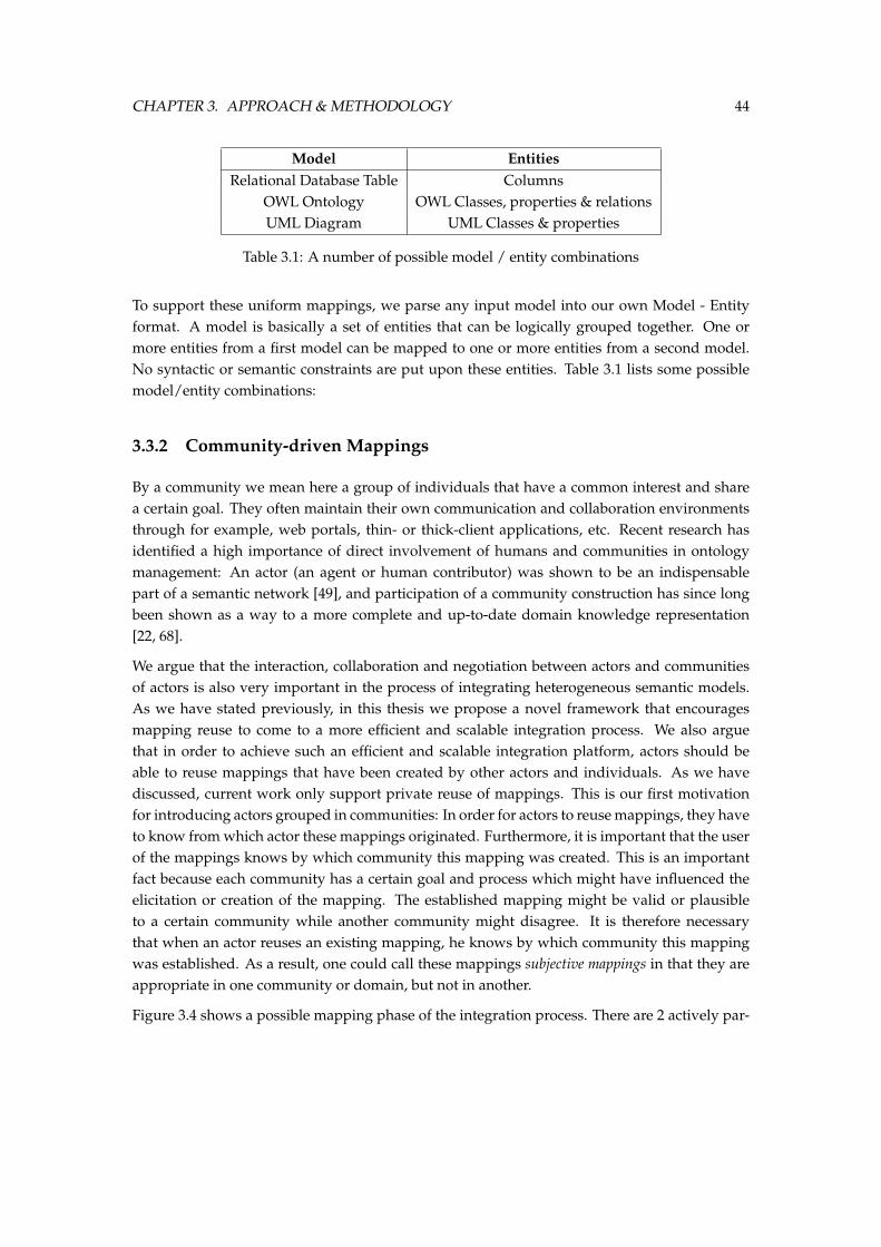
CHAPTER 3. APPROACH & METHODOLOGY 44
Model EntitiesRelational Database Table Columns
OWL Ontology OWL Classes, properties & relationsUML Diagram UML Classes & properties
Table 3.1: A number of possible model / entity combinations
To support these uniform mappings, we parse any input model into our own Model - Entityformat. A model is basically a set of entities that can be logically grouped together. One ormore entities from a first model can be mapped to one or more entities from a second model.No syntactic or semantic constraints are put upon these entities. Table 3.1 lists some possiblemodel/entity combinations:
3.3.2 Community-driven Mappings
By a community we mean here a group of individuals that have a common interest and sharea certain goal. They often maintain their own communication and collaboration environmentsthrough for example, web portals, thin- or thick-client applications, etc. Recent research hasidentified a high importance of direct involvement of humans and communities in ontologymanagement: An actor (an agent or human contributor) was shown to be an indispensablepart of a semantic network [49], and participation of a community construction has since longbeen shown as a way to a more complete and up-to-date domain knowledge representation[22, 68].
We argue that the interaction, collaboration and negotiation between actors and communitiesof actors is also very important in the process of integrating heterogeneous semantic models.As we have stated previously, in this thesis we propose a novel framework that encouragesmapping reuse to come to a more efficient and scalable integration process. We also arguethat in order to achieve such an efficient and scalable integration platform, actors should beable to reuse mappings that have been created by other actors and individuals. As we havediscussed, current work only support private reuse of mappings. This is our first motivationfor introducing actors grouped in communities: In order for actors to reuse mappings, they haveto know from which actor these mappings originated. Furthermore, it is important that the userof the mappings knows by which community this mapping was created. This is an importantfact because each community has a certain goal and process which might have influenced theelicitation or creation of the mapping. The established mapping might be valid or plausibleto a certain community while another community might disagree. It is therefore necessarythat when an actor reuses an existing mapping, he knows by which community this mappingwas established. As a result, one could call these mappings subjective mappings in that they areappropriate in one community or domain, but not in another.
Figure 3.4 shows a possible mapping phase of the integration process. There are 2 actively par-
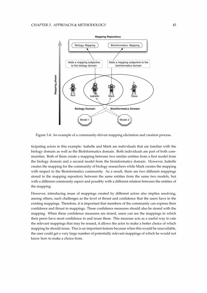
CHAPTER 3. APPROACH & METHODOLOGY 45
Biology Domain BioInformatics Domain
Mapping Repository
Ann Mark Dave
?
Isabelle
Biology, Mapping
Model 1 Model 2
BioInformatics, Mapping
Adds a mapping subjective to the biology domain
Adds a mapping subjective to the bioinformatics domain
Map
pin
g p
has
e
Figure 3.4: An example of a community-driven mapping elicitation and creation process.
ticipating actors in this example: Isabelle and Mark are individuals that are familiar with thebiology domain as well as the BioInformatics domain. Both individuals are part of both com-munities. Both of them create a mapping between two similar entities from a first model fromthe biology domain and a second model from the bioinformatics domain. However, Isabellecreates the mapping for the community of biology researchers while Mark creates the mappingwith respect to the Bioinformatics community. As a result, there are two different mappingsstored in the mapping repository between the same entities from the same two models, butwith a different community aspect and possibly with a different relation between the entities ofthe mapping.
However, introducing reuse of mappings created by different actors also implies resolving,among others, such challenges as the level of thrust and confidence that the users have in theexisting mappings. Therefore, it is important that members of the community can express theirconfidence and thrust in mappings. These confidence measures should also be stored with themapping. When these confidence measures are stored, users can see the mappings in whichtheir peers have most confidence in and reuse these. This measure acts as a useful way to ratethe relevant mappings that may be reused, it allows the actor to make a better choice of whichmapping he should reuse. This is an important feature because when this would be unavailable,the user could get a very large number of potentially relevant mappings of which he would notknow how to make a choice from.
CHAPTER 3. APPROACH & METHODOLOGY 46
Biology Domain BioInformatics Domain
Mapping Repository
Mark Dave
?
Isabelle
Biology, Mapping BioInformatics, Mapping
Express the confidence & thrust from a community in the mapping
Express the confidence & thrust from a community in the mapping
Figure 3.5: An example of a communication and negotiation process in which the communitycan express its confidence and thrust in the existing mappings.
To revisit the previous example, figure 3.5 shows the negotiation and communication processin which the community members can express their confidence and thrust in the mappings pre-viously created by their peers. Because these mappings are stored in a conceptual manner anddo contain any application-specific technicalities, the knowledge engineers and domain expertscan efficiently review the quality of the mappings. When the quality is not sufficient, they canadd their own mappings. As a result, when an individual want to reuse a mapping from hiscommunity, he will be able to see in which mappings the other actors from his community havemost confidence in. When we discuss the context of a mapping, we will show how we can iden-tify similar mappings (mapping between the same entities) from the same community.
In the second phase of our integration methodology, the commitment phase, the actor mustmake a selection of mappings to create an alignment that best approximates its intended use. Inthis phase, the actor will browse or search through the mapping repository to find the most rele-vant mappings. The community-driven integration platform brings two important advantagesin this stage of the integration process:
1. Since the mappings are grouped by community, the actor can easily find the relevant map-pings for his application. This is important because when the mapping repository growslarger and larger, finding the relevant mappings will prove to become more difficult overtime. This is a recursive problem: When the actor is unable to find a relevant mapping, hemight decide to create its own and add it to the mapping repository which will becomelarger. The next actor that needs to find a relevant mapping will have an even harder timeto find the relevant mapping and might also decide to create his own mapping, etc.
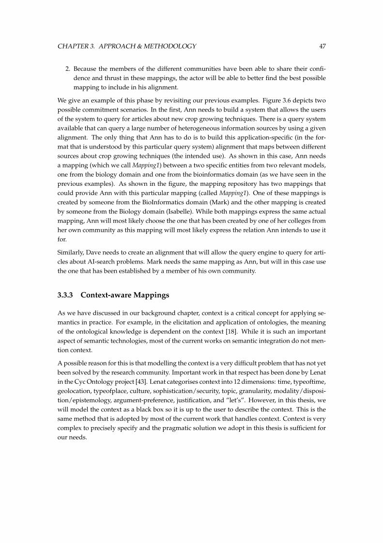
CHAPTER 3. APPROACH & METHODOLOGY 47
2. Because the members of the different communities have been able to share their confi-dence and thrust in these mappings, the actor will be able to better find the best possiblemapping to include in his alignment.
We give an example of this phase by revisiting our previous examples. Figure 3.6 depicts twopossible commitment scenarios. In the first, Ann needs to build a system that allows the usersof the system to query for articles about new crop growing techniques. There is a query systemavailable that can query a large number of heterogeneous information sources by using a givenalignment. The only thing that Ann has to do is to build this application-specific (in the for-mat that is understood by this particular query system) alignment that maps between differentsources about crop growing techniques (the intended use). As shown in this case, Ann needsa mapping (which we call Mapping1) between a two specific entities from two relevant models,one from the biology domain and one from the bioinformatics domain (as we have seen in theprevious examples). As shown in the figure, the mapping repository has two mappings thatcould provide Ann with this particular mapping (called Mapping1). One of these mappings iscreated by someone from the BioInformatics domain (Mark) and the other mapping is createdby someone from the Biology domain (Isabelle). While both mappings express the same actualmapping, Ann will most likely choose the one that has been created by one of her colleges fromher own community as this mapping will most likely express the relation Ann intends to use itfor.
Similarly, Dave needs to create an alignment that will allow the query engine to query for arti-cles about AI-search problems. Mark needs the same mapping as Ann, but will in this case usethe one that has been established by a member of his own community.
3.3.3 Context-aware Mappings
As we have discussed in our background chapter, context is a critical concept for applying se-mantics in practice. For example, in the elicitation and application of ontologies, the meaningof the ontological knowledge is dependent on the context [18]. While it is such an importantaspect of semantic technologies, most of the current works on semantic integration do not men-tion context.
A possible reason for this is that modelling the context is a very difficult problem that has not yetbeen solved by the research community. Important work in that respect has been done by Lenatin the Cyc Ontology project [43]. Lenat categorises context into 12 dimensions: time, typeoftime,geolocation, typeofplace, culture, sophistication/security, topic, granularity, modality/disposi-tion/epistemology, argument-preference, justification, and ”let’s”. However, in this thesis, wewill model the context as a black box so it is up to the user to describe the context. This is thesame method that is adopted by most of the current work that handles context. Context is verycomplex to precisely specify and the pragmatic solution we adopt in this thesis is sufficient forour needs.
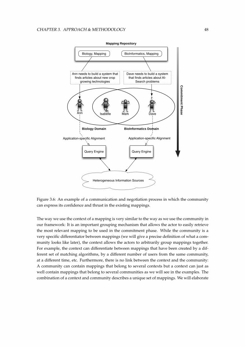
CHAPTER 3. APPROACH & METHODOLOGY 48
Biology Domain BioInformatics Domain
Mapping Repository
Ann Mark Dave
?
Isabelle
Biology, Mapping BioInformatics, Mapping
Dave needs to build a system that finds articles about AI-
Search problems
Co
mm
itmen
t Ph
ase
Query EngineQuery Engine
Ann needs to build a system that finds articles about new crop
growing technologies
Application-specific Alignment Application-specific Alignment
Heterogeneous Information Sources
Figure 3.6: An example of a communication and negotiation process in which the communitycan express its confidence and thrust in the existing mappings.
The way we use the context of a mapping is very similar to the way as we use the community inour framework: It is an important grouping mechanism that allows the actor to easily retrievethe most relevant mapping to be used in the commitment phase. While the community is avery specific differentiator between mappings (we will give a precise definition of what a com-munity looks like later), the context allows the actors to arbitrarily group mappings together.For example, the context can differentiate between mappings that have been created by a dif-ferent set of matching algorithms, by a different number of users from the same community,at a different time, etc. Furthermore, there is no link between the context and the community:A community can contain mappings that belong to several contexts but a context can just aswell contain mappings that belong to several communities as we will see in the examples. Thecombination of a context and community describes a unique set of mappings. We will elaborate
CHAPTER 3. APPROACH & METHODOLOGY 49
on the exact semantics of our integration model in the next section.
Because the context is such a undefined, black-box, we think it is best to show its use through acouple of examples:
Context to disambiguate mappings: The first obvious use of context is to disambiguate be-tween mappings. While we introduced the community-awereness of a mapping to specif-ically disambiguate on the creators of the mappings, we also need to disambiguate onother potential aspects of a mapping. This is particularly critical in our framework. Be-cause the strength of our approach is directly linked with the ability to reuse plausible,conceptual mappings, it is important that enough of these relevant mappings exist. There-fore, we need a way to disambiguate similar mappings on more then only their creatorsso that enough mappings are available for different scenarios.
Context to disambiguate relations: In ontology management, the context is used to disam-biguate similar terms that refer to different concepts. Context can be similarly used inontology integration whereas a relation term in one context refers to a certain relationdefinition while the same relation term in another context can refer to another relationdefinition. For example, a relation in one context might meant to be transitive while thesame relation in another context might not. It is important that our platforms provides away to disambiguate these two relations by letting them refer to a different relation defini-tion. We will discuss this in more detail when we present the semantics of our integrationplatform.
Context to support collaboration: To allow public reuse of mappings, the mappings must bestored in a repository which runs on a server accessible by different actors through differ-ent systems. However, such a collaboration environment introduces typical groupwareproblems: What to do if two actors edit the same mapping at the same time and store itback into the repository? The offline editing of mappings and storing them back in to therepository introduces a number of typical problems. One possible solution is to view themappings from a database perspective and use several locking techniques. However, thescalability of this approach is questionable. Another possible solution is to build a merge-operator that merges different versions of a single mapping. A potential implementationof this solution could be to automatically create a new context when two mappings cannot be merged. This could be extended to introducing dependencies between contextsand brings us to the concept of evolution. We will discuss this in more detail when weelaborate on the additional benefits of our approach.
3.4 Mapping Semantics
In this section we elaborate on the specific semantics underlying our methodology and plat-form. We will provide definitions of the different concepts we have introduced in the previous
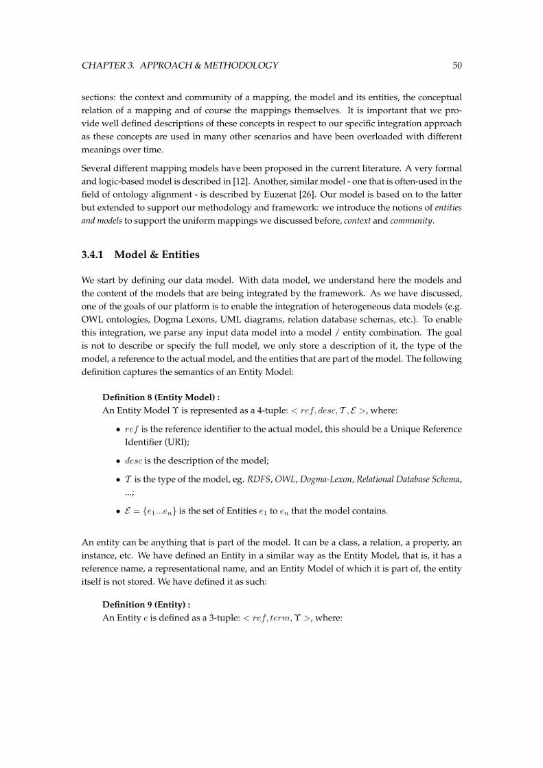
CHAPTER 3. APPROACH & METHODOLOGY 50
sections: the context and community of a mapping, the model and its entities, the conceptualrelation of a mapping and of course the mappings themselves. It is important that we pro-vide well defined descriptions of these concepts in respect to our specific integration approachas these concepts are used in many other scenarios and have been overloaded with differentmeanings over time.
Several different mapping models have been proposed in the current literature. A very formaland logic-based model is described in [12]. Another, similar model - one that is often-used in thefield of ontology alignment - is described by Euzenat [26]. Our model is based on to the latterbut extended to support our methodology and framework: we introduce the notions of entitiesand models to support the uniform mappings we discussed before, context and community.
3.4.1 Model & Entities
We start by defining our data model. With data model, we understand here the models andthe content of the models that are being integrated by the framework. As we have discussed,one of the goals of our platform is to enable the integration of heterogeneous data models (e.g.OWL ontologies, Dogma Lexons, UML diagrams, relation database schemas, etc.). To enablethis integration, we parse any input data model into a model / entity combination. The goalis not to describe or specify the full model, we only store a description of it, the type of themodel, a reference to the actual model, and the entities that are part of the model. The followingdefinition captures the semantics of an Entity Model:
Definition 8 (Entity Model) :An Entity Model Υ is represented as a 4-tuple: < ref, desc, T , E >, where:
• ref is the reference identifier to the actual model, this should be a Unique ReferenceIdentifier (URI);
• desc is the description of the model;
• T is the type of the model, eg. RDFS, OWL, Dogma-Lexon, Relational Database Schema,...;
• E = e1...en is the set of Entities e1 to en that the model contains.
An entity can be anything that is part of the model. It can be a class, a relation, a property, aninstance, etc. We have defined an Entity in a similar way as the Entity Model, that is, it has areference name, a representational name, and an Entity Model of which it is part of, the entityitself is not stored. We have defined it as such:
Definition 9 (Entity) :An Entity e is defined as a 3-tuple: < ref, term,Υ >, where:
CHAPTER 3. APPROACH & METHODOLOGY 51
• ref is the reference identifier of the entity;
• term is the representational term of the entity;
• Υ is the model of which the entity is part of.
3.4.2 Mapping Element
We first introduce the 2 concepts of Community and Context before we define the mapping el-ement. At this point, our goal is not to provide a complete and sound definition for the com-munity and the context. They are very complex dimensions. Their use is mostly pragmatic andlies in the commitment phase, where they will both be leveraged by the actors involved in thecommitment phase to commit to a final alignment.
However, to agree on a certain terminology, we give an informal, pragmatic definition of bothconcepts:
Definition 10 (Community) :A community P has two intrinsic elements: an ID which identifies the community and anumber of actors which identify the persons involved in the community. Two extra extrin-sic characteristics are the goal of the community (for example, agreeing on an alignment oftwo ontologies) and the process they want to perform on the knowledge they share.
The community P is modelled as a 3-tuple: < A,G, ρ > where:
• A is the set of Actors;
• G is the goal of the community; and
• ρ is the process the community wants to follow.
At this time, the context is still a black box. We do not define a precise model for the context.The actors are free to model it as they wish. The goal of the context however, is to model thetimeframe, algorithms used, domain, ... in which the creation of the mapping element tookplace. While the context is not formally defined, it must not be overlooked. The context is animportant information-source for the actors in the commitment-phase and is needed to keep themapping element unambiguous from other mappings which share the same concepts, relationand community elements.
Definition 11 (Context) :A Context γ is represented as the tuple: < ref, term, description > where:
• ref is the unique reference to this particular context;
• term is the terminological name of the context; and
CHAPTER 3. APPROACH & METHODOLOGY 52
• description is the informal description of the context.
Now that we have provided definitions for the community and the context, we can move on togive the formal definition of a Mapping Element. We use the term Ontology in our definitionvery broadly: It can be a very rich ontology described in OWL or modelled in Dogma, but it canalso be a lightweight ”Ontology” such as a shared vocabulary, taxonomy, XML model, ... thatcontains far less (up to none) explicit semantics. The two ontologies used in a mapping alsodon’t need to have a similar level of explicit semantics of formalism. The purpose is to allowmappings between very different data sources, which is an important requirement to be able touse this mapping framework in all of the foreseen scenarios.
Definition 12 (Mapping Element) :We define a mapping elementM between 2 ordered lists of entities E1 = e1, ..., ex ε OntologyO1
and E2 = ex+1, ..., ey ε OntologyO2 as a 6-tuple < P, γ, E1, E2,Rtermx, n > where:
• P stands for the community that was responsible for creating the mapping;
• γ is the context in which the mapping was created;
• E1 is the ordered list of entities belonging to Ontology O1;
• E2 is the ordered list of entities belonging to Ontology O2;
• Rtermx is the relation term. This is not the actual relation definition. Rterm is theterminological name of the relation and should, in combination with the context,refer to a unique relation definition. We will discuss this in more detail when weintroduce the semantics of a relation.
When the relation is fuzzy, x is the strength of the relation.
• n is the degree of confidence, a measure of thrust in the fact that the mapping isappropriate. This degree of confidence will given by the community (directly orindirectly) to the mapping.
Both the strength of the relation (x) and the degree of confidence (n) are normalised be-tween an upper bound (>) and a lower bound (⊥). We set the upper and lower bound torespectively 1 and 0. A mapping element will always be at least unidirectional, however,the direction of the mapping depends on the relation definition. The relation definitionwill always be at least unidirectional but may also be bidirectional. A mapping is alsouniquely identified by it’s community, context, and entities. That means that only onepossible relation between two sets of entities in a certain context and community is possi-ble.
The mapping element can also be written in a less verbose manner. This will be the formatwe will use in the remainder of this thesis:
P, γ : E1 Rtermx,n E2
CHAPTER 3. APPROACH & METHODOLOGY 53
Let us clarify this definition with some examples:
• A mapping from the entity e1 from Ontology O1 to an entity e2 from Ontology O2. Themapping has a non-fuzzy equivalence relation. The confidence in the mapping is 0.85. Thismapping would be written as:
P, γ : e1 equivalence1,.85 e2
• A mapping between the same entities, but now by a different community in a differentcontext and with a fuzzy subsumes relation with strength 0.90 and confidence 0.70.
P ′, γ′ : e1 subsumes.90,.70 e2
• A mapping between property foaf : name from the FOAF Ontology2 and propertiesperson : firstName, person : middleName, person : lastName from ebiquity’s PersonOntology3, with a fuzzy union relation with strength 0.75 and confidence 0.95.
P ′′, γ′′ : person : firstName, person : middleName, person : lastNameunion.75,.95
foaf : name
3.4.3 Mapping Relations
A mapping element is a lexical representation of a conceptual mapping between two lists ofentities. As the definition of a mapping element shows, the entities are only references to theactual entities from the model. In the same way, the relation name is only a reference to a con-ceptual relation definition. A relational name Rterm from a mapping combined with a contextγ refers to exactly one unique relation definition R. Going from the lexical representation tothe conceptual relation corresponds to articulating the relational term into a relation definition.This articulation is done using an articulation mapping ct:
Definition 13 (Relation Articulation) :Given the partial function ct : γ × Rterm → R, then
ct(γ,Rterm) = R.
An association ct(γ,Rterm) = R is called the ”relation articulation” or articulation of arelation term Rterm (in particular context γ) into a relation definition R.
A relation definition should provide the system with a well-defined relation that can be inter-preted by the different committers:
2http://www.foaf-project.org/3http://ebiquity.umbc.edu/ontology/person.owl
CHAPTER 3. APPROACH & METHODOLOGY 54
Definition 14 (Relation Definition) :A Relation DefinitionR is represented as the tuple: < name, description, definition, properties >
where:
• name is the name of the relation definition;
• description is the textual description of the relation;
• definition is the logical description of the relation, in first order or description logic;
• properties are the properties of the relation; these can be one or more of the fol-lowing: unidirectional, bidirectional, transitive, reflexive, irreflexive, symmetrical,assymetrical and antisymmetrical.
3.5 Motivation
Now that we have thoroughly reviewed the methodology of our integration approach and itsdifferentiating characteristics, we will elaborate on the motivation for our choices. We will givea number of additional advantages and benefits that are a direct consequence of our uniform,context-aware and community-supported integration platform. We argue that the advantagesthat we will discuss here show how this thesis tackles some of the problems of existing worksin the semantic integration domain.
3.5.1 Scalability
Semantic integration is an expensive process and one that is currently not scalable: For everyintegration scenario the entire integration process must be redone. While this is not a big prob-lem when the user is confronted with only a few integration problems, this becomes a criticalissue when the user must integrate a large number of heterogeneous date sources - which is atrend that we see more and more in the current and future IT applications.
To tackle this scalability problem, we have split the integration process into two separate phases.The first phase, the mapping phase, must only be done once. After the plausible mappings areestablished in the mapping phase and stored in an application-neutral manner, they can bereused by selecting the relevant mappings for the specific integration scenario and committingthem to the application-specific integration language. In that way, the end user can fully lever-age the existing mappings so that the full integration process becomes much shorter, hencefaster and more scalable.
However, by introducing mapping reuse, another issue of scalability represents itself: Thestorage of mappings must also be sufficiently scalable. It must scale in two different dimen-sions:
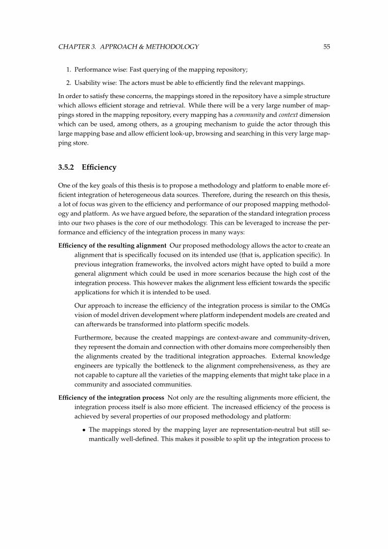
CHAPTER 3. APPROACH & METHODOLOGY 55
1. Performance wise: Fast querying of the mapping repository;
2. Usability wise: The actors must be able to efficiently find the relevant mappings.
In order to satisfy these concerns, the mappings stored in the repository have a simple structurewhich allows efficient storage and retrieval. While there will be a very large number of map-pings stored in the mapping repository, every mapping has a community and context dimensionwhich can be used, among others, as a grouping mechanism to guide the actor through thislarge mapping base and allow efficient look-up, browsing and searching in this very large map-ping store.
3.5.2 Efficiency
One of the key goals of this thesis is to propose a methodology and platform to enable more ef-ficient integration of heterogeneous data sources. Therefore, during the research on this thesis,a lot of focus was given to the efficiency and performance of our proposed mapping methodol-ogy and platform. As we have argued before, the separation of the standard integration processinto our two phases is the core of our methodology. This can be leveraged to increase the per-formance and efficiency of the integration process in many ways:
Efficiency of the resulting alignment Our proposed methodology allows the actor to create analignment that is specifically focused on its intended use (that is, application specific). Inprevious integration frameworks, the involved actors might have opted to build a moregeneral alignment which could be used in more scenarios because the high cost of theintegration process. This however makes the alignment less efficient towards the specificapplications for which it is intended to be used.
Our approach to increase the efficiency of the integration process is similar to the OMGsvision of model driven development where platform independent models are created andcan afterwards be transformed into platform specific models.
Furthermore, because the created mappings are context-aware and community-driven,they represent the domain and connection with other domains more comprehensibly thenthe alignments created by the traditional integration approaches. External knowledgeengineers are typically the bottleneck to the alignment comprehensiveness, as they arenot capable to capture all the varieties of the mapping elements that might take place in acommunity and associated communities.
Efficiency of the integration process Not only are the resulting alignments more efficient, theintegration process itself is also more efficient. The increased efficiency of the process isachieved by several properties of our proposed methodology and platform:
• The mappings stored by the mapping layer are representation-neutral but still se-mantically well-defined. This makes it possible to split up the integration process to
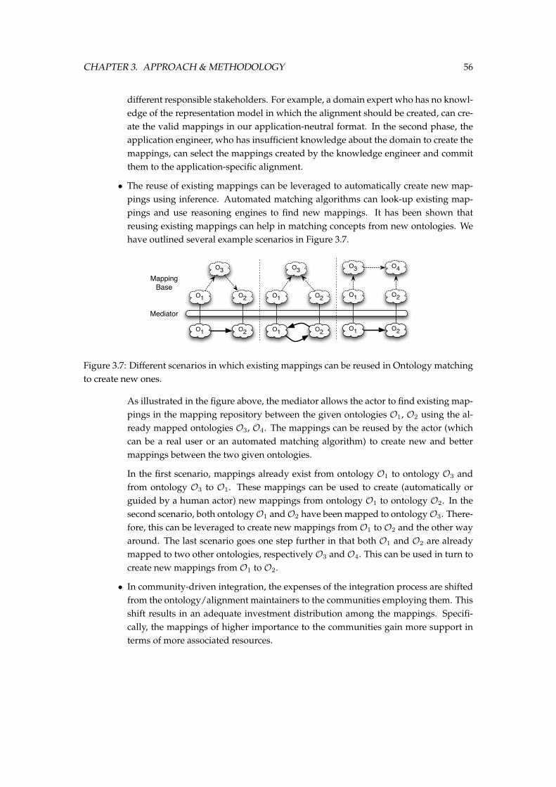
CHAPTER 3. APPROACH & METHODOLOGY 56
different responsible stakeholders. For example, a domain expert who has no knowl-edge of the representation model in which the alignment should be created, can cre-ate the valid mappings in our application-neutral format. In the second phase, theapplication engineer, who has insufficient knowledge about the domain to create themappings, can select the mappings created by the knowledge engineer and committhem to the application-specific alignment.
• The reuse of existing mappings can be leveraged to automatically create new map-pings using inference. Automated matching algorithms can look-up existing map-pings and use reasoning engines to find new mappings. It has been shown thatreusing existing mappings can help in matching concepts from new ontologies. Wehave outlined several example scenarios in Figure 3.7.
O1 O2
O3
O1 O2
O1 O2
O3
O1 O2
O1 O2
O3
O1 O2
O4
Mediator
Mapping Base
Figure 3.7: Different scenarios in which existing mappings can be reused in Ontology matchingto create new ones.
As illustrated in the figure above, the mediator allows the actor to find existing map-pings in the mapping repository between the given ontologies O1, O2 using the al-ready mapped ontologies O3, O4. The mappings can be reused by the actor (whichcan be a real user or an automated matching algorithm) to create new and bettermappings between the two given ontologies.
In the first scenario, mappings already exist from ontology O1 to ontology O3 andfrom ontology O3 to O1. These mappings can be used to create (automatically orguided by a human actor) new mappings from ontology O1 to ontology O2. In thesecond scenario, both ontologyO1 andO2 have been mapped to ontologyO3. There-fore, this can be leveraged to create new mappings from O1 to O2 and the other wayaround. The last scenario goes one step further in that both O1 and O2 are alreadymapped to two other ontologies, respectively O3 and O4. This can be used in turn tocreate new mappings from O1 to O2.
• In community-driven integration, the expenses of the integration process are shiftedfrom the ontology/alignment maintainers to the communities employing them. Thisshift results in an adequate investment distribution among the mappings. Specifi-cally, the mappings of higher importance to the communities gain more support interms of more associated resources.
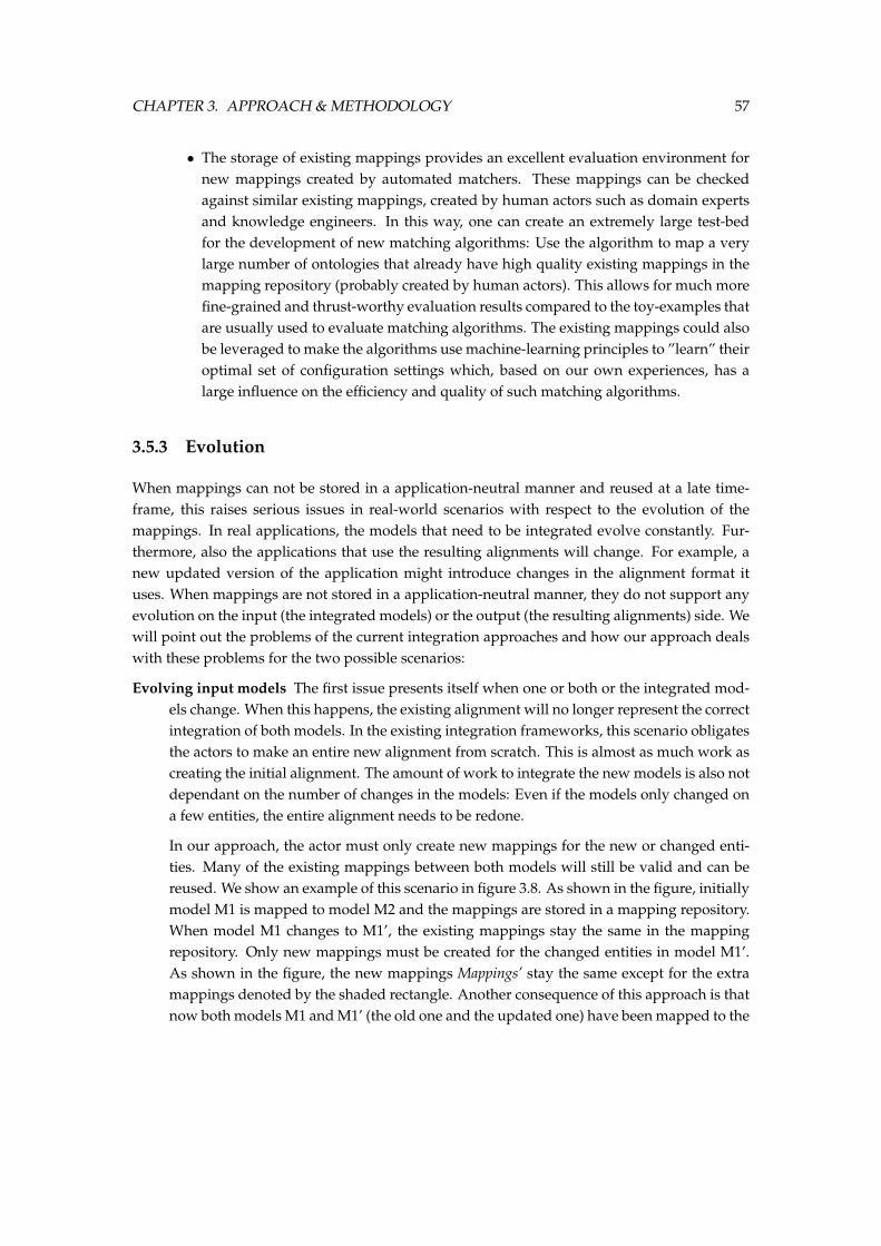
CHAPTER 3. APPROACH & METHODOLOGY 57
• The storage of existing mappings provides an excellent evaluation environment fornew mappings created by automated matchers. These mappings can be checkedagainst similar existing mappings, created by human actors such as domain expertsand knowledge engineers. In this way, one can create an extremely large test-bedfor the development of new matching algorithms: Use the algorithm to map a verylarge number of ontologies that already have high quality existing mappings in themapping repository (probably created by human actors). This allows for much morefine-grained and thrust-worthy evaluation results compared to the toy-examples thatare usually used to evaluate matching algorithms. The existing mappings could alsobe leveraged to make the algorithms use machine-learning principles to ”learn” theiroptimal set of configuration settings which, based on our own experiences, has alarge influence on the efficiency and quality of such matching algorithms.
3.5.3 Evolution
When mappings can not be stored in a application-neutral manner and reused at a late time-frame, this raises serious issues in real-world scenarios with respect to the evolution of themappings. In real applications, the models that need to be integrated evolve constantly. Fur-thermore, also the applications that use the resulting alignments will change. For example, anew updated version of the application might introduce changes in the alignment format ituses. When mappings are not stored in a application-neutral manner, they do not support anyevolution on the input (the integrated models) or the output (the resulting alignments) side. Wewill point out the problems of the current integration approaches and how our approach dealswith these problems for the two possible scenarios:
Evolving input models The first issue presents itself when one or both or the integrated mod-els change. When this happens, the existing alignment will no longer represent the correctintegration of both models. In the existing integration frameworks, this scenario obligatesthe actors to make an entire new alignment from scratch. This is almost as much work ascreating the initial alignment. The amount of work to integrate the new models is also notdependant on the number of changes in the models: Even if the models only changed ona few entities, the entire alignment needs to be redone.
In our approach, the actor must only create new mappings for the new or changed enti-ties. Many of the existing mappings between both models will still be valid and can bereused. We show an example of this scenario in figure 3.8. As shown in the figure, initiallymodel M1 is mapped to model M2 and the mappings are stored in a mapping repository.When model M1 changes to M1’, the existing mappings stay the same in the mappingrepository. Only new mappings must be created for the changed entities in model M1’.As shown in the figure, the new mappings Mappings’ stay the same except for the extramappings denoted by the shaded rectangle. Another consequence of this approach is thatnow both models M1 and M1’ (the old one and the updated one) have been mapped to the
CHAPTER 3. APPROACH & METHODOLOGY 58
M1 M2
Mapping Repository
M1'
Map
ping
sM
appi
ngs'
Figure 3.8: A possible evolution scenario where one model changes and the mappings need tobe updated accordingly.
other model M2 so the previous version of the model is still supported by the mappingrepository.
Evolving application scenarios The second scenario represents itself when the application inwhich the alignment resulting from the integration process must be used, changes. Inexisting works, the entire alignment must again be entirely recreated. In our case, onlythe second phase of our integration methodology must be redone: The actor can reuse themappings stored in the repository to commit to the new alignment format.
3.6 Conclusions
We started this chapter by introducing the two cornerstones of our proposed integration ap-proach: Mapping reuse and application-specific mappings. We identified several scenarios thatare problematic for the existing integration frameworks, but are much better handled usingour methodology. In the second section of this chapter, we elaborated in more detail on ourmethodology. We discussed in detail the two phases of our integration approach: The Mappingphase and the Commitment phase. We discussed the tree most significant characteristics of ourapproach and methodology: Uniform and context-aware mappings, and a community-drivenmapping process. In the third section we defined the precise semantics of the conceptual datamodel used by our methodology: We provided exact definitions of the Context, the Commu-nity, the Mapping, the Model, the Entity, and the Relation Definition used in our approach. Toconclude the section, we elaborated on the motivation for our choices. We showed how ourapproach has significant benefits over existing approaches and how it accomplishes the goalswe have set for this thesis.
4The Platform
In this chapter, we present our integration platform implementing the conceptual frameworkand specifications we presented in the previous chapter. We first discuss the architecture of theplatform: We describe how we have mapped our two-step methodology (the mapping phaseand commitment phase) and the specific characteristics of our approach (uniform, context-aware, and community-driven mappings) to our integration platform. In the second sectionwe elaborate on the implementation details of the Platform Server. We show its technologystack and motivate our choices. In the third section of this chapter, we provide the reader withan overview on our Mapping Client tool. We also give a brief overview of its implementationwhile not going into too much irrelevant details. We end this chapter with a preliminary evalu-ation of the platform. In a real-life scenario we integrate two ontologies using the platform byfollowing our methodology. In this way, we show how the platform we developed supports theintegration of two heterogeneous models using the methodology we presented in the previouschapter.
4.1 Overview
In the previous chapter we have outlined the methodology and approach of our integrationprocess. In this section, we will present the architecture of our platform that implements thismethodology. As we have discussed, the two cornerstones of our proposed integration ap-
59
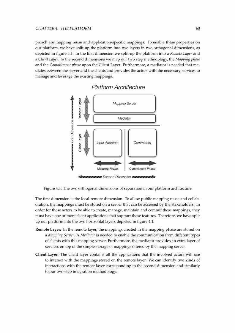
CHAPTER 4. THE PLATFORM 60
proach are mapping reuse and application-specific mappings. To enable these properties onour platform, we have split-up the platform into two layers in two orthogonal dimensions, asdepicted in figure 4.1. In the first dimension we split-up the platform into a Remote Layer anda Client Layer. In the second dimensions we map our two step methodology, the Mapping phaseand the Commitment phase upon the Client Layer. Furthermore, a mediator is needed that me-diates between the server and the clients and provides the actors with the necessary services tomanage and leverage the existing mappings.
Rem
ote
Laye
r
Mapping Phase
Mapping Server
Mediator
Clie
nt L
ayer
Input Adapters Committers
Commitment Phase
Platform Architecture
Firs
t Dim
ensi
on
Second Dimension
Figure 4.1: The two orthogonal dimensions of separation in our platform architecture
The first dimension is the local-remote dimension. To allow public mapping reuse and collab-oration, the mappings must be stored on a server that can be accessed by the stakeholders. Inorder for these actors to be able to create, manage, maintain and commit these mappings, theymust have one or more client applications that support these features. Therefore, we have splitup our platform into the two horizontal layers depicted in figure 4.1:
Remote Layer: In the remote layer, the mappings created in the mapping phase are stored ona Mapping Server. A Mediator is needed to enable the communication from different typesof clients with this mapping server. Furthermore, the mediator provides an extra layer ofservices on top of the simple storage of mappings offered by the mapping server.
Client Layer: The client layer contains all the applications that the involved actors will useto interact with the mappings stored on the remote layer. We can identify two kinds ofinteractions with the remote layer corresponding to the second dimension and similarlyto our two-step integration methodology:
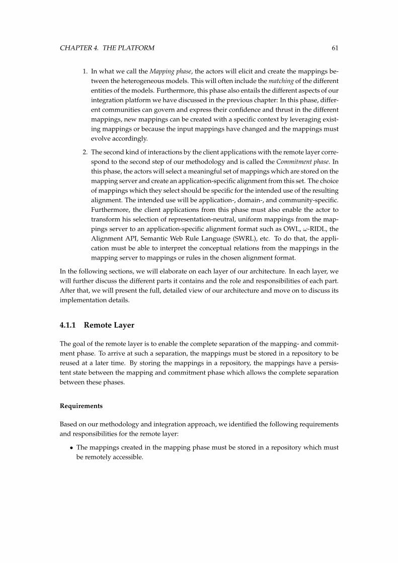
CHAPTER 4. THE PLATFORM 61
1. In what we call the Mapping phase, the actors will elicit and create the mappings be-tween the heterogeneous models. This will often include the matching of the differententities of the models. Furthermore, this phase also entails the different aspects of ourintegration platform we have discussed in the previous chapter: In this phase, differ-ent communities can govern and express their confidence and thrust in the differentmappings, new mappings can be created with a specific context by leveraging exist-ing mappings or because the input mappings have changed and the mappings mustevolve accordingly.
2. The second kind of interactions by the client applications with the remote layer corre-spond to the second step of our methodology and is called the Commitment phase. Inthis phase, the actors will select a meaningful set of mappings which are stored on themapping server and create an application-specific alignment from this set. The choiceof mappings which they select should be specific for the intended use of the resultingalignment. The intended use will be application-, domain-, and community-specific.Furthermore, the client applications from this phase must also enable the actor totransform his selection of representation-neutral, uniform mappings from the map-pings server to an application-specific alignment format such as OWL, ω-RIDL, theAlignment API, Semantic Web Rule Language (SWRL), etc. To do that, the appli-cation must be able to interpret the conceptual relations from the mappings in themapping server to mappings or rules in the chosen alignment format.
In the following sections, we will elaborate on each layer of our architecture. In each layer, wewill further discuss the different parts it contains and the role and responsibilities of each part.After that, we will present the full, detailed view of our architecture and move on to discuss itsimplementation details.
4.1.1 Remote Layer
The goal of the remote layer is to enable the complete separation of the mapping- and commit-ment phase. To arrive at such a separation, the mappings must be stored in a repository to bereused at a later time. By storing the mappings in a repository, the mappings have a persis-tent state between the mapping and commitment phase which allows the complete separationbetween these phases.
Requirements
Based on our methodology and integration approach, we identified the following requirementsand responsibilities for the remote layer:
• The mappings created in the mapping phase must be stored in a repository which mustbe remotely accessible.
CHAPTER 4. THE PLATFORM 62
• This repository must be able to store mappings from any given input format. That is, itmust be possible to create mappings between any kind of model and store these on theremote layer of the architecture.
• The mappings must be stored in a application-neutral, uniform manner. The mappingsmust also be context- and community-aware. The relations in the mapping must further-more be well-defined and context-dependant. Therefore, the remote layer must supportthe relation articulation function we have defined in the section on our mapping seman-tics.
• The involved actors must be able to select a meaningful set of mappings from this map-ping repository in order to create an application-specific alignment. They should be ableto efficiently search and browse the mapping repository to discover the relevant mappingsto allow for an efficient and scalable integration process.
Rem
ote
Laye
r
Mediator
Mapping BaseModel/Entity
StoreRelation Library
Mapping Server
mapping elementmapping elementmapping elementmapping elementmapping elementmapping elementmapping elementmapping elementmapping elementmapping elementmapping elementmapping elementmapping elementmapping elementmapping elementmapping element
mapping elementmapping elementmapping elementmapping elementmapping elementmapping elementmapping elementmapping element
Figure 4.2: The different parts of the remote layer.
These requirements have led to four big parts that constitute the Mapping Layer: the MappingBase which stores the mappings, the Relation Library which provides definitions of the relationsused in the mappings, the Model and Entity Store that enables the uniform use of different datasources and a Mediator which mediates between this layer and the actors of the system. Theoverview of the remote layer is depicted in figure 4.2.
Mapping Base
The Mapping Base is the repository in which the mapping elements we have defined in section3.4 are stored. In time, the Mapping Base will become very large (to the order of millions)as a match between two models with respectively n and m number of elements will yield nm
mappings. Not all of these mapping elements should be added to the mapping base howeveras most entities will be completely unrelated. Nevertheless, as we described in our integrationmethodology, the selection of relevant and meaningful mappings happens at the commitmentphase. Hence, the actor should not decide (up to some limit - probably using some thresholdvalue) which mappings are relevant enough to add to the mapping base. The large size of the
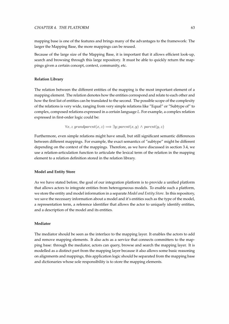
CHAPTER 4. THE PLATFORM 63
mapping base is one of the features and brings many of the advantages to the framework: Thelarger the Mapping Base, the more mappings can be reused.
Because of the large size of the Mapping Base, it is important that it allows efficient look-up,search and browsing through this large repository. It must be able to quickly return the map-pings given a certain concept, context, community, etc.
Relation Library
The relation between the different entities of the mapping is the most important element of amapping element. The relation denotes how the entities correspond and relate to each other andhow the first list of entities can be translated to the second. The possible scope of the complexityof the relations is very wide, ranging from very simple relations like ”Equal” or ”Subtype of” tocomplex, composed relations expressed in a certain language L. For example, a complex relationexpressed in first-order logic could be:
∀x, z grandparent(x, z) =⇒ ∃y; parent(x, y) ∧ parent(y, z)
Furthermore, even simple relations might have small, but still significant semantic differencesbetween different mappings. For example, the exact semantics of ”subtype” might be differentdepending on the context of the mappings. Therefore, as we have discussed in section 3.4, weuse a relation-articulation function to articulate the lexical term of the relation in the mappingelement to a relation definition stored in the relation library.
Model and Entity Store
As we have stated before, the goal of our integration platform is to provide a unified platformthat allows actors to integrate entities from heterogeneous models. To enable such a platform,we store the entity and model information in a separate Model and Entity Store. In this repository,we save the necessary information about a model and it’s entities such as the type of the model,a representation term, a reference identifier that allows the actor to uniquely identify entities,and a description of the model and its entities.
Mediator
The mediator should be seen as the interface to the mapping layer. It enables the actors to addand remove mapping elements. It also acts as a service that connects committers to the map-ping base: through the mediator, actors can query, browse and search the mapping layer. It ismodelled as a distinct part from the mapping layer because it also allows some basic reasoningon alignments and mappings, this application logic should be separated from the mapping baseand dictionaries whose sole responsibility is to store the mapping elements.
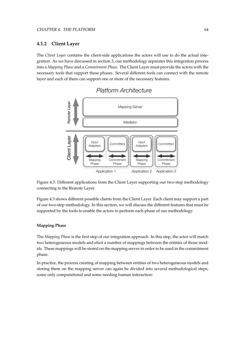
CHAPTER 4. THE PLATFORM 64
4.1.2 Client Layer
The Client Layer contains the client-side applications the actors will use to do the actual inte-gration. As we have discussed in section 3, our methodology separates this integration processinto a Mapping Phase and a Commitment Phase. The Client Layer must provide the actors with thenecessary tools that support these phases. Several different tools can connect with the remotelayer and each of them can support one or more of the necessary features.
Rem
ote
Laye
r
Mapping Server
Mediator
Clie
nt L
ayer
Input Adapters Committers
Platform Architecture
Input Adapters Committers
Application 1 Application 2 Application 3
Mapping Phase
Commitment Phase
Commitment Phase
Mapping Phase
Figure 4.3: Different applications from the Client Layer supporting our two-step methodologyconnecting to the Remote Layer.
Figure 4.3 shows different possible clients from the Client Layer. Each client may support a partof our two-step methodology. In this section, we will discuss the different features that must besupported by the tools to enable the actors to perform each phase of our methodology.
Mapping Phase
The Mapping Phase is the first step of our integration approach. In this step, the actor will matchtwo heterogeneous models and elicit a number of mappings between the entities of those mod-els. These mappings will be stored on the mapping server in order to be used in the commitmentphase.
In practice, the process creating of mapping between entities of two heterogeneous models andstoring them on the mapping server can again be divided into several methodological steps,some only computational and some needing human interaction:
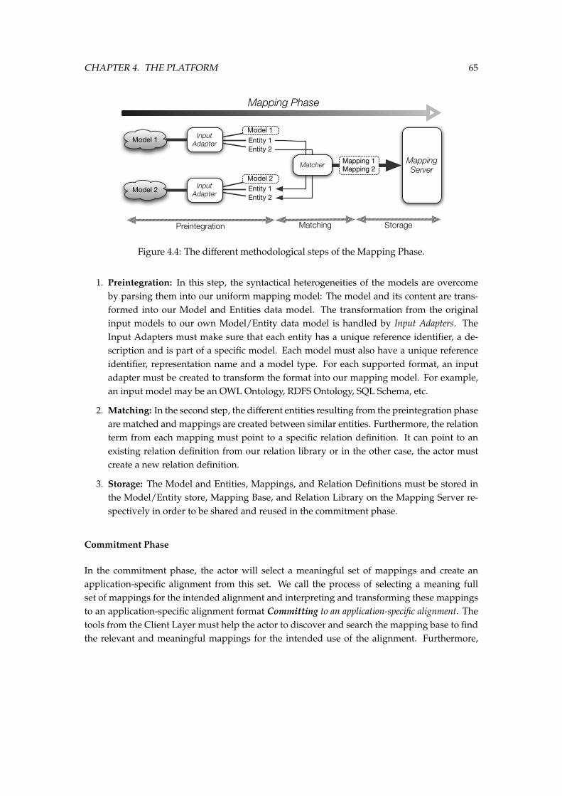
CHAPTER 4. THE PLATFORM 65
Mapping Phase
Model 1
Model 2 Input Adapter
Input Adapter
Model 1Entity 1Entity 2
Model 2Entity 1Entity 2
Matcher Mapping Server
Mapping 1Mapping 2
Preintegration Matching Storage
Figure 4.4: The different methodological steps of the Mapping Phase.
1. Preintegration: In this step, the syntactical heterogeneities of the models are overcomeby parsing them into our uniform mapping model: The model and its content are trans-formed into our Model and Entities data model. The transformation from the originalinput models to our own Model/Entity data model is handled by Input Adapters. TheInput Adapters must make sure that each entity has a unique reference identifier, a de-scription and is part of a specific model. Each model must also have a unique referenceidentifier, representation name and a model type. For each supported format, an inputadapter must be created to transform the format into our mapping model. For example,an input model may be an OWL Ontology, RDFS Ontology, SQL Schema, etc.
2. Matching: In the second step, the different entities resulting from the preintegration phaseare matched and mappings are created between similar entities. Furthermore, the relationterm from each mapping must point to a specific relation definition. It can point to anexisting relation definition from our relation library or in the other case, the actor mustcreate a new relation definition.
3. Storage: The Model and Entities, Mappings, and Relation Definitions must be stored inthe Model/Entity store, Mapping Base, and Relation Library on the Mapping Server re-spectively in order to be shared and reused in the commitment phase.
Commitment Phase
In the commitment phase, the actor will select a meaningful set of mappings and create anapplication-specific alignment from this set. We call the process of selecting a meaning fullset of mappings for the intended alignment and interpreting and transforming these mappingsto an application-specific alignment format Committing to an application-specific alignment. Thetools from the Client Layer must help the actor to discover and search the mapping base to findthe relevant and meaningful mappings for the intended use of the alignment. Furthermore,
CHAPTER 4. THE PLATFORM 66
the tools must guide the actor to interpret this set of mappings with their relation definition totransform it to an application-specific alignment in a certain integration format.
Commitment Phase
Mapping Server
Mapping 1Mapping 2Mapping 3Mapping 4Mapping 5
Meaningful set of application-neutral
MappingsOWL
Committer
Omega-RIDL Committer
Alignment-API Committer
Application-specifc Alignments
OWL Alignment
Omega-RIDL Alignment
Alignment-API Alignment
Select meaningful set of mappings Translate to specific alignment format
Figure 4.5: The methodological steps of the Commitment phase and the necessary tool-support.
Figure 4.5 depicts the Commitment Phase process. We identify the two methodological stepsthat are needed to create the final, application-specific alignment. First, a meaningful set ofmappings must be selected from the Mapping Base. Secondly, this set of mappings must beinterpreted and translated into a specific alignment format. We will now elaborate on bothsteps of the commitment process:
1. Select meaningful set of Mappings:
When an actor needs an alignment to integrate two heterogeneous data sources, this align-ment will be application-specific: To integrate the two sources, the alignment will need tobe executed to, for example, transform data in one format to another data model format.The kind of mappings that will be needed to do this integration are dependant on the useof the alignment. For example, two scenarios in which the same two models need to beintegrated, may still need a different alignment. In the first scenario, it might be sufficientthat a certain concept from the first model is similar to a concept from the second model;while in the second scenario, the concept from the first model might need a specific trans-formation function to be translated to the concept from the second model.
In this step, the actor must search and browse the mapping base to discover the meaning-ful set of mappings that best models or approximates the intended use of the alignment.He can do this efficiently because of our context-aware and community-driven mappings:The mappings are grouped by context and community which enables the actor to quicklyfind the relevant mappings. Furthermore, the community might have expressed theirthrust and confidence in certain mappings which may be used by the actor as a measureof quality and acceptance of the mapping.
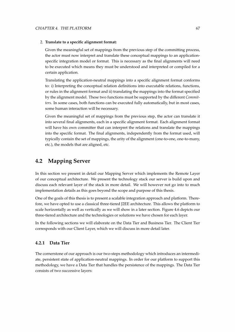
CHAPTER 4. THE PLATFORM 67
2. Translate to a specific alignment format:
Given the meaningful set of mappings from the previous step of the committing process,the actor must now interpret and translate these conceptual mappings to an application-specific integration model or format. This is necessary as the final alignments will needto be executed which means they must be understood and interpreted or compiled for acertain application.
Translating the application-neutral mappings into a specific alignment format conformsto: i) Interpreting the conceptual relation definitions into executable relations, functions,or rules in the alignment format and ii) translating the mappings into the format specifiedby the alignment model. These two functions must be supported by the different Commit-ters. In some cases, both functions can be executed fully automatically, but in most cases,some human interaction will be necessary.
Given the meaningful set of mappings from the previous step, the actor can translate itinto several final alignments, each in a specific alignment format. Each alignment formatwill have his own committer that can interpret the relations and translate the mappingsinto the specific format. The final alignments, independently from the format used, willtypically contain the set of mappings, the arity of the alignment (one-to-one, one-to-many,etc.), the models that are aligned, etc.
4.2 Mapping Server
In this section we present in detail our Mapping Server which implements the Remote Layerof our conceptual architecture. We present the technology stack our server is build upon anddiscuss each relevant layer of the stack in more detail. We will however not go into to muchimplementation details as this goes beyond the scope and purpose of this thesis.
One of the goals of this thesis is to present a scalable integration approach and platform. There-fore, we have opted to use a classical three-tiered J2EE architecture. This allows the platform toscale horizontally as well as vertically as we will show in a later section. Figure 4.6 depicts ourthree-tiered architecture and the technologies or solutions we have chosen for each layer.
In the following sections we will elaborate on the Data Tier and Business Tier. The Client Tiercorresponds with our Client Layer, which we will discuss in more detail later.
4.2.1 Data Tier
The cornerstone of our approach is our two-steps methodology which introduces an intermedi-ate, persistent state of application-neutral mappings. In order for our platform to support thismethodology, we have a Data Tier that handles the persistence of the mappings. The Data Tierconsists of two successive layers:
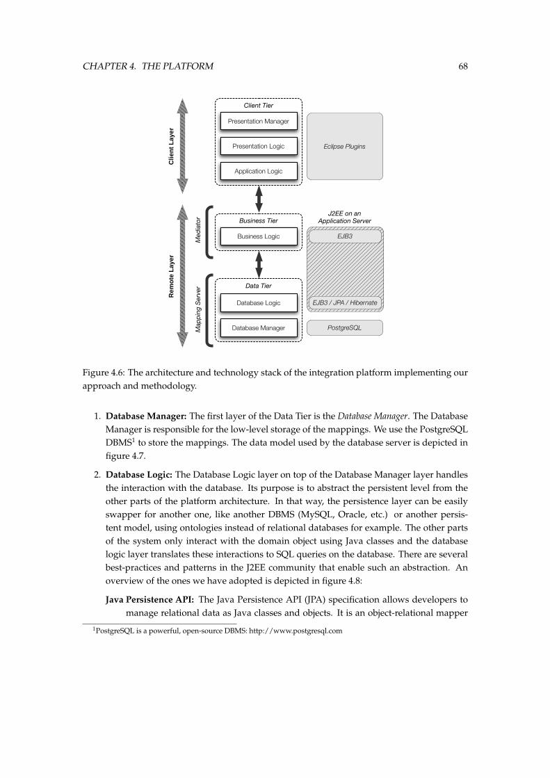
CHAPTER 4. THE PLATFORM 68
Database Logic
Data Tier
Business Logic
Business Tier
Client Tier
Presentation Manager
Presentation Logic
Application Logic
PostgreSQLDatabase Manager
EJB3 / JPA / Hibernate
EJB3
Eclipse Plugins
J2EE on an Application Server
Rem
ote
Lay
erC
lien
t L
ayer
Map
pin
g S
erve
rM
edia
tor
Figure 4.6: The architecture and technology stack of the integration platform implementing ourapproach and methodology.
1. Database Manager: The first layer of the Data Tier is the Database Manager. The DatabaseManager is responsible for the low-level storage of the mappings. We use the PostgreSQLDBMS1 to store the mappings. The data model used by the database server is depicted infigure 4.7.
2. Database Logic: The Database Logic layer on top of the Database Manager layer handlesthe interaction with the database. Its purpose is to abstract the persistent level from theother parts of the platform architecture. In that way, the persistence layer can be easilyswapper for another one, like another DBMS (MySQL, Oracle, etc.) or another persis-tent model, using ontologies instead of relational databases for example. The other partsof the system only interact with the domain object using Java classes and the databaselogic layer translates these interactions to SQL queries on the database. There are severalbest-practices and patterns in the J2EE community that enable such an abstraction. Anoverview of the ones we have adopted is depicted in figure 4.8:
Java Persistence API: The Java Persistence API (JPA) specification allows developers tomanage relational data as Java classes and objects. It is an object-relational mapper
1PostgreSQL is a powerful, open-source DBMS: http://www.postgresql.com
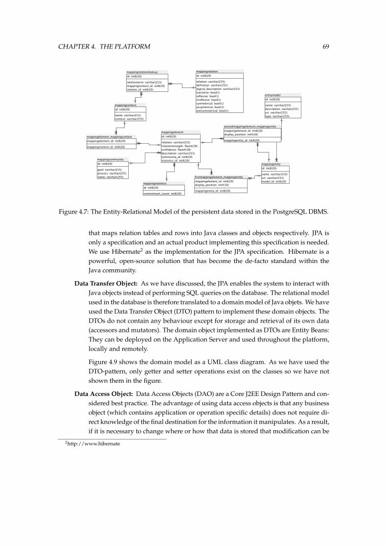
CHAPTER 4. THE PLATFORM 69
Figure 4.7: The Entity-Relational Model of the persistent data stored in the PostgreSQL DBMS.
that maps relation tables and rows into Java classes and objects respectively. JPA isonly a specification and an actual product implementing this specification is needed.We use Hibernate2 as the implementation for the JPA specification. Hibernate is apowerful, open-source solution that has become the de-facto standard within theJava community.
Data Transfer Object: As we have discussed, the JPA enables the system to interact withJava objects instead of performing SQL queries on the database. The relational modelused in the database is therefore translated to a domain model of Java objets. We haveused the Data Transfer Object (DTO) pattern to implement these domain objects. TheDTOs do not contain any behaviour except for storage and retrieval of its own data(accessors and mutators). The domain object implemented as DTOs are Entity Beans:They can be deployed on the Application Server and used throughout the platform,locally and remotely.
Figure 4.9 shows the domain model as a UML class diagram. As we have used theDTO-pattern, only getter and setter operations exist on the classes so we have notshown them in the figure.
Data Access Object: Data Access Objects (DAO) are a Core J2EE Design Pattern and con-sidered best practice. The advantage of using data access objects is that any businessobject (which contains application or operation specific details) does not require di-rect knowledge of the final destination for the information it manipulates. As a result,if it is necessary to change where or how that data is stored that modification can be
2http://www.hibernate
CHAPTER 4. THE PLATFORM 70
Database Logic
JPA / Hibernate
Data Transfer Objects (DTO)
Data Access Objects (DAO)
Database Manager
Data Tier
Figure 4.8: The patterns and best-practices used in the Database Logic layer.
made without needing to change the main application. Data Access Objects can beused in Java to insulate an application from the underlying Java persistence tech-nology, which could be JDBC, JDO, EJB CMP, TopLink, Hibernate (which we use),iBATIS, or any one of a range of technologies. Using Data Access Objects means theunderlying technology can be upgraded or swapped without changing other partsof the application.
Figure 4.10 depicts the DAO interfaces for each class from the domain model DTOs.By implementing the DAO pattern using interfaces, the architecture is even furtherabstracted from the underlying technologies. In the second figure 4.11, the JPA-basedimplementation of the DAO interfaces are shown using a UML class diagram. Wehave omitted the operations and attributes in the second figure as these are exactlythe same as the ones from the interfaces they implement.
Figure 4.11 also shows that the JPA-specific DAO classes are Stateless Session Beansfrom the EJB3 specification. A class can be specified as a Stateless Session Bean usingannotations first introduced in Java 5. When a class is specified as a session bean,the class automatically becomes available in the application server and can be usedremotely or locally to support the Inversion of Control (IOC) pattern.
4.2.2 Business Tier
The Business Tier of our implementation architecture corresponds with the mediator of the plat-form. It mediates between the data tier and the requests from the remote client applications.It provides services which allow the clients to interact with the data stored in the data tier. Wehave implemented this tier using two specific patterns and best-practices: the Session Facadepattern and the Business Delegate pattern.
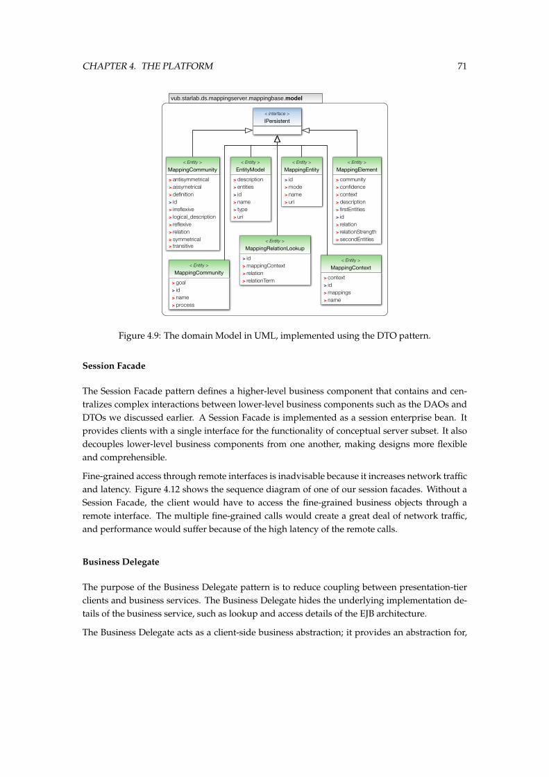
CHAPTER 4. THE PLATFORM 71
vub.starlab.ds.mappingserver.mappingbase.model
IPersistent< interface >
> antisymmetrical> assymetrical> definition> id> irreflexive> logical_description> reflexive> relation> symmetrical> transitive
MappingCommunity< Entity >
> description> entities> id> name> type> uri
EntityModel< Entity >
> id> mode> name> uri
MappingEntity< Entity >
> community> confidence> context> description> firstEntities> id> relation> relationStrength> secondEntities
MappingElement< Entity >
> id> mappingContext> relation> relationTerm
MappingRelationLookup< Entity >
> context> id> mappings> name
MappingContext< Entity >
> goal> id> name> process
MappingCommunity< Entity >
Figure 4.9: The domain Model in UML, implemented using the DTO pattern.
Session Facade
The Session Facade pattern defines a higher-level business component that contains and cen-tralizes complex interactions between lower-level business components such as the DAOs andDTOs we discussed earlier. A Session Facade is implemented as a session enterprise bean. Itprovides clients with a single interface for the functionality of conceptual server subset. It alsodecouples lower-level business components from one another, making designs more flexibleand comprehensible.
Fine-grained access through remote interfaces is inadvisable because it increases network trafficand latency. Figure 4.12 shows the sequence diagram of one of our session facades. Without aSession Facade, the client would have to access the fine-grained business objects through aremote interface. The multiple fine-grained calls would create a great deal of network traffic,and performance would suffer because of the high latency of the remote calls.
Business Delegate
The purpose of the Business Delegate pattern is to reduce coupling between presentation-tierclients and business services. The Business Delegate hides the underlying implementation de-tails of the business service, such as lookup and access details of the EJB architecture.
The Business Delegate acts as a client-side business abstraction; it provides an abstraction for,
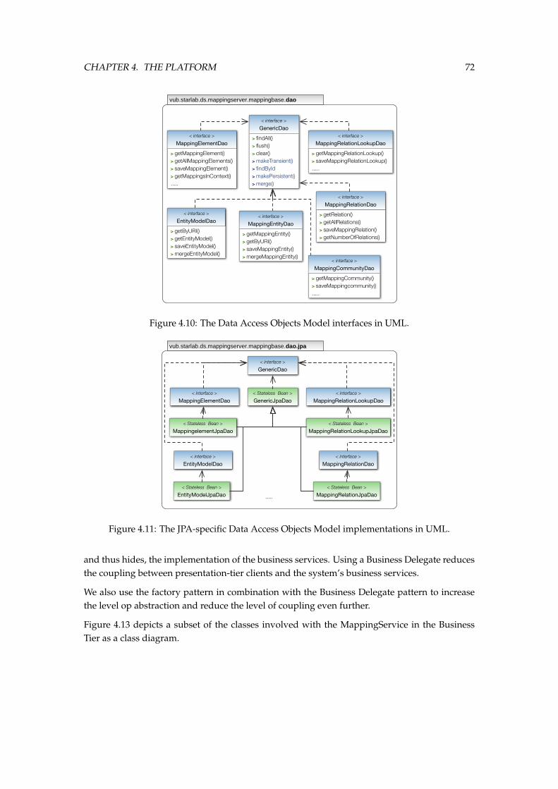
CHAPTER 4. THE PLATFORM 72
vub.starlab.ds.mappingserver.mappingbase.dao
> findAll()> flush()> clear()> makeTransient()> findById> makePersistent()> merge()
GenericDao< interface >
> getMappingElement()> getAllMappingElements()> saveMappingElement()> getMappingsInContext().....
MappingElementDao< interface >
> getMappingRelationLookup()> saveMappingRelationLookup().....
MappingRelationLookupDao< interface >
> getRelation()> getAllRelations()> saveMappingRelation()> getNumberOfRelations()
MappingRelationDao< interface >
> getByURI()> getEntityModel()> saveEntityModel()> mergeEntityModel()
EntityModelDao< interface >
> getMappingEntity()> getByURI()> saveMappingEntity()> mergeMappingEntity()
MappingEntityDao< interface >
> getMappingCommunity()> saveMappingcommunity().....
MappingCommunityDao< interface >
Figure 4.10: The Data Access Objects Model interfaces in UML.
vub.starlab.ds.mappingserver.mappingbase.dao.jpa
GenericDao< interface >
GenericJpaDao< Stateless Bean >
MappingElementDao< interface >
MappingRelationLookupDao< interface >
MappingelementJpaDao< Stateless Bean >
MappingRelationLookupJpaDao< Stateless Bean >
EntityModelDao< interface >
EntityModelJpaDao< Stateless Bean >
MappingRelationDao< interface >
MappingRelationJpaDao< Stateless Bean >
.....
Figure 4.11: The JPA-specific Data Access Objects Model implementations in UML.
and thus hides, the implementation of the business services. Using a Business Delegate reducesthe coupling between presentation-tier clients and the system’s business services.
We also use the factory pattern in combination with the Business Delegate pattern to increasethe level op abstraction and reduce the level of coupling even further.
Figure 4.13 depicts a subset of the classes involved with the MappingService in the BusinessTier as a class diagram.
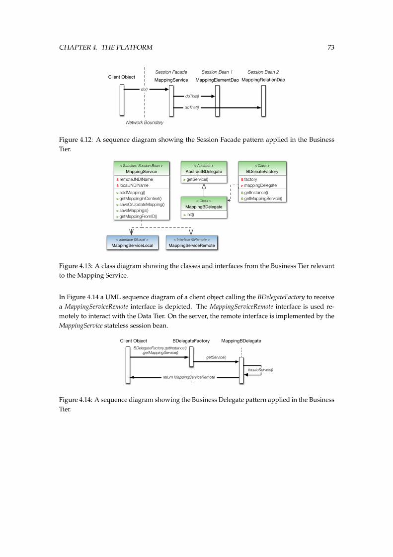
CHAPTER 4. THE PLATFORM 73
doThis()
Client Object
Network Boundary
Session Bean 1 Session Bean 2
doThat()
MappingElementDao MappingRelationDao
Session Facade
MappingService
do()
Figure 4.12: A sequence diagram showing the Session Facade pattern applied in the BusinessTier.
AbstractBDelegate< Abstract >
MappingBDelegate< Class >
> getService()
> init()
BDeleateFactory< Class >
S factory> mappingDelegate
S getInstance()S getMappingService()
MappingService< Stateless Session Bean >
S remoteJNDINameS localJNDIName
> addMapping()> getMappingInContext()> saveOrUpdateMapping()> saveMappings()> getMappingFromID()
MappingServiceRemoteMappingServiceLocal< Interface @Local > < Interface @Remote >
Figure 4.13: A class diagram showing the classes and interfaces from the Business Tier relevantto the Mapping Service.
In Figure 4.14 a UML sequence diagram of a client object calling the BDelegateFactory to receivea MappingServiceRemote interface is depicted. The MappingServiceRemote interface is used re-motely to interact with the Data Tier. On the server, the remote interface is implemented by theMappingService stateless session bean.
BDelegateFactory.getInstance().getMappingService()
Client Object BDelegateFactory MappingBDelegate
getService()
return MappingServiceRemote
locateService()
Figure 4.14: A sequence diagram showing the Business Delegate pattern applied in the BusinessTier.
CHAPTER 4. THE PLATFORM 74
4.2.3 Scalability
One of the goals of this thesis is to present a scalable integration platform. This scalability re-quirement is reflected in our integration approach and two-step methodology promoting reuseof mappings. However, the scalability factor is equally important in our implementation ar-chitecture: If the methodology allows for a scalable integration approach, the platform andarchitecture enabling the methodology must too. Therefore, we will discuss briefly the scal-ability potential of our platform. While this discussion falls mostly outside the scope of thisthesis, we find it important to discuss it briefly in order to back-up our choice of technologiesand frameworks on which we have build our platform.
There are two types of scalability, vertical scalability and horizontal scalability:
Vertical Scaling is achieved by adding capacity (CPU, memory, storage) to the existing infras-tructure. It requires no changes to the architecture of a system and is usually cheaper thanhorizontal scalability. However, one can not endlessly vertically scale-up a system andthe limits are quickly reached. Furthermore, vertical scaling decreases the reliability andavailability of the system as a single failure is more likely to lead to system failure. J2EEsupports vertical scaling because of its automatic lifecycle management: Adding morecapacity to a server allows it to manage more components (Entity beans, Service beans,etc.).
Horizontal Scaling is achieved by adding servers to the system. While it increases the com-plexity of the system architecture, it should be possible to scale a system almost endlesslyin this way. It further increases the reliability, availability, capacity and performance of thesystem. Our architecture supports horizontal scaling because the J2EE application serverson which the business logic runs and database management system for storage can bereplicated and clustered and the whole can be load-balanced without many changed tothe architecture of the platform.
4.3 Mapping Client
To validate our methodology and approach, we have implemented a client-application thatenables actors to create mappings and store them on the Mapping Server. The tool also allowsactors to browse the Mapping Server and select a meaningful set of mappings to commit to afinal alignment.
In this section, we will present our tool: We give an overview of the looks and features imple-mented by the tool and provide a brief overview of its implementation details.
We start the discussion of our Mapping Client with an overview of the main parts of theMapping tool and how it is situated within our platform’s architecture. Figure 4.15 gives anoverview or the most important components of the tool. It further shows how and where the
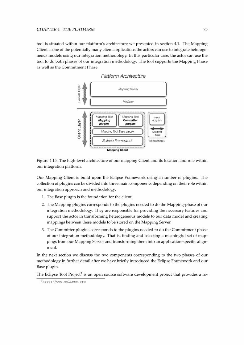
CHAPTER 4. THE PLATFORM 75
tool is situated within our platform’s architecture we presented in section 4.1. The MappingClient is one of the potentially many client applications the actors can use to integrate heteroge-neous models using our integration methodology. In this particular case, the actor can use thetool to do both phases of our integration methodology: The tool supports the Mapping Phaseas well as the Commitment Phase.
Eclipse Framework
Mapping Tool Base plugin
Mapping Tool Mapping plugins
Mapping Tool Committer
plugins
Rem
ote
Laye
r
Mapping Server
Mediator
Clie
nt L
ayer
Platform Architecture
Input Adapters
Application 2
Mapping Phase
Mapping Client
Figure 4.15: The high-level architecture of our mapping Client and its location and role withinour integration platform.
Our Mapping Client is build upon the Eclipse Framework using a number of plugins. Thecollection of plugins can be divided into three main components depending on their role withinour integration approach and methodology:
1. The Base plugin is the foundation for the client.
2. The Mapping plugins corresponds to the plugins needed to do the Mapping-phase of ourintegration methodology. They are responsible for providing the necessary features andsupport the actor in transforming heterogeneous models to our data model and creatingmappings between these models to be stored on the Mapping Server.
3. The Committer plugins corresponds to the plugins needed to do the Commitment phaseof our integration methodology. That is, finding and selecting a meaningful set of map-pings from our Mapping Server and transforming them into an application-specific align-ment.
In the next section we discuss the two components corresponding to the two phases of ourmethodology in further detail after we have briefly introduced the Eclipse Framework and ourBase plugin.
The Eclipse Tool Project3 is an open source software development project that provides a ro-3http://www.eclipse.org
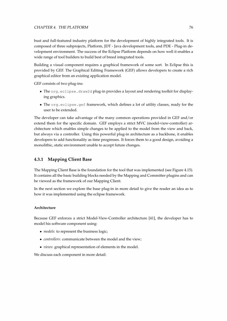
CHAPTER 4. THE PLATFORM 76
bust and full-featured industry platform for the development of highly integrated tools. It iscomposed of three subprojects, Platform, JDT - Java development tools, and PDE - Plug-in de-velopment environment. The success of the Eclipse Platform depends on how well it enables awide range of tool builders to build best of breed integrated tools.
Building a visual component requires a graphical framework of some sort. In Eclipse this isprovided by GEF. The Graphical Editing Framework (GEF) allows developers to create a richgraphical editor from an existing application model.
GEF consists of two plug-ins:
• The org.eclipse.draw2d plug-in provides a layout and rendering toolkit for display-ing graphics.
• The org.eclipse.gef framework, which defines a lot of utility classes, ready for theuser to be extended.
The developer can take advantage of the many common operations provided in GEF and/orextend them for the specific domain. GEF employs a strict MVC (model-view-controller) ar-chitecture which enables simple changes to be applied to the model from the view and back,but always via a controller. Using this powerful plug-in architecture as a backbone, it enablesdevelopers to add functionality as time progresses. It forces them to a good design, avoiding amonolithic, static environment unable to accept future changes.
4.3.1 Mapping Client Base
The Mapping Client Base is the foundation for the tool that was implemented (see Figure 4.15).It contains all the basic building blocks needed by the Mapping and Committer plugins and canbe viewed as the framework of our Mapping Client.
In the next section we explore the base plug-in in more detail to give the reader an idea as tohow it was implemented using the eclipse framework.
Architecture
Because GEF enforces a strict Model-View-Controller architecture [41], the developer has tomodel his software component using:
• models: to represent the business logic;
• controllers: communicate between the model and the view;
• views: graphical representation of elements in the model.
We discuss each component in more detail:
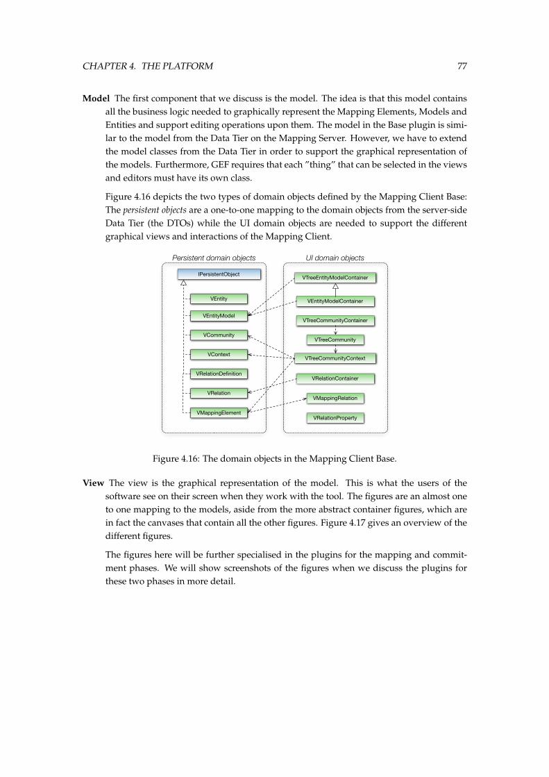
CHAPTER 4. THE PLATFORM 77
Model The first component that we discuss is the model. The idea is that this model containsall the business logic needed to graphically represent the Mapping Elements, Models andEntities and support editing operations upon them. The model in the Base plugin is simi-lar to the model from the Data Tier on the Mapping Server. However, we have to extendthe model classes from the Data Tier in order to support the graphical representation ofthe models. Furthermore, GEF requires that each ”thing” that can be selected in the viewsand editors must have its own class.
Figure 4.16 depicts the two types of domain objects defined by the Mapping Client Base:The persistent objects are a one-to-one mapping to the domain objects from the server-sideData Tier (the DTOs) while the UI domain objects are needed to support the differentgraphical views and interactions of the Mapping Client.
VCommunity
IPersistentObject
VContext
VEntity
VEntityModel
VMappingElement
VRelation
VRelationDefinition
VMappingRelation
VRelationProperty
VTreeCommunity
VTreeCommunityContainer
VTreeEntityModelContainer
VEntityModelContainer
VRelationContainer
VTreeCommunityContext
Persistent domain objects UI domain objects
Figure 4.16: The domain objects in the Mapping Client Base.
View The view is the graphical representation of the model. This is what the users of thesoftware see on their screen when they work with the tool. The figures are an almost oneto one mapping to the models, aside from the more abstract container figures, which arein fact the canvases that contain all the other figures. Figure 4.17 gives an overview of thedifferent figures.
The figures here will be further specialised in the plugins for the mapping and commit-ment phases. We will show screenshots of the figures when we discuss the plugins forthese two phases in more detail.
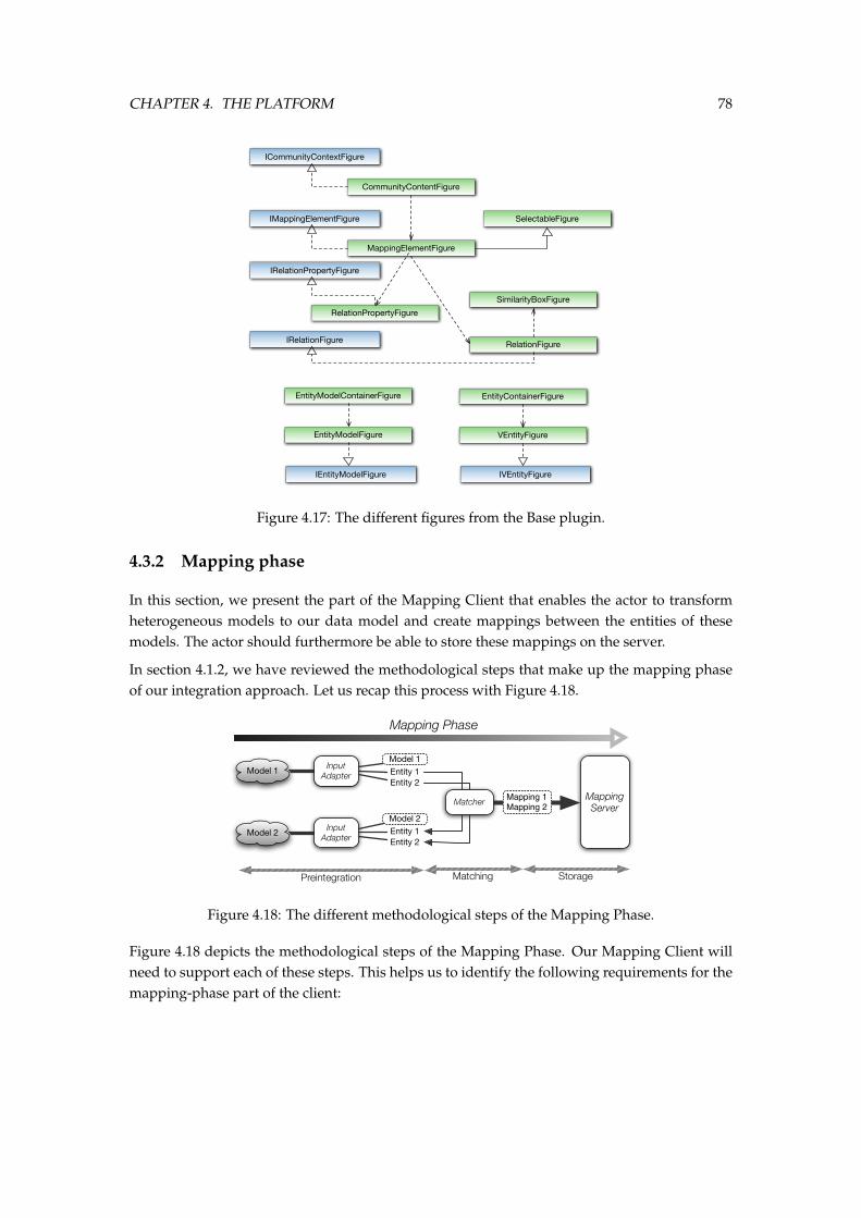
CHAPTER 4. THE PLATFORM 78
ICommunityContextFigure
IEntityModelFigure
IMappingElementFigure
IRelationFigure
IRelationPropertyFigure
IVEntityFigure
CommunityContentFigure
EntityContainerFigureEntityModelContainerFigure
EntityModelFigure
MappingElementFigure
RelationFigure
RelationPropertyFigure
SelectableFigure
SimilarityBoxFigure
VEntityFigure
Figure 4.17: The different figures from the Base plugin.
4.3.2 Mapping phase
In this section, we present the part of the Mapping Client that enables the actor to transformheterogeneous models to our data model and create mappings between the entities of thesemodels. The actor should furthermore be able to store these mappings on the server.
In section 4.1.2, we have reviewed the methodological steps that make up the mapping phaseof our integration approach. Let us recap this process with Figure 4.18.
Mapping Phase
Model 1
Model 2 Input Adapter
Input Adapter
Model 1Entity 1Entity 2
Model 2Entity 1Entity 2
Matcher Mapping Server
Mapping 1Mapping 2
Preintegration Matching Storage
Figure 4.18: The different methodological steps of the Mapping Phase.
Figure 4.18 depicts the methodological steps of the Mapping Phase. Our Mapping Client willneed to support each of these steps. This helps us to identify the following requirements for themapping-phase part of the client:
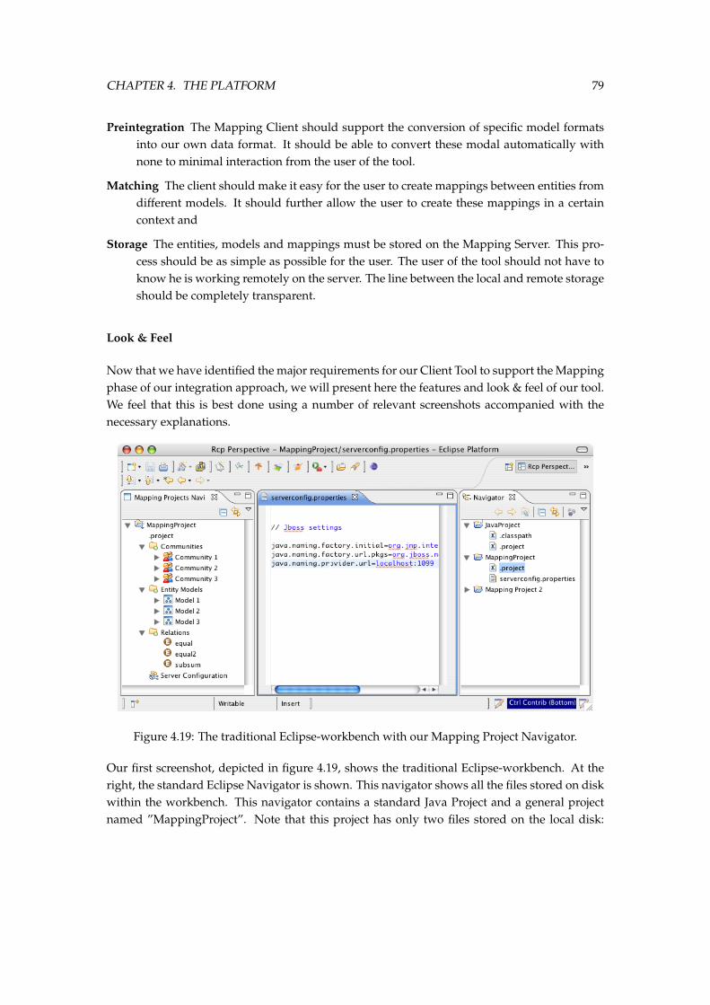
CHAPTER 4. THE PLATFORM 79
Preintegration The Mapping Client should support the conversion of specific model formatsinto our own data format. It should be able to convert these modal automatically withnone to minimal interaction from the user of the tool.
Matching The client should make it easy for the user to create mappings between entities fromdifferent models. It should further allow the user to create these mappings in a certaincontext and
Storage The entities, models and mappings must be stored on the Mapping Server. This pro-cess should be as simple as possible for the user. The user of the tool should not have toknow he is working remotely on the server. The line between the local and remote storageshould be completely transparent.
Look & Feel
Now that we have identified the major requirements for our Client Tool to support the Mappingphase of our integration approach, we will present here the features and look & feel of our tool.We feel that this is best done using a number of relevant screenshots accompanied with thenecessary explanations.
Figure 4.19: The traditional Eclipse-workbench with our Mapping Project Navigator.
Our first screenshot, depicted in figure 4.19, shows the traditional Eclipse-workbench. At theright, the standard Eclipse Navigator is shown. This navigator shows all the files stored on diskwithin the workbench. This navigator contains a standard Java Project and a general projectnamed ”MappingProject”. Note that this project has only two files stored on the local disk:
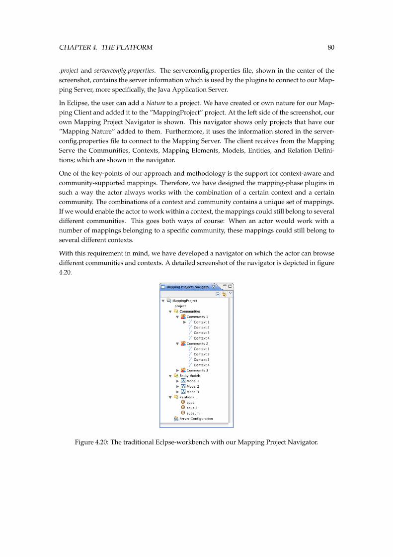
CHAPTER 4. THE PLATFORM 80
.project and serverconfig.properties. The serverconfig.properties file, shown in the center of thescreenshot, contains the server information which is used by the plugins to connect to our Map-ping Server, more specifically, the Java Application Server.
In Eclipse, the user can add a Nature to a project. We have created or own nature for our Map-ping Client and added it to the ”MappingProject” project. At the left side of the screenshot, ourown Mapping Project Navigator is shown. This navigator shows only projects that have our”Mapping Nature” added to them. Furthermore, it uses the information stored in the server-config.properties file to connect to the Mapping Server. The client receives from the MappingServe the Communities, Contexts, Mapping Elements, Models, Entities, and Relation Defini-tions; which are shown in the navigator.
One of the key-points of our approach and methodology is the support for context-aware andcommunity-supported mappings. Therefore, we have designed the mapping-phase plugins insuch a way the actor always works with the combination of a certain context and a certaincommunity. The combinations of a context and community contains a unique set of mappings.If we would enable the actor to work within a context, the mappings could still belong to severaldifferent communities. This goes both ways of course: When an actor would work with anumber of mappings belonging to a specific community, these mappings could still belong toseveral different contexts.
With this requirement in mind, we have developed a navigator on which the actor can browsedifferent communities and contexts. A detailed screenshot of the navigator is depicted in figure4.20.
Figure 4.20: The traditional Eclpse-workbench with our Mapping Project Navigator.
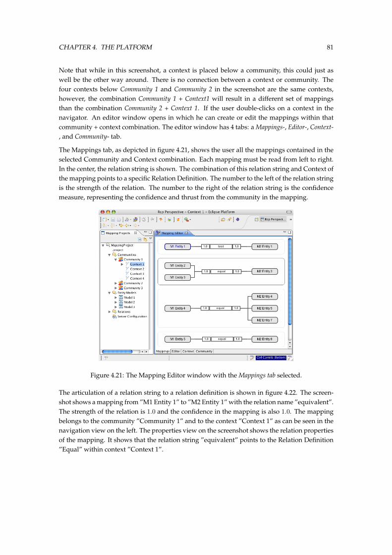
CHAPTER 4. THE PLATFORM 81
Note that while in this screenshot, a context is placed below a community, this could just aswell be the other way around. There is no connection between a context or community. Thefour contexts below Community 1 and Community 2 in the screenshot are the same contexts,however, the combination Community 1 + Context1 will result in a different set of mappingsthan the combination Community 2 + Context 1. If the user double-clicks on a context in thenavigator. An editor window opens in which he can create or edit the mappings within thatcommunity + context combination. The editor window has 4 tabs: a Mappings-, Editor-, Context-, and Community- tab.
The Mappings tab, as depicted in figure 4.21, shows the user all the mappings contained in theselected Community and Context combination. Each mapping must be read from left to right.In the center, the relation string is shown. The combination of this relation string and Context ofthe mapping points to a specific Relation Definition. The number to the left of the relation stringis the strength of the relation. The number to the right of the relation string is the confidencemeasure, representing the confidence and thrust from the community in the mapping.
Figure 4.21: The Mapping Editor window with the Mappings tab selected.
The articulation of a relation string to a relation definition is shown in figure 4.22. The screen-shot shows a mapping from ”M1 Entity 1” to ”M2 Entity 1” with the relation name ”equivalent”.The strength of the relation is 1.0 and the confidence in the mapping is also 1.0. The mappingbelongs to the community ”Community 1” and to the context ”Context 1” as can be seen in thenavigation view on the left. The properties view on the screenshot shows the relation propertiesof the mapping. It shows that the relation string ”equivalent” points to the Relation Definition”Equal” within context ”Context 1”.
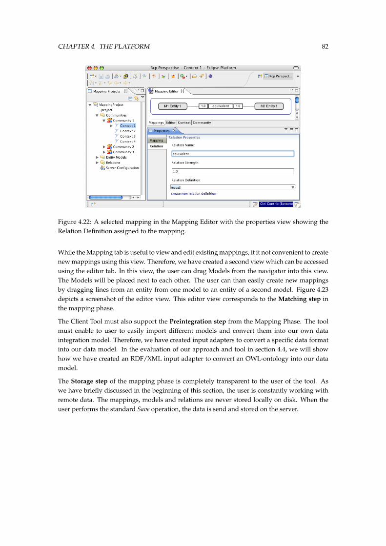
CHAPTER 4. THE PLATFORM 82
Figure 4.22: A selected mapping in the Mapping Editor with the properties view showing theRelation Definition assigned to the mapping.
While the Mapping tab is useful to view and edit existing mappings, it it not convenient to createnew mappings using this view. Therefore, we have created a second view which can be accessedusing the editor tab. In this view, the user can drag Models from the navigator into this view.The Models will be placed next to each other. The user can than easily create new mappingsby dragging lines from an entity from one model to an entity of a second model. Figure 4.23depicts a screenshot of the editor view. This editor view corresponds to the Matching step inthe mapping phase.
The Client Tool must also support the Preintegration step from the Mapping Phase. The toolmust enable to user to easily import different models and convert them into our own dataintegration model. Therefore, we have created input adapters to convert a specific data formatinto our data model. In the evaluation of our approach and tool in section 4.4, we will showhow we have created an RDF/XML input adapter to convert an OWL-ontology into our datamodel.
The Storage step of the mapping phase is completely transparent to the user of the tool. Aswe have briefly discussed in the beginning of this section, the user is constantly working withremote data. The mappings, models and relations are never stored locally on disk. When theuser performs the standard Save operation, the data is send and stored on the server.
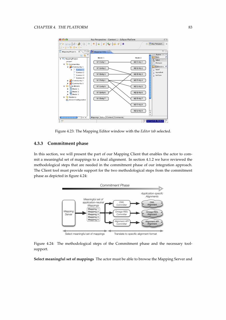
CHAPTER 4. THE PLATFORM 83
Figure 4.23: The Mapping Editor window with the Editor tab selected.
4.3.3 Commitment phase
In this section, we will present the part of our Mapping Client that enables the actor to com-mit a meaningful set of mappings to a final alignment. In section 4.1.2 we have reviewed themethodological steps that are needed in the commitment phase of our integration approach.The Client tool must provide support for the two methodological steps from the commitmentphase as depicted in figure 4.24:
Commitment Phase
Mapping Server
Mapping 1Mapping 2Mapping 3Mapping 4Mapping 5
Meaningful set of application-neutral
MappingsOWL
Committer
Omega-RIDL Committer
Alignment-API Committer
Application-specifc Alignments
OWL Alignment
Omega-RIDL Alignment
Alignment-API Alignment
Select meaningful set of mappings Translate to specific alignment format
Figure 4.24: The methodological steps of the Commitment phase and the necessary tool-support.
Select meaningful set of mappings The actor must be able to browse the Mapping Server and
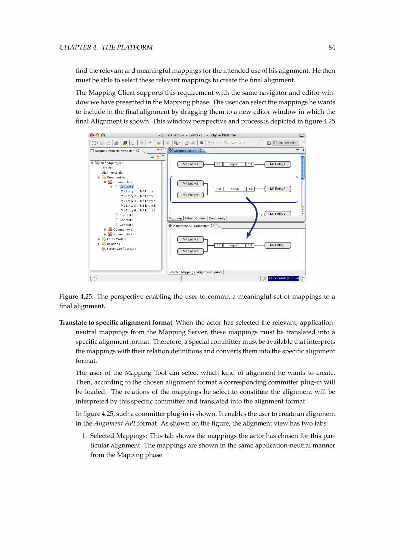
CHAPTER 4. THE PLATFORM 84
find the relevant and meaningful mappings for the intended use of his alignment. He thenmust be able to select these relevant mappings to create the final alignment.
The Mapping Client supports this requirement with the same navigator and editor win-dow we have presented in the Mapping phase. The user can select the mappings he wantsto include in the final alignment by dragging them to a new editor window in which thefinal Alignment is shown. This window perspective and process is depicted in figure 4.25
Figure 4.25: The perspective enabling the user to commit a meaningful set of mappings to afinal alignment.
Translate to specific alignment format When the actor has selected the relevant, application-neutral mappings from the Mapping Server, these mappings must be translated into aspecific alignment format. Therefore, a special committer must be available that interpretsthe mappings with their relation definitions and converts them into the specific alignmentformat.
The user of the Mapping Tool can select which kind of alignment he wants to create.Then, according to the chosen alignment format a corresponding committer plug-in willbe loaded. The relations of the mappings he select to constitute the alignment will beinterpreted by this specific committer and translated into the alignment format.
In figure 4.25, such a committer plug-in is shown. It enables the user to create an alignmentin the Alignment API format. As shown on the figure, the alignment view has two tabs:
1. Selected Mappings: This tab shows the mappings the actor has chosen for this par-ticular alignment. The mappings are shown in the same application-neutral mannerfrom the Mapping phase.
CHAPTER 4. THE PLATFORM 85
2. Alignment Source: This tab shows the selection of meaningful mappings from thealignment translated into the specific alignment format chosen by the user.
4.4 Evaluation
To validate our methodology and approach, we have implemented an integration platform con-sisting of a server and client tool following the specification of the platform from chapter 3. Inthe previous sections, we have presented the Mapping Server and Mapping Client in furtherdetail and have elaborated on how they support our proposed methodology.
In this section, we will further evaluate these tools using a more real-life scenario in order todo an preliminary evaluation of our thesis. It should be noted however that is is very difficultand out of the scope of this thesis to do a full evaluation of our community-driven, context-aware, and scalable integration approach. In order to be able to evaluate these elements ofour approach, we would need a much larger test- and user-base. Both things take a significantamount of work to set up and accurately measure, therefore, we feel that this falls outside of thescope of this thesis.
As a preliminary evaluation of this thesis, we present a real-life scenario in which an align-ment must be created between two heterogeneous ontologies. We have opted to integrate twoRDF-based ontologies as these should sufficiently show the strengths and weaknesses of ourplatform.
In section 4.4.2 of this evaluation, we will precisely show how the user can create mappingsbetween two heterogeneous models and store these mappings on the server, within a certaincontext and community. In section 4.4.3, we show how the user can browse the contexts andcommunities from the server and get a detailed view of every mapping contained in such acontext/community pair. We furthermore show how the user can then select the relevant map-pings and create an alignment between these two heterogeneous models in the Alignment APIformat.
4.4.1 Scenario
In this evaluation we will go through the entire process of integrating two similar, but hetero-geneous RDF-based ontologies. We have chosen two citation ontologies:
1. UMBC Publication Ontology4: This is a publication ontology developed by the UMBCebiquity research group from the university of Maryland. The authors use the ontology topublish their publications on their home-page conforming the Semantic Web principles.
4http://ebiquity.umbc.edu/ontology/publication.owl
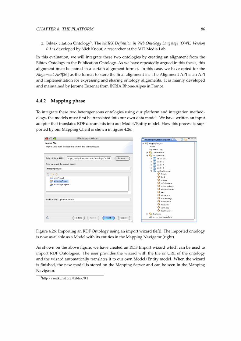
CHAPTER 4. THE PLATFORM 86
2. Bibtex citation Ontology5: The bibTeX Definition in Web Ontology Language (OWL) Version0.1 is developed by Nick Knouf, a researcher at the MIT Media Lab.
In this evaluation, we will integrate these two ontologies by creating an alignment from theBibtex Ontology to the Publication Ontology. As we have repeatedly argued in this thesis, thisalignment must be stored in a certain alignment format. In this case, we have opted for theAlignment API[26] as the format to store the final alignment in. The Alignment API is an APIand implementation for expressing and sharing ontology alignments. It is mainly developedand maintained by Jerome Euzenat from INRIA Rhone-Alpes in France.
4.4.2 Mapping phase
To integrate these two heterogeneous ontologies using our platform and integration method-ology, the models must first be translated into our own data model. We have written an inputadapter that translates RDF documents into our Model/Entity model. How this process is sup-ported by our Mapping Client is shown in figure 4.26.
Figure 4.26: Importing an RDF Ontology using an import wizard (left). The imported ontologyis now available as a Model with its entities in the Mapping Navigator (right).
As shown on the above figure, we have created an RDF Import wizard which can be used toimport RDF Ontologies. The user provides the wizard with the file or URL of the ontologyand the wizard automatically translates it to our own Model/Entity model. When the wizardis finished, the new model is stored on the Mapping Server and can be seen in the MappingNavigator.
5http://zeitkunst.org/bibtex/0.1
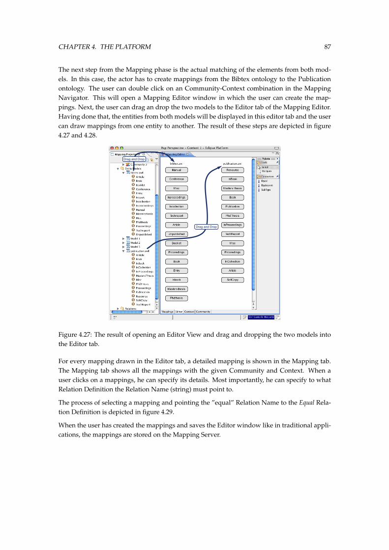
CHAPTER 4. THE PLATFORM 87
The next step from the Mapping phase is the actual matching of the elements from both mod-els. In this case, the actor has to create mappings from the Bibtex ontology to the Publicationontology. The user can double click on an Community-Context combination in the MappingNavigator. This will open a Mapping Editor window in which the user can create the map-pings. Next, the user can drag an drop the two models to the Editor tab of the Mapping Editor.Having done that, the entities from both models will be displayed in this editor tab and the usercan draw mappings from one entity to another. The result of these steps are depicted in figure4.27 and 4.28.
Drag and Drop
Drag and Drop
Figure 4.27: The result of opening an Editor View and drag and dropping the two models intothe Editor tab.
For every mapping drawn in the Editor tab, a detailed mapping is shown in the Mapping tab.The Mapping tab shows all the mappings with the given Community and Context. When auser clicks on a mappings, he can specify its details. Most importantly, he can specify to whatRelation Definition the Relation Name (string) must point to.
The process of selecting a mapping and pointing the ”equal” Relation Name to the Equal Rela-tion Definition is depicted in figure 4.29.
When the user has created the mappings and saves the Editor window like in traditional appli-cations, the mappings are stored on the Mapping Server.
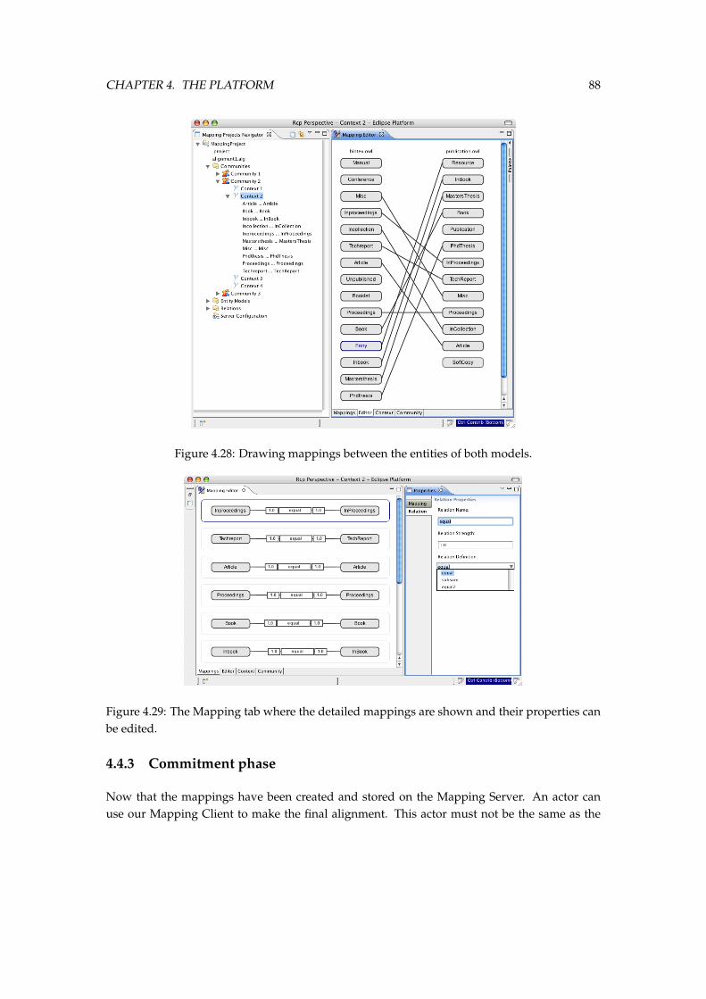
CHAPTER 4. THE PLATFORM 88
Figure 4.28: Drawing mappings between the entities of both models.
Figure 4.29: The Mapping tab where the detailed mappings are shown and their properties canbe edited.
4.4.3 Commitment phase
Now that the mappings have been created and stored on the Mapping Server. An actor canuse our Mapping Client to make the final alignment. This actor must not be the same as the
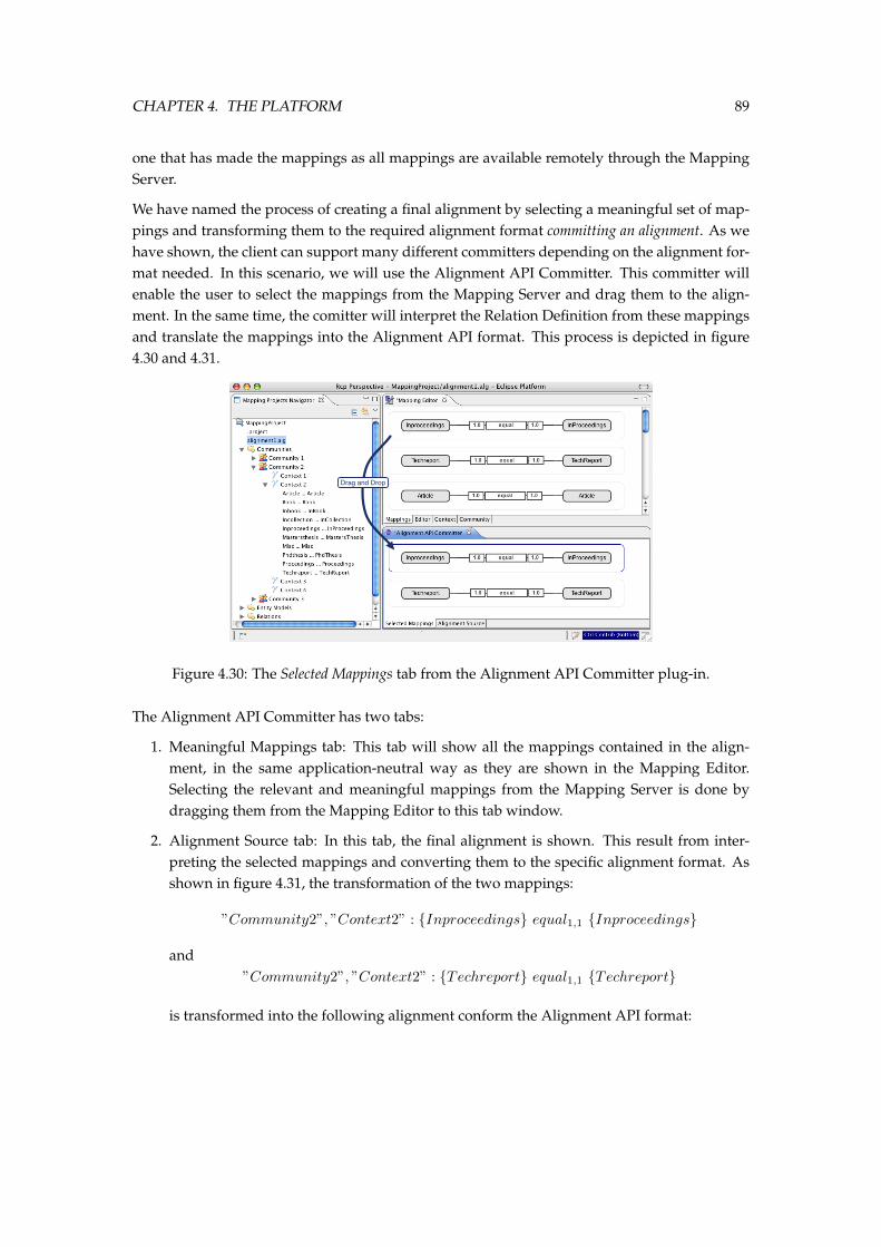
CHAPTER 4. THE PLATFORM 89
one that has made the mappings as all mappings are available remotely through the MappingServer.
We have named the process of creating a final alignment by selecting a meaningful set of map-pings and transforming them to the required alignment format committing an alignment. As wehave shown, the client can support many different committers depending on the alignment for-mat needed. In this scenario, we will use the Alignment API Committer. This committer willenable the user to select the mappings from the Mapping Server and drag them to the align-ment. In the same time, the comitter will interpret the Relation Definition from these mappingsand translate the mappings into the Alignment API format. This process is depicted in figure4.30 and 4.31.
Drag and Drop
Figure 4.30: The Selected Mappings tab from the Alignment API Committer plug-in.
The Alignment API Committer has two tabs:
1. Meaningful Mappings tab: This tab will show all the mappings contained in the align-ment, in the same application-neutral way as they are shown in the Mapping Editor.Selecting the relevant and meaningful mappings from the Mapping Server is done bydragging them from the Mapping Editor to this tab window.
2. Alignment Source tab: In this tab, the final alignment is shown. This result from inter-preting the selected mappings and converting them to the specific alignment format. Asshown in figure 4.31, the transformation of the two mappings:
”Community2”, ”Context2” : Inproceedings equal1,1 Inproceedings
and”Community2”, ”Context2” : Techreport equal1,1 Techreport
is transformed into the following alignment conform the Alignment API format:
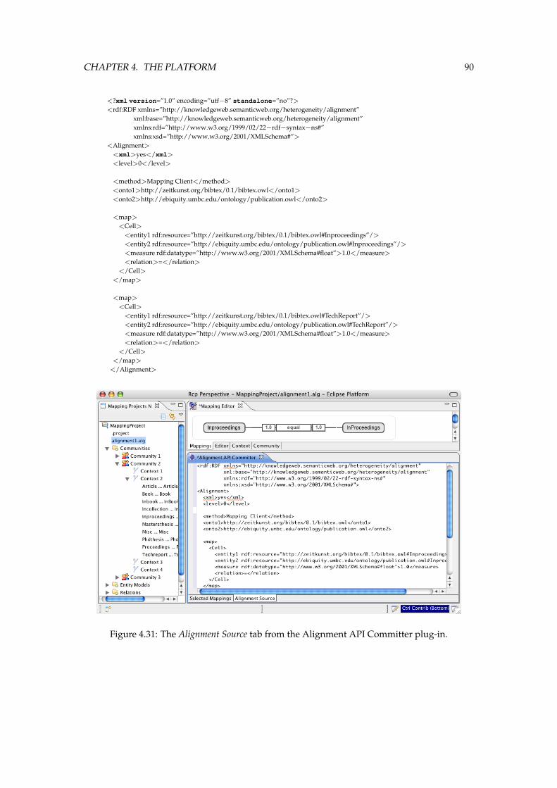
CHAPTER 4. THE PLATFORM 90
<?xml version=”1.0” encoding=”utf−8” standalone=”no”?><rdf:RDF xmlns=”http://knowledgeweb.semanticweb.org/heterogeneity/alignment”
xml:base=”http://knowledgeweb.semanticweb.org/heterogeneity/alignment”xmlns:rdf=”http://www.w3.org/1999/02/22−rdf−syntax−ns#”xmlns:xsd=”http://www.w3.org/2001/XMLSchema#”>
<Alignment><xml>yes</xml>
<level>0</level>
<method>Mapping Client</method>
<onto1>http://zeitkunst.org/bibtex/0.1/bibtex.owl</onto1>
<onto2>http://ebiquity.umbc.edu/ontology/publication.owl</onto2>
<map>
<Cell><entity1 rdf:resource=”http://zeitkunst.org/bibtex/0.1/bibtex.owl#Inproceedings”/>
<entity2 rdf:resource=”http://ebiquity.umbc.edu/ontology/publication.owl#Inproceedings”/>
<measure rdf:datatype=”http://www.w3.org/2001/XMLSchema#float”>1.0</measure>
<relation>=</relation>
</Cell></map>
<map>
<Cell><entity1 rdf:resource=”http://zeitkunst.org/bibtex/0.1/bibtex.owl#TechReport”/>
<entity2 rdf:resource=”http://ebiquity.umbc.edu/ontology/publication.owl#TechReport”/>
<measure rdf:datatype=”http://www.w3.org/2001/XMLSchema#float”>1.0</measure>
<relation>=</relation>
</Cell></map>
</Alignment>
Figure 4.31: The Alignment Source tab from the Alignment API Committer plug-in.
CHAPTER 4. THE PLATFORM 91
4.5 Conclusions
We started this chapter by presenting the high-level architecture of our integration platform.The platform consists of a Remote layer and a Client layer. In the client layer, a separation canbe made between the two steps of our integration methodology: the Mapping phase and the Com-mitment phase. We identified the different steps that need to be followed in each phase and howthese steps are translated into requirements for the Mapping Client. In the second section ofthis chapter, we discussed the Remote Layer of our platform in further detail. We presented thetechnology stack on which the remote layer is based: a three-tiered J2EE architecture. We furtherelaborated on each of the two remote tiers, discussing the implementation details using UMLclass and sequence diagrams and elaborating on the patterns we adopted. In the third section,we discussed the Mapping Client in further detail. We presented the architectural foundationof the tool. Next, we discussed how the Mapping Client supports the two methodological stepsof our integration methodology. In the last section, we performed a preliminary evaluation ofour platform and methodology using a real-life scenario. We showed how two heterogeneousontologies can be integrated using our two-step methodology.
5Conclusions
In this chapter we reflect on the questions we have asked ourselves in this thesis and on how weanswered those questions. Finally we list what we feel are the most important points of futurework
5.1 Research Questions and Objectives
In this thesis we have asked ourselves the following questions and answered them in distinctchapters of this thesis:
1. What kinds of information heterogeneity exist and where does this heterogeneity comefrom? (Chapter 2)
2. What is the existing work on integration methodologies, algorithms and frameworks?(Chapter 2)
3. Can we propose a methodology based on the notions of collaboration, context-awarenessand reuse to attain a scalable integration approach? (Chapter 2)
4. What would the advantages and disadvantages of such an approach be? (Chapter 2)
5. Can we develop an platform that implements and support this methodology? (Chapter 3)
In the next Section we describe how we have answered these questions and met our objec-tives.
92
CHAPTER 5. CONCLUSIONS 93
5.2 Results and Contributions
We now present the results of the thesis. We split up the presentation of our results in threeparts following the research methodology we adopted:
5.2.1 Background
We answered our first two questions in this chapter. We discussed the different forms of se-mantics and how these can lead to heterogeneity. We further discussed STARLab’s DOGMAapproach to ontology engineering as this framework forms the basis of many of the propertiesof our own approach and methodology for information integration. Next, we discussed theuse of semantics in practice, more specifically, we presented the Semantic Web initiative andthe OMG’s model driven architecture (MDA) and ontology definition model (ODM) initiatives.We ended this chapter by providing the reader with a background on semantic integration: Wepresented the common terminology we used throughout the rest of this thesis; we discussedthe different forms and levels in which heterogeneity can appear; we presented a state of the arton ontology matching, a very important part of the integration process, and finally provided anoverview of the most important existing integration frameworks.
5.2.2 Approach & Methodology
We started this chapter by introducing the two cornerstones of our proposed integration ap-proach: Mapping reuse and application-specific mappings. We identified several scenarios thatare problematic for the existing integration frameworks, but are much better handled usingour methodology. In the second section of this chapter, we elaborated in more detail on ourmethodology. We discussed in detail the two phases of our integration approach: The Mappingphase and the Commitment phase. We discussed the tree most significant characteristics of ourapproach and methodology: Uniform and context-aware mappings, and a community-drivenmapping process. In the third section we defined the precise semantics of the conceptual datamodel used by our methodology: We provided exact definitions of the Context, the Commu-nity, the Mapping, the Model, the Entity, and the Relation Definition used in our approach. Toconclude the section, we elaborated on the motivation for our choices. We showed how ourapproach has significant benefits over existing approaches and how it accomplishes the goalswe have set for this thesis.
5.2.3 The Platform
We started this chapter by presenting the high-level architecture of our integration platform.The platform consists of a Remote layer and a Client layer. In the client layer, a separation can
CHAPTER 5. CONCLUSIONS 94
be made between the two steps of our integration methodology: the Mapping phase and the Com-mitment phase. We identified the different steps that need to be followed in each phase and howthese steps are translated into requirements for the Mapping Client. In the second section ofthis chapter, we discussed the Remote Layer of our platform in further detail. We presented thetechnology stack on which the remote layer is based: a three-tiered J2EE architecture. We furtherelaborated on each of the two remote tiers, discussing the implementation details using UMLclass and sequence diagrams and elaborating on the patterns we adopted. In the third section,we discussed the Mapping Client in further detail. We presented the architectural foundationof the tool. Next, we discussed how the Mapping Client supports the two methodological stepsof our integration methodology. In the last section, we performed a preliminary evaluation ofour platform and methodology using a real-life scenario. We showed how two heterogeneousontologies can be integrated using our two-step methodology.
5.3 Discussion
In this thesis, we have presented our two-step methodology that splits up the traditional inte-gration process into two completely separated phases. In the first phase, the Mapping phase,heterogeneous models are matched and mappings are created between corresponding entitiesof these models. The mappings are stored on a remote server in an application-neutral manner.We further introduced a community and contextual dimension for each mapping, which could,among others, be used as a grouping mechanism providing an extra level of scalability as thenumber of similar mappings can grow very large. In the second phase of our proposed method-ology, the Commitment phase, a final, application-specific alignment is created by the actor. Hecreates this alignment by selecting from the Mapping Server a meaningful set of mappings de-pending on the intended use of the alignment. The tool will aid him in automatically interpret-ing the selected application-neutral mappings and translating them into the application-specificintegration format.
As we argued in chapter 3, this methodology brings many of the advantages we found werelacking in current integration frameworks, but very necessary in our increasingly information-dependant, fast-moving, collaborative information society. By introducing an application-neutral,persistent state between the two steps of our methodology, mappings can be efficiently reusedwhich enables a new level of scalability and efficiency:
• a mapping can be created once and used many times;
• when the model evolves, new mappings must only be created for the new and changedentities of the model;
• because the process of creating an application-specific alignment from a large number ofexisting application-neutral mappings is very efficient and requires only a small effort,users must no longer create general alignments, but can create alignments that are specif-ically tailored for their intended use without much overhead;
CHAPTER 5. CONCLUSIONS 95
• storing application-neutral, conceptual mappings on a remote server enables a commu-nity of stakeholders to reason over, express their confidence in, and govern over thesemappings. In this way, the mapping creation and management process encourages collab-oration and can become community-driven, which may result in more and higher-quailitymappings.
While we argue that these advantages may result from adopting our methodology, this thesismisses a real case-study evaluating our claims. This could be one argument against this thesis.However, putting together such an evaluation study would need a large and controlled userbase. This is very difficult to set up and as we did not have such resources to our disposal, webelieve this falls outside the scope of this thesis and remains future work.
We have however done a preliminary evaluation of the platform we developed. We have shownthat two real ontologies can be successfully integrated using our platform by following ourmethodology.
5.4 Future Work
In this thesis, we have presented our novel methodology and platform that should allow for amore efficient, scalable, and collaborative integration process. However, more research shouldbe conducted in order to make this a robust, repeatable and well-tested process. We acknowl-edge future work is needed on two aspects of our approach: The methodology needs moreresearch and evaluation to become more robust and well-defined. On the other side, better toolsupport will need to be developed to aid the users and increase the efficiency of our two-stepapproach. We identify a number of issues for which future work could further increase thequality and efficiency of the integration process:
Integration Methodology
With respect to our integration methodology, we identify the areas where future work coulddirectly strengthen the methodology:
Collaboration More research is needed on the way users and communities of users interact tocome to a larger number of high-quality mappings. Certain policies of thrust and confi-dence must be introduced and social network analysing techniques may be appropriateto evaluate the quality and thrust in a mapping. This may lead to a complete community-driven integration process which could further increase the scalability and efficiency ofthe platform, and quality of the resulting alignments.
Evolution More research may be necessary to develop a robust methodology to support evo-lution of models and hence the mappings between them. Problems like versioning andgovernance will need to be looked into.
CHAPTER 5. CONCLUSIONS 96
Integration Platform
An integration platform that supports our methodology is almost just as important as themethodology itself. It is critical that the actor has a powerful tool suite available that will enablehim to integrate heterogeneous models using our methodology as efficiently as possible.
Integrating existing matching frameworks Many matching algorithms and frameworks havealready been developed. These should be integrated in our platform as the Mappingphase of our methodology has a matching step itself: The actors must match the corre-sponding entities from the heterogeneous models to create the mappings. When match-ing algorithms would be integrated in the client, they could propose the mappings to theuser. This could lead to a semi-automated mapping phase which would further increasethe efficiency of our approach. When the entire process becomes community-driven, afully automated Mapping phase might be possible: The mappings could be created fullyautomatically after which the community could express their confidence and thrust in thebest mappings. This would fully exploit the Wisdom of Crowds and Collective Intelligencewe referred to in our introduction.
Interpretation of application-neutral mappings In the Commitment phase of our methodol-ogy, the application-neutral mappings must be translated into application-specific map-pings conform the given alignment format. It is important that the tool supports the useras much as possible in this process. This translation should be as transparent as possiblefor the user. Several interpreters will need to be developed to understand the concep-tual relation from the mappings on the server and translate them into the correspondingrelations or rules in the different alignment formats.
Bibliography
[1] Ontology definition metamodel. Request for proposal, Object Management Group, March2003.
[2] Topic maps data model. Technical Report 13250-2, ISO/IEC, December 2005.
[3] Meta object facility (mof) core specification. OMG Available Specification Version 2.0, Ob-ject Management Group, January 2006.
[4] Unified modeling language. Technical Report Version 2.0, Object Management Group,March 2006.
[5] D. Aumueller, H.-H. Do, S. Massmann, and E. Rahm. Schema and ontology matching withcoma++. In SIGMOD ’05: Proceedings of the 2005 ACM SIGMOD international conference onManagement of data, pages 906–908, New York, NY, USA, 2005. ACM Press.
[6] J. Barwise and J. Seligman. Information Flow: the Logic of distributed systems, volume Cam-bridge Tracts in Theoretical Computer Science 44. Cambridge University Press, 1997.
[7] M. Benerecetti, P. Bouquet, and C. Ghindini. Contextual reasoning destilled. Journal ofTheoretical and Experimental Artificial Intelligence, 12(3):279–305, 2000.
[8] T. Berners-Lee, J. Hendler, and O. Lassila. The semantic web. Scientific American 284(5),pages 34–43, 2001.
[9] J. Bezivin and O. Gerbe. Towards a precise definition of the omg/mda framework. InAutomated Software Engineering, San Diego, USA, November 2001.
[10] J. D. Bo, P. Spyns, and R. Meersman. Assisting ontology integration with existing thesauri.In Z. T. e. a. Meersman R., editor, On the Move to Meaningful Internet Systems 2004: CoopIS,DOA, and ODBASE (part I), volume 3290 of LNCS, pages 801 – 818. Springer Verlag, 2004.
[11] H. Boley. The rule markup language: Rdf-xml data model, xml schema hierarchy, andxsl transformations. In Web Knowledge Management and Decision Support: 14th InternationalConference on Applications of Prolog, INAP, volume 2543/2003 of Lecture Notes in ComputerScience, pages 5–22, Tokyo, Japan, October 2001. Springer Berlin / Heidelberg.
[12] P. Bouquet, M. Ehrig, J. Euzenat, E. Franconi, P. Hitzler, and et al. D2.2.1 specification of acommon framework for characterizing alignment. KnowledgeWeb Deliverable, February2005.
97
BIBLIOGRAPHY 98
[13] D. Brickley and R. V. Guha. Rdf vocabulary description language 1.0: Rdf schema. W3crecommandation, W3C, February 2004.
[14] A. Brown. An introduction to model driven architecture - part 1: Mda and today’s systems.
[15] R. Colomb, K. Raymond, L. Hart, P. Emery, C. Welty, G. T. Xie, and E. Kendall. The objectmanagement group ontology definition metamodel. In F. Ruiz, C. Calero, and M. Piattini,editors, Ontologies for Software Engineering and Technology. Springer, 2006.
[16] S. Crawley, S. Davis, J. Indulska, S. McBride, and K. Raymond. Meta-meta is better-better.In Workshop on Distributed Applications and Interoperable Systems (DAIS), 1997.
[17] J. De Bo, P. Spyns, and R. Meersman. Creating a ”dogmatic” multilingual ontology infras-tructure to support a semantic portal. In Z. T. e. a. R. Meersman, editor, On the Move toMeaningful Internet Systems 2003: OTM 2003 Workshops, volume 2889 of LNCS, pages 253 –266. Springer Verlag, 2003.
[18] P. De Leenheer and A. de Moor. Context-driven disambiguation in ontology elicitation. InP. Shvaiko and J. Euzenat, editors, Context and Ontologies: Theory, Practice and Applications,volume WS-05-01 of AAAI Technical Report, pages 17–24, Pittsburg USA, 7 2005. AAAIPress.
[19] P. De Leenheer, A. de Moor, and R. Meersman. Context dependency management in on-tology engineering: a formal approach. Journal on Data Semantics VIII, LNCS(4380):26–56,2007.
[20] P. De Leenheer and R. Meersman. Towards a formal foundation of dogma ontology: parti. Technical Report STAR-2005-06, VUB STARLab, Brussel, 2005.
[21] A. de Moor. Ontology-guided meaning negotiation in communities of practice. In P. Mam-brey and W. Graether, editors, Proceedings of the Workshop on the Design for Large-Scale DigitalCommunities at the 2nd International Conference on Communities and Technologies (C&T 2005),pages 21 – 28, Milano, 2005.
[22] A. de Moor, P. De Leenheer, and R. Meersman. DOGMA-MESS: A meaning evolutionsupport system for interorganizational ontology engineering. In Proceedings of the 14th In-ternational Conference on Conceptual Structures, (ICCS 2006), Aalborg, Denmark, Lecture Notesin Computer Science. Springer-Verlag, 2006.
[23] M. Dean and G. Schreiber. Owl web ontology language reference. W3c recommandation,Word Wide Web Consortium (W3C), February 2004.
[24] H. H. Do and E. Rahm. Coma - a system for flexible combinations of schema matchingapproaches. Proceedings of the Very Large Data Bases conference (VLDB), pages 610–621, 2001.
[25] K. Duddy. Uml2 must enable a family of languages. Communications of the ACM, 45(11):73– 75, 2002.
BIBLIOGRAPHY 99
[26] J. Euzenat. An api for ontology alignment. In The Semantic Web, ISWC 2004: Third Inter-national Semantic Web Conference, volume 3298/2004 of Lecture Notes in Computer Science,pages 698–712. Springer Berlin / Heidelberg, 2004.
[27] B. Ganter and R. Wille. Formal Concept Analysis: mathematical foundations. Springer, 1999.
[28] O. Gerbe and B. Kerherve. Modeling and metamodeling requirements for knowledge man-agement. In J. Bezivin, J. Ernst, and W. Pidcock, editors, Proceedings of OOPSLA Workshopon Model Engineering with CDIF, Vancouver, Canada, October 1998.
[29] F. Giunchiglia and P. Shvaiko. Semantic matching. The Knowledge Engineering Review Journal(KER), 18(3):265–280, 2003.
[30] F. Giunchiglia and P. Shvaiko. S-match: an algorithm and an implementation of semanticmatching. In Proceedings of the European Semantic Web Symposium (ESWS), pages 61–75,2004.
[31] F. Giunchiglia and T. Walsh. A theory of abstraction. Artificial Intelligence, 57(2-3):323–390,1992.
[32] T. R. Gruber. A translation approach to portable ontology specifications. Knowledge Acqui-sition, 5(2):199–220, 1993.
[33] N. Guarino and P. Giaretta. Ontologies and knowledge bases: Towards a terminologicalclarification. In N. Mars, editor, Towards Very Large Knowledge Bases: Knowledge Building andKnowledge Sharing, pages 25 – 32, Amsterdam, 1995. IOS Press.
[34] P. Hayes. Rdf semantics. Technical report, W3C, 2004.
[35] I. Horrocks, P. F. Patel-Schneider, H. Boley, S. Tabel, B. Grosof, and M. Dean. Swrl: Asemantic web rule language combining owl and ruleml. W3c member submission, WorldWide Web Consortium, 2004.
[36] ISO/IEC. Information technology - common logic (cl) - a framework for a family of logic-based languages. Official ISO FCD Draft 24707, ISO/IEC, April 2006.
[37] E. J. Towards a principled approach to semantic interoperability. In G.-P. A., G. M., andS. H, editors, Proceedings IJCAI 2001 Workshop on ontology and ifnormation sharing, pages 19– 25, 2001.
[38] Y. Kalfoglou, B. Hu, D. Reynolds, and N. Shadbolt. Capturing representing and opera-tionalising semantic integration. 6th month deliverable: Semantic integration technologiessurvey, The University of Southampton, Hewlett Packard Laboratories@Bristol, 2005.
[39] M. Klein. Combining and relating ontologies: an analysis of problems and solutions. InA. Gomez-Perez, M. Gruniger, H. Stuckenschmidt, and M. Ushold, editors, ProceedingsIJCAI 2001 Workshop on ontology and ifnormation sharing, WA USA, 2001.
[40] G. Klyne and J. J. Carroll. Resource description framework (rdf): Concepts and abstractsyntax. Technical report, W3C, 2004.
BIBLIOGRAPHY 100
[41] G. E. Krasner and S. T. Pope. A cookbook for using the model-view controller user interfaceparadigm in smalltalk-80. J. Object Oriented Program., 1(3):26–49, 1988.
[42] O. Lassila and R. R. Swick. Resource description framework (rdf) model and syntax speci-fication. Technical report, World Wide Web Consortium, January 1999.
[43] D. Lenat. The dimensions of context space.
[44] J. Madhavan, P. Bernstein, and E. Rahm. Generic schema matching with cupid. In P. M. G.Apers, P. Atzeni, S. Ceri, S. Paraboschi, K. Ramamohanarao, and R. T. Snodgrass, editors,Proceedings of 27th International Conference on Very Large Data Bases, pages 49–58, 2001.
[45] J. Madhavan, P. A. Bernstein, A. Doan, and A. Halevy. Corpus-based schema matching.In ICDE ’05: Proceedings of the 21st International Conference on Data Engineering (ICDE’05),pages 57–68, Washington, DC, USA, 2005. IEEE Computer Society.
[46] N. Martin. Wine Journal: Chateau Cheval-Blanc. http://www.wine-journal.com/
cheval.html, 2004.
[47] D. McComb. Semantics in Business Systems. Morgan Kaufmann Publishers Inc., 2003.
[48] R. Meersman. The ridl conceptual language. Control Data DMRL, 1982.
[49] P. Mika. Ontologies are us: A unified model of social networks and semantics. Web Seman-tics: Science, Services and Agents on the World Wide Web, 5(1):5–15, 2007.
[50] G. A. Miller. Wordnet: a lexical database for english. Commun. ACM, 38(11):39–41, 1995.
[51] I. Niles and A. Pease. Towards a standard upper ontology. In C. Welty and B. Smith,editors, FOIS ’01: Proceedings of the international conference on Formal Ontology in InformationSystems, pages 2–9, New York, NY, USA, 2001. ACM Press.
[52] N. Noy and M. A. Musen. Anchor-prompt: Using non-local context for semantic matching.In In Proceedings of IJCAI workshop on Ontologies and Information Sharing, page 63n70, 2001.
[53] C. Ogden and I. A. Richards. The meaning of meaning: A study of the influence of lan-guage upon thought and of the science of symbolism. 8th ed. 1923. Reprint New York: Har-court Brace Jovanovich, 1923.
[54] E. R. Philip A. Bernstein. Data warehouse scenarios for model management. In LectureNotes in Computer Science, volume 1920, pages 1–15. Springer Berlin / Heidelberg, 2000.
[55] G. Por. Blog of collective intelligence, 2007.
[56] A. J. Pretorius. Lexon visualisation: Visualising binary fact types in ontology bases. Un-published MSc Thesis, Brussels, Vrije Universiteit Brussel, 2004.
[57] E. Prud’hommeaux and A. Seaborne. Sparql query language for rdf. W3c candidate rec-ommendation, Word Wide Web Consortium (W3C), 2006.
[58] M. R. and J. M. An architecture and toolset for practical ontology engineering and deploy-ment: the dogma approach. Technical Report 06, STAR Lab, Brussels, 2002.
BIBLIOGRAPHY 101
[59] E. Rahm and P. A. Bernstein. A survey of approaches to automatic schema matching. TheVLDB Journal, 10(4):334–350, 2001.
[60] R. Reiter. Towards a logical reconstruction of relational database theory. In Brodie, M.,Mylopoulos, J., Schmidt, J. (eds.), On Conceptual Modelling, pages 191–233, 1984.
[61] B. Rosario. Classification of the semantic relations in noun compounds.
[62] P. Shvaiko and J. Euzenat. A survey of schema-based matching approaches. Journal on DataSemantics, IV, 2005.
[63] P. Spyns and R. Meersman. A survey on ontology alignment and merging. OntoBasisDeliverable #D1.5, STAR Lab, Brussel, 2003.
[64] P. Spyns, R. Meersman, and M. Jarrar. Data modelling versus ontology engineering. SIG-MOD Record Special Issue on Semantic Web, Database Management and Information Systems,31(4):12–17, 2002.
[65] J. Surowiecki. The Wisdom of Crowds. Anchor, August 2005.
[66] M. Ushold and M. Gruninger. Ontologies: Principles, methods and applications. In TheKnowledge Engineering Review, 1996.
[67] H. Wache, T. Vogele, U. Visser, H. Stuckenschmidt, G. Schuster, H. Neumann, and S. Huber.Ontology-based integration of information – a survey of existing approaches. In Proceed-ings of the IJCAI-Workshop Ontologies and Information Sharing, pages 108–117, Seattle, WA,2001.
[68] A. V. Zhdanova, R. Krummenacher, J. Henke, and D. Fensel. Community-driven ontol-ogy management: Deri case study. In Proceedings of the 2005 IEEE/WIC/ACM InternationalConference on Web Intelligence, pages 73–79, Washington, DC, USA, 2005. IEEE ComputerSociety.