Embed Size (px)
Citation preview
VRML
Anthony SteedDepartment of Computer Science
University College London
©Anthony Steed 1998-2001
Introduction to VRML
• Virtual Reality Modelling Language– A file format to describe 3D scenes
• identified by “.wrl” extension
– Also a description of a run-time system for animating worlds
– Designed to be used in network situations
• Integration with web browsers
• Can embed VRML in HTML documents
– Supports interaction and simulation of behaviour of objects
• 3D hyperlinks
• Movement about scene
– Designed to run on desktop PCs through to high-end workstations
– MIME type is model/vrml
VRML Basics
• VRML file contains Nodes that describe the scene
• A Node is defined with several Fields
• Example Node specificationCone {
field SFFloat bottomRadius 1
field SFFloat height 2
field SFBool side TRUE
field SFBool bottom TRUE
}
– Each line give the field, the type of the field, the name and the default value.
– Example useCone {
height 5
bottom FALSE
}
Sample VRML File
• “example1.wrl”
#VRML V2.0 utf8
Transform { children [ Shape {
appearance Appearance { material Material { diffuseColor 0.1 0.7 0.2 } } geometry Sphere { radius 2 }
} ]}
• Every VRML97 file starts#VRML V2.0 utf8
Classes of Node
• Shapes– Geometry
– Appearance
• Transformations• Lights• Groups
Shapes
• Each Shape has a geometry field that contains a geometry node and an appearance field that contains an Appearance node
Shape {
appearance <some appearance>
geometry <some geometry>
}• Example (from example1.wrl)
Shape { appearance Appearance { material Material { diffuseColor 0.1 0.7 0.2 } } geometry Sphere { radius 2 }
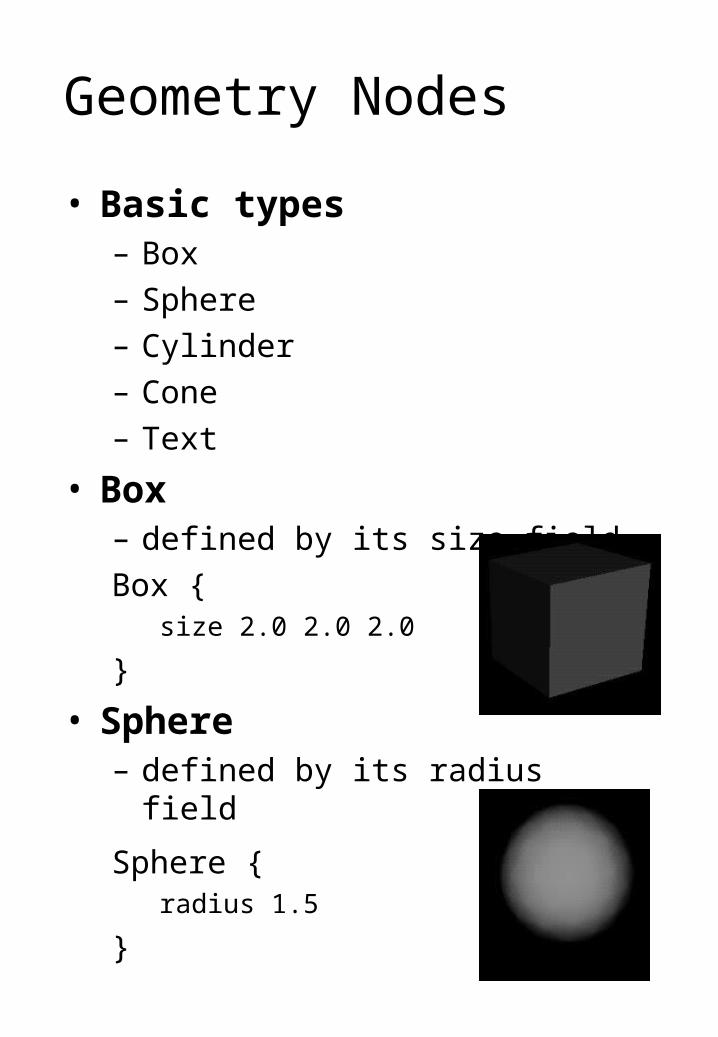
Geometry Nodes
• Basic types– Box
– Sphere
– Cylinder
– Cone
– Text
• Box– defined by its size field
Box {size 2.0 2.0 2.0
}
• Sphere– defined by its radius field
Sphere {radius 1.5
}
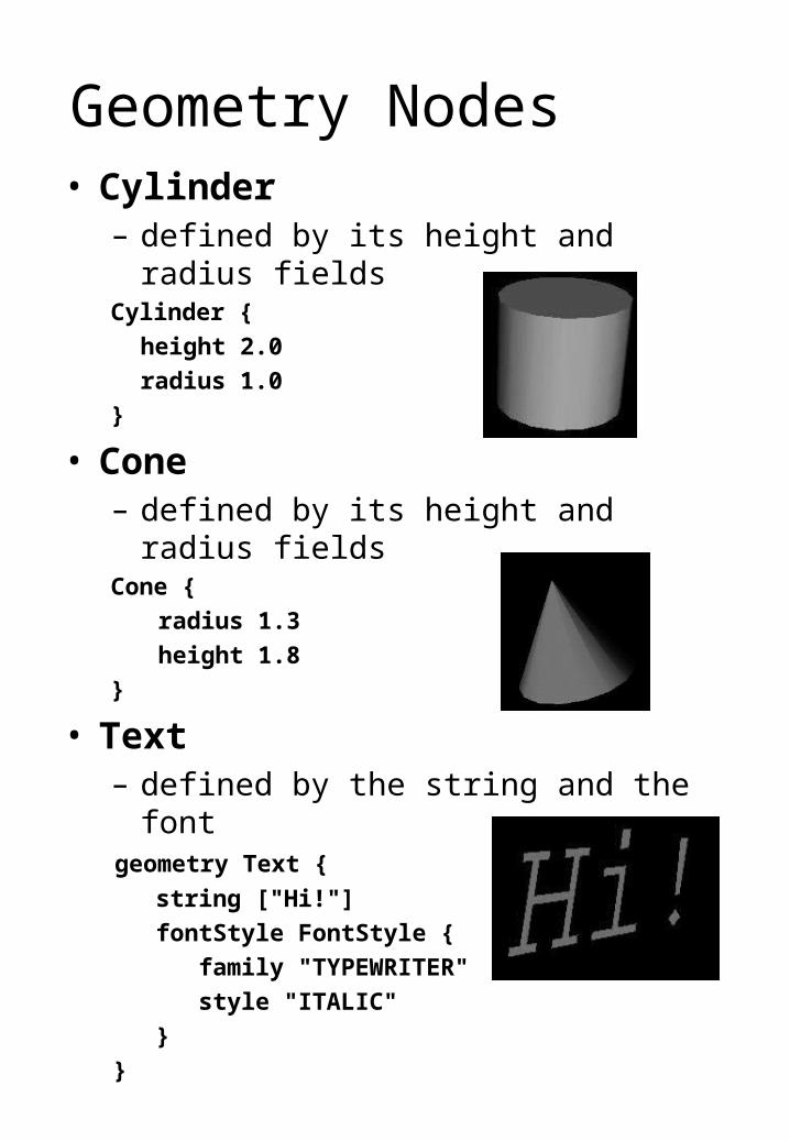
Geometry Nodes• Cylinder
– defined by its height and radius fieldsCylinder {
height 2.0
radius 1.0
}
• Cone– defined by its height and radius fieldsCone {
radius 1.3
height 1.8
}
• Text– defined by the string and the font
geometry Text {
string ["Hi!"]
fontStyle FontStyle {
family "TYPEWRITER"
style "ITALIC"
}
}
Complex Geometry
• Many objects can not be described with standard solids
• General geometry described with– IndexedFaceSet
– IndexedLineSet
– PointSet
– ElevationGrid
– Extrusion
• Each uses some of the following nodes in definition– Coordinate
– Normal
– Color
– TextureCoordinate
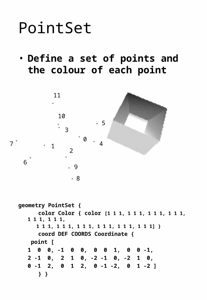
PointSet
• Define a set of points and the colour of each point
geometry PointSet {
color Color { color [1 1 1, 1 1 1, 1 1 1, 1 1 1, 1 1 1, 1 1 1,
1 1 1, 1 1 1, 1 1 1, 1 1 1, 1 1 1, 1 1 1] }
coord DEF COORDS Coordinate {
point [
1 0 0, -1 0 0, 0 0 1, 0 0 -1,
2 -1 0, 2 1 0, -2 -1 0, -2 1 0,
0 -1 2, 0 1 2, 0 -1 -2, 0 1 -2 ]
} }
01
2
3
4
5
8
6
7
9
10
11
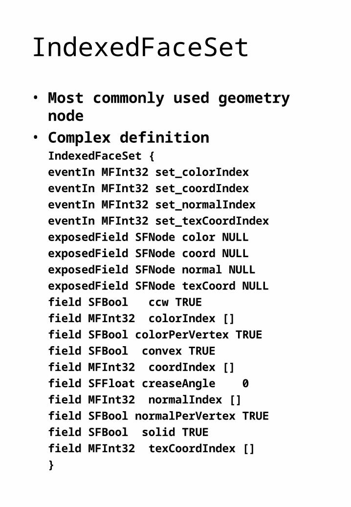
IndexedFaceSet
• Most commonly used geometry node
• Complex definitionIndexedFaceSet {
eventIn MFInt32 set_colorIndex
eventIn MFInt32 set_coordIndex
eventIn MFInt32 set_normalIndex
eventIn MFInt32 set_texCoordIndex
exposedField SFNode color NULL
exposedField SFNode coord NULL
exposedField SFNode normal NULL
exposedField SFNode texCoord NULL
field SFBool ccw TRUE
field MFInt32 colorIndex []
field SFBool colorPerVertex TRUE
field SFBool convex TRUE
field MFInt32 coordIndex []
field SFFloat creaseAngle 0
field MFInt32 normalIndex []
field SFBool normalPerVertex TRUE
field SFBool solid TRUE
field MFInt32 texCoordIndex []
}
IndexedFaceSet
• Components– the points to construct the face from
– the normals to give at the points
– the colours of the points
– the texture coordinates of the points
• Can define normals and colours– for each vertex or each face
• Texture coordinate defined at each vertex (since they are usually different!)
• Hints– each face is “convex”
– the faces are defined in counter-clockwise order
– the object is solid (i.e. each triangle is one-sided)
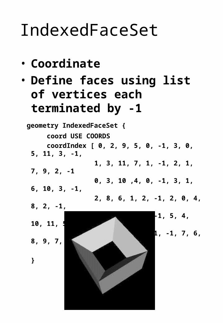
IndexedFaceSet
• Coordinate• Define faces using list of vertices
each terminated by -1 geometry IndexedFaceSet {
coord USE COORDS
coordIndex [ 0, 2, 9, 5, 0, -1, 3, 0, 5, 11, 3, -1,
1, 3, 11, 7, 1, -1, 2, 1, 7, 9, 2, -1
0, 3, 10 ,4, 0, -1, 3, 1, 6, 10, 3, -1,
2, 8, 6, 1, 2, -1, 2, 0, 4, 8, 2, -1,
9, 8, 4, 5, 9, -1, 5, 4, 10, 11, 5, -1,
11, 10, 6, 7, 11, -1, 7, 6, 8, 9, 7, -1
]
}
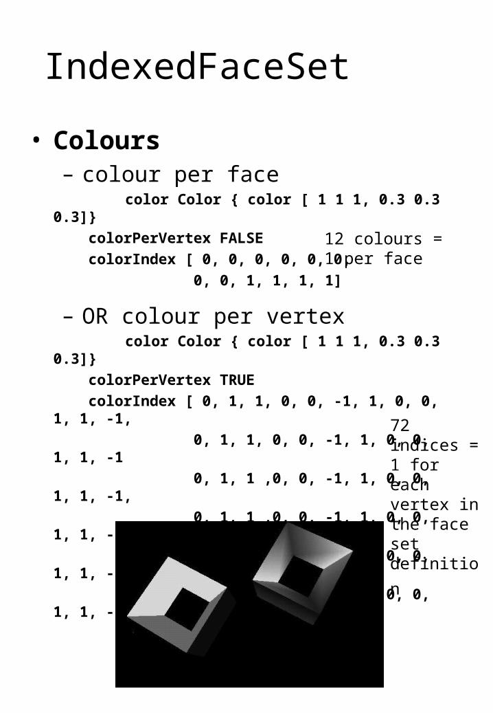
IndexedFaceSet
• Colours– colour per face
color Color { color [ 1 1 1, 0.3 0.3 0.3]}
colorPerVertex FALSE
colorIndex [ 0, 0, 0, 0, 0, 0,
0, 0, 1, 1, 1, 1]
– OR colour per vertex color Color { color [ 1 1 1, 0.3 0.3 0.3]}
colorPerVertex TRUE
colorIndex [ 0, 1, 1, 0, 0, -1, 1, 0, 0, 1, 1, -1,
0, 1, 1, 0, 0, -1, 1, 0, 0, 1, 1, -1
0, 1, 1 ,0, 0, -1, 1, 0, 0, 1, 1, -1,
0, 1, 1 ,0, 0, -1, 1, 0, 0, 1, 1, -1,
0, 1, 1 ,0, 0, -1, 1, 0, 0, 1, 1, -1,
0, 1, 1 ,0, 0, -1, 1, 0, 0, 1, 1, -1
]
12 colours = 1 per face
72 indices = 1 for each vertex in the face set
definition
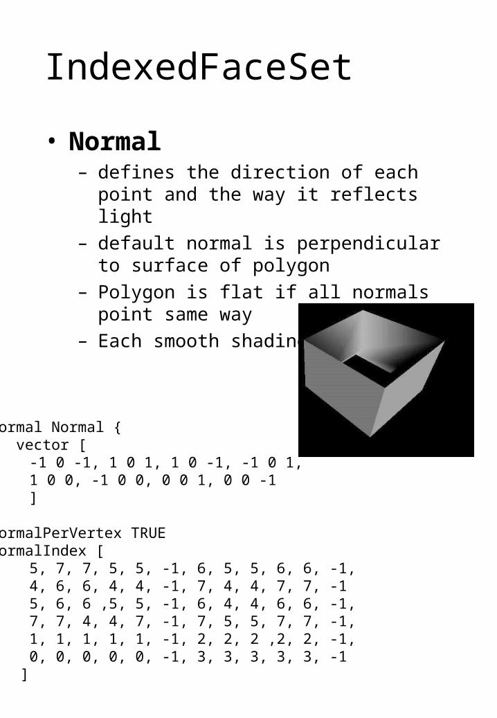
IndexedFaceSet
• Normal– defines the direction of each point and the way
it reflects light
– default normal is perpendicular to surface of polygon
– Polygon is flat if all normals point same way
– Each smooth shading
normal Normal { vector [
-1 0 -1, 1 0 1, 1 0 -1, -1 0 1, 1 0 0, -1 0 0, 0 0 1, 0 0 -1 ]
} normalPerVertex TRUE normalIndex [
5, 7, 7, 5, 5, -1, 6, 5, 5, 6, 6, -1, 4, 6, 6, 4, 4, -1, 7, 4, 4, 7, 7, -1 5, 6, 6 ,5, 5, -1, 6, 4, 4, 6, 6, -1, 7, 7, 4, 4, 7, -1, 7, 5, 5, 7, 7, -1, 1, 1, 1, 1, 1, -1, 2, 2, 2 ,2, 2, -1, 0, 0, 0, 0, 0, -1, 3, 3, 3, 3, 3, -1]
IndexedFaceSet
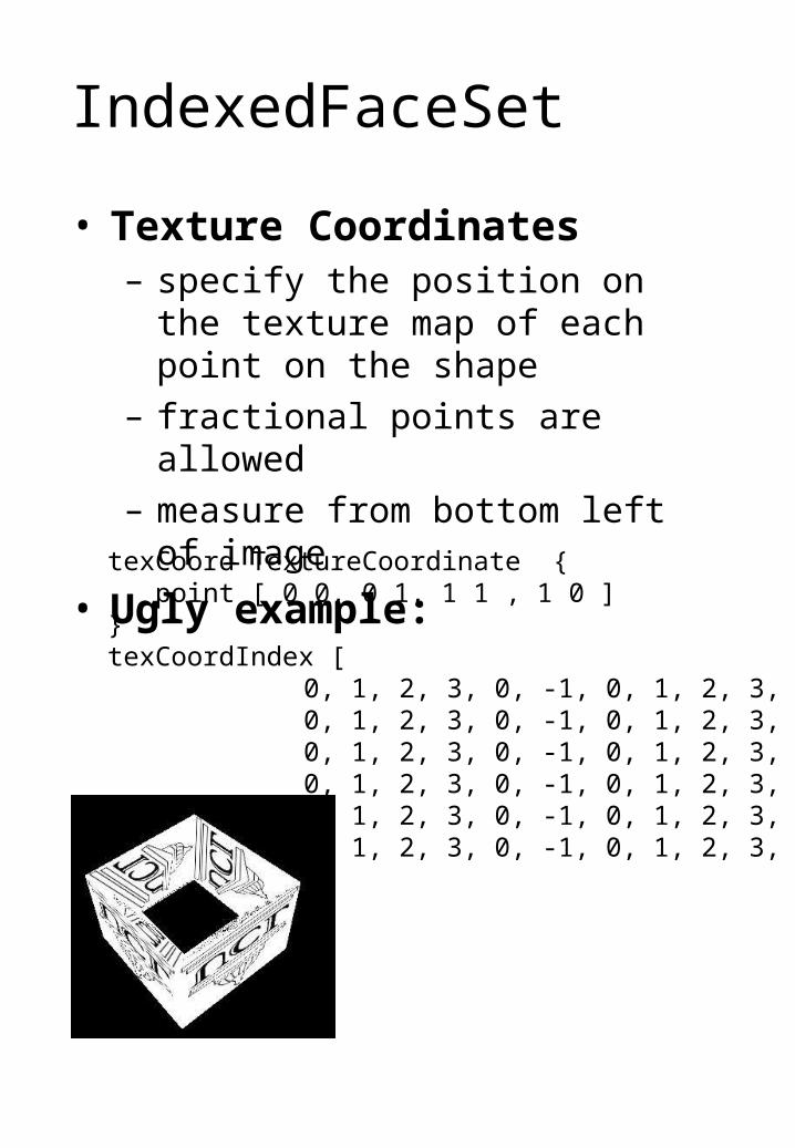
• Texture Coordinates– specify the position on the texture map
of each point on the shape
– fractional points are allowed
– measure from bottom left of image
• Ugly example:
texCoord TextureCoordinate { point [ 0 0, 0 1, 1 1 , 1 0 ] } texCoordIndex [
0, 1, 2, 3, 0, -1, 0, 1, 2, 3, 0, -1, 0, 1, 2, 3, 0, -1, 0, 1, 2, 3, 0, -1, 0, 1, 2, 3, 0, -1, 0, 1, 2, 3, 0, -1, 0, 1, 2, 3, 0, -1, 0, 1, 2, 3, 0, -1, 0, 1, 2, 3, 0, -1, 0, 1, 2, 3, 0, -1, 0, 1, 2, 3, 0, -1, 0, 1, 2, 3, 0, -1]
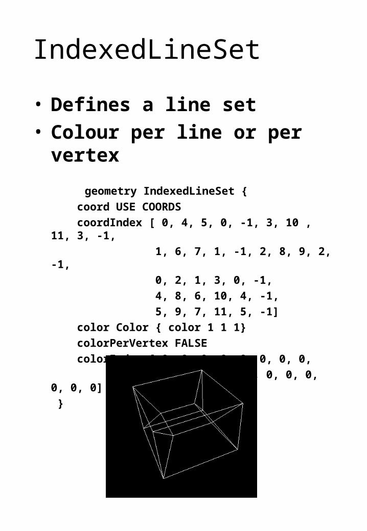
IndexedLineSet
• Defines a line set• Colour per line or per vertex
geometry IndexedLineSet {
coord USE COORDS
coordIndex [ 0, 4, 5, 0, -1, 3, 10 , 11, 3, -1,
1, 6, 7, 1, -1, 2, 8, 9, 2, -1,
0, 2, 1, 3, 0, -1,
4, 8, 6, 10, 4, -1,
5, 9, 7, 11, 5, -1]
color Color { color 1 1 1}
colorPerVertex FALSE
colorIndex [ 0, 0, 0, 0, 0, 0, 0, 0,
0, 0, 0, 0, 0, 0, 0, 0, 0, 0, 0, 0]
}
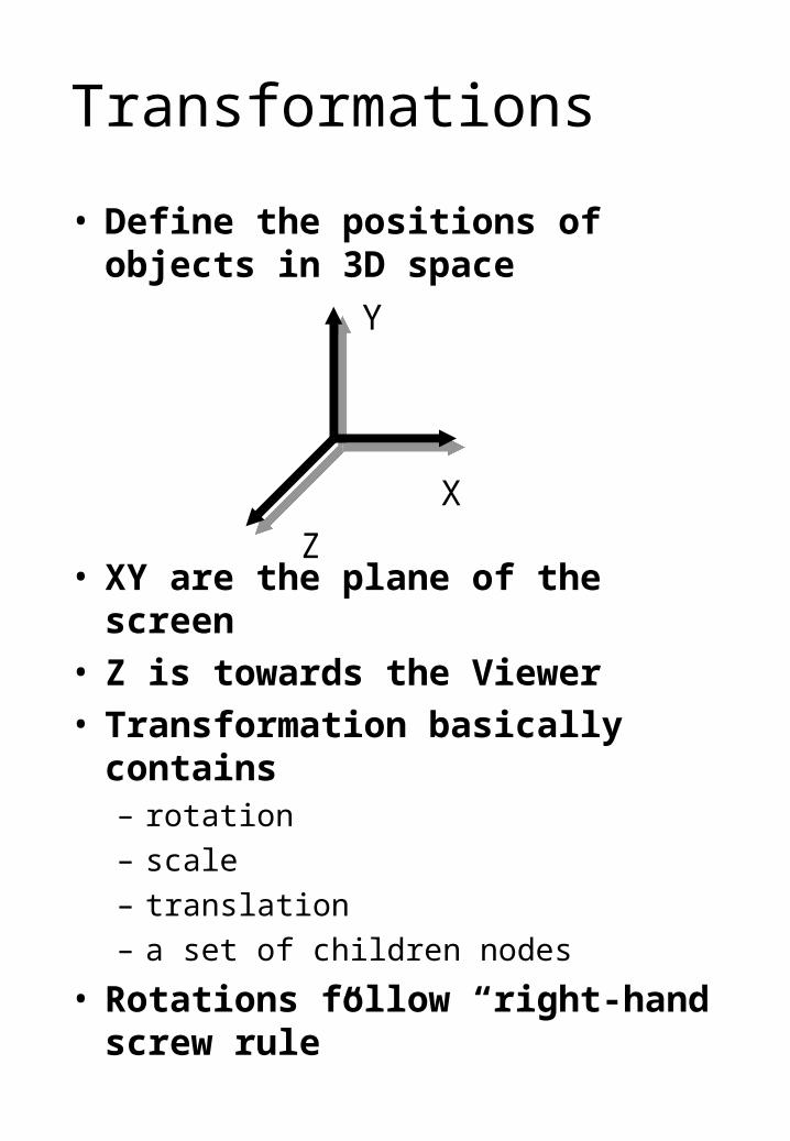
Transformations
• Define the positions of objects in 3D space
• XY are the plane of the screen• Z is towards the Viewer• Transformation basically contains
– rotation
– scale
– translation
– a set of children nodes
• Rotations follow “right-hand screw rule”
X
Z
Y
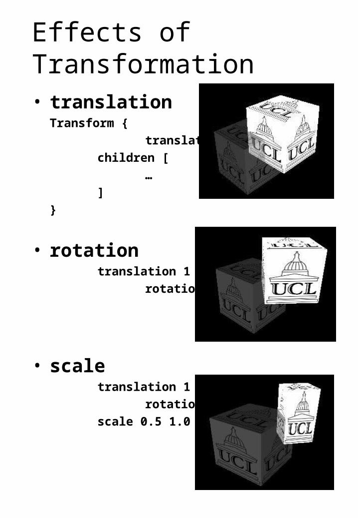
Effects of Transformation
• translationTransform {
translation 1 1 -1
children [
…
]
}
• rotationtranslation 1 1 -1
rotation 0 1 0 0.785
• scaletranslation 1 1 -1
rotation 0 1 0 0.785
scale 0.5 1.0 0.5
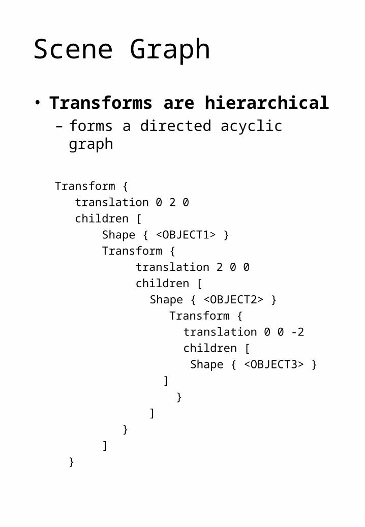
Scene Graph
• Transforms are hierarchical– forms a directed acyclic graph
Transform {
translation 0 2 0
children [
Shape { <OBJECT1> }
Transform {
translation 2 0 0
children [
Shape { <OBJECT2> }
Transform {
translation 0 0 -2
children [
Shape { <OBJECT3> }
]
}
]
}
]
}
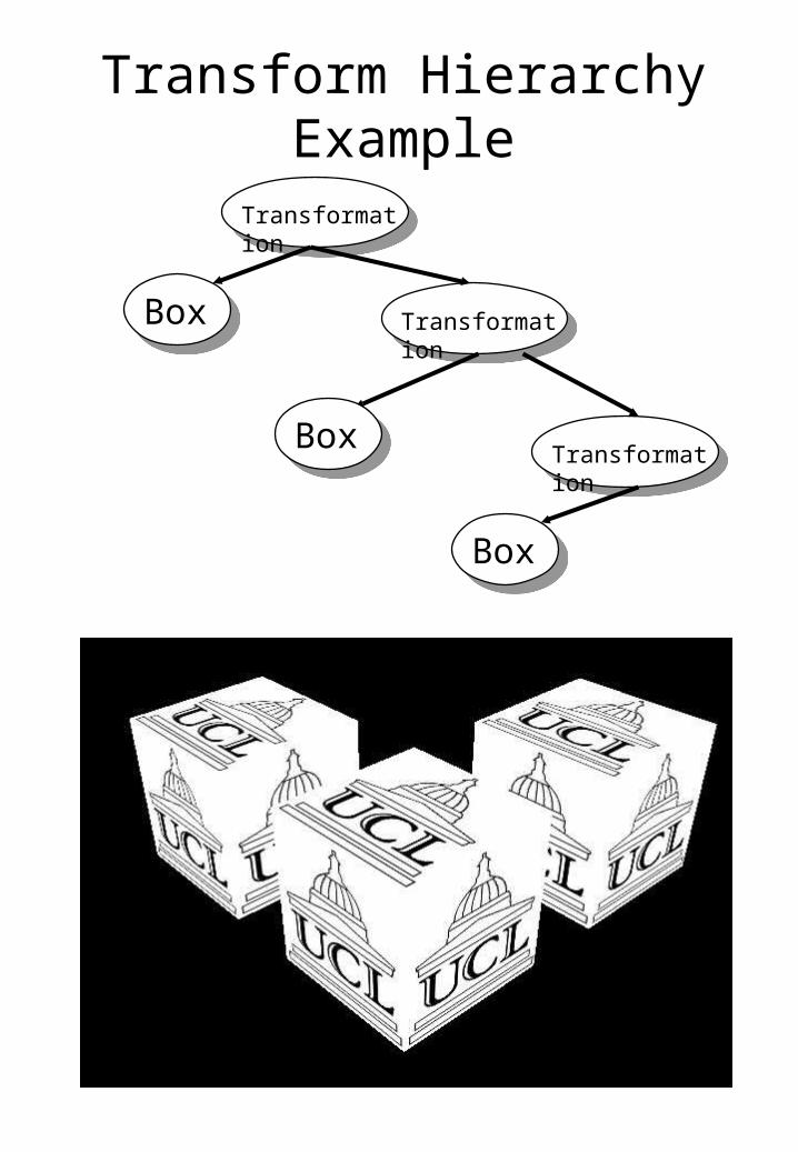
Transform Hierarchy Example
Transformation
Box
Box
Transformation
TransformationBox
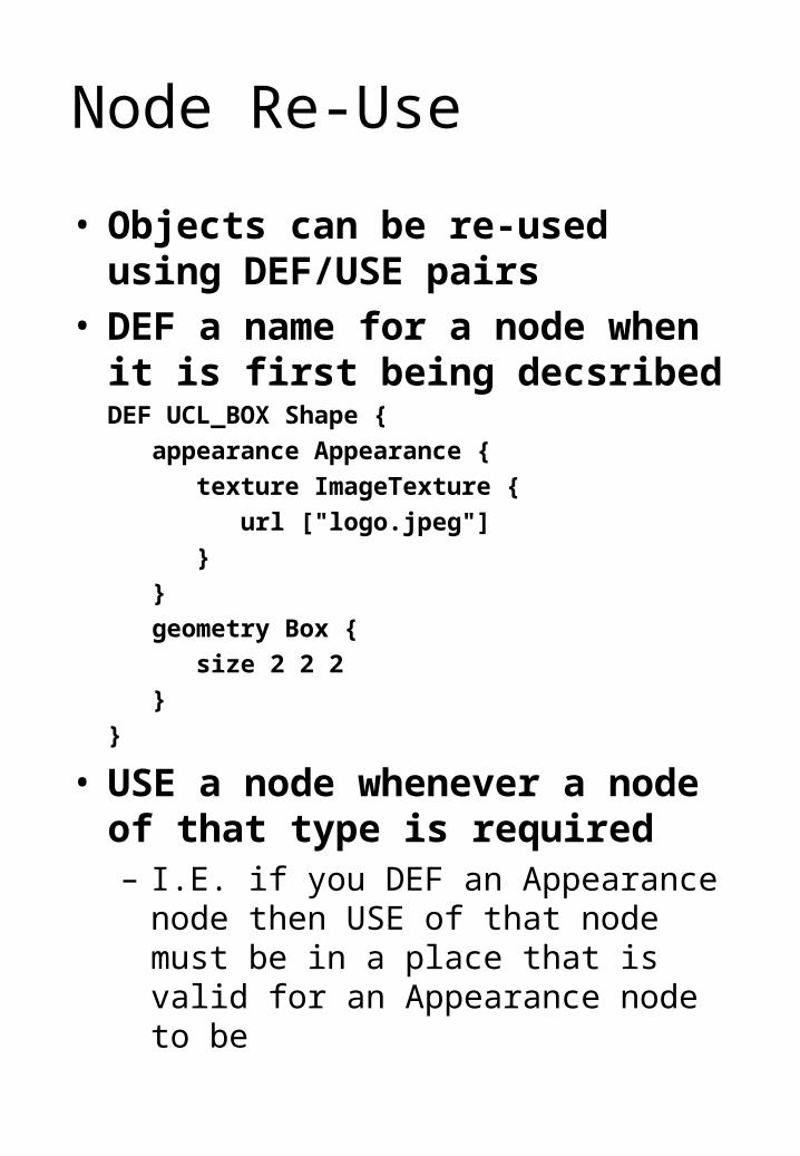
Node Re-Use
• Objects can be re-used using DEF/USE pairs
• DEF a name for a node when it is first being decsribed
DEF UCL_BOX Shape {
appearance Appearance {
texture ImageTexture {
url ["logo.jpeg"]
}
}
geometry Box {
size 2 2 2
}
}
• USE a node whenever a node of that type is required– I.E. if you DEF an Appearance node
then USE of that node must be in a place that is valid for an Appearance node to be
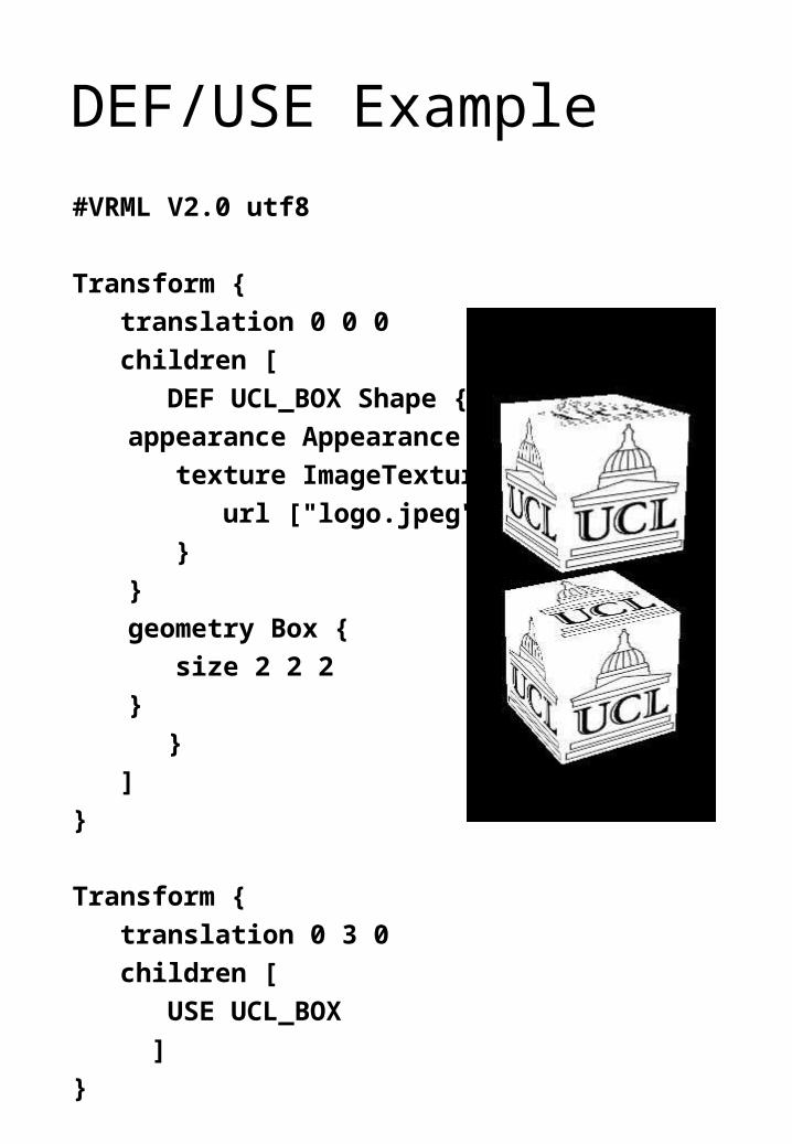
DEF/USE Example
#VRML V2.0 utf8
Transform {
translation 0 0 0
children [
DEF UCL_BOX Shape {
appearance Appearance {
texture ImageTexture {
url ["logo.jpeg"]
}
}
geometry Box {
size 2 2 2
}
}
]
}
Transform {
translation 0 3 0
children [
USE UCL_BOX
]
}
Appearance
• Defines the look of some piece of geometry– Material
• combination of – ambient colour
– diffuse colour
– emmisive colour
– shinines
– transparency
– specular colour
– Texture• defines a picture to paste to the object
– fetch from a URL
– supports movies
– TextureTransform• defines how the picture is applied to the
object
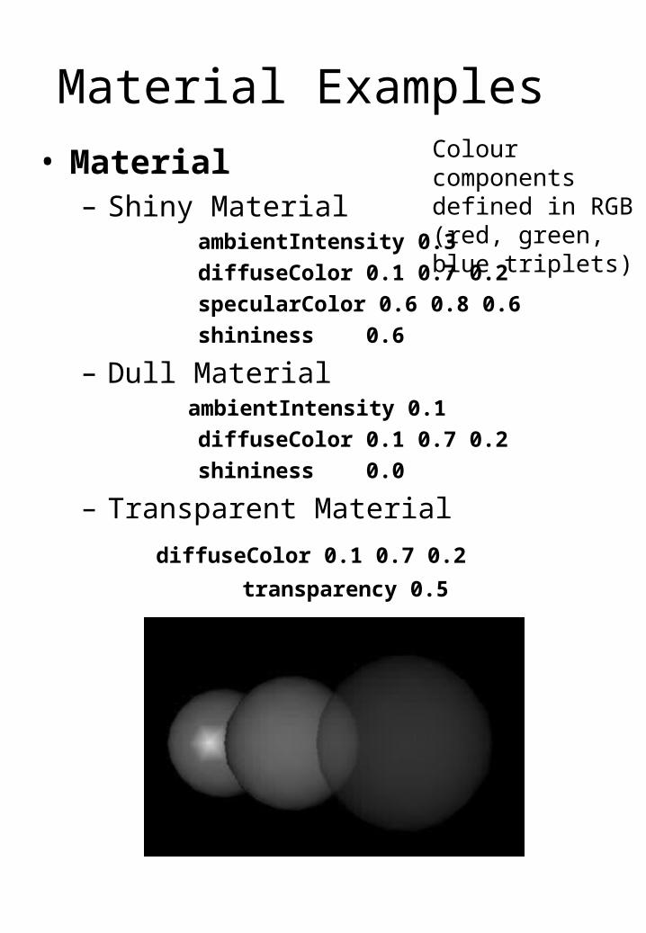
Material Examples
• Material– Shiny Material
ambientIntensity 0.3
diffuseColor 0.1 0.7 0.2
specularColor 0.6 0.8 0.6
shininess 0.6
– Dull Material ambientIntensity 0.1
diffuseColor 0.1 0.7 0.2
shininess 0.0
– Transparent Material
diffuseColor 0.1 0.7 0.2
transparency 0.5
Colour components defined in RGB (red, green, blue triplets)
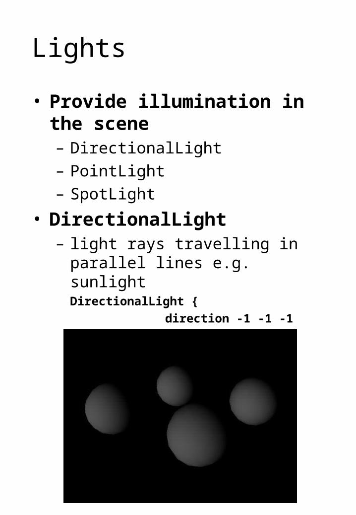
Lights
• Provide illumination in the scene– DirectionalLight
– PointLight
– SpotLight
• DirectionalLight– light rays travelling in parallel lines e.g.
sunlightDirectionalLight {
direction -1 -1 -1
intensity 0.8
}
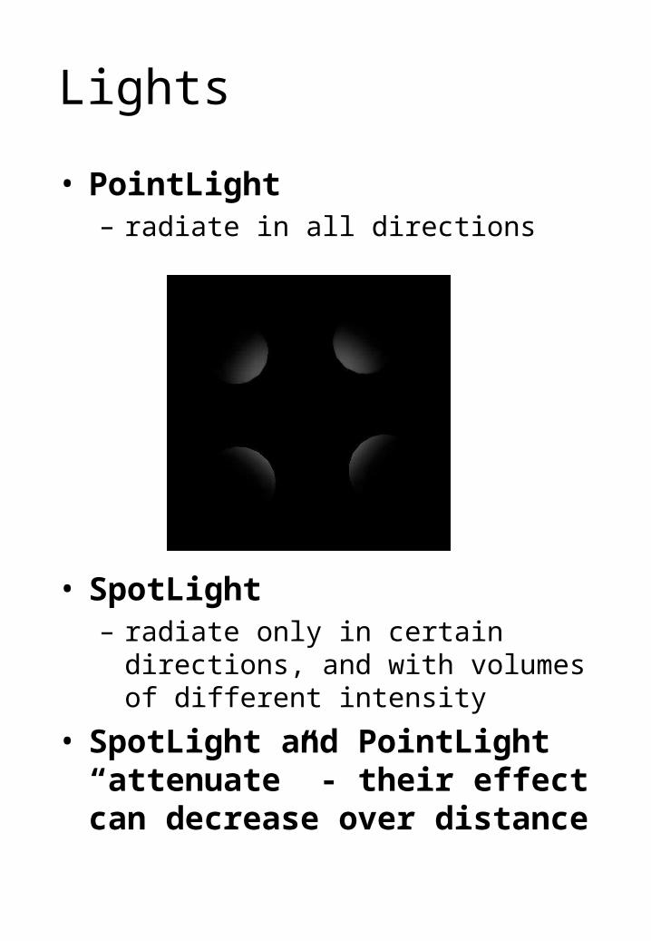
Lights
• PointLight– radiate in all directions
• SpotLight– radiate only in certain directions, and
with volumes of different intensity
• SpotLight and PointLight “attenuate” - their effect can decrease over distance
Other Things …
• Interaction• Scripting
– Java
– JavaScript
• Interpolators• Sensors• Fog• Background• Audio• Video• LOD• Billboard
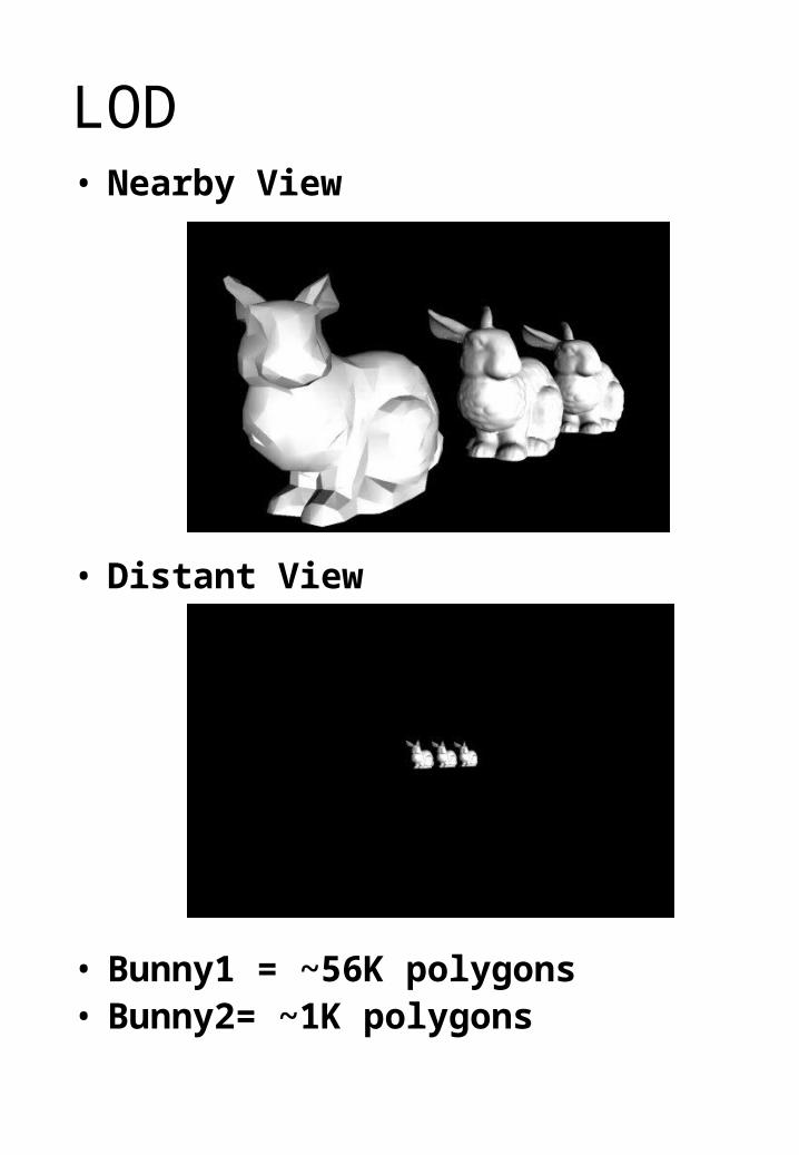
LOD• Nearby View
• Distant View
• Bunny1 = ~56K polygons• Bunny2= ~1K polygons
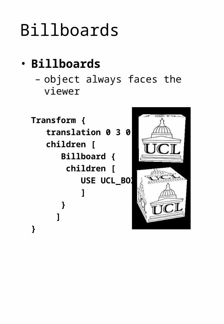
Billboards
• Billboards– object always faces the viewer
Transform {
translation 0 3 0
children [
Billboard {
children [
USE UCL_BOX
]
}
]
}