Embed Size (px)
Citation preview
YASKAWA
LITERATURE NO. KAE-S606-12E
COMPACT INVERTER FOR GENERAL-USE
VS mini J7200V CLASS (THREE-PHASE) 0.1 TO 3.7kW (0.13 TO 5HP)200V CLASS (SINGLE-PHASE) 0.1 TO 1.5kW (0.13 TO 2HP)400V CLASS (THREE-PHASE) 0.2 TO 3.7kW (0.25 TO 5HP)
JQA-EM0498
QUALITY SYSTEM
C
ER T I F I ED
MA
NAGEMENT SYST
EM
JQA-0403
Certified forISO9001 andISO14001
Inverter Magic
2 3
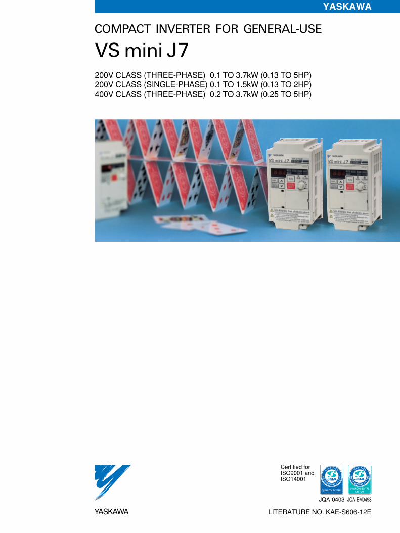
Instant Upgrade for Your Small Machinery!The VS mini J7 inverter delivers the solution for all those users who want to easily upgrade small machinery to
variable-speed drives. Turn your machinery into the optimum drive through our powerful performance and rich array of functions. Try the compact, economical VS mini J7 for simple operation and maintenance.
The main circuit terminals are arranged in upper and lower rows, so you can wire it up just like a contactor. For operation, just turn the frequency volume setting knob. The entire design is user-friendly through-and-through, such as one-touch cooling fan replacement.
SimpleOperation
Because the motor can be fully controlled, it is easier than ever to adjust conveyor and mixer speeds, or pump and fan flow rates. Inverter functions deliver the optimum drive at a reasonable cost (see application examples on page 5). Just snap it on, and just like magic! Your inverter is transformed.
Upgrade Your Machinery
Compact design means it fits into your panel efficiently. And with global specifications: certified under UL/cUL and CE standards, they are available in both 200V (3-phase/single-phase) and 400V (3-phase) series. Power supply harmonics are also controlled so our inverters can be used safely anywhere in the world.
CE marking forEuropean safetystandards
Only 128mm Tall
Inverter MagicFEATURES
OPERATION METHOD
STANDARD SPECIFICATIONS/DIMENSIONS
STANDARD WIRING/CONSTANTS LIST
PROGRAMMINGFEATURES
PROTECTIVE FUNCTIONS
NOTES ON USE
OPTIONS/PERIPHERALUNITS
4
6
8
11
16
28
31
35
Note: When using CE standard inverters, the special EMC conformed noise filter is required. Contact your YASKAWA representative.

Major Features of the VSmini J7
Power supply high-harmonics suppressedAn optional DC reactor can be connected, and of course AC reactors are also available.
300
(%)
(min-1)
200
100
100 1,000 2,0000
SPEED
TORQUE
Outstanding starting torque characteristics
Motor: 200V, 0.4kW, 4-pole105%/1.5Hz155%/ 3Hz
4
Full-range automatic torque boost
Delivers outsanding starting torque (150%/3Hz) for its class, for smooth machinery start-up.
Full range of protective functions
High-speed current-limiting function minimizes over-current trips (above 250% of rated current) for enhanced tripless operation (restart after momentary power loss, stall prevention function, fault retry, etc.)
Inrush current suppression circuit buit-in.
Diverse operating methods and functions
Multi-step speed operation (up to nine steps), UP/DOWN operation and jog operation.
Full range of functions, including slip compensation, overtorque detection and high-speed search.
Just wire it up and run!
Frequency volume setting knob located on the control panel (operator) as a standard feature. Immediate operation after you supply power. If remote operation is required, the optional operator and cable can be mounted on your control panel.
Simple installation and wiring
The main circuit terminals are arranged in upper and lower rows, so you can wire it up just like a contactor.
Main and control circuit terminals are screw-type, for simple wiring and improved reliability.
One-touch mounting/detaching with DIN rail attach-ments.
Wide range of input/output
Multi-function I/O terminals, 0-10V, 4-20mA or 0-20mA inputs, as well as analog monitors are available.
Application freedom is increased since multi-function
inputs can be set to PNP or NPN.
One-touch mounting and/or detaching. The life of the cooling fan is extended by a cooling fan ON/OFF control.
Performanceand
FunctionsOperability
Screw-type terminals
Removable cooling fan
10Hz
3Hz
6Hz 30Hz60Hz
1.5Hz
Even for a single given machine, the required motor torque will vary with the load conditions. The full-range automatic torque boost function automatically adjusts V (voltage) in V/f as required. The VS mini J7 can adjust V for the required torque during acceleration as well as during constant-speed operation. The inverter calculates the required torque automatically.
Supprot for RS-232C and RS-485/422 (MEMOBUS protocol) available as options.
Simple maintenance
5
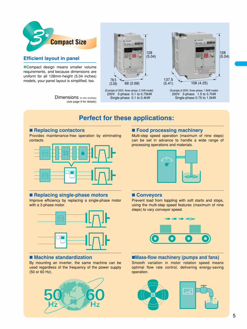
Perfect for these applications:
Replacing contactorsProvides maintenance-free operation by eliminating contacts.
ConveyorsPrevent load from toppling with soft starts and stops, using the multi-step speed features (maximum of nine steps) to vary conveyor speed.
Replacing single-phase motorsImprove efficiency by replacing a single-phase motor with a 3-phase motor.
Machine standardizationBy mounting an inverter, the same machine can be used regardless of the frequency of the power supply (50 or 60 Hz).
Mass-flow machinery (pumps and fans)Smooth variation in motor rotation speed means optimal flow rate control, delivering energy-saving operation.
Food processing machineryMulti-step speed operation (maximum of nine steps) can be set in advance to handle a wide range of processing operations and materials.
Compact Size
108 (4.25)68 (2.68)78.5
(3.09)137.5(5.41)
128(5.04)
128(5.04)
200V 3-phase 0.1 to 0.75kWSingle-phase 0.1 to 0.4kW
200V 3-phase 1.5 to 3.7kWSingle-phase 0.75 to 1.5kWDimensions in mm (inches)
(see page 9 for details)
Efficient layout in panel
Compact design means smaller volume requirements, and because dimensions are uniform for all 128mm-height (5.04 inches) models, your panel layout is simplified, too.
(Example of 200V, three–phase, 0.1kW model) (Example of 200V, three–phase, 1.5kW model)

Display and Keypad Description
Function Display LED Description
6
OPERATING DIGITAL OPERATOR
Frequency referencesetting/monitoring
FREF
Output frequencymonitoring
FOUT
Output currentmonitoring
IOUT
Multi-functionmonitoring
MNTR
Operator RUN commandFWD/REV selection
F/R
LOCAL/REMOTEselection
LO/ RE
Constant No./data
PRGM
Data Display
Increment KeyIncrease constant No. or data.
Switch functions among function display LEDs.
Decrement KeyDecrease constant No. or data.
Enter KeyEnter data when setting constants.After selecting constant No. at PRGM mode, data are displayed.
Display Selection Key
Digital Operator
Function Display LEDsSelected function is lit (See the functions below). Its data is displayed on data display.
Operation KeyPress to run the motor. The RUN light is ON while running.
Stop/Reset KeyPress to stop the motor. If fault occurs, reset the inverter.
Frequency Setting VolumeSet operational frequency with volume.
Run LED
Alarm LED

Switching the Function LEDs
Monitor (MNTR) Lists
Changing the Constant Data
Changing the displayed data
• Example: Changing frequency reference from 60Hz to 30HzFREF
DSPL
Frequency referencesetting/monitor (Hz)
FOUT
DSPL
Output frequencymonitor (Hz)
Power ON
IOUT
DSPL
Output currentmonitor (A)
MNTR
DSPL
Monitor(Output frequency monitor)
F/R
DSPL
FWD/REVrun selection
LO/RE
DSPL
Remote/localselection
DSPL
PRGMConstant no./data
Note: : Indicates display switching flowduring operation
: Indicates display switching flowwhile stopped
FREF
<
Frequency reference: 60Hz
FREFENTER
The data blinks while changing
FREF
The data isentered.
Selecting the constant no.
• Example: Setting the constant n02 (operation reference selection)
PRGM<
Select n02operationreference
PRGMENTER
Initial setting "0"for digital operatorreference
<
ENTERPRGM
Select "1" for control circuitterminal reference(Data blinks while changing)
PRGM
After 1sec, returns to the constant no.
PRGM
The data isentered
Displaying the monitor (See the monitor lists below)
• Example: Monitoring output voltage reference
MNTR MNTRDSPL OR
Output voltage reference isdisplayed
ENTERENTER
Constant No. UnitMonitor
U 01 HzFrequency reference (FREF)*
U 02 HzOutput frequency (FOUT)*
U 03 AOutput current (IOUT)*
U 04 VOutput voltage (1V unit)Example: 200V
U 05 VDC voltage (1V unit)Example: 300V
U 06 —Input terminal status
U 07 —Output terminal status
U 09 —Fault history(The last four faults are displayed.)
U 10 —Software No.(Four digits of PROM are displayed.)
* The digital operator LED is not lit.
Fault display method• Display format
: 3-digit, 7-segment LED
Fault description example: “UV1” is displayed at Uv1 fault.“---” is displayed when there is no fault.
• Clearing fault history Set the constant n01 to “6,” then the n01 data returns to the previous value. Or initialize the constant, then n01 returns to the default setting.
Select U 04Depress or key to change constant no.
<<
6 0.0
6 0.0
0 0.2
U 0 4
N 0 2
N 0 1
U 0 1
F O
L O
N 0 2
6 0.0 3 0.0 3 0.0
2 0 0
0 1
1
7
VS mini J7
8
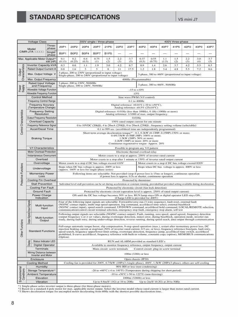
STANDARD SPECIFICATIONS
Voltage Class
Inverter Capacity kVA
Out
put
Cha
ract
eris
tics
Pow
erSu
pply
Con
trol C
hara
cter
istic
sPr
otec
tive
Func
tions
Oth
er F
unct
ions
Envi
ronm
enta
lC
ondi
tions
Input
Sign
alsOu
tput S
ignals
Disp
lay
Rated Output Current A
Max. Output Voltage V
Max. Output Frequency
Allowable Voltage Function
Allowable Frequency Function
Control Method
Rated Input Voltageand Frequency
3-phase, 200 to 230V (proportional to input voltage)Single-phase, 200 to 240V (proportional to input voltage)
3-phase, 200 to 230V, 50/60HzSingle-phase, 200 to 240V, 50/60Hz
400Hz (Programmable)
-15 to +10%
±5%
Sine wave PWM (V/f control)
Frequency Control Range 0.1 to 400Hz
Frequency Accuracy(Temperature Change)
Digital reference: ±0.01% (-10 to +50°C),Analog reference: ±0.5% (25±10°C)
Frequency SettingResolution
Output Frequency Resolution
Digital reference: 0.01Hz (less than 100Hz), 0.1Hz (100Hz or more)Analog reference: 1/1000 of max. output frequency
0.01Hz
Overload Capacity 150% rated output current for one minute
Frequency Reference Signal 0 to 10VDC (20kΩ), 4 to 20mA (250Ω), 0 to 20mA (250Ω) , frequency setting volume (selectable)
Accel/Decel Time
Braking Torque
0.1 to 999 sec. (accel/decel time are independently programmed)
V/f Characteristics Possible to program any V/f pattern
Motor Overload Protection Electronic thermal overload relay
Instantaneous Overcurrent Motor coasts to a stop at approx. 250% of inverter rated current
Overload Motor coasts to a stop after 1 minute at 150% of inverter rated output current
Overvoltage Motor coasts to a stop if DC bus voltage exceed 410V
Momentary PowerLoss
Following items are selectable: Not provided (stop if power loss is 15ms or longer), continuous operation if power loss is approx. 0.5s or shorter, continuous operation
Cooling Fin Overheat Protected by thermister
Stall Prevention Individual level stall prevention can be set during acceleration or constant running, provided/not provided setting available during deceleration
Cooling Fan Fault Protected by electronic circuit (fan lock detection)
Ground Fault Protected by electronic circuit (operation level is approx. 250% of rated output current)
Status Indicator LED RUN and ALARM provided as standard LED’s
Digital Operator Available to monitor frequency reference, output frequency, output current
Main circuit: screw terminals Control circuit: plug-in screw terminal
Power ChargeIndication
ON until the DC bus voltage becomes 50V or less. RUN lamp stays ON or digital operator LED stays ON.(Charge LED is provided for 400V)
Multi-functionInput
Multi-functionOutput
Four of the following input signals are selectable: Forward/reverse run (3-wire sequence), fault reset, external fault (NO/NC contact input), multi-step speed operation, Jog command, accel/decel time select, external baseblock (NO/NC contact input), speed search command, UP/DOWN command, accel/decel hold command, LOCAL/REMOTE selection, communication/control circuit terminal selection, emergency stop fault, emergency stop alarm, self test
Following output signals are selectable (NO/NC contact output): Fault, running, zero speed, speed agreed, frequency detection (output frequency ≤ or ≥ set value), during overtorque detection, minor error, during baseblock, operation mode, inverter run ready, during fault retry, during undervoltage detection, reverse running, during speed seach, data output through communication
Standard Functions
Enclosure
Terminals
100m (328ft) or less
Open chassis (IP20)
Cooling Method
Humidity
Cooling fan is provided for 200V, 0.75kW (1HP)(3-/single-phase), 400V, 1.5kW (2HP)(3-phase), others are self-cooling
90% RH or less (non-condensing)
Storage Temperature*4 -20 to +60°C (-4 to 140°F) (Temperature during shipping for short period)
Ambient Temperature -10 to +50°C (-50 to 122°F) (non-freezing)
Elevation 1000m (3280ft) or less
*1 Single-phase series inverter output is three-phase (for three-phase motors).*2 Based on a standard 4-pole motor for max. applicable motor output. Select the inverter model whose rated current is larger than motor rated current.*3 Shows deceleration torque for uncoupled motor decelerating from 60Hz with the shortest possible deceleration time.
Vibration Up to 9.8m/S2 (1G) at 10 to 20Hz Up to 2m/S2 (0.2G) at 20 to 50Hz
Wiring Distance betweenInverter and Motor
Full-range automatic torque boost, slip compensation, 9-step speed operation (max.), restart after momentary power loss, DC injection braking current at stop/start (50% of inverter rated current, 0.5 sec, or less), frequency reference bias/gain, fault retry, speed search, frequency upper/lower limit setting, overtorque detection, frequency jump, accel/decel time switch, accel/decel prohibited, S-curve accel/decel, frequency reference with built-in volume, constants copy (option), MEMOBUS communications(Option)
Motor coasts to a stop if DC bus voltage exceed 820V
UndervoltageStops when DC bus voltage is approx. 200V or less(approx. 160V or less for single-phase series)
Stops when DC bus voltage is approx. 400V or less
Short-term average deceleration touque*3 : 0.1, 0.2kW (0.13HP, 0.25HP):150% or more;0.4/0.75kW (0.5HP,1HP): 100% or more;
1.5kW (2HP): 50% or more;2.2kW (3HP) or more: 20% or more
Continuous regenerative torgue: Approx. 20%
3-phase, 380 to 460V (proportional to input voltage)
3-phase, 380 to 460V, 50/60Hz
200V single-/ three-phase 400V three-phase
ModelCIMR-J7A=????
Max. Applicable Motor Output*2
kW (HP)
Three-phase 20P1 20P2 20P4 20P7 21P5 22P2 23P7
B0P1
0.3 0.6 1.1 1.9 3.0 4.2 6.7
0.8 1.6 3 5 8 11 17.5
0.9 1.4 2.6 3.7 4.2 5.5 6.5
1.2 1.8 3.4 4.8 5.5 7.2 8.6
0.1(0.13)
0.2(0.25)
0.4(0.5)
0.75(1)
1.5(2)
2.2(3)
3.7(5)
0.37(0.5)
0.55(0.75)
1.1(1.5)
1.5(2)
2.2(3)
3.0(4)
3.7(5)
B0P2 B0P4 B0P7 B1P5 — —
40P2 40P4 40P7 41P5 42P2 43P0 43P7
— — — — — — —Single-phase
*1

8.5(0.34)
8.5(0.34)
2 – M 44 – M 4
9
< Model Designation < Capacity Code Designation
VoltageClass
CapacitykW (HP)
0.1 (0.13)0.2 (0.25)0.4 (0.5)
0.75 (1)1.5 (2)2.2 (3)3.7 (5)0.1 (0.13)0.2 (0.25)0.4 (0.5)
0.75 (1)1.5 (2)
0.37 (0.5)0.55 (0.75)
1.1 (1.5)1.5 (2)2.2 (3)3.0 (4)3.7 (5)
Fig.No.
1
68(2.68)
68(2.68)108
(4.25)140(5.51) 128(5.04) 161(6.34) 128(5.04) 118(4.65) 5 (0.20) 2.1(4.63) 96.7 52.4
128(5.04)128
(5.04)128
(5.04)
70(2.76)
102 (4.16)
56(2.20)
56(2.20)
96(3.78)
118(4.65)118
(4.65)118
(4.65)
5(0.20)
5(0.20)
5(0.20)
1
2
2
2
68(2.68)
108(4.25)
108(4.25)
140(5.51)
128(5.04)
128(5.04)
128(5.04)
128(5.04)
70 (2.76)
154 (6.06)161
(6.34)
129 (5.08)
122 (4.80)
154 (6.06)81 (3.19)99 (3.90)
129 (5.08)
56(2.20)
96(3.78)
96(3.78)
128(5.04)
118(4.65)
118(4.65)
118(4.65)
118(4.65)
5(0.20)
5(0.20)
5(0.20)
5(0.20)
0.5 (1.1)
0.5 (1.1)
0.8 (1.76)0.9 (1.98)1.3 (2.83)1.5 (3.31)
3.77.715.828.453.760.4
3.77.715.828.453.79.415.130.345.850.558.273.4
10.412.316.123.029.113.715.024.629.932.537.644.5
14.120.131.951.482.823.130.154.975.783.095.8117.9
9.310.312.316.719.134.4
13.018.028.145.172.894.8149.1
0.9 (1.98)
1.5 (3.31)
1.0 (2.20)1.1 (2.43)
1.5 (3.31)
2.1 (4.63)
Masskg (lb)W H D W1 H1 H2 Fin Inside
UnitTotal Heat
Loss
Dimensions in mm (inches) Heat Loss W
200VThree-phase
200VSingle-phase
400VThree-phase
112 (4.41)
129 (5.08)154 (6.06)
No. Applicable maximum motor output0P1 0.1kW (0.13HP)0P2 0.2kW (0.25HP)0P4 0.4kW (0.5HP)0P7 0.75kW (1HP)1P5 1.5kW (2HP)2P2 2.2kW (3HP)3P0 3.0kW (4HP)3P7 3.7kW (5HP)
0.1kW (0.13HP)0.2kW (0.25HP)0.4kW (0.5HP)0.75kW (1HP)1.5kW (2HP)2.2kW (3HP)3.0kW (4HP)3.7kW (5HP)
No. Applicable maximum motor output0P10P20P40P71P52P23P03P7
No. Voltage ClassB Single-phase 200VAC2 Three-phase 200VAC4 Three-phase 400VAC
No. Type
No. SpecificationsA Japan domestic standards
Conformed to UL/cUL, CE marking.
Inverter
VS mini J7 series
A With digital operator (with volume)B Without digital operatorC With digital operator (without volume)
B Single-phase 200VACNo. Phase / Voltage
2 Three-phase 200VAC4 Three-phase 400VAC
C I M R — J 7 A A 2 0 P 1
No. Protective structure0 Open chassis (IP20)
2 0 P 1 0
< Models
Voltageclass
Single-phase200V
With DigitalOperator
With DigitalOperator
With DigitalOperator
Without Digital Operator
With Analog VolumeWithout Analog Volume
With Analog VolumeWithout Analog Volume
With Analog VolumeWithout Analog Volume
Without Digital Operator
Without Digital Operator
Note: Models without cooling fin are available. Contact your YASKAWA representative.
>: provided
Three-phase200V
Three-phase400V
Description 0P1(0.1)
0P2(0.2)
0P4(0.4)
0P7(0.7)
1P5(1.5)
2P2(2.2)
3P0(3.0)
3P7(3.7)
> > > > > — — —
> > > > > — — —
> > > > > > — >
> > > > > > — >
— > > > > > > >
— > > > > > > >
Model
CIMR-J7A=B CIMR-J7C=B CIMR-J7B=B CIMR-J7A=2 CIMR-J7C=2 CIMR-J7B=2 CIMR-J7A=4 CIMR-J7C=4 CIMR-J7B=4
Capacity code to be filled in model (Max. applicable motor output kW)
Figure 1 Figure 2

U XDC REACTOR (OPTION)
SHORT BAR
MCCB
R
S
T
FORWARD RUN/STOP
VS mini J7
REVERSE RUN/STOP
EXTERNAL FAULT(NO CONTACT)
FAULT RESET
MULTI-STEP SPEEDREFERENCE 1
MULTI-FUNCTIONINPUT
FREQUENCYREFERENCE
PULSE TRAIN INPUT
FREQUENCY SETTER
2kΩ
P P
AM
AC
FREQUENCY METERADJUSTING POTENTIOMETER
ANALOG MONITOR OUTPUT0 TO 10VDC (2mA)
OUTPUT FEQUENCY
P FM
DIGITAL OPERATORFREQUENCY SETTINGVOLUME MIN MAX
2 1
U/T1
V/T2
W/T3
R/L1
S/L2
T/L3
S1
S2
S3
S4
S5
FS
FR
FC
SC
SHIELDED CONNECTIONTERMINAL
FREQUENCY SETTING POWER SUPPLY(12V 20mA)SPEED FREQUENCY REFERENCE0 TO 10V (20kΩ) OR 4 to 20mA (250Ω)
0V
MA
MB
MC
GROUNDING
RUNNINGMULTI-FUNCTIONOUTPUT250VAC 1A OR ESS30VDC 1A OR LESS
IM
indicates twisted pair shielded wire.
indicates shielded wire.
P
: shows the connection for the following two kinds of sequence input (S1 to S5) siglals: no-voltage contact and NPN transistors (0V common). For a PNP transistor (+24V common), a 24V external power supply is necessary.
VS mini J7
10
STANDARD WIRING
< Model Description
Type Terminal
Mai
n C
ircui
t
R/L1, S/L2, T/L3 AC Power Supply Input
U/T1, V/T2, W/T3 Inverter Output For inverter output
+2, +1 DC Reactor Connection Remove the short bar between +2 and +1 when connecting DC reactor (option)
+1, –
S1
DC Power Supply Input For power supply input (+1: positive electrode; – : negative electrode)*
Grounding
Forward Run Input
For grounding (Grounding should be conforming to the local grounding code.)
Runs when CLOSED, stops when OPEN.
24VDC, 8mAphotocouplerinsulation
Contact capacity250VAC, 1A or less30VDC, 1A or less
0 to 10V 2mA or lessResolution: 8bits
S2 Multi-function Input Selection 2 Factory setting: Runs when CLOSED, stops when OPEN.
S3 Multi-function Input Selection 3 Factory setting: “Fault reset”
S4 Multi-function Input Selection 4 Factory setting: “External fault (NO contact)”
S5 Multi-function Input Selection 5 Factory setting: “Multi-step speed reference 1”
SC Multi-function Input Selection Common Common for control signal
FSPower Supply Terminal for Frequency Setting +12V (allowable current: 20mA max.)
FR Speed Frequency Reference 0 to +10V DC (20kΩ) or 4 to 20mA (250Ω), 0 to 20mA (250Ω) (resolution 1/1000)
FC Frequency Reference Common 0V
MA NO Contact Output
MB NO Contact Output Factory setting: “Running”
MC Contact Output Common
AM Analog Monitor Output
AC Analog Monitor Common
Factory setting: “Output frequency” 0 to +10V output
0V
*DC power supply input terminal is not conformed to CE and UL/cUL standards.
Main circuit power supply input (Use R/L1 and S/L2 for single-phase power supply inverter. Do not use T/L3 of the models less than 0.75kW for other usage, such as a junction terminal.)
Name Function (Signal Level)
Sequ
ence
Freq
uenc
yR
efer
ence
Mul
ti-fu
nctio
nC
onta
ct
Out
put
Out
put
Inpu
t
Con
trol C
ircui
t
11
VS mini J7CONSTANTS LIST
Function Constant No.n==
Function Name Description SettingRange
Min.Setting
UnitInitial Ref.
Page
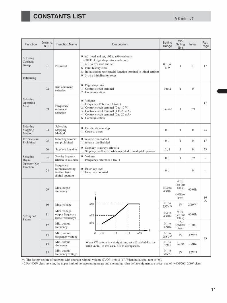
SelectingConstantGroup 01 Password
0 : n01 read and set, n02 to n79 read only(FREF of digital operator can be set)
1 : n01 to n79 read and set6 : Fault history clear8 : Initialization-reset (multi-function terminal to initial setting)9 : 3-wire initialization-reset
0, 1, 6,8, 9
1 1 17
SelectingOperationMode
02Run commandselection
0 : Digital operator1 : Control circuit terminal2 : Communication
0 to 2 1 0
17
03Frequencyreference selection
0 : Volume1 : Frequency Reference 1 (n21)2 : Control circuit terminal (0 to 10 V)3 : Control circuit terminal (4 to 20 mA)4 : Control circuit terminal (0 to 20 mA)6 : Communication
0 to 4.6 1 0*1
SelectingStoppingMethod
04Selecting Stopping Method
0 : Deceleration to stop1 : Coast to a stop
0, 1 1 0 23
Reverse RunProhibited
05Selecting reverserun prohibited
0 : reverse run enabled1 : reverse run disabled
0, 1 1 0 17
SelectingDigitalOperator KeyFunction
06 Stop key function0 : Stop key is always effective1 : Stop key is effective when operated from digital operator
0 , 1 1 0 23
07Selecting frequencyreference in local mode
0 : Volume1 : Frequency reference 1 (n21)
0, 1 1 0*1 –
08
Frequencyreference settingmethod fromdigital operator
0 : Enter key used1 : Enter key not used
0, 1 0 –
Setting V/fPattern
09Max. outputfrequency
50.0 to400Hz
0.1Hz(less than100Hz)
1Hz(100Hz or
more)
60.0Hz
1625
10 Max. voltage0.1 to
255V*2 1V 200V*2
11Max. voltageoutput frequency(base frequency)
0.2 to400Hz
0.1Hz(less than100Hz)
1Hz(100Hz or
more)
60.0Hz
12Mid. outputfrequency
0.1 to399Hz
1.5Hz
2513
Mid. outputfrequency voltage
0.1 to255V*2 1V 12V*2
14Min. outputfrequency
0.1 to10Hz
0.1Hz 1.5Hz
15Min. outputfrequency voltage
0.1 to50V*2 1V 12V*2
Initializing
When V/f pattern is a straight line, set n12 and n14 to thesame value. In this case, n13 is disregarded.
*1 The factory setting of inverters with operator without volume (JVOP-146) is “1”. When initialized, turn to “0”.
*2 For 400V class inverter, the upper limit of voltage setting range and the setting value before shipment are twice that of (=400/200) 200V class.
0 n14
n10
n13
n15
n12 n11 n09F
V

Function Constant No.n==
Function Name Description SettingRange
Min.Setting
UnitInitial Ref.
Page
16* Acceleration time 1Sets acceleration time in the unit when frequency referencechanges from 0 to 100 %.
0.0 to 9990.1s
(less than100s)
1s(100s ormore)
10.0s
1619
17* Deceleration time 1Sets deceleration time in the unit when frequency referencechanges from 100 to 0 %.
0.0 to 999 10.0s
18* Acceleration time 2Effective when acceleration time 2 is selected at multi-functioncontact input selection. Setting is the same as n16.
0.0 to 999 10.0s
19* Deceleration time 2Effective when deceleration time 2 is selected at multi-functioncontact input selection. Setting is the same as n17.
0.0 to 999 10.0s
Selecting S-curve
20* S-curve selection
0 : S-curve not provided1 : 0.2 s2 : 0.5 s3 : 1.0 s
0 to 3 1 0 20
FrequencyReference( FREF )
21*Frequency reference 1(Master speed
frequency reference)
Sets master speed frequency reference. Setting is the same assimple operation lamp FREF ).
0.0 to400Hz
0.1 Hz(less than100Hz)
1 Hz (100 Hz or
more)
6.0Hz
18
22*Frequencyreference 2
Sets second frequency reference. It is effective when multi-stepspeed reference 1 is selected in multi-function contact input.
0.0Hz
23*Frequencyreference 3
Sets third frequency reference. It is effective when multi-stepspeed reference 2 is selected in multi-function contact input.
24*Frequencyreference 4
Sets fourth frequency reference. It is effective when multi-step speedreferences 1 and 2 are selected in multi-function contact input.
25*Frequencyreference 5
Sets fifth frequency reference. It is effective when multi-stepspeed reference 3 is selected in multi-function contact input.
26*Frequencyreference 6
Sets sixth frequency reference. It is effective when multi-step speedreferences 1 and 3 are selected in multi-function contact input.
27*Frequencyreference 7
Sets seventh frequency reference. It is effective when multi-step speedreferences 2 and 3 are selected in multi-function contact input.
28*Frequencyreference 8
Sets eighth frequency reference. It is effective when multi-step speedreferences 1, 2, and 3 are selected in multi-function contact input.
29* Jog frequencySets jog frequency. It is effective when jog frequency isselected in multi-function contact input.
6.0Hz1819
FrequencyReferenceLimit
30Frequency referenceupper limit
Sets upper limit of frequency reference in units of 1 %. Max. output frequency (n09) is 100 %.
0 to 110% 1% 100%
31Frequency referencelower limit
Sets lower limit of frequency reference in units of 1 %. Max. output frequency (n09) is 100 %.
0 to 110% 1% 0%19
MotorProtection byElectronicThermal
32 Motor rated currentSets motor rated current of the motor nameplate. It is thestandard current for motor electro-thermal protection.
0 to 120 % ofinverter ratedoutput current
0.1ADifferentaccording toinvertercapacity (kVA)
1727
33Electronic thermalmotor protectionselection
0 : Standard motor1 : Inverter motor2 : No protection
0 to 2 1 0
27
34Electronic thermalmotor protection timeconstant setting
Sets constant for motor protection. For standard and invertermotors (standard rating), 8min., for others (short period rating),5min.
1 to 60min 1min 8min
SelectingCooling FanOperation
35Selecting coolingfan operation
0 : ON/OFF control (ON while running, OFF when stopped.ON for one minute after stopping.)
1 : Operates with power supply ON0.1 1 0
SelectingAcceleration/DecelerationTime
12
–
VS mini J7CONSTANTS LIST (Cont'd)
* Can be changed during operation.
Function Constant No.n==
Function Name Description SettingRange
Min.Setting
UnitInitial Ref.
Page
SelectingSequenceInputFunctions
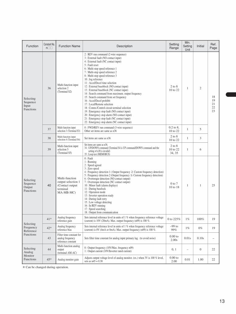
36Multi-function inputselection 2(Terminal S2)
2 : REV run command (2-wire sequence)3 : External fault (NO contact input)4 : External fault (NC contact input)5 : Fault reset6 : Multi-step speed reference 17 : Multi-step speed reference 28 : Multi-step speed reference 310 : Jog reference11 : Accel/Decel time selection12 : External baseblock (NO contact input)13 : External baseblock (NC contact input)14 : Search command from maximum. output frequency15 : Search command from set frequency16 : Accel/Decel prohibit17 : Local/Remote selection18 : Comm./Control circuit terminal selection19 : Emergency stop fault (NO contact input)20 : Emergency stop alarm (NO contact input)21 : Emergency stop fault (NC contact input)22 : Emergency stop alarm (NC contact input)
2 to 810 to 22
1 2
1819212223
37 Multi-function inputselection 3 (Terminal S3)
0 : FWD/REV run command (3-wire sequence)Other set items are same as n36
0.2 to 8,10 to 22
1 5
38 Multi-function inputselection 4 (Terminal S4) Set items are same as n36
2 to 810 to 22
1 3
39Multi-function inputselection 5 (Terminal S5)
Set items are same as n36.34 : UP/DOWN command (Terminal S4 is UP command/DOWN command and the
setting of n38 is invalid)35 : Loop test (MEMOBUS)
2 to 810 to 2234, 35
1 6
SelectingSequenceOutputFunctions
40
Multi-functionoutput selection 1 (Contact outputterminal MA-MB-MC)
0 : Fault1 : Running2 : Speed agreed 3 : Zero speed4 : Frequency detection 1 ( Output frequency ≧ Custom frequency detection)5 : Frequency detection 2 (Output frequency ≦ Custom frequency detection)6 : Overtorque detection (NO contact output)7 : Overtorque detection (NC contact output)10 : Minor fault (alarm displays)11 : During baselock12 : Operation mode13 : Inverter operation ready14 : During fault retry15 : Low voltage detecting16 : In REV running17 : Speed searching18 : Output from communication
0 to 710 to 18
1 1 25
SelectingFrequencyReferenceFunctions
41* Analog frequencyreference gain
Sets internal reference level in units of 1 % when frequency reference voltage(current) is 10V (20mA). Max. output frequency (n09) is 100 %. 0 to 225% 1% 100% 19
42* Analog frequencyreference bias
Sets internal reference level in units of 1 % when frequency reference voltage(current) is 0V (4mA or 0mA). Max. output frequency (n09) is 100 %.
–99 to99%
1% 0% 19
43Filter time constant foranalog frequencyreference constant
Sets filter time constant for analog input primary lag. (to avoid noise)0.00 to2.00s
0.01s 0.10s –
SelectingAnalogMonitorFunctions
44Multi-function analogoutput (terminal AM-AC)
0 : Output frequency (10V/Max. frequency n09)1 : Output current (10V/Inverter rated current) 0, 1 – 0 22
45* Analog monitor gain Adjusts output voltage level of analog monitor. (ex.) when 3V is 100 % level,sets as n45 = 0.30
0.00 to2.00
0.01 1.00 22
* Can be changed during operation.
13
Function Constant No.n==
Function Name Description SettingRange
Min.Setting
UnitInitial Ref.
Page
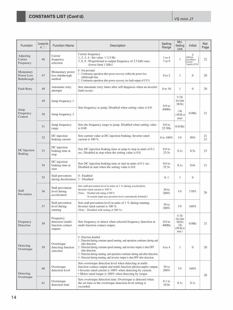
AdjustingCarrierFrequency
46Carrierfrequencyselection
Carrier frequency1, 2, 3, 4 : Set value ×2.5 Hz7, 8, 9 : Proportional to output frequency of 2.5 kHz max.
(lower limit 1 kHz)
1 to 47 to 9
1
4
(Different )according toinverter capacity (kVA)
22
MomentaryPower LossRidethrough
47Momentary powerloss ridethroughmethod
0 : Not provided1 : Continuous operation after power recovery within the power loss
ridethrough time.2 : Continuous operation after power recovery (no fault output of UV1)
0 to 2 1 0 20
Fault Retry 48Automatic retryattempts
Sets automatic retry times after self-diagnosis when an inverterfault occurs.
0 to 10 1 0 20
JumpFrequencyControl
49 Jump frequency 1
Sets frequency to jump. Disabled when setting value is 0.0.0.0 to400Hz
0.1 Hz(less than100 Hz)
1 Hz( 100 Hz or
more)
0.0Hz 2150 Jump frequency 2
51Jump frequencyrange
Sets the frequency range to jump. Disabled when setting valueis 0.00.
0.0 to25.5Hz
0.01Hz
DC InjectionBraking
52DC injectionbraking current
Sets current value at DC injection braking. Inverter ratedcurrent is 100 %.
0 to 100% 1% 50%2123
53DC injectionbraking time atstop
Sets DC injection braking time at ramp to stop in units of 0.1sec. Disabled at stop when the setting value is 0.0.
0.0 to25.5s
0.1s 0.5s 23
54DC injectionbraking time atstart
Sets DC injection braking time at start in units of 0.1 sec.Disabled at start when the setting value is 0.0.
0.0 to25.5s
0.1s 0.0s 21
StallPrevention
55Stall preventionduring deceleration
0 : Enabled 1 : Disabled
0, 1 1 0
2656Stall preventionlevel duringacceleration
Sets stall prevention level in units of 1 % during acceleration. Inverter rated current is 100 %(Notes: ・Disabled with setting of 200 %.
・In constant output area, prevention level is automatically lowered.)
30 to200%
1% 170%
57Stall preventionlevel duringrunning
Sets stall prevention level in units of 1 % during running.Inverter rated current is 100 %.(Note:Disabled with setting of 200 %)
30 to200%
1% 160%
FrequencyDetection
58
Frequencydetection (multi-function contactoutput)
Sets frequency to detect when selected frequency detection atmulti-function contact output .
0.0 to400Hz
0.1 Hz(less than100 Hz)
1 Hz(100 Hz or
more )
0.0Hz 21
DetectingOvertorque
59Overtorquedetecting functionselection
0 : Detection disabled1 : Detected during constant-speed running, and operation continues during and
after detection.2 : Detected during constant-speed running, and inverter output is shut OFF
after detection.3 : Detected during running, and operation continues during and after detection.4 : Detected during running, and inverter output is shut OFF after detection.
0 to 4 1 0 20
14
VS mini J7CONSTANTS LIST (Cont'd)
60Overtorquedetection level
Sets overtorque detection level when detecting at multi-function contact output and multi-function photocoupler output.• Inverter rated current is 100% when detecting by current.• Motor rated torque is 100% when detecting by torque.
30 to200%
1% 160%
61Overtorquedetection time
Sets overtorque detection time. Overtorque is detected whenthe set time or the overtorque detection level setting isexceeded.
0.1 to10.0s
0.1s 0.1s
DetectingOvertorque
20

15
Function Constant No.n==
Function Name Description SettingRange
Min.Setting
UnitInitial Ref.
Page
62Hold outputfrequecy savingselection
Selects whether or not to save the frequency when holding atUP/DOWN command from multi-function input terminal.0 : Output frequency is not saved while holding1 : When holding more than 5 sec, saves output frequency at
holding and operates at this frequency when restarted.
0, 1 1 0
TorqueCompensation
63*1 Torquecompensation gain
Sets torque compensation gain in units of 0.1. Normally, noadjustment necessary.
0.0 to 2.5 0.1 1.0 25
SlipCompensationFunction
64*1 Motor rated slip Sets motor rated slip in units of 0.1 Hz.0.0 to
20.0Hz0.1Hz –
65Motor no-loadcurrent
Sets motor no-load current proportional to the motor ratedcurrent.
0 to 99% 1%
66*1 Slip compensationgain
For motor slipping calculated from the output current, sets gainto correct output frequency in units of 0.1.
0.0 to 2.5 0.1 0.0
67Slip compensationtime constant
Adjusts for unstable speed and slow speed response.0.0 to25.5s
0.1s 2.0s –
27
27
HoldingOutputFrequency
–
MEMOBUSCommunica-tion(whenoptionunit isprovided)
68MEMOBUS timeover detection
0 : Time over detection is enabled. (Coast to a stop)1 : Time over detection is enabled. (Ramp to stop-Decel. 1)2 : Time over detection is enabled. (Ramp to stop-Decel. 2)3 : Time over detection is enabled. (Continue operation - alarm)4 : Time over detection is disabled.
0 to 4 1 0 –
69MEMOBUS frequencyreference and frequencymonitor unit
0 : 0.1 Hz1 : 0.01 Hz2 : 30000/100% (30000=MAX. output frequency)3 : 0.1 %
0 to 3 1 0
70MEMOBUS slaveaddress
Allocates inverter MEMOBUS communication slave addressbetween 0 to 32.Note: When set “0,” ignores command from master and does
not respond.
0 to 32 1 0
71MEMOBUS BPSselection
0 : 2400 bps1 : 4800 bps2 : 9600 bps3 : 19200 bps
0 to 3 1 2
72MEMOBUS parityselection
0 : Even parity1 : Odd parity2 : No parity
0 to 2 1 0
73Transmissionwaiting time
0 to 65ms 1ms 10ms
74 RTS Control0 : Enabled1 : Disabled (RS-422: at 1 to 1 communication)
0, 1 1 0
CarrierFrequencySelection*2
75Reducing carrierfrequency selectionat low speed
0 : Invalid1 : Valid
0, 1 1 0 –
SoftwareVersion
79Software VersionNo.
Displays lowest 3 digits of software No. (only for monitoring) – – – –
–
–
–
–
–
–
Differentaccording toinvertercapacity (kVA)
( )Differentaccording toinvertercapacity (kVA)
( )
*1 Can be changed during operation.
*2 Not built in for the software virsion VSP020010.
Control CopyFunction*2
76Constant copyfunction selection
rdy : READY vFy : VERIFYrEd : READ vA : Inverter capacity displayCpy : COPY Sno : software No. display
rdy, rEdcPy, uFuvA, Sno
– rdy –
77Constant Readselection prohibit
0 : READ prohibited1 : READ allowed
0.1 1 0 –
Fault History 78 Fault history Displays newest one fault (only for monitoring) – – – –
FREQUENCY
ACCEL TIME(n16)
DECEL TIME(n17)
MAX. OUTPUTFREQUENCY
RUNCOMMAND ON
TIME
16
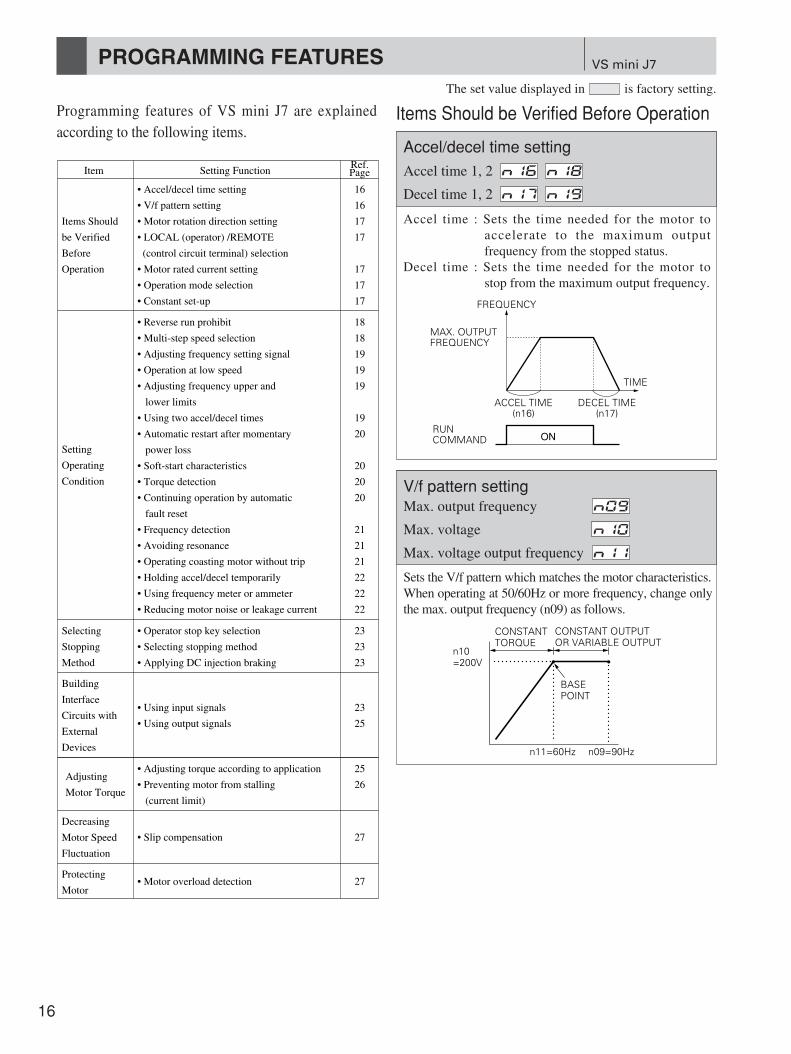
VS mini J7PROGRAMMING FEATURES
Programming features of VS mini J7 are explainedaccording to the following items.
Accel time : Sets the time needed for the motor toaccelerate to the maximum outputfrequency from the stopped status.
Decel time : Sets the time needed for the motor tostop from the maximum output frequency.
Item Setting FunctionRef.Page
• Accel/decel time setting
• V/f pattern setting
• Motor rotation direction setting
• LOCAL (operator) /REMOTE
(control circuit terminal) selection
• Motor rated current setting
• Operation mode selection
• Constant set-up
• Reverse run prohibit
• Multi-step speed selection
• Adjusting frequency setting signal
• Operation at low speed
• Adjusting frequency upper and
lower limits
• Using two accel/decel times
• Automatic restart after momentary
power loss
• Soft-start characteristics
• Torque detection
• Continuing operation by automatic
fault reset
• Frequency detection
• Avoiding resonance
• Operating coasting motor without trip
• Holding accel/decel temporarily
• Using frequency meter or ammeter
• Reducing motor noise or leakage current
• Operator stop key selection
• Selecting stopping method
• Applying DC injection braking
23
23
23
18
18
19
19
19
19
20
20
20
20
21
21
21
22
22
22
Items Should
be Verified
Before
Operation
Setting
Operating
Condition
Selecting
Stopping
Method
• Using input signals
• Using output signals
23
25
Building
Interface
Circuits with
External
Devices
• Adjusting torque according to application
• Preventing motor from stalling
(current limit)
25
26Adjusting
Motor Torque
• Slip compensation 27
Decreasing
Motor Speed
Fluctuation
• Motor overload detection 27Protecting
Motor
16
16
17
17
17
17
17
n11=60Hz
BASEPOINT
CONSTANTTORQUE
CONSTANT OUTPUTOR VARIABLE OUTPUT
n10=200V
n09=90Hz
Sets the V/f pattern which matches the motor characteristics.When operating at 50/60Hz or more frequency, change onlythe max. output frequency (n09) as follows.
Items Should be Verified Before OperationThe set value displayed in is factory setting.
Accel/decel time setting
Accel time 1, 2
Decel time 1, 2 N19N17
N18N16
V/f pattern settingMax. output frequency
Max. voltage
Max. voltage output frequency N11
N10
N09

17
FWDRUN( ) REV
RUN( )
Sets the motor rotation direction when run command isgiven by the digital operator.FWD and REV run can be switched by pressing or
key.v^
Operation can be switched from digital operator orcontrol circuit terminal. This function is valid only whenstopped.e.g. : Digital operator/control circuit terminal selection:
Operation mode selection n02=1Frequency reference selection n03=2, 3 or 4Local (LO) : Receives frequency reference (set at
n07) and run command from digitaloperator
Remote (RE) : Receives frequency reference (FR)and run command (terminals S1and S2) of circuit control terminal
* When local/remote selection function is allocated tomulti-function input terminal, switching operationusing and keys is invalid. v^
VS mini J7 modelCIMR-J7??
VS mini J7 modelCIMR-J7??
20P1B0P1
0.1(0.13)
0.6
20P2B0P2
0.2(0.25)
1.1
20P4B0P4
0.4(0.5)
1.9
20P7B0P7
0.75(1)
3.3
21P5B1P5
1.5(2)
6.2
22P2
2.2(3)
8.5
23P7
3.7(5)
14.1
Max. Applicable MotorOutput kw(HP)
Motor Current FactorySetting A
40P2
0.37(0.5)
0.6
40P4
0.55(0.75)
1.0
40P7
1.1(1.5)
1.6
41P5
1.5(2)
3.1
42P2
2.2(3)
4.2
43P0
3(4)
7.0
43P7
3.7(5)
7.0
Max. Applicable MotorOutput kw(HP)
Motor Current FactorySetting A
Sets motor rated current. The following table shows thestandard set value for each inverter capacity. When theapplicable motor rated current value differs from thevalue listed below, change the set value.
N02Setting Run Command
0 Operator
Control circuit terminal S1, S2
Communication
1
2
N03
N21
Setting Frequency Reference
0 Volume
Operator (Frequency reference 1)
Control circuit terminal FR (0 to 10V)
Control circuit terminal FR (0 to 20mA)
Control circuit terminal FR (4 to 20mA)
1
2
3
4
Communication (register No., 0002H)6
Selects whether operation is performed by digitaloperator or control circuit terminal.
Notes : When set to 2 or 3 (current input reference), dip switch settingmust be changed. For details, refer to the instruction manual.
Setting Constant
0(Constant write disable)
Only n01 can be set, n01 to n79 can be read
n01 to n79 read/set
Fault history clear
1
6
Constant initialization (factory setting: 2-wire sequence)
Constant initialization (3-wire sequence)
8*
9*
The following table describes the data which can be setor read when n01 is set.
* Initialization resets the value to factory setting.
Motor rotation direction setting
FWD/REV direction selection F/R
LOCAL (operator)/REMOTE (control circuitterminal) selection
LOCAL/REMOTE switching LO/RE
Motor rated current setting
Motor rated current N32
Operation mode selection
Run command selection
Frequency reference selection N03
N02
Constant set-up
Password N01

VS mini J7PROGRAMMING FEATURES (Cont’d)
18
Setting Operating ConditionThe set value displayed in is factory setting.
Setting Description
0 Reverse run enabled.
Reverse run disabled.1
“Reverse run disabled” setting does not accept a reverserun command from the control circuit terminal or digitaloperator. This setting is used for applications where areverse run command can cause problems.
By combining frequency reference and input terminalfunction selections, up to 9-step speed can be set.
2-step speed change examplen02 = 1 (Operation mode selection)n03 = 1 (Frequency reference selection)
n21 = 30.0Hzn22 = 50.0Hz
Note : When n03 is set to 0, 2 ,3, or 4, frequency reference 1 (n21) isdisabled and frequency reference from volume (0) or controlcircuit terminal (FR) is enabled.
FWD RUN/STOP S1
S2
S5
SC
REV RUN/STOP
MULTI-STEP SPEED REF. 1
ON
ON
TIME
FREQUENCYREF.
FWD (REV)/STOP[TERMINAL S1 (S2)]
MULTI-STEP SPEED REF.(TERMINAL S5)
FREQUENCY REF. 1 (n21)30.0Hz
FREQUENCY REF. 2 (n22)50.0Hz
8-step speed change examplen02 = 1 (Operation mode selection)n03 = 1 (Frequency reference selection)
n21 = 25.0 Hzn22 = 30.0 Hzn23 = 35.0 Hzn24 = 40.0 Hzn25 = 45.0 Hzn26 = 50.0 Hzn27 = 55.0 Hzn28 = 60.0 Hz
n37 = 6 (Multi-function input terminal S3)n38 = 7 (Multi-function input terminal S4)n39 = 8 (Multi-function input terminal S5)
S1
S2
S3
S4
S5
SC
FWD RUN/STOP
REV RUN/STOPMULTI-STEPSPEED REF. 1
MULTI-STEPSPEED REF. 2
MULTI-STEPSPEED REF. 3
ON
ON ON
ON
ON ONON
ON
TIME
FREQUENCYREF.
(n21) 25.0Hz(n22) 30.0Hz
(n23) 35.0Hz(n24) 40.0Hz
(n25) 45.0Hz(n26) 50.0Hz
(n27) 55.0Hz(n28) 60.0Hz
FWD (REV) RUN/STOP [TERMINAL S1 (S2)]MULTI-STEP SEED REF. 1 [TERMINAL S3]MULTI-STEP SEED REF. 2 [TERMINAL S4]MULTI-STEP SEED REF. 3 [TERMINAL S5]
Reverse run prohibit
Reverse run prohibit N05
Multi-step speed selection
Frequency reference to
Multi-function input terminal function selection to N39N36
N29N21FREF
19
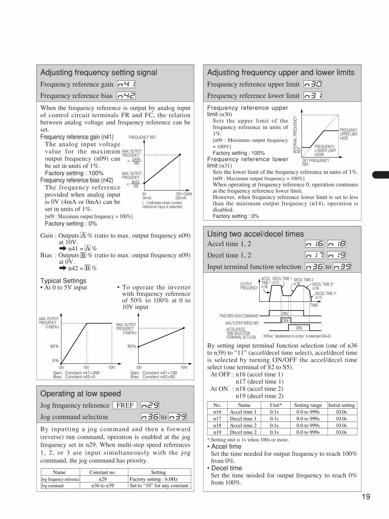
When the frequency reference is output by analog inputof control circuit terminals FR and FC, the relationbetween analog voltage and frequency reference can beset. Frequency reference gain (n41)
The analog input voltagevalue for the maximumoutput frequency (n09) canbe set in units of 1%.Factory setting : 100%
Frequency reference bias (n42)The frequency referenceprovided when analog inputis 0V (4mA or 0mA) can beset in units of 1%.[n09 : Maximum output frequency = 100%]Factory setting : 0%
Gain : Outputs % (ratio to max. output frequency n09)at 10V.a n41 = %
Bias : Outputs % (ratio to max. output frequency n09)at 0V.a n42 = %B
BA
A
FREQUENCY REF.
0V(4mA)
10VGAIN(20mA)
MAX. OUTPUT FREQUENCY
GAIN100
MAX. OUTPUT FREQUENCY
BIAS100
( ) indicates when current reference input is selected.
Typical Settings• At 0 to 5V input • To operate the inverter
with frequency referenceof 50% to 100% at 0 to10V input
0VGain:Bias:
Constant n41=100Constant n42=50
10V
MAX. OUTPUT FREQUENCY
(100%)
50%
0VGain:Bias:
Constant n41=200Constant n42=0
10V5V
MAX. OUTPUT FREQUENCY
(100%)
50%
0%
By inputting a jog command and then a forward(reverse) run command, operation is enabled at the jogfrequency set in n29. When multi-step speed references1, 2, or 3 are input simultaneously with the jogcommand, the jog command has priority.
Name Constant no.Jog frequency referenceJog command
n29n36 to n39
SettingFactory setting : 6.0HzSet to “10” for any constant.
Frequency reference upperlimit (n30)
Sets the upper limit of thefrequency reference in units of1%.[n09 : Maximum output frequency= 100%]Factory setting : 100%
Frequency reference lowerlimit (n31)
Sets the lower limit of the frequency reference in units of 1%.[n09 : Maximum output frequency = 100%]When operating at frequency reference 0, operation continuesat the frequency reference lower limit.However, when frequency reference lower limit is set to lessthan the minimum output frequency (n14), operation isdisabled.Factory setting : 0%
INTE
RNAL
FRE
QUE
NCY
REF.
FREQUENCYUPPER LIMIT(n033)
FREQUENCYLOWER LIMIT(n034)
SET FREQUENCYREF.
By setting input terminal function selection (one of n36to n39) to “11” (accel/decel time select), accel/decel timeis selected by turning ON/OFF the accel/decel timeselect (one terminal of S2 to S5).At OFF : n16 (accel time 1)
n17 (decel time 1)At ON : n18 (accel time 2)
n19 (decel time 2)
OUTPUTFREQUENCY
ACCEL TIME 1(n16)
DECEL TIME 1(n17)
DECEL TIME 2(n18) DECEL TIME 2*
(n19)DECEL TIME 1*(n17)
TIME
ON
ON
ON
FWD (REV) RUN COMMAND
MULTI-STEP SPEED REF.ACCEL/DECELTIME SELECTION(TERMINAL S2 TO S5) *When “deceleration to a stop” is selected (n04=0).
No.n16n17n18n19
Unit*0.1s0.1s0.1s0.1s
Setting range0.0 to 999s0.0 to 999s0.0 to 999s0.0 to 999s
Initial setting10.0s10.0s10.0s10.0s
NameAccel time 1Decel time 1Accel time 2Decel time 2
* Setting unit is 1s when 100s or more.• Accel time
Set the time needed for output frequency to reach 100%from 0%.
• Decel timeSet the time needed for output frequency to reach 0%from 100%.
Adjusting frequency setting signal
Frequency reference gain
Frequency reference bias N42
N41
Operating at low speed
Jog frequency reference
Jog command selection to N39N36
N29FREF
Adjusting frequency upper and lower limits
Frequency reference upper limit
Frequency reference lower limit N31
N30
Using two accel/decel timesAccel time 1, 2
Decel time 1, 2
Input terminal function selection to N39N36
N19N17
N18N16

VS mini J7PROGRAMMING FEATURES (Cont’d)
20
The set value displayed in is factory setting.
When momentary power loss occurs, operation restartsautomatically.
* Hold the operation command to continue the operation afterrecovery from a momentary power loss.
† When 2 is selected, operation restarts if power supply voltagereaches its normal level. No fault signal is output.
Setting01*2*†
DescriptionContinuous operation after momentary power loss not provided.Continuous operation after power recovery within 0.5 second.Continuous operation after power recovery (Fault output not provided).
To prevent shock at machine start/stop, accel/decel canbe performed in S-curve pattern.
Note : S-curve characteristic time is the time from accel/decel rate 0 toa regular accel/decel determined by the set accel/decel time.
Setting0123
S-curve characteristic timeS-curve characteristic not provided
0.2 second0.5 second1.0 second
Time chart at FWD/REV run switching at deceleration toa stop
FREQUENCYREF.
OUTPUTFREQUENCY
S-CURVE CHARACTERISTIC TIME (Tsc)
OUTPUTFREQUENCY
TIME
DC INJECTIONBRAKING TIME AT STOPn53
MIN. OUTPUT FREQUENCYn14
MIN. OUTPUT FREQUENCY n14
DECELACCEL
DECELACCEL
FWD RUN COMMANDREV RUN COMMAND
OUTPUT FREQUENCY
S-curve characteristic in
If excessive load is applied to the machine, outputcurrent increase can be detected by output alarm signalsat multi-function output terminals MA, MB and MC.To output overtorque detection signal, set multi-functionoutput terminal selection n40 to “overtorque detection(set 6 or 7)”.
TIME
n61n61ONON
MOTORCURRENT
n60
MULTI-FUNCTION OUTPUT SIGNAL(OVERTORQUE DETECTION SIGNAL)TERMINAL MA, MB, P1 AND P2(WHEN SETTING IS 6)
HYSTERESIS DURING OVERTORQUE DETECTIONIS APPROX. 5% OFINVERTER RATED CURRENT
Overtorque detection function selection 1 (n59)
Setting01234
DescriptionOvertorque detection not provided.Detected only during constant-speed running, and operation continues after detection.Detected only during constant-speed running, and operation stops after detection.Detected during running, and operation continues after detection.Detected during running, and operation stops after detection.
Sets the inverter to restart and reset fault detection[overcurrent (OC) or overvoltage (OV)] after a faultoccurs.The number of self-diagnosis and retry attempts can beset at n48 up to 10 times.The number of retry attempts are cleared to 0 in thefollowing cases :
• If no other fault occurs within 10 minutes after retry• When the fault reset signal is ON after the fault is detected• Power supply is turned OFF
Automatic restart after momentary power loss
Operation selection after momentary power loss N47
Soft-start characteristics
S-curve accel/decel time selection N20
Torque detectionOvertorque detection function selection
Overtorque detection level
Overtorque detection time N61
N60
N59
Continuing operation by automatic fault reset
No. of fault retry times N48
21
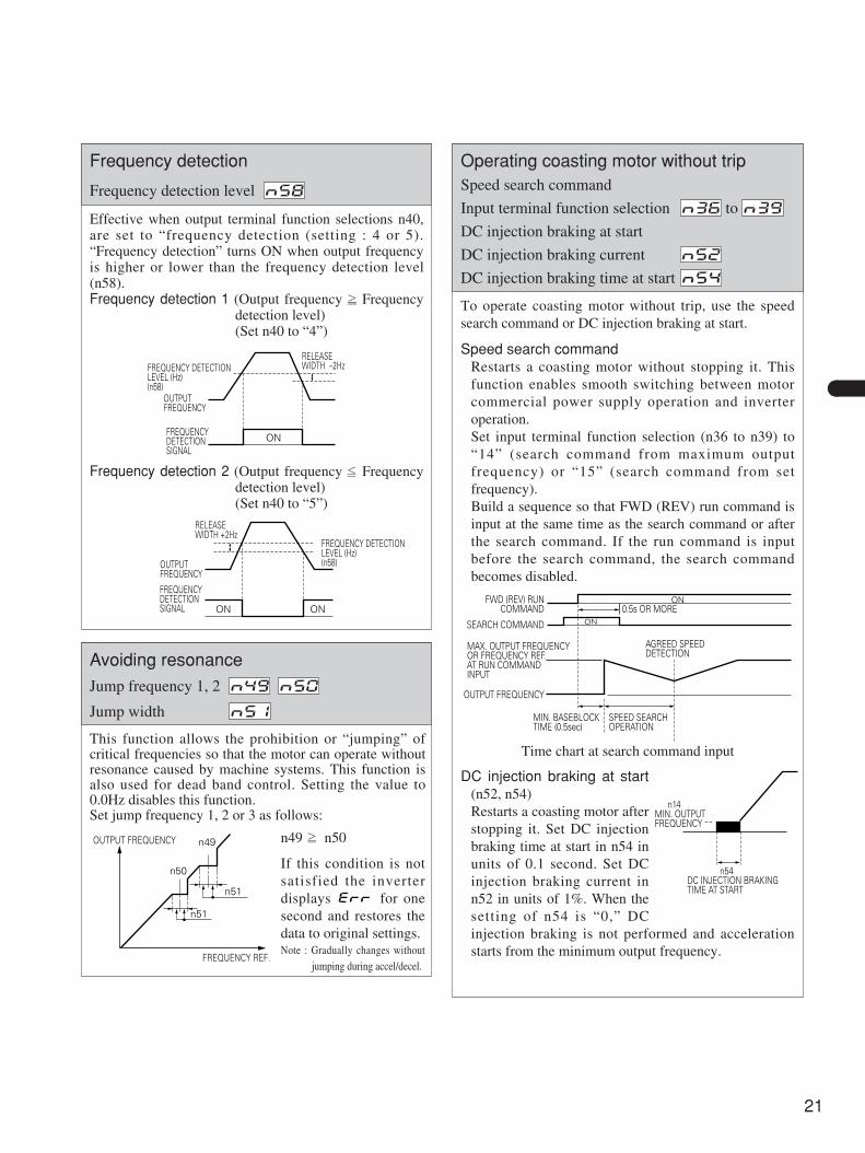
Effective when output terminal function selections n40,are set to “frequency detection (setting : 4 or 5).“Frequency detection” turns ON when output frequencyis higher or lower than the frequency detection level(n58).Frequency detection 1 (Output frequency Frequency
detection level)(Set n40 to “4”)
FREQUENCY DETECTION LEVEL (Hz)(n58)
OUTPUT FREQUENCY
FREQUENCY DETECTION SIGNAL
RELEASE WIDTH –2Hz
ON
Frequency detection 2 (Output frequency Frequencydetection level)(Set n40 to “5”)
FREQUENCY DETECTION LEVEL (Hz)(n58)OUTPUT
FREQUENCY
FREQUENCY DETECTION SIGNAL ONON
RELEASE WIDTH +2Hz
This function allows the prohibition or “jumping” ofcritical frequencies so that the motor can operate withoutresonance caused by machine systems. This function isalso used for dead band control. Setting the value to0.0Hz disables this function.Set jump frequency 1, 2 or 3 as follows:
n49 n50
If this condition is notsatisfied the inverterdisplays for onesecond and restores thedata to original settings.Note : Gradually changes without
jumping during accel/decel.
n51
n49
n50
n51
OUTPUT FREQUENCY
FREQUENCY REF.
To operate coasting motor without trip, use the speedsearch command or DC injection braking at start.
Speed search commandRestarts a coasting motor without stopping it. Thisfunction enables smooth switching between motorcommercial power supply operation and inverteroperation. Set input terminal function selection (n36 to n39) to“14” (search command from maximum outputfrequency) or “15” (search command from setfrequency).Build a sequence so that FWD (REV) run command isinput at the same time as the search command or afterthe search command. If the run command is inputbefore the search command, the search commandbecomes disabled.
ON
ON
0.5s OR MOREFWD (REV) RUN
COMMAND
SEARCH COMMAND
OUTPUT FREQUENCY
AGREED SPEEDDETECTION
MAX. OUTPUT FREQUENCYOR FREQUENCY REF.AT RUN COMMANDINPUT
MIN. BASEBLOCKTIME (0.5sec)
SPEED SEARCHOPERATION
Time chart at search command input
DC injection braking at start(n52, n54)Restarts a coasting motor afterstopping it. Set DC injectionbraking time at start in n54 inunits of 0.1 second. Set DCinjection braking current inn52 in units of 1%. When thesetting of n54 is “0,” DCinjection braking is not performed and accelerationstarts from the minimum output frequency.
n14MIN. OUTPUTFREQUENCY
n54DC INJECTION BRAKINGTIME AT START
Frequency detection
Frequency detection level N58
Avoiding resonance
Jump frequency 1, 2
Jump width N51
N50N49
Operating coasting motor without tripSpeed search command
Input terminal function selection to
DC injection braking at start
DC injection braking current
DC injection braking time at start N54
N52
N39N36

VS mini J7PROGRAMMING FEATURES (Cont’d)
22
The set value displayed in is factory setting.
FWD RUNCOMMAND
ACCEL/DECELHOLD COMMAND
FREQUENCYREF.
OUTPUTFREQUENCY
SPEEDAGREED SIGNAL
ON
ONONON
ON
ON
Time chart at accel/decel hold command input
To hold acceleration, input accel/decel hold command.The output frequency is maintained when the aceel/decelhold command is input during acceleration ordeceleration.The stop command releases the accel/decel hold and theoperation ramps to stop while inputting accel/decel holdcommand.Set input terminal function selection (n36 to n39) to 16(accel/decel hold command).
Selects to output either output frequency or outputcurrent to analog output terminals AM-AC formonitoring.
AM
AC
0 TO 10VDC
FREQUENCY METER
FM
Setting01
DescriptionOutput frequencyOutput current
• Example of analog monitor gain adjustmentWhen using a frequency meter (full scale : 3V, 1mA)which indicates 0 to 60Hz at 0 to 3V.
OUTPUT FREQUENCY(OUTPUT CURRENT)
Analog monitor gaincan be set by n45(When n45=0.30)
100%
0 3VANALOG OUTPUT
10V
fc=CARRIER FREQUENCY
2.5kHz
1.0kHz
83.3Hz 208.3HzFOUT
fc=12 fout
n46=7
fc=CARRIER FREQUENCY
2.5kHz
1.0kHz
27.7Hz 69.4HzFOUT
fc=32 fout
n46=9
fc=CARRIER FREQUENCY
2.5kHz
1.0kHz
41.6Hz 104.1HzFOUT
fc=24 fout
n46=8
Setting1234
7 to 9
Carrier frequency (Hz) Metallic noise from motor Current leakage2.5
–
5.07.510.0
Higher
Not audible
–
Smaller
LargerSynchronized type with lower limit 1kHz and upper limit 2.5Hz
Sets inverter output transistor swiching frequency(carrier frequency).
Carrier frequency initial value differs depending oninverter capacity as follows :• 10kHz (setting n46 = 4) : 200V three-phase 0.1 to 0.75kW• 7.5kHz (setting n46 = 3) : 200V three-phase 1.5 to 3.7kW
200V single-phase, 1.5kW400V three-phase, all models
To change the initial value 7.5kHz to 10kHz, continuousoutput current must be lowered. For details, refer to theinstruction manual.
Holding accel/decel temporarily
Accel/decel hold command
Input terminal function selection to N39N36
Using frequency meter or ammeter
Analog monitor selection
Analog monitor gain N45
N44
Reducing motor noise or leakage current
Carrier frequency N46

23
Setting Description
0
1
STOP key effective when running from terminals or communication.When STOP key is depressed, the inverter stops according to the setting of constant n04. At this time, the digital operator displays “ ” alarm (blinking). This stop command is held in the inverter until both forward and reverse run commands are open or operation command from communication is “0”.
STOP key ineffective when running from terminals or communication.
Selects processing when STOP key is depressed duringoperation from control circuit terminal or communication.
Selecting Method to Stop
Selects the stopping method suitable for application.
Setting01
DescriptionDeceleration to stopCoast to stop
• Deceleration to stopExample when accel/decel time 1 is selected
OUTPUTFREQUENCY
ACCELTIME 1(n16)
DECEL TIME 1(n17)
DECEL TIME 1(n17)
n14(FACTORY SETTING: 1.5Hz)
MIN. OUTPUT FREQUENCY(FREQUENCY ATDC INJECTION BRAKINGSTART)
DC INJECTION BRAKINGTIME AT STOP (n53)(FACTORY SETTING: 0.5s)
TIMEFWD (REV)RUNCOMMAND ON
**
When frequency referenceis changed during running.
*
• Coast to a stopExample when accel/decel time 1 is selected
OUTPUTFREQUENCY
ACCELTIME 1(n16)
DECEL TIME 1(n17)
COAST TO STOP
TIME
FWD (REV)RUNCOMMAND ON
**
When frequency referenceis changed during running.
*
n14MIN. OUTPUTFREQUENCY
n53DC INJECTION BRAKINGTIME AT STOP
When coasting to a stop isspecified in stopping methodselection (n04), DC injectionbraking at stop does not operate.
Building Interface Circuits with External Devices
Setting
0
2
3
4
5
6
7
8
10
11
12
13
14
15
16
17
18
19
20
21
22
34
35
24
–
–
–
18
19
19
–
21
22
24
24
–
–
–
–
24
–
Function Name
FWD/REV run command(3-wire sequence selection)
Setting enabled only forn052
Inverter stops by externalfault signal input.Digital operator displayis “EF?*”Resets fault. It is disabledwith run signal entered.
Motor coasts to stop bythis signal input.Digital operator display“BB” (blinking).
Speed search commandsignal
Setting is enabled onlyfor n39.Setting is enabled onlyfor n39.
REV run command(2-wire sequence)External fault(NO contact input)External fault(NC contact input)
Fault reset
Multi-step speed reference 1
Multi-step speed reference 2
Multi-step speed reference 3
Jog command
Accel/decel time select
External baseblock(NO contact input)External baseblock(NC contact input)Search command from max.output frequencySearch command from set frequency
Accel/decel hold command
LOCAL/REMOTE selection
Communication/Controlcircuit terminal selectionEmergency stop fault(NO contact input) Emergency stop alarm(NO contact input) Emergency stop fault(NC contact input) Emergency stop alarm(NC contact input)
UP/DOWN command
Self-test
Description
–
–
–
–
–
–
–
–
–
Inverter stops by emergency stop signal input according to stopping method selection (n04). When frequency deceleration to a stop (n04=0) is selected, inverter decelerates to a stop according to decel time setting 2 (n19). Digital operator displays “ ” (lights at fault, blinks at alarm).
Ref.Page
Multi-function input terminals S2 to S5 functions can bechanged when necessary by setting constants n36 ton39, respectivery. The same value can not be set todifferent constant setting.
• Terminal S2 function : Set to n36 : Factory setting 2• Terminal S3 function : Set to n37 : Factory setting 5• Terminal S4 function : Set to n38 : Factory setting 3• Terminal S5 function : Set to n39 : Factory setting 6
* : A number 2 to 5 is displayed in ? corresponding to the number ofterminal S2 to S5 respectively.
Operator stop key selection
Operator stop key selection N06
Selecting stopping method
Stopping method selection N04
Applying DC injection braking
DC injection braking current
DC injection braking time at stop N53
N52
Using input signals
Input terminal function selection to N39N36

VS mini J7PROGRAMMING FEATURES (Cont’d)
24
The set value displayed in is factory setting.
Terminal function at 3-wire sequence selection
RUN COMMAND(Run when “closed”)STOP COMMAND(Stop when “open”)FWD/REV RUN SELECTION FWD run when “open” REV run when “closed”
STOP SW(NC CONTACT)
RUN SW(NO CONTACT)
S1
S2
S3
SC ( )
Control circuit terminal S4 (UP command)Control circuit terminal S5 (DOWN command)
Operation status
ClosedOpen
Accel
ClosedClosed
Hold
ClosedOpen
Decel
OpenOpen
Hold
LOCAL/REMOTE select (setting : 17)Select operation reference by the digital operator or bythe control circuit terminal.LOCAL/REMOTE select is valid only during stop.Open : Run by setting at run command selection (n02)
and frequency reference selection (n03).Closed : Run by frequency reference and run command
from digital operator.e.g. : When the digital operator/control circuit terminal
selection setting is n02 = 1 and n03 = 2, 3 or 4Open : Receives frequency reference (terminal FR,
RP) and run command (terminals S1 to S5 )from control circuit terminal
Closed : Receives frequency reference (setting at n07)and run command from digital operator.
Communication/control circuit terminal selection(setting : 18)Selects operation reference by communication or bycontrol circuit terminal. Communication/control circuitterminal selection is valid only during stop.Open : Run according to the setting at n02 and n03
(operation method selection).Closed : Run by frequency reference and run command
from communication.e.g. : When used for communication/control circuit
terminal selection, set n02 = 1 and n03 = 2, 3or 4
Open : Receives frequency reference (terminal FR)and run command (terminals S1 to S5 ) fromcontrol circuit terminal
Closed : Receives frequency reference and runcommand from communication
UP/DOWN command (setting : n39 = 34)With the FWD (REV) run command entered,accel/decel is enabled by inputting the UP or DOWNsignals to control circuit terminals S4 and S5 withoutchanging the frequency reference, so that operation canbe perfomed at the desired speed. When UP/DOWNcommands are specified by n39, any function set ton38 becomes disabled; terminal S4 becomes an inputterminal for UP command and terminal S5 for DOWNcommand.
* : Effective only when with option unit.
D1H D1 D1 D1U U UH H H H H HD D D
FWD RUNUP COMMAND S4
DOWN COMMAND S5
UPPER LIMIT SPEED
LOWER LIMIT SPEEDOUTPUT FREQUENCY
FREQUENCY AGREEDSIGNAL
Time chart at UP/DOWN command input
U = UP (accelerating) statusD = DOWN (decelerating) statusH = HOLD (constant speed) statusU1 = UP status, clamping at upper limit speedD1 = DOWN status, clamping at lower limit speed
Notes : • When UP/DOWN command is selected, theupper limit speed is set regardless offrequency reference. Upper limit speed = Max. output frequency
(n09) × Frequencyreference upper limit(n30) /100
• The lower limit speed is the largest valueamong min. output frequency (n14) andfrequency reference lower limit (n31).
• When the FWD (REV) run command is input,operation starts at the lower limit speedwithout UP/DOWN command.
• When the jog command is input while runningby the UP/DOWN command, the jogcommand has priority. The UP/DOWNcommand can not be input together withmulti-step speed reference.
• By setting hold output frequency memoryselection (n62) to 1, the output frequencyduring hold can be saved.
Setting at n62 Description
0 Output frequency during hold is not saved.
1After 5 sec. of hold state, the output frequency during hold is saved and the operation will restart with the saved output frequency

25
Multi-function output terminal MA and MB, functionscan be changed when necessary by setting constantsn40.• Terminal MA and MB functions : Set to n40
Setting Ref.Page
0 –
1 –
2 Figurebelow
3 –
421
5
620
7
10 28
11 –
12 –
13 –
14 –
15 –
16 –
17 21
18 –
Function Name
Fault “Closed” (ON) wheninverter fault occurs.
Running
Speed agreed
Zero speed
Frequency detection 1(output frequency frequency detection level)Frequency detection 2(output frequency frequency detection level)Overtorque detection(NO contact output)Overtorque detection(NC contact output)
Minor fault (alarm display)
During baseblock
Operation mode
Inverter run ready
In fault retry
Low voltage (UV) detected
In REV run
In speed search
Data output from communication
Description
–
–
–
–
–
–
–
“Closed” (ON) when FWD or REV run command is input, or when the inverter outputs voltage.
“Closed” (ON) when the inverter output frequency is less than min. output frequency
“Closed” (ON) when the inverter output is shut off.
“Closed” (ON) when “LOCAL” is selected by L O C A L / R E M O T E selection
“Closed” (ON) when the inverter is ready to operate without any fault.
“Closed” (ON) when the inverter is detecting low voltage.
“Closed” (ON) during speed search of inverter.
By command from MEMOBUS communication, multi-function output terminal is operated independently from the inverter operation.
“Closed” (ON) duringfault retry.
DETECTION WIDTH ±2Hz
OUTPUT FREQUENCY
SPEED AGREED SIGNAL ON
RELEASE WIDTH±4HzFREQUENCYREF
Factory settings n40 : 1
Setting example of “Speed agreed signal” (setting = 2)
Adjusting Motor Torque
Adjust motor torque by using “V/f pattern” and “full-range automatic torque boost”.
V/f pattern settingSet V/f pattern by n09 to n15 as described below. Seteach pattern when using a special motor (high-speedmotor, etc.) or when requiring special torque adjustmentof machine.V: VOLTAGE
n10
n13
n15
0 n14 n12 n11 n09fFREQUENCY
ConstantsNo.
n09
Name Unit Setting Range Initial Setting
Max. output frequency 0.1Hz 50.0 to 400Hz 60.0HzMax. voltage 1V 1 to 255V 200V*Max. voltage output frequency(base frequency) 0.1Hz 0.2 to 400Hz 60.0Hz
Mid. output frequency 0.1Hz 0.1 to 399Hz 1.5HzMid. output frequency voltage 1V 1 to 255V 12V*Min. output frequency 0.1Hz 0.1 to 10.0Hz 1.5HzMin. output frequency voltage 1V 1 to 50V 12V*
n10
n11
n12n13n14n15
Note : Refer to the instruction manual for details of setting.* : Twice for 400V class.
Full-range automatic torque boostMotor torque requirement changes according to loadconditions. Full-range automatic torque boost adjustsvoltage of V/f pattern according to the requirement.The VS mini J7 automatically adjusts the voltageduring constant-speed operation as well as duringacceleration. The required torque is calculated by theinverter.Normally, no adjustment is necessary for torquecompensation gain (n63 factory setting = 1.0). Whenthe wiring distance between the inverter and the motoris long, or when the motor generates vibration, changethe torque compensation gain. In these cases, reset theV/f pattern (n09 to n15).
Be sure to satisfy thefollowing conditions for thesetting of n09 to n15.n14 n12 < n11 n09If n14 = n12 is set, the setvalue of n13 is disabled.
Using output signals
Multi-function output terminal function selection N40
Adjusting torque according to applicationMax. output frequency
Max. voltage
Max. voltage output frequency
Mid. output frequency
Mid. output frequency voltage
Min. output frequency
Min. output frequency voltage
Torque compensation gain N63
N15
N14
N13
N12
N11
N10
N09

VS mini J7PROGRAMMING FEATURES (Cont’d)
26
The set value displayed in is factory setting.
Stall prevention (current limit) level during accel(n56)Automatically adjusts the output frequency and theoutput current according to the load to continueoperation without stalling the motor.During acceleration if the output current exceeds 170%of the inverter rated current [the value set for n56],acceleration stops and then frequency is maintained.When the output current goes down to 170% [the valueset for n56], acceleration starts. Inverter rated currentbecomes 100%.
MOTOR CURRENT
OUTPUTFREQUENCY
170% OFINVERTERRATEDCURRENT
*
(n56)
TIME
TIME
Holds the acceleration to prevent the motor from stalling.*
Factory setting of n56 = 170%When set to 200%, this function becomes disabled.
In the constant output area [output frequency max.voltage output frequency (n11)], the stall preventionlevel during acceleration is automatically decreased bythe following equation.
Stall prevention (current limit) level during accel in constant output area
= 170% [n56 setting] ×Max. voltage output frequency (n11)
Output frequency
Stall prevention (current limit) level during runningDuring agreed speed if the output current exceeds 160%of the inverter rated current [the value set for n57],deceleration starts.When the output current exceeds 160% [the value set forn57], deceleration continues.When the output current goes down to the value,acceleration starts, up to the set frequency.
MOTOR CURRENT
OUTPUTFREQUENCY
160% OFINVERTERRATEDCURRENT
*1
*2
*2
TIME
TIME
(n57)
Decreases frequency to prevent the motor from stalling.If the output current does not become set level or less, the operation will be held at the min. output frequency.
*1.
*2.
Factory setting of n57 = 160%When set to 200%, this function becomes disabled.
Stall prevention (current limit) during deceleration(n55)To prevent overvoltage during deceleration, the inverterautomatically extends the deceleration time according tothe value of main circuit DC voltage.
TIME
FREQUENCY
SETDECEL TIME
Controls the decelerationtime to preventovervoltage fault.
Setting01
Stall prevention during decelerationProvidedNot Provided
Preventing motor from stalling (Current limit)Stall prevention (current limit) level during accel
Stall prevention (current limit) level during running
Stall prevention during decel N55
N57
N56
27
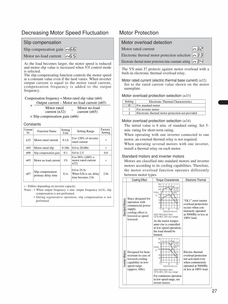
Decreasing Motor Speed Fluctuation
As the load becomes larger, the motor speed is reducedand motor slip value is increased when V/f control modeis selected.The slip compensating function controls the motor speedat a constant value even if the laod varies. When inverteroutput current is equal to the motor rated current,compensation frequency is added to the outputfrequency.
ConstantNo. Function Name Setting
UnitSetting Range Factory
Setting
Motor rated current 0.1A0 to 120% of inverterrated current *
Motor rated slip 0.1Hz 0.0 to 20.0Hz *
Slip compensation gain 0.1 0.0 to 2.5 0.0
Motor no-load current
Slip compensationprimary delay time
1%0 to 99% (100% =motor rated current n32)
*
0.1s0.0 to 25.5sWhen 0.0s is set, delaytime becomes 2.0s
2.0s
n32
n64
n66
n65
n67
* : Differs depending on inverter capacity.Notes : • When output frequency < min. output frequency (n14), slip
compensation is not performed.• During regenerative operation, slip compensation is not
performed.
Constants
Compensation frequency = Motor rated slip value (n64)
×Output current – Motor no-load current (n65)
× Slip compensation gain (n66)
–Motor ratedcurrent (n32)
Motor no-loadcurrent (n65)
Motor Protection
The VS mini J7 protects against motor overload with abuilt-in electronic thermal overload relay.
Motor rated current (electric thermal base current) (n32)Set to the rated current value shown on the motornameplate.
Motor overload protection selection (n33)
Setting012
Electronic Thermal CharacteristicsFor standard motorFor inverter motorElectronic thermal motor protection not provided
Motor overload protection selection (n34)The initial value is 8 min. of standard rating. Set 5-min. rating for short-term rating.When operating with one inverter connected to onemotor, an external thermal relay is not required.When operating severad motors with one inverter,install a thermal relay on each motor.
Standard motors and inverter motorsMotors are classified into standard motors and invertermotors according to its cooling capabilities. Therefore,the motor overload function operates differentlybetween motor types.
Electronic ThermalTorque CharacteristicCooling Effect
Stan
dard
Mot
ors
Inve
rter M
otor
s
Since designed foroperation with commercial power supply, cooling effect is lowered as speedlowered. As the motor temper-
ature rise is controlled at low-speed operation,the load should be limited.
“OL1” error (motoroverload protection)occurs when con-tinuously operated at 50/60Hz or less at 100% load.
Electric thermaloverload protectionnot activated evenwhen continuouslyoperated at 50/60Hzor less at 100% load.
Designed for heat-resistant in case oflowered coolingcapability in low-speed range (approx. 6Hz).
BASE FREQUENCY 60Hz(V/f for 60Hz, 220V input voltage)
For continuous operationin low-speed range, useinveter motors.
BASE FREQUENCY 60Hz(V/f for 60Hz, 220V input voltage)
60 sec. SHORT-TERM
CONTINUOUSRATING
180155140
100805538
03 20 60 120
TORQUE
(%)
OPERATION FREQ. (Hz)
180
155
100
5538
06 60 120
TORQUE
(%)
OPERATION FREQ. (Hz)
60 sec. SHORT-TERM
CONTINUOUSRATING
Slip compensation
Slip compensation gain
Motor no-load current N65
N66
Motor overload detectionMotor rated current
Electronic thermal motor protection selection
Electronic thermal motor protection time constants setting N34
N33
N32
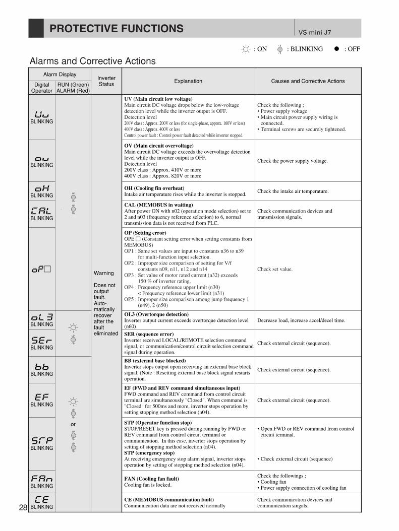
VS mini J7
28
PROTECTIVE FUNCTIONS
Alarms and Corrective Actions: ON : BLINKING : OFF
Alarm DisplayInverterStatus Explanation Causes and Corrective Actions
DigitalOperator
RUN (Green)ALARM (Red)
Warning
Does notoutputfault.Auto-maticallyrecoverafter thefaulteliminated
UV (Main circuit low voltage)Main circuit DC voltage drops below the low-voltagedetection level while the inverter output is OFF.Detection level 200V class : Approx. 200V or less (for single-phase, approx. 160V or less)400V class : Approx. 400V or lessControl power fault : Control power fault detected while inverter stopped.
Check the following :• Power supply voltage• Main circuit power supply wiring is
connected.• Terminal screws are securely tightened.
OV (Main circuit overvoltage)Main circuit DC voltage exceeds the overvoltage detectionlevel while the inverter output is OFF.Detection level200V class : Approx. 410V or more400V class : Approx. 820V or more
Check the power supply voltage.
OH (Cooling fin overheat)Intake air temperature rises while the inverter is stopped.
Check the intake air temperature.
CAL (MEMOBUS in waiting)After power ON with n02 (operation mode selection) set to2 and n03 (frequency reference selection) to 6, normaltransmission data is not received from PLC.
Check communication devices andtransmission signals.
OP (Setting error)OPE (Constant setting error when setting constants fromMEMOBUS)OP1 : Same set values are input to constants n36 to n39
for multi-function input selection.OP2 : Improper size comparison of setting for V/f
constants n09, n11, n12 and n14OP3 : Set value of motor rated current (n32) exceeds
150 % of inverter rating.OP4 : Frequency reference upper limit (n30)
< Frequency reference lower limit (n31) OP5 : Improper size comparison among jump frequency 1
(n49), 2 (n50)
Check set value.
OL3 (Overtorque detection)Inverter output current exceeds overtorque detection level(n60)
Decrease load, increase accel/decel time.
SER (sequence error)Inverter received LOCAL/REMOTE selection commandsignal, or communication/control circuit selection commandsignal during operation.
Check external circuit (sequence).
BB (external base blocked)Inverter stops output upon receiving an external base blocksignal. (Note : Resetting external base block signal restartsoperation.
Check external circuit (sequence).
EF (FWD and REV command simultaneous input)FWD command and REV command from control circuitterminal are simultaneously "Closed". When command is"Closed" for 500ms and more, inverter stops operation bysetting stopping method selection (n04).
Check external circuit (sequence).
STP (Operator function stop)STOP/RESET key is pressed during running by FWD orREV command from control circuit terminal orcommunication. In this case, inverter stops operation bysetting of stopping method selection (n04).STP (emergency stop)At receiving emergency stop alarm signal, inverter stopsoperation by setting of stopping method selection (n04).
• Open FWD or REV command from controlcircuit terminal.
• Check external circuit (sequence)
FAN (Cooling fan fault)Cooling fan is locked.
Check the followings :• Cooling fan• Power supply connection of cooling fan
or
CE (MEMOBUS communication fault)Communication data are not received normally
Check communication devices andcommunication singals.
BLINKING
BLINKING
BLINKING
BLINKING
BLINKING
BLINKING
BLINKING
BLINKING
BLINKING
BLINKING
BLINKING

29
Faults and Corrective ActionsFault Display
InverterStatus Explanation Causes and Corrective Actions
DigitalOperator
RUN (Green)ALARM (Red)
ProtectiveOperation
Output isshutt OFFand motorcoasts to astop.
OC (overcurrent)Inverter output current momentarily exceeds approx. 250 %of rated current.
Check the following and restart:• Short-circuit or grounding at inverter output
side• Excessive load GD2
• Extremely rapid accel/decel time (n16 ton19)
• Special motor used• Starting motor during coasting• Motor of a capacity greater than the inverterrating has been started.
• Magnetic contactor open/closed at the inverteroutput side
(control power supply fault)Voltage fault of control power supply is detected.
Turn OFF, and ON power. If the fault remains,replace the inverter.
OV (main circuit overvoltage)Main circuit DC voltage exceeds the overvoltage detectionlevel due to excessive regenerative energy from the motor.Detection level200V class : approx. 410V and more400V class : approx. 820V and more
• Insufficient decel time (constants n17 andn19)
• Large minus load at lowering (elevator, etc.)d
• Increase decel time.• Connect optional braking resistor.
UV1 (main circuit low-voltage)Main circuit DC voltage drops below the low-voltagedetection level while inverter output is ON.Detection level200V class : approx. 200V and less (approx. 160V and
less for single-phase)400V class : approx. 400V and less
• Reduction of input power supply voltage• Open phase of input supply• Occurrence of momentary power loss
dCheck the following:• Power supply voltage• Main circuit power supply wiring is
connected• Terminal screws are securely tightened.
OH (cooling fin overheat)Temperature rise due to inverter overload operation orintake air temperature rise.
• Excessive load• Improper V/f pattern setting• Insufficient accel time if the fault occurs
during acceleration• Intake air temperature exceeding 50 • Cooling fan is stopped.
dCheck the following:• Load size• V/f pattern setting (n09 to n15)• Intake air temperature
OL1 (motor overload)Motor overload protection activated by built-in electronicthermal overload relay.
• Check the load size and V/f pattern setting (n09 to n15)
• Set n36 to the rated current on motor nameplate.
OL2 (inverter overload)Inverter overload protection activated by built-in electronicthermal overload relay.
• Check the load size and V/f pattern setting(n09 to n15)
• Check the inverter capacity
OL3 (overtorque detection)When V/f mode is selected, inverter output current exceedsthe overtoraue detection level (n60).If overtorque is detected, inverter operates according to thesetting at n59)
Check the driven machine and correct the causeof the fault, or increase the value of n60 up tothe highest allowable value for the machine.
GF (ground fault)*Inverter output ground fault current exceeds the inverter rated current.
Check the connection at output side wiring andthe motor.
* This alarm detects ground fault in the motor winding. It cannot protect low-resistant ground fault in the motor cable, the terminal block, etc.
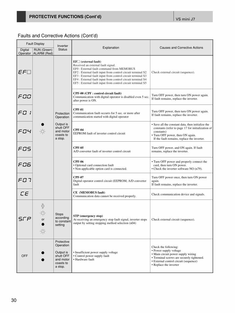
30
Faults and Corrective Actions (Cont’d)
Fault DisplayInverterStatus Explanation Causes and Corrective Actions
DigitalOperator
RUN (Green)ALARM (Red)
ProtectionOperation
Output isshutt OFFand motorcoasts toa stop.
EF (external fault)Received an external fault signal.EF0 : External fault command from MEMOBUSEF2 : External fault input from control circuit terminal S2EF3 : External fault input from control circuit terminal S3EF4 : External fault input from control circuit terminal S4EF5 : External fault input from control circuit terminal S5
Check external circuit (sequence).
CPF-00 (CPF : control circuit fault)Communication with digital operator is disabled even 5 sec.after power is ON.
Turn OFF power, then turn ON power again.If fault remains, replace the inverter.
CPF-01Communication fault occurrs for 5 sec. or more aftercommunication started with digital operator
Turn OFF power, then turn ON power again.If fault remains, replace the inverter.
CPF-04EEPROM fault of inverter control circuit
• Save all the constant data, then initialize theconstants (refer to page 17 for initialization ofconstants)
• Turn OFF power, then ON again.If the fault remains, replace the inverter.
CPF-05A/D converter fault of inverter control circuit
Turn OFF power, and ON again. If faultremains, replace the inverter.
CPF-06• Optional card connection fault• Non-applicable option card is connected.
• Turn OFF power and properly connect the card, then turn ON power.
• Check the inverter software NO (n79).
CPF-07Digital operator control circuit (EEPROM, A/D converterfault
Turn OFF power once, then turn ON poweragain.If fault remains, replace the inverter.
CE (MEMOBUS fault)Communication data cannot be received properly.
Check communication device and signals.
Stopsaccordingto constantsetting
STP (emergency stop)At receiving an emergency stop fault signal, inverter stopsoutput by setting stopping method selection (n04)
Check external circuit (sequence).
OFF
ProtectiveOperation
Output isshutt OFFand motorcoasts toa stop.
• Insufficient power supply voltage• Control power supply fault• Hardware fault
Check the following:• Power supply voltage• Main circuit power supply wiring• Terminal screws are securely tightened.• External control circuit (sequence)• Replace the inverter
or
VS mini J7PROTECTIVE FUNCTIONS (Cont’d)

Inverter
Selection
31
VS mini J7NOTES ON USE
< Use a DC reactor (option) or an AC reactor (option) on the inverter power side when the inverter is connected directly toa large-capacity power transformer (600kVA and over within 10m distance) or when a phase advance capacitor isswitched. Otherwise excess peak current may occur in the power feed circuit and the converter section may be damaged.A DC reactor or an AC reactor is also required when a thyristor converter such as a DC drive is connected to the samepower system.
< When a special motor is used or more than one motor is driven in parallel with a single inverter, select the invertercapacity so that 1.1 times of the total motor rated current does not exceed the inverter rated output current.
< The starting and accelerating characteristics of the motor driven by an inverter are restricted by the overload currentratings of the inverter. Compared to running with commercial power supply, lower touque output should be expected. Ifhigh starting torque is required, use an inverter of higher capacity or increase the capacities of both the motor and theinverter.
< When an error occurs, a protective circuit is activated and the inverter output is turned OFF. However, the motor cannotbe stopped immediately. Use a mechanical brake and hold the equipment for a fast stop if necessary.
< Terminals +1 and +2 are for DC reactor (option). Do not connect other equipment.
Setting< The inverter can be driven at an output frequency of up to 400Hz with the digital operator. Setting errors may create a
dangerous situation. Set the upper limit with the upper limit frequency setting function. (Maximum output frequency inexternal input signal operation is preset to 60Hz at the factory.)
< Large DC injection braking operating voltages and times may cause motor overheating.
< Motor accel/decel time is determined by the motor generating touque, load torque, and load inertia WK2 (GD2). If thestall prevention function is activated during accel/decel, set the accel/decel time longer. After the stall preventionfunction is activated, the accel/decel time is extended to a length that the inverter can handle. To shorten the accel/deceltime, increase the capacity of the inverter and possibly the motor.
Operation< Applying power to inverter output terminals U/T1, V/T2, W/T3 will damage the inverter. Double check wiring and
sequence before turnig the power ON.
< If magnetic contactor (MC) is used on the primary side of the inverter, do not use the MC for starting and stopping theinverter. Otherwise, the inverter life may be reduced.
< After turning power to the inverter OFF, electric charges in the internal capacitors are retained temporarily. Wait untilthe charge LED goes off before touching the inside of the inverter.
Installation< Avoid oil mist or dust. Place the inverter in a clean area or house it in a totally-enclosed case so that no contamination
enters. To use the totally-enclosed case, select the cooling method and panel dimensions so the inverter ambienttemperature will be within the allowable range.
< Do not install the inverter on flammable material, such as wood.
< Install the inverter on a wall with the longer side in the vertical position.

Peripheral Devices
VS mini J7
32
Installation and selection of molded-case circuit breakerOn the input power side, a molded-case circuit breaker (MCCB) to protect inverter primary wiring should be installed. The inverter power-factor(depending on power voltage, output frequency, and load) must be taken into account for selecting MCCB. For standard settings, see page 36. If a fullelectromagnetic MCCB is to be used, select a larger capacity because the operating characteristics are altered by harmonic current. A leakage currentbreaker threshold of 200mA and above, or of inverter (suppressing high frequency) use is recommended.
Use of input side magnetic contactorThe inverter can be used without an input side magnetic contactor (MC). An input MC can be used to prevent an automatic restart after recovery from anexternal power loss during remote control operation. However, do not use the MC frequently for start/stop operation, or it will lead to a reducedreliability. When the digital operator is used, automatic restart after power failure is disabled, so that MC starting is impossible. Although the MC canstop the inverter, regeneration braking is disabled and the motor coasts to a stop.
Use of secondary magnetic contactorIn general magnetic contactors on the output of the inverter, for motor control should not be used. Starting a motor with the inverter running will causelarge surge currents and the inverter overcurrent protector to trigger. If an MC is used for switching to commercial power supply, switch MC after theinverter and the motor stop. To switch during motor rotation, use the speed search command. (See page 21.)
Use of overload relayThe inverter includes an electronic thermal protective function to protect the motor from overheating. However, when multi-drive by one inverter is used,place a overload relay between the inverter and the motor. Set 2 in n33, and set the ovverload relay to the current nameplate value at 50Hz, or 1.1 times ofthat at 60Hz.
Power-factor improvement (elimination of phase advance capacitor)
To improve the power-factor, install a DC reactor or an AC reactor on the inverter's power side. Power-factor improvement capacitor or surge suppressorson the inverter output side will be damaged by the harmonic component in the inverter output. Also, the overcurrent caused in the inverter output willtrigger the overcurrent protection. To avoid this, do not use capacitors or surge suppressors in the inverter's output. To improve the power-factor, installan AC reactor on the inverter primary side.
Radio frequency interferenceBecause the inverter I/O (main circuit) contains a higher harmonics component, it may emit RFI noise to communication equipment (AM radio, etc.) nearthe inverter. Use a noise filter to decrease the noise. Use of a metalic conduit between the inverter and motor and grouding the conduit is also effective.Proper routing of input and output lead is also recommended.
Wire thickness and cable lengthIf a long cable is used between the inverter and a motor (especially whenlow frequency is output ), motor torque decreases because of voltage drop inthe cable. Use sufficiently thick wire. If a long cable is used and invertercarrier frequency (main transistor switching frequency) is high, harmonicleakage current from the cable will increase to affect the inverter unit orperipheral devices. Reduce the inverter carrier frequency.When a digital operator is to be installed separately from the inverter, usethe YASKAWA remote interface and special connection cable (option). Forremote control with analog signals, connect the operating signal terminaland the inverter within 30m (98.4ft) of the inverter. The cable must berouted separately from power circuits (main circuit and relay sequencecircuit) so that it is not subjected to inductive interference by otherequipment. if frequencies are set not only from the digital operator but alsowith external frequency controller, use twisted-pair shielded wire as shownin the following figure and connect the shielding to terminal .
FREQUENCYCONTROLLER
SHIELDEDINSULATED WIRECONNECTIONTERMINAL
FS SPEED SETTING POWER +12V 20mA
FR MASTER REFERENCE 0 TO +10V (20KΩ)/ 4 TO 20mA
TWISTED-PAIRSHIELDED WIRE
0 to +10V
FC
0V
3
P P
2kΩ
21
NOTES ON USE (Cont'd)
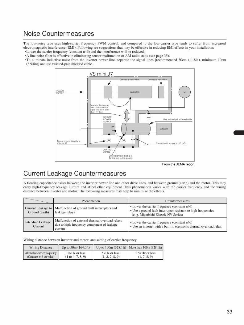
33
Noise CountermeasuresThe low-noise type uses high-carrier frequency PWM control, and compared to the low-carrier type tends to suffer from increasedelectromagnetic interference (EMI). Following are suggestions that may be effective in reducing EMI effects in your installation:• Lower the carrier frequency (constant n46) and the interference will be reduced.• A line noise filter is effective in eliminating sensor malfunction or AM radio static (see page 35).• To eliminate inductive noise from the inverter power line, separate the signal lines [recommended 30cm (11.8in), minimum 10cm(3.94in)] and use twisted-pair shielded cable.
Current Leakage CountermeasuresA floating capacitance exists between the inverter power line and other drive lines, and between ground (earth) and the motor. This maycarry high-frequency leakage current and affect other equipment. This phenomenon varies with the carrier frequency and the wiringdistance between inverter and motor. The following measures may help to minimize the effects.
Wiring distance between inverter and motor, and setting of carrier frequency
POWERSUPPLY INVERTER M
SENSOR+–
SENSORPOWERSUPPLY
CONTROLBOARD
Connect shielded cable to0V line, not to the ground.
Separate the inverterfrom power line andsignal line more than30cm (11.8in).
Connect a noise filter.
VS mini J7Connect a noise filter.
Connect with a capacitor (0.1µF)
Use twisted-pair shielded cable.
Do not ground direcitly toVS mini J7
From the JEMA report
Phenomenon
Current Leakage toGround (earth)
Malfunction of ground fault interrupters and leakage relays
• Lower the carrier frequency (constant n46) • Use a ground fault interrupter resistant to high frequencies
(e. g. Mitsubishi Electric NV Series)
• Lower the carrier frequency (constant n46) • Use an inverter with a built-in electronic thermal overload relay.
Malfunction of external thermal overload relays due to high-frequency component of leakage current
Inter-line Leakage Current
Countermeasures
Wiring Distance
Allowable carrier frequency(Constant n46 set value)
10kHz or less(1 to 4, 7, 8, 9)
5kHz or less(1, 2, 7, 8, 9)
2.5kHz or less(1, 7, 8, 9)
Up to 50m (164.0ft) Up to 100m (328.1ft) More than 100m (328.1ft)
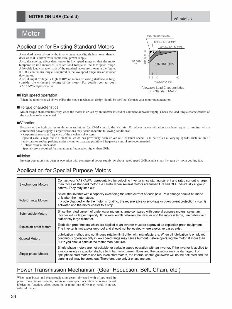
VS mini J7
34
NOTES ON USE (Cont'd)
Motor
When gear boxes and change/reduction gears lubricated with oil are used inpower transmission systems, continuous low speed operation decreases the oillubrication function. Also, operation at more than 60Hz may result in noise,reduced life, etc.
Synchronous MotorsContact your YASKAWA representative for selecting inverter since starting current and rated current is largerthan those of standard motor. Be careful when several motors are turned ON and OFF individually at group control. They may step out.
Select the inverter with a capacity exceeding the rated current of each pole. Pole change should be madeonly after the motor stops.If a pole changed while the motor is rotating, the regenerative overvoltage or overcurrent protection circuit is activated and the motor coasts to a stop.
Since the rated current of underwater motors is large compared with general purpose motors, select an inverter with a larger capacity. If the wire length between the inverter and the motor is large, use cables with sufficiently large diameter.
Explosion-proof motors which are applied to an inverter must be approved as explosion-proof equipment. The inverter is not explosion-proof and should not be located where explosive gases exist.
Lubrication method and continuous rotation limit differ with manufacturers. When oil lubrication is employed,continuous operation only in low speed range may cause burnout. Before operating the motor at more than60Hz you should consult the motor manufacturer.
Single-phase motors are not suitable for variable speed operation with an inverter. If the inverter is applied toa motor using a capacitor stack, a high harmonic current flows and the capacitor may be damaged. Forsplit-phase start motors and repulsion start motors, the internal centrifugal switch will not be actuated and the starting coil may be burnd out. Therefore, use only 3-phase motors.
Pole Change Motors
Submersible Motors
Explosion-proof Motors
Geared Motors
Single-phase Motors
3 6 20
FREQUENCY (Hz)
60% ED (OR 40 MIN)
40% ED (OR 20 MIN)
25% ED (OR 15 MIN)
TORQUE(%) 50
607082
100
Allowable Load Characteristicsof a Standard Motor
60
CONTINUOUS
Application for Existing Standard MotorsA standard motor driven by the inverter generates slightly less power than itdoes when it is driven with commercial power supply.Also, the cooling effect deteriorates in low speed range so that the motortemperature rise increases. Reduce load torque in the low speed range.Allowable load characteristics of the standard motor are shown in the figure.If 100% continuous torque is required in the low speed range, use an inverterduty motor.Also, if input voltage is high (440V or more) or wiring distance is long,consider the withstand voltage of the motor. For details, contact yourYASKAWA representative.
When the motor is used above 60Hz, the motor mechanical design should be verified. Contact your motor manufacturer.<High speed operation
Motor torque characteristics vary when the motor is driven by an inverter instead of commercial power supply. Check the load torque characteristics ofthe machine to be connected.
<Torque characteristics
Because of the high carrier modulation technique for PWM control, the VS mini J7 reduces motor vibration to a level equal to running with acommercial power supply. Larger vibrations may occur under the following conditions:• Response at resonant frequency of the mechanical system.Special care is required if a machine which has previously been driven at a constant speed, is to be driven at varying speeds. Installation ofantivibration rubber padding under the motor base and prohibited frequency control are recommended.
• Rotator residual imbalanceSpecial care is required for operation at frequencies higher than 60Hz.
<Vibration
Inverter operation is as quiet as operation with commercial power supply: At above rated speed (60Hz), noise may increase by motor cooling fan.<Noise
Application for Special Purpose Motors
Power Transmission Mechanism (Gear Reduction, Belt, Chain, etc.)
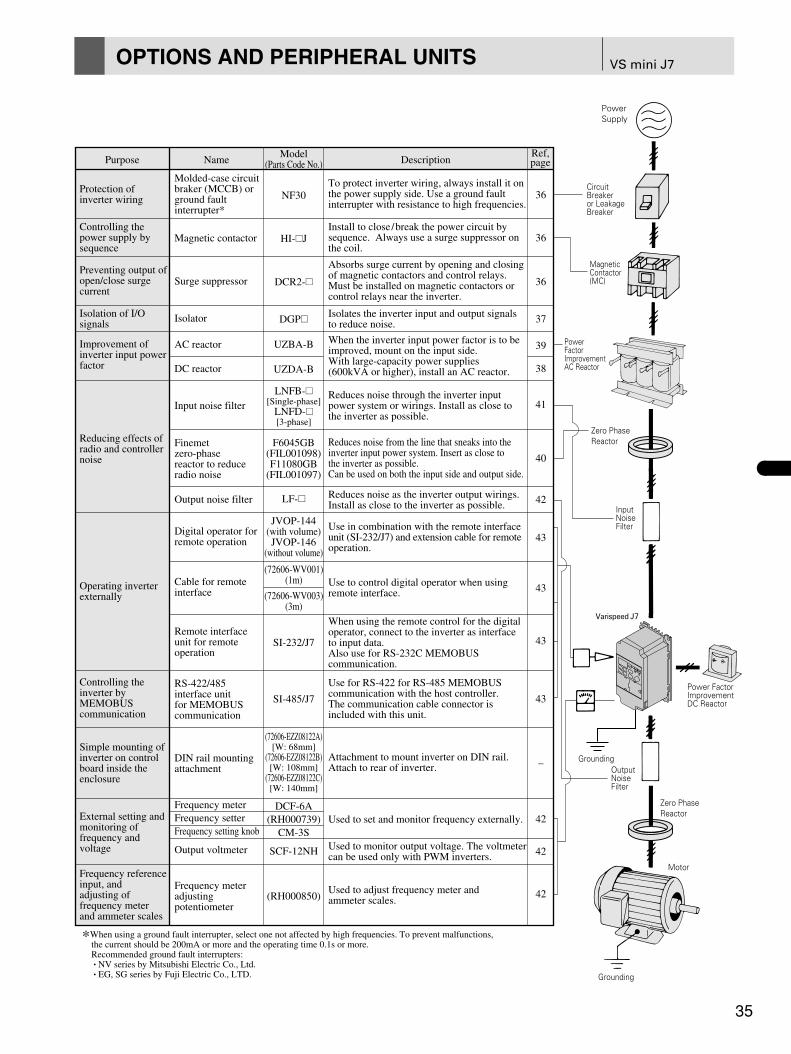
35
VS mini J7OPTIONS AND PERIPHERAL UNITS
Purpose
Protection of inverter wiring
Controlling the power supply by sequence
Preventing output ofopen/close surgecurrent
Isolation of I/Osignals
Improvement ofinverter input powerfactor
Reducing effects ofradio and controllernoise
Controlling theinverter by MEMOBUScommunication
Operating inverterexternally
Simple mounting ofinverter on controlboard inside theenclosure
External setting andmonitoring of frequency and voltage
Frequency referenceinput, and adjusting of frequency meter and ammeter scales
*When using a ground fault interrupter, select one not affected by high frequencies. To prevent malfunctions, the current should be 200mA or more and the operating time 0.1s or more. Recommended ground fault interrupters: • NV series by Mitsubishi Electric Co., Ltd. • EG, SG series by Fuji Electric Co., LTD.
Name
Molded-case circuitbraker (MCCB) orground fault interrupter*
Magnetic contactor
Surge suppressor
Isolator
AC reactor
DC reactor
Input noise filter
Output noise filter
Digital operator forremote operation
Remote interfaceunit for remoteoperation
RS-422/485interface unitfor MEMOBUScommunication
Cable for remoteinterface
DIN rail mountingattachment
Frequency meterFrequency setterFrequency setting knob
Frequency meteradjusting potentiometer
Output voltmeter
Model(Parts Code No.)
NF30
HI-?J
DCR2-?
DGP?
LF-?
UZBA-B
UZDA-B
LNFB-?[Single-phase]
LNFD-?[3-phase]
JVOP-144(with volume)JVOP-146
(without volume)
(72606-EZZ08122A)[W: 68mm]
(72606-EZZ08122B)[W: 108mm]
(72606-EZZ08122C)[W: 140mm]
DCF-6A(RH000739)
SI-232/J7
SI-485/J7
CM-3S
SCF-12NH
(RH000850)
(72606-WV001)(1m)
(72606-WV003)(3m)
DescriptionRef,page
36
36
36
37
39
38
41
42
43
43
43
43
–
42
42
42
To protect inverter wiring, always install it on the power supply side. Use a ground fault interrupter with resistance to high frequencies.
Install to close/break the power circuit by sequence. Always use a surge suppressor on the coil.
Absorbs surge current by opening and closing of magnetic contactors and control relays.Must be installed on magnetic contactors or control relays near the inverter.
Isolates the inverter input and output signals to reduce noise.
When the inverter input power factor is to beimproved, mount on the input side.With large-capacity power supplies(600kVA or higher), install an AC reactor.
Reduces noise through the inverter input power system or wirings. Install as close to the inverter as possible.
Reduces noise as the inverter output wirings.Install as close to the inverter as possible.
F6045GB(FIL001098)F11080GB
(FIL001097)
Use in combination with the remote interface unit (SI-232/J7) and extension cable for remote operation.
Use to control digital operator when using remote interface.
Attachment to mount inverter on DIN rail.Attach to rear of inverter.
When using the remote control for the digitaloperator, connect to the inverter as interfaceto input data.Also use for RS-232C MEMOBUS communication.
Use for RS-422 for RS-485 MEMOBUScommunication with the host controller.The communication cable connector is included with this unit.
Finemetzero-phasereactor to reduceradio noise
40
Reduces noise from the line that sneaks into theinverter input power system. Insert as close tothe inverter as possible.Can be used on both the input side and output side.
Used to set and monitor frequency externally.
Used to monitor output voltage. The voltmetercan be used only with PWM inverters.
Used to adjust frequency meter and ammeter scales.
Zero PhaseReactor
Varispeed J7
Zero PhaseReactor
PowerSupply
CircuitBreakeror LeakageBreaker
MagneticContactor(MC)
PowerFactorImprovementAC Reactor
InputNoiseFilter
Power FactorImprovementDC Reactor
Grounding
Grounding
OutputNoiseFilter
Motor

Molded-Case Circuit Breaker (MCCB) and Magnetic Contactor (MC)
Molded-Case CircuitBreaker (MCCB)
Type DCR2-50A22E Type DCR2-10A25C Type RFN3AL504KD
Power Supply MagneticContactor (MC)
Surge Suppressor (Manufactured by Marcon Electronics)
200V Three-phase Input Series
MotorCapacity
kW
VS mini J7 ModelCIMR-J7?A?
Molded-Case Circuit Breaker (MCCB)Without Reactor
Model Rated Current A Model Model ModelRated Current AWithout Reactor With ReactorWith Reactor
Magnetic Contactor (MC)
0.10.20.40.751.52.23.7
20P120P220P420P721P522P223P7
NF30
NF30
NF30
NF30
NF30
NF30
NF30
3
3
5
10
15
20
30
NF30
NF30
NF30
NF30
NF30
NF30
NF30
HI-11J
HI-11J
HI-11J
HI-11J
HI-15J
HI-20J
HI-35J
HI-11J
HI-11J
HI-11J
HI-11J
HI-11J
HI-15J
HI-25J
3
3
5
10
10
15
20
200V Single-phase Input Series
MotorCapacity
kW
VS mini J7 ModelCIMR-J7?A?
Molded-Case Circuit Breaker (MCCB)Without Reactor
Model Rated Current A Model Model ModelRated Current AWithout Reactor With ReactorWith Reactor
Magnetic Contactor (MC)
0.10.20.40.751.5
B0P1B0P2B0P4B0P7B1P5
NF30
NF30
NF30
NF30
NF30
3
5
10
15
30
NF30
NF30
NF30
NF30
NF30
HI-11J
HI-11J
HI-11J
HI-15J
HI-35J
HI-11J
HI-11J
HI-11J
HI-15J
HI-20J
3
5
10
15
20
400V Three-phase Input Series
MotorCapacity
kW
Coils of Magnetic Contactorand Control Relay
200Vto
230V
Large-size Magnetic Contactors
DCR2-50A22E 220VAC 0.5μF+200Ω
250VAC 0.1μF+100ΩDCR2-10A25C
1000VDC 0.5μF+220Ω380 to 460V Units
ControlRelay
LY-2, -3HH-22, -23MM-2, -4
VS mini J7 ModelCIMR-J7?A?
Molded-Case Circuit Breaker (MCCB)Without Reactor
Model Rated Current A Model Model ModelRated Current AWithout Reactor With ReactorWith Reactor
Magnetic Contactor (MC)
0.20.40.751.52.23.03.7
40P240P440P741P542P243P043P7
NF30
NF30
NF30
NF30
NF30
NF30
NF30
3
5
5
10
15
15
20
NF30
NF30
NF30
NF30
NF30
NF30
NF30
HI-11J
HI-11J
HI-11J
HI-11J
HI-15J
HI-15J
HI-20J
HI-11J
HI-11J
HI-11J
HI-11J
HI-11J
HI-11J
HI-15J
3
3
5
10
10
10
15
RFN3AL504KD
C002417
C002482
C002630
Model Specifications
Surge Suppressor
Code No.
Be sure to connect a MCCB between the power supply and the input AC reactor.Connect a MC if required.
Connect surge suppressors to coils in magnetic contactors, control relays, electromagnetic valves, and electromagnetic brakes used as the VS mini J7 peripheral units.
VS mini J7
36
OPTIONS AND PERIPHERAL UNITS (Cont’d)

37
Allowance
Temperature Influence
Aux. Power Supply Influence
Load Resistance Influence
Output Ripple
Response Time
Withstand Voltage
Insulation Resistance
±0.25% of output span [Ambient temp : 23°C, (73.4°F)]
With ±0.25% of output span [The value at ±10°C (±50°F) of ambient temp.]
With ±0.1% of output span (The value at ±10% of aux. power supply)
With ±0.05% of output span (In the range of load resistance)
With ±0.5%P-P of output span
0.5 sec. or less (Time to settle to ±1% of final steady value)
2000VAC for one min. (between each terminal of input, output, power supply and enclosure)
20MΩ and above (by 500VDC megger) (between each terminal of input, output, power supply and enclosure)
Model
DGP2-4-4
DGP2-4-8
DGP2-8-4
DGP2-3-4
DGP3-4-4
DGP3-4-8
DGP3-8-4
DGP3-3-4
Input Signal
0-10V
0-10V
4-20mA
0-5V
0-10V
0-10V
4-20mA
0-5V
Output Signal
0-10V
4-20mA
0-10V
0-10V
0-10V
4-20mA
0-10V
0-10V
Power Supply
100VAC
100VAC
100VAC
100VAC
200VAC
200VAC
200VAC
200VAC
Code No.
CON 000019.25
CON 000019.26
CON 000019.35
CON 000019.15
CON 000020.25
CON 000020.26
CON 000020.35
CON 000020.15
Isolator(Insulation Type DCTransmission Converter)
690-169 Product Line
Performance
Dimensions in mm (inches)110 (4.33) 50 (1.97)
78 (3
.07)
100 (3.94)10
(0.39)
ADJUSTER
50 (1.97)23.5(0.93)
400.2
(1.570.08)
6 5 4 3
7 8 1 2
80 (3
.15)
4(0.
16)
4(0.16)
5(0.20)
M3.5TERMINALSCREW
2 (0.08)-4.5 (0.18)DIA. HOLES
35.4
(1.4
0)
MAX. 122 (4.80)
Terminal Description
1 Output +
2 Output –
3 –
4 Input +
5 Input –
6 Grounding
7Power supply
8
INPUT
LOADPOWER SUPPLY
Connection Cable Length
• 4 to 20mA : Within 100m• 0 to 10V : Within 50m
Approx. Mass
• Model GP Series : 350g• Socket : 60g
Model GPSeries
Socket View of socket mounted
Adjuster’s position or PC’s varies due to models.

VS mini J7
38
OPTIONS AND PERIPHERAL UNITS (Cont’d)
DC Reactor (Model UZDA-B for DC circuit)
When power capacity is significantly greater whencompared to inverter capacity, or when the power-factor needs to be improved, connect the AC or DCreactor.AC reactor can be used at the same time forharmonic measure.
200V Three-phase Input Series
Note: Contact your YASKAWA representative for three-phase, 200V, 0.1 to 0.2kW and single-phase, 200V, 0.1 to 3.7kW models.
Note: Contact your YASKAWA representative for three-phase, 400V, 0.2kW model.
* 75°C(167°F), IV cable, 45°C (113°F) ambient temperature, three or less wires connected.
Max. ApplicableMotor Output
kW (HP)0.4 (0.5)
5.4 8 X010048 1 85(3.35)
— — 53(2.09)
74(2.91)
— — 32(1.26)
M4 0.8(2.3)
2(0.0031)
8
2.0(5.6)
5(0.0085)
18
—
86(3.39)
36(1.41)
80(3.15)
76(2.99)
60(2.36)
55(2.17)
18(0.71)
— M4 M518 3 X010049 2
0.75 (1)1.5 (2)2.2 (3)3.7 (5)
CurrentValue
A
InductancemH
PartsCodeNo.
Fig. No.
Fig. No.
Dimensions in mm (inches) Approx.Masskg (lb)
WireSize*
mm2 (in2)Loss
WX Y1 Y2 Z B H K G 1 2
400V Three-phase Input SeriesMax. Applicable
Motor OutputkW (HP )0.4 (0.5)
3.2 28 X010052 85(3.35)
— — 53(2.09)
74(2.91)
— — 32(1.26)
M4 0.8(2.3)
2(0.0031)
9—
5.7 11 X0100531
90(3.54)
— — 60(2.36)
80(3.15)
— — 32(1.26)
M4 1.0(2.8)
2(0.0031)
11—
12 6.3 X010054 2 86(3.39)
36(1.41)
80(3.15)
76(2.99)
60(2.36)
55(2.17)
18(0.71)
M4 M5 2.0(5.6)
2(0.0031)
16—
0.75 (1)1.5 (2)2.2 (3)
3.7 (5)
CurrentValue
A
InductancemH
PartsCodeNo.
Dimensions in mm (inches) Approx.Masskg (lb)
WireSize*
mm2 (in2)Loss
WX Y1 Y2 Z B H K G 1 2
L1(R)
L2(S)
L3(T)
L1(R)
L2(S)
L3(T)
T1(U)
T2(V)
T3(W)
VS mini J7
MCCBMOTOR
DC REACTOR
U X
IM
+1 +2
Connection Example
WITHOUTREACTOR
0
600
4000
60 400
WITH REACTOR FORPOWER SUPPLYCOORDINATION
INVERTER CAPACITY (kVA)
POWERSUPPLYCAPACITY(KVA)
Take off the shorting bar between +1 and + 2, and wire as shown in the diagram.
95-68088
2-MTG HOLE1 (0.039) DIA.
4-MTG HOLE1 (0.039) DIA.
2-TERMINAL 2 (0.079) DIA.
B
X
X
U
GZ
Z
60 (2
.36)
CONNECTIONLEAD1.25mm2
(0.0091 in2)NAMEPLATE
BX
NAMEPLATE Y1
Y2
HK
Figure 1 Figure 2
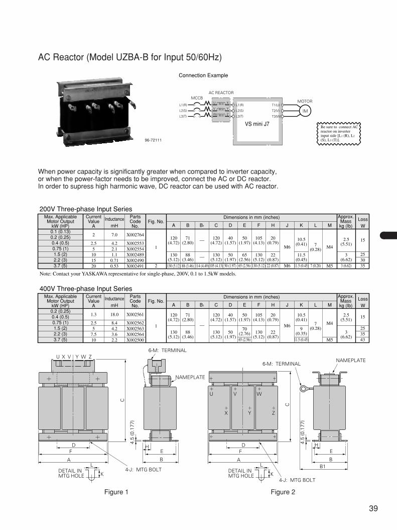
39
AC Reactor (Model UZBA-B for Input 50/60Hz)
200V Three-phase Input SeriesMax. Applicable
Motor OutputkW (HP)
0.4 (0.5) 2.5 4.2 X0025530.2 (0.25)0.1 (0.13)
2 7.0 X002764
5 2.1 X00255410 1.1 X00248915 0.71 X00249020 0.53 X002491
1
35114 (4.49)130 (5.12) 88 (3.46) 105 (4.13) 50 (1.97) 65 (2.56) 130 (5.12) 22 (0.87) 11.5 (0.45) 7 (0.28) 3 (6.62)M53025130
(5.12)88
(3.46)130
(5.12)50
(1.97)65
(2.56)130
(5.12)11.5
(0.45)3
(6.62)22
(0.87)
15120(4.72)
71(2.80)
120(4.72)
40(1.57)
50(1.97)
105(4.13)
20(0.79)
10.5(0.41) 7
(0.28)
2.5(5.51)
M6
M6
—
—
M4
2
0.75 (1)1.5 (2)2.2 (3)3.7 (5)
CurrentValue
A
InductancemH
PartsCodeNo.
Fig. No.Dimensions in mm (inches) Approx.
Masskg (Ib)
LossWA B B1 C D E F H J K L M
400V Three-phase Input SeriesMax. Applicable
Motor OutputkW (HP)
0.4 (0.5) 1.3 18.0 X0025610.2 (0.25)
2.5 8.4 X0025625 4.2 X002563
7.5 3.6 X00256410 2.2 X002500
1
4311.5 (0.45) M565 (2.56)3525
130(5.12)
88(3.46)
130(5.12)
50(1.97)
70(2.76) 130
(5.12)22
(0.87)
9(0.35) 3
(6.62)
15120(4.72)
71(2.80)
120(4.72)
40(1.57)
50(1.97)
105(4.13)
20(0.79)
10.5(0.41)
7(0.28)
2.5(5.51)
M6 M4—0.75 (1)1.5 (2)2.2 (3)3.7 (5)
CurrentValue
A
InductancemH
PartsCodeNo.
Fig. No.Dimensions in mm (inches) Approx.
Masskg (Ib)
LossWA B B1 C D E F H J K L M
Note: Contact your YASKAWA representative for single-phase, 200V, 0.1 to 1.5kW models.
96-72111
When power capacity is significantly greater when compared to inverter capacity,or when the power-factor needs to be improved, connect the AC or DC reactor.In order to supress high harmonic wave, DC reactor can be used with AC reactor.
L1(R)U
V
W
X
Y
ZL2(S)
L3(T)
L1(R)
L2(S)
L3(T)
T1(U)
T2(V)
T3(W)
VS mini J7
MCCBMOTOR
AC REACTOR
IM
Connection Example
Be sure to connect AC reactor on inverter input side [L1 (R), L2 (S), L3 (T)].
Figure 1 Figure 2
U X V Y W Z
D
4-J: MTG BOLT
6-M: TERMINAL
NAMEPLATE
C
4.5
(0.1
77)
F
A
HE
B
K
LDETAIL INMTG HOLE K
DETAIL INMTG HOLE
D
4-J: MTG BOLT
6-M: TERMINALNAMEPLATE
C
4.5
(0.1
77)
F
A
HE
BB1L
W
ZYX
VU

Note: Finemet is a registered trademark of Hitachi Metals, Ltd.
200V Three-phase Input SeriesCan be used both for input and output sides ofthe inverter and effective on noise reduction.Inverter Finemet Zero Phase Reactor
Model Model Code No. Qty. WiringMethod
RecommendedWire Size mm2
CIMR-J7?A20P1
CIMR-J7?A20P2
CIMR-J7?A20P4
CIMR-J7?A20P7
CIMR-J7?A21P5
CIMR-J7?A22P2
CIMR-J7?A23P7
2
3.5
5.5
F6045GB FIL001098 1 3 winds
400V Three-phase Input Series
Inverter Finemet Zero Phase Reactor
Model Model Code No. Qty. WiringMethod
RecommendedWire Size mm2
CIMR-J7?A40P2
CIMR-J7?A40P4
CIMR-J7?A40P7
CIMR-J7?A41P5
CIMR-J7?A42P2
CIMR-J7?A43P7
2 F6045GB FIL001098 1 3 winds
200V Single-phase Input Series
Inverter Finemet Zero Phase Reactor
Model Model Code No. Qty. WiringMethod
RecommendedWire Size mm2
CIMR-J7?AB0P1
CIMR-J7?AB0P2
CIMR-J7?AB0P4
CIMR-J7?AB0P7
CIMR-J7?AB1P5
2
3.5
5.5
F6045GB FIL001098 1 3 winds
78 M
AX
39.5
MIN
72±0
.5
7±0.5
50±0.5
95 MAX
80±0.5
12.5
±0.3
3–4.5DIA.
2–5.5DIA.
26 MAX
3–M4HEXAGON SOCKET
Model F6045GB
Connection Diagram
R/L1
POWERSUPPLY S/L2
T/L3
VS mini J7
V
W
Wind each wire (R, S, T or U, V, W) 3 times aroundthe core.
ZERO PHASEREACTOR
U
Finemet Zero Phase Reactor to Reduce Radio Noise (Made by Hitachi Metals, Ltd.)
Zero Phase Reactor
40
VS mini J7OPTIONS AND PERIPHERAL UNITS (Cont’d)

41
Input Noise Filter
Specifi-cations
Max. ApplicableMotor Output
kW (HP)
InverterCapacity
kVA
RatedCurrent
AModel Product Code Prats Codes No. Figure
No.Dimensions in mm (inches)
Mounting ScrewApprox.Masskg (lb)W D H A A’ B
200VClass
(Signle-)phase
0.1 (0.13), 0.2 (0.25) 0.3, 0.6 10 LNFB-2102DY 72600-B2102DY FIL 128 1 120 (4.72) 80 (3.15) 50 (1.97) 108 (4.25) – 68 (2.68) M44, 20mm (0.79in.) 0.1 (0.22)
0.4 (0.5) 1.1 15 LNFB-2152DY 72600-B2152DY FIL 129 1 120 (4.72) 80 (3.15) 50 (1.97) 108 (4.25) – 68 (2.68) M44, 20mm (0.79in.) 0.2 (0.44)
0.75 (1) 1.9 20 LNFB-2202DY 72600-B2202DY FIL 130 1 120 (4.72) 80 (3.15) 50 (1.97) 108 (4.25) – 68 (2.68) M44, 20mm (0.79in.) 0.2 (0.44)
1.5 (2) 3.0 30 LNFB-2302DY 72600-B2302DY FIL 131 1 130 (5.12) 90 (3.54) 65 (2.56) 118 (4.65) – 78 (3.07) M44, 20mm (0.79in.) 0.3 (0.66)
200VClass
(Three-)phase
0.1 (0.13) to 0.75 (1) 0.3 to 1.9 10 LNFD-2103DY 72600-D2103DY FIL 132 2 120 (4.72) 80 (3.15) 55 (2.17) 108 (4.25) – 68 (2.68) M44, 20mm (0.79in.) 0.2 (0.44)
1.5 (2) 3.0 15 LNFD-2153DY 72600-D2153DY FIL 133 2 120 (4.72) 80 (3.15) 55 (2.17) 108 (4.25) – 68 (2.68) M44, 20mm (0.79in.) 0.2 (0.44)
2.2 (3) 4.2 20 LNFD-2203DY 72600-D2203DY FIL 134 2 170 (6.69) 90 (3.54) 70 (2.76) 158 (6.22) – 78 (3.07) M44, 20mm (0.79in.) 0.4 (0.88)
3.7 (5) 6.7 30 LNFD-2303DY 72600-D2303DY FIL 135 3 170 (6.69) 110 (4.33) 70 (2.76) – 79 (3.11) 98 (3.86) M46, 20mm (0.79in.) 0.5 (1.10)
400VClass
(Three-)phase
0.2 (0.25) to 0.75 (1) 0.9 to 2.6 5 LNFD-4053DY 72600-D4053DY FIL 144 3 170 (6.69) 130 (5.12) 75 (2.95) – 79 (3.11) 118 (4.65) M46, 30mm (1.18in.) 0.3 (0.66)
1.5 (2), 2.2 (3) 3.7 to 4.2 10 LNFD-4103DY 72600-D4103DY FIL 145 3 170 (6.69) 130 (5.12) 95 (3.94) – 79 (3.11) 118 (4.65) M46, 30mm (1.18in.) 0.4 (0.88)
3.0 (2.2), 3.7 (5) 5.5 to 7.0 15 LNFD-4503DY 72600-D4153DY FIL 146 3 170 (6.69) 130 (5.12) 95 (3.94) – 79 (3.11) 118 (4.65) M46, 30mm (1.18in.) 0.4 (0.88)
Specifi-cations
Max. ApplicableMotor Output
kW (HP)
InverterCapacity
kVA
RatedCurrent
AModel Product Code Parts Codes No.
Dimensions in mm (inches)Mounting Screw
Approx.Masskg (lb)W
200VClass
(Signle-)phase
0.1 (0.13), 0.2 (0.25) 0.3, 0.6 10 LNFB-2102HY 72600-B2102HY FIL 136 M44, 10mm (0.39in.) 0.8 (1.77)
0.4 (0.5) 1.1 15 LNFB-2152HY 72600-B2152HY FIL 137 M44, 10mm (0.39in.) 0.8 (1.77)
0.75 (1) 1.9 20 LNFB-2202HY 72600-B2202HY FIL 138 M44, 10mm (0.39in.) 0.9 (1.99)
1.5 (2) 3.0 30 LNFB-2302HY 72600-B2302HY FIL 139 M44, 10mm (0.39in.) 1.1 (2.43)
200VClass
(Three-)phase
0.1 (0.13) to 0.75 (1) 0.3 to 1.9 10 LNFD-2103HY 72600-D2103HY FIL 140 M44, 10mm (0.39in.) 0.9 (1.99)
1.5 (2) 3.0 15 LNFD-2153HY 72600-D2153HY FIL 141 M44, 10mm (0.39in.) 0.9 (1.99)
2.2 (3) 4.2 20 LNFD-2203HY 72600-D2203HY FIL 142 M44, 10mm (0.39in.) 1.5 (3.31)
3.7 (5) 6.7 30 LNFD-2303HY 72600-D2303HY FIL 143 M44, 10mm (0.39in.) 1.6 (3.53)
400VClass
(Three-)phase
0.2 (0.25) to 0.75 (1) 0.9 to 2.6 5 LNFD-4053HY 72600-D4053HY FIL 149 M44, 10mm (0.39in.) 1.6 (3.53)
1.5 (2), 2.2 (3) 3.7 to 4.2 10 LNFD-4103HY 72600-D4103HY FIL 150 M44, 10mm (0.39in.) 1.7 (3.75)
3.0 (2.2), 3.7 (5) 5.5 to 7.0 15 LNFD-4153HY 72600-D4153HY FIL 151 M44, 10mm (0.39in.) 1.7 (3.75)
D H A A’ B
185 (7.28) 95 (3.74) 85 (3.35) 155 (6.10) 65 (2.56) 33 (1.30)
185 (7.28) 95 (3.74) 85 (3.35) 155 (6.10) 65 (2.56) 33 (1.30)
185 (7.28) 95 (3.74) 85 (3.35) 155 (6.10) 65 (2.56) 33 (1.30)
200 (7.87) 105 (4.13) 95 (3.74) 170 (6.69) 75 (2.95) 33 (1.30)
185 (7.28) 95 (3.74) 85 (3.35) 155 (6.10) 65 (2.56) 33 (1.30)
185 (7.28) 95 (3.74) 85 (3.35) 155 (6.10) 65 (2.56) 33 (1.30)
240 (9.45) 125 (4.92) 100 (3.94) 210 (8.27) 95 (3.74) 33 (1.30)
240 (9.45) 125 (4.92) 100 (3.94) 210 (8.27) 95 (3.74) 33 (1.30)
235 (9.25) 140 (5.51) 120 (4.72) 205 (8.07) 110 (4.33) 43 (1.69)
235 (9.25) 140 (5.51) 120 (4.72) 205 (8.07) 110 (4.33) 43 (1.69)
235 (9.25) 140 (5.51) 120 (4.72) 205 (8.07) 110 (4.33) 43 (1.69)
1
NOISE FILTERMCCB
R
S
32 4
EIM
VS mini J7
L1(R)
L2(S)
T1(U)
T2(V)
T3(W)
R
NOISE FILTERMCCB
R
ST
US
L
V
WE
IM
VS mini J7
L1(R)
L2(S)
L3(T)
T1(U)
T2(V)
T3(W)
Example: Single-phase input (Model LNFB) Three-phase input (Model LNFD)
WA
A
B DC
H m
ax.
SR
TVU
WE
5 (0.2) DIA.
30 (1.18)DIA.
12 (0.47) DIA.
C10 15
15
5 (0
.2)
(0.39) (0.59)
(0.5
9)
Noise Filter without Case
692-383
Note: When using CE standard inverters, thespecial EMC conformed noise filter isrequired.Contact your YASKAWA representative.
W
A
B DH
max
.
SR
T
VU
WE
Figure 2(Three-phase input)
W
A' A'
B DH
max
.
SR
T
VU
WE
Figure 3(Three-phase input)
Noise Filter with Case
W
A
B DH
max
.
12
34E
Figure 1(Single-phase input)
Example three-phase input.

42
VS mini J7OPTIONS AND PERIPHERAL UNITS (Cont’d)
Max. ApplicableMotor Output
kW (HP)
InverterCapacity
kVAModel Rated Current
APart Code
No.
0.1 (0.13) 0.3 LF-310KA 10 FIL 000068
0.2 (0.25) 0.6 LF-310KA 10 FIL 000068
0.4 (0.5) 1.1 LF-310KA 10 FIL 000068
0.75 (1) 1.9 LF-310KA 10 FIL 000068
1.5 (2) 3.0 LF-310KA 10 FIL 000068
2.2 (3) 4.2 LF-320KA 20 FIL 000069
3.7 (5) 6.7 LF-320KA 20 FIL 000069
Specifications
200V Class (Three-phase)
400V Class (Three-phase)Max. Applicable
Motor OutputkW (HP)
InverterCapacity
kVAModel Rated Current
APart Code
No.
0.2 (0.25), 0.4 (0.5) 0.9, 1.4 LF-310KB 10 FIL 000071
0.75 (1) 2.6 LF-310KB 10 FIL 000071
1.5 (2) 3.7 LF-310KB 10 FIL 000071
2.2 (3) 4.2 LF-310KB 10 FIL 000071
3.0 (2.2), 3.7 (5) 5.5, 7.0 LF-310KB 10 FIL 000071Model TerminalPlate
Dimensions in mm (inches) Approx.Masskg (lb)A B C D E F G H
LF-310KA TE-K55M4 140 (5.51) 100 (3.94) 100 (3.94) 90 (3.54) 70 (2.76) 45 (1.77) 74.5 (0.18) dia. 4.5 (0.18)dia. 0.5 (1.10)
LF-320KA TE-K55M4 140 (5.51) 100 (3.94) 100 (3.94) 90 (3.54) 70 (2.76) 45 (1.77) 74.5 (0.18) dia. 4.5 (0.18)dia. 0.6 (1.32)
LF-310KB TE-K55M4 140 (5.51) 100 (3.94) 100 (3.94) 90 (3.54) 70 (2.76) 45 (1.77) 74.5 (0.18) dia. 4.5 (0.18)dia. 0.5 (1.00)
Output Noise Filter(Tohoku Metal Industries Co., Ltd.)
Dimensions
1
OUTPUTNOISE FILTER
MCCBR
S
T
VS mini J7
4
2 5
3 6
IM
INL1(R)
L2(S)
L3(T)
T1(U)
T2(V)
T3(W)
A
F
HG
B D
C
E
690-119
Example
Frequency Meter MODEL DCF-6A*, 3V, 1mA : Analog frequency indicating meter is available as an option.
690-121
*DCF-6A is 3V, 1mA, 3kΩ.For VS mini J7 multi-function analog monitor output, set frequencymeter adjusting potentiometer or constant n45 (analog monitor outputgain) within the range of 0 to 3V (Inilial setting is 0 to 10V).
Frequency Meter Adjusting PotentiometerModel RV30YN 20S, 2kΩ: Corrects frequency meter reading. (Parts code no.: RH000850)
29.9 (1.18)23 (0.91)
26.1 (1.03)32.8 (1.29)
16.1
(0.6
3)15
(0.59
)7.5
(0.30
)3.
4 (0
.13)
SHAFT6 (0.24)DIA.
Frequency SettingKnob (Model CM-3S)
Used to adjust potentiometer frequency setting.
1.5(0.06)
101(0.390.04)
17.5 (0.69) 201
2.5 (0.1) 0.04
30 (2
.18)
0.
08 D
IA. M9 P0.75
12 (0.4
7)
2.80.2(0.110.008) DIA.
25 (0
.98)
1 32
60°
4.5 (0.18)DIA.
10 (0.39)DIA.
12 (0.4
7)
Mass: 0.2kg (0.44lb) (0.790.04) 6
(0.2
4
)
DIA.
0
0.
1
0
0.00
4
688-81 Potentiometer Drawing for Frequency Meter Adjustment and Frequency Setting
Output Voltmeter (Model SCF-12NH Rectification Type Class 2.5)200V Class: 300V full-scale (Parts code no.: VM000481)400V Class: 600V full-scale (Parts code no.: Output voltmeter: VM000502, )Transformer for instrument: PT000084
12.5(0.49)
30(1.18)
12(0.47)
0.5 10(0.02) (0.39)
85 (3
.35)
DIA
.
4-M4 MTG. SCREW
120 (4.72)
50(1.97)
50(1.97)
100
(3.9
3)
45 (1
.77)
35 (1
.30) 87
(3.43
)
50(1.97)
50(1.97)
4 (0.16)-5 (0.20)DIA.
4535
(1.77
)(1.
30)
Panel Drilling Plan
Mass: 0.3kg (0.66lb)
Panel Drilling Plan690-166
0 10
91
3 7
64
3.6 (0.14) DIA. SCREW
9.5 (0.37) DIA. SCREW
12(0
.47)
45 (1
.77)
45 (1.77)
Scale Plate(Parts code no.: NPJT41561-1)
12.5(0.49)
30(1.18)
12(0.47)
0.5 10(0.02) (0.39)
52 (2
.05)
DIA
.
2-M4 TERMINAL SCREWS4-M3 MTG. SCREW
65 (2.56)
24(0.94)
24(0.94)
60 (2
.36)
24 (0
.94)
24 (0
.94) 53
(2.09
)
24(0.94)
24(0.94)
4 (0.16)-4 (0.16)DIA.
2424
(0.94
)(0.
94)
Panel Drilling Plan
Scale parts code no.75Hz full scale: FM00006560/120Hz full scale: FM000085
Frequency Setter model RV30YN20S, 2kΩ (Parts code no.: RH000739)

43
Digital Operator for Remote Operation (Model JVOP-146/144)Remote Interface Unit for Remote Operation (Model SI-232/J7)Interface Unit for Copy Unit (Model SI-232/J7C)
RS-422/485 Interface Unit for MEMOBUS Communication (Model SI-485/J7)
Dimensions in mm (inches)Digital Operator for Remote Operation(Model: JVOP-146)
Remote Interface Unit for Remote Operation
Dimensions in mm (inches)
RS-422/485 Interface UnitModel SI-485/J7
Communication Cable Connector
Note : The communication cable connector is included with this unit.
When using digital operator for remote operation (JVOP-146/144)as copy unit, use the SI-232/J7C, which can be easily attachedand removed.
Note : Order digital operater, cable, remote interface separately.
Digital Operator for Remote Operation
Cable for Remote InterfaceParts code NO 72606-WV 001: 1m 72606-WV 003: 3m
Remote Interface Unit forRemote Operation(Model SI-232/J7)Interface Unit for Copy Unit*(Model SI-232/J7C)
21.5(0.85)
2.5(0.1)
19(0.75)
63(2.48) 8(0.31)
15.
5(0
.61)
16
(0.6
3)
29
(1.1
4)
12(0.47)
8 19(0.3) (0.75) (0.3)
63(2.48)
13(0
.51)
16(0
.63)
29
(1.1
4)
4 3.8(0.15)=15.2(0.6)
8
DATA (15.5)
STOP
78 (3.07)18.2(0.72)
88 (3.46)5
(0.2)
80 (3
.15)
4-4.4 DIA. MTG HOLES
58 (2
.28)
11 (0.43
)
70 (2.76)15.5 (0.61)
23.1
(0.9
1)
50 (1
.97)
10.5(0.41)
30.4(1.20)
1.7(0.07)12.2(0.48)
68 (2
.68)
56 (2.20)
4-M4 SPOT FACING DEEP 3.5 (0.14)
(Model: JVOP-144)
DSPL
STOPRESET
DATAENTER
78 (3.07)18.2(0.72)
88 (3.46)5
(0.2)
80 (3
.15)
4-4.4 DIA. MTG HOLES
58 (2
.28)
11 (0.43
)
70 (2.76)15.5 (0.61)
23.1
(0.9
1)
50 (1
.97)
10.5(0.41)
30.4(1.20)
68 (2
.68)
56 (2.20)
4-M4 SPOT FACING DEEP 3.5 (0.14)
Model : JVOP-146 Model : JVOP-144
RUN
DIGITALOPERATORJVOP-140
MIN MAX
12.2 (0.48)12.2 (0.48)12.2 (0.48)
9.3 (0.37)9.3 (0.37)9.3 (0.37)
1.7 (0.07)1.7 (0.07)1.7 (0.07)

44
YASKAWA ELECTRIC EUROPE GmbHEurope, South Africa
Korea
Frankfurt
Singapore
Seoul
YASKAWA ELECTRIC KOREA CORPORATION
YASKAWA ELECTRICO DOBRAZIL COMERCIO LTDA.
Korea
YASKAWA ELECTRIC AMERICA, INC.North, South, and Central America
Service Agency
YASKAWA SubsidiaryService Location
Serivce Area
TAIAN ELECTRIC CO., LTD.Taiwan
SAMSUNG ELECTRONICS CO., LTD.
East ChinaShanghai Yaskawa Tongji M & E Co., Ltd.
South East ChinaYASKAWA ELECTRIC (HK) COMPANY LIMITED
South East AsiaYASKAWA ELECTRIC (SINGAPORE) PTE. LTD.
New JerseyBoston
Toronto
Ohio
North Carolina
San Francisco
Sao Pãulo
Los Angels
Chicago
YEG
YEK
SSC
YHK
SEC
YSP
TEC
YEA
YEB
South America
Area Service AreaServiceLocation
Service Agency : YASKAWA Subsidiary
Telephone/Fax ( ): Country Code
All of EuropeandSouth Africa
Frankfurt(HQ)DusseldorfLondonFrance, ItalySpain
Europe YASKAWAELECTRICEUROPE GmbH
(YEG)*HeadquartersPHONE (49)-6196-569-300FAX (49)-6196-888-301
ChinaShanghaiEast China
ShanghaiShanghai Yaskawa-Tongji M&E Co., Ltd.
(SSC)*
PHONE (852)-2803-2385FAX (852)-2547-5773
Hong Kong Hong KongSouth East China
Hong KongYASKAWA ELECTRIC(HK) COMPANY LIMITED
(YHK)*
PHONE (86)-21-6531-4242FAX (86)-21-6531-4242
South EastAsia Singapore
YASKAWA ELECTRIC(SINGAPORE)PTE. LTD.
(YSP)* Singapore, Indonesia Thailand, Malaysia Philippines, Hong Kong
Korea
Entire Area
YASKAWAELECTRICAMERICA INC.(Chicago HQ)
North America
South America
Central America
Chicago(HQ)Los AngelesNew JerseyBostonSan FranciscoOhio
(YEA)*HeadquartersPHONE (1)-847-887-7094FAX (1)-847-887-7070
Korea Seoul
YASKAWA ELECTRICKOREA CORPORATION
SAMSUNGELECTRONICSCO., LTD.
(YEK)*
(SEC)
PHONE (82)-2-776-7844FAX (82)-2-753-2639
TAIAN ELECTRICCO., LTD.
(TAIAN) PHONE (886)-2-2511-1181FAX (886)-2-2563-8854
PHONE (82)-2-331-200-2981FAX (82)-2-331-200-2970
Taiwan Taiwan Taipei
*
SouthAfrica
South America Sao Pãulo
YASKAWAELECTRICO DOBRASILCOMERCIO LTDA.
(YEB)* PHONE (55)-11-825-7723FAX (55)-11-210-9781
SouthAmerica
¨
PHONE (65)-282-3003FAX (65)-289-3003
VS mini J7SERVICE NETWORK
VS mini J7
9
YASKAWA
YASKAWA ELECTRIC CORPORATION
Printed in Japan June 2003 98-12
LITERATURE NO. KAE-S606-12E
03-4③
In the event that the end user of this product is to be the military and said product is to be employed in any weapons systems or the manufacture thereof, the export will fall under the relevant regulations as stipulated in the Foreign Exchange and Foreign Trade Regulations. Therefore, be sure to follow all procedures and submit all relevant documentation according to any and all rules, regulations and laws that may apply.
Specifications are subject to change without notice for ongoing product modifications and improvements.
© 1998-2003 YASKAWA ELECTRIC CORPORATION. All rights reserved.
IRUMA BUSINESS CENTER480, Kamifujisawa, Iruma, Saitama 358-8555, JapanPhone 81-42-962-5696 Fax 81-42-962-6138
YASKAWA ELECTRIC AMERICA, INC.2121 Norman Drive South, Waukegan, IL 60085, U.S.A.Phone 1-847-887-7000 Fax 1-847-887-7370
MOTOMAN INC. HEADQUARTERS805 Liberty Lane West Carrollton, OH 45449, U.S.A.Phone 1-937-847-6200 Fax 1-937-847-6277
YASKAWA ELETRICO DO BRASIL COMERCIO LTD.A.Avenida Fagundes Filho, 620 Bairro Saude-Sao Paulo-SP, Brazil CEP: 04304-000Phone 55-11-5071-2552 Fax 55-11-5581-8795
YASKAWA ELECTRIC EUROPE GmbHAm Kronberger Hang 2, 65824 Schwalbach, GermanyPhone 49-6196-569-300 Fax 49-6196-569-398
Motoman Robotics Europe ABBox 504 S38525 Torsas, SwedenPhone 46-486-48800 Fax 46-486-41410
Motoman Robotec GmbHKammerfeldstraβe 1, 85391 Allershausen, GermanyPhone 49-8166-90-100 Fax 49-8166-90-103
YASKAWA ELECTRIC UK LTD.1 Hunt Hill Orchardton Woods Cumbernauld, G68 9LF, United KingdomPhone 44-1236-735000 Fax 44-1236-458182
YASKAWA ELECTRIC KOREA CORPORATIONKfpa Bldg #1201, 35-4 Youido-dong, Yeongdungpo-Ku, Seoul 150-010, KoreaPhone 82-2-784-7844 Fax 82-2-784-8495
YASKAWA ELECTRIC (SINGAPORE) PTE. LTD.151 Lorong Chuan, #04-01, New Tech Park Singapore 556741, SingaporePhone 65-6282-3003 Fax 65-6289-3003
YASKAWA ELECTRIC (SHANGHAI) CO., LTD.No.18 Xizang Zhong Road. Room 1805, Harbour Ring Plaza Shanghai 20000, ChinaPhone 86-21-5385-2200 Fax 86-21-5385-3299
YATEC ENGINEERING CORPORATION4F., No.49 Wu Kong 6 Rd, Wu-Ku Industrial Park, Taipei, TaiwanPhone 886-2-2298-3676 Fax 886-2-2298-3677
YASKAWA ELECTRIC (HK) COMPANY LIMITEDRm. 2909-10, Hong Kong Plaza, 186-191 Connaught Road West, Hong KongPhone 852-2803-2385 Fax 852-2547-5773
BEIJING OFFICERoom No. 301 Office Building of Beijing International Club, 21Jianguomenwai Avenue, Beijing 100020, ChinaPhone 86-10-6532-1850 Fax 86-10-6532-1851
TAIPEI OFFICE9F, 16, Nanking E. Rd., Sec. 3, Taipei, TaiwanPhone 886-2-2502-5003 Fax 886-2-2505-1280
SHANGHAI YASKAWA-TONGJI M & E CO., LTD.27 Hui He Road Shanghai China 200437Phone 86-21-6553-6060 Fax 86-21-5588-1190
BEIJING YASKAWA BEIKE AUTOMATION ENGINEERING CO., LTD.30 Xue Yuan Road, Haidian, Beijing P.R. China Post Code: 100083Phone 86-10-6233-2782 Fax 86-10-6232-1536
SHOUGANG MOTOMAN ROBOT CO., LTD.7, Yongchang-North Street, Beijing Economic Technological Investment & Development Area, Beijing 100076, P.R. ChinaPhone 86-10-6788-0551 Fax 86-10-6788-2878


![publib.boulder.ibm.compublib.boulder.ibm.com/tividd/td/security/pol_admin37/ja_JA/PDF/... · m0$s&]j7< ....................................................... 35 e}]j7](https://img.pdfslide.net/doc/110x75/5b38e0da7f8b9a5a178dd6e8/-m0sj7-35-ej7.jpg)