Embed Size (px)
Citation preview

Contents Section G — Overview ...................................................................................2
1. Description .............................................................................................2 2. Related Australian Design Rules .............................................................2 3. Record keeping .......................................................................................2 4. Vehicle types ..........................................................................................3 5. Design requirements ..............................................................................3 Section G Modification report – Air system re-charge data sheet ..............6
Modification Code G1 — Relocation of air brake components .....................7 1. Scope ......................................................................................................7 2. Related standards...................................................................................7 3. Certification procedure ..........................................................................7 4. Compliance requirements ......................................................................7 5. Design requirements ..............................................................................7 6. Installation requirements .......................................................................7 G1 Checklist — Relocation of air brake components (example) .................8
Modification Code G2 — Installation of trailer braking controls ..................9 1. Scope ......................................................................................................9 2. Related standards...................................................................................9 3. Certification procedure ..........................................................................9 4. Compliance requirements ......................................................................9 5. Design requirements ..............................................................................9 G2 Checklist — Install trailer braking controls: air brakes (example) .......11
Modification Code G3 — Trailer brake system upgrade..............................13 1. Scope ....................................................................................................13 2. Related standards.................................................................................13 3. Certification procedure ........................................................................13 4. Compliance requirements ....................................................................13 5. Design requirements ............................................................................13 G3 Checklist — Trailer brake system upgrade (example) .........................15
Modification Code G4 — Motor vehicle brake system certification ...........17 1. Scope ....................................................................................................17 2. Related standards.................................................................................17 3. Certification procedure ........................................................................17 4. Compliance requirements ....................................................................17
5. Design requirements ............................................................................ 19 G4 Checklist — Brake system certification (example) .............................. 23 G4 Modification report — Brake system:ADR certified vehicle (example)25 G4 Modification report — Brake system (pre-ADR vehicle) (example) .... 26 G4 Test report — Brake torque build-up check: adjacent axles (example)27
Modification Code G5 — Fitting of auxiliary and endurance brakes .......... 28 1. Scope ................................................................................................... 28 2. Related standards ................................................................................ 28 3. Certification procedure ........................................................................ 28 4. Compliance requirements .................................................................... 28 5. Design requirements ............................................................................ 28 G5 Checklist — Fitting of auxiliary and endurance brakes (example)....... 29
Modification Code G6 — Fitting of air operated accessories ...................... 30 1. Scope ................................................................................................... 30 2. Related standards ................................................................................ 30 3. Certification procedure ........................................................................ 30 4. Compliance requirements .................................................................... 30 5. Design requirements ............................................................................ 30 G6 Checklist — Fitting of air operated accessories (example).................. 31
Modification Code G7 — Brake system substitution/wheelbase extension32 1. Scope ................................................................................................... 32 2. Related standards ................................................................................ 32 3. Certification procedure ........................................................................ 32 4. Compliance requirements .................................................................... 32 5. Design requirements ............................................................................ 33 6. Installation requirements ..................................................................... 34 G7 Checklist — Brake substitution/wheelbase extension (example) ....... 35
Modification code G8 — Trailer brake system upgrade (design) ................ 36 1. Scope ................................................................................................... 36 2. Related standards ................................................................................ 36 3. Certification procedure ........................................................................ 36 4. Compliance requirements .................................................................... 36 5. Design requirements ............................................................................ 36 6. Testing requirements ........................................................................... 37 G8 Checklist — Trailer brake system upgrade (design) (example) ........... 39

Vehicle Standards Bulletin 6 — Version 3.1 Section G — Brakes 2 of 40
Section G — Overview
1. Description This section of Vehicle Standards Bulletin 6 (VSB6) relates to modifications of heavy vehicle brake systems, including requirements for modifications such as the relocation of components and controls. It specifies the minimum design and performance requirements for heavy vehicle brake systems and the method for checking such a system to ensure it complies with the Australian Design Rules (ADRs) and operates and performs in a safe and efficient manner.
It also sets out the standards for certifying changes to a vehicle’s brake system that are as a result of other modifications, including:
• fitting of an additional axle • removing an existing axle • increasing or decreasing the gross vehicle mass (GVM) of the
vehicle • fitting of bodywork that interferes with circulation of air
around the wheels • altering original braking system components • addition or relocation of auxiliary braking components • fitting of wheels that have smaller ventilation holes than those
specified by the truck original equipment manufacturer (OEM) • fitting of wheels or tyres that have a larger diameter than the
maximum diameter specified by the truck OEM • changing ADR category, for example, a truck that is changed to
bus • changing differential ratio (for vehicles fitted with transmission
or driveline park brake) with a lower numerical number than that specified by the truck OEM.
VSB6 Section G consists of the following modification codes:
G1 Relocation of air brake components • repositioning of brake system componentry, including
controls, valves, tanks and lengthening minimum. G2 Installation of trailer braking controls
• fitting or substitution of trailer brake connections and controls on prime mover vehicles including controls, valves, tanks and pipe work.
G3 Trailer brake system upgrade • substitution of the original trailer brake system with the
entire brake system from another certified trailer with an aggregate trailer mass (ATM) of between 100% and 115% of the proposed ATM of the trailer to be modified
• upgrading a trailer’s brake system to comply with ADR 38/.. , in conjunction with altering the number of axles, i.e. tandem to tri-axle or vice versa.
G4 Motor vehicle brake system certification • fitting of non-standard brake system or componentry,
including a load sensing proportioning valve • use of a brake system on a vehicle with a wheelbase
outside of manufacturer options • fitting of a brake system with a lower certified GVM/GCM
rating to align with vehicle’s proposed GVM/GCM rating. G5 Fitting of auxiliary and endurance brakes
• fitting of auxiliary braking devices, i.e. engine, exhaust or retarder type, independent of the primary braking system.
G6 Fitting of air operated accessories • fitting of accessories powered by brake air supply from
main air compressor supplying air to the braking system, e.g. PTO, air seats, air horns, tyre pumps etc. • fitting of an additional method of brake application, e.g.
anti-roll away. G7 Brake system substitution / wheelbase extension
• substitution of original brake system with entire brake system from an ADR 35/.. certified vehicle with a GVM equal to or greater than the GVM of the proposed vehicle, where the modified vehicle wheelbase is equal to or greater than the manufacturer’s minimum optional wheelbase of the brake system on the model vehicle • modification of brake system due to wheelbase extension
of a vehicle while maintaining the original braking system. G8 Trailer brake system upgrade (design)
• upgrading brake system of a trailer modified to a specification that differs from the manufacturer’s standard • issue of a Trailer Brake System Upgrading G8 certificate
and checklist for use by a G3 approved vehicle examiner (AVE), for a trailer brake specification supplied either by the owner or by the G3 approved AVE, where the trailer itself has not been inspected by the G8 approved AVE.
2. Related Australian Design Rules The ADRs relevant to this section include:
ADR no. Title 7/.. Brake Hoses 35, 35A, 35/.. Commercial Vehicle Brake Systems 38, 38/.. Trailer Brake Systems 42/.. General Safety Requirements
3. Record keeping The person responsible for certifying the modification should:
• collate complete records, including drawings, calculations, test results and copies of the appropriate issue of Australian Standards and ADRs
• retain the records for a minimum of seven years after commissioning of the modified vehicle
• make the records available upon request for inspection by officers of the relevant federal, state or territory authority or relevant heavy vehicle regulator.
Reports and checklists The person responsible for certifying the modification must complete and record the following reports and checklists as applicable:
G Modification report* Air system re-charge data sheet G1 Checklist Relocation of air brake components G2 Checklist Installation of trailer braking controls:
air brakes G3 Checklist Trailer brake system upgrade G4 Checklist Brake system certification G4 Modification report Brake system: ADR certified vehicle G4 Modification report Brake system: Pre-ADR vehicle

Section G - Overview
Vehicle Standards Bulletin 6 — Version 3.1 Section G — Brakes 3 of 40
G4 Test report Brake torque build-up check: adjacent axles
G5 Checklist Fitting of auxiliary and endurance brakes
G6 Checklist Fitting of air operated accessories G7 Checklist Brake system substitution /
wheelbase extension G8 Checklist Trailer brake system upgrade (design)
* Modification report to be completed when the modified vehicle is an ADR vehicle.
4. Vehicle types Brake requirements apply to heavy vehicles of all ages, including those that are pre-ADR, and cover a variety of brake systems. To determine how they are treated for certification purposes, vehicles are grouped into the following types:
Type 1 No longer applicable. Type 2 • Vehicles manufactured prior to ADR 35/ADR 38 and
modified on or after 1 January 1993. • If the vehicle is changing from a truck to a bus, treat
the modified vehicle as a Type 3 vehicle. • Where no change of category is involved, the
vehicle's brake system must, at least, be upgraded in accordance with VSB6 Modification Code G4.
Type 3 • Vehicles manufactured after the introduction of ADR 35/ADR 38 and built to comply with ADR 35, ADR 35A, ADR 35/.., ADR 38 or ADR 38/.. .
• After the vehicle is modified, it must comply with the appropriate ADR.
• All modified Type 3 vehicles must comply with the ADR in force at the time of manufacture as a minimum and with later ADR's being acceptable. Where a vehicle is re-rated under VSB6 Section S — Vehicle rating, and the vehicle is required to meet the requirements of a different vehicle category, i.e. category change from NB2 to NC, the vehicle must comply with the requirements (including ADR’s) of the new category at the date the vehicle was manufactured. Omnibuses are the exception to this, as where a vehicle becomes an omnibus, the vehicle must comply with the braking requirements that were applicable at the date the modification was certified.
5. Design requirements Ensure any supporting modifications are performed and certified in accordance with the relevant modification codes. For example where a trailer’s brakes are upgraded, the ATM/GTM (gross trailer mass) is certified in accordance with VSB6 Modification Code S7.
Good quality work is essential in the fitting of brake systems and equipment to vehicles.
Anyone modifying braking systems on heavy vehicles must have sound practical knowledge of braking systems and a clear understanding of the ADRs that apply to them.
Manufacturer’s ratings for various components of the vehicle (tyres, axles, suspension and chassis etc.) must not be exceeded. All components and devices in the brake system must meet or exceed at least one appropriate and recognised international, national or association standard or the relevant parts thereof, where such standards exist. Recognised standards include AS, AS/NZS, SAE, BS, JIS, DIN and UN ECE standards.
Any alteration to a vehicle must not result in a reduction of service or parking brake performance and must not impair the correct functioning of the original equipment failure warning systems and secondary braking systems.
Advanced braking systems Exercise extra caution when modifying vehicles fitted with advanced braking systems, which may be known as:
• electronic stability control (ESC) • electronic stability program (ESP) • vehicle stability control (VSC) • dynamic stability control (DSC) • vehicle stability assist (VSA) • roll stability control (RSC) • roll control system (RCS) • electronic braking system (EBS) • trailer electronic braking system (TEBS).
Advanced braking systems often derive information from vehicle yaw motion, lateral and linear acceleration, steering input and road wheel rotation. Braking is automatically applied to individual wheels, such as the outer front wheel to counter oversteer, or the inner rear wheel to counter understeer. Some advanced braking systems also reduce engine power until steering control is regained. Advanced braking systems are programmed by the vehicle manufacturer for the vehicle to which they are fitted, taking into account design parameters like braking system, engine control, tyre size, steering control, suspension characteristics, vehicle mass and its distribution (as applicable).
Where an advanced braking system is fitted to a vehicle, ensure that the manufacturer’s advice has been provided indicating that the vehicle is suitable for installation of the system. The modification, subject to the above advice, can be certified under the applicable brake upgrade code (see VSB6 modification codes G4 or G8).
Required: • Validate the retrofit of any advanced braking system with the
vehicle and equipment manufacturers as being correctly setup for the modified vehicle with the vehicle’s changed specifications.
• Apply for modification approval from the relevant heavy vehicle regulator for any vehicle that is retrofitted with an advanced braking system where the system was not originally offered by the manufacturer and the modification is not addressed in this section.
• Perform any modifications to a vehicle with an advanced braking system in consultation with the manufacturer and an appropriately accredited AVE.
• When a trailer is retrofitted with roll stability control (RSC), ensure that it is programmed for that application by someone approved by the manufacturer of the trailer or the RSC.
Advanced braking systems and their components may be easily damaged by common modification, maintenance and servicing techniques, such as the use of rattle guns within one metre of the sensors. When undertaking any work on a vehicle fitted with an advanced braking system, ensure all modifiers are familiar with these systems and the precautions that must be taken.
Ensure that before undertaking any modification on a vehicle that is fitted with an advanced braking system, the modifier and AVE consult with the vehicle manufacturer to determine the impact on the system.

Section G - Overview
Vehicle Standards Bulletin 6 — Version 3.1 Section G — Brakes 4 of 40
Recommended: • Ensure automatic slack adjusters are fitted to vehicles
wherever an advanced braking system is added or modified.
Vehicles fitted with an anti-lock braking system
Required: • Only retrofit vehicles with anti-lock braking systems (ABS) that
are appropriately programmed and certified by the vehicle or braking system manufacturer.
• Ensure vehicles fitted with an ABS retain the system after any modification to the brake system.
• When adding an axle which requires wheel speed sensors, ensure the ABS tone/sensor wheel has the same characteristics as the other axles on the vehicle, including the number of teeth.
• Ensure OEM recommendations are followed when upgrading an axle to ABS configuration.
ABS requirements
Required: • Ensure where ABS is retrofitted to a vehicle, the ABS complies
with the version of ADR 35/.. or ADR 38/.. as applicable at the time the vehicle modification is certified, including but not limited to:
− system (axle) configuration (as applicable) − minimum number of sensed axles − warning Lamps − wiring and electrical requirements.
• Ensure the braking system meets all other relevant requirements of ADR 35/.. and ADR 38/.. as applicable at the date of manufacture with and without the anti-lock system operational.
• Ensure where a B-double rated prime mover has ABS retrofitted, or the ABS is modified, that the vehicle is fitted with ABS as required in ADR 64/.. .
• Ensure slack adjusters are of an automatic type, including where ABS is retrofitted to a vehicle.
Pipes, hoses and wiring requirements
Required: • Consider changes in internal diameter of any new piping in
consultation with the original manufacturer. • Ensure pipes and hosing meet appropriate standards such as:
This… Should be manufactured … Air brake piping to SAE J844 or equivalent Air brake hoses to SAE J1402 or equivalent Hydraulic brake piping to SAE J1047 or equivalent Hydraulic brake hoses to SAE J1401 or equivalent Flares for tubing in accord with SAE J5336 or
equivalent • Do not allow alterations of air and hydraulic lines to introduce
restrictions at joints or fittings. • Ensure all pipe and tube adaptors, fittings and connectors are
of the correct size, type and compatible thread form. • Use components that are within manufacturer ratings. • Fasten and install all air and hydraulic lines securely to prevent
movement, twisting and stress, and protect them from heat, abrasion, impact corrosion and other damage.
• Install flexible hoses between the chassis and axle with suitable mounting to:
− eliminate stresses in any fixed piping due to axle movement
− ensure flexing of the hose is within the hose capability limits.
• If a hose assembly is connected to a moving part, ensure that hoses can only move in the planes intended in design.
• Ensure all joints and components are free from leakage. • Do not cut and join sensor wiring harnesses for ABS or ESC
systems; use a new harness that is the correct length. • Ensure that all air reservoirs are fitted with a condensate drain
valve, plug or other means at the lowest point of the reservoir to permit the removal of water or other foreign matter that may accumulate at the bottom of the reservoir.
• Ensure drain systems are capable of being opened and closed without the use of tools.
• Ensure all valves and air operated components are fastened securely to the vehicle.
Figure 1a: Installation of hoses — length
Figure 1b: Installation of hoses — routing
Figure 1c: Installation of hoses — moving parts
Recommended: • Make all straight hose assemblies at least 3% longer than the
maximum distance between the fittings to which they are connected to allow for shrinkage, vibration, movement and whip, and ensure the hose assembly is not under tension (see Figure 1a).
• Where hoses are used to connect adjacent fittings, select connectors that minimise kinking or restrictions in the hose (see Figure 1b).
• Where hoses connect to a moving part or span a joint, ensure the hose has adequate length through the full range of movement (see Figure 1c).
• Ensure that any additional axles are installed using new or reconditioned axle/brake/suspension assemblies.
• Maintain original air circuit connections wherever possible and avoid creating excessive additional joints.

Section G - Overview
Vehicle Standards Bulletin 6 — Version 3.1 Section G — Brakes 5 of 40
Air brake systems Ensure that consideration is given to the potential impact that suspension may have on the vehicle’s braking system.
ADR 35/.. and ADR 38/.. vehicles
Required: • Ensure that all vehicles which are modified comply with the
requirements of ADR 35/.. and ADR 38/.. as applicable at the vehicle’s date of manufacture.
Pre-ADR 35/.. and ADR 38/.. vehicles
Required: • Ensure the air reservoir(s) supplying the service brake
chambers has a total volume of at least the combined volume of all service brake chambers at maximum travel of pistons or diaphragms multiplied by:
− 12 for motor vehicles; and − eight for trailers.
• Ensure brake chamber volume versus push rod travel is based on data sourced from the brake chamber manufacturer. An example of this data can be seen in Figure 2.
• Ensure that the motor vehicle compressor is suitable to re-charge the service brake system (all reservoirs at once) either: − in accordance with ADR 35/.. or − from 85% to 100% of the average operating pressure
(engine speed for this is optional; testing may be conducted at maximum engine speed if desired) in less than:
Actual stored energy capacityRequired stored energy capacity × 25 𝑠𝑠𝑠𝑠𝑠𝑠𝑠𝑠𝑠𝑠𝑠𝑠𝑠𝑠
• For systems using stored energy other than spring brake
systems, read and apply the provisions of ADR 35/.. .
Figure 2: Brake chamber volume versus push rod travel
Recommended: • For vehicles equipped to tow a trailer over 3500 kg, ensure
that the vehicle can comply with the recharge requirements with the ‘required stored energy capacity’ increased with:
− an additional 1.0 litres per tonne of rated towing capacity (the difference between the gross combination mass [GCM] and the GVM); or
− where the GCM exceeds 65 tonnes, use the value of 65 tonnes for the GCM to establish the additional reservoir capacity needed.
• Do not fit aerodynamic devices that affect the flow of air in the vicinity of the brakes without prior approval of the vehicle manufacturer.
Vacuum brake systems requirements
Required: • If hydraulic system components are vacuum assisted, ensure
the vehicle has sufficient reservoir capacity as per the requirements of the relevant ADR 35/.. version.
• On pre-ADR vehicles where the vacuum systems are charged by vacuum pump, ensure the reservoir volume is sufficient to provide eight applications of the brake after the engine is stopped with four applications before the low vacuum warning light is activated.
• On pre-ADR vehicles where the vacuum systems are charged by engine manifold vacuum, ensure the reservoir volume is sufficient to provide four applications of the brake after the engine is stopped with two applications before the low vacuum warning light is activated.
• On pre-ADR vehicles, ensure that the vacuum supply can build vacuum from fully used up to:
− the level when the warning signal no longer operates within 30 seconds; and
− the normal working level within 60 seconds.
Parking brake systems requirements
Required: • Ensure that with the vehicle loaded to its GVM/ATM (with load
uniformly distributed) it meets the performance requirements of ADR 35, 35A, 35/.., 38, 38/.. .
• For pre-ADR vehicles: − Ensure the combined load on all axles fitted with
brakes actuated by the parking brake system is not less than one third of the vehicle’s GVM/ATM.
− Ensure the brake control is designed to minimise the possibility of inadvertent release of the brake. This may be met by requiring at least two separate and distinct movements to disengage the parking brake.
− Ensure that any modification that changes how the park brake system is applied is designed to be separate from the service brake control and incorporate a device to retain it in the brake on position.
Recommended: • Fit a mechanical park brake facility to wheels of at least one
axle on vehicles with transmission or driveline parking brakes.
It is highly recommended that all brake chambers on an axle be of the same make, model and size.
Average operating pressure (refer to ADR definitions) is normally nominated by the vehicle manufacturer. Alternatively, it may be regarded as the average of the compressor cut-in and cut-out pressures for the purpose of this test.
The ‘required stored energy capacity’ is the minimum air capacity as defined in the first dot point above.
It is highly recommended that all brake chambers on an axle be of the same make, model and size.

Vehicle Standards Bulletin 6 — Version 3.1 Section G — Brakes 6 of 40
Section G Modification report – Air system re-charge data sheet

Vehicle Standards Bulletin 6 — Version 3.1 Section G — Brakes 7 of 40
Modification Code G1 — Relocation of air brake components
1. Scope Modifications covered under this code:
Covered • repositioning of brake system componentry, including
controls, valves, tanks and hose lengthening. Not covered • any change to the original brake system componentry
involving a change to the circuit diagram other than length and routing of pipelines.
2. Related standards Modified vehicles must comply with all ADRs, Australian Standards, acts and regulations. Below are some but not all of the areas that may be affected by the modifications in this code and require certification testing or evidence to demonstrate compliance.
The certifier must ensure that the modified vehicle continues to comply with all affected Australian Design Rules.
This… Must comply with… Brake system VSB6 Section G — Brakes
Good engineering practice
3. Certification procedure The certification procedure for this modification code is as follows:
1. Modifier Determine if the modification is within manufacturer specifications. • If yes, the modification will need to be done
in accordance with manufacturer specifications.
• If no, the modification will need to be done in accordance with this modification code.
2. Modifier Consult with an accredited G1 AVE for guidance on how to perform the modification.
3. Modifier Perform modification in accordance with AVE advice and this code.
4. Modifier Organise approval inspection by an accredited G1 AVE.
5. G1 AVE Perform inspection, complete G1 checklist and determine if compliance has been achieved. • If yes, proceed to step 6. • If no, do not proceed, advise modifier rework
is required to ensure compliance. Return to step 2.
6. G1 AVE Issue modification certificate, affix modification plate, and submit paperwork as required by the relevant AVE registration scheme.
AVEs must be satisfied that the vehicle modification requirements are being met. It is advised that before modifications are carried out they are discussed with the certifying AVE.
4. Compliance requirements
Required: • Ensure modified vehicles continue to meet relevant ADRs or
relevant heavy vehicle standards regulation. • Ensure where brake lines are lengthened that the maximum
transmission length is as per the brake system certification, and where this is not known, that the brake system continues to meet the application and release times of ADR 35/.. and ADR 38/.. as applicable.
5. Design requirements If fitting a body or auxiliary equipment, it is strongly recommended that the installation not interfere with the vehicle’s brake system unless there are no other options.
Required: • Ensure the brake actuating response times meet the
requirements of ADR35/.. relating to Service Brake Actuating Time Test (for powered vehicles) or ADR 38/.. for Time Response Measurement (for trailers).
6. Installation requirements
Required: • When repositioning is performed, ensure that the original
brake circuit remains unaltered and that no valves or braking equipment are removed or added.

Vehicle Standards Bulletin 6 — Version 3.1 Section G — Brakes 8 of 40
G1 Checklist — Relocation of air brake components (example)

Vehicle Standards Bulletin 6 — Version 3.1 Section G — Brakes 9 of 40
Modification Code G2 — Installation of trailer braking controls
1. Scope Modifications covered under this code:
Covered • fitting or substitution of trailer brake connections and controls
on a motor vehicle including controls, valves, tanks and pipe work.
Not covered • modifications to trailer brake systems • modifications to truck brake systems, apart from the fitting of
trailer brake connections and controls.
2. Related standards Modified vehicles must comply with all ADRs, Australian Standards, acts and regulations. Below are some, but not all of the areas that may be affected by the modifications in this code and require certification testing or evidence to demonstrate compliance.
The certifier must ensure that the modified vehicle continues to comply with all affected ADRs.
This… Must comply with… Brake system VSB6 Section G — Brakes
Good engineering practice
3. Certification procedure The certification procedure for this modification code is as follows: 1. Modifier Determine if the modification is within
manufacturer specifications. • If yes, the modification will need to be done in
accordance with manufacturer specifications. • If no, the modification will need to be done in
accordance with this modification code. 2. Modifier Consult with an accredited G2 AVE for guidance
on how to perform the modification. 3. Modifier Consult with an AVE who is accredited to certify
any other modification for guidance on how any modification is required to be performed. Follow the certification procedure in each applicable modification code.
For example, where the vehicle has a GCM established with the fitment of trailer brake controls, refer to an accredited S3 AVE and VSB6 Modification Code S3.
4. Modifier Perform modification in accordance with AVE advice and this code.
5. Modifier Organise approval inspection by an accredited G2 AVE.
6. G2 AVE Perform inspection, complete G2 checklist and determine if compliance has been achieved. • If yes, proceed to step 7. • If no, do not proceed, advise modifier rework is
required to ensure compliance. Return to step 2. 7. G2 AVE Issue modification certificate, affix modification
plate, and submit paperwork as required by the relevant AVE registration scheme.
AVEs must be satisfied that the vehicle modification requirements are being met. It is advised that before
modifications are carried out they are discussed with the certifying AVE.
4. Compliance requirements Ensure where a vehicle is fitted with a trailer brake control system, the vehicle complies with the requirements of ADR 35, 35A, 35/.. as required at the date that the vehicle was manufactured.
Where the vehicle is pre-ADR, ensure the modification is performed in accordance with this modification code.
Required: • If a vehicle is equipped to tow a trailer with an ATM of more
than 4.5 tonnes and it is fitted with an electrical connection for the ABS, ensure it complies with ADR 35/..
• Mark the voltage on the plug and provide a warning label in the cabin to warn the driver.
5. Design requirements The minimum installation requirements for a trailer air braking system is compliance with ADR 35/.. or as indicated in the details of this modification code.
Air brakes: Tractor protected air supply
Required: • Fit a tractor protection valve and ensure it automatically
discontinues supply to the trailer when: − pressure in at least one of the motor vehicle air brake
circuits drops below 450 kPa; and − when the trailer is disconnected.
Recommended: • Either supply the trailer air brake system from:
− a separate reservoir so that there is no interference with operation of the existing vehicle’s brake system
− an air reservoir that will not adversely affect brake performance and give adequate warning of a system failure.
Air brakes: Tractor protected service brake signal
Required: • Ensure the trailer service signal output supplied by the motor
vehicle is within the levels required by ADR 35/01 (or later) for the motor vehicle service brake performance (established retardation coefficient).
• Test trailer signal response time in accordance with VSB6
Modification Code G8.
This is typically achieved by the fitment and calibration of a ratio/relay valve (if required) so that the output to the trailer service signal is varied in proportion to the truck service signal to compensate for differences in brake performance and ensure combination braking compatibility. For the brake system to achieve adequate response times, some systems require devices with additional check valved storage reservoir of tractor protected air between the tractor protection valve and any ratio/relay valve.

Modification Code G2
Vehicle Standards Bulletin 6 — Version 3.1 Section G — Brakes 10 of 40
Recommended: • Source the trailer service brake signal, via a double check
valve, from each of the circuits of a dual brake system.
Air brakes: Optional hand control valve
Required: • Where a hand control valve is fitted to a vehicle:
− mark the control with the words not for parking − fit a brake light switch downstream of the hand control
to operate vehicle brake lights when the hand control is activated.
Recommended: • Optionally install a hand control valve to provide a driver
modulated trailer brake signal independent of the truck brakes. This control should source its air from the same reservoir as the trailer control system.
• When using a hand control, supply the trailer service signal line by a double check valve receiving signals from either the hand control or truck service brake valves.
In-cab manual ratio valves
Required: • If an in-cab manual ratio valve is fitted, ensure that the service
signal output with relation to the vehicle’s brake performance remains within the output level requirements of ADR 35/01 (or later) with the manual hand control valve in all positions.
Air brakes: Trailer air connections
Required: • Ensure brake line couplings for the trailer supply and control
signals are polarised (not interchangeable). • Ensure couplings comply with the requirements of ADR 35/02
or later. • Ensure the trailer air connections are colour coded in
accordance with AS4945 Commercial Road Vehicles — Interchangeable quick connect/release couplings for use with air-pressure braking systems or:
− supply: red − signal: blue or yellow.
Air brakes: Compressor
Required: • Ensure the performance level of the prime mover’s
compressor is sufficient to satisfy the braking requirement of the combination unit.
• As a minimum ensure the vehicle can comply with the Air brake system re-charge requirements in Section G — Overview.
Pre-ADR 35/01 vehicles
Recommended: • Ensure that the vehicle can comply with the Air brake system
re-charge requirements in Section G — Overview with the ‘required stored energy capacity’ increased with:
− an additional 1.0 litre per tonne of rated towing capacity (the difference between the GCM and the GVM); or
− where the GCM exceeds 65 tonnes, use the value of 65 tonnes for the GCM to establish the additional reservoir capacity needed.
Park brake control
Required: • Ensure it is possible to apply the trailer park brakes readily
from the normal driving position. • Where a vehicle complies with ADR 35/.. directly, ensure that
application of the park brake on the motor vehicle applies the park brakes on the trailer.
Recommended: • Where a vehicle complies with ADR 35/.. via the alternative
standards of UNECE R13, ensure application of the park brake on the vehicle applies the park brakes on the trailer.
• Consider an automatically resetting disconnect function for tipping trailers.
Trailer electrical connections
Required: • Ensure the vehicle is fitted with an electrical connector to
supply electricity to the trailer lights in accordance with the requirements of ADR 42/00 or later.
• If a vehicle is fitted with ABS, fit an electrical connection for the ABS of any towed trailers meeting the ABS electrical connection requirements of ADR 35/01 or later.
• If a vehicle is fitted with an electrical connection for the ABS of any towed trailers, ensure the vehicle is fitted with a warning light. The warning light must meet the criteria listed as required in the ABS Requirements section in Section G — Overview.
Recommended: • If a motor vehicle is not fitted with ABS, fit an electrical
connection for the ABS of any towed trailers that meets the ABS electrical connection requirements of ADR 35/01 or later.
• Ensure the park/clearance circuit is protected by fuse or circuit breaker for the trailer supply.
In order for the brake system to achieve adequate response times, some systems require devices with additional check valved storage reservoir of tractor protected air between the tractor protection valve and any ratio/relay valve.
Vehicle Standards Bulletin 6 — Version 3.1 Section G — Brakes 11 of 40
G2 Checklist — Installation of trailer braking controls: air brakes (example)

Vehicle Standards Bulletin 6 — Version 3.1 Section G — Brakes 12 of 40

Vehicle Standards Bulletin 6 — Version 3.1 Section G — Brakes 13 of 40
Modification Code G3 — Trailer brake system upgrade
1. Scope Modifications covered under this code:
Covered • substitution of the original trailer brake system with the entire
brake system from another trailer certified to ADR 38/.. as in force at the time of the original trailer’s manufacture or later, with an ATM of between 100% and 115% of the proposed ATM of the trailer to be modified
• upgrading a trailer’s brake system to comply with ADR 38/.. , in conjunction with altering the number of axles, i.e. tandem to tri-axle or vice versa.
Not covered • substitution of the original brake system of a trailer with a
wheelbase less than the minimum or more than the maximum optional wheelbase available in the model of trailer from which the replacement brake system is sourced (see VSB6 Modification Code G8)
• fitting of a brake system from a trailer with a lower ATM rating than the proposed ATM of the modified trailer (see VSB6 Modification Code G8)
• fitting of a brake system from a trailer with an ATM rating greater than 115% of the proposed ATM of the modified trailer (see VSB6 Modification Code G8)
• fitting of a brake system to a trailer whereby the modification causes it to be regarded as new, i.e. changes to trailer chassis, drawbar, type, to trailer configuration (e.g. from dog to a pig trailer)
• fitting of a brake system that is not compliant with ADR 38/.. as applicable at the date the trailer was manufactured or later.
2. Related standards Modified vehicles must comply with all ADRs, Australian Standards, acts and regulations. Below are some but not all of the areas that may be affected by the modifications in this code and require certification testing or evidence to demonstrate compliance.
The certifier must ensure that the modified vehicle continues to comply with all affected ADRs.
This… Must comply with… Brake system VSB6 Section G — Brakes
Good engineering practice Re-rating of GVM VSB6 Section S — Vehicle rating
3. Certification procedure The certification procedure for this modification code is as follows:
1. Modifier Determine if the modification is within manufacturer specifications. • If yes, the modification will need to be done in
accordance with manufacturer specifications. • If no, the modification will need to be done in
accordance with a G8 design and this modification code.
2. Modifier Consult with an accredited G3 AVE for guidance on how to perform the modification.
3. Modifier Consult with an AVE who is accredited to certify any other modification for guidance on how any modification is required to be performed. Follow the certification procedure in each applicable modification code.
For example, where the trailer brake system is upgraded or downgraded and the ATM/GTM is changed, refer to an accredited S7 AVE and VSB6 Modification Code S7.
4. Modifier Perform modification in accordance with AVE advice and this code.
5. Modifier Organise approval inspection by an accredited G3 AVE.
6. G3 AVE Perform inspection, complete G3 checklist and determine if compliance has been achieved. • If yes, proceed to step 7. • If no, do not proceed, advise modifier rework is
required to ensure compliance. Return to step 2. 7. G3 AVE Issue modification certificate, affix modification
plate, and submit paperwork as required by the relevant AVE registration scheme.
AVEs must be satisfied that the vehicle modification requirements are being met. It is advised that before modifications are carried out they are discussed with the certifying AVE.
4. Compliance requirements
Required: • Ensure any supporting modifications are performed and
certified in accordance with the relevant modification codes. • Ensure that the wheelbase of a modified dog trailer is within
the minimum and maximum optional wheelbases of the trailer on which the brake system is modelled.
• Ensure that the transmission length is no more than the maximum of the trailer on which the brake system is modelled, or where the control system is certified with a sub-assembly registration number (SARN), no more than the approved maximum designed transmission length.
• Ensure that the modified trailer complies with the requirements of ADR 38/.. as in force at the date of manufacture. This can be validated, through:
− comparing the modified trailer with a trailer certified to the same or later version of ADR 38/.. (using identification plate approval as evidence); and
− ensure the modified trailer uses identical subassemblies to the comparison trailer.
or − certified to a G8 approval.
• Where the braking system performance has been altered, verify the ATM/GTM in accordance with the requirements of VSB6 modification codes S7 and S12 where applicable.

Modification Code G3
Vehicle Standards Bulletin 6 — Version 3.1 Section G — Brakes 14 of 40
5. Design requirements
Ventilation
Required: • Ensure that the body configuration provides adequate
ventilation, as changes to ventilation (i.e. ventilation holes in the wheels) may affect operating temperature and braking performance.
Wheel guards
Recommended: • When designing wheel guards take into account brake
performance and cooling, and use large wheel clearances while still ensuring compliance with mud guard requirements.
• Avoid designs as shown in Figure 3 which provide limited ventilation to the brake, as this reduced ventilation can negatively affect the braking performance, particularly in relation to brake fade as tested in accordance with ADR 38/..
Minimum dimensions (mm)
A 1335 F 195 B 2600 G 225 C 655 H 580
D 600 (10.00x20 tyres) 520 (9.00x20 tyres) 360 (8.00x20 tyres)
I 1000
E 620 J 1260
Figure 3: Wheel guard clearances
Increase in ATM/GTM when fitting brake system
Required: • Ensure that if modifying the brakes of a pre-ADR trailer in
order to increase its ATM/GTM, the braking system is compatible with the proposed ATM/GTM.
Recommended: • If the modified vehicle has an original date of manufacture
before the introduction of ADR 38/.. , upgrade the brake system to comply with this ADR, at the revised ATM/GTM.
Compounding of spring and service brakes When forces provided by the spring parking brake and the service brake system act simultaneously on the mechanical components of the brake actuation system a condition known as compounding occurs and may cause overloading of components and foundation brakes.
Recommended: • To prevent the risk of compounding, fit an anti-compounding
valve into the service brake system. • If both the service and park brake systems of the vehicle are
modified, or the park brake system only, incorporate anti-compounding into that modification.
Figure 4: Example data — Spring (park) brake force vs stroke
Figure 5: Example data — Service brake vs stroke at varying pressures
Upgrading of a trailer’s brakes is only one possible change that may be required to increase the ATM/GTM. Assessment and certification of the trailer under the S7 and S12 modification codes (as applicable) is also required. Evidence from the G3 certifying AVE may be required by the S7/S12 AVE to ensure the appropriateness of the braking system.

Vehicle Standards Bulletin 6 — Version 3.1 Section G — Brakes 15 of 40
G3 Checklist — Trailer brake system upgrade (example)

Vehicle Standards Bulletin 6 — Version 3.1 Section G — Brakes 16 of 40

Vehicle Standards Bulletin 6 — Version 3.1 Section G — Brakes 17 of 40
Modification Code G4 — Motor vehicle brake system certification
1. Scope Modifications covered under this code:
Covered • fitting of non-standard brake system or componentry,
including a load sensing proportioning valve on a motor vehicle
• fitting of a brake system on a motor vehicle with a wheelbase outside of manufacturer options
• fitting of brake system to a motor vehicle with lower certified GVM/GCM rating to align with the vehicle’s proposed GVM/GCM re-rating.
Not covered • modifications to trailers • substitution of standard brake system with another standard
brake system with an equivalent or higher GVM rating (see VSB6 Modification Code G7)
• fitting of an auxiliary brake (see VSB6 Modification Code G5).
2. Related standards Modified vehicles must comply with all ADRs, Australian Standards, acts and regulations. Below are some, but not all of the areas that may be affected by the modifications in this code and require certification testing or evidence to demonstrate compliance.
The certifier must ensure that the modified vehicle continues to comply with all affected ADRs.
This… Must comply with… Brake system VSB6 Section G — Brakes
Good engineering practice
3. Certification procedure The certification procedure for this modification code is as follows:
1. Modifier Determine if the modification is within manufacturer specifications. • If yes, the modification will need to be done in
accordance with manufacturer specifications. • If no, the modification will need to be done in
accordance with this modification code. 2. Modifier Consult with an accredited G4 AVE for guidance
on how to perform the modification. 3. Modifier Consult with an AVE who is accredited to certify
any other modification for guidance on how any modification is required to be performed. Follow the certification procedure in each applicable modification code.
For example, where the motor vehicle brake system is downgraded and the GVM/GCM is reduced, refer to an accredited S1 AVE and VSB6 Modification Code S1.
4. Modifier Perform modification in accordance with AVE advice and this code.
5. Modifier Organise approval inspection by an accredited G4 AVE.
6. G4 AVE Perform inspection, complete G4 checklist and determine if compliance has been achieved. • If yes, proceed to step 7. • If no, do not proceed, advise modifier rework is
required to ensure compliance. Return to step 2. 7. G4 AVE Issue modification certificate, affix modification
plate, and submit paperwork as required by the relevant AVE registration scheme.
AVEs must be satisfied that the vehicle modification requirements are being met. It is advised that before modifications are carried out they are discussed with the certifying AVE.
4. Compliance requirements To certify a modified motor vehicle, AVEs must gather data using checklists or using tests and other sources outlined below.
Test data
Required: • Assess the vehicle to ensure it meets the specifications of the
vehicle tested in the following: − Full ADR 35/.. Test Procedure − Abridged ADR 35/.. Test Procedure − alternative procedure to laden tests − other technical data — ADR vehicles.
• If motor vehicle is modified to a specification that is in line with one of the situations above, physically test at least one vehicle to provide the following data:
− volumetric capacities − air and/or hydraulic pressures − charging and response times − stored application numbers − physical test data on braking from 50 km/h, under
lightly loaded mass condition with actuation pressures and deceleration values being recorded.
Other technical data — ADR vehicles
Recommended: • If the motor vehicle’s original manufacturer provides sufficient
data to certify the modified vehicle to the appropriate ADR, do not undertake physical testing beyond that outlined above.
• If an individual component manufacturer supplies technical data, use this data in conjunction with measured data and the vehicle manufacturer’s data to perform comparisons in accordance with Commercial vehicle brake systems — ADR 35/.. below.
• If data is unavailable from other sources, undertake low speed road testing under lightly laden and at GVM conditions, while recording actuation pressures and deceleration values.
Commercial vehicle brake systems — ADR 35/..
Required: • Demonstrate compliance with ADR 35/.. Commercial Vehicle
Brake Systems requirements by: − preparing a complete ADR 35/.. submission showing
that the modified vehicle complies with all applicable clauses; or
− for NB and NC category vehicles only, showing that the modified vehicle complies with requirements outlined in Abridged ADR 35/.. Test Procedure of VSB6
Modification Code G4
Vehicle Standards Bulletin 6 — Version 3.1 Section G — Brakes 18 of 40
Modification Code G4 — Motor vehicle brake system certification; or
− by comparing motor vehicles, if the complete brake system is replaced by or upgraded to a standard vehicle manufacturer’s system that is offered on a vehicle of similar specifications to the one to be modified.
• The proposed new brake system must: − have identical components to those of a motor vehicle
no older than the modified vehicle, including the circuit, air-hydraulic storage capacity, chamber size, size of air-lines, types of valves, length of slack adjusters, dimensions of the brake components etc.
• comparison must be from a vehicle that has − the same or higher GVM, or within 20% more if not
increasing GVM − the same axle configuration and a comparable
wheelbase.
Abridged ADR 35/.. Test Procedure
Required: • Assess compliance with ADR 35/.. through the abridged ADR
35/.. Test Procedure based on the following conditions: − It applies only to NB and NC category vehicles. − If the wheelbase is modified, the modified wheelbase
is not less than the shortest optional wheelbase available from the manufacturer (see VSB6 Section H — Chassis).
− If the wheelbase is shortened to less than that available from the manufacturer, test the vehicle to show compliance with the sections of the applicable ADR 35 relating to:
Lightly laden
• Service Brake Lightly Laden Effectiveness Test • Lightly Laden Secondary Brake Test • Lightly Laden Partial Failure Test
Laden • Service Brake Laden Effectiveness Test • Laden Secondary Brake Test • Laden Partial Failure Test.
− This abridged procedure only replaces the following tests:
Lightly laden
• Service Brake Lightly Laden Effectiveness Test • Lightly Laden Secondary Brake Test • Lightly Laden Partial Failure Test
Laden • Service Brake Laden Effectiveness Test • Laden Secondary Brake Test • Laden Partial Failure Test
Fade • Service Brake Fade Test • Service Brake Fade Effectiveness Check
Brake water
• Service Brake Water Conditioning (ADR 35/00 and /01 only)
• Service Brake Water Recovery (ADR 35/00 and /01 only)
• Service Brake Water Effectiveness Test (ADR 35/00 and /01 only)
Spike stop
• Service Brake Spike Stop Procedure and Effectiveness (ADR 35/00 and /01 only).
• Satisfy all remaining applicable requirements of ADR 35/.. by normal methods.
• Except when the abridged testing procedure is used, satisfy the test procedure and performance requirements by testing in accordance with, and showing compliance with, the requirements of ADR 35/.., and the following:
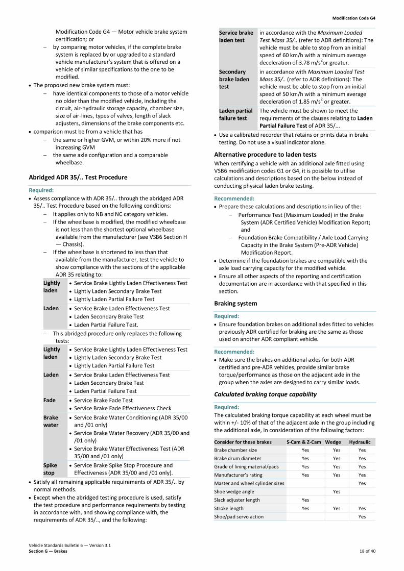
Service brake laden test
in accordance with the Maximum Loaded Test Mass 35/.. (refer to ADR definitions): The vehicle must be able to stop from an initial speed of 60 km/h with a minimum average deceleration of 3.78 m/s2or greater.
Secondary brake laden test
in accordance with Maximum Loaded Test Mass 35/.. (refer to ADR definitions): The vehicle must be able to stop from an initial speed of 50 km/h with a minimum average deceleration of 1.85 m/s2 or greater.
Laden partial failure test
The vehicle must be shown to meet the requirements of the clauses relating to Laden Partial Failure Test of ADR 35/...
• Use a calibrated recorder that retains or prints data in brake testing. Do not use a visual indicator alone.
Alternative procedure to laden tests When certifying a vehicle with an additional axle fitted using VSB6 modification codes G1 or G4, it is possible to utilise calculations and descriptions based on the below instead of conducting physical laden brake testing.
Recommended: • Prepare these calculations and descriptions in lieu of the:
− Performance Test (Maximum Loaded) in the Brake System (ADR Certified Vehicle) Modification Report; and
− Foundation Brake Compatibility / Axle Load Carrying Capacity in the Brake System (Pre-ADR Vehicle) Modification Report.
• Determine if the foundation brakes are compatible with the axle load carrying capacity for the modified vehicle.
• Ensure all other aspects of the reporting and certification documentation are in accordance with that specified in this section.
Braking system
Required: • Ensure foundation brakes on additional axles fitted to vehicles
previously ADR certified for braking are the same as those used on another ADR compliant vehicle.
Recommended: • Make sure the brakes on additional axles for both ADR
certified and pre-ADR vehicles, provide similar brake torque/performance as those on the adjacent axle in the group when the axles are designed to carry similar loads.
Calculated braking torque capability
Required: The calculated braking torque capability at each wheel must be within +/- 10% of that of the adjacent axle in the group including the additional axle, in consideration of the following factors:
Consider for these brakes S-Cam & Z-Cam Wedge Hydraulic Brake chamber size Yes Yes Yes Brake drum diameter Yes Yes Yes Grade of lining material/pads Yes Yes Yes Manufacturer’s rating Yes Yes Yes Master and wheel cylinder sizes Yes Shoe wedge angle Yes Slack adjuster length Yes Stroke length Yes Yes Yes Shoe/pad servo action Yes

Modification Code G4
Vehicle Standards Bulletin 6 — Version 3.1 Section G — Brakes 19 of 40
Additional axle brake shoes/pads: When additional axle brake shoes/pads are interchangeable with those of the original adjacent axle, the grade of the material fitted to the additional axle must be the same. If the grade of the material cannot be determined, use that specified for replacement linings by the original vehicle manufacturer.
Spring parking brakes: Unless it is shown that the laden parking brake effectiveness (i.e. holding on a grade of 18% or more) at the increased GVM is achieved by other means, all additional axles must have mechanical spring parking brakes fitted, with the spring forces of the additional axle not less than 80% of that on the original axle.
Secondary brake performance (partial failure test): In this test you need to ensure the vehicle can meet the minimum deceleration specified in ADR 35/.. for partial failure test (e.g. 1.8m/s2 for an NC category vehicle).
To show that the vehicle meets this requirement without conducting a laden test, either:
1. Prove by analytical methods that the braked wheels for each sub-circuit in the brake support system support enough of the vehicle’s mass (under dynamic conditions) to provide the specified deceleration under partial failure of the system.
OR 2. If the brakes are capable of locking the wheels, use a
maximum coefficient of friction of 0.7 between the tyres and the road surface. If the brakes on the additional axle are integrated into the vehicle’s existing air brake supply/control system and it has spring brakes fitted, install a spring brake/service brake modulation valve to provide adequate braking and control of the system in the event of a partial brake failure.
OR 3. The additional axle’s air supply may be totally independent
of the vehicle’s existing air reserve, with only the brake control signal being derived from options A or B below: A Pneumatic circuitry prescribed by the original
manufacturer, or alternate system that meets the intent of ADR 35/.. OR
B Control signal taken from both front and rear circuits and routed into a transfer or shuttle valve which then provides the control signal for the additional axle valve.
For both options A and B:
• fit an additional reservoir with a capacity of 12 times the total displacement of the power chambers on the additional axle
• fit a low pressure warning system and a supply line check valve at the entry point.
Suspension Required: • connect the additional axle to the original adjacent axles in the
group by a load sharing suspension of a similar type that has been used on the vehicle.
5. Design requirements
Air/Hydraulic brake systems
Fitting of lazy axle Required: Ensure that a lazy axle with full air brakes has:
Air reservoir capacity
additional air reservoirs fitted with a minimum capacity 12 times the volume of the brake chamber consumption of the additional axle
Brake reservoir
charging time of the revised air tank capacity system in accordance with the Overview section of this modification code.
• Ensure that a lazy axle with hydraulically actuated vacuum or air assisted brakes has:
− displacement of the master cylinder greater than total displacement at maximum stroke at the wheel cylinders that it services, possibly needing extra master cylinders to be filled to service the additional axle
− mechanical advantage of the entire brake system, including hydraulic and assistance (for the vehicle with the additional axle) must be approximately the same as that for the original vehicle (within ± 5.0%).
• If any parameters above vary outside tolerances, perform a physical test to prove compatibility with the Overview section of this modification code and apply these performance criteria:
− ratio of additional air tank capacity to the additional brake power assist unit capacity must be the same as for the original vehicle, otherwise test to ADR requirements for reservoir capacity
− reservoir pressure build-up times must accord with Section G — Overview of this modification code.
− parking brake meets performance requirements in Section G — Overview of this modification code.
Brake systems with mixed method of application
Recommended: • Retain the same method of brake actuation for all wheels on a
vehicle (full air, air-over hydraulic, vacuum assisted hydraulic, mechanical, regenerative electric, etc.).
• If a vehicle is modified so that different methods of brake actuation are used, then the brake torque on adjacent axles within an axle group should be the same.
Additional verification Perform the following in addition to any testing required in this modification code: Required: • Perform a comparison between the response times for the
application and the release of braking torque for each of the differing brake assemblies.
• Ensure the pressure within the brake chamber on each axle fitted to the vehicle reaches at least 65% of the average operating pressure within 600 milliseconds immediately following the rapid and complete application of the foot-operated control.
Recommended: • Plot brake output torque versus the applied pedal force or line
pressure for each axle on the modified vehicle and the corresponding axle on the comparison vehicle.
• Show the plot for each individual axle of both vehicles on the same graph for at least five equally spaced readings of pedal
Modification Code G4
Vehicle Standards Bulletin 6 — Version 3.1 Section G — Brakes 20 of 40
force or line pressure in the range of 0–700 N or 0–700 kPa respectively.
• Ensure the variation of brake torque, as measured in the nominated test range, does not exceed 20% and is randomly distributed.
• If testing using a brake dynamometer, make the brake output torque for the plot the sum of the left and right-hand brake output torques for that axle.
• Do not allow response times for both brakes application and release to vary by more than 200 milliseconds between axles.
Load sensing proportioning valves
Required: • If load sensing proportioning valves (LSPVs) are added to a
brake system, install them in accordance with the manufacturer’s recommendations.
• Ensure a vehicle fitted with a LSPV has indelible markings advising the following if the LSPV consists of: a device mechanically controlled by suspension travel (i.e. in applications with mechanical spring suspension)
• the useful travel (recommended units of mm)
• inlet/outlet pressures (in kPa) of the device between the positions corresponding to unladen and GVM/GTM
• any further information to enable the setting of the device to be checked in service
a device that modulates air pressure in the brake transmission based on the air pressure from the suspension (i.e. in applications with air bag suspension)
• the axle loads (in kg) corresponding to the unladen and GVM/GTM for the axles that control the device
• corresponding nominal inlet and outlet pressures (in kPa) of the device
• any further information to enable the setting of the device to be checked in service.
• Supply instructions to the vehicle operator illustrating how to correctly set or adjust the LSPV for use during service.
• If a LSPV is added to a brake system, certify it in accordance with this modification code.
Effect of wheel guards
Ventilation
Required: • Ensure that the body configuration provides adequate
ventilation, as changes to ventilation (i.e. ventilation holes in the wheels) may affect operating temperature and braking performance.
Wheel guards
Recommended: • When designing wheel guards take into account brake
performance and cooling, and use large wheel clearances while still ensuring compliance, with mud guard requirements.
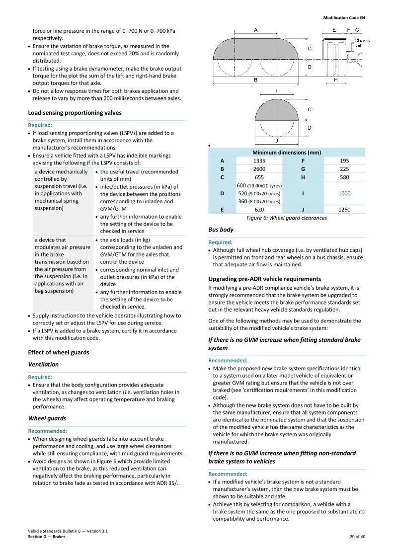
• Avoid designs as shown in Figure 6 which provide limited ventilation to the brake, as this reduced ventilation can negatively affect the braking performance, particularly in relation to brake fade as tested in accordance with ADR 35/..
• Minimum dimensions (mm)
A 1335 F 195 B 2600 G 225 C 655 H 580
D 600 (10.00x20 tyres) 520 (9.00x20 tyres) 360 (8.00x20 tyres)
I 1000
E 620 J 1260 Figure 6: Wheel guard clearances
Bus body
Required: • Although full wheel hub coverage (i.e. by ventilated hub caps)
is permitted on front and rear wheels on a bus chassis, ensure that adequate air flow is maintained.
Upgrading pre-ADR vehicle requirements If modifying a pre-ADR compliance vehicle’s brake system, it is strongly recommended that the brake system be upgraded to ensure the vehicle meets the brake performance standards set out in the relevant heavy vehicle standards regulation.
One of the following methods may be used to demonstrate the suitability of the modified vehicle’s brake system:
If there is no GVM increase when fitting standard brake system
Recommended: • Make the proposed new brake system specifications identical
to a system used on a later model vehicle of equivalent or greater GVM rating but ensure that the vehicle is not over braked (see ‘certification requirements’ in this modification code).
• Although the new brake system does not have to be built by the same manufacturer, ensure that all system components are identical to the nominated system and that the suspension of the modified vehicle has the same characteristics as the vehicle for which the brake system was originally manufactured.
If there is no GVM increase when fitting non-standard brake system to vehicles
Recommended: • If a modified vehicle’s brake system is not a standard
manufacturer’s system, then the new brake system must be shown to be suitable and safe.
• Achieve this by selecting for comparison, a vehicle with a brake system the same as the one proposed to substantiate its compatibility and performance.

Modification Code G4
Vehicle Standards Bulletin 6 — Version 3.1 Section G — Brakes 21 of 40
• Ensure that the comparison vehicle: − is not altered from its standard manufacturer’s
specifications − is of later date of manufacture than the vehicle being
modified (ADR 35/.. compliant vehicle is suggested) − is available as a manufacturer’s option in a wheelbase
within 10% of the wheelbase of the vehicle being modified
− has axle loading capacities and a GVM rating equivalent to, or up to 20% greater than the vehicle being modified
− has an axle configuration identical to the vehicle being modified
− has a similar type of suspension to the vehicle being modified.
− has similar tyre sizes to the vehicle being modified. • Ensure the modified vehicle meets these requirements:
− brake application response time is in accordance with clauses relating to ADR 35/.. Service brake actuating time test
− brake output torque versus the applied pedal force or line pressure is plotted for each axle on the modified vehicle and the corresponding axle on the comparison vehicle
− plots for each axle of both vehicles on the graph are shown for at least five equally spaced readings of pedal force or line pressure in the range 0–700 N or 0–700 kPa respectively
− variation of brake torque, as measured in the nominated test range, does not exceed 20% and is randomly distributed
− ratio of front axle group brake to rear axle group brake efficiency is in the range of 0.75 to 1.0, if the axle group brake efficiency is the average of (brake force/wheel load) for each wheel in the axle group.
If there is increase in GVM when fitting brake system
Required: • Ensure that if modifying a pre-ADR vehicle to increase its GVM,
the braking system is compatible with the proposed GVM, and that it meets:
− the above requirements; and − the braking performance standard under partial
system failure provided by the fitting of the number of spring brake units specified in the ‘additional axles requirements’ section of this code.
• Ensure that if the modified vehicle has an original date of manufacture after the introduction of ADR 35, 35A or 35/.. or the braking system has to be upgraded to ADR standard, it meets the requirements of the relevant ADR at the revised GVM.
Axle requirements
Alternative axles — if no GVM change
Required: • If the brake equipment is identical to that fitted to the original
axle then substitute the axles on the vehicles without having to re-certify the brake system.
• Certify the installation of the axle to VSB6 Section D — Rear axles or VSB6 Section E — Front axle steering wheels and tyres, as applicable.
• Do not alter front-to-rear load distribution and GVM (refer to the identification or modification plate for the GVM rating).
Recommended: • Organise proof of equivalent performance from dynamometer
test data even if with identical lining material and similar actuation, the brake group is of an alternative manufacturer which may not be equivalent to the original equipment brakes, due to different shoe factors and efficiencies.
Alternative axles — if there is a GVM change
Required: • Substitute axles resulting in a GVM increase only if the:
− braking system on the axles is compatible with the increased GVM
− axle load distribution is correct at the increased GVM − chassis is of sufficient strength for the increased GVM.
• Substitute axles resulting in a GVM decrease only if the: − braking system on the axles is compatible with the
decreased GVM − axle load distribution is correct at the decreased GVM.
Additional axles requirements When upgrading a braking system with additional axles, modify the vehicle so that its specifications are identical to that of another model offered by the manufacturer. The upgraded brake system should have the same combination of components with the same dimensional properties as the selected model.
Required: • If an equivalent or higher rated braking/suspension
combination is not available from the manufacturer, then: − adapt a complete (ADR tested) brake system from a
similar vehicle with the equivalent or greater GVM rating and suspension of similar characteristics, or
− test and certify the new brake system to the relevant ADR.
• Fit all additional axles as follows: − Brake all the wheels on each axle. − Install axles on motor vehicles in accordance with VSB6
Section D — Rear axles and Section E — Front axle steering wheels and tyres.
• Ensure braking equipment fitted to the axle is compatible with the braking system of the base vehicle (see above: Brake systems with mixed method of application)
If brake specification differs from the original
Required: • If the brake specification on the additional axle differs from
that of the original adjacent axle (i.e. method of actuation, drum/disc size, lining contact area, brake chamber size, mechanical advantage of linkages, etc.) then meet these requirements:
− Ensure brake response time on the additional axle is within 200 milliseconds of the adjacent axle response times.
− Ensure brake-torque characteristics of the additional axle are similar to adjacent axles within a tolerance of +/- 10%.
− Make allowance for variations in axle load between the axles, in the case of brake-torque characteristics.
− Ensure response time to the slowest re-acting air booster in the overall brake system does not exceed 600 milliseconds.
− If automatic slack adjusters are fitted to the original axles in the group, also fit them to any additional axles.
− If a new axle assembly is substituted for an axle/group that was provided as original equipment (e.g. when a

Modification Code G4
Vehicle Standards Bulletin 6 — Version 3.1 Section G — Brakes 22 of 40
tandem group replaces an original single axle), ensure the above characteristics are the same before and after conversion.
• To achieve the above, consider upgrading or replacing: − hydraulic system: master cylinder, booster size,
reservoir capacity, pipe diameters etc. − air system: compressor, air tank capacities, relay
valves, QRV, pipe diameters etc.
Single circuit service brake systems
Required: If a vehicle fitted with a single circuit service brake system is undergoing a GVM upgrade then:
• Upgrade all single circuit braking systems to dual circuit braking systems before upgrading the GVM of the vehicle.
• Ensure the completed vehicle satisfies the requirements of this modification code.
Dual circuit service brake systems
Required: • In dual circuit service brake systems, couple the brakes on any
additional axle to the service brake sub-system, appropriate to its location, in a manner that does not impair the correct functioning of either sub-system.
Recommended: • Where practical, couple the additional axle to the sub-system
with the least number of axles, to ensure that secondary brake performance levels are not unduly affected.
• In dual circuit brake systems, where one circuit actuates one axle only of a three axle vehicle, use modulated spring brake actuation to support the axle via a modulating spring brake valve. This releases air from the spring brakes in proportion to the intensity of the intact circuit service brake signal in the absence of a service brake signal from the second circuit.
Removal of an axle requirements When a vehicle’s axle configuration is altered by removing an axle, treat the certification of the vehicle in the same way as any other major brake modification.
Required: • If the axle removed is likely to affect parking brake capability,
verify that the modified vehicle meets the requirements in this modification code.
• If the proposed wheelbase is outside the range offered by the manufacturer, then ‘wheelbase alterations requirements’ in VSB6 Modification Code G7 apply.
• Even if the axle configuration is available as an option from the manufacturer, then re-certify the brake system of the modified vehicle as per ‘certification requirements’ in this modification code.
• Ensure the GVM rating of the modified vehicle does not exceed the rating for which the brake system has been certified.
• If a load sensing valve or other controlling device is normally fitted for the proposed axle/wheelbase configuration, install the valve correctly and adjust it in the modified vehicle
Recommended: • Make specifications of the entire braking system of the
proposed vehicle identical to those of a similar model offered by the manufacturer.
Compounding of spring and service brakes When forces provided by the spring parking brake and the service brake system act simultaneously on the mechanical components of the brake actuation system a condition known as compounding occurs and may cause overloading of components and foundation brakes.
Required: • To prevent the risk of compounding, fit an anti-compounding
valve system into the service brake system. • If both the service and park brake systems of the vehicle are
modified, or the park brake system only, incorporate anti-compounding into that modification.
Figure 7: Example data — Spring (park) brake force vs stroke
Figure 8: Example data — Service brake vs stroke at varying pressures

Modification Code G4
Vehicle Standards Bulletin 6 — Version 3.1 Section G — Brakes 23 of 40
G4 Checklist — Brake system certification (example)

Modification Code G4
Vehicle Standards Bulletin 6 — Version 3.1 Section G — Brakes 24 of 40

Modification Code G4
Vehicle Standards Bulletin 6 — Version 3.1 Section G — Brakes 25 of 40
G4 Modification report — Brake system: ADR certified vehicle (example)

Modification Code G4
Vehicle Standards Bulletin 6 — Version 3.1 Section G — Brakes 26 of 40
G4 Modification report — Brake system (pre-ADR vehicle) (example)

Modification Code G4
Vehicle Standards Bulletin 6 — Version 3.1 Section G — Brakes 27 of 40
G4 Test report — Brake torque build-up check: adjacent axles (example)

Vehicle Standards Bulletin 6 — Version 3.1 Section G — Brakes 28 of 40
Modification Code G5 — Fitting of auxiliary and endurance brakes
1. Scope Modifications covered under this code:
Covered • fitting of auxiliary/endurance braking devices, i.e. engine,
exhaust or retarder type, independent of primary braking system.
Not covered • alterations to the primary braking system.
2. Related standards Modified vehicles must comply with all ADRs, Australian Standards, acts and regulations. Below are some but not all of the areas that may be affected by the modifications in this code and require certification testing or evidence to demonstrate compliance.
The certifier must ensure that the modified vehicle continues to comply with all affected ADRs.
This… Must comply with… Engine VSB6 Section A — Engines
Good engineering practice Exhaust VSB6 Section A — Engines
Good engineering practice Cooling system VSB6 Section A — Engines
Good engineering practice Tail shaft VSB6 Section C — Tail shafts
Good engineering practice
3. Certification procedure The certification procedure for this modification code is as follows:
1. Modifier Determine if the modification is within manufacturer specifications. • If yes, the modification will need to be done
in accordance with manufacturer specifications.
• If no, the modification will need to be done in accordance with this modification code.
2. Modifier Consult with an accredited G5 AVE for guidance on how to perform the modification.
3. Modifier Perform modification in accordance with AVE advice and this code.
4. Modifier Organise approval inspection by an accredited G5 AVE.
5. G5 AVE Perform inspection, complete G5 checklist and determine if compliance has been achieved. • If yes, proceed to step 6. • If no, do not proceed, advise modifier rework is
required to ensure compliance. Return to step 2. 6. G5 AVE Issue modification certificate, affix modification
plate, and submit paperwork as required by the relevant AVE registration scheme.
AVEs must be satisfied that the vehicle modification requirements are being met. It is advised that before modifications are carried out they are discussed with the certifying AVE.
4. Compliance requirements
Required: • Ensure that installation of an auxiliary and endurance brake
does not cause exhaust back pressure to exceed the vehicle manufacturer’s specifications (see VSB6 Modification Code A4).
• For auxiliary/endurance brakes that act on drivelines or transmissions see VSB6 Section B — Transmissions or Section C — Tail shafts as applicable.
Recommended: • Auxiliary/endurance braking devices do not need to comply
with ADR 35/.., so no additional brake testing is needed when they are fitted.
• If fitting of an engine retarder is required by a relevant heavy vehicle regulation it may have to comply with statutory minimum performance requirements.
5. Design requirements
Recommended: • Install engine, exhaust or retarder components in accordance
with vehicle or engine manufacturer’s recommendations and fit them so that depressing either the clutch or accelerator will render the brake inoperative.
• When installing an auxiliary/endurance brake that utilises the engine cooling system, supply the vehicle a radiator with sufficient capacity to reject the additional heat generated by the retarder.

Modification Code G5
Vehicle Standards Bulletin 6 — Version 3.1 Section G — Brakes 29 of 40
G5 Checklist — Fitting of auxiliary and endurance brakes (example)

Vehicle Standards Bulletin 6 — Version 3.1 Section G — Brakes 30 of 40
Modification Code G6 — Fitting of air operated accessories
1. Scope Modifications covered under this code:
Covered • installation of a pressure protection valve for the use with air
operated accessories • installation of an additional method of brake application. Not covered • any other modification or addition to the brake system.
2. Related standards Modified vehicles must comply with all ADRs, Australian Standards, acts and regulations. Below are some but not all of the areas that may be affected by the modifications in this code and require certification testing or evidence to demonstrate compliance.
The certifier must ensure that the modified vehicle continues to comply with all affected ADRs.
This… Must comply with… Brake system VSB6 Section G — Brakes
Good engineering practice
3. Certification procedure The certification procedure for this modification code is as follows:
1. Modifier Determine if the modification is within manufacturer specifications. • If yes, the modification will need to be done in
accordance with manufacturer specifications. • If no, the modification will need to be done in
accordance with this modification code. 2. Modifier Consult with an accredited G6 AVE for guidance
on how to perform the modification. 3. Modifier Perform modification in accordance with AVE
advice and this code. 4. Modifier Organise approval inspection by an accredited
G6 AVE. 5. G6 AVE Perform inspection, complete G6 checklist and
determine if compliance has been achieved. • If yes, proceed to step 6. • If no, do not proceed, advise modifier rework is
required to ensure compliance. Return to step 2. 6. G6 AVE Issue modification certificate, affix modification
plate, and submit paperwork as required by the relevant AVE registration scheme.
AVEs must be satisfied that the vehicle modification requirements are being met. It is advised that before modifications are carried out they are discussed with the certifying AVE.
4. Compliance requirements Pressure protection valves and air operated accessories Fitting an air operated accessory alone is considered a minor modification not requiring certification under this code if:
• It is installed in a vehicle already fitted with a pressure protected supply for use with accessory items that denies air
pressure when the service brake system is less than 450 kPa; and
• the pressure protected supply has been certified as part of the vehicle’s brake system under the vehicle identification plate approval or this modification code.
Additional methods of brake application • Where any additional method of brake application is installed
to a vehicle, ensure the application and release methods meet the requirements of ADR 35/.. and ADR 38/.. as applicable.
5. Design requirements Pressure protection valves and air operated accessories
Required: • When a vehicle’s air compressor supplies air to systems other
than the brake system, give preference to charging the brake system air reservoirs.
• Ensure the air compressor is of suitable capacity and duty cycle, taking into account the air draw of any air-operated accessories fitted.
• Deny air supply to any device deriving air from the same source as the service brake system whenever the pressure in the service brake system is less than 450 kPa.
• If an additional tank is fitted for air powered accessories or after a pressure protection valve, ensure the vehicle continues to comply with the re-charge requirements of ADR35/.. or the relevant heavy vehicle standards regulation (as applicable).
Recommended: • If a vehicle is fitted with a supply (wet) reservoir that provides
air to separate braking system reservoirs, then source air for ancillary devices only from the supply (wet) reservoir.
Additional methods of brake application
Required: • Ensure where connected to the park brake system the release
is designed to minimise the possibility of inadvertent release of the brake.
• Ensure where connected to the service brake system the application method applies the brakes to all of the road wheels.
• Ensure where separate methods of actuation of the brake system are provided for any of the systems (i.e. service/park), the actuation of one system does not cause the operation of any other system.
• Ensure an additional method of brake application: − is not capable of engaging when the vehicle is:
o for truck or trailer mounted attenuators travelling in excess of 45km/h; or
o for all other vehicles, travelling in excess of 10 km/h in the forward direction.
− is fitted with an in-cab audible and visual warning to alert the driver when the system is activated.
• Ensure any additional methods of brake application or release are within the reach of the driver in their normal seated position.
Recommended: • Ensure that any additional method of brake application only
acts on the park brake system.

Modification Code G6
Vehicle Standards Bulletin 6 — Version 3.1 Section G — Brakes 31 of 40
G6 Checklist — Fitting of air operated accessories (example)
Vehicle Standards Bulletin 6 — Version 3.1 Section G — Brakes 32 of 40
Modification Code G7 — Brake system substitution / wheelbase extension
1. Scope Modifications covered under this code:
Covered • substitution of original brake system with the entire brake
system from an ADR 35/.. certified vehicle with a GVM equal to or greater than the GVM of the proposed vehicle; where the modified vehicle wheelbase is equal to or greater than the manufacturer’s minimum optional wheelbase of the brake system on the model vehicle
• modification of brake system due to wheelbase extension of a vehicle while maintaining the original braking system.
Not covered • substitution of a brake system to a vehicle where the intended
wheelbase is shorter than the minimum wheelbase of the vehicle from which the system was taken (see VSB6 Modification Code G4).
• fitting of a brake system from a vehicle with a lower GVM rating than the proposed GVM of the proposed modified vehicle (see VSB6 Modification Code G4).
• partial fitting of an additional brake system, e.g. to an additional axle (see VSB6 Modification Code G4).
2. Related standards Modified vehicles must comply with all ADRs, Australian Standards, acts and regulations. Below are some, but not all of the areas that may be affected by the modifications in this code and require certification testing or evidence to demonstrate compliance.
The certifier must ensure that the modified vehicle continues to comply with all affected ADRs.
This… Must comply with… Brake system VSB6 Section G — Brakes
Good engineering practice
3. Certification procedure The certification procedure for this modification code is as follows:
1. Modifier Determine if the modification is within manufacturer specifications. • If yes, the modification will need to be done
in accordance with manufacturer specifications.
• If no, the modification will need to be done in accordance with this modification code.
2. Modifier Consult with an accredited G7 AVE for guidance on how to perform the modification.
3. Modifier Perform modification in accordance with AVE advice and this code.
4. Modifier Organise approval inspection by an accredited G7 AVE.
5. G7 AVE Perform inspection, complete G7 checklist and determine if compliance has been achieved: • If yes, proceed to step 6. • If no, do not proceed, advise modifier rework
is required to ensure compliance. Return to step 2.
6. G7 AVE Issue modification certificate, affix modification plate, and submit paperwork as required by the relevant AVE registration scheme.
AVEs must be satisfied that the vehicle modification requirements are being met. It is advised that before modifications are carried out they are discussed with the certifying AVE.
4. Compliance requirements
Alternative axles — if no GVM change
Required: • If the brake equipment is identical to that fitted to the original
axle then substitute the axles on the vehicles without having to re-certify the brake system.
• Certify the installation of the axle to VSB6 Section D — Rear Axles or VSB6 Section E — Front axle steering wheels and tyres, as applicable.
• Do not alter front-to-rear load distribution and GVM (refer to the identification or modification plate for the GVM rating).
Recommended: • Organise proof of equivalent performance from dynamometer
test data, even if with identical lining material and similar actuation the brake group is of an alternative manufacturer which may not be equivalent to the original equipment brakes, due to different shoe factors and efficiencies.
Alternative axles — if there is a GVM change
Required: • Substitute axles resulting in a GVM increase only if the:
− braking system on the axles is compatible with the increased GVM
− axle load distribution is correct at the increased GVM − chassis is of sufficient strength for the increased
GVM. • Substitute axles resulting in a GVM decrease only if the:
− braking system on the axles is compatible with the decreased GVM
− axle load distribution is correct at the decreased GVM.
Removal of axles When a vehicle’s axle configuration is altered by removing an axle, treat the certification of the vehicle in the same way as any other major brake modification.
Required: • If the axle removed is likely to affect parking brake capability,
verify that the modified vehicle meets the requirements in VSB6 Modification Code G4.
• If the proposed wheelbase is outside the range offered by the manufacturer, then verify that the modified vehicle meets the requirements in the ‘wheelbase alterations requirements’ section of this modification code.
• Even if the axle configuration is available as an option from the manufacturer, then re-certify the brake system of the modified vehicle as per ‘certification requirements’ in VSB6 Modification Code G4.
• Ensure the GVM rating of the modified vehicle does not exceed the rating for which the brake system has been certified.

Modification Code G7
Vehicle Standards Bulletin 6 — Version 3.1 Section G — Brakes 33 of 40
Recommended: • Make specifications of the entire braking system of the
proposed vehicle identical to those of a similar model offered by the manufacturer.
5. Design requirements
Wheelbase alterations
Required: • Replace all air and hydraulic lines that need alteration with
new lines with the same internal bore as the manufacturer’s originals.
• If the wheelbase is reduced to less than the minimum option offered by the manufacturer for that model, and if it is also fitted with ABS or a load proportioning valve, test the vehicle in a lightly loaded condition to see if it complies with ADR 35A or ADR 35/..
Recommended: • Do not perform additional testing if the specifications of a
vehicle’s original brake system remain unchanged and the wheelbase/brake system combination is modified within the range offered by the manufacturer for that model.
• If the wheelbase of an air-brake system equipped vehicle is extended beyond the maximum offered by the manufacturer for that model, check the brake application response times at the proposed new pipe lengths.
Additional axles When upgrading a braking system with additional axles modify the vehicle so that its specifications are identical to that of another model offered by the manufacturer. The upgraded brake system should have the same combination of components with the same dimensional properties as the selected model.
Required: • If an equivalent or higher rated braking/suspension
combination is not available from the manufacturer, then: − adapt a complete (ADR tested) brake system from a
similar vehicle with the equivalent or greater GVM rating and suspension of similar characteristics, or
− test and certify the new brake system to the relevant ADR.
• Ensure braking equipment fitted to the axle is compatible with the braking system of the base vehicle (see ‘brake systems with mixed method of application’ in VSB6 Modification Code G4).
Brake specification differs from original
Required: • If the brake specification on the additional axle differs from
that of the original adjacent axle (i.e. method of actuation, drum/disc size, lining contact area, brake chamber size, mechanical advantage of linkages, etc.) then meet these requirements:
− Ensure brake response time on the additional axle is within 200 milliseconds of the adjacent axle response times.
− Ensure brake-torque characteristics of the additional axle are similar to adjacent axles within a tolerance of +/- 10%.
− Make allowance for variations in axle load between the axles, in the case of brake-torque characteristics.
− Ensure response time to the slowest re-acting air booster in the overall brake system must not exceed 600 milliseconds
− If automatic slack adjusters are fitted to the original axles in the group, also fit them to any additional axles
− If a new axle assembly is substituted for an axle/group that was provided as original equipment (e.g. when a tandem group replaces an original single axle), ensure the above characteristics are the same before and after conversion.
• To achieve the above consider upgrading or replacing: − hydraulic system: master cylinder, booster size,
reservoir capacity, pipe diameters etc. − air system: compressor, air tank capacities, relay
valves, QRV, pipe diameters etc.
Single circuit service brake systems
Required: If a vehicle fitted with a single circuit service brake system is undergoing a GVM upgrade then:
• upgrade all single circuit braking systems to dual circuit braking systems before upgrading the GVM of the vehicle
• ensure the completed vehicle satisfies the requirements of this modification code.
Dual circuit service brake systems
Required: • In dual circuit service brake systems, couple the brakes on any
additional axle to the service brake sub-system, appropriate to its location, in a manner that does not impair the correct functioning of either sub-system.
Recommended: • Where practical, couple the additional axle to the sub-system
with the least number of axles to ensure that secondary brake performance levels are not unduly affected.
• In dual circuit brake systems, where one circuit actuates one axle only of a three-axle vehicle, use modulated spring brake actuation to support the axle via a modulating spring brake valve. This releases air from the spring brakes in proportion to the intensity of the intact circuit service brake signal in the absence of a service brake signal from the second circuit.
Removal of an axle requirements When a vehicle’s axle configuration is altered by removing an axle, treat the certification of the vehicle in the same way as any other major brake modification.
Required: • If the axle removed is likely to affect parking brake capability,
verify that the modified vehicle meets the requirements in this modification code.
• If the proposed wheelbase is outside the range offered by the manufacturer, then ‘wheelbase alterations requirements’ in VSB6 Modification Code G7 apply.
• Even if the axle configuration is available as an option from the manufacturer, then re-certify the brake system of the modified vehicle as per ‘certification requirements certification requirements’ in this modification code.
• Ensure the GVM rating of the modified vehicle does not exceed the rating for which the brake system has been certified.

Modification Code G7
Vehicle Standards Bulletin 6 — Version 3.1 Section G — Brakes 34 of 40
Recommended: • Make specifications of the entire braking system of the
proposed vehicle identical to those of a similar model offered by the manufacturer.
• If a load sensing valve, or other controlling device, is normally fitted for the proposed axle/wheelbase configuration, install the valve correctly and adjust it in the modified vehicle.
Compounding of spring and service brakes When forces provided by the spring parking brake and the service brake system act simultaneously on the mechanical components of the brake actuation system a condition known as compounding occurs and may cause overloading of components and foundation brakes.
Required: • To prevent the risk of compounding, fit an anti-compounding
valve system into the service brake system. • If both the service and park brake systems of the vehicle are
modified, or the park brake system only, incorporate anti-compounding into that modification.
Figure 9: Example data — Spring (park) brake force vs stroke
Figure 10: Example data — Service brake vs stroke at varying pressures
6. Installation requirements
Additional axles
Required: • Fit all additional axles as follows:
− Brake all the wheels on each axle. − Install axles on trailers in accordance with axle or
trailer manufacturer’s instructions. − Install axles on motor vehicles in accordance with
VSB6 Section D — Rear axles and VSB6 Section E — Front axle steering wheels and tyres.
• Ensure braking equipment fitted to the axle is compatible with the braking system of the base vehicle (see ‘brake systems with mixed method of application’ in VSB6 Modification Code G4).

Modification Code G7
Vehicle Standards Bulletin 6 — Version 3.1 Section G — Brakes 35 of 40
G7 Checklist — Brake system substitution / wheelbase extension (example)

Vehicle Standards Bulletin 6 — Version 3.1 Section G — Brakes 36 of 40
Modification code G8 — Trailer brake system upgrade (design)
1. Scope Modifications covered under this code:
Covered • issue of G8 certificate and checklist for use by a G3 approved
AVE, for a trailer brake specification supplied either by the owner or by the G3 approved AVE, where the trailer itself has not been inspected by the G8 approved AVE.
Not covered • trailer brake system upgrading of trailers modified to change
their registration category, e.g. semi to dog trailer, pig to dog trailer, semi to dolly, etc.1
• upgrading brake system of road train trailers (VSB6 Modification Code S11) or B-double trailers (VSB6 Modification Code S9).
1 Such trailers are regarded as newly manufactured and must obtain a new vehicle identification number (VIN) and be fitted with a newly issued trailer identification plate.
2. Related standards Modified vehicles must comply with all ADRs, Australian Standards, acts and regulations. Below are some but not all of the areas that may be affected by the modifications in this code and require certification testing or evidence to demonstrate compliance.
The certifier must ensure that the modified vehicle continues to comply with all affected ADRs.
This… Must comply with… Brakes VSB6 Section G — Brakes
ADR 38, 38/.. Suspension Manufacturer’s rating
VSB6 Modification Code F2 Re-rating ATM VSB6 Section S — Vehicle rating
3. Certification procedure The certification procedure for this modification code is as follows:
1. Modifier Contact an accredited G8 AVE to supply vehicle specifications or organise vehicle inspection by appropriately qualified and accredited G8 AVE.
2 G8 AVE Assess and provide design certification to modifier listing specifications, parts list and calculations.
3 Modifier Consult with an accredited G3 AVE for guidance on what modifications are required.
AVEs must be satisfied that the vehicle modification requirements are being met. It is advised that before modifications are carried out they be discussed with the certifying AVE.
4. Compliance requirements
Required: • Certify the design of a trailer when it has been changed from
tandem axle to tri-axle semitrailer configuration, two axle to three axle dog trailer conversion, replacement of axles, suspensions or control systems with alternative components which would allow a different load rating.
• Ensure the change of axles or suspension is in accordance with VSB6 modification codes D1 and F2.
• In all cases, check that the suspensions and axles are used within the manufacturer’s rated capacities.
Recommended: • A G8 approved AVE may issue a G8 modification certificate
and checklist, for use by a G3 approved AVE to inspect and fit a modification plate to a modified trailer.
• When trailers are not inspected by a G8 approved AVE, base the brake system re-certification and the G3 AVE checklist on information derived from owner or modifier specifications or data sourced by the G8 approved AVE.
• Issue the G8 modification certificate checklist and design certificate, recommending an appropriate brake system specification for the trailer.
The checklist identifies the source of brake system data and confirms that the trailer has not been inspected by the G8 approved AVE.
The G3 approved AVE uses the G8 modification certificate to approve the trailer’s braking system after inspection to verify that the componentry is as described in the modification certificate and checklist and that the vehicle’s mechanical condition is satisfactory. This may be required in conjunction with an ATM re-rating in accordance with VSB6 modification codes S12 and S7.
ADR 38/.. advises the use of calculations to establish how trailer design can meet ADR requirements.
One of these calculations provides the established retardation coefficient (ERC), which provides performance requirements for limit bands and emergency ERC, parking ability, skid limit performance, friction utilisation and axle fade rating.
5. Design requirements
Compounding of spring and service brakes When forces provided by the spring parking brake and the service brake system act simultaneously on the mechanical components of the brake actuation system a condition known as compounding occurs and may cause overloading of components and foundation brakes.
Required: • To prevent the risk of compounding, fit an anti-compounding
valve system into the service brake system. • If both the service and park brake systems of the vehicle are
modified, or the park brake system only, incorporate anti-compounding into that modification.
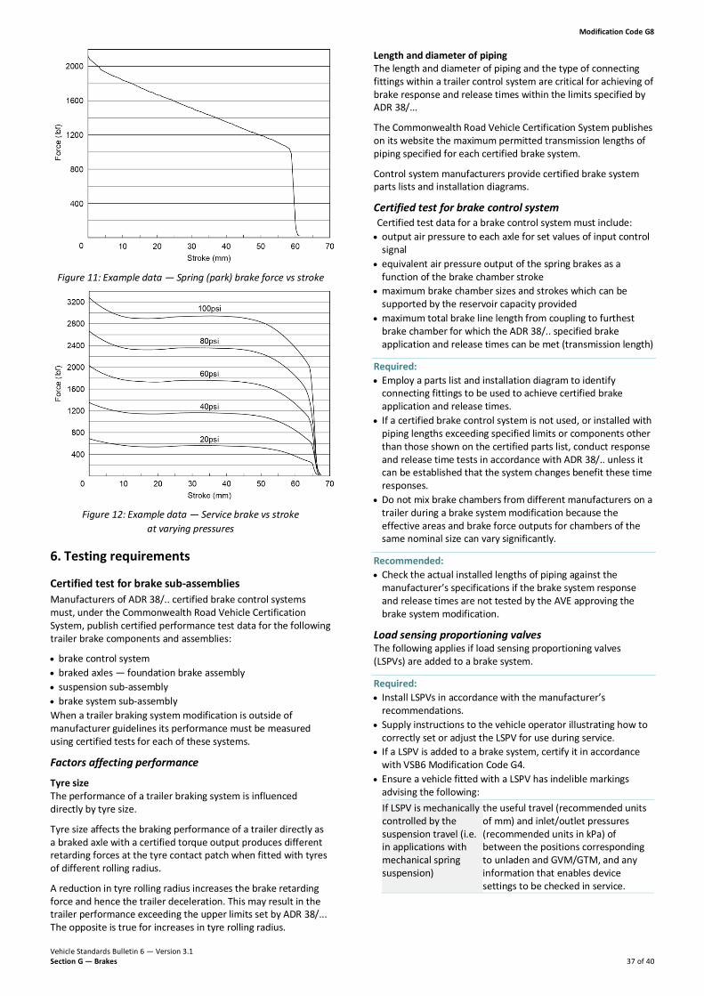
Modification Code G8
Vehicle Standards Bulletin 6 — Version 3.1 Section G — Brakes 37 of 40
Figure 11: Example data — Spring (park) brake force vs stroke
Figure 12: Example data — Service brake vs stroke at varying pressures
6. Testing requirements
Certified test for brake sub-assemblies Manufacturers of ADR 38/.. certified brake control systems must, under the Commonwealth Road Vehicle Certification System, publish certified performance test data for the following trailer brake components and assemblies:
• brake control system • braked axles — foundation brake assembly • suspension sub-assembly • brake system sub-assembly When a trailer braking system modification is outside of manufacturer guidelines its performance must be measured using certified tests for each of these systems.
Factors affecting performance
Tyre size The performance of a trailer braking system is influenced directly by tyre size.
Tyre size affects the braking performance of a trailer directly as a braked axle with a certified torque output produces different retarding forces at the tyre contact patch when fitted with tyres of different rolling radius.
A reduction in tyre rolling radius increases the brake retarding force and hence the trailer deceleration. This may result in the trailer performance exceeding the upper limits set by ADR 38/... The opposite is true for increases in tyre rolling radius.
Length and diameter of piping The length and diameter of piping and the type of connecting fittings within a trailer control system are critical for achieving of brake response and release times within the limits specified by ADR 38/...
The Commonwealth Road Vehicle Certification System publishes on its website the maximum permitted transmission lengths of piping specified for each certified brake system.
Control system manufacturers provide certified brake system parts lists and installation diagrams.
Certified test for brake control system Certified test data for a brake control system must include: • output air pressure to each axle for set values of input control
signal • equivalent air pressure output of the spring brakes as a
function of the brake chamber stroke • maximum brake chamber sizes and strokes which can be
supported by the reservoir capacity provided • maximum total brake line length from coupling to furthest
brake chamber for which the ADR 38/.. specified brake application and release times can be met (transmission length)
Required: • Employ a parts list and installation diagram to identify
connecting fittings to be used to achieve certified brake application and release times.
• If a certified brake control system is not used, or installed with piping lengths exceeding specified limits or components other than those shown on the certified parts list, conduct response and release time tests in accordance with ADR 38/.. unless it can be established that the system changes benefit these time responses.
• Do not mix brake chambers from different manufacturers on a trailer during a brake system modification because the effective areas and brake force outputs for chambers of the same nominal size can vary significantly.
Recommended: • Check the actual installed lengths of piping against the
manufacturer’s specifications if the brake system response and release times are not tested by the AVE approving the brake system modification.
Load sensing proportioning valves The following applies if load sensing proportioning valves (LSPVs) are added to a brake system.
Required: • Install LSPVs in accordance with the manufacturer’s
recommendations. • Supply instructions to the vehicle operator illustrating how to
correctly set or adjust the LSPV for use during service. • If a LSPV is added to a brake system, certify it in accordance
with VSB6 Modification Code G4. • Ensure a vehicle fitted with a LSPV has indelible markings
advising the following: If LSPV is mechanically controlled by the suspension travel (i.e. in applications with mechanical spring suspension)
the useful travel (recommended units of mm) and inlet/outlet pressures (recommended units in kPa) of between the positions corresponding to unladen and GVM/GTM, and any information that enables device settings to be checked in service.

Modification Code G8
Vehicle Standards Bulletin 6 — Version 3.1 Section G — Brakes 38 of 40
If LSPV modulates air pressure in the brake transmission based on air pressure from the suspension (i.e. in applications with air bag suspension)
axle loads (recommended units of kg) corresponding to the unladen and GVM/GTM for the axles that control the device and its corresponding nominal inlet and outlet pressures (recommended units of kPa), and any information that enables device settings to be checked in service.
Certified test for foundation brake Manufacturers of ADR 38/.. certified braked axles are required under the Commonwealth Road Vehicle Certification System to publish certified test data:
• the brake output torque at 650 kPa air pressure for a given brake chamber area and slack adjuster length
• the actual chamber stroke required by the brake for a range of input air pressures to allow calculation of the spring brake force available for emergency and parking braking
• the axle load rating at which ADR 38/.. brake fade performance has been established.
This brake data is used to predict the trailer deceleration performance based on the calculation provided in ADR 38/.. .
The nominal torque output figure is adjusted for the actual brake chamber size and slack adjuster length used at each axle position on the trailer.
This corrected torque rating is then multiplied by the certified control system output ratio for various control input pressures and divided by the tyre rolling radius to predict the retarding force available from the axle at those control input pressures. The trailer deceleration performance can then be calculated from this force data.
Certified test for suspension sub-assembly The service brake skid limit for an axle position in a suspension is expressed as the ratio of the torque applied to that axle compared with the highest torque applied to any other axle in the group. This figure shows whether larger or smaller brake chambers can be fitted at a given axle position in the group and is critical for some tri-axle suspensions that use smaller chambers on the front axle than on the other axles to prevent front axle lockup and for singe point tandem suspensions using smaller chambers on rear axles for the same reason.
Emergency skid limits are certified as the maximum ratio of emergency brake retarding force (N) divided by static axle load (kg) that can be tolerated by suspension without causing wheel lockup.
As the emergency brake is usually also the parking brake, this sets an upper limit to the parking brake force that can be used and hence limits the possible ATM.
Certified test data for a brake control system must include: • mass rating of the suspension • skid limits at which the suspension has been proved to still
permit an effective retardation coefficient (ERC) of 0.45 without wheel lockup, which is equivalent to a retardation of 0.45G if the suspension is brake reactive.
Certified test for brake system sub-assembly A G8 approved AVE must prepare a design certificate and checklist for use by a G3 approved AVE who will conduct the physical inspection of the trailer.
Required: • Supply a copy of the checklist with the G8 modification
certificate and with copies of the control system certified diagram and parts lists.
• Ensure the following information appears on the checklist: − calculated ERC vs control pressure performance
figures, together with upper and lower boundary limits
− certified subassemblies for control system, braked axles and suspension
− slack adjuster lengths required for each axle − brake chamber sizes required for each axle − wheelbase and centre of gravity height in the case of a
dog trailer − tyre size − aggregate trailer mass (ATM) − axle group loads.

Modification Code G8
Vehicle Standards Bulletin 6 — Version 3.1 Section G — Brakes 39 of 40
G8 Checklist — Trailer brake system upgrade (design) (example)

Modification Code G8
Vehicle Standards Bulletin 6 — Version 3.1 Section G — Brakes 40 of 40