Embed Size (px)
Citation preview
VyattaSuite 200
1301 Shoreway RoadBelmont, CA 94002
vyatta.com650 413 7200
1 888 VYATTA 1 (US and Canada)
VPN REFERENCE GUIDEIntroduction to VPNIPsec Site-to-Site VPNRemote Access VPNOpenVPN
VYATTA, INC. | Vyatta System
Title
COPYRIGHT
Copyright © 2005–2009 Vyatta, Inc. All rights reserved.
Vyatta reserves the right to make changes to software, hardware, and documentation without notice. For the most recent version of documentation, visit the Vyatta web site at vyatta.com.
PROPRIETARY NOTICES
Vyatta is a registered trademark of Vyatta, Inc.
VMware, VMware ESX, and VMware server are trademarks of VMware, Inc.
All other trademarks are the property of their respective owners.
ISSUE DATE: February 2009
DOCUMENT REVISION. VC5 v03
RELEASED WITH: VC5.0.2
PART NO. A0-0122-10-0002
Copyright

iii
Table of Contents
Quick Reference to Commands . . . . . . . . . . . . . . . . . . . . . . . . . . . . . . . . . . . . . . . . . . . . . . . . . . . . . . . . ix
Quick List of Examples . . . . . . . . . . . . . . . . . . . . . . . . . . . . . . . . . . . . . . . . . . . . . . . . . . . . . . . . . . . . . . xii
Preface . . . . . . . . . . . . . . . . . . . . . . . . . . . . . . . . . . . . . . . . . . . . . . . . . . . . . . . . . . . . . . . . . . . . . . . . . . . xiv
Intended Audience . . . . . . . . . . . . . . . . . . . . . . . . . . . . . . . . . . . . . . . . . . . . . . . . . . . . . . . . . . . . . . . . . . . . . . . . . . . . xv
Organization of This Guide . . . . . . . . . . . . . . . . . . . . . . . . . . . . . . . . . . . . . . . . . . . . . . . . . . . . . . . . . . . . . . . . . . . . . . xv
Document Conventions . . . . . . . . . . . . . . . . . . . . . . . . . . . . . . . . . . . . . . . . . . . . . . . . . . . . . . . . . . . . . . . . . . . . . . . . . xvi
Advisory Paragraphs . . . . . . . . . . . . . . . . . . . . . . . . . . . . . . . . . . . . . . . . . . . . . . . . . . . . . . . . . . . . . . . . . . . . . . . . xvi
Typographic Conventions . . . . . . . . . . . . . . . . . . . . . . . . . . . . . . . . . . . . . . . . . . . . . . . . . . . . . . . . . . . . . . . . . . . . xvi
Vyatta Publications . . . . . . . . . . . . . . . . . . . . . . . . . . . . . . . . . . . . . . . . . . . . . . . . . . . . . . . . . . . . . . . . . . . . . . . . . . . .xvii
Chapter 1 Introduction to VPN . . . . . . . . . . . . . . . . . . . . . . . . . . . . . . . . . . . . . . . . . . . . . . . . . . . . . . . . 1
Types of VPNs . . . . . . . . . . . . . . . . . . . . . . . . . . . . . . . . . . . . . . . . . . . . . . . . . . . . . . . . . . . . . . . . . . . . . . . . . . . . . . . . . 2
Supported Solutions . . . . . . . . . . . . . . . . . . . . . . . . . . . . . . . . . . . . . . . . . . . . . . . . . . . . . . . . . . . . . . . . . . . . . . . . . . . . 3
Site-to-Site with IPsec . . . . . . . . . . . . . . . . . . . . . . . . . . . . . . . . . . . . . . . . . . . . . . . . . . . . . . . . . . . . . . . . . . . . . . . . 4
Remote Access Using PPTP . . . . . . . . . . . . . . . . . . . . . . . . . . . . . . . . . . . . . . . . . . . . . . . . . . . . . . . . . . . . . . . . . . . . 4
Remote Access Using L2TP and IPsec . . . . . . . . . . . . . . . . . . . . . . . . . . . . . . . . . . . . . . . . . . . . . . . . . . . . . . . . . . . . 5
Site-to-Site and Remote Access Using OpenVPN . . . . . . . . . . . . . . . . . . . . . . . . . . . . . . . . . . . . . . . . . . . . . . . . . . . . 5
Comparing VPN Solutions . . . . . . . . . . . . . . . . . . . . . . . . . . . . . . . . . . . . . . . . . . . . . . . . . . . . . . . . . . . . . . . . . . . . . . . . 6
PPTP . . . . . . . . . . . . . . . . . . . . . . . . . . . . . . . . . . . . . . . . . . . . . . . . . . . . . . . . . . . . . . . . . . . . . . . . . . . . . . . . 7
L2TP/IPsec . . . . . . . . . . . . . . . . . . . . . . . . . . . . . . . . . . . . . . . . . . . . . . . . . . . . . . . . . . . . . . . . . . . . . . . . . . . 7
Pre-shared keys (L2TP/IPsec) . . . . . . . . . . . . . . . . . . . . . . . . . . . . . . . . . . . . . . . . . . . . . . . . . . . . . . . . . . . . 8
X.509 certificates (L2TP/IPsec) . . . . . . . . . . . . . . . . . . . . . . . . . . . . . . . . . . . . . . . . . . . . . . . . . . . . . . . . . . . . 8
VPNs and NAT . . . . . . . . . . . . . . . . . . . . . . . . . . . . . . . . . . . . . . . . . . . . . . . . . . . . . . . . . . . . . . . . . . . . . . . . . . . . . . . . 8
Chapter 2 IPsec Site-to-Site VPN . . . . . . . . . . . . . . . . . . . . . . . . . . . . . . . . . . . . . . . . . . . . . . . . . . . . . . . 9
IPsec Site-to-Site VPN Configuration . . . . . . . . . . . . . . . . . . . . . . . . . . . . . . . . . . . . . . . . . . . . . . . . . . . . . . . . . . . . . . . 10
IPsec Site-to-Site VPN Overview . . . . . . . . . . . . . . . . . . . . . . . . . . . . . . . . . . . . . . . . . . . . . . . . . . . . . . . . . . . . . . . 10

VPN Rel VC5 v. 03 Vyatta
iv
IPsec Architecture . . . . . . . . . . . . . . . . . . . . . . . . . . . . . . . . . . . . . . . . . . . . . . . . . . . . . . . . . . . . . . . . . . . . . 11
IPsec Phase 1 and Phase 2 . . . . . . . . . . . . . . . . . . . . . . . . . . . . . . . . . . . . . . . . . . . . . . . . . . . . . . . . . . . . . 12
IKE Key Exchange . . . . . . . . . . . . . . . . . . . . . . . . . . . . . . . . . . . . . . . . . . . . . . . . . . . . . . . . . . . . . . . . . . . . 13
Encryption Ciphers . . . . . . . . . . . . . . . . . . . . . . . . . . . . . . . . . . . . . . . . . . . . . . . . . . . . . . . . . . . . . . . . . . . . 14
Hash Algorithms . . . . . . . . . . . . . . . . . . . . . . . . . . . . . . . . . . . . . . . . . . . . . . . . . . . . . . . . . . . . . . . . . . . . . . 14
Pre-Shared Keys . . . . . . . . . . . . . . . . . . . . . . . . . . . . . . . . . . . . . . . . . . . . . . . . . . . . . . . . . . . . . . . . . . . . . . 15
Digital Signatures . . . . . . . . . . . . . . . . . . . . . . . . . . . . . . . . . . . . . . . . . . . . . . . . . . . . . . . . . . . . . . . . . . . . . 16
Diffie-Hellman Groups . . . . . . . . . . . . . . . . . . . . . . . . . . . . . . . . . . . . . . . . . . . . . . . . . . . . . . . . . . . . . . . . . . 17
Main Mode . . . . . . . . . . . . . . . . . . . . . . . . . . . . . . . . . . . . . . . . . . . . . . . . . . . . . . . . . . . . . . . . . . . . . . . . . . 18
Aggressive Mode . . . . . . . . . . . . . . . . . . . . . . . . . . . . . . . . . . . . . . . . . . . . . . . . . . . . . . . . . . . . . . . . . . . . . 18
Perfect Forward Secrecy . . . . . . . . . . . . . . . . . . . . . . . . . . . . . . . . . . . . . . . . . . . . . . . . . . . . . . . . . . . . . . . . 19
Committing VPN Configuration Changes . . . . . . . . . . . . . . . . . . . . . . . . . . . . . . . . . . . . . . . . . . . . . . . . . . . . . . . . 19
Configuring a Basic Site-to-Site Connection . . . . . . . . . . . . . . . . . . . . . . . . . . . . . . . . . . . . . . . . . . . . . . . . . . . . . . 20
Configure WEST . . . . . . . . . . . . . . . . . . . . . . . . . . . . . . . . . . . . . . . . . . . . . . . . . . . . . . . . . . . . . . . . . . . . . . 21
Configure EAST . . . . . . . . . . . . . . . . . . . . . . . . . . . . . . . . . . . . . . . . . . . . . . . . . . . . . . . . . . . . . . . . . . . . . . 27
Authenticating with RSA Digital Signatures . . . . . . . . . . . . . . . . . . . . . . . . . . . . . . . . . . . . . . . . . . . . . . . . . . . . . . 32
Generate a Digital Signature on WEST . . . . . . . . . . . . . . . . . . . . . . . . . . . . . . . . . . . . . . . . . . . . . . . . . . . . 32
Generate a Digital Signature on EAST . . . . . . . . . . . . . . . . . . . . . . . . . . . . . . . . . . . . . . . . . . . . . . . . . . . . . 33
Record EAST’s Public Key on WEST . . . . . . . . . . . . . . . . . . . . . . . . . . . . . . . . . . . . . . . . . . . . . . . . . . . . . . 34
Modify WEST’s Connection to EAST . . . . . . . . . . . . . . . . . . . . . . . . . . . . . . . . . . . . . . . . . . . . . . . . . . . . . . 35
Record WEST’s Public Key on EAST . . . . . . . . . . . . . . . . . . . . . . . . . . . . . . . . . . . . . . . . . . . . . . . . . . . . . . 37
Modify EAST’s Connection to WEST . . . . . . . . . . . . . . . . . . . . . . . . . . . . . . . . . . . . . . . . . . . . . . . . . . . . . . 38
Defining a VPN Connection with NAT . . . . . . . . . . . . . . . . . . . . . . . . . . . . . . . . . . . . . . . . . . . . . . . . . . . . . . . . . . 39
Configure WEST . . . . . . . . . . . . . . . . . . . . . . . . . . . . . . . . . . . . . . . . . . . . . . . . . . . . . . . . . . . . . . . . . . . . . . 40
Configure EAST . . . . . . . . . . . . . . . . . . . . . . . . . . . . . . . . . . . . . . . . . . . . . . . . . . . . . . . . . . . . . . . . . . . . . . 42
Configuring IPsec Tunnels between Three Gateways . . . . . . . . . . . . . . . . . . . . . . . . . . . . . . . . . . . . . . . . . . . . . . . 42
Configure WEST . . . . . . . . . . . . . . . . . . . . . . . . . . . . . . . . . . . . . . . . . . . . . . . . . . . . . . . . . . . . . . . . . . . . . . 43
Configure EAST . . . . . . . . . . . . . . . . . . . . . . . . . . . . . . . . . . . . . . . . . . . . . . . . . . . . . . . . . . . . . . . . . . . . . . 49
Configure SOUTH . . . . . . . . . . . . . . . . . . . . . . . . . . . . . . . . . . . . . . . . . . . . . . . . . . . . . . . . . . . . . . . . . . . . . 55
Protecting a GRE Tunnel with IPsec . . . . . . . . . . . . . . . . . . . . . . . . . . . . . . . . . . . . . . . . . . . . . . . . . . . . . . . . . . . . . . . . 65
Configure “WEST” . . . . . . . . . . . . . . . . . . . . . . . . . . . . . . . . . . . . . . . . . . . . . . . . . . . . . . . . . . . . . . . . . . . . . . . . 66
Define the GRE Tunnel on “WEST” . . . . . . . . . . . . . . . . . . . . . . . . . . . . . . . . . . . . . . . . . . . . . . . . . . . . . . . 66
Define the IPsec Tunnel on “WEST” . . . . . . . . . . . . . . . . . . . . . . . . . . . . . . . . . . . . . . . . . . . . . . . . . . . . . . . 66
Configure “EAST” . . . . . . . . . . . . . . . . . . . . . . . . . . . . . . . . . . . . . . . . . . . . . . . . . . . . . . . . . . . . . . . . . . . . . . . . 68
Define the GRE Tunnel on “EAST” . . . . . . . . . . . . . . . . . . . . . . . . . . . . . . . . . . . . . . . . . . . . . . . . . . . . . . . . 68
Define the IPsec Tunnel on “EAST” . . . . . . . . . . . . . . . . . . . . . . . . . . . . . . . . . . . . . . . . . . . . . . . . . . . . . . . 69

VPN Rel VC5 v. 03 Vyatta
v
Monitoring IPsec Site-to-Site VPN . . . . . . . . . . . . . . . . . . . . . . . . . . . . . . . . . . . . . . . . . . . . . . . . . . . . . . . . . . . . . . . . . 71
Showing IKE Information . . . . . . . . . . . . . . . . . . . . . . . . . . . . . . . . . . . . . . . . . . . . . . . . . . . . . . . . . . . . . . . . . . . . 71
Showing IPsec Information . . . . . . . . . . . . . . . . . . . . . . . . . . . . . . . . . . . . . . . . . . . . . . . . . . . . . . . . . . . . . . . . . . . 72
Viewing IPsec VPN Debug Information . . . . . . . . . . . . . . . . . . . . . . . . . . . . . . . . . . . . . . . . . . . . . . . . . . . . . . . . . . 73
Sending IPSec VPN Messages to Syslog . . . . . . . . . . . . . . . . . . . . . . . . . . . . . . . . . . . . . . . . . . . . . . . . . . . . . . . . . 74
IPsec Site-to-Site VPN Commands . . . . . . . . . . . . . . . . . . . . . . . . . . . . . . . . . . . . . . . . . . . . . . . . . . . . . . . . . . . . . . . . . 76
clear vpn ipsec-process . . . . . . . . . . . . . . . . . . . . . . . . . . . . . . . . . . . . . . . . . . . . . . . . . . . . . . . . . . . . . . . . . . . . . . 79
show vpn debug . . . . . . . . . . . . . . . . . . . . . . . . . . . . . . . . . . . . . . . . . . . . . . . . . . . . . . . . . . . . . . . . . . . . . . . . . . 80
show vpn ike rsa-keys . . . . . . . . . . . . . . . . . . . . . . . . . . . . . . . . . . . . . . . . . . . . . . . . . . . . . . . . . . . . . . . . . . . . . . 83
show vpn ike sa . . . . . . . . . . . . . . . . . . . . . . . . . . . . . . . . . . . . . . . . . . . . . . . . . . . . . . . . . . . . . . . . . . . . . . . . . . . 85
show vpn ike secrets . . . . . . . . . . . . . . . . . . . . . . . . . . . . . . . . . . . . . . . . . . . . . . . . . . . . . . . . . . . . . . . . . . . . . . . 87
show vpn ike status . . . . . . . . . . . . . . . . . . . . . . . . . . . . . . . . . . . . . . . . . . . . . . . . . . . . . . . . . . . . . . . . . . . . . . . . 88
show vpn ipsec sa . . . . . . . . . . . . . . . . . . . . . . . . . . . . . . . . . . . . . . . . . . . . . . . . . . . . . . . . . . . . . . . . . . . . . . . . . 89
show vpn ipsec sa nat-traversal . . . . . . . . . . . . . . . . . . . . . . . . . . . . . . . . . . . . . . . . . . . . . . . . . . . . . . . . . . . . . . . 92
show vpn ipsec sa peer <peer> . . . . . . . . . . . . . . . . . . . . . . . . . . . . . . . . . . . . . . . . . . . . . . . . . . . . . . . . . . . . . . . 93
show vpn ipsec sa statistics . . . . . . . . . . . . . . . . . . . . . . . . . . . . . . . . . . . . . . . . . . . . . . . . . . . . . . . . . . . . . . . . . . 94
show vpn ipsec status . . . . . . . . . . . . . . . . . . . . . . . . . . . . . . . . . . . . . . . . . . . . . . . . . . . . . . . . . . . . . . . . . . . . . . 96
vpn ipsec . . . . . . . . . . . . . . . . . . . . . . . . . . . . . . . . . . . . . . . . . . . . . . . . . . . . . . . . . . . . . . . . . . . . . . . . . . . . . . . . 97
vpn ipsec copy-tos <state> . . . . . . . . . . . . . . . . . . . . . . . . . . . . . . . . . . . . . . . . . . . . . . . . . . . . . . . . . . . . . . . . . . . 98
vpn ipsec esp-group <name> . . . . . . . . . . . . . . . . . . . . . . . . . . . . . . . . . . . . . . . . . . . . . . . . . . . . . . . . . . . . . . . . 100
vpn ipsec esp-group <name> compression <state> . . . . . . . . . . . . . . . . . . . . . . . . . . . . . . . . . . . . . . . . . . . . . . . 102
vpn ipsec esp-group <name> lifetime <lifetime> . . . . . . . . . . . . . . . . . . . . . . . . . . . . . . . . . . . . . . . . . . . . . . . . . 104
vpn ipsec esp-group <name> mode <mode> . . . . . . . . . . . . . . . . . . . . . . . . . . . . . . . . . . . . . . . . . . . . . . . . . . . . 106
vpn ipsec esp-group <name> pfs <state> . . . . . . . . . . . . . . . . . . . . . . . . . . . . . . . . . . . . . . . . . . . . . . . . . . . . . . 108
vpn ipsec esp-group <name> proposal <num> . . . . . . . . . . . . . . . . . . . . . . . . . . . . . . . . . . . . . . . . . . . . . . . . . . 110
vpn ipsec esp-group <name> proposal <num> encryption <cipher> . . . . . . . . . . . . . . . . . . . . . . . . . . . . . . . . . . 112
vpn ipsec esp-group <name> proposal <num> hash <hash> . . . . . . . . . . . . . . . . . . . . . . . . . . . . . . . . . . . . . . . . 114
vpn ipsec ike-group <name> . . . . . . . . . . . . . . . . . . . . . . . . . . . . . . . . . . . . . . . . . . . . . . . . . . . . . . . . . . . . . . . . 116
vpn ipsec ike-group <name> agressive-mode <state> . . . . . . . . . . . . . . . . . . . . . . . . . . . . . . . . . . . . . . . . . . . . . 118
vpn ipsec ike-group <name> dead-peer-detection . . . . . . . . . . . . . . . . . . . . . . . . . . . . . . . . . . . . . . . . . . . . . . . . 120
vpn ipsec ike-group <name> lifetime <lifetime> . . . . . . . . . . . . . . . . . . . . . . . . . . . . . . . . . . . . . . . . . . . . . . . . . . 122
vpn ipsec ike-group <name> proposal <num> . . . . . . . . . . . . . . . . . . . . . . . . . . . . . . . . . . . . . . . . . . . . . . . . . . . 124
vpn ipsec ike-group <name> proposal <num> dh-group <group> . . . . . . . . . . . . . . . . . . . . . . . . . . . . . . . . . . . . 126
vpn ipsec ike-group <name> proposal <num> encryption <cipher> . . . . . . . . . . . . . . . . . . . . . . . . . . . . . . . . . . . 128
vpn ipsec ike-group <name> proposal <num> hash <hash> . . . . . . . . . . . . . . . . . . . . . . . . . . . . . . . . . . . . . . . . 130
vpn ipsec ipsec-interfaces interface <if-name> . . . . . . . . . . . . . . . . . . . . . . . . . . . . . . . . . . . . . . . . . . . . . . . . . . . 132
vpn ipsec logging . . . . . . . . . . . . . . . . . . . . . . . . . . . . . . . . . . . . . . . . . . . . . . . . . . . . . . . . . . . . . . . . . . . . . . . . . 134
vpn ipsec nat-networks allowed-network <ipv4net> . . . . . . . . . . . . . . . . . . . . . . . . . . . . . . . . . . . . . . . . . . . . . . 137
vpn ipsec nat-traversal <state> . . . . . . . . . . . . . . . . . . . . . . . . . . . . . . . . . . . . . . . . . . . . . . . . . . . . . . . . . . . . . . . 139
vpn ipsec site-to-site peer <ipv4> . . . . . . . . . . . . . . . . . . . . . . . . . . . . . . . . . . . . . . . . . . . . . . . . . . . . . . . . . . . . . 141
vpn ipsec site-to-site peer <ipv4> authentication . . . . . . . . . . . . . . . . . . . . . . . . . . . . . . . . . . . . . . . . . . . . . . . . . 143
vpn ipsec site-to-site peer <ipv4> ike-group <group> . . . . . . . . . . . . . . . . . . . . . . . . . . . . . . . . . . . . . . . . . . . . . 145
vpn ipsec site-to-site peer <ipv4> local-ip <ipv4a> . . . . . . . . . . . . . . . . . . . . . . . . . . . . . . . . . . . . . . . . . . . . . . . . 147
vpn ipsec site-to-site peer <ipv4> tunnel <tunx> . . . . . . . . . . . . . . . . . . . . . . . . . . . . . . . . . . . . . . . . . . . . . . . . . 149

VPN Rel VC5 v. 03 Vyatta
vi
vpn rsa-key generate . . . . . . . . . . . . . . . . . . . . . . . . . . . . . . . . . . . . . . . . . . . . . . . . . . . . . . . . . . . . . . . . . . . . . . 152
vpn rsa-keys . . . . . . . . . . . . . . . . . . . . . . . . . . . . . . . . . . . . . . . . . . . . . . . . . . . . . . . . . . . . . . . . . . . . . . . . . . . . . 154
Chapter 3 Remote Access VPN . . . . . . . . . . . . . . . . . . . . . . . . . . . . . . . . . . . . . . . . . . . . . . . . . . . . . . 156
Remote Access VPN Configuration . . . . . . . . . . . . . . . . . . . . . . . . . . . . . . . . . . . . . . . . . . . . . . . . . . . . . . . . . . . . . . . 157
Remote Access VPN Overview . . . . . . . . . . . . . . . . . . . . . . . . . . . . . . . . . . . . . . . . . . . . . . . . . . . . . . . . . . . . . . . 157
PPTP VPN Overview . . . . . . . . . . . . . . . . . . . . . . . . . . . . . . . . . . . . . . . . . . . . . . . . . . . . . . . . . . . . . . . . . 159
L2TP/IPsec with Pre-Shared Key VPN Overview . . . . . . . . . . . . . . . . . . . . . . . . . . . . . . . . . . . . . . . . . . . . 160
L2TP/IPsec with X.509 Certificates VPN Overview . . . . . . . . . . . . . . . . . . . . . . . . . . . . . . . . . . . . . . . . . . . 161
Remote Access VPN Configuration Examples . . . . . . . . . . . . . . . . . . . . . . . . . . . . . . . . . . . . . . . . . . . . . . . . . . . . 163
PPTP VPN Example . . . . . . . . . . . . . . . . . . . . . . . . . . . . . . . . . . . . . . . . . . . . . . . . . . . . . . . . . . . . . . . . . . 164
L2TP/IPsec with Pre-Shared Key VPN Example . . . . . . . . . . . . . . . . . . . . . . . . . . . . . . . . . . . . . . . . . . . . 166
L2TP/IPsec with X.509 Certificates VPN Example . . . . . . . . . . . . . . . . . . . . . . . . . . . . . . . . . . . . . . . . . . . 168
Configuring Internet Traffic with VPN . . . . . . . . . . . . . . . . . . . . . . . . . . . . . . . . . . . . . . . . . . . . . . . . . . . . . 168
Remote Access VPN Commands . . . . . . . . . . . . . . . . . . . . . . . . . . . . . . . . . . . . . . . . . . . . . . . . . . . . . . . . . . . . . . . . . 169
clear vpn remote-access user <user-name> . . . . . . . . . . . . . . . . . . . . . . . . . . . . . . . . . . . . . . . . . . . . . . . . . . . . . 172
show vpn remote-access . . . . . . . . . . . . . . . . . . . . . . . . . . . . . . . . . . . . . . . . . . . . . . . . . . . . . . . . . . . . . . . . . . . 173
vpn l2tp . . . . . . . . . . . . . . . . . . . . . . . . . . . . . . . . . . . . . . . . . . . . . . . . . . . . . . . . . . . . . . . . . . . . . . . . . . . . . . . . 175
vpn l2tp remote-access authentication mode <mode> . . . . . . . . . . . . . . . . . . . . . . . . . . . . . . . . . . . . . . . . . . . . . 176
vpn l2tp remote-access authentication local-users user-name <user-name> password <password> . . . . . . . . . . . 178
vpn l2tp remote-access authentication radius-server <ipv4> key <key> . . . . . . . . . . . . . . . . . . . . . . . . . . . . . . . . 180
vpn l2tp remote-access client-ip-pool start <ipv4> . . . . . . . . . . . . . . . . . . . . . . . . . . . . . . . . . . . . . . . . . . . . . . . . 182
vpn l2tp remote-access client-ip-pool stop <ipv4> . . . . . . . . . . . . . . . . . . . . . . . . . . . . . . . . . . . . . . . . . . . . . . . . 184
vpn l2tp remote-access dns-servers server-1 <ipv4> . . . . . . . . . . . . . . . . . . . . . . . . . . . . . . . . . . . . . . . . . . . . . . . 186
vpn l2tp remote-access dns-servers server-2 <ipv4> . . . . . . . . . . . . . . . . . . . . . . . . . . . . . . . . . . . . . . . . . . . . . . . 187
vpn l2tp remote-access ipsec-settings authentication mode <mode> . . . . . . . . . . . . . . . . . . . . . . . . . . . . . . . . . . 188
vpn l2tp remote-access ipsec-settings authentication pre-shared-secret <secret> . . . . . . . . . . . . . . . . . . . . . . . . . 190
vpn l2tp remote-access ipsec-settings authentication x509 ca-cert-file <file-name> . . . . . . . . . . . . . . . . . . . . . . . 192
vpn l2tp remote-access ipsec-settings authentication x509 crl-file <file-name> . . . . . . . . . . . . . . . . . . . . . . . . . . . 194
vpn l2tp remote-access ipsec-settings authentication x509 server-cert-file <file-name> . . . . . . . . . . . . . . . . . . . . 196
vpn l2tp remote-access ipsec-settings authentication x509 server-key-file <file-name> . . . . . . . . . . . . . . . . . . . . . 198
vpn l2tp remote-access ipsec-settings authentication x509 server-key-password <password> . . . . . . . . . . . . . . . . 200
vpn l2tp remote-access outside-address <ipv4> . . . . . . . . . . . . . . . . . . . . . . . . . . . . . . . . . . . . . . . . . . . . . . . . . . 202
vpn l2tp remote-access outside-nexthop <ipv4> . . . . . . . . . . . . . . . . . . . . . . . . . . . . . . . . . . . . . . . . . . . . . . . . . 204
vpn l2tp remote-access wins-servers server-1 <ipv4> . . . . . . . . . . . . . . . . . . . . . . . . . . . . . . . . . . . . . . . . . . . . . . 205
vpn l2tp remote-access wins-servers server-2 <ipv4> . . . . . . . . . . . . . . . . . . . . . . . . . . . . . . . . . . . . . . . . . . . . . . 207
vpn pptp . . . . . . . . . . . . . . . . . . . . . . . . . . . . . . . . . . . . . . . . . . . . . . . . . . . . . . . . . . . . . . . . . . . . . . . . . . . . . . . 209
vpn pptp remote-access authentication mode <mode> . . . . . . . . . . . . . . . . . . . . . . . . . . . . . . . . . . . . . . . . . . . . 210
vpn pptp remote-access authentication local-users user-name <user-name> password <password> . . . . . . . . . . . 212
vpn pptp remote-access authentication radius-server <ipv4> key <key> . . . . . . . . . . . . . . . . . . . . . . . . . . . . . . . . 214
vpn pptp remote-access client-ip-pool start <ipv4> . . . . . . . . . . . . . . . . . . . . . . . . . . . . . . . . . . . . . . . . . . . . . . . 216

VPN Rel VC5 v. 03 Vyatta
vii
vpn pptp remote-access client-ip-pool stop <ipv4> . . . . . . . . . . . . . . . . . . . . . . . . . . . . . . . . . . . . . . . . . . . . . . . 218
vpn pptp remote-access dns-servers server-1 <ipv4> . . . . . . . . . . . . . . . . . . . . . . . . . . . . . . . . . . . . . . . . . . . . . . 220
vpn pptp remote-access dns-servers server-2 <ipv4> . . . . . . . . . . . . . . . . . . . . . . . . . . . . . . . . . . . . . . . . . . . . . . 221
vpn pptp remote-access outside-address <ipv4> . . . . . . . . . . . . . . . . . . . . . . . . . . . . . . . . . . . . . . . . . . . . . . . . . 222
vpn pptp remote-access wins-servers server-1 <ipv4> . . . . . . . . . . . . . . . . . . . . . . . . . . . . . . . . . . . . . . . . . . . . . 224
vpn pptp remote-access wins-servers server-2 <ipv4> . . . . . . . . . . . . . . . . . . . . . . . . . . . . . . . . . . . . . . . . . . . . . 226
Chapter 4 OpenVPN . . . . . . . . . . . . . . . . . . . . . . . . . . . . . . . . . . . . . . . . . . . . . . . . . . . . . . . . . . . . . . 228
OpenVPN Configuration . . . . . . . . . . . . . . . . . . . . . . . . . . . . . . . . . . . . . . . . . . . . . . . . . . . . . . . . . . . . . . . . . . . . . . . 229
OpenVPN Security Mechanisms . . . . . . . . . . . . . . . . . . . . . . . . . . . . . . . . . . . . . . . . . . . . . . . . . . . . . . . . . . . . . . 229
Pre-Shared Secret . . . . . . . . . . . . . . . . . . . . . . . . . . . . . . . . . . . . . . . . . . . . . . . . . . . . . . . . . . . . . . . . . . . 229
TLS . . . . . . . . . . . . . . . . . . . . . . . . . . . . . . . . . . . . . . . . . . . . . . . . . . . . . . . . . . . . . . . . . . . . . . . . . . . . . . . 230
OpenVPN Modes of Operation . . . . . . . . . . . . . . . . . . . . . . . . . . . . . . . . . . . . . . . . . . . . . . . . . . . . . . . . . . . . . . . 231
Site-to-Site Operation . . . . . . . . . . . . . . . . . . . . . . . . . . . . . . . . . . . . . . . . . . . . . . . . . . . . . . . . . . . . . . . . . 231
Remote Access Operation . . . . . . . . . . . . . . . . . . . . . . . . . . . . . . . . . . . . . . . . . . . . . . . . . . . . . . . . . . . . . 232
Configuration Examples for Basic Usage . . . . . . . . . . . . . . . . . . . . . . . . . . . . . . . . . . . . . . . . . . . . . . . . . . . . . . . . 233
Site-to-Site Mode with Pre-Shared Secret . . . . . . . . . . . . . . . . . . . . . . . . . . . . . . . . . . . . . . . . . . . . . . . . . 233
Site-to-Site Mode with TLS . . . . . . . . . . . . . . . . . . . . . . . . . . . . . . . . . . . . . . . . . . . . . . . . . . . . . . . . . . . . . 237
Client-Server Mode . . . . . . . . . . . . . . . . . . . . . . . . . . . . . . . . . . . . . . . . . . . . . . . . . . . . . . . . . . . . . . . . . . . 240
Setting Up OpenVPN Clients on Windows Hosts . . . . . . . . . . . . . . . . . . . . . . . . . . . . . . . . . . . . . . . . . . . . 243
Firewall Configuration . . . . . . . . . . . . . . . . . . . . . . . . . . . . . . . . . . . . . . . . . . . . . . . . . . . . . . . . . . . . . . . . . 245
Configuration Examples for Advanced Options . . . . . . . . . . . . . . . . . . . . . . . . . . . . . . . . . . . . . . . . . . . . . . . . . . 245
Transport Protocol (Site-to-Site, Client, Server) . . . . . . . . . . . . . . . . . . . . . . . . . . . . . . . . . . . . . . . . . . . . . 246
Cryptographic Algorithms (Site-to-Site, Client, Server) . . . . . . . . . . . . . . . . . . . . . . . . . . . . . . . . . . . . . . . . 247
Split Tunnelling (Site-to-Site, Client, Server) . . . . . . . . . . . . . . . . . . . . . . . . . . . . . . . . . . . . . . . . . . . . . . . . 248
Multiple Remote Endpoints (Client Only) . . . . . . . . . . . . . . . . . . . . . . . . . . . . . . . . . . . . . . . . . . . . . . . . . . 249
Client-Server Topology (Server Only) . . . . . . . . . . . . . . . . . . . . . . . . . . . . . . . . . . . . . . . . . . . . . . . . . . . . . 250
Client-Specific settings (Server Only) . . . . . . . . . . . . . . . . . . . . . . . . . . . . . . . . . . . . . . . . . . . . . . . . . . . . . 251
Unsupported OpenVPN Options . . . . . . . . . . . . . . . . . . . . . . . . . . . . . . . . . . . . . . . . . . . . . . . . . . . . . . . . . . . . . . 254
OpenVPN Commands . . . . . . . . . . . . . . . . . . . . . . . . . . . . . . . . . . . . . . . . . . . . . . . . . . . . . . . . . . . . . . . . . . . . . . . . . 257
interfaces openvpn <vtunx> . . . . . . . . . . . . . . . . . . . . . . . . . . . . . . . . . . . . . . . . . . . . . . . . . . . . . . . . . . . . . . . . . 259
interfaces openvpn <vtunx> encryption <algorithm> . . . . . . . . . . . . . . . . . . . . . . . . . . . . . . . . . . . . . . . . . . . . . . 260
interfaces openvpn <vtunx> hash <algorithm> . . . . . . . . . . . . . . . . . . . . . . . . . . . . . . . . . . . . . . . . . . . . . . . . . . 262
interfaces openvpn <vtunx> local-address <ipv4> . . . . . . . . . . . . . . . . . . . . . . . . . . . . . . . . . . . . . . . . . . . . . . . . 264
interfaces openvpn <vtunx> local-host <ipv4> . . . . . . . . . . . . . . . . . . . . . . . . . . . . . . . . . . . . . . . . . . . . . . . . . . . 266
interfaces openvpn <vtunx> local-port <port> . . . . . . . . . . . . . . . . . . . . . . . . . . . . . . . . . . . . . . . . . . . . . . . . . . . 268
interfaces openvpn <vtunx> mode <mode> . . . . . . . . . . . . . . . . . . . . . . . . . . . . . . . . . . . . . . . . . . . . . . . . . . . . . 270
interfaces openvpn <vtunx> openvpn-option <options> . . . . . . . . . . . . . . . . . . . . . . . . . . . . . . . . . . . . . . . . . . . 272
interfaces openvpn <vtunx> protocol <protocol> . . . . . . . . . . . . . . . . . . . . . . . . . . . . . . . . . . . . . . . . . . . . . . . . . 274

VPN Rel VC5 v. 03 Vyatta
viii
interfaces openvpn <vtunx> remote-address <ipv4> . . . . . . . . . . . . . . . . . . . . . . . . . . . . . . . . . . . . . . . . . . . . . . 276
interfaces openvpn <vtunx> remote-host <ipv4> . . . . . . . . . . . . . . . . . . . . . . . . . . . . . . . . . . . . . . . . . . . . . . . . . 278
interfaces openvpn <vtunx> remote-port <port> . . . . . . . . . . . . . . . . . . . . . . . . . . . . . . . . . . . . . . . . . . . . . . . . . 280
interfaces openvpn <vtunx> replace-default-route . . . . . . . . . . . . . . . . . . . . . . . . . . . . . . . . . . . . . . . . . . . . . . . . 282
interfaces openvpn <vtunx> server . . . . . . . . . . . . . . . . . . . . . . . . . . . . . . . . . . . . . . . . . . . . . . . . . . . . . . . . . . . . 284
interfaces openvpn <vtunx> server client <client-name> . . . . . . . . . . . . . . . . . . . . . . . . . . . . . . . . . . . . . . . . . . . 285
interfaces openvpn <vtunx> server client <client-name> ip <ipv4> . . . . . . . . . . . . . . . . . . . . . . . . . . . . . . . . . . . . 287
interfaces openvpn <vtunx> server client <client-name> subnet <ipv4net> . . . . . . . . . . . . . . . . . . . . . . . . . . . . . 289
interfaces openvpn <vtunx> server topology <topology> . . . . . . . . . . . . . . . . . . . . . . . . . . . . . . . . . . . . . . . . . . . 291
interfaces openvpn <vtunx> shared-secret-key-file <filename> . . . . . . . . . . . . . . . . . . . . . . . . . . . . . . . . . . . . . . . 293
interfaces openvpn <vtunx> tls . . . . . . . . . . . . . . . . . . . . . . . . . . . . . . . . . . . . . . . . . . . . . . . . . . . . . . . . . . . . . . 295
interfaces openvpn <vtunx> tls ca-cert-file <filename> . . . . . . . . . . . . . . . . . . . . . . . . . . . . . . . . . . . . . . . . . . . . . 296
interfaces openvpn <vtunx> tls cert-file <filename> . . . . . . . . . . . . . . . . . . . . . . . . . . . . . . . . . . . . . . . . . . . . . . . 298
interfaces openvpn <vtunx> tls crl-file <filename> . . . . . . . . . . . . . . . . . . . . . . . . . . . . . . . . . . . . . . . . . . . . . . . . 300
interfaces openvpn <vtunx> tls dh-file <filename> . . . . . . . . . . . . . . . . . . . . . . . . . . . . . . . . . . . . . . . . . . . . . . . . 302
interfaces openvpn <vtunx> tls key-file <filename> . . . . . . . . . . . . . . . . . . . . . . . . . . . . . . . . . . . . . . . . . . . . . . . 304
interfaces openvpn <vtunx> tls role <role> . . . . . . . . . . . . . . . . . . . . . . . . . . . . . . . . . . . . . . . . . . . . . . . . . . . . . 306
vpn openvpn-key generate <filename> . . . . . . . . . . . . . . . . . . . . . . . . . . . . . . . . . . . . . . . . . . . . . . . . . . . . . . . . 308
show interfaces openvpn . . . . . . . . . . . . . . . . . . . . . . . . . . . . . . . . . . . . . . . . . . . . . . . . . . . . . . . . . . . . . . . . . . . 309
show interfaces openvpn <interface> . . . . . . . . . . . . . . . . . . . . . . . . . . . . . . . . . . . . . . . . . . . . . . . . . . . . . . . . . 310
show interfaces openvpn <interface> brief . . . . . . . . . . . . . . . . . . . . . . . . . . . . . . . . . . . . . . . . . . . . . . . . . . . . . 311
show interfaces openvpn <interface> capture . . . . . . . . . . . . . . . . . . . . . . . . . . . . . . . . . . . . . . . . . . . . . . . . . . . 312
show interfaces openvpn detail . . . . . . . . . . . . . . . . . . . . . . . . . . . . . . . . . . . . . . . . . . . . . . . . . . . . . . . . . . . . . . 313
show openvpn server-status . . . . . . . . . . . . . . . . . . . . . . . . . . . . . . . . . . . . . . . . . . . . . . . . . . . . . . . . . . . . . . . . . 314
Glossary of Acronyms . . . . . . . . . . . . . . . . . . . . . . . . . . . . . . . . . . . . . . . . . . . . . . . . . . . . . . . . . . . . . . 315

ix
Quick Reference to Commands
Use this section to help you quickly locate a command.
clear vpn ipsec-process . . . . . . . . . . . . . . . . . . . . . . . . . . . . . . . . . . . . . . . . . . . . . . . . . . . . . . . . . . . . . . . . . . . . . . . . . 79
clear vpn remote-access user <user-name> . . . . . . . . . . . . . . . . . . . . . . . . . . . . . . . . . . . . . . . . . . . . . . . . . . . . . . . . . 172
interfaces openvpn <vtunx> . . . . . . . . . . . . . . . . . . . . . . . . . . . . . . . . . . . . . . . . . . . . . . . . . . . . . . . . . . . . . . . . . . . . 259
interfaces openvpn <vtunx> encryption <algorithm> . . . . . . . . . . . . . . . . . . . . . . . . . . . . . . . . . . . . . . . . . . . . . . . . . . 260
interfaces openvpn <vtunx> hash <algorithm> . . . . . . . . . . . . . . . . . . . . . . . . . . . . . . . . . . . . . . . . . . . . . . . . . . . . . . 262
interfaces openvpn <vtunx> local-address <ipv4> . . . . . . . . . . . . . . . . . . . . . . . . . . . . . . . . . . . . . . . . . . . . . . . . . . . . 264
interfaces openvpn <vtunx> local-host <ipv4> . . . . . . . . . . . . . . . . . . . . . . . . . . . . . . . . . . . . . . . . . . . . . . . . . . . . . . 266
interfaces openvpn <vtunx> local-port <port> . . . . . . . . . . . . . . . . . . . . . . . . . . . . . . . . . . . . . . . . . . . . . . . . . . . . . . 268
interfaces openvpn <vtunx> mode <mode> . . . . . . . . . . . . . . . . . . . . . . . . . . . . . . . . . . . . . . . . . . . . . . . . . . . . . . . . 270
interfaces openvpn <vtunx> openvpn-option <options> . . . . . . . . . . . . . . . . . . . . . . . . . . . . . . . . . . . . . . . . . . . . . . . 272
interfaces openvpn <vtunx> protocol <protocol> . . . . . . . . . . . . . . . . . . . . . . . . . . . . . . . . . . . . . . . . . . . . . . . . . . . . 274
interfaces openvpn <vtunx> remote-address <ipv4> . . . . . . . . . . . . . . . . . . . . . . . . . . . . . . . . . . . . . . . . . . . . . . . . . . 276
interfaces openvpn <vtunx> remote-host <ipv4> . . . . . . . . . . . . . . . . . . . . . . . . . . . . . . . . . . . . . . . . . . . . . . . . . . . . 278
interfaces openvpn <vtunx> remote-port <port> . . . . . . . . . . . . . . . . . . . . . . . . . . . . . . . . . . . . . . . . . . . . . . . . . . . . 280
interfaces openvpn <vtunx> replace-default-route . . . . . . . . . . . . . . . . . . . . . . . . . . . . . . . . . . . . . . . . . . . . . . . . . . . 282
interfaces openvpn <vtunx> server . . . . . . . . . . . . . . . . . . . . . . . . . . . . . . . . . . . . . . . . . . . . . . . . . . . . . . . . . . . . . . . 284
interfaces openvpn <vtunx> server client <client-name> . . . . . . . . . . . . . . . . . . . . . . . . . . . . . . . . . . . . . . . . . . . . . . . 285
interfaces openvpn <vtunx> server client <client-name> ip <ipv4> . . . . . . . . . . . . . . . . . . . . . . . . . . . . . . . . . . . . . . . 287
interfaces openvpn <vtunx> server client <client-name> subnet <ipv4net> . . . . . . . . . . . . . . . . . . . . . . . . . . . . . . . . . 289
interfaces openvpn <vtunx> server topology <topology> . . . . . . . . . . . . . . . . . . . . . . . . . . . . . . . . . . . . . . . . . . . . . . 291
interfaces openvpn <vtunx> shared-secret-key-file <filename> . . . . . . . . . . . . . . . . . . . . . . . . . . . . . . . . . . . . . . . . . . 293
interfaces openvpn <vtunx> tls . . . . . . . . . . . . . . . . . . . . . . . . . . . . . . . . . . . . . . . . . . . . . . . . . . . . . . . . . . . . . . . . . . 295
interfaces openvpn <vtunx> tls ca-cert-file <filename> . . . . . . . . . . . . . . . . . . . . . . . . . . . . . . . . . . . . . . . . . . . . . . . . 296
interfaces openvpn <vtunx> tls cert-file <filename> . . . . . . . . . . . . . . . . . . . . . . . . . . . . . . . . . . . . . . . . . . . . . . . . . . 298
interfaces openvpn <vtunx> tls crl-file <filename> . . . . . . . . . . . . . . . . . . . . . . . . . . . . . . . . . . . . . . . . . . . . . . . . . . . . 300
interfaces openvpn <vtunx> tls dh-file <filename> . . . . . . . . . . . . . . . . . . . . . . . . . . . . . . . . . . . . . . . . . . . . . . . . . . . 302
interfaces openvpn <vtunx> tls key-file <filename> . . . . . . . . . . . . . . . . . . . . . . . . . . . . . . . . . . . . . . . . . . . . . . . . . . . 304
interfaces openvpn <vtunx> tls role <role> . . . . . . . . . . . . . . . . . . . . . . . . . . . . . . . . . . . . . . . . . . . . . . . . . . . . . . . . . 306
show interfaces openvpn . . . . . . . . . . . . . . . . . . . . . . . . . . . . . . . . . . . . . . . . . . . . . . . . . . . . . . . . . . . . . . . . . . . . . . 309
show interfaces openvpn <interface> . . . . . . . . . . . . . . . . . . . . . . . . . . . . . . . . . . . . . . . . . . . . . . . . . . . . . . . . . . . . . 310
show interfaces openvpn <interface> brief . . . . . . . . . . . . . . . . . . . . . . . . . . . . . . . . . . . . . . . . . . . . . . . . . . . . . . . . . 311
show interfaces openvpn <interface> capture . . . . . . . . . . . . . . . . . . . . . . . . . . . . . . . . . . . . . . . . . . . . . . . . . . . . . . . 312

VPN Rel VC5 v. 03 Vyatta
x
show interfaces openvpn detail . . . . . . . . . . . . . . . . . . . . . . . . . . . . . . . . . . . . . . . . . . . . . . . . . . . . . . . . . . . . . . . . . . 313
show openvpn server-status . . . . . . . . . . . . . . . . . . . . . . . . . . . . . . . . . . . . . . . . . . . . . . . . . . . . . . . . . . . . . . . . . . . . 314
show vpn debug . . . . . . . . . . . . . . . . . . . . . . . . . . . . . . . . . . . . . . . . . . . . . . . . . . . . . . . . . . . . . . . . . . . . . . . . . . . . . . 80
show vpn ike rsa-keys . . . . . . . . . . . . . . . . . . . . . . . . . . . . . . . . . . . . . . . . . . . . . . . . . . . . . . . . . . . . . . . . . . . . . . . . . . 83
show vpn ike sa . . . . . . . . . . . . . . . . . . . . . . . . . . . . . . . . . . . . . . . . . . . . . . . . . . . . . . . . . . . . . . . . . . . . . . . . . . . . . . 85
show vpn ike secrets . . . . . . . . . . . . . . . . . . . . . . . . . . . . . . . . . . . . . . . . . . . . . . . . . . . . . . . . . . . . . . . . . . . . . . . . . . . 87
show vpn ike status . . . . . . . . . . . . . . . . . . . . . . . . . . . . . . . . . . . . . . . . . . . . . . . . . . . . . . . . . . . . . . . . . . . . . . . . . . . 88
show vpn ipsec sa . . . . . . . . . . . . . . . . . . . . . . . . . . . . . . . . . . . . . . . . . . . . . . . . . . . . . . . . . . . . . . . . . . . . . . . . . . . . . 89
show vpn ipsec sa nat-traversal . . . . . . . . . . . . . . . . . . . . . . . . . . . . . . . . . . . . . . . . . . . . . . . . . . . . . . . . . . . . . . . . . . . 92
show vpn ipsec sa peer <peer> . . . . . . . . . . . . . . . . . . . . . . . . . . . . . . . . . . . . . . . . . . . . . . . . . . . . . . . . . . . . . . . . . . . 93
show vpn ipsec sa statistics . . . . . . . . . . . . . . . . . . . . . . . . . . . . . . . . . . . . . . . . . . . . . . . . . . . . . . . . . . . . . . . . . . . . . . 94
show vpn ipsec status . . . . . . . . . . . . . . . . . . . . . . . . . . . . . . . . . . . . . . . . . . . . . . . . . . . . . . . . . . . . . . . . . . . . . . . . . . 96
show vpn remote-access . . . . . . . . . . . . . . . . . . . . . . . . . . . . . . . . . . . . . . . . . . . . . . . . . . . . . . . . . . . . . . . . . . . . . . . 173
vpn ipsec . . . . . . . . . . . . . . . . . . . . . . . . . . . . . . . . . . . . . . . . . . . . . . . . . . . . . . . . . . . . . . . . . . . . . . . . . . . . . . . . . . . 97
vpn ipsec copy-tos <state> . . . . . . . . . . . . . . . . . . . . . . . . . . . . . . . . . . . . . . . . . . . . . . . . . . . . . . . . . . . . . . . . . . . . . . 98
vpn ipsec esp-group <name> . . . . . . . . . . . . . . . . . . . . . . . . . . . . . . . . . . . . . . . . . . . . . . . . . . . . . . . . . . . . . . . . . . . 100
vpn ipsec esp-group <name> compression <state> . . . . . . . . . . . . . . . . . . . . . . . . . . . . . . . . . . . . . . . . . . . . . . . . . . . 102
vpn ipsec esp-group <name> lifetime <lifetime> . . . . . . . . . . . . . . . . . . . . . . . . . . . . . . . . . . . . . . . . . . . . . . . . . . . . . 104
vpn ipsec esp-group <name> mode <mode> . . . . . . . . . . . . . . . . . . . . . . . . . . . . . . . . . . . . . . . . . . . . . . . . . . . . . . . 106
vpn ipsec esp-group <name> pfs <state> . . . . . . . . . . . . . . . . . . . . . . . . . . . . . . . . . . . . . . . . . . . . . . . . . . . . . . . . . . 108
vpn ipsec esp-group <name> proposal <num> . . . . . . . . . . . . . . . . . . . . . . . . . . . . . . . . . . . . . . . . . . . . . . . . . . . . . . 110
vpn ipsec esp-group <name> proposal <num> encryption <cipher> . . . . . . . . . . . . . . . . . . . . . . . . . . . . . . . . . . . . . . 112
vpn ipsec esp-group <name> proposal <num> hash <hash> . . . . . . . . . . . . . . . . . . . . . . . . . . . . . . . . . . . . . . . . . . . . 114
vpn ipsec ike-group <name> . . . . . . . . . . . . . . . . . . . . . . . . . . . . . . . . . . . . . . . . . . . . . . . . . . . . . . . . . . . . . . . . . . . . 116
vpn ipsec ike-group <name> agressive-mode <state> . . . . . . . . . . . . . . . . . . . . . . . . . . . . . . . . . . . . . . . . . . . . . . . . . 118
vpn ipsec ike-group <name> dead-peer-detection . . . . . . . . . . . . . . . . . . . . . . . . . . . . . . . . . . . . . . . . . . . . . . . . . . . . 120
vpn ipsec ike-group <name> lifetime <lifetime> . . . . . . . . . . . . . . . . . . . . . . . . . . . . . . . . . . . . . . . . . . . . . . . . . . . . . 122
vpn ipsec ike-group <name> proposal <num> . . . . . . . . . . . . . . . . . . . . . . . . . . . . . . . . . . . . . . . . . . . . . . . . . . . . . . 124
vpn ipsec ike-group <name> proposal <num> dh-group <group> . . . . . . . . . . . . . . . . . . . . . . . . . . . . . . . . . . . . . . . 126
vpn ipsec ike-group <name> proposal <num> encryption <cipher> . . . . . . . . . . . . . . . . . . . . . . . . . . . . . . . . . . . . . . 128
vpn ipsec ike-group <name> proposal <num> hash <hash> . . . . . . . . . . . . . . . . . . . . . . . . . . . . . . . . . . . . . . . . . . . . 130
vpn ipsec ipsec-interfaces interface <if-name> . . . . . . . . . . . . . . . . . . . . . . . . . . . . . . . . . . . . . . . . . . . . . . . . . . . . . . 132
vpn ipsec logging . . . . . . . . . . . . . . . . . . . . . . . . . . . . . . . . . . . . . . . . . . . . . . . . . . . . . . . . . . . . . . . . . . . . . . . . . . . . 134
vpn ipsec nat-networks allowed-network <ipv4net> . . . . . . . . . . . . . . . . . . . . . . . . . . . . . . . . . . . . . . . . . . . . . . . . . . 137
vpn ipsec nat-traversal <state> . . . . . . . . . . . . . . . . . . . . . . . . . . . . . . . . . . . . . . . . . . . . . . . . . . . . . . . . . . . . . . . . . . 139
vpn ipsec site-to-site peer <ipv4> . . . . . . . . . . . . . . . . . . . . . . . . . . . . . . . . . . . . . . . . . . . . . . . . . . . . . . . . . . . . . . . . 141
vpn ipsec site-to-site peer <ipv4> authentication . . . . . . . . . . . . . . . . . . . . . . . . . . . . . . . . . . . . . . . . . . . . . . . . . . . . . 143
vpn ipsec site-to-site peer <ipv4> ike-group <group> . . . . . . . . . . . . . . . . . . . . . . . . . . . . . . . . . . . . . . . . . . . . . . . . . 145
vpn ipsec site-to-site peer <ipv4> local-ip <ipv4a> . . . . . . . . . . . . . . . . . . . . . . . . . . . . . . . . . . . . . . . . . . . . . . . . . . . . 147
vpn ipsec site-to-site peer <ipv4> tunnel <tunx> . . . . . . . . . . . . . . . . . . . . . . . . . . . . . . . . . . . . . . . . . . . . . . . . . . . . . 149
vpn l2tp . . . . . . . . . . . . . . . . . . . . . . . . . . . . . . . . . . . . . . . . . . . . . . . . . . . . . . . . . . . . . . . . . . . . . . . . . . . . . . . . . . . 175
vpn l2tp remote-access authentication local-users user-name <user-name> password <password> . . . . . . . . . . . . . . . 178
vpn l2tp remote-access authentication mode <mode> . . . . . . . . . . . . . . . . . . . . . . . . . . . . . . . . . . . . . . . . . . . . . . . . 176
vpn l2tp remote-access authentication radius-server <ipv4> key <key> . . . . . . . . . . . . . . . . . . . . . . . . . . . . . . . . . . . . 180

VPN Rel VC5 v. 03 Vyatta
xi
vpn l2tp remote-access client-ip-pool start <ipv4> . . . . . . . . . . . . . . . . . . . . . . . . . . . . . . . . . . . . . . . . . . . . . . . . . . . . 182
vpn l2tp remote-access client-ip-pool stop <ipv4> . . . . . . . . . . . . . . . . . . . . . . . . . . . . . . . . . . . . . . . . . . . . . . . . . . . . 184
vpn l2tp remote-access dns-servers server-1 <ipv4> . . . . . . . . . . . . . . . . . . . . . . . . . . . . . . . . . . . . . . . . . . . . . . . . . . 186
vpn l2tp remote-access dns-servers server-2 <ipv4> . . . . . . . . . . . . . . . . . . . . . . . . . . . . . . . . . . . . . . . . . . . . . . . . . . 187
vpn l2tp remote-access ipsec-settings authentication mode <mode> . . . . . . . . . . . . . . . . . . . . . . . . . . . . . . . . . . . . . . 188
vpn l2tp remote-access ipsec-settings authentication pre-shared-secret <secret> . . . . . . . . . . . . . . . . . . . . . . . . . . . . . 190
vpn l2tp remote-access ipsec-settings authentication x509 ca-cert-file <file-name> . . . . . . . . . . . . . . . . . . . . . . . . . . . 192
vpn l2tp remote-access ipsec-settings authentication x509 crl-file <file-name> . . . . . . . . . . . . . . . . . . . . . . . . . . . . . . 194
vpn l2tp remote-access ipsec-settings authentication x509 server-cert-file <file-name> . . . . . . . . . . . . . . . . . . . . . . . . 196
vpn l2tp remote-access ipsec-settings authentication x509 server-key-file <file-name> . . . . . . . . . . . . . . . . . . . . . . . . 198
vpn l2tp remote-access ipsec-settings authentication x509 server-key-password <password> . . . . . . . . . . . . . . . . . . . 200
vpn l2tp remote-access outside-address <ipv4> . . . . . . . . . . . . . . . . . . . . . . . . . . . . . . . . . . . . . . . . . . . . . . . . . . . . . . 202
vpn l2tp remote-access outside-nexthop <ipv4> . . . . . . . . . . . . . . . . . . . . . . . . . . . . . . . . . . . . . . . . . . . . . . . . . . . . . 204
vpn l2tp remote-access wins-servers server-1 <ipv4> . . . . . . . . . . . . . . . . . . . . . . . . . . . . . . . . . . . . . . . . . . . . . . . . . . 205
vpn l2tp remote-access wins-servers server-2 <ipv4> . . . . . . . . . . . . . . . . . . . . . . . . . . . . . . . . . . . . . . . . . . . . . . . . . . 207
vpn openvpn-key generate <filename> . . . . . . . . . . . . . . . . . . . . . . . . . . . . . . . . . . . . . . . . . . . . . . . . . . . . . . . . . . . . 308
vpn pptp . . . . . . . . . . . . . . . . . . . . . . . . . . . . . . . . . . . . . . . . . . . . . . . . . . . . . . . . . . . . . . . . . . . . . . . . . . . . . . . . . . . 209
vpn pptp remote-access authentication local-users user-name <user-name> password <password> . . . . . . . . . . . . . . 212
vpn pptp remote-access authentication mode <mode> . . . . . . . . . . . . . . . . . . . . . . . . . . . . . . . . . . . . . . . . . . . . . . . . 210
vpn pptp remote-access authentication radius-server <ipv4> key <key> . . . . . . . . . . . . . . . . . . . . . . . . . . . . . . . . . . . 214
vpn pptp remote-access client-ip-pool start <ipv4> . . . . . . . . . . . . . . . . . . . . . . . . . . . . . . . . . . . . . . . . . . . . . . . . . . . 216
vpn pptp remote-access client-ip-pool stop <ipv4> . . . . . . . . . . . . . . . . . . . . . . . . . . . . . . . . . . . . . . . . . . . . . . . . . . . 218
vpn pptp remote-access dns-servers server-1 <ipv4> . . . . . . . . . . . . . . . . . . . . . . . . . . . . . . . . . . . . . . . . . . . . . . . . . . 220
vpn pptp remote-access dns-servers server-2 <ipv4> . . . . . . . . . . . . . . . . . . . . . . . . . . . . . . . . . . . . . . . . . . . . . . . . . . 221
vpn pptp remote-access outside-address <ipv4> . . . . . . . . . . . . . . . . . . . . . . . . . . . . . . . . . . . . . . . . . . . . . . . . . . . . . 222
vpn pptp remote-access wins-servers server-1 <ipv4> . . . . . . . . . . . . . . . . . . . . . . . . . . . . . . . . . . . . . . . . . . . . . . . . . 224
vpn pptp remote-access wins-servers server-2 <ipv4> . . . . . . . . . . . . . . . . . . . . . . . . . . . . . . . . . . . . . . . . . . . . . . . . . 226
vpn rsa-key generate . . . . . . . . . . . . . . . . . . . . . . . . . . . . . . . . . . . . . . . . . . . . . . . . . . . . . . . . . . . . . . . . . . . . . . . . . . 152
vpn rsa-keys . . . . . . . . . . . . . . . . . . . . . . . . . . . . . . . . . . . . . . . . . . . . . . . . . . . . . . . . . . . . . . . . . . . . . . . . . . . . . . . . 154

xii
Quick List of Examples
Use this list to help you locate examples you’d like to try or look at.
Example 2-31 Viewing IKE security associations . . . . . . . . . . . . . . . . . . . . . . . . . . . . . . . . . . . . . . . . . . . . . . . . . . . . 71
Example 2-32 Viewing IKE status information . . . . . . . . . . . . . . . . . . . . . . . . . . . . . . . . . . . . . . . . . . . . . . . . . . . . . . . 71
Example 2-33 Viewing IPsec security associations . . . . . . . . . . . . . . . . . . . . . . . . . . . . . . . . . . . . . . . . . . . . . . . . . . . . 72
Example 2-34 Viewing IPsec statistics . . . . . . . . . . . . . . . . . . . . . . . . . . . . . . . . . . . . . . . . . . . . . . . . . . . . . . . . . . . . 72
Example 2-35 Viewing IPsec status information . . . . . . . . . . . . . . . . . . . . . . . . . . . . . . . . . . . . . . . . . . . . . . . . . . . . . . 72
Example 2-36 Viewing IPsec VPN debug information . . . . . . . . . . . . . . . . . . . . . . . . . . . . . . . . . . . . . . . . . . . . . . . . . 73
Example 2-38 “clear vpn ipsec-process” sample output . . . . . . . . . . . . . . . . . . . . . . . . . . . . . . . . . . . . . . . . . . . . . . . . 79
Example 2-39 “show vpn debug” sample output . . . . . . . . . . . . . . . . . . . . . . . . . . . . . . . . . . . . . . . . . . . . . . . . . . . . . 80
Example 2-40 “show vpn debug detail” sample output . . . . . . . . . . . . . . . . . . . . . . . . . . . . . . . . . . . . . . . . . . . . . . . . 81
Example 2-41 “show vpn ike rsa-keys” sample output . . . . . . . . . . . . . . . . . . . . . . . . . . . . . . . . . . . . . . . . . . . . . . . . 83
Example 2-42 “show vpn ike sa” sample output . . . . . . . . . . . . . . . . . . . . . . . . . . . . . . . . . . . . . . . . . . . . . . . . . . . . . 86
Example 2-43 “show vpn ike secrets” sample output . . . . . . . . . . . . . . . . . . . . . . . . . . . . . . . . . . . . . . . . . . . . . . . . . 87
Example 2-44 “show vpn ike status” sample output . . . . . . . . . . . . . . . . . . . . . . . . . . . . . . . . . . . . . . . . . . . . . . . . . . 88
Example 2-45 “show vpn ipsec sa” sample output . . . . . . . . . . . . . . . . . . . . . . . . . . . . . . . . . . . . . . . . . . . . . . . . . . . 90
Example 2-46 “show vpn ipsec sa detail” sample output . . . . . . . . . . . . . . . . . . . . . . . . . . . . . . . . . . . . . . . . . . . . . . . 90
Example 2-47 “show vpn ipsec sa” sample output when a peer is specified . . . . . . . . . . . . . . . . . . . . . . . . . . . . . . . . 93
Example 2-48 “show vpn ipsec sa statistics” sample output . . . . . . . . . . . . . . . . . . . . . . . . . . . . . . . . . . . . . . . . . . . . 95
Example 2-49 “show vpn ipsec status” sample output . . . . . . . . . . . . . . . . . . . . . . . . . . . . . . . . . . . . . . . . . . . . . . . . 96
Example 3-3 “clear vpn remote access user”: Terminating a user’s active sessions . . . . . . . . . . . . . . . . . . . . . . . . . . . 172
Example 3-4 “show vpn remote-access”: Viewing remote VPN sessions . . . . . . . . . . . . . . . . . . . . . . . . . . . . . . . . . 174
Example 4-10 Configuration options related to protocol type . . . . . . . . . . . . . . . . . . . . . . . . . . . . . . . . . . . . . . . . . . 246
Example 4-11 Configuration options related to security . . . . . . . . . . . . . . . . . . . . . . . . . . . . . . . . . . . . . . . . . . . . . . . 247
Example 4-12 Configuration options related to split tunnelling . . . . . . . . . . . . . . . . . . . . . . . . . . . . . . . . . . . . . . . . . 249
Example 4-14 Configuration options related to topology . . . . . . . . . . . . . . . . . . . . . . . . . . . . . . . . . . . . . . . . . . . . . . 251
Example 4-15 Configuration options related to client-server . . . . . . . . . . . . . . . . . . . . . . . . . . . . . . . . . . . . . . . . . . . 252

VPN Rel VC5 v. 03 Vyatta
xiii
Example 4-18 The “openvpn-option” configuration attibute . . . . . . . . . . . . . . . . . . . . . . . . . . . . . . . . . . . . . . . . . . . 255
Example 4-20 “show interfaces openvpn”: Viewing OpenVPN interface status . . . . . . . . . . . . . . . . . . . . . . . . . . . . 309
Example 4-21 “show interfaces openvpn vtun0”: Viewing OpenVPN interface status . . . . . . . . . . . . . . . . . . . . . . . 310
Example 4-22 “show interfaces openvpn vtun0 brief”: Viewing OpenVPN interface status . . . . . . . . . . . . . . . . . . . 311
Example 4-23 “show interfaces openvpn vtun0 capture”: Capturing OpenVPN interface traffic . . . . . . . . . . . . . . . . 312
Example 4-24 “show interfaces openvpn detail”: Viewing OpenVPN interface status . . . . . . . . . . . . . . . . . . . . . . . . 313
Example 4-25 “show openvpn server-status”: Viewing OpenVPN server status . . . . . . . . . . . . . . . . . . . . . . . . . . . . 314

xiv
Preface
This guide explains how to configure and use various types of virtual private networks (VPNs) on the Vyatta system. It describes the available commands and provides configuration examples.
This preface provides information about using this guide. The following topics are covered:
• Intended Audience
• Organization of This Guide
• Document Conventions
• Vyatta Publications

Intended Audience
VPN Rel VC5 v. 03 Vyatta
xv
Intended Audience
This guide is intended for experienced system and network administrators. Depending on the functionality to be used, readers should have specific knowledge in the following areas:
• Networking and data communications
• TCP/IP protocols
• General router configuration
• Routing protocols
• Network administration
• Network security
Organization of This GuideThis guide has the following aid to help you find the information you are looking for:
• Quick Reference to Commands
Use this section to help you quickly locate a command.
• Quick List of Examples
Use this list to help you locate examples you’d like to try or look at.
This guide has the following chapters and appendixes:
Chapter Description Page
Chapter 1: Introduction to VPN This chapter provides a brief background to different types of virtual private network (VPN).
1
Chapter 2: IPsec Site-to-Site VPN This chapter explains how to set up IPsec site-to-site VPN connections on the Vyatta system.
9
Chapter 3: Remote Access VPN This chapter explains how to set up VPN access for remote users of the Vyatta system.
156
Chapter 4: OpenVPN This chapter explains how to set up both site-to-site and remote access OpenVPN virtual private networks on the Vyatta system.
228
Glossary of Acronyms 315

Document Conventions
VPN Rel VC5 v. 03 Vyatta
xvi
Document ConventionsThis guide contains advisory paragraphs and uses typographic conventions.
Advisory ParagraphsThis guide uses the following advisory paragraphs:
Warnings alert you to situations that may pose a threat to personal safety, as in the following example:
Cautions alert you to situations that might cause harm to your system or damage to equipment, or that may affect service, as in the following example:
Notes provide information you might need to avoid problems or configuration errors:
NOTE You must create and configure network interfaces before enabling them for
routing protocols.
Typographic ConventionsThis document uses the following typographic conventions:
WARNING Risk of injury. Switch off power at the main breaker before attempting to connect the remote cable to the service power at the utility box.
CAUTION Risk of loss of service. Restarting a running system will interrupt service.
Courier Examples, command-line output, and representations of configuration nodes.
boldface Courier
In an example, your input: something you type at a command line.
boldface In-line commands, keywords, and file names .
italics Arguments and variables, where you supply a value.
<key> A key on your keyboard. Combinations of keys are joined by plus signs (“+”). An example is <Ctrl>+<Alt>+<Del>.
[ arg1 | arg2] Enumerated options for completing a syntax. An example is [enable | disable].

Vyatta Publications
VPN Rel VC5 v. 03 Vyatta
xvii
Vyatta PublicationsMore information about the Vyatta system is available in the Vyatta technical library, and on www.vyatta.com and www.vyatta.org.
Full product documentation is provided in the Vyatta technical library. To see what documentation is available for your release, see the Vyatta Documentation Map. This guide is posted with every release of Vyatta software and provides a great starting point for finding what you need.
num1–numN A inclusive range of numbers. An example is 1–65535, which means 1 through 65535.
arg1..argN A range of enumerated values. An example is eth0..eth3, which means eth0, eth1, eth2, and eth3.
arg [arg ...]arg,[arg,...]
A value that can optionally represent a list of elements (a space-separated list in the first case, and a comma-separated list in the second case).

1
Chapter 1: Introduction to VPN
This chapter provides a brief background to different types of virtual private network (VPN).
This chapter presents the following topics:
• Types of VPNs
• Supported Solutions
• Comparing VPN Solutions
• VPNs and NAT

Chapter 1: Introduction to VPN Types of VPNs
VPN Rel VC5 v. 03 Vyatta
2
Types of VPNsThe Vyatta system supports Vyatta supports two different types of VPN solutions:
• “Site-to-site” VPN allows you to connect two or more sites separated by a wide area network such that they appear to be on a single private network. The sites are connected by a “tunnel” as shown in Figure 1-1.
Figure 1-1 Site-to-site VPN
• “Remote access” VPN allows a VPN tunnel to be established between a remote user and a VPN server. This allows, for example, a remote user to access the company network from home. This scenario is shown in Figure 1-2.
Private Network 1 Private Network 2
VPN endpoint 1 VPN endpoint 2
VPN tunnel

Chapter 1: Introduction to VPN Supported Solutions
VPN Rel VC5 v. 03 Vyatta
3
Figure 1-2 Remote access VPN
Conceptually, site-to-site VPN and remote access VPN are quite similar, in that they both use a tunnel to make the two endpoints appear to be on the same network. Different solutions vary in the way that the tunnel is established.
Supported SolutionsThe Vyatta solution supports all of the following solutions:
• Site-to-Site with IPsec
• Remote Access Using PPTP
• Remote Access Using L2TP and IPsec
• Site-to-Site and Remote Access Using OpenVPN
VPN server Remote User
VPN tunnel
Private Network 1

Chapter 1: Introduction to VPN Supported Solutions
VPN Rel VC5 v. 03 Vyatta
4
Site-to-Site with IPsecFigure 1-3 shows a site-to-site VPN functionality is implemented using IPsec.
Figure 1-3 Site-to-site - IPsec
Remote Access Using PPTPFigure 1-4 shows a remote access VPN using Point-to-Point Tunneling Protocol (PPTP).
Figure 1-4 Remote-access - PPTP
In this kind of solution:
1 The PPTP client establishes a TCP connection to server port 1723.
2 Through the connection above, the PPTP client and server establish a Generic Routing Encapsulation (GRE) tunnel.
3 A Point-to-Point Protocol (PPP) session is then established on top of the GRE tunnel; that is, the PPP packets are encapsulated and sent/received inside the GRE tunnel.
VPN endpoint 1
IPSEC
VPN endpoint 1
RA VPN Server Remote Client
TCP Port 1723
GRE
PPP

Chapter 1: Introduction to VPN Supported Solutions
VPN Rel VC5 v. 03 Vyatta
5
Remote Access Using L2TP and IPsecFigure 1-5 shows a remote access VPN using Layer 2 Tunneling Protocol (L2TP) and IPsec.
Figure 1-5 Remote-access - L2TP/IPsec
In this kind of solution:
1 The remote host first establishes an IPsec tunnel with the VPN server.
2 The L2TP client and server then establish an L2TP tunnel on top of the IPsec tunnel.
3 Finally, a PPP session is established on top of the L2TP tunnel; that is, the PPP packets are encapsulated and sent/received inside the L2TP tunnel.
Site-to-Site and Remote Access Using OpenVPNOpenVPN is an open-source VPN solution that supports both site-to-site and remote access modes of operation. Although OpenVPN is sometimes referred to as a Secure Sockets Layer protocol (SSL) VPN solution, it should not be confused with “SSL VPN” as it is commonly understood, as a browser-based VPN product. At a high level, browser-based SSL VPN works as shown in Figure 1-6.
Figure 1-6 Browser-based SSL
RA VPN Server Remote Client
IPsec
L2TP
PPP
SSL VPN Server Remote Client (browser)
TCP
SSL
HTTP

Chapter 1: Introduction to VPN Comparing VPN Solutions
VPN Rel VC5 v. 03 Vyatta
6
In essence, on the client side, the remote user points the web browser to a secure (HTTPS) web site. The browser establishes a TCP connection to the server, then an SSL protocol session within this connection, and finally an HTTP session on top of the SSL session. The SSL session provides a secure “tunnel” for authentication of the HTTP session, similar to logging into a bank’s secure web site.
In most such solutions, after the user has been authenticated, the browser dynamically downloads a fragment of code (for example, an ActiveX component) to be run on the client’s host. Such code can then, for example, create a virtual interface, so that VPN traffic can be routed through the tunnel. The application of the name “SSL VPN” to this solution refers to the fact that security is provided by the SSL protocol.
Figure 1-7 OpenVPN
In contrast, OpenVPN implements its own communication protocol. This protocol is transported on top of UDP or TCP and provides a secure tunnel for VPN traffic. By default, UDP is used for better performance.
The reason that OpenVPN is sometimes called “SSL VPN” is that the SSL protocol is used (on top of the OpenVPN protocol) in one mode of operation and because OpenVPN uses the open-source OpenSSL library. As can be seen, an OpenVPN solution is quite different from the market definition of “SSL VPN,” and there is no interoperability between them. In an OpenVPN solution, OpenVPN must be used on both tunnel endpoints.
Comparing VPN SolutionsEach solution has advantages and disadvantages. For example, there are concerns about the security of PPTP, IPsec-based solutions have various issues when NAT is involved, and IPsec is complex and can be hard to troubleshoot. This section presents some deployment issues for the different solutions:
• PPTP
• L2TP/IPsec
• Pre-shared keys (L2TP/IPsec)
• X.509 certificates (L2TP/IPsec)
OpenVPN ServerOpenVPN Client
UDP or TCP
OpenVPN protocol

Chapter 1: Introduction to VPN Comparing VPN Solutions
VPN Rel VC5 v. 03 Vyatta
7
PPTPThe security of a PPTP solution is significantly affected by the strength of the passwords that users employ. Therefore, in a production environment, you should make an effort to use strong passwords for your users.
At the same time, stronger passwords have difficulties of their own—for example, they may be harder to remember. This could result in a user configuring the password in their VPN password such that the client “remembers” the password, or making a note of the password somewhere. This behavior undermines the added security of strong passwords.
L2TP/IPsecWhen an L2TP server is started, it “listens” on UDP port 1701 for incoming L2TP connections on the external interface of the VPN server. In the normal mode of operation, a VPN client establishes an IPsec session with the VPN server first, and then the L2TP connection is established within the IPsec tunnel.
One issue is that since the L2TP server is listening on port 1701, it will also accept incoming L2TP connections that are not tunneled in IPsec. This may be a issue, for example, if a user establishes an L2TP VPN connection without the IPsec tunnel (note that the Windows VPN client does not allow this), in which case all the user's traffic will be “in the clear;” that is, not encrypted.
In a production environment, it is recommended that that you prevent L2TP-only connections (that is, L2TP connections not tunneled in IPsec). Depending on the setup, there are different ways to achieve this. For example:
• If the VPN server is deployed in a demilitarized zone (DMZ) and has a firewall in front of it, then the firewall can be configured to only allow IPsec traffic to the VPN server (in other words, UDP port 1701 is not allowed). This way, L2TP/IPsec connections can be established, but L2TP-only connections will be blocked.
• If the VPN server is directly exposed, the firewall on the VPN server should be configured to disallow L2TP-only connections. For example, the following rule can be defined and applied to local on the external interface to allow L2TP/IPsec connections. (L2TP-only connections can be blocked by the default-drop rule).
rule 10 {action accept
destination {port 1701
}

Chapter 1: Introduction to VPN VPNs and NAT
VPN Rel VC5 v. 03 Vyatta
8
ipsec {match-ipsec
}protocol udp
}
Pre-shared keys (L2TP/IPsec)Pre-shared keys (PSKs) for L2TP/IPsec are easy to configure, both on the VPN server and on all the VPN clients. However, the same PSK must be used for all remote VPN users for the IPsec part of their VPN connections. This can be a problem—for example, when VPN access needs to be revoked for a particular user. Although access can be revoked at higher-level user authentication, the user will still possess the IPsec PSK and can still establish an IPsec session, which may not be desirable. To prevent this, a new PSK needs to be configured on the VPN server and all VPN clients.
X.509 certificates (L2TP/IPsec)Using X.509 certificates with L2TP/IPsec avoids the issue with the PSK solution above. However, it presents its own challenges. Here are several examples.
• X.509 certificates must be generated using a Public Key Infrastructure (PKI) with a particular certificate authority (CA). This can be either a commercial PKI (for example, VeriSign) or an in-house PKI established using either a commercial product (for example, a PKI appliance) or open-source software (for example, OpenSSL). Setting up a PKI involves complex security issues.
• Once the certificates are obtained, there remains the problem of securely distributing the user certificate to each of the remote VPN users. This may involve, for example, physically taking a USB flash drive to each user’s machine and manually transferring the certificate.
• When using X.509 certificates with L2TP/IPsec, the configuration for the Windows VPN client becomes much more complicated than configuration using a pre-shared key. For this reason, and because of the problem of distributing the certificates, IT personnel may need to preconfigure users’ machines for remote access.
VPNs and NATWhen using NAT and VPN on the same device, special care must be taken to achieve desired results. Please refer to the Masquerade NAT and VPN configuration section in the Vyatta IP Services Reference Guide for details.

9
Chapter 2: IPsec Site-to-Site VPN
This chapter explains how to set up IPsec site-to-site VPN connections on the Vyatta system.
This chapter presents the following topics:
• IPsec Site-to-Site VPN Configuration
• Monitoring IPsec Site-to-Site VPN
• IPsec Site-to-Site VPN Commands

Chapter 2: IPsec Site-to-Site VPN IPsec Site-to-Site VPN Configuration
VPN Rel VC5 v. 03 Vyatta
10
IPsec Site-to-Site VPN ConfigurationThis section describes how to configure IPsec site-to-site Virtual Private Network (VPN) connections on the Vyatta system.
This section presents the following topics:
• IPsec Site-to-Site VPN Overview
• Committing VPN Configuration Changes
• Configuring a Basic Site-to-Site Connection
• Authenticating with RSA Digital Signatures
• Defining a VPN Connection with NAT
• Configuring IPsec Tunnels between Three Gateways
• Protecting a GRE Tunnel with IPsec
• Monitoring IPsec Site-to-Site VPN
IPsec Site-to-Site VPN OverviewThis section presents the following topics:
• IPsec Architecture
• IPsec Phase 1 and Phase 2
• IKE Key Exchange
• Encryption Ciphers
• Hash Algorithms
• Pre-Shared Keys
• Digital Signatures
• Diffie-Hellman Groups
• Main Mode
• Aggressive Mode
• Perfect Forward Secrecy
An IPsec Virtual Private Network (VPN) is a virtual network that operates across the public network, but remains “private” by establishing encrypted tunnels between two or more end points. VPNs provide:
• Data integrity. Data integrity ensures that no one has tampered with or modified data while it traverses the network. Data integrity is maintained with hash algorithms.

Chapter 2: IPsec Site-to-Site VPN IPsec Site-to-Site VPN Configuration
VPN Rel VC5 v. 03 Vyatta
11
• Authentication. Authentication guarantees that data you receive is authentic; that is, that it originates from where it is supposed to, and not from someone masquerading as the source. Authentication is also ensured with hash algorithms.
• Confidentiality. Confidentiality ensures data is protected from being examined or copied while transiting the network. Confidentiality is accomplished using encryption.
An IP Security (IPsec) VPN secures communications and access to network resources for site-to-site access using encryption, authentication, and key management protocols. On a properly configured VPN, communications are secure, and the information that is passed is protected from attackers.
The Vyatta system currently supports site-to-site IPsec VPN connectivity. Site-to-site VPN connections are normally established between two (or more) VPN gateways and provide connectivity for user hosts, servers, and other devices at each location. Connectivity is normally based on IP source and destination network pairs, allowing multiple hosts to share the same tunnel between locations.
Site-to-site VPNs enable enterprises to create low-cost connectivity between offices. These site-to-site VPNs frequently replace more expensive WAN technologies such as private lines or Frame Relay.
IPsec ArchitectureIPsec is a suite of protocols designed to provide end-to-end security at the network layer (Layer 3), using encryption and authentication techniques. From the point of view of IP networking equipment, encrypted packets can be routed just like any other ordinary IP packets. The only devices that require an IPsec implementation are the IPsec endpoints.
There are three main components of the IPsec architecture. These are:
• The Authentication Header (AH) protocol.
• The Encapsulating Security Payload (ESP) protocol
• The Internet Key Exchange (IKE) protocol, formerly referred to as ISAKMP/Oakley
Of these, the Vyatta system currently supports ESP, which encrypts the packet payload and prevents it from being monitored, and IKE, which provides a secure method of exchanging cryptographic keys and negotiating authentication and encryption methods.
The set of IPsec parameters describing a connection is called a security policy. The security policy describes how both endpoints will use security services, such as encryption, hash algorithms, and Diffie-Hellman groups, to communicate securely.
The IPsec peers negotiate a set of security parameters, which must match on both sides. Then they create a security association (SA). An IPsec SA describes the connection in one direction. For packets to travel in both directions in a connection, both an inbound and an outbound SA are required.

Chapter 2: IPsec Site-to-Site VPN IPsec Site-to-Site VPN Configuration
VPN Rel VC5 v. 03 Vyatta
12
IPsec Phase 1 and Phase 2The establishment of an IPsec connection takes place in two phases, called IKE phases:
• In IKE Phase 1, the two endpoints authenticate one another and negotiate keying material. This results in an encrypted tunnel used by Phase 2 for negotiating the ESP security associations.
• In IKE Phase 2, the two endpoints use the secure tunnel created in Phase 1 to negotiate ESP SAs. The ESP SAs are what are used to encrypt the actual user data that is passed between the two endpoints.
IKE Phase 1 establishes an ISAKMP SA (typically called an IKE SA). The IKE protocol is used to dynamically negotiate and authenticate keying material and other security parameters required to provide secure communications. IKE itself uses a combination of four protocols (including ISAKMP and Oakley) to dynamically manage keys in the context of IPsec.
If the IKE Phase 1 negotiation is successful, then the ISAKMP SA is established. The ISAKMP SA essentially contains the information from the “winning proposal” of the negotiation, recording the security encryption and keying material that was successfully negotiated. This creates a secure “control channel” where keys and other information for protecting Phase 2 negotiation are maintained. The ISAKMP SA encrypts only Phase 2 ESP security association negotiations, plus any IKE messages between the two endpoints.
An ISAKMP SA is maintained for a pre-determined lifetime. This lifetime is configured, not negotiated or passed between peers. The configured lifetime may be different between peers. When the configured lifetime expires, a new ISAKMP SA is negotiated.
IKE Phase 2 negotiations are also managed by the IKE protocol. Using the encryption provided by the security association, the security policy is used to try and negotiate a Phase 2 SA. The security policy includes information about the communicating hosts and subnets, as well as the ESP information for providing security services for the connection, such as encryption cipher and hash algorithm. If the IKE Phase 2 negotiation process is successful, a pair of ESP SAs (typically called IPsec SAs) is established—one inbound and one outbound—between the two endpoints. This is the encrypted VPN “tunnel” between the two endpoints. At this point, the user data can be exchanged through the encrypted tunnel.
Between any two IPsec VPN peers, there can be just one control channel for exchanging Phase 2 keying material. This means that between any two peers there will be just one ISAKMP SA on each peer.
However, between two VPN peers, any number of security policies can be defined. For example, you can define a security policy that creates a tunnel between two hosts, and a different security policy that creates a tunnel between a host and a subnet, or between two subnets. Since multiple tunnels can exist between two peers, this means that multiple IPsec SAs can be active at any time between two peers.

Chapter 2: IPsec Site-to-Site VPN IPsec Site-to-Site VPN Configuration
VPN Rel VC5 v. 03 Vyatta
13
IKE Key ExchangeTo be able to create an ISAKMP SA, the two devices must agree on all of the following:
• The encryption algorithm
• The bit-strength of the encryption key (Diffie-Hellman group)
• The authentication method
• The hash algorithm
• The authentication material (pre-shared secret)
All of this information is contained in an IKE Phase 1 proposal. A VPN gateway can be configured multiple Phase 1 proposals. Note that the SA lifetime is not negotiated.
During an IKE key exchange, one device (the initiator) sends the first packet in the exchange. This first packet consist of all the Phase 1 proposals configured for this VPN peer, in a sequence. This set of proposals informs the other gateway of what security and authentication policies it supports. The second device (the responder) inspects the set of proposals and returns the policy representing strongest security policy that both devices can agree on. If this process is successful, both devices agree on the parameter and the ISAKMP SA is established.
Once the ISAKMP SA has been established, the two devices can use this SA to encrypt the Phase 2 traffic where the two endpoints try to negotiate an IPsec SA for each matching security policy that has been configured between the two endpoints. Only after the IPsec SAs have been established can IPsec traffic be passed.
Different devices initiate IKE negotiation differently. Many VPN devices bring up VPN tunnels only on demand. These devices monitor traffic to see if it is “interesting”—that is, to see if it matches a configured security policy. Once the device receives traffic matching a specific security policy, the device will attempt to negotiate an IPsec SA that will be used to encrypt that traffic.
Other devices, including the Vyatta system, will attempt to initiate Phase 2 negotiations as soon as a correct policy configuration is entered. If both endpoints behave in this way, a race condition can occur, where duplicate IPsec SAs get created.

Chapter 2: IPsec Site-to-Site VPN IPsec Site-to-Site VPN Configuration
VPN Rel VC5 v. 03 Vyatta
14
Encryption CiphersCiphers are used to encrypt data, so that it cannot be read or monitored during transit. The Vyatta system supports the following encryption ciphers:
Hash AlgorithmsA hash function is a cryptographic algorithm used for message authentication. A hash function takes a message of arbitrary length and produces an output of fixed length, called a message digest or fingerprint. Hash functions are used to verify that messages have not been tampered with.
Table 2-1 Supported encryption ciphers
Cipher Description
AES The Advanced Encryption Standard (AES) is a U.S. government standard that was developed to take the place of DES, which has become easier to break using the more powerful computers available today. AES can run very quickly for a block cipher and can be implemented in a relatively small space. It has a block length which can vary between 192 and 256 bits, and a key length that can range between 128 and 256 bits in increments of 32 bits.The Vyatta system supports AES with a 128-bit key and with a 256-bit key.
3DES Triple-DES is a variant of the Data Encryption Standard (DES). DES was formerly the most commonly used cipher, but in recent years has been compromised, and is no longer recommended as a first choice. The Vyatta system only supports Triple-DES.Triple-DES is an iterative block cipher, where DES is used in three consecutive iterations on the same block of text, where either two or three keys are used. The resulting ciphertext is much harder to break than DES. Using two keys yields 112 bits key strength; using 3 keys yields 168 bits key strength.

Chapter 2: IPsec Site-to-Site VPN IPsec Site-to-Site VPN Configuration
VPN Rel VC5 v. 03 Vyatta
15
The Vyatta system supports the following hash functions:
Pre-Shared KeysA pre-shared secret, or pre-shared key (PSK), is a method of authentication. The secret, or key, is a string agreed upon beforehand by both parties as key for authenticating the session. It is used to generate a hash such that each VPN endpoint can authenticate the other.
Note that the pre-shared secret, although an ordinary string, is not a “password.” It is actually used to generate a hashed key to form a “fingerprint” proving the identity of each endpoint. This means that long complex strings are more secure than short strings. Choose complex pre-shared secrets and avoid short ones, which can be more easily compromised by an attack.
The preshared secret is not passed during IKE negotiation. It is configured on both sides, and must match on both sides.
A pre-shared secret is an example of symmetric cryptography: the key is the same on both sides. Symmetric encryption algorithms are less computationally intensive than asymmetric algorithms, and are therefore faster. However, in symmetric cryptography, the two communicating parties must exchange keys in advance. Doing this securely can be a problem.
Table 2-2 Supported hash functions
Cipher Description
MD5 MD5 is the most recent version of message digest algorithm. MD5 takes a message of arbitrary length and produces a 128-bit condensed digital representation, called a message digest. It is often used when a large file must be compressed and encrypted, then signed with a digital signature. Message digest is quite fast and efficient compared with SHA-1, because it uses primitive operations and produces a shorter message. However, it is not as secure as SHA-1, and has reportedly been compromised in some ways, though not yet in ways that make it insecure.
SHA-1 SHA stands for Secure Hash Algorithm, also known as the Secure Hash Standard. The SHA hash functions are five one-way cryptographic algorithms for computing a message digest. SHA-1 is an extension of the original SHA, and is the standard hash algorithm supported by the U.S. government. SHA-1 takes a message of arbitrary string length (the message must be smaller than 2^64 bits) and produces a 160-bit message digest. SHA-1 is slower than MD5, but it is more secure, because the additional bits in the message digest provide more protection from brute-force attacks.

Chapter 2: IPsec Site-to-Site VPN IPsec Site-to-Site VPN Configuration
VPN Rel VC5 v. 03 Vyatta
16
Pre-shared secret and digital signatures are the most common methods of IKE authentication. Pre-shared secret is an easy and effective way to quickly set up authentication with little administrative overhead. However, it has several drawbacks.
• If a pre-shared key is captured and no one is aware of it, the attacker has access to your network as long as that key is in use.
• Pre-shared secrets are manually configured, so they should be regularly changed. However, this task is often falls off the list of busy network administrators. Using pre-shared key values with remote users is equivalent to giviing them a password to your network.
NOTE You should restrict the use of pre-shared keys to smaller, low-risk environments.
Digital SignaturesAlong with pre-shared key, RSA digital signatures are the most common means of IKE authentication.
An RSA digital signature is based on a cryptographic key that has two parts: a public part and a private part. One part (the public key) is widely shared, and may even be publicly distributed. The other part (the private key) remains secret. These keys are mathematically related but are independent, so that neither key is derivable from the other.
The key is used as input to a hash function; together, the key and the hash function form a signing function that, when applied to a document, creates a digital signature.
An RSA key can be used either to encrypt or authenticate, and this is based on two facts:
• Data encrypted with the agent’s public key can only be decrypted by the agent, using the private key. This means that any peer can send information securely by encrypting it with the public key and forwarding it to the agent.
• Data processed with a hash function can be encrypted with the signer’s private key—such data is said to be digitally signed. Since anyone with the public key can verify the digital signature, this communication can be accepted as authentically coming from the agent.
The algorithms that encrypt using RSA keys are very secure but extremely slow—so slow that it would be impracticable to encrypt an entire set of data using them. Instead, the agent produces a digital signature for the data, as follows:
1 A hash function is applied to the data to generate a message digest. The message digest is much shorter than the original data, and any peer possessing the same hash function can produce the identical message digest.
2 The private key is used to encrypt the message digest. This encrypted message digest is the digital signature.
3 The original message and the digital signature are all sent to the peer in an encrypted packet. (The encryption of the packet is independent of the digital signature.)
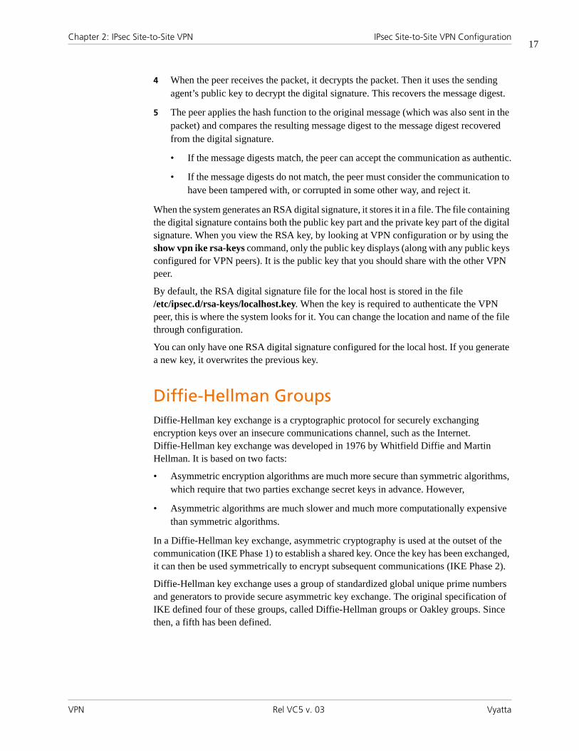
Chapter 2: IPsec Site-to-Site VPN IPsec Site-to-Site VPN Configuration
VPN Rel VC5 v. 03 Vyatta
17
4 When the peer receives the packet, it decrypts the packet. Then it uses the sending agent’s public key to decrypt the digital signature. This recovers the message digest.
5 The peer applies the hash function to the original message (which was also sent in the packet) and compares the resulting message digest to the message digest recovered from the digital signature.
• If the message digests match, the peer can accept the communication as authentic.
• If the message digests do not match, the peer must consider the communication to have been tampered with, or corrupted in some other way, and reject it.
When the system generates an RSA digital signature, it stores it in a file. The file containing the digital signature contains both the public key part and the private key part of the digital signature. When you view the RSA key, by looking at VPN configuration or by using the show vpn ike rsa-keys command, only the public key displays (along with any public keys configured for VPN peers). It is the public key that you should share with the other VPN peer.
By default, the RSA digital signature file for the local host is stored in the file /etc/ipsec.d/rsa-keys/localhost.key. When the key is required to authenticate the VPN peer, this is where the system looks for it. You can change the location and name of the file through configuration.
You can only have one RSA digital signature configured for the local host. If you generate a new key, it overwrites the previous key.
Diffie-Hellman GroupsDiffie-Hellman key exchange is a cryptographic protocol for securely exchanging encryption keys over an insecure communications channel, such as the Internet. Diffie-Hellman key exchange was developed in 1976 by Whitfield Diffie and Martin Hellman. It is based on two facts:
• Asymmetric encryption algorithms are much more secure than symmetric algorithms, which require that two parties exchange secret keys in advance. However,
• Asymmetric algorithms are much slower and much more computationally expensive than symmetric algorithms.
In a Diffie-Hellman key exchange, asymmetric cryptography is used at the outset of the communication (IKE Phase 1) to establish a shared key. Once the key has been exchanged, it can then be used symmetrically to encrypt subsequent communications (IKE Phase 2).
Diffie-Hellman key exchange uses a group of standardized global unique prime numbers and generators to provide secure asymmetric key exchange. The original specification of IKE defined four of these groups, called Diffie-Hellman groups or Oakley groups. Since then, a fifth has been defined.

Chapter 2: IPsec Site-to-Site VPN IPsec Site-to-Site VPN Configuration
VPN Rel VC5 v. 03 Vyatta
18
The Vyatta system supports the following Diffie-Hellman groups:
Main ModeUnder ordinary conditions, establishing the ISAKMP SA requires several packets to be sent and received:
• The first two messages determine communications policy.
• The next two messages exchange Diffie-Hellman public data.
• The last two messages authenticate the Diffie-Hellman exchange.
This is the normal method of establishing a successful Phase 1 connection, and it is called main mode. This method provides the most security and privacy, because authentication information is not exchanged until a full Diffie-Hellman exchange has been negotiated and encryption has been enabled. It also affords the most flexibility, because there are more message exchanges in which to negotiate suitable options. At the same time, main mode is slower because of the exchange of so many computationally expensive messages.
Aggressive ModePhase 1 negotiation can generate a fair bit of latency, and some vendors required a faster mode, in which fewer packets were needed. This mode is called aggressive mode. In aggressive mode, the number of round-trip messages is reduced:
• The first two messages determine a communications policy and exchange Diffie-Hellman public data. The information required for the security association, key exchange, and authentication are all transmitted at once.
• A third message authenticates the responder, and this completes the negotiation.
This means that the hash of the authentication key is exchanged before encryption has been enabled. If these packets were to be captured, they could be used in an attack against the system. Also, because the authentication material is sent in the initial packet, a Denial-of-Service attack can be accomplished just by bombarding it with initial aggressive mode packets.
Table 2-3 Supported Diffie-Hellman groups
Diffie-Hellman Group Description
2 Diffie-Hellman group 2 is a modular exponentiation group (MODP). This group has a 1024-bit modulus.
5 Diffie-Hellman group 5 is a 1536-bit modular exponentiation (MODP) group. This group has a 1536-bit modulus.

Chapter 2: IPsec Site-to-Site VPN IPsec Site-to-Site VPN Configuration
VPN Rel VC5 v. 03 Vyatta
19
In addition, because fewer messages are exchanged, there are fewer opportunities to negotiate options. That is, there can be multiple IKE proposals for Phase 1 negotiation. In in main mode, the VPN peers can “fall through” the proposals until they find one that matches, but in aggressive mode, the first proposal in the policy must match or the connection will fail. This may lead to more failures in aggressive mode to establish mutually acceptable security associations.
NOTE You should avoid using aggressive mode, unless you are working in an
environment known to be secure.
Perfect Forward SecrecyIn Perfect Forward Secrecy (PFS), the private key is used to generate a temporary key (the session key) that is used for a short time and then discarded. Subsequent keys are independent of any previously created keys. This way, if a key is compromised, it does not affect any further keys, or compromise the security of data protected by other keys.
PFS provides a way to optimize both efficiently and security. Reasonably-sized keys are much more computationally efficient than large keys, but are also less secure. In PFS, you can use reasonably-sized keys and refresh them frequently.
Committing VPN Configuration ChangesAn IPsec VPN connection includes multiple components, some of which are interdependent. For example, a VPN connection configuration requires a valid IKE group configuration, a valid ESP group configuration, and a valid tunnel configuration. In addition, the interface specified in the connection must be enabled for IPsec VPN. When you commit a VPN configuration, the Vyatta system performs a full verification on the configuration. If any required component is missing or incorrectly specified, the commit will fail.
For an IPsec VPN site-to-site connection configuration to successfully commit, all the following must be correctly configured:
• The interface and IP address must already be configured.
• The interface must be enabled for IPsec VPN.
• The peer must be configured.
• The IKE group specified in the peer configuration must be defined.
• The tunnel must be configured.
• The ESP group specified in the tunnel must be defined.
• The local IP address specified for the peer must be configured on the VPN-enabled interface.

Chapter 2: IPsec Site-to-Site VPN IPsec Site-to-Site VPN Configuration
VPN Rel VC5 v. 03 Vyatta
20
In addition, please note that modifying global parameters (such as ipsec-interface or nat-traversal) requires an IPsec restart, and therefore restarts all tunnels.
Adding, modifying, or deleting a tunnel restarts only the modified tunnel. Modifying an existing IKE group or ESP group restarts any tunnel using the group. Changing authentication information (pre-shared key or RSA signature) does not result in a tunnel restart.
Configuring a Basic Site-to-Site ConnectionThis section presents the following topics:
• Configure WEST
• Configure EAST
This section presents a sample configuration for a basic IPsec tunnel between Vyatta systems WEST and EAST. First WEST is configured, and then EAST. When you have finished, these peers will be configured as shown in Figure 2-1.
Figure 2-1 Basic site-to-site IPsec VPN connection
Before you begin:
• In this set of examples, we assume that you have two Vyatta systems, with host names configured WEST and EAST. (The example systems are configured with the host name in upper case.) The last set of examples assumes you have a third Vyatta system with host name SOUTH.
• Any Ethernet interface to be used for IPsec VPN must already be configured. In this example, you will need eth1 on WEST and eth0 on EAST, plus internal subnet information.
eth0 eth1 eth1eth0
.5 .1 .31 .63 .33 .8
192.0.2.0/26 192.0.2.32./26
VPN Tunnel
192.168.60.0/24192.168.40.0/24
EASTWEST

Chapter 2: IPsec Site-to-Site VPN IPsec Site-to-Site VPN Configuration
VPN Rel VC5 v. 03 Vyatta
21
Tip: Where public IP addresses would normally be used, the example uses RFC 3330 “TEST-NET” IP addresses (192.0.2.0/24)
• The interface must be configured with the IP address you want to use as the source IP for packets sent to the peer VPN gateway. In this example, IP address 192.0.2.1 is defined on eth1 of WEST, and 192.0.2.33 is defined on eth0 of EAST.
NOTE The sending and receiving of ICMP redirects is disabled when IPsec VPN is
configured.
Configure WESTThis section presents the following topics:
• Enable VPN on WEST
• Configuring an IKE Group on WEST
• Configuring an ESP Group on WEST
• Creating the Connection to EAST
This section presents the following examples:
• Example 2-1 Enabling IPsec VPN on WEST
• Example 2-2 Configuring an IKE group on WEST
• Example 2-3 Configuring an ESP group on Vyatta system WEST
• Example 2-4 Creating a site-to-site connection from WEST to EAST
ENABLE VPN ON WESTIn this section, you enable IPsec VPN on the interfaces that will be used in VPN connections. The VPN tunnel in the example configuration extends from eth1 on WEST through the wide area network to eth0 on EAST. This means that eth1 on WEST must have VPN enabled. The other interfaces on WEST need not.
To create an IPsec connection with another VPN gateway, you must specify the local IP address to be used as the source IP in packets sent to the destination gateway. This IP address:
• Must be one that is defined on a local Ethernet interface, and
• The interface must have IPsec VPN enabled on it
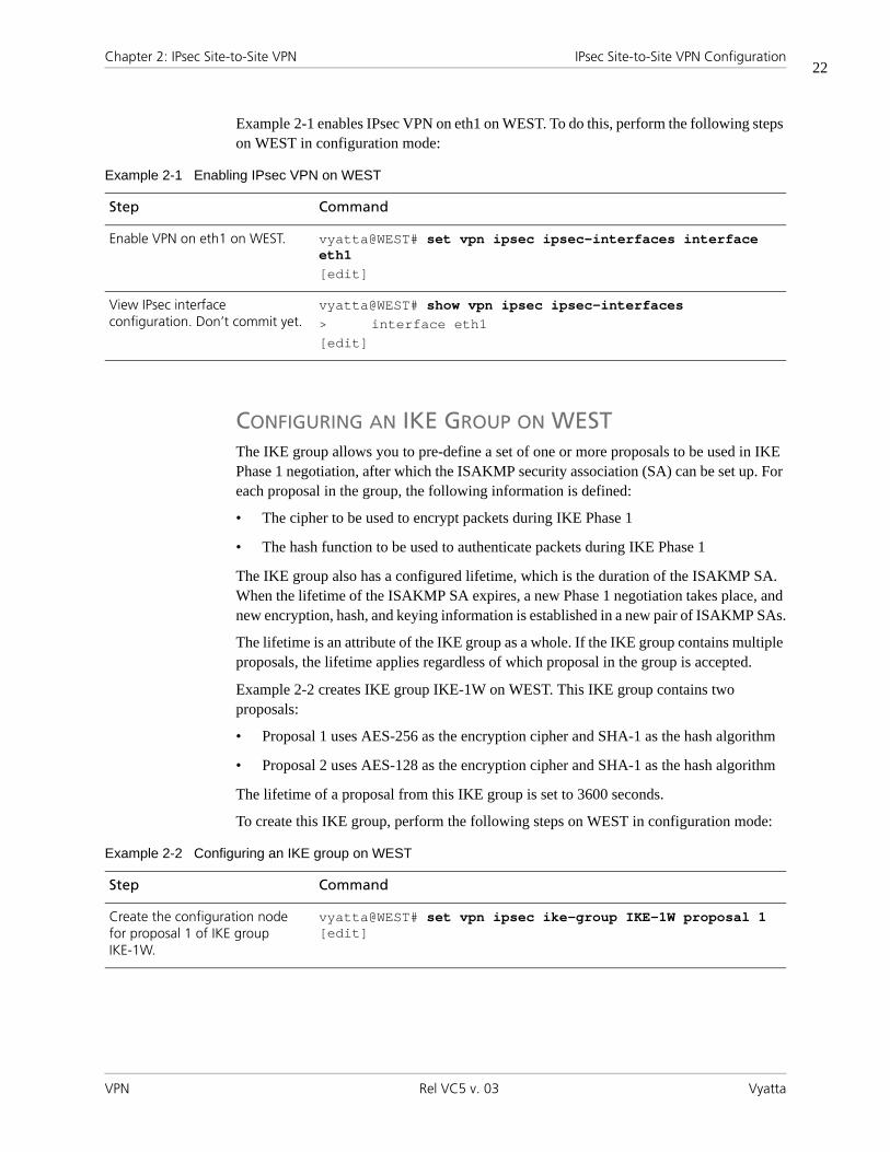
Chapter 2: IPsec Site-to-Site VPN IPsec Site-to-Site VPN Configuration
VPN Rel VC5 v. 03 Vyatta
22
Example 2-1 enables IPsec VPN on eth1 on WEST. To do this, perform the following steps on WEST in configuration mode:
CONFIGURING AN IKE GROUP ON WESTThe IKE group allows you to pre-define a set of one or more proposals to be used in IKE Phase 1 negotiation, after which the ISAKMP security association (SA) can be set up. For each proposal in the group, the following information is defined:
• The cipher to be used to encrypt packets during IKE Phase 1
• The hash function to be used to authenticate packets during IKE Phase 1
The IKE group also has a configured lifetime, which is the duration of the ISAKMP SA. When the lifetime of the ISAKMP SA expires, a new Phase 1 negotiation takes place, and new encryption, hash, and keying information is established in a new pair of ISAKMP SAs.
The lifetime is an attribute of the IKE group as a whole. If the IKE group contains multiple proposals, the lifetime applies regardless of which proposal in the group is accepted.
Example 2-2 creates IKE group IKE-1W on WEST. This IKE group contains two proposals:
• Proposal 1 uses AES-256 as the encryption cipher and SHA-1 as the hash algorithm
• Proposal 2 uses AES-128 as the encryption cipher and SHA-1 as the hash algorithm
The lifetime of a proposal from this IKE group is set to 3600 seconds.
To create this IKE group, perform the following steps on WEST in configuration mode:
Example 2-1 Enabling IPsec VPN on WEST
Step Command
Enable VPN on eth1 on WEST. vyatta@WEST# set vpn ipsec ipsec-interfaces interface eth1[edit]
View IPsec interface configuration. Don’t commit yet.
vyatta@WEST# show vpn ipsec ipsec-interfaces> interface eth1[edit]
Example 2-2 Configuring an IKE group on WEST
Step Command
Create the configuration node for proposal 1 of IKE group IKE-1W.
vyatta@WEST# set vpn ipsec ike-group IKE-1W proposal 1 [edit]

Chapter 2: IPsec Site-to-Site VPN IPsec Site-to-Site VPN Configuration
VPN Rel VC5 v. 03 Vyatta
23
CONFIGURING AN ESP GROUP ON WESTEncapsulated Security Payload (ESP) is an authentication protocol that provides authentication for IP packets, and it also encrypts them.
The ESP protocol negotiates a unique number for the session connection, called the Security Parameter Index (SPI). It also starts a numbering sequence for the packets and negotiates the hashing algorithm that will be used to authenticate packets.
The Vyatta system allows you to pre-define multiple ESP configurations. Each one is known as an “ESP group.” ESP group includes the Phase 2 proposals, which contain the parameters needed to negotiate an IPsec security association:
• The cipher to be used to encrypt user data across the IPsec tunnel
• The hashing function to be used to authenticate packets in the IPsec tunnel
Set the encryption cipher for proposal 1.
vyatta@WEST# set vpn ipsec ike-group IKE-1W proposal 1 encryption aes256[edit]
Set the hash algorithm for proposal 1.
vyatta@WEST# set vpn ipsec ike-group IKE-1W proposal 1 hash sha1[edit]
Set the encryption cipher for proposal 2. This also creates the configuration node for proposal 2 of IKE group IKE-1W.
vyatta@WEST# set vpn ipsec ike-group IKE-1W proposal 2 encryption aes128[edit]
Set the hash algorithm for proposal 2.
vyatta@WEST# set vpn ipsec ike-group IKE-1W proposal 2 hash sha1[edit]
Set the lifetime for the whole IKE group.
vyatta@WEST# set vpn ipsec ike-group IKE-1W lifetime 3600[edit]
View the configuration for the IKE group. Don’t commit yet.
vyatta@WEST# show -all vpn ipsec ike-group IKE-1W> proposal 1 {> encryption aes256> hash sha1> }> proposal 2 {> encryption aes128> hash sha1> }> lifetime 3600
[edit]
Example 2-2 Configuring an IKE group on WEST

Chapter 2: IPsec Site-to-Site VPN IPsec Site-to-Site VPN Configuration
VPN Rel VC5 v. 03 Vyatta
24
• The lifetime of the IPsec security association
Example 2-3 creates ESP group ESP-1W on Vyatta system WEST. This ESP group contains two proposals:
• Proposal 1 uses AES-256 as the encryption cipher and SHA-1 as the hash algorithm
• Proposal 2 uses Triple-DES as the encryption cipher and MD5 as the hash algorithm
The lifetime of a proposal from this ESP group is set to 1800 seconds.
To create this ESP group, perform the following steps on WEST in configuration mode:
Example 2-3 Configuring an ESP group on Vyatta system WEST
Step Command
Create the configuration node for proposal 1 of ESP group ESP-1W.
vyatta@WEST# set vpn ipsec esp-group ESP-1W proposal 1 [edit]
Set the encryption cipher for proposal 1.
vyatta@WEST# set vpn ipsec esp-group ESP-1W proposal 1 encryption aes256[edit]
Set the hash algorithm for proposal 1.
vyatta@WEST# set vpn ipsec esp-group ESP-1W proposal 1 hash sha1[edit]
Set the encryption cipher for proposal 2. This also creates the configuration node for proposal 2 of ESP group ESP-1W.
vyatta@WEST# set vpn ipsec esp-group ESP-1W proposal 2 encryption 3des[edit]
Set the hash algorithm for proposal 2.
vyatta@WEST# set vpn ipsec esp-group ESP-1W proposal 2 hash md5[edit]
Set the lifetime for the whole ESP group.
vyatta@WEST# set vpn ipsec esp-group ESP-1W lifetime 1800[edit]
View the configuration for the ESP group. Don’t commit yet.
vyatta@WEST# show -all vpn ipsec esp-group ESP-1W> proposal 1 {> encryption aes256> hash sha1> }> proposal 2 {> encryption 3des> hash md5> }> lifetime 1800
[edit]

Chapter 2: IPsec Site-to-Site VPN IPsec Site-to-Site VPN Configuration
VPN Rel VC5 v. 03 Vyatta
25
CREATING THE CONNECTION TO EASTIn defining a site-to-site connection, you specify IPsec policy information (most of which is pre-configured as an IKE and ESP group) and the routing information for the two endpoints of the IPsec tunnel.
The local endpoint is the Vyatta system. The remote endpoint is the peer VPN gateway—this can be another Vyatta system, or it can be another IPsec-compliant router, an IPsec-capable firewall, or a VPN concentrator. For each end of the tunnel, you define the IP address and subnet mask of the local and remote subnets or hosts.
In all, you must specify:
• The IP address of the remote peer.
• The authentication mode that the peers will use to authenticate one another. Currently, the Vyatta system supports peer authentication by pre-shared secret (pre-shared key, or PSK), so you must also supply the string that will be used to generate the hashed key.
• The IKE group to be used in the connection.
• The ESP group to be used in the connection.
• The IP address on this Vyatta system to use for the tunnel. This IP address must be pre-configured on the interface enabled for VPN.
• The communicating subnet or host for each end of the tunnel. You can define multiple tunnels for each VPN peer, and each tunnel can use a different security policy.
When supplying a preshared secret, keep the following in mind:
A pre-shared secret, or pre-shared key (PSK), is a method of authentication. The secret, or key, is a string agreed upon beforehand by both parties as key for authenticating the session. It is used to generate a hash such that each VPN endpoint can authenticate the other.
Note that the pre-shared secret, although an ordinary string, is not a “password.” It is actually used to generate a hashed key to form a “fingerprint” proving the identity of each endpoint. This means that long complex strings are more secure than short strings. Choose complex pre-shared secrets and avoid short ones, which can be more easily compromised by an attack.
The preshared secret is not passed during IKE negotiation. It is configured on both sides, and must match on both sides.
A pre-shared secret is an example of symmetric cryptography: the key is the same on both sides. Symmetric encryption algorithms are less computationally intensive than asymmetric algorithms, and are therefore faster. However, in symmetric cryptography, the two communicating parties must exchange keys in advance. Doing this securely can be a problem.
Pre-shared secret and digital signatures are the most common methods of IKE authentication. Pre-shared secret is an easy and effective way to quickly set up authentication with little administrative overhead. However, it has several drawbacks.

Chapter 2: IPsec Site-to-Site VPN IPsec Site-to-Site VPN Configuration
VPN Rel VC5 v. 03 Vyatta
26
• If a pre-shared key is captured and no one is aware of it, the attacker has access to your network as long as that key is in use.
• Pre-shared secrets are manually configured, so they should be regularly changed. However, this task is often falls off the list of busy network administrators. Using pre-shared key values with remote users is equivalent to giviing them a password to your network.
NOTE You should restrict the use of pre-shared keys to smaller, low-risk environments.
Example 2-4 defines a site-to-site connection to EAST.
• This connection is configured with a single tunnel:
— Tunnel 1 communicates between 192.168.40.0/24 on WEST and 192.168.60.0/24 on EAST, using ESP group ESP-1W.
• WEST uses IP address 192.0.2.1 on eth1.
• EAST uses IP address 192.0.2.33 on eth0.
• The IKE group is IKE-1W
• The authentication mode is pre-shared secret. The pre-shared secret is “test_key_1”.
To configure this connection, perform the following steps on Vyatta system WEST in configuration mode:
Example 2-4 Creating a site-to-site connection from WEST to EAST
Step Command
Create the node for EAST and set the authentication mode.
vyatta@WEST# set vpn ipsec site-to-site peer 192.0.2.33 authentication mode pre-shared-secret[edit]
Navigate to the node for the peer for easier editing.
vyatta@WEST# edit vpn ipsec site-to-site peer 192.0.2.33[edit vpn/ipsec/site-to-site/peer/192.0.2.33]
Provide the string that will be used to generate encryption keys.
vyatta@WEST# set authentication pre-shared-secret test_key_1[edit vpn/ipsec/site-to-site/peer/192.0.2.33]
Specify the IKE group. vyatta@WEST# set ike-group IKE-1W[edit vpn/ipsec/site-to-site/peer/192.0.2.33]
Identify the IP address on this Vyatta system to be used for this connection.
vyatta@WEST# set local-ip 192.0.2.1[edit vpn/ipsec/site-to-site/peer/192.0.2.33]
Create a tunnel configuration, and provide the local subnet for this tunnel.
vyatta@WEST# set tunnel 1 local-subnet 192.168.40.0/24[edit vpn/ipsec/site-to-site/peer/192.0.2.33]

Chapter 2: IPsec Site-to-Site VPN IPsec Site-to-Site VPN Configuration
VPN Rel VC5 v. 03 Vyatta
27
Configure EASTThis section presents the following topics:
• Enabling VPN on EAST
• Configuring an IKE Group on EAST
• Configuring an ESP Group on EAST
• Creating the Connection to WEST
This section presents the following examples:
• Example 2-5 Enabling IPsec VPN on EAST
• Example 2-6 Configuring an IKE group on EAST
• Example 2-7 Configuring an ESP group on EAST
• Example 2-8 Creating a site-to-site connection from EAST to WEST
Provide the remote subnet for the tunnel.
vyatta@WEST# set tunnel 1 remote-subnet 192.168.60.0/24[edit vpn/ipsec/site-to-site/peer/192.0.2.33]
Specify the ESP group for this tunnel.
vyatta@WEST# set tunnel 1 esp-group ESP-1W[edit vpn/ipsec/site-to-site/peer/192.0.2.33]
Return to the top of the configuration tree.
vyatta@WEST# top[edit]
Now commit the configuration. vyatta@WEST# commit[edit]
View the configuration for the site-to-site connection.
vyatta@WEST# show -all vpn ipsec site-to-site peer 192.0.2.33
authenticationmode pre-shared-secretpre-shared-secret test_key_1
}ike-group IKE-1Wlocal-ip 192.0.2.1tunnel 1 {
local-subnet 192.168.40.0/24remote-subnet 192.168.60.0/24esp-group ESP-1W
}
[edit]
Example 2-4 Creating a site-to-site connection from WEST to EAST

Chapter 2: IPsec Site-to-Site VPN IPsec Site-to-Site VPN Configuration
VPN Rel VC5 v. 03 Vyatta
28
ENABLING VPN ON EASTIn this section, you enable IPsec VPN on the interfaces that will be used in VPN connections on Vyatta system EAST. The VPN tunnel in the example configuration extends from eth1 on WEST through the wide area network to eth0 on EAST. This means that eth0 on EAST must have VPN enabled. The other interfaces on EAST need not.
Example 2-5 enables IPsec VPN on eth0 on EAST. To do this, perform the following steps on EAST in configuration mode:
CONFIGURING AN IKE GROUP ON EASTExample 2-6 creates IKE group IKE-1E on EAST. This IKE group contains two proposals:
• Proposal 1 uses AES-256 as the encryption cipher and SHA-1 as the hash algorithm
• Proposal 2 uses AES-128 as the encryption cipher and SHA-1 as the hash algorithm
The lifetime of a proposal from this IKE group is set to 3600.
Note that these parameters correspond to those set in IKE-1W on WEST. You must ensure, in defining proposals, that the encryption ciphers and hash algorithms are such that the two peers will be able to agree on at least one combination.
To create this IKE group, perform the following steps on EAST in configuration mode:
Example 2-5 Enabling IPsec VPN on EAST
Step Command
Enable VPN on eth0 on EAST. vyatta@EAST# set vpn ipsec ipsec-interfaces interface eth0[edit]
View IPsec interface configuration. Don’t commit yet.
vyatta@EAST# show vpn ipsec ipsec-interfaces> interface eth0[edit]
Example 2-6 Configuring an IKE group on EAST
Step Command
Create the configuration node for proposal 1 of IKE group IKE-1E.
vyatta@EAST# set vpn ipsec ike-group IKE-1E proposal 1 [edit]
Set the encryption cipher for proposal 1.
vyatta@EAST# set vpn ipsec ike-group IKE-1E proposal 1 encryption aes256[edit]

Chapter 2: IPsec Site-to-Site VPN IPsec Site-to-Site VPN Configuration
VPN Rel VC5 v. 03 Vyatta
29
CONFIGURING AN ESP GROUP ON EASTExample 2-7 creates ESP group ESP-1E on EAST. This ESP group contains two proposals:
• Proposal 1 uses AES-256 as the encryption cipher and SHA-1 as the hash algorithm
• Proposal 2 uses Triple-DES as the encryption cipher and MD5 as the hash algorithm
The lifetime of a proposal from this ESP group is set to 1800 seconds.
To create this ESP group, perform the following steps on EAST in configuration mode:
Set the hash algorithm for proposal 1.
vyatta@EAST# set vpn ipsec ike-group IKE-1E proposal 1 hash sha1[edit]
Set the encryption cipher for proposal 2. This also creates the configuration node for proposal 2 of IKE group IKE-1E.
vyatta@EAST# set vpn ipsec ike-group IKE-1E proposal 2 encryption aes128[edit]
Set the hash algorithm for proposal 2.
vyatta@EAST# set vpn ipsec ike-group IKE-1E proposal 2 hash sha1[edit]
Set the lifetime for the whole IKE group.
vyatta@EAST# set vpn ipsec ike-group IKE-1E lifetime 3600[edit]
View the configuration for the IKE group. Don’t commit yet.
vyatta@EAST# show -all vpn ipsec ike-group IKE-1E> proposal 1 {> encryption aes256> hash sha1> }> proposal 2 {> encryption aes128> hash sha1> }> lifetime 3600
[edit]
Example 2-6 Configuring an IKE group on EAST
Example 2-7 Configuring an ESP group on EAST
Step Command
Create the configuration node for proposal 1 of ESP group ESP-1E.
vyatta@EAST# set vpn ipsec esp-group ESP-1E proposal 1 [edit]

Chapter 2: IPsec Site-to-Site VPN IPsec Site-to-Site VPN Configuration
VPN Rel VC5 v. 03 Vyatta
30
CREATING THE CONNECTION TO WESTExample 2-8 defines a site-to-site connection to WEST. In this example:
• This connection is configured with a single tunnel:
— Tunnel 1 communicates between 192.168.60.0/24 on EAST and 192.168.40.0/24 on WEST, using ESP group ESP-1E.
• EAST uses IP address 192.0.2.33 on eth0.
• WEST uses IP address 192.0.2.1 on eth1.
• The IKE group is IKE-1E.
• The authentication mode is pre-shared secret. The pre-shared secret is “test_key_1”.
Set the encryption cipher for proposal 1.
vyatta@EAST# set vpn ipsec esp-group ESP-1E proposal 1 encryption aes256[edit]
Set the hash algorithm for proposal 1.
vyatta@EAST# set vpn ipsec esp-group ESP-1E proposal 1 hash sha1[edit]
Set the encryption cipher for proposal 2. This also creates the configuration node for proposal 2 of ESP group ESP-1E.
vyatta@EAST# set vpn ipsec esp-group ESP-1E proposal 2 encryption 3des[edit]
Set the hash algorithm for proposal 2.
vyatta@EAST# set vpn ipsec esp-group ESP-1E proposal 2 hash md5[edit]
Set the lifetime for the whole ESP group.
vyatta@EAST# set vpn ipsec esp-group ESP-1E lifetime 1800[edit]
View the configuration for the ESP group. Don’t commit yet.
vyatta@EAST# show -all vpn ipsec esp-group ESP-1E> proposal 1 {> encryption aes256> hash sha1> }> proposal 2 {> encryption 3des> hash md5> }> lifetime 1800
[edit]
Example 2-7 Configuring an ESP group on EAST

Chapter 2: IPsec Site-to-Site VPN IPsec Site-to-Site VPN Configuration
VPN Rel VC5 v. 03 Vyatta
31
To configure this connection, perform the following steps on EAST in configuration mode:
Example 2-8 Creating a site-to-site connection from EAST to WEST
Step Command
Create the node for WEST and set the authentication mode
vyatta@EAST# set vpn ipsec site-to-site peer 192.0.2.1 authentication mode pre-shared-secret[edit]
Navigate to the node for the peer for easier editing
vyatta@EAST# edit vpn ipsec site-to-site peer 192.0.2.1[edit vpn/ipsec/site-to-site/peer/172.3.3.5]
Provide the string that will be used to generate encryption keys.
vyatta@EAST# set authentication pre-shared-secret test_key_1[edit vpn/ipsec/site-to-site/peer/192.0.2.1]
Specify the IKE group. vyatta@EAST# set ike-group IKE-1E[edit vpn/ipsec/site-to-site/peer/192.0.2.1]
Identify the IP address on this Vyatta system to be used for this connection.
vyatta@EAST# set local-ip 192.0.2.33[edit vpn/ipsec/site-to-site/peer/192.0.2.1]
Create a tunnel configuration, and provide the local subnet for this tunnel.
vyatta@EAST# set tunnel 1 local-subnet 192.168.60.0/24[edit vpn/ipsec/site-to-site/peer/192.0.2.1]
Provide the remote subnet for the tunnel.
vyatta@EAST# set tunnel 1 remote-subnet 192.168.40.0/24[edit vpn/ipsec/site-to-site/peer/192.0.2.1]
Specify the ESP group for this tunnel.
vyatta@EAST# set tunnel 1 esp-group ESP-1E[edit vpn/ipsec/site-to-site/peer/192.0.2.1]
Return to the top of the configuration tree.
vyatta@EAST# top[edit]
Now commit the configuration. vyatta@EAST# commit[edit]

Chapter 2: IPsec Site-to-Site VPN IPsec Site-to-Site VPN Configuration
VPN Rel VC5 v. 03 Vyatta
32
Authenticating with RSA Digital SignaturesThis section presents the following topics:
• Generate a Digital Signature on WEST
• Generate a Digital Signature on EAST
• Record EAST’s Public Key on WEST
• Modify WEST’s Connection to EAST
• Record WEST’s Public Key on EAST
• Modify EAST’s Connection to WEST
In this set of examples, you modify the VPN connection configured in the previous set of examples between WEST and EAST (“Configuring a Basic Site-to-Site Connection” on page 20). The site-to-site connection created in that set of examples used pre-shared keys for authentication. This set of examples modifies the connection to use RSA digital signatures for authentication.
Generate a Digital Signature on WESTIn this example, you generate WEST’s digital signature. This signature will have two parts: a public part (the public key) and a private part (the private key). The public key will be shared with EAST; the private key will remain secret.
View the configuration for the site-to-site connection.
vyatta@EAST# show -all vpn ipsec site-to-site peer 192.0.2.1
authenticationmode pre-shared-secretpre-shared-secret test_key_1
}ike-group IKE-1Elocal-ip 192.0.2.33tunnel 1 {
local-subnet 192.168.60.0/24remote-subnet 192.168.40.0/24esp-group ESP-1E
}
[edit]
Example 2-8 Creating a site-to-site connection from EAST to WEST

Chapter 2: IPsec Site-to-Site VPN IPsec Site-to-Site VPN Configuration
VPN Rel VC5 v. 03 Vyatta
33
To generate an RSA digital signature for system WEST, perform the following steps in operational mode.
Generate a Digital Signature on EASTIn this example, you generate EAST’s digital signature. This signature will have two parts: a public part (the public key) and a private part (the private key). The public key will be shared with WEST; the private key will remain secret.
To generate an RSA digital signature for system EAST, perform the following steps in operational mode.
Example 2-9 Generating a digital signature on WEST
Step Command
Generate the key. vyatta@WEST> vpn rsa-key generate
The system warns you that the existing RSA key file will be overwritten. You have the opportunity to exit the key generation process by pressing <Ctrl>+c.
A local RSA key file already exists and will be overwritten<CTRL>C to exit: 8
The system indicates the location of the file where the key will be written.
Generating rsa-key to /etc/ipsec.d/rsa-keys/localhost.key
The system displays the public portion of the generated key.By default, this key (including the private portion of the key) is stored in /etc/ipsec.d/rsa-keys/localhost.key
Your new local RSA key has been generatedThe public portion of the key is:
0sAQPEOQvukvkv1ofuO8gEKp7IFFZz4lQqMZyVMInoQKUU/T0iKSK/0NSH9Ldrr8yQUFayzKag6wM7ASXWXKyt0LS1Gn8tJVsjKGaOkFgLREtVJD3pRzoc7DSUOBViCD6f/TloTkPepRUtW1bmYev2H7tajSO0K0 rqu+7nlocZI0ppMAyF6CS+Wd5W1JBpVGL+EkKfyEl9RagKxRW82XJbgY4LG77K2YDN90Wd2GgMY3kf+YJLIzFEt/xRbh2/380FMpdaUYcbY31o/5PedUutJCK5RMwl+IJGaxrKf1OmCQfzXlkM09ijZx8kzPIlBk 5hulZrbUWjzBJdFcwFAyPM3yCuv3+ndFX00t3ZLfKu+/wX595J
vyatta@WEST>
Example 2-10 Generating a digital signature on EAST
Step Command
Generate the key. vyatta@EAST> vpn rsa-key generate

Chapter 2: IPsec Site-to-Site VPN IPsec Site-to-Site VPN Configuration
VPN Rel VC5 v. 03 Vyatta
34
Record EAST’s Public Key on WESTIn this example, you record the public key you have obtained from EAST. The key is then saved under a name that you can refer to in site-to-site configuration.
A digital signature can be typed in manually, but digital signatures are lengthy and difficult to type. It is generally easier to copy the digital signature into the clipboard of your system and then paste it into the configuration. You do this in a number of ways; for example:
• Receive the public key from the operator of the VPN peer in an e-mail—perhaps an e-mail protected by a PGP signature. Copy the key text into your clipboard.
• From an X.509 certificate, provided by a Certificate Agency.
• Connect to the VPN peer directly through a Telnet or SSH control session. View view the public portion of the key using a show command, select the text, and copy the key text into your clipboard.
Example 2-11 pastes EAST’s public key into RSA configuration. The name “EAST-key” is used as the identifier of the key.
Before you begin, copy EAST’s public key into your clipboard.
The system warns you that the existing RSA key file will be overwritten. You have the opportunity to exit the key generation process by pressing <Ctrl>+c.
A local RSA key file already exists and will be overwritten<CTRL>C to exit: 5
The system indicates the location of the file where the key will be written.
Generating rsa-key to /etc/ipsec.d/rsa-keys/localhost.key
The system displays the public portion of the generated key.By default, this key (including the private portion of the key) is stored in /etc/ipsec.d/rsa-keys/localhost.key
Your new local RSA key has been generatedThe public portion of the key is:
0sAQOVBIJL+rIkpTuwh8FPeceAF0bhgLr++W51bOAIjFbRDbR8gX3Vlz6wiUbMgGwQxWlYQiqsCeacicsfZx/amlEn9PkSE4e7tqK/JQo40L5C7gcNM24mup1d+0WmN3zLb9Qhmq5q3pNJxEwnVbPPQeIdZMJxnb1+lA8DPC3SIxJM/3at1/KrwqCAhX3QNFY/zNmOtFogELCeyl4+d54wQljA+3dwFAQ4bboJ7YIDs+rqORxWd3l3I7IajT/pLrwr5eZ8OA9NtAedbMiCwxyuyUbznxXZ8Z/MAi3xjL1pjYyWjNNiOij82QJfMOrjoXVCfcPn96ZN+Jqk+KknoVeNDwzpoahFOseJREeXzkw3/lkMN9N1
vyatta@EAST>
Example 2-10 Generating a digital signature on EAST

Chapter 2: IPsec Site-to-Site VPN IPsec Site-to-Site VPN Configuration
VPN Rel VC5 v. 03 Vyatta
35
If you are in operational mode on WEST, enter configuration mode now and perform the following steps:
Modify WEST’s Connection to EASTExample 2-12 modifies the connection from WEST to EAST to use RSA digital signatures for authentication. In this example:
• The authentication mode is changed from pre-shared secret to RSA digital signatures.
• EAST’s public key is specified as the remote key, under the identifier configured in the previous step (see “Record EAST’s Public Key on WEST” on page 34).
Example 2-11 Record EAST’s public key on WEST
Step Command
Specify a name for EAST’s public key and paste EAST’s public key into the configuration.
vyatta@WEST# set vpn rsa-keys rsa-key-name EAST-key rsa-key 0sAQOVBIJL+rIkpTuwh8FPeceAF0bhgLr++W51bOAIjFbRDbR8gX3Vlz6wiUbMgGwQxWlYQiqsCeacicsfZx/amlEn9PkSE4e7tqK/JQo40L5C7gcNM24mup1d+0WmN3zLb9Qhmq5q3pNJxEwnVbPPQeIdZMJxnb1+lA8DPC3SIxJM/3at1/KrwqCAhX3QNFY/zNmOtFogELCeyl4+d54wQljA+3dwFAQ4bboJ7YIDs+rqORxWd3l3I7IajT/pLrwr5eZ8OA9NtAedbMiCwxyuyUbznxXZ8Z/MAi3xjL1pjYyWjNNiOij82QJfMOrjoXVCfcPn96ZN+Jqk+KknoVeNDwzpoahFOseJREeXzkw3/lkMN9N1[edit]
Commit the configuration. vyatta@WEST# commit[edit]
View the configuration for RSA keys.Since you have not changed the configuration for the local host’s key, it does not display.
vyatta@WEST# show vpn rsa-keys
rsa-key-name EAST-key { rsa-key 0sAQOVBIJL+rIkpTuwh8FPeceAF0bhgLr++W51bOAIjFbRDbR8gX3Vlz6wiUbMgGwQxWlYQiqsCeacicsfZx/amlEn9PkSE4e7tqK/JQo40L5C7gcNM24mup1d+0WmN3zLb9Qhmq5q3pNJxEwnVbPPQeIdZMJxnb1+lA8DPC3SIxJM/3at1/KrwqCAhX3QNFY/zNmOtFogELCeyl4+d54wQljA+3dwFAQ4bboJ7YIDs+rqORxWd3l3I7IajT/pLrwr5eZ8OA9NtAedbMiCwxyuyUbznxXZ8Z/MAi3xjL1pjYyWjNNiOij82QJfMOrjoXVCfcPn96ZN+Jqk+KknoVeNDwzpoahFOseJREeXzkw3/lkMN9N1 }
[edit]vyatta@WEST#

Chapter 2: IPsec Site-to-Site VPN IPsec Site-to-Site VPN Configuration
VPN Rel VC5 v. 03 Vyatta
36
To modify the site-to-site connection to use RSA configuration, perform the following steps:
Example 2-12 Configure WEST for RSA authentication
Step Command
Change the authentication mode vyatta@WEST# set vpn ipsec site-to-site peer 192.0.2.33 authentication mode rsa[edit]
Provide the identifier for EAST’s digital signature.
vyatta@WEST# set vpn ipsec site-to-site peer 192.0.2.33 authentication rsa-key-name EAST-key
Commit the configuration. vyatta@WEST# commit[edit]
View the modified configuration for the site-to-site connection.
vyatta@EAST# show -all vpn ipsec site-to-site peer 192.0.2.33[edit]
authenticationmode rsapre-shared-secret test_key_1rsa-key-name EAST-key
}ike-group IKE-1Wlocal-ip 192.0.2.1tunnel 1 {
local-subnet 192.168.40.0/24remote-subnet 192.168.40.0/24esp-group ESP-1W
}
[edit]

Chapter 2: IPsec Site-to-Site VPN IPsec Site-to-Site VPN Configuration
VPN Rel VC5 v. 03 Vyatta
37
Record WEST’s Public Key on EASTExample 2-13 pastes WEST’s public key into RSA configuration. The name “WEST-key” is used as the identifier of the key.
Before you begin, copy WEST’s public key into your clipboard.
If you are in operational mode on EAST, enter configuration mode now and perform the following steps:
Example 2-13 Record WEST’s public key on EAST
Step Command
Specify a name for WEST’s public key and paste WEST’s public key into the configuration.
vyatta@EAST# set vpn rsa-keys rsa-key-name WEST-key rsa-key 0sAQPEOQvukvkv1ofuO8gEKp7IFFZz4lQqMZyVMInoQKUU/T0iKSK/0NSH9Ldrr8yQUFayzKag6wM7ASXWXKyt0LS1Gn8tJVsjKGaOkFgLREtVJD3pRzoc7DSUOBViCD6f/TloTkPepRUtW1bmYev2H7tajSO0K0 rqu+7nlocZI0ppMAyF6CS+Wd5W1JBpVGL+EkKfyEl9RagKxRW82XJbgY4LG77K2YDN90Wd2GgMY3kf+YJLIzFEt/xRbh2/380FMpdaUYcbY31o/5PedUutJCK5RMwl+IJGaxrKf1OmCQfzXlkM09ijZx8kzPIlBk 5hulZrbUWjzBJdFcwFAyPM3yCuv3+ndFX00t3ZLfKu+/wX595J[edit]
Commit the configuration. vyatta@EAST# commit[edit]
View the configuration for RSA keys.Since you have not changed the configuration for the local host’s key, it does not display.
vyatta@EAST# show vvpn rsa-keys
rsa-key-name WEST-key { rsa-key 0sAQPEOQvukvkv1ofuO8gEKp7IFFZz4lQqMZyVMInoQKUU/T0iKSK/0NSH9Ldrr8yQUFayzKag6wM7ASXWXKyt0LS1Gn8tJVsjKGaOkFgLREtVJD3pRzoc7DSUOBViCD6f/TloTkPepRUtW1bmYev2H7tajSO0K0 rqu+7nlocZI0ppMAyF6CS+Wd5W1JBpVGL+EkKfyEl9RagKxRW82XJbgY4LG77K2YDN90Wd2GgMY3kf+YJLIzFEt/xRbh2/380FMpdaUYcbY31o/5PedUutJCK5RMwl+IJGaxrKf1OmCQfzXlkM09ijZx8kzPIlBk 5hulZrbUWjzBJdFcwFAyPM3yCuv3+ndFX00t3ZLfKu+/wX595J }
[edit]vyatta@EAST#

Chapter 2: IPsec Site-to-Site VPN IPsec Site-to-Site VPN Configuration
VPN Rel VC5 v. 03 Vyatta
38
Modify EAST’s Connection to WESTExample 2-12 modifies the connection from EAST to WEST to use RSA digital signatures for authentication.
In this example:
• The authentication mode is changed from pre-shared secret to RSA digital signatures.
• WEST’s public key is specified as the remote key, under the identifier configured in the previous step (see “Record WEST’s Public Key on EAST” on page 37).
To modify the site-to-site connection to use RSA configuration, perform the following steps:
Example 2-14 Configure EAST for RSA authentication
Step Command
Change the authentication mode vyatta@EAST# set vpn ipsec site-to-site peer 192.0.2.1 authentication mode rsa[edit]
Provide the identifier for WEST’s digital signature.
vyatta@EAST# set vpn ipsec site-to-site peer 192.0.2.1 authentication rsa-key-name WEST-key
Commit the configuration. vyatta@EAST# commit[edit]
View the modified configuration for the site-to-site connection.
vyatta@EAST# show -all vpn ipsec site-to-site peer 192.0.2.1[edit]
authenticationmode rsapre-shared-secret test_key_1rsa-key WEST-key
}ike-group IKE-1Elocal-ip 192.0.2.33tunnel 1 {
local-subnet 192.168.60.0/24remote-subnet 192.168.40.0/24esp-group ESP-1E
}
[edit]

Chapter 2: IPsec Site-to-Site VPN IPsec Site-to-Site VPN Configuration
VPN Rel VC5 v. 03 Vyatta
39
Defining a VPN Connection with NATThis section presents the following topics:
• Configure WEST
• Configure EAST
Native IPsec packets are encapsulated using Encapsulated Security Payload (ESP). In these packets, the IP addresses are embedded within the encapsulated packet. This causes problems when IPsec packets must traverse a NAT gateway.
When performing Network Address Translation (NAT), the NAT gateway substitutes its own source IP address (and sometimes a port number), for the original source IP and port on outgoing packets. The NAT device listens for a reply, and when a response packet is received, the NAT device reverses the translation so that the incoming packet can arrive at the correct destination. This allows IP addresses within a private network to be “hidden” from external networks.
NAT does not work well with IPsec, because the IP addresses are embedded within the payload of the encapsulated packet. For a number of reasons, this means that the IPsec peer cannot be located behind the NAT device.
The IPsec NAT Traversal protocol (NAT-T, RFCs 3947 and 3948) allows each IPsec packet to be re-encapsulated within a UDP packet, which can be handled correctly by the NAT device. NAT-T runs on top of IPsec. To support NAT-T, the firewall must be set to allow all of the following:
• IKE through UDP port 500
• IPsec NAT-T through UDP port 4500
• ESP
Some gateway devices pre-allow all of these in a feature called “IPsec Passthrough.” However, IPsec Passthrough is incompatible with NAT traversal. IPsec Passthrough devices recognize the IPsec-in-UDP packets and incorrectly attempt passthrough-type operations on the packets. This corrupts the packets in such a way that NAT-T no longer works.
NOTE If you enable NAT traversal support, make sure you DISABLE IPsec Passthrough on
the NAT device.
This section presents a sample configuration for a NATted connection between WEST and EAST. In this example:
• EAST resides behind a NAT device, and therefore has a dynamic IP address from WEST’s point of view.
• WEST retains its fixed IP address.
This configuration is similar to something you might see for an IPsec endpoint that is behind a DSL connection, where the DSL peer’s public IP address is dynamic and the DSL peer is performing NAT.

Chapter 2: IPsec Site-to-Site VPN IPsec Site-to-Site VPN Configuration
VPN Rel VC5 v. 03 Vyatta
40
When you have finished, these systems will be configured as shown in Figure 2-2.
Figure 2-2 IPsec VPN connection with dynamic IP address and NAT
Before you begin:
• This example assumes that you have already configured a basic site-to-site connection using a preshared key between WEST and EAST, as explained in the section “Configuring a Basic Site-to-Site Connection,” which begins on page 157. Only the relevant changes to that configuration are presented here.
Configure WEST To allow for EAST’s dynamic IP address, WEST must create a new site-to-site connection to a peer that has a dynamic IP address.
Example 2-15 defines a new site-to-site connection to EAST.
• The important change is the IP address of the peer. This is set to 0.0.0.0 to represent “any” IP address.
• All other information is set to be the same as the connection created for the basic site-to-site tunnel.
To configure this connection, perform the following steps on WEST in configuration mode:
eth0 eth1 eth1eth0
.5 .1 .31 .63 dynamic .8
192.0.2.0/26 192.0.32./26
VPN Tunnel
192.168.60.0/24192.168.40.0/24
EASTWEST
NAT
Example 2-15 Creating a site-to-site connection to a peer with a dynamic IP address
Step Command
Create the node for EAST, setting the IP address to “any”, and set the authentication mode.
vyatta@WEST# set vpn ipsec site-to-site peer 0.0.0.0 authentication authentication mode pre-shared-secret[edit]
Navigate to the node for the peer for easier editing.
vyatta@WEST# edit vpn ipsec site-to-site peer 0.0.0.0[edit vpn/ipsec/site-to-site/peer/0.0.0.0]
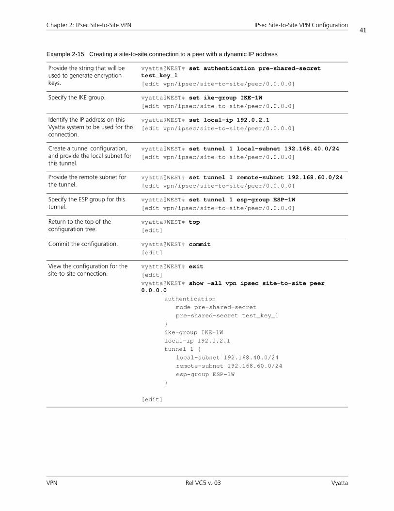
Chapter 2: IPsec Site-to-Site VPN IPsec Site-to-Site VPN Configuration
VPN Rel VC5 v. 03 Vyatta
41
Provide the string that will be used to generate encryption keys.
vyatta@WEST# set authentication pre-shared-secret test_key_1[edit vpn/ipsec/site-to-site/peer/0.0.0.0]
Specify the IKE group. vyatta@WEST# set ike-group IKE-1W[edit vpn/ipsec/site-to-site/peer/0.0.0.0]
Identify the IP address on this Vyatta system to be used for this connection.
vyatta@WEST# set local-ip 192.0.2.1[edit vpn/ipsec/site-to-site/peer/0.0.0.0]
Create a tunnel configuration, and provide the local subnet for this tunnel.
vyatta@WEST# set tunnel 1 local-subnet 192.168.40.0/24[edit vpn/ipsec/site-to-site/peer/0.0.0.0]
Provide the remote subnet for the tunnel.
vyatta@WEST# set tunnel 1 remote-subnet 192.168.60.0/24[edit vpn/ipsec/site-to-site/peer/0.0.0.0]
Specify the ESP group for this tunnel.
vyatta@WEST# set tunnel 1 esp-group ESP-1W[edit vpn/ipsec/site-to-site/peer/0.0.0.0]
Return to the top of the configuration tree.
vyatta@WEST# top[edit]
Commit the configuration. vyatta@WEST# commit[edit]
View the configuration for the site-to-site connection.
vyatta@WEST# exit[edit]vyatta@WEST# show -all vpn ipsec site-to-site peer 0.0.0.0
authenticationmode pre-shared-secretpre-shared-secret test_key_1
}ike-group IKE-1Wlocal-ip 192.0.2.1tunnel 1 {
local-subnet 192.168.40.0/24remote-subnet 192.168.60.0/24esp-group ESP-1W
}
[edit]
Example 2-15 Creating a site-to-site connection to a peer with a dynamic IP address

Chapter 2: IPsec Site-to-Site VPN IPsec Site-to-Site VPN Configuration
VPN Rel VC5 v. 03 Vyatta
42
Configure EASTThe connection from EAST to WEST does not have to be changed in any way from that configured in the section “Configuring a Basic Site-to-Site Connection” on page 20.
• The NAT device keeps track of EAST’s fixed IP and correctly routes incoming packets to EAST, making any necessary changes to outgoing packets
• WEST retains its fixed IP, so no modification is required to the remote peer IP address.
Configuring IPsec Tunnels between Three GatewaysThis section presents the following topics:
• Configure WEST
• Configure EAST
• Configure SOUTH
This section presents a sample configuration for multiple site-to-site tunnels between three gateways: WEST, EAST, and SOUTH. When you have finished, these peers will be configured as shown in Figure 2-2.
Figure 2-3 Multiple site-to-site tunnels between three gateways
eth0 eth1 eth1eth0
.1 .31 .63 .33
192.0.2.0/26 192.0.2.32./26
VPN Tunnel
192.168.60.0/24192.168.40.0/24
EASTWEST
eth1
eth0
192.168.80.0/24192.168.81.0/24
SOUTH
192.0.2.64./26
.65
VPN Tunnel

Chapter 2: IPsec Site-to-Site VPN IPsec Site-to-Site VPN Configuration
VPN Rel VC5 v. 03 Vyatta
43
Configure WESTThis section presents the following topics:
• Configuring the Second ESP Group on WEST
• Adding Tunnels to the Connection to EAST
• Creating the Connection to SOUTH
This example assumes that WEST has already been configured for a basic connection to EAST, as described in “Configuring a Basic Site-to-Site Connection” on page 157. The additional configuration for WEST for this scenario consists of the following:
• An additional ESP group
• Three new tunnel configurations for the site-to-site connection to EAST
• A new site-to-site connection to SOUTH
This section presents the following examples:
• Example 2-16 Configuring a second ESP group on WEST
• Example 2-17 Adding tunnels to the connection to EAST
• Example 2-18 Creating a site-to-site connection from WEST to SOUTH
CONFIGURING THE SECOND ESP GROUP ON WESTExample 2-16 creates a second ESP group ESP-2W on WEST. This ESP group contains just one proposal:
• Proposal 1 uses AES-256 as the encryption cipher and SHA-1 as the hash algorithm
• The lifetime of a proposal from this ESP group is set to 600 seconds.
To create this ESP group, perform the following steps on WEST in configuration mode:
Example 2-16 Configuring a second ESP group on WEST
Step Command
Create the configuration node for proposal 1 of ESP group ESP-2W.
vyatta@WEST# set vpn ipsec esp-group ESP-2W proposal 1[edit]
Set the encryption cipher for proposal 1.
vyatta@WEST# set vpn ipsec esp-group ESP-2W proposal 1 encryption aes256[edit]
Set the hash algorithm for proposal 1 of ESP-2W.
vyatta@WEST# set vpn ipsec esp-group ESP-2W proposal 1 hash sha1[edit]

Chapter 2: IPsec Site-to-Site VPN IPsec Site-to-Site VPN Configuration
VPN Rel VC5 v. 03 Vyatta
44
ADDING TUNNELS TO THE CONNECTION TO EASTExample 2-17 adds three tunnels to the site-to-site connection from WEST to EAST.
• Tunnel 2 communicates between 192.168.40.0/24 on WEST and 192.168.61.0/24 on EAST, and uses ESP group ESP-1W.
• Tunnel 3 communicates between 192.168.41.0/24 on WEST and 192.168.60.0/24 on EAST, and uses ESP group ESP-2W.
• Tunnel 4 communicates between 192.168.41.0/24 on WEST and 192.168.61.0/24 on EAST, and uses ESP group ESP-2W.
To configure this connection, perform the following steps on WEST in configuration mode:
Set the lifetime for ESP-2W. vyatta@WEST# set vpn ipsec esp-group ESP-2W lifetime 600[edit]
View the configuration for the ESP group. Don’t commit yet.
vyatta@WEST# show -all vpn ipsec esp-group ESP-2W> proposal 1 {> encryption aes256> hash sha1> }> lifetime 600
[edit]
Example 2-16 Configuring a second ESP group on WEST
Example 2-17 Adding tunnels to the connection to EAST
Step Command
Navigate to the configuration node for EAST for easier editing
vyatta@WEST# edit vpn ipsec site-to-site peer 192.0.2.33[edit vpn/ipsec/site-to-site/peer/192.0.2.254]
Create the configuration node for tunnel 2, and provide the local subnet for this tunnel.
vyatta@WEST# set tunnel 2 local-subnet 192.168.40.0/24[edit vpn/ipsec/site-to-site/peer/192.0.2.33]
Provide the remote subnet for tunnel 2.
vyatta@WEST# set tunnel 2 remote-subnet 192.168.61.0/24[edit vpn/ipsec/site-to-site/peer/192.0.2.33]
Specify the ESP group for tunnel 2.
vyatta@WEST# set tunnel 2 esp-group ESP-1W[edit vpn/ipsec/site-to-site/peer/192.0.2.33]
Create the configuration node for tunnel 3, and provide the local subnet for this tunnel.
vyatta@WEST# set tunnel 3 local-subnet 192.168.41.0/24[edit vpn/ipsec/site-to-site/peer/192.0.2.33]

Chapter 2: IPsec Site-to-Site VPN IPsec Site-to-Site VPN Configuration
VPN Rel VC5 v. 03 Vyatta
45
Provide the remote subnet for tunnel 3.
vyatta@WEST# set tunnel 3 remote-subnet 192.168.60.0/24[edit vpn/ipsec/site-to-site/peer/192.0.2.33]
Specify the ESP group for tunnel 3.
vyatta@WEST# set tunnel 3 esp-group ESP-2W[edit vpn/ipsec/site-to-site/peer/192.0.2.33]
Create the configuration node for tunnel 4, and provide the local subnet for this tunnel.
vyatta@WEST# set tunnel 4 local-subnet 192.168.41.0/24[edit vpn/ipsec/site-to-site/peer/192.0.2.33]
Provide the remote subnet for tunnel 4.
vyatta@WEST# set tunnel 4 remote-subnet 192.168.61.0/24[edit vpn/ipsec/site-to-site/peer/192.0.2.33]
Specify the ESP group for tunnel 4.
vyatta@WEST# set tunnel 4 esp-group ESP-2W[edit vpn/ipsec/site-to-site/peer/192.0.2.33]
Return to the top of the configuration tree.
vyatta@WEST# top[edit]
Commit the configuration. vyatta@WEST# commit[edit]
Example 2-17 Adding tunnels to the connection to EAST

Chapter 2: IPsec Site-to-Site VPN IPsec Site-to-Site VPN Configuration
VPN Rel VC5 v. 03 Vyatta
46
View the configuration for the site-to-site connection.
vyatta@WEST# exit[edit]vyatta@WEST> show -all vpn ipsec site-to-site peer 192.0.2.33
authenticationmode pre-shared-secretpre-shared-secret test_key_1
}ike-group IKE-1Wlocal-ip 192.2.0.1tunnel 1 {
local-subnet 192.168.40.0/24remote-subnet 192.168.60.0/24esp-group ESP-1W
}tunnel 2 {
local-subnet 192.168.40.0/24remote-subnet 192.168.61.0/24esp-group ESP-1W
}tunnel 3 {
local-subnet 192.168.41.0/24remote-subnet 192.168.60.0/24esp-group ESP-2W
}tunnel 4 {
local-subnet 192.168.41.0/24remote-subnet 192.168.61.0/24esp-group ESP-2W
}
[edit]
Example 2-17 Adding tunnels to the connection to EAST

Chapter 2: IPsec Site-to-Site VPN IPsec Site-to-Site VPN Configuration
VPN Rel VC5 v. 03 Vyatta
47
CREATING THE CONNECTION TO SOUTHExample 2-18 defines a site-to-site connection from WEST to SOUTH.
• The connection has four tunnels:
— Tunnel 1 communicates between 192.168.40.0/24 on WEST and 192.168.80.0/24 on SOUTH, and uses ESP group ESP-1W.
— Tunnel 2 communicates between 192.168.40.0/24 on WEST and 192.168.81.0/24 on SOUTH, and uses ESP group ESP-1W.
— Tunnel 3 communicates between 192.168.41.0/24 on WEST and 192.168.80.0/24 on SOUTH, and uses ESP group ESP-1W.
— Tunnel 4 communicates between 192.168.41.0/24 on WEST and 192.168.81.0/24 on SOUTH, and uses ESP group ESP-1W.
• WEST uses IP address 192.0.2.1 on eth1.
• SOUTH uses IP address 192.0.2.65 on eth0.
• The IKE group is IKE-1W
• The preshared secret is “test_key_2”.
To configure this connection, perform the following steps on WEST in configuration mode:
Example 2-18 Creating a site-to-site connection from WEST to SOUTH
Step Command
Create the node for SOUTH and set the authentication mode
vyatta@WEST# set vpn ipsec site-to-site peer 192.0.2.65 authentication mode pre-shared-secret[edit]
Navigate to the node for the peer for easier editing
vyatta@WEST# edit vpn ipsec site-to-site peer 192.0.2.65[edit vpn/ipsec/site-to-site/peer/192.0.2.65]
Provide the string that will be used to generate encryption keys.
vyatta@WEST# set authentication pre-shared-secret test_key_2[edit vpn/ipsec/site-to-site/peer/192.0.2.65]
Specify the IKE group. vyatta@WEST# set ike-group IKE-1W[edit vpn/ipsec/site-to-site/peer/192.0.2.65]
Identify the IP address on this Vyatta system to be used for this connection.
vyatta@WEST# set local-ip 192.0.2.1[edit vpn/ipsec/site-to-site/peer/192.0.2.65]
Create the configuration node for tunnel 1, and provide the local subnet for this tunnel.
vyatta@WEST# set tunnel 1 local-subnet 192.168.40.0/24[edit vpn/ipsec/site-to-site/peer/192.0.2.65]

Chapter 2: IPsec Site-to-Site VPN IPsec Site-to-Site VPN Configuration
VPN Rel VC5 v. 03 Vyatta
48
Provide the remote subnet for tunnel 1.
vyatta@WEST# set tunnel 1 remote-subnet 192.168.80.0/24[edit vpn/ipsec/site-to-site/peer/192.0.2.65]
Specify the ESP group for tunnel 1.
vyatta@WEST# set tunnel 1 esp-group ESP-1W[edit vpn/ipsec/site-to-site/peer/192.0.2.65]
Create the configuration node for tunnel 2, and provide the local subnet for this tunnel.
vyatta@WEST# set tunnel 2 local-subnet 192.168.40.0/24[edit vpn/ipsec/site-to-site/peer/192.0.2.65]
Provide the remote subnet for tunnel 2.
vyatta@WEST# set tunnel 2 remote-subnet 192.168.81.0/24[edit vpn/ipsec/site-to-site/peer/192.0.2.65]
Specify the ESP group for tunnel 2.
vyatta@WEST# set tunnel 2 esp-group ESP-1W[edit vpn/ipsec/site-to-site/peer/192.0.2.65]
Create the configuration node for tunnel 3, and provide the local subnet for this tunnel.
vyatta@WEST# set tunnel 3 local-subnet 192.168.41.0/24[edit vpn/ipsec/site-to-site/peer/192.0.2.65]
Provide the remote subnet for tunnel 3.
vyatta@WEST# set tunnel 3 remote-subnet 192.168.80.0/24[edit vpn/ipsec/site-to-site/peer/192.0.2.65]
Specify the ESP group for tunnel 3.
vyatta@WEST# set tunnel 3 esp-group ESP-1W[edit vpn/ipsec/site-to-site/peer/192.0.2.65]
Create the configuration node for tunnel 4, and provide the local subnet for this tunnel.
vyatta@WEST# set tunnel 4 local-subnet 192.168.41.0/24[edit vpn/ipsec/site-to-site/peer/192.0.2.65]
Provide the remote subnet for tunnel 4.
vyatta@WEST# set tunnel 4 remote-subnet 192.168.81.0/24[edit vpn/ipsec/site-to-site/peer/192.0.2.65]
Specify the ESP group for tunnel 4.
vyatta@WEST# set tunnel 4 esp-group ESP-1W[edit vpn/ipsec/site-to-site/peer/192.0.2.65]
Return to the top of the configuration tree.
vyatta@WEST# top[edit]
Commit the configuration. vyatta@WEST# commit[edit]
Example 2-18 Creating a site-to-site connection from WEST to SOUTH

Chapter 2: IPsec Site-to-Site VPN IPsec Site-to-Site VPN Configuration
VPN Rel VC5 v. 03 Vyatta
49
Configure EASTThis section presents the following topics:
• Configuring the Second ESP Group on EAST
• Adding Tunnels to the Connection to WEST
• Creating the Connection to SOUTH
This example assumes that EAST has already been configured for a basic connection to WEST, as described in ““Configuring a Basic Site-to-Site Connection” on page 20. The additional configuration for EAST for this scenario consists of the following:
View the configuration for the site-to-site connection.
vyatta@WEST# exit[edit]vyatta@WEST> show -all vpn ipsec site-to-site peer 192.0.2.65
authenticationmode pre-shared-secretpre-shared-secret test_key_2
}ike-group IKE-1Wlocal-ip 192.0.2.1tunnel 1 {
local-subnet 192.168.40.0/24remote-subnet 192.168.80.0/24esp-group ESP-1W
}tunnel 2 {
local-subnet 192.168.40.0/24remote-subnet 192.168.81.0/24esp-group ESP-1W
}tunnel 3 {
local-subnet 192.168.41.0/24remote-subnet 192.168.80.0/24esp-group ESP-1W
}tunnel 4 {
local-subnet 192.168.41.0/24remote-subnet 192.168.81.0/24esp-group ESP-1W
}
[edit]
Example 2-18 Creating a site-to-site connection from WEST to SOUTH

Chapter 2: IPsec Site-to-Site VPN IPsec Site-to-Site VPN Configuration
VPN Rel VC5 v. 03 Vyatta
50
• An additional ESP group
• Three new tunnel configurations for the site-to-site connection to WEST
• A new site-to-site connection to SOUTH
This section presents the following examples:
• Example 2-19 Configuring a second ESP group on EAST
• Example 2-20 Adding tunnels to the connection to WEST
• Example 2-21 Creating a site-to-site connection from EAST to SOUTH
CONFIGURING THE SECOND ESP GROUP ON EASTExample 2-19 creates a second ESP group ESP-2W on EAST. This ESP group contains just one proposal:
• Proposal 1 uses AES-256 as the encryption cipher and SHA-1 as the hash algorithm
The lifetime of a proposal from this ESP group is set to 600 seconds.
To create this ESP group, perform the following steps on EAST in configuration mode:
Example 2-19 Configuring a second ESP group on EAST
Step Command
Create the configuration node for proposal 1 of ESP group ESP-2E.
vyatta@EAST# set vpn ipsec esp-group ESP-2E proposal 1[edit]
Set the encryption cipher for proposal 1.
vyatta@EAST# set vpn ipsec esp-group ESP-2E proposal 1 encryption aes256[edit]
Set the hash algorithm for proposal 1 of ESP-2E.
vyatta@EAST# set vpn ipsec esp-group ESP-2E proposal 1 hash sha1[edit]
Set the lifetime for ESP-2E. vyatta@EAST# set vpn ipsec esp-group ESP-2E lifetime 600[edit]
View the configuration for the ESP group. Don’t commit yet.
vyatta@EAST# show -all vpn ipsec esp-group ESP-2E> proposal 1 {> encryption aes256> hash sha1> }> lifetime 600
[edit]

Chapter 2: IPsec Site-to-Site VPN IPsec Site-to-Site VPN Configuration
VPN Rel VC5 v. 03 Vyatta
51
ADDING TUNNELS TO THE CONNECTION TO WESTExample 2-20 adds three tunnels to the site-to-site connection from EAST to WEST.
• Tunnel 2 communicates between 192.168.60.0/24 on EAST and 192.168.41.0/24 on WEST, and uses ESP group ESP-1E.
• Tunnel 3 communicates between 192.168.61.0/24 on EAST and 192.168.40.0/24 on WEST, and uses ESP group ESP-2E.
• Tunnel 4 communicates between 192.168.61.0/24 on EAST and 192.168.41.0/24 on WEST, and uses ESP group ESP-2E.
To configure this connection, perform the following steps on EAST in configuration mode:
Example 2-20 Adding tunnels to the connection to WEST
Step Command
Navigate to the configuration node for WEST for easier editing
vyatta@EAST# edit vpn ipsec site-to-site peer 192.0.2.1[edit vpn/ipsec/site-to-site/peer/192.0.2.1]
Create the configuration node for tunnel 2, and provide the local subnet for this tunnel.
vyatta@EAST# set tunnel 2 local-subnet 192.168.60.0/24[edit vpn/ipsec/site-to-site/peer/192.0.2.1]
Provide the remote subnet for tunnel 2.
vyatta@EAST# set tunnel 2 remote-subnet 192.168.41.0/24[edit vpn/ipsec/site-to-site/peer/192.0.2.1]
Specify the ESP group for tunnel 2.
vyatta@EAST# set tunnel 2 esp-group ESP-1E[edit vpn/ipsec/site-to-site/peer/192.0.2.1]
Create the configuration node for tunnel 3, and provide the local subnet for this tunnel.
vyatta@EAST# set tunnel 3 local-subnet 192.168.61.0/24[edit vpn/ipsec/site-to-site/peer/192.0.2.1]
Provide the remote subnet for tunnel 3.
vyatta@EAST# set tunnel 3 remote-subnet 192.168.40.0/24[edit vpn/ipsec/site-to-site/peer/192.0.2.1]
Specify the ESP group for tunnel 3.
vyatta@EAST# set tunnel 3 esp-group ESP-2E[edit vpn/ipsec/site-to-site/peer/192.0.2.1]
Create the configuration node for tunnel 4, and provide the local subnet for this tunnel.
vyatta@EAST# set tunnel 4 local-subnet 192.168.61.0/24[edit vpn/ipsec/site-to-site/peer/192.0.2.1]
Provide the remote subnet for tunnel 4.
vyatta@EAST# set tunnel 4 remote-subnet 192.168.41.0/24[edit vpn/ipsec/site-to-site/peer/192.0.2.1]
Specify the ESP group for tunnel 4.
vyatta@EAST# set tunnel 4 esp-group ESP-2E[edit vpn/ipsec/site-to-site/peer/192.0.2.1]
Return to the top of the configuration tree.
vyatta@EAST# top[edit]

Chapter 2: IPsec Site-to-Site VPN IPsec Site-to-Site VPN Configuration
VPN Rel VC5 v. 03 Vyatta
52
CREATING THE CONNECTION TO SOUTHExample 2-21 defines a site-to-site connection from EAST to SOUTH.
• The connection has four tunnels:
— Tunnel 1 communicates between 192.168.60.0/24 on EAST and 192.168.80.0/24 on SOUTH, and uses ESP group ESP-1E.
Commit the configuration. vyatta@EAST# commit[edit]
View the configuration for the site-to-site connection.
vyatta@EAST# exit[edit]vyatta@EAST> show -all vpn ipsec site-to-site peer 192.0.2.1
authenticationmode pre-shared-secretpre-shared-secret test_key_1
}ike-group IKE-1Elocal-ip 192.0.2.33tunnel 1 {
local-subnet 192.168.60.0/24remote-subnet 192.168.40.0/24esp-group ESP-1E
}tunnel 2 {
local-subnet 192.168.60.0/24remote-subnet 192.168.41.0/24esp-group ESP-1E
}tunnel 3 {
local-subnet 192.168.61.0/24remote-subnet 192.168.40.0/24esp-group ESP-2E
}tunnel 4 {
local-subnet 192.168.61.0/24remote-subnet 192.168.41.0/24esp-group ESP-2E
}
[edit]
Example 2-20 Adding tunnels to the connection to WEST

Chapter 2: IPsec Site-to-Site VPN IPsec Site-to-Site VPN Configuration
VPN Rel VC5 v. 03 Vyatta
53
— Tunnel 2 communicates between 192.168.60.0/24 on EAST and 192.168.81.0/24 on SOUTH, and uses ESP group ESP-1E.
— Tunnel 3 communicates between 192.168.61.0/24 on EAST and 192.168.80.0/24 on SOUTH, and uses ESP group ESP-1E.
— Tunnel 4 communicates between 192.168.61.0/24 on EAST and 192.168.81.0/24 on SOUTH, and uses ESP group ESP-1E.
• EAST uses IP address 192.0.2.33 on eth1.
• SOUTH uses IP address 192.0.2.65 on eth0.
• The IKE group is IKE-1E
• The preshared secret is “test_key_2”.
To configure this connection, perform the following steps on EAST in configuration mode:
Example 2-21 Creating a site-to-site connection from EAST to SOUTH
Step Command
Create the node for SOUTH and set the authentication mode
vyatta@EAST# set vpn ipsec site-to-site peer 192.0.2.65 authentication mode pre-shared-secret[edit]
Navigate to the node for the peer for easier editing
vyatta@EAST# edit vpn ipsec site-to-site peer 192.0.2.65[edit vpn/ipsec/site-to-site/peer/192.0.2.65]
Provide the string that will be used to generate encryption keys.
vyatta@EAST# set authentication pre-shared-secret test_key_2[edit vpn/ipsec/site-to-site/peer/192.0.2.65]
Specify the IKE group. vyatta@EAST# set ike-group IKE-1E[edit vpn/ipsec/site-to-site/peer/192.0.2.65]
Identify the IP address on this Vyatta system to be used for this connection.
vyatta@EAST# set local-ip 192.0.2.33[edit vpn/ipsec/site-to-site/peer/192.0.2.65]
Create the configuration node for tunnel 1, and provide the local subnet for this tunnel.
vyatta@EAST# set tunnel 1 local-subnet 192.168.60.0/24[edit vpn/ipsec/site-to-site/peer/192.0.2.65]
Provide the remote subnet for tunnel 1.
vyatta@EAST# set tunnel 1 remote-subnet 192.168.80.0/24[edit vpn/ipsec/site-to-site/peer/192.0.2.65]
Specify the ESP group for tunnel 1.
vyatta@EAST# set tunnel 1 esp-group ESP-1E[edit vpn/ipsec/site-to-site/peer/192.0.2.65]
Create the configuration node for tunnel 2, and provide the local subnet for this tunnel.
vyatta@EAST# set tunnel 2 local-subnet 192.168.60.0/24[edit vpn/ipsec/site-to-site/peer/192.0.2.65]
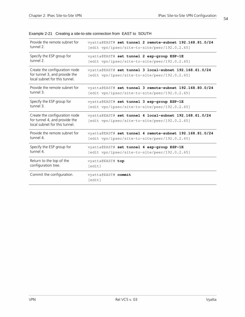
Chapter 2: IPsec Site-to-Site VPN IPsec Site-to-Site VPN Configuration
VPN Rel VC5 v. 03 Vyatta
54
Provide the remote subnet for tunnel 2.
vyatta@EAST# set tunnel 2 remote-subnet 192.168.81.0/24[edit vpn/ipsec/site-to-site/peer/192.0.2.65]
Specify the ESP group for tunnel 2.
vyatta@EAST# set tunnel 2 esp-group ESP-1E[edit vpn/ipsec/site-to-site/peer/192.0.2.65]
Create the configuration node for tunnel 3, and provide the local subnet for this tunnel.
vyatta@EAST# set tunnel 3 local-subnet 192.168.61.0/24[edit vpn/ipsec/site-to-site/peer/192.0.2.65]
Provide the remote subnet for tunnel 3.
vyatta@EAST# set tunnel 3 remote-subnet 192.168.80.0/24[edit vpn/ipsec/site-to-site/peer/192.0.2.65]
Specify the ESP group for tunnel 3.
vyatta@EAST# set tunnel 3 esp-group ESP-1E[edit vpn/ipsec/site-to-site/peer/192.0.2.65]
Create the configuration node for tunnel 4, and provide the local subnet for this tunnel.
vyatta@EAST# set tunnel 4 local-subnet 192.168.61.0/24[edit vpn/ipsec/site-to-site/peer/192.0.2.65]
Provide the remote subnet for tunnel 4.
vyatta@EAST# set tunnel 4 remote-subnet 192.168.81.0/24[edit vpn/ipsec/site-to-site/peer/192.0.2.65]
Specify the ESP group for tunnel 4.
vyatta@EAST# set tunnel 4 esp-group ESP-1E[edit vpn/ipsec/site-to-site/peer/192.0.2.65]
Return to the top of the configuration tree.
vyatta@EAST# top[edit]
Commit the configuration. vyatta@EAST# commit[edit]
Example 2-21 Creating a site-to-site connection from EAST to SOUTH

Chapter 2: IPsec Site-to-Site VPN IPsec Site-to-Site VPN Configuration
VPN Rel VC5 v. 03 Vyatta
55
Configure SOUTHThis section presents the following topics:
• Enabling VPN on SOUTH
• Configuring an IKE Group on SOUTH
• Configuring an ESP Group on SOUTH
• Creating the Connection to WEST
• Creating the Connection to EAST
View the configuration for the site-to-site connection.
vyatta@EAST# exit[edit]vyatta@EAST> show -all vpn ipsec site-to-site peer 192.0.2.65
authenticationmode pre-shared-secretpre-shared-secret test_key_2
}ike-group IKE-1Elocal-ip 192.0.2.33tunnel 1 {
local-subnet 192.168.60.0/24remote-subnet 192.168.80.0/24esp-group ESP-1E
}tunnel 2 {
local-subnet 192.168.60.0/24remote-subnet 192.168.81.0/24esp-group ESP-1E
}tunnel 3 {
local-subnet 192.168.61.0/24remote-subnet 192.168.80.0/24esp-group ESP-1E
}tunnel 4 {
local-subnet 192.168.61.0/24remote-subnet 192.168.81.0/24esp-group ESP-1E
}
[edit]
Example 2-21 Creating a site-to-site connection from EAST to SOUTH

Chapter 2: IPsec Site-to-Site VPN IPsec Site-to-Site VPN Configuration
VPN Rel VC5 v. 03 Vyatta
56
•
This section presents the following examples:
• Example 2-22 Enabling IPsec VPN on SOUTH
• Example 2-23 Configuring an IKE group on SOUTH
• Example 2-24 Configuring an ESP group on SOUTH
• Example 2-25 Creating a site-to-site connection from SOUTH to WEST
• Example 2-26 Creating a site-to-site connection from SOUTH to EAST
ENABLING VPN ON SOUTHIn this section, you enable IPsec VPN on the interfaces that will be used in VPN connections on SOUTH. The VPN tunnels in the example configuration extend through the wide-area network to eth0 on SOUTH. This means that eth0 on SOUTH must have VPN enabled. The other interfaces on SOUTH need not.
Example 2-22 enables IPsec VPN on eth0 on SOUTH. To do this, perform the following steps on SOUTH in configuration mode:
CONFIGURING AN IKE GROUP ON SOUTHExample 2-23 creates IKE group IKE-1S on SOUTH. This IKE group contains two proposals:
• Proposal 1 uses AES-256 as the encryption cipher and SHA-1 as the hash algorithm
• Proposal 2 uses AES-128 as the encryption cipher and SHA-1 as the hash algorithm
The lifetime of a proposal from this IKE group is set to 3600.
Note that these parameters correspond to those set in IKE-1W on WEST and IKE-1E on EAST. You must ensure, in defining proposals, that the encryption ciphers and hash algorithms are such that the two peers will be able to agree on a combination.
To create this IKE group, perform the following steps on SOUTH in configuration mode:
Example 2-22 Enabling IPsec VPN on SOUTH
Step Command
Enable VPN on eth0 on SOUTH. vyatta@SOUTH# set vpn ipsec ipsec-interfaces interface eth0[edit]
View IPsec interface configuration. Don’t commit yet.
vyatta@SOUTH# show vpn ipsec ipsec-interfaces> interface eth0[edit]

Chapter 2: IPsec Site-to-Site VPN IPsec Site-to-Site VPN Configuration
VPN Rel VC5 v. 03 Vyatta
57
Example 2-23 Configuring an IKE group on SOUTH
Step Command
Creates the configuration node for proposal 1 of IKE group IKE-1S.
vyatta@SOUTH# set vpn ipsec ike-group IKE-1S proposal 1 [edit]
Set the encryption cipher for proposal 1.
vyatta@SOUTH# set vpn ipsec ike-group IKE-1S proposal 1 encryption aes256[edit]
Set the hash algorithm for proposal 1.
vyatta@SOUTH# set vpn ipsec ike-group IKE-1S proposal 1 hash sha1[edit]
Set the encryption cipher for proposal 2. This also creates the configuration node for proposal 2 of IKE group IKE-1S.
vyatta@SOUTH# set vpn ipsec ike-group IKE-1S proposal 2 encryption aes128[edit]
Set the hash algorithm for proposal 2.
vyatta@SOUTH# set vpn ipsec ike-group IKE-1S proposal 2 hash sha1[edit]
Set the lifetime for the whole IKE group.
vyatta@SOUTH# set vpn ipsec ike-group IKE-1S lifetime 3600[edit]
View the configuration for the IKE group. Don’t commit yet.
vyatta@SOUTH# show -all vpn ipsec ike-group IKE-1S> proposal 1 {> encryption aes256> hash sha1> }> proposal 2 {> encryption aes128> hash sha1> }> lifetime 3600
[edit]

Chapter 2: IPsec Site-to-Site VPN IPsec Site-to-Site VPN Configuration
VPN Rel VC5 v. 03 Vyatta
58
CONFIGURING AN ESP GROUP ON SOUTHExample 2-24 creates ESP group ESP-1S on SOUTH. This ESP group contains two proposals:
• Proposal 1 uses AES-256 as the encryption cipher and SHA-1 as the hash algorithm
• Proposal 2 uses Triple-DES as the encryption cipher and MD5 as the hash algorithm
The lifetime of a proposal from this ESP group is set to 1800 seconds.
To create this ESP group, perform the following steps on SOUTH in configuration mode:
Example 2-24 Configuring an ESP group on SOUTH
Step Command
Create the configuration node for proposal 1 of ESP group ESP-1S.
vyatta@SOUTH# set vpn ipsec esp-group ESP-1S proposal 1[edit]
Set the encryption cipher for proposal 1.
vyatta@SOUTH# set vpn ipsec esp-group ESP-1S proposal 1 encryption aes256[edit]
Set the hash algorithm for proposal 1.
vyatta@SOUTH# set vpn ipsec esp-group ESP-1S proposal 1 hash sha1[edit]
Set the encryption cipher for proposal 2. This also creates the configuration node for proposal 2 of ESP group ESP-1S.
vyatta@SOUTH# set vpn ipsec esp-group ESP-1S proposal 2 encryption 3des[edit]
Set the hash algorithm for proposal 2.
vyatta@SOUTH# set vpn ipsec esp-group ESP-1S proposal 2 hash md5[edit]
Set the lifetime for the whole ESP group.
vyatta@SOUTH# set vpn ipsec esp-group ESP-1S lifetime 1800[edit]
View the configuration for the ESP group. Don’t commit yet.
vyatta@SOUTH# show -all vpn ipsec esp-group ESP-1S> proposal 1 {> encryption aes256> hash sha1> }> proposal 2 {> encryption 3de> hash md5> }> lifetime 1800
[edit]

Chapter 2: IPsec Site-to-Site VPN IPsec Site-to-Site VPN Configuration
VPN Rel VC5 v. 03 Vyatta
59
CREATING THE CONNECTION TO WESTExample 2-25 defines a site-to-site connection to WEST.
• This connection is configured with four tunnels:
— Tunnel 1 communicates between 192.168.80.0/24 on SOUTH and 192.168.40.0/24 on WEST, and uses ESP group ESP-1S.
— Tunnel 2 communicates between 192.168.80.0/24 on SOUTH and 192.168.41.0/24 on WEST, and uses ESP group ESP-1S.
— Tunnel 3 communicates between 192.168.81.0/24 on SOUTH and 192.168.40.0/24 on WEST, and uses ESP group ESP-1S.
— Tunnel 4 communicates between 192.168.81.0/24 on SOUTH and 192.168.41.0/24 on WEST, and uses ESP group ESP-1S.
• SOUTH uses IP address 192.0.2.65 on eth0.
• WEST uses IP address 192.0.2.1 on eth1.
• The IKE group is IKE-1S.
• The preshared secret is “test_key_2”.
To configure this connection, perform the following steps on SOUTH in configuration mode:
Example 2-25 Creating a site-to-site connection from SOUTH to WEST
Step Command
Create the node for WEST and set the authentication mode
vyatta@SOUTH# set vpn ipsec site-to-site peer 192.0.2.1 authentication mode pre-shared-secret[edit]
Navigate to the node for the peer for easier editing
vyatta@SOUTH# edit vpn ipsec site-to-site peer 192.0.2.1[edit vpn/ipsec/site-to-site/peer/192.0.2.1]
Provide the string that will be used to generate encryption keys.
vyatta@SOUTH# set authentication pre-shared-secret test_key_2[edit vpn/ipsec/site-to-site/peer/192.0.2.1]
Specify the IKE group. vyatta@SOUTH# set ike-group IKE-1S[edit vpn/ipsec/site-to-site/peer/192.0.2.1]
Identify the IP address on this Vyatta system to be used for this connection.
vyatta@SOUTH# set local-ip 192.0.2.65[edit vpn/ipsec/site-to-site/peer/192.0.2.1]
Create the configuration node for tunnel 1, and provide the local subnet for this tunnel.
vyatta@SOUTH# set tunnel 1 local-subnet 192.168.80.0/24[edit vpn/ipsec/site-to-site/peer/192.0.2.1]

Chapter 2: IPsec Site-to-Site VPN IPsec Site-to-Site VPN Configuration
VPN Rel VC5 v. 03 Vyatta
60
Provide the remote subnet for tunnel 1.
vyatta@SOUTH# set tunnel 1 remote-subnet 192.168.40.0/24[edit vpn/ipsec/site-to-site/peer/192.0.2.1]
Specify the ESP group for tunnel 1.
vyatta@SOUTH# set tunnel 1 esp-group ESP-1S[edit vpn/ipsec/site-to-site/peer/192.0.2.1]
Create the configuration node for tunnel 2, and provide the local subnet for this tunnel.
vyatta@SOUTH# set tunnel 2 local-subnet 192.168.80.0/24[edit vpn/ipsec/site-to-site/peer/192.0.2.1]
Provide the remote subnet for tunnel 2.
vyatta@SOUTH# set tunnel 2 remote-subnet 192.168.41.0/24[edit vpn/ipsec/site-to-site/peer/192.0.2.1]
Specify the ESP group for tunnel 2.
vyatta@SOUTH# set tunnel 2 esp-group ESP-1S[edit vpn/ipsec/site-to-site/peer/192.0.2.1]
Create the configuration node for tunnel 3, and provide the local subnet for this tunnel.
vyatta@SOUTH# set tunnel 3 local-subnet 192.168.81.0/24[edit vpn/ipsec/site-to-site/peer/192.0.2.1]
Provide the remote subnet for tunnel 3.
vyatta@SOUTH# set tunnel 3 remote-subnet 192.168.40.0/24[edit vpn/ipsec/site-to-site/peer/192.0.2.1]
Specify the ESP group for tunnel 3.
vyatta@SOUTH# set tunnel 3 esp-group ESP-1S[edit vpn/ipsec/site-to-site/peer/192.0.2.1]
Create the configuration node for tunnel 4, and provide the local subnet for this tunnel.
vyatta@SOUTH# set tunnel 4 local-subnet 192.168.81.0/24[edit vpn/ipsec/site-to-site/peer/192.0.2.1]
Provide the remote subnet for tunnel 4.
vyatta@SOUTH# set tunnel 4 remote-subnet 192.168.41.0/24[edit vpn/ipsec/site-to-site/peer/192.0.2.1]
Specify the ESP group for tunnel 4.
vyatta@SOUTH# set tunnel 4 esp-group ESP-1S[edit vpn/ipsec/site-to-site/peer/192.0.2.1]
Return to the top of the configuration tree.
vyatta@SOUTH# top[edit]
Now commit the configuration. vyatta@SOUTH# commit[edit]
Example 2-25 Creating a site-to-site connection from SOUTH to WEST
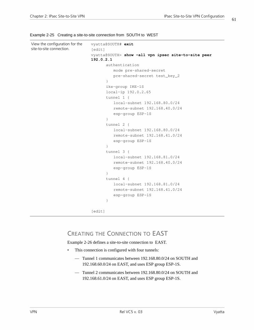
Chapter 2: IPsec Site-to-Site VPN IPsec Site-to-Site VPN Configuration
VPN Rel VC5 v. 03 Vyatta
61
CREATING THE CONNECTION TO EASTExample 2-26 defines a site-to-site connection to EAST.
• This connection is configured with four tunnels:
— Tunnel 1 communicates between 192.168.80.0/24 on SOUTH and 192.168.60.0/24 on EAST, and uses ESP group ESP-1S.
— Tunnel 2 communicates between 192.168.80.0/24 on SOUTH and 192.168.61.0/24 on EAST, and uses ESP group ESP-1S.
View the configuration for the site-to-site connection.
vyatta@SOUTH# exit[edit]vyatta@SOUTH> show -all vpn ipsec site-to-site peer 192.0.2.1
authenticationmode pre-shared-secretpre-shared-secret test_key_2
}ike-group IKE-1Slocal-ip 192.0.2.65tunnel 1 {
local-subnet 192.168.80.0/24remote-subnet 192.168.40.0/24esp-group ESP-1S
}tunnel 2 {
local-subnet 192.168.80.0/24remote-subnet 192.168.41.0/24esp-group ESP-1S
}tunnel 3 {
local-subnet 192.168.81.0/24remote-subnet 192.168.40.0/24esp-group ESP-1S
}tunnel 4 {
local-subnet 192.168.81.0/24remote-subnet 192.168.41.0/24esp-group ESP-1S
}
[edit]
Example 2-25 Creating a site-to-site connection from SOUTH to WEST

Chapter 2: IPsec Site-to-Site VPN IPsec Site-to-Site VPN Configuration
VPN Rel VC5 v. 03 Vyatta
62
— Tunnel 3 communicates between 192.168.81.0/24 on SOUTH and 192.168.60.0/24 on EAST, and uses ESP group ESP-1S.
— Tunnel 4 communicates between 192.168.81.0/24 on SOUTH and 192.168.61.0/24 on EAST, and uses ESP group ESP-1S.
• SOUTH uses IP address 192.0.2.65 on eth0.
• EAST uses IP address 192.0.2.33 on eth1.
• The IKE group is IKE-1S.
• The preshared secret is “test_key_2”.
To configure this connection, perform the following steps on SOUTH in configuration mode:
Example 2-26 Creating a site-to-site connection from SOUTH to EAST
Step Command
Create the node for EAST and set the authentication mode
vyatta@SOUTH# set vpn ipsec site-to-site peer 192.0.2.33 [edit]
Navigate to the node for the peer for easier editing
vyatta@SOUTH# edit vpn ipsec site-to-site peer 192.0.2.33[edit vpn/ipsec/site-to-site/peer/192.0.2.33]
Provide the string that will be used to generate encryption keys.
vyatta@SOUTH# set authentication pre-shared-secret test_key_2[edit vpn/ipsec/site-to-site/peer/192.0.2.33]
Specify the IKE group. vyatta@SOUTH# set ike-group IKE-1S[edit vpn/ipsec/site-to-site/peer/192.0.2.33]
Identify the IP address on this Vyatta system to be used for this connection.
vyatta@SOUTH# set local-ip 172.5.5.8[edit vpn/ipsec/site-to-site/peer/192.0.2.33]
Create the configuration node for tunnel 1, and provide the local subnet for this tunnel.
vyatta@SOUTH# set tunnel 1 local-subnet 192.168.80.0/24[edit vpn/ipsec/site-to-site/peer/192.0.2.33]
Provide the remote subnet for tunnel 1.
vyatta@SOUTH# set tunnel 1 remote-subnet 192.168.60.0/24[edit vpn/ipsec/site-to-site/peer/192.0.2.33]
Specify the ESP group for tunnel 1.
vyatta@SOUTH# set tunnel 1 esp-group ESP-1S[edit vpn/ipsec/site-to-site/peer/192.0.2.33]
Create the configuration node for tunnel 2, and provide the local subnet for this tunnel.
vyatta@SOUTH# set tunnel 2 local-subnet 192.168.80.0/24[edit vpn/ipsec/site-to-site/peer/192.0.2.33]
Provide the remote subnet for tunnel 2.
vyatta@SOUTH# set tunnel 2 remote-subnet 192.168.61.0/24[edit vpn/ipsec/site-to-site/peer/192.0.2.33]

Chapter 2: IPsec Site-to-Site VPN IPsec Site-to-Site VPN Configuration
VPN Rel VC5 v. 03 Vyatta
63
Specify the ESP group for tunnel 2.
vyatta@SOUTH# set tunnel 2 esp-group ESP-1S[edit vpn/ipsec/site-to-site/peer/192.0.2.33]
Create the configuration node for tunnel 3, and provide the local subnet for this tunnel.
vyatta@SOUTH# set tunnel 3 local-subnet 192.168.81.0/24[edit vpn/ipsec/site-to-site/peer/192.0.2.33]
Provide the remote subnet for tunnel 3.
vyatta@SOUTH# set tunnel 3 remote-subnet 192.168.60.0/24[edit vpn/ipsec/site-to-site/peer/192.0.2.33]
Specify the ESP group for tunnel 3.
vyatta@SOUTH# set tunnel 3 esp-group ESP-1S[edit vpn/ipsec/site-to-site/peer/192.0.2.33]
Create the configuration node for tunnel 4, and provide the local subnet for this tunnel.
vyatta@SOUTH# set tunnel 4 local-subnet 192.168.81.0/24[edit vpn/ipsec/site-to-site/peer/192.0.2.33]
Provide the remote subnet for tunnel 4.
vyatta@SOUTH# set tunnel 4 remote-subnet 192.168.61.0/24[edit vpn/ipsec/site-to-site/peer/192.0.2.33]
Specify the ESP group for tunnel 4.
vyatta@SOUTH# set tunnel 4 esp-group ESP-1S[edit vpn/ipsec/site-to-site/peer/192.0.2.33]
Return to the top of the configuration tree.
vyatta@SOUTH# top[edit]
Now commit the configuration. vyatta@SOUTH# commit[edit]
Example 2-26 Creating a site-to-site connection from SOUTH to EAST

Chapter 2: IPsec Site-to-Site VPN IPsec Site-to-Site VPN Configuration
VPN Rel VC5 v. 03 Vyatta
64
View the configuration for the site-to-site connection.
vyatta@SOUTH# exit[edit]vyatta@SOUTH> show -all vpn ipsec site-to-site peer 192.0.2.33
authenticationmode pre-shared-secretpre-shared-secret test_key_2
}ike-group IKE-1Slocal-ip 192.0.2.54tunnel 1 {
local-subnet 192.168.80.0/24remote-subnet 192.168.60.0/24esp-group ESP-1S
}tunnel 2 {
local-subnet 192.168.80.0/24remote-subnet 192.168.61.0/24esp-group ESP-1S
}tunnel 3 {
local-subnet 192.168.81.0/24remote-subnet 192.168.60.0/24esp-group ESP-1S
}tunnel 4 {
local-subnet 192.168.81.0/24remote-subnet 192.168.61.0/24esp-group ESP-1S
}
[edit]
Example 2-26 Creating a site-to-site connection from SOUTH to EAST
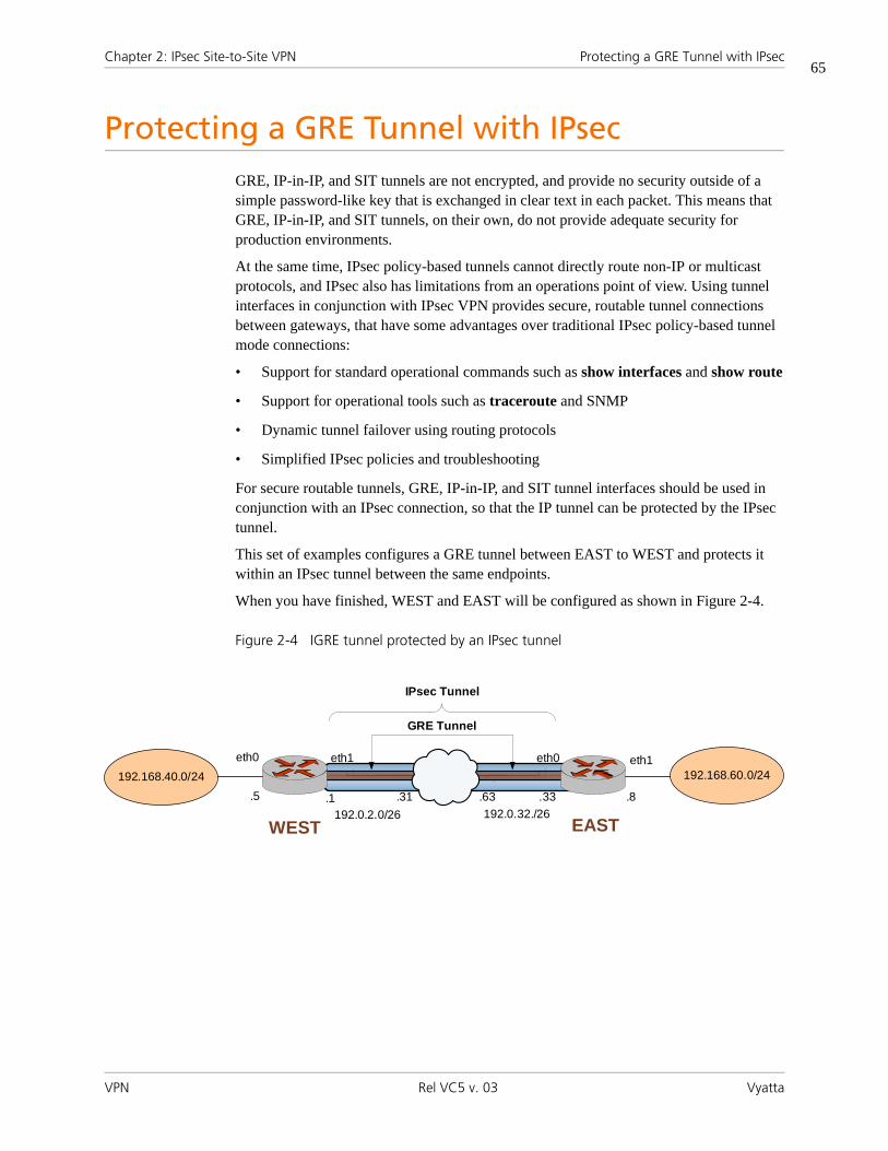
Chapter 2: IPsec Site-to-Site VPN Protecting a GRE Tunnel with IPsec
VPN Rel VC5 v. 03 Vyatta
65
Protecting a GRE Tunnel with IPsecGRE, IP-in-IP, and SIT tunnels are not encrypted, and provide no security outside of a simple password-like key that is exchanged in clear text in each packet. This means that GRE, IP-in-IP, and SIT tunnels, on their own, do not provide adequate security for production environments.
At the same time, IPsec policy-based tunnels cannot directly route non-IP or multicast protocols, and IPsec also has limitations from an operations point of view. Using tunnel interfaces in conjunction with IPsec VPN provides secure, routable tunnel connections between gateways, that have some advantages over traditional IPsec policy-based tunnel mode connections:
• Support for standard operational commands such as show interfaces and show route
• Support for operational tools such as traceroute and SNMP
• Dynamic tunnel failover using routing protocols
• Simplified IPsec policies and troubleshooting
For secure routable tunnels, GRE, IP-in-IP, and SIT tunnel interfaces should be used in conjunction with an IPsec connection, so that the IP tunnel can be protected by the IPsec tunnel.
This set of examples configures a GRE tunnel between EAST to WEST and protects it within an IPsec tunnel between the same endpoints.
When you have finished, WEST and EAST will be configured as shown in Figure 2-4.
Figure 2-4 IGRE tunnel protected by an IPsec tunnel
eth0 eth1 eth1eth0
.5 .1 .31 .63 .33 .8
192.0.2.0/26 192.0.32./26
IPsec Tunnel
192.168.60.0/24192.168.40.0/24
EASTWEST
GRE Tunnel

Chapter 2: IPsec Site-to-Site VPN Protecting a GRE Tunnel with IPsec
VPN Rel VC5 v. 03 Vyatta
66
Configure “WEST”This section presents the following examples:
• Example 2-27 Defining the GRE tunnel from WEST to EAST
• Example 2-28 Defining the IPsec tunnel from WEST to EAST
Define the GRE Tunnel on “WEST”GRE tunnels are explained in detail in the Please see that chapter for more information.
Example 2-1 defines WEST’s end of the GRE tunnel. In this example:
• The tunnel interface tun0 on router WEST and source IP are both assigned the IP address 192.0.2.1 on network 192.0.2.0/26.
• The IP address of the other end of the tunnel is 192.0.2.33 on router EAST.
To do creates the tunnel interface and the tunnel endpoint on WEST, perform the following steps in configuration mode:
Define the IPsec Tunnel on “WEST”Example 2-1 creates the IPsec tunnel from WEST to EAST.
• WEST uses IP address 192.0.2.1 on eth1.
Example 2-27 Defining the GRE tunnel from WEST to EAST
Step Command
Create the GRE tunnel interface, and specify the IP address and network to be associated with it.
vyatta@WEST# set interfaces tunnel tun0 address 192.0.2.1 prefix-length 26[edit]
Specify the source IP address for the GRE tunnel.
vyatta@WEST# set interfaces tunnel tun0 local-ip 192.0.2.1[edit]
Specify the IP address of the other end of the GRE tunnel.
vyatta@WEST# set interfaces tunnel tun0 remote-ip 192.0.2.33[edit]
Specify the encapsulation mode for the tunnel.
vyatta@WEST# set interfaces tunnel tun0 encapsulation gre[edit]
Assign a brief description for the GRE tunnel interface.
vyatta@WEST# set interfaces tunnel tun0 description “GRE tunnel to router EAST”[edit]

Chapter 2: IPsec Site-to-Site VPN Protecting a GRE Tunnel with IPsec
VPN Rel VC5 v. 03 Vyatta
67
• EAST uses IP address 192.0.2.33 on eth0.
• The IKE group is IKE-1W
• The preshared secret is “test_key_1”.
• The IPsec tunnel communicates between 192.168.40.0/24 on WEST and 192.168.60.0/24 on EAST, using ESP group ESP-1W.
This examples assumes that you have already configured the following:
• IKE group IKE-1W (see page 22)
• ESP group ESP-1W (see page 23)
To create the IPsec tunnel from WEST to EAST, perform the following steps on WEST in configuration mode:
Example 2-28 Defining the IPsec tunnel from WEST to EAST
Step Command
Enable VPN on eth1. vyatta@WEST# set vpn ipsec ipsec-interfaces interface eth1[edit]
Define the site-to-site connection to EAST. Set the authentication mode.
vyatta@WEST# set vpn ipsec site-to-site peer 192.0.2.33 authentication mode pre-shared-secret[edit]
Navigate to the node for the peer for easier editing.
vyatta@WEST# edit vpn ipsec site-to-site peer 192.0.2.33[edit vpn/ipsec/site-to-site/peer/192.0.2.33]
Provide the string that will be used to authenticate the peers.
vyatta@WEST# set authentication pre-shared-secret test_key_1[edit vpn/ipsec/site-to-site/peer/192.0.2.33]
Specify the IKE group. vyatta@WEST# set ike-group IKE-1W[edit vpn/ipsec/site-to-site/peer/192.0.2.33]
Identify the IP address on this Vyatta system to be used for this connection.
vyatta@WEST# set local-ip 192.0.2.1[edit vpn/ipsec/site-to-site/peer/192.0.2.33]
Create a tunnel configuration, and provide the local subnet for this tunnel.
vyatta@WEST# set tunnel 1 local-subnet 192.168.40.0/24[edit vpn/ipsec/site-to-site/peer/192.0.2.33]
Specify the remote subnet for the tunnel.
vyatta@WEST# set tunnel 1 remote-subnet 192.168.60.0/24[edit vpn/ipsec/site-to-site/peer/192.0.2.33]
Specify the ESP group for this tunnel.
vyatta@WEST# set tunnel 1 esp-group ESP-1W[edit vpn/ipsec/site-to-site/peer/192.0.2.33]

Chapter 2: IPsec Site-to-Site VPN Protecting a GRE Tunnel with IPsec
VPN Rel VC5 v. 03 Vyatta
68
Configure “EAST”This section presents the following examples:
• Example 2-29 Defining the GRE tunnel from EAST to WEST
• Example 2-30 Defining the IPsec tunnel from EAST to WEST
Define the GRE Tunnel on “EAST”GRE tunnels are explained in detail in Vyatta Encapsulation and Tunnels Reference Guide. Please see that chapter for more information.
Example 2-1 defines EAST’s end of the GRE tunnel. In this example:
• The tunnel interface tun0 on router EAST and source IP are both assigned the IP address 192.0.2.33 on network 192.0.2.32/26.
• The IP address of the other end of the tunnel is 192.0.2.1 on router WEST.
To do creates the tunnel interface and the tunnel endpoint on EAST, perform the following steps in configuration mode:
Example 2-29 Defining the GRE tunnel from EAST to WEST
Step Command
Create the GRE tunnel interface, and specify the IP address and network to be associated with it.
vyatta@EAST# set interfaces tunnel tun0 address 192.0.2.33 prefix-length 26[edit]
Specify the source IP address for the GRE tunnel.
vyatta@EAST# set interfaces tunnel tun0 local-ip 192.0.2.33[edit]
Specify the IP address of the other end of the GRE tunnel.
vyatta@EAST# set interfaces tunnel tun0 remote-ip 192.0.2.1[edit]
Specify the encapsulation mode for the tunnel.
vyatta@EAST# set interfaces tunnel tun0 encapsulation gre[edit]
Assign a brief description for the GRE tunnel interface.
vyatta@EAST# set interfaces tunnel tun0 description “GRE tunnel to router WEST”[edit]

Chapter 2: IPsec Site-to-Site VPN Protecting a GRE Tunnel with IPsec
VPN Rel VC5 v. 03 Vyatta
69
Define the IPsec Tunnel on “EAST”Example 2-1 creates the IPsec tunnel from EAST to WEST.
• EAST uses IP address 192.0.2.33 on eth0.
• WEST uses IP address 192.0.2.1 on eth1.
• The IKE group is IKE-1E
• The preshared secret is “test_key_1”.
• The IPsec tunnel communicates between 192.168.60.0/24 on EAST and 192.168.40.0/24 on WEST, using ESP group ESP-1E.
This examples assumes that you have already configured the following:
• IKE group IKE-1E (see page 28)
• ESP group ESP-1E (see page 29)
To create the IPsec tunnel from EAST to WEST, perform the following steps on EAST in configuration mode:
Example 2-30 Defining the IPsec tunnel from EAST to WEST
Step Command
Enable VPN on eth0. vyatta@EAST# set vpn ipsec ipsec-interfaces interface eth0[edit]
Define the site-to-site connection to EAST. Set the authentication mode.
vyatta@EAST# set vpn ipsec site-to-site peer 192.0.2.1 authentication mode pre-shared-secret[edit]
Navigate to the node for the peer for easier editing.
vyatta@EAST# edit vpn ipsec site-to-site peer 192.0.2.1[edit vpn/ipsec/site-to-site/peer/192.0.2.1]
Provide the string that will be used to authenticate the peers.
vyatta@EAST# set authentication pre-shared-secret test_key_1[edit vpn/ipsec/site-to-site/peer/192.0.2.1]
Specify the IKE group. vyatta@EAST# set ike-group IKE-1E[edit vpn/ipsec/site-to-site/peer/192.0.2.1]
Identify the IP address on this Vyatta system to be used for this connection.
vyatta@EAST# set local-ip 192.0.2.22[edit vpn/ipsec/site-to-site/peer/192.0.2.1]
Create a tunnel configuration, and provide the local subnet for this tunnel.
vyatta@EAST# set tunnel 1 local-subnet 192.168.60.0/24[edit vpn/ipsec/site-to-site/peer/192.0.2.1]

Chapter 2: IPsec Site-to-Site VPN Protecting a GRE Tunnel with IPsec
VPN Rel VC5 v. 03 Vyatta
70
Specify the remote subnet for the tunnel.
vyatta@EAST# set tunnel 1 remote-subnet 192.168.40.0/24[edit vpn/ipsec/site-to-site/peer/192.0.2.1]
Specify the ESP group for this tunnel.
vyatta@EAST# set tunnel 1 esp-group ESP-1E[edit vpn/ipsec/site-to-site/peer/192.0.2.1]
Example 2-30 Defining the IPsec tunnel from EAST to WEST

Chapter 2: IPsec Site-to-Site VPN Monitoring IPsec Site-to-Site VPN
VPN Rel VC5 v. 03 Vyatta
71
Monitoring IPsec Site-to-Site VPNThis section presents the following topics:
• Showing IKE Information
• Showing IPsec Information
• Viewing IPsec VPN Debug Information
• Sending IPSec VPN Messages to Syslog
This section includes the following examples:
• Example 2-31 Viewing IKE security associations
• Example 2-32 Viewing IKE status information
• Example 2-33 Viewing IPsec security associations
• Example 2-34 Viewing IPsec statistics
• Example 2-35 Viewing IPsec status information
• Example 2-36 Viewing IPsec VPN debug information
NOTE The sample output in these examples may show information unrelated to the
sample configurations.
Showing IKE InformationTo see IKE security associations, you can use the show vpn ike sa command, as shown in Example 2-31.
Example 2-31 Viewing IKE security associations
vyatta@WEST> show vpn ike saLocal IP Peer IP State Encrypt Hash Active L-Time NAT-T-------- ------- ----- ------- ---- ------ ------ -----10.6.0.55 10.6.0.57 up aes128 sha1 454 28800 disab
vyatta@WEST>
To see the status of the IKE process, you can use the show vpn ike status command, as shown in Example 2-32.
Example 2-32 Viewing IKE status information
vyatta@west> show vpn ike status

Chapter 2: IPsec Site-to-Site VPN Monitoring IPsec Site-to-Site VPN
VPN Rel VC5 v. 03 Vyatta
72
IKE Process Running
PID: 5832
vyatta@west>
Showing IPsec InformationTo see IPsec security associations, you can use the show vpn ipsec sa command, as shown in Example 2-33.
Example 2-33 Viewing IPsec security associations
vyatta@WEST> show vpn ipsec saPeer IP Dir SPI Encrypt Hash Active Lifetime------- --- --- ------- ---- ------ --------10.6.0.57 in bf8ea130 aes128 sha1 565 360010.6.0.57 out 5818d99e aes128 sha1 565 3600
vyatta@WEST>
To see IPsec statistics, you can use the show vpn ipsec statistics command, as shown in Example 2-34.
Example 2-34 Viewing IPsec statistics
vyatta@WEST> show vpn ipsec sa statisticsPeer IP Dir SRC Network DST Network Bytes------- --- ----------- ----------- -----10.6.0.57 in 0.0.0.0/0 10.7.0.48/28 0(bytes)10.6.0.57 out 10.7.0.48/28 0.0.0.0/0 0(bytes)
vyatta@WEST>
To see the status of the IPsec process, you can use the show vpn ipsec status command, as shown in Example 2-35.
Example 2-35 Viewing IPsec status information
vyatta@WEST> show vpn ipsec statusIPSec Process Running PID: 5832

Chapter 2: IPsec Site-to-Site VPN Monitoring IPsec Site-to-Site VPN
VPN Rel VC5 v. 03 Vyatta
73
4 Active IPsec Tunnels
IPsec Interfaces: eth1 (10.6.0.55)
vyatta@WEST>
Viewing IPsec VPN Debug InformationTo see more detailed information when you are troubleshooting, you can use the show vpn debug command, with or without the detail option. Example 2-36 shows the command without the detail option.
Example 2-36 Viewing IPsec VPN debug information
vyatta@WEST> show vpn debug000 interface lo/lo ::1000 interface lo/lo 127.0.0.1000 interface eth0/eth0 10.1.0.55000 interface eth1/eth1 10.6.0.55000 %myid = (none)000 debug none000000 algorithm ESP encrypt: id=2, name=ESP_DES, ivlen=8, keysizemin=64, keysizema x=64000 algorithm ESP encrypt: id=3, name=ESP_3DES, ivlen=8, keysizemin=192, keysize max=192000 algorithm ESP encrypt: id=7, name=ESP_BLOWFISH, ivlen=8, keysizemin=40, keys izemax=448000 algorithm ESP encrypt: id=11, name=ESP_NULL, ivlen=0, keysizemin=0, keysizem ax=0000 algorithm ESP encrypt: id=12, name=ESP_AES, ivlen=8, keysizemin=128, keysize max=256000 algorithm ESP encrypt: id=252, name=ESP_SERPENT, ivlen=8, keysizemin=128, ke ysizemax=256000 algorithm ESP encrypt: id=253, name=ESP_TWOFISH, ivlen=8, keysizemin=128, ke ysizemax=256000 algorithm ESP auth attr: id=1, name=AUTH_ALGORITHM_HMAC_MD5, keysizemin=128, keysizemax=128--More--

Chapter 2: IPsec Site-to-Site VPN Monitoring IPsec Site-to-Site VPN
VPN Rel VC5 v. 03 Vyatta
74
Sending IPSec VPN Messages to SyslogThis section presents the following examples:
• Example 2-37 Setting VPN log mode and logging severity
The IPsec process generates log messages during operation. You can direct the system to send IPsec log messages to syslog. The result will depend on how the system syslog is configured.
Keep in mind that in the current implementation, the main syslog file reports only messages of severity warning and above, regardless of the severity level configured. If you want to configure a different level of severity for log messages (for example, if you want to see debug messages during troubleshooting), you must configure syslog to send messages into a different file, which you define within syslog.
Configuring log modes is optional. When a log mode is not configured, IPsec log messages consist mostly of IPsec startup and shutdown messages. The log modes allow you to direct the system to inspect the IPsec packets and report the results.
Note that some log modes (for example, all and control) generate several log messages per packet. Using any of these options may severely degrade system performance.
VPN IPsec log messages use standard syslog levels of severity.
The Vyatta system supports the following logging modes for IPsec VPN.
Note that some logging modes (for example, “all”) print several messages per packet. Verbose logging modes can cause severe performance degradation.
Example 2-37 configures logging for VPN messages on WEST. In this example:
• Two logging modes are applied:
— raw, which shows the raw bytes of messages
— crypt, which shows the encryption and decryption of messages.
Table 2-4 IPsec VPN logging modes
Severity Meaning
raw Shows the raw bytes of messages.
crypt Shows the encryption and decryption of messages.
parsing Shows the structure of input messages.
emitting Shows the structure of output messages.
control Shows the decision-making process of the IKE daemon (Pluto).
private Allows debugging output with private keys.
all Enables all logging options.

Chapter 2: IPsec Site-to-Site VPN Monitoring IPsec Site-to-Site VPN
VPN Rel VC5 v. 03 Vyatta
75
• Severity is set to warning, which is more verbose than the default err, but might be suitable for some troubleshooting scenarios.
• Facility is set to daemon.
To configure logging in this way, perform the following steps on WEST in configuration mode:
Example 2-37 Setting VPN log mode and logging severity
Step Command
Apply a log mode of raw. vyatta@WEST# set vpn ipsec logging log-modes raw[edit]
Apply a second log mode of crypt.
vyatta@WEST# set vpn ipsec logging log-modes crypt[edit]
Set the log severity to warning. vyatta@WEST# set vpn ipsec logging level warning[edit]
Set the log facility to daemon. vyatta@WEST# set vpn ipsec logging facility daemon[edit]
Commit the configuration. vyatta@WEST# commit[edit]
View the configuration for logging.
vyatta@WEST# exit[edit]vyatta@WEST> show -all vpn ipsec logging
facility: daemonlevel: warninglog-modes rawlog-modes crypt
[edit]

Chapter 2: IPsec Site-to-Site VPN IPsec Site-to-Site VPN Commands
VPN Rel VC5 v. 03 Vyatta
76
IPsec Site-to-Site VPN CommandsThis chapter contains the following commands.
Configuration Commands
Global IPsec
vpn ipsec Enables IPsec VPN functionality on the system.
vpn ipsec copy-tos <state> Specifies whether the Type of Service byte should be copied into the header of the IPsec packet.
vpn ipsec ipsec-interfaces interface <if-name> Enables IPsec VPN on an interface.
vpn ipsec logging Specifies logging options for IPsec VPN.
vpn ipsec nat-networks allowed-network <ipv4net> Specifies the private network addresses that remote hosts behind a NAT device may use.
vpn ipsec nat-traversal <state> Specifies whether the local VPN gateway proposes NAT Traversal capability.
ESP Group
vpn ipsec esp-group <name> Defines a named ESP configuration for IKE Phase 2 negotiations.
vpn ipsec esp-group <name> compression <state> Specifies whether this VPN gateway should propose the use of compression.
vpn ipsec esp-group <name> lifetime <lifetime> Specifies how long an ESP encryption key can stay in effect.
vpn ipsec esp-group <name> mode <mode> Specifies the IPsec connection mode to be used.
vpn ipsec esp-group <name> pfs <state> Specifies whether or not PFS is used.
vpn ipsec esp-group <name> proposal <num> Defines an ESP group proposal for IKE Phase 2 negotation.
vpn ipsec esp-group <name> proposal <num> encryption <cipher>
Specifies the encryption cipher for an ESP proposal.
vpn ipsec esp-group <name> proposal <num> hash <hash>
Specifies the hash algorithm for an ESP proposal.
IKE Group
vpn ipsec ike-group <name> Defines a named IKE configuration for IKE Phase 1 negotiations.
vpn ipsec ike-group <name> agressive-mode <state> Specifies the IKE mode to use for ISAKMP negotiation.

Chapter 2: IPsec Site-to-Site VPN IPsec Site-to-Site VPN Commands
VPN Rel VC5 v. 03 Vyatta
77
vpn ipsec ike-group <name> dead-peer-detection Defines the behavior if the VPN peer becomes unreachable.
vpn ipsec ike-group <name> lifetime <lifetime> Specifies how long an IKE group key can stay in effect.
vpn ipsec ike-group <name> proposal <num> Specifies the IKE group proposal number.
vpn ipsec ike-group <name> proposal <num> dh-group <group>
Specifies the Oakley group to be proposed for Diffie-Hellman key exchanges.
vpn ipsec ike-group <name> proposal <num> encryption <cipher>
Specifies the encryption cipher to be proposed in IKE Phase 1 negotiation.
vpn ipsec ike-group <name> proposal <num> hash <hash>
Specifies the hash algorithm to be proposed.
IPsec Peer
vpn ipsec site-to-site peer <ipv4> Defines a site-to-site connection between the Vyatta system and another VPN gateway.
vpn ipsec site-to-site peer <ipv4> authentication Provides the information required for authenticating communications.
vpn ipsec site-to-site peer <ipv4> ike-group <group> Specifies the named IKE configuration to be used for a peer connection.
vpn ipsec site-to-site peer <ipv4> local-ip <ipv4a> Specifies the local IP address to be used as the source IP for packets destined for the remote peer.
vpn ipsec site-to-site peer <ipv4> tunnel <tunx> Defines an IPsec tunnel configuration for a site-to-site connection.
RSA Keys
vpn rsa-key generate Generates an RSA digital signature for the local host.
vpn rsa-keys Records RSA keys for the local host.
Operational Commands
clear vpn ipsec-process Restarts the IPsec process.
show vpn debug Provides trace-level information about IPsec VPN.
show vpn ike rsa-keys Displays RSA public keys recorded in the system.
show vpn ike sa Provides information about all currently active IKE (ISAKMP) security associations.
show vpn ike secrets Displays configured pre-shared secrets.
show vpn ike status Displays summary information about the IKE process.

Chapter 2: IPsec Site-to-Site VPN IPsec Site-to-Site VPN Commands
VPN Rel VC5 v. 03 Vyatta
78
show vpn ipsec sa Provides information about all active IPsec security associations.
show vpn ipsec sa nat-traversal Provides information about all active IPsec security associations that are using NAT Traversal.
show vpn ipsec sa peer <peer> Provides information about all active IPsec security associations for a specific peer.
show vpn ipsec sa statistics Display information about active tunnels that have an IPsec security association (SA).
show vpn ipsec status Displays information about the status of IPsec processes.
vpn rsa-key generate Generates an RSA digital signature for the local host.

Chapter 2: IPsec Site-to-Site VPN IPsec Site-to-Site VPN Commands
VPN Rel VC5 v. 03 Vyatta
79
clear vpn ipsec-processRestarts the IPsec process.
Syntax
clear vpn ipsec-process
Command Mode
Operational mode.
Parameters
None.
Usage Guidelines
Use this command to restart the IPsec process.
Restarting IPsec will cause all tunnels to be torn down and re-established.
Examples
Example 2-38 shows the output resulting from the clear vpn ipsec-process command.
Example 2-38 “clear vpn ipsec-process” sample output
vyatta@WEST> clear vpn ipsec-processStopping Openswan IPsec…Starting Openswan IPsec 2.4.6…
vyatta@WEST>

Chapter 2: IPsec Site-to-Site VPN IPsec Site-to-Site VPN Commands
VPN Rel VC5 v. 03 Vyatta
80
show vpn debugProvides trace-level information about IPsec VPN.
Syntax
show vpn debug [detail]
Command Mode
Operational mode.
Parameters
Usage Guidelines
Use this command to view trace-level messages for IPsec VPN.
This command is useful for troubleshooting and diagnostic situations.
Examples
Example 2-39 shows the output of the show vpn debug command.
Example 2-39 “show vpn debug” sample output
vyatta@WEST> show vpn debug000 interface lo/lo ::1000 interface lo/lo 127.0.0.1000 interface eth0/eth0 10.1.0.55000 interface eth1/eth1 10.6.0.55000 %myid = (none)000 debug none000000 algorithm ESP encrypt: id=2, name=ESP_DES, ivlen=8, keysizemin=64, keysizema x=64000 algorithm ESP encrypt: id=3, name=ESP_3DES, ivlen=8, keysizemin=192, keysize max=192000 algorithm ESP encrypt: id=7, name=ESP_BLOWFISH, ivlen=8, keysizemin=40, keys izemax=448000 algorithm ESP encrypt: id=11, name=ESP_NULL, ivlen=0, keysizemin=0, keysizem ax=0
detail Provides extra verbose output at the trace level.

Chapter 2: IPsec Site-to-Site VPN IPsec Site-to-Site VPN Commands
VPN Rel VC5 v. 03 Vyatta
81
000 algorithm ESP encrypt: id=12, name=ESP_AES, ivlen=8, keysizemin=128, keysize max=256000 algorithm ESP encrypt: id=252, name=ESP_SERPENT, ivlen=8, keysizemin=128, ke ysizemax=256000 algorithm ESP encrypt: id=253, name=ESP_TWOFISH, ivlen=8, keysizemin=128, ke ysizemax=256000 algorithm ESP auth attr: id=1, name=AUTH_ALGORITHM_HMAC_MD5, keysizemin=128, keysizemax=128--More--
Example 2-40 shows the output of the show vpn debug detail command.
Example 2-40 “show vpn debug detail” sample output
vyatta@WEST> show vpn debug detailWESTvenusThu Feb 15 14:03:45 PST 2007+ _________________________ version+ ipsec --versionLinux Openswan U2.4.6/K2.6.19 (netkey)See `ipsec --copyright' for copyright information.+ _________________________ /proc/version+ cat /proc/versionLinux version 2.6.19 ([email protected]) (gcc version 4.1.1) #1 SMP Wed Feb 14 00:39:15 PST 2007+ _________________________ /proc/net/ipsec_eroute+ test -r /proc/net/ipsec_eroute+ _________________________ netstat-rn+ netstat -nr+ head -n 100Kernel IP routing tableDestination Gateway Genmask Flags MSS Window irtt Iface10.6.0.48 0.0.0.0 255.255.255.240 U 0 0 0 eth110.7.0.48 0.0.0.0 255.255.255.240 U 0 0 0 eth110.0.0.0 10.1.0.1 255.255.255.0 UG 0 0 0 eth010.3.0.0 10.1.0.1 255.255.255.0 UG 0 0 0 eth010.1.0.0 0.0.0.0 255.255.255.0 U 0 0 0 eth010.5.0.0 10.1.0.1 255.255.255.0 UG 0 0 0 eth00.0.0.0 10.1.0.1 0.0.0.0 UG 0 0 0 eth0+ _________________________ /proc/net/ipsec_spi+ test -r /proc/net/ipsec_spi+ _________________________ /proc/net/ipsec_spigrp+ test -r /proc/net/ipsec_spigrp+ _________________________ /proc/net/ipsec_tncfg+ test -r /proc/net/ipsec_tncfg+ _________________________ /proc/net/pfkey

Chapter 2: IPsec Site-to-Site VPN IPsec Site-to-Site VPN Commands
VPN Rel VC5 v. 03 Vyatta
82
+ test -r /proc/net/pfkey+ cat /proc/net/pfkeysk RefCnt Rmem Wmem User Inode+ _________________________ ip-xfrm-state+ ip xfrm statesrc 10.6.0.55 dst 10.6.0.57 proto esp spi 0xcf27e260 reqid 16385 mode tunnel replay-window 32 auth hmac(sha1) 0x44134345fa2f46503247ba1df23aeb021d4b7b24 enc cbc(aes) 0x8187e719edc13241635e8ee2870fe656src 10.6.0.57 dst 10.6.0.55 proto esp spi 0xa6dc6d28 reqid 16385 mode tunnel replay-window 32--More--

Chapter 2: IPsec Site-to-Site VPN IPsec Site-to-Site VPN Commands
VPN Rel VC5 v. 03 Vyatta
83
show vpn ike rsa-keysDisplays RSA public keys recorded in the system.
Syntax
show vpn ike rsa-keys
Command Mode
Operational mode.
Parameters
None.
Usage Guidelines
Use this command to display the public portion of all RSA digital signatures recorded on the system.
This will include the public portion of the RSA digital signature of the local host (the private portion will not be displayed), plus the public key configured for any VPN peer.
Examples
Example 2-41 shows output of the show vpn ike rsa-keys command, which displays the RSA digital signatures stored on router WEST. In this example:
• The public portion of the key for the local host is shown, but the private portion of the local key remains hidden in the RSA keys file.
• The RSA public key recorded for the VPN peer EAST is also shown.
Example 2-41 “show vpn ike rsa-keys” sample output
vyatta@WEST> show vpn ike rsa-keys
Local public key0sAQNfpZicOXWl1rMvNWLIfFppq1uWtUvj8esyjBl/zBfrK4ecZbt7WzMdMLiLugYtVgo+zJQV5dmQnN+n3qkU9ZLM5QWBxG4iLFtYcwC5fCMx0hBJfnIEd68d11h7Ea6J4IAm3ZWXcBeOV4S8mC4HV+mqZfv3xyh1ELjfmLM3fWkp8g5mX7ymgcTpneHiSYX1T9NU3i2CHjYfeKPFb4zJIopu2R654kODGOa+4r241Zx3cDIJgHBYSYOiSFYbcdQhKQS3cclFPGVMHYGXjjoiUSA7d2eMabDtIU4FwnqH3qVN/kdedK34sEJiMUgieT6pJQ6W8y+5PgESvouykx8cyTiOobnx0G9oqFcxYLknQ3GbrPej
===============================================================

Chapter 2: IPsec Site-to-Site VPN IPsec Site-to-Site VPN Commands
VPN Rel VC5 v. 03 Vyatta
84
Peer IP: 10.1.0.55 (EAST)
0sAQOVBIJL+rIkpTuwh8FPeceAF0bhgLr++W51bOAIjFbRDbR8gX3Vlz6wiUbMgGwQxWlYQiqsCeacicsfZx/amlEn9PkSE4e7tqK/JQo40L5C7gcNM24mup1d+0WmN3zLb9Qhmq5q3pNJxEwnVbPPQeIdZMJxnb1+lA8DPC3SIxJM/3at1/KrwqCAhX3QNFY/zNmOtFogELCeyl4+d54wQljA+3dwFAQ4bboJ7YIDs+rqORxWd3l3I7IajT/pLrwr5eZ8OA9NtAedbMiCwxyuyUbznxXZ8Z/MAi3xjL1pjYyWjNNiOij82QJfMOrjoXVCfcPn96ZN+Jqk+KknoVeNDwzpoahFOseJREeXzkw3/lkMN9N1vyatta@WEST>

Chapter 2: IPsec Site-to-Site VPN IPsec Site-to-Site VPN Commands
VPN Rel VC5 v. 03 Vyatta
85
show vpn ike saProvides information about all currently active IKE (ISAKMP) security associations.
Syntax
show vpn ike sa [peer peer | nat-traversal]
Command Mode
Operational mode.
Parameters
Usage Guidelines
Use this command to display information about IKE security associations (SAs).
This command displays a list of remote VPN peers and their current IKE status. The information shown includes:
• The IP addresses being used for IPsec on the local and remote VPN gateways
• The state of the connection
• The encryption cipher
• The hash algorithm
• The length of time the connection has been active
• The configured lifetime of the SA
• Whether RFC 3947 NAT Traversal is enabled
peer Shows IKE SA information for the specified VPN peer. The format is the IP address of the peer.
There will be at most one IKE SA per peer (except possibly during re-key negotiation).
nat-traversal Displays all the IKE SAs that are using RFC 3947 NAT Traversal.

Chapter 2: IPsec Site-to-Site VPN IPsec Site-to-Site VPN Commands
VPN Rel VC5 v. 03 Vyatta
86
Examples
Example 2-42 shows the output of the show vpn ike sa command.
Example 2-42 “show vpn ike sa” sample output
vyatta@WEST> show vpn ike saLocal IP Peer IP State Encrypt Hash Active L-Time NAT-T-------- ------- ----- ------- ---- ------ ------ -----10.6.0.55 10.6.0.57 up aes128 sha1 454 28800 disab
vyatta@WEST>

Chapter 2: IPsec Site-to-Site VPN IPsec Site-to-Site VPN Commands
VPN Rel VC5 v. 03 Vyatta
87
show vpn ike secretsDisplays configured pre-shared secrets.
Syntax
show vpn ike secrets
Command Mode
Operational mode.
Parameters
None.
Usage Guidelines
Use this command to display information about pre-shared secrets recorded in the system.
This command displays the following information:
• The local IP address
• The peer IP address
• The pre-shared secret.
Examples
Example 2-43 shows the output of the show vpn ike secrets command.
Example 2-43 “show vpn ike secrets” sample output
vyatta@WEST> show vpn ike secrets
Local IP Peer IP Secret-------- ------- ------101.102.103.104 201.202.203.204 vpn_key_1101.102.103.104 110.111.112.113 vpn_key_2

Chapter 2: IPsec Site-to-Site VPN IPsec Site-to-Site VPN Commands
VPN Rel VC5 v. 03 Vyatta
88
show vpn ike statusDisplays summary information about the IKE process.
Syntax
show vpn ike status
Command Mode
Operational mode.
Parameters
None
Usage Guidelines
Use this command to see the status of the IKE process.
Examples
Example 2-44 shows the output of the show vpn ike status command.
Example 2-44 “show vpn ike status” sample output
vyatta@west> show vpn ike statusIKE Process Running
PID: 5832
vyatta@west>

Chapter 2: IPsec Site-to-Site VPN IPsec Site-to-Site VPN Commands
VPN Rel VC5 v. 03 Vyatta
89
show vpn ipsec saProvides information about all active IPsec security associations.
Syntax
show vpn ipsec sa [detail [connection connection-name | peer peer]]
Command Mode
Operational mode.
Parameters
Usage Guidelines
Use this command to display information about remote VPN peers and IPsec security associations (SAs) currently in effect.
The information shown includes:
• The IP address of the remote VPN gateway
• The direction of the SA
• The SPI of the connection
• The encryption cipher
• The hash algorithm
• The configured lifetime for the SA
Additional information shown with the detail option includes the following:.
• The internal connection name being used by the SA
detail Shows additional detail.
connection-name Shows additional detail for the specified connection.
Depending on the number of tunnels (security policies) configured for the peer, there maybe multiple IPsec SAs per peer.
peer Shows all IPsec SAs associated with the specified VPN peer. The format is the IP address of the peer.
Depending on the number of tunnels (security policies) configured for the peer, there maybe multiple IPsec SAs per peer.

Chapter 2: IPsec Site-to-Site VPN IPsec Site-to-Site VPN Commands
VPN Rel VC5 v. 03 Vyatta
90
• Whether Perfect Forward Secrecy is enabled
• The Diffie-Hellman group in use
• The amount of time the SA has been active
• The number of bytes that have passed through this SA
• The number of packets that have passed through this SA
• The NAT encapsulation status
• The NAT source port
• The NAT destination port
• The source network
• The destination network.
You can examine detailed information for a specific tunnel by specifying its connection name. The connection name is constructed using of the peer IP address plus the identifier you assigned to the tunnel (during site-to-site connection configuration), as follows:
conn-peer_ip-tunnel-tun_id
For example, if the peer’s IP address is 172.3.3.5 and the tunnel ID is 1, then the connection name is the following:
conn-172.3.3.5-tunnel-1
To see the connection names for IPsec SAs, you can use the detail option by itself.
Examples
Example 2-45 shows the output of the show vpn ipsec sa command.
Example 2-45 “show vpn ipsec sa” sample output
vyatta@WEST> show vpn ipsec saPeer IP Dir SPI Encrypt Hash Active Lifetime------- --- --- ------- ---- ------ --------10.6.0.57 in bf8ea130 aes128 sha1 565 360010.6.0.57 out 5818d99e aes128 sha1 565 3600
vyatta@WEST>
Example 2-46 shows the output of the show vpn ipsec sa detail command.
Example 2-46 “show vpn ipsec sa detail” sample output

Chapter 2: IPsec Site-to-Site VPN IPsec Site-to-Site VPN Commands
VPN Rel VC5 v. 03 Vyatta
91
vyatta@WEST> show vpn ipsec sa detail
Conn Name: peer-172.3.3.5-tunnel-1Peer IP: 172.3.3.5Direction: inOutbound interface: eth0Source Net: 192.168.40.0/24Dest Net: 192.168.60.0/24SPI: 0x3f3b130e2Encryption: aes-256Hash: md5PFS: disableDH Group: 2NAT Traversal: NoNAT Source Port: n/aNAT Dest Port: n/aPackets: 154Bytes: 34687Active: 345 sLifetime: 600 s
-------------------------------
Conn Name: peer-172.3.3.5-tun-1Peer IP: 172.3.3.5Direction: outOutbound interface: eth0Source Net: 192.168.40.0/24Dest Net: 192.168.60.0/24SPI: 0x3f3b1995eeEncryption: aes-256Hash: md5PFS: disableDH Group: 2NAT Traversal: NoNAT Source Port: n/aNAT Dest Port: n/aPackets: 154Bytes: 34687Active: 345 sLifetime: 600 s
vyatta@WEST>

Chapter 2: IPsec Site-to-Site VPN IPsec Site-to-Site VPN Commands
VPN Rel VC5 v. 03 Vyatta
92
show vpn ipsec sa nat-traversalProvides information about all active IPsec security associations that are using NAT Traversal.
Syntax
show vpn ipsec sa nat-traversal
Command Mode
Operational mode.
Parameters
None.
Usage Guidelines
Use this command to display information about all active IPsec security associations that are using RFC 3947 NAT Traversal.

Chapter 2: IPsec Site-to-Site VPN IPsec Site-to-Site VPN Commands
VPN Rel VC5 v. 03 Vyatta
93
show vpn ipsec sa peer <peer>Provides information about all active IPsec security associations for a specific peer.
Syntax
show vpn ipsec sa peer peer
Command Mode
Operational mode.
Parameters
Usage Guidelines
Use this command to display information about all active IPsec security associations for a specific peer.
Examples
Example 2-47 shows the output of the show vpn ipsec sa command with a peer specified.
Example 2-47 “show vpn ipsec sa” sample output when a peer is specified
vyatta@WEST> show vpn ipsec sa peer 172.201.202.203
Peer IP Dir SPI Encrypt Hash ActiveLifetime--------- --- --- ------- ---- --------------172.201.202.203 in 0x3f3b130e2 aes-256 md5 321 600172.201.202.203 out 0xa144ca324 aes-256 md5 321 600
vyatta@WEST>
peer The peer to display information about.

Chapter 2: IPsec Site-to-Site VPN IPsec Site-to-Site VPN Commands
VPN Rel VC5 v. 03 Vyatta
94
show vpn ipsec sa statisticsDisplay information about active tunnels that have an IPsec security association (SA).
Syntax
show vpn ipsec sa statistics
Command Mode
Operational mode.
Parameters
None
Usage Guidelines
Use this command to see statistics for active tunnels with an IPsec security association (SA).
The information shown includes:
• The IP address of the remote VPN gateway
• The direction of the SA
• The address of the source network
• The address of the destination network
• The number of packets that have passed through this SA
• The number of bytes that have passed through this SA

Chapter 2: IPsec Site-to-Site VPN IPsec Site-to-Site VPN Commands
VPN Rel VC5 v. 03 Vyatta
95
Examples
Example 2-48 shows the output of the show vpn ipsec sa statistics command.
Example 2-48 “show vpn ipsec sa statistics” sample output
vyatta@WEST> show vpn ipsec sa statisticsPeer IP Dir SRC Network DST Network Bytes------- --- ----------- ----------- -----10.6.0.57 in 0.0.0.0/0 10.7.0.48/28 0(bytes)10.6.0.57 out 10.7.0.48/28 0.0.0.0/0 0(bytes)
vyatta@WEST>

Chapter 2: IPsec Site-to-Site VPN IPsec Site-to-Site VPN Commands
VPN Rel VC5 v. 03 Vyatta
96
show vpn ipsec statusDisplays information about the status of IPsec processes.
Syntax
show vpn ipsec status
Command Mode
Operational mode.
Parameters
None
Usage Guidelines
Use this command to display information about the status about running IPsec processes.
The information shown includes:
• The process ID
• The number of active tunnels
• The interfaces configured for IPsec
• The IP addresses of interfaces configured for IPsec
Examples
fa shows the output of the show vpn ipsec status command.
Example 2-49 “show vpn ipsec status” sample output
vyatta@WEST> show vpn ipsec statusIPSec Process Running PID: 5832
4 Active IPsec Tunnels
IPsec Interfaces: eth1 (10.6.0.55)
vyatta@WEST>

Chapter 2: IPsec Site-to-Site VPN IPsec Site-to-Site VPN Commands
VPN Rel VC5 v. 03 Vyatta
97
vpn ipsecEnables IPsec VPN functionality on the system.
Syntax
set vpn ipsec
delete vpn ipsec
show vpn ipsec
Command Mode
Configuration mode.
Configuration Statement
vpn {ipsec {}
}
Parameters
None.
Default
None.
Usage Guidelines
Use this command to enable IPsec VPN functionality on the Vyatta system.
To configure VPN connections, you must also enable IPsec VPN on each interface to be used for sending and receiving VPN traffic. To do this, use the the vpn ipsec ipsec-interfaces interface <if-name> command (see page 132).
NOTE The sending and receiving of ICMP redirects is disabled when IPsec VPN is
configured.
Use the set form of this command to enable IPsec VPN.
Use the delete form of this command to remove all IPsec VPN configuration and disable IPsec VPN functionality.
Use the show form of this command to view the IPsec VPN configuration.

Chapter 2: IPsec Site-to-Site VPN IPsec Site-to-Site VPN Commands
VPN Rel VC5 v. 03 Vyatta
98
vpn ipsec copy-tos <state>Specifies whether the Type of Service byte should be copied into the header of the IPsec packet.
Syntax
set vpn ipsec copy-tos state
delete vpn ipsec copy-tos
show vpn ipsec copy-tos
Command Mode
Configuration mode.
Configuration Statement
vpn {ipsec {
copy-tos: [enable | disable]}
}
Parameters
Default
The ToS byte is not copied into the header of the encapsulated packet.
Usage Guidelines
Use this command to specify whether the Type of Service (ToS) byte in the original IP header of the packet should be copied into the IPsec header of the encapsulated packet. The ToS byte deteremines the forwarding behavior of the packet.
state Enables or disables copying the ToS byte into the header of the encapsulated packet. Supported values are as follows:
enable: Copy the ToS byte.
disable: Do not copy the ToS byte

Chapter 2: IPsec Site-to-Site VPN IPsec Site-to-Site VPN Commands
VPN Rel VC5 v. 03 Vyatta
99
Use the set form of this command to specify whether or not the ToS byte should be copied into the header of the encapsulated packet.
Use the delete form of this command to remove the copy-tos configuration.
Use the show form of this command to view the copy-tos configuration.

Chapter 2: IPsec Site-to-Site VPN IPsec Site-to-Site VPN Commands
VPN Rel VC5 v. 03 Vyatta
100
vpn ipsec esp-group <name>Defines a named ESP configuration for IKE Phase 2 negotiations.
Syntax
set vpn ipsec esp-group name
delete vpn ipsec esp-group
show vpn ipsec esp-group
Command Mode
Configuration mode.
Configuration Statement
vpn {ipsec {
esp-group text {}
}}
Parameters
Default
None.
Usage Guidelines
Use this command to define an ESP group.
An ESP group lets you set the Encapsulating Security Payload (ESP) parameters required for IKE Phase 2, and to set the lifetime of the resulting IPsec security association.
name Multi-node. The name to be used to refer to the ESP configuration.
You can create multiple ESP configurations by creating multiple esp-group configuration nodes. At least one ESP configuration must be defined, for use in tunnel configuration.

Chapter 2: IPsec Site-to-Site VPN IPsec Site-to-Site VPN Commands
VPN Rel VC5 v. 03 Vyatta
101
Use the set form of this command to create and modify an ESP group.
Use the delete form of this command to remove ESP group configuration.
Use the show form of this command to view ESP group configuration.

Chapter 2: IPsec Site-to-Site VPN IPsec Site-to-Site VPN Commands
VPN Rel VC5 v. 03 Vyatta
102
vpn ipsec esp-group <name> compression <state>Specifies whether this VPN gateway should propose the use of compression.
Syntax
set vpn ipsec esp-group name compression state
delete vpn ipsec esp-group name compression
show vpn ipsec esp-group name compression
Command Mode
Configuration mode.
Configuration Statement
vpn {ipsec {
esp-group text {compression: [enable|disable]
}}
}
Parameters
Default
ESP compression is disabled.
name The name to be used to refer to the ESP configuration.
state Enables or disables proposal of ESP compression. Supported values are as follows:
enable: Enables proposal of ESP compression.
disable: Disables proposal ESP compression.
Chapter 2: IPsec Site-to-Site VPN IPsec Site-to-Site VPN Commands
VPN Rel VC5 v. 03 Vyatta
103
Usage Guidelines
Use this command to specify whether or not to propose ESP compression during IKE Phase 2 negotiation.
NOTE Regardless of this setting, if the other gateway proposes compression, this
gateway will comply.
Use the set form of this command to specify whether or not to enable ESP compression.
Use the delete form of this command to restore the default behavior.
Use the show form of this command to view ESP compression configuration.

Chapter 2: IPsec Site-to-Site VPN IPsec Site-to-Site VPN Commands
VPN Rel VC5 v. 03 Vyatta
104
vpn ipsec esp-group <name> lifetime <lifetime>Specifies how long an ESP encryption key can stay in effect.
Syntax
set vpn ipsec esp-group name lifetime lifetime
delete vpn ipsec esp-group name lifetime
show vpn ipsec esp-group name lifetime
Command Mode
Configuration mode.
Configuration Statement
vpn {ipsec {
esp-group text {lifetime: 30-86400
}}
}
Parameters
Default
Keys stay in effect for 3,600 seconds (1 hour).
name The name to be used to refer to the ESP configuration.
lifetime The time, in seconds, that any key created during IKE Phase 2 negotiation can persist before the next negotiation is triggered. The range is 30 to 86400 (that is, 24 hours). The default is 3600 (1 hour).

Chapter 2: IPsec Site-to-Site VPN IPsec Site-to-Site VPN Commands
VPN Rel VC5 v. 03 Vyatta
105
Usage Guidelines
Use this command to specify the lifetime of a key.
Use the set form of this command to specify the lifetime of a key.
Use the delete form of this command to remove the lifetime configuration.
Use the show form of this command to view the lifetime configuration.

Chapter 2: IPsec Site-to-Site VPN IPsec Site-to-Site VPN Commands
VPN Rel VC5 v. 03 Vyatta
106
vpn ipsec esp-group <name> mode <mode>Specifies the IPsec connection mode to be used.
Syntax
set vpn ipsec esp-group name mode mode
delete vpn ipsec esp-group name mode
show vpn ipsec esp-group name mode
Command Mode
Configuration mode.
Configuration Statement
vpn {ipsec {
esp-group text {mode: [tunnel|transport]
}}
}
Parameters
Default
IPsec connections use tunnel mode.
name The name to be used to refer to the ESP configuration.
mode The IPsec connection mode. Supported values are as follows:
tunnel: Tunnel mode.
transport: Transport mode.

Chapter 2: IPsec Site-to-Site VPN IPsec Site-to-Site VPN Commands
VPN Rel VC5 v. 03 Vyatta
107
Usage Guidelines
Use this command to specify the IPsec connection mode to be used.
Use the set form of this command to specify the IPsec connection mode to be used.
Use the delete form of this command to restore the default IPsec connection mode.
Use the show form of this command to view IPsec connection mode configuration.

Chapter 2: IPsec Site-to-Site VPN IPsec Site-to-Site VPN Commands
VPN Rel VC5 v. 03 Vyatta
108
vpn ipsec esp-group <name> pfs <state>Specifies whether or not PFS is used.
Syntax
set vpn ipsec esp-group name pfs state
delete vpn ipsec esp-group name pfs
show vpn ipsec esp-group name pfs
Command Mode
Configuration mode.
Configuration Statement
vpn {ipsec {
esp-group text {pfs: [enable | disable]
}}
}
Parameters
Default
Perfect Forward Secrecy is enabled.
name The name to be used to refer to the ESP configuration.
state Enables or disables Perfect Forward Secrecy. Supported values are as follows:
enable: Enables Perfect Forward Secrecy.
disable: Disables Perfect Forward Secrecy.

Chapter 2: IPsec Site-to-Site VPN IPsec Site-to-Site VPN Commands
VPN Rel VC5 v. 03 Vyatta
109
Usage Guidelines
Use this command to specify whether or not Perfect Forward Secrecy (PFS) will be used
NOTE Regardless of the setting of this parameter, if the far-end VPN peer requests PFS,
the Vyatta system will use PFS.
Use the set form of this command to specify whether or not Perfect Forward Secrecy (PFS) will be used.
Use the delete form of this command to restore default PFS configuration.
Use the show form of this command to view PFS configuration.

Chapter 2: IPsec Site-to-Site VPN IPsec Site-to-Site VPN Commands
VPN Rel VC5 v. 03 Vyatta
110
vpn ipsec esp-group <name> proposal <num>Defines an ESP group proposal for IKE Phase 2 negotation.
Syntax
set vpn ipsec esp-group name proposal num
delete vpn ipsec esp-group proposal
show vpn ipsec esp-group proposal
Command Mode
Configuration mode.
Configuration Statement
vpn {ipsec {
esp-group text {proposal 1-65535 {}
}}
}
Parameters
Default
None.
name The name to be used to refer to the ESP configuration.
num Multi-node. An integer uniquely identifying a proposal to be used in IKE Phase 2 negotiation.
You can define multiple proposals within a single ESP configuration by creating multiple proposal configuration nodes. Each must have a unique identifier.

Chapter 2: IPsec Site-to-Site VPN IPsec Site-to-Site VPN Commands
VPN Rel VC5 v. 03 Vyatta
111
Usage Guidelines
Use this command to define an ESP proposal for IKE Phase 2 negotiation.
Use the set form of this command to create an ESP proposal.
Use the delete form of this command to remove an ESP proposal and all its configuration.
Use the show form of this command to view ESP proposal configuration.

Chapter 2: IPsec Site-to-Site VPN IPsec Site-to-Site VPN Commands
VPN Rel VC5 v. 03 Vyatta
112
vpn ipsec esp-group <name> proposal <num> encryption <cipher>
Specifies the encryption cipher for an ESP proposal.
Syntax
set vpn ipsec esp-group name proposal num encryption cipher
delete vpn ipsec esp-group proposal num encryption
show vpn ipsec esp-group proposal num encryption
Command Mode
Configuration mode.
Configuration Statement
vpn {ipsec {
esp-group text {proposal 1-65535 {
encryption: [aes128|aes256|3des]}
}}
}
Parameters
name The name to be used to refer to the ESP configuration.
proposal An integer uniquely identifying a proposal to be used in IKE Phase 2 negotiation.
cipher The encryption cipher to be proposed. Supported values are as follows:
aes128: Advanced Encryption Standard with a 128-bit key.
aes256: Advanced Encryption Standard with a 256-bit key.
3des: Triple-DES (Data Encryption Standard).

Chapter 2: IPsec Site-to-Site VPN IPsec Site-to-Site VPN Commands
VPN Rel VC5 v. 03 Vyatta
113
Default
The default is aes128.
Usage Guidelines
Use this command to specify the encryption cipher to be proposed in an ESP proposal during IKE Phase 2 negotiation.
Use the set form of this command to specify the encryption cipher.
Use the delete form of this command to restore default encryption configuration.
Use the show form of this command to view ESP proposal encryption configuration.

Chapter 2: IPsec Site-to-Site VPN IPsec Site-to-Site VPN Commands
VPN Rel VC5 v. 03 Vyatta
114
vpn ipsec esp-group <name> proposal <num> hash <hash>
Specifies the hash algorithm for an ESP proposal.
Syntax
set vpn ipsec esp-group name proposal num hash hash
delete vpn ipsec esp-group proposal num hash
show vpn ipsec esp-group proposal num hash
Command Mode
Configuration mode.
Configuration Statement
vpn {ipsec {
esp-group text {proposal 1-65535 {
hash: [sha1|md5]}
}}
}
Parameters
Default
The default is sha1.
name The name to be used to refer to the ESP configuration.
proposal An integer uniquely identifying a proposal to be used in IKE Phase 2 negotiation.
hash The hash algorithm to be used. Supported values are as follows:
sha1: The SHA-1 variant of the Secure Hash Algorithm.
md5: Version 5 of the message digest algorithm.

Chapter 2: IPsec Site-to-Site VPN IPsec Site-to-Site VPN Commands
VPN Rel VC5 v. 03 Vyatta
115
Usage Guidelines
Use this command to specify the hash algorithm to be proposed in an ESP proposal.
Use the set form of this command to specify the hash algorithm to be proposed.
Use the delete form of this command to restore default hash algorithm configuration.
Use the show form of this command to view ESP proposal hash algorithm configuration.

Chapter 2: IPsec Site-to-Site VPN IPsec Site-to-Site VPN Commands
VPN Rel VC5 v. 03 Vyatta
116
vpn ipsec ike-group <name>Defines a named IKE configuration for IKE Phase 1 negotiations.
Syntax
set vpn ipsec ike-group name
delete vpn ipsec ike-group
show vpn ipsec ike-group
Command Mode
Configuration mode.
Configuration Statement
vpn {ipsec {
ike-group text {}
}}
Parameters
Default
None.
Usage Guidelines
Use this command to configure a set of values for IKE configuration.
This configuration can be referred to as part of configuring a site-to-site configuration with a VPN peer, using the vpn ipsec site-to-site peer <ipv4> command (see page 141).
name Mandatory. Multi-node. The name to be used to refer to this IKE configuration.
You can create multiple IKE configurations by creating multiple ike-group configuration nodes.

Chapter 2: IPsec Site-to-Site VPN IPsec Site-to-Site VPN Commands
VPN Rel VC5 v. 03 Vyatta
117
Use the set form of this command to create an IKE group.
Use the delete form of this command to remove an IKE group and all its configuration.
Use the show form of this command to view IKE group configuration.

Chapter 2: IPsec Site-to-Site VPN IPsec Site-to-Site VPN Commands
VPN Rel VC5 v. 03 Vyatta
118
vpn ipsec ike-group <name> agressive-mode <state>Specifies the IKE mode to use for ISAKMP negotiation.
Syntax
set vpn ipsec ike-group name aggressive-mode state
delete vpn ipsec ike-group name aggressive-mode
show vpn ipsec ike-group name aggressive-mode
Command Mode
Configuration mode.
Configuration Statement
vpn {ipsec {
ike-group text {aggressive-mode: [enable | disable]
}}
}
Parameters
Default
IKE main mode is used for ISAKMP negotiation.
name The name to be used to refer to the ESP configuration.
state Enables or disables aggressive mode during ISAKMP negotiation. Supported values are as follows:
enable: Uses IKE aggressive mode.
disable: Uses IKE main mode.

Chapter 2: IPsec Site-to-Site VPN IPsec Site-to-Site VPN Commands
VPN Rel VC5 v. 03 Vyatta
119
Usage Guidelines
Use this command to specify the IKE mode for ISAKMP negotiation.
Aggressive mode is faster than main mode, but is less secure and can make the gateway vulnerable to certain attacks. Avoid using aggressive mode unless identity protection of the communicating peers is not required.
Main mode is much more secure than aggressive mode, but requires a greater number of message exchanges and so is slower.
Use the set form of this command to specify the IKE negotiation mode.
Use the delete form of this command to restore the default IKE negotiation mode.
Use the show form of this command to view IKE negotiation mode configuration.

Chapter 2: IPsec Site-to-Site VPN IPsec Site-to-Site VPN Commands
VPN Rel VC5 v. 03 Vyatta
120
vpn ipsec ike-group <name> dead-peer-detectionDefines the behavior if the VPN peer becomes unreachable.
Syntax
set vpn ipsec ike-group name dead-peer-detection [action action | interval interval | timeout timeout]
delete vpn ipsec ike-group name dead-peer-detection
show vpn ipsec ike-group name dead-peer-detection
Command Mode
Configuration mode.
Configuration Statement
vpn {ipsec {
ike-group text {dead-peer-detection {
action: [hold|clear|restart]interval: 15-86400timeout: 30-86400
}}
}}
Parameters
name The name to be used to refer to this IKE configuration.
action Specifies the action to be taken if the timeout interval expires. Supported values are as follows:
hold: Queue packets until the tunnel comes back up.
clear: Delete the connection information.
restart: Attempt to restart the tunnel.
interval The interval, in seconds, at which IKE keep-alive messages will be sent to VPN peers. The range is 15 to 86400. The default is 30.

Chapter 2: IPsec Site-to-Site VPN IPsec Site-to-Site VPN Commands
VPN Rel VC5 v. 03 Vyatta
121
Default
Dead peers are not detected.
Usage Guidelines
Use this command to specify how the system should detect dead IPsec VPN peers.
Use the set form of this command to configure dead peer detection.
Use the delete form of this command to remove dead peer detection configuration.
Use the show form of this command to view dead peer detection configuration.
timeout The interval, in seconds, after which if the peer has not responded the defined action will be taken. The range is 30 to 86400. The default is 120.

Chapter 2: IPsec Site-to-Site VPN IPsec Site-to-Site VPN Commands
VPN Rel VC5 v. 03 Vyatta
122
vpn ipsec ike-group <name> lifetime <lifetime>Specifies how long an IKE group key can stay in effect.
Syntax
set vpn ipsec ike-group name lifetime lifetime
delete vpn ipsec ike-group name lifetime
show vpn ipsec ike-group name lifetime
Command Mode
Configuration mode.
Configuration Statement
vpn {ipsec {
ike-group text {lifetime: 30-86400
}}
}
Parameters
Default
An IKE key stays in effect for 8 hours.
name The name to be used to refer to this IKE configuration.
lifetime The time, in seconds, that any key created during IKE Phase 1 negotiation can persist before the next negotiation is triggered. The range is 30 to 86400 (that is, 24 hours). The default is 28800 (8 hours).

Chapter 2: IPsec Site-to-Site VPN IPsec Site-to-Site VPN Commands
VPN Rel VC5 v. 03 Vyatta
123
Usage Guidelines
Use this command to specify the lifetime of an IKE key.
Use the set form of this command to specify key lifetime.
Use the delete form of this command to restore the default key lifetime.
Use the show form of this command to view key lifetime configuration.

Chapter 2: IPsec Site-to-Site VPN IPsec Site-to-Site VPN Commands
VPN Rel VC5 v. 03 Vyatta
124
vpn ipsec ike-group <name> proposal <num>Specifies the IKE group proposal number.
Syntax
set vpn ipsec ike-group name proposal num
delete vpn ipsec ike-group proposal
show vpn ipsec ike-group proposal
Command Mode
Configuration mode.
Configuration Statement
vpn {ipsec {
ike-group text {proposal 1-65535 {}
}}
}
Parameters
Default
None.
name The name to be used to refer to the IKE configuration.
proposal Multi-node. An integer uniquely identifying an IKE proposal .
You can define up to 10 proposals within a single IKE configuration by creating multiple proposal configuration nodes. Each proposal must have a unique identifier.

Chapter 2: IPsec Site-to-Site VPN IPsec Site-to-Site VPN Commands
VPN Rel VC5 v. 03 Vyatta
125
Usage Guidelines
Use this command to create an IKE proposal. The proposal will be used in IKE Phase 1 negotiation.
Use the set form of this command to create an IKE proposal.
Use the delete form of this command to remove an IKE proposal and all its configuration.
Use the show form of this command to view IKE proposal configuration.

Chapter 2: IPsec Site-to-Site VPN IPsec Site-to-Site VPN Commands
VPN Rel VC5 v. 03 Vyatta
126
vpn ipsec ike-group <name> proposal <num> dh-group <group>
Specifies the Oakley group to be proposed for Diffie-Hellman key exchanges.
Syntax
set vpn ipsec ike-group name proposal num dh-group group
delete vpn ipsec ike-group proposal num dh-group
show vpn ipsec ike-group proposal num dh-group
Command Mode
Configuration mode.
Configuration Statement
vpn {ipsec {
ike-group text {proposal 1-65535 {
dh-group: [2|5]}
}}
}
Parameters
Default
None.
name The name to be used to refer to the IKE configuration.
proposal An integer uniquely identifying an IKE proposal.
group The Oakley group to be used in Diffie-Hellman key exchanges. Supported values are as follows:
2: Oakley group 2.
5: Oakley group 5.

Chapter 2: IPsec Site-to-Site VPN IPsec Site-to-Site VPN Commands
VPN Rel VC5 v. 03 Vyatta
127
Usage Guidelines
Use this command to specify the Oakley group to be proposed for Diffie-Hellman key exchanges.
Use the set form of this command to specify the Oakley group.
Use the delete form of this command to remove Oakley group configuration.
Use the show form of this command to view Oakley group configuration.

Chapter 2: IPsec Site-to-Site VPN IPsec Site-to-Site VPN Commands
VPN Rel VC5 v. 03 Vyatta
128
vpn ipsec ike-group <name> proposal <num> encryption <cipher>
Specifies the encryption cipher to be proposed in IKE Phase 1 negotiation.
Syntax
set vpn ipsec ike-group name proposal num encryption cipher
delete vpn ipsec ike-group proposal num encryption
show vpn ipsec ike-group proposal num encryption
Command Mode
Configuration mode.
Configuration Statement
vpn {ipsec {
ike-group text {proposal 1-65535 {
encryption: [aes128 | aes256 | 3des]}
}}
}
Parameters
name The name to be used to refer to the IKE configuration.
proposal An integer uniquely identifying an IKE proposal.
cipher The encryption cipher to be used in IKE Phase 1 negotiaton. Supported values are as follows:
aes128: Advanced Encryption Standard with a 128-bit key.
aes256: Advanced Encryption Standard with a 256-bit key.
3des: Triple-DES (Data Encryption Standard).

Chapter 2: IPsec Site-to-Site VPN IPsec Site-to-Site VPN Commands
VPN Rel VC5 v. 03 Vyatta
129
Default
The default is aes128.
Usage Guidelines
Use this command to specify the encryption cipher to be proposed in IKE Phase 1 negotiation.
Use the set form of this command to set the encryption cipher.
Use the delete form of this command to restore the default encryption cipher.
Use the show form of this command to view encryption cipher configuration.

Chapter 2: IPsec Site-to-Site VPN IPsec Site-to-Site VPN Commands
VPN Rel VC5 v. 03 Vyatta
130
vpn ipsec ike-group <name> proposal <num> hash <hash>
Specifies the hash algorithm to be proposed.
Syntax
set vpn ipsec ike-group name proposal num hash hash
delete vpn ipsec ike-group proposal num hash
show vpn ipsec ike-group proposal num hash
Command Mode
Configuration mode.
Configuration Statement
vpn {ipsec {
ike-group text {proposal 1-65535 {
hash: [sha1|md5]}
}}
}
Parameters
Default
The default is sha1.
name The name to be used to refer to the IKE configuration.
proposal An integer uniquely identifying an IKE proposal.
hash The hash algorithm to be used. Supported values are as follows:
sha1: The SHA-1 variant of the Secure Hash Algorithm.
md5: Version 5 of the message digest algorithm.
Chapter 2: IPsec Site-to-Site VPN IPsec Site-to-Site VPN Commands
VPN Rel VC5 v. 03 Vyatta
131
Usage Guidelines
Use this command to specify the hash algorithm to be proposed in an IKE proposal.
Use the set form of this command to specify the hash algorithm to be proposed.
Use the delete form of this command to restore default hash algorithm configuration.
Use the show form of this command to view IKE proposal hash algorithm configuration.

Chapter 2: IPsec Site-to-Site VPN IPsec Site-to-Site VPN Commands
VPN Rel VC5 v. 03 Vyatta
132
vpn ipsec ipsec-interfaces interface <if-name>Enables IPsec VPN on an interface.
Syntax
set vpn ipsec ipsec-interfaces interface if-name
delete vpn ipsec ipsec-interfaces interface if-name
show vpn ipsec ipsec-interfaces interface
Command Mode
Configuration mode.
Configuration Statement
vpn {ipsec {
ipsec-interfaces {interface: text
}}
}
Parameters
Default
None.
if-name Multi-node. The name of a network interface to be used for IPsec VPN. The network interface must already be created and configured.
You can enable IPsec VPN on more than one interface by creating multiple interface configuration nodes.

Chapter 2: IPsec Site-to-Site VPN IPsec Site-to-Site VPN Commands
VPN Rel VC5 v. 03 Vyatta
133
Usage Guidelines
Use this command to configure IPsec on an interface.
Use the set form of this command to enable IPsec on an interface.
Use the delete form of this command to remove the IPsec interfaces configuration.
NOTE If you delete an interface from IPsec configuration, IPsec connections referencing
this tunnel will no longer operate. If you attempt to enable a connection referencing the
IP address of a deleted interface, an error will result.
Use the show form of this command to view IPsec interfaces configuration.

Chapter 2: IPsec Site-to-Site VPN IPsec Site-to-Site VPN Commands
VPN Rel VC5 v. 03 Vyatta
134
vpn ipsec loggingSpecifies logging options for IPsec VPN.
Syntax
set vpn ipsec logging [facility facility | level level | log-modes mode]
delete vpn ipsec logging [facility | level | log-modes]
show vpn ipsec logging [facility | level | log-modes]
Command Mode
Configuration mode.
Configuration Statement
vpn {ipsec {
logging {facility: [daemon|local0..local7]level: [emerg|alert|crit|err|warning|notice|info|debug]log-modes: [all|raw|crypt|parsing|emitting|control|
private]}
}}
Parameters
facility facility Optional, but if facility is set, then level must be set, and vice versa. The syslog facility to use for IPsec log messages. Supported values are as follows:
daemon: Use the Vyatta system’s internal VPN logging daemon for IPsec log messages.
local0 to local7: Use the specified UNIX logging facility for IPsec log messages.
There is no default.
level level Optional, but if facility is set, then level must be set, and vice versa. The syslog severity level to be used for IPsec log messages. Supported values are emerg, alert, crit, err, warning, notice, info, and debug. There is no default.

Chapter 2: IPsec Site-to-Site VPN IPsec Site-to-Site VPN Commands
VPN Rel VC5 v. 03 Vyatta
135
Default
None.
Usage Guidelines
Use this command to define logging options for IPsec VPN.
When this command is set, the system uses the Vyatta system’s internal VPN logging daemon for IPsec log messages.
The IPsec process generates log messages during operation. You can direct the system to send IPsec log messages to syslog. The result will depend on how the system syslog is configured.
Keep in mind that in the current implementation, the main syslog file reports only messages of severity warning and above, regardless of the severity level configured. If you want to configure a different level of severity for log messages (for example, if you want to see debug messages during troubleshooting), you must configure syslog to send messages into a different file, which you define within syslog.
Configuring log modes is optional. When a log mode is not configured, IPsec log messages consist mostly of IPsec startup and shutdown messages. The log modes allow you to direct the system to inspect the IPsec packets and report the results.
Note that some log modes (for example, all and control) generate several log messages per packet. Using any of these options may severely degrade system performance.
.VPN IPsec log messages use standard syslog levels of severity.
Use the set form of this command to specify logging levels, modes, and facilities for IPsec VPN.
log-modes mode Mandatory. Multi-node. The log mode to be used for IPsec log messages. Supported values are as follows:
all: Enables all logging options.
raw: Shows the raw bytes of messages.
crypt: Shows the encryption and decryption of messages.
parsing: Shows the structure of input messages.
emitting: Shows the structure of output messages.
control: Shows the decision-making process of the IKE daemon (Pluto).
private: Allows debugging output with private keys.
You can configure multiple log modes, by creating more than one log-mode configuration node.

Chapter 2: IPsec Site-to-Site VPN IPsec Site-to-Site VPN Commands
VPN Rel VC5 v. 03 Vyatta
136
Use the delete form of this command to remove the logging configuration.
Use the show form of this command to view the logging configuration.

Chapter 2: IPsec Site-to-Site VPN IPsec Site-to-Site VPN Commands
VPN Rel VC5 v. 03 Vyatta
137
vpn ipsec nat-networks allowed-network <ipv4net>Specifies the private network addresses that remote hosts behind a NAT device may use.
Syntax
set vpn ipsec nat-networks allowed-network ipv4net [exclude ipv4net-exclude]
delete vpn ipsec nat-networks allowed-network ipv4net [exclude ipv4net-exclude]
show vpn ipsec nat-networks allowed-network [ipv4net [exclude]]
Command Mode
Configuration mode.
Configuration Statement
vpn {ipsec {
nat-networks {allowed-network ipv4net {
exclude: ipv4net}
}}
}
Parameters
Default
None.
ipv4net Multi-node. An IPv4 network of private IP addresses that remote hosts behind a NAT device may use.
ipv4net-exclude Multi-node. An IPv4 network to be excluded from the allowed network range. These are the RFC 1918 (“private”) IP addresses being used on the network internal to this VPN gateway.

Chapter 2: IPsec Site-to-Site VPN IPsec Site-to-Site VPN Commands
VPN Rel VC5 v. 03 Vyatta
138
Usage Guidelines
Use this command to specify RFC 1918 private IP addresses for remote networks that may reside behind a NAT device.
Unlike public IP addresses, private IP addresses may be re-used between sites. That means that private IP address ranges behind a NAT device at the far end of the VPN connection may overlap or be coextensive with private IP addresses on the internal network behind this VPN gateway, causing routing problems. For this reason, you must specify the allowed private network addresses that reside behind a NAT device, excluding internal network addresses.
Table 2-5 lists the three blocks of the IP address space that the Internet Assigned Numbers Authority (IANA) has reserved for private internets.
Use the set form of this command to specify the private network addresses that remote hosts behind a NAT device may use.
Use the delete form of this command to remove the configuration.
Use the show form of this command to view the configuration.
Table 2-5 IP addresses reserved for private networks
Network Prefix
10.0.0.0–10.255.255.255 10.0.0.0/8
172.16.0.0–172.31.255.255 172.16.0.0/12
192.168.0.0–192.168.255.255 192.168.0.0/16
Chapter 2: IPsec Site-to-Site VPN IPsec Site-to-Site VPN Commands
VPN Rel VC5 v. 03 Vyatta
139
vpn ipsec nat-traversal <state>Specifies whether the local VPN gateway proposes NAT Traversal capability.
Syntax
set vpn ipsec nat-traversal state
delete vpn ipsec nat-traversal
show vpn ipsec nat-traversal
Command Mode
Configuration mode.
Configuration Statement
vpn {ipsec {
nat-traversal: [enable|disable]}
}
Parameters
Default
None.
Usage Guidelines
Use this command to direct the Vyatta system to propose RFC 3947 NAT Traversal support during IKE negotiation.
state Enables or disables RFC 3947 NAT Traversal. Supported values are as follows:
enable: Enables NAT Traversal.
disable: Disables NAT Traversal.

Chapter 2: IPsec Site-to-Site VPN IPsec Site-to-Site VPN Commands
VPN Rel VC5 v. 03 Vyatta
140
Regardless of the setting of this parameter, if the far-end VPN peer requests NAT Traversal, the Vyatta system will use NAT Traversal.
Use the set form of this command to specify whether the system proposes NAT Ttraversal capability.
Use the delete form of this command to remove the configuration.
Use the show form of this command to view the configuration.

Chapter 2: IPsec Site-to-Site VPN IPsec Site-to-Site VPN Commands
VPN Rel VC5 v. 03 Vyatta
141
vpn ipsec site-to-site peer <ipv4>Defines a site-to-site connection between the Vyatta system and another VPN gateway.
Syntax
set vpn ipsec site-to-site peer ipv4
delete vpn ipsec site-to-site peer ipv4
show vpn ipsec site-to-site peer ipv4
Command Mode
Configuration mode.
Configuration Statement
vpn {ipsec {
site-to-site {peer ipv4 {}
}}
}
Parameters
Default
None.
ipv4 Multi-node. The address of the far-end VPN gateway. The format is an IPv4 address, where host address 0.0.0.0 means any remote peer.
You can define more than one VPN peer by creating multiple peer configuration nodes.

Chapter 2: IPsec Site-to-Site VPN IPsec Site-to-Site VPN Commands
VPN Rel VC5 v. 03 Vyatta
142
Usage Guidelines
Use this command to define a site-to-site connection with another VPN peer.
Use the set form of this command to define a site-to-site connection with another VPN peer.
Use the delete form of this command to remove the peer configuration.
Use the show form of this command to view the peer configuration.

Chapter 2: IPsec Site-to-Site VPN IPsec Site-to-Site VPN Commands
VPN Rel VC5 v. 03 Vyatta
143
vpn ipsec site-to-site peer <ipv4> authenticationProvides the information required for authenticating communications.
Syntax
set vpn ipsec site-to-site peer ipv4 authentication [mode mode | pre-shared-secret secret | rsa-key-name name]
delete vpn ipsec site-to-site peer ipv4 authentication
show vpn ipsec site-to-site peer ipv4 authentication
Command Mode
Configuration mode.
Configuration Statement
vpn {ipsec {
site-to-site {peer ipv4 {
authentication {mode: [pre-shared-secret|rsa]pre-shared-secret: textrsa-key-name: text
}}
}}
}
Parameters
ipv4 The address of the far-end VPN gateway. The format is an IPv4 address, where host address 0.0.0.0 means any remote peer.
mode mode Specifies the authentication method to be used for this connection. Supported values are as follows:
pre-shared-secret: Uses a pre-shared secret for authentication.
rsa: Uses an RSA digital signature for authentication.

Chapter 2: IPsec Site-to-Site VPN IPsec Site-to-Site VPN Commands
VPN Rel VC5 v. 03 Vyatta
144
Default
None.
Usage Guidelines
Use this command to provide the information required for authenticating communications.
Use the set form of this command to specify the information required for authenticating communications.
Use the delete form of this command to remove IPsec peer authentication configuration.
Use the show form of this command to view IPsec peer authentication configuration.
pre-shared-secret secret Mandatory if the authentication mode is pre-shared-secret; ignored otherwise. Specifies the pre-shared secret to be used to authenticate the remote host.
rsa-key-name name The name of the digital signature recorded for the remote host.
To record an RSA digital signature for a remote host, use the set vpn rsa-keys command (see page 154).
Chapter 2: IPsec Site-to-Site VPN IPsec Site-to-Site VPN Commands
VPN Rel VC5 v. 03 Vyatta
145
vpn ipsec site-to-site peer <ipv4> ike-group <group>Specifies the named IKE configuration to be used for a peer connection.
Syntax
set vpn ipsec site-to-site peer ipv4 ike-group group
delete vpn ipsec site-to-site peer ipv4 ike-group
show vpn ipsec site-to-site peer ipv4 ike-group
Command Mode
Configuration mode.
Configuration Statement
vpn {ipsec {
site-to-site {peer ipv4 {
ike-group: text}
}}
}
Parameters
Default
None.
ipv4 Mandatory. The address of the far-end VPN gateway. The format is an IPv4 address, where host address 0.0.0.0 means any remote peer.
group Mandatory. The named IKE configuration to be used for this connection. The IKE configuration must have already been defined, using the the vpn ipsec ike-group <name> agressive-mode <state> command (see page 118).

Chapter 2: IPsec Site-to-Site VPN IPsec Site-to-Site VPN Commands
VPN Rel VC5 v. 03 Vyatta
146
Usage Guidelines
Use this command to specify a named IKE configuration (an IKE group) to be used for an IPsec peer connection.
Use the set form of this command to specify the IKE group.
Use the delete form of this command to remove IKE group configuration.
Use the show form of this command to view IKE group configuration.

Chapter 2: IPsec Site-to-Site VPN IPsec Site-to-Site VPN Commands
VPN Rel VC5 v. 03 Vyatta
147
vpn ipsec site-to-site peer <ipv4> local-ip <ipv4a>Specifies the local IP address to be used as the source IP for packets destined for the remote peer.
Syntax
set vpn ipsec site-to-site peer ipv4 local-ip ipv4-local-ip
delete vpn ipsec site-to-site peer ipv4 local-ip
show vpn ipsec site-to-site peer ipv4 local-ip
Command Mode
Configuration mode.
Configuration Statement
vpn {ipsec {
site-to-site {peer ipv4 {
local-ip: ipv4}
}}
}
Parameters
ipv4 Mandatory. The address of the far-end VPN gateway. The format is an IPv4 address, where host address 0.0.0.0 means any remote peer.
ipv4-local-ip Mandatory. The local IP address to be used as the source IP for packets destined for the remote peer. Please note that the interface must already have IPsec VPN enabled, using the the vpn ipsec ipsec-interfaces interface <if-name> command (see page 132).
Note also the following:
• If the VPN tunnel is being clustered for high availability, the local-ip attribute must be the cluster IP address, not the IP address configured for the physical interface.
• Otherwise, the local-ip must be the address configured for the physical interface.

Chapter 2: IPsec Site-to-Site VPN IPsec Site-to-Site VPN Commands
VPN Rel VC5 v. 03 Vyatta
148
Default
None.
Usage Guidelines
Use this command to specify the local IP address to be used as the source IP for packets destined for the remote peer.
Use the set form of this command to specify the local IP address to be used as the source IP for packets destined for the remote peer.
Use the delete form of this command to remove local IP address configuration.
Use the show form of this command to view local IP address configuration.

Chapter 2: IPsec Site-to-Site VPN IPsec Site-to-Site VPN Commands
VPN Rel VC5 v. 03 Vyatta
149
vpn ipsec site-to-site peer <ipv4> tunnel <tunx>Defines an IPsec tunnel configuration for a site-to-site connection.
Syntax
set vpn ipsec site-to-site peer ipv4 tunnel tunx [allow-nat-networks state | allow-public-networks state | esp-group name | local-subnet ipv4net | remote-subnet ipv4net]
delete vpn ipsec site-to-site peer ipv4 tunnel tunx [allow-nat-networks | allow-public-networks | esp-group | local-subnet | remote-subnet]
show vpn ipsec site-to-site peer ipv4 tunnel tunx [allow-nat-networks | allow-public-networks | esp-group | local-subnet | remote-subnet]
Command Mode
Configuration mode.
Configuration Statement
vpn {ipsec {
site-to-site {peer ipv4 {
tunnel text {allow-nat-networks: [enable|disable]allow-public-networks: [enable | disable]esp-group: textlocal-subnet: ipv4netremote-subnet: ipv4net
}}
}}
}
Parameters
ipv4 Multi-node. The address of the far-end VPN gateway. The format is an IPv4 address, where host address 0.0.0.0 means any remote peer.
You can define more than one VPN peer by creating multiple peer configuration nodes.

Chapter 2: IPsec Site-to-Site VPN IPsec Site-to-Site VPN Commands
VPN Rel VC5 v. 03 Vyatta
150
tunx Mandatory. Multi-node. An integer that uniquely identifies this tunnel configuration for this peer VPN gateway. Each tunnel corresponds to a distinct connection configuration. The range is 1 to 65535.
A given VPN peer may have more than one tunnel configuration, but each peer must have at least one. To define more than one tunnel configuration for a peer, create multiple tunnel configuration nodes within the peer configuration.
allow-nat-networks state
Allows connection to a defined network of private IP addresses on a per-tunnel basis. Supported values are as follows:
enable: Allow connection to the private network.
disable: Do not allow connection to the private network.
This option is mandatory if the allow-public-networks is enabled; optional otherwise. The allowed private network must be defined using the vpn ipsec nat-networks allowed-network <ipv4net> command (see page 137).
If this option is enabled, any value set for the remote-subnet option is ignored.
The default is disable.
allow-public-networks state
Allows connections to public IP addresses on a per-tunnel basis. Supported values are as follows
enable: Allow connections to public networks.
disable: Do not allow connections to public networks.
This option requires that the allow nat-networks option be enabled, and that allowed NAT networks be specified using the vpn ipsec nat-networks allowed-network <ipv4net> command (see page 137).
The default is disable.
esp-group name Specifies the named ESP configuration (ESP group) to be used for this connection. Mandatory. The ESP group must have already been defined, using the the vpn ipsec esp-group <name> command (see page 100).
local-subnet ipv4net Mandatory. The local subnet to which the remote VPN gateway will have access. The format is an IPv4 network address, where network address 0.0.0.0/0 means any local subnet.

Chapter 2: IPsec Site-to-Site VPN IPsec Site-to-Site VPN Commands
VPN Rel VC5 v. 03 Vyatta
151
Default
None.
Usage Guidelines
Use this command to define an IPsec tunnel connection to a peer VPN gateway.
Use the set form of this command to set the tunnel characteristics.
Use the delete form of this command to remove tunnel configuration.
Use the show form of this command to view tunnel configuration.
remote-subnet ipv4net Specifies the remote subnet behind the remote VPN gateway, to which the Vyatta system will have access.
Mandatory. The remote subnet behind the remote VPN gateway, to which the Vyatta system will have access. The format is an IPv4 network address, where network address 0.0.0.0/0 means any subnet behind the remote VPN gateway.
This option is ignored if allowed-nat-networks is enabled.
Chapter 2: IPsec Site-to-Site VPN IPsec Site-to-Site VPN Commands
VPN Rel VC5 v. 03 Vyatta
152
vpn rsa-key generateGenerates an RSA digital signature for the local host.
Syntax
vpn rsa-key generate [bits 16-4096 [random random-device]]
Command Mode
Operational mode.
Parameters
Usage Guidelines
Use this command to generate an RSA digital signature for the local host.
RSA digital signatures are used to authenticate communications. To use RSA authentication, you must generate an RSA digital signature for the local host. This digital signature will have both a public key portion and a private key portion. The public key portion must be shared with the remote peer so that it can decrypt communications from this host.
The RSA digital signature for the local host can be generated using this command in operational mode. Once generated, the key is stored at the location specified by the local-key rsa-key-name option. By default, this is the localhost.key file in the /opt/vyatta/etc/config/ directory.
bits Specifies the bit-length of the generated key, in 16-bit increments. The range is 16 to 4096. The default is 2192.
random random-device Specifies the Linux kernel random number source device to use for generating random numbers. Supported values are as follows:
/dev/random: Uses the /dev/random random device, which uses the system entropy to seed the random number generator. This is more secure than software generation, but can be extremely slow. See the “Usage Guidelines” for more information.
/dev/urandom: Uses the /dev/urandom random device, which is a software random number generator.
The default is /dev/random.

Chapter 2: IPsec Site-to-Site VPN IPsec Site-to-Site VPN Commands
VPN Rel VC5 v. 03 Vyatta
153
You can change the name and location where the key file is stored using the vpn rsa-keys command (see page 154).
NOTE If you save a configuration to floppy after changing the name and location of the
localhost.keys file, then booting the system from LiveCD may generate a parse error
because it will not be able to find the file.
System entropy random number generation is more secure than software random number generation. However, in the Vyatta router’s case, /dev/random may take a very long time to generate a key, because there may be limited system activity. In some cases, simply typing on the keyboard can generate sufficient entropy, but in others, the system may appear to hang for a long time—on the order of 45 minutes.
To avoid this, you can use a random device that does not rely on system entropy, such as /dev/urandom, which is a software random number generator; for example:
vpn rsa-key generate bits 2192 random /dev/urandom
Keep the following in mind:
• If you are using /dev/random because security is a concern, keep in mind that you can increase the strength of the key simply by specifying a longer key length.
• If you do use the /dev/random random device and key generation takes too long, remember that you can use <Ctrl>+c to interrupt the process.

Chapter 2: IPsec Site-to-Site VPN IPsec Site-to-Site VPN Commands
VPN Rel VC5 v. 03 Vyatta
154
vpn rsa-keys Records RSA keys for the local host.
Syntax
set vpn rsa-keys [local-key file file-name | rsa-key-name name rsa-key key]
delete vpn rsa-keys local-key file [local-key file | rsa-key-name [name rsa-key]]
show vpn rsa-keys local-key file [local-key file | rsa-key-name [name rsa-key]]
Command Mode
Configuration mode.
Configuration Statement
vpn {rsa-keys {
local-key {file: text
rsa-key-name text {rsa-key: text
}}
}
Parameters
Default
None.
local-key file file-name Specifies the name and location of the file containing the RSA digital signature of the local host (both public key and private key). By default, the RSA digital signature for the local host is recorded in /opt/vyatta/etc/config/.
rsa-key-name name A mnemonic name for the remote key. This is the name you refer to when configuring RSA configuration in site-to-site connections.
rsa-key key The RSA public key data for the remote peer.

Chapter 2: IPsec Site-to-Site VPN IPsec Site-to-Site VPN Commands
VPN Rel VC5 v. 03 Vyatta
155
Usage Guidelines
Use this command to view or change the location of the file containing RSA key information for the local host, or to record an RSA public key for a remote host.
The RSA digital signature for the local host can be generated using the vpn rsa-key generate command (see page 152) in operational mode. Once generated, the key is stored at the location specified by the local-key rsa-key-name option. By default, this is the localhost.key file in the /opt/vyatta/etc/config/ directory.
The main use of the local-key option is to save your RSA key to the floppy drive, so that you can load it on reboot if you are running the Vyatta system using LiveCD.
NOTE If you save a configuration to floppy after changing the name and location of the
localhost.keys file, then booting the system from LiveCD may generate a parse error
because it will not be able to find the file.
You must also enter the public key of the remote peer, as the rsa-key-name name rsa-key attribute. Digital signatures are lengthy, so to configure this value copy it as text into your clipboard and paste it into the configuration. Once recorded with a mnemonic name, you can refer to the RSA key by the name in site-to-site connection configurations.
Use the set form of this command to set RSA key configuration.
Use the delete form of this command to remove RSA key configuration.
Use the show form of this command to view RSA key configuration.

156
Chapter 3: Remote Access VPN
This chapter explains how to set up VPN access for remote users of the Vyatta system.
This chapter presents the following topics:
• Remote Access VPN Configuration
• Remote Access VPN Commands

Chapter 3: Remote Access VPN Remote Access VPN Configuration
VPN Rel VC5 v. 03 Vyatta
157
Remote Access VPN ConfigurationThis section describes how to configure remote Virtual Private Network (VPN) access on the Vyatta system.
This section presents the following topics:
• Remote Access VPN Overview
• Remote Access VPN Configuration Examples
Remote Access VPN OverviewThis section presents the following topics:
• PPTP VPN Overview
• L2TP/IPsec with Pre-Shared Key VPN Overview
• L2TP/IPsec with X.509 Certificates VPN Overview
The Vyatta system currently supports two VPN mechanisms: site-to-site IPsec VPN, and Remote Access VPN (RA VPN). A site-to-site IPsec VPN connection allows two or more remote private networks to be “merged” into a single network as shown in Figure 3-1.
Figure 3-1 Site-to-site IPsec VPN
Private Network 1 Private Network 2
VPN Peer 1 VPN Peer 2
VPN tunnel

Chapter 3: Remote Access VPN Remote Access VPN Configuration
VPN Rel VC5 v. 03 Vyatta
158
With RA VPN, the Vyatta system acts as a VPN server to a remote user with a client PC. A typical use for this capability is a travelling employee accessing the corporate network over the Internet. In this scenario, the remote employee’s computer appears as another host on the corporate private subnet and is able to access all resources within that subnet. This scenario is shown in Figure 3-2.
Figure 3-2 Remote Access VPN
The Vyatta RA VPN implementation supports the built-in Windows VPN clients: Point-to-Point Tunnelling Protocol (PPTP) VPN and Layer 2 Tunneling Protocol (L2TP)/IPsec VPN.
The Windows L2TP/IPsec client supports two IPsec authentication mechanisms:
• Pre-shared key (PSK), where the two IPsec peers can use a PSK to authenticate each other based on the assumption that only the other peer knows the key.
• X.509 certificates, which are based on public key cryptography—specifically, digital signatures.
The Vyatta system supports both pre-shared key and X.509 certificate authentication for L2TP/IPsec client; consequently, the Vyatta system supports three different RA VPN deployments:
• PPTP
Private Network 1
VPN Server
Remote User
VPN tunnel

Chapter 3: Remote Access VPN Remote Access VPN Configuration
VPN Rel VC5 v. 03 Vyatta
159
• L2TP/IPsec authenticated with pre-shared key
• L2TP/IPsec authenticated with X.509 certificates
PPTP VPN OverviewIn this scenario, the remote user establishes a PPTP VPN session with the VPN server as shown in Figure 3-3.
Figure 3-3 Remote Access VPN—PPTP
1 The remote client establishes a TCP connection to server port 1723.
2 Through the TCP connection, the PPTP client and server establish a Generic Routing Encapsulation (GRE) tunnel.
3 A Point-to-Point Protocol (PPP) session is then established on top of the GRE tunnel; that is, the PPP packets are encapsulated and sent/received inside the GRE tunnel.
In this deployment, both user authentication and data encryption are done at the PPP level, using a user name/password combination with MS CHAPv2 for authentication and MPPE for encryption).
Note that the security of this solution is significantly affected by the “strength” of a user’s passwords, since the password is used to derive the encryption authentication keys. As a result, studies have shown that PPTP deployments are relatively weak compared to other solutions.
RA VPN Server Remote Client
TCP Port 1723
GRE
PPP

Chapter 3: Remote Access VPN Remote Access VPN Configuration
VPN Rel VC5 v. 03 Vyatta
160
L2TP/IPsec with Pre-Shared Key VPN OverviewFigure 3-4 shows establishment of an L2TP/IPsec VPN session.
Figure 3-4 Remote Access VPN—L2TP/IPsec with pre-shared key
1 The remote client first establishes an IPsec tunnel with the VPN server.
2 The L2TP client and server then establish an L2TP tunnel on top of the IPsec tunnel.
3 Finally, a PPP session is established on top of the L2TP tunnel, i.e., the PPP packets are encapsulated and sent/received inside the L2TP tunnel.
With this solution, only user authentication is done at the PPP level (with username/password). Data encryption is provided by the IPsec tunnel instead. Furthermore, in order to perform encryption, IPsec also requires authentication (studies have shown that IPsec encryption-only mode is not secure) at the host level.
When pre-shared key is used with L2TP/IPsec, all remote clients must be configured with the same PSK for IPsec authentication. This presents both a security challenge and an operations challenge, since when the key is changed, all remote clients must be re-configured. An alternative is to use L2TP/IPsec with X.509 certificates, as discussed in the next section.
RA VPN Server Remote Client
IPsec
L2TP
PPP
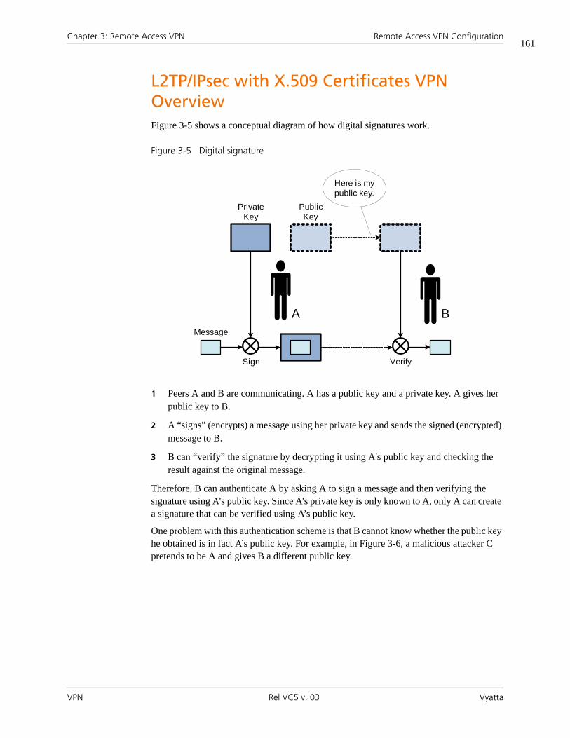
Chapter 3: Remote Access VPN Remote Access VPN Configuration
VPN Rel VC5 v. 03 Vyatta
161
L2TP/IPsec with X.509 Certificates VPN OverviewFigure 3-5 shows a conceptual diagram of how digital signatures work.
Figure 3-5 Digital signature
1 Peers A and B are communicating. A has a public key and a private key. A gives her public key to B.
2 A “signs” (encrypts) a message using her private key and sends the signed (encrypted) message to B.
3 B can “verify” the signature by decrypting it using A's public key and checking the result against the original message.
Therefore, B can authenticate A by asking A to sign a message and then verifying the signature using A’s public key. Since A’s private key is only known to A, only A can create a signature that can be verified using A’s public key.
One problem with this authentication scheme is that B cannot know whether the public key he obtained is in fact A’s public key. For example, in Figure 3-6, a malicious attacker C pretends to be A and gives B a different public key.
Message
Sign Verify
PrivateKey
PublicKey
A B
Here is my public key.

Chapter 3: Remote Access VPN Remote Access VPN Configuration
VPN Rel VC5 v. 03 Vyatta
162
Figure 3-6 Malicious attacker
In practice, this problem is solved by using a Public Key Infrastructure (PKI), which is based on a trusted third party, the Certificate Authority (CA). The CA can be either a commercial CA, such as Verisign, or a CA set up internal to the organization. Figure 3-7 illustrates conceptually how PKI works.
Figure 3-7 Trusted Third Party: Certificate Authority
C B
I’m A. Here is my public key.
PrivateKey
PublicKey
A
Please sign.
B
CA
PrivateKey
PublicKey
A:A:
A:
Trusted Third Party:Certificate Authority (CA)

Chapter 3: Remote Access VPN Remote Access VPN Configuration
VPN Rel VC5 v. 03 Vyatta
163
1 Both A and B trust CA.
2 A asks the CA to sign a message verifying A’s public key.
3 The CA signs the message using its private key, resulting in a “certificate.”
4 A gives the certificate to B.
5 B can verify the certificate from A (and hence A’s public key) using the CA’s public key.
X.509 is a standard that defines public key certificate formats, revocation, and so on. Given the above scheme, L2TP/IPsec VPN with X.509 certificates works as follows.
1 The network admin obtains a certificate signed by a CA for each remote user (A in the example) and distributes it, along with public/private keys for the user, to the user through a secure channel.
2 The network admin configures the VPN server (B in the example) with the CA’s public key, among other things.
3 When the remote client connects to the VPN server, it presents its certificate.
4 The VPN server verifies the certificate using the CA’s public key. If the authentication is successful, the result tells the server the client’s public key.
5 The server can then use the client’s public key for authentication as described previously.
6 If authentication is successful, the IPsec tunnel is established between the client and server. Then the L2TP and PPP operations are identical to the PSK case described previously.
Remote Access VPN Configuration ExamplesThis section presents the following topics:
• PPTP VPN Example
• L2TP/IPsec with Pre-Shared Key VPN Example
• L2TP/IPsec with X.509 Certificates VPN Example
• Configuring Internet Traffic with VPN
This section provides configuration examples for each of the RA VPN scenarios supported: PPTP, L2TP/IPsec with pre-shared key, and L2TP/IPsec with X.509 certificates. Each configuration example uses the diagram shown in Figure 3-8 as the deployment scenario:

Chapter 3: Remote Access VPN Remote Access VPN Configuration
VPN Rel VC5 v. 03 Vyatta
164
Figure 3-8 Remote Access VPN Example
PPTP VPN ExampleThe first step in configuring basic remote access for PPTP on a Windows XP client is to configure R1 as a PPTP-based VPN Server.
192 .168 .1.0/24
Private Network 1
VPN Server (R1)
Remote User
VPN tunnel
12.34.56.78wan1
eth0192.168.1.254
Example 3-1 Remote Access VPN - PPTP example)
Step Command
Bind the PPTP server to the external address.
vyatta@R1# set vpn pptp remote-access outside-address 12.34.56.78[edit]
Set up the pool of IP addresses that remote VPN connections will assume on the private network. In this case we make 10 addresses available - from .101 to .110.
vyatta@R1# set vpn pptp remote-access client-ip-pool start 192.168.1.101[edit]vyatta@R1# set vpn pptp remote-access client-ip-pool stop 192.168.1.110[edit]
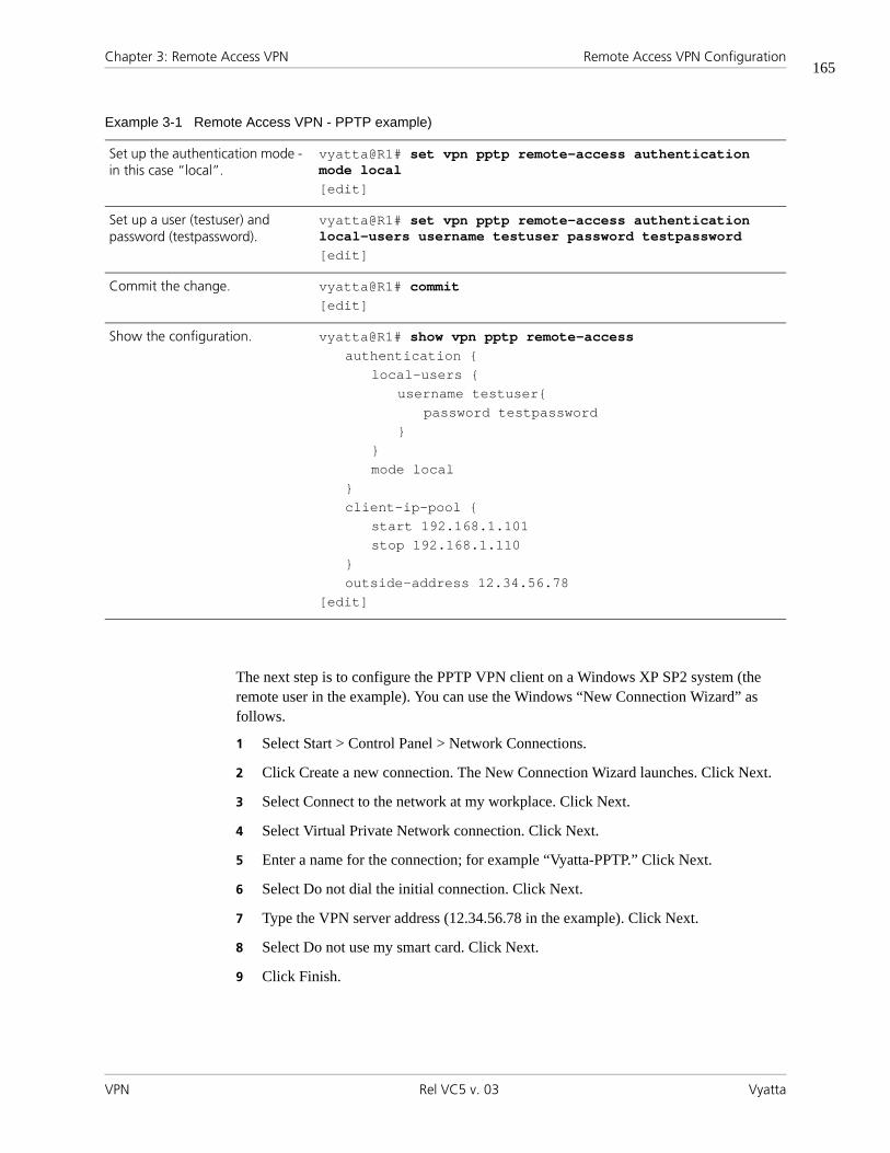
Chapter 3: Remote Access VPN Remote Access VPN Configuration
VPN Rel VC5 v. 03 Vyatta
165
The next step is to configure the PPTP VPN client on a Windows XP SP2 system (the remote user in the example). You can use the Windows “New Connection Wizard” as follows.
1 Select Start > Control Panel > Network Connections.
2 Click Create a new connection. The New Connection Wizard launches. Click Next.
3 Select Connect to the network at my workplace. Click Next.
4 Select Virtual Private Network connection. Click Next.
5 Enter a name for the connection; for example “Vyatta-PPTP.” Click Next.
6 Select Do not dial the initial connection. Click Next.
7 Type the VPN server address (12.34.56.78 in the example). Click Next.
8 Select Do not use my smart card. Click Next.
9 Click Finish.
Set up the authentication mode - in this case “local”.
vyatta@R1# set vpn pptp remote-access authentication mode local[edit]
Set up a user (testuser) and password (testpassword).
vyatta@R1# set vpn pptp remote-access authentication local-users username testuser password testpassword[edit]
Commit the change. vyatta@R1# commit[edit]
Show the configuration. vyatta@R1# show vpn pptp remote-accessauthentication {
local-users {username testuser{
password testpassword}
}mode local
}client-ip-pool {
start 192.168.1.101stop 192.168.1.110
}outside-address 12.34.56.78
[edit]
Example 3-1 Remote Access VPN - PPTP example)

Chapter 3: Remote Access VPN Remote Access VPN Configuration
VPN Rel VC5 v. 03 Vyatta
166
To connect to the VPN server, double-click the VPN connection icon, enter your user name (“testuser” in the example) and password (“testpassword” in the example), and then click Connect.
NOTE You must make sure that, between the remote client and the VPN server, nothing
is blocking packets with protocol GRE or TCP port 1723. (Check firewall settings, home
gateway, DSL modem, ISP, and so on.)
L2TP/IPsec with Pre-Shared Key VPN ExampleThe first step for configuring a basic remote access VPN setup to use L2TP/IPsec with pre-shared key and a Windows XP client to access it is to configure R1 as a L2TP/IPsec–based VPN server.
Example 3-2 Remote Access VPN - PPTP example)
Step Command
Define the interface used for IPsec; in this case, wan1.
vyatta@R1# set vpn ipsec ipsec-interfaces interface wan1[edit]
Enable NAT traversal. This is mandatory.
vyatta@R1# set vpn ipsec nat-traversal enable[edit]
TBD vyatta@R1# set vpn ipsec nat-networks allowed-network ???[edit]
Bind the L2TP server to the external address.
vyatta@R1# set vpn l2tp remote-access outside-address 12.34.56.78[edit]
TBD vyatta@R1# set vpn l2tp remote-access outside-nexthop [edit]
Set up the pool of IP addresses that remote VPN connections will assume on the private network. In this case we make 10 addresses available - from .101 to .110.
vyatta@R1# set vpn l2tp remote-access client-ip-pool start 192.168.1.101[edit]vyatta@R1# set vpn l2tp remote-access client-ip-pool stop 192.168.1.110[edit]
TBD vyatta@R1# set vpn l2tp remote-access ipsec-settings authentication mode pre-shared-secret[edit]
TBD vyatta@R1# set vpn l2tp remote-access ipsec-settings authentication pre-shared-secret !secrettext![edit]

Chapter 3: Remote Access VPN Remote Access VPN Configuration
VPN Rel VC5 v. 03 Vyatta
167
The next step is to configure the PPTP VPN client on a Windows XP SP2 system (the remote user in the example). You can use the Windows “New Connection Wizard” as follows.
1 Select Start > Control Panel > Network Connections.
2 Click Create a new connection. The New Connection Wizard launches. Click Next.
3 Select Connect to the network at my workplace. Click Next.
4 Select Virtual Private Network connection. Click Next.
5 Enter a name for the connection; for example “Vyatta-PPTP.” Click Next.
6 Select Do not dial the initial connection. Click Next.
7 Type the VPN server address (12.34.56.78 in the example). Click Next.
8 Select Do not use my smart card. Click Next.
9 Click Finish.
TBD vyatta@R1# set vpn l2tp remote-access authentication mode local[edit]
TBD vyatta@R1# set vpn l2tp remote-access authentication local-users username testuser password testpassword[edit]
Commit the change. vyatta@R1# commit[edit]
Show the configuration. vyatta@R1# show vpn l2tp remote-accessauthentication {
local-users {username testuser{
password testpassword}
}mode local
}client-ip-pool {
start 192.168.1.101stop 192.168.1.110
}outside-address 12.34.56.78
[edit]
Example 3-2 Remote Access VPN - PPTP example)

Chapter 3: Remote Access VPN Remote Access VPN Configuration
VPN Rel VC5 v. 03 Vyatta
168
By default, after the VPN connection is established, a default route pointing to the VPN will be added. This means that, e.g., your Internet traffic will be routed to the VPN as well. If you do not want this (i.e., you want to keep your default route), you can modify the VPN configuration as follows.
1 Go to “Network Connections” in the “Control Panel”.
2 Right-click the “Vyatta-PPTP” (or whatever name you specified) icon. Select “Properties”.
3 Click “Networking” tab. Click “Internet Protocol (TCP/IP)”. Click “Properties”.
4 Click “Advanced”. Uncheck “Use default gateway on remote network”.
5 Click “OK”. Click “OK”. Click “OK”.
To connect to the VPN server, double-click the “Vyatta-PPTP” icon, type the user name (“testuser” in our example) and password (“testpassword” in our example), and then click “Connect”.
NOTE You need to make sure that, between the remote client and the VPN server,
nothing is blocking packets with protocol GRE or TCP port 1723. (Check firewall settings,
home gateway, DSL modem, ISP, etc.)
L2TP/IPsec with X.509 Certificates VPN ExampleTBD
Configuring Internet Traffic with VPNBy default, after the VPN connection is established, the system adds a default route pointing to the VPN. This means that, for example, your Internet traffic will be routed to the VPN as well. If you do not want this (that is, if you want to retain your current route), you can modify the VPN configuration as follows:
1 Select Start > Control Panel > Network Connections.
2 Right-click the icon for the VPN connection (“Vyatta-PPTP” in the example). Click Properties.
3 Click the Networking tab. Select Internet Protocol (TCP/IP), then click Properties.
4 Click Advanced. Uncheck the Use default gateway on remote network checkbox.
5 Click OK three times.

Chapter 3: Remote Access VPN Remote Access VPN Commands
VPN Rel VC5 v. 03 Vyatta
169
Remote Access VPN CommandsThis chapter contains the following commands.
Configuration Commands
Global IPsec
vpn ipsec For these commands, see “Chapter 2: IPsec Site-to-Site VPN.”
vpn ipsec ipsec-interfaces interface <if-name>
vpn ipsec logging
vpn ipsec nat-networks allowed-network <ipv4net>
vpn ipsec nat-traversal <state>
L2TP
vpn l2tp Creates the top-most configuration node for L2TP VPN, enabling L2TP VPN functionality.
vpn l2tp remote-access authentication mode <mode> Specifies user authentication mode for L2TP VPN remote access connections.
vpn l2tp remote-access authentication local-users user-name <user-name> password <password>
Specifies the user name and password for L2TP VPN remote users being authenticated locally.
vpn l2tp remote-access authentication radius-server <ipv4> key <key>
Defines a RADIUS server authenticating L2TP VPN remote users.
vpn l2tp remote-access client-ip-pool start <ipv4> Specifies the beginning address of a pool of IP addresses for L2TP VPN remote clients.
vpn l2tp remote-access client-ip-pool stop <ipv4> Specifies the ending address of a pool of IP addresses for L2TP VPN remote clients.
vpn l2tp remote-access dns-servers server-1 <ipv4> Specifies the IP address for the primary DNS server for L2TP VPN remote clients.
vpn l2tp remote-access dns-servers server-2 <ipv4> Specifies the IP address for the secondary DNS server for L2TP VPN remote clients.
vpn l2tp remote-access ipsec-settings authentication mode <mode>
Sets the IPsec authentication mode to be used for IPsec authentication on remote access L2TP VPN connections.
vpn l2tp remote-access ipsec-settings authentication pre-shared-secret <secret>
Sets a pre-shared key for IPsec authentication on remote access L2TP VPN connections.
vpn l2tp remote-access ipsec-settings authentication x509 ca-cert-file <file-name>
Specifies the location of an X.509 Certificate Authority (CA) certificate file for IPsec authentication on remote access L2TP VPN connections.

Chapter 3: Remote Access VPN Remote Access VPN Commands
VPN Rel VC5 v. 03 Vyatta
170
vpn l2tp remote-access ipsec-settings authentication x509 crl-file <file-name>
Specifies the location of an X.509 Certificate Revocation List (CRL) file for IPsec authentication on L2TP VPN remote access connections.
vpn l2tp remote-access ipsec-settings authentication x509 server-cert-file <file-name>
Specifies the location of VPN server’s certificate file for IPsec authentication on L2TP VPN remote access connections.
vpn l2tp remote-access ipsec-settings authentication x509 server-key-file <file-name>
Specifies the location of VPN server’s private key file for IPsec authentication on L2TP VPN remote access connections.
vpn l2tp remote-access ipsec-settings authentication x509 server-key-password <password>
Specifies the password that protects the L2TP VPN server’s private key.
vpn l2tp remote-access outside-address <ipv4> Sets the IP address to be bound to the L2TP server.
vpn l2tp remote-access outside-nexthop <ipv4> Sets the IP address of the next hop on the external network.
vpn l2tp remote-access wins-servers server-1 <ipv4> Specifies the IP address for the primary WINS server for L2TP VPN remote clients.
vpn l2tp remote-access wins-servers server-2 <ipv4> Specifies the IP address for the secondary WINS server for L2TP VPN remote clients.
PPTP
vpn pptp Creates the top-most configuration node for PPTP VPN, enabling PPTP VPN functionality.
vpn pptp remote-access authentication mode <mode> Specifies user authentication mode for PPTP VPN remote access connections.
vpn pptp remote-access authentication local-users user-name <user-name> password <password>
Specifies the user name and password for PPTP VPN remote users being authenticated locally.
vpn pptp remote-access authentication radius-server <ipv4> key <key>
Specifies the RADIUS server to use to authenticate PPTP VPN remote users.
vpn pptp remote-access client-ip-pool start <ipv4> Specifies the beginning address of a pool of IP addresses for PPTP VPN remote clients.
vpn pptp remote-access client-ip-pool stop <ipv4> Specifies the ending address of a pool of IP addresses for PPTP VPN remote clients.
vpn pptp remote-access dns-servers server-1 <ipv4> Specifies the IP address for the primary DNS server for PPTP VPN remote clients.
vpn pptp remote-access dns-servers server-2 <ipv4> Specifies the IP address for the secondary DNS server for PPTP VPN remote clients.
vpn pptp remote-access outside-address <ipv4> Sets the IP address to be bound to the PPTP server.

Chapter 3: Remote Access VPN Remote Access VPN Commands
VPN Rel VC5 v. 03 Vyatta
171
vpn pptp remote-access wins-servers server-1 <ipv4> Specifies the IP address for the primary WINS server for PPTP VPN remote clients.
vpn pptp remote-access wins-servers server-2 <ipv4> Specifies the IP address for the secondary WINS server for PPTP VPN remote clients.
Operational Commands
clear vpn ipsec-process Restarts the IPsec process. See page 79 in “Chapter 2: IPsec Site-to-Site VPN.”
clear vpn remote-access user <user-name> Terminates the specified user’s active sessions.
show vpn debug Provides trace-level information about IPsec VPN. See page 80 in “Chapter 2: IPsec Site-to-Site VPN.”
show vpn ipsec sa Provides information about all active IPsec security associations. See page 89 in “Chapter 2: IPsec Site-to-Site VPN.”
show vpn ipsec sa nat-traversal Provides information about all active IPsec security associations that are using NAT Traversal. See page 92 in “Chapter 2: IPsec Site-to-Site VPN.”
show vpn ipsec status Displays information about the status of IPsec processes. See page 96 in “Chapter 2: IPsec Site-to-Site VPN.”
show vpn remote-access Shows information about currently active remote access VPN sessions.

Chapter 3: Remote Access VPN Remote Access VPN Commands
VPN Rel VC5 v. 03 Vyatta
172
clear vpn remote-access user <user-name>Terminates the specified user’s active sessions.
Syntax
clear vpn remote-access user user-name
Command Mode
Operational mode.
Configuration Statement
None.
Parameters
None.
Default
None.
Usage Guidelines
Use this command to terminate all active sessions for the specified user.
Examples
Example 3-3 terminates all active sessions for user robert.
Example 3-3 “clear vpn remote access user”: Terminating a user’s active sessions
vyatta@vyatta# clear remote-access user robertvyatta@vyatta#
r

Chapter 3: Remote Access VPN Remote Access VPN Commands
VPN Rel VC5 v. 03 Vyatta
173
show vpn remote-accessShows information about currently active remote access VPN sessions.
Syntax
show vpn remote-access
Command Mode
Operational mode.
Configuration Statement
None.
Parameters
None
Default
None.
Usage Guidelines
Use this command to see information about the currently active remote access VPN sessions.

Chapter 3: Remote Access VPN Remote Access VPN Commands
VPN Rel VC5 v. 03 Vyatta
174
Examples
Example 3-4 shows the output of the show vpn remote-access command.
Example 3-4 “show vpn remote-access”: Viewing remote VPN sessions
vyatta@vyatta# show vpn remote-accessActive remote access VPN sessions:
User Time Proto Iface Remote IP TX pkt/byte RX pkt/byte---------- --------- ----- ----- --------------- ------ ------ ------ ------stig 01d02h12m PPTP ppp0 10.254.1.1 28.0K 7.7M 26.3K 2.0Mshemminger 00h12m15s PPTP ppp1 10.254.1.2 85.2K 119.6M 46.6K 2.7Mancheng 15h15m33s PPTP ppp2 10.254.1.3 73.6K 28.5M 68.3K 4.3Mvpn:~#vyatta@vyatta#

Chapter 3: Remote Access VPN Remote Access VPN Commands
VPN Rel VC5 v. 03 Vyatta
175
vpn l2tp Creates the top-most configuration node for L2TP VPN, enabling L2TP VPN functionality.
Syntax
set vpn l2tp
delete vpn l2tp
show vpn l2tp
Command Mode
Configuration mode.
Configuration Statement
vpn {l2tp
}
Parameters
None.
Default
None.
Usage Guidelines
Use this command to create the configuration node for Layer 2 Tunneling Protocol (L2TP) Virtual Private Network (VPN) functionality.
Use the set form of this command to create the L2TP VPN configuration node.
Use the delete form of this command to remove all L2TP VPN configuration.
Use the show form of this command to display L2TP VPN configuration.

Chapter 3: Remote Access VPN Remote Access VPN Commands
VPN Rel VC5 v. 03 Vyatta
176
vpn l2tp remote-access authentication mode <mode>Specifies user authentication mode for L2TP VPN remote access connections.
Syntax
set vpn l2tp remote-access authentication mode mode
delete vpn l2tp remote-access authentication mode
show vpn l2tp remote-access authentication mode
Command Mode
Configuration mode.
Configuration Statement
vpn {l2tp {
remote-access {authentication {
mode: [local|radius]}
}}
}
Parameters
Default
Users are authenticated using the system’s local user database defined in the vpn l2tp configuration.
Usage Guidelines
Use this command to specify how L2TP VPN remote users are to be authenticated.
mode Mandatory. The mode to be used for authenticating remote users. Supported values are as follows:
local: Authenticates users locally.
radius: Authenticates using a RADIUS server.

Chapter 3: Remote Access VPN Remote Access VPN Commands
VPN Rel VC5 v. 03 Vyatta
177
Users can be authenticated either locally, using login credentials specified using the vpn l2tp remote-access authentication local-users user-name <user-name> password <password> command (see page 178), or using one or more servers running the Remote Access Dial In User Service (RADIUS) protocol.
If you specify RADIUS authentication, you must specify the location of the RADIUS servers, and record the RADIUS login password, by using the vpn l2tp remote-access authentication radius-server <ipv4> key <key> command (see page 180).
Use the set form of this command to configure the authentication mode for users.
Use the delete form of this command to remove the user authentication mode.
Use the show form of this command to display the user authentication mode.
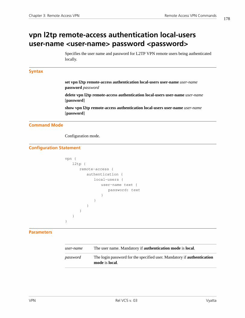
Chapter 3: Remote Access VPN Remote Access VPN Commands
VPN Rel VC5 v. 03 Vyatta
178
vpn l2tp remote-access authentication local-users user-name <user-name> password <password>
Specifies the user name and password for L2TP VPN remote users being authenticated locally.
Syntax
set vpn l2tp remote-access authentication local-users user-name user-name password password
delete vpn l2tp remote-access authentication local-users user-name user-name [password]
show vpn l2tp remote-access authentication local-users user-name user-name [password]
Command Mode
Configuration mode.
Configuration Statement
vpn {l2tp {
remote-access {authentication {
local-users {user-name text {
password: text}
}}
}}
}
Parameters
user-name The user name. Mandatory if authentication mode is local.
password The login password for the specified user. Mandatory if authentication mode is local.

Chapter 3: Remote Access VPN Remote Access VPN Commands
VPN Rel VC5 v. 03 Vyatta
179
Default
None.
Usage Guidelines
Use this command to specify login credentials for L2TP VPN remote users.
Use the set form of this command to create the user name configuration node and set the password for the user.
Use the delete form of this command to remove a user’s login credentials.
Use the show form of this command to display the user login authentication configuration.

Chapter 3: Remote Access VPN Remote Access VPN Commands
VPN Rel VC5 v. 03 Vyatta
180
vpn l2tp remote-access authentication radius-server <ipv4> key <key>
Defines a RADIUS server authenticating L2TP VPN remote users.
Syntax
set vpn l2tp remote-access authentication radius-server ipv4 key key
delete vpn l2tp remote-access authentication radius-server ipv4 [key]
show vpn l2tp remote-access authentication radius-server ipv4 [key]
Command Mode
Configuration mode.
Configuration Statement
vpn {l2tp {
remote-access {authentication {
radius-server ipv4 {key: text
}}
}}
}
Parameters
radius-server Multi-node. The IPv4 address of the RADIUS server. Mandatory if authentication mode is radius.
You can define more than one RADIUS server by creating multiple radius-server configuration nodes.
key The password for the RADIUS server. This must be the same as that recorded on the RADIUS server. Mandatory if authentication mode is radius.
Supported characters are alphanumeric, space, and special characters. Strings containing spaces must be enclosed in double quotes.
Chapter 3: Remote Access VPN Remote Access VPN Commands
VPN Rel VC5 v. 03 Vyatta
181
Default
None.
Usage Guidelines
Use this command to define one or more RADIUS servers for authenticating remote L2TP VPN and the login credentials required to access it.
At least one RADIUS server must be defined if RADIUS is set as the user authentication mode.
RADIUS servers are queried in the order they were configured. If the query to the first RADIUS server times out, the next RADIUS server in the list is queried. If no query is successful, the login attempt fails.
The RADIUS secret is specified in plain text. RADIUS secrets are stored in plain text on the system, and used as part of a cryptographic operation for transferring authentication information securely over the network. When you view RADIUS secrets, they are displayed in plain text.
Use the set form of this command to define a RADIUS server. Note that you cannot use set to change the IP address of a defined server. To change the server’s IP address, delete the server and create a new one.
Use the delete form of this command to remove the RADIUS server configuration node or the key. Note that the key is mandatory; if you delete the key, you must configure another one.
Use the show form of this command to display RADIUS server configuration.

Chapter 3: Remote Access VPN Remote Access VPN Commands
VPN Rel VC5 v. 03 Vyatta
182
vpn l2tp remote-access client-ip-pool start <ipv4>Specifies the beginning address of a pool of IP addresses for L2TP VPN remote clients.
Syntax
set vpn l2tp remote-access client-ip-pool start ipv4
delete vpn l2tp remote-access client-ip-pool start
show vpn l2tp remote-access client-ip-pool start
Command Mode
Configuration mode.
Configuration Statement
vpn {l2tp {
remote-access {client-ip-pool {
start: ipv4}
}}
}
Parameters
Default
None.
ipv4 Mandatory. The IP address that designates the beginning of the address pool.

Chapter 3: Remote Access VPN Remote Access VPN Commands
VPN Rel VC5 v. 03 Vyatta
183
Usage Guidelines
Use this command to specify the start of an address pool for remote remote L2TP VPN clients.
Both the start address and the stop address must be specified. The stop address is specified using the vpn l2tp remote-access client-ip-pool stop <ipv4> command (see page 184).
Use the set form of this command to define the start address.
Use the delete form of this command to remove the start address.
Use the show form of this command to display the start address.

Chapter 3: Remote Access VPN Remote Access VPN Commands
VPN Rel VC5 v. 03 Vyatta
184
vpn l2tp remote-access client-ip-pool stop <ipv4>Specifies the ending address of a pool of IP addresses for L2TP VPN remote clients.
Syntax
set vpn l2tp remote-access client-ip-pool stop ipv4
delete vpn l2tp remote-access client-ip-pool stop
show vpn l2tp remote-access client-ip-pool stop
Command Mode
Configuration mode.
Configuration Statement
vpn {l2tp {
remote-access {client-ip-pool {
stop: ipv4}
}}
}
Parameters
Default
None.
ipv4 Mandatory. The IP address that designates the end of the address pool.

Chapter 3: Remote Access VPN Remote Access VPN Commands
VPN Rel VC5 v. 03 Vyatta
185
Usage Guidelines
Use this command to specify the end of the address pool for remote L2TP VPN clients.
Both the start address and the stop address must be specified. The start address is specified using the vpn l2tp remote-access client-ip-pool start <ipv4> command (see page 182).
Use the set form of this command to define the stop address.
Use the delete form of this command to remove the stop address.
Use the show form of this command to display the stop address.

Chapter 3: Remote Access VPN Remote Access VPN Commands
VPN Rel VC5 v. 03 Vyatta
186
vpn l2tp remote-access dns-servers server-1 <ipv4>Specifies the IP address for the primary DNS server for L2TP VPN remote clients.
Syntax
set vpn l2tp remote-access dns-servers server-1 ipv4
delete vpn l2tp remote-access dns-servers server-1
show vpn l2tp remote-access dns-servers server-1
Command Mode
Configuration mode.
Configuration Statement
vpn {l2tp {
remote-access {dns-servers {
server-1: ipv4}
}}
}
Parameters
Default
None.
Usage Guidelines
Use this command to specify the primary DNS server to be associated with remote L2TP VPN clients.
Use the set form of this command to specify the primary DNS server IP address.
Use the delete form of this command to remove the primary DNS server IP address.
Use the show form of this command to display the primary DNS server IP address.
ipv4 The IP address of the primary DNS server for remote clients.

Chapter 3: Remote Access VPN Remote Access VPN Commands
VPN Rel VC5 v. 03 Vyatta
187
vpn l2tp remote-access dns-servers server-2 <ipv4>Specifies the IP address for the secondary DNS server for L2TP VPN remote clients.
Syntax
set vpn l2tp remote-access dns-servers server-2 ipv4
delete vpn l2tp remote-access dns-servers server-2
show vpn l2tp remote-access dns-servers server-2
Command Mode
Configuration mode.
Configuration Statement
vpn {l2tp {
remote-access {dns-servers {
server-2: ipv4}
}}
}
Parameters
Default
None.
Usage Guidelines
Use this command to specify the secondary DNS server to be associated with remote L2TP VPN clients.
Use the set form of this command to specify the secondary DNS server IP address.
Use the delete form of this command to remove the secondary DNS server IP address.
Use the show form of this command to display the secondary DNS server IP address.
ipv4 The IP address of the secondary DNS server for remote clients.

Chapter 3: Remote Access VPN Remote Access VPN Commands
VPN Rel VC5 v. 03 Vyatta
188
vpn l2tp remote-access ipsec-settings authentication mode <mode>
Sets the IPsec authentication mode to be used for IPsec authentication on remote access L2TP VPN connections.
Syntax
set vpn l2tp remote-access ipsec-settings authentication mode mode
delete vpn l2tp remote-access ipsec-settings authentication mode
show vpn l2tp remote-access ipsec-settings authentication mode
Command Mode
Configuration mode.
Configuration Statement
vpn {l2tp {
remote-access {ipsec-settings {
authentication {mode: [pre-shared-secret|x509]
}}
}}
}
Parameters
Default
Pre-shared secret.
mode Mandatory. Specifies the authentication mode to be used for IPsec authentication on L2TP VPN remote access connections. Supported values are as follows:
pre-shared-secret: Uses a pre-shared secret for authentication.
x509: Uses X.509 V.3 certificates for authentication.

Chapter 3: Remote Access VPN Remote Access VPN Commands
VPN Rel VC5 v. 03 Vyatta
189
Usage Guidelines
Use this command to set the authentication mode to be used for IPsec authentication on remote access L2TP VPN connections.
A pre-shared secret, or pre-shared key (PSK), is a method of authentication. The secret, or key, is a string agreed upon beforehand by both parties as key for authenticating the session. It is used to generate a hash such that each VPN endpoint can authenticate the other.
If the authentication mode is pre-shared secret, you must configure the secret using the vpn l2tp remote-access ipsec-settings authentication pre-shared-secret <secret> command (see page 190).
The pre-shared secret is not passed from side to side. It is configured on both sides, and must match on both sides. Pre-shared secrets are less secure than X.509 certificates.
NOTE You should restrict the use of pre-shared keys to smaller, low-risk environments.
X.509 v.3 certificates are certificates conforming to the ITU-T X.509 version 3 standard for public key infrastructure (PKI). The certificate is issued by a Certificate Authority (CA), and stored securely on the local Vyatta system.
If the mode is X.509 certificates, you must configure all X.509 certificate information.
Use the set form of this command to specify the authentication mode for remote access L2TP VPN.
Use the delete form of this command to remove authentication mode configuration.
Use the show form of this command to display authentication mode configuration.

Chapter 3: Remote Access VPN Remote Access VPN Commands
VPN Rel VC5 v. 03 Vyatta
190
vpn l2tp remote-access ipsec-settings authentication pre-shared-secret <secret>
Sets a pre-shared key for IPsec authentication on remote access L2TP VPN connections.
Syntax
set vpn l2tp remote-access ipsec-settings authentication pre-shared-secret secret
delete vpn l2tp remote-access ipsec-settings authentication pre-shared-secret
show vpn l2tp remote-access ipsec-settings authentication pre-shared-secret
Command Mode
Configuration mode.
Configuration Statement
vpn {l2tp {
remote-access {ipsec-settings {
authentication {pre-shared-secret: text
}}
}}
}
Parameters
Default
None.
secret The password, or secret, to be used to authenticate the remote access connection. This parameter is mandatory if authentication mode is pre-shared-secret. The secret must be the same on both sides of the connection.

Chapter 3: Remote Access VPN Remote Access VPN Commands
VPN Rel VC5 v. 03 Vyatta
191
Usage Guidelines
Use this command to set a pre-shared secret to be used to authenticate the IPsec part of remote access L2TP VPN connections.
Use the set form of this command to specify the pre-shared secret.
Use the delete form of this command to remove pre-shared secret configuration.
Use the show form of this command to display pre-shared secret configuration.

Chapter 3: Remote Access VPN Remote Access VPN Commands
VPN Rel VC5 v. 03 Vyatta
192
vpn l2tp remote-access ipsec-settings authentication x509 ca-cert-file <file-name>
Specifies the location of an X.509 Certificate Authority (CA) certificate file for IPsec authentication on remote access L2TP VPN connections.
Syntax
set vpn l2tp remote-access ipsec-settings authentication x509 ca-cert-file file-name
delete vpn l2tp remote-access ipsec-settings authentication x509 ca-cert-file
show vpn l2tp remote-access ipsec-settings authentication x509 ca-cert-file
Command Mode
Configuration mode.
Configuration Statement
vpn {l2tp {
remote-access {ipsec-settings {
authentication {x509 {
ca-cert-file: text}
}}
}}
}
Parameters
Default
None.
file-name The absolute path to the certificate file. This parameter is mandatory if authentication mode is x509.

Chapter 3: Remote Access VPN Remote Access VPN Commands
VPN Rel VC5 v. 03 Vyatta
193
Usage Guidelines
Use this command to specify the location of an X.509 Certificate Authority (CA) certificate file. The X.509 CA certificate is used for IPsec authentication on remote access L2TP VPN connections.
Use the set form of this command to specify the location of the CA certificate file.
Use the delete form of this command to remove the location of the CA certificate file.
Use the show form of this command to display CA certificate file configuration.
Chapter 3: Remote Access VPN Remote Access VPN Commands
VPN Rel VC5 v. 03 Vyatta
194
vpn l2tp remote-access ipsec-settings authentication x509 crl-file <file-name>
Specifies the location of an X.509 Certificate Revocation List (CRL) file for IPsec authentication on L2TP VPN remote access connections.
Syntax
set vpn l2tp remote-access ipsec-settings authentication x509 crl-file file-name
delete vpn l2tp remote-access ipsec-settings authentication x509 crl-file
show vpn l2tp remote-access ipsec-settings authentication x509 crl-file
Command Mode
Configuration mode.
Configuration Statement
vpn {l2tp {
remote-access {ipsec-settings {
authentication {x509 {
crl-file: text}
}}
}}
}
Parameters
Default
None.
file-name The absolute path to the CRL file. This parameter is mandatory if authentication mode is x509.

Chapter 3: Remote Access VPN Remote Access VPN Commands
VPN Rel VC5 v. 03 Vyatta
195
Usage Guidelines
Use this command to specify the location to a Certificate Revocation List (CRL) file.
A CRL is a time-stamped signed data structure issued by the Certificate Authority (CA) identifying revoked certificates. When the remote user attempts to log on to the system, the system checks both the remote user’s certificate signature and also the CRL to make sure that the remote user’s certificate serial number is not on the CRL.
Use the set form of this command to specify the location of the CRL file.
Use the delete form of this command to remove the location of the CRL file.
Use the show form of this command to display CRL file configuration.

Chapter 3: Remote Access VPN Remote Access VPN Commands
VPN Rel VC5 v. 03 Vyatta
196
vpn l2tp remote-access ipsec-settings authentication x509 server-cert-file <file-name>
Specifies the location of VPN server’s certificate file for IPsec authentication on L2TP VPN remote access connections.
Syntax
set vpn l2tp remote-access ipsec-settings authentication x509 server-cert-file file-name
delete vpn l2tp remote-access ipsec-settings authentication x509 server-cert-file
show vpn l2tp remote-access ipsec-settings authentication x509 server-cert-file
Command Mode
Configuration mode.
Configuration Statement
vpn {l2tp {
remote-access {ipsec-settings {
authentication {x509 {
server-cert-file: text}
}}
}}
}
Parameters
Default
None.
file-name The absolute path to the VPN server’s certificate file. This parameter is mandatory if authentication mode is x509.

Chapter 3: Remote Access VPN Remote Access VPN Commands
VPN Rel VC5 v. 03 Vyatta
197
Usage Guidelines
Use this command to specify the location to the VPN server’s certificate file.
VPN server’s certificate certifies the identity of the VPN server.
Use the set form of this command to specify the location of the VPN server’s certificate file.
Use the delete form of this command to remove the location of the VPN server’s certificate file.
Use the show form of this command to display VPN server certificate file configuration.

Chapter 3: Remote Access VPN Remote Access VPN Commands
VPN Rel VC5 v. 03 Vyatta
198
vpn l2tp remote-access ipsec-settings authentication x509 server-key-file <file-name>
Specifies the location of VPN server’s private key file for IPsec authentication on L2TP VPN remote access connections.
Syntax
set vpn l2tp remote-access ipsec-settings authentication x509 server-key-file file-name
delete vpn l2tp remote-access ipsec-settings authentication x509 server-key-file
show vpn l2tp remote-access ipsec-settings authentication x509 server-key-file
Command Mode
Configuration mode.
Configuration Statement
vpn {l2tp {
remote-access {ipsec-settings {
authentication {x509 {
server-key-file: text}
}}
}}
}
Parameters
Default
None.
file-name The absolute path to the VPN server’s private key file. This parameter is mandatory if authentication mode is x509.

Chapter 3: Remote Access VPN Remote Access VPN Commands
VPN Rel VC5 v. 03 Vyatta
199
Usage Guidelines
Use this command to specify the location to the VPN server’s private key file.
VPN server’s private key certifies the identity of the VPN server.
Use the set form of this command to specify the location of the VPN server’s private key file.
Use the delete form of this command to remove the location of the VPN server’s private key file.
Use the show form of this command to display VPN server private key file configuration.
Chapter 3: Remote Access VPN Remote Access VPN Commands
VPN Rel VC5 v. 03 Vyatta
200
vpn l2tp remote-access ipsec-settings authentication x509 server-key-password <password>
Specifies the password that protects the L2TP VPN server’s private key.
Syntax
set vpn l2tp remote-access ipsec-settings authentication x509 password password
delete vpn l2tp remote-access ipsec-settings authentication x509 password
show vpn l2tp remote-access ipsec-settings authentication x509 password
Command Mode
Configuration mode.
Configuration Statement
vpn {l2tp {
remote-access {ipsec-settings {
authentication {x509 {
server-key-password: text}
}}
}}
}
Parameters
Default
None.
password The password protecting the VPN server’s private key file. This parameter is mandatory if authentication mode is x509.

Chapter 3: Remote Access VPN Remote Access VPN Commands
VPN Rel VC5 v. 03 Vyatta
201
Usage Guidelines
Use this command to specify a password that protects the VPN server’s private key.
Use the set form of this command to specify the password for the VPN server’s private key.
Use the delete form of this command to remove the password for the VPN server’s private key.
Use the show form of this command to display VPN servers private key password configuration.

Chapter 3: Remote Access VPN Remote Access VPN Commands
VPN Rel VC5 v. 03 Vyatta
202
vpn l2tp remote-access outside-address <ipv4>Sets the IP address to be bound to the L2TP server.
Syntax
set vpn l2tp remote-access outside-address ipv4
delete vpn l2tp remote-access
show vpn l2tp remote-access
Command Mode
Configuration mode.
Configuration Statement
vpn {l2tp {
remote-access {outside-address: ipv4
}}
}
Parameters
Default
None.
Usage Guidelines
Use this command to set the outside address for a remote access L2TP VPN connection.
The outside address is the address of the interface facing the external network. This is the address to which the L2TP server binds, and only remote connections coming into this address will be accepted.
Use the set form of this command to set the L2TP VPN outside address.
Use the delete form of this command to remove the L2TP VPN outside address.
ipv4 Mandatory. The IPv4 address to which the L2TP server should bind.

Chapter 3: Remote Access VPN Remote Access VPN Commands
VPN Rel VC5 v. 03 Vyatta
203
Use the show form of this command to display L2TP VPN outside address configuration.

Chapter 3: Remote Access VPN Remote Access VPN Commands
VPN Rel VC5 v. 03 Vyatta
204
vpn l2tp remote-access outside-nexthop <ipv4>Sets the IP address of the next hop on the external network.
Syntax
set vpn l2tp remote-access outside-nexthop ipv4
delete vpn l2tp remote-access outside-nexthop ipv4
show vpn l2tp remote-access outside-nexthop
Command Mode
Configuration mode.
Configuration Statement
vpn {l2tp {
remote-access {outside-nexthop: ipv4
}}
}
Parameters
Default
None.
Usage Guidelines
Use this command to set the next hop on the external network for a remote access L2TP VPN connection.
Use the set form of this command to set the L2TP VPN outside next hop.
Use the delete form of this command to remove the L2TP VPN outside next hop.
Use the show form of this command to display L2TP VPN outside next-hop configuration.
ipv4 The IPv4 address of the next hop on the outside network.

Chapter 3: Remote Access VPN Remote Access VPN Commands
VPN Rel VC5 v. 03 Vyatta
205
vpn l2tp remote-access wins-servers server-1 <ipv4>Specifies the IP address for the primary WINS server for L2TP VPN remote clients.
Syntax
set vpn l2tp remote-access wins-servers server-1 ipv4
delete vpn l2tp remote-access wins-servers server-1
show vpn l2tp remote-access wins-servers server-1
Command Mode
Configuration mode.
Configuration Statement
vpn {l2tp {
remote-access {wins-servers {
server-1: ipv4}
}}
}
Parameters
Default
None.
ipv4 The IP address of the primary WINS server for remote clients.

Chapter 3: Remote Access VPN Remote Access VPN Commands
VPN Rel VC5 v. 03 Vyatta
206
Usage Guidelines
Use this command to specify a primary WINS server to be associated with remote L2TP VPN clients.
The Windows Internet Net Service (WINS) is used to support environments in which users access resources that have NetBIOS names.
Use the set form of this command to specify the primary WINS server IP address.
Use the delete form of this command to remove the primary WINS server IP address.
Use the show form of this command to display the primary WINS server IP address.

Chapter 3: Remote Access VPN Remote Access VPN Commands
VPN Rel VC5 v. 03 Vyatta
207
vpn l2tp remote-access wins-servers server-2 <ipv4>Specifies the IP address for the secondary WINS server for L2TP VPN remote clients.
Syntax
set vpn l2tp remote-access wins-servers server-2 ipv4
delete vpn l2tp remote-access wins-servers server-2
show vpn l2tp remote-access wins-servers server-2
Command Mode
Configuration mode.
Configuration Statement
vpn {l2tp {
remote-access {wins-servers {
server-2: ipv4}
}}
}
Parameters
Default
None.
ipv4 The IP address of the secondary WINS server for remote clients.

Chapter 3: Remote Access VPN Remote Access VPN Commands
VPN Rel VC5 v. 03 Vyatta
208
Usage Guidelines
Use this command to specify the secondary WINS server to be associated with remote L2TP VPN clients.
The Windows Internet Net Service (WINS) is used to support environments in which users access resources that have NetBIOS names.
Use the set form of this command to specify the secondary WINS server IP address.
Use the delete form of this command to remove the secondary WINS server IP address.
Use the show form of this command to display the secondary WINS server IP address.

Chapter 3: Remote Access VPN Remote Access VPN Commands
VPN Rel VC5 v. 03 Vyatta
209
vpn pptp Creates the top-most configuration node for PPTP VPN, enabling PPTP VPN functionality.
Syntax
set vpn pptp
delete vpn pptp
show vpn pptp
Command Mode
Configuration mode.
Configuration Statement
vpn {pptp
}
Parameters
None.
Default
None.
Usage Guidelines
Use this command to create the configuration node for Point-to-Point Tunneling Protocol (PPTP) Virtual Private Network (VPN) functionality.
Use the set form of this command to create the PPTP VPN configuration node.
Use the delete form of this command to remove all PPTP VPN configuration.
Use the show form of this command to display PPTP VPN configuration.

Chapter 3: Remote Access VPN Remote Access VPN Commands
VPN Rel VC5 v. 03 Vyatta
210
vpn pptp remote-access authentication mode <mode>Specifies user authentication mode for PPTP VPN remote access connections.
Syntax
set vpn pptp remote-access authentication mode mode
delete vpn pptp remote-access authentication mode
show vpn pptp remote-access authentication mode
Command Mode
Configuration mode.
Configuration Statement
vpn {pptp {
remote-access {authentication {
mode: [local|radius]}
}}
}
Parameters
Default
Users are authenticated using the system’s local user database defined in the vpn pptp configuration.
Usage Guidelines
Use this command to specify how PPTP VPN remote users are to be authenticated.
mode Mandatory. The mode to be used for authenticating remote users. Supported values are as follows:
local: Authenticates users locally.
radius: Authenticates using a RADIUS server.

Chapter 3: Remote Access VPN Remote Access VPN Commands
VPN Rel VC5 v. 03 Vyatta
211
Users can be authenticated either locally, using login credentials specified using the vpn pptp remote-access authentication local-users user-name <user-name> password <password> command (see page 212), or using one or more servers running the Remote Access Dial In User Service (RADIUS) protocol.
If you specify RADIUS authentication, you must specify the location of the RADIUS servers, and record the RADIUS login password, by using the vpn pptp remote-access authentication radius-server <ipv4> key <key> command (see page 214).
Use the set form of this command to configure the authentication mode.
Use the delete form of this command to remove the authentication mode.
Use the show form of this command to display the authentication mode.

Chapter 3: Remote Access VPN Remote Access VPN Commands
VPN Rel VC5 v. 03 Vyatta
212
vpn pptp remote-access authentication local-users user-name <user-name> password <password>
Specifies the user name and password for PPTP VPN remote users being authenticated locally.
Syntax
set vpn pptp remote-access authentication local-users user-name user-name password password
delete vpn pptp remote-access authentication local-users user-name user-name [password]
show vpn pptp remote-access authentication local-users user-name user-name [password]
Command Mode
Configuration mode.
Configuration Statement
vpn {pptp {
remote-access {authentication {
local-users {user-name text {
password: text}
}}
}}
}
Parameters
user-name The user name. This parameter is mandatory if authentication mode is local.
password The password associated with the user name. This parameter is mandatory if authentication mode is local.
Chapter 3: Remote Access VPN Remote Access VPN Commands
VPN Rel VC5 v. 03 Vyatta
213
Default
None.
Usage Guidelines
Use this command to specify user information for PPTP VPN remote access users that are to be authenticated locally.
Use the set form of this command to create the user name configuration node and set the password for the user.
Use the delete form of this command to remove the user name configuration node or the password.
Use the show form of this command to display the user name configuration node or the password.

Chapter 3: Remote Access VPN Remote Access VPN Commands
VPN Rel VC5 v. 03 Vyatta
214
vpn pptp remote-access authentication radius-server <ipv4> key <key>
Specifies the RADIUS server to use to authenticate PPTP VPN remote users.
Syntax
set vpn pptp remote-access authentication radius-server ipv4 key key
delete vpn pptp remote-access authentication radius-server ipv4 [key]
show vpn pptp remote-access authentication radius-server ipv4 [key]
Command Mode
Configuration mode.
Configuration Statement
vpn {pptp {
remote-access {authentication {
radius-server ipv4 {key: text
}}
}}
}
Parameters
Default
None.
radius-server The IPv4 address of the RADIUS server to use to authenticate remote users. This parameter is mandatory if authentication mode is radius.
key The key used to access the RADIUS server. This parameter is mandatory if authentication mode is radius.

Chapter 3: Remote Access VPN Remote Access VPN Commands
VPN Rel VC5 v. 03 Vyatta
215
Usage Guidelines
Use this command to define one or more RADIUS servers for authenticating remote PPTP VPN and the login credentials required to access it.
At least one RADIUS server must be defined if RADIUS is set as the user authentication mode.
RADIUS servers are queried in the order they were configured. If the query to the first RADIUS server times out, the next RADIUS server in the list is queried. If no query is successful, the login attempt fails.
The RADIUS secret is specified in plain text. RADIUS secrets are stored in plain text on the system, and used as part of a cryptographic operation for transferring authentication information securely over the network. When you view RADIUS secrets, they are displayed in plain text.
Use the set form of this command to define a RADIUS server. Note that you cannot use set to change the IP address of a defined server. To change the server’s IP address, delete the server and create a new one.
Use the delete form of this command to remove the RADIUS server configuration node or the key. Note that the key is mandatory; if you delete the key, you must configure another one.
Use the show form of this command to display RADIUS server configuration.

Chapter 3: Remote Access VPN Remote Access VPN Commands
VPN Rel VC5 v. 03 Vyatta
216
vpn pptp remote-access client-ip-pool start <ipv4>Specifies the beginning address of a pool of IP addresses for PPTP VPN remote clients.
Syntax
set vpn pptp remote-access client-ip-pool start ipv4
delete vpn pptp remote-access client-ip-pool start
show vpn pptp remote-access client-ip-pool start
Command Mode
Configuration mode.
Configuration Statement
vpn {pptp {
remote-access {client-ip-pool {
start: ipv4}
}}
}
Parameters
Default
None.
ipv4 Mandatory. The IP address that designates the beginning of the address pool.

Chapter 3: Remote Access VPN Remote Access VPN Commands
VPN Rel VC5 v. 03 Vyatta
217
Usage Guidelines
Use this command to specify the start of the address pool for remote PPTP VPN clients.
Both the start address and the stop address must be specified. The stop address is specified using the vpn pptp remote-access client-ip-pool stop <ipv4> command (see page 218).
Use the set form of this command to define the start address.
Use the delete form of this command to remove the start address.
Use the show form of this command to display the start address.

Chapter 3: Remote Access VPN Remote Access VPN Commands
VPN Rel VC5 v. 03 Vyatta
218
vpn pptp remote-access client-ip-pool stop <ipv4>Specifies the ending address of a pool of IP addresses for PPTP VPN remote clients.
Syntax
set vpn pptp remote-access client-ip-pool stop ipv4
delete vpn pptp remote-access client-ip-pool stop
show vpn pptp remote-access client-ip-pool stop
Command Mode
Configuration mode.
Configuration Statement
vpn {pptp {
remote-access {client-ip-pool {
stop: ipv4}
}}
}
Parameters
Default
None.
ipv4 Mandatory. The IP address that designates the end of the address pool.

Chapter 3: Remote Access VPN Remote Access VPN Commands
VPN Rel VC5 v. 03 Vyatta
219
Usage Guidelines
Use this command to specify the end of the address pool for remote PPTP VPN clients.
Both the start address and the stop address must be specified. The start address is specified using the vpn pptp remote-access client-ip-pool start <ipv4> command (see page 216). Use the set form of this command to define the stop address.
Use the delete form of this command to remove the stop address.
Use the show form of this command to display the stop address.

Chapter 3: Remote Access VPN Remote Access VPN Commands
VPN Rel VC5 v. 03 Vyatta
220
vpn pptp remote-access dns-servers server-1 <ipv4>Specifies the IP address for the primary DNS server for PPTP VPN remote clients.
Syntax
set vpn pptp remote-access dns-servers server-1 ipv4
delete vpn pptp remote-access dns-servers server-1
show vpn pptp remote-access dns-servers server-1
Command Mode
Configuration mode.
Configuration Statement
vpn {pptp {
remote-access {dns-servers {
server-1: ipv4}
}}
}
Parameters
Default
None.
Usage Guidelines
Use this command to specify the primary DNS server to be associated with PPTP VPN remote clients.
Use the set form of this command to specify the primary DNS server IP address.
Use the delete form of this command to remove the primary DNS server IP address.
Use the show form of this command to display the primary DNS server IP address.
ipv4 The IP address of the primary DNS server for remote clients.

Chapter 3: Remote Access VPN Remote Access VPN Commands
VPN Rel VC5 v. 03 Vyatta
221
vpn pptp remote-access dns-servers server-2 <ipv4>Specifies the IP address for the secondary DNS server for PPTP VPN remote clients.
Syntax
set vpn pptp remote-access dns-servers server-2 ipv4
delete vpn pptp remote-access dns-servers server-2
show vpn pptp remote-access dns-servers server-2
Command Mode
Configuration mode.
Configuration Statement
vpn {pptp {
remote-access {dns-servers {
server-2: ipv4}
}}
}
Parameters
Default
None.
Usage Guidelines
Use this command to specify the secondary DNS server to be associated with remote clients.
Use the set form of this command to specify the secondary DNS server IP address.
Use the delete form of this command to remove the secondary DNS server IP address.
Use the show form of this command to display the secondary DNS server IP address.
ipv4 The IP address of the secondary DNS server for remote clients.

Chapter 3: Remote Access VPN Remote Access VPN Commands
VPN Rel VC5 v. 03 Vyatta
222
vpn pptp remote-access outside-address <ipv4>Sets the IP address to be bound to the PPTP server.
Syntax
set vpn pptp remote-access outside-address ipv4
delete vpn pptp remote-access
show vpn pptp remote-access
Command Mode
Configuration mode.
Configuration Statement
vpn {pptp {
remote-access {outside-address: ipv4
}}
}
Parameters
Default
None.
Usage Guidelines
Use this command to set the outside address for a remote access PPTP VPN connection.
The outside address is the address of the interface facing the external network. This is the address to which the PPTP server binds, and only remote connections coming into the address will be accepted.
Use the set form of this command to set the PPTP VPN outside address.
Use the delete form of this command to remove the PPTP VPN outside address.
ipv4 Mandatory. The IPv4 address to which the PPTP server should bind.

Chapter 3: Remote Access VPN Remote Access VPN Commands
VPN Rel VC5 v. 03 Vyatta
223
Use the show form of this command to display PPTP VPN outside address configuration.

Chapter 3: Remote Access VPN Remote Access VPN Commands
VPN Rel VC5 v. 03 Vyatta
224
vpn pptp remote-access wins-servers server-1 <ipv4>Specifies the IP address for the primary WINS server for PPTP VPN remote clients.
Syntax
set vpn pptp remote-access wins-servers server-1 ipv4
delete vpn pptp remote-access wins-servers server-1
show vpn pptp remote-access wins-servers server-1
Command Mode
Configuration mode.
Configuration Statement
vpn {pptp {
remote-access {wins-servers {
server-1: ipv4}
}}
}
Parameters
Default
None.
ipv4 The IP address of the primary WINS server for remote clients.

Chapter 3: Remote Access VPN Remote Access VPN Commands
VPN Rel VC5 v. 03 Vyatta
225
Usage Guidelines
Use this command to specify the primary WINS server to be associated with remote PPTP VPN clients.
The Windows Internet Net Service (WINS) is used to support environments in which users access resources that have NetBIOS names.
Use the set form of this command to specify the primary WINS server IP address.
Use the delete form of this command to remove the primary WINS server IP address.
Use the show form of this command to display the primary WINS server IP address.

Chapter 3: Remote Access VPN Remote Access VPN Commands
VPN Rel VC5 v. 03 Vyatta
226
vpn pptp remote-access wins-servers server-2 <ipv4>Specifies the IP address for the secondary WINS server for PPTP VPN remote clients.
Syntax
set vpn pptp remote-access wins-servers server-2 ipv4
delete vpn pptp remote-access wins-servers server-2
show vpn pptp remote-access wins-servers server-2
Command Mode
Configuration mode.
Configuration Statement
vpn {pptp {
remote-access {wins-servers {
server-2: ipv4}
}}
}
Parameters
Default
None.
ipv4 The IP address of the secondary WINS server for remote clients.

Chapter 3: Remote Access VPN Remote Access VPN Commands
VPN Rel VC5 v. 03 Vyatta
227
Usage Guidelines
Use this command to specify the secondary WINS server to be associated with remote PPTP VPN clients.
The Windows Internet Net Service (WINS) is used to support environments in which users access resources that have NetBIOS names.
Use the set form of this command to specify the secondary WINS server IP address.
Use the delete form of this command to remove the secondary WINS server IP address.
Use the show form of this command to display the secondary WINS server IP address.

228
Chapter 4: OpenVPN
This chapter explains how to set up both site-to-site and remote access OpenVPN virtual private networks on the Vyatta system.
This chapter presents the following topics:
• OpenVPN Configuration
• OpenVPN Commands
Chapter 4: OpenVPN OpenVPN Configuration
VPN Rel VC5 v. 03 Vyatta
229
OpenVPN ConfigurationThis section presents the following topics:
• OpenVPN Security Mechanisms
• OpenVPN Modes of Operation
• Configuration Examples for Basic Usage
• Configuration Examples for Advanced Options
• Unsupported OpenVPN Options
OpenVPN Security MechanismsThis section provides a high-level overview of the security mechanisms and modes of operation for OpenVPN.
This section presents the following topics:
• Pre-Shared Secret
• TLS
The security requirements for a virtual private network include authentication, confidentiality, and integrity. OpenVPN provides a choice of two different security mechanisms: pre-shared secret and transport layer security (TLS).
NOTE SSL is the predecessor of TLS, and most references to SSL nowadays are, in fact,
references to TLS. Therefore, these terms are used interchangeably in this document.
Pre-Shared Secret When pre-shared secret is used for security, OpenVPN works as follows:
1 The administrator uses the Vyatta operational command vpn openvpn-key generate to generate a file containing a certain number of random data bytes; that is, the secret to be used to provide security.
2 The administrator transfers the secret file to each of the two tunnel endpoints using pre-established secure channels. For example, the file can be generated on one of the endpoints and then transferred to the other endpoint using a secure file transfer protocol, such as SCP.
3 When the two endpoints want to establish the VPN tunnel, the OpenVPN orices on the one endpoint authenticates the other endpoint. Authentication is based on the assumption that the pre-shared secret is known only to the other endpoint; that is, authentication is based on the assumption that if any host knows the shared secret, that host must be the other endpoint.

Chapter 4: OpenVPN OpenVPN Configuration
VPN Rel VC5 v. 03 Vyatta
230
4 Once the endpoints are authenticated, the OpenVPN process on each side derives a set of keys from the pre-shared secret. These keys are used for two purposes:
— Some are used in an encryption algorithm to encrypt the tunnel data. This provides data confidentiality.
— The others are used in a message authentication code (MAC) that uses a hash algorithm with the keys on the tunnel data. This provides data integrity.
TLS Transport Layer Security (TLS) is a cryptographic protocol that uses public key cryptography and does not require the two endpoints to have a pre-shared secret. OpenVPN uses TLS with X.509 certificates, and requires public key infrastructure (PKI) to generate the certificates. (For a brief overview of X.509 certificates, please see “L2TP/IPsec with X.509 Certificates VPN Overview” on page 161.) When TLS is used, OpenVPN works as follows:
1 Using PKI, the adminstrator generates a certificate and the associated files for each endpoint. All certificates are “signed” by the certificate authority (CA) of the PKI. The certificate for an endpoint contains many pieces of information, one of which is the endpoint’s name, which is stored in the Common Name field of the certificate.
2 The adminstrator transfers each certificate and the associated files to the corresponding endpoint using a pre-established, secure channel (for example, SCP).
3 When two endpoints want to establish the VPN tunnel, one takes a passive role while the other endpoint must take an active role and initiate the TLS session with the passive endpoint.
4 Once the active endpoint initiates the TLS session, the two sides authenticate one another using their public/private key pairs and the CA’s public key, which is known to both endpoints.
5 After the two endpoints have authenticated each other, they establish a shared secret using public key cryptography. Each endpoint then derives a set of keys for the session. As for the pre-shared secret mechanism, these keys are then used for encryption and MAC on the tunnel data to provide data confidentiality and integrity. However, unlike the pre-shared secret mechanism, these keys are only used for the one session, and for this reason they are called “session keys.”
Certificate generation and distribution using PKI involves numerous complex security issues, which are outside the scope of this document.

Chapter 4: OpenVPN OpenVPN Configuration
VPN Rel VC5 v. 03 Vyatta
231
OpenVPN Modes of Operation OpenVPN supports both site-to-site and remote access operation. This section presents more details about these modes of operation, in the following topics:
• Site-to-Site Operation
• Remote Access Operation
Site-to-Site OperationFigure 4-1 illustrates a simple site-to-site VPN scenario. This scenario could represent, for example, a connection between a branch office and a data center.
Figure 4-1 Site-to-site operation
At each of the two VPN tunnel endpoints, the OpenVPN process creates a routable “tunnel interface” and establishes a secure tunnel with the other endpoint. Subsequently, the two interfaces appear to be on the same network, although packets flowing between these two interfaces are actually processed and sent through the secure tunnel by the OpenVPN process.
Note that there are two relevant IP addresses on each endpoint:
• The tunnel IP address: This address is the virtual IP address (VIP) on each end of the tunnel. The tunnel IP addresses at each end of the tunnel must be on the same subnet. In the example in Figure 4-1, the tunnel IP addresses of the two endpoints are 192.168.1.1 and 192.168.1.2.
192.168.100.0/24 192.168.101.0/24
Private Network 1 Private Network 2
VPN endpoint 1 VPN endpoint 2
OpenVPN tunnel
OpenVPN interface 192.168.1.2
OpenVPN interface 192.168.1.1
Physical interfaces12.34.56.78
87.65.43.21

Chapter 4: OpenVPN OpenVPN Configuration
VPN Rel VC5 v. 03 Vyatta
232
• The physical IP address: This is the IP address configured for the physical network interface over which the VPN tunnel is established. In the example above, the physical IP addresses of the two endpoints are 12.34.56.78 and 87.65.43.21.
In most scenarios, the VPN tunnel is used to transport traffic from different private subnets across the wide area network (WAN). In the example above, the private subnets 192.168.100.0/24 and 192.168.101.0/24 are each “behind” a VPN tunnel endpoint. Therefore, on each endpoint, you must add a static route that directs traffic to and from the remote private subnet through the tunnel interface.
In site-to-site mode, a single host can establish multiple OpenVPN tunnels, each of which may be to distinct sites. Even if all tunnels originate from a single physical interface, each tunnel is represented by a different tunnel interface IP address and operates independently.
Remote Access OperationOpenVPN also supports remote access VPN using a client-server mode. In this mode, one OpenVPN endpoint acts as the server and all remote endpoints operate as clients, which connect to the OpenVPN server to establish VPN tunnels, so that each client establishes has an independent tunnel to the server. A simple remote access VPN setup is shown in Figure 4-2.
Figure 4-2 Remote access operation
One major difference between site-to-site mode and client-server mode is that in client-server mode, all the VPN tunnels on the server side terminate at a single tunnel interface. Having a single termination point eliminates the need to set up separate tunnel interface IP addresses for each VPN tunnel. This is more convenient and operationally simpler for a remote access setup.
OpenVPN server OpenVPN client
OpenVPN tunnel
OpenVPN interface 192.168.1.x
(assigned by server)
OpenVPN interface 192.168.1.1

Chapter 4: OpenVPN OpenVPN Configuration
VPN Rel VC5 v. 03 Vyatta
233
Another difference is that in client-server mode, the server-side OpenVPN process dynamically allocates all tunnel IP addresses from a configured subnet (192.168.1.0/24 in the example) instead of using fixed tunnel IP addresses for tunnel endpoints. Thus, when the OpenVPN process is started on the server, it creates the tunnel interface and assigns it an IP address from the subnet to the interface (for example, 192.168.1.1). Then, when a client establishes a VPN tunnel with the server, the server-side OpenVPN process also allocates the client an IP address from the same subnet (for example, 192.168.1.4) and the tunnel interface on the client adopts this address.
Configuration Examples for Basic UsageThis section describes several basic scenarios of OpenVPN usage and explains how to configure them. This section presents the following topics:
• Site-to-Site Mode with Pre-Shared Secret
• Site-to-Site Mode with TLS
• Client-Server Mode
• Setting Up OpenVPN Clients on Windows Hosts
• Firewall Configuration
Site-to-Site Mode with Pre-Shared Secret Figure 4-3 shows the site-to-site scenario configured with pre-shared secret.
In this example:
• The physical IP addresses for V1 and V2 are 12.34.56.78 and 87.65.43.21, respectively.
• The tunnel IP addresses for V1 and V2 are 192.168.1.1 and 192.168.1.2, respectively.
• The subnet to be accessed from V1 (via V2 over the VPN) is 192.168.100.0/24.
• The subnet we want to access on V2 (via V1over the VPN) is 192.168.101.0/24.
To configure an OpenVPN tunnel, you create an interface of type openvpn.The interface name is in the form of vtunnum; for example, vtun0, vtun1, and so on.
In addition, you must add a static interface route to direct traffic for the remote subnet through the tunnel interface vtun0. (For information on setting up static routes, see the “Static Routes” chapter in the Vyatta Basic Routing Reference Guide.)

Chapter 4: OpenVPN OpenVPN Configuration
VPN Rel VC5 v. 03 Vyatta
234
Figure 4-3 Site-to-site VPN with pre-shared secret
This section presents the following examples:
• Example 4-1 Site-to-site OpenVPN with pre-shared secret: V1 endpoint
• Example 4-2 Site-to-site OpenVPN with pre-shared secret: V1 static route
• Example 4-3 Site-to-site OpenVPN with pre-shared secret: V2 endpoint
• Example 4-4 Site-to-site OpenVPN with pre-shared secret: V2 static route
To configure the V1 endpoint, perform the following steps in configuration mode.
192.168.100.0/24 192.168.101.0/24
V1 V2
OpenVPN tunnel
OpenVPN interface 192.168.1.2
OpenVPN interface 192.168.1.1
Physical interfaces12.34.56.78
87.65.43.21
Example 4-1 Site-to-site OpenVPN with pre-shared secret: V1 endpoint
Step Command
Create the vtun0 configuration node.
vyatta@V1# set interfaces openvpn vtun0[edit]
Set the tunnel IP address for the local endpoint.
vyatta@V1# set interfaces openvpn vtun0 local-address 192.168.1.1[edit]
Set the OpenVPN mode to “site-to-site”.
vyatta@V1# set interfaces openvpn vtun0 mode site-to-site[edit]
Set the tunnel IP address of the remote endpoint.
vyatta@V1# set interfaces openvpn vtun0 remote-address 192.168.1.2[edit]
Specify the physical IP address of the remote host.
vyatta@V1# set interfaces openvpn vtun0 remote-host 87.65.43.21[edit]

Chapter 4: OpenVPN OpenVPN Configuration
VPN Rel VC5 v. 03 Vyatta
235
To configure a static route to access the remote subnet via the OpenVPN tunnel, perform the following steps in configuration mode.
The VPN endpoint V2 is identically to endpoint V1, except that local and remote tunnel IP addresses are reversed. To configure the V2 endpoint, perform the following steps in configuration mode.
Specify the location of the file containing the pre-shared secret.
vyatta@V1# set interfaces openvpn vtun0 shared-secret-key-file /root/secret[edit]
Commit the change. vyatta@V1# commit[edit]
Show the OpenVPN configuration.
vyatta@V1# show interfaces openvpn vtun0local-address 192.168.1.1mode site-to-siteremote-address 192.168.1.2remote-host 87.65.43.21shared-secret-key-file /root/secret
[edit]
Example 4-1 Site-to-site OpenVPN with pre-shared secret: V1 endpoint
Example 4-2 Site-to-site OpenVPN with pre-shared secret: V1 static route
Step Command
Create the static route to access the remote subnet via the OpenVPN tunnel.
vyatta@V1# set protocols static interface-route 192.168.101.0/24 next-hop-interface vtun0[edit]
Commit the change. vyatta@V1# commit[edit]
Show the static routing configuration.
vyatta@V1# show protocols staticinterface-route 192.168.101.0/24 {
next-hop-interface vtun0 {}
}[edit]

Chapter 4: OpenVPN OpenVPN Configuration
VPN Rel VC5 v. 03 Vyatta
236
Again, the shared secret file must be the same on both endpoints (the path need not be the same, but the content must be). Note also that the remote-host option is only required on one of the endpoints; that is, the site-to-site tunnel can be established as long as at least one endpoint has enough information to contact the other.
To configure a static route to access the remote subnet via the OpenVPN tunnel, perform the following steps in configuration mode.
Example 4-3 Site-to-site OpenVPN with pre-shared secret: V2 endpoint
Step Command
Create the vtun0 configuration node.
vyatta@V2# set interfaces openvpn vtun0[edit]
Set the tunnel IP address for the local endpoint.
vyatta@V2# set interfaces openvpn vtun0 local-address 192.168.1.2[edit]
Set the OpenVPN mode to “site-to-site”.
vyatta@V2# set interfaces openvpn vtun0 mode site-to-site[edit]
Set the tunnel IP address of the remote endpoint.
vyatta@V2# set interfaces openvpn vtun0 remote-address 192.168.1.1[edit]
Specify the physical IP address of the remote host.
vyatta@V2# set interfaces openvpn vtun0 remote-host 12.34.56.78[edit]
Specify the location of the file containing the pre-shared secret.
vyatta@V2# set interfaces openvpn vtun0 shared-secret-key-file /root/secret[edit]
Commit the change. vyatta@V2# commit[edit]
Show the OpenVPN configuration.
vyatta@V2# show interfaces openvpn vtun0local-address 192.168.1.2mode site-to-siteremote-address 192.168.1.1remote-host 12.34.56.78shared-secret-key-file /root/secret
[edit]

Chapter 4: OpenVPN OpenVPN Configuration
VPN Rel VC5 v. 03 Vyatta
237
Site-to-Site Mode with TLS When TLS is used in site-to-site mode, the Vyatta configuration is the same as the previous section, except that you must configure TLS-related options instead of the shared-secret-key-file option. As discussed previously, one endpoint takes the passive role and the other takes the active role.
Each endpoint must also have the following files, which are required for the TLS protocol.
• CA certificate file: This file contains the certificate authority's certificate, which will be used to validate the other endpoint's certificate.
• Host certificate file: This file contains the endpoint's own certificate, which will be presented to the other endpoint during the TLS negotiation.
• Host key file: This file contains the endpoint's own private key, which is kept secret from anybody else.
• Certificate revocation list (CRL) file: (Optional) This file contains a list of certificates that have been revoked, which will prevent endpoints with these certificates from establishing a VPN tunnel.
• DH parameters file: (Only needed by the passive endpoint) This file contains Diffie Hellman parameters that are required only by the endpoint taking the passive role in the TLS negotiation.
More information about these files is available in the OpenVPN documentation.
The configuration that follows corresponds to the configuration for the example in the previous section. Assumed that the necessary files have been generated and distributed to each endpoint and that V1 and V2 are passive and active, respectively.
Example 4-4 Site-to-site OpenVPN with pre-shared secret: V2 static route
Step Command
Create the static route to access the remote subnet via the OpenVPN tunnel.
vyatta@V2# set protocols static interface-route 192.168.100.0/24 next-hop-interface vtun0[edit]
Commit the change. vyatta@V2# commit[edit]
Show the static routing configuration.
vyatta@V2# show protocols staticinterface-route 192.168.100.0/24 {
next-hop-interface vtun0 {}
}[edit]

Chapter 4: OpenVPN OpenVPN Configuration
VPN Rel VC5 v. 03 Vyatta
238
To configure V1 for a site-to-site VPN with TLS, perform the following steps in configuration mode.
Example 4-5 V1 OpenVPN configuration - site-to-site with TLS
Step Command
Create the vtun0 configuration node.
vyatta@V1# set interfaces openvpn vtun0[edit]
Set the local IP address of the VPN tunnel.
vyatta@V1# set interfaces openvpn vtun0 local-address 192.168.1.1[edit]
Set the OpenVPN mode. vyatta@V1# set interfaces openvpn vtun0 mode site-to-site[edit]
Set the remote IP address of the VPN tunnel.
vyatta@V1# set interfaces openvpn vtun0 remote-address 192.168.1.2[edit]
Specify the physical IP address of the remote host.
vyatta@V1# set interfaces openvpn vtun0 remote-host 87.65.43.21[edit]
Set the role of this endpoint. vyatta@V1# set interfaces openvpn vtun0 tls role passive[edit]
Specify the location of the CA certificate file.
vyatta@V1# set interfaces openvpn vtun0 tls ca-cert-file /root/ca.crt[edit]
Specify the location of the host certificate file.
vyatta@V1# set interfaces openvpn vtun0 tls cert-file /root/V1.crt[edit]
Specify the location of the CRL parameters file.
vyatta@V1# set interfaces openvpn vtun0 tls crl-file /root/crl.pem[edit]
Specify the location of the DH file.
vyatta@V1# set interfaces openvpn vtun0 tls dh-file /root/dh1024.pem[edit]
Specify the location of the host key file.
vyatta@V1# set interfaces openvpn vtun0 tls key-file /root/V1.key[edit]
Commit the change. vyatta@V1# commit[edit]
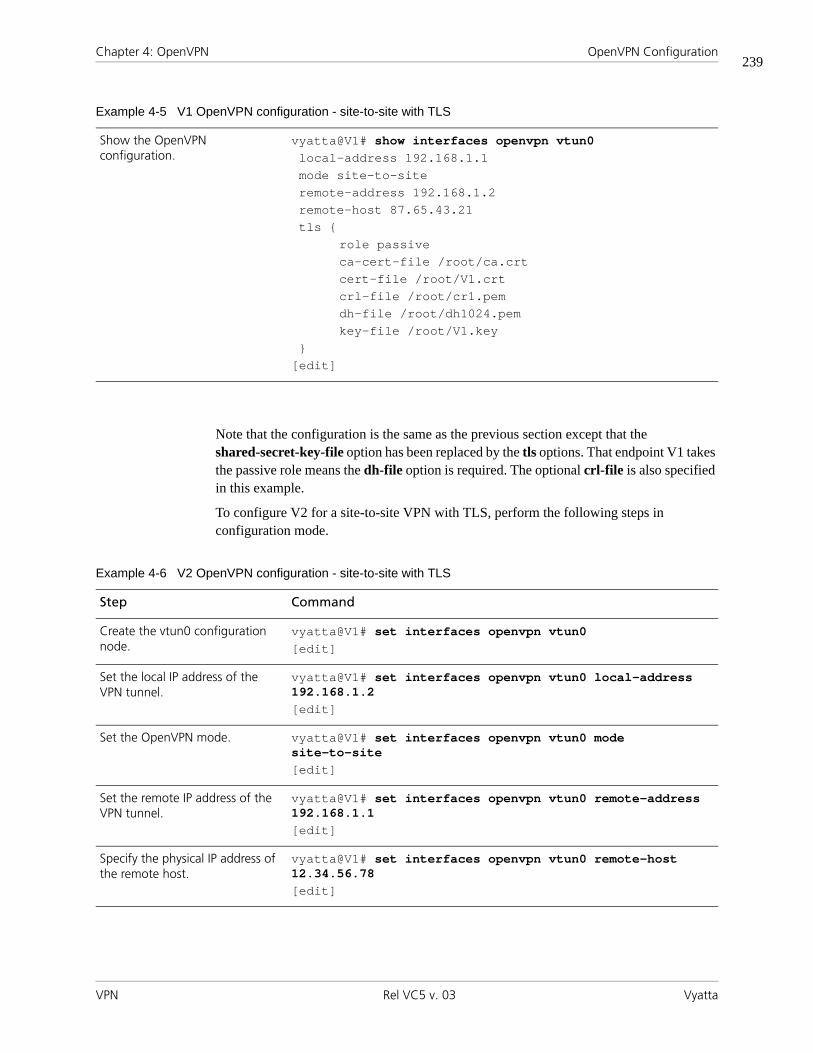
Chapter 4: OpenVPN OpenVPN Configuration
VPN Rel VC5 v. 03 Vyatta
239
Note that the configuration is the same as the previous section except that the shared-secret-key-file option has been replaced by the tls options. That endpoint V1 takes the passive role means the dh-file option is required. The optional crl-file is also specified in this example.
To configure V2 for a site-to-site VPN with TLS, perform the following steps in configuration mode.
Show the OpenVPN configuration.
vyatta@V1# show interfaces openvpn vtun0local-address 192.168.1.1mode site-to-siteremote-address 192.168.1.2remote-host 87.65.43.21tls {
role passiveca-cert-file /root/ca.crtcert-file /root/V1.crtcrl-file /root/cr1.pemdh-file /root/dh1024.pemkey-file /root/V1.key
}[edit]
Example 4-5 V1 OpenVPN configuration - site-to-site with TLS
Example 4-6 V2 OpenVPN configuration - site-to-site with TLS
Step Command
Create the vtun0 configuration node.
vyatta@V1# set interfaces openvpn vtun0[edit]
Set the local IP address of the VPN tunnel.
vyatta@V1# set interfaces openvpn vtun0 local-address 192.168.1.2[edit]
Set the OpenVPN mode. vyatta@V1# set interfaces openvpn vtun0 mode site-to-site[edit]
Set the remote IP address of the VPN tunnel.
vyatta@V1# set interfaces openvpn vtun0 remote-address 192.168.1.1[edit]
Specify the physical IP address of the remote host.
vyatta@V1# set interfaces openvpn vtun0 remote-host 12.34.56.78[edit]
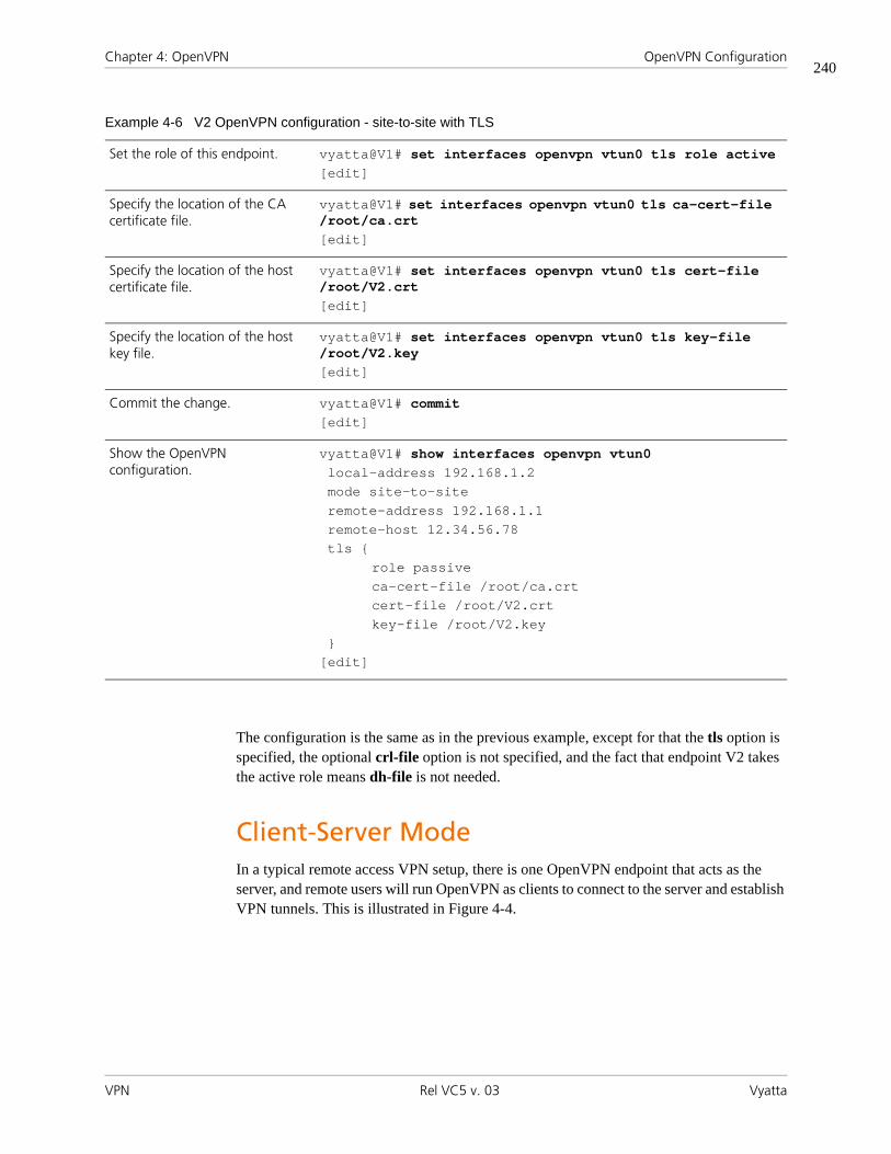
Chapter 4: OpenVPN OpenVPN Configuration
VPN Rel VC5 v. 03 Vyatta
240
The configuration is the same as in the previous example, except for that the tls option is specified, the optional crl-file option is not specified, and the fact that endpoint V2 takes the active role means dh-file is not needed.
Client-Server Mode In a typical remote access VPN setup, there is one OpenVPN endpoint that acts as the server, and remote users will run OpenVPN as clients to connect to the server and establish VPN tunnels. This is illustrated in Figure 4-4.
Set the role of this endpoint. vyatta@V1# set interfaces openvpn vtun0 tls role active[edit]
Specify the location of the CA certificate file.
vyatta@V1# set interfaces openvpn vtun0 tls ca-cert-file /root/ca.crt[edit]
Specify the location of the host certificate file.
vyatta@V1# set interfaces openvpn vtun0 tls cert-file /root/V2.crt[edit]
Specify the location of the host key file.
vyatta@V1# set interfaces openvpn vtun0 tls key-file /root/V2.key[edit]
Commit the change. vyatta@V1# commit[edit]
Show the OpenVPN configuration.
vyatta@V1# show interfaces openvpn vtun0local-address 192.168.1.2mode site-to-siteremote-address 192.168.1.1remote-host 12.34.56.78tls {
role passiveca-cert-file /root/ca.crtcert-file /root/V2.crtkey-file /root/V2.key
}[edit]
Example 4-6 V2 OpenVPN configuration - site-to-site with TLS

Chapter 4: OpenVPN OpenVPN Configuration
VPN Rel VC5 v. 03 Vyatta
241
Figure 4-4 Client-server mode
One thing to note is that OpenVPN requires TLS in client-server mode, and naturally the server takes the passive role while the clients are active. Therefore, it is not necessary to specify the tls role option in this mode. In the above example, assuming that V1 is the server and V2 is a client, the configuration for V1 is shown below.
To configure V1 for client-server with TLS, perform the following steps in configuration mode.
OpenVPN server OpenVPN client
OpenVPN tunnel
OpenVPN interface 192.168.1.x
(assigned by server)
OpenVPN interface 192.168.1.1 Physical interface
12.34.56.78
Example 4-7 V1 OpenVPN configuration - client-server with TLS (server)
Step Command
Create the vtun0 configuration node.
vyatta@V1# set interfaces openvpn vtun0[edit]
Set the OpenVPN mode. vyatta@V1# set interfaces openvpn vtun0 mode server[edit]
Set the subnet for the OpenVPN tunnel.
vyatta@V1# set interfaces openvpn vtun0 server subnet 192.168.1.0/24[edit]
Specify the location of the CA certificate file.
vyatta@V1# set interfaces openvpn vtun0 tls ca-cert-file /root/ca.crt[edit]
Specify the location of the host certificate file.
vyatta@V1# set interfaces openvpn vtun0 tls cert-file /root/V1.crt[edit]

Chapter 4: OpenVPN OpenVPN Configuration
VPN Rel VC5 v. 03 Vyatta
242
The mode option specifies that this endpoint will operate in server mode. The server subnet option indicates that the client’s tunnel IP addresses will be allocated from the 192.168.1.0/24 subnet, and the server’s tunnel IP address (i.e., the address of vtun0 on the server) will be 192.168.1.1. Note that the remote-host option is not set since the clients will be actively contacting the server.
To configure V2 for client-server with TLS, perform the following steps in configuration mode.
Specify the location of the CRL parameters file.
vyatta@V1# set interfaces openvpn vtun0 tls crl-file /root/crl.pem[edit]
Specify the location of the DH file.
vyatta@V1# set interfaces openvpn vtun0 tls dh-file /root/dh1024.pem[edit]
Specify the location of the host key file.
vyatta@V1# set interfaces openvpn vtun0 tls key-file /root/V1.key[edit]
Commit the change. vyatta@V1# commit[edit]
Show the OpenVPN configuration.
vyatta@V1# show interfaces openvpn vtun0mode serverserver {
subnet 192.168.1.0/24}tls {
ca-cert-file /root/ca.crtcert-file /root/V1.crtcrl-file /root/cr1.pemdh-file /root/dh1024.pemkey-file /root/V1.key
}[edit]
Example 4-7 V1 OpenVPN configuration - client-server with TLS (server)
Example 4-8 V2 OpenVPN configuration - client-server with TLS (client)
Step Command
Create the vtun0 configuration node.
vyatta@V1# set interfaces openvpn vtun0[edit]

Chapter 4: OpenVPN OpenVPN Configuration
VPN Rel VC5 v. 03 Vyatta
243
Since V2 is in client mode, it needs to be actively contacting the server, and therefore the remote-host option is needed to indicate where the server is. When the tunnel is established, V2’s tunnel IP address (that is, the address of vtun0 on V2) will be assigned by V1 from the 192.168.1.0/24 subnet.
Setting Up OpenVPN Clients on Windows Hosts As mentioned earlier, OpenVPN is different from and cannot interoperate with the “SSL VPN” solutions on the market, and therefore OpenVPN must be installed on all VPN hosts. In a remote access VPN setup, many remote users will need to connect to the OpenVPN
Set the OpenVPN mode. vyatta@V1# set interfaces openvpn vtun0 mode client[edit]
Specify the physical IP address of the remote host.
vyatta@V1# set interfaces openvpn vtun0 remote-host 12.34.56.78[edit]
Specify the location of the CA certificate file.
vyatta@V1# set interfaces openvpn vtun0 tls ca-cert-file /root/ca.crt[edit]
Specify the location of the host certificate file.
vyatta@V1# set interfaces openvpn vtun0 tls cert-file /root/V2.crt[edit]
Specify the location of the host key file.
vyatta@V1# set interfaces openvpn vtun0 tls key-file /root/V2.key[edit]
Commit the change. vyatta@V1# commit[edit]
Show the OpenVPN configuration.
vyatta@V1# show interfaces openvpn vtun0mode clientremote-host 12.34.56.78tls {
ca-cert-file /root/ca.crtcert-file /root/V2.crtkey-file /root/V2.key
}[edit]
Example 4-8 V2 OpenVPN configuration - client-server with TLS (client)

Chapter 4: OpenVPN OpenVPN Configuration
VPN Rel VC5 v. 03 Vyatta
244
server from hosts that run Windows. To set up the OpenVPN client on a Windows machine, download and install the OpenVPN Windows Installer package from the OpenVPN Web site (http://openvpn.net/index.php/downloads.html).
After installation, the OpenVPN client can be either run from the Windows command line or controlled by the OpenVPN GUI. Using the setup from the previous section as example, if the client V2 is a Windows host, the OpenVPN client can be run from the command line by entering the following.
openvpn --dev tun --client --remote 12.34.56.78 --ca ca.crt --cert V2.crt --key V2.key
This command establishes a VPN tunnel with the OpenVPN server V1 in the above example. Note that the referenced files must be in the same directory from which this command is issued. Otherwise, full paths should be used for the files.
Alternatively, to control the OpenVPN client using the OpenVPN GUI,you must create a control file. The file must be named with extension .ovpn, for example, vyatta.ovpn. A configuration file that corresponds to the preceding command line contains would look as follows.
dev tunclientremote 12.34.56.78ca ca.crtcert V2.crtkey V2.key
Put the configuration file and the referenced files (certificates, etc.) into the OpenVPN configuration directory. This is usually C:\Program files\OpenVPN\config.
Start the OpenVPN GUI, which will show an icon in the notification area of the Windows taskbar. To establish the OpenVPN tunnel, right-click the icon and select “Connect” from the drop-down menu. If there are multiple ovpn configuration files, the actions for each configuration will appear in its own drop-down menu.

Chapter 4: OpenVPN OpenVPN Configuration
VPN Rel VC5 v. 03 Vyatta
245
Firewall Configuration The firewall configuration for an OpenVPN tunnel interface is the same as the configuration for other types of interfaces. Here is an example.
To configure firewall on V1, perform the following steps in configuration mode.
For more information on configuring firewall for interfaces, see the firewall chapter in the Vyatta Security Reference Guide.
Configuration Examples for Advanced Options The previous section presented a few basic OpenVPN setups and how they are configured in Vyatta. In the following subsections, we will discuss a number of more advanced concepts and the associated configuration options that may be useful to administrators of more complex environments. Note that each subsection specifies the mode(s) of operation (site-to-site, client, or server) to which the concepts/options are applicable.
Example 4-9 V1 OpenVPN firewall configuration
Step Command
Create the vtun0 configuration node.
vyatta@V1# set interfaces openvpn vtun0[edit]
Additional configuration commands.
...
Set the firewall rule for inbound traffic on the vtun0 interface.
vyatta@V1# set interfaces openvpn vtun0 firewall in name rules-in[edit]
Additional configuration commands.
...
Commit the change. vyatta@V1# commit[edit]
Show the OpenVPN configuration.
vyatta@V1# show interfaces openvpn vtun0...firewall {
in {name rules-in
}}...
[edit]

Chapter 4: OpenVPN OpenVPN Configuration
VPN Rel VC5 v. 03 Vyatta
246
Transport Protocol (Site-to-Site, Client, Server) By default, OpenVPN uses UDP as the underlying transport protocol. Since UDP is connectionless, either side can initiate the VPN tunnel by sending packets to UDP port 1194 (default) on the other endpoint. Alternatively, OpenVPN can also use TCP as the transport. However, if TCP is used, one endpoint must take a passive role (i.e., listen to incoming TCP connections), and the other endpoint must take an active role, i.e., initiate the TCP connection to TCP port 1194 (default) on the passive endpoint.
Each protocol has different advantages in this context. For example, using TCP makes it much less prone to firewall/NAT problems in networks between the two endpoints. However, when packet losses occur, the TCP retransmissions at the tunnel level may interfere with retransmissions done by the individual TCP flows inside the VPN tunnel. Therefore, using UDP will likely result in better performance.
The related configuration options are described below.
Example 4-10 Configuration options related to protocol type
interfaces {
openvpn <if_name> {protocol <protocol>local-host <local_host_ip>local-port <local_port>remote-port <remote_port>
}}
• protocol: Valid values for this option are "udp", "tcp-active", and "tcp-passive". If protocol is not specified or if it is specified as "udp", then UDP will be used. On the other hand, when using TCP, the following requirements should be noted:
— As discussed above, when TCP is used, one endpoint must be active and the other one passive.
— On the "tcp-active" endpoint, the remote-host option must be set so that it can initiate the TCP connection.
— On the "tcp-passive" endpoint, if the remote-host option is set, then only the specified host can initiate the TCP connection to this endpoint.
— If TCP is used in client-server mode, naturally the client must be "tcp-active" and the server must be "tcp-passive".

Chapter 4: OpenVPN OpenVPN Configuration
VPN Rel VC5 v. 03 Vyatta
247
— When TCP is used in combination with TLS, the active/passive roles for TCP and TLS should match. In other words, the "tcp-active" endpoint should also be active for TLS (similarly for "passive"). (Note that this is not an OpenVPN restriction, but it is enforced to avoid confusion.)
• local-host: This option can be used for (1) the server endpoint in client-server mode, (2) either endpoint when UDP is used in site-to-site mode, or (3) the tcp-passive endpoint when TCP is used in site-to-site mode, or . The value can be an IP address on any of network interfaces on this endpoint. If this is set, the OpenVPN process will only accept sessions coming in on the particular IP address, and this applies to both UDP and TCP. If not set, OpenVPN accept incoming sessions on any interfaces.
• local-port: This option can be used for (1) the server endpoint in client-server mode, (2) either endpoint when UDP is used in site-to-site mode, or (3) the tcp-passive endpoint when TCP is used in site-to-site mode. It specifies the UDP or TCP port number on which OpenVPN will accept incoming sessions. If not set, OpenVPN will accept incoming sessions on the default port 1194.
• remote-port: This option can be used for (1) the client endpoint in client-server mode, (2) either endpoint when UDP is used in site-to-site mode, or (3) the tcp-active endpoint when TCP is used in site-to-site mode. It specifies the UDP or TCP port number on the other endpoint to which OpenVPN will initiate sessions. In other words, the other endpoint is accepting sessions on this port. If not set, OpenVPN will initiate the session to the default port 1194 on the remote endpoint. Note that, if set, the remote-port setting on one endpoint must match the local-port setting on the other, and vice versa.
Cryptographic Algorithms (Site-to-Site, Client, Server) As discussed earlier, whichever security mechanism is used (pre-shared secret or TLS), after the VPN tunnel is established, the two endpoints will apply an encryption algorithm and a hash algorithm on the tunneled VPN data to provide confidentiality and integrity. By default, the encryption and hash algorithms used by OpenVPN are Blowfish (with 128-bit keys) and SHA-1, respectively, which should be reasonable in typical environments (the Blowfish algorithm performs well in software and has no known weakness, and SHA-1 is widely used and is part of the NIST Secure Hash Standard).
When a particular encryption or hash algorithm is required in an environment, the following two configuration options can be used to specify the algorithm.
Example 4-11 Configuration options related to security
interfaces {
openvpn <if_name> {encryption <algorithm>
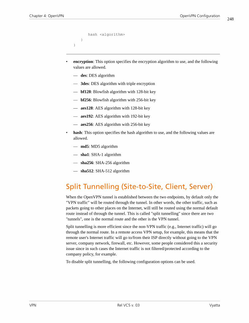
Chapter 4: OpenVPN OpenVPN Configuration
VPN Rel VC5 v. 03 Vyatta
248
hash <algorithm>}
}
• encryption: This option specifies the encryption algorithm to use, and the following values are allowed.
— des: DES algorithm
— 3des: DES algorithm with triple encryption
— bf128: Blowfish algorithm with 128-bit key
— bf256: Blowfish algorithm with 256-bit key
— aes128: AES algorithm with 128-bit key
— aes192: AES algorithm with 192-bit key
— aes256: AES algorithm with 256-bit key
• hash: This option specifies the hash algorithm to use, and the following values are allowed.
— md5: MD5 algorithm
— sha1: SHA-1 algorithm
— sha256: SHA-256 algorithm
— sha512: SHA-512 algorithm
Split Tunnelling (Site-to-Site, Client, Server) When the OpenVPN tunnel is established between the two endpoints, by default only the "VPN traffic" will be routed through the tunnel. In other words, the other traffic, such as packets going to other places on the Internet, will still be routed using the normal default route instead of through the tunnel. This is called "split tunnelling" since there are two "tunnels", one is the normal route and the other is the VPN tunnel.
Split tunnelling is more efficient since the non-VPN traffic (e.g., Internet traffic) will go through the normal route. In a remote access VPN setup, for example, this means that the remote user's Internet traffic will go to/from their ISP directly without going to the VPN server, company network, firewall, etc. However, some people considered this a security issue since in such cases the Internet traffic is not filtered/protected according to the company policy, for example.
To disable split tunnelling, the following configuration options can be used.

Chapter 4: OpenVPN OpenVPN Configuration
VPN Rel VC5 v. 03 Vyatta
249
Example 4-12 Configuration options related to split tunnelling
interfaces {
openvpn <if_name> {replace-default-route {
local}
}}
• replace-default-route: This option tells OpenVPN that the default route should be replaced by a route through the VPN tunnel, i.e., split tunnelling should be disabled. Note that, when set, this option has different effects depending on the OpenVPN mode in which the endpoint operates.
— If the endpoint is in site-to-site mode or client mode, setting replace-default-route will replace the default route on this endpoint with a route through VPN tunnel. In other words, it disables split tunnelling on this endpoint.
— If the endpoint is in server mode, setting replace-default-route will cause the clients connecting to this server to replace their default route. In other words, it disables split tunnelling on the clients.
• local: The local option under replace-default-route must be set if and only if the two tunnel endpoints are directly connected, i.e., on the same subnet.
Of course, since the OpenVPN tunnel interface is routable, one can always add static routes either with or without split tunnelling to override the default behavior.
Multiple Remote Endpoints (Client Only) In client-server mode, the remote-host option needs to be specified on the client endpoints so that they can initiate the VPN sessions. In some environments, the administrator may want the clients to have a list of servers so that when one of them fails, a client can try the next one, thus providing some redundancy. In the Vyatta configuration, this can be achieved by specifying multiple remote-host entries.
To configure multiple endpoints on V2, perform the following steps in configuration mode.
Example 4-13 V2 OpenVPN multiple endpoints configuration
Step Command
Create the vtun0 configuration node.
vyatta@V2# set interfaces openvpn vtun0[edit]

Chapter 4: OpenVPN OpenVPN Configuration
VPN Rel VC5 v. 03 Vyatta
250
When multiple entries are specified, a client will start from the beginning of the list and attempt to establish a VPN tunnel with the first remote-host. If the first one does not work, the client will try the second one, and so on.
Note that multiple remote-host entries can also be specified in site-to-site mode. However, since the two endpoints are most likely fixed in this mode, such usage probably does not make sense in most cases.
Client-Server Topology (Server Only) In the client-server mode, two different client-server "topologies" can be configured using the following option.
Additional configuration commands.
...
Specify the physical IP address of the first remote host.
vyatta@V1# set interfaces openvpn vtun0 remote-host 12.34.56.78[edit]
Specify the physical IP address of the second remote host.
vyatta@V1# set interfaces openvpn vtun0 remote-host 12.34.56.79[edit]
Specify the physical IP address of the third remote host.
vyatta@V1# set interfaces openvpn vtun0 remote-host 12.34.56.80[edit]
Set the firewall rule for inbound traffic on the vtun0 interface.
vyatta@V2# set interfaces openvpn vtun0 firewall in name rules-in[edit]
Additional configuration commands.
...
Commit the change. vyatta@V2# commit[edit]
Show the OpenVPN configuration.
vyatta@V2# show interfaces openvpn vtun0...remote-host 12.34.56.78remote-host 12.34.56.79remote-host 12.34.56.80...
[edit]
Example 4-13 V2 OpenVPN multiple endpoints configuration
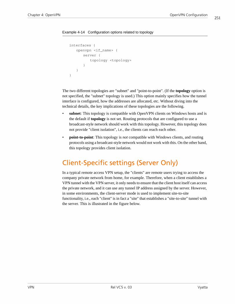
Chapter 4: OpenVPN OpenVPN Configuration
VPN Rel VC5 v. 03 Vyatta
251
Example 4-14 Configuration options related to topology
interfaces {
openvpn <if_name> {server {
topology <topology>}
}}
The two different topologies are "subnet" and "point-to-point". (If the topology option is not specified, the "subnet" topology is used.) This option mainly specifies how the tunnel interface is configured, how the addresses are allocated, etc. Without diving into the technical details, the key implications of these topologies are the following.
• subnet: This topology is compatible with OpenVPN clients on Windows hosts and is the default if topology is not set. Routing protocols that are configured to use a broadcast-style network should work with this topology. However, this topology does not provide "client isolation", i.e., the clients can reach each other.
• point-to-point: This topology is not compatible with Windows clients, and routing protocols using a broadcast-style network would not work with this. On the other hand, this topology provides client isolation.
Client-Specific settings (Server Only) In a typical remote access VPN setup, the "clients" are remote users trying to access the company private network from home, for example. Therefore, when a client establishes a VPN tunnel with the VPN server, it only needs to ensure that the client host itself can access the private network, and it can use any tunnel IP address assigned by the server. However, in some environments, the client-server mode is used to implement site-to-site functionality, i.e., each "client" is in fact a "site" that establishes a "site-to-site" tunnel with the server. This is illustrated in the figure below.

Chapter 4: OpenVPN OpenVPN Configuration
VPN Rel VC5 v. 03 Vyatta
252
Figure 4-5 Client-server mode
In such an environment, it may be useful to give a fixed IP address to each individual "client". Furthermore, in such cases there may be a private network behind a client as well, and the OpenVPN server needs to know that traffic destined to this private network should be routed to the particular client. In other words, these are client-specific settings that are tied to a particular client, and they can be configured using the following options.
Example 4-15 Configuration options related to client-server
interfaces {
openvpn <if_name> {server {
client <client_name> {ip <client_ip>subnet <client_subnet>
}}
}}
• client: This specifies the "name" of the client and corresponds to the aforementioned "common name" contained in the client's certificate. When a client initiates the VPN session, the server uses the name in the certificate to look up and apply client-specific settings (if any).
• ip: This specifies the fixed IP address that will be assigned to the particular client.
• subnet: This specifies the private subnet behind the particular client, and OpenVPN will route traffic destined to this subnet to the client. Note that this setting only tells the OpenVPN server to which client the traffic for this subnet should be routed. However,
OpenVPN server OpenVPN client
OpenVPN tunnel
OpenVPN interface 192.168.1.x
(assigned by serverbut fixed)
OpenVPN interface 192.168.1.1 Physical interface
12.34.56.78
192.168.100.0/24

Chapter 4: OpenVPN OpenVPN Configuration
VPN Rel VC5 v. 03 Vyatta
253
before the OpenVPN server gets to make this decision, such traffic needs to be routed to the tunnel interface so that it will be handled by the OpenVPN server. Therefore, a static interface route needs to be added separately to direct traffic for this subnet to the tunnel interface.
In the above example, the server V1 can be configured with the client IP and subnet specific to the client V2 as follows (note that a static interface route is also needed for the client V2's subnet).
To configure this scenario, perform the following steps in configuration mode.
Example 4-16 V1 OpenVPN configuration - site-to-site with pre-shared secret
Step Command
Create the vtun0 configuration node.
vyatta@V1# set interfaces openvpn vtun0[edit]
Additional configuration commands.
...
Create the server configuration node.
vyatta@V1# set interfaces openvpn vtun0 server[edit]
Additional configuration commands.
...
Create the client V2 configuration node.
vyatta@V1# set interfaces openvpn vtun0 server client V2[edit]
Set the IP address of the client. vyatta@V1# set interfaces openvpn vtun0 server client V2 subnet 192.168.100.0/24[edit]
Specify the subnet at the client. vyatta@V1# set interfaces openvpn vtun0 server client V2 ip 192.168.1.100[edit]
Additional configuration commands.
...
Commit the change. vyatta@V1# commit[edit]
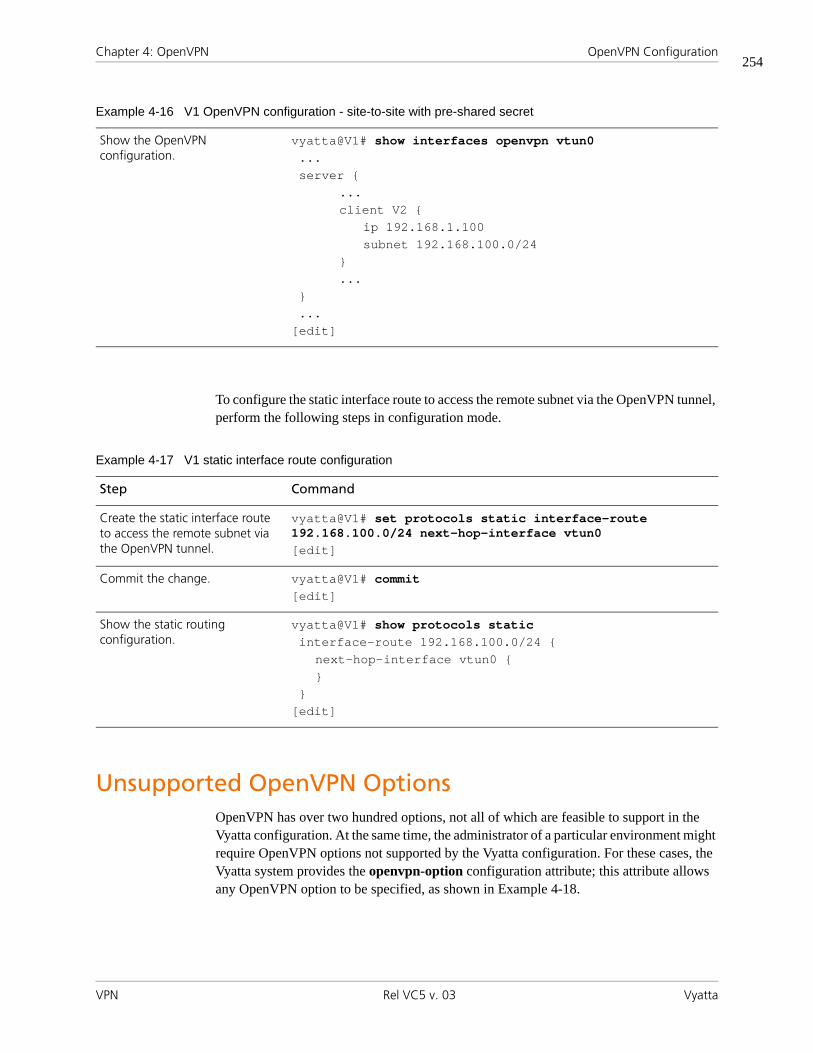
Chapter 4: OpenVPN OpenVPN Configuration
VPN Rel VC5 v. 03 Vyatta
254
To configure the static interface route to access the remote subnet via the OpenVPN tunnel, perform the following steps in configuration mode.
Unsupported OpenVPN Options OpenVPN has over two hundred options, not all of which are feasible to support in the Vyatta configuration. At the same time, the administrator of a particular environment might require OpenVPN options not supported by the Vyatta configuration. For these cases, the Vyatta system provides the openvpn-option configuration attribute; this attribute allows any OpenVPN option to be specified, as shown in Example 4-18.
Show the OpenVPN configuration.
vyatta@V1# show interfaces openvpn vtun0...server {
...client V2 {
ip 192.168.1.100subnet 192.168.100.0/24
}...
}...
[edit]
Example 4-16 V1 OpenVPN configuration - site-to-site with pre-shared secret
Example 4-17 V1 static interface route configuration
Step Command
Create the static interface route to access the remote subnet via the OpenVPN tunnel.
vyatta@V1# set protocols static interface-route 192.168.100.0/24 next-hop-interface vtun0[edit]
Commit the change. vyatta@V1# commit[edit]
Show the static routing configuration.
vyatta@V1# show protocols staticinterface-route 192.168.100.0/24 {
next-hop-interface vtun0 {}
}[edit]

Chapter 4: OpenVPN OpenVPN Configuration
VPN Rel VC5 v. 03 Vyatta
255
Example 4-18 The “openvpn-option” configuration attibute
interfaces {
openvpn <if_name> {openvpn-option <options>
}}
The text of the openvpn-option attribute value is passed directly (without any validation) to OpenVPN when OpenVPN is invoked, as if the text had been typed on the OpenVPN command line by the user. Therefore, multiple options can be entered together as shown below.
To configure this example, perform the following steps in configuration mode.
No validation is done on this setting; therefore, when using it, you should make sure that the specified OpenVPN options and their values (if any) are valid. Furthermore, since many OpenVPN options conflict with one another, you should also ensure that the specified options do not conflict with one another or with any other OpenVPN options configured
Example 4-19 Entering multiple OpenVPN options using “openvpn-option”
Step Command
Create the vtun0 configuration node.
vyatta@V1# set interfaces openvpn vtun0[edit]
Additional configuration commands.
...
Set the desired OpenVPN options.
vyatta@V1# set interfaces openvpn vtun0 openvpn-option "--verb 5 --secret /root/secret 1"[edit]
Additional configuration commands.
...
Commit the change. vyatta@V1# commit[edit]
Show the OpenVPN configuration.
vyatta@V1# show interfaces openvpn vtun0...openvpn-option "--verb 5 --secret /root/secret 1"...
[edit]

Chapter 4: OpenVPN OpenVPN Configuration
VPN Rel VC5 v. 03 Vyatta
256
through the Vyatta configuration. Finally, some OpenVPN options require coordination between the two endpoints (for example, the value must be 0 on one side and 1 on the other), and one should ensure such constraints are met.

Chapter 4: OpenVPN OpenVPN Commands
VPN Rel VC5 v. 03 Vyatta
257
OpenVPN CommandsThis chapter contains the following commands.
Configuration Commands
Global OpenVPN Commands
interfaces openvpn <vtunx> Defines an OpenVPN interface.
interfaces openvpn <vtunx> encryption <algorithm> Specifies the encryption algorithm to be used for the OpenVPN tunnel.
interfaces openvpn <vtunx> hash <algorithm> Specifies the hash algorithm to be used for the OpenVPN tunnel.
interfaces openvpn <vtunx> local-address <ipv4> Sets the IP address for the tunnel interface of the local OpenVPN endpoint.
interfaces openvpn <vtunx> local-host <ipv4> Specifies the IP address of the local physical interface.
interfaces openvpn <vtunx> local-port <port> Specifies the port number to be used for OpenVPN traffic on the local tunnel interface.
interfaces openvpn <vtunx> mode <mode> Specifies the mode the OpenVPN interface will operate in.
interfaces openvpn <vtunx> openvpn-option <options> Specifies additional OpenVPN options.
interfaces openvpn <vtunx> protocol <protocol> Specifies the OpenVPN communications protocol.
interfaces openvpn <vtunx> remote-address <ipv4> Specifies the IP address for the tunnel interface of the remote OpenVPN endpoint.
interfaces openvpn <vtunx> remote-host <ipv4> Specifies the remote IP address to which connections are made.
interfaces openvpn <vtunx> remote-port <port> Specifies the port number on which outgoing sessions are sent.
interfaces openvpn <vtunx> replace-default-route Specifies that the default route should be through the OpenVPN tunnel.
interfaces openvpn <vtunx> shared-secret-key-file <filename>
Specifies the file containing a secret key shared with the remote end of the tunnel.
OpenVPN Server
interfaces openvpn <vtunx> server Defines an OpenVPN server mode endpoint.
interfaces openvpn <vtunx> server client <client-name> Defines a client site on the server in a client-server environment.

Chapter 4: OpenVPN OpenVPN Commands
VPN Rel VC5 v. 03 Vyatta
258
Commands for using other system features with OpenVPN interfaces can be found in the following locations
interfaces openvpn <vtunx> server client <client-name> ip <ipv4>
Specifies the IP address of a client site on the server in a client-server environment.
interfaces openvpn <vtunx> server client <client-name> subnet <ipv4net>
Specifies a subnet at a client site on the server in a client-server environment.
interfaces openvpn <vtunx> server topology <topology> Specifies the topology to use in a client-server environment.
TLS
interfaces openvpn <vtunx> tls Defines a Transport Layer Security (TLS) configuration.
interfaces openvpn <vtunx> tls ca-cert-file <filename> Specifies the file containing the certificate authority’s certificate.
interfaces openvpn <vtunx> tls cert-file <filename> Specifies the file containing the endpoint’s own certificate.
interfaces openvpn <vtunx> tls crl-file <filename> Specifies the file containing a certificate revocation list.
interfaces openvpn <vtunx> tls dh-file <filename> Specifies the file containing Diffie Hellman parameters.
interfaces openvpn <vtunx> tls key-file <filename> Specifies the file containing the endpoint’s own private key.
interfaces openvpn <vtunx> tls role <role> Specifies the TLS role the endpoint will take.
Operational Commands
vpn openvpn-key generate <filename> Generates a shared secret file.
show interfaces openvpn Displays a status summary of all OpenVPN interfaces.
show interfaces openvpn <interface> Displays the detailed status of an OpenVPN interface.
show interfaces openvpn <interface> brief Displays the status summary of an OpenVPN interface.
show interfaces openvpn <interface> capture Captures data passing through the OpenVPN interface.
show interfaces openvpn detail Displays the detailed status of all OpenVPN interfaces on the system.
show openvpn server-status Displays information on connected clients in server mode.
Related Commands Documented Elsewhere
Firewall Commands for configuring firewall on OpenVPN interfaces are described in the Vyatta Security Reference Guide.

Chapter 4: OpenVPN OpenVPN Commands
VPN Rel VC5 v. 03 Vyatta
259
interfaces openvpn <vtunx> Defines an OpenVPN interface.
Syntax
set interfaces openvpn vtunx
delete interfaces openvpn vtunx
show interfaces openvpn vtunx
Command Mode
Configuration mode.
Configuration Statement
interfaces {openvpn vtun0..vtunx {}
}
Parameters
Default
None.
Usage Guidelines
Use this command to configure an OpenVPN interface.
Use the set form of this command to create an OpenVPN interface.
Use the delete form of this command to remove all configuration for an OpenVPN interface.
Use the show form of this command to view OpenVPN interface configuration.
vtunx Mandatory. Multi-node. The identifier for the OpenVPN interface you are defining. This may be vtun0 to vtunx, where x is a non-negative integer.

Chapter 4: OpenVPN OpenVPN Commands
VPN Rel VC5 v. 03 Vyatta
260
interfaces openvpn <vtunx> encryption <algorithm>Specifies the encryption algorithm to be used for the OpenVPN tunnel.
Syntax
set interfaces openvpn vtunx encryption algorithm
delete interfaces openvpn vtunx encryption
show interfaces openvpn vtunx encryption
Command Mode
Configuration mode.
Configuration Statement
interfaces {openvpn vtun0..vtunx {
encryption [3des|aes128|aes192|aes256|bf128|bf256|des]}
}
Parameters
vtunx Mandatory. Multi-node. The identifier for the OpenVPN interface. This may be vtun0 to vtunx, where x is a non-negative integer.
algorithm The encryption algorithm that will be used within the OpenVPN tunnel. Supported values are as follows:
3des: DES algorithm with triple encryption
aes128: AES algorithm with 128-bit key
aes192: AES algorithm with 192-bit key
aes256: AES algorithm with 256-bit key
bf128: Blowfish algorithm with 128-bit key
bf256: Blowfish algorithm with 256-bit key
des: DES algorithm
The default is bf128.

Chapter 4: OpenVPN OpenVPN Commands
VPN Rel VC5 v. 03 Vyatta
261
Default
Blowfish algorithm with 128-bit key is used as the encryption algorithm.
Usage Guidelines
Use this command to configure the encryption algorithm that will be used within the OpenVPN tunnel.
Use the set form of this command to define the encryption algorithm that will be used within the OpenVPN tunnel.
Use the delete form of this command to remove the encryption algorithm that will be used within the OpenVPN tunnel and return to the default.
Use the show form of this command to view the encryption algorithm that will be used within the OpenVPN tunnel.

Chapter 4: OpenVPN OpenVPN Commands
VPN Rel VC5 v. 03 Vyatta
262
interfaces openvpn <vtunx> hash <algorithm>Specifies the hash algorithm to be used for the OpenVPN tunnel.
Syntax
set interfaces openvpn vtunx hash algorithm
delete interfaces openvpn vtunx hash
show interfaces openvpn vtunx hash
Command Mode
Configuration mode.
Configuration Statement
interfaces {openvpn vtun0..vtunx {
hash [md5|sha1|sha256|sha512]}
}
Parameters
Default
SHA-1 is used as the hash algorithm.
vtunx Mandatory. Multi-node. The identifier for the OpenVPN interface. This may be vtun0 to vtunx, where x is a non-negative integer.
algorithm The hash algorithm that will be used within the OpenVPN tunnel. Supported values are as follows:
md5: MD5 algorithm
sha1: SHA-1 algorithm
sha256: SHA-256 algorithm
sha512: SHA-512 algorithm
The default is sha1.

Chapter 4: OpenVPN OpenVPN Commands
VPN Rel VC5 v. 03 Vyatta
263
Usage Guidelines
Use this command to configure the hash algorithm that will be used within the OpenVPN tunnel.
Use the set form of this command to define the hash algorithm that will be used within the OpenVPN tunnel.
Use the delete form of this command to remove the hash algorithm that will be used within the OpenVPN tunnel and return to the default.
Use the show form of this command to view the hash algorithm that will be used within the OpenVPN tunnel.

Chapter 4: OpenVPN OpenVPN Commands
VPN Rel VC5 v. 03 Vyatta
264
interfaces openvpn <vtunx> local-address <ipv4>Sets the IP address for the tunnel interface of the local OpenVPN endpoint.
Syntax
set interfaces openvpn vtunx local-address ipv4
delete interfaces openvpn vtunx local-address
show interfaces openvpn vtunx local-address
Command Mode
Configuration mode.
Configuration Statement
interfaces {openvpn vtun0..vtunx {
local-address ipv4}
}
Parameters
Default
None.
Usage Guidelines
Use this command to configure the tunnel IP address on the local end of the OpenVPN tunnel. Only a single address can be specified. This is required for site-to-site mode OpenVPN tunnels but not for client-server mode tunnels.
Use the set form of this command to define the tunnel IP address on the local end of the OpenVPN tunnel.
vtunx Mandatory. Multi-node. The identifier for the OpenVPN interface. The range of values is vtun0 to vtunx, where x is a non-negative integer.
ipv4 Mandatory. An IPv4 address.

Chapter 4: OpenVPN OpenVPN Commands
VPN Rel VC5 v. 03 Vyatta
265
Use the delete form of this command to remove the tunnel IP address on the local end of the OpenVPN tunnel.
Use the show form of this command to view the tunnel IP address on the local end of the OpenVPN tunnel.

Chapter 4: OpenVPN OpenVPN Commands
VPN Rel VC5 v. 03 Vyatta
266
interfaces openvpn <vtunx> local-host <ipv4>Specifies the IP address of the local physical interface.
Syntax
set interfaces openvpn vtunx local-host ipv4
delete interfaces openvpn vtunx local-host
show interfaces openvpn vtunx local-host
Command Mode
Configuration mode.
Configuration Statement
interfaces {openvpn vtun0..vtunx {
local-host ipv4}
}
Parameters
Default
None.
Usage Guidelines
Use this command to configure the local IP address to which connections are accepted. This can be used for a server endpoint in a client-server mode tunnel or the tcp-passive endpoint when TCP is used in site-to-site mode. The value can be an IP address on any of network
vtunx Mandatory. Multi-node. The identifier for the OpenVPN interface. This may be vtun0 to vtunx, where x is a non-negative integer.
ipv4 Optional. The IP address of the local physical interface. This is the which connections are accepted. If not specified then all connections are accepted.
Chapter 4: OpenVPN OpenVPN Commands
VPN Rel VC5 v. 03 Vyatta
267
interfaces on this endpoint. If this is set, the OpenVPN process will only accept sessions coming in on the particular IP address, and this applies to both UDP and TCP. If not set, OpenVPN accepts incoming sessions on any interface.
Use the set form of this command to specify the local IP address to which connections are accepted.
Use the delete form of this command to remove the local IP address to which connections are accepted.
Use the show form of this command to view the local IP address to which connections are accepted.

Chapter 4: OpenVPN OpenVPN Commands
VPN Rel VC5 v. 03 Vyatta
268
interfaces openvpn <vtunx> local-port <port>Specifies the port number to be used for OpenVPN traffic on the local tunnel interface.
Syntax
set interfaces openvpn vtunx local-port port
delete interfaces openvpn vtunx local-port
show interfaces openvpn vtunx local-port
Command Mode
Configuration mode.
Configuration Statement
interfaces {openvpn vtun0..vtunx {
local-port u32}
}
Parameters
Default
The default is port 1194.
Usage Guidelines
Use this command to configure the local UDP or TCP port on which incoming sessions are accepted. This can be used for a server endpoint in a client-server mode tunnel or the tcp-passive endpoint when TCP is used in site-to-site mode.
Use the set form of this command to specify the local port to which incoming sessions are accepted.
vtunx Mandatory. Multi-node. The identifier for the OpenVPN interface. This may be vtun0 to vtunx, where x is a non-negative integer.
port Optional. The port number on which incoming sessions are accepted. The default is port 1194.

Chapter 4: OpenVPN OpenVPN Commands
VPN Rel VC5 v. 03 Vyatta
269
Use the delete form of this command to remove the local port to which incoming sessions are accepted.
Use the show form of this command to view the local port to which incoming sessions are accepted.

Chapter 4: OpenVPN OpenVPN Commands
VPN Rel VC5 v. 03 Vyatta
270
interfaces openvpn <vtunx> mode <mode>Specifies the mode the OpenVPN interface will operate in.
Syntax
set interfaces openvpn vtunx mode mode
delete interfaces openvpn vtunx mode
show interfaces openvpn vtunx mode
Command Mode
Configuration mode.
Configuration Statement
interfaces {openvpn vtun0..vtunx {
mode [client|server|site-to-site]}
}
Parameters
Default
None.
vtunx Mandatory. Multi-node. The identifier for the OpenVPN interface. This may be vtun0 to vtunx, where x is a non-negative integer.
mode Mandatory. The mode the OpenVPN interface will operate in. Supported values are as follows:
client: The endpoint is the client in a client-server OpenVPN tunnel.
server: The endpoint is the server in a client-server OpenVPN tunnel.
site-to-site: The endpoint is one end of a site-to-site OpenVPN tunnel.
Chapter 4: OpenVPN OpenVPN Commands
VPN Rel VC5 v. 03 Vyatta
271
Usage Guidelines
Use this command to specify the mode the OpenVPN interface will operate in.
Use the set form of this command to specify the mode the OpenVPN interface will operate in.
Use the delete form of this command to remove the mode the OpenVPN interface will operate in.
Use the show form of this command to view the mode the OpenVPN interface will operate in.

Chapter 4: OpenVPN OpenVPN Commands
VPN Rel VC5 v. 03 Vyatta
272
interfaces openvpn <vtunx> openvpn-option <options>Specifies additional OpenVPN options.
Syntax
set interfaces openvpn vtunx openvpn-option options
delete interfaces openvpn vtunx openvpn-option
show interfaces openvpn vtunx openvpn-option
Command Mode
Configuration mode.
Configuration Statement
interfaces {openvpn vtun0..vtunx {
openvpn-option text}
}
Parameters
Default
None.
Usage Guidelines
Use this command to specify additional OpenVPN options that are not available within Vyatta OpenVPN commands. As the OpenVPN process has over two hundred commands only a base set is available through Vyatta commands. This command provides access to all options available in OpenVPN. Further information regarding OpenVPN can be found at http://openvpn.net/.
Use the set form of this command to specify additional OpenVPN options.
vtunx Mandatory. Multi-node. The identifier for the OpenVPN interface. This may be vtun0 to vtunx, where x is a non-negative integer.
options The string of options to pass to the OpenVPN process.

Chapter 4: OpenVPN OpenVPN Commands
VPN Rel VC5 v. 03 Vyatta
273
Use the delete form of this command to remove additional OpenVPN options.
Use the show form of this command to view additional OpenVPN options.

Chapter 4: OpenVPN OpenVPN Commands
VPN Rel VC5 v. 03 Vyatta
274
interfaces openvpn <vtunx> protocol <protocol>Specifies the OpenVPN communications protocol.
Syntax
set interfaces openvpn vtunx protocol protocol
delete interfaces openvpn vtunx protocol
show interfaces openvpn vtunx protocol
Command Mode
Configuration mode.
Configuration Statement
interfaces {openvpn vtun0..vtunx {
protocol [tcp-active|tcp-passive|udp]}
}
Parameters
Default
The default is udp.
Usage Guidelines
Use this command to specify the OpenVPN communications protocol.
Use the set form of this command to specify the OpenVPN communications protocol.
vtunx Mandatory. Multi-node. The identifier for the OpenVPN interface. This may be vtun0 to vtunx, where x is a non-negative integer.
protocol The OpenVPN communications protocol. Supported values are as follows:
tcp-active: TCP transport protocol - active role.
tcp-passive: TCP transport protocol - passive role.
udp: UDP transport protocol. This is the default.

Chapter 4: OpenVPN OpenVPN Commands
VPN Rel VC5 v. 03 Vyatta
275
Use the delete form of this command to remove the OpenVPN communications protocol.
Use the show form of this command to view the OpenVPN communications protocol.

Chapter 4: OpenVPN OpenVPN Commands
VPN Rel VC5 v. 03 Vyatta
276
interfaces openvpn <vtunx> remote-address <ipv4>Specifies the IP address for the tunnel interface of the remote OpenVPN endpoint.
Syntax
set interfaces openvpn vtunx remote-address ipv4
delete interfaces openvpn vtunx remote-address
show interfaces openvpn vtunx remote-address
Command Mode
Configuration mode.
Configuration Statement
interfaces {openvpn vtun0..vtunx {
remote-address ipv4}
}
Parameters
Default
None.
Usage Guidelines
Use this command to configure the tunnel IP address on the remote end of the OpenVPN tunnel. Only a single address can be specified. This is required for site-to-site mode OpenVPN tunnels but not for client-server mode tunnels.
Use the set form of this command to define the tunnel IP address on the remote end of the OpenVPN tunnel.
vtunx Mandatory. Multi-node. The identifier for the OpenVPN interface. This may be vtun0 to vtunx, where x is a non-negative integer.
ipv4 Mandatory. The tunnel IP address on the remote end of the OpenVPN tunnel.

Chapter 4: OpenVPN OpenVPN Commands
VPN Rel VC5 v. 03 Vyatta
277
Use the delete form of this command to remove the tunnel IP address on the remote end of the OpenVPN tunnel.
Use the show form of this command to view the tunnel IP address on the remote end of the OpenVPN tunnel.
Chapter 4: OpenVPN OpenVPN Commands
VPN Rel VC5 v. 03 Vyatta
278
interfaces openvpn <vtunx> remote-host <ipv4>Specifies the remote IP address to which connections are made.
Syntax
set interfaces openvpn vtunx remote-host ipv4
delete interfaces openvpn vtunx remote-host
show interfaces openvpn vtunx remote-host
Command Mode
Configuration mode.
Configuration Statement
interfaces {openvpn vtun0..vtunx {
remote-host ipv4}
}
Parameters
Default
None.
Usage Guidelines
Use this command to configure the remote IP address (or hostname) to which connections are made. This is required by a client to specify a server endpoint in a client-server mode tunnel. It is also required by both sides in site-to-site mode.
Use the set form of this command to specify the remote IP address to which connections are made.
vtunx Mandatory. Multi-node. The identifier for the OpenVPN interface. This may be vtun0 to vtunx, where x is a non-negative integer.
ipv4 The remote IP address (or hostname) to which connections are made.

Chapter 4: OpenVPN OpenVPN Commands
VPN Rel VC5 v. 03 Vyatta
279
Use the delete form of this command to remove the remote IP address to which connections are made.
Use the show form of this command to view the remote IP address to which connections are made.

Chapter 4: OpenVPN OpenVPN Commands
VPN Rel VC5 v. 03 Vyatta
280
interfaces openvpn <vtunx> remote-port <port>Specifies the port number on which outgoing sessions are sent.
Syntax
set interfaces openvpn vtunx remote-port port
delete interfaces openvpn vtunx remote-port
show interfaces openvpn vtunx remote-port
Command Mode
Configuration mode.
Configuration Statement
interfaces {openvpn vtun0..vtunx {
remote-port u32}
}
Parameters
Default
The default is port 1194.
Usage Guidelines
Use this command to configure the remote UDP or TCP port on which outgoing sessions are sent. This can be used for a client endpoint in a client-server mode tunnel, either endpoint when UDP is used in site-to-site mode, or the tcp-active endpoint when TCP is used in site-to-site mode. Note that, if set, the remote-port setting on one endpoint must match the local-port setting on the other, and vice versa.
vtunx Mandatory. Multi-node. The identifier for the OpenVPN interface. This may be vtun0 to vtunx, where x is a non-negative integer.
port Optional. The port number on which outgoing sessions are sent. The default is port 1194.

Chapter 4: OpenVPN OpenVPN Commands
VPN Rel VC5 v. 03 Vyatta
281
Use the set form of this command to specify the remote UDP or TCP port on which outgoing sessions are sent.
Use the delete form of this command to remove the remote UDP or TCP port on which outgoing sessions are sent.
Use the show form of this command to view the remote UDP or TCP port on which outgoing sessions are sent.

Chapter 4: OpenVPN OpenVPN Commands
VPN Rel VC5 v. 03 Vyatta
282
interfaces openvpn <vtunx> replace-default-route Specifies that the default route should be through the OpenVPN tunnel.
Syntax
set interfaces openvpn vtunx replace-default-route [local]
delete interfaces openvpn vtunx replace-default-route
show interfaces openvpn vtunx replace-default-route
Command Mode
Configuration mode.
Configuration Statement
interfaces {openvpn vtun0..vtunx {
replace-default-route {local
}}
}
Parameters
Default
None.
Usage Guidelines
Use this command to tell OpenVPN that the default route should be replaced by a route through the VPN tunnel, i.e., split tunnelling should be disabled. Note that, when set, this option has different effects depending on the OpenVPN mode in which the endpoint operates.
vtunx Mandatory. Multi-node. The identifier for the OpenVPN interface. This may be vtun0 to vtunx, where x is a non-negative integer.
local Optional. This option must be set if and only if the two tunnel endpoints are directly connected, i.e., on the same subnet.

Chapter 4: OpenVPN OpenVPN Commands
VPN Rel VC5 v. 03 Vyatta
283
If the endpoint is in site-to-site mode or client mode, setting replace-default-route will replace the default route on this endpoint with a route through VPN tunnel. In other words, it disables split tunnelling on this endpoint.
If the endpoint is in server mode, setting replace-default-route will cause the clients connecting to this server to replace their default route. In other words, it disables split tunnelling on the clients.
Use the set form of this command to specify that the default route should be through the OpenVPN tunnel.
Use the delete form of this command to remove the configuration.
Use the show form of this command to view the configuration.

Chapter 4: OpenVPN OpenVPN Commands
VPN Rel VC5 v. 03 Vyatta
284
interfaces openvpn <vtunx> serverDefines an OpenVPN server mode endpoint.
Syntax
set interfaces openvpn vtunx server
delete interfaces openvpn vtunx server
show interfaces openvpn vtunx server
Command Mode
Configuration mode.
Configuration Statement
interfaces {openvpn vtun0..vtunx {
server {}
}}
Parameters
Default
None.
Usage Guidelines
Use this command to define an OpenVPN server mode endpoint.
Use the set form of this command to create the server mode configuration node.
Use the delete form of this command to remove the server mode configuration node.
Use the show form of this command to view the configuration.
vtunx Mandatory. Multi-node. The identifier for the OpenVPN interface. This may be vtun0 to vtunx, where x is a non-negative integer.

Chapter 4: OpenVPN OpenVPN Commands
VPN Rel VC5 v. 03 Vyatta
285
interfaces openvpn <vtunx> server client <client-name>Defines a client site on the server in a client-server environment.
Syntax
set interfaces openvpn vtunx server client client-name
delete interfaces openvpn vtunx server client [client-name]
show interfaces openvpn vtunx server client [client-name]
Command Mode
Configuration mode.
Configuration Statement
interfaces {openvpn vtun0..vtunx {
server {client text {}
}}
}
Parameters
Default
None.
Usage Guidelines
Use this command to define a client site on the server in a client-server environment.
vtunx Mandatory. Multi-node. The identifier for the OpenVPN interface. This may be vtun0 to vtunx, where x is a non-negative integer.
client-name Mandatory. The "name" of the client. It corresponds to the "common name" contained in the client's certificate. When a client initiates the VPN session, the server uses the name in the certificate to look up and apply client-specific settings (if any).

Chapter 4: OpenVPN OpenVPN Commands
VPN Rel VC5 v. 03 Vyatta
286
Use the set form of this command to create the client configuration node.
Use the delete form of this command to remove the client configuration node.
Use the show form of this command to view the configuration.

Chapter 4: OpenVPN OpenVPN Commands
VPN Rel VC5 v. 03 Vyatta
287
interfaces openvpn <vtunx> server client <client-name> ip <ipv4>
Specifies the IP address of a client site on the server in a client-server environment.
Syntax
set interfaces openvpn vtunx server client client-name ip ipv4
delete interfaces openvpn vtunx server client client-name ip
show interfaces openvpn vtunx server client client-name ip
Command Mode
Configuration mode.
Configuration Statement
interfaces {openvpn vtun0..vtunx {
server {client text {
ip ipv4}
}}
}
Parameters
Default
None.
vtunx Mandatory. Multi-node. The identifier for the OpenVPN interface. This may be vtun0 to vtunx, where x is a non-negative integer.
client-name Mandatory. The "name" of the client. It corresponds to the "common name" contained in the client's certificate. When a client initiates the VPN session, the server uses the name in the certificate to look up and apply client-specific settings (if any).
ipv4 The IP address to be assigned to the client.

Chapter 4: OpenVPN OpenVPN Commands
VPN Rel VC5 v. 03 Vyatta
288
Usage Guidelines
Use this command to specify the IP address to assign to the client in a client-server environment.
Use the set form of this command to specify the IP address to assign to the client in a client-server environment.
Use the delete form of this command to remove the IP address.
Use the show form of this command to view the IP address.

Chapter 4: OpenVPN OpenVPN Commands
VPN Rel VC5 v. 03 Vyatta
289
interfaces openvpn <vtunx> server client <client-name> subnet <ipv4net>
Specifies a subnet at a client site on the server in a client-server environment.
Syntax
set interfaces openvpn vtunx server client client-name subnet ipv4net
delete interfaces openvpn vtunx server client client-name subnet
show interfaces openvpn vtunx server client client-name subnet
Command Mode
Configuration mode.
Configuration Statement
interfaces {openvpn vtun0..vtunx {
server {client text {
subnet ipv4net}
}}
}
Parameters
Default
None.
vtunx Mandatory. Multi-node. The identifier for the OpenVPN interface. This may be vtun0 to vtunx, where x is a non-negative integer.
client-name Mandatory. The "name" of the client. It corresponds to the "common name" contained in the client's certificate. When a client initiates the VPN session, the server uses the name in the certificate to look up and apply client-specific settings (if any).
ipv4net A subnet at the client site.

Chapter 4: OpenVPN OpenVPN Commands
VPN Rel VC5 v. 03 Vyatta
290
Usage Guidelines
Use this command to identify a subnet at a client site in a client-server environment.
Use the set form of this command to specify the subnet.
Use the delete form of this command to remove the subnet configuration.
Use the show form of this command to view the subnet configuration.

Chapter 4: OpenVPN OpenVPN Commands
VPN Rel VC5 v. 03 Vyatta
291
interfaces openvpn <vtunx> server topology <topology>
Specifies the topology to use in a client-server environment.
Syntax
set interfaces openvpn vtunx server topology topology
delete interfaces openvpn vtunx server topology
show interfaces openvpn vtunx server topology
Command Mode
Configuration mode.
Configuration Statement
interfaces {openvpn vtun0..vtunx {
server {topology [point-to-point|subnet]
}}
}
Parameters
vtunx Mandatory. Multi-node. The identifier for the OpenVPN interface. This may be vtun0 to vtunx, where x is a non-negative integer.
topology The topology used in client-server mode. Supported values are as follows:
point-to-point: This topology provides "client isolation" (i.e. the clients can not reach each other) but is not compatible with Windows clients, and routing protocols using a broadcast-style network would not work with this.
subnet: This topology is compatible with OpenVPN clients on Windows hosts and is the default if topology is not set. Routing protocols that are configured to use a broadcast-style network should work with this topology. However, this topology does not provide "client isolation" (i.e. the clients can reach each other).

Chapter 4: OpenVPN OpenVPN Commands
VPN Rel VC5 v. 03 Vyatta
292
Default
The default is subnet.
Usage Guidelines
Use this command to specify the topology to use in a client-server environment.
Use the set form of this command to specify the topology.
Use the delete form of this command to remove the topology configuration.
Use the show form of this command to view the topology configuration.

Chapter 4: OpenVPN OpenVPN Commands
VPN Rel VC5 v. 03 Vyatta
293
interfaces openvpn <vtunx> shared-secret-key-file <filename>
Specifies the file containing a secret key shared with the remote end of the tunnel.
Syntax
set interfaces openvpn vtunx shared-secret-key-file filename
delete interfaces openvpn vtunx shared-secret-key-file
show interfaces openvpn vtunx shared-secret-key-file
Command Mode
Configuration mode.
Configuration Statement
interfaces {openvpn vtun0..vtunx {
shared-secret-key-file text }
}
Parameters
Default
None.
Usage Guidelines
Use this command to specify the file containing a secret key shared with the remote end of the tunnel.
vtunx Mandatory. Multi-node. The identifier for the OpenVPN interface. This may be vtun0 to vtunx, where x is a non-negative integer.
filename The full path to the shared secret file. The file can be generated using the vpn openvpn-key generate operational command, and the other endpoint must have the same file for the pre-shared secret mechanism to work.

Chapter 4: OpenVPN OpenVPN Commands
VPN Rel VC5 v. 03 Vyatta
294
Use the set form of this command to specify the file containing a secret key shared with the remote end of the tunnel.
Use the delete form of this command to remove the shared secret key file configuration.
Use the show form of this command to view the shared secret key file configuration.

Chapter 4: OpenVPN OpenVPN Commands
VPN Rel VC5 v. 03 Vyatta
295
interfaces openvpn <vtunx> tlsDefines a Transport Layer Security (TLS) configuration.
Syntax
set interfaces openvpn vtunx tls
delete interfaces openvpn vtunx tls
show interfaces openvpn vtunx tls
Command Mode
Configuration mode.
Configuration Statement
interfaces {openvpn vtun0..vtunx {
tls {}
}}
Parameters
Default
None.
Usage Guidelines
Use this command to define a Transport Layer Security (TLS) configuration.
Use the set form of this command to create the TLS configuration node.
Use the delete form of this command to remove the TLS configuration node.
Use the show form of this command to view the TLS configuration.
vtunx Mandatory. Multi-node. The identifier for the OpenVPN interface. This may be vtun0 to vtunx, where x is a non-negative integer.

Chapter 4: OpenVPN OpenVPN Commands
VPN Rel VC5 v. 03 Vyatta
296
interfaces openvpn <vtunx> tls ca-cert-file <filename>Specifies the file containing the certificate authority’s certificate.
Syntax
set interfaces openvpn vtunx tls ca-cert-file filename
delete interfaces openvpn vtunx tls ca-cert-file
show interfaces openvpn vtunx tls ca-cert-file
Command Mode
Configuration mode.
Configuration Statement
interfaces {openvpn vtun0..vtunx {
tls {ca-cert-file text
}}
}
Parameters
Default
None.
Usage Guidelines
Use this command to specify the file containing the certificate authority’s certificate.
Use the set form of this command to specify the file containing the certificate authority’s certificate.
vtunx Mandatory. Multi-node. The identifier for the OpenVPN interface. This may be vtun0 to vtunx, where x is a non-negative integer.
filename The full path to the file containing the certificate authority's certificate, which will be used to validate the other endpoint's certificate.

Chapter 4: OpenVPN OpenVPN Commands
VPN Rel VC5 v. 03 Vyatta
297
Use the delete form of this command to remove the pointer to the file containing the certificate authority’s certificate.
Use the show form of this command to view the configuration.

Chapter 4: OpenVPN OpenVPN Commands
VPN Rel VC5 v. 03 Vyatta
298
interfaces openvpn <vtunx> tls cert-file <filename>Specifies the file containing the endpoint’s own certificate.
Syntax
set interfaces openvpn vtunx tls cert-file filename
delete interfaces openvpn vtunx tls cert-file
show interfaces openvpn vtunx tls cert-file
Command Mode
Configuration mode.
Configuration Statement
interfaces {openvpn vtun0..vtunx {
tls {cert-file text
}}
}
Parameters
Default
None.
Usage Guidelines
Use this command to specify the file containing the endpoint’s own certificate.
Use the set form of this command to specify the file containing the endpoint’s certificate.
vtunx Mandatory. Multi-node. The identifier for the OpenVPN interface. This may be vtun0 to vtunx, where x is a non-negative integer.
filename The full path to the file containing the endpoint's own certificate, which will be presented to the other endpoint during the TLS negotiation.

Chapter 4: OpenVPN OpenVPN Commands
VPN Rel VC5 v. 03 Vyatta
299
Use the delete form of this command to remove the pointer to the file containing the endpoint’s certificate.
Use the show form of this command to view the configuration.

Chapter 4: OpenVPN OpenVPN Commands
VPN Rel VC5 v. 03 Vyatta
300
interfaces openvpn <vtunx> tls crl-file <filename>Specifies the file containing a certificate revocation list.
Syntax
set interfaces openvpn vtunx tls crl-file filename
delete interfaces openvpn vtunx tls crl-file
show interfaces openvpn vtunx tls crl-file
Command Mode
Configuration mode.
Configuration Statement
interfaces {openvpn vtun0..vtunx {
tls {crl-file text
}}
}
Parameters
Default
None.
Usage Guidelines
Use this command to specify the file containing a certificate revocation list.
Use the set form of this command to specify the file containing a certificate revocation list.
vtunx Mandatory. Multi-node. The identifier for the OpenVPN interface. This may be vtun0 to vtunx, where x is a non-negative integer.
filename The full path to a file containing a list of certificates that have been revoked, which will prevent endpoints with these certificates from establishing a VPN tunnel. Specifying this file in the TLS configuration is optional.

Chapter 4: OpenVPN OpenVPN Commands
VPN Rel VC5 v. 03 Vyatta
301
Use the delete form of this command to remove the pointer to the file containing a certificate revocation list.
Use the show form of this command to view the configuration.

Chapter 4: OpenVPN OpenVPN Commands
VPN Rel VC5 v. 03 Vyatta
302
interfaces openvpn <vtunx> tls dh-file <filename>Specifies the file containing Diffie Hellman parameters.
Syntax
set interfaces openvpn vtunx tls dh-file filename
delete interfaces openvpn vtunx tls dh-file
show interfaces openvpn vtunx tls dh-file
Command Mode
Configuration mode.
Configuration Statement
interfaces {openvpn vtun0..vtunx {
tls {dh-file text
}}
}
Parameters
Default
None.
Usage Guidelines
Use this command to specify the file containing Diffie Hellman parameters.
Use the set form of this command to specify the file containing Diffie Hellman parameters.
vtunx Mandatory. Multi-node. The identifier for the OpenVPN interface. This may be vtun0 to vtunx, where x is a non-negative integer.
filename The full path to a file containing Diffie Hellman parameters that are required only by the endpoint taking the passive role in the TLS negotiation.

Chapter 4: OpenVPN OpenVPN Commands
VPN Rel VC5 v. 03 Vyatta
303
Use the delete form of this command to remove the pointer to the file containing Diffie Hellman parameters.
Use the show form of this command to view the configuration.

Chapter 4: OpenVPN OpenVPN Commands
VPN Rel VC5 v. 03 Vyatta
304
interfaces openvpn <vtunx> tls key-file <filename>Specifies the file containing the endpoint’s own private key.
Syntax
set interfaces openvpn vtunx tls key-file filename
delete interfaces openvpn vtunx tls key-file
show interfaces openvpn vtunx tls key-file
Command Mode
Configuration mode.
Configuration Statement
interfaces {openvpn vtun0..vtunx {
tls {key-file text
}}
}
Parameters
Default
None.
Usage Guidelines
Use this command to specify the file containing the endpoint’s own private key.
Use the set form of this command to specify the file containing the endpoint’s own private key.
vtunx Mandatory. Multi-node. The identifier for the OpenVPN interface. This may be vtun0 to vtunx, where x is a non-negative integer.
filename The full path to a file containing the endpoint's own private key, which is kept secret from everyone.

Chapter 4: OpenVPN OpenVPN Commands
VPN Rel VC5 v. 03 Vyatta
305
Use the delete form of this command to remove the pointer to the file containing the endpoint’s own private key.
Use the show form of this command to view the configuration.

Chapter 4: OpenVPN OpenVPN Commands
VPN Rel VC5 v. 03 Vyatta
306
interfaces openvpn <vtunx> tls role <role>Specifies the TLS role the endpoint will take.
Syntax
set interfaces openvpn vtunx tls role role
delete interfaces openvpn vtunx tls role
show interfaces openvpn vtunx tls role
Command Mode
Configuration mode.
Configuration Statement
interfaces {openvpn vtun0..vtunx {
tls {role [active|passive]
}}
}
Parameters
Default
None.
Usage Guidelines
Use this command to specify the TLS role the endpoint will take.
vtunx Mandatory. Multi-node. The identifier for the OpenVPN interface. This may be vtun0 to vtunx, where x is a non-negative integer.
role The TLS role that the endpoint will take. Supported values are as follows:
active: The endpoint takes the active role.
passive: The endpoint takes the passive role.

Chapter 4: OpenVPN OpenVPN Commands
VPN Rel VC5 v. 03 Vyatta
307
Use the set form of this command to specify the TLS role the endpoint will take.
Use the delete form of this command to remove the TLS role.
Use the show form of this command to view the configuration.
Chapter 4: OpenVPN OpenVPN Commands
VPN Rel VC5 v. 03 Vyatta
308
vpn openvpn-key generate <filename>Generates a shared secret file.
Syntax
vpn openvpn-key generate filename
Command Mode
Operational mode.
Parameters
Default
None.
Usage Guidelines
Use this command to generate a shared secret file that is required when the OpenVPN pre-shared secret mechanism is used.
filename The name of the shared secret file that is generated.

Chapter 4: OpenVPN OpenVPN Commands
VPN Rel VC5 v. 03 Vyatta
309
show interfaces openvpnDisplays a status summary of all OpenVPN interfaces.
Syntax
show interfaces openvpn
Command Mode
Operational mode.
Parameters
None.
Default
None.
Usage Guidelines
Use this command to display the high level status of all OpenVPN interfaces on the system.
Examples
Example 4-20 shows the output of the show interfaces openvpn command.
Example 4-20 “show interfaces openvpn”: Viewing OpenVPN interface status
vyatta@vyatta# show interfaces openvpn Interface IP Address State Link Description vtun0 192.168.1.1/32 up upvyatta@vyatta#

Chapter 4: OpenVPN OpenVPN Commands
VPN Rel VC5 v. 03 Vyatta
310
show interfaces openvpn <interface>Displays the detailed status of an OpenVPN interface.
Syntax
show interfaces openvpn interface
Command Mode
Operational mode.
Parameters
Default
None.
Usage Guidelines
Use this command to display detailed status of an OpenVPN interface.
Examples
Example 4-21 shows the output of the show interfaces openvpn <interface> command.
Example 4-21 “show interfaces openvpn vtun0”: Viewing OpenVPN interface status
vyatta@vyatta# show interfaces openvpn vtun0 vtun0: <POINTOPOINT,MULTICAST,NOARP,UP,LOWER_UP> mtu 1500 qdisc pfifo_fast state UNKNOWN qlen 100 link/[65534] inet 192.168.1.1 peer 192.168.1.2/32 scope global vtun0
RX: bytes packets errors dropped overrun mcast 1216 16 0 0 0 0 TX: bytes packets errors dropped carrier collisions 0 0 0 0 0 0vyatta@vyatta#
interface The OpenVPN interface name.

Chapter 4: OpenVPN OpenVPN Commands
VPN Rel VC5 v. 03 Vyatta
311
show interfaces openvpn <interface> briefDisplays the status summary of an OpenVPN interface.
Syntax
show interfaces openvpn interface brief
Command Mode
Operational mode.
Parameters
Default
None.
Usage Guidelines
Use this command to display a status summary of an OpenVPN interface.
Examples
Example 4-22 shows the output of the show interfaces openvpn <interface> brief command.
Example 4-22 “show interfaces openvpn vtun0 brief”: Viewing OpenVPN interface status
vyatta@vyatta# show interfaces openvpn vtun0 brief Interface IP Address State Link Description vtun0 192.168.1.1/32 up upvyatta@vyatta#
interface The OpenVPN interface name.

Chapter 4: OpenVPN OpenVPN Commands
VPN Rel VC5 v. 03 Vyatta
312
show interfaces openvpn <interface> captureCaptures data passing through the OpenVPN interface.
Syntax
show interfaces openvpn interface capture
Command Mode
Operational mode.
Parameters
Default
None.
Usage Guidelines
Use this command to capture data passing through an OpenVPN interface.
Examples
Example 4-23 shows the output of the show interfaces openvpn <interface> capture command.
Example 4-23 “show interfaces openvpn vtun0 capture”: Capturing OpenVPN interface traffic
vyatta@vyatta# show interfaces openvpn vtun0 capture Capturing traffic on vtun0 ...
interface The OpenVPN interface name.

Chapter 4: OpenVPN OpenVPN Commands
VPN Rel VC5 v. 03 Vyatta
313
show interfaces openvpn detailDisplays the detailed status of all OpenVPN interfaces on the system.
Syntax
show interfaces openvpn detail
Command Mode
Operational mode.
Parameters
None.
Default
None.
Usage Guidelines
Use this command to display detailed status of all OpenVPN interfaces on the system.
Examples
Example 4-24 shows the output of the show interfaces openvpn detail command.
Example 4-24 “show interfaces openvpn detail”: Viewing OpenVPN interface status
vyatta@vyatta# show interfaces openvpn detail vtun0: <POINTOPOINT,MULTICAST,NOARP,UP,LOWER_UP> mtu 1500 qdisc pfifo_fast state UNKNOWN qlen 100 link/[65534] inet 192.168.1.1 peer 192.168.1.2/32 scope global vtun0
RX: bytes packets errors dropped overrun mcast 1216 16 0 0 0 0 TX: bytes packets errors dropped carrier collisions 0 0 0 0 0 0vyatta@vyatta#

Chapter 4: OpenVPN OpenVPN Commands
VPN Rel VC5 v. 03 Vyatta
314
show openvpn server-statusDisplays information on connected clients in server mode.
Syntax
show openvpn server-status
Command Mode
Operational mode.
Parameters
None.
Default
None.
Usage Guidelines
Use this command to display information on all connected clients. This command is only available on a server-mode endpoint. Also, note that the command output is not updated in real time. The time is was last updated is displayed.
Examples
Example 4-25 shows the output of the show openvpn server-status command.
Example 4-25 “show openvpn server-status”: Viewing OpenVPN server status
vyatta@vyatta# show openvpn server-statusOpenVPN server status on vtun0 (last updated on Wed Oct 29 22:34:18 2008)
Client Remote IP Tunnel IP TX byte RX byte Connected Since--------------- --------------- --------------- ------- ------- -------------------vclient1 192.168.252.3 192.168.1.4 16.0K 16.5K Wed Oct 29 21:59:50 2008vyatta@vyatta#

315
Glossary of Acronyms
ACL access control list
ADSL Asymmetric Digital Subscriber Line
AS autonomous system
ARP Address Resolution Protocol
BGP Border Gateway Protocol
BIOS Basic Input Output System
BPDU Bridge Protocol Data Unit
CA certificate authority
CHAP Challenge Handshake Authentication Protocol
CLI command-line interface
DDNS dynamic DNS
DHCP Dynamic Host Configuration Protocol
DLCI data-link connection identifier
DMI desktop management interface
DMZ demilitarized zone
DNS Domain Name System
DSCP Differentiated Services Code Point
DSL Digital Subscriber Line
eBGP external BGP
EGP Exterior Gateway Protocol

VPN Rel VC5 v. 03 Vyatta
316
ECMP equal-cost multipath
ESP Encapsulating Security Payload
FIB Forwarding Information Base
FTP File Transfer Protocol
GRE Generic Routing Encapsulation
HDLC High-Level Data Link Control
I/O Input/Ouput
ICMP Internet Control Message Protocol
IDS Intrusion Detection System
IEEE Institute of Electrical and Electronics Engineers
IGP Interior Gateway Protocol
IPS Intrusion Protection System
IKE Internet Key Exchange
IP Internet Protocol
IPOA IP over ATM
IPsec IP security
IPv4 IP Version 4
IPv6 IP Version 6
IS-IS Intermediate System–to–Intermediate System
ISP Internet Service Provider
L2TP Layer 2 Tunneling Protocol
LACP Link Aggregation Control Protocol
LAN local area network
MAC medium access control
MIB Management Information Base
MLPPP multilink PPP
MPLS Multiprotocol Label Switching

VPN Rel VC5 v. 03 Vyatta
317
MPLS EXP MPLS experimental
MPLS TE MPLS Traffic Engineering
MRRU maximum received reconstructed unit
MTU maximum transmission unit
NAT Network Address Translation
ND Neighbor Discovery
NIC network interface card
NTP Network Time Protocol
OSPF Open Shortest Path First
OSPFv2 OSPF Version 2
OSPFv3 OSPF Version 3
PAM Pluggable Authentication Module
PAP Password Authentication Protocol
PCI peripheral component interconnect
PKI Public Key Infrastructure
PPP Point-to-Point Protocol
PPPoA PPP over ATM
PPPoE PPP over Ethernet
PPTP Point-to-Point Tunneling Protocol
PVC permanent virtual circuit
QoS quality of service
RADIUS Remote Authentication Dial-In User Service
RIB Routing Information Base
RIP Routing Information Protocol
RIPng RIP next generation
Rx receive
SNMP Simple Network Management Protocol

VPN Rel VC5 v. 03 Vyatta
318
SONET Synchronous Optical Network
SSH Secure Shell
STP Spanning Tree Protocol
TACACS+ Terminal Access Controller Access Control System Plus
TCP Transmission Control Protocol
ToS Type of Service
Tx transmit
UDP User Datagram Protocol
vif virtual interface
VLAN virtual LAN
VPN Virtual Private Network
VRRP Virtual Router Redundancy Protocol
WAN wide area network