Embed Size (px)
Citation preview
VYSOKE UCENI TECHNICKE V BRNEBRNO UNIVERSITY OF TECHNOLOGY
FAKULTA ELEKTROTECHNIKY A KOMUNIKACNICH TECHNOLOGIIUSTAV TELEKOMUNIKACI
FACULTY OF ELECTRICAL ENGINEERING AND COMMUNICATIONDEPARTMENT OF TELECOMMUNICATIONS
MULTIMEDIALNI SITE V AUTOMOBILECH
DIPLOMOVA PRACEMASTER’S THESIS
AUTOR PRACE BC. PETR KNOPPAUTHOR
BRNO 2009
VYSOKE UCENI TECHNICKE V BRNEBRNO UNIVERSITY OF TECHNOLOGY
FAKULTA ELEKTROTECHNIKYA KOMUNIKACNICH TECHNOLOGIIUSTAV TELEKOMUNIKACI
FACULTY OF ELECTRICAL ENGINEERING ANDCOMMUNICATIONDEPARTMENT OF TELECOMMUNICATIONS
MULTIMEDIALNI SITE V AUTOMOBILECHMULTIMEDIA NETWORKS IN CARS
DIPLOMOVA PRACEMASTER’S THESIS
AUTOR PRACE BC. PETR KNOPPAUTHOR
VEDOUCI PRACE ING. MARTIN KOUTNYSUPERVISOR
BRNO 2009

ZDE VLOZIT LIST ZADANI
Z duvodu spravneho cıslovanı stranek

ZDE VLOZIT PRVNI LIST LICENCNI
SMLOUVY
Z duvodu spravneho cıslovanı stranek

ZDE VLOZIT DRUHY LIST LICENCNI
SMLOUVY
Z duvodu spravneho cıslovanı stranek
ABSTRAKTModernı elektronika se stava nezbytnou soucastı dnesnıch automobilu. Dynamicky se
rozvıjejıcı informacnı a telematicke sluzby nachazejı siroke uplatnenı v automobilovem
prostredı. Modernı aplikace vyzadujı prenos velkeho mnozstvı dat, coz jim zajistujı dnesnı
komunikacnı protokoly. Cılem me diplomove prace je analyza a navrh implementace
mutlimedialnıch sıtı do automobilu. Jednotlive navhy jsou chrakerizovany a srovnany
podle pozadavku, kterym jsou v automobilovem prostredı vystaveny. Navrzene topologie
vyuzıvajı nejen dnes pouzıvane technologie, ale jsou zde i navrhy, ktere nebyly dosud v
automobilovem prostredı pouzity. Jednotlive navrhy jsou srovnany a vyhodnoceny z
pohledu automobiloveho vyrobce.
KLICOVA SLOVAmultimedialnı sıt, automobilovy, CAN, MOST, IDB1394, APIX, opticke vlakno
ABSTRACTAutomotive manufacturers face interesting challenges as electronic devices are becoming
essential in modern vehicles. One of the most rapidly growing domains is infotainment
and telematics, where applications require a large amount of data to be transmitted
on-board and also exchanged with the external world. This thesis is intended to ana-
lyze possible implementations of multimedia networks in vehicles, in relation to various
aspects and features in this area. Based on various requirements different multimedia
networks are proposed and studied, making a comparison between them with regards
to a number of criteria. A broad approach during the investigation of the multimedia
protocols is chosen in order to enlarge the area of used technology. The comparison
gives an insight into the particular proposed solutions from the automotive industry’s
point of view. Based on the comparison of the proposals a suitable multimedia network
can be chosen.
KEYWORDSmultimedia networks, automotive, performance requirements, vehicle, CAN, MOST,
IDB1394, APIX, optical fiber

KNOPP, P. Multimedia Networks in Cars. Brno: Vysoke ucenı technicke v Brne, Fakulta
elektrotechniky a komunikacnıch technologiı, 2009. 73 s. Vedoucı diplomove prace Ing.
Martin Koutny.
PROHLASENI
Prohlasuji, ze svou diplomovou praci na tema Multimedialnı sıte v automobilech jsem
vypracoval samostatne pod vedenım vedoucıho diplomove prace a s pouzitım odborne
literatury a dalsıch informacnıch zdroju, ktere jsou vsechny citovany v praci a uvedeny
v seznamu literatury na konci prace.
Jako autor uvedene diplomove prace dale prohlasuji, ze v souvislosti s vytvorenım
teto diplomove prace jsem neporusil autorska prava tretıch osob, zejmena jsem nezasahl
nedovolenym zpusobem do cizıch autorskych prav osobnostnıch a jsem si plne vedom
nasledku porusenı ustanovenı § 11 a nasledujıcıch autorskeho zakona c. 121/2000 Sb.,
vcetne moznych trestnepravnıch dusledku vyplyvajıcıch z ustanovenı § 152 trestnıho
zakona c. 140/1961 Sb.
V Brne dne . . . . . . . . . . . . . . . . . . . . . . . . . . . . . . . . . . . . . . . . . . . . . . . . .
(podpis autora)
CONTENTS
Introduction 12
1 Infotainment Systems and Related Projects 13
1.1 Background - Automotive Embedded Systems . . . . . . . . . . . . . 13
1.2 Telematic and Infotainment Systems . . . . . . . . . . . . . . . . . . 13
1.2.1 Safety and Security . . . . . . . . . . . . . . . . . . . . . . . . 13
1.2.2 Remote Vehicle Diagnostics . . . . . . . . . . . . . . . . . . . 14
1.2.3 In-Vehicle Telephony Systems . . . . . . . . . . . . . . . . . . 14
1.2.4 Navigation and Fleet Management . . . . . . . . . . . . . . . 15
1.2.5 Audio Video Systems . . . . . . . . . . . . . . . . . . . . . . . 15
1.2.6 Connectivity . . . . . . . . . . . . . . . . . . . . . . . . . . . . 16
1.3 Related Projects . . . . . . . . . . . . . . . . . . . . . . . . . . . . . 16
1.3.1 Prototype of IDB-1394 Network . . . . . . . . . . . . . . . . . 16
1.3.2 SCOOT-R . . . . . . . . . . . . . . . . . . . . . . . . . . . . . 17
1.3.3 Ad-hoc Network . . . . . . . . . . . . . . . . . . . . . . . . . . 18
1.3.4 Video Transfer over WLAN . . . . . . . . . . . . . . . . . . . 19
1.3.5 MOST Networks in the Car Industry . . . . . . . . . . . . . . 19
2 Automotive Networks and Protocols 20
2.1 MOST . . . . . . . . . . . . . . . . . . . . . . . . . . . . . . . . . . . 20
2.1.1 Application Section . . . . . . . . . . . . . . . . . . . . . . . . 20
2.1.2 Network section . . . . . . . . . . . . . . . . . . . . . . . . . . 23
2.1.3 Physical section . . . . . . . . . . . . . . . . . . . . . . . . . . 26
2.2 SAE J1939 . . . . . . . . . . . . . . . . . . . . . . . . . . . . . . . . . 29
2.2.1 Physical Layer . . . . . . . . . . . . . . . . . . . . . . . . . . . 29
2.2.2 Data Link Layer . . . . . . . . . . . . . . . . . . . . . . . . . 29
2.2.3 Network Layer . . . . . . . . . . . . . . . . . . . . . . . . . . 30
2.2.4 Vehicle Application Layer . . . . . . . . . . . . . . . . . . . . 31
2.2.5 Network Management . . . . . . . . . . . . . . . . . . . . . . 31
2.3 IDB-1394 . . . . . . . . . . . . . . . . . . . . . . . . . . . . . . . . . 32
2.3.1 IDB-1394 Specification . . . . . . . . . . . . . . . . . . . . . . 32
2.3.2 Topology Configuration . . . . . . . . . . . . . . . . . . . . . 33
2.4 APIX Link . . . . . . . . . . . . . . . . . . . . . . . . . . . . . . . . . 34
3 Performance Requirements 36
3.1 Performance Requirements and Characteristics of Automotive Multi-
media Systems . . . . . . . . . . . . . . . . . . . . . . . . . . . . . . 36
3.1.1 Requirements of automotive electronics . . . . . . . . . . . . . 36
3.1.2 Requirements of Telematic and Infotainment systems . . . . . 39
3.1.3 Relations between aspects . . . . . . . . . . . . . . . . . . . . 42
4 Evaluation of different topologies 43
4.1 CAN-based Networks . . . . . . . . . . . . . . . . . . . . . . . . . . . 43
4.1.1 Typical Multimedia Topology for Vehicles . . . . . . . . . . . 43
4.1.2 Description . . . . . . . . . . . . . . . . . . . . . . . . . . . . 43
4.1.3 Communication . . . . . . . . . . . . . . . . . . . . . . . . . . 43
4.1.4 Aspects . . . . . . . . . . . . . . . . . . . . . . . . . . . . . . 44
4.1.5 Summary . . . . . . . . . . . . . . . . . . . . . . . . . . . . . 47
4.2 MOST50 Network . . . . . . . . . . . . . . . . . . . . . . . . . . . . . 48
4.2.1 Description . . . . . . . . . . . . . . . . . . . . . . . . . . . . 48
4.2.2 Related projects . . . . . . . . . . . . . . . . . . . . . . . . . . 49
4.2.3 Communication . . . . . . . . . . . . . . . . . . . . . . . . . . 49
4.2.4 Aspects . . . . . . . . . . . . . . . . . . . . . . . . . . . . . . 51
4.2.5 Summary . . . . . . . . . . . . . . . . . . . . . . . . . . . . . 53
4.3 Network based on IDB-1394 . . . . . . . . . . . . . . . . . . . . . . . 54
4.3.1 Description . . . . . . . . . . . . . . . . . . . . . . . . . . . . 54
4.3.2 Aspects . . . . . . . . . . . . . . . . . . . . . . . . . . . . . . 54
4.3.3 Summary . . . . . . . . . . . . . . . . . . . . . . . . . . . . . 56
4.4 Network using the APIX link . . . . . . . . . . . . . . . . . . . . . . 57
4.4.1 Description . . . . . . . . . . . . . . . . . . . . . . . . . . . . 57
4.4.2 Communication . . . . . . . . . . . . . . . . . . . . . . . . . . 57
4.4.3 Aspects . . . . . . . . . . . . . . . . . . . . . . . . . . . . . . 59
4.4.4 Summary . . . . . . . . . . . . . . . . . . . . . . . . . . . . . 61
4.5 Comparison of the Proposed Networks . . . . . . . . . . . . . . . . . 62
Conclusions 64
References 66
List of Acronyms 69
List of Appendix 70
Appendix A 71
A.1.1 MSC Introduction . . . . . . . . . . . . . . . . . . . . . . . . 71
A.1.2 MSC Example . . . . . . . . . . . . . . . . . . . . . . . . . . . 71
LIST OF FIGURES
2.1 Virtual and real communication between two devices . . . . . . . . . 23
2.2 Structure of MOST25 Data Frame . . . . . . . . . . . . . . . . . . . . 24
2.3 Structure of MOST50 Data Frame . . . . . . . . . . . . . . . . . . . . 25
3.1 Performance requirements . . . . . . . . . . . . . . . . . . . . . . . . 36
4.1 Insufficiency of CAN bus as a multimedia network . . . . . . . . . . . 44
4.2 CAN-based solution . . . . . . . . . . . . . . . . . . . . . . . . . . . . 45
4.3 MOST50 Network . . . . . . . . . . . . . . . . . . . . . . . . . . . . . 48
4.4 MOST Example . . . . . . . . . . . . . . . . . . . . . . . . . . . . . . 49
4.5 Topology of the proposed IDB-1394 network . . . . . . . . . . . . . . 54
4.6 Topology based on the APIX link . . . . . . . . . . . . . . . . . . . . 58
A.7 Adaptation of MSCs for Automotive Multimedia Networks: a) Gen-
eral instance for user interaction b) MSCs message c) Timer (set and
timeout) . . . . . . . . . . . . . . . . . . . . . . . . . . . . . . . . . . 71
A.8 An example from section 4.2.3 described by MSCs . . . . . . . . . . . 72

LIST OF TABLES
2.1 MOST network matching the OSI Model . . . . . . . . . . . . . . . . 21
2.2 SAE J1939 network matching the OSI Model . . . . . . . . . . . . . . 30
2.3 IDB-1394 network matching the OSI Model . . . . . . . . . . . . . . 33
4.1 Aspects of the particular solutions compared to each other . . . . . . 62
INTRODUCTION
The automotive industry reached an important stage of its development process.
Automotive companies are generally becoming more open to introducing new tech-
nologies into their products. Thus, plenty of new technologies are developed to
fulfill the increasing requirements for heterogeneous services on-board and to pro-
vide sophisticated vehicles equipped by various modern technologies. Multimedia
networks in automotive environment, which is the focus of this project, belongs
to one of the significant and rapidly improving technologies. The multimedia net-
works in the car industry is currently undergoing the dynamic changes. My work
will considerably benefit from the experiences gained during the development and
implementation process of multimedia technologies in the car industry. The newly
introduced technologies can bring to the car manufacturer a great deal of benefits
for the competitive automotive industry. This project is based on [1].
Pursuing these lines of thoughts, my project is intended for the development pro-
cess and implementation of multimedia networks into the automotive environment.
In the first part of the project the current multimedia communication technologies
and protocols used in the automotive domain are deeply studied. The second phase
is closely related to the performance requirements of the current infotainment and
telematics systems. An important aspects that may affect the design and choice of
multimedia communication networks are discussed and the relations between them
are explained. Finally, the third phase, analysis how particular multimedia proto-
cols could be integrated in the electronics architectures of the car and which network
topologies meets all of the requirements best. Solutions satisfying different aspects
are proposed and the trade-offs between various alternatives are explained. In an-
other words, by combining the results from the first and the second phase, the third
phase is accomplished by the suggestion of different networks topologies and their
further specifications. This thesis proposes different multimedia networks topologies,
which constitutes an important step towards establishing the needs of multimedia
automotive networks in the automotive industry.
12
1 INFOTAINMENT SYSTEMS AND RELATED
PROJECTS
1.1 Background - Automotive Embedded Systems
Automotive systems can be defined as combination of mechanical, electronic, control
and software components belonging to the wider area of mechatronics [2]. Embed-
ded systems are systems, where the computer is a part of a larger system performing
its requirements. Embedded systems are widely implemented in today’s automotive
industry and are significantly changing the properties of the device they are em-
bedded into [2]. Automotive embedded systems provides working environments for
automotive applications. Generally the automotive applications are divided into
different groups from different points of view (e.g. front seat, back seat and under
the hood applications). In this project Iam focused on the automotive multimedia
systems, where the multimedia applications are represented by the Telematics and
Infotainment systems.
1.2 Telematic and Infotainment Systems
This section gives an overview of common telematics and infotainment systems which
can be integrated in the vehicle, and as consequence have impact on the in-vehicle
networks.
1.2.1 Safety and Security
Adaptive Cruise Control: A forward-looking radar usually placed behind the
grill together with digital signal procesor detects the relative speed and the distance
of other vehicles. If the distance to the vehicle ahead is too small, the driver will be
warned. Furthermore the speed is adjusted to the lead vehicle by intervening in the
engine or break management.
Lane Departure Warning System: In a lane departure warning system a front
camera, which can be located behind the windshield, tracks the visible lane mark-
ings. Those images are sent to a CPU running an image recognition software,
together with other data such as vehicle speed or steering angle. In case of a lane
departure the driver is warned by either an optical or acoustic signal, a vibration of
the steering wheel or the seat, or a combination of these.
13
Cameras: Cameras and streaming video will be the main drivers for the need
of a high-speed backbone. Such cameras can be located anywhere around the car.
Examples could be a front-camera for detecting objects or people in front of the car
as well as for a lane departure warning system, side cameras which make overtaking
of other vehicles and integrating into another lane much easier and finally a backup
camera.
1.2.2 Remote Vehicle Diagnostics
Remote vehicle diagnostics provides high potential of reducing costs. Some impor-
tant applications are given below.
Breakdown Assistance: All new vehicles in Europe must be equipped with an
automatic emergency call system called eCall by the year 2009 [3]. The eCall system
will forward the exact location of the vehicle in the case of a crash to an emergency
service using the location-enhanced single European Emergency number (E-112) [3].
This call can be initiated automatically or manually. Therefore the vehicles have to
be equipped with a GPS receiver and at least a GSM link.
Warranty Analysis: Error codes can be forwarded wirelessly to identify warranty
trends. Furthermore the fault identification time as well as the ”no fault found”
components can be reduced. The latter is the case when the driver observes an
unusual behavior of the vehicle, but it can not be reproduced again at a service
point. Costs can be reduced, as the production of potentially faulty vehicles will
not be continued. The transmission of vehicle running data can help the vehicle
manufacturer to improve future vehicle design. As a GPS receiver and a GSM
transmitter will be compulsory due to the eCall system, there will be no need for
additional hardware in the vehicle.
Remote Software Download: The possibility to automatically download patches
to fix ECU based errors brings the advantage of cost savings on recalls. Apparently
the security question has not been answered satisfactorily at the moment.
1.2.3 In-Vehicle Telephony Systems
An important technology for this purpose is Bluetooth. As the major European car
manufacturers already provide Bluetooth at least as an upgrade option, it is just
a question of time, when it will be implemented into every vehicle. The Bluetooth
link can be used to realize hands free telephony as well as to enable the mobile’s
14
GSM transmitter to send telematics data. The problem is still that it results in
prohibitive cost and that not all mobile phones are supported due to the lack of
profiles. However [4] claims that as soon as the number of Bluetooth-enabled phones
will exceeds 50 % the cost factor can be ignored. The next approach is to have a
fully integrated GSM phone as a module in the network and to use the HMI and
audio system to substantiate the GSM functions. Finally an interface between GSM
phone and automotive network can be used to send an audio (data) signal to the
automotive network and to charge the mobile unit.
1.2.4 Navigation and Fleet Management
Satellite navigation system (Global Positioning System, henceforth GPS) have be-
come a standardized navigation technology for automotive industry. The navigation
unit can be as a standalone device with its own display or an integrated device to
the multimedia subnet. The integrated version can be further divided according to
the software strategy into distributed or complex navigation units. A distributed
navigation devices send over the network only the data necessary to discover its
position, where the software part located in the head unit will calculate the position
and create the video signal. A complex navigation units on the other hand calcu-
late and create the video navigation signal and send the compressed signal over the
network. The Fleet Management systems control the vehicle position and behavior.
1.2.5 Audio Video Systems
Not only for the entertainment but also for navigation, telematics and GSM services
are audio and video signals used.
Audio Devices: Audio devices can be implemented as a complex or standalone
devices and may consist of the following parts:
• Amplifier - analog amplification of the incoming signal
• Radio Tuner - supporting an analog or digital broadcasting with various ad-
ditional functions e.g. RDS (Radio Data System)
• CD player - including MP3
Video Devices: Video devices are represented by a DVD player (DVB receiver)
with connected entertainment display. The video switch is engaged as a switch for
the video signals coming from different devices (e.g., a navigation unit or front-
camera).
15
1.2.6 Connectivity
Gateway: The need for cooperation with other networks is satisfied by the gate-
ways, where various items of information from the vehicle can be transferred to the
different subnets. This data can be used for e.g. sending a digital odometer data to
the company.
Connectivity Box: Represents various interfaces to connect different devices.
Further specification of the interfaces is not given, since there is a strong correlation
with the suppliers and customers.
1.3 Related Projects
This section gives an overview of current and past projects dealing with in-vehicle
multimedia networks. Most projects aim at providing rear-seat entertainment, as
this can be seen as the driver for high-speed networks, due in turn, to the trends of
the car industry.
1.3.1 Prototype of IDB-1394 Network
The Nissan Corporation has designed a prototype of an in-vehicle network based on
IDB-1394 using a ring topology with a bandwidth of 400 Mbit/s which meets the
demands for audio and video [5]. The system consists of:
• Main units located in front panel which contains DVD player and DVB-T
receiver
• Two rear seat displays
• Audio amplifier
All streams, two MPEG-2 and one PCM audio stream, are transmitted simultane-
ously. The two MPEG-2 streams of the 30 channels of DVB-T and the DVD video
player occupy 32 Mbit/s and 36 Mbit/s respectively. The PCM audio stream needs
10 Mbit/s. In total approximately 30 % of the available bandwidth is used.
The signal of both the DVB-T receiver and the DVD player has to be converted
to an MPEG-2 stream. This leads to the problem, that chips for encoding/decoding
the MPEG-2 stream are needed which makes the system more expensive and pro-
duces delay times of 200 to 300 ms which is not acceptable for real-time rear-view
cameras for instance.
16
Therefore a new IDB-1394 controller, the Fujitsu MB88387, was introduced, which
can process the two streams simultaneously. It uses the smartCODEC algorithm
which compresses the raw data, YUV or RGB, to one third of its original size.
This algorithm, with encoding and decoding times between 2 and 3 ms, meets the
required real-time demands. This controller is one possibility to make real-time
camera systems feasible and to design rear seat entertainment systems at lower
cost.
1.3.2 SCOOT-R
SCOOT-R which is a subset of the European project ROADSENSE, is a frame-
work for software development. It offers a framework for distributing tasks on
multi-processing units architecture along with communication and synchronization
services. It also includes additional support to verify real-time constraints and to
implement fault-tolerant strategies [6, 7]. This reduces the cost as commercial off-
the-shelf hardware based on IEEE-1394 can be used. SCOOT-R is implemented as
a middleware above the real-time kernel of RTAI Linux.
The main idea is that client-server and emitter-receiver paradigms were developed.
The client-server model is used for asynchronous applications whereas emitters and
receivers are responsible for synchronous and isochronous traffic with high band-
width like multimedia streams. Devices acting as emitters are for instance front and
back cameras. On the other hand GPS or odometer sensors represent servers.
Fault-tolerance is achieved through partial replication of critical systems, especially
the redundancy of servers and emitters. A quality identifier is assigned to each of
the servers or emitters respectively. Furthermore this quality identifier is modified
dynamically at runtime either explicitly by high-level applications or implicitly by
monitoring the application behaviour.
A possible real world application, as presented in [6, 7], is an accurate position-
ing system of a car in a digital cartography geographical information system in
real-time. In this project a GPS module, an odometer module, a GIS module and a
front camera are implemented as SCOOT-R servers/emitters and clients/receivers
which communicate through the SCOOT-R middleware.
17
1.3.3 Ad-hoc Network
A problem in today’s in-car networking concept is that there are independent net-
works such as CAN, LIN, Byteflight, d2B, MOST, Flexray, and IEEE-1394b, among
others, for the different domains like the power train or body domain. The commu-
nication between these domains and their corresponding networks is often done via
gateways which acts as an application gateway as there are no common communi-
cation layers.
An in-vehicle ad-hoc network would allow dynamic initialization of devices depen-
dent on their built-in location or the car type instead of configuring the devices
manually which will be more complex with the number of devices. Also an intel-
ligent power management device (a device that can for instance be sent into sleep
mode) causes the network to be dynamic. Furthermore a reconfiguration of the net-
work at runtime may be needed due to the flexible topology of IEEE-1394. A good
example for the latter is the consumer convenience port (CCP) of the IDB-1394
network.
In the ad-hoc network proposed in [8] the main communication network is divided
into several specialized modules as for instance a telematics module, a powertrain
module or a dashboard module. Each module contains a network, optimized for its
purpose. The module itself represents a gateway in the main communication net-
work. This architecture allows a more selective and optimized power management.
Also one failing node does not wake up the whole system.
To realize this ad-hoc network a new session layer was defined. In this session
layer the connection is not described by network and transport layer address, for
instance IP address and port number in TCP/IP networks, but by an application
and a session address. A lookup service requests the actual node address, node
unique numbers and application information of all nodes. Topology and application
changes have to be passed to this service. This information is stored in informa-
tion databases in the gateways. This is similar to middleware concepts like Jini or
CORBA.
Typical in-car networks like CAN or LIN are only implemented up to OSI layer
2 or layer 3 and partly layer 4 in the case of IEEE 1394 and Bluetooth. There-
fore adapters can be used to fill the gap to layer 5, the session layer. For IEEE-
1394 based networks an adapter was defined meeting the requirements. For CAN
CANopen provides connections and an object directory which is necessary for service
and application discovery.
18
1.3.4 Video Transfer over WLAN
For applications that require longer link lengths (30m) like a rear view system for
trucks, [9] suggests a wireless link using a 802.11b point-to-point wireless trans-
mission. These applications include parking aids, blind spot avoidance as well as
distance warnings. The proposed system consists of two printed circuit boards for
each the transmitter and the receiver side. The motherboard connects to the camera
or to the display and contains a DSP for real-time video encoding and decoding.
The RF unit is placed on the daughterboard. The transmitted full color video is
encoded in MPEG 4 with a resolution of 640x480 pixels at a rate of 30 fps. 802.11b
which provides a maximum transfer rate of 11 Mbit/s is sufficient for this purpose.
1.3.5 MOST Networks in the Car Industry
MOST Technology is a widely used multimedia network among European carmakers
and is already implemented in 38 vehicle models [10]. The different methods and
approaches were used. The following text describes available informations about the
particular implementations.
• BMW - is a member of a core group responsible for the development process of
the MOST technology. Therefore, BMW integrated the MOST into almost all
BMW car series as a transfer network for audio signal [11]. MOST technology
is used from low-end vehicle variants with a single radio unit up to high end
sophisticated navigation system with 14 devices (e.g. BMW iDrive) connected
to the bus. The topology of the network is a passive MOST star with a 5-port
in-line coupler placed in the trunk of the car. The reason for implementing
the MOST Technology as a star is, that the changes in star topology (adding
devices) are cheaper then in the ring.
• Volvo Cars - used the MOST Technology in their high-end products. The
following models benefit from the MOST multimedia technology: Volvo XC90,
Volvo C70 and Volvo S80 [10].
19
2 AUTOMOTIVE NETWORKS AND PROTO-
COLS
This chapter gives a survey of all important networks and protocols which are elab-
orated and which are important in the automotive multimedia networks. At the
end, typically used physical layers and their properties are described and compared
to each other with regards to the automotive environment.
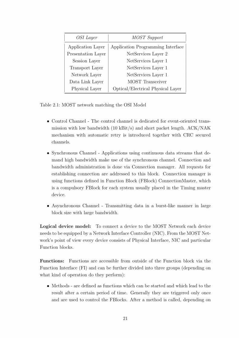
2.1 MOST
Media Oriented System Transport (MOST) is an industry standard for automotive
multimedia networking [12]. It is a technology designed to provide a network for
multimedia automotive applications. The interest of researchers developing MOST
is to support heterogeneous multimedia devices and facilitate mutual communication
by introducing a low cost peer-to-peer network. Thus a plenty of new multimedia
applications for automotive environment can be developed without significant hard-
ware limitations. Behind the inception and the development of MOST technology
is an organization called MOST Cooperation (MOSTCO) made up of car manufac-
turers, component suppliers, system architects and the IT industry. The scope of
MOSTCO is to define, promote, and standardize the MOST Technology. Table 2.1
shows how MOST specification covers all layers of Open System Interconnect (OSI)
reference model.
By having specified software, hardware and Application Programming Interfaces
(APIs), an implementation of multimedia network supporting devices from differ-
ent manufacturers becomes simpler. Most technology was originally developed to
transfer data over the optical physical layer (oPhy), known as a MOST25 (according
to the bandwidth). Recently a new specification for the electrical layer (ePhy) was
added due to increasing interest in the MOST Technology from the automotive in-
dustry. MOST Technology operating over the ePhy is denoted as a MOST50. From
MOST Specification point of view, the network model is divided in to three sections:
Application section, Network section and Physical section.
2.1.1 Application Section
MOST network supports various devices with wide range of functionality. Starting
with simple audio devices like microphones and speakers, MOST networks include
video cameras culminating with sophisticated telematics systems. Three different
data channels are available for applications:
20
OSI Layer MOST Support
Application Layer Application Programming Interface
Presentation Layer NetServices Layer 2
Session Layer NetServices Layer 1
Transport Layer NetServices Layer 1
Network Layer NetServices Layer 1
Data Link Layer MOST Transceiver
Physical Layer Optical/Electrical Physical Layer
Table 2.1: MOST network matching the OSI Model
• Control Channel - The control channel is dedicated for event-oriented trans-
mission with low bandwidth (10 kBit/s) and short packet length. ACK/NAK
mechanism with automatic retry is introduced together with CRC secured
channels.
• Synchronous Channel - Applications using continuous data streams that de-
mand high bandwidth make use of the synchronous channel. Connection and
bandwidth administration is done via Connection manager. All requests for
establishing connection are addressed to this block. Connection manager is
using functions defined in Function Block (FBlock) ConnectionMaster, which
is a compulsory FBlock for each system usually placed in the Timing master
device.
• Asynchronous Channel - Transmitting data in a burst-like manner in large
block size with large bandwidth.
Logical device model: To connect a device to the MOST Network each device
needs to be equipped by a Network Interface Controller (NIC). From the MOST Net-
work’s point of view every device consists of Physical Interface, NIC and particular
Function blocks.
Functions: Functions are accessible from outside of the Function block via the
Function Interface (FI) and can be further divided into three groups (depending on
what kind of operation do they perform):
• Methods - are defined as functions which can be started and which lead to the
result after a certain period of time. Generally they are triggered only once
and are used to control the FBlocks. After a method is called, depending on
21
what kind of operation type do we use (e.g. start, start/result [12]), the error
or report message should be sent to the initiator.
• Properties - functions determine to change the status of a device i.e. the
property of a device. The Operation Types for the properties are: get, set,
increment, etc. Every property has a one unique state.
• Events - are basically same as properties, the only distinction is that events
occur without any external request (e.g. incoming phone call).
Function Block: Each FBlocks contain functions. Every device has a several
FBlocks representing the applications (e.g. CD player, Amplifier, etc.) and one
mandatory FBlock called Netblock, maintaining functions related to the entire de-
vice. We have three different types of FBlocks: slaves, controllers and HMIs. Slaves
are always controlled FBlocks, controllers are FBlocks using functions in another
Function Block and HMIs are FBlocks communicating with the user. By using
the delegation, heredity and device hierarchy methods, the complex system can be
controlled in an understandable way [12].
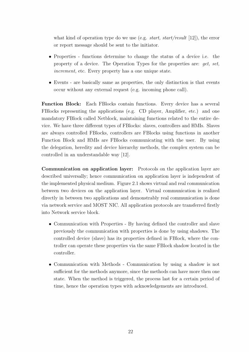
Communication on application layer: Protocols on the application layer are
described universally; hence communication on application layer is independent of
the implemented physical medium. Figure 2.1 shows virtual and real communication
between two devices on the application layer. Virtual communication is realized
directly in between two applications and demonstrably real communication is done
via network service and MOST NIC. All application protocols are transferred firstly
into Network service block.
• Communication with Properties - By having defined the controller and slave
previously the communication with properties is done by using shadows. The
controlled device (slave) has its properties defined in FBlock, where the con-
troller can operate these properties via the same FBlock shadow located in the
controller.
• Communication with Methods - Communication by using a shadow is not
sufficient for the methods anymore, since the methods can have more then one
state. When the method is triggered, the process last for a certain period of
time, hence the operation types with acknowledgements are introduced.
22
Figure 2.1: Virtual and real communication between two devices
2.1.2 Network section
MOST Network Interface Controller: MOST Network can be implemented
as a star-, ring- or daisy-chain topology. As described earlier MOST Network Inter-
face Controller (NIC) is a mandatory part of each connected device to the MOST
Network. The following part will give an overview of functions of NIC.
• Bypass - Each device has its own bypass function. If a bypass is activated,
data coming from the input interface are transferred directly to the output
interface. As a result, the device is passive and from the MOST bus point of
view therefore invisible.
• Source data bypass - As soon as the device wants to send an item of data a
source data bypass must be opened.
• Timing Master (Frame Generator) - The MOST Network can be maximally
connected with 64 NICs, thus maximally 64 devices. In order to establish com-
munication, one of those devices must become a Timing Master. The main task
is to generate and transport the system clock, the blocks and frames. Other
devices (timing slaves) are synchronized with the Frame Generator by using
internal PLL (Phase-Locked Loop). By having all the devices synchronized to
the network no memory buffering is needed.
Data Transport: Data transport includes mechanisms for network delay detec-
tion, burst data channel management, and automatic channel routing. The sample
frequency can be chosen between 30 kHz and 50 kHz.
23

Optical physical layer: When using optical physical layer, data is trans-
ported in continuous bi-phase encoded bit stream at 24.8 Mbit/s and 44.1 kHz
rate. Bit error rate (BER) is ensured at less then 10−10. Data stream consists of
blocks further composed from particular Frames. This structure is required for net-
work management and transport of control data. Each Frame has 512 bits where
one Block contains 16 Frames. One frame has 60 Bytes of data available for syn-
chronous and asynchronous packet data transfer and 2 Bytes transfer control data.
Remaining 2 Bytes are added to the control frame to transport a control telegram.
The structure of MOST25 data frame is depicted in the Figure 2.2.
Figure 2.2: Structure of MOST25 Data Frame
Electrical physical layer: Recently released specifications for the electrical
layer can transfer data at 50 Mbit/s [13]. MOST50 frame consists of 1024 bits, where
the first 88 bits are used for control data (4 Bytes) and for other administrative
functions. For the synchronous and the asynchronous data transfer the remaining
117 Bytes are used. The MOST50 frame is depicted in the Figure 2.3. Vendors are
developing new INICs operating over optical layer with data rate 150 Mbit/s.
Data Frame: Structure of data frames are shown in Figures 2.2 and 2.3. The
particular parts are described in the following section.
• Preamble - is used to synchronize the MOST nodes and its functions to the
bit stream. Two different mechanisms of synchronization are implemented.
First is for slave nodes and is done by reception of the valid preamble. This
method results in slave node beeing locked to the timing master (phase and
24
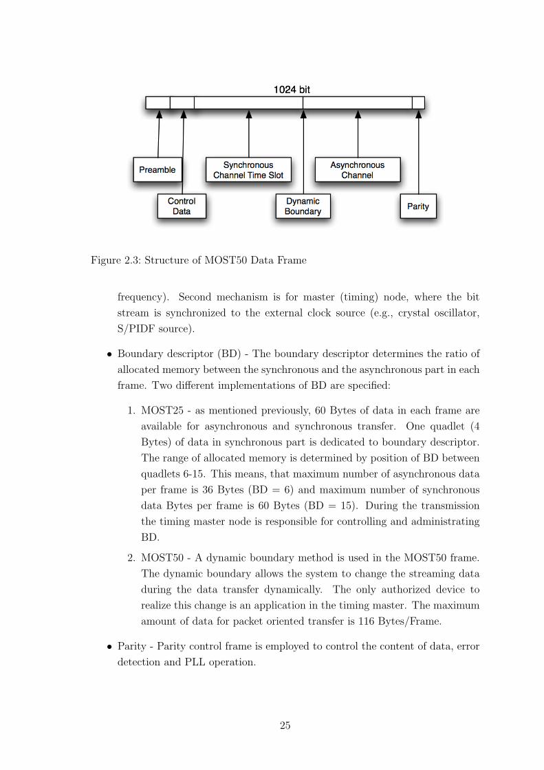
Figure 2.3: Structure of MOST50 Data Frame
frequency). Second mechanism is for master (timing) node, where the bit
stream is synchronized to the external clock source (e.g., crystal oscillator,
S/PIDF source).
• Boundary descriptor (BD) - The boundary descriptor determines the ratio of
allocated memory between the synchronous and the asynchronous part in each
frame. Two different implementations of BD are specified:
1. MOST25 - as mentioned previously, 60 Bytes of data in each frame are
available for asynchronous and synchronous transfer. One quadlet (4
Bytes) of data in synchronous part is dedicated to boundary descriptor.
The range of allocated memory is determined by position of BD between
quadlets 6-15. This means, that maximum number of asynchronous data
per frame is 36 Bytes (BD = 6) and maximum number of synchronous
data Bytes per frame is 60 Bytes (BD = 15). During the transmission
the timing master node is responsible for controlling and administrating
BD.
2. MOST50 - A dynamic boundary method is used in the MOST50 frame.
The dynamic boundary allows the system to change the streaming data
during the data transfer dynamically. The only authorized device to
realize this change is an application in the timing master. The maximum
amount of data for packet oriented transfer is 116 Bytes/Frame.
• Parity - Parity control frame is employed to control the content of data, error
detection and PLL operation.
25

• Synchronous area - Allocated time slots for synchronous channel are used for
real-time data transmission (audio/video, monitoring, sensors). The Time Di-
vision Multiplex (TDM) method with allocation of quasi-static physical chan-
nels for different periods of time technique is implemented. Maximum number
of bites for the MOST25 is equal to 60x8 bits/frame with the used rate 44 100
frames/s. For the MOST50 frame the maximum number is 117x8 bits/frame
with 48 000 frames/s.
• Asynchronous area - Two different mechanisms for transfer of asynchronous
(packet) data are realized. Firstly transfer of slow asynchronous data (e.g.
telegrams to control devices) which is used control channel of the MOST Net-
work Interface Controller. Secondly, faster packet-oriented transfer done via
an asynchronous channel designed to handle burst like traffic. Access method
for this channel is implemented in token ring fashion; the maximum packet
length is 48 Bytes. Hardware CRC protection is calculated and is assigned to
the end of each asynchronous message.
• Control data - For communication between single nodes on the bus the control
data channel is used. Carrier Sense Multiple Access (CSMA) mechanism is
employed for accessing the data channel. Two kinds of control messages are
used. Normal messages, to provide a control of applications (commands, sta-
tus and diagnosis messages) and system messages for system administration
(resource handling). Arbitration is provided automatically by MOST NIC.
2.1.3 Physical section
MOST Network uses mechanism of actuating. Device can convert it’s mode in to
sleep mode, where the consumption of energy is low (I ≤ 100 µA).
The following text describes particular sections of the MOST device structure.
• Interface Area - Consists of a transmitter (TX) and receiver (RX) communicat-
ing with NIC. During a data transmission the phase jitter can be accumulated,
hence this factor together with power budget is rigorously considered during
the design of Optical Interface Area.
• MOST Function Area - Network Interface Controller, crystal and PLL-Filter
are the main blocks in MOST Function Area. NIC communicates with µController
via I2C (Inter-Integrated Circuit), SPI (Serial Peripheral Interface) or parallel
bus.
• µController Area - microcontroller (µC) and memory is a usual content of this
optional block.
26
• Application Area - Belongs to the application peripherals (i.e., receiver, am-
plifier).
• Power Supply Area - Consists of different facilities performing various tasks
(e.g., EMI/EMC protection, Micropower regulator, watchdog timer, etc [12]).
Optical Physical Layer: As mentioned earlier, the MOST Network was origi-
nally developed and designed to operate over the plastic optical fibres (POFs) as a
physical layer. This took abroad various pros and cons. In that time the certain ad-
vantages were an Electro-Magnetic Interference (EMI) immunity and light weight.
On the other hand, small bend radius and limited temperature range were the
two most significant imperfections from the automotive point of view [14]. MOST
technology utilization was increasing by implementing this multimedia network into
luxury modern cars. The used optical medium for the MOST25 is POF/LED.
Electrical Physical Layer: The automotive progress is becoming more and more
focused on the electronic area and carmakers are competing between each other in
providing more superior and sophisticated multimedia services. Under these condi-
tions the needs for multimedia services in budget-range cars and for new physical
layer (ePHY) arise. Simultaneously with new electrical physical layer the Intelligent
NIC (INIC) was introduced [15]. As a transmission medium Unshielded Twist Pair
(UTP) cables are employed. From preceding text one problem arises, which is the
Electro-Magnetic Compatibility (EMC) in automotive world.
EMC Testing The following part summarizes the most significant improve-
ments in order to reduce EMI in ePHY.
• Improved signal skew by usage of common mode filter [16].
• Power between physical layer and NIC was decreased (from 5 V to 3,3 V and
2,5 V [11]).
• Differential signalling, filtering and scrambling of the signal was introduced.
• Size and number of high-speed traces in Printed Circuit Board were reduced.
MOST50 was individually tested by several carmakers. The list of the passed stan-
dards can be found in [10]. Different kinds of UTP cables with the twist length ≤45
mm and impedance of 100 Ω were tested. Standard automotive connectors (e.g.
crimp style connector with 4 or more pins [10]) can be used.
27
The Intelligent Network Interface Controller for MOST was designed to facilitate
the integration of the new electrical physical layer. Significant benefits are:
• Doubled transmission rate from 25 Mbit/s to 50 Mbit/s in MOST50.
• High number of interconnects (up to 8 in-line couplers per link between 2
devices).
• Utilization of current manufacturing processes (UTP cables).
• Simple manipulation.
New signal circuitry provides differential input and output directly interfacing with
the ePHY transformer. The INIC contains its own microcontroller and mini-kernel
to implement the function from Network Service Layer 1 and NetBlock from Net-
work Service Layer 2. Originally in NIC a register wall was used as an interface.
As it was stated, the MOST Network is a dynamically developing technology. This
paragraph draws up the future development trends and directions.
• MOST 150 - Is a next step in the development process with a higher band-
width (150 Mbit/s) based still on the POF/LED. Carmakers like BMW or
Daimler Chrysler tend towards this solution, since the already well known and
tested POF/LED can be utilized. However 150 Mbit/s seems to be as the
highest possible value over POF and LED. For more bandwidth a new optical
transceivers will be used. It is expected, that the MOST150 ring will transfer
multiple sound and compressed video signals simultaneously.
• MOST 1000 - In order to increase the bandwidth, the PCS/VCSEL physical
layer will be utilized. The MOST1000 is a technology for long time consider-
ation and its introduction is not expected within the next 10 years.
28
2.2 SAE J1939
The CAN-based SAE J1939 bus was developed for diagnostics and component con-
trol applications in truck and trailer systems like radar and lidar, and engine, trans-
mission and EBS electronic control modules. This SAE class C network supports
real-time closed loop control function between ECUs [17].
2.2.1 Physical Layer
OSI layer one and layer two are identical to the CAN 2.0b standard. The physi-
cal medium can be both shielded (SAE J1939-11) and unshielded (SAE J1939-15)
twisted pair of copper wires. The maximum bus length is 40 m, terminated with a
resistor at each end to reduce reflections, with a maximum data rate of 250 kBit/s.
The ECUs may be in direct contact with the bus, or via short stubs. No loops are
allowed, although redundant bus segments can be provided for fault tolerance. In
this case the corresponding ECUs must be able to deal with these redundant wires.
To provide electrical isolation and compatibility of different data rates and physical
media between segments like tractor, trailor or implements, bridges are used. J1939
supports up to 30 ECUs per bus segment if STP wires are used, in the case of UTP
this number is reduced to 10 [18, 19].
2.2.2 Data Link Layer
SAE J1939 uses the CAN 2.0b extended frame format with 29 identifier bits in the
arbitration field [20]. The first three bits define the priority of the message. This
field is followed by a reserved bit which is set to zero and the data page bit which
extends the parameter group extensions. The next eight bits define the PDU format
followed by 8-bit PDU specific field. If the PDU format field has a value of 0-239
(PDU1) the PDU specific field will contain the destination address of the frame,
on the other hand with a value of 240-255 (PDU2) it contains the group extension.
Therefore a total of (240 + (16 ∗ 256)) ∗ 2 = 8672 parameter groups are possible.
Most messages sent in a J1939 network are of the later type and therefore they
are broadcasted. The source address also consists of eight bits which is sufficient
for 256 devices. Addresses are usually preassigned, but if necessary, there is also
a procedure for assigning addresses available. Finally the data field provides eight
bytes. If the message is longer, up to 1785 bytes, a transport protocol function is
used and the message is divided to multiple CAN data frames.
The parameter group number defines five message types, which are:
29
• Commands, such as ”Transmission Control”
• Requests
• Broadcast/Response
• Acknowledgement in the form of in-frame ACKs, which indicates that at least
one node has successfully received the message and as a response to a request.
• Group functions, which contain proprietary functions or network management
Bus access, arbitration and error correction are handled as specified in CAN.
OSI Layer SAE J1939
Application Layer SAE J1939/71
Presentation Layer not specified
Session Layer not specified
Transport Layer not specified
Network Layer SAE J1939/31
Data Link Layer SAE J1939/21, CAN 2.0b
Physical Layer SAE J1939/11, SAE J1939/15
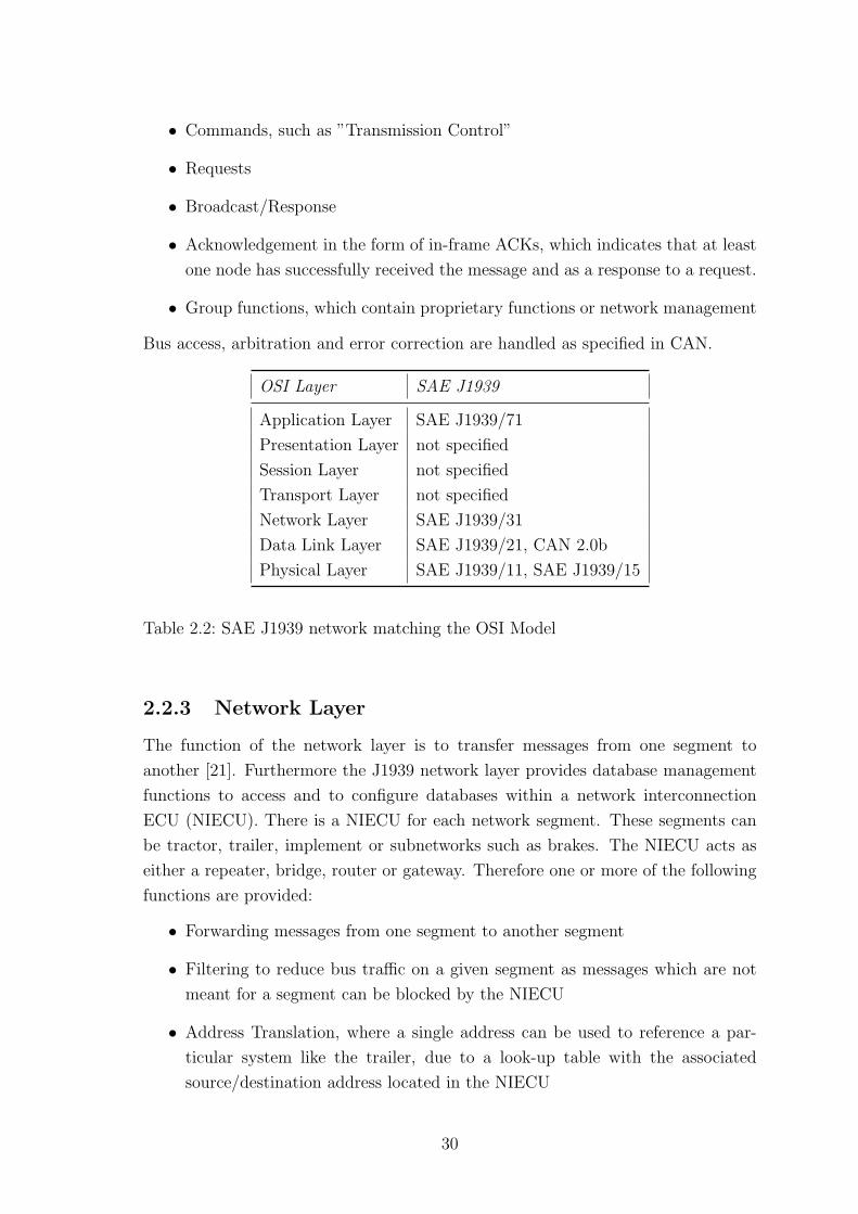
Table 2.2: SAE J1939 network matching the OSI Model
2.2.3 Network Layer
The function of the network layer is to transfer messages from one segment to
another [21]. Furthermore the J1939 network layer provides database management
functions to access and to configure databases within a network interconnection
ECU (NIECU). There is a NIECU for each network segment. These segments can
be tractor, trailer, implement or subnetworks such as brakes. The NIECU acts as
either a repeater, bridge, router or gateway. Therefore one or more of the following
functions are provided:
• Forwarding messages from one segment to another segment
• Filtering to reduce bus traffic on a given segment as messages which are not
meant for a segment can be blocked by the NIECU
• Address Translation, where a single address can be used to reference a par-
ticular system like the trailer, due to a look-up table with the associated
source/destination address located in the NIECU
30
• Message Repackaging, which provides a potential reduction of bus traffic as
several parameters can be grouped more efficiently
• Database Management to access and configure databases in the NIECU such
as the static filter database
2.2.4 Vehicle Application Layer
In the vehicle application layer of SAE J1939 all the parameter groups as well as the
parameter group numbers are specified. The parameter group number is a unique
identifier for each CAN message [22]. Furthermore a ”source address of controlling
device” parameter was added in the last revision which makes it possible to identify
the original source of a message in a bridged network.
2.2.5 Network Management
Network management covers all OSI layers [23]. This layer defines various state
diagrams for instance for initialization and it defines constraints on the use of ad-
dresses.
31
2.3 IDB-1394
IDB-1394 is an automotive version of the IEEE-1394b standard, a high-speed bidi-
rectional serial bus usually used for digital video cameras, hard discs and other
high-speed devices, extended by higher level protocols [24]. For automotive ap-
plications either plastic optical fibres (POF) or hard clad silica fibres (HCS) are
applicable. Depending on the physical medium, maximum transmission rates of 100
Mbit/s and 200 Mbit/s over a link length of 50 m (POF) and 100 m (HCS). Using
shorter link lengths increases the transmission rate up to 400 Mbit/s and soon up
to 1600 and even 3200 Mbit/s.
The standard supports up to 63 nodes per bus including a consumer convenience
port, automatic node identification and topology configuration. IEEE-1394 also
supports both isochronous traffic with guaranteed latency and bandwidth which
makes it suitable for real-time applications and asynchronous traffic. The physical
topology of IEEE-1394 can be a bus or ”daisy-chain” and a tree. In the automotive
version IDB-1394 additionally a ring topology is possible, which is the suggested
topology here as it provides a reliable level of system availability. Each IEEE-1394
device provides at least two connectors.
2.3.1 IDB-1394 Specification
IDB-1394 specifies OSI layer one to layer five. The first three layers, except the
IDB-1394 protocol also meet the IEEE-1394 specifications [25].
• Physical Layer including the CCP (Consumer Convenience Port, which pro-
vides an interface, used for portable devices)
• IEEE-1394 stack and driver: The driver acts as the hardware device driver
whereas the stack is responsible for bus management, isochronous resource
management and isochronous and asynchronous transaction management.
• Higher-level protocols: This protocols include the communication management
protocol IEC-61883, which defines the format in which audio and video data
are transported, and the AV/C controller which defines control messages for
audio and video and descriptors for their presentation. Furthermore the IDB-
1394 protocol, designed for automotive requirements, is located in this layer.
It initiates on request the sleep-mode and the wake-up signal for embedded
network devices.
32
• Communication layer: This layer acts as the automotive message transport
layer and provides interfaces between different networks and protocols like
Bluetooth, IDB-1394 or CAN.
OSI Layer IDB-1394
Application Layer not specified
Presentation Layer not specified
Session Layer not specified
Transport Layer Network Adaption Layer
Network Layer AV/C, VIP
Data Link Layer IEC-61883
Physical Layer IEEE-1394
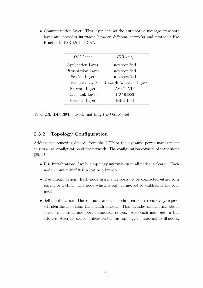
Table 2.3: IDB-1394 network matching the OSI Model
2.3.2 Topology Configuration
Adding and removing devices from the CCP or the dynamic power management
causes a (re-)configuration of the network. The configuration consists of three steps
[26, 27]:
• Bus Initialization: Any bus topology information in all nodes is cleared. Each
node knows only if it is a leaf or a branch.
• Tree Identification: Each node assigns its ports to be connected either to a
parent or a child. The node which is only connected to children is the root
node.
• Self-identification: The root node and all the children nodes recursively request
self-identification from their children node. This includes information about
speed capabilities and port connection status. Also each node gets a bus
address. After the self-identification the bus topology is broadcast to all nodes.
33
2.4 APIX Link
The Automotive PIXel Link was developed by Inova Semiconductors [28, 29, 30]
in cooperation with the Fraunhofer Gesellschaft in spring 2005. The link was the
answer to the car industry’s question if GigaSTaR (Gigabit-Serial-Transmit and Re-
ceive), which offers data rates of up to 1.2 Gbit/s over a pair of copper wires can
be used in automotive applications. GigaSTaR is currently utilized for passenger
information systems in trains, to connect remote terminals in the automation in-
dustry, as well as for modern LED video walls. The high requirements of the car
industry concerning EMI and EMC were not fulfilled by GigaSTaR. Therefore Inova
Semiconductors developed APIX to meet these demands.
The APIX point-to-point link is based on a one or two pairs of STP copper wires
and transmits uncompressed pixel data with a data rate of up to 1 Gbit/s on the
downlink and up to 62.5 Mbit/s on the upstream link over a wire length of 15 m.
One big advantage of APIX compared to optical networks like MOST or IDB-1394 is
that optical-to-electronic and electronic-to-optical converters on each device, which
produces rather high cost, and comparable unflexible POFs can be avoided. The
transceiver and receiver chips are produced in a 0.18-µm-CMOS process which keeps
the purchasing costs low. Also the energy consumption is as low as 200 mW and
the possible application area covers a temperature range from -40 C to 105 C [31].
Due to special IOs, adjustable driving current and pre-emphasis, new spread-spectrum
clocking and an optimized PLL concept, a very good electromagnetical compatibil-
ity of the link is ensured. The APIX link only specifies the physical layer.
APIX provides a continuous real-time data stream with low latency and low BER,
running for instance at 1 Gbit/s for the high-resolution, full-colour display link be-
tween the image processor and the TFT display or 500 Mbit/s on the camera link
between the CMOS sensor and the processor. The camera can be monitored and
controlled with the integrated back channel simultaneously. Altogether the APIX
link consists of three independent channels: the unidirectional downstream pixel
channel and the bidirectional side band channels. All channels can be multiplexed
and transmitted over a single STP wire. The upstream side band channel could
also be established over a second pair of wires. One application for these additional
side band channels is to transmit other protocols ’piggyback-like’ without the need
of buffers. These protocols can be used to monitor and control parameters of the
CMOS sensors and displays.
34
Applications for the APIX link as proposed by Inova Semiconductors are for in-
stance dashboard, rear seat, or head-up displays as well as cameras for lane depar-
ture warning, adaptive cruise control, rear and side mirror replacement and blind
spot detection. Large 24-bit full-colour displays with a resolution of 1280x480 pixels
are said to replace the analogue dashboard in the near future.
Several press releases like [31] say that APIX’ safe and EMC-optimized physical
layer will be a good basis to meet the requirements for the next decade. A large
number of suppliers have already started to integrate the APIX functionality in their
chip sets.
35
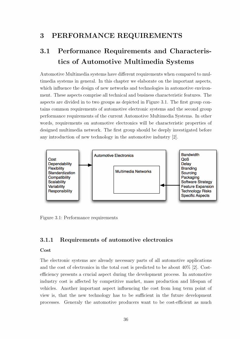
3 PERFORMANCE REQUIREMENTS
3.1 Performance Requirements and Characteris-
tics of Automotive Multimedia Systems
Automotive Multimedia systems have different requirements when compared to mul-
timedia systems in general. In this chapter we elaborate on the important aspects,
which influence the design of new networks and technologies in automotive environ-
ment. These aspects comprise all technical and business characteristic features. The
aspects are divided in to two groups as depicted in Figure 3.1. The first group con-
tains common requirements of automotive electronic systems and the second group
performance requirements of the current Automotive Multimedia Systems. In other
words, requirements on automotive electronics will be characteristic properties of
designed multimedia network. The first group should be deeply investigated before
any introduction of new technology in the automotive industry [2].
Figure 3.1: Performance requirements
3.1.1 Requirements of automotive electronics
Cost
The electronic systems are already necessary parts of all automotive applications
and the cost of electronics in the total cost is predicted to be about 40% [2]. Cost-
efficiency presents a crucial aspect during the development process. In automotive
industry cost is affected by competitive market, mass production and lifespan of
vehicles. Another important aspect influencing the cost from long term point of
view is, that the new technology has to be sufficient in the future development
processes. Generaly the automotive producers want to be cost-efficient as much
36
as possible. Hence they aim to decrease development, production and maintanance
costs of their products on the lowest possible level. An important point is to consider
that the cost-efficient system has also to satisfy its future requirements.
Dependability
Dependability can be further divided into the following aspects [2, chap. 3].
• Reliability and Availability- both factors are closely related to each other.
Nevertheless one important divergence is that reliability guarantees correct
functioning over a given period of time and availability guarantees this oper-
ation in any time.
• Safety is undoubtedly decisive factor when choosing a new technology. When
having a safety parameter in mind, one can think about faults, errors and sys-
tem failures. More information on how to solve and prevent different situations
can be found in [2].
• Confidentiality is a crucial aspect in the competitive automotive industry.
Therefore it is not convenient to disclose any confidential information, unless
it is a purposeful step, where the informations are shared (e.g. platforms in
the car industry)
• Maintainability is an important factor not only for seamless functioning during
product lifetime, but also various repairs, improvements and changes in the
system can be performed.
Flexibility
Flexible arrangement of the system provides the possibility to improve and change
existing functionality and topology. Flexible arrangement can be achieved by using
platforms and layered structures. The flexibility is important for the automotive
electronics as well as for the multimedia networks. The flexible system usually
decreases the cost during performing any changes and improvements.
Standardization
The automotive industry visibly desiderates open standard solutions. Many man-
ufacturers in automotive area are developing their own solutions. With open stan-
dards solutions development process can be divided into more companies, hence the
cost can be decreased. As all industry developments have their own advantages and
disadvantages, every little improvement of the open source system will be beneficial
37
to all involved manufacturers, which does not have to be desirable. The most visi-
ble organization in automotive standardization is AMI-C (Automotive Multimedia
Interface Collaboration). In the interest of AMI-C is to adopt already existing stan-
dards on the market to the automotive industry, primarily in multimedia networks
(i.e. MOST, IDB 1394, Bluetooth). Standardization generally refers to streaming
media and communication interfaces. MOST Network and AUTOSAR (AUTomo-
tive Open System ARchitecture) are technologies developed as a standard from the
beginning. Behind those two projects are standing different groups of carmakers
and manufacturers.
Compatibility
Compatibility can be increased by standardization process (e.g. defining various
interfaces and gateways to communicate with other external devices or systems)
and is an important aspect bringing the cooperation between various producers.
Generally compatible technology brings benefits for suppliers, automotive producers
and customers.
Scalability
Scalable systems are systems whose functionality improves, when new devices are
added. Translated into my topic, scalable automotive electronics system has to
demonstrate improved performance after adding new additional hardware or soft-
ware. These changes are mostly related to the future improvements of the electronic
systems. A scalable systems should satisfy requirements, when new services and
technologies are introduced and implemented. Thus, researchers in automotive elec-
tronics aim for predicting the future trends and development as much as it is possible
and encompass them in the development process. Obviously this is not an easy pro-
cess, as simply introducing of new technologies can not be predicted. However a
reasonable trade off between expected growth trends and possible current solution
should be considered carefully. In the forth part of this theis, the scalability is as-
sociated with the network topology and with the possibility to improve particular
technologies.
In the MOST Network, which is described in detail in first phase of this project,
when the researchers introduced new electrical physical layer (ePHY), mean that
changes were necessary in Network Interface Controllers (NICs) and Network Ser-
vices (Layer1 and 2). From these facts we can observe to what degree the system is
scalable.
38
Variability
Variability is defined as a capability of the system to be configurable with respect
to the special demands of the customers [32]. Electronic system must be available
in configurations to be implemented in different models. The importance of this
aspect in automotive industry is evident, since the demands of customers for various
combinations are well known. In the automotive area the customer’s demands vary
as well as the devices connected to the multimedia networks and their topology.
The proposed system should be identical with these changes and their realization as
cheap as possible.
Responsibility
Responsibility is an important aspect when choosing various device suppliers. If
the car manufacturer decides to implement many of complex devices from external
suppliers in his product, the responsibility for functioning of the device will rely
on the suppliers. This solution is usually not cost effective for the company and
reasonable trade off between suppliers’ products and companies’ technical solutions
has to be chosen. The designed system can become extremely expensive, when the
suppliers will perform all small changes and repairs in the system. On the other
hand the technologies are usually very complex, hence the automotive producers
can not invest their resources into the development process of all used technologies.
3.1.2 Requirements of Telematic and Infotainment systems
By having in mind the growing importance of Telematic and Infotainment systems
in automotive applications, requirements on multimedia networks driven by these
systems, from carmakers point of view, are highlighted in the following subsection.
Bandwidth
Bandwidth belongs between the major aspects in multimedia networking area. Dif-
ferent solutions have been proposed in order to provide higher bandwidth and to
allow superior services (e.g., streaming video). With the introduction of new net-
work technologies the bandwidth will unambiguously increase, since the applications
demand a large amount of data to be transmitted on-board. Generally today’s state
of the art does not provide satisfactory solutions for implementing all services.
39
QoS
Quality of Service should be also considered when a complex multimedia network is
proposed. Priorities in the packet switched data networks should be determined to
improve network throughput.
Delay
Delay of data packets and variance of the delay (delay jitter) plays an important
role in the networking area. Therefore these aspects must be considered along the
development process.
Branding
When a new device is delivered by a supplier, the car maker usually does not want
to have a supplier’s brand written on the device. Therefore a branding stands for
replacing all supplier’s related trademarks and logos by car maker’s own brand.
Power Supply
Different power supply schemes and strategies can be implemented. This factor
affects the final solution. Generally two approaches are used. The first is to use a
separate cable for the power supply and second is to use the electrical communication
medium as a source of energy. This can reduces a number of used cables in the
vehicles, but demands more complicated transceivers.
Packaging
This aspect is related to different device topologies. One solution can represent a
complex device supporting many services and other solutions can be a distributed
topology of a device providing various services not just from one device box. The
complex device is easy to implement in to the vehicle, but it is not possible to change
the functionality nor the topology of the system. Such a complex device can be rep-
resented by one box with all the required functions and features.
In the distributed solution a communication network acts as a transfer medium for
the particular devices. Therefore adding new features and services is possible and
all of the devices can benefit from their mutual communication. The distributed so-
lution brings another issues into the consideration e.g. compatibility, responsibility,
etc.
40
Software strategy
Automotive producer has to look at heterogeneous aspects during the implementa-
tion of new technologies. Software strategy is a factor which affects other aspects
such as the cost and the packaging. By software strategy it is meant different ap-
proaches with regard to the implementation of software. One approach can be tried
involving a trade off between supplier’s software implementation and the carmaker’s
software solution. The second approach deals with placing the software parts into
the various places in the system (i.e. some applications can be placed in the central
device and some in the particular parts in the network). The software strategy is
closely related to the responsibility, hence these aspects should be clearly defined
during a cooperation with a supplier.
Feature expansion possibility
This aspect is closely related to the scalability. To emphasize the significance of
scalability in infotainment systems, feature expansion possibility features are placed
in this group. An importance of this aspect is visible, since the multimedia devices
are dynamically developing and new features and functions are introduced. New
introduced technology should be able to support functions and features introduced
during the period of the technology’s lifetime.
Technology risks
Technology risks can occur when introducing new technologies, which were not suf-
ficiently tested and which for example are unlikely to become the standard or major
track in the industry. The automotive manufacturers are guarding against taking
undesirable technology risks and are rather careful in implementing revolutionary
technologies. Based on these facts, one can begin to understand the conservatism
which is prevalent in the automotive industry (e.g. vehicle’s combustion engine etc).
Generally car makers are quite conservative when it comes to new technologies be-
cause ‘new’ implies untested and therefore unknown risks. The technology risks is
in the automotive industry increased by the fact, that the devices in the vehicles
face to the specific conditions (e.g. temperature, shakes, etc).
Specific Aspects
In this paragraph specific aspects which affect the development process are men-
tioned. These aspects are considered during the technologies development processes
and are related to the physical layer:
• Temperature range
41
• BER (Bit Error Rate)
• SNR (Signal to Noise Ratio)
• Crosstalk
• EMI (ElectroMagnetic Interference)
• Inductance
• Capacitance
3.1.3 Relations between aspects
All aspects mentioned above should be considered carefully during a development
process. Various relations between aspects can be theoretically observed and more
relations appear during the implementation procedure. Generally speaking the most
dependable aspect or most related aspect, both from the automotive manufacturer’s
point of view is the cost (e.g., in order to have a cost-efficient product the sufficient
degree of scalability must be guaranteed).
42
4 EVALUATION OF DIFFERENT TOPOLOGIES
In this chapter various networks and their topologies are described and presented as
my proposed solutions. The aspects mentioned in the previous chapter are compared
with the proposals. Therefore a general evaluation of the proposed networks and
their comparisons are given.
4.1 CAN-based Networks
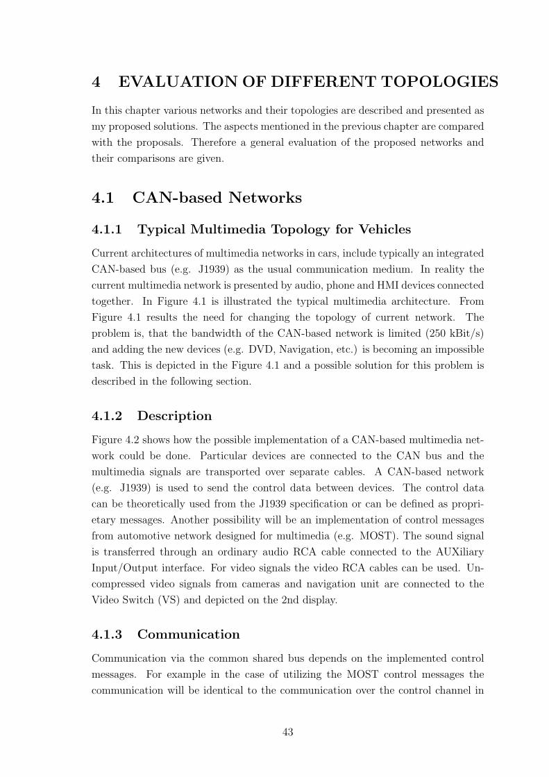
4.1.1 Typical Multimedia Topology for Vehicles
Current architectures of multimedia networks in cars, include typically an integrated
CAN-based bus (e.g. J1939) as the usual communication medium. In reality the
current multimedia network is presented by audio, phone and HMI devices connected
together. In Figure 4.1 is illustrated the typical multimedia architecture. From
Figure 4.1 results the need for changing the topology of current network. The
problem is, that the bandwidth of the CAN-based network is limited (250 kBit/s)
and adding the new devices (e.g. DVD, Navigation, etc.) is becoming an impossible
task. This is depicted in the Figure 4.1 and a possible solution for this problem is
described in the following section.
4.1.2 Description
Figure 4.2 shows how the possible implementation of a CAN-based multimedia net-
work could be done. Particular devices are connected to the CAN bus and the
multimedia signals are transported over separate cables. A CAN-based network
(e.g. J1939) is used to send the control data between devices. The control data
can be theoretically used from the J1939 specification or can be defined as propri-
etary messages. Another possibility will be an implementation of control messages
from automotive network designed for multimedia (e.g. MOST). The sound signal
is transferred through an ordinary audio RCA cable connected to the AUXiliary
Input/Output interface. For video signals the video RCA cables can be used. Un-
compressed video signals from cameras and navigation unit are connected to the
Video Switch (VS) and depicted on the 2nd display.
4.1.3 Communication
Communication via the common shared bus depends on the implemented control
messages. For example in the case of utilizing the MOST control messages the
communication will be identical to the communication over the control channel in
43
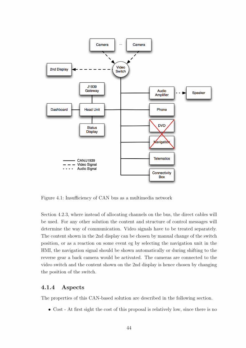
Figure 4.1: Insufficiency of CAN bus as a multimedia network
Section 4.2.3, where instead of allocating channels on the bus, the direct cables will
be used. For any other solution the content and structure of control messages will
determine the way of communication. Video signals have to be treated separately.
The content shown in the 2nd display can be chosen by manual change of the switch
position, or as a reaction on some event eg by selecting the navigation unit in the
HMI, the navigation signal should be shown automatically or during shifting to the
reverse gear a back camera would be activated. The cameras are connected to the
video switch and the content shown on the 2nd display is hence chosen by changing
the position of the switch.
4.1.4 Aspects
The properties of this CAN-based solution are described in the following section.
• Cost - At first sight the cost of this proposal is relatively low, since there is no
44
Figure 4.2: CAN-based solution
new technology introduced and the used devices need to undergo just minor
changes. As defined in the Section 3.1.1 the future benefit of the solution
is closely related to the cost, hence the cost of this proposal is significantly
increased by this factor.
• Scalability - This solution is not very satisfactory in terms of the scalability. By
adding a new device the whole topology has to be changed and new interfaces
to connect the device need to be added. This has a further implication in
bringing in an undesirable increase in the number of the cables and interfaces,
which in turn may increase the cost.
• Variability - Variability can be ensured by connecting particular devices to the
network. This increases the number of used cables and interfaces.
• Dependability - Reliability, availability and safety are ensured by the used
45
control channel, in both possibilities (i.e. the MOST control messages and the
proprietary control messages) are those aspects guaranteed.
• Flexibility - The flexibility of the solution is decreased by the facts that the
signals are transferred via different cables and the possibility to change the
topology or introduce a new function useful for more then one device is im-
possible.
• Standardization - CAN is a standardized technology as is the transfer of the
audio and video signals via RCA cables
• Compatibility - This solution is compatible with the surrounding technology
(CAN network) and for the functional part the connectivity box with different
interfaces to connect audio devices is present.
• Responsibility - The responsibility is predominantly on the side of the automo-
tive manufacturer. No sophisticated devices are implemented and the control
mechanism can be maintained by the carmaker.
• Bandwidth - As it was written in the Section 4.1.1 the bandwidth limitation
was an obstacle for using the CAN bus to transfer all signals. Hence, the
solution with separate cables partially solves this bandwidth problem.
• QoS - Quality of Services are guaranteed by the technology used in the control
channel.
• Power supply - The power supplies are designed separately.
• Packaging - A distributed approach in CAN network is applied.
• Software strategy - Depending on the suppliers, a distributed or uniform soft-
ware strategy can be chosen. From the communication point of view, the
distributed version is more viable, since the communication channel between
the head unit and the devices is limited and only control data can be ex-
changed. For example a software part of a navigation unit has to be placed in
the device and can not be as a part of the head unit.
• Feature expansion possibility - This aspect is very limited, not only because
of the low scalability, but also the features of particular devices are restricted.
• Technology risks - Technology risk is low, because of already known used CAN
technology. Nevertheless implementation in the new environment (multime-
dia) can cause unexpected problems.
46
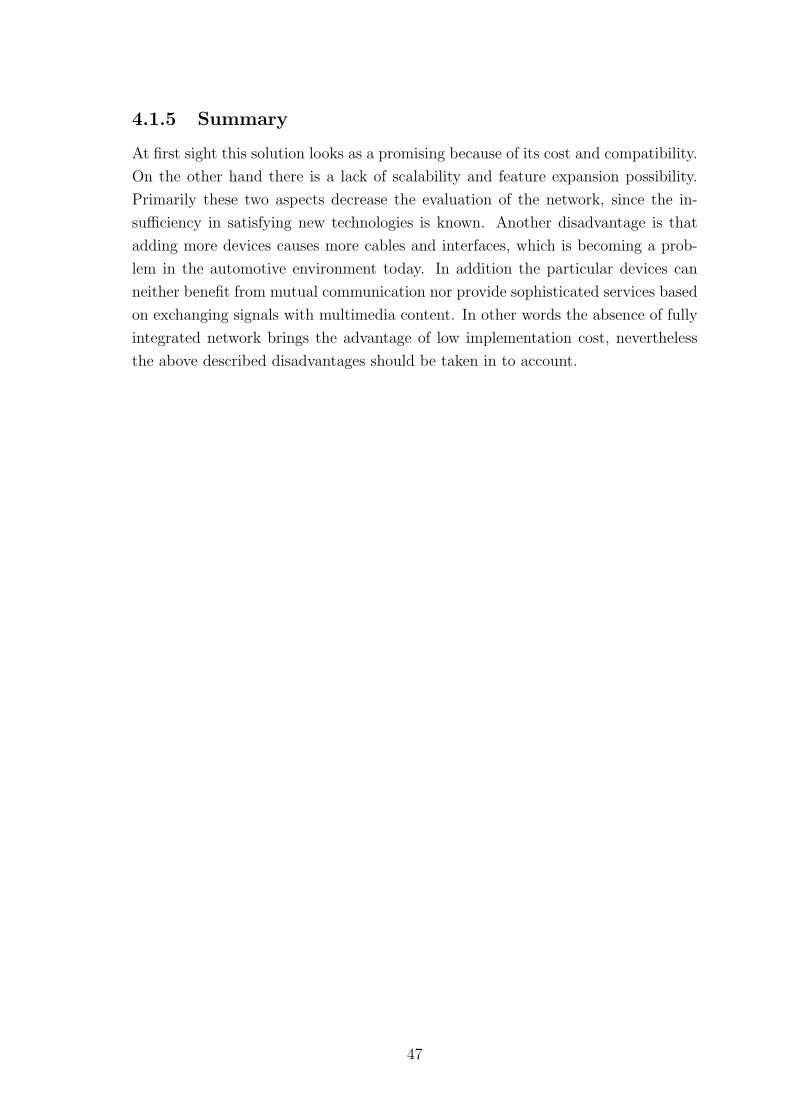
4.1.5 Summary
At first sight this solution looks as a promising because of its cost and compatibility.
On the other hand there is a lack of scalability and feature expansion possibility.
Primarily these two aspects decrease the evaluation of the network, since the in-
sufficiency in satisfying new technologies is known. Another disadvantage is that
adding more devices causes more cables and interfaces, which is becoming a prob-
lem in the automotive environment today. In addition the particular devices can
neither benefit from mutual communication nor provide sophisticated services based
on exchanging signals with multimedia content. In other words the absence of fully
integrated network brings the advantage of low implementation cost, nevertheless
the above described disadvantages should be taken in to account.
47
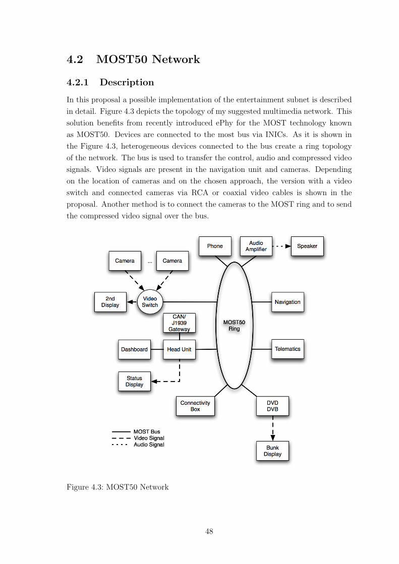
4.2 MOST50 Network
4.2.1 Description
In this proposal a possible implementation of the entertainment subnet is described
in detail. Figure 4.3 depicts the topology of my suggested multimedia network. This
solution benefits from recently introduced ePhy for the MOST technology known
as MOST50. Devices are connected to the most bus via INICs. As it is shown in
the Figure 4.3, heterogeneous devices connected to the bus create a ring topology
of the network. The bus is used to transfer the control, audio and compressed video
signals. Video signals are present in the navigation unit and cameras. Depending
on the location of cameras and on the chosen approach, the version with a video
switch and connected cameras via RCA or coaxial video cables is shown in the
proposal. Another method is to connect the cameras to the MOST ring and to send
the compressed video signal over the bus.
Figure 4.3: MOST50 Network
48
4.2.2 Related projects
MOST System is a widely used technology in today’s car industry. MOST Network
operating over an oPhy was implemented in more then 40 vehicle models of European
top carmakers [33]. The leader of the ePhy development process is Toyota Motor
Corporation. On the basis of the known facts, that the MOST50 meets the carmak-
ers requirements sufficiently (i.e. double bandwidth and lower cost) and the switch
from oPhy to the ePhy does not imply any application and framework changes [34].
Furthermore utilization of the system by carmakers in their new models is highly
probable. Exceptions are carmakers with an already advanced implementation of
MOST oPhy. Companies such as BMW or Daimler Chrysler do not want to lose
their lead in the optical field area investigation and will probably continue to support
further MOST oPhy versions such as MOST150.
4.2.3 Communication
In order to explain the communication process on the application layer, a more
detailed example will be introduced and described. To keep the complexity of the
example on an understandable level, let us consider a simple case from a Figure 4.4
with an audio, phone and HMI devices connected to the MOST50 bus. According to
the most terminology, the FBlocks amplifier and GSM are called slaves and FBlock
HMI is titled as a controller. The messages sent though the control channel are
denoted as protocols. The communication example is shown in the Figure 4.4.
Example: An audio device contains more function blocks i.e. CD player, amplifier
Figure 4.4: MOST Example
49
and radio tuner. After the change of the CD track, an incoming phone call will occur
and the sound signal will be changed.
Solution: The HMI controls the Audio device via the FBlock CD shadow located
in the controller. As mentioned in the chapter 2.1, the shadow in the controller
represents an image of the property of the slave device. The next track on the CD
can be chosen by pressing the NEXT button, where the shadow of the CD will
transfer the following protocol from the HMI device (controller) to the amplifier
(slave): CD.1.Track.Set(2). On the application layer the physical addresses are
not known, hence the Network services of HMI assigns to this protocol the device
ID parameter as follows:
Audio.CD.1.Track.Set(2)
and for the transmission the structure is completed by a sender’s address:
HMI.Audio.CD.1.Track.Set(2). This telegram is received by the audio device
as a HMI.CD.1.Track.Set(2), where the parameter device ID=Audio is missing,
since there is no need to have this information on Audio’s application level.
Following the same procedure a status reply can be sent:
Audio.HMI.CD.1.Track.Status(2),
similarly interpreted by the controller as: Audio.CD.1.Track.Status(2). The
content of the status message can be displayed on the monochrome Status Display
(SD) . Until this point we do not have any synchronous or asynchronous channels
allocated on the MOST bus. The only used communication channel is the control
channel, because the amplifier and the speakers are integrated, connected to the
audio device respectively.
Let us assume that the integrated GSM mobile unit is receiving a call. Thus after
the reception of the call the synchronous channel has to be allocated. Firstly the
user has to decide if the call will be accepted or rejected. The phone number can
be displayed on the SD via this telegram:
GSM.HMI.1.Call.Status(PhoneNumber)
(where Call is an event) from GMS unit to the HMI device.
Simultaneously the properties Audio.HMI.CD.1.Stop.Set() in the CD and
Audio.HMI.Amplifier.1.Ring.set() in the amplifier are started. The ring tone
can be integrated as e.g. generated sound from synthesizer in amplifier, saved ring
tone in HMI/Amplifier or different solution for integrated phone module. In the
case of the acceptance a method inCall.StartResult provided in the FBlock GSM
is triggered, otherwise when the call is not accepted the method inCall.Abort
is started. Method inCall.StartResult will act as an initiator for establishing
50
a connection between the source and the sink. The Connection Manager (CM)
is responsible for all synchronous connections. The procedure for a establishing
connection is:
1. Firstly the initiator (inCall) starts a method BuildSyncConnection in the CM.
2. The connection Manager will establish and maintain the synchronous channel
between the source (GSM unit) and the sink (Audio device), hence the CM
will send a command to the source, to connect its output to the synchronous
network channel. In this case, the source unit does not need to allocate the
channel and uses the proposed one from CM. After this, the source unit sends
a status reply to CM.
3. If the status is ‘connected’ the CM is trying to connect the sink to the same
channel. After sending the description of the channel (delay and number), sink
is connected and status reply is sent back. When the sink (i.e. the amplifier)
is connected, the ring signal will be cancelled and the GSM sound signal can
proceed to the speakers.
4. When source and sink are connected to the channel the connection is estab-
lished and the report to the initiator (GSM unit) is sent. CM stores the
connection data in case that new sink wants to connect to the source.
Now the telegram inCall.Result from the GSM to the HMI unit can be sent. Let’s
assume, that one FBlock in the GSM unit is a microphone connected to the GSM
voice coder. The GSM call is finally established through the MOST Network.
4.2.4 Aspects
In this section is my solution analyzed with regard to the aspects described in the
third part of the thesis.
• Cost - In order to analyze the cost of the system a trade off between the
cost related to an introduction of new technology and the future sufficiency
of the network has to be chosen. On one hand we have the expenses for
the implementation of new protocol: particular devices need to be equipped
with INIC for MOST50, new interfaces to connect the devices, NetServices
functions and application layer have to be defined. On the other hand the
future utilization of the network should be considered carefully (i.e. how long
will be the network sufficient for the new devices and technologies?).
51
• Scalability - This proposal is designed as a fully scalable system. Firstly the
MOST bus can operate with 64 INICs, hence we can connect up to 64 hetero-
geneous devices to the network and secondly the MOST Technology is scalable
itself, since different MOST versions (MOST50, MOST150, etc.) can be con-
nected to the INIC, without any changes in the higher layers.
• Variability - Different variants and combinations of multimedia devices are
supported. From the simplest variant consisting of one audio device and inte-
grated phone unit, till complex combination of multimedia devices (see Figure
4.3), the proposed network can be implemented.
• Dependability - Reliability, availability and safety are ensured by the properties
of the MOST technology. Namely the error detection and the phase lock loop
mechanisms are providing reliable services. Maintainability is considered in
the system as well and further changes or improvements are available.
• Flexibility - Flexibility is ensured by the MOST Technology. Different topolo-
gies are possible and different physical layers for the MOST Technology are
available. The change of the physical layer does not affect the higher layers.
• Standardization - MOST System is a de facto standardized network. Front
automotive carmakers, which are the members of MOSTCO, are developing
and improving the system.
• Compatibility - Compatibility is guaranteed with a gateway to the CAN-based
network and with the connectivity box.
• Responsibility - Since the MOST System is an open standard, the imple-
mentation can be accomplished by automotive producer in conjunction with
appropriate vendors. Thus the responsibility is derived from this cooperation.
• Bandwidth - Particular devices can use the bandwidth up to 50 MBit/s. For
calculating the amount of bandwidth we have to consider the audio and video
signal separately. The most bandwidth consuming audio device in the network
is a DVD player using an AC3 codec with data rate 448 kBit/s, also known
as a Dolby Digital. Enhanced AC3 codec in Digital TV has improved coding
efficiency and the bandwidth needed is about 256 kBit/s. Video signal can
be transferred over the MOST Network in compressed format. From Figure
4.3 results, that only video signal transferred over the network is a navigation
video signal. This signal has to be compressed and the bandwidth depends on
the implemented navigation device.
52
• QoS - The introduced priority levels ensure that the important messages will
be sent, when for example the control channel is overloaded.
• Power Supply - The power supplies in the proposal have to be separate from
the INICs, micro-controller and application peripherals.
• Packaging - The proposed solution is organized in a distributed manner (de-
vices communicating over a shared bus). Theoretically any device in the
MOST network can be a timing master, but in this case the HMIIOM is
logically chosen as a control unit.
• Software strategy - Depending on the approach of carmakers different strate-
gies can be used. For example the navigation device can send only GPS posi-
tion data to the HMIIOM, where implemented software will draw the position
as a picture. Other solution will be to have the software part in the Navigation
GPS unit and send over the network the data in a viewable form (shown on
the 2nd display).
• Feature expansion possibility - The extensive research process of MOST tech-
nology is giving us a certainty of further development of the system. Hence
more compatible devices and functions will be available.
• Technology risks - With the introduction of a new technology there is certainly
a risk present, even though the MOST Network is de facto standard.
4.2.5 Summary
MOST Technology is a dynamically developing area. In this part the description,
related projects, communication example and aspects comparisons of the proposed
solution were investigated. Table 4.1 shows how the particular aspects can be inter-
preted and how significant they are for this proposed solution. Among the others
the importance of scalability and cost should be emphasized. MOST50 proposal
appears to be as a promising solution for automotive multimedia networks. An
example from the Section 4.2.3 is described by MSC (Message Sequence Chart) in
Appendix A.
53
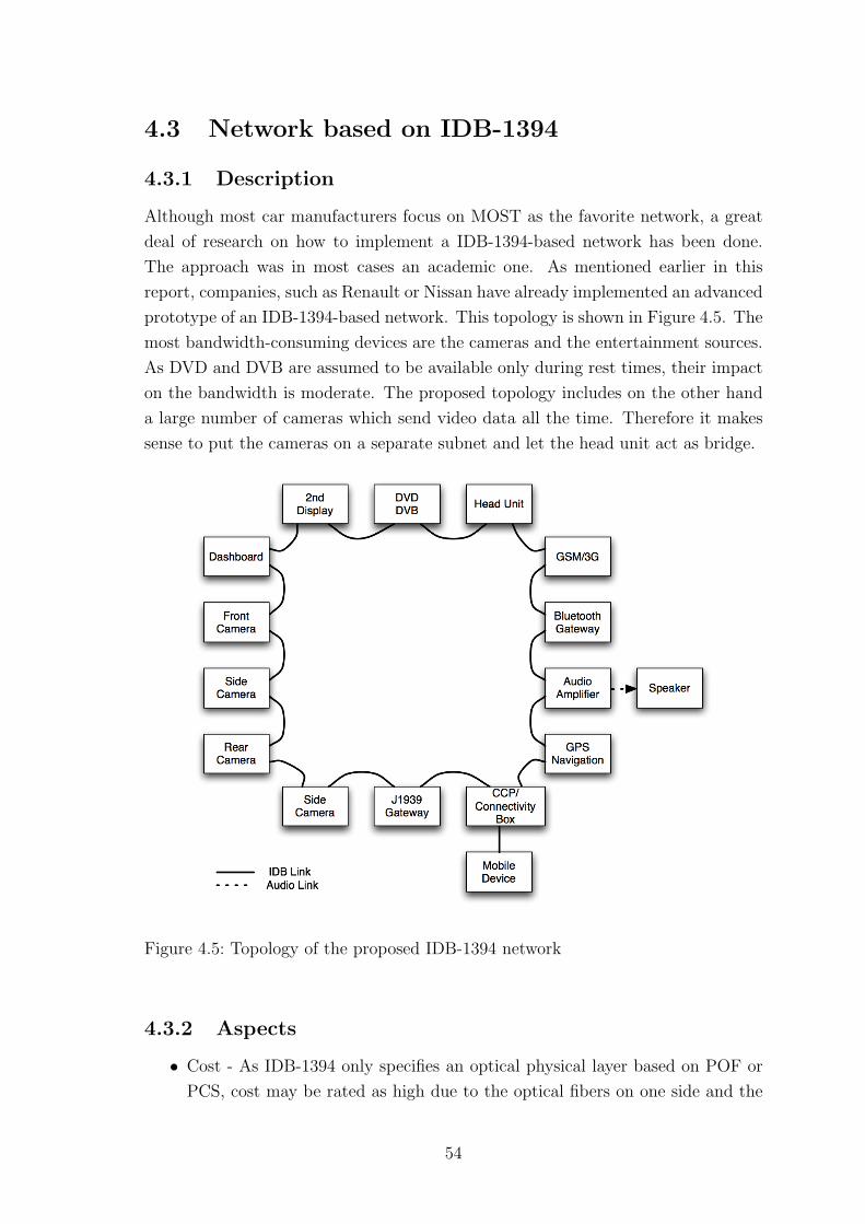
4.3 Network based on IDB-1394
4.3.1 Description
Although most car manufacturers focus on MOST as the favorite network, a great
deal of research on how to implement a IDB-1394-based network has been done.
The approach was in most cases an academic one. As mentioned earlier in this
report, companies, such as Renault or Nissan have already implemented an advanced
prototype of an IDB-1394-based network. This topology is shown in Figure 4.5. The
most bandwidth-consuming devices are the cameras and the entertainment sources.
As DVD and DVB are assumed to be available only during rest times, their impact
on the bandwidth is moderate. The proposed topology includes on the other hand
a large number of cameras which send video data all the time. Therefore it makes
sense to put the cameras on a separate subnet and let the head unit act as bridge.
Figure 4.5: Topology of the proposed IDB-1394 network
4.3.2 Aspects
• Cost - As IDB-1394 only specifies an optical physical layer based on POF or
PCS, cost may be rated as high due to the optical fibers on one side and the
54
necessary optical-to-electrical and electrical-to-optical converters on the other
side.
• Scalability - The IDB-1394 network is able to reconfigure itself fully automat-
ically. Although the topology of a typical automotive network is more or less
static, the reconfiguration plays an important roll if a device is connected to
the CCP.
• Variability - This network has the potential to be the most variable and flexible
network mentioned in this report, due to the origin in the Firewire protocol.
Starting from two devices which are able to configure themselves, up to 63
nodes may be integrated.
• Dependability - Firewire was developed to support a physical star, tree or
daisy-chain topology. The automotive version also allows a ring which provides
an alternative route if the connection between two nodes breaks down due to
whatever reason.
• Standardization - IDB-1394 is fully standardized by the IDB forum as well as
AMI-C
• Compatibility - IDB-1394 is completely compatible with IEEE-1394-based con-
sumer electronics as most protocol layers are equal. Furthermore gateways to
Bluetooth and CAN are available.
• Bandwidth - Compared to MOST the bandwidth is much higher. As long as
compressed video is used there will be no limitation. On the other hand when
uncompressed data is needed because only minimum delay can be accepted, it
turns out that the available 400 Mbit/s may be the bottleneck depending on
resolution, colourdepth and frames per second.
• QoS - IDB-1394 supports both asynchronous and isochronous traffic and pro-
vides mechanisms for QoS as mentioned earlier.
• Power Supply - Traditional IEEE-1394 is able to supply power to the devices
using some of the copper wires. As the automotive version is only specified
for optical fibers, extra wiring is needed.
• Technology risks - As can be seen in the related projects section, there has
been a great deal of research done using this type of network but most car
manufacturers focus on the MOST solution. Therefore it is hard to say, how
the support for this technology will be in the future. Also the latest update
of the official IDB website dates back a rather long time.
55
4.3.3 Summary
A major benefit of the IDB-1394-based network is the dynamic reconfiguration after
booting and after changes in the topology, such as connecting a portable device to
the consumer convenience port. If different encoding is used, as mentioned in the
Nissan project in the related work section, IDB-1394 is even suitable for camera
applications where no delay can be accepted. The drawback nevertheless is that
currently only optical fibers are specified for automotive applications which makes
it interesting for luxury cars due to the rather high costs of fibers and converters.
56
4.4 Network using the APIX link
4.4.1 Description
Figure 4.6 shows a proposed topology with a focus on the APIX link. A similar
network for the entertainment system in a car is shown in [28] and [31]. The network
consists of the head unit, which contains most of the intelligence, two or more
displays, cameras located around the vehicle and gateways to the J1939 vehicle bus,
GPS and GSM. All cameras are assumed to have a resolution of 640x480 pixels
operating at 60 frames per second. If the cameras have a color resolution of 16 bit,
or 10 bit for the night vision camera respectively, the bandwidth of the APIX link
will be sufficient to transmit the multiplexed uncompressed signal.
Bitrate = Σsourcesresolution ∗ colordepth ∗ frames per second
On the other hand, there is no bandwidth problem at all with the two rear view
cameras and the other sources such as the DVD player or the DVB receiver. The
two camera signals can even have a colour resolution of 24 bit and the data rate of
the multiplexed signal is still below 1 GBit/s. As DVD and DVB are not available
during driving, those sources are connected via a video switch, therefore they have
no impact on the bandwidth calculation.
One advantage of this link is that the cameras can be supplied with power over
the return channel, due to the fact that both the uplink and the downlink channel
are completely decoupled from direct voltage. Therefore there is only need for one
STP cable to connect the camera and the head unit.
As the side-band channels can be used to control the cameras in real-time by trans-
mitting the I2C as well as the CAN bus, it is also possible to synchronize them in
order to get a 360-degree-view or a multiview system.
4.4.2 Communication
Front camera system: The front and side cameras send uncompressed video via
multiplexer to the CPU in the head unit. In the CPU of the head unit all the
necessary image processing is done which is required for the lane departure warning
system, object recognition and similar tasks.
Rear view cameras and entertainment sources: As the DVD, DVB and other
entertainment functions are not provided during driving, a video switch is suggested
57
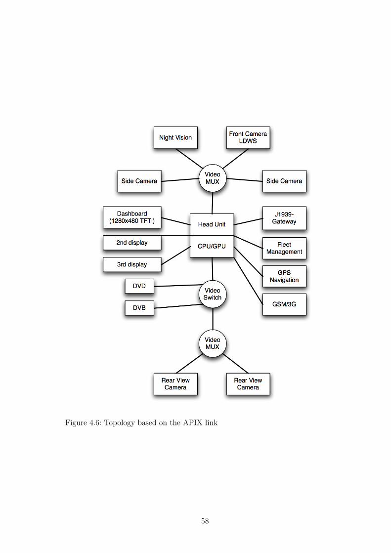
Figure 4.6: Topology based on the APIX link
58
to switch video between the rear view system in normal operation and DVD/DVB
during the rest times.
Displays: As mentioned before, the displays receive uncompressed pixeldata from
the head unit. To input data, such as messages from the driver to the dispatcher,
touchscreen can be used. The emerging control data can be transmitted either by
sending I2C signals, by using modified CAN/J1939 frames or even by using the
messages of the MOST control channel on the side-band channels.
GPS and Navigation: The communication between head unit and the navigation
system works the same way as from the head units to the displays. The position is
transmitted over the side-band channel and the according images, if not created in
the head unit, will use the high-bandwidth link.
GSM and 3G: Communication with the world outside is important if a fleet
management system is used, for the eCall system and for lots of other applications.
Two different possibilities are imaginable here.
• Bluetooth - A Bluetooth tranceiver is integrated in the head unit or connected
by a bus. In this case the communication will be done with an external GSM
transceiver, such as a Bluetooth-enabled mobile phone.
• Wired - The GSM can also be integrated in the head unit or the integration
can be achieved by transmitting data between GSM and head unit. As no
high bandwidth is needed in the latter case, it can be done by the CAN/J1939
bus.
Audio: To transmit the audio signals between the devices, [28] and [31] propose
a separate MOST ring. As the side-band channels of the APIX link provide almost
the same bandwidth as the traditional MOST25 network it is also imaginable that
sound could be sent over those channels. Further investigations can be done in this
case.
4.4.3 Aspects
The following describes how the solution based on the APIX link performs in relation
to the previously defined aspects.
• Cost - The use of shielded twisted pair cables instead of optical fibers keeps
the cost of the solution low. On the other hand rather high development costs
may arise as there is no real reference implementation available yet.
59
• Scalability - The Apix link is a point-to-point pixel link. Therefore the main
limitations for the scalability are located in the head unit. The more connec-
tors and the faster the CPU or GPU is, the more devices can be connected.
Nevertheless the scalability is high.
• Variability - This link only makes sense if high-quality video is required. But
then everything is possible, starting from a simple rear-view camera to a fully
equipped network as proposed above.
• Flexibility - The GBit/s downstream link is a direct pixel link, but the side-
band channels make APIX very flexible, as a variety of buses and protocols
can be sent over those channels.
• Standardization - The APIX chip is solely developed and produced by the
company Inova Semiconductors. A data sheet is available for download, but it
is not standardized. On the other hand, a separate standardized MOST ring
to transmit audio signals is suggested by Inova.
• Compatibility - The chip connects to common 10, 12, 18 and 24-bit RGB
interfaces. Furthermore the side-band channels can transmit the popular I2C
bus bi-directionally to control camera functions.
• Bandwidth - Besides IDB-1394 (under certain conditions) this link is the only
possibility in the automotive area to transmit uncompressed, low-delay video
signals. Furthermore it is the only solution presented in this report which
provides enough bandwidth for future high-resolution 1280x480 pixel TFTs
which will probably replace the traditional analogue gauges.
• QoS - The control messages on the side-band channels do not influence the
actual pixel data in any way. Consequently full QoS is given concerning the
link itself.
• Power Supply - Devices such as cameras can be sourced by the same STP
cable that carries the data. Therefore no extra wiring is needed.
• Packaging - The network consists basically of the central head unit and a
number devices like cameras and screens which are connected directly or via
a multiplexer to the head unit.
• Technology risks - As the APIX link was recently introduced in 2006 it is
hard to say how it will be accepted by the very conservative vehicle industry.
Although the technology is promising, the technology risk must be rated as
high.
60

4.4.4 Summary
The APIX chip was introduced recently, but it has, as well as similar technologies
from other companies, the potential to be implemented in a wide area. In particular
if uncompressed video is required, for instance for object recognition, this link is the
only one discussed in this report, which provides sufficient bandwidth. This applies
also for a high-resolution digital dashboard replacement, which may be introduced
in cars in a few years.
61
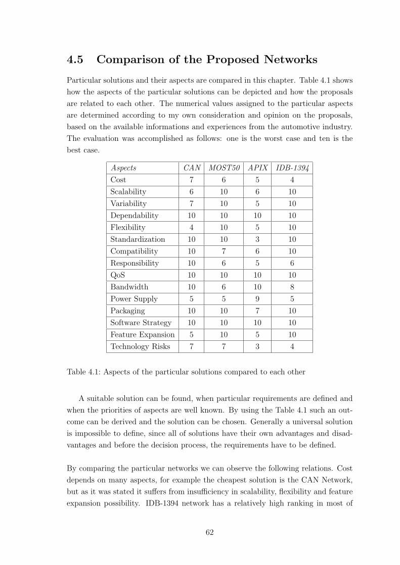
4.5 Comparison of the Proposed Networks
Particular solutions and their aspects are compared in this chapter. Table 4.1 shows
how the aspects of the particular solutions can be depicted and how the proposals
are related to each other. The numerical values assigned to the particular aspects
are determined according to my own consideration and opinion on the proposals,
based on the available informations and experiences from the automotive industry.
The evaluation was accomplished as follows: one is the worst case and ten is the
best case.
Aspects CAN MOST50 APIX IDB-1394
Cost 7 6 5 4
Scalability 6 10 6 10
Variability 7 10 5 10
Dependability 10 10 10 10
Flexibility 4 10 5 10
Standardization 10 10 3 10
Compatibility 10 7 6 10
Responsibility 10 6 5 6
QoS 10 10 10 10
Bandwidth 10 6 10 8
Power Supply 5 5 9 5
Packaging 10 10 7 10
Software Strategy 10 10 10 10
Feature Expansion 5 10 5 10
Technology Risks 7 7 3 4
Table 4.1: Aspects of the particular solutions compared to each other
A suitable solution can be found, when particular requirements are defined and
when the priorities of aspects are well known. By using the Table 4.1 such an out-
come can be derived and the solution can be chosen. Generally a universal solution
is impossible to define, since all of solutions have their own advantages and disad-
vantages and before the decision process, the requirements have to be defined.
By comparing the particular networks we can observe the following relations. Cost
depends on many aspects, for example the cheapest solution is the CAN Network,
but as it was stated it suffers from insufficiency in scalability, flexibility and feature
expansion possibility. IDB-1394 network has a relatively high ranking in most of
62
the aspects except the cost, which is caused by the optical physical layer. As it is
visible from the Table 4.1 such an expensive solution should be evaluated, since it
fulfills the other requirements and brings another benefits (e.g. future utilization of
the system). The APIX link compared to the others is a promising solution for the
transmission of video signals. Another important aspect is scalability, where MOST
and IDB1394 networks indicate a full satisfaction. Aspects like dependability and
software strategy are not dependent only on the used technology but also on the
agreement between suppliers and automotive producers. Feature expansion possi-
bility is an important property of the system and is fully satisfied in the MOST and
IDB1394 technologies. Standardization is fulfilled in the CAN, MOST and IDB1394.
From my point of view the MOST Network for the audio signals and the APIX
link as a medium for the video signals transfer appear to be as the most suitable
solution.
63
CONCLUSIONS
Multimedia networks for automotive applications is an evolving and promising area.
Researchers from different communities (such as IT, Communication and Electronic,
etc.) are more focused on the automotive industry, in order to migrate their high-
end products in to the vehicles. This naturally demands a new attitude towards new
environment and conditions for their products. Besides this, the customers demand
more sophisticated functions to be implemented in their vehicles. The car industry
is the main driver for automotive multimedia networks and during the investigation
was the car industry likewise the main source of information.
This thesis analyzes multimedia networks for automotive applications. The first
part, introduction and related projects, introduces the area of investigation. In
the second part an extensive survey about the state of art is given. The avail-
able communication protocols and technologies are described in detail. It should be
remarked, that the development process is relatively young and the effort to stan-
dardize and propagate particular technologies is visible. The third part describes
the requirements on the automotive electronics in general and requirements driven
by infotainment systems. From the description of the aspects an outlook on the
environment, where the final proposals should be implemented, is given. Finally
the last part represents the goal of my thesis. By comparing the available protocols
and networks with the investigated aspects four possible solutions are described and
examined. The chosen topologies result from the network specifications and their
implementation in the automotive industry.
Indeed the MOST Network is considered as a standardized and promising tech-
nology, but this does not mean that the importance of other protocols and networks
should be decreased. CAN-based solutions can not support the development process
for long time and will not prove satisfactory for the future devices. New networks
and technologies supporting more bandwidth for video signals are going to be intro-
duced in the future, but before this an APIX solution for video signals together with
the MOST audio network appear to be, from my point of view, as the most suitable
solution. An example of how the optical fibers can be used in the car is given in
the IDB-1394 Network. Generally, the optical fibers are not popular among the
vehicle manufacturers. This might be a disadvantages for the future technologies,
when for example the bandwidth of copper cable will not be sufficient anymore, then
optic fibers will be introduced. The disadvantage is the introduction of the optic
fibers as a new technology into the already existing networks, without any previous
experiences and implementations. On the other hand there is a huge development
64
process behind the electrical cables and the methods, how to implement them in the
automotive industry are well known.
My aim was to define the problems and aspects for choosing the automotive mul-
timedia network. My suggestions for the decision process are correlated to the
requirements of the automotive manufacturer. In other words they depends on
what the manufacturer wants to implement. Its requirements are represented as
the particular aspect ranking for each solution. Hence from the Table 4.1 can be
this solution chosen, depending on the requirements. Generally a solution which
fully satisfies all of the requirements does not exist and therefore a suitable trade
off has to be chosen. A reasonable approach, when the decision should be done, is
to consider the network usage from the future point of view and to take into the
account all protocols and networks available on the market. Newly arising promising
technologies should be considered as well.
65
REFERENCES
[1] P. Knopp and K. Feichtenschlager. Analysis of multimedia networks for automo-
tive applications. Master’s thesis, Hogskolan in Halmstad, Halmstad, January
2007.
[2] Ola Larses. Architecting and modeling automotive embedded systems. PhD
thesis, Kungliga Tekniska Hogskolan, Stockholm, December 2005.
[3] EU. Cars that can dial 112: Commission an industry target
2009. http://europa.eu.int/rapid/pressReleasesAction.do?reference=..., Febru-
ary 2005.
[4] D. McClure. White paper: Trends of in-car bluetooth and wireless technologies
in europe, July 2005.
[5] Akio Nezu and Wolfgang Wiewesiek. Networking standards en-
able in-vehicle video entertainment and information systems.
http://www.automotivedesignline.com/howto/infotainment/192300781;
jsessionid= CYHM022NAXR0KQSNDLOSKHSCJUNN2JVN, 2006.
[6] K. Chaaban, M. Shawky, and P. Crubille. Dynamic reconfiguration for high level
in-vehicle application using ieee-1394. 2004 IEEE Intelligent Transportation
Systems Conference, pages 826–830, October 2004.
[7] K. Chaaban, M. Shawky, and P. Crubille. A distributed framework for real-time
in-vehicle applications. Proceeding of the 8th International IEEE Conference
on Intelligent Transportation Systems, pages 925–929, September 2005.
[8] M. Rabel, A. Schmeiser, and H.-P. Grossmann. Ad-hoc in-car networking con-
cept. In Proceeding of the 8th International IEEE Conference on Intelligent
Transport Systems, pages 143–148, Vienna, Austria, September 2005.
[9] Venkatraman K K. Real time image transfer over wlan for rear view systems
in automobiles. WIPRO Technologies White Paper, pages 1–9, 2003.
[10] MOST Cooperation. Japan interconnectivity conference.
http://www.mostcooperation.com/news/Conferences+%26+Presentations/2006/1/
40/files/01MOSTCO+Presentation+2006.pdf, November 2006.
[11] Robert Reiter. Most at bmw group - experience and future scenarios.
http://www.mostcooperation.com/news/Conferences+%26+Presentations/2006/1/
40/files/10+BMW+Presentation+2006.pdf, November 2006.
66
[12] MOST Cooperation. Most specification rev 2.4.
http://www.mostcooperation.com, 2005.
[13] MOST Cooperation. Most specification rev 2.5.
http://www.mostcooperation.com, 2006.
[14] SMSC. ephy overview and implementation. http://smsc-
ais.com/files/ePHY/ePHY Overview TB0812AN1A1.pdf, 2006.
[15] H. Muyshondt. Most intelligent network interface controllers.
http://www.esemagazine.com, February 2006.
[16] Keiko Murase. Emc control with high-speed dif-
ferential transmission with common mode filter.
http://www.mostcooperation.com/news/Conferences+%26+Presentations/2006/1/
40/files/05+TDK+Presentation+2006.pdf, November 2006.
[17] Kvaser aB. Sae j1939. http://www.kvaser.com, 2005.
[18] SAE. J1939-11 - physical layer, 250 kbit/s, twisted shilded pair, 1999.
[19] SAE. J1939-15 - reduced physical layer, 250 kbit/s, unshielded twisted pair,
2000.
[20] SAE. J1939-21 - data link layer, 2001.
[21] SAE. J1939-15 - network layer, 1997.
[22] SAE. J1939-71 - vehicle application layer, 2005.
[23] SAE. J1939-81 - network management, 2002.
[24] M. Rabel, A. Schmeiser, and H.-P. Grossmann. Integrating ieee 1394 as infotain-
ment backbone into the automotive environment. IEEE Trans. Veh. Technol.,
3:2026–2031, 2001.
[25] M. Lessard. Idb-1394 automotive reference platform - enabling in-vehicle enter-
tainment. Business Briefing: Global Automotive Manufactoring & Technology,
pages 1–5, 2003.
[26] A. Paskins. The ieee 1394 bus. IEE Colloquium on New High Capacity Digital
Media And Their Applications, pages 1–6, 1997.
[27] D. Steinberg and Y. Birk. An empirical analysis of the ieee-1394 serial bus
protocol. IEEE Micro, 20:58–65, 2000.
67
[28] Robert Kraus. Datenautobahn fur Multimedia auf vier Rodern.
http://www.electroniknet.de/index.php?id=1373, 2006.
[29] Axel Krepil. Kfz-Elektronik: Videodatenautobahn Ubertragt bis zu 1 GBit/s.
http://www.elektronikpraxis.de/fachartikel/ep fachartikel 2951471.html,
2006.
[30] Inova Semiconductors. Apix specification rev 0.9. http://www.inova-
semiconductors.de/en/datasheets/Q PP APIX.pdf, 2006.
[31] Axel Krepil. Datenautobahn fur ungesterte Bildebertragung. Hanser Automo-
tive, 7-8:64–66, 2006.
[32] Matthias Weber and Joachim Weisbrod. Requirements engineering in automo-
tive developmnet: Experiences and challenges. IEEE Softw., 20:16–24, Septem-
ber 2003.
[33] SMSC. Smsc’s most50 technology doubles the bandwidth for auto-
motive multimedia networking and supports an electrical physical layer.
http://www.smsc.com/whatsnew/pr/most50pr.html, June 2006.
[34] SMSC. Most50 double bandwidth and electrical physical layer.
http://www.mostcooperation.com/news/Conferences+%26+Presentations/2006/1/
40/files/03+SMSC+Presentation+2006.pdf, November 2006.
[35] MOST Cooperation. Most msc cookbook.
http://mostcooperation.com/downloads/ Specifica-
tions/MOST%20Guidelines/MOST% 20MSC%20Cookbook.pdf, April 2005.
[36] ITU. Itu-t recommendation z.120 message sequence chart.
http://www.itu.int/ITU-T/studygroups/com10/languages/Z.120 1199.pdf,
November 1999.
[37] MOST Cooperation. Most functionblock audiodiskplayer, rev. 2.4.
http://www.mostcooperation.com/downloads/Specifications/MOST%20Function%
20Block%20Library/MOST%20FunctionBlock%20AudioDiskPlayer.pdf,
September 2003.
[38] MOST Cooperation. Most functionblock audioamplifier, rev. 2.4.2.
http://www.mostcooperation.com/downloads/Specifications/MOST%20Function%
20Block%20Library/MOST%20FunctionBlock%20AudioAmplifier.pdf,
September 2003.
68
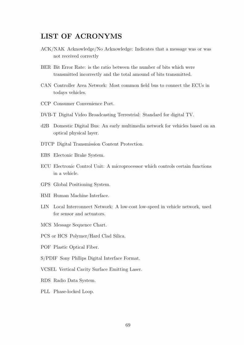
LIST OF ACRONYMS
ACK/NAK Acknowledge/No Acknowledge: Indicates that a message was or was
not received correctly
BER Bit Error Rate: is the ratio between the number of bits which were
transmitted incorrectly and the total amound of bits transmitted.
CAN Controller Area Network: Most common field bus to connect the ECUs in
todays vehicles.
CCP Consumer Convenience Port.
DVB-T Digital Video Broadcasting Terrestrial: Standard for digital TV.
d2B Domestic Digital Bus: An early multimedia network for vehicles based on an
optical physical layer.
DTCP Digital Transmission Content Protection.
EBS Electonic Brake System.
ECU Electronic Control Unit: A microprocessor which controls certain functions
in a vehicle.
GPS Global Positioning System.
HMI Human Machine Interface.
LIN Local Interconnect Network: A low-cost low-speed in vehicle network, used
for sensor and actuators.
MCS Message Sequence Chart.
PCS or HCS Polymer/Hard Clad Silica.
POF Plastic Optical Fiber.
S/PDIF Sony Phllips Digital Interface Format.
VCSEL Vertical Cavity Surface Emitting Laser.
RDS Radio Data System.
PLL Phase-locked Loop.
69

LIST OF APPENDIX
A.1.1 MSC Introduction . . . . . . . . . . . . . . . . . . . . . . . . 71
A.1.2 MSC Example . . . . . . . . . . . . . . . . . . . . . . . . . . . 71
70
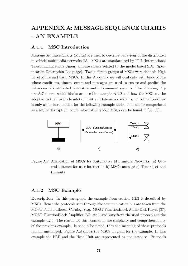
APPENDIX A: MESSAGE SEQUENCE CHARTS
- AN EXAMPLE
A.1.1 MSC Introduction
Message Sequence Charts (MSCs) are used to describe behaviour of the distributed
in-vehicle multimedia networks [35]. MSCs are standardized by ITU (International
Telecommunications Union) and are closely related to the model based SDL (Spec-
ification Description Language). Two different groups of MSCs were defined: High
Level MSCs and basic MSCs. In this Appendix we will deal only with basic MSCs
where conditions, timers, errors and messages are used to ensure and predict the
behaviour of distributed telematics and infotainment systems. The following Fig-
ure A.7 shows, which blocks are used in example A.1.2 and how the MSC can be
adopted to the in-vehicle infotainment and telematics systems. This brief overview
is only as an introduction for the following example and should not be comprehend
as a MSCs description. More information about MSCs can be found in [35, 36].
Figure A.7: Adaptation of MSCs for Automotive Multimedia Networks: a) Gen-
eral instance for user interaction b) MSCs message c) Timer (set and
timeout)
A.1.2 MSC Example
Description In this paragraph the example from section 4.2.3 is described by
MSCs. Hence the protocols sent through the communication bus are taken from the
MOST FunctionBlocks Catalogs (e.g. MOST FunctionBlock Audio Disk Player [37],
MOST FunctionBlock Amplifier [38], etc.) and vary from the used protocols in the
example 4.2.3. The reason for this consists in the simplicity and comprehensibility
of the previous example. It should be noted, that the meaning of these protocols
remain unchanged. Figure A.8 shows the MSCs diagram for the example. In this
example the HMI and the Head Unit are represented as one instance. Protocols
71
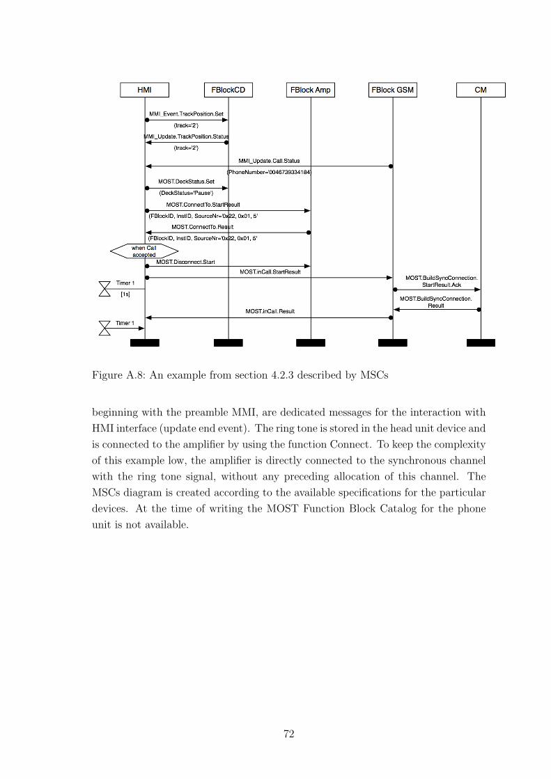
Figure A.8: An example from section 4.2.3 described by MSCs
beginning with the preamble MMI, are dedicated messages for the interaction with
HMI interface (update end event). The ring tone is stored in the head unit device and
is connected to the amplifier by using the function Connect. To keep the complexity
of this example low, the amplifier is directly connected to the synchronous channel
with the ring tone signal, without any preceding allocation of this channel. The
MSCs diagram is created according to the available specifications for the particular
devices. At the time of writing the MOST Function Block Catalog for the phone
unit is not available.
72

![VYSOKE U´ CENˇ ´I TECHNICK E V BRN´ Eˇ · Tvar, nahoda a dimenze [11] (francouzsky Les objets fractals, forme, hasard et dimen-sion) uvedl Benoit Mandelbrot. Mnoho takovyc´](https://img.pdfslide.net/doc/110x75/6033727d99159a4ee15f4fe6/vysoke-u-cen-i-technick-e-v-brn-e-tvar-nahoda-a-dimenze-11-francouzsky.jpg)