Embed Size (px)
Citation preview
http://www.iaeme.com/IJCIET/index.asp 1074 [email protected]
International Journal of Civil Engineering and Technology (IJCIET) Volume 8, Issue 4, April 2017, pp. 1074–1085 Article ID: IJCIET_08_04_121 Available online at http://www.iaeme.com/IJCIET/issues.asp?JType=IJCIET&VType=8&IType=4 ISSN Print: 0976-6308 and ISSN Online: 0976-6316 © IAEME Publication Scopus Indexed
WIND LOAD ANALYSIS FOR INDUSTRIAL BUILDING WITH DIFFERENT BRACING
PATTERNS AND ITS COMPARISON WITH PRE ENGINEERED BUILDING
Seena Somasekharan PG Student, Division of Structural Engineering, School of Mechanical and Building
Sciences, VIT University, Chennai, India
Vasugi K Assistant Professor (Sr), Division of Structural Engineering ,School of Mechanical and
Building Sciences ,VIT University, Chennai, India
ABSTRACT Steel structures are the most common and smart choice for industrial construction
they are basically because of its ability to create large span space at low cost. Along with the existence of Conventional Steel building (CSB), the PEB came into being from 1960s. The methodology tracked followed in PEB is highly multifaceted not just because of the quality in pre-designing and pre-fabrication but also due to the light weight outcome and economically sound factor. In this study, using SAP 2000-18 the truss chord members are designed for different sections such as ISLC/ISA, UB/UC and SHS. The most economic truss chord sections is utilised for the design of the industrial building, the industrial buildings are thus designed to carry out wind analysis with different bracings such as X- bracing, diagonal bracing and k- bracing. Therefore, the most optimised structured is then compared with PEB structure for the same parameters Key words: Steel Structure, Conventional Steel Building (CSB), Pre Engineered Building (PEB), Bracing Systems, Wind Analysis, Cross Bracing, Diagonal Bracing, K-Bracing.
Cite this Article: Seena Somasekharan and Vasugi K, Wind Load Analysis for Industrial Building with Different Bracing Patterns and its Comparison With Pre Engineered Building. International Journal of Civil Engineering and Technology, 8(4), 2017, pp. 1074–1085. http://www.iaeme.com/IJCIET/issues.asp?JType=IJCIET&VType=8&IType=4
1. INTRODUCTION Steel industry is one of the super growing industries in almost every part of the world. Being the second fastest growing economy in the world India has a huge percentage of it is attributed to the construction industries. They are not just economical but also highly eco-

Seena Somasekharan and Vasugi K
http://www.iaeme.com/IJCIET/index.asp 1075 [email protected]
friendly when it comes to a treat of global warming, steel is 100% recyclable and the most recycled material Thus, each ton of recycled steel saves 2,500 pounds of iron ore and approximately 1,000 pounds of coal Steel members also have the advantages of high tensile strength and ductility. Steel is mostly used in the construction of industrial building with larger span when the concrete is not under the feasible state or the construction time is critical. In CSB, the sections used for columns and beams are the mill produced hot rolled sections. The hot rolled sections are of constant depth therefore on the area of low internal stress it leads to excess design of the member. The frames of PEB on other hand are designed by tapered and often have with the flanges and web with variable thickness plates based on the level of internal stress over the sections. The graphical growth of steel industrial structures have been going high with the introduction of PEB along with the existence of
Conventional Steel Building. These are low rise steel structures which are characterised by low heights, less or lack of interior floors, walls and partition. The structure composed of walls which are of steel column which are profiled by steel caddling either profiled or G.I sheeting Although PEB systems are intensely used in industrial structures and many other non-residential constructions worldwide, it is still a fresh concept in India; it was introduced lately in 1990s with the expansion of economy and setting up of many Multinational projects.
2. LITERATURE SURVEY A literature review is carried out on various studies of conventional steel building and pre-engineered buildings. This section presents a brief report on the literatures reviewed as part of this project.
Sagar D Wankhade et al [1] carried out a comparison on CSB and PEB on varied dimensions like 14m x31.5m, 20m x50m, 28m x70m with bay spacing 5.25m, 6.25m and 7m with column height of 7m. The total weight of PEB was obtained as 116.31kN and for truss 183.45kN
G Durga Rama Naidu et al. [2] analysed the CSB and PEB, in which the PEB was analyzed for the varied increase in bay spacing. IS875-part 3 was considered for analysis. It was found that PEB was economical compared to CSB and it is noticed that with the increase of bay spacing up to certain limit there is reduction of weight of PEB and further increase in bay spacing makes the weight heavier.
S.D Charkha [3] concluded that why it is necessary to optimize the steel building using PEB and it is because PEB reduces the steel quantity, reduction of steel quantity reduces the dead load and reduction of dead load reduces the foundation size and the PEB usage increase aesthetic view.
BK Raghu et al. [4] presented the optimization of PEB according on several parameters like inclination of gable, span, bay spacing, which control the cost of the structure and these parameters are varied systematically and in each case the gable frame is designed for the common loads DL, LL, EQ and WL. The quantity of steel in each case is obtained and finally the structure which regulates the lowest quantity of steel is recommended, however there can be slight difference for the different data input like location zone for earthquake and wind, grade of steel, type of soil, frame with special cranes and multi-spans.
Pradip S Lande [5] reviewed the design and analysis of industrial steel structure (ware house) according to Indian standard IS 800-2007 and American code MBMA-96 by using structural analysis and design software STAAD-pro, they also reviewed the study between cold formed sections as purlins with traditional used hot rolled sections for industrial structures. It is noticed that PEB designed with IS800:2000 is of higher weight than the one designed with MBMA-96 and which is because limiting ratio of the section, it is also noticed that PEB roof structure with Z purlins is 30% lighter than traditional used hot rolled section.

Wind Load Analysis for Industrial Building with Different Bracing Patterns and its Comparison With Pre Engineered Building
http://www.iaeme.com/IJCIET/index.asp 1076 [email protected]
Vrushali Bahadu et al. [6] conducted the comparison of A-type and saw tooth type truss and portal frame for industrial shed using STAAD-pro and found that Saw tooth type industrial shed require less steel as compared to the other two which means it is economically good, the saw tooth type truss is than compared with PEB and found PEB the most economical.
Milind Bhojkar P [7] on comparison study of Pre-engineered building and conventional steel building based on cost and time effectiveness observed that PEB roof structure is almost 26% lighter than the conventional steel building and PEB building cost is 30% lesser than the cost of CSB.
A Jayaram, R Geethamani et al. [8] worked on design and economical of roof truss and purlin where they studies on behaviour and economical of fink type roof truss. Channel section purlin by comparison of limit state and working stress method. It was noticed that the theoretical results of limit state method in bending moment and load carrying capacity is higher than working stress method, whereas it is also found that working stress method is more economical than limit state method.
G Sairam et al. [9] Kumar underwent a case study on comparison of design procedure of PEB (2014) In this study, an industrial structure (Ware House) is analyzed and designed according to the Indian standards, IS 800-1984, IS 800-2007 and also by referring MBMA-96 and AISC-89. In this study, a structure with length 187m,width 40m,with clear height 8m and having R-Slope1:10,isconsidered to carry out analysis& design for2D frames (End frame, frame without crane and frame with 3 module cranes).The economy of the structure is discussed in terms of its weight comparison, between Indian codes (IS800-1984, IS800-2007) & American code (MBMA-96), & between Indian codes (IS800-1984, IS800-2007). It is found that-One of the main reason to increase in weight in IS 800-1984 compared to IS 800-2007 is “Serviceability Criteria”. Deflection limits by IS code are higher than deflection limits by MBMA. Reason for higher wt. in IS 800-2007 compared to AISC/MBMA is limiting ratios of the sections (Table2 of IS800-2007). Live load is 0.75 KN/m in IS code & whereas it is 0.57 KN/min MBMA. Thus, concluded that loading as per Indian codes is greater than MBMA code. The main difference between the Indian Code (IS800-2007) to the other equivalent American Codes are in the classification of the cross-section of the steel member.
Abhyuday Tikish et al. [10] (2015) measured the comparative study of Conventional steel building and PEB to be used as industrial shed. It’s a case study for Industrial Shed based on the review and various case studies which shows their experimental and analytical studies carried out in this field. This paper of comparative study between conventional and pre-engineered building shows their experimental and analytical studies carried out in this field. The results show that the steel structures are far more economical energy efficient and flexible in design than other type of structures for industrial use. The pre-engineered buildings are more advantageous over conventionally designed buildings in terms of cost effectiveness, time saving, future scope, subtleness and economy.
Upendra Pathak [11] carried out optimization and rationalization of truss design with different types of geometries (A-type truss, Fink truss, Pratt truss, Howe truss, King post truss, Queen post truss etc) and sections (Angle section, Tube section, square hollow section etc) are widely used.
Veera Shobana et al. [12] conducted a parametric study on X and V bracing on industrial steel structure. In this study an earthquake load analysis is carried out to find a system which balances the lateral load and minimize the displacement of industrial steel structure by
Seena Somasekharan and Vasugi K
http://www.iaeme.com/IJCIET/index.asp 1077 [email protected]
introducing X and V Bracing and to understand the modelling of buildings braced with conventional concentric braced
3. RESEARCH SIGNIFICANCE Only few research works were carried out to study of wind analysis of industrial structures. Research works were more intensely carried out on wind analysis of conventional building. Many projects have been carried out regarding the comparison study of the Conventional Steel Building and Pre Engineered Building with changes of certain structural parameters. The purpose of this project is to study the performance of the conventional steel building and pre engineered building on wind analysis and also to identify the best suited bracings system on them with respect to the economical features, So that for equal structural parameters when a project choose CSB or PEB they will clearly get a real results based on which bracings to be adopted and how far its technically and economically feasible.
3.1. OBJECTIVE To optimize the sections for Pratt truss chord members.
To model most optimized truss section & PEB with different bracings by using SAP 2000
To analyze Conventional Steel Building( Pratt truss)& PEB structure under wind load
Comparison of Pre Engineered Building and Conventional Steel Building (Pratt Truss).
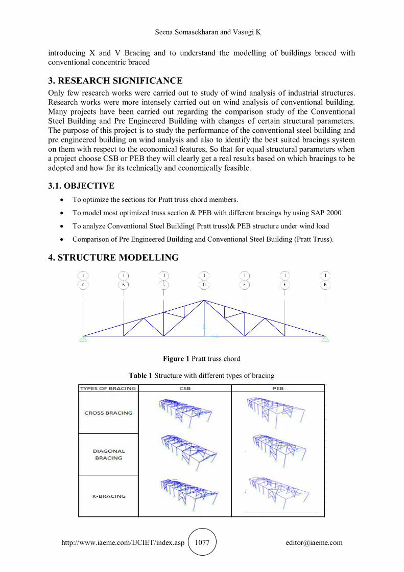
4. STRUCTURE MODELLING
Figure 1 Pratt truss chord
Table 1 Structure with different types of bracing

Wind Load Analysis for Industrial Building with Different Bracing Patterns and its Comparison With Pre Engineered Building
http://www.iaeme.com/IJCIET/index.asp 1078 [email protected]
Figure 2 Example of conventional steel building model 3D view
Figure 3 Example of PEB model 3D view
4.1. Section Properties of Tapered Rafter The frames of PEB on other hand are designed by tapered and often have with the flanges and web with variable thickness plates based on the level of internal stress over the section. The length of the rafter is divided and tapered into three different sections – tapered1, tapered2, tapered3.
Figure 4 Tapered parts

Seena Somasekharan and Vasugi K
http://www.iaeme.com/IJCIET/index.asp 1079 [email protected]
Table 2 Tapered 1
DEPTH OF THE SECTION AT START NODE 0.4m THICKNESS OF WEB 0.06 DEPTH OF THE SECTION AT END NODE 0.28m WIDTH OF TOP FLANGE 0.25m THICKNESS OF TOP FLANGE 0.008m WIDTH OF BOTTOM FLANGE 0.25m THICKNESS OF BOTTOM FLANGE 0.008m
Table 3 Tapered 2
DEPTH OF THE SECTION AT START NODE 0.28m THICKNESS OF WEB 0.06m DEPTH OF THE SECTION AT END NODE 0.28m WIDTH OF TOP FLANGE 0.25m THICKNESS OF TOP FLANGE 0.008m WIDTH OF BOTTOM FLANGE 0.25m THICKNESS OF BOTTOM FLANGE 0.008m
Table 4 Tapered 3
DEPTH OF THE SECTION AT START NODE 0.28m THICKNESS OF WEB 0.06m DEPTH OF THE SECTION AT END NODE 0.4m WIDTH OF TOP FLANGE 0.25m THICKNESS OF TOP FLANGE 0.008m WIDTH OF BOTTOM FLANGE 0.25m THICKNESS OF BOTTOM FLANGE 0.008m
Table 5 Tapered 4
DEPTH OF THE SECTION AT START NODE 0.455m THICKNESS OF WEB 0.01m DEPTH OF THE SECTION AT END NODE 0.655m WIDTH OF TOP FLANGE 0.309m THICKNESS OF TOP FLANGE 0.012m WIDTH OF BOTTOM FLANGE 0.309m THICKNESS OF BOTTOM FLANGE 0.012m
4.2. Structural Details Table 6 Structural configurations:
Type of building: Industrial Building Building dimension 6 m x 42 m Area of the building 504 m2 Type of roofing GI sheet Location of the building Chennai Bay spacing 6 m Wind speed 50 m/s Roof slope 1 in 3 Riser height 2 m Height of the column 9 m Purlin spacing 1.4m Girt spacing 1.7m column section (CSB) UC section Truss chord sections SHS and RHS Column section (PEB) Tapered plates Rafter of PEB Tapered plates

Wind Load Analysis for Industrial Building with Different Bracing Patterns and its Comparison With Pre Engineered Building
http://www.iaeme.com/IJCIET/index.asp 1080 [email protected]
5. ANALYSIS The design was carried our as per IS800-2007.The Pratt type truss is being used as the truss for CSB as from literature review it was found that it is the most economically and structurally feasible. The Pratt truss chord was designed and analysed with different sections such as ISLC/ISA, UB/UC and SHS/RHS. The most economised section is then use for CSB’s truss chord member. The CSB is then modelled and design for three different bracings such as cross bracing, diagonal bracing and K bracing. The PEB is also modelled and design for the same bracings as above. Both the CSB and PEB will be analysed for wind loads. The analysis results will be compared for ‘economic analysis and technical analyses’.
5.1. Loadings
Table 7 Gravity load
LOAD INTENSITY CODE DEAD 1.507kN/m IS 875-part 1 LIVE 2.322kN/m IS 875- part2
Wind load (As per IS 875:1987-PART3) Designed wind speed = k1 x k2 x k3 x Vb
Designed wind pressure, pz = 0.6Vb2 = 1.5 kN/m2
Internal pressure (Cpi) = ± 0.5 (assuming 20% openings)
Table 8 External pressure (Cpe)
WALL ROOF 0 ⁰ 0.7 -0.3 -0.76 -0.515 90 ⁰ -0.5 -0.5 -0.8 -0.6
Wind load = (Cpe ± Cpi) pz x bay spacing. Load combinations: (WLP- wind load from left with positive internal pressure, WLN- wind load from left with negative internal pressure, WRP- wind load from right with positive internal pressure, WRN- wind load from right with negative internal pressure, WFP- wind load normal towards the structure with positive internal pressure)
1.2DD+1.2LL+1.2WLP
1.2DD+1.2LL+1.2WLN
1.2DD+1.2LL+1.2WRP
1.2DD+1.2LL+1.2WRN
1.2DD+1.2LL+1.2WFP
0.9DD+1.5WLN
0.9DD+1.5WLP
0.9DD+1.5WRP
0.9DD+1.5WRN
0.9DD+1.5WFP
SERVICIBILITY 1DD+1LL

Seena Somasekharan and Vasugi K
http://www.iaeme.com/IJCIET/index.asp 1081 [email protected]
SERVICIBILITY1DD+0.88LL+0.8WLN
SERVICIBILITY1DD+0.88LL+0.8WLP
SERVICIBILITY1DD+0.88LL+0.8WRP
SERVICIBILITY1DD+0.88LL+0.8WRN
SERVICIBILITY1DD+0.88LL+0.8WFP
SERVICIBILITY 1DD+1WLN
SERVICIBILITY 1DD+1WLP
SERVICIBILITY 1DD+1WRN
SERVICIBILITY 1DD+1WRP
SERVICIBILITY 1DD+1WFP
Figure 4 Wind load diagram for PEB and CSB
6. RESULTS AND COMPARISON
6.1. Economical Analysis Bracings are those structural elements which functions under stress loads. The way lateral loads act on it and bring it to foundation depends upon the types of bracing we choose and their implementations are subjected to requirements about functionality as well as economical parameter. Keeping the deflection limits IS800-2007, the deflection when optimized the weight of the structure is noted to find the economical analysis. For economical analysis the total weight of the structure with each configuration was considered.
Table 9 Weight on tons:
BRACINGS TYPE CSB PEB
K-bracing 38.7 33.5
Cross bracing 39 30
Diagonal 36 34

Wind Load Analysis for Industrial Building with Different Bracing Patterns and its Comparison With Pre Engineered Building
http://www.iaeme.com/IJCIET/index.asp 1082 [email protected]
Figure 5 Comparison of weight between PEB and CSB with different bracings
6.2. Technical Analysis The models are analyzed with cross bracing, K- bracing and diagonal bracing to avoid high displacement. If suppose the structures were to be analyzed without any bracing then the displacement of the structure when the wind load hits at 90o will be beyond the limits and result in the failure of the structure. Therefore it is suggested to go with bracing since the roof and the ridge cannot alone provide rigidity to the structure especially for PEB the ridge of the tapered frame will fail easily for any slight lateral force. The structures were analyzed for wind loads at 0o and wind loads at 90o. When the wind acts at 0o the considerable displacement is prevented by the columns and truss chords in case of CSB or by tapered frames in case of PEB , however the bracings and wind bracings also helped in the functioning of the structure effectively. When wind load acts at 90o the bracing plays a major role in preventing deflection of the members.
Figure 6 Deflection scale of PEB
0
10
20
30
40
50
K-BRACING CROSS BRACING
DIAGONAL BRACING
WEI
GH
T IN
TO
NS
TYPES OF BRACING
CSB
PEB
Column1

Seena Somasekharan and Vasugi K
http://www.iaeme.com/IJCIET/index.asp 1083 [email protected]
Figure7 Deflection scale of CSB
Table 10 Deflection of PEB and CSB
TYPES OF BRACING PEB CSB CROSS BRACING 47.725 53.581 K-BRACING 33.855 48.431 DIAGONAL BRACING 30.687 54.204
Figure 8 Graphical presentation of maximum displacement
7. DISCUSSION For the usage of sections for coming up with the most economical members for the truss chord members, it’s been found that SHS/RHS is the best economical where RHS is used as outer chord and SHS as inner chord.
From the analysis following are the outcome: UB/UC to ISLC – 17.41% steel saving
0102030405060
CROSS BRACING
K-BRACING DIAGONAL BRACING
RESU
LTAN
T DE
FLEC
TIO
N
TYPES OF BRACINGS
PEB
CSB
Column1

Wind Load Analysis for Industrial Building with Different Bracing Patterns and its Comparison With Pre Engineered Building
http://www.iaeme.com/IJCIET/index.asp 1084 [email protected]
ISLC to SHS/RHS – 39.01% steel saving
UB/UC to SHS/RHS – 49.715 steel saving
Table 11 Section property of SHS 40X40X4.0
DEPTH OR WIDTH 40.0mm THICKNESS 4.0mm WEIGHT 4.02kg/m AREA OF SECTION 5.35cm2 MOMENT OF INERTIA 11.07cm4 RADIUS OF GYRATION 1.44cm ELASTIC MODULUS 5.54cm3 PLASTIC MODULUS 7.01cm3
Table 12 Section property of RHS 200x100x8.0 THICKNESS 8.0mm SECTION AREA 43.79cm2 UNIT WEIGHT 34.38kg/m MOMENT OF INERTIA 2146.21cm4 MOMENT OF INERTIA 719.91cm4 RADIUS OF GYRATION 7.0cm RADIUS OF GYRATION 4.05cm ELASTIC OF MODULUS 214.62cm3 ELASTIC OF MODULUS 143.84cm3
OUTER SURFACE AREA PER METER 0.559m2
It is found that among ISLC/ISA, Universal beam/Universal Column and Square Hollow Section (SHS)/Rectangle Hollow Section (RHS), SHS/RHS is found to be most economical with section weight of 3.659kN.
From economical analysis it’s found that: Percentage of weight increased in CSB when compared to PEB in cross bracing is 8.9%
Percentage of weight increased in CSB when compared to PEB in diagonal bracing is 4.378%
Percentage of weight increased in CSB when compared to PEB in diagonal bracing is 6.6% From technical analysis its obtained that: The CSB with cross bracing has 5.83% more deflection than that of PEB
The CSB with K-bracing has 17.71%more deflection than that of PEB
The CSB with diagonal bracing has 27.71%more deflection than that of PEB Using the SHS and RHS when CSB is been carried out for wind load analysis and
compared with the PEB, the following are the outcomes: The maximum displacement among PEB is obtained when cross bracing is used and least
displacement is observed with diagonal bracing.
The maximum displacement among CSB is obtained when diagonal bracing is used and the least displacement is observed with K-bracing.
When compared between CSB and PEB its found CSB with cross bracing has the maximum displacement and the least one is with PEB diagonal bracing.

Seena Somasekharan and Vasugi K
http://www.iaeme.com/IJCIET/index.asp 1085 [email protected]
The maximum deflection locations are seen in the ridge and rafter of the structure that is because the maximum wind load is obtained when wind load is from the front of the structure (90o)to the structure,
From economical analysis it’s found that PEB cross bracing is the one with least weight (30tons) and CSB cross bracing the heaviest (39tons).
8. CONCLUSION After economic and technical analysis of the PEB and CSB with span 42m and bay spacing
6m, when carried out wind analysis for the Chennai zone.
It’s been suggested that PEB with diagonal bracing gives the best suited result based on the economical feasibility and the structural safety.
When for a project if PEB is the preferred design then it is found that PEB with K-bracing comes out to be the best suited when both economical and technical analysis is considered together.
The overall economic analysis shows that, PEB comes out to be economically less than CSB.
Using of PEB instead of CSB reduces the steel quantity.
Reduction in the steel quantity definitely reducing the dead load.
Reduction in the dead load reducing the size of Foundation.
Using of PEB increase the Aesthetic view of structure
Therefore, from above study we can conclude about the suitable types of industrial structure either CSB or PEB, when the span is almost closer to 42m and with bay spacing 6m.
REFERENCES [1] Sagar D Wankhade et al .Design and comparison of various types of industrial building. [2] G Durga Rama Naidu et al. Comparison study for analysis and design of PEB and
conventional steel frame. [3] S.D Charkha Economizing steel building using PEB [4] BK Raghu et al Optimisation of PEB [5] Pradip S Lande Design and analysis of industrial steel structure (ware house) according to
Indian standard IS 800-2007 and American code MBMA-96. [6] Vrushali Bahadu et al Comparison on different types of truss [7] Milind Bhojkar P comparison study of Pre-engineered building and conventional steel
building on cost and time effectiveness [8] A Jayaram, R Geethamani et al design and economical of roof truss [9] G Sairam et al. on comparison of design procedure of PEB [10] Abhyuday Tikish et al the comparative study of Conventional steel building and PEB to
be used as industrial shed [11] Swati D. Ambadkar, Pajgade P.S 2013 “ Cost comparison of industrial steel building by
considering different types of column sections ” Int. Journal of Applied Sciences and Engineering Research, Vol. 2, No. 1 .
[12] IS 875: Part 1 to 5 Code Of Practice For Design Loads (Other Than Earthquake) For Buildings and Structures,1st Revision, New Delhi: BIS..
[13] IS 1893-2002 Criteria for earthquake resistant design of structure. [14] IS 800-2007 General construction of steel – code of practice. [15] IS 801-1975 Code of practice for use of cold formed light gauge steel structural members