Embed Size (px)
Citation preview

w
TESTING AND
RESEARCH
CONFIDENTIAL Z.9923
HAND/FOOT OPERATED WATER PUMPS FOR USE IN DEVELOPING COUNTRIES
FINAL SUMMARY REPORT
'. jSrTjrjiifi
- " • > • • • - . - .
232-'^ %oUf\ ^88

tf® 252^ &0Hf)
CONFIDENTIAL j Z.9923 i «• HAND/FOOT OPERATED WATER PUMPS FOR
USE IN DEVELOPING COUNTRIES
FINAL SUMMARY REPORT
To: Mr. B. M. U. Bennell, British Overseas Development Administration
DATE OF ISSUE: October 1980
iCi ;.-J^:r.-,;,;;:; '..'^r 3i.»pp!y

PROJECT TEAM: John Kingham
Chris Allen
John Cuthbert
Tetra Dixon
Rosemary Hill
Ted Hudson
Geoff Hughes
John Keen
Malcolm Osborne
Mike Piggott
Keith Ruttley
Don Unwin
Clive Wade
Cate Andrews
: Project Controller
: Technician
: Adviser
: User Test Organiser
: Statistician
: Electronics
: Electronics
: Mechanical Rig Design
: Mechanical Rigs
: Mechanical Rigs
: Mechanical Rigs
: Engineering Manager
: Engineering Drawings
: Checker
REPORT APPROVED (J^XV. fityfYC*? John Kingham : P r o j e c t C o n t r o l l e r
Ken Mills : Testing Manager
Two copies of this Report are : in the Project File
in Harpenden Laboratory Archives

Z.9923
LIST OF CONTENTS
SECTION PAGE
1 Introduction 1
2 Choice of Pumps 3
3 Summary of Results 8
Code A 9
Code B 15
Code C 21
Code D 27
Code E. is
Code F 39
Code G 4 5
Code H 49
Code J 55
Code K 61
Code L 6 5
Code M 69
4 Discussion and Recommendations 73
Table 1 List of Pumps Tested
Table 2 Overall Summary

Z.9923 -1
1. INTRODUCTION
Hand pumps have been available for many years. Indeed, in the Western world, they were common 100 years ago but in modern times the availability of piped water supplies has relegated the hand pump, as a source of drinking water, to a comparatively unimportant position. There has been increasing interest, however, in the use of hand pumps to provide safe drinking water in developing countries. This has been especially true during the last 10 -15 years and is expected to become more marked during the present World Water Decade (the 1980's).
Where there is suitable ground water, the use of a hand pump is generally the cheapest means of providing a potable water supply. The use of such pumps in developing countries however has produced many problems as well as solving some. Many, perhaps the majority, of these problems have their roots either in the sociological and cultural attitudes of the pump users or in the organisation (or lack of it) of the hand pump installation and maintenance programme. One major problem, however, is the unreliability of many of the pumps which have been installed and the havoc wrought with the water supply consequent upon it. This unreliability may result from several sources:
1. The intensive use of a pump in a village water supply scheme which may require it to be in operation for perhaps 12 hours of the day, when it was designed for only occasional use - e.g. on a farm.
2. The use of cheap and unreliable pumps in an effort to provide water to the greatest number of people within the scope of a limited budget.
3. The choice of a poor pump simply due to the lack of suitable, unbiased and reliable test data on the pumps available.
4. Lack of sufficient knowledge of pumps to foresee those peculiar features which could clash with the cultural behaviour of the pump users.
To the authors' knowledge there has been no wide scale, fully comparative testing of hand pumps under controlled laboratory conditions. The British Overseas Development Administration was particularly concerned about this and in Juiy 19/7 contracted with CA Testing and Research, Harpenden, U.K., a laboratory specializing in the comparative testing of consumer products, to test 12 brands of hand/'foot-operated deepwell force pumps for use in developing countries. The tests were fairly long-term, each pump being endurance-tested for 4000 hours as well as having extensive performance and user tests and engineering evaluations. The tests were designed to run in two stages with 6 pumps being tested in each stage.
This report gives a final summary of all salient features of the pumps discovered during the tests and a discussion of the pumps, together with recommendations. Details of the tests performed and the methods of analysis of the results have been given in a paper entitled "Guidelines for Hand Pump Testing", presented at a conference organised by the International Reference Centre for Community Water Supply, The Hague, Holland, and held at Harpenden, Herts. on May 29th - June 1st 1979. Full details of all test results will be reported separately from this report.
For the purpose of the report, and to avoid confusion, all twelve pumps were coded by the letters A to M. In the report reference to the pumps is made by the code letter only.

Z . 9 9 2 3 - 2
B l a n k

Z.9923 -3
2. CHOICE OF PUMPS
Before any testing could commence it was necessary to select 12 pumps froru c:ll over the world as being typical of those used in village water supply schemes. A complete world market survey was performed. Letters were sent to around 100 manufacturers asking for details of the pumps they made, including spares and prices, their manufacturing capacity, the countries in which, their pumps were normally sold, and their approximate market share, if known. From the replies received a selection of deep well pumps was made, bi<sed generally on the following criteria.
a. As many different types of pump as possible should be included in the test, i.e.
Flywheel-operated
Foot-operated
Normal hand-operated with reciprocating motion
with as many different pumping methods as possible, e.g.
Hydraulically-operated pumps
Spring-operated pumps
Diaphragm pumps
Simple lift pumps
b. The pumps should include some old, well-established designs, as well as some of the more modern, innovative designs, and some pumps made in developing countries, but not pumps in early development stages.
c. Pumps should be included which hfive been, or are at present being, tested in field trials known to the authors.
A list of pumps selected is given in Table 1 together with a brief description of the features for which each was chosen. The final choice was difficult and several pumps had to be left out which had interesting and novel features which could have made them perform well in some situations.
Two samples of each pump v/ere ordered together with any spares which it was thought might become necessary. Where several sizes of cylinder were available, a size generally between 55 and 67 mm diameter was selected, except where; the pump design criteria made a different size a better choice. The aim was to choose, where possible, pump combinations which, could be used at depths of around 20 - 40 n .

Z.9923 -4
TABLE 1
LIST OF PUMPS TESTED
CODE
A
B
C
D
E
F
G
BRAND
Petropump
Vergnet
Dempster
Mono
Climax
Godwin
Abi
MODEL
Type 95
Hydropompe Type 4C2
23F (CS)
ES 30
Not stated
W1H51
Type M
MANUFACTURER
Petropump Carl Westmans Vag 5 S-13300 Saltsjobaden, Sweden
Ets Pierre Mengin Zone Industrielle d'Amilly 45203 Montargis France
Dempster Industries Inc PC Box 848 Beatrice, Nebraska 68310 USA
Mono Pumps (Engineering) Ltd Mono House Sekforde Street Clerkenwell Green London EC1R OHE, England
Barnaby Climax Ltd White Ladies Close Little London Worcester, WR1 1PZ, England
H J Godwin Ltd Quenington, Cirencester Gloucester, GL7 5B4, England
Abi Bcite Postale 343 Abidjan, Ivory Coast

Z.9923 - 5
TYPE
Hand-operated Diaphragmatic hose
Foot-operated Hydraulic operation, diaphragmatic hose
Hand-operated lift-pump
Hand-operated, rotary, helical screw type operation
Hand-operated flywheel lift pump
Hand-operated geared lift pump
Hand-operated lift pump
REASONS FOR CHOICE
Recent innovative design, especially for LDC; many interesting features.
New design foot pump, claimed to be easy to maintain: many interesting features.
A standard cast iron handpump which is widely used.
A rotary pump with an unconventional pumping method, using no valves. Fairly good world-wide reputation.
A standard, heavy flywheel-operated pump with proven record in many countries.
A standard light handwheel, geared pump with proven record in many countries.
A pump made in a developing country of an interesting design.
PRICE PAID (LATE 1977) (EX WORKS)
2000 Skr (£221.5) excluding pipe
3863 FF Complete to 50 metres (£421.7) 3050 FF (£333) Excluding pipe.
$ 109.68 Excluding pipe and rod (£56.5)
£370.4 Complete to 10 metres
£730.9 Complete to 21 metres (approximately £50O without pipe)
£865.5 Complete to 21 metres
£358.3 Excluding pipe and rod

Z.9923
i t
TABLE 1 (cont)
LIST OF PUMPS TESTED
CODE
H
J
K
L
M
BRAND
GSW (Beatty)
Monarch
Kangaroo
India
Consallen
MODEL
1205
P3
Not stated
Mkll
LD5
MANUFACTURER
GSW Limited Hill Street Fergus Ontario, Canada
Monarch Industries Ltd PO Box 429 Winnipeg, Canada
Pijpers International Water Supply Engineering PO Box 138 Nijkerk, Holland
Balaji Industrial and Agricultural Castings (2 samples)* PB No 1634 Secunderabad-3, India
Consallen Structures Ltd 291 High Street Epping Essex CM16 4BY United Kingdom
* 1 sample also manufactured by : Inalsa Industrial and Allied Sales PVT Ltd. 19 K.G. Marg. New Delhi India

Z.9923 -7
TYPE
Hand-operated lift pump
Hand-operated
lift pump
Foot/Spring-operated lift pump
Hand-operated lift pump
Hand-operated lift pump
REASONS FOR CHOICE
A standard, well known, lift pump tested in CIDA field trials, Ghana
A fairly new design of lift pump which performed well in CIDA field trials, Ghana.
A new, unusual and apparently promising design which is already made in a developing country (Tanzania)
A new improved UNICEF design. Similar designs have performed well in CIDA field trials.
A new design which is fairly simple, apparently rugged and with much emphasis on corrosion resistance
PRICE PAID (LATE 1977) (EX WORKS)
C$321.7 (£163) Excluding pipe and rod
$446.8 (£248.7) excluding pipe $644.9 (£359) Complete to 30 m
Df 660 (£163.57) Excluding pipe and rod Df 1140 (£282.5) Complete to 20 m
$125 (£64.9) Excluding pipe and rod
£169 Excluding pipe and rod £296.8 Complete to 20 m
N.B. Prices for Codes D, E, F and M include Value Added Tax at 8%.

Z.9923 -8
SUMMARY OF RESULTS
The results of all tests and evaluations are presented, pump by pump, in a summary. Details of tests are not included. In the summary the emphasis has been placed mostly on durability, reliability and resistance to the neglect and misuse which could occur in developing countries. Consideration has also been given to the possibility of simplifying or modifying the design so as to make a pump easier to manufacture or more reliable.
Following the summaries there is a discussion of the pumps in general together with recommendations. One point which should be recognised at this stage is that, if a pump is to be used in a developing country, it is much better if it can be made and maintained easily in that country. The pumps have, therefore, also been considered simply from the design point of view so that the ease of making a pump similar to any one design featured here can be assessed. Any actual manufacturing defects in the pumps received have also been noted however.
Table 2 on page 78 shows a simplified overall summary of results with important features rated on a five point scale.

Z.9923 -9
SUMMARY OF CODE A (PETROPUMP TYPE 95)
DESCRIPTION
An unusual design using a diaphragmatic hose as the pumping element, and a V galvanised steel pipe both to operate the pumping element and to deliver the water. Its use requires hard rock at the bottom of the well, on which the jaws at the bottom of the hose can grip, though it can also be made to grip in a 4" well casing. The drop pipe is attached to the top of the hose0 When downward pressure is applied to the handle, the drop pipe is lifted and stretches the hose, reducing its internal volume. Water is thus forced up the pipe. The water flow is controlled by valves at the top and bottom of the hose.
The pumpstand is a simple design using only one pivot, the force on the handle being transferred to the drop pipe via a steel cable resting over a quadrant on the handle. Its most unusual feature is that it is not fixed to the ground with anchor bolts in the normal way but is attached to the well casing with clamping rings. This means that the well casing must project 30 to 60 cm above the well cover. All steel parts of the pumpstand have an electroplated zinc finish.
TESTING AND EVALUATION
At first sight this pump appeared to possess many desirable qualities, being easily transportable, requiring little maintenance and having no moving seals to wear out. Subsequent investigation, however, showed several design and manufacturing shortcomings most of which can easily be rectified.
The design is certainly not conventional and several points can be made here.
1. The well is not adequately sealed against contamination. Resistance to surface water is reasonably good, but the top of the well casing is not adequately sealed against atmospheric contamination, or such as might arise through abuse. The method used of clamping the pump to the well casing would seem to make the solution to this problem more difficult. This clamping method also makes the use of the pump on existing wells more difficult, since these often have the well casing only just protruding from the ground. A return to a more conventional type of stand might be the answer.
2. The pump is designed for use in wells which are drilled in hard rock - this is required so that the pumping element anchors can grip. Although the pumping element can be made to grip in a well casing, the size required (4"<~-' lOOmm) is not compatible with that for the pumpstand (.5"~' 125mm) . In the schematic drawing on p. 12, the pumping element is shown in a well casing. No problems of anchor slippage were found during tests when the pump was in the well casing but, after the pumping element had been removed for inspection, it proved very difficult to make it grip again. Small, hardened steel pins are inserted into the cast iron serrated anchors and these, it was found, tended to chip or break off because they were rather too hard. Redesigning the anchor so that it is made completely from steel hardened and tempered to the correct value (we suggest 550 - 6CO HV) and with sharp teeth could be an answer.

Z.9923 -10
SUMMARY OF CODE A (Cont)
TESTING AND EVALUATION (Cont)
3. The design uses V pipe both to operate the pump and to carry the' water to the surface. This results in a greater upward force on the handle than is usual on pumps which use a conventional pump rod, but is negated by a counterbalance weight on the handle (see drawing). However, the use of a narrower pipe than is usual (IV to 2V is used on most other pumps) has resulted in other problems because the resistance to water flow is much greater. Both tests and calculations have shown that the pumping forces required to overcome the water flow resistance at a normal 40 strokes/minute are greater than those required actually to lift the water. In practical terms, it means that pumping water from a depth of 20 metres with this pump requires the same amount of work as another pump (using a wider drop pipe) would demand in order to pump from a depth of about 50 m under the same conditions (i.e. the same water output, but neglecting other frictional losses).
As the water flow resistance is dependent on the pumping speed, the natural tendency is to pump rather more slowly than with other reciprocating pumps.
It is difficult to know how to overcome this problem within the original design concept of a diaphragmatic hose. Increasing the pipe diameter will mean a much heavier pipe string to be lifted, and probably an unacceptably large counterbalance weight. It will also be more costly.
4. The pump is constructed fairly simply from zinc-plated or galvanised standard steel sections which pack well together for transport. Assembly was nuts and bolts as fasteners. This may be very good in some areas of the world but, with so many easily removable fastenings of common sizes, pilferage of pump parts could well prove a problem in other areas. The security of the bolts could be improved in some places by the use of nut-locking devices.
Two manufacturing problems were encountered during testing.
1. A hardening thread sealant has been used on the pumping element; this has a tendency to break off when handling the pump, with subsequent jamming of the discharge valve. Either a non-hardening thread sealant should be used or, alternatively, a valve less prone to such jamming could be incorporated.
2. The threads on the anchor-locking wedge plate (arrowed by (x)on the drawing) were badly cut and resulted in a failure during endurance testing when the thread stripped. Good threading is vital on this component as the cyclic tensile stresses carried are high.
The performance of the pump was adequate but the mechanical efficiency was low, due to the flow resistance problems mentioned previously. Typical figures vary from 25 - 40% depending on pumping speed and depth.
Ergonomically the pump had both good and bad points. The handle height could be set to the best compromise value for any given selection of users by varying the amount by which the well casing protruded from the ground. The forces required to operate the pump were rather high at normal pumping speeds, but the counterbalance made it easier to operate than it would otherwise have been (NB. The use of a counterbalance weight does not normally affect the physical work required to lift the water; it merely reduces the forces necessary by balancing the loads on the up and down strokes more evenly). Since the force required to stretch the diaphragmatic hose is quite considerable (about 22 kg load on the handle), the pump can never be as easy to use as many conventional pumps.

Z.9923 -11
SUMMARY OF CODE A (Cont)
TESTING AND EVALUATION (Cont)
On the other hand the handle is comparatively long, has a fairly high mechanical advantage and moves over a comparatively small arc between the top and bottom of its stroke. This tends to mean that there is less body movement required to operate the pump as the direction of application of the force does not change very much. Indeed, it was found during practical user tests that, particularly on this pump, children could often operate the pump fairly easily by simply hanging onto the handle and lifting their feet off the ground.
The spout of the pump was fairly good and could fill most vessels without excessive splashing. Some narrow-necked vessels, however, could prove more difficult as the spout moves up and down during pumping.
The reliability of the pump could prove somewhat variable. The major fault which occurred during tests was the failure of the pumping element. Its typical life was about 1500 hours. The cause of the failure was splitting of the rubber diaphragmatic hose at the ends where it was gripped by a plastic insert and a stainless steel clamping ring. Other problems encountered during testing include failure of the pumping element anchor, as mentioned previously, and nuts coming loose, particularly on the main handle bearing.
Although no problems with anchor failure were encountered during the tests, it is obvious that correct operation of the pump is very dependent on the anchor gripping successfully. This may be a problem more associated with installation of the pump, but we cannot but express concern that making the anchor grip, after removing the pump for inspection, often proved rather frustrating.
Wear on the pump is likely to be small and unlikely to affect performance or reliability to any great extent. No significant bearing wear was encountered and only slight wear on the pipe guides.
Corrosion is unlikely to be a major problem except in very acidic waters where galvanised steel is inadequate. The electro-plated zinc coating on the pumpstand may also be inadequate over longer periods of time when exposed to the weather. The manufacturer states, however, that the finish has now been changed to dip galvanizing which is much better. Pumping of sandy water did not show any major problems.
VERDICT
An interesting design which, under the right geological, cultural and sociological conditions, could work very satisfactorily but which, we feel, has too many problems in its existing form to be considered for wide scale application.
Note: It would appear from discussions with the manufacturer that many of the problems here are known. We are unable to determine the details of any modifications or their impact on the pump.

-K05
Z.9923 -12
CDCZztl I
=125(6
-±
= \ ^
"J A
205 -J
'695 to 800
! = £.
Rising main

Z.9923 -13
CODE A
Pumpstand (without counterbalance weight) showing method of clamping to the well casing.
Pumping element.

CODE A (Cont)
Pumpstand Operating Mechanism
Z.9923 -14
Z.9923 -15
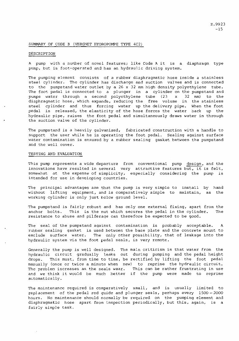
SUMMARY OF CODE B (VERGNET HYDROPOMPE TYPE 4C2)
DESCRIPTION
A pump with a number of novel features; like Code A it is a diaphragm type pump, but is foot-operated and has an hydraulic driving system.
The pumping element consists of a rubber diaphragmatic hose inside a stainless steel cylinder. The cylinder has discharge and suction valves and is connected to the pumpstand water outlet by a 26 x 32 mm high density polyethylene tube. The foot pedal is connected to a plunger in a cylinder on the pumpstand and pumps water through a second polyethylene tube (23 x 32 mm) to the diaphragmatic hose, which expands, reducing the free volume in the stainless steel cylinder and thus forcing water up the delivery pipe. When the foot pedal is released, the elasticity of the hose forces the water back up the hydraulic pipe, raises the foot pedal and simultaneously draws water in through the suction valve of the cylinder.
The pumpstand is a heavily galvanized, fabricated construction with a handle to support the user while he is operating the foot pedal. Sealing against surface water contamination is ensured by a rubber sealing gasket between the pumpstand and the well cover.
TESTING AND EVALUATION
This pump represents a wide departure from conventional pump design, and the innovations have resulted in several very attractive features but, it is felt, somewhat at the expense of simplicity, especially considering the pump is intended for use in developing countries.
The principal advantages are that the pump is very simple to install by hand without lifting equipment, and is comparatively simple to maintain, as the working cylinder is only just below ground level.
The pumpstand is fairly robust and has only one external fixing, apart from the anchor bolts. This is the nut which secures the pedal in the cylinder. The resistance to abuse and pilferage can therefore be expected to be good.
The seal of the pumpstand against contamination is probably acceptable. A rubber sealing gasket is used between the base plate and the concrete mount to exclude surface water. The only other possibility, that of leakage into the hydraulic system via the foot pedal seals, is very remote.
Generally the pump is well designed. The main criticism is that water from the hydraulic circuit gradually leaks out during pumping and the pedal height drops. This must, from time to time, be rectified by lifting the foot pedal manually (once or twice a minute when new) to reprime the hydraulic circuit. The problem increases as the seals wear. This can be rather frustrating in use and we think it would be much better if the pump were made to reprime automatically.
The maintenance required is comparatively small, and is usually limited to replacement of the pedal rod guide and plunger seals, perhaps every 1500 — 2000 hours. No maintenance should normally be required on the pumping element and diaphragmatic hose apart from inspection periodically, but this, again, is a fairly simple task.

Z.9923 -16
SUMMARY OF CODE B (Cont)
TESTING AND EVALUATION (Cont)
The manufacture of the pump requires a wide range of manufacturing processes and it is unlikely that many developing countries would have the facilities and skills to manufacture such a design on a large scale.
Ergonomically, the pump is acceptable. It is normally fairly easy to operate, the major problem being the falling in the foot pedal height already mentioned. (Women with long dresses may find it more difficult, however). The spout is good, though for some containers it might be better if it pointed down at the end, rather than at 45°.
The performance of the pump was acceptable. Mechanical efficiencies tend to be rather low (15-55%) particularly at lower pumping heads. The use of fairly narrow polyethylene pipe (23 mm bore for the hydraulic system, 26 mm bore for the delivery circuit), causes some significant flow resistance, but nowhere near so much as for Code A. Most of the losses would seem to occur through pedal seal/guide friction, hysteresis losses in the diaphragmatic hose, and the rapidly changing velocity of the water. In comparison with other hand-operated pumps, the fact that the human body can apply more effort with the legs makes the ease of use at least comparable, and probably ever, better, for deep wells.
The reliability of the pump is likely to be fairly good. Endurance tests indicated that pedal guide wear is likely to be the major problem though, even so, this is unlikely to cause catastrophic failure. This will obviously be influenced, however, by the amount of dust around the area of the pump site. No problems were encountered with the pumping element down the well, even with water containing abrasive sand.
The corrosion resistance of the pump is very good overall. Only on one component, the aluminium alloy clamping ring on the diaphragmatic hose, was significant corrosion found. Some pitting occurred here, but any problems associated with this would be over very long time scales.
VERDICT
A fairly well designed pump which could perform acceptably under many conditions, and which has many points in its favour. It is, however, costly and fairly complex, and would require good spares availability, and a properly organised system to carry out the necessary, though infrequent, maintenance.

Z . 9 9 2 3 - 1 7
B
195 -f-4-
-<£- - H I
U 280
Ifi.
<3
! I 1065
/\
585
I
- KO—|
335

CODE B
Pumpstand and cylinder
&
Pumping element
Z.9923 -18

Z.992^ -19
CODE B (Cont)
Underside of baseplate showing the hydraulic cylinder and the repriming circuit
^^SttM^t?i^^f^a^sa%^ " ^ ^ " • • n r f

Z . 9 9 2 J - 2 0
B l a n k
*

Z.9923 -21
SUMMARY OF CODE C (DEMPSTER 23F (CS))
DESCRIPTION
One of the "standard" pump designs which have been available for a long time. It uses a normal, non-extractable pumping cylinder which is made of cast iron, but lined with brass, the two leather plunger (on the 2k" size) being operated by a 7/16" zinc-plated pump rod. The drop pipe size is IV.
The predominantly cast iron pumpstand has a 3 pivot handle system with a stuffing box rod guide. An air chamber is situated above the spout to smooth the water flow when used as a force pump. Two types of spout are available, the compression spout being fitted with a tap for use when force pump operation is required.
TESTING AND EVALUATION
A conventional design of pump which has altered little over the years and is fairly cheap. Although it can be very satisfactory on farms, where it is used comparatively infrequently, it is unlikely to stand up to the severity of usage normally associated with a village pump in developing countries.
The design uses mostly cast iron components, with plain pinned bearings. The bearing loads are excessively high for the type of bearing used, particularly the one to which the pump rod is attached, and considerable wear can be expected. Bearings are also open to the atmosphere and thus liable to be affected by dust.
The resistance to impact and other accidental damage is also relatively poor, as the cast iron handle can be broken fairly easily by side impacts.
There are a number of external fixings on the pump which would be prone to vandalism and pilferage. The bolts securing the pump cap to the stand are poor: they have no locking mechanism and bear onto cast iron, making it very likely that they would come loose. The split pins which hold the bearing pins in position are also easily removed without any special tools.
Maintenance is required fairly frequently to inspect the stuffing box nut and lubricate the bearings.
The cylinder design is fairly good, though corrosion of the cast iron casing could cause problems in acidic waters. The bimetallic corrosion couple by the use of a brass cylinder liner and valve cage, connected to a galvanised pipe and rod, can also cause problems. Severe pitting of the rod will occur if the dissolved oxygen content of the water is high.
Economically the pump was fairly good. The spout had a somewhat turbulent flow of water, and was rather wide for filling narrow-necked vessels. Operating forces were acceptable but, on deeper wells, the use of a counterbalanced handle would have improved the ease of use. The wide angle of movement of the pump handle was difficult to use to full advantage, as it involved considerable back bending. Many people who used the pump did not operate it over its full stroke. Some users found it easy to knock the handle against its stops, particularly at the upper handle position. This can result in high momentary forces in the pump rod and handle bearings, possibly causing damage over longer periods of time.

Z.9923 -22
SUMMARY OF CODE C (Cont)
TESTING AND EVALUATION (Cont)
Performance was good. Frictional losses were comparatively low, the major variable being the quality of the fit of the leathers in the cylinder. In the sample tested, this was good and overall mechanical efficiencies as high as 87% were obtained.
Reliability during endurance tests was poor. Wear occurred on the stuffing box nut fairly rapidly, resulting in bending and eventual breakage of the pump rod. Replacement of the stuffing box nut at least every 500 hours, or even more frequently, would be necessary to avoid this failure. Wear on the bearings was also high, particularly on that joining the pump rod to the handle, and this would require a new handle if severe wear occurred. Nylon bushes are fitted to the hole in the pump rod connector but the pin tends rather to rotate in, and wear, the cast iron handle. During the tests, to prevent this type of failure causing continual breakdowns, the bearing holes were drilled out and oil-impregnated, sintered bronze bushes were fitted. This was done after the pump had run for 1000 hours. A modified stuffing box nut, also with sintered bushes was fitted. These functioned without significant wear till the end of the tests (a further 3000 hours). Only one further problem occurred: one of the split pins securing a pinned bearing sheared off and the pin fell out. A new split pin was fitted.
No problem occurred with the pumping cylinder, neither were the leathers renewed at all during the endurance tests. Even pumping for 1000 hours with sand in the water, although it increased the rate of wear, did not significantly affect the performance over the given timescale. It is expected, however, that longer periods of time would cause a reduction in performance due to sand becoming embedded in the leathers.
Corrosion was found to a noticeable extent as predicted, but is likely to cause major problems only in acidic waters.
VERDICT
A pump which performs well, but has too many problems to be worth considering where intensive usage is required.

Z . 9 9 2 3 - 2 3
/ /
J L
s
Nli l
!JI
Rising m a n 1 £ ASP
1-i

Z.9923 -24
CODE C
Pumpstand
Dismantled pump cylinder

CODE C (Cont)
Pumpstand operating mechanism
Z.992J -25
^ *£$***

Z . 9 9 2 3 - 2 6
B l a n k

Z.9923 -27
SUMMARY OF CODE D (MONO ES3Q)
DESCRIPTION
A fairly well established design - the only rotary pump tested. Rotation of the two handles is converted to rotary motion of the vertical plain steel pump rod by means of cast bevel gears which are immersed in an oil bath. The pumping element works by a kind of screw principle - a "progressive cavity pump" as the manufacturer styles it. A chromium-plated double-helical rotor rotates inside a triple-helical rubber stator. As the rotor turns, sealed cavities are formed which travel up between the rotor and stator carrying the water. Although theoretically a foot valve is not necessary, one is incorporated to maintain the prime of the pump when it is not being used, as the rotor/stator seal is not perfect. The rotor rotational speed is approximately twice that of the handle.
The pumpstand is of predominantly cast iron construction. It is however, designed to be mounted on some kind of stand or concrete pillar, which must be made separately of a height suited to the pump users, and this is not normally supplied by the manufacturers. A grey painted finish is used.
TESTING AND EVALUATION
A very robust and sturdy design which is fairly simple in principle, but which requires complex equipment for manufacture of the pumping element.
The basic design of the pumpstand is very good and the only major problem associated with the pumpstand is the tendency for oil to leak from the gearbox. Most of the oil leaks from the handle bearings initially and, after some time, also from the vertical shaft seal. The leakage can contaminate the water as it runs down the shaft and into the gland packing. The leakage is never great, and very unlikely to run the gearbox dry for many years under normal operating conditions.
The seal of the pump against contamination will depend to a large extent on how well the concrete plinth, or stand, on which the pump is mounted is made. The spout is horizontal and wide, and hence the pump could easily be contaminated through abuse. A slightly narrower spout with a downward pointing bend would be much better.
The pumpstand has several external fixings but these are all hexagonal socket head screws and well located; pilferage is therefore unlikely to be a problem.
Maintenance is rarely required: occasional checking of the gland packing and oil Level is all.
The cylinder has only two basic parts, a rotor and a stator. The tolerances on the manufacture of these are critical as the fit between the two must be adequate to provide a good seal, and yet not so tight that the rotor is difficult to turn. In fact, this causes some problems as discussed later. Only one other minor criticism of the cylinder: the clearance between the valve and its surrounding cage is unnecessarily tight - a slight dent on the cage can jam the valve.

Z.9923 -28
SUMMARY OF CODE D (Cont)
TESTING AND EVALUATION (Cont)
The performance of the pump overall was poor and, as a result, the pump was not popular with users. In particular the volumetric efficiency varies with both pumping speed and temperature. The reason for this, it was discovered, was that the seal between the rotor and stator was not perfect. A slight leakage therefore occurred back through the cylinder. Tests showed that this leakage rate was not much affected by the pumping speed, but was affected by the pumping head, increasing with an increase in the pumping head. It also varied with water temperature. At higher water temperatures, the rubber stator expanded more than the metallic rotor did, making a more effective seal. Until the pumping speed was such that the amount of water pumped exceeded the leak rate, no water at all appeared at the spout. This minimum pumping speed, when the pumping rate just balanced the leak rate, varied from 19 rpm at 7 m head and 30°C to 137 rpm at 45 m head and 6°c. These figures are quite large and, in practice, it was found almost impossible to pump significant amounts of water at water temperatures less than about 22°C and heads greater than 20 m. This poor performance, it was felt, was enough to eliminate this pump from consideration in its present form. However, as these results were so serious, they were communicated to the manufacturer at an early stage of testing. The findings were not queried and, after some months investigation, the manufacturer claimed to have developed a new cylinder which solved the problem. C.A. Testing and Research has seen the results of tests conducted by the manufacturer and these certainly represent a very great improvement, if true. However, the new cylinder has not been tested for this report.
Economically, the pump is fairly good, though users tended to downrate it because of the excessive time taken to pump a bucket of water. The pump was fairly easy to use otherwise.
The very even flow of water made filling of most vessels fairly easy, even though the spout was horizontal.
The reliability of the pump was very good. No problems at all were experienced during the 4000 hour endurance tests.
VERDICT
A very reliable and sturdy pump, which, if the performance problems have been eliminated as the manufacturers claim, could be worth considering. The cost, however, is rather high.

Z.992 ; ( - 2 9
D
615
90
=»500
PN
Risingmatn 1 7 B S P
rh
<—<
TUDf

CODE D
Purapstand (one handle not f i t t e d )
Z.992 3 -30
Dismantled pumping element
VjS - jap.

Z . 9 9 2 3 - 1 1
CODE D t C o n t )
Dismantled gearbox

Z . 9 9 2 3 - 3 2
B l a n k

Z.9923 -33
SUMMARY OF CODE E (CLIMAX)
DESCRIPTION
A design of long standing, generously engineered and comparatively complicated but requiring little maintenance. A normal pumping cylinder is used, made of extruded brass, the two-leather plunger (on the 2^" size) being operated by a V diameter zinc-plated steel pump rod. The drop pipe size is 2h" when used with an extractable type cylinder. Both the suction valve (a spear valve) and the plunger can be removed from the well leaving the cylinder intact.
The predominantly cast iron pumpstand has a handle on a counterbalanced flywheel, driving the pump rod via a connecting rod and crank. The internal mechanical components are all splash-lubricated from an oil bath. A moving pump rod seal in a cylinder below the crank provides the effect of a double-acting pump to smooth out the water flow. The spout is a simple pipe bend, though a cast iron spout with a tap can be fitted for force pump operation. A blue painted finish is used.
TESTING AND EVALUATION
A very heavy pump (185 kg in total for the pumpstand), which is complicated but well designed to give a long life. Its weight makes installation and repair rather more difficult than for some pumps, but an extractable cylinder helps. Maintenance required is minimal. A few points can be made concerning its design.
1. The use of a very heavy flywheel gives two opposing effects. It makes the pump smooth and easy to operate, even on deep wells - it was one of the most popular with users. However, it is also a possible safety hazard as the flywheel can rotate for several revolutions after the user has stopped pumping and any child who stepped in the way could be seriously injured.
2. The design of the base of the pumpstand could be improved as the sanitary seal is not really adequate. The well casing must be cut off at the surface and water could seep under the base and down the side of the well casing.
3. There are many external fixings on the pump, mainly nuts and bolts without lockwashers, which are comparatively easily removed. The pump is not therefore resistant to pilferage.
4. One fault, which was shown up during endurance tests, is that the handle is prone to fatigue failure. The handle load, while pumping steadily, is fairly low but high loads (>35 kg) are frequently incurred during starting and stopping due to the high inertia of the flywheel. It is these high loads, combined with a threaded connection at the point where the maximum bending load on the handle occurs which initiates the fatigue failure. Repeat tests on a fatigue testing machine showed convincingly that loads as low as 20 kg could cause failure within 1,000,000 cycles (i.e. revolutions of the handle).

Z.9923 -34
SUMMARY OF CODE E (Cont)
TESTING AND EVALUATION (Cont)
ErgonomicalLy the pump was good. It was easy to use and popular with users. The water flow from the spout was even and most vessels were easy to fill without splashing. The spout was however rather low (375 mm) and some containers might need to be tilted.
The performance of the pump was good, the mechanical efficiency again being dependent on the leathers. The leathers supplied with the pump however were poor, because they were too thick (about 5.0 mm instead of about 4.2 mm). When the pump was installed the operation was just satisfactory but, after being left for a few days, the leathers swelled and jammed in the cylinder. Second and third sets of leathers purchased from the manufacturers showed the same problem, so leathers from another source were used for all tests. These were satisfactory and mechanical efficiencies up to 74% were recorded.
The reliability of the pump was very good, apart from the handle failure mentioned earlier. The only other problem which arose during endurance tests was that leakage of water occurred from the pumpst.and inspection covers. This was found to be due to the moving pump rod seals and was cured simply by removing the leather seals and flexing them outwards.
Corrosion is likely to be a problem only in acidic waters. The bimetallic corrosion couple, caused by the use of a brass cylinder and galvanized pipe and rod, causes severe pitting of the pipe and rod near the cylinder, in waters of a high dissolved oxygen content.
Wear is likely to be minimal on the pumpstand; leathers were not replaced at all during the endurance tests (4000 hours). Even pumping with sand in the water for 1000 hours, although it increased the rate of wear, did not significantly affect the performance over the given time scale. It is expected, however, that longer periods of time would cause a reduction in performance due to sand becoming embedded in the leathers.
VERDICT
A well made, easy to use, and reliable pump if the minor problems concerning the handle and leathers can be overcome. Its price and complexity will, however, be against it when it is considered for use in less developed countries.

Z . 9 9 2 3 - 3 5

Z.9923 -36
CODE E
Pumpstand (handle not fitted)
*«* s-^-fe-Sf-w*11
Dismantled pump cylinder
> « ' '$''
* / • $ & ' -

Z.992 3 -37
CODE E (Cont)
Pumpstand with flywheel and cover removed to show internal components
4
t-

Z . 9 9 2 3 - 3 8
B l a n k

Z.9923 -39
SUMMARY OF CODE F (GODWIN W1H51)
DESCRIPTION
This pump uses a standard pumping cylinder made in extruded brass and gunmetal, and has stainless steel ball valves for the suction and discharge valves and the foot valve. (The pumping cylinder we tested was of the 2h" extractable type, both suction valve and plunger capable of being removed from the well leaving the cylinder intact). A wooden pump rod is used which is joined together by plates secured to both wide faces of the rectangular section rod, by bolts passing through the rod.
The pumpstand is partly fabricated steel and partly cast iron. The handle is attached to a fairly light handwheel, the rotation of which is reduced in the ratio of 3.91:1 by gears, before being converted to reciprocating motion by a connecting rod and crank. The internal components are all lubricated from an oil bath. An oil pump is incorporated. A moving pump rod seal in a cylinder below the crank provides the effect of a double-acting pump to smooth out the water flow. The spout is cast iron and has a tap for use when force pump operation is required. A green painted finish is used.
TESTING AND EVALUATION
The most complex and expensive pump tested. Although rather heavy (121 kg for the pumpstand) and hence more cumbersome to install and repair than some pumps, the extractable cylxnder helps repair. During installation, one manufacturing problem was encountered: the bolts which hold the sections of wooden pump rod together were too long and did not fit inside the drop pipe.
The design generally is good, but rather complex. There are many external fixings, however, including some nuts and bolts without locking mechanisms. Worse, was the fact that the top cover was only held on by one eye bolt, which was easily removed by hand. Removal of the cover allows access to all internal components - an open invitation to vandalism. Maintenance required is minimal - only occasional checking of the oil level and perhaps the leathers. The base design could also be improved to give a better sanitary seal.
Performance generally was adequate, with mechanical efficiencies up to 66% being recorded. These, of course, are dependent to a fairly large extent on the leathers and how tight they are in the cylinder. Because the handle is geared down, however, the pumping rate is low.
The ergonomic aspects of the pump varied. The spout was well-positioned and a smooth flow of water enabled almost all vessels to be filled easily. The pump was not very popular with users, however. This seemed to be due to the fact that the pump was geared down, about four revolutions of the handle being required for one pumping cycle. This meant that the wheel operated very freely for about two revolutions as the plunger returned, followed by two much stiffer revolutions as the water was lifted on the upstroke. The uneven pumping made the pump rather disconcerting to use. This, combined with the low pumping rate, tended to give the pump a low overall score in the User Tests.
The reliability was excellent, no problems at all being experienced during endurance tests. This included 1000 hours of pumping water containing sand.

Z.9923 -40
SUMMARY OF CODE F (Cont)
TESTING AND EVALUATION (Cont)
Although leathers were not changed during testing, over 4000 hours, it is expected that the continual pumping of sandy water would accelerate the wear, due to sand becoming embedded in the leathers.
Corrosion is likely to be a problem only in acidic waters. The major problem is that common to other pumps: a bimetallic corrosion couple between the galvanized pipe and the brass cylinder causing severe pitting of the pipe in water of a high dissolved oxygen content.
Wear on the pumpstand mechanical components was insignificant.
VERDICT
A very reliable pump, but its unpopularity with users and poor resistance to vandalism, combined with a very high price, probably make it unworthy of consideration in the majority of developing country applications.

Z . 9 9 2 3 - 4 1
II
i I
B n LLJ
V I
u
Rising main 2 2 BSP
i '

Z.9923 -42
CODE F
Pumpstand (handle not fitted)
Dismantled pump cylinder

Z.9923 -43
CODE F (Cont)
Punpstand with cover removed to show internal components
tr*#i&yt£l&t1e#rV& -V.

Z . 9 9 2 3 - 4 4
B l a n k

Z.9923 -45
SUMMARY OF CODE G (ABI TYPE M)
DESCRIPTION
A fairly sturdy pump of reasonably simple design. The stand consists of a top section made of two castings, connected to a frame made of steel angle sections. The sections are welded to a simple base plate with a hole in the centre through which the drop pipe fits.
The handle is made of a welded steel framework and is fitted with two large sealed ball races, for the main fulcrum, and a simple plain bearing to give direct connection to the pump rod. No correction for the pump rod alignment variation, due to handle movement, is thus provided. The handle main bearings are clamped between the two top castings of the stand. Metal-to-metal handle stops are provided inside the castings.
The cylinder, diameter 60 mm, is made from fairly thick brass extruded tube and has brass fittings. The single leather plunger is fitted with plastic (nylon?) spool-type valves, which have rubber sealing rings. 40 mm (IV) internal diameter pipe is used for the drop pipe and 14 mm diameter zinc-painted steel pump rod. The spout is simply a piece of bent steel pipe. A grey painted finish is used.
TESTING AND EVALUATION
A very robust design which has several good points but too many faults. It is about average to repair. Maintenance requires only occasional checking of leathers and bearings.
1. There is no attempt to provide a sanitary seal to the well. The drop pipe simply goes through a hole in the baseplate, through which contaminated water can easily seep back into the well.
2. The internal faces of the bearings on the handle are open to splashing by water inside the pump. Under these circumstances, the sealing of the ball bearings may not be adequate to prevent corrosion and seizure over longer periods of time.
3. It is very easy to jar the handle against the metal-to-metal stops when pumping. This could cause pump rod failure, or bearing damage in severe circumstances, as very high momentary stresses are produced.
4. The handle is poorly designed and constructed in that final assembly is completed by welding, after the bearings have been put on. This, apart from likely damage by welding in close proximity to the bearings, means that any bearing failure will require replacement of the complete handle. This is rather an expensive repair and one likely to be required fairly frequently.
5. The bolts and nuts securing the pump cover and handles were fairly easily removed. Some bolts were fitted with lock washers, but not all on the samples received.
There also seem to be problems regarding the quality of construction.

Z.9923 -46
SUMMARY OF CODE G (Cont)
TESTING AND EVALUATION (Cont)
The pump rod sections and joining nuts on the samples tested were badly threaded. At the least this is likely to involve a misaligned plunger in the cylinder; at the worst, complete pump rod failure.
Threading on the cylinder end-caps was also poor. On one sample received the thread was cut so deeply that, if there had been no hemp round the thread, it would not have held at all.
The quality of casting of the brass plunger in the cylinder was poor, with very bad porosity.
Control of the brass composition is very important too as, in some waters, various corrosion problems may be experienced as well if the composition is wrong.
The ergonomics of the pump were good. The spout height was slightly on the low side (330 mm) but gave a very smooth flow of water that enabled most vessels to be filled easily. The heavy handle acted as an effective counterbalance to the pump rod weight, and enabled the pump to be operated fairly easily, though some users thought the handle height rather low.
The performance was good though, as with most other pumps, the efficiency varies with the leathers. Mechanical efficiencies up to around 60% were recorded.
The reliability of the pump was excellent on the 4000 hours endurance tests conducted. No failures were reported at all. However, these endurance tests do not take account of the problems involved with knocking the handle against the stops and, in practice, the reliability may not be nearly so good.
Corrosion is likely to be a major problem only in acidic waters. The use of a brass cylinder together with galvanized pipe can cause severe pitting of the pipe in waters of a high dissolved oxygen content.
Wear is unlikely to cause problems except over very long timescales. The leathers were not changed during the 4CO0 hours endurance tests, which included pumping water containing sand for 1000 hours. It is expected, however, that continuous pumping of sandy water would result in much more rapid wear due to sand becoming embedded in the leathers.
VERDICT
Performs well and easy to use, but has too many problems to be worth considering in its present form.
Note: Information received from the manufacturer concerning recent design changes, indicates that the problems noted under 1, 2 and 4 above have received attention, though we are unable to determine the effect of these modifications.

Z . 9 9 2 3 - 4 7
- 630 J
P»
H
i
950
3

CODE G
Pumpstand
Z.9923 -48
Dismantled pump cylinder

Z.9923 -49
SUMMARY OF CODE H (GSW(BEATTY) L2Q5)
DESCRIPTION
A fairly standard design which uses a wide range of manufacturing processes. The base is made from pressed steel and welded to the lower half of the body which is made from steel tube. The middle section of the pumpstand, including the spout, is an iron casting. The pump rod moves up and down supported on a yoke which slides on two guide pillars (white metal bearings). The handle operates on a three-pivot system using plain pinned bearings running in bronze bushes. The handle has a choice of three pivot holes, so that the mechanical advantage can be varied. (The handle is simply a steel tube held by two grub screws).
The 2V diameter cylinder is made of brass with cast iron end caps and uses two leather washers. The pump rod diameter is 7/16" and the pipe size IV. The whole pump has a painted green finish.
TESTING AND EVALUATION
A fairly standard design which has been used for many years and which would seem capable of good service in many areas. Installation is fairly straightforward. The maintenance required is fairly limited, and mainly involves lubrication of bearings every few months. Some points, however, can be criticised.
1. There are many external nuts and bolts without locking mechanisms, which provide an open invitation for vandalism and pilferage.
2. The alignment of the guide pillars is very critical for correct operation. This does not cause any major problems on the pumps tested, but if a similar design was made in a developing country, difficulty could be experienced in maintaining adequate quality control.
3. There are several potential finger traps on the pump which could cause nasty injuries. It is not difficult, when the handle is in the lowest position, to catch one's fingers between the handle and its stop, or between the handle and the pump stay.
4. The pump stay tends to get in the way when pumping and, in any case, should not really be necessary. If the base requires additional strengthening, webs welded to the base would be better. Eliminating the stay also removes one of the potential finger traps.
The cylinder design is fairly good, though the thin brass cylinder could be dented rather easily during installation manhandling.
Ergonomically the pump was average. The spout was good though rather wide for narrow-necked vessels. The water flow was slightly turbulent. The pump was acceptable for ease of use, though, on deeper wells, a counterbalanced handle would be better. The wide angle through which the handle moves means that considerable back-bending is required of the user. Although metal-to-metal stops are used, it is very unlikely to cause severe knocking against the lower stop, and only somewhat more likely on the upper stop, particularly in deeper wells.

Z.9923 -50
SUMMARY OF CODE H (Cont)
TESTING AND EVALUATION (Cont)
The performance of the pump was fairly good. Mechanical efficiency depends to a large extent on the tightness of the leathers in the cylinder. Values up to a maximum of 65% were recorded.
Reliability during endurance tests was quite good. Over the 4000 hour test, the only problems were fastenings which became loose, particularly the grub screws holding the handle in place.
Wear was quite appreciable on the pump rod guide bearing, but this seemed to be partly due to a very slight misalignment between the pump rod slide and the guide bearing in the pump cap. Most of the wear seemed to occur at the beginning of the test. Wear on the other bearings was very slight.
The leathers were not changed at all during the endurance tests, and this included pumping for lOOO hours with sand in the water. It is expected, however, that longer periods of time would cause a reduction in performance due to sand becoming embedded in the leathers.
The corrosion problems are very similar to those of most other pumps, i.e. significant mostly in acidic waters. Again there is the bimetallic corrosion couple caused by the use of galvanized rod/pipe and a brass cylinder. It is less pronounced than on many pumps however because of the cast iron end caps separating the cylinder from the pipe.
VERDICT
A pump which could perform fairly well in some areas, but the ease with which it can be pilfered or damaged could limit its application in others. The price is about average.
Note: Information from the manufacturer indicates that the handle is now screwed in place rather than held by grub screws. On the most recent model the complete handle linkage assembly has also been redesigned.

Z . 9 9 2 i
1000 J H
1220

Z.9923
-52
CODE H
Pumpstand
v **»», _
Dismantled pump cylinder
* -

CODE H (Cont)
Pumpstand operating mechanism
Z.9923 -53

Z . 9 9 2 3 - 5 4
B l a n k

Z.9923 -55
SUMMARY OF CODE J (MONARCH P3)
DESCRIPTION
Made predominantly of cast iron components, this pump uses a three pivot handle system. Each pivot has two double-sealed ball bearings. The handle is separate and made of wood; it is secured to the pump by three bolts.
Two sintered bronze bushes guide the top of the pump rod where it is attached to the handle.
The 2h" diameter cylinder is made of brass and uses two leathers. The pump rod diameter is 7/16" and the pipe size IV. The pump is painted orange.
TESTING AND EVALUATION
This is a design which has obviously been drawn-up in an attempt to eliminate the wear common on similar pumps with pinned bearings. Installation is fairly straightforward. Maintenance should normally be minimal, excluding replacement of any worn bearings. Several problems remain with the pump design however.
1. The handle movement is rather unusual - its maximum raised position occurs when the handle is horizontal. It is very difficult to avoid knocking the handle quite hard against its upper metal stop. The high momentary stresses produced are quite likely to produce bearing failure, particularly on the main handle fulcrum.
2. There are considerable numbers of external fixings, including some nuts and bolts bearing on cast iron and without any locking mechanism. These present problems with nuts coming loose during service and the likelihood of pilferage or vandalism in some areas.
3. The use of two widely-separated and rigidly-held pump rod guides requires a section of rod machined to very close tolerances and perfectly straight. This may not be difficult to achieve in the factory but, in practice, almost imperceptible bending of the rod could easily occur - due perhaps to rough handling during installation. This at the very least would involve a stiff operation of the handle, and also accelerate the wear of the bushes.
4. The use of a wooden handle would initially seem to be an advantage in that it is easily replaceable should it be broken. In practice, however, it proved more of a disadvantage. The bolts holding the handle on the pump had a tendency to become loose and, moreover, the handle on the pump tested did not break under impact loads as expected. Instead the pump rod was knocked out of alignment. Impacts of 200 joules on the curve of the handle caused the operation to become very stiff. 300 joule impacts completely jammed the mechanism.

Z.9923 -56
SUMMARY OF CODE J (Cont)
TESTING AND EVALUATION (Cont)
5. The cylinder design is fairly good though, since it is fairly thin, care would need to be taken to prevent dents or other damage during installation.
Ergonomically the pump was about average. The spout was quite good, though slightly wide and with a somewhat turbulent water flow. Most vessels, except perhaps some with narrow necks, could be filled quite easily. The pump was fairly easy to use, though with a tendency to knock against the upper stop very harshly.
Performance was good with mechanical efficiencies recorded up to about 65%. On the tests, the leathers, normally the cause of most variation, were very good, most of the losses being due to friction on the pump rod guides.
The reliability of the pump was quite good. Problems occurring were loosening of nuts, mostly those securing the wooden handle, and wear of the pump rod guides. The top rod guide wore through completely in about 3400 hours.
Corrosion, as with most other pumps, is likely to be a major problem only in acidic waters. The bimetallic corrosion couple caused by the use of galvanised pipe and rod together with a brass cylinder can cause severe pitting of the rod and pipe in waters with a high dissolved oxygen content.
Wear on the bearings was minimal.
No problems were encountered with the cylinder. The leathers were not changed during the whole test of 4000 hours, even including 1000 hours pumping water with sand in it. It is expected that continual pumping of sandy water, however, would cause rapidly accelerated wear due to sand becoming embedded in the leathers.
VERDICT
A pump which could perform fairly well in some areas, but the potential problems limit its more widespread application. The price is slightly higher than average.
Note: Details have been received from the manufacturer of recent design modifications. It would seem that the problems enumerated under 3 and 4 above are likely to have been overcome. Attention has also been paid to the problem described in 1, but we are unable to determine the effect of the design changes.

Z.9923 - 5 7
<~ 210- 955-
1250
J 1
7
•

CODE J
2.9923 -58
Pumpstand
Dismantled pump cylinder

CODE J (Cont)
Pumpstand operating mechanism
Z.9923 -59

Z.9923 - 6 0
Blank

Z.9923 -61
SUMMARY OF CODE K (KANGAROO)
DESCRIPTION
A very unusual design: a steel tube is mounted vertically on a baseplate with a long, stainless steel spring down its centre. The spring rests against a stop near the baseplate and protrudes some way above the tube. A second tube, slightly wider than the first, fits over it. To the top of the second tube a cap is welded, to the centre of which the pump rod is attached. The pump rod is thus coaxial with both tubes. The spring also rests against the inside of the cap. To the lower end of the outer tube, a circular platform is welded; this is held down with the spring slightly under compression by a stop. A spout is attached to the inner tube at the baseplate level.
The pump uses 2" PVC pipe, and with the 2" cylinder tested (also made from 2" PVC pipe), 1" PVC pipe for the pump rod. The cylinder uses a double-sided rubber hydraulic-type seal and ball valves.
Operation of the pump involves standing on the platform in order to compress the spring and move the plunger down the cylinder. Stepping off the platform then allows the spring to return, raising the plunger and hence lifting the water. The cycle is repeated continuously.
TESTING AND EVALUATION
An interesting design, which at first sight looked as though it had some potential, but more thorough investigation revealed that it had many problems. In theory, maintenance should be almost non-existent but, in practice, the reliability problems result in the need for fairly frequent attention.
The resistance to vandalism and general abuse is good. The pump is robust and, apart from the anchor bolts, has only two external nuts which are securely locked.
Most of the problems associated with the pump arise from either the basic design concept, or from use of unsuitable materials, rather than poor design of individual assemblies.
1. The use of PVC pipe, particularly threaded pipe for both drop pipe and pump rod is to be deprecated. PVC is notoriously poor at resisting cyclic stresses, particularly at notches, and trouble is bound to arise sooner or later.
2. The "snaking" of the spring inside the inner tube on the pumpstand is bound to cause very high frictional losses.
3. Because the spring is open to splashing by water, corrosion fatigue is a major possibility even though stainless steel is used for the spring.
4. The valves on the cylinder are poor. Ordinary steel balls are used (not stainless steel) and plain, comparatively soft, steel seatings. Hammering of the valve seat will occur with consequent burring over of the edge, and the steel ball will rust, accentuating the wear.

Z.9923 -62
SUMMARY OF CODE K (Cont)
TESTING AND EVALUATION (Cont)
5. No mechanical advantage is provided by the operating mechanism and, hence, the effect of any frictional losses on ease of operation is accentuated also. It is interesting to note that the maximum quoted pumping depth (with a 2" cylinder) is 20 metres, smaller than all the other pumps tested.
The use of a rubber seal in a PVC cylinder is unusual but perfectly satisfactory - it can probably tolerate variations in the cylinder better than leather. It is also water-lubricated. A double-sided seal, however, i-s—unnecessary—and-on-1-y—adds—to- the—frictiona!—losses-; " '
The ergonomics of the pump are poor. It proved very difficult to operate and, even when pumping from a depth of only 12 metres, 8 users out of 60 were unable to operate the pump properly. An even larger number were unable to fill a bucket. The times taken to fill a bucket (for those users who did so) varied from an average of 42 seconds (tall men) to 290 seconds (tall girls aged 11 -13) .
The relatively small size of the platform would make the pump particularly difficult for pregnant women to use. The only sensible way in which children could operate the pump is for two to jump on the platform at once.
The spout is rather low (300 mm) and some vessels can be difficult to fill without tilting. The water flow is rather turbulent.
The performance of the pump is poor, owing largely to the high frictional losses in the pump which made it impossible to conduct tests at the normal pumping heads used. Mechanical efficiency was hence very low.
The reliability of the pump was very poor. After 400 hours, the spring had broken in four places and the valves in the cylinder were badly damaged. It was found impossible to obtain replacements as the manufacturer had modified the design somewhat, and, thus, the tests were not continued beyond this point. The most recent modification of the pump has been examined by the Laboratory and, although improved, the basic problems of poor performance and difficulty of use seem unresolved. This modified pump was not tested, however.
VERDICT
Not worth considering at any price.

300
• 4 0 0
Lr-T
E l £x
La
p l r • •*• • • • ' . • • • (
1060
2 . 9 9 2 3 - 6 3
K

• t v
Dismantled pump cylinder

Z.9923 -65
SUMMARY OF CODE L (INDIA MK II)
DESCRIPTION
A design which, in its basic form, has existed for some time but has now been
modified and considerably improved. It is different from all other pumps in that it is designed to be concreted directly into the well apron, instead of being bolted down.
The pump is fabricated from steel sections and plate and bolted together. Additional locknuts are used to improve security. A chain and quadrant system is used to provide pump rod alignment during pumping, sealed ball bearings being used for the main pivot. 7/16" diameter pump rod and I V drop pipe (both galvanized) are used to operate the 2 V diameter cylinder. The cylinder is very similar to that on Code C, being brass-lined cast iron and painted red. The handle is heavily made and designed to counterbalance the pump rod weight at a depth of about 25 m.
TESTING AND EVALUATION
A pump whose design has benefited considerably from experience and which would, no doubt, give excellent service in the country where it is made (India). It could possibly be improved still further, it is felt, to give it a wider range of application. The pump is fairly straightforward to install on new wells, but existing wells could cause problems as the concrete apron would need remaking. Maintenance would consist of very occasional lubrication of the chain/quadrant, and perhaps checking of the cylinder.
1. The major problem with using a chain and quadrant system for preserving pump rod alignment is that of dependence on the weight of the pump rod to return the plunger. On deeper wells (> 20 m) this is usually not much of a problem but, with the vagaries of leathers, it could well result in the plunger not returning correctly on shallower wells. This, in fact, proved a considerable problem in Laboratory testing; it was temporarily overcome by fitting a simple return spring. It is not thought, however, that this is a good idea for a permanently installed pump.
Considering the comparatively high mechanical advantage provided by this pump (8:1) and the small arc through which the handle moves, it is not clear, anyway, why a chain and quadrant system is necessary. Could the pump rod not be connected directly to the handle as in Codes G and M? The only other requirement is an elongated hole for the pump rod. This design would be much simpler and the problems with non-return of the pump rod eliminated. The slight misalignment of the pump rod would be insignificant and, in any case, no greater than that to be expected from drop pipes and rods which are slightly out of straight. Certainly no problems occurred on Codes G and M which use this method of connection.
2. Most bolts on the pump are securely locked but the inspection cover bolt is not. Perhaps it would be advisable to recess this bolt, or use some other method to reduce the likelihood of someone tampering with the pump.
The ergonomic aspects of the pump were good. The spout design was very good and unlikely to cause problems with any type of vessel normally used. The pump was very easy to use and popular with users. Although metal-to-metal stops are used, the tendency to knock the handle hard against the stops was much less than with many other pumps, possibly helped by the counterbalanced handle.

Z.9923 -66
SUMMARY OF CODE L (Cont)
TESTING AND EVALUATION (Cont)
The performance was also fairly good, mechanical efficiencies up to 70% being recorded. As with most other pumps, the quality of the leathers has a very significant effect on the results here.
The reliability of the pump was excellent. No problems at all were encountered during endurance tests (4000 hours). These included pumping for 1000 hours with sand in the water. Although the leathers did not need changing during the tests, it is felt that continual pumping of sandy water would result in _c_ompar.ati-veLy_rapid_wear_due_to-sand-becoming-embedded—i-n—the—leathers^
Corrosion is unlikely to be a major problem except in acidic waters. The use of a galvanized steel rod and pipe combined with brass parts on the cylinder could cause severe pitting of the rod when pumping water with a high dissolved oxygen content.
Wear is unlikely to be a problem unless the occasional lubrication of the chain is neglected.
VERDICT
A very cheap, well-made and reliable pump, but with some restrictions on its extent of application. These, however, are capable of fairly simple solution. Well worth considering.

Z.9923 -67
1040
D

CODE L
Pumpstand
Z.9923 -68
Dismantled pump cylinder
$>*:•
r

Z.9923 -69
SUMMARY OF CODE M (CONSALLEN LD5)
DESCRIPTION
A new and very simple design made from steel plate and sections welded together. Some parts of the handle have been flame-cut with a profile cutter. The pump body has been galvanized after fabrication. A simple, two pivot handle has been used, so no correction of the pump rod alignment is provided. Heavy sealed ball bearings are used in each case.
The pump uses V diameter stainless steel pump rod with brass connectors and rubber buffers between sections. ±h" ABS pipe is used for the drop pipe. The cylinder tested is made from stainless steel, with machined ABS end caps which are a press fit in the cylinder and secured by circlips. A single polymeric seal is used, together with a wear ring and a brass disc valve. The suction valve is very unusual, consisting of a rubber cone inside a similarly sized perforated metal cone, the two cones being joined at their apex.
TESTING AND EVALUATION
It is obvious that considerable thought has gone into this design, in an attempt to reduce the effects of some of the problems found in developing countries. The result is promising but some further modifications could make it even more applicable in a wider range of circumstances. The pump is fairly straightforward to install, and maintenance should also be practically non-existent, apart from very occasional checks of bearings, seals, etc.
The cylinder design represents a departure from traditional methods of construction. Although it should prove reliable under most circumstances, there are several potential problems.
1. The valve stop is a piece of nylon-reinforced PVC pipe pushed onto the pump rod. This is acceptable when the pump is new, but continual operation of the pump eventually pushes the stop up the pump rod„ This increases the valvelift and reduces performance somewhat.
2. The cylinder is thin and fairly easily damaged during installation.
3. The nut securing the pump rod to the plunger was loose on one sample received as was also the threaded plunger. According to the manufacturer the latter should have had a thread locking agent. As it was, the plunger could have separated from the pump rod.
4. The double cone type of suction valve works well and is very simple. It is more prone to jamming and, hence, leakage than most other types of valve. A fine mesh strainer might be advisable but the solid impurities normally found in water are unlikely to cause many problems.
5. The cylinder is very difficult to dismantle and repair in the field. Ideally a hydraulic press is required to remove the end caps. The lower end cap can be removed by a hammering process but it was found very easy to damage the pipe threads when doing this.
The pumpstand is good but there are one or two modifications we would recommend.

Z.9923 -70
SUMMARY OF CODE M (Cont)
TESTING AND EVALUATION (Cont)
6. The spout is not very resistant to abuse. A narrower spout with a bend in it would be better.
7. Although knocking the handles against the stops is not a major problem, metal-to-metal stops would be better avoided, especially as ball races are used. In practice this may not be easy as the alternatives produce other problems. Only field tests will show whether modifications are actually necessary. •
Ergonomically, the pump was about average. Its fairly low mechanical advantage (4:1) made it slightly more difficult to operate than average and it required some back-bending on the part of the user. The spout was good and could easily fill most vessels.
The performance of the pump was quite good, mechanical efficiencies in excess of 70% being obtained.
The reliability of the pump was good, no problems at all being encountered during 4000 hours of endurance testing. At the end of testing, however, the leak rate was found to be high. The cylinder seal was badly worn, and in need of replacement and, to a lesser extent, the wear ring. It would, therefore, seem that the pump is not resistant to the sandy water it was pumping during the last 1000 hours.
Corrosion resistance is extremely good, and the pump is likely to resist any chemical attack due to impurities in the water.
One final point: it was noticed that, when the pump was operating, considerable "snaking" of the ABS drop pipe occurred. This is bound to cause local wear points in the pipe. Although no problems were encountered during tests, we are worried that there could be long-term effects.
VERDICT
A promising design, of an average price which, with suitable modifications, could be made better and, probably, more cheaply. Well worth considering where ground water is rather corrosive, though an alternative, more conventional pipe and cylinder could equally be used satisfactorily in more neutral waters.

Z.9923 - 7 1
M

CODE M
Pumpstand
Z.9923 . -72
. . [ • 1
. ° i 'x y ' 1 > 5 M ;. A -
b
- L 1 (T£-7
IT
"*.-.' * *
• ':, " •• i
'
Dismantled pump cylinder

Z.9923 -73
4. DISCUSSION AND RECOMMENDATIONS
Testing the twelve pumps for this report has proved very instructive and it has been satisfying to find, in many instances, that problems predicted in the Laboratory do actually occur in practice. It has also become clear why pumps vary so much in their apparent reliability - why the same pump can last for years, without problems, in one district, and yet fail within a comparatively short time in another country.
Choosing a pump for any given water programme is a difficult task, and a full weighting tree, to aid decision-making, is presented in the detailed report to be issued separately. Although it may be possible to find a pump which does work well, the reverse is more usually true. It will never be possible to design a pump suitable for all given conditions. Nevertheless, it is felt that one which will answer the requirements of most village pumps is perfectly feasible. Design, however, is not the complete answer. Good quality manufacture and installation are also necessary and, unless these are present, a successful water programme will never be achieved. Before discussing details of pumps, consider simply some of the most important aspects of a pump which must be taken into account when making a choice.
1. The pump should be as simple as possible and reasonably easy to repair when necessary.
2. Maintenance required should normally be as little as possible. In some cases, however, a cheaper pump requiring more maintenance may be preferable, if the maintenance can be carried out easily.
3. Manufacture should not present any major quality control problems and, preferably, should be undertaken in the country where the pump is installed.
4. The pump must be reliable.
5. Pumps should be resistant to abuse, pilferage of parts and vandalism. It is felt that this feature is the one which accounts for many of the apparent differences in reliability which are reported for the same pump in different areas.
6. The pump should be acceptable to users and compatible with their cultural traditions, reasonably easy to use, and produce water at an acceptable rate.
7. The pump should be compatible with the hydrological features where it is to be installed (i.e. well depth, annual variation in water table, quality of water, type of aquifer).
8. The price should be as low as possible, consistent with the other criteria being satisfied.

Z.9923 -74
DISCUSSION AND RECOMMENDATIONS (Cont)
Now consider what these features could mean, in practical terms, on a pump and what we feel should be looked for, taking them sequentially as before.
1. Simplicity and ease of repair. To satisfy this requirement, a pump should not be excessively heavy. The operating mechanism should not be complicated and should also be designed to use readily available or easily manufactured components. Dismantling a pump should not require anything more than the simple tools normally available in the field and be straightforward.
2. The need for maintenance is often regarded as going hand-in-hand with price., but this is_not_necessarily_so.. Besides.,—maintenance—costs—will almost certainly be far higher than any price involved in reducing maintenance to a minimum. Elimination of bearing lubrication, (and, often, increased reliability) can be obtained by using sealed ball races instead of pinned bearings. Ball races however are more susceptible to damage by impact loading, such as might occur by knocking a handle against its metal stops, and in many cases a self-lubricating bush may be a better answer. Other parts which require continual lubrication or adjustment should also be eliminated, e.g. stuffing box nuts. Most other preventative maintenance required is usually due to wear of moving parts, and this can often be reduced by careful choice of materials (see 7 for example).
3. This needs no further comment.
4. Reliability, defined as the frequency with which a pump breaks down and requires repair, is a function of many variables. Components which wear rapidly, even if they do not cause failure themselves, may affect other components which do fail (e.g. a worn stuffing box nut can cause pump rod failure). Sometimes poor assembly of the pump can cause failure e.g. incorrectly locked nuts and bolts on the pumpstand, or even between pump rod connections. Sometimes choice of incorrect materials results in corrosion and subsequent failure. All these possibilities, and more, must be considered when examining a pump. Some can be predicted by careful inspection; some can only be found by testing.
5. It is felt that the lack of resistance to abuse, vandalism and pilferage is a major downfall of many pumps. Pumps should be designed to resist abusive contamination by using a correctly designed spout and baseplate. External fixings and fasteners should be an absolute minimum. The ideal is to have only one external fastening which is very carefully protected, and difficult to remove without special tools, and through which access is gained to other fastenings. This is not always possible, nor indeed in some cases even necessary, but it is felt that a pump which approaches the ideal is likely to have a wider area of application. Pumps should also be resistant to impact, either accidental or deliberate. Cast iron handles, pump mechanisms easily knocked out of alignment, etc. should be avoided.
6. The overall user acceptability of the pump can obviously vary from one place to another depending on abstruse factors sometimes. Some features, such as ease of use, however, are less variable. Tests would indicate that in general, on conventional pumps it is best to use a handle of a mechanical advantage of at least 6:1, preferably 8:1, a long handle with a relatively smaller arc of movement and with a counterbalance weight.

Z.9923 -75
DISCUSSION AND RECOMMENDATIONS (Cont)
A larger cylinder, used with a large mechanical advantage handle, is better than a small cylinder, used with a small mechanical advantage handle and a longer stroke. The stroke should not become so small as to give a stroke length less than about 80 mm however.
7. Choosing the correct pump for the geological conditions is very important, e.g. the corrosion resistance of the pump must be dependent on the water quality. The size of cylinder used, and any counterbalance weights on the handle, should be determined from the we].] depths. If the well is likely to run dry, or the pump cylinder likely regularly to become dry, then a conventional cylinder with leathers should be avoided. The possibility of solid impurities in the water should be taken into account, and the effect of this on the pump wear assessed. Even such things as variation in water temperature may need to be considered (see summary of Code D).
Having considered some of the possibilities which must be looked at, it will hardly be surprising if it is said that none of the pumps tested will suit every situation; nor indeed is there a pump which comes as close to the ideal as is possible. Some pumps are so expensive that they would almost be ruled cut on price grounds alone; some could not be made to give good service without modifying them out of all recognition. For the purposes of comparison, the three major sections of a pump will be looked at separately, i.e. cylinder, connecting assembly and pumpstand.
Perhaps one surprising result of the tests is that no major problems were encountered with any of the conventional brass cylinders during endurance tests. No leathers were replaced on any cylinder. It would seem that, provided leathers are made correctly, they are capable of giving a very long life with perhaps two provisions: firstly, that the leathers are kept wet; secondly that the cylinder bore is smooth. If leathers are continually drying out, and becoming wet again, (e.g. on shallow well pumps and deepwell pumps where the cylinder is not immersed), rapid deterioration is bound to occur. If the conditions where drying out occurs cannot be avoided, then some other seal material must be considered.
Leathers, however, are very variable and can markedly affect the ease of use of a pump. The forces required to operate a pump immediately after its installation can be very different from those measured three days later, due to swelling of the leathers. It would seem that manufacture of good leathern is critical. Some that were seen during the course of the tests described here were too thick and jammed in the cylinder; some were too hard and did not flex sufficiently, and some were badly made and curved inwards. Those supplied with Code? C were thought to be consistently good.
As a general purpose cylinder for a conventional pump, therefore, any of those on Codes C, E, F, H, J, L could be used, though some have slight disadvantages. Codes E and F are used with 2V diameter pipe, but are extractable. The remainder have 14" or I V pipe connections and are non-extractable. Code G cannot be recommended because of the doubts cast over its quality of manufacture,. Codes C and L alone have brass liners and C particularly, could be more affected by corrosion.

Z.9923 -76
DISCUSSION AND RECOMMENDATIONS (Cont)
Code L is also short and, thus, very careful plunger alignment is required during installation. Codes H and J are rather thin and more easily dented during the manhandling associated with installation. The cylinder on Code K cannot be recommended due to the poor valves; Code M has a stainless steel cylinder which does not use leathers and also has a stainless steel pump rod. It can be reliable but is difficult to dismantle for repairs, (see summary).
Very little can be said about the connecting assemblies. Most use galvanized drop pipe and rod and, provided the water is not excessively corrosive and connections are properly made and locked, problems should be rare. (The exception may be due to high momentary stresses caused by knocking of a pumpstand handle against its stops). The use of plastic (ABS or PVC) pipe may be necessary in some cases to avoid failure through corrosion. The use of PVC is best limited to fairly shallow wells where the pipe can be solvent-welded together and removed from the well in one length. Threaded connections may cause problems because PVC is not resistant to cyclic stressing. ABS is acceptable with both threaded and solvent-welded connections, though, on Code M, minor instances of thread damage occurred during the frequent screwing and unscrewing of connections during testing. Our main worry is that, particularly on deeper wells, the rigidity of the pipe may not be sufficient to prevent considerable "snaking" of the pipe on the lifting stroke. The long term effects of this have yet to be shown. The larger diameter pipe is obviously better.
Considering the pumpstands and pumps as a whole, where the below ground components are unique to the pump, there are four pumps which we would select as being generally worthy of consideration, with suitable modifications where necessary.
C o d e B w a s robust and resistant to abuse, and of adequate performance. It could pump from a wide range of well depths. Maintenance and installation were easy and maintenance only required at infrequent intervals (1000-1500 hours of use). The problem with regard to the loss of prime and consequent fall in the maximum pedal height would need to be resolved however. The design is also fairly complex and requires a wide range of manufacturing processes. It is probably not suitable (in most developing countries) if local manufacture is envisaged.
Cpde_D - If (and only if) the performance problems of the pump have been overcome, it could well be worth serious consideration, particularly if the water is likely to have sand in it. A few simple modifications are suggested in the summary. The pump is reliable, robust and requires very little maintenance.
£ode_M is a very promising design and, with a few slight modifications to
the pumpstand, could come very close to what we consider the ideaT The
S " £ " , b " ! ! d ^ ^ C ° f r 0 S i 0 n " S t a n c e , however, and in some 'cales the use of more conventional materials for ^ ZIZ ground com^one^ ToT* prove equally suitable, and possibly make maintenance and repair simpler!

Z.9923 -77
DISCUSSION AND RECOMMENDATIONS (Cont)
Code L is also a very good pump and very cheap, but with a few modifications, we feel it could be made still better and -more cheaply. Its main downfall at present is its limitation to fairly deep wells. Its only other potential problem is that the number of external fastenings, though these are good, is greater than is desirable. The pump is easy to use, very reliable and requires little maintenance.
In conclusion we think that a suitably designed conventional pump could easily fulfil the majority of the needs for drinking water wells in developing countries. None of the pumps tested fully met all the requirements we think necessary, but Codes L and M came nearest. Such a pump should possess a modular design so that the correct pumping cylinder, connecting assembly and pumpstand could be selected depending on the conditions prevailing in the area of installation.
For example:
The cylinder could be a standard brass or stainless steel one but with the options of different seals depending on the water quality and water table variations likely to be encountered.
The connecting assembly could be plain steel rod and galvanized pipe or, perhaps, ABS pipe and stainless steel rod as an option for very corrosive waters.
The pumpstand would be of fairly standard design but with options for the types of bearing and the base design (i.e. whether the pump is concreted in, or fixed to, the well apron with anchor bolts).
We recommend that such a desiqn should be drawn up and field-tested as soon as possible.
There will still be the requirement for additional pumps for use in more unusual situations, such as very deep wells, pumping sandy water etc; designs similar to Codes B and D could play a useful role here.

TABLE 2
OVERALL SUMMARY
PROPERTY
Ease of manufacture
Ease of Installation
Frequency of maintenance
Performance
Ease of use
Frequency of breakdown
Resistance to abuse and neglect
Overall design
User acceptability
Adequacy of well head seal
Corrosion resistance
Safety
Approximate price (£) excluding pipe
CODE:
A
4
3
4
3
3
3
2
2
3
3
4
5
220
B
2
- 5 —
3
3
4
4
4
4
4
4
5
5
330
C
3
— 3 —
1
5
4
1
1
2
4
4
2
5
60
D
2
- 3 —
5
1
3
5
4
4
1*
4
2
5
340
E
1
- 1 —
5
5
5
4
3
4
5
3
2
2
500
F
1
- 1 —
5
4
3
5
3
4
2
3
2
5
630
G
3
- 3 —
4
4
5
3
2
2
4
1
2
5
360
H
2
- 3 —
2
4
4
4
1
2
3
4
2
2
165
J
3
- 3 —
3
4
3
3
2
2
3
4
2
5
250
K
4
- 3 —
4
1
1
1
5
2
1
3
3
4
165
L
4
- 3 —
4
4
5+
5
4
4
4
5
2
5
65
M
4
3
5
4
3
5
4
5
3
4
5
5
170
+ In deeper wells. Cannot easily be used in wells shallower than about 20 m.
* If performance was acceptable would be 3 - 4.
** Performance ratings are based on mechanical and volumetric efficiency measurements only.
Ratings are on a .1.-5 scale :
5 - very good
1 - poor
Z.9923 -78