Embed Size (px)
Citation preview

www.allsportsystems.com
Page 1 of 29

Page 2 of 29

Table of Contents
Items You Supply: 4 MICROBAY™ Setup Instructions 5
Items Provided By AllSportSystems: 5 MEASURING AND CUTTING THE 1” EMT POLES FOR THE MICROBAY 6 BUILDING THE MICROBAY FRAME 7 INSTALL THE HITTING SCREEN AND BLACK LEG WRAPPERS 9 INSTALL THE BLACK SIDE TRIM 10 ATTACH VELCRO STRIPS TO THE REAR SIDE OF THE TOP POLE 11 INSTALL THE TOP VALENCE 12
MINIBAY™ and SUPERBAY™ Setup Instructions 14 Items Provided By AllSportSystems: 14 MEASURING AND CUTTING THE 1” EMT POLES 15 BUILDING THE FRAME (Method #1 – For Tall Ceilings) 16 BUILDING THE FRAME (Method #2 – For Tight Ceilings) 17 INSTALLING THE NETTING 19 Handling of Excess Netting 22 Installing the Baffle Net 23 Installing a Video Projection Screen (sold separately) 25
Page 3 of 29

Items You Will Need:
● Screwdriver ● Hacksaw/Tubing Cutter ● Scissors/Utility Knife ● Measuring Tape ● Pencil ● Zip Ties (50 recommended) ● 1” EMT Conduit Purchased Locally – Purchase these in 10' Lengths
Page 4 of 29

MICROBAY™ Setup Instructions
Items Provided By AllSportSystems for the MicroBay:
QUANTITY ITEM DESCRIPTION 4 3-Way Connectors 4 “T” Connectors 2 2-Way or “L” Connectors 3 Inline Couplers (comes with Wide format
MicroBay™ only) 2 Black Side Panel Wrappers, 2' wide x 8' tall 1 Black Valence, 10' wide (or wider, depending on the size you order) Stick-On Velcro Strips
Page 5 of 29

MEASURING AND CUTTING THE 1” EMT POLES FOR THE MICROBAY
Poles Required for the MicroBay Golf Hitting Enclosure
WIDTH POLES: (QTY 3 needed) 10' long. These poles determine the WIDTH of your enclosure (bottom back, top back, top front). There is nothing to cut if you want a 10' wide cage. DEPTH POLES: (QTY 4 needed) 2 each measuring 2' long, and 2 each measuring 3' long. These poles determine the DEPTH of your enclosure (left and right sides). The MicroBay bottom legs should be at least 3' long. The top depth poles should be exactly 2' long. HEIGHT POLES (QTY 4 needed) These poles determine the HEIGHT of your enclosure (vertical poles). We recommend cutting these poles approximately 2 inches shorter than your MicroBay height, as the corner brackets will add about 2 inches to the height. So, for an 8’ tall MicroBay you will need 4 poles measuring 7’10”. For a 9’ tall Microbay you will need 4 poles measuring 8’10”. TOTAL POLES REQUIRED for the MicroBay:
● For a 10' wide MicroBay you need to purchase a total of 8 10' poles. ● For a 12' wide MicroBay you need to purchase a total of 9 10' poles.
Poles (after cutting) and Brackets for a 10' Wide MicroBay
Page 6 of 29

Page 7 of 29

BUILDING THE MICROBAY FRAME TIP: Always position the corner connectors so that the Eye Bolts face DOWN and INSIDE.
1. BUILD THE BOTTOM Position a Bottom Width Pole for the back of the enclosure with two 3-way corner connectors on either end. Then position and connect two Bottom Depth Poles for the sides. Tighten the connectors.
2. ADD 2 REAR HEIGHT POLES Place 3-way corner connectors on top of two Height Poles, then insert one Height pole into each bottom rear corner connector. Tighten the connectors.
3. INSTALL THE TOP REAR WIDTH POLE Insert the Top Rear Width Pole and tighten its connectors.
4. BUILD THE TOP SIDES Insert the Top Left Depth pole into its Rear 3-way connector and tighten the connector. Insert the Top Right Depth pole into its Rear 3-way connector and tighten the connector.
5. ADD THE FRONT HEIGHT POLES Attach a Tee Connector onto each end of the two remaining Height Poles, positioning the Tee Connectors so that the eye bolts face the inside of the structure. Slide one Height Pole onto each of the side poles at the bottom and top, and push the side poles toward the back of the structure, stopping at around 8” from the back.
6. INSTALL THE TOP FRONT WIDTH POLE Attach the two “L” Connectors to each end of the Top Front Width Pole, then connect it to the top side poles. Tighten all connectors on the enclosure.
Page 8 of 29
PROPER POSITION OF THE POLES AND BRACKETS FOR THE MICROBAY FRAME. NOTE THAT THE BOTTOM SIDE LEGS ARE LONGER THAN THE
TOP SIDE ARMS.
Page 9 of 29
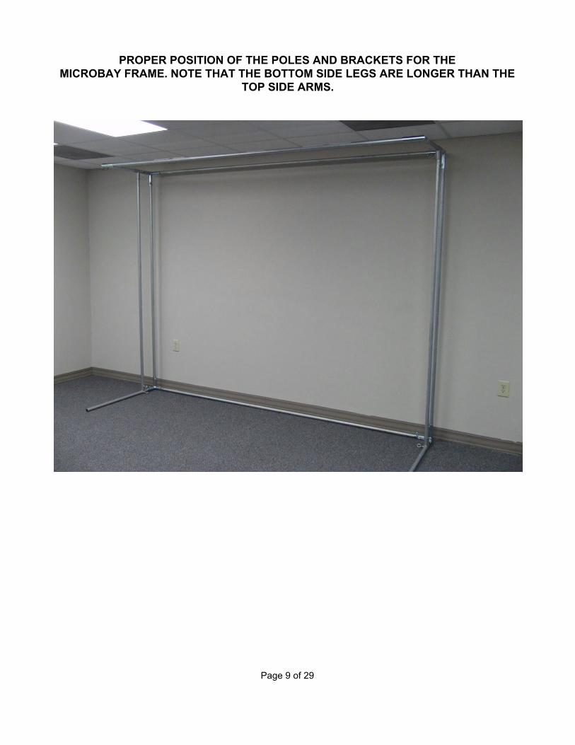
INSTALL THE HITTING SCREEN AND BLACK LEG WRAPPERS
The screen is easier to install if you attach the corners first.
Page 10 of 29

INSTALL THE BLACK SIDE TRIM PANELS
You can adjust the height of the side trim panels to match your floor exactly. They can hang “down” from the top poles by up to 4 inches.
Page 11 of 29

ATTACH VELCRO STRIPS ONTO THE REAR SIDE OF THE TOP POLE
The velcro strips will hold the screen valence in place. It works best when applied to the back side of the top pole.
Page 12 of 29

INSTALL THE TOP VALENCE
The top valence wraps around the sides as shown.
Page 13 of 29

Your MicroBay system is now complete and ready for use! Due to the lack of side and top netting we strongly recommend using “Almost Golf Balls” or foam balls rather than real golf balls when using your MicroBay. This is a safety recommendation only. The MicroBay screen is fully capable of handling full golf shots from real golf balls.
Page 14 of 29

MINIBAY™ and SUPERBAY™ Setup Instructions
Items Provided By AllSportSystems:
QUANTITY ITEM DESCRIPTION 6 3-Way Connectors 2 “T” Connectors 2 2-Way or “L” Connectors 1 Enclosure Netting 1 Baffle Back Stop 4 Inline Couplers (comes with SuperBay™ only)
Page 15 of 29

MEASURING AND CUTTING THE 1” EMT POLES
10’ Wide MiniBay Poles (This section applies only to customers with a 10’ Wide MiniBay)
WIDTH POLES: (QTY 4 needed) 10' long. These poles determine the WIDTH of your enclosure (bottom back, top back, top baffle/screen hanger, top front). There is nothing to cut if you want a 10' wide cage. The netting provided will cover any width up to 10'. DEPTH POLES: (QTY 4 needed) 4'-10' long. These poles determine the DEPTH of your enclosure (left and right sides). You can configure the depth of your MiniBay by using poles of any length from 4' up to 10' to match the netting you ordered. HEIGHT POLES (QTY 4 needed) These poles determine the HEIGHT of your enclosure (vertical poles). We recommend cutting these poles approximately 2 inches shorter than your finished Bay height, as the corner brackets will add about 2 inches to the height. So, for a 8’ tall Bay you will need 4 poles measuring 7’10”. For a 9’ tall Bay you will need 4 poles measuring 8’10”. TOTAL POLES REQUIRED for the MiniBay:
● For a 5' deep enclosure or smaller, you need to purchase a total of 10 10' poles. ● For enclosures that are 6'-10' deep you need to purchase a total of 12 10' poles.
Page 16 of 29

12’ Wide, 14’ Wide, or 16’ Wide SuperBay Poles
(This section applies only to customers with a 12’ or Wider SuperBay)
WIDTH POLES: (QTY 4 needed) 10' long + the Extender Poles described next. Width Extender Poles (QTY 4 needed) These poles are used to extend the width of your enclosure to match the size of the netting you purchased.
● For a 12' Wide Enclosure you need Qty 4 2' poles. ● For a 14' Wide Enclosure you need Qty 4 4' poles. ● For a 16' Wide Enclosure you need Qty 4 6' poles.
** Complete your Width Poles by adding one Inline Coupler and one Width Extender Pole to each. DEPTH POLES: (QTY 4 needed) 5' or 8' long. These poles determine the DEPTH of your enclosure (left and right sides). Prepare poles to match the depth of your netting. HEIGHT POLES (QTY 4 needed) These poles determine the HEIGHT of your enclosure (vertical poles). We recommend cutting these poles approximately 2 inches shorter than your finished Bay height, as the corner brackets will add about 2 inches to the height. So, for a 8’ tall Bay you will need 4 poles measuring 7’10”. For a 9’ tall Bay you will need 4 poles measuring 8’10”.
Page 17 of 29

OPTIONAL: If the screen pole sags near the extender bracket connection you can reinforce it using a product called “Metal Framing Channel”. It typically measures 1 5/8 in. Wide x 13/16 in. High x 10’ Long. We recommend strapping this channel material on the front and back sides of the screen pole (not top and bottom), and overlapping the extender bracket as far as possible in both directions. The screen pole will recess slightly into the channels. You can use stainless steel pipe straps to affix the channel to the screen pole.
1 ⅝” x 13/16” Metal Framing Channel, usually sold in 10’ lengths.
Stainless Steel Pipe Clamp
Page 18 of 29

BUILDING THE MINIBAY OR SUPERBAY FRAME (Method #1 – For Tall Ceilings)
NOTE: This method is recommended for situations where the ceiling is at least 6” taller than the enclosure you are building. If your enclosure will be closer to the ceiling then please refer to Method #2. TIP: Always position the corner connectors so that the Eye Bolts face DOWN and INSIDE.
7. BUILD THE BOTTOM Position a Bottom Width pole for the back of the enclosure with two 3-way corner connectors on either end. Then position and connect two Depth poles for the bottom sides. Next, install 2-way corners in the front, pointing upward. This establishes the bottom of your frame. Tighten all bottom connectors.
8. ADD THE 4 HEIGHT POLES Place 3-way corner connectors on top of each Height pole, then insert one Height pole into each bottom corner connector. Tighten the connectors. (Have assistants hold the front Height poles if needed.)
9. BUILD THE TOP SIDES Slide a TEE connector onto the last 2 Depth poles, leaving the tees loose (position the TEE connectors so that the eye bolts face the ground). Insert the Top Left Depth pole into its Front and Rear 3-way connectors at the top and tighten these connectors. Insert the Top Right Depth pole into its Front and Rear 3-way connectors at the top and tighten these connectors.
10. Install the Top Rear Pole Insert the Top Rear Width pole and tighten its connectors.
11. Install the Top Tee Pole Slide the two tee connectors to the front, and carefully insert a Width pole into them. You may need to carefully expand the top of the enclosure to fit the tee pole into the tee connectors. Once the tee pole is inside the tee connectors slide it all the way to the back of the enclosure, as far as you can. Tighten the tee connectors.
12. Install the Top Front Width Pole Insert the TOP FRONT Width pole. You may need to carefully expand the top of the enclosure to fit the top front width pole into its connectors. TIP: Make sure that the Top Tee pole is pushed as far back as possible to make this easier. Tighten all connectors on the front of the enclosure.
13.Loosen the Tee Connectors and slide the Tee Pole forward until it sits about 12” from Page 19 of 29
the back of the enclosure. Tighten the tee connectors.
BUILDING THE FRAME (Method #2 – For Tight Ceilings) NOTE: This method is recommended for situations where the enclosure height is very close to your ceiling height. TIP: Always position the corner connectors so that the Eye Bolts face DOWN and INSIDE.
1. BUILD THE REAR Position a Width pole for the Rear Top of the enclosure with two 3-way connectors on each end. Then connect two Height poles to the same connectors. Add two more 3-way connectors to the other end of the Height Poles, but do not fully tighten these. Carefully stand the structure up and lean it against the back wall of your room. Now insert the Bottom Width Pole and tighten the connectors. Tip: Leaving the bottom 3-Way connectors loose will allow you to spin them when tilting the rear structure into place. Once it is in place you can then spin them into their proper orientation so as to install the bottom Width Pole.
2. ADD THE BOTTOM DEPTH POLES Insert two Depth poles into the Bottom Rear 3-way connectors and tighten these connectors. The structure should now stand on its own.
3. BUILD THE TOP SIDES AND ADD THE TEE POLE Insert the two remaining Depth poles into the top Rear 3-way connectors and tighten these connectors. Next, slide a TEE connector onto the front of each top Depth pole, and attach a WIDTH pole between them. This will create the TEE Pole. Carefully slide the TEE Pole back toward the rear of the enclosure.
4. BUILD AND ATTACH THE FRONT Place 3-way connectors on one end of the two remaining front Height poles, then attach the top Width Pole between them. Next, attach 2-way connectors onto the other end of the front Height Poles. Carefully tilt this structure up, with the 3-way connectors at the top, and attach it to the front of the Top Depth Poles. (If necessary, spin the 2 way connectors so that you can tilt the structure up.) Connect the Bottom Depth Poles to the bottom front 2-way connectors.
Page 20 of 29

PROPER POSITION OF THE BAFFLE/SCREEN HANGER POLE 12” FROM THE BACK OF THE FRAME
Check and Tighten all Connectors! Check all connectors at all positions and verify that everything is tightly
connected before proceeding with the net installation.
Page 21 of 29

INSTALLING THE NETTING Open the netting and locate the TOP REAR CORNERS. Use Zip Ties or similar to attach the netting to the top rear corners first. After attaching the top rear corners, zip tie the netting along the top rear WIDTH pole. Zip tie the netting to the rear Height poles (the back sides)
Page 22 of 29

Attach the Top Left Front corner, then zip tie across the top Left Depth pole and Left Front Height Pole. Then finish tie-wrapping the netting around the top and right side. ** NOTE: The netting attaches inside the cage, not on the outside.
PULL THE TOP AND SIDES OF YOUR NETTING AS TIGHTLY AS POSSIBLE.
TIGHT NETTING WILL STOP STRAY GOLF BALLS WITH MINIMAL FLEXING.
Page 23 of 29

Completed Netting Installation
PULL THE TOP AND SIDES OF YOUR NETTING AS TIGHTLY AS POSSIBLE.
TIGHT NETTING WILL STOP STRAY GOLF BALLS WITH MINIMAL FLEXING.
Page 24 of 29

Handling of Excess Netting Your netting system may provide more material than you require, depending on how deep you build your enclosure. If you have excess netting then you have two options:
1) Along the front edges, wrap the netting onto the outside of the enclosure, and then pull it back toward the rear. Zip tie it in place once you've stretched it back as far as it will go.
2) Roll the excess netting up to create a “bundle” along the front edges, and zip tie it in place along the front poles.
Page 25 of 29

Installing the Baffle Net Attach the baffle net to the top tee pole, which should be located about 12” from the back of the enclosure.
Using either black cord or zip ties, connect the sides of the baffle net to the outside netting in a few places along each side.
Page 26 of 29

Completed Baffle Net Installation
Page 27 of 29

Installing a Video Projection Screen (sold separately) Install your video hitting screen with zip ties along the top tee pole, which should be located about 12” from the back of the enclosure. Then attach bungee cords between the side grommets on your screen and the bottom poles of your enclosure. This will create downward tension on the screen to help keep it flat, and will also assist with absorbing golf shots.
Page 28 of 29

Your system is now complete and ready for use! We recommend that you position the sides of your enclosure no closer than 12” away from side walls or other objects. We also strongly recommend using “Almost Golf Balls”, or foam balls rather than real golf balls when hitting indoors. This is a safety recommendation only. The screen is fully capable of handling full golf shots from real golf balls.
Page 29 of 29