Embed Size (px)
Citation preview

©2007 Standard Refrigeration Company. All rights reserved.
Product Catalog
20072008
T h i s c a t a l o g i s a v a i l a b l e t o d o w n l o a d a t o u r w e b s i t e
W W W . S T A N R E F . C O M
W AT E R C O O L E D C O N D E N S E R SC H I L L E R B A R R E L S
L I Q U I D R E C E I V E R SS U C T I O N A C C U M U L AT O R SR E F R I G E R A N T S U B C O O L E R S
VA LV E S , B R A C K E T S A N D A C C E S S O R I E SL O W S I D E C H I L L E R B U I L D E R K I T S
2
Pressure Vessel Fabrication Information 4
Water-Cooled Condensers 5
Selecting the Right Condenser 6
HSE Shell & Tube Super Efficient 8
SST Shell & Tube General Service 16
MSE Marine Service Shell & Tube 26
HP High Pressure/High Pumpdown 34
CA Stainless Steel Water-Side Shell & Tube 35
VSE Shell & Coil Vertical Space-Saver 36
ELT Tube in Tube Cleanable 38
KHX Tube in Tube Cleanable 39
SCH/SCS Coaxial 40
Custom Design Condenser Spec Sheet 41
Replacement Condenser Gaskets & Endplates Cross Reference Chart 42
Chiller Barrels 48Chiller Barrel Ratings & Design Features 48
Chiller Barrel Sizing 49
Selecting the Right Evaporator 52
TX/TXC Super Compact Serviceable Shell & Tube 52
TXG Ultra Compact Serviceable Shell & Tube 61
ERS/ERD OEM Single and Three-Pass Replacement Chiller Barrels 66
Custom Design Chiller Spec Sheet 68
Replacement Chiller Barrel Gaskets Cross Reference Chart 69
T A B L E O F
3
Refrigerant Subcoolers 70
SCT Vertical Subcoolers 70
Chiller Builder KitsCB Kits Low-Side Chiller Builder Kit 71
Liquid Receivers 74
Receiver Ratings & Design Features 74
HR Horizontal Design 75
RBV Horizontal Design with Brackets &Valves 76
UR Upright Design 77
UV Upright Design with Valves 78
L Compact Vertical Design 79
Suction Accumulators 80A Accumulators 80
Valves, Brackets and Accessories 81
Rotalock Valves 81
(4) Bolt Flanged Valves / Indicator Components 82
Float Type Indicators 83
Rotalock Components 84
Safety Devices / Sight Glass Indicators 85
Brackets 86
Warranty Back Cover
C O N T E N T S
4
Pressure Vessel Fabrication & Codes
NotesUL Listing may be obtained for a vessel, typical samples of whichcan withstand five times the marked working pressure without fail-ure for the gas side and three times the marked working pressurewithout failure for the fluid side. Initial tests are made atUnderwriters Laboratory and reexamination tests are made underUL supervision, at the manufacturer’s plant.
ASME Code Construction is the same whether UM or U certified.Essentially, the vessel must have a calculated design strength capableof withstanding the maximum allowable working pressure (MAWP)and tested pneumatically to 1.1 time the MAWP or hydrostatically to1.3 times the MAWP. Certain details of construction must beobserved, and chemical and physical test certification for all materi-al must be on file. Welding procedures, equipment, and personnelmust be qualified by performance tests. UM Certification meansthat the manufacturer’s personnel have performed the necessaryinspection and tests. The letters UM appear in the ASME cloverleafstamp on the tag. Only when requested, a certificate (Form U–3) isfurnished, signed by the manufacturer.
UL Recognition of UM vessels. Their testing, and reexaminationprocedure is identical to that for listing. This recognition require-ment comes about because UL takes the position that someoneother than the manufacturer should check the construction. Therecognition list is not published —as is the listing— the records arekept by UL and generally used only when granting listing to anassembly that includes the vessel.
NotesNational Board Registration means that in addition to the ASMEconstruction, an independant, licensed inspector has monitored theprocedures, fabrication and testing of the vessel.The letter U appears inthe ASME cloverleaf stamp on the tag. We recommend referring to Nat.Bd., rather than U–stamp, to avoid confusion between U and UM.
Underwriters Laboratory will automatically accept a National Boardregistered vessel when listing an assembly, because it has been inspectedby an independent agent, to specifications more strict than their own.
A National Board certified vessel is accepted by all state and municipalcodes in the United States. Most other countries will accept them also.
Certain government or military requirements essentially parallel theASME code, but may specify approval and/or certification by inspec-tors from a government agency in addition to, or in place of ASMEcode, or UL requirements.
International Code StampsCRN Canadian registration is available on cataloged models. CRNor special code requests should be made at time of order.
Other international codes possibly available upon request includeNew Zealand, Australia, Japan, China and Europe (CE).
Size of Vessel
Under six inches ID
Six inches or greater ID, but less than1.5 cubic feet net internal volume
Six inches or greater ID, with over 1.5cubic feet net internal volume
Construction and Certificationgenerally acceptable, furnished
unless otherwise specified
UL Listing
ASME Code Construction withUM Certification and UL Recognition
ASME Code Construction with UCertification and National BoardRegistration
5
Condensers
design features & ratings
Nominal Horsepower Rating Basis
15,000 Btu per hour @ 85°F. inlet water, 0.00025 additive fouling factor and 105°F.condensing temperature, with a three gallon per minute (gpm) water flow and refrigerant 22.
Sizing by Nominal Horsepower
A condenser is properly sized when its capacity to transfer heat from the system is equal to thecooling load, plus the extra heat generated by the work of compressing the gas. This total iscalled the Total Heat of Rejection. For air–conditioning or a high back pressure system, it’s safeand convenient to size by nominal horsepower. However, matching nominal HP can result inover-sizing for low and very low temperature applications. When your application varies fromnominal-air conditioning or normal operating conditions utilize Standard Refrigeration’s con-denser selection software or condenser performance tables, which can be obtained at www.stan-ref.com or from customer service.
Pumpdown Capacity
Pumpdown figures have been compensated to provide capacity for R-22 based on 80% of con-denser volume filled with liquid at 90°F.
Pumpdown requirements relate to the amount of refrigerant storage available in a condenserduring operation or servicing. A pumpdown capacity of three pounds of refrigerant per ton willbe sufficient for high back-pressure air conditioning, five pounds per ton for medium back-pressure air conditioning and up to seven pounds per ton for commercial refrigeration/lowback-pressure systems.
Operating Charge
Approximately 10% of the pumpdown capacity is required for shell & tube models and 5% forshell & coil models for proper operation.
Nominal Water Pressure Drop
Nominal pressure drops (psi) given are at nominal flow rates. To determine nominal flow ratesmultiply nominal horsepower (hp) by 3.0. Water pressure drops provided do not include any
external fittings or valves.
Pressure drop is defined as the loss of pressure due to friction and is the pressure differencebetween entering and leaving water sides.
Water Flow
Velocities of eight feet per second or higher risk premature impingement corrosion and tubefailure. Operation below minimum flow rates may result in excessive fouling and poor heattransfer. All values in this catalog section are limited to flows below eight feet per second.
Custom Designs
Standard Refrigeration is always happy to design and build customized condensers if an appli-cation calls for special materials, additional valves, water or refrigerant fittings, mounting brack-ets or other accessories. Contact customer service for a quotation.transfer.
Note on Refrigerant R410a Applications
Due to the high working pressures of Refrigerant R410a. Any condenser product in our catalogmust be customized to conform to ASME construction. Please contact customer service forquotation.
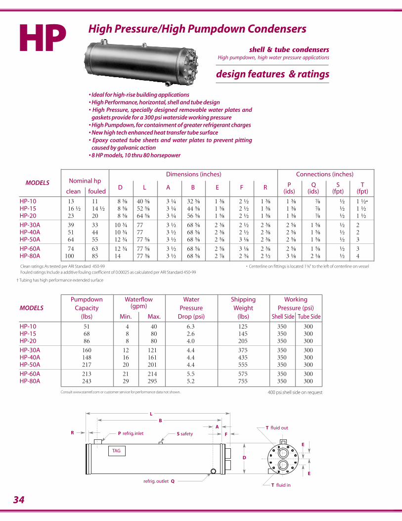
HSE
SST
HP
CA
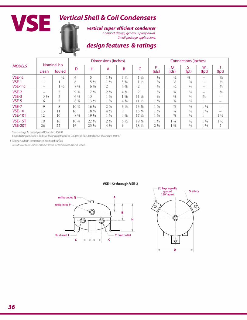
VSE
ELT
KHX
MSE
SCH / SCS
6
selecting theright condenser
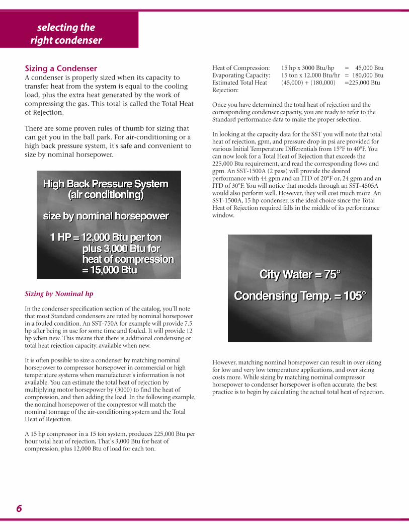
Sizing a CondenserA condenser is properly sized when its capacity totransfer heat from the system is equal to the coolingload, plus the extra heat generated by the work ofcompressing the gas. This total is called the Total Heatof Rejection.
There are some proven rules of thumb for sizing thatcan get you in the ball park. For air-conditioning or ahigh back pressure system, it's safe and convenient tosize by nominal horsepower.
Sizing by Nominal hp
In the condenser specification section of the catalog, you'll notethat most Standard condensers are rated by nominal horsepowerin a fouled condition. An SST-750A for example will provide 7.5hp after being in use for some time and fouled. It will provide 12hp when new. This means that there is additional condensing ortotal heat rejection capacity, available when new.
It is often possible to size a condenser by matching nominalhorsepower to compressor horsepower in commercial or hightemperature systems when manufacturer's information is notavailable. You can estimate the total heat of rejection bymultiplying motor horsepower by (3000) to find the heat ofcompression, and then adding the load. In the following example,the nominal horsepower of the compressor will match thenominal tonnage of the air-conditioning system and the TotalHeat of Rejection.
A 15 hp compressor in a 15 ton system, produces 225,000 Btu perhour total heat of rejection, That's 3,000 Btu for heat ofcompression, plus 12,000 Btu of load for each ton.
Heat of Compression: 15 hp x 3000 Btu/hp = 45,000 BtuEvaporating Capacity: 15 ton x 12,000 Btu/hr = 180,000 BtuEstimated Total Heat (45,000) + (180,000) =225,000 BtuRejection:
Once you have determined the total heat of rejection and thecorresponding condenser capacity, you are ready to refer to theStandard performance data to make the proper selection.
In looking at the capacity data for the SST you will note that totalheat of rejection, gpm, and pressure drop in psi are provided forvarious Initial Temperature Differentials from 15°F to 40°F. Youcan now look for a Total Heat of Rejection that exceeds the225,000 Btu requirement, and read the corresponding flows andgpm. An SST-1500A (2 pass) will provide the desiredperformance with 44 gpm and an ITD of 20°F or, 24 gpm and anITD of 30°F. You will notice that models through an SST-4505Awould also perform well. However, they will cost much more. AnSST-1500A, 15 hp condenser, is the ideal choice since the TotalHeat of Rejection required falls in the middle of its performancewindow.
However, matching nominal horsepower can result in over sizingfor low and very low temperature applications, and over sizingcosts more. While sizing by matching nominal compressorhorsepower to condenser horsepower is often accurate, the bestpractice is to begin by calculating the actual total heat of rejection.
selecting theright condenser
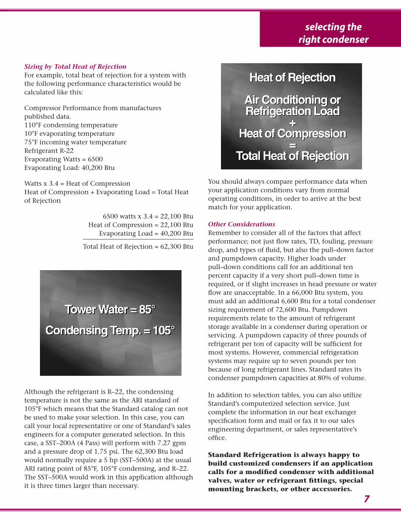
Sizing by Total Heat of RejectionFor example, total heat of rejection for a system withthe following performance characteristics would becalculated like this:
Compressor Performance from manufactures published data.110°F condensing temperature10°F evaporating temperature75°F incoming water temperatureRefrigerant R-22Evaporating Watts = 6500 Evaporating Load: 40,200 Btu
Watts x 3.4 = Heat of CompressionHeat of Compression + Evaporating Load = Total Heatof Rejection
6500 watts x 3.4 = 22,100 BtuHeat of Compression = 22,100 Btu
Evaporating Load = 40,200 Btu
Total Heat of Rejection = 62,300 Btu
Although the refrigerant is R–22, the condensingtemperature is not the same as the ARI standard of105°F which means that the Standard catalog can notbe used to make your selection. In this case, you cancall your local representative or one of Standard’s salesengineers for a computer generated selection. In thiscase, a SST–200A (4 Pass) will perform with 7.27 gpmand a pressure drop of 1.75 psi. The 62,300 Btu loadwould normally require a 5 hp (SST–500A) at the usualARI rating point of 85°F, 105°F condensing, and R–22.The SST–500A would work in this application althoughit is three times larger than necessary.
You should always compare performance data whenyour application conditions vary from normaloperating conditions, in order to arrive at the bestmatch for your application.
Other ConsiderationsRemember to consider all of the factors that affectperformance; not just flow rates, TD, fouling, pressuredrop, and types of fluid, but also the pull–down factorand pumpdown capacity. Higher loads underpull–down conditions call for an additional tenpercent capacity if a very short pull–down time isrequired, or if slight increases in head pressure or waterflow are unacceptable. In a 66,000 Btu system, youmust add an additional 6,600 Btu for a total condensersizing requirement of 72,600 Btu. Pumpdownrequirements relate to the amount of refrigerantstorage available in a condenser during operation orservicing. A pumpdown capacity of three pounds ofrefrigerant per ton of capacity will be sufficient formost systems. However, commercial refrigerationsystems may require up to seven pounds per tonbecause of long refrigerant lines. Standard rates itscondenser pumpdown capacities at 80% of volume.
In addition to selection tables, you can also utilizeStandard’s computerized selection service. Justcomplete the information in our heat exchangerspecification form and mail or fax it to our salesengineering department, or sales representative’soffice.
Standard Refrigeration is always happy tobuild customized condensers if an applicationcalls for a modified condenser with additionalvalves, water or refrigerant fittings, specialmounting brackets, or other accessories.
7
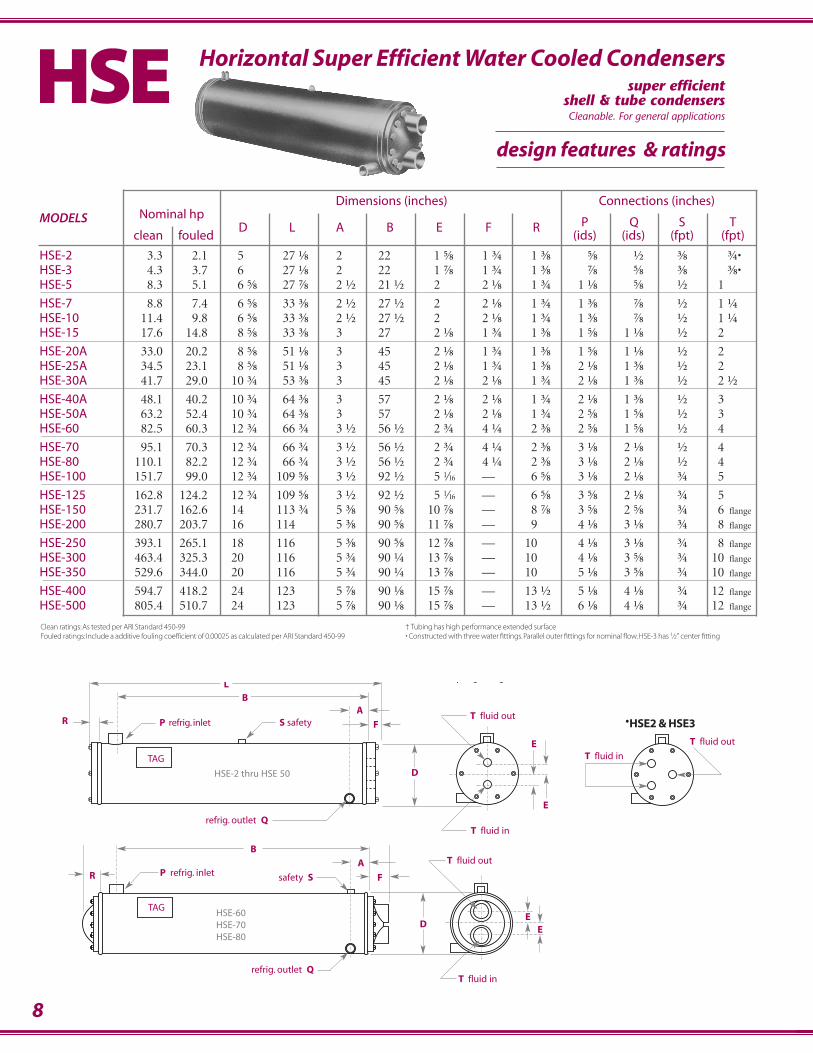
8
Dimensions (inches) Connections (inches)MODELS Nominal hp
P Q S Tclean fouled
D L A B E F R(ids) (ids) (fpt) (fpt)
HSE-2 3.3 2.1 5 27.⅛ 2 22 1.⅝ 1.¾ 1.⅜ .⅝ .½ .⅜ .¾•HSE-3 4.3 3.7 6 27.⅛ 2 22 1.⅞ 1.¾ 1.⅜ .⅞ .⅝ .⅜ .⅜•HSE-5 8.3 5.1 6.⅝ 27.⅞ 2.½ 21.½ 2 2.⅛ 1.¾ 1.⅛ .⅝ .½ 1.
HSE-7 8.8 7.4 6.⅝ 33.⅜ 2.½ 27.½ 2 2.⅛ 1.¾ 1.⅜ .⅞ .½ 1.¼HSE-10 11.4 9.8 6.⅝ 33.⅜ 2.½ 27.½ 2 2.⅛ 1.¾ 1.⅜ .⅞ .½ 1.¼HSE-15 17.6 14.8 8.⅝ 33.⅜ 3 27. 2.⅛ 1.¾ 1.⅜ 1.⅝ 1.⅛ .½ 2
HSE-20A 33.0 20.2 8.⅝ 51.⅛ 3 45 2.⅛ 1.¾ 1.⅜ 1.⅝ 1.⅛ .½ 2HSE-25A 34.5 23.1 8.⅝ 51.⅛ 3 45 2.⅛ 1.¾ 1.⅜ 2.⅛ 1.⅜ .½ 2HSE-30A 41.7 29.0 10.¾ 53.⅜ 3 45 2.⅛ 2.⅛ 1.¾ 2.⅛ 1.⅜ .½ 2.½
HSE-40A 48.1 40.2 10.¾ 64.⅜ 3 57 2.⅛ 2.⅛ 1.¾ 2.⅛ 1.⅜ .½ 3HSE-50A 63.2 52.4 10.¾ 64.⅜ 3 57 2.⅛ 2.⅛ 1.¾ 2.⅝ 1.⅝ .½ 3.HSE-60 82.5 60.3 12.¾ 66.¾ 3.½ 56.½ 2.¾ 4.¼ 2.⅜ 2.⅝ 1.⅝ .½ 4
HSE-70 95.1 70.3 12.¾ 66.¾ 3.½ 56.½ 2.¾ 4.¼ 2.⅜ 3.⅛ 2.⅛ .½ 4HSE-80 110.1 82.2 12.¾ 66.¾ 3.½ 56.½ 2.¾ 4.¼ 2.⅜ 3.⅛ 2.⅛ .½ 4HSE-100 151.7 99.0 12.¾ 109.⅝ 3.½ 92.½ 5.1 16 — 6.⅝ 3.⅛ 2.⅛ .¾ 5
HSE-125 162.8 124.2 12.¾ 109.⅝ 3.½ 92.½ 5.1 16 — 6.⅝ 3.⅝ 2.⅛ .¾ 5HSE-150 231.7 162.6 14 113.¾ 5.⅜ 90.⅝ 10.⅞ — 8.⅞ 3.⅝ 2.⅝ .¾ 6 flange
HSE-200 280.7 203.7 16 114 5.⅜ 90.⅝ 11.⅞ — 9 4.⅛ 3.⅛ .¾ 8 flange
HSE-250 393.1 265.1 18 116 5.⅜ 90.⅝ 12.⅞ — 10 4.⅛ 3.⅛ .¾ 8 flange
HSE-300 463.4 325.3 20 116 5.¾ 90.¼ 13.⅞ — 10 4.⅛ 3.⅝ .¾ 10 flange
HSE-350 529.6 344.0 20 116 5.¾ 90.¼ 13.⅞ — 10 5.⅛ 3.⅝ .¾ 10 flange
HSE-400 594.7 418.2 24 123 5.⅞ 90.⅛ 15.⅞ — 13.½ 5.⅛ 4.⅛ .¾ 12 flange
HSE-500 805.4 510.7 24 123 5.⅞ 90.⅛ 15.⅞ — 13.½ 6.⅛ 4.⅛ .¾ 12 flange
Horizontal Super Efficient WaterCooled Condensers
Horizontal Super Efficient Water Cooled Condensers
design features & ratings
HSE
T fluid in
T fluid out
HSE2 & HSE3
TAG
BL
RA
F
D EE
refrig. outlet Q
safety SP refrig. inlet
HSE-60HSE-70HSE-80
T fluid out
T fluid in
TAG
BL
RA
F
D
E
E
P refrig. inlet
T fluid inrefrig. outlet Q
T fluid outS safety
HSE-2 thru HSE 50
Clean ratings: As tested per ARI Standard 450-99Fouled ratings: Include a additive fouling coefficient of 0.00025 as calculated per ARI Standard 450-99
† Tubing has high performance extended surface• Constructed with three water fittings. Parallel outer fittings for nominal flow. HSE-3 has 1⁄2" center fitting
•
super efficientshell & tube condensersCleanable. For general applications
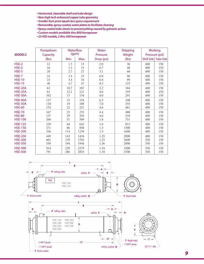
Pumpdown Waterflow Water Shipping Working MODELS Capacity (gpm) Pressure Weight Pressure (psi)
(lbs) Min. Max. Drop (psi) (lbs) Shell Side Tube Side
HSE-2 12 1.3 13 2.0 36 400 150HSE-3 16 1.3 13 6.7 48 400 150HSE-5 20 2.7 27 3.1 66 400 150
HSE-7 24 2.4 23 6.8 96 400 150HSE-10 23 3.4 34 6.6 89 400 150HSE-15 40 4.7 47 8.3 123 400 150
HSE-20A 63 10.7 107 3.2 184 400 150HSE-25A 61 12.1 121 4.6 193 400 150HSE-30A 102 15 154 4.0 291 400 150
HSE-40A 127 15 154 6.5 348 400 150HSE-50A 118 19 188 7.0 355 400 150HSE-60 176 22 221 4.6 461 400 150
HSE-70 167 25 255 4.4 480 400 150HSE-80 157 29 295 4.6 518 400 150HSE-100 268 51 509 1.8 751 400 150
HSE-125 239 64 643 1.6 812 400 150HSE-150 271 86 858 1.3 1300 400 150HSE-200 356 114 1139 1.3 1600 400 150
HSE-250 449 143 1434 1.35 2000 400 150HSE-300 601 170 1702 1.25 2600 350 150HSE-350 550 194 1944 1.36 2800 350 150
HSE-400 914 228 2279 1.34 3300 350 150HSE-500 791 286 2855 1.34 3700 350 150
9
• Horizontal, cleanable shell and tube design• New high tech enhanced copper tube geometry• Smaller foot-print equals less space requirement• Removable, epoxy coated, water plates to facilitate cleaning• Epoxy coated tube sheets to prevent pitting caused by galvanic action• Custom models available thru 800 horsepower• 23 HSE models, 2 thru 500 horsepower
TAG
BL
RA
R
D
refrig. outlet Q
safety SP refrig. inlet
T fluid inletT fluid outlet
HSE-100HSE-125
E
BL
R A
R
W
refrig. outlet Q
T fluid inlet
safety SP refrig. inlet
(2) 9⁄16" dia.
T fluid outlet
78"
18" 13"
E
3⁄4”NPT drain3⁄4”NPT drain
D
HSE-150HSE-200HSE-250HSE-300
HSE-350HSE-400HSE-500
3⁄4"NPT drain3⁄4"NPT drain
10
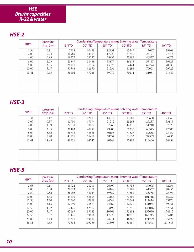
HSEBtu/hr capacities
R-22 & water
pressure Condensing Temperature minus Entering Water Temperaturegpm drop (psi) 15° ITD 20° ITD 25° ITD 30° ITD 35° ITD 40° ITD
1.34 0.11 7918 10458 12931 15349 17697 199682.00 0.24 10989 14504 17920 21255 24491 276144.00 0.93 18372 24237 29932 35489 40877 460776.00 2.03 23847 31469 38877 46113 53137 599258.00 3.55 28111 37114 45876 54444 62774 70838
10.00 5.47 31546 41670 51536 61196 70601 7972313.41 9.65 36102 47726 59079 70214 81081 91647
HSE-2
pressure Condensing Temperature minus Entering Water Temperaturegpm drop (psi) 15° ITD 20° ITD 25° ITD 30° ITD 35° ITD 40° ITD
2.68 0.11 15922 21211 26490 31755 37005 422565.00 0.38 26573 35378 44149 52881 61567 702567.50 0.82 36095 48024 59889 71681 83385 95094
10.00 1.43 44139 58695 73154 87501 101716 11593712.50 2.20 51060 67868 84544 101068 117414 13377015.00 3.13 57099 75863 94462 112870 131055 14925117.50 4.22 62426 82912 103199 123256 143046 16285120.00 5.47 67169 89183 110966 132484 153690 17491522.50 6.87 71426 94808 117928 140747 163215 18570425.00 8.43 75271 99887 124211 148200 171799 19542226.81 9.65 77834 103269 128393 153159 177508 201883
HSE-5
pressure Condensing Temperature minus Entering Water Temperaturegpm drop (psi) 15° ITD 20° ITD 25° ITD 30° ITD 35° ITD 40° ITD
1.34 0.17 9047 12003 14912 17781 20600 233602.00 0.37 12901 17094 21212 25265 29237 331154.00 1.39 22730 30074 37260 44316 51210 579206.00 3.05 30463 40292 49903 59335 68545 775058.00 5.32 36718 48566 60153 71527 82638 93452
10.00 8.20 41891 55418 68654 81653 94359 10673613.41 14.48 48921 64745 80248 95489 110406 124959
HSE-3
11
HSEBtu/hr capacities
R-22 & water
pressure Condensing Temperature minus Entering Water Temperaturegpm drop (psi) 15° ITD 20° ITD 25° ITD 30° ITD 35° ITD 40° ITD
2.35 0.14 15895 21183 26465 31738 37002 422672.50 0.15 16844 22447 28042 33628 39204 447805.00 0.57 30914 41171 51396 61586 71734 818847.50 1.24 42899 57097 71232 85294 99268 113247
10.00 2.15 53247 70832 88317 105683 122910 14014412.50 3.30 62284 82815 103204 123428 143458 16349815.00 4.68 70253 93373 116308 139031 161503 18398817.50 6.29 77341 102755 127943 152870 177492 20213020.00 8.13 83691 111154 138352 165241 191770 21832023.46 11.05 91467 121434 151079 180354 209197 238065
HSE-7
pressure Condensing Temperature minus Entering Water Temperaturegpm drop (psi) 15° ITD 20° ITD 25° ITD 30° ITD 35° ITD 40° ITD
4.69 0.14 31791 42367 52929 63476 74005 845345.00 0.15 33688 44894 56084 67256 78407 89559
10.00 0.57 61829 82341 102792 123172 143468 16376815.00 1.24 85798 114194 142464 170587 198536 22649320.00 2.15 106494 141665 176633 211366 245821 28028925.00 3.30 124568 165630 206409 246856 286916 32699630.00 4.68 140507 186746 232617 278061 323006 36797635.00 6.29 154682 205510 255886 305741 354983 40426040.00 8.13 167381 222309 276703 330482 383540 43663946.92 11.05 182935 242868 302158 360708 418394 476131
HSE-15
pressure Condensing Temperature minus Entering Water Temperaturegpm drop (psi) 15° ITD 20° ITD 25° ITD 30° ITD 35° ITD 40° ITD
3.35 0.14 22708 30262 37807 45340 52861 603825.00 0.29 32512 43315 54096 64851 75577 86303
10.00 1.09 58065 77291 96437 115490 134433 15338015.00 2.36 78786 104796 130650 156322 181780 20724820.00 4.10 95972 127576 158941 190029 220792 25157125.00 6.29 110487 146793 182776 218386 253560 28875733.51 11.05 130668 173477 215827 257649 298853 340093
HSE-10
12
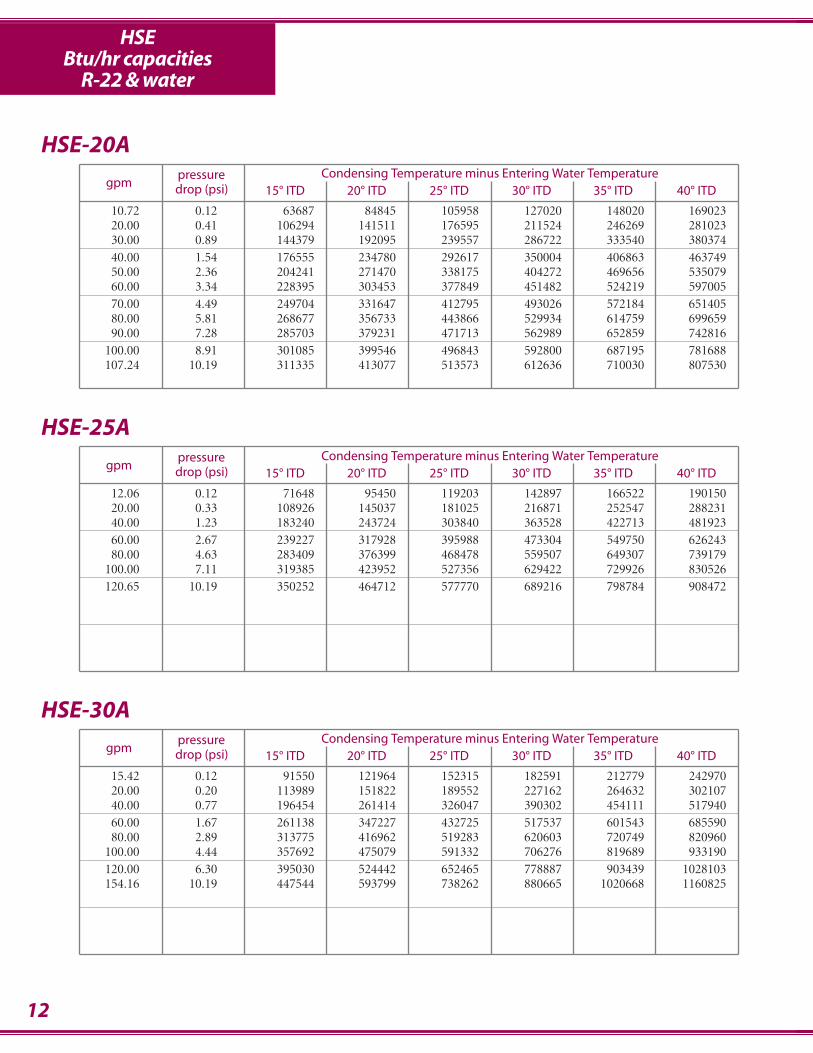
HSEBtu/hr capacities
R-22 & water
pressure Condensing Temperature minus Entering Water Temperaturegpm drop (psi) 15° ITD 20° ITD 25° ITD 30° ITD 35° ITD 40° ITD
10.72 0.12 63687 84845 105958 127020 148020 16902320.00 0.41 106294 141511 176595 211524 246269 28102330.00 0.89 144379 192095 239557 286722 333540 38037440.00 1.54 176555 234780 292617 350004 406863 46374950.00 2.36 204241 271470 338175 404272 469656 53507960.00 3.34 228395 303453 377849 451482 524219 59700570.00 4.49 249704 331647 412795 493026 572184 65140580.00 5.81 268677 356733 443866 529934 614759 69965990.00 7.28 285703 379231 471713 562989 652859 742816
100.00 8.91 301085 399546 496843 592800 687195 781688107.24 10.19 311335 413077 513573 612636 710030 807530
HSE-20A
pressure Condensing Temperature minus Entering Water Temperaturegpm drop (psi) 15° ITD 20° ITD 25° ITD 30° ITD 35° ITD 40° ITD
15.42 0.12 91550 121964 152315 182591 212779 24297020.00 0.20 113989 151822 189552 227162 264632 30210740.00 0.77 196454 261414 326047 390302 454111 51794060.00 1.67 261138 347227 432725 517537 601543 68559080.00 2.89 313775 416962 519283 620603 720749 820960
100.00 4.44 357692 475079 591332 706276 819689 933190120.00 6.30 395030 524442 652465 778887 903439 1028103154.16 10.19 447544 593799 738262 880665 1020668 1160825
HSE-30A
pressure Condensing Temperature minus Entering Water Temperaturegpm drop (psi) 15° ITD 20° ITD 25° ITD 30° ITD 35° ITD 40° ITD
12.06 0.12 71648 95450 119203 142897 166522 19015020.00 0.33 108926 145037 181025 216871 252547 28823140.00 1.23 183240 243724 303840 363528 422713 48192360.00 2.67 239227 317928 395988 473304 549750 62624380.00 4.63 283409 376399 468478 559507 649307 739179
100.00 7.11 319385 423952 527356 629422 729926 830526120.65 10.19 350252 464712 577770 689216 798784 908472
HSE-25A
13
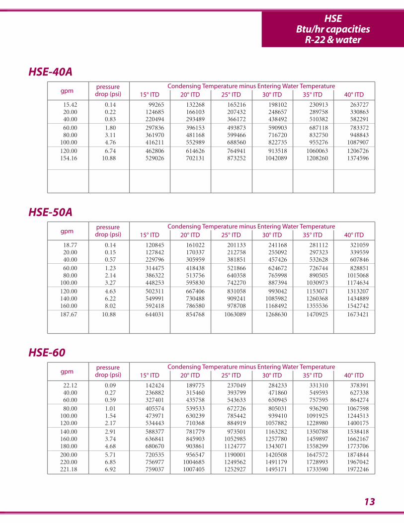
HSEBtu/hr capacities
R-22 & water
pressure Condensing Temperature minus Entering Water Temperaturegpm drop (psi) 15° ITD 20° ITD 25° ITD 30° ITD 35° ITD 40° ITD
15.42 0.14 99265 132268 165216 198102 230913 26372720.00 0.22 124685 166103 207432 248657 289758 33086340.00 0.83 220494 293489 366172 438492 510382 58229160.00 1.80 297836 396153 493873 590903 687118 78337280.00 3.11 361970 481168 599466 716720 832750 948843
100.00 4.76 416211 552989 688560 822735 955276 1087907120.00 6.74 462806 614626 764941 913518 1060063 1206726154.16 10.88 529026 702131 873252 1042089 1208260 1374596
HSE-40A
pressure Condensing Temperature minus Entering Water Temperaturegpm drop (psi) 15° ITD 20° ITD 25° ITD 30° ITD 35° ITD 40° ITD
22.12 0.09 142424 189775 237049 284233 331310 37839140.00 0.27 236882 315460 393799 471860 549593 62733860.00 0.59 327401 435758 543633 650945 757595 86427480.00 1.01 405574 539533 672726 805031 936290 1067598
100.00 1.54 473971 630239 785442 939410 1091925 1244513120.00 2.17 534443 710368 884919 1057882 1228980 1400175140.00 2.91 588377 781779 973501 1163282 1350788 1538418160.00 3.74 636841 845903 1052985 1257780 1459897 1662167180.00 4.68 680670 903861 1124777 1343071 1558299 1773706200.00 5.71 720535 956547 1190001 1420508 1647572 1874844220.00 6.85 756977 1004685 1249562 1491179 1728993 1967042221.18 6.92 759037 1007405 1252927 1495171 1733590 1972246
HSE-60
pressure Condensing Temperature minus Entering Water Temperaturegpm drop (psi) 15° ITD 20° ITD 25° ITD 30° ITD 35° ITD 40° ITD
18.77 0.14 120845 161022 201133 241168 281112 32105920.00 0.15 127842 170337 212758 255092 297323 33955940.00 0.57 229796 305959 381851 457426 532628 60784660.00 1.23 314475 418438 521866 624672 726744 82885180.00 2.14 386322 513756 640358 765998 890505 1015068
100.00 3.27 448253 595830 742270 887394 1030973 1174634120.00 4.63 502311 667406 831058 993042 1153071 1313207140.00 6.22 549991 730488 909241 1085982 1260368 1434889160.00 8.02 592418 786580 978708 1168492 1355536 1542742187.67 10.88 644031 854768 1063089 1268630 1470925 1673421
HSE-50A
14
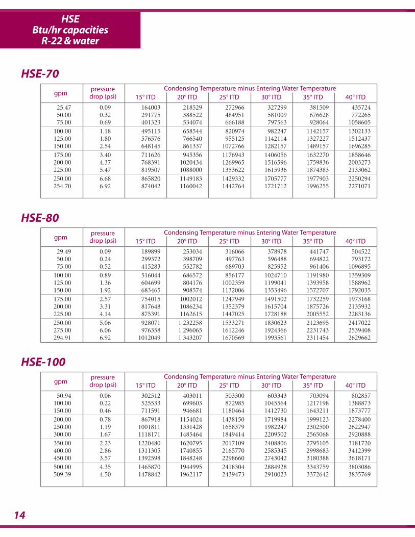
HSEBtu/hr capacities
R-22 & water
pressure Condensing Temperature minus Entering Water Temperaturegpm drop (psi) 15° ITD 20° ITD 25° ITD 30° ITD 35° ITD 40° ITD
25.47 0.09 164003 218529 272966 327299 381509 43572450.00 0.32 291775 388522 484951 581009 676628 77226575.00 0.69 401323 534074 666188 797563 928064 1058605
100.00 1.18 495115 658544 820974 982247 1142157 1302133125.00 1.80 576576 766540 955125 1142114 1327227 1512437150.00 2.54 648145 861337 1072766 1282157 1489157 1696285175.00 3.40 711626 945356 1176943 1406056 1632270 1858646200.00 4.37 768391 1020434 1269965 1516596 1759836 2003273225.00 5.47 819507 1088000 1353622 1615936 1874383 2133062250.00 6.68 865820 1149183 1429332 1705777 1977903 2250294254.70 6.92 874042 1160042 1442764 1721712 1996255 2271071
HSE-70
pressure Condensing Temperature minus Entering Water Temperaturegpm drop (psi) 15° ITD 20° ITD 25° ITD 30° ITD 35° ITD 40° ITD
50.94 0.06 302512 403011 503300 603343 703094 802857100.00 0.22 525533 699603 872985 1045564 1217198 1388873150.00 0.46 711591 946681 1180464 1412730 1643211 1873777200.00 0.78 867918 1154024 1438150 1719984 1999123 2278400250.00 1.19 1001811 1331428 1658379 1982247 2302500 2622947300.00 1.67 1118171 1485464 1849414 2209502 2565068 2920888350.00 2.23 1220480 1620795 2017109 2408806 2795105 3181720400.00 2.86 1311305 1740855 2165770 2585345 2998683 3412399450.00 3.57 1392598 1848248 2298660 2743042 3180388 3618171500.00 4.35 1465870 1944995 2418304 2884928 3343759 3803086509.39 4.50 1478842 1962117 2439473 2910023 3372642 3835769
HSE-100
pressure Condensing Temperature minus Entering Water Temperaturegpm drop (psi) 15° ITD 20° ITD 25° ITD 30° ITD 35° ITD 40° ITD
29.49 0.09 189899 253034 316066 378978 441747 50452250.00 0.24 299372 398709 497763 596488 694822 79317275.00 0.52 415283 552782 689703 825952 961406 1096895
100.00 0.89 516044 686572 856177 1024710 1191980 1359309125.00 1.36 604699 804176 1002359 1199041 1393958 1588962150.00 1.92 683465 908574 1132006 1353496 1572707 1792035175.00 2.57 754015 1002012 1247949 1491502 1732259 1973168200.00 3.31 817648 1086234 1352379 1615704 1875726 2135932225.00 4.14 875391 1162615 1447025 1728188 2005552 2283136250.00 5.06 928071 1 232258 1533271 1830623 2123695 2417022275.00 6.06 976358 1 296065 1612246 1924366 2231743 2539408294.91 6.92 1012049 1 343207 1670569 1993561 2311454 2629662
HSE-80

15
HSEBtu/hr capacities
R-22 & water
pressure Condensing Temperature minus Entering Water Temperaturegpm drop (psi) 15° ITD 20° ITD 25° ITD 30° ITD 35° ITD 40° ITD
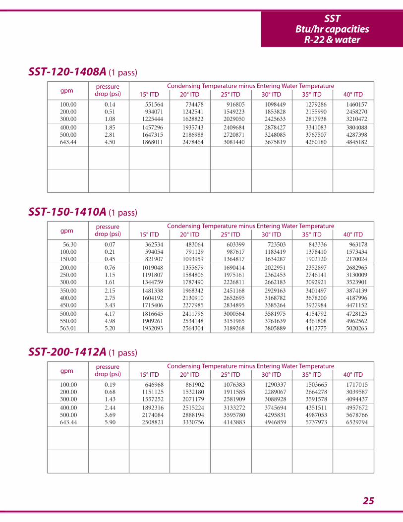
64.34 0.06 382120 509067 635747 762117 888119 1014135100.00 0.14 551564 734478 916805 1098449 1279286 1460157200.00 0.51 934071 242541 1549223 1853828 2155990 2458270300.00 1.08 1225444 628822 2029050 2425633 2817938 3210472400.00 1.85 1457296 935743 2409684 2878427 3341083 3804088500.00 2.81 1647315 186988 2720871 3248085 3767507 4287398643.44 4.50 1868011 478464 3081440 3675819 4260180 4845182
HSE-125
pressure Condensing Temperature minus Entering Water Temperaturegpm drop (psi) 15° ITD 20° ITD 25° ITD 30° ITD 35° ITD 40° ITD
113.94 0.07 676671 901473 1125803 1349582 1572710 1795864200.00 0.19 1076645 1433474 1789024 2143086 2495391 2847770300.00 0.40 1467715 1952983 2435787 2915728 3392296 3869021400.00 0.67 1800210 2394171 2984350 3570144 4150781 4731674500.00 1.01 2087824 2775429 3457885 4134380 4803878 5473743600.00 1.41 2339897 3109288 3872160 4627495 5373997 6120983700.00 1.87 2563157 3404764 4238503 5063163 5877192 6691828800.00 2.39 2762634 3668586 4565365 5451565 6325399 7199961900.00 2.97 2942189 3905918 4859216 5800493 6727735 7655826
1000.00 3.60 3104852 4120808 5125123 6116038 7091319 80675711100.00 4.29 3253039 4316480 5367123 6403048 7421812 84416661139.43 4.58 3307936 4388945 5456715 6509261 7544069 8580009
HSE-200
pressure Condensing Temperature minus Entering Water Temperaturegpm drop (psi) 15° ITD 20° ITD 25° ITD 30° ITD 35° ITD 40° ITD
85.79 0.07 509494 678756 847663 1016156 1184158 1352180100.00 0.09 580148 772778 964937 1156548 1347511 1538500200.00 0.32 1009521 1343561 1676067 2006791 2335414 2664131300.00 0.67 1351822 1797856 2241058 2680976 3117033 3553282400.00 1.13 1633925 2171763 2705400 3234177 3757251 4280629500.00 1.70 1871732 2486613 3095932 3698828 4294202 4890000600.00 2.37 2075648 2756341 3430159 4096046 4752662 5409822700.00 3.15 2252893 2990605 3720188 4440407 5149696 5859651857.93 4.58 2490681 3304618 4108586 4901091 5680239 6460242
HSE-150
Consult www.stanref.com or customer service for performance data not shown.
TAG
BL
RA
F
D EE
safety SP refrig. inlet
fluid in Trefrig. outlet Q
T fluid out
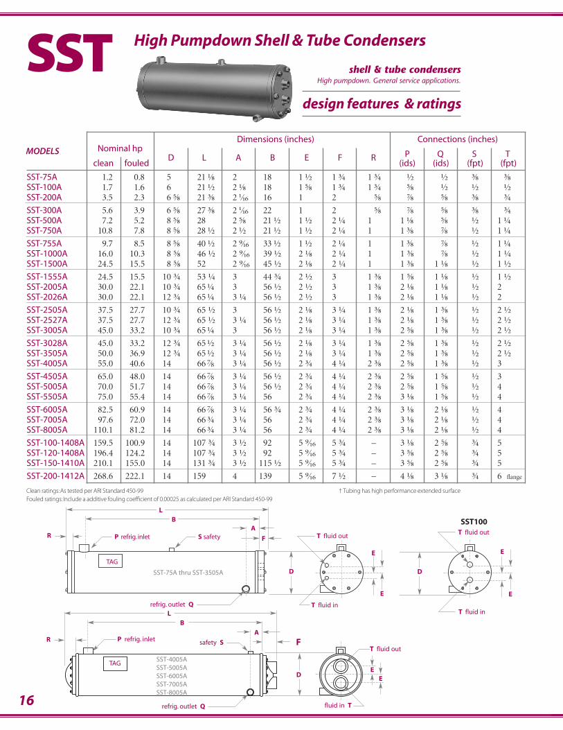
SST-4005ASST-5005ASST-6005ASST-7005ASST-8005A
Dimensions (inches) Connections (inches)MODELS Nominal hp
P Q S Tclean fouled
D L A B E F R(ids) (ids) (fpt) (fpt)
SST-75A 1.2 0.8 5. 21.⅛ 2. 18. 1.½ 1.¾ 1.¾ .½ .½ .⅜ .⅜SST-100A 1.7 1.6 6 21.½ 2.⅛ 18. 1.⅝ 1.¾ 1.¾ .⅝ .½ .½ .½SST-200A 3.5 2.3 6.⅝ 21.⅜ 2.1⁄16 16. 1. 2. .⅝ .⅞ .⅝ .⅜ .¾
SST-300A 5.6 3.9 6.⅝ 27.⅜. 2.1⁄16 22. 1. 2. .⅝ .⅞ .⅝ .⅜ .¾SST-500A 7.2 5.2 8.⅝ 28. 2.⅝ 21.½ 1.½ 2.¼ 1. 1.⅛ .⅝ .½ 1.¼SST-750A 10.8 7.8 8.⅝ 28.½. 2.½ 21.½ 1.½ 2.¼ 1. 1.⅜ .⅞ .½ 1.¼
SST-755A 9.7 8.5 8.⅝ 40.½ 2.9⁄16 33.½ 1.½ 2.¼ 1. 1.⅜ .⅞ .½ 1.¼SST-1000A 16.0 10.3 8.⅝ 46.½ 2.9⁄16 39.½ 2.⅛ 2.¼ 1. 1.⅜ .⅞ .½ 1.¼SST-1500A 24.5 15.5 8.⅝ 52. 2.9⁄16 45.½ 2.⅛ 2.¼ 1. 1.⅜ 1.⅛ .½ 1.½
SST-1555A 24.5 15.5 10.¾ 53.¼ 3. 44.¾ 2.½ 3. 1.⅜. 1.⅝ 1.⅛ .½ 1.½SST-2005A 30.0 22.1 10.¾ 65.¼ 3. 56.½ 2.½ 3. 1.⅜. 2.⅛ 1.⅛ .½ 2SST-2026A 30.0 22.1 12.¾ 65.¼ 3.¼ 56.½ 2.½ 3. 1.⅜. 2.⅛ 1.⅛ .½ 2
SST-2505A 37.5 27.7 10.¾ 65.½ 3. 56.½ 2.⅛ 3.¼ 1.⅜. 2.⅛ 1.⅜ .½ 2.½SST-2527A 37.5 27.7 12.¾ 65.½ 3.¼ 56.½ 2.⅛ 3.¼ 1.⅜. 2.⅛ 1.⅜ .½ 2.½SST-3005A 45.0 33.2 10.¾ 65.¼ 3 56.½ 2.⅛ 3.¼ 1.⅜. 2.⅝ 1.⅜ .½ 2.½
SST-3028A 45.0 33.2 12.¾ 65.½ 3.¼ 56.½ 2.⅛ 3.¼ 1.⅜ 2.⅝ 1.⅜ .½ 2.½SST-3505A 50.0 36.9 12.¾ 65.½ 3.¼ 56.½ 2.⅛ 3.¼ 1.⅜. 2.⅝ 1.⅜ .½ 2.½SST-4005A 55.0 40.6 14. 66.7⁄8 3.¼ 56.½ 2.¾ 4.¼ 2.⅜ 2.⅝ 1.⅜ .½ 3
SST-4505A 65.0 48.0 14. 66.7⁄8 3.¼ 56.½ 2.¾ 4.¼ 2.⅜ 2.⅝ 1.⅝ .½ 3SST-5005A 70.0 51.7 14. 66.7⁄8 3.¼ 56.½ 2.¾ 4.¼ 2.⅜ 2.⅝ 1.⅝ .½ 4SST-5505A 75.0 55.4 14. 66.7⁄8 3.¼ 56. 2.¾ 4.¼ 2.⅜ 3.⅛ 1.⅝ .½ 4
SST-6005A 82.5 60.9 14. 66.7⁄8 3.¼ 56.¾ 2.¾ 4.¼ 2.⅜ 3.⅛ 2.⅛ .½ 4SST-7005A 97.6 72.0 14. 66.¾ 3.¼ 56. 2.¾ 4.¼ 2.⅜ 3.⅛ 2.⅛ .½ 4SST-8005A 110.1 81.2 14 66.¾ 3.¼ 56. 2.¾ 4.¼ 2.⅜ 3.⅛ 2.⅛ .½ 4
SST-100-1408A 159.5 100.9 14 107.¾ 3.½ 92. 5.9⁄16 5.¾ – 3.⅛ 2.⅝ .¾ 5SST-120-1408A 196.4 124.2 14 107.¾ 3.½ 92. 5.9⁄16 5.¾ – 3.⅝ 2.⅝ .¾ 5SST-150-1410A 210.1 155.0 14 131.¾ 3.½ 115.½ 5.9⁄16 5.¾ – 3.⅝ 2.⅝ .¾ 5
SST-200-1412A 268.6 222.1 14 159 4. 139. 5.9⁄16 7.½ – 4.⅛ 3.⅛ .¾ 6 flange
Horizontal Super Efficient WaterCooled Condensers
High Pumpdown Shell & Tube Condensers
TAG
BL
RA
F
D
E
E
S safety P refrig. inlet
refrig. outlet Q T fluid in
T fluid in
T fluid out
SST-75A thru SST-3505A
Clean ratings: As tested per ARI Standard 450-99Fouled ratings: Include a additive fouling coefficient of 0.00025 as calculated per ARI Standard 450-99
† Tubing has high performance extended surface
D
E
E
T fluid in
T fluid out
SST
F
16
SST100
design features & ratings
shell & tube condensersHigh pumpdown. General service applications.
BL
F AF
D
refrig. outlet Q T fluid inlet
safety SP refrig. inlet
T fluid outlet
E
TAG
BL
FA
F
D
refrig. outlet Q
safety SP refrig. inlet
T fluid inletT fluid outlet
SST-100-1408ASST-120-1408ASST-150-1410A
SST-200-1412A
E
17
• Industry’s most widely used and trusted model• Heavy duty, horizontal, shell and tube design• Nominal ratings and sizes to handle the most demanding requirements• Removable, epoxy coated, water plates to facilitate cleaning• All copper, heavy wall, straight tube water channels• Epoxy coated tube sheets to prevent pitting caused by galvanic action• Generous pumpdown capacities• Custom models available thru 800 horsepower• 28 SST models, 3⁄4 thru 200 horsepower
Pumpdown Waterflow Water Shipping Working MODELS Capacity (gpm) Pressure Weight Pressure (psi)
(lbs) Min. Max. Drop (psi) (lbs) Shell Side Tube Side
SST-75A 9 0.7 2.3 3.4 28 450 150SST-100A 17 0.7 4.7 2.7 39 450 150SST-200A 15 2.0 18.0 1.7 52 450 150
SST-300A 21 2.0 16.0 1.7 71 450 150SST-500A 35 2.7 26.8 3.5 90 450 150SST-750A 32 4.0 30.0 2.4 109 450 150
SST-755A 53 3.4 20.0 3.3 144 450 150SST-1000A 59 6.7 67.0 0.9 159 450 150SST-1500A 65 8.0 70.0 1.5 180 450 150
SST-1555A 111 8.0 80.4 2.0 272 450 150SST-2005A 138 8.0 80.4 3.5 313 450 150SST-2026A 208 8.0 80.4 2.8 428 450 150
SST-2505A 135 10.1 100.5 4.0 345 450 150SST-2527A 205 10.1 100.5 3.2 413 450 150SST-3005A 128 12.1 100.1 4.0 350 450 150
SST-3028A 198 12.1 100.1 3.1 448 450 150SST-3505A 199 13.4 111.2 5.5 400 450 150SST-4005A 244 14.8 122.3 4.7 489 450 150
SST-4505A 237 17.4 144.6 4.3 519 450 150SST-5005A 233 18.8 187.7 4.7 527 450 150SST-5505A 230 20.1 201.1 4.8 521 450 150
SST-6005A 224 22.1 221.2 4.6 542 450 150SST-7005A 214 26.1 261.4 4.7 548 450 150SST-8005A 205 29.5 294.9 4.8 596 450 150
SST-100-1408A 342 52.3 522.8 4.7 1136 450 150SST-120-1408A 316 64.3 643.4 4.7 1176 450 150SST-150-1410A 416 56.3 563.0 6.7 1298 450 150
SST-200-1412A 474 64.3 643.4 4.8 1505 450 150
18
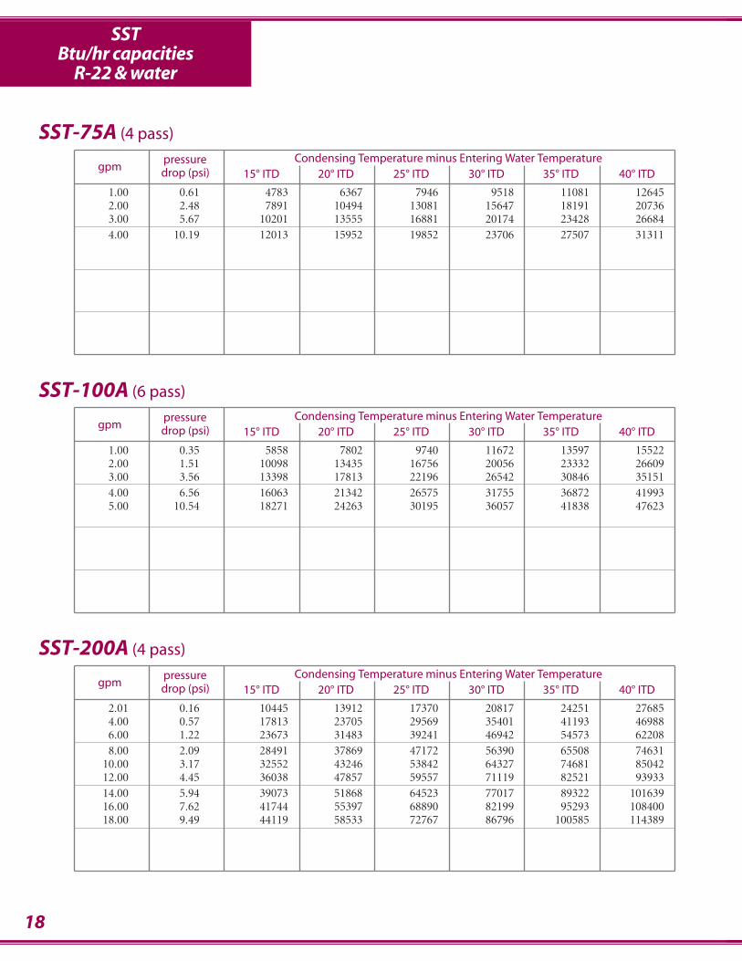
pressure Condensing Temperature minus Entering Water Temperaturegpm drop (psi) 15° ITD 20° ITD 25° ITD 30° ITD 35° ITD 40° ITD
1.00 0.61 4783 6367 7946 9518 11081 126452.00 2.48 7891 10494 13081 15647 18191 207363.00 5.67 10201 13555 16881 20174 23428 266844.00 10.19 12013 15952 19852 23706 27507 31311
SST-75A (4 pass)
pressure Condensing Temperature minus Entering Water Temperaturegpm drop (psi) 15° ITD 20° ITD 25° ITD 30° ITD 35° ITD 40° ITD
2.01 0.16 10445 13912 17370 20817 24251 276854.00 0.57 17813 23705 29569 35401 41193 469886.00 1.22 23673 31483 39241 46942 54573 622088.00 2.09 28491 37869 47172 56390 65508 74631
10.00 3.17 32552 43246 53842 64327 74681 8504212.00 4.45 36038 47857 59557 71119 82521 9393314.00 5.94 39073 51868 64523 77017 89322 10163916.00 7.62 41744 55397 68890 82199 95293 10840018.00 9.49 44119 58533 72767 86796 100585 114389
SST-200A (4 pass)
pressure Condensing Temperature minus Entering Water Temperaturegpm drop (psi) 15° ITD 20° ITD 25° ITD 30° ITD 35° ITD 40° ITD
1.00 0.35 5858 7802 9740 11672 13597 155222.00 1.51 10098 13435 16756 20056 23332 266093.00 3.56 13398 17813 22196 26542 30846 351514.00 6.56 16063 21342 26575 31755 36872 419935.00 10.54 18271 24263 30195 36057 41838 47623
SST-100A (6 pass)
SSTBtu/hr capacities
R-22 & water

19
pressure Condensing Temperature minus Entering Water Temperaturegpm drop (psi) 15° ITD 20° ITD 25° ITD 30° ITD 35° ITD 40° ITD
4.00 0.61 20959 27901 34815 41697 48540 553856.00 1.30 28356 37723 47038 56291 65473 746588.00 2.22 34562 45954 57267 68487 79599 90717
10.00 3.37 39871 52988 65998 78884 91625 10437412.00 4.73 44480 59089 73564 87884 102023 11617214.00 6.30 48529 64445 80200 95770 111124 12649116.00 8.08 52121 69192 86078 102750 119173 13561018.00 10.06 55334 73436 91329 108981 126351 143739
SST-300A (4 pass)
pressure Condensing Temperature minus Entering Water Temperaturegpm drop (psi) 15° ITD 20° ITD 25° ITD 30° ITD 35° ITD 40° ITD
10.00 1.19 49661 66087 82433 98686 114831 13098015.00 2.60 66208 88043 109731 131252 152574 17390620.00 4.54 79742 105976 131996 157768 183250 20874825.00 7.00 91081 120984 150605 179902 208818 23775630.00 9.96 100754 133775 166450 198725 230535 262372
SST-750A (4 pass)
pressure Condensing Temperature minus Entering Water Temperaturegpm drop (psi) 15° ITD 20° ITD 25° ITD 30° ITD 35° ITD 40° ITD
7.50 1.49 36095 48024 59889 71681 83385 9509410.00 2.60 44139 58695 73154 87501 101716 11593712.50 4.01 51060 67868 84544 101068 117414 13377015.00 5.71 57099 75863 94462 112870 131055 14925117.50 7.69 62426 82912 103199 123256 143046 16285120.00 9.96 67169 89183 110966 132484 153690 17491522.50 12.52 71426 94808 117928 140747 163215 185704
SST-500A (4 pass)
SSTBtu/hr capacities
R-22 & water
20
pressure Condensing Temperature minus Entering Water Temperaturegpm drop (psi) 15° ITD 20° ITD 25° ITD 30° ITD 35° ITD 40° ITD
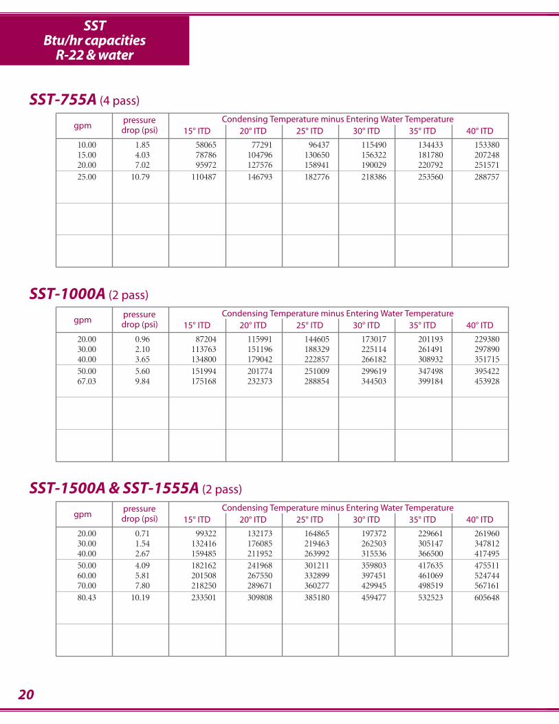
10.00 1.85 58065 77291 96437 115490 134433 15338015.00 4.03 78786 104796 130650 156322 181780 20724820.00 7.02 95972 127576 158941 190029 220792 25157125.00 10.79 110487 146793 182776 218386 253560 288757
SST-755A (4 pass)
pressure Condensing Temperature minus Entering Water Temperaturegpm drop (psi) 15° ITD 20° ITD 25° ITD 30° ITD 35° ITD 40° ITD
20.00 0.71 99322 132173 164865 197372 229661 26196030.00 1.54 132416 176085 219463 262503 305147 34781240.00 2.67 159485 211952 263992 315536 366500 41749550.00 4.09 182162 241968 301211 359803 417635 47551160.00 5.81 201508 267550 332899 397451 461069 52474470.00 7.80 218250 289671 360277 429945 498519 56716180.43 10.19 233501 309808 385180 459477 532523 605648
SST-1500A & SST-1555A (2 pass)
pressure Condensing Temperature minus Entering Water Temperaturegpm drop (psi) 15° ITD 20° ITD 25° ITD 30° ITD 35° ITD 40° ITD
20.00 0.96 87204 115991 144605 173017 201193 22938030.00 2.10 113763 151196 188329 225114 261491 29789040.00 3.65 134800 179042 222857 266182 308932 35171550.00 5.60 151994 201774 251009 299619 347498 39542267.03 9.84 175168 232373 288854 344503 399184 453928
SST-1000A (2 pass)
SSTBtu/hr capacities
R-22 & water
21
pressure Condensing Temperature minus Entering Water Temperaturegpm drop (psi) 15° ITD 20° ITD 25° ITD 30° ITD 35° ITD 40° ITD
30.00 1.22 150769 200555 250050 299206 347963 39674040.00 2.10 183673 244181 304245 363796 422744 48172250.00 3.19 211620 281192 350167 418452 485928 55344860.00 4.50 235711 313066 389675 465421 540158 61495270.00 6.03 256732 340858 424091 506297 587301 66837780.43 7.84 276013 366329 455610 543698 630396 717180
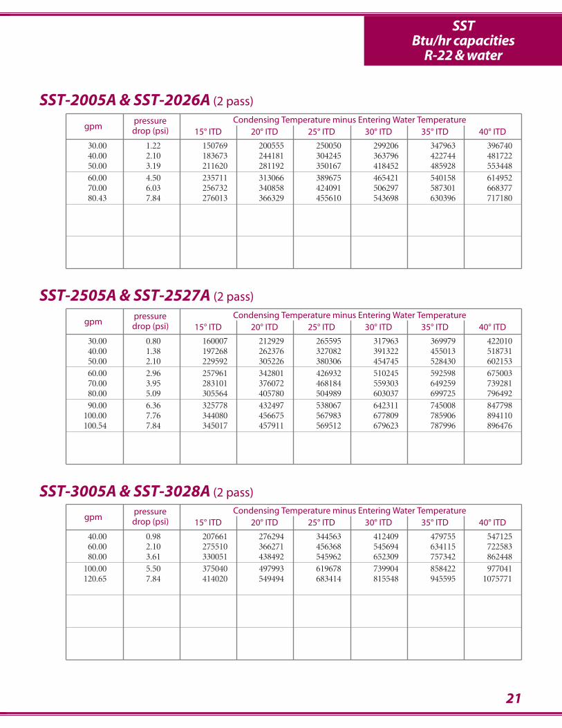
SST-2005A & SST-2026A (2 pass)
pressure Condensing Temperature minus Entering Water Temperaturegpm drop (psi) 15° ITD 20° ITD 25° ITD 30° ITD 35° ITD 40° ITD
40.00 0.98 207661 276294 344563 412409 479755 54712560.00 2.10 275510 366271 456368 545694 634115 72258380.00 3.61 330051 438492 545962 652309 757342 862448
100.00 5.50 375040 497993 619678 739904 858422 977041120.65 7.84 414020 549494 683414 815548 945595 1075771
SST-3005A & SST-3028A (2 pass)
pressure Condensing Temperature minus Entering Water Temperaturegpm drop (psi) 15° ITD 20° ITD 25° ITD 30° ITD 35° ITD 40° ITD
30.00 0.80 160007 212929 265595 317963 369979 42201040.00 1.38 197268 262376 327082 391322 455013 51873150.00 2.10 229592 305226 380306 454745 528430 60215360.00 2.96 257961 342801 426932 510245 592598 67500370.00 3.95 283101 376072 468184 559303 649259 73928180.00 5.09 305564 405780 504989 603037 699725 79649290.00 6.36 325778 432497 538067 642311 745008 847798
100.00 7.76 344080 456675 567983 677809 785906 894110100.54 7.84 345017 457911 569512 679623 787996 896476
SST-2505A & SST-2527A (2 pass)
SSTBtu/hr capacities
R-22 & water
22
pressure Condensing Temperature minus Entering Water Temperaturegpm drop (psi) 15° ITD 20° ITD 25° ITD 30° ITD 35° ITD 40° ITD
20.00 0.22 122203 162775 203245 243597 283809 32402640.00 0.80 213342 283906 354127 423951 493305 56268060.00 1.72 285305 379378 472814 565512 657343 74921780.00 2.96 343948 457067 569243 680327 790131 900004
100.00 4.50 392851 521777 649458 775701 900263 1024920134.05 7.84 460022 610549 759349 906164 1050661 1195301
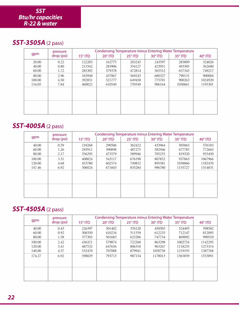
SST-3505A (2 pass)
pressure Condensing Temperature minus Entering Water Temperaturegpm drop (psi) 15° ITD 20° ITD 25° ITD 30° ITD 35° ITD 40° ITD
40.00 0.43 226397 301402 376120 450505 524495 59850260.00 0.92 308350 410234 511559 612235 712147 81209580.00 1.58 377303 501683 625206 747734 869092 990510
100.00 2.42 436321 579874 722260 863298 1002754 1142295120.00 3.41 487532 647656 806310 963267 1118235 1273314140.00 4.57 532470 707088 879941 1050758 1219193 1387768174.27 6.92 598029 793713 987154 1178013 1365859 1553891
SST-4505A (2 pass)
pressure Condensing Temperature minus Entering Water Temperaturegpm drop (psi) 15° ITD 20° ITD 25° ITD 30° ITD 35° ITD 40° ITD
40.00 0.59 218268 290506 362422 433964 505063 57618360.00 1.26 293911 390898 487275 582946 677785 77266580.00 2.17 356295 473579 589946 705255 819320 933450
100.00 3.31 408824 543117 676190 807852 937863 1067966120.00 4.68 453780 602574 749852 895381 1038866 1182470147.46 6.92 506024 671603 835284 996780 1155727 1314831
SST-4005A (2 pass)
SSTBtu/hr capacities
R-22 & water

23
pressure Condensing Temperature minus Entering Water Temperaturegpm drop (psi) 15° ITD 20° ITD 25° ITD 30° ITD 35° ITD 40° ITD
18.77 0.09 120845 161022 201133 241168 281112 32105920.00 0.10 127842 170337 212758 255092 297323 33955940.00 0.37 229796 305959 381851 457426 532628 60784660.00 0.80 314475 418438 521866 624672 726744 82885180.00 1.38 386322 513756 640358 765998 890505 1015068
100.00 2.10 448253 595830 742270 887394 1030973 1174634120.00 2.96 502311 667406 831058 993042 1153071 1313207140.00 3.97 549991 730488 909241 1085982 1260368 1434889160.00 5.11 592418 786580 978708 1168492 1355536 1542742187.67 6.92 644031 854768 1063089 1268630 1470925 1673421
SST-5005A (2 pass)
pressure Condensing Temperature minus Entering Water Temperaturegpm drop (psi) 15° ITD 20° ITD 25° ITD 30° ITD 35° ITD 40° ITD
22.12 0.09 142424 189775 237049 284233 331310 37839140.00 0.27 236882 315460 393799 471860 549593 62733860.00 0.59 327401 435758 543633 650945 757595 86427480.00 1.01 405574 539533 672726 805031 936290 1067598
100.00 1.54 473971 630239 785442 939410 1091925 1244513120.00 2.17 534443 710368 884919 1057882 1228980 1400175140.00 2.91 588377 781779 973501 1163282 1350788 1538418160.00 3.74 636841 845903 1052985 1257780 1459897 1662167180.00 4.68 680670 903861 1124777 1343071 1558299 1773706200.00 5.71 720535 956547 1190001 1420508 1647572 1874844220.00 6.85 756977 1004685 1249562 1491179 1728993 1967042221.18 6.92 759037 1007405 1252927 1495171 1733590 1972246
SST-6005A (2 pass)
pressure Condensing Temperature minus Entering Water Temperaturegpm drop (psi) 15° ITD 20° ITD 25° ITD 30° ITD 35° ITD 40° ITD
20.11 0.09 129476 172523 215500 258394 301191 34399240.00 0.33 232847 310049 386995 463640 539930 61623660.00 0.70 320014 425859 531191 635926 739957 84402080.00 1.21 394536 524752 654164 782644 910026 1037462
100.00 1.84 459184 610452 760613 909490 1056859 1204306120.00 2.60 515922 685601 853864 1020491 1185197 1350007140.00 3.48 566202 752145 936368 1118606 1298518 1478562160.00 4.48 611128 811561 1009979 1206073 1399449 1592984180.00 5.61 651555 864994 1076134 1284623 1490016 1695595200.00 6.85 688161 913350 1135965 1355618 1571812 1788220201.08 6.92 690033 915823 1139024 1359246 1575991 1792951
SST-5505A (2 pass)
SSTBtu/hr capacities
R-22 & water
24
pressure Condensing Temperature minus Entering Water Temperaturegpm drop (psi) 15° ITD 20° ITD 25° ITD 30° ITD 35° ITD 40° ITD
26.14 0.09 168319 224280 280149 335912 391549 44719050.00 0.30 293165 390387 487296 583842 679957 77609175.00 0.65 403864 537478 670466 802727 934128 1065568
100.00 1.12 498904 663617 827345 989930 1151169 1312473125.00 1.71 581643 773319 963631 1152363 1339239 1526208150.00 2.42 654482 869810 1083390 1294947 1504131 1713442175.00 3.23 719203 955480 1189629 1421316 1650122 1879088200.00 4.16 777166 1032153 1284638 1534236 1780456 2026871225.00 5.21 829433 1101249 1370202 1635855 1897651 2159677250.00 6.36 876846 1163894 1447731 1727870 2003693 2279780261.40 6.92 897043 1190570 1480731 1767020 2048788 2330836
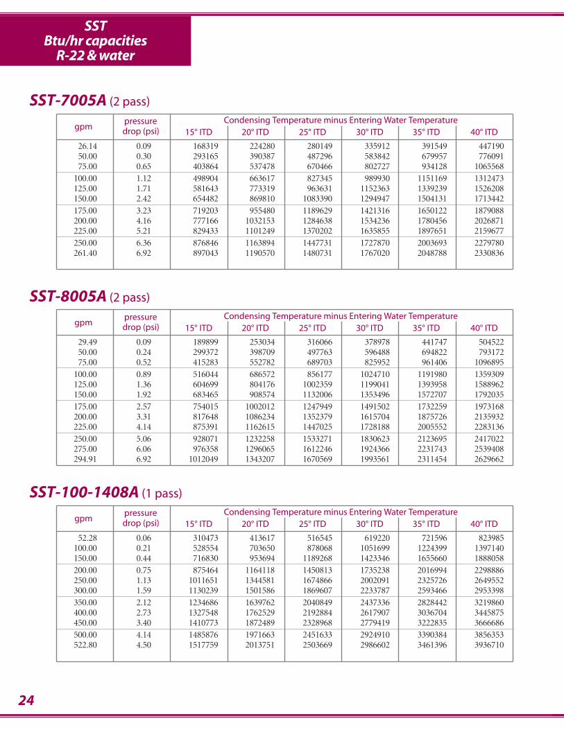
SST-7005A (2 pass)
pressure Condensing Temperature minus Entering Water Temperaturegpm drop (psi) 15° ITD 20° ITD 25° ITD 30° ITD 35° ITD 40° ITD
52.28 0.06 310473 413617 516545 619220 721596 823985100.00 0.21 528554 703650 878068 1051699 1224399 1397140150.00 0.44 716830 953694 1189268 1423346 1655660 1888058200.00 0.75 875464 1164118 1450813 1735238 2016994 2298886250.00 1.13 1011651 1344581 1674866 2002091 2325726 2649552300.00 1.59 1130239 1501586 1869607 2233787 2593466 2953398350.00 2.12 1234686 1639762 2040849 2437336 2828442 3219860400.00 2.73 1327548 1762529 2192884 2617907 3036704 3445875450.00 3.40 1410773 1872489 2328968 2779419 3222835 3666686500.00 4.14 1485876 1971663 2451633 2924910 3390384 3856353522.80 4.50 1517759 2013751 2503669 2986602 3461396 3936710
SST-100-1408A (1 pass)
pressure Condensing Temperature minus Entering Water Temperaturegpm drop (psi) 15° ITD 20° ITD 25° ITD 30° ITD 35° ITD 40° ITD
29.49 0.09 189899 253034 316066 378978 441747 50452250.00 0.24 299372 398709 497763 596488 694822 79317275.00 0.52 415283 552782 689703 825952 961406 1096895
100.00 0.89 516044 686572 856177 1024710 1191980 1359309125.00 1.36 604699 804176 1002359 1199041 1393958 1588962150.00 1.92 683465 908574 1132006 1353496 1572707 1792035175.00 2.57 754015 1002012 1247949 1491502 1732259 1973168200.00 3.31 817648 1086234 1352379 1615704 1875726 2135932225.00 4.14 875391 1162615 1447025 1728188 2005552 2283136250.00 5.06 928071 1232258 1533271 1830623 2123695 2417022275.00 6.06 976358 1296065 1612246 1924366 2231743 2539408294.91 6.92 1012049 1343207 1670569 1993561 2311454 2629662
SST-8005A (2 pass)
SSTBtu/hr capacities
R-22 & water
25
pressure Condensing Temperature minus Entering Water Temperaturegpm drop (psi) 15° ITD 20° ITD 25° ITD 30° ITD 35° ITD 40° ITD
100.00 0.14 551564 734478 916805 1098449 1279286 1460157200.00 0.51 934071 1242541 1549223 1853828 2155990 2458270300.00 1.08 1225444 1628822 2029050 2425633 2817938 3210472400.00 1.85 1457296 1935743 2409684 2878427 3341083 3804088500.00 2.81 1647315 2186988 2720871 3248085 3767507 4287398643.44 4.50 1868011 2478464 3081440 3675819 4260180 4845182
SST-120-1408A (1 pass)
pressure Condensing Temperature minus Entering Water Temperaturegpm drop (psi) 15° ITD 20° ITD 25° ITD 30° ITD 35° ITD 40° ITD
100.00 0.19 646968 861902 1076383 1290337 1503665 1717015200.00 0.68 1151125 1532180 1911585 2289067 2664278 3039587300.00 1.43 1557252 2071179 2581909 3088928 3591578 4094437400.00 2.44 1892316 2515224 3133272 3745694 4351511 4957672500.00 3.69 2174084 2888194 3595780 4295831 4987053 5678766643.44 5.90 2508821 3330756 4143883 4946859 5737973 6529794
SST-200-1412A (1 pass)
pressure Condensing Temperature minus Entering Water Temperaturegpm drop (psi) 15° ITD 20° ITD 25° ITD 30° ITD 35° ITD 40° ITD
56.30 0.07 362534 483064 603399 723503 843336 963178100.00 0.21 594054 791129 987617 1183419 1378410 1573434150.00 0.45 821907 1093959 1364817 1634287 1902120 2170024200.00 0.76 1019048 1355679 1690414 2022951 2352897 2682965250.00 1.15 1191807 1584806 1975161 2362453 2746141 3130009300.00 1.61 1344759 1787490 2226811 2662183 3092921 3523901350.00 2.15 1481338 1968342 2451168 2929163 3401497 3874139400.00 2.75 1604192 2130910 2652695 3168782 3678200 4187996450.00 3.43 1715406 2277985 2834895 3385264 3927984 4471152500.00 4.17 1816645 2411796 3000564 3581975 4154792 4728125550.00 4.98 1909261 2534148 3151965 3761639 4361808 4962562563.01 5.20 1932093 2564304 3189268 3805889 4412775 5020263
SST-150-1410A (1 pass)
SSTBtu/hr capacities
R-22 & water
26
TAG
BL
RA
F
DE
E
P refrig. inlet
refrig. outlets QT fluid in
T fluid outS safety
MSE100 through MSE5005
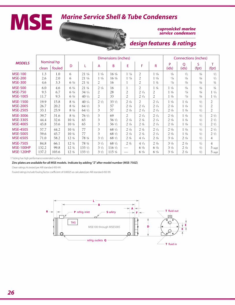
Dimensions (inches) Connections (inches)MODELS Nominal hp
P Q S Tclean fouled
D L A B E F R(ids) (ids) (fpt) (fpt)
MSE-100 1.3 1.0 6 21.5/8 1.5/8 16.3/8 1.7/8 2. 1.5/8 .5/8 .1/2 .3/8 .1/2
MSE-200 2.6 2.0 6 21.5/8 1.5/8 16.3/8 1.7/8 2. 1.5/8 .7/8 .5/8 .3/8 .1/2
MSE-300 4.6 3.3 6.5/8 21.3/4 2 16 1 2. 1.3/4 .7/8 .5/8 .3/8 .3/4
MSE-500 6.0 4.6 6.5/8 21.3/4 2.1/8 16 1 2. 1.3/4 1.1/8 .5/8 .3/8 .3/4MSE-750 9.5 6.7 6.5/8 34.1/4 2 28 2 2.1/4 2. 1.3/8 .7/8 .3/8 1.1/4
MSE-1005 11.7 9.5 6.5/8 40.1/4 2 33 2 2.1/4 2. 1.3/8 .7/8 .3/8 1.1/4
MSE-1500 19.9 15.8 8.5/8 40.1/4 2.1/2 33.1/2 2.1/8 2. 2.1/4 1.5/8 1.1/8 .1/2 2MSE-2005 26.7 20.2 8.5/8 64.1/2 3 57 2.1/8 2.1/4 2.1/4 2.1/8 1.1/8 .1/2 2 MSE-2505 33.1 25.9 8.5/8 64.1/2 3 57 2.1/8 2.1/4 2.1/4 2.1/8 1.3/8 .1/2 2
MSE-3006 39.7 31.6 8.5/8 76.1/2 3 69 2 2.1/4 2.1/4 2.5/8 1.3/8 .1/2 2.1/2
MSE-3305 44.4 32.6 10.3/4 65. 3 56.1/2 2.1/8 2.3/4 2.1/4 2.5/8 1.3/8 .1/2 2.1/2
MSE-4005 45.8 33.6 10.3/4 65. 3 56.1/2 2.1/8 2.3/4 2.1/4 2.5/8 1.5/8 .1/2 2.1/2
MSE-4505 57.7 44.2 10.3/4 77. 3 68.1/2 2.1/8 2.3/4 2.1/4 2.5/8 1.5/8 .1/2 2.1/2
MSE-5005 59.6 45.7 10.3/4 77. 3 68.1/2 2.1/8 2.3/4 2.1/4 2.5/8 1.5/8 .1/2 2.1/2
MSE-6505 71.0 58.2 12.3/4 78.3/4 3.1/2 68.1/2 2.3/4 4.1/4 2.3/8 3.1/8 2.1/8 .1/2 4
MSE-7505 84.8 66.1 12.3/4 78.3/4 3.1/2 68.1/2 2.3/4 4.1/4 2.3/8 3.1/8 2.1/8 .1/2 4MSE-100HP 132.2 99.8 12.3/4 133.1/2 3.1/2 116.1/2 — 6.5/8 6.5/8 3.1/8 2.1/8 .1/2 5.mpt
MSE-120HP 137.2 103.6 12.3/4 133.1/2 3.1/2 115.3/4 — 6.5/8 6.5/8 3.5/8 2.1/8 .1/2 5.mpt
Horizontal Super Efficient Water Cooled CondensersMarine Service Shell & Tube CondensersMSE
† Tubing has high performance extended surface
Zinc plates are available for all MSE models. Indicate by adding “Z” after model number (MSE-750Z)
Clean ratings: As tested per ARI standard 450-99.
Fouled ratings: Include fouling factor coefficient of 0.00025 as calculated per ARI standard 450-99.
design features & ratings
cupronickel marineservice condensers
27
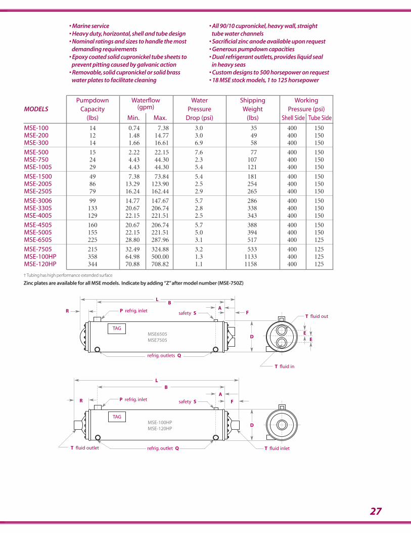
Pumpdown Waterflow Water Shipping Working MODELS Capacity (gpm) Pressure Weight Pressure (psi)
(lbs) Min. Max. Drop (psi) (lbs) Shell Side Tube Side
MSE-100 14 0.74 7.38 3.0 35 400 150MSE-200 12 1.48 14.77 3.0 49 400 150MSE-300 14 1.66 16.61 6.9 58 400 150
MSE-500 15 2.22 22.15 7.6 77 400 150MSE-750 24 4.43 44.30 2.3 107 400 150MSE-1005 29 4.43 44.30 5.4 121 400 150
MSE-1500 49 7.38 73.84 5.4 181 400 150MSE-2005 86 13.29 123.90 2.5 254 400 150MSE-2505 79 16.24 162.44 2.9 265 400 150
MSE-3006 99 14.77 147.67 5.7 286 400 150MSE-3305 133 20.67 206.74 2.8 338 400 150MSE-4005 129 22.15 221.51 2.5 343 400 150
MSE-4505 160 20.67 206.74 5.7 388 400 150MSE-5005 155 22.15 221.51 5.0 394 400 150MSE-6505 225 28.80 287.96 3.1 517 400 125
MSE-7505 215 32.49 324.88 3.2 533 400 125MSE-100HP 358 64.98 500.00 1.3 1133 400 125MSE-120HP 344 70.88 708.82 1.1 1158 400 125
• Marine service• Heavy duty, horizontal, shell and tube design• Nominal ratings and sizes to handle the most
demanding requirements• Epoxy coated solid cupronickel tube sheets to
prevent pitting caused by galvanic action• Removable, solid cupronickel or solid brass
water plates to facilitate cleaning
• All 90/10 cupronickel, heavy wall, straight tube water channels
• Sacrificial zinc anode available upon request• Generous pumpdown capacities• Dual refrigerant outlets, provides liquid seal
in heavy seas• Custom designs to 500 horsepower on request• 18 MSE stock models, 1 to 125 horsepower
TAG
BL
R A
F
D EE
safety SP refrig. inlet
refrig. outlets Q
TAG
BL
RA
F
D
safety SP refrig. inlet
T fluid inletT fluid outlet
MSE-100HPMSE-120HP
T fluid in
T fluid out
MSE6505MSE7505
refrig. outlet Q
† Tubing has high performance extended surface
Zinc plates are available for all MSE models. Indicate by adding “Z” after model number (MSE-750Z)

28
pressure Condensing Temperature minus Entering Water Temperaturegpm drop (psi) 15° ITD 20° ITD 25° ITD 30° ITD 40° ITD 50° ITD
1.00 0.30 5256 6994 8722 10439 13849 172282.00 1.28 8651 11492 14307 17091 22590 280003.00 3.02 11099 14727 18310 21843 28794 355994.00 5.55 12967 17190 21352 25445 33474 413045.00 8.91 14448 19140 23756 28285 37151 457736.00 13.14 15656 20728 25711 30592 40130 49383
MSE-100
pressure Condensing Temperature minus Entering Water Temperaturegpm drop (psi) 15° ITD 20° ITD 25° ITD 30° ITD 40° ITD 50° ITD
2.00 0.30 12152 16180 20193 24189 32142 400444.00 1.16 21047 27984 34872 41704 55236 686006.00 2.55 27886 37036 46097 55054 72734 901108.00 4.46 33329 44227 54993 65610 86503 106962
10.00 6.89 37778 50093 62239 74190 97656 12056412.00 9.83 41490 54982 68269 81320 106895 13180114.00 13.28 44640 59127 73375 87350 114689 141258
MSE-300
pressure Condensing Temperature minus Entering Water Temperaturegpm drop (psi) 15° ITD 20° ITD 25° ITD 30° ITD 40° ITD 50° ITD
2.00 0.30 10512 13987 17443 20878 27699 344564.00 1.28 17302 22984 28613 34181 45180 560006.00 3.02 22198 29453 36621 43686 57588 711978.00 5.55 25934 34380 42704 50889 66947 82609
10.00 8.91 28896 38279 47512 56571 74303 9154712.00 13.14 31312 41455 51421 61185 80259 98765
MSE-200
MSEBtu/hr capacities
R-22 & water
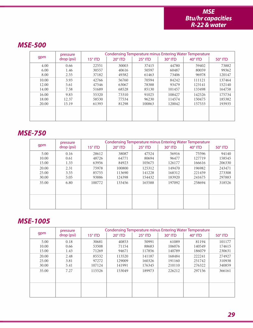
29
pressure Condensing Temperature minus Entering Water Temperaturegpm drop (psi) 15° ITD 20° ITD 25° ITD 30° ITD 40° ITD 50° ITD
4.00 0.66 22551 30003 37415 44780 59402 738826.00 1.46 30557 40616 50597 60487 80059 993628.00 2.55 37182 49382 61463 73406 96978 120147
10.00 3.93 42766 56760 70594 84242 111121 13746412.00 5.61 47546 63067 78388 93479 123141 15214014.00 7.58 51689 68528 85130 101457 133498 16475816.00 9.83 55320 73310 91025 108427 142526 17573418.00 12.37 58530 77534 96230 114574 150475 18538220.00 15.19 61393 81298 100863 120042 157533 193935
MSE-500
pressure Condensing Temperature minus Entering Water Temperaturegpm drop (psi) 15° ITD 20° ITD 25° ITD 30° ITD 40° ITD 50° ITD
5.00 0.18 30681 40853 50991 61089 81194 10117710.00 0.66 53508 71154 88683 106076 140549 17461515.00 1.43 71269 94671 117856 140789 186079 23063120.00 2.48 85532 113520 141187 168484 222241 27492725.00 3.81 97272 129009 160326 191160 251742 31093830.00 5.41 107124 141991 176345 210110 276322 34085935.00 7.27 115526 153049 189973 226212 297156 366161
MSE-1005
pressure Condensing Temperature minus Entering Water Temperaturegpm drop (psi) 15° ITD 20° ITD 25° ITD 30° ITD 40° ITD 50° ITD
5.00 0.16 28612 38087 47524 56916 75596 9414010.00 0.61 48726 64771 80694 96477 127719 15854515.00 1.33 63956 84923 105675 126177 166616 20633020.00 2.31 75978 100800 125312 149470 196982 24347125.00 3.55 85755 113690 141228 168312 221459 27330830.00 5.05 93886 124398 154432 183920 241675 29788335.00 6.80 100772 133456 165588 197092 258694 318526
MSE-750
MSEBtu/hr capacities
R-22 & water
30
MSEBtu/hr capacities
R-22 & water
pressure Condensing Temperature minus Entering Water Temperaturegpm drop (psi) 15° ITD 20° ITD 25° ITD 30° ITD 40° ITD 50° ITD
10.00 0.25 59597 79334 98991 118554 157464 19609020.00 0.94 101857 135387 168657 201623 266863 33120830.00 2.03 133624 177407 220723 263500 347833 43060040.00 3.52 158486 210223 261293 311596 410468 50713550.00 5.41 178540 236652 293908 350184 460536 56809860.00 7.67 195101 258447 320767 381914 501584 617938
MSE-1500
pressure Condensing Temperature minus Entering Water Temperaturegpm drop (psi) 15° ITD 20° ITD 25° ITD 30° ITD 40° ITD 50° ITD
20.00 0.21 112607 149877 186983 223896 297279 37008540.00 0.78 189915 252397 314372 375759 497190 61688860.00 1.68 247513 328574 408749 487903 643893 79691980.00 2.91 292438 387870 482049 574790 757029 935140
100.00 4.46 328632 435565 540907 644426 847375 1045141120.00 6.31 358515 474893 589372 701679 921440 1135072140.00 8.47 383667 507960 630074 749701 983416 1210156
MSE-2505
pressure Condensing Temperature minus Entering Water Temperaturegpm drop (psi) 15° ITD 20° ITD 25° ITD 30° ITD 40° ITD 50° ITD
20.00 0.30 108039 143745 179260 214554 284629 25589640.00 1.14 177895 236296 294144 351354 464318 35404160.00 2.47 227935 302399 375937 448408 590945 57541580.00 4.27 265875 352412 437678 521485 685829 730412
100.00 6.54 295789 391783 486196 578802 759978 846023
MSE-2005
31
MSEBtu/hr capacities
R-22 & water
pressure Condensing Temperature minus Entering Water Temperaturegpm drop (psi) 15° ITD 20° ITD 25° ITD 30° ITD 40° ITD 50° ITD
20.00 0.27 119194 158668 197981 237108 314927 39218140.00 1.00 203714 270775 337313 403246 533726 66241560.00 2.16 267248 354814 441445 527001 695667 86120080.00 3.73 316972 420447 522587 623191 820937 1014270
100.00 5.70 357080 473303 587816 700368 921073 1136197120.00 8.07 390203 516895 641535 763828 1003168 1235876147.67 11.98 427634 566097 702086 835252 1095307 1347457
MSE-3006
pressure Condensing Temperature minus Entering Water Temperaturegpm drop (psi) 15° ITD 20° ITD 25° ITD 30° ITD 40° ITD 50° ITD
40.00 0.43 206995 275301 343178 410556 544166 67629360.00 0.93 276436 367293 457355 546497 722684 89617180.00 1.61 332895 441949 549829 656355 866335 1072382
100.00 2.47 379891 503999 626562 747347 984908 1217354120.00 3.49 419732 556536 691442 824170 1084731 1339070140.00 4.69 454010 601688 747138 890036 1170111 1442939160.00 6.05 483862 640976 795553 947229 1244097 1532771180.00 7.57 510131 675520 838085 997425 1308916 1611340200.00 9.26 533450 706163 875787 1041884 1366237 1680719220.00 11.11 554309 733558 909468 1081573 1417338 1742490
MSE-4005
pressure Condensing Temperature minus Entering Water Temperaturegpm drop (psi) 15° ITD 20° ITD 25° ITD 30° ITD 40° ITD 50° ITD
40.00 0.49 203368 270435 337055 403156 534166 66363560.00 1.06 270184 358919 446835 533807 705597 87461980.00 1.84 324026 430085 534949 638434 842283 1042140
100.00 2.81 368524 488812 607539 724472 954291 1178959120.00 3.98 406027 538245 668557 796684 1048031 1293152140.00 5.35 438135 580522 720682 858294 1127816 1390122160.00 6.90 465983 617154 765804 911569 1196666 1473641180.00 8.64 490398 649248 805300 958158 1256770 1546429200.00 10.57 512004 677628 840201 999294 1309756 1610504
MSE-3305
32
MSEBtu/hr capacities
R-22 & water
pressure Condensing Temperature minus Entering Water Temperaturegpm drop (psi) 15° ITD 20° ITD 25° ITD 30° ITD 40° ITD 50° ITD
40.00 0.53 222101 295452 368379 440814 584547 72680660.00 1.14 299407 397895 495572 592308 783629 97217780.00 1.97 362801 481745 599466 715774 945177 1170461
100.00 3.01 415852 551807 686130 818575 1079214 1334425120.00 4.25 460986 611337 759664 905667 1192437 1472544140.00 5.70 499913 662624 822942 980515 1289502 1590675160.00 7.35 533874 707327 878040 1045616 1373750 1693004180.00 9.20 563795 746681 926502 1102821 1447644 1782602200.00 11.25 590381 781622 969498 1153531 1513045 1861782
MSE-4505
pressure Condensing Temperature minus Entering Water Temperaturegpm drop (psi) 15° ITD 20° ITD 25° ITD 30° ITD 40° ITD 50° ITD
50.00 0.29 284244 378205 471676 564576 749061 93183675.00 0.63 386253 513455 639699 764832 1012550 1256977
100.00 1.07 471085 625731 778909 930389 1229482 1523605125.00 1.63 542890 720624 896373 1069836 1411576 1746680150.00 2.30 604559 802018 996991 1189104 1566873 1936406175.00 3.08 658171 872703 1084268 1292426 1701077 2099983200.00 3.96 705264 934735 1160784 1382908 1818356 2242646225.00 4.94 747002 989668 1228482 1462885 1921830 2368296250.00 6.03 784279 1038696 1288856 1534149 2013880 2479904275.00 7.22 817801 1082755 1343073 1598098 2096363 2579776
MSE-6505
pressure Condensing Temperature minus Entering Water Temperaturegpm drop (psi) 15° ITD 20° ITD 25° ITD 30° ITD 40° ITD 50° ITD
40.00 0.46 225512 300034 374152 447801 594016 73882460.00 1.00 305571 406162 505970 604869 800588 99362380.00 1.73 371817 493819 614628 734058 969780 1201472
100.00 2.64 427660 567600 705935 842422 1111207 1374637120.00 3.73 475457 630670 783880 934787 1231405 1521404140.00 5.00 516891 685284 851295 1014571 1334977 1647576160.00 6.45 553197 733095 910252 1084268 1425264 1757343180.00 8.07 585304 775342 962302 1145741 1504752 1853815200.00 9.86 613927 812977 1008634 1200415 1575333 1939346220.00 11.82 639622 846741 1050173 1249395 1638473 2015757
MSE-5005
33
MSEBtu/hr capacities
R-22 & water
pressure Condensing Temperature minus Entering Water Temperaturegpm drop (psi) 15° ITD 20° ITD 25° ITD 30° ITD 40° ITD 50° ITD
50.00 0.23 291168 387507 483401 578775 768321 956302100.00 0.86 490040 651131 810830 968917 1281408 1589157150.00 1.84 635743 843711 1049260 1252020 1651225 2042360200.00 3.15 747663 991324 1231588 1467955 1931921 2384744250.00 4.80 836666 1108516 1376084 1638749 2153110 2653591
MSE-7505
pressure Condensing Temperature minus Entering Water Temperaturegpm drop (psi) 15° ITD 20° ITD 25° ITD 30° ITD 40° ITD 50° ITD
100.00 0.14 547789 728918 909135 1088292 1444158 1796845200.00 0.51 909170 1207855 1503845 1796719 2375363 2944872300.00 1.09 1171407 1554406 1932828 2305980 3040371 3759553400.00 1.85 1372071 1819034 2259654 2692998 3543340 4372926500.00 2.81 1531392 2028801 2518274 2998663 3939141 4853944600.00 3.94 1661415 2199775 2728773 3247078 4259886 5242689
MSE-120HP
pressure Condensing Temperature minus Entering Water Temperaturegpm drop (psi) 15° ITD 20° ITD 25° ITD 30° ITD 40° ITD 50° ITD
100.00 0.17 537497 715103 891741 1067252 1415682 1760744200.00 0.60 882542 1172197 1459065 1742714 2302684 2853247300.00 1.28 1128583 1497177 1861120 2219714 2924830 3614563400.00 2.18 1314530 1742261 2163630 2577705 3389501 4180566500.00 3.30 1460790 1934727 2400777 2857809 3751754 4620297
MSE-100HP
34
Pumpdown Waterflow Water Shipping Working MODELS Capacity (gpm) Pressure Weight Pressure (psi)
(lbs) Min. Max. Drop (psi) (lbs) Shell Side Tube Side
HP-10 51 4 40 6.3 125 350 300HP-15 68 8 80 2.6 145 350 300HP-20 86 8 80 4.0 205 350 300
HP-30A 160 12 121 4.4 375 350 300HP-40A 148 16 161 4.4 435 350 300HP-50A 217 20 201 4.4 555 350 300
HP-60A 213 21 214 5.5 575 350 300HP-80A 243 29 295 5.2 755 350 300
Dimensions (inches) Connections (inches)MODELS Nominal hp
P Q S Tclean fouled
D L A B E F R(ids) (ids) (fpt) (fpt)
HP-10 13 11 8.⅝ 40.⅝ 3.¼ 32.⅝ 1.⅜ 2.½ 1.⅜ 1.⅜ .⅞ .½ 1.½•HP-15 16.½ 14.½ 8.⅝ 52.⅝ 3.¼ 44.⅝ 1.⅝ 2.½ 1.⅜ 1.⅜ .⅞ .½ 1.½HP-20 23 20 8.⅝ 64.⅝ 3.¼ 56.⅝ 1.⅝ 2.½ 1.⅜ 1.⅜ .⅞ .½ 1.½
HP-30A 39 33 10.¾ 77 3.½ 68.⅝ 2.⅜ 2.½ 2.⅜ 2.⅝ 1.⅝ .½ 2HP-40A 51 44 10.¾ 77 3.½ 68.⅝ 2.⅜ 2.½ 2.⅜ 2.⅝ 1.⅝ .½ 2HP-50A 64 55 12.¾ 77.⅝ 3.½ 68.⅝ 2.⅝ 3.⅛ 2.⅜ 2.⅝ 1.⅝ .½ 3
HP-60A 74 63 12.¾ 77.⅝ 3.½ 68.⅝ 2.⅝ 3.⅛ 2.⅜ 2.⅝ 1.⅝ .½ 3HP-80A 100 85 14 77.⅜ 3.½ 68.⅝ 2.⅞ 2.¾ 2.½ 3.⅛ 2.⅛ .½ 4
Horizontal Super Efficient Water Cooled CondensersHigh Pressure/High Pumpdown Condensers
Clean ratings: As tested per ARI Standard 450-99Fouled ratings: Include a additive fouling coefficient of 0.00025 as calculated per ARI Standard 450-99
† Tubing has high performance extended surface
• Centerline on fittings is located 13⁄8" to the left of centerline on vessel
HP• Ideal for high-rise building applications• High Performance, horizontal, shell and tube design• High Pressure, specially designed removable water plates and
gaskets provide for a 300 psi waterside working pressure• High Pumpdown, for containment of greater refrigerant charges• New high tech enhanced heat transfer tube surface• Epoxy coated tube sheets and water plates to prevent pitting
caused by galvanic action• 8 HP models, 10 thru 80 horsepower
TAG
BL
RA
F
D
E
E
P refrig. inlet
refrig. outlet Q
T fluid out
T fluid in
S safety
400 psi.shell side on request
design features & ratings
shell & tube condensersHigh pumpdown, high water pressure applications
Consult www.stanref.com or customer service for performance data not shown.
35
Pumpdown Waterflow Water Shipping Working MODELS Capacity (gpm) Pressure Weight Pressure (psi)
(lbs) Min. Max. Drop (psi) (lbs) Shell Side Tube Side
CA-050 23 2.2 32.8 7.9 115 350 150CA-075 44 2.9 43.7 9.2 175 350 150CA-100 40 3.6 54.7 10.0 190 350 150
CA-150 63 5.5 82.0 10.0 265 350 150CA-200 83 7.3 109.3 6.9 305 350 150CA-300 131 10.9 164.0 6.9 450 350 150
Horizontal Super Efficient Water Cooled CondensersStainless Steel/Corrosive Fluid Condensers
Clean ratings: As tested per ARI Standard 450-87Fouled ratings: Include a additive fouling coefficient of 0.00025 as calculated per ARI Standard 450-87 (.0005 total)
† Tubing has high performance extended surface
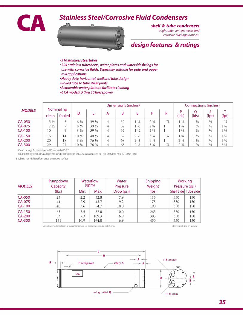
CA• 316 stainless steel tubes • 304 stainless tubesheets, water plates and waterside fittings for
use with corrosive fluids. Especially suitable for pulp and papermill applications
• Heavy duty, horizontal, shell and tube design• Rolled tube to tube sheet joints• Removable water plates to facilitate cleaning• 6 CA models, 5 thru 30 horsepower
400 psi.shell side on request
TAG
BL
RA
F
DE
E
safety SP refrig. inlet
refrig.outlet Q
T fluid out
T fluid in
Dimensions (inches) Connections (inches)MODELS Nominal hp
P Q S Tclean fouled
D L A B E F R(ids) (ids) (fpt) (fpt)
CA-050 5.½ 5 6.⅝ 39.¼ 4 32. 1.⅛ 2.⅜ .⅞ 1.⅛ .⅞ .½ .¾CA-075 7.½ 7 8.⅝ 39.⅝ 4 32. 1.½ 2.⅝ 1. 1.⅜ .⅞ .½ 1.¼CA-100 10 9 8.⅝ 39.⅝ 4 32. 1.½ 2.⅝ 1. 1.⅜ .⅞ .½ 1.¼
CA-150 15 14 10.¾ 40.⅛ 4 32. 2.½ 3.⅛ .⅞ 1.⅝ 1.⅛ .½ 1.½CA-200 20 18 8.⅝ 76.⅛ 4 68. 2.⅛ 3.⅛ 1. 2.⅛ 1.⅛ .½ 1.½CA-300 29 27 10.¾ 76.¾ 4 68. 2.½ 3.¾ .⅞ 2.⅝ 1.⅜ .½ 2.½
design features & ratings
shell & tube condensersHigh sulfur content water and
corrosive fluid applications.
Consult www.stanref.com or customer service for performance data not shown.
Dimensions (inches) Connections (inches)MODELS Nominal hp
P Q S W Tclean fouled
D H A B C(ids) (ids) (fpt) (fpt) (fpt)
VSE-1⁄2 – .½ 6 5 1.¼ 3.¼ 1.½ .½ .½ .⅜ – ½VSE-1 – 1 6. 5.½ 1.½ 3.⅝ 1.½ .⅝ .½ .⅜ – ½VSE-11⁄2 – 1.½ 8.⅝ 6.⅜ 2 4.⅜ 2 .⅝ .½ .⅜ – ¾
VSE-2 – 2 9.¾ 7.¼ 2.⅛ 4.¾ 2 .⅝ .⅝ .½ – ¾VSE-3 3.½ 3 6.⅝ 13. 1.⅝ 1.⅝ 11.⅛ .⅞ .⅝ .⅜ .¾ –VSE-5 6 5 8.⅝ 13.½ 1.¾ 4.⅝ 11.½ 1.⅛ .⅝ .½ 1. –
VSE-7 9 8 10.¾ 16.¼ 2.⅝ 6.½ 13.⅜ 1.⅜ .⅞ .½ 1.¼ –VSE-10 13 11 16 18.¾ 4.½ 9 13.¾ 1.⅜ .⅞ .½ 1.¼ –VSE-10T 12 10 8.⅝ 19.½ 1.¾ 4.⅝ 17.½ 1.⅜ .⅞ .½ 1. 1.½
VSE-15T 19 16 10.¾ 22.¼ 2.⅝ 6.½ 19.⅜ 1.⅝ 1.⅛ .½ 1.¼ 1.½VSE-20T 26 22 16 23.¼ 4.½ 9 18.¼ 2.⅛ 1.⅜ .½ 1.½ 2
36
Vertical Shell & Coil Condensers
Clean ratings: As tested per ARI Standard 450-99Fouled ratings: Include a additive fouling coefficient of 0.00025 as calculated per ARI Standard 450-99
† Tubing has high performance extended surface
Consult www.stanref.com or customer service for performance data not shown.
VSE
refrig.outlet Q
refrig. inlet P
T fluid outletfluid inlet T
S safety(3) legs equally
spaced120° apart
A
B
H
D
CC
VSE-1/2 through VSE-2
design features & ratings
vertical super efficient condenserCompact design, generous pumpdown.
Small package applications.
37
• Sealed construction, vertical, shell and coil design• Greatest refrigerant pumpdown capacity in a upright compact package• Special "T" models have auxiliary connection for tower applications or to reduce
pressure drops• Size and efficiency make it ideal for use in small package units; ice makers, vending
machines, self contained refrigeration cases• 11 VSE models, 1⁄2 thru 20 horsepower
safety S
Prefrig. inlet
W fluidoutlet
Q refrig. outlet
T fluidoutlet
W fluid inlet
3 legs equallyspaced 120° apart
D
A
B
C
H
400 psi.shell side on request
Pumpdown Waterflow Water Shipping Working MODELS Capacity (gpm) Pressure Weight Pressure (psi)
(lbs) Min. Max. Drop (psi) (lbs) Shell Side Tube Side
VSE-1⁄2 3 0.4 3.7 0.6 10 350 250VSE-1 3.5 0.4 3.7 2.7 12 350 250VSE-11⁄2 9 0.6 5.9 3.4 28 350 250
VSE-2 11 0.6 5.9 7.0 29 350 250VSE-3 9 1.2 12 3.3 26 350 250VSE-5 15 1.8 18 4.5 45 350 250
VSE-7 29 2.4 24 5.6 83 350 250VSE-10 80 3.0 30 7.6 146 350 250VSE-10T 20 3.6 36 3.9 69 350 250VSE-15T 36 4.7 47 5.9 130 350 250VSE-20T 96 5.9 60 7.1 204 350 250
VSE-3 through VSE-20T
Dimensions (inches) Connections (inches)MODELS Nominal
P Q Thp D L H A B C
(ids) (ids) (ids)
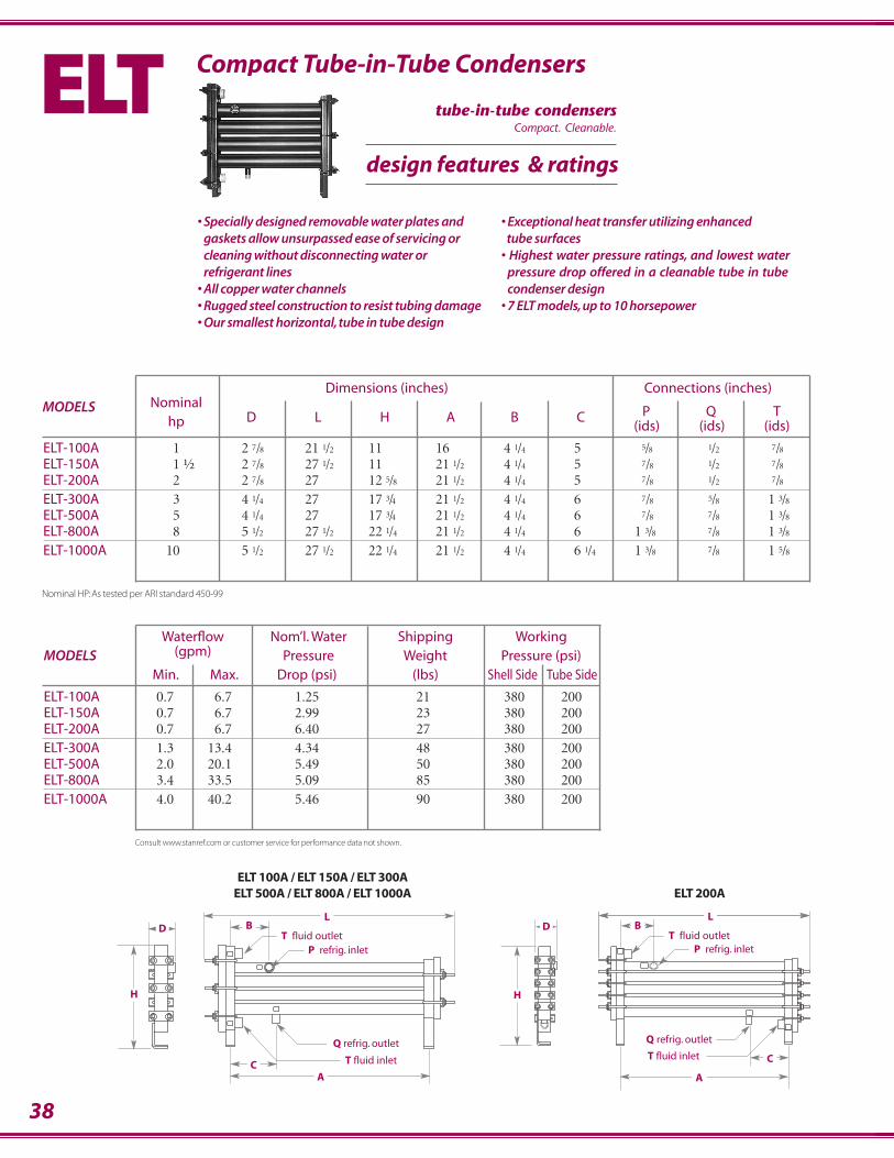
ELT-100A 1 2.7/8 21.1/2 11 16 4.1/4 5 ..5/8 .1/2 .7/8
ELT-150A 1.½ 2.7/8 27.1/2 11 21.1/2 4.1/4 5 ..7/8 .1/2 .7/8
ELT-200A 2 2.7/8 27 12.5/8 21.1/2 4.1/4 5 ..7/8 .1/2 .7/8
ELT-300A 3 4.1/4 27 17.3/4 21.1/2 4.1/4 6 ..7/8 .5/8 1.3/8
ELT-500A 5 4.1/4 27 17.3/4 21.1/2 4.1/4 6 ..7/8 .7/8 1.3/8
ELT-800A 8 5.1/2 27.1/2 22.1/4 21.1/2 4.1/4 6 1.3/8 .7/8 1.3/8
ELT-1000A 10 5.1/2 27.1/2 22.1/4 21.1/2 4.1/4 6.1/4 1.3/8 .7/8 1.5/8
Waterflow Nom’l. Water Shipping Working MODELS (gpm) Pressure Weight Pressure (psi)
Min. Max. Drop (psi) (lbs) Shell Side Tube Side
ELT-100A 0.7 6.7 1.25 21 380 200ELT-150A 0.7 6.7 2.99 23 380 200ELT-200A 0.7 6.7 6.40 27 380 200ELT-300A 1.3 13.4 4.34 48 380 200ELT-500A 2.0 20.1 5.49 50 380 200ELT-800A 3.4 33.5 5.09 85 380 200ELT-1000A 4.0 40.2 5.46 90 380 200
38
Compact Tube-in-Tube CondensersELT• Specially designed removable water plates and
gaskets allow unsurpassed ease of servicing orcleaning without disconnecting water orrefrigerant lines
• All copper water channels• Rugged steel construction to resist tubing damage• Our smallest horizontal, tube in tube design
LB
T fluid outletP refrig. inlet
T fluid inlet
Q refrig. outlet
D
H
AC
• Exceptional heat transfer utilizing enhanced tube surfaces
• Highest water pressure ratings, and lowest waterpressure drop offered in a cleanable tube in tubecondenser design
• 7 ELT models, up to 10 horsepower
D
H
T fluid inlet C
A
Q refrig. outlet
BL
T fluid outletP refrig. inlet
ELT 200AELT 100A / ELT 150A / ELT 300A
ELT 500A / ELT 800A / ELT 1000A
Nominal HP: As tested per ARI standard 450-99
design features & ratings
tube-in-tube condensersCompact. Cleanable.
Consult www.stanref.com or customer service for performance data not shown.
Q refrig.outlet
DL
A
P refrig. inlet
H
2"3⁄8 x 1" long slots
T water outlet
T water inlet
Dimensions (inches) Connections (inches)MODELS Nominal
P Q Thp D L H A
(IDS) (IDS) (FPT)
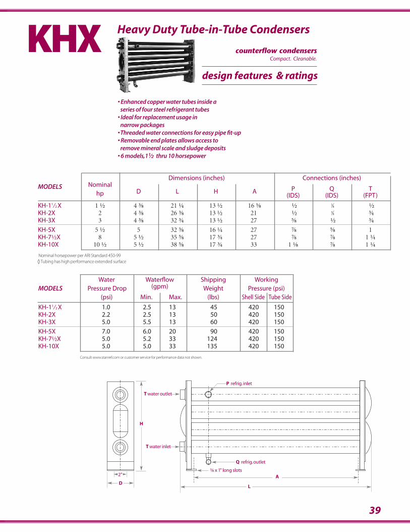
KH-11⁄2 X 1.½ 4.⅜ 21.¼ 13.½ 16.⅝ .½ .3⁄8 .½KH-2X 2 4.⅜ 26.⅜ 13.½ 21. .½ .3⁄8 .¾KH-3X 3 4.⅜ 32.¾ 13.½ 27. .⅝ .½ .¾
KH-5X 5.½ 5 32.⅜ 16.¼ 27. .⅞ .⅝ 1KH-7½X 8 5.½ 35.⅝ 17.¾ 27. .⅞ .⅞ 1.¼KH-10X 10.½ 5.½ 38.⅝ 17.¾ 33. 1.⅛ .⅞ 1.¼
Heavy Duty Tube-in-Tube Condensers
Nominal horsepower per ARI Standard 450-99◊ Tubing has high performance extended surface
KHX• Enhanced copper water tubes inside a
series of four steel refrigerant tubes• Ideal for replacement usage in
narrow packages•Threaded water connections for easy pipe fit-up• Removable end plates allows access to
remove mineral scale and sludge deposits• 6 models,11⁄2 thru 10 horsepower
Water Waterflow Shipping Working MODELS Pressure Drop (gpm) Weight Pressure (psi)
(psi) Min. Max. (lbs) Shell Side Tube Side
KH-11⁄2 X 1.0 2.5 13 45 420 150KH-2X 2.2 2.5 13 50 420 150KH-3X 5.0 5.5 13 60 420 150
KH-5X 7.0 6.0 20 90 420 150KH-7½X 5.0 5.2 33 124 420 150KH-10X 5.0 5.0 33 135 420 150
design features & ratings
counterflow condensersCompact. Cleanable.
Consult www.stanref.com or customer service for performance data not shown.
39
40
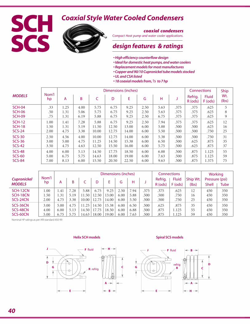
Dimensions (inches) Connections WorkingCupronickel Nom'l Refrig. Fluid Ship Wt. Pressure (psi)MODELS hp A B C D E G H J
R (ods) F (ods) (lbs) Shell Tube
SCH-12CN 1.00 1.41 7.28 5.88 6.75 9.25 2.50 7.94 .375 .375 .625 12 450 350SCH-18CN 1.50 1.31 5.19 11.50 12.50 13.00 6.00 5.88 .500 .500 .750 16 450 350SCS-24CN 2.00 4.75 3.38 10.00 12.75 14.00 6.00 5.50 .500 .500 .750 25 450 350
SCS-36CN 3.00 5.00 4.75 11.25 14.50 15.38 6.00 6.50 .500 .625 .875 35 450 350SCS-48CN 4.00 6.00 5.13 14.50 17.75 18.50 6.00 6.88 .500 .875 1.125 55 450 350SCS-60CN 5.00 6.75 5.75 14.63 18.00 19.00 6.00 7.63 .500 .875 1.125 59 450 350
Dimensions (inches) Connections ShipMODELS Nom'l Refrig. Fluid Wt.
hp A B C D E G H JR (ods) F (ods) (lbs)
SCH-04 .33 1.25 4.00 5.75 6.75 9.25 2.50 5.63 .375 .375 .625 5SCH-06 .50 1.31 5.06 5.75 6.75 9.25 2.50 5.63 .375 .375 .625 8SCH-09 .75 1.31 6.19 5.88 6.75 9.25 2.50 6.75 .375 .375 .625 9
SCH-12 1.00 1.41 7.28 5.88 6.75 9.25 2.50 7.94 .375 .375 .625 12SCH-18 1.50 1.31 5.19 11.50 12.50 13.00 6.00 5.88 .500 .500 .625 16SCS-24 2.00 4.75 3.38 10.00 12.75 14.00 6.00 5.50 .500 .500 .750 25
SCS-30 2.50 4.56 4.00 10.00 12.75 14.00 6.00 5.38 .500 .500 .750 31SCS-36 3.00 5.00 4.75 11.25 14.50 15.38 6.00 6.50 .500 .625 .875 35SCS-42 3.50 4.75 4.63 12.50 15.50 16.00 6.00 5.75 .500 .625 .875 37
SCS-48 4.00 6.00 5.13 14.50 17.75 18.50 6.00 6.88 .500 .875 1.125 55SCS-60 5.00 6.75 5.75 14.63 18.00 19.00 6.00 7.63 .500 .875 1.125 59SCS-84 7.00 8.13 6.00 15.50 20.50 22.50 6.00 9.63 .500 .875 1.375 75
Coaxial Style Water Cooled CondensersSCHSCS
E
R refrig
F fluid
G
J
D
C
A
B
H
E
refrigR
F fluid
G
J
DC
Helix SCH models Spiral SCS models
A
H
B
• High efficiency counterflow design• Ideal for domestic heat pumps, and water coolers• Replacement models for most manufactures• Copper and 90/10 Cupronickel tube models stocked• UL and CSA listed• 18 coaxial models from, 1⁄3 to 7 hp
Nominal HP ratings as per ARI standard 450-99
design features & ratings
coaxial condensersCompact Heat pump and water cooler applications.

41
Photo Copy and Fax to: Standard Sales Department
708 345 3513or via the World Wide Web
www.stanref.com/quote.htm
Condenser Specification Data
specify ids, fpt,flange or flare
Customer Information
Company ______________________________________________________________________________________________
Contact Name ____________________________________ Date ________________________________________________
Phone __________________________________________ Fax ________________________________________________
Performanceinlet fluid temperature ______________________°F
condensing refrigerant temperature __________°F
fouling factor (.00025 ARI standard)__________iF
THR___________________________________Btu/hr
refrigerant ___________________________________
pressure drop______________________________psi
Fluid Circulated■■ water______________________________%
■■ propylene glycol____________________%
■■ sodium chloride (NaCl)______________%
■■ ethylene glycol ____________________%
■■ calcium chloride (CaCl2) ____________%
■■ other______________________________%
If other, specify properties at inlet temperature
specific gravity ________________________
thermal conductivity __________________
viscosity (centipose) ___________________
specific heat___________________________
Constructionsize: width____________________________length ___________________________height____________________________
materials: shell _________________________________________tube______________________________________________
connections: refrigerant inlet ____________________________ refrigerant outlet __________________________________
fluid inlet __________________________________fluid outlet________________________________________
Application
___________________________________________________________________________
___________________________________________________________________________
___________________________________________________________________________
___________________________________________________________________________
___________________________________________________________________________

40
Dimensions (inches) Connections WorkingCupronickel Nom'l Refrig. Fluid Ship Wt. Pressure (psi)MODELS hp A B C D E G H J
R (ods) F (ods) (lbs) Shell Tube
SCH-12CN 1.00 1.41 7.28 5.88 6.75 9.25 2.50 7.94 .375 .375 .625 12 450 350SCH-18CN 1.50 1.31 5.19 11.50 12.50 13.00 6.00 5.88 .500 .500 .750 16 450 350SCS-24CN 2.00 4.75 3.38 10.00 12.75 14.00 6.00 5.50 .500 .500 .750 25 450 350
SCS-36CN 3.00 5.00 4.75 11.25 14.50 15.38 6.00 6.50 .500 .625 .875 35 450 350SCS-48CN 4.00 6.00 5.13 14.50 17.75 18.50 6.00 6.88 .500 .875 1.125 55 450 350SCS-60CN 5.00 6.75 5.75 14.63 18.00 19.00 6.00 7.63 .500 .875 1.125 59 450 350
Dimensions (inches) Connections ShipMODELS Nom'l Refrig. Fluid Wt.
hp A B C D E G H JR (ods) F (ods) (lbs)
SCH-04 .33 1.25 4.00 5.75 6.75 9.25 2.50 5.63 .375 .375 .625 5SCH-06 .50 1.31 5.06 5.75 6.75 9.25 2.50 5.63 .375 .375 .625 8SCH-09 .75 1.31 6.19 5.88 6.75 9.25 2.50 6.75 .375 .375 .625 9
SCH-12 1.00 1.41 7.28 5.88 6.75 9.25 2.50 7.94 .375 .375 .625 12SCH-18 1.50 1.31 5.19 11.50 12.50 13.00 6.00 5.88 .500 .500 .625 16SCS-24 2.00 4.75 3.38 10.00 12.75 14.00 6.00 5.50 .500 .500 .750 25
SCS-30 2.50 4.56 4.00 10.00 12.75 14.00 6.00 5.38 .500 .500 .750 31SCS-36 3.00 5.00 4.75 11.25 14.50 15.38 6.00 6.50 .500 .625 .875 35SCS-42 3.50 4.75 4.63 12.50 15.50 16.00 6.00 5.75 .500 .625 .875 37
SCS-48 4.00 6.00 5.13 14.50 17.75 18.50 6.00 6.88 .500 .875 1.125 55SCS-60 5.00 6.75 5.75 14.63 18.00 19.00 6.00 7.63 .500 .875 1.125 59SCS-84 7.00 8.13 6.00 15.50 20.50 22.50 6.00 9.63 .500 .875 1.375 75
Coaxial Style Water Cooled CondensersSCHSCS
E
R refrig
F fluid
G
J
D
C
A
B
H
E
refrigR
F fluid
G
J
DC
Helix SCH models Spiral SCS models
A
H
B
• High efficiency counterflow design• Ideal for domestic heat pumps, and water coolers• Replacement models for most manufactures• Copper and 90/10 Cupronickel tube models stocked• UL and CSA listed• 18 coaxial models from, 1⁄3 to 7 hp
Nominal HP ratings as per ARI standard 450-99
design features & ratings
coaxial condensersCompact Heat pump and water cooler applications.
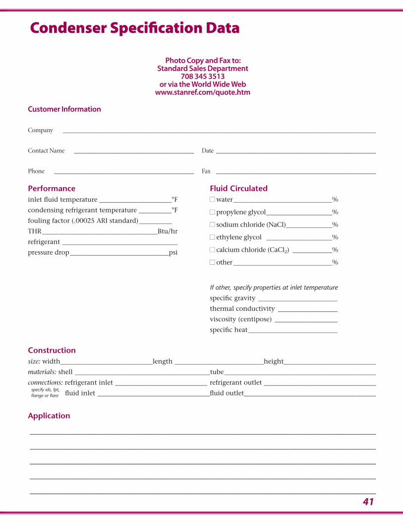
41
Photo Copy and Fax to: Standard Sales Department
708 345 3513or via the World Wide Web
www.stanref.com/quote.htm
Condenser Specification Data
specify ids, fpt,flange or flare
Customer Information
Company ______________________________________________________________________________________________
Contact Name ____________________________________ Date ________________________________________________
Phone __________________________________________ Fax ________________________________________________
Performanceinlet fluid temperature ______________________°F
condensing refrigerant temperature __________°F
fouling factor (.00025 ARI standard)__________iF
THR___________________________________Btu/hr
refrigerant ___________________________________
pressure drop______________________________psi
Fluid Circulated■■ water______________________________%
■■ propylene glycol____________________%
■■ sodium chloride (NaCl)______________%
■■ ethylene glycol ____________________%
■■ calcium chloride (CaCl2) ____________%
■■ other______________________________%
If other, specify properties at inlet temperature
specific gravity ________________________
thermal conductivity __________________
viscosity (centipose) ___________________
specific heat___________________________
Constructionsize: width____________________________length ___________________________height____________________________
materials: shell _________________________________________tube______________________________________________
connections: refrigerant inlet ____________________________ refrigerant outlet __________________________________
fluid inlet __________________________________fluid outlet________________________________________
Application
___________________________________________________________________________
___________________________________________________________________________
___________________________________________________________________________
___________________________________________________________________________
___________________________________________________________________________
42
Fron
t Gas
ket
Rear G
aske
t
Fron
t Endplat
e
Rear E
ndplate
Condenser *SST 150-1410A 120 120 2245 2245*SST 150-2250M 2254 2254 lH1039 lH1039*SST 200-1412A 120 120 4335 4335*SST 200-3000M 2263 2263 lH1048 lH1048*SST 250-3750M 1679 1679 lH1057 lH1057*SST 300-4500M 1688 1688 lH1066 lH1066*SST 350-5250M 1688 1688 lH1066 lH1066*SST 400-6000M 2290 2290 lH1921 lH1921*SST 500-7500M 2290 2290 lH1921 lH1921
*HSE 2 337 346 6412 30*HSE 3 175 184 6717 5026*HSE 5 3718 3170 6229 76*HSE 7 3718 3170 5552 76*HSE 10 3718 3170 5552 76*HSE 15 445 247 5495 21*HSE 20A 2953 2584 5707 4047*HSE 20 1723 1732 2227 21*HSE 25A 2953 2584 5707 4047*HSE 25 1723 1732 2227 21*HSE 30A 1741 2984 5583 4180*HSE 30 1741 1750 2236 4180*HSE 40A 1741 2984 5464 4180*HSE 40 1741 1750 2236 4180*HSE 50A 1741 2984 5464 4180*HSE 50 1741 1750 2236 4180*HSE 60 111 120 247 238*HSE 70 111 120 247 238*HSE 80 111 120 247 238*HSE 100 120 120 2245 2245*HSE 125 120 120 2245 2245*HSE 150 2254 2254 lH1039 lH1039*HSE 200 2263 2263 lH1048 lH1048*HSE 250 1679 1679 lH1057 lH1057*HSE 300 1688 1688 lH1066 lH1066*HSE 350 1688 1688 lH1066 lH1066*HSE 400 2290 2290 lH1921 lH1921*HSE 450 2290 2290 lH1921 lH1921*HSE 500 2290 2290 lH1921 lH1921
▲HP 10 Call Factory▲HP 15 Call Factory▲HP 20 Call Factory▲HP 30 Call Factory▲HP 40 Call Factory▲HP 50 Call Factory▲HP 60 Call Factory▲HP 80 Call Factory
✧CA 050 355 364 2876 2885✧CA 075 238 247 2911 2902✧CA 100 238 247 2911 2902vCA 150 256 265 2920 2948vCA 200 445 247 2894 2902vCA 300 373 265 2939 2948
This chart is to be used for reference purposes only. For replacement parts contact customer service with your condenser model and serial numbers.
* Indicates that model is obsolete and no longer manufactured.
Condenser *SST 75A 3156 346 4304 30*SST 75 337 346 49 30*SST 100A 3163 3149 5040 5026*SST 100 175 184 67 58*SST 150 175 184 67 58*SST 200A 3101 3170 5819 76*SST 200 193 201 85 76*SST 300A 3101 3170 5819 76*SST 300 193 201 85 76*SST 500A 3118 2584 5938 4047*SST 500 210 229 120 21*SST 750A 3118 2584 5938 4047*SST 750 210 229 12 21*SST 755A 3118 2584 5938 4047*SST 755 238 247 12 21*SST 1000A 1723 2953 6605 4047*SST 1000 238 247 12 21*SST 1500A 1723 2953 5576 4047*SST 1501 2977 2584 175 4047*SST 1555A 2591 2984 5907 4180*SST 1555 256 265 193 184*SST 2005A 2591 2984 5914 4180*SST 2005 256 265 148 184*SST 2026A 2591 2984 5914 4180*SST 2026 256 265 148 184*SST 2505A 2591 2984 6205 4180*SST 2505 256 265 148 184*SST 2527A 2591 2984 6205 4180*SST 2527 256 265 148 184*SST 3005A 2591 2984 6205 4180*SST 3005 256 265 148 184*SST 3028A 2591 2984 6205 4180*SST 3028 256 265 148 184*SST 30-460M 166 111 166 157*SST 3505A 2591 2984 6205 4180*SST 35-520M 166 111 201 157*SST 4005A 111 120 210 238*SST 40-610M 111 120 210 238*SST 4505A 111 120 210 238*SST 45-680M 111 120 210 238*SST 5005A 111 120 247 238*SST 50-760M 111 120 210 238*SST 5505A 111 120 247 238*SST 55-850M 111 120 210 238*SST 6005A 111 120 247 238*SST 60-940M 111 120 247 238*SST 7005A 111 120 247 238*SST 70-1060M 111 120 247 238*SST 8005A 111 120 247 238*SST 80-1200M 111 120 247 238*SST 100-1408A 120 120 2245 2245*SST 100-1500M 111 120 247 238*SST 120-1408A 120 120 2245 2245*SST 126-1905M 120 120 3994 3994
GASKE–
GASKE–
ENDPL
––
ENDPL
––
Fron
t Gas
ket
Rear G
aske
t
Fron
t Endplat
e
Rear E
ndplate
GASKE–
GASKE–
ENDPL
––
ENDPL
––
Gasket & Endplates Cross Reference
43
Condenser *MSE 100 3163 3149 6436 300*MSE 200 3163 3149 6436 300*MSE 300 355 364 6386 337*MSE 500 355 364 6386 337*MSE 750 436 364 6281 4461*MSE 1005 436 364 6281 4461*MSE 1500 445 2584 5752 4104*MSE 2005 1723 2953 5752 4104*MSE 2505 1723 2953 5752 4104*MSE 3006 1723 2953 6467 4104*MSE 3305 1741 2984 6481 5114*MSE 4005 1741 2984 6481 5114*MSE 4505 1741 2984 6481 5114*MSE 5005 1741 2984 6481 5114*MSE 6505 111 120 2542 5233*MSE 7505 111 120 2542 5233*MSE 100Hp 4092 4092 120 120*MSE 120Hp 4092 4092 120 120*MS 100 175 184 328 300*MS 150 175 184 328 300*MS 200 355 364 2452 337*MS 300 355 364 2452 337*MS 500 382 229 2461 355*MS 750 382 229 2470 355*MS 755 445 247 3334 355*MS 1000 445 247 3334 355*MS 1500 445 247 2489 355*MS 1501 1723 2953 2489 4104*MS 1555 373 265 2498 373*MS 2005 373 265 2506 373*MS 2026 373 265 2506 373*MS 2505 373 265 2506 373*MS 2527 373 265 2506 373*MS 3005 373 265 2506 373*MS 3028 373 265 2506 373*MS 30 460M 166 111 2524 2597*MS 35 520M 166 111 2524 2597*MS 40 610M 111 120 2533 2605*MS 45 680M 111 120 2533 2605*MS 50 760M 111 120 2533 2605*MS 55 850M 111 120 2533 2605*MS 60 940M 111 120 2533 2605*MS 70 1060M 111 120 2542 2605*MS 80 1200M 111 120 2542 2605*MS 100 1500M 111 120 2542 2605*MS 120 1901M 120 120 4092 4092*MS 125 1900M 111 120 2542 2605
Condenser
*MS 100Z 175 184 328 4454*MS 150Z 175 184 328 4454*MS 200Z 355 364 2452 4461*MS 300Z 355 364 2452 4461*MS 500Z 382 229 2461 4478*MS 750Z 382 229 2470 4478*MS 755Z 445 247 3334 4478*MS 1000Z 445 247 3334 4478*MS 1501Z 1723 2953 2489 4485*MS 1555Z 373 265 2498 4492*MS 2005Z 373 265 2506 4492*MS 2026Z 373 265 2506 4492*MS 2505Z 373 265 2506 4492*MS 2527Z 373 265 2506 4492*MS 3005Z 373 265 2506 4492*MS 3028Z 373 265 2506 4492
ELT 100A 5057 5064 3055 3073ELT 150A 5057 5064 3055 3073ELT 200A 5057 5057 3055 3154ELT 300A 2191 2209 3253 3280ELT 500A 2191 2209 3253 3280ELT 800A 2461 2470 3451 3482ELT 1000A 2461 2470 3451 3482
*ELT 50 2092 2100 3046 3064*ELT 75 2092 2100 3046 3064*ELT 100 2092 2100 3046 3064*ELT 150 2092 2100 3046 3064*ELT 200 2092 2092 3424 3424*ELT 300 2191 2209 3262 3280*ELT 500 2191 2209 3262 3280*ELT 800 2461 2470 3475 3482*ELT 1000 2461 2470 3475 3482
*KH 11/2X 698A 698B 1840 1796*KH 2X 698A 698B 1840 1796*KH 3X 698A 698B 1840 1796*KH 5X 706A 706B 1859 1813*KH 71/2X 724A 724B 1868 1831*KH 10X 724A 724B 1868 1831
(MS Units with Zinc Anode)
Fron
t Gas
ket
Rear G
aske
t
Fron
t Endplat
e
Rear E
ndplate
GASKE–
GASKE–
ENDPL
––
ENDPL
––
Fron
t Gas
ket
Rear G
aske
t
Fron
t Endplat
e
Rear E
ndplate
GASKE–
GASKE–
ENDPL
––
ENDPL
––
This chart is to be used for reference purposes only. For replacement parts contact customer service with your condenser model and serial numbers.
* Indicates that model is obsolete and no longer manufactured.
44
167919 11/16”Dia.
25610 3/4” Dia.9 Studs
11112 3/4” Dia.12 Studs
2478 5/8” Dia.6 Studs
698A
724A
724B
12012 3/4” Dia.12 Studs
1756”Dia.4 Studs
1846”Dia.4 Studs
1936 5/8” Dia.6 Studs
2016 5/8” Dia.6 Studs
2108 5/8” Dia.6 Studs
2298 5/8” Dia.6 Studs
2388 5/8” Dia.6 Studs
3375” Dia.4 Studs
3465” Dia.4 Studs
3556 5/8” Dia.6 Studs
3646 5/8” Dia.6 Studs
37310 3/4” Dia.9 Studs
3828 5/8” Dia.6 Studs
4458 5/8” Dia.6 Studs
17238 5/8” Dia.6 Studs
10666 5/8” Dia.6 Studs
146210 3/4” Dia.12 Studs
14718 5/8” Dia.12 Studs
148012 3/4” Dia.12 Studs
149914” Dia.12 Studs
10576 5/8” Dia.6 Studs
17328 5/8” Dia.6 Studs
174110 3/4” Dia.9 Studs
175010 3/4” Dia.9 Studs
26510 3/4” Dia.9 Studs
168821 11/16”Dia.
tube-in-tube gasketNo picture available
16612 3/4” Dia.12 Studs
706A
706B
4366 5/8” Dia.6 Studs
Condenser Gasket ID
698B
2074
45
2083
31188 5/8” Dia.6 Studs
29538 5/8” Dia.6 Studs
20921 3/16” x 9 1/16”
259110 3/4” Dia.9 Studs
21001 3/16” x 6 5/16”
21912 9/16” x 15 3/4” Dia.
22092 9/16” x 15 3/4” Dia.
225414 11/16”Dia.
226316 11/16”Dia.
229025” Dia.
24613 1/4” x 20 1/4” Dia.
24703 1/4” x 13 1/2” Dia.
25848 5/8” Dia.6 Studs
298410 3/4” Dia.9 Studs
31016 5/8” Dia.6 Studs
31496” Dia.4 Studs
31565” Dia.4 Studs
31636” Dia.4 Studs
31706 5/8” Dia.6 Studs
29778 5/8” Dia.6 Studs
tube-in-tube gasketNo picture available
37186 5/8” Dia.6 Studs
50571 3/16” x 9 1/16”
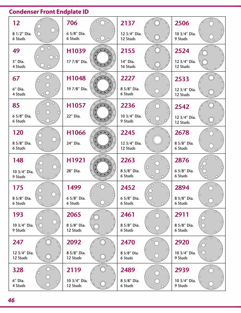
46
12
8 1/2” Dia.6 Studs
H1039
17 7/8” Dia.
706
6 5/8” Dia.6 Studs
2137
12 3/4” Dia.12 Studs
2155
14” Dia.16 Studs
2227
8 5/8” Dia.6 Studs
2236
10 3/4” Dia.9 Studs
2245
12 3/4” Dia.12 Studs
2263
8 5/8” Dia.6 Studs
2920
10 3/4” Dia.9 Studs
49
5” Dia.4 Studs
67
6” Dia.4 Studs
85
6 5/8” Dia.6 Studs
120
8 5/8” Dia.6 Studs
148
10 3/4” Dia.9 Studs
175
8 5/8” Dia.6 Studs
193
10 3/4” Dia.9 Studs
247
12 3/4” Dia.12 Studs
H1057
22” Dia.
H1066
24” Dia.
H1921
28” Dia.
1499
6 5/8” Dia.6 Studs
2065
8 5/8” Dia.12 Studs
2092
8 5/8” Dia.12 Studs
2119
10 3/4” Dia.12 Studs
2678
8 5/8” Dia.6 Studs
2461
8 5/8” Dia.6 Studs
2470
8 5/8” Dia.6 Studs
2489
8 5/8” Dia.6 Studs
2506
10 3/4” Dia.9 Studs
2524
12 3/4” Dia.12 Studs
2452
6 5/8” Dia.6 Studs
2876
6 5/8” Dia.6 Studs
2894
8 5/8” Dia.6 Studs
2911
8 5/8” Dia.6 Studs
2533
12 3/4” Dia.12 Studs
H1048
19 7/8” Dia.
2542
12 3/4” Dia.12 Studs
2939
10 3/4” Dia.9 Studs
Condenser Front Endplate ID
328
6” Dia.4 Studs
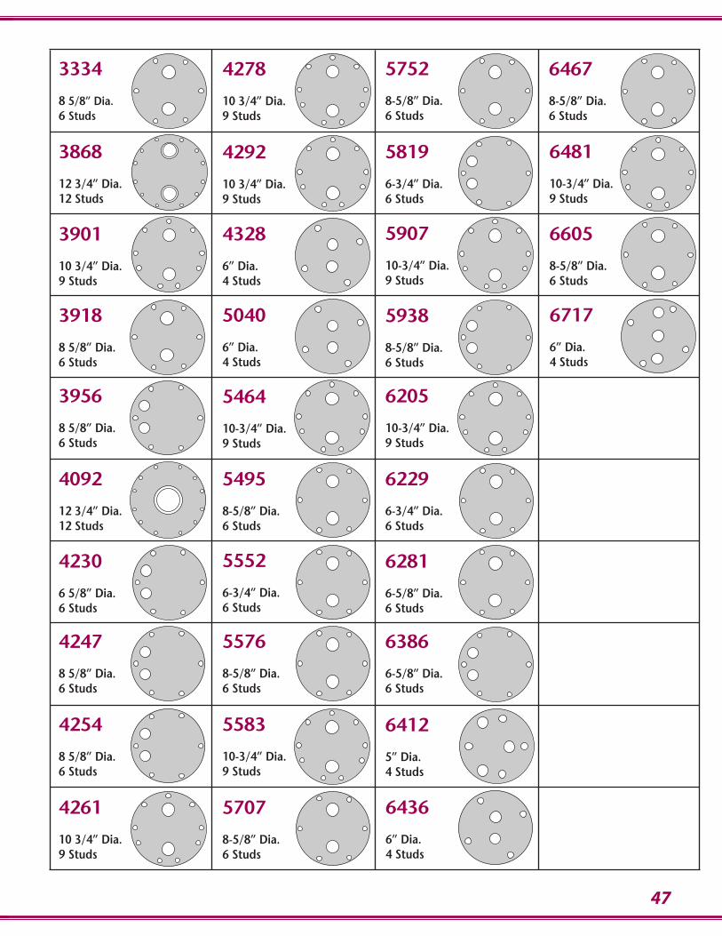
47
4292
10 3/4” Dia.9 Studs
3334
8 5/8” Dia.6 Studs
4278
10 3/4” Dia.9 Studs
5752
8-5/8” Dia.6 Studs
5819
6-3/4” Dia.6 Studs
5907
10-3/4” Dia.9 Studs
5938
8-5/8” Dia.6 Studs
6205
10-3/4” Dia.9 Studs
6229
6-3/4” Dia.6 Studs
3868
12 3/4” Dia.12 Studs
3901
10 3/4” Dia.9 Studs
3918
8 5/8” Dia.6 Studs
3956
8 5/8” Dia.6 Studs
4092
12 3/4” Dia.12 Studs
4230
6 5/8” Dia.6 Studs
4247
8 5/8” Dia.6 Studs
4254
8 5/8” Dia.6 Studs
4261
10 3/4” Dia.9 Studs
5464
10-3/4” Dia.9 Studs
5495
8-5/8” Dia.6 Studs
5552
6-3/4” Dia.6 Studs
5576
8-5/8” Dia.6 Studs
5707
8-5/8” Dia.6 Studs
6386
6-5/8” Dia.6 Studs
6412
5” Dia.4 Studs
6436
6” Dia.4 Studs
6467
8-5/8” Dia.6 Studs
6481
10-3/4” Dia.9 Studs
6281
6-5/8” Dia.6 Studs
6605
8-5/8” Dia.6 Studs
6717
6” Dia.4 Studs
4328
6” Dia.4 Studs
5040
6” Dia.4 Studs
5583
10-3/4” Dia.9 Studs
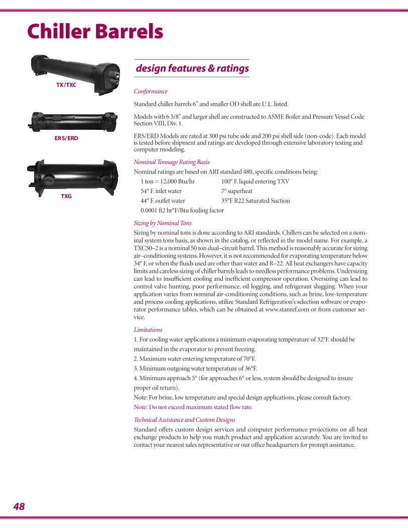
48
Chiller Barrels
design features & ratings
Conformance
Standard chiller barrels 6" and smaller OD shell are U.L. listed.
Models with 6 5/8" and larger shell are constructed to ASME Boiler and Pressure Vessel CodeSection VIII, Div. 1.
ERS/ERD Models are rated at 300 psi tube side and 200 psi shell side (non-code). Each modelis tested before shipment and ratings are developed through extensive laboratory testing andcomputer modeling.
Nominal Tonnage Rating Basis
Nominal ratings are based on ARI standard 480, specific conditions being:
1 ton = 12,000 Btu/hr 100° F. liquid entering TXV
54° F. inlet water 7° superheat
44° F. outlet water 35°F R22 Saturated Suction
0.0001 ft2 hr°F/Btu fouling factor
Sizing by Nominal Tons
Sizing by nominal tons is done according to ARI standards. Chillers can be selected on a nom-inal system tons basis, as shown in the catalog, or reflected in the model name. For example, aTXC50–2 is a nominal 50 ton dual–circuit barrel. This method is reasonably accurate for sizingair–conditioning systems. However, it is not recommended for evaporating temperature below34° F, or when the fluids used are other than water and R–22. All heat exchangers have capacitylimits and careless sizing of chiller barrels leads to needless performance problems. Undersizingcan lead to insufficient cooling and inefficient compressor operation. Oversizing can lead tocontrol valve hunting, poor performance, oil logging, and refrigerant slugging. When yourapplication varies from nominal air-conditioning conditions, such as brine, low-temperatureand process cooling applications, utilize Standard Refrigeration’s selection software or evapo-rator performance tables, which can be obtained at www.stanref.com or from customer ser-vice.
Limitations
1. For cooling water applications a minimum evaporating temperature of 32°F. should be
maintained in the evaporator to prevent freezing.
2. Maximum water entering temperature of 70°F.
3. Minimum outgoing water temperature of 36°F.
4. Minimum approach 5° (for approaches 6° or less, system should be designed to insure
proper oil return).
Note: For brine, low temperature and special design applications, please consult factory.
Note: Do not exceed maximum stated flow rate.
Technical Assistance and Custom Designs
Standard offers custom design services and computer performance projections on all heatexchange products to help you match product and application accurately. You are invited tocontact your nearest sales representative or our office headquarters for prompt assistance.
TX/TXC
ERS/ERD
TXG
49
Selecting the proper chiller barrel for your application depends on four basic sizing consid-erations:
RangeThe desired temperature drop of the fluid measured as the difference between incoming and-outgoing fluid temperatures.
ApproachThe desired temperature difference between outgoing fluid and the refrigerant evaporatingtemperature.
Pressure DropAcceptable level of fluid pressure drop through the chiller barrel at computed gallons perminute (gpm) flow rate.
CapacityNecessary heat removal (tonnage) at maximum operating load
After determining fluid temperature drop (Range), find the capacity table identified for theparticular range. (If no table exists for that specific point, use the next lowest temperaturerange for which a table exists.) At the top of the table, various approach temperatures aregiven. Find the approach desired and read down the tons column until you reach a capacityadequate to do the job. The water pressure drop (psi) is listed next to the capacity figure. Todetermine gpm, multiply tons by the gpm factor, which is noted below each range chart.
Chiller barrels may be sized by other methods as well. Where the desired temperature rangeis known (difference between incoming and outgoing fluid), determine the Btu/hr capacityneeded by multiplying the temperature range by gpm flow and convert to pounds of waterper hour using the multiplier 500.
Range x gpm x 500 = Btu/hrAnother sizing method is by compressor capacity. Manufacturer curves showing compressorBtu/hr values serve as a simple guideline for selecting chiller barrels for a given system.
Also, Standard chiller barrels are rated to ARI standards and can be selected on a nominal sys-tem tons basis using the capacity charts in this catalog. This method, however, is recom-mended only for high temperature (air conditioning) systems.
Fluid Nozzle LocationThe standard fluid nozzle location is on the right as you are facing the refrigerant connections.Special top, and left side connections can be ordered.
TX2 through TX20 have top side nozzle location as standard.
Technical Assistance and Custom DesignsStandard offers custom design services and computer performance projections on all heatexchange products to help you match product and application accurately. You are invited tocontact your nearest sales representative or our office headquarters for prompt assistance.
Note on Refrigerant R410a ApplicationsDue to the high working pressures of Refrigerant R410a. Any Chiller Barrel product in our catalog must be customized to conform to ASME construction. Please contact customer service for quotation.
Chiller Barrel Sizing
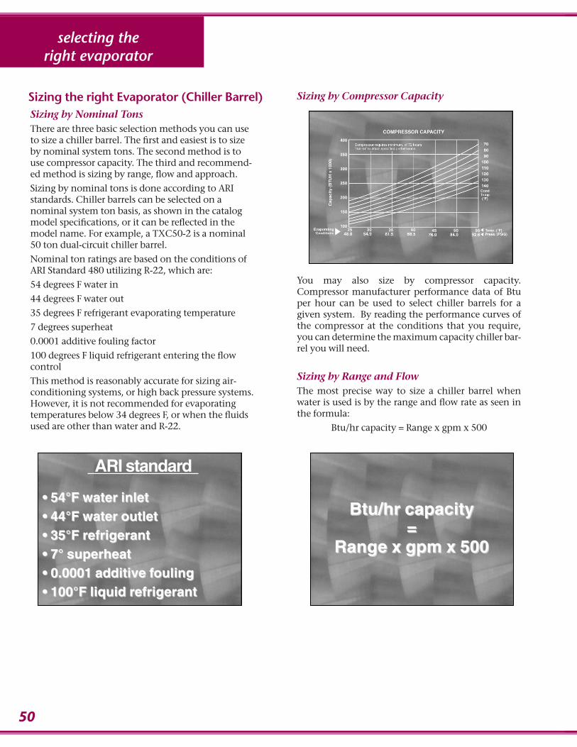
50
selecting theright evaporator
Sizing by Nominal TonsThere are three basic selection methods you can useto size a chiller barrel. The first and easiest is to sizeby nominal system tons. The second method is touse compressor capacity. The third and recommend-ed method is sizing by range, flow and approach.
Sizing by nominal tons is done according to ARIstandards. Chiller barrels can be selected on anominal system ton basis, as shown in the catalogmodel specifications, or it can be reflected in themodel name. For example, a TXC50-2 is a nominal50 ton dual-circuit chiller barrel.
Nominal ton ratings are based on the conditions ofARI Standard 480 utilizing R-22, which are:
54 degrees F water in
44 degrees F water out
35 degrees F refrigerant evaporating temperature
7 degrees superheat
0.0001 additive fouling factor
100 degrees F liquid refrigerant entering the flowcontrol
This method is reasonably accurate for sizing air-conditioning systems, or high back pressure systems.However, it is not recommended for evaporatingtemperatures below 34 degrees F, or when the fluidsused are other than water and R-22.
Sizing by Compressor Capacity
You may also size by compressor capacity.Compressor manufacturer performance data of Btuper hour can be used to select chiller barrels for agiven system. By reading the performance curves ofthe compressor at the conditions that you require,you can determine the maximum capacity chiller bar-rel you will need.
Sizing by Range and FlowThe most precise way to size a chiller barrel whenwater is used is by the range and flow rate as seen inthe formula:
Btu/hr capacity = Range x gpm x 500
ARI standard
• 54°F water inlet• 54°F water inlet• 44°F water outlet• 44°F water outlet• 35°F refrigerant• 35°F refrigerant• 7° superheat• 7° superheat• 0.0001 additive fouling• 0.0001 additive fouling• 100°F liquid refrigerant• 100°F liquid refrigerant
Btu/hr capacityBtu/hr capacity==
Range x gpm x 500Range x gpm x 500
Sizing the right Evaporator (Chiller Barrel)
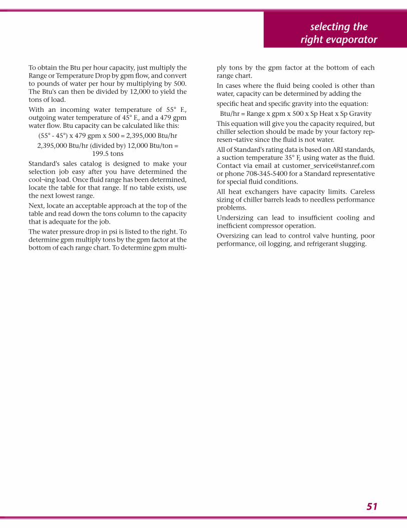
selecting theright evaporator
51
To obtain the Btu per hour capacity, just multiply theRange or Temperature Drop by gpm flow, and convertto pounds of water per hour by multiplying by 500.The Btu's can then be divided by 12,000 to yield thetons of load.
With an incoming water temperature of 55° F., outgoing water temperature of 45° F., and a 479 gpmwater flow. Btu capacity can be calculated like this:
(55° - 45°) x 479 gpm x 500 = 2,395,000 Btu/hr
2,395,000 Btu/hr (divided by) 12,000 Btu/ton =199.5 tons
Standard's sales catalog is designed to make yourselection job easy after you have determined thecool¬ing load. Once fluid range has been determined,locate the table for that range. If no table exists, usethe next lowest range.
Next, locate an acceptable approach at the top of thetable and read down the tons column to the capacitythat is adequate for the job.
The water pressure drop in psi is listed to the right. Todetermine gpm multiply tons by the gpm factor at thebottom of each range chart. To determine gpm multi-
ply tons by the gpm factor at the bottom of eachrange chart.
In cases where the fluid being cooled is other thanwater, capacity can be determined by adding the
specific heat and specific gravity into the equation:
Btu/hr = Range x gpm x 500 x Sp Heat x Sp Gravity
This equation will give you the capacity required, butchiller selection should be made by your factory rep-resen¬tative since the fluid is not water.
All of Standard's rating data is based on ARI standards,a suction temperature 35° F, using water as the fluid.Contact via email at [email protected] phone 708-345-5400 for a Standard representativefor special fluid conditions.
All heat exchangers have capacity limits. Careless sizing of chiller barrels leads to needless performanceproblems.
Undersizing can lead to insufficient cooling and inefficient compressor operation.
Oversizing can lead to control valve hunting, poorperformance, oil logging, and refrigerant slugging.

52
Connections Specifications WorkingMODELS Nominal Tons**
Ref. Ref. W T Fluid Tube Shell Shipping Pressure
Circuits clean fouled In Out Fluid (ftp) Volume Length Diameter Weight (psig)1-CIRCUIT (ids) (ids) Conn. (gal) (inches) (inches) (lbs) Shell Side Tube Side
TX2-1 1 2.8 2.2 5⁄8 7⁄8 1FPT 3⁄8 0.4 24 2.3⁄4 46 225 225TX3-1 1 3.8 2.9 5⁄8 7⁄8 1FPT 3⁄8 0.4 24 2.3⁄4 50 225 225TX5-1 1 6.0 4.8 5⁄8 1.1⁄8 1.1⁄4FPT 1⁄2 1.6 36 4 62 225 225
TX6-1 1 8.7 7.1 5⁄8 1.1⁄8 1.1⁄2FPT 1⁄2 1.5 36 4 64 225 225TX71⁄2 -1 1 9.5 7.8 7⁄8 1.5⁄8 1.1⁄2FPT 1⁄2 1.4 36 4 66 225 225TX10-1 1 11.9 11.0 7⁄8 1.5⁄8 2FPT 1⁄2 1.2 36 4 70 225 225
TX12-1 1 15.8 13.0 7⁄8 1.5⁄8 2FPT 1⁄2 3.4 36 6 120 225 225TX15-1 1 20.2 16.5 1.1⁄8 2.1⁄8 2.1⁄2FPT 1⁄2 3.2 36 6 128 225 225TX20-1 1 23.9 19.7 1.1⁄8 2.1⁄8 3FPT 1⁄2 2.9 36 6 136 225 225
TX25-1 1 26.9 22.3 1.1⁄8 2.5⁄8 3FPT 1⁄2 2.6 36 6 142 225 150TXC30-1 1 32.1 30.0 1.1⁄8 2.5⁄8 3 MPT 3⁄4 9.3 72 6. 5⁄8 414 300 150TXC40-1 1 42.8 40.0 1.3⁄8 2.5⁄8 3 MPT 3⁄4 17.5 72 8. 5⁄8 563 300 150
TXC50-1 1 53.7 50.0 1.3⁄8 3.1⁄8 4"FLANGE 3⁄4 17.1 72 8. 5⁄8 594 300 150TXC60-1 1 64.3 60.0 1.5⁄8 3.1⁄8 4"FLANGE 3⁄4 19.8 84 8. 5⁄8 642 300 150TXC75-1 1 80.7 75.0 2.1⁄8 3.1⁄8 5"FLANGE 3⁄4 19.5 84 8. 5⁄8 671 300 150
TXC100-1 1 124.7 110.0 2.1⁄8 3.5⁄8 5"FLANGE 3⁄4 28.4 84 10.3⁄4 1070 225 150TXC120-1 1 136.8 120.0 2.1⁄8 3.5⁄8 6"FLANGE 3⁄4 26.9 84 12.3⁄4 1080 225 150
2-CIRCUIT
TX10-2 2 11.9 11.0 5⁄8 1.1⁄8 2 FPT 1⁄2 1.2 36 4 70 225 225TX12-2 2 15.8 13.0 5⁄8 1.1⁄8 2 FPT 1⁄2 3.4 36 6 120 225 225TX15-2 2 20.2 16.5 7⁄8 1.5⁄8 2.1⁄2 FPT 1⁄2 3.2 36 6 128 225 225
TX20-2 2 23.9 19.7 7⁄8 1.5⁄8 3FPT 1⁄2 2.9 36 6 136 225 225TX25-2 2 26.9 22.3 7⁄8 1.5⁄8 3FPT 1⁄2 2.6 36 6 142 225 225TXC30-2 2 32.1 30.0 7⁄8 1.5⁄8 3MPT 3⁄4 9.3 72 6.5⁄8 404 300 150
TXC40-2 2 42.8 40.0 1.1⁄8 2.1⁄8 3MPT 3⁄4 17.5 72 8.5⁄8 556 300 150TXC50-2 2 53.7 50.0 1.1⁄8 2.1⁄8 4"FLANGE 3⁄4 17.1 72 8.5⁄8 581 300 150TXC60-2 2 64.3 60.0 1.1⁄8 2.5⁄8 4"FLANGE 3⁄4 19.8 84 8.5⁄8 634 300 150
TXC75-2 2 80.7 75.0 1.3⁄8 2.5⁄8 5"FLANGE 3⁄4 19.5 84 8.5⁄8 662 300 150TXC100-2 2 124.7 110.0 1.3⁄8 3.1⁄8 5"FLANGE 3⁄4 28.4 84 10.3⁄4 1070 225 150TXC120-2 2 136.8 120.0 1.3⁄8 3.1⁄8 6"FLANGE 3⁄4 26.9 84 12.3⁄4 1080 225 150
TXC150-2 2 173.0 152.3 1.3⁄8 2.5⁄8 6"FLANGE 3⁄4 34.0 84 14 1600 225 150TXC175-2 2 198.0 174.5 1.3⁄8 2.5⁄8 6"FLANGE 3⁄4 31.0 84 14 1700 225 150TXC200-2 2 242.0 212.9 1.3⁄8 3.1⁄8 8"FLANGE 3⁄4 42.0 84 16 2100 225 150
TXC250-2 2 284.0 251.1 1.3⁄8 3.1⁄8 8"FLANGE 3⁄4 39.0 84 16 2200 225 150TXC275-2 2 309.0 273.5 2.1⁄8 4.1⁄8 8"FLANGE 3⁄4 54.0 84 18 2600 225 150TXC300-2 2 361.0 319.7 2.1⁄8 3.5⁄8 8"FLANGE 3⁄4 73.0 84 20 2800 225 150
TXC500-2 2 573.0 505.5 2.1⁄8 4.1⁄8 10"FLANGE 3⁄4 101.0 84 24 3600 225 150
MULTI-CIRCUIT
TX15-3 3 22.1 18.1 .5⁄8 1.1⁄8 2.1⁄2 FPT .1⁄2 8.4 72 6 145 225 225TX20-4 4 26.7 24.6 .5⁄8 1.1⁄8 3 FPT .1⁄2 8.1 72 6 155 225 225
TX/TXC Compact Serviceable Chiller Barrels
**Clean ratings: As tested per ARI standard 480-01
Fouled ratings: Include a additive fouling coefficient of 0.0001 ft2 hr°F/Btu over clean rating per ARI standard 480-01
design features & ratings
compact serviceablechiller barrels
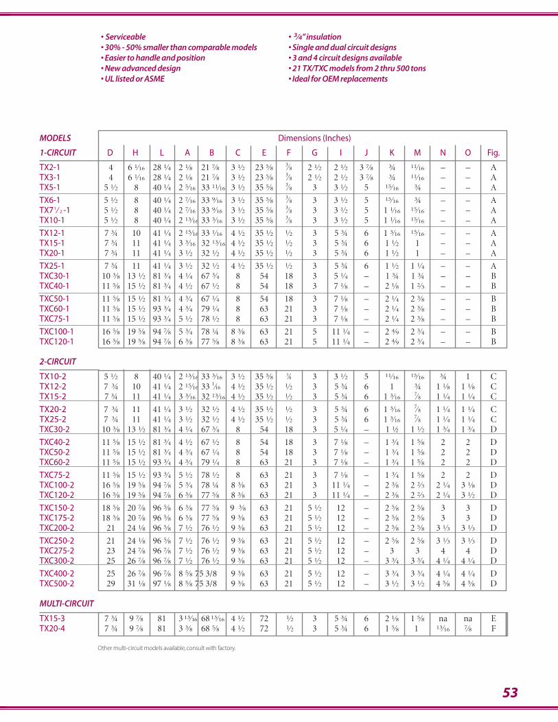
53
MODELS Dimensions (Inches)
1-CIRCUIT D H L A B C E F G I J K M N O Fig.
TX2-1 4 6.1⁄16 28.1⁄4 2.1⁄8 21.7⁄8 3.1⁄2 23.5⁄8 3⁄8 2.1⁄2 2.1⁄2 3.7⁄8 3⁄4 11⁄16 – – ATX3-1 4 6.1⁄16 28.1⁄4 2.1⁄8 21.7⁄8 3.1⁄2 23.5⁄8 3⁄8 2.1⁄2 2.1⁄2 3.7⁄8 3⁄4 11⁄16 – – ATX5-1 5.1⁄2 8 40.1⁄4 2.5⁄16 33.11⁄16 3.1⁄2 35.5⁄8 3⁄8 3 3.1⁄2 5 15⁄16 3⁄4 – – A
TX6-1 5.1⁄2 8 40.1⁄4 2.7⁄16 33.9⁄16 3.1⁄2 35.5⁄8 3⁄8 3 3.1⁄2 5 15⁄16 3⁄4 – – ATX71⁄2 -1 5.1⁄2 8 40.1⁄4 2.7⁄16 33.9⁄16 3.1⁄2 35.5⁄8 3⁄8 3 3.1⁄2 5 1.1⁄16 15⁄16 – – ATX10-1 5.1⁄2 8 40.1⁄4 2.13⁄16 33.3⁄16 3.1⁄2 35.5⁄8 3⁄8 3 3.1⁄2 5 1.1⁄16 15⁄16 – – A
TX12-1 7.3⁄4 10 41.1⁄4 2.15⁄16 33.1⁄16 4.1⁄2 35.1⁄2 1⁄2 3 5.3⁄4 6 1.3⁄16 15⁄16 – – ATX15-1 7.3⁄4 11 41.1⁄4 3.3⁄16 32.13⁄16 4.1⁄2 35.1⁄2 1⁄2 3 5.3⁄4 6 1.1⁄2 1 – – ATX20-1 7.3⁄4 11 41.1⁄4 3.1⁄2 32.1⁄2 4.1⁄2 35.1⁄2 1⁄2 3 5.3⁄4 6 1.1⁄2 1 – – A
TX25-1 7.3⁄4 11 41.1⁄4 3.1⁄2 32.1⁄2 4.1⁄2 35.1⁄2 1⁄2 3 5.3⁄4 6 1.1⁄2 1.1⁄4 – – ATXC30-1 10.3⁄8 13.1⁄2 81.3⁄4 4.1⁄4 67.3⁄4 8 54 18 3 5.1⁄4 – 1.3⁄4 1.3⁄4 – – BTXC40-1 11.5⁄8 15.1⁄2 81.3⁄4 4.1⁄2 67.1⁄2 8 54 18 3 7.1⁄8 – 2.1⁄8 1.2⁄3 – – B
TXC50-1 11.5⁄8 15.1⁄2 81.3⁄4 4.3⁄4 67.1⁄4 8 54 18 3 7.1⁄8 – 2.1⁄4 2.3⁄8 – – BTXC60-1 11.5⁄8 15.1⁄2 93.3⁄4 4.3⁄4 79.1⁄4 8 63 21 3 7.1⁄8 – 2.1⁄4 2.3⁄8 – – BTXC75-1 11.5⁄8 15.1⁄2 93.3⁄4 5.1⁄2 78.1⁄2 8 63 21 3 7.1⁄8 – 2.1⁄4 2.3⁄8 – – B
TXC100-1 16.5⁄8 19.5⁄8 94.7⁄8 5.3⁄4 78.1⁄4 8.3⁄8 63 21 5 11.1⁄4 – 2.4⁄9 2.3⁄4 – – BTXC120-1 16.5⁄8 19.5⁄8 94.7⁄8 6.3⁄8 77.5⁄8 8.3⁄8 63 21 5 11.1⁄4 – 2.4⁄9 2.3⁄4 – – B
2-CIRCUIT
TX10-2 5.1⁄2 8 40.1⁄4 2.13⁄16 33.3⁄16 3.1⁄2 35.5⁄8 3⁄8 3 3.1⁄2 5 11⁄16 15⁄16 3⁄4 1 CTX12-2 7. 3⁄4 10 41.1⁄4 2.15⁄16 33.1⁄16 4.1⁄2 35.1⁄2 1⁄2 3 5.3⁄4 6 1 3⁄4 1.1⁄8 1.1⁄8 CTX15-2 7.3⁄4 11 41.1⁄4 3.3⁄16 32.13⁄16 4.1⁄2 35.1⁄2 1⁄2 3 5.3⁄4 6 1.3⁄16
7⁄8 1.1⁄4 1.1⁄4 C
TX20-2 7. 3⁄4 11 41.1⁄4 3.1⁄2 32.1⁄2 4.1⁄2 35.1⁄2 1⁄2 3 5.3⁄4 6 1.3⁄167⁄8 1.1⁄4 1.1⁄4 C
TX25-2 7. 3⁄4 11 41.1⁄4 3.1⁄2 32.1⁄2 4.1⁄2 35.1⁄2 1⁄2 3 5.3⁄4 6 1.3⁄167⁄8 1.1⁄4 1.1⁄4 C
TXC30-2 10.3⁄8 13.1⁄2 81.3⁄4 4.1⁄4 67.3⁄4 8 54 18 3 5.1⁄4 – 1.1⁄2 1.1⁄2 1.3⁄4 1.3⁄4 D
TXC40-2 11.5⁄8 15.1⁄2 81.3⁄4 4.1⁄2 67.1⁄2 8 54 18 3 7.1⁄8 – 1.3⁄4 1.5⁄8 2 2 DTXC50-2 11.5⁄8 15.1⁄2 81.3⁄4 4.3⁄4 67.1⁄4 8 54 18 3 7.1⁄8 – 1.3⁄4 1.5⁄8 2 2 DTXC60-2 11.5⁄8 15.1⁄2 93.3⁄4 4.3⁄4 79.1⁄4 8 63 21 3 7.1⁄8 – 1.3⁄4 1.5⁄8 2 2 D
TXC75-2 11.5⁄8 15.1⁄2 93.3⁄4 5.1⁄2 78.1⁄2 8 63 21 3 7.1⁄8 – 1.3⁄4 1.5⁄8 2 2 DTXC100-2 16.5⁄8 19.5⁄8 94.7⁄8 5.3⁄4 78.1⁄4 8.3⁄8 63 21 3 11.1⁄4 – 2.3⁄8 2.2⁄3 2.1⁄4 3.1⁄8 DTXC120-2 16.5⁄8 19.5⁄8 94.7⁄8 6.3⁄8 77.5⁄8 8.3⁄8 63 21 3 11.1⁄4 – 2.3⁄8 2.2⁄3 2.1⁄4 3.1⁄2 D
TXC150-2 18.5⁄8 20.7⁄8 96.5⁄8 6.3⁄8 77.5⁄8 9 .3⁄8 63 21 5.1⁄2 12 – 2.5⁄8 2.5⁄8 3 3 DTXC175-2 18.5⁄8 20.7⁄8 96.5⁄8 6.3⁄8 77.5⁄8 9.3⁄8 63 21 5.1⁄2 12 – 2.5⁄8 2.5⁄8 3 3 DTXC200-2 21 24.1⁄8 96.5⁄8 7.1⁄2 76.1⁄2 9.3⁄8 63 21 5.1⁄2 12 – 2.5⁄8 2.5⁄8 3.1⁄3 3.1⁄3 D
TXC250-2 21 24.1⁄8 96.5⁄8 7.1⁄2 76.1⁄2 9.3⁄8 63 21 5.1⁄2 12 – 2.5⁄8 2.5⁄8 3.1⁄3 3.1⁄3 DTXC275-2 23 24.7⁄8 96.7⁄8 7.1⁄2 76.1⁄2 9.3⁄8 63 21 5.1⁄2 12 – 3 3 4 4 DTXC300-2 25 26.7⁄8 96.7⁄8 7.1⁄2 76.1⁄2 9.3⁄8 63 21 5.1⁄2 12 – 3.3⁄4 3.3⁄4 4.1⁄4 4.1⁄4 D
TXC400-2 25 26.7⁄8 96.7⁄8 8.5⁄8 75 3/8 9.3⁄8 63 21 5.1⁄2 12 – 3.3⁄4 3.3⁄4 4.1⁄4 4.1⁄4 DTXC500-2 29 31.1⁄8 97.1⁄8 8.5⁄8 75 3/8 9.3⁄8 63 21 5.1⁄2 12 – 3.1⁄2 3.1⁄2 4.5⁄8 4.5⁄8 D
MULTI-CIRCUIT
TX15-3 7.3⁄4 9.7⁄8 81 3.13⁄16 68.13⁄16 4.1⁄2 72 .1⁄2 3 5.3⁄4 6 2.1⁄8 1.5⁄8 na na ETX20-4 7.3⁄4 9.7⁄8 81 3.3⁄8 68.5⁄8 4.1⁄2 72 .1⁄2 3 5.3⁄4 6 1.5⁄8 1. 13⁄16 7⁄8 F
• Serviceable• 30% - 50% smaller than comparable models• Easier to handle and position• New advanced design• UL listed or ASME
• 3⁄4” insulation• Single and dual circuit designs• 3 and 4 circuit designs available• 21 TX/TXC models from 2 thru 500 tons• Ideal for OEM replacements
Other multi-circuit models available, consult with factory.
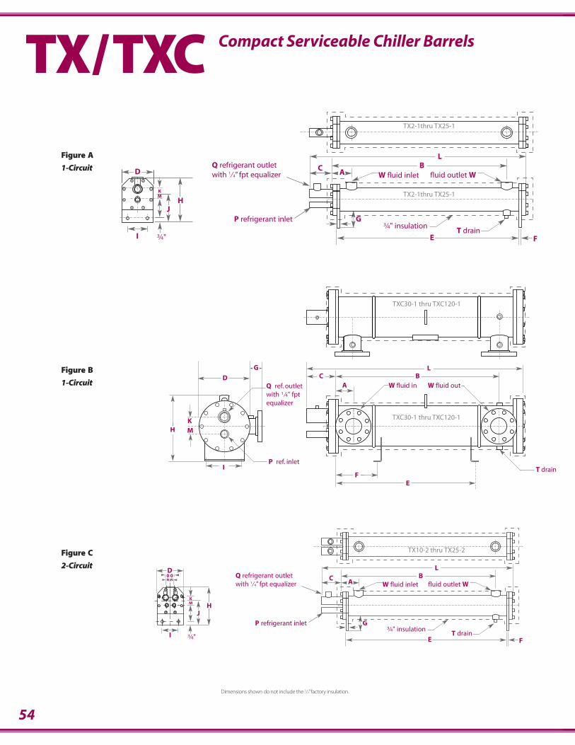
54
LBC
G3⁄4" insulation
T drain
fluid outlet WW fluid inlet
P refrigerant inlet
Q refrigerant outletwith 1⁄4” fpt equalizer
MK
JH
I 3⁄4"
AD
FE
TX2-1 thru TX25-1
TX2-1 thru TX25-1
KM
0 0N N
JH
I 3⁄4"
D LBC
G3⁄4" insulation
T drain
fluid outlet WW fluid inlet
P refrigerant inlet
Q refrigerant outletwith 1⁄4” fpt equalizer A
FE
TX10-2 thru TX25-2
P ref. inlet
KM
I
E
Q ref. outletwith 1⁄4" fptequalizer
AC
LB
H
D
G
F
W fluid in W fluid out
TXC30-1 thru TXC120-1
TXC30-1 thru TXC120-1
T drain
TX/TXC Compact Serviceable Chiller Barrels
Figure A
1-Circuit
Dimensions shown do not include the 3⁄4” factory insulation.
Figure B
1-Circuit
Figure C
2-Circuit
TX2-1thru TX25-1
TX2-1thru TX25-1
TX10-2 thru TX25-2
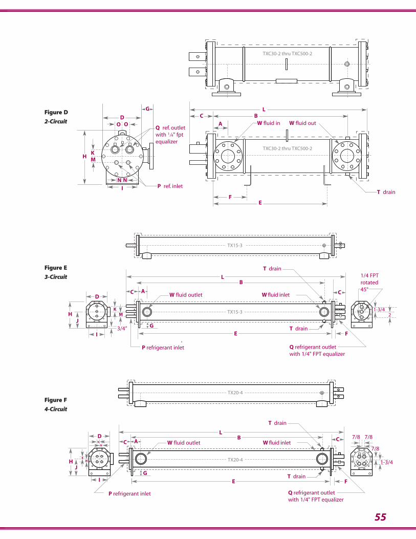
55
KM
I
O O
P ref. inlet
E
Q ref. outletwith 1⁄4" fptequalizer
A
CL
BD
G
FT drain
H
N N
W fluid in W fluid out
TXC30-2 thru TXC500-2
TXC30-2 thru TXC500-2
P refrigerant inlet Q refrigerant outletwith 1/4" FPT equalizer
2
T drainE
W fluid outlet
B
W fluid inlet
1/4 FPTrotated 45°
T drain
GJ
KM
3/4”
TX15-3
TX15-3
L
H
I F
CD
C A
1-3/4
IT drain
NN
MK
HJ
D
E
L
W fluid outletB
W fluid inlet
P refrigerant inlet Q refrigerant outletwith 1/4" FPT equalizer
T drain
F
1-3/4
7/8C A
TX20-4
TX20-4
G
C 7/8 7/8
Figure F
4-Circuit
Figure E
3-Circuit
Figure D
2-Circuit
TXC30-2 thru TXC500-2
TXC30-2 thru TXC500-2
TX15-3
TX15-3
TX20-4
TX20-4
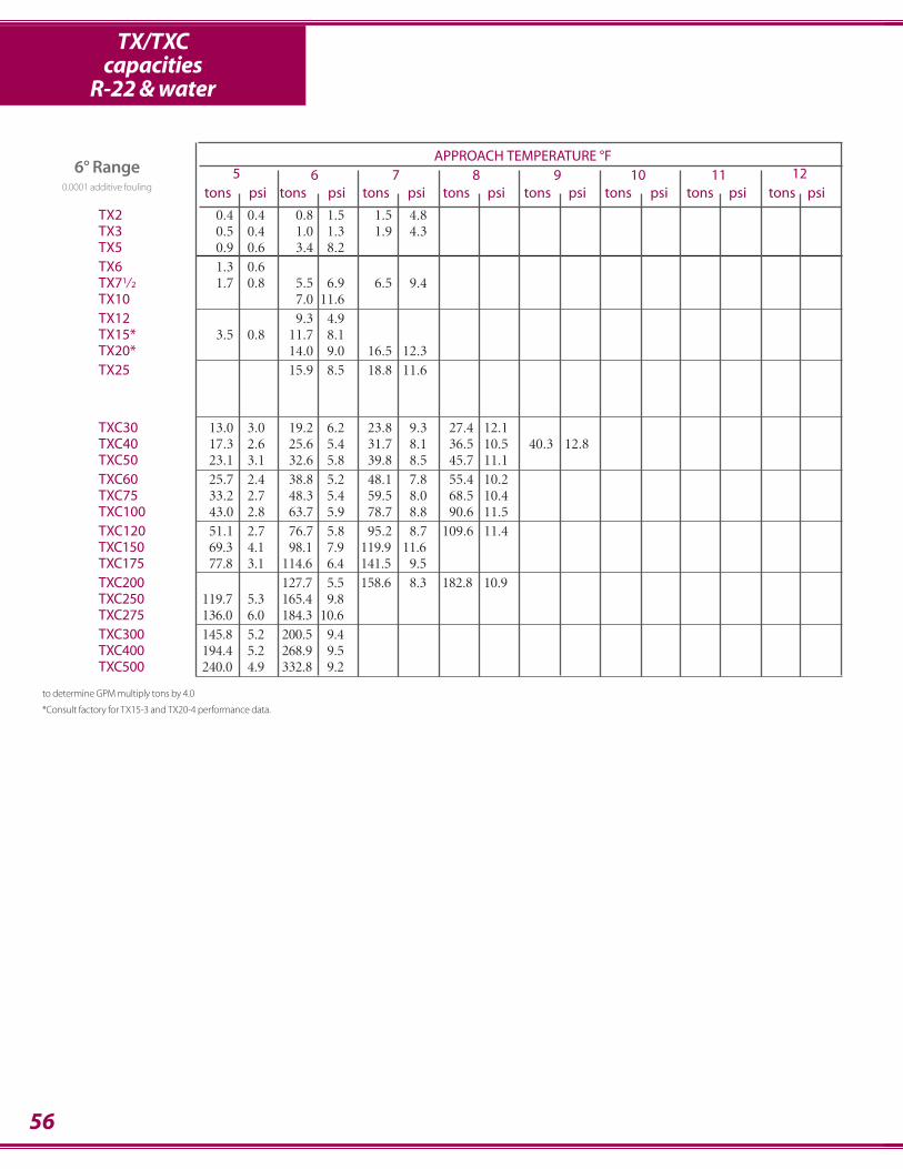
APPROACH TEMPERATURE °F5 6 7 8 9 10 11 12
tons psi tons psi tons psi tons psi tons psi tons psi tons psi tons psi
TX2 0.4 0.4 0.8 1.5 1.5 4.8TX3 0.5 0.4 1.0 1.3 1.9 4.3TX5 0.9 0.6 3.4 8.2TX6 1.3 0.6TX71⁄2 1.7 0.8 5.5 6.9 6.5 9.4TX10 7.0 11.6TX12 9.3 4.9TX15* 3.5 0.8 11.7 8.1TX20* 14.0 9.0 16.5 12.3TX25 15.9 8.5 18.8 11.6
TXC30 13.0 3.0 19.2 6.2 23.8 9.3 27.4 12.1TXC40 17.3 2.6 25.6 5.4 31.7 8.1 36.5 10.5 40.3 12.8TXC50 23.1 3.1 32.6 5.8 39.8 8.5 45.7 11.1TXC60 25.7 2.4 38.8 5.2 48.1 7.8 55.4 10.2TXC75 33.2 2.7 48.3 5.4 59.5 8.0 68.5 10.4TXC100 43.0 2.8 63.7 5.9 78.7 8.8 90.6 11.5TXC120 51.1 2.7 76.7 5.8 95.2 8.7 109.6 11.4TXC150 69.3 4.1 98.1 7.9 119.9 11.6TXC175 77.8 3.1 114.6 6.4 141.5 9.5TXC200 127.7 5.5 158.6 8.3 182.8 10.9TXC250 119.7 5.3 165.4 9.8TXC275 136.0 6.0 184.3 10.6TXC300 145.8 5.2 200.5 9.4TXC400 194.4 5.2 268.9 9.5TXC500 240.0 4.9 332.8 9.2
56
TX/TXCcapacities
R-22 & water
6° Range0.0001 additive fouling
to determine GPM multiply tons by 4.0
*Consult factory for TX15-3 and TX20-4 performance data.
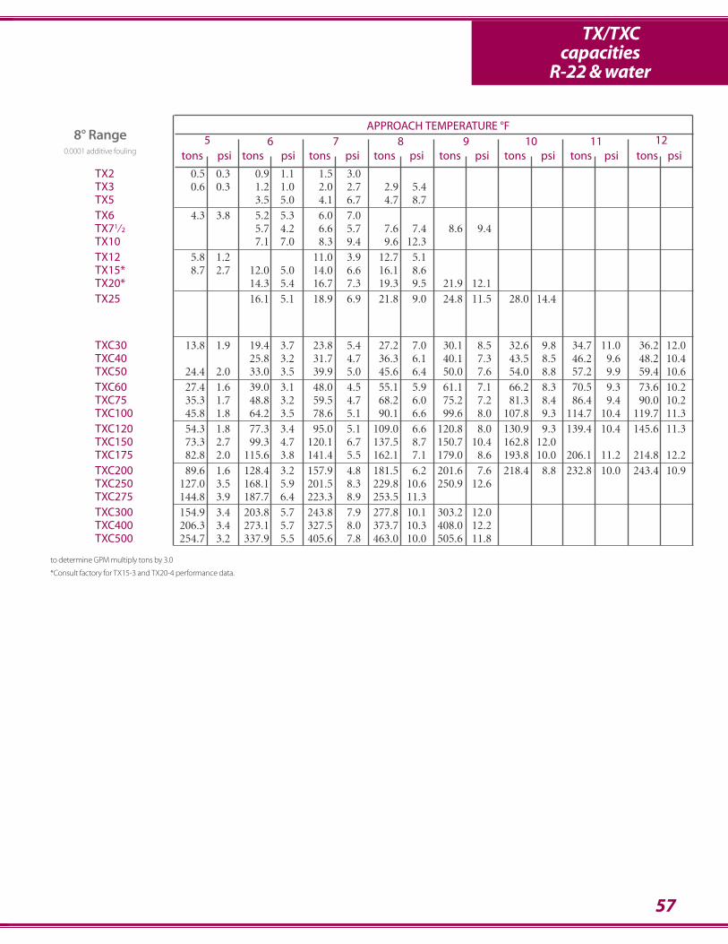
57
TX/TXCcapacities
R-22 & water
APPROACH TEMPERATURE °F5 6 7 8 9 10 11 12
tons psi tons psi tons psi tons psi tons psi tons psi tons psi tons psi
TX2 0.5 0.3 0.9 1.1 1.5 3.0TX3 0.6 0.3 1.2 1.0 2.0 2.7 2.9 5.4TX5 3.5 5.0 4.1 6.7 4.7 8.7TX6 4.3 3.8 5.2 5.3 6.0 7.0TX71⁄2 5.7 4.2 6.6 5.7 7.6 7.4 8.6 9.4TX10 7.1 7.0 8.3 9.4 9.6 12.3TX12 5.8 1.2 11.0 3.9 12.7 5.1TX15* 8.7 2.7 12.0 5.0 14.0 6.6 16.1 8.6TX20* 14.3 5.4 16.7 7.3 19.3 9.5 21.9 12.1TX25 16.1 5.1 18.9 6.9 21.8 9.0 24.8 11.5 28.0 14.4
TXC30 13.8 1.9 19.4 3.7 23.8 5.4 27.2 7.0 30.1 8.5 32.6 9.8 34.7 11.0 36.2 12.0TXC40 25.8 3.2 31.7 4.7 36.3 6.1 40.1 7.3 43.5 8.5 46.2 9.6 48.2 10.4TXC50 24.4 2.0 33.0 3.5 39.9 5.0 45.6 6.4 50.0 7.6 54.0 8.8 57.2 9.9 59.4 10.6TXC60 27.4 1.6 39.0 3.1 48.0 4.5 55.1 5.9 61.1 7.1 66.2 8.3 70.5 9.3 73.6 10.2TXC75 35.3 1.7 48.8 3.2 59.5 4.7 68.2 6.0 75.2 7.2 81.3 8.4 86.4 9.4 90.0 10.2TXC100 45.8 1.8 64.2 3.5 78.6 5.1 90.1 6.6 99.6 8.0 107.8 9.3 114.7 10.4 119.7 11.3TXC120 54.3 1.8 77.3 3.4 95.0 5.1 109.0 6.6 120.8 8.0 130.9 9.3 139.4 10.4 145.6 11.3TXC150 73.3 2.7 99.3 4.7 120.1 6.7 137.5 8.7 150.7 10.4 162.8 12.0TXC175 82.8 2.0 115.6 3.8 141.4 5.5 162.1 7.1 179.0 8.6 193.8 10.0 206.1 11.2 214.8 12.2TXC200 89.6 1.6 128.4 3.2 157.9 4.8 181.5 6.2 201.6 7.6 218.4 8.8 232.8 10.0 243.4 10.9TXC250 127.0 3.5 168.1 5.9 201.5 8.3 229.8 10.6 250.9 12.6TXC275 144.8 3.9 187.7 6.4 223.3 8.9 253.5 11.3TXC300 154.9 3.4 203.8 5.7 243.8 7.9 277.8 10.1 303.2 12.0TXC400 206.3 3.4 273.1 5.7 327.5 8.0 373.7 10.3 408.0 12.2TXC500 254.7 3.2 337.9 5.5 405.6 7.8 463.0 10.0 505.6 11.8
8° Range0.0001 additive fouling
to determine GPM multiply tons by 3.0
*Consult factory for TX15-3 and TX20-4 performance data.

58
TX/TXCcapacities
R-22 & water
APPROACH TEMPERATURE °F5 6 7 8 9 10 11 12
tons psi tons psi tons psi tons psi tons psi tons psi tons psi tons psi
TX2 0.6 0.3 1.0 0.9 1.6 2.2 2.1 3.6 2.5 4.9TX3 0.7 0.3 1.3 0.8 2.1 1.9 2.9 3.6 3.4 4.8 3.9 6.4TX5 3.1 2.6 3.6 3.5 4.2 4.6 4.8 6.0 5.5 7.5 6.1 9.2TX6 4.5 2.7 5.3 3.7 6.2 4.8 7.0 6.2 7.9 7.8TX7-1/2 4.6 1.9 5.8 2.9 6.7 3.9 7.7 5.0 8.7 6.3 9.7 7.7 10.8 9.3TX10 4.6 2.0 7.2 4.7 8.5 6.3 9.7 8.2 11.0 10.4 12.3 12.7TX12 6.8 1.1 9.6 2.0 11.2 2.7 12.9 3.5 14.5 4.4 16.2 5.4TX15 10.0 2.3 12.3 3.4 14.3 4.5 16.4 5.9 18.5 7.4 20.7 9.0TX20 9.9 1.8 14.6 3.7 17.0 4.9 19.5 6.4 22.0 8.1 24.6 9.9 27.2 12.0 29.9 14.3TX25 9.3 1.2 16.3 3.4 19.1 4.6 21.9 6.0 24.8 7.6 27.8 9.3 30.8 11.3 33.8 13.5
TXC30 14.6 1.4 19.7 2.5 23.9 3.6 27.3 4.6 30.0 5.5 32.4 6.4 34.4 7.1 36.0 7.8TXC40 19.4 1.2 26.2 2.2 31.8 3.1 36.3 4.0 40.0 4.8 43.1 5.5 45.8 6.2 47.9 6.7TXC50 25.8 1.4 33.6 2.4 40.2 3.3 45.8 4.3 50.0 5.0 53.7 5.7 56.9 6.4 59.1 6.9TXC60 28.9 1.1 39.5 2.1 48.1 3.0 55.0 3.8 60.8 4.7 65.6 5.4 69.8 6.0 73.2 6.6TXC75 37.1 1.3 49.5 2.2 59.8 3.1 68.3 4.0 75.0 4.7 80.8 5.5 85.8 6.1 89.5 6.6TXC100 48.3 1.3 65.0 2.4 78.9 3.4 90.1 4.4 99.4 5.2 107.1 6.0 113.8 6.8 118.9 7.3TXC120 57.4 1.3 78.2 2.3 95.3 3.3 108.9 4.3 120.4 5.2 129.8 6.0 138.1 6.7 144.7 7.4TXC150 77.3 1.9 101.0 3.2 120.9 4.5 138.0 5.8 150.7 6.8 162.1 7.8 171.6 8.7 178.4 9.4TXC175 87.1 1.5 117.2 2.5 141.9 3.7 162.2 4.7 178.6 5.6 192.5 6.5 204.4 7.3 213.6 7.9TXC200 94.7 1.2 129.9 2.2 158.4 3.2 181.3 4.1 200.8 5.0 216.7 5.7 230.6 6.4 241.8 7.0TXC250 133.9 2.5 171.3 4.0 203.2 5.5 230.8 7.0 251.2 8.3 269.5 9.4 285.0 10.5 295.2 11.2TXC275 150.5 2.8 191.5 4.4 225.7 5.9 254.9 7.5 277.1 8.8 296.7 10.0 312.7 11.0 323.6 11.7TXC300 162.7 2.4 207.8 3.9 246.1 5.3 279.0 6.7 303.7 7.9 325.6 9.0 344.0 10.0 356.2 10.7TXC400 217.6 2.4 278.5 3.9 330.4 5.4 375.2 6.8 408.4 8.0 438.2 9.2 463.4 10.2 480.0 10.9TXC500 268.9 2.3 344.5 3.7 409.0 5.2 464.8 6.6 506.1 7.7 543.1 8.8 574.4 9.8 595.2 10.5
10° Range 0.0001 additive fouling
to determine GPM multiply tons by 2.4
*Consult factory for TX15-3 and TX20-4 performance data.
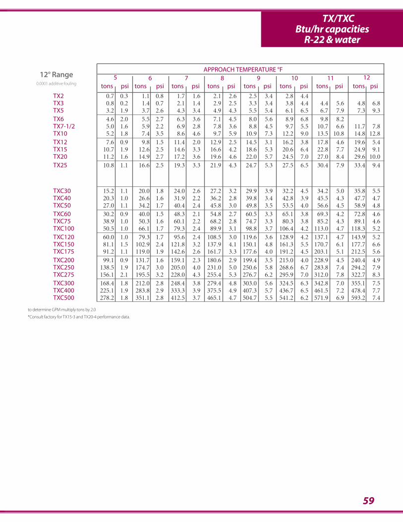
59
TX/TXCBtu/hr capacities
R-22 & water
APPROACH TEMPERATURE °F5 6 7 8 9 10 11 12
tons psi tons psi tons psi tons psi tons psi tons psi tons psi tons psi
TX2 0.7 0.3 1.1 0.8 1.7 1.6 2.1 2.6 2.5 3.4 2.8 4.4TX3 0.8 0.2 1.4 0.7 2.1 1.4 2.9 2.5 3.3 3.4 3.8 4.4 4.4 5.6 4.8 6.8TX5 3.2 1.9 3.7 2.6 4.3 3.4 4.9 4.3 5.5 5.4 6.1 6.5 6.7 7.9 7.3 9.3TX6 4.6 2.0 5.5 2.7 6.3 3.6 7.1 4.5 8.0 5.6 8.9 6.8 9.8 8.2TX7-1/2 5.0 1.6 5.9 2.2 6.9 2.8 7.8 3.6 8.8 4.5 9.7 5.5 10.7 6.6 11.7 7.8TX10 5.2 1.8 7.4 3.5 8.6 4.6 9.7 5.9 10.9 7.3 12.2 9.0 13.5 10.8 14.8 12.8TX12 7.6 0.9 9.8 1.5 11.4 2.0 12.9 2.5 14.5 3.1 16.2 3.8 17.8 4.6 19.6 5.4TX15 10.7 1.9 12.6 2.5 14.6 3.3 16.6 4.2 18.6 5.3 20.6 6.4 22.8 7.7 24.9 9.1TX20 11.2 1.6 14.9 2.7 17.2 3.6 19.6 4.6 22.0 5.7 24.5 7.0 27.0 8.4 29.6 10.0TX25 10.8 1.1 16.6 2.5 19.3 3.3 21.9 4.3 24.7 5.3 27.5 6.5 30.4 7.9 33.4 9.4
TXC30 15.2 1.1 20.0 1.8 24.0 2.6 27.2 3.2 29.9 3.9 32.2 4.5 34.2 5.0 35.8 5.5TXC40 20.3 1.0 26.6 1.6 31.9 2.2 36.2 2.8 39.8 3.4 42.8 3.9 45.5 4.3 47.7 4.7TXC50 27.0 1.1 34.2 1.7 40.4 2.4 45.8 3.0 49.8 3.5 53.5 4.0 56.6 4.5 58.9 4.8TXC60 30.2 0.9 40.0 1.5 48.3 2.1 54.8 2.7 60.5 3.3 65.1 3.8 69.3 4.2 72.8 4.6TXC75 38.9 1.0 50.3 1.6 60.1 2.2 68.2 2.8 74.7 3.3 80.3 3.8 85.2 4.3 89.1 4.6TXC100 50.5 1.0 66.1 1.7 79.3 2.4 89.9 3.1 98.8 3.7 106.4 4.2 113.0 4.7 118.3 5.2TXC120 60.0 1.0 79.3 1.7 95.6 2.4 108.5 3.0 119.6 3.6 128.9 4.2 137.1 4.7 143.9 5.2TXC150 81.1 1.5 102.9 2.4 121.8 3.2 137.9 4.1 150.1 4.8 161.3 5.5 170.7 6.1 177.7 6.6TXC175 91.2 1.1 119.0 1.9 142.6 2.6 161.7 3.3 177.6 4.0 191.2 4.5 203.1 5.1 212.5 5.6TXC200 99.1 0.9 131.7 1.6 159.1 2.3 180.6 2.9 199.4 3.5 215.0 4.0 228.9 4.5 240.4 4.9TXC250 138.5 1.9 174.7 3.0 205.0 4.0 231.0 5.0 250.6 5.8 268.6 6.7 283.8 7.4 294.2 7.9TXC275 156.1 2.1 195.5 3.2 228.0 4.3 255.4 5.3 276.7 6.2 295.9 7.0 312.0 7.8 322.7 8.3TXC300 168.4 1.8 212.0 2.8 248.4 3.8 279.4 4.8 303.0 5.6 324.5 6.3 342.8 7.0 355.1 7.5TXC400 225.1 1.9 283.8 2.9 333.3 3.9 375.5 4.9 407.3 5.7 436.7 6.5 461.5 7.2 478.4 7.7TXC500 278.2 1.8 351.1 2.8 412.5 3.7 465.1 4.7 504.7 5.5 541.2 6.2 571.9 6.9 593.2 7.4
12° Range0.0001 additive fouling
to determine GPM multiply tons by 2.0
*Consult factory for TX15-3 and TX20-4 performance data.
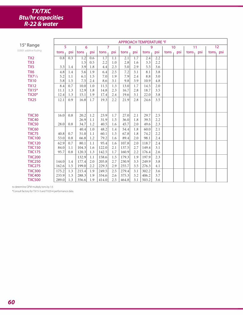
60
TX/TXCBtu/hr capacities
R-22 & water
APPROACH TEMPERATURE °F5 6 7 8 9 10 11 12
tons psi tons psi tons psi tons psi tons psi tons psi tons psi tons psi
TX2 0.8 0.3 1.2 0.6 1.7 1.1 2.1 1.7 2.4 2.2TX3 1.5 0.5 2.2 1.0 2.8 1.6 3.3 2.2TX5 3.3 1.4 3.9 1.8 4.4 2.3 5.0 2.9 5.5 3.6TX6 4.8 1.4 5.6 1.9 6.4 2.5 7.2 3.1 8.1 3.8TX71⁄2 5.2 1.1 6.1 1.5 7.0 1.9 7.9 2.4 8.8 3.0TX10 5.8 1.5 7.5 2.4 8.6 3.1 9.8 3.9 10.9 4.8TX12 8.4 0.7 10.0 1.0 11.5 1.3 13.0 1.7 14.5 2.0TX15* 11.1 1.3 12.9 1.8 14.8 2.3 16.7 2.8 18.7 3.5TX20* 12.4 1.3 15.1 1.9 17.4 2.4 19.6 3.1 22.0 3.8TX25 12.1 0.9 16.8 1.7 19.3 2.2 21.9 2.8 24.6 3.5
TXC30 16.0 0.8 20.2 1.2 23.9 1.7 27.0 2.1 29.7 2.5TXC40 26.9 1.1 31.9 1.5 36.0 1.8 39.5 2.2TXC50 28.0 0.8 34.7 1.2 40.5 1.6 45.7 2.0 49.6 2.3TXC60 40.4 1.0 48.2 1.4 54.4 1.8 60.0 2.1TXC75 40.8 0.7 51.0 1.1 60.1 1.5 67.8 1.8 74.2 2.2TXC100 53.0 0.8 66.8 1.2 79.2 1.6 89.4 2.0 98.1 2.4TXC120 62.9 0.7 80.1 1.1 95.4 1.6 107.8 2.0 118.7 2.4TXC150 84.0 1.1 104.3 1.6 122.0 2.1 137.5 2.7 149.4 3.1TXC175 95.7 0.8 120.3 1.3 142.5 1.7 160.9 2.2 176.4 2.6TXC200 132.9 1.1 158.6 1.5 179.3 1.9 197.9 2.3TXC250 144.0 1.4 177.4 2.0 205.8 2.7 230.9 3.3 249.9 3.8TXC275 162.6 1.5 199.0 2.2 229.3 2.9 255.7 3.5 276.3 4.1TXC300 175.2 1.3 215.4 1.9 249.5 2.5 279.4 3.1 302.2 3.6TXC400 233.9 1.3 288.3 1.9 334.6 2.6 375.3 3.2 406.2 3.7TXC500 289.0 1.3 356.6 1.9 414.0 2.5 464.8 3.1 503.2 3.6
15° Range0.0001 additive fouling
to determine GPM multiply tons by 1.6
*Consult factory for TX15-3 and TX20-4 performance data.
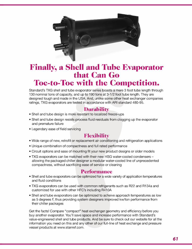
61
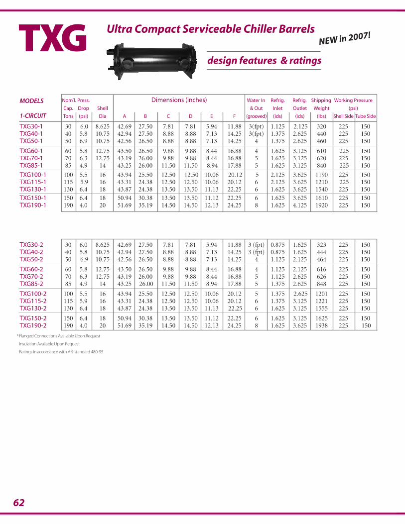
62
Nom’l. Press. Dimensions (inches) Water In Refrig. Refrig. Shipping Working PressureMODELSCap. Drop Shell & Out Inlet Outlet Weight (psi)
1-CIRCUIT Tons (psi) Dia A B C D E F (grooved) (ids) (ids) (lbs) Shell Side Tube Side
TXG30-1 30 6.0 8.625 42.69 27.50 7.81 7.81 5.94 11.88 3(fpt) 1.125 2.125 320 225 150TXG40-1 40 5.8 10.75 42.94 27.50 8.88 8.88 7.13 14.25 3(fpt) 1.375 2.625 440 225 150TXG50-1 50 6.9 10.75 42.56 26.50 8.88 8.88 7.13 14.25 4 1.375 2.625 460 225 150
TXG60-1 60 5.8 12.75 43.50 26.50 9.88 9.88 8.44 16.88 4 1.625 3.125 610 225 150TXG70-1 70 6.3 12.75 43.19 26.00 9.88 9.88 8.44 16.88 5 1.625 3.125 620 225 150TXG85-1 85 4.9 14 43.25 26.00 11.50 11.50 8.94 17.88 5 1.625 3.125 840 225 150
TXG100-1 100 5.5 16 43.94 25.50 12.50 12.50 10.06 20.12 5 2.125 3.625 1190 225 150TXG115-1 115 5.9 16 43.31 24.38 12.50 12.50 10.06 20.12 6 2.125 3.625 1210 225 150TXG130-1 130 6.4 18 43.87 24.38 13.50 13.50 11.13 22.25 6 1.625 3.625 1540 225 150TXG150-1 150 6.4 18 50.94 30.38 13.50 13.50 11.12 22.25 6 1.625 3.625 1610 225 150TXG190-1 190 4.0 20 51.69 35.19 14.50 14.50 12.13 24.25 8 1.625 4.125 1920 225 150
Ultra Compact Serviceable Chiller BarrelsTXGdesign features & ratings
TXG30-2 30 6.0 8.625 42.69 27.50 7.81 7.81 5.94 11.88 3 (fpt) 0.875 1.625 323 225 150TXG40-2 40 5.8 10.75 42.94 27.50 8.88 8.88 7.13 14.25 3 (fpt) 0.875 1.625 444 225 150TXG50-2 50 6.9 10.75 42.56 26.50 8.88 8.88 7.13 14.25 4 1.125 2.125 464 225 150
TXG60-2 60 5.8 12.75 43.50 26.50 9.88 9.88 8.44 16.88 4 1.125 2.125 616 225 150TXG70-2 70 6.3 12.75 43.19 26.00 9.88 9.88 8.44 16.88 5 1.125 2.625 626 225 150TXG85-2 85 4.9 14 43.25 26.00 11.50 11.50 8.94 17.88 5 1.375 2.625 848 225 150
TXG100-2 100 5.5 16 43.94 25.50 12.50 12.50 10.06 20.12 5 1.375 2.625 1201 225 150TXG115-2 115 5.9 16 43.31 24.38 12.50 12.50 10.06 20.12 6 1.375 3.125 1221 225 150TXG130-2 130 6.4 18 43.87 24.38 13.50 13.50 11.13 22.25 6 1.625 3.125 1555 225 150
TXG150-2 150 6.4 18 50.94 30.38 13.50 13.50 11.12 22.25 6 1.625 3.125 1625 225 150TXG190-2 190 4.0 20 51.69 35.19 14.50 14.50 12.13 24.25 8 1.625 3.625 1938 225 150
*Flanged Connections Available Upon Request
Insulation Available Upon Request
Ratings in accordance with ARI standard 480-95
NEW in 2007!
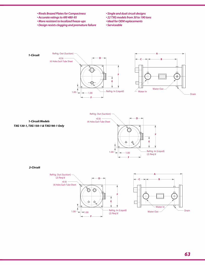
63
• Rivals Brazed Plates for Compactness• Accurate ratings to ARI 480-95• More resistant to localized freeze-ups• Design resists clogging and premature failure
• Single and dual circuit designs• 22 TXG models from 30 to 190 tons• Ideal for OEM replacements• Serviceable
1.001.00
Ø0.56 (4) Holes Each Tube Sheet
Refrig. Out (Suction)(2) Req’d D
A
BC
E
F
F
Refrig. In (Liquid)(2) Req’d
Water In
DrainWater Out
Ø0.56 (4) Holes Each Tube Sheet
DrainRefrig. In (Liquid)
1.001.00Water Out
Water In
Refrig. Out (Suction)
BCD
E
F
F
A
CØ0.56 (4) Holes Each Tube Sheet
Refrig. Out (Suction)
Refrig. In (Liquid)(2) Req’d
1.001.00
F
E
F
D
2-Circuit
1-Circuit
1-Circuit Models
TXG 130-1, TXG 150-1 & TXG190-1 Only
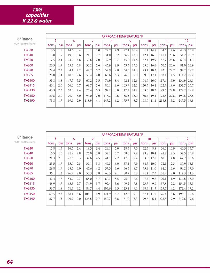
TXGcapacities
R-22 & water
APPROACH TEMPERATURE °F5 6 7 8 9 10 11 12
tons psi tons psi tons psi tons psi tons psi tons psi tons psi tons psi
TXG30 10.5 1.8 14.6 3.4 18.1 5.0 22.7 7.9 27.1 10.9 31.4 14.7 34.6 17.6 40.3 23.9
TXG40 3.8 1.9 19.0 3.6 24.1 5.7 31.0 9.2 36.9 13.0 42.1 16.6 47.1 20.6 54.2 26.9
TXG50 17.5 2.4 24.9 4.8 30.6 7.0 37.9 10.7 45.2 14.8 52.4 19.9 57.7 23.8 66.4 31.3
TXG60 20.3 1.9 29.2 3.8 36.2 5.6 45.9 8.9 55.3 13.0 63.0 16.6 70.5 20.6 81.0 26.9
TXG70 24.4 2.2 34.1 4.2 42.2 6.2 52.9 9.8 64.5 14.3 73.4 18.3 82.0 22.7 94.2 29.7
TXG85 28.8 1.4 40.6 2.6 50.4 4.0 63.6 6.3 76.8 9.0 89.0 12.1 98.1 14.5 114.2 19.7
TXG100 33.8 1.8 47.7 3.5 60.2 5.5 74.9 8.4 92.1 12.6 104.9 16.0 117.4 19.9 134.9 26.1
TXG115 40.1 2.0 56.0 3.7 68.7 5.6 86.1 8.6 103.9 12.2 120.3 16.4 132.7 19.6 152.7 25.7
TXG130 45.3 2.3 63.3 4.4 76.4 6.3 97.2 10.0 117.2 14.2 133.6 18.2 149.6 22.8 172.2 29.9
TXG150 59.8 3.0 79.0 5.0 94.0 7.0 116.2 10.6 138.5 15.0 156.7 19.1 172.3 22.8 194.8 28.8
TXG190 73.8 1.7 99.9 2.9 118.9 4.1 147.2 6.2 175.7 8.7 198.9 11.1 218.8 13.2 247.5 16.8
64
6° Range0.0001 additive fouling
APPROACH TEMPERATURE °F5 6 7 8 9 10 11 12
tons psi tons psi tons psi tons psi tons psi tons psi tons psi tons psi
TXG30 12.8 1.5 16.5 2.4 19.5 3.4 24.1 5.0 28.5 7.0 32.3 8.8 36.0 10.9 40.3 13.7
TXG40 16.5 1.6 21.9 2.8 26.0 3.8 32.1 5.7 38.0 7.9 43.8 10.4 48.2 12.3 54.5 15.9
TXG50 21.3 2.0 27.6 3.3 32.6 4.5 41.1 7.2 47.5 9.4 53.8 12.0 60.0 14.8 67.2 18.6
TXG60 25.5 1.7 33.0 2.8 39.1 3.8 49.3 6.0 57.1 7.9 64.7 10.0 72.1 12.3 80.9 15.5
TXG70 29.8 1.9 38.5 3.0 45.6 4.2 57.5 6.6 66.5 8.7 75.4 11.0 84.0 13.6 94.2 17.0
TXG85 36.1 1.2 46.7 2.0 55.3 2.8 68.3 4.1 80.7 5.8 91.4 7.3 101.9 9.0 114.3 11.3
TXG100 42.4 1.6 54.9 2.7 65.0 3.7 80.3 5.5 95.0 7.6 107.7 9.7 120.1 11.9 134.8 15.0
TXG115 48.9 1.7 63.3 2.7 74.9 3.7 92.4 5.6 109.2 7.8 123.7 9.9 137.8 12.2 154.5 15.3
TXG130 53.7 1.8 71.6 3.2 84.7 4.4 103.6 6.5 123.4 9.1 138.6 11.3 155.5 14.2 172.4 17.2
TXG150 69.5 2.3 88.1 3.6 103.1 4.9 121.9 6.7 142.8 9.1 157.4 11.0 176.4 13.6 195.1 16.6
TXG190 87.7 1.3 109.7 2.0 128.8 2.7 152.7 3.8 181.0 5.3 199.6 6.4 223.8 7.9 247.6 9.6
8° Range0.0001 additive fouling

TXGBtu/hr capacities
R-22 & water
65
APPROACH TEMPERATURE °F5 6 7 8 9 10 11 12
tons psi tons psi tons psi tons psi tons psi tons psi tons psi tons psi
TXG30 15.0 1.3 18.7 2.0 21.1 2.5 26.2 3.9 30.0 5.0 33.0 6.0 37.4 7.7 41.3 9.3
TXG40 19.0 1.4 24.1 2.1 28.0 2.9 34.1 4.1 40.0 5.7 44.4 6.9 50.0 8.7 55.9 10.8
TXG50 25.0 1.8 31.3 2.7 36.1 3.6 43.6 5.2 50.0 6.8 55.0 8.1 62.4 10.4 68.8 12.5
TXG60 29.9 1.5 37.4 2.3 42.1 2.9 52.3 4.4 60.0 5.6 66.0 6.8 75.0 8.7 83.7 10.8
TXG70 34.9 1.7 43.8 2.5 49.2 3.1 61.0 4.8 70.0 6.2 77.0 7.5 87.4 9.6 96.4 11.5
TXG85 42.3 1.1 51.9 1.6 59.7 2.1 72.6 3.0 85.0 4.1 93.4 5.0 106.0 6.4 117.0 7.6
TXG100 48.7 1.4 61.4 2.1 70.1 2.8 85.3 4.0 100.0 5.5 110.0 6.6 124.9 8.4 139.4 10.5
TXG115 57.4 1.5 70.3 2.2 80.8 2.8 100.3 4.3 115.0 5.6 126.4 6.7 143.5 8.6 158.3 10.3
TXG130 63.3 1.7 78.3 2.5 91.4 3.3 110.2 4.8 130.0 6.5 142.8 7.8 162.0 10.0 178.7 12.0
TXG150 79.0 1.9 97.0 2.9 109.3 3.5 127.9 4.8 150.0 6.5 164.5 7.8 182.3 9.4 202.0 11.6
TXG190 99.7 1.1 119.2 1.6 138.2 2.1 161.9 2.8 190.0 3.8 208.4 4.6 231.1 5.5 256.2 6.7
10° Range0.0001 additive fouling
APPROACH TEMPERATURE °F5 6 7 8 9 10 11 12
tons psi tons psi tons psi tons psi tons psi tons psi tons psi tons psi
TXG30 16.5 1.1 20.3 1.7 23.2 2.2 27.0 2.9 31.6 3.9 34.5 4.6 37.7 5.4 42.0 6.7
TXG40 21.5 1.2 26.9 1.9 30.1 2.3 35.9 3.3 42.0 4.4 46.0 5.2 50.9 6.4 56.8 7.9
TXG50 27.6 1.5 34.9 2.4 38.7 2.9 45.0 3.9 52.7 5.2 57.6 6.2 63.6 7.6 70.0 9.1
TXG60 33.0 1.3 40.6 1.9 46.3 2.5 54.0 3.3 63.2 4.4 69.1 5.2 76.4 6.3 84.6 7.7
TXG70 38.6 1.4 47.5 2.1 54.1 2.7 63.0 3.6 73.7 4.8 80.6 5.7 89.1 7.0 98.0 8.4
TXG85 46.8 0.9 57.6 1.4 65.7 1.8 76.4 2.4 89.4 3.2 97.8 3.8 106.7 4.5 119.0 5.6
TXG100 54.9 1.2 67.6 1.8 75.3 2.2 89.8 3.2 105.2 4.2 115.1 5.0 127.3 6.2 140.2 7.4
TXG115 63.5 1.3 78.3 1.9 89.0 2.4 103.5 3.2 121.1 4.3 132.4 5.2 144.5 6.1 161.0 7.5
TXG130 71.8 1.5 87.6 2.2 100.6 2.8 117.1 3.8 136.9 5.1 149.7 6.0 163.2 7.1 181.9 8.8
TXG150 88.2 1.7 104.8 2.3 119.6 3.0 135.6 3.8 154.0 4.8 172.0 6.0 187.1 7.1 203.2 8.2
TXG190 109.6 0.9 132.3 1.4 147.9 1.7 171.5 2.2 196.5 2.9 217.9 3.5 237.1 4.1 257.6 4.8
12° Range0.0001 additive fouling
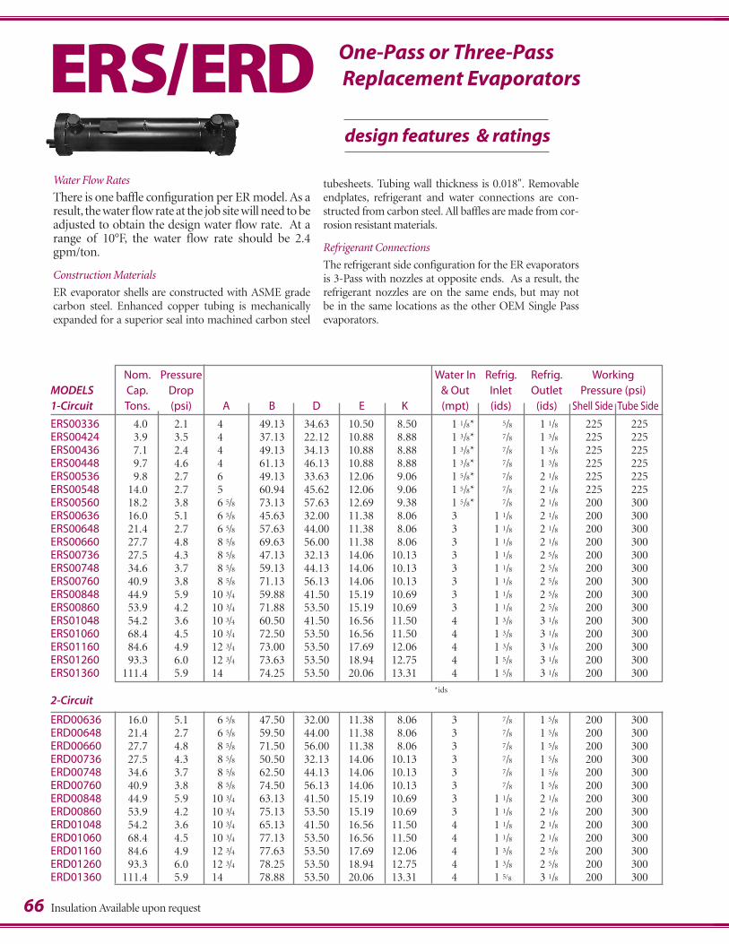
Nom. Pressure Water In Refrig. Refrig. WorkingMODELS Cap. Drop & Out Inlet Outlet Pressure (psi)1-Circuit Tons. (psi) A B D E K (mpt) (ids) (ids) Shell Side Tube Side
ERS00336 4.0 2.1 4 49.13 34.63 10.50 8.50 1.1/8* .5/8 1.1/8 225 225ERS00424 3.9 3.5 4 37.13 22.12 10.88 8.88 1.3/8* .7/8 1.3/8 225 225ERS00436 7.1 2.4 4 49.13 34.13 10.88 8.88 1.3/8* .7/8 1.3/8 225 225ERS00448 9.7 4.6 4 61.13 46.13 10.88 8.88 1.3/8* .7/8 1.3/8 225 225ERS00536 9.8 2.7 6 49.13 33.63 12.06 9.06 1.5/8* .7/8 2.1/8 225 225ERS00548 14.0 2.7 5 60.94 45.62 12.06 9.06 1.5/8* .7/8 2.1/8 225 225ERS00560 18.2 3.8 6.5/8 73.13 57.63 12.69 9.38 1.5/8* .7/8 2.1/8 200 300ERS00636 16.0 5.1 6.5/8 45.63 32.00 11.38 8.06 3 1.1/8 2.1/8 200 300ERS00648 21.4 2.7 6.5/8 57.63 44.00 11.38 8.06 3 1.1/8 2.1/8 200 300ERS00660 27.7 4.8 8.5/8 69.63 56.00 11.38 8.06 3 1.1/8 2.1/8 200 300ERS00736 27.5 4.3 8.5/8 47.13 32.13 14.06 10.13 3 1.1/8 2.5/8 200 300ERS00748 34.6 3.7 8.5/8 59.13 44.13 14.06 10.13 3 1.1/8 2.5/8 200 300ERS00760 40.9 3.8 8.5/8 71.13 56.13 14.06 10.13 3 1.1/8 2.5/8 200 300ERS00848 44.9 5.9 10.3/4 59.88 41.50 15.19 10.69 3 1.1/8 2.5/8 200 300ERS00860 53.9 4.2 10.3/4 71.88 53.50 15.19 10.69 3 1.1/8 2.5/8 200 300ERS01048 54.2 3.6 10.3/4 60.50 41.50 16.56 11.50 4 1.3/8 3.1/8 200 300ERS01060 68.4 4.5 10.3/4 72.50 53.50 16.56 11.50 4 1.3/8 3.1/8 200 300ERS01160 84.6 4.9 12.3/4 73.00 53.50 17.69 12.06 4 1.3/8 3.1/8 200 300ERS01260 93.3 6.0 12.3/4 73.63 53.50 18.94 12.75 4 1.5/8 3.1/8 200 300ERS01360 111.4 5.9 14 74.25 53.50 20.06 13.31 4 1.5/8 3.1/8 200 300
2-Circuit
ERD00636 16.0 5.1 6.5/8 47.50 32.00 11.38 8.06 3 .7/8 1.5/8 200 300ERD00648 21.4 2.7 6.5/8 59.50 44.00 11.38 8.06 3 .7/8 1.5/8 200 300ERD00660 27.7 4.8 8.5/8 71.50 56.00 11.38 8.06 3 .7/8 1.5/8 200 300ERD00736 27.5 4.3 8.5/8 50.50 32.13 14.06 10.13 3 .7/8 1.5/8 200 300ERD00748 34.6 3.7 8.5/8 62.50 44.13 14.06 10.13 3 .7/8 1.5/8 200 300ERD00760 40.9 3.8 8.5/8 74.50 56.13 14.06 10.13 3 .7/8 1.5/8 200 300ERD00848 44.9 5.9 10.3/4 63.13 41.50 15.19 10.69 3 1.1/8 2.1/8 200 300ERD00860 53.9 4.2 10.3/4 75.13 53.50 15.19 10.69 3 1.1/8 2.1/8 200 300ERD01048 54.2 3.6 10.3/4 65.13 41.50 16.56 11.50 4 1.1/8 2.1/8 200 300ERD01060 68.4 4.5 10.3/4 77.13 53.50 16.56 11.50 4 1.1/8 2.1/8 200 300ERD01160 84.6 4.9 12.3/4 77.63 53.50 17.69 12.06 4 1.3/8 2.5/8 200 300ERD01260 93.3 6.0 12.3/4 78.25 53.50 18.94 12.75 4 1.3/8 2.5/8 200 300ERD01360 111.4 5.9 14 78.88 53.50 20.06 13.31 4 1.5/8 3.1/8 200 300
tubesheets. Tubing wall thickness is 0.018". Removableendplates, refrigerant and water connections are con-structed from carbon steel. All baffles are made from cor-rosion resistant materials.
Refrigerant Connections
The refrigerant side configuration for the ER evaporatorsis 3-Pass with nozzles at opposite ends. As a result, therefrigerant nozzles are on the same ends, but may not be in the same locations as the other OEM Single Pass evaporators.
66
design features & ratings
ERS/ERDWater Flow Rates
There is one baffle configuration per ER model. As aresult, the water flow rate at the job site will need to beadjusted to obtain the design water flow rate. At arange of 10°F, the water flow rate should be 2.4gpm/ton.
Construction Materials
ER evaporator shells are constructed with ASME gradecarbon steel. Enhanced copper tubing is mechanicallyexpanded for a superior seal into machined carbon steel
*ids
One-Pass or Three-PassReplacement Evaporators
Insulation Available upon request
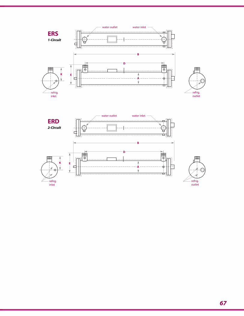
67
water outlet water inlet
refrig.outlet
refrig.inlet
D
B
AK E
water outlet water inlet
refrig.outlet
refrig.inlet
D
B
AK E
ERS1-Circuit
ERD2-Circuit
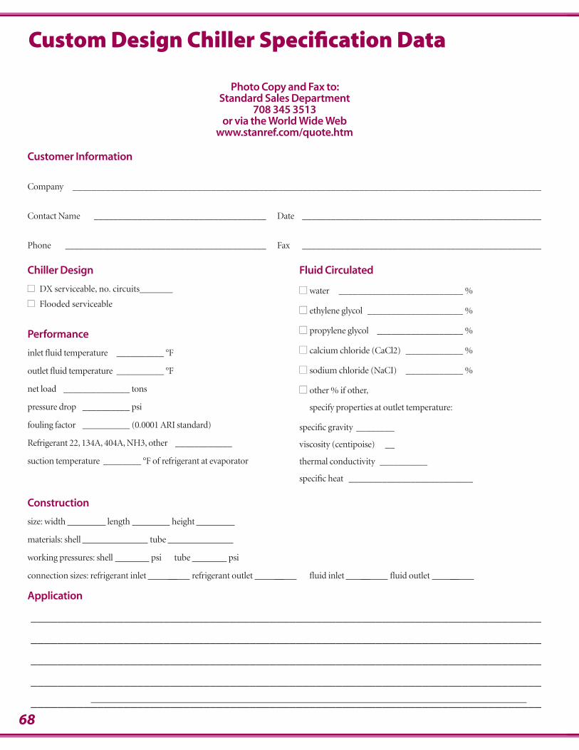
68
Construction
size: width length height
materials: shell tube
working pressures: shell psi tube psi
connection sizes: refrigerant inlet __ refrigerant outlet __ fluid inlet __ fluid outlet __
Application
_____________________________________________________________________________
_____________________________________________________________________________
_____________________________________________________________________________
_____________________________________________________________________________
_____________________________________________________________________________
Customer Information
Company __________________________________________________________________________________________________
Contact Name ____________________________________ Date __________________________________________________
Phone __________________________________________ Fax __________________________________________________
Chiller Design
■■ DX serviceable, no. circuits_______
■■ Flooded serviceable
Performance
inlet fluid temperature __________ °F
outlet fluid temperature __________ °F
net load ______________ tons
pressure drop __________ psi
fouling factor __________ (0.0001 ARI standard)
Refrigerant 22, 134A, 404A, NH3, other ____________
suction temperature ________ °F of refrigerant at evaporator
Fluid Circulated
■■ water __________________________ %
■■ ethylene glycol ____________________ %
■■ propylene glycol __________________ %
■■ calcium chloride (CaCl2) ____________ %
■■ sodium chloride (NaCI) ____________ %
■■ other % if other,
specify properties at outlet temperature:
specific gravity ________
viscosity (centipoise) __
thermal conductivity __________
specific heat __________________________
Photo Copy and Fax to: Standard Sales Department
708 345 3513or via the World Wide Web
www.stanref.com/quote.htm
Custom Design Chiller Specification Data
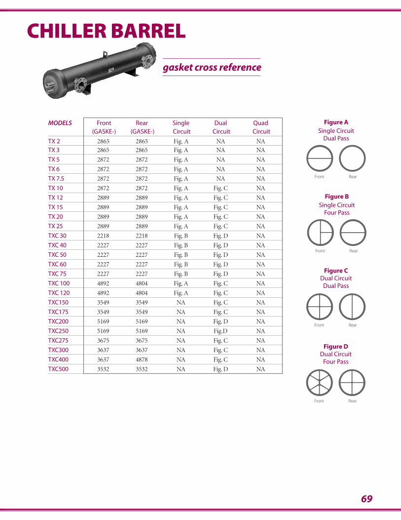
69
MODELS Front Rear Single Dual Quad(GASKE-) (GASKE-) Circuit Circuit Circuit
TX 2 2865 2865 Fig. A NA NA
TX 3 2865 2865 Fig. A NA NA
TX 5 2872 2872 Fig. A NA NA
TX 6 2872 2872 Fig. A NA NA
TX 7.5 2872 2872 Fig. A NA NA
TX 10 2872 2872 Fig. A Fig. C NA
TX 12 2889 2889 Fig. A Fig. C NA
TX 15 2889 2889 Fig. A Fig. C NA
TX 20 2889 2889 Fig. A Fig. C NA
TX 25 2889 2889 Fig. A Fig. C NA
TXC 30 2218 2218 Fig. B Fig. D NA
TXC 40 2227 2227 Fig. B Fig. D NA
TXC 50 2227 2227 Fig. B Fig. D NA
TXC 60 2227 2227 Fig. B Fig. D NA
TXC 75 2227 2227 Fig. B Fig. D NA
TXC 100 4892 4804 Fig. A Fig. C NA
TXC 120 4892 4804 Fig. A Fig. C NA
TXC150 3549 3549 NA Fig. C NA
TXC175 3549 3549 NA Fig. C NA
TXC200 5169 5169 NA Fig. D NA
TXC250 5169 5169 NA Fig.D NA
TXC275 3675 3675 NA Fig. C NA
TXC300 3637 3637 NA Fig. C NA
TXC400 3637 4878 NA Fig. C NA
TXC500 3532 3532 NA Fig. D NA
gasket cross reference
CHILLER BARREL
Figure ASingle Circuit
Dual Pass
Front Rear
Figure BSingle Circuit
Four Pass
Front Rear
Figure CDual Circuit
Dual Pass
Front Rear
Figure DDual Circuit
Four Pass
Front Rear
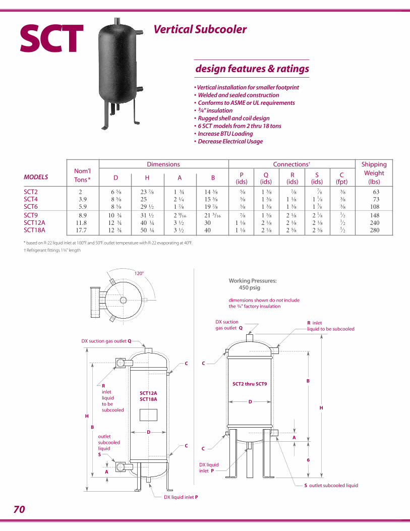
70
A
DX suction gas outlet Q
C
C
S outlet subcooled liquid
6
B
HD
R inletliquid to be subcooled
DX liquid inlet P
Working Pressures:450 psig
dimensions shown do not includethe 3⁄4" factory insulation
A
DX suction gas outlet Q
H
BD
C
C
120°
SCT12ASCT18A
Rinletliquidto be subcooled
outletsubcooledliquidS
DX liquid inlet P
SCT2 thru SCT9
* based on R-22 liquid inlet at 100°F. and 50°F. outlet temperature with R-22 evaporating at 40°F.
† Refrigerant fittings 13⁄4" length
Dimensions Connections† ShippingNom’l
D H A B P Q R S C WeightMODELS Tons* (ids) (ids) (ids) (ids) (fpt) (lbs)
SCT2 2 6.5⁄8 23.7⁄8 1. 3⁄4 14.3⁄8 .5⁄8 1.3⁄8 .7⁄8 .7⁄8 .3⁄8 63SCT4 3.9 8.5⁄8 25. 2.1⁄4 15.3⁄8 .5⁄8 1.3⁄8 1.1⁄8 1.1⁄8 .3⁄8 73SCT6 5.9 8.5⁄8 29.1⁄2 1.7⁄8 19.7⁄8 .5⁄8 1.3⁄8 1.3⁄8 1.3⁄8 .3⁄8 108SCT9 8.9 10. 3⁄4 31.1⁄2 2.9/16 21.3/16 .7⁄8 1.5⁄8 2.1⁄8 2.1⁄8 .1⁄2 148SCT12A 11.8 12. 3⁄4 40. 1⁄4 3.1⁄2 30. 1.1⁄8 2.1⁄8 2.1⁄8 2.1⁄8 .1⁄2 240SCT18A 17.7 12. 3⁄4 50. 1⁄4. 3.1⁄2 40. 1.1⁄8 2.1⁄8 2.5⁄8 2.5⁄8 .1⁄2 280
Vertical SubcoolerSCTdesign features & ratings
• Vertical installation for smaller footprint• Welded and sealed construction• Conforms to ASME or UL requirements • 3⁄4" insulation• Rugged shell and coil design• 6 SCT models from 2 thru 18 tons• Increase BTU Loading• Decrease Electrical Usage
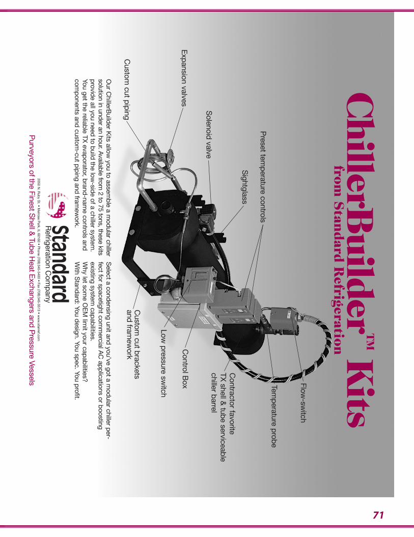
Our C
hillerBuilder K
its allow you to assem
ble a modular chiller
solution in under an hour. Available from
2 to 75 tons, these kitsprovide all you need to build the low
-side of a chiller system.
You get the reliable TX evaporator, brand-nam
e controls andcom
ponents and custom-cut piping and fram
ework.
Select a condensing unit and you’ve got a m
odular chiller per-fect for spacetight com
mercial A
C applications or boosting
existing system capabilities.
Why let som
e OE
M lim
it your capabilities?W
ith Standard: You design. You spec. You profit.
Flow-sw
itch
Preset tem
perature controls
Expansion valves
Custom
cut piping
Solenoid valve
Sightglass
Temperature probe
Control B
ox
Contractor favorite
TX shell &
tube serviceablechiller barrel
Custom
cut bracketsand fram
ework
Low pressure sw
itch
2050 N. R
uby St. • M
elrose Park, IL 60160 • P
hone (708)345-5400 • Fax (708)345-3513 • ww
w.stanref.com
71
ChillerB
uilder
TMK
itsfrom
Stan
dard
Refrigeration
StandardR
efrigeration Com
pany
Purveyors of the Finest S
hell & Tube H
eat Exchangers and P
ressure Vessels
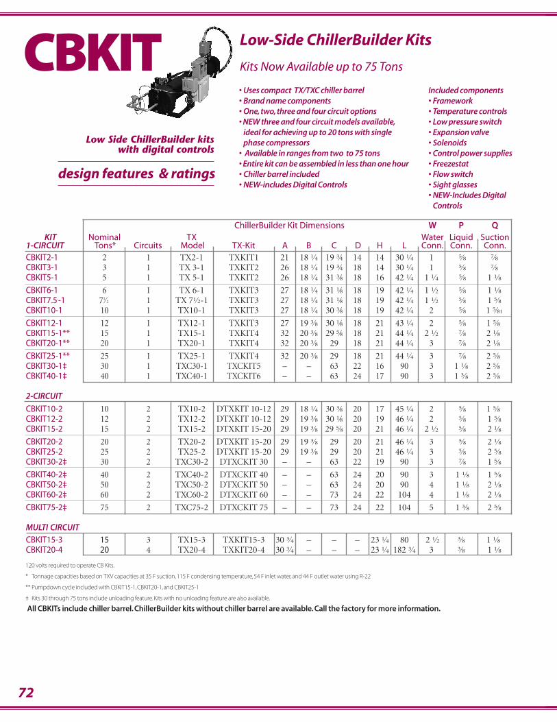
ChillerBuilder Kit Dimensions W P QKIT Nominal TX Water Liquid Suction
1-CIRCUIT Tons* Circuits Model TX-Kit A B C D H L Conn. Conn. Conn.CBKIT2-1 2 1 TX2-1 TXKIT1 21 18.1⁄4 19.3⁄4 14 14 30.1⁄4 1 .5⁄8 .7⁄8CBKIT3-1 3 1 TX 3-1 TXKIT2 26 18.1⁄4 19.3⁄4 18 14 30.1⁄4 1 .5⁄8 .7⁄8CBKIT5-1 5 1 TX 5-1 TXKIT2 26 18.1⁄4 31.3⁄8 18 16 42.1⁄4 1.1⁄4 .5⁄8 .1.1⁄8
CBKIT6-1 6 1 TX 6-1 TXKIT3 27 18.1⁄4 31.1⁄8 18 19 42.1⁄4 1.1⁄2 .5⁄8 .1.1⁄8CBKIT7.5.-1 71⁄2 1 TX 71⁄2-1 TXKIT3 27 18.1⁄4 31.1⁄8 18 19 42.1⁄4 1.1⁄2 .5⁄8 .1.5⁄8CBKIT10-1 10 1 TX10-1 TXKIT3 27 18.1⁄4 30.3⁄8 18 19 42.1⁄4 2 .5⁄8 .1.5⁄81
CBKIT12-1 12 1 TX12-1 TXKIT3 27 19.3⁄8 30.1⁄8 18 21 43.1⁄4 2 .5⁄8 1.5⁄8CBKIT15-1** 15 1 TX15-1 TXKIT4 32 20.3⁄8 29.5⁄8 18 21 44.1⁄4 2.1⁄2 .7⁄8 2.1⁄8CBKIT20-1** 20 1 TX20-1 TXKIT4 32 20.3⁄8 29 18 21 44.1⁄4 3 .7⁄8 2.1⁄8
CBKIT25-1** 25 1 TX25-1 TXKIT4 32 20.3⁄8 29 18 21 44.1⁄4 3 .7⁄8 2.5⁄8CBKIT30-1‡ 30 1 TXC30-1 TXCKIT5 – – 63 22 16 90 3 1.1⁄8 2.5⁄8CBKIT40-1‡ 40 1 TXC40-1 TXCKIT6 – – 63 24 17 90 3 1.3⁄8 2.5⁄8
2-CIRCUIT
CBKIT10-2 10 2 TX10-2 DTXKIT 10-12 29 18.1⁄4 30.3⁄8 20 17 45.1⁄4 2 .5⁄8 1.5⁄8CBKIT12-2 12 2 TX12-2 DTXKIT 10-12 29 19.3⁄8 30.1⁄8 20 19 46.1⁄4 2 .5⁄8 .1.5⁄8CBKIT15-2 15 2 TX15-2 DTXKIT 15-20 29 19.3⁄8 29.5⁄8 20 21 46.1⁄4 2.1⁄2 .5⁄8 .2.1⁄8
CBKIT20-2 20 2 TX20-2 DTXKIT 15-20 29 19.3⁄8 29 20 21 46.1⁄4 3 .5⁄8 .2.1⁄8CBKIT25-2 25 2 TX25-2 DTXKIT 15-20 29 19.3⁄8 29 20 21 46.1⁄4 3 .5⁄8 .2.5⁄8CBKIT30-2‡ 30 2 TXC30-2 DTXCKIT 30 – – 63 22 19 90 3 .7⁄8 .1.5⁄8
CBKIT40-2‡ 40 2 TXC40-2 DTXCKIT 40 – – 63 24 20 90 3 .1.1⁄8 .1.5⁄8CBKIT50-2‡ 50 2 TXC50-2 DTXCKIT 50 – – 63 24 20 90 4 .1.1⁄8 .2.1⁄8CBKIT60-2‡ 60 2 TXC60-2 DTXCKIT 60 – – 73 24 22 104 4 .1.1⁄8 .2.1⁄8
CBKIT75-2‡ 75 2 TXC75-2 DTXCKIT 75 – – 73 24 22 104 5 .1.3⁄8 .2.5⁄8
MULTI CIRCUITCBKIT15-3 15 3 TX15-3 TXKIT15-3 30.3⁄4 – – – 23.1⁄4 80 .2.1⁄2 3⁄8 1.1⁄8CBKIT20-4 20 4 TX20-4 TXKIT20-4 30.3⁄4 – – – 23.1⁄4 182.3⁄4 3 3⁄8 .1.1⁄8
72
120 volts required to operate CB Kits.
* Tonnage capacities based on TXV capacities at 35 F suction, 115 F condensing temperature, 54 F inlet water, and 44 F outlet water using R-22
** Pumpdown cycle included with CBKIT15-1, CBKIT20-1, and CBKIT25-1
‡ Kits 30 through 75 tons include unloading feature. Kits with no unloading feature are also available.
All CBKITs include chiller barrel. ChillerBuilder kits without chiller barrel are available. Call the factory for more information.
• Uses compact TX/TXC chiller barrel• Brand name components• One, two, three and four circuit options • NEW three and four circuit models available,
ideal for achieving up to 20 tons with single phase compressors
• Available in ranges from two to 75 tons• Entire kit can be assembled in less than one hour• Chiller barrel included• NEW-includes Digital Controls
Included components• Framework• Temperature controls• Low pressure switch • Expansion valve• Solenoids• Control power supplies• Freezestat• Flow switch• Sight glasses• NEW-Includes Digital
Controls
Horizontal Super Efficient Water Cooled CondensersLow-Side ChillerBuilder Kits
Kits Now Available up to 75 TonsCBKIT
design features & ratings
Low Side ChillerBuilder kitswith digital controls
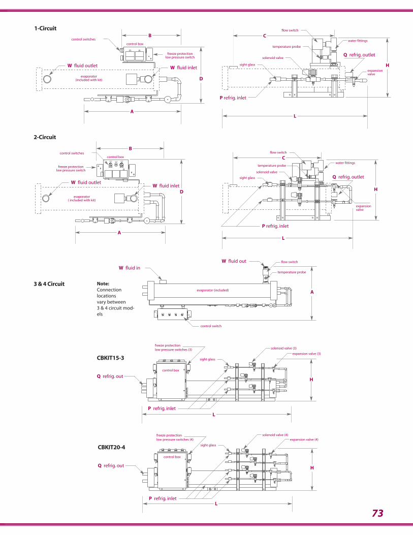
73
control switch
flow switch
temperature probe
evaporator (included) A
W fluid outW fluid in
sight glass
control box
L
H
P refrig. inlet
freeze protection low pressure switches (3)
Q refrig. out
solenoid valve (3)
expansion valve (3)
CONTROL BOX
sight glass
control box
solenoid valve (4)expansion valve (4)
freeze protection low pressure switches (4)
H
L
Q refrig. out
P refrig. inlet
CBKIT15-3
CBKIT20-4
Note:Connectionlocationsvary between3 & 4 circuit mod-els
Q refrig. outlet
flow switch
temperature probe
solenoid valve
sight glass
water fittings
expansionvalve
H
C
L
P refrig. inlet
D
control switchescontrol box
evaporator(included with kit)
freeze protectionlow pressure switch
B
A
W fluid outlet W fluid inlet
Q refrig. outlet
flow switch
temperature probe
solenoid valve
sight glass
water fittings
expansionvalve
H
C
L
P refrig. inlet
ON OFF ON OFF
SWITCH
COMP 2CONTROL
SWITCHCONTROLCOMP 1CIRCUIT
BREAKER
D
control switchescontrol box
evaporator( included with kit)
freeze protectionlow pressure switch
B
W fluid outletW fluid inlet
A
1-Circuit
2-Circuit
3 & 4 Circuit
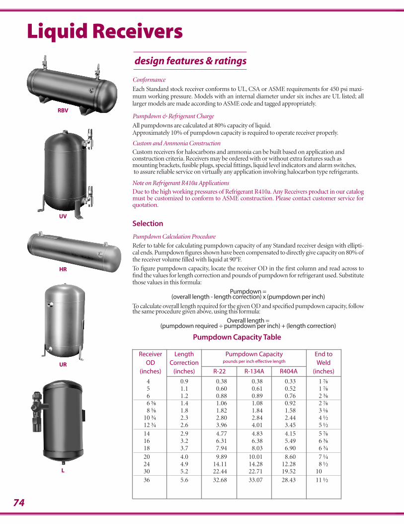
74
Liquid Receiversdesign features & ratings
Conformance
Each Standard stock receiver conforms to UL, CSA or ASME requirements for 450 psi maxi-mum working pressure. Models with an internal diameter under six inches are UL listed; alllarger models are made according to ASME code and tagged appropriately.
Pumpdown & Refrigerant Charge
All pumpdowns are calculated at 80% capacity of liquid.Approximately 10% of pumpdown capacity is required to operate receiver properly.
Custom and Ammonia ConstructionCustom receivers for halocarbons and ammonia can be built based on application andconstruction criteria. Receivers may be ordered with or without extra features such asmounting brackets, fusible plugs, special fittings, liquid level indicators and alarm switches,to assure reliable service on virtually any application involving halocarbon type refrigerants.
Note on Refrigerant R410a ApplicationsDue to the high working pressures of Refrigerant R410a. Any Receivers product in our catalogmust be customized to conform to ASME construction. Please contact customer service forquotation.
Selection
Pumpdown Calculation Procedure
Refer to table for calculating pumpdown capacity of any Standard receiver design with ellipti-cal ends. Pumpdown figures shown have been compensated to directly give capacity on 80% ofthe receiver volume filled with liquid at 90°F.
To figure pumpdown capacity, locate the receiver OD in the first column and read across tofind the values for length correction and pounds of pumpdown for refrigerant used. Substitutethose values in this formula:
Pumpdown =(overall length - length correction) x (pumpdown per inch)
To calculate overall length required for the given OD and specified pumpdown capacity, followthe same procedure given above, using this formula:
Overall length =(pumpdown required ÷ pumpdown per inch) + (length correction)
Pumpdown Capacity Table
Receiver Length Pumpdown Capacity End toOD Correction pounds per inch effective length Weld
(inches) (inches) R-22 R-134A R404A (inches)
4 0.9 0.38 0.38 0.33 1.⅞5 1.1 0.60 0.61 0.52 1.⅞6 1.2 0.88 0.89 0.76 2.⅜6.⅝ 1.4 1.06 1.08 0.92 2.⅞8.⅝ 1.8 1.82 1.84 1.58 3.⅛
10.¾ 2.3 2.80 2.84 2.44 4.½12.¾ 2.6 3.96 4.01 3.45 5.½
14 2.9 4.77 4.83 4.15 5.⅞16 3.2 6.31 6.38 5.49 6.⅜18 3.7 7.94 8.03 6.90 6.¾
20 4.0 9.89 10.01 8.60 7.¼24 4.9 14.11 14.28 12.28 8.½30 5.2 22.44 22.71 19.52 1036 5.6 32.68 33.07 28.43 11.½
RBV
UV
HR
UR
L

75
Pumpdown* Dimensions (inches) Connections (inches) Shipping(lbs)
P Q S WeightMODELS
R-22 R-134AD L A B
(ids) (ids) (fpt) (lbs)
285 16 16 5 28 3 25 .⅝ .⅝ .⅜ 19306 25 26 6 30 3.⅝ 26.⅜ .⅝ .⅝ .⅜ 24366 31 31 6 36 3.⅝ 32.⅜ .⅝ .⅝ .⅜ 31
3865 39 40 6.⅝ 38 4.⅜ 33.⅝ .⅞ .⅝ .½ 422885 48 48 8.⅝ 28 4.⅝ 23.⅜ 1.⅛ .⅞ .½ 453685 62 63 8.⅝ 36 4.⅝ 31.⅜ 1.⅛ .⅞ .½ 65
4285 73 74 8.⅝ 42 4.⅝ 37.⅜ 1.⅛ .⅞ .½ 714885 84 85 8.⅝ 48 4.⅝ 43.⅜ 1.⅛ 1.⅛ .½ 776085 106 107 8.⅝ 60 4.⅝ 55.⅜ 1.⅛ 1.⅛ .½ 108
36105 94 96 10.¾ 36 6.½ 29.½ 1.⅜ 1.⅜ .½ 11548105 128 130 10.¾ 48 6.½ 41.½ 1.⅜ 1.⅜ .½ 13860105 162 164 10.¾ 60 6.½ 53.½ 1.⅜ 1.⅜ .½ 166
72105 195 198 10.¾ 72 6.½ 65.½ 1.⅜ 1.⅜ .½ 19696105 262 266 10.¾ 96 6.½ 89.½ 1.⅝ 1.⅜ .½ 28548122 180 182 12.¾ 48 8 40 1.⅝ 1.⅜ .½ 182
60122 227 230 12.¾ 60 8 52 1.⅝ 1.⅜ .½ 21872122 275 278 12.¾ 72 8 64 2.⅛ 1.⅜ .½ 26096122 370 375 12.¾ 96 8 88 2.⅛ 1.⅜ .½† 360
72145 330 334 14 72 8.⅜ 63.⅝ 2.⅛ 1.⅝ .½† 31696145 444 450 14 96 8.⅜ 87.⅝ 2.⅝ 2.⅛ .½† 42560166 358 362 16 60 8.⅞ 51.⅛ 2.⅝ 2.⅛ .½† 306
72166 434 439 16 72 8.⅞ 63.⅛ 2.⅝ 2.⅛ .½† 38096166 586 592 16 96 8.⅞ 87.⅛ 2.⅝ 2.⅛ .½† 48672188 542 548 18 72 9.⅞ 62.⅛ 3.⅛ 2.⅛ .½† 510
72201 673 681 20 72 10.½ 61.½ 3.⅛ 2.⅝ .½† 57084201 791 801 20 84 10.½ 73.½ 3.⅛ 2.⅝ .½† 63996201 910 921 20 96 10.½ 85.½ 3.⅛ 2.⅝ .½† 756
96241 1,285 1,301 24 96 12.½ 83.½ 3.⅝ 3.⅛ .¾† 100012241 1,624 1,644 24 120 13 107 4.⅛ 3.⅝ .¾† 125012301 2,576 2,607 30 120 15 105 4.⅛ 3.⅝ .¾† 1800
design features & ratings
R-12= R-22 capacity x 1.10R-502= R-22 capacity x 1.01R-404A= R-22 capacity x 0.89R-507= R-22 capacity x 0.88
* All pumpdowns are calculated at 80% of receiver volume
Use the following multipliers for refrigerants other than shown above:
† Safety fitting located 30° above centerline below refrigerant outlet
HR
Working Pressure: 450 psi
Horizontal ReceiversHR
Tag location may vary per model.
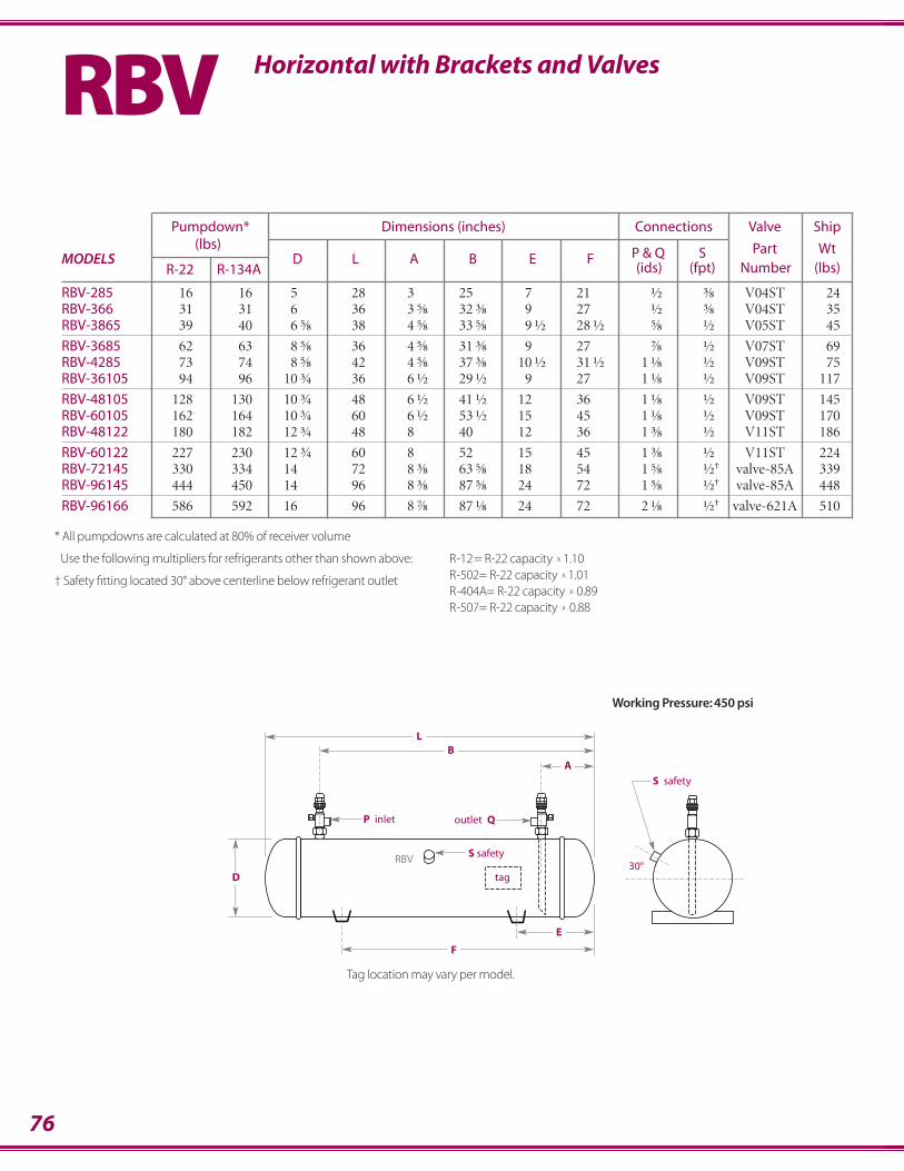
76
LB
A
30°D
outlet Q
S safety
P inlet
tag
E
F
S safety RBV
Pumpdown* Dimensions (inches) Connections Valve Ship(lbs)
P & Q S Part WtMODELS
R-22 R-134AD L A B E F
(ids) (fpt) Number (lbs)
RBV-285 16 16 5 28 3 25 7 21 .½ .⅜ V04ST 24RBV-366 31 31 6 36 3.⅝ 32.⅜ 9 27 .½ .⅜ V04ST 35RBV-3865 39 40 6.⅝ 38 4.⅝ 33.⅝ 9.½ 28.½ .⅝ .½ V05ST 45
RBV-3685 62 63 8.⅝ 36 4.⅝ 31.⅜ 9 27 .⅞ .½ V07ST 69RBV-4285 73 74 8.⅝ 42 4.⅝ 37.⅜ 10.½ 31.½ 1.⅛ .½ V09ST 75RBV-36105 94 96 10.¾ 36 6.½ 29.½ 9 27 1.⅛ .½ V09ST 117
RBV-48105 128 130 10.¾ 48 6.½ 41.½ 12 36 1.⅛ .½ V09ST 145RBV-60105 162 164 10.¾ 60 6.½ 53.½ 15 45 1.⅛ .½ V09ST 170RBV-48122 180 182 12.¾ 48 8 40 12 36 1.⅜ .½ V11ST 186
RBV-60122 227 230 12.¾ 60 8 52 15 45 1.⅜ .½ V11ST 224RBV-72145 330 334 14 72 8.⅜ 63.⅝ 18 54 1.⅝ .½† valve-85A 339RBV-96145 444 450 14 96 8.⅜ 87.⅝ 24 72 1.⅝ .½† valve-85A 448
RBV-96166 586 592 16 96 8.⅞ 87.⅛ 24 72 2.⅛ .½† valve-621A 510
Working Pressure: 450 psi
R-12= R-22 capacity x 1.10R-502= R-22 capacity x 1.01R-404A= R-22 capacity x 0.89R-507= R-22 capacity x 0.88
* All pumpdowns are calculated at 80% of receiver volume
Use the following multipliers for refrigerants other than shown above:
† Safety fitting located 30° above centerline below refrigerant outlet
Horizontal with Brackets and ValvesRBV
Tag location may vary per model.
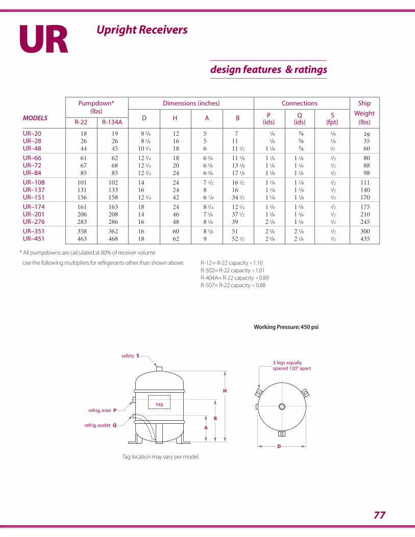
77
Upright ReceiversURdesign features & ratings
safety S
refrig. inlet P
refrig. outlet Q
3 legs equallyspaced 120° apart
D
A
B
H
tag
Working Pressure: 450 psi
R-12= R-22 capacity x 1.10R-502= R-22 capacity x 1.01R-404A= R-22 capacity x 0.89R-507= R-22 capacity x 0.88
* All pumpdowns are calculated at 80% of receiver volume
Use the following multipliers for refrigerants other than shown above:
Pumpdown* Dimensions (inches) Connections Ship(lbs)
P Q S WeightMODELS
R-22 R-134AD H A B
(ids) (ids) (fpt) (lbs)
UR–20 18 19 8.5/8 12. 5 7. .5/8 .⅝ .3/8 29UR–28 26 26 8.5/8 16 5 11. .5/8 .⅝ .3/8 35UR–48 44 45 10.3/4 18 6 11.1/2 1.1/8 .⅞ 1/2 60
UR–66 61 62 12.3/4 18 6.5/8 11.3/8 1.1/8 1.1/8 .1/2 80UR–72 67 68 12.3/4 20 6.5/8 13.3/8 1.1/8 1.1/8 .1/2 88UR–84 85 85 12.3/4 24 6.5/8 17.3/8 1.1/8 1.1/8 .1/2 98
UR–108 101 102 14 24 7.1/2 16.1/2 1.3/8 1.3/8 .1/2 111UR–137 131 133 16 24 8. 16 1.3/8 1.3/8 .1/2 140UR–151 156 158 12.3/4 42 6.7/8 34.1/2 1.3/8 1.3/8 .1/2 170
UR–174 161 163 18 24 8.3/4 12.1/4 1.5/8 1.5/8 .1/2 175UR–201 206 208 14 46 7.5/8 37.1/2 1.5/8 1.5/8 .1/2 210UR–276 283 286 16 48 8.1/8 39 2.1/8 1.5/8 .1/2 245
UR–351 358 362 16 60 8.3/8 51 2.5/8 2.1/8 .1/2 300UR–451 463 468 18 62 9. 52.1/2 2.5/8 2.1/8 .1/2 435
Tag location may vary per model.
78
safety S
refrig. inlet P
3 legs equallyspaced 120° apart
D
A
B
H
refrig. outlet Q
tag
Pumpdown* Dimensions (inches) Connections Valve Ship(lbs)
P & Q S Part WeightMODELS
R-22 R-134AD H A B
(ids) (fpt) Number (lbs)
UV-30 29 30 8.5/8 18 5.1/8 12.7/8 .1/2 .3/8 H04ST 40UV-40 40 41 8.5/8 24 5.1/8 19.3/8 .5/8 .3/8 H05ST 47UV-50 55 56 8.5/8 32 5.1/4 26.3/4 .7/8 .3/8 H07ST 60
UV-70 72 73 10.3/4. 28 6. 21.1/2 1.1/8 .1/2 H09ST 90UV-100 100 101 10.3/4. 38 6 31.1/2 1.1/8 .1/2 H09ST 120UV-125 132 134 12.3/4 36 6.5/8 29.3/8 1.1/8 .1/2 H09ST 160
UV-150 156 158 12.3/4 42 6.5/8 34.1/2 1.1/8 .1/2 H09ST 175UV-200 206 208 14. 46 7.1/2 37.1/2 1.3/8 .1/2 H11ST 215UV-275 283 286 16. 48 8.1/8 39 1.5/8 .1/2 valve-85A 250
UV-350 358 362 16. 60 8.1/8 51 1.5/8 .1/2 valve-85A 305UV-450 463 468 18. 62 8.3/4 52.1/2 1.5/8 .1/2 valve-85A 440
Working Pressure: 450 psi
R-12= R-22 capacity x 1.10R-502= R-22 capacity x 1.01R-404A= R-22 capacity x 0.89R-507= R-22 capacity x 0.88
* All pumpdowns are calculated at 80% of receiver volume
Use the following multipliers for refrigerants other than shown above:
Upright Receivers with ValvesUVdesign features & ratings
Tag location may vary per model.
79
Pumpdown* Dimensions (inches) Connections W Ship(lbs)
P Q S Weld WeightMODELS
R-22 R-502B D H A
(flare) (fpt) Screw (lbs)
L-408C 2.9 2.95 na 4. 8 2.11⁄16 .3⁄8 .3⁄8 .1⁄8 3⁄8”-16 x 1 7L-413C 5.0 5.10 3.1⁄2 4. 13.1⁄2 2.1⁄2 .3⁄8 .3⁄8 .3⁄8 3⁄8”-16 x 1 10L-516C 9.3 9.45 3.1⁄2 5. 16 2.1⁄2 .1⁄2 .1/2 .3⁄8 3⁄8”-16 x 1 14
L-618C 15.3 15.56 3.1⁄2 6. 18 2.1⁄2 .1⁄2 .1/2 3⁄8 .1⁄2”-13 x 1 19L-623C 19.7 20.03 3.1⁄2 6. 23 2.1⁄2 .1⁄2 .1/2 .3⁄8 .1⁄2”-13 x 1 24L-630C 25.3 25.7 3.5⁄8 6. 30 2.1⁄2 .5/8 .⅝ 3⁄8 .1⁄2”-13 x 1 29
S safetyw/430° fusible plug
P refrig. outlet withbrazed on flare valve
refrig.inlet Q
(ids)
W weld screw
A
H
B
W weld screw
refrig.inlet Q(flare)
P refrig. outlet withbrazed on flare valve
S safetyw/430° fusible plug
L408C Model Only
D
D
A
R-12= R-22 capacity x 1.10R-502= R-22 capacity x 1.01R-404A= R-22 capacity x 0.89R-507= R-22 capacity x 0.88
* All pumpdowns are calculated at 80% of receiver volume
Use the following multipliers for refrigerants other than shown above:
Working Pressure: 500 psi
Compact Vertical Receivers with Valve and Fusible PlugL
80
design features & ratings
Suction Accumulatorswith or without boil-out coil
Refrig. Dimensions Shipping Recommended Tons of RefrigerationCap. Weight Suction Evaporator Temp. ( °F )(lbs) (lbs) R-22
MODELS
R-22 A B C (ids) E (ids) +40° +20° 0° -20° -40°
A-6118 23.1⁄2 NA 26 MAX 9.1 6.5 4.2 2.8 1.8A-6118C 21.8 6.⅝ 27.1⁄2 1.⅛ 7⁄8 31 MIN 0.9 0.8 0.7 0.5 0.4A-6138 23.1⁄2 NA 26 MAX 15.6 10.8 6.8 4.5 2.9A-6138C 21.0 6.⅝ 27.1⁄2 1.⅜ 1.1⁄8 31 MIN 1.8 1.5 1.3 1.1 0.9A-6158 23.1⁄2 NA 27A-6158C 20.1 6.⅝ 27.1⁄2 1.⅝ 1.1⁄8 32 MAX 27.6 19.5 12.0 7.8 5.0A-8158 25.3⁄4 NA 42 MIN 3.2 2.4 2.0 1.6 1.5A-8158C 31.0 8.⅝ 29.1⁄2 1.⅝ 1.3⁄8 47A-8218 22.3⁄4 NA 43A-8218C 30.0 8.⅝ 29.1⁄2 2.⅛ 1.3⁄8 48 MAX 58.1 40.1 26.1 18.2 12.3A-10218 22.1⁄22 NA 65 MIN 6.1 5.6 4.6 4.1 3.2A-10218C 45.0 10.¾ 25.1⁄2. 2.⅛ 1.5⁄8 70A-10258 22.1⁄22 NA 66 MAX 89.1 61.2 41.1 28.1 18.0A-10258C 44.0 10.¾ 25.1⁄2. 2.⅝ 1.5⁄8 71 MIN 9.1 8.6 7.1 6.6 4.5A-10318 24.15⁄16. NA 72A-10318C 49.0 10.¾ 25.1⁄2. 3.⅛ 1.5⁄8 77 MAX 132.2 92.1 61.3 40.4 28.0A-12318 25.1⁄2. NA 92 MIN 15.6 13.2 11.6 9.6 7.5A-12318C 73.0 12.¾ 28.1⁄2. 3.⅛ 2.1⁄8 97A-14418 33.1⁄2 NA 157 MAX 250.0 175.0 116.0 76.0 54.0A-14418C 125.0 14 36.3⁄4 4.⅛ 2.1⁄8 162 MIN 33.0 28.0 25.0 20.0 16.0
Use the following multipliers for refrigerants other than shown above: R-404A= R-22 capacity x 0.89Models with ‘C’ suffix include boil-out coil heat exchanger for R-507= R-22 capacity x 0.88 Working Pressure: 450 psiadditional protection.
• Vertical installation for smaller footprint• Prevents compressor damage due to slugging
of refrigerant and oil• Positive oil return at all rated conditions• Designed for low temperature application• Low pressure drop• Acts as a suction muffler• Corrosion resistant paint• A.S.M.E. Coded Construction
A
on boil-out coil models only
BA
C
A
inlet outlet
1/2”safetyBoil out coil models only on models with ‘C’ suffix.
E
1/4" drain available onlyon models with ‘C’ suffix
3 legs equallyspaced 120° apart
81
Connections Top Left Right Dimensions (inches)Body Coupling Gage Gage Gage Body A B C D E
Port Port Port Size
⅜ flare ¾–16 V03FT V03FL V03FR ¾ hex 3.1⁄16 1.5⁄32 .13⁄16 1.⅛ 1½ flare 1–14 V04FT V04FL V04FR ⅞ sq 3.5⁄16 1.9⁄32 .⅞ 1.9⁄32 1.1⁄16
⅝ flare 1–14 V05FT V05FL V05FR ⅞ sq 3.5⁄16 1.9⁄32 .⅞ 1.17⁄32 1.1⁄16
½ ids 1–14 V04ST V04SL V04SR ⅞ sq 3.11⁄16 1.9⁄32 .⅞ 1.1⁄32 1.1⁄16
⅝ ids 1–14 V05ST V05SL V05SR ⅞ sq 3.11⁄16 1.9⁄32 .⅞ 1.1⁄32 1.1⁄16
⅞ ids 1.¼–12 V07ST V07SL V07SR 1.⅛ sq 4.25⁄32 1.¾ 1.3⁄32 1.9⁄16 1.3⁄16
1.⅛ ids 1.¼–12 V09ST V09SL V09SR 1.⅛ sq 4.25⁄32 1.¾ 1.3⁄32 1.13⁄16 1.3⁄16
1.⅜ ids 1.¾–12 V11ST V11SL n/a 1.⅜ sq 6.3⁄16 2.5⁄16 1.15⁄32 2.3⁄16 1.5⁄16
Connections Top Left Right Dimensions (inches)Body Coupling Gage Gage Gage Body A B C D E
Port Port Port Size
⅜ flare ¾–16 H03FT H03FL H03FR ¾ hex 3.23⁄32 1.17⁄32 1.3⁄16 .25⁄32 1½ flare 1–14 H04FT H04FL H04FR ⅞ sq 4.⅛ 1.23⁄32 1.5⁄16 .¾ 1.1⁄16
⅝ flare 1–14 H05FT H05FL H05FR ⅞ sq 4.⅜ 1.31⁄32 1.9⁄16 .¾ 1.1⁄16
½ ids 1–14 H04ST H04SL H04SR ⅞ sq 4.1⁄32 1.⅝ 1.7⁄32 .¾ 1.1⁄16
⅝ ids 1–14 H05ST H05SL H05SR ⅞ sq 4.9⁄32 1.⅞ 1.15⁄32 .¾ 1.1⁄16
⅞ ids 1.¼–12 H07ST H07SL H07SR 1.⅛ sq 5.⅜ 2.11⁄32 1.11⁄16 .31⁄32 1.3⁄16
1.⅛ ids 1.¼–12 H09ST H09SL H09SR 1.⅛ sq 5.⅝ 2.19⁄32 1.15⁄32 .31⁄32 1.3⁄16
1.⅜ ids 1.¾–12 H11ST H11SL n/a 1.⅜ sq 7.3⁄16 3.5⁄16 2.15⁄32 1.3⁄16 1.5⁄16
Valves Rotalock®
use stem end of valve & body connectionas reference when determining gageport position
B
A
D
coupling connection
body connection
gage port
CE
body
design features & ratings
use stem end of valve & couplingconnection as reference when
determining gage port position
coupling connection
bodyconnection
gageport
B
E
D
A
C
body
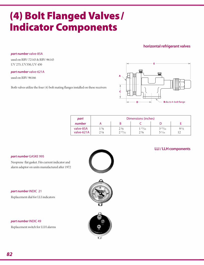
82
(4) Bolt Flanged Valves/Indicator Components
horizontal refrigerant valves
part number valve-85A
used on RBV-72145 & RBV-96145
UV 275, UV350, UV 450
part number valve-621A
used on RBV-96166
Both valves utilize the four (4) bolt mating flanges installed on these receivers
part Dimensions (inches)
number A B C D E
valve-85A 1.⅝ 2.⅛ 1.13⁄16 3.15⁄16 9.½valve-621A 2.⅛ 2.17⁄32 2.⅜ 5.1⁄16 12
E
D B dia.to 4–bolt flange
A
C
LLI / LLH components
part number GASKE 995
Neoprene flat gasket. Fits current indicator and
alarm adaptor on units manufactured after 1972
part number INDIC 21
Replacement dial for LLI indicators
part number INDIC 49
Replacement switch for LLH alarms
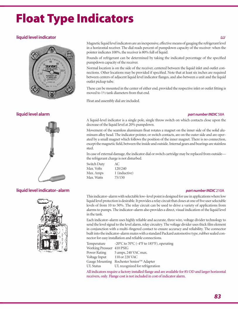
83
Float Type Indicators
liquid level indicator–alarm part number INDIC 210A
This indicator–alarm with selectable low–level point is designed for use in applications where lowliquid level protection is desirable. It provides a relay circuit that closes at one of five user selectablelevels of from 10 to 50%. The relay circuit can be used to drive a variety of applications fromalarms to pumps. The indicator–alarm also provides a direct, visual indication of the liquid levelin the tank.
Each indicator–alarm uses highly reliable and accurate, three wire, voltage divider technology tosend the level signal to the level alarm, relay circuitry. The voltage divider uses thick film elementin conjunction with a multi–fingered contact to ensure accuracy and reliability. The connectorbuilt into the indicator–alarm mates with a standard Packard automotive type, rubber sealed con-nector for easy installation and reliable connections.
Temperature -20°C to 70°C (-4°F to 185°F), operatingWorking Pressuer 410 PSIGPower Rating 5 amps, 240 VAC max.Voltage Input 110 or 220 VACGauge Mounting Rochester Senior™ AdapterUL Status UL recognized for refrigeration
All indicators require a factory installed flange and are available for 85⁄8 OD and larger horizontalreceivers, only. Flange cost is not included in cost of indicator alarm.
liquid level alarm part number INDIC 58A
A liquid-level indicator is a single pole, single throw switch on which contacts close upon thedecrease of the liquid level at 20% pumpdown.
Movement of the seamless aluminum float rotates a magnet on the inner side of the solid alu-minum alloy head. The indicator pointer, or switch contacts, are on the outer side and are oper-ated by a small magnet which follows the position of the inner magnet. There is no connection,except the magnetic field, between the inside and outside. Internal gears and bearings are stainlesssteel.
In case of external damage, the indicator dial or switch cartridge may be replaced from outside—the refrigerant charge is not disturbed.
Switch Duty ACMax. Volts 120/240Max. Amps 1 (inductive)Max. Watts 75/150
liquid level indicator LLI
Magnetic liquid level indicators are an inexpensive, effective means of gauging the refrigerant levelin a horizontal receiver. The dial reads percent of pumpdown capacity of the receiver: when thepointer indicates 100%, the receiver is 80% full of liquid.
Pounds of refrigerant can be determined by taking the indicated percentage of the specifiedpumpdown capacity of the receiver.
Normal location is on the side of the receiver, centered between the liquid inlet and outlet con-nections. Other locations may be provided if specified. Note that at least six inches are requiredbetween centers of adjacent liquid level indicator flanges, and also between a unit and the liquidoutlet pickup tube.
These can be mounted in the center of either end, provided the respective inlet or outlet fitting ismoved to 1½ tank diameters from that end.
Float and assembly dial are included.
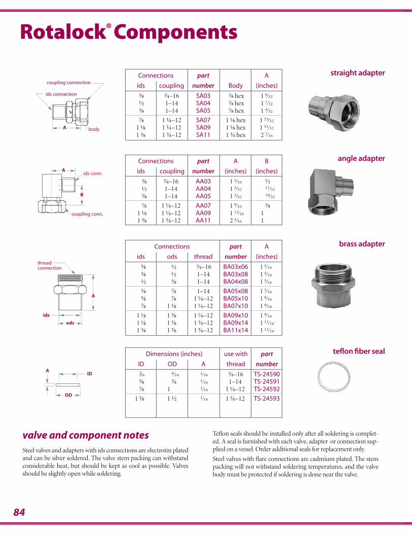
84
valve and component notesSteel valves and adapters with ids connections are electrotin platedand can be silver soldered. The valve stem packing can withstandconsiderable heat, but should be kept as cool as possible. Valvesshould be slightly open while soldering.
Teflon seals should be installed only after all soldering is complet-ed. A seal is furnished with each valve, adapter or connection sup-plied on a vessel. Order additional seals for replacement only.
Steel valves with flare connections are cadmium plated. The stempacking will not withstand soldering temperatures, and the valvebody must be protected if soldering is done near the valve.
Connections part A
ids coupling number Body (inches).⅜ ¾–16 SA03 .⅞ hex 1.9⁄32
.½ 1–14 SA04 .⅞ hex 1.7⁄32
.⅝ 1–14 SA05 .⅞ hex 1.9⁄32
.⅞ 1.¼–12 SA07 1.⅛ hex 1.23⁄32
1.⅛ 1.¼–12 SA09 1.⅛ hex 1.31⁄32
1.⅜ 1.¾–12 SA11 1.¾ hex 2.7⁄16
straight adapter
Connections part A
ids ods thread number (inches).⅜ .½ .¾–16 BA03x06 1.5⁄16
.⅜ .½ 1–14 BA03x08 1.5⁄16
.½ .⅝ 1–14 BA04x08 1.5⁄16
.⅝ .⅞ 1–14 BA05x08 1.5⁄16
.⅝ .⅞ 1.¼–12 BA05x10 1.9⁄16
.⅞ 1.⅛ 1.¼–12 BA07x10 1.9⁄16
1.⅛ 1.⅜ 1.¼–12 BA09x10 1.9⁄16
1.⅛ 1.⅜ 1.¾–12 BA09x14 1.11⁄16
1.⅜ 1.⅝ 1.¾–12 BA11x14 1.11⁄16
brass adapter
angle adapterConnections part A B
ids coupling number (inches) (inches).⅜ ¾–16 AA03 1.5⁄16 .½.½ 1–14 AA04 1.3⁄32 .17⁄32
.⅝ 1–14 AA05 1.3⁄32 .19⁄32
.⅞ 1.¼–12 AA07 1.9⁄16 .⅝1.⅛ 1.¼–12 AA09 1.13⁄16 11.⅜ 1.¾–12 AA11 2.3⁄16 1
teflon fiber sealDimensions (inches) use with part
ID OD A thread number.7⁄16 .9⁄16 .1⁄16 .¾–16 TS-24590.⅝ .¾ .1⁄16 1–14 TS-24591.⅞ 1 .1⁄16 1.¼–12 TS-24592
1.⅜ 1.½ .1⁄16 1.¾–12 TS-24593
Rotalock® Components
A
ids connection
coupling connection
body
Aids conn.
coupling conn.
B
ods
ids
thread connection
A
AID
OD
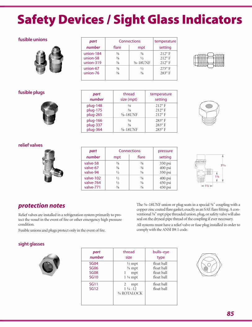
85
Safety Devices / Sight Glass Indicators
part thread bulls–eyenumber size type
SG04 .½ mpt float ballSG06 .¾ mpt float ballSG08 1.¾ mpt float ballSG10 1.¼ mpt float ball
SG11 2.¾ mpt float ballSG12 1.¼ -12 float ball
¾ ROTALOCK
sight glasses
fusible unions
relief valvespart Connections pressure
number mpt flare setting
valve-58 .⅜ .⅜ 350 psivalve-67 .⅜ .⅜ 400 psivalve-94 .½ .⅝ 350 psi
valve-102 .½ .⅝ 400 psivalve-764 .½ .⅝ 450 psivalve-771 .⅜ .⅜ 450 psi
protection notesRelief valves are installed in a refrigeration system primarily to pro-tect the vessel in the event of fire or other emergency high pressurecondition.
Fusible unions and plugs protect only in the event of fire.
The ⅝–18UNF union or plug seats in a special ⅜" coupling with acopper zinc coated flare gasket, exactly as an SAE flare fitting. A con-ventional ⅜" mpt pipe threaded union, plug, or safety valve will alsoseal on the dryseal pipe thread of the coupling if ever necessary.
All systems must have a relief valve or fuse plug installed in order tocomply with the ANSI B9.1 code.
part thread temperaturenumber size (mpt) setting
plug-148 .⅛ 212° Fplug-175 .⅜ 212° Fplug-265 .⅝-18UNF 212° F
plug-166 .⅛ 283° Fplug-337 .⅜ 283° Fplug-364 .⅝-18UNF 283° F
fusible plugs
part Connections temperature
number flare mpt setting
union-184 .⅜ .⅜ 212° Funion-58 .⅜ .½ 212° Funion-319 .⅜ .⅝-18UNF 212° F
union-67 .⅜ .½ 275° Funion-76 .⅜ .⅜ 283° F
39⁄16
13⁄8
15⁄8
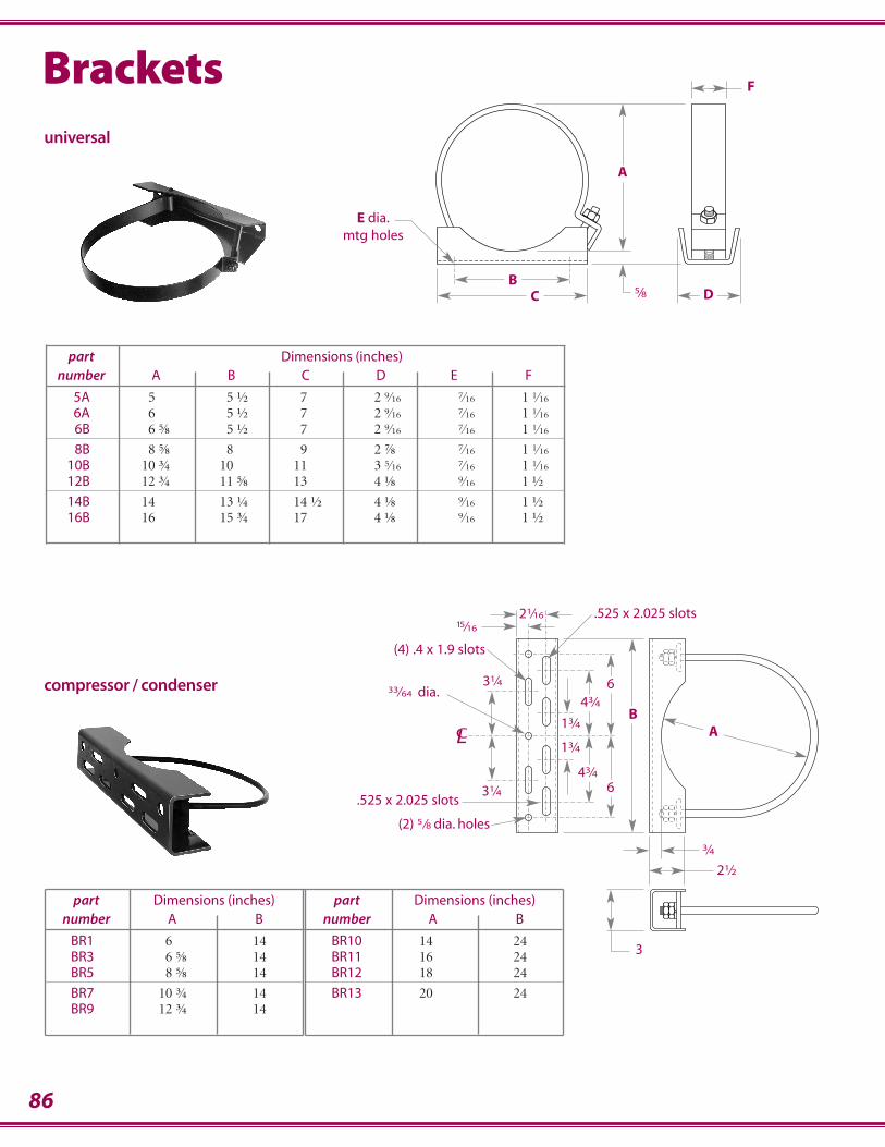
86
BA
13⁄4
13⁄4
43⁄431⁄4
CL
21⁄2
3⁄4
3
31⁄4
(4) .4 x 1.9 slots
(2) 5⁄8 dia. holes
.525 x 2.025 slots21⁄1615⁄16
43⁄4
6
633⁄64 dia.
.525 x 2.025 slots
part Dimensions (inches)number A B
BR10 14 24BR11 16 24BR12 18 24
BR13 20 24
part Dimensions (inches)number A B
BR1 6 14BR3 6.⅝ 14BR5 8.⅝ 14
BR7 10.¾ 14BR9 12.¾ 14
part Dimensions (inches)number A B C D E F
5A 5 5.½ 7 2.9⁄16 .7⁄16 1.1⁄16
6A 6 5.½ 7 2.9⁄16 .7⁄16 1.1⁄16
6B 6.⅝ 5.½ 7 2.9⁄16 .7⁄16 1.1⁄16
8B 8.⅝ 8 9 2.⅞ .7⁄16 1.1⁄16
10B 10.¾ 10 11 3.5⁄16 .7⁄16 1.1⁄16
12B 12.¾ 11.⅝ 13 4.⅛ .9⁄16 1.½
14B 14 13.¼ 14.½ 4.⅛ .9⁄16 1.½16B 16 15.¾ 17 4.⅛ .9⁄16 1.½
universal
compressor / condenser
BD5⁄8
F
C
E dia.mtg holes
A
Brackets
87
notes
2050 North Ruby StreetMelrose Park, Illinois 60160-1133
708 345 5400 fax 345 3513www.stanref.com
Liability and LimitationsAll products are thoroughly inspected and tested before leaving the factory, and are guaranteed against defects in material and workmanship to the extent expressly provided in this Paragraph. If it is proven to Standard satisfaction thatany part of any such product was defective when shipped from the factory, and such part is returned to Standard’s factory in Melrose Park, Illinois within twelve months of date of shipment thereof, transportation prepaid, Standardshall either furnish a replacement part or repair such part (whichever Standard may elect) free of charge and shallreturn such replacement part or repaired part to Purchaser, transportation prepaid. The foregoing shall not apply andStandard shall have no obligation under this Paragraph with respect to any part or product which Standarddetermines was subject to abuse, misuse, or improper installation or application. EXCEPT AS EXPRESSLY PROVIDED ABOVE, STANDARD MAKES NO GUARANTEE OR WARRANTY EXPRESS OR IMPLIED WITHRESPECT TO ANY PRODUCTS SOLD HEREUNDER OR ANY PART OF ANY SUCH PRODUCT, INCLUDING(WITHOUT LIMITING THE GENERALITY OF THE FOREGOING) WARRANTIES OF MERCHANTABILITYAND WARRANTIES OF FITNESS OR SUITABILITY FOR ANY PARTICULAR PURPOSE, and Standard shall haveno other liability whatsoever with respect to such products or parts including (without limitation) any liability for indirect, consequential or resultant damages whether based upon breach of warranty, negligence or any other ground,it being understood that replacement or repair of defective parts as herein provided shall be Purchaser’s sole and exclusive remedy.
Changes and ImprovementsChanges and improvements may be made at any time but Standard Refrigeration Company shall be under no obligation to incorporate same in, or substitute the same for any products previously sold to any customer.
Merchandise Returned for CreditNo merchandise will be accepted for credit unless authority of the factory has been first obtained. Only merchandiseof current design, in their original individual cartons will be considered for return—and if returned, a handling chargeof 12% of the original net purchase price, plus transportation, will be made. No provision is made for the return ofmerchandise of special nature, and orders for special merchandise are not subject to cancellation.
Engineering AssistanceFor assistance in the design, specification or use of Standard products, please contact your nearest sales representa-tive or our office headquarters in Melrose Park, Illinois.
Engineering specifications in this catalog are current as of the printing date, but are subject to future design changes. Consult factory for latest specifica-tion data before ordering.
Product performance is based on ARI standards and nominal operating conditions Standard Refrigeration Company is not responsible for product failurein nonconforming applications. For assistance, please consult the factory.
1/07
warranty