Embed Size (px)
Citation preview
Provided data is not contractual, data may be changed without notice. All rights reserved Global Valve Center b.v.
2011www.globalvalvecenter.com Front Page
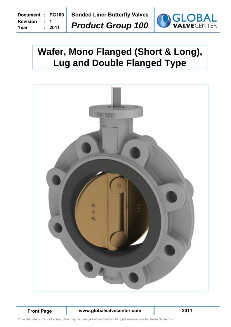
Bonded Liner Butterfly Valves
Product Group 100
Document : PG100
Revision : 1 Year : 2011
Wafer, Mono Flanged (Short & Long),Lug and Double Flanged Type
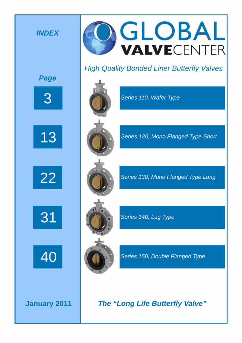
High Quality Bonded Liner Butterfly Valves
INDEX
The “Long Life Butterfly Valve”
3
13
22
31
40
Series 110, Wafer Type
Series 120, Mono Flanged Type Short
Series 130, Mono Flanged Type Long
Series 140, Lug Type
Series 150, Double Flanged Type
Page
January 2011
Provided data is not contractual, data may be changed without notice. All rights reserved Global Valve Center b.v.
2011 www.globalvalvecenter.com Page 3
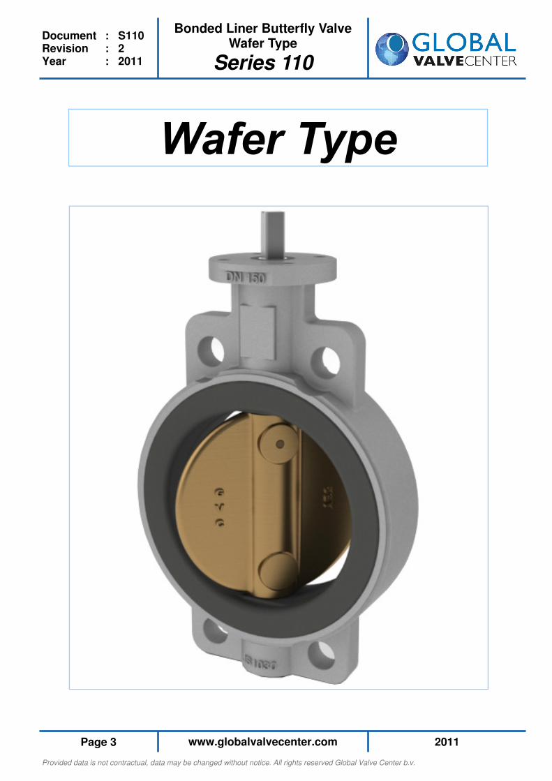
Bonded Liner Butterfly Valve Wafer Type
Series 110
Document : S110 Revision : 2 Year : 2011
Provided data is not contractual, data may be changed without notice. All rights reserved Global Valve Center b.v.
2011 www.globalvalvecenter.com Page 4
Bonded Liner Butterfly Valve Wafer Type
Series 110
Document : S110 Revision : 2 Year : 2011
Technical Data
General Product Information
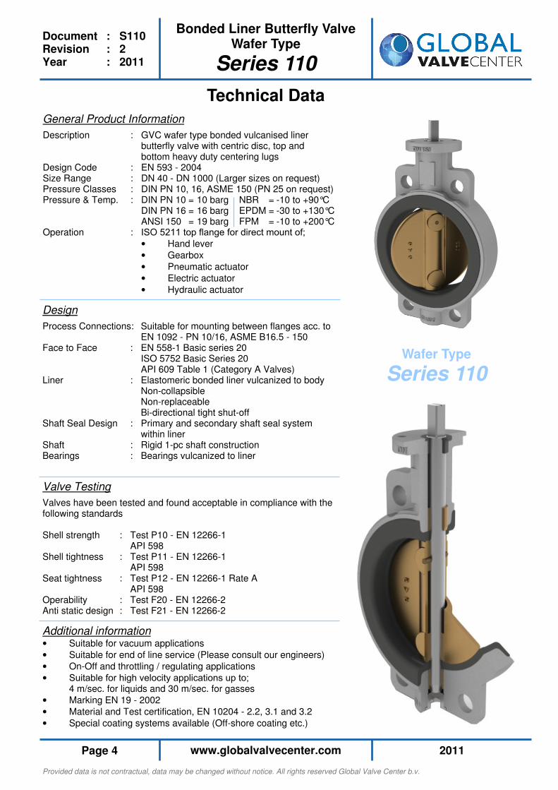
Description : GVC wafer type bonded vulcanised liner butterfly valve with centric disc, top and bottom heavy duty centering lugs Design Code : EN 593 - 2004 Size Range : DN 40 - DN 1000 (Larger sizes on request) Pressure Classes : DIN PN 10, 16, ASME 150 (PN 25 on request) Pressure & Temp. : DIN PN 10 = 10 barg NBR = -10 to +90°C DIN PN 16 = 16 barg EPDM = -30 to +130°C ANSI 150 = 19 barg FPM = -10 to +200°C Operation : ISO 5211 top flange for direct mount of;
• Hand lever
• Gearbox
• Pneumatic actuator
• Electric actuator
• Hydraulic actuator
Design
Process Connections: Suitable for mounting between flanges acc. to EN 1092 - PN 10/16, ASME B16.5 - 150 Face to Face : EN 558-1 Basic series 20 ISO 5752 Basic Series 20 API 609 Table 1 (Category A Valves) Liner : Elastomeric bonded liner vulcanized to body Non-collapsible Non-replaceable Bi-directional tight shut-off Shaft Seal Design : Primary and secondary shaft seal system within liner Shaft : Rigid 1-pc shaft construction Bearings : Bearings vulcanized to liner
Valve Testing
Valves have been tested and found acceptable in compliance with the following standards Shell strength : Test P10 - EN 12266-1 API 598 Shell tightness : Test P11 - EN 12266-1 API 598 Seat tightness : Test P12 - EN 12266-1 Rate A API 598 Operability : Test F20 - EN 12266-2 Anti static design : Test F21 - EN 12266-2
Wafer Type
Series 110
Additional information
• Suitable for vacuum applications
• Suitable for end of line service (Please consult our engineers)
• On-Off and throttling / regulating applications
• Suitable for high velocity applications up to; 4 m/sec. for liquids and 30 m/sec. for gasses
• Marking EN 19 - 2002
• Material and Test certification, EN 10204 - 2.2, 3.1 and 3.2
• Special coating systems available (Off-shore coating etc.)
Provided data is not contractual, data may be changed without notice. All rights reserved Global Valve Center b.v.
2011 www.globalvalvecenter.com Page 5
Bonded Liner Butterfly Valve Wafer Type
Series 110
Document : S110 Revision : 2 Year : 2011
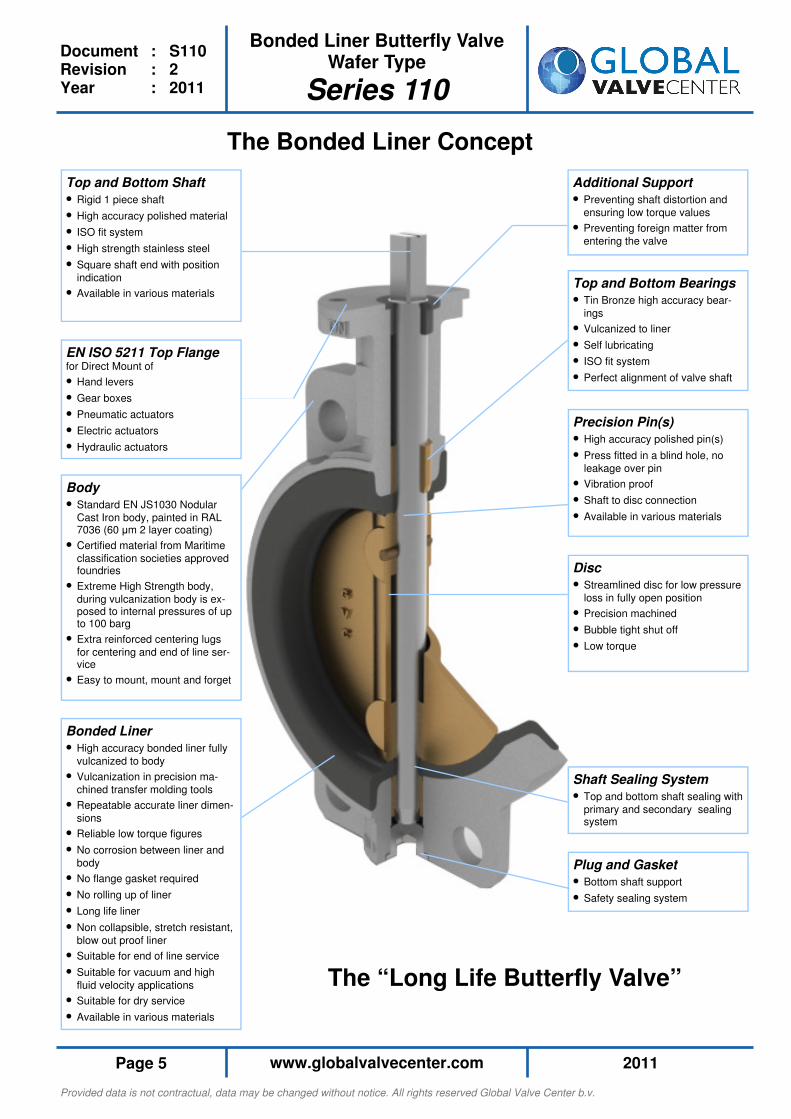
Shaft Sealing System
• Top and bottom shaft sealing with
primary and secondary sealing system
Disc
• Streamlined disc for low pressure
loss in fully open position
• Precision machined
• Bubble tight shut off
• Low torque
The Bonded Liner Concept
Top and Bottom Bearings
• Tin Bronze high accuracy bear-
ings
• Vulcanized to liner
• Self lubricating
• ISO fit system
• Perfect alignment of valve shaft
Precision Pin(s)
• High accuracy polished pin(s)
• Press fitted in a blind hole, no
leakage over pin
• Vibration proof
• Shaft to disc connection
• Available in various materials
Additional Support
• Preventing shaft distortion and
ensuring low torque values
• Preventing foreign matter from
entering the valve
Top and Bottom Shaft
• Rigid 1 piece shaft
• High accuracy polished material
• ISO fit system
• High strength stainless steel
• Square shaft end with position
indication
• Available in various materials
EN ISO 5211 Top Flange for Direct Mount of
• Hand levers
• Gear boxes
• Pneumatic actuators
• Electric actuators
• Hydraulic actuators
Body
• Standard EN JS1030 Nodular
Cast Iron body, painted in RAL 7036 (60 µm 2 layer coating)
• Certified material from Maritime
classification societies approved foundries
• Extreme High Strength body,
during vulcanization body is ex-posed to internal pressures of up to 100 barg
• Extra reinforced centering lugs
for centering and end of line ser-vice
• Easy to mount, mount and forget
Bonded Liner
• High accuracy bonded liner fully
vulcanized to body
• Vulcanization in precision ma-
chined transfer molding tools
• Repeatable accurate liner dimen-
sions
• Reliable low torque figures
• No corrosion between liner and
body
• No flange gasket required
• No rolling up of liner
• Long life liner
• Non collapsible, stretch resistant,
blow out proof liner
• Suitable for end of line service
• Suitable for vacuum and high
fluid velocity applications
• Suitable for dry service
• Available in various materials
Plug and Gasket
• Bottom shaft support
• Safety sealing system
The “Long Life Butterfly Valve”
Provided data is not contractual, data may be changed without notice. All rights reserved Global Valve Center b.v.
2011 www.globalvalvecenter.com Page 6
Bonded Liner Butterfly Valve Wafer Type
Series 110
Document : S110 Revision : 2 Year : 2011
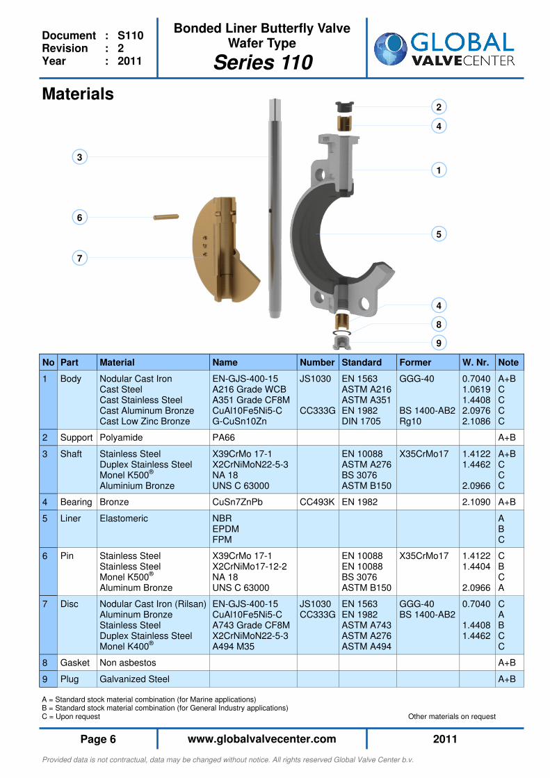
A = Standard stock material combination (for Marine applications) B = Standard stock material combination (for General Industry applications) C = Upon request Other materials on request
1
2
3
4
4
5
6
7
8
9
No Part Material Name
1 Body Nodular Cast Iron Cast Steel Cast Stainless Steel Cast Aluminum Bronze Cast Low Zinc Bronze
EN-GJS-400-15 A216 Grade WCB A351 Grade CF8M CuAl10Fe5Ni5-C G-CuSn10Zn
2 Support Polyamide PA66
3 Shaft Stainless Steel Duplex Stainless Steel Monel K500® Aluminium Bronze
X39CrMo 17-1 X2CrNiMoN22-5-3 NA 18 UNS C 63000
4 Bearing Bronze CuSn7ZnPb
5 Liner
Elastomeric NBR EPDM FPM
6 Pin Stainless Steel Stainless Steel Monel K500® Aluminum Bronze
X39CrMo 17-1 X2CrNiMo17-12-2 NA 18 UNS C 63000
7 Disc Nodular Cast Iron (Rilsan) Aluminum Bronze Stainless Steel Duplex Stainless Steel Monel K400®
EN-GJS-400-15 CuAl10Fe5Ni5-C A743 Grade CF8M X2CrNiMoN22-5-3 A494 M35
8 Gasket Non asbestos
9 Plug Galvanized Steel
Note
A+B C C C C
A+B
A+B C C C
A+B
A B C
C B C A
C A B C C
A+B
A+B
Former
GGG-40 BS 1400-AB2 Rg10
X35CrMo17
X35CrMo17
GGG-40 BS 1400-AB2
Standard
EN 1563 ASTM A216 ASTM A351 EN 1982 DIN 1705
EN 10088 ASTM A276 BS 3076 ASTM B150
EN 1982
EN 10088 EN 10088 BS 3076 ASTM B150
EN 1563 EN 1982 ASTM A743 ASTM A276 ASTM A494
Number
JS1030 CC333G
CC493K
JS1030 CC333G
W. Nr.
0.7040 1.0619 1.4408 2.0976 2.1086
1.4122 1.4462 2.0966
2.1090
1.4122 1.4404 2.0966
0.7040 1.4408 1.4462
Materials
Provided data is not contractual, data may be changed without notice. All rights reserved Global Valve Center b.v.
2011 www.globalvalvecenter.com Page 7
Bonded Liner Butterfly Valve Wafer Type
Series 110
Document : S110 Revision : 2 Year : 2011
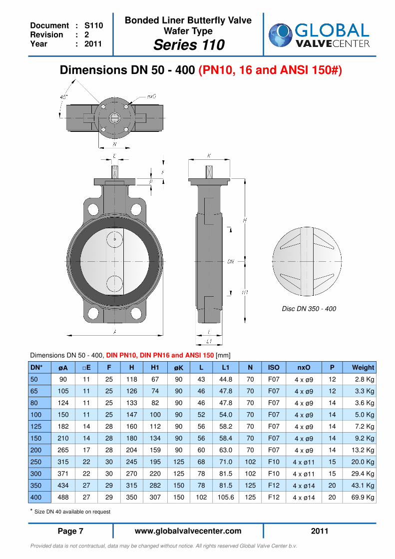
Dimensions DN 50 - 400 (PN10, 16 and ANSI 150#)
DN* øA □E F H H1 øK L L1 N nxO P Weight
50 90 11 25 118 67 90 43 44.8 70 4 x ø9 12 2.8 Kg
65 105 11 25 126 74 90 46 47.8 70 4 x ø9 12 3.3 Kg
80 124 11 25 133 82 90 46 47.8 70 4 x ø9 14 3.6 Kg
100 150 11 25 147 100 90 52 54.0 70 4 x ø9 14 5.0 Kg
125 182 14 28 160 112 90 56 58.2 70 4 x ø9 14 7.2 Kg
150 210 14 28 180 134 90 56 58.4 70 4 x ø9 14 9.2 Kg
200 265 17 28 204 159 90 60 63.0 70 4 x ø9 14 13.2 Kg
250 315 22 30 245 195 125 68 71.0 102 4 x ø11 15 20.0 Kg
300 371 22 30 270 220 125 78 81.5 102 4 x ø11 15 29.4 Kg
350 434 27 29 315 282 150 78 81.5 125 4 x ø14 20 43.1 Kg
400 488 27 29 350 307 150 102 105.6 125 4 x ø14 20 69.9 Kg
ISO
F07
F07
F07
F07
F07
F07
F07
F10
F10
F12
F12
Dimensions DN 50 - 400, DIN PN10, DIN PN16 and ANSI 150 [mm]
* Size DN 40 available on request
Disc DN 350 - 400
Provided data is not contractual, data may be changed without notice. All rights reserved Global Valve Center b.v.
2011 www.globalvalvecenter.com Page 8
Bonded Liner Butterfly Valve Wafer Type
Series 110
Document : S110 Revision : 2 Year : 2011
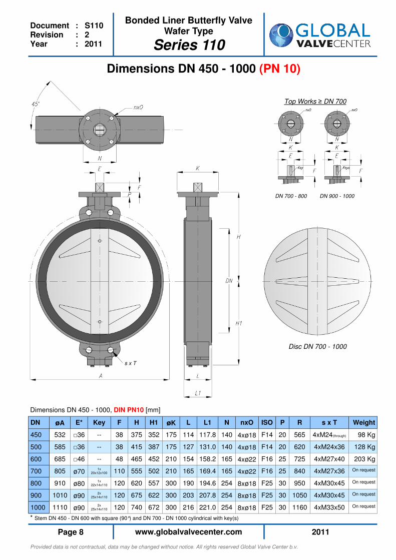
Dimensions DN 450 - 1000 (PN 10)
DN øA E* F H H1 øK L L1 N nxO P R s x T Weight
450 532 □36 38 375 352 175 114 117.8 140 4xø18 20 565 4xM24(through) 98 Kg
500 585 □36 38 415 387 175 127 131.0 140 4xø18 20 620 4xM24x36 128 Kg
600 685 □46 48 465 452 210 154 158.2 165 4xø22 25 725 4xM27x40 203 Kg
ISO
F14
F14
F16
700 805 ø70 110 555 502 210 165 169.4 165 4xø22 F16 25 840 4xM27x36 On request
800 910 ø80 120 620 557 300 190 194.6 254 8xø18 F25 30 950 4xM30x45 On request
900 1010 ø90 120 675 622 300 203 207.8 254 8xø18 F25 30 1050 4xM30x45 On request
1000 1110 ø90 120 740 672 300 216 221.0 254 8xø18 F25 30 1160 4xM33x50 On request
Key
--
--
--
1x 20x12x100
1x 22x14x110
2x 25x14x110
2x 25x14x110
Dimensions DN 450 - 1000, DIN PN10 [mm]
* Stem DN 450 - DN 600 with square (90°) and DN 700 - DN 1000 cylindrical with key(s)
Disc DN 700 - 1000
Top Works ≥ DN 700
DN 700 - 800 DN 900 - 1000
s x T

Provided data is not contractual, data may be changed without notice. All rights reserved Global Valve Center b.v.
2011 www.globalvalvecenter.com Page 9
Bonded Liner Butterfly Valve Wafer Type
Series 110
Document : S110 Revision : 2 Year : 2011
Dimensions DN 450 - 1000, DIN PN16 [mm]
Dimensions DN 450 - 1000 (PN 16)
DN øA E* F H H1 øK L L1 N nxO P R s x T Weight
450 532 □36 38 375 352 175 114 117.8 140 4xø18 20 585 4xM27 (through) 97 Kg
500 585 □36 38 415 387 175 127 131.0 140 4xø18 20 650 4xM30x40 127 Kg
600 685 □46 48 465 452 210 154 158.2 165 4xø22 25 770 4xM33x47 204 Kg
ISO
F14
F14
F16
700 805 ø80 120 555 502 300 165 169.4 254 8xø18 F25 30 840 4xM33x47 On request
800 910 ø100 120 620 557 300 190 194.6 254 8xø18 F25 30 950 4xM33x47 On request
900 1010 ø110 120 675 622 300 203 207.8 254 8xø18 F25 30 1050 4xM36x52 On request
1000 1110 ø120 160 740 672 300 216 221.0 254 8xø18 F25 30 1170 4xM39x55 On request
Key
--
--
--
1x 22x14x110
1x 28x16x110
2x 28x16x110
2x 32x18x140
* Stem DN 450 - DN 600 with square (90°) and DN 700 - DN 1000 cylindrical with key(s)
Disc DN 700 - 1000
Top Works ≥ DN 700
DN 700 - 800 DN 900 - 1000
s x T
Provided data is not contractual, data may be changed without notice. All rights reserved Global Valve Center b.v.
2011 www.globalvalvecenter.com Page 10
Bonded Liner Butterfly Valve Wafer Type
Series 110
Document : S110 Revision : 2 Year : 2011
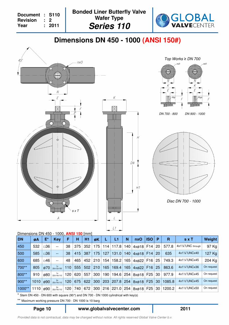
** Maximum working pressure DN 700 - DN 1000 is 10 barg
* Stem DN 450 - DN 600 with square (90°) and DN 700 - DN 1000 cylindrical with key(s)
Dimensions DN 450 - 1000 (ANSI 150#)
DN øA E* F H H1 øK L L1 N nxO P R s x T Weight
450 532 □36 38 375 352 175 114 117.8 140 4xø18 20 577.8 4x1⅛”UNC through 97 Kg
500 585 □36 38 415 387 175 127 131.0 140 4xø18 20 635 4x1⅛”UNCx40 127 Kg
600 685 □46 48 465 452 210 154 158.2 165 4xø22 25 749.3 4x1¼”UNCx45 204 Kg
ISO
F14
F14
F16
700** 805 ø70 110 555 502 210 165 169.4 165 4xø22 F16 25 863.6 4x1¼”UNCx36 On request
800** 910 ø80 120 620 557 300 190 194.6 254 8xø18 F25 30 977.9 4x1½”UNCx45 On request
900** 1010 ø90 120 675 622 300 203 207.8 254 8xø18 F25 30 1085.8 4x1½”UNCx45 On request
1000** 1110 ø90 120 740 672 300 216 221.0 254 8xø18 F25 30 1200.2 4x1½”UNCx50 On request
Key
--
--
--
1x 20x12x100
1x 22x14x110
2x 25x14x110
2x 25x14x110
Dimensions DN 450 - 1000, ANSI 150 [mm]
Disc DN 700 - 1000
Top Works ≥ DN 700
DN 700 - 800 DN 900 - 1000
s x T
Provided data is not contractual, data may be changed without notice. All rights reserved Global Valve Center b.v.
2011 www.globalvalvecenter.com Page 11
Bonded Liner Butterfly Valve Wafer Type
Series 110
Document : S110 Revision : 2 Year : 2011
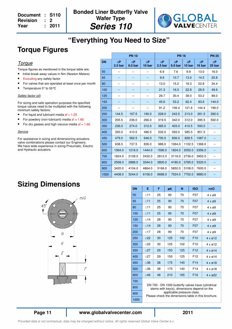
“Everything You Need to Size”
Torque Figures
Torque
Torque figures as mentioned in the torque table are;
• Initial break away values in Nm (Newton Meters)
• Excluding any safety factor
• For valves that are operated at least once per month
• Temperature 0° to 50°C
Safety factor (sf) For sizing and safe operation purposes the specified torque values need to be multiplied with the following minimum safety factors;
• For liquid and lubricant media sf = 1.25
• For powdery (non-lubricant) media sf = 1.60
• For dry gasses and high viscous media sf = 1.60
Service For assistance in sizing and dimensioning actuators-valve combinations please contact our Engineers. We have wide experience in sizing Pneumatic, Electric and Hydraulic actuators.
DN E F øK N ISO nxO
50 □11 25 90 70 F07 4 x ø9
65 □11 25 90 70 F07 4 x ø9
80 □11 25 90 70 F07 4 x ø9
100 □11 25 90 70 F07 4 x ø9
125 □14 28 90 70 F07 4 x ø9
150 □14 28 90 70 F07 4 x ø9
200 □17 28 90 70 F07 4 x ø9
250 □22 30 125 102 F10 4 x ø12
300 □22 30 125 102 F10 4 x ø12
350 □27 29 150 125 F12 4 x ø14
400 □27 29 150 125 F12 4 x ø14
450 □36 38 175 140 F14 4 x ø18
500 □36 38 175 140 F14 4 x ø18
600 □46 48 210 165 F16 4 x ø22
700
800
900
1000
DN 700 - DN 1000 butterfly valves have cylindrical stems with key(s), dimensions depend on the
applicable pressure class. Please check the dimensions table in this brochure.
Sizing Dimensions
PN 10 PN 25
DN ∆P 2.5 bar
∆P 6.0 bar
∆P 10 bar
∆P 2.5 bar
∆P 6.0 bar
∆P 10 bar
∆P 16 bar
∆P 25 bar
50 -- -- -- 6.9 7.6 9.9 13.0 16.0
65 -- -- -- 9.9 10.7 13.0 14.5 20.8
80 -- -- -- 13.0 15.2 18.3 22.8 34.4
100 -- -- -- 21.3 16.0 22.8 28.9 49.6
125 -- -- -- 29.7 30.4 38.0 53.2 88.0
150 -- -- -- 45.6 53.2 62.4 83.6 144.0
200 -- -- -- 91.2 106.4 121.6 144.4 196.0
250 144.5 167.5 190.0 228.0 243.5 213.0 281.5 392.0
300 205.5 236.0 266.0 319.5 342.0 312.0 395.5 592.0
350 236.0 274.0 312.0 365.0 403.0 410.5 593.0 --
400 350.0 410.5 486.5 532.0 593.0 585.5 851.5 --
450 479.0 562.5 646.0 730.0 836.0 828.5 1087.0 --
500 638.5 737.5 836.0 988.0 1064.0 1102.5 1368.0 --
600 1064.0 1216.0 1444.0 1596.0 1824.0 2052.0 2356.0 --
700 1824.0 2128.0 2432.0 2812.0 3116.0 2736.0 3952.0 --
800 2508.0 2888.0 3344.0 3800.0 4180.0 3785.0 5320.0 --
900 3420.0 4104.0 4864.0 5168.0 5852.0 5108.0 7600.0 --
1000 4408.0 5244.0 6156.0 6688.0 7524.0 7752.0 9880.0 --
PN 16
Provided data is not contractual, data may be changed without notice. All rights reserved Global Valve Center b.v.
2011 www.globalvalvecenter.com Page 12
Bonded Liner Butterfly Valve Wafer Type
Series 110
Document : S110 Revision : 2 Year : 2011
KV Values
KV-values
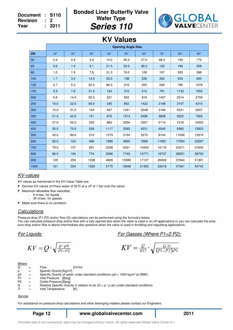
KV values as mentioned in the KV-Value Table are;
• German KV values (m³/hour water of 20°C at a ∆P of 1 bar over the valve)
• Maximum allowable flow velocities;
- 4 m/sec. for liquids - 30 m/sec. for gasses
• Make sure there is no cavitation
Calculations
Pressure drop (P1-P2) and/or flow (Q) calculations can be performed using the formula’s below. You can calculate pressure drop and/or flow with a fully opened disc when the valve is used in on-off applications or you can calculate the pres-sure drop and/or flow in above intermediate disc positions when the valve is used in throttling and regulating applications.
For Liquids: For Gasses (Where P1<2·P2): Where Q = Flow [m³/hr] ρ = Specific Gravity [Kg/m³] ρ0 = Specific Gravity of water under standard conditions (ρ0 = 1000 kg/m³ at 288K) P1 = Inlet Pressure [Barg] P2 = Outlet Pressure [Barg] G = Relative Specific Gravity in relation to air (G = ρ / ρ air) under standard conditions Ti = Inlet Temperature [K] Service For assistance on pressure drop calculations and other belonging matters please contact our Engineers.
Opening Angle Disc
DN 20° 30° 40° 50° 60° 70° 80° 90°
50 0.9 3.4 14.0 35.0 57.0 88.0 126 172
65 1.4 5.1 21.0 53.0 86.0 132 189 258
80 1.9 7.8 31.0 78.0 128 197 283 388
100 3.5 14.0 55.0 138 228 352 504 690
125 5.3 22.0 86.0 216 355 549 786 1078
150 7.8 31.0 124 310 512 791 1133 1552
200 14.0 55.0 221 552 918 1407 2014 2759
250 22.0 86.0 345 862 1422 2198 3147 4310
300 31.0 124 497 1241 2048 3166 4531 6207
350 42.0 151 676 1513 2496 3858 5522 7565
400 55.0 200 883 2004 3307 5110 7316 10022
450 70.0 256 1117 2565 4231 6540 9360 12823
500 89.0 319 1379 3194 5270 8144 11658 15970
600 124 466 1986 4660 7688 11881 17054 23297
700 157 891 2528 6321 10429 16118 23071 31605
800 194 774 3096 7740 12771 19737 28251 38700
900 259 1038 4828 10380 17127 26469 37844 51901
1000 324 1295 5179 12948 21365 33018 47261 54742
10°
0.4
0.6
1.0
1.7
2.7
3.9
6.9
10.0
15.0
21.0
27.0
35.0
43.0
62.0
79.0
96.0
129
161

Provided data is not contractual, data may be changed without notice. All rights reserved Global Valve Center b.v.
2011 www.globalvalvecenter.com Page 13
Bonded Liner Butterfly Valve Mono Flanged Type (Short)
Series 120
Document : S120 Revision : 2 Year : 2011
Short Face to Face

Provided data is not contractual, data may be changed without notice. All rights reserved Global Valve Center b.v.
2011 www.globalvalvecenter.com Page 14
Bonded Liner Butterfly Valve Mono Flanged Type (Short)
Series 120
Document : S120 Revision : 2 Year : 2011
Technical Data
Design
Process Connections: Suitable for mounting between flanges acc. to EN 1092 - PN 10/16, ASME B16.5 - 150 Face to Face : EN 558 Basic series 20 ISO 5752 Basic Series 20 API 609 Table 1 (Category A Valves) Liner : Elastomeric bonded liner vulcanized to body Non-collapsible Non-replaceable Bi-directional tight shut-off Shaft Seal Design : Primary and secondary shaft seal system within liner Shaft : Rigid 1-pc shaft construction Bearings : Bearings vulcanized to liner
Valve Testing
Valves have been tested and found acceptable in compliance with the following standards Shell strength : Test P10 - EN 12266-1 API 598 Shell tightness : Test P11 - EN 12266-1 API 598 Seat tightness : Test P12 - EN 12266-1 Rate A API 598 Operability : Test F20 - EN 12266-2 Anti static design : Test F21 - EN 12266-2
Mono Flanged Type
Series 120
General Product Information
Description : GVC Mono flanged type bonded vulcanised liner butterfly valve with centric disc Design Code : EN 593 - 2004 Size Range : DN 50 - DN 400 (Larger sizes on request) Pressure Classes : DIN PN10, DIN PN 16 and ANSI/ASME 150 Pressure & Temp. : DIN PN 10 = 10 barg NBR = -10 to +90°C DIN PN 16 = 16 barg EPDM = -30 to +130°C ANSI 150 = 19 barg FPM = -10 to +200°C Operation : ISO 5211 top flange for direct mount of;
• Hand lever
• Gearbox
• Pneumatic actuator
• Electric actuator
• Hydraulic actuator
Additional information
• Suitable for vacuum applications
• Suitable for end of line service
• On-Off and throttling / regulating applications
• Suitable for high velocity applications up to; - 4 m/sec. for liquids - 30 m/sec. for gasses
• Marking EN 19 - 2002
• Material and Test certification, EN 10204 - 2.2, 3.1 and 3.2
• Special Coating Systems available (Off-Shore coating etc.)

Provided data is not contractual, data may be changed without notice. All rights reserved Global Valve Center b.v.
2011 www.globalvalvecenter.com Page 15
Bonded Liner Butterfly Valve Mono Flanged Type (Short)
Series 120
Document : S120 Revision : 2 Year : 2011
Shaft Sealing System
• Top and bottom shaft sealing with
primary and secondary sealing system
Disc
• Streamlined disc for low pressure
loss in fully open position
• Precision machined
• Bubble tight shut off
• Low torque
The Bonded Liner Concept
Top and Bottom Bearings
• Tin Bronze high accuracy bear-
ings
• Vulcanized to liner
• Self lubricating
• ISO fit system
• Perfect alignment of valve shaft
Precision Pin(s)
• High accuracy polished pin(s)
• Press fitted in a blind hole, no
leakage over pin
• Vibration proof
• Shaft to disc connection
• Available in various materials
Additional Support
• Preventing shaft distortion and
ensuring low torque values
• Preventing foreign matter from
entering the valve
Top and Bottom Shaft
• Rigid 1 piece shaft
• High accuracy polished material
• ISO fit system
• High strength stainless steel
• Square shaft end with position
indication
• Available in various materials
EN ISO 5211 Top Flange for Direct Mount of
• Hand levers
• Gear boxes
• Pneumatic actuators
• Electric actuators
• Hydraulic actuators
Body
• Standard EN JS1030 Nodular
Cast Iron body, painted in RAL 7036 (60 µm 2 layer coating)
• Certified material from Maritime
classification societies approved foundries
• Extreme High Strength body,
during vulcanization body is ex-posed to internal pressures of up to 100 barg
• Mono Flanged body, short F to F
• End of line service
• Easy to mount, mount and forget
• Available in various materials
Bonded Liner
• High accuracy bonded liner fully
vulcanized to body
• Vulcanization in precision ma-
chined transfer molding tools
• Repeatable accurate liner dimen-
sions
• Reliable low torque figures
• No corrosion between liner and
body
• No flange gasket required
• No rolling up of liner
• Long life liner
• Non collapsible, stretch resistant,
blow out proof liner
• Suitable for end of line service
• Suitable for vacuum and high
fluid velocity applications
• Suitable for dry service
• Available in various materials
Plug and Gasket
• Bottom shaft support
• Safety sealing system
The “Long Life Butterfly Valve”
Provided data is not contractual, data may be changed without notice. All rights reserved Global Valve Center b.v.
2011 www.globalvalvecenter.com Page 16
Bonded Liner Butterfly Valve Mono Flanged Type (Short)
Series 120
Document : S120 Revision : 2 Year : 2011
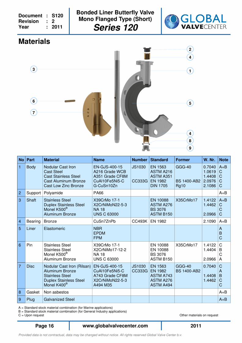
A = Standard stock material combination (for Marine applications) B = Standard stock material combination (for General Industry applications) C = Upon request Other materials on request
Materials
1
2
3
4
4
5 6
7
8
9
No Part Material Name
1 Body Nodular Cast Iron Cast Steel Cast Stainless Steel Cast Aluminum Bronze Cast Low Zinc Bronze
EN-GJS-400-15 A216 Grade WCB A351 Grade CF8M CuAl10Fe5Ni5-C G-CuSn10Zn
2 Support Polyamide PA66
3 Shaft Stainless Steel Duplex Stainless Steel Monel K500® Aluminum Bronze
X39CrMo 17-1 X2CrNiMoN22-5-3 NA 18 UNS C 63000
4 Bearing Bronze CuSn7ZnPb
5 Liner
Elastomeric NBR EPDM FPM
6 Pin Stainless Steel Stainless Steel Monel K500® Aluminum Bronze
X39CrMo 17-1 X2CrNiMo17-12-2 NA 18 UNS C 63000
7 Disc Nodular Cast Iron (Rilsan) Aluminum Bronze Stainless Steel Duplex Stainless Steel Monel K400®
EN-GJS-400-15 CuAl10Fe5Ni5-C A743 Grade CF8M X2CrNiMoN22-5-3 A494 M35
8 Gasket Non asbestos
9 Plug Galvanized Steel
Note
A+B C C C C
A+B
A+B C C C
A+B
A B C
C B C A
C A B C C
A+B
A+B
Former
GGG-40 BS 1400-AB2 Rg10
X35CrMo17
X35CrMo17
GGG-40 BS 1400-AB2
Standard
EN 1563 ASTM A216 ASTM A351 EN 1982 DIN 1705
EN 10088 ASTM A276 BS 3076 ASTM B150
EN 1982
EN 10088 EN 10088 BS 3076 ASTM B150
EN 1563 EN 1982 ASTM A743 ASTM A276 ASTM A494
Number
JS1030 CC333G
CC493K
JS1030 CC333G
W. Nr.
0.7040 1.0619 1.4408 2.0976 2.1086
1.4122 1.4462 2.0966
2.1090
1.4122 1.4404 2.0966
0.7040 1.4408 1.4462
Provided data is not contractual, data may be changed without notice. All rights reserved Global Valve Center b.v.
2011 www.globalvalvecenter.com Page 17
Bonded Liner Butterfly Valve Mono Flanged Type (Short)
Series 120
Document : S120 Revision : 2 Year : 2011
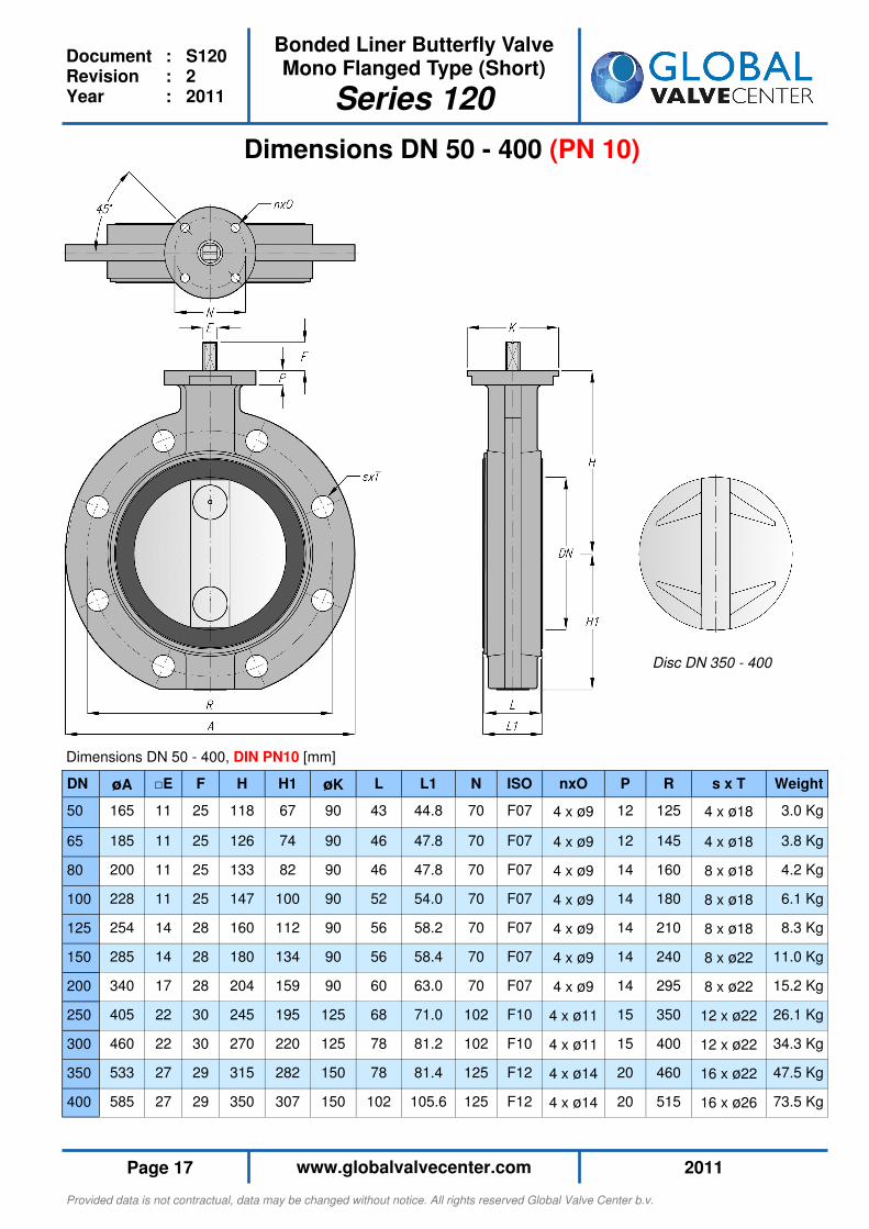
Dimensions DN 50 - 400 (PN 10)
DN øA □E F H H1 øK L L1 N ISO nxO P R s x T Weight
50 165 11 25 118 67 90 43 44.8 70 F07 4 x ø9 12 125 4 x ø18 3.0 Kg
65 185 11 25 126 74 90 46 47.8 70 F07 4 x ø9 12 145 4 x ø18 3.8 Kg
80 200 11 25 133 82 90 46 47.8 70 F07 4 x ø9 14 160 8 x ø18 4.2 Kg
100 228 11 25 147 100 90 52 54.0 70 F07 4 x ø9 14 180 8 x ø18 6.1 Kg
125 254 14 28 160 112 90 56 58.2 70 F07 4 x ø9 14 210 8 x ø18 8.3 Kg
150 285 14 28 180 134 90 56 58.4 70 F07 4 x ø9 14 240 8 x ø22 11.0 Kg
200 340 17 28 204 159 90 60 63.0 70 F07 4 x ø9 14 295 8 x ø22 15.2 Kg
250 405 22 30 245 195 125 68 71.0 102 F10 4 x ø11 15 350 12 x ø22 26.1 Kg
300 460 22 30 270 220 125 78 81.2 102 F10 4 x ø11 15 400 12 x ø22 34.3 Kg
350 533 27 29 315 282 150 78 81.4 125 F12 4 x ø14 20 460 16 x ø22 47.5 Kg
400 585 27 29 350 307 150 102 105.6 125 F12 4 x ø14 20 515 16 x ø26 73.5 Kg
Dimensions DN 50 - 400, DIN PN10 [mm]
Disc DN 350 - 400
Provided data is not contractual, data may be changed without notice. All rights reserved Global Valve Center b.v.
2011 www.globalvalvecenter.com Page 18
Bonded Liner Butterfly Valve Mono Flanged Type (Short)
Series 120
Document : S120 Revision : 2 Year : 2011
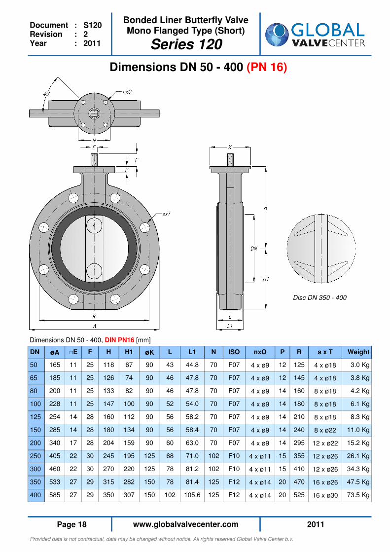
Dimensions DN 50 - 400 (PN 16)
DN øA □E F H H1 øK L L1 N ISO nxO P R s x T Weight
50 165 11 25 118 67 90 43 44.8 70 F07 4 x ø9 12 125 4 x ø18 3.0 Kg
65 185 11 25 126 74 90 46 47.8 70 F07 4 x ø9 12 145 4 x ø18 3.8 Kg
80 200 11 25 133 82 90 46 47.8 70 F07 4 x ø9 14 160 8 x ø18 4.2 Kg
100 228 11 25 147 100 90 52 54.0 70 F07 4 x ø9 14 180 8 x ø18 6.1 Kg
125 254 14 28 160 112 90 56 58.2 70 F07 4 x ø9 14 210 8 x ø18 8.3 Kg
150 285 14 28 180 134 90 56 58.4 70 F07 4 x ø9 14 240 8 x ø22 11.0 Kg
200 340 17 28 204 159 90 60 63.0 70 F07 4 x ø9 14 295 12 x ø22 15.2 Kg
250 405 22 30 245 195 125 68 71.0 102 F10 4 x ø11 15 355 12 x ø26 26.1 Kg
300 460 22 30 270 220 125 78 81.2 102 F10 4 x ø11 15 410 12 x ø26 34.3 Kg
350 533 27 29 315 282 150 78 81.4 125 F12 4 x ø14 20 470 16 x ø26 47.5 Kg
400 585 27 29 350 307 150 102 105.6 125 F12 4 x ø14 20 525 16 x ø30 73.5 Kg
Dimensions DN 50 - 400, DIN PN16 [mm]
Disc DN 350 - 400
Provided data is not contractual, data may be changed without notice. All rights reserved Global Valve Center b.v.
2011 www.globalvalvecenter.com Page 19
Bonded Liner Butterfly Valve Mono Flanged Type (Short)
Series 120
Document : S120 Revision : 2 Year : 2011
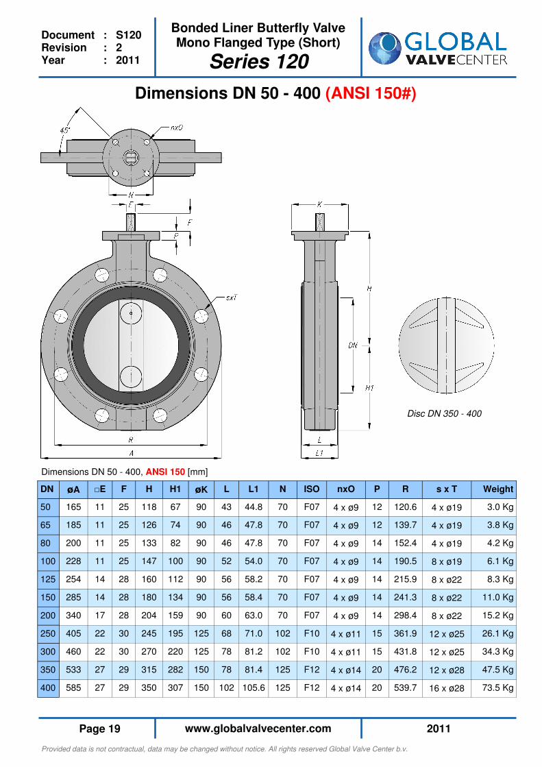
Dimensions DN 50 - 400 (ANSI 150#)
DN øA □E F H H1 øK L L1 N ISO nxO P R s x T Weight
50 165 11 25 118 67 90 43 44.8 70 F07 4 x ø9 12 120.6 4 x ø19 3.0 Kg
65 185 11 25 126 74 90 46 47.8 70 F07 4 x ø9 12 139.7 4 x ø19 3.8 Kg
80 200 11 25 133 82 90 46 47.8 70 F07 4 x ø9 14 152.4 4 x ø19 4.2 Kg
100 228 11 25 147 100 90 52 54.0 70 F07 4 x ø9 14 190.5 8 x ø19 6.1 Kg
125 254 14 28 160 112 90 56 58.2 70 F07 4 x ø9 14 215.9 8 x ø22 8.3 Kg
150 285 14 28 180 134 90 56 58.4 70 F07 4 x ø9 14 241.3 8 x ø22 11.0 Kg
200 340 17 28 204 159 90 60 63.0 70 F07 4 x ø9 14 298.4 8 x ø22 15.2 Kg
250 405 22 30 245 195 125 68 71.0 102 F10 4 x ø11 15 361.9 12 x ø25 26.1 Kg
300 460 22 30 270 220 125 78 81.2 102 F10 4 x ø11 15 431.8 12 x ø25 34.3 Kg
350 533 27 29 315 282 150 78 81.4 125 F12 4 x ø14 20 476.2 12 x ø28 47.5 Kg
400 585 27 29 350 307 150 102 105.6 125 F12 4 x ø14 20 539.7 16 x ø28 73.5 Kg
Dimensions DN 50 - 400, ANSI 150 [mm]
Disc DN 350 - 400

Provided data is not contractual, data may be changed without notice. All rights reserved Global Valve Center b.v.
2011 www.globalvalvecenter.com Page 20
Bonded Liner Butterfly Valve Mono Flanged Type (Short)
Series 120
Document : S120 Revision : 2 Year : 2011
DN E F øK N ISO nxO
50 □11 25 90 70 F07 4 x ø9
65 □11 25 90 70 F07 4 x ø9
80 □11 25 90 70 F07 4 x ø9
100 □11 25 90 70 F07 4 x ø9
125 □14 28 90 70 F07 4 x ø9
150 □14 28 90 70 F07 4 x ø9
200 □17 28 90 70 F07 4 x ø9
250 □22 30 125 102 F10 4 x ø12
300 □22 30 125 102 F10 4 x ø12
350 □27 29 150 125 F12 4 x ø14
400 □27 29 150 125 F12 4 x ø14
Sizing Dimensions
“Everything You Need to Size”
Torque Figures
Torque
Torque figures as mentioned in the torque table are;
• Initial break away values in Nm (Newton Meters)
• Excluding any safety factor
• For valves that are operated at least once per month
• Temperature 0° to 50°C
Safety factor (sf) For sizing and safe operation purposes the specified torque values need to be multiplied with the following minimum safety factors;
• For liquid and lubricant media sf = 1.25
• For powdery (non-lubricant) media sf = 1.60
• For dry gasses and high viscous media sf = 1.60
Service For assistance in sizing and dimensioning actuators-valve combinations please contact our Engineers. We have wide experience in sizing Pneumatic, Electric and Hydraulic actuators.
PN 10 PN 16
DN ∆P 2.5 bar
∆P 6.0 bar
∆P 10 bar
∆P 2.5 bar
∆P 6.0 bar
∆P 10 bar
∆P 16 bar
50 -- -- -- 6.9 7.6 9.9 13.0
65 -- -- -- 9.9 10.7 13.0 14.5
80 -- -- -- 13.0 15.2 18.3 22.8
100 -- -- -- 21.3 16.0 22.8 28.9
125 -- -- -- 29.7 30.4 38.0 53.2
150 -- -- -- 45.6 53.2 62.4 83.6
200 -- -- -- 91.2 106.4 121.6 144.4
250 144.5 167.5 190.0 228.0 243.5 213.0 281.5
300 205.5 236.0 266.0 319.5 342.0 312.0 395.5
350 236.0 274.0 312.0 365.0 403.0 410.5 593.0
400 350.0 410.5 486.5 532.0 593.0 585.5 851.5

Provided data is not contractual, data may be changed without notice. All rights reserved Global Valve Center b.v.
2011 www.globalvalvecenter.com Page 21
Bonded Liner Butterfly Valve Mono Flanged Type (Short)
Series 120
Document : S120 Revision : 2 Year : 2011
KV Values
KV-values
KV values as mentioned in the KV-Value Table are;
• German KV values (m³/hour water of 20°C at a ∆P of 1 bar over the valve)
• Maximum allowable flow velocities; - 4 m/sec. for liquids - 30 m/sec. for gasses
• Cavitation should be avoided
Calculations
Pressure drop (P1-P2) and/or flow (Q) calculations can be performed using the formula’s below. You can calculate pressure drop and/or flow with a fully opened disc when the valve is used in on-off applications or you can calculate the pressure drop and/or flow in above intermediate disc positions when the valve is used in throt-tling and regulating applications. For Liquids: For Gasses (Where P1<2·P2): Where Q = Flow [m³/hr] ρ = Specific Gravity [Kg/m³] ρ0 = Specific Gravity of water under standard conditions (ρ0 = 1000 kg/m³ at 288K) P1 = Inlet Pressure [Barg] P2 = Outlet Pressure [Barg] G = Relative Specific Gravity in relation to air (G = ρ / ρ air) under standard conditions Ti = Inlet Temperature [K]
Service
For assistance on pressure drop calculations and other belonging matters please contact our Engineers.
DN 20° 30° 40° 50° 60° 90°
50 0.9 3.4 14.0 35.0 57.0 172
65 1.4 5.1 21.0 53.0 86.0 258
80 1.9 7.8 31.0 78.0 128 388
100 3.5 14.0 55.0 138 228 690
125 5.3 22.0 86.0 216 355 1078
150 7.8 31.0 124 310 512 1552
200 14.0 55.0 221 552 918 2759
250 22.0 86.0 345 862 1422 4310
300 31.0 124 497 1241 2048 6207
350 42.0 151 676 1513 2496 7565
400 55.0 200 883 2004 3307 10022
Opening Angle Disc
70°
88.0
132
197
352
549
791
1407
2198
3166
3858
5110
80°
126
189
283
504
786
1133
2014
3147
4531
5522
7316
10°
0.4
0.6
1.0
1.7
2.7
3.9
6.9
10.0
15.0
21.0
27.0
Provided data is not contractual, data may be changed without notice. All rights reserved Global Valve Center b.v.
2011 www.globalvalvecenter.com Page 22
Document : S130 Revision : 2 Year : 2011
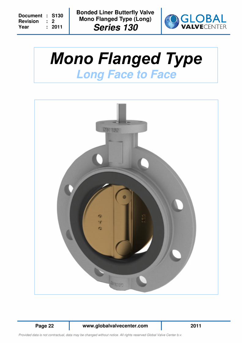
Bonded Liner Butterfly Valve Mono Flanged Type (Long)
Series 130
Long Face to Face
Provided data is not contractual, data may be changed without notice. All rights reserved Global Valve Center b.v.
2011 www.globalvalvecenter.com Page 23
Document : S130 Revision : 2 Year : 2011
Bonded Liner Butterfly Valve Mono Flanged Type (Long)
Series 130
Additional information • Suitable for vacuum applications
• Suitable for end of line service
• On-Off and throttling / regulating applications
• Suitable for high velocity applications up to; - 4 m/sec. for liquids - 30 m/sec. for gasses
• Marking EN 19 - 2002
• Material and Test certification, EN 10204 - 2.2, 3.1 and 3.2
• Special coating systems available (Off-shore coating etc.)
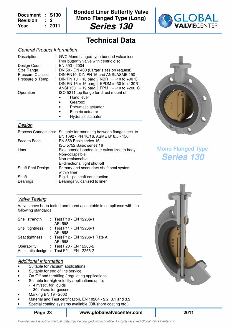
Technical Data
General Product Information
Description : GVC Mono flanged type bonded vulcanised liner butterfly valve with centric disc Design Code : EN 593 - 2004 Size Range : DN 50 - DN 400 (Larger sizes on request) Pressure Classes : DIN PN10, DIN PN 16 and ANSI/ASME 150 Pressure & Temp. : DIN PN 10 = 10 barg NBR = -10 to +90°C DIN PN 16 = 16 barg EPDM = -30 to +130°C ANSI 150 = 19 barg FPM = -10 to +200°C Operation : ISO 5211 top flange for direct mount of;
• Hand lever
• Gearbox
• Pneumatic actuator
• Electric actuator
• Hydraulic actuator
Design
Process Connections: Suitable for mounting between flanges acc. to EN 1092 - PN 10/16, ASME B16.5 - 150 Face to Face : EN 558 Basic series 16 ISO 5752 Basic series 16 Liner : Elastomeric bonded liner vulcanized to body Non-collapsible Non-replaceable Bi-directional tight shut-off Shaft Seal Design : Primary and secondary shaft seal system within liner Shaft : Rigid 1-pc shaft construction Bearings : Bearings vulcanized to liner
Valve Testing
Valves have been tested and found acceptable in compliance with the following standards Shell strength : Test P10 - EN 12266-1 API 598 Shell tightness : Test P11 - EN 12266-1 API 598 Seat tightness : Test P12 - EN 12266-1 Rate A API 598 Operability : Test F20 - EN 12266-2 Anti static design : Test F21 - EN 12266-2
Mono Flanged Type
Series 130
Provided data is not contractual, data may be changed without notice. All rights reserved Global Valve Center b.v.
2011 www.globalvalvecenter.com Page 24
Document : S130 Revision : 2 Year : 2011
Bonded Liner Butterfly Valve Mono Flanged Type (Long)
Series 130
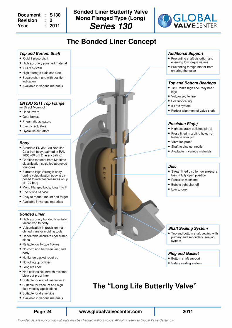
Shaft Sealing System
• Top and bottom shaft sealing with
primary and secondary sealing system
Disc
• Streamlined disc for low pressure
loss in fully open position
• Precision machined
• Bubble tight shut off
• Low torque
The Bonded Liner Concept
Top and Bottom Bearings
• Tin Bronze high accuracy bear-
ings
• Vulcanized to liner
• Self lubricating
• ISO fit system
• Perfect alignment of valve shaft
Precision Pin(s)
• High accuracy polished pin(s)
• Press fitted in a blind hole, no
leakage over pin
• Vibration proof
• Shaft to disc connection
• Available in various materials
Additional Support
• Preventing shaft distortion and
ensuring low torque values
• Preventing foreign matter from
entering the valve
Top and Bottom Shaft
• Rigid 1 piece shaft
• High accuracy polished material
• ISO fit system
• High strength stainless steel
• Square shaft end with position
indication
• Available in various materials
EN ISO 5211 Top Flange for Direct Mount of
• Hand levers
• Gear boxes
• Pneumatic actuators
• Electric actuators
• Hydraulic actuators
Body
• Standard EN JS1030 Nodular
Cast Iron body, painted in RAL 7036 (60 µm 2 layer coating)
• Certified material from Maritime
classification societies approved foundries
• Extreme High Strength body,
during vulcanization body is ex-posed to internal pressures of up to 100 barg
• Mono Flanged body, long F to F
• End of line service
• Easy to mount, mount and forget
• Available in various materials
Bonded Liner
• High accuracy bonded liner fully
vulcanized to body
• Vulcanization in precision ma-
chined transfer molding tools
• Repeatable accurate liner dimen-
sions
• Reliable low torque figures
• No corrosion between liner and
body
• No flange gasket required
• No rolling up of liner
• Long life liner
• Non collapsible, stretch resistant,
blow out proof liner
• Suitable for end of line service
• Suitable for vacuum and high
fluid velocity applications
• Suitable for dry service
• Available in various materials
Plug and Gasket
• Bottom shaft support
• Safety sealing system
The “Long Life Butterfly Valve”
Provided data is not contractual, data may be changed without notice. All rights reserved Global Valve Center b.v.
2011 www.globalvalvecenter.com Page 25
Document : S130 Revision : 2 Year : 2011
Bonded Liner Butterfly Valve Mono Flanged Type (Long)
Series 130
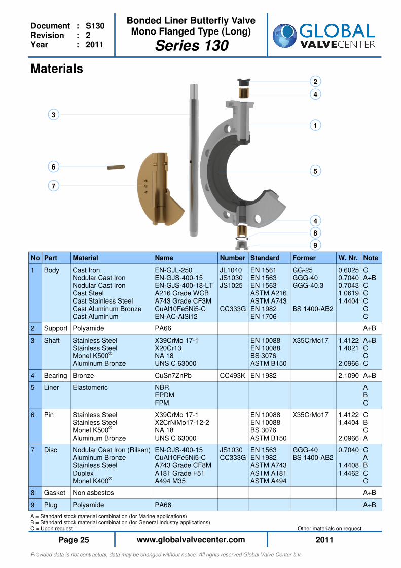
A = Standard stock material combination (for Marine applications) B = Standard stock material combination (for General Industry applications) C = Upon request Other materials on request
1
2
3
4
4
5 6
7
8
9
Materials
No Part Material Name
1 Body Cast Iron Nodular Cast Iron Nodular Cast Iron Cast Steel Cast Stainless Steel Cast Aluminum Bronze Cast Aluminum
EN-GJL-250 EN-GJS-400-15 EN-GJS-400-18-LT A216 Grade WCB A743 Grade CF3M CuAl10Fe5Ni5-C EN-AC-AlSi12
2 Support Polyamide PA66
3 Shaft Stainless Steel Stainless Steel Monel K500® Aluminum Bronze
X39CrMo 17-1 X20Cr13 NA 18 UNS C 63000
4 Bearing Bronze CuSn7ZnPb
5 Liner
Elastomeric NBR EPDM FPM
6 Pin Stainless Steel Stainless Steel Monel K500® Aluminum Bronze
X39CrMo 17-1 X2CrNiMo17-12-2 NA 18 UNS C 63000
7 Disc Nodular Cast Iron (Rilsan) Aluminum Bronze Stainless Steel Duplex Monel K400®
EN-GJS-400-15 CuAl10Fe5Ni5-C A743 Grade CF8M A181 Grade F51 A494 M35
8 Gasket Non asbestos
9 Plug Polyamide PA66
Note
C A+B C C C C C
A+B
A+B C C C
A+B
A B C
C B C A
C A B C C
A+B
A+B
Former
GG-25 GGG-40 GGG-40.3 BS 1400-AB2
X35CrMo17
X35CrMo17
GGG-40 BS 1400-AB2
Standard
EN 1561 EN 1563 EN 1563 ASTM A216 ASTM A743 EN 1982 EN 1706
EN 10088 EN 10088 BS 3076 ASTM B150
EN 1982
EN 10088 EN 10088 BS 3076 ASTM B150
EN 1563 EN 1982 ASTM A743 ASTM A181 ASTM A494
Number
JL1040 JS1030 JS1025 CC333G
CC493K
JS1030 CC333G
W. Nr.
0.6025 0.7040 0.7043 1.0619 1.4404
1.4122 1.4021 2.0966
2.1090
1.4122 1.4404 2.0966
0.7040 1.4408 1.4462
Provided data is not contractual, data may be changed without notice. All rights reserved Global Valve Center b.v.
2011 www.globalvalvecenter.com Page 26
Document : S130 Revision : 2 Year : 2011
Bonded Liner Butterfly Valve Mono Flanged Type (Long)
Series 130
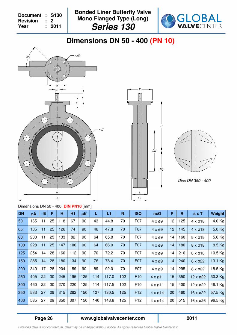
Dimensions DN 50 - 400 (PN 10)
Dimensions DN 50 - 400, DIN PN10 [mm]
Disc DN 350 - 400
DN øA □E F H H1 øK L L1 N ISO nxO P R s x T Weight
50 165 11 25 118 67 90 43 44.8 70 F07 4 x ø9 12 125 4 x ø18 4.0 Kg
65 185 11 25 126 74 90 46 47.8 70 F07 4 x ø9 12 145 4 x ø18 5.0 Kg
80 200 11 25 133 82 90 64 65.8 70 F07 4 x ø9 14 160 8 x ø18 5.6 Kg
100 228 11 25 147 100 90 64 66.0 70 F07 4 x ø9 14 180 8 x ø18 8.5 Kg
125 254 14 28 160 112 90 70 72.2 70 F07 4 x ø9 14 210 8 x ø18 10.5 Kg
150 285 14 28 180 134 90 76 78.4 70 F07 4 x ø9 14 240 8 x ø22 13.1 Kg
200 340 17 28 204 159 90 89 92.0 70 F07 4 x ø9 14 295 8 x ø22 18.5 Kg
250 405 22 30 245 195 125 114 117.0 102 F10 4 x ø11 15 350 12 x ø22 30.3 Kg
300 460 22 30 270 220 125 114 117.5 102 F10 4 x ø11 15 400 12 x ø22 46.1 Kg
350 533 27 29 315 282 150 127 130.5 125 F12 4 x ø14 20 460 16 x ø22 57.5 Kg
400 585 27 29 350 307 150 140 143.6 125 F12 4 x ø14 20 515 16 x ø26 96.5 Kg

Provided data is not contractual, data may be changed without notice. All rights reserved Global Valve Center b.v.
2011 www.globalvalvecenter.com Page 27
Document : S130 Revision : 2 Year : 2011
Bonded Liner Butterfly Valve Mono Flanged Type (Long)
Series 130
Dimensions DN 50 - 400 (PN 16)
Dimensions DN 50 - 400, DIN PN16 [mm]
Disc DN 350 - 400
DN øA □E F H H1 øK L L1 N ISO nxO P R s x T Weight
50 165 11 25 118 67 90 43 44.8 70 F07 4 x ø9 12 125 4 x ø18 4.0 Kg
65 185 11 25 126 74 90 46 47.8 70 F07 4 x ø9 12 145 4 x ø18 5.0 Kg
80 200 11 25 133 82 90 64 65.8 70 F07 4 x ø9 14 160 8 x ø18 5.6 Kg
100 228 11 25 147 100 90 64 66.0 70 F07 4 x ø9 14 180 8 x ø18 8.5 Kg
125 254 14 28 160 112 90 70 72.2 70 F07 4 x ø9 14 210 8 x ø18 10.5 Kg
150 285 14 28 180 134 90 76 78.4 70 F07 4 x ø9 14 240 8 x ø22 13.1 Kg
200 340 17 28 204 159 90 89 92.0 70 F07 4 x ø9 14 295 12 x ø22 18.5 Kg
250 405 22 30 245 195 125 114 117.0 102 F10 4 x ø11 15 355 12 x ø26 30.3 Kg
300 460 22 30 270 220 125 114 117.5 102 F10 4 x ø11 15 410 12 x ø26 46.1 Kg
350 533 27 29 315 282 150 127 130.5 125 F12 4 x ø14 20 470 16 x ø26 57.5 Kg
400 585 27 29 350 307 150 140 143.6 125 F12 4 x ø14 20 525 16 x ø30 96.5 Kg

Provided data is not contractual, data may be changed without notice. All rights reserved Global Valve Center b.v.
2011 www.globalvalvecenter.com Page 28
Document : S130 Revision : 2 Year : 2011
Bonded Liner Butterfly Valve Mono Flanged Type (Long)
Series 130
Dimensions DN 50 - 400 (ANSI 150)
Dimensions DN 50 - 400, ANSI 150 [mm]
Disc DN 350 - 400
DN øA □E F H H1 øK L L1 N ISO nxO P R s x T Weight
50 165 11 25 118 67 90 43 44.8 70 F07 4 x ø9 12 120.6 4 x ø19 4.0 Kg
65 185 11 25 126 74 90 46 47.8 70 F07 4 x ø9 12 139.7 4 x ø19 5.0 Kg
80 200 11 25 133 82 90 64 65.8 70 F07 4 x ø9 14 152.4 4 x ø19 5.6 Kg
100 228 11 25 147 100 90 64 66.0 70 F07 4 x ø9 14 190.5 8 x ø19 8.5 Kg
125 254 14 28 160 112 90 70 72.2 70 F07 4 x ø9 14 215.9 8 x ø22 10.5 Kg
150 285 14 28 180 134 90 76 78.4 70 F07 4 x ø9 14 241.3 8 x ø22 13.1 Kg
200 340 17 28 204 159 90 89 92.0 70 F07 4 x ø9 14 298.4 8 x ø22 18.5 Kg
250 405 22 30 245 195 125 114 117.0 102 F10 4 x ø11 15 361.9 12 x ø25 30.3 Kg
300 460 22 30 270 220 125 114 117.5 102 F10 4 x ø11 15 431.8 12 x ø35 46.1 Kg
350 533 27 29 315 282 150 127 130.5 125 F12 4 x ø14 20 476.2 12 x ø28 57.5 Kg
400 585 27 29 350 307 150 140 143.6 125 F12 4 x ø14 20 539.7 16 x ø28 96.5 Kg
Provided data is not contractual, data may be changed without notice. All rights reserved Global Valve Center b.v.
2011 www.globalvalvecenter.com Page 29
Document : S130 Revision : 2 Year : 2011
Bonded Liner Butterfly Valve Mono Flanged Type (Long)
Series 130
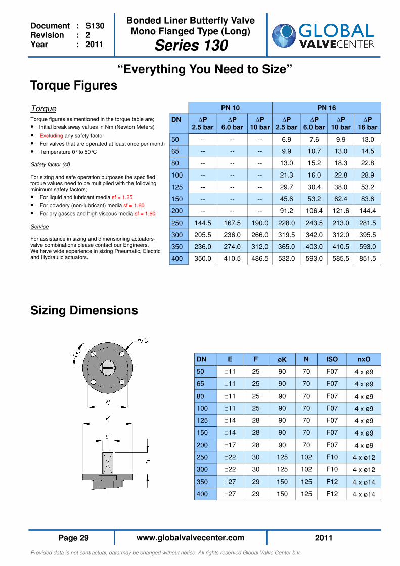
DN E F øK N ISO nxO
50 □11 25 90 70 F07 4 x ø9
65 □11 25 90 70 F07 4 x ø9
80 □11 25 90 70 F07 4 x ø9
100 □11 25 90 70 F07 4 x ø9
125 □14 28 90 70 F07 4 x ø9
150 □14 28 90 70 F07 4 x ø9
200 □17 28 90 70 F07 4 x ø9
250 □22 30 125 102 F10 4 x ø12
300 □22 30 125 102 F10 4 x ø12
350 □27 29 150 125 F12 4 x ø14
400 □27 29 150 125 F12 4 x ø14
Sizing Dimensions
“Everything You Need to Size”
Torque Figures
Torque
Torque figures as mentioned in the torque table are;
• Initial break away values in Nm (Newton Meters)
• Excluding any safety factor
• For valves that are operated at least once per month
• Temperature 0° to 50°C
Safety factor (sf) For sizing and safe operation purposes the specified torque values need to be multiplied with the following minimum safety factors;
• For liquid and lubricant media sf = 1.25
• For powdery (non-lubricant) media sf = 1.60
• For dry gasses and high viscous media sf = 1.60
Service For assistance in sizing and dimensioning actuators-valve combinations please contact our Engineers. We have wide experience in sizing Pneumatic, Electric and Hydraulic actuators.
PN 10 PN 16
DN ∆P 2.5 bar
∆P 6.0 bar
∆P 10 bar
∆P 2.5 bar
∆P 6.0 bar
∆P 10 bar
∆P 16 bar
50 -- -- -- 6.9 7.6 9.9 13.0
65 -- -- -- 9.9 10.7 13.0 14.5
80 -- -- -- 13.0 15.2 18.3 22.8
100 -- -- -- 21.3 16.0 22.8 28.9
125 -- -- -- 29.7 30.4 38.0 53.2
150 -- -- -- 45.6 53.2 62.4 83.6
200 -- -- -- 91.2 106.4 121.6 144.4
250 144.5 167.5 190.0 228.0 243.5 213.0 281.5
300 205.5 236.0 266.0 319.5 342.0 312.0 395.5
350 236.0 274.0 312.0 365.0 403.0 410.5 593.0
400 350.0 410.5 486.5 532.0 593.0 585.5 851.5
Provided data is not contractual, data may be changed without notice. All rights reserved Global Valve Center b.v.
2011 www.globalvalvecenter.com Page 30
Document : S130 Revision : 2 Year : 2011
Bonded Liner Butterfly Valve Mono Flanged Type (Long)
Series 130
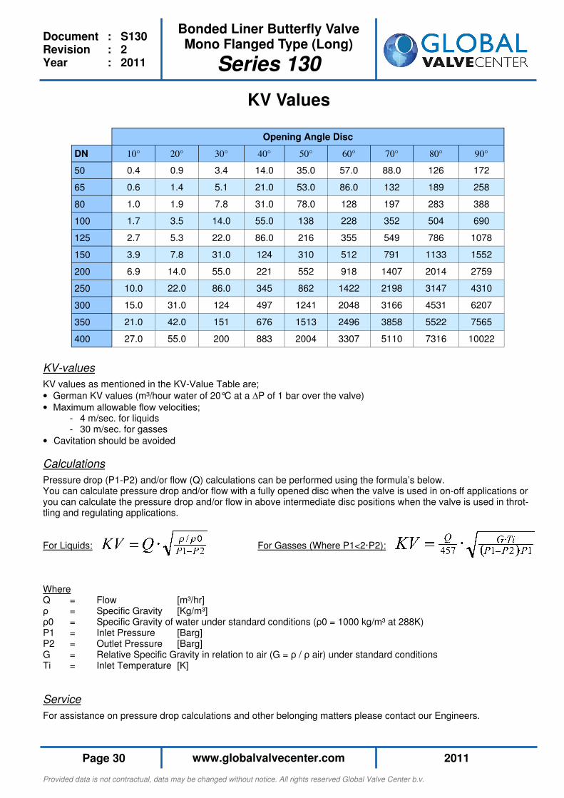
KV Values
DN 20° 30° 40° 50° 60° 90°
50 0.9 3.4 14.0 35.0 57.0 172
65 1.4 5.1 21.0 53.0 86.0 258
80 1.9 7.8 31.0 78.0 128 388
100 3.5 14.0 55.0 138 228 690
125 5.3 22.0 86.0 216 355 1078
150 7.8 31.0 124 310 512 1552
200 14.0 55.0 221 552 918 2759
250 22.0 86.0 345 862 1422 4310
300 31.0 124 497 1241 2048 6207
350 42.0 151 676 1513 2496 7565
400 55.0 200 883 2004 3307 10022
Opening Angle Disc
70°
88.0
132
197
352
549
791
1407
2198
3166
3858
5110
80°
126
189
283
504
786
1133
2014
3147
4531
5522
7316
10°
0.4
0.6
1.0
1.7
2.7
3.9
6.9
10.0
15.0
21.0
27.0
KV-values
KV values as mentioned in the KV-Value Table are;
• German KV values (m³/hour water of 20°C at a ∆P of 1 bar over the valve)
• Maximum allowable flow velocities; - 4 m/sec. for liquids - 30 m/sec. for gasses
• Cavitation should be avoided
Calculations
Pressure drop (P1-P2) and/or flow (Q) calculations can be performed using the formula’s below. You can calculate pressure drop and/or flow with a fully opened disc when the valve is used in on-off applications or you can calculate the pressure drop and/or flow in above intermediate disc positions when the valve is used in throt-tling and regulating applications. For Liquids: For Gasses (Where P1<2·P2): Where Q = Flow [m³/hr] ρ = Specific Gravity [Kg/m³] ρ0 = Specific Gravity of water under standard conditions (ρ0 = 1000 kg/m³ at 288K) P1 = Inlet Pressure [Barg] P2 = Outlet Pressure [Barg] G = Relative Specific Gravity in relation to air (G = ρ / ρ air) under standard conditions Ti = Inlet Temperature [K]
Service
For assistance on pressure drop calculations and other belonging matters please contact our Engineers.
Provided data is not contractual, data may be changed without notice. All rights reserved Global Valve Center b.v.
2011 www.globalvalvecenter.com Page 31
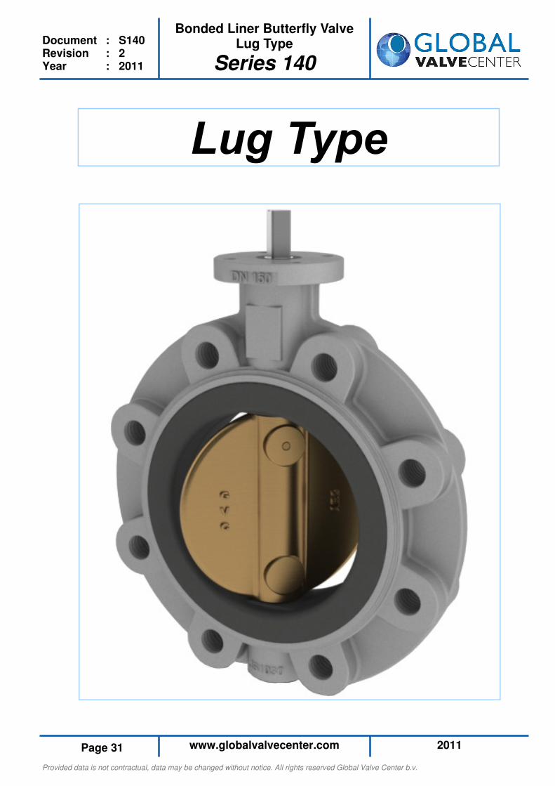
Bonded Liner Butterfly Valve Lug Type
Series 140
Document : S140 Revision : 2 Year : 2011
Provided data is not contractual, data may be changed without notice. All rights reserved Global Valve Center b.v.
2011 www.globalvalvecenter.com Page 32
Bonded Liner Butterfly Valve Lug Type
Series 140
Document : S140 Revision : 2 Year : 2011
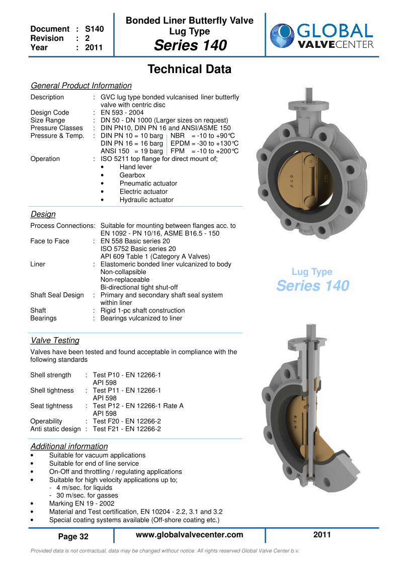
Technical Data
Design
Process Connections: Suitable for mounting between flanges acc. to EN 1092 - PN 10/16, ASME B16.5 - 150 Face to Face : EN 558 Basic series 20 ISO 5752 Basic series 20 API 609 Table 1 (Category A Valves) Liner : Elastomeric bonded liner vulcanized to body Non-collapsible Non-replaceable Bi-directional tight shut-off Shaft Seal Design : Primary and secondary shaft seal system within liner Shaft : Rigid 1-pc shaft construction Bearings : Bearings vulcanized to liner
Valve Testing
Valves have been tested and found acceptable in compliance with the following standards Shell strength : Test P10 - EN 12266-1 API 598 Shell tightness : Test P11 - EN 12266-1 API 598 Seat tightness : Test P12 - EN 12266-1 Rate A API 598 Operability : Test F20 - EN 12266-2 Anti static design : Test F21 - EN 12266-2
Lug Type
Series 140
General Product Information
Description : GVC lug type bonded vulcanised liner butterfly valve with centric disc Design Code : EN 593 - 2004 Size Range : DN 50 - DN 1000 (Larger sizes on request) Pressure Classes : DIN PN10, DIN PN 16 and ANSI/ASME 150 Pressure & Temp. : DIN PN 10 = 10 barg NBR = -10 to +90°C DIN PN 16 = 16 barg EPDM = -30 to +130°C ANSI 150 = 19 barg FPM = -10 to +200°C Operation : ISO 5211 top flange for direct mount of;
• Hand lever
• Gearbox
• Pneumatic actuator
• Electric actuator
• Hydraulic actuator
Additional information • Suitable for vacuum applications
• Suitable for end of line service
• On-Off and throttling / regulating applications
• Suitable for high velocity applications up to; - 4 m/sec. for liquids - 30 m/sec. for gasses
• Marking EN 19 - 2002
• Material and Test certification, EN 10204 - 2.2, 3.1 and 3.2
• Special coating systems available (Off-shore coating etc.)
Provided data is not contractual, data may be changed without notice. All rights reserved Global Valve Center b.v.
2011 www.globalvalvecenter.com Page 33
Bonded Liner Butterfly Valve Lug Type
Series 140
Document : S140 Revision : 2 Year : 2011
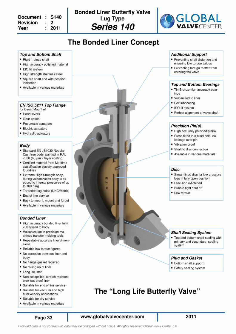
Shaft Sealing System
• Top and bottom shaft sealing with
primary and secondary sealing system
Disc
• Streamlined disc for low pressure
loss in fully open position
• Precision machined
• Bubble tight shut off
• Low torque
The Bonded Liner Concept
Top and Bottom Bearings
• Tin Bronze high accuracy bear-
ings
• Vulcanized to liner
• Self lubricating
• ISO fit system
• Perfect alignment of valve shaft
Precision Pin(s)
• High accuracy polished pin(s)
• Press fitted in a blind hole, no
leakage over pin
• Vibration proof
• Shaft to disc connection
• Available in various materials
Additional Support
• Preventing shaft distortion and
ensuring low torque values
• Preventing foreign matter from
entering the valve
Top and Bottom Shaft
• Rigid 1 piece shaft
• High accuracy polished material
• ISO fit system
• High strength stainless steel
• Square shaft end with position
indication
• Available in various materials
EN ISO 5211 Top Flange for Direct Mount of
• Hand levers
• Gear boxes
• Pneumatic actuators
• Electric actuators
• Hydraulic actuators
Body
• Standard EN JS1030 Nodular
Cast Iron body, painted in RAL 7036 (60 µm 2 layer coating)
• Certified material from Maritime
classification society approved foundries
• Extreme High Strength body,
during vulcanization body is ex-posed to internal pressures of up to 100 barg
• Threaded lug holes (UNC/Metric)
• End of line service
• Easy to mount, mount and forget
• Available in various materials
Bonded Liner
• High accuracy bonded liner fully
vulcanized to body
• Vulcanization in precision ma-
chined transfer molding tools
• Repeatable accurate liner dimen-
sions
• Reliable low torque figures
• No corrosion between liner and
body
• No flange gasket required
• No rolling up of liner
• Long life liner
• Non collapsible, stretch resistant,
blow out proof liner
• Suitable for end of line service
• Suitable for vacuum and high
fluid velocity applications
• Suitable for dry service
• Available in various materials
Plug and Gasket
• Bottom shaft support
• Safety sealing system
The “Long Life Butterfly Valve”
Provided data is not contractual, data may be changed without notice. All rights reserved Global Valve Center b.v.
2011 www.globalvalvecenter.com Page 34
Bonded Liner Butterfly Valve Lug Type
Series 140
Document : S140 Revision : 2 Year : 2011
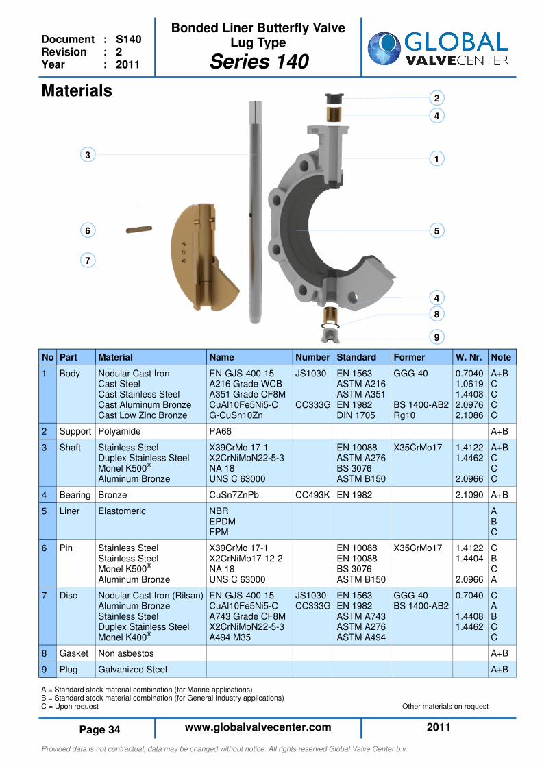
1
2
3
4
4
5 6
7
8
9
Materials
A = Standard stock material combination (for Marine applications) B = Standard stock material combination (for General Industry applications) C = Upon request Other materials on request
No Part Material Name
1 Body Nodular Cast Iron Cast Steel Cast Stainless Steel Cast Aluminum Bronze Cast Low Zinc Bronze
EN-GJS-400-15 A216 Grade WCB A351 Grade CF8M CuAl10Fe5Ni5-C G-CuSn10Zn
2 Support Polyamide PA66
3 Shaft Stainless Steel Duplex Stainless Steel Monel K500® Aluminum Bronze
X39CrMo 17-1 X2CrNiMoN22-5-3 NA 18 UNS C 63000
4 Bearing Bronze CuSn7ZnPb
5 Liner
Elastomeric NBR EPDM FPM
6 Pin Stainless Steel Stainless Steel Monel K500® Aluminum Bronze
X39CrMo 17-1 X2CrNiMo17-12-2 NA 18 UNS C 63000
7 Disc Nodular Cast Iron (Rilsan) Aluminum Bronze Stainless Steel Duplex Stainless Steel Monel K400®
EN-GJS-400-15 CuAl10Fe5Ni5-C A743 Grade CF8M X2CrNiMoN22-5-3 A494 M35
8 Gasket Non asbestos
9 Plug Galvanized Steel
Note
A+B C C C C
A+B
A+B C C C
A+B
A B C
C B C A
C A B C C
A+B
A+B
Former
GGG-40 BS 1400-AB2 Rg10
X35CrMo17
X35CrMo17
GGG-40 BS 1400-AB2
Standard
EN 1563 ASTM A216 ASTM A351 EN 1982 DIN 1705
EN 10088 ASTM A276 BS 3076 ASTM B150
EN 1982
EN 10088 EN 10088 BS 3076 ASTM B150
EN 1563 EN 1982 ASTM A743 ASTM A276 ASTM A494
Number
JS1030 CC333G
CC493K
JS1030 CC333G
W. Nr.
0.7040 1.0619 1.4408 2.0976 2.1086
1.4122 1.4462 2.0966
2.1090
1.4122 1.4404 2.0966
0.7040 1.4408 1.4462
Provided data is not contractual, data may be changed without notice. All rights reserved Global Valve Center b.v.
2011 www.globalvalvecenter.com Page 35
Bonded Liner Butterfly Valve Lug Type
Series 140
Document : S140 Revision : 2 Year : 2011
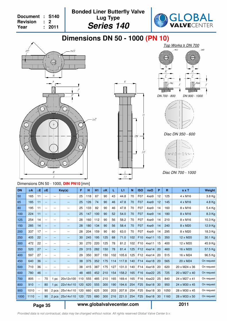
Dimensions DN 50 - 1000 (PN 10)
Dimensions DN 50 - 1000, DIN PN10 [mm]
DN øA □E øE F H H1 øK L L1 N ISO nxO P R s x T Weight
50 165 11 -- -- -- 25 118 67 90 43 44.8 70 F07 4xø9 12 125 4 x M16 3.8 Kg
65 185 11 -- -- -- 25 126 74 90 46 47.8 70 F07 4xø9 12 145 4 x M16 4.8 Kg
80 195 11 -- -- -- 25 133 82 90 46 47.8 70 F07 4xø9 14 160 8 x M16 5.4 Kg
100 224 11 -- -- -- 25 147 100 90 52 54.0 70 F07 4xø9 14 180 8 x M16 8.3 Kg
125 254 14 -- -- -- 28 160 112 90 56 58.2 70 F07 4xø9 14 210 8 x M16 10.3 Kg
150 285 14 -- -- -- 28 180 134 90 56 58.4 70 F07 4xø9 14 240 8 x M20 12.9 Kg
200 337 17 -- -- -- 28 204 159 90 60 63.0 70 F07 4xø9 14 295 8 x M20 18.3 Kg
250 405 22 -- -- -- 30 245 195 125 68 71.0 102 F10 4xø11 15 350 12 x M20 30.1 Kg
300 472 22 -- -- -- 30 270 220 125 78 81.2 102 F10 4xø11 15 400 12 x M20 45.9 Kg
350 520 27 -- -- -- 29 315 282 150 78 81.4 125 F12 4xø14 20 460 16 x M20 57.5 Kg
400 597 27 -- -- -- 29 350 307 150 102 105.6 125 F12 4xø14 20 515 16 x M24 96.5 Kg
450 640 36 -- -- -- 38 375 352 175 114 117.8 140 F14 4xø18 20 565 20 x M24 On request
500 710 36 -- -- -- 38 415 387 175 127 131.0 140 F14 4xø18 20 620 20 x M24 x 36 On request
600 780 46 -- -- -- 48 465 452 210 154 158.2 165 F16 4xø22 25 725 20 x M27 x 40 On request
700 805 -- 70 1 pc 20x12x100 110 555 485 210 165 169.4 165 F16 4xø22 25 840 24 x M27 x 41 On request
800 910 -- 80 1 pc 22x14x110 120 620 555 300 190 194.6 254 F25 8xø18 30 950 24 x M30 x 45 On request
900 1010 -- 90 2 pcs 25x14x110 120 660 625 300 203 207.8 254 F25 8xø18 30 1050 28 x M30 x 45 On request
1000 1110 -- 90 2 pcs 25x14x110 120 725 680 300 216 221.0 254 F25 8xø18 30 1160 28 x M33 x 50 On request
Key(s)
Disc DN 350 - 600
Disc DN 700 - 1000
Top Works ≥ DN 700
DN 700 - 800 DN 900 - 1000

Provided data is not contractual, data may be changed without notice. All rights reserved Global Valve Center b.v.
2011 www.globalvalvecenter.com Page 36
Bonded Liner Butterfly Valve Lug Type
Series 140
Document : S140 Revision : 2 Year : 2011
Dimensions DN 50 - 1000 (PN 16)
Dimensions DN 50 - 1000, DIN PN16 [mm]
Disc DN 350 - 600
Disc DN 700 - 1000
Top Works ≥ DN 700
DN 700 - 800 DN 900 - 1000
DN øA □E øE F H H1 øK L L1 N ISO nxO P R s x T Weight
50 165 11 -- -- -- 25 118 67 90 43 44.8 70 F07 4xø9 12 125 4 x M16 3.8 Kg
65 185 11 -- -- -- 25 126 74 90 46 47.8 70 F07 4xø9 12 145 4 x M16 4.8 Kg
80 195 11 -- -- -- 25 133 82 90 46 47.8 70 F07 4xø9 14 160 8 x M16 5.4 Kg
100 224 11 -- -- -- 25 147 100 90 52 54.0 70 F07 4xø9 14 180 8 x M16 8.3 Kg
125 254 14 -- -- -- 28 160 112 90 56 58.2 70 F07 4xø9 14 210 8 x M16 10.3 Kg
150 285 14 -- -- -- 28 180 134 90 56 58.4 70 F07 4xø9 14 240 8 x M20 12.9 Kg
200 335 17 -- -- -- 28 204 159 90 60 63.0 70 F07 4xø9 14 295 12 x M20 18.3 Kg
250 405 22 -- -- -- 30 245 195 125 68 71.0 102 F10 4xø11 15 355 12 x M24 30.1 Kg
300 472 22 -- -- -- 30 270 220 125 78 81.2 102 F10 4xø11 15 410 12 x M24 45.9 Kg
350 520 27 -- -- -- 29 315 282 150 78 81.4 125 F12 4xø14 20 470 16 x M24 57.5 Kg
400 597 27 -- -- -- 29 350 307 150 102 105.6 125 F12 4xø14 20 525 16 x M27 96.5 Kg
450 640 36 -- -- -- 38 375 352 175 114 117.8 140 F14 4xø18 20 585 20 x M27 On request
500 710 36 -- -- -- 38 415 387 175 127 131.0 140 F14 4xø18 20 650 20 x M30 x 45 On request
600 780 46 -- -- -- 48 465 452 210 154 158.2 165 F16 4xø22 25 770 20 x M33 x 47 On request
700 805 -- 80 1 pc 22x14x110 120 555 505 210 165 169.4 165 F16 4xø22 25 840 24 x M33 x 50 On request
800 900 -- 100 1 pc 28x16x110 120 615 575 300 190 194.6 254 F25 8xø18 30 950 24 x M36 x 54 On request
900 1010 -- 110 2 pcs 32x16x140 160 675 645 300 203 207.8 254 F25 8xø18 30 1050 28 x M36 x 54 On request
1000 1110 -- 120 2 pcs 32x18x140 160 750 695 300 216 221.0 254 F25 8xø18 30 1170 28 x M39 x 59 On request
Key(s)
Provided data is not contractual, data may be changed without notice. All rights reserved Global Valve Center b.v.
2011 www.globalvalvecenter.com Page 37
Bonded Liner Butterfly Valve Lug Type
Series 140
Document : S140 Revision : 2 Year : 2011
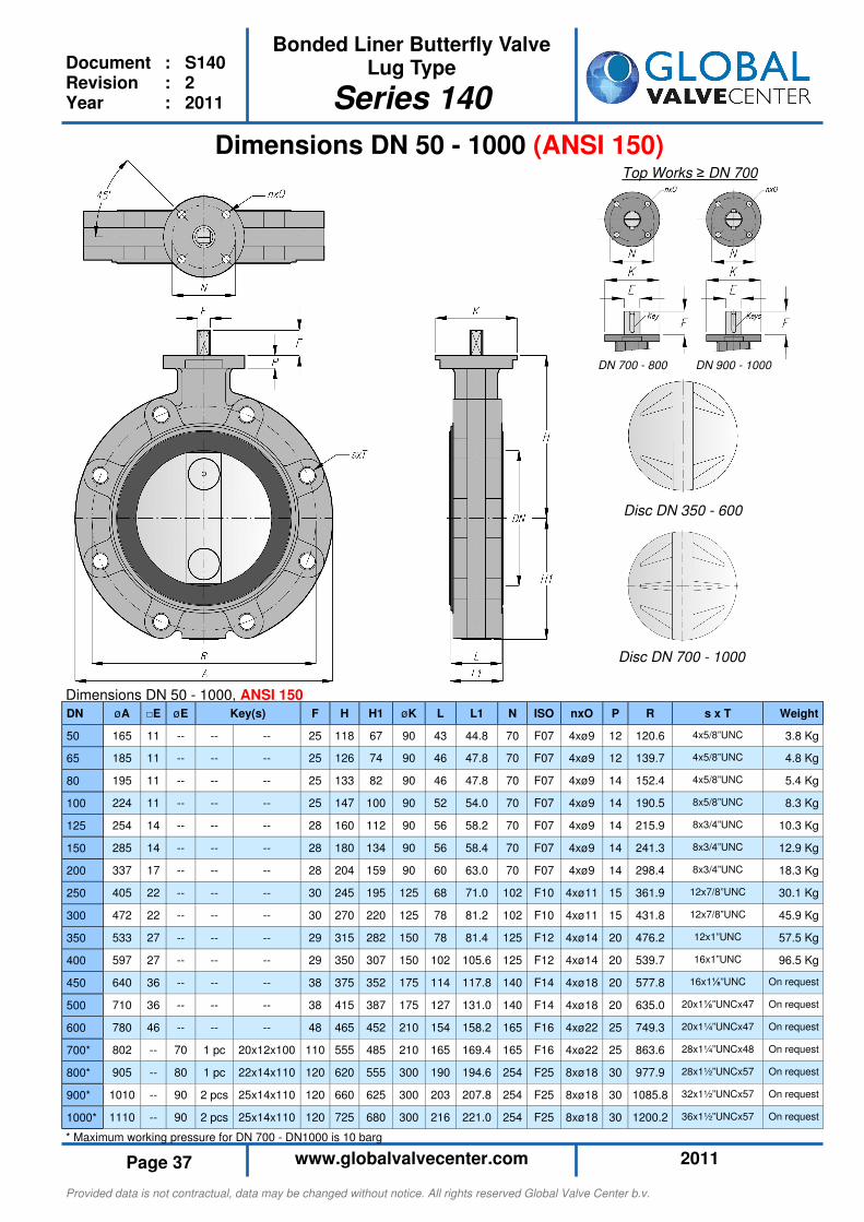
* Maximum working pressure for DN 700 - DN1000 is 10 barg
Dimensions DN 50 - 1000 (ANSI 150)
Dimensions DN 50 - 1000, ANSI 150
Disc DN 350 - 600
Disc DN 700 - 1000
Top Works ≥ DN 700
DN 700 - 800 DN 900 - 1000
DN øA □E øE F H H1 øK L L1 N ISO nxO P R s x T Weight
50 165 11 -- -- -- 25 118 67 90 43 44.8 70 F07 4xø9 12 120.6 4x5/8”UNC 3.8 Kg
65 185 11 -- -- -- 25 126 74 90 46 47.8 70 F07 4xø9 12 139.7 4x5/8”UNC 4.8 Kg
80 195 11 -- -- -- 25 133 82 90 46 47.8 70 F07 4xø9 14 152.4 4x5/8”UNC 5.4 Kg
100 224 11 -- -- -- 25 147 100 90 52 54.0 70 F07 4xø9 14 190.5 8x5/8”UNC 8.3 Kg
125 254 14 -- -- -- 28 160 112 90 56 58.2 70 F07 4xø9 14 215.9 8x3/4”UNC 10.3 Kg
150 285 14 -- -- -- 28 180 134 90 56 58.4 70 F07 4xø9 14 241.3 8x3/4”UNC 12.9 Kg
200 337 17 -- -- -- 28 204 159 90 60 63.0 70 F07 4xø9 14 298.4 8x3/4”UNC 18.3 Kg
250 405 22 -- -- -- 30 245 195 125 68 71.0 102 F10 4xø11 15 361.9 12x7/8”UNC 30.1 Kg
300 472 22 -- -- -- 30 270 220 125 78 81.2 102 F10 4xø11 15 431.8 12x7/8”UNC 45.9 Kg
350 533 27 -- -- -- 29 315 282 150 78 81.4 125 F12 4xø14 20 476.2 12x1”UNC 57.5 Kg
400 597 27 -- -- -- 29 350 307 150 102 105.6 125 F12 4xø14 20 539.7 16x1”UNC 96.5 Kg
450 640 36 -- -- -- 38 375 352 175 114 117.8 140 F14 4xø18 20 577.8 16x1⅛”UNC On request
500 710 36 -- -- -- 38 415 387 175 127 131.0 140 F14 4xø18 20 635.0 20x1⅛”UNCx47 On request
600 780 46 -- -- -- 48 465 452 210 154 158.2 165 F16 4xø22 25 749.3 20x1¼”UNCx47 On request
700* 802 -- 70 1 pc 20x12x100 110 555 485 210 165 169.4 165 F16 4xø22 25 863.6 28x1¼”UNCx48 On request
800* 905 -- 80 1 pc 22x14x110 120 620 555 300 190 194.6 254 F25 8xø18 30 977.9 28x1½”UNCx57 On request
900* 1010 -- 90 2 pcs 25x14x110 120 660 625 300 203 207.8 254 F25 8xø18 30 1085.8 32x1½”UNCx57 On request
1000* 1110 -- 90 2 pcs 25x14x110 120 725 680 300 216 221.0 254 F25 8xø18 30 1200.2 36x1½”UNCx57 On request
Key(s)
Provided data is not contractual, data may be changed without notice. All rights reserved Global Valve Center b.v.
2011 www.globalvalvecenter.com Page 38
Bonded Liner Butterfly Valve Lug Type
Series 140
Document : S140 Revision : 2 Year : 2011
“Everything You Need to Size”
Torque Figures
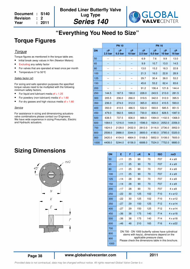
Torque
Torque figures as mentioned in the torque table are;
• Initial break away values in Nm (Newton Meters)
• Excluding any safety factor
• For valves that are operated at least once per month
• Temperature 0° to 50°C
Safety factor (sf) For sizing and safe operation purposes the specified torque values need to be multiplied with the following minimum safety factors;
• For liquid and lubricant media sf = 1.25
• For powdery (non-lubricant) media sf = 1.60
• For dry gasses and high viscous media sf = 1.60
Service For assistance in sizing and dimensioning actuators-valve combinations please contact our Engineers. We have wide experience in sizing Pneumatic, Electric and Hydraulic actuators.
DN E F øK N ISO nxO
50 □11 25 90 70 F07 4 x ø9
65 □11 25 90 70 F07 4 x ø9
80 □11 25 90 70 F07 4 x ø9
100 □11 25 90 70 F07 4 x ø9
125 □14 28 90 70 F07 4 x ø9
150 □14 28 90 70 F07 4 x ø9
200 □17 28 90 70 F07 4 x ø9
250 □22 30 125 102 F10 4 x ø12
300 □22 30 125 102 F10 4 x ø12
350 □27 29 150 125 F12 4 x ø14
400 □27 29 150 125 F12 4 x ø14
450 □36 38 175 140 F14 4 x ø18
500 □36 38 175 140 F14 4 x ø18
600 □46 48 210 165 F16 4 x ø22
700
800
900
1000
DN 700 - DN 1000 butterfly valves have cylindrical stems with key(s), dimensions depend on the
applicable pressure class. Please check the dimensions table in this brochure.
Sizing Dimensions
PN 10 PN 16
DN ∆P 2.5 bar
∆P 6.0 bar
∆P 10 bar
∆P 2.5 bar
∆P 6.0 bar
∆P 10 bar
∆P 16 bar
50 -- -- -- 6.9 7.6 9.9 13.0
65 -- -- -- 9.9 10.7 13.0 14.5
80 -- -- -- 13.0 15.2 18.3 22.8
100 -- -- -- 21.3 16.0 22.8 28.9
125 -- -- -- 29.7 30.4 38.0 53.2
150 -- -- -- 45.6 53.2 62.4 83.6
200 -- -- -- 91.2 106.4 121.6 144.4
250 144.5 167.5 190.0 228.0 243.5 213.0 281.5
300 205.5 236.0 266.0 319.5 342.0 312.0 395.5
350 236.0 274.0 312.0 365.0 403.0 410.5 593.0
400 350.0 410.5 486.5 532.0 593.0 585.5 851.5
450 479.0 562.5 646.0 730.0 836.0 828.5 1087.0
500 638.5 737.5 836.0 988.0 1064.0 1102.5 1368.0
600 1064.0 1216.0 1444.0 1596.0 1824.0 2052.0 2356.0
700 1824.0 2128.0 2432.0 2812.0 3116.0 2736.0 3952.0
800 2508.0 2888.0 3344.0 3800.0 4180.0 3785.0 5320.0
900 3420.0 4104.0 4864.0 5168.0 5852.0 5108.0 7600.0
1000 4408.0 5244.0 6156.0 6688.0 7524.0 7752.0 9880.0

Provided data is not contractual, data may be changed without notice. All rights reserved Global Valve Center b.v.
2011 www.globalvalvecenter.com Page 39
Bonded Liner Butterfly Valve Lug Type
Series 140
Document : S140 Revision : 2 Year : 2011
KV Values
KV-values
KV values as mentioned in the KV-Value Table are;
• German KV values (m³/hour water of 20°C at a ∆P of 1 bar over the valve)
• Maximum allowable flow velocities;
- 4 m/sec. for liquids - 30 m/sec. for gasses
• Make sure there is no cavitation
Calculations
Pressure drop (P1-P2) and/or flow (Q) calculations can be performed using the formula’s below. You can calculate pressure drop and/or flow with a fully opened disc when the valve is used in on-off applications or you can calculate the pres-sure drop and/or flow in above intermediate disc positions when the valve is used in throttling and regulating applications.
For Liquids: For Gasses (Where P1<2·P2): Where Q = Flow [m³/hr] ρ = Specific Gravity [Kg/m³] ρ0 = Specific Gravity of water under standard conditions (ρ0 = 1000 kg/m³ at 288K) P1 = Inlet Pressure [Barg] P2 = Outlet Pressure [Barg] G = Relative Specific Gravity in relation to air (G = ρ / ρ air) under standard conditions Ti = Inlet Temperature [K] Service For assistance on pressure drop calculations and other belonging matters please contact our Engineers.
Opening Angle Disc
DN 20° 30° 40° 50° 60° 70° 80° 90°
50 0.9 3.4 14.0 35.0 57.0 88.0 126 172
65 1.4 5.1 21.0 53.0 86.0 132 189 258
80 1.9 7.8 31.0 78.0 128 197 283 388
100 3.5 14.0 55.0 138 228 352 504 690
125 5.3 22.0 86.0 216 355 549 786 1078
150 7.8 31.0 124 310 512 791 1133 1552
200 14.0 55.0 221 552 918 1407 2014 2759
250 22.0 86.0 345 862 1422 2198 3147 4310
300 31.0 124 497 1241 2048 3166 4531 6207
350 42.0 151 676 1513 2496 3858 5522 7565
400 55.0 200 883 2004 3307 5110 7316 10022
450 70.0 256 1117 2565 4231 6540 9360 12823
500 89.0 319 1379 3194 5270 8144 11658 15970
600 124 466 1986 4660 7688 11881 17054 23297
700 157 891 2528 6321 10429 16118 23071 31605
800 194 774 3096 7740 12771 19737 28251 38700
900 259 1038 4828 10380 17127 26469 37844 51901
1000 324 1295 5179 12948 21365 33018 47261 54742
10°
0.4
0.6
1.0
1.7
2.7
3.9
6.9
10.0
15.0
21.0
27.0
35.0
43.0
62.0
79.0
96.0
129
161
Provided data is not contractual, data may be changed without notice. All rights reserved Global Valve Center b.v.
2011 www.globalvalvecenter.com Page 40
Bonded Liner Butterfly Valve Double Flanged Type
Series 150
Document : S150 Revision : 2 Year : 2011
Provided data is not contractual, data may be changed without notice. All rights reserved Global Valve Center b.v.
2011 www.globalvalvecenter.com Page 41
Bonded Liner Butterfly Valve Double Flanged Type
Series 150
Document : S150 Revision : 2 Year : 2011
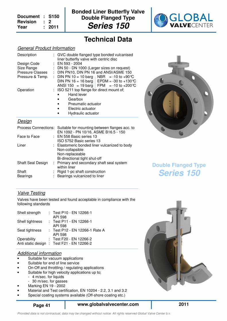
Additional information • Suitable for vacuum applications
• Suitable for end of line service
• On-Off and throttling / regulating applications
• Suitable for high velocity applications up to; - 4 m/sec. for liquids - 30 m/sec. for gasses
• Marking EN 19 - 2002
• Material and Test certification, EN 10204 - 2.2, 3.1 and 3.2
• Special coating systems available (Off-shore coating etc.)
Technical Data
Design
Process Connections: Suitable for mounting between flanges acc. to EN 1092 - PN 10/16, ASME B16.5 - 150 Face to Face : EN 558 Basic series 13 ISO 5752 Basic series 13 Liner : Elastomeric bonded liner vulcanized to body Non-collapsible Non-replaceable Bi-directional tight shut-off Shaft Seal Design : Primary and secondary shaft seal system within liner Shaft : Rigid 1-pc shaft construction Bearings : Bearings vulcanized to liner
Valve Testing
Valves have been tested and found acceptable in compliance with the following standards Shell strength : Test P10 - EN 12266-1 API 598 Shell tightness : Test P11 - EN 12266-1 API 598 Seat tightness : Test P12 - EN 12266-1 Rate A API 598 Operability : Test F20 - EN 12266-2 Anti static design : Test F21 - EN 12266-2
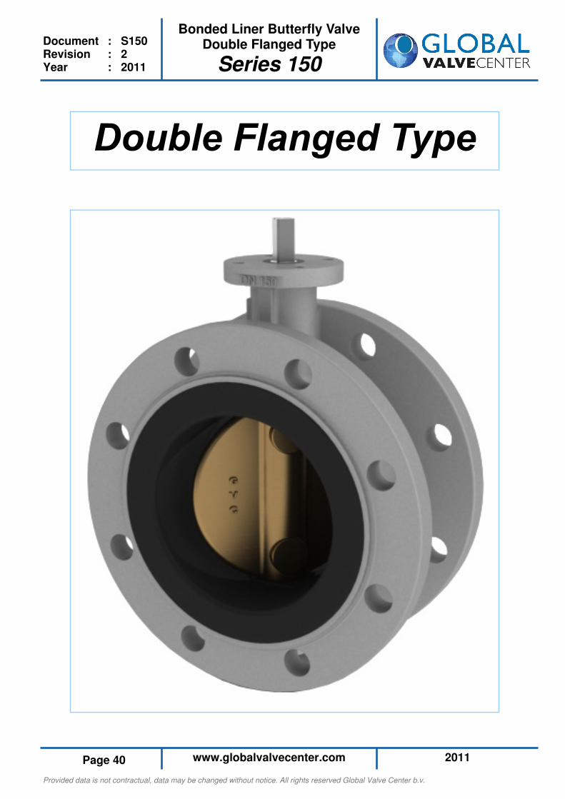
Double Flanged Type
Series 150
General Product Information
Description : GVC double flanged type bonded vulcanised liner butterfly valve with centric disc Design Code : EN 593 - 2004 Size Range : DN 50 - DN 1000 (Larger sizes on request) Pressure Classes : DIN PN10, DIN PN 16 and ANSI/ASME 150 Pressure & Temp. : DIN PN 10 = 10 barg NBR = -10 to +90°C DIN PN 16 = 16 barg EPDM = -30 to +130°C ANSI 150 = 19 barg FPM = -10 to +200°C Operation : ISO 5211 top flange for direct mount of;
• Hand lever
• Gearbox
• Pneumatic actuator
• Electric actuator
• Hydraulic actuator
Provided data is not contractual, data may be changed without notice. All rights reserved Global Valve Center b.v.
2011 www.globalvalvecenter.com Page 42
Bonded Liner Butterfly Valve Double Flanged Type
Series 150
Document : S150 Revision : 2 Year : 2011
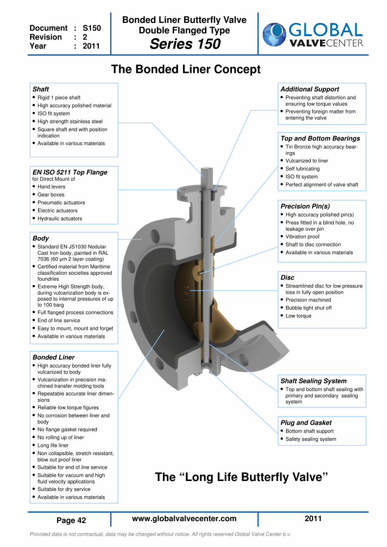
Shaft Sealing System
• Top and bottom shaft sealing with
primary and secondary sealing system
Disc
• Streamlined disc for low pressure
loss in fully open position
• Precision machined
• Bubble tight shut off
• Low torque
The Bonded Liner Concept
Top and Bottom Bearings
• Tin Bronze high accuracy bear-
ings
• Vulcanized to liner
• Self lubricating
• ISO fit system
• Perfect alignment of valve shaft
Precision Pin(s)
• High accuracy polished pin(s)
• Press fitted in a blind hole, no
leakage over pin
• Vibration proof
• Shaft to disc connection
• Available in various materials
Additional Support
• Preventing shaft distortion and
ensuring low torque values
• Preventing foreign matter from
entering the valve
Shaft
• Rigid 1 piece shaft
• High accuracy polished material
• ISO fit system
• High strength stainless steel
• Square shaft end with position
indication
• Available in various materials
EN ISO 5211 Top Flange for Direct Mount of
• Hand levers
• Gear boxes
• Pneumatic actuators
• Electric actuators
• Hydraulic actuators
Body
• Standard EN JS1030 Nodular
Cast Iron body, painted in RAL 7036 (60 µm 2 layer coating)
• Certified material from Maritime
classification societies approved foundries
• Extreme High Strength body,
during vulcanization body is ex-posed to internal pressures of up to 100 barg
• Full flanged process connections
• End of line service
• Easy to mount, mount and forget
• Available in various materials
Bonded Liner
• High accuracy bonded liner fully
vulcanized to body
• Vulcanization in precision ma-
chined transfer molding tools
• Repeatable accurate liner dimen-
sions
• Reliable low torque figures
• No corrosion between liner and
body
• No flange gasket required
• No rolling up of liner
• Long life liner
• Non collapsible, stretch resistant,
blow out proof liner
• Suitable for end of line service
• Suitable for vacuum and high
fluid velocity applications
• Suitable for dry service
• Available in various materials
The “Long Life Butterfly Valve”
Plug and Gasket
• Bottom shaft support
• Safety sealing system
Provided data is not contractual, data may be changed without notice. All rights reserved Global Valve Center b.v.
2011 www.globalvalvecenter.com Page 43
Bonded Liner Butterfly Valve Double Flanged Type
Series 150
Document : S150 Revision : 2 Year : 2011
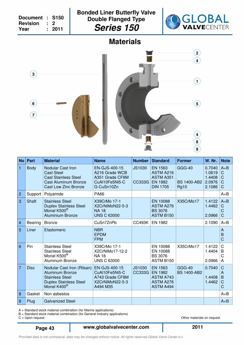
1
2
3
4
4
5 6
7
8
9
Materials
A = Standard stock material combination (for Marine applications) B = Standard stock material combination (for General Industry applications) C = Upon request Other materials on request
No Part Material Name
1 Body Nodular Cast Iron Cast Steel Cast Stainless Steel Cast Aluminum Bronze Cast Low Zinc Bronze
EN-GJS-400-15 A216 Grade WCB A351 Grade CF8M CuAl10Fe5Ni5-C G-CuSn10Zn
2 Support Polyamide PA66
3 Shaft Stainless Steel Duplex Stainless Steel Monel K500® Aluminium Bronze
X39CrMo 17-1 X2CrNiMoN22-5-3 NA 18 UNS C 63000
4 Bearing Bronze CuSn7ZnPb
5 Liner
Elastomeric NBR EPDM FPM
6 Pin Stainless Steel Stainless Steel Monel K500® Aluminum Bronze
X39CrMo 17-1 X2CrNiMo17-12-2 NA 18 UNS C 63000
7 Disc Nodular Cast Iron (Rilsan) Aluminum Bronze Stainless Steel Duplex Stainless Steel Monel K400®
EN-GJS-400-15 CuAl10Fe5Ni5-C A743 Grade CF8M X2CrNiMoN22-5-3 A494 M35
8 Gasket Non asbestos
9 Plug Galvanized Steel
Note
A+B C C C C
A+B
A+B C C C
A+B
A B C
C B C A
C A B C C
A+B
A+B
Former
GGG-40 BS 1400-AB2 Rg10
X35CrMo17
X35CrMo17
GGG-40 BS 1400-AB2
Standard
EN 1563 ASTM A216 ASTM A351 EN 1982 DIN 1705
EN 10088 ASTM A276 BS 3076 ASTM B150
EN 1982
EN 10088 EN 10088 BS 3076 ASTM B150
EN 1563 EN 1982 ASTM A743 ASTM A276 ASTM A494
Number
JS1030 CC333G
CC493K
JS1030 CC333G
W. Nr.
0.7040 1.0619 1.4408 2.0976 2.1086
1.4122 1.4462 2.0966
2.1090
1.4122 1.4404 2.0966
0.7040 1.4408 1.4462
Provided data is not contractual, data may be changed without notice. All rights reserved Global Valve Center b.v.
2011 www.globalvalvecenter.com Page 44
Bonded Liner Butterfly Valve Double Flanged Type
Series 150
Document : S150 Revision : 2 Year : 2011
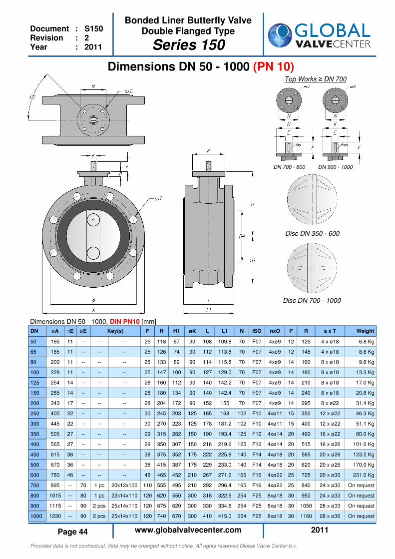
Dimensions DN 50 - 1000 (PN 10)
Dimensions DN 50 - 1000, DIN PN10 [mm]
Disc DN 350 - 600
Disc DN 700 - 1000
Top Works ≥ DN 700
DN 700 - 800 DN 900 - 1000
DN øA □E øE F H H1 øK L L1 N ISO nxO P R s x T Weight
50 165 11 -- -- -- 25 118 67 90 108 109.8 70 F07 4xø9 12 125 4 x ø18 6.8 Kg
65 185 11 -- -- -- 25 126 74 90 112 113.8 70 F07 4xø9 12 145 4 x ø18 8.6 Kg
80 200 11 -- -- -- 25 133 82 90 114 115.8 70 F07 4xø9 14 160 8 x ø18 9.8 Kg
100 228 11 -- -- -- 25 147 100 90 127 129.0 70 F07 4xø9 14 180 8 x ø18 13.3 Kg
125 254 14 -- -- -- 28 160 112 90 140 142.2 70 F07 4xø9 14 210 8 x ø18 17.0 Kg
150 285 14 -- -- -- 28 180 134 90 140 142.4 70 F07 4xø9 14 240 8 x ø18 20.8 Kg
200 343 17 -- -- -- 28 204 172 90 152 155 70 F07 4xø9 14 295 8 x ø22 31.4 Kg
250 405 22 -- -- -- 30 245 203 125 165 168 102 F10 4xø11 15 350 12 x ø22 46.3 Kg
300 445 22 -- -- -- 30 270 223 125 178 181.2 102 F10 4xø11 15 400 12 x ø22 51.1 Kg
350 505 27 -- -- -- 29 315 282 150 190 193.4 125 F12 4xø14 20 460 16 x ø22 80.0 Kg
400 565 27 -- -- -- 29 350 307 150 216 219.6 125 F12 4xø14 20 515 16 x ø26 101.0 Kg
450 615 36 -- -- -- 38 375 352 175 222 225.8 140 F14 4xø18 20 565 20 x ø26 123.2 Kg
500 670 36 -- -- -- 38 415 387 175 229 233.0 140 F14 4xø18 20 620 20 x ø26 170.0 Kg
600 780 46 -- -- -- 48 465 452 210 267 271.2 165 F16 4xø22 25 725 20 x ø30 231.0 Kg
700 895 -- 70 1 pc 20x12x100 110 555 495 210 292 296.4 165 F16 4xø22 25 840 24 x ø30 On request
800 1015 -- 80 1 pc 22x14x110 120 620 550 300 318 322.6 254 F25 8xø18 30 950 24 x ø33 On request
900 1115 -- 90 2 pcs 25x14x110 120 675 620 300 330 334.8 254 F25 8xø18 30 1050 28 x ø33 On request
1000 1230 -- 90 2 pcs 25x14x110 120 740 670 300 410 415.0 254 F25 8xø18 30 1160 28 x ø36 On request
Key(s)

Provided data is not contractual, data may be changed without notice. All rights reserved Global Valve Center b.v.
2011 www.globalvalvecenter.com Page 45
Bonded Liner Butterfly Valve Double Flanged Type
Series 150
Document : S150 Revision : 2 Year : 2011
Dimensions DN 50 - 1000 (PN 16)
Dimensions DN 50 - 1000, DIN PN16 [mm]
Disc DN 350 - 600
Disc DN 700 - 1000
Top Works ≥ DN 700
DN 700 - 800 DN 900 - 1000
DN øA □E øE F H H1 øK L L1 N ISO nxO P R s x T Weight
50 165 11 -- -- -- 25 118 67 90 108 109.8 70 F07 4xø9 12 125 4 x ø18 6.8 Kg
65 185 11 -- -- -- 25 126 74 90 112 113.8 70 F07 4xø9 12 145 4 x ø18 8.6 Kg
80 200 11 -- -- -- 25 133 82 90 114 115.8 70 F07 4xø9 14 160 8 x ø18 9.8 Kg
100 228 11 -- -- -- 25 147 100 90 127 129.0 70 F07 4xø9 14 180 8 x ø18 13.3 Kg
125 254 14 -- -- -- 28 160 112 90 140 142.2 70 F07 4xø9 14 210 8 x ø18 17.0 Kg
150 285 14 -- -- -- 28 180 134 90 140 142.4 70 F07 4xø9 14 240 8 x ø18 20.8 Kg
200 343 17 -- -- -- 28 204 172 90 152 155 70 F07 4xø9 14 295 12 x ø22 31.4 Kg
250 405 22 -- -- -- 30 245 203 125 165 168 102 F10 4xø11 15 355 12 x ø26 46.3 Kg
300 482 22 -- -- -- 30 270 241 125 178 181.2 102 F10 4xø11 15 410 12 x ø26 68.8 Kg
350 533 27 -- -- -- 29 315 282 150 190 193.4 125 F12 4xø14 20 470 16 x ø26 95.0 Kg
400 597 27 -- -- -- 29 350 307 150 216 219.6 125 F12 4xø14 20 525 16 x ø30 120.5 Kg
450 640 36 -- -- -- 38 375 352 175 222 225.8 140 F14 4xø18 20 585 20 x ø30 150.0 Kg
500 715 36 -- -- -- 38 415 387 175 229 233.0 140 F14 4xø18 20 650 20 x ø33 210.0 Kg
600 840 46 -- -- -- 48 465 452 210 267 271.2 165 F16 4xø22 25 770 20 x ø36 291.0 Kg
700 910 -- 80 1 pc 22x14x110 120 555 495 300 292 296.4 254 F25 8xø18 30 840 24 x ø36 On request
800 1025 -- 100 1 pc 28x16x110 120 620 550 300 318 322.6 254 F25 8xø18 30 950 24 x ø36 On request
900 1112 -- 110 2 pcs 28x16x110 120 675 620 300 330 334.8 254 F25 8xø18 30 1050 28 x ø39 On request
1000 1255 -- 120 2 pcs 32x18x140 160 740 670 300 410 415.0 254 F25 8xø18 30 1170 28 x ø42 On request
Key(s)
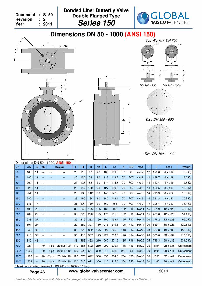
Provided data is not contractual, data may be changed without notice. All rights reserved Global Valve Center b.v.
2011 www.globalvalvecenter.com Page 46
Bonded Liner Butterfly Valve Double Flanged Type
Series 150
Document : S150 Revision : 2 Year : 2011
Dimensions DN 50 - 1000 (ANSI 150)
* Maximum working pressure for DN 700 - DN1000 is 10 barg
Dimensions DN 50 - 1000, ANSI 150
DN øA □E øE F H H1 øK L L1 N ISO nxO P R s x T Weight
50 165 11 -- -- -- 25 118 67 90 108 109.8 70 F07 4xø9 12 120.6 4 x ø19 6.8 Kg
65 185 11 -- -- -- 25 126 74 90 112 113.8 70 F07 4xø9 12 139.7 4 x ø19 8.6 Kg
80 200 11 -- -- -- 25 133 82 90 114 115.8 70 F07 4xø9 14 152.4 4 x ø19 9.8 Kg
100 228 11 -- -- -- 25 147 100 90 127 129.0 70 F07 4xø9 14 190.5 8 x ø19 13.3 Kg
125 254 14 -- -- -- 28 160 112 90 140 142.2 70 F07 4xø9 14 215.9 8 x ø22 17.0 Kg
150 285 14 -- -- -- 28 180 134 90 140 142.4 70 F07 4xø9 14 241.3 8 x ø22 20.8 Kg
200 343 17 -- -- -- 28 204 159 90 152 155 70 F07 4xø9 14 298.4 8 x ø22 31.4 Kg
250 405 22 -- -- -- 30 245 195 125 165 168 102 F10 4xø11 15 361.9 12 x ø25 46.3 Kg
300 482 22 -- -- -- 30 270 220 125 178 181.2 102 F10 4xø11 15 431.8 12 x ø25 51.1 Kg
350 533 27 -- -- -- 29 315 282 150 190 193.4 125 F12 4xø14 20 476.2 12 x ø28 95.0 Kg
400 597 27 -- -- -- 29 350 307 150 216 219.6 125 F12 4xø14 20 539.7 16 x ø28 120.5 Kg
450 640 36 -- -- -- 38 375 352 175 222 225.8 140 F14 4xø18 20 577.8 16 x ø32 150.0 Kg
500 715 36 -- -- -- 38 415 387 175 229 233.0 140 F14 4xø18 20 635.0 20 x ø32 210.0 Kg
600 840 46 -- -- -- 48 465 452 210 267 271.2 165 F16 4xø22 25 749.3 20 x ø35 231.0 Kg
700* 927 -- 70 1 pc 20x12x100 110 555 502 210 292 296.4 165 F16 4xø22 25 840 28 x ø35 On request
800* 1060 -- 80 1 pc 22x14x110 120 620 557 300 318 322.6 254 F25 8xø18 30 950 28 x ø41 On request
900* 1168 -- 90 2 pcs 25x14x110 120 675 622 300 330 334.8 254 F25 8xø18 30 1050 32 x ø41 On request
1000* 1829 -- 90 2 pcs 25x14x110 120 740 672 300 410 415.0 254 F25 8xø18 30 1160 36 x ø41 On request
Key(s)
Disc DN 350 - 600
Disc DN 700 - 1000
Top Works ≥ DN 700
DN 700 - 800 DN 900 - 1000
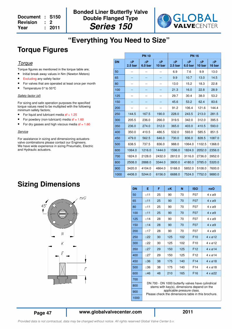
Provided data is not contractual, data may be changed without notice. All rights reserved Global Valve Center b.v.
2011 www.globalvalvecenter.com Page 47
Bonded Liner Butterfly Valve Double Flanged Type
Series 150
Document : S150 Revision : 2 Year : 2011
“Everything You Need to Size”
Torque Figures
Torque
Torque figures as mentioned in the torque table are;
• Initial break away values in Nm (Newton Meters)
• Excluding any safety factor
• For valves that are operated at least once per month
• Temperature 0° to 50°C
Safety factor (sf) For sizing and safe operation purposes the specified torque values need to be multiplied with the following minimum safety factors;
• For liquid and lubricant media sf = 1.25
• For powdery (non-lubricant) media sf = 1.60
• For dry gasses and high viscous media sf = 1.60
Service For assistance in sizing and dimensioning actuators-valve combinations please contact our Engineers. We have wide experience in sizing Pneumatic, Electric and Hydraulic actuators.
DN E F øK N ISO nxO
50 □11 25 90 70 F07 4 x ø9
65 □11 25 90 70 F07 4 x ø9
80 □11 25 90 70 F07 4 x ø9
100 □11 25 90 70 F07 4 x ø9
125 □14 28 90 70 F07 4 x ø9
150 □14 28 90 70 F07 4 x ø9
200 □17 28 90 70 F07 4 x ø9
250 □22 30 125 102 F10 4 x ø12
300 □22 30 125 102 F10 4 x ø12
350 □27 29 150 125 F12 4 x ø14
400 □27 29 150 125 F12 4 x ø14
450 □36 38 175 140 F14 4 x ø18
500 □36 38 175 140 F14 4 x ø18
600 □46 48 210 165 F16 4 x ø22
700
800
900
1000
DN 700 - DN 1000 butterfly valves have cylindrical stems with key(s), dimensions depend on the
applicable pressure class. Please check the dimensions table in this brochure.
Sizing Dimensions
PN 10 PN 16
DN ∆P 2.5 bar
∆P 6.0 bar
∆P 10 bar
∆P 2.5 bar
∆P 6.0 bar
∆P 10 bar
∆P 16 bar
50 -- -- -- 6.9 7.6 9.9 13.0
65 -- -- -- 9.9 10.7 13.0 14.5
80 -- -- -- 13.0 15.2 18.3 22.8
100 -- -- -- 21.3 16.0 22.8 28.9
125 -- -- -- 29.7 30.4 38.0 53.2
150 -- -- -- 45.6 53.2 62.4 83.6
200 -- -- -- 91.2 106.4 121.6 144.4
250 144.5 167.5 190.0 228.0 243.5 213.0 281.5
300 205.5 236.0 266.0 319.5 342.0 312.0 395.5
350 236.0 274.0 312.0 365.0 403.0 410.5 593.0
400 350.0 410.5 486.5 532.0 593.0 585.5 851.5
450 479.0 562.5 646.0 730.0 836.0 828.5 1087.0
500 638.5 737.5 836.0 988.0 1064.0 1102.5 1368.0
600 1064.0 1216.0 1444.0 1596.0 1824.0 2052.0 2356.0
700 1824.0 2128.0 2432.0 2812.0 3116.0 2736.0 3952.0
800 2508.0 2888.0 3344.0 3800.0 4180.0 3785.0 5320.0
900 3420.0 4104.0 4864.0 5168.0 5852.0 5108.0 7600.0
1000 4408.0 5244.0 6156.0 6688.0 7524.0 7752.0 9880.0
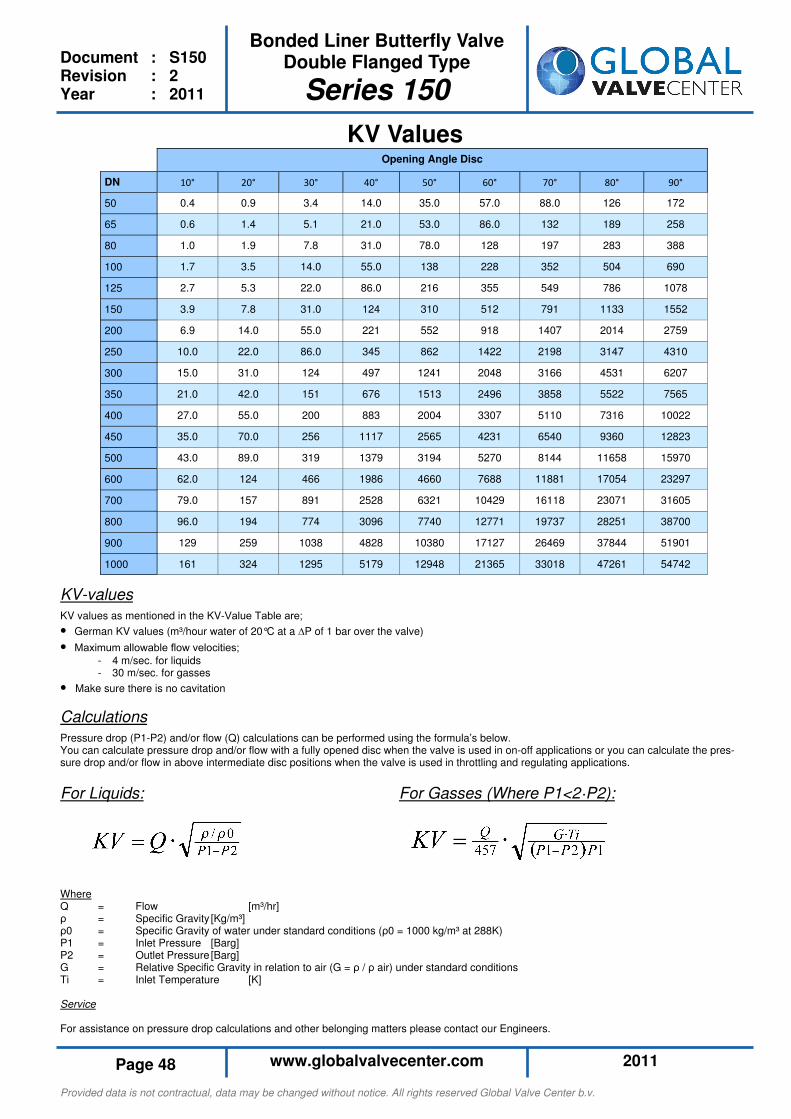
Provided data is not contractual, data may be changed without notice. All rights reserved Global Valve Center b.v.
2011 www.globalvalvecenter.com Page 48
Bonded Liner Butterfly Valve Double Flanged Type
Series 150
Document : S150 Revision : 2 Year : 2011
KV Values Opening Angle Disc
DN 20° 30° 40° 50° 60° 70° 80° 90°
50 0.9 3.4 14.0 35.0 57.0 88.0 126 172
65 1.4 5.1 21.0 53.0 86.0 132 189 258
80 1.9 7.8 31.0 78.0 128 197 283 388
100 3.5 14.0 55.0 138 228 352 504 690
125 5.3 22.0 86.0 216 355 549 786 1078
150 7.8 31.0 124 310 512 791 1133 1552
200 14.0 55.0 221 552 918 1407 2014 2759
250 22.0 86.0 345 862 1422 2198 3147 4310
300 31.0 124 497 1241 2048 3166 4531 6207
350 42.0 151 676 1513 2496 3858 5522 7565
400 55.0 200 883 2004 3307 5110 7316 10022
450 70.0 256 1117 2565 4231 6540 9360 12823
500 89.0 319 1379 3194 5270 8144 11658 15970
600 124 466 1986 4660 7688 11881 17054 23297
700 157 891 2528 6321 10429 16118 23071 31605
800 194 774 3096 7740 12771 19737 28251 38700
900 259 1038 4828 10380 17127 26469 37844 51901
1000 324 1295 5179 12948 21365 33018 47261 54742
10°
0.4
0.6
1.0
1.7
2.7
3.9
6.9
10.0
15.0
21.0
27.0
35.0
43.0
62.0
79.0
96.0
129
161
KV-values
KV values as mentioned in the KV-Value Table are;
• German KV values (m³/hour water of 20°C at a ∆P of 1 bar over the valve)
• Maximum allowable flow velocities;
- 4 m/sec. for liquids - 30 m/sec. for gasses
• Make sure there is no cavitation
Calculations
Pressure drop (P1-P2) and/or flow (Q) calculations can be performed using the formula’s below. You can calculate pressure drop and/or flow with a fully opened disc when the valve is used in on-off applications or you can calculate the pres-sure drop and/or flow in above intermediate disc positions when the valve is used in throttling and regulating applications.
For Liquids: For Gasses (Where P1<2·P2): Where Q = Flow [m³/hr] ρ = Specific Gravity [Kg/m³] ρ0 = Specific Gravity of water under standard conditions (ρ0 = 1000 kg/m³ at 288K) P1 = Inlet Pressure [Barg] P2 = Outlet Pressure [Barg] G = Relative Specific Gravity in relation to air (G = ρ / ρ air) under standard conditions Ti = Inlet Temperature [K] Service For assistance on pressure drop calculations and other belonging matters please contact our Engineers.
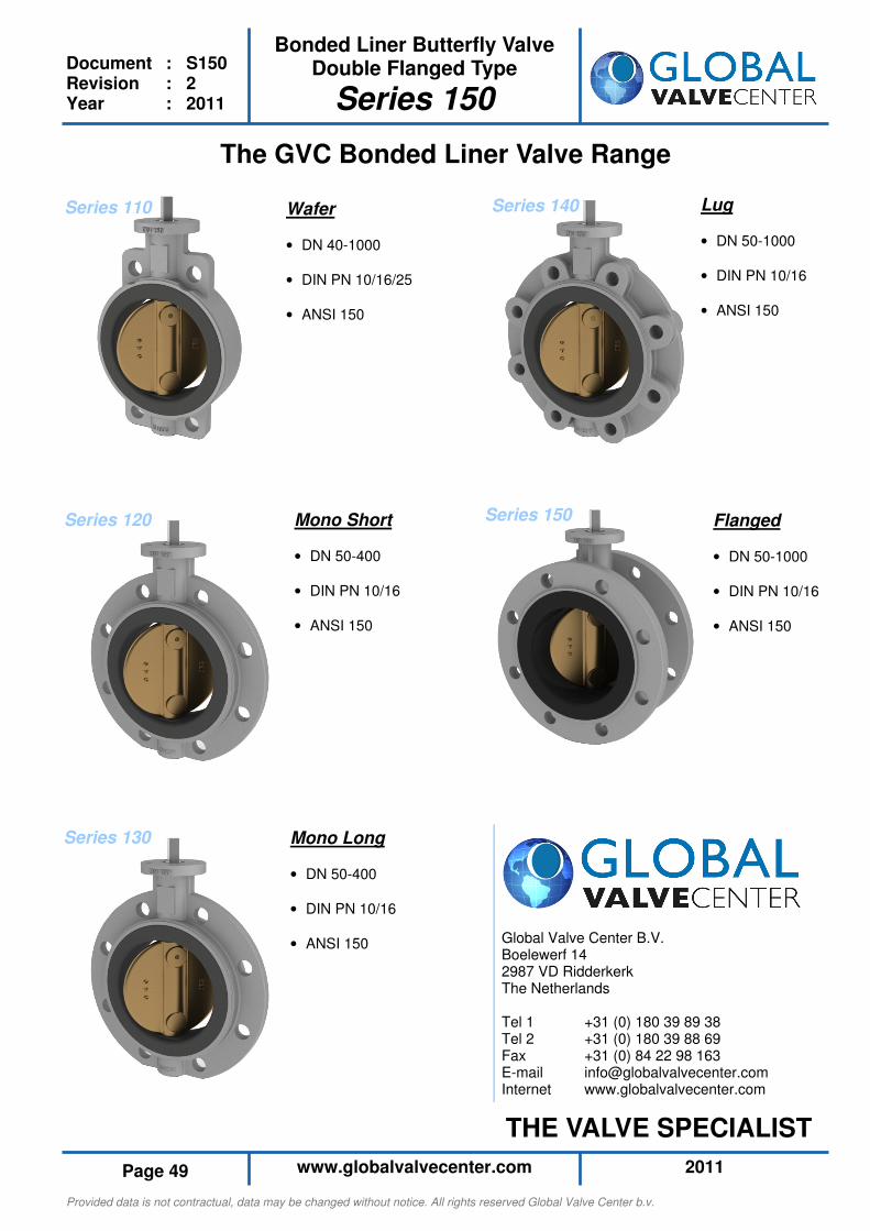
Provided data is not contractual, data may be changed without notice. All rights reserved Global Valve Center b.v.
2011 www.globalvalvecenter.com Page 49
Bonded Liner Butterfly Valve Double Flanged Type
Series 150
Document : S150 Revision : 2 Year : 2011
The GVC Bonded Liner Valve Range
Wafer
• DN 40-1000
• DIN PN 10/16/25
• ANSI 150
Flanged
• DN 50-1000
• DIN PN 10/16
• ANSI 150
Mono Short
• DN 50-400
• DIN PN 10/16
• ANSI 150
Lug
• DN 50-1000
• DIN PN 10/16
• ANSI 150
Mono Long
• DN 50-400
• DIN PN 10/16
• ANSI 150
Series 110 Series 140
Series 120 Series 150
Series 130
Global Valve Center B.V. Boelewerf 14 2987 VD Ridderkerk The Netherlands Tel 1 +31 (0) 180 39 89 38 Tel 2 +31 (0) 180 39 88 69 Fax +31 (0) 84 22 98 163 E-mail [email protected] Internet www.globalvalvecenter.com
THE VALVE SPECIALIST


![Section 18 Butterfly Valves - AAP Industries · BUTTERFLY VALVES [18] Wafer Butterfly Valve with Gear-Op Stainless Steel Wafer Butterfly Valve Wafer Butterfly Valve with Stainless](https://img.pdfslide.net/doc/110x75/60a1925cd0b68c353a5fc104/section-18-butterfly-valves-aap-industries-butterfly-valves-18-wafer-butterfly.jpg)