Embed Size (px)
Citation preview
WAGGA MOBILE CRANES &
HEAVY HAULAGE
Load Chart For 55 Ton TADANO Slew Crane
02 6925 2556
7-9 Pearson Street, Wagga Wagga NSW 2650 [email protected]
CRANE SPECIFICATIONSMODELGT-550EX
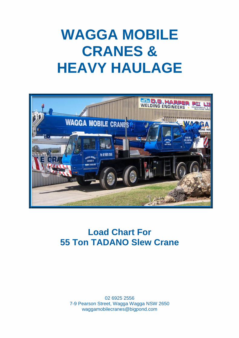
CAPACITY55,000 kg at 3.0 m
CRANE CAPACITY 55,000 kg at 3.0 m5-section, 11.1 m - 42.0m
approx. 13,480 mmapprox. 2,820 mmapprox. 3,680 mm
approx. 39,800 kgapprox. 15,900 kgapprox. 23,900 kg
computed 83 km/hcomputed 53 %
BOOMDIMENSION
Overall lengthOverall width Overall height
MASSGross vehicle mass
-front axle -rear axle
PERFORMANCEMax. travelling speed Gradeability (tan )
GENERAL DATA
HYDRAULIC TRUCK CRANE
SPEC. SHEET NO. GT-550E-1-00102/EX-93
GT-550EXGT-550EX
BOOM5-section full power partially synchronized telescoping boom of round hexagonal box construction with 6 sheaves at boom head. The synchronization system consists of 2 telescope cylinders, extension cables and retraction cables. Hydraulic cylinders fitted with holding valves. Fully retracted length....... 11.1 m Fully extended length..... 42.0 m Extension speed.............. 30.9 m in 123 s
JIB2-staged boom extension. Triple offset (5˚ /25˚ / 45˚ ) type. Stored under base boom section.Single sheave at jib head. Length............................ 9.0 m and 14.6 m
SINGLE TOP (AUXILIARY BOOM SHEAVE)Single sheave. Mounted to main boom head for single line work.
ELEVATIONBy a double-acting hydraulic cylinder, fitted with holding valve. Elevation speed............... - 2˚ to 80˚ in 68 s
HOIST-Main winchVariable speed type with grooved drum driven by hydraulic axial piston motor through winch speed reducer. Power load lowering and hoisting. Equipped with automatic brake (Neutral brake) and counterbalance valve. Controlled independently of auxiliary winch. Single line pull................. 42.2 kN { 4,300kgf } Single line speed............. 143 m/min (at the 4th layer) Wire rope......................... Spin-resistant type
(Non-spin type for 35 ton capacity hook block)
Diameter x length............19 mm x 227 m
CARRIER : TC-4255
CRANE SPECIFICATIONSSPEC. SHEET NO. GT-550E-1-00102/EX-93
- 2 -
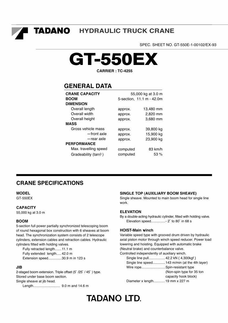
HOIST-Auxiliary winchVariable speed type with grooved drum driven by hydraulic axial piston motor through winch speed reducer. Power load lowering and hoisting. Equipped with automatic brake (Neutral brake) and counterbalance valve. Controlled independently of main winch. Single line pull................. 44.1 kN { 4,500kgf } Single line speed............. 123 m/min (at the 2nd layer) Wire rope......................... Spin-resistant type Diameter x length............ 19 mm x 127 m
SWINGHydraulic axial piston motor driven through planetary speed reducer. Continuous 360˚ full circle swing on ball bearing slew ring. Equipped with manually locked/released swing brake. Swing speed.................... 1.9 min-1 { rpm }
HYDRAULIC SYSTEM Pumps............................. Quadruple gear pumps driven by carrier engine through P.T.O. Control valves.................. Multiple valves actuated by pilot pressure with integral pressure relief valves.
Circuit.............................. Equipped with air cooled type oil cooler. Oil pressure appears on AML display for main circuit.
Hydraulic oil tank capacity..... approx. 690 liters Filters............................... Return line filter
CRANE CONTROLBy 4 control levers for swing, boom hoist, main winch, boom telescoping or auxiliary winch with 2 control pedals for boom hoist and boom telescoping based on ISO standard layout.Control lever stands can change neutral positions and tilt for easy access to cab.
CABOne sided one-man type, steel construction with sliding door access and tinted safety glass windows opening at side.Door window is powered control.Operator's 3 way adjustable seat with headrest and armrest.
TADANO Automatic Moment Limiter (Model:AML-L)Main unit in crane cab gives audible and visual warning of approach to overload. Automatically cuts out crane motions before overload. With working range (load radius and / or boom angle and / or tip height and / or swing range) limit function.Nine functions are displayed. Digital liquid crystal display: Either boom angle or moment % Either boom length or potential hook height Either actual working radius or swing angle Actual hook load Permissible load Either jib offset angle or number of parts line of rope Boom position indicator Outrigger position indicator Bar graphical display: Either moment as percentage or main hydraulic pressure (Display changes by alternation key on the AML front panel)
OUTRIGGERS4-hydraulically operated H-type outriggers. Each outrigger controlled simultaneously or independently from either side of carrier. Equipped with sight level gauge. Floats mounted integrally with the jacks retract to within vehicle width. All cylinders fitted with pilot check valves. Crane operation with different extended length of each outrigger.Equipped with extension width detector for each outrigger. Extended width Fully.............................. 6,800 mm Middle........................... 4,600 mm Minimum....................... 2,390 mm Float size (Diameter)...... 400 mm
FRONT JACKA fifth hydraulically operated outrigger jack. Mounted to the front frame of carrier to permit 360˚ lifting capabilities.Hydraulic cylinder fitted with pilot check valve.Equipped with front jack extension detector. Float size(Diameter)........350 mm
COUNTERWEIGHTIntegral with swing frame Mass................................ 4,200 kg
NOTE:Each crane motion speed is based on unladen conditions.
CARRIER SPECIFICATIONSSPEC. SHEET NO. GT-550E-1-00102/EX-93
- 3 -
EQUIPMENT
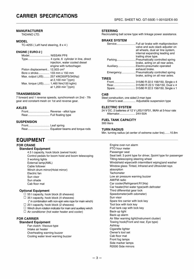
MANUFACTURER TADANO LTD.
MODEL TC-4255 ( Left hand steering, 8 x 4 )
ENGINE [ EURO-2 ] Model.......................... NISSAN PF6 Type............................ 4 cycle, 6 cylinder in line, direct
injection, water cooled diesel engine with turbochager.
Piston displacement... 12,503 cm3
Bore x stroke.............. 133 mm x 150 mm Max. output (JIS)........ 257 kW{350PS/345hp} at 2,100 min-1{rpm} Max. torque (JIS)........ 1,460 Nm{150 kgfm} at 1,200 min-1{rpm}
TRANSMISSION7 forward and 1 reverse speeds, synchromesh on 2nd - 7th gear and constant-mesh on 1st and reverse gear.
AXLES Front........................... Reverse - elliot type Rear............................ Full floating type
SUSPENSION Front........................... Leaf spring Rear............................ Equalizer beams and torque rods
STEERINGRecirculating ball screw type with linkage power assistance.
BRAKE SYSTEM Service........................ Full air brake with maltiprotection
valve and auto slack adjuster on all wheels, dual air line system, internal expanding leading and trailing shoe type.
Parking........................ Pneumatically controlled spring brake, acting on all rear axles.
Auxiliary....................... Electro-pneumatic operated exhaust brake.
Emergency.................. Pneumatically controlled spring brake, acting on all rear axles.
TIRES Front........................... 315/80 R 22.5 156/150, Single x 4 Rear............................ 315/80 R 22.5 156/150, Dual x 4 Spare.......................... 315/80 R 22.5 156/150, Single x 1
CABSteel construction, one sided 2-man type Driverʼs seat................ Adjustable suspension type
ELECTRIC SYSTEM24 V DC. 2 batteries of 12 V (JIS)115F51, 96Ah at 5-hour rate Alternator.................... 24V-50A
FUEL TANK CAPACITY300 liters
TURN RADIUSMin. turning radius (at center of extreme outer tire).......10.8m
FOR CRANEStandard Equipment
4.5 t capacity, hook block (swivel hook)Control pedals for boom hoist and boom telescoping3 working lightsExternal lamp(AML)Cable followerWinch drum mirror(Hoist mirror)Electric fanSun visorSun shadeCab floor mat
Optional Equipment55 t capacity, hook block (6 sheaves)35 t capacity, hook block (4 sheaves) (* in combination with non-spin wire rope for main winch)20 t capacity, hook block (2 sheaves)Winch drum rotation indicator for main and auxiliary winchAir conditioner (hot water heater and cooler)
FOR CARRIERStandard Equipment
Fan clutch: Viscous-typeIntake air heaterOverheating warning buzzerCooling water level warning buzzer
Engine over-run alarmPTO hour meterPassenger seatSeat belt: 3 point type for driver, 2point type for passengerTilting-telescoping steering wheelWindshield wiper(with intermittent wiping)and washerWindow glass: Tinted, Infrared and Ultraviolet raysabsorption TachometerLow air pressure warning buzzerAM/FM radioCar cooler(Refrigerant:R134a)Car heater(Hot water type)with defrosterThird differential gear lockSpeedometer(with odometer)Sun visorSpare tire carrier with lock keyTool box with lock keyFuel tank cap with lock keyBack-up lightBack-up alarmAir filter warning light(Instrument cluster)Towing hook(Front and rear, Eye type)AshtrayCigarette lighterOwner's tool setCab floor matFront fog lampsSide marker lampsR2000 Side mirrors
WORKING RANGESPEC. SHEET NO. GT-550E-1-00102/EX-93
- 4 -
BOOM
JIB
LIFT
ING
HEI
GH
T (m
)
0
5
10
15
20
25
30
35
40
45
50
55
60
65
0 5 10 15 20 25 30 35 40
5˚ 25˚
10˚
0˚
45˚
20˚
WORKING RADIUS (m)
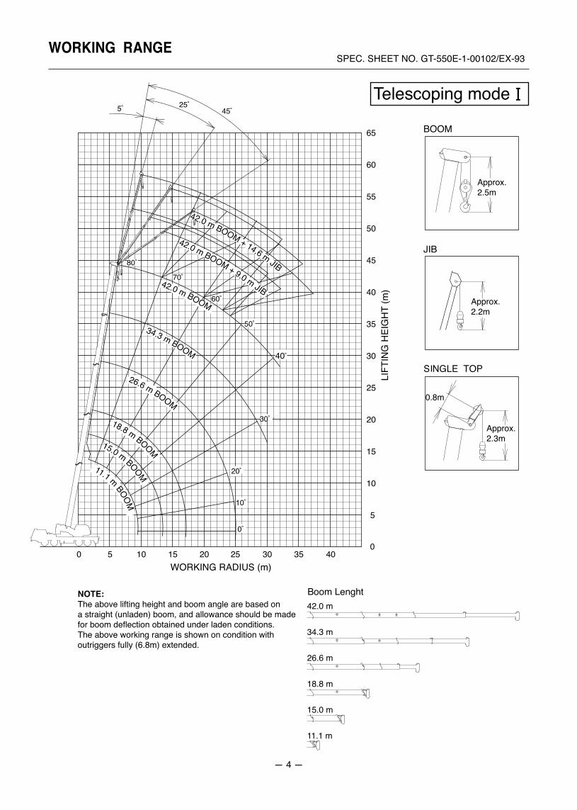
11.1 m BOOM15.0 m BOOM
18.8 m BOOM
26.6 m BOOM
34.3 m BOOM
42.0 m BOOM
42.0 m BOOM + 9.0 m JIB
42.0 m BOOM + 14.6 m JIB70˚
50˚
40˚
60˚
80˚
30˚
NOTE: The above lifting height and boom angle are based on a straight (unladen) boom, and allowance should be made for boom deflection obtained under laden conditions.The above working range is shown on condition with outriggers fully (6.8m) extended.
Approx. 2.5m
Approx. 2.2m
Approx. 2.3m
0.8m
42.0 m
34.3 m
26.6 m
18.8 m
15.0 m
11.1 m
Telescoping mode
WORKING RANGESPEC. SHEET NO. GT-550E-1-00102/EX-93
- 5 -
BOOM
JIB
42.0 m
38.1 m
34.3 m
26.6 m
18.8 m
11.1 m
LIFT
ING
HEI
GH
T (m
)
Approx. 2.5m
Approx. 2.2m
Approx. 2.3m
0.8m
Telescoping mode
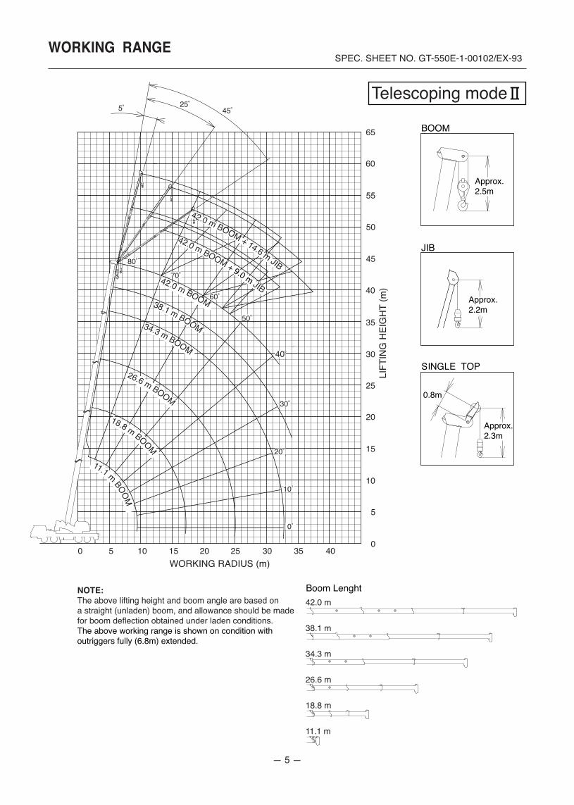
NOTE: The above lifting height and boom angle are based on a straight (unladen) boom, and allowance should be made for boom deflection obtained under laden conditions.The above working range is shown on condition with outriggers fully (6.8m) extended.
WORKING RADIUS (m)0 5 10 15 20 25 30 35 40
0
5
10
15
20
25
30
35
40
45
50
55
60
65
11.1 m BOOM
18.8 m BOOM
34.3 m BOOM
38.1 m BOOM
26.6 m BOOM
42.0 m BOOM
42.0 m BOOM + 9.0 m JIB
42.0 m BOOM + 14.6 m JIB
5˚ 25˚45˚
10˚
0˚
20˚
70˚
50˚
40˚
60˚
80˚
30˚
40,00040,00038,10033,80030,40027,40025,00022,80021,00019,30017,90014,60011,600
9,5007,800
55,00043,70038,50034,20030,80027,80025,40023,20021,40019,70018,30015,200
3.03.54.04.55.05.56.06.57.07.58.09.0
10.011.012.014.016.018.020.022.024.026.028.030.032.034.0
28,00028,00028,00028,00028,00027,20024,70022,50020,70019,10017,60014,20011,300
9,1007,5005,1003,500
20,00020,00020,00019,80019,00018,20017,50016,80016,20015,70015,20014,30013,50011,400
9,6007,2005,500
20,00020,00020,00020,00018,90017,80016,70015,80014,20012,50010,300
8,6006,2004,5003,3002,4001,7001,200
100100100100
8,0008,0008,0008,0008,0007,6007,0006,4005,8004,9004,2003,6003,2002,8002,5002,1001,7001,4001,100
14,00014,00013,60012,80012,00011,40010,80010,200
9,3008,5007,8007,2006,2005,4004,7003,7003,0002,400
8,0008,0008,0008,0007,5006,9006,4005,5004,7004,1003,6002,8002,2001,8001,4001,000
700500
8,0008,0008,0008,0008,0007,5006,9005,9005,2004,2003,2002,5001,9001,4001,000
700450
0000
50000
100000
0333333
100333333
0666666
100666666
0100100100
50100100100
14,00014,00013,50013,00012,50011,30010,400
9,6008,8006,8005,1003,9003,0002,2001,6001,200
800500
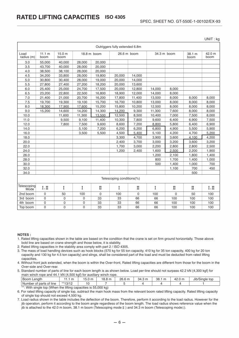
Outriggers fully extended 6.8m
Load radius (m)
11.1 mboom
15.0 mboom
18.8 m boom 26.6 m boom 34.3 m boom 38.1 m boom
42.0 m boom
Telescoping conditions(%)
NOTES :1. Rated lifting capacities shown in the table are based on the condition that the crane is set on firm ground horizontally. Those above
bold line are based on crane strength and those below, it is stability.2. Rated lifting capacities in the stability area comply with part 2 / ISO 4305.3. The mass of load handling devices such as hook blocks {570 kg for 55 ton capacity, 410 kg for 35 ton capacity, 400 kg for 20 ton
capacity and 130 kg for 4.5 ton capacity} and slings, shall be considered part of the load and must be deducted from rated lifting capacities.
4. Without front jack extended, when the boom is within the Over-front, Rated lifting capacities are different from those for the boom in the Over-side and Over-rear.
5. Standard number of parts of line for each boom length is as shown below. Load per-line should not surpass 42.2 kN {4,300 kgf} for main winch rope and 44.1 kN {4,500 kgf} for auxiliary winch rope. Boom Length 11.1 m 15.0 m 18.8 m 26.6 m 34.3 m 38.1 m 42.0 m Jib/Single top Number of parts of line **13/12 10 7 5 4 4 4 1**: With single top (When the lifting capacities is 55,000 kg)
6. For rated lifting capacity of single top, subtract the main hook mass from the relevant boom rated lifting capacity. Rated lifting capacity of single top should not exceed 4,500 kg.
7. Load radius shown in the table includes the deflection of the boom. Therefore, perform it according to the load radius. However for the jib operation, perform it according to the boom angle regardless of the boom length. The load radius shows reference value when the jib is attached to the 42.0 m boom, 38.1 m boom (Telescoping mode ) and 34.3 m boom (Telescoping mode ).
Telescoping Mode2nd boom3rd boom4th boomTop boom
SPEC. SHEET NO. GT-550E-1-00102/EX-93RATED LIFTING CAPACITIES
UNIT : kg
- 6 -
, ,
ISO 4305
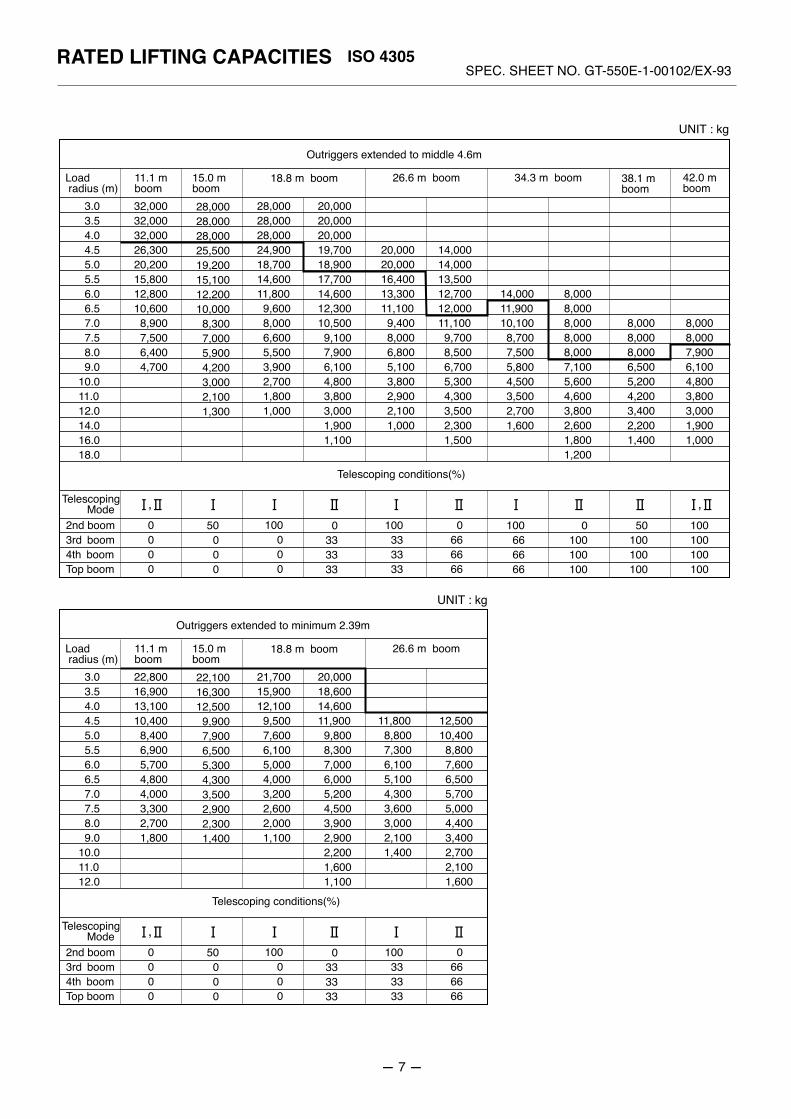
28,00028,00028,00025,50019,20015,10012,20010,000
8,3007,0005,9004,2003,0002,1001,300
32,00032,00032,00026,30020,20015,80012,80010,600
8,9007,5006,4004,700
3.03.54.04.55.05.56.06.57.07.58.09.0
10.011.012.014.016.018.0
28,00028,00028,00024,90018,70014,60011,800
9,6008,0006,6005,5003,9002,7001,8001,000
20,00020,00020,00019,70018,90017,70014,60012,30010,500
9,1007,9006,1004,8003,8003,0001,9001,100
20,00020,00016,40013,30011,100
9,4008,0006,8005,1003,8002,9002,1001,000
100100100100
8,0008,0008,0008,0008,0007,1005,6004,6003,8002,6001,8001,200
14,00014,00013,50012,70012,00011,100
9,7008,5006,7005,3004,3003,5002,3001,500
8,0008,0008,0006,5005,2004,2003,4002,2001,400
8,0008,0007,9006,1004,8003,8003,0001,9001,000
0000
50000
100000
0333333
100333333
0666666
100666666
0100100100
50100100100
14,00011,90010,100
8,7007,5005,8004,5003,5002,7001,600
Outriggers extended to middle 4.6m
Load radius (m)
11.1 mboom
15.0 mboom
18.8 m boom 26.6 m boom 34.3 m boom 38.1 m boom
42.0 m boom
Telescoping conditions(%)
, Telescoping Mode2nd boom3rd boom4th boomTop boom
SPEC. SHEET NO. GT-550E-1-00102/EX-93RATED LIFTING CAPACITIES
UNIT : kg
22,10016,30012,500
9,9007,9006,5005,3004,3003,5002,9002,3001,400
22,80016,90013,10010,400
8,4006,9005,7004,8004,0003,3002,7001,800
3.03.54.04.55.05.56.06.57.07.58.09.0
10.011.012.0
21,70015,90012,100
9,5007,6006,1005,0004,0003,2002,6002,0001,100
20,00018,60014,60011,900
9,8008,3007,0006,0005,2004,5003,9002,9002,2001,6001,100
11,8008,8007,3006,1005,1004,3003,6003,0002,1001,400
12,50010,400
8,8007,6006,5005,7005,0004,4003,4002,7002,1001,600
0000
50000
100000
0333333
100333333
0666666
Outriggers extended to minimum 2.39m
Load radius (m)
11.1 mboom
15.0 mboom
18.8 m boom 26.6 m boom
Telescoping conditions(%)
Telescoping Mode2nd boom3rd boom4th boomTop boom
UNIT : kg
- 7 -
,
,
ISO 4305
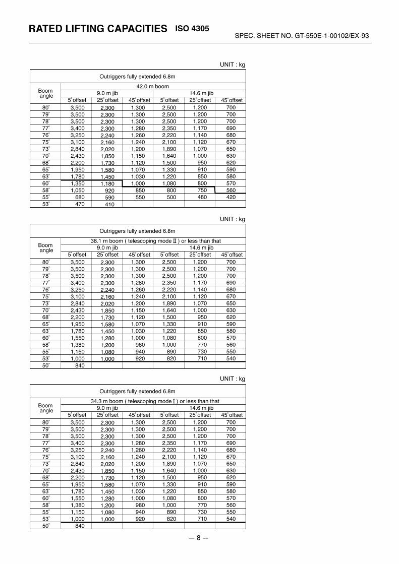
2,3002,3002,3002,3002,2402,1602,0201,8501,7301,5801,4501,180
920590410
3,5003,5003,5003,4003,2503,1002,8402,4302,2001,9501,7801,3501,050
680470
80˚79˚78˚77˚76˚75˚73˚70˚68˚65˚63˚60˚58˚55˚53˚
1,3001,3001,3001,2801,2601,2401,2001,1501,1201,0701,0301,000
850550
2,5002,5002,5002,3502,2202,1001,8901,6401,5001,3301,2201,080
800500
1,2001,2001,2001,1701,1401,1201,0701,000
950910850800750480
700700700690680670650630620590580570560420
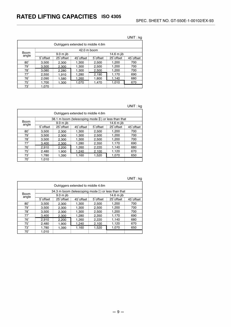
Outriggers fully extended 6.8m
Boom angle
5˚offset 25˚offset9.0 m jib
42.0 m boom
45˚offset 5˚offset 25˚offset14.6 m jib
45˚offset
SPEC. SHEET NO. GT-550E-1-00102/EX-93RATED LIFTING CAPACITIES
UNIT : kg
UNIT : kg
UNIT : kg
2,3002,3002,3002,3002,2402,1602,0201,8501,7301,5801,4501,2801,2001,0801,000
3,5003,5003,5003,4003,2503,1002,8402,4302,2001,9501,7801,5501,3801,1501,000
840
80˚79˚78˚77˚76˚75˚73˚70˚68˚65˚63˚60˚58˚55˚53˚50˚
1,3001,3001,3001,2801,2601,2401,2001,1501,1201,0701,0301,000
980940920
2,5002,5002,5002,3502,2202,1001,8901,6401,5001,3301,2201,0801,000
890820
1,2001,2001,2001,1701,1401,1201,0701,000
950910850800770730710
700700700690680670650630620590580570560550540
Outriggers fully extended 6.8m
Boom angle
5˚offset 25˚offset9.0 m jib
38.1 m boom ( telescoping mode ) or less than that
45˚offset 5˚offset 25˚offset14.6 m jib
45˚offset
2,3002,3002,3002,3002,2402,1602,0201,8501,7301,5801,4501,2801,2001,0801,000
3,5003,5003,5003,4003,2503,1002,8402,4302,2001,9501,7801,5501,3801,1501,000
840
80˚79˚78˚77˚76˚75˚73˚70˚68˚65˚63˚60˚58˚55˚53˚50˚
1,3001,3001,3001,2801,2601,2401,2001,1501,1201,0701,0301,000
980940920
2,5002,5002,5002,3502,2202,1001,8901,6401,5001,3301,2201,0801,000
890820
1,2001,2001,2001,1701,1401,1201,0701,000
950910850800770730710
700700700690680670650630620590580570560550540
Outriggers fully extended 6.8m
Boom angle
5˚offset 25˚offset9.0 m jib
34.3 m boom ( telescoping mode ) or less than that
45˚offset 5˚offset 25˚offset14.6 m jib
45˚offset
- 8 -
ISO 4305
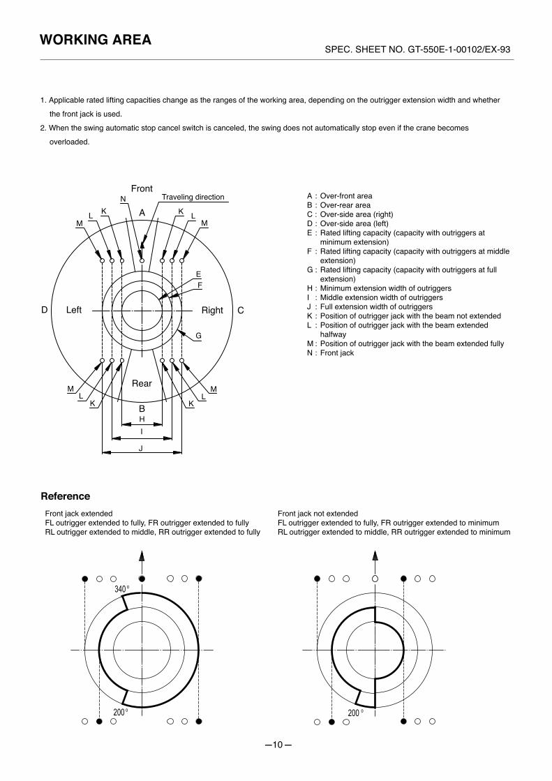
Reference
SPEC. SHEET NO. GT-550E-1-00102/EX-93WORKING AREA
1. Applicable rated lifting capacities change as the ranges of the working area, depending on the outrigger extension width and whether
the front jack is used.
2. When the swing automatic stop cancel switch is canceled, the swing does not automatically stop even if the crane becomes
overloaded.
Front
Rear
Traveling direction
Left Right
A
B
CD
EF
G
HI
J
K
KK
KL
LL
LM
MM
M
N A : Over-front areaB : Over-rear areaC : Over-side area (right)D : Over-side area (left)E : Rated lifting capacity (capacity with outriggers at
minimum extension)F : Rated lifting capacity (capacity with outriggers at middle
extension)G : Rated lifting capacity (capacity with outriggers at full
extension)H : Minimum extension width of outriggersI : Middle extension width of outriggersJ : Full extension width of outriggersK : Position of outrigger jack with the beam not extendedL : Position of outrigger jack with the beam extended
halfwayM : Position of outrigger jack with the beam extended fullyN : Front jack
Front jack extendedFL outrigger extended to fully, FR outrigger extended to fullyRL outrigger extended to middle, RR outrigger extended to fully
Front jack not extendedFL outrigger extended to fully, FR outrigger extended to minimumRL outrigger extended to middle, RR outrigger extended to minimum
-10-
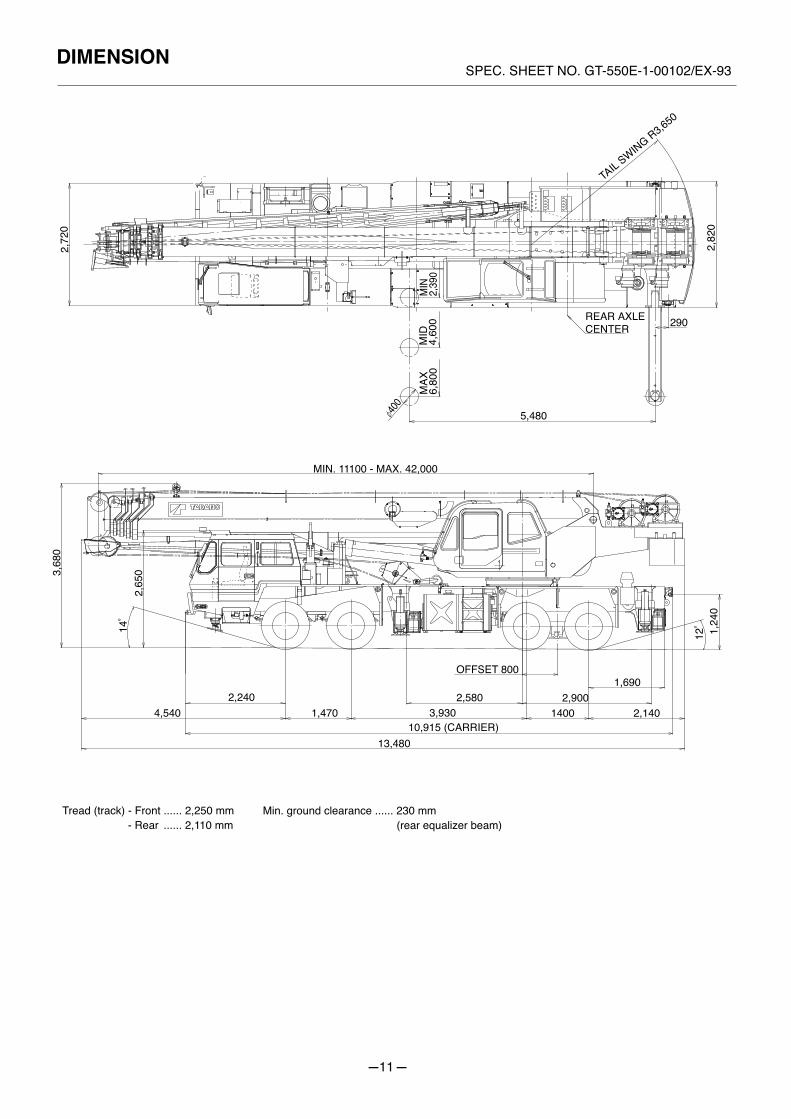
SPEC. SHEET NO. GT-550E-1-00102/EX-93DIMENSION
2,72
0
MIN
2,39
0M
ID4,
600
MAX
6,80
0
400
5,480
REAR AXLECENTER 290
2,82
0
TAIL S
WING R3,650
MIN. 11100 - MAX. 42,000
3,68
0
2,65
0
4,5402,240
1,470
13,48010,915 (CARRIER)
3,9302,580
OFFSET 800
14002,900
1,690
2,1401,
240
14˚
12˚
Tread (track) - Front ...... 2,250 mm - Rear ...... 2,110 mm
Min. ground clearance ...... 230 mm (rear equalizer beam)
-11-

Specifications are subject to change without notice.
4-12, Kamezawa 2-chome,Sumida-ku, Tokyo 130-0014, JapanTel : 81-(0)3-3621-7750Fax : 81-(0)3-3621-7785
http : //www.tadano.co.jp / [email protected]
Printed in Japan
GT-550E-2007-02-1
E-mailURL
(International Division)