Embed Size (px)
Citation preview
Engineered to Save
CDWM SeriesWall Mount Desiccant Dryer
7–50 SCFM
NEW
CDWM Series
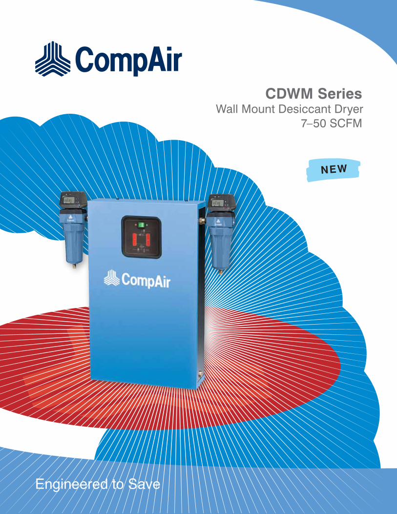
Benefits
• Consistent outlet pressure dew points – desiccant beds and cycle time optimized to produce -40°F (-40°C) pressure dew point at standard flow rating
• Minimum purge air usage – saving the heat of adsorption maximizes the moisture holding capacity of the purge air, minimizing the amount of purge air required
• Long desiccant life – beds sized to prevent fluidization plus slow and complete regeneration prevent desiccant movement and deterioration
• Heavy duty purge exhaust muffler for quiet operation
• Non-lubricated, soft seated control valves
Cutting Edge
• CompAir’s CDWM Series Wall Mount Desiccant Air Dryers incorporates Pressure-Swing technology to protect air systems exposed to temperatures below freezing. The fully enclosed wall-mounted package delivers dew points of ISO 8573.1 Class 1 (-100°F, -73°C) and Class 2 (-40°F, -40°C) guaranteed flow rates of 7 to 50 scfm.
• Applications including hospitals, and high-tech installations all benefit from the clean, dry air, improved productivity, and more floor space provided by CompAir’s CDWM Series.
2
CDWM Series Features
Supreme Craftsmanship
• Completely assembled, piped and wired unit ensures easy installation
• Shipped with full charge of desiccant
• Simply hook up utilities and begin operating
• 6’ cord set standard
Highly Accurate Solid State Timer
• Standard 4 minute cycle
• Allows off-stream tower to be fully repressurized before going on-stream
• Prevents bed movement and loss
of pressure downstream
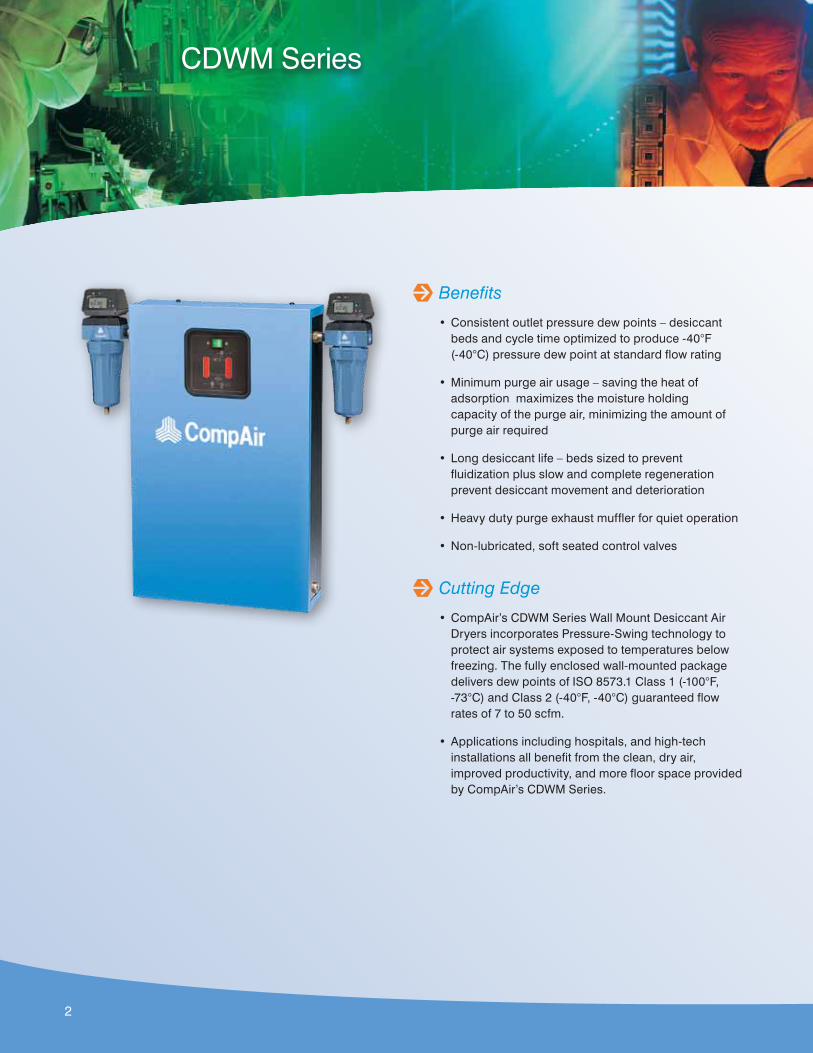
Front Mounted Control Panel
• Power on light
• Tower indicator lights
• On-off switchLighted On/Off
Switch
Active TowerIndicating
Lights
3
Operation
TOWER 1
TOWER 2
TOWER 1
TOWER 2
A A
BB
C C
D DD D
E E
Model CDWM50
Figure 1 Figure 2
TOWER 1
TOWER 2
TOWER 1
TOWER 2
A A
BB
C C
DD
E E
Model CDWM7 through CDWM35
Figure 1 Figure 2
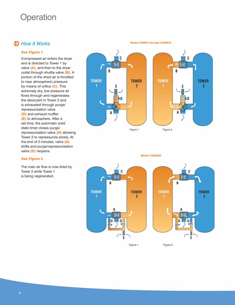
How It Works
See Figure 1
Compressed air enters the dryer and is directed to Tower 1 by valve (A), and then to the dryer outlet through shuttle valve (B). A portion of the dried air is throttled to near atmospheric pressure by means of orifice (C). This extremely dry, low pressure air flows through and regenerates the desiccant in Tower 2 and is exhausted through purge/repressurization valve (D) and exhaust muffler (E) to atmosphere. After a set time, the automatic solid state timer closes purge/repressurization valve (D) allowing Tower 2 to repressurize slowly. At the end of 2 minutes, valve (A) shifts and purge/repressurization valve (D) reopens.
See Figure 2
The main air flow is now dried by Tower 2 while Tower 1 is being regenerated.
4
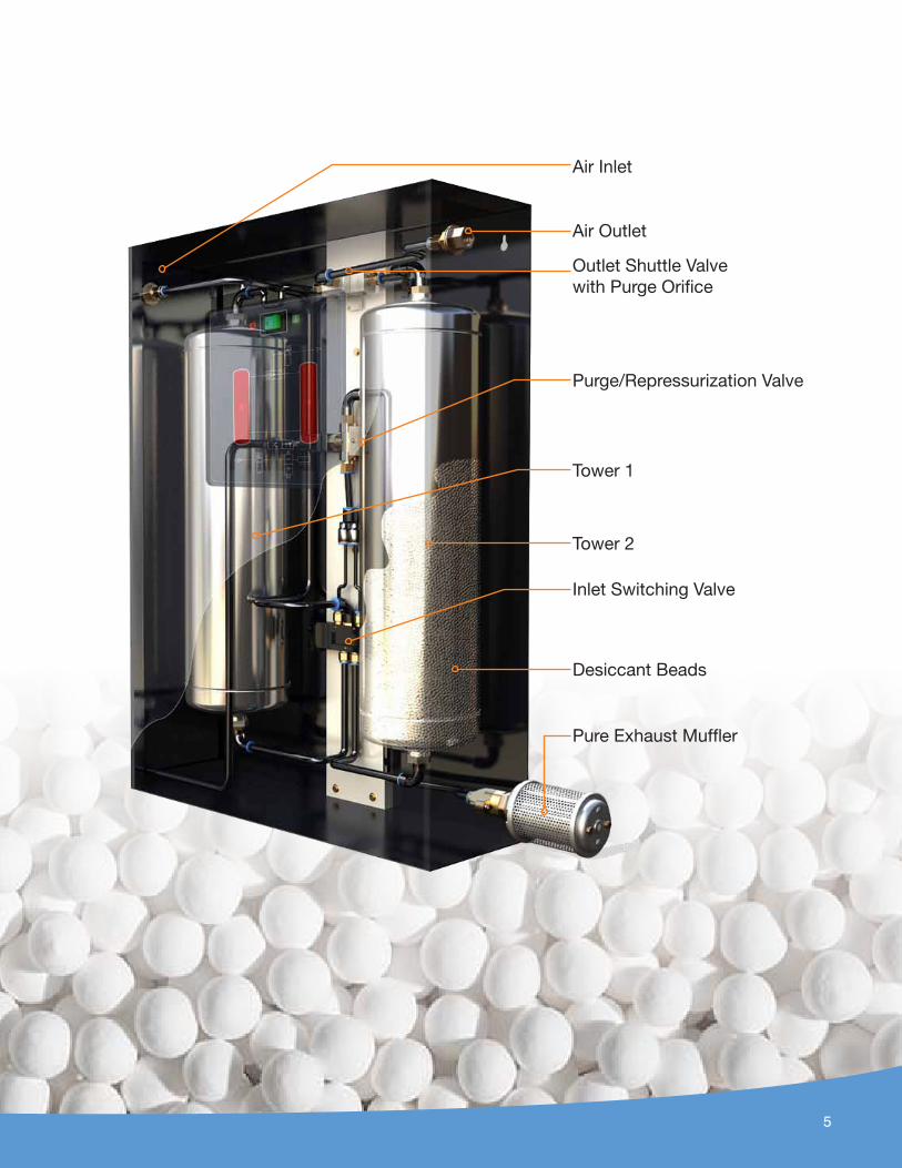
Air Inlet
Air Outlet
Outlet Shuttle Valve with Purge Orifice
Purge/Repressurization Valve
Tower 1
Tower 2
Inlet Switching Valve
Desiccant Beads
Pure Exhaust Muffler
5
Optional Filtration
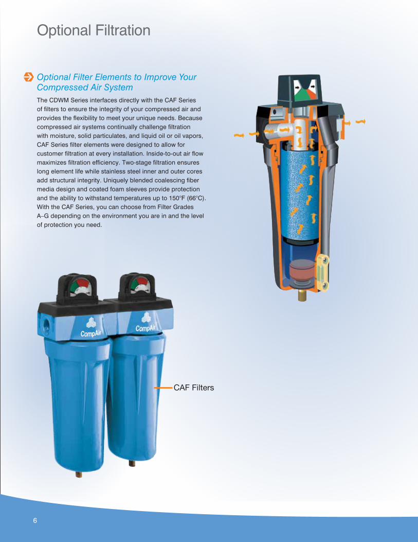
Optional Filter Elements to Improve Your Compressed Air SystemThe CDWM Series interfaces directly with the CAF Series of filters to ensure the integrity of your compressed air and provides the flexibility to meet your unique needs. Because compressed air systems continually challenge filtration with moisture, solid particulates, and liquid oil or oil vapors, CAF Series filter elements were designed to allow for customer filtration at every installation. Inside-to-out air flow maximizes filtration efficiency. Two-stage filtration ensures long element life while stainless steel inner and outer cores add structural integrity. Uniquely blended coalescing fiber media design and coated foam sleeves provide protection and the ability to withstand temperatures up to 150°F (66°C). With the CAF Series, you can choose from Filter Grades A–G depending on the environment you are in and the level of protection you need.
CAF Filters
6
Specifications
1. Average purge Flow is the total amount of air used to purge and repressurize off-stream towers averaged over the cycle time. Maximum Purge Flow is the flow rate through the off-stream tower during that portion of the cycle the purge/ repressurization valve is open.
2. Inlet flows are established in accordance with CAGI (Compressed Air and Gas Institute)standard ADF-200, Dual Stage Regenerative Desiccant Compressed Air Dryers – Methods for Testing and Rating. Conditions for rating dryers are: Inlet pressure –100 psig; inlettemperature–saturated at 100°F.
CDWM Series Product Specifications
Model Flow (scfm) Voltage L x W x H Weight
(lbs.) Connections
CDWM7 7 115/1/50-60 17.5 x 6.7 x 30.5 55 ³/8"
CDWM13 13 115/1/50-60 17.5 x 6.7 x 30.5 60 ³/8"
CDWM20 20 115/1/50-60 17.5 x 6.7 x 30.5 71 ³/8"
CDWM25 25 115/1/50-60 24.4 x 8.5 x 31.6 93 ³/8"
CDWM30 30 115/1/50-60 24.4 x 8.5 x 31.6 93 ½"
CDWM35 35 115/1/50-60 24.4 x 8.5 x 31.6 99 ½"
CDWM50 50 115/1/50-60 24.4 x 8.5 x 31.6 132 ½"
Capacity Correction Factors• To determine maximum inlet flow at inlet pressures other than 100 psig, multiply
inlet flow from Table 2 by multiplier A from Table 1 that corresponds to system pressure at inlet of dryer.
• To determine purge flow at inlet pressures other than 100 psig, multiply purge flow at 100 psig, from Table 2 by Multiplier B from Table 1 that corresponds to system pressure at inlet of dryer.
• To determine outlet flow capacity subtract purge flow from inlet flow
Table 1 – Inlet Pressure
Inlet PressurePSIG
KG/cm²50 3.5
70 4.9
90 6.3
100 7.0
110 7.7
120 8.4
130 9.1
150 10.5
Mulitplier A 0.81 0.54 0.83 1.00 1.09 1.17 1.26 1.44
Mulitiplier B 0.55 0.73 0.91 1.00 1.09 1.17 1.26 1.44
Table 2 –Inlet & Purge Flows @ 100 psig
Model
Inlet Flow Rating¹ (scfm) Purge Flow² (scfm)
-40°F(-40°C)
-100°F(-73°C)
Average Maximum
CDWM7 7.3 5.6 1.5 2
CDWM13 13 10 2.7 3.7
CDWM20 20 16 4.2 5.5
CDWM25 25 20 5.1 6.8
CDWM30 30 24 6.2 8.2
CDWM35 35 28 7.2 9.6
CDWM50 50 40 10.2 13.6
7
www.CompAir.com [email protected]
®
MemberPlease recycle after use.
CompAir USA 1301 North Euclid Avenue Princeton, IL 61356 United States of AmericaTel (866) 994-8807 Fax (800) 443-7790
CompAir Canada 871 Cranberry Court Oakville, Ontario L6L 6J7 CanadaTel (905) 847-0688 Fax (905) 847-8124
8
ACCREDITED
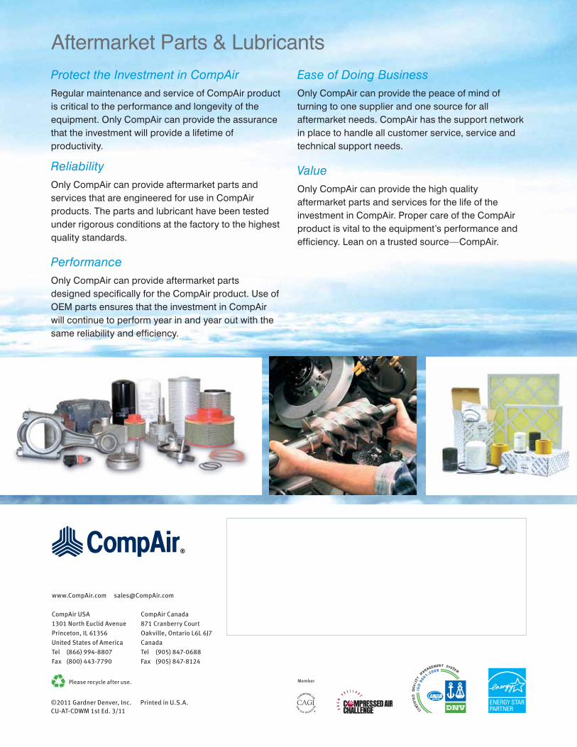
Protect the Investment in CompAirRegular maintenance and service of CompAir product is critical to the performance and longevity of the equipment. Only CompAir can provide the assurance that the investment will provide a lifetime of productivity.
ReliabilityOnly CompAir can provide aftermarket parts and services that are engineered for use in CompAir products. The parts and lubricant have been tested under rigorous conditions at the factory to the highest quality standards.
PerformanceOnly CompAir can provide aftermarket parts designed specifically for the CompAir product. Use of OEM parts ensures that the investment in CompAir will continue to perform year in and year out with the same reliability and efficiency.
Ease of Doing BusinessOnly CompAir can provide the peace of mind of turning to one supplier and one source for all aftermarket needs. CompAir has the support network in place to handle all customer service, service and technical support needs.
ValueOnly CompAir can provide the high quality aftermarket parts and services for the life of the investment in CompAir. Proper care of the CompAir product is vital to the equipment’s performance and efficiency. Lean on a trusted source—CompAir.
Aftermarket Parts & Lubricants
©2011 Gardner Denver, Inc. Printed in U.S.A. CU-AT-CDWM 1st Ed. 3/11