Embed Size (px)
Citation preview

Appendix A


Appendix C

Moment Magnification Calculations
Moment Magnification Calculations for Load Combination 1010 for Bottom of Column 1
Aashto Lrfd 5.7.4.3 and 4.5.3.2.2b
Factored Load Reactions from RC-Pier
Column 1 Column 2 Column 3
Fy1 = 727.65 k Fy2 = 709.02 k Fy3 = 597.08 k
Mx1 = 313.24 k*ft Mx2 = 311.86 k*ft Mx3 = 313.24 k*ft
Mz1 = -25.43 k*ft Mz2 = -11.38 k*ft Mz3 = 23.60 k*ft
RC-Pier assumes minimum eccentricity according to Aashto Std. Spec. 8.16.5.2.8
emin = 0.6 + 0.03*h = 0.6 + (0.03)*(30”) = 1.5” = 0.125’
Mx_min1 = Mz_min1 = (Fy1)*(emin) = (727.65 k)*(0.125’) = 90.956 k*ft
Mx_min2 = Mz_min2 = (Fy2)*(emin) = (709.02 k)*(0.125’) = 88.628 k*ft
Mx_min3 = Mz_min3 = (Fy3)*(emin) = (597.08 k)*(0.125’) = 74.635 k*ft
Factored Loads Considered
Column 1 Column 2 Column 3
Fy1 = 727.65 k Fy2 = 709.02 k Fy3 = 597.08 k
Mx1 = 313.24 k*ft Mx2 = 311.86 k*ft Mx3 = 313.24 k*ft
Mz1 = -90.956 k*ft Mz2 = -88.628 k*ft Mz3 = 74.635 k*ft
Moment Magnification from Aashto Lrfd 4.5.3.2.2b with RC-Pier Modifications
Mc = bM2b + sM2s RC-Pier modifies this equation for unbraced frames by assuming
Mc = sM2 that all moments are to be magnified by s alone.
where s = 1 / [1 – Pu/( k* Pe)]
k = 0.75 Stiffness reduction factor for concrete
Pe = 2*EI/(k*lu)
2 Euler buckling load
EI = (Ec*Ig/2.5)/(1 + d) Flexural column stiffness
d is ratio of maximum factored dead load moment to
maximum factored total moment, always positive
Calculate d = | Maximum Factored Dead Load Moment / Maximum Factored Total Load Moment |
Loads from RC-Pier
Unfactored Self-weight
Fy1 = 40.10 k Fy2 = 44.88 k Fy3 = 40.10 k
Mx1 = 0.00 k*ft Mx2 = 0.00 k*ft Mx3 = 0.00 k*ft
Mz1 = -0.41 k*ft Mz2 = 0.00 k*ft Mz3 = 0.41 k*ft
Unfactored DC loads
Fy1 = 305.22 k Fy2 = 282.22 k Fy3 = 305.22 k
Mx1 = 0.00 k*ft Mx2 = 0.00 k*ft Mx3 = 0.00 k*ft
Mz1 = 4.87 k*ft Mz2 = 0.00 k*ft Mz3 = -4.87 k*ft
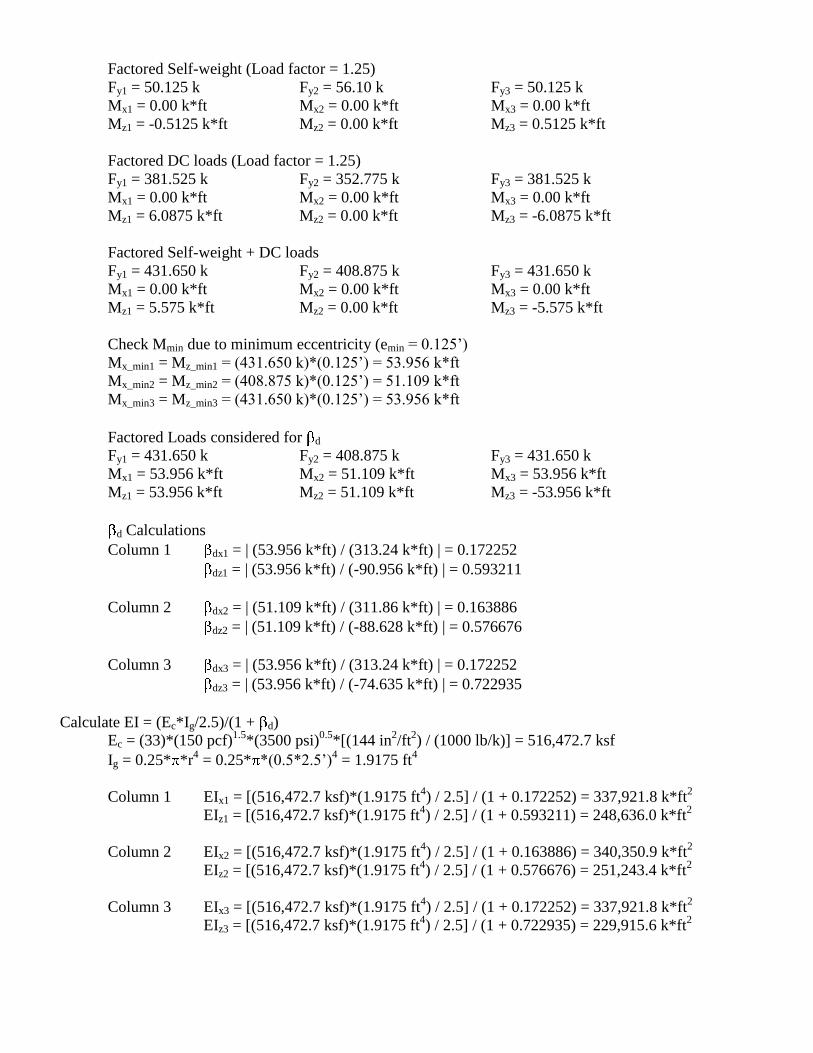
Factored Self-weight (Load factor = 1.25)
Fy1 = 50.125 k Fy2 = 56.10 k Fy3 = 50.125 k
Mx1 = 0.00 k*ft Mx2 = 0.00 k*ft Mx3 = 0.00 k*ft
Mz1 = -0.5125 k*ft Mz2 = 0.00 k*ft Mz3 = 0.5125 k*ft
Factored DC loads (Load factor = 1.25)
Fy1 = 381.525 k Fy2 = 352.775 k Fy3 = 381.525 k
Mx1 = 0.00 k*ft Mx2 = 0.00 k*ft Mx3 = 0.00 k*ft
Mz1 = 6.0875 k*ft Mz2 = 0.00 k*ft Mz3 = -6.0875 k*ft
Factored Self-weight + DC loads
Fy1 = 431.650 k Fy2 = 408.875 k Fy3 = 431.650 k
Mx1 = 0.00 k*ft Mx2 = 0.00 k*ft Mx3 = 0.00 k*ft
Mz1 = 5.575 k*ft Mz2 = 0.00 k*ft Mz3 = -5.575 k*ft
Check Mmin due to minimum eccentricity (emin = 0.125’)
Mx_min1 = Mz_min1 = (431.650 k)*(0.125’) = 53.956 k*ft
Mx_min2 = Mz_min2 = (408.875 k)*(0.125’) = 51.109 k*ft
Mx_min3 = Mz_min3 = (431.650 k)*(0.125’) = 53.956 k*ft
Factored Loads considered for d
Fy1 = 431.650 k Fy2 = 408.875 k Fy3 = 431.650 k
Mx1 = 53.956 k*ft Mx2 = 51.109 k*ft Mx3 = 53.956 k*ft
Mz1 = 53.956 k*ft Mz2 = 51.109 k*ft Mz3 = -53.956 k*ft
d Calculations
Column 1 dx1 = | (53.956 k*ft) / (313.24 k*ft) | = 0.172252
dz1 = | (53.956 k*ft) / (-90.956 k*ft) | = 0.593211
Column 2 dx2 = | (51.109 k*ft) / (311.86 k*ft) | = 0.163886
dz2 = | (51.109 k*ft) / (-88.628 k*ft) | = 0.576676
Column 3 dx3 = | (53.956 k*ft) / (313.24 k*ft) | = 0.172252
dz3 = | (53.956 k*ft) / (-74.635 k*ft) | = 0.722935
Calculate EI = (Ec*Ig/2.5)/(1 + d)
Ec = (33)*(150 pcf)1.5
*(3500 psi)0.5
*[(144 in2/ft
2) / (1000 lb/k)] = 516,472.7 ksf
Ig = 0.25* *r4 = 0.25* *(0.5*2.5’)
4 = 1.9175 ft
4
Column 1 EIx1 = [(516,472.7 ksf)*(1.9175 ft4) / 2.5] / (1 + 0.172252) = 337,921.8 k*ft
2
EIz1 = [(516,472.7 ksf)*(1.9175 ft4) / 2.5] / (1 + 0.593211) = 248,636.0 k*ft
2
Column 2 EIx2 = [(516,472.7 ksf)*(1.9175 ft4) / 2.5] / (1 + 0.163886) = 340,350.9 k*ft
2
EIz2 = [(516,472.7 ksf)*(1.9175 ft4) / 2.5] / (1 + 0.576676) = 251,243.4 k*ft
2
Column 3 EIx3 = [(516,472.7 ksf)*(1.9175 ft4) / 2.5] / (1 + 0.172252) = 337,921.8 k*ft
2
EIz3 = [(516,472.7 ksf)*(1.9175 ft4) / 2.5] / (1 + 0.722935) = 229,915.6 k*ft
2
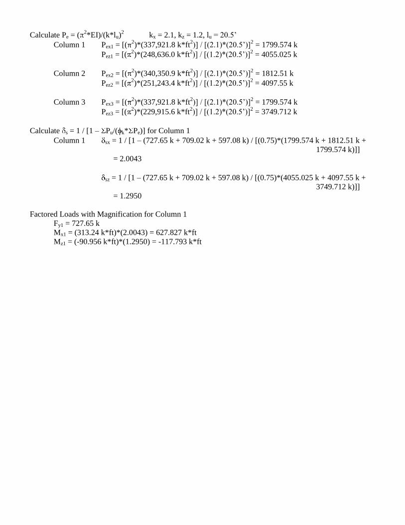
Calculate Pe = (2*EI)/(k*lu)
2 kx = 2.1, kz = 1.2, lu = 20.5’
Column 1 Pex1 = [(2)*(337,921.8 k*ft
2)] / [(2.1)*(20.5’)]
2 = 1799.574 k
Pez1 = [(2)*(248,636.0 k*ft
2)] / [(1.2)*(20.5’)]
2 = 4055.025 k
Column 2 Pex2 = [(2)*(340,350.9 k*ft
2)] / [(2.1)*(20.5’)]
2 = 1812.51 k
Pez2 = [(2)*(251,243.4 k*ft
2)] / [(1.2)*(20.5’)]
2 = 4097.55 k
Column 3 Pex3 = [(2)*(337,921.8 k*ft
2)] / [(2.1)*(20.5’)]
2 = 1799.574 k
Pez3 = [(2)*(229,915.6 k*ft
2)] / [(1.2)*(20.5’)]
2 = 3749.712 k
Calculate s = 1 / [1 – Pu/( k* Pe)] for Column 1
Column 1 sx = 1 / [1 – (727.65 k + 709.02 k + 597.08 k) / [(0.75)*(1799.574 k + 1812.51 k +
1799.574 k)]]
= 2.0043
sz = 1 / [1 – (727.65 k + 709.02 k + 597.08 k) / [(0.75)*(4055.025 k + 4097.55 k +
3749.712 k)]]
= 1.2950
Factored Loads with Magnification for Column 1
Fy1 = 727.65 k
Mx1 = (313.24 k*ft)*(2.0043) = 627.827 k*ft
Mz1 = (-90.956 k*ft)*(1.2950) = -117.793 k*ft

Appendix D
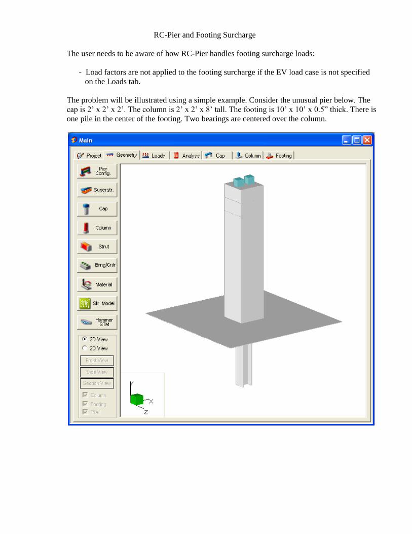
RC-Pier and Footing Surcharge
The user needs to be aware of how RC-Pier handles footing surcharge loads:
- Load factors are not applied to the footing surcharge if the EV load case is not specified
on the Loads tab.
The problem will be illustrated using a simple example. Consider the unusual pier below. The
cap is 2’ x 2’ x 2’. The column is 2’ x 2’ x 8’ tall. The footing is 10’ x 10’ x 0.5” thick. There is
one pile in the center of the footing. Two bearings are centered over the column.
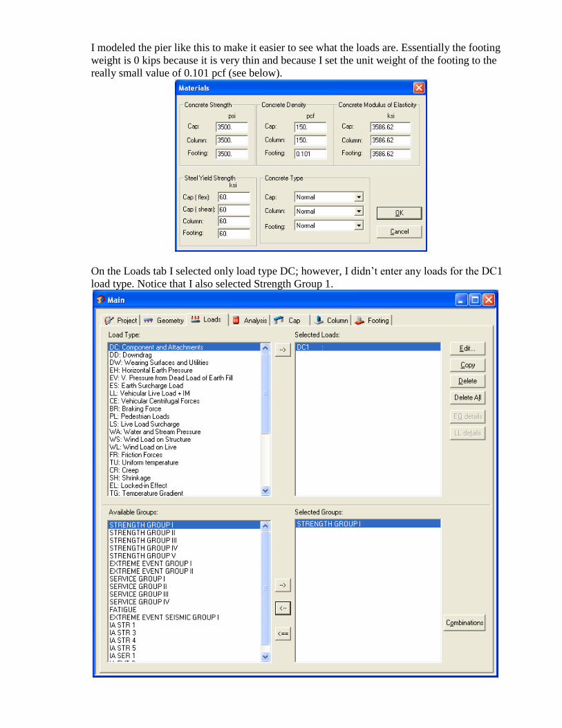
I modeled the pier like this to make it easier to see what the loads are. Essentially the footing
weight is 0 kips because it is very thin and because I set the unit weight of the footing to the
really small value of 0.101 pcf (see below).
On the Loads tab I selected only load type DC; however, I didn’t enter any loads for the DC1
load type. Notice that I also selected Strength Group 1.
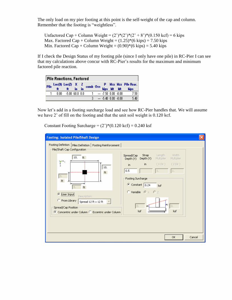
The only load on my pier footing at this point is the self-weight of the cap and column.
Remember that the footing is “weightless”.
Unfactored Cap + Column Weight = (2’)*(2’)*(2’ + 8’)*(0.150 kcf) = 6 kips
Max. Factored Cap + Column Weight = (1.25)*(6 kips) = 7.50 kips
Min. Factored Cap + Column Weight = (0.90)*(6 kips) = 5.40 kips
If I check the Design Status of my footing pile (since I only have one pile) in RC-Pier I can see
that my calculations above concur with RC-Pier’s results for the maximum and minimum
factored pile reaction.
Now let’s add in a footing surcharge load and see how RC-Pier handles that. We will assume
we have 2’ of fill on the footing and that the unit soil weight is 0.120 kcf.
Constant Footing Surcharge = (2’)*(0.120 kcf) = 0.240 ksf
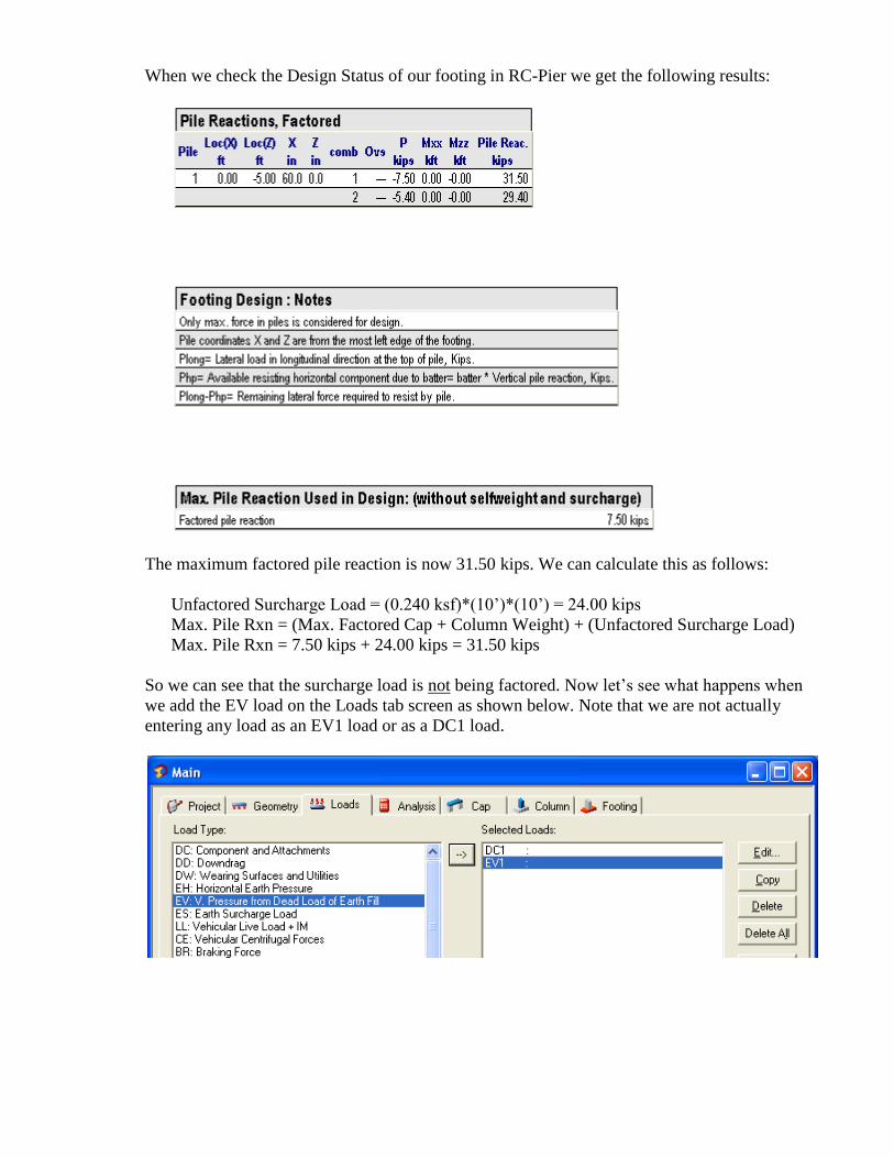
When we check the Design Status of our footing in RC-Pier we get the following results:
The maximum factored pile reaction is now 31.50 kips. We can calculate this as follows:
Unfactored Surcharge Load = (0.240 ksf)*(10’)*(10’) = 24.00 kips
Max. Pile Rxn = (Max. Factored Cap + Column Weight) + (Unfactored Surcharge Load)
Max. Pile Rxn = 7.50 kips + 24.00 kips = 31.50 kips
So we can see that the surcharge load is not being factored. Now let’s see what happens when
we add the EV load on the Loads tab screen as shown below. Note that we are not actually
entering any load as an EV1 load or as a DC1 load.

This time we get the different results as shown below.
The maximum factored pile reaction is now 39.90 kips. We can calculate this as follows:
Factored Surcharge Load = (1.35)*(24.00 kips) = 32.40 kips
Max. Pile Rxn = (Max. Factored Cap + Column Weight) + (Factored Surcharge Load)
Max. Pile Rxn = 7.50 kips + 32.40 kips = 39.90 kips
So we can see that the surcharge load is being factored when we add EV to the Loads tab
screen. [Note that I also tried an ES load instead of an EV load. The ES load did not result in a
load factor being applied to the Footing Surcharge load.] So, the Footing Surcharge is only
factored when the EV load is specified on the Loads tab screen. Excluding the load factor for
the fill loads on the footing can be fairly significant if you have a deep fill and relatively light
superstructure loads.
So, if you typically enter the footing surcharge load on the Footing tab then you should still
supply an EV load on the Loads tab even if you don’t enter a load for it. Apparently RC-Pier
hasn’t always functioned in this manner. An office example I put together for 305 Wapello
around 10/10/2006 (RC-Pier Version 4.1.0) shows some calculations that make it apparent that
the load factor was being included in the footing surcharge load when it was entered on the
Footing tab, but no EV load was specified on the Loads tab.
One recommended procedure might be to enter the footing fill load for each pier footing as an
EV load near the bottom of each column on the Loads tab. [I recommend the load be placed just
a fraction above the bottom of the column for the RC-Pier footing design runs since that ensures
the Analysis Results on the Analysis tab reflect the load.] Doing it this way may affect whether
or not you want to make use of RC-Pier to design your footing reinforcement since it will have
some effect on those results.

An interesting side note concerns the footing self-weight applied by RC-Pier. Not that you
would ever do this, but… if you were ever to do a run of RC-Pier with no DC loads then you
would find that the cap and column self-weight would not be included as a load on your footing.
However, the footing self-weight would be applied to your footing, but it would not have a load
factor applied.
Finally it should be noted that the column area is not deducted from the footing area when the
footing surcharge is actually computed. Normally this isn’t a big deal since the column area is
generally quite a bit smaller than the footing area, but it is something to keep in mind.

Appendix E

RC-Pier and Battered Piles
As you may have seen, RC-Pier allows the user to enter pile batter in the z-axis direction only. For
instance, in the figure below I have entered a batter of 14.03 degrees which is approximately a 1:4
batter. When a pile batter is entered the program prints some additional output to the Pile Reactions
table. Some of the calculations for this additional output are demonstrated on the following pages.

For these example calculations we are going to run only one combination (#79).
We are only going to look at the calculations for footing 1 which corresponds with node 1 of member
1. The forces for combination 79 at node 1 are as follows.
The pile reactions for this footing are as follows. The last three columns of output are printed because
we have input a pile batter.
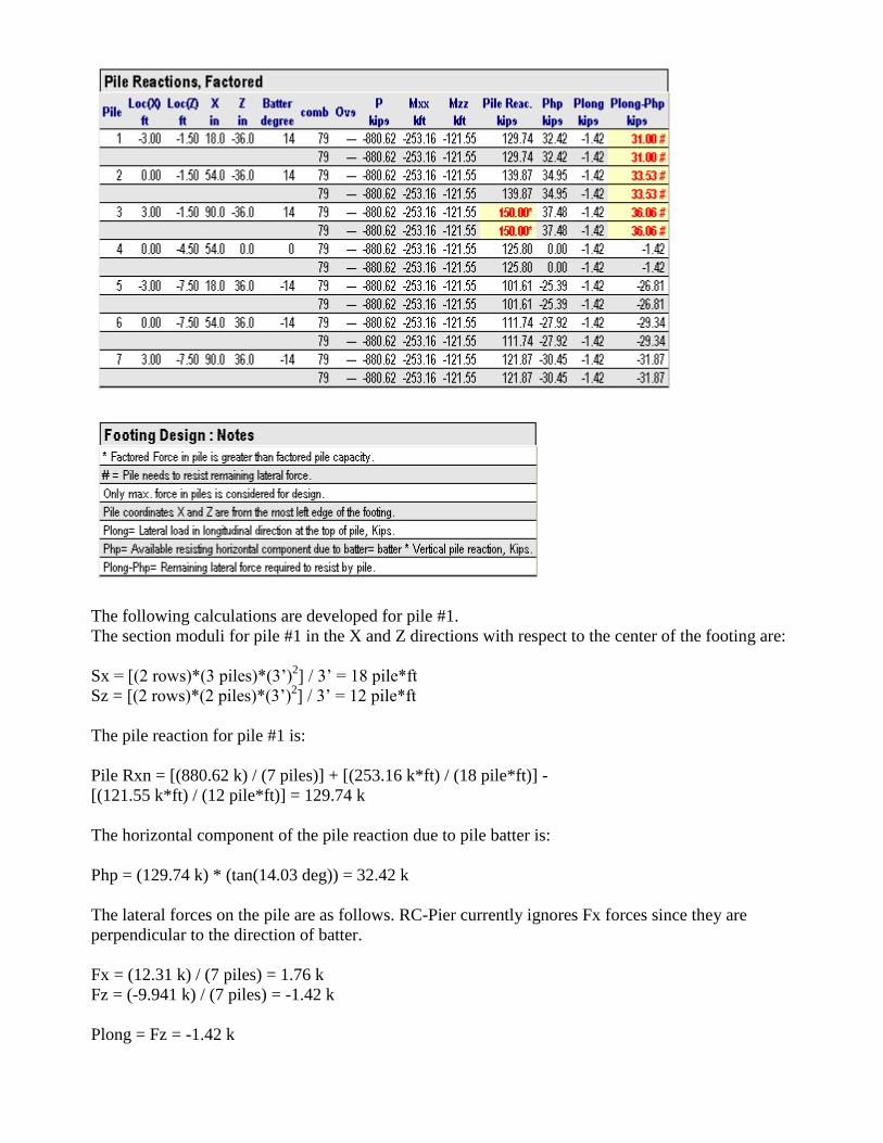
The following calculations are developed for pile #1.
The section moduli for pile #1 in the X and Z directions with respect to the center of the footing are:
Sx = [(2 rows)*(3 piles)*(3’)2] / 3’ = 18 pile*ft
Sz = [(2 rows)*(2 piles)*(3’)2] / 3’ = 12 pile*ft
The pile reaction for pile #1 is:
Pile Rxn = [(880.62 k) / (7 piles)] + [(253.16 k*ft) / (18 pile*ft)] -
[(121.55 k*ft) / (12 pile*ft)] = 129.74 k
The horizontal component of the pile reaction due to pile batter is:
Php = (129.74 k) * (tan(14.03 deg)) = 32.42 k
The lateral forces on the pile are as follows. RC-Pier currently ignores Fx forces since they are
perpendicular to the direction of batter.
Fx = (12.31 k) / (7 piles) = 1.76 k
Fz = (-9.941 k) / (7 piles) = -1.42 k
Plong = Fz = -1.42 k

The sign convention for this lateral force and the horizontal component of the pile reaction are
opposed and thus RC-Pier assumes:
Plong-Php = 32.42 k - 1.42 k = 31.00 k
It appears (from additional testing) that RC-Pier flags any positive value for “Plong-Php” as a failure.
The additional RC-Pier output for battered piles is somewhat confusing and, for the time being, you
should simply refer to the Bridge Design Manual for guidance in dealing with lateral pile forces for
vertical and battered piles.
BDM 6.6.4.1.3.1
“The pile group supporting a pier footing shall be checked for lateral loading [OBS MM No. 9].
Each vertical pile may be assumed to have shear resistance, and each battered pile may be
assumed to have shear resistance plus the horizontal component of the axial resistance. See the
pile resistance guidelines for steel H-piles [BDM 6.2.6.1] and for timber piles [BDM 6.2.6.3].”

Appendix F

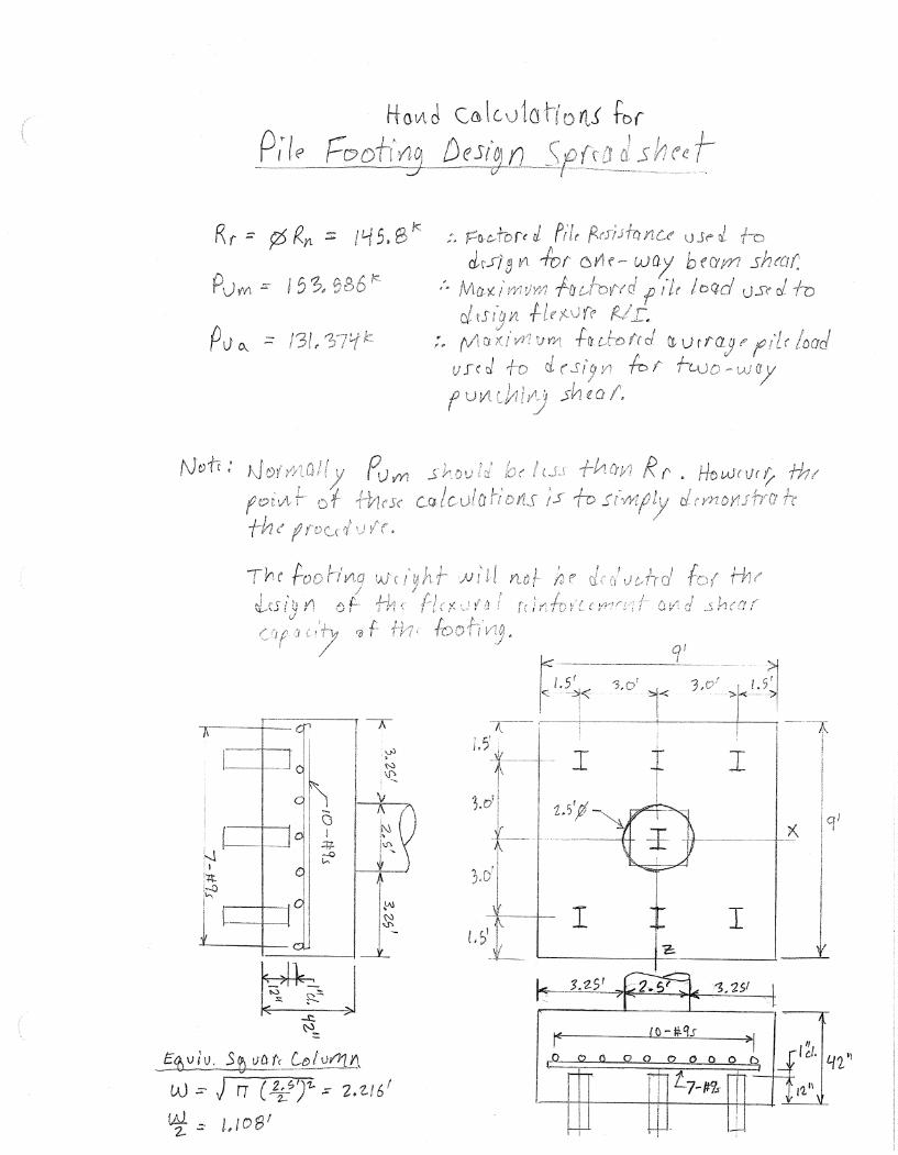
RC-Pier and Pile Footing Design: Flexure and Shear
This run will be used to illustrate
footing design in RC-Pier. I’m only going
to show screens that have been
modified from the cap/column run.
In RC-Pier, the footing
and pile are not part of
the structural model.
Pile batter was
not included.
The columns have
been extended 3.5’
to the bottom of
the footing for this
footing design run.
The footing and fill weight will be placed using the
entries on the “Footing” tab since I am interested in
looking at RC-Pier’s methodology for footing design.
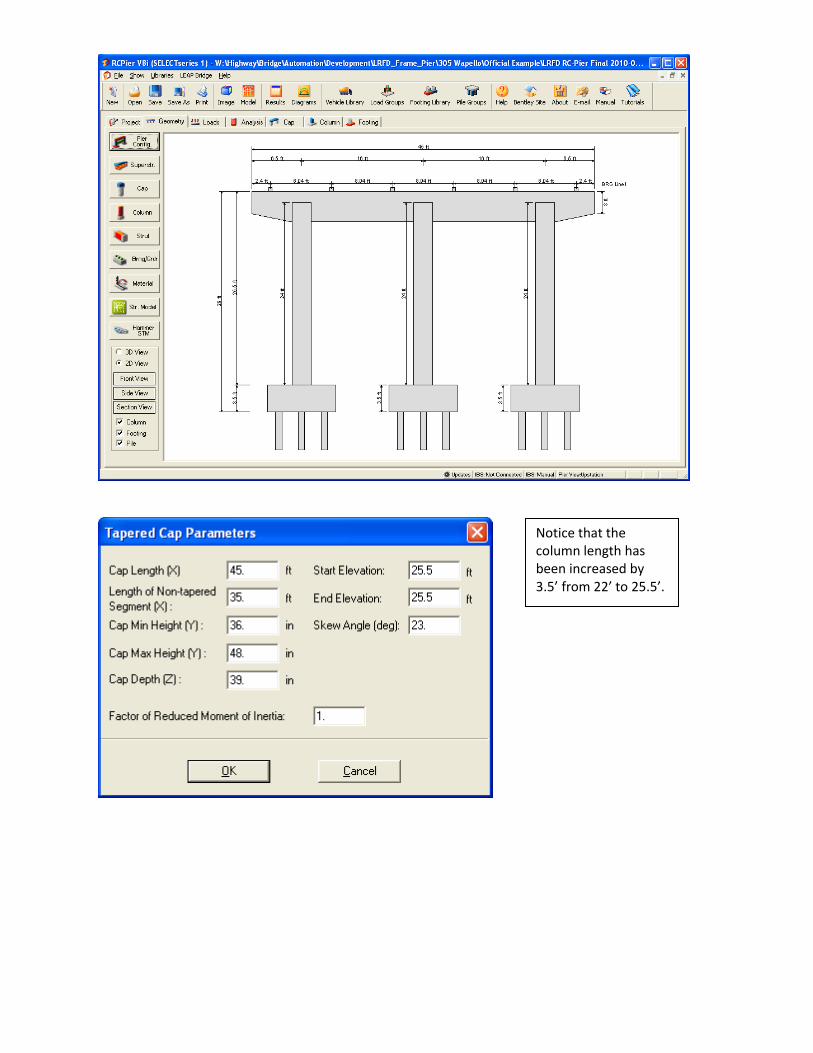
Notice that the column length has been increased by 3.5’ from 22’ to 25.5’.
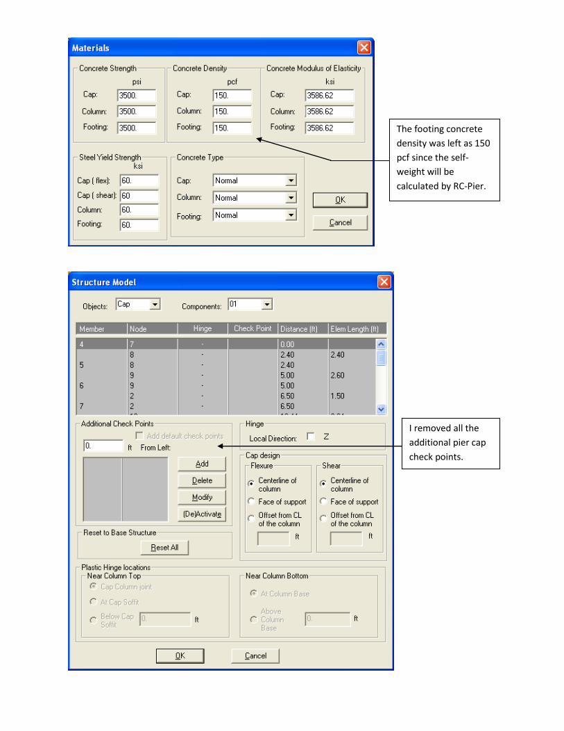
The footing concrete
density was left as 150
pcf since the self-
weight will be
calculated by RC-Pier.
I removed all the
additional pier cap
check points.
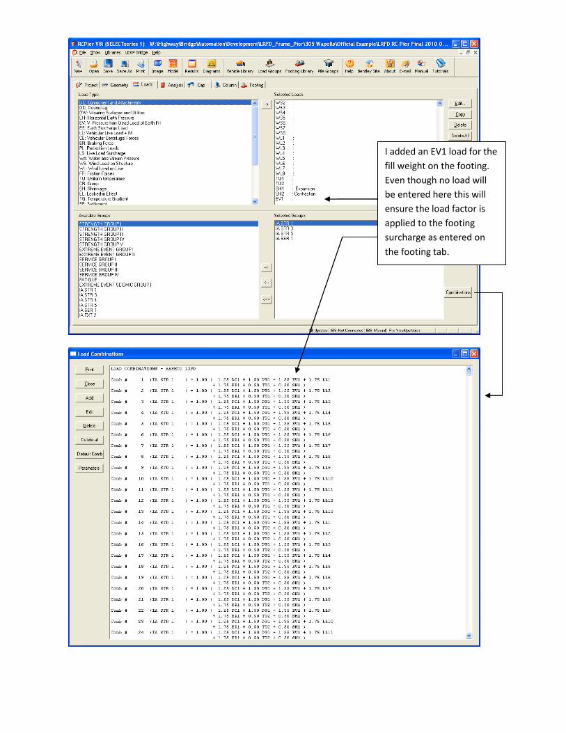
I added an EV1 load for the
fill weight on the footing.
Even though no load will
be entered here this will
ensure the load factor is
applied to the footing
surcharge as entered on
the footing tab.
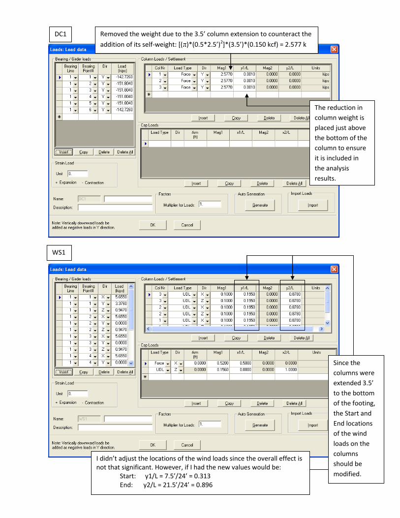
Removed the weight due to the 3.5’ column extension to counteract the
addition of its self-weight: [( )*(0.5*2.5’)2]*(3.5’)*(0.150 kcf) = 2.577 k
DC1
WS1
The reduction in
column weight is
placed just above
the bottom of the
column to ensure
it is included in
the analysis
results.
Since the
columns were
extended 3.5’
to the bottom
of the footing,
the Start and
End locations
of the wind
loads on the
columns
should be
modified.
I didn’t adjust the locations of the wind loads since the overall effect is not that significant. However, if I had the new values would be:
Start: y1/L = 7.5’/24’ = 0.313 End: y2/L = 21.5’/24’ = 0.896
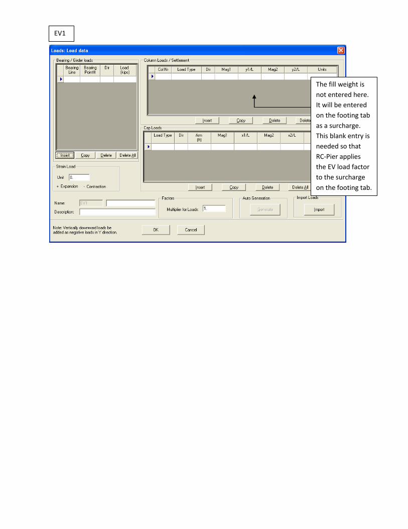
EV1
The fill weight is
not entered here.
It will be entered
on the footing tab
as a surcharge.
This blank entry is
needed so that
RC-Pier applies
the EV load factor
to the surcharge
on the footing tab.

Click on
this for
screen
below.
All dynamic load allowance factors
were set to 0 to ensure that the
analysis results exclude impact if
they are written to a file.
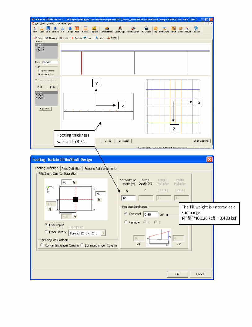
Footing thickness
was set to 3.5’.
The fill weight is entered as a surcharge: (4’ fill)*(0.120 kcf) = 0.480 ksf
Y
X
Z
X

This is used for
graphics display.
See next page. This value is arbitrary
since the Iowa DOT
currently bases pile
design on the Strength
and Extreme Event
Combinations.
Not used in the structural model – it
is simply used in the graphic display.
I keep the pile short so they don’t
take up the whole picture.
This information is from a
library – see following pages.
See below.
HP10x57 Structural Resistance Level 1 Factored Resistance = (6 ksi)*(0.1167 ft2)*(144 in2/ft2)*(1.45) = 146.16 k BDM Table 6.2.6.1-1 shows (0.6)*(243 k) = 145.8 k
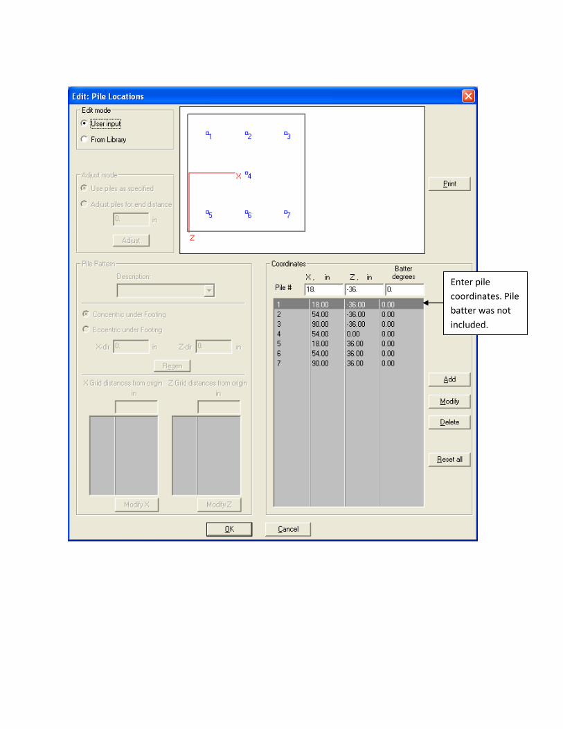
Enter pile
coordinates. Pile
batter was not
included.
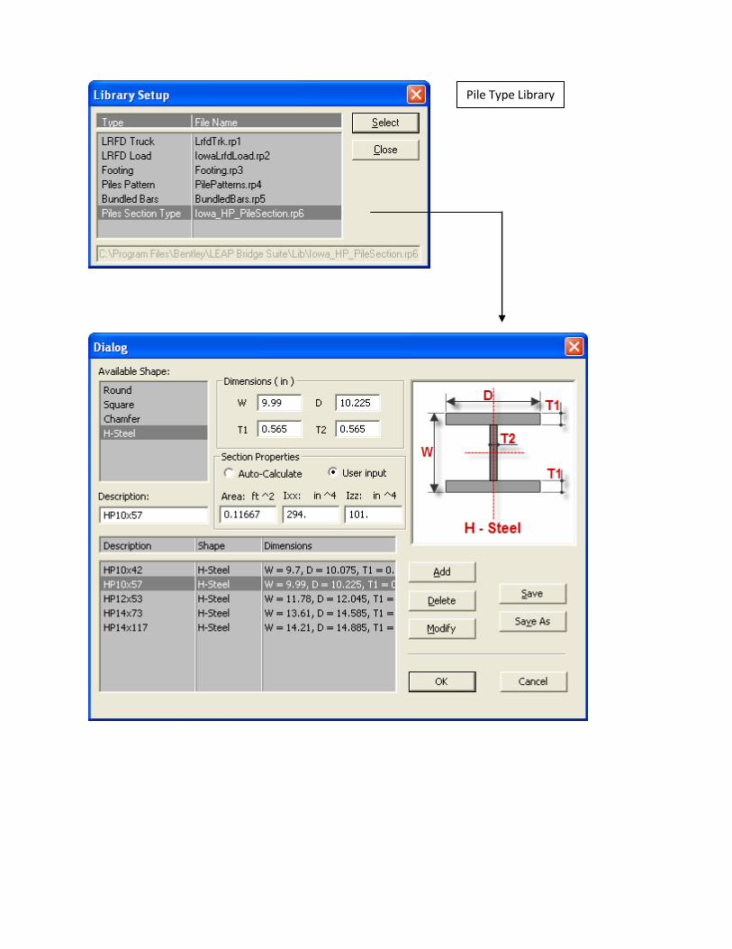
Pile Type Library

This button lets
you review the
design.
Footing reinforcement was
entered according to the plans.

I’ve included some portions of
RC-Pier’s output for the footing.
Not interested in the
Service capacity of
the piles at this time.
Maximum Service Reaction

This is greater than the factored
resistance of 145.80 k. So, I
should modify my pile
arrangement or add more piling.
I won’t do that at this time.
Note that the maximum
factored pile reaction is
not 154.04 kips in this
table. This is because the
footing and surcharge (fill
weight) have been
deducted. The same is true
for the service pile
reaction.
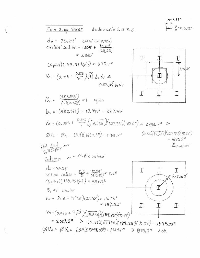
Footing Self-weight = (0.150 kcf)*(9’)*(9’)*(3.5’) / (7 piles) = 6.075 k/pile
Surcharge = (0.120 kcf)*(9’)*(9’)*(4’ fill depth) / (7 piles) = 5.5543 k/pile
Factored Pile Reaction = 154.04 k – (1.25)*(6.075 k) – (1.35)*(5.5543 k) = 138.95 k
Service Pile Reaction = 125.24 k – (1.00)*(6.075 k) – (1.00)*(5.5543 k) = 113.61 k
Note that the column footprint in the fill is not deducted.

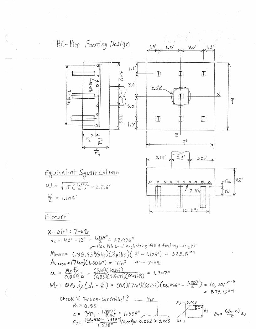
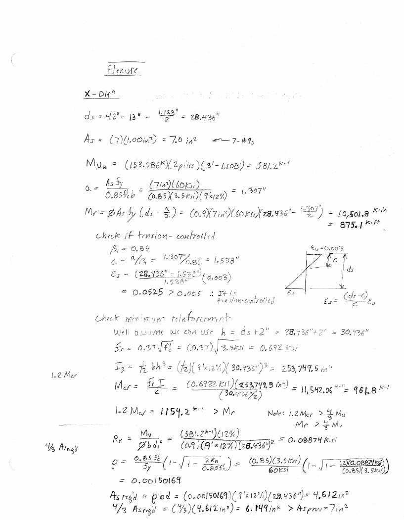
As = 0.0015*Ag/2 = (0.0015)*(9’)*(12
in/ft)*(3.5’)*(12 in/ft) / 2 = 3.402 in2
This appears to be based on the 2005
Aashto Lrfd Code Art. 5.10.8.2
See hand calculations
for Asb required
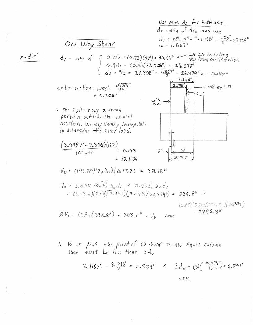
1.108’ to critical face of column
(based on equiv. square)
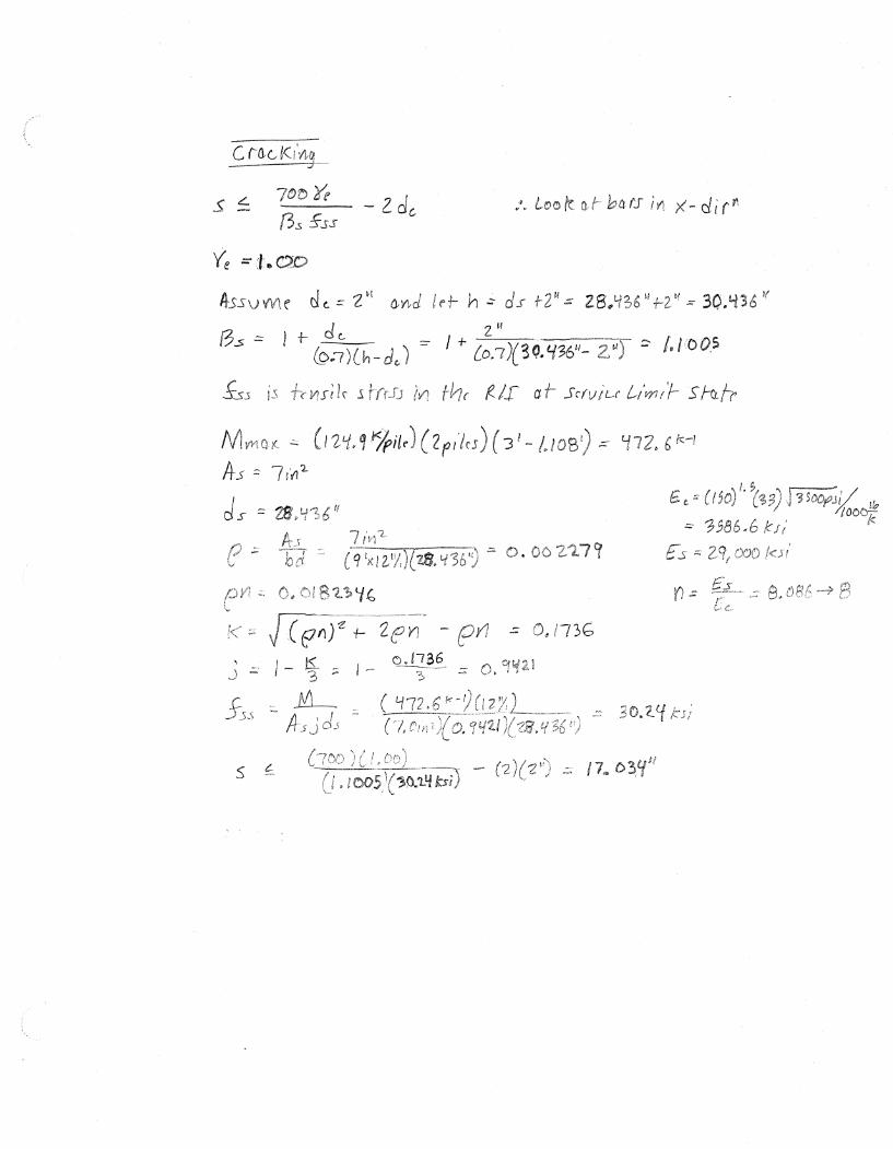
See hand calculations
for cracking check
See hand calculations
for one-way shear
See hand calculations
for two-way shear


Appendix H


Appendix I

Pier Loads - CE
CE – Vehicular Centrifugal Force
o CE is applied 6.0 feet above the deck surface to piers with
horizontally curved roadways.
o Design speed for the appropriate highway classification shall be
taken from the Office of Design’s Design Manual.
o Number of lanes loaded for CE shall be consistent with number
of lanes loaded for vertical LL. Multiple presence factors apply
to CE.
o Each pier shall resist the total CE force individually – it is not
distributed among the bents.
Pier Loads – CE
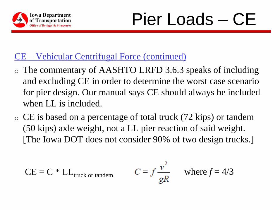
CE – Vehicular Centrifugal Force (continued)
o The commentary of AASHTO LRFD 3.6.3 speaks of including
and excluding CE in order to determine the worst case scenario
for pier design. Our manual says CE should always be included
when LL is included.
o CE is based on a percentage of total truck (72 kips) or tandem
(50 kips) axle weight, not a LL pier reaction of said weight.
[The Iowa DOT does not consider 90% of two design trucks.]
CE = C * LLtruck or tandem where f = 4/3
Pier Loads – CE
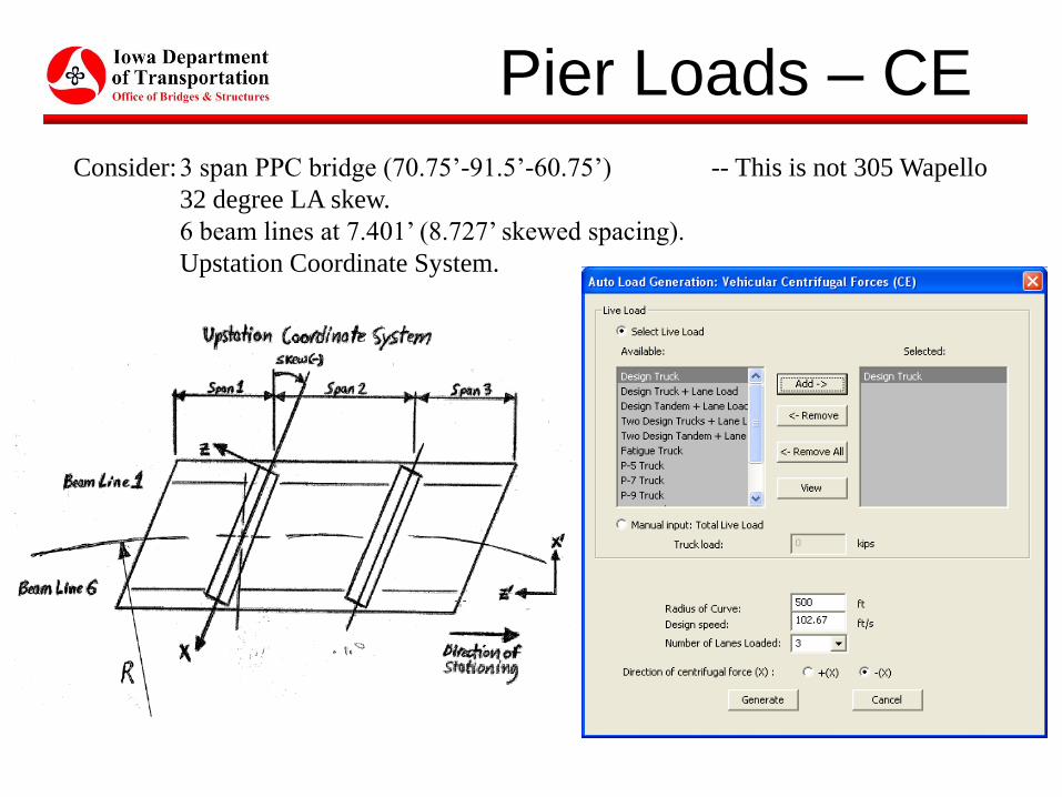
Consider:3 span PPC bridge (70.75’-91.5’-60.75’) -- This is not 305 Wapello
32 degree LA skew.
6 beam lines at 7.401’ (8.727’ skewed spacing).
Upstation Coordinate System.
Pier Loads – CE
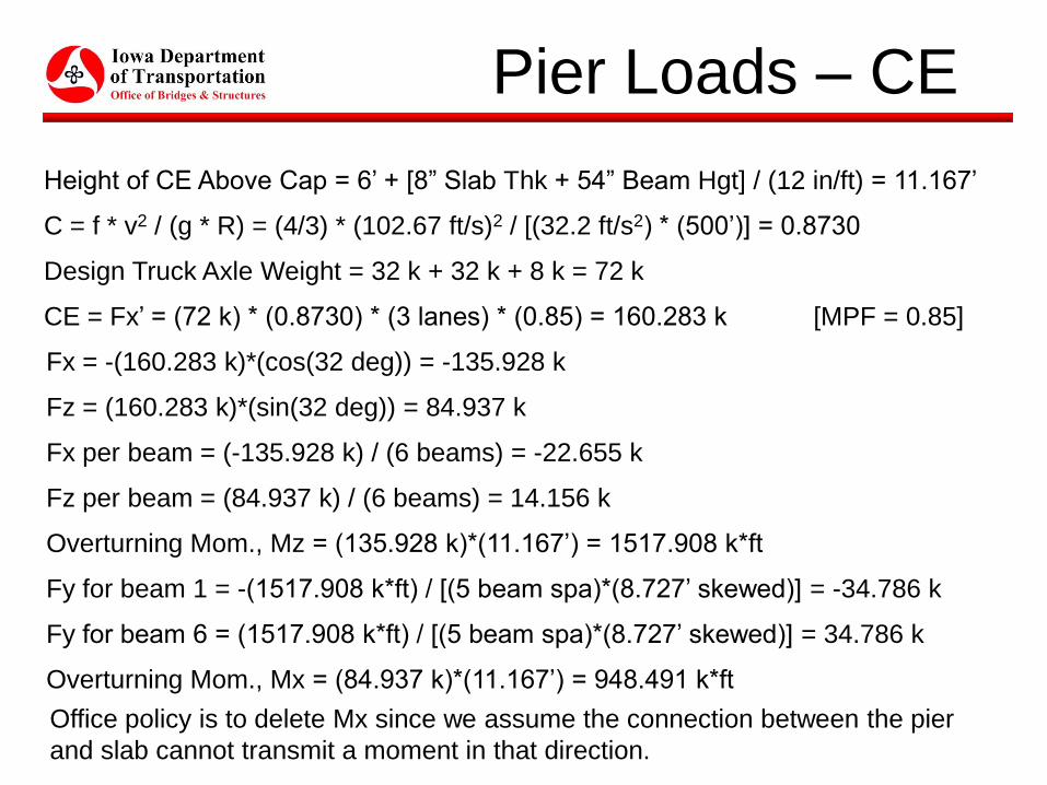
Height of CE Above Cap = 6’ + [8” Slab Thk + 54” Beam Hgt] / (12 in/ft) = 11.167’
C = f * v2 / (g * R) = (4/3) * (102.67 ft/s)2 / [(32.2 ft/s2) * (500’)] = 0.8730
Design Truck Axle Weight = 32 k + 32 k + 8 k = 72 k
CE = Fx’ = (72 k) * (0.8730) * (3 lanes) * (0.85) = 160.283 k [MPF = 0.85]
Fx = -(160.283 k)*(cos(32 deg)) = -135.928 k
Fz = (160.283 k)*(sin(32 deg)) = 84.937 k
Fx per beam = (-135.928 k) / (6 beams) = -22.655 k
Fz per beam = (84.937 k) / (6 beams) = 14.156 k
Overturning Mom., Mz = (135.928 k)*(11.167’) = 1517.908 k*ft
Fy for beam 1 = -(1517.908 k*ft) / [(5 beam spa)*(8.727’ skewed)] = -34.786 k
Fy for beam 6 = (1517.908 k*ft) / [(5 beam spa)*(8.727’ skewed)] = 34.786 k
Overturning Mom., Mx = (84.937 k)*(11.167’) = 948.491 k*ft
Office policy is to delete Mx since we assume the connection between the pier
and slab cannot transmit a moment in that direction.

Pier Loads – CE