Embed Size (px)
Citation preview
WAR DEPARTMENT TECHNICAL MANUAL
TM 9 1501
ORDNANCE MAINTENANCE
OPERATION ANDMAINTENANCE OF
OPTICAL COATINGEQUIPMENT
WAR DEPARTMENT . 12 MARCH 1945
RESTRICTED. DISSEMINATION OF RESTRICTED MATTER.No person is entitled solely by virtue of his grade or position to knowledge or possession of
classified matter. Such matter is entrusted only to those individuals whose official duties
require such knowledge or possession.
(See also paragraph 23b, AR 380-5, I5 March 1944.)
WAR DEPARTMENTWashington 25, D.C., 12 March
1945
TM 9-1501, Ordnance Maintenance: Operation and Maintenanceof Optical Coating Equipment, is published for the information andguidance of all concerned.
By ORDER OF THE SECRETARY OF WAR:
~ G. C. MARSHALL,C h i e f o f
Staff.
OFFICIAL:. J. A. ULIO,Major General,
The Adjutant General.
DISTRIBUTION: AGF (10); ASF (2); S Div ASF (1); Dept (10); Arm &; SvBd (2); Tech Sv (2); SvC (10); PE, 9 (5); Dist 0, 9 (5); DistBr O, 9 (3); Reg O, 9 (3); Decentralized Sub-O, 9 (3);USMA (20); A (10); CHQ (10).
(For explanation of symbols, see FM 21-6.)
CONTENTS
Paragraph Pages
CHAPTER 1. GENERALSECTION I. INTRODUCTION 1–5
Purpose. ......................................................... 1 1Scope.............................................................. 2 1Necessity for Coating.................................... 3 1–3Effects of Coating.......................................... 4 3–4Disadvantages of Coating ............................. 5 5
SECTION II. THEORY OF REFLECTION REDUCINGFILMS
History of Films............................................. 6 5–6Nature of Light .............................................. 7 6–7Thickness of Film.......................................... 8 7–9Index of Refraction........................................ 9 9–10Determination of Thickness......................... 10 10–11Suitable Coating Materials........................... 11 11–12
Types of Films and Their Identifi-cation 12 12–14
SECTION III. OPTICAL PROPERTIES OF FILMVisible Spectrum .......................................... 13 14Light Source ................................................. 14 15–16Efficiency Ranges of One-quarter
Wave Length Films................................. 15 16–17Half Wave Length Films.............................. 16 17–18Three-quarter Wave Length Films............... 17 18–19Variations in Color ....................................... 18 19
SECTION IV. MECHANICAL PROPERTIES OF FILMDurability...................................................... 19 20Mechanical Defects ...................................... 20 21
SECTION V. APPLICATION OF REFLECTIONRE-DUCING FILMS TO MILITARYINSTRUMENTS
Instruments with Coated Optics ............. 21 21–22Determination of Elements To Be
Coated ................................................ 22 22–30
CONTENTS – Contd.
Paragraph PageCHAPTER 2. THE COATING PROCESS
SECTION I. INTRODUCTIONApplication of Magnesium Fluoride
Films ........................................................ 23 31Vacuum Pumps ...................................................24 31–32Pumping Speeds..................................................25 32"Outgassing" ......................................................26 32Vapor Pressures ..................................................27 32–33
SECTION II. DESCRIPTION OF THE COATING UNITThe Coating Unit ................................................28 33Stand....................................................................29 33Vacuum Chamber ...............................................30 34Elevating Mechanism .........................................31 35–38Base Plate ............................................................32 39–43Pumping Equipment ...........................................33 43–54Electrical Systems...............................................34 55–59Vacuum Gages ....................................................35 60–65
SECTION III. OPERATION OF COATING EQUIP-MENT
Decoating Optical Elements...............................36 65–66Cleaning of Optical Elements ............................37 66–71Holding Fixture Set-up .......................................38 71Coating Procedure (Step-by-Step) .....................39 71–75Operation Within a Shop....................................40 76–78
CHAPTER 3. MAINTENANCE OF COATINGEQUIPMENT
SECTION I. INTRODUCTION
General................................................................ 41 79Burning of Diffusion Pump Oil..........................42 79Back Streaming of Oil in the Me-
chanical Pump ................................................43 79–80Contamination of Oil by Dust and
Dirt ..................................................................44 80Foreign Particles in Mechanical
Pump...............................................................45 80Failure of Ionization Tube....................................46 80Failure of Variacs ................................................ 47 80Deterioration of Gaskets...................................... 48 81
SECTION II. PREVENTIVE MAINTENANCECleaning of the Equipment.................................. 49 81–83Renewal of Oil..................................................... 50 83–84Replacement of Filaments .................................. 51 84
CONTENTS- Contd.
Paragraph Pages
SECTION III. LEAKS IN VACUUMSYSTEMGeneral... ............................................................ 52 84–85Indications of Leaks........................................... 53 85–86Search for a Leak ............................................... 54 86–90Elimination of Leaks.......................................... 55 90Virtual Leaks...................................................... 56 90–91
SECTION IV. DISASSEMBLY, OVERHAUL, ANDAS-SEMBLY OF THE MAJORCOMPONENTS OF THE COATINGUNIT
Mechanical Pump...............................................57 91–94Diffusion Pump and Baffle Assem-
bly.................................................................. 58 94–97Vacuum Valve.................................................... 59 97–98Base Plate Assembly.......................................... 60 99–100Rewiring of Heater............................................. 61 100Vacuum Gages ................................................... 62 100–103Replacement of Gaskets .................................... 63 103Preparation of Gasket......................................... 64 103–104
CHAPTER 4. CEMENTING
SECTION I. INTRODUCTIONReasons for Cementing...................................... 65 105Requirements of Lens Cements......................... 66 105–106Types of Cements............................................... 67 106
SECTION II. THERMOPLASTIC CEMENT
Description of Canada Turpentine(Balsam)........................................................ 68 106–107
Cementing Technique ........................................ 69 107–111
SECTION III. THERMOSETTING CEMENT
Reasons for Using ThermosettingCement .......................................................... 70 112
Description of Thermosetting Ce-ment (Optician's) .......................................... 71 112
Mixing of Thermosetting Cement(Optician's).................................................... 72 112
Cementing Technique ........................................ 73 113–115
SECTION IV. DECEMENTINGDefinition............................................................ 74 115Reasons for Decementing.................................. 75 115Techniques of Decementing. ............................. 76 115–118
CONTENTS – Contd.
Paragraph PagesAPPENDIX 1. ELEMENTARY PHYSICS
Introduction ....................................................1 119System of Measurement.................................2 119Derived Units .................................................3 119-120Scientific Notation .........................................4 120Newton's Laws of Motion..............................5 121Resultant of Several Forces ...........................6 121Gravitation. ....................................................7 121-122Kinetic and Potential Energy .........................8 123The Nature of Matter......................................9 123Hydrostatics..................................................10 123Liquid Pressure.............................................11 123-124Pascal's Principle..........................................12 124-125Buoyancy......................................................13 126Viscosity .......................................................14 127Gases.............................................................15 127Gas Pressure .................................................16 127-128Temperature..................................................17 128General Gas Law..........................................18 128
Molecular Weight and the GramMolecule...................................................19 128-129
Atmospheric Pressure. .................................20 129-131Vapor Pressure .............................................21 131-132Wilson Cloud................................................22 132Mean Free Path.............................................23 132
APPENDIX 2. TABLES OF USEFUL INFOR-MATION
TABLE 1. Electrical Units .................................................133TABLE 2. Wave Lengths of Various Radia-
tions ................................................................................. 133TABLE 3. Melting and Boiling Points of Vari-
ous Metals ....................................................................... 133TABLE 4. Boiling and Flash Points of Various
Solvents ........................................................................... 133TABLE 5. Vapor Pressures of Water (H20)
and Mercury (Hg) ........................................................... 134TABLE 6. Resistivities of Conductors .............................. 134TABLE 7. Characteristics of Copper Wire........................ 134
APPENDIX 3. REFERENCESPublications Indexes.................................... 1 135Standard Nomenclature Lists...................... 2 135Explanatory Publications ............................ 3 135
TM 9-15011–3
RESTRICTED
CHAPTER 1
GENERAL
Section I
INTRODUCTION
1. PURPOSE.a. The information contained herein is directed to Ordnance Department
Base Shop personnel.b. This manual shall serve as a guide in the process of applying
reflection reducing films on optical elements of fire control instruments.
2. SCOPE. *a. This manual contains the following descriptions and instructions.(1) A description of the theoretical principles on which optical coating is
based.(2) A description of the machinery which is used to apply reflection
reducing films. .(3) Instructions for the operation, care, and routine maintenance of this
equipment.(4) Instructions for the performance of common repair work.(5) Instructions for recementing optical components whose separation is
necessitated by the coating process.
3. NECESSITY FOR COATING.
a. "Loss" of Light. When a beam of light strikes a transparent mediumsuch as glass, a small part of the light is reflected from the surface of themedium, while the major part is refracted, or bent, as it enters the medium.The refracted light is partially absorbed by the medium and partiallytransmitted through it. Only the transmitted light will reach the eye of theobserver and will serve to form the image of a target. It is necessary,therefore, to transmit a maximum of light; the absorbed light, as well as thereflected light, must be considered as lost for the purpose of formingimages.
h. Loss From Absorption. All substances have the inherent property ofabsorbing light, and just as there is no perfect reflector of light, there is noperfectly transparent medium. The absorption_______
*To provide maintenance instructions with the materiel, this Technical Manual has been published in advance ofcomplete technical review. Any errors or omissions wilt be corrected by changes or, if extensive, by an early revision.
1
TM 9-15013
CHAPTER ONE – GENERAL
RAPD94156
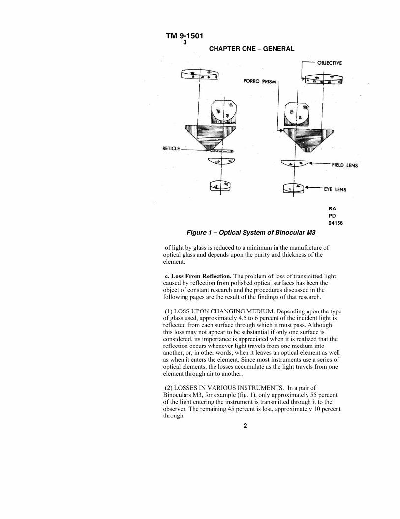
Figure 1 – Optical System of Binocular M3
of light by glass is reduced to a minimum in the manufacture ofoptical glass and depends upon the purity and thickness of theelement.
c. Loss From Reflection. The problem of loss of transmitted lightcaused by reflection from polished optical surfaces has been theobject of constant research and the procedures discussed in thefollowing pages are the result of the findings of that research.
(1) LOSS UPON CHANGING MEDIUM. Depending upon the typeof glass used, approximately 4.5 to 6 percent of the incident light isreflected from each surface through which it must pass. Althoughthis loss may not appear to be substantial if only one surface isconsidered, its importance is appreciated when it is realized that thereflection occurs whenever light travels from one medium intoanother, or, in other words, when it leaves an optical element as wellas when it enters the element. Since most instruments use a series ofoptical elements, the losses accumulate as the light travels from oneelement through air to another.
(2) LOSSES IN VARIOUS INSTRUMENTS. In a pair ofBinoculars M3, for example (fig. 1), only approximately 55 percentof the light entering the instrument is transmitted through it to theobserver. The remaining 45 percent is lost, approximately 10 percentthrough
2
TM 9-1501 3–4
INTRODUCTION
absorption and approximately 35 percent because of reflection. The greaterthe number of optical elements within a given instrument, the greater the lossof transmitted light. This loss assumes prohibitive proportions in suchinstruments as the Height Finder M1 in which only approximately 15 percentof the incident light is transmitted through to the observer.
d. Effects of Internal Reflections. Light which is reflected from thesurfaces of optical elements is not only lost for the human eye in viewing atarget, but causes very undesirable effects in the image. Light reflected fromone glass surface may be reflected back toward its original direction by anothersurface. Such internal reflections do not, in general, come to a focus in theimage plane, but cause diffuse illumination of the image. This results in lesscontrast between the image and its apparent background than would beobtained from a reflection free system.
4. EFFECTS OF COATING.
a. The purpose of coating optical elements is to reduce the undesirableeffects of surface reflection in fire control instruments by applying areflection reducing film on the surfaces of optical elements.
b. Increase in Light Transmission. The main advantage of coating is theincrease of transmitted light resulting in better visibility of targets.
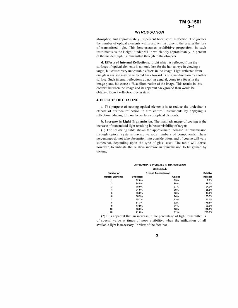
(1) The following table shows the approximate increase in transmissionthrough optical systems having various numbers of components. Thesepercentages do not take absorption into consideration, and of course will varysomewhat, depending upon the type of glass used. The table will serve,however, to indicate the relative increase in transmission to be gained bycoating.
APPROXIMATE INCREASE IN TRANSMISSION(Calculated)
Number of Over-all Transmission Relative Optical Elements Uncoated Coated Increase
1 92.0% 99% 7.6% 2 84.5% 98% 16.0% 3 78.0% 97% 24.3% 4 71.6% 96% 35.5% 5 66.0% 95% 44.0% 6 60.5% 94% 55.5% 7 55.7% 93% 67.0% 8 51.3% 92% 79.5% 9 47.2% 91% 93.0%
10 45.5% 90% 100.0% 20 21.6% 81% 279.0%
(2) It is apparent that an increase in the percentage of light transmitted isof special value at times of poor visibility, when the utilization of allavailable light is necessary. In view of the fact that
3
TM 9-15014
CHAPTER ONE – GENERAL
military operations are preferably conducted under the protection of poor visibility, theadvantages of coating are of paramount importance in military instruments. At dawn anddusk this advantage may permit accurate observation of targets for an additional 15 to 30minutes which would be impossible with uncoated instruments.
c. Reduction of Haze. Another important advantage of coating is the reduction ofhaze. The reason for this condition in an uncoated instrument was discussed in paragraph3 d. Scattered rays of internally reflected light cause loss of brilliancy and contrast.Coating reduces internal reflections and thereby minimizes the formation of such a veil ofstray light and restores the brilliancy and contrast of the original image. This conditionbecomes most apparent when there is an abundance of light and thus renders the use ofcoated instruments more advantageous at mid-day as well as at dawn and dusk.
d. Reduction of "Ghost" Images. When looking through an observation instrument
during darkness at a bright target such as a burning house, or an object illuminated by flare
light, it can often be noted that a series of images rather than one image appears before the
eye of the observer. These so-called "ghost" images are also caused by internal reflections
which produce images slightly out of focus and somewhat less bright than the image in
focus, but still noticeable and very distracting to the observer. By reducing internal
reflections, coating greatly reduces the formation of "ghost" images. The greatest value ofthis advantage will be obtained at night, although the condition also exists to a less
apparent degree during the day.
e. Reduction of Reflection From Front Surfaces. It is a common experience of fieldpersonnel that reflections from the front surface of optical instruments constitute an actualhazard since such reflections tend to give the observer's position away. Ordinary glassessuffer the same disadvantage, although not to the extent of polished glass surfaces whichoffer a much more noticeable target. The reduction of front surface reflections byapplication of coating will thus reduce the danger of detection although it offers onlylimited protection.
f. Protective Coating of Optical Mirrors. The coating material is sometimes appliedto front surface optical mirrors as a protective covering for sensitive metallic mirrorsurfaces. The film applied in this case must be of greater thickness than that used forreflection reduction since the properties of the coating depend upon its thickness, and itsantireflection properties are destroyed by the application of too thick a film.
4
TM 9-15015–6
THEORY OF REFLECTION REDUCING FILMS
5. DISADVANTAGES OF COATING.a. Optical Disadvantages. It is essential to remember that there are no optical
disadvantages of coating. Even a comparatively inefficient coating or one that is partlyremoved is better than no coating at all. Except in the case of mirror coatings which if toothin might possess undesirable antireflection properties, the poorest coating can neverlower the optical efficiency of an element. A coating, therefore, should never be removed,even if it has partially deteriorated, unless recoating facilities are available.
b. Disadvantages Arising From Production Problems. The only disadvantages ofcoating are encountered in the production of coated optical elements which requires anadditional complicated and difficult manufacturing process. In instrument repair work,every compound element must be decemented when recoating is necessary and thisadditional handling increases the danger of damaging optical elements. Also heat appliedto optical elements in the coating process may result in the cracking of elements if theheat is improperly applied. Improper operation may further result in the spattering ofoptical components by small particles of the coating material. However, thesedisadvantages may be minimized if the correct procedures are followed by thoroughlytrained and skilled personnel.
Section II
THEORY OF REFLECTION REDUCING FILMS
6. HISTORY OF FILMS.a. In 1892, Harold Dennis Taylor, a famous English lens designer, discovered that an
old, badly tarnished photographic lens transmitted more light than a new lens. He wasaware of the fact that the reason for this increase was to be found in the patina which hadformed on the lens surface and tried to produce such a film artificially. The results ofthese efforts were rather unsatisfactory since he did not know the exact nature of areflection reducing film.
b. Taylor's discovery, however, was the starting point for a long series ofinvestigations of this phenomenon. The first definite progress was made in January 1936with the publication of an article called "On a Method of Decreasing the Reflection FromNon-Metallic Surfaces." It was explained that the phenomenon observed in Taylor'starnished lens was due to interference of two light waves and that a reflection reducingfilm must create a state of interference between the light waves reflected from the film-glass surface and the waves from the air-film surface.
5
TM 9-15016–7
CHAPTER ONE – GENERAL
RA PD 94135
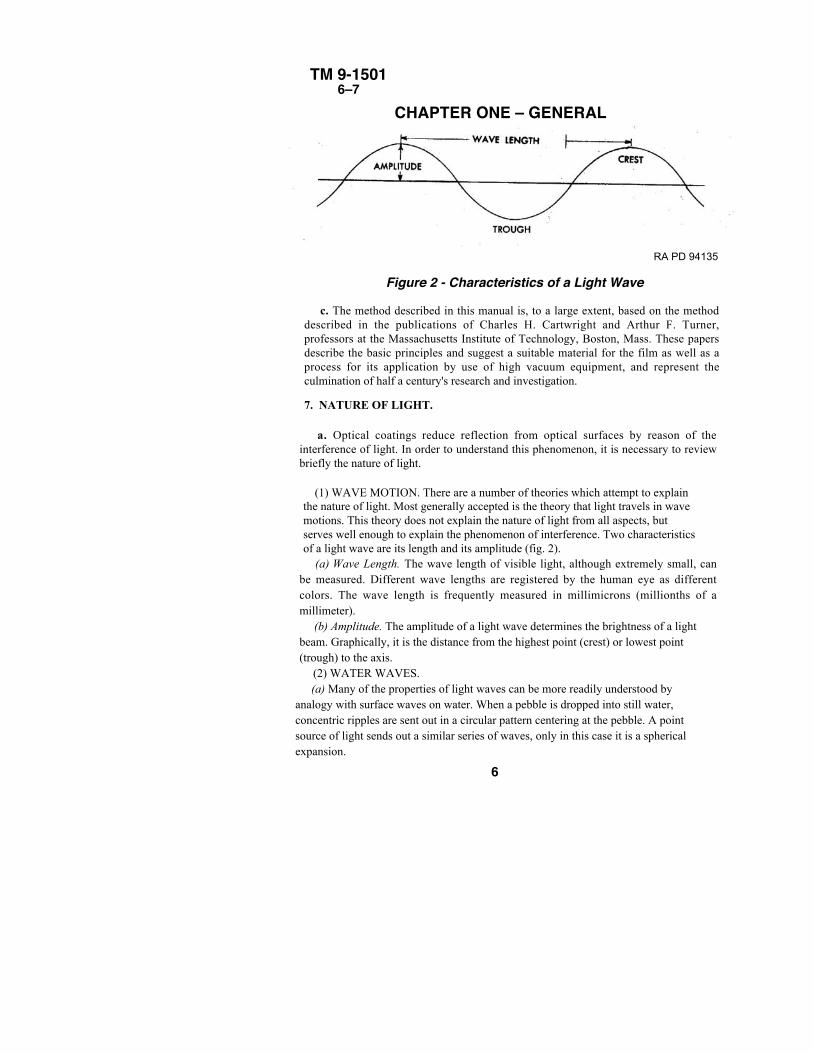
Figure 2 - Characteristics of a Light Wave
c. The method described in this manual is, to a large extent, based on the methoddescribed in the publications of Charles H. Cartwright and Arthur F. Turner,professors at the Massachusetts Institute of Technology, Boston, Mass. These papersdescribe the basic principles and suggest a suitable material for the film as well as aprocess for its application by use of high vacuum equipment, and represent theculmination of half a century's research and investigation.
7. NATURE OF LIGHT.
a. Optical coatings reduce reflection from optical surfaces by reason of theinterference of light. In order to understand this phenomenon, it is necessary to reviewbriefly the nature of light.
(1) WAVE MOTION. There are a number of theories which attempt to explainthe nature of light. Most generally accepted is the theory that light travels in wavemotions. This theory does not explain the nature of light from all aspects, butserves well enough to explain the phenomenon of interference. Two characteristicsof a light wave are its length and its amplitude (fig. 2).
(a) Wave Length. The wave length of visible light, although extremely small, canbe measured. Different wave lengths are registered by the human eye as differentcolors. The wave length is frequently measured in millimicrons (millionths of amillimeter).
(b) Amplitude. The amplitude of a light wave determines the brightness of a lightbeam. Graphically, it is the distance from the highest point (crest) or lowest point(trough) to the axis.
(2) WATER WAVES.(a) Many of the properties of light waves can be more readily understood by
analogy with surface waves on water. When a pebble is dropped into still water,concentric ripples are sent out in a circular pattern centering at the pebble. A pointsource of light sends out a similar series of waves, only in this case it is a sphericalexpansion.
6
TM 9-15017–8
THEORY OF REFLECTION REDUCING FILMS(b) When two pebbles are dropped into still water, two systems of waves will pass over
the surface of the water, each producing its own displacement of the surface independentlyof the other. The resultant displacement of the surface is obtained by summing the twoseparate displacements.
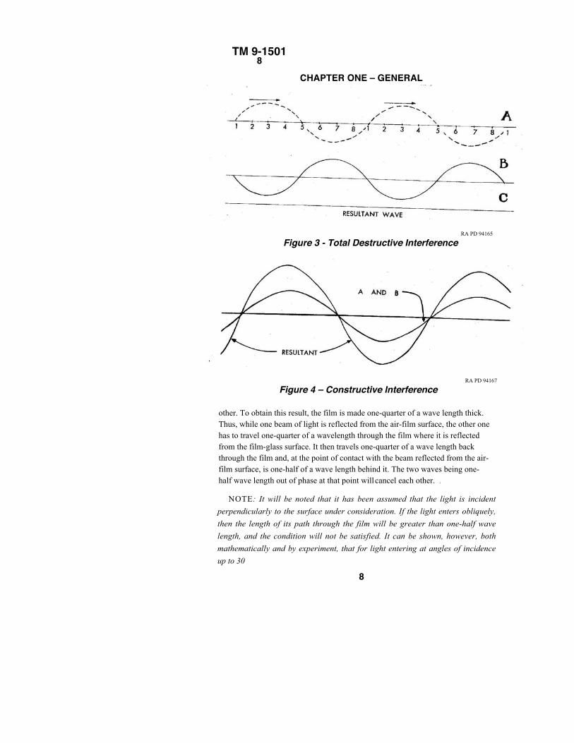
(3) INTERMINGLING LIGHT WAVES. Light waves may be considered to act in thesame way as the water waves discussed above. Two waves of equal wave length can add upto zero (fig. 3), or to an augmented wave (fig. 4), with a continuous variation between (fig.5), depending on the "phase" relation. The phase relation of two waves refers to the positionof their crests and troughs with respect to one another. This phenomenon of two wavesintermingling with each other is called interference.
(a) In the case shown in figure 3, the displacement of wave B with respect to wave Aamounts to one-half of a wave length. The resultant amplitude is zero since the crest of onewave coincides with the trough of the other wave. Since the amplitude determines theintensity of the light (the intensity being the square of the amplitude) and the amplitude inthis case is zero, the intensity is also zero which means that there is no light. This is knownas total destructive interference.
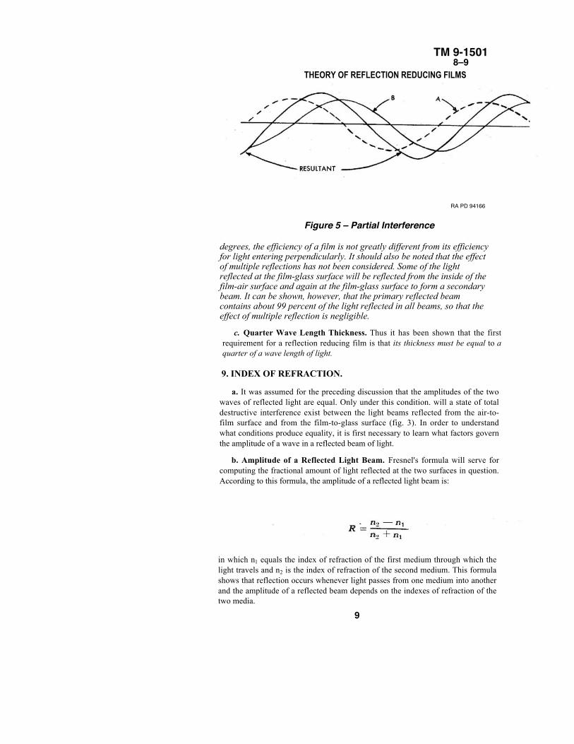
(b) In the case shown in figure 4, the crests and troughs of both waves coincide. The twowaves reinforce each other and the resultant wave has an amplitude twice that of each ofthe two component waves. The intensity of the resultant wave is therefore increased.
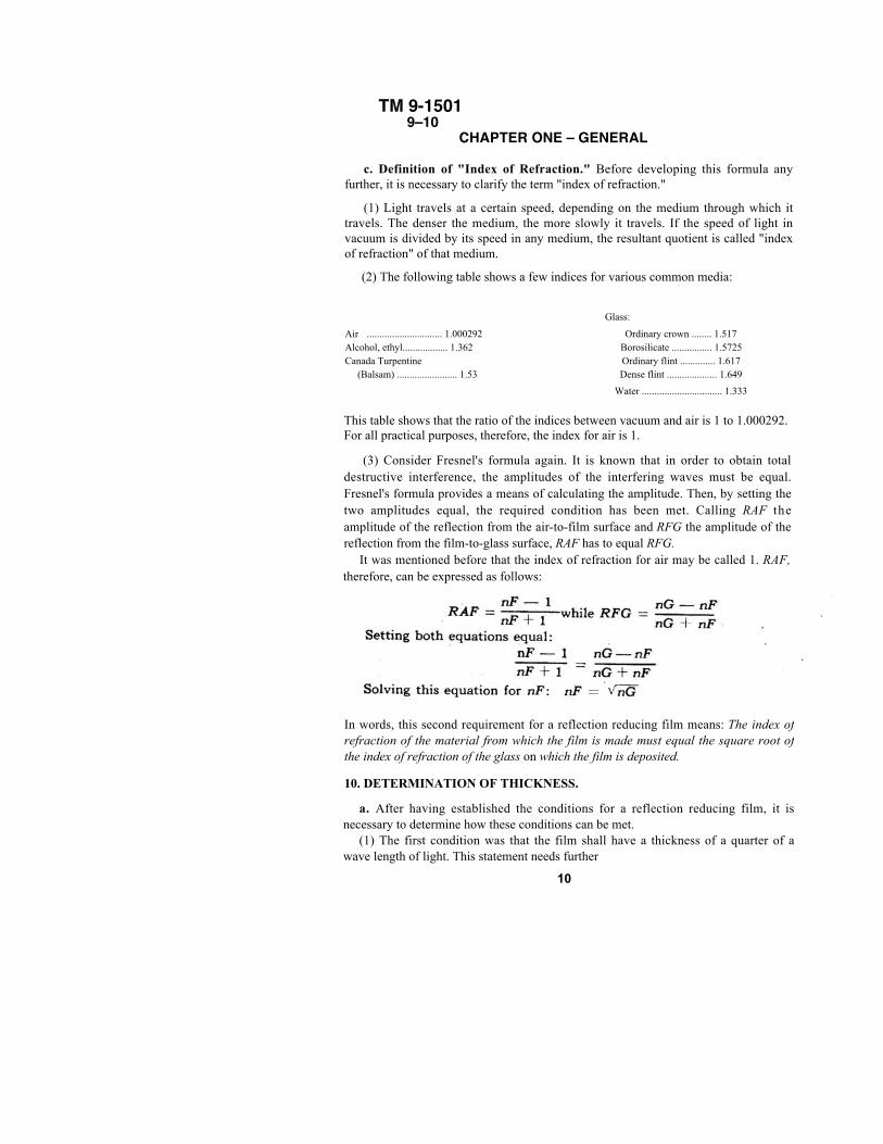
(c) Figures 3 and 4 represent the two extreme possibilities. Any other phase relation willresult in partial interference where the resultant wave can be found by adding algebraicallythe amplitude of both waves (fig. 5).
8. THICKNESS OF FILM.
a. Relation of Interference to Coating. The phenomenon of interference is utilized forreducing the reflected light from optical glass surfaces. By applying a thin transparent film tothe optical surface, light will be reflected both by the film surface and the glass beneath. Thephase relation of these two reflected beams must now be arranged so that a state of totaldestructive interference is created, which will result in the elimination of both as shown infigure 3.
b. Phase Relation. The phase relation between the reflection from the air-film surfaceand that from the film-glass surface must be so arranged that the latter is displaced half awave length from the former. Thus, when they intermingle above the surface of the film,they will be a half wave length out of phase and cancel each
7
TM 9-15018
CHAPTER ONE – GENERAL
RA PD 94165
Figure 3 - Total Destructive Interference
RA PD 94167
Figure 4 – Constructive Interference
other. To obtain this result, the film is made one-quarter of a wave length thick.Thus, while one beam of light is reflected from the air-film surface, the other onehas to travel one-quarter of a wavelength through the film where it is reflectedfrom the film-glass surface. It then travels one-quarter of a wave length backthrough the film and, at the point of contact with the beam reflected from the air-film surface, is one-half of a wave length behind it. The two waves being one-half wave length out of phase at that point will cancel each other. .
NOTE: It will be noted that it has been assumed that the light is incident
perpendicularly to the surface under consideration. If the light enters obliquely,
then the length of its path through the film will be greater than one-half wave
length, and the condition will not be satisfied. It can be shown, however, both
mathematically and by experiment, that for light entering at angles of incidence
up to 30
8
TM 9-15018–9
THEORY OF REFLECTION REDUCING FILMS
RA PD 94166
Figure 5 – Partial Interference
degrees, the efficiency of a film is not greatly different from its efficiencyfor light entering perpendicularly. It should also be noted that the effectof multiple reflections has not been considered. Some of the lightreflected at the film-glass surface will be reflected from the inside of thefilm-air surface and again at the film-glass surface to form a secondarybeam. It can be shown, however, that the primary reflected beamcontains about 99 percent of the light reflected in all beams, so that theeffect of multiple reflection is negligible.
c. Quarter Wave Length Thickness. Thus it has been shown that the firstrequirement for a reflection reducing film is that its thickness must be equal to aquarter of a wave length of light.
9. INDEX OF REFRACTION.
a. It was assumed for the preceding discussion that the amplitudes of the twowaves of reflected light are equal. Only under this condition. will a state of totaldestructive interference exist between the light beams reflected from the air-to-film surface and from the film-to-glass surface (fig. 3). In order to understandwhat conditions produce equality, it is first necessary to learn what factors governthe amplitude of a wave in a reflected beam of light.
b. Amplitude of a Reflected Light Beam. Fresnel's formula will serve forcomputing the fractional amount of light reflected at the two surfaces in question.According to this formula, the amplitude of a reflected light beam is:
in which n1 equals the index of refraction of the first medium through which thelight travels and n2 is the index of refraction of the second medium. This formulashows that reflection occurs whenever light passes from one medium into anotherand the amplitude of a reflected beam depends on the indexes of refraction of thetwo media.
9
TM 9-1501 9–10
CHAPTER ONE – GENERAL
c. Definition of "Index of Refraction." Before developing this formula anyfurther, it is necessary to clarify the term "index of refraction."
(1) Light travels at a certain speed, depending on the medium through which ittravels. The denser the medium, the more slowly it travels. If the speed of light invacuum is divided by its speed in any medium, the resultant quotient is called "indexof refraction" of that medium.
(2) The following table shows a few indices for various common media:
Glass:
Air .............................. 1.000292 Ordinary crown ........ 1.517Alcohol, ethyl.................. 1.362 Borosilicate ................ 1.5725Canada Turpentine Ordinary flint .............. 1.617 (Balsam) ........................ 1.53 Dense flint .................... 1.649
Water ................................ 1.333
This table shows that the ratio of the indices between vacuum and air is 1 to 1.000292.For all practical purposes, therefore, the index for air is 1.
(3) Consider Fresnel's formula again. It is known that in order to obtain totaldestructive interference, the amplitudes of the interfering waves must be equal.Fresnel's formula provides a means of calculating the amplitude. Then, by setting thetwo amplitudes equal, the required condition has been met. Calling RAF theamplitude of the reflection from the air-to-film surface and RFG the amplitude of thereflection from the film-to-glass surface, RAF has to equal RFG.
It was mentioned before that the index of refraction for air may be called 1. RAF,therefore, can be expressed as follows:
In words, this second requirement for a reflection reducing film means: The index ofrefraction of the material from which the film is made must equal the square root ofthe index of refraction of the glass on which the film is deposited.
10. DETERMINATION OF THICKNESS.
a. After having established the conditions for a reflection reducing film, it isnecessary to determine how these conditions can be met.
(1) The first condition was that the film shall have a thickness of a quarter of awave length of light. This statement needs further
10
TM 9-150110–11
THEORY OF REFLECTION REDUCING FILMSspecification because daylight or "white" light, as it is often called, is composed of lightof many different wave lengths, that is, it consists of a mixture of all colors.
(2) If a film is to have a thickness of a quarter of a wave length of light, it must beparticularly specified what wave length of light is meant. The film can have a thickness ofa quarter of a wave length only for a particular color, whereas the condition for othercolors is met only approximately. Thus it is explained why it is impossible to obtain afilm which completely eliminates reflections of white light, and only possible to reducereflections. The only case in which total elimination of reflected light would be possiblewould be that of monochromatic light.
(3) This limitation, however, serves as an excellent guide for the proper thickness. Ifthe film is chosen to meet the requirement for one color, this color will be transmittedclose to 100 percent, whereas the other colors will be transmitted at a slightly lowerpercentage. Therefore, the remaining reflection will be composed of all colors minus theone for which the requirement is fully met. If, for instance, green light is chosen as themost desirable color to be transmitted at a maximum, the remaining reflection will becomposed of white light minus green light, therefore, will appear purple. When coating anoptical element, the change of color in a reflected beam is watched until the color isreached which indicates that the reflection of the one particu1ar color chosen iseliminated. In this way, the color appearance serves as an indication of the thickness ofthe film.
( 4 ) In the preceding discussion, thickness was expressed in terms of portions of awave length. This measurement is called the optical thickness. Since the film is soinfinitesimally thin, it can only be measured optically. If an attempt were made todetermine the thickness mechanically, it would be noted that the film is between three andfour millionths of an inch thick, a value which is impossible to measure mechanically. Tovisualize the dimensions involved, the following comparison can be used: If an individualsheet of the paper on which this manual is printed could be sliced into 500 separate sheetseach the same size but only one five-hundredth as thick as the original page, one of the500 thin sheets would be approximately as thick as the film used for coating.
II. SUITABLE COATING MATERIALS.
a. The second requirement for a reflection reducing film specifies the index ofrefraction of the coating material. In order to meet this requirement many difficulties mustbe overcome since different types of glass used in optical instruments have differentindexes of refraction. To meet this requirement completely, it would therefore be
11
TM 9-1501 11–12
CHAPTER ONE – GENERALnecessary to have a different coating material for each type of glass on which the film isdeposited. This would be highly impractical.
(1) Even the attempt to find a material which meets the requirement for one type ofglass only, cannot meet with complete success since no known material has an index ofrefraction low enough to equal the square root of the index of any of the common types ofoptical glass. Such a material would necessarily have an index of about 1.25.
(2) Here again the requirement can be met only approximately, which is anotherreason why reflections cannot be eliminated but only reduced. One of the most suitablematerials is magnesium fluoride (MgF2) which has an index of refraction of 1.38 and atthe same time possesses the quality of adhering well to glass. It is the most commonlyused coating material and is used in the process described in this manual.
(3) Other materials which have an index of refraction close to that of MgF2 are calciumfluoride, CaF2; sodium fluoride, NaF; and sodium-aluminum-fluoride, Na3AIF6, which isalso shown as cryolite. Some of these latter-named substances have even better opticalproperties, but none of them can be made as adherent as can magnesium fluoride.
12. TYPES OF FILMS AND THEIR IDENTIFICATION.
a. Magnesium Fluoride Film. The most commonly used type of film is made ofmagnesium fluoride by evaporation in high vacuum. This film, however, if applied cold, issoft and is easily removed while in use. This film may be identified by a lavenderappearance of white light reflected from it.
b. High-temperature-baked Magnesium Fluoride Film. If the film described insubparagraph a, above, is deposited on glass which is heated to about 450°F in vacuumbefore the deposition of the film, this film is made durable and cannot be readily removed.It will not deteriorate in normal use. The color appearance of this film is the same as thatdescribed in subparagraph a, above. Its higher resistance to abrasion will distinguish itfrom an unbaked film.
c. Other evaporated films could be made from materials listed in paragraph 11 a (3).They are, however, not in use since they cannot be made durable enough even whenapplied in a vacuum to a heated surface. Only cryolite films have been found on capturedenemy instruments.
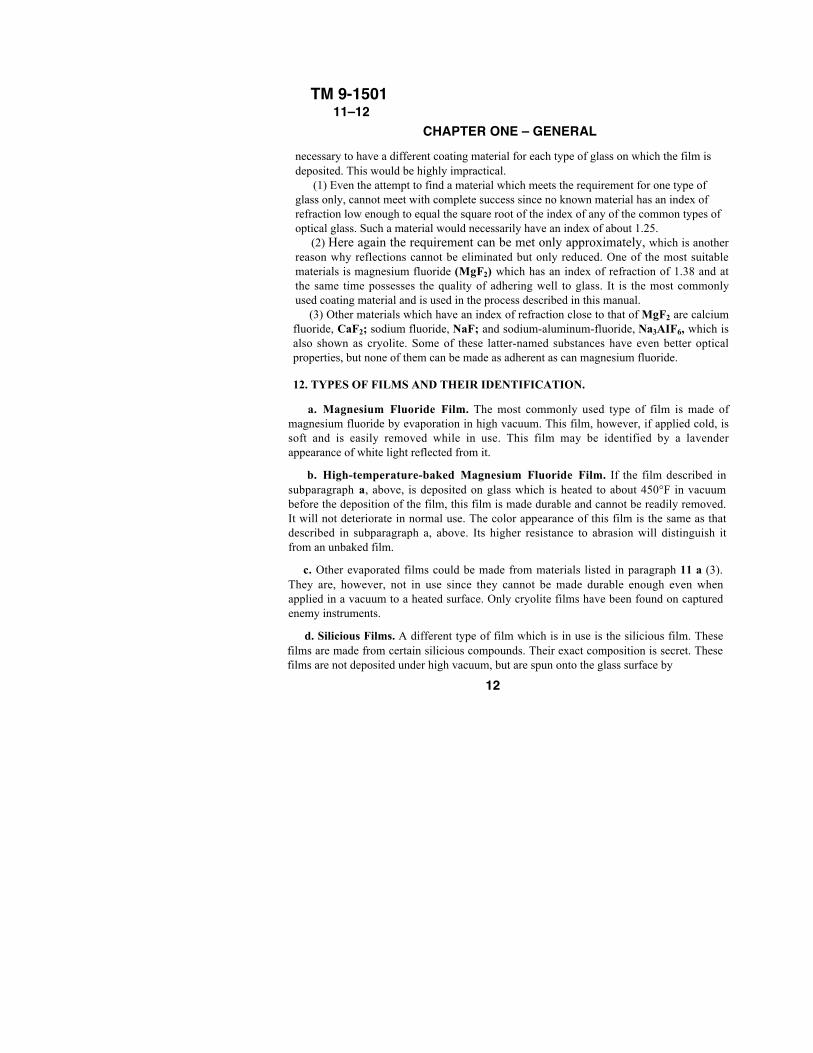
d. Silicious Films. A different type of film which is in use is the silicious film. Thesefilms are made from certain silicious compounds. Their exact composition is secret. Thesefilms are not deposited under high vacuum, but are spun onto the glass surface by
12
TM 9-1501 12
Figure 6 – Machine for Applying Silicious Films13
TM 9-150112–13
C H A P T E R O N E –GENERAL
RA PD 94179
Figure 7 – Decalcomania for Instruments With Coated Opticsmeans of a simple rotating device (fig. 6). The device turns at about 750 revolutions per
minute, and the film is spread over the surface by centrifugal force. These films appear
more saturated in color and of more uneven thickness than a magnesium fluoride film.
Their durability is considerably lower than that of the high-temperature-baked
magnesium fluoride film. A number of Binoculars M3, Telescopes of the M70 Series,
Telescopes, B.C., M65, and Height Finders M1, have this type of coating.
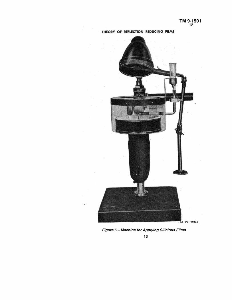
e. Decalcomania: "Coated Optics" (fig. 7). All coated instruments should carry a
decalcomania which reads: "This Instrument Has Coated Optics--Clean Lenses
Carefully” Whenever a coated instrument is found which does not have such a
decalcomania or when coating is applied on a previously uncoated instrument, a
decalcomania should be put on for the purpose of insuring proper handling in the future.
Section IIIOPTICAL PROPERTIES OF FILM
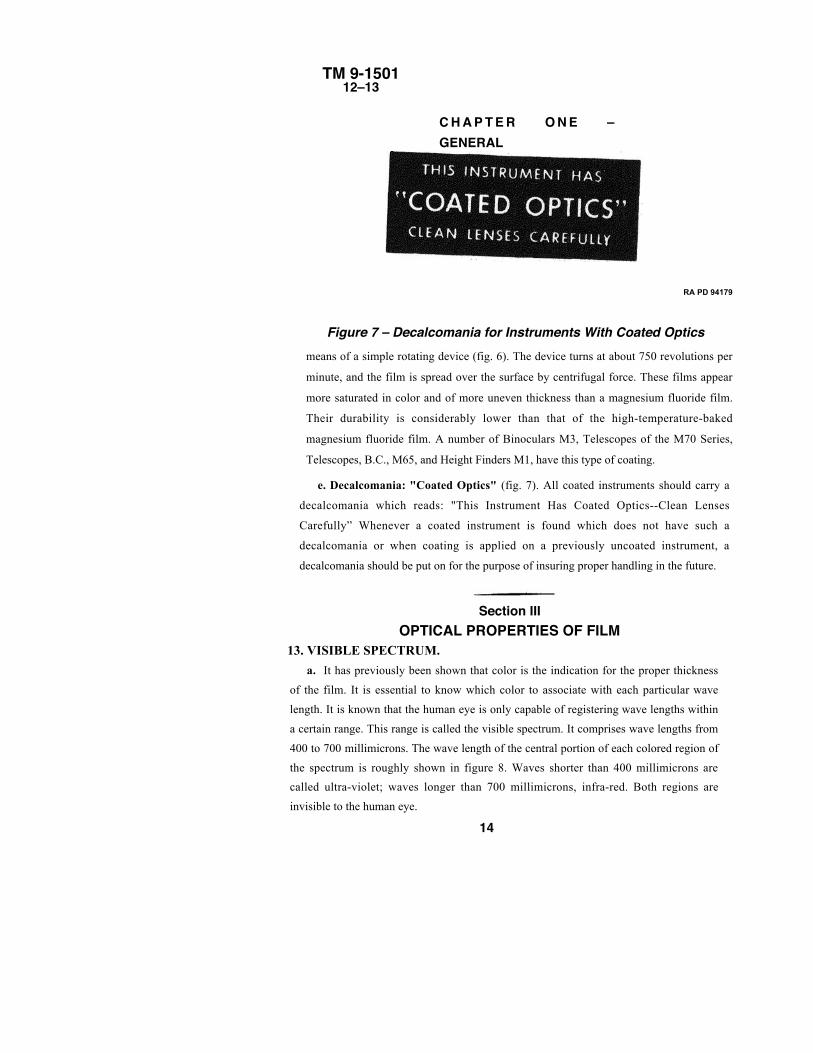
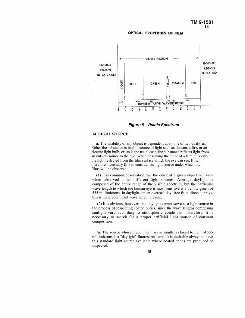
13. VISIBLE SPECTRUM.
a. It has previously been shown that color is the indication for the proper thickness
of the film. It is essential to know which color to associate with each particular wave
length. It is known that the human eye is only capable of registering wave lengths within
a certain range. This range is called the visible spectrum. It comprises wave lengths from
400 to 700 millimicrons. The wave length of the central portion of each colored region of
the spectrum is roughly shown in figure 8. Waves shorter than 400 millimicrons are
called ultra-violet; waves longer than 700 millimicrons, infra-red. Both regions are
invisible to the human eye.
14
TM 9-1501
Figure 8 –Visible Spectrum
14. LIGHT SOURCE.
a. The visibility of any object is dependent upon one of two qualities.Either the substance is itself a source of light such as the sun, a fire, or anelectric light bulb, or, as is the usual case, the substance reflects light froman outside source to the eye. When observing the color of a film, it is onlythe light reflected from the film surface which the eye can see. It is,therefore, necessary first to consider the light source under which thefilms will be observed.
(1) It is common observation that the color of a given object will varywhen observed under different light sources, Average daylight iscomposed of the entire range of the visible spectrum, but the particularwave length to which the human eye is most sensitive is a yellow-green of555 millimicrons. In daylight, on an overcast day, free from direct sunrays,this is the predominant wave length present.
(2) It is obvious, however, that daylight cannot serve as a light source inthe process of inspecting coated optics, since the wave lengths composingsunlight vary according to atmospheric conditions. Therefore, it isnecessary to search for a proper artificial light source of constantcomposition.
(a) The source whose predominant wave length is closest to light of 555millimicrons is a "daylight" fluorescent lamp. It is desirable always to havethis standard light source available where coated optics are produced orinspected.
15
TM 9-150114–15
CHAPTER ONE – GENERAL
(b) If the "daylight" lamp is not available, however, an ordinary yellowishfluorescent lamp may be substituted. It should be kept in mind, however, that thecolor observed under this light source is not the true color and proper allowanceshould be made for this difference when inspecting coated optics.
(c) If no fluorescent light is available, a frosted blue incandescent lamp or, ifthat is not available, an ordinary frosted bulb can be used as long as the coloreffect caused by the improper light source is taken into consideration.
15. EFFICIENCY RANGES OF ONE-QUARTER WAVELENGTH FILMS.
a. Figure 8 shows the colors and their representative wave lengths from whichcan be chosen the wave length for maximum transmission. The light source underwhich these colors should be inspected has also been considered.
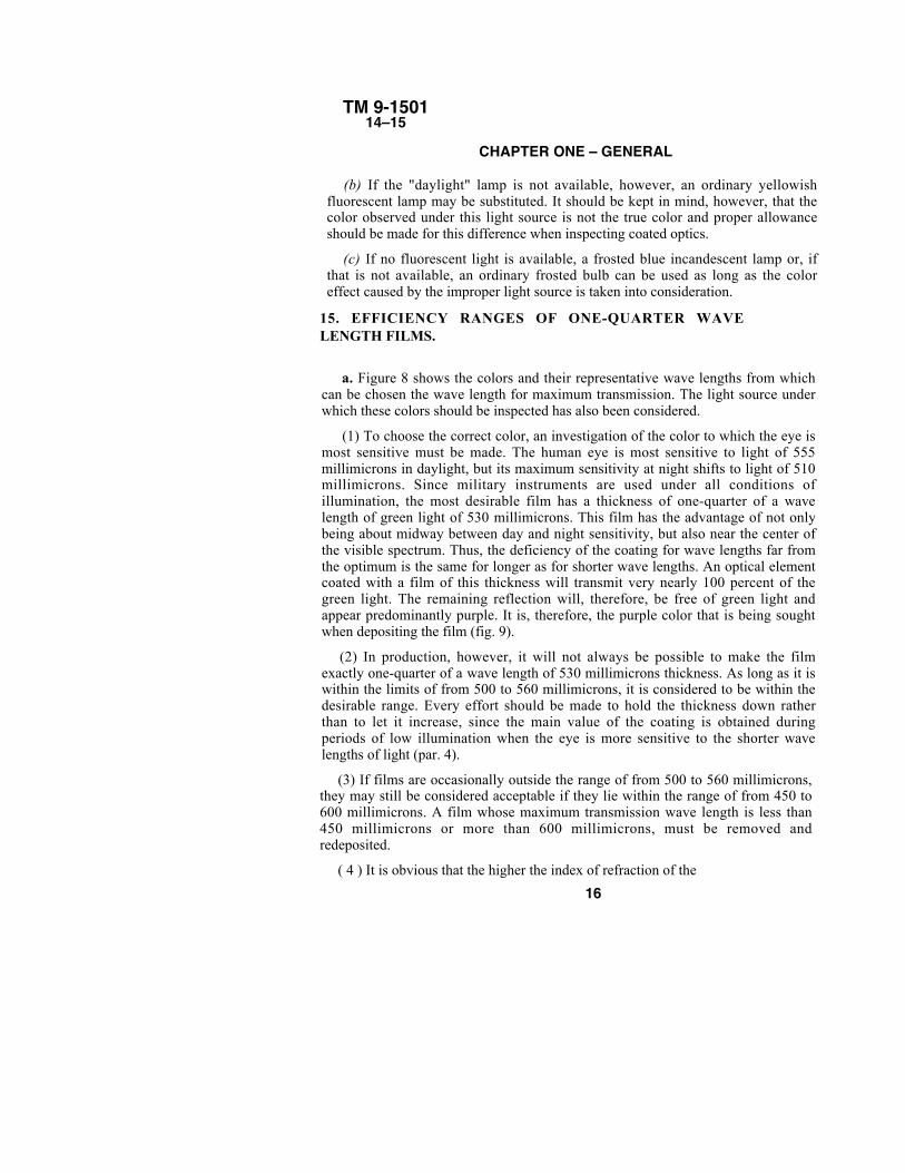
(1) To choose the correct color, an investigation of the color to which the eye ismost sensitive must be made. The human eye is most sensitive to light of 555millimicrons in daylight, but its maximum sensitivity at night shifts to light of 510millimicrons. Since military instruments are used under all conditions ofillumination, the most desirable film has a thickness of one-quarter of a wavelength of green light of 530 millimicrons. This film has the advantage of not onlybeing about midway between day and night sensitivity, but also near the center ofthe visible spectrum. Thus, the deficiency of the coating for wave lengths far fromthe optimum is the same for longer as for shorter wave lengths. An optical elementcoated with a film of this thickness will transmit very nearly 100 percent of thegreen light. The remaining reflection will, therefore, be free of green light andappear predominantly purple. It is, therefore, the purple color that is being soughtwhen depositing the film (fig. 9).
(2) In production, however, it will not always be possible to make the filmexactly one-quarter of a wave length of 530 millimicrons thickness. As long as it iswithin the limits of from 500 to 560 millimicrons, it is considered to be within thedesirable range. Every effort should be made to hold the thickness down ratherthan to let it increase, since the main value of the coating is obtained duringperiods of low illumination when the eye is more sensitive to the shorter wavelengths of light (par. 4).
(3) If films are occasionally outside the range of from 500 to 560 millimicrons,they may still be considered acceptable if they lie within the range of from 450 to600 millimicrons. A film whose maximum transmission wave length is less than450 millimicrons or more than 600 millimicrons, must be removed andredeposited.
( 4 ) It is obvious that the higher the index of refraction of the
16
TM 9-150115–16
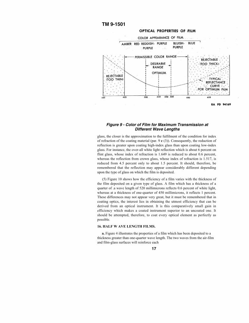
Figure 9 - Color of Film for Maximum Transmission atDifferent Wave Lengths
glass, the closer is the approximation to the fulfilment of the condition for indexof refraction of the coating material (par. 9 c (3)). Consequently, the reduction ofreflection is greater upon coating high-index glass than upon coating low-indexglass. For instance, the over-all white light reflection which is about 6 percent onflint glass, whose index of refraction is 1.649 is reduced to about 0.6 percent,whereas the reflection from crown glass, whose index of refraction is 1.517, isreduced from 4.5 percent only to about 1.5 percent. It should, therefore, beremembered that the reflection may appear considerably different dependingupon the type of glass on which the film is deposited.
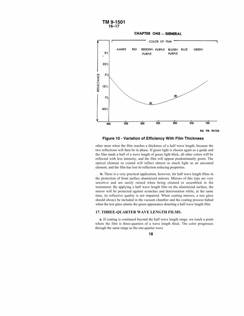
(5) Figure 10 shows how the efficiency of a film varies with the thickness ofthe film deposited on a given type of glass. A film which has a thickness of aquarter of .a wave length of 520 millimicrons reflects 0.6 percent of white light,whereas at a thickness of one-quarter of 450 millimicrons, it reflects 1 percent.These differences may not appear very great, but it must be remembered that incoating optics, the interest lies in obtaining the utmost efficiency that can bederived from an optical instrument. It is this comparatively small gain inefficiency which makes a coated instrument superior to an uncoated one. Itshould be attempted, therefore, to coat every optical element as perfectly aspossible.
16. HALF W AVE LENGTH FILMS.
a. Figure 4 illustrates the properties of a film which has been deposited to athickness greater than one-quarter wave length. The two waves from the air-filmand film-glass surfaces will reinforce each
17
TM 9-150116–17
Figure 10 - Variation of Efficiency With Film Thicknessother most when the film reaches a thickness of a half wave length, because thetwo reflections will then be in phase. If green light is chosen again as a guide andthe film made a half of a wave length of green light thick, all other colors will bereflected with less intensity, and the film will appear predominantly green. Theoptical element so coated will reflect almost as much light as an uncoatedelement, and the film has lost its reflection reducing properties.
b. There is a very practical application, however, for half wave length films inthe protection of front surface aluminized mirrors. Mirrors of this type are verysensitive and are easily ruined when being cleaned or assembled in theinstrument. By applying a half wave length film on the aluminized surface, themirror will be protected against scratches and deterioration while, at the sametime, its reflective quality is not impaired. When coating mirrors, a test glassshould always be included in the vacuum chamber and the coating process haltedwhen the test glass attains the green appearance denoting a half wave length film.
17. THREE-QUARTER WAVE LENGTH FILMS.
a. If coating is continued beyond the half wave length range, we reach a pointwhere the film is three-quarters of a wave length thick. The color progressesthrough the same range as the one-quarter wave
18
TM 9-150111–18
OPTICAL PROPERTIES OF FILMlength film, depending on the particular wave length for which the film is three-fourthsthick. The colors, however, appear deeper, more saturated.
b. In this case, the light must travel three-fourths of a wave length through the filmwhere it is partly reflected from the film-glass surface. It then travels three-fourths of a wavelength back through the film and, at the point of contact with the beam, is reflected from theair-film surface one to one-half wave lengths out of phase.
c. These films, however, are undesirable. The reflection for one wave length of light forwhich the film is three-quarters wave length thick is reduced just as much as in the case of aone-quarter wave length film. However, the reflections for the other wave lengthcomponents of white light are not reduced so much and the over-all transmission of whitelight is less.
18. VARIATIONS IN COLOR.
a. It can sometimes be noticed that coated optics show a variation in color. Variationsmay be noticed among different optical elements which were coated in the same run. In fact,a single element may exhibit a variation in color over its surface for various reasons.
(1) The position of the element in the machine is one of the more frequent reasons. If thedistance from any optical element to the source of coating material is greater than that ofanother element, the thickness and thereby the color will vary. Proper set-up and adjustmentof the coating fixture which is holding the optical elements during the coating process willremedy variations of this nature to a large extent. Very slight variations may be unavoidableand should not be considered serious.
(2) CURVATURE. A very short radius lens or a large flat surfaced prism may sufferfrom the same effect. Care should be exercised to keep the effective aperture of the elementwithin the desirable range.
(3) DIRTY SURFACE. Traces of grease or dirt left on the surface before coating mayalso cause variations in color. Although such spots may not be objectionable from an opticalstandpoint, it is usually an indication of a soft coating at those spots and will be dealt withunder paragraph 20 d.
(4) STAIN. An even stain over the surface of an optical element was the beginning ofcoating research (par. 6 a). It is frequently called "nature's coating." Stains are notobjectionable, although they add to the thickness of the film and must be taken intoconsideration when depositing the film. If the stain, however, is uneven or covers only partof the surface, an attempt should be made to remove it before coating.
19
TM 9-150119
CHAPTER ONE - GENERAL
Section IV
MECHANICAL PROPERTIES OF FILM
19. DURABILITY.
a. The term "durability" is commonly used to describe the ability of a solid substanceto resist wear and tear. Since reflection-reducing films are negligibly thin, however, theterm "durability" will be used in this publication to describe the adherence or tenacity ofthese films.
b. Scope of Durability. It is necessary, first, to explain what durability requirementsthe film must meet. The film shall be sufficiently durable:
(1) So that the instrument can be assembled without damage to the film.
(2) So that adherence is maintained regardless of the atmospheric conditions underwhich the instrument is used. Films are particularly subject to attack by salt atmosphere,moisture, and heat. Shell bursts and explosions often loosen the seal and allow theentrance of air beneath the film with resulting deterioration.
(3) To permit overhaul in the field. Instruments overhauled in the field are frequentlyhandled more roughly than in regular repair shops.
c. Requirements for Producing Hard Film.
(1) HEAT. It was mentioned before that baking of optical elements to about 450° F for30 minutes under vacuum is the principal factor that makes a coating durable.
(2) CLEAN SURFACE. Without an absolutely clean surface, no film will adhere,whatever heat may be applied. It is therefore of utmost importance to remove all traces ofgrease, dirt, or dust before coating is begun.
(3 ) VACUUM. Another prerequisite is that a sufficient degree of vacuum be reachedbefore the film is applied. The vacuum required will be discussed later.
d. Durability Tests.
(1) There are various tests for hardness, some of which can be performed only in alaboratory, such as those which involve exposure to carefully controlled atmosphericconditions over relatively long periods of time.
(2) In base shop installations the necessary apparatus for conducting such tests will notbe available. A simple and very effective way of testing for durability is to rub firmly witha soft grit free rubber eraser, for about 20 cycles (back and forth), over the coated surface.The film should not be removed or scratched by this treatment. This test should be madeon the test piece included in each run.
20
TM 9-150120–21
APPLICATION OF REFLECTION REDUCING FILMSTO MILITARY INSTRUMENTS
20. MECHANICAL DEFECTS.
a. Spattering. One of the most serious difficulties encountered in the coating of opticalelements occurs when small particles of hot magnesium fluoride hit and become imbeddedin the glass. Any such spattering will ruin the optical element. The reason for spatteringmay be impurities in the magnesium fluoride which, upon heating, develop gases whichexpand and drive small chunks of fluoride up to the lens surface. Another cause may bethat the heating filament comes in contact with part of the magnesium fluoride which istherefore heated faster than other parts and driven out of the crucible. Utmost care must betaken to prevent spattering. A protective shield (spatter plate) should be kept over themagnesium fluoride while preheating and for a short while after full heat is turned on tomake sure that no spattering will occur after the shield is removed.
b. Pinholes. Dust particles adhering to the surface will prevent the area which theycover from being coated. Cleanliness will prevent this defect. A few pinholes widelyscattered over the surface may be tolerated since they merely increase the reflection anegligible amount.
c. Scratches. Scratches may indicate a soft coating and appropriate tests should bemade. If the coating is hard, minute scratches in the form of hairlines may be toleratedsince they, too, merely increase the reflection by a negligible amount.
d. Irregular Blotches, Blemishes, and Streaks. These are sometimes an indication of adirty surface. In this case, the film should always be removed and another applied. If they arecaused by a stain and the stain cannot be removed, they must be tolerated.
Section VAPPLICATION OF REFLECTION REDUCING FILMS
TO MILITARY INSTRUMENTS
21. INSTRUMENTS WITH COATED OPTICS.
a. Practically all fire control instruments produced since March 1944 and many of theinstruments produced during 1943 have coated optical elements.
b. These instruments include:
Binoculars M3, M7, MI5, M16, and M17; some Binoculars M3 have soft coatings, whileothers may have silicious coatings. Elbow Telescopes MIAI, M6AI, M61, M75C, andM75D. B.C. Telescopes M65.
21
TM 9-150121–22
CHAPTER ONE - GENERAL
Telescopes–all telescopes of the M70 series and many others. Periscopes M10and T8.Height Finders M 1 (some).Range Finders M7 and M9.Azimuth Instruments Ml.Aiming Circles M1.Observation Telescopes M49.Panoramic Telescopes M1, M6, some M8, M12, and T115.
c. It will be the responsibility of the coating facilities in base shops to coat:(1) All instruments which have not previously been coated.(2) All instruments that have previously been coated but whose coating has
deteriorated.
22. DETERMINATION OF ELEMENTS TO BE COATED.
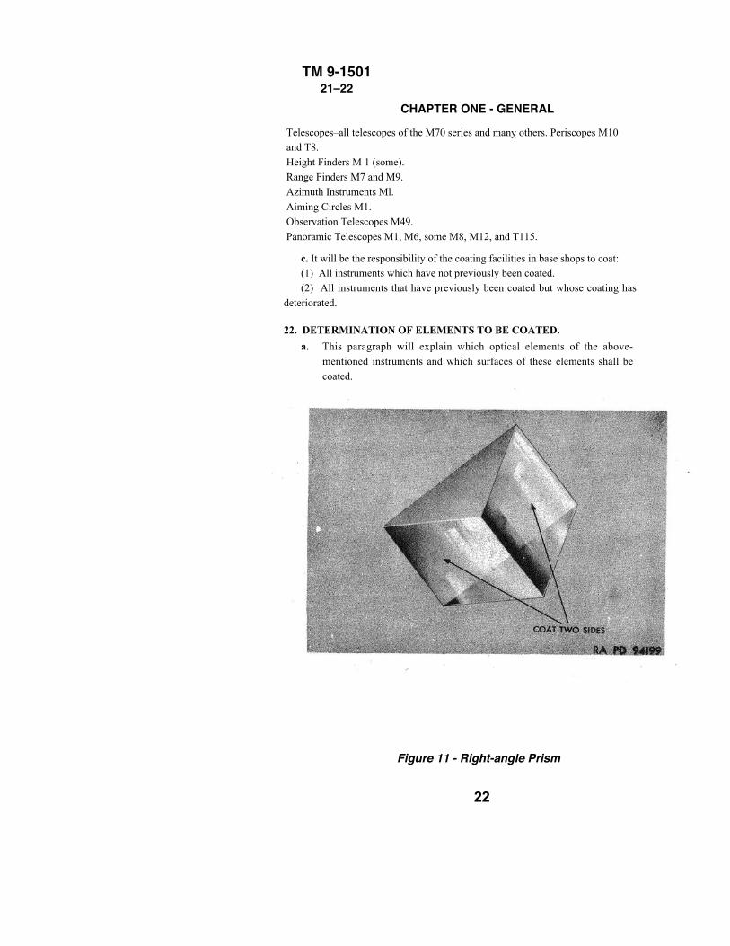
a. This paragraph will explain which optical elements of the above-mentioned instruments and which surfaces of these elements shall becoated.
Figure 11 - Right-angle Prism
22
TM 9-150122
23
TM 9-150122
24
TM 9-150122
b. Lenses.
(1) All glass-air surfaces of lenses are coated, except in the occasional instanceswhere a reticle is etched on a lens.
(2) COMPOUND LENSES. Compound lenses must be decementedbefore coating. For procedures of decementing and recementing, see chapter4. Decemented lenses must be clearly marked on the edge with indeliblepencil or crayon, indicating which is the cemented side. Cemented sides arenot coated. Usually the steepest side of a double convex lens and theconcave side of a meniscus diverging lens are cemented together in acompound lens. Lenses decemented for coating should be kept together inpairs at all times.
(a) Windows. Windows are coated on both sides.
(b) Filters. Filters are not to be coated.
(c) Reticles. Reticles are not to be coated.(d) Wedges. Wedges are coated on both sides. Note whether wedges areachromatic, that is, composed of two elements cemented together. If so,do not coat, as the recementing requires special fixtures which are notavailable.
25
TM 9-1501 22
26
TM 9-150122
27
TM 9-150122
28
TM 9-150122
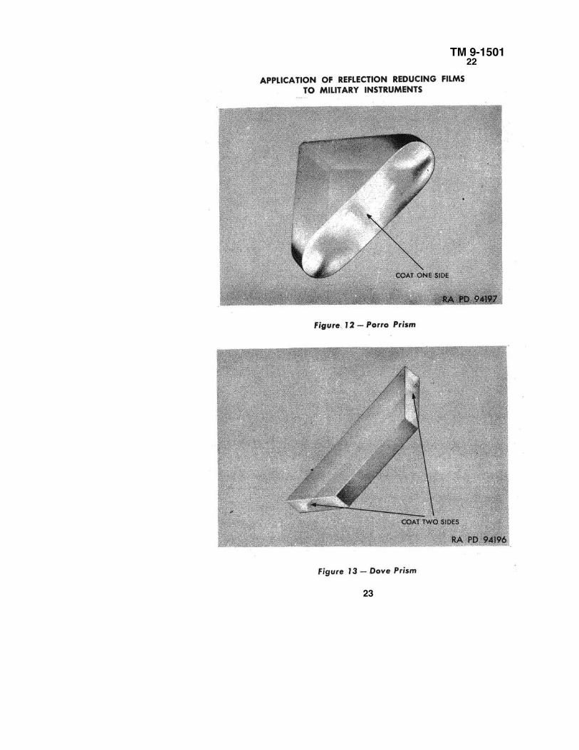
(e) Prisms.1. Prisms are coated on all surfaces through which light is transmitted,with the exceptions noted in steps 3 i and j, below.2. Silvered prisms. Silvered sides are not to be coated.3. Identification of surfaces:a. Right-angle prisms are used in panoramic telescopes, periscopes,
and B.C. telescopes (fig. 11).b. Porro prisms are used in binoculars and observation telescopes.
NOTE: Porro prisms have the same general shape as right-angleprisms. They can be distinguished by rounded corners (fig. 12).
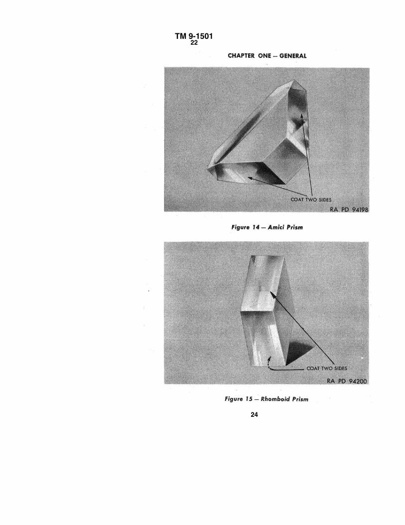
c. Dove prisms are used in panoramic telescopes (fig. 13).d. Amici roof prisms are used in panoramic telescopes and elbow
telescopes (fig. 14).e. Rhomboid prisms are used in range finders and height finders
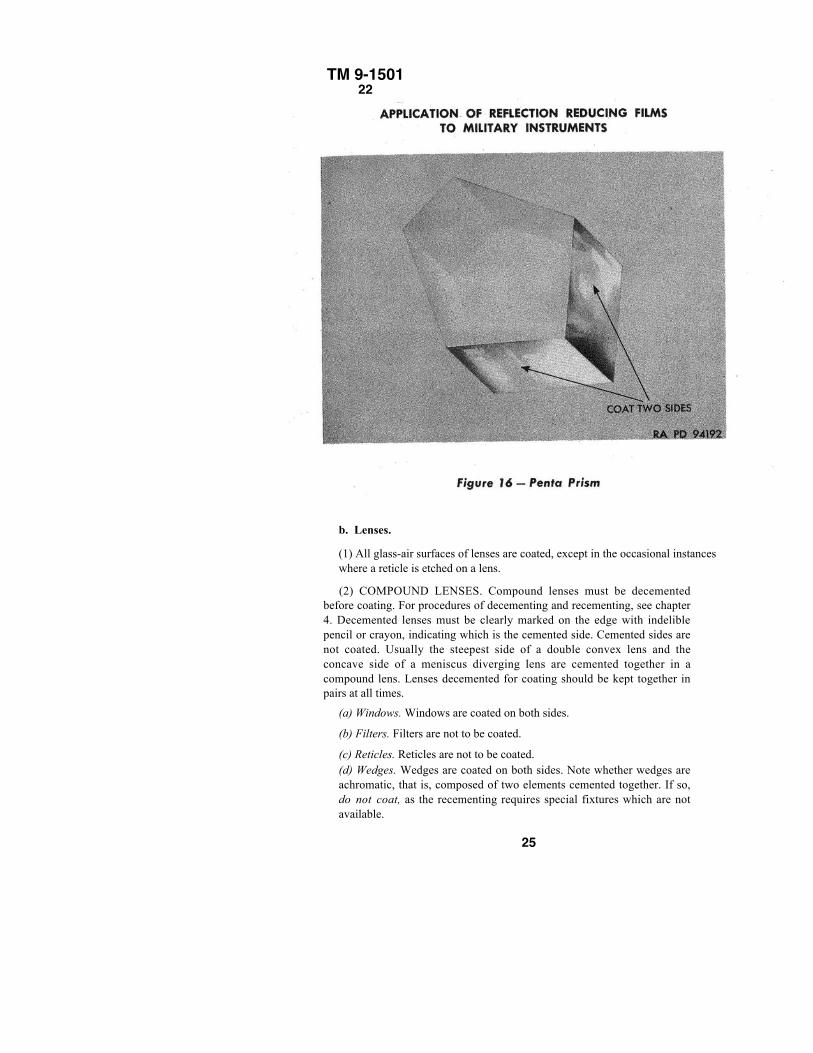
(fig. 15).f. Penta prisms are used in range finders and AA BC telescopes
(fig. 16).
29
TM 9-150122
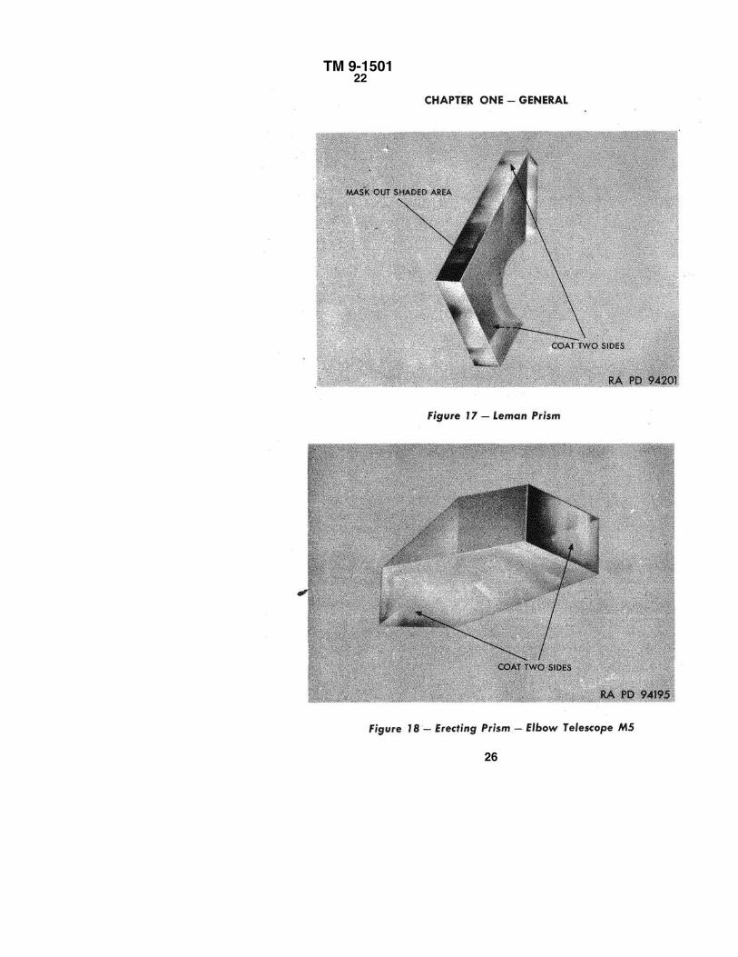
CHAPTER ONE – GENERALg. Leman prisms are used in telescopic sights (fig. 17).
h. Erecting prisms are used in Elbow Telescope M5 (fig. 18).
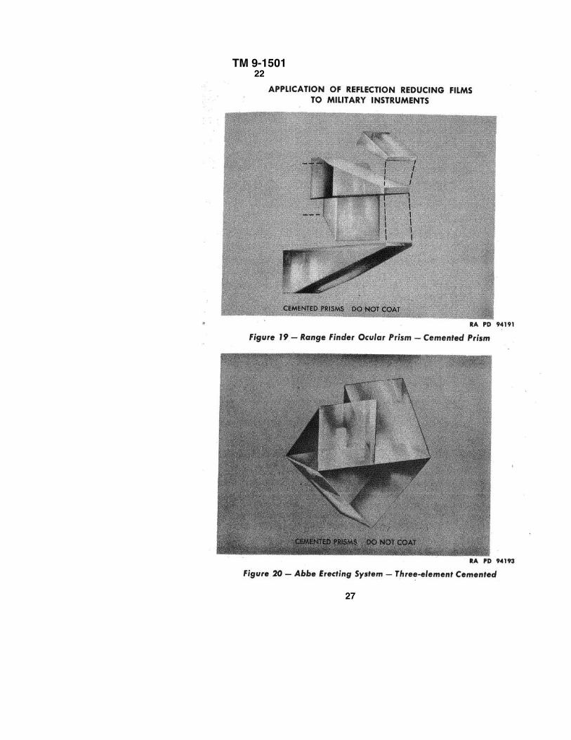
i. Range tinder ocular prisms must not be coated because they are cemented and require
special fixtures for adjustment and recementing (fig. 19). .
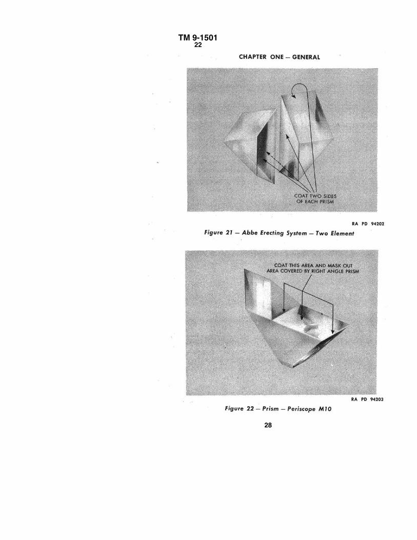
j. Abbe erecting systems are used in straight tube telescopes. NOTE: There are two types
of Abbe erecting systems requiring different treatment as indicated below:
Type I – The three-element Abbe erecting system is not to be coated because of the
difficulties encountered when the elements must be recemented (fig. 20).
Type II – Two-element Abbe erecting systems may be coated as shown in figure 21.
k. Erecting prisms are used in the Periscope M10 (fig. 22).
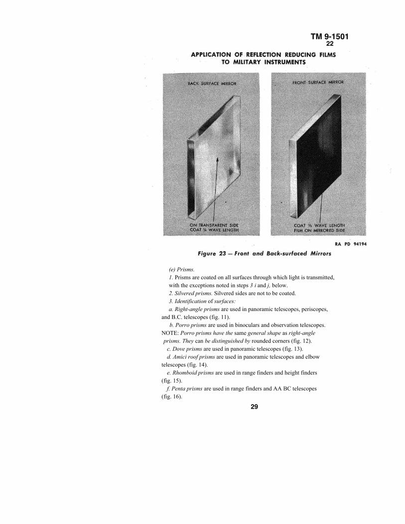
(f) Mirrors. Mirrors whose front surface are metal plated and reflect the light from the
front surface are to be coated with a half wavelength film (par. 16).
(g) Optical elements whose back surfaces are mirror plated are not to be coated on theplated surface. However, the light transmitting surfaces will be coated in the normal manner(fig. 23).
30
TM 9-150123–24
CHAPTER 2THE COATING PROCESS
Section I
INTRODUCTON
23. APPLICATION OF MAGNESIUM FLUORIDE FILMS.
a. The process of applying high-temperature-baked magnesium fluoridefilms involves the use of a vacuum chamber and most of the problemsencountered in the process are those common to high vacuum work. Thevacuum system which is used for the coating process is a kinetic system. Insuch a system, the pumps are constantly operating. No effort is made to sealthe system absolutely against leaks or to completely outgas (par. 26) thecomponents. The required degree of vacuum in a kinetic system ismaintained by the high-evacuating capacity of the pumps. If, at the vacuumpressure desired, the pumps can remove gases as fast as or faster than theyaccumulate, the system will operate satisfactorily. It does not follow that itis needless to worry about leaks in a kinetic system. It is easy for leaks todevelop which are beyond the capacity of the pumps to neutralize, and suchleaks must be located and sealed. However, the slow seepage of gasesthrough and around gaskets and even through the walls of the vacuumchamber are immaterial if the proper vacuum can be maintained. It shouldbe remembered that all high vacuum systems are very sensitive and must beregarded as such. Any foreign matter inside the vacuum system, even insmall quantities, increases the vapor pressure (par. 27) and contaminates thesystem, thereby reducing the operating efficiency. .
24. VACUUMPUMPS.
a. Modern mechanical pumps are quite fast, but they are unable toprovide a vacuum sufficient for optical coating work. To obtain the highervacuum required for coating work, a diffusion pump is used. The operationof a diffusion pump is quite different from that of a mechanical pump. Theevacuating capacity of a diffusion pump is high and the limiting pressure islow; however, it can operate only against a small differential of pressure. Inother words, the pressure at the exhaust port can be only slightly higherthan the pressure at the entrance port. For this reason, the diffusion pump isconnected so that it exhausts into the mechanical pump which in turnexhausts into the atmosphere. Diffusion pumps are of the mercury or oiltype. In general, the oil diffusion pump is faster than the mercury type. The
31
TM 9-150l24–27
CHAPTER TWO – THE COATING PROCESSdiffusion pump used with the coating unit is the oil type and has a limiting pressure, whenbacked up by a mechanical pump, at 10-5 mm.
25. PUMPING SPEEDS.
a. If a perfect vacuum is connected to the atmosphere by an aperture one squarecentimeter in area, air will enter the vacuum at the rate of 11.7 liters per second. No vacuumpump can pump air at a speed in excess of this when operating against atmospheric pressure,but most pumps approach it very closely. The speed factor of a pump is the ratio of itsevacuating rate to the value of 11.7 liters per second per square centimeter. The diffusionpump used with the coating unit has a speed factor of 0.25, while the mechanical pump has aspeed factor of 0.04. The evacuating rate of a pumping system depends upon the connectionsand apertures used in the system. For efficient operation, all air connections, such as pipesand tubing, must be as short in length and as large in diameter as possible, since long pipesand small apertures offer a resistance to the flow of air.
26. "OUTGASSING."
a. All objects contain dissolved gases. There is also a surface film of moisture, gases, andother materials on the objects. When the atmospheric pressure is removed, as in a vacuumchamber, these absorbed and surface materials' are released slowly by a process similar toevaporation. This "outgassing" is accelerated under high temperature. Prolonged heating willdrive off virtually all of these materials. Thus, it is evident that in any vacuum system, therewill be a continuous evolution of gas until the components are thoroughly "outgassed" byprolonged heating. When these objects are again exposed to atmospheric pressure, they willpick up these materials. However, unless the objects are exposed to the atmosphere for aconsiderable period, they will "outgas" much more readily when again placed in the vacuum.In a kinetic vacuum system the pumps can usually keep ahead of this "outgassing." Theremay be times when the pumps cannot exhaust the gases as fast as they are "outgassed" by theitems within the vacuum chamber. When this occurs, the pressure will momentarily risecausing a "virtual leak."
27. VAPOR PRESSURES.
a. As prescribed in appendix 1, paragraph 23, all substances, including solids, evaporate.The rate of evaporation depends upon the vapor pressure of the substance which increaseswith the temperature, and the partial pressure of the evaporated substance in theneighborhood. The partial pressure of a gas is that part of the total pressure due to all gaseswhich is attributable to the gas in question. Thus, the air is composed of oxygen, nitrogen,helium, and other gases, each existing
32
TM 9-150127–29
DESCRIPTION OF THE COATING UNITat a particular pressure. The sum of all these partial pressures is the pressureof the atmosphere. In the neighborhood of an evaporating substance, some ofthe gas present will consist of evaporated molecules of the substance itself,and this will exert its own partial pressure. When the partial pressure of thesubstance equals its vapor pressure at the existing temperature, theevaporated molecules will be condensing at the same rate new molecules arebeing evaporated, and there will be no change in the partial pressure and nonet emission of gas from the substance. If, however, the gas pressure isconstantly being reduced by pumps, there will be a continuous evaporationwhenever the gas pressure is less than the vapor pressure. It can be seen fromthe foregoing discussion that the substances exposed in a vacuum must havea vapor pressure lower than the desired vacuum pressure. The vaporpressures of metal and glass are quite low so that no trouble will beexperienced in the vacuum system used for coating optical elements.However, special care must be taken in the selection of sealing compounds,waxes, and cements to assure that there are no high vapor pressureconstituents present. Dust and dirt must be excluded from the vacuum systemsince their vapor pressures are not as low as the vacuum pressure at which thesystem must operate.
Section II
DESCRIPTION OF THE COATING UNIT
28. THE COATING UNIT.
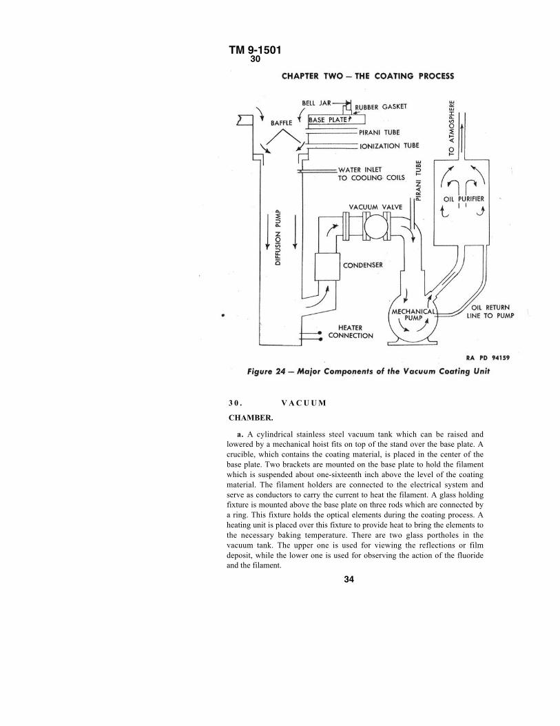
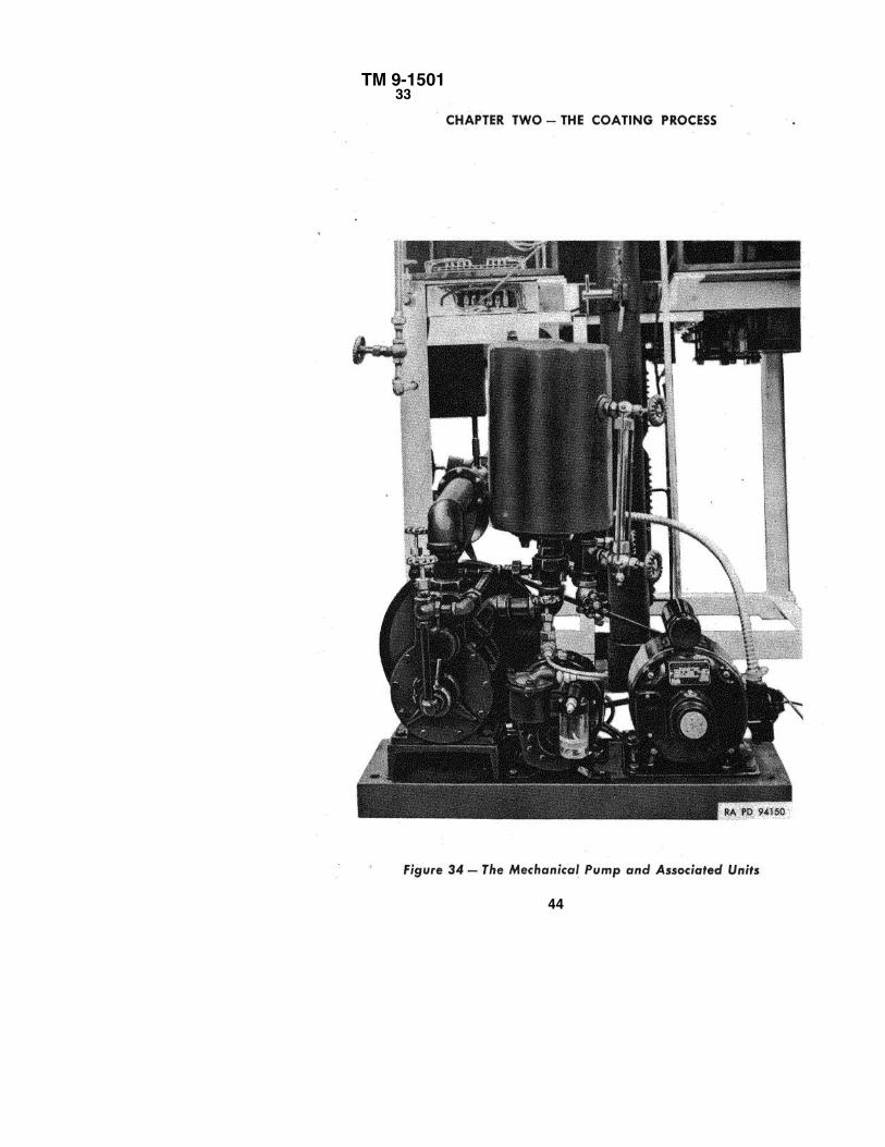
a. The coating unit consists of three major sections: the vacuum chamber,consisting of a stainless steel cylindrical chamber resting upon a base plate;an oil diffusion pump; and a rotary mechanical or "roughing" pump, usuallyreferred to as the mechanical pump (fig. 24).
29. STAND.
a. The stand is of welded angle iron construction. The stand is covered onthe front and sides with removable enameled steel panels. The top of thestand is of polished steel. There is a circular hole in the top plate over whichthe base plate is mounted. There is a removable steel collar around this toprevent anything from falling into the hole. Two electrical panel boxes aremounted at the top rear of the stand. These boxes contain the electricalcontrols for the Pirani and ion gages, the variacs and meters for heat control,and the filament and pump switches. Two water valves are locatedunderneath the stand on the right side. These are labeled "UPPER COILS"and "LOWER COILS." These valves are used for regulating the water supplyto the pump cooling system.
33
TM 9-150130
3 0 . V A C U U M
CHAMBER.
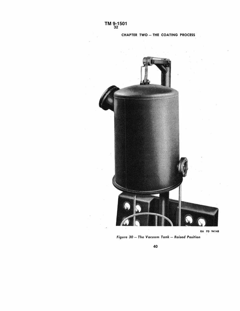
a. A cylindrical stainless steel vacuum tank which can be raised andlowered by a mechanical hoist fits on top of the stand over the base plate. Acrucible, which contains the coating material, is placed in the center of thebase plate. Two brackets are mounted on the base plate to hold the filamentwhich is suspended about one-sixteenth inch above the level of the coatingmaterial. The filament holders are connected to the electrical system andserve as conductors to carry the current to heat the filament. A glass holdingfixture is mounted above the base plate on three rods which are connected bya ring. This fixture holds the optical elements during the coating process. Aheating unit is placed over this fixture to provide heat to bring the elements tothe necessary baking temperature. There are two glass portholes in thevacuum tank. The upper one is used for viewing the reflections or filmdeposit, while the lower one is used for observing the action of the fluorideand the filament.
34
TM 9-150131
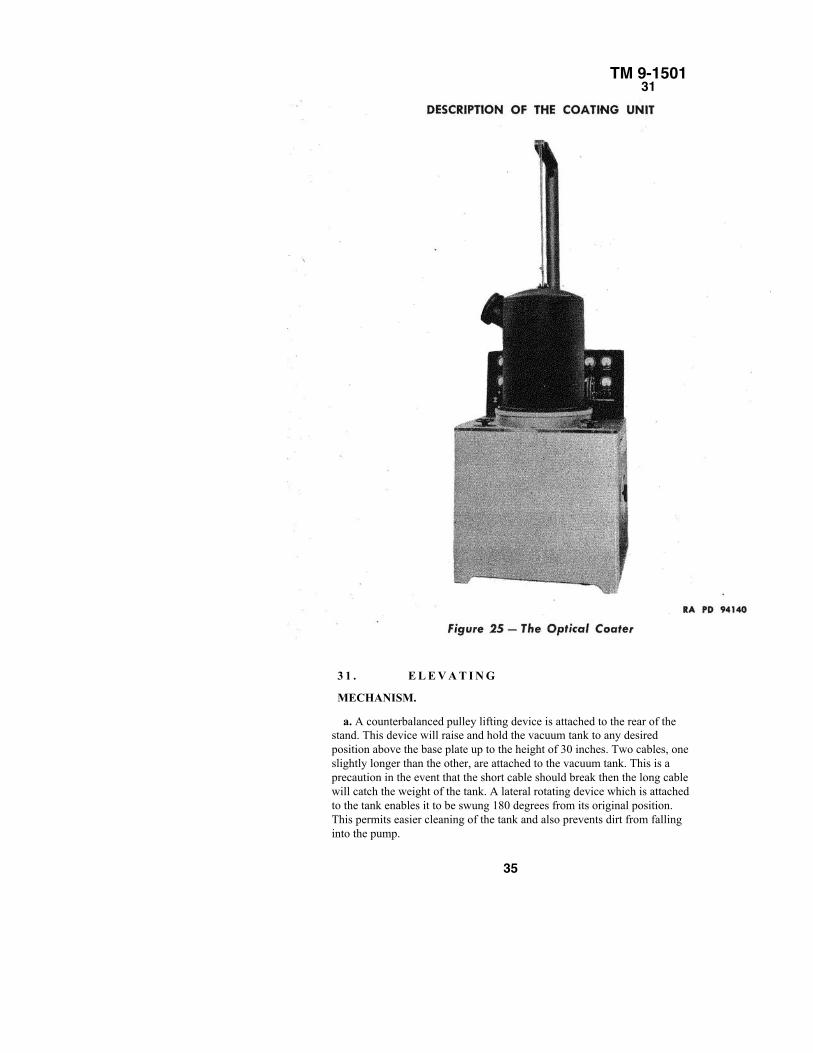
3 1 . E L E V A T I N G
MECHANISM.
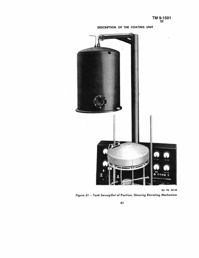
a. A counterbalanced pulley lifting device is attached to the rear of thestand. This device will raise and hold the vacuum tank to any desiredposition above the base plate up to the height of 30 inches. Two cables, oneslightly longer than the other, are attached to the vacuum tank. This is aprecaution in the event that the short cable should break then the long cablewill catch the weight of the tank. A lateral rotating device which is attachedto the tank enables it to be swung 180 degrees from its original position.This permits easier cleaning of the tank and also prevents dirt from fallinginto the pump.
35
TM 9-150131
36
TM 9-150131
37
TM 9-150131
38
TM 9-150132
32. BASE PLATE.
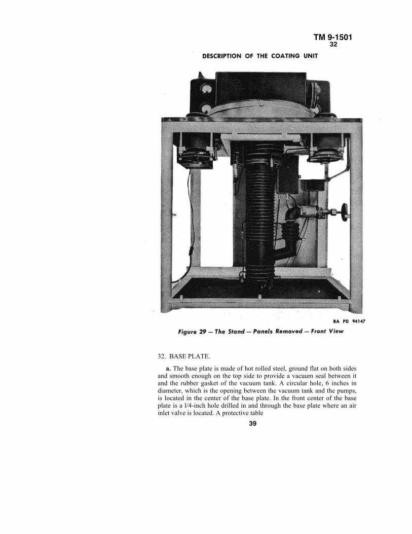
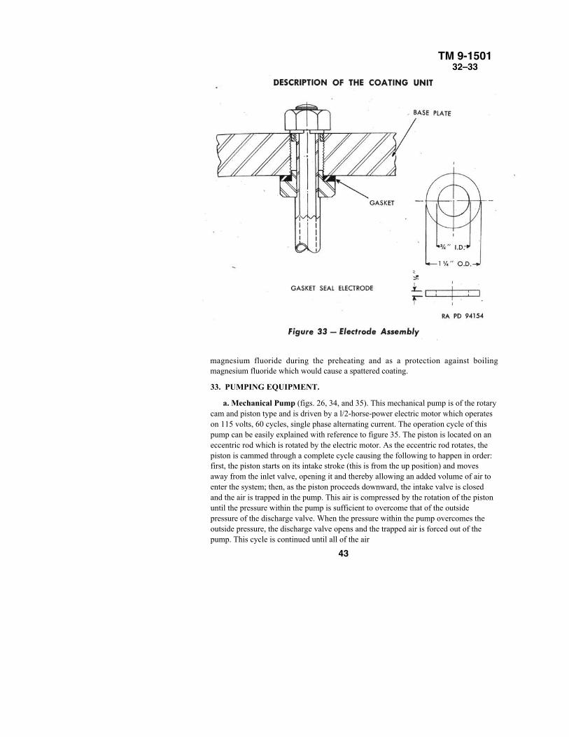
a. The base plate is made of hot rolled steel, ground flat on both sidesand smooth enough on the top side to provide a vacuum seal between itand the rubber gasket of the vacuum tank. A circular hole, 6 inches indiameter, which is the opening between the vacuum tank and the pumps,is located in the center of the base plate. In the front center of the baseplate is a l/4-inch hole drilled in and through the base plate where an airinlet valve is located. A protective table
39
TM 9-150132
40
TM 9-150132
41
TM 9-150132
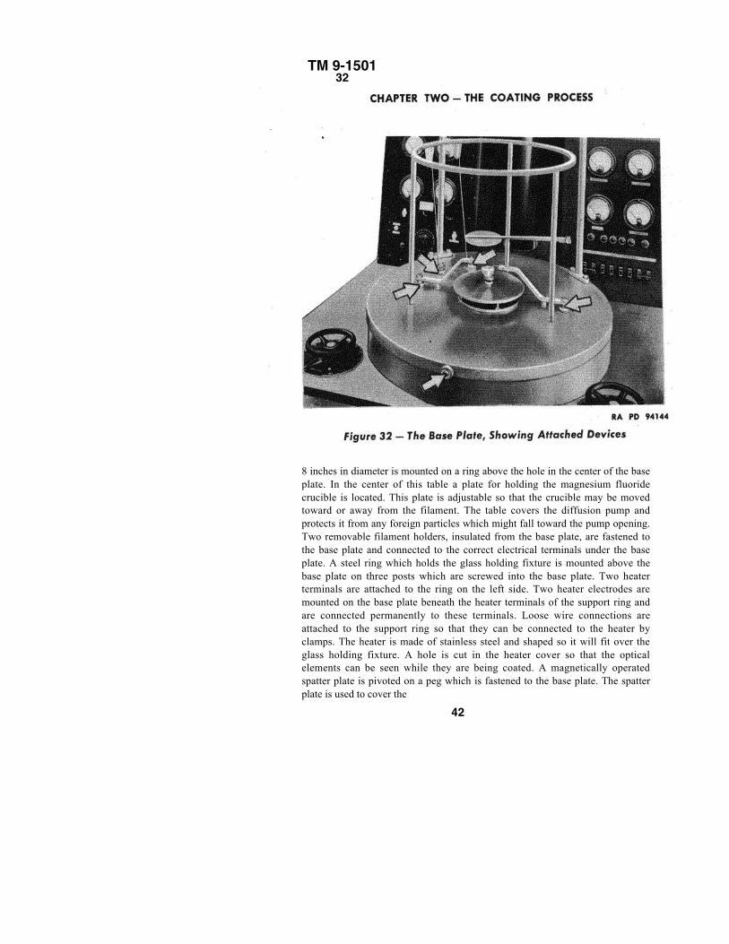
8 inches in diameter is mounted on a ring above the hole in the center of the baseplate. In the center of this table a plate for holding the magnesium fluoridecrucible is located. This plate is adjustable so that the crucible may be movedtoward or away from the filament. The table covers the diffusion pump andprotects it from any foreign particles which might fall toward the pump opening.Two removable filament holders, insulated from the base plate, are fastened tothe base plate and connected to the correct electrical terminals under the baseplate. A steel ring which holds the glass holding fixture is mounted above thebase plate on three posts which are screwed into the base plate. Two heaterterminals are attached to the ring on the left side. Two heater electrodes aremounted on the base plate beneath the heater terminals of the support ring andare connected permanently to these terminals. Loose wire connections areattached to the support ring so that they can be connected to the heater byclamps. The heater is made of stainless steel and shaped so it will fit over theglass holding fixture. A hole is cut in the heater cover so that the opticalelements can be seen while they are being coated. A magnetically operatedspatter plate is pivoted on a peg which is fastened to the base plate. The spatterplate is used to cover the
42
TM 9-150132–33
magnesium fluoride during the preheating and as a protection against boilingmagnesium fluoride which would cause a spattered coating.
33. PUMPING EQUIPMENT.
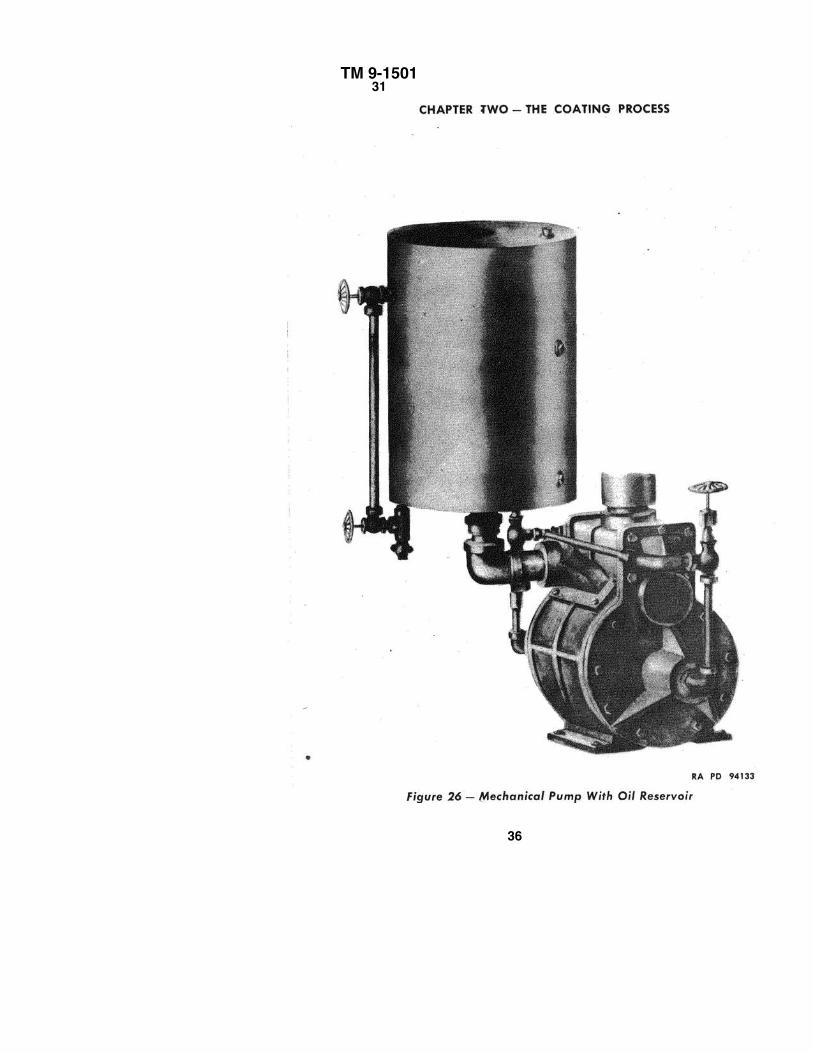
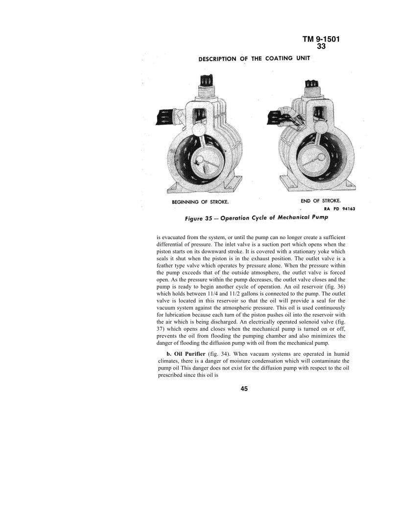
a. Mechanical Pump (figs. 26, 34, and 35). This mechanical pump is of the rotarycam and piston type and is driven by a l/2-horse-power electric motor which operateson 115 volts, 60 cycles, single phase alternating current. The operation cycle of thispump can be easily explained with reference to figure 35. The piston is located on aneccentric rod which is rotated by the electric motor. As the eccentric rod rotates, thepiston is cammed through a complete cycle causing the following to happen in order:first, the piston starts on its intake stroke (this is from the up position) and movesaway from the inlet valve, opening it and thereby allowing an added volume of air toenter the system; then, as the piston proceeds downward, the intake valve is closedand the air is trapped in the pump. This air is compressed by the rotation of the pistonuntil the pressure within the pump is sufficient to overcome that of the outsidepressure of the discharge valve. When the pressure within the pump overcomes theoutside pressure, the discharge valve opens and the trapped air is forced out of thepump. This cycle is continued until all of the air
43
TM 9-150133
44
TM 9-150133
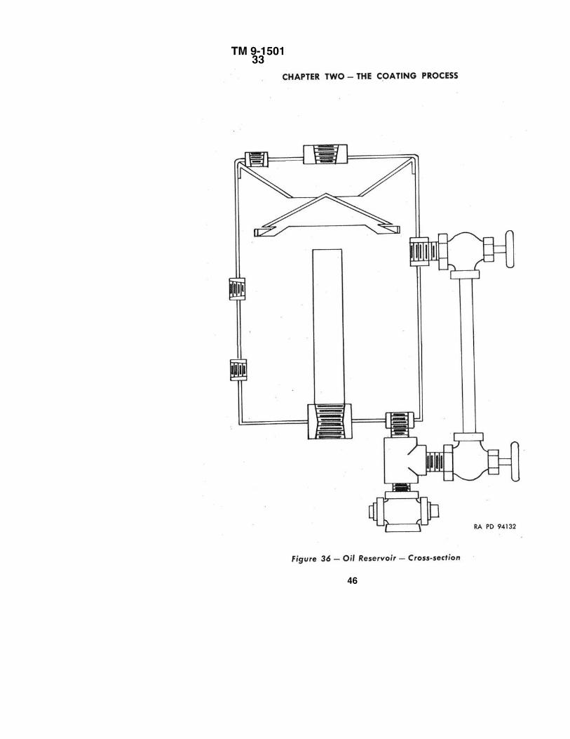
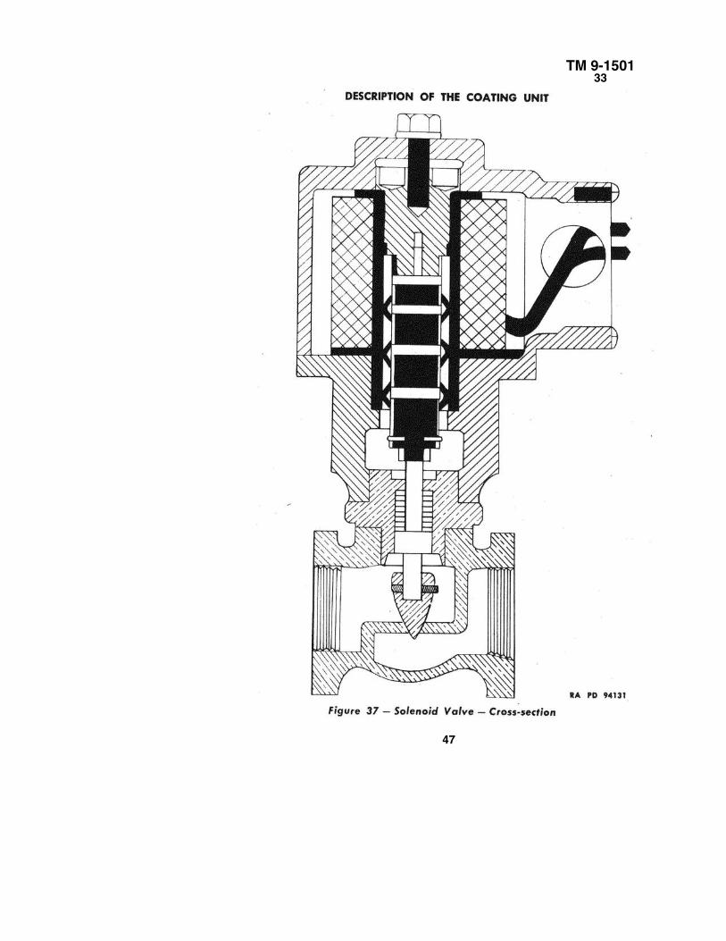
is evacuated from the system, or until the pump can no longer create a sufficientdifferential of pressure. The inlet valve is a suction port which opens when thepiston starts on its downward stroke. It is covered with a stationary yoke whichseals it shut when the piston is in the exhaust position. The outlet valve is afeather type valve which operates by pressure alone. When the pressure withinthe pump exceeds that of the outside atmosphere, the outlet valve is forcedopen. As the pressure within the pump decreases, the outlet valve closes and thepump is ready to begin another cycle of operation. An oil reservoir (fig. 36)which holds between 11/4 and 11/2 gallons is connected to the pump. The outletvalve is located in this reservoir so that the oil will provide a seal for thevacuum system against the atmospheric pressure. This oil is used continuouslyfor lubrication because each turn of the piston pushes oil into the reservoir withthe air which is being discharged. An electrically operated solenoid valve (fig.37) which opens and closes when the mechanical pump is turned on or off,prevents the oil from flooding the pumping chamber and also minimizes thedanger of flooding the diffusion pump with oil from the mechanical pump.
b. Oil Purifier (fig. 34). When vacuum systems are operated in humidclimates, there is a danger of moisture condensation which will contaminate thepump oil This danger does not exist for the diffusion pump with respect to the oilprescribed since this oil is
45
TM 9-150133
46
TM 9-150133
47
TM 9-150133
48
TM 9-150133
heated to a degree at which any condensation would be vaporized andsucked out through the mechanical pump. Condensation of moisture can,however, occur in the mechanical pump. The oil in this pump is not heatedand water mixed with oil would be detrimental to the efficient operation ofthe pump. To prevent this condensation, an oil purifier is attached to themechanical pump. This purifier consists of a 400-watt electric heater woundaround the elbow at the bottom of the oil reservoir. This oil purifier heatsthe oil that is dis-
49
TM 9-150133
charged from the mechanical pump and any water that might be mixed withthe oil is vaporized. An air pressure and vacuum pump which is also attachedto the elbows will then blow the water vapors out of the reservoir. This pumpis operated by a 1/2-horsepower motor which rotates the pump at 1,750revolutions per minute.
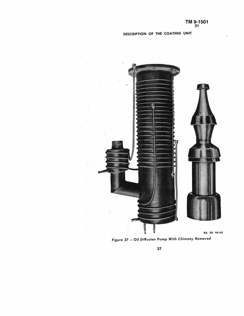
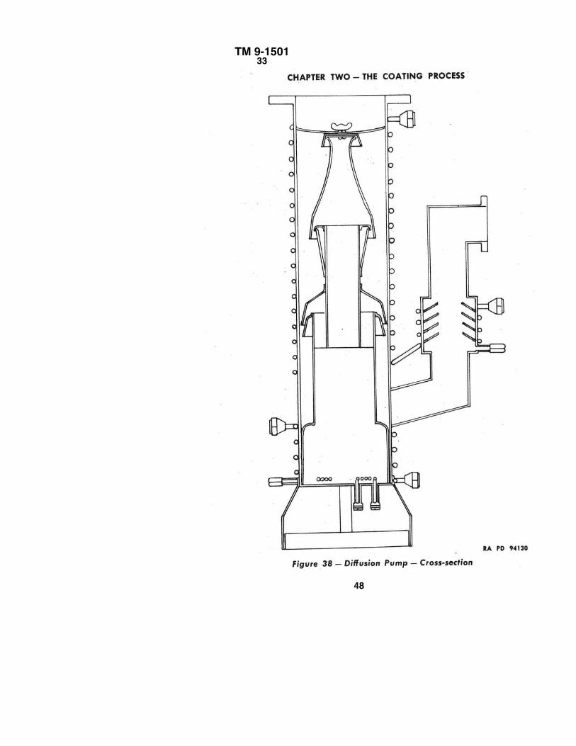
c. Diffusion Pump (figs. 27 and 38). This pump is of the MC 500 type. Apilot light which lights when the water is turned on in the upper coils serves as awarning device against turning the pump on when the water is not running. If thepump were to be turned on when the water was not running, vapors would rise inthe system, contaminating it, and cause the oil to disintegrate. The operation ofthis pump may be compared to a vapor stream pump since it operates on the air-jetprinciple. The oil in the bottom of the pump is heated by the heater coil and thevapors rise through the chimney where they escape through the holes in the sidesor where they are deflected down by the hood on top of the chimney. These oilvapors are deflected at a high velocity from the jets in the chimney thus creating adecrease in pressure between the chimney and the housing. Since air will spreadout to occupy as much space as possible, the air from the vacuum tank will rushinto the chimney when the pressure is reduced. This air is then diffused into thedownward stream of oil (which re-
50
TM 9-150133
51
TM 9-150133
CHAPTER TWO – THE COATING PROCESS
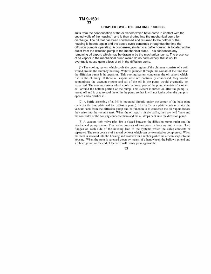
sults from the condensation of the oil vapors which have come in contact with thecooled walls of the housing), and is then drafted into the mechanical pump fordischarge. The oil that has been condensed and returned to the bottom of thehousing is heated again and the above cycle continues throughout the time thediffusion pump is operating. A condenser, similar to a baffle housing, is located at theoutlet from the diffusion pump to the mechanical pump. This condenses anyremaining oil vapors which may be drawn in by the mechanical pump. The presenceof oil vapors in the mechanical pump would do no harm except that it wouldeventually cause quite a loss of oil in the diffusion pump.
(1) The cooling system which cools the upper region of the chimney consists of a coilwound around the chimney housing. Water is pumped through this coil all of the time thatthe diffusion pump is in operation. This cooling system condenses the oil vapors whichrise in the chimney. If these oil vapors were not continually condensed, they wouldcontaminate the vacuum system and all of the oil in the pump would eventually bevaporized. The cooling system which cools the lower part of the pump consists of anothercoil around the bottom portion of the pump. This system is turned on after the pump isturned off and is used to cool the oil in the pump so that it will not ignite when the pump isopened and air rushes in.
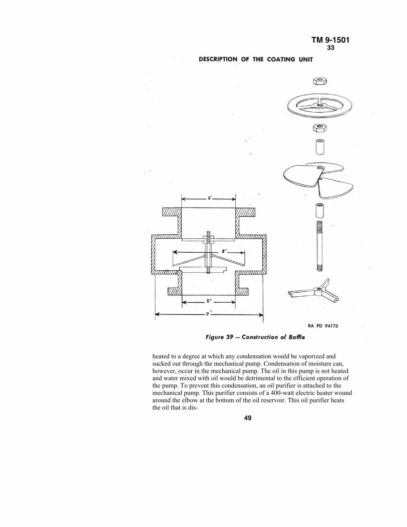
(2) A baffle assembly (fig. 39) is mounted directly under the center of the base plate(between the base plate and the diffusion pump). This baffle is a plate which separates thevacuum tank from the diffusion pump and its function is to condense the oil vapors beforethey arise into the vacuum tank. When the oil vapors hit the baffle, they are held 'there andthe cool sides of the housing condense them and the oil drops back into the diffusion pump.
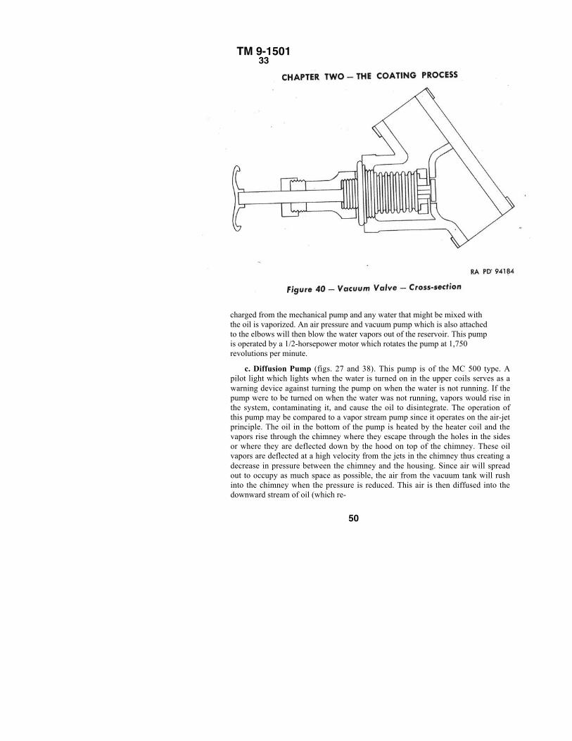
(3) A vacuum tight valve (fig. 40) is placed between the diffusion pump outlet and themechanical pump intake. This valve consists of two parts, a housing and a stem. Twoflanges on each side of the housing lead to the systems which the valve connects orseparates. The stem consists of a metal bellows which can be extended or compressed. Whenthe stem is screwed into the housing and sealed with a rubber gasket, no air can seep into thehousing. When the stem is screwed down by means of a handwheel, the bellows extend anda rubber gasket on the end of the stem will firmly press against the
52
TM 9-150133
valve seat, thereby separating the two sides of the valve. When opened, thebellows compress and air is allowed to flow between the two sides of thevalve. The main use of this valve is to isolate the mechanical pump from thesystem when searching for leaks. By closing the valve and switching the Piranigage over to the tube, which is connected to the fore-pressure, the reading willindicate whether or not the fore-pressure line is working properly. If nosatisfactory reading can be obtained, it is apparent that there is either a leak inthe fore-pressure line, or the pump itself is not operating properly. Anotherimportant function of the vacuum valve is to prevent the formation of a so-called "Wilson" cloud, particularly in humid climates. This cloud is likely toform when the evacuating of the vacuum chamber takes place for the first time.This cloud lingers long enough to contaminate the surfaces of the opticalelements which are to receive coating. The formation of this momentary cloudis caused by the high evacuating speed of the mechanical pump. The suddenreduction of pressure inside the vacuum tank creates sufficient cooling to causeminute condensation to gather around the dust particles in the air, and createsthe cloud phenomenon. This formation can be eliminated by retarding theinitial evacuating speed. This is accomplished by starting evacuation with thevalve just barely open for a minute or so. After this, it can be opened wide andthe evacuation completed at the full pumping rate.
54
TM 9-150134
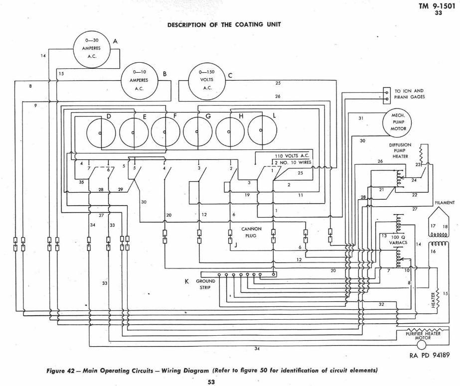
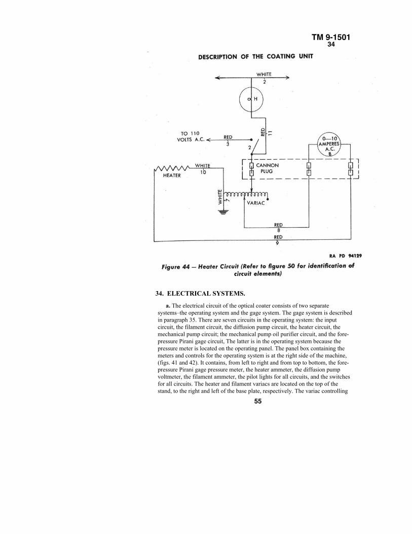
34. ELECTRICAL SYSTEMS.
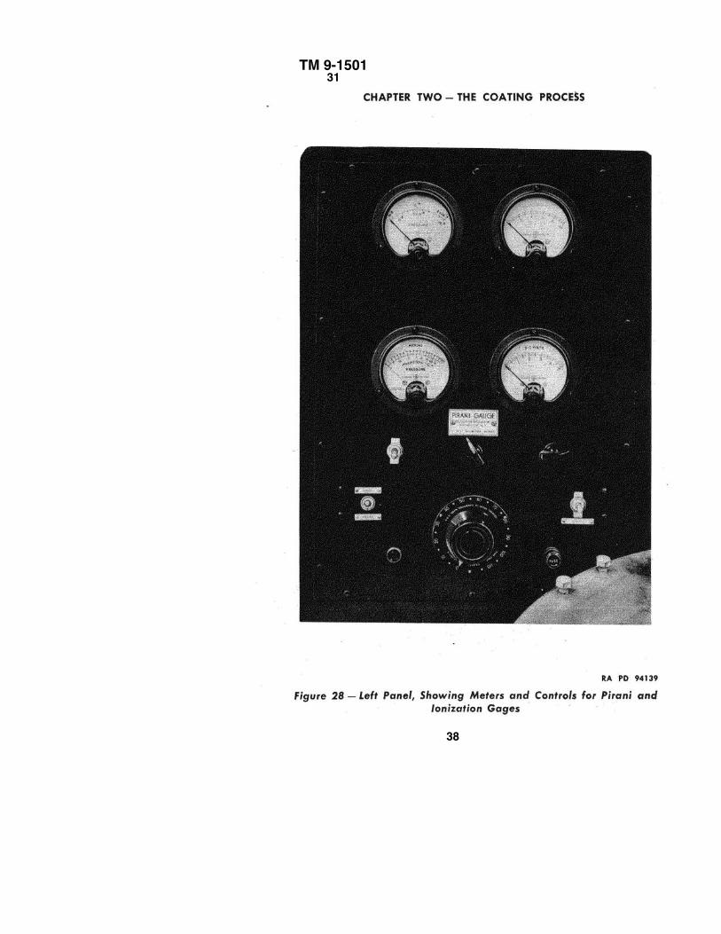
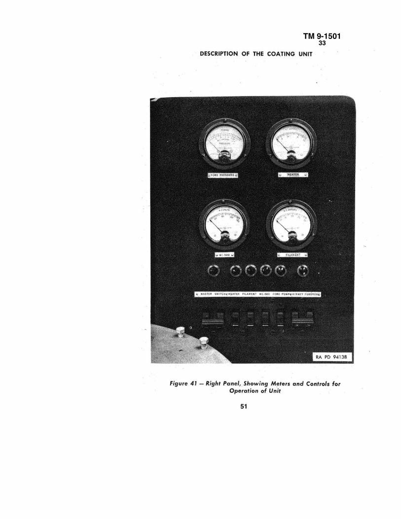
a. The electrical circuit of the optical coater consists of two separatesystems–the operating system and the gage system. The gage system is describedin paragraph 35. There are seven circuits in the operating system: the inputcircuit, the filament circuit, the diffusion pump circuit, the heater circuit, themechanical pump circuit; the mechanical pump oil purifier circuit, and the fore-pressure Pirani gage circuit, The latter is in the operating system because thepressure meter is located on the operating panel. The panel box containing themeters and controls for the operating system is at the right side of the machine,(figs. 41 and 42). It contains, from left to right and from top to bottom, the fore-pressure Pirani gage pressure meter, the heater ammeter, the diffusion pumpvoltmeter, the filament ammeter, the pilot lights for all circuits, and the switchesfor all circuits. The heater and filament variacs are located on the top of thestand, to the right and left of the base plate, respectively. The variac controlling
55
TM 9-150134
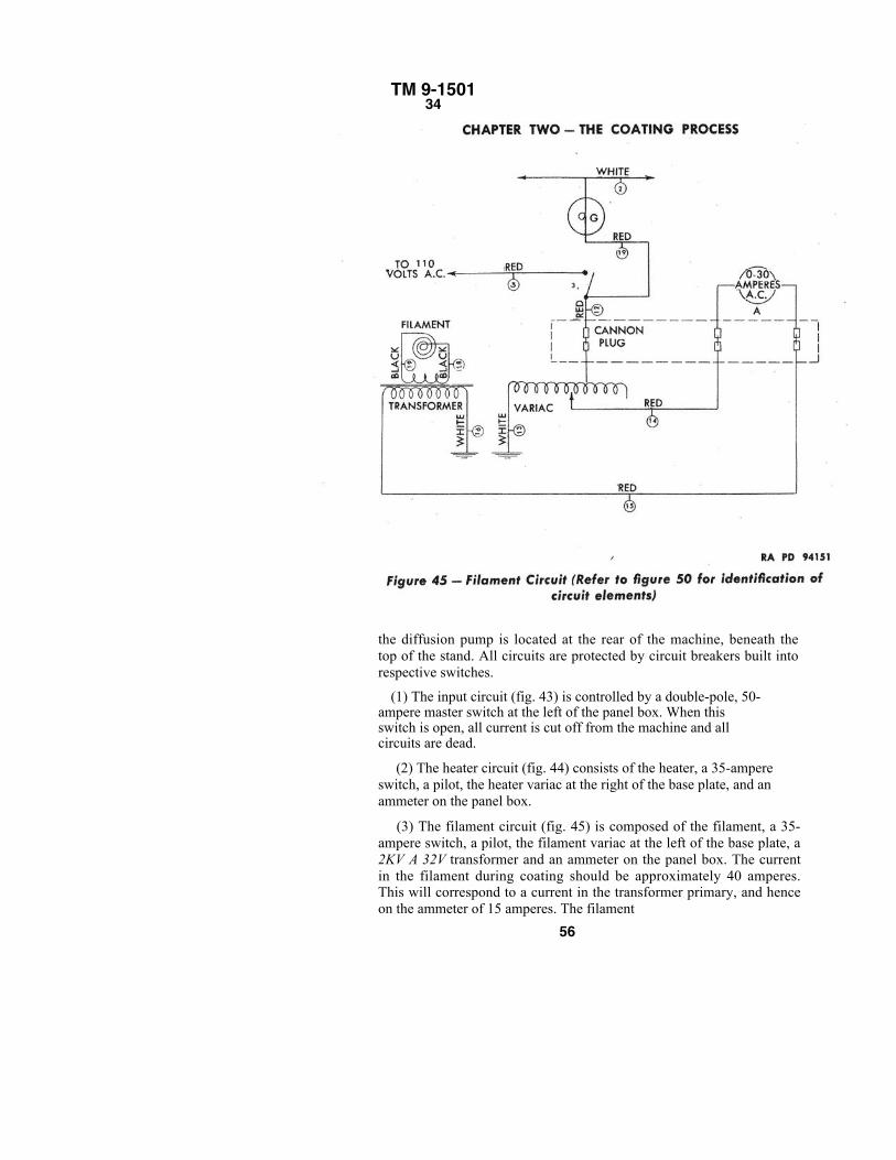
the diffusion pump is located at the rear of the machine, beneath thetop of the stand. All circuits are protected by circuit breakers built intorespective switches.
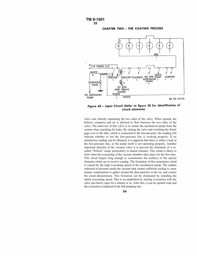
(1) The input circuit (fig. 43) is controlled by a double-pole, 50-ampere master switch at the left of the panel box. When thisswitch is open, all current is cut off from the machine and allcircuits are dead.
(2) The heater circuit (fig. 44) consists of the heater, a 35-ampereswitch, a pilot, the heater variac at the right of the base plate, and anammeter on the panel box.
(3) The filament circuit (fig. 45) is composed of the filament, a 35-ampere switch, a pilot, the filament variac at the left of the base plate, a2KV A 32V transformer and an ammeter on the panel box. The currentin the filament during coating should be approximately 40 amperes.This will correspond to a current in the transformer primary, and henceon the ammeter of 15 amperes. The filament
56
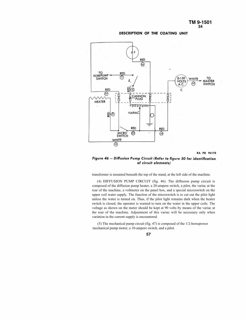
TM 9-150134
transformer is mounted beneath the top of the stand, at the left side of the machine.
(4) DIFFUSION PUMP CIRCUIT (fig. 46). The diffusion pump circuit iscomposed of the diffusion pump heater, a 20-ampere switch, a pilot, the variac at therear of the machine, a voltmeter on the panel box, and a special microswitch on theupper coil water supply. The function of the microswitch is to cut out the pilot lightunless the water is turned on. Thus, if the pilot light remains dark when the heaterswitch is closed, the operator is warned to turn on the water in the upper coils. Thevoltage as shown on the meter should be kept at 90 volts by means of the variac atthe rear of the machine. Adjustment of this variac will be necessary only whenvariation in the current supply is encountered.
(5) The mechanical pump circuit (fig. 47) is composed of the 1/2-horsepowermechanical pump motor, a 10-ampere switch, and a pilot.
57
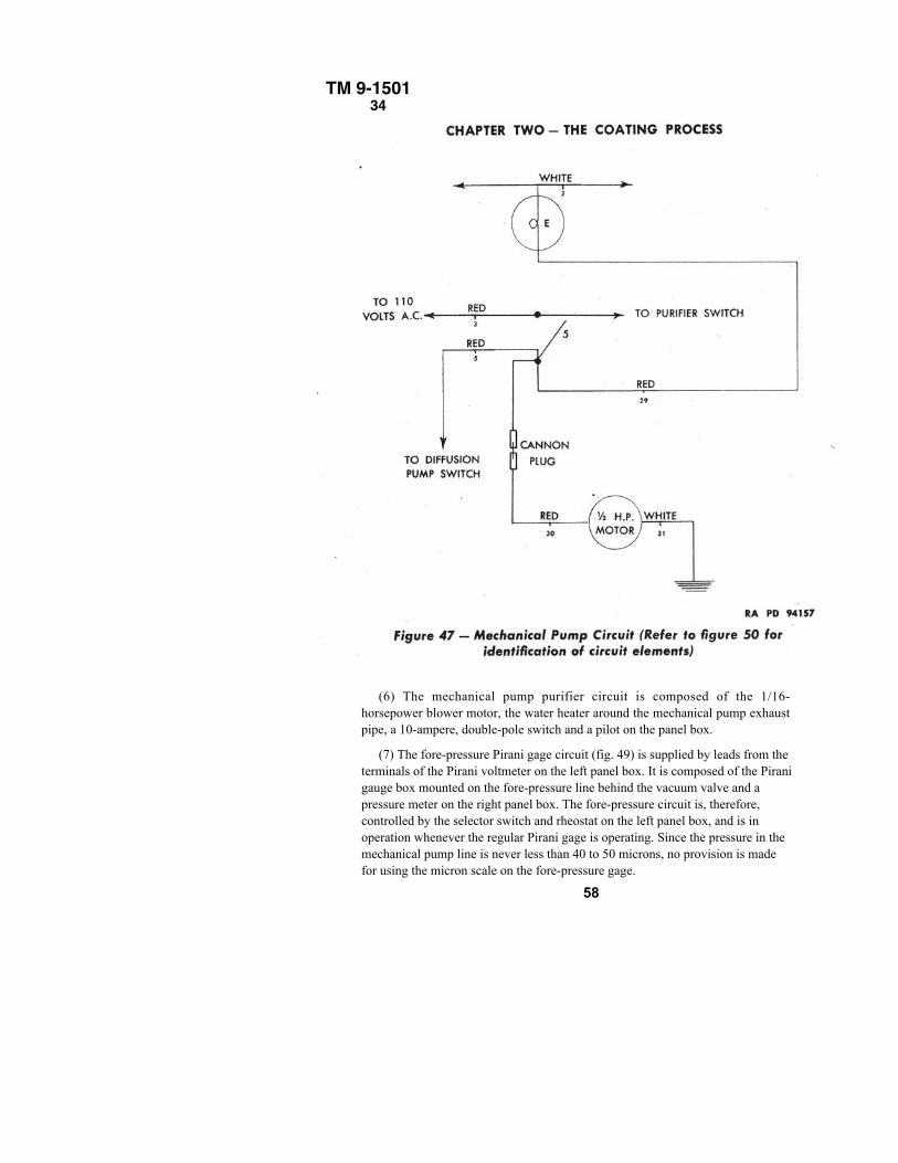
TM 9-150134
(6) The mechanical pump purifier circuit is composed of the 1/16-horsepower blower motor, the water heater around the mechanical pump exhaustpipe, a 10-ampere, double-pole switch and a pilot on the panel box.
(7) The fore-pressure Pirani gage circuit (fig. 49) is supplied by leads from theterminals of the Pirani voltmeter on the left panel box. It is composed of the Piranigauge box mounted on the fore-pressure line behind the vacuum valve and apressure meter on the right panel box. The fore-pressure circuit is, therefore,controlled by the selector switch and rheostat on the left panel box, and is inoperation whenever the regular Pirani gage is operating. Since the pressure in themechanical pump line is never less than 40 to 50 microns, no provision is madefor using the micron scale on the fore-pressure gage.
58
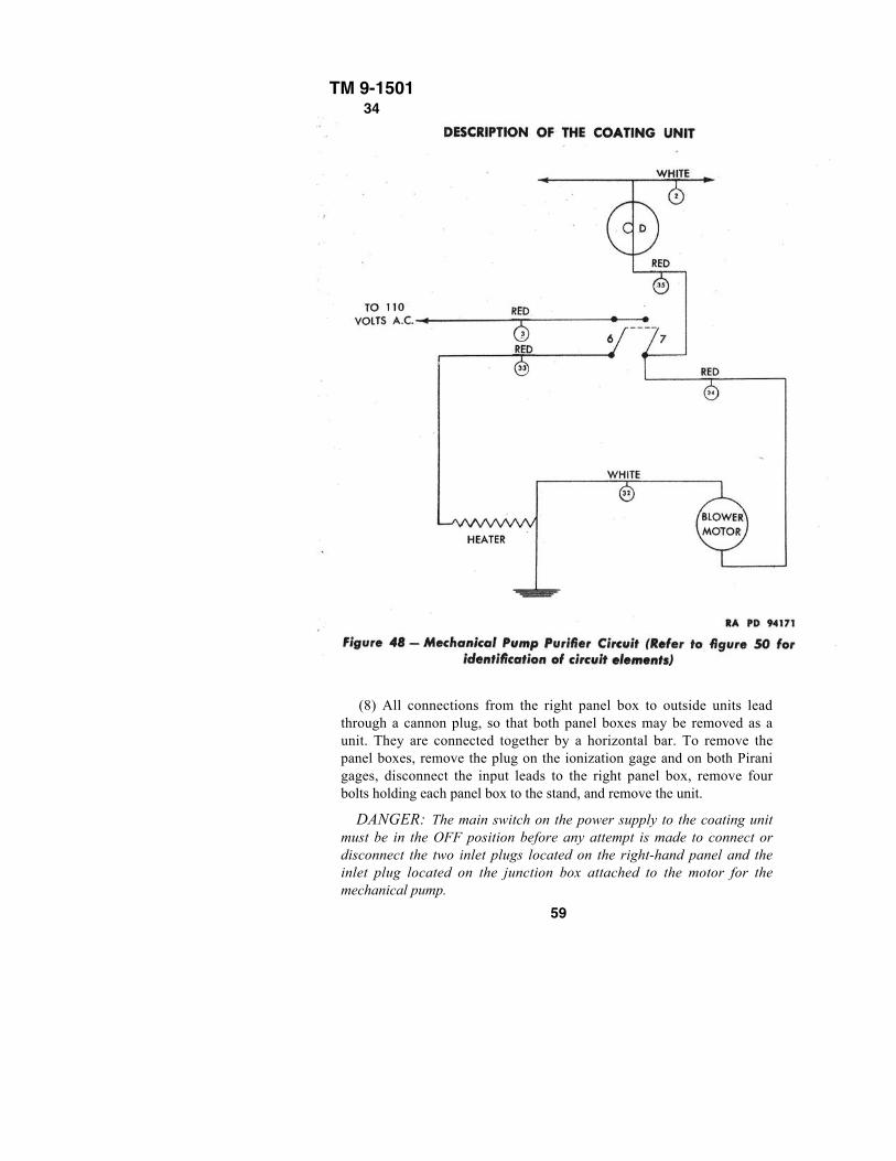
TM 9-150134
(8) All connections from the right panel box to outside units leadthrough a cannon plug, so that both panel boxes may be removed as aunit. They are connected together by a horizontal bar. To remove thepanel boxes, remove the plug on the ionization gage and on both Piranigages, disconnect the input leads to the right panel box, remove fourbolts holding each panel box to the stand, and remove the unit.
DANGER: The main switch on the power supply to the coating unitmust be in the OFF position before any attempt is made to connect ordisconnect the two inlet plugs located on the right-hand panel and theinlet plug located on the junction box attached to the motor for themechanical pump.
59
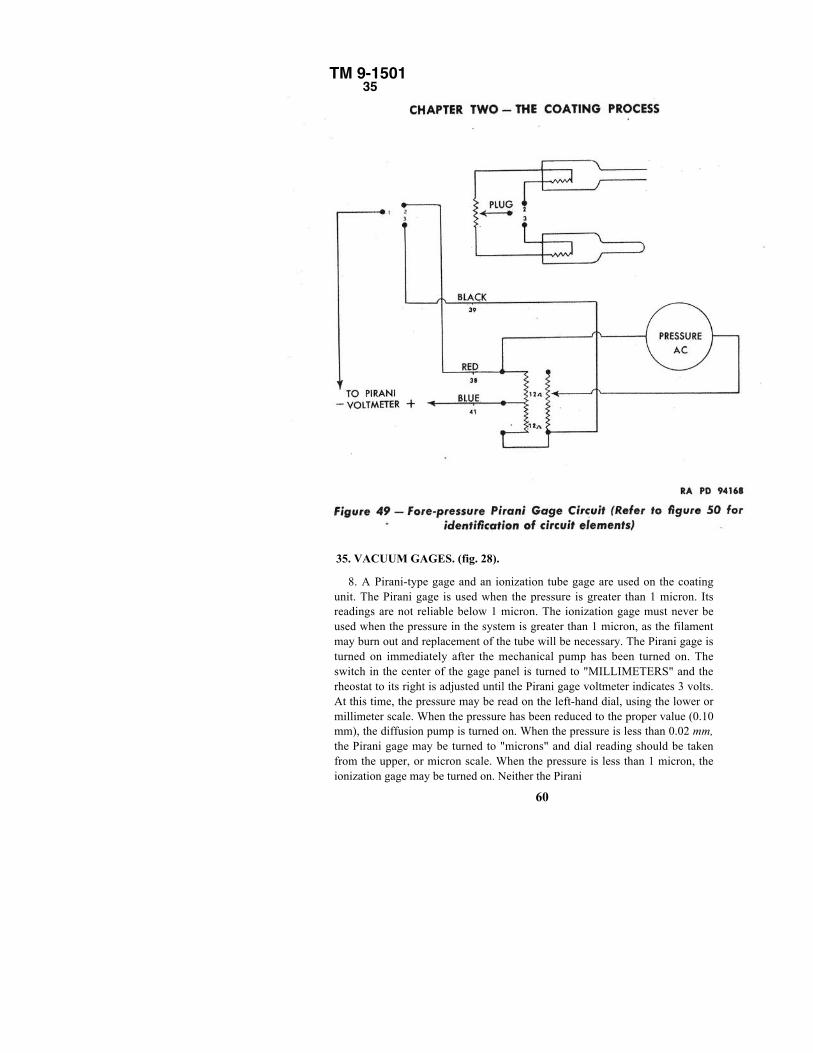
TM 9-1501 35
35. VACUUM GAGES. (fig. 28).
8. A Pirani-type gage and an ionization tube gage are used on the coatingunit. The Pirani gage is used when the pressure is greater than 1 micron. Itsreadings are not reliable below 1 micron. The ionization gage must never beused when the pressure in the system is greater than 1 micron, as the filamentmay burn out and replacement of the tube will be necessary. The Pirani gage isturned on immediately after the mechanical pump has been turned on. Theswitch in the center of the gage panel is turned to "MILLIMETERS" and therheostat to its right is adjusted until the Pirani gage voltmeter indicates 3 volts.At this time, the pressure may be read on the left-hand dial, using the lower ormillimeter scale. When the pressure has been reduced to the proper value (0.10mm), the diffusion pump is turned on. When the pressure is less than 0.02 mm,the Pirani gage may be turned to "microns" and dial reading should be takenfrom the upper, or micron scale. When the pressure is less than 1 micron, theionization gage may be turned on. Neither the Pirani
60
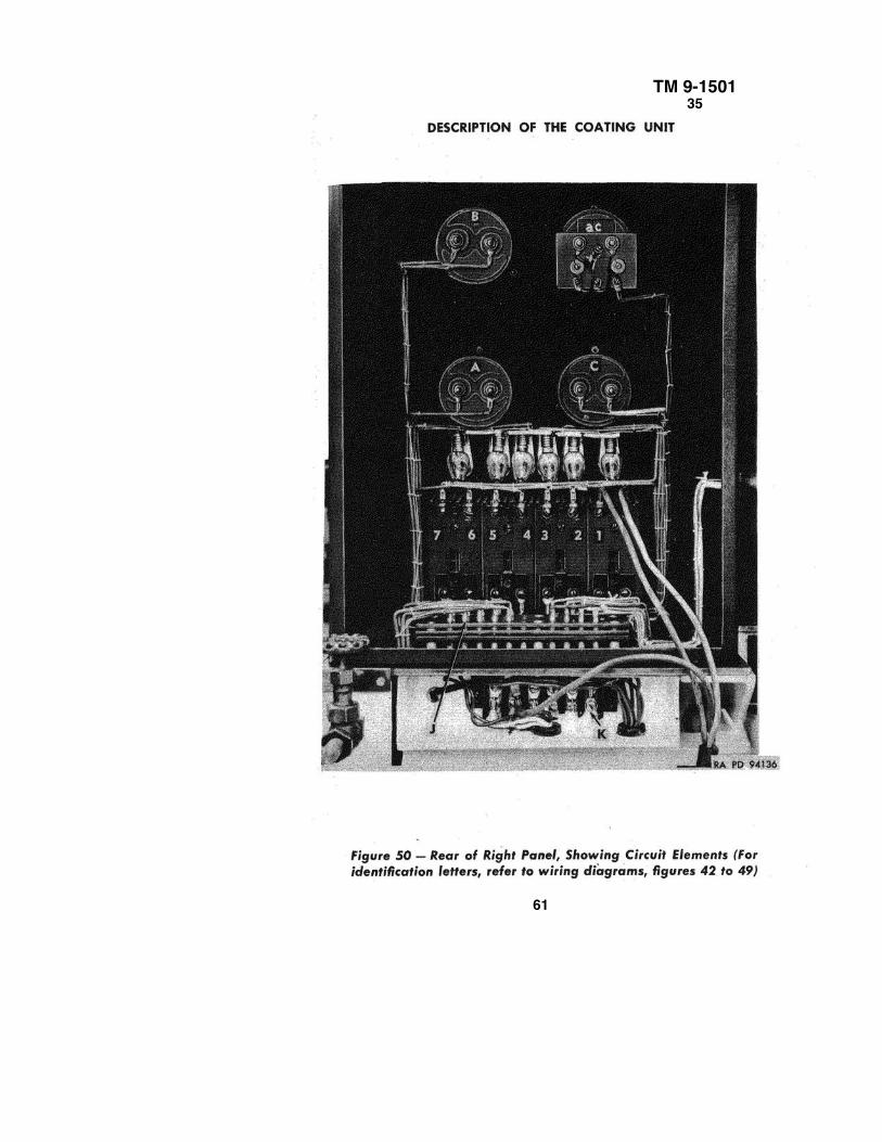
TM 9-150135
61
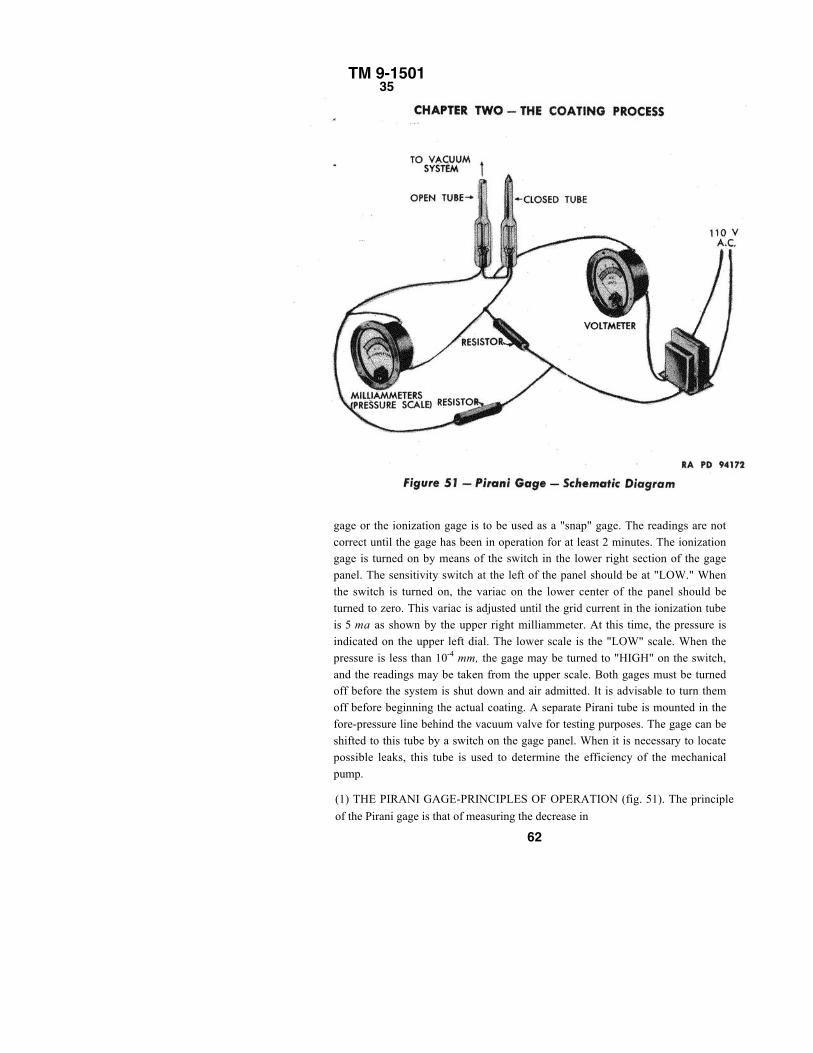
TM 9-150135
gage or the ionization gage is to be used as a "snap" gage. The readings are notcorrect until the gage has been in operation for at least 2 minutes. The ionizationgage is turned on by means of the switch in the lower right section of the gagepanel. The sensitivity switch at the left of the panel should be at "LOW." Whenthe switch is turned on, the variac on the lower center of the panel should beturned to zero. This variac is adjusted until the grid current in the ionization tubeis 5 ma as shown by the upper right milliammeter. At this time, the pressure isindicated on the upper left dial. The lower scale is the "LOW" scale. When thepressure is less than 10-4 mm, the gage may be turned to "HIGH" on the switch,and the readings may be taken from the upper scale. Both gages must be turnedoff before the system is shut down and air admitted. It is advisable to turn themoff before beginning the actual coating. A separate Pirani tube is mounted in thefore-pressure line behind the vacuum valve for testing purposes. The gage can beshifted to this tube by a switch on the gage panel. When it is necessary to locatepossible leaks, this tube is used to determine the efficiency of the mechanicalpump.
(1) THE PIRANI GAGE-PRINCIPLES OF OPERATION (fig. 51). The principle
of the Pirani gage is that of measuring the decrease in
62
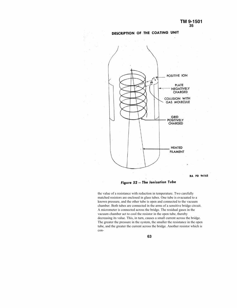
TM 9-150135
the value of a resistance with reduction in temperature. Two carefullymatched resistors are enclosed in glass tubes. One tube is evacuated to aknown pressure, and the other tube is open and connected to the vacuumchamber. Both tubes are connected in the arms of a sensitive bridge circuit.A micrometer is connected across the bridge. The residual gases in thevacuum chamber act to cool the resistor in the open tube, therebydecreasing its value. This, in turn, causes a small current across the bridge.The greater the pressure in the system, the smaller the resistance in the opentube, and the greater the current across the bridge. Another resistor which iscon-
63
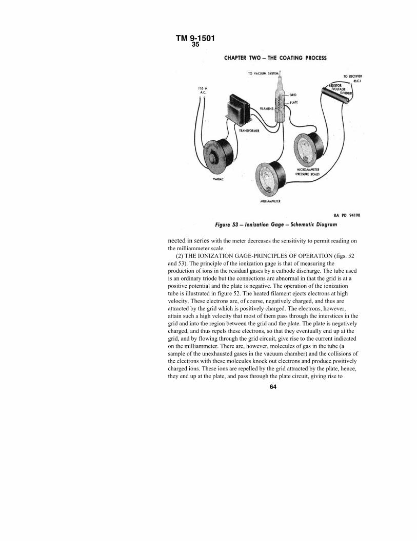
TM 9-150135
nected in series with the meter decreases the sensitivity to permit reading onthe milliammeter scale.
(2) THE IONIZATION GAGE-PRINCIPLES OF OPERATION (figs. 52and 53). The principle of the ionization gage is that of measuring theproduction of ions in the residual gases by a cathode discharge. The tube usedis an ordinary triode but the connections are abnormal in that the grid is at apositive potential and the plate is negative. The operation of the ionizationtube is illustrated in figure 52. The heated filament ejects electrons at highvelocity. These electrons are, of course, negatively charged, and thus areattracted by the grid which is positively charged. The electrons, however,attain such a high velocity that most of them pass through the interstices in thegrid and into the region between the grid and the plate. The plate is negativelycharged, and thus repels these electrons, so that they eventually end up at thegrid, and by flowing through the grid circuit, give rise to the current indicatedon the milliammeter. There are, however, molecules of gas in the tube (asample of the unexhausted gases in the vacuum chamber) and the collisions ofthe electrons with these molecules knock out electrons and produce positivelycharged ions. These ions are repelled by the grid attracted by the plate, hence,they end up at the plate, and pass through the plate circuit, giving rise to
64
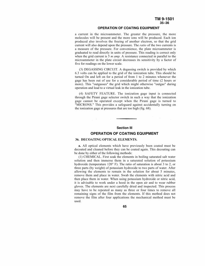
TM 9-150135–36
OPERATION OF COATING EQUIPMENTa current in the microammeter. The greater the pressure, the moremolecules will be present and the more ions will be produced. Each ionproduced also involves the freeing of another electron, so that the gridcurrent will also depend upon the pressure. The ratio of the two currents isa measure of the pressure. For convenience, the plate microammeter isgraduated to read directly in units of pressure. This reading is correct onlywhen the grid current is 5 m amp. A resistance connected in parallel to themicroammeter in the plate circuit decreases its sensitivity by a factor offive for readings on the lower scale.
(3) DEGASSING CIRCUIT. A degassing switch is provided by which6.3 volts can be applied to the grid of the ionization tube. This should beturned On and left on for a period of from 1 to 2 minutes whenever thegage has been out of use for a considerable period of time (2 hours ormore). This "outgasses" the grid which might otherwise "outgas" duringoperation and lead to a virtual leak in the ionization tube.
(4) SAFETY FEATURE. The ionization gage input is connectedthrough the Pirani gage selector switch in such a way that the ionizationgage cannot be operated except when the Pirani gage is turned to"MICRONS." This provides a safeguard against accidentally turning onthe ionization gage at pressures that are too high (fig. 68).
Section IIIOPERATION OF COATING EQUIPMENT
36. DECOATING OPTICAL ELEMENTS.
a. All optical elements which have previously been coated must bedecoated and cleaned before they can be coated again. This decoating canbe done by either of the following methods:
(1) CHEMICAL. First soak the elements in boiling saturated salt watersolution and then immerse them in a saturated solution of potassiumhydroxide (temperature 120° F). The ratio of saturation is about 3 to 2, orthree parts (by weight) of potassium hydroxide to two parts of water. Afterallowing the elements to remain in the solution for about 5 minutes,remove them and place in water. Swab the elements with nitric acid andthen place them in water. When using potassium hydroxide or nitric acid,it is advisable to work under a hood in the open air and to wear rubbergloves. The elements are next carefully dried and inspected. This processmay have to be repeated as many as three or four times to remove allremaining signs of the film from the elements. If this method does notremove the film after four applications the mechanical method must beused.
65
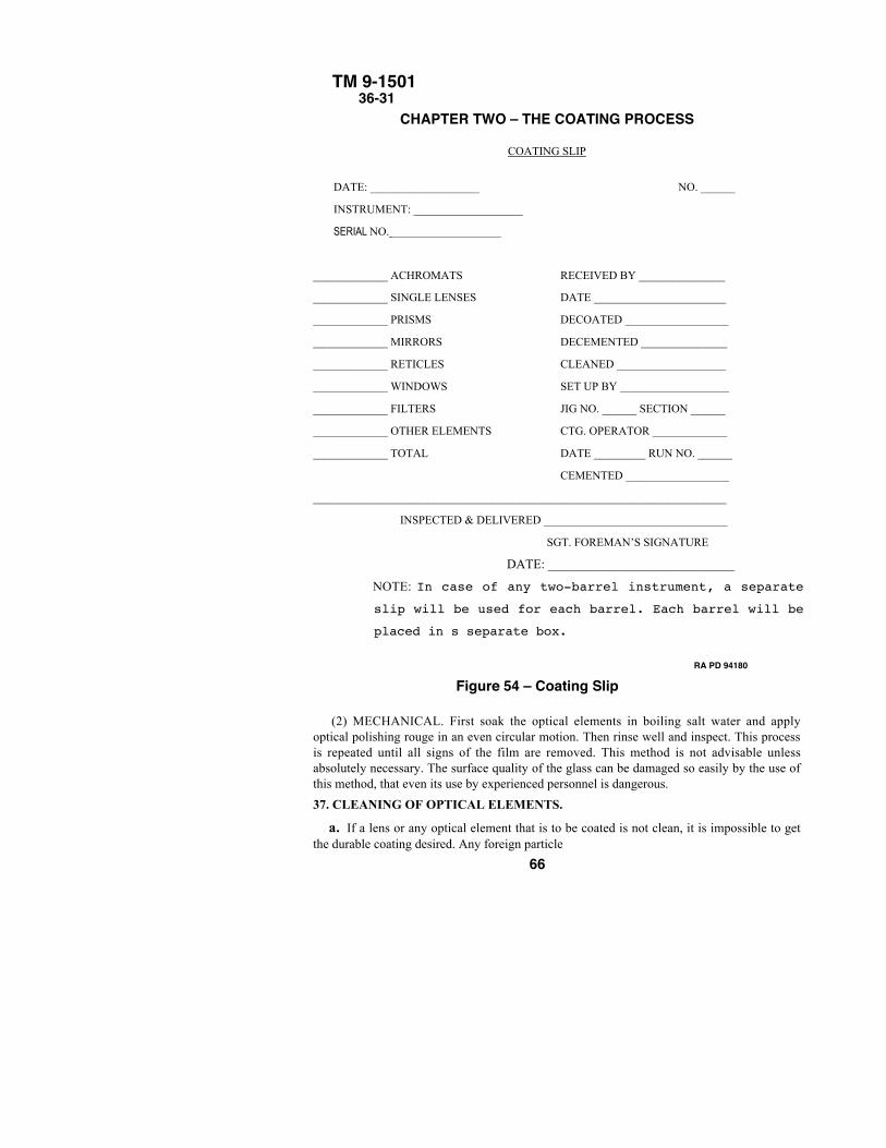
TM 9-1501 36-31
CHAPTER TWO – THE COATING PROCESS
COATING SLIP
DATE: ___________________ NO. ______
INSTRUMENT: ___________________
SERIAL NO. ___________________
_____________ ACHROMATS RECEIVED BY _______________
_____________ SINGLE LENSES DATE _______________________
_____________ PRISMS DECOATED __________________
_____________ MIRRORS DECEMENTED _______________
_____________ RETICLES CLEANED ___________________
_____________ WINDOWS SET UP BY ___________________
_____________ FILTERS JIG NO. ______ SECTION ______
_____________ OTHER ELEMENTS CTG. OPERATOR _____________
_____________ TOTAL DATE _________ RUN NO. ______
CEMENTED __________________
________________________________________________________________________
INSPECTED & DELIVERED ________________________________
SGT. FOREMAN’S SIGNATURE
DATE: _____________________________
NOTE: In case of any two-barrel instrument, a separate
slip will be used for each barrel. Each barrel will be
placed in s separate box.
RA PD 94180
Figure 54 – Coating Slip
(2) MECHANICAL. First soak the optical elements in boiling salt water and applyoptical polishing rouge in an even circular motion. Then rinse well and inspect. This processis repeated until all signs of the film are removed. This method is not advisable unlessabsolutely necessary. The surface quality of the glass can be damaged so easily by the use ofthis method, that even its use by experienced personnel is dangerous.
37. CLEANING OF OPTICAL ELEMENTS.
a. If a lens or any optical element that is to be coated is not clean, it is impossible to getthe durable coating desired. Any foreign particle
66
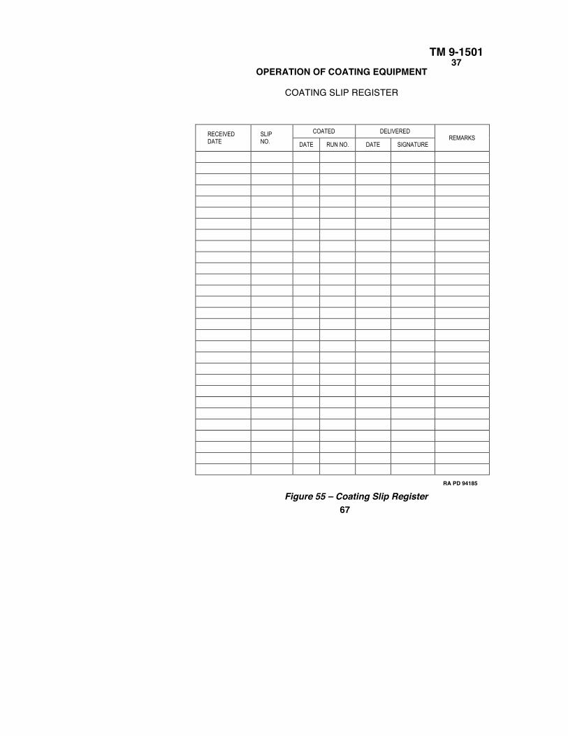
TM 9-150137
OPERATION OF COATING EQUIPMENT
COATING SLIP REGISTER
COATED DELIVEREDRECEIVEDDATE
SLIPNO. DATE RUN NO. DATE SIGNATURE
REMARKS
RA PD 94185
Figure 55 – Coating Slip Register67
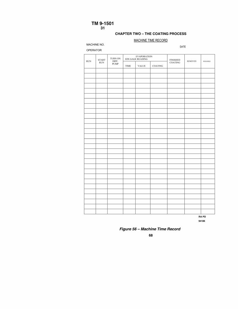
TM 9-150131
CHAPTER TWO – THE COATING PROCESS
MACHINE TIME RECORDMACHINE NO.
DATEOPERATOR
EVAPORATIONION GAGE READING
RUN STARTRUN
TURN ONDIFF.PUMP
TIME VALUE COATING
FINISHEDCOATING
REMOVED REMARKS
RA PD94186
Figure 56 – Machine Time Record68
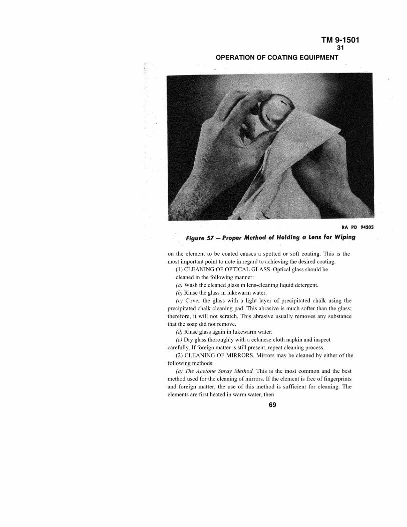
TM 9-150131
OPERATION OF COATING EQUIPMENT
on the element to be coated causes a spotted or soft coating. This is themost important point to note in regard to achieving the desired coating.
(1) CLEANING OF OPTICAL GLASS. Optical glass should becleaned in the following manner:(a) Wash the cleaned glass in lens-cleaning liquid detergent.(b) Rinse the glass in lukewarm water.(c) Cover the glass with a light layer of precipitated chalk using the
precipitated chalk cleaning pad. This abrasive is much softer than the glass;therefore, it will not scratch. This abrasive usually removes any substancethat the soap did not remove.
(d) Rinse glass again in lukewarm water.(e) Dry glass thoroughly with a celanese cloth napkin and inspect
carefully. If foreign matter is still present, repeat cleaning process.(2) CLEANING OF MIRRORS. Mirrors may be cleaned by either of the
following methods:(a) The Acetone Spray Method. This is the most common and the best
method used for the cleaning of mirrors. If the element is free of fingerprintsand foreign matter, the use of this method is sufficient for cleaning. Theelements are first heated in warm water, then
69
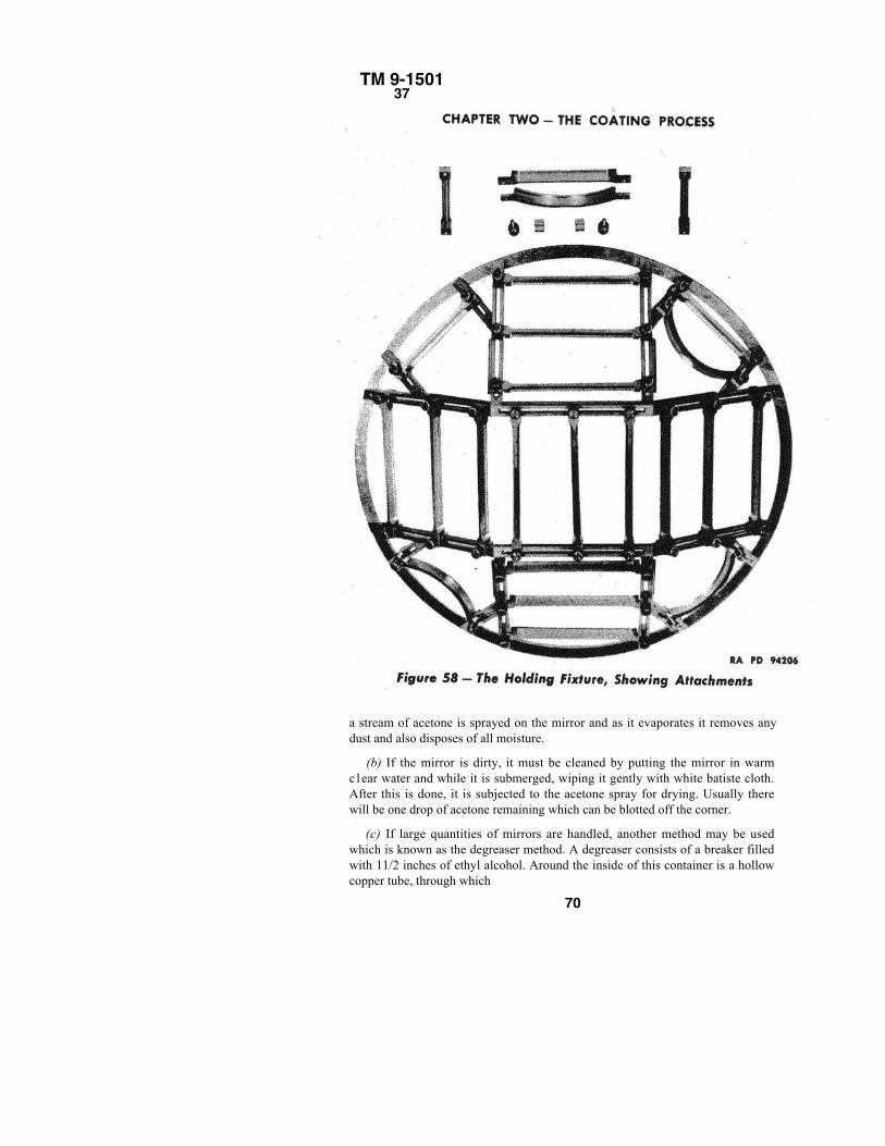
TM 9-150137
a stream of acetone is sprayed on the mirror and as it evaporates it removes anydust and also disposes of all moisture.
(b) If the mirror is dirty, it must be cleaned by putting the mirror in warmc1ear water and while it is submerged, wiping it gently with white batiste cloth.After this is done, it is subjected to the acetone spray for drying. Usually therewill be one drop of acetone remaining which can be blotted off the corner.
(c) If large quantities of mirrors are handled, another method may be usedwhich is known as the degreaser method. A degreaser consists of a breaker filledwith 11/2 inches of ethyl alcohol. Around the inside of this container is a hollowcopper tube, through which
70
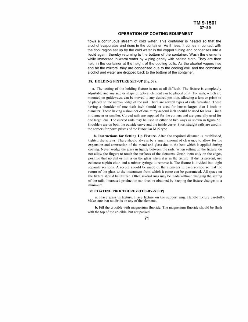
TM 9-150137–39
OPERATION OF COATING EQUIPMENTflows a continuous stream of cold water. This container is heated so that thealcohol evaporates and rises in the container. As it rises, it comes in contact withthe cool region set up by the cold water in the copper tubing and condenses into aliquid again, thereby returning to the bottom of the container. Wash the elementswhile immersed in warm water by wiping gently with batiste cloth. They are thenheld in the container at the height of the cooling coils. As the alcohol vapors riseand hit the mirrors, they are condensed due to the cooling coil, and the combinedalcohol and water are dropped back to the bottom of the container.
38. HOLDING FIXTURE SET-UP (fig. 58).
a. The setting of the holding fixture is not at all difficult. The fixture is completelyadjustable and any size or shape of optical element can be placed on it. The rails, which aremounted on guideways, can be moved to any desired position, allowing a lens or prism tobe placed on the narrow ledge of the rail. There are several types of rails furnished. Thosehaving a shoulder of one-sixth inch should be used for lenses larger than 1 inch indiameter. Those having a shoulder of one thirty-second inch should be used for lens 1 inchin diameter or smaller. Curved rails are supplied for the corners and are generally used forone large lens. The curved rails may be used in either of two ways as shown in figure 58.Shoulders are on both the outside curve and the inside curve. Short straight rails are used inthe corners for porro prisms of the Binocular M15 type.
b. Instructions for Setting Up Fixture. After the required distance is established,tighten the screws. There should always be a small amount of clearance to allow for theexpansion and contraction of the metal and glass due to the heat which is applied duringcoating. Never wedge the glass in tightly between the rails. When setting up the fixture, donot allow the fingers to touch the surfaces of the elements. Grasp them only on the edges,positive that no dirt or lint is on the glass when it is in the fixture. If dirt is present, usecelanese napkin cloth and a rubber syringe to remove it. The fixture is divided into eightseparate sections. A record should be made of the elements in each section so that thereturn of the glass to the instrument from which it came can be guaranteed. All space onthe fixture should be utilized. Often several runs may be made without changing the settingof the rails. Increased production can thus be obtained by keeping the fixture changes to aminimum.
39. COATING PROCEDURE (STEP-BY-STEP).
a. Place glass in fixture. Place fixture on the support ring. Handle fixture carefully.Make sure that no dirt is on any of the elements.
b. Fill the crucible with magnesium fluoride. The magnesium fluoride should be flushwith the top of the crucible, but not packed
71
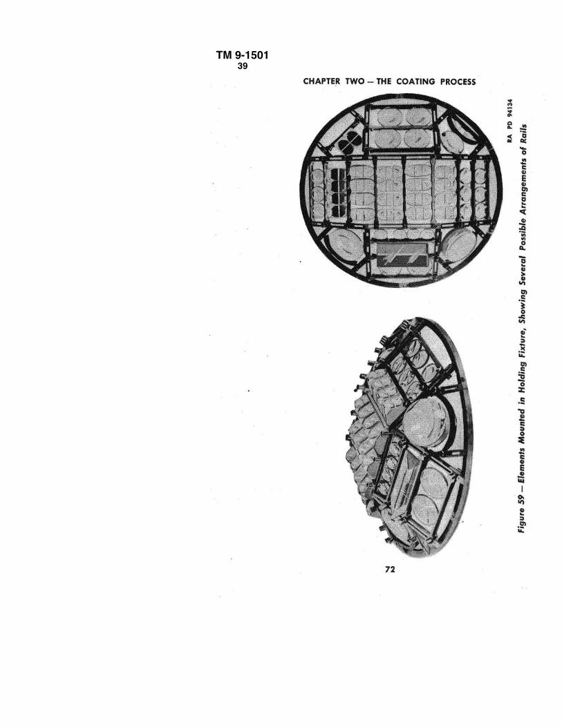
TM 9-150139
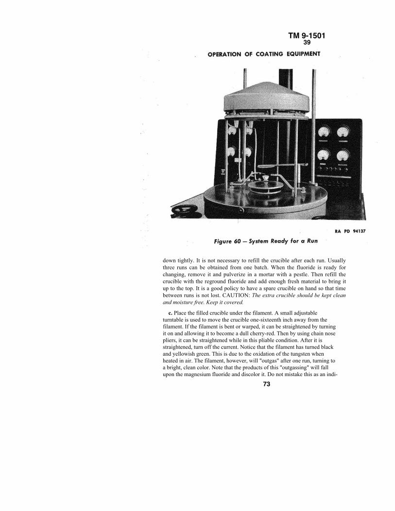
TM 9-150139
down tightly. It is not necessary to refill the crucible after each run. Usuallythree runs can be obtained from one batch. When the fluoride is ready forchanging, remove it and pulverize in a mortar with a pestle. Then refill thecrucible with the reground fluoride and add enough fresh material to bring itup to the top. It is a good policy to have a spare crucible on hand so that timebetween runs is not lost. CAUTION: The extra crucible should be kept cleanand moisture free. Keep it covered.
c. Place the filled crucible under the filament. A small adjustableturntable is used to move the crucible one-sixteenth inch away from thefilament. If the filament is bent or warped, it can be straightened by turningit on and allowing it to become a dull cherry-red. Then by using chain nosepliers, it can be straightened while in this pliable condition. After it isstraightened, turn off the current. Notice that the filament has turned blackand yellowish green. This is due to the oxidation of the tungsten whenheated in air. The filament, however, will "outgas" after one run, turning toa bright, clean color. Note that the products of this "outgassing" will fallupon the magnesium fluoride and discolor it. Do not mistake this as an indi-
73
TM 9-150139
CHAPTER TWO – THE COATING PROCESScation of a leak. Change the magnesium fluoride and notice it after the next run. Themagnesium fluoride should be once again a clean, white or light gray crystallized mass.CAUTION: Never let the filament sink into the magnesium fluoride because this will causespattering.
d. Lower the vacuum tank carefully. Make sure no dirt is under the gasket. Hold the tankdown flush upon the base plate until the pump creates a vacuum sufficient to hold it there.
e. Check to see that the air inlet valve and the vacuum valve are closed. Start mechanicalpump. If the machine is in continuous operation, the mechanical pump should be allowed torun constantly and the vacuum valve should be used to admit and shut off air from thevacuum system to the pump. The vacuum valve must be opened very slowly at first toprevent a rapid drop in pressure, thus avoiding the Wilson cloud.
f. Turn on heater. The heater should be turned up to a dull red color immediately after thesystem is closed and the pump started. If very large masses of glass are coated, it isadvisable to turn the heat up gradually by turning it up halfway for about 15 minutes, andthen to full heat for the remainder of the time. The length of time for heating isapproximately 40 minutes. For large masses of glass, however, about an hour and a quarterare necessary. The glass must attain a heat of 400° F for best results in coating.
g. Turn on Pirani gage. The Pirani gage should be turned on and the steady decrease inpressure observed. The diffusion pump may be turned on only when the pressure is 0.1 mmor 100 microns or less.
h. Turn on diffusion pump. The pilot light will go on only if the water, which flowsthrough the upper coils of the diffusion pump and the baffle housing, is turned on. Neverforget to turn on the water simultaneously with the pump. It is a good practice to make sureno water remains in the coiling coils of the lower part of the pump. This prevents rapidaction of the diffusion pump. To insure against this, use the bicycle pump to blowout anywater present in the lower coils before starting the diffusion pump.
i. When the vacuum is low enough, turn on the ionization gage.
It is best to strive for a vacuum of 5 x 10⁻⁵ mm or better for coating. Coating, however, maybe done at a pressure of 9 x 10⁻⁵ mm. CAUTION: Never coat at a higher pressure than 9 x10⁻⁵ mm. The ion tube should be used to obtain the proper reading, and then turned off inorder to insure longer life.
j. When the pressure is at the desired point, the filament switch is turned on and thefilament variac is turned up until the filament
74
TM 9-150139
OPERATION OF COATlNG EQUIPMENT
is dull red. The filament heats the magnesium fluoride slowly. It is imperativethat the spatter plate be kept over the magnesium fluoride constantly untilactual coating is begun. After 3 minutes of pre-heating, slowly turn thefilament to a bright white, giving off a brilliant light. At this time, examine thefilament and magnesium fluoride through the porthole, using a pair of welding-type goggles to prevent injury to the eyes. It is vital that the magnesiumfluoride be examined for any signs of boiling, bubbling, or excitation, sincethis is the cause of spattering. If the magnesium fluoride appears excited, turnthe heat down to preheat level for a few minutes, and then try again. If themagnesium fluoride appears absolutely motionless, then it is changing directlyfrom a solid to a vapor. This is known as sublimation. When the magnesiumfluoride is ready for coating, swing the spatter plate by moving the outermagnet to either side. It may be observed that the ion gage records an increasein pressure when the filament is on full heat. This shows that the magnesiumfluoride is "outgassing." Heat the magnesium fluoride until the pressure goesdown; then start coating.
k. Allow the fluoride to deposit until the desired color is observed whenusing the fluorescent light extension cord.
l. When the desired color is obtained, perform the following operations atonce: Turn off the filament; turn off the heater; turn off the diffusion pump;and then turn on the water in the lower coils. It will take about 15 minutes forthe pump to cool. The temperature can be tested by feeling the very bottom ofthe diffusion pump. When it is absolutely cold, then the vacuum may bebroken.
m. Before admitting air to the system, close the vacuum valve and allow themechanical pump to continue running. Then slowly admit air to the system.Stop the flow of water in both upper and lower coils, and blow the remainingwater out of the lower coils by use of the hand pump.
n. After the air is let in, raise the vacuum tank carefully. Remove the heater.Then quickly and carefully remove the glass and place under the plastic hoodssupplied. The glass will then cool slowly and not break.
o. Examine the test piece or at least one other piece from each run. Testdurability. If the coat is soft, the glass must be decoated and the reason for thepoor adherence found, and any malfunctions must be corrected.
p. System is now ready for next run.
75
TM 9-150140
CHAPTER TWO - THE COATING PROCESS40. OPERATION WITHIN A SHOP.
a. To organize a coating section for a shop, the following requirements must beremembered:
b. It will be necessary to provide a clean room, large enough to contain:The optical coating machine.The cleaning table.The glass setting table.The inspection and wrapping table.The decoating equipment.The cementing and decementing table. (If possible, a separate room
is preferred for this process.)
c. The following lists the cleaning, preserving, sealing, adhesive, lubricating, and relatedmaterials prescribed in the operating maintenance and preservation procedures:
Nomenclature Fed. Stock No.
ACID, nitric, technical grade (61 %), l-lb ground stopperedBottle ................................................................................................................................51-A-1145
BUTYL PEROXIDE (Ditertiary) catalyst, l-oz amber bottle ..........................................51-B-846-30
COMPOUND, sealing, heavy 1/4-lb jar ............................................................................52-C-3259-25
CEMENT, thermosetting (optician's) 2-oz amber bottle...................................................52-C-1680-950
PAD, cleaning, precipitated chalk, 24 pads per box..........................................................51-P-25
CLOTH, batiste, white, 39 in. wide, (Rose pattern), 5 yd
per box .............................................................................................................................27-C-779
NAPKIN cloth (celanese), lintless, w/hem, size 18 in. x 17 in.
6 in. waterproof envelope................................................................................................27-N-100
CLOTH, cheese, 36 in. wide, 5 yd per waterproof package .............................................27-C-310
DETERGENT. lens-cleaning, liquid 71/2-Ib jar ...............................................................51-D-I07-22
MAGNESIUM FLUORIDE (chemically pure) 1/4-lb jar ................................................51-M-194
OIL, low vapor pressure, lOOO-gram can.........................................................................14-0-1250
POTASSIUM HYDROXIDE, technical grade (flakes), 5-lb tin .....................................51-P-1875
CEMENT, porcelain, liquid 1/2-pt can ..............................................................................52-C-1245
ROUGE, optical, polishing, paste, 4-oz jar........................................................................51-R-439-75
LACQUER, edging, optical lenses, black, 1/4 pt ..............................................................52-L-1024-750
SALT, sodium chloride, technical grade............................................................................56-S-7805
OIL, Navy symbol 2135......................................................................................................
SOAP, castile (issue soap to be used if not available) ......................................................
CANADA, turpentine ... .....................................................................................................51-C-593-10
ACETONE, grade B............................................................................................................51-A-227
ALCOHOL, ethyl, grade 1..................................................................................................51-A-1964
BRUSH, mottling, No.1 (7/8 in.)........................................................................................38-B-2405
CLOTH, crocus, sheets 9 x 11,1 gr ....................................................................................49-C-20420
OIL, castor, technical grade
PAPER, black, velour, roll..................................................................................................53-P-2311
PAPER, lens-tissue, sheets 71/2 x 11 in., 10 sheets per book .........................................53-P-14104
TAPE, cellulose, transparent.
76
TM 9-150140
OPERATION OF COATING EQUIPMENTNomendature Fed. Stock No.
THINNER, enamel, synthetic .......................................................................... 52- T-441-75PAINT, synthetic (glyptal), black.................................................................... 52-P-8057-10PAINT, synthetic (glyptal), red ....................................................................... 52-P-8057-700TRISODIUM-PHOSPHATE........................................................................... 51- T -5943-500VARNISH, shellac, orange, medium body, high iodine ................................ 52-V-2508-10WOOL, steel, commercial, No. 0 .................................................................... 42-W-5018WOOL, steel, commercial, No. 3 .................................................................... 42-W-5040
d. An air-conditioned room is desirable. If such a room is not available, a roomthat is light and airy should be obtained.
e. There should be sufficient water available to provide for the
cleaning and the decoating processes.f. Cold running water should be provided for cooling the diffusion
pump.
g. There should be sufficient electric current available to operate the machinerywithout interruptions. The electrical supply should be 115 volts, 60 cycles,alternating current.
h. A hood should be provided for the decoating set-up to draw off the noxiousfumes. If no hood is available, decoating must be done near an open window.
i. If possible, room should be maintained at an even temperature of about 70° F.The humidity should be kept low for best results in coating.
j. During the actual operation, certain records should be maintained. Thesuggested steps in record keeping are as follows:
(1) The Instrument Repair Section sends the material to the Coating Section tobe coated. The slip number, the date it is sent to the Coating Section, the type ofinstrument, serial number, and the amount and type of optical elements are enteredon the "Coating Slip" (fig. 54) which is sent along with the material.
(2) The chief of the Coating Section receives and checks the material and signsand dates the slip. At this time, an entry is made in the "Coating Slip Register," abook containing the forms shown in figure 55.
(3) The material is decoated and the slip is signed.
(4) The material is decemented and the slip is signed.
(5) The elements are cleaned and the slip is signed.(6) The elements are set up in the glass holding fixture and slip
is signed. The jig number and the section containing the elements noted.
(7) The material is coated and the slip is signed and dated and the run noted.During the coating, a record is kept on each coating run on a "Machine TimeRecord" (fig. 56). Each coating cycle should
77
TM 9-150140
CHAPTER TWO - THE COATING PROCESS
be approximately the same. This record will give an early indication of anyincorrect functioning of the equipment. Comments should be made on the slip ofanything unusual that occurs during the operation.
(8) The elements are recemented and the slip is signed.
(9) The chief of the Coating Section then completes the information in the"Coating Slip Register."
(10) The chief of the Coating Section inspects the elements, signs and dates theslip, and returns the coated material to the chief of the Instrument Repair Sectionwho signs the "Coating Slip Register."
(11) The "Coating Slip" is then filed.
(12) One more record should be maintained. This is the Machine Log Book. Allrepairs performed on the machine should be recorded, giving complete descriptionof the repair, the date the trouble was located, and the date it was repaired. Allchanges of oil should be noted. Any maintenance on the machine should be enteredin the book. Any additions, deletions, or alterations should be recorded. In short, thelog book should be a complete life history of the machine.
(13) Whenever optical elements are sent from the Instrument Repair Section tobe coated, efforts must be made to guarantee that no mix-up in elements will occur.Therefore, a note should be made listing the section of the glass holding fixture inwhich the optical elements of any instrument are placed. Sometimes two identicallenses, usually erectors, are found in one instrument. It is important to keep thecrown and flint of each lens together to avoid improper matching. A good policy isto keep the crown and flint of each set wrapped together in transferring the lensfrom step to step. In actual coating, a set of one crown and one flint should beplaced in the same row and the other set in a different row, far removed from thefirst. Whenever the crown and flint have wide enough edges, the elements shouldbe scribed for identification purposes. To avoid confusion, each barrel of a two-barrel instrument should be treated as a separate instrument.
78
TM 9-150141–43
CHAPTER 3MAINTENANCE OF COATING EQUIPMENT
Section I
INTRODUCTION
41. GENERAL.
a. Vacuum systems are very sensitive. To draw and maintain thedegree of vacuum necessary for coating optics, the equipment mustbe in the best possible condition for operation. There are a greatmany mistakes that can be made which will prevent the machinefrom working properly. The most common mistakes that lead torepair work are discussed in the following paragraphs.
42. BURNING OF DIFFUSION PUMPOIL.
a. The oil in the diffusion pump is heated to a degree where itwill vaporize under vacuum. Under normal atmospheric pressure,where plenty of oxygen is available, the oil will burn or scorchrather than vaporize. The diffusion pump should, therefore, neverbe started under normal atmospheric pressure. If the unit is startedwhen the air inlet valve is not completely closed, or the vacuumtank is not properly lowered so that air is allowed to leak into thesystem, the Pirani gage will not indicate any drop in pressure. If thediffusion pump is started under this condition, diffusion pump oilwill burn and a gummy substance will adhere to parts of thepumping system. The system must then be disassembledcompletely, reconditioned, and reassembled. Another commonmistake is to forget to turn the water on in the upper cooling coilsof the diffusion pump as soon as the pump is started. The rising oilvapors will not condense and will stream into the mechanical pumpand contaminate the oil in the mechanical pump. The pumpingaction of the diffusion pump is thereby not utilized. At the sametime, the amount of oil in the diffusion pump is continuously beingreduced and the oil will soon disintegrate. Igniting the oil may alsoresult from starting the diffusion pump either without, orsimultaneously with, the mechanical pump. Since there is too muchoxygen present in the beginning, the oil will ignite instead ofvaporizing.43. BACK STREAMING OF OIL IN THE MECHANICALPUMP.
a. Another mistake, which makes it necessary to disassemble thepumping equipment, is to stop the mechanical pump simultaneouslywith the diffusion pump after the run is completed. Although theheater is shut off in the diffusion pump, the oil is still boiling, andoil
79
TM 9-150143–47
CHAPTER THREE – MAINTENANCE OF COATING EQUIPMENTvapors are still streaming through the diffusion pump system. If the mechanical pump isshut off, its oil will rush into the diffusion pump and contaminate the diffusion pump oil.Therefore, the mechanical pump should always be kept running until the diffusion pumpis completely cooled.
44. CONTAMINATION OF OIL BY DUST AND DIRT.
a. The consequences of a collection of dust and dirt in the pumping system havealready been discussed. It can be seen that absolute cleanliness is imperative.
45. FOREIGN PARTICLES IN MECHANICAL PUMP.
a. The mechanical pump is a finely machined piece of equipment. If any coarseparticles such as metal, dust, or other abrasives are allowed to enter the system, finegrooves will be worn in the pump piston and cylinder. This will eventually preventproper functioning of the pump. If these grooves are very fine, it will be possible tosmooth the metal part by using crocus cloth. Surfaces treated in this manner will bethoroughly cleaned with acetone prior to installation. However, deep grooves will renderthe part nonrepairable and it must be replaced.
46. FAILURE OF IONIZATION TUBE.
a. The tubes used in the ionization gage are radio tubes, but they are not evacuatedbecause they indicate the degree of vacuum reached in the vacuum system. If theionization gage is turned on at atmospheric pressure, the filament will oxidize and thetube may burn out in a few seconds. The gage should, therefore, never be turned onbefore the Pirani gage indicates that the pressure has been reduced to 1 micron or less.The life of a tube, even under normal operation, is rather limited. The gage should,therefore, be switched off when a reading has been taken. The tube should not be kept incontinuous operation. If the tube is burned out, it must be removed and replaced by anew calibrated tube and the connection to the system must be properly sealed. Burned-out tubes are repairable if they have not previously been repaired. Tubes burned out forthe first time are to be returned to the Frankford Ordnance Depot, Frankford Arsenal,Philadelphia, Pa.
47. FAILURE OF VARIACS.
a. The heating unit which heats the optical elements during the coating operation iscontrolled by a variac. If the heater wires are shorted, the variac will burn out when fullyturned on. The heater leads should be inspected to insure that they are properlyinsulated.
80
TM 9 –1501 48–49
PREVENTIVE MAINTENANCE
4 8 . D E T E R I O R A T I O N O FGASKETS.
a. If the unit is operated properly, the above difficulties will beavoided. However, even under correct operation, some repair work willbe necessary from time to time. Oil vapors affect all rubber gaskets andeventually they will require replacement. Magnesium fluoride vaporsmay get into the pumping system and contaminate it. The sealing willharden in time, become brittle, and allow air to seep into the vacuumsystem. The system then must be disassembled, reconditioned, andreassembled.
Section IIPREVENTIVE MAINTENANCE.
49. CLEANING OF THE EQUIPMENT.
a. When cleaning the tank, it is necessary to swing the tank on therotating device so that it will not be over the machine as it is importantnot to get any foreign matter on the base plate or into the diffusionpump. To clean the tank, use a warm saturated salt solution appliedwith a cheese cloth, rinse with clean warm water, and wipe thoroughly.This method will be used in daily cleaning only. Once a week, the tankshould be cleaned out thoroughly. Use crocus cloth to remove toughfilm and clean thoroughly with acetone. This method is a goodguarantee that all remaining magnesium fluoride film will be entirelyremoved. After cleaning, wash out thoroughly with the warm saltsolution and rinse with clean warm water. Dry with a cleancheesecloth. All parts of the superstructure must be wiped off dailywith the warm salt water solution. The purpose of the daily cleaning isto keep down the accumulation of the magnesium fluoride film. Once aweek the superstructure must be completely dismantled and cleanedthoroughly. At this time the parts are cleaned using acetone and crocuscloth. All of the parts are then rinsed in the salt solution, rinsed withwarm water, and dried thoroughly. Although the base plate is notremoved, it must be cleaned by the same method as the other parts. Thediffusion pump and baffle will be cleaned every 3 months or wheneverit is evident that congealing or disintegration of the oil has occurred.These parts are cleaned with acetone. Each part of the chimney of thediffusion pump must be cleaned separately. The inside of the pumphousing and baffle may be cleaned by rinsing them with acetone. Afterall these parts are thoroughly cleaned, a blast of warm air, if available,should be sent through the pump housing and baffle by removing thecaps from the drain tubes. If the air is not available, the pump may beplaced over a hot plate and heated slightly so as to evaporate theacetone. After assembly and connection to the system, it is best tomake a trial run, not only to check for loose connections, but to"outgas" the system. The mechanical pump must be
81
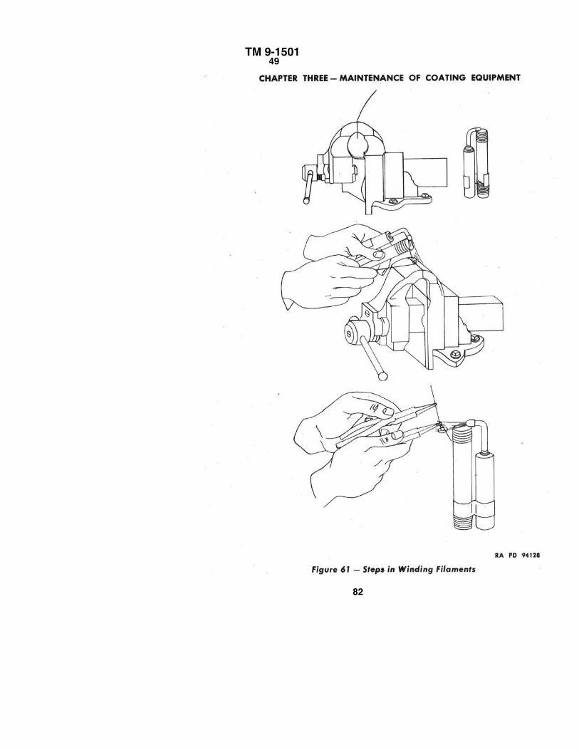
TM 9-1501 49
82
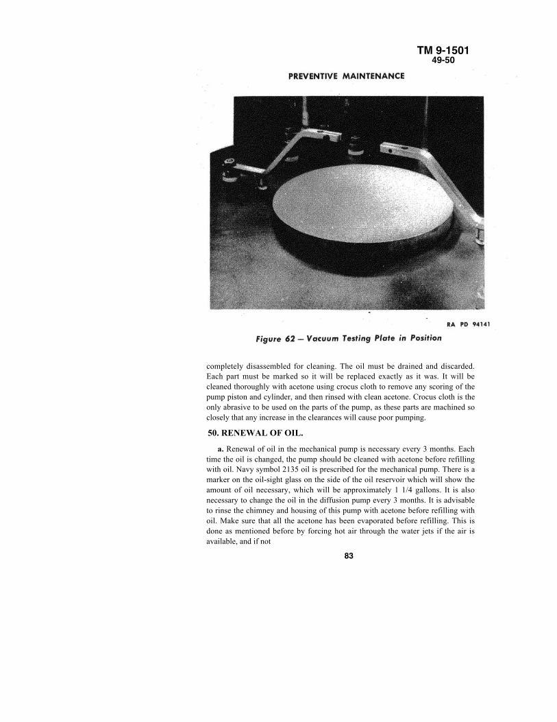
TM 9-150149-50
completely disassembled for cleaning. The oil must be drained and discarded.Each part must be marked so it will be replaced exactly as it was. It will becleaned thoroughly with acetone using crocus cloth to remove any scoring of thepump piston and cylinder, and then rinsed with clean acetone. Crocus cloth is theonly abrasive to be used on the parts of the pump, as these parts are machined soclosely that any increase in the clearances will cause poor pumping.
50. RENEWAL OF OIL.
a. Renewal of oil in the mechanical pump is necessary every 3 months. Eachtime the oil is changed, the pump should be cleaned with acetone before refillingwith oil. Navy symbol 2135 oil is prescribed for the mechanical pump. There is amarker on the oil-sight glass on the side of the oil reservoir which will show theamount of oil necessary, which will be approximately 1 1/4 gallons. It is alsonecessary to change the oil in the diffusion pump every 3 months. It is advisableto rinse the chimney and housing of this pump with acetone before refilling withoil. Make sure that all the acetone has been evaporated before refilling. This isdone as mentioned before by forcing hot air through the water jets if the air isavailable, and if not
83
TM 9-150150–52
CHAPTER THREE – MAINTENANCE OF COATING EQUIPMENT
available, the pump may be put over a hot plate and heated slightly. Lowvapor pressure oil is prescribed for this pump. Use about 700 grams to fillthe pump. Monthly apply six to eight drops of Navy symbol oil 2135 to thedrive shaft end of the 1/2-horsepower mechanical pump motor.
51. REPLACEMENT OF FILAMENTS.
a. The filament wire is tungsten and is 0.035 inch or 0.040 inch indiameter. From tests of wires of sizes it has been found that thinner wire hasa tendency to sag in the center, and thicker wire has too little resistance perunit length. The winding of filaments is quite important. It is done with theuse of an ordinary bench vise or with any type of special jig which can bemade up. The winding of these filaments, because of the brittleness oftungsten, must be done under the application of heat by the use of a bunsenburner or alcohol torch. The spacing between the turns in the filamentshould be approximately one-sixteenth inch. For good distribution of heat, itshould be made in 2 1/2 turns. Any necessary straightening may be doneafter the filament is put in the holders. The filament will be changed when itbreaks and any time when it may look as if it is getting thin. It should beinspected regularly, as a poor coating may result if it breaks during a run.Before replacing the filament, the filament holders should be cleanedthoroughly and the inserts should be filed clean for better connections.
Section IIILEAKS IN VACUUM SYSTEM
52. GENERAL.
a. Leaks as small as a pinhole can create trouble for the coating operator.No discussion of leaks is complete without first mentioning some commonerrors which often mislead the operator into attributing poor vacuums toleaks. Several reasons for not getting a good vacuum, other than thosecaused by leaks, can be avoided if the following precautions are taken:
(1) Improper cooling or lack of cooling of the diffusion pump will causedisintegration of the oil in the diffusion pump. The odor given off by the oilwill indicate whether or not the oil is undergoing any change in structure.Always feel the upper coils to see that the water running through them is atleast 20° F cooler than room temperature.
(2) Check to see that water is not running in lower section when thediffusion pump is on. If this water is running, the oil will not get
84
TM 9-150152–53
LEAKS IN VACUUM SYSTEMhot enough to evaporate and the pressure will not be lowered by the pump.
(3) Check the mechanical pump to see that sufficient oil is present and that it isnot contaminated. Be sure that the control valve in the oil line is turned onapproximately one turn. A scarred or chipped rotor in the pump might causeimproper functioning of the pump, resulting in a poor vacuum.
(4) If the electrical current is not flowing to any parts of the machine, thedesired vacuum may not be obtained. Therefore, examine the electricalconnections.
53. INDICATIONS OF LEAKS.
a. It is very important to be able to recognize symptoms of a leak. If the gagesare functioning properly and they record very poor pressure readings, the chancesare that there is a leak. The most positive leak indicator is the condition of thefluoride. Notice the fluoride after each run. If it is white or has a slight grey tint, thevacuum system is tight. However, if black or very dark grey color, there is a leakwhich allows the air to get into the system, causing the magnesium fluoride tooxidize. To reiterate, the condition of the magnesium fluoride is the best "vacuumbarometer." Sometimes the filament does not appear as brilliant as it should. If thefilament is new and connected properly, the lack of brilliance is attributed to a leak.If an exceedingly thick, brownish deposit forms on the side walls of the vacuumtank, air is leaking in. This deposit is the result of the oxidation of the magnesiumfluoride. If the optical elements are cleaned properly and heated sufficiently buthave a soft coat, a poor vacuum probably existed during the run. If the opticalelements in the glass holding fixture show up with a great variation in color fromend to end of the fixture, then a leak is present causing a poor vacuum. This leak,allowing more air molecules than should be present, cuts down the distance of thefree mean path of the magnesium fluoride molecules. This means that there aremore molecular bombardments than should be the case; hence, the molecules,instead of rushing straight up to the lens and adhering evenly to the surface, aresubject to very erratic motions imparted by the many collisions, and may adhere ingreater concentrations in certain areas and in lesser concentrations in other areas.This is the reason for such color difference over the fixture. It should be commonpractice to close the vacuum valve at the end of each run. The system will be shuttight and the degree of vacuum noted. Before the next run, the gages will be readagain and the vacuum noted. If there is a noticeable difference between the tworeadings, there is a leakage of air into the system.
85
TM 9-150153–54
CHAPTER THREE – MAINTENANCE OF COATING EQUIPMENTCAUTION: The gages may sometimes give a false impression by showing a
good vacuum. However, the magnesium fluoride may be black, the coat may take along time forming, or any of the other indications may exist. Therefore, check for aleak. In other words, even if there is only one indication of a poor vacuum, starttrouble shooting immediately. Always remember that time can be saved if theindications of a leak are recognized and interpreted properly and at once. Constantcare and vigil will keep the machines running continuously.
54. SEARCH FOR A LEAK.
a. Knowing how to search for a leak saves time and keeps the machinesproducing as long and efficiently as possible. When it becomes apparent that a leakis present, the following procedure should be followed:
(1) The leak must be isolated. It therefore becomes necessary to determinewhether the leak is above the base plate, between the base plate and the mechanicalpump, or in the mechanical pump. In order to determine whether the leak is abovethe base plate, use a vacuum testing plate and operate the machine. (A vacuumtesting plate is supplied with each machine.) A rubber disk one-eighth inch thickand 8 inches in diameter is cut from sheet rubber. This should have a hole in thecenter about one-half inch in diameter. There will also be a solid piece of steelthree-quarters inch thick and 8 inches in diameter. To use the vacuum testing plate,the rubber is placed over the opening in the base plate and the metal placed over it.Heavy sealing compound is used to seal the plate over the hole. If the gages, whichare below the base plate, indicate a good vacuum, then the leak must be above thebase plate. Then perform the following:
(a) Check the rubber gasket around the vacuum tank. If certain areas are markedin such a way that channels of magnesium fluoride are present, then the leak mayexist under or around the rubber gasket.
(b) Inspect the vacuum tank for any bending of the edge. If it is marred, cracked,or fractured, a leak may be present.
(c) Check the glass ports. Operate the machine with the vacuum tank lowered.Spray acetone on the glass portholes. Notice if the gage moves, indicating a leak.The acetone spray test works because acetone, which is highly volatile, seeps intothe system, causing an increase in pressure that is recorded by the gages.
(d) Check the seals of the heater and filament electrodes with acetone.
86
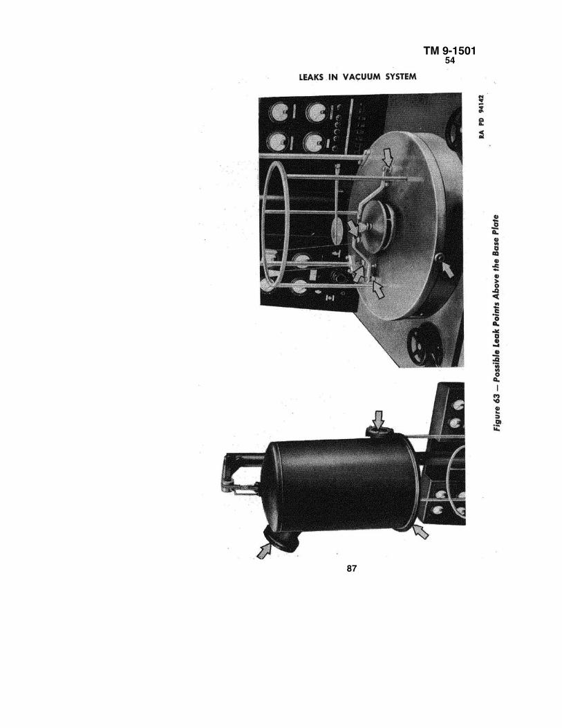
TM 9-150154
87
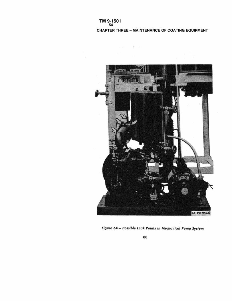
TM 9-1501 54
CHAPTER THREE – MAINTENANCE OF COATING EQUIPMENT
88
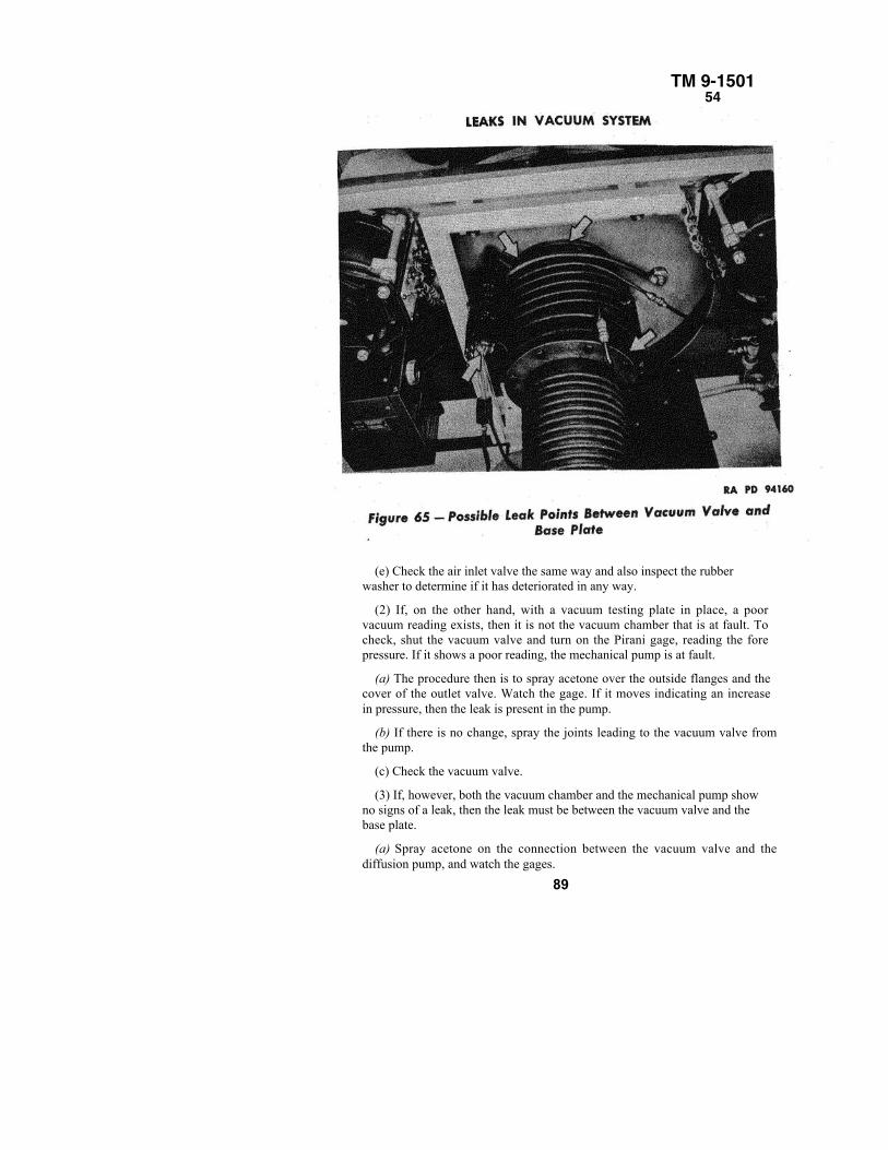
TM 9-150154
(e) Check the air inlet valve the same way and also inspect the rubberwasher to determine if it has deteriorated in any way.
(2) If, on the other hand, with a vacuum testing plate in place, a poorvacuum reading exists, then it is not the vacuum chamber that is at fault. Tocheck, shut the vacuum valve and turn on the Pirani gage, reading the forepressure. If it shows a poor reading, the mechanical pump is at fault.
(a) The procedure then is to spray acetone over the outside flanges and thecover of the outlet valve. Watch the gage. If it moves indicating an increasein pressure, then the leak is present in the pump.
(b) If there is no change, spray the joints leading to the vacuum valve fromthe pump.
(c) Check the vacuum valve.
(3) If, however, both the vacuum chamber and the mechanical pump showno signs of a leak, then the leak must be between the vacuum valve and thebase plate.
(a) Spray acetone on the connection between the vacuum valve and thediffusion pump, and watch the gages.
89
TM 9-150154–56CHAPTER THREE–MAINTENANCE OF COATING EQUIPMENT
(b) Check the connection between the diffusion pump and the baffle housing.
(c) Check the connection between the baffle housing and the base plate.(d) Check the connection of the Pirani gage to the baffle housing.(e) Check the connection of the ion gage to the baffle housing.(f) Check the gages to see that there is no break in the glass.NOTE: Another method of location leaks employs heavy sealing compound.This compound is spread on suspected leak areas. A seal is formed and thegages then record a lower pressure in the system.
55. ELIMINATION OF LEAKS.a. After a leak is located, if it is found to be small, it can be effectively sealed
by painting it with several layers of synthetic paint (glyptal). Synthetic glyptalpaint is available in red and black. Upon being exposed to air it solidifies into asolid airtight waterproof mass. This paint is to be used to seal metal againstmetal, or metal against rubber. However, where glass is to be sealed, as in thecase of the Pirani and ion tubes, heavy sealing compound is often used. This is ayellowish material with the consistency of very thick honey. It has a very lowvapor pressure. If a leak is located and it cannot be effectively sealed withsynthetic paint or heavy sealing compound, the worn part should be replaced. Allgaskets should be examined , for holes, worn spots, cracks, thin spots, misshapenareas, and ragged edges. Defective gaskets should be replaced by new ones.Joints should be tightened and covered with paint. If the plates of the mechanicalpump are leaking, they should be cleaned and replaced with a thin coat of shellacvarnish between the plates and the sides of the pump. The bolts should betightened well and the synthetic paint applied. Broken or cracked tubes should becarefully replaced and properly sealed. The vacuum tank flange should besmoothed out so that there are no marred edges and no cracks. The rubber gasketaround the vacuum tank should be replaced if defective. Any worn parts in thevacuum valve should be replaced.
56. VIRTUAL LEAKS.a. A virtual leak is not actually a true leak, in the sense that outside air is
getting into the system. It merely manifests itself in such a way that it appears asif a slow leak is present in the system. Virtual leaks are caused by the followingconditions:
(1) Continuous "outgassing" of the metal vacuum tank, metal fixtures, moistfluoride, and glass (par. 27).
(2) Gas entrapped in the threads of screws present in the vacuum system isreleased when the pressure is lowered.
90
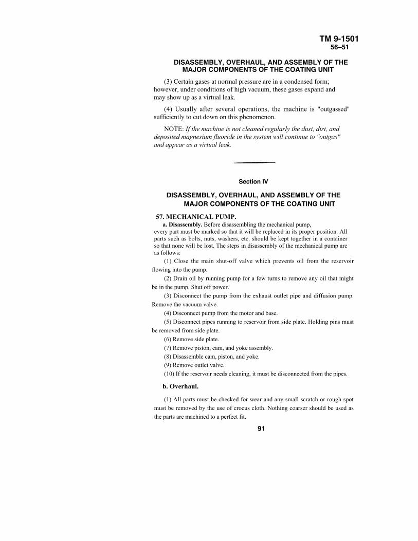
TM 9-150156–51
DISASSEMBLY, OVERHAUL, AND ASSEMBLY OF THEMAJOR COMPONENTS OF THE COATING UNIT
(3) Certain gases at normal pressure are in a condensed form;however, under conditions of high vacuum, these gases expand andmay show up as a virtual leak.
(4) Usually after several operations, the machine is "outgassed"sufficiently to cut down on this phenomenon.
NOTE: If the machine is not cleaned regularly the dust, dirt, anddeposited magnesium fluoride in the system will continue to "outgas"and appear as a virtual leak.
Section IV
DISASSEMBLY, OVERHAUL, AND ASSEMBLY OF THEMAJOR COMPONENTS OF THE COATING UNIT
57. MECHANICAL PUMP.a. Disassembly. Before disassembling the mechanical pump,
every part must be marked so that it will be replaced in its proper position. Allparts such as bolts, nuts, washers, etc. should be kept together in a containerso that none will be lost. The steps in disassembly of the mechanical pump areas follows:
(1) Close the main shut-off valve which prevents oil from the reservoir
flowing into the pump.
(2) Drain oil by running pump for a few turns to remove any oil that might
be in the pump. Shut off power.
(3) Disconnect the pump from the exhaust outlet pipe and diffusion pump.
Remove the vacuum valve.
(4) Disconnect pump from the motor and base.
(5) Disconnect pipes running to reservoir from side plate. Holding pins must
be removed from side plate.
(6) Remove side plate.
(7) Remove piston, cam, and yoke assembly.
(8) Disassemble cam, piston, and yoke.(9) Remove outlet valve.
(10) If the reservoir needs cleaning, it must be disconnected from the pipes.
b. Overhaul.
(1) All parts must be checked for wear and any small scratch or rough spot
must be removed by the use of crocus cloth. Nothing coarser should be used as
the parts are machined to a perfect fit.
91
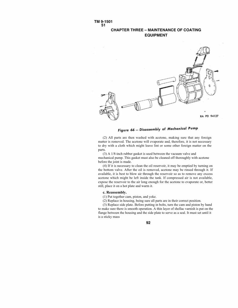
TM 9-150151
CHAPTER THREE – MAINTENANCE OF COATINGEQUIPMENT
(2) All parts are then washed with acetone, making sure that any foreignmatter is removed. The acetone will evaporate and, therefore, it is not necessaryto dry with a cloth which might leave lint or some other foreign matter on theparts.
(3) A 1/8-inch rubber gasket is used between the vacuum valve andmechanical pump. This gasket must also be cleaned off thoroughly with acetonebefore the joint is made.
(4) If it is necessary to clean the oil reservoir, it may be emptied by turning onthe bottom valve. After the oil is removed, acetone may be rinsed through it. Ifavailable, it is best to blow air through the reservoir so as to remove any excessacetone which might be left inside the tank. If compressed air is not available,expose the reservoir to the air long enough for the acetone to evaporate or, betterstill, place it on a hot plate and warm it.
c. Reassembly.(1) Put together cam, piston, and yoke.(2) Replace in housing, being sure all parts are in their correct position.(3) Replace side plate. Before putting in bolts, turn the cam and piston by hand
to make sure there is smooth operation. A thin layer of shellac varnish is put on theflange between the housing and the side plate to serve as a seal. It must set until itis a sticky mass
92
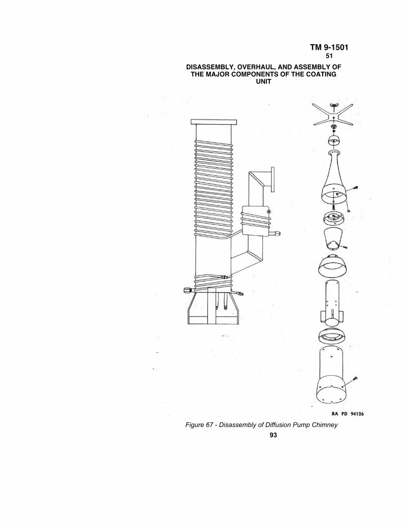
TM 9-150151
DISASSEMBLY, OVERHAUL, AND ASSEMBLY OFTHE MAJOR COMPONENTS OF THE COATING
UNIT
Figure 67 - Disassembly of Diffusion Pump Chimney
93
TM 9-150157–58
CHAPTER THREE – MAINTENANCE OF COATING EQUIPMENT
before putting on side plate. Do not use a rubber gasket. When fastening the side plate tothe housing, insert holding pins, making sure they are securely in place. When putting inthe bolts, tighten them gradually by going from one to the other before fastening them allsecurely.
(4) Replace outlet valve, exactly as it was removed.(5) Connect pipes running to oil reservoir.(6) Fasten pump to the adjustable base and connect to motor.
Adjust distance necessary for correct tightness of V-belt.(7) Connect exhaust outlet pipe, and connect to diffusion pump.(8) After all connections are made, paint all joints two or three times with synthetic(glyptal) paint.(9) Refill oil reservoir with Navy Symbol 2135 oil.(10) Turn on valves which control oil flow. This valve is turned approximately one turn
which controls the flow of oil at the correct speed to prevent flooding the pump.
58. DIFFUSION PUMP AND BAFFLE ASSEMBLY.
a. Disassembly of Diffusion Pump (fig. 38).
(1) Drain oil from the housing.
(2) Disconnect pump coils from the water connections. Disconnect heater wires.
(3) Disconnect diffusion pump from the mechanical pump and the baffle housing.
(4) Remove chimney from the pump housing.
(5) Each section of the chimney should be taken apart.
b. Disassembly of the Baffle Assembly (fig. 38).
(1) Disconnect cooling coils from baffle housing.
(2) Remove Pirani gage and tubes (ion gage) from the baffle housing.
(3) Disconnect housing from the base plate and the diffusion pump.
(4) Remove baffle. This baffle may be removed through the base plate.
c. Overhaul of Diffusion Pump.
(1) As there is no wear of any part, it is not necessary to check the chimney forbrokenparts. The only part of the diffusion pump which might need repairing is the heater coil inthe bottom of the housing or the cooling coils on the outside of the housing.
94
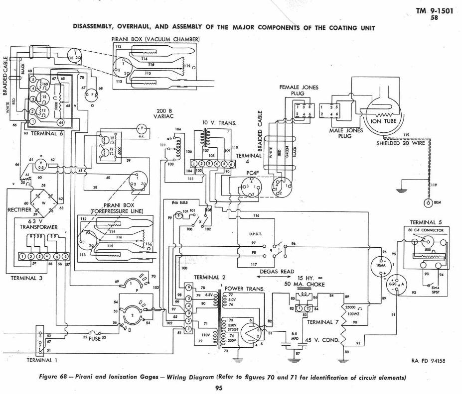
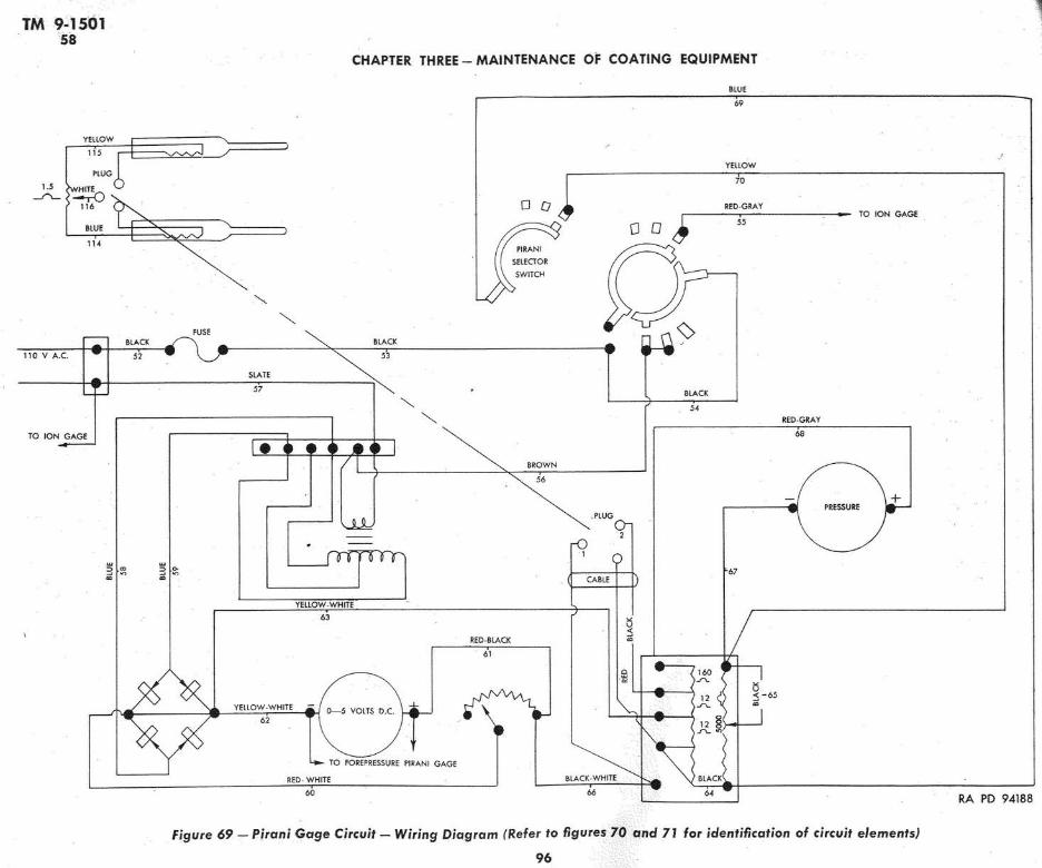
TM 9-150158–59
DISASSEMBLY, OVERHAUL, AND ASSEMBLY OF THE MAJOR COMPONENTSOF THE COATING UNIT
(2) Should the oil disintegrate, burn, follow the regular cleaning method, using eithercrocus cloth or, when needed, steel wool. After this, the inside of the housing must berinsed with acetone.
(3) New gaskets must be made for connection between baffle housing and vacuum valve.
d. Overhaul of Baffle Assembly.
(1) Rinse the baffle housing with acetone and expose to the air to dry, or heat it slightlyover a hot plate.
(2) Check cooling coils.
(3) Clean baffle with crocus cloth and rinse with acetone. This will be done at the sametime the diffusion pump is being overhauled.
(4) Make new gasket for connection between baffle housing and base plate.
e. Reassembly of Baffle Assembly.
(1) Make connections between housing and diffusion pump. Paint this connection withsynthetic (glyptal) paint.
(2) Make necessary water connections.
(3) Mount Pirani gage and tubes (ion gage) in baffle housing.
f. Reassembly of Diffusion Pump.
(1) Reassemble the chimney.
(2) Connect the pump to baffle housing and mechanical pump. These connections mustbe sealed with synthetic (glyptal) paint.
(3) Put 725 grams of low vapor pressure oil into the pump.
(4) Insert chimney into the housing, through the base plate.
(5) Insert baffle through base plate.
(6) Connect the water pipes and attach heater wires to the heater terminals.
59. VACUUM VALVE (fig. 40).
a. If the vacuum valve is suspected to be leaking, there are three places that may be atfault:
(1) The valve stem is sealed against the housing with a rubber gasket. The stem may be
unscrewed from the housing and the gasket replaced. NOTE: Make sure that the valve is
wide open before attempting to unscrew the stem from the housing, otherwise the bellows
might be twisted and break. While the stem is out of the housing, the bellows should not be
extended since it may easily be extended too far and the bellows thereby be damaged. Thisdanger does not exist when the stem is screwed into the housing, since the valve seat
provides an automatic stop against overextension.
97
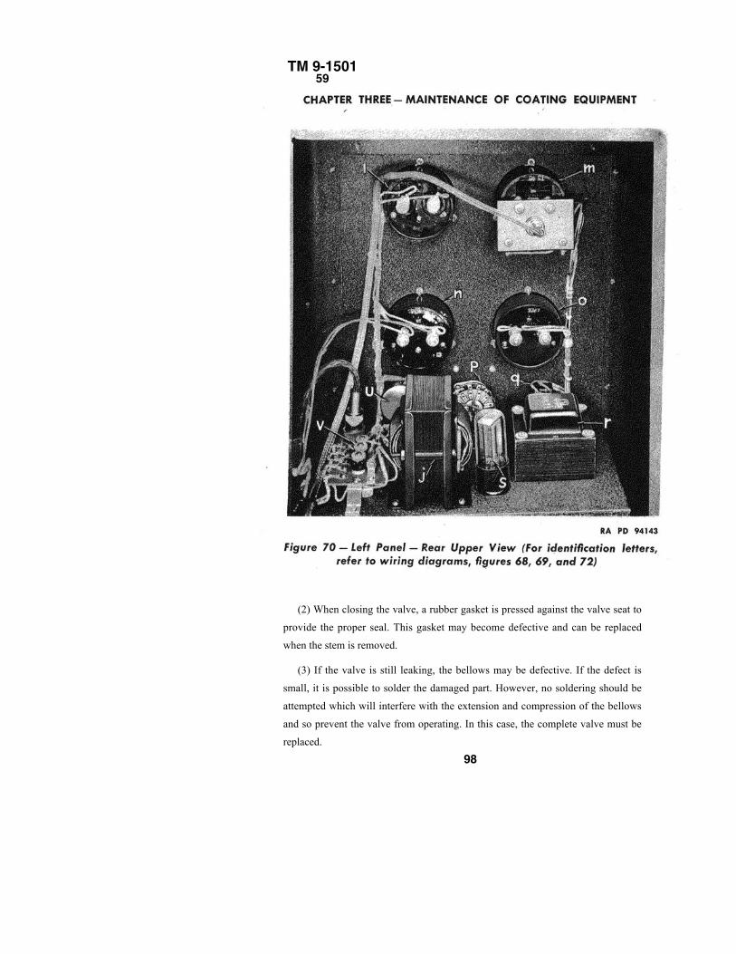
TM 9-150159
(2) When closing the valve, a rubber gasket is pressed against the valve seat to
provide the proper seal. This gasket may become defective and can be replaced
when the stem is removed.
(3) If the valve is still leaking, the bellows may be defective. If the defect is
small, it is possible to solder the damaged part. However, no soldering should be
attempted which will interfere with the extension and compression of the bellows
and so prevent the valve from operating. In this case, the complete valve must be
replaced.
98
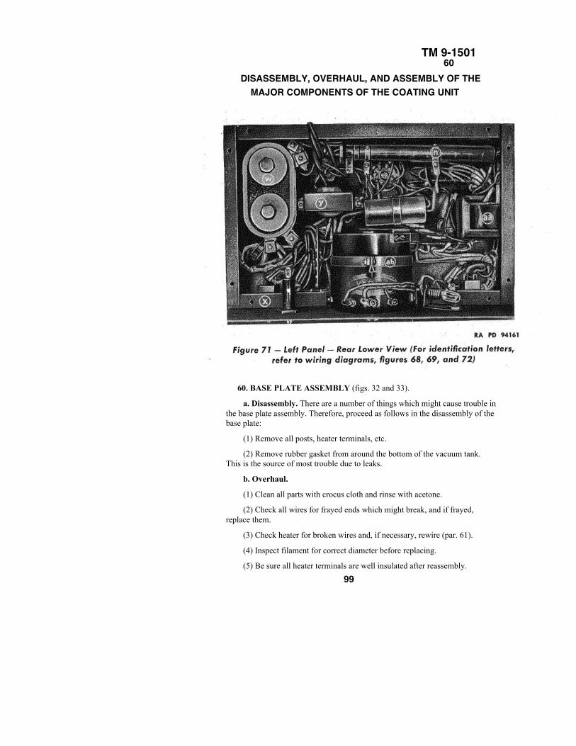
TM 9-150160
DISASSEMBLY, OVERHAUL, AND ASSEMBLY OF THEMAJOR COMPONENTS OF THE COATING UNIT
60. BASE PLATE ASSEMBLY (figs. 32 and 33).
a. Disassembly. There are a number of things which might cause trouble inthe base plate assembly. Therefore, proceed as follows in the disassembly of thebase plate:
(1) Remove all posts, heater terminals, etc.
(2) Remove rubber gasket from around the bottom of the vacuum tank.This is the source of most trouble due to leaks.
b. Overhaul.
(1) Clean all parts with crocus cloth and rinse with acetone.
(2) Check all wires for frayed ends which might break, and if frayed,replace them.
(3) Check heater for broken wires and, if necessary, rewire (par. 61).
(4) Inspect filament for correct diameter before replacing.
(5) Be sure all heater terminals are well insulated after reassembly.
99
TM 9-150160–62CHAPTER THREE – MAINTENANCE OF COATING EQUIPMENT
(6) Check rubber gasket on vacuum tank for wear. When replacing this, rub asmall amount of heavy sealing compound on inside of rubber. After putting it on,fasten and seal it securely by using transparent cellulose tape, making sure it is put onevenly.
(7) Make sure elevating mechanism is in good order at this time.
c. Reassembly.
(1) Replace all posts, heater terminals, etc., making sure of proper insulation.
(2) Replace rubber gasket around bottom of vacuum tank, following instruction above.
NOTE: After all these repairs and checks are made, a trial run must be made to insuregood connections, running order, etc.
61. REWIRING OF HEATER.
a. It may occasionally be necessary to rewire the heater, due to burning out, oxidation,or heavy deposits of fluoride. The heater is wound with No. 14 resistance wire. The wireappears a dull red at 1,000 watts. This requires approximately 35 feet. In rewiring theheater, the wire is strung through the insulators already provided in the spiderlike frame. Itis best to start at the top center and work out to the edge in concentric circles.
62. VACUUM GAGES.
a. Precautions. If vacuum gages are used according to instructions, no damage is likelyto occur to meters or other circuit elements. Precautions pertaining to proper use have beencovered in other sections of this manual. It is emphasized that the ionization gage must neverbe turned on until it is known that the pressure is less than 1 micron, and it must be turned offbefore beginning to coat.
b. Replacement of Tubes. Spare tubes for both Pirani and ionization gages areprovided. The life of these tubes is indeterminate. Unless they are damaged mechanically,they will operate indefinitely, but after a period of operation, they may give erroneousreadings due to absorption of gases in the filaments and oxidation of filaments. Both Piranigage and tubes (ion gage) should be checked once a month, in the following manner:
(1) PIRANI GAGE.
(a) Draw a vacuum in the chamber, using the mechanical pump only for a period of aboutone-half hour. Note the reading of the Pirani gage carefully.
(b) Destroy the vacuum and replace the Pirani gage tube.
100
.
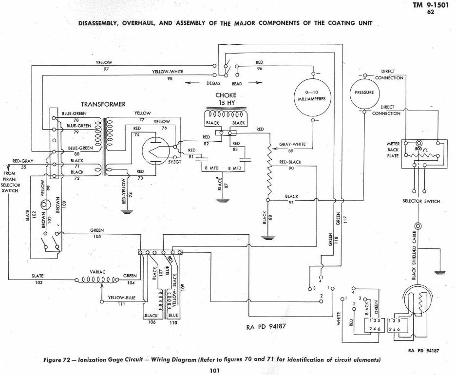
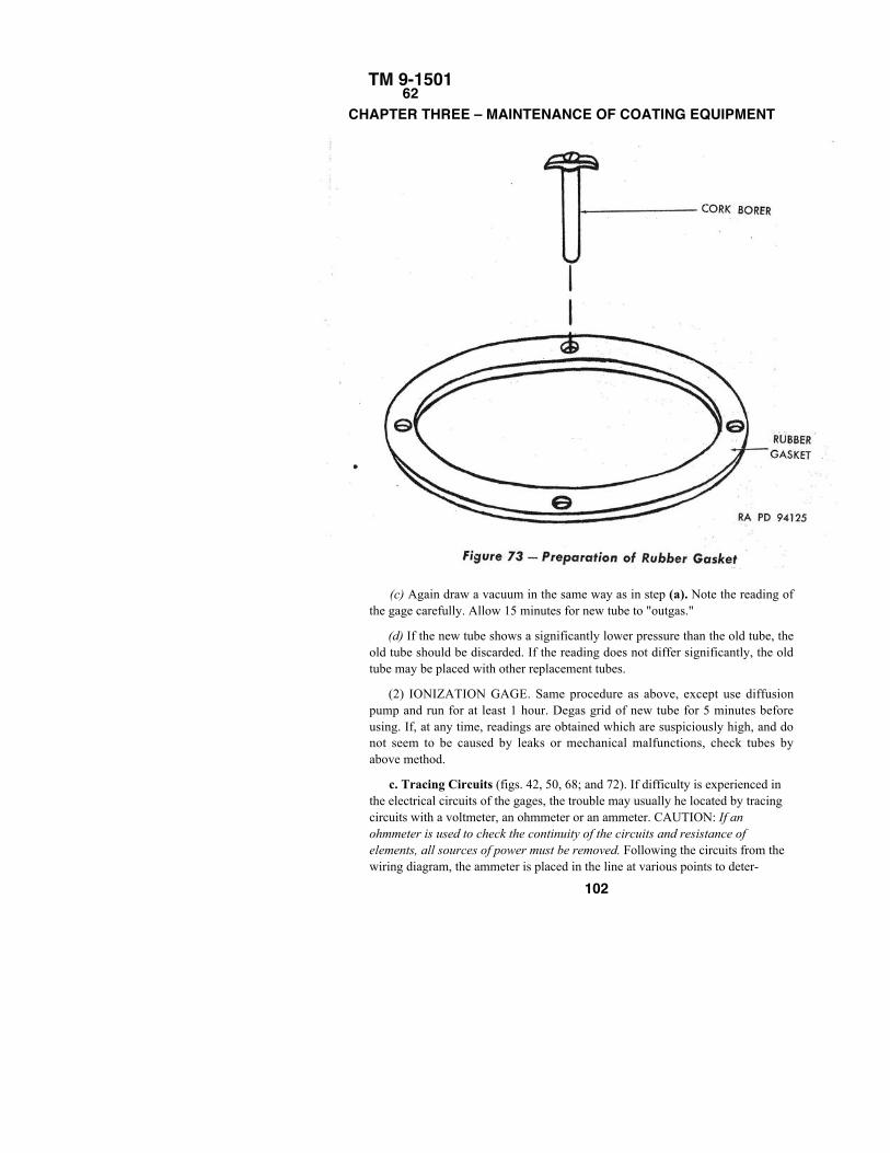
TM 9-150162
CHAPTER THREE – MAINTENANCE OF COATING EQUIPMENT
(c) Again draw a vacuum in the same way as in step (a). Note the reading ofthe gage carefully. Allow 15 minutes for new tube to "outgas."
(d) If the new tube shows a significantly lower pressure than the old tube, theold tube should be discarded. If the reading does not differ significantly, the oldtube may be placed with other replacement tubes.
(2) IONIZATION GAGE. Same procedure as above, except use diffusionpump and run for at least 1 hour. Degas grid of new tube for 5 minutes beforeusing. If, at any time, readings are obtained which are suspiciously high, and donot seem to be caused by leaks or mechanical malfunctions, check tubes byabove method.
c. Tracing Circuits (figs. 42, 50, 68; and 72). If difficulty is experienced inthe electrical circuits of the gages, the trouble may usually he located by tracingcircuits with a voltmeter, an ohmmeter or an ammeter. CAUTION: If anohmmeter is used to check the continuity of the circuits and resistance ofelements, all sources of power must be removed. Following the circuits from thewiring diagram, the ammeter is placed in the line at various points to deter-
102
TM 9-150162–64
DISASSEMBLY, OVERHAUL, AND ASSEMBLY OF THEMAJOR COMPONENTS OF THE COATING UNIT
mine if a current is flowing. Proceed from the power input through the circuits, thuscircuit elements will be eliminated progressively. Be sure the ammeter is not placedacross a line where the current is too heavy for its connection.
63. REPLACEMENT OF GASKETS.
a. It is good policy when disassembling the coating machine to replace all gaskets.Gaskets should not be worn, punctured, frayed at the edges, bent, or so small that theyprove ineffective. They must not be so large that they protrude into the vacuum systemfor then they will be continually "outgassing" into the system and they will provide anarea for the collection of dirt.
b. Rubber gaskets are used in the following places:(1) Around the vacuum tank.(2) Between the glass ports and the vacuum tank.(3) For the heater and filament electrodes.(4) Between the base plate and the baffle housing.(5) Between the baffle housing and the diffusion pump.(6) Between the diffusion pump and the vacuum valve.(7) Between the vacuum valve and the mechanical pump.(8) In the air inlet valve in the base plate.
64. PREPARATION OF GASKET.a. A gasket is made out of 1/8-inch or 1/16-inch sheet rubber or neoprene. An
impression of the flange to be sealed is made upon the rubber in the following manner:(1) Cover the rubber with a smooth, even layer of dry precipitated chalk pad. Then
place the flange directly upon the rubber. Press the flange hard against the rubber. Removethe flange without twisting or turning to prevent smearing of the impression. A clearimprint of the flange and its holes will appear on the rubber.
(2) To cut the rubber gasket, scissors, a gasket cutter, and holecutting devices calledcork borers are supplied. Cut the rubber evenly. Use the cork borers to punch the holes (fig.73).
(3) After the gasket is cut, clean it in soapy water, rinse in clean water, wipe dry, thenrinse in acetone and wipe dry. The gasket should then be ready for use.
(4) Place the gasket between the two flanges. Press together and tighten the bolts.Tighten the bolts only sufficiently to prevent air from leaking. The bolts must not beforced. The gasket will be ineffective if pressed out too much between the plates. Thereshould
103
TM 9-150164
CHAPTER THREE – MAINTENANCE OF COATING EQUIPMENTbe a steady pressure tight enough to keep the rubber firmly pressed between the plates.
(5) After the gasket is in place and the bolts tightened, synthetic (glyptal) paint should beapplied in an even coat. Twenty minutes should be allowed for it to dry; then another coat ofdifferent color should be applied. After another 20-minute drying period, the machine isready for use. The following day, a third and final coat should be applied. Figure 33 showsthe correct type of gasket used for the electrode seals.
104
TM 9-150165–66
CHAPTER 4CEMENTING
Section I
INTRODUCTION
65. REASONS FOR CEMENTING.
a. One of the common properties of glass is its ability to resolve whitelight into its component colors. In lenses this tendency gives rise to colorfringes in the field of view known as chromatic aberration. In order toreduce this effect, it is necessary to compound lenses out of dissimilartypes of glass. By using glasses of different indices of refraction, such ascrown and flint, most of the difficulty may be eliminated.
b. Thus, it will be found that many modern lenses are in realitycomposed of two lenses; usually a converging element of crown glass anda diverging element of flint glass. These lenses are so designed that theflint element counteracts the tendency of the crown element to disperse thelight, and the result is a better transmission of white light. Such a lens iscalled a compound lens.
c. Another reason for using compound lenses is to reduce sphericalaberration, which is caused by the inability of a single element to convergeall rays at a single focus point. In a compound lens the crown, whichcauses the rays to converge too much, is neutralized by the flint whichcauses an excess of divergence.
d. The simplest method for rendering these compound lenses easier tohandle and less likely to be damaged is to cement them permanentlytogether.
e. Another and more important reason for cementing the elementstogether is to avoid loss of light due to the internal reflections that occurbetween the elements. It was observed that an approximate 4 to 6 percentloss of light occurs when light travels from air to glass or glass to air, dueto the change in index of refraction. Therefore the light lost when travelingfrom the crown element to the flint would be roughly 71/2 to 11 percent.Not only is this loss serious, but reflections are disturbing and tend tocause poor image formation. However, when these elements are cementedtogether, this loss becomes almost negligible, since the index of thecement is nearly equal to that of glass.
66. REQUIREMENTS OF LENS CEMENTS.
a. The cement must not flow, fracture, or feather at -45°F.
b. The cement must not flow or soften at 160° F.
105
TM 9-150166–68
CHAPTER FOUR – CEMENTING
c. The cement must not separate, feather, or soften when shocked bya sudden jolt to the instrument.
d. The cement must have an index of refraction close to glass,approximately 1.5, and must not have any noticeable tint ordiscoloration.
67. TYPES OF CEMENTS.
a. Thermoplastic. A thermoplastic type of cement will flow orbecome plastic upon the application of heat. It will solidify upon coolingand can be made to flow again upon the reapplication of heat. Thethermoplastic cement prescribed is Canada turpentine (Canadabalsam).
b. Thermosetting. A thermosetting type of cement will set orbecome solid upon the application of heat. This setting is calledpolymerization. Once the cement sets it will not again melt, no matterhow it is heated. The thermosetting cement prescribed is thermosettingcement (optician's). A more detailed explanation of polymerizationfollows: A liquid, composed of identical molecules which cannot bebroken down into any smaller unit without losing their identity orproperties, is called a monomer. Certain chemical reactions occurcausing these single molecules to combine into large groups. This unionis aided or hastened by the application of heat, the presence of a catalyst,or both. When these single units form large groups, a condition of manymonomers together, or polymers, exists. This combining is calledpolymerization. In order to hasten polymerization of the resinous basecement, both a catalytic agent is added and heat is applied. Thiscombination causes the cement to become more and more viscous untilit becomes a solid.
Section II
THERMOPLASTIC CEMENT
68. DESCRIPTION OF CANADA TURPENTINE (BALSAM).
a. The thermoplastic cement most frequently used is Canada turpentine,commonly called Canada balsam. This cement is translucent and of a yellowishcolor. It is a natural resin taken from the sap of the Douglas fir and possessesthe distinctive odor of pine needles. Canada turpentine (balsam) is usuallysupplied in a solid form and has the property of becoming plastic when heated,and of solidifying when cooled to room temperature. Canada turpentine(balsam) is quite durable, transparent, and colorless when used in thin layers,and has an index of refraction very close to that of glass,
106
TM 9-150168–69
THERMOPLASTIC CEMENT
approximately 1.53. It is exceedingly easy to work, and for most normal uses (wherelenses are not subjected to extremes of temperature or to harsh bumps or knocks) it isan entirely suitable cement. Until recently, it was used almost exclusively in thecementing of all optical elements.
69. CEMENTING TECHNIQUE.
a. The following equipment is necessary:HotplateCanada turpentineEthyl alcoholTweezersCork stoppersV-blocksStraightedgeKnifeSoapy waterLens tissue paperMagnifying glassBlack velour paperMottling brushWhite batiste clothRubber syringeBottle, with cork stopper, to hold cement
b. Cleanliness. The work bench should be absolutely clean and free from grease,dust, dirt, and lint, and should be lined with clean paper if available. The operator'shands and person must be perfectly clean. If possible, a clean apron or coverallshould be worn. Make sure no grit or dust can fall from clothing onto the work.
c. Hotplate Temperature. Set the hotplate at 350° F.
d. Preparation of Cement. Remove the metallic covering
from the bottom of a tube of Canada turpentine (balsam) and insert the stick intothe warmed cement as shown in figure 74.
e. Examination of Elements. Examine the elements to be cemented, making surethat no large chips or fractures are present. Be positive that the elements match bylooking for the interference bands which will appear between the inside surfaces.
f. Cleaning of Elements. Place the elements in a small amount of ethyl alcohol,taking care to prevent scratching of the lens. Use a batiste cloth swab to rub thelenses immersed in alcohol. Remove the flint element first, shaking off the ethylalcohol. Rotate the lens in a clean dry batiste cloth two or three times or until dry(fig. 57). If, upon examination, lint is found, it should be removed with a mot-
107
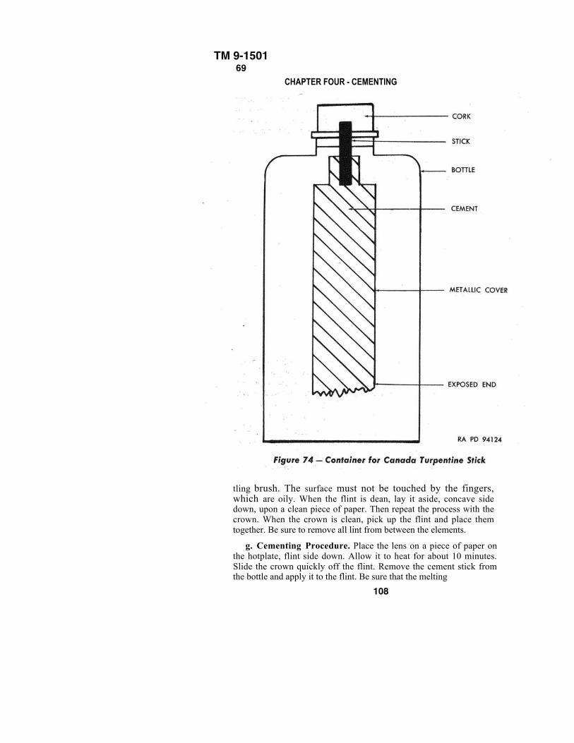
TM 9-150169
CHAPTER FOUR - CEMENTING
tling brush. The surface must not be touched by the fingers,which are oily. When the flint is dean, lay it aside, concave sidedown, upon a clean piece of paper. Then repeat the process with thecrown. When the crown is clean, pick up the flint and place themtogether. Be sure to remove all lint from between the elements.
g. Cementing Procedure. Place the lens on a piece of paper onthe hotplate, flint side down. Allow it to heat for about 10 minutes.Slide the crown quickly off the flint. Remove the cement stick fromthe bottle and apply it to the flint. Be sure that the melting
108
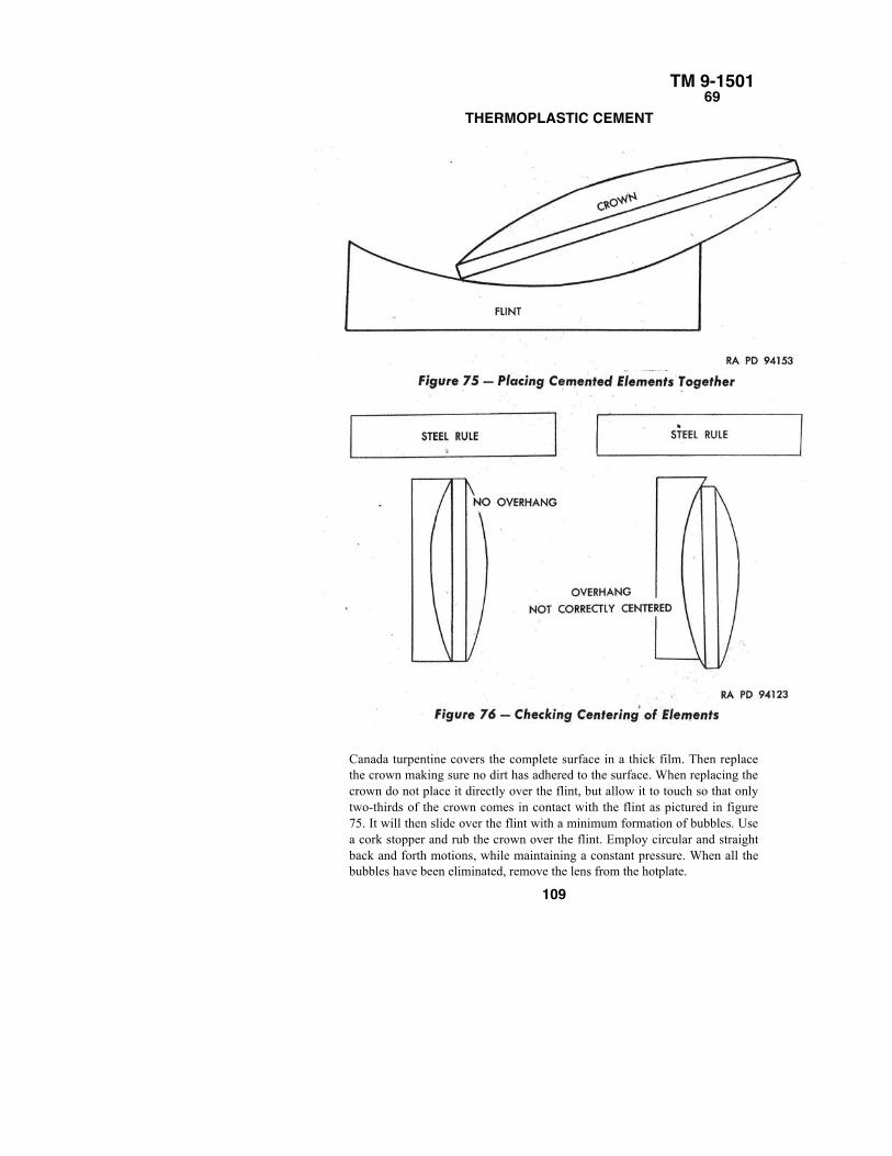
TM 9-150169
THERMOPLASTIC CEMENT
Canada turpentine covers the complete surface in a thick film. Then replacethe crown making sure no dirt has adhered to the surface. When replacing thecrown do not place it directly over the flint, but allow it to touch so that onlytwo-thirds of the crown comes in contact with the flint as pictured in figure75. It will then slide over the flint with a minimum formation of bubbles. Usea cork stopper and rub the crown over the flint. Employ circular and straightback and forth motions, while maintaining a constant pressure. When all thebubbles have been eliminated, remove the lens from the hotplate.
109
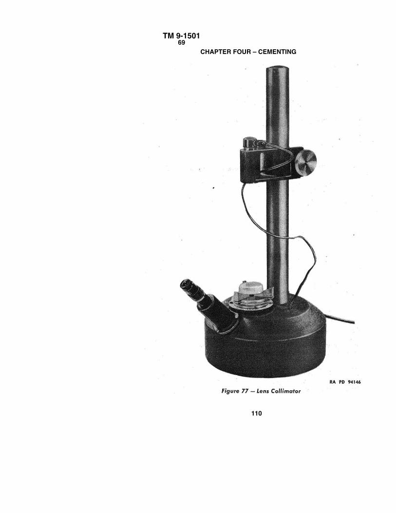
TM 9-150169
CHAPTER FOUR – CEMENTING
110
TM 9-150169
THERMOPLASTIC CEMENTh. Cleaning of Edges. Remove the excess Canada turpentine with the knife while the
cement is still in a plastic state.
i. Centering of Lens. Using two V-blocks, center the lens before the Canada turpentinehardens. If the outside diameters are alined perfectly with the V-blocks, the optical axis willbe absolutely perpendicular to the surface of the lens.
j. Alinement of Elements. When centering is finished, the edges should be in a straightline. To check this, hold the lens edge up to a light source, and, placing a straightedgeperpendicular to the edge, notice if any light seeps under the crown or flint edge. If the lensis not centered, reheat and repeat the process of V-block centering (fig. 76).
k. Checking of Alinement Optically. A more accurate method of checking for correctcentering employs an optical collimator. The cemented lens is placed in an adjustable,rotatable chuck. The lens is then rotated in the chuck several times. The lens therebyfunctions as part of a telescopic system. A light source at the bottom of the collimator sendsparallel rays of light perpendicular to the lens surface. The eye is then placed at the eyepieceand a reticle is viewed. As the lens is rotated, any lack of concentricity of the two elementswill cause the image of the reticle to describe a circle in the field of view. A very slightmovement only is permissible. If it is found that the lens is out of alinement, reheat andrecenter (fig. 77).
1. Cleaning of Lens. When the lens has thoroughly cooled, it is ready to be cleaned. Useethyl alcohol to remove all excess cement. CAUTION: Do not soak. Ethyl alcohol will seepin between the elements.
m. Inspection of the Lens. Examine for lint, dirt, and air bubbles in the cement. A fewsmall pieces of lint or dirt in the periphery of the lens, but not in the effective aperture, maybe acceptable. Any lint or dirt in the center of the lens necessitates re-cementing the lens.Any air bubbles in a lens must be removed because they are danger spots where feathering,deterioration, and separation of the cement start. To remove air bubbles, merely place on thehotplate and when the cement becomes plastic again, rub out the bubbles. NOTE: It isimperative that the lens not be allowed to remain too long on the hotplate once the cement isapplied to prevent oxidation of the cement with attendent loss of adhesive properties.
111
TM 9-150110–12
CHAPTER FOUR – CEMENTING
Section III
THERMOSETTING CEMENT
70. REASONS FOR USING THERMOSETTING CEMENT.
a. Extremes of heat and cold cause balsam to separate, fracture, split, feather, andflower. Efforts to eliminate these difficulties led to the development of such thermosettingelements as PKR-15, HE-2, UV-I01, and thermosetting cement (optician's).
b. For reasons of storage, stability without refrigeration, and ease of handling,thermosetting cement (optician's) was chosen for field service use.
71. DESCRIPTION OF THERMOSETTING CEMENT (OPTIClAN'S).
a. Thermosetting cement (optician's) is a resinous mixture. The chief constituent is asyrupy liquid with a viscosity similar to fresh honey and gives off an odor suggestive ofrubber cement. It has a yellowish color and an index of refraction nearly equal to that ofglass, approximately 1.535. Like balsam, when used in thin layers, it is transparent andcolorless. It is very sensitive to ultraviolet light and should be kept in darkened bottles. It isfairly stable, requires no refrigeration, and will last approximately 3 months at roomtemperature, when not mixed.
72. MIXING OF THERMOSETTING CEMENT (OPTICIAN'S).
a. The cement is supplied in two bottles. One wilt be a 2-ounce bottle containing thecement proper and will be labeled "Thermosetting Cement (Optician's)." A 1-ounce bottle,containing the catalytic agent (Ditertiary), butyl peroxide, is labeled "Catalyst."
b. To each 2-ounce bottle of thermosetting cement add approximately 100 drops of thecatalyst (Ditertiary) butyl peroxide. Be sure the pipette is absolutely clean. Do not mix upmore than one bottle at a time, because once the cement is mixed it will not stay liquid for aperiod longer than 2 weeks. (When polymerization is started, the cement becomes moreviscous each day until it solidifies.) Stir the mixture thoroughly. Make sure it is given avigorous shaking. After it is mixed properly, it may be poured into specially suppliedcement bottles which are complete with glass covers and rods. It must be remembered thatextreme cleanliness is essential at all times.
112
TM 9-150113
THERMOSETTING CEMENT
73. CEMENTING TECHNIQUE.
a. The following equipment is necessary:
HotplateOvenThermosetting cement (optician's), mixed EthylalcoholCork stoppersV-blocksStraightedgeKnifeSoapy waterLens tissue paperLoupeBlack velour paperMottling brushWhite batiste clothRubber syringeBottle and glass rod for cementMetal strips for centeringBattery clipsTweezers
b. Cleanliness. See paragraph 76 b.
c. Hotplate Setting. Set the hotplate at 250° F.
d. Examination of Elements. See paragraph 76 e.
e. Cleaning of the Elements. See paragraph 76 f.
f. Preheating the Lenses. One method of preheating is to place the cleanedlenses in the oven which is set at 180°F allowing them to heat for 15 minutes. Thelenses should then be removed and placed on the hotplate. Another method ofpreheating uses the hotplate alone. Both are acceptable. The lenses should not beallowed to become too hot to hold.
g. Cementing Procedure. Remove the lens from the hotplate. Slide the crownoff the flint quickly and place a few drops of thermosetting cement on the flint.Experience will soon teach the amount of thermosetting cement to use which isapproximately two drops per l-inch diameter. Return the glass rod to the cementbottle and cover the cement. Replace the crown so that approximately two-thirdscontact is obtained (fig. 75). Then use a cork stopper and rub the crown over theflint employing circular and straight back and forth motions, while maintaining aconstant pressure. It will be easy to remove the bubbles and less pressure isrequired than with Canada turpentine.
113
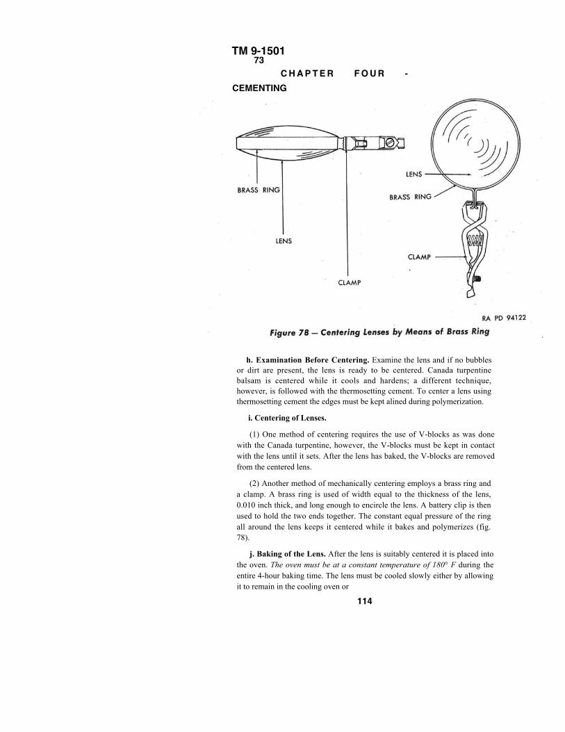
TM 9-150173
C H A P T E R F O U R -CEMENTING
h. Examination Before Centering. Examine the lens and if no bubblesor dirt are present, the lens is ready to be centered. Canada turpentinebalsam is centered while it cools and hardens; a different technique,however, is followed with the thermosetting cement. To center a lens usingthermosetting cement the edges must be kept alined during polymerization.
i. Centering of Lenses.
(1) One method of centering requires the use of V-blocks as was donewith the Canada turpentine, however, the V-blocks must be kept in contactwith the lens until it sets. After the lens has baked, the V-blocks are removedfrom the centered lens.
(2) Another method of mechanically centering employs a brass ring anda clamp. A brass ring is used of width equal to the thickness of the lens,0.010 inch thick, and long enough to encircle the lens. A battery clip is thenused to hold the two ends together. The constant equal pressure of the ringall around the lens keeps it centered while it bakes and polymerizes (fig.78).
j. Baking of the Lens. After the lens is suitably centered it is placed intothe oven. The oven must be at a constant temperature of 180° F during theentire 4-hour baking time. The lens must be cooled slowly either by allowingit to remain in the cooling oven or
114
TM 9-150173–76
DECEMENTINGby wrapping in several layers of cheesecloth immediately upon removal inorder to prevent breakage.
k. The lens must be carefully cleaned with acetone to remove excesscement after cooling is complete.
l. Inspection of Lens. The lens must be inspected for lint, dirt, and airbubbles in the cement. A few small pieces of lint, or dirt in the periphery ofthe lens, but not in the effective aperture, may be acceptable. Any lint or dirtin the center of the lens necessitates the recementing of the lens. Sincethermosetting cement sets into a solid form small air bubbles that are not toonumerous may be acceptable. These small air bubbles will not be areascausing separation as in Canada turpentine. A lens having many bubbles isrejected because the bubbles set up disturbing internal reflections. Bubbles ina field lens or a lens close to the field of view are not acceptable.
m. Checking of Lens. To check how accurately the centering was done,use the steel rule method for a rough check and the collimating method for amore accurate test. This centering technique was discussed underthermoplastic cement in paragraph 76. If the lens is improperly centered, itmust be separated, recemented, and recentered.
CAUTION: Never use Canada turpentine when thermosetting cement isavailable.
Section IV
DECEMENTING
74. DEFINITION.
a. Decementing refers to the methods used to separate the two elements
of a lens. Various methods have been developed for each type of cement.
75. REASONS FOR DECEMENTING.
a. All lenses which are defective because of deterioration of cement must
be separated.
b. All lenses that have a soft or silicious coat must be separated.
c. All uncoated lenses must be separated.
d. Any lens having one defective element must be decemented.
76. TECHNIQUES OF DE CEMENTING.
a. Prior to beginning the decementing operation, it is necessary to
determine the type of cement used by testing its reaction to temperature and
certain solvents. .
115
TM 9-150116
CHAPTER FOUR – CEMENTINGb. First place the lens containing the unknown cement on a hotplate set at
250° F. If the lens may be separated after the application of heat, it has beencemented with a thermoplastic. The odor of pine needles will indicate thatCanada turpentine (Canada balsam) has been used which, after cooling, may beremoved with alcohol. The absence of piney odor indicates that a type of cementhas been used which dissolves in acetone but not in ethyl alcohol. If heat alonedoes not permit separation, a thermosetting cement has been used.
c. To decement thermosetting lenses, the following equipment is necessary:Castor oilBeakerAlcohol torchThermometer reading as high as 550° FTripodTongsCheeseclothWire gauzeStand for supporting thermometer in oil
d. Heat the castor oil in a beaker to a temperature of 450° F. Then carefullyplace the lens into the oil. If a cracking noise is heard in about 30 seconds, allowthe lens to remain in the oil for another minute; then remove and the lens will befound to be entirely separated. If the lens is not entirely decemented the firsttime, color fringes or interference bands will be noticed, in which case the lensmust be replaced in the oil for another minute (fig. 79). CAUTION: Whenever ahot lens is exposed to the air, it must be properly insulated to prevent breakage.Wrap the lens in several layers of cheesecloth every time the lens is removedfrom the hot castor oil.
e. The separation of lenses when placed in hot oil is explained by thedifference in coefficients of expansion of the crown and the flint. The expansionof the elements and the cement all at different rates, causes them to spring awayfrom each other.
f. After the lens has been separated, a thin, solid, cellophanelike film will benoticed adhering to one of the surfaces. To remove this film and the oil, the lensshould be placed into hot soapy water and washed. Washing with ethyl alcoholwill complete the cleaning process.
g. If no cracking noise is heard, and the lens does not come apart in 1 minute,then the lens should be allowed to remain in the oil for at least 5 minutes.Remove the lens, wrap in cheesecloth, and apply pressure to force the elementsapart.
116
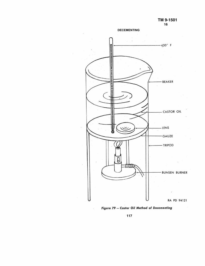
TM 9-150116
DECEMENTING
117
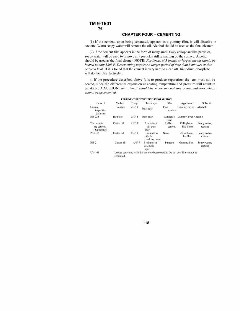
TM 9-150176
CHAPTER FOUR – CEMENTING(1) If the cement, upon being separated, appears as a gummy film, it will dissolve in
acetone. Warm soapy water will remove the oil. Alcohol should be used as the final cleaner.
(2) If the cement film appears in the form of many small flaky cellophanelike particles,soapy water will be used to remove any particles still remaining on the surface. Alcoholshould be used as the final cleaner. NOTE: For lenses of 3 inches or larger, the oil should beheated to only 380° F. Decementing requires a longer period of time than 5 minutes at thisreduced heat. If it is found that the cement is very hard to clean off, tri-sodium-phosphatewill do the job effectively.
h. If the procedure described above fails to produce separation, the lens must not becoated, since the differential expansion at coating temperature and pressure will result inbreakage: CAUTION: No attempt should be made to coat any compound lens whichcannot be decemented.
PERTINENT DECEMENTING INFORMATION
Cement Method Temp. Technique Odor Appearance Solvent
Canada Hotplate 250° F Pine Gummy layer Alcohol turpentine
Push apartneedles
(balsam) HE-225 Hotplate 250° F Push apart Synthetic Gummy layer Acetone
resin Thermoset- Castor oil 450° F 5 minutes in Rubber Cellophane- Soapy water,
ing cement oil, push cement like fiakes acetone ( Optician's) apart
PKR-15 Castor oil 450° F 1 minute in None Cellophane. Soapy water,oil after like film acetonecracking noise
HE-2 Castor oil 450° F 5 minute. in Pungent Gummy film Soapy water,oil, push acetoneapart
UV-101 Lenses cemented with this are not decementable. Do not coat if it cannot beseparated.
118
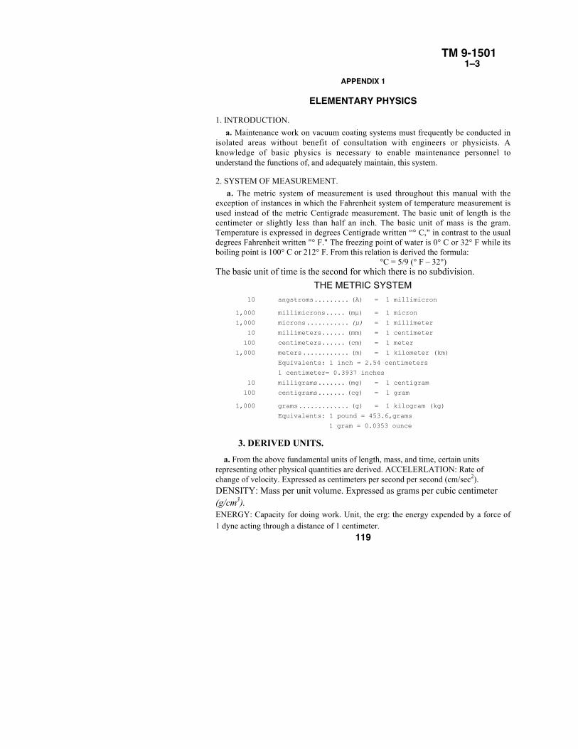
TM 9-15011–3
APPENDIX 1
ELEMENTARY PHYSICS
1. INTRODUCTION.
a. Maintenance work on vacuum coating systems must frequently be conducted inisolated areas without benefit of consultation with engineers or physicists. Aknowledge of basic physics is necessary to enable maintenance personnel tounderstand the functions of, and adequately maintain, this system.
2. SYSTEM OF MEASUREMENT.
a. The metric system of measurement is used throughout this manual with theexception of instances in which the Fahrenheit system of temperature measurement isused instead of the metric Centigrade measurement. The basic unit of length is thecentimeter or slightly less than half an inch. The basic unit of mass is the gram.Temperature is expressed in degrees Centigrade written “° C," in contrast to the usualdegrees Fahrenheit written "° F." The freezing point of water is 0° C or 32° F while itsboiling point is 100° C or 212° F. From this relation is derived the formula:
°C = 5/9 (° F – 32°)The basic unit of time is the second for which there is no subdivision.
THE METRIC SYSTEM10 angstroms......... (A) = 1 millimicron
1,000 millimicrons..... (mµ) = 1 micron
1,000 microns........... (µ) = 1 millimeter
10 millimeters...... (mm) = 1 centimeter
100 centimeters...... (cm) = 1 meter
1,000 meters............ (m) = 1 kilometer (km)
Equivalents: 1 inch = 2.54 centimeters
1 centimeter= 0.3937 inches
10 milligrams....... (mg) = 1 centigram
100 centigrams....... (cg) = 1 gram
1,000 grams............. (g) = 1 kilogram (kg)
Equivalents: 1 pound = 453.6,grams
1 gram = 0.0353 ounce
3. DERIVED UNITS.
a. From the above fundamental units of length, mass, and time, certain unitsrepresenting other physical quantities are derived. ACCELERLATION: Rate ofchange of velocity. Expressed as centimeters per second per second (cm/sec2).DENSITY: Mass per unit volume. Expressed as grams per cubic centimeter(g/cm3).ENERGY: Capacity for doing work. Unit, the erg: the energy expended by a force of1 dyne acting through a distance of 1 centimeter.
119
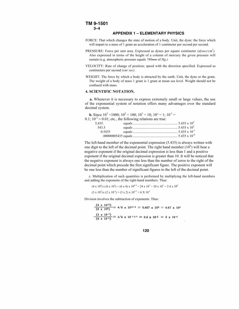
TM 9-15013–4
APPENDIX 1 – ELEMENTARY PHYSICSFORCE: That which changes the state of motion of a body. Unit, the dyne: the force which
will impart to a mass of 1 gram an acceleration of 1 centimeter per second per second.
PRESSURE: Force per unit area. Expressed as dynes per square centimeter (dynes/cm2).Also expressed in terms of the height of a column of mercury the given pressure willsustain (e.g. atmospheric pressure equals 760mm of Hg.).
VELOCITY: Rate of change of position; speed with the direction specified. Expressed ascentimeters per second (cm/ sec).
WEIGHT: The force by which a body is attracted by the earth. Unit, the dyne or the gram.The weight of a body of mass 1 gram is 1 gram at mean sea level. Weight should not beconfused with mass.
4. SCIENTIFIC NOTATION.
a. Whenever it is necessary to express extremely small or large values, the useof the exponential system of notation offers many advantages over the standarddecimal system.
b. Since 103 =1000; 102 = 100; 101 = 10; 10° = 1; 10-1 =0.1; 10-2 = 0.01; etc., the following relations are true:
5,435. equals ..................................................... 5.435 x 10³
543.5 equals ..................................................... 5.435 x 10²
0.5435 equals ..................................................... 5.435 x 10⁻¹
.00000005435 equals ..................................................... 5.435 x 10⁻⁸
The left-hand member of the exponential expression (5.435) is always written withone digit to the left of the decimal point. The right hand member (10x) will bear anegative exponent if the original decimal expression is less than 1 and a positiveexponent if the original decimal expression is greater than 10. It will be noticed thatthe negative exponent is always one less than the number of zeros to the right of thedecimal point which precede the first significant figure. The positive exponent willbe one less than the number of significant figures to the left of the decimal point.
c. Multiplication of such quantities is performed by multiplying the left-hand membersand adding the exponents of the right-hand members. Thus:
(4 x 104) x (6 x 103) = (6 x 4) x 104+3 = 24 x 107 = 24 x 107 = 2.4 x 10⁸
(3 x 103) x (2 x 10-5) = (3 x 2) x 103-5 = 6 X 10⁻²
Division involves the subtraction of exponents. Thus:
120
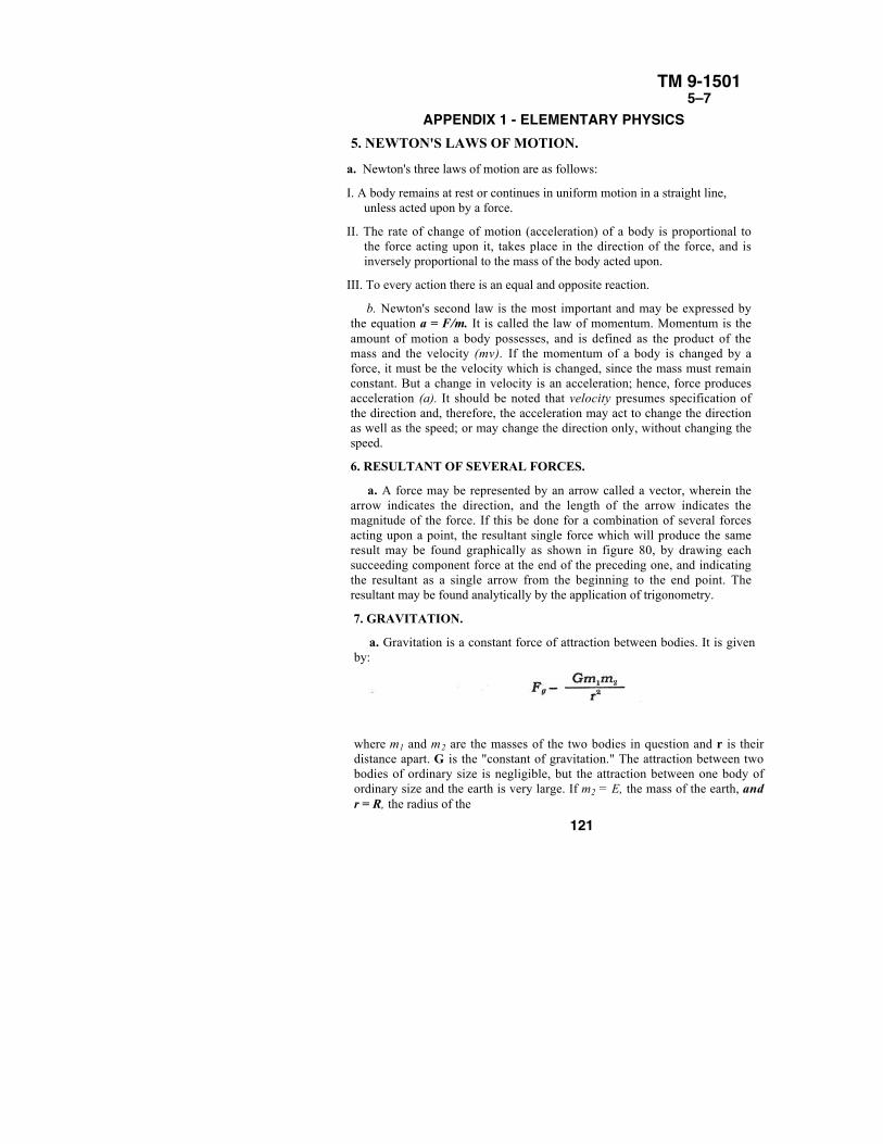
TM 9-15015–7
APPENDIX 1 - ELEMENTARY PHYSICS5. NEWTON'S LAWS OF MOTION.
a. Newton's three laws of motion are as follows:
I. A body remains at rest or continues in uniform motion in a straight line,unless acted upon by a force.
II. The rate of change of motion (acceleration) of a body is proportional tothe force acting upon it, takes place in the direction of the force, and isinversely proportional to the mass of the body acted upon.
III. To every action there is an equal and opposite reaction.
b. Newton's second law is the most important and may be expressed bythe equation a = F/m. It is called the law of momentum. Momentum is theamount of motion a body possesses, and is defined as the product of themass and the velocity (mv). If the momentum of a body is changed by aforce, it must be the velocity which is changed, since the mass must remainconstant. But a change in velocity is an acceleration; hence, force producesacceleration (a). It should be noted that velocity presumes specification ofthe direction and, therefore, the acceleration may act to change the directionas well as the speed; or may change the direction only, without changing thespeed.
6. RESULTANT OF SEVERAL FORCES.
a. A force may be represented by an arrow called a vector, wherein thearrow indicates the direction, and the length of the arrow indicates themagnitude of the force. If this be done for a combination of several forcesacting upon a point, the resultant single force which will produce the sameresult may be found graphically as shown in figure 80, by drawing eachsucceeding component force at the end of the preceding one, and indicatingthe resultant as a single arrow from the beginning to the end point. Theresultant may be found analytically by the application of trigonometry.
7. GRAVITATION.
a. Gravitation is a constant force of attraction between bodies. It is givenby:
where m1 and m2 are the masses of the two bodies in question and r is theirdistance apart. G is the "constant of gravitation." The attraction between twobodies of ordinary size is negligible, but the attraction between one body ofordinary size and the earth is very large. If m2 = E, the mass of the earth, andr = R, the radius of the
121
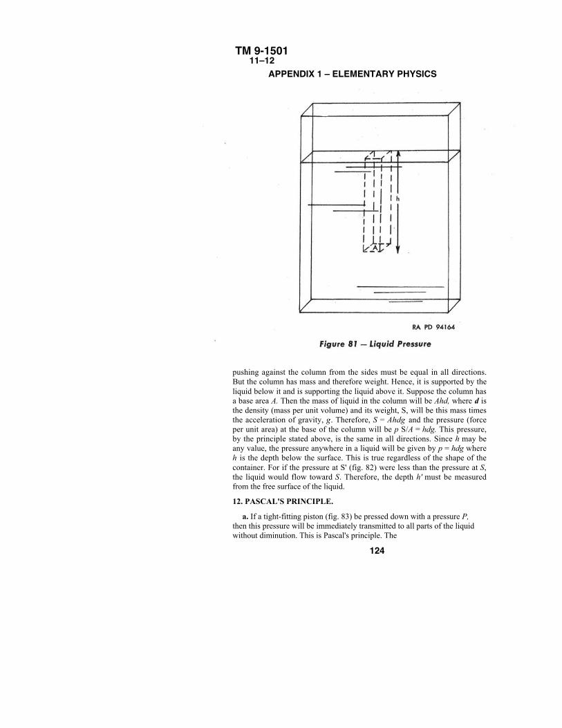
TM 9-150111–12
APPENDIX 1 – ELEMENTARY PHYSICS
pushing against the column from the sides must be equal in all directions.But the column has mass and therefore weight. Hence, it is supported by theliquid below it and is supporting the liquid above it. Suppose the column hasa base area A. Then the mass of liquid in the column will be Ahd, where d isthe density (mass per unit volume) and its weight, S, will be this mass timesthe acceleration of gravity, g. Therefore, S = Ahdg and the pressure (forceper unit area) at the base of the column will be p S/A = hdg. This pressure,by the principle stated above, is the same in all directions. Since h may beany value, the pressure anywhere in a liquid will be given by p = hdg whereh is the depth below the surface. This is true regardless of the shape of thecontainer. For if the pressure at S' (fig. 82) were less than the pressure at S,the liquid would flow toward S. Therefore, the depth h' must be measuredfrom the free surface of the liquid.
12. PASCAL'S PRINCIPLE.
a. If a tight-fitting piston (fig. 83) be pressed down with a pressure P,then this pressure will be immediately transmitted to all parts of the liquidwithout diminution. This is Pascal's principle. The
124
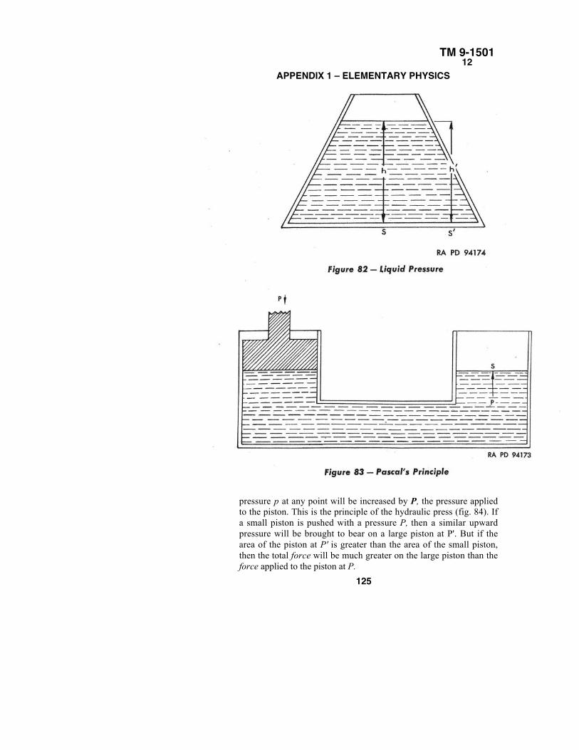
TM 9-150112
APPENDIX 1 – ELEMENTARY PHYSICS
pressure p at any point will be increased by P, the pressure appliedto the piston. This is the principle of the hydraulic press (fig. 84). Ifa small piston is pushed with a pressure P, then a similar upwardpressure will be brought to bear on a large piston at P'. But if thearea of the piston at P' is greater than the area of the small piston,then the total force will be much greater on the large piston than theforce applied to the piston at P.
125
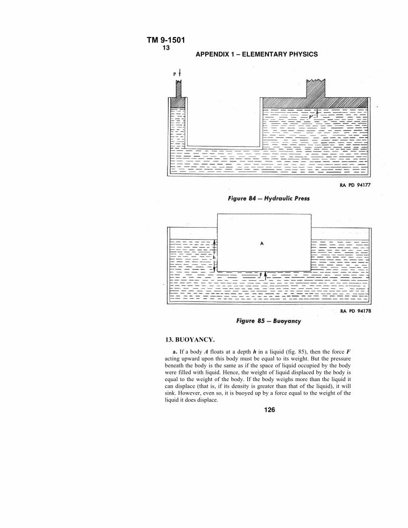
TM 9-150113
APPENDIX 1 – ELEMENTARY PHYSICS
13. BUOYANCY.
a. If a body A floats at a depth h in a liquid (fig. 85), then the force Facting upward upon this body must be equal to its weight. But the pressurebeneath the body is the same as if the space of liquid occupied by the bodywere filled with liquid. Hence, the weight of liquid displaced by the body isequal to the weight of the body. If the body weighs more than the liquid itcan displace (that is, if its density is greater than that of the liquid), it willsink. However, even so, it is buoyed up by a force equal to the weight of theliquid it does displace.
126
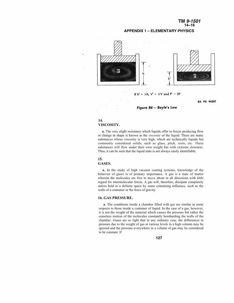
TM 9-150114–16
APPENDIX 1 – ELEMENTARY PHYSICS
14.VISCOSITY.
a. The very slight resistance which liquids offer to forces producing flowor change in shape is known as the viscosity of the liquid. There are manysubstances whose viscosity is very high, which are technically liquids butcommonly considered solids, such as glass, pitch, resin, etc. Thesesubstances will flow under their own weight but with extreme slowness.Thus, it can be seen that the liquid state is not always easily identifiable.
15.GASES.
a. In the study of high vacuum coating systems, knowledge of thebehavior of gases is of primary importance. A gas is a state of matterwherein the molecules are free to move about in all directions with littleregard for intermolecular forces. A gas will, therefore, dissipate completelyunless held in a definite space by some containing influence, such as thewalls of a container or the force of gravity.
16. GAS PRESSURE.
a. The conditions inside a chamber filled with gas are similar in somerespects to those inside a container of liquid. In the case of a gas, however,it is not the weight of the material which causes the pressure but rather theceaseless motion of the molecules constantly bombarding the walls of thechamber. Gases are so light that in any ordinary case, the differences inpressure due to the weight of gas at various levels in a high column may beignored and the pressure everywhere in a volume of gas may be consideredto be constant. If
127
TM 9-150116–19
APPENDIX 1 – ELEMENTARY PHYSICSthe volume, V, of the gas is reduced, as by a piston (fig. 88), the moleculeswill not have so far to travel to strike the chamber walls and hence willstrike more often; also, there will be more molecules per unit volume thanbefore and the pressure will therefore increase. The law describing therelation between pressure and volume states that the product of thepressure and the volume is constant, or PV = constant. Thus, if eitherpressure of volume changes, the other quantity must vary inversely. This istrue only if the temperature remains constant.
17.
TEMPERATURE.
a. It has been proven that temperature is merely an indication of thekinetic energy of molecules. But if the kinetic energy of the moleculesincreases, they will bombard the walls of the chamber more vigorously andhence the pressure will be greater. The law describing this property of gasis known as Charles' Law and states that the pressure is directlyproportional to the temperature, or P = kT.
18. GENERAL GAS LAW.
a. Boyle's Law and Charles' Law can be combined to give theGeneral Gas Law, which is PV = RT. Since the constant R in theabove equation will vary with the kind and quantity of gasconcerned, it may be rendered even more general by evaluation andwe can derive the equation
in which m is the mass of the gas being considered, M is the molecularweight (par. 19) and R is the universal gas constant and is equal to 1.83 x10⁷. An important conclusion which will not be proven is that at a givenpressure and temperature, a given volume of gas always contains the samenumber of molecules, regardless of the kind of gas.
19. MOLECULAR WEIGHT AND THE GRAM
MOLECULE.
a. If given volumes of different gases are weighed at a specifictemperature and pressure, the relative weights of the gases areobtained since, by the conclusion stated above, each samplecontains the same number of molecules. The standard conditionsare: temperature 0° C, pressure 760mm (atmospheric). The standardvolume is so defined that the weight of the sample of oxygen is 32grams. The relative weights so determined are known as themolecular weights of the gases concerned.
128
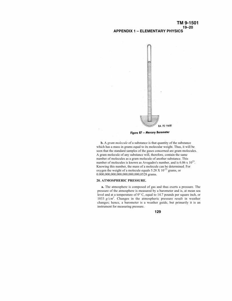
TM 9-150119–20
APPENDIX 1 – ELEMENTARY PHYSICS
b. A gram molecule of a substance is that quantity of the substancewhich has a mass in grams equal to its molecular weight. Thus, it will beseen that the standard samples of the gases concerned are gram molecules.A gram molecule of any substance will, therefore, contain the samenumber of molecules as a gram molecule of another substance. Thisnumber of molecules is known as Avogadro's number, and is 6.06 x 10²³.Knowing this number, the mass of a molecule can be determined. Foroxygen the weight of a molecule equals 5.28 X 10⁻²³ grams, or0.000,000,000,000,000,000,000,0528 grams.
20. ATMOSPHERIC PRESSURE.
a. The atmosphere is composed of gas and thus exerts a pressure. Thepressure of the atmosphere is measured by a barometer and is, at mean sealevel and at a temperature of 0° C, equal to 14.7 pounds per square inch, or1033 g/cm2. Changes in the atmospheric pressure result in weatherchanges; hence, a barometer is a weather guide, but primarily it is aninstrument for measuring pressure.
129
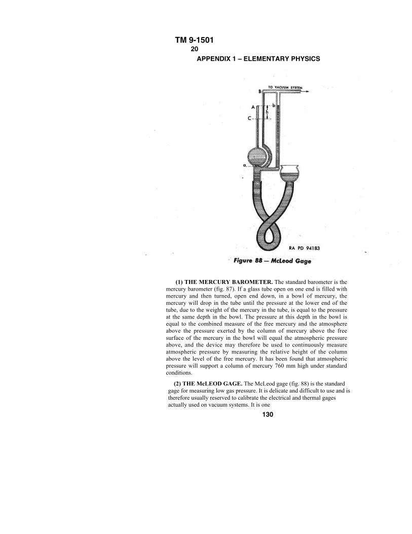
TM 9-150120
APPENDIX 1 – ELEMENTARY PHYSICS
(1) THE MERCURY BAROMETER. The standard barometer is themercury barometer (fig. 87). If a glass tube open on one end is filled withmercury and then turned, open end down, in a bowl of mercury, themercury will drop in the tube until the pressure at the lower end of thetube, due to the weight of the mercury in the tube, is equal to the pressureat the same depth in the bowl. The pressure at this depth in the bowl isequal to the combined measure of the free mercury and the atmosphereabove the pressure exerted by the column of mercury above the freesurface of the mercury in the bowl will equal the atmospheric pressureabove, and the device may therefore be used to continuously measureatmospheric pressure by measuring the relative height of the columnabove the level of the free mercury. It has been found that atmosphericpressure will support a column of mercury 760 mm high under standardconditions.
(2) THE McLEOD GAGE. The McLeod gage (fig. 88) is the standardgage for measuring low gas pressure. It is delicate and difficult to use and istherefore usually reserved to calibrate the electrical and thermal gagesactually used on vacuum systems. It is one
130
TM 9-150120–21
APPENDIX 1 – ELEMENTARY PHYSICSof the few gages actually capable of making a direct measurement ofpressure.
(a) The, McLeod gage consists of two capillary (small-diameter) tubes, Aand B, both of the same inside diameter. One is connected with a chamberand both the chamber and the second capillary are connected to a reservoirC, as shown in the diagram. The second capillary opens into the chamber inwhich the pressure is to be measured.
(b) The reservoir is filled with mercury and lowered until the level of themercury in the gage is below the point a. At this time the pressurethroughout the gage is equal to the pressure to be measured. The reservoir israised, causing the level of mercury to rise in the gage. When the mercuryreaches s, the chamber and capillary tube A are sealed off from the rest ofthe gage. The volume of the chamber and capillary A has been carefullymeasured and is accurately known. If this known volume is called V, then inA the condition pV exists where p is the pressure to be determined. If thereservoir is raised further, the level of mercury will rise in both A and B. Butin A , which is sealed off from the rest of the system, the pressure isconstantly increasing, due to the decrease of volume of the trapped gas. It isassumed that the volume of the remainder of the system is large with respectto the volume V. The reservoir is raised until the mercury in capillary B risesto the point b, which is level with the top of A. At this point the mercury inA will stand at a level C, lower than b. Calling the new pressure in A, P, andthe new volume, V, and the height of b above C, h, then pV Pv by Boyle'sLaw. But the pressure P is supporting a column of mercury of height h andtherefore is equal to h millimeters of mercury. V = Πr2h, where r is theradius of the capillary, and thus
But, r and V are known and can be combined into a constant K, and P = Kh2, his measured on the gage to determine p. Usually a card is graduated so that pcan be measured directly on the gage.
21. VAPOR PRESSURE.
a. All substances evaporate to a certain degree. In an enclosed space, thisevaporation will cease when the pressure, due to evaporated molecules ofthe substance, increases to a certain critical value known as the vaporpressure of that substance. At this point the molecules are escaping from thesubstance at the same rate at which previously evaporated molecules arefalling back into it. The vapor pressure depends upon temperature, rising asthe temperature rises. This vapor pressure is of importance in vacuumsystems since it is
131
TM 9-15021–23
APPENDIX 1 – ELEMENTARY PHYSICSimpossible to produce a vacuum better than the vapor pressure of the substancescontained in it, since continuous evaporation will hold the pressure at the valueof the vapor pressure. It is thus necessary to make sure that all substancesexposed in a vacuum chamber have low vapor pressures. When the actual vaporpresent is sufficient to produce the critical vapor pressure, the vapor is said to besaturated, and evaporation ceases. If now the temperature is lowered,condensation takes place until the pressure equals the vapor pressure at the newtemperature.
22. WILSON CLOUD.
a. Occasionally when pumps are started in a vacuum system, the suddendecrease of pressure results in the formation of a cloud of water vapor, known asa Wilson cloud. This may occur when the air is saturated with water vapor ornearly so. The sudden decrease of pressure cools the gas, causing the vaporpressure to drop suddenly. This drop in vapor pressure results in condensation,but the drop has been too sudden to permit condensation to take place upon thewalls and floor of the chamber in the usual way. Instead, the condensation takesplace in minute droplets which are suspended in the remaining gas, causing avisible cloud.
23. MEAN FREE PATH.
a. An important concept is that of the mean free path of a molecule. A11 of themolecules in a gas are traveling in straight lines in all directions, resulting innumerous collisions with other molecules. The average distance a molecule cantravel before colliding with another molecule is known as the mean free path.This distance will become greater as the number of molecules in a given spacedecreases and therefore varies inversely as the pressure.
132
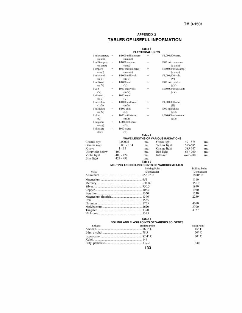
TM 9-1501
APPENDIX 2TABLES OF USEFUL INFORMATION
Table 1ELECTRICAL UNITS
1 microampere = 1/1000 milliampere = 1/1,000,000 amp.(µ amp) (m amp)
1 milliampere = 1/1000 ampere = 1000 microamperes(m amp) (amp) (µ amp)
1 ampere = 1000 milliamperes = 1,000,000 microamp.(amp) (m amp) (µ amp)
1 microvolt = 1/1000 millivolt = 1/1,000,000 volt(µ V) (m V) (V)
1 millivolt = 1/1000 volt = 1000 microvolts(m V) (V) (µV)
1 volt = 1000 millivolts = 1,000,000 microvolts(V) (m V) (µV)
1 kilovolt = 1000 volts(k V) (V)
1 microhm = 1/1000 milliohm = 1/1,000,000 ohm(1-Ω) (mΩ) (Ω)
1 milliohm = 1/100 ohm = 1000 microhms(m Ω) (Ω) (µΩ)
1 ohm = 1000 milliohms = 1,000,000 microhms(Ω) (mΩ) (µΩ)
1 megohm = 1,000,000 ohms(meg) (Ω)
1 kilowatt = 1000 watts(kw) (w)
Table 2WAVE LENGTHS OF VARIOUS RADIATIONS
Cosmic rays 0.00005 mµ Green light 491-575 mµGamma rays 0.001- 0.14 mµ Yellow light 575-585 mµX-rays 1 - 15 mµ Orange light 585-647 mµUltraviolet below 400 mµ Red light 647-700 mµViolet light 400 - 424 mµ Infra-red over-700 mµBlue light 424 - 491 mµ
Table 3MELTING AND BOILING POINTS OF VARIOUS METALS
Melting Point Boiling PointMetal (Centigrade) (Centigrade)
Aluminum.........................................................658.7° C 1800° C
Magnesium.......................................................651 1110Mercury ............................................................- 38.89 356.9Silver.................................................................950.5 1950Copper ..............................................................1083 1950Beryllium..........................................................1350 1530Magnesium fluoride.........................................1396 2239Iron....................................................................1535Platinum............................................................1755 4050Molybdenum ....................................................2620 3700Tungsten ...........................................................3370 4727Nichrome..........................................................1395
Table 4BOILING AND FLASH POINTS OF VARIOUS SOLVENTS
Solvent Boiling Point Flash PointAcetone.............................................................56.1° C 15° FEthyl alcohol ....................................................78.3 70° CIsopropanol.......................................................82.4° C 70° CXylol .................................................................144Butyl phthalate .................................................339.2 340
133
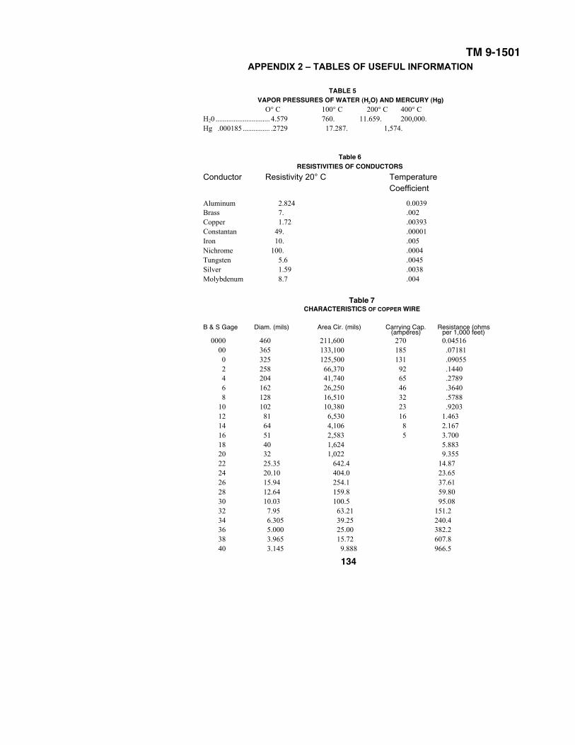
TM 9-1501APPENDIX 2 – TABLES OF USEFUL INFORMATION
TABLE 5VAPOR PRESSURES OF WATER (H2O) AND MERCURY (Hg)
O° C 100° C 200° C 400° CH20 .............................. 4.579 760. 11.659. 200,000.Hg .000185 ............... .2729 17.287. 1,574.
Table 6RESISTIVITIES OF CONDUCTORS
Conductor Resistivity 20° C TemperatureCoefficient
Aluminum 2.824 0.0039Brass 7. .002Copper 1.72 .00393Constantan 49. .00001Iron 10. .005Nichrome 100. .0004Tungsten 5.6 .0045Silver 1.59 .0038Molybdenum 8.7 .004
Table 7CHARACTERISTICS OF COPPER WIRE
B & S Gage Diam. (mils) Area Cir. (mils) Carrying Cap. Resistance (ohms(amperes) per 1,000 feet)
0000 460 211,600 270 0.0451600 365 133,100 185 .071810 325 125,500 131 .09055 2 258 66,370 92 .14404 204 41,740 65 .27896 162 26,250 46 .36408 128 16,510 32 .5788
10 102 10,380 23 .920312 81 6,530 16 1.46314 64 4,106 8 2.16716 51 2,583 5 3.70018 40 1,624 5.88320 32 1,022 9.35522 25.35 642.4 14.8724 20.10 404.0 23.6526 15.94 254.1 37.6128 12.64 159.8 59.8030 10.03 100.5 95.0832 7.95 63.21 151.234 6.305 39.25 240.436 5.000 25.00 382.238 3.965 15.72 607.840 3.145 9.888 966.5
134
TM 9-15011–3
APPENDIX 3REFERENCES
1. PUBLICATIONS INDEXES.
The following publications indexes should be consulted frequently for latest changesor revisions of references given in this section and for new publications relating tomateriel covered in this manual:
a. Ordnance supply catalog index (index toSNL's) .............................................................................................. ASF Cat.
ORD 2 OPSI
b. Major items and combinations, and pertinent
publications. ...................................................................................... ...SB 9-1
c. List of publications for training (listing ..................................... CCBP's,FM's, FT's, MTP's, TB's, TM's, TR's, TC's, and WDLO's). ................. FM 21-6
d. List of training films, film strips, and film bulletins.............. FM 21-7
e. Military training aids (listing graphic training
aids, models, devices, and displays)................................................. FM 21-8
f. List of administrative and supply publications
(listing MR's, RR's, SB's, WDMWO's, and WD Pamphlet
WDP's) .............................................................................................. 12-6
2. STANDARD NOMENCLATURE LISTS.
a. Cleaning, preserving, and lubricating materials; recoil fluids, special oils, and
miscellaneous related items ................................................................... K-1
3. EXPLANATORY PUBLICATIONS.
a. Cleaning, preserving, sealing, lubricating and
related materials issued for ordnance materiel ................................ TM 9-850
b. Instruction guide: The instrument repairman ........................ TM 9-2602
RAPD27MAR45-5M 135PUBLICATIONS DEPARTMENT – RARITAN ARSENAL