Embed Size (px)
Citation preview
1
M74006A.3 Owner’s Manual
Instructions for Installation/Set-up, Operation, Servicing, & Storage
Portable, Outdoor Use-Only, Gasoline Generator
Can be used to power individual appliances plugged directly into the generator’s outlets, or as a back-up connection to a building’s power supply (via a professionally installed UL-listed transfer switch).
WARNING – READ THIS MANUAL
READ and UNDERSTAND this manual completely before using the generator! Failure to properly set up, operate, and maintain this generator could result in serious injury or death from carbon monoxide poisoning, electric shock, fire/explosion, or burns. Generator has been shipped WITHOUT engine oil, Check the oil level using the dipstick and add oil as needed. In particular, be aware of the following hazards:
CO Poisoning Generators give off carbon monoxide, a poisonous gas that can kill you. You CANNOT smell it, see it, or taste it.
• ONLY run generator OUTDOORS and AWAY from building air intakes. NEVER run generator inside any enclosed or semi-enclosed spaces, including homes, basements, garages, sheds, boxes, RVs, boats or pick-up truck beds. These spaces can trap poisonous gases, EVEN if you run a fan or open windows.
• Install carbon monoxide alarms inside nearby structures/buildings (battery-operated, or plug-in with battery backup). Electric shock / Electrocution
• High voltage electricity from generator can kill. DO NOT operate in wet locations. Be sure generator is properly grounded. Use only UL-listed, outdoor-rated grounded extension cords of proper size.
• NEVER plug the generator directly into a wall outlet. ANY connection to a building’s electrical system MUST ISOLATE THE GENERATOR FROM UTILITY POWER via a UL-listed transfer switch installed by a licensed electrician. Otherwise, back feed from the generator into the power grid could kill utility workers.
Fire / Explosion
• DO NOT overload generator (per rated capacity), and OPERATE ONLY in an area with adequate cooling ventilation so engine does not overheat. Exhaust can be extremely hot. Keep muffler at least 7 feet from all combustible objects.
• All fuels are flammable. Never fuel a running or hot engine. Never pump fuel directly into generator at gas station – use approved container to transfer fuel. Ensure there are no fuel leaks, and keep sources of sparks and flames away.
• ALWAYS keep a fire extinguisher rated “ABC” nearby.
STOP!
CHOOSE THE RIGHT GENERATOR FOR YOUR NEEDS. See the “Power Load Planning & Management” section of this manual to determine your power load requirements and then compare to the generator’s rated capacity.
INSPECT COMPONENTS: Closely inspect to make sure no components are missing or damaged. See the “Unpacking & Delivery Inspection” section for instructions on whom to contact to report missing or damaged parts.
ARRANGE FOR PROFESSIONAL INSTALLATION of a transfer switch if you will be connecting the generator to your building’s electrical system. See the “Installation/Initial Set-Up” section for more information about this requirement.
Any Questions, Comments, Problems, or Parts Orders Call Powerhorse Product Support 1-866-443-2576
Item Number: 74006
Serial Number: _____________
Hazard Signal Word Definitions
2
This is the safety alert symbol. It is used to alert you to potential personal injury hazards. Obey all safety messages that follow this symbol to avoid possible injury or death. DANGER indicates a hazardous situation, which if not avoided, will result in death or serious injury.
WARNING indicates a hazardous situation, which if not avoided, could result in death or serious injury.
CAUTION used with the safety alert symbol, indicates a hazardous situation, which if not avoided, could result in minor or moderate injury.
CAUTION without the safety alert symbol, is used to address practices not related to personal injury. NOTICE is used to address practices not related to personal injury.
DANGER
WARNING
CAUTION
CAUTION
NOTICE
Table of Contents
3
Hazard Signal Word Definitions .................................................................................................................. 2 About Your Generator .................................................................................................................................. 4 Specifications ............................................................................................................................................... 6 Safety Label Locations ................................................................................................................................ 7 Machine Component Identification ............................................................................................................. 9 Power Load Planning & Management ...................................................................................................... 18
Installation / Initial Set-Up: 1. Unpacking & Delivery Inspection ......................................................................................................... 21 2. Assembly ............................................................................................................................................. 22 3. Planning the Power Load .................................................................................................................... 24 4. Set-up either as a BUILDING BACK-UP or PORTABLE Power Source ............................................. 24 5. Selecting a Suitable Site...................................................................................................................... 27 6. Grounding the Generator..................................................................................................................... 29
Operation: 1. General Safety Rules for Operation .................................................................................................... 30 2. Preparing for Operation ....................................................................................................................... 33 3. Starting the Generator ........................................................................................................................ 38 4. Checking Generator Output ................................................................................................................ 39 5. Connecting Loads .............................................................................................................................. 40 6. Stopping the Generator ....................................................................................................................... 40 7. AC Parallel Operation .......................................................................................................................... 41 8. Storage & Exercise .............................................................................................................................. 43
Maintenance & Repair ................................................................................................................................ 45 Troubleshooting ......................................................................................................................................... 53 Summary of Important Safety Information for Operation ....................................................................... 54 Generator Exploded View .......................................................................................................................... 58 Generator Kit Exploded View .................................................................................................................... 62 Engine Exploded View ............................................................................................................................... 64 Engine Kit Exploded View and Parts List ................................................................................................. 66 Limited Warranty ........................................................................................................................................ 67 California Proposition 65 Information ...................................................................................................... 68
About Your Generator
4
Thank you for purchasing a Powerhorse portable generator!
About Your Generator
This engine-driven, portable generator is designed to provide up to its rated amount of electrical power. (See the specifications section of this manual for model specific ratings) It can supply power:
1. As a portable power source: You can plug appliances directly into the generator’s electrical outlets. 2. As a back-up, standby power source for a building: A licensed electrician can connect the generator to your
building’s electrical system via the installation of an UL-approved transfer switch. (See the “Installation & Initial Set-up” section of this manual to learn more about specific requirements and precautions relating to wiring the generator to your building’s electrical system.)
You must select a generator adequately sized for your power needs. You need to determine the power needs of all the appliances/tools you wish to power at the same time and choose a generator rated to provide at least that power level. See the Power Load Planning & Management section of this manual to determine your specific power load requirements and then compare them to this generator’s rated capacity. You must not overload the generator. Overloading will cause damage to the generator and attached electrical devices, and may also result in fire.
Be sure to read about site selection and grounding requirements for running this generator. More detailed information can be found in the Installation & Initial Set-up, steps 5 and 6 of this manual.
Contact Powerhorse Product Support at 1-866-443-2576 to order or for questions regarding optional accessories.
Read this Manual
DANGER
Improper use or maintenance of this generator can result in serious injury or death from carbon monoxide poisoning, electric shock/electrocution, fire/explosion, or burns.
Read this manual completely before using the generator and follow all instructions and safety rules.
You must follow all instructions and safety precautions presented throughout this manual. A summary of important safety information can be found at the end of the manual. Keep this manual for reference and review.
Proper preparation, operation, and maintenance will result in operator safety, as well as best performance and long life of the generator. For detailed engine operation and maintenance information, refer to the “Operation” and “Maintenance & Repair” sections within this generator manual.
Powerhorse is constantly improving its products. The specifications outlined herein are subject to change without prior notice or obligation. The purchaser and/or user shall assume liability for any modification and/or alterations of this equipment from original design and manufacture.
Before using, the user shall determine the suitability of this product for its intended use and assumes liability therein.
Contact Powerhorse Product Support at 1-866-443-2576 for any questions about the appropriate use of this generator.
About Your Generator
5
Warranty Registration
Please fill in the warranty registration information in the back of this manual and have it on hand when you call in on a warranty claim or replacement parts.
ATTENTION: Rental companies and private owners who loan this equipment to others!
All persons to whom you rent/loan this generator must have access to and read this manual. Keep this owner's manual with the generator at all times and advise all persons who will operate the machine to read it. You must also provide personal instruction on how to safely set-up and operate the generator and remain available to answer any questions a renter/borrower might have.
Specifications
6
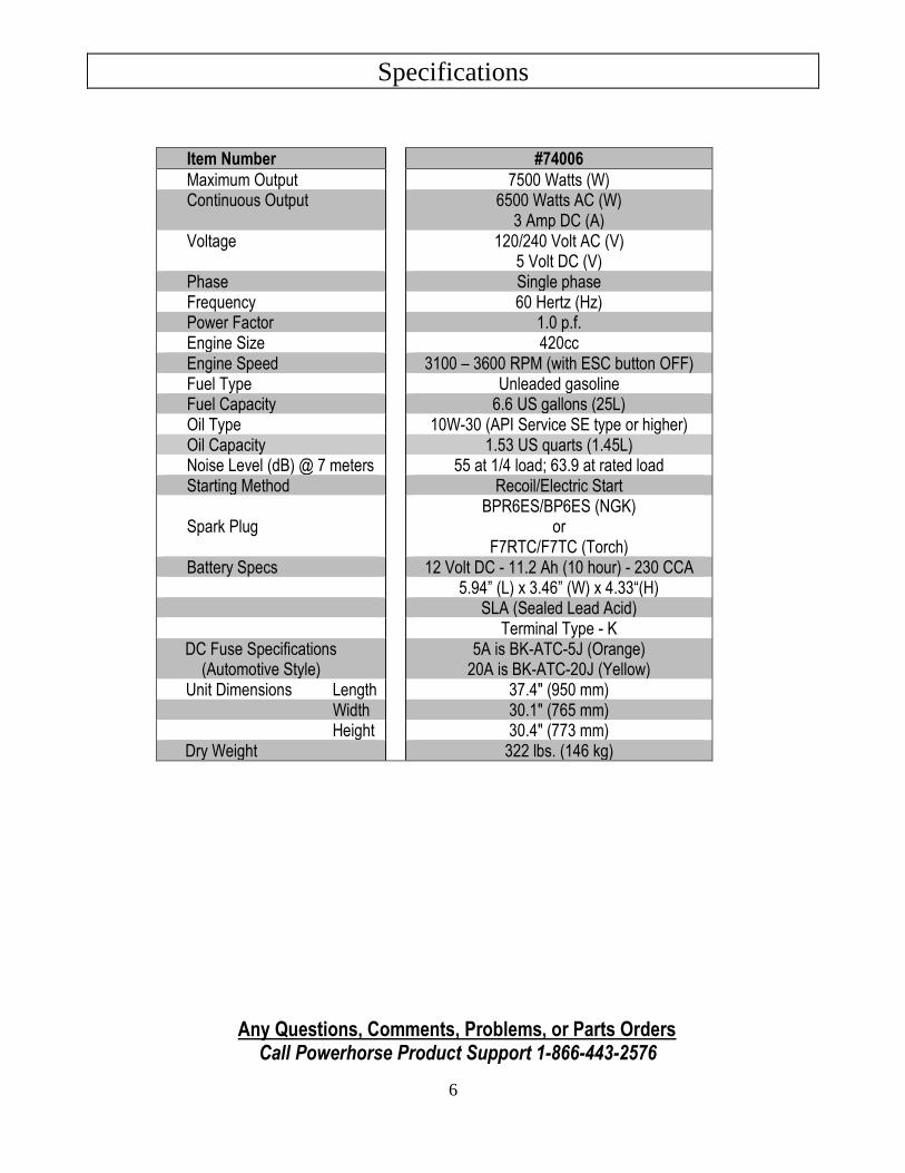
Item Number #74006
Maximum Output 7500 Watts (W) Continuous Output 6500 Watts AC (W)
3 Amp DC (A) Voltage 120/240 Volt AC (V)
5 Volt DC (V) Phase Single phase Frequency 60 Hertz (Hz) Power Factor 1.0 p.f. Engine Size 420cc Engine Speed 3100 – 3600 RPM (with ESC button OFF) Fuel Type Unleaded gasoline Fuel Capacity 6.6 US gallons (25L) Oil Type 10W-30 (API Service SE type or higher) Oil Capacity 1.53 US quarts (1.45L) Noise Level (dB) @ 7 meters 55 at 1/4 load; 63.9 at rated load Starting Method Recoil/Electric Start
Spark Plug BPR6ES/BP6ES (NGK)
or F7RTC/F7TC (Torch)
Battery Specs 12 Volt DC - 11.2 Ah (10 hour) - 230 CCA 5.94” (L) x 3.46” (W) x 4.33“(H) SLA (Sealed Lead Acid) Terminal Type - K DC Fuse Specifications (Automotive Style)
5A is BK-ATC-5J (Orange) 20A is BK-ATC-20J (Yellow)
Unit Dimensions Length 37.4" (950 mm) Width 30.1" (765 mm) Height 30.4" (773 mm)
Dry Weight 322 lbs. (146 kg)
Any Questions, Comments, Problems, or Parts Orders Call Powerhorse Product Support 1-866-443-2576
Safety Label Locations
7
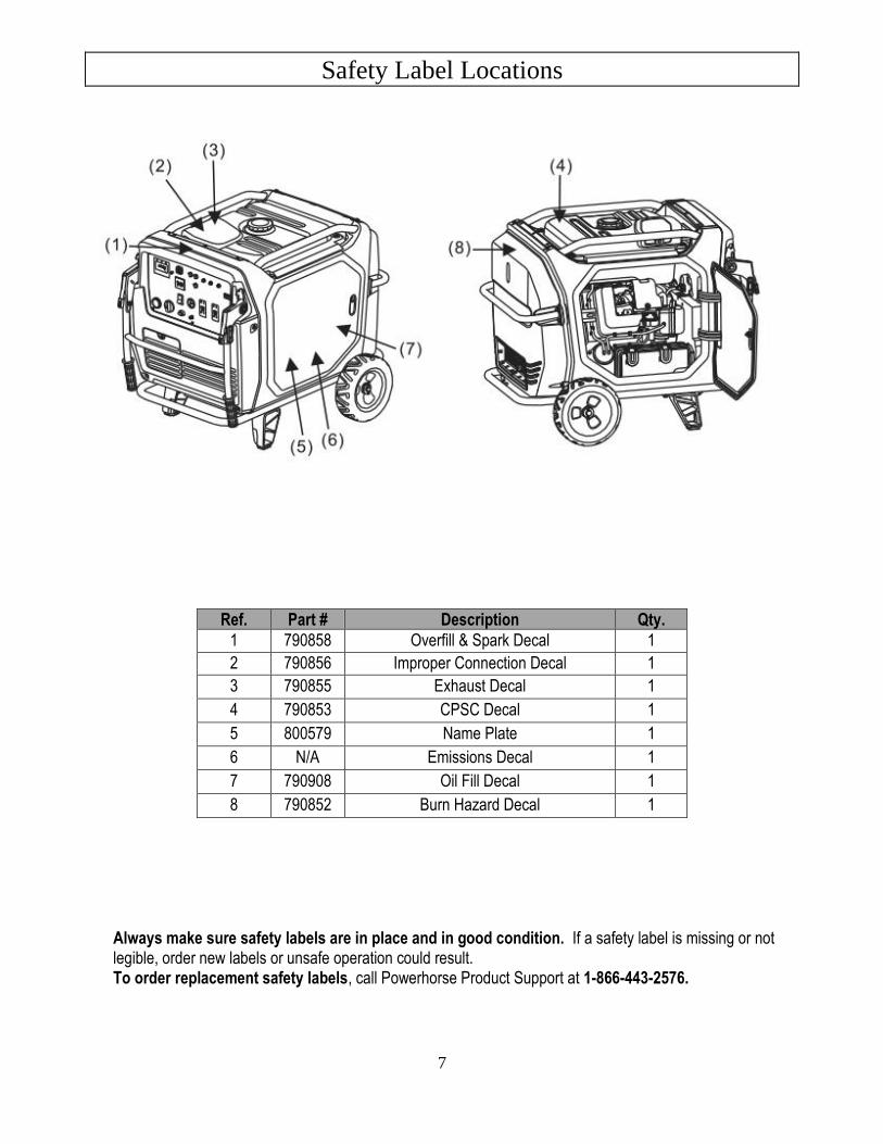
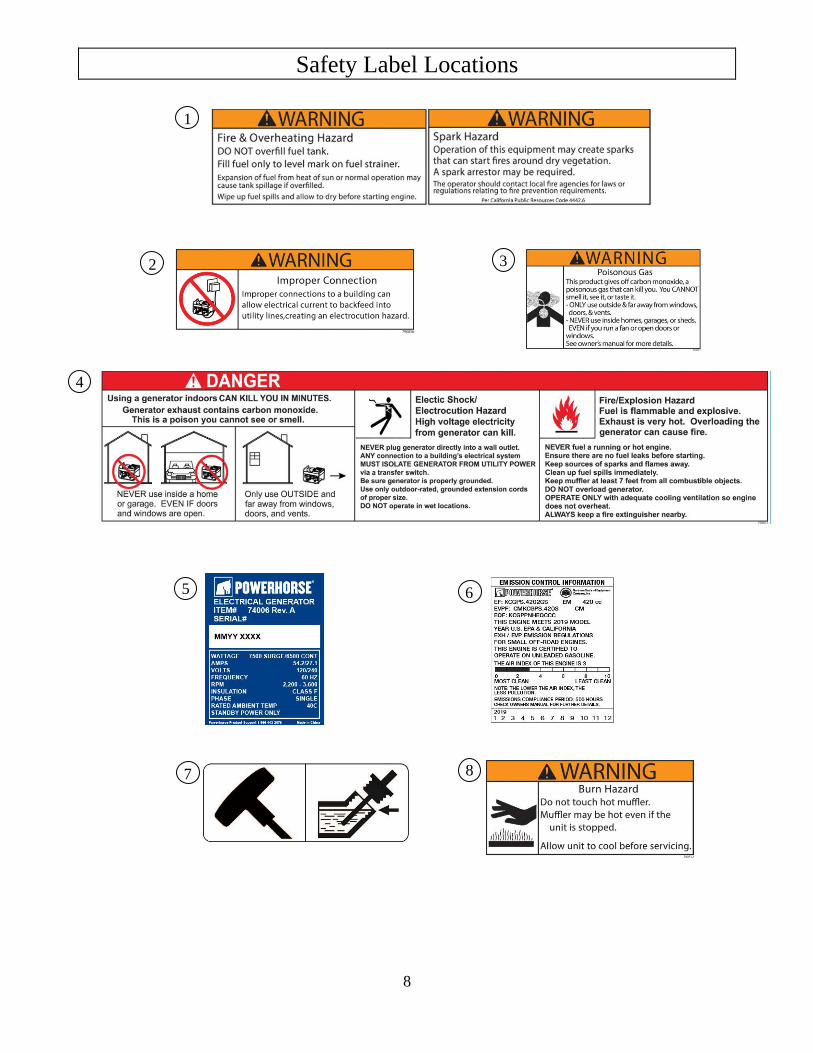
Always make sure safety labels are in place and in good condition. If a safety label is missing or not legible, order new labels or unsafe operation could result. To order replacement safety labels, call Powerhorse Product Support at 1-866-443-2576.
Ref. Part # Description Qty.
1 790858 Overfill & Spark Decal 1
2 790856 Improper Connection Decal 1
3 790855 Exhaust Decal 1
4 790853 CPSC Decal 1
5 800579 Name Plate 1
6 N/A Emissions Decal 1
7 790908 Oil Fill Decal 1
8 790852 Burn Hazard Decal 1
Safety Label Locations
8
2
4
5
1
6
6
7
6
3
8
Machine Component Identification
9
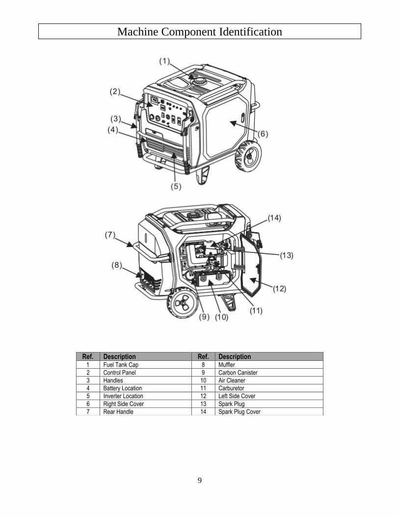
Ref. Description Ref. Description 1 Fuel Tank Cap 8 Muffler
2 Control Panel 9 Carbon Canister
3 Handles 10 Air Cleaner
4 Battery Location 11 Carburetor
5 Inverter Location 12 Left Side Cover
6 Right Side Cover 13 Spark Plug
7 Rear Handle 14 Spark Plug Cover
Machine Component Identification
10
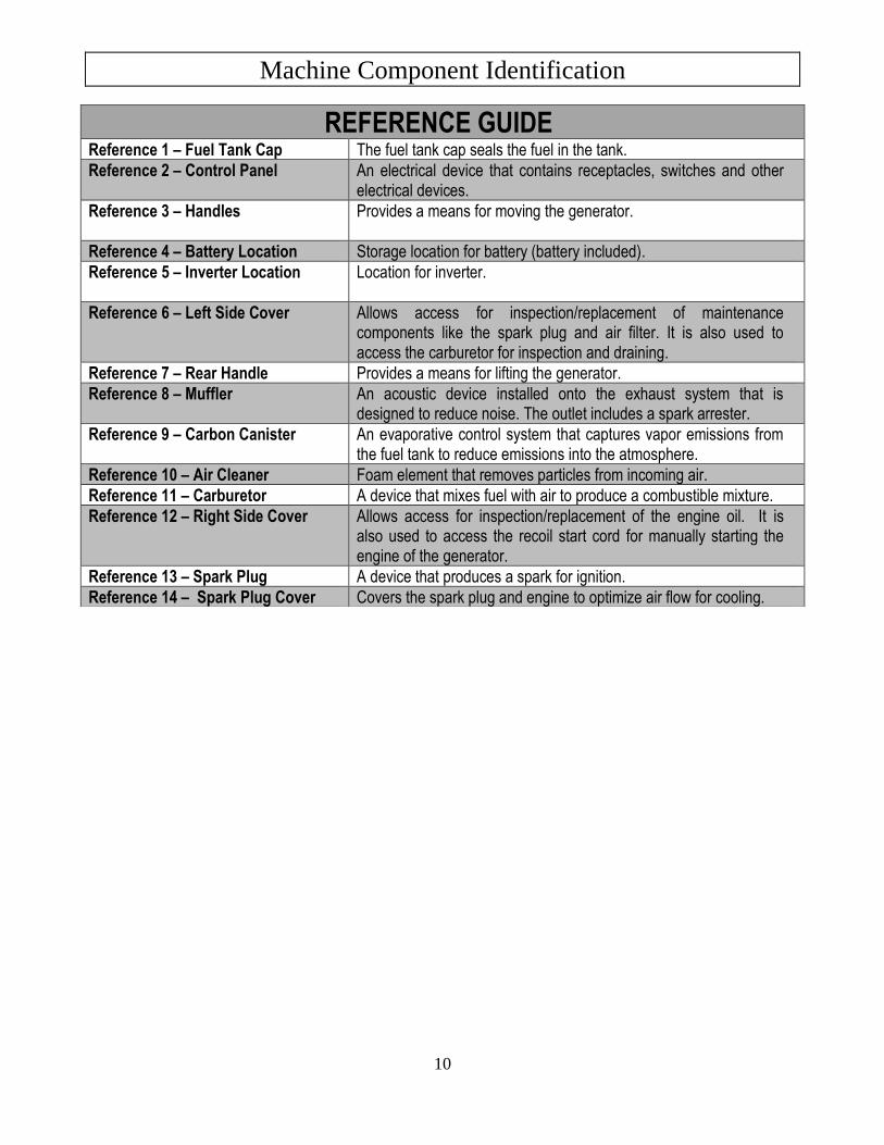
REFERENCE GUIDE Reference 1 – Fuel Tank Cap The fuel tank cap seals the fuel in the tank.
Reference 2 – Control Panel An electrical device that contains receptacles, switches and other electrical devices.
Reference 3 – Handles
Provides a means for moving the generator.
Reference 4 – Battery Location Storage location for battery (battery included).
Reference 5 – Inverter Location
Location for inverter.
Reference 6 – Left Side Cover Allows access for inspection/replacement of maintenance components like the spark plug and air filter. It is also used to access the carburetor for inspection and draining.
Reference 7 – Rear Handle Provides a means for lifting the generator.
Reference 8 – Muffler An acoustic device installed onto the exhaust system that is designed to reduce noise. The outlet includes a spark arrester.
Reference 9 – Carbon Canister An evaporative control system that captures vapor emissions from the fuel tank to reduce emissions into the atmosphere.
Reference 10 – Air Cleaner Foam element that removes particles from incoming air.
Reference 11 – Carburetor A device that mixes fuel with air to produce a combustible mixture.
Reference 12 – Right Side Cover Allows access for inspection/replacement of the engine oil. It is also used to access the recoil start cord for manually starting the engine of the generator.
Reference 13 – Spark Plug A device that produces a spark for ignition.
Reference 14 – Spark Plug Cover Covers the spark plug and engine to optimize air flow for cooling.
Machine Component Identification
11
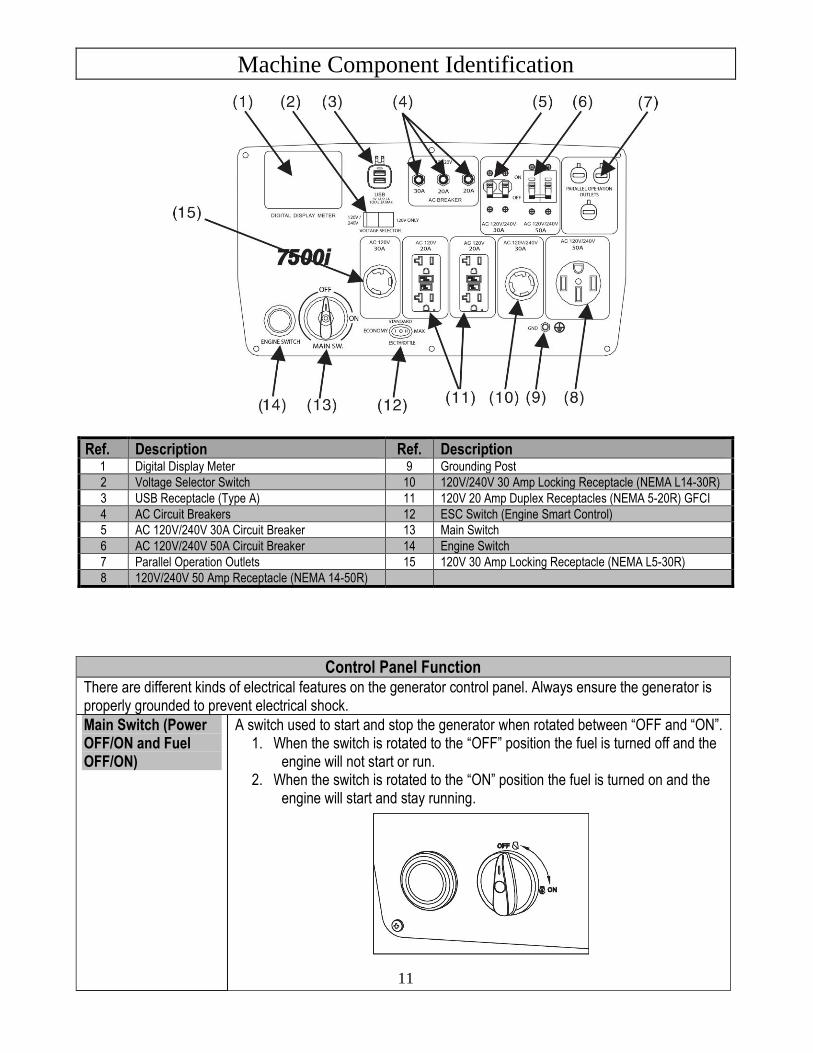
Ref. Description Ref. Description 1 Digital Display Meter 9 Grounding Post
2 Voltage Selector Switch 10 120V/240V 30 Amp Locking Receptacle (NEMA L14-30R)
3 USB Receptacle (Type A) 11 120V 20 Amp Duplex Receptacles (NEMA 5-20R) GFCI
4 AC Circuit Breakers 12 ESC Switch (Engine Smart Control)
5 AC 120V/240V 30A Circuit Breaker 13 Main Switch
6 AC 120V/240V 50A Circuit Breaker 14 Engine Switch
7 Parallel Operation Outlets 15 120V 30 Amp Locking Receptacle (NEMA L5-30R)
8 120V/240V 50 Amp Receptacle (NEMA 14-50R)
Control Panel Function There are different kinds of electrical features on the generator control panel. Always ensure the generator is properly grounded to prevent electrical shock.
Main Switch (Power OFF/ON and Fuel OFF/ON)
A switch used to start and stop the generator when rotated between “OFF and “ON”. 1. When the switch is rotated to the “OFF” position the fuel is turned off and the
engine will not start or run. 2. When the switch is rotated to the “ON” position the fuel is turned on and the
engine will start and stay running.
Machine Component Identification
12
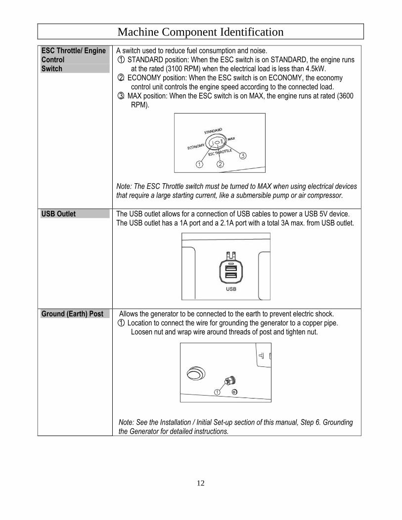
ESC Throttle/ Engine Control Switch
A switch used to reduce fuel consumption and noise. 1. STANDARD position: When the ESC switch is on STANDARD, the engine runs
at the rated (3100 RPM) when the electrical load is less than 4.5kW. 2. ECONOMY position: When the ESC switch is on ECONOMY, the economy
control unit controls the engine speed according to the connected load. 3. MAX position: When the ESC switch is on MAX, the engine runs at rated (3600
RPM).
Note: The ESC Throttle switch must be turned to MAX when using electrical devices that require a large starting current, like a submersible pump or air compressor.
USB Outlet The USB outlet allows for a connection of USB cables to power a USB 5V device. The USB outlet has a 1A port and a 2.1A port with a total 3A max. from USB outlet.
Ground (Earth) Post Allows the generator to be connected to the earth to prevent electric shock. 1. Location to connect the wire for grounding the generator to a copper pipe.
Loosen nut and wrap wire around threads of post and tighten nut.
Note: See the Installation / Initial Set-up section of this manual, Step 6. Grounding the Generator for detailed instructions.
Machine Component Identification
13
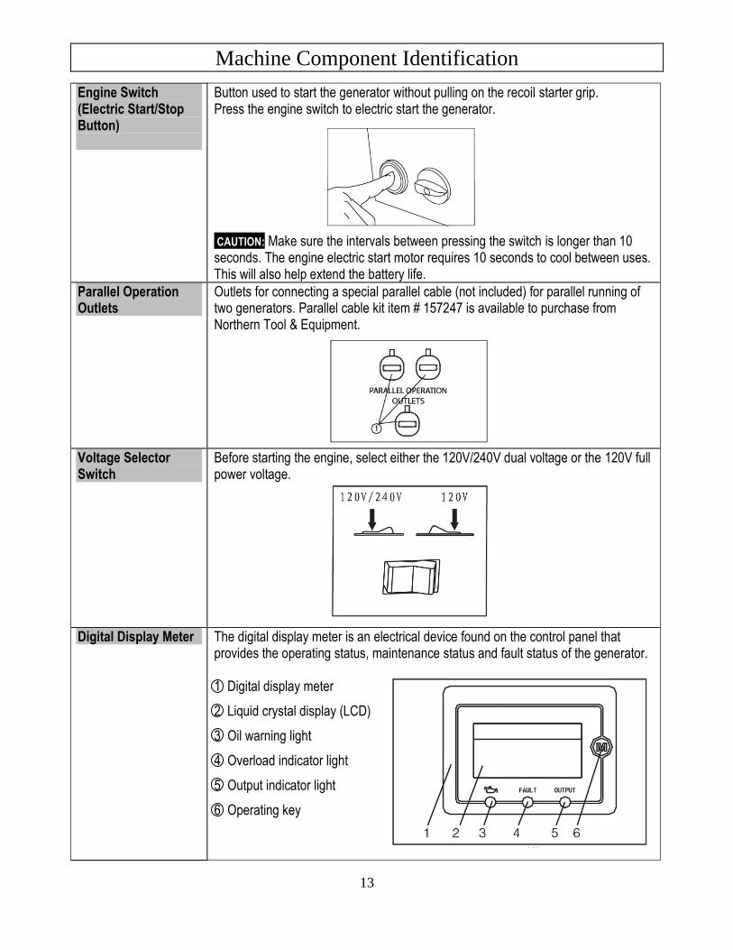
Engine Switch (Electric Start/Stop Button)
Button used to start the generator without pulling on the recoil starter grip. Press the engine switch to electric start the generator.
CAUTION: Make sure the intervals between pressing the switch is longer than 10 seconds. The engine electric start motor requires 10 seconds to cool between uses. This will also help extend the battery life.
Parallel Operation Outlets
Outlets for connecting a special parallel cable (not included) for parallel running of two generators. Parallel cable kit item # 157247 is available to purchase from Northern Tool & Equipment.
Voltage Selector Switch
Before starting the engine, select either the 120V/240V dual voltage or the 120V full power voltage.
Digital Display Meter The digital display meter is an electrical device found on the control panel that provides the operating status, maintenance status and fault status of the generator. 1 Digital display meter
2 Liquid crystal display (LCD)
3 Oil warning light
4 Overload indicator light
5 Output indicator light
6 Operating key
Machine Component Identification
14
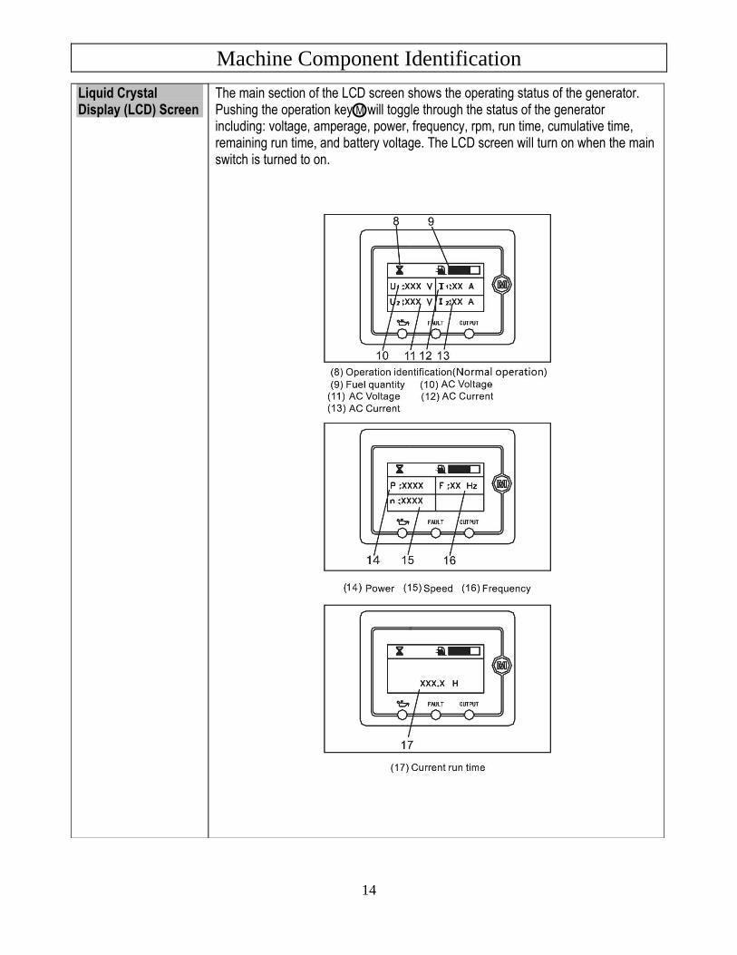
Liquid Crystal Display (LCD) Screen
The main section of the LCD screen shows the operating status of the generator. Pushing the operation key M will toggle through the status of the generator including: voltage, amperage, power, frequency, rpm, run time, cumulative time, remaining run time, and battery voltage. The LCD screen will turn on when the main switch is turned to on.
Machine Component Identification
15
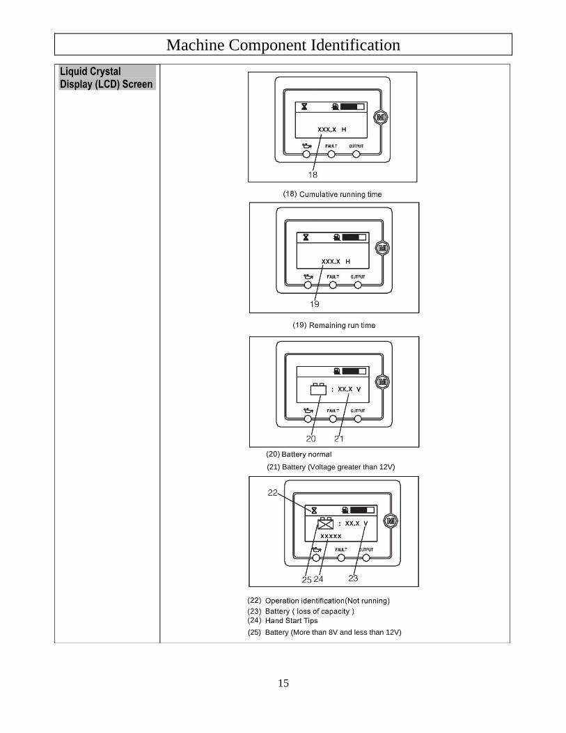
Liquid Crystal Display (LCD) Screen
(21) Battery (Voltage greater than 12V)
(25) Battery (More than 8V and less than 12V)
Machine Component Identification
16
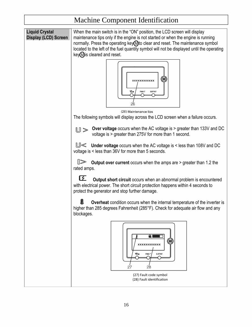
Liquid Crystal Display (LCD) Screen
When the main switch is in the “ON” position, the LCD screen will display maintenance tips only if the engine is not started or when the engine is running normally. Press the operating key M to clear and reset. The maintenance symbol located to the left of the fuel quantity symbol will not be displayed until the operating key M is cleared and reset. The following symbols will display across the LCD screen when a failure occurs.
Over voltage occurs when the AC voltage is > greater than 133V and DC voltage is > greater than 275V for more than 1 second. Under voltage occurs when the AC voltage is < less than 108V and DC
voltage is < less than 36V for more than 5 seconds. Output over current occurs when the amps are > greater than 1.2 the
rated amps. Output short circuit occurs when an abnormal problem is encountered
with electrical power. The short circuit protection happens within 4 seconds to protect the generator and stop further damage.
Overheat condition occurs when the internal temperature of the inverter is
higher than 285 degrees Fahrenheit (285°F). Check for adequate air flow and any blockages.
(27) Fault code symbol (28) Fault identification
Machine Component Identification
17
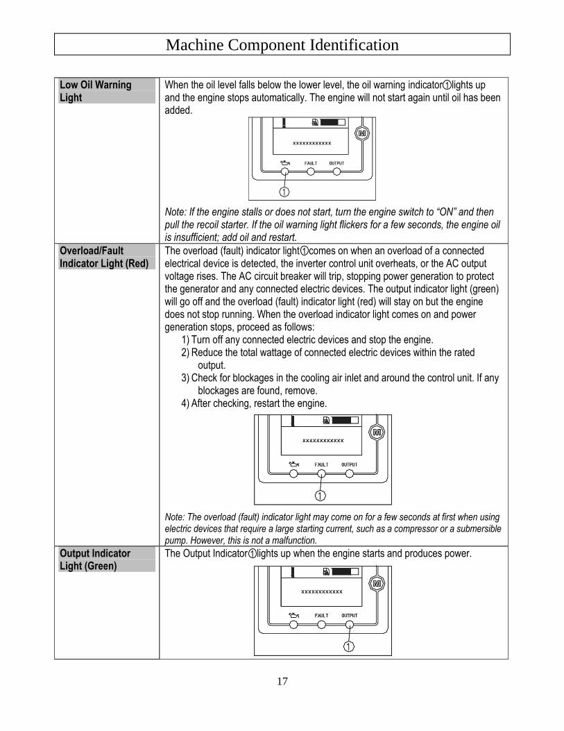
Low Oil Warning Light
When the oil level falls below the lower level, the oil warning indicator 1 lights up and the engine stops automatically. The engine will not start again until oil has been added. Note: If the engine stalls or does not start, turn the engine switch to “ON” and then pull the recoil starter. If the oil warning light flickers for a few seconds, the engine oil is insufficient; add oil and restart.
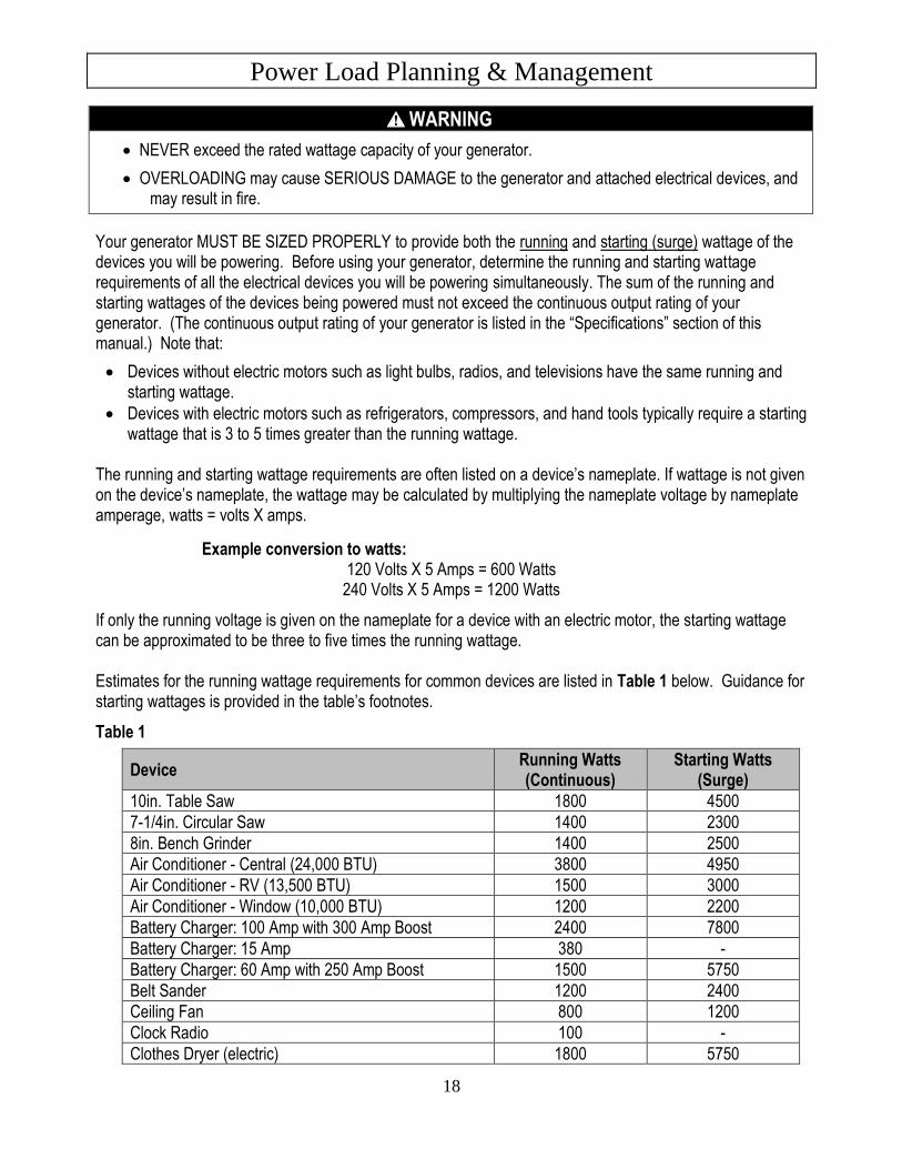
Overload/Fault Indicator Light (Red)
The overload (fault) indicator light 1 comes on when an overload of a connected electrical device is detected, the inverter control unit overheats, or the AC output voltage rises. The AC circuit breaker will trip, stopping power generation to protect the generator and any connected electric devices. The output indicator light (green) will go off and the overload (fault) indicator light (red) will stay on but the engine does not stop running. When the overload indicator light comes on and power generation stops, proceed as follows:
1) Turn off any connected electric devices and stop the engine. 2) Reduce the total wattage of connected electric devices within the rated
output. 3) Check for blockages in the cooling air inlet and around the control unit. If any
blockages are found, remove. 4) After checking, restart the engine.
Note: The overload (fault) indicator light may come on for a few seconds at first when using electric devices that require a large starting current, such as a compressor or a submersible pump. However, this is not a malfunction.
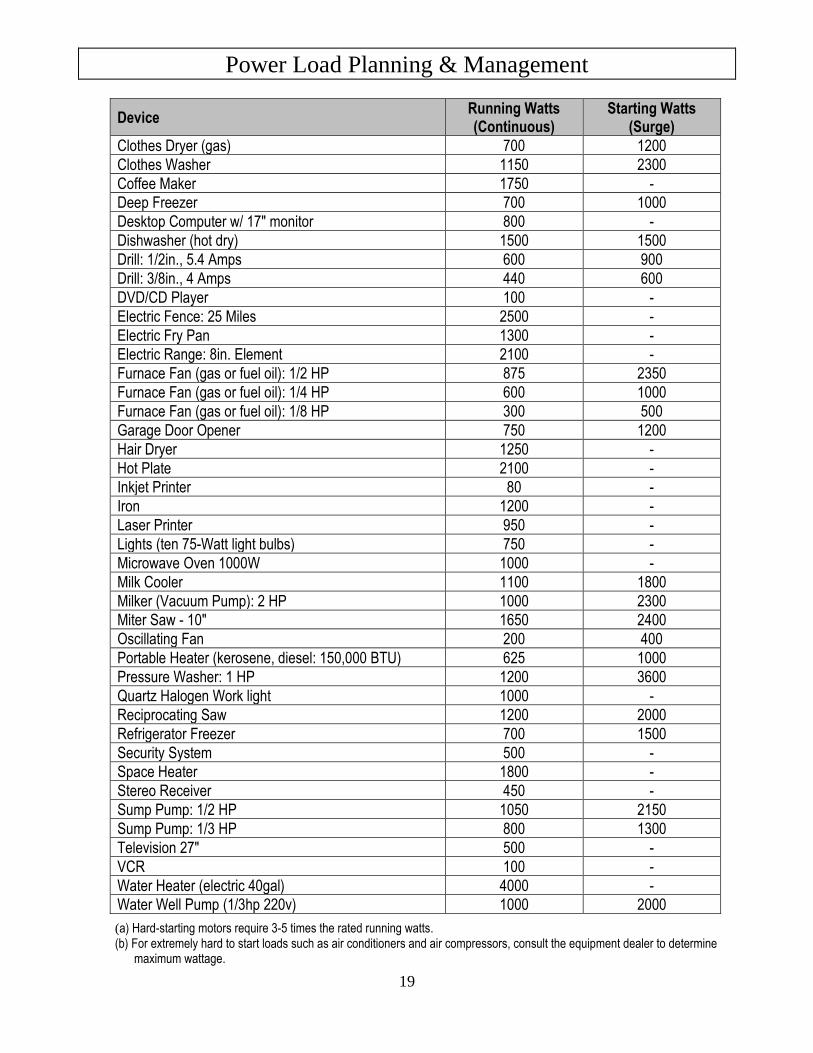
Output Indicator Light (Green)
The Output Indicator 1 lights up when the engine starts and produces power.
Power Load Planning & Management
18
WARNING
• NEVER exceed the rated wattage capacity of your generator.
• OVERLOADING may cause SERIOUS DAMAGE to the generator and attached electrical devices, and may result in fire.
Your generator MUST BE SIZED PROPERLY to provide both the running and starting (surge) wattage of the devices you will be powering. Before using your generator, determine the running and starting wattage requirements of all the electrical devices you will be powering simultaneously. The sum of the running and starting wattages of the devices being powered must not exceed the continuous output rating of your generator. (The continuous output rating of your generator is listed in the “Specifications” section of this manual.) Note that:
• Devices without electric motors such as light bulbs, radios, and televisions have the same running and starting wattage.
• Devices with electric motors such as refrigerators, compressors, and hand tools typically require a starting wattage that is 3 to 5 times greater than the running wattage.
The running and starting wattage requirements are often listed on a device’s nameplate. If wattage is not given on the device’s nameplate, the wattage may be calculated by multiplying the nameplate voltage by nameplate amperage, watts = volts X amps.
Example conversion to watts: 120 Volts X 5 Amps = 600 Watts
240 Volts X 5 Amps = 1200 Watts
If only the running voltage is given on the nameplate for a device with an electric motor, the starting wattage can be approximated to be three to five times the running wattage. Estimates for the running wattage requirements for common devices are listed in Table 1 below. Guidance for starting wattages is provided in the table’s footnotes.
Table 1
Device Running Watts (Continuous)
Starting Watts (Surge)
10in. Table Saw 1800 4500
7-1/4in. Circular Saw 1400 2300
8in. Bench Grinder 1400 2500
Air Conditioner - Central (24,000 BTU) 3800 4950
Air Conditioner - RV (13,500 BTU) 1500 3000
Air Conditioner - Window (10,000 BTU) 1200 2200
Battery Charger: 100 Amp with 300 Amp Boost 2400 7800
Battery Charger: 15 Amp 380 -
Battery Charger: 60 Amp with 250 Amp Boost 1500 5750
Belt Sander 1200 2400
Ceiling Fan 800 1200
Clock Radio 100 -
Clothes Dryer (electric) 1800 5750
Power Load Planning & Management
19
Device Running Watts (Continuous)
Starting Watts (Surge)
Clothes Dryer (gas) 700 1200
Clothes Washer 1150 2300
Coffee Maker 1750 -
Deep Freezer 700 1000
Desktop Computer w/ 17" monitor 800 -
Dishwasher (hot dry) 1500 1500
Drill: 1/2in., 5.4 Amps 600 900
Drill: 3/8in., 4 Amps 440 600
DVD/CD Player 100 -
Electric Fence: 25 Miles 2500 -
Electric Fry Pan 1300 -
Electric Range: 8in. Element 2100 -
Furnace Fan (gas or fuel oil): 1/2 HP 875 2350
Furnace Fan (gas or fuel oil): 1/4 HP 600 1000
Furnace Fan (gas or fuel oil): 1/8 HP 300 500
Garage Door Opener 750 1200
Hair Dryer 1250 -
Hot Plate 2100 -
Inkjet Printer 80 -
Iron 1200 -
Laser Printer 950 -
Lights (ten 75-Watt light bulbs) 750 -
Microwave Oven 1000W 1000 -
Milk Cooler 1100 1800
Milker (Vacuum Pump): 2 HP 1000 2300
Miter Saw - 10" 1650 2400
Oscillating Fan 200 400
Portable Heater (kerosene, diesel: 150,000 BTU) 625 1000
Pressure Washer: 1 HP 1200 3600
Quartz Halogen Work light 1000 -
Reciprocating Saw 1200 2000
Refrigerator Freezer 700 1500
Security System 500 -
Space Heater 1800 -
Stereo Receiver 450 -
Sump Pump: 1/2 HP 1050 2150
Sump Pump: 1/3 HP 800 1300
Television 27" 500 -
VCR 100 -
Water Heater (electric 40gal) 4000 -
Water Well Pump (1/3hp 220v) 1000 2000
(a) Hard-starting motors require 3-5 times the rated running watts. (b) For extremely hard to start loads such as air conditioners and air compressors, consult the equipment dealer to determine
maximum wattage.
Power Load Planning & Management
20
To calculate the running and starting wattage requirements for the devices you will be powering, follow these steps:
1. Make a list of all electrical devices you will be powering at the same time with the generator.
2. List the greater of the running or starting wattage next to each device as obtained from the devices’ nameplate or Table 1. If only the running wattage for a device with an electric motor is known, the starting wattage can be estimated to be at least 3 times the running wattage.
3. Add the wattages for all devices on your list. This total must be lower than the continuous output rating of your generator.
Example:
Device to be Powered
Greater of Starting/Running Wattage
Light Bulbs (ten – 75 watt) 750 W
Refrigerator Freezer 1500 W
Microwave Oven 1000W 1000 W
Air Conditioner, Window (10,000 BTU) 2200 W
Sump Pump (1/3 hp) 1300 W
Total 6750W
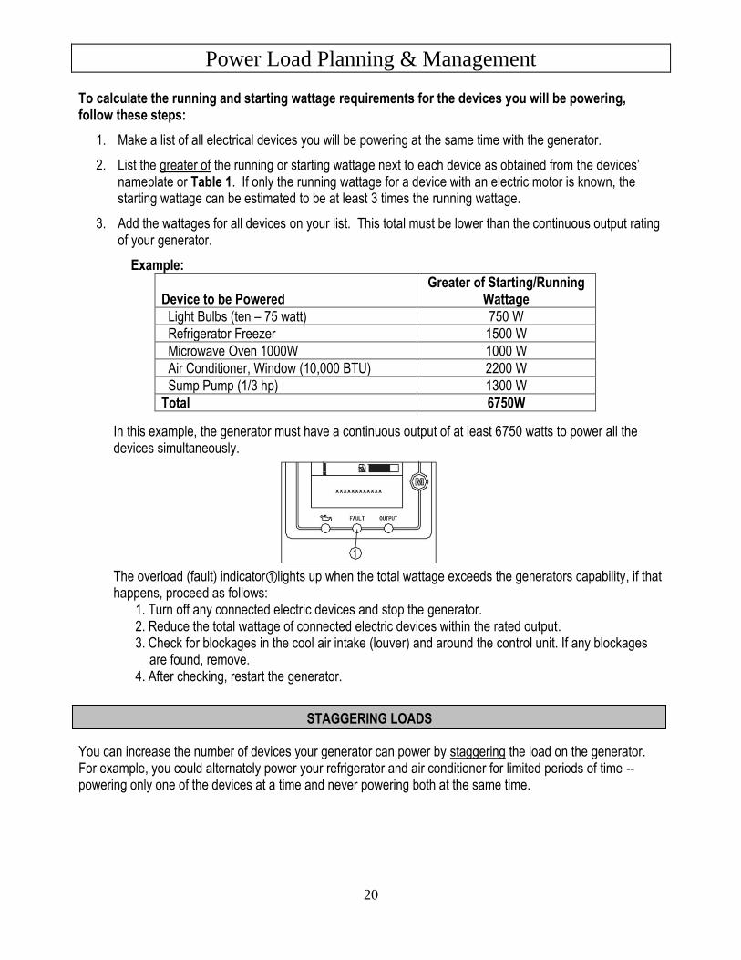
In this example, the generator must have a continuous output of at least 6750 watts to power all the devices simultaneously.
The overload (fault) indicator 1 lights up when the total wattage exceeds the generators capability, if that happens, proceed as follows:
1. Turn off any connected electric devices and stop the generator. 2. Reduce the total wattage of connected electric devices within the rated output. 3. Check for blockages in the cool air intake (louver) and around the control unit. If any blockages
are found, remove. 4. After checking, restart the generator.
You can increase the number of devices your generator can power by staggering the load on the generator. For example, you could alternately power your refrigerator and air conditioner for limited periods of time -- powering only one of the devices at a time and never powering both at the same time.
STAGGERING LOADS
Installation / Initial Set-Up
21
There are a number of important steps required to set up your generator for initial use. These steps are:
Steps for Installation / Initial Set-Up
1. Unpacking & delivery inspection.
2. Assembly.
3. Planning the power load to stay within the generator’s rated capacity.
4. Setting up generator for the type of power generation you need:
a. portable power source, or b. connected to a building as a back-up power source.
5. Selecting a site for using the generator.
6. Grounding.
Each of these steps is discussed in detail below:
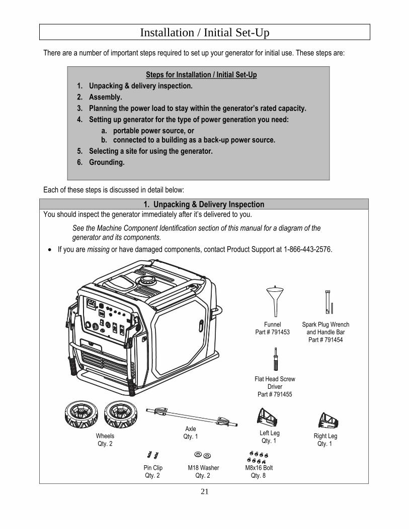
1. Unpacking & Delivery Inspection You should inspect the generator immediately after it’s delivered to you.
See the Machine Component Identification section of this manual for a diagram of the generator and its components.
• If you are missing or have damaged components, contact Product Support at 1-866-443-2576.
Funnel Part # 791453
Spark Plug Wrench and Handle Bar Part # 791454
Flat Head Screw Driver
Part # 791455
Wheels Qty. 2
Axle Qty. 1
Left Leg Qty. 1
Right Leg Qty. 1
Pin Clip Qty. 2
M18 Washer Qty. 2
M8x16 Bolt Qty. 8
Installation / Initial Set-Up
22
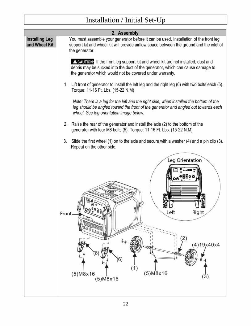
2. Assembly Installing Leg and Wheel Kit
You must assemble your generator before it can be used. Installation of the front leg support kit and wheel kit will provide airflow space between the ground and the inlet of the generator.
CAUTION: If the front leg support kit and wheel kit are not installed, dust and debris may be sucked into the duct of the generator, which can cause damage to the generator which would not be covered under warranty.
1. Lift front of generator to install the left leg and the right leg (6) with two bolts each (5).
Torque: 11-16 Ft. Lbs. (15-22 N.M)
Note: There is a leg for the left and the right side, when installed the bottom of the leg should be angled toward the front of the generator and angled out towards each wheel. See leg orientation image below.
2. Raise the rear of the generator and install the axle (2) to the bottom of the
generator with four M8 bolts (5). Torque: 11-16 Ft. Lbs. (15-22 N.M)
3. Slide the first wheel (1) on to the axle and secure with a washer (4) and a pin clip (3). Repeat on the other side.
Installation / Initial Set-Up
23
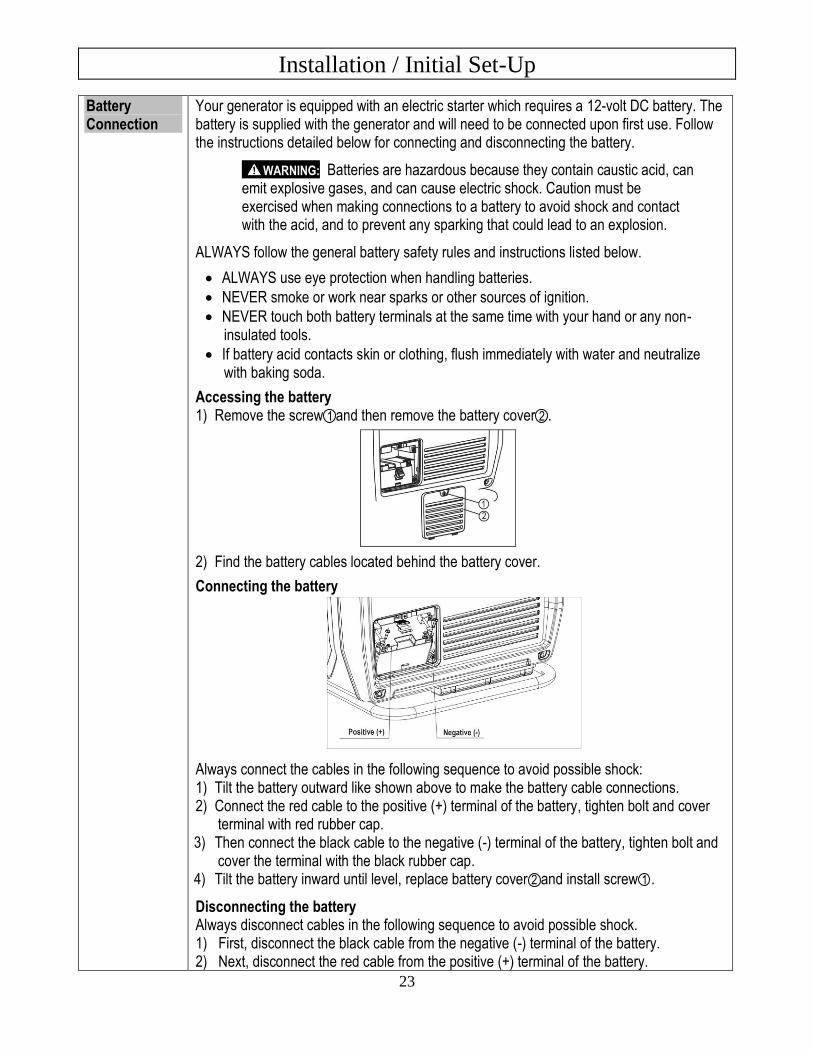
Battery Connection
Your generator is equipped with an electric starter which requires a 12-volt DC battery. The battery is supplied with the generator and will need to be connected upon first use. Follow the instructions detailed below for connecting and disconnecting the battery.
WARNING: Batteries are hazardous because they contain caustic acid, can emit explosive gases, and can cause electric shock. Caution must be exercised when making connections to a battery to avoid shock and contact with the acid, and to prevent any sparking that could lead to an explosion.
ALWAYS follow the general battery safety rules and instructions listed below.
• ALWAYS use eye protection when handling batteries.
• NEVER smoke or work near sparks or other sources of ignition.
• NEVER touch both battery terminals at the same time with your hand or any non-insulated tools.
• If battery acid contacts skin or clothing, flush immediately with water and neutralize with baking soda.
Accessing the battery 1) Remove the screw 1 and then remove the battery cover 2 .
2) Find the battery cables located behind the battery cover.
Connecting the battery
Always connect the cables in the following sequence to avoid possible shock: 1) Tilt the battery outward like shown above to make the battery cable connections. 2) Connect the red cable to the positive (+) terminal of the battery, tighten bolt and cover
terminal with red rubber cap. 3) Then connect the black cable to the negative (-) terminal of the battery, tighten bolt and
cover the terminal with the black rubber cap. 4) Tilt the battery inward until level, replace battery cover 2 and install screw 1 .
Disconnecting the battery Always disconnect cables in the following sequence to avoid possible shock. 1) First, disconnect the black cable from the negative (-) terminal of the battery. 2) Next, disconnect the red cable from the positive (+) terminal of the battery.
Installation / Initial Set-Up
24
3. Planning the Power Load Plan your power load so that you do not exceed the generator’s rated capacity.
See the “Power Load Planning & Management” section of this manual to review how to plan and manage power loads for the generator.
4. Set-up either as a BUILDING BACK-UP or PORTABLE Power Source This generator is designed to provide up to its rated amount of electrical power. It can supply electricity in two ways:
1. As a back-up, standby power source for a building. For this application, you must arrange for a licensed electrician to connect the generator to your building’s electrical system via the installation of an UL-approved transfer switch. The transfer switch must be installed in accordance with building electrical code and guidelines supplied by your power company.
2. As a portable power source. You can plug appliances or tools directly into the generator’s electrical outlets.
Specific requirements for each are given below.
Note: Regardless of whether you use your generator as a back-up power source connected to a building or as a portable power source, you must not overload the generator. Overloading may cause serious damage to the generator and attached electrical devices.
Using as a Back-up Power Source for a Building
Contact a licensed electrician to install an UL-listed transfer switch if you want to use your generator as a back-up power source for a building.
What does a transfer switch do? It:
a) Safely connects the generator to your building’s electrical system by isolating your generator from your utility company’s power lines, AND
b) Connects your generator to a critical subset of your building’s circuits that are needed for emergency power needs.
If your generator will be connected to your building’s electrical system, it MUST ALWAYS be isolated from the utility power grid with a UL-listed transfer switch installed by a licensed electrician in compliance with all applicable building and electrical codes, and in accordance with guidelines supplied by your power company.
DANGER: A transfer switch must be installed in order to isolate your generator from the utility power grid. If your generator is NOT properly isolated from the utility system, serious hazards will arise: When your generator is running, its output will back feed into the utility
power line and transformer that are normally used to provide you with power. The transformer will step up the current to the normal line voltage. An unsuspecting utility line worker working on an assumed deactivated line could be electrocuted.
If your generator is connected (running or not) when utility power is restored, your generator will be destroyed. It could also explode or cause fire.
Installation / Initial Set-Up
25
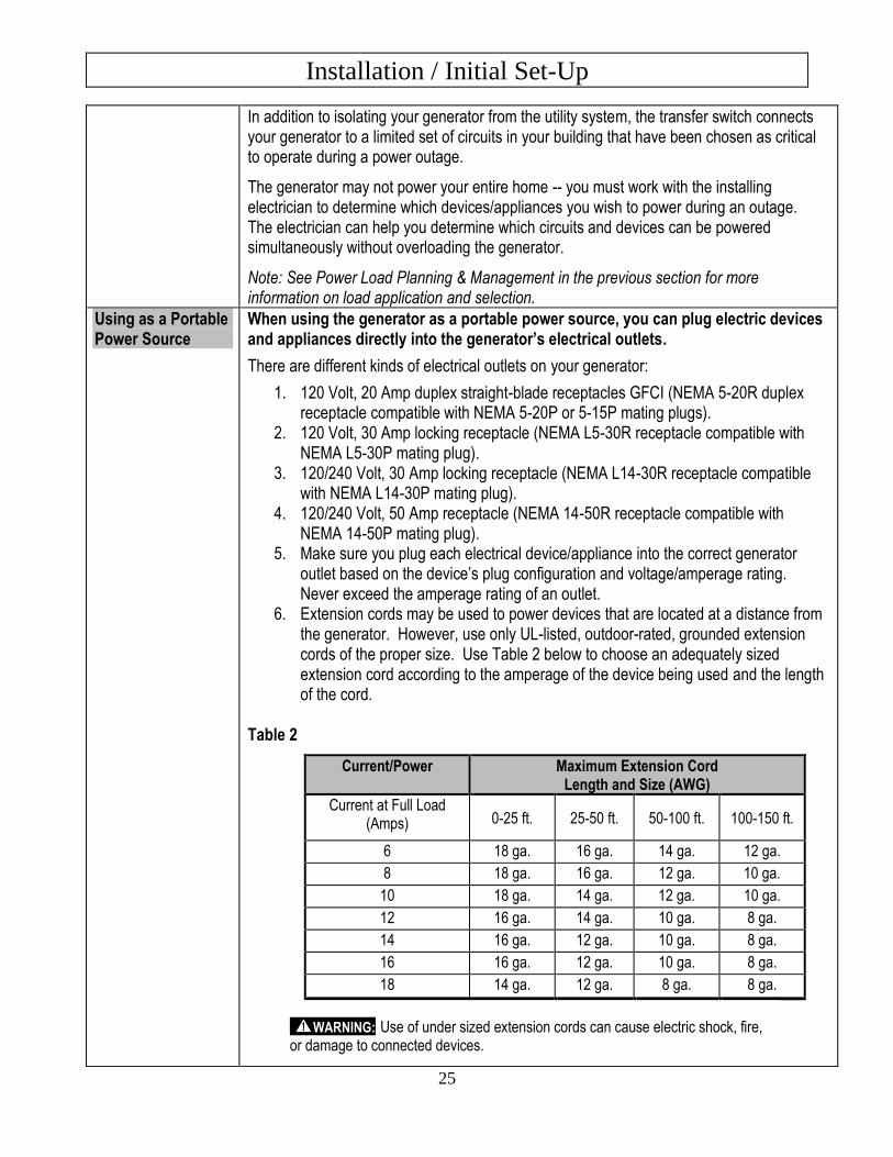
In addition to isolating your generator from the utility system, the transfer switch connects your generator to a limited set of circuits in your building that have been chosen as critical to operate during a power outage.
The generator may not power your entire home -- you must work with the installing electrician to determine which devices/appliances you wish to power during an outage. The electrician can help you determine which circuits and devices can be powered simultaneously without overloading the generator.
Note: See Power Load Planning & Management in the previous section for more information on load application and selection.
Using as a Portable Power Source
When using the generator as a portable power source, you can plug electric devices and appliances directly into the generator’s electrical outlets.
There are different kinds of electrical outlets on your generator:
1. 120 Volt, 20 Amp duplex straight-blade receptacles GFCI (NEMA 5-20R duplex receptacle compatible with NEMA 5-20P or 5-15P mating plugs).
2. 120 Volt, 30 Amp locking receptacle (NEMA L5-30R receptacle compatible with NEMA L5-30P mating plug).
3. 120/240 Volt, 30 Amp locking receptacle (NEMA L14-30R receptacle compatible with NEMA L14-30P mating plug).
4. 120/240 Volt, 50 Amp receptacle (NEMA 14-50R receptacle compatible with NEMA 14-50P mating plug).
5. Make sure you plug each electrical device/appliance into the correct generator outlet based on the device’s plug configuration and voltage/amperage rating. Never exceed the amperage rating of an outlet.
6. Extension cords may be used to power devices that are located at a distance from the generator. However, use only UL-listed, outdoor-rated, grounded extension cords of the proper size. Use Table 2 below to choose an adequately sized extension cord according to the amperage of the device being used and the length of the cord.
Table 2
Current/Power Maximum Extension Cord Length and Size (AWG)
Current at Full Load (Amps) 0-25 ft. 25-50 ft. 50-100 ft. 100-150 ft.
6 18 ga. 16 ga. 14 ga. 12 ga.
8 18 ga. 16 ga. 12 ga. 10 ga.
10 18 ga. 14 ga. 12 ga. 10 ga.
12 16 ga. 14 ga. 10 ga. 8 ga.
14 16 ga. 12 ga. 10 ga. 8 ga.
16 16 ga. 12 ga. 10 ga. 8 ga.
18 14 ga. 12 ga. 8 ga. 8 ga.
WARNING: Use of under sized extension cords can cause electric shock, fire, or damage to connected devices.
Installation / Initial Set-Up
26
7. All extension and appliance cords must be in good condition and not worn, bare, frayed, or otherwise damaged.
WARNING: Use of damaged electric cords can cause electric shock or fire.
Note: If an extension cord becomes hot to the touch, it is overloaded or damaged and must be replaced.
Northern Tool is NOT responsible for damage or injury resulting from customer use of inadequate extension cords.
Installation / Initial Set-Up
27
5. Select a Suitable Site Before using the generator, you must select a suitable OUTDOOR location for installation and operation. This location should meet all the criteria listed below.
WARNING: You must choose a suitable site for operating your generator to avoid equipment damage and/or injury and possible death from carbon monoxide poisoning, electric shock, or fire. Choose a site that meets all of the criteria specified.
Dry, Level Surface The generator should be positioned on a dry, firm, level surface. Ensure that the generator sits level and will not slide or shift during operation. If applicable, block the generator’s wheels to prevent sliding and shifting.
Outdoors Only – Dangerous Carbon Monoxide Exhaust
WARNING: The exhaust from your generator contains carbon monoxide (CO), a poisonous gas that can kill. You cannot smell it, see it, or taste it. Carbon monoxide exhaust is given off whether you are using gasoline, natural gas, or propane as the fuel source to power the generator. Follow the directions below for choosing a location to operate your generator in order to avoid carbon monoxide poisoning.
The location you choose to operate the generator must be OUTDOORS and away from all air intakes:
• Never run the generator inside any closed or semi-enclosed spaces (even if outdoors), including homes, garages, basements, sheds, or boxes. These spaces can trap poisonous gases, even if you run a fan or open windows.
• Never place the generator immediately adjacent to a building or other structure – allow at least 7 feet clearance.
• Place the generator so that the exhaust fumes will not be directed towards people or building air intakes.
• Ensure that working, battery-operated or battery back-up carbon monoxide alarms are used in any dwelling/structure that is in close proximity to the running generator.
• Note that this generator is NOT designed or approved for use in vehicles or marine applications. Never run the generator inside RVs or other vehicles, on boats, or in pick-up truck beds.
WARNING: Never attempt to attach ductwork to the muffler system to allow for installation inside an enclosure. This could cause hot air deflection, heat build-up, and increased exhaust back-pressure, resulting in possible exhaust leakage or damage to the generator.
Installation / Initial Set-Up
28
Adequate Cooling Ventilation
The generator needs adequate, unobstructed flow of air to allow for proper cooling of engine and generator head.
WARNING: Heat build-up from inadequate ventilation can result in fire, posing a serious risk to nearby persons and structures.
• Situate so there is adequate clearance around generator to allow for cooling airflow so that heat does not build up.
• Never place the generator immediately adjacent to a building or other structure – allow at least 7 feet of clearance.
• Do not run the generator in close proximity to other heat-generating equipment, such as another generator. The combined heat that is generated may raise air temperature in the immediate area and there will not be adequate cooling ventilation.
• Do not allow debris to accumulate and block airflow.
• Do not operate with a tarp, blanket, or cover surrounding the generator.
No Wet Conditions Choose a location where the generator will NOT be exposed to rain, snow, or direct sunlight. Exposure to water can cause electric shock.
You may operate the generator under an outdoor, canopy-like structure of heat-resistant material that is open on all sides. Make sure that all parts of canopy are at least 7 feet from exhaust, and allow for adequate clearance above generator so that heat does not build up.
Hot Exhaust Clearance
The exhaust gas from your generator is extremely hot and can cause combustible materials to catch on fire.
• Make sure your generator’s exhaust system is at least 7 feet from all combustible materials and buildings/structures.
• Your generator is equipped with a USDA Forest Service qualified spark arrester so it can be operated near any ignitable forest, brush, or grassy land. Make sure you comply with applicable local, state, and federal codes.
• Keep a fire extinguisher rated “ABC” nearby. Keep it properly charged and be familiar with its use.
Away from Dust and Dirt
Do not use the generator in extremely dusty or dirty conditions. Excessive dust and dirt can cause premature failure of the machine.
Hearing Protection Generators can produce noise levels of up to 95 dB in close proximity, which can be dangerous to human hearing with prolonged exposure.
Hearing protection may be required for persons working within 15-20 feet of the running generator for an extended period of time.
WARNING: Never attempt to attach ductwork to the muffler system to lower noise levels. This could cause hot air deflection, heat build-up, and increased exhaust back-pressure, resulting in possible exhaust leakage or damage to the generator.
Installation / Initial Set-Up
29
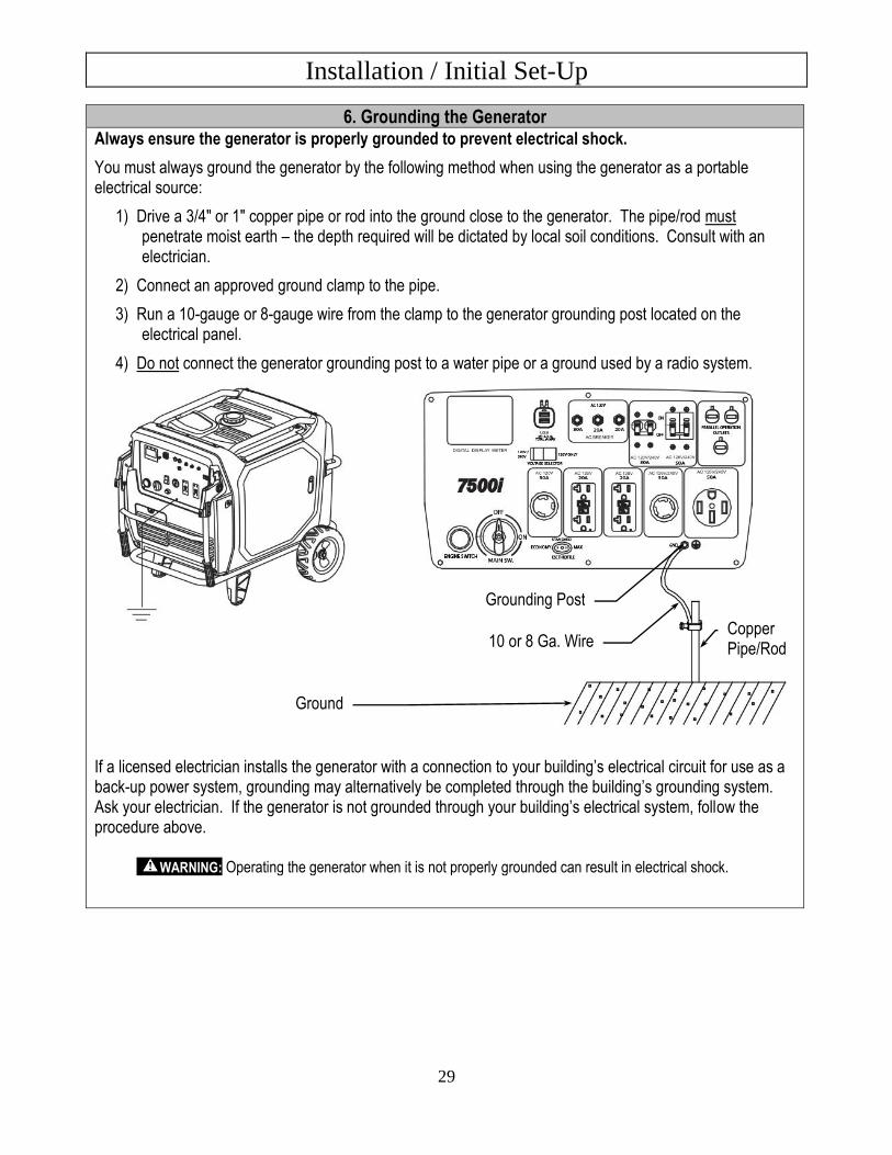
6. Grounding the Generator Always ensure the generator is properly grounded to prevent electrical shock.
You must always ground the generator by the following method when using the generator as a portable electrical source:
1) Drive a 3/4" or 1" copper pipe or rod into the ground close to the generator. The pipe/rod must penetrate moist earth – the depth required will be dictated by local soil conditions. Consult with an electrician.
2) Connect an approved ground clamp to the pipe.
3) Run a 10-gauge or 8-gauge wire from the clamp to the generator grounding post located on the electrical panel.
4) Do not connect the generator grounding post to a water pipe or a ground used by a radio system.
If a licensed electrician installs the generator with a connection to your building’s electrical circuit for use as a back-up power system, grounding may alternatively be completed through the building’s grounding system. Ask your electrician. If the generator is not grounded through your building’s electrical system, follow the procedure above.
WARNING: Operating the generator when it is not properly grounded can result in electrical shock.
Copper Pipe/Rod
Grounding Post
Ground
10 or 8 Ga. Wire
Operation
30
Once you have set up your generator for use, it is time to start your generator. The following are the procedures necessary for safe, successful operation of your generator.
Operation Procedures
1. General Safety Rules for Operation
2. Preparing for Operation
3. Starting the Generator
4. Checking Generator Output
5. Connecting Electrical Loads (Portable Power Generation)
6. Stopping the Generator
7. AC Parallel Operation
8. Storage & Exercise of Generator
Each of these procedures is discussed in detail below:
1. General Safety Rules for Operation Before starting the generator, review the following general safety rules for operation:
WARNING: Failure to follow safety rules may result in serious injury or death to the operator or bystanders.
• Know proper use/how to stop. Be thoroughly familiar with proper use of the equipment and all generator controls,
output receptacles, and connections. Know how to stop the generator quickly if needed. (See Operation, step 6 of Stopping the Engine.)
• Instruct operators. The generator owner must instruct all operators in safe generator set-up and operation. Only trained adults should set up and operate the generator – Do not let children operate.
• Intended use. Carefully read about and understand the intended use of this generator. Do not use for other purposes, as unforeseen hazards or equipment damage may result.
• Under the influence. Never operate, or let anyone else operate, the generator while under the influence of alcohol, drugs, or medication.
• Safety equipment / controls. Do not operate the generator unless all safety covers, guards, and barriers are in place and in good working order, and all controls are properly adjusted for safe operation.
• Damaged. Do not operate the generator with damaged, missing, or broken parts.
• Modifications. Do not modify the generator in any way. Modifications can create serious safety hazards and will also void the warranty.
• Engine speed. Never attempt to modify the engine speed setting. The engine speed is preset for safe and optimal performance of the generator. If speed needs adjusting, it must be done by factory-authorized personnel.
• External fuel sources. Never attempt to connect external gasoline/diesel sources in order to increase engine run time. Larger tank at pressure or higher elevation will cause gasoline to leak from carburetor during operation. Fire or explosion could result.
Operation
31
• Malfunction during operation. Immediately turn off the generator if any of the following conditions arise during operation:
o Excessive change in engine speed, slow or fast o Overheating in load connecting devices o Sparking or arcs from generator o Loss of electrical output o Receptacle damage o Engine misfire o Excessive vibration o Flame or smoke o Abnormal noise
• Adjusting / repairing. Always turn off generator and remove the spark plug(s) or spark plug wire(s) before working on the generator to prevent accidental starting. (See Maintenance & Repair section of this manual for instructions on how to do this.)
• Carbon monoxide poisoning. The running engine gives off carbon monoxide, a poisonous gas that can kill you. You CANNOT smell it, see it, or taste it. Follow all instructions for site selection and positioning the generator, and avoid inhaling the exhaust. If you start to feel sick, dizzy, or weak while using the generator, shut off the engine and get to fresh air RIGHT AWAY. See a doctor. You may have carbon monoxide poisoning.
• Other exhaust dangers. This product contains or emits chemicals known to the State of California to cause cancer, birth defects or other reproductive harm. Avoid inhalation of exhaust.
• Wet conditions. Do not operate the generator or handle any electrical equipment while standing in water, while barefoot, while hands are wet or while in the rain or snow. Electric shock may result.
• Ground fault circuit interrupter. Always use a ground fault circuit interrupter (GFCI) protected extension cord (or outlet, if generator is equipped) in damp or highly electrical conductive areas and on construction jobsites to prevent electrical shock.
• Avoid contact. Avoid contact with bare wires, terminals, connections, etc. while the unit is running.
• Electric shock accident. If an electric shock accident occurs, immediately shut down the source of electrical power. If this is not possible, attempt to free the victim from the live conductor. Avoid direct contact with victim. Use a non-conducting implement, such as a dry rope or board, to free the victim from the live conductor. Apply first aid and get immediate medical help.
• Smoking/sparks. Never smoke near the running generator, and never operate near sources of sparks or flames.
• Hot muffler. Never touch hot muffler, hot exhaust manifold, or engine cooling fins. Exhaust and engine parts can be very hot and will burn you.
• Moving parts. Keep hands, feet, and apparel away from drive belts, fans, and other moving parts. Never remove any drive belt or fan guard while the unit is operating.
• Transporting. Do not overfill the fuel tank if driving on rough terrain.
o Transport in horizontal position only. o Main switch needs to be in the “OFF” position.
Operation
32
Static Electricity and Filling the Gasoline Tank
Static electricity can initiate from ungrounded gasoline tanks or containers, from flowing gasoline, and from persons carrying a static electric charge.
Static electricity can explosively ignite gasoline vapors that are present during the fueling process, resulting in serious burns to nearby persons. To avoid static electricity while fueling, certain steps must be followed before and during the fueling process to minimize and safely dissipate static charge build-up:
• Touch a grounded metal object before starting. Always dissipate static charge from your body before beginning the fueling process by touching a grounded metal object at a safe distance away from fuel sources.
• Use a portable container to fill tank. Never fill the generator’s gas tank directly from the fuel pump – the generator’s tank is not grounded and the high velocity flow of gasoline from a fuel pump can cause static electric build-up. Use an approved portable container to transfer gasoline to the generator’s tank.
• Fill container on the ground. Never fill the portable gas container while it is sitting inside a vehicle, trailer, trunk, or pick-up truck bed. ALWAYS place container on the ground to be filled.
• Keep nozzle in contact with container. Keep nozzle in contact with the portable container at all times while filling. Manually control the flow of gasoline; do NOT use the nozzle’s lock-open device.
• Use a portable container made of metal or conductive plastic. It will dissipate charge to ground more readily.
About static electricity and fueling Many common objects can accumulate and retain a static electric charge. Objects made of non-conductive materials (e.g. plastics) easily accumulate and retain static electric charge, as can objects made of conductive material (e.g. metal, water) if they are not electrically grounded. The static electric charge on an object, such as a human body or plastic fuel tank/container, can reach as high as several thousand volts!
A static electric spark can be generated if the static electric charge stored on an object “jumps” to another, less charged object. Such a spark can ignite invisible gasoline vapors that are present during fueling situations.
Typical sources of static electric hazards during fueling The following objects can accumulate a static electric charge and cause an ignition spark in typical fueling situations:
• Ungrounded tanks/containers. Any ungrounded fuel tank or container can accumulate a static electric charge as a result of contact with other objects or friction during transportation. This static electricity can discharge as a spark to the grounded gasoline dispenser nozzle, as the nozzle is first brought close to the tank/container at the beginning of the fueling process.
• Flowing gasoline. Most people are not aware that gasoline accumulates static electric charge while flowing through a hose or pipe. This charge then transfers to and accumulates in the gas tank or container that is being filled. The total amount of charge accumulation depends on the amount of gas pumped into the container, the speed with which it is pumped, and whether or not the tank/container is grounded. If sufficient static electric charge accumulates in the fuel tank or container during the fueling process, the tank/container may discharge a spark to the grounded gasoline dispenser nozzle.
• Persons. A person dispensing the gasoline can carry a static electric charge on their body, typically resulting from contact with their car seat or electronics. The static electricity can discharge as a spark between that person’s hand and either the grounded dispenser nozzle or the fuel tank opening.
Operation
33
2. Preparing for Operation Position
Generator
Position generator in accordance with the instructions given in Installation & Initial Set-up, Step 5: Select a Suitable Site of this manual. Operate outside only, on dry, level ground with adequate clearance and ventilation.
WARNING: Generators give off carbon monoxide exhaust, a poisonous gas that can kill. You CANNOT smell it, see it, or taste it. ONLY run generator OUTDOORS and away from air intakes. NEVER run generator inside any enclosed or semi-enclosed spaces, including homes, garages, basements, sheds, boxes, pick-up truck beds, RVs, or boats. These spaces can trap poisonous gases, EVEN if you run a fan or open windows. Carbon monoxide exhaust is given off whether you are using gasoline, natural gas, or propane to power the generator.
Ground
Generator
Make sure the generator is grounded in accordance with instruction given in Installation & Initial Set-up, Step 6: Grounding the Generator of this manual.
WARNING: Always ensure generator is properly grounded to prevent electrical shock.
Perform
Scheduled
Maintenance
as Needed
Make sure that any regular maintenance has been performed as prescribed in this manual in the Maintenance & Repair section.
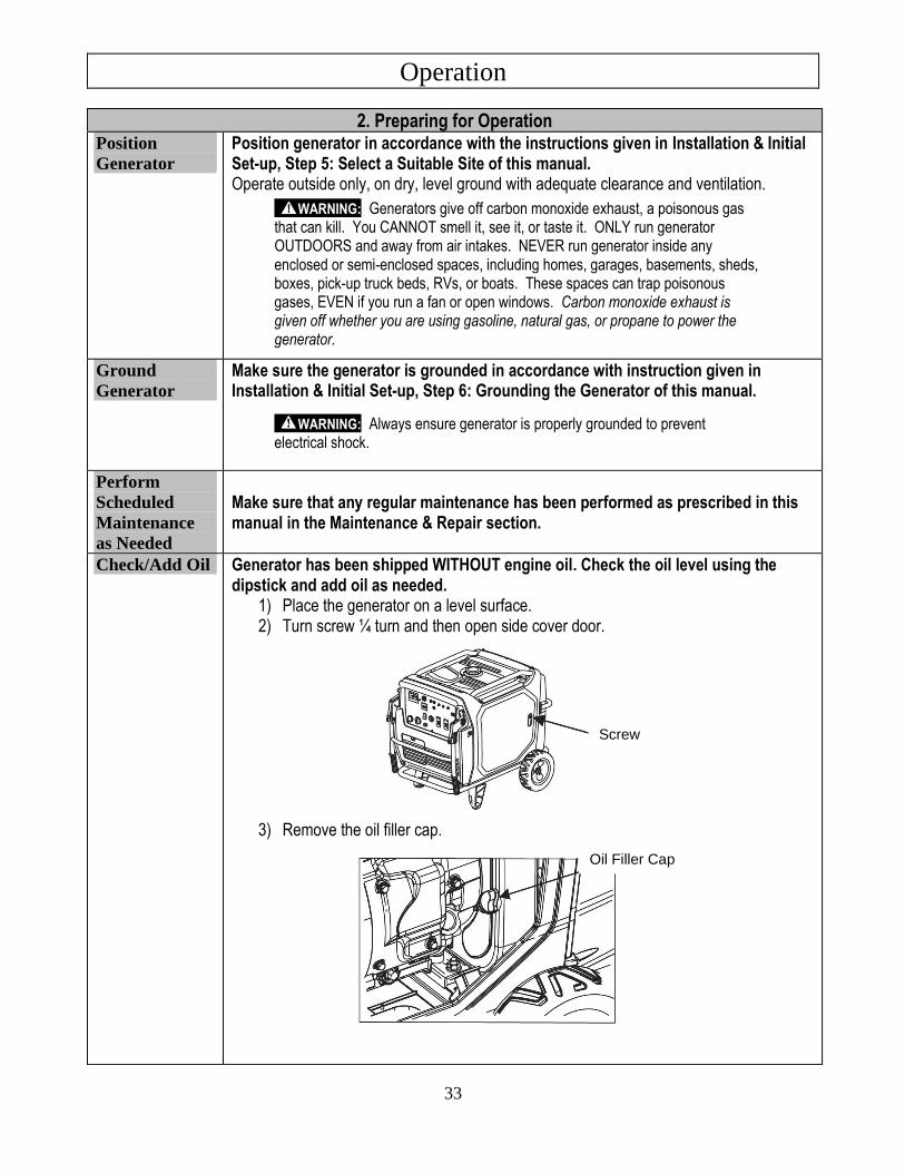
Check/Add Oil Generator has been shipped WITHOUT engine oil. Check the oil level using the dipstick and add oil as needed.
1) Place the generator on a level surface. 2) Turn screw ¼ turn and then open side cover door.
3) Remove the oil filler cap.
Screw
Oil Filler Cap
Operation
34
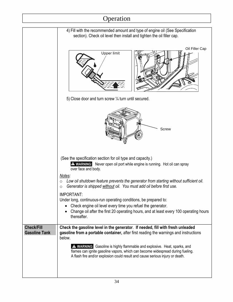
4) Fill with the recommended amount and type of engine oil (See Specification section). Check oil level then install and tighten the oil filler cap.
5) Close door and turn screw ¼ turn until secured.
(See the specification section for oil type and capacity.)
WARNING: Never open oil port while engine is running. Hot oil can spray over face and body.
˙
Notes: o Low oil shutdown feature prevents the generator from starting without sufficient oil. o Generator is shipped without oil. You must add oil before first use.
IMPORTANT: Under long, continuous-run operating conditions, be prepared to:
• Check engine oil level every time you refuel the generator.
• Change oil after the first 20 operating hours, and at least every 100 operating hours thereafter.
Check/Fill Gasoline Tank
Check the gasoline level in the generator. If needed, fill with fresh unleaded gasoline from a portable container, after first reading the warnings and instructions below.
WARNING: Gasoline is highly flammable and explosive. Heat, sparks, and flames can ignite gasoline vapors, which can become widespread during fueling. A flash fire and/or explosion could result and cause serious injury or death.
Screw
Oil Filler Cap
Operation
35
Use extreme care when handling gasoline. Carefully follow all the instructions in this section to avoid the following conditions which could result in gasoline ignition:
• gas vapor collection inside enclosures
• static electric sparks
• sparks from electric wiring, batteries, or running engines
• sources of heat (such as a hot engine or exhaust)
• open flames, including pilot lights
1) Before starting, review the following general safety precautions for fueling:
a) Never pump gasoline directly into the generator’s gas tank at a gas station – high velocity flow from the pump could result in a static electric build-up in the generator’s tank. Always use a portable container to fill the tank. See warning box regarding static electric spark hazards below.
b) Fill gasoline tank OUTDOORS – never indoors. c) Stay away from all sources of heat, sparks, and flames. Do not smoke.
2) Turn generator off and allow unit to cool for at least two minutes before removing gas cap.
NOTICE: A running or still-hot engine is hot enough to ignite fuel.
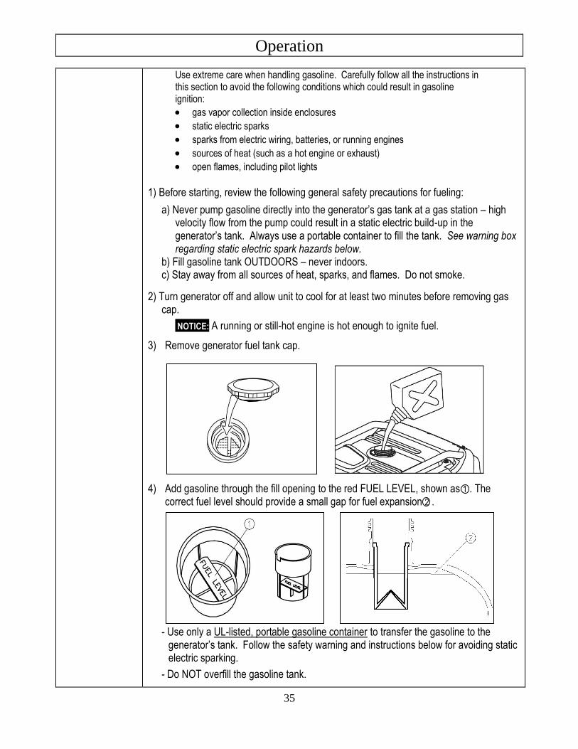
3) Remove generator fuel tank cap. 4) Add gasoline through the fill opening to the red FUEL LEVEL, shown as 1 . The
correct fuel level should provide a small gap for fuel expansion 2 .
- Use only a UL-listed, portable gasoline container to transfer the gasoline to the generator’s tank. Follow the safety warning and instructions below for avoiding static electric sparking.
- Do NOT overfill the gasoline tank.
Operation
36
WARNING: A static electric spark can explosively ignite gasoline vapor, resulting in a flash fire that could cause serious injury or death.
To avoid static electric sparking while filling the gasoline tank, the following steps must be followed to minimize and safely dissipate static electric charge build-up before and during the fueling process:
• Always dissipate static charge from your body before beginning the fueling process by touching a grounded metal object at a safe distance from fuel sources.
• Never fill the generator’s gas tank directly from the fuel pump – the generator’s tank is not grounded and high velocity flow from the pump can cause static electricity build-up. Use an approved portable container to transfer gas to the generator’s tank.
• Never fill the portable gas container while it is sitting inside a vehicle, trailer, trunk, or pick-up truck bed. ALWAYS place container on the ground to be filled.
• Keep nozzle in contact with portable container while filling. Manually control the flow of gasoline; do NOT use the nozzle’s lock-open device.
• A portable container made of metal or conductive plastic is preferred because it dissipates charge to ground more readily.
5) Clean up gasoline spills /splashes immediately.
• If possible, move the generator away from spilled gasoline on the ground.
• Wipe up spilled gasoline and wait 5 minutes for excess gasoline to evaporate before starting engine.
• Gasoline soaked rags are flammable and should be disposed of properly.
• If gasoline is spilled on your skin or clothes, change clothes and wash skin immediately.
6) Replace gasoline cap securely before starting engine.
7) Store extra gasoline in a cool, dry place in an UL-listed, tightly sealed container.
IMPORTANT: For continuous operation, be prepared to check and refuel the generator on a regular basis. A tank of gasoline should last about 16 hours @ 1/4 load.
Inspect Fuel System / Check for Leaks
Inspect fuel system and check for leaks BEFORE starting generator. Do not start generator until all needed repairs have been completed.
WARNING: Gasoline is highly explosive and fuel leaks can result in fire or explosions. You can be burned and seriously injured if the fuel system is not properly hooked up or there is a fuel leak when you start the engine.
Inspect the entire fuel system. Look for:
• signs of leaks or deterioration,
• chafed or spongy fuel hose,
• loose connections,
• loose or missing fuel hose clamps,
• a damaged gasoline tank, or
• a defective gasoline shut-off valve.
Operation
37
Personal Protection
1) Hearing can be damaged from prolonged, close-range exposure to the type of noise produced by this generator. The use of ear plugs or other hearing protection device is recommended for persons working within 15-20 feet of the running generator for an extended period of time.
2) Loose or dangling apparel can become entangled in moving parts. Metal jewelry can conduct electricity. Never wear jewelry or loose-fitting clothing when starting or operating the generator.
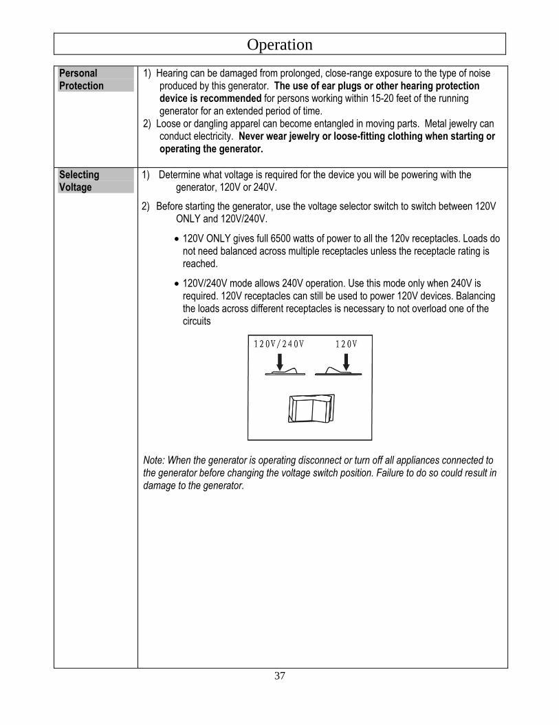
Selecting Voltage
1) Determine what voltage is required for the device you will be powering with the generator, 120V or 240V.
2) Before starting the generator, use the voltage selector switch to switch between 120V ONLY and 120V/240V.
• 120V ONLY gives full 6500 watts of power to all the 120v receptacles. Loads do not need balanced across multiple receptacles unless the receptacle rating is reached.
• 120V/240V mode allows 240V operation. Use this mode only when 240V is required. 120V receptacles can still be used to power 120V devices. Balancing the loads across different receptacles is necessary to not overload one of the circuits
Note: When the generator is operating disconnect or turn off all appliances connected to the generator before changing the voltage switch position. Failure to do so could result in damage to the generator.
Operation
38
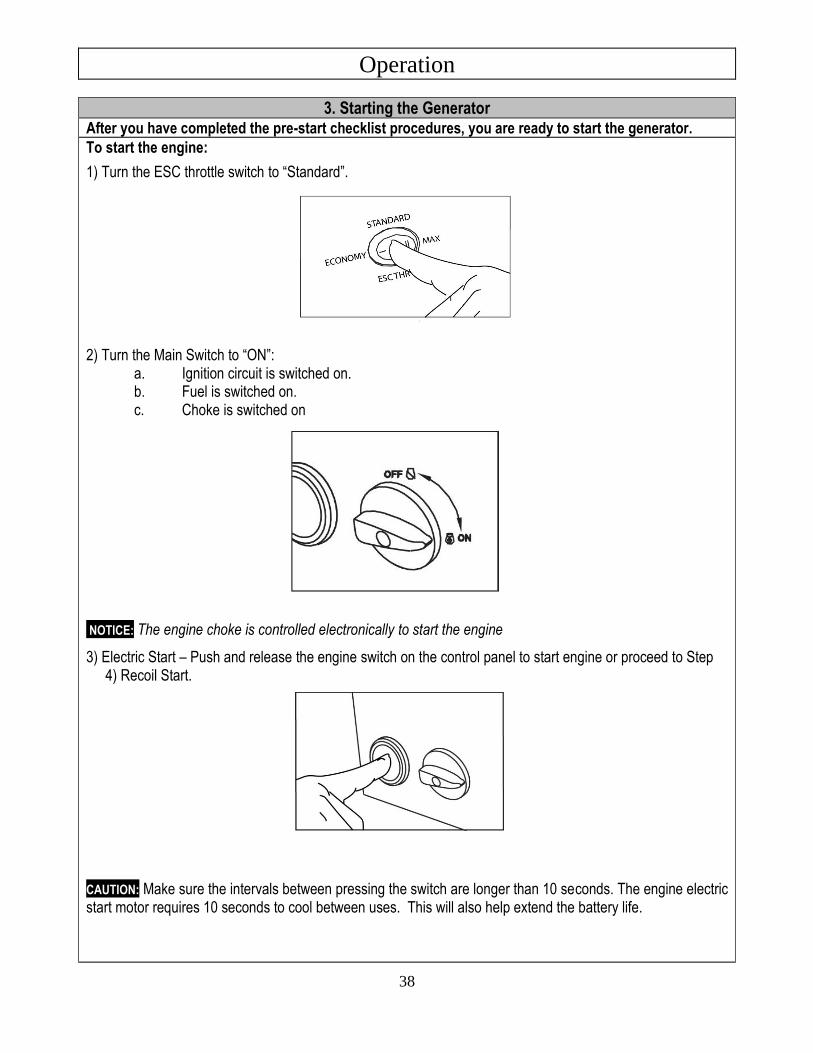
3. Starting the Generator After you have completed the pre-start checklist procedures, you are ready to start the generator.
To start the engine:
1) Turn the ESC throttle switch to “Standard”.
2) Turn the Main Switch to “ON”: a. Ignition circuit is switched on. b. Fuel is switched on. c. Choke is switched on
NOTICE: The engine choke is controlled electronically to start the engine
3) Electric Start – Push and release the engine switch on the control panel to start engine or proceed to Step 4) Recoil Start.
CAUTION: Make sure the intervals between pressing the switch are longer than 10 seconds. The engine electric start motor requires 10 seconds to cool between uses. This will also help extend the battery life.
Operation
39
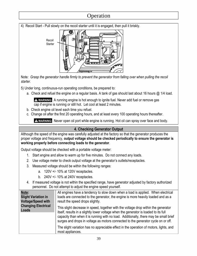
4) Recoil Start - Pull slowly on the recoil starter until it is engaged, then pull it briskly.
Note: Grasp the generator handle firmly to prevent the generator from falling over when pulling the recoil starter.
5) Under long, continuous-run operating conditions, be prepared to:
a. Check and refuel the engine on a regular basis. A tank of gas should last about 16 hours @ 1/4 load.
WARNING: A running engine is hot enough to ignite fuel. Never add fuel or remove gas cap if engine is running or still hot. Let cool at least 2 minutes.
b. Check engine oil level each time you refuel. c. Change oil after the first 20 operating hours, and at least every 100 operating hours thereafter.
WARNING: Never open oil port while engine is running. Hot oil can spray over face and body.
4. Checking Generator Output Although the speed of the engine was carefully adjusted at the factory so that the generator produces the proper voltage and frequency, output voltage should be checked periodically to ensure the generator is working properly before connecting loads to the generator.
Output voltage should be checked with a portable voltage meter:
1. Start engine and allow to warm up for five minutes. Do not connect any loads.
2. Use voltage meter to check output voltage at the generator’s outlets/receptacles.
3. Measured voltage should be within the following ranges:
a. 120V +/- 10% at 120V receptacles.
b. 240V +/- 10% at 240V receptacles.
4. If measured voltage is not within the specified range, have generator adjusted by factory authorized personnel. Do not attempt to adjust the engine speed yourself.
Note: Slight Variation in Voltage/Speed with Changing Electrical Loads
All engines have a tendency to slow down when a load is applied. When electrical loads are connected to the generator, the engine is more heavily loaded and as a result the speed drops slightly.
This slight decrease in speed, together with the voltage drop within the generator itself, results in a slightly lower voltage when the generator is loaded to its full capacity than when it is running with no load. Additionally, there may be small brief surges and drops in voltage as motors connected to the generator cycle on or off.
The slight variation has no appreciable effect in the operation of motors, lights, and most appliances.
Recoil Starter
Operation
40
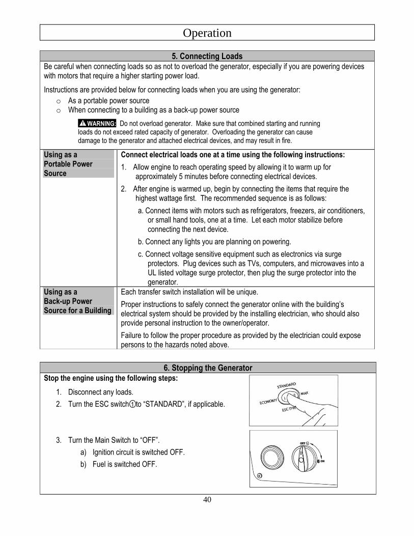
6. Stopping the Generator Stop the engine using the following steps:
1. Disconnect any loads.
2. Turn the ESC switch 1 to “STANDARD”, if applicable.
3. Turn the Main Switch to “OFF”.
a) Ignition circuit is switched OFF.
b) Fuel is switched OFF.
5. Connecting Loads Be careful when connecting loads so as not to overload the generator, especially if you are powering devices with motors that require a higher starting power load.
Instructions are provided below for connecting loads when you are using the generator:
o As a portable power source o When connecting to a building as a back-up power source
WARNING: Do not overload generator. Make sure that combined starting and running loads do not exceed rated capacity of generator. Overloading the generator can cause damage to the generator and attached electrical devices, and may result in fire.
Using as a Portable Power Source
Connect electrical loads one at a time using the following instructions:
1. Allow engine to reach operating speed by allowing it to warm up for approximately 5 minutes before connecting electrical devices.
2. After engine is warmed up, begin by connecting the items that require the highest wattage first. The recommended sequence is as follows:
a. Connect items with motors such as refrigerators, freezers, air conditioners, or small hand tools, one at a time. Let each motor stabilize before connecting the next device.
b. Connect any lights you are planning on powering.
c. Connect voltage sensitive equipment such as electronics via surge protectors. Plug devices such as TVs, computers, and microwaves into a UL listed voltage surge protector, then plug the surge protector into the generator.
Using as a Back-up Power Source for a Building
Each transfer switch installation will be unique.
Proper instructions to safely connect the generator online with the building’s electrical system should be provided by the installing electrician, who should also provide personal instruction to the owner/operator.
Failure to follow the proper procedure as provided by the electrician could expose persons to the hazards noted above.
Operation
41
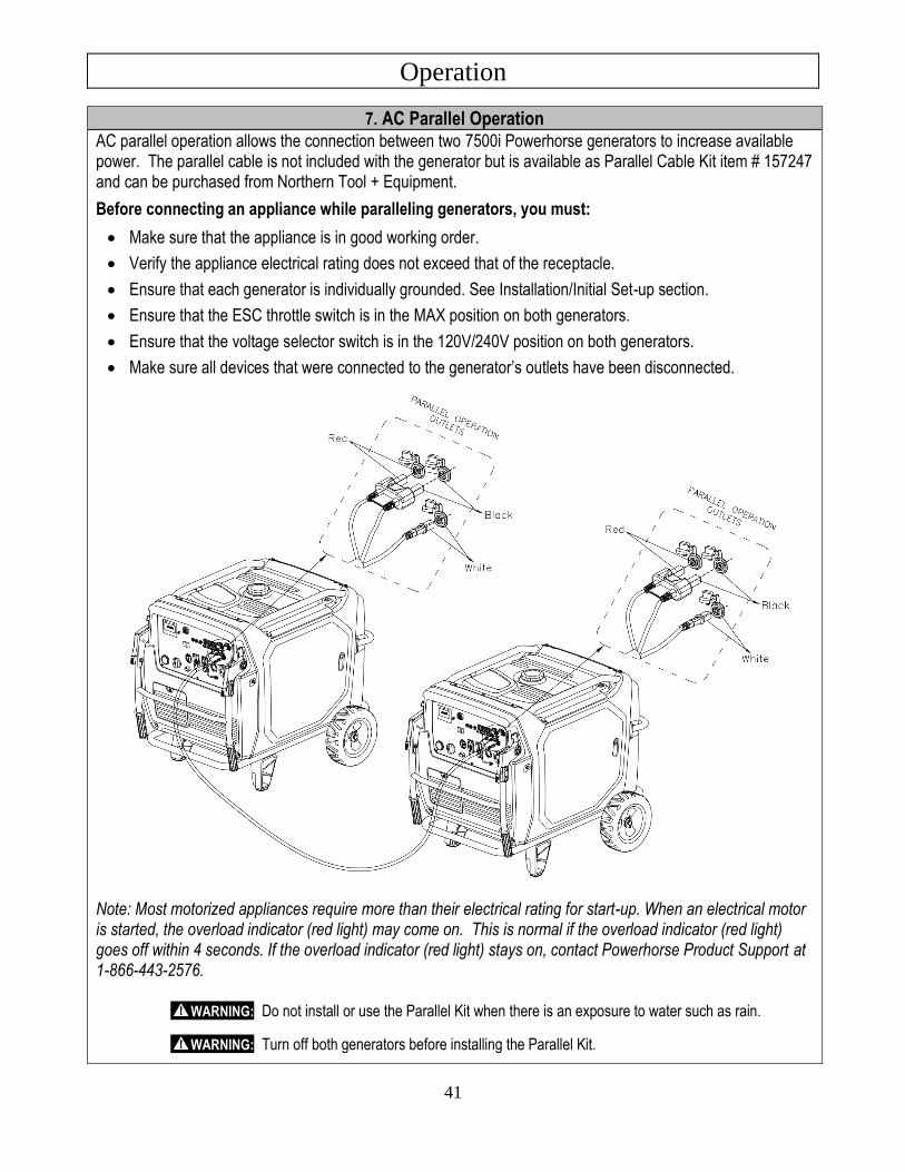
7. AC Parallel Operation
AC parallel operation allows the connection between two 7500i Powerhorse generators to increase available power. The parallel cable is not included with the generator but is available as Parallel Cable Kit item # 157247 and can be purchased from Northern Tool + Equipment.
Before connecting an appliance while paralleling generators, you must:
• Make sure that the appliance is in good working order.
• Verify the appliance electrical rating does not exceed that of the receptacle.
• Ensure that each generator is individually grounded. See Installation/Initial Set-up section.
• Ensure that the ESC throttle switch is in the MAX position on both generators.
• Ensure that the voltage selector switch is in the 120V/240V position on both generators.
• Make sure all devices that were connected to the generator’s outlets have been disconnected.
Note: Most motorized appliances require more than their electrical rating for start-up. When an electrical motor is started, the overload indicator (red light) may come on. This is normal if the overload indicator (red light) goes off within 4 seconds. If the overload indicator (red light) stays on, contact Powerhorse Product Support at 1-866-443-2576.
WARNING: Do not install or use the Parallel Kit when there is an exposure to water such as rain.
WARNING: Turn off both generators before installing the Parallel Kit.
Operation
42
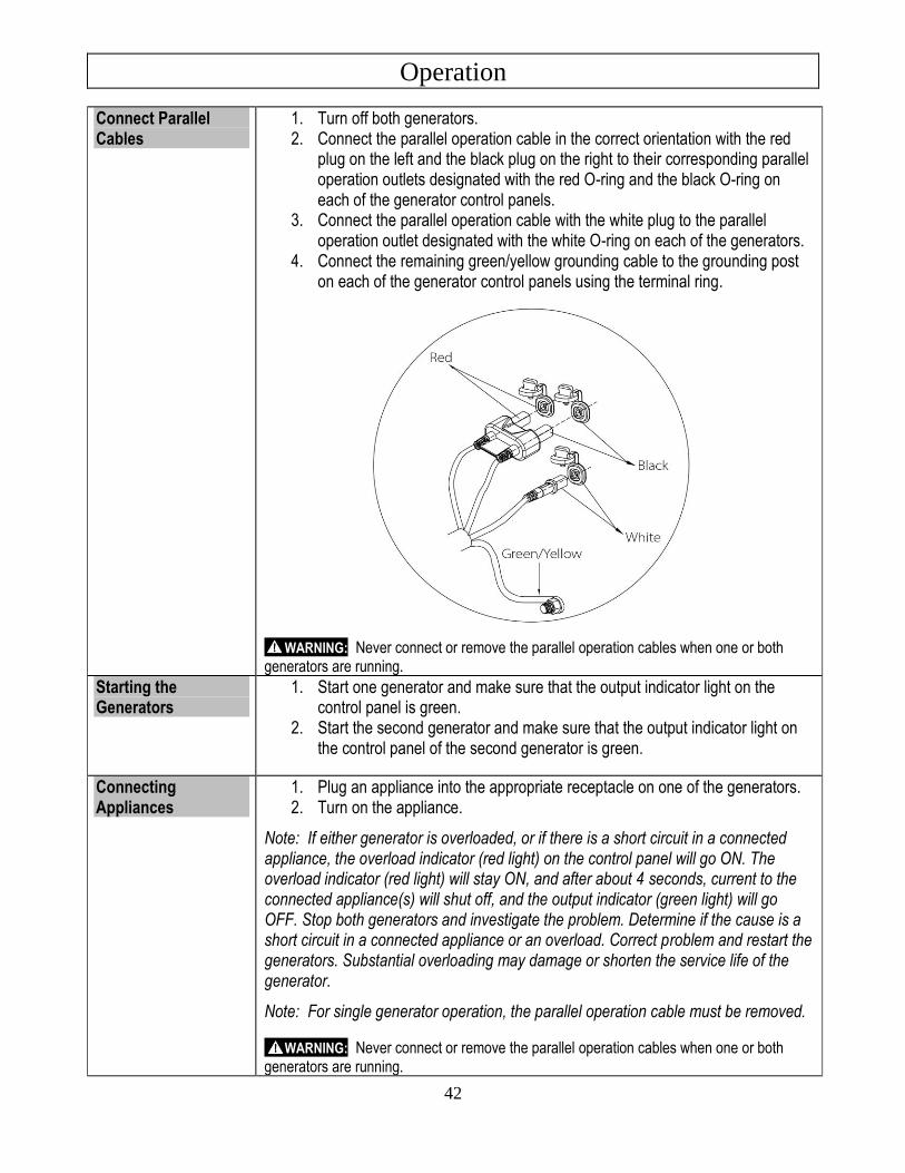
Connect Parallel Cables
1. Turn off both generators. 2. Connect the parallel operation cable in the correct orientation with the red
plug on the left and the black plug on the right to their corresponding parallel operation outlets designated with the red O-ring and the black O-ring on each of the generator control panels.
3. Connect the parallel operation cable with the white plug to the parallel operation outlet designated with the white O-ring on each of the generators.
4. Connect the remaining green/yellow grounding cable to the grounding post on each of the generator control panels using the terminal ring.
WARNING: Never connect or remove the parallel operation cables when one or both generators are running.
Starting the Generators
1. Start one generator and make sure that the output indicator light on the control panel is green.
2. Start the second generator and make sure that the output indicator light on the control panel of the second generator is green.
Connecting Appliances
1. Plug an appliance into the appropriate receptacle on one of the generators. 2. Turn on the appliance.
Note: If either generator is overloaded, or if there is a short circuit in a connected appliance, the overload indicator (red light) on the control panel will go ON. The overload indicator (red light) will stay ON, and after about 4 seconds, current to the connected appliance(s) will shut off, and the output indicator (green light) will go OFF. Stop both generators and investigate the problem. Determine if the cause is a short circuit in a connected appliance or an overload. Correct problem and restart the generators. Substantial overloading may damage or shorten the service life of the generator.
Note: For single generator operation, the parallel operation cable must be removed.
WARNING: Never connect or remove the parallel operation cables when one or both generators are running.
Operation
43
8. Storage & Exercise
When you are finished using the generator, you must:
o Disconnect all loads.
o Allow generator to completely cool down.
o Store the generator properly.
o Plan on exercising the engine regularly unless the generator is prepared for long-term storage.
Detailed instructions are provided below.
Disconnect Loads When you are finished using the generator:
o Make sure all devices that were connected to the generator’s outlets have been disconnected.
Cool Engine Before Storing
Let engine cool for at least five minutes before storing. A hot engine can be a fire hazard.
Choose a Storage Location
Store the generator in a location that is: o Clean and dry. o Away from sources of heat, open flames, sparks, or pilot lights, even if the
generator’s fuel tank is empty. Residual fuel in the tank could ignite. o Away from extreme high or low temperatures.
Prevent Accidental Starting
Remove spark plug(s) in order to ensure the generator cannot be started accidentally in a storage location or by untrained persons.
Exercise Generator every 4 weeks
The generator should be exercised regularly. At least every four weeks, start the engine and let it run for 10 to 15 minutes with a small load plugged in, such as a lamp or fan.
Monthly exercising of the generator will: o Dry out any moisture that has accumulated in the windings. If left, this
moisture can cause corrosion in the winding. o Ensure that the unit is operating properly should it be needed in an
emergency.
Perform Regular Maintenance
Perform periodic maintenance as directed in this manual to keep the generator in safe working condition.
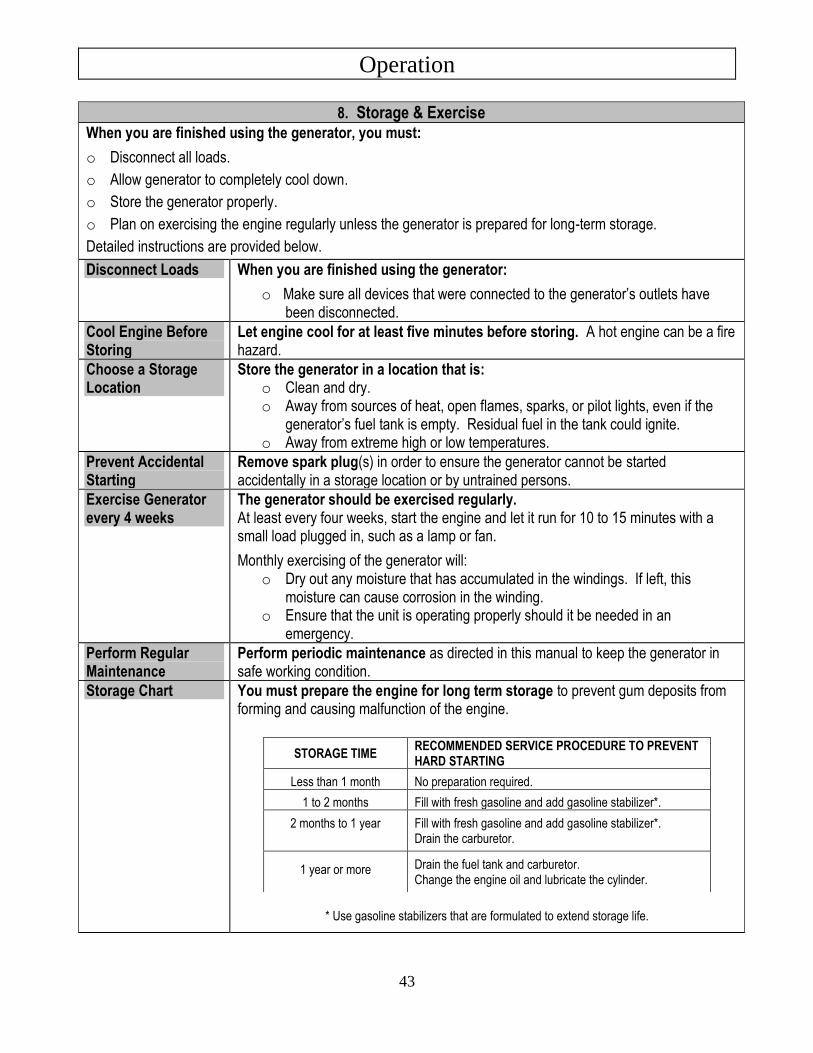
Storage Chart You must prepare the engine for long term storage to prevent gum deposits from forming and causing malfunction of the engine.
* Use gasoline stabilizers that are formulated to extend storage life.
STORAGE TIME RECOMMENDED SERVICE PROCEDURE TO PREVENT HARD STARTING
Less than 1 month No preparation required.
1 to 2 months Fill with fresh gasoline and add gasoline stabilizer*.
2 months to 1 year
Fill with fresh gasoline and add gasoline stabilizer*. Drain the carburetor.
1 year or more
Drain the fuel tank and carburetor. Change the engine oil and lubricate the cylinder.
Operation
44
Prepare Engine for 1 to 2 Months Storage
Add fuel stabilizer: 1. Ensure gasoline tank is full. 2. Add fuel stabilizer to fuel tank. 3. Run engine at least 10 minutes after adding stabilizer to allow it to enter the fuel
system. 4. Shut off engine. 5. Disconnect spark plug wire and remove spark plug. 6. Add one teaspoon oil through spark plug hole. 7. Place rag over spark plug hole and turn starter (or pull the recoil) a few times to
lubricate the combustion chamber. 8. Replace spark plug but do not reconnect the spark plug wire.
Prepare Engine for 2 Months to 1 Year Storage
Add fuel stabilizer and drain carburetor: 1. Ensure gasoline tank is full. 2. Add fuel stabilizer to fuel tank. 3. Run engine at least 10 minutes after adding stabilizer to allow it to enter the
fuel system. 4. Shut off engine. 5. Remove the side cover and screws. 6. Loosen the carburetor drain screw (See Maintenance & Repair section). 7. Drain the gasoline from the carburetor into a suitable container. 8. Tighten the carburetor drain screw. 9. Disconnect spark plug wire and remove spark plug. 10. Add one teaspoon oil through spark plug hole. 11. Place rag over spark plug hole and turn starter (or pull the recoil) a few times to
lubricate the combustion chamber. 12. Replace spark plug but do not reconnect the spark plug wire.
Prepare Engine for 1 Year or More Storage
Drain fuel tank and drain carburetor: 1. Remove the fuel tank cap, remove the filter. 2. Remove the fuel in the fuel tank using one of these methods:
a. Extract the fuel from the fuel tank into an approved gasoline container using a commercially available hand siphon. (NTE sells Item # 206500). Install the fuel filter and fuel tank cap.
b. Drain the fuel from tank into a suitable container using the barb on the bottom of the fuel tank.
3. Start the generator and allow to run until it stops (approx. 20 minutes) 4. Remove the side cover and screws. 5. Drain the fuel from the carburetor by loosening the drain screw on the
carburetor. 6. Tighten the drain screw. 7. Install the side cover and tighten the screws. 8. Disconnect spark plug wire and remove spark plug. 9. Add one teaspoon oil through spark plug hole. 10. Place rag over spark plug hole and turn starter (or pull the recoil) a few times to
lubricate the combustion chamber. 11. Replace spark plug but do not reconnect the spark plug wire.
Maintenance & Repair
45
Inspect and maintain your generator as specified below in order to keep it in safe and optimal working order. Follow all safety rules and recommended maintenance steps.
WARNING ALWAYS shut off the engine, disconnect the spark plug(s), and discharge the capacitor before cleaning, adjusting, or servicing the generator. Make sure all guards and shields are replaced before using.
NOTICE: The generator head is brushless and maintenance free. The bearing is a heavy-duty, sealed ball bearing, which requires no maintenance or lubrication.
Maintenance & Repair Follow Safety Rules Read and follow these safety rules whenever you will be servicing the
generator: • Turn off generator. Always turn off generator and remove spark plug(s) or spark plug
wire(s) before working on the engine or generator to prevent accidental starting.
• Replace guards. Make sure all guards and shields are replaced after servicing the generator.
• Repair. Major service, including the installation or replacement of parts, should be performed only by a qualified electrical service technician. Obtain factory approved parts from Powerhorse Product Support at 1-866-443-2576.
• Replacement parts. If a part needs replacement, only use factory approved repair parts. Replacement parts that do not meet specifications may result in a safety hazard or poor operation of the generator and will void the warranty.
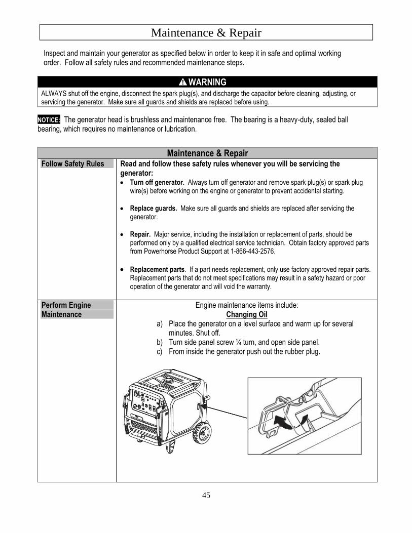
Perform Engine Maintenance
Engine maintenance items include: Changing Oil
a) Place the generator on a level surface and warm up for several minutes. Shut off.
b) Turn side panel screw ¼ turn, and open side panel. c) From inside the generator push out the rubber plug.
Maintenance & Repair (continued)
46
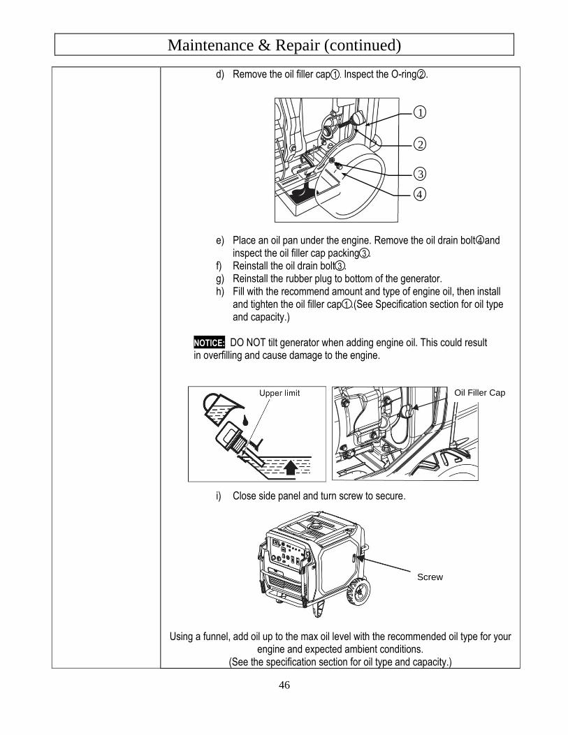
d) Remove the oil filler cap 1 . Inspect the O-ring 2 .
e) Place an oil pan under the engine. Remove the oil drain bolt 4 and inspect the oil filler cap packing 3 .
f) Reinstall the oil drain bolt 3 . g) Reinstall the rubber plug to bottom of the generator. h) Fill with the recommend amount and type of engine oil, then install
and tighten the oil filler cap 1 .(See Specification section for oil type and capacity.)
NOTICE: DO NOT tilt generator when adding engine oil. This could result in overfilling and cause damage to the engine.
i) Close side panel and turn screw to secure.
Using a funnel, add oil up to the max oil level with the recommended oil type for your engine and expected ambient conditions.
(See the specification section for oil type and capacity.)
1
2
4
3
Screw
Oil Filler Cap
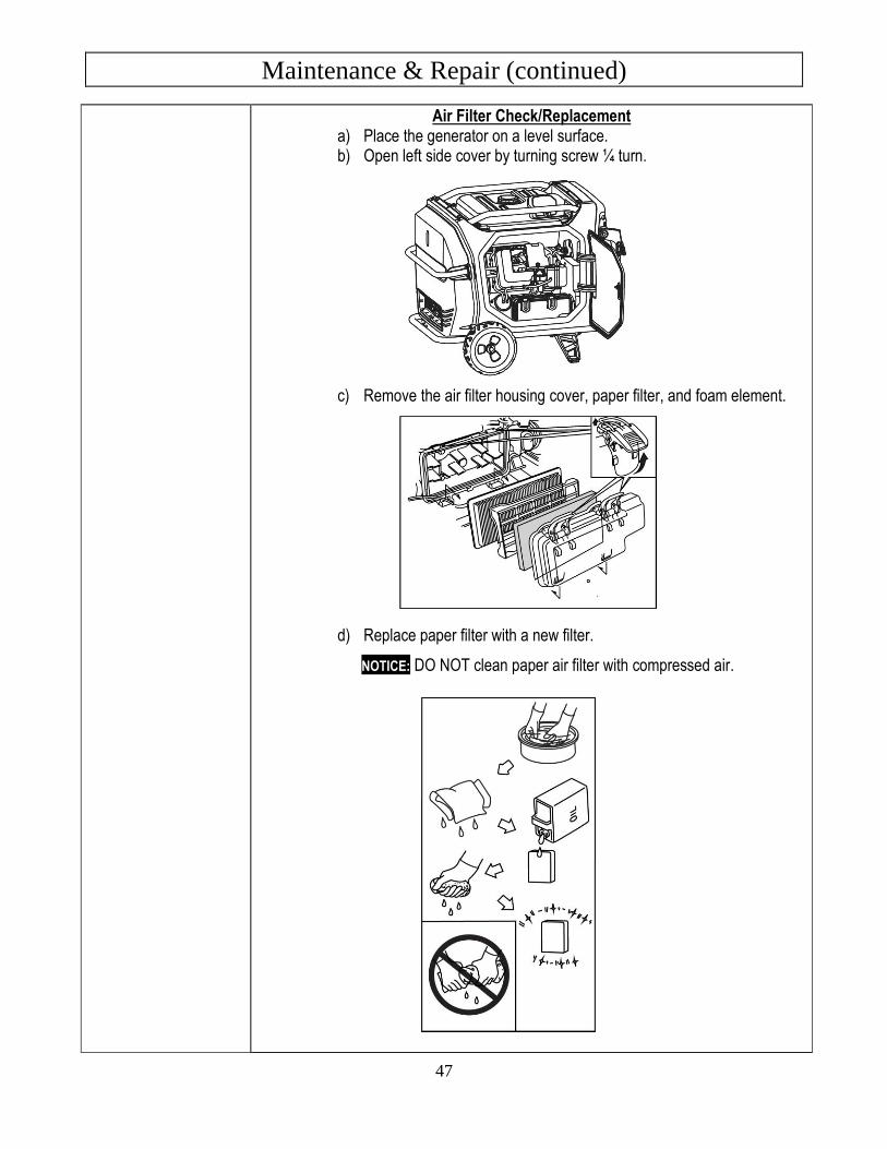
Maintenance & Repair (continued)
47
Air Filter Check/Replacement a) Place the generator on a level surface. b) Open left side cover by turning screw ¼ turn.
c) Remove the air filter housing cover, paper filter, and foam element.
d) Replace paper filter with a new filter.
NOTICE: DO NOT clean paper air filter with compressed air.
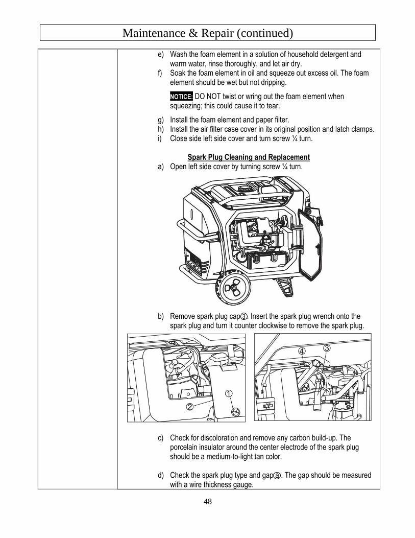
Maintenance & Repair (continued)
48
e) Wash the foam element in a solution of household detergent and warm water, rinse thoroughly, and let air dry.
f) Soak the foam element in oil and squeeze out excess oil. The foam element should be wet but not dripping.
NOTICE: DO NOT twist or wring out the foam element when squeezing; this could cause it to tear.
g) Install the foam element and paper filter. h) Install the air filter case cover in its original position and latch clamps. i) Close side left side cover and turn screw ¼ turn.
Spark Plug Cleaning and Replacement
a) Open left side cover by turning screw ¼ turn.
b) Remove spark plug cap 3 . Insert the spark plug wrench onto the spark plug and turn it counter clockwise to remove the spark plug.
c) Check for discoloration and remove any carbon build-up. The
porcelain insulator around the center electrode of the spark plug should be a medium-to-light tan color.
d) Check the spark plug type and gap a . The gap should be measured
with a wire thickness gauge.
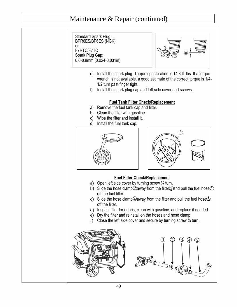
Maintenance & Repair (continued)
49
e) Install the spark plug. Torque specification is 14.8 ft. lbs. If a torque wrench is not available, a good estimate of the correct torque is 1/4-1/2 turn past finger tight.
f) Install the spark plug cap and left side cover and screws.
Fuel Tank Filter Check/Replacement
a) Remove the fuel tank cap and filter. b) Clean the filter with gasoline. c) Wipe the filter and install it. d) Install the fuel tank cap.
Fuel Filter Check/Replacement
a) Open left side cover by turning screw ¼ turn. b) Slide the hose clamp 2 away from the filter 3 and pull the fuel hose 1
off the fuel filter. c) Slide the hose clamp 4 away from the filter and pull the fuel hose 5
off the filter. d) Inspect filter for debris, clean with gasoline, and replace if needed. e) Dry the filter and reinstall on the hoses and hose clamp. f) Close the left side cover and secure by turning screw ¼ turn.
Standard Spark Plug: BPR6ES/BP6ES (NGK) or F7RTC/F7TC Spark Plug Gap: 0.6-0.8mm (0.024-0.031in)
1 2 3
4 3 5
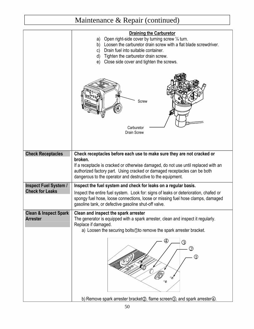
Maintenance & Repair (continued)
50
Draining the Carburetor a) Open right-side cover by turning screw ¼ turn. b) Loosen the carburetor drain screw with a flat blade screwdriver. c) Drain fuel into suitable container. d) Tighten the carburetor drain screw. e) Close side cover and tighten the screws.
Check Receptacles Check receptacles before each use to make sure they are not cracked or broken. If a receptacle is cracked or otherwise damaged, do not use until replaced with an authorized factory part. Using cracked or damaged receptacles can be both dangerous to the operator and destructive to the equipment.
Inspect Fuel System / Check for Leaks
Inspect the fuel system and check for leaks on a regular basis.
Inspect the entire fuel system. Look for: signs of leaks or deterioration, chafed or spongy fuel hose, loose connections, loose or missing fuel hose clamps, damaged gasoline tank, or defective gasoline shut-off valve.
Clean & Inspect Spark Arrester
Clean and inspect the spark arrester
The generator is equipped with a spark arrester, clean and inspect it regularly. Replace if damaged.
a) Loosen the securing bolts 1 to remove the spark arrester bracket.
b) Remove spark arrester bracket 2 , flame screen 3 , and spark arrester 4 .
Carburetor Drain Screw
4 3
2
1
Screw
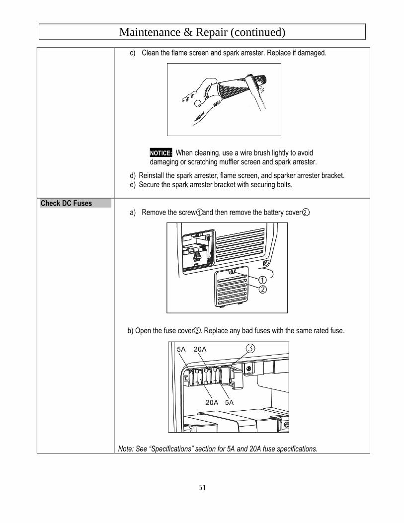
Maintenance & Repair (continued)
51
c) Clean the flame screen and spark arrester. Replace if damaged.
NOTICE: When cleaning, use a wire brush lightly to avoid damaging or scratching muffler screen and spark arrester.
d) Reinstall the spark arrester, flame screen, and sparker arrester bracket. e) Secure the spark arrester bracket with securing bolts.
Check DC Fuses a) Remove the screw 1 and then remove the battery cover 2 .
b) Open the fuse cover 3 . Replace any bad fuses with the same rated fuse.
Note: See “Specifications” section for 5A and 20A fuse specifications.
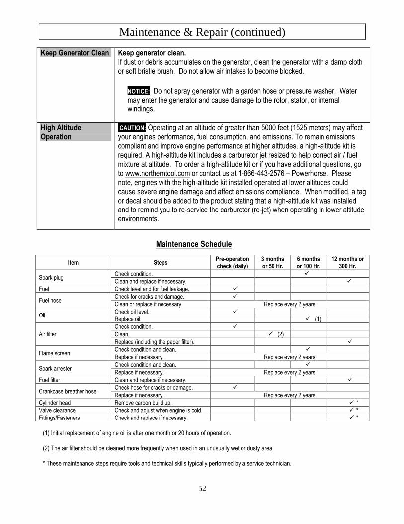
Maintenance & Repair (continued)
52
Keep Generator Clean Keep generator clean. If dust or debris accumulates on the generator, clean the generator with a damp cloth or soft bristle brush. Do not allow air intakes to become blocked.
NOTICE: Do not spray generator with a garden hose or pressure washer. Water may enter the generator and cause damage to the rotor, stator, or internal windings.
High Altitude Operation
CAUTION: Operating at an altitude of greater than 5000 feet (1525 meters) may affect your engines performance, fuel consumption, and emissions. To remain emissions compliant and improve engine performance at higher altitudes, a high-altitude kit is required. A high-altitude kit includes a carburetor jet resized to help correct air / fuel mixture at altitude. To order a high-altitude kit or if you have additional questions, go to www.northerntool.com or contact us at 1-866-443-2576 – Powerhorse. Please note, engines with the high-altitude kit installed operated at lower altitudes could cause severe engine damage and affect emissions compliance. When modified, a tag or decal should be added to the product stating that a high-altitude kit was installed and to remind you to re-service the carburetor (re-jet) when operating in lower altitude environments.
Maintenance Schedule
(1) Initial replacement of engine oil is after one month or 20 hours of operation. (2) The air filter should be cleaned more frequently when used in an unusually wet or dusty area.
* These maintenance steps require tools and technical skills typically performed by a service technician.
Item Steps Pre-operation check (daily)
3 months or 50 Hr.
6 months or 100 Hr.
12 months or 300 Hr.
Spark plug Check condition. ✓
Clean and replace if necessary. ✓
Fuel Check level and for fuel leakage. ✓
Fuel hose Check for cracks and damage. ✓
Clean or replace if necessary. Replace every 2 years
Oil Check oil level. ✓
Replace oil. ✓ (1)
Air filter
Check condition. ✓
Clean. ✓ (2)
Replace (including the paper filter). ✓
Flame screen Check condition and clean. ✓
Replace if necessary. Replace every 2 years
Spark arrester Check condition and clean. ✓
Replace if necessary. Replace every 2 years
Fuel filter Clean and replace if necessary. ✓
Crankcase breather hose Check hose for cracks or damage. ✓
Replace if necessary. Replace every 2 years
Cylinder head Remove carbon build up. ✓ *
Valve clearance Check and adjust when engine is cold. ✓ *
Fittings/Fasteners Check and replace if necessary. ✓ *
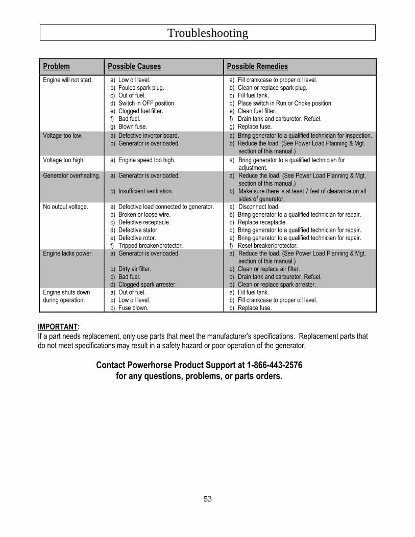
Troubleshooting
53
IMPORTANT: If a part needs replacement, only use parts that meet the manufacturer’s specifications. Replacement parts that do not meet specifications may result in a safety hazard or poor operation of the generator.
Contact Powerhorse Product Support at 1-866-443-2576 for any questions, problems, or parts orders.
Problem Possible Causes Possible Remedies
Engine will not start. a) Low oil level. b) Fouled spark plug. c) Out of fuel. d) Switch in OFF position. e) Clogged fuel filter. f) Bad fuel. g) Blown fuse.
a) Fill crankcase to proper oil level. b) Clean or replace spark plug. c) Fill fuel tank. d) Place switch in Run or Choke position. e) Clean fuel filter. f) Drain tank and carburetor. Refuel. g) Replace fuse.
Voltage too low. a) Defective invertor board. b) Generator is overloaded.
a) Bring generator to a qualified technician for inspection. b) Reduce the load. (See Power Load Planning & Mgt.
section of this manual.)
Voltage too high. a) Engine speed too high. a) Bring generator to a qualified technician for adjustment.
Generator overheating. a) Generator is overloaded.
b) Insufficient ventilation.
a) Reduce the load. (See Power Load Planning & Mgt. section of this manual.)
b) Make sure there is at least 7 feet of clearance on all sides of generator.
No output voltage. a) Defective load connected to generator. b) Broken or loose wire. c) Defective receptacle. d) Defective stator. e) Defective rotor. f) Tripped breaker/protector.
a) Disconnect load. b) Bring generator to a qualified technician for repair. c) Replace receptacle. d) Bring generator to a qualified technician for repair. e) Bring generator to a qualified technician for repair. f) Reset breaker/protector.
Engine lacks power. a) Generator is overloaded.
b) Dirty air filter. c) Bad fuel. d) Clogged spark arrester.
a) Reduce the load. (See Power Load Planning & Mgt. section of this manual.)
b) Clean or replace air filter. c) Drain tank and carburetor. Refuel. d) Clean or replace spark arrester.
Engine shuts down during operation.
a) Out of fuel. b) Low oil level. c) Fuse blown.
a) Fill fuel tank. b) Fill crankcase to proper oil level. c) Replace fuse.
Summary of Important Safety Information for Operation
54
This section provides a summary of the various safety procedures and measures that have been presented throughout the manual. Keep this summary handy and refer to it to refresh your memory about how to safely use your generator.
WARNING
Carefully read and make sure you understand the following safety information before using the generator. Improper use or maintenance of the generator can result in serious injury or death from carbon monoxide poisoning, electric shock, fire/explosion, or burns.
General • Read manual. Read this Owner’s Manual and the engine owner’s manual completely before attempting to set-up and use the
generator. Serious injury or death can result if safety instructions are not followed.
• Instruct operators. The generator owner must instruct all operators in safe generator set-up and operation. Do not allow anyone to operate the generator who has not read the Owner’s Manual and been instructed on its safe use.
• Adults only. Only trained adults should set up and operate the generator. Do not let children operate.
• Under the influence. Never operate, or let anyone else operate, the generator while under the influence of alcohol, drugs, or medication.
• Intended use. Carefully read about and understand the intended use of this generator. Do not use for other purposes, as unforeseen hazards or equipment damage may result.
Prohibition Against Modifications
Never modify or alter the generator in any way. Modifications can create serious safety hazards and will also void the warranty.
• Engine speed. Never attempt to modify the engine speed setting. The engine speed is preset for safe and optimal performance of the generator. If speed needs adjusting, it must be done by factory-authorized personnel.
• Fuel/exhaust system. Never modify the exhaust system, fuel tanks, or fuel lines. Carbon monoxide poisoning, fire, or explosion could result.
• Guards. Do not operate generator unless all guards and cover shields, which prevent access to moving parts and pinch points, are in place. Failure to guard the power transmission mechanisms may result in serious injury or death.
Safety – Installation & Set-up
Battery Safety Batteries are hazardous because they contain caustic acid, can emit explosive gases, and can cause electric shock. Caution must be exercised when making connections to a battery to avoid shock and contact with the acid, and to prevent any sparking that could lead to an explosion. Follow safety rules carefully when connecting battery to generator:
• Eye/skin protection. Always wear eye protection and protective clothing when connecting or disconnecting battery.
• Sparks/smoking. Never smoke or work near sparks or other sources of ignition.
• Electric shock. Never touch both battery terminals at the same time with your hand or any non-insulated tools.
• Connection/disconnection sequence. ALWAYS connect and disconnect cables to the correct battery terminals in the proper sequence: o When CONNECTING the battery, connect the RED cable to the POSITIVE terminal FIRST. o When DISCONNECTING the battery, disconnect the BLACK cable from the NEGATIVE terminal FIRST.
• Acid/skin contact. If battery acid contacts skin or clothing, flush immediately with water and neutralize with baking soda.
Summary of Important Safety Information for Operation
55
Installation / Initial Set-up Safety • Dry, level surface. Situate generator on a dry, firm, level surface. Ensure generator sits level and will not slide or shift during
operation. Block wheels if applicable.
• Operate OUTSIDE only – dangerous carbon monoxide exhaust! Generators give off carbon monoxide exhaust, a poisonous gas that can kill. You CANNOT smell it, see it, or taste it. ONLY run generator OUTDOORS and away from building air intakes. NEVER run generator inside homes, garages, sheds, or other semi-enclosed spaces. These spaces can trap poisonous gases, EVEN if you run a fan or open windows. Carbon monoxide is given off whether you are using gasoline, natural gas, or propane to power the generator.
• No vehicle/marine use. This generator is NOT designed or approved for use in vehicles or marine applications. Never run the generator inside RVs or other vehicles, on boats, or on pick-up truck beds.
• Cooling ventilation. The generator needs adequate, unobstructed flow of air to allow for proper cooling of engine and generator head. Situate so there is adequate clearance around generator to allow for cooling airflow. Do not allow debris to accumulate and block airflow.
• Grounding. Always ensure generator is properly grounded to prevent electrical shock. This generator is equipped with a grounding post. Always complete the grounding path from the generator to a copper pipe/rod driven into moist earth to a sufficient depth. Check with an electrician for local grounding requirements. If a licensed electrician installs the generator with a connection to your building’s electrical circuit for use as a standby power system, grounding will be complete through the building’s grounding system.
• Isolate connection to building’s electrical circuit. Never plug the generator directly into a wall outlet. ANY connection to a building’s electrical system MUST ISOLATE THE GENERATOR FROM UTILITY POWER via an UL-approved transfer switch installed by a licensed electrician in compliance with all applicable local building and electrical codes. If the generator is not isolated from the utility power system by such means, generator output will back feed into the utility power grid. This may result in injury or death to utility power workers or others who contact the lines during a power outage. It may also cause the generator to explode or cause fires when utility power is restored.
• Wet conditions. Water conducts electricity. Do not operate generator where it is wet. Operate on a dry surface under an open, canopy-like structure.
• CO alarms. Ensure that working, battery-operated or battery back-up carbon monoxide alarms are used in any dwelling/structure that is in close proximity to the running generator.
• Hot exhaust - fires. Exhaust from engine can be extremely hot and cause fire. Position muffler at least 7’ from combustible objects during operation.
• Spark arrester. Equip engine with a spark arrester if generator will be used near any ignitable forest, brush, or grassy land. See the “Specifications” section of this manual to determine if your generator is already equipped. Make sure you comply with applicable local, state, and federal codes.
• Fire extinguisher. Keep a fire extinguisher rated “ABC” by the National Fire Protection Association nearby. Keep it properly charged and be familiar with its use.
Safety – Before Use
Know How to Operate
• Review safety rules. Before each use of this generator, review the “Rules for Safe Operation.” Failure to follow these rules may result in serious injury or death.
• Know how to operate. Be thoroughly familiar with all controls and with the proper use of the equipment. Know how to stop the generator quickly if needed.
Personal Protective Equipment • Hearing protection. The use of ear plugs or other hearing protection device is recommended for those in close proximity to the
generator while it is operating.
• Loose / dangling. Loose or dangling apparel can become entangled in moving parts. Metal jewelry can conduct electricity. Never wear jewelry or loose-fitting clothing when operating the generator.
Gasoline Safety Gasoline is highly flammable and explosive. You can be burned or seriously injured when handling fuel. Use extreme care when handling:
Summary of Important Safety Information for Operation
56
• Fuel outdoors. Fill fuel tank outdoors – never indoors. Gasoline vapors can ignite if they collect inside an enclosure. Explosion can result.
• Use approved container. Never pump fuel directly into engine at gas station. Static charge can build and ignite fuel. Use a UL-listed fuel container to transfer gas to the engine.
• Running / hot engine. A running engine is hot enough to ignite fuel. Never add fuel or remove gas cap if engine is running or still hot. Stop the engine and allow to cool at least two minutes before adding fuel.
• Heat / flames / sparks. Stay away from sources of heat, flame, or sparks while adding fuel. Don’t overfill. DO NOT overfill the gas tank. Fill to bottom of fill neck to allow for fuel expansion.
• Replace cap. Replace gas cap securely before starting engine.
• Spills. Clean up fuel spills immediately. Move generator away from spilled fuel on the ground. Wipe fuel off engine and wait 5 minutes for excess fuel to evaporate before starting engine. Gas soaked rags should be disposed of properly.
• On skin / clothes. If gasoline is spilled on your skin or clothes, change clothes and wash skin immediately.
• Inspect fuel system. Check fuel system on a regular basis. Look for signs of leaks, deterioration, chafed or spongy fuel hose, lose or missing fuel hose clamps, damaged fuel tank, or a defective fuel shut-off valve. Do not start generator until needed repairs have been completed.
• Gasoline storage. Store gasoline in a cool, dry place in a UL-listed, tightly sealed container.
Safety – During Use • Safety equipment / controls. Always operate the generator with all safety covers, guards, and barriers in place and in good
working order, and all controls properly adjusted for safe operation.
• Know how to stop. Be thoroughly familiar with proper use of the equipment and all generator controls, output receptacles, and connections. Know how to stop the generator quickly if needed.
• Damaged. Do not operate the generator with damaged, missing, or broken parts.
• Carbon monoxide exhaust. The running engine gives off carbon monoxide, a poisonous gas that can kill you. You CANNOT smell it, see it, or taste it. If you start to feel sick, dizzy, or weak while using the generator, shut off the engine and get to fresh air RIGHT AWAY. See a doctor. You may have carbon monoxide poisoning.
• Other exhaust dangers. This product contains or emits chemicals known to the State of California to cause cancer, birth defects or other reproductive harm. Avoid inhalation of exhaust.
• Smoking/sparks. Never smoke near the running generator, and never operate near sources of sparks or flames.
• Check output voltage. Check output voltage to ensure the generator is working properly before connecting loads to the generator. Failure to do so could result in damage to equipment powered by the generator and possible injury to the individual. Do not adjust output speed of engine to change voltage. If voltage is not within specified range, have generator repaired by factory authorized personnel.
• Stabilize before connecting loads. Start generator and let engine stabilize before connecting electrical loads.
• Do not overload. Do not overload the generator. Make sure that combined starting and running loads do not exceed rated capacity of generator or damage will result.
• Protect sensitive electronics. Some electronic equipment, such as computers and audio/video equipment, can be damaged by small fluctuations in the flow of power. Use a surge suppressor for any voltage-sensitive electronic equipment you will be powering with the generator.
• Wet conditions. Do not operate the generator or handle any electrical equipment while standing in water, while barefoot, while hands are wet or while in the rain or snow. Electric shock may result.
• Ground fault circuit interrupter. Always use a ground fault circuit interrupter (GFCI) protected extension cord (or outlet, if generator is equipped) in damp or highly electrical conductive areas and on construction jobsites to prevent electrical shock.
• Electrical cords. Use only UL-listed, outdoor-rated, three prong extension cords of the proper size. All extension and appliance cords must be in good condition and not worn, bare, frayed, or otherwise damaged. Use of inadequate or damaged electric cords can cause electric shock or fire.
• Avoid contact. Avoid contact with bare wires, terminals, connections, etc. while the unit is running.
• Electric shock accident. If an electric shock accident occurs, immediately shut down the source of electrical power. If this is not possible, attempt to free the victim from the live conductor. Avoid direct contact with victim. Use a nonconducting implement, such as a dry rope or board, to free the victim from the live conductor. Apply first aid and get immediate medical help.
• Hot muffler. Never touch hot muffler, hot exhaust manifold, or engine cooling fins. Exhaust and engine parts can be very hot and will burn you.
• Moving parts. Keep hands, feet, and apparel away from drive belts, fans, and other moving parts. Never remove any drive belt or fan guard while the unit is operating.
• Refueling. DO NOT refuel the engine until it has cooled at least two minutes.
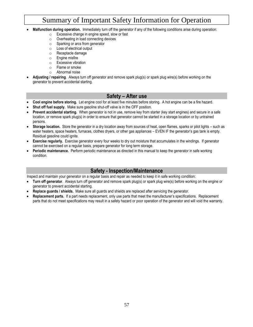
Summary of Important Safety Information for Operation
57
• Malfunction during operation. Immediately turn off the generator if any of the following conditions arise during operation: o Excessive change in engine speed, slow or fast o Overheating in load connecting devices o Sparking or arcs from generator o Loss of electrical output o Receptacle damage o Engine misfire o Excessive vibration o Flame or smoke o Abnormal noise
• Adjusting / repairing. Always turn off generator and remove spark plug(s) or spark plug wire(s) before working on the generator to prevent accidental starting.
Safety – After use • Cool engine before storing. Let engine cool for at least five minutes before storing. A hot engine can be a fire hazard.
• Shut off fuel supply. Make sure gasoline shut-off valve is in the OFF position.
• Prevent accidental starting. When generator is not in use, remove key from starter (key start engines) and secure in a safe location, or remove spark plug(s) in order to ensure that generator cannot be started in a storage location or by untrained persons.
• Storage location. Store the generator in a dry location away from sources of heat, open flames, sparks or pilot lights – such as water heaters, space heaters, furnaces, clothes dryers, or other gas appliances – EVEN IF the generator’s gas tank is empty. Residual gasoline could ignite.
• Exercise regularly. Exercise generator every four weeks to dry out moisture that accumulates in the windings. If generator cannot be exercised on a regular basis, prepare generator for long term storage.
• Periodic maintenance. Perform periodic maintenance as directed in this manual to keep the generator in safe working condition.
Safety - Inspection/Maintenance Inspect and maintain your generator on a regular basis and repair as needed to keep it in safe working condition:
• Turn off generator. Always turn off generator and remove spark plug(s) or spark plug wire(s) before working on the engine or generator to prevent accidental starting.
• Replace guards / shields. Make sure all guards and shields are replaced after servicing the generator.
• Replacement parts. If a part needs replacement, only use parts that meet the manufacturer’s specifications. Replacement parts that do not meet specifications may result in a safety hazard or poor operation of the generator and will void the warranty.
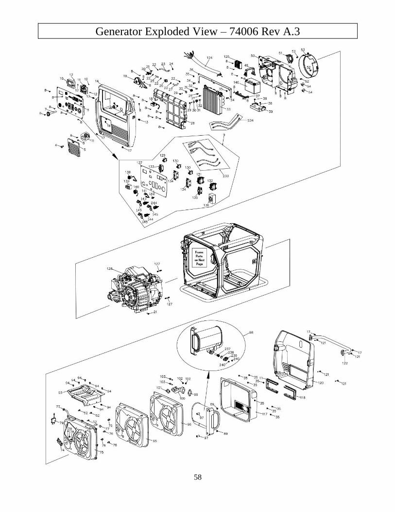
Generator Exploded View – 74006 Rev A.3
58
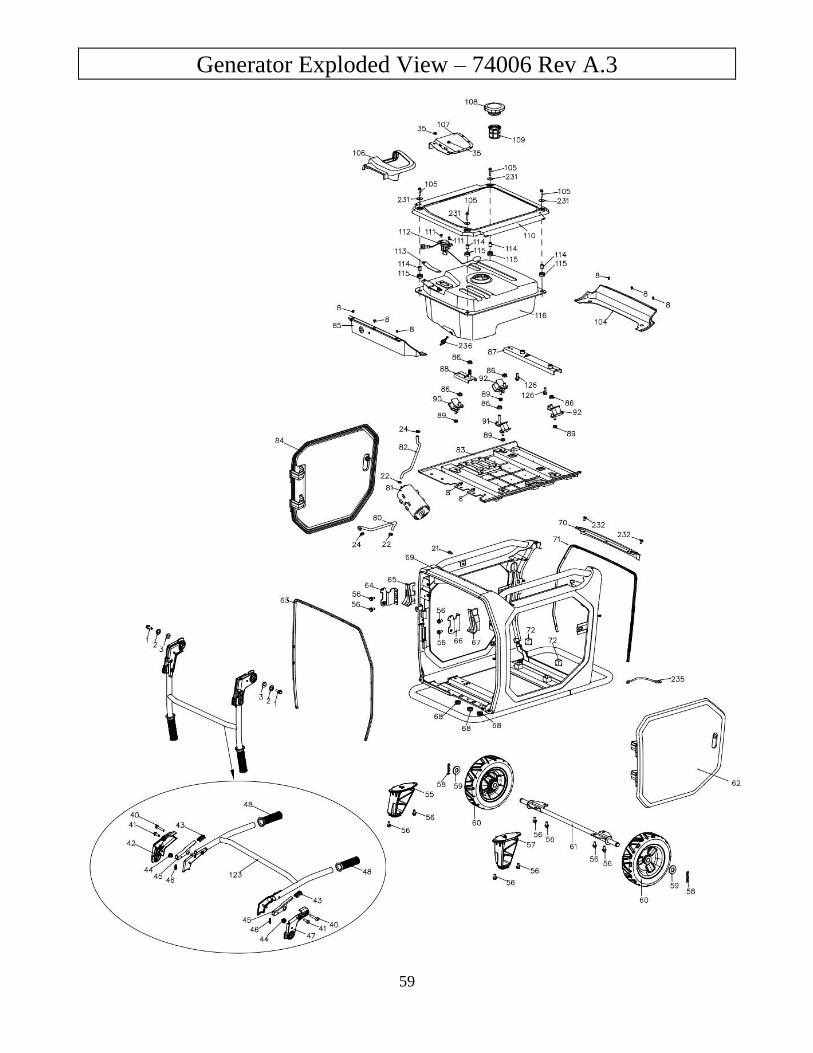
Generator Exploded View – 74006 Rev A.3
59
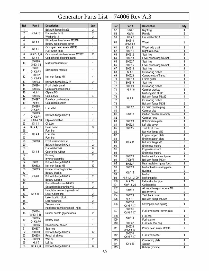
Generator Parts List – 74006 Rev A.3
60
Ref Part # Description Qty
57 Kit # 7 Right leg 1
58 Kit # 8 Pin clip 2
59 Kit # 8 Flat washer M18 2
60 800310
Or Kit # 8 Wheel 2
61 Kit # 8 Wheel axle shaft 1
62 800311 Right side cover 1
63 800312 Seal ring 1
64 800313 Lever connecting bracket 1
65 800527 Seal ring 1
66 800315 Lever connecting bracket 1
67 800316 Seal ring 1
68 Kit # 5 Cushioning rubber 3
69 800528 Components of frame 1
70 800318 Frame girder 1
71 800319 Seal ring 1
72 800320 Cushioning rubber 2
74 Kit # 10 Canister bracket 1
75
Kit # 9
Muffler guard shield 1
76 Bolt with flange M8x12 4
77 Cushioning rubber 2
78 Bolt with flange M6X8 2
79 800322 Oil drain release plug 1
80
Kit # 10
Canister pipe 1
81 Carbon canister assembly 1
82 Canister hose 1
83 800323 Bottom frame plate 1
84 800324 Left side cover 1
85 800325 Tank front cover 1
86
Kit # 11
Nut with flange M10 5
87 Engine support plate 1
88 Engine support plate 1
89 Nut with flange M8 6
90 Engine iso mount 1
91 Engine iso mount 1
92 Engine iso mount 2
93 800326 Muffler reinforcement plate 1
94 790978 Bolt with flange M6X14 7
95 800327 Heat insulation (glass fiber) 1
96 800328 Muffler heat insulating plate 1
97 Kit # 12
Bushing 2
98 Muffler 1
99 Kit # 12, 13, 29 Muffler gasket 1
100 Kit # 13 Exhaust outlet pipe 1
101 Kit # 13, 29 Outlet gasket 1
102 Kit # 13
All metal hexagon locknut M8 2
103 Bolt M10X40 2
104 800329 Tank back cover 1
105 Kit # 17 Bolt with flange M6X30 4
106 800330
Or Kit # 17 Cover plate sealing ring 1
107 800331
Or Kit # 17 Fuel level sensor cover plate 1
108 Kit # 14
Fuel cap 1
109 Fuel strainer 1
110 800332 Fuel tank seal ring 1
111 800333
Or Kit # 17 Philips head screw M5X16 2
112 800334
Or Kit # 17 Fuel level sensor 1
113
Kit # 17
Connecting plate 1
114 Spacer 4
115 Rubber grommet 4
Ref Part # Description Qty
1 Kit # 16
Bolt with flange M8x26 2
2 Flat washer M12 2
3 Washer M12 2
4 Kit # 1
Slotted pan head screw M5X10 1
5 Battery maintenance cover 1
6 Kit # 2
Cross pan head screw M4X18 1
7 Fuel switch knob 1
8 Kit # 3, 4, 6 Cross small pan head screw M5X12 38
9 Kit # 3 Components of control panel 1
10 800290
Or Kit # 3 Multifunctional meter 1
11 800291
Or Kit # 3 Start control module 1
12 800292
Or Kit # 3 Nut with flange M4 4
13 800293 Bolt with flange M6 X 15 2
14 800294 Front plastic panel 1
15 800295 Cable connection panel 1
16 Kit # 1 Clip nut M5 1
17 800296 Cap nut M6 4
18 800297 Fuse box combination 1
19 Kit # 4 Combination switch 1
20 800298
Or Kit # 4 Fuel valve 1
21 800299
Or Kit # 4 Bolt with flange M6X10 1
22 Kit # 4, 10 Clip combination 7
23 Kit # 4 Oil tube 1
24 Kit # 4, 10 Hose clamp 3
25
Kit # 4
Fuel line 1
26 Fuel filter 1
27 Fuel line 1
28 800300 Front inverter shroud 1
29
Kit # 5
Bolt with flange M6X28 2
30 Flat washer M6 6
31 Cushioning rubber 2
32 Bushing 2
33 Inverter assembly 1
34 800301 Bolt with flange M6X20 2
35 800302 Nut with flange M6 12
36 800303 inverter mounting bracket 1
37 Kit # 6
Battery bracket 1
38 Bolt with flange M6X25 2
39 Battery cushion 1
40
Kit # 16
Socket head screw M8X25 2
41 Socket head screw M8X45 2
42 Handlebar connecting seat - left 1
43 Lever rubber grip 2
44 Lever location block 2
45 Locking handle 2
46 Tension spring 2
47 Handlebar connecting seat - right 1
48 800304
Or Kit # 16 Rubber handle grip individual 2
49 800305
Or Kit # 6 Battery strap 1
50 800306 Back inverter shroud 1
51 800307 Seal ring 1
52 790980 Bolt with flange M6X16 6
53 800308 Recoil air shroud 1
54 800309 Wire tie 2
55 Kit # 7 Left leg 1
56 Kit # 7, 8 Bolt with flange M8X16 8
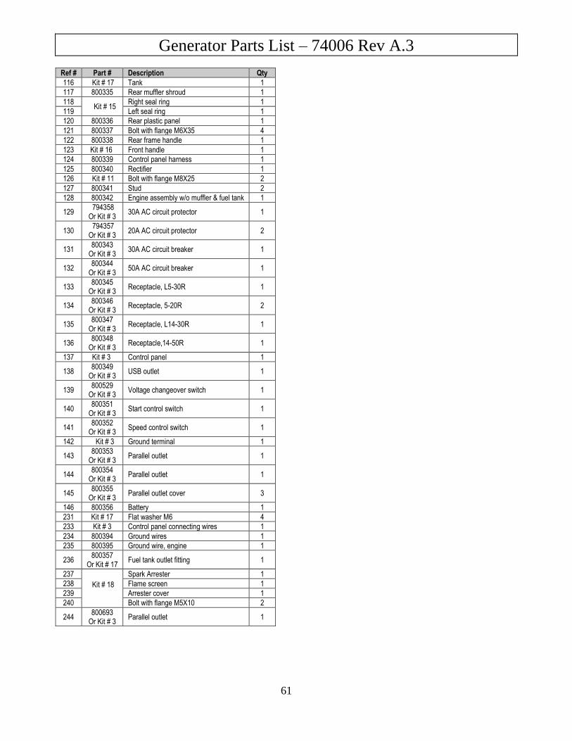
Generator Parts List – 74006 Rev A.3
61
Ref # Part # Description Qty
116 Kit # 17 Tank 1
117 800335 Rear muffler shroud 1
118 Kit # 15
Right seal ring 1
119 Left seal ring 1
120 800336 Rear plastic panel 1
121 800337 Bolt with flange M6X35 4
122 800338 Rear frame handle 1
123 Kit # 16 Front handle 1
124 800339 Control panel harness 1
125 800340 Rectifier 1
126 Kit # 11 Bolt with flange M8X25 2
127 800341 Stud 2
128 800342 Engine assembly w/o muffler & fuel tank 1
129 794358
Or Kit # 3 30A AC circuit protector 1
130 794357
Or Kit # 3 20A AC circuit protector 2
131 800343
Or Kit # 3 30A AC circuit breaker 1
132 800344
Or Kit # 3 50A AC circuit breaker 1
133 800345
Or Kit # 3 Receptacle, L5-30R 1
134 800346
Or Kit # 3 Receptacle, 5-20R 2
135 800347
Or Kit # 3 Receptacle, L14-30R 1
136 800348
Or Kit # 3 Receptacle,14-50R 1
137 Kit # 3 Control panel 1
138 800349
Or Kit # 3 USB outlet 1
139 800529
Or Kit # 3 Voltage changeover switch 1
140 800351
Or Kit # 3 Start control switch 1
141 800352
Or Kit # 3 Speed control switch 1
142 Kit # 3 Ground terminal 1
143 800353
Or Kit # 3 Parallel outlet 1
144 800354
Or Kit # 3 Parallel outlet 1
145 800355
Or Kit # 3 Parallel outlet cover 3
146 800356 Battery 1
231 Kit # 17 Flat washer M6 4
233 Kit # 3 Control panel connecting wires 1
234 800394 Ground wires 1
235 800395 Ground wire, engine 1
236 800357
Or Kit # 17 Fuel tank outlet fitting 1
237 Kit # 18
Spark Arrester 1
238 Flame screen 1
239 Arrester cover 1
240 Bolt with flange M5X10 2
244 800693
Or Kit # 3 Parallel outlet 1
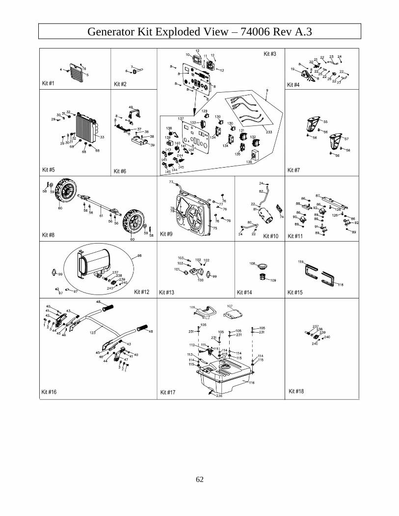
Generator Kit Exploded View – 74006 Rev A.3
62
Kit #1
Kit #2 Kit #4
Kit #5
Kit #6
Kit #7
Kit #8
Kit #9
Kit #10
Kit #11
Kit #12
Kit #13
Kit #14
Kit #15
Kit #16
Kit #17
Kit #18
Kit #3
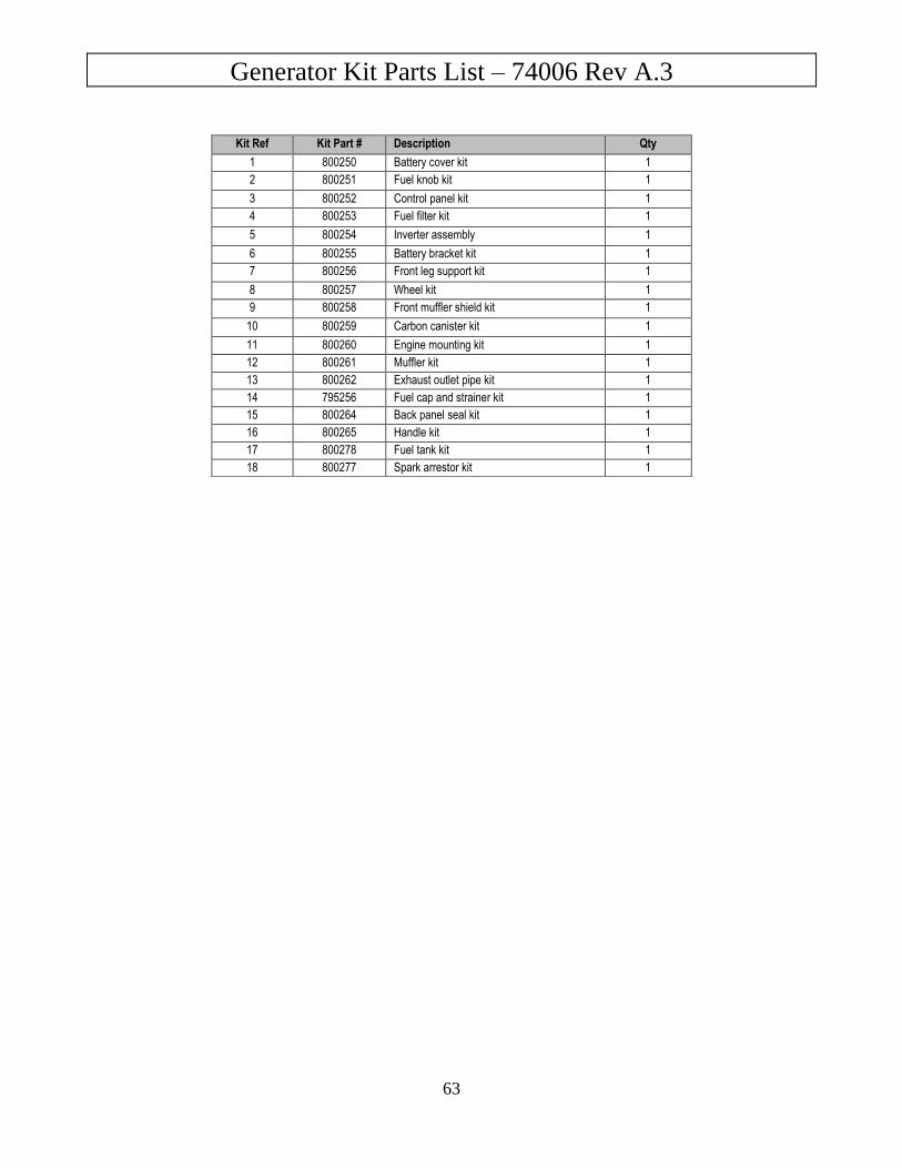
Generator Kit Parts List – 74006 Rev A.3
63
Kit Ref Kit Part # Description Qty
1 800250 Battery cover kit 1
2 800251 Fuel knob kit 1
3 800252 Control panel kit 1
4 800253 Fuel filter kit 1
5 800254 Inverter assembly 1
6 800255 Battery bracket kit 1
7 800256 Front leg support kit 1
8 800257 Wheel kit 1
9 800258 Front muffler shield kit 1
10 800259 Carbon canister kit 1
11 800260 Engine mounting kit 1
12 800261 Muffler kit 1
13 800262 Exhaust outlet pipe kit 1
14 795256 Fuel cap and strainer kit 1
15 800264 Back panel seal kit 1
16 800265 Handle kit 1
17 800278 Fuel tank kit 1
18 800277 Spark arrestor kit 1
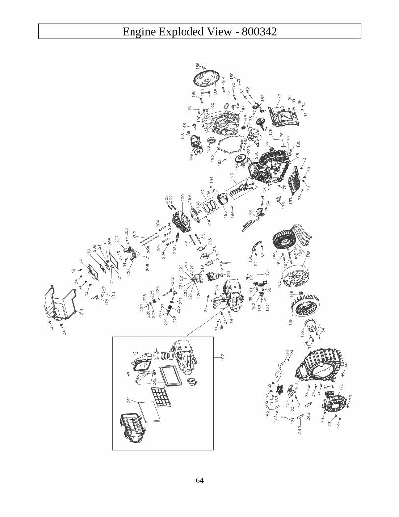
Engine Exploded View - 800342
64
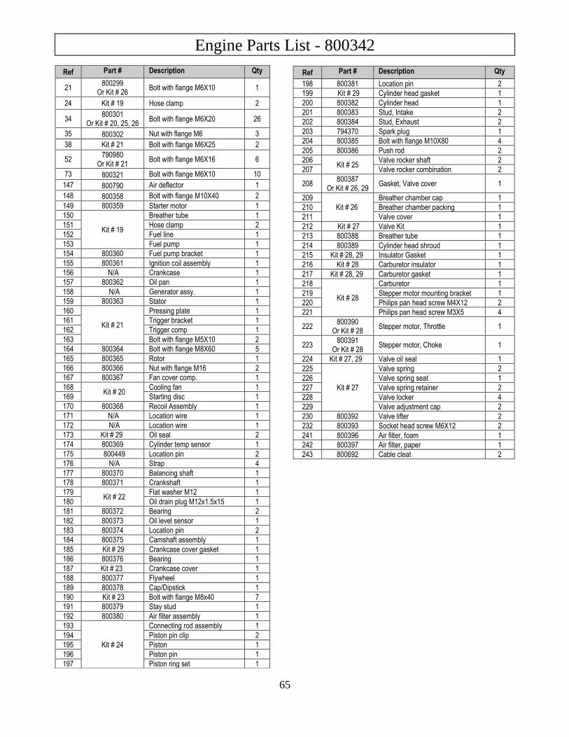
Engine Parts List - 800342
65
Ref Part # Description Qty
21 800299
Or Kit # 26 Bolt with flange M6X10 1
24 Kit # 19 Hose clamp 2
34 800301
Or Kit # 20, 25, 26 Bolt with flange M6X20 26
35 800302 Nut with flange M6 3
38 Kit # 21 Bolt with flange M6X25 2
52 790980
Or Kit # 21 Bolt with flange M6X16 6
73 800321 Bolt with flange M6X10 10
147 800790 Air deflector 1
148 800358 Bolt with flange M10X40 2
149 800359 Starter motor 1
150
Kit # 19
Breather tube 1
151 Hose clamp 2
152 Fuel line 1
153 Fuel pump 1
154 800360 Fuel pump bracket 1
155 800361 Ignition coil assembly 1
156 N/A Crankcase 1
157 800362 Oil pan 1
158 N/A Generator assy. 1
159 800363 Stator 1
160
Kit # 21
Pressing plate 1
161 Trigger bracket 1
162 Trigger comp 1
163 Bolt with flange M5X10 2
164 800364 Bolt with flange M8X60 5
165 800365 Rotor 1
166 800366 Nut with flange M16 2
167 800367 Fan cover comp. 1
168 Kit # 20
Cooling fan 1
169 Starting disc 1
170 800368 Recoil Assembly 1
171 N/A Location wire 1
172 N/A Location wire 1
173 Kit # 29 Oil seal 2
174 800369 Cylinder temp sensor 1
175 800449 Location pin 2
176 N/A Strap 4
177 800370 Balancing shaft 1
178 800371 Crankshaft 1
179 Kit # 22
Flat washer M12 1
180 Oil drain plug M12x1.5x15 1
181 800372 Bearing 2
182 800373 Oil level sensor 1
183 800374 Location pin 2
184 800375 Camshaft assembly 1
185 Kit # 29 Crankcase cover gasket 1
186 800376 Bearing 1
187 Kit # 23 Crankcase cover 1
188 800377 Flywheel 1
189 800378 Cap/Dipstick 1
190 Kit # 23 Bolt with flange M8x40 7
191 800379 Stay stud 1
192 800380 Air filter assembly 1
193
Kit # 24
Connecting rod assembly 1
194 Piston pin clip 2
195 Piston 1
196 Piston pin 1
197 Piston ring set 1
Ref Part # Description Qty
198 800381 Location pin 2
199 Kit # 29 Cylinder head gasket 1
200 800382 Cylinder head 1
201 800383 Stud, Intake 2
202 800384 Stud, Exhaust 2
203 794370 Spark plug 1
204 800385 Bolt with flange M10X80 4
205 800386 Push rod 2
206 Kit # 25
Valve rocker shaft 2
207 Valve rocker combination 2
208 800387
Or Kit # 26, 29 Gasket, Valve cover 1
209 Kit # 26
Breather chamber cap 1
210 Breather chamber packing 1
211 Valve cover 1
212 Kit # 27 Valve Kit 1
213 800388 Breather tube 1
214 800389 Cylinder head shroud 1
215 Kit # 28, 29 Insulator Gasket 1
216 Kit # 28 Carburetor insulator 1
217 Kit # 28, 29 Carburetor gasket 1
218
Kit # 28
Carburetor 1
219 Stepper motor mounting bracket 1
220 Philips pan head screw M4X12 2
221 Philips pan head screw M3X5 4
222 800390
Or Kit # 28 Stepper motor, Throttle 1
223 800391
Or Kit # 28 Stepper motor, Choke 1
224 Kit # 27, 29 Valve oil seal 1
225
Kit # 27
Valve spring 2
226 Valve spring seat 1
227 Valve spring retainer 2
228 Valve locker 4
229 Valve adjustment cap 2
230 800392 Valve lifter 2
232 800393 Socket head screw M6X12 2
241 800396 Air filter, foam 1
242 800397 Air filter, paper 1
243 800692 Cable cleat 2
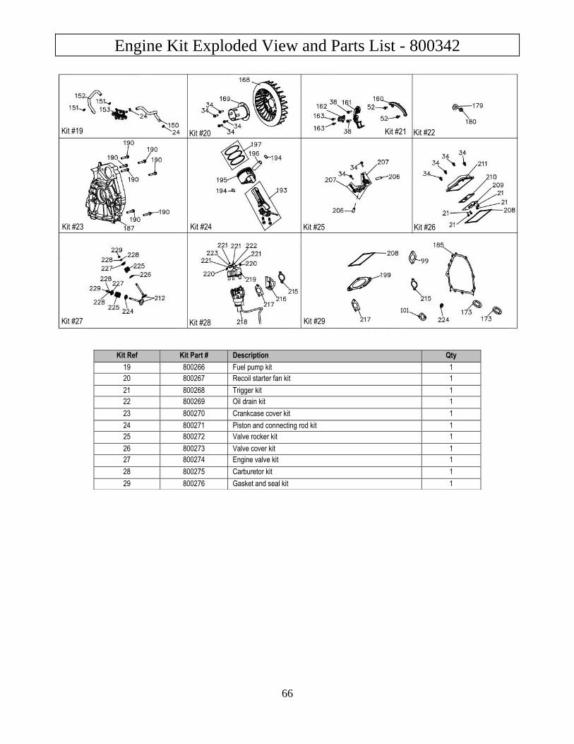
Engine Kit Exploded View and Parts List - 800342
66
Kit Ref Kit Part # Description Qty
19 800266 Fuel pump kit 1
20 800267 Recoil starter fan kit 1
21 800268 Trigger kit 1
22 800269 Oil drain kit 1
23 800270 Crankcase cover kit 1
24 800271 Piston and connecting rod kit 1
25 800272 Valve rocker kit 1
26 800273 Valve cover kit 1
27 800274 Engine valve kit 1
28 800275 Carburetor kit 1
29 800276 Gasket and seal kit 1
Kit #19
Kit #20
Kit #21
Kit #22
Kit #23
Kit #24
Kit #25
Kit #26
Kit #27
Kit #28
Kit #29
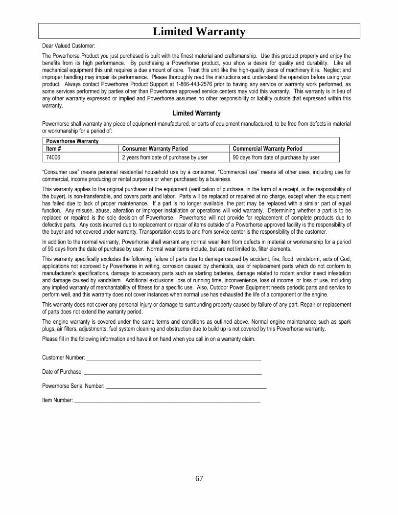
Limited Warranty
67
Dear Valued Customer:
The Powerhorse Product you just purchased is built with the finest material and craftsmanship. Use this product properly and enjoy the benefits from its high performance. By purchasing a Powerhorse product, you show a desire for quality and durability. Like all mechanical equipment this unit requires a due amount of care. Treat this unit like the high-quality piece of machinery it is. Neglect and improper handling may impair its performance. Please thoroughly read the instructions and understand the operation before using your product. Always contact Powerhorse Product Support at 1-866-443-2576 prior to having any service or warranty work performed, as some services performed by parties other than Powerhorse approved service centers may void this warranty. This warranty is in lieu of any other warranty expressed or implied and Powerhorse assumes no other responsibility or liability outside that expressed within this warranty.
Limited Warranty
Powerhorse shall warranty any piece of equipment manufactured, or parts of equipment manufactured, to be free from defects in material or workmanship for a period of:
Powerhorse Warranty
Item # Consumer Warranty Period Commercial Warranty Period
74006 2 years from date of purchase by user 90 days from date of purchase by user
“Consumer use” means personal residential household use by a consumer. “Commercial use” means all other uses, including use for commercial, income producing or rental purposes or when purchased by a business.
This warranty applies to the original purchaser of the equipment (verification of purchase, in the form of a receipt, is the responsibility of the buyer), is non-transferable, and covers parts and labor. Parts will be replaced or repaired at no charge, except when the equipment has failed due to lack of proper maintenance. If a part is no longer available, the part may be replaced with a similar part of equal function. Any misuse, abuse, alteration or improper installation or operations will void warranty. Determining whether a part is to be replaced or repaired is the sole decision of Powerhorse. Powerhorse will not provide for replacement of complete products due to defective parts. Any costs incurred due to replacement or repair of items outside of a Powerhorse approved facility is the responsibility of the buyer and not covered under warranty. Transportation costs to and from service center is the responsibility of the customer.
In addition to the normal warranty, Powerhorse shall warrant any normal wear item from defects in material or workmanship for a period of 90 days from the date of purchase by user. Normal wear items include, but are not limited to, filter elements.
This warranty specifically excludes the following; failure of parts due to damage caused by accident, fire, flood, windstorm, acts of God, applications not approved by Powerhorse in writing, corrosion caused by chemicals, use of replacement parts which do not conform to manufacturer’s specifications, damage to accessory parts such as starting batteries, damage related to rodent and/or insect infestation and damage caused by vandalism. Additional exclusions: loss of running time, inconvenience, loss of income, or loss of use, including any implied warranty of merchantability of fitness for a specific use. Also, Outdoor Power Equipment needs periodic parts and service to perform well, and this warranty does not cover instances when normal use has exhausted the life of a component or the engine.
This warranty does not cover any personal injury or damage to surrounding property caused by failure of any part. Repair or replacement of parts does not extend the warranty period.
The engine warranty is covered under the same terms and conditions as outlined above. Normal engine maintenance such as spark plugs, air filters, adjustments, fuel system cleaning and obstruction due to build up is not covered by this Powerhorse warranty.
Please fill in the following information and have it on hand when you call in on a warranty claim.
Customer Number: ______________________________________________________________ Date of Purchase: _______________________________________________________________ Powerhorse Serial Number: _________________________________________________________ Item Number: __________________________________________________________________
68
Distributed by Northern Tool and Equipment Company, Inc.
Burnsville, MN 55306 www.northerntool.com | Made in China
WARNING: This product can expose you to chemicals including gasoline engine exhaust, which is known to the State of California to cause cancer, and carbon monoxide, which is known to the State of California to cause birth defects or other reproductive harm.
For more information go to www.P65Warnings.ca.gov.


![4N[sic] - Electrocution](https://img.pdfslide.net/doc/110x75/5875aa491a28ab8b618b47a9/4nsic-electrocution.jpg)