Embed Size (px)
Citation preview
1
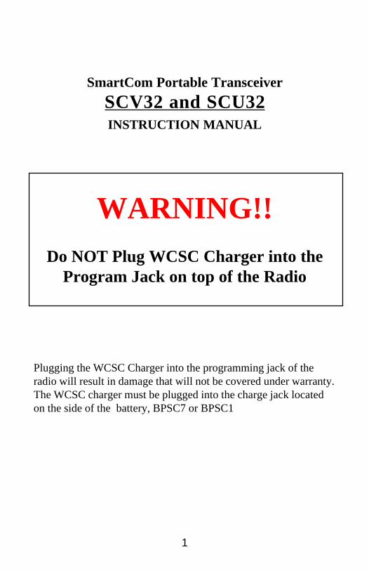
WARNING!!Do NOT Plug WCSC Charger into the
Program Jack on top of the Radio
Plugging the WCSC Charger into the programming jack of theradio will result in damage that will not be covered under warranty.The WCSC charger must be plugged into the charge jack locatedon the side of the battery, BPSC7 or BPSC1
SmartCom Portable Transceiver
SCV32 and SCU32INSTRUCTION MANUAL
2
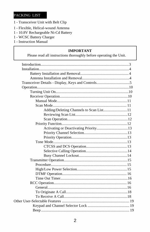
PACKING LIST
1 - Transceiver Unit with Belt Clip
1 - Flexible, Helical-wound Antenna1 - 10.8V Rechargeable Ni-Cd Battery1 - WCSC Battery Charger1 - Instruction Manual
IMPORTANTPlease read all instructions thoroughly before operating the Unit.
Introduction.............................................................................................3Installation...............................................................................................4
Battery Installation and Removal................................................... 4Antenna Installation and Removal..................................................4
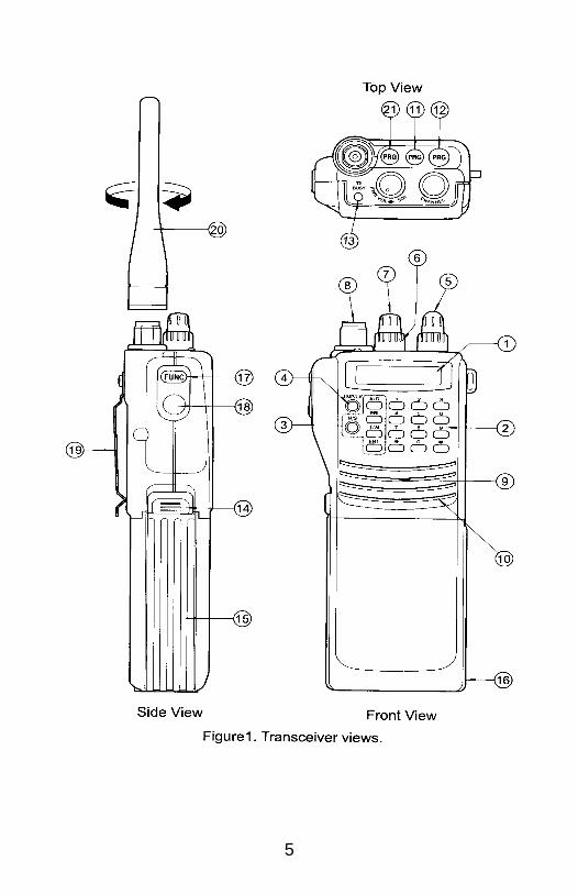
Transceiver Details - Display, Keys and Controls...................................5Operation.................................................................................................10
Turning Unit On.............................................................................10Receiver Operation........................................................................10
Manual Mode..........................................................................11Scan Mode.............................................................................. 11
Adding/Deleting Channels to Scan List.........................11Reviewing Scan List.......................................................12Scan Operation................................................................12
Priority Function.....................................................................12Activating or Deactivating Priority.................................13Priority Channel Selection..............................................13Priority Operation...........................................................13
Tone Mode..............................................................................13CTCSS and DCS Operation...........................................13Selective Calling Operation............................................14Busy Channel Lockout...................................................14
Transmitter Operation...................................................................15Procedure................................................................................15High/Low Power Selection.....................................................15DTMF Operation.................................................................... 16Time Out Timer.......................................................................16
RCC Operation............................................................................. 16General....................................................................................16To Originate A Call.................................................................18To Receive A Call...................................................................18
Other User-Selectable Features ....................................................................... 19Keypad and Channel Selector Lock ............................................ 19Beep ............................................................................................. 19
3
Battery Information .............................................................................. 19General Information .................................................................... 19Power Save Function ................................................................... 19For Longest Battery Life and Best Performance ......................... 20
Maintenance ......................................................................................... 20Troubleshooting ................................................................................... 21Summary of Dealer’s Programming Options ...................................... 22Power Save Timer Details .................................................................... 23Specifications .............................................................................. 23 & 24Review Mode ....................................................................................... 24
INTRODUCTION
NOTE: In this manual, the words Transceiver, Radio and Unit areused interchangeably.
SCV32 and SCU 32 are 32-channel, state-of-the-art, synthesized portable FMTransceivers. The SCV32 operates in the 138-174 MHz VHF band. SCU32operates in the 403-430 MHz and 450-480 MHz UHF band. Each Unit has anon-volatile memory that requires no battery to maintain its Dealer-programmedinformation.
Two RF power outputs are available - Low: 1 Watt; High : 5 Watts for SCV32;4 Watts for SC U32.
Each Unit features a Priority function which periodically samples aUser-selectable channel for activity. It also features a built-in DTMFKeypad.
A Liquid Crystal Display (LCD) provides useful information such asChannel Number and Status, Priority Channel and Status, OutputPower Level Status, etc. See page 5 for details.
The Radio can be programmed by a Factory-authorized Service Dealer toprovide any number of channels from 1 to 32, CTCSS tone frequencies, DCSCodes, DTMF and Selective Calling operation, Radio Common Carrier (RCC)operation and other features to meet various User requirements. See pages 22and 23 for details.
Optional Accessories:-RSC-2l Drop-in Quick Charger-BPSCI 10.8V (1000 mAH) Rechargeable Battery
4
-LCSC Leather Carrying Case-SMSC External Speaker/Microphone
INSTALLATION
BATTERY INSTALLATION AND REMOVAL
A. To attach the battery, align the grooves on the battery case with those on theUnit and slide it into place until a “snap” is heard.
NOTE: If the Unit is turned on and the display starts “flashing”,thebattery is low and needs to be charged. See pages 4 and 19 for details.
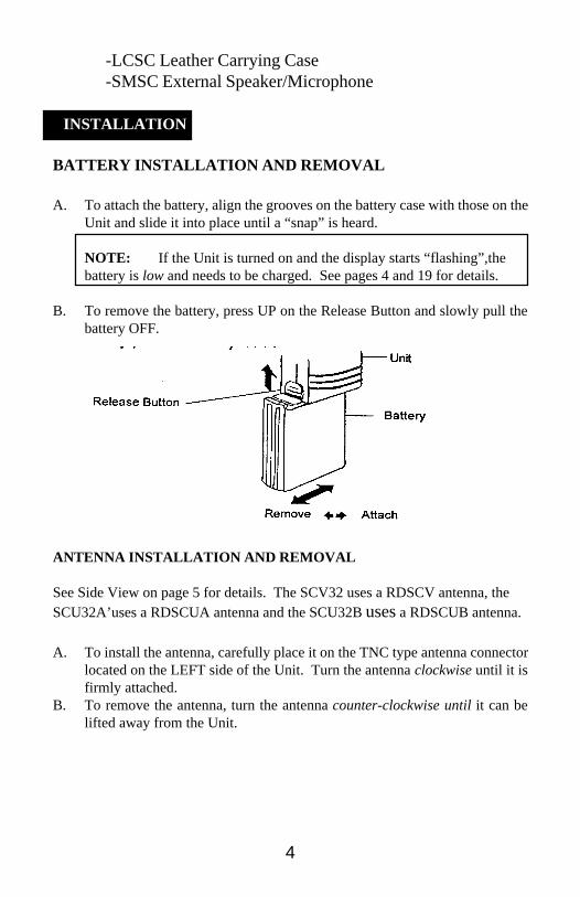
B. To remove the battery, press UP on the Release Button and slowly pull thebattery OFF.
ANTENNA INSTALLATION AND REMOVAL
See Side View on page 5 for details. The SCV32 uses a RDSCV antenna, theSCU32A’uses a RDSCUA antenna and the SCU32B uses a RDSCUB antenna.
A. To install the antenna, carefully place it on the TNC type antenna connectorlocated on the LEFT side of the Unit. Turn the antenna clockwise until it isfirmly attached.
B. To remove the antenna, turn the antenna counter-clockwise until it can belifted away from the Unit.
5
6
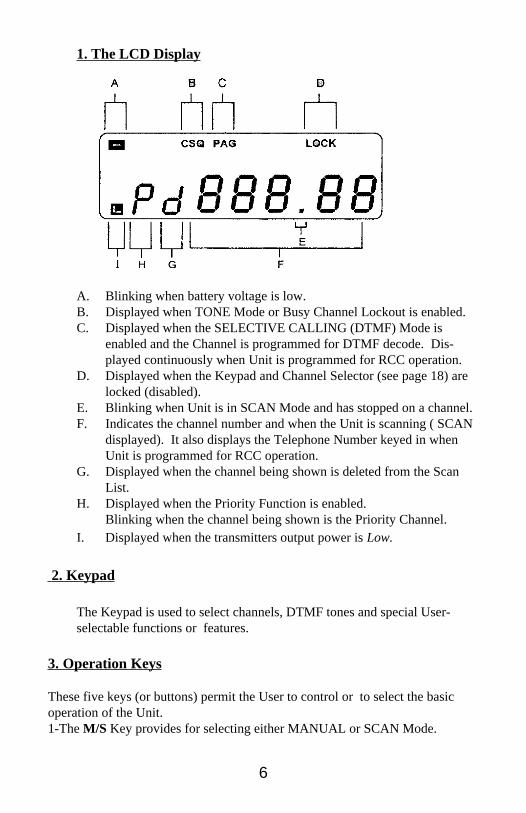
1. The LCD Display
A. Blinking when battery voltage is low.B. Displayed when TONE Mode or Busy Channel Lockout is enabled.C. Displayed when the SELECTIVE CALLING (DTMF) Mode is
enabled and the Channel is programmed for DTMF decode. Dis-played continuously when Unit is programmed for RCC operation.
D. Displayed when the Keypad and Channel Selector (see page 18) arelocked (disabled).
E. Blinking when Unit is in SCAN Mode and has stopped on a channel.F. Indicates the channel number and when the Unit is scanning ( SCAN
displayed). It also displays the Telephone Number keyed in whenUnit is programmed for RCC operation.
G. Displayed when the channel being shown is deleted from the ScanList.
H. Displayed when the Priority Function is enabled.Blinking when the channel being shown is the Priority Channel.
I. Displayed when the transmitters output power is Low.
2. Keypad
The Keypad is used to select channels, DTMF tones and special User-selectable functions or features.
3. Operation Keys
These five keys (or buttons) permit the User to control or to select the basicoperation of the Unit.1-The M/S Key provides for selecting either MANUAL or SCAN Mode.
7
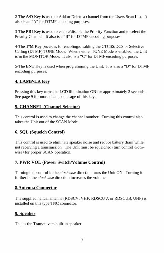
2-The A/D Key is used to Add or Delete a channel from the Users Scan List. Italso is an “A” for DTMF encoding purposes.
3-The PRI Key is used to enable/disable the Priority Function and to select thePriority Channel. It also is a “B” for DTMF encoding purposes.
4-The T/M Key provides for enabling/disabling the CTCSS/DCS or SelectiveCalling (DTMF) TONE Mode. When neither TONE Mode is enabled, the Unitis in the MONITOR Mode. It also is a “C” for DTMF encoding purposes.
5-The ENT Key is used when programming the Unit. It is also a “D” for DTMFencoding purposes.
4. LAMP/LK Key
Pressing this key turns the LCD illumination ON for approximately 2 seconds.See page 9 for more details on usage of this key.
5. CHANNEL (Channel Selector)
This control is used to change the channel number. Turning this control alsotakes the Unit out of the SCAN Mode.
6. SQL (Squelch Control)
This control is used to eliminate speaker noise and reduce battery drain whilenot receiving a transmission. The Unit must be squelched (turn control clock-wise) for proper SCAN operation.
7. PWR VOL (Power Switch/Volume Control)
Turning this control in the clockwise direction turns the Unit ON. Turning itfurther in the clockwise direction increases the volume.
8.Antenna Connector
The supplied helical antenna (RDSCV, VHF; RDSCU A or RDSCUB, UHF) isinstalled on this type TNC connector.
9. Speaker
This is the Transceivers built-in speaker.
8
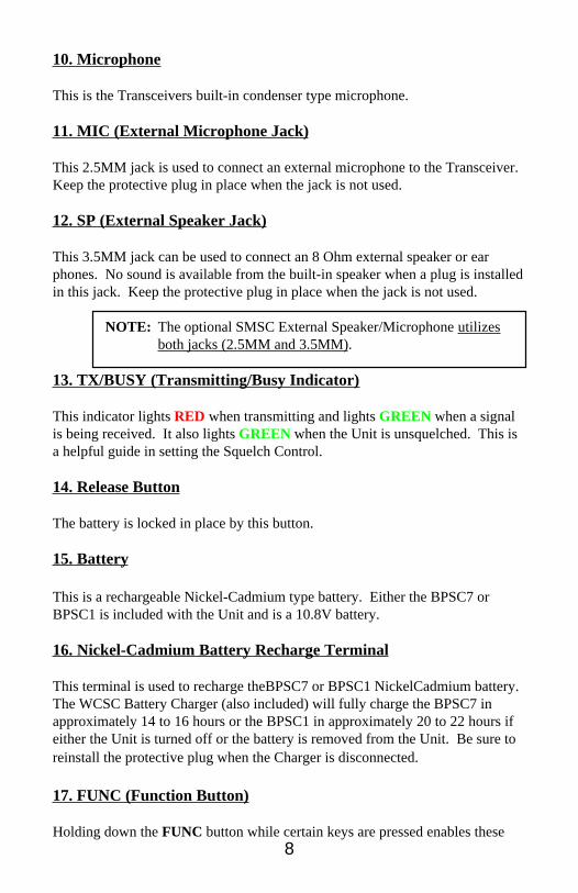
10. Microphone
This is the Transceivers built-in condenser type microphone.
11. MIC (External Microphone Jack)
This 2.5MM jack is used to connect an external microphone to the Transceiver.Keep the protective plug in place when the jack is not used.
12. SP (External Speaker Jack)
This 3.5MM jack can be used to connect an 8 Ohm external speaker or earphones. No sound is available from the built-in speaker when a plug is installedin this jack. Keep the protective plug in place when the jack is not used.
NOTE: The optional SMSC External Speaker/Microphone utilizesboth jacks (2.5MM and 3.5MM).
13. TX/BUSY (Transmitting/Busy Indicator)
This indicator lights RED when transmitting and lights GREEN when a signalis being received. It also lights GREEN when the Unit is unsquelched. This isa helpful guide in setting the Squelch Control.
14. Release Button
The battery is locked in place by this button.
15. Battery
This is a rechargeable Nickel-Cadmium type battery. Either the BPSC7 orBPSC1 is included with the Unit and is a 10.8V battery.
16. Nickel-Cadmium Battery Recharge Terminal
This terminal is used to recharge theBPSC7 or BPSC1 NickelCadmium battery.The WCSC Battery Charger (also included) will fully charge the BPSC7 inapproximately 14 to 16 hours or the BPSC1 in approximately 20 to 22 hours ifeither the Unit is turned off or the battery is removed from the Unit. Be sure toreinstall the protective plug when the Charger is disconnected.
17. FUNC (Function Button)
Holding down the FUNC button while certain keys are pressed enables these
9
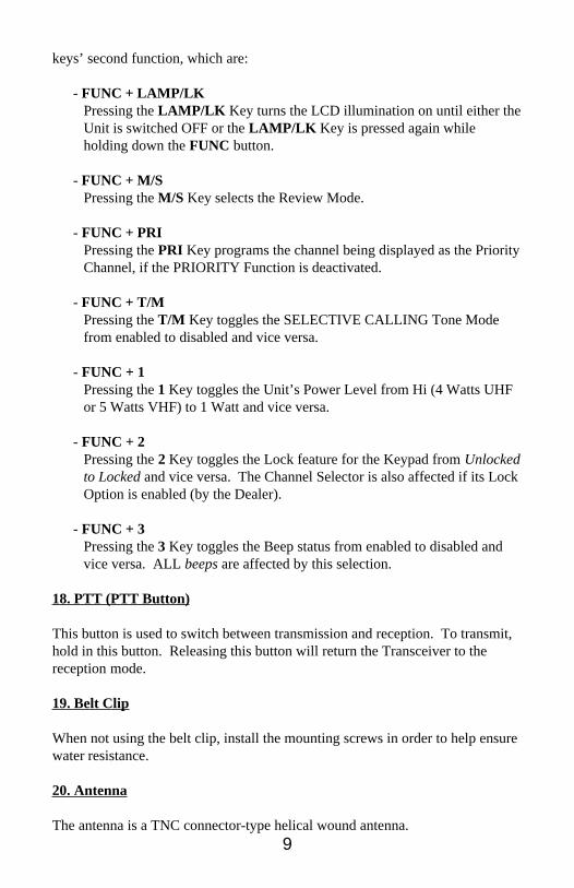
keys’ second function, which are:
- FUNC + LAMP/LKPressing the LAMP/LK Key turns the LCD illumination on until either theUnit is switched OFF or the LAMP/LK Key is pressed again whileholding down the FUNC button.
- FUNC + M/SPressing the M/S Key selects the Review Mode.
- FUNC + PRIPressing the PRI Key programs the channel being displayed as the PriorityChannel, if the PRIORITY Function is deactivated.
- FUNC + T/MPressing the T/M Key toggles the SELECTIVE CALLING Tone Modefrom enabled to disabled and vice versa.
- FUNC + 1Pressing the 1 Key toggles the Unit’s Power Level from Hi (4 Watts UHFor 5 Watts VHF) to 1 Watt and vice versa.
- FUNC + 2Pressing the 2 Key toggles the Lock feature for the Keypad from Unlockedto Locked and vice versa. The Channel Selector is also affected if its LockOption is enabled (by the Dealer).
- FUNC + 3Pressing the 3 Key toggles the Beep status from enabled to disabled andvice versa. ALL beeps are affected by this selection.
18. PTT (PTT Button)
This button is used to switch between transmission and reception. To transmit,hold in this button. Releasing this button will return the Transceiver to thereception mode.
19. Belt Clip
When not using the belt clip, install the mounting screws in order to help ensurewater resistance.
20. Antenna
The antenna is a TNC connector-type helical wound antenna.
10
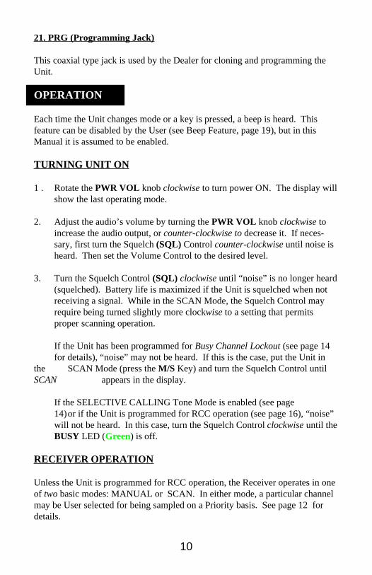
21. PRG (Programming Jack)
This coaxial type jack is used by the Dealer for cloning and programming theUnit.
OPERATION
Each time the Unit changes mode or a key is pressed, a beep is heard. Thisfeature can be disabled by the User (see Beep Feature, page 19), but in thisManual it is assumed to be enabled.
TURNING UNIT ON
1 . Rotate the PWR VOL knob clockwise to turn power ON. The display willshow the last operating mode.
2. Adjust the audio’s volume by turning the PWR VOL knob clockwise toincrease the audio output, or counter-clockwise to decrease it. If neces-sary, first turn the Squelch (SQL) Control counter-clockwise until noise isheard. Then set the Volume Control to the desired level.
3. Turn the Squelch Control (SQL) clockwise until “noise” is no longer heard(squelched). Battery life is maximized if the Unit is squelched when notreceiving a signal. While in the SCAN Mode, the Squelch Control mayrequire being turned slightly more clockwise to a setting that permitsproper scanning operation.
If the Unit has been programmed for Busy Channel Lockout (see page 14for details), “noise” may not be heard. If this is the case, put the Unit in
the SCAN Mode (press the M/S Key) and turn the Squelch Control untilSCAN appears in the display.
If the SELECTIVE CALLING Tone Mode is enabled (see page14)or if the Unit is programmed for RCC operation (see page 16), “noise”will not be heard. In this case, turn the Squelch Control clockwise until theBUSY LED (Green) is off.
RECEIVER OPERATION
Unless the Unit is programmed for RCC operation, the Receiver operates in oneof two basic modes: MANUAL or SCAN. In either mode, a particular channelmay be User selected for being sampled on a Priority basis. See page 12 fordetails.
11
MANUAL Mode
In this mode, the Unit monitors activity on the displayed channel. To put theUnit in the MANUAL Mode, if it is in the SCAN Mode,either:
1. Press the M/S Key, or2. Turn the Channel Selector knob, or3. Press the desired channel’s number (two digits; 01 - 32).
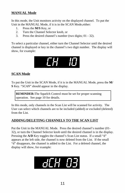
To select a particular channel, either turn the Channel Selector until the desiredchannel is displayed or key in the channel’s two digit number. The display willshow, for example:
SCAN Mode
To put the Unit in the SCAN Mode, if it is in the MANUAL Mode, press the M/S Key. “SCAN” should appear in the display.
REMINDER: The Squelch Control must be set for proper scanningoperation. See page 10 for details.
In this mode, only channels in the Scan List will be scanned for activity. TheUser can select which channels are to be included (added) or excluded (deleted)from the List.
ADDING/DELETING CHANNELS TO THE SCAN LIST
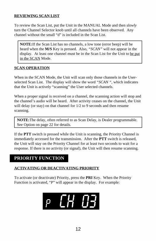
Put the Unit in the MANUAL Mode. Press the desired channel’s number (01-32), or turn the Channel Selector knob until the desired channel is in the display.Pressing the A/D Key toggles the channel’s Scan List status. If a small “d”appears at the left side, the channel is now deleted from the List. If the small“d” disappears, the channel is added to the List. For a deleted channel, thedisplay will show, for example:
12
REVIEWING SCAN LIST
To review the Scan List, put the Unit in the MANUAL Mode and then slowlyturn the Channel Selector knob until all channels have been observed. Anychannel without the small “d” is included in the Scan List.
NOTE: If the Scan List has no channels, a low tone (error beep) will beheard when the M/S Key is pressed. Also, “SCAN” will not appear in thedisplay. At least one channel must be in the Scan List for the Unit to be putin the SCAN Mode.
SCAN OPERATION
When in the SCAN Mode, the Unit will scan only those channels in the User-selected Scan List. The display will show the word “SCAN “, which indicatesthat the Unit is actively “scanning” the User selected channels.
When a proper signal is received on a channel, the scanning action will stop andthe channel’s audio will be heard. After activity ceases on the channel, the Unitwill delay (or stay) on that channel for 1/2 to 9 seconds and then resumescanning.
NOTE:The delay, often referred to as Scan Delay, is Dealer programmable.See Option on page 22 for details.
If the PTT switch is pressed while the Unit is scanning, the Priority Channel isimmediately accessed for the transmission. After the PTT switch is released,the Unit will stay on the Priority Channel for at least two seconds to wait for aresponse. If there is no activity (or signal), the Unit will then resume scanning.
PRIORITY FUNCTION
ACTIVATING OR DEACTIVATING PRIORITY
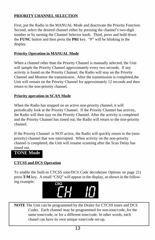
To activate (or deactivate) Priority, press the PRI Key. When the PriorityFunction is activated, “P” will appear in the display. For example:
13
PRIORITY CHANNEL SELECTION
First, put the Radio in the MANUAL Mode and deactivate the Priority Function.Second, select the desired channel either by pressing the channel’s two-digitnumber or by turning the Channel Selector knob. Third, press and hold downthe FUNC button and then press the PRI key. “P” will be blinking in thedisplay.
Priority Operation in MANUAL Mode
When a channel other than the Priority Channel is manually selected, the Unitwill sample the Priority Channel approximately every two seconds. If anyactivity is found on the Priority Channel, the Radio will stay on the PriorityChannel and Monitor the transmission. After the transmission is completed,theUnit will remain on the Priority Channel for approximately 12 seconds and thenreturn to the non-priority channel.
Priority operation in SCAN Mode
When the Radio has stopped on an active non-priority channel, it willperiodically look at the Priority Channel. If the Priority Channel has activity,the Radio will then stay on the Priority Channel. After the activity is completedand the Priority Channel has timed out, the Radio will return to the non-prioritychannel.
If the Priority Channel is NOT active, the Radio will quickly return to the (non-priority) channel that was interrupted. When activity on the non-prioritychannel is completed, the Unit will resume scanning after the Scan Delay hastimed out.TONE Mode
CTCSS and DCS Operation
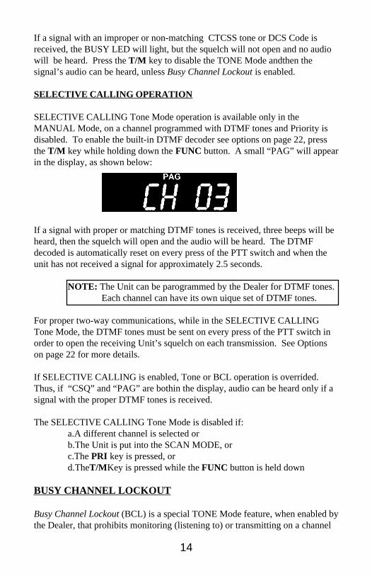
To enable the built-in CTCSS tone/DCS Code decode(see Options on page 21)press T/M key. A small “CSQ” will appear in the display, as shown in the follow-ing example:
NOTE The Unit can be programmed by the Dealer for CTCSS tones and DCSCodes. Each channel may be programmed for non-tone/code, for thesame tone/code, or for a different tone/code. In other words, eachchanel can have its own unique tone/code set-up.
14
If a signal with an improper or non-matching CTCSS tone or DCS Code isreceived, the BUSY LED will light, but the squelch will not open and no audiowill be heard. Press the T/M key to disable the TONE Mode andthen thesignal’s audio can be heard, unless Busy Channel Lockout is enabled.
SELECTIVE CALLING OPERATION
SELECTIVE CALLING Tone Mode operation is available only in theMANUAL Mode, on a channel programmed with DTMF tones and Priority isdisabled. To enable the built-in DTMF decoder see options on page 22, pressthe T/M key while holding down the FUNC button. A small “PAG” will appearin the display, as shown below:
If a signal with proper or matching DTMF tones is received, three beeps will beheard, then the squelch will open and the audio will be heard. The DTMFdecoded is automatically reset on every press of the PTT switch and when theunit has not received a signal for approximately 2.5 seconds.
NOTE: The Unit can be parogrammed by the Dealer for DTMF tones.Each channel can have its own uique set of DTMF tones.
For proper two-way communications, while in the SELECTIVE CALLINGTone Mode, the DTMF tones must be sent on every press of the PTT switch inorder to open the receiving Unit’s squelch on each transmission. See Optionson page 22 for more details.
If SELECTIVE CALLING is enabled, Tone or BCL operation is overrided.Thus, if “CSQ” and “PAG” are bothin the display, audio can be heard only if asignal with the proper DTMF tones is received.
The SELECTIVE CALLING Tone Mode is disabled if:a.A different channel is selected orb.The Unit is put into the SCAN MODE, orc.The PRI key is pressed, ord.TheT/M Key is pressed while the FUNC button is held down
BUSY CHANNEL LOCKOUT
Busy Channel Lockout (BCL) is a special TONE Mode feature, when enabled bythe Dealer, that prohibits monitoring (listening to) or transmitting on a channel
15
that is receiving a signal with an improper CTCSS tone or DCS Code. Nomatter where the Squelch Control is set, audio will NOT be heard unless thesignal has the proper tone or code. The BUSY LED (green) will be on, butaudio may not be heard. The T/M Key will be disabled and thus, the Unit cannot be put into the MONITOR Mode.
TRANSMITTER OPERATION
WARNING An Industry Canada license is required on all transmitchannels. Do NOT transmit on unlicensed channels
WARNING Do NOT operate this Unit close to electrical blasting caps,or in an explosive atmosphere such as fuel or solvent vapors, dust, etc.
Procedure
1 . Select the desired channel. Monitor the channel for activity beforetransmitting to avoid interfering with communications already in progress.If the BUSY LED is ON and no audio is heard, the signal probably has adifferent tone than what is programmed for the channel.
2. Press and hold in the Push-to-Talk (PTT) switch located on the left side ofthe Unit. The Red TX LED will light and stay on as long as the PTTswitch is held in.
a. If BCL is enabled and the channel is receiving an incorrect tone, aseries of beeps will be heard and the Unit will NOT transmit (TXLED stays off).
b. Also, if the channel is Receive Only, a series of beeps will be heardand the Unit will NOT transmit(TX LED stays off).
HIGH/LOW Power Selection
To change the Units Power Output level from High (4 or 5 Watts) to Low (1Watt), or vice versa, first put the Unit in the MANUAL Mode Second, pressand hold in the FUNC button and then press the 1Key. A small L will appearin the display to indicate Low Power.High Power is indicated by the absence of L..
If the - is “flashing” (Low Baftery indication), the Unit will then automaticallyrevert to Low Power when transmitting in order to help prolong the Battery’soperational life.
16
DTMF Operation
The Dealer can program any Channel for DTMF decoding and encoding. Eachchannel can have 4 DTMF tones (numbers 0 through 9; # and *; A, B, C and D).For encoding purposes, the Dealer can program the Unit so that the DTMF tonesare automatically sent upon either the first or every press of the PTT switch.See Option No. 6 on page 22. The “first” press of the PTT switch is the initialactivation of the transmitter on the channel. Subsequent pressings of the PTTswitch will NOT send the DTMF unless:
a. The channel’s number is entered again by the key pad, orb. The Channel Selector is turned off the channel and then back to it, orc. The Unit is turned off and then back on, ord. A different channel is selected.
Individual DTMF tones can also be sent, while transmitting, by pressing thecorresponding button on the Keypad or one of the four Operational Keys. SeeFigure 2 on page 17.
NOTE: For DTMF encoding purposes: the A/D Key is an A, the PRI Key isa B, the T/M Key is a C and the ENT Key is a D.
Time Out Timer
A transmit Time Out Timer is built into the Unit. The Timer can beprogrammed by the Dealer to automatically shut down the transmitter after 15seconds (or up to 60 seconds) of operation even if the PTT switch is held incontinuously. The Dealer can also disable the Timer. In which case, the lengthof any transmission is determined by how long the PTT switch is held in. SeeOption No. 9 on page 22.
If the Timer is enabled, a series of beeps will be heard and the TX LED will goout when the PTT switch is held in after the Timer has timed out. To resumetransmitting, momentarily release the PTT switch and then press again.
RCC OPERATION
General
Radio Common Carrier (RCC) operation provides the User with mobiletelephone capabilities. The Unit can originate or receive calls somewhat similarto regular telephone usage. However, conversation is not carried on in a two-way manner, but in a push-to-talk (PTT) and release-to-listen manner.
When programmed (by the Dealer) for RCC operation, the Unit is always in the
17
MANUAL Mode. Channel selection can be made only by use of the rotaryChannel Selector switch. The display will always show “PAG” (small letters)and either the Channel Number or a keyed in Telephone Number. The Dealerwill also program in a special identifying code referred to as the Unit’sAutomatic Number Identification (ANI) Code.
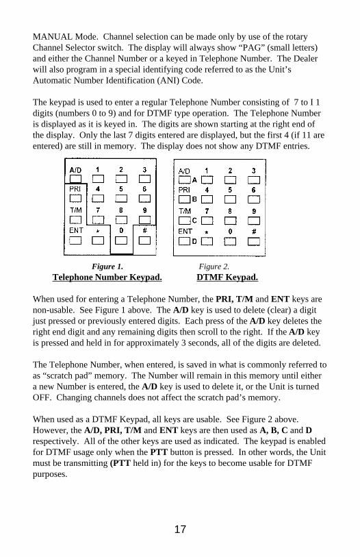
The keypad is used to enter a regular Telephone Number consisting of 7 to I 1digits (numbers 0 to 9) and for DTMF type operation. The Telephone Numberis displayed as it is keyed in. The digits are shown starting at the right end ofthe display. Only the last 7 digits entered are displayed, but the first 4 (if 11 areentered) are still in memory. The display does not show any DTMF entries.
Figure 1. Figure 2.Telephone Number Keypad. DTMF Keypad.
When used for entering a Telephone Number, the PRI, T/M and ENT keys arenon-usable. See Figure 1 above. The A/D key is used to delete (clear) a digitjust pressed or previously entered digits. Each press of the A/D key deletes theright end digit and any remaining digits then scroll to the right. If the A/D keyis pressed and held in for approximately 3 seconds, all of the digits are deleted.
The Telephone Number, when entered, is saved in what is commonly referred toas “scratch pad” memory. The Number will remain in this memory until eithera new Number is entered, the A/D key is used to delete it, or the Unit is turnedOFF. Changing channels does not affect the scratch pad’s memory.
When used as a DTMF Keypad, all keys are usable. See Figure 2 above.However, the A/D, PRI, T/M and ENT keys are then used as A, B, C and Drespectively. All of the other keys are used as indicated. The keypad is enabledfor DTMF usage only when the PTT button is pressed. In other words, the Unitmust be transmitting (PTT held in) for the keys to become usable for DTMFpurposes.
18
To Originate A Call
Key in the desired Telephone Number (up to 11 digits). If the channel is notbusy, press the * key to automatically transmit the connect (*) tone, the Unit’sANI Code and then, after the RCC Delay time (programmed by Dealer), theTelephone Number.
REMINDER: The Telephone Number does not have to be keyed in eachtime a call is to be made, unless it is to be changed or the Unit has beenturned OFF since the last call.
The Radio is now in the Receive Mode and the PTT button can be pressed, whichenables the Transmitter and the DTMF keypad. At this time, while holding in thePTT button, either press the desired DTMF keys and/or speak into the Radio’smicrophone. After your end of the conversation is finished, release the PTTbutton to listen to any reply. To end the contact, press the # key to automaticallysend the disconnect (#) tone and the ANI code.
If a Telephone Number is not in the scratch pad memory (it has been deleted orthe Unit was turned OFF) and the * key is pressed, the Radio will still transmitthe connect (*) tone and the ANI code. It will then go to the Receive Mode andwait for a dial tone to be received. After the dial tone is received, press the PTTbutton and key in the desired Telephone Number.
To Receive a Call
With the Radio in the Receive Mode, squelch will open and 3 beeps will beheard only when it receives an ANI code that corresponds (identical) to its ownANI code. At this time, the PTT button is enabled and can be pressed to starttransmitting your end of the conversation. Release the PTT button to listen toany reply.
OTHER USER-SELECTABLE FEATURES
KEYPAD AND CHANNEL SELECTOR LOCK
The Keypad and all other buttons (except FUNC, LAMP/LK and PTT) and theChannel Selector* can be “LOCKED” or be made inoperative while the Unit isin the Receiver Mode. These buttons can still be used for DTMF encodingwhile the Unit is in the Transmitter Mode. The Unit can be in either theMANUAL or the SCAN Mode.
*The Channel Selector can be locked with the keypad only if theChannel Selector Lock option (Dealer Programmable) is enabled. SeeOption 11 on page 22.
19
Press and hold in the FUNC button and then press the 2 Key. A small “LOCK”will appear in the display to indicate the LOCK function is enabled. Use thesame procedure to disable the LOCK function.
IMPORTANT: Keypad Lock feature is disabled if the, Unit is programmedfor RCC operations
The Channel Selector can be locked with the keypad only if the ChannelSelector Lock Option (Dealer Programmable) is enabled. See Option 11 on page22.
BEEP
When the Beep feature is enabled, a beep can be heard when any button (exceptLAMP/LK and PTT) is pressed or when the Channel Selector is turned toChannel 01. To disable this feature, press and hold in the FUNC button andthen press the 3 Key. No beeps will be heard except for when the PTT ispressed and the channel is a Receive Only channel or the channel is receiving anincorrect tone and BCL is enabled. In this case, a series of error beeps will beheard until the PTT button is released.
BATTERY INFORMATION
GENERAL INFORMATION
Keep the Battery charged. It may be charged without being installed on theUnit. Either the WCSC Wall-mounted Charger supplied with the Unit or theoptional accessory RSC-21 Drop-in Quick Charger may be used.
Do NOT use any other charger, or damage to the Battery may occur.
The WCSC Charger will fully charge the BPSC7 in approximately 14 hours andthe BPSC1 in approximately 20 hours. The RSC-21 Drop-in Charger will fullycharge either battery in approximately 1 3/4 hours. These times are dependentupon the Unit being turned off or the battery is not installed while beingcharged.
NOTE:The BPSC7 or BPSC1 battery is not fully charged when shippedfrom the Factory. It should be properly charged before use.
POWER SAVE FUNCTION
A Power Save Timer is built into the Unit. With the Unit in the MANUALMode and not receiving a signal, the Power Save Function conserves batterypower, by reducing the current drain for a selected period of time. The Timer
20
automatically shuts down the receiver for 150 milliseconds and then turns itback on for approximately 110 milliseconds, for a total cycle time of 260milliseconds. See page 23 for more details.
FOR LONGEST BATTERY LIFE AND BEST PERFORMANCE
I . Charge the Battery to full capacity: 14 to 20 hours with the WCSC;for the RSC-21 Quick Charger allow 1 3/4 hours.
2. Use the Battery as soon and as much of its capacity as possible andpractical. A Battery that is charged and discharged completely willmaintain the longest operating time capacity. Also, typically 3 to 5charge-discharge cycles are required to bring a new Battery up to itsrated capacity.
3. Store and charge the Battery at a room temperature of 18 to 24 C (65to 75 F). A Battery that has been stored for over a month should berecharged before being put into service, due to chemical self-discharge which occurs at a rate of approximately 1% per day. DoNOT charge a cold battery that is at 0 C (32 F) or below until it is atleast above 7 C (45 F).
4. Reduced capacity of the Battery may result from repeated identicalshallow discharge-full charge cycles. If such a condition issuspected, use the Battery until the Transceiver indicates a LowBattery (“flashing” 0), then fully recharge and discharge again.Repeat this cycle 3 to 5 times. Full rated capacity should then beavailable.
CAUTION: Do NOT short or incinerate the battery
IMPORTANT: Please recycle or properly dispose of any nonusable ordefective BPSC7 or BPSC1 battery.
MAINTENANCE
NOTE: All adjustments affecting transmitter power output, carrierfrequency or modulation MUST be performed by a qualifiedelectronics technician.
CAUTION Do NOT tamper with internal adjustments. Damage to theequimpent and/or impropert operation may result.
Service ReminderHave the Transceiver checked periodically by a qualified techincian.
21
TROUBLESHOOTING
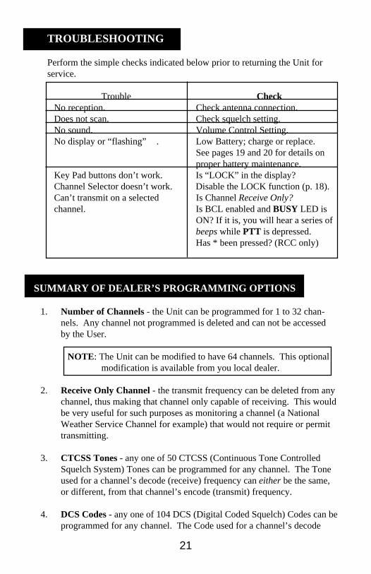
Perform the simple checks indicated below prior to returning the Unit forservice.
Trouble CheckNo reception. Check antenna connection.Does not scan. Check squelch setting.No sound. Volume Control Setting.No display or “flashing” - . Low Battery; charge or replace.
See pages 19 and 20 for details onproper battery maintenance.
Key Pad buttons don’t work. Is “LOCK” in the display?Channel Selector doesn’t work. Disable the LOCK function (p. 18).Can’t transmit on a selected Is Channel Receive Only?channel. Is BCL enabled and BUSY LED is
ON? If it is, you will hear a series ofbeeps while PTT is depressed.Has * been pressed? (RCC only)
SUMMARY OF DEALER’S PROGRAMMING OPTIONS
1. Number of Channels - the Unit can be programmed for 1 to 32 chan-nels. Any channel not programmed is deleted and can not be accessedby the User.
NOTE: The Unit can be modified to have 64 channels. This optionalmodification is available from you local dealer.
2. Receive Only Channel - the transmit frequency can be deleted from anychannel, thus making that channel only capable of receiving. This wouldbe very useful for such purposes as monitoring a channel (a NationalWeather Service Channel for example) that would not require or permittransmitting.
3. CTCSS Tones - any one of 50 CTCSS (Continuous Tone ControlledSquelch System) Tones can be programmed for any channel. The Toneused for a channel’s decode (receive) frequency can either be the same,or different, from that channel’s encode (transmit) frequency.
4. DCS Codes - any one of 104 DCS (Digital Coded Squelch) Codes can beprogrammed for any channel. The Code used for a channel’s decode

22
(receive) frequency can either be the same, or different, from thatchannel’s encode (transmit) frequency.
5. DTMF Tones - any four DTMF (Dual-Tone Multi-Frequency) Tones,consisting of 0 - 9, * and #, A - D, can be programmed for any channel.
6. DTMF Operation - The Unit can be programmed to automatically sendthe DTMF Tones either after the first press of the PTT switch or forevery press of the PTT switch.
For proper two-way SELECTIVE CALLING operation, the DTMF tonesmust be sent on every press of the PTT switch in order to open the otheror receiving Unit’s squelch. This is because a Unit’s DTMF decoder isalways automatically reset after it transmits while in the SELECTIVECALLING Tone Mode.
Also, the Unit’s DTMF decoder automatically resets if it has not receiveda signal for approximately 2.5 seconds. Thus, it needs to receive theDTMF tones again to open squelch.
7. Busy Channel Lockout - the Unit can be programmed to preventlistening or transmitting on a channel if that channel is receiving a signalthat has a DCS Code, CTCSS Tone or DTMF Tones that do NOT matchits own Code, Tone or Tones. Thus, it is a busy channel and should notbe used at this time.
8. Scan Delay - the Unit can be programmed to delay (for 1/2, 1 or up to 9seconds) the restart of the scanning action after the signal has gone away.This delay gives the User some time to respond to the signal beforescanning resumes.
9. Time-Out-Timer - the Unit’s Time-Out-Timer can either be disabledcompletely or set to only allow a transmission of 1/4, 1/2 or 1 minuteduration. The Timer is normally used to prevent excessively longtransmissions that might be deliberate or caused by an inadvertent oraccidental pressing of the PTT switch.
10. RCC Operation - The Unit can be programmed to be used in the RadioCommon Carrier (RCC) Services. If programmed as such, it can not beused as a normal or standard 2-way radio. RCC Delay (1/2 to 9 seconds) isalso selected when the Unit is programmed for RCC operation. RCCDelay is the time after the ANI is sent before the scratch pad number isautomatically sent.
11. Channel Selector Lock - the Unit can be programmed so that the Channel
23
Selector is locked (inoperative) when the Keypad is locked (userselectable).
POWER SAVE TIMER DETAILS
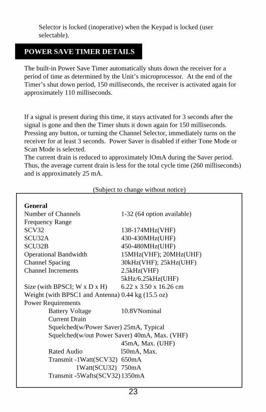
The built-in Power Save Timer automatically shuts down the receiver for aperiod of time as determined by the Unit’s microprocessor. At the end of theTimer’s shut down period, 150 milliseconds, the receiver is activated again forapproximately 110 milliseconds.
If a signal is present during this time, it stays activated for 3 seconds after thesignal is gone and then the Timer shuts it down again for 150 milliseconds.Pressing any button, or turning the Channel Selector, immediately turns on thereceiver for at least 3 seconds. Power Saver is disabled if either Tone Mode orScan Mode is selected.The current drain is reduced to approximately lOmA during the Saver period.Thus, the average current drain is less for the total cycle time (260 milliseconds)and is approximately 25 mA.
SPECIFICATIONS (Subject to change without notice)
GeneralNumber of Channels 1-32 (64 option available)Frequency RangeSCV32 138-174MHz(VHF)SCU32A 430-430MHz(UHF)SCU32B 450-480MHz(UHF)Operational Bandwidth 15MHz(VHF); 20MHz(UHF)Channel Spacing 30kHz(VHF); 25kHz(UHF)Channel Increments 2.5kHz(VHF)
5kHz/6.25kHz(UHF)Size (with BPSCI; W x D x H) 6.22 x 3.50 x 16.26 cmWeight (with BPSC1 and Antenna) 0.44 kg (15.5 oz)Power Requirements
Battery Voltage 10.8VNominalCurrent DrainSquelched(w/Power Saver) 25mA, TypicalSquelched(w/out Power Saver) 40mA, Max. (VHF)
45mA, Max. (UHF)Rated Audio l50mA, Max.Transmit -1Watt(SCV32) 650mA
1Watt(SCU32) 750mATransmit -5Wafts(SCV32)1350mA
24
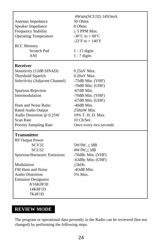
4Watts(SCU32) 145OmAAntenna Impedance 50 OhmsSpeaker Impedance 8 OhmsFrequency Stability + 5 PPM Max.Operating Temperature -30’C to + 60’C
-22’F to + 140’FRCC Memory
Scratch Pad 1 - 11 digitsANI 1 - 7 digits
ReceiverSensitivity (12dB SINAD) 0.25uV Max.Threshold Squelch 0.20uV Max.Selectivity (Adjacent Channel) -75dB Min. (VHF)
-70dB Min. (UHF)Spurious Rejection -67dB Min.Intermodulation -70dB Min. (VHF)
-67dB Min. (UHF)Hum and Noise Ratio -40dB Min.Rated Audio Output 250mW Min.Audio Distortion @ 0.25W 10% T. H. D. Max.Scan Rate 10 Ch/Sec.Priority Sampling Rate Once every two seconds
TransmitterRF Output Power
SCV32 5W/lW, + ldB SCU32 4W/lW,+ ldB
Spurious/Harmonic Emissions -70dBc Min. (VHF)-63dBc Min. (UHF)
Modulation +5kHzFM Hum and Noise -4OdB Min.Audio Distortion 5% Max.Emission Designator
8/16K0F3E14K8F1D7K4F1D
REVIEW MODE
The program or operational data presently in the Radio can be reviewed (but notchanged) by performing the following steps.
25
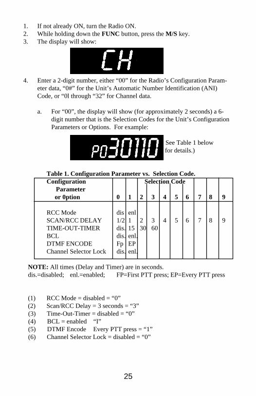
1. If not already ON, turn the Radio ON.2. While holding down the FUNC button, press the M/S key.3. The display will show:
4. Enter a 2-digit number, either “00” for the Radio’s Configuration Param-eter data, “0#” for the Unit’s Automatic Number Identification (ANI)Code, or “0l through “32” for Channel data.
a. For “00”, the display will show (for approximately 2 seconds) a 6-digit number that is the Selection Codes for the Unit’s ConfigurationParameters or Options. For example:
( See Table 1 below for details.)
Table 1. Configuration Parameter vs. Selection Code.Configuration Selection Code
Parameter or 0ption 0 1 2 3 4 5 6 7 8 9
RCC Mode dis enlSCAN/RCC DELAY 1/2 1 2 3 4 5 6 7 8 9TIME-OUT-TIMER dis. 15 30 60BCL dis. enl.DTMF ENCODE Fp EPChannel Selector Lock dis. enl.
NOTE: All times (Delay and Timer) are in seconds.dis.=disabled; enl.=enabled; FP=First PTT press; EP=Every PTT press
(1) RCC Mode = disabled = “0”(2) Scan/RCC Delay = 3 seconds = “3”
(3) Time-Out-Timer = disabled = “0” (4) BCL = enabled “I” (5) DTMF Encode Every PTT press = “1” (6) Channel Selector Lock = disabled = “0”
26
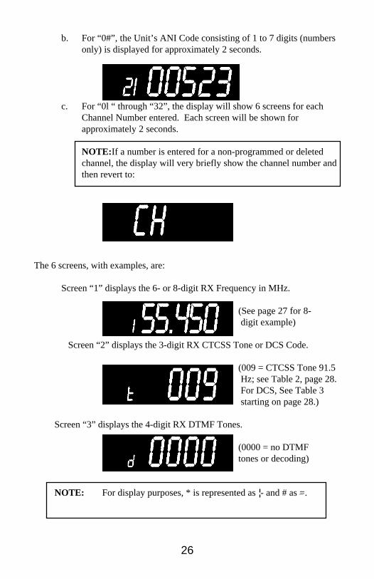
b. For “0#”, the Unit’s ANI Code consisting of 1 to 7 digits (numbersonly) is displayed for approximately 2 seconds.
c. For “0l “ through “32”, the display will show 6 screens for eachChannel Number entered. Each screen will be shown forapproximately 2 seconds.
NOTE: If a number is entered for a non-programmed or deletedchannel, the display will very briefly show the channel number andthen revert to:
The 6 screens, with examples, are:
Screen “1” displays the 6- or 8-digit RX Frequency in MHz.
(See page 27 for 8- digit example)
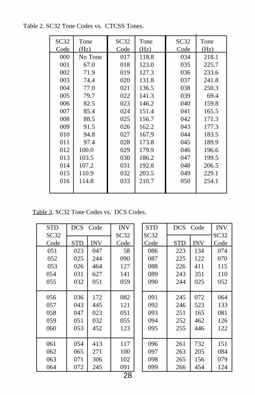
Screen “2” displays the 3-digit RX CTCSS Tone or DCS Code.
(009 = CTCSS Tone 91.5 Hz; see Table 2, page 28. For DCS, See Table 3 starting on page 28.)
Screen “3” displays the 4-digit RX DTMF Tones.
(0000 = no DTMFtones or decoding)
NOTE: For display purposes, * is represented as - and # as =.
27
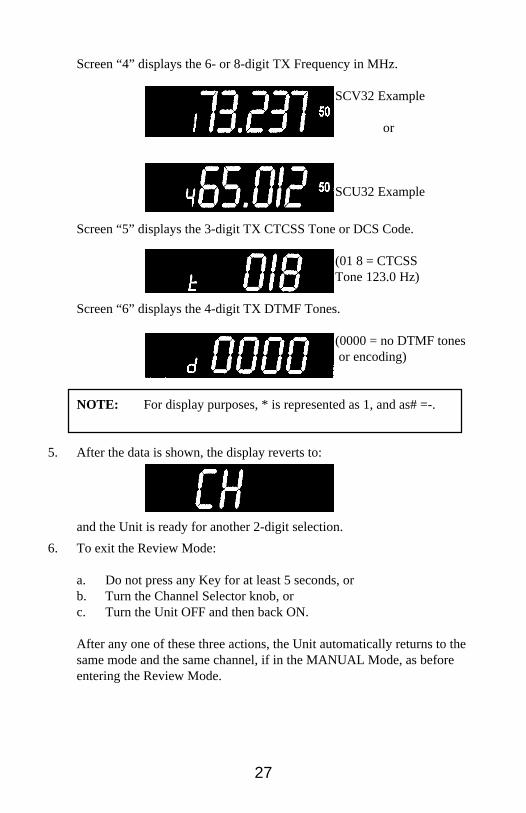
Screen “4” displays the 6- or 8-digit TX Frequency in MHz.
SCV32 Example
or
SCU32 Example
Screen “5” displays the 3-digit TX CTCSS Tone or DCS Code.
(01 8 = CTCSSTone 123.0 Hz)
Screen “6” displays the 4-digit TX DTMF Tones.
(0000 = no DTMF tones or encoding)
NOTE: For display purposes, * is represented as 1, and as# =-.
5. After the data is shown, the display reverts to:
and the Unit is ready for another 2-digit selection.
6. To exit the Review Mode:
a. Do not press any Key for at least 5 seconds, orb. Turn the Channel Selector knob, orc. Turn the Unit OFF and then back ON.
After any one of these three actions, the Unit automatically returns to thesame mode and the same channel, if in the MANUAL Mode, as beforeentering the Review Mode.
28
Table 2. SC32 Tone Codes vs. CTCSS Tones.
SC32 Tone SC32 Tone SC32 ToneCode (Hz) Code (Hz) Code (Hz)
000 No Tone 017 118.8 034 218.1001 67.0 018 123.0 035 225.7002 71.9 019 127.3 036 233.6003 74.4 020 131.8 037 241.8004 77.0 021 136.5 038 250.3005 79.7 022 141.3 039 69.4006 82.5 023 146.2 040 159.8007 85.4 024 151.4 041 165.5008 88.5 025 156.7 042 171.3009 91.5 026 162.2 043 177.3010 94.8 027 167.9 044 183.5011 97.4 028 173.8 045 189.9012 100.0 029 179.9 046 196.6013 103.5 030 186.2 047 199.5014 107.2 031 192.8 048 206.5015 110.9 032 203.5 049 229.1016 114.8 033 210.7 050 254.1
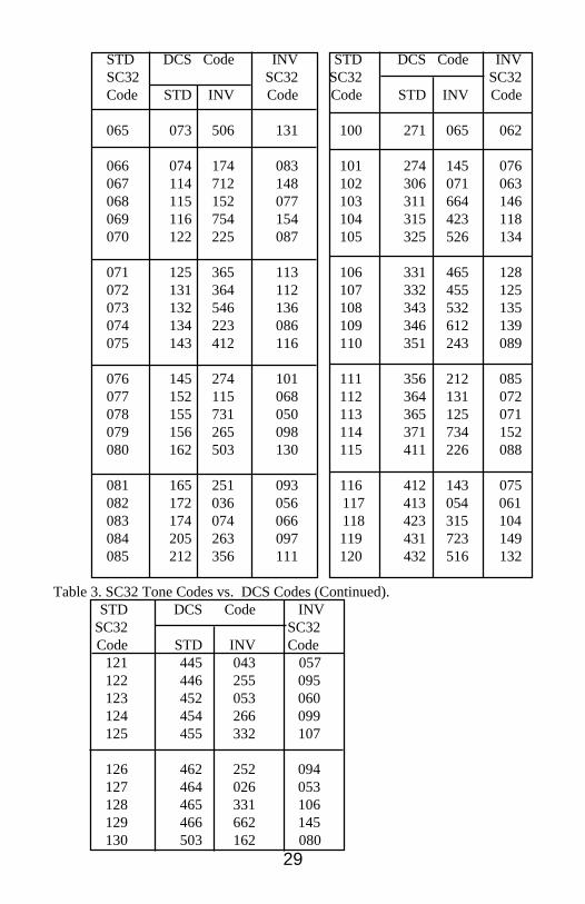
Table 3. SC32 Tone Codes vs. DCS Codes.
STD DCS Code INV STD DCS Code INVSC32 SC32 SC32 SC32Code STD INV Code Code STD INV Code
051 023 047 58 086 223 134 074 052 025 244 090 087 225 122 070 053 026 464 127 088 226 411 115
054 031 627 141 089 243 351 110055 032 051 059 090 244 025 052
056 036 172 082 091 245 072 064057 043 445 121 092 246 523 133058 047 023 051 093 251 165 081059 051 032 055 094 252 462 126060 053 452 123 095 255 446 122
061 054 413 117 096 261 732 151062 065 271 100 097 263 205 084063 071 306 102 098 265 156 079064 072 245 091 099 266 454 124
29
STD DCS Code INV STD DCS Code INVSC32 SC32 SC32 SC32Code STD INV Code Code STD INV Code
065 073 506 131 100 271 065 062
066 074 174 083 101 274 145 076067 114 712 148 102 306 071 063068 115 152 077 103 311 664 146069 116 754 154 104 315 423 118070 122 225 087 105 325 526 134
071 125 365 113 106 331 465 128072 131 364 112 107 332 455 125073 132 546 136 108 343 532 135074 134 223 086 109 346 612 139075 143 412 116 110 351 243 089
076 145 274 101 111 356 212 085077 152 115 068 112 364 131 072078 155 731 050 113 365 125 071079 156 265 098 114 371 734 152080 162 503 130 115 411 226 088
081 165 251 093 116 412 143 075082 172 036 056 117 413 054 061083 174 074 066 118 423 315 104084 205 263 097 119 431 723 149085 212 356 111 120 432 516 132
Table 3. SC32 Tone Codes vs. DCS Codes (Continued).STD DCS Code INV
SC32 SC32Code STD INV Code
121 445 043 057122 446 255 095123 452 053 060124 454 266 099125 455 332 107
126 462 252 094127 464 026 053128 465 331 106129 466 662 145130 503 162 080
30
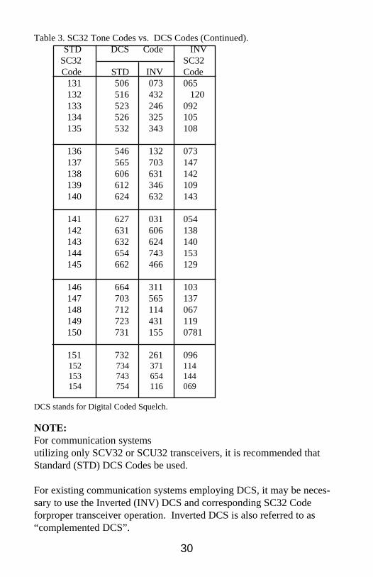
Table 3. SC32 Tone Codes vs. DCS Codes (Continued).STD DCS Code INV
SC32 SC32Code STD INV Code
131 506 073 065132 516 432 120133 523 246 092134 526 325 105135 532 343 108
136 546 132 073137 565 703 147138 606 631 142139 612 346 109140 624 632 143
141 627 031 054142 631 606 138143 632 624 140144 654 743 153145 662 466 129
146 664 311 103147 703 565 137148 712 114 067149 723 431 119150 731 155 0781
151 732 261 096152 734 371 114153 743 654 144154 754 116 069
DCS stands for Digital Coded Squelch.
NOTE:For communication systemsutilizing only SCV32 or SCU32 transceivers, it is recommended thatStandard (STD) DCS Codes be used.
For existing communication systems employing DCS, it may be neces-sary to use the Inverted (INV) DCS and corresponding SC32 Codeforproper transceiver operation. Inverted DCS is also referred to as“complemented DCS”.