Embed Size (px)
Citation preview
Page 1
This appliance may be installed in an aftermarket, permanently located, manufactured home (USA only) or mobile home, where not prohibited by local codes.This appliance is only for use with the type of gas indicated on the rating plate. This appliance is not convertible for use with other gases, unless a certified kit is used.
WARNINGIf not installed, operated and maintained in accordance with the manufacturer’s instructions, this product could expose you to substances in fuel or from fuel combustion which can cause death or serious illness.
NOTICE: Barrier required.
HOT GLASS
DO NOT TOUCH
NEVER
WILLCAUSE BURNS.
GLASSUNTIL COOLED.
ALLOW CHILDRENTO TOUCH GLASS.
WARNING
A barrier designed to reduce the risk of burns from thehot viewing glass is provided with this appliance and shallbe installed for the protection of children and other at-riskindividuals.
INSTALLER: Leave this manual with the appliance.
CONSUMER: Retain this manual for future reference.
DIRECT VENT ZERO CLEARANCE GAS FIREPLACE
HEATER MODEL SERIES:MULTIFUNCTION
REMOTE (MF)DVLL72BP90(N,P)-2
UL FILE NO. MH30033
GAS-FIRED
INSTALLATION INSTRUCTIONS
WARNINGFIRE OR EXPLOSION HAZARDFailure to follow safety warnings exactly could result in serious injury, death or property damage.
— Do not store or use gasoline or other flammable vapors and liquids in the vicinity of this or any other appliance.
— WHAT TO DO IF YOU SMELL GAS• Do not try to light any appliance.• Do not touch any electrical switch;
do not use any phone in your building.• Leave the building immediately.• Immediately call your gas supplier
from a neighbor’s phone. Follow the gas supplier’s instructions.
• If you cannot reach your gas supplier, call the fire department.
— Installation and service must be performed by a qualified installer, service agency or the gas supplier.
41118-2-0420Page 2
BEFORE YOU STARTSAMPLE WARNINGS AND DEFINITIONS:
DANGERIndicates a hazardous situation which, if not avoided, will result in death or serious injury.
WARNINGIndicates a hazardous situation which, if not avoided, could result in death or serious injury.
CAUTIONIndicates a hazardous situation which, if not avoided, could result in minor or moderate injury.
NOTICE: Addresses practices not related to personal injury.
1. Read the safety information on pages 57 - 58.2. If located in the Commonwealth of Massachusetts, please
note the special requirements on page 59.3. Areyougoingtoinstallablowerintothefireplace?See
pages 8 - 10.4. Whereareyougoingtoinstallthefireplace?Seepage13.5. Frametheopening.Seepage20.6. Installthegaslines.Seepages16-17.7. Installthewiring.Seepages18-19.8. Installtheventing.Seepages26-35.9. Installthefireplace.Seepages20-25.10. Installtheremotesystem.Seepages40-46.11. Linerrequirements.Seepage38.12. Installtheglassmedia.Seepage39.13. Lightthefireplaceandtroubleshoot.Seepage47.14. Showthehomeownerhowtooperatethefireplace.15. Showthehomeownerhowtodothebasicmaintenance.
UNPACKING THE FIREPLACE1. Remove crate boards as needed using a screw gun to
remove wood screws.2. Remove top hand-bent top brackets (2) securing the long 2 x
4 board. Remove the 2 x 4 board and corner posts.3. Remove non-combustible boards and heatshield from pallet
and set aside.
4. Liftfireplaceoffofthepallet.5. Verifythatthefireplaceandcomponentshavenotbeen
damaged during shipping.6. Setfireplaceinalocationneartoitsfinalinstallationlocation.
INSTALLATION CONSIDERATIONS - FIREPLACE INSTALLATION GUIDELINESWhenplanningafireplaceinstallation,it’snecessarytodetermine:• Gas supply piping (right side entrance).• Electrical supply requirements
(120V, 60Hz, 1 Amp) (right side entrance)• DVLL72BP models include the factory installed LED Light
assembly. • Proper opening size of framing required for installation of
thefireplace.Theframingofthefireplacewilldeterminehowthefireplacefinishingmaterialswillbeapplied.Refertotheinstallation information on pages 20 to 23.
• Theblowerkitiseasiertoinstallatthetimeoffireplaceinstallations.Seeblowerinstallationsectiononpages8to10.
Inplanningtheinstallationforthefireplace,determinewherethefireplaceistobeinstalledandwhetheroptionalaccessoriesaredesired. Gas supply piping should also be planned at this time.Thefireplacecanbemountedonanyofthesesurfaces:1. Aflathardcombustibleornon-combustiblesurface.2. A raised platform of combustible or non-combustible
material.
Ifthefireplaceisinstalleddirectlyoncarpeting,tileorothercombustiblematerialotherthanwoodflooring,itshouldbeinstalled on a metal or wood panel extending the full width and depthofthefireplace.
Thefireplaceisdesignedtobeinstalledinazero-clearanceenclosure.Thismeansthatcombustiblematerialsmustbelocatedatclearancesspecifiedorprovidedbystandoffsorspacersattachedtothefireplace.Combustible materials can come in contact with the nailing flangesprovided.
HOMEOWNER REFERENCE INFORMATIONRecordthefollowinginformationaboutyourfireplace.
Model: ____________________________________ Date purchased/installed: ____________________
SerialNumber: _____________________________ Locationonfireplace: _______________________
Dealership: ________________________________ Dealer Phone: ____________________________
Notes: _______________________________________________________________________________
_____________________________________________________________________________________
41118-2-0420 Page 3
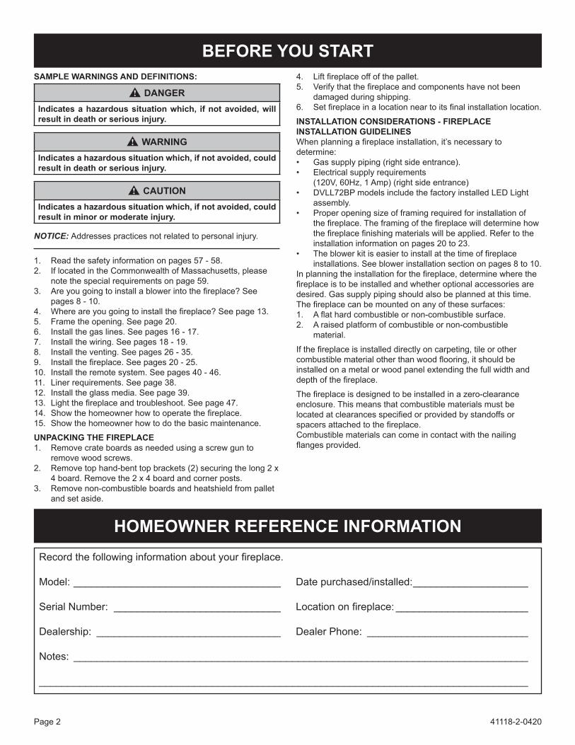
CARTON CONTENTS & HARDWARE PACK
Items not shown to scale.
INDEX NUMBER DESCRIPTION PART
NO.QUANTITY SUPPLIED
1 DoorRemovalTool(attachedtofireplace) 35978 1
2 Product Registration Card 29804 13 AA Battery B076529 44 AAA Battery R10600 3
5 WallThimbleSpacer(attachedtofireplace) 33331 1
6 Mounting Bracket 36827 17 RemoteTransmitter R11550 18 Junction Box Cover R3491 19 Duplex Receptacle R3492 110 Flue Restrictor Assembly 34054 111 Remote Receiver R11584 112 Bushing, 5/8 DIA R1536 113 Wall Plate R12296 114 Wall Mounted Control Box R12295 115 ButtonSwitch R11921 2
16 Wire Harness Module ToInterface R11552 1
A #10x1/2Screw R2737 22B #8x1Self-DrillingScrew* R11509 15C NailingFlange 28450 4
D#4 x 3/8 Phillips PanHeadScrew
R12300 4
*Foruseinmountingnon-combustibleboardtostandoffs.SeePartsListsonpages50fororderingreplacementparts.Donotorderbatteries,bolts,screws,washersornuts.Theyarestandard hardware items and can be purchased at any local hardware store.
1615
1413
1211
109
87
65
43
21 A
B
C
D
1” PHILLIPS SELF DRILLING SCREW
#10 X ½” HEX HEAD SCREW
NAILING FLANGES
3/8”
#10x1/2”HEXHEADSCREW
1”PHILLIPSSELFDRILLINGSCREW
NAILINGFLANGES
#4x3/8”STAINLESSPHILLIPSHEADSCREW
41118-2-0420Page 4
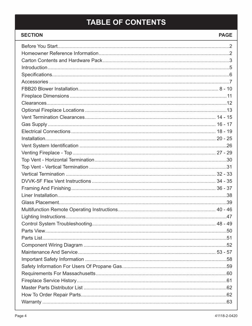
TABLE OF CONTENTS
BeforeYouStart.............................................................................................................................2Homeowner Reference Information ...............................................................................................2Carton Contents and Hardware Pack ............................................................................................3Introduction ....................................................................................................................................5Specifications.................................................................................................................................6Accessories ...................................................................................................................................7FBB20 Blower Installation...................................................................................................... 8 - 10Fireplace Dimensions ..................................................................................................................11Clearances...................................................................................................................................12Optional Fireplace Locations .......................................................................................................13VentTerminationClearances ............................................................................................... 14 - 15GasSupply .......................................................................................................................... 16 - 17Electrical Connections ......................................................................................................... 18 - 19Installation............................................................................................................................ 20 - 25VentSystemIdentification ...........................................................................................................26VentingFireplace-Top ........................................................................................................ 27 - 29TopVent-HorizontalTermination ................................................................................................30TopVent-VerticalTermination ....................................................................................................31VerticalTermination ............................................................................................................. 32 - 33DVVK-5F Flex Vent Instructions .......................................................................................... 34 - 35Framing And Finishing ......................................................................................................... 36 - 37Liner Installation...........................................................................................................................38Glass Placement..........................................................................................................................39Multifunction Remote Operating Instructions ....................................................................... 40 - 46Lighting Instructions .....................................................................................................................47ControlSystemTroubleshooting.......................................................................................... 48 - 49Parts View ....................................................................................................................................50Parts List ......................................................................................................................................51Component Wiring Diagram ........................................................................................................52MaintenanceAndService .................................................................................................... 53 - 57ImportantSafetyInformation .......................................................................................................58SafetyInformationForUsersOfPropaneGas ............................................................................59Requirements For Massachusetts ...............................................................................................60FireplaceServiceHistory .............................................................................................................61Master Parts Distributor List ........................................................................................................62HowToOrderRepairParts ..........................................................................................................62Warranty ......................................................................................................................................63
SECTION PAGE
41118-2-0420 Page 5
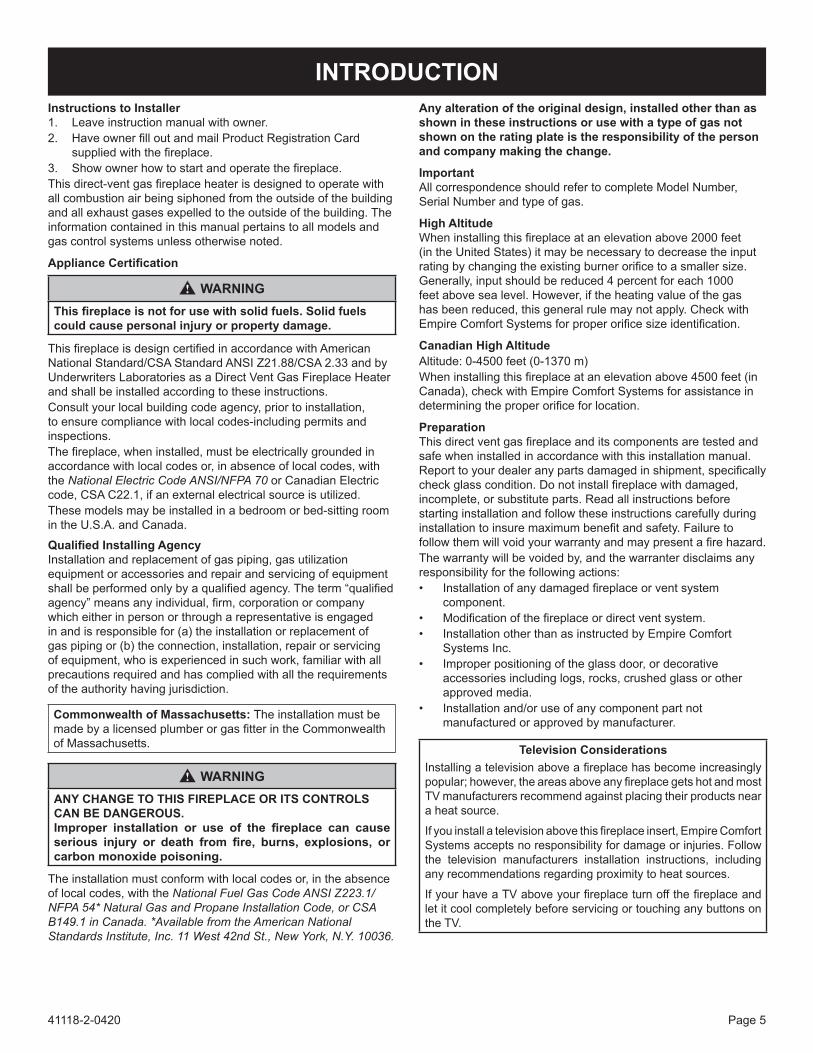
Instructions to Installer1. Leave instruction manual with owner.2. HaveownerfilloutandmailProductRegistrationCard
suppliedwiththefireplace.3. Showownerhowtostartandoperatethefireplace.Thisdirect-ventgasfireplaceheaterisdesignedtooperatewithall combustion air being siphoned from the outside of the building andallexhaustgasesexpelledtotheoutsideofthebuilding.Theinformation contained in this manual pertains to all models and gas control systems unless otherwise noted.
Appliance Certification
WARNINGThis fireplace is not for use with solid fuels. Solid fuels could cause personal injury or property damage.
ThisfireplaceisdesigncertifiedinaccordancewithAmericanNationalStandard/CSAStandardANSIZ21.88/CSA2.33andbyUnderwritersLaboratoriesasaDirectVentGasFireplaceHeaterand shall be installed according to these instructions.Consult your local building code agency, prior to installation, to ensure compliance with local codes-including permits and inspections.Thefireplace,wheninstalled,mustbeelectricallygroundedinaccordance with local codes or, in absence of local codes, with the National Electric Code ANSI/NFPA 70 or Canadian Electric code,CSAC22.1,ifanexternalelectricalsourceisutilized.Thesemodelsmaybeinstalledinabedroomorbed-sittingroomintheU.S.A.andCanada.
Qualified Installing AgencyInstallation and replacement of gas piping, gas utilization equipment or accessories and repair and servicing of equipment shallbeperformedonlybyaqualifiedagency.Theterm“qualifiedagency”meansanyindividual,firm,corporationorcompanywhich either in person or through a representative is engaged in and is responsible for (a) the installation or replacement of gas piping or (b) the connection, installation, repair or servicing of equipment, who is experienced in such work, familiar with all precautions required and has complied with all the requirements of the authority having jurisdiction.
Commonwealth of Massachusetts: TheinstallationmustbemadebyalicensedplumberorgasfitterintheCommonwealthof Massachusetts.
WARNINGANY CHANGE TO THIS FIREPLACE OR ITS CONTROLS CAN BE DANGEROUS.Improper installation or use of the fireplace can cause serious injury or death from fire, burns, explosions, or carbon monoxide poisoning.
Theinstallationmustconformwithlocalcodesor,intheabsenceof local codes, with the National Fuel Gas Code ANSI Z223.1/NFPA 54* Natural Gas and Propane Installation Code, or CSA B149.1 in Canada. *Available from the American National Standards Institute, Inc. 11 West 42nd St., New York, N.Y. 10036.
Any alteration of the original design, installed other than as shown in these instructions or use with a type of gas not shown on the rating plate is the responsibility of the person and company making the change.
ImportantAllcorrespondenceshouldrefertocompleteModelNumber,SerialNumberandtypeofgas.
High Altitude Wheninstallingthisfireplaceatanelevationabove2000feet(intheUnitedStates)itmaybenecessarytodecreasetheinputratingbychangingtheexistingburnerorificetoasmallersize.Generally, input should be reduced 4 percent for each 1000 feet above sea level. However, if the heating value of the gas has been reduced, this general rule may not apply. Check with EmpireComfortSystemsforproperorificesizeidentification.
Canadian High Altitude Altitude: 0-4500 feet (0-1370 m)Wheninstallingthisfireplaceatanelevationabove4500feet(inCanada),checkwithEmpireComfortSystemsforassistanceindeterminingtheproperorificeforlocation.
PreparationThisdirectventgasfireplaceanditscomponentsaretestedandsafe when installed in accordance with this installation manual. Reporttoyourdealeranypartsdamagedinshipment,specificallycheckglasscondition.Donotinstallfireplacewithdamaged,incomplete, or substitute parts. Read all instructions before starting installation and follow these instructions carefully during installationtoinsuremaximumbenefitandsafety.Failuretofollowthemwillvoidyourwarrantyandmaypresentafirehazard.Thewarrantywillbevoidedby,andthewarranterdisclaimsanyresponsibility for the following actions:• Installationofanydamagedfireplaceorventsystem
component.• Modificationofthefireplaceordirectventsystem.• Installation other than as instructed by Empire Comfort
SystemsInc.• Improper positioning of the glass door, or decorative
accessories including logs, rocks, crushed glass or other approved media.
• Installation and/or use of any component part not manufactured or approved by manufacturer.
Television ConsiderationsInstallingatelevisionaboveafireplacehasbecomeincreasinglypopular;however,theareasaboveanyfireplacegetshotandmostTVmanufacturersrecommendagainstplacingtheirproductsneara heat source.
Ifyouinstallatelevisionabovethisfireplaceinsert,EmpireComfortSystemsacceptsnoresponsibilityfordamageorinjuries.Followthe television manufacturers installation instructions, including any recommendations regarding proximity to heat sources.
IfyourhaveaTVaboveyourfireplaceturnoffthefireplaceandlet it cool completely before servicing or touching any buttons on theTV.
INTRODUCTION
41118-2-0420Page 6
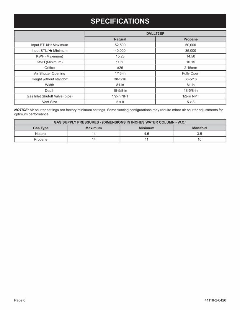
SPECIFICATIONSDVLL72BP
Natural PropaneInputBTU/HrMaximum 52,500 50,000InputBTU/HrMinimum 40,000 35,000
KWH (Maximum) 15.23 14.50KWH (Minimum) 11.60 10.15
Orifice #26 2.15mmAirShutterOpening 1/16-in Fully Open
Height without standoff 38-5/16 38-5/16Width 81-in 81-inDepth 18-5/8-in 18-5/8-in
GasInletShutoffValve(pipe) 1/2-inNPT 1/2-inNPTVentSize 5 x 8 5 x 8
NOTICE: Airshuttersettingsarefactoryminimumsettings.Someventingconfigurationsmayrequireminorairshutteradjustmentsforoptimum performance.
GAS SUPPLY PRESSURES - (DIMENSIONS IN INCHES WATER COLUMN - W.C.)Gas Type Maximum Minimum ManifoldNatural 14 4.5 3.5
Propane 14 11 10
41118-2-0420 Page 7
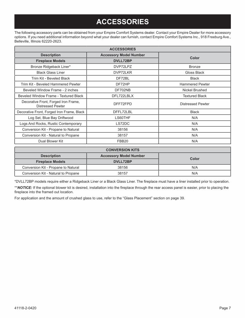
ThefollowingaccessorypartscanbeobtainedfromyourEmpireComfortSystemsdealer.ContactyourEmpireDealerformoreaccessoryoptions.Ifyouneedadditionalinformationbeyondwhatyourdealercanfurnish,contactEmpireComfortSystemsInc.,918FreeburgAve.,Belleville, Illinois 62220-2623.
ACCESSORIESDescription Accessory Model Number
ColorFireplace Models DVLL72BP
BronzeRidgebackLiner* DVP72LPZ BronzeBlack Glass Liner DVP72LKR Gloss Black
TrimKit-BeveledBlack DF72BL BlackTrimKit-BeveledHammeredPewter DF72HP Hammered Pewter
Beveled Window Frame - 2 inches DF702NB NickelBrushedBeveledWindowFrame-TexturedBlack DFL722LBLX TexturedBlack
Decorative Front, Forged Iron Frame, Distressed Pewter DFF72FPD Distressed Pewter
Decorative Front, Forged Iron Frame, Black DFFL72LBL BlackLogSet,BlueBayDriftwood LS60THF N/A
Logs And Rocks, Rustic Contemporary LS72DC N/AConversionKit-PropanetoNatural 38156 N/AConversionKit-NaturaltoPropane 38157 N/A
Dual Blower Kit FBB20 N/A
CONVERSION KITSDescription Accessory Model Number
ColorFireplace Models DVLL72BP
ConversionKit-PropanetoNatural 38156 N/AConversionKit-NaturaltoPropane 38157 N/A
*DVLL72BPmodelsrequireeitheraRidgebackLineroraBlackGlassLiner.Thefireplacemusthavealinerinstalledpriortooperation.
**NOTICE:Iftheoptionalblowerkitisdesired,installationintothefireplacethroughtherearaccesspaneliseasier,priortoplacingthefireplaceintotheframedoutlocation.
Forapplicationandtheamountofcrushedglasstouse,refertothe“GlassPlacement”sectiononpage39.
ACCESSORIES
41118-2-0420Page 8
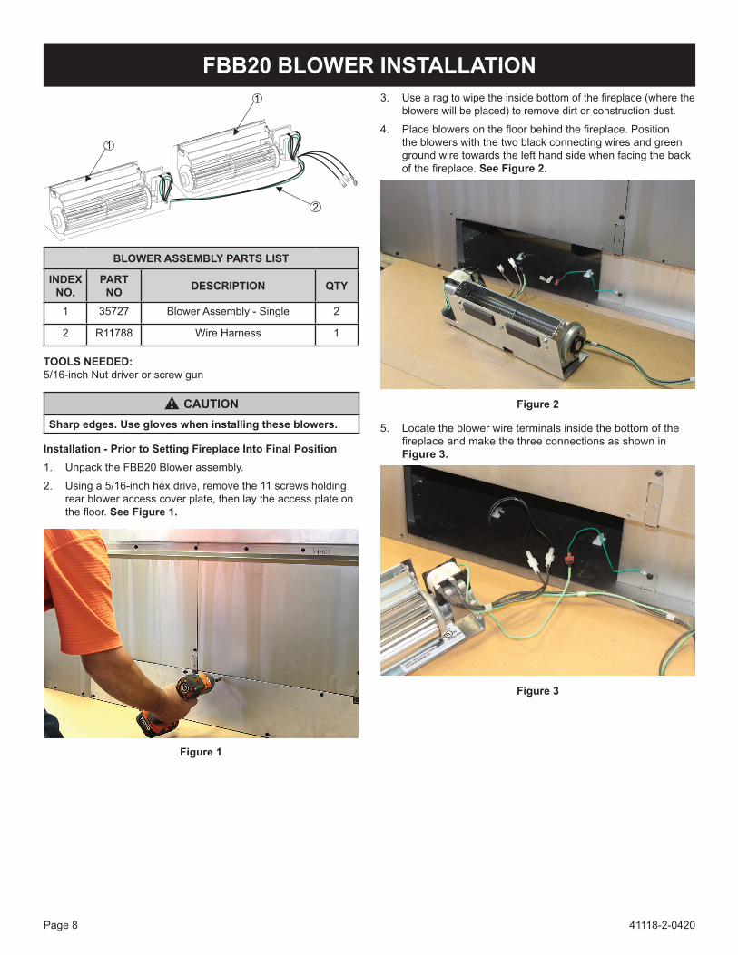
FBB20 BLOWER INSTALLATION
1
1
2
BLOWER ASSEMBLY PARTS LIST
INDEX NO.
PART NO DESCRIPTION QTY
1 35727 BlowerAssembly-Single 2
2 R11788 Wire Harness 1
TOOLS NEEDED:5/16-inchNutdriverorscrewgun
CAUTIONSharp edges. Use gloves when installing these blowers.
Installation - Prior to Setting Fireplace Into Final Position1. UnpacktheFBB20Blowerassembly.
2. Usinga5/16-inchhexdrive,removethe11screwsholdingrear blower access cover plate, then lay the access plate on thefloor.See Figure 1.
Figure 1
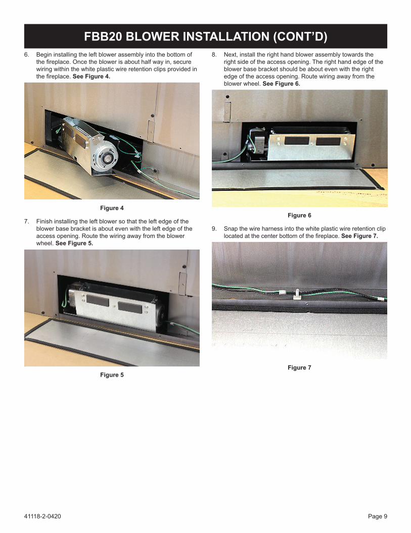
3. Usearagtowipetheinsidebottomofthefireplace(wheretheblowers will be placed) to remove dirt or construction dust.
4. Placeblowersonthefloorbehindthefireplace.Positionthe blowers with the two black connecting wires and green ground wire towards the left hand side when facing the back ofthefireplace.See Figure 2.
Figure 2
5. Locate the blower wire terminals inside the bottom of the fireplaceandmakethethreeconnectionsasshowninFigure 3.
Figure 3
41118-2-0420 Page 9
FBB20 BLOWER INSTALLATION (CONT’D)6. Begin installing the left blower assembly into the bottom of
thefireplace.Oncetheblowerisabouthalfwayin,securewiring within the white plastic wire retention clips provided in thefireplace.See Figure 4.
Figure 4
7. Finish installing the left blower so that the left edge of the blower base bracket is about even with the left edge of the access opening. Route the wiring away from the blower wheel. See Figure 5.
Figure 5
8. Next,installtherighthandblowerassemblytowardstherightsideoftheaccessopening.Therighthandedgeoftheblower base bracket should be about even with the right edge of the access opening. Route wiring away from the blower wheel. See Figure 6.
Figure 6
9. Snapthewireharnessintothewhiteplasticwireretentioncliplocatedatthecenterbottomofthefireplace.See Figure 7.
Figure 7
41118-2-0420Page 10
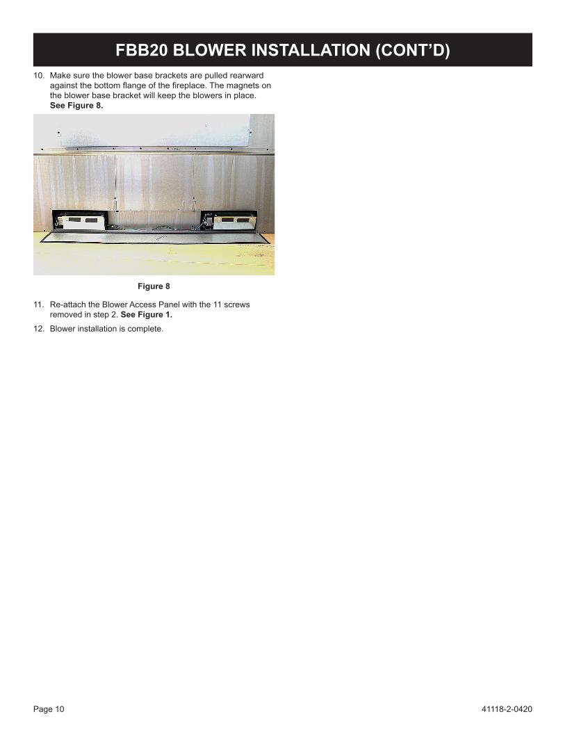
FBB20 BLOWER INSTALLATION (CONT’D)10. Make sure the blower base brackets are pulled rearward
againstthebottomflangeofthefireplace.Themagnetsonthe blower base bracket will keep the blowers in place.
See Figure 8.
Figure 8
11. Re-attach the Blower Access Panel with the 11 screws removed in step 2. See Figure 1.
12. Blower installation is complete.
41118-2-0420 Page 11
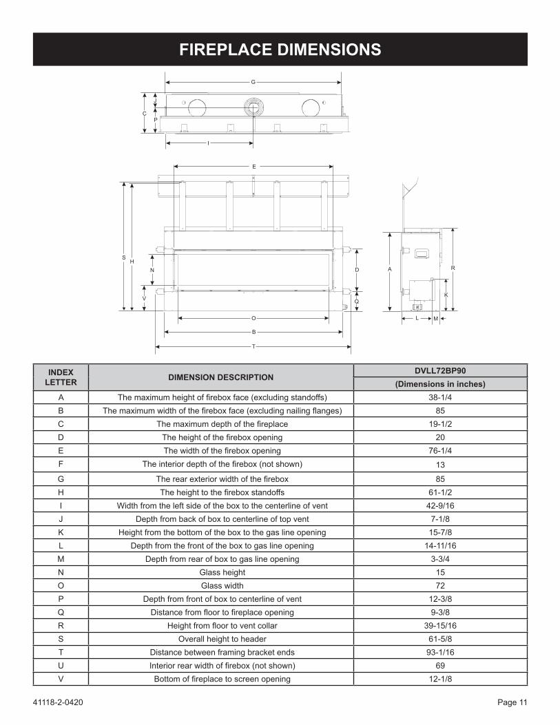
FIREPLACE DIMENSIONS
INDEX LETTER DIMENSION DESCRIPTION
DVLL72BP90(Dimensions in inches)
A Themaximumheightoffireboxface(excludingstandoffs) 38-1/4B Themaximumwidthofthefireboxface(excludingnailingflanges) 85C Themaximumdepthofthefireplace 19-1/2D Theheightofthefireboxopening 20E Thewidthofthefireboxopening 76-1/4F Theinteriordepthofthefirebox(notshown) 13
G Therearexteriorwidthofthefirebox 85H Theheighttothefireboxstandoffs 61-1/2I Width from the left side of the box to the centerline of vent 42-9/16J Depth from back of box to centerline of top vent 7-1/8K Height from the bottom of the box to the gas line opening 15-7/8L Depth from the front of the box to gas line opening 14-11/16M Depth from rear of box to gas line opening 3-3/4N Glass height 15O Glass width 72P Depth from front of box to centerline of vent 12-3/8Q Distancefromfloortofireplaceopening 9-3/8R Heightfromfloortoventcollar 39-15/16S Overall height to header 61-5/8T Distance between framing bracket ends 93-1/16U Interiorrearwidthoffirebox(notshown) 69V Bottomoffireplacetoscreenopening 12-1/8
J
C
P
G
I
E
HS
V
N
T
B
O
Q
D A
L M
K
R
41118-2-0420Page 12
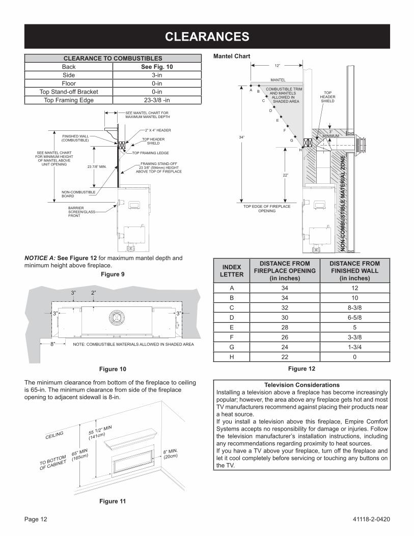
CLEARANCESCLEARANCE TO COMBUSTIBLESBack See Fig. 10Side 3-in Floor 0-in
TopStand-offBracket 0-in TopFramingEdge 23-3/8 -in
SEE MANTEL CHART FORMAXIMUM MANTEL DEPTH
23 7/8” MIN.
2” X 4” HEADER
FRAMING STAND-OFF23 3/8” (594mm) HEIGHT
ABOVE TOP OF FIREPLACE
FINISHED WALL(COMBUSTIBLE)
NON-COMBUSTIBLEBOARD
TOP FRAMING LEDGESEE MANTEL CHARTFOR MINIMUM HEIGHT
OF MANTEL ABOVEUNIT OPENING
BARRIERSCREEN/GLASSFRONT
TOP HEADERSHIELD
NOTICE A: See Figure 12 for maximum mantel depth and minimumheightabovefireplace.
Figure 9
8”
3”
3” 2”
NOTE: COMBUSTIBLE MATERIALS ALLOWED IN SHADED AREA
3”
Figure 10
Theminimumclearancefrombottomofthefireplacetoceilingis 65-in.Theminimumclearancefromsideofthefireplaceopening to adjacent sidewall is 8-in.
8” MIN.
(20cm)
TO BOTTOM
OF CABINET
CEILING 55 1/2” MIN
(141cm)
65” MIN
(165cm)
Figure 11
Mantel Chart
TOP EDGE OF
FIREPLACE OPENING
H
22”
34”
12”
A
3”
MINIMUM
NO
N-C
OM
BU
ST
IBL
E M
AT
ER
IAL
ZO
NE
TOP
HEADER
SHIELD
INDEX LETTER
DISTANCE FROM FIREPLACE OPENING
(in inches)
DISTANCE FROM FINISHED WALL
(in inches)A 34 12B 34 10C 32 8-3/8D 30 6-5/8E 28 5F 26 3-3/8G 24 1-3/4H 22 0
Figure 12
Television ConsiderationsInstallingatelevisionaboveafireplacehasbecomeincreasinglypopular;however,theareaaboveanyfireplacegetshotandmostTVmanufacturersrecommendagainstplacingtheirproductsneara heat source.If you install a television above this fireplace, Empire ComfortSystemsacceptsnoresponsibilityfordamageorinjuries.Followthe television manufacturer’s installation instructions, includingany recommendations regarding proximity to heat sources.IfyouhaveaTVaboveyourfireplace,turnoffthefireplaceandlet it cool completely before servicing or touching any buttons on theTV.
TOPEDGEOFFIREPLACEOPENING
41118-2-0420 Page 13
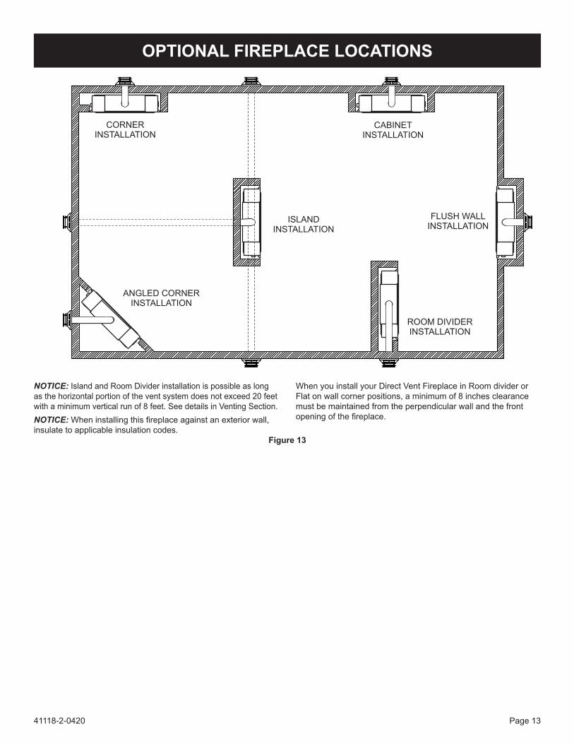
NOTICE: Island and Room Divider installation is possible as long as the horizontal portion of the vent system does not exceed 20 feet withaminimumverticalrunof8feet.SeedetailsinVentingSection.NOTICE:Wheninstallingthisfireplaceagainstanexteriorwall,insulate to applicable insulation codes.
When you install your Direct Vent Fireplace in Room divider or Flat on wall corner positions, a minimum of 8 inches clearance must be maintained from the perpendicular wall and the front openingofthefireplace.
OPTIONAL FIREPLACE LOCATIONS
ROOM DIVIDER
INSTALLATION
FLUSH WALL
INSTALLATIONISLAND
INSTALLATION
CABINET
INSTALLATION
CORNER
INSTALLATION
ANGLED CORNER
INSTALLATION
Figure 13
41118-2-0420Page 14
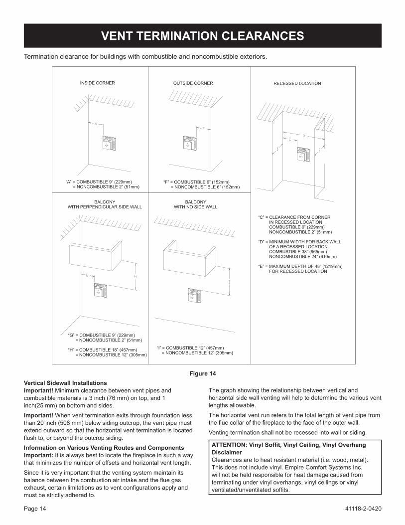
Terminationclearanceforbuildingswithcombustibleandnoncombustibleexteriors.
Vertical Sidewall InstallationsImportant! Minimum clearance between vent pipes and combustible materials is 3 inch (76 mm) on top, and 1 inch(25 mm) on bottom and sides.Important! When vent termination exits through foundation less than 20 inch (508 mm) below siding outcrop, the vent pipe must extend outward so that the horizontal vent termination is located flushto,orbeyondtheoutcropsiding.Information on Various Venting Routes and ComponentsImportant:Itisalwaysbesttolocatethefireplaceinsuchawaythat minimizes the number of offsets and horizontal vent length.Sinceitisveryimportantthattheventingsystemmaintainitsbalancebetweenthecombustionairintakeandthefluegasexhaust,certainlimitationsastoventconfigurationsapplyandmust be strictly adhered to.
Figure 14
VENT TERMINATION CLEARANCES
Thegraphshowingtherelationshipbetweenverticalandhorizontal side wall venting will help to determine the various vent lengths allowable.Thehorizontalventrunreferstothetotallengthofventpipefromthefluecollarofthefireplacetothefaceoftheouterwall.Venting termination shall not be recessed into wall or siding.
ATTENTION: Vinyl Soffit, Vinyl Ceiling, Vinyl Overhang DisclaimerClearances are to heat resistant material (i.e. wood, metal). Thisdoesnotincludevinyl.EmpireComfortSystemsInc.will not be held responsible for heat damage caused from terminating under vinyl overhangs, vinyl ceilings or vinyl ventilated/unventilatedsoffits.
RECESSED LOCATIONOUTSIDE CORNERINSIDE CORNER
“A” = COMBUSTIBLE 9” (229mm)= NONCOMBUSTIBLE 2” (51mm)
“F” = COMBUSTIBLE 6” (152mm)= NONCOMBUSTIBLE 6” (152mm)
BALCONYWITH PERPENDICULAR SIDE WALL
BALCONYWITH NO SIDE WALL
“C” = CLEARANCE FROM CORNERIN RECESSED LOCATIONCOMBUSTIBLE 9” (229mm)NONCOMBUSTIBLE 2” (51mm)
“D” = MINIMUM WIDTH FOR BACK WALLOF A RECESSED LOCATIONCOMBUSTIBLE 38” (965mm)NONCOMBUSTIBLE 24” (610mm)
“E” = MAXIMUM DEPTH OF 48” (1219mm)FOR RECESSED LOCATION
“G” = COMBUSTIBLE 9” (229mm)= NONCOMBUSTIBLE 2” (51mm)
“H” = COMBUSTIBLE 18” (457mm)= NONCOMBUSTIBLE 12” (305mm)
“I” = COMBUSTIBLE 12” (457mm)= NONCOMBUSTIBLE 12” (305mm)
41118-2-0420 Page 15
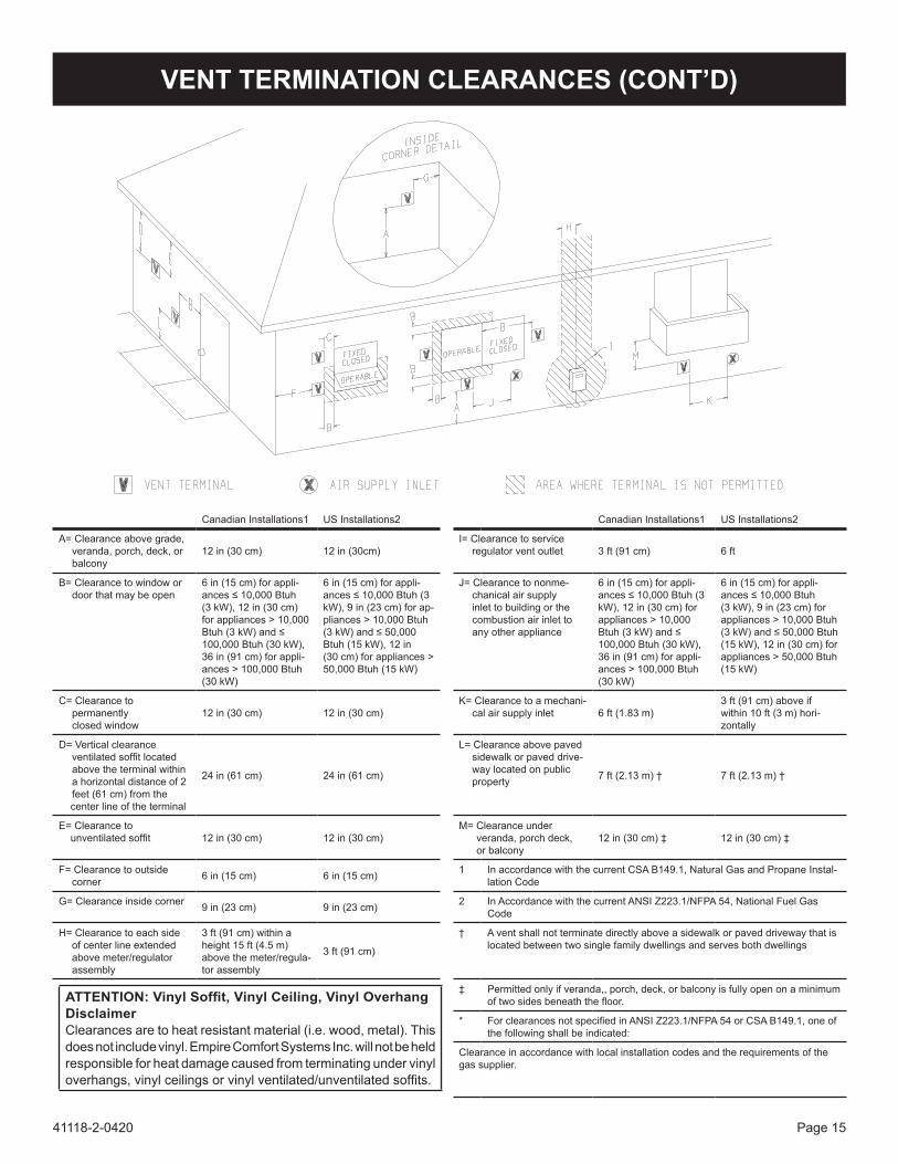
VENT TERMINATION CLEARANCES (CONT’D)
Canadian Installations1 USInstallations2 Canadian Installations1 USInstallations2
A= Clearance above grade, veranda, porch, deck, or balcony
12 in (30 cm) 12 in (30cm)I= Clearance to service
regulator vent outlet 3 ft (91 cm) 6 ft
B= Clearance to window or door that may be open
6 in (15 cm) for appli-ances≤10,000Btuh (3 kW), 12 in (30 cm) for appliances > 10,000 Btuh(3kW)and≤100,000 Btuh (30 kW), 36 in (91 cm) for appli-ances > 100,000 Btuh (30 kW)
6 in (15 cm) for appli-ances≤10,000Btuh(3kW), 9 in (23 cm) for ap-pliances > 10,000 Btuh (3kW)and≤50,000Btuh (15 kW), 12 in (30 cm) for appliances > 50,000 Btuh (15 kW)
J= Clearance to nonme-chanical air supply inlet to building or the combustion air inlet to any other appliance
6 in (15 cm) for appli-ances≤10,000Btuh(3kW), 12 in (30 cm) for appliances > 10,000 Btuh(3kW)and≤100,000 Btuh (30 kW), 36 in (91 cm) for appli-ances > 100,000 Btuh (30 kW)
6 in (15 cm) for appli-ances≤10,000Btuh(3 kW), 9 in (23 cm) for appliances > 10,000 Btuh (3kW)and≤50,000Btuh(15 kW), 12 in (30 cm) for appliances > 50,000 Btuh (15 kW)
C= Clearance to permanently closed window
12 in (30 cm) 12 in (30 cm)K= Clearance to a mechani-
cal air supply inlet 6 ft (1.83 m)3 ft (91 cm) above if within 10 ft (3 m) hori-zontally
D= Vertical clearance ventilatedsoffitlocatedabove the terminal within a horizontal distance of 2 feet (61 cm) from the center line of the terminal
24 in (61 cm) 24 in (61 cm)
L= Clearance above paved sidewalk or paved drive-way located on public property 7 ft (2.13 m) † 7 ft (2.13 m) †
E= Clearance to unventilatedsoffit 12 in (30 cm) 12 in (30 cm)
M= Clearance under veranda, porch deck, or balcony
12 in (30 cm) ‡ 12 in (30 cm) ‡
F= Clearance to outside corner 6 in (15 cm) 6 in (15 cm) 1 InaccordancewiththecurrentCSAB149.1,NaturalGasandPropaneInstal-
lation Code
G= Clearance inside corner 9 in (23 cm) 9 in (23 cm) 2 InAccordancewiththecurrentANSIZ223.1/NFPA54,NationalFuelGasCode
H= Clearance to each side of center line extended above meter/regulator assembly
3 ft (91 cm) within a height 15 ft (4.5 m) above the meter/regula-tor assembly
3 ft (91 cm)
† A vent shall not terminate directly above a sidewalk or paved driveway that is located between two single family dwellings and serves both dwellings
ATTENTION: Vinyl Soffit, Vinyl Ceiling, Vinyl Overhang DisclaimerClearancesaretoheatresistantmaterial(i.e.wood,metal).Thisdoesnotincludevinyl.EmpireComfortSystemsInc.willnotbeheldresponsible for heat damage caused from terminating under vinyl overhangs,vinylceilingsorvinylventilated/unventilatedsoffits.
‡ Permitted only if veranda,, porch, deck, or balcony is fully open on a minimum oftwosidesbeneaththefloor.
* ForclearancesnotspecifiedinANSIZ223.1/NFPA54orCSAB149.1,oneofthe following shall be indicated:
Clearance in accordance with local installation codes and the requirements of the gas supplier.
41118-2-0420Page 16
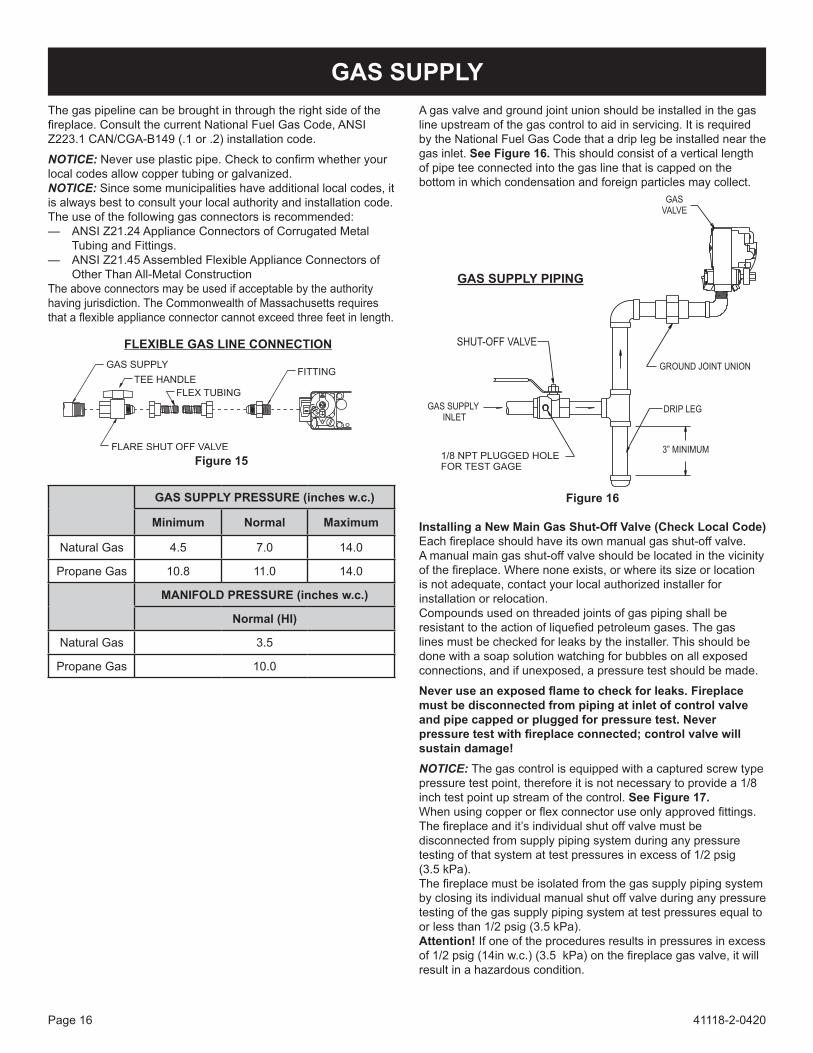
GAS SUPPLYThegaspipelinecanbebroughtinthroughtherightsideofthefireplace.ConsultthecurrentNationalFuelGasCode,ANSIZ223.1CAN/CGA-B149(.1or.2)installationcode.
NOTICE:Neveruseplasticpipe.Checktoconfirmwhetheryourlocal codes allow copper tubing or galvanized.NOTICE: Sincesomemunicipalitieshaveadditionallocalcodes,itis always best to consult your local authority and installation code.Theuseofthefollowinggasconnectorsisrecommended:— ANSIZ21.24ApplianceConnectorsofCorrugatedMetal
TubingandFittings.— ANSIZ21.45AssembledFlexibleApplianceConnectorsof
OtherThanAll-MetalConstructionTheaboveconnectorsmaybeusedifacceptablebytheauthorityhavingjurisdiction.TheCommonwealthofMassachusettsrequiresthataflexibleapplianceconnectorcannotexceedthreefeetinlength.
Figure 15
GAS SUPPLY PRESSURE (inches w.c.)
Minimum Normal Maximum
NaturalGas 4.5 7.0 14.0
Propane Gas 10.8 11.0 14.0
MANIFOLD PRESSURE (inches w.c.)
Normal (HI)
NaturalGas 3.5
Propane Gas 10.0
A gas valve and ground joint union should be installed in the gas line upstream of the gas control to aid in servicing. It is required bytheNationalFuelGasCodethatadriplegbeinstallednearthegas inlet. See Figure 16. Thisshouldconsistofaverticallengthof pipe tee connected into the gas line that is capped on the bottom in which condensation and foreign particles may collect.
Figure 16
Installing a New Main Gas Shut-Off Valve (Check Local Code)Eachfireplaceshouldhaveitsownmanualgasshut-offvalve.A manual main gas shut-off valve should be located in the vicinity ofthefireplace.Wherenoneexists,orwhereitssizeorlocationis not adequate, contact your local authorized installer for installation or relocation.Compounds used on threaded joints of gas piping shall be resistanttotheactionofliquefiedpetroleumgases.Thegaslinesmustbecheckedforleaksbytheinstaller.Thisshouldbedone with a soap solution watching for bubbles on all exposed connections, and if unexposed, a pressure test should be made.
Never use an exposed flame to check for leaks. Fireplace must be disconnected from piping at inlet of control valve and pipe capped or plugged for pressure test. Never pressure test with fireplace connected; control valve will sustain damage!NOTICE: Thegascontrolisequippedwithacapturedscrewtypepressure test point, therefore it is not necessary to provide a 1/8 inch test point up stream of the control. See Figure 17.Whenusingcopperorflexconnectoruseonlyapprovedfittings. Thefireplaceandit’sindividualshutoffvalvemustbedisconnected from supply piping system during any pressure testing of that system at test pressures in excess of 1/2 psig (3.5 kPa).Thefireplacemustbeisolatedfromthegassupplypipingsystemby closing its individual manual shut off valve during any pressure testing of the gas supply piping system at test pressures equal to or less than 1/2 psig (3.5 kPa).Attention! If one of the procedures results in pressures in excess of1/2psig(14inw.c.)(3.5kPa)onthefireplacegasvalve,itwillresult in a hazardous condition.
GAS SUPPLY PIPING
41118-2-0420 Page 17
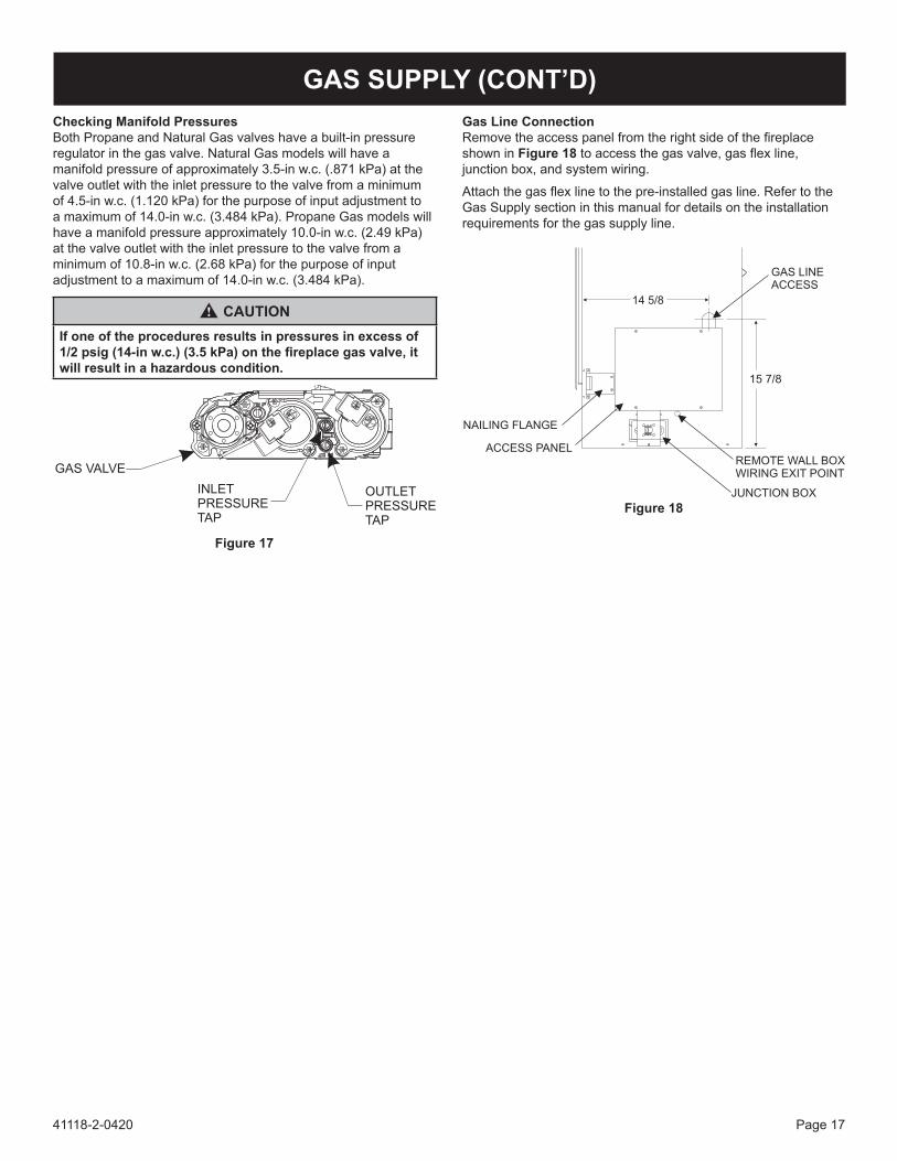
GAS SUPPLY (CONT’D)Checking Manifold PressuresBothPropaneandNaturalGasvalveshaveabuilt-inpressureregulatorinthegasvalve.NaturalGasmodelswillhaveamanifold pressure of approximately 3.5-in w.c. (.871 kPa) at the valve outlet with the inlet pressure to the valve from a minimum of 4.5-in w.c. (1.120 kPa) for the purpose of input adjustment to a maximum of 14.0-in w.c. (3.484 kPa). Propane Gas models will have a manifold pressure approximately 10.0-in w.c. (2.49 kPa) at the valve outlet with the inlet pressure to the valve from a minimum of 10.8-in w.c. (2.68 kPa) for the purpose of input adjustment to a maximum of 14.0-in w.c. (3.484 kPa).
CAUTIONIf one of the procedures results in pressures in excess of 1/2 psig (14-in w.c.) (3.5 kPa) on the fireplace gas valve, it will result in a hazardous condition.
GAS VALVE
OUTLET
PRESSURE
TAP
INLET
PRESSURE
TAP
Figure 17
Gas Line ConnectionRemovetheaccesspanelfromtherightsideofthefireplaceshown in Figure 18toaccessthegasvalve,gasflexline,junction box, and system wiring.
Attachthegasflexlinetothepre-installedgasline.RefertotheGasSupplysectioninthismanualfordetailsontheinstallationrequirements for the gas supply line.
15 7/8
14 5/8
ACCESS PANEL
NAILING FLANGE
JUNCTION BOX
REMOTE WALL BOX
WIRING EXIT POINT
GAS LINE
ACCESS
Figure 18
41118-2-0420Page 18
ELECTRICAL CONNECTIONS
CAUTIONAll wiring should be done by a qualified electrician and shall be in compliance with all local, city and state building codes. Before making the electrical connection, make sure that the main power supply is disconnected. The fireplace, when installed, must be electrically grounded in accordance with local codes, or in the absence of local codes, with the National Electrical Code ANSI/NFPA 70 (Latest Edition).
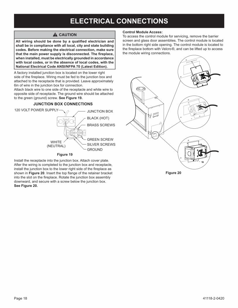
A factory installed junction box is located on the lower right sideofthefireplace.Wiringmustbefedtothejunctionboxandattached to the receptacle that is provided. Leave approximately 6in of wire in the junction box for connection.Attach black wire to one side of the receptacle and white wire to oppositesideofreceptacle.Thegroundwireshouldbeattachedto the green (ground) screw. See Figure 19.
BLACK (HOT)
BRASS SCREWS
JUNCTION BOX
GROUND
SILVER SCREWS
GREEN SCREWWHITE
(NEUTRAL)
120 VOLT POWER SUPPLY
Figure 19Install the receptacle into the junction box. Attach cover plate.After the wiring is completed to the junction box and receptacle, installthejunctionboxtothelowerrightsideofthefireplaceasshown in Figure 20.Insertthetopflangeoftheretainerbracketintotheslotonthefireplace.Rotatethejunctionboxassemblydownward, and secure with a screw below the junction box. See Figure 20.
Control Module Access:Toaccessthecontrolmoduleforservicing,removethebarrierscreenandglassdoorassemblies.Thecontrolmoduleislocatedinthebottomrightsideopening.ThecontrolmoduleislocatedtothefireplacebottomwithVelcro®,andcanbelifteduptoaccessthe module wiring connections.
Figure 20
JUNCTION BOX CONNECTIONS
41118-2-0420 Page 19
Once the Junction box has been installed with the receptacle outletsfacinginwardtowardsthefireplace,locatethe3-prongpower cord from the control module and plug into the receptical.
In addition, locate the 3-prong power cord from the LED Light Transformerandplugintothejunctionboxreceptacle.ThefireplaceissuppliedwithaUserInterfacewallboxthatmustbeinstalled in a standard plastic outlet box (not provided). A low voltageorangeorblueboxisrecommended.Theuserinterfacewall box must be placed in the wall within ten feet from the right sideofthefireplace.10-feetbatteryanduserinterfaceextensionwire harnesses are supplied. See Figures 21- a,b,c.Install the wall-mounted control box within 8 feet to the right side or 2 feet from the left. See Figure 21a.
WALL MOUNT
CONTROL BOX
6” MIN
10’ MAX WIRE
EXTENSION LENGTH
Figure 21aRoute the yellow LED wire harness with a gray remote receiver harness through the bushing. Mount the controls and connect the wiring. See Figure 21b.
REMOTE
SWITCH
COVER PLATE
YEL/BLUE
GRAY EXTENSION
WIRE
YELLOW EXTENSION
WIRE
RED/GREEN
TO FIREPLACE
CONTROL HARNESS
TO FIREPLACE
LED CONTROLS
LED SWITCH
ON/OFF
LED SWITCH
COLOR MODE
ZIP TIE
Figure 21b
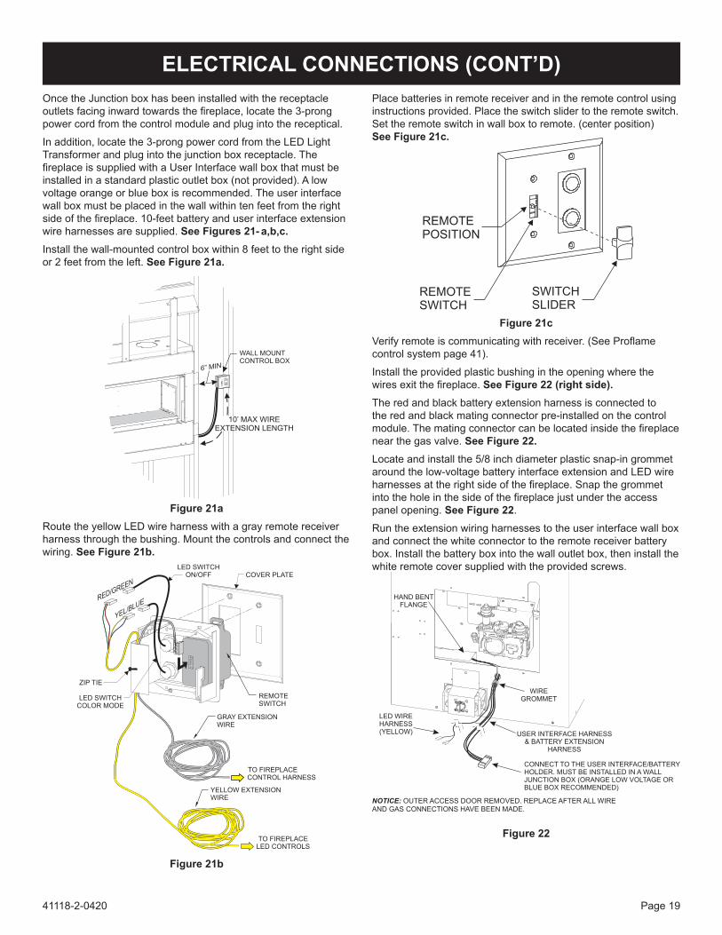
ELECTRICAL CONNECTIONS (CONT’D)Place batteries in remote receiver and in the remote control using instructions provided. Place the switch slider to the remote switch.Settheremoteswitchinwallboxtoremote.(centerposition)See Figure 21c.
REMOTE
POSITION
REMOTE
SWITCH
SWITCH
SLIDER
Figure 21cVerifyremoteiscommunicatingwithreceiver.(SeeProflamecontrol system page 41).
Install the provided plastic bushing in the opening where the wiresexitthefireplace.See Figure 22 (right side).Theredandblackbatteryextensionharnessisconnectedtothe red and black mating connector pre-installed on the control module.Thematingconnectorcanbelocatedinsidethefireplacenear the gas valve. See Figure 22.Locate and install the 5/8 inch diameter plastic snap-in grommet around the low-voltage battery interface extension and LED wire harnessesattherightsideofthefireplace.Snapthegrommetintotheholeinthesideofthefireplacejustundertheaccesspanel opening. See Figure 22.
Run the extension wiring harnesses to the user interface wall box and connect the white connector to the remote receiver battery box. Install the battery box into the wall outlet box, then install the white remote cover supplied with the provided screws.
HAND BENTFLANGE
WIREGROMMET
USER INTERFACE HARNESS& BATTERY EXTENSION
HARNESS
CONNECT TO THE USER INTERFACE/BATTERYHOLDER. MUST BE INSTALLED IN A WALLJUNCTION BOX (ORANGE LOW VOLTAGE ORBLUE BOX RECOMMENDED)
NOTE: OUTER ACCESS DOOR REMOVED. REPLACE AFTER ALLWIRE AND GAS CONNECTIONS HAVE BEEN MADE
LED WIREHARNESS(YELLOW)
NOTICE: OUTERACCESSDOORREMOVED.REPLACEAFTERALLWIREANDGASCONNECTIONSHAVEBEENMADE.
Figure 22
41118-2-0420Page 20
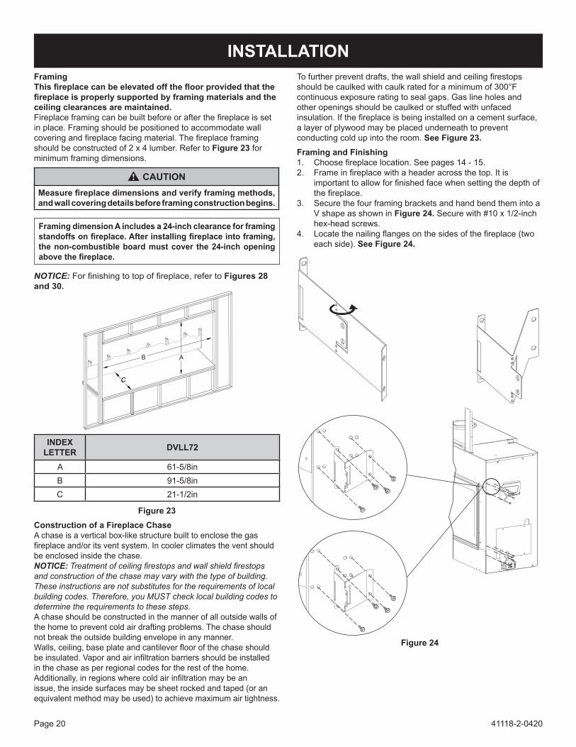
INSTALLATIONFramingThis fireplace can be elevated off the floor provided that the fireplace is properly supported by framing materials and the ceiling clearances are maintained.Fireplaceframingcanbebuiltbeforeorafterthefireplaceissetin place. Framing should be positioned to accommodate wall coveringandfireplacefacingmaterial.Thefireplaceframingshould be constructed of 2 x 4 lumber. Refer to Figure 23 for minimum framing dimensions.
CAUTIONMeasure fireplace dimensions and verify framing methods, and wall covering details before framing construction begins.
Framing dimension A includes a 24-inch clearance for framing standoffs on fireplace. After installing fireplace into framing, the non-combustible board must cover the 24-inch opening above the fireplace.
NOTICE:Forfinishingtotopoffireplace,refertoFigures 28 and 30.
B
C
A
C
INDEX LETTER DVLL72
A 61-5/8inB 91-5/8inC 21-1/2in
Figure 23Construction of a Fireplace ChaseA chase is a vertical box-like structure built to enclose the gas fireplaceand/oritsventsystem.Incoolerclimatestheventshouldbe enclosed inside the chase. NOTICE: Treatment of ceiling firestops and wall shield firestops and construction of the chase may vary with the type of building. These instructions are not substitutes for the requirements of local building codes. Therefore, you MUST check local building codes to determine the requirements to these steps.A chase should be constructed in the manner of all outside walls of thehometopreventcoldairdraftingproblems.Thechaseshouldnot break the outside building envelope in any manner. Walls,ceiling,baseplateandcantileverfloorofthechaseshouldbeinsulated.Vaporandairinfiltrationbarriersshouldbeinstalledin the chase as per regional codes for the rest of the home. Additionally,inregionswherecoldairinfiltrationmaybeanissue, the inside surfaces may be sheet rocked and taped (or an equivalent method may be used) to achieve maximum air tightness.
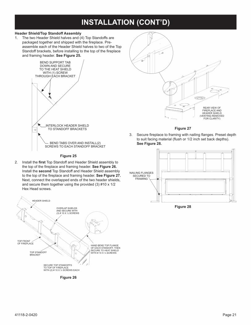
Tofurtherpreventdrafts,thewallshieldandceilingfirestopsshould be caulked with caulk rated for a minimum of 300°F continuous exposure rating to seal gaps. Gas line holes and other openings should be caulked or stuffed with unfaced insulation.Ifthefireplaceisbeinginstalledonacementsurface,a layer of plywood may be placed underneath to prevent conducting cold up into the room. See Figure 23.Framing and Finishing 1. Choosefireplacelocation.Seepages14-15.2. Frameinfireplacewithaheaderacrossthetop.Itis
importanttoallowforfinishedfacewhensettingthedepthofthefireplace.
3. SecurethefourframingbracketsandhandbendthemintoaV shape as shown in Figure 24.Securewith#10x1/2-inchhex-head screws.
4. Locatethenailingflangesonthesidesofthefireplace(twoeach side). See Figure 24.
Figure 24
41118-2-0420 Page 21
INSTALLATION (CONT’D)Header Shield/Top Standoff Assembly1. ThetwoHeaderShieldhalvesand(4)TopStandoffsare
packagedtogetherandshippedwiththefireplace.Pre-assembleeachoftheHeaderShieldhalvestotwooftheTopStandoffbrackets,beforeinstallingtothetopofthefireplaceand framing header. See Figure 25.
BEND SUPPORT TABDOWN AND SECURETO THE HEAT SHIELD
WITH (1) SCREWTHROUGH EACH BRACKET
INTERLOCK HEADER SHIELDTO STANDOFF BRACKETS
BEND TABS OVER AND INSTALL(2)SCREWS TO EACH STANDOFF BRACKET
Figure 252. Install the first TopStandoffandHeaderShieldassemblyto
thetopofthefireplaceandframingheader.See Figure 26. Install the secondTopStandoffandHeaderShieldassembly
tothetopofthefireplaceandframingheader.See Figure 27. Next,connecttheoverlappedendsofthetwoheadershields,and secure them together using the provided (3) #10 x 1/2 Hex Head screws.
HEADER SHIELD
OVERLAP SHIELDSAND SECURE WITH(3) # 10 X ½ SCREWS
TOP FRONTOF FIREPLACE
TOP STANDOFFBRACKET
SECURE TOP STANDOFFSTO TOP OF FIREPLACEWITH (2) # 10 X ½ SCREWS EACH
HAND BEND TOP FLANGEOF EACH STANDOFF, THENSECURE TO HEAT SHIELDWITH # 10 X ½ SCREWS
Figure 26
REAR VIEW OFFIREPLACE ANDHEADER SHIELD
(VENTING REMOVEDFOR CLARITY)
Figure 27 3. Securefireplacetoframingwithnailingflanges.Presetdepth
tosuitfacingmaterial(flushor1/2inchsetbackdepths).See Figure 28.
NAILING FLANGES
SECURED TO
FRAMING
Figure 28
41118-2-0420Page 22
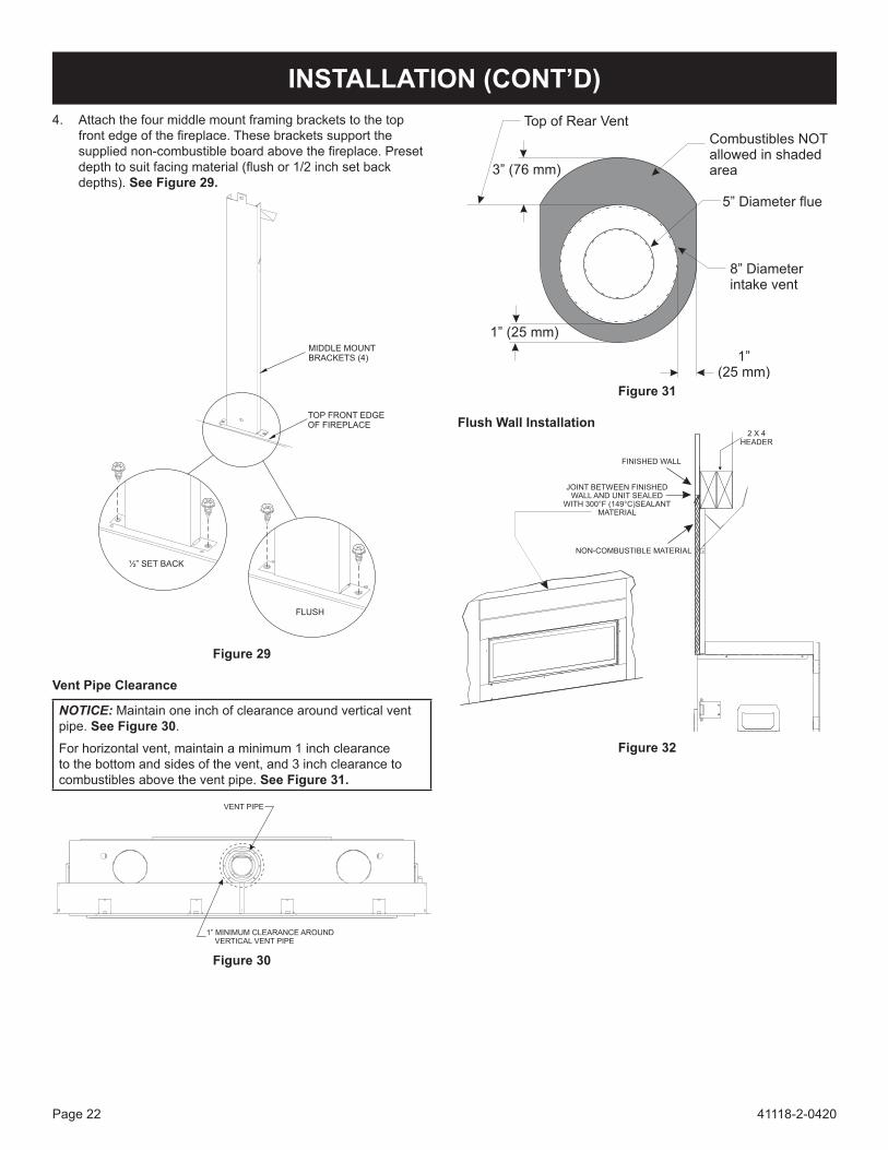
INSTALLATION (CONT’D)4. Attach the four middle mount framing brackets to the top
frontedgeofthefireplace.Thesebracketssupportthesuppliednon-combustibleboardabovethefireplace.Presetdepthtosuitfacingmaterial(flushor1/2inchsetbackdepths). See Figure 29.
FLUSH
½” SET BACK
MIDDLE MOUNTBRACKETS (4)
TOP FRONT EDGEOF FIREPLACE
Figure 29
Vent Pipe Clearance
NOTICE: Maintain one inch of clearance around vertical vent pipe. See Figure 30.
For horizontal vent, maintain a minimum 1 inch clearance to the bottom and sides of the vent, and 3 inch clearance to combustibles above the vent pipe. See Figure 31.
VENT PIPE
1” MINIMUM CLEARANCE AROUND
VERTICAL VENT PIPE
Figure 30
Figure 31
Flush Wall Installation
NON-COMBUSTIBLE MATERIAL
2 X 4HEADER
FINISHED WALL
JOINT BETWEEN FINISHEDWALL AND UNIT SEALED
WITH 300°F (149°C)SEALANTMATERIAL
Figure 32
41118-2-0420 Page 23
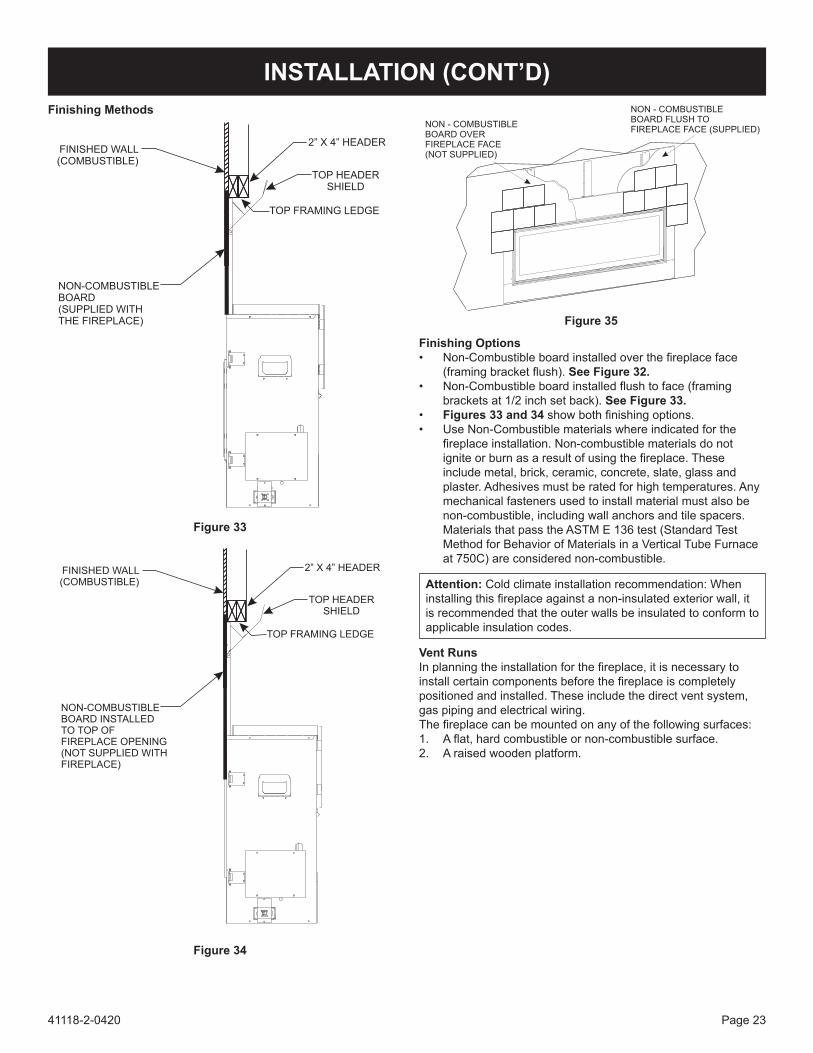
INSTALLATION (CONT’D)Finishing Methods
2” X 4” HEADERFINISHED WALL(COMBUSTIBLE)
NON-COMBUSTIBLEBOARD(SUPPLIED WITHTHE FIREPLACE)
TOP FRAMING LEDGE
TOP HEADERSHIELD
Figure 33
2” X 4” HEADERFINISHED WALL(COMBUSTIBLE)
NON-COMBUSTIBLEBOARD INSTALLEDTO TOP OFFIREPLACE OPENING(NOT SUPPLIED WITHFIREPLACE)
TOP FRAMING LEDGE
TOP HEADERSHIELD
Figure 34
NON - COMBUSTIBLEBOARD FLUSH TOFIREPLACE FACE (SUPPLIED)
NON - COMBUSTIBLEBOARD OVERFIREPLACE FACE(NOT SUPPLIED)
Figure 35
Finishing Options• Non-Combustibleboardinstalledoverthefireplaceface
(framingbracketflush).See Figure 32.• Non-Combustibleboardinstalledflushtoface(framing
brackets at 1/2 inch set back). See Figure 33.• Figures 33 and 34showbothfinishingoptions.• UseNon-Combustiblematerialswhereindicatedforthe
fireplaceinstallation.Non-combustiblematerialsdonotigniteorburnasaresultofusingthefireplace.Theseinclude metal, brick, ceramic, concrete, slate, glass and plaster. Adhesives must be rated for high temperatures. Any mechanical fasteners used to install material must also be non-combustible, including wall anchors and tile spacers. MaterialsthatpasstheASTME136test(StandardTestMethodforBehaviorofMaterialsinaVerticalTubeFurnaceat 750C) are considered non-combustible.
Attention: Cold climate installation recommendation: When installingthisfireplaceagainstanon-insulatedexteriorwall,itis recommended that the outer walls be insulated to conform to applicable insulation codes.
Vent RunsInplanningtheinstallationforthefireplace,itisnecessarytoinstallcertaincomponentsbeforethefireplaceiscompletelypositionedandinstalled.Theseincludethedirectventsystem,gas piping and electrical wiring. Thefireplacecanbemountedonanyofthefollowingsurfaces:1. Aflat,hardcombustibleornon-combustiblesurface.2. A raised wooden platform.
41118-2-0420Page 24
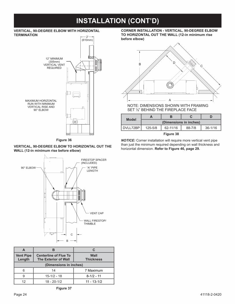
INSTALLATION (CONT’D)VERTICAL, 90-DEGREE ELBOW WITH HORIZONTAL TERMINATION
2’(610mm)
12” MINIMUM(305mm)
VERTICAL VENTREQUIRED
MAXIMUM HORIZONTALRUN WITH MINIMUMVERTICAL RISE AND
90° ELBOW
Figure 36
VERTICAL, 90-DEGREE ELBOW TO HORIZONTAL OUT THEWALL (12-in minimum rise before elbow)
90° ELBOW “A” PIPELENGTH
FIRESTOP SPACER(INCLUDED)
VENT CAP
WALL FIRESTOP/THIMBLE
B
C
A B CVent Pipe
LengthCenterline of Flue To The Exterior of Wall
Wall Thickness
(Dimensions in inches)6 14 7 Maximum9 15-1/2 - 18 8-1/2 - 11
12 18 - 20-1/2 11 - 13-1/2
Figure 37
CORNER INSTALLATION - VERTICAL, 90-DEGREE ELBOWTO HORIZONTAL OUT THE WALL (12-in minimum rise before elbow)
NOTE: DIMENSIONS SHOWN WITH FRAMING
SET ½” BEHIND THE FIREPLACE FACE
A
DB
C
ModelA B C D
(Dimensions in inches)DVLL72BP 125-5/8 62-11/16 88-7/8 36-1/16
Figure 38
NOTICE: Corner installation will require more vertical vent pipe than just the minimum required depending on wall thickness and horizontal dimension. Refer to Figure 46, page 29.

41118-2-0420 Page 25
ThisPageIntentionallyLeftBlank.
41118-2-0420Page 26
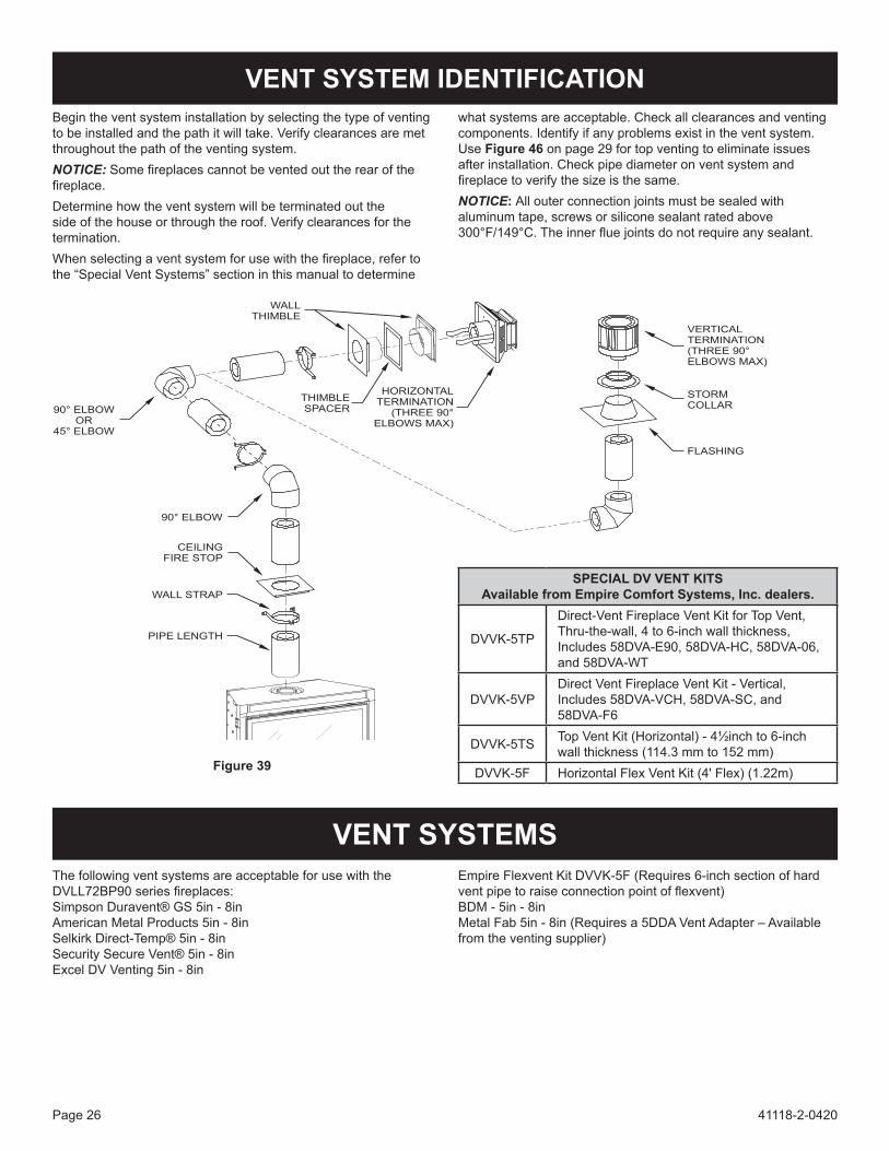
Begin the vent system installation by selecting the type of venting to be installed and the path it will take. Verify clearances are met throughout the path of the venting system. NOTICE:Somefireplacescannotbeventedouttherearofthefireplace.Determine how the vent system will be terminated out the side of the house or through the roof. Verify clearances for the termination.Whenselectingaventsystemforusewiththefireplace,refertothe“SpecialVentSystems”sectioninthismanualtodetermine
what systems are acceptable. Check all clearances and venting components. Identify if any problems exist in the vent system. UseFigure 46 on page 29 for top venting to eliminate issues after installation. Check pipe diameter on vent system and fireplacetoverifythesizeisthesame.NOTICE: All outer connection joints must be sealed with aluminum tape, screws or silicone sealant rated above 300°F/149°C.Theinnerfluejointsdonotrequireanysealant.
VENT SYSTEM IDENTIFICATION
SPECIAL DV VENT KITSAvailable from Empire Comfort Systems, Inc. dealers.
DVVK-5TP
Direct-VentFireplaceVentKitforTopVent,Thru-the-wall,4to6-inchwallthickness,Includes 58DVA-E90, 58DVA-HC, 58DVA-06, and58DVA-WT
DVVK-5VPDirect Vent Fireplace Vent Kit - Vertical, Includes58DVA-VCH,58DVA-SC,and58DVA-F6
DVVK-5TS TopVentKit(Horizontal)-4½inchto6-inchwall thickness (114.3 mm to 152 mm)
DVVK-5F Horizontal Flex Vent Kit (4' Flex) (1.22m)
VENT SYSTEMSThefollowingventsystemsareacceptableforusewiththeDVLL72BP90seriesfireplaces:SimpsonDuravent®GS5in-8inAmerican Metal Products 5in - 8inSelkirkDirect-Temp®5in-8inSecuritySecureVent®5in-8inExcel DV Venting 5in - 8in
Empire Flexvent Kit DVVK-5F (Requires 6-inch section of hard ventpipetoraiseconnectionpointofflexvent)BDM - 5in - 8inMetal Fab 5in - 8in (Requires a 5DDA Vent Adapter – Available from the venting supplier)
Figure 39
FLASHING
STORMCOLLAR
VERTICALTERMINATION(THREE 90°ELBOWS MAX)
WALLTHIMBLE
HORIZONTALTERMINATION
(THREE 90°ELBOWS MAX)
90° ELBOWOR
45° ELBOW
90° ELBOW
CEILINGFIRE STOP
WALL STRAP
PIPE LENGTH
THIMBLESPACER
41118-2-0420 Page 27
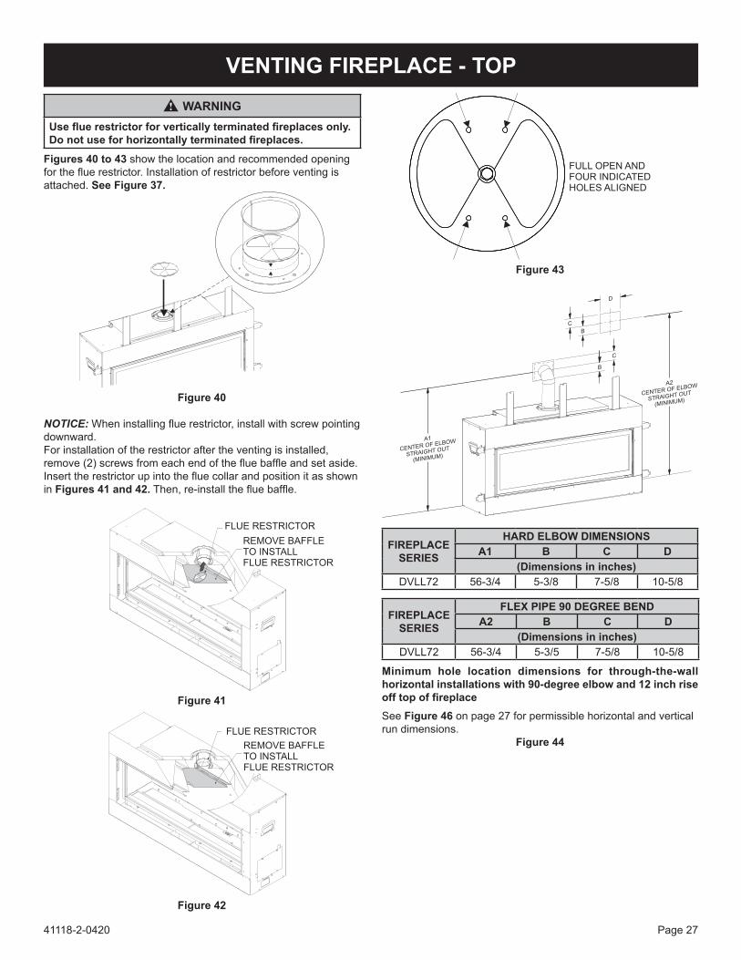
VENTING FIREPLACE - TOPWARNING
Use flue restrictor for vertically terminated fireplaces only. Do not use for horizontally terminated fireplaces.
Figures 40 to 43 show the location and recommended opening forthefluerestrictor.Installationofrestrictorbeforeventingisattached. See Figure 37.
Figure 40
NOTICE: Wheninstallingfluerestrictor,installwithscrewpointingdownward.For installation of the restrictor after the venting is installed, remove(2)screwsfromeachendofthefluebaffleandsetaside.Inserttherestrictorupintothefluecollarandpositionitasshownin Figures 41 and 42.Then,re-installthefluebaffle.
REMOVE BAFFLE
TO INSTALL
FLUE RESTRICTOR
FLUE RESTRICTOR
Figure 41
REMOVE BAFFLE
TO INSTALL
FLUE RESTRICTOR
FLUE RESTRICTOR
Figure 42
Figure 43
A1
CENTER OF ELBOW
STRAIGHT OUT
(MINIMUM)
A2
CENTER OF ELBOW
STRAIGHT OUT
(MINIMUM)
FIREPLACESERIES
HARD ELBOW DIMENSIONSA1 B C D
(Dimensions in inches)DVLL72 56-3/4 5-3/8 7-5/8 10-5/8
FIREPLACESERIES
FLEX PIPE 90 DEGREE BENDA2 B C D
(Dimensions in inches)DVLL72 56-3/4 5-3/5 7-5/8 10-5/8
Minimum hole location dimensions for through-the-wall horizontal installations with 90-degree elbow and 12 inch rise off top of fireplaceSee Figure 46 on page 27 for permissible horizontal and vertical run dimensions.
Figure 44
FLUERESTRICTOR
FLUERESTRICTOR
REMOVE BAFFLETOINSTALLFLUERESTRICTOR
REMOVE BAFFLETOINSTALLFLUERESTRICTOR
FULLOPENANDFOURINDICATEDHOLESALIGNED

41118-2-0420Page 28
VENTING FIREPLACE - TOP (CONT’D)Positioning the FireplaceDeterminetheexactpositionofthefireplacesothedirect-venttermination will be centered (if possible) between two studs. Thiswillavoidanyextraframing.Allventkitpipesshouldbeassembledonthefireplaceafterthefireplaceismovedintothefinalposition.
Cutting the HoleAfterthefireplacehasbeenpositionedinitspermanentlocation,theholethroughtheexteriorwallcanbecut.Thisholemustbe13-in (330mm) high x 10-5/8-in (270mm) wide with its center line determined by the amount of vertical rise and horizontal run of the termination. See Figures 44 and 45. When locating the hole it must be noted that the bottom of the cap must be minimum of 12-in (305mm) above the ground level, and top of the cap must be no less than 18-in (457mm) below a combustible projection, and no closer than 9-in (229mm) to any wall running parallel to vent termination.
U:\INSTRUCTIONS\Instructions Original Graphics\DVLL60BP\DVLL Vent Cap Clearance - 061515
Figure 45
Below Grade InstallationWhen it is not possible to meet the required vent termination clearances of 12 inch (305 mm) above grade level, a snorkel kit is recommended. It allows installation depth down to 7 inch (178mm)belowgradelevel.The7inch(178mm)ismeasuredfrom the center of the horizontal vent pipe as it penetrates through the wall.Ensure the sidewall venting clearances are observed. If venting system is installed below ground, we recommend a window well with adequate and proper drainage to be installed around the termination area.
TYPICAL BASEMENT INSTALLATION
12” (30.5cm) ABOVEGRADE OR AVERAGE
EXPECTED SNOW LEVEL
Figure 46
ATTENTION: Vinyl Soffit, Vinyl Ceiling, Vinyl Overhang DisclaimerClearances are to heat resistant material (i.e. wood, metal). Thisdoesnotincludevinyl.EmpireComfortSystemsInc.will not be held responsible for heat damage caused from terminating under vinyl overhangs, vinyl ceilings or vinyl ventilated/unventilatedsoffits.
41118-2-0420 Page 29
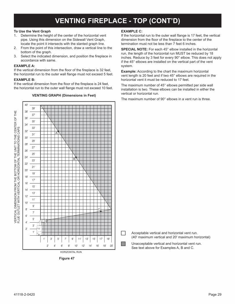
VENTING FIREPLACE - TOP (CONT’D)To Use the Vent Graph1. Determine the height of the center of the horizontal vent
pipe.UsingthisdimensionontheSidewallVentGraph,locate the point it intersects with the slanted graph line.
2. From the point of this intersection, draw a vertical line to the bottom of the graph.
3. Selecttheindicateddimension,andpositionthefireplaceinaccordance with same.
EXAMPLE A:Iftheverticaldimensionfromthefloorofthefireplaceis32feet,thehorizontalruntotheouterwallflangemustnotexceed5feet.EXAMPLE B:Iftheverticaldimensionfromthefloorofthefireplaceis24feet,thehorizontalruntotheouterwallflangemustnotexceed10feet.
EXAMPLE C:Ifthehorizontalruntotheouterwallflangeis17feet,theverticaldimensionfromthefloorofthefireplacetothecenterofthetermination must not be less than 7 feet 6 inches.SPECIAL NOTE: For each 45° elbow installed in the horizontal run,thelengthofthehorizontalrunMUSTbereducedby18inches.Reduceby3feetforevery90°elbow.Thisdoesnotapplyif the 45° elbows are installed on the vertical part of the vent system. Example: According to the chart the maximum horizontal vent length is 20 feet and if two 45° elbows are required in the horizontal vent it must be reduced to 17 feet.Themaximumnumberof45°elbowspermittedpersidewallinstallationistwo.Theseelbowscanbeinstalledineitherthevertical or horizontal run.Themaximumnumberof90°elbowsinaventrunisthree.
Acceptable vertical and horizontal vent run. (40' maximum vertical and 20' maximum horizontal)
Unacceptableverticalandhorizontalventrun. SeetextaboveforExamplesA,BandC.
Figure 47
VENTING GRAPH (Dimensions in Feet)
A
C
B
HORIZONTAL RUN
VE
RT
ICA
LD
IME
NS
ION
FR
OM
TH
E B
OT
TO
M O
FT
HE
UN
ITT
OT
HE
CE
NT
ER
OF
TH
E
FLU
E O
UT
LE
TW
ITH
VE
RT
ICA
LO
R H
OR
IZO
NTA
LT
ER
MIN
AT
ION
S C
AP
S
41118-2-0420Page 30
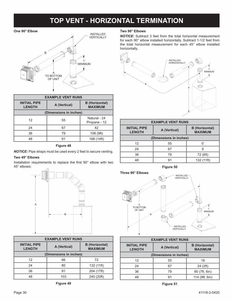
TOP VENT - HORIZONTAL TERMINATIONOne 90° Elbow
A
TO BOTTOM
OF UNIT
B
INSTALLED
VERTICALLY
1’
MINIMUM
EXAMPLE VENT RUNSINITIAL PIPE
LENGTH A (Vertical) B (Horizontal)MAXIMUM
(Dimensions in inches)
12 55 Natural-24Propane - 12
24 67 4236 79 108 (9ft)48 91 168 (14ft)
Figure 48NOTICE: Pipe straps must be used every 2 feet to secure venting.
Two 45° ElbowsInstallation requirements to replace the first 90° elbowwith two45° elbows:
B
A
EXAMPLE VENT RUNSINITIAL PIPE
LENGTH A (Vertical) B (Horizontal)MAXIMUM
(Dimensions in inches)12 66 7224 80 132 (11ft)36 91 204 (17ft)48 103 240 (20ft)
Figure 49
Two 90° ElbowsNOTICE:Subtract3 feet from the totalhorizontalmeasurementforeach90°elbowinstalledhorizontally.Subtract1-1/2feetfromthe total horizontal measurement for each 45° elbow installed horizontally.
EXAMPLE VENT RUNSINITIAL PIPE
LENGTH A (Vertical) B (Horizontal)MAXIMUM
(Dimensions in inches)12 55 0’24 67 636 79 72 (6ft)48 91 132 (11ft)
Figure 50Three 90° Elbows
1’
MININUM
B
INSTALLED
VERTICALLY
INSTALLED
VERTICALLY
A
TO BOTTOM
OF UNIT
EXAMPLE VENT RUNSINITIAL PIPE
LENGTH A (Vertical) B (Horizontal)MAXIMUM
(Dimensions in inches)12 55 1824 67 24 (2ft)36 79 90 (7ft, 6in)48 91 114 (9ft, 6in)
Figure 51
41118-2-0420 Page 31
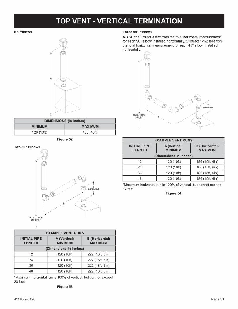
TOP VENT - VERTICAL TERMINATIONNo Elbows
DIMENSIONS (in inches)MINIMUM MAXIMUM120 (10ft) 480 (40ft)
Figure 52
Two 90° Elbows
EXAMPLE VENT RUNSINITIAL PIPE
LENGTHA (Vertical)MINIMUM
B (Horizontal)MAXIMUM
(Dimensions in inches)12 120 (10ft) 222 (18ft, 6in)24 120 (10ft) 222 (18ft, 6in)36 120 (10ft) 222 (18ft, 6in)48 120 (10ft) 222 (18ft, 6in)
*Maximumhorizontalrunis100%ofvertical,butcannotexceed20 feet.
Figure 53
Three 90° ElbowsNOTICE:Subtract3feetfromthetotalhorizontalmeasurementforeach90°elbowinstalledhorizontally.Subtract1-1/2feetfromthe total horizontal measurement for each 45° elbow installed horizontally.
EXAMPLE VENT RUNSINITIAL PIPE
LENGTHA (Vertical)MINIMUM
B (Horizontal)MAXIMUM
(Dimensions in inches)12 120 (10ft) 186 (15ft, 6in)24 120 (10ft) 186 (15ft, 6in)36 120 (10ft) 186 (15ft, 6in)48 120 (10ft) 186 (15ft, 6in)
*Maximumhorizontalrunis100%ofvertical,butcannotexceed17 feet.
Figure 54

41118-2-0420Page 32
VERTICAL TERMINATIONLocate and mark the center point of the vent pipe using a nail on the underside of the roof. Drive the nail through the center point. Mark the outline of the roof hole around this center point.NOTICE:Sizeoftheroofholedimensionsdependonthepitch
oftheroof.Theremustbea1inch(25mm)clearancetotheverticalpipesections.Thisclearanceistoallcombustible material.
Cover the opening of the vent pipe and cut and frame the roof hole.Useframinglumberthesamesizeastheroofraftersandinstall the frame securely. Flashing anchored to frame must withstandhighwinds.Thestormcollarisplacedoverthisjointtomakeawater-tightseal.Non-hardeningsealantshouldbeusedtocompletelysealthisflashinginstallation.
Determining Minimum Vent Height Above the Roof.
WARNINGMajor U.S. building codes specify minimum chimney and/or vent height above the roof top. These minimum heights are necessary in the interest of safety. These specifications are summarized in Figure 55.
VENT CAP
GAS VENT
24”
24”
MORE
THAN
10 FEET
Figure 55
Notethatforsteeproofpitches,theventheightmustbeincreased. In high wind conditions, nearby trees, adjoining roof lines, steep pitched roofs, and other similar factors can result in poor draft, or down-drafting. In these cases, increasing the vent height may solve this problem.
Installing the Vent System in a ChaseA chase is a vertical box-like structure built to enclose the gas fireplaceand/oritsventsystem.Verticalventrunsontheoutsideof a building may be, but are not required to be installed inside a chase.
CAUTIONTreatment of firestop spacers and construction of the chase may vary with the type of building. These instructions are not substitutes for the requirements of local building codes. Check local building codes to determine the requirements for these steps.
NOTICE: Build the chase large enough to maintain the minimum clearance of combustible materials (including insulation) to the vent system. When installing the vent system in a chase, insulate thechaseasyouwouldtheoutsidewallsofyourhome.Thisisespeciallyimportantincoldclimates.Uponcompletionofchaseframing, install the vent system by following the instructions in this manual.Theverticalterminationcapforthisfireplacemustnotbeanycloser than 24-in. to combustible materials. See Figure 53.
40’(12.19M)
MAX
24” MINIMUMCLEARANCE TOCOMBUSTIBLES
NATURAL ORMAN MADE
8’ (2.44M)MAX
8’ (2.44M)MAX
45°
45°
Figure 56
If two vertical terminations are run near each other, they may be placed a minimum of 12 inches between them if they are at the same height. See Figure 54. If two vent terminations are not at the same height, they must be positioned at least 24 inches apart to minimize draft issues between them.
12”
MINIMUM
Figure 57
41118-2-0420 Page 33
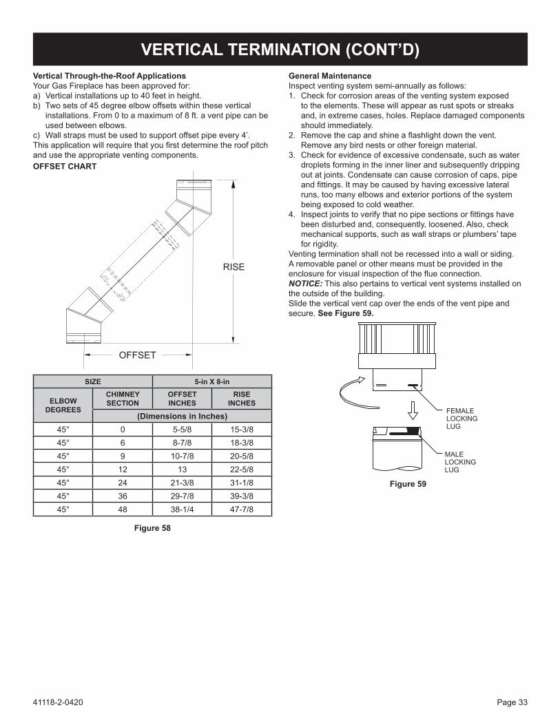
Vertical Through-the-Roof ApplicationsYour Gas Fireplace has been approved for:a) Vertical installations up to 40 feet in height.b) Twosetsof45degreeelbowoffsetswithinthesevertical
installations. From 0 to a maximum of 8 ft. a vent pipe can be used between elbows.
c) Wallstrapsmustbeusedtosupportoffsetpipeevery4’.Thisapplicationwillrequirethatyoufirstdeterminetheroofpitchand use the appropriate venting components.OFFSET CHART
RISE
OFFSET
SIZE 5-in X 8-in
ELBOWDEGREES
CHIMNEYSECTION
OFFSETINCHES
RISEINCHES
(Dimensions in Inches)45° 0 5-5/8 15-3/845° 6 8-7/8 18-3/845° 9 10-7/8 20-5/845° 12 13 22-5/845° 24 21-3/8 31-1/845° 36 29-7/8 39-3/845° 48 38-1/4 47-7/8
Figure 58
General MaintenanceInspect venting system semi-annually as follows:1. Check for corrosion areas of the venting system exposed
totheelements.Thesewillappearasrustspotsorstreaksand, in extreme cases, holes. Replace damaged components should immediately.
2. Removethecapandshineaflashlightdownthevent.Remove any bird nests or other foreign material.
3. Check for evidence of excessive condensate, such as water droplets forming in the inner liner and subsequently dripping out at joints. Condensate can cause corrosion of caps, pipe andfittings.Itmaybecausedbyhavingexcessivelateralruns, too many elbows and exterior portions of the system being exposed to cold weather.
4. Inspectjointstoverifythatnopipesectionsorfittingshavebeen disturbed and, consequently, loosened. Also, check mechanicalsupports,suchaswallstrapsorplumbers’tapefor rigidity.
Venting termination shall not be recessed into a wall or siding.A removable panel or other means must be provided in the enclosureforvisualinspectionoftheflueconnection.NOTICE:Thisalsopertainstoverticalventsystemsinstalledonthe outside of the building.Slidetheverticalventcapovertheendsoftheventpipeandsecure. See Figure 59.
Figure 59
VERTICAL TERMINATION (CONT’D)
41118-2-0420Page 34
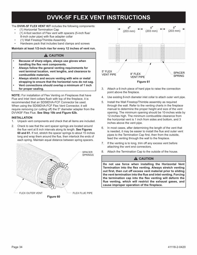
DVVK-5F FLEX VENT INSTRUCTIONSTheDVVK-5F FLEX VENT KIT includes the following components:• (1)HorizontalTerminationCap• (1)4-footsectionofFlexventwithspacers(5-inchflue/
8-inchouterpipe)withflueadaptercollar• (1)WallFirestop/ThimbleAssembly• Hardware pack that includes band clamps and screws
Maintain at least 1/2-inch rise for every 12 inches of vent run.
CAUTION• Because of sharp edges, always use gloves when
handling the flex vent components.• Always follow the general venting requirements for
vent terminal location, vent lengths, and clearance to combustible materials.
• Always stretch and secure venting with wire or metal strapping to ensure that the horizontal runs do not sag.
• Vent connections should overlap a minimum of 1 inch for proper sealing.
NOTE: For installation of Flex Venting on Fireplaces that have FlueandInletVentcollarsflushwithtopofthefireplace,itisrecommendedthatanSD58DVA-FCFConnectorbeused.WhenusingtheSD58DVA-FCFFlexVentConnector,itwillrequire removing (or cutting off) the 5" diameter adapter from the DVVK5F Flex Flue. See Step 10b and Figure 62b. INSTALLATION1. Unpackventcomponentsandcheckthatallitemsareincluded.
2. Check to see that the vent spacer springs are located around theflueventat8inchintervalsalongitslength.See Figures 60 and 61. If not, stretch the spacer springs to about 15 inches longandwrapthemaroundtheflue,theninterlocktheendsofeach spring. Maintain equal distance between spring spacers.
Figure 60
5” FLEX
VENT PIPESPACER
SPRING8” FLEX
VENT PIPE
Figure 61
3. Attach a 6-inch piece of hard pipe to raise the connection pointabovethefireplace.
4. Useexisting8-inchdiameterinletcollartoattachouterventpipe.
5. InstalltheWallFirestop/Thimbleassemblyasrequiredthrough the wall. Refer to the venting charts in the fireplace manual to determine the proper height and size of the vent opening.Theminimumopeningshouldbe10-incheswideby12-incheshigh.Theminimumcombustibleclearancefromthe horizontal vent is 1 inch from sides and bottom, and 3 inches above the vent pipe.
6. In most cases, after determining the length of the vent that is needed, it may be easier to install the flue and outer vent pipestotheTerminationCapfirst,thenfromtheoutside,feed the venting through the wall to the fireplace.
7. If the venting is to long, trim off any excess vent before attaching the vent end connectors.
8. AttachtheTerminationCaptotheoutsideofthehouse.
CAUTIONDo not use force when installing the Horizontal Vent Termination into the flex venting. Always stretch venting out first, then cut off excess vent material prior to sliding the vent termination into the flue and inlet venting. Forcing the termination cap into the flex venting will deform the flue venting, which will restrict the exhaust gases, and cause improper operation of the fireplace.
41118-2-0420 Page 35
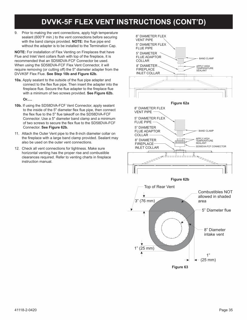
DVVK-5F FLEX VENT INSTRUCTIONS (CONT’D)9. Prior to making the vent connections, apply high temperature
sealant (600°F min.) to the vent connections before securing with the band clamps provided. NOTE: the flue pipe end withouttheadapteristobeinstalledtotheTerminationCap.
NOTE: For installation of Flex Venting on Fireplaces that have FlueandInletVentcollarsflushwithtopofthefireplace,itisrecommendedthatanSD58DVA-FCFConnectorbeused.WhenusingtheSD58DVA-FCFFlexVentConnector,itwillrequire removing (or cutting off) the 5" diameter adapter from the DVVK5F Flex Flue. See Step 10b and Figure 62b.10a. Applysealanttotheoutsideofthefluepipeadapterand
connecttotheflexfluepipe.Theninserttheadapterintothefireplaceflue.Securetheflueadaptertothefireplacefluewith a minimum of two screws provided. See Figure 62b.Or.....
10b.IfusingtheSD58DVA-FCFVentConnector,applysealanttotheinsideofthe5"diameterflexfluepipe,thenconnecttheflexfluetothe5"fluetakeoffontheSD58DVA-FCFConnector.Usea5"diameterbandclampandaminimumoftwoscrewstosecuretheflexfluetotheSD58DVA-FCFConnector. See Figure 62b.
11. Attach the Outer Vent pipe to the 8-inch diameter collar on thefireplacewithalargebandclampprovided.Sealantmayalso be used on the outer vent connections.
12. Check all vent connections for tightness. Make sure horizontal venting has the proper rise and combustible clearances required. Refer to venting charts in fireplace instruction manual.
8” DIAMETER FLEX
VENT PIPE
5” DIAMETER FLEX
FLUE PIPE
5” DIAMETER
FLUE ADAPTOR
COLLAR
8” DIAMETER
FIREPLACE
INLET COLLAR
Figure 62a
Figure 62b
Figure 63
41118-2-0420Page 36
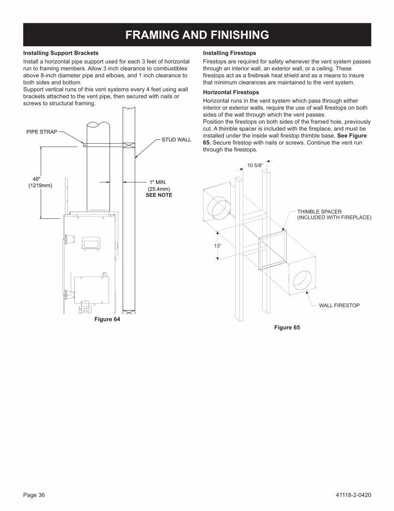
FRAMING AND FINISHINGInstalling Support BracketsInstall a horizontal pipe support used for each 3 feet of horizontal run to framing members. Allow 3 inch clearance to combustibles above 8-inch diameter pipe and elbows, and 1 inch clearance to both sides and bottom.Supportverticalrunsofthisventsystemsevery4feetusingwallbrackets attached to the vent pipe, then secured with nails or screws to structural framing.
Figure 64
Installing FirestopsFirestops are required for safety whenever the vent system passes throughaninteriorwall,anexteriorwall,oraceiling.Thesefirestopsactasafirebreakheatshieldandasameanstoinsurethat minimum clearances are maintained to the vent system.
Horizontal FirestopsHorizontal runs in the vent system which pass through either interiororexteriorwalls,requiretheuseofwallfirestopsonbothsides of the wall through which the vent passes.Positionthefirestopsonbothsidesoftheframedhole,previouslycut.Athimblespacerisincludedwiththefireplace,andmustbeinstalledundertheinsidewallfirestopthimblebase.See Figure 65.Securefirestopwithnailsorscrews.Continuetheventrunthroughthefirestops.
13”
10 5/8”
WALL FIRESTOP
THIMBLE SPACER(INCLUDED WITH FIREPLACE)
Figure 65
41118-2-0420 Page 37
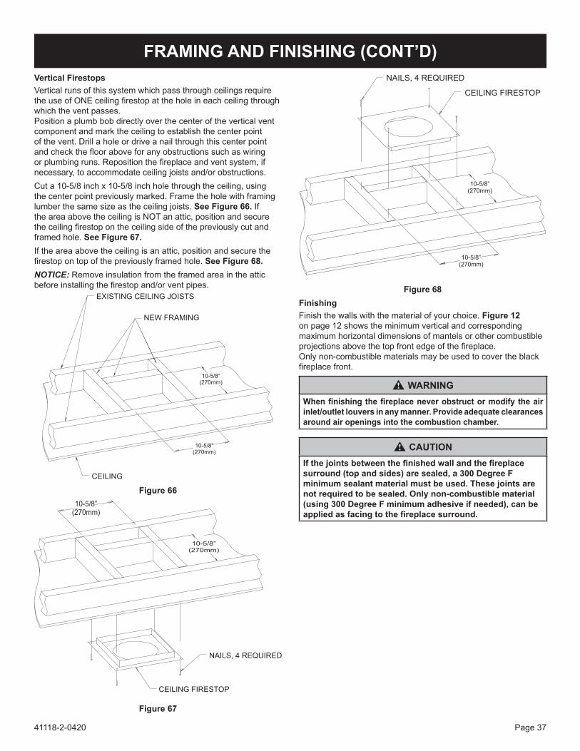
FRAMING AND FINISHING (CONT’D)Vertical FirestopsVertical runs of this system which pass through ceilings require theuseofONEceilingfirestopattheholeineachceilingthroughwhich the vent passes.Position a plumb bob directly over the center of the vertical vent component and mark the ceiling to establish the center point of the vent. Drill a hole or drive a nail through this center point andchecktheflooraboveforanyobstructionssuchaswiringorplumbingruns.Repositionthefireplaceandventsystem,ifnecessary, to accommodate ceiling joists and/or obstructions.Cut a 10-5/8 inch x 10-5/8 inch hole through the ceiling, using the center point previously marked. Frame the hole with framing lumber the same size as the ceiling joists. See Figure 66. If theareaabovetheceilingisNOTanattic,positionandsecuretheceilingfirestopontheceilingsideofthepreviouslycutandframed hole. See Figure 67. If the area above the ceiling is an attic, position and secure the firestopontopofthepreviouslyframedhole.See Figure 68.NOTICE: Remove insulation from the framed area in the attic beforeinstallingthefirestopand/orventpipes.
Figure 66
Figure 67
Figure 68FinishingFinish the walls with the material of your choice. Figure 12 on page 12 shows the minimum vertical and corresponding maximum horizontal dimensions of mantels or other combustible projectionsabovethetopfrontedgeofthefireplace.Only non-combustible materials may be used to cover the black fireplacefront.
WARNINGWhen finishing the fireplace never obstruct or modify the air inlet/outlet louvers in any manner. Provide adequate clearances around air openings into the combustion chamber.
CAUTIONIf the joints between the finished wall and the fireplace surround (top and sides) are sealed, a 300 Degree F minimum sealant material must be used. These joints are not required to be sealed. Only non-combustible material (using 300 Degree F minimum adhesive if needed), can be applied as facing to the fireplace surround.
41118-2-0420Page 38
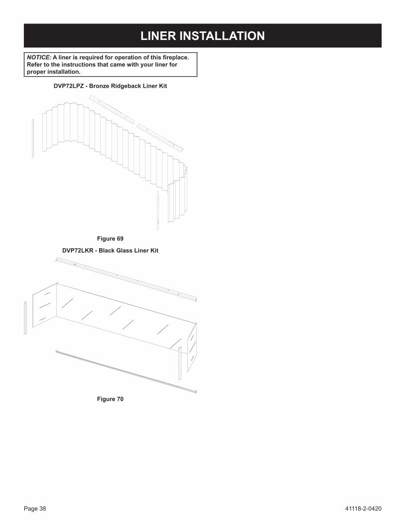
LINER INSTALLATIONNOTICE: A liner is required for operation of this fireplace. Refer to the instructions that came with your liner for proper installation.
DVP72LPZ - Bronze Ridgeback Liner Kit
Figure 69
DVP72LKR - Black Glass Liner Kit
Figure 70
DECORATIVE GLASS PLACEMENT
41118-2-0420 Page 39
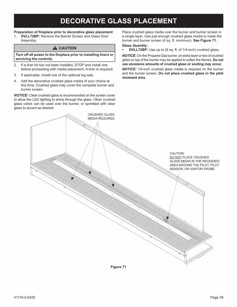
Preparation of fireplace prior to decorative glass placement1. DVLL72BP: RemovetheBarrierScreenandGlassDoor
Assembly.
CAUTIONTurn off all power to the fireplace prior to installing liners or servicing the controls.
2. Ifalinerkithasnotbeeninstalled,STOPandinstallonebefore proceeding with media placement. A liner is required.
3. If applicable, install one of the optional log sets.
4. Add the decorative crushed glass media of your choice at this time. Crushed glass may cover the complete burner and burner screen.
NOTICE: Clear crushed glass is recommended on the screen cover to allow the LED lighting to shine through the glass. Other crushed glass colors can be used over the burner, or sprinkled with clear glass to accent as desired.
Place crushed glass media over the burner and burner screen in asinglelayer.Usejustenoughcrushedglassmediatomasktheburner and burner screen (6 sq. ft. minimum). See Figure 71. Glass Quantity:• DVLL72BP: Useupto(8sq.ft.of1/4-inch)crushedglass.NOTICE: On the Propane Gas burner, an extra layer or two of crushed glassontopoftheburnermaybeappliedtosoftentheflames.Do not use excessive amounts of crushed glass or sooting may occur.NOTICE: 1/4-inch crushed glass media is required on the burner and the burner screen. Do not place crushed glass in the pilot recessed area.
Figure 71
CRUSHED GLASS
MEDIA REQUIRED
CAUTION:
PLACE CRUSHED
GLASS MEDIA IN THE RECESSED
AREA AROUND THE PILOT, PILOT
SENSOR, OR IGNITOR PROBE
DO NOTCAUTION:DONOTPLACECRUSHEDGLASSMEDIAINTHERECESSEDAREAAROUNDTHEPILOT,PILOTSENSOR,ORIGNITORPROBE
CRUSHEDGLASSMEDIAREQUIRED
41118-2-0420Page 40
MULTIFUNCTION REMOTE OPERATING INSTRUCTIONS
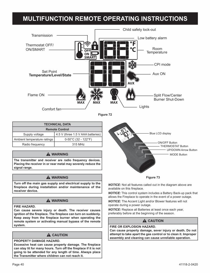
TECHNICAL DATARemote Control
Supplyvoltage 4.5 V (three 1.5 V AAA batteries)Ambient temperature ratings 0-50°C (32 - 122°F)
Radio frequency 315 MHz
WARNINGThe transmitter and receiver are radio frequency devices. Placing the receiver in or near metal may severely reduce the signal range.
WARNINGTurn off the main gas supply and electrical supply to the fireplace during installation and/or maintenance of the receiver device.
WARNINGFIRE HAZARD. Can cause severe injury or death. The receiver causes ignition of the fireplace. The fireplace can turn on suddenly. Keep away from the fireplace burner when operating the remote system or activating manual bypass of the remote system.
CAUTIONPROPERTY DAMAGE HAZARD.Excessive heat can cause property damage. The fireplace can stay lit for many hours. Turn off the fireplace if it is not going to be attended for any length of time. Always place the Transmitter where children can not reach it.
Figure 72
Figure 73
NOTICE:Notallfeaturescalledoutinthediagramaboveareavailableonthisfireplace.NOTICE:ThiscontrolsystemincludesaBatteryBack-uppackthatallows the Fireplace to operate in the event of a power outage.NOTICE:TheAccentLightand/orBlowerfeatureswillnotoperate during a power outage.NOTICE: Replace all Batteries at least once each year, preferably before at the beginning of the season.
CAUTIONFIRE OR EXPLOSION HAZARD. Can cause property damage, sever injury or death. Do not attempt to take apart the gas control or to clean it. Improper assembly and cleaning can cause unreliable operation.
41118-2-0420 Page 41
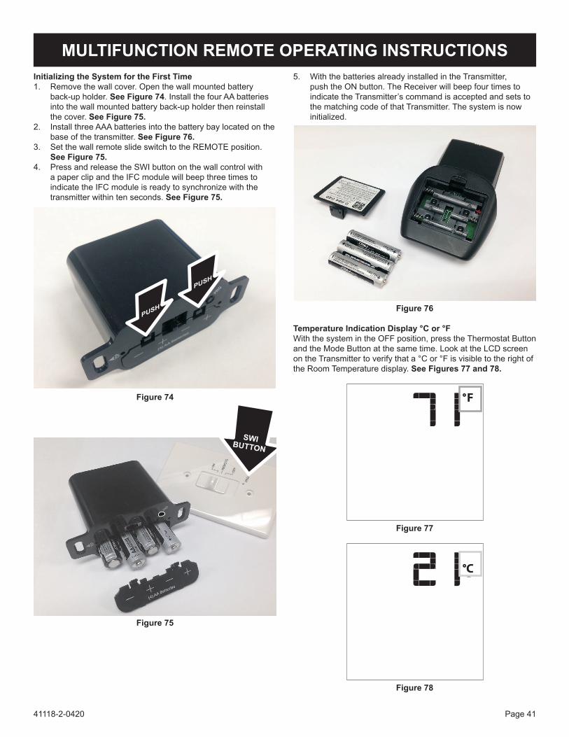
MULTIFUNCTION REMOTE OPERATING INSTRUCTIONSInitializing the System for the First Time1. Remove the wall cover. Open the wall mounted battery back-up holder. See Figure 74. Install the four AA batteries
into the wall mounted battery back-up holder then reinstall the cover. See Figure 75.
2. Install three AAA batteries into the battery bay located on the base of the transmitter. See Figure 76.
3. SetthewallremoteslideswitchtotheREMOTEposition.See Figure 75.
4. PressandreleasetheSWIbuttononthewallcontrolwitha paper clip and the IFC module will beep three times to indicate the IFC module is ready to synchronize with the transmitter within ten seconds. See Figure 75.
Figure 74
SWIBUTTON
Figure 75
5. WiththebatteriesalreadyinstalledintheTransmitter,pushtheONbutton.TheReceiverwillbeepfourtimestoindicatetheTransmitter’scommandisacceptedandsetstothematchingcodeofthatTransmitter.Thesystemisnowinitialized.
Figure 76
Temperature Indication Display °C or °FWiththesystemintheOFFposition,presstheThermostatButtonand the Mode Button at the same time. Look at the LCD screen ontheTransmittertoverifythata°Cor°FisvisibletotherightoftheRoomTemperaturedisplay.See Figures 77 and 78.
Figure 77
Figure 78
41118-2-0420Page 42
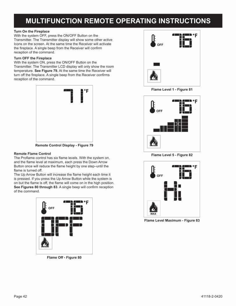
Turn On the FireplaceWiththesystemOFF,presstheON/OFFButtonontheTransmitter.TheTransmitterdisplaywillshowsomeotheractiveIcons on the screen. At the same time the Receiver will activate thefireplace.AsinglebeepfromtheReceiverwillconfirmreception of the command.
Turn OFF the FireplaceWiththesystemON,presstheON/OFFButtonontheTransmitter.TheTransmitterLCDdisplaywillonlyshowtheroomtemperature. See Figure 79. At the same time the Receiver will turnoffthefireplace.AsinglebeepfromtheReceiverconfirmsreception of the command.
Remote Control Display - Figure 79
Remote Flame ControlTheProflamecontrolhassixflamelevels.Withthesystemon,andtheflamelevelatmaximum,eachpresstheDownArrowButtononcewillreducetheflameheightbyonestep–untiltheflameisturnedoff.TheUpArrowButtonwillincreasetheflameheighteachtimeitispressed.IfyoupresstheUpArrowButtonwhilethesystemisonbuttheflameisoff,theflamewillcomeoninthehighposition.See Figures 80 through 83.Asinglebeepwillconfirmreceptionof the command.
OFF
Flame Off - Figure 80
MULTIFUNCTION REMOTE OPERATING INSTRUCTIONS
OFF
Flame Level 1 - Figure 81
OFF
Flame Level 5 - Figure 82
OFF
Flame Level Maximum - Figure 83
41118-2-0420 Page 43
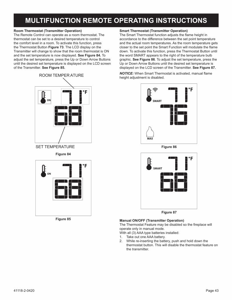
MULTIFUNCTION REMOTE OPERATING INSTRUCTIONSRoom Thermostat (Transmitter Operation)TheRemoteControlcanoperateasaroomthermostat.Thethermostat can be set to a desired temperature to control thecomfortlevelinaroom.Toactivatethisfunction,presstheThermostatButtonFigure 73.TheLCDdisplayontheTransmitterwillchangetoshowthattheroomthermostatisONand the set temperature is now displayed. See Figure 84.Toadjustthesettemperature,presstheUporDownArrowButtonsuntil the desired set temperature is displayed on the LCD screen oftheTransmitter.See Figure 85.
Figure 84
Figure 85
Smart Thermostat (Transmitter Operation)TheSmartThermostatfunctionadjuststheflameheightinaccordance to the difference between the set point temperature and the actual room temperatures. As the room temperature gets closertothesetpointtheSmartFunctionwillmodulatetheflamedown.Toactivatethisfunction,presstheThermostatButtonuntilthewordSMARTappearstotherightofthetemperaturebulbgraphic. See Figure 86.Toadjustthesettemperature,presstheUporDownArrowButtonsuntilthedesiredsettemperatureisdisplayedontheLCDscreenoftheTransmitter.See Figure 87.NOTICE:WhenSmartThermostatisactivated,manualflameheight adjustment is disabled.
Figure 86
Figure 87
Manual ON/OFF (Transmitter Operation)TheThermostatFeaturemaybedisabledsothefireplacewilloperate only in manual mode. With all (3) AAA type batteries installed:1. TakeoutoneAAAbattery.2. While re-inserting the battery, push and hold down the
thermostatbutton.Thiswilldisablethethermostatfeatureonthe transmitter.
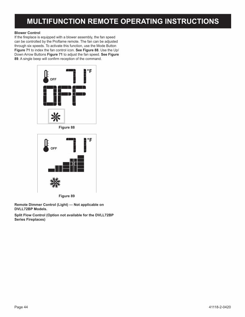
41118-2-0420Page 44
Blower ControlIfthefireplaceisequippedwithablowerassembly,thefanspeedcanbecontrolledbytheProflameremote.Thefancanbeadjustedthroughsixspeeds.Toactivatethisfunction,usetheModeButtonFigure 71 to index the fan control icon. See Figure 88.UsetheUp/Down Arrow Buttons Figure 71 to adjust the fan speed. See Figure 89.Asinglebeepwillconfirmreceptionofthecommand.
OFF
Figure 88
OFF
Figure 89
Remote Dimmer Control (Light) — Not applicable on DVLL72BP Models.Split Flow Control (Option not available for the DVLL72BP Series Fireplaces)
MULTIFUNCTION REMOTE OPERATING INSTRUCTIONS
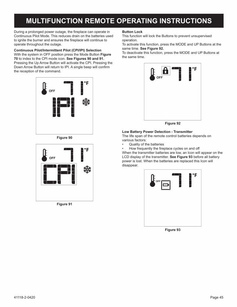
41118-2-0420 Page 45
MULTIFUNCTION REMOTE OPERATING INSTRUCTIONSDuring aprolongedpoweroutage,thefireplacecanoperateinContinuousPilotMode.Thisreducesdrainonthebatteriesusedtoignitetheburnerandensuresthefireplacewillcontinuetooperate throughout the outage.
Continuous Pilot/Intermittent Pilot (CPI/IPI) SelectionWith the system in OFF position press the Mode Button Figure 70 to index to the CPI mode icon. See Figures 90 and 91.PressingtheUpArrowButtonwillactivatetheCPI.PressingtheDownArrowButtonwillreturntoIPI.Asinglebeepwillconfirmthe reception of the command.
OFF
Figure 90
OFF
Figure 91
Button LockThisfunctionwilllocktheButtonstopreventunsupervisedoperation.Toactivatethisfunction,presstheMODEandUPButtonsatthesame time. See Figure 92.Todeactivatethisfunction,presstheMODEandUPButtonsatthe same time.
OFF
Figure 92
Low Battery Power Detection - TransmitterThelifespanoftheremotecontrolbatteriesdependsonvarious factors: • Quality of the batteries• HowfrequentlythefireplacecyclesonandoffWhen the transmitter batteries are low, an Icon will appear on the LCD display of the transmitter. See Figure 93 before all battery power is lost. When the batteries are replaced this Icon will disappear.
OFF
Figure 93
41118-2-0420Page 46
MULTIFUNCTION REMOTE OPERATING INSTRUCTIONSLockout State DefinitionTopreventdamagetothefireplace,IFCboardwillautomaticallylockouttheremotecontrolifitdetectsaanomalousflameortoomanyunsuccessfulignitionattempts.Thelockoutstatewillremain as long as the power supplies are applied.When the IFC board goes into lockout state:1. both the Pilot and the Main Burner solenoids in the gas valve
are de-energized;2. a diagnostic code is sent through the diagnostic red LED.3. the IFC board will ignore any burner ignition command
and remain in the OFF state unless the unlock command sequence is met.
Turnthesystempowersupplies(tothewallcontrolorremotecontrol) OFF for two or three seconds and then restore power.Ifthelockoutreoccurs,callyourdealer.Thecausesoflockoutmust be investigated under safe conditions by trained service personnel.
Using the Fireplace without a Remote ControlThefireplacecanbeturnedON(HIonly)andOFFwiththewallswitch.ThefireplaceflameON/OFFistheonlyfunctionthatwilloperate;noflameadjustment,lightorblowerwillworkwhenusingthewallswitch.ThewallcontrolswitchshouldbeturnedOFFwhenthefireplaceisnotbeingusedforextendedperiodsoftime.
Battery Backup OperationInstallbatteries(Seeinitializationsequenceonpage41).Incaseofpowerloss,thefireplacewillswitchtobatterymodeautomatically.Thefireplacewilloperatenormallywithoutthefanor light control when in battery mode.
Low Battery DetectionWhen the backup batteries are low, the module emits a double-beepwhenitreceivesanon/offcommand.Thesystemwill not accept any commands until the batteries are replaced or A/C power is restored.
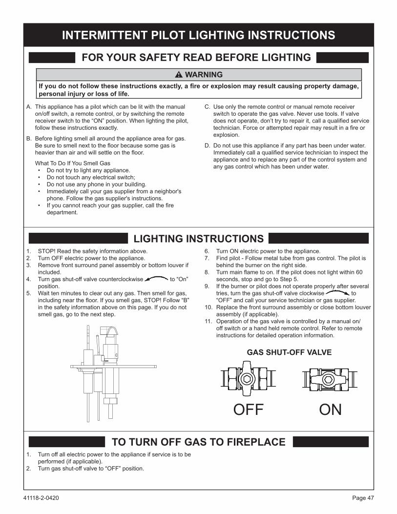
41118-2-0420 Page 47
1. Turnoffallelectricpowertotheapplianceifserviceistobeperformed (if applicable).
2. Turngasshut-offvalveto“OFF” position.
TO TURN OFF GAS TO FIREPLACE
GAS SHUT-OFF VALVE
1. STOP!Readthesafetyinformationabove.2. TurnOFFelectricpowertotheappliance.3. Remove front surround panel assembly or bottom louver if
included.4. Turngasshut-offvalvecounterclockwise to “On”
position.5. Waittenminutestoclearoutanygas.Thensmellforgas,
includingnearthefloor.Ifyousmellgas,STOP!Follow“B” in the safety information above on this page. If you do not smell gas, go to the next step.
6. TurnONelectricpowertotheappliance.7. Findpilot-Followmetaltubefromgascontrol.Thepilotis
behind the burner on the right side.8. Turnmainflametoon.Ifthepilotdoesnotlightwithin60
seconds,stopandgotoStep5.9. If the burner or pilot does not operate properly after several
tries, turn the gas shut-off valve clockwise to “OFF” and call your service technician or gas supplier.
10. Replace the front surround assembly or close bottom louver assembly (if applicable).
11. Operation of the gas valve is controlled by a manual on/off switch or a hand held remote control. Refer to remote instructions for detailed operation information.
LIGHTING INSTRUCTIONS
A.Thisappliancehasapilotwhichcanbelitwiththemanualon/off switch, a remote control, or by switching the remote receiverswitchtothe“ON”position.Whenlightingthepilot,follow these instructions exactly.
B. Before lighting smell all around the appliance area for gas. Besuretosmellnexttothefloorbecausesomegasisheavierthanairandwillsettleonthefloor.
WhatToDoIfYouSmellGas• Do not try to light any appliance.• Do not touch any electrical switch; • Do not use any phone in your building.• Immediately call your gas supplier from a neighbor's
phone. Follow the gas supplier's instructions.• Ifyoucannotreachyourgassupplier,callthefire
department.
C.Useonlytheremotecontrolormanualremotereceiverswitchtooperatethegasvalve.Neverusetools.Ifvalvedoesnotoperate,don’ttrytorepairit,callaqualifiedservicetechnician.Forceorattemptedrepairmayresultinafireorexplosion.
D. Do not use this appliance if any part has been under water. Immediatelycallaqualifiedservicetechniciantoinspecttheappliance and to replace any part of the control system and any gas control which has been under water.
FOR YOUR SAFETY READ BEFORE LIGHTING
INTERMITTENT PILOT LIGHTING INSTRUCTIONS
WARNING If you do not follow these instructions exactly, a fire or explosion may result causing property damage, personal injury or loss of life.
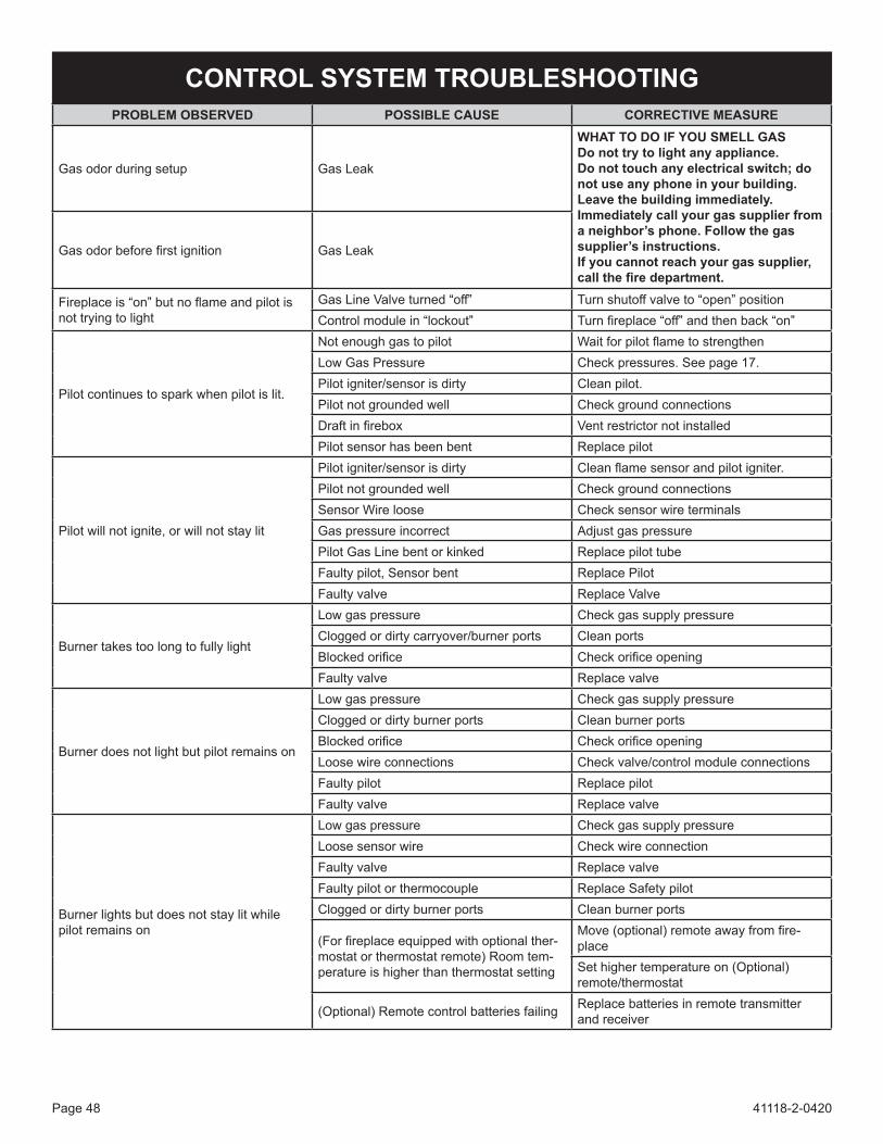
41118-2-0420Page 48
CONTROL SYSTEM TROUBLESHOOTINGPROBLEM OBSERVED POSSIBLE CAUSE CORRECTIVE MEASURE
Gas odor during setup Gas Leak
WHAT TO DO IF YOU SMELL GASDo not try to light any appliance.Do not touch any electrical switch; do not use any phone in your building.Leave the building immediately.Immediately call your gas supplier from a neighbor’s phone. Follow the gas supplier’s instructions.If you cannot reach your gas supplier, call the fire department.
Gasodorbeforefirstignition Gas Leak
Fireplace is “on”butnoflameandpilotisnot trying to light
Gas Line Valve turned “off” Turnshutoffvalveto“open” positionControl module in “lockout” Turnfireplace“off” and then back “on”
Pilot continues to spark when pilot is lit.
Notenoughgastopilot WaitforpilotflametostrengthenLow Gas Pressure Checkpressures.Seepage17.Pilot igniter/sensor is dirty Clean pilot. Pilot not grounded well Check ground connectionsDraftinfirebox Vent restrictor not installedPilot sensor has been bent Replace pilot
Pilot will not ignite, or will not stay lit
Pilot igniter/sensor is dirty Cleanflamesensorandpilotigniter.Pilot not grounded well Check ground connectionsSensorWireloose Check sensor wire terminalsGas pressure incorrect Adjust gas pressurePilot Gas Line bent or kinked Replace pilot tubeFaultypilot,Sensorbent Replace PilotFaulty valve Replace Valve
Burner takes too long to fully light
Low gas pressure Check gas supply pressureClogged or dirty carryover/burner ports Clean portsBlockedorifice CheckorificeopeningFaulty valve Replace valve
Burner does not light but pilot remains on
Low gas pressure Check gas supply pressureClogged or dirty burner ports Clean burner portsBlockedorifice CheckorificeopeningLoose wire connections Check valve/control module connectionsFaulty pilot Replace pilotFaulty valve Replace valve
Burner lights but does not stay lit while pilot remains on
Low gas pressure Check gas supply pressureLoose sensor wire Check wire connectionFaulty valve Replace valveFaulty pilot or thermocouple ReplaceSafetypilotClogged or dirty burner ports Clean burner ports
(Forfireplaceequippedwithoptionalther-mostat or thermostat remote) Room tem-perature is higher than thermostat setting
Move(optional)remoteawayfromfire-placeSethighertemperatureon(Optional)remote/thermostat
(Optional) Remote control batteries failing Replace batteries in remote transmitter and receiver
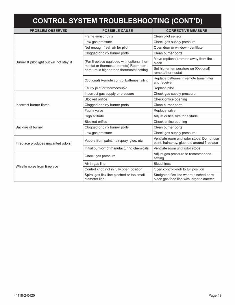
41118-2-0420 Page 49
CONTROL SYSTEM TROUBLESHOOTING (CONT’D)PROBLEM OBSERVED POSSIBLE CAUSE CORRECTIVE MEASURE
Burner & pilot light but will not stay lit
Flame sensor dirty Clean pilot sensorLow gas pressure Check gas supply pressureNotenoughfreshairforpilot Open door or window - ventilateClogged or dirty burner ports Clean burner ports
(Forfireplaceequippedwithoptionalther-mostat or thermostat remote) Room tem-perature is higher than thermostat setting
Move(optional)remoteawayfromfire-placeSethighertemperatureon(Optional)remote/thermostat
(Optional) Remote control batteries failing Replace batteries in remote transmitter and receiver
Faulty pilot or thermocouple Replace pilot
Incorrectburnerflame
Incorrect gas supply or pressure Check gas supply pressureBlockedorifice CheckorificeopeningClogged or dirty burner ports Clean burner portsFaulty valve Replace valveHigh altitude Adjustorificesizeforaltitude
BackfireofburnerBlockedorifice CheckorificeopeningClogged or dirty burner ports Clean burner portsLow gas pressure Check gas supply pressure
Fireplace produces unwanted odorsVapors from paint, hairspray, glue, etc. Ventilate room until odor stops. Do not use
paint,hairspray,glue,etcaroundfireplaceInitial burn-off of manufacturing chemicals Ventilate room until odor stops
Whistlenoisefromfireplace
Check gas pressure Adjust gas pressure to recommended setting.
Air in gas line Bleed linesControl knob not in fully open position Open control knob to full positionSpiralgasflexlinepinchedortoosmalldiameter line
Straightenflexlinewherepinchedorre-place gas feed line with larger diameter
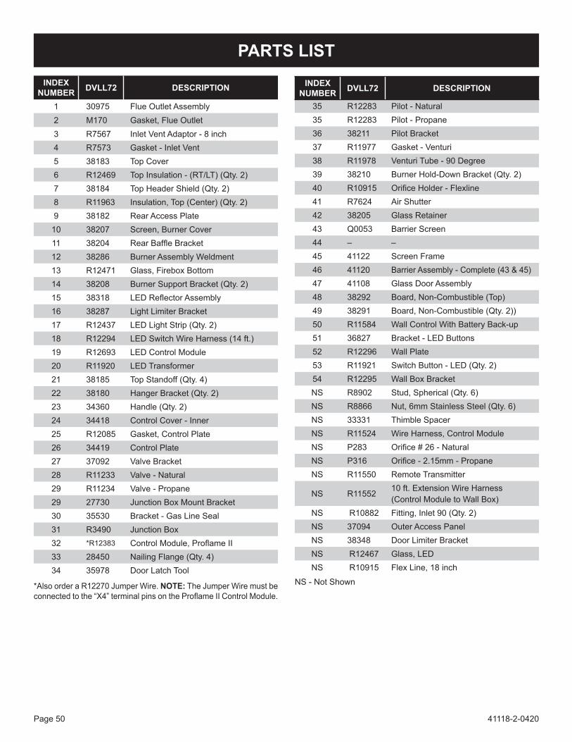
41118-2-0420Page 50
PARTS LISTINDEX
NUMBER DVLL72 DESCRIPTION
1 30975 Flue Outlet Assembly2 M170 Gasket, Flue Outlet3 R7567 Inlet Vent Adaptor - 8 inch4 R7573 Gasket - Inlet Vent5 38183 TopCover6 R12469 TopInsulation-(RT/LT)(Qty.2)7 38184 TopHeaderShield(Qty.2)8 R11963 Insulation,Top(Center)(Qty.2)9 38182 Rear Access Plate10 38207 Screen,BurnerCover11 38204 RearBaffleBracket12 38286 Burner Assembly Weldment13 R12471 Glass, Firebox Bottom14 38208 BurnerSupportBracket(Qty.2)15 38318 LEDReflectorAssembly16 38287 Light Limiter Bracket17 R12437 LEDLightStrip(Qty.2)18 R12294 LEDSwitchWireHarness(14ft.)19 R12693 LED Control Module20 R11920 LEDTransformer21 38185 TopStandoff(Qty.4)22 38180 Hanger Bracket (Qty. 2)23 34360 Handle (Qty. 2)24 34418 Control Cover - Inner25 R12085 Gasket, Control Plate26 34419 Control Plate27 37092 Valve Bracket28 R11233 Valve-Natural29 R11234 Valve - Propane29 27730 Junction Box Mount Bracket30 35530 Bracket-GasLineSeal31 R3490 Junction Box32 *R12383 ControlModule,ProflameII33 28450 NailingFlange(Qty.4)34 35978 DoorLatchTool
35 R12283 Pilot-Natural35 R12283 Pilot - Propane36 38211 Pilot Bracket37 R11977 Gasket - Venturi38 R11978 VenturiTube-90Degree39 38210 Burner Hold-Down Bracket (Qty. 2)40 R10915 OrificeHolder-Flexline41 R7624 AirShutter42 38205 Glass Retainer43 Q0053 BarrierScreen44 – –45 41122 ScreenFrame46 41120 Barrier Assembly - Complete (43 & 45)47 41108 Glass Door Assembly48 38292 Board,Non-Combustible(Top)49 38291 Board,Non-Combustible(Qty.2))50 R11584 Wall Control With Battery Back-up51 36827 Bracket - LED Buttons52 R12296 Wall Plate53 R11921 SwitchButton-LED(Qty.2)54 R12295 Wall Box BracketNS R8902 Stud,Spherical(Qty.6)NS R8866 Nut,6mmStainlessSteel(Qty.6)NS 33331 ThimbleSpacerNS R11524 Wire Harness, Control ModuleNS P283 Orifice#26-NaturalNS P316 Orifice-2.15mm-PropaneNS R11550 RemoteTransmitter
NS R1155210 ft. Extension Wire Harness (Control Module to Wall Box)
NS R10882 Fitting, Inlet 90 (Qty. 2)NS 37094 Outer Access PanelNS 38348 Door Limiter BracketNS R12467 Glass, LEDNS R10915 Flex Line, 18 inch
NS-NotShown
INDEX NUMBER DVLL72 DESCRIPTION
*AlsoorderaR12270JumperWire.NOTE:TheJumperWiremustbeconnectedtothe“X4”terminalpinsontheProflameIIControlModule.
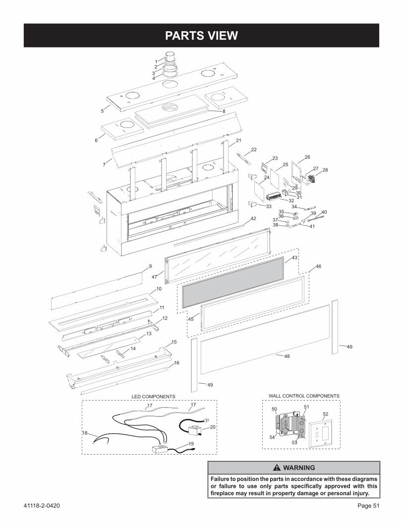
41118-2-0420 Page 51
LED COMPONENTS WALL CONTROL COMPONENTS
1
2
3
4
5
6
7
21
22
23
25
24
26
27 28
29
3031
32
33
42
38
373635
34
39 40
43
49
48
45
47
9
10
11
12
13
14
15
16
49
18
19
20
50
54
53
51
52
1717
8
41
46
PARTS VIEW
WARNINGFailure to position the parts in accordance with these diagrams or failure to use only parts specifically approved with this fireplace may result in property damage or personal injury.
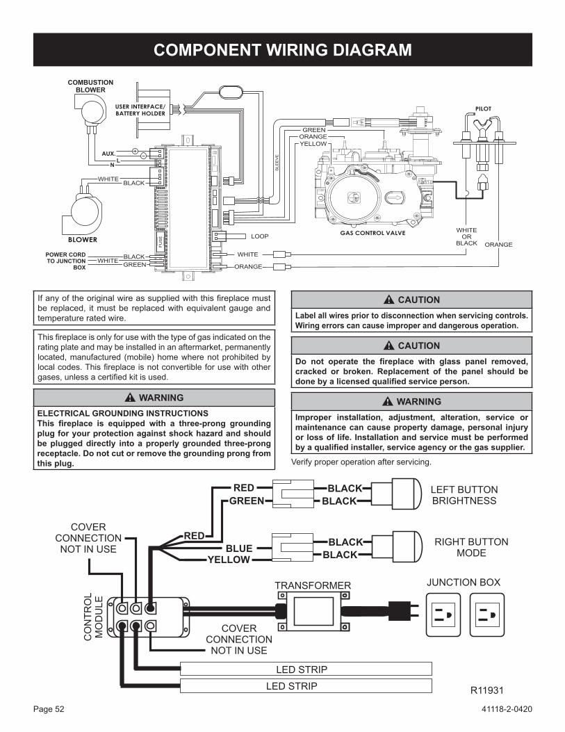
41118-2-0420Page 52
COMPONENT WIRING DIAGRAM
Ifanyoftheoriginalwireassuppliedwiththisfireplacemustbe replaced, it must be replaced with equivalent gauge and temperature rated wire.
Thisfireplaceisonlyforusewiththetypeofgasindicatedontherating plate and may be installed in an aftermarket, permanently located, manufactured (mobile) home where not prohibited by localcodes.Thisfireplaceisnotconvertibleforusewithothergases,unlessacertifiedkitisused.
WARNINGELECTRICAL GROUNDING INSTRUCTIONSThis fireplace is equipped with a three-prong grounding plug for your protection against shock hazard and should be plugged directly into a properly grounded three-prong receptacle. Do not cut or remove the grounding prong from this plug.
CAUTIONLabel all wires prior to disconnection when servicing controls. Wiring errors can cause improper and dangerous operation.
CAUTIONDo not operate the fireplace with glass panel removed, cracked or broken. Replacement of the panel should be done by a licensed qualified service person.
WARNINGImproper installation, adjustment, alteration, service or maintenance can cause property damage, personal injury or loss of life. Installation and service must be performed by a qualified installer, service agency or the gas supplier.
Verify proper operation after servicing.
NL
COMBUSTION
BLOWER
ORANGE
PILOT
GAS CONTROL VALVE
ORANGE
GREEN
YELLOW
WHITE
OR
BLACK
BLACKWHITE
BLOWER
FU
SE
BLACKWHITE
GREEN
POWER CORD
TO JUNCTION
BOX
AUX.
LOOP
SLE
EV
E
USER INTERFACE/
BATTERY HOLDER
ORANGE
WHITE
R11931
YELLOW
RED
GREEN
BLUE
REDBLACK
LED STRIP
LED STRIP
TRANSFORMER
CO
NT
RO
L
MO
DU
LE
BLACK
BLACK
BLACK
LEFT BUTTON
BRIGHTNESS
RIGHT BUTTON
MODE
JUNCTION BOX
COVER
CONNECTION
NOT IN USE
COVER
CONNECTION
NOT IN USE
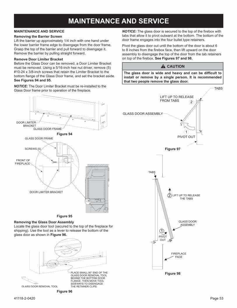
41118-2-0420 Page 53
MAINTENANCE AND SERVICEMAINTENANCE AND SERVICERemoving the Barrier ScreenLift the barrier up approximately 1/4 inch with one hand under the lower barrier frame edge to disengage from the door frame. Grasp the top of the barrier and pull forward to disengage it. Remove the barrier by pulling straight forward.
Remove Door Limiter BracketBefore the Glass Door can be removed, a Door Limiter Bracket mustberemoved.Usinga5/16-inchhexnutdriver,remove(5)#10-24 x 3/8-inch screws that retain the Limiter Bracket to the bottomflangeoftheGlassDoorframe,andsetthebracketaside.See Figures 94 and 95.NOTICE: TheDoorLimiterBracketmustbere-installedtotheGlassDoorframepriortooperationofthefireplace.
DOOR LIMITER BRACKET
GLASS DOOR FRAME
Figure 94GLASS DOOR FRAME
DOOR LIMITER BRACKET
SCREW (5)
FRONTOF
FIREPLACE
Figure 95Removing the Glass Door AssemblyLocatetheglassdoortool(securedtothetopofthefireplaceforshipping).Usethetoolasalevertoreleasethebottomoftheglass door as shown in Figure 96.
GLASS DOOR REMOVAL TOOL
PLACE SMALL 90° END OF THE
GLASS DOOR REMOVAL TOOL
BEHIND THE BOTTOM DOOR
FLANGE, THEN MOVE TOOL
SIDEWAYS TO DISENGAGE
THE RETAINER CLIPS
Figure 96
NOTICE:Theglassdoorissecuredtothetopofthefireboxwithtabsthatallowittopivotoutwardatthebottom.Thebottomofthedoor frame engages into the four bullet type retainers.
Pivot the glass door out until the bottom of the door is about 6 to8inchesfromthefireboxface,thenliftupwardonthedoorassembly to disengage the top of the door from the tab retainers ontopofthefirebox.See Figures 97 and 98.
CAUTIONThe glass door is wide and heavy and can be difficult to install or remove by a single person. It is recommended that two people remove the glass door.
LIFT UP TO RELEASE
FROM TABS
TABS
1
2
FIREPLACE FACE
PIVOT OUT
GLASS DOOR ASSEMBLY
Figure 97
PIVOT
OUT
TABS
2 LIFT UP TO
RELEASE OFF
THE TABS
GLASS DOOR
ASSEMBLY
FIREPLACE
FACE
1
Figure 98
GLASSDOORFRAME
DOORLIMITERBRACKET
SCREWS(5)
GLASSDOORFRAME
DOORLIMITERBRACKET
FRONTOFFIREPLACE
LIFTUPTORELEASETHETABS
GLASSDOORASSEMBLY
FIREPLACEFACE
PIVOTOUT
TABS
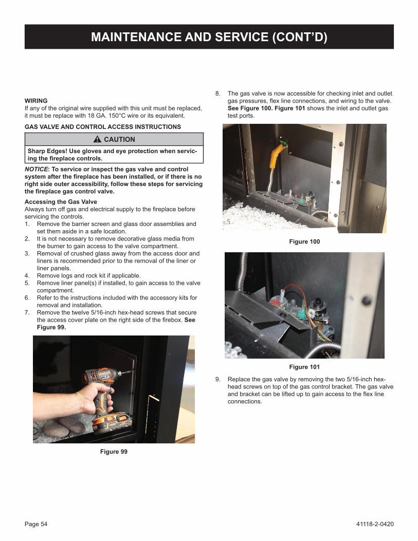
41118-2-0420Page 54
MAINTENANCE AND SERVICE (CONT’D)
WIRINGIf any of the original wire supplied with this unit must be replaced, it must be replace with 18 GA. 150°C wire or its equivalent.
GAS VALVE AND CONTROL ACCESS INSTRUCTIONS
CAUTIONSharp Edges! Use gloves and eye protection when servic-ing the fireplace controls.
NOTICE: To service or inspect the gas valve and control system after the fireplace has been installed, or if there is no right side outer accessibility, follow these steps for servicing the fireplace gas control valve.Accessing the Gas ValveAlwaysturnoffgasandelectricalsupplytothefireplacebeforeservicing the controls.1. Remove the barrier screen and glass door assemblies and
set them aside in a safe location.2. It is not necessary to remove decorative glass media from
the burner to gain access to the valve compartment.3. Removal of crushed glass away from the access door and
liners is recommended prior to the removal of the liner or liner panels.
4. Remove logs and rock kit if applicable.5. Remove liner panel(s) if installed, to gain access to the valve
compartment.6. Refer to the instructions included with the accessory kits for
removal and installation.7. Remove the twelve 5/16-inch hex-head screws that secure
theaccesscoverplateontherightsideofthefirebox.See Figure 99.
Figure 99
8. Thegasvalveisnowaccessibleforcheckinginletandoutletgaspressures,flexlineconnections,andwiringtothevalve.See Figure 100. Figure 101 shows the inlet and outlet gas test ports.
Figure 100
Figure 101
9. Replace the gas valve by removing the two 5/16-inch hex-headscrewsontopofthegascontrolbracket.Thegasvalveandbracketcanbelifteduptogainaccesstotheflexlineconnections.
41118-2-0420 Page 55
MAINTENANCE AND SERVICE (CONT’D)MAINTENANCE AND SERVICETheonlyrecommendedmaintenanceforthehomeownerisperiodically cleaning the glass. Before cleaning the glass read the warnings below.Thisfireplacehasnouser-serviceablemechanicalcomponents.Contactyourdealeroraqualifiedgasapplianceservicetechnician for all service and repair.
ACCESSING THE CONTROL MODULE
WARNINGAlways turn off gas and electrical supply to the fireplace before servicing.
1. Remove the barrier screen and glass door assemblies, and set them aside in a safe location.
2. It is not necessary to remove decorative glass media from the burner cover or accent glass panels to gain access to the control module.
3. Thecontrolmoduleisinthelowerfrontcornerofthefireplacebottom.ItissecuredtothefireplacewithVelcro.ThegascontrolandLEDlightwiringisroutedthroughthelower right side opening to the gas valve wire connections. The120Vpowercordsareroutedthroughthelowerrightside opening and plugged into the Junction Box receptacle.
Refer to the electrical connections section for additional information.
MAINTENANCEMaintenance frequency must be determined individually for each application.Someconsiderationsare:• Cycling frequency. Fireplaces that may cycle 20,000 times
annually should be checked monthly.• Intermittent use. Fireplaces that are used seasonally should
be checked before shutdown and again before the next use.• Dusty, wet or corrosive environment. Because these
environments can cause the gas control to deteriorate more rapidly, the system should be checked more often.
• Any control should be replaced if it does not perform properly on checkout or service. In addition, replace any module if it is wet or looks like it has been wet.
SERVICEDo not disassemble the gas control; it contains non-replaceable components. Attempted disassembly or repair can damage the control.Exactly follow the warnings and the lighting instructions.1. Beforelighting,smellaroundthefireplaceareaforgas.If
thefireplaceusesPropane(bottled)gas,besuretosmellnexttothefloorbecausePropanegasisheavierthanair.Ifyou smell gas, immediately shut off the manual valve in the gaspipingtothefireplaceoronPropaneatthetank.Donottry to light any appliance. Do not touch any electrical switch or use the phone. Leave the building and call your gas supplier.Ifyourgassuppliercannotbereached,callthefiredepartment.
2. Thegascontrolmustbereplacedifithasbeenfloodedwithwater.Callaqualifiedservicetechnician.
3. Thegascontrolisasafetydevice.Itmustbereplacedin case of any physical damage such as bent terminals, missing parts, stripped threads, or evidence of exposure to excessive heat.
Follow the operating instructions provided by the manufacturer of your appliance.
NOTICE: Itisnormalforfireplacesfabricatedofsteeltogiveoffsome expansion and/or contraction noise during the start up or cooldowncycle.Similarnoisesarefoundwithyourfurnaceheatexchanger or car engine.Itisnormalforyourgasfireplacetogiveoffsomeodorthefirsttimeitisburned.Thisisduetothecuringofthepaintandoilfromthe manufacturing process.
Please ensure that your room is well ventilated - open a window.
Burn your fireplace for at least one hour the first time you use it. If optional fan kit has been installed, place fan in the OFF position during this time.IMPORTANT: Turnoffgasbeforeservicingfireplace.Haveaqualifiedservicepersonperformthesecheck-upsonceayearpreferablybeforetheusingofthefireplace.
• Clean Burner and Control Compartment Keep the control compartment and burner area clean by
vacuuming or brushing at least twice a year.
CLEANING PROCEDURE1. Turnofffireplace.2. Removethebarrierscreenandglassdoorassembly.See
Glass Door Removal.3. Remove decorative media (a clean portable shop-vac is
recommended).4. Vacuumburnercoverandburnerscreenareas.Thecontrol
module located in the bottom front corner can also be vacuumed off.
5. Replace decorative media.6. Reinstall the glass door and barrier screen.7. Ignitefireplace.SeeLightingInstructions.8. Ifflameappearsabnormal,callaserviceperson.
WARNINGHandle the glass with care to avoid breaking it. Never strike the glass. To prevent etching or discoloring, clean the glass with Fireplace Glass Cleaner (available from your dealer). Never use cleaners that contain ammonia or abrasives. Never clean the glass while it is hot or even warm. Touching hot glass can cause severe burns. Using liquids or aerosols on hot glass will cause it to shatter. Never operate the fireplace with the glass removed or cracked. Have your dealer replace damaged glass only with glass and gasket material from Empire Comfort Systems. Using substitute glass will void the warranty.
41118-2-0420Page 56
• CHECK VENT SYSTEM Thefireplaceandventingsystemshouldbeinspectedbeforeinitialuseandatleastannuallybyaqualifiedserviceperson.Inspect the external vent cap on a regular basis to make sure thatnodebrisisinterferingwiththeairflow.
GLASS CLEANINGClean the glass before use and two or three times each heating season. During start-up condensation (which is normal) forms on the inside of the glass and causes lint, dust and other airborne particles to cling to the glass surface. Also initial paint curing may depositaslightfilmontheglass.Useanon-abrasivehouseholdcleanerandwarmwater(werecommendgasfireplaceglasscleaner).
WARNINGDo not use Ammonia based or abrasive cleaners on glass. Do not attempt to clean glass when glass is hot.
GENERAL GLASS INFORMATION
WARNINGDo not operate fireplace with the glass front removed, cracked or broken.
Onlyglassapprovedforusebythemanufacturerinfireplacemaybeusedforreplacement.Theglassreplacementshouldbedonebyalicensedorqualifiedserviceperson.
WARNING1. The use of substitute glass will void all product warranties.2. Care must be taken to avoid breakage of the glass.3. Under no circumstances should this fireplace be
operated without the glass front or with a broken glass front. Replacement of the glass (with gasket) as supplied by the manufacturer should be done by a qualified service person.
4. Do not abuse the glass by striking or hitting it.
MAINTENANCE AND SERVICE (CONT’D)GLASS DOOR AND BARRIER SCREEN REMOVAL AND REPLACEMENTRefer to page 53 for removal of the barrier screen and glass door assemblies.Refer to the Parts View and Parts List on pages 50 and 51 to identify replacement parts such as the barrier screen and glass door assemblies.GLASS DOOR INSTALLATIONRefer to Figures 96 and 97 to install the glass door assembly. Because of the width of the door assembly, it is recommended that two people install it. Hold the door at an angle so the bottom isabout8inchesfromthefireplaceface.Engagethetopslotsintodoorframewiththetabslocatedatthetopofthefirebox.Gently pivot the door inward to align the four bullet catches across the bottom of the door frame. Once the bullet pins are aligned with the spring catches on the door frame, push the bottom of the door inward to engage the spring catches with the bullet pins.
DOOR LIMITER BRACKET INSTALLATIONAfter the Glass Door is installed, the Door Limiter Bracket must beattached.Usinga5/16-inchhexnutdriver,install(5)#10-24x3/8-inchscrewstoretaintheLimiterBrackettothebottomflangeof the Glass Door frame.NOTICE: TheDoorLimiterBracketmustbere-installedtotheGlassDoorframepriortooperationofthefireplace.BARRIER INSTALLATIONThebarrierscreenassemblyinstallsontotheglassdoorassemblywithoutfasteners.Thetopflangeofthebarrierengagesthetopofthedoorframeandthebottomflange.Thebottomflangeonthebarrierinsertsbetweentheglassdoorframeacross the bottom. Adjust the barrier left to right to center it.
41118-2-0420 Page 57
MAINTENANCE AND SERVICE (CONT’D)ANNUAL INSPECTION• Havethefireplaceinspectedannuallybeforeuse.• More frequent inspection and cleaning may be required if the
fireplaceisinstalledinanareaexposedtopethairordust,or to excessive lint from new carpeting or bedding materials.
During The Annual Checkup, The Technician Will:• Inspectthepilot(flamesafetysystem)andburner(s)for
proper operation and replace any damaged parts.• Testandmeasuretheflamefailureresponsetimeofthe
flamesafetysystem.Itmustde-energizethesafetyshut-offin no more than 30 seconds.
• Vacuumandcleananyforeigndebrisinthefireboxthatisnot supposed to be there.
• Inspect and ensure that the lighting of the main burner occurs within 4 seconds of the gas valve opening. Visual inspection should match the information illustrated in the manual. Inspect primary air openings for blockage.
• Check the glass and gasket for proper seal.• CleanGlasswithasuitablefireplaceglasscleaner.Abrasive
cleaners must not be used. Be careful not to scratch the glass when cleaning.
• Check all latches or other door retention components for proper operation, tension, and relief mechanisms are free from obstructions. See Figure 81.• Checkthebarrierscreenforfitandstructuralintegrity. See Figure 79.• Inspect the log set (if applicable) and decorative media (if applicable) for debris or damage.• Freshen up the glowing embers if applicable.• Replace batteries in the remote transmitter and receiver if applicable.• Inspect the venting and vent termination cap for damage,
corrosion, sooting, or obstruction and correct if present.• Check all accessible gas-carrying tubes, connections, pipes and other components for leaks.
• In addition, clean and inspect the fireplace following any remodeling work in your home.
FOR THE INSTALLERMaintenance PrecautionsInstallationandrepairshouldbedonebyaqualifiedserviceperson.Thefireplaceshouldbeinspectedbeforeuseandatleastannuallybyaqualifiedserviceperson.Morefrequentcleaning might be required due to excessive lint from carpeting, bedding material, etc.Keep burner and control compartment clean. Examine venting system periodically and replace damaged parts.Make a periodic visual check of pilot and burners. Clean and replace damaged parts.
Damaged FireplaceDonotusethisfireplaceifanyparthasbeenunderwater.Immediatelycallaqualifiedservicetechniciantoinspectthefireplaceandtoreplaceanypartofthecontrolsystemandanygas control which has been under water.Intheeventofanaturaldisaster(tornado,earthquake,fire,etc.)haveaqualifiedtechnicianinspectthefireplacefordamageorpotential gas leaks. Repair or replace any damaged components beforeoperatingthisfireplace.
41118-2-0420Page 58
DONOTOPERATETHISAPPLIANCEWITHOUTGLASSFRONTPANELINSTALLED
Before enclosing the vent pipe assembly, operate the appliance to ensure it is venting properly.
IMPORTANT SAFETY INFORMATION
WARNING1. “Due to high temperatures, the appliance should be
located out of traffic and away from furniture anddraperies.”
2. “Childrenandadultsshouldbealertedtothehazardsof high surface temperature and should stay away to avoid burns or clothing ignition.”
3. “Youngchildrenshouldbecarefullysupervisedwhentheyareinthesameroomastheappliance.Toddlers,youngchildren, and others may be susceptible to accidental contact burns. A physical barrier is recommended if there areat-riskindividualsinthehouse.Torestrictaccesstoafireplaceorstove,installanadjustablesafetygatetokeeptoddlers, young children, and other at-risk individuals out of the room and away from hot surfaces.”
4. For appliances requiring a barrier, as determined under Clause5.15.4:“Abarrierdesignedtoreducetheriskofburns from the hot viewing glass is provided with this appliance and shall be installed for the protection of children and other at-risk individuals.”
5. “If the barrier becomes damaged, the barrier shallbe replaced with themanufacturer’s barrier for thisappliance.”
6. “Clothing or other flammablematerial should not beplaced on or near the appliance.”
7. “Any safety screen, guard, or barrier removed forservicing an appliance must be replaced prior to operating the appliance” (see Clause 4.1.6).
8. “Installation and repair should be done by a qualifiedservice person. The appliance should be inspectedbefore use and at least annually by a professional service person. More frequent cleaning might be required due to excessive lint from carpeting, bedding material, et cetera. It is imperative that control compartments, burners, and circulating air passageways of the appliance be kept clean.”
9. The instructions for an appliance optionally for usewithglassdoors(orequivalent)shallstatethat,“Onlydoorscertifiedwiththeapplianceshallbeused.”
10. Theinstructionsforanappliancenotintendedforusewith glass doors (or equivalent) shall emphasize that the appliance is not for use with glass doors.
11. Where applicable, provide a means by which the consumer can identify the barrier, (such as graphic representation, clear description, or reference marking).
WARNINGCARBON MONOXIDE POISONING HAZARDFailure to follow the steps outlined below for each appliance connected to the venting system being placed into operation could result in carbon monoxide poisoning or death. The following steps shall be followed for each applianceconnected to the venting system being placed into operation, while all other appliances connected to the venting system are not in operation:1. Sealanyunusedopeningsintheventingsystem.2. Inspect the venting system for proper size and horizontal
pitch, as required in the National Fuel Gas Code ANSI Z223.1/NFPA 54 or the National Gas and Propane Installation CodeCSAB149.1and these instructions.Determine that there is no blockage or restriction, leakage,corrosionandotherdeficiencieswhichcouldcause an unsafe condition.
3. As far as practical, close all building doors and windows and all doors between the space in which the appliance(s) connected to the venting system are located and other spaces of the building.
4. Closefireplacedampers.
5. Turnonclothesdryersandanyappliancenotconnectedtotheventingsystem.Turnonanyexhaustfans,suchas range hoods and bathroom exhausts, so they are operating at maximum speed. Do not operate a summer exhaust fan.
6. Follow the lighting instructions. Place the appliance being inspected into operation. Adjust the thermostat so appliance is operating continuously.
7. Testforspillagefromdrafthoodequippedappliancesat the draft hood relief opening after 5 minutes of main burneroperation.Usetheflameofamatchorcandle.
8. If improper venting is observed during any of the above tests, the venting system must be corrected in accordance with National Fuel Gas Code, ANSIZ223.1/NFPA and/or National Gas and Propane Installation Code,CSAB149.1.
9. After it has been determined that each appliance connected to the venting system properly vents when tested as outlined above, return doors, windows, exhaustfans,fireplacedampersandanyothergas-firedburning appliance to their previous conditions of use.
41118-2-0420 Page 59
SAFETY INFORMATION FOR USERS OF PROPANE GASPropane is a flammable gas which can cause fires and explosions. In its natural state, propane is odorless and colorless. You may not know all the following safety precautions which can protect both you and your family from an accident. Read them carefully now, then review them point by point with the members of your household. Someday when there may not be a minute to lose, everyone’s safety will depend on knowing exactly what to do. If, after reading the following information, you feel you still need more information, please contact your gas supplier.PROPANE GAS WARNING ODOR
If a gas leak happens, you should be able to smell the gas because of the odorant put in the Propane Gas. That’s your signal to go into immediate action!
• Do not operate electric switches, light matches, use your phone. Do not do anything that could ignite the gas.
• Get everyone out of the building, vehicle, trailer, or area. Do thatIMMEDIATELY.
• Close all gas tank or cylinder supply valves.• Propane Gas is heavier than air and may settle in low areas
such as basements. When you have reason to suspect a gas leak,keepoutofbasementsandotherlowareas.Stayoutuntilfirefightersdeclarethemtobesafe.
• Useyourneighbor’sphoneandcallatrainedPropaneGasservicepersonandthefiredepartment.Eventhoughyoumay not continue to smell gas, do not turn on the gas again. Do not re-enter the building, vehicle, trailer, or area.
• Finally,lettheservicemanandfirefighterscheckforescaped gas. Have them air out the area before you return. Properly trained Propane Gas service people should repair theleak,thencheckandrelightthegasfireplaceforyou.
NO ODOR DETECTED - ODOR FADESome people cannot smell well. Some people cannot smell the odor of the chemical put into the gas. You must find out if you can smell the odorant in propane.Smokingcandecrease your ability to smell. Being around an odor for a time canaffectyoursensitivityorabilitytodetectthatodor.Sometimesother odors in the area mask the gas odor. People may not smell thegasodorortheirmindsareonsomethingelse.Thinkingabout smelling a gas odor can make it easier to smell.The odorant in Propane Gas is colorless, and it can fade under some circumstances. For example, if there is an underground leak, the movement of the gas through soil can filtertheodorant.OdorantsinPropaneGasalsoaresubjecttooxidation.Thisfadingcanoccurifthereisrustinsidethestoragetank or in iron gas pipes.
Theodorantinescapedgascanadsorborabsorbontoorintowalls,masonryandothermaterialsandfabricsinaroom.Thatwilltake some of the odorant out of the gas, reducing its odor intensity.Propane Gas may stratify in a closed area, and the odor intensity couldvaryatdifferentlevels.Sinceitisheavierthanair,theremay be more odor at lower levels. Always be sensitive to the slightest gas odor. If you detect any odor, treat it as a serious leak. Immediately go into action as instructed earlier.
SOME POINTS TO REMEMBER• Learn to recognize the odor of Propane Gas. Your local
PropaneGasDealercangiveyoua“ScratchandSniff”pamphlet.Useittofindoutwhatthepropaneodorsmellslike. If you suspect that your Propane Gas has a weak or abnormal odor, call your Propane Gas Dealer.
• Ifyouarenotqualified,donotlightpilotlights,performservice, or make adjustments to appliances on the Propane Gassystem.Ifyouarequalified,consciouslythinkabouttheodor of Propane Gas prior to and while lighting pilot lights or performing service or making adjustments.
• Sometimesabasementoraclosed-uphousehasamustysmell that can cover up the Propane Gas odor. Do not try to light pilot lights, perform service, or make adjustments in an area where the conditions are such that you may not detect the odor if there has been a leak of Propane Gas.
• Odor fade, due to oxidation by rust or adsorption on walls ofnewcylindersandtanks,ispossible.Therefore,peopleshould be particularly alert and careful when new tanks or cylinders are placed in service. Odor fade can occur in new tanks,orreinstalledoldtanks,iftheyarefilledandallowedtosettoolongbeforerefilling.Cylindersandtankswhichhave been out of service for a time may develop internal rust which will cause odor fade. If such conditions are suspected to exist, a periodic sniff test of the gas is advisable. If you have any question about the gas odor, call your Propane Gas Dealer. A periodic sniff test of the Propane Gas is a good safety measure under any condition.
• If, at any time, you do not smell the Propane Gas odorant andyouthinkyoushould,assumeyouhavealeak.Thentake the same immediate action recommended above for the occasion when you do detect the odorized Propane Gas.
• Ifyouexperienceacomplete“gasout,”(thecontaineris under no vapor pressure), turn the tank valve off immediately. If the container valve is left on, the container may draw in some air through openings such as pilot light orifices.Ifthisoccurs,somenewinternalrustingcouldoccur.If the valve is left open, then treat the container as a new tank. Always be sure your container is under vapor pressure by turning it off at the container before it goes completely emptyorhavingitrefilledbeforeitiscompletelyempty.
41118-2-0420Page 60
REQUIREMENTS FOR MASSACHUSETTSFor all side wall horizontally vented gas fueled equipment installed in every dwelling, building or structure used in whole or in part for residential purposes, including those owned or operated by the Commonwealth and where the side wall exhaust ventterminationislessthansevenfeetabovefinishedgradeinthe area of the venting, including but not limited to decks and porches,thefollowingrequirementsshallbesatisfied:1. INSTALLATIONOFCARBONMONOXIDEDETECTORS.
At the time of installation of the side wall horizontal vented gasfueledequipment,theinstallingplumberorgasfittershallobserve that a hard wired carbon monoxide detector with analarmandbatteryback-upisinstalledonthefloorlevelwhere the gas equipment is to be installed. In addition, the installingplumberorgasfittershallobservethatabatteryoperated or hard wired carbon monoxide detector with an alarm is installed on each additional level of the dwelling, building or structure served by the side wall horizontal vented gas fueled equipment. It shall be the responsibility ofthepropertyownertosecuretheservicesofqualifiedlicensed professionals for the installation of hard wired carbon monoxide detectors
a. In the event that the side wall horizontally vented gas fueled equipment is installed in a crawl space or an attic, the hard wired carbon monoxide detector with alarm and battery back-up may be installed on the next adjacent floorlevel.
b. In the event that the requirements of this subdivision can not be met at the time of completion of installation, the owner shall have a period of thirty days to comply with the above requirements; provided, however, that during said thirty day period, a battery operated carbon monoxide detector with an alarm shall be installed.
2. APPROVEDCARBONMONOXIDEDETECTORS.Eachcarbon monoxide detector as required in accordance with theaboveprovisionsshallcomplywithNFPA720andbeANSI/UL2034listedandIAScertified.
3. SIGNAGE.Ametalorplasticidentificationplateshallbepermanently mounted to the exterior of the building at a minimum height of eight feet above grade directly in line with the exhaust vent termination for the horizontally vented gas fueledapplianceorequipment.Thesignshallread,inprintsize no less than 1/2 inch in size, “GAS VENT DIRECTLY BELOW. KEEP CLEAR OF ALL OBSTRUCTIONS”.
4. INSPECTION.Thestateorlocalgasinspectoroftheside wall horizontally vented gas fueled equipment shall not approve the installation unless, upon inspection, the inspector observes carbon monoxide detectors and signage installed in accordance with the provisions of 248 CMR 5.08(2)(a) 1 through 4.
(b) EXEMPTIONS:Thefollowingequipmentisexemptfrom248 CMR 5.08(2)(a)1 through 4:
1. TheequipmentlistedinChapter10entitled“EquipmentNotRequiredToBeVented”inthemostcurrenteditionofNFPA54asadoptedbytheBoard; and
2. Product Approved side wall horizontally vented gas fueled equipment installed in a room or structure separate from the dwelling, building or structure used in whole or in part for residential purposes.
(d) MANUFACTURERREQUIREMENTS-GASEQUIPMENTVENTINGSYSTEMNOTPROVIDED.When the manufacturer of a Product Approved side wall horizontally vented gas fueled equipment does notprovidethepartsforventingthefluegases,butidentifies“specialventingsystems”,thefollowingrequirementsshallbesatisfiedbythemanufacturer:
1. Thereferenced“specialventingsystem”instructions shall be included with the appliance or equipment installation instructions; and
2. The“specialventingsystems”shallbeProductApproved by the Board, and the instructions for that system shall include a parts list and detailed installation instruction.
(e) A copy of all installation instructions for all Product Approved side wall horizontally vented gas fueled equipment, all venting instructions, all parts lists for venting instructions, and/or all venting design instructions shall remain with the appliance or equipment at the completion of the installation.
41118-2-0420 Page 61
FIREPLACE SERVICE HISTORYDate Dealer Name Service Technician Name Service Performed/Notes
41118-2-0420Page 62
ToOrderPartsUnderWarranty,pleasecontactyourlocalEmpiredealer.Seethedealerlocatoratwww.empirecomfort.com.Toprovidewarrantyservice,yourdealerwillneedyournameandaddress,purchasedateandserialnumber,andthenatureof the problem with the unit. ToOrderPartsAftertheWarrantyPeriod,pleasecontactyourdealeroroneoftheMasterPartsDistributorslistedbelow.Thislistchangesfromtimetotime.Forthecurrentlist,pleaseclickontheMasterPartsbuttonatwww.empirecomfort.com.Please note: Master Parts Distributors are independent businesses that stock the most commonly ordered Original EquipmentrepairpartsforHeaters,Grills,andFireplacesmanufacturedbyEmpireComfortSystemsInc.
MASTER PARTS DISTRIBUTOR LIST
Parts Not Under WarrantyPartscanbeorderedthroughyourServicePerson,Dealer,oraMasterPartsDistributor.SeethispagefortheMasterPartsDistribu-tors list. For best results, the service person or dealer should order parts through the distributor. Parts can be shipped directly to the service person/dealer.Warranty PartsWarrantypartswillneedaproofofpurchaseandcanbeorderedbyyourServicePersonorDealer.Proofofpurchaseisrequired for warranty parts.AllpartslistedinthePartsListhaveaPartNumber.Whenorderingparts,firstobtaintheModelNumberandSerialNumberfromthenameplateonyourequipment.ThendeterminethePartNumber(nottheIndexNumber)andtheDescriptionofeachpartfromthefol-lowing illustration and part list. Be sure to give all this information . . .
FireplaceModelNumber Part Description
FireplaceSerialNumber PartNumber
TypeofGas(PropaneorNatural)
Donotorderbolts,screws,washersornuts.Theyarestandardhardwareitemsandcanbepurchasedatanylocalhardwarestore.Shipmentscontingentuponstrikes,firesandallcausesbeyondourcontrol.
HOW TO ORDER REPAIR PARTS
Dey Distributing1401 Willow Lake BoulevardVadnaisHeights,MN55101
Phone: 651-490-9191Toll Free: 800-397-1339Website: www.deydistributing.comParts: Heater, Hearth and Grills
F. W. Webb Company200LocustStreetHartford,CT06114
Phone: 860-722-2433Toll Free: 800-243-9360Fax: 860-293-0479Toll Free Fax: 800-274-2004Websites: www.fwwebb.com & www.victormfg.comParts: Heater, Hearth and Grills
East Coast Energy Products10 East Route 36WestLongBranch,NJ07764
Phone: 732-870-8809Toll Free: 800-755-8809Fax: 732-870-8811Website: www.eastcoastenergy.comParts: Heater, Hearth and Grills
41118-2-0420 Page 63
WARRANTYEmpireComfortSystemsInc.warrantiesthishearthproducttobefreefromdefectsatthetimeofpurchaseandfortheperiodsspecifiedbelow.EmpirewillnotwarrantyanyBoulevard,Portrait,TruFlamefireplacethatisnotinstalledbythesellingdealerorthatdealer’sdirectcontractagents.Thiswarrantyappliestotheoriginalpurchaseronlyandisnottransferable.Allwarrantyrepairsmustbeaccomplishedbyaqualifiedgasappliancetechnician.
Limited Lifetime Parts Warranty – Combustion Chamber, Heat Exchanger, and Factory-Installed Glass If the combustion chamber, heat exchanger (see parts list) or factory-installed glass fails because of defective
workmanshipormaterial,EmpirewillrepairorreplaceitatEmpire’soption.
Limited Three-Year Parts Warranty – All Other Components (Except Remote Controls, Thermostats, Lights, Accessories and Replacement Parts) Shouldanypartfailbecauseofdefectiveworkmanshipormaterialwithinthreeyearsfromthedateofpurchase,
EmpirewillrepairorreplaceitatEmpire’soption.
Limited One-Year Parts Warranty – Remote Controls, Thermostats, Lights, Accessories, and Replacement Parts Shouldanyremotecontrol,thermostat,lightingsystem,accessory,orreplacementpartfailbecauseofdefective
workmanshipwithinoneyearfromthedateofpurchase,EmpirewillrepairorreplaceitatEmpire’soption.
Duties of the Owner Havetheapplianceinstalledbyaqualifiedinstaller,andoperateandmaintainitinaccordancewiththefurnished
instructions Provide proof of purchase (receipt) to establish the purchase date, which determines the warranty start date. Provide ready access to the appliance for service.
What Is Not Covered Damage caused by misuse or improper installation. Damage caused by improper maintenance or lack of maintenance. Claims that do not involve defective workmanship or materials. Unauthorizedserviceorreplacementparts. Travel,diagnosticcostsandfreightchargesonwarrantedpartstoandfromthefactory. Removal and reinstallation cost.
How to Get Service Providethedealerwiththemodelnumber,serialnumber,typeofgas,andproofofpurchase.Theinstallingdealer
is responsible for providing service and will contact the factory to initiate any warranted parts replacements. Empirewillmakereplacementpartsavailableatthefactory.Shippingexpensesarenotcovered. If, after contacting your Empire dealer, the service received has not been satisfactory, send an e-mail describing the
[email protected]“ConsumerRelations”inthesubjectline.
Your Rights under State Law Thiswarrantygivesyouspecificlegalrights,andyoumayalsohaveotherrights,whichvaryfromstatetostate.

41118-0-0819www.empirecomfort.com
Empire Comfort Systems Inc.Belleville, ILIf you have a general question about our products, please e-mail us at [email protected]. If you have a service or repair question, please contact your dealer.