Embed Size (px)
Citation preview

WARNINGS AND APPLICATION INSTRUCTIONS
WARNING
2017
RopeBlock logo PMS
PMS 648
PMS 648 70%
PMS 556
General warning, use, inspection, maintenance and safety information
for sockets.
Warning: This document contains important information
for the safe and proper installation and use of
your Ropeblock components.
© Copyright Ropeblock B.V.

Warnings and application instructions
GeneralSafety measures should be taken into account when using our
sockets. Carefully follow all installation instructions. Important
measures can be found below.
Spelter Socketsn Proper spelter socket terminations have an efficiency equal to the
breaking load of the wire. This can be limited by the minimum
breaking load of the socket (MBL), as mentioned in the tablesn Please read the instructions of the resin manufacturer carefully before
use. Incorrect use of the resin or spelter material can result in an unsafe
termination. More information can also be obtained from your wire
rope suppliern Always remove any dirt and grease from the wire rope broom and
socket basketn Ensure that the broomed wires are evenly spaced in the basket and
that the wire and basket are aligned with each othern When using white metal or zinc, the socket may be preheated to
300°C (570°F), but never over 350°C (660°F)n Make sure the base of the socket is properly sealed. This to
prevent resin leakage, which may cause voidsn Never use an assembly before the resin is fully hardenedn Procedures in EN 13411-4, ISO 17558 or equivalent should be followedn Socketing shall always be executed by competent personnel only
Fast Connector Socketsn The FCS Spin Resistant connector shall be used with non-rotation
resistant wire rope and may be used with rotation resistant wire ropen The FCS standard (rotating) connector shall be used with non-rotating
or rotation resistant wire rope onlyn Socketing of the connector shall be executed by competent
personnel only. Normal socketing procedures for spelter sockets
shall be followed
Requ
ired
resin
vol
ume
for s
ocke
ting
wire
rope
term
inat
ions
6 - 7
8 - 10
11 - 13
14 - 16
18 - 19
20 - 22
23 - 26
27 - 30
31 - 36
37 - 39
40 - 42
43 - 48
49 - 54
55 - 60
61 - 68
69 - 75
76 - 80
81 - 86
87 - 93
94 - 102
108 - 115
120 - 130
135 - 140
141 - 153
154 - 165
166 - 178
179 - 191
192 - 204
1/43/81/25/83/47/81
1 1/81 1/2 - 1 3/8
1 1/21 5/8
1 3/4 - 1 7/82 - 2 1/8
2 1/4 - 2 3/82 1/2 - 2 5/82 3/4 - 2 7/8
3 - 3 1/83 1/4 - 3 3/83 1/2 - 3 5/8
3 3/4 - 4
4 1/4 - 4 1/2
4 3/4 - 5
5 1/2
5 3/4 - 66 1/4 - 6 1/2
6 3/4 - 77 1/4 - 7 1/2
7 3/4 - 8
9
15
35
50
80
120
160
220
350
425
500
700
1200
1450
1850
2250
3500
4000
5000
7500
10500
14000
16000
20000
26000
33000
39000
48000
For wire rope Ø Approximateresin
volume
mm inch cc
W A R N I N G Sn Always carry out a visual inspection
before using a socket and pin.n Never use a part showing cracks.n Do not side-load a socket.n Repairs are not allowed, for any
repairs contact your supplier.n Never shock-load a socket.
1

RO
PEB
LOC
KWarnings and application instructions
Super reeve Connector Socketsn The SCS Spin Resistant connector shall be used with non-rotation resistant
wire rope and may be used with rotation resistant wire ropen The SCS standard (rotating) connector shall be used with non-rotating
or rotation resistant wire rope onlyn Socketing of the connector shall be executed by competent personnel only
Normal socketing procedures for spelter sockets shall be followedn The connector cap shall be secured after socketing by means of a high strength
thread locking adhesiven The connector cap is not a lifting device; it is used to pull the connector through
the reeving system with a standard shacklen The connector shall always be installed and used with the retainer properly installed
Wedge Socketsn Always mount the loaded part of the wire in the centre line of the pin (see figures below)n Secure properly the dead end with a wire rope clipn Do not attach the dead end to the live wiren The dead end should have a length of 6 times the wire diameter with a minimum of 150 mmn Ensure that the wire rope and wedge are fully seated after the first loadn A load may slip if the connection is not properly installedn Inspect the connection regularlyn The efficiency of a 6 or 8 strand wire rope and most high performance ropes with a
Ropeblock wedge socket connection is 80% of the MBL of the wire rope, but limited
to the MBL of the socketn Check your wire rope supplier for efficiency rating details when used with high
performance ropes and test the assembly to determine efficiencyn Nominal intermediate rope sizes should be used with the biggest socket within the range
incorrectincorrectcorrect
2
Warnings and application instructions
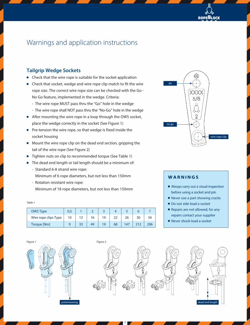
Tailgrip Wedge Socketsn Check that the wire rope is suitable for the socket applicationn Check that socket, wedge and wire rope clip match to fit the wire
rope size. The correct wire rope size can be checked with the Go -
No Go feature, implemented in the wedge. Criteria:
- The wire rope MUST pass thru the “Go” hole in the wedge
- The wire rope shall NOT pass thru the “No-Go” hole in the wedge n After mounting the wire rope in a loop through the OWS socket,
place the wedge correctly in the socket (See Figure 1)n Pre-tension the wire rope, so that wedge is fixed inside the
socket housingn Mount the wire rope clip on the dead end section, gripping the
tail of the wire rope (See Figure 2)n Tighten nuts on clip to recommended torque (See Table 1)n The dead end length or tail length should be a minimum of:
- Standard 6-8 strand wire rope:
Minimum of 6 rope diameters, but not less than 150mm
- Rotation resistant wire rope:
Minimum of 18 rope diameters, but not less than 150mm
dead end length
go
no go
wire rope clip
OWS Type
Wire rope clips Type
Torque [Nm]
0,5
10
9
1
13
33
2
16
49
3
19
19
4
22
68
5
26
147
6
30
212
7
34
296
W A R N I N G S
n Always carry out a visual inspection
before using a socket and pinn Never use a part showing cracksn Do not side-load a socketn Repairs are not allowed, for any
repairs contact your suppliern Never shock-load a socket
Table 1
Figure 2
pretensioning
Figure 1
3