Embed Size (px)
Citation preview

Form P-VALVES, P/N 263995R4, Page 1
WARNINGS Selection of replacement control parts from this manual and all servicing to Reznor® products must be done by a Reznor® Distributor or other qualified technician. Improper selection or servicing could result in severe personal injury, death, or property damage. Reznor Corporation will accept no responsibility or liability as a result of improper servicing of Reznor® products. In the United States, all installations of Reznor® gas-fired products must be in accordance with the Standards of the NFPA (National Fire Protection Association), the National Fuel Gas Code, and all local authorities. In Canada, all installations of Reznor® gas-fired products must be in accordance with the CAN/CSA Installation Code for Gas Burning Appliances and Equipment and all provincial and local authorities.
�Form P-VALVES (Version F.3)
Obsoletes Form P-VALVES (Version F.2)
Applies to: Serial No. Explanation; Model No. Explanation; Replacement Ignition Systems and Gas Valves by Serial No. Code;
and Maxitrol System Components by Serial No. Suffix
SAFETY WARNINGS AND GUIDELINES FOR A QUALIFIED SERVICE TECHNICIANWhen selecting a replacement control, always have the complete Model No. and Serial No. of the heater.
(See pages 2-4 for instructions on decoding those numbers.) If the model and serial number are not available, contact your Reznor® Representative. DO NOT SELECT REPLACEMENT CONTROLS WITH-OUT COMPLETE INFORMATION.
Before servicing a heater, always turn off the gas and the power supply. Because of the electrical safety features, never turn off the power supply without turning off the gas.
The electrical operating valve is the primary safety shutoff. The gas supply line must be free of dirt or scale before connecting the valve.
Leak test all gas connections including pilot connections. Test using a commercial leak detecting or a soap solution. WARNING: DO NOT TEST WITH OPEN FLAME. If a leak cannot be stopped by tightening, replace the part.
In the event of pilot outage or improper ignition, wait at least five minutes before attempting to relight the heater.
After any service is completed, always test for proper operation. Re-connect the electrical supply and turn on the gas. Verify against operating sequence information on the heater and in the heater instal-lation manual. Safety check the installation and equipment. CHECK THAT ALL SAFETY DEVICES ARE FUNCTIONING PROPERLY.
SAFETY WARNINGS AND GUIDELINES ................................................1Instructions for Selecting a Replacement Ignition Controller
and/or Valve ........................................................................................2Serial Number and Model Codes ...........................................................3
Serial No. Decoding ............................................................................ 3Serial Number Key - Month and Year of Manufacture ....4Heater Serial No. PREFIX and SUFFIX Codes ..............5
Model No. Decoding ............................................................................ 5Safety Pilot or Ignition System by Serial No. Code .........................6-10Type of Gas Valve by Serial No. Code ...........................................11-27Maxitrol Components for Electronic Modulation .........................28-31
Replacement Parts
Table of Contents

Form P-VALVES, P/N 263995R4, Page 2
FOR YOUR SAFETYWARNINGS
The use and storage of gasoline or other flammable vapors and liquids in the vicinity of this heating appliance is hazardous.
Instructions for Selecting a Replacement Ignition Controller and/or Valve
Serial No. Codes - Identify the code of the valve or ignition controller needing replacement. Serial No. Codes are defined on pages 3-5. IMPORTANT NOTE: Serial No. and Model No. Codes apply only to original equipment. IGNITION CONTROLLER - To select the replacement ignition controller, locate the Serial No. safety pilot code in the listing on pages 6-10. Select carefully, reading all applicable notes. If the part is no longer available from Reznor, a functional replacement or alternative instructions are listed.VALVE - To select a replacement valve, locate the Serial No. valve code in the listing on pages 12-19. The valve supplied on the heater is described. If the valve is no longer available from Reznor, a functional replacement or alternative instructions may be listed. Select carefully, read-ing all applicable notes. All valve code notes are on pages 20-22. See pages 23-27 for represen-tative illustrations of valves.
VALVE WIRING TERMINAL IDENTIFICATION/WIRE COLORValve Manufacturer Common Pilot Main or Low Stage High Stage
HoneywellTR TH-TR TH
PV-MV PV MVC PV MV H1
White-RodgersC P M
C1-C2 -- W1 W22 4 1 3
Robertshaw C P MOriginal Wire Color (exceptions possible)
White or Brown Blue Black Red
IMPORTANT: The controls identified in this form are the controls factory-installed on units manufactured beginning in 1963. Much of the earlier information provided is for reference only and does not mean that replacing parts is recommended or that replacement parts are available. See date code information on page 4.
1. Always include complete heater model and serial number so that any specification change can be considered for parts shipment. It can save time and expense.
2. Specifications are subject to change without notice.3. We reserve the right to substitute functional replacements.4. Order either by Kit or Component Part No.
IMPORTANT ORDERING REMINDERS
DANGERThe gas burner in all Reznor® gas-fired equipment is designed and equipped to provide safe, complete combustion. However if the installation does not permit the burner to receive the proper supply of combustion air, complete combustion may not occur. The result is incomplete combustion which produces carbon monoxide, a poisonous gas that can cause death. Safe operation of indirect-fired gas burning equipment requires a properly operating vent system which vents all the products to the outside atmosphere. Failure to provide proper venting will result in a health hazard which could cause serious personal injury or death.Always comply with the combustion air requirements in the installation codes and instructions. Combustion air at the burner should be regulated only by manufacturer-provided equipment. NEVER RESTRICT OR OTHERWISE ALTER THE SUPPLY OF COMBUSTION AIR TO ANY HEATER. Indoor units installed in a confined space must be supplied with air for combustion as required by code and in the installation manual. ON INDIRECT-FIRED EQUIPMENT, MAINTAIN THE VENT SYSTEM IN PROPERLY FUNCTIONING CONDITION. Direct-fired and other unvented installations should provide for air changes as required by applicable installation codes.

Form P-VALVES, P/N 263995R4, Page 3
Example of a Rating Plate that applies to most Reznor® Models showing Model and Serial NumbersSerial No. Decoding
DUCT FURNACECATEGORY IFOR INDUSTRIAL/COMMERCIAL USE ONLY NRTLDESIGN CERTIFIED UNDER ANSI Z83.8a-1998
DUCT FURNACEMODEL HX100E-8-S OCT 2004SERIAL# EBDJ66W8N12345115 VOLTS 1PH 60HZ MAXIMUM TOTAL INPUT .5AMPSTYPE OF GAS NATURALORIFICE SIZE #41 DRILL HAS BEEN FACTORY ADJUSTEDFOR USE AT 0-2000 FEET (0-610 METERS) OF ALTITUDE SEA LEVEL ALT ADJUSTEDNORMAL INPUT 100000 100000 BTU/HROUTPUT CAPACITY 80000 80000 BTU/HRMIN. INPUT (2, M, MB, MV MODELS) 50000 50000 BTU/HRNORMAL MANIFOLD PRESSURE 3.5 IN. W.C.MIN. PERMISSIBLE GAS SUPPLY PRESSUREFOR PURPOSE OF INPUT ADJUSTMENT 5.0 IN. W.C.MAXIMUM THROUGHPUT 3704 CFMMINIMUM THROUGHPUT 988 CFM
CLEARANCE TO COMBUSTIBLE CONSTRUCTION: TOP - 6"; FLUE CONNECTION - 6"; SERVICE SIDE - WIDTH OF UNIT; OPPOSITE SIDE - 6"; BOTTOM - 3", MAY BE INSTALLED ON NONCOMBUSTIBLE FLOORS.INSTALL ON THE POSITIVE PRESSURE SIDE OF AIR CIRCULATING BLOWER.THIS UNIT MAY BE INSTALLED DOWNSTREAM FROM A REFRIGERATION SYSTEM (USE DRAIN OPTION CS1).FOR ALTERNATE INSTALLATION, USE THE LATEST OF THE APPROPRIATE STANDARDS LISTED BELOW:FOR AIRCRAFT HANGARS USE STANDARD ANSI/NFPA 409FOR PARKING STRUCTURES USE STANDARD ANSI/NFPA 88AFOR REPAIR GARAGES USE STANDARD ANSI/NFPA 88B
�
Mercer, PA 16137
Serial Number and Model Codes
Sample of a Serial No. for Units manufactured from 1963 through 1974:
OA 1 2 N 693 Serial No.1 2 3 4 5 Element
Sample of a Serial No. for Units manufactured beginning in 1975:BDJ 66 W8 N 12345 Serial No.1 2 3 4 5 Element
Element Key:1 = Month and Year of manufacture; see page 4.2 = Type of safety pilot or ignition system; see pages 6-10 for Code
explanation.3 = Type of valve; see pages 12-22 for Code explanation and illustra-
tions on pages 23-27. (A dash indicates that the valve was field supplied.)
4 = Type of gas that the heater was originally manufactured to burn D = Dual fuel, natural and propane; L = Propane; N = Natural
(Check for gas conversion label.)5 = Consecutive number of heater manufactured. Used for identifi-
cation purposes only.In addition to the basic five elements, the serial number may also include prefix and/or suffix codes. See page 5 for a listing and explanation of these codes. All codes apply to original equipment only.
REZNOR® MERCER, PA, U.S.A. 16137
MADE IN USAFOR INDUSTRIAL/COMMERCIAL USE ONLYSUITABLE FOR OUTDOOR USEMODEL [ A ] [ B ]SERIAL NO. [ ]
ELECTRICAL[D] VOLTS +/- 10% [D] PHASE [D] HZ MINIMUM CIRCUIT AMPACITY (MCA) [ F ] AMPSMAXIMUM FUSE SIZE/*CKT BREAKER [ G ] AMPS
QTY FLA (EA) HP (EA)SUPPLY AIR BLOWER MOTOR 1 [ E ] [ C ]CONDENSER FAN MOTOR (S) [ T ] [ U ] [ Z ]
QTY RLA (EA) LRA (EA)COMPRESSOR A [ H ] [ I ] [ J ]COMPRESSOR B [ K ] [ L ] [ M ]COMPRESSOR C [ N ] [ O ] [ P ]COMPRESSOR D [ Q ] [ R ] [ S ]COMPRESSOR E [ GG ] [ HH ] [ II ]
CIRCUITS A B C D EREFRIGERANT - R-410a CHARGE - LBS [ V ] [ W ] [ X ] [ Y ] [ JJ ]TEST PRESSURES HIGH 600PSIG LOW 45PSIGEQUIPPED FOR OPERATION AT AN AIR FLOW OF [ CC ] SCFMAGAINST A STATIC PRESSURE OF [ DD ] INCHES WATER COLUMNDRIVE RPM [ EE ]WIRE DIAGRAM [ FF ]REFER TO RATING PLATE IN THE FURNACE SECTION (WHEN USED)FOR ADDITIONAL INFORMATION.*HACR TYPE REQUIRED PER NEC
Rating Plate Key for MAPS® Model Series RCA, RDA, RCB, RDB, RCC, and RDC (NOTE: To decode a MAPS Serial No., see page 4.)
Example of a Reznor® MAPS® Unit Rating Plate Showing Model and Serial Numbers
CC = SCFM AirflowDD = External
Static Pressure (“ w.c.)
EE = Drive (Option AM)
FF = Wiring Dia-gram No.
GG = Quantity - Compressor E
HH = Rated Load Amps of Com-pressor E
II = Locked Rotor Amps of Com-pressor E
JJ = Refrigerant Charge (lbs) - Circuit E
A = Model B = Manufacturing Date (Month/Year)C = Blower Motor HPD = Volts/Phase/HertzE = Full Load Amps (FLA) of Blower MotorF = Minimum Circuit Ampacity (MCA)G = Maximum Fuse Size (MOP)H = Quantity - Compressor AI = Rated Load Amps of Compressor AJ = Locked Rotor Amps of Compressor AK = Quantity - Compressor BL = Rated Load Amps of Compressor BM = Locked Rotor Amps of Compressor BN = Quantity - Compressor CO = Rated Load Amps of Compressor CP = Locked Rotor Amps of Compressor CQ = Quantity - Compressor DR = Rated Load Amps of Compressor DS = Locked Rotor Amps of Compressor DT = Quantity Condenser Fan MotorsU = Rated Load Amps of Condenser(s)V = Refrigerant Charge (lbs) - Circuit AW = Refrigerant Charge (lbs) - Circuit BX = Refrigerant Charge (lbs) - Circuit CY = Refrigerant Charge (lbs) - Circuit DZ = Condenser Fan Motor HP

Form P-VALVES, P/N 263995R4, Page 4
Year Jan Feb Mar Apr May June July Aug Sept Oct Nov Dec1963 OA OB OC OD OE OF OG OH OI OJ OK OL1964 PA PB PC PD PE PF PG PH PI PJ PK PL1965 QA QB QC QD QE QF QG QH QI QJ QK QL1966 RA RB RC RD RE RF RG RH RI RJ RK RL1967 SA SB SC SD SE SF SG SH SI SJ SK SL1968 TA TB TC TD TE TF TG TH TI TJ TK TL1969 UA UB UC UD UE UF UG UH UI UJ UK UL1970 VA VB VC VD VE VF VG VH VI VJ VK VL1971 WA WB WC WD WE WF WG WH WI WJ WK WL1972 XA XB XC XD XE XF XG XH XI XJ XK XL1973 YA YB YC YD YE YF YG YH YI YJ YK YL1974 ZA ZB ZC ZD ZE ZF ZG ZH ZI ZJ ZK ZL1975 AAA AAB AAC AAD AAE AAF AAG AAH AAI AAJ AAK AAL1976 ABA ABB ABC ABD ABE ABF ABG ABH ABI ABJ ABK ABL1977 ACA ACB ACC ACD ACE ACF ACG ACH ACI ACJ ACK ACL1978 ADA ADB ADC ADD ADE ADF ADG ADH ADI ADJ ADK ADL1979 AEA AEB AEC AED AEE AEF AEG AEH AEI AEJ AEK AEL1980 AFA AFB AFC AFD AFE AFF AFG AFH AFI AFJ AFK AFL1981 AGA AGB AGC AGD AGE AGF AGG AGH AGI AGJ AGK AGL1982 AHA AHB AHC AHD AHE AHF AHG AHH AHI AHJ AHK AHL1983 AIA AIB AIC AID AIE AIF AIG AIH AII AIJ AIK AIL1984 AJA AJB AJC AJD AJE AJF AJG AJH AJI AJJ AJK AJL1985 AKA AKB AKC AKD AKE AKF AKG AKH AKI AKJ AKK AKL1986 ALA ALB ALC ALD ALE ALF ALG ALH ALI ALJ ALK ALL1987 AMA AMB AMC AMD AME AMF AMG AMH AMI AMJ AMK AML1988 ANA ANB ANC AND ANE ANF ANG ANH ANI ANJ ANK ANL1989 AOA AOB AOC AOD AOE AOE AOG AOH AOI AOJ AOK AOL1990 APA APB APC APD APE APF APG APH API APJ APK APL1991 AQA AQB AQC AQD AQE AQF AQG AQH AQI AQJ AQK AQL1992 ARA ARB ARC ARD ARE ARF ARG ARH ARI ARJ ARK ARL1993 ASA ASB ASC ASD ASE ASF ASG ASH ASI ASJ ASK ASL1994 ATA ATB ATC ATD ATE ATF ATG ATH ATI ATJ ATK ATL1995 AUA AUB AUC AUD AUE AUF AUG AUH AUI AUJ AUK AUL1996 AVA AVB AVC AVD AVE AVF AVG AVH AVI AVJ AVK AVL1997 AWA AWB AWC AWD AWE AWF AWG AWH AWI AWJ AWK AWL1998 AXA AXB AXC AXD AXE AXF AXG AXH AXI AXJ AXK AXL1999 AYA AYB AYC AYD AYE AYF AYG AYH AYI AYJ AYK AYL2000 AZA AZB AZC AZD AZE AZF AZG AZH AZI AZJ AZK AZL2001 BAA BAB BAC BAD BAE BAF BAG BAH BAI BAJ BAK BAL2002 BBA BBB BBC BBD BBE BBF BBG BBH BBI BBJ BBK BBL2003 BCA BCB BCC BCD BCE BCF BCG BCH BCI BCJ BCK BCL2004 BDA BDB BDC BDD BDE BDF BDG BDH BDI BDJ BDK BDL2005 BEA BEB BEC BED BEE BEF BEG BEH BEI BEJ BEK BEL2006 BFA BFB BFC BFD BFE BFF BFG BFH BFI BFJ BFK BFL2007 BGA BGB BGC BGD BGE BGF BGG BGH BGI BGJ BGK BGL2008 BHA BHB BHC BHD BHE BHF BHG BHH BHI BHJ BHK BHL2009 BIA BIB BIC BID BIE BIF BIG BIH BII BIJ BIK BIL2010 BJA BJB BJC BJD BJE BJF BJG BJH BJI BJJ BJK BJL2011 BKA BKB BKC BKD BKE BKF BKG BKH BKI BKJ BKK BKL2012 BLA BLB BLC BLD BLE BLF BLG BLH BLI BLJ BLK BLL2013 BMA BMB BMC BMD BME BMF BMG BMH BMI BMJ BMK BML2014 BNA BNB BNC BND BNE BNF BNG BNH BNI BNJ BNK BNL2015 BOA BOB BOC BOD BOE BOF BOG BOH BOI BOJ BOK BOL2016 BPA BPB BPC BPD BPE BPF BPG BPH BPI BPJ BPK BPL2017 BQA BQB BQC BQD BQE BQF BQG BQH BQI BQJ BQK BQL2018 BRA BRB BRC BRD BRE BRF BRG BRH BRI BRJ BRK BRL
Serial Number and Model Codes (cont'd)
Decoding a MAPS® Unit Serial No.Serial No. Sample: 3 BIJ 789 BK 08 N 96 7D Elements of No.: 1| 2 | 3 | 4 | 5 |6| 7 | 8 Elements 1-5 apply to all MAPS® models. Elements 6-8 apply to a MAPS® with a gas heat section .Key: 1 = Phase (1 or 3) 2 = Date CODE (See table below.) 3 = Consecutive number 4 = Drive (See Form P-MAPSII or P-MAPSIII) 5 = Motor HP (See explanation on the right.) 6 = Type of Gas (N = Natural) 7 = Ignition CODE (See pages 6-10.) 8 = Valve CODE (See pages 12-22.)
Motor HP Serial No. Code1/2 033/4 041 05
1-1/2 062 07
3 (3450 rpm) 085 (3450 rpm) 09
7-1/2 1115 1210 1320 14
3 (1800rpm) 155 (1800rpm) 16
Serial Number Key - Month and Year of Manufacture

Form P-VALVES, P/N 263995R4, Page 5
Heater Model No. SUFFIX Codes
Heater Serial No. PREFIX and SUFFIX CodesSerial Number PREFIX Codes and Definitions:Code ExplanationE = E3 (409) stainless steel heat exchangerS = 316 or 321 stainless steel heat exchangerSerial Number SUFFIX Codes and Definitions:Code ExplanationB = Baso pilot (indicates Baso pilot in place of General Controls pilot)
CA = Constant air volumeEE = Energy efficient motorFD = Fan duct furnace (spotter)HV = High throw fan assemblyMP1 = Modulating gas control with 20%-100% firing rate (AG39)
For a list of components of Maxitrol electronic modulation
systems used on Model Series X, SC, RX, RPV, RG, RP, and EEDU indirect-fired equipment, see pag-es 25-27. For list of components of Maxitrol electronic modulation systems used on Model Series ADF, DV, and RDFdirect-fired equipment, see pages 27-28.
MP2 = Modulating gas control with 20%-100% firing rate with signal conditioner for DDC (AG40)MP3 = Modulating gas control 20-100% firing rate on 1st furnace; 2-stage on 2nd (AG41)MP4 = Modulating gas control 20-100% on 1st furnace; 2-stage on 2nd - w/signal conditioner for DDC (AG42)MP5 = 1-stage on 1st furnace; 2-stage on 2nd furnace (AG43)MP6 = 1-stage on 1st furnace; 2-stage on 2nd furnace - with signal conditioner for DDC (AG44)MV1 = Maxitrol 20AH Electronic Modulation (50-100%) System (AG7 for single furnace)MV2 = Maxitrol 30AH Electronic Modulation (50-100%) System (AG7 for multiple furnaces)MV3 = Maxitrol 21H Electronic Modulation (50-100%) System (AG8 for single furnace)MV4 = Maxitrol 21HR Electronic Modulation (50-100%) System (AG9 for single furnace)MV5 = Maxitrol 31H Electronic Modulation (50-100%) System (AG8 for multiple furnaces)MV6 = Maxitrol 31HR Electronic Modulation (50-100%) System (AG9 for multiple furnaces)MV7 = Maxitrol 14 Electronic Modulation System (AG30 and AG31)MV8 = Maxitrol 14A and 14B Electronic Modulation Systems (AG32 and AG35)MV9 = Maxitrol 44 Electronic Modulation System (AG33)MVA = Maxitrol Electronic Modulation (50-100%) System w/Signal Conditioner for DDC on Indirect-Fired Equipment (AG21)MVB = Maxitrol 94 Electronic Modulation System for Paint Booth for Direct-Fired Equipment (AG36)
(Reference NOTE: For PREEVA indirect-fired models, see Form
P-PREEVA for modulation control components.)
MVC = Maxitrol Electronic Modulation System with Signal Conditioner for DDC on Direct-Fired Equipment (AG37)MVD = Maxitrol DFM14E Digital Control System (AG47) (Direct-fired RDF or DV)MVE = Maxitrol DFM 44E Digital Control System (AG48) (Direct-fired RDF or DV)MVF = Maxitrol DFM 44E Digital Control System with Remote Sensor (AG51) (RDF or DV)RA = Recirculation airTE = Totally enclosed motorTS = Two speed motorVA = Variable air volumeX = Manufactured in Mexico
In addition to the five elements found in every serial number, the heater serial number may be coded with prefixes and suffixes that further identify optional equipment or capabilities applicable to that particular unit. All prefix and suffix codes are listed below. See pages 3-4 for explanation of the basic elements of a serial number.
SUFFIX Code Explanation
-2 = Two stage heating/MUA control-2L = Two stage control (heating/MUA) with 33% low fire and constant thermal efficiency (AG60, AG61, AG62)-C = Unit with a C.G.A. rating plate-CV = Common vent-D2 = Digital control, space temperature, 2-stage heating/3-stage cooling (DG1)-D2J = Digital control, electronic modulation heating/3-stage cooling (DG2)-DM = Digital control, discharge temperature (makeup air), 2-stage heating/3-stage cooling (DG5)-DMJ = Digital control, discharge temperature (makeup air), electronic modulation heating/3-stage cooling (DG6)
-E = Intermittent spark pilot (Applies to Models F, B, X, XE, XL, XLB that have a standard match lit pilot; models that have a standard spark pilot do not have this code.)
-H = Orificed for high altitude-IL = Manifold arrangement and remote console for Illinois School Code* -J = Makeup air (code appears on blower cabinet plate only)* -JR = Makeup air with evaporative cooling (code appears on blower cabinet plate only)-LN = Low noise-M = Mechanical modulation-MB = Mechanical modulation with full fire bypass-MP = Electronic modulation (20-100% firing rate)-MV = Electronic modulation (50-100% firing rate)-R = Evaporative cooling -S = Stainless steel heat exchanger-W = Wide heater cabinet on Models RX75 and 100 Series 5 and 6* -Y = High fire lightoff-Z = Equipped with “Z” baffle for 4-foot stack extension
The Model No. may or may not include suffix code(s) that further identify the heater. See the listing in the table for their identification.
Model No. DecodingHX 100 8 SModel Size Series Suffix
*Effective 12/96, Codes J, JR, and Y are no longer used.
Form P-VALVES, P/N 263995R4, Page 6
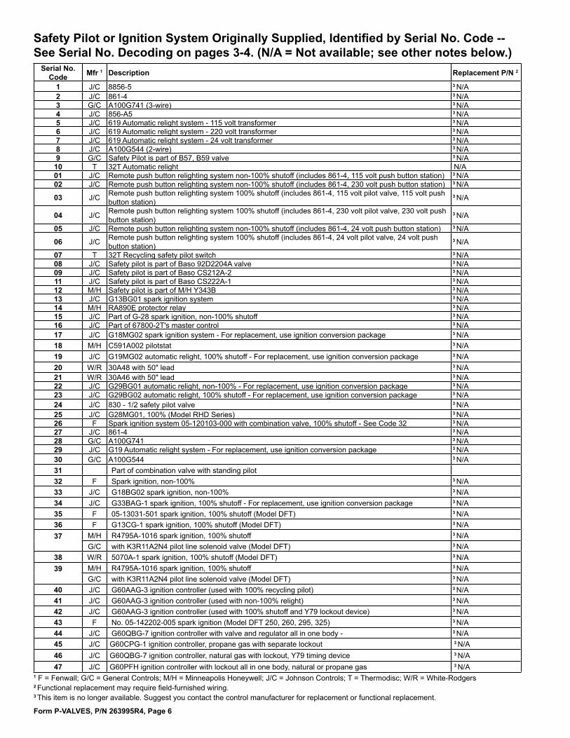
Safety Pilot or Ignition System Originally Supplied, Identified by Serial No. Code -- See Serial No. Decoding on pages 3-4. (N/A = Not available; see other notes below.)
1 F = Fenwall; G/C = General Controls; M/H = Minneapolis Honeywell; J/C = Johnson Controls; T = Thermodisc; W/R = White-Rodgers2 Functional replacement may require field-furnished wiring.3 This item is no longer available. Suggest you contact the control manufacturer for replacement or functional replacement.
Serial No. Code Mfr 1 Description Replacement P/N 2
1 J/C 8856-5 3 N/A2 J/C 861-4 3 N/A3 G/C A100G741 (3-wire) 3 N/A4 J/C 856-A5 3 N/A5 J/C 619 Automatic relight system - 115 volt transformer 3 N/A6 J/C 619 Automatic relight system - 220 volt transformer 3 N/A7 J/C 619 Automatic relight system - 24 volt transformer 3 N/A8 J/C A100G544 (2-wire) 3 N/A9 G/C Safety Pilot is part of B57, B59 valve 3 N/A10 T 32T Automatic relight N/A01 J/C Remote push button relighting system non-100% shutoff (includes 861-4, 115 volt push button station) 3 N/A02 J/C Remote push button relighting system non-100% shutoff (includes 861-4, 230 volt push button station) 3 N/A
03 J/C Remote push button relighting system 100% shutoff (includes 861-4, 115 volt pilot valve, 115 volt push button station)
3 N/A
04 J/C Remote push button relighting system 100% shutoff (includes 861-4, 230 volt pilot valve, 230 volt push button station)
3 N/A
05 J/C Remote push button relighting system non-100% shutoff (includes 861-4, 24 volt push button station) 3 N/A
06 J/C Remote push button relighting system 100% shutoff (includes 861-4, 24 volt pilot valve, 24 volt push button station)
3 N/A
07 T 32T Recycling safety pilot switch 3 N/A08 J/C Safety pilot is part of Baso 92D2204A valve 3 N/A09 J/C Safety pilot is part of Baso CS212A-2 3 N/A11 J/C Safety pilot is part of Baso CS222A-1 3 N/A12 M/H Safety pilot is part of M/H Y343B 3 N/A13 J/C G13BG01 spark ignition system 3 N/A14 M/H RA890E protector relay 3 N/A15 J/C Part of G-28 spark ignition, non-100% shutoff 3 N/A16 J/C Part of 67800-2T's master control 3 N/A17 J/C G18MG02 spark ignition system - For replacement, use ignition conversion package 3 N/A18 M/H C591A002 pilotstat 3 N/A19 J/C G19MG02 automatic relight, 100% shutoff - For replacement, use ignition conversion package 3 N/A20 W/R 30A48 with 50" lead 3 N/A21 W/R 30A46 with 50" lead 3 N/A22 J/C G29BG01 automatic relight, non-100% - For replacement, use ignition conversion package 3 N/A23 J/C G29BG02 automatic relight, 100% shutoff - For replacement, use ignition conversion package 3 N/A24 J/C 830 - 1/2 safety pilot valve 3 N/A25 J/C G28MG01, 100% (Model RHD Series) 3 N/A26 F Spark ignition system 05-120103-000 with combination valve, 100% shutoff - See Code 32 3 N/A27 J/C 861-4 3 N/A28 G/C A100G741 3 N/A29 J/C G19 Automatic relight system - For replacement, use ignition conversion package 3 N/A30 G/C A100G544 3 N/A31 Part of combination valve with standing pilot32 F Spark ignition, non-100% 3 N/A33 J/C G18BG02 spark ignition, non-100% 3 N/A34 J/C G33BAG-1 spark ignition, 100% shutoff - For replacement, use ignition conversion package 3 N/A35 F 05-13031-501 spark ignition, 100% shutoff (Model DFT) 3 N/A36 F G13CG-1 spark ignition, 100% shutoff (Model DFT) 3 N/A37
M/H R4795A-1016 spark ignition, 100% shutoff 3 N/AG/C with K3R11A2N4 pilot line solenoid valve (Model DFT) 3 N/A
38 W/R 5070A-1 spark ignition, 100% shutoff (Model DFT) 3 N/A39
M/H R4795A-1016 spark ignition, 100% shutoff 3 N/AG/C with K3R11A2N4 pilot line solenoid valve (Model DFT) 3 N/A
40 J/C G60AAG-3 ignition controller (used with 100% recycling pilot) 3 N/A41 J/C G60AAG-3 ignition controller (used with non-100% relight) 3 N/A42 J/C G60AAG-3 ignition controller (used with 100% shutoff and Y79 lockout device) 3 N/A43 F No. 05-142202-005 spark ignition (Model DFT 250, 260, 295, 325) 3 N/A44 J/C G60QBG-7 ignition controller with valve and regulator all in one body - 3 N/A45 J/C G60CPG-1 ignition controller, propane gas with separate lockout 3 N/A46 J/C G60QBG-7 ignition controller, natural gas with lockout, Y79 timing device 3 N/A47 J/C G60PFH ignition controller with lockout all in one body, natural or propane gas 3 N/A
Form P-VALVES, P/N 263995R4, Page 7
1 F = Fenwall; G/C = General Controls; J/C = Johnson Controls; M/H = Honeywell; T = Thermodisc; W/R = White-Rodgers2 Functional replacement may require field-furnished wiring.3 This item is no longer available. Suggest you contact the control manufacturer for replacement or functional replacement.
Code Mfr Description P/N Replaced by62 J/C Ignition controller
G67BG-2, natural gas or propane on outdoor units only
89314-N/A Kit P/N 257472
63 J/C Ignition controller G67NG-2, natural gas or propane on outdoor units only
89488-N/A Kit P/N 257473
64 M/H Safety pilot for Bell Telephone, L62GB
N/A N/A
65 J/C Ignition controller G770NGC-4 with lockout, natural gas or propane
97547-N/A Kit P/N 257473 except for Model TR, use P/N 216970
66 J/C Ignition controller G67BG-5, natural gas or propane on outdoor units only
97782-N/A Kit P/N 257472
Code Mfr Description P/N Replaced by67 RAM Hot surface
ignition module H4MC2
121543 204376 (Code 82)
68 M/H Piezo Ignitor Q635A1010
125836
69 M/H Ignition controller GS4S6DD
134780
70 M/H Ignition Controller S4560B1055-ML11149
145714
71 RAM Direct Spark Integrated Control Board 3MC4-03
147102 Kit P/N 257531
72 RAM Hot surface ignition module H4MC2
157953 204376 (Code 82)
Serial No. Code Mfr 1 Description P/N Replacement P/N 2
48 J/C G60QRH-1 ignition controller, propane gas valve with regulator and lockout all in one body N/A 3 N/A49 M/H L626B3 N/A 3 N/A50 J/C G65BCG-1 ignition controller and natural gas valve with regulator all in one body, 1/2" 67983-N/A 3 N/A51 J/C G65DCM-1 ignition controller & propane gas valve w/regulator & lockout, 1 body, 1/2" 68055-N/A 3 N/A52 J/C G65BBG-4 ignition controller and natural gas valve with regulator all in one body, 1/2" 79887-N/A 3 N/A53 J/C G65BKG-2 ignition controller and natural gas valve with regulator all in one body, 3/4" 79888-N/A 3 N/A54 J/C G65BCM-1 ignition controller & natural gas valve w/regulator & lockout, 1 body, 1/2" 79808-N/A 3 N/A55 J/C G65BBM-3 ignition controller & natural gas valve w/regulator & lockout, 1 body, 1/2" 84570-N/A 3 N/A56 J/C G65BKM-2 ignition controller & natural gas valve w/regulator & lockout, 1 body, 3/4" 79900-N/A 3 N/A
57 J/C G66BMG-1 ignition controller and natural gas valve with regulator and lockout all in one body, 1/2" - Special for export N/A 3 N/A
58 M/H Solid state flame safeguard, RA890F (flame rectification) 86972 To replace with HSI: New wiring dia-gram PLUS Kit P/N 146268; or kits with 200VA transformer, P/N 146318 (115V); P/N 146319 (208V, 240, 480, 575V)
Solid state spark generator, Q624A1006 or Q624A1014 86974
59 M/H Solid state flame safeguard, RA890G (ultraviolet) 89409Solid state spark generator, Q624A1006 or Q624A1014 86974
60 M/H Solid state flame safeguard, R7795B (flame rectification) 89407Solid state spark generator, Q624A1006 or Q624A1014 86974
61 M/H Solid state flame safeguard, R7795A (ultraviolet) 89436Solid state spark generator, Q624A1006 or Q624A1014 86974
Safety Pilot or Ignition System Originally Supplied, Identified by Serial No. Code (cont'd) -- See Serial No. Decoding on pages 3-4. (N/A = Not available; see other notes below.)
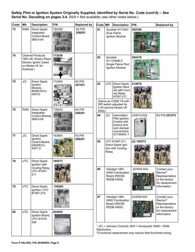
Form P-VALVES, P/N 263995R4, Page 8
1 J/C = Johnson Controls; M/H = Honeywell; RAM = RAM Electronics 2 Functional replacement may require field-furnished wiring.
Code Mfr Description P/N Replaced by73 RAM Direct Spark
integrated Control Board 3MC4-04
164326 Kit P/N 258251
74 Channel Products 1691-06, Rotary Piezo Electric Ignitor (Used on Model UF for Ambirad.)
173036
75 J/C Direct Spark Ignition Module, #G861KCC- 5401D
174260 Kit P/N 257531
76 RAM Direct Spark Integrated Control Module 3MC4-06
178453 Kit P/N 258251
77 J/C Direct Spark Ignition Control Board, G822KCC- 5401 D
193804 Kit P/N 258251
78 UTC Direct Spark Ignition with Cooling Relay, UTC #1097-211
195573
79 UTC Direct Spark Ignition, UTC #1097-210
195265
80 UTC Direct Spark Ignition Board, UTC #1016-426
204955
Code Mfr Description P/N Replaced by81 Synetek IH1104C
Dual Flame Ignition Module
204166
82 Synetek IH-11040B-C Single Flame Rod Ignition Module
204376
83 UTC Direct Spark Ignition Mod-ule with Cool-ing Relay, #1097-211
214979
(Same as CODE 78 with DIP switch adjusted for a 45 second blower off delay)84 J/C Intermittent
Pilot Ignition Control with lockout and vent damper connections, G770NHC-1
234012-N/A Kit P/N 257473
85 UTC #1097-211, Direct Spark Igni-tion with Cooling Relay
(2) 195573
86 Varidigm VB4-H500 Combustion Board (RDCB/RDDB H500)
223554-N/A Contact your Reznor® Representative or the factory for replacement information.
87 Varidigm VB4-H600 Combustion Board (RDCB/RDDB H600)
223555-N/A Contact your Reznor® Representative or the factory for replacement information.
Safety Pilot or Ignition System Originally Supplied, Identified by Serial No. Code (cont'd) -- See Serial No. Decoding on pages 3-4. (N/A = Not available; see other notes below.)

Form P-VALVES, P/N 263995R4, Page 9
ID Plug
Code Description P/N(s) Replaced by88 Varidigm
VB4-H700 Combustion Board (RDCB/RDDB H700)
223556-N/A Contact your Reznor® Representative or the factory for replacement information.
89 Varidigm VB4-H800 Combustion Board (RDCB/RDDB H800)
222678 - N/A Contact your Reznor® Representative or the factory for replacement information.
90 UTC #1097-211 Direct Spark Ignition and Varidigm VB4-H500 Combustion Board (RDCB/RDDB H10C)
195573
223554 - N/A
P/N 223554 is no longer available. Contact your Reznor® Representative or the factory for replacement information.
91 UTC #1097-211 Direct Spark Ignition and Varidigm VB4-H600 Combustion Board (RDCB/RDDB H12C)
195573
223555 - N/A
P/N 223555 is no longer available. Contact your Reznor® Representative or the factory for replacement information.
92 UTC #1097-211 Direct Spark Ignition and Varidigm VB4-H700 Combustion Board (RDCB/RDDB H14C)
195573
223556 - N/A
P/N 223556 is no longer available. Contact your Reznor® Representative or the factory for replacement information.
93 UTC #1097-211 Direct Spark Ignition and Varidigm VB4 Combustion Board (RDCB/RDDB H16C)
195573
222678 - N/A
P/N 222678 is no longer available. Contact your Reznor® Representative or the factory for replacement information.
Code Description P/N Replacement94 UTC #1003-
638-A Recyclying Ignition Controller
257009
95 UTC #1003-514 Ignition Controller with Lockout
257010
96 Varidigm VB1200-5-RZNR-C
257246 NOTE: If CODE 96 board is replaced, the ID plug must either be replaced also or removed and installed on the new board. See page 10 for a list of ID plugs.
97 Varidigm VB1200-5-RZNR-AB
258319 NOTE: If CODE 97 board is replaced, the ID plug must either be replaced also or removed and installed on the new board. See page 10 for a list of ID plugs.
98 Varidigm VB1200-2-RZNR-PVA
260252 NOTE: If CODE 98 board is replaced, the ID plug must either be replaced also or removed and installed on the new board. See page 10 for a list of ID plugs.
99 Varidigm VB1200-5-RZNR-SHH
260917 NOTE: If CODE 99 board is replaced, the ID plug must either be replaced also or removed and installed on the new board. See page 10 for a list of ID plugs.
A1 Direct Spark Ignition, UTC #1097-218, 7 Sec TFI
269867
Safety Pilot or Ignition System Originally Supplied, Identified by Serial No. Code (cont'd) -- See Serial No. Decoding on pages 3-4.
ID Plug
ID Plug
ID Plug

Form P-VALVES, P/N 263995R4, Page 10
Ignition Conversion Kits to Convert from Match-Lit Pilot to Spark Pilot for Models F and B
Ignition Conversion Kits to Convert Pilot Systems to Updated Spark Pilot, Hot Surface, or Direct Spark Ignition System for Models listed
Model F or B Gas Kit Description Kit P/N InstructionsF/B 25-165
Natural
Spark-ignited, intermittent safety pilot without lockout (UTEC Model 1003-638A,
P/N 257009)
100525
Form CP-F/B IGN, P/N 100550
F/B 200-250 100526F 300-400, B 300 100527B 400 102348F/B 25-165 Spark-ignited, intermittent
safety pilot with lockout (UTEC Model 1003-514, P/N
2570010)
(NOTE: Controller includes terminal for connecting vent
damper.)
100528F/B 200-250 100529F 300-400, B 300 100530B 400 102349F/B 25-200
Propane100531
F 250-400, B 250-300 100532B 400 102350
ID Plug P/N
ID Plug No. ID Plug Label Applies to
Model Heat Section Ignition CODE Gas258113 13 MAPS A100NG
Models RDCB, RDDB, RDCC, &
RDDC
100
97
Natural258114 14 MAPS A100LP Propane258115 15 MAPS A150NG 150 Natural258116 16 MAPS A150LP Propane258117 17 MAPS A200NG 200 Natural258118 18 MAPS A200LP Propane258129 29 MAPS B250NG
Models RDCB, RDDB, RDCC, &
RDDC
250 Natural258130 30 MAPS B250LP Propane258131 31 MAPS B300NG 300 Natural258132 32 MAPS B300LP Propane258133 33 MAPS C400NG
Models RDCB, RDDB, RDCC, &
RDDC
400
96
Natural258134 34 MAPS C500NG 500 Natural258135 35 MAPS C600NG 600 Natural258140 40 MAPS C700NG 700 Natural258141 41 MAPS D500NG
Models RDCB & RDDB
500 &1000 Natural258142 42 MAPS D600NG 600 & 1200 Natural258143 43 MAPS D700NG 700 & 1400 Natural258144 44 MAPS D800NG 800 & 1600 Natural
ID Plugs for Varidigm Deep Modulation Boards, Ignition CODES 96 and 97, on page 9
Ignition Systems Miscellaneous Information
ID Plugs for Varidigm Deep Modulation Board, Ignition CODE 98, on page 9
ID Plug P/N ID Plug Label
Applies to Model RDH with Ignition CODE 98
Heat Section Gas258081 PREEVA 175NG 175 Natural258082 PREEVA 175LP Propane258083 PREEVA 200NG 200 Natural258084 PREEVA 200LP Propane258085 PREEVA 225NG 225 Natural258086 PREEVA 225LP Propane258087 PREEVA 250NG 250 Natural258088 PREEVA 250LP Propane258089 PREEVA 300NG 300 Natural258090 PREEVA 300LP Propane258091 PREEVA 350NG 350 Natural258092 PREEVA 350LP Propane258093 PREEVA 400NG 400 Natural258094 PREEVA 400LP Propane
ID Plug P/N
ID Plug Label
Applies to Model RHH and Model SHH with
Ignition CODE 99Heat Section Gas
258101 SHH 130NG 130 Natural258102 SHH 130LP Propane258103 SHH 180NG 180 Natural258104 SHH 180LP Propane258105 SHH 260NG 260 Natural258106 SHH 260LP Propane258107 SHH 350NG 350 Natural258108 SHH 350LP Propane
ID Plugs for Varidigm Deep Modulation Board, Ignition CODE 99, on page 9
Ignition System being Replaced Gas Conversion Kit P/N (Type of Igni-
tion Controller in the Kit)
Instructions (in the Kit) Applies to Models
Form P/N
Replaces Pilot Codes 62, 63, 65, 66, 84
Natural or
Propane
257473 (Ignition Controller 257010)257472 (Ignition Controller 257009)
CP-IGN CNTRL 134704
Indirect-fired models with Pilot Code 62, 63, 65, 66, or 84
Replaces Pilot Code 71 or 75 257531 (Ignition Controller 195265) CP-DSI
CNTRL 265905 FT, SFT, TRP
Spark - flame rectifica-tion or ultraviolet
146268, 146318, 146319 (HSI P/N 204376) CP-RDF-HSI 146321 RDF with Pilot Code
58, 59, 60, or 61Model CAUA with Pilot Code 76 or 77 258251 (Ignition Controller 195573) CP-CAUA-
IGN CNTRL 178435 CAUA with Pilot Code 76 or 77
Model TR with Spark Pilot Code 65 or 66 216970 (DSI P/N 204955) CP-TR-IGN
CNV 215975 TR/TR-H with Pilot code 65 or 66

Form P-VALVES, P/N 263995R4, Page 11
Type of Valve Originally Supplied -- See Serial No. Decoding on pages 3-4. A dash (-) in the serial number means that no electric valve was furnished. All valves are 24 volt unless noted otherwise. See ALL notes on pages 19-22. N/A = Not Available. See illustrations on pages 23-27.
Serial No. Code Original Valve on Heater Valve
Mfr 1 Pipe Size P/N2 Functional ReplacementCode P/N
1 5 GF21G18 or 91F21G18 J/C 3/8 N/A 10 882422 5 GA4G18 or 91A4G18 J/C 1/2 (sm) N/A 10 882423 5 GD4G18 or 91D4G18 J/C 1/2 (lg) N/A 10 882424 5 GS5G18 J/C 3/4 N/A 10 882425 5 2509-206 W/R 3/4 N/A 10 882426 5 2509-207 W/R 3/4 N/A 10 882427 5 2509-208 W/R 1 N/A 5 1129228 5 V-80 M/H 1/2 N/A 10 882429 5 V-80 M/H 3/4 N/A 10 8824201 5 NC1013-2T M/N 1/2 N/A 10 8824202 5 NC1014-2T M/N 3/4 N/A 10 8824203 5 NC1030-2E or NC1058-2T M/N 1 N/A 5 11292204 5 VA84A1004 M/H 1-1/4 N/A 5 11292205 5 VA84A1012 M/H 1-1/2 N/A 5 11292206 6 K3J41A102, 2 stage G/C 1/2 N/A X2 11 17739607 6 K3J51A102, 2 stage G/C 3/4 N/A X3 11 17739708 6 K3J61A102 G/C 1 N/A 3
09 5 VA835 M/H 1/2 N/A 10 8824210 5 VA835 M/H 3/4 N/A 10 8824212 5 VA84 M/H 1 N/A 5 11292213 5 91S5G18 J/C 3/4 N/A 10 8824214 5 2509-204 W/R 1/2 N/A 10 8824215 5 K3A G/C 1-1/4 N/A 3 16 5 V81A1060 M/H 1/2(sm) N/A 10 8824217 5 V81A1078 M/H 3/4(sm) N/A 10 8824218 5 91A4G3 J/C 1/2(sm) N/A 10 8824219 5 91D4G3 or H91EG-3 J/C 1/2(lg) N/A 10 8824220 7 B57 (Natural), single stage G/C 1/2 N/A K6 12 9630021 8 B57 (Propane), single stage G/C 1/2 N/A K9 12 9630322 5 V81D262 M/H 1 N/A 5 11292223 5 3601-228 W/R 1/2 N/A 10 8824224 5 3606-228 (Propane) W/R 1/2 N/A 10 8824225 5 NC1054-2E M/N 3/4 N/A 5 11292226 5 1200AER R 3/8x1/2 N/A 3
27 9 92D2204-A-1, 100% shutoff, 115V J/C 1/2 N/A 3
28 9 CS212-A2, 100% shutoff, 115V J/C 1/2 N/A 3
29 9 CS222A-1, 100% shutoff, 115V J/C 1/2 N/A 3
30 Direct Spark, 115V, V4225B100, Propane M/H 1/2 N/A 3 31 Direct Spark, 115V, V4224A1077, Natural M/H 1/2 N/A 3 33 7 B59R02-Natural or B59R109, single stage G/C 1/2 N/A K6 12 9630034 7 B59R06-Natural or B59R111, single stage G/C 3/4 N/A K7 12 9630135 8 B59A01-Propane or B59A15, single stage G/C 1/2 N/A K9 12 9630336 8 B59A05-Propane or B59A110, single stage G/C 1/2 N/A K9 12 9630337 5 V8257-A1244 M/H 1/2 N/A 10 8824238 5 V829A-1001 M/H 1/2 N/A 10 8824239 5 V81A-1359 M/H 3/4 N/A 5 11292240 5 V88A-1345 M/H 1-1/2 N/A 3 41 5 V81A-1086 M/H 1 N/A 5 11292242 5 V8292A-1001 M/H 3/4 N/A 10 8824243 5 V8146A102 M/H 3/4 N/A 5 11292244 5 V8146B-1023 M/H 3/4 N/A 5 11292245 5 V88A13372 M/H 1 N/A 5 11292246 13 NC1014-1E M/N 3/4 N/A 3 47 13 92D4004A1 J/C 1/2 N/A 3 48 5 V8202A M/H 3/4 N/A 3
49 5 25A15-226 with plug for electric ignition W/R 3/8 N/A 3
50 5 25046-404 W/R 1/2 N/A 3
51 5 92D4004G3 J/C 1/2 N/A 3
52 5 K3A G/C 1/2 N/A 5 11292253 5 K3A G/C 3/4 N/A 5 11292254 5 K3A G/C 1 N/A 5 11292255 5 25G10-204 W/R 1/2 N/A 10 8824256 V48A2144 Diaphragm Type M/H 1 N/A 3
57 5 K40AC251 G/C 3/4 N/A 3
(continued)

Form P-VALVES, P/N 263995R4, Page 12
Type of Valve Originally Supplied (cont'd) -- See Serial No. Decoding on pages 3-4.A dash (-) in the serial number means that no electric valve was furnished. All valves are 24 volt unless noted otherwise. See ALL notes on pages 19-22. N/A = Not Available. See illustrations on pages 23-27. Serial No. Code Original Valve on Heater Valve
Mfr 1Pipe Size P/N
2 Functional ReplacementCode P/N
58 14 G52BAG-12 (Natural) J/C 3/4 N/A 4
59 14 G52DAG-13 (Natural) 2-stage (lg) J/C 1/2 N/A 4
60 5 K40AC361 G/C 1 N/A 3
61 14 96AGT-9 J/C 1/2 N/A 4
62 963006-G J/C 3/4 N/A 3
63 14 G52BLG-12 (Propane) J/C 3/4 N/A 4
64 14 G52AAG-12 (Natural) J/C 1 N/A 4
65 15 G52AAY-1; DFT 250,260,290,325; Natural J/C 1 N/A 3
66 5 2509-207 W/R 3/4 N/A 5 11292267 5 2509-208 W/R 1 N/A 5 11292268 5 2509-206 (Small) W/R 3/4 N/A 10 8824269 7 B590RA44 - Natural G/C 3/4 N/A K7 12 9630170 18 B590AA45 - Propane G/C 3/4 N/A 4
71 19 B59RJ155 - Natural G/C 1/2 N/A 4
72 19 B59RJ157 - Propane G/C 3/4 N/A 4
73 18 B59AJ156 - Propane G/C 1/2 N/A 4
74 18 B59RJ158 - Propane G/C 3/4 N/A 4
75 5 H91DG-3 Natural and Propane J/C 1/2 N/A 10 8824276 5 H91DG-3 Natural; H91DG-2 Propane J/C 1/2 N/A 10 88242
775 NC1014-2T Natural M/N 3/4 N/A 5 112922H91DG-2 Propane M/N 1/2 N/A 10 88242
785 NC1014-2T Natural M/N 3/4 N/A 5 112922H91EG-3 Propane M/N 1/2 N/A 10 88242
795 NC1054-2T Natural M/N 3/4 N/A 5 112922H91EG-2 Propane M/N 1/2 N/A 10 88242
805 NC1054-2T M/N 3/4 N/A 5 112922H91LG-1 M/N 3/4 N/A 10 88242
81 5 G95AGL-1 Natural - Model RHD J/C 1/2 N/A 3
82 5 G95GL-1 W/Kit Y71AA-4 Propane - Model RHD J/C 1/2 N/A 3
83 16 K72R13 Natural - side entrance 90° outlet valve, single stage G/C 1/2 39298-N/A K6 12 9630084 17 K72A14 Propane - side entrance 90° outlet valve, single stage G/C 1/2 39299-N/A G9 8239685 18 G50AAY-1 Natural, 1-stage - DFT250 (includes built-in regulator) J/C 1 N/A 3
86 6 G52BLY-1, 2-stage, Propane, DFT 250, 260, 290, 325 J/C 3/4 N/A 3
87 5 G50BLY-1, 1-stage, Propane, DFT250 J/C 3/4 N/A 3
8813 1014-1E Natural, High Stage, DFT 300,400 M/N 3/4 N/A 3
13 1013-1E Natural, Low Stage, DFT 300,400 M/N 1/2 N/A 3
8913 1054-1E Natural, High Stage, DFT 500 M/N 3/4 N/A 3
13 1013-1E Natural, Low Stage, DFT 500 M/N 1/2 N/A 3
9013 V48H-100-1, Natural, High Stage, DFT 600 M/N 3/4 N/A 3
13 1013-1E Natural, Low Stage, DFT 600 M/N 1/2 N/A 3
91 14 G52BAG-6, 2-stage, Natural, DFT 220 J/C 3/4 N/A 3
92 14 G52AAG-6, 2-stage, Natural, DFT 285,340,395 J/C 1 N/A 3
93 23 G52BLG-10, 2-stage, Propane, DFT 285,340,395 J/C 3/4 N/A 3
94 8215B30 J/C 3/4 N/A 3
95 5 H91LG-1 91D4G-3 J/C 3/4 47537-N/A 10 8824296 22 B59SJK171 Natural, 2 stage G/C 1/2 N/A X2 24 17739697 22 B59BJK172 Propane, 2 stage G/C 1/2 N/A X1 24 17739598 22 B59SJK163 Natural, 2 stage G/C 3/4 N/A X3 24 17739799 22 B59BJK164 Propane, 2 stage G/C 3/4 N/A X1 24 177395A1 22 B590SAK50 Natural, 2 stage G/C 3/4 N/A X3 24 177397A2 22 B590BAK51 Propane, 2 stage G/C 3/4 N/A X1 24 177395A3 13 SNC1054-1 M/N 3/4 N/A 3
A4 7 7000ERHC 455-501-501 Natural, single stage R 3/4x1 N/A K7 12 96301A5 21 242NS 242-111121-1101 Natural, single stage E 1/2 47380-N/A Q2 25 121598A6 21 242NS 242-131121-1101 Natural, single stage E 3/4 47381-N/A 9A 221525A7 21 242NSU 242-111120-2101 Propane, single stage E 1/2 N/A Q4 25 121600 36
A8 21 242NSU 242-131120-2101 Propane, single stage E 3/4 N/A Q4 25 121600 36
A9 17 7000GVER-HC Natural, single stage R 3/4x1 N/A 9A 221525B1 5 K3A441 G/C 1/2 N/A 10 88242B2 5 K3A451 G/C 3/4 N/A 5 112922B3 5 K3A461 G/C 1 N/A 5 112922B4 G60QBG-7 with Controller - Natural J/C 1/2 50448-N/A 3
B5 H91MG Natural J/C 1 47538-N/A 5 112922B6 38, 7 7000BER Natural 300-501-502, single stage R 1/2 48577-N/A K6 12 96300 B7 7 7000BER Natural 302-501-502A, single stage R 3/4 N/A K7 12 96301

Form P-VALVES, P/N 263995R4, Page 13
Type of Valve Originally Supplied (cont'd) -- See Serial No. Decoding on pages 3-4.A dash (-) in the serial number means that no electric valve was furnished. All valves are 24 volt unless noted otherwise. See ALL notes on pages19-22. N/A = Not Available. See illustrations on pages 23-27. Serial No. Code Original Valve on Heater Valve
Mfr 1Pipe Size P/N
2 Functional ReplacementCode P/N
B8 8 7000BE Propane 300-505-501, single stage R 1/2 N/A K9 12 96303B9 8 7000BE Propane 302-505-501, single stage R 3/4 N/A K9 12 96303C1 17 7000BGVER Natural 312-501-503 R 1/2 N/A 3
C2 17 7000BGVER Natural 307-501-503 R 3/4 N/A 3
C3 28 7000BGVE Propane 312-505-526 R 1/2 N/A 3
C4 28 7000BGVE Propane 307-505-501 R 3/4 N/A 3
C5 38 7 V800A1039 Natural, single stage M/H 3/4 51299-N/A K7 12 96301
C6 8 G50DAG-1 Natural, single stageJ/C 3/4 N/A 12
Replacement for Standing Pilot K7 96301Replacement for Spark Pilot 9A 221525
C7 22 V852A1097 Natural, 2-Stage M/H 1/2 51357-N/A X2 12, 24 177396C8 22 V852A1071 Natural, 2-Stage M/H 3/4 51358-N/A X3 12, 24 177397C9 22 V852A1105 Propane, 2-Stage M/H 1/2 51359-N/A X1 12, 24 177395D1 22 V852A1089 Propane, 2-Stage M/H 3/4 51360-N/A X1 12, 24 177395
D226 G60CPG-1 Propane w/separate lockout device J/C 1/2 N/A 3
Y79 Lockout Device only, Y70BBA J/C 46869-N/A
D326 G60QBG-7 Natural J/C 1/2 N/A 3
Y79 Lockout Device only, Y70BBA J/C 46869-N/AD4 27 V850A1133 Natural, 2-Stage M/H 3/4 52886-N/A P8 20 115351D5 27 V850A117 Natural, 2-Stage M/H 3/4 N/A 4
D6 14 G52AAG-16 DFT units J/C 1 N/A 3
D7 38, 7 242 N-1 (Natural) 242-131131-1181, single stage E 3/4 59341-N/A K7 12 96301D8 28 H91EG J/C 1/2 N/A 3
D9 31 H91EG J/C 1/2 N/A 3
E1 30 B79B77RK34 Natural, 2-Stage G/C 1/2 60609-N/A X2 12 177396E2 30 B79B77WK35 Natural, 2-Stage G/C 3/4 60610-N/A X3 12 177397E3 30 B79B77WK36, Propane, 2-Stage G/C 1/2 60611-N/A X1 12 177395E4 21 SX242 242-131121-1214 Natural, single stage E 3/4 61098-N/A 9A 221525
E521 SX242LS 242-111122-1215 Propane, single stg (also could be used on natural gas units equipped with Maxitrol controls) E 1/2 61099-N/A Q4 25 121600 36
E6 32 V4036B1019, 115V M/H 1/2 N/A 3
E7 32 V4036B1084, 240V M/H 3/4 N/A 3
E838, 7 RS7000BER 300-502-719 Propane, single stg (also could be used on natural gas units equipped with Maxitrol controls) R 1/2 62969-N/A K9 12 96303
E9 15 K72S32 Side Entrance Propane, single stage G/C 1/2 64420-N/A G9 82396F1 30 V850A1166 2-Stage, Natural M/H 1/2 62966-N/A P8 115351F2 30 V850A1158 2-Stage, Propane M/H 1/2 62967-N/A P9 115352F3 VR852A1068 2-Stage, Propane M/H 1/2 62946-N/A X1 12 177395F4 G60QRH-1 Propane J/C 1/2 56826-N/A 3
F5 SX242LSH 242-131122-1248 Propane, single stg (also could be used on natural gas units equipped with Maxitrol controls) E 3/4 63282-N/A 1B 221526
F6 23 36D05-201 Natural W/R 1/2 62972-NA 3
F7 23 36D05-401 Natural W/R 3/4 62973-N/A 3
F8 23 36D05-202 Propane W/R 1/2 62974-NA 3
F9 and G129 G65BC Natural - Code F9 Valve Codes F9 and G1 indicate G65
ignition (Codes 50-56) and gas valve.3
29 G65DCM-1 Propane - Code G1 3
G2 15 7000BER 379-501-502 Side Entrance Natural R 1/2 N/A K6 12 96300G3 16 7000BE 379-501-501 Side Entrance Propane R 1/2 N/A G9 82396G4 7 7000BER 403-501-729 Nat, single stage (no ECO cnntr) R 1/2 82196-N/A K6 12 96300
G57 7000BER 403-502-719 Propane, single stg (also could be used on natural gas units equipped with Maxitrol system) R 1/2 82197-N/A 221634
G6 7 7000BER 408-501-502 Nat, single stg (with ECO cnntr) R 1/2 82198-N/A K6 12 96300
G77 7000BER 408-502-719 Propane, Side Entrance, single stage (with ECO connector) R 1/2 82199-N/A G9 82396
G8 37, 7 36C03270 Natural, Side Entrance, single stg, w/ECO W/R 1/2 82395-N/A K6 12 96300
G937, 7 36C03-433 Natural & Propane, Side Entrance, single stage, w/ECO W/R 1/2 82396
H1 38, 7 V800A7028 Natural, single stage, w/ECO terminal M/H 3/4 82398-N/A K7 12 96301H2 38, 7 36C03-258 Natural, single stage, w/ECO terminal W/R 1/2 82397-N/A K6 12 96300H3 38, 7 700BER 403-501-832 Nat, single stg, w/ECO terminal R 1/2 82624-N/A K6 12 96300H4 7 700BER 403-502-835 Pro, single stg, w/ECO terminal R 1/2 82669-N/A K9 12 96303H5 30 36D13-208 Natural, 2-Stage W/R 1/2 87430 X2 12, 39 177396H6 30 36D13-405 Natural, 2-Stage W/R 3/4 87432 X3 12, 39 177397H7 30 36D13-209 Propane, 2-Stage W/R 1/2 87431 X1 12, 39 177395
(continued)

Form P-VALVES, P/N 263995R4, Page 14
Type of Valve Originally Supplied (cont'd) -- See Serial No. Decoding on pages 3-4.A dash (-) in the serial number means that no electric valve was furnished. All valves are 24 volt unless noted otherwise. See ALL notes on pages 19-22. N/A = Not Available. See illustrations on pages 23-27. Serial No. Code Original Valve on Heater Valve
Mfr 1Pipe Size P/N
2 Functional ReplacementCode P/N
H8 36D05-403 Propane W/R 1/2x3/4 88243-N/A 3
H9 VR8440C3031 Propane, single stage M/H 1/2x3/4 93386-N/A Q4 121600 36
J1 (Two Valves)
5 (2) K3A562S, T, or U, or 2LB27BB6127, 115V G/C, ASCO, or Skinner 1 86966 (2 required)
J2 V5055A1004 Fluid Power, 115V M/H 1 86992 W1 (alternate for J2; both Codes are approved)V4055A1007 Actuator M/H 86993
J3 (Two Valves)
(2) V5055A1004 Fluid Power, 115V M/H 1 86992 (2 required) W1 (alternate for J2; both Codes are approved)(2) V4055A1007 Actuator M/H 86993 (2 required)
J4 (Three Valves)
V5055A1004 Fluid Power, 115V M/H
1
86992V4055A1007 Actuator M/H 869935 (2) K3A562S, T, or U, or 2LB27BB6127, 115V G/C, ASCO,
or Skinner 86966 (2 required)
J5 17 DER7100 71P11A-000 Natural, single stage R 1/2 89461-N/A M4 96307J6 17 DER7100 71P11C-013 Propane, single stage R 1/2 89462-N/A M7 96310J7 17 VR8440A2092B Natural, single stage M/H 1/2 89370-N/A Q2 121598J8 17 36C68-441 Natural, single stage W/R 3/4 89397-N/A 9A 221525J9 17 VR8440A2100B Propane, single stage M/H 1/2 89371-N/A Q4 121600 36
K117 36C68-442 Pro, single stage (also could be used on natural gas units equipped with Maxitrol controls) W/R 3/4 89398-N/A 1B 221526
K2 V50551012 Fluid Power, 115V M/H 1-1/4 89356 W3 (alternate for K2; both Codes are approved)V4055A1007 Actuator M/H 86993
K3 FT8215C20, 115V (for Bell Telephone) ASCO 1/2 N/A
K4 V50551038 Fluid Power, 115V M/H 2 91079 W4 (alternate for K4; both Codes are approved)V4055A1007 Actuator M/H 86993
K5 V8200M7003, Natural, single stage M/H 1/2 96299 9B 208920K6 36C03-211 Natural, single stage W/R 1/2 96300K7 V800M7009 Natural, single stage M/H 3/4 96301K8 V8200M7011 Propane, single stage M/H 1/2 96302 1C 209412K9 V800M7017 Propane, single stage M/H 3/4x3/4 96303M1 V850E7003 Natural, 2-stage M/H 1/2 96304-N/A P8 40 115351M2 V850E7029 Natural, 2-stage M/H 3/4 96305-N/A P8 40 115351M3 V850E7011 Propane, 2-stage M/H 1/2x3/4 96306-N/A P9 40 115352M4 VR8204M1000 Natural, single stage M/H 1/2 96307M5 VR8440A2159 Natural, single stage M/H 1/2 96308-N/A Q3 121599M6 36C68-452 Natural, single stage W/R 3/4 96309-N/A Kit P/N 222037M7 VR8204M1018 Propane, single stage M/H 1/2 96310
M8 36C68-325 Pro, single stage (also could be used on natural gas units equipped with Maxitrol controls) W/R 1/2x3/4 96311-NA Kit P/N 221634
M9 36D13-304 Propane, 2-stage W/R 1/2x3/4 96312 X4 12, 39 177398N1 36D19-402 Natural, 50-90°F W/R 3/4x3/4 100321-N/A 34
N2 36D19-403 Natural 90-130°F W/R 3/4x3/4 100322-N/A 3
N3 36D19-405 Propane, 50-90°F W/R 3/4x3/4 100323-N/A 34
N4 36D19-406 Propane 90-130°F W/R 3/4x3/4 100324-N/A 3
N5 (Two Valves)
Mechanical modulation 50-90°F, Code N3, with bypass, Code M7, for Sizes 75-20036D19-405 Propane W/R 3/4x3/4 100323(N3)-N/A 34
VR8204M1018 Propane, single stage M/H 1/2 96310(M7)
N6 (Two Valves)
Mechanical modulation 50-90°F, Code N3, with bypass, Code M8, for Sizes 225-40036D19-405 Propane W/R 3/4x3/4 100323(N3)-N/A 34
36C68-325 Propane, single stage W.R 1/2x3/4 96311(M8)-N/A Kit P/N 221634
N7 (Two Valves)
AG13 Mechanical modulation 50-90°F, Code N1, with bypass, Code M4, for Sizes 75-15036D19-402 Natural W/R 3/4x3/4 1003213(N1)-N/A 34
VR8204M1000 Natural, single stage M/H 1/2 96307(M4)
N8 (Two Valves)
AG13 Mechanical modulation 50-90°F, Code N1, with bypass, Code M5, for Sizes 175-25036D19-402 Natural W/R 3/4x3/4 1003213(N1)-N/A 34
VR8440A2159 Natural, single stage M/H 1/2 96308-N/A Q3 121599
N9 (Two Valves)
AG13 Mechanical modulation 50-90°F, Code N1, w/bypass, Code M6, Sizes 300-400 and ADF/ADFH Nat & LP36D19-402 Natural W/R 3/4x3/4 100321(N1)-N/A 34
36C68-452 Natural, single stage W/R 3/4 96309-N/A Kit P/N 222037O1&P1 33 (Two Valves)
AG14 Mechanical modulation 90-130°F, Code N2, with bypass, Code M4, for Sizes 75-15036D19-403 Natural W/R 3/4x3/4 100322-N/A 3
VR8204M1000 Natural, single stage M/H 1/2 96307 (M4)O2&P2 33 (Two Valves)
AG14 Mechanical modulation 90-130°F, Code N2, with bypass, Code M5, for Sizes 175-25036D19-403 Natural W/R 3/4x3/4 100322-N/A 3
VR8440A2159 Natural, single stage M/H 1/2 96308-N/A Q3 125199

Form P-VALVES, P/N 263995R4, Page 15
(continued)
Serial No. Code Original Valve on Heater Valve
Mfr 1Pipe Size P/N
2 Functional ReplacementCode P/N
O3&P3 33 (Two Valves)
AG14 Mechanical modulation 90-130°F, Code N2, w/bypass, Code M6, Sizes 300-400 and ADF/ADFH Nat & LP36D19-403 Natural W/R 3/4x3/4 100322-N/A 34
36C68-452 Natural, single stage W/R 3/4 96309(M6)-N/A Kit P/N 222037O4&P4 33 (Two Valves)
AG14 Mechanical modulation 90-130°F, Code N4, with bypass, Code M7, for Sizes 75-20036D19-406 Propane W/R 3/4x3/4 100324-N/A 3
VR8204M1018 Propane, single stage M/H 1/2 96310(M7)O5&P5 33 (Two Valves)
AG14 Mechanical modulation 90-130°F, Code N4, with bypass, Code M8, for Sizes 225-40036D19-406 Propane W/R 3/4x3/4 100324-N/A 3
36C68-325 Propane, single stage W/R 1/2x3/4 96311(M8)-N/A Kit P/N 221634
P6 (Two Valves)
Mechanical modulation 50-90°F, Code N1, with bypass, Code Q3, for Sizes 175-25036D19-402 Natural W/R 3/4x3/4 100321(N1)-N/A 34
VR8304M2816 Natural, single stage M/H 1/2 121599(Q3)
P7 (Two Valves)
Mechanical modulation 90-130°F, Code N2, with bypass, Code Q3, for Sizes 175-25036D19-403 Natural W/R 3/4x3/4 100322-N/A 3
VR8304M2816 Natural, single stage M/H 1/2 121599(Q3)P8 36C40-408 2-Stage, Natural (std pilot) W/R 3/4 115351P9 36C41-408 2-Stage, Propane (std pilot) W/R 3/4 115352Q2 VR8304M2808 Natural, single stage M/H 1/2 121598Q3 VR8304M2816 Natural, single stage M/H 1/2 121599Q4 VR8304H3802 Propane, single stage M/H 1/2x3/4 121600
Q5 (Two Valves)
Mechanical modulation 50-90°F, Code N1, with bypass, Code J8, for Sizes 300-40036D19-402 Natural W/R 3/4x3/4 100321(N1)-N/A 34
36C68-441 Natural, single stage W/R 3/4 89397(J8)-N/A 9A 221525
Q6 (Two Valves)
Mechanical modulation 90-130°F, Code N2, with bypass, Code J8, for Sizes 300-40036D19-403 Natural W/R 3/4x3/4 100322-N/A 3
36C68-441 Natural, single stage W/R 3/4 89397(J8)-N/A 9A 221526
Q7 (Two Valves)
Mechanical modulation 50-90°F, Code N1, with bypass, Code Q2, for Sizes 75-25036D19-402 Natural W/R 3/4x3/4 100321(N1)-N/A 34
VR8304M2808 Natural, single stage M/H 1/2 121598 (Q2)
Q8 (Two Valves)
Mechanical modulation 90-130oF, Code N2, with bypass, Code Q2, for Sizes 75-25036D19-403 Natural W/R 3/4x3/4 100322-N/A 3
VR8304M2808 Natural, single stage M/H 1/2 121598 (Q2)
Q9 (Two Valves)
Mechanical modulation 50-90oF, Code N3, with bypass, Code Q4, for Sizes 75-20036D19-405 Propane W/R 3/4x3/4 100323(N3)-N/A 34
VR8304H3802 Propane, single stage M/H 1/2x3/4 121600(Q4)
R1 (Two Valves)
Mechanical modulation 90-130oF, Code N4, with bypass, Code Q4, for Sizes 225-40036D19-406 Propane W/R 3/4x3/4 100324-N/A 3
VR8304H3802 Propane, single stage M/H 1/2x3/4 121600(Q4)R2 5 K3A651SF Natural & Propane G/C 3/4 123604R3 5 K3A561-U Natural & Propane ASCO 1 123603R4 5 K3A671SF Natural & Propane G/C 1-1/4 123605R5 V4600A1023 Nat or V4600A1031 Nat/Pro M/H 1/2 113766R6 V4400A10093 M/H 1/2 11376735 R7 3B0-341-A04 or 3F1241A04 Natural, 50-100°F, Mod R 3/4 13145335 R8 5N7-341-A04 or 5R9241A04 Natural, 50-100°F, Mod R 1 13145535 R9 3B0-342-A05 or 3F1242A05 Propane, 50-100°F, Mod R 3/4 13145435 S1 5N7-342-A05 or 5R9242A05 Propane, 50-100°F, Mod R 1 131456S2 (Two Valves)
3B0-341-A04 or 3F1241A04 Natural, 50-100°F, Mod R 3/4 131453(R7)36C68-325, Propane, single stage W/R 1/2X3/4 96311(M8)-N/A Kit P/N 221634
S3 (Two Valves)
5N7-341-A04 or 5R9241A04 Natural, 50-100°F, Mod R 1 131455(R8)36C68-442, Propane, single stage W/R 3/4 89398(K1)-N/A 1B 221526
S4 (Two Valves)
3B0-342-A05 or 3F1242A05 Propane, 50-100°F, Mod R 3/4 131454(R9)36C68-325, Propane, single stage W/R 1/2x3/4 96311(M8)-N/A Kit P/N 221634
S5 (Two Valves)
5N7-342-A05 or 5R9242A05 Propane, 50-100°F, Mod R 1 131456(S1)36C68-442 Propane, single stage W/R 3/4 89398(K1)-N/A 1B 221526
S6 (Three Valves)
Mechanical modulation 50-100°F, with bypass, Code Q2, for Sizes 75-2253B0-341-A04 or 3F1241A04 Natural, 50-100°F R 3/4 131453(R7)36C68-325, Pro, single stage W/R 1/2x3/4 96311(M8)-N/A Kit P/N 221634VR8304M2808 Natural, single stage M/H 1/2 121598(Q2)
S7 (Three Valves)
Mechanical modulation 50-100°F, with bypass, Code J8, for Sizes 250-3503B0-341-A04 or 3F1241A04 Natural, 50-100°F R 3/4 131453(R7)36C68-442, Pro, single stage W/R 3/4 89398(K1)-N/A 1B 22152636C68-441 Natural, single stage W/R 3/4 89397(J8)-N/A 9A 221525
Type of Valve Originally Supplied (cont'd) -- See Serial No. Decoding on pages 3-4.A dash (-) in the serial number means that no electric valve was furnished. All valves are 24 volt unless noted otherwise. See ALL notes on pages 19-22. N/A = Not Available. See illustrations on pages 23-27.
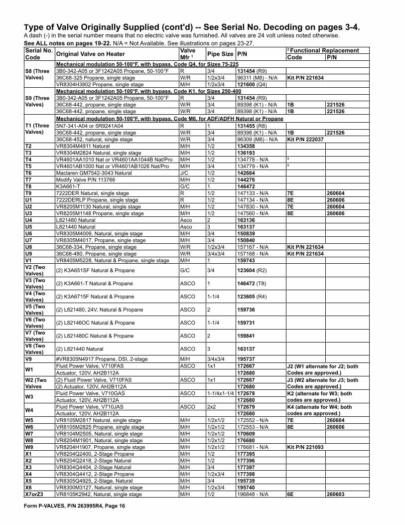
Form P-VALVES, P/N 263995R4, Page 16
Type of Valve Originally Supplied (cont'd) -- See Serial No. Decoding on pages 3-4.A dash (-) in the serial number means that no electric valve was furnished. All valves are 24 volt unless noted otherwise. See ALL notes on pages 19-22. N/A = Not Available. See illustrations on pages 23-27. Serial No. Code Original Valve on Heater Valve
Mfr 1 Pipe Size P/N2 Functional ReplacementCode P/N
S8 (Three Valves)
Mechanical modulation 50-100°F, with bypass, Code Q4, for Sizes 75-2253B0-342-A05 or 3F1242A05 Propane, 50-100°F R 3/4 131454 (R9)36C68-325 Propane, single stage W/R 1/2x3/4 96311 (M8) - N/A Kit P/N 221634VR8304H3802 Propane, single stage M/H 1/2x3/4 121600 (Q4)
S9 (Three Valves)
Mechanical modulation 50-100°F, with bypass, Code K1, for Sizes 250-4003B0-342-A05 or 3F1242A05 Propane, 50-100°F R 3/4 131454 (R9)36C68-442, propane, single stage W/R 3/4 89398 (K1) - N/A 1B 22152636C68-442, propane, single stage W/R 3/4 89398 (K1) - N/A 1B 221526
T1 (Three Valves)
Mechanical modulation 50-100°F, with bypass, Code M6, for ADF/ADFH Natural or Propane5N7-341-A04 or 5R9241A04 R 1 131455 (R8)36C68-442, propane, single stage W/R 3/4 89398 (K1) - N/A 1B 22152636C68-452, natural, single stage W/R 3/4 96309 (M6) - N/A Kit P/N 222037
T2 VR8304M4911 Natural M/H 1/2 134358T3 VR8304M2824 Natural, single stage M/H 1/2 136193T4 VR4601AA1010 Nat or VR4601AA1044B Nat/Pro M/H 1/2 134778 - N/A 3
T5 VR4601AB1000 Nat or VR4601AB1026 Nat/Pro M/H 3/4 134779 - N/A 3
T6 Maclaren GM7542-3043 Natural J/C 1/2 142664T7 Modify Valve P/N 113766 M/H 1/2 144276T8 K3A661-T G/C 1 146472T9 7222DER Natural, single stage R 1/2 147133 - N/A 7E 260604U1 7222DERLP Propane, single stage R 1/2 147134 - N/A 8E 260606U2 VR8205M1130 Natural, single stage M/H 1/2 147830 - N/A 7E 260604U3 VR8205M1148 Propane, single stage M/H 1/2 147560 - N/A 8E 260606U4 L821480 Natural Asco 2 163136U5 L821440 Natural Asco 3 163137U6 VR8305M4009, Natural, single stage M/H 3/4 150839U7 VR8305M4017, Propane, single stage M/H 3/4 150840U8 36C68-334, Propane, single stage W/R 1/2x3/4 157167 - N/A Kit P/N 221634U9 36C68-480, Propane, single stage W/R 3/4x3/4 157168 - N/A Kit P/N 221634V1 VR8405M5228, Natural & Propane, single stage M/H 1 159743V2 (Two Valves) (2) K3A651SF Natural & Propane G/C 3/4 123604 (R2)
V3 (Two Valves) (2) K3A661-T Natural & Propane ASCO 1 146472 (T8)
V4 (Two Valves) (2) K3A6715F Natural & Propane ASCO 1-1/4 123605 (R4)
V5 (Two Valves) (2) L821480, 24V, Natural & Propane ASCO 2 159736
V6 (Two Valves) (2) L82146OC Natural & Propane ASCO 1-1/4 159731
V7 (Two Valves) (2) L821480C Natural & Propane ASCO 2 159841
V8 (Two Valves) (2) L821440 Natural ASCO 3 163137
V9 #VR8305N4917 Propane, DSI, 2-stage M/H 3/4x3/4 195737
W1 Fluid Power Valve, V710FAS ASCO 1x1 172667 J2 (W1 alternate for J2; both Codes are approved.) Actuator, 120V, AH2B112A 172680
W2 (Two Valves
(2) Fluid Power Valve, V710FAS ASCO 1x1 172667 J3 (W2 alternate for J3; both Codes are approved.)(2) Actuator, 120V, AH2B112A 172680
W3 Fluid Power Valve, V710GAS ASCO 1-1/4x1-1/4 172678 K2 (alternate for W3; both codes are approved.)Actuator, 120V, AH2B112A 172680
W4 Fluid Power Valve, V710JAS ASCO 2x2 172679 K4 (alternate for W4; both codes are approved.)Actuator, 120V, AH2B112A 172680
W5 VR8105M2817 Natural, single stage M/H 1/2x1/2 172552 - N/A 7E 260604W6 VR8105M2825 Propane, single stage M/H 1/2x1/2 172553 - N/A 8E 260606W7 VR8104M2505, Natural, single stage M/H 1/2x1/2 170609W8 VR8204M1901, Natural, single stage M/H 1/2x1/2 176680W9 VR8204H1907, Propane, single stage M/H 1/2x1/2 176681 - N/A Kit P/N 221093X1 VR8204Q2400, 2-Stage Propane M/H 1/2 177395 X2 VR8204Q2418, 2-Stage Natural M/H 1/2 177396 X3 VR8304Q4404, 2-Stage Natural M/H 3/4 177397X4 VR8304Q4412, 2-Stage Propane M/H 1/2x3/4 177398X5 VR8305Q4925, 2-Stage, Natural M/H 3/4 195739X6 VR8300M3127, Natural, single stage M/H 1/2x3/4 195740X7orZ3 VR8105K2942, Natural, single stage M/H 1/2 196848 - N/A 6E 260603

Form P-VALVES, P/N 263995R4, Page 17
Type of Valve Originally Supplied (cont'd) -- See Serial No. Decoding on pages 3-4.A dash (-) in the serial number means that no electric valve was furnished. All valves are 24 volt unless noted otherwise. See ALL notes on pages 19-22. N/A = Not Available. See illustrations on pages 23-27. Serial No. Code Original Valve on Heater Valve
Mfr 1Pipe Size P/N
2 Functional ReplacementCode P/N
X8orZ4 VR8105N2949, Nat, 2-stage M/H 1/2 196849 - N/A Y8or4A 197066X9orZ5 VR8105K2959, LP, single stage M/H 1/2 196850 - N/A 9E 263999Y1orZ6 VR8105N2931, LP, 2-stage M/H 1/2 196851 - N/A 2A 197064Y2orZ7 VR8205K2957, Natural, single stage M/H 1/2 196980 - N/A 6E 44 260603Y3orZ8 VR8305K4241, Natural, single stage M/H 3/4 196981Y4orZ9 VR8205K2965, LP, single stage M/H 1/2 196982 - N/A 9E 44 263999Y5or1A VR8305K4258, LP, single stage M/H 3/4 196983 Y6or2A VR8205N2913, LP, 2-stage M/H 1/2 197064 Y7or3A VR8305N4289, LP, 2-stage M/H 3/4 197065 Y8or4A VR8205N2921, Natural, 2-stage M/H 1/2 197066 Y9or5A VR8305N4297, Natural, 2-stage M/H 3/4 197067Z1 2-STG VLV, LP, VR8205N2939 M/H 1/2 195736Z2 2-STG VLV, NAT, VR8205N2947 M/H 1/2 1957386A VR8205M2955, Nalural, single stage M/H 1/2 2043017A V8295A1031, 2PSI Natural & Propane M/H 1 2038608A V8295A1049, N & P M/H 1-1/4 2038619A 36H32-441 Natural, single stage W/R 3/4 2215251B 36H32-442 Propane, single stage W/R 3/4 2215262B V8944N-1053, 2-Stage, Natural M/H 1 2038663B V5155B-2548, Mech Mod Vlv 40-160° M/H 1 203868-N/A 3
4B V5155A Mech Mod Vlv 40-120° M/H 1 203869
5B (Two Valves)
41 AG55, 3:1 Turndown with two 1-stage valves, natural gas, RDCA/RDDA w/Heat Section 200, 250, 300VR8105K2942, Nat, single stage (Code X7 or Z3) M/H 1/2 196848 (X7orZ3) - N/A 6E 260603VR8205K8905, Nat, single stage (Code Y2 or Z7) M/H 1/2 196980 (Y2orZ7) - N/A 6E 260603
6B (Three Valves)
42 AG57, 6:1 Turndown w/two 1-stage valves & a modulating valve, nat gas, RDCA/RDDA w/Heat Section 100, 150VR8105K2942, Nat, single stage (Code X7 or Z3) M/H 1/2 (2)196848 (X7orZ3) - N/A 6E (2) 260603MR410-1, Maxitrol Modulating Valve Maxitrol 1/2 205582
7B (Three Valves)
42 AG57, 6:1 Turndown w/two 1-stage valves & a modulating valve, nat gas, RDCA/RDDA with Heat Section 200VR8105K2942, Nat, single stage (Code X7 or Z3) M/H 1/2 196848 (X7orZ3) - N/A 6E 260603VR8205K8905, Nat, single stage (Code Y2 or Z7) M/H 1/2 196980 (Y2orZ7) - N/A 6E 260603MR410-1, Maxitrol Modulating Valve Maxitrol 1/2 205581
8B (Three Valves)
2 AG57, 6:1 Turndown w/two 1-stage valves & a modulating valve, nat gas, RDCA/RDDA w/Heat Section 250, 300VR8105K2942, Nat, single stage (Code X7 or Z3) M/H 1/2 96848 (X7orZ3) - N/A 6E 260603VR8205K8905, Nat, single stage (Code Y2 or Z7) M/H 1/2 196980 (Y2orZ7) - N/A 6E 260603MR510, Maxitrol Modulating Valve Maxitrol 1/2 205580
9B VR8200M7005 , Natural, single stage, w/stnd pilot M/H 1/2 2089201C VR8200M7013, LP, single stage, w/stnd pilot M/H 1/2 209412
2C (Two Valves)
41 AG55, 3:1 Turndown with two 1-stage valves, natural gas, RDCA/RDDA with Heat Section 100, 150VR8105K2942, Nat, single stage (Code X7 or Z3) M/H 1/2 196848 (X7orZ3) - N/A 6E 260603VR8105K2942, Nat, single stage (Code X7 or Z3) M/H 1/2 196848 (X7orZ3) - N/A 6E 260603
3C (Three Valves)
41 AG55, 3:1 Turndown w/three 1-stage valves, nat gas, RDCA/RDDA w/Heat Section 450, 500, 550, 600, 650, 700 (2) VR8305K4241, Nat, single stg (Code Y3 or Z8) M/H 3/4 (2)196981 (Y3orZ8)VR8205K8905, Nat, single stage (Code Y2 or Z7) M/H 1/2 (1)196980 (Y2orZ7) - N/A 6E 260603
4C (Two Valves)
41 AG55, 3:1 Turndown w/two 1-stage valves, propane gas, RDCA/RDDA w/Heat Section 100, 150, 200, 250, 300VR8105K2959, Pro, single stage (Code X9 or Z5) M/H 1/2 196850 (X9orZ5) - N/A 9E 263999VR8105K2959, Pro, single stage (Code X9 or Z5) M/H 1/2 196850 (X9orZ5) - N/A 9E 263999
5C (Two Valves)
41 AG55, 3:1 Turndown with two 1-stage valves, propane gas, RDCA/RDDA with Heat Section 350, 400VR8105K2959, Pro, single stage (Code X9 or Z5) M/H 1/2 196850 (X9orZ5) - N/A 9E 263999VR8305K4258, Pro, single stage (Y5 or 1A) M/H 3/4 196983 (Y5or1A)
6C (Three Valves)
41 AG55, 3:1 Turndown w/three 1-stage valves, propane gas, RDCA/RDDA w/Heat Sctn 450, 500, 550, 600, 650, 700VR8105K2959, Pro, single stage (Code X9 or Z5) M/H 1/2 196850 (X9orZ5) - N/A 9E 263999(2) VR8305K4258, Pro, single stg (Code Y5 or 1A) M/H 3/4 (2)196983 (Y5or1A)
7C (Three Valves)
2 AG57, 6:1 Turndown w/two 1-stage valves & a modulating valve, nat gas, RDCA/RDDA w/Heat Section 350, 400VR8305K4241, Nat, single stage (Code Y3 or Z8) M/H 3/4 196981 (Y3orZ8)VR8205K8905, Nat, single stage (Code Y2 or Z7) M/H 1/2 196980 (Y2orZ7) - N/A 6E 260603MR610-1-66, Modulating Valve Maxitrol 3/4 208370
8C (Three Valves)
42 AG57, 6:1 Turndown w/3 1-stg valves & a modulating valve, nat gas, RDCA/RDDA w/Heat Sctn 450, 500, 550, 600, 650, 700(2) VR8305K4241, Nat, single stg (Code Y3 or Z8) M/H 3/4 (2)196981 (Y3orZ8)VR8205K8905, Nat, single stage (Code Y2 or Z7) M/H 1/2 196980 (Y2orZ7) - N/A 6E 260603MR610-1-88, Modulating Valve Maxitrol 1 208371
9C (Three Valves)
41 AG55, 3:1 Turndown with two 1-stage valves, natural gas, RDCA/RDDA with Heat Section 350, 400VR8305K4241, Nat, single stage (Code Y3 or Z8) M/H 3/4 196981 (Y3orZ8)VR8205K8905, Nat, single stage (Code Y2 or Z7) M/H 1/2 196980 (Y2orZ7) - N/A 6E 260603
(continued)

Form P-VALVES, P/N 263995R4, Page 18
Type of Valve Originally Supplied (cont'd) -- See Serial No. Decoding on pages 3-4.A dash (-) in the serial number means that no electric valve was furnished. All valves are 24 volt unless noted otherwise. See ALL notes on pages 19-22. N/A = Not Available. See illustrations on pages 23-27.
Serial No. Code Original Valve on Heater Valve
Mfr 1Pipe Size P/N
2 Functional ReplacementCode P/N
1D V5097C1000, Natural or Propane M/H 3/4x2 2038622D 36H32-423, Natural, single stage W/R 3/4x3/4 221633
3D (Two Valves)
AG70, 8:1 Turndown w/dual 1-stg valve & actuated ball valve (nat gas only), RDCB/RDDB/RDCC/RDDC w/Ht Sctn 400, 500, 600, 700, 800 VR8405M5228 Natural, dual 1-stg (Code V1) M/H 1 159743 (V1)43 ABV-1.0NN Ball Valve RTC 222861
4D (Three Valves)
AG70, 16:1 Turndown w/dual 1-stg valve & actuated ball valve (nat gas only), RDCB/RDDB w/Ht Sctn 1000, 1200, 1400, 1600(2) VR8405M5228 Natural, dual 1-stg (Code V1) M/H 1 159743 (V1)43 ABV-1.0NN Ball Valve RTC 222861
5D (Two Valves)
AG69, 2-stg gas control, RDCB/RDDB with Heat Section 500, 600, 700, 800 VR8405M5228 Natural, dual 1-stg (Code V1) M/H 1 159743 (V1)V8944N-1053, 2-Stage, Natural (Code 2B) M/H 1 203866 (2B)
6D (Four Valves)
AG69, 2-stg gas control,, RDCB/RDDB with Heat Section 1000, 1200, 1400, 1600(2) VR8405M5228 Natural, dual 1-stg (Code V1) M/H 1 159743 (V1)(2) V8944N-1053, 2-Stage, Natural (Code 2B) M/H 1 203866 (2B)
7D (Two Valves)
AG70, 8:1 Turndown with 1-stg valve & actuated ball valve (natural gas), RDCB/RDDB with Ht Sctn 250, 300AG58 & D12G, 8:1 Turndown with 1-stg valve & actuated ball valve (natural gas), RDH Sizes 225, 225, 250, 300, 350, 400A; and SHH & RHH Sizes 260 & 350 VR8305K4241, Nat, single stage (Code Y3 or Z8) M/H 3/4 196981 45 RDCB/RDDB replace w/150839 (U6) 43 ABV-3.4NN Ball Valve RTC 258321
8D (Two Valves)
AG70, 8:1 Turndown with 1-stg valve & actuated ball valve (propane), RDCB/RDDBC with Ht Sctn 250, 300AG58 & D12G, 6:1 Turndown with 1-stg valve & actuated ball valve (propane), RDH Sizes 225, 225, 250, 300, 350, 400A; and SHH & RHH Sizes 260 & 350
VR8305K4258, LP, single stage(Code Y5 or 1A) M/H 3/4 196983 45 RDCB/RDDB replace w/150840 (U7)
43 ABV-3.4NN Ball Valve RTC 258321
9D (Two Valves)
AG70, 8:1 Turndown w/1-stg valve & actuated ball valve (natural gas), RDCB/RDDB w/Ht Sctn 100, 150, 200AG58 & D12G, 8:1 Turndown w/1-stg valve & actuated ball valve (natural gas), RDH 175 & 200; and SHH & RHH 130 & 180
VR8205K8905, Nat, single stage (Code Y2 or Z7) M/H 1/2 196980 - N/A45 RDCB/RDDB replace w/260604 (7E)44 RDH replace w/260603 (6E)
43 ABV-1.2NN Ball Valve RTC 255786
1E (Two Valves)
AG70, 8:1 Turndown w/1-stg valve & actuated ball valve (propane), RDCB/RDDB w/Ht Sctn 100, 150, 200AG58 & D12G, 6:1 Turndown with 1-stg valve & actuated ball valve (propane), RDH 175 & 200; and SHH & RHH 130 & 180
VR8205K2965, LP, single stage (Y4orZ9) M/H 1/2 196982 - N/A45 RDCB/RDDB replace w/260606 (8E)44 RDH replace w/263999 (9E)
43 ABV-1.2NN Ball Valve RTC 255786
2E (Two Valves)
AG70, 8:1 Turndown with 1-stg valve & actuated ball valve (natural gas), RDCB/RDDB/RDCC/RDDC with Ht Sctn 250, 300VR8305M4009, Natural, single stage (U6) M/H 3/4 150839 (U6)43 ABV-3.4NN Ball Valve RTC 258321
3E (Two Valves)
AG70, 8:1 Turndown with 1-stg valve & actuated ball valve (propane), RDCB/RDDB/RDCC/RDDC with Ht Sctn 250, 300VR8305M4017, Propane, single stage (U7) M/H 3/4 150840 (U7)43 ABV-3.4NN Ball Valve RTC 258321
4E (Two Valves)
AG70, 8:1 Turndown w/1-stg valve & actuated ball valve (natural gas), RDCB/RDDB/RDCC/RDDC w/Ht Sctn 100, 150, 200VR8205M1130 Natural, single stage (U2) M/H 1/2 147830 - N/A 7E 26060443 ABV-1.2NN Ball Valve RTC 255786
5E (Two Valves)
AG70, 8:1 Turndown w/1-stg valve & actuated ball valve (propane), RDCB/RDDB/RDCC/RDDC w/Ht Sctn 100, 150, 200VR8205M1148 Propane, single stage (U3) M/H 1/2 147560 - N/A 8E 26060643 ABV-1.2NN Ball Valve RTC 255786
6E VR8215T1239, Natural, single stage (slow opening) MH 1/2 2606037E VR8215S1263, Natural, single stage (std opening) MH 1/2 2606048E VR8215S5215, Propane, single stage (std opening) MH 1/2 2606069E VR8215T5214, Propane, single stage (slow opening) MH 1/2 263999

Form P-VALVES, P/N 263995R4, Page 19
1 G/C = General Controls; J/C = Johnson Controls; M/H = Minneapolis Honeywell; M/N = McQuay- Norris; R = Robertshaw; W/R = White-Rodgers
2 Functional replacement may require field-furnished reducers and/or nipples. Replacement valves subject to change without notice.
3 This item is no longer available. Suggest you contact the control manufacturer for replacement or functional replacement.
4 Original no longer available. Contact Reznor® representative to determine availabil-ity of functional replacement. Provide complete Model No., type of gas, and type of pilot.
5 Single-stage solenoid valve.6 Two-stage solenoid valve.7 Combination valve consisting of automatic gas valve, pilot line filter, pressure regu-
lator, pilot shutoff, manual shutoff, and safety pilot, all in one body.8 Combination valve consisting of automatic gas valve, manual shutoff, pilot shutoff,
and safety pilot, all in one body.9 Same as 8 except 115 volts and less manual shutoff.10 J/C #H91LG-8, 3/4", may require field supplied 3/4 x 1/2 bushings.11 When used as a functional replacement, this valve replaces valve and pressure
regulator on unit and safety pilot.12 Requires male compression nut, P/N 9664 (Baso #43283-2), for 1/4" pilot tubing
connection (remove pilot tubing fitting supplied with valve). Some replacement applications require field-supplied 3/4x1/2 bushing and/or pipe nipple. If installed on Model (C)XL(B), (C)EEXL(B), or EEDU, a new bracket for assembling the valve and ignition controller is required; order P/N 124019.
13 Single-stage solenoid valve, 115 volt14 Combination two-stage valve consisting of solenoid and regulator, all in one body.15 Same as Note 14 , except 115 volt16 Combination side entrance valve consisting of automatic gas valve, pilot line filter,
pressure regulator, pilot shutoff, manual shutoff, safety pilot, all in one body.17 Same as Note 16 except less regulator.18 Combination valve consisting of automatic gas valve and manual shutoff, all in one
body.19 Combination valve consisting of automatic gas valve, pilot line filter, pressure regu-
lator, pilot shutoff, and manual shutoff, all in one body, less safety pilot.20 For replacement of ECO adapter only on original valve, see page 26. The ECO
adapter on the replacement valve is not field replaceable.21 Combination valve consisting of automatic gas valve, pilot solenoid, pilot line filter,
pressure regulator, pilot shutoff, manual shutoff, all in one body, less safety pilot.22 Combination two-stage valve consisting of solenoid, regulator, pilot line filter, and
manual shutoff, all in one body.23 Modulating redundant valve consisting of solenoid, regulator, and manual shutoff,
all in one body, less safety pilot.24 Pilot line solenoid valve on original unit must be removed.25 If installed on a Model (C)XL(B), (C)EEXL(B), or EEDU, a new bracket for assem-
bling the valve and ignition controller is required; order P/N 124019.26 Combination valve consisting of automatic gas valve, regulator, safety pilot or igni-
tion controller, all in one body.27 Combination two-stage valve consisting of solenoid, regulator, pilot shutoff, manual
shutoff, and safety pilot, all in one body.28 Special 1/2" H91EG drilled #42 used as low stage on XL30; also used as standard
1/2" H91EG as high stage.29 Combination valve consisting of automatic gas valve, regulator, safety pilot or igni-
tion controller with lockout, all in one body.30 Combination two-stage valve consisting of solenoid, regulator, pilot valve, manual
shutoff, all in one body.
NOTES for pages 11-18, "Type of Valve Originally Supplied"
(continued)

Form P-VALVES, P/N 263995R4, Page 20
*Model Series Sizes Gas
Original Valve Code (see Serial No. on Furnace Rating Plate)
P/N's (and Codes) of Valves that can be used as Functional Replacements for the Mechanical Modulation Valve (two replace-ment valves are always required)
X/RX 75-350** Natural N1 P/N 131453 (R7) and solenoid valve, P/N 88242 (J/C #H91LG-8)X/RX 400 Natural N1 Replacement is not available.X/RX 75-400 Propane N3 P/N 131454 (R9) and solenoid valve, P/N 88242 (J/C #H91LG-8)RG/RP/SSC 75-225 Natural N1, N7, N8, P6, Q7 P/N 131453 (R7) and Replacement Kit P/N 221634RG/RP/SSC 250-400 Natural N1 P/N 131455 (R8) and Replacement Kit P/N 221526RG/RP/SSC 250-350** Natural N8, N9, P6, Q5 P/N 131453 (R7) and Replacement Kit P/N 221526RG/RP/SSC 400 Natural N9, Q5 Replacement is not available.RG/RP/SSC 75-225 Propane N3, N5, N6, Q9 P/N 131454 (R9) and Replacement Kit P/N 221634RG/RP/SSC 250-400 Propane N3 P/N 131456 (S1) and Replacement Kit P/N 221526RG/RP/SSC 250-400 Propane N6 P/N 131454 (R9) and Replacement Kit P/N 221526
ADF/ADFH 300-1200 Natural or Propane N1, N9 P/N 131455 (R8) and Replacement Kit P/N 221526
*Only duct furnace model identification of indirect-fired units appears here and on the rating plate. If the duct furnace is part of a Model XE, RGB, RPB, PAK, PGBL, RGBL, RPBL or SSCBL packaged furnace/blower system, valve replacement requirements are the same as for the component duct furnaces.**On duct furnace Sizes 300 and 350, dual functional replacement valves require a minimum gas supply pressure of 7" w.c.
31 Special 1/2" H91EG valve drilled 1/8", used as low stage valve on Model XL60, also used a standard 1/2" H91EG as high stage.
32 Special valve furnished by Bell Telephone.33 Serial No. Codes O1, O2, O3, O4, and O5 apply to units manufactured from 5/90 to
12/90. Beginning with 1/91, these codes were changed to P1, P2, P3, P4 and P5.34 When the current inventory of this valve is depleted, a SINGLE mechanical modu-
lation replacement valve WILL NO LONGER BE AVAILABLE.
WARNING: Do not replace an existing mechanical modula-tion valve with mechanical modulation valve Code R7, R8, R9, or S1 ONLY. To do so will result in an unsafe condition.
Replacement requires dual functional valves. A mechanical modulation valve plus either a solenoid valve or a single-stage valve depending on the application are required. Field-furnished pipe nipples will be required to adapt the manifold for the two replacement valves. Install valves in series with single-stage or solenoid valve first and mechanical modulation valve second in the gas stream. The chart below lists dual functional replacement valves by model/size/gas type combinations. Valves are available for most sizes. When functional replacement valves are not available from Reznor, contact valve manufacturer concerning avail-ability of a functional replacement.
35 Manifold arrangement also includes a single-stage solenoid valve, P/N 88242, J/C #H91LG-8.
36 (H)(C)X(E) and (H)(C)RX(E) units mfgd prior to 11/86 must add lighter tube carry-over kit.
37 Original valve includes an ECO adapter that is not field replaceable. 38 For replacement of ECO adapter only, see page 26.39 Do not use replacement valve on units with G29 or G33 ignition controls40 ECO adapter on replacement valve is not field replaceable.41 AG55, 3:1 gas control manifold illustrations identifying valves by their location.
Gas Valve controllinggas flow to 1/3 burnerSize Gas P/N Code100-400 Nat 196980 Z7100-400 Pro 196982 Z9
Gas Valve controllinggas flow to 2/3 burnerSize Gas P/N Code100-300 Nat 196980 Z7100-300 Pro 196982 Z9350-400 Nat 196981 Y3orZ8350-400 Pro 196983 Y5or1A
To 2/3 Burner(STAGE 2)
To 1/3 Burner(STAGE 1)
Both Valves; Full Burner (STAGE 3)
Manifold Arrangement for Gas Control AG55 on Gas Heat Section Sizes 100-400 in MAPS®II Models RDCA/RDDA
NOTES (cont'd) for pages 11-18, "Type of Valve Originally Supplied"
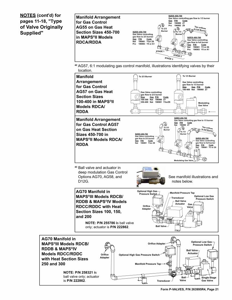
Form P-VALVES, P/N 263995R4, Page 21
42 AG57, 6:1 modulating gas control manifold, illustrations identifying valves by their location.
To 2/3 Burner To 1/3 Burner
ModulatingGas Valve
Gas Valve controllinggas flow to 2/3 burnerSize Gas P/N Code100-300 Nat 196980 Z7350-400 Nat 196981 Y3orZ8
Gas Valve controllinggas flow to 1/3 burnerSize Gas P/N Code100-400 Nat 196980 Z7
Two orifices to full BurnerTo 1/3 Burner
To 2/3 Burner
Modulating Gas Valve
SIZES 450-700Gas Valve controllinggas flow to 2/3 burnerGas P/N CodeNat 196981 Y3or Z8
SIZES 450-700Gas Valve controlling gas flow to 1/3 burnerGas P/N CodeNat 196980 Z7
SIZES 450-700Gas Valve controllinggas flow to full burnerGas P/N CodeNat 196981 Y3 or Z8
Manifold Arrangement for Gas Control AG57 on Gas Heat Section Sizes 100-400 in MAPS®II Models RDCA/RDDA
Manifold Arrangement for Gas Control AG57 on Gas Heat Section Sizes 450-700 in MAPS®II Models RDCA/RDDA
To 2/3 Burner To 1/3
Burner
Two orifices to full Burner
STAGE 1
STAGE 3
STAGE 2
SIZES 450-700Gas Valve controllinggas flow to 2/3 burnerGas P/N CodeNat 196981 Y3or Z8Pro 196983 Y5 or A1
SIZES 450-700Gas Valve controllinggas flow to full burnerGas P/N CodeNat 196981 Y3 or Z8Pro 196983 Y5 or A1
SIZES 450-700Gas Valve controlling gas flow to 1/3 burnerGas P/N CodeNat 196980 Z7Pro 196982 Z9
Manifold Arrangement for Gas Control AG55 on Gas Heat Section Sizes 450-700 in MAPS®II Models RDCA/RDDA
43 Ball valve and actuator in deep modulation Gas Control Options AG70, AG58, and D12G.
See manifold illustrations and notes below.
AG70 Manifold in MAPS®III Models RDCB/RDDB & MAPS®IV Models RDCC/RDDC with Heat Section Sizes 100, 150, and 200
Orifice Adapter
Ball Valve
Optional High Gas Pressure Switch
TransducerBall Valve Actuator Gas
Valve
Optional Low Gas Pressure Switch
Manifold Pressure Tap
NOTE: P/N 255786 is ball valve only; actuator is P/N 222862.
Orifice Adapter
Orifice Adapter
Optional High Gas Pressure Switch
TransducerBall
ValveSingle-Stage Gas Valve
Ball ValveActuator
Optional Low GasPressure Switch
Manifold Pressure Tap
AG70 Manifold in MAPS®III Models RDCB/RDDB & MAPS®IV Models RDCC/RDDC with Heat Section Sizes 250 and 300
NOTE: P/N 258321 is ball valve only; actuator is P/N 222862.
NOTES (cont'd) for pages 11-18, "Type of Valve Originally Supplied"

Form P-VALVES, P/N 263995R4, Page 22
Optional High Gas Pressure Switch
Optional Low Gas Pressure Switch
Dual, Single-Stage Gas ValveBall Valve
with Actuator
Transducer
From Gas
Supply
To Burner
Manifold Pressure Tap
AG70 Manifold in MAPS®III Models RDCB/RDDB & MAPS®IV Models RDCC/RDDC with Heat Section Sizes 400, 500, 600, 700
Optional Low Gas Pressure
Switch
Manual Shutoff Valve(manifold for single-stage burner)
Manual Shutoff Valve(modulating burner manifold)
Dual,Single-Stage
Gas Valve(modulating burner)
Dual, Single-Stage Gas Valve (single-stage burner)
Optional High Gas Pressure Switch (modulating burner)
Manifold Pressure TAP(modulating burner)
Optional High Gas Pressure Switch (single-stage burner)
To modulating burner
To burner withsingle-stagecontrol
Gas Supply
Ball Valve with Actuator(modulating burner)
Pressure Switch(modulating
burner)
AG70 Manifold in MAPS®III D Cabinet Models RDCB/RDDB with Heat Section Sizes 500, 600, 700, 800, 1000, 1200, 1400, and 1600
NOTE: P/N 222861 is the ball valve only; actuator is P/N 222862.
43 NOTE 43 (cont'd) Ball valve and actuator in Gas Control Option AG70, AG58, and D12G.
NOTE: P/N 222861 is the ball valve only; actuator is P/N 222862.
NOTE: Manifold for single-stage burner applies only to Sizes 1000, 1200, 1400 and 1600. Sizes 500, 600, 700, and 800 have only the manifold for the modulating burner.
Top View
SideView
Ball ValveActuator
Ball ValveActuator
Combination Gas Valve
PressureTranducer
Ball Valve
Gas ValveBracket
Orifice
ManifoldPressureTap
Manifold in Models RDH, SHH, and RHH with AG58 or D12G Gas Control
RDH Size SHH and RHH Size Gas Ball
ValveBall Valve Actuator
175 & 200 130 & 180Nat 255786 222862
Pro 255786 222862225, 250, 300, 350, & 400
250 & 350Nat 258321 222862
Pro 258321 222862
NOTES (cont'd) for pages 11-18, "Type of Valve Originally Supplied"
44 NOTE 44: When installing this valve as a replacement for a valve with a different Serial No. Valve Code on a Model PDH, SDH, RDH, SHH, or RHH, a new valve bracket is required. • For PDH, SDH, and RDH Sizes 75, 100, 125, and 150, order bracket P/N
261650. • For PDH, SDH, and RDH Sizes 175 and 200, order bracket P/N 261249• For SHH and RHH Size 130, order bracket P/N 261650.• For SHH and RHH Size 180, order bracket P/N 261249.
45 NOTE 45: As a result of continued product improvement, the valve that is factory installed on these Model RDCB/RDDB heat section sizes was changed from slow opening to standard opening effective 8/09. When replacing, the valve listed here is the appropriate functional replacement.

Form P-VALVES, P/N 263995R4, Page 23
Replacement Valve P/N 96300
Replacement Valves (cont'd) - Identified by Third Element of the Serial No. (see pages 11-22). Valves showing "Replaced by P/N's" are no longer available from Reznor.
See SerialNo. Code Size Gas P/N Page Replaced by:
Code P/N Page83 1/2 N 39298 12 K6 96300 14E9 1/2 P 64420 13 G9 82396 13
For replacement of ECO adapter only for original valves, see page 26. The ECO adapter on the replacement valves is not field replaceable.
Replacement single-stage Valve P/N 96300
P/N 25787
Replacement Valve P/N 121598
For replacement of ECO adapter only, see page 26.
Replacement Valve P/N 96301
Replacement Valve P/N 177396
Replacement Valve P/N 115351
For replacement of ECO adapter only, see page 26.
Replacement Valve P/N 96300
See SerialNo. Code Size Gas P/N Page Replaced by:
Code P/N PageA5 1/2 N 47380 12 Q2 121598 15A6 3/4 N 47381 12 9A 221525 17E4 3/4 N 61098 13 9A 221525 17E5 1/2 P 61099 13 Q4 121600 15F5 3/4 P 63282 13 1B 221526 172D 3/4 N 221633 18
See SerialNo. Code Size Gas P/N Page Replaced by:
Code P/N PageC5 3/4 N 51299 13 K7 *96301 14D7 3/4 N 59341 13 K7 *96301 14H1 3/4 N 82398 13 K7 *96301 14
*Replacement requires 1/4" pilot tubing connection, P/N 9664.
See SerialNo. Code Size Gas P/N Page Replaced by:
P/N Page95 3/4 N or P 47537 12 88242 19, Note 10
B5 1 N or P 47538 12 112922 19, Note 5
Pilot Line Valve 1/4 N or P 25787
See SerialNo. Code Size Gas P/N Page Replaced by:
Code P/N PageB6 1/2 N 48577 12 K6 *96300 14E8 1/2 P 62969 13 K9 *96303 14H3 1/2 N 82624 13 K6 *96300 14H4 1/2 P 82669 13 K9 *96303 14*Replacement requires 1/4" pilot tubing connection, P/N 9664.
See SerialNo. Code Size Gas P/N Page Replaced by:
Code P/N PageD4 3/4 N 52886 13 P8 115351 15F1 1/2 N 62966 13 P8 115351 15F2 1/2 P 62967 13 P9 115352 15
See SerialNo. Code Size Gas P/N Page Replaced by:
Code P/N PageE1 1/2 N 60609 13 X2 177396* 16E2 3/4 N 60610 13 X3 177397* 16E3 1/2 P 60611 13 X1 177395* 16F3 1/2 P 62946 13 X1 177395* 16*Replacement requires 1/4" pilot tubing connection, P/N 9664.
See SerialNo. Code Size Gas P/N Page Replaced by:
Code P/N PageG8 1/2 N 82395 13 K6 96300 14G9 1/2 P 82396 13Original valves include an ECO adapter that is not field replaceable.

Form P-VALVES, P/N 263995R4, Page 24
P/N 86993 Actuator (M/H V4055A1077) - Part of Serial No. Codes J2, J3, J4, K2, and K4
Replacement Valves (cont'd) - Identified by Third Element of the Serial No. (see pages 11-22). Valves showing "Replaced by P/N's" are no longer available from Reznor.
Replacement Valve P/N 177396
P/N 86966 may be a valve manufactured by either General
Controls or Skinner (Skinner valve illustrated.)
Replacement Valve P/N 96310
Replacement Valve P/N 121599
Fluid Power Valve
Replacement Valve P/N 96300
Original valves include an ECO adapter that is not field replace-able.
Replacement Valve P/N 221525
NOTE: Do not use on units with G29 or G33 ignition controls; order ignition kit P/N 49491.
Replacement Valve P/N 208920
See SerialNo. Code Size Gas P/N Page Replaced by:
Code P/N PageH5 1/2 N 87430 13 X2 177396* 16H6 3/4 N 87432 13 X3 177397* 16H7 1/2 P 87431 13 X1 177395* 16M9 1/2x3/4 P 96312 14 X4 177398* 16*Replacement requires 1/4" pilot tubing connection, P/N 9664.
See SerialNo. Code Size Gas P/N Page
J1 1 N or P (2) 86966 14
See SerialNo. Code Size Gas P/N Page
J2, J3, J4 1 N or P 86992 (M/H #V5055A1004) 14K2 1-1/4 N or P 89356 (M/H #V5055A1012) 14K4 2 N or P 91079 (M/H #V5055A1038) 14M/H fluid power valves above used with actuator, P/N 86993W1, W2 1 N or P 172667 (ASCO V710FAS) 16W3 1-1/4 N or P 172678 (ASCO V710GAS) 16W4 2 N or P 179679 (ASCO V710JAS) 16ASCO fluid power valves above used with actuator, P/N 172680
See SerialNo. Code Size Gas P/N Page Replaced by:
Code P/N PageJ5 1/2 N 89461 14 M4 96307 14J6 1/2 P 89462 14 M7 96310 14
See SerialNo. Code Size Gas P/N Page Replaced by:
Code P/N PageH2 1/2 N 82397 13 K6 *96300 14K6 1/2 N 96300 14*Replacement requires 1/4" pilot tubing connection, P/N 9664.
See SerialNo. Code Size Gas P/N Page Replaced by:
Code P/N PageH9 3/4x1/2 P 93386 14 Q4 121600 15J7 1/2 N 89370 14 Q2 121598 15J9 3/4 P 89371 14 Q4 121600 15M5 1/2 N 96308 14 Q3 121599 15
See SerialNo. Code Size Gas P/N Page Replaced by:
Code P/N PageJ8 3/4 N 89397 14 9A 221525 17K1 3/4 P 89398 14 1B 221526 17M6 3/4 N 96309 14 Kit P/N 222037M8 1/2x3/4 P 96311 14 Kit P/N 221634U8 1/2x3/4 P 157167 16 Kit P/N 221634U9 3/4x3/4 P 157168 16 Kit P/N 221634
See SerialNo. Code Size Gas P/N Page Replaced by:
Code P/N PageK5 1/2 N 96299 14 9B 208920 17K8 1/2 P 96302 14 1C 209412 17
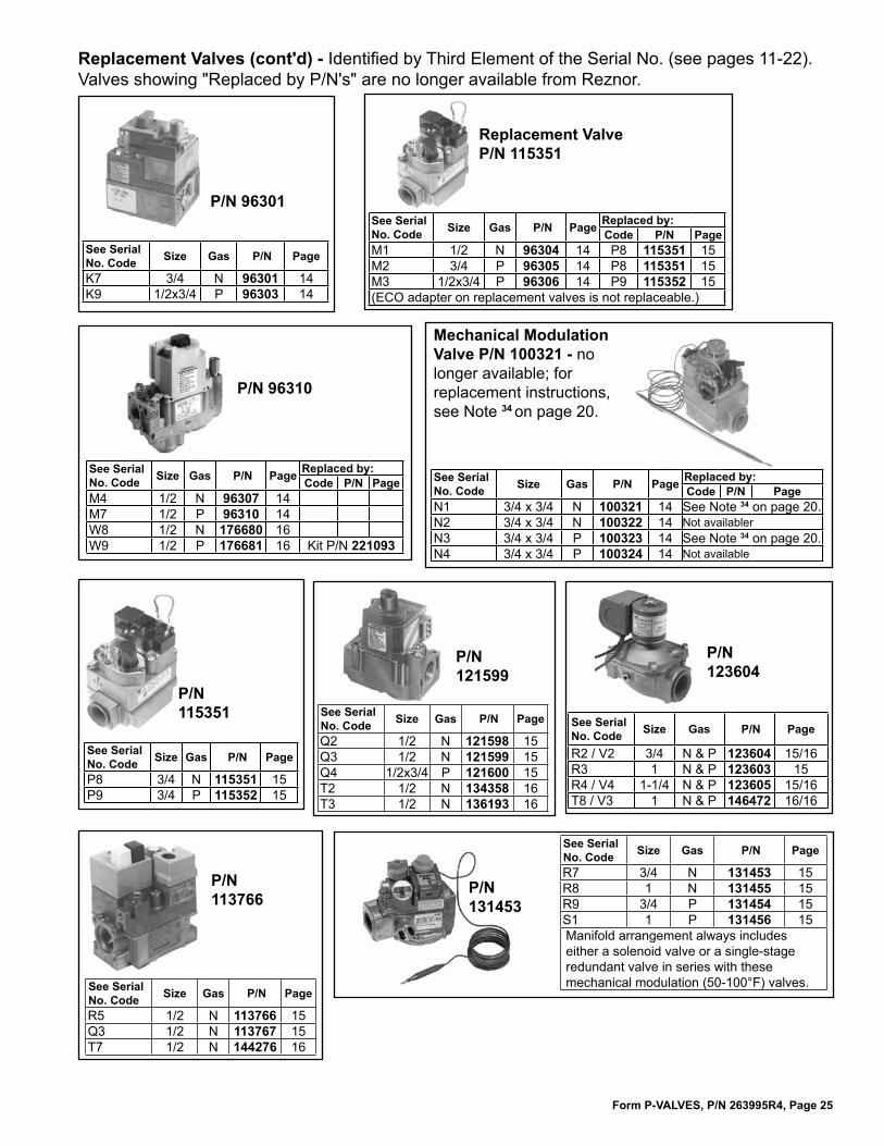
Form P-VALVES, P/N 263995R4, Page 25
P/N 121599
P/N 123604
Replacement Valves (cont'd) - Identified by Third Element of the Serial No. (see pages 11-22). Valves showing "Replaced by P/N's" are no longer available from Reznor.
Replacement Valve P/N 115351
P/N 96310
P/N 115351
Mechanical Modulation Valve P/N 100321 - no longer available; for replacement instructions, see Note 34 on page 20.
P/N 131453
P/N 113766
P/N 96301
See SerialNo. Code Size Gas P/N Page
K7 3/4 N 96301 14K9 1/2x3/4 P 96303 14
See SerialNo. Code Size Gas P/N Page Replaced by:
Code P/N PageM1 1/2 N 96304 14 P8 115351 15M2 3/4 P 96305 14 P8 115351 15M3 1/2x3/4 P 96306 14 P9 115352 15(ECO adapter on replacement valves is not replaceable.)
See SerialNo. Code Size Gas P/N Page Replaced by:
Code P/N PageM4 1/2 N 96307 14M7 1/2 P 96310 14W8 1/2 N 176680 16W9 1/2 P 176681 16 Kit P/N 221093
See SerialNo. Code Size Gas P/N Page Replaced by:
Code P/N PageN1 3/4 x 3/4 N 100321 14 See Note 34 on page 20.N2 3/4 x 3/4 N 100322 14 Not availablerN3 3/4 x 3/4 P 100323 14 See Note 34 on page 20.N4 3/4 x 3/4 P 100324 14 Not available
See SerialNo. Code Size Gas P/N Page
P8 3/4 N 115351 15P9 3/4 P 115352 15
See SerialNo. Code Size Gas P/N Page
Q2 1/2 N 121598 15Q3 1/2 N 121599 15Q4 1/2x3/4 P 121600 15T2 1/2 N 134358 16T3 1/2 N 136193 16
See SerialNo. Code Size Gas P/N Page
R2 / V2 3/4 N & P 123604 15/16R3 1 N & P 123603 15R4 / V4 1-1/4 N & P 123605 15/16T8 / V3 1 N & P 146472 16/16
See SerialNo. Code Size Gas P/N Page
R5 1/2 N 113766 15Q3 1/2 N 113767 15T7 1/2 N 144276 16
See SerialNo. Code Size Gas P/N Page
R7 3/4 N 131453 15R8 1 N 131455 15R9 3/4 P 131454 15S1 1 P 131456 15Manifold arrangement always includes either a solenoid valve or a single-stage redundant valve in series with these mechanical modulation (50-100°F) valves.
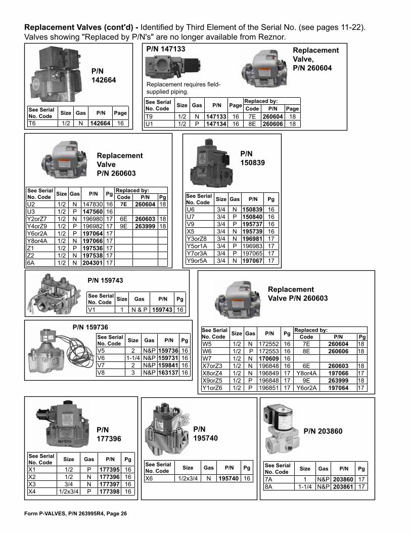
Form P-VALVES, P/N 263995R4, Page 26
Replacement Valves (cont'd) - Identified by Third Element of the Serial No. (see pages 11-22). Valves showing "Replaced by P/N's" are no longer available from Reznor.
P/N 150839
Replacement Valve P/N 260603
P/N 159743
P/N 142664
Replacement Valve P/N 260603
P/N 177396
P/N 147133
Replacement requires field-supplied piping.
P/N 159736
P/N 195740
Replacement Valve, P/N 260604
P/N 203860
See SerialNo. Code Size Gas P/N Page
T6 1/2 N 142664 16
See SerialNo. Code Size Gas P/N Page
Replaced by:Code P/N Page
T9 1/2 N 147133 16 7E 260604 18U1 1/2 P 147134 16 8E 260606 18
See SerialNo. Code Size Gas P/N Pg Replaced by:
Code P/N PgU2 1/2 N 147830 16 7E 260604 18U3 1/2 P 147560 16Y2orZ7 1/2 N 196980 17 6E 260603 18Y4orZ9 1/2 P 196982 17 9E 263999 18Y6or2A 1/2 P 197064 17Y8or4A 1/2 N 197066 17Z1 1/2 P 197536 17Z2 1/2 N 197538 176A 1/2 N 204301 17
See SerialNo. Code Size Gas P/N Pg Replaced by:
Code P/N PgW5 1/2 N 172552 16 7E 260604 18W6 1/2 P 172553 16 8E 260606 18W7 1/2 N 170609 16 X7orZ3 1/2 N 196848 16 6E 260603 18X8orZ4 1/2 N 196849 17 Y8or4A 197066 17X9orZ5 1/2 P 196848 17 9E 263999 18Y1orZ6 1/2 P 196851 17 Y6or2A 197064 17
See SerialNo. Code Size Gas P/N Pg
V1 1 N & P 159743 16
See SerialNo. Code Size Gas P/N Pg
V5 2 N&P 159736 16V6 1-1/4 N&P 159731 16V7 2 N&P 159841 16V8 3 N&P 163137 16
See SerialNo. Code Size Gas P/N Pg
U6 3/4 N 150839 16U7 3/4 P 150840 16V9 3/4 P 195737 16X5 3/4 N 195739 16Y3orZ8 3/4 N 196981 17Y5or1A 3/4 P 196983 17Y7or3A 3/4 P 197065 17Y9or5A 3/4 N 197067 17
See SerialNo. Code Size Gas P/N Pg
X1 1/2 P 177395 16X2 1/2 N 177396 16X3 3/4 N 177397 16X4 1/2x3/4 P 177398 16
See SerialNo. Code Size Gas P/N Pg
X6 1/2x3/4 N 195740 16
See SerialNo. Code Size Gas P/N Pg
7A 1 N&P 203860 178A 1-1/4 N&P 203861 17

Form P-VALVES, P/N 263995R4, Page 27
P/N 203869P/N 203866
Replacement ECO Adapters - The replacement adapters apply only to the valves listed; adapters do not apply to replacement valves.
Valve P/N
Serial No. Code
Valve P/N
Serial No. Code
Valve P/N
Serial No. Code
52886 D4 96304 M1 82398 H162967 F2 96306 M3 96303 F996301 K7 62996 F1 96305 M2P/N 82698,
M/H #39240-1
P/N 82699, R#21608
P/N 113149, M/H #39200-20
Replacement Valves (cont'd) - Identified by Third Element of the Serial No. (see pages 11-22). Valves showing "Replaced by P/N's" are no longer available from Reznor.
See Serial No. Code Size Gas P/N Page
9B 1/2 N 208920 171C 1/2 P 209412 17
P/N 208920
See Serial No. Code Size Gas P/N Page
1D 3/4x2 N or P 209412 18
P/N 203862
See Serial No. Code Size Gas P/N Page
9A 3/4 N 221525 171B 3/4 P 221526 172D 3/4 N 221633 18
P/N 221525
See SerialNo. Code Size Gas P/N Pg
2B 1 N 203866 17
See SerialNo. Code Size Gas P/N Page
Replaced by:Code P/N Page
3B 1 N&P 203868 17 No longer avaialble4B 1 N&P 203869 17
Valve P/N Serial No. Code82624 H382669 H4
Valve P/N Serial No. Code96299 K596302 K8
See Serial No. Code Size Gas P/N Page
6E 1/2 N 260603 187E 1/2 N 260604 188E 1/2 P 260606 189E 1/2 P 263999 18
P/N 260603

Form P-VALVES, P/N 263995R4, Page 28
Kit P/N 262320 replaces A1010B Amplifier, P/N 48035, used in Maxitrol 21HR (Option AG9) and 20AH (Option AG7) Systems and 1011F Amplifier, P/N 48036, in Maxitrol 30AH (Option AG7) and 31HR (Option AG9) Systems
P/N 48041, TS12MT2-12 Duct Sensor used in Maxitrol 21H, 21HR, 31H and 31HR Systems, Option AG8 and AG9
P/N 133228, Duct Sensor, Maxitrol TS194, used in Option AG39 and Option AG41
Other Replacement Maxitrol Discharge Air Sensors (sensor only, no box) - match with selector:#TS121A, P/N 194261#TS121B, P/N 194262#TS121F, P/N 194263
Maxitrol Components for Electronic Modulation - Indirect-Fired Equipment Model Series X, SC, RG, RP, RX, RPV, and EEDU with Options AG7, AG8, AG9, AG21, AG39, AG40, AG41, or AG42(References: For modulation control components for PREEVA Models PDH, SDH, and RDH, see replacement parts Form P-PRE-EVA. For MAPSII, see replacement parts Form P-MAPSII.)
Maxitrol Temperature Selectors/Thermostats, Temperature Sensors, and AmplifiersMaxitrol System 20AH 30AH 21H 31H 21HR 31HR Series 92Serial No. Suffix Code MV-1 MV-2 MV-3 MV-5 MV-4 MV-6 MP-1 MP-3
Reznor® Model Series X, SC, RX, RPV, RG, RP, EEDU INDIRECT-Fired Furnaces with OptionComponents by Option AG7 AG8 AG9 AG39 AG41
Number of Furances Single Furnace
Multiple Furnaces
Single Furnace
Multiple Furnaces
Single Furnace
Multiple Furnaces
Single Furnace
Multiple Furnaces (Maxitrol components on 1st furnace only)
Temperature Selector
Reznor® P/N-- -- On the Amplifier
48042 48042 174849 174849Maxitrol # TD-121 TD-121 TD92-0509 TD92-0509
SelectrastatReznor® P/N 48033 48033
-- -- -- -- -- --Maxitrol # T120 T120
Optional Override Thermostat
Reznor® P/N -- -- 24857 24857 24857 24857 -- --
Maxitrol # T-115 T-115 T-115 T-115
Sensor (P/N 48041 includes mix-ing tube)
Reznor® P/N -- -- 48041 48041 48041 48041 133228 133228
Maxitrol # TS-121 TS-121 TS-121 TS-121 TS194 TS194
Mixing Tube Only
Reznor® P/N -- -- 90323 90323 90323 90323 90323 90323Maxitrol # MTI-12 MTI-12 MTI-12 MTI-12 MTI-12 MTI-12
AmplifierReznor® P/N 260863 260863 260864 260864 260863 260863 174848 174848
Maxitrol # A1010U A1010U AD1010U AD1010U A1010U A1010U A1092 A1092
P/N 48033, T120 Thermostat used in Maxitrol 20AH and 30AH Systems, Option AG7
P/N 48042, TD121 remotely located Temperature Selector used in Maxitrol 21HR and 31HR Systems, Option AG9 (box not included)Selector with box, P/N 158465
P/N 24857, T115 Overriding Thermostat used in Options AG8 and AG9(Also used on Direct-Fired with Option AG31; see page 30.)
P/N 174849, Maxitrol TD92-0509, remotely located Temperature
Selector used in Options AG39 &
AG41Other Replacement Maxitrol Temperature Selectors (selector only; no box) - match selector with sensor:#TD121A, P/N 194258#TD121B, P/N 194259#TD121F, P/N 194260
(changed from 4x4 box to 2x4 box effective 5/89)
Amplifier, Maxitrol A1010U, P/N 260863, in Replacement Kit P/N 262320
Amplifier, Maxitrol AD1010U, P/N 260864, in Replacement Kit P/N 262321
Kit P/N 262321 replaces A1010F Amplifier, P/N 48037, used in Maxitrol 21H (Option AG8) Systems and A1011F Amplifier, P/N 48038, used in Maxitrol 31H (Option AG8) Systems
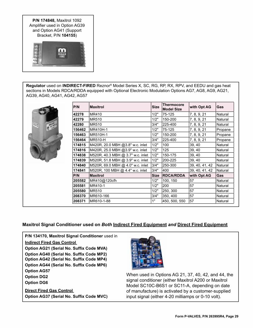
Form P-VALVES, P/N 263995R4, Page 29
P/N 174848, Maxitrol 1092 Amplifier used in Option AG39
and Option AG41 (Support Bracket, P/N 104155)
P/N Maxitrol Size Thermocore Model Size with Opt AG Gas
42278 MR410 1/2" 75-125 7, 8, 9, 21 Natural42279 MR510 1/2" 150-200 7, 8, 9, 21 Natural42280 MR510 3/4" 225-400 7, 8, 9, 21 Natural156462 MR410H-1 1/2" 75-125 7, 8, 9, 21 Propane156463 MR510H-1 1/2" 150-200 7, 8, 9, 21 Propane156464 MR510-H 3/4" 225-400 7, 8, 9, 21 Propane174815 M420R, 20.0 MBH @3.8" w.c. inlet 1/2" 100 39, 40 Natural174816 M420R, 25.0 MBH @3.9" w.c. inlet 1/2" 125 39, 40 Natural174838 M520R, 40.3 MBH @ 3.7" w.c. inlet 1/2" 150-175 39, 40 Natural174839 M520R, 51.8 MBH @ 3.9" w.c. inlet 1/2" 200-225 39, 40 Natural174840 M520R, 69.0 MBH @ 4.0" w.c. inlet 3/4" 250-300 39, 40, 41, 42 Natural174841 M520R, 100 MBH @ 4.4" w.c. inlet 3/4" 400 39, 40, 41, 42 NaturalP/N Maxitrol Size RDCA/RDDA with Opt AG Gas205582 MR410@120cfh 1/2" 100, 150 57 Natural205581 MR410-1 1/2" 200 57 Natural205580 MR510 1/2" 250, 300 57 Natural208370 MR610-166 3/4" 350, 400 57 Natural208371 MR610-1-88 1" 450, 500, 550 57 Natural
Regulator used on INDIRECT-FIRED Reznor® Model Series X, SC, RG, RP, RX, RPV, and EEDU and gas heat sections in Models RDCA/RDDA equipped with Optional Electronic Modulation Options AG7, AG8, AG9, AG21, AG39, AG40, AG41, AG42, AG57
P/N 134170, Maxitrol Signal Conditioner used in Indirect Fired Gas Control Option AG21 (Serial No. Suffix Code MVA) Option AG40 (Serial No. Suffix Code MP2) Option AG42 (Serial No. Suffix Code MP4)Option AG44 (Serial No. Suffix Code MP6)Option AG57Option DG2Option DG6
Direct Fired Gas Control Option AG37 (Serial No. Suffix Code MVC)
When used in Options AG 21, 37, 40, 42, and 44, the signal conditioner (either Maxitrol A200 or Maxitrol Model SC10C-B6S1 or SC11-A, depending on date of manufacture) is activated by a customer-supplied input signal (either 4-20 milliamps or 0-10 volt).
Maxitrol Signal Conditioner used on Both Indirect Fired Equipment and Direct Fired Equipment

Form P-VALVES, P/N 263995R4, Page 30
Maxitrol Components for Electronic Modulation - Direct-Fired Equipment Model Series ADF, DV, and RDF with Options AG30, AG31, AG32, AG35, AG33, AG36, AG37, AG47, AG48, AG51 Maxitrol System 14 14 14A 14BSerial No. Suffix Code MV-7 MV-7 MV-8 MV-8
Reznor® Model Series ADF, DV, and RDF DIRECT-Fired Furnaces with OptionComponents by Option AG30 AG31 AG32 AG35
Temperature SelectorReznor® P/N 86988
U.S. - 86988; Canada -
10116587107 123943, 140°F Stop
159285, 160°F Stop
Maxitrol # TD114 TD114 TD114A TD114BOverride Thermostat (illustrated on page 23)
Reznor® P/N -- 24857 -- --Maxitrol # -- T-115 -- --
SensorReznor® P/N 90324 90324 87106 123944
Maxitrol # TS-114 TS-114 TS-114A TS-114B
Mixing Tube Reznor® P/N 90323 90323 90323 90323
Maxitrol # MTI-12 MTI-12 MTI-12 MTI-12
AmplifierReznor® P/N 148590* 148590* 148590* 148590*
Maxitrol # A1014R A1014R A1014R A1014R
P/N 268274, Model A1044U, used in Option AG33** To replace P/N 194159 (A1044CL); P/N 157915 (A1044EL); P/N 119616 (A1044E) and P/N 86989 (A1044), order Replacement Kit P/N 268302.
P/N 148590, Model A1014R Amplifier used in Options AG 30, 31, 32, 35 * To replace P/N 148590, Model A1014L or A1014U or P/N 86976, order Replacement Kit P/N 268301.
P/N 133229, A1494 Amplifier, for Paint Booth Application, Option AG36
P/N 204454, ADFM14 Amplifier
Maxitrol Amplifiers used on Reznor® Direct-Fired Model Series ADF, DV, and RDF
Maxitrol System 44 94Serial No. Suffix Code MV-9 MV-B
Reznor® Model Series ADF, DV, and RDF DIRECT-Fired Furnaces with Option
Components by Option AG33 AG36Temperature Selector
Reznor® P/N 86990 133230, 120°F 159287, 160°FMaxitrol # T244, Selectrastat TD294E-609-0818
Sensor Reznor® P/N 119617 (max 120°F)
194160 (max 140°F) 133228
Maxitrol # TS-144E TS-144C TS194 Remote Sensor
Reznor® P/N -- -- -- --Maxitrol # -- -- -- --
Mixing Tube Reznor® P/N 90323 90323Maxitrol # MTI-12 MTI-12
Amplifier Reznor® P/N 268274** 268274** 133229Maxitrol # A1044U A1044U A1494
NOTE: Shown with cover removed.

Form P-VALVES, P/N 263995R4, Page 31
P/N 86990, T244
Selectrastat, Option AG33
Regulators used on DIRECT FIRED Units are determined by BM Option and Manifold Size
P/N 89351, MR212D, 1-1/4"; P/N 91071, MR212E, 2"; P/N 163143, MR212G, 3"
Temperature Selectors (see table, page 30, for option application)P/N 86988, TD114 U.S. Models, Range 55-90°F (selector with box, P/N 156085);P/N 101165, TD114, Canadian Models, Range 50-75°F;P/N 87107, TD114A, Range 80-130°F;P/N 123943, TD114B, Range 120-140°FP/N 159285, TD114B, Range 120-160°FP/N 204455, TD DFM14P/N 204451, TD DFM44
P/N 123916, M611-R66, 3/4"; P/N 87001, M611-R88, 1"
Temperature Sensor (see table, page 30, for option application):P/N 90324, TS114, Range 55-90°F; P/N 87106, TS114-A, Range 80-130°F; P/N 123944, TS114B, Range 80-140°F; P/N 204452, TS394-2B-4;P/N 204453, TS194Q; P/N 119617, TS144E, Range 20-60°F and 60-120°F; P/N 194160, TS144C, Range 20-60°F and 80-140°F; P/N 87041, TS144, Range 40-80°F and 80-140°F; P/N 133228 TS194 for Paint Booth Application
IMPORTANT NOTES: When replacing a temperature sensor on a Maxitrol MV-9 system (Option AG33), check the Model No. on the sensor. P/N 119617 or 194160 is used on units manufactured beginning 2/92; P/N 87041 is used on units manufactured prior to 2/92. Sensors are not interchangeable; the sensor must match the amplifier shown on page 30.
P/N 133230, #TD294E-609-0818,
Dual Temperature Selector for Paint Booth Application,
Option AG36
Maxitrol Components for Electronic Modulation - Direct-Fired Equipment Model Series ADF, DV, and RDF with Options AG30, AG31, AG32, AG35, AG33, AG36, AG37, AG47, AG48, AG51 (cont'd)
Mixing Tube for temperature sensors, P/N 90323, MTI-12

Form P-VALVES, P/N 263995R4, Page 32
www.ReznorHVAC.com; (800)695-1901©2014 Reznor LLC, All rights reserved. Trademark Notes: Reznor®, MAPS®, and PREEVA® are registered in at least the United States. All other trademarks are the property of their respective owners.
06/14 (Serial No. Date Code BNF), Form P-VALVES (Version F.3)
DDate of Manufacture 4
EECO Adapters 27
IID Plugs 10Ignition Conversion Kits 10Ignition System 6Instructions 2
MAG70 Manifold in a MAPS III & IV 22Manifold Arrangement for Gas Control AG55 20Manifold Arrangement for Gas Control AG57 21Maxitrol Components for Electronic Modulation 28, 30Model No. Decoding 5
NNOTES for Third Element of the Serial Number (Valves) 19, 20, 21, 22
PPREFIX and SUFFIX Codes 5
RRating Plate 3
SSafety Pilot 6SAFETY WARNINGS 1Serial No. 5Decoding a MAPS® Unit Serial No. 4Serial No. Decoding 3Signal Conditioner 29SUFFIX Codes 5
VValve Originally Supplied 11Replacement Valves 23, 24, 25, 26, 27
Index
�