Embed Size (px)
Citation preview
Warranty and Repair Policy 1. Interface warrants that its instruments shall be free from defects in material and workmanship for one year under normal and proper use when correctly installed. 2. Any Interface product which proves defective in material or in workmanship within one year from date of shipment by Interface, will be repaired or replaced free of charge provided that (1) buyer provides Interface with satisfactory proof of the defect and that the product was properly installed, maintained, and operated within the limits of rated and normal usage; (2) buyer obtains from Interface authorization to return the product; and (3) products claimed to be defective must be returned with transportation charges prepaid. Product will be returned to Buyer with transportation charges collect unless the item is found to be defective, in which case Interface will pay the return transportation charges. 3. The remedy set forth herein does not apply to damage to or defects in any product caused by the Buyer's misuse or neglect, nor does it apply to any product which has been repaired or disassembled, which in the sole judgement of Interface affects the performance of the product. 4. Interface makes no warranty concerning components not manufactured by it. However, in the event of the failure of any component or accessory not manufactured by Interface, reasonable assistance will be given to Buyer in obtaining from the respective manufacturer whatever adjustment is reasonable based on the manufacturer's own warranty. Interface expressly disclaims any liability to its customers, dealers, and representatives, and to users of its products, and to any other person for special or consequential damages of any kind and from any cause whatsoever arising out of or in any way connected with the manufacture, sale, handling, repair, maintenance, or replacement arising out of or in anyway connected with the use of said products. 5. Representations and warranties made by any person, including dealers and representatives of Interface, which are inconsistent or in conflict with the terms of this warranty (including but not limited to the limitations of the liability of Interface, as set forth above), shall not be binding upon Interface unless reduced to writing and approved by an officer of Interface, Inc. THIS EXPRESS WARRANTY SUPERCEDES ANY AND ALL OTHER WARRANTIES, EXPRESSED OR IMPLIED, INCLUDING IMPLIED WARRANTY OF MERCHANTABILITY OR FITNESS FOR PARTICULAR PURPOSE. OBTAINING SERVICE UNDER WARRANTY Advance authorization is required before any product is returned to Interface. Prior to the return of any product, write or call the Repair Department at Interface advising them of; (1) a part number; (2) a serial number of the defective product; (3) a technical description of the defect including specific test data, written observations on the failure and specific corrective action required; (4) a no-charge purchase order number (so the product can be returned to sender correctly); and (5) ship and bill addresses. Non-verified problems or defects may be subject to an evaluation charge. Please return the original calibration data with the unit. REPAIR WARRANTY All repairs of Interface products are warranted for a period of 90 days from date of shipment. This warranty applies only to those items which were found defective and repaired. It does not apply to products in which no defect was found and returned as is or merely recalibrated. Out of warranty products may not be capable of being
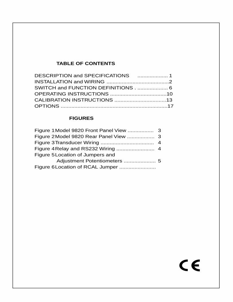
TABLE OF CONTENTS
DESCRIPTION and SPECIFICATIONS .................... 1 INSTALLATION and WIRING .........................................2
SWITCH and FUNCTION DEFINITIONS . .................... 6OPERATING INSTRUCTIONS .....................................10CALIBRATION INSTRUCTIONS ..................................13OPTIONS ......................................................................17
FIGURES
Figure 1Model 9820 Front Panel View ................. 3Figure 2Model 9820 Rear Panel View .................. 3Figure 3Transducer Wiring ................................... 4Figure 4Relay and RS232 Wiring ......................... 4Figure 5Location of Jumpers and
Adjustment Potentiometers ..................... 5Figure 6Location of RCAL Jumper ........................
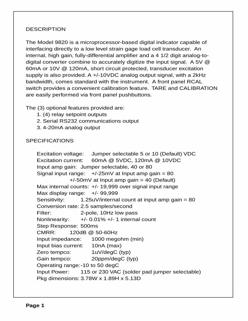
DESCRIPTION
The Model 9820 is a microprocessor-based digital indicator capable of interfacing directly to a low level strain gage load cell transducer. An internal, high gain, fully-differential amplifier and a 4 1/2 digit analog-to-digital converter combine to accurately digitize the input signal. A 5V @ 60mA or 10V @ 120mA, short circuit protected, transducer excitation supply is also provided. A +/-10VDC analog output signal, with a 2kHz bandwidth, comes standard with the instrument. A front panel RCAL switch provides a convenient calibration feature. TARE and CALIBRATION are easily performed via front panel pushbuttons.
The (3) optional features provided are:1. (4) relay setpoint outputs2. Serial RS232 communications output3. 4-20mA analog output
SPECIFICATIONS
Excitation voltage: Jumper selectable 5 or 10 (Default) VDCExcitation current: 60mA @ 5VDC, 120mA @ 10VDCInput amp gain: Jumper selectable, 40 or 80Signal input range: +/-25mV at Input amp gain = 80
+/-50mV at Input amp gain = 40 (Default)Max internal counts: +/- 19,999 over signal input rangeMax display range: +/- 99,999Sensitivity: 1.25uV/internal count at input amp gain = 80Conversion rate: 2.5 samples/secondFilter: 2-pole, 10Hz low passNonlinearity: +/- 0.01% +/- 1 internal countStep Response: 500msCMRR: 120dB @ 50-60HzInput impedance: 1000 megohm (min)Input bias current: 10nA (max)Zero tempco: 1uV/degC (typ)Gain tempco: 20ppm/degC (typ)Operating range:-10 to 50 degCInput Power: 115 or 230 VAC (solder pad jumper selectable)Pkg dimensions: 3.78W x 1.89H x 5.13D
Page 1

INSTALLATION AND WIRING
INSTALLATION
The Model 9820 enclosure is designated for panel mounting in a 1/8 DIN cutout. The cutout dimensions are shown below.
To panel mount the 9820, perform the following steps.
1. Rotate the four pawl screws ( outside screws in each corner) several turns counter-clockwise to retract the pawls. Make sure
the pawls retract enough to clear the back of the mounting panel. The pawls may be retracted to accomodate panel thicknesses up
to 0.25 inches (6.35mm).
2. Insert the instrument into the panel cutout.
3. Position the pawls so that their elongated dimension overlaps the panel cutout, then tighten the screws. Do not over-tighten.
4. Installation complete.
WIRING
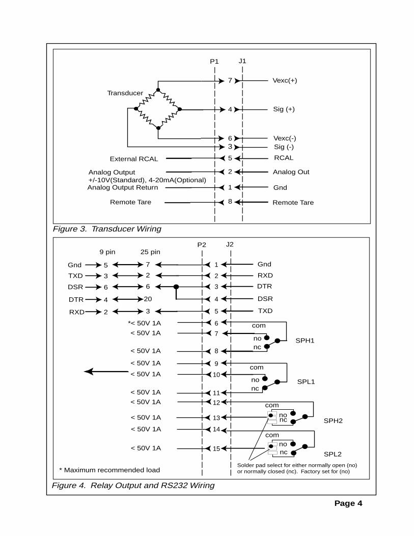
Reference Figures 3 and 4 for TRANSDUCER and RELAY/RS232 wiring information. Power is applied with a 3-prong AC power cord. The instrument is protected by a 250V, 250mA fast acting 5mm fuse. The fuse holder is an integral part of the input power connector. A spare fuse is provided in the fuse holder. Internal solder jumpers are provided to allow 115VAC or 230VAC operation (Reference Figure 6 on page 5).
3.622"(+0.032, -0.000)
92 mm
1.772"(+0.024, -0.000)
45mm
Page 2
MODE TARE CALSTEP RCAL
interfaceADVANCED FORCE MEASUREMENT
CAL
TARE
H1
H2
L1
L2
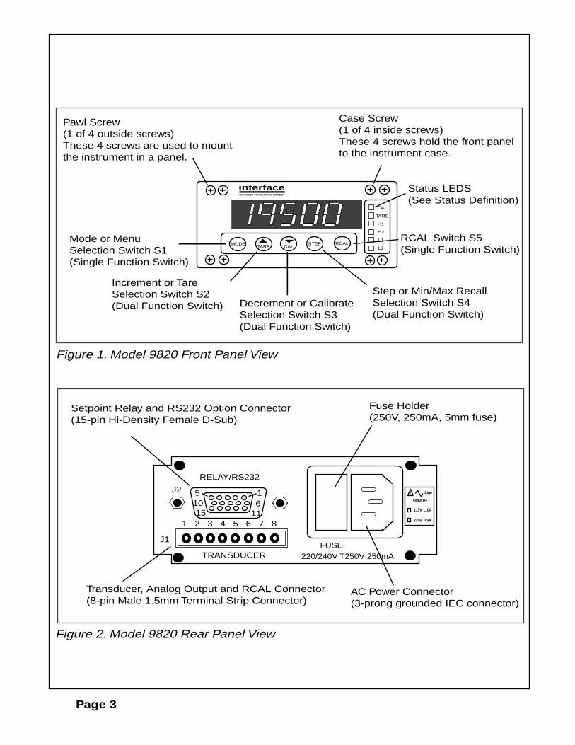
Pawl Screw (1 of 4 outside screws)These 4 screws are used to mountthe instrument in a panel.
Mode or MenuSelection Switch S1(Single Function Switch)
Increment or TareSelection Switch S2(Dual Function Switch) Decrement or Calibrate
Selection Switch S3(Dual Function Switch)
Step or Min/Max RecallSelection Switch S4(Dual Function Switch)
RCAL Switch S5(Single Function Switch)
Status LEDS(See Status Definition)
Case Screw(1 of 4 inside screws)These 4 screws hold the front panelto the instrument case.
Setpoint Relay and RS232 Option Connector(15-pin Hi-Density Female D-Sub)
Transducer, Analog Output and RCAL Connector(8-pin Male 1.5mm Terminal Strip Connector)
AC Power Connector(3-prong grounded IEC connector)
Fuse Holder(250V, 250mA, 5mm fuse)
Figure 1. Model 9820 Front Panel View
Figure 2. Model 9820 Rear Panel View
RELAY/RS232
J2
J1
1 2 3 4 5 6 7 8
15610
1115
TRANSDUCERFUSE
220/240V T250V 250mA
115V .10A
230v .05A
! Line
50/60 Hz
Page 3
||||||||||||||||||||
||||||||||||||||||||
J1P1
6
Vexc(+)
Sig (+)
Vexc(-)
Analog Out
Gnd
Analog Output+/-10V(Standard), 4-20mA(Optional) Analog Output Return 1
Remote Tare
|||||||||||||||||||||||||||||
|||||||||||||||||||||||||||||
J2P2
7
6
4
3
2
1
8
5
Gnd
RXD
DTR
DSR
TXD
ncno
com
SPH1
SPL1
9
10
11ncno
com
ncno
com
SPH2
SPL2ncno
com
12
13
14
15
Figure 3. Transducer Wiring
Figure 4. Relay Output and RS232 Wiring
4
Remote Tare
25 pin9 pin
75Gnd
23TXD
66DSR
204DTR
32RXD
*< 50V 1A
< 50V 1A
< 50V 1A
< 50V 1A
< 50V 1A
< 50V 1A
< 50V 1A
< 50V 1A
< 50V 1A
* Maximum recommended load
< 50V 1A
Page 4
5 RCALExternal RCAL
Sig (-)
Transducer
7
3
2
8
Solder pad select for either normally open (no)or normally closed (nc). Factory set for (no)

RC
AL
10V Analog OutZero Adjust
10V Analog OutFS Adjust
20mA Analog Output Adjust
4mA AnalogOutput Adjust
Vexc Adjust
5V E
xcG
ain
40
1 2 3 41 2 3 4
Baud Rate
Transformer
1
Front Panel S3 CALSwitch Enable
Figure 5. Location of Jumpers and Adjustment Potentiometers (Top View)
Figure 6. Location of Jumper (Bottom View)
For RCAL to generatea Positive Outputinstall solder jumper 5as shown below.
For RCAL to generatea Negative Output remove solder jumper 5 and install solder jumper 4.
Gai
n 80
Relay OutputOption Connector
NOTE: DO NOT INSTALL SOLDER JUMPERS 4 AND 5 AT THE SAME TIME. THIS WILL SHORT OUT Vexc.
Page 5
45
115
220
Solder jumpers shown (2)for 115VAC operation.For 230VAC operationremove both 115VAC solder jumpers and add(1) solder jumper here.
back
Note: For use with an external RCAL resistor, remove internal RCAL resistor (see Figure 5).
2
Front Panel S1 MODESwitch Enable
Spar
e
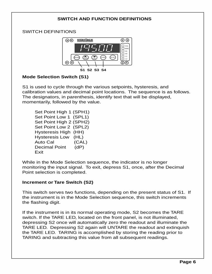
SWITCH DEFINITIONS
Mode Selection Switch (S1)
S1 is used to cycle through the various setpoints, hysteresis, and calibration values and decimal point locations. The sequence is as follows. The designators, in parenthesis, identify text that will be displayed, momentarily, followed by the value.
Set Point High 1 (SPH1)Set Point Low 1 (SPL1)Set Point High 2 (SPH2)Set Point Low 2 (SPL2)Hysteresis High (HH)Hysteresis Low (HL)Auto Cal (CAL)Decimal Point (dP)Exit
While in the Mode Selection sequence, the indicator is no longer monitoring the input signal. To exit, depress S1, once, after the Decimal Point selection is completed.
Increment or Tare Switch (S2)
This switch serves two functions, depending on the present status of S1. If the instrument is in the Mode Selection sequence, this switch increments the flashing digit.
If the instrument is in its normal operating mode, S2 becomes the TARE switch. If the TARE LED, located on the front panel, is not illuminated, depressing S2 once will automatically zero the readout and illuminate the TARE LED. Depressing S2 again will UNTARE the readout and extinquish the TARE LED. TARING is accomplished by storing the reading prior to TARING and subtracting this value from all subsequent readings.
SWITCH AND FUNCTION DEFINITIONS
MODE TARE CALSTEP RCAL
interfaceADVANCED FORCE MEASUREMENT
CAL
TARE
H1
H2
L1
L2
S1 S2 S3 S4
Page 6
SWITCH DEFINITIONS (CONT)
Decrement or Calibrate Switch (S3)
This switch serves two functions, depending on the present status of S1. If the instrument is in the Mode Selection sequence, this switch will decrement the flashing digit.
If the instrument is in its operating mode, S3 becomes an AUTO CAL switch. CAUTION: Depressing this switch will cause the instrument to recalibrate its full scale reading. Be sure to read the CALIBRATION INSTRUCTIONS before using this switch.
Step Switch (S4)
This switch also serves two functions, depending on the present status of S1. If the instrument is in the Mode Selection sequence, this switch allows the user to cycle through the digits. Used in conjunction with S2 and S3, it allows rapid updating of the Set Point, Hysteresis and Cal values.If the instrument is in the operating mode, S4 recalls the max (Hi) and min (Lo) values.
RCAL Switch (S5)
This switch activates a reed relay, which places a fixed resistor across Sig(-) and Vexc(-) for a positive RCAL reading, or across Sig(+) and Vexc(-) for a negative RCAL reading. Solder jumpers 4 and 5 determine which RCAL reading is generated (Reference Figure 6).
Front Panel Switch Disable Jumper (Reference Figure 5)
Jumper 1, when removed, disables the CAL Switch (S3).Jumper 2, when removed, disables the MODE Switch (S1).
Page 7

FUNCTION DEFINITIONS
Set Point High 1 (SPH1)
SPH1 is the present value being constantly compared with the displayed reading. If the magnitude and sign of the reading exceeds the present SPH1 value, the SPH1 relay will activate (relay option assembly required) and the front panel LED (H1) will illuminate. If the displayed reading equals the SPH1 value, nothing will happen. If SPH1 is exceeded, the readout must then drop below SPH1 less the Hysteresis High (HH) value before the relay deactivates and the H1 LED turns off.
Set Point Low 1 (SPL1)
SPL1 is another preset value being constantly compared with the displayed reading. If the magnitude and sign of the displayed reading is less than the SPL1 present value, the SPL1 relay will activate (relay option assembly required) and the front panel LED (L1) will illuminate. If the displayed reading equals the SPL1 value, nothing will happen. If the displayed reading drops below SPL1, it must then exceed SPL1 plus the Hysteresis Low (HL) value before the relay deactivates and the L1 LED turns off.
Set Point High 2 (SPH2)
SPH2 is independent and functions identically to SPH1. SPH2 has its own relay contact outputs and front panel LED (H2).
Set Point Low 2 (SPL2)
SPL2 is independent and functions identically to SPL1. SPL2 has its own relay contact outputs and front panel LED (L2).
Hysteresis High (HH)
HH is the hysteresis value for SPH1 and SPH2. The hysteresis value determines the number of counts the displayed reading must fall below SPH1 and SPH2 values before deactivating their respective relays and LEDs. The maximum value of hysteresis is 99 counts while the minimum is 00 counts.
Page 8

FUNCTION DEFINITIONS (CONT)
Hysteresis Low (HL)
HL is the hysteresis value for SPL1 and SPL2. The hysteresis value determines the number of counts the displayed reading must exceeed SPL1 and SPL2 values before deactivating their respective relays and LEDs. The maximum value of hysteresis is 99 counts while the minimum is 00 counts.
Auto Cal (CAL)
This input allows the user to calibrate the full scale readout to any desired engineering units. The CAL number is entered in the same way as the Set Point and Hysteresis values. This input must be entered prior to performing the calibration. The CAL number may be any number from 1 to 99,999. Zero is an invalid CAL number. For best stability and performance, keep the maximum CAL number below 19,999 counts.
Decimal Point (dP)
dP allows selection of decimal point locations for display. The locations selectable are x.xxxx, xx.xxx, xxx.xx, xxxx.x and xxxxx.
Min/Max Recall (HI/LO)
The HI and LO values are the maximum and minimum values, respectively, of the displayed readings. Sign and magnitude are constantly compared with the displayed readings at the instrument update rate. The maximum value is initialized to -99,999 and the minimum value to 99.999 each time the TARE switch (S2) is depressed, whether to TARE or UNTARE the readout.
Page 9
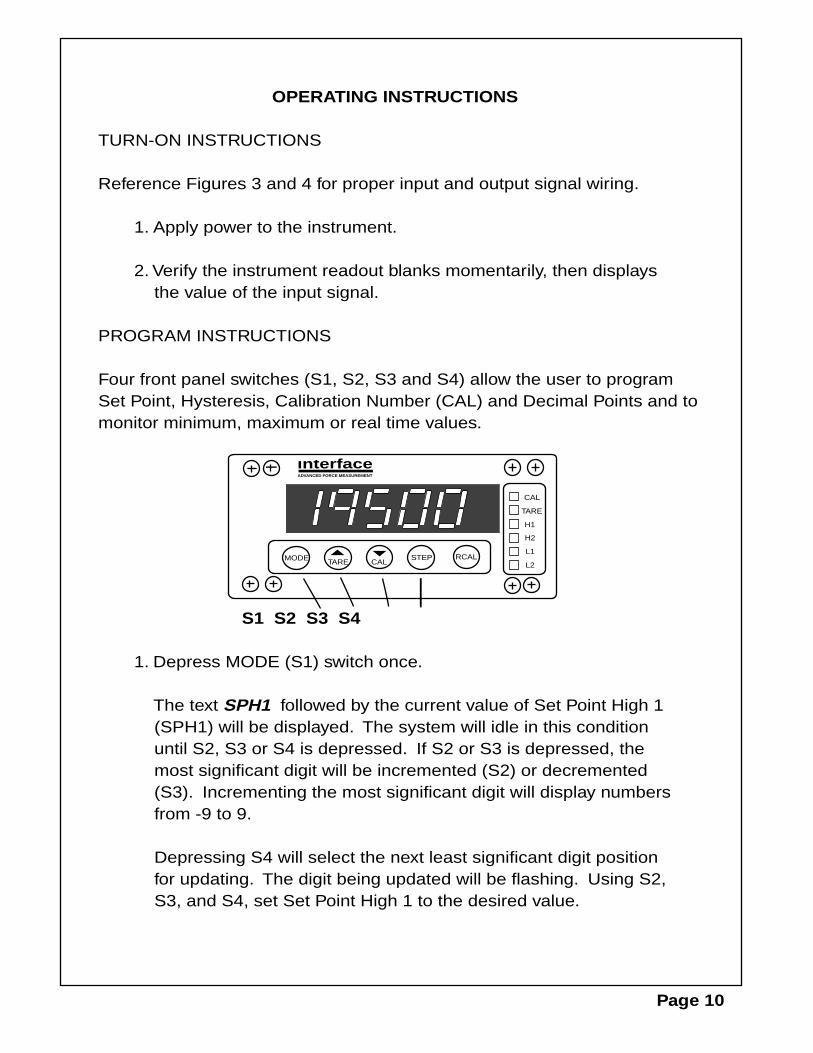
OPERATING INSTRUCTIONS
TURN-ON INSTRUCTIONS
Reference Figures 3 and 4 for proper input and output signal wiring.
1. Apply power to the instrument.
2. Verify the instrument readout blanks momentarily, then displays the value of the input signal.
PROGRAM INSTRUCTIONS
Four front panel switches (S1, S2, S3 and S4) allow the user to program Set Point, Hysteresis, Calibration Number (CAL) and Decimal Points and to monitor minimum, maximum or real time values.
S1 S2 S3 S4
1. Depress MODE (S1) switch once.
The text SPH1 followed by the current value of Set Point High 1 (SPH1) will be displayed. The system will idle in this condition until S2, S3 or S4 is depressed. If S2 or S3 is depressed, the most significant digit will be incremented (S2) or decremented (S3). Incrementing the most significant digit will display numbers from -9 to 9.
Depressing S4 will select the next least significant digit position for updating. The digit being updated will be flashing. Using S2, S3, and S4, set Set Point High 1 to the desired value.
MODE TARE CALSTEP RCAL
interfaceADVANCED FORCE MEASUREMENT
CAL
TARE
H1
H2
L1
L2
Page 10
PROGRAM INSTRUCTIONS (CONT)
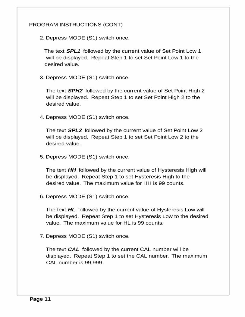
2. Depress MODE (S1) switch once.
The text SPL1 followed by the current value of Set Point Low 1 will be displayed. Repeat Step 1 to set Set Point Low 1 to the
desired value.
3. Depress MODE (S1) switch once.
The text SPH2 followed by the current value of Set Point High 2 will be displayed. Repeat Step 1 to set Set Point High 2 to the desired value.
4. Depress MODE (S1) switch once.
The text SPL2 followed by the current value of Set Point Low 2 will be displayed. Repeat Step 1 to set Set Point Low 2 to the desired value.
5. Depress MODE (S1) switch once.
The text HH followed by the current value of Hysteresis High will be displayed. Repeat Step 1 to set Hysteresis High to the
desired value. The maximum value for HH is 99 counts.
6. Depress MODE (S1) switch once.
The text HL followed by the current value of Hysteresis Low will be displayed. Repeat Step 1 to set Hysteresis Low to the desired value. The maximum value for HL is 99 counts.
7. Depress MODE (S1) switch once.
The text CAL followed by the current CAL number will be displayed. Repeat Step 1 to set the CAL number. The maximum CAL number is 99,999.
Page 11
PROGRAM INSTRUCTIONS (CONT)
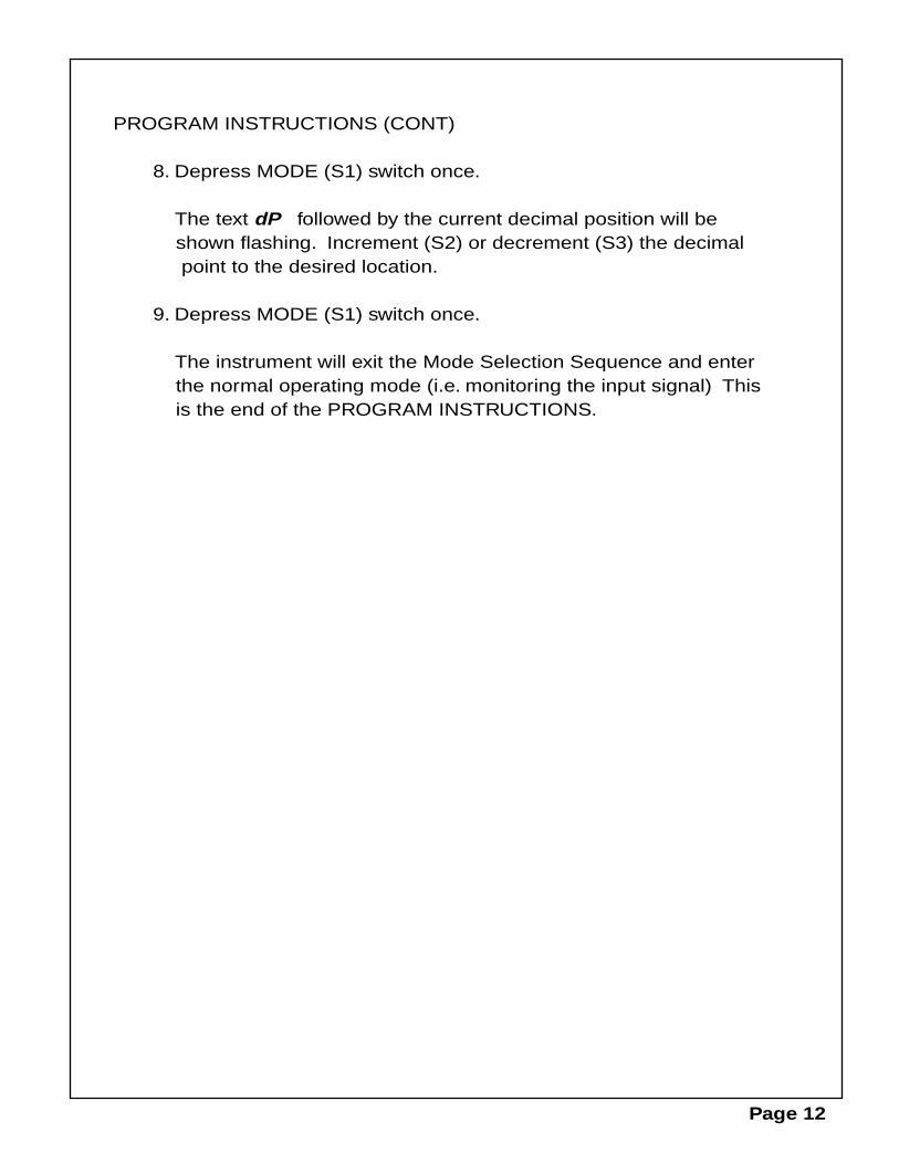
8. Depress MODE (S1) switch once.
The text dP followed by the current decimal position will be shown flashing. Increment (S2) or decrement (S3) the decimal point to the desired location.
9. Depress MODE (S1) switch once.
The instrument will exit the Mode Selection Sequence and enter the normal operating mode (i.e. monitoring the input signal) This is the end of the PROGRAM INSTRUCTIONS.
Page 12
CALIBRATION INSTRUCTIONS
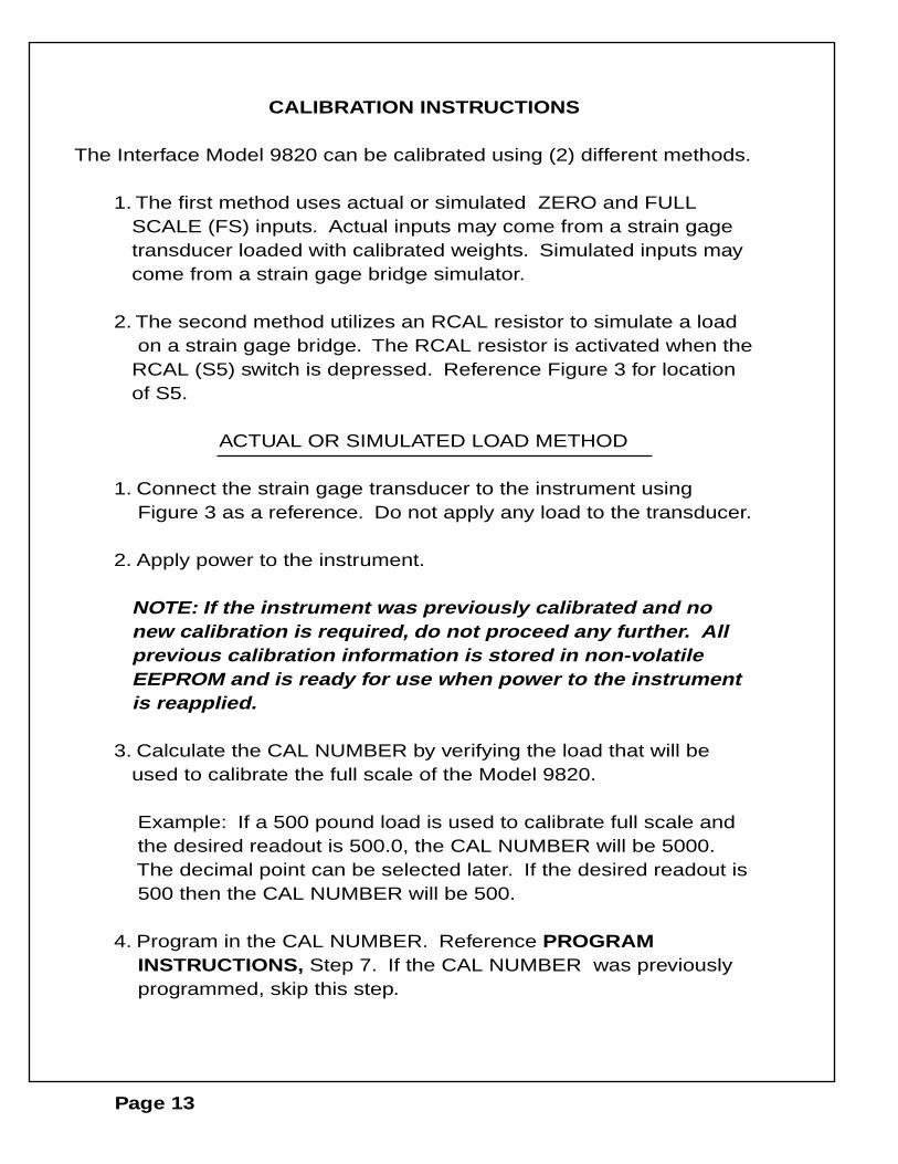
The Interface Model 9820 can be calibrated using (2) different methods.
1. The first method uses actual or simulated ZERO and FULL SCALE (FS) inputs. Actual inputs may come from a strain gage transducer loaded with calibrated weights. Simulated inputs may come from a strain gage bridge simulator.
2. The second method utilizes an RCAL resistor to simulate a load on a strain gage bridge. The RCAL resistor is activated when the RCAL (S5) switch is depressed. Reference Figure 3 for location of S5.
ACTUAL OR SIMULATED LOAD METHOD
1. Connect the strain gage transducer to the instrument using Figure 3 as a reference. Do not apply any load to the transducer.
2. Apply power to the instrument.
NOTE: If the instrument was previously calibrated and no new calibration is required, do not proceed any further. All previous calibration information is stored in non-volatile EEPROM and is ready for use when power to the instrument is reapplied.
3. Calculate the CAL NUMBER by verifying the load that will be used to calibrate the full scale of the Model 9820.
Example: If a 500 pound load is used to calibrate full scale and the desired readout is 500.0, the CAL NUMBER will be 5000. The decimal point can be selected later. If the desired readout is 500 then the CAL NUMBER will be 500.
4. Program in the CAL NUMBER. Reference PROGRAM INSTRUCTIONS, Step 7. If the CAL NUMBER was previously programmed, skip this step.
Page 13
CALIBRATION INSTRUCTIONS (CONT.)
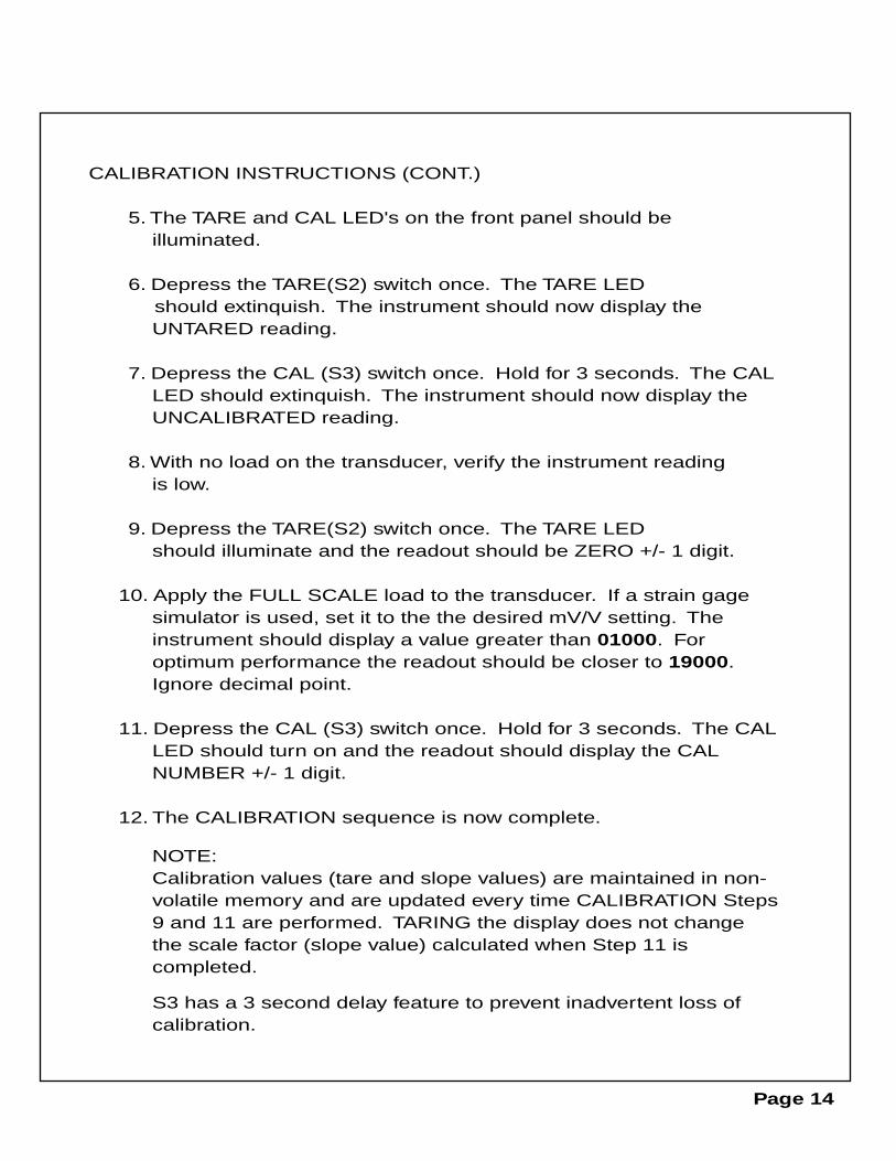
5. The TARE and CAL LED's on the front panel should be illuminated.
6. Depress the TARE(S2) switch once. The TARE LED should extinquish. The instrument should now display the
UNTARED reading.
7. Depress the CAL (S3) switch once. Hold for 3 seconds. The CAL LED should extinquish. The instrument should now display the UNCALIBRATED reading.
8. With no load on the transducer, verify the instrument reading is low.
9. Depress the TARE(S2) switch once. The TARE LED should illuminate and the readout should be ZERO +/- 1 digit.
10. Apply the FULL SCALE load to the transducer. If a strain gage simulator is used, set it to the the desired mV/V setting. The instrument should display a value greater than 01000. For
optimum performance the readout should be closer to 19000. Ignore decimal point.
11. Depress the CAL (S3) switch once. Hold for 3 seconds. The CAL LED should turn on and the readout should display the CAL NUMBER +/- 1 digit.
12. The CALIBRATION sequence is now complete.
NOTE: Calibration values (tare and slope values) are maintained in non- volatile memory and are updated every time CALIBRATION Steps 9 and 11 are performed. TARING the display does not change the scale factor (slope value) calculated when Step 11 is completed.
S3 has a 3 second delay feature to prevent inadvertent loss of calibration.
Page 14
Page 15
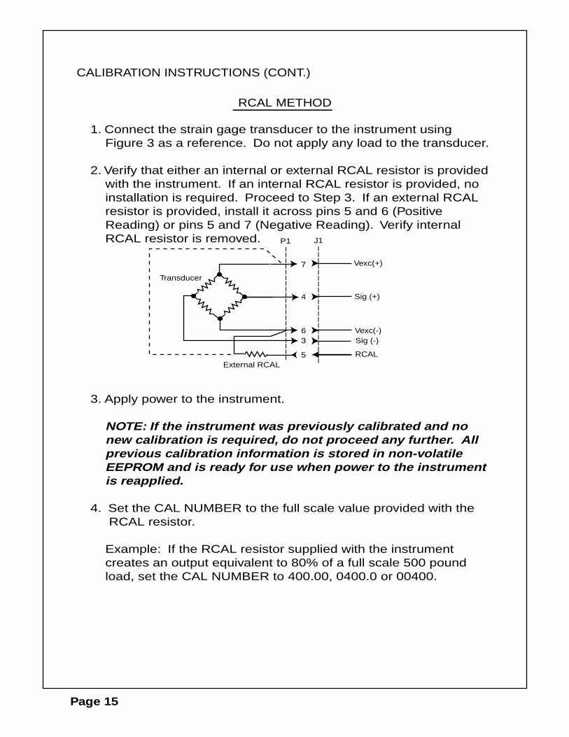
1. Connect the strain gage transducer to the instrument using Figure 3 as a reference. Do not apply any load to the transducer.
2. Verify that either an internal or external RCAL resistor is provided with the instrument. If an internal RCAL resistor is provided, no installation is required. Proceed to Step 3. If an external RCAL resistor is provided, install it across pins 5 and 6 (Positive Reading) or pins 5 and 7 (Negative Reading). Verify internal RCAL resistor is removed.
3. Apply power to the instrument.
NOTE: If the instrument was previously calibrated and no new calibration is required, do not proceed any further. All previous calibration information is stored in non-volatile EEPROM and is ready for use when power to the instrument is reapplied.
4. Set the CAL NUMBER to the full scale value provided with the RCAL resistor.
Example: If the RCAL resistor supplied with the instrument creates an output equivalent to 80% of a full scale 500 pound load, set the CAL NUMBER to 400.00, 0400.0 or 00400.
||||||||||||||||||||
||||||||||||||||||||
J1P1
7
6
Vexc(+)
Sig (+)
Vexc(-)
4
5 RCALExternal RCAL
Sig (-)
Transducer
RCAL METHOD
CALIBRATION INSTRUCTIONS (CONT.)
CALIBRATION INSTRUCTIONS (CONT.)
5. The TARE and CAL LED's on the front panel should be illuminated.
6. Depress the TARE (S2) switch once. The TARE LED should extinquish. The instrument should now display the UNTARED reading.
7. Depress the CAL(S3) switch once. (Hold for 3 seconds) The CAL LED should extinquish. The instrument should now display the UNCALIBRATED reading.
8. With no load on the transducer, verify the readout is approximately zero.
9. Depress the TARE(S2) switch once. The TARE LED should illuminate and the readout should be ZERO +/- 1 digit.
10. Depress and hold the RCAL switch. The display should read a value greater than 01000. For optimum performance the readout should be closer to 19000. Ignore decimal point.
While holding down the RCAL switch, depress the CAL (S3) switch once. The CAL LED should turn on and the readout should display the CAL NUMBER +/- 1 digit.
11. The RCAL CALIBRATION sequence is now complete.
NOTES: Calibration values (tare and slope values) are maintained in non-volatile memory and are updated every time CALIBRATION Steps 9 and 10 are performed. TARING the
display does not change the scale factor (slope value) calculated when Step 10 is completed.
S3 has a 3 second delay feature to prevent the inadvertent loss of calibration.
Page 16
OPTIONS
4-20 mA ANALOG OUTPUT OPTION
The 4-20mA analog output option replaces the +/-10VDC output. It is therefore available on J1-pin 2 (Reference page 4, Figure 3)). It has a compliance voltage of 15VDC. The output is normally 4mA at Signal=Zero and factory adjusted to 20mA at Signal=Full Scale.
RELAY OUTPUT OPTION
The relay outputs are triggered by SPH1, SPL1, SPH2 and SPL2 (Reference page 4, Figure 4) for wiring information. The relays for SPL1 and SPL2 have only the normally open contact brought out to J1. The normally closed contact may be brought out instead if the appropriate solder jumper were installed. For safety, it is recommended that a voltage less than 50V and a current less than 1A be applied to any relay contact.
RS232 SERIAL COMMUNICATION OUTPUT
The RS232 transmission is of the displayed reading and is transmitted once every display update, if the DSR line is TRUE (HIGH). The data format is described below.
1. No parity bit2. 1 stop bit3. 8 data bits
The data transmission sequence is described below.
1. Sign: plus or minus (1st word)2. Magnitude: most significant digit (MSD) first (2nd thru 6th word)3. Decimal point: exponent (7th word)4. End of Line (EOL): Control Z (8th word)
Note: Data is transmitted in ASCII characters. The decimal position is t ttransmitted as a power of 10 exponent in ASCII.
Page 17
Page 18
RS232 SERIAL COMMUNICATION OUTPUT (CONT)
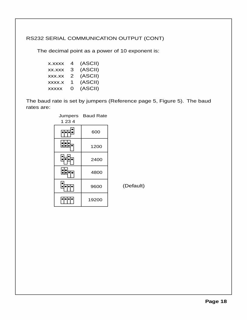
The decimal point as a power of 10 exponent is:
x.xxxx 4 (ASCII)xx.xxx 3 (ASCII)xxx.xx 2 (ASCII)xxxx.x 1 (ASCII)xxxxx 0 (ASCII)
The baud rate is set by jumpers (Reference page 5, Figure 5). The baud rates are:
1 23 4Jumpers Baud Rate
600
1200
2400
4800
9600
19200
(Default)

This page left intentionally blank
Page 19

MODEL 9820 PROGRAM MENU DIAGRAM
Depress MODE
START
SPH1 Set SPH1
Depress
Depress
Depress STEP
IncrementsFlashing Digit
DecrementsFlashing Digit
Steps FlashingDigit to Right
SPL1 Set SPL1 Depress
Depress STEP
IncrementsFlashing Digit
DecrementsFlashing Digit
Steps FlashingDigit to Right
SPH2 Set SPH2 Depress
Depress STEP
IncrementsFlashing Digit
DecrementsFlashing Digit
Steps FlashingDigit to Right
Depress MODE
Depress MODE
SPL2 Set SPL2 Depress
Depress STEP
IncrementsFlashing Digit
DecrementsFlashing Digit
Steps FlashingDigit to Right
Depress MODE
Depress
Depress
HH Set HH Depress
Depress STEP
IncrementsFlashing Digit
DecrementsFlashing Digit
Steps FlashingDigit to Right
Depress MODE Depress
HL Set HL Depress
Depress STEP
IncrementsFlashing Digit
DecrementsFlashing Digit
Steps FlashingDigit to Right
Depress MODE Depress
CAL Set CAL Depress
Depress STEP
IncrementsFlashing Digit
DecrementsFlashing Digit
Steps FlashingDigit to Right
Depress MODE Depress
dP Set dP Depress
Depress STEP
Shifts DecimalPt to the Right
Shifts DecimalPt to the Left
No Change
Depress MODE Depress
Depress MODE
OPERATE
SETUP PROCEDURE CALIBRATION PROCEDURE USING ACTUAL OR SIMULATED LOADS
START
Is TARE LED on?
DepressYES
Depress
Is CAL LED on?
Depress
TARE Led turns off
CAL Led turns off
YES
NO
Apply input signal forzero reading on display
NO
Depress Readout displays 0000
TARE Led turns on
Apply full scaleinput signal
Readout displays CAL
CAL Led turns on
Depress
CALIBRATION PROCEDURE USING RCAL RESISTOR
START
Is TARE LED on?
DepressYES
Is CAL LED on?
Depress
TARE Led turns off
CAL Led turns off
YES
NO
Apply no load to thestrain gage transducer
NO
Depress Readout displays 0000
TARE Led turns on
Depress RCAL& switch
Readout displays CAL
CAL Led turns on

7401 E. BUTHERUS DR. SCOTTSDALE, AZ 85260
TEL: (480) 948-5555 FAX: (480) 948-1924
www.interfaceforce.com
ADVANCED FORCE MEASUREMENT