Embed Size (px)
Citation preview
WARRANTY.....Top Flite Models guarantees this kit to be free of defects in both material and workmanship at the date of purchase. This warrantydoes not cover any component parts damaged by use or modification. In no case shall Top Flite‘s liability exceed the original cost of the purchased kit. Further, Top Flitereserves the right to change or modify this warranty without notice. In that Top Flite has no control over the final assembly or material used for final assembly, no liability shallbe assumed nor accepted for any damage resulting from the use by the user of the final user-assembled product. By the act of using the user-assembled product the useraccepts all resulting liability. If the buyer is not prepared to accept the liability associated with the use of this product, the buyer is advised to immediately return this kit innew and unused condition to the place of purchase.
Top Flite Models 3002 N. Apollo Dr., Suite 1, Champaign, IL 61822 Technical Assistance Call (217) 398-8970 [email protected]
READ THROUGH THIS INSTRUCTION BOOK FIRST. IT CONTAINS IMPORTANT INSTRUCTIONS AND WARNINGS CONCERNING THE ASSEMBLY AND USE OF THIS MODEL.
USAMADE IN
P47GP03 V1.1Entire Contents © Copyright 2008
Wingspan: 85 in [2159mm]Wing Area: 1327 sq in [85.6 sq dm]Weight: 20-22 lbs [9-10kg]Wing Loading: 34.7-38.2 oz/sq ft
[106-117 g/sq dm]Length: 75.5 in [1918mm]
™
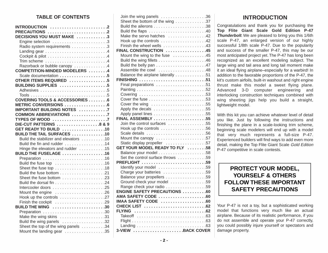
TABLE OF CONTENTS
INTRODUCTION . . . . . . . . . . . . . . . . . . . . . . . .2PRECAUTIONS . . . . . . . . . . . . . . . . . . . . . . . . .2 DECISIONS YOU MUST MAKE . . . . . . . . . . . . .3
Engine selection . . . . . . . . . . . . . . . . . . . . . . .3Radio system requirements . . . . . . . . . . . . . . .3Landing gear . . . . . . . . . . . . . . . . . . . . . . . . . .4Cockpit & pilot . . . . . . . . . . . . . . . . . . . . . . . . .4Trim scheme . . . . . . . . . . . . . . . . . . . . . . . . . .4Razorback or bubble canopy . . . . . . . . . . . . . .4
COMPETITION-MINDED MODELERS . . . . . . . .4Scale documentation . . . . . . . . . . . . . . . . . . . .5
OTHER ITEMS REQUIRED . . . . . . . . . . . . . . . .5BUILDING SUPPLIES . . . . . . . . . . . . . . . . . . . .5
Adhesives . . . . . . . . . . . . . . . . . . . . . . . . . . . .5Tools . . . . . . . . . . . . . . . . . . . . . . . . . . . . . . . .5
COVERING TOOLS & ACCESSORIES . . . . . . . .6METRIC CONVERSIONS . . . . . . . . . . . . . . . . . .6IMPORTANT BUILDING NOTES . . . . . . . . . . . .7COMMON ABBREVIATIONS . . . . . . . . . . . . . . .7TYPES OF WOOD . . . . . . . . . . . . . . . . . . . . . . .7DIE-CUT PATTERNS . . . . . . . . . . . . . . . . . .8 & 9GET READY TO BUILD . . . . . . . . . . . . . . . . . .10BUILD THE TAIL SURFACES . . . . . . . . . . . . . .10
Build the stabilizer and elevators . . . . . . . . . .10Build the fin and rudder . . . . . . . . . . . . . . . . .14Hinge the elevators and rudder . . . . . . . . . . .15
BUILD THE FUSELAGE . . . . . . . . . . . . . . . . . .16Preparation . . . . . . . . . . . . . . . . . . . . . . . . . .16Build the fuse top . . . . . . . . . . . . . . . . . . . . .16Sheet the fuse top . . . . . . . . . . . . . . . . . . . . .18Build the fuse bottom . . . . . . . . . . . . . . . . . . .21Sheet the fuse bottom . . . . . . . . . . . . . . . . . .23Build the dorsal fin . . . . . . . . . . . . . . . . . . . . .24Intercooler doors . . . . . . . . . . . . . . . . . . . . . .25Mount the engine . . . . . . . . . . . . . . . . . . . . .26Hook up the controls . . . . . . . . . . . . . . . . . . .27Finish the cockpit . . . . . . . . . . . . . . . . . . . . .29
BUILD THE WING . . . . . . . . . . . . . . . . . . . . . .30Preparation . . . . . . . . . . . . . . . . . . . . . . . . . .30Make the wing skins . . . . . . . . . . . . . . . . . . .31Build the wing panels . . . . . . . . . . . . . . . . . .32Sheet the top of the wing panels . . . . . . . . . .34Mount the landing gear . . . . . . . . . . . . . . . . .35
Join the wing panels . . . . . . . . . . . . . . . . . . .36Sheet the bottom of the wing . . . . . . . . . . . . .37Build the ailerons . . . . . . . . . . . . . . . . . . . . . .38Build the flaps . . . . . . . . . . . . . . . . . . . . . . . .40Make the servo hatches . . . . . . . . . . . . . . . .42Hook up the controls . . . . . . . . . . . . . . . . . . .42Finish the wheel wells . . . . . . . . . . . . . . . . . .43
FINAL CONSTRUCTION . . . . . . . . . . . . . . . . .45Mount the wing to the fuse . . . . . . . . . . . . . .45Build the wing fillets . . . . . . . . . . . . . . . . . . . .46Build the belly pan . . . . . . . . . . . . . . . . . . . . .47Assemble the cowl . . . . . . . . . . . . . . . . . . . .48Balance the airplane laterally . . . . . . . . . . . . .51
FINISHING . . . . . . . . . . . . . . . . . . . . . . . . . . . .51Final preparations . . . . . . . . . . . . . . . . . . . . .51Painting . . . . . . . . . . . . . . . . . . . . . . . . . . . . .52Covering . . . . . . . . . . . . . . . . . . . . . . . . . . . .53Cover the fuse . . . . . . . . . . . . . . . . . . . . . . . .53Cover the wing . . . . . . . . . . . . . . . . . . . . . . .55Apply the decals . . . . . . . . . . . . . . . . . . . . . .55Apply panel lines . . . . . . . . . . . . . . . . . . . . . .55
FINAL ASSEMBLY . . . . . . . . . . . . . . . . . . . . . .55Join the control surfaces . . . . . . . . . . . . . . . .55Hook up the controls . . . . . . . . . . . . . . . . . . .56Scale details . . . . . . . . . . . . . . . . . . . . . . . . .56Mount the canopy . . . . . . . . . . . . . . . . . . . . .57Static display propeller . . . . . . . . . . . . . . . . .57
GET YOUR MODEL READY TO FLY . . . . . . . .58Balance your model . . . . . . . . . . . . . . . . . . . .58Set the control surface throws . . . . . . . . . . . .59
PREFLIGHT . . . . . . . . . . . . . . . . . . . . . . . . . . .59Identify your model . . . . . . . . . . . . . . . . . . . .59Charge your batteries . . . . . . . . . . . . . . . . . .59Balance your propellers . . . . . . . . . . . . . . . . .59Ground check your model . . . . . . . . . . . . . . .59Range check your radio . . . . . . . . . . . . . . . . .59
ENGINE SAFETY PRECAUTIONS . . . . . . . . . .60AMA SAFETY CODE . . . . . . . . . . . . . . . . . . . .60IMAA SAFETY CODE . . . . . . . . . . . . . . . . . . .60CHECK LIST . . . . . . . . . . . . . . . . . . . . . . . . . .62FLYING . . . . . . . . . . . . . . . . . . . . . . . . . . . . . .62
Takeoff . . . . . . . . . . . . . . . . . . . . . . . . . . . . .63Flight . . . . . . . . . . . . . . . . . . . . . . . . . . . . . . .63Landing . . . . . . . . . . . . . . . . . . . . . . . . . . . . .63
3-VIEW . . . . . . . . . . . . . . . . . . . . .BACK COVER
INTRODUCTIONCongratulations and thank you for purchasing theTop Flite Giant Scale Gold Edition P-47Thunderbolt. We are pleased to bring you this 1/6thscale P-47, an enlarged version of our highlysuccessful 1/8th scale P-47. Due to the popularityand success of the smaller P-47, this may be ourmost anticipated project yet. The P-47 has long beenrecognized as an excellent modeling subject. Thelarge wing and tail area and long tail moment makeit an ideal flying airplane–especially for a warbird! Inaddition to the favorable proportions of the P-47, thekit's custom airfoils, built-in washout and right enginethrust make this model a sweet flying plane.Advanced 3-D computer engineering andinterlocking construction techniques combined withwing sheeting jigs help you build a straight,lightweight model.
With this kit you can achieve whatever level of detailyou like. Just by following the instructions andfinishing the plane in a scale-looking trim scheme,beginning scale modelers will end up with a modelthat very much represents a full-size P-47.Experienced builders will find ways to add even moredetail, making the Top Flite Giant Scale Gold EditionP-47 competitive in scale contests.
Your P-47 is not a toy, but a sophisticated workingmodel that functions very much like an actualairplane. Because of its realistic performance, if youdo not assemble and operate your P-47 correctly,you could possibly injure yourself or spectators anddamage property.
PROTECT YOUR MODEL,YOURSELF & OTHERS
FOLLOW THESE IMPORTANTSAFETY PRECAUTIONS
- 2 -
If this is your first giant scale project, getassistance with assembly and your first flightsfrom an experienced, knowledgeable modeler.You’ll avoid risking your model before you’re ready tofly it for the first time. Your local hobby shop hasinformation about flying clubs in your area whosemembership includes qualified instructors.
You can also contact the Academy of ModelAeronautics (AMA), which has more than 2,500chartered clubs across the country. We recommendyou join the AMA which will insure you at AMA clubsites and events. AMA Membership is required atchartered club fields where qualified flight instructorsare available. Contact the AMA at the address or toll-free phone number below.
Academy of Model Aeronautics5151 East Memorial Drive
Muncie, IN 47302(800) 435-9262
Fax (765) 741-0057or via the Internet at: http://www.modelaircraft.org
1. You must build the plane according to the plan andinstructions. Do not alter or modify the model, asdoing so may result in an unsafe or unflyable model. Ina few cases the plan and instructions may differslightly from the photos. In those instances theplan and written instructions are correct.
2. You must take time to build straight, true and strong.
3. You must use a proper R/C radio that is in firstclass condition, the correct sized engine and correctcomponents (fuel tank, wheels, etc.) throughoutyour building process.
4. You must properly install all R/C and othercomponents so that the model operates properly onthe ground and in the air.
5. You must test the operation of the model beforeevery flight to insure that all equipment is operatingand you must make certain that the model hasremained structurally sound.
6. If you are not already an experienced R/C pilot,you must fly the model only with the help of acompetent, experienced R/C pilot.
Please inspect all parts carefully before you startto build! If any parts are missing, broken ordefective, or if you have any questions aboutbuilding or flying this model, please call us at:
(217) 398-8970 or e-mail us [email protected]
If you are calling for replacement parts, pleaselook up the part numbers and the kitidentification number (stamped on the end of thecarton) and have them ready when you call.
instructions show a Great Planes® Isolation Mount(GPMG2000) with the U.S. Engines™ 41cc engine.J-Tec, Soundmaster and others produce soft mountsfor large engines as well.
RADIO SYSTEM REQUIREMENTS
For operations other than flight-critical control surfaces(such as the tail wheel steering, throttle, air controlvalve, flaps and optional onboard ignition kill switch forgas engines), you may use standard servos.Frequently, we even use a micro servo for the aircontrol valve. For flight-critical control surfaces(ailerons, elevators, rudder), this model requires five“high-torque” servos. IMAA recommendations specifyservos with a minimum of 45 inch-ounces of torque.However, some standard servos supply nearly thatmuch, so for the giant P-47 we suggest servos with atleast 50 inch-ounces of torque. Another reason to useservos with a higher torque rating is that they havestronger centering capabilities with less free-play. Aservo that holds strongly when centered is necessaryto prevent flutter on giant models. Futaba 9001’s areshown in the model in this manual.We use them in ourgiant warbird flying prototypes. 9001’s put outapproximately 54 inch-ounces of torque and aresuitable for your P-47 if it is powered by most of theengines within the recommended range (such as theUS Engines 41cc). If you are using a more powerfulengine and plan to fly your model at high speeds,servos closer to 70 inch-ounces of torque arerecommended.There are many high torque, standardsize servos available, but larger 1/4-scale servos maybe used in this model too. The servo tray in thefuselage and the servo hatches in the wing aredesigned to fit standard size servos. If you choose touse large 1/4-scale servos, you will have to modify theservo trays or make your own to accommodate the servos.
The minimum capacity of a receiver battery pack requiredfor this model is 1000 mAh.Receiver packs having 1200to 1400 mAh are preferable. Some modelers use 6-volt(five cell) 1200 to 1500 mAh packs.
ENGINE SELECTION
Recommended engine size:34.5 - 45cc (2.1 - 2.8 cu. in.) displacementGlow Engine
41 - 70cc (2.5 - 4.2 cu. in.) displacementGasoline Engine
We strongly recommend the use of a soft enginemount to relieve the stresses on the airframe andradio system and to make your aircraft quieter. The
DECISIONS YOU MUST MAKE
NOTE: We, as the kit manufacturer, provide youwith a top quality kit and great instructions, butultimately the quality and flyability of your finishedmodel depends on how you build it; therefore, wecannot in any way guarantee the performance ofyour completed model, and no representationsare expressed or implied as to the performance orsafety of your completed model.
- 3 -
COMPETITION-MINDED MODELERS
The outline of the Top Flite Gold Edition P-47 wasderived from three-view drawings and photos. Theelevator and rudder hinge lines have been modifiedto simplify assembly and to use standard modelhinging techniques. The landing gear has beenslightly relocated to improve handling and durabilityand the wheels are smaller than scale to fit in thespace available. The landing gear does not retractfully into the wheel wells, but protrudes below thewing by approximately 3/16".
The approximate scale of this model is 1:5.6.
If you plan to enter your P-47 in scale competition (it’slots of fun and the runways are usually paved!), this kitmay be entered in Fun Scale, Sportsman Scale andExpert Scale classes in AMA competition. All classeshave the same flight requirements in which you mustperform ten maneuvers, five of which are mandatory.The other five are up to you–“easy” stuff like a slow, low“inspection pass” with flaps extended, or maybe a touch-and-go. If you have never competed in a scale contest,you could start out in Fun Scale. In Fun Scale, the onlydocumentation required for static judging is any proofthat a full-size aircraft of this type, in the paint/markingsscheme on your model, did exist. A single photo, a kitbox cover from a plastic model, or even a painting issufficient proof! If you’re interested, contact the AMA fora rule book that will tell you everything you need to know.You can find a contest schedule in the back of the AMAmagazine (Model Aviation).
One last note for those who are interested in scalecompetition: Strive to build your model to reflect yourdocumentation. Whatever lines and features appearon the full size plane should also appear on yourmodel. Refer to the photos and documentation of theP-47 you are using for your model.
TRIM SCHEME
The colorful “Tarheel Hal” trim scheme on the kitbox cover is rather bold and ambitious, but can beaccomplished by modelers who have experiencewith iron-on coverings. Top Flite MonoKote® wasused for the covering and LustreKote® was usedfor the paint. Refer to the back of this manual formore information about painting and covering (andfor more details that may help you to decidewhether or not to attempt this scheme).
The primary colors of MonoKote film required for“Tarheel Hal” are aluminum (main portions of fuseand wing), orange (tail) and royal blue (front offuse). Additionally, you will need small amounts ofinsignia blue, cub yellow and missile red (for theflag on the rudder), black and jet white (for theinvasion stripes) and flat black (for the anti-glarepanels on the top of the fuse).
The colors of LustreKote paint required are twocans of white primer and one can each ofaluminum, royal blue, missile red, cub yellow, flatblack, crystal clear and gloss black. If you’ll bepainting the intercooler doors to match the starsand bars on the side of the fuse, you’ll also need asmall amount of insignia blue.
RAZORBACK OR BUBBLE CANOPY
The Giant P-47 may be constructed as either a D-23 Razorback or a D-25 Bubble Canopy (itshould be noted that not all bubble canopy P-47’sfeatured a dorsal fin). This kit includes all the woodparts and complete instructions to build eitherversion, but includes the bubble canopy only. Therazor back canopy is available separately if youwish to build the D-23 version (order numberTOPQ8042). You don’t have to decide which oneto build until you get to the turtle deck when you’rebuilding the fuse.
Be certain your servos, receiver, on/off switch and charging system are compatible with your batterypack. Use servo extension cords and Y-connectorswhere required. It is likely that you will need these forflaps and ailerons. Connections between servo cordsand extension cords or Y-connectors should besecured with heat shrink tubing, vinyl tape or specialclips intended for this purpose.
LANDING GEAR
The Top Flite Giant P-47 uses Robart #622retractable main landing gear which are designedspecifically for this model and a #160LWCretractable tail gear. Other systems may work, butit will be up to you to make the modificationsrequired to fit them. Following is a list of itemsrequired for the retracts.
Robart # 622 Top Flite Giant P-47 main landinggear retracts (ROBQ1636)
Robart #160LWC Retractable tail gear (Robart direct)Robart #157VR Air Control Kit w/ variable rate
valve (ROBQ2301)Robart #192 Large Pressure Tank (ROBQ2392)Robart #164G 100 PSI Pump w/gauge
(ROBQ2363)Robart # 190 Quick disconnects (ROBQ2395)Pull-Pull cable kit for tail wheel steering (SULQ3120)(16) #6 x 1/2" screws for mounting main and tail
gear (GPMQ3160, 4 per pack)
COCKPIT & PILOT
Your Thunderbolt won’t be complete without the TopFlite Giant P-47 Cockpit Kit (TOPQ8410). It includesthe floor, side panels, instrument panel, seat,headrest and hardware. The cockpit kit can beinstalled after the fuselage is completed, but is easierto install if you have it on hand during construction.
Top Flite offers two 1/5 scale WW II Military Pilotsspecially made for the Giant Scale Gold Editionkits. One is a full body pilot (TOPQ9030) and theother is a bust only (TOPQ9032).
- 4 -
SCALE DOCUMENTATION
Three-view drawings and photo packs of full size P-47’s are available from:
Scale Model Research3114 Yukon Ave, Costa Mesa, CA 92626
(714) 979-8058Fax: (714) 979-7279
Even if you’re not intending to build your P-47 forcompetition, photos and color drawings of P-47s areextremely useful for completing much of the detailwork such as the intercooler doors, turbo-supercharger exhaust, oil cooler shutters, antennamast, panel lines, etc. Squadron/Signal Publicationshas a series of books with dozens of close-up photosand highly accurate color drawings featuring trimschemes that may help you decide how to finish yourmodel. Two of the P-47 books are listed below andare available from most hobby shops.
P-47 Thunderbolt in action, No.1067 (ordernumber SSPZ1067)
-and-
Thunderbolt, The Republic P-47 Thunderboltin the European Theater, No. 6076 (ordernumber SSPZ6076)
OTHER ITEMS REQUIREDThese are the additional items you will need tocomplete your P-47 that have not already beenmentioned and are not included with the kit. Ordernumbers are in parentheses (HCAM2200). TOP is theTop Flite brand, GPM is the Great Planes brand andHCA is the Hobbico® brand.
❏ 6 - 7 Channel radio with 10 servos and a highcapacity receiver battery pack, see RADIOSYSTEM REQUIREMENTS
❏ (2) 24" Aileron servo extension cords(HCAM2200 - Futaba J)
❏ Y-Connector harness for flap servos(HCAM2500 - Futaba J)
❏ Switch/charging jack mount kit (GPMM1000)❏ Gasoline or glow engine (see Engine Selection)❏ Propellers (refer to the instructions that come
with your engine)❏ Great Planes 32 oz. fuel tank (this tank is
suitable for gas and glow fuel, GPMQ4115)❏ Fuel line for gas engines (Du-Bro Tygon, 1/8"
ID, 3' DUBQ0493)-or-
Fuel line for glow engines (Large siliconetubing, 2' GPMQ4133)
❏ Fuel filler valve for glow fuel (GPMQ4160)-or-
Fuel filler valve for gas (GPMQ4161)❏ (2) 5" dia. Main wheels (DUBQ0847)❏ 1-3/4" Tailwheel (GPMQ4220)❏ 2 pkgs #310 Robart Super Hinge Points (ROBQ2510)❏ R/C Foam padding (1/4", HCAQ1000, or 1/2",
HCAQ1050)❏ Top Flite 1/5th Scale Replica Radial Engine
(TOPQ7903)❏ Top Flite MonoKote covering (see Finishing
section)❏ Paint (see Finishing section)❏ 3 pkgs #366 Du-Bro Large Control Horns (DUBQ1985)❏ 4 pkgs #4 x 1/2" Screws (GPMQ3154)
BUILDING SUPPLIES
Here’s a list of supplies you should have on handwhile you’re building. Some of these are optional.Use your own experience to decide what you need.We recommend Great Planes Pro CA and Epoxy.
ADHESIVES
❏ 4 oz. Thin CA (GPMR6004)❏ 4 oz. Medium CA+ (GPMR6010)❏ 2 oz. Thick CA- (GPMR6015)❏ CA Accelerator (GPMR6035)❏ CA Debonder (GMPR6039)❏ CA Applicator Tips (HCAR3780)❏ 30-minute Epoxy (GPMR6047)
or45-minute Epoxy (GPMR6048)
❏ 6-minute Epoxy (GPMR6045)❏ Pro Wood Glue (GPMR6161)❏ J & Z Products Z RC/56 canopy glue (JOZR5007)❏ Microballoons (TOPR1090)❏ Milled Fiberglass (GPMR6165)❏ Lightweight Hobby Filler (Balsa Color, HCAR3401)❏ Auto body filler (Bondo® or similar)❏ Isopropyl Alcohol (to clean up excess epoxy)❏ 3M 75 Repositionable spray adhesive (MMMR1900)
TOOLS
❏ #11 Blades (HCAR0311, 100 qty.)❏ Single-Edge Razor Blades (HCAR0312, 100 qty.)❏ Razor Plane (MASR1510)❏ 1/4-20 Tap & drill (GPMR8105)❏ Hobbico Builder’s Triangle (HCAR0480)❏ T-Pins (HCAR5100 (S), HCAR5150 (M),
HCAR5200 (L)❏ Drill Bits: 1/16", 3/32", 7/64", 5/32", 3/16", #7 or
13/64" (not required if you have a 1/4-20 tap
Your Top Flite Gold Edition Giant P-47 is intendedfor scale and general sport flying, including mildaerobatics such as loops, stall turns, rolls, etc. Itsstructure is designed to withstand such stresses.If you intend to use your P-47 for more rigoroustypes of flying such as aggressive aerobatics orracing, it is your responsibility to reinforce areasof the model that will be subjected to the resultingunusually high stresses.
- 5 -
and drill set), #9 or 13/64" (for enlarging hole intail wheel to fit on tail axle), 17/64", 19/64" (or5/16"), 1/4", size “F” (or 1/4"— for enlarging holein main wheels to fit landing gear axles), 1/2"(optional for landing gear cover mounts—seepage 44),
❏ Curved-Tip Scissors (HCAR0667)❏ Long handle 7/64" ball end hex wrench
(GPMR8003)❏ Silver Solder w/flux (GPMR8070)❏ Great Planes Plan Protector (GPMR6167) or
wax paper❏ Masking Tape (TOPR8018)❏ Dremel® #178 cutting bit (for countersinking
screws in the servo hatch covers)❏ Robart® Super Stand II (ROBP1402)
Note: In several instances the manual suggestsusing K & S brass tubing sharpened at one end tocut accurate, clean holes in balsa. Use a rotary toolwith a cut-off wheel to sharpen the outside edge ofthe tube and a hobby knife to sharpen the insideedge of the tube. The sizes of tubing used are 5/32",3/16", 7/32", 1/4" and 9/32".
COVERING TOOLS ANDACCESSORIES
❏ Top Flite Heat Gun (TOPR2000)❏ Top Flite Trim Seal Tool (TOPR2200)
-and-❏ Top Flite Sealing Iron (TOPR2100)❏ Top Flite Hot Sock (TOPR2175)
-or-❏ 21st Century® Sealing Iron (COVR2700)❏ 21st Century Cover Sock (COVR2702)
EASY-TOUCH™ BAR SANDER
A flat, durable, easy to handle sanding tool is a necessityfor building a well finished model. Great Planes makes acomplete range of patented Easy-Touch Bar Sandersand replaceable Easy-Touch Adhesive-backedSandpaper. While building the Thunderbolt we used two5-1/2" Bar Sanders and two 11" Bar Sanders equippedwith 80-grit and 150-grit Adhesive-backed Sandpaper.
Here’s the complete list of Easy-Touch Bar Sandersand Adhesive Backed Sandpaper:
5-1/2" Bar Sander (GPMR6169)11" Bar Sander (GPMR6170)22" Bar Sander (GPMR6172)33" Bar Sander (GPMR6174)44" Bar Sander (GPMR6176)11" Contour Multi-Sander (GPMR6190)22" Contour Multi-Sander (GPMR6191)
12' roll of Adhesive-backed sandpaper
80-grit (GPMR6180)150-grit (GPMR6183)180-grit (GPMR6184)220-grit (GPMR6185)
Assortment pack of 5-1/2" strips (GPMR6189)
We also use Top Flite 320-grit (TOPR8030, 4 sheets)and 400-grit (TOPR8032, 4 sheets) wet-or-drysandpaper for finish sanding.
1/64" = .4mm1/32" = .8mm1/16" = 1.6mm3/32" = 2.4mm1/8" = 3.2mm
5/32" = 4mm3/16" = 4.8mm1/4" = 6.4mm3/8" = 9.5mm1/2" = 12.7mm5/8" = 15.9mm3/4" = 19mm
1" = 25.4mm2" = 50.8mm3" = 76.2mm6" = 152.4mm
12" = 304.8mm15" = 381mm18" = 457.2mm21" = 533.4mm24" = 609.6mm30" = 762mm36" = 914.4mm
METRIC CONVERSION1" = 25.4mm (conversion factor)
We recommend using plastic bags filled with leadshot for building weights. They assume the shapeof the curved surfaces to apply uniform pressurewithout making dents in the balsa. You canpurchase shot at sporting goods stores wherehunting supplies are sold. We use #6 lead shot.One 25 lb. bag costs about fifteen to twenty dollars.You can use small sealable food storage bags tohold the shot. Tape them shut for security. Each bagholds about two to three pounds. Fifteen to twentybags may be required for a giant scale project.
- 6 -
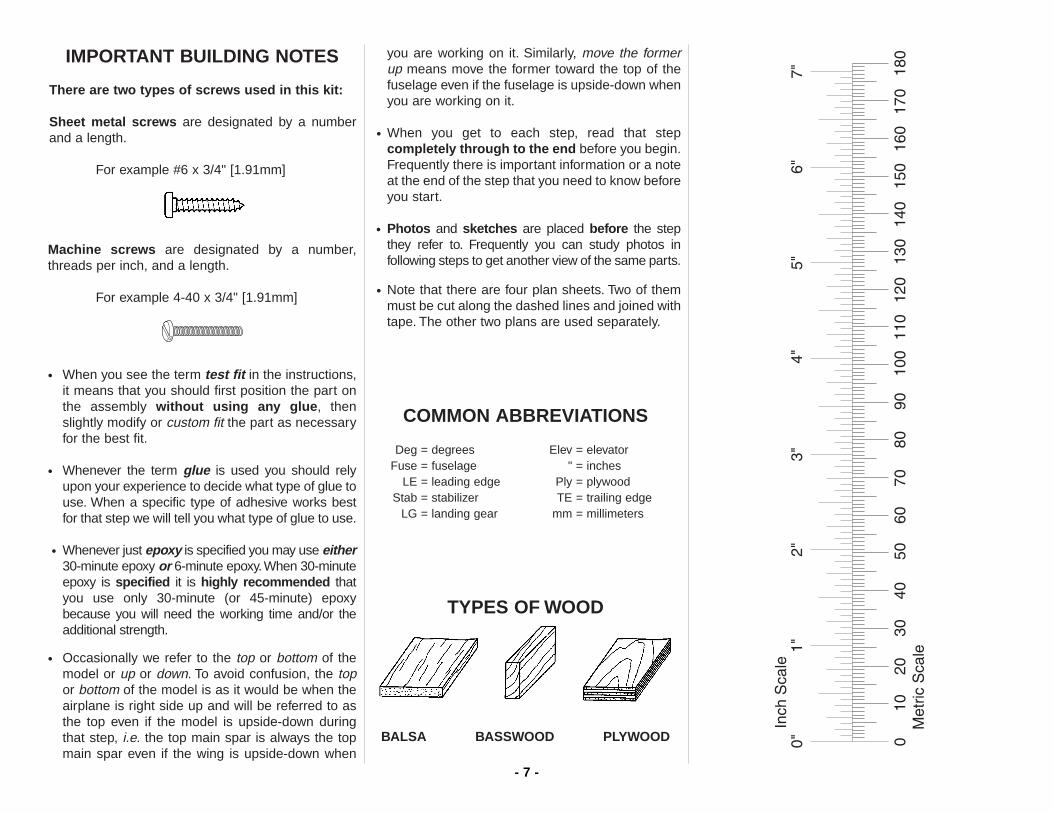
IMPORTANT BUILDING NOTES
There are two types of screws used in this kit:
Sheet metal screws are designated by a numberand a length.
For example #6 x 3/4" [1.91mm]
Machine screws are designated by a number,threads per inch, and a length.
For example 4-40 x 3/4" [1.91mm]
• When you see the term test fit in the instructions,it means that you should first position the part onthe assembly without using any glue, thenslightly modify or custom fit the part as necessaryfor the best fit.
• Whenever the term glue is used you should relyupon your experience to decide what type of glue touse. When a specific type of adhesive works bestfor that step we will tell you what type of glue to use.
• Whenever just epoxy is specified you may use either30-minute epoxy or 6-minute epoxy.When 30-minuteepoxy is specified it is highly recommended thatyou use only 30-minute (or 45-minute) epoxybecause you will need the working time and/or theadditional strength.
• Occasionally we refer to the top or bottom of themodel or up or down. To avoid confusion, the topor bottom of the model is as it would be when theairplane is right side up and will be referred to asthe top even if the model is upside-down duringthat step, i.e. the top main spar is always the topmain spar even if the wing is upside-down when
you are working on it. Similarly, move the formerup means move the former toward the top of thefuselage even if the fuselage is upside-down whenyou are working on it.
• When you get to each step, read that stepcompletely through to the end before you begin.Frequently there is important information or a noteat the end of the step that you need to know beforeyou start.
• Photos and sketches are placed before the stepthey refer to. Frequently you can study photos infollowing steps to get another view of the same parts.
• Note that there are four plan sheets. Two of themmust be cut along the dashed lines and joined withtape. The other two plans are used separately.
COMMON ABBREVIATIONS
Deg = degrees Elev = elevatorFuse = fuselage " = inches
LE = leading edge Ply = plywoodStab = stabilizer TE = trailing edge
LG = landing gear mm = millimeters
TYPES OF WOOD
BALSA BASSWOOD PLYWOOD
- 7 -
- 8 -
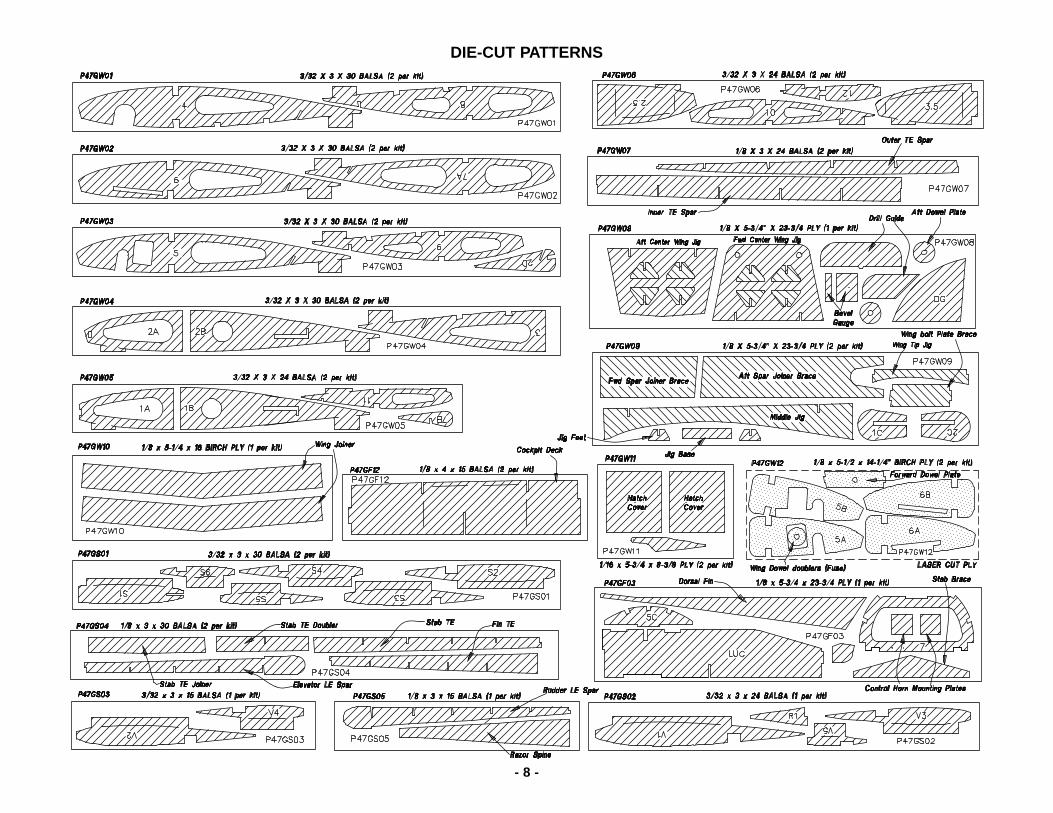
DIE-CUT PATTERNS
- 9 -
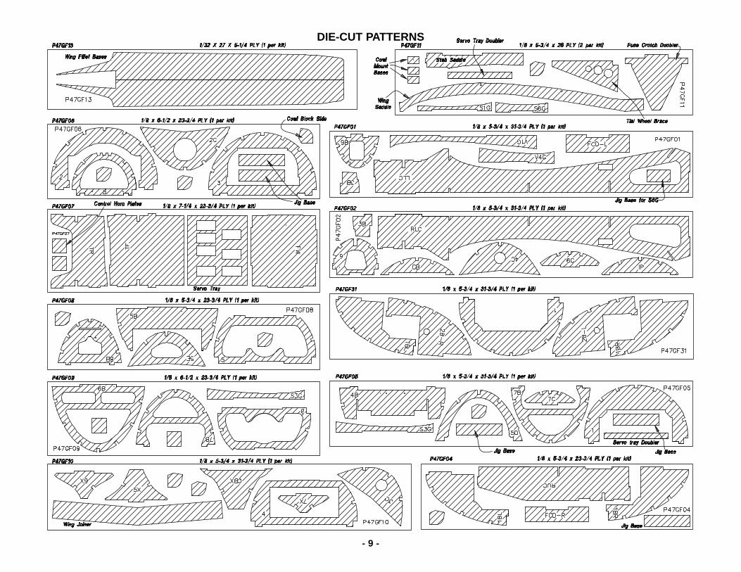
DIE-CUT PATTERNS
GET READY TO BUILD
1. If you’ve already purchased your retractablelanding gear, or as soon as you do, take the air linesout of the package, unravel them and hang themsomewhere in your shop. By the time you are readyto install the air lines, all the kinks will be out andthey’ll be easier to work with.
2. Unroll the plan sheets. Roll them inside out sothey lie flat. Cut one of the fuse plan sheets alongthe dashed lines. Align the plan that you cut with thedashed lines on the other fuse plan and tape themtogether. Do the same thing with the wing plan whenyou are ready to build the wing.
3. Remove all the parts from the box. IMPORTANT:Use a ballpoint pen (not a felt tip pen) to write thename or size on each piece so you can identify itlater. Use the die-cut patterns on pages 8 & 9 toidentify and mark the die-cut and laser-cut partsbefore you remove them from their die sheets. Manyof the parts already have numbers stamped on them,but in some cases the numbers are located alongsidethe parts or only on the die drawings in themanual. You may remove all the die-cut parts fromtheir die sheets now, or wait until you need them. If apart is difficult to remove, don’t force it out, but cutaround it with a hobby knife and a #11 blade. After youremove the parts from their die sheets, lightly sandthe edges to remove slivers or die-cuttingirregularities. Save some of the larger pieces of wood.
4. Separate the parts into groups such as stab, fin,wing and fuse. Store smaller parts in zipper-topfood storage bags.
BUILD THE TAIL SURFACES
Build the stabilizer and elevators
❏ 1. Place the stab plan over your building board (youmay cut it from the fuse plan). If you wish to protect theplan from glue (though this is not absolutely necessary
because the ribs rest on jig tabs and do not contact thebuilding board), cover the plan with film such as waxpaper or Great Planes Plan Protector.
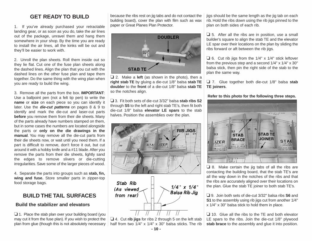
❏ 2. Make a left (as shown in the photo), then aright stab TE by gluing a die-cut 1/8" balsa stab TEdoubler to the front of a die-cut 1/8" balsa stab TEso the notches align.
❏ 3. Fit both sets of die-cut 3/32" balsa stab ribs S2through S5 to the left and right stab TE’s, then fit bothdie-cut 1/8" balsa elevator LE spars to the stabhalves. Position the assemblies over the plan.
❏ 4. Cut rib jigs for ribs 2 through 5 on the left stabhalf from two 1/4" x 1/4" x 30" balsa sticks. The rib
jigs should be the same length as the jig tab on eachrib. Hold the ribs down using the rib jigs pinned to theplan on both sides of each rib.
❏ 5. After all the ribs are in position, use a smallbuilder’s square to align the stab TE and the elevatorLE spar over their locations on the plan by sliding theribs forward or aft between the rib jigs.
❏ 6. Cut rib jigs from the 1/4" x 1/4" stick leftoverfrom the previous step and a second 1/4" x 1/4" x 30"balsa stick, then pin the right side of the stab to theplan the same way.
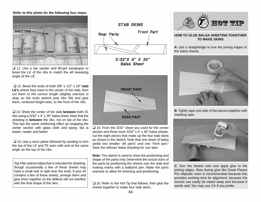
❏ 7. Glue together both die-cut 1/8" balsa stab TE joiners.
Refer to this photo for the following three steps.
❏ 8. Make certain the jig tabs of all the ribs arecontacting the building board, that the stab TE’s areall the way down in the notches of the ribs and thatthe ribs are accurately aligned over their locations onthe plan. Glue the stab TE joiner to both stab TE’s.
❏ 9. Join both sets of die-cut 3/32" balsa ribs S6 andS1 to the assembly using rib jigs cut from another 1/4"x 1/4" x 30" balsa stick to hold them in place.
❏ 10. Glue all the ribs to the TE and both elevatorLE spars to the ribs. Join the die-cut 1/8" plywoodstab brace to the assembly and glue it into position.
- 10 -
Refer to this photo for the following four steps.
❏ 11. Use a bar sander and 80-grit sandpaper tobevel the LE of the ribs to match the aft sweepingangle of the LE.
❏ 12. Bevel the ends of both 3/8" x 1/2" x 18" stabLE’s where they meet in the center of the stab, thencut them to the correct length (slightly oversize isokay so the ends extend past ribs S6) and gluethem, centered height-wise, to the front of the ribs.
❏ 13. Sheet the center of the stab between both S1ribs using a 3/32" x 4" x 30" balsa sheet. Note that thesheeting is between the ribs, not on top of the ribs.This has the same reinforcing effect as wrapping thecenter section with glass cloth and epoxy, but iseasier, neater and faster!
❏ 14. Use a razor plane followed by sanding to trimthe top of the LE and TE even with and at the sameangle as the top of the ribs.
❏ 15. From the 3/32" sheet you used for the centersection and three more 3/32" x 4" x 30" balsa sheets,cut the eight pieces that make up the four stab skinsas shown in the sketch. Note that one sheet of balsayields two smaller “aft parts” and one “front part.”Save the leftover balsa sheeting for use later.
Note: The sketch is used to show the positioning andshape of the parts only. Determine the actual sizes ofthe parts by positioning the sheets over the stab andmaking marks with a ballpoint pen. Make the partsoversize to allow for trimming and positioning.
❏ 16. Refer to the Hot Tip that follows, then glue thesheets together to make four stab skins.
C. Turn the sheets over and apply glue to thejoining edges. Slow drying glue like Great PlanesPro Aliphatic resin is recommended because thisprovides working time for alignment, because theexcess can easily be wiped away and because itsands well. You may use CA if you prefer.
B. Tightly tape one side of the pieces together withmasking tape.
HOW TO GLUE BALSA SHEETING TOGETHERTO MAKE SKINS
A. Use a straightedge to true the joining edges ofthe balsa sheets.
Top Flite selects balsa that is intended for sheeting,though occasionally a few of these sheets mayhave a small nick or split near the ends. If your kitcontains a few of these sheets, arrange them andglue them together so the defects will not interferewith the final shape of the skin.
-11-
❏ 17. Glue two stab skins to the top of the stab usingaliphatic resin or medium or thick CA. Our preferredmethod is to apply aliphatic resin to the tops of theribs and the TE, then position the skin and hold itdown with weights and T-pins where necessary.Before the glue dries, use thin or medium CA to gluethe front of the skin to the LE.
❏ 18. Use the template on the plan to make theelevator skins from two 3/32" x 4" x 24" balsa sheets.Hint: Use 3M 75 Repositionable Spray Adhesive tostick the paper template to the balsa sheet, then cutit out. If you have a band saw or a scroll saw, stackall four sheets together with 3M 75 and cut them outall at once.
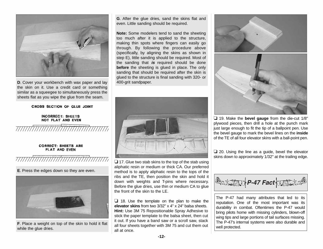
❏ 19. Make the bevel gauge from the die-cut 1/8"plywood pieces, then drill a hole at the punch markjust large enough to fit the tip of a ballpoint pen. Usethe bevel gauge to mark the bevel lines on the insideof the TE of all four elevator skins with a ball-point pen.
❏ 20. Using the line as a guide, bevel the elevatorskins down to approximately 1/32" at the trailing edge.
The P-47 had many attributes that led to itsreputation. One of the most important was itsdurability in combat. Oftentimes the P-47 wouldbring pilots home with missing cylinders, blown-offwing tips and large portions of tail surfaces missing.The P-47’s internal systems were also durable andwell protected.
G. After the glue dries, sand the skins flat andeven. Little sanding should be required.
Note: Some modelers tend to sand the sheetingtoo much after it is applied to the structure,making thin spots where fingers can easily gothrough. By following the procedure above(specifically, by aligning the skins as shown instep E), little sanding should be required. Most ofthe sanding that is required should be donebefore the sheeting is glued in place. The onlysanding that should be required after the skin isglued to the structure is final sanding with 320- or400-grit sandpaper.
F. Place a weight on top of the skin to hold it flatwhile the glue dries.
E. Press the edges down so they are even.
D. Cover your workbench with wax paper and laythe skin on it. Use a credit card or somethingsimilar as a squeegee to simultaneously press thesheets flat as you wipe the glue from the seam.
-12-
❏ 21. If you haven’t done so already, trim the topedge of the elevator LE spars even with the top of theribs. Glue the top elevator skins to the top of theelevators. As shown on the cross section on the plan,the beveled edges are on the inside.
❏ 22. Remove the stab and elevators from yourbuilding board. Save the jig sticks for use on the fin.
❏ 23. Use a hobby knife to trim the jig tabs from thebottom of the ribs, finishing with a bar sander and80-grit sandpaper so the ribs appear as though thejig tabs were never there. While you’re at it, trim thebottom of the LE so it matches the ribs.
❏ 24. Cut eighteen 1-1/2" long hinge blocks from a1/4" x 1/2" x 30" balsa stick. Glue the hinge blocks tothe stab TE and elevator LE spar where shown onthe plan. NOTE: The hinge block sizes shown on the
plan are intended to accommodate Robart largehinge points. If you plan to use flat hinges, the hingeblocks may need to be longer.
❏ 25. If necessary, trim the bottom of the elevator LEspar even with the bottom of the ribs. Glue thebottom elevator skins to the elevators. Be certain theTE of the top and bottom skins align and arethoroughly bonded together.
❏ 26. Use leftover 3/32" sheeting to sheet thebottom of the stab between ribs S1 just the same asyou did on the top of the stab.
❏ 27. Build the six stab cradles (three for each sideof the stab) from the die-cut 1/8" plywood pieces as shown.
❏ 28. With the stab plan positioned over your flatbuilding board, place the stab cradles over theirrespective locations on the plan. Note that the frontof the cradles is the end with the embossed lettering.Hint: Hold the cradles to the plan with 3M 75Repositionable Spray Adhesive.
❏ 29. Place the stab on the cradles aligned with theplan. Glue the bottom skins into position. A slowdrying glue such as aliphatic resin is preferred. Placeweights on top of the stab to hold the skins down.
❏ 30. After the glue from the previous step hasdried, remove the stab from the cradles. Use a barsander with 80-grit sandpaper to remove excessiveglue. Sand the ends of the stab and elevatorsheeting even with the tips.
❏ 31. Cut both elevators from the stab. Sand the LEof the elevators and the TE of the stab to remove theprotruding portions of the ribs.
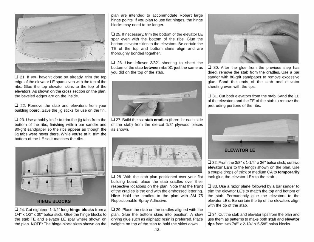
❏ 32. From the 3/8" x 1-1/4" x 36" balsa stick, cut twoelevator LE’s to the length shown on the plan. Usea couple drops of thick or medium CA to temporarilytack glue the elevator LE’s to the stab.
❏ 33. Use a razor plane followed by a bar sander totrim the elevator LE’s to match the top and bottom ofthe stab. Permanently glue the elevators to theelevator LE’s. Be certain the tip of the elevators alignwith the tip of the stab.
❏ 34. Cut the stab and elevator tips from the plan anduse them as patterns to make both stab and elevatortips from two 7/8" x 2-1/4" x 5-5/8" balsa blocks.
-13-
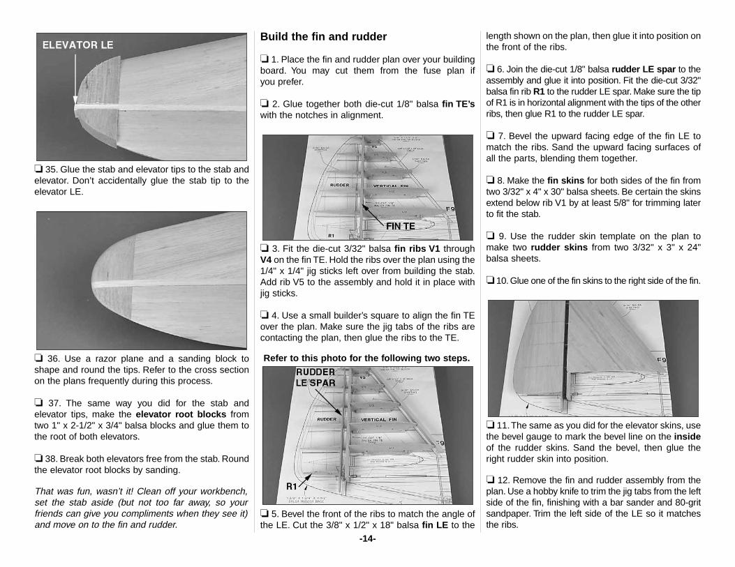
❏ 35. Glue the stab and elevator tips to the stab andelevator. Don’t accidentally glue the stab tip to theelevator LE.
❏ 36. Use a razor plane and a sanding block toshape and round the tips. Refer to the cross sectionon the plans frequently during this process.
❏ 37. The same way you did for the stab andelevator tips, make the elevator root blocks fromtwo 1" x 2-1/2" x 3/4" balsa blocks and glue them tothe root of both elevators.
❏ 38. Break both elevators free from the stab. Roundthe elevator root blocks by sanding.
That was fun, wasn’t it! Clean off your workbench,set the stab aside (but not too far away, so yourfriends can give you compliments when they see it)and move on to the fin and rudder.
Build the fin and rudder
❏ 1. Place the fin and rudder plan over your buildingboard. You may cut them from the fuse plan if you prefer.
❏ 2. Glue together both die-cut 1/8" balsa fin TE’swith the notches in alignment.
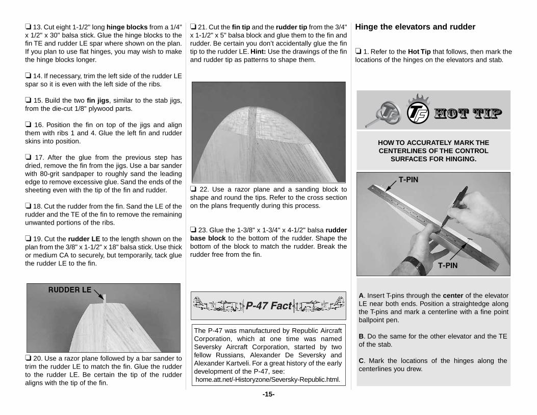
❏ 3. Fit the die-cut 3/32" balsa fin ribs V1 throughV4 on the fin TE. Hold the ribs over the plan using the1/4" x 1/4" jig sticks left over from building the stab.Add rib V5 to the assembly and hold it in place withjig sticks.
❏ 4. Use a small builder’s square to align the fin TEover the plan. Make sure the jig tabs of the ribs arecontacting the plan, then glue the ribs to the TE.
Refer to this photo for the following two steps.
❏ 5. Bevel the front of the ribs to match the angle ofthe LE. Cut the 3/8" x 1/2" x 18" balsa fin LE to the
length shown on the plan, then glue it into position onthe front of the ribs.
❏ 6. Join the die-cut 1/8" balsa rudder LE spar to theassembly and glue it into position. Fit the die-cut 3/32"balsa fin rib R1 to the rudder LE spar. Make sure the tipof R1 is in horizontal alignment with the tips of the otherribs, then glue R1 to the rudder LE spar.
❏ 7. Bevel the upward facing edge of the fin LE tomatch the ribs. Sand the upward facing surfaces ofall the parts, blending them together.
❏ 8. Make the fin skins for both sides of the fin fromtwo 3/32" x 4" x 30" balsa sheets. Be certain the skinsextend below rib V1 by at least 5/8" for trimming laterto fit the stab.
❏ 9. Use the rudder skin template on the plan tomake two rudder skins from two 3/32" x 3" x 24"balsa sheets.
❏ 10. Glue one of the fin skins to the right side of the fin.
❏ 11.The same as you did for the elevator skins, usethe bevel gauge to mark the bevel line on the insideof the rudder skins. Sand the bevel, then glue theright rudder skin into position.
❏ 12. Remove the fin and rudder assembly from theplan. Use a hobby knife to trim the jig tabs from the leftside of the fin, finishing with a bar sander and 80-gritsandpaper. Trim the left side of the LE so it matchesthe ribs.
-14-
❏ 13. Cut eight 1-1/2" long hinge blocks from a 1/4"x 1/2" x 30" balsa stick. Glue the hinge blocks to thefin TE and rudder LE spar where shown on the plan.If you plan to use flat hinges, you may wish to makethe hinge blocks longer.
❏ 14. If necessary, trim the left side of the rudder LEspar so it is even with the left side of the ribs.
❏ 15. Build the two fin jigs, similar to the stab jigs,from the die-cut 1/8" plywood parts.
❏ 16. Position the fin on top of the jigs and alignthem with ribs 1 and 4. Glue the left fin and rudderskins into position.
❏ 17. After the glue from the previous step hasdried, remove the fin from the jigs. Use a bar sanderwith 80-grit sandpaper to roughly sand the leadingedge to remove excessive glue. Sand the ends of thesheeting even with the tip of the fin and rudder.
❏ 18. Cut the rudder from the fin. Sand the LE of therudder and the TE of the fin to remove the remainingunwanted portions of the ribs.
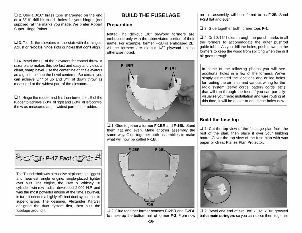
❏ 19. Cut the rudder LE to the length shown on theplan from the 3/8" x 1-1/2" x 18" balsa stick. Use thickor medium CA to securely, but temporarily, tack gluethe rudder LE to the fin.
❏ 20. Use a razor plane followed by a bar sander totrim the rudder LE to match the fin. Glue the rudderto the rudder LE. Be certain the tip of the rudderaligns with the tip of the fin.
❏ 21. Cut the fin tip and the rudder tip from the 3/4"x 1-1/2" x 5" balsa block and glue them to the fin andrudder. Be certain you don’t accidentally glue the fintip to the rudder LE. Hint: Use the drawings of the finand rudder tip as patterns to shape them.
❏ 22. Use a razor plane and a sanding block toshape and round the tips. Refer to the cross sectionon the plans frequently during this process.
❏ 23. Glue the 1-3/8" x 1-3/4" x 4-1/2" balsa rudderbase block to the bottom of the rudder. Shape thebottom of the block to match the rudder. Break therudder free from the fin.
Hinge the elevators and rudder
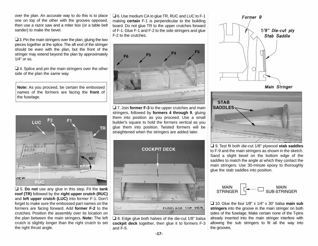
❏ 1. Refer to the Hot Tip that follows, then mark thelocations of the hinges on the elevators and stab.
A. Insert T-pins through the center of the elevatorLE near both ends. Position a straightedge alongthe T-pins and mark a centerline with a fine pointballpoint pen.
B. Do the same for the other elevator and the TEof the stab.
C. Mark the locations of the hinges along thecenterlines you drew.
HOW TO ACCURATELY MARK THECENTERLINES OF THE CONTROL
SURFACES FOR HINGING.
The P-47 was manufactured by Republic AircraftCorporation, which at one time was namedSeversky Aircraft Corporation, started by twofellow Russians, Alexander De Seversky andAlexander Kartveli. For a great history of the earlydevelopment of the P-47, see:home.att.net/-Historyzone/Seversky-Republic.html.
-15-
❏ 2. Use a 3/16" brass tube sharpened on the endor a 3/16" drill bit to drill holes for your hinges (notsupplied) at the marks you made. We prefer RobartSuper Hinge Points.
❏ 3. Test fit the elevators to the stab with the hinges.Adjust or relocate hinge slots or holes that don’t align.
❏ 4. Bevel the LE of the elevators for control throw. Arazor plane makes this job fast and easy and yields aclean, sharp bevel. Use the centerline on the elevatorsas a guide to keep the bevel centered. Be certain youcan achieve 3/4" of up and 3/4" of down throw asmeasured at the widest part of the elevators.
❏ 5. Hinge the rudder and fin, then bevel the LE of therudder to achieve 1-3/4" of right and 1-3/4" of left controlthrow as measured at the widest part of the rudder.
BUILD THE FUSELAGE
Preparation
Note: The die-cut 1/8" plywood formers areembossed only with the abbreviated portion of theirname. For example, former F-2B is embossed 2B.All the formers are die-cut 1/8" plywood unlessotherwise noted.
❏ 1. Glue together a former F-1BR and F-1BL. Sandthem flat and even. Make another assembly thesame way. Glue together both assemblies to makewhat will now be called F-1B.
❏ 2. Glue together former bottoms F-2BR and F-2BLto make up the bottom half of former F-2. From now
on this assembly will be referred to as F-2B. Sand F-2B flat and even.
❏ 3. Glue together both former tops F-1.
❏ 4. Drill 3/16" holes through the punch marks in allthe formers to accommodate the outer pushrodguide tubes. As you drill the holes, push down on theformers to keep the wood from splitting when the drillbit goes through.
Build the fuse top
❏ 1. Cut the top view of the fuselage plan from therest of the plan, then place it over your buildingboard. Cover the top view of the fuse plan with waxpaper or Great Planes Plan Protector.
❏ 2. Bevel one end of two 3/8" x 1/2" x 30" groovedbalsa main stringers so you can splice them together
In some of the following photos you will seeadditional holes in a few of the formers. We’vesimply estimated the locations and drilled holesfor routing the air lines and various wiring for theradio system (servo cords, battery cords, etc.)that will run through the fuse. If you can partiallyvisualize your radio installation and wire routing atthis time, it will be easier to drill these holes now.
The Thunderbolt was a massive airplane, the biggestand heaviest single engine, single-placed fighterever built. The engine, the Pratt & Whitney 18cylinder twin-row radial, developed 2,000 H.P. andwas the most powerful engine at the time. However,in turn, it needed a highly efficient duct system for itssuper-charger. The designer, Alexander Kartvelidesigned the duct system first, then built thefuselage around it.
-16-
over the plan. An accurate way to do this is to placeone on top of the other with the grooves opposed,then use a razor saw and a miter box (or a table beltsander) to make the bevel.
❏ 3. Pin the main stringers over the plan, gluing the twopieces together at the splice.The aft end of the stringershould be even with the plan, but the front of thestringer may extend beyond the plan by approximately1/4" or so.
❏ 4. Splice and pin the main stringers over the otherside of the plan the same way.
❏ 5. Do not use any glue in this step. Fit the tankroof (TR) followed by the right upper crutch (RUC)and left upper crutch (LUC) into former F-1. Don’tforget to make sure the embossed part names on theformers are facing forward. Add former F-2 to thecrutches. Position the assembly over its location onthe plan between the main stringers. Note: The leftcrutch is slightly longer than the right crutch to setthe right thrust angle.
❏ 6. Use medium CA to glue TR, RUC and LUC to F-1making certain F-1 is perpendicular to the buildingboard. Do not glue TR to the upper crutches forwardof F-1. Glue F-1 and F-2 to the side stringers and glueF-2 to the crutches.
❏ 7. Join former F-3 to the upper crutches and mainstringers, followed by formers 4 through 9, gluingthem into position as you proceed. Use a smallbuilder’s square to hold the formers vertical as youglue them into position. Twisted formers will bestraightened when the stringers are added later.
❏ 8. Edge glue both halves of the die-cut 1/8" balsacockpit deck together, then glue it to formers F-3and F-5.
❏ 9. Test fit both die-cut 1/8" plywood stab saddlesto F-9 and the main stringers as shown in the sketch.Sand a slight bevel on the bottom edge of thesaddles to match the angle at which they contact themain stringers. Use 30-minute epoxy to thoroughlyglue the stab saddles into position.
❏ 10. Glue the four 1/8" x 1/4" x 30" balsa main substringers into the groove in the main stringer on bothsides of the fuselage. Make certain none of the T-pinsalready inserted into the main stringer interfere withallowing the sub stringers to fit all the way into the grooves.
Note: As you proceed, be certain the embossednames of the formers are facing the front of the fuselage.
-17-
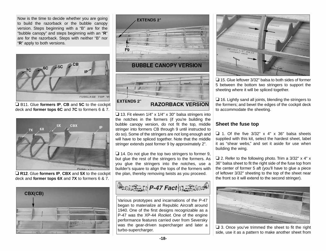
❏ B11. Glue formers IP, CB and 5C to the cockpitdeck and former tops 6C and 7C to formers 6 & 7.
❏ R12. Glue formers IP, CBX and 5X to the cockpitdeck and former tops 6X and 7X to formers 6 & 7.
❏ 13. Fit eleven 1/4" x 1/4" x 30" balsa stringers intothe notches in the formers (if you’re building thebubble canopy version, do not fit the top, middlestringer into formers CB through 9 until instructed todo so). Some of the stringers are not long enough andwill have to be spliced together. Note that the middlestringer extends past former 9 by approximately 2".
❏ 14. Do not glue the top two stringers to former 9,but glue the rest of the stringers to the formers. Asyou glue the stringers into the notches, use abuilder’s square to align the tops of the formers withthe plan, thereby removing twists as you proceed.
❏ 15. Glue leftover 3/32" balsa to both sides of former5 between the bottom two stringers to support thesheeting where it will be spliced together.
❏ 16. Lightly sand all joints, blending the stringers tothe formers; and bevel the edges of the cockpit deckto accommodate the sheeting.
Sheet the fuse top
❏ 1. Of the five 3/32" x 4" x 36" balsa sheetssupplied with this kit, select the hardest sheet, labelit as “shear webs,” and set it aside for use whenbuilding the wing.
❏ 2. Refer to the following photo. Trim a 3/32" x 4" x36" balsa sheet to fit the right side of the fuse top fromthe center of former 5 aft (you’ll have to glue a pieceof leftover 3/32" sheeting to the top of the sheet nearthe front so it will extend to the second stringer).
❏ 3. Once you’ve trimmed the sheet to fit the rightside, use it as a pattern to make another sheet from
Various prototypes and incarnations of the P-47began to materialize at Republic Aircraft around1940. One of the first designs recognizable as aP-47 was the XP-44 Rocket. One of the engineperformance features carried over from Severskywas the gear-driven supercharger and later aturbo-supercharger.
Now is the time to decide whether you are goingto build the razorback or the bubble canopyversion. Steps beginning with a “B” are for the“bubble canopy” and steps beginning with an “R”are for the razorback. Steps with neither “B” nor“R” apply to both versions.
-18-
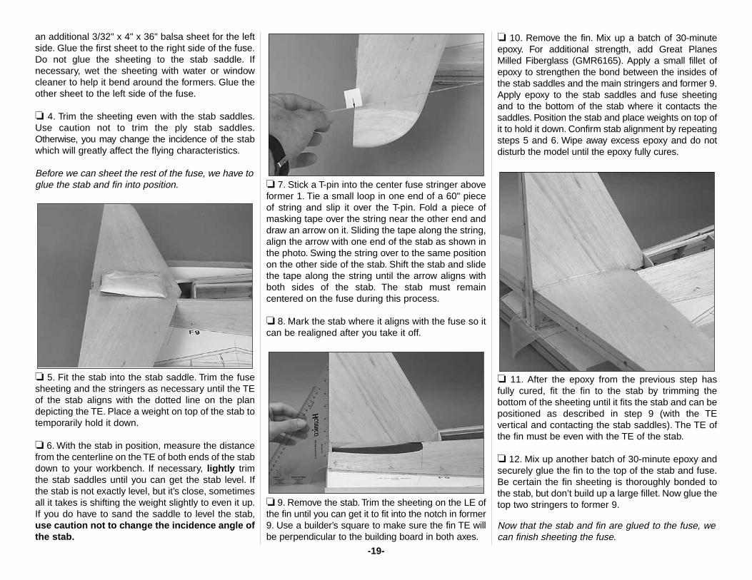
an additional 3/32" x 4" x 36" balsa sheet for the leftside. Glue the first sheet to the right side of the fuse.Do not glue the sheeting to the stab saddle. Ifnecessary, wet the sheeting with water or windowcleaner to help it bend around the formers. Glue theother sheet to the left side of the fuse.
❏ 4. Trim the sheeting even with the stab saddles.Use caution not to trim the ply stab saddles.Otherwise, you may change the incidence of the stabwhich will greatly affect the flying characteristics.
Before we can sheet the rest of the fuse, we have toglue the stab and fin into position.
❏ 5. Fit the stab into the stab saddle. Trim the fusesheeting and the stringers as necessary until the TEof the stab aligns with the dotted line on the plandepicting the TE. Place a weight on top of the stab totemporarily hold it down.
❏ 6. With the stab in position, measure the distancefrom the centerline on the TE of both ends of the stabdown to your workbench. If necessary, lightly trimthe stab saddles until you can get the stab level. Ifthe stab is not exactly level, but it’s close, sometimesall it takes is shifting the weight slightly to even it up.If you do have to sand the saddle to level the stab,use caution not to change the incidence angle ofthe stab.
❏ 7. Stick a T-pin into the center fuse stringer aboveformer 1. Tie a small loop in one end of a 60" pieceof string and slip it over the T-pin. Fold a piece ofmasking tape over the string near the other end anddraw an arrow on it. Sliding the tape along the string,align the arrow with one end of the stab as shown inthe photo. Swing the string over to the same positionon the other side of the stab. Shift the stab and slidethe tape along the string until the arrow aligns withboth sides of the stab. The stab must remaincentered on the fuse during this process.
❏ 8. Mark the stab where it aligns with the fuse so itcan be realigned after you take it off.
❏ 9. Remove the stab. Trim the sheeting on the LE ofthe fin until you can get it to fit into the notch in former9. Use a builder’s square to make sure the fin TE willbe perpendicular to the building board in both axes.
❏ 10. Remove the fin. Mix up a batch of 30-minuteepoxy. For additional strength, add Great PlanesMilled Fiberglass (GMR6165). Apply a small fillet ofepoxy to strengthen the bond between the insides ofthe stab saddles and the main stringers and former 9.Apply epoxy to the stab saddles and fuse sheetingand to the bottom of the stab where it contacts thesaddles. Position the stab and place weights on top ofit to hold it down. Confirm stab alignment by repeatingsteps 5 and 6. Wipe away excess epoxy and do notdisturb the model until the epoxy fully cures.
❏ 11. After the epoxy from the previous step hasfully cured, fit the fin to the stab by trimming thebottom of the sheeting until it fits the stab and can bepositioned as described in step 9 (with the TEvertical and contacting the stab saddles). The TE ofthe fin must be even with the TE of the stab.
❏ 12. Mix up another batch of 30-minute epoxy andsecurely glue the fin to the top of the stab and fuse.Be certain the fin sheeting is thoroughly bonded tothe stab, but don’t build up a large fillet. Now glue thetop two stringers to former 9.
Now that the stab and fin are glued to the fuse, wecan finish sheeting the fuse.
-19-
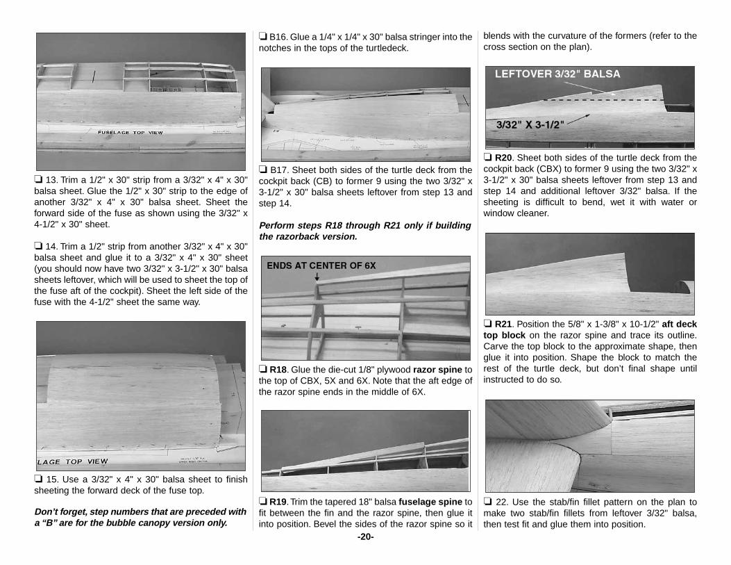
❏ 13. Trim a 1/2" x 30" strip from a 3/32" x 4" x 30"balsa sheet. Glue the 1/2" x 30" strip to the edge ofanother 3/32" x 4" x 30" balsa sheet. Sheet theforward side of the fuse as shown using the 3/32" x4-1/2" x 30" sheet.
❏ 14. Trim a 1/2" strip from another 3/32" x 4" x 30"balsa sheet and glue it to a 3/32" x 4" x 30" sheet(you should now have two 3/32" x 3-1/2" x 30" balsasheets leftover, which will be used to sheet the top ofthe fuse aft of the cockpit). Sheet the left side of thefuse with the 4-1/2" sheet the same way.
❏ 15. Use a 3/32" x 4" x 30" balsa sheet to finishsheeting the forward deck of the fuse top.
Don’t forget, step numbers that are preceded witha “B” are for the bubble canopy version only.
❏ B16. Glue a 1/4" x 1/4" x 30" balsa stringer into thenotches in the tops of the turtledeck.
❏ B17. Sheet both sides of the turtle deck from thecockpit back (CB) to former 9 using the two 3/32" x3-1/2" x 30" balsa sheets leftover from step 13 andstep 14.
Perform steps R18 through R21 only if buildingthe razorback version.
❏ R18. Glue the die-cut 1/8" plywood razor spine tothe top of CBX, 5X and 6X. Note that the aft edge ofthe razor spine ends in the middle of 6X.
❏ R19.Trim the tapered 18" balsa fuselage spine tofit between the fin and the razor spine, then glue itinto position. Bevel the sides of the razor spine so it
blends with the curvature of the formers (refer to thecross section on the plan).
❏ R20. Sheet both sides of the turtle deck from thecockpit back (CBX) to former 9 using the two 3/32" x3-1/2" x 30" balsa sheets leftover from step 13 andstep 14 and additional leftover 3/32" balsa. If thesheeting is difficult to bend, wet it with water orwindow cleaner.
❏ R21. Position the 5/8" x 1-3/8" x 10-1/2" aft decktop block on the razor spine and trace its outline.Carve the top block to the approximate shape, thenglue it into position. Shape the block to match therest of the turtle deck, but don’t final shape untilinstructed to do so.
❏ 22. Use the stab/fin fillet pattern on the plan tomake two stab/fin fillets from leftover 3/32" balsa,then test fit and glue them into position.
-20-
❏ 23. Take out all the T-pins and remove the fuse topfrom your building board. Place the fuselage upside-down in a suitable building stand (such as a Robart®
Super Stand II, ROBP1402, seen in following photos).Reinforce glue joints you couldn’t reach earlier.
❏ 24. Use leftover 1/4" x 1/4" balsa (shaped intotriangle stock) to reinforce the glue joint between thebottom of the stab and the inside of the stab saddles.
Build the fuse bottom
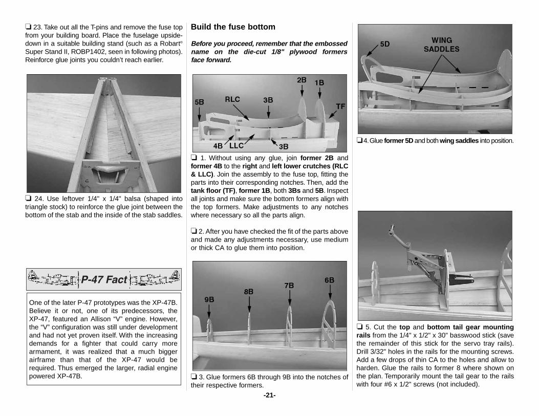
Before you proceed, remember that the embossedname on the die-cut 1/8" plywood formers face forward.
❏ 1. Without using any glue, join former 2B andformer 4B to the right and left lower crutches (RLC& LLC). Join the assembly to the fuse top, fitting theparts into their corresponding notches. Then, add thetank floor (TF), former 1B, both 3Bs and 5B. Inspectall joints and make sure the bottom formers align withthe top formers. Make adjustments to any notcheswhere necessary so all the parts align.
❏ 2. After you have checked the fit of the parts aboveand made any adjustments necessary, use mediumor thick CA to glue them into position.
❏ 3. Glue formers 6B through 9B into the notches oftheir respective formers.
❏4.Glue former 5D and both wing saddles into position.
❏ 5. Cut the top and bottom tail gear mountingrails from the 1/4" x 1/2" x 30" basswood stick (savethe remainder of this stick for the servo tray rails).Drill 3/32" holes in the rails for the mounting screws.Add a few drops of thin CA to the holes and allow toharden. Glue the rails to former 8 where shown onthe plan. Temporarily mount the tail gear to the railswith four #6 x 1/2" screws (not included).
One of the later P-47 prototypes was the XP-47B.Believe it or not, one of its predecessors, the XP-47, featured an Allison “V” engine. However,the “V” configuration was still under developmentand had not yet proven itself. With the increasingdemands for a fighter that could carry morearmament, it was realized that a much biggerairframe than that of the XP-47 would berequired. Thus emerged the larger, radial enginepowered XP-47B.
-21-
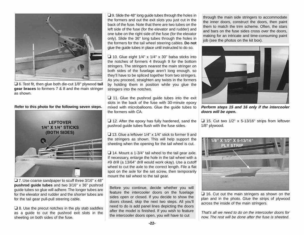
❏ 6. Test fit, then glue both die-cut 1/8" plywood tailgear braces to formers 7 & 8 and the main stringeras shown.
Refer to this photo for the following seven steps.
❏ 7. Use coarse sandpaper to scuff three 3/16" x 48"pushrod guide tubes and two 3/16" x 36" pushrodguide tubes so glue will adhere. The longer tubes arefor the elevator and rudder and the shorter tubes arefor the tail gear pull-pull steering cable.
❏ 8. Use the precut notches in the ply stab saddlesas a guide to cut the pushrod exit slots in thesheeting on both sides of the fuse.
❏ 9. Slide the 48" long guide tubes through the holes inthe formers and out the exit slots you just cut in theback of the fuse. Note that there are two tubes on theleft side of the fuse (for the elevator and rudder) andone tube on the right side of the fuse (for the elevatoronly). Slide the 36" long tubes through the holes inthe formers for the tail wheel steering cables. Do notglue the guide tubes in place until instructed to do so.
❏ 10. Glue eight 1/4" x 1/4" x 30" balsa sticks intothe notches of formers 4 through 9 for the bottomstringers. The stringers nearest the main stringer onboth sides of the fuselage aren’t long enough, sothey’ll have to be spliced together from two stringers.As you proceed, straighten any twists in the formersby holding them in position while you glue thestringers into the notches.
❏ 11. Glue the pushrod guide tubes into the exitslots in the back of the fuse with 30-minute epoxymixed with microballoons. Glue the guide tubes tothe formers with CA.
❏ 12. After the epoxy has fully hardened, sand thepushrod guide tubes flush with the fuse sides.
❏ 13. Glue a leftover 1/4" x 1/4" stick to former 9 andthe stringers as shown. This will help support thesheeting when the opening for the tail wheel is cut.
❏ 14. Mount a 1-3/4" tail wheel to the tail gear axle.If necessary, enlarge the hole in the tail wheel with a#9 drill (a 13/64" drill would work okay). Use a cutoffwheel to cut the axle to the correct length. File a flatspot on the axle for the set screw, then temporarilymount the tail wheel to the tail gear.
Perform steps 15 and 16 only if the intercoolerdoors will be open.
❏ 15. Cut two 1/2" x 5-13/16" strips from leftover 1/8" plywood.
❏ 16. Cut out the main stringers as shown on theplan and in the photo. Glue the strips of plywoodacross the inside of the main stringers.
That’s all we need to do on the intercooler doors fornow. The rest will be done after the fuse is sheeted.
through the main side stringers to accommodatethe inner doors, construct the doors, then paintthem to match the trim scheme. Often, the starsand bars on the fuse sides cross over the doors,making for an intricate and time-consuming paintjob (see the photos on the kit box).
Before you continue, decide whether you willfeature the intercooler doors on the fuselagesides open or closed. If you decide to show thedoors closed, skip the next two steps. All you’llneed to do is add panel lines depicting the doorsafter the model is finished. If you wish to featurethe intercooler doors open, you will have to cut
-22-
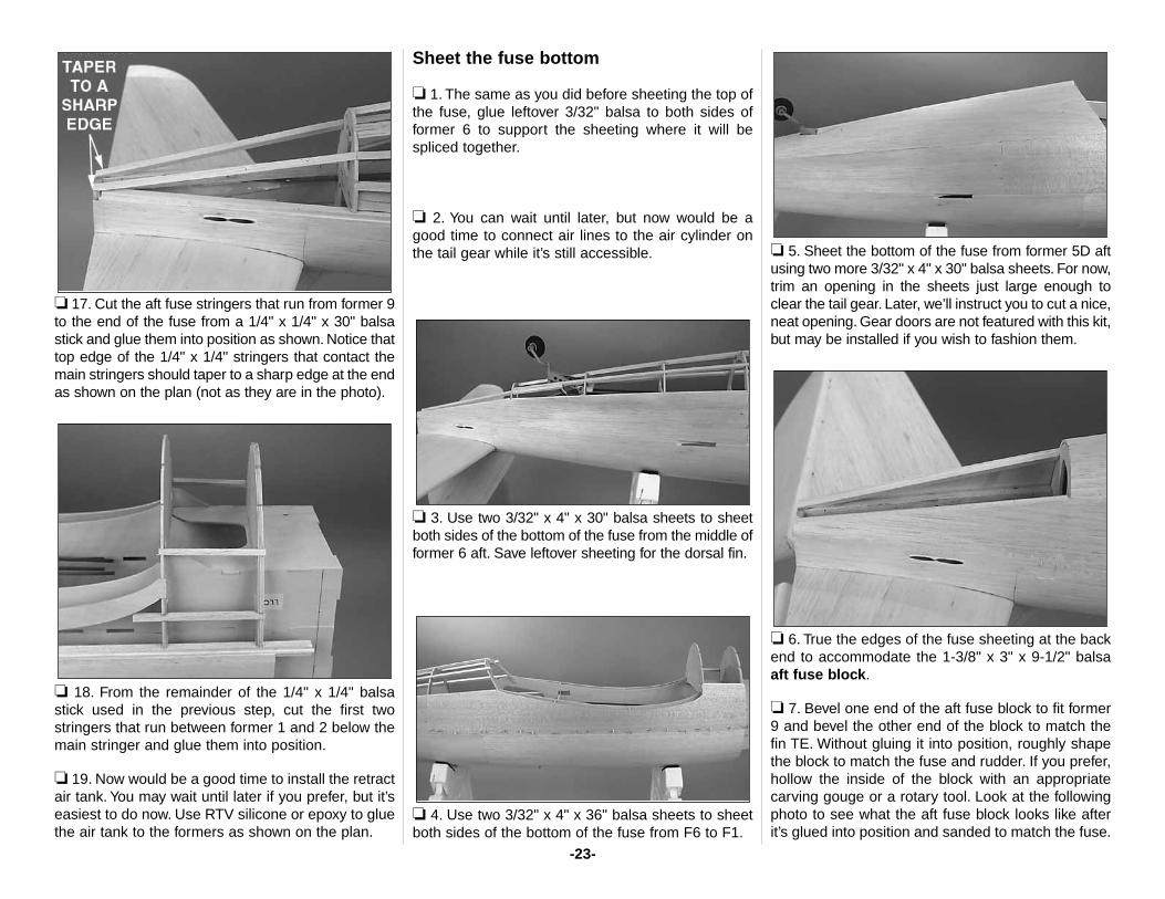
❏ 17. Cut the aft fuse stringers that run from former 9to the end of the fuse from a 1/4" x 1/4" x 30" balsastick and glue them into position as shown. Notice thattop edge of the 1/4" x 1/4" stringers that contact themain stringers should taper to a sharp edge at the endas shown on the plan (not as they are in the photo).
❏ 18. From the remainder of the 1/4" x 1/4" balsastick used in the previous step, cut the first twostringers that run between former 1 and 2 below themain stringer and glue them into position.
❏ 19. Now would be a good time to install the retractair tank. You may wait until later if you prefer, but it’seasiest to do now. Use RTV silicone or epoxy to gluethe air tank to the formers as shown on the plan.
Sheet the fuse bottom
❏ 1. The same as you did before sheeting the top ofthe fuse, glue leftover 3/32" balsa to both sides offormer 6 to support the sheeting where it will bespliced together.
❏ 2. You can wait until later, but now would be agood time to connect air lines to the air cylinder onthe tail gear while it’s still accessible.
❏ 3. Use two 3/32" x 4" x 30" balsa sheets to sheetboth sides of the bottom of the fuse from the middle offormer 6 aft. Save leftover sheeting for the dorsal fin.
❏ 4. Use two 3/32" x 4" x 36" balsa sheets to sheetboth sides of the bottom of the fuse from F6 to F1.
❏ 5. Sheet the bottom of the fuse from former 5D aftusing two more 3/32" x 4" x 30" balsa sheets. For now,trim an opening in the sheets just large enough toclear the tail gear. Later, we’ll instruct you to cut a nice,neat opening. Gear doors are not featured with this kit,but may be installed if you wish to fashion them.
❏ 6. True the edges of the fuse sheeting at the backend to accommodate the 1-3/8" x 3" x 9-1/2" balsaaft fuse block.
❏ 7. Bevel one end of the aft fuse block to fit former9 and bevel the other end of the block to match thefin TE. Without gluing it into position, roughly shapethe block to match the fuse and rudder. If you prefer,hollow the inside of the block with an appropriatecarving gouge or a rotary tool. Look at the followingphoto to see what the aft fuse block looks like afterit’s glued into position and sanded to match the fuse.
-23-
❏ 8. Glue the aft fuse block into position. Temporarilyjoin the rudder to the fin with the hinges and usemasking tape to hold it, centered, in place. Use a barsander with 80-grit sandpaper to blend the fuse, theaft fuse block and the rudder.
❏ 9. Trim the bottom sheeting, former 9 and aportion of the aft fuse block to allow the tail gear toretract. Use a 1/4" brass tube sharpened at the endto cut four holes through the sheeting so you canreach the tail gear mounting screws with ascrewdriver (you thought we were going to forgetdidn’t you?).
❏ 10. Use lightweight hobby filler such as HobbicoHobbyLite™ to fill gaps between the sheeting whereneeded. After the filler dries, rough-sand the fuse,eliminating uneven sheeting and high spots. Savefinal sanding for later.
Build the dorsal fin
Skip this section if you are building therazorback version (or if you’re building one ofthe bubble canopy versions that doesn’t have adorsal fin).
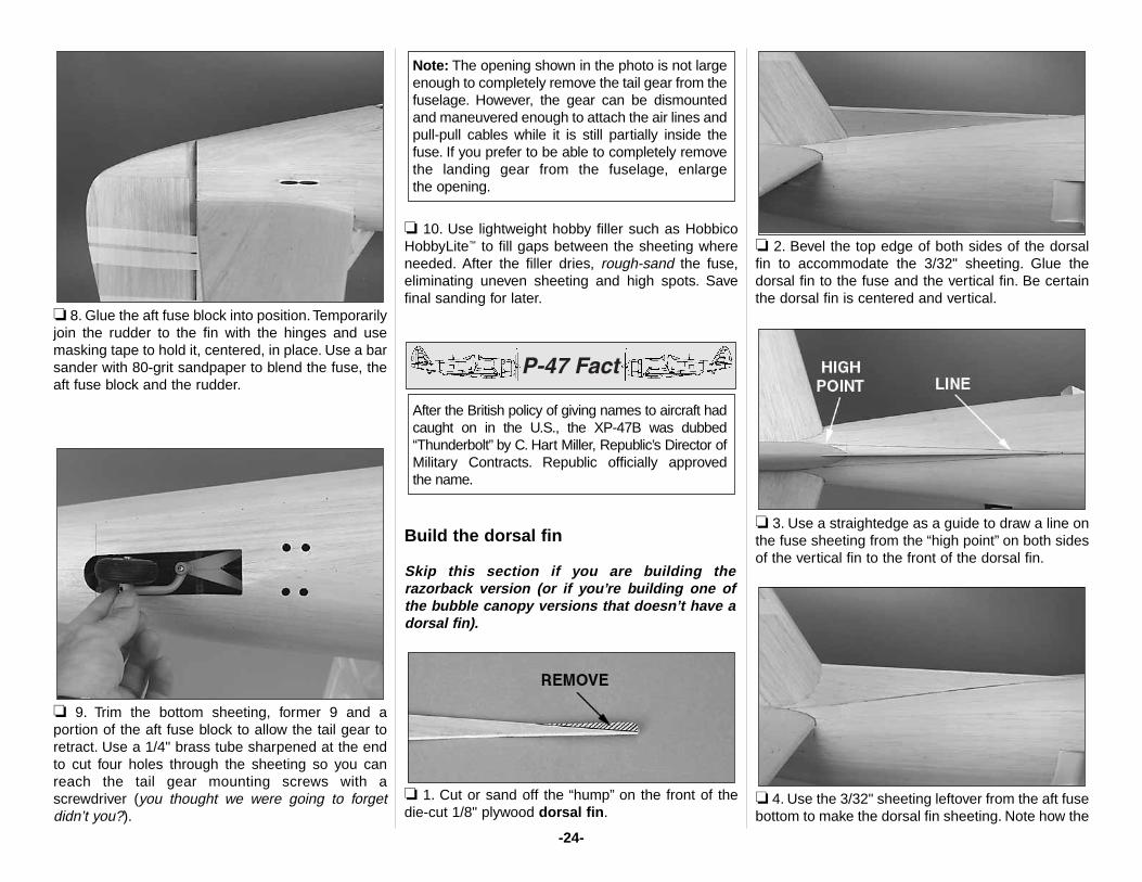
❏ 1. Cut or sand off the “hump” on the front of thedie-cut 1/8" plywood dorsal fin.
❏ 2. Bevel the top edge of both sides of the dorsalfin to accommodate the 3/32" sheeting. Glue thedorsal fin to the fuse and the vertical fin. Be certainthe dorsal fin is centered and vertical.
❏ 3. Use a straightedge as a guide to draw a line onthe fuse sheeting from the “high point” on both sidesof the vertical fin to the front of the dorsal fin.
❏ 4. Use the 3/32" sheeting leftover from the aft fusebottom to make the dorsal fin sheeting. Note how the
After the British policy of giving names to aircraft hadcaught on in the U.S., the XP-47B was dubbed“Thunderbolt” by C. Hart Miller, Republic’s Director ofMilitary Contracts. Republic officially approved the name.
Note: The opening shown in the photo is not largeenough to completely remove the tail gear from thefuselage. However, the gear can be dismountedand maneuvered enough to attach the air lines andpull-pull cables while it is still partially inside thefuse. If you prefer to be able to completely removethe landing gear from the fuselage, enlarge the opening.
-24-
sheeting blends the fin to the dorsal fin in a nearlyseamless transition. Glue the dorsal fin sheeting intoposition on both sides.
❏ 5. Use balsa filler to blend the dorsal fin to the finand to the fuselage. While you’re at it, make a smallfillet around the fin and stab, blending them to eachother and to the fuse. Sand the filler after it dries. Itshouldn’t take much filler to do the job (you can seehow the stab and fin are blended in photos later inthe manual).
Hint: Some modelers apply lots of filler, taking theapproach that “you can always sand off what youdon’t need.” However, since balsa filler is harder thanbalsa, you usually end up sanding the balsa aroundthe filler more than the filler itself. For this reason,you should take your time applying filler and only usewhat is needed.
Intercooler doors
Skip this section if you’ve decided not to build theintercooler doors in the open position.
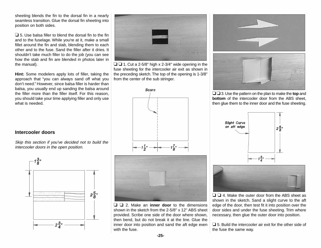
❏ ❏ 1. Cut a 2-5/8" high x 2-3/4" wide opening in thefuse sheeting for the intercooler air exit as shown inthe preceding sketch. The top of the opening is 1-3/8"from the center of the sub stringer.
❏ ❏ 2. Make an inner door to the dimensionsshown in the sketch from the 2-5/8" x 12" ABS sheetprovided. Scribe one side of the door where shown,then bend, but do not break it at the line. Glue theinner door into position and sand the aft edge evenwith the fuse.
❏ ❏ 3. Use the pattern on the plan to make the top andbottom of the intercooler door from the ABS sheet,then glue them to the inner door and the fuse sheeting.
❏ ❏ 4. Make the outer door from the ABS sheet asshown in the sketch. Sand a slight curve to the aftedge of the door, then test fit it into position over thedoor sides and under the fuse sheeting. Trim wherenecessary, then glue the outer door into position.
❏ 5. Build the intercooler air exit for the other side ofthe fuse the same way.
-25-
Mount the engine
The instructions show a U.S. Engines 41cc engineand a Great Planes Isolation Mount. Other enginesare suitable, provided they are within therecommended range, but may require a differentengine mount. Keep in mind that you can rotate theengine to conceal the muffler inside the cowl and toaim the engine exhaust where you want (the enginedoesn’t have to be mounted exactly inverted). Justmake sure the mount is centered on the referencelines on the firewall and that the orientation you havechosen will allow sufficient air flow over the headand cylinder.
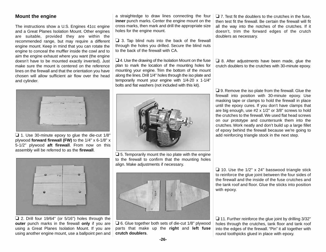
❏ 1. Use 30-minute epoxy to glue the die-cut 1/8"plywood forward firewall (FW) to the 1/4" x 6-1/8" x5-1/2" plywood aft firewall. From now on thisassembly will be referred to as the firewall.
❏ 2. Drill four 19/64" (or 5/16") holes through theouter punch marks in the firewall only if you areusing a Great Planes Isolation Mount. If you areusing another engine mount, use a ballpoint pen and
a straightedge to draw lines connecting the fourinner punch marks. Center the engine mount on thecross marks, then mark and drill the appropriate sizeholes for the engine mount.
❏ 3. Tap blind nuts into the back of the firewallthrough the holes you drilled. Secure the blind nutsto the back of the firewall with CA.
❏ 4. Use the drawing of the Isolation Mount on the fuseplan to mark the location of the mounting holes formounting your engine. Trim the bottom of the mountalong the lines. Drill 1/4" holes through the iso plate andtemporarily mount your engine with 1/4-20 x 1-1/4"bolts and flat washers (not included with this kit).
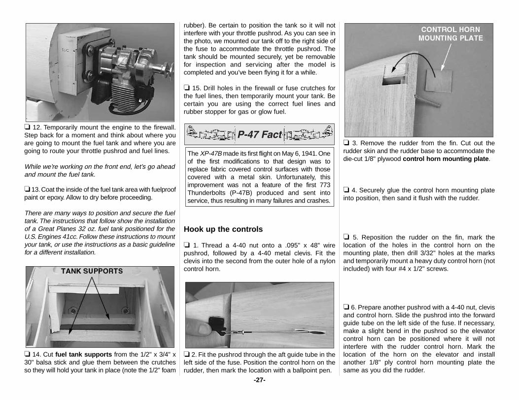
❏ 5. Temporarily mount the iso plate with the engineto the firewall to confirm that the mounting holesalign. Make adjustments if necessary.
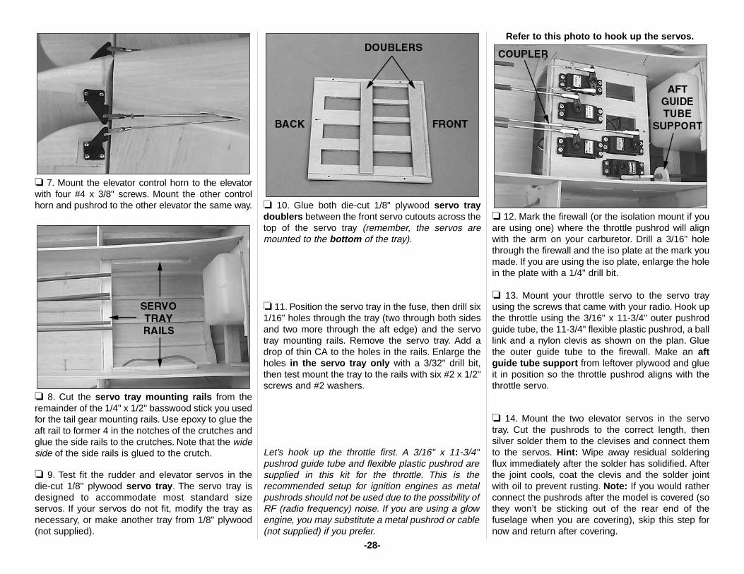
❏ 6. Glue together both sets of die-cut 1/8" plywoodparts that make up the right and left fuse crutch doublers.
❏ 7. Test fit the doublers to the crutches in the fuse,then test fit the firewall. Be certain the firewall will fitall the way into the notches of the crutches. If itdoesn’t, trim the forward edges of the crutchdoublers as necessary.
❏ 8. After adjustments have been made, glue thecrutch doublers to the crutches with 30-minute epoxy.
❏ 9. Remove the iso plate from the firewall. Glue thefirewall into position with 30-minute epoxy. Usemasking tape or clamps to hold the firewall in placeuntil the epoxy cures. If you don’t have clamps thatare big enough, use #2 x 1/2" or 3/8" screws to holdthe crutches to the firewall. We used flat head screwson our prototype and countersunk them into thecrutches. Work neatly and don’t build up a large filletof epoxy behind the firewall because we’re going toadd reinforcing triangle stock in the next step.
❏ 10. Use the 1/2" x 24" basswood triangle stickto reinforce the glue joint between the four sides ofthe firewall and the inside of the fuse crutches andthe tank roof and floor. Glue the sticks into positionwith epoxy.
❏ 11. Further reinforce the glue joint by drilling 3/32"holes through the crutches, tank floor and tank roofinto the edges of the firewall. “Pin” it all together withround toothpicks glued in place with epoxy.
-26-
❏ 12. Temporarily mount the engine to the firewall.Step back for a moment and think about where youare going to mount the fuel tank and where you aregoing to route your throttle pushrod and fuel lines.
While we’re working on the front end, let’s go aheadand mount the fuel tank.
❏ 13.Coat the inside of the fuel tank area with fuelproofpaint or epoxy. Allow to dry before proceeding.
There are many ways to position and secure the fueltank. The instructions that follow show the installationof a Great Planes 32 oz. fuel tank positioned for theU.S. Engines 41cc. Follow these instructions to mountyour tank, or use the instructions as a basic guidelinefor a different installation.
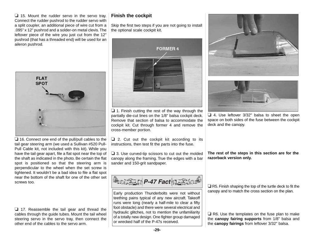
❏ 14. Cut fuel tank supports from the 1/2" x 3/4" x30" balsa stick and glue them between the crutchesso they will hold your tank in place (note the 1/2" foam
rubber). Be certain to position the tank so it will notinterfere with your throttle pushrod. As you can see inthe photo, we mounted our tank off to the right side ofthe fuse to accommodate the throttle pushrod. Thetank should be mounted securely, yet be removablefor inspection and servicing after the model iscompleted and you’ve been flying it for a while.
❏ 15. Drill holes in the firewall or fuse crutches forthe fuel lines, then temporarily mount your tank. Becertain you are using the correct fuel lines andrubber stopper for gas or glow fuel.
Hook up the controls
❏ 1. Thread a 4-40 nut onto a .095" x 48" wirepushrod, followed by a 4-40 metal clevis. Fit theclevis into the second from the outer hole of a nyloncontrol horn.
❏ 2. Fit the pushrod through the aft guide tube in theleft side of the fuse. Position the control horn on therudder, then mark the location with a ballpoint pen.
❏ 3. Remove the rudder from the fin. Cut out therudder skin and the rudder base to accommodate thedie-cut 1/8" plywood control horn mounting plate.
❏ 4. Securely glue the control horn mounting plateinto position, then sand it flush with the rudder.
❏ 5. Reposition the rudder on the fin, mark thelocation of the holes in the control horn on themounting plate, then drill 3/32" holes at the marksand temporarily mount a heavy duty control horn (notincluded) with four #4 x 1/2" screws.
❏ 6. Prepare another pushrod with a 4-40 nut, clevisand control horn. Slide the pushrod into the forwardguide tube on the left side of the fuse. If necessary,make a slight bend in the pushrod so the elevatorcontrol horn can be positioned where it will notinterfere with the rudder control horn. Mark thelocation of the horn on the elevator and installanother 1/8" ply control horn mounting plate thesame as you did the rudder.
The XP-47B made its first flight on May 6, 1941.Oneof the first modifications to that design was toreplace fabric covered control surfaces with thosecovered with a metal skin. Unfortunately, thisimprovement was not a feature of the first 773Thunderbolts (P-47B) produced and sent intoservice, thus resulting in many failures and crashes.
-27-
❏ 7. Mount the elevator control horn to the elevatorwith four #4 x 3/8" screws. Mount the other controlhorn and pushrod to the other elevator the same way.
❏ 8. Cut the servo tray mounting rails from theremainder of the 1/4" x 1/2" basswood stick you usedfor the tail gear mounting rails. Use epoxy to glue theaft rail to former 4 in the notches of the crutches andglue the side rails to the crutches. Note that the wideside of the side rails is glued to the crutch.
❏ 9. Test fit the rudder and elevator servos in the die-cut 1/8" plywood servo tray. The servo tray isdesigned to accommodate most standard sizeservos. If your servos do not fit, modify the tray asnecessary, or make another tray from 1/8" plywood(not supplied).
❏ 10. Glue both die-cut 1/8" plywood servo traydoublers between the front servo cutouts across thetop of the servo tray (remember, the servos aremounted to the bottom of the tray).
❏ 11. Position the servo tray in the fuse, then drill six1/16" holes through the tray (two through both sidesand two more through the aft edge) and the servotray mounting rails. Remove the servo tray. Add adrop of thin CA to the holes in the rails. Enlarge theholes in the servo tray only with a 3/32" drill bit,then test mount the tray to the rails with six #2 x 1/2"screws and #2 washers.
Let’s hook up the throttle first. A 3/16" x 11-3/4"pushrod guide tube and flexible plastic pushrod aresupplied in this kit for the throttle. This is therecommended setup for ignition engines as metalpushrods should not be used due to the possibility ofRF (radio frequency) noise. If you are using a glowengine, you may substitute a metal pushrod or cable(not supplied) if you prefer.
Refer to this photo to hook up the servos.
❏ 12. Mark the firewall (or the isolation mount if youare using one) where the throttle pushrod will alignwith the arm on your carburetor. Drill a 3/16" holethrough the firewall and the iso plate at the mark youmade. If you are using the iso plate, enlarge the holein the plate with a 1/4" drill bit.
❏ 13. Mount your throttle servo to the servo trayusing the screws that came with your radio. Hook upthe throttle using the 3/16" x 11-3/4" outer pushrodguide tube, the 11-3/4" flexible plastic pushrod, a balllink and a nylon clevis as shown on the plan. Gluethe outer guide tube to the firewall. Make an aftguide tube support from leftover plywood and glueit in position so the throttle pushrod aligns with thethrottle servo.
❏ 14. Mount the two elevator servos in the servotray. Cut the pushrods to the correct length, thensilver solder them to the clevises and connect themto the servos. Hint: Wipe away residual solderingflux immediately after the solder has solidified. Afterthe joint cools, coat the clevis and the solder jointwith oil to prevent rusting. Note: If you would ratherconnect the pushrods after the model is covered (sothey won’t be sticking out of the rear end of thefuselage when you are covering), skip this step fornow and return after covering.
-28-
❏ 15. Mount the rudder servo in the servo tray.Connect the rudder pushrod to the rudder servo witha split coupler, an additional piece of wire cut from a.095” x 12” pushrod and a solder-on metal clevis.Theleftover piece of the wire you just cut from the 12”pushrod (that has a threaded end) will be used for anaileron pushrod.
❏ 16. Connect one end of the pull/pull cables to thetail gear steering arm (we used a Sullivan #520 Pull-Pull Cable kit, not included with this kit). While youhave the tail gear apart, file a flat spot near the top ofthe shaft as indicated in the photo. Be certain the flatspot is positioned so that the steering arm isperpendicular to the wheel when the set screw istightened. It wouldn’t be a bad idea to file a flat spotnear the bottom of the shaft for one of the other setscrews too.
❏ 17. Reassemble the tail gear and thread thecables through the guide tubes. Mount the tail wheelsteering servo in the servo tray, then connect theother end of the cables to the servo arm.
Finish the cockpit
Skip the first two steps if you are not going to installthe optional scale cockpit kit.
❏ 1. Finish cutting the rest of the way through thepartially die-cut lines on the 1/8" balsa cockpit deck.Remove that section of balsa to accommodate thecockpit kit. Cut through former 4 and remove thecross-member portion.
❏ 2. Cut out the cockpit kit according to itsinstructions, then test fit the parts into the fuse.
❏ 3. Use curved-tip scissors to cut out the moldedcanopy along the framing. True the edges with a barsander and 150-grit sandpaper.
❏ 4. Use leftover 3/32" balsa to sheet the openspace on both sides of the fuse between the cockpitdeck and the canopy.
The rest of the steps in this section are for therazorback version only.
❏ R5. Finish shaping the top of the turtle deck to fit thecanopy and to match the cross section on the plan.
❏ R6. Use the templates on the fuse plan to makethe canopy fairing supports from 1/8" balsa andthe canopy fairings from leftover 3/32" balsa.
Early production Thunderbolts were not withoutteething pains typical of any new aircraft. Takeoffruns were long (nearly a half-mile to clear a fiftyfoot obstacle) and there were several electrical andhydraulic glitches, not to mention the unfamiliarityof a totally new design. One fighter group damagedor wrecked half of the P-47s received.
-29-
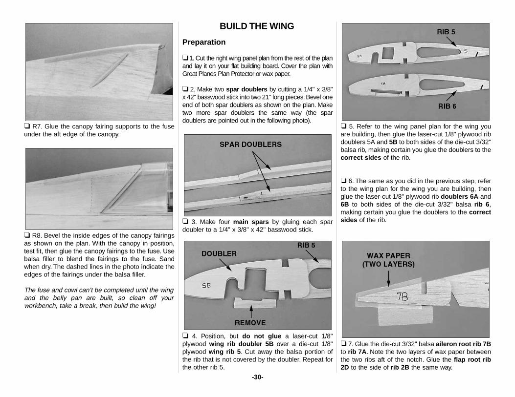
❏ R7. Glue the canopy fairing supports to the fuseunder the aft edge of the canopy.
❏ R8. Bevel the inside edges of the canopy fairingsas shown on the plan. With the canopy in position,test fit, then glue the canopy fairings to the fuse. Usebalsa filler to blend the fairings to the fuse. Sandwhen dry. The dashed lines in the photo indicate theedges of the fairings under the balsa filler.
The fuse and cowl can’t be completed until the wingand the belly pan are built, so clean off yourworkbench, take a break, then build the wing!
BUILD THE WING
Preparation
❏ 1. Cut the right wing panel plan from the rest of the planand lay it on your flat building board. Cover the plan withGreat Planes Plan Protector or wax paper.
❏ 2. Make two spar doublers by cutting a 1/4" x 3/8"x 42" basswood stick into two 21" long pieces.Bevel oneend of both spar doublers as shown on the plan. Maketwo more spar doublers the same way (the spardoublers are pointed out in the following photo).
❏ 3. Make four main spars by gluing each spardoubler to a 1/4" x 3/8" x 42" basswood stick.
❏ 4. Position, but do not glue a laser-cut 1/8"plywood wing rib doubler 5B over a die-cut 1/8"plywood wing rib 5. Cut away the balsa portion ofthe rib that is not covered by the doubler. Repeat forthe other rib 5.
❏ 5. Refer to the wing panel plan for the wing youare building, then glue the laser-cut 1/8" plywood ribdoublers 5A and 5B to both sides of the die-cut 3/32"balsa rib, making certain you glue the doublers to thecorrect sides of the rib.
❏ 6. The same as you did in the previous step, referto the wing plan for the wing you are building, thenglue the laser-cut 1/8" plywood rib doublers 6A and6B to both sides of the die-cut 3/32" balsa rib 6,making certain you glue the doublers to the correctsides of the rib.
❏ 7. Glue the die-cut 3/32" balsa aileron root rib 7Bto rib 7A. Note the two layers of wax paper betweenthe two ribs aft of the notch. Glue the flap root rib2D to the side of rib 2B the same way.
-30-
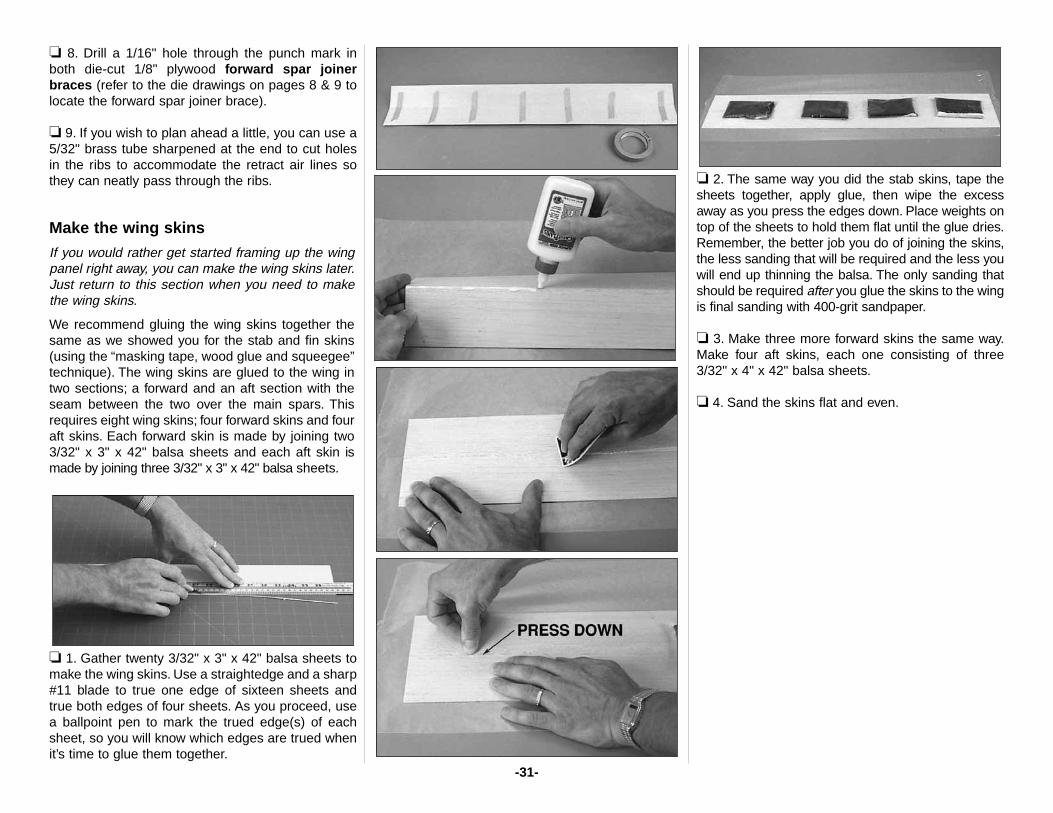
❏ 8. Drill a 1/16" hole through the punch mark inboth die-cut 1/8" plywood forward spar joinerbraces (refer to the die drawings on pages 8 & 9 tolocate the forward spar joiner brace).
❏ 9. If you wish to plan ahead a little, you can use a5/32" brass tube sharpened at the end to cut holesin the ribs to accommodate the retract air lines sothey can neatly pass through the ribs.
Make the wing skins
If you would rather get started framing up the wingpanel right away, you can make the wing skins later.Just return to this section when you need to makethe wing skins.
We recommend gluing the wing skins together thesame as we showed you for the stab and fin skins(using the “masking tape, wood glue and squeegee”technique). The wing skins are glued to the wing intwo sections; a forward and an aft section with theseam between the two over the main spars. Thisrequires eight wing skins; four forward skins and fouraft skins. Each forward skin is made by joining two3/32" x 3" x 42" balsa sheets and each aft skin ismade by joining three 3/32" x 3" x 42" balsa sheets.
❏ 1. Gather twenty 3/32" x 3" x 42" balsa sheets tomake the wing skins. Use a straightedge and a sharp#11 blade to true one edge of sixteen sheets andtrue both edges of four sheets. As you proceed, usea ballpoint pen to mark the trued edge(s) of eachsheet, so you will know which edges are trued whenit’s time to glue them together.
❏ 2. The same way you did the stab skins, tape thesheets together, apply glue, then wipe the excessaway as you press the edges down. Place weights ontop of the sheets to hold them flat until the glue dries.Remember, the better job you do of joining the skins,the less sanding that will be required and the less youwill end up thinning the balsa. The only sanding thatshould be required after you glue the skins to the wingis final sanding with 400-grit sandpaper.
❏ 3. Make three more forward skins the same way.Make four aft skins, each one consisting of three3/32" x 4" x 42" balsa sheets.
❏ 4. Sand the skins flat and even.
-31-
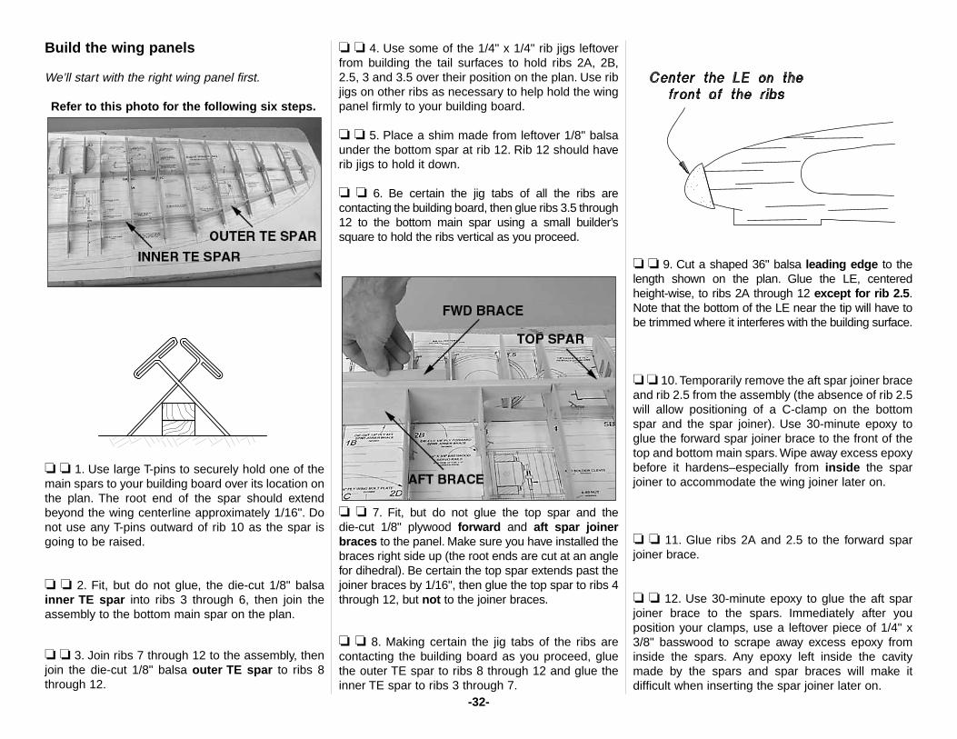
Build the wing panels
We’ll start with the right wing panel first.
Refer to this photo for the following six steps.
❏ ❏ 1. Use large T-pins to securely hold one of themain spars to your building board over its location onthe plan. The root end of the spar should extendbeyond the wing centerline approximately 1/16". Donot use any T-pins outward of rib 10 as the spar isgoing to be raised.
❏ ❏ 2. Fit, but do not glue, the die-cut 1/8" balsainner TE spar into ribs 3 through 6, then join theassembly to the bottom main spar on the plan.
❏ ❏ 3. Join ribs 7 through 12 to the assembly, thenjoin the die-cut 1/8" balsa outer TE spar to ribs 8through 12.
❏ ❏ 4. Use some of the 1/4" x 1/4" rib jigs leftoverfrom building the tail surfaces to hold ribs 2A, 2B,2.5, 3 and 3.5 over their position on the plan. Use ribjigs on other ribs as necessary to help hold the wingpanel firmly to your building board.
❏ ❏ 5. Place a shim made from leftover 1/8" balsaunder the bottom spar at rib 12. Rib 12 should haverib jigs to hold it down.
❏ ❏ 6. Be certain the jig tabs of all the ribs arecontacting the building board, then glue ribs 3.5 through12 to the bottom main spar using a small builder’ssquare to hold the ribs vertical as you proceed.
❏ ❏ 7. Fit, but do not glue the top spar and the die-cut 1/8" plywood forward and aft spar joinerbraces to the panel. Make sure you have installed thebraces right side up (the root ends are cut at an anglefor dihedral). Be certain the top spar extends past thejoiner braces by 1/16", then glue the top spar to ribs 4through 12, but not to the joiner braces.
❏ ❏ 8. Making certain the jig tabs of the ribs arecontacting the building board as you proceed, gluethe outer TE spar to ribs 8 through 12 and glue theinner TE spar to ribs 3 through 7.
❏ ❏ 9. Cut a shaped 36" balsa leading edge to thelength shown on the plan. Glue the LE, centered height-wise, to ribs 2A through 12 except for rib 2.5.Note that the bottom of the LE near the tip will have tobe trimmed where it interferes with the building surface.
❏ ❏ 10.Temporarily remove the aft spar joiner braceand rib 2.5 from the assembly (the absence of rib 2.5will allow positioning of a C-clamp on the bottomspar and the spar joiner). Use 30-minute epoxy toglue the forward spar joiner brace to the front of thetop and bottom main spars. Wipe away excess epoxybefore it hardens–especially from inside the sparjoiner to accommodate the wing joiner later on.
❏ ❏ 11. Glue ribs 2A and 2.5 to the forward sparjoiner brace.
❏ ❏ 12. Use 30-minute epoxy to glue the aft sparjoiner brace to the spars. Immediately after youposition your clamps, use a leftover piece of 1/4" x3/8" basswood to scrape away excess epoxy frominside the spars. Any epoxy left inside the cavitymade by the spars and spar braces will make itdifficult when inserting the spar joiner later on.
-32-
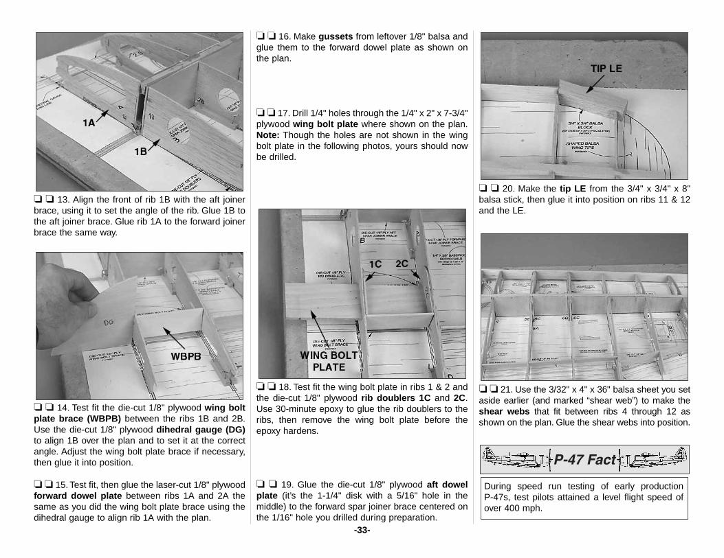
❏ ❏ 13. Align the front of rib 1B with the aft joinerbrace, using it to set the angle of the rib. Glue 1B tothe aft joiner brace. Glue rib 1A to the forward joinerbrace the same way.
❏ ❏ 14. Test fit the die-cut 1/8" plywood wing boltplate brace (WBPB) between the ribs 1B and 2B.Use the die-cut 1/8" plywood dihedral gauge (DG)to align 1B over the plan and to set it at the correctangle. Adjust the wing bolt plate brace if necessary,then glue it into position.
❏ ❏ 15. Test fit, then glue the laser-cut 1/8" plywoodforward dowel plate between ribs 1A and 2A thesame as you did the wing bolt plate brace using thedihedral gauge to align rib 1A with the plan.
❏ ❏ 16. Make gussets from leftover 1/8" balsa andglue them to the forward dowel plate as shown onthe plan.
❏ ❏ 17. Drill 1/4" holes through the 1/4" x 2" x 7-3/4"plywood wing bolt plate where shown on the plan.Note: Though the holes are not shown in the wingbolt plate in the following photos, yours should nowbe drilled.
❏ ❏ 18. Test fit the wing bolt plate in ribs 1 & 2 andthe die-cut 1/8" plywood rib doublers 1C and 2C.Use 30-minute epoxy to glue the rib doublers to theribs, then remove the wing bolt plate before theepoxy hardens.
❏ ❏ 19. Glue the die-cut 1/8" plywood aft dowelplate (it’s the 1-1/4" disk with a 5/16" hole in themiddle) to the forward spar joiner brace centered onthe 1/16" hole you drilled during preparation.
❏ ❏ 20. Make the tip LE from the 3/4" x 3/4" x 8"balsa stick, then glue it into position on ribs 11 & 12and the LE.
❏ ❏ 21. Use the 3/32" x 4" x 36" balsa sheet you setaside earlier (and marked “shear web”) to make theshear webs that fit between ribs 4 through 12 asshown on the plan. Glue the shear webs into position.
During speed run testing of early production P-47s, test pilots attained a level flight speed ofover 400 mph.
-33-
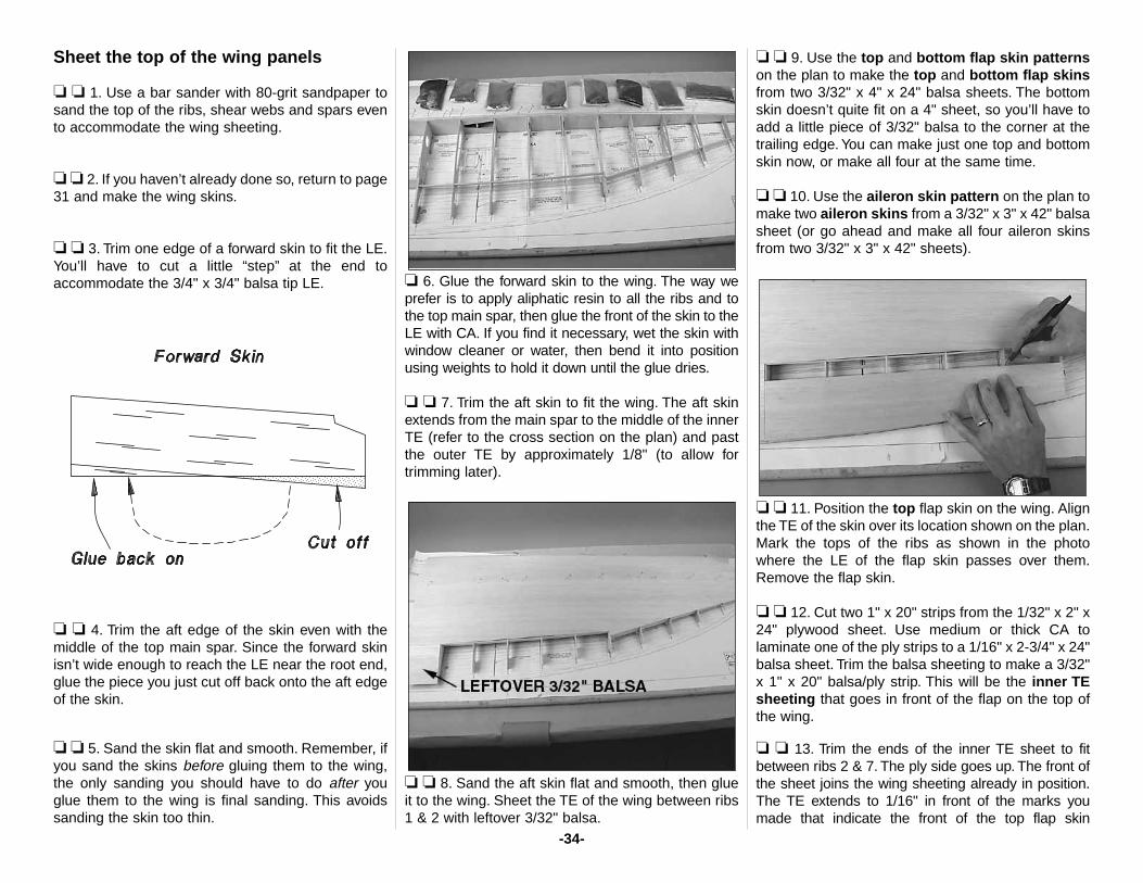
Sheet the top of the wing panels
❏ ❏ 1. Use a bar sander with 80-grit sandpaper tosand the top of the ribs, shear webs and spars evento accommodate the wing sheeting.
❏ ❏ 2. If you haven’t already done so, return to page31 and make the wing skins.
❏ ❏ 3. Trim one edge of a forward skin to fit the LE.You’ll have to cut a little “step” at the end toaccommodate the 3/4" x 3/4" balsa tip LE.
❏ ❏ 4. Trim the aft edge of the skin even with themiddle of the top main spar. Since the forward skinisn’t wide enough to reach the LE near the root end,glue the piece you just cut off back onto the aft edgeof the skin.
❏ ❏ 5. Sand the skin flat and smooth. Remember, ifyou sand the skins before gluing them to the wing,the only sanding you should have to do after youglue them to the wing is final sanding. This avoidssanding the skin too thin.
❏ 6. Glue the forward skin to the wing. The way weprefer is to apply aliphatic resin to all the ribs and tothe top main spar, then glue the front of the skin to theLE with CA. If you find it necessary, wet the skin withwindow cleaner or water, then bend it into positionusing weights to hold it down until the glue dries.
❏ ❏ 7. Trim the aft skin to fit the wing. The aft skinextends from the main spar to the middle of the innerTE (refer to the cross section on the plan) and pastthe outer TE by approximately 1/8" (to allow fortrimming later).
❏ ❏ 8. Sand the aft skin flat and smooth, then glueit to the wing. Sheet the TE of the wing between ribs1 & 2 with leftover 3/32" balsa.
❏ ❏ 9. Use the top and bottom flap skin patternson the plan to make the top and bottom flap skinsfrom two 3/32" x 4" x 24" balsa sheets. The bottomskin doesn’t quite fit on a 4" sheet, so you’ll have toadd a little piece of 3/32" balsa to the corner at thetrailing edge. You can make just one top and bottomskin now, or make all four at the same time.
❏ ❏ 10. Use the aileron skin pattern on the plan tomake two aileron skins from a 3/32" x 3" x 42" balsasheet (or go ahead and make all four aileron skinsfrom two 3/32" x 3" x 42" sheets).
❏ ❏ 11. Position the top flap skin on the wing. Alignthe TE of the skin over its location shown on the plan.Mark the tops of the ribs as shown in the photowhere the LE of the flap skin passes over them.Remove the flap skin.
❏ ❏ 12. Cut two 1" x 20" strips from the 1/32" x 2" x24" plywood sheet. Use medium or thick CA tolaminate one of the ply strips to a 1/16" x 2-3/4" x 24"balsa sheet. Trim the balsa sheeting to make a 3/32"x 1" x 20" balsa/ply strip. This will be the inner TEsheeting that goes in front of the flap on the top ofthe wing.
❏ ❏ 13. Trim the ends of the inner TE sheet to fitbetween ribs 2 & 7. The ply side goes up. The front ofthe sheet joins the wing sheeting already in position.The TE extends to 1/16" in front of the marks youmade that indicate the front of the top flap skin
-34-
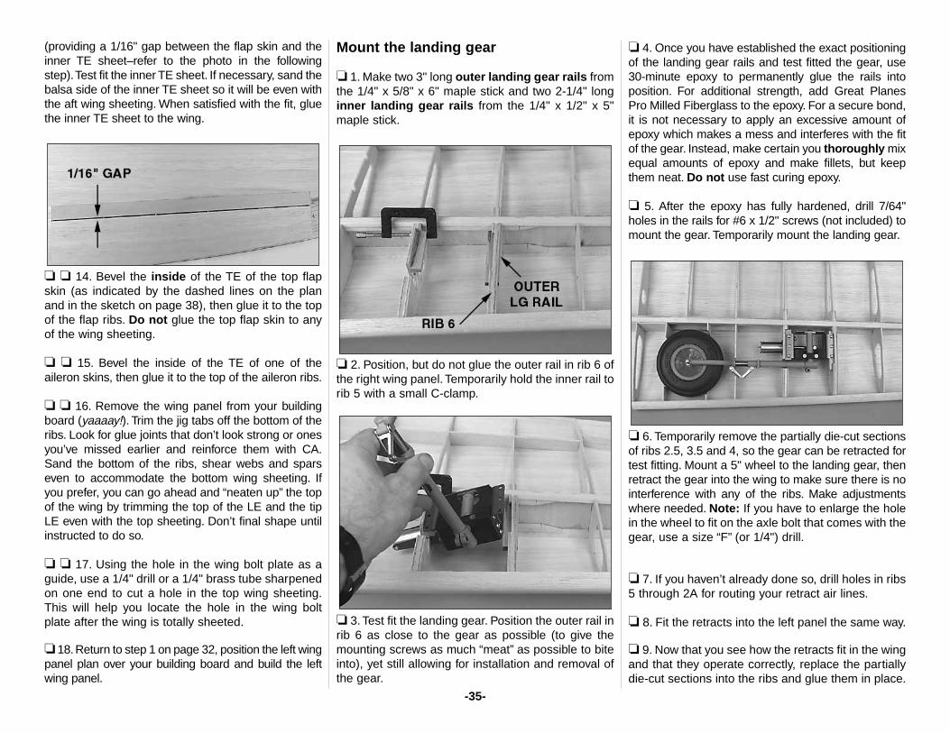
(providing a 1/16" gap between the flap skin and theinner TE sheet–refer to the photo in the followingstep).Test fit the inner TE sheet. If necessary, sand thebalsa side of the inner TE sheet so it will be even withthe aft wing sheeting. When satisfied with the fit, gluethe inner TE sheet to the wing.
❏ ❏ 14. Bevel the inside of the TE of the top flapskin (as indicated by the dashed lines on the planand in the sketch on page 38), then glue it to the topof the flap ribs. Do not glue the top flap skin to anyof the wing sheeting.
❏ ❏ 15. Bevel the inside of the TE of one of theaileron skins, then glue it to the top of the aileron ribs.
❏ ❏ 16. Remove the wing panel from your buildingboard (yaaaay!). Trim the jig tabs off the bottom of theribs. Look for glue joints that don’t look strong or onesyou’ve missed earlier and reinforce them with CA.Sand the bottom of the ribs, shear webs and sparseven to accommodate the bottom wing sheeting. Ifyou prefer, you can go ahead and “neaten up” the topof the wing by trimming the top of the LE and the tipLE even with the top sheeting. Don’t final shape untilinstructed to do so.
❏ ❏ 17. Using the hole in the wing bolt plate as aguide, use a 1/4" drill or a 1/4" brass tube sharpenedon one end to cut a hole in the top wing sheeting.This will help you locate the hole in the wing boltplate after the wing is totally sheeted.
❏ 18.Return to step 1 on page 32, position the left wingpanel plan over your building board and build the leftwing panel.
Mount the landing gear
❏ 1. Make two 3" long outer landing gear rails fromthe 1/4" x 5/8" x 6" maple stick and two 2-1/4" longinner landing gear rails from the 1/4" x 1/2" x 5"maple stick.
❏ 2. Position, but do not glue the outer rail in rib 6 ofthe right wing panel. Temporarily hold the inner rail torib 5 with a small C-clamp.
❏ 3. Test fit the landing gear. Position the outer rail inrib 6 as close to the gear as possible (to give themounting screws as much “meat” as possible to biteinto), yet still allowing for installation and removal ofthe gear.
❏ 4. Once you have established the exact positioningof the landing gear rails and test fitted the gear, use30-minute epoxy to permanently glue the rails intoposition. For additional strength, add Great PlanesPro Milled Fiberglass to the epoxy. For a secure bond,it is not necessary to apply an excessive amount ofepoxy which makes a mess and interferes with the fitof the gear. Instead, make certain you thoroughly mixequal amounts of epoxy and make fillets, but keepthem neat. Do not use fast curing epoxy.
❏ 5. After the epoxy has fully hardened, drill 7/64"holes in the rails for #6 x 1/2" screws (not included) tomount the gear. Temporarily mount the landing gear.
❏ 6. Temporarily remove the partially die-cut sectionsof ribs 2.5, 3.5 and 4, so the gear can be retracted fortest fitting. Mount a 5" wheel to the landing gear, thenretract the gear into the wing to make sure there is nointerference with any of the ribs. Make adjustmentswhere needed. Note: If you have to enlarge the holein the wheel to fit on the axle bolt that comes with thegear, use a size “F” (or 1/4") drill.
❏ 7. If you haven’t already done so, drill holes in ribs5 through 2A for routing your retract air lines.
❏ 8. Fit the retracts into the left panel the same way.
❏ 9. Now that you see how the retracts fit in the wingand that they operate correctly, replace the partiallydie-cut sections into the ribs and glue them in place.
-35-
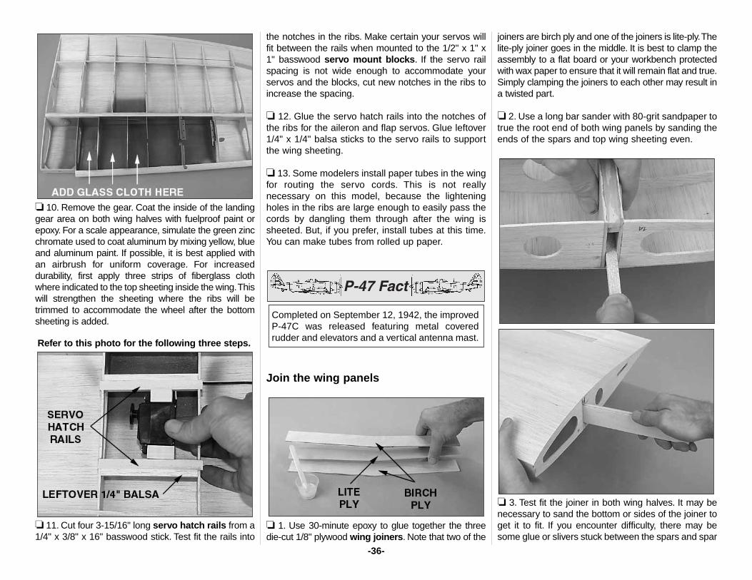
❏ 10. Remove the gear. Coat the inside of the landinggear area on both wing halves with fuelproof paint orepoxy. For a scale appearance, simulate the green zincchromate used to coat aluminum by mixing yellow, blueand aluminum paint. If possible, it is best applied withan airbrush for uniform coverage. For increaseddurability, first apply three strips of fiberglass clothwhere indicated to the top sheeting inside the wing.Thiswill strengthen the sheeting where the ribs will betrimmed to accommodate the wheel after the bottomsheeting is added.
Refer to this photo for the following three steps.
❏ 11. Cut four 3-15/16" long servo hatch rails from a1/4" x 3/8" x 16" basswood stick. Test fit the rails into
the notches in the ribs. Make certain your servos willfit between the rails when mounted to the 1/2" x 1" x1" basswood servo mount blocks. If the servo railspacing is not wide enough to accommodate yourservos and the blocks, cut new notches in the ribs toincrease the spacing.
❏ 12. Glue the servo hatch rails into the notches ofthe ribs for the aileron and flap servos. Glue leftover1/4" x 1/4" balsa sticks to the servo rails to supportthe wing sheeting.
❏ 13. Some modelers install paper tubes in the wingfor routing the servo cords. This is not reallynecessary on this model, because the lighteningholes in the ribs are large enough to easily pass thecords by dangling them through after the wing issheeted. But, if you prefer, install tubes at this time.You can make tubes from rolled up paper.
Join the wing panels
❏ 1. Use 30-minute epoxy to glue together the threedie-cut 1/8" plywood wing joiners. Note that two of the
joiners are birch ply and one of the joiners is lite-ply.Thelite-ply joiner goes in the middle. It is best to clamp theassembly to a flat board or your workbench protectedwith wax paper to ensure that it will remain flat and true.Simply clamping the joiners to each other may result ina twisted part.
❏ 2. Use a long bar sander with 80-grit sandpaper totrue the root end of both wing panels by sanding theends of the spars and top wing sheeting even.
❏ 3. Test fit the joiner in both wing halves. It may benecessary to sand the bottom or sides of the joiner toget it to fit. If you encounter difficulty, there may besome glue or slivers stuck between the spars and spar
Completed on September 12, 1942, the improvedP-47C was released featuring metal coveredrudder and elevators and a vertical antenna mast.
-36-
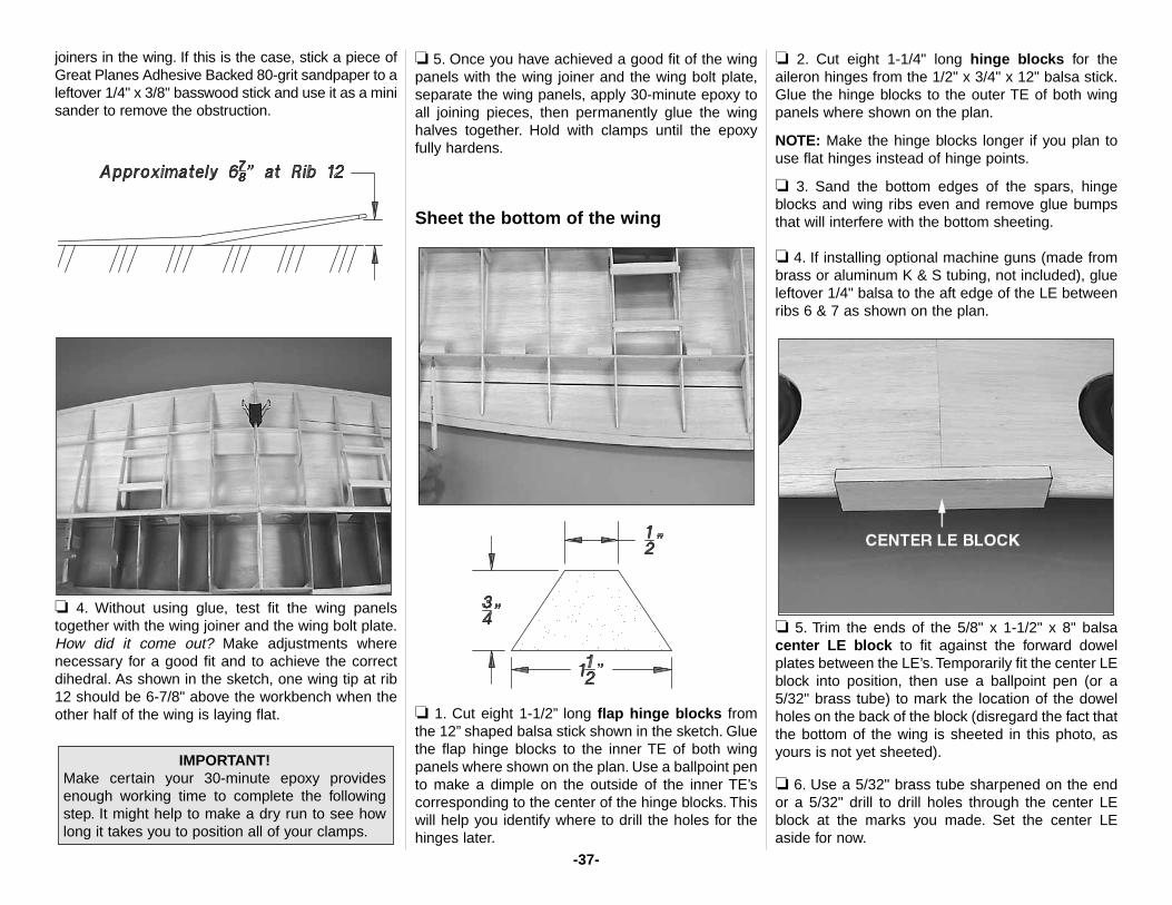
joiners in the wing. If this is the case, stick a piece ofGreat Planes Adhesive Backed 80-grit sandpaper to aleftover 1/4" x 3/8" basswood stick and use it as a minisander to remove the obstruction.
❏ 4. Without using glue, test fit the wing panelstogether with the wing joiner and the wing bolt plate.How did it come out? Make adjustments wherenecessary for a good fit and to achieve the correctdihedral. As shown in the sketch, one wing tip at rib12 should be 6-7/8" above the workbench when theother half of the wing is laying flat.
❏ 5. Once you have achieved a good fit of the wingpanels with the wing joiner and the wing bolt plate,separate the wing panels, apply 30-minute epoxy toall joining pieces, then permanently glue the winghalves together. Hold with clamps until the epoxyfully hardens.
Sheet the bottom of the wing
❏ 1. Cut eight 1-1/2” long flap hinge blocks fromthe 12” shaped balsa stick shown in the sketch. Gluethe flap hinge blocks to the inner TE of both wingpanels where shown on the plan. Use a ballpoint pento make a dimple on the outside of the inner TE’scorresponding to the center of the hinge blocks. Thiswill help you identify where to drill the holes for thehinges later.
❏ 2. Cut eight 1-1/4" long hinge blocks for theaileron hinges from the 1/2" x 3/4" x 12" balsa stick.Glue the hinge blocks to the outer TE of both wingpanels where shown on the plan.
NOTE: Make the hinge blocks longer if you plan touse flat hinges instead of hinge points.
❏ 3. Sand the bottom edges of the spars, hingeblocks and wing ribs even and remove glue bumpsthat will interfere with the bottom sheeting.
❏ 4. If installing optional machine guns (made frombrass or aluminum K & S tubing, not included), glueleftover 1/4" balsa to the aft edge of the LE betweenribs 6 & 7 as shown on the plan.
❏ 5. Trim the ends of the 5/8" x 1-1/2" x 8" balsacenter LE block to fit against the forward dowelplates between the LE’s.Temporarily fit the center LEblock into position, then use a ballpoint pen (or a5/32" brass tube) to mark the location of the dowelholes on the back of the block (disregard the fact thatthe bottom of the wing is sheeted in this photo, asyours is not yet sheeted).
❏ 6. Use a 5/32" brass tube sharpened on the endor a 5/32" drill to drill holes through the center LEblock at the marks you made. Set the center LEaside for now.
IMPORTANT!Make certain your 30-minute epoxy providesenough working time to complete the followingstep. It might help to make a dry run to see howlong it takes you to position all of your clamps.
-37-
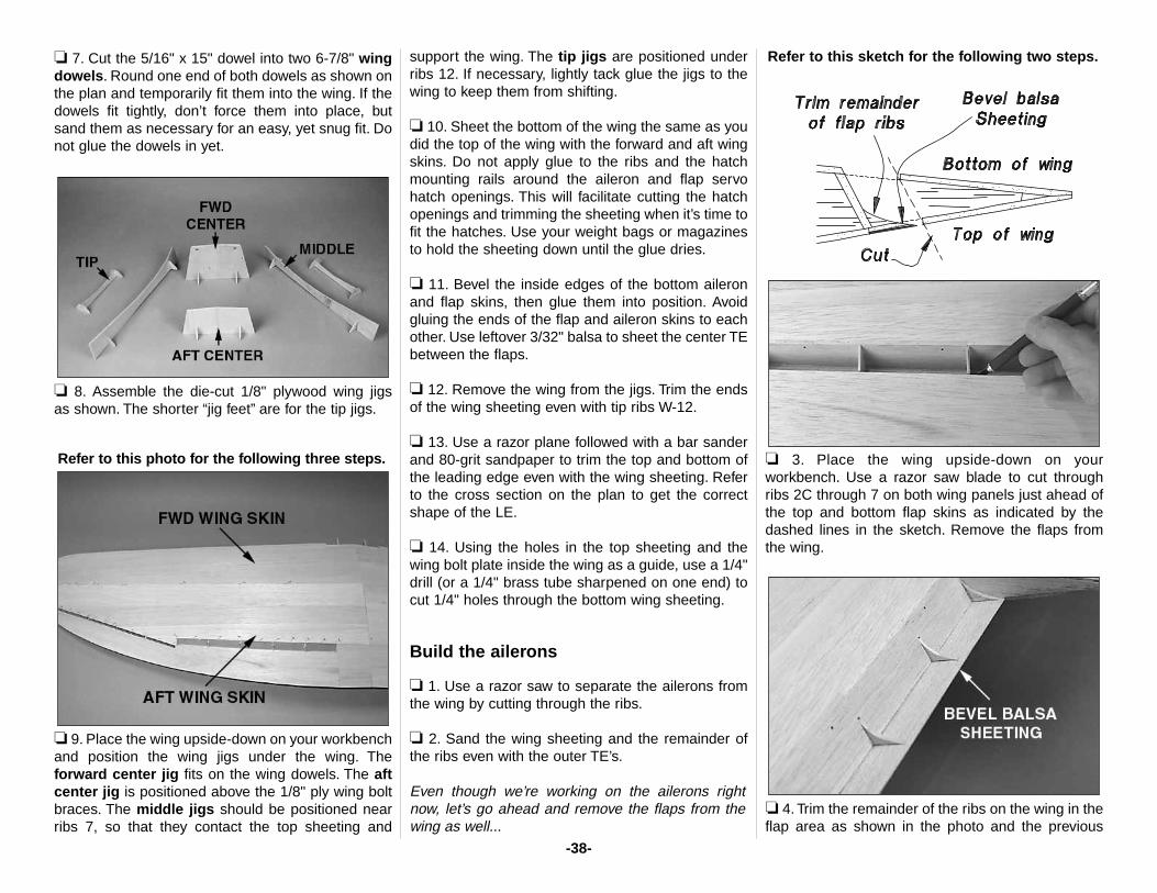
❏ 7. Cut the 5/16" x 15" dowel into two 6-7/8" wingdowels. Round one end of both dowels as shown onthe plan and temporarily fit them into the wing. If thedowels fit tightly, don’t force them into place, butsand them as necessary for an easy, yet snug fit. Donot glue the dowels in yet.
❏ 8. Assemble the die-cut 1/8" plywood wing jigs as shown. The shorter “jig feet” are for the tip jigs.
Refer to this photo for the following three steps.
❏ 9. Place the wing upside-down on your workbenchand position the wing jigs under the wing. Theforward center jig fits on the wing dowels. The aftcenter jig is positioned above the 1/8" ply wing boltbraces. The middle jigs should be positioned nearribs 7, so that they contact the top sheeting and
support the wing. The tip jigs are positioned underribs 12. If necessary, lightly tack glue the jigs to thewing to keep them from shifting.
❏ 10. Sheet the bottom of the wing the same as youdid the top of the wing with the forward and aft wingskins. Do not apply glue to the ribs and the hatchmounting rails around the aileron and flap servohatch openings. This will facilitate cutting the hatchopenings and trimming the sheeting when it’s time tofit the hatches. Use your weight bags or magazinesto hold the sheeting down until the glue dries.
❏ 11. Bevel the inside edges of the bottom aileronand flap skins, then glue them into position. Avoidgluing the ends of the flap and aileron skins to eachother. Use leftover 3/32" balsa to sheet the center TEbetween the flaps.
❏ 12. Remove the wing from the jigs. Trim the endsof the wing sheeting even with tip ribs W-12.
❏ 13. Use a razor plane followed with a bar sanderand 80-grit sandpaper to trim the top and bottom ofthe leading edge even with the wing sheeting. Referto the cross section on the plan to get the correctshape of the LE.
❏ 14. Using the holes in the top sheeting and thewing bolt plate inside the wing as a guide, use a 1/4"drill (or a 1/4" brass tube sharpened on one end) tocut 1/4" holes through the bottom wing sheeting.
Build the ailerons
❏ 1. Use a razor saw to separate the ailerons fromthe wing by cutting through the ribs.
❏ 2. Sand the wing sheeting and the remainder ofthe ribs even with the outer TE’s.
Even though we’re working on the ailerons rightnow, let’s go ahead and remove the flaps from thewing as well...
Refer to this sketch for the following two steps.
❏ 3. Place the wing upside-down on yourworkbench. Use a razor saw blade to cut throughribs 2C through 7 on both wing panels just ahead ofthe top and bottom flap skins as indicated by thedashed lines in the sketch. Remove the flaps fromthe wing.
❏ 4. Trim the remainder of the ribs on the wing in theflap area as shown in the photo and the previous
-38-
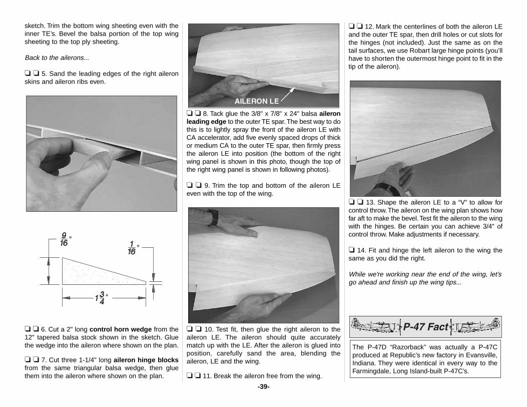
sketch. Trim the bottom wing sheeting even with theinner TE’s. Bevel the balsa portion of the top wingsheeting to the top ply sheeting.
Back to the ailerons...
❏ ❏ 5. Sand the leading edges of the right aileronskins and aileron ribs even.
❏ ❏ 6. Cut a 2" long control horn wedge from the12" tapered balsa stock shown in the sketch. Gluethe wedge into the aileron where shown on the plan.
❏ ❏ 7. Cut three 1-1/4" long aileron hinge blocksfrom the same triangular balsa wedge, then gluethem into the aileron where shown on the plan.
❏ ❏ 8. Tack glue the 3/8" x 7/8" x 24" balsa aileronleading edge to the outer TE spar.The best way to dothis is to lightly spray the front of the aileron LE withCA accelerator, add five evenly spaced drops of thickor medium CA to the outer TE spar, then firmly pressthe aileron LE into position (the bottom of the rightwing panel is shown in this photo, though the top ofthe right wing panel is shown in following photos).
❏ ❏ 9. Trim the top and bottom of the aileron LEeven with the top of the wing.
❏ ❏ 10. Test fit, then glue the right aileron to theaileron LE. The aileron should quite accuratelymatch up with the LE. After the aileron is glued intoposition, carefully sand the area, blending theaileron, LE and the wing.
❏ ❏ 11. Break the aileron free from the wing.
❏ ❏ 12. Mark the centerlines of both the aileron LEand the outer TE spar, then drill holes or cut slots forthe hinges (not included). Just the same as on thetail surfaces, we use Robart large hinge points (you’llhave to shorten the outermost hinge point to fit in thetip of the aileron).
❏ ❏ 13. Shape the aileron LE to a “V” to allow forcontrol throw.The aileron on the wing plan shows howfar aft to make the bevel.Test fit the aileron to the wingwith the hinges. Be certain you can achieve 3/4" ofcontrol throw. Make adjustments if necessary.
❏ 14. Fit and hinge the left aileron to the wing thesame as you did the right.
While we’re working near the end of the wing, let’sgo ahead and finish up the wing tips...
The P-47D “Razorback” was actually a P-47Cproduced at Republic’s new factory in Evansville,Indiana. They were identical in every way to theFarmingdale, Long Island-built P-47C’s.
-39-
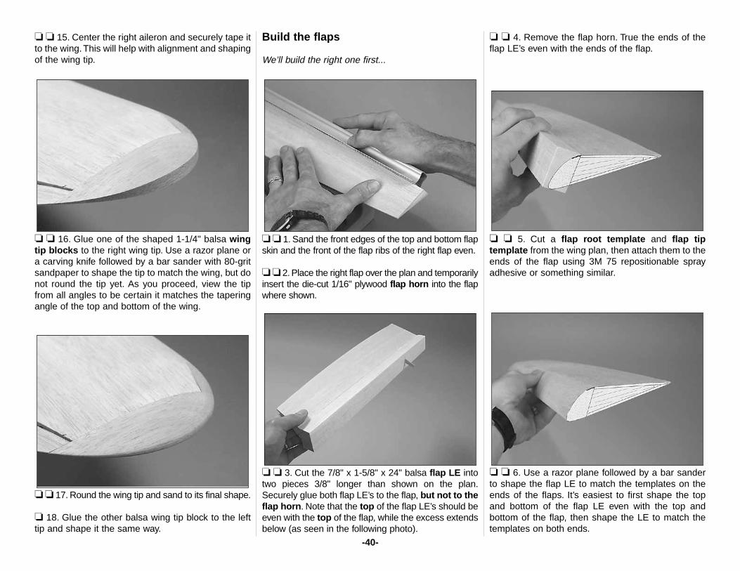
❏ ❏ 15. Center the right aileron and securely tape itto the wing. This will help with alignment and shapingof the wing tip.
❏ ❏ 16. Glue one of the shaped 1-1/4" balsa wingtip blocks to the right wing tip. Use a razor plane ora carving knife followed by a bar sander with 80-gritsandpaper to shape the tip to match the wing, but donot round the tip yet. As you proceed, view the tipfrom all angles to be certain it matches the taperingangle of the top and bottom of the wing.
❏ ❏ 17. Round the wing tip and sand to its final shape.
❏ 18. Glue the other balsa wing tip block to the lefttip and shape it the same way.
Build the flaps
We’ll build the right one first...
❏ ❏ 1. Sand the front edges of the top and bottom flapskin and the front of the flap ribs of the right flap even.
❏ ❏ 2. Place the right flap over the plan and temporarilyinsert the die-cut 1/16" plywood flap horn into the flapwhere shown.
❏ ❏ 3. Cut the 7/8" x 1-5/8" x 24" balsa flap LE intotwo pieces 3/8" longer than shown on the plan.Securely glue both flap LE’s to the flap, but not to theflap horn. Note that the top of the flap LE’s should beeven with the top of the flap, while the excess extendsbelow (as seen in the following photo).
❏ ❏ 4. Remove the flap horn. True the ends of theflap LE’s even with the ends of the flap.
❏ ❏ 5. Cut a flap root template and flap tiptemplate from the wing plan, then attach them to theends of the flap using 3M 75 repositionable sprayadhesive or something similar.
❏ ❏ 6. Use a razor plane followed by a bar sanderto shape the flap LE to match the templates on theends of the flaps. It’s easiest to first shape the topand bottom of the flap LE even with the top andbottom of the flap, then shape the LE to match thetemplates on both ends.
-40-
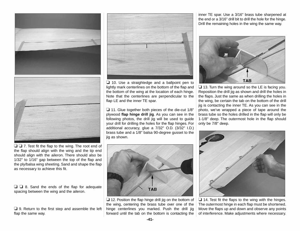
❏ ❏ 7. Test fit the flap to the wing. The root end ofthe flap should align with the wing and the tip endshould align with the aileron. There should also be1/32" to 1/16" gap between the top of the flap andthe ply/balsa wing sheeting. Sand and shape the flapas necessary to achieve this fit.
❏ ❏ 8. Sand the ends of the flap for adequatespacing between the wing and the aileron.
❏ 9. Return to the first step and assemble the leftflap the same way.
❏ 10. Use a straightedge and a ballpoint pen tolightly mark centerlines on the bottom of the flap andthe bottom of the wing at the location of each hinge.Note that the centerlines are perpendicular to theflap LE and the inner TE spar.
❏ 11. Glue together both pieces of the die-cut 1/8"plywood flap hinge drill jig. As you can see in thefollowing photos, the drill jig will be used to guideyour drill for drilling the holes for the flap hinges. Foradditional accuracy, glue a 7/32" O.D. (3/32" I.D.)brass tube and a 1/8" balsa 90-degree gusset to thejig as shown.
❏ 12. Position the flap hinge drill jig on the bottom ofthe wing, centering the brass tube over one of thehinge centerlines you marked. Push the drill jigforward until the tab on the bottom is contacting the
inner TE spar. Use a 3/16" brass tube sharpened atthe end or a 3/16" drill bit to drill the hole for the hinge.Drill the remaining holes in the wing the same way.
❏ 13. Turn the wing around so the LE is facing you.Reposition the drill jig as shown and drill the holes inthe flaps. Just the same as when drilling the holes inthe wing, be certain the tab on the bottom of the drilljig is contacting the inner TE. As you can see in thephoto, we’ve wrapped a piece of tape around thebrass tube so the holes drilled in the flap will only be1-1/8" deep. The outermost hole in the flap shouldonly be 7/8" deep.
❏ 14. Test fit the flaps to the wing with the hinges.The outermost hinge in each flap must be shortened.Move the flaps up and down and observe any pointsof interference. Make adjustments where necessary.
-41-
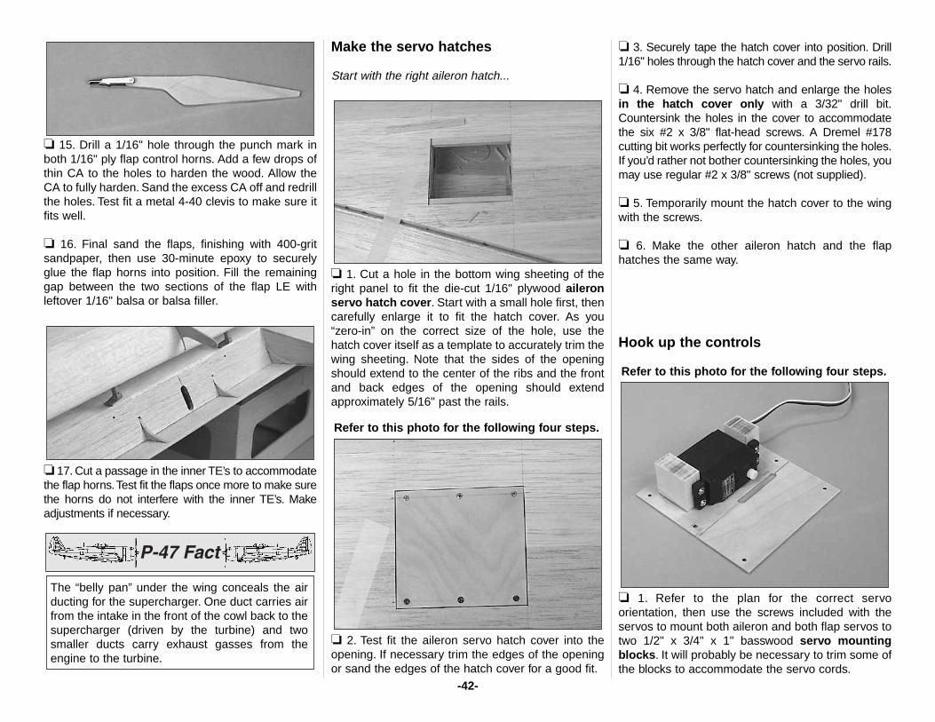
❏ 15. Drill a 1/16" hole through the punch mark inboth 1/16" ply flap control horns. Add a few drops ofthin CA to the holes to harden the wood. Allow theCA to fully harden. Sand the excess CA off and redrillthe holes. Test fit a metal 4-40 clevis to make sure itfits well.
❏ 16. Final sand the flaps, finishing with 400-gritsandpaper, then use 30-minute epoxy to securelyglue the flap horns into position. Fill the remaininggap between the two sections of the flap LE withleftover 1/16" balsa or balsa filler.
❏ 17. Cut a passage in the inner TE’s to accommodatethe flap horns.Test fit the flaps once more to make surethe horns do not interfere with the inner TE’s. Makeadjustments if necessary.
Make the servo hatches
Start with the right aileron hatch...
❏ 1. Cut a hole in the bottom wing sheeting of theright panel to fit the die-cut 1/16" plywood aileronservo hatch cover. Start with a small hole first, thencarefully enlarge it to fit the hatch cover. As you“zero-in” on the correct size of the hole, use thehatch cover itself as a template to accurately trim thewing sheeting. Note that the sides of the openingshould extend to the center of the ribs and the frontand back edges of the opening should extendapproximately 5/16" past the rails.
Refer to this photo for the following four steps.
❏ 2. Test fit the aileron servo hatch cover into theopening. If necessary trim the edges of the openingor sand the edges of the hatch cover for a good fit.
❏ 3. Securely tape the hatch cover into position. Drill1/16" holes through the hatch cover and the servo rails.
❏ 4. Remove the servo hatch and enlarge the holesin the hatch cover only with a 3/32" drill bit.Countersink the holes in the cover to accommodatethe six #2 x 3/8" flat-head screws. A Dremel #178cutting bit works perfectly for countersinking the holes.If you’d rather not bother countersinking the holes, youmay use regular #2 x 3/8" screws (not supplied).
❏ 5. Temporarily mount the hatch cover to the wingwith the screws.
❏ 6. Make the other aileron hatch and the flaphatches the same way.
Hook up the controls
Refer to this photo for the following four steps.
❏ 1. Refer to the plan for the correct servoorientation, then use the screws included with theservos to mount both aileron and both flap servos totwo 1/2" x 3/4" x 1" basswood servo mountingblocks. It will probably be necessary to trim some ofthe blocks to accommodate the servo cords.
The “belly pan” under the wing conceals the airducting for the supercharger. One duct carries airfrom the intake in the front of the cowl back to thesupercharger (driven by the turbine) and twosmaller ducts carry exhaust gasses from theengine to the turbine.
-42-
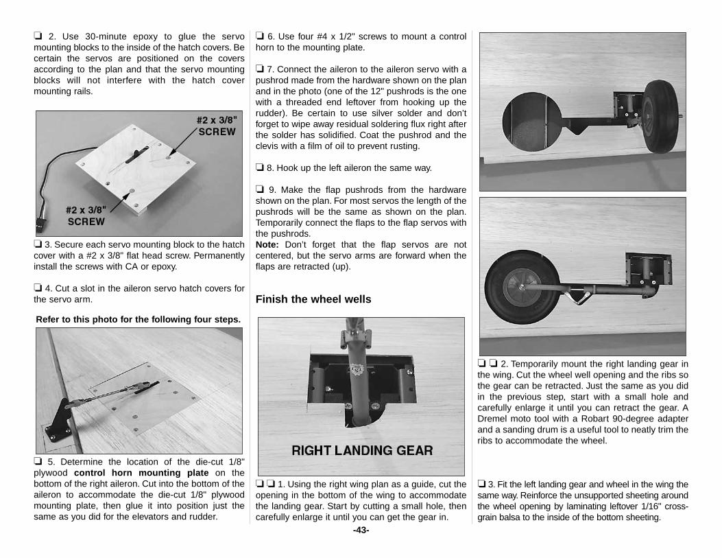
❏ 2. Use 30-minute epoxy to glue the servomounting blocks to the inside of the hatch covers. Becertain the servos are positioned on the coversaccording to the plan and that the servo mountingblocks will not interfere with the hatch covermounting rails.
❏ 3. Secure each servo mounting block to the hatchcover with a #2 x 3/8" flat head screw. Permanentlyinstall the screws with CA or epoxy.
❏ 4. Cut a slot in the aileron servo hatch covers forthe servo arm.
Refer to this photo for the following four steps.
❏ 5. Determine the location of the die-cut 1/8"plywood control horn mounting plate on thebottom of the right aileron. Cut into the bottom of theaileron to accommodate the die-cut 1/8" plywoodmounting plate, then glue it into position just thesame as you did for the elevators and rudder.
❏ 6. Use four #4 x 1/2" screws to mount a controlhorn to the mounting plate.
❏ 7. Connect the aileron to the aileron servo with apushrod made from the hardware shown on the planand in the photo (one of the 12" pushrods is the onewith a threaded end leftover from hooking up therudder). Be certain to use silver solder and don’tforget to wipe away residual soldering flux right afterthe solder has solidified. Coat the pushrod and theclevis with a film of oil to prevent rusting.
❏ 8. Hook up the left aileron the same way.
❏ 9. Make the flap pushrods from the hardwareshown on the plan. For most servos the length of thepushrods will be the same as shown on the plan.Temporarily connect the flaps to the flap servos withthe pushrods.Note: Don’t forget that the flap servos are notcentered, but the servo arms are forward when theflaps are retracted (up).
Finish the wheel wells
❏ ❏ 1. Using the right wing plan as a guide, cut theopening in the bottom of the wing to accommodatethe landing gear. Start by cutting a small hole, thencarefully enlarge it until you can get the gear in.
❏ ❏ 2. Temporarily mount the right landing gear inthe wing. Cut the wheel well opening and the ribs sothe gear can be retracted. Just the same as you didin the previous step, start with a small hole andcarefully enlarge it until you can retract the gear. ADremel moto tool with a Robart 90-degree adapterand a sanding drum is a useful tool to neatly trim theribs to accommodate the wheel.
❏ 3. Fit the left landing gear and wheel in the wing thesame way. Reinforce the unsupported sheeting aroundthe wheel opening by laminating leftover 1/16" cross-grain balsa to the inside of the bottom sheeting.
-43-
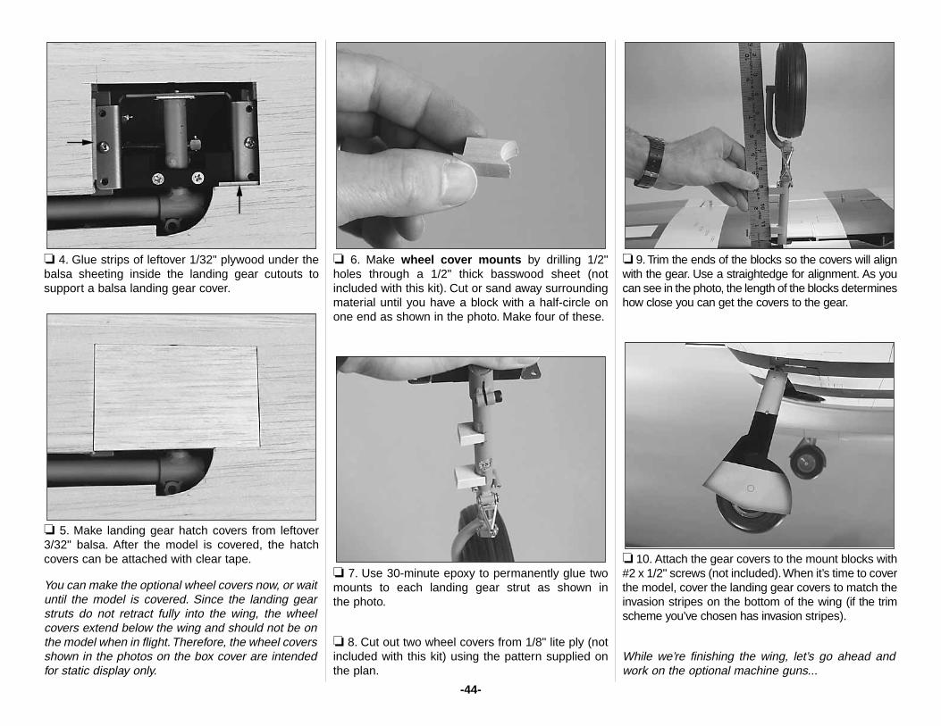
❏ 4. Glue strips of leftover 1/32" plywood under thebalsa sheeting inside the landing gear cutouts tosupport a balsa landing gear cover.
❏ 5. Make landing gear hatch covers from leftover3/32" balsa. After the model is covered, the hatchcovers can be attached with clear tape.
You can make the optional wheel covers now, or waituntil the model is covered. Since the landing gearstruts do not retract fully into the wing, the wheelcovers extend below the wing and should not be onthe model when in flight.Therefore, the wheel coversshown in the photos on the box cover are intendedfor static display only.
❏ 6. Make wheel cover mounts by drilling 1/2"holes through a 1/2" thick basswood sheet (notincluded with this kit). Cut or sand away surroundingmaterial until you have a block with a half-circle onone end as shown in the photo. Make four of these.
❏ 7. Use 30-minute epoxy to permanently glue twomounts to each landing gear strut as shown in the photo.
❏ 8. Cut out two wheel covers from 1/8" lite ply (notincluded with this kit) using the pattern supplied onthe plan.
❏ 9. Trim the ends of the blocks so the covers will alignwith the gear. Use a straightedge for alignment. As youcan see in the photo, the length of the blocks determineshow close you can get the covers to the gear.
❏ 10. Attach the gear covers to the mount blocks with#2 x 1/2" screws (not included).When it’s time to coverthe model, cover the landing gear covers to match theinvasion stripes on the bottom of the wing (if the trimscheme you’ve chosen has invasion stripes).
While we’re finishing the wing, let’s go ahead andwork on the optional machine guns...
-44-
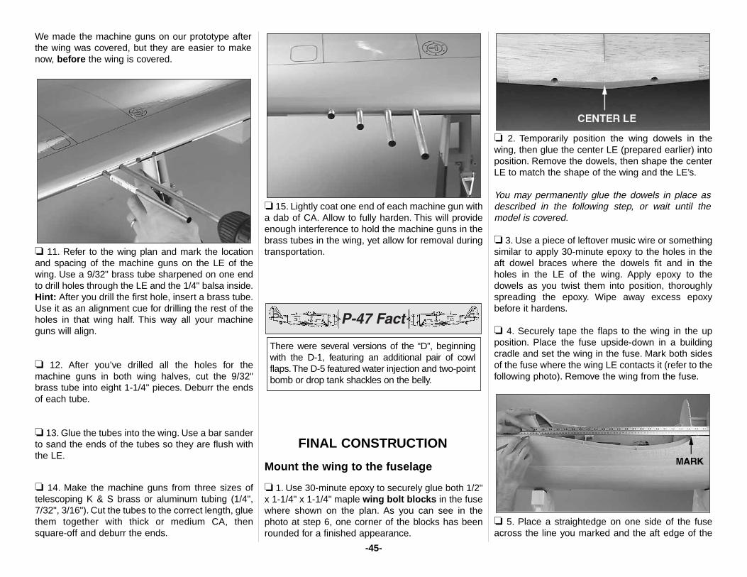
We made the machine guns on our prototype afterthe wing was covered, but they are easier to makenow, before the wing is covered.
❏ 11. Refer to the wing plan and mark the locationand spacing of the machine guns on the LE of thewing. Use a 9/32" brass tube sharpened on one endto drill holes through the LE and the 1/4" balsa inside.Hint: After you drill the first hole, insert a brass tube.Use it as an alignment cue for drilling the rest of theholes in that wing half. This way all your machineguns will align.
❏ 12. After you’ve drilled all the holes for themachine guns in both wing halves, cut the 9/32"brass tube into eight 1-1/4" pieces. Deburr the endsof each tube.
❏ 13. Glue the tubes into the wing. Use a bar sanderto sand the ends of the tubes so they are flush withthe LE.
❏ 14. Make the machine guns from three sizes oftelescoping K & S brass or aluminum tubing (1/4",7/32", 3/16"). Cut the tubes to the correct length, gluethem together with thick or medium CA, then square-off and deburr the ends.
❏ 15. Lightly coat one end of each machine gun witha dab of CA. Allow to fully harden. This will provideenough interference to hold the machine guns in thebrass tubes in the wing, yet allow for removal duringtransportation.
FINAL CONSTRUCTION
Mount the wing to the fuselage
❏ 1. Use 30-minute epoxy to securely glue both 1/2"x 1-1/4" x 1-1/4" maple wing bolt blocks in the fusewhere shown on the plan. As you can see in thephoto at step 6, one corner of the blocks has beenrounded for a finished appearance.
❏ 2. Temporarily position the wing dowels in thewing, then glue the center LE (prepared earlier) intoposition. Remove the dowels, then shape the centerLE to match the shape of the wing and the LE’s.
You may permanently glue the dowels in place asdescribed in the following step, or wait until themodel is covered.
❏ 3. Use a piece of leftover music wire or somethingsimilar to apply 30-minute epoxy to the holes in theaft dowel braces where the dowels fit and in theholes in the LE of the wing. Apply epoxy to thedowels as you twist them into position, thoroughlyspreading the epoxy. Wipe away excess epoxybefore it hardens.
❏ 4. Securely tape the flaps to the wing in the upposition. Place the fuse upside-down in a buildingcradle and set the wing in the fuse. Mark both sidesof the fuse where the wing LE contacts it (refer to thefollowing photo). Remove the wing from the fuse.
❏ 5. Place a straightedge on one side of the fuseacross the line you marked and the aft edge of the
There were several versions of the “D”, beginningwith the D-1, featuring an additional pair of cowlflaps.The D-5 featured water injection and two-pointbomb or drop tank shackles on the belly.
-45-
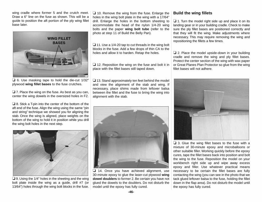
wing cradle where former 5 and the crutch meet.Draw a 6" line on the fuse as shown. This will be aguide to position the aft portion of the ply wing filletbase later.
❏ 6. Use masking tape to hold the die-cut 1/32"plywood wing fillet bases to the fuse crutches.
❏ 7. Place the wing on the fuse. As best as you can,center the wing dowels in the oversized holes in F2.
❏ 8. Stick a T-pin into the center of the bottom of theaft end of the fuse. Align the wing using the same “pinand string” technique we showed you for aligning thestab. Once the wing is aligned, place weights on thebottom of the wing to hold it in position while you drillthe wing bolt holes in the next step.
❏ 9. Using the 1/4" holes in the sheeting and the wingbolt plate inside the wing as a guide, drill #7 (or13/64") holes through the wing bolt blocks in the fuse.
❏ 10. Remove the wing from the fuse. Enlarge theholes in the wing bolt plate in the wing with a 17/64"drill. Enlarge the holes in the bottom sheeting toaccommodate the head of the nylon 1/4-20 wingbolts and the paper wing bolt tube (refer to thephoto at step 11 of Build the Belly Pan).
❏ 11. Use a 1/4-20 tap to cut threads in the wing boltblocks in the fuse. Add a few drops of thin CA to theholes and allow it to harden. Retap the holes.
❏ 12. Reposition the wing on the fuse and bolt it inplace with the fillet bases still taped down.
❏ 13. Stand approximately ten feet behind the modeland view the alignment of the stab and wing. Ifnecessary, place shims made from leftover balsabetween the fillet and the fuse to bring the wing intoalignment with the stab.
❏ 14. Once you have achieved alignment, use 30-minute epoxy to glue the laser-cut plywood wingdowel doublers to former 2. Be certain you have notglued the dowels to the doublers. Do not disturb themodel until the epoxy has fully cured.
Build the wing fillets
❏ 1. Turn the model right side up and place it on itslanding gear or in your building cradle. Check to makesure the ply fillet bases are positioned correctly andthat they will fit the wing. Make adjustments wherenecessary. This may require removing the wing andrepositioning the fillets a few times.
❏ 2. Place the model upside-down in your buildingcradle and remove the wing and ply fillet bases.Protect the center section of the wing with wax paperor Great Planes Plan Protector so glue from the wingfillet bases will not adhere.
❏ 3. Glue the wing fillet bases to the fuse with amixture of 30-minute epoxy and microballoons orother suitable filler. Working quickly before the epoxycures, tape the fillet bases back into position and boltthe wing to the fuse. Reposition the model on yourworkbench right side up and wipe away excessepoxy and filler. Use whatever practical meansnecessary to be certain the fillet bases are fullycontacting the wing (you can see in the photo that wetack glued leftover balsa to the fuse, holding the filletdown in the flap area). Do not disturb the model untilthe epoxy has fully cured.
-46-
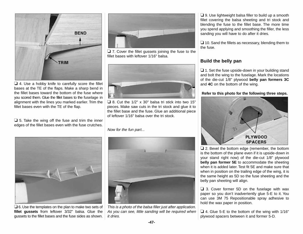
❏ 4. Use a hobby knife to carefully score the filletbases at the TE of the flaps. Make a sharp bend inthe fillet bases toward the bottom of the fuse whereyou scored them. Glue the fillet bases to the fuselage inalignment with the lines you marked earlier. Trim thefillet bases even with the TE of the flap.
❏ 5. Take the wing off the fuse and trim the inneredges of the fillet bases even with the fuse crutches.
❏ 6. Use the templates on the plan to make two sets offillet gussets from leftover 3/32" balsa. Glue thegussets to the fillet bases and the fuse sides as shown.
❏ 7. Cover the fillet gussets joining the fuse to thefillet bases with leftover 1/16" balsa.
❏ 8. Cut the 1/2" x 30" balsa tri stick into two 15"pieces. Make saw cuts in the tri stock and glue it tothe fillet base and the fuse. Glue an additional pieceof leftover 1/16" balsa over the tri stock.
Now for the fun part...
This is a photo of the balsa filler just after application.As you can see, little sanding will be required whenit dries.
❏ 9. Use lightweight balsa filler to build up a smoothfillet covering the balsa sheeting and tri stock andblending the fuse to the fillet base. The more timeyou spend applying and smoothing the filler, the lesssanding you will have to do after it dries.
❏ 10. Sand the fillets as necessary, blending them tothe fuse.
Build the belly pan
❏ 1. Set the fuse upside-down in your building standand bolt the wing to the fuselage. Mark the locationsof the die-cut 1/8" plywood belly pan formers 3Cand 4C on the bottom of the wing.
Refer to this photo for the following three steps.
❏ 2. Bevel the bottom edge (remember, the bottomis the bottom of the plane even if it is upside-down inyour stand right now) of the die-cut 1/8" plywoodbelly pan former 5E to accommodate the sheetingwhen it is added later. Test fit 5E and make sure thatwhen in position on the trailing edge of the wing, it isthe same height as 5D so the fuse sheeting and thebelly pan sheeting will align.
❏ 3. Cover former 5D on the fuselage with waxpaper so you don’t inadvertently glue 5-E to it. Youcan use 3M 75 Repositionable spray adhesive tohold the wax paper in position.
❏ 4. Glue 5-E to the bottom of the wing with 1/16"plywood spacers between it and former 5-D.
-47-
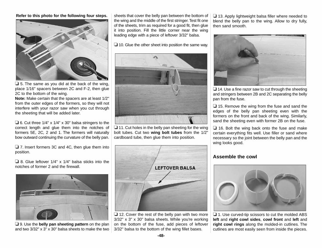
Refer to this photo for the following four steps.
❏ 5. The same as you did at the back of the wing,place 1/16" spacers between 2C and F-2, then glue2C to the bottom of the wing.Note: Make certain that the spacers are at least 1/2"from the outer edges of the formers, so they will notinterfere with your razor saw when you cut throughthe sheeting that will be added later.
❏ 6. Cut three 1/4" x 1/4" x 30" balsa stringers to thecorrect length and glue them into the notches offormers 5E, 2C, 2 and 1. The formers will naturallybow outward continuing the curvature of the belly pan.
❏ 7. Insert formers 3C and 4C, then glue them intoposition.
❏ 8. Glue leftover 1/4" x 1/4" balsa sticks into thenotches of former 2 and the firewall.
❏ 9. Use the belly pan sheeting pattern on the planand two 3/32" x 3" x 30" balsa sheets to make the two
sheets that cover the belly pan between the bottom ofthe wing and the middle of the first stringer.Test fit oneof the sheets, trim as required for a good fit, then glueit into position. Fill the little corner near the wingleading edge with a piece of leftover 3/32" balsa.
❏ 10. Glue the other sheet into position the same way.
❏ 11. Cut holes in the belly pan sheeting for the wingbolt tubes. Cut two wing bolt tubes from the 1/2"cardboard tube, then glue them into position.
❏ 12. Cover the rest of the belly pan with two more3/32" x 3" x 30" balsa sheets. While you’re workingon the bottom of the fuse, add pieces of leftover3/32" balsa to the bottom of the wing fillet bases.
❏ 13. Apply lightweight balsa filler where needed toblend the belly pan to the wing. Allow to dry fully,then sand smooth.
❏ 14. Use a fine razor saw to cut through the sheetingand stringers between 2B and 2C separating the bellypan from the fuse.
❏ 15. Remove the wing from the fuse and sand theedges of the belly pan sheeting even with theformers on the front and back of the wing. Similarly,sand the sheeting even with former 2B on the fuse.
❏ 16. Bolt the wing back onto the fuse and makecertain everything fits well. Use filler or sand wherenecessary so the joint between the belly pan and thewing looks good.
Assemble the cowl
❏ 1. Use curved-tip scissors to cut the molded ABSleft and right cowl sides, cowl front and left andright cowl rings along the molded-in cutlines. Thecutlines are most easily seen from inside the pieces.
-48-
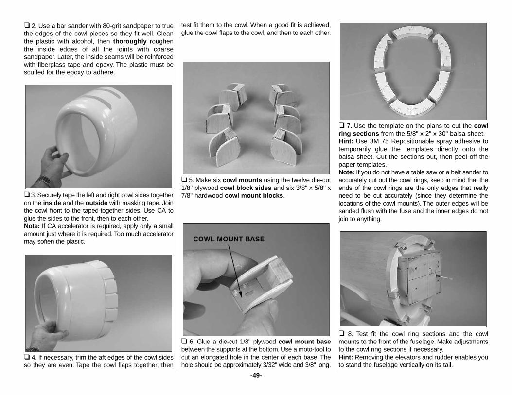
❏ 2. Use a bar sander with 80-grit sandpaper to truethe edges of the cowl pieces so they fit well. Cleanthe plastic with alcohol, then thoroughly roughenthe inside edges of all the joints with coarsesandpaper. Later, the inside seams will be reinforcedwith fiberglass tape and epoxy. The plastic must bescuffed for the epoxy to adhere.
❏ 3. Securely tape the left and right cowl sides togetheron the inside and the outside with masking tape. Jointhe cowl front to the taped-together sides. Use CA toglue the sides to the front, then to each other.Note: If CA accelerator is required, apply only a smallamount just where it is required. Too much acceleratormay soften the plastic.
❏ 4. If necessary, trim the aft edges of the cowl sidesso they are even. Tape the cowl flaps together, then
test fit them to the cowl. When a good fit is achieved,glue the cowl flaps to the cowl, and then to each other.
❏ 5. Make six cowl mounts using the twelve die-cut1/8" plywood cowl block sides and six 3/8" x 5/8" x7/8" hardwood cowl mount blocks.
❏ 6. Glue a die-cut 1/8" plywood cowl mount basebetween the supports at the bottom. Use a moto-tool tocut an elongated hole in the center of each base. Thehole should be approximately 3/32" wide and 3/8" long.
❏ 7. Use the template on the plans to cut the cowlring sections from the 5/8" x 2" x 30" balsa sheet.Hint: Use 3M 75 Repositionable spray adhesive totemporarily glue the templates directly onto the balsa sheet. Cut the sections out, then peel off thepaper templates.Note: If you do not have a table saw or a belt sander toaccurately cut out the cowl rings, keep in mind that theends of the cowl rings are the only edges that reallyneed to be cut accurately (since they determine thelocations of the cowl mounts). The outer edges will besanded flush with the fuse and the inner edges do notjoin to anything.
❏ 8. Test fit the cowl ring sections and the cowlmounts to the front of the fuselage. Make adjustmentsto the cowl ring sections if necessary.Hint: Removing the elevators and rudder enables youto stand the fuselage vertically on its tail.
-49-
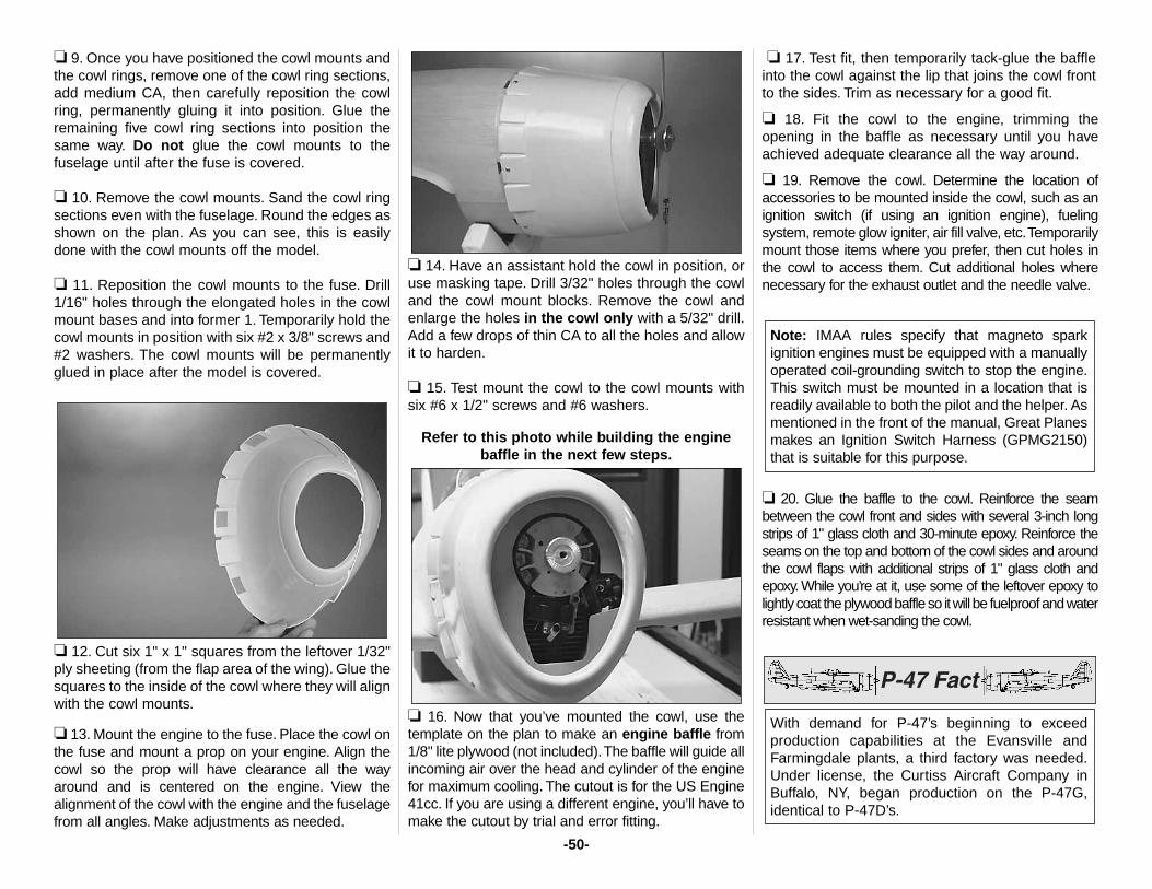
❏ 9. Once you have positioned the cowl mounts andthe cowl rings, remove one of the cowl ring sections,add medium CA, then carefully reposition the cowlring, permanently gluing it into position. Glue theremaining five cowl ring sections into position thesame way. Do not glue the cowl mounts to thefuselage until after the fuse is covered.
❏ 10. Remove the cowl mounts. Sand the cowl ringsections even with the fuselage. Round the edges asshown on the plan. As you can see, this is easilydone with the cowl mounts off the model.
❏ 11. Reposition the cowl mounts to the fuse. Drill1/16" holes through the elongated holes in the cowlmount bases and into former 1. Temporarily hold thecowl mounts in position with six #2 x 3/8" screws and#2 washers. The cowl mounts will be permanentlyglued in place after the model is covered.
❏ 12. Cut six 1" x 1" squares from the leftover 1/32"ply sheeting (from the flap area of the wing). Glue thesquares to the inside of the cowl where they will alignwith the cowl mounts.
❏ 13. Mount the engine to the fuse. Place the cowl onthe fuse and mount a prop on your engine. Align thecowl so the prop will have clearance all the wayaround and is centered on the engine. View thealignment of the cowl with the engine and the fuselagefrom all angles. Make adjustments as needed.
❏ 14. Have an assistant hold the cowl in position, oruse masking tape. Drill 3/32" holes through the cowland the cowl mount blocks. Remove the cowl andenlarge the holes in the cowl only with a 5/32" drill.Add a few drops of thin CA to all the holes and allowit to harden.
❏ 15. Test mount the cowl to the cowl mounts withsix #6 x 1/2" screws and #6 washers.
Refer to this photo while building the enginebaffle in the next few steps.
❏ 16. Now that you’ve mounted the cowl, use thetemplate on the plan to make an engine baffle from1/8" lite plywood (not included).The baffle will guide allincoming air over the head and cylinder of the enginefor maximum cooling. The cutout is for the US Engine41cc. If you are using a different engine, you’ll have tomake the cutout by trial and error fitting.
❏ 17. Test fit, then temporarily tack-glue the baffleinto the cowl against the lip that joins the cowl frontto the sides. Trim as necessary for a good fit.
❏ 18. Fit the cowl to the engine, trimming theopening in the baffle as necessary until you haveachieved adequate clearance all the way around.
❏ 19. Remove the cowl. Determine the location ofaccessories to be mounted inside the cowl, such as anignition switch (if using an ignition engine), fuelingsystem, remote glow igniter, air fill valve, etc.Temporarilymount those items where you prefer, then cut holes inthe cowl to access them. Cut additional holes wherenecessary for the exhaust outlet and the needle valve.
❏ 20. Glue the baffle to the cowl. Reinforce the seambetween the cowl front and sides with several 3-inch longstrips of 1" glass cloth and 30-minute epoxy. Reinforce theseams on the top and bottom of the cowl sides and aroundthe cowl flaps with additional strips of 1" glass cloth andepoxy. While you’re at it, use some of the leftover epoxy tolightly coat the plywood baffle so it will be fuelproof and waterresistant when wet-sanding the cowl.
With demand for P-47’s beginning to exceedproduction capabilities at the Evansville andFarmingdale plants, a third factory was needed.Under license, the Curtiss Aircraft Company inBuffalo, NY, began production on the P-47G,identical to P-47D’s.
Note: IMAA rules specify that magneto sparkignition engines must be equipped with a manuallyoperated coil-grounding switch to stop the engine.This switch must be mounted in a location that isreadily available to both the pilot and the helper. Asmentioned in the front of the manual, Great Planesmakes an Ignition Switch Harness (GPMG2150)that is suitable for this purpose.
-50-
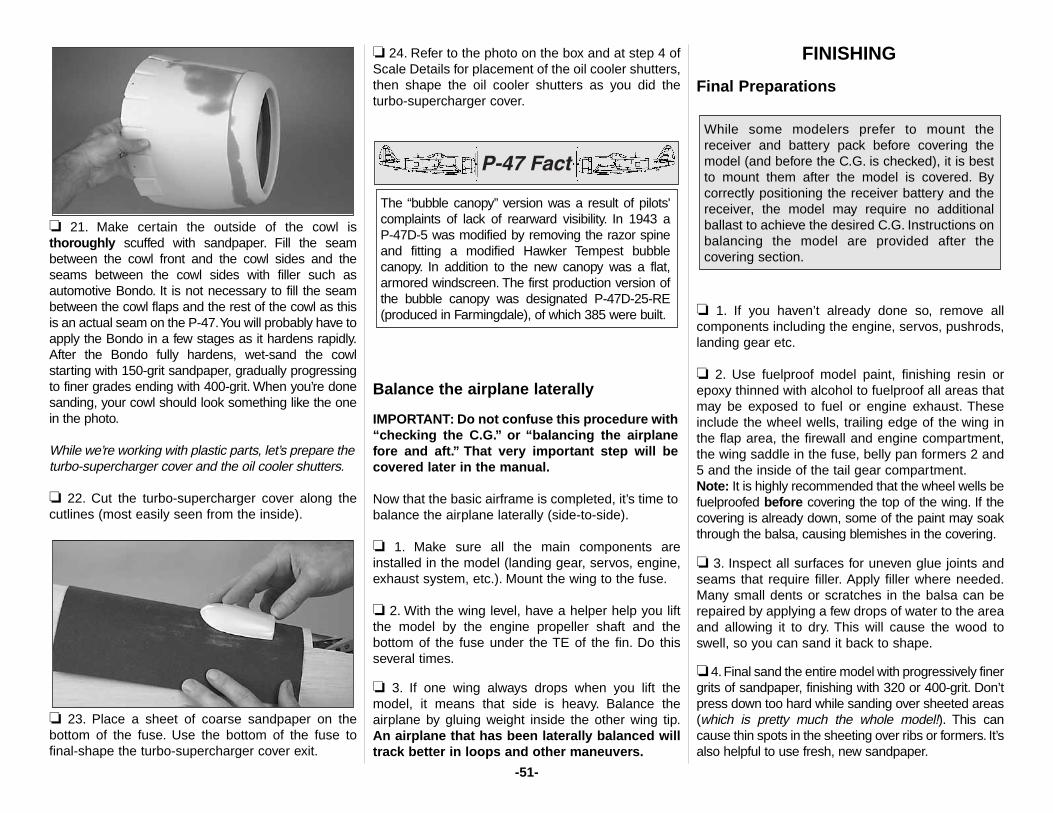
❏ 21. Make certain the outside of the cowl isthoroughly scuffed with sandpaper. Fill the seambetween the cowl front and the cowl sides and theseams between the cowl sides with filler such asautomotive Bondo. It is not necessary to fill the seambetween the cowl flaps and the rest of the cowl as thisis an actual seam on the P-47.You will probably have toapply the Bondo in a few stages as it hardens rapidly.After the Bondo fully hardens, wet-sand the cowlstarting with 150-grit sandpaper, gradually progressingto finer grades ending with 400-grit. When you’re donesanding, your cowl should look something like the onein the photo.
While we’re working with plastic parts, let’s prepare theturbo-supercharger cover and the oil cooler shutters.
❏ 22. Cut the turbo-supercharger cover along thecutlines (most easily seen from the inside).
❏ 23. Place a sheet of coarse sandpaper on thebottom of the fuse. Use the bottom of the fuse tofinal-shape the turbo-supercharger cover exit.
❏ 24. Refer to the photo on the box and at step 4 ofScale Details for placement of the oil cooler shutters,then shape the oil cooler shutters as you did theturbo-supercharger cover.
Balance the airplane laterally
IMPORTANT: Do not confuse this procedure with“checking the C.G.” or “balancing the airplanefore and aft.” That very important step will becovered later in the manual.
Now that the basic airframe is completed, it’s time tobalance the airplane laterally (side-to-side).
❏ 1. Make sure all the main components areinstalled in the model (landing gear, servos, engine,exhaust system, etc.). Mount the wing to the fuse.
❏ 2. With the wing level, have a helper help you liftthe model by the engine propeller shaft and thebottom of the fuse under the TE of the fin. Do thisseveral times.
❏ 3. If one wing always drops when you lift themodel, it means that side is heavy. Balance theairplane by gluing weight inside the other wing tip.An airplane that has been laterally balanced willtrack better in loops and other maneuvers.
FINISHING
Final Preparations
❏ 1. If you haven’t already done so, remove allcomponents including the engine, servos, pushrods,landing gear etc.
❏ 2. Use fuelproof model paint, finishing resin orepoxy thinned with alcohol to fuelproof all areas thatmay be exposed to fuel or engine exhaust. Theseinclude the wheel wells, trailing edge of the wing inthe flap area, the firewall and engine compartment,the wing saddle in the fuse, belly pan formers 2 and5 and the inside of the tail gear compartment.Note: It is highly recommended that the wheel wells befuelproofed before covering the top of the wing. If thecovering is already down, some of the paint may soakthrough the balsa, causing blemishes in the covering.
❏ 3. Inspect all surfaces for uneven glue joints andseams that require filler. Apply filler where needed.Many small dents or scratches in the balsa can berepaired by applying a few drops of water to the areaand allowing it to dry. This will cause the wood toswell, so you can sand it back to shape.
❏ 4.Final sand the entire model with progressively finergrits of sandpaper, finishing with 320 or 400-grit. Don’tpress down too hard while sanding over sheeted areas(which is pretty much the whole model!). This cancause thin spots in the sheeting over ribs or formers. It’salso helpful to use fresh, new sandpaper.
While some modelers prefer to mount thereceiver and battery pack before covering themodel (and before the C.G. is checked), it is bestto mount them after the model is covered. Bycorrectly positioning the receiver battery and thereceiver, the model may require no additionalballast to achieve the desired C.G. Instructions onbalancing the model are provided after thecovering section.
The “bubble canopy” version was a result of pilots'complaints of lack of rearward visibility. In 1943 a P-47D-5 was modified by removing the razor spineand fitting a modified Hawker Tempest bubblecanopy. In addition to the new canopy was a flat,armored windscreen. The first production version ofthe bubble canopy was designated P-47D-25-RE(produced in Farmingdale), of which 385 were built.
-51-
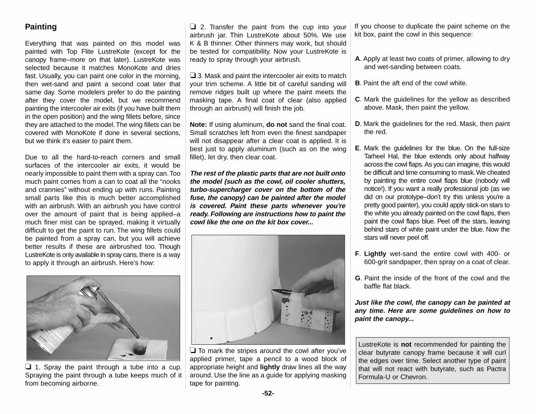
Painting
Everything that was painted on this model waspainted with Top Flite LustreKote (except for thecanopy frame–more on that later). LustreKote wasselected because it matches MonoKote and driesfast. Usually, you can paint one color in the morning,then wet-sand and paint a second coat later thatsame day. Some modelers prefer to do the paintingafter they cover the model, but we recommendpainting the intercooler air exits (if you have built themin the open position) and the wing fillets before, sincethey are attached to the model.The wing fillets can becovered with MonoKote if done in several sections,but we think it’s easier to paint them.
Due to all the hard-to-reach corners and smallsurfaces of the intercooler air exits, it would benearly impossible to paint them with a spray can.Toomuch paint comes from a can to coat all the “nooksand crannies” without ending up with runs. Paintingsmall parts like this is much better accomplishedwith an airbrush. With an airbrush you have controlover the amount of paint that is being applied–amuch finer mist can be sprayed, making it virtuallydifficult to get the paint to run. The wing fillets couldbe painted from a spray can, but you will achievebetter results if these are airbrushed too. ThoughLustreKote is only available in spray cans, there is a wayto apply it through an airbrush. Here’s how:
❏ 1. Spray the paint through a tube into a cup.Spraying the paint through a tube keeps much of itfrom becoming airborne.
❏ 2. Transfer the paint from the cup into yourairbrush jar. Thin LustreKote about 50%. We useK & B thinner. Other thinners may work, but shouldbe tested for compatibility. Now your LustreKote isready to spray through your airbrush.
❏ 3. Mask and paint the intercooler air exits to matchyour trim scheme. A little bit of careful sanding willremove ridges built up where the paint meets themasking tape. A final coat of clear (also appliedthrough an airbrush) will finish the job.
Note: If using aluminum, do not sand the final coat.Small scratches left from even the finest sandpaperwill not disappear after a clear coat is applied. It isbest just to apply aluminum (such as on the wingfillet), let dry, then clear coat.
The rest of the plastic parts that are not built ontothe model (such as the cowl, oil cooler shutters,turbo-supercharger cover on the bottom of thefuse, the canopy) can be painted after the modelis covered. Paint these parts whenever you’reready. Following are instructions how to paint thecowl like the one on the kit box cover...
❏ To mark the stripes around the cowl after you’veapplied primer, tape a pencil to a wood block ofappropriate height and lightly draw lines all the wayaround. Use the line as a guide for applying maskingtape for painting.
If you choose to duplicate the paint scheme on thekit box, paint the cowl in this sequence:
A. Apply at least two coats of primer, allowing to dryand wet-sanding between coats.
B. Paint the aft end of the cowl white.
C. Mark the guidelines for the yellow as describedabove. Mask, then paint the yellow.
D. Mark the guidelines for the red. Mask, then paintthe red.
E. Mark the guidelines for the blue. On the full-sizeTarheel Hal, the blue extends only about halfwayacross the cowl flaps.As you can imagine, this wouldbe difficult and time consuming to mask.We cheatedby painting the entire cowl flaps blue (nobody willnotice!). If you want a really professional job (as wedid on our prototype–don’t try this unless you’re apretty good painter), you could apply stick-on stars tothe white you already painted on the cowl flaps, thenpaint the cowl flaps blue. Peel off the stars, leavingbehind stars of white paint under the blue. Now thestars will never peel off.
F. Lightly wet-sand the entire cowl with 400- or 600-grit sandpaper, then spray on a coat of clear.
G. Paint the inside of the front of the cowl and thebaffle flat black.
Just like the cowl, the canopy can be painted atany time. Here are some guidelines on how topaint the canopy...
LustreKote is not recommended for painting theclear butyrate canopy frame because it will curlthe edges over time. Select another type of paintthat will not react with butyrate, such as PactraFormula-U or Chevron.
-52-
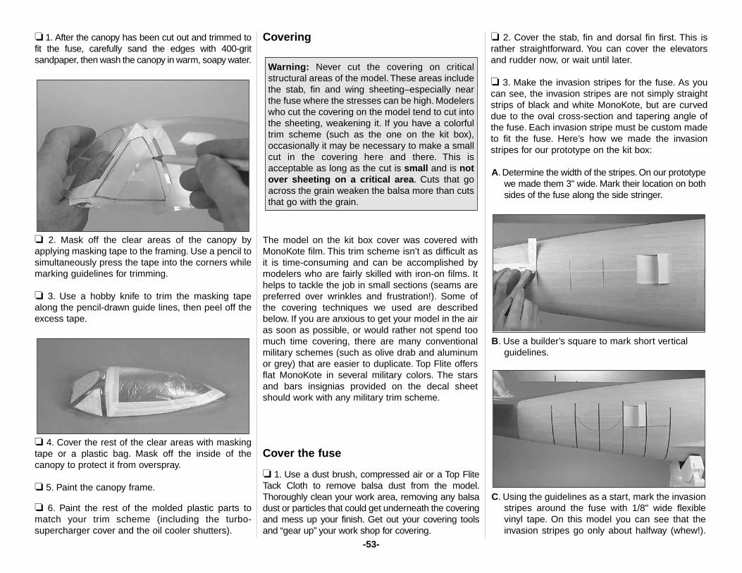
❏ 1. After the canopy has been cut out and trimmed tofit the fuse, carefully sand the edges with 400-gritsandpaper, then wash the canopy in warm, soapy water.
❏ 2. Mask off the clear areas of the canopy byapplying masking tape to the framing. Use a pencil tosimultaneously press the tape into the corners whilemarking guidelines for trimming.
❏ 3. Use a hobby knife to trim the masking tapealong the pencil-drawn guide lines, then peel off theexcess tape.
❏ 4. Cover the rest of the clear areas with maskingtape or a plastic bag. Mask off the inside of thecanopy to protect it from overspray.
❏ 5. Paint the canopy frame.
❏ 6. Paint the rest of the molded plastic parts tomatch your trim scheme (including the turbo-supercharger cover and the oil cooler shutters).
Covering
The model on the kit box cover was covered withMonoKote film. This trim scheme isn’t as difficult asit is time-consuming and can be accomplished bymodelers who are fairly skilled with iron-on films. Ithelps to tackle the job in small sections (seams arepreferred over wrinkles and frustration!). Some ofthe covering techniques we used are describedbelow. If you are anxious to get your model in the airas soon as possible, or would rather not spend toomuch time covering, there are many conventionalmilitary schemes (such as olive drab and aluminumor grey) that are easier to duplicate. Top Flite offersflat MonoKote in several military colors. The starsand bars insignias provided on the decal sheetshould work with any military trim scheme.
Cover the fuse
❏ 1. Use a dust brush, compressed air or a Top FliteTack Cloth to remove balsa dust from the model.Thoroughly clean your work area, removing any balsadust or particles that could get underneath the coveringand mess up your finish. Get out your covering toolsand “gear up” your work shop for covering.
❏ 2. Cover the stab, fin and dorsal fin first. This israther straightforward. You can cover the elevatorsand rudder now, or wait until later.
❏ 3. Make the invasion stripes for the fuse. As youcan see, the invasion stripes are not simply straightstrips of black and white MonoKote, but are curveddue to the oval cross-section and tapering angle ofthe fuse. Each invasion stripe must be custom madeto fit the fuse. Here’s how we made the invasionstripes for our prototype on the kit box:
A. Determine the width of the stripes. On our prototypewe made them 3" wide. Mark their location on bothsides of the fuse along the side stringer.
B. Use a builder’s square to mark short verticalguidelines.
C. Using the guidelines as a start, mark the invasionstripes around the fuse with 1/8" wide flexiblevinyl tape. On this model you can see that theinvasion stripes go only about halfway (whew!).
Warning: Never cut the covering on criticalstructural areas of the model. These areas includethe stab, fin and wing sheeting–especially nearthe fuse where the stresses can be high. Modelerswho cut the covering on the model tend to cut intothe sheeting, weakening it. If you have a colorfultrim scheme (such as the one on the kit box),occasionally it may be necessary to make a smallcut in the covering here and there. This isacceptable as long as the cut is small and is notover sheeting on a critical area. Cuts that goacross the grain weaken the balsa more than cutsthat go with the grain.
-53-
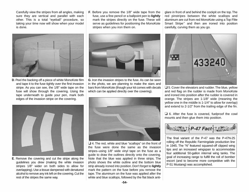
Carefully view the stripes from all angles, makingsure they are vertical and parallel with eachother. This is a total “eyeball” procedure, sotaking your time now will show when your modelis done.
D. Peel the backing off a piece of white MonoKote filmand tape it to the fuse tightly over the first invasionstripe. As you can see, the 1/8" wide tape on thefuse will show through the covering. Using thetape underneath to guide your pen, mark bothedges of the invasion stripe on the covering.
E. Remove the covering and cut the stripe along theguidelines you drew (making the white invasionstripes 1/8" wider on both sides to allow foroverlapping).Use a tissue dampened with denaturedalcohol to remove any ink left on the covering.Cut therest of the stripes the same way.
F. Before you remove the 1/8" wide tape from thefuse, use a fine pencil or a ballpoint pen to lightlymark the stripes directly on the fuse. These willserve as guidelines for positioning the MonoKotestripes when you iron them on.
G. Iron the invasion stripes to the fuse. As can be seenin the photo, we are planning to make the stars andbars from MonoKote (though your kit comes with decalswhich can be applied directly over the covering).
❏ 4. The red, white and blue “scallops” on the front ofthe fuse were done the same as the invasionstripes–using 1/8" wide vinyl tape on the fuse as aguide to draw the outlines directly onto the covering.Note that the blue was applied in three strips. Thephoto shows the white outline and the bottom bluestrip already ironed into position. Don’t forget to lightlymark the pattern on the fuse before you remove thetape. The aluminum on the fuse was applied after thewhite and blue scallops, followed by the flat black anti-
glare in front of and behind the cockpit on the top. Thered pinstripes between the white scallops andaluminum are cut from red MonoKote using a Top FliteSmart Stripe™ and then are ironed into positioncarefully, curving them as you go.
❏ 5. Cover the elevators and rudder.The blue, yellowand red flag on the rudder is made from MonoKoteand ironed into position after the rudder is covered inorange. The stripes are 1-1/8" wide (meaning theyellow one in the middle is 1-1/4" to allow for overlap)and extend to 2-1/2" from the trailing edge of the fin.
❏ 6. After the fuse is covered, fuelproof the cowlmounts and then glue them into position.
The final variant of the P-47 was the P-47N-25rolling off the Republic Farmingdale production linein 1945. The “N” featured squared-off clipped wingtips and an increased wingspan to accommodatefour additional 50-gallon internal wing tanks. Thegoal of increasing range to fulfill the roll of bomberescort (and to become more competitive with the P-51 Mustang) was accomplished.
-54-
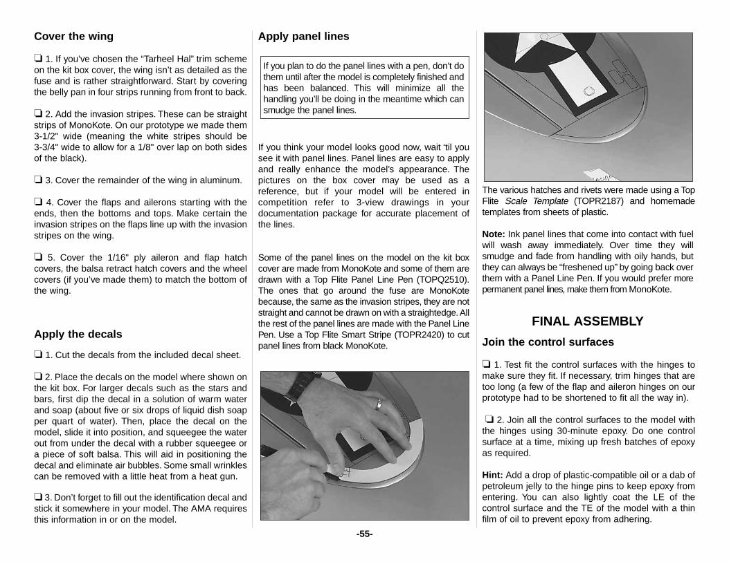
Cover the wing
❏ 1. If you’ve chosen the “Tarheel Hal” trim schemeon the kit box cover, the wing isn’t as detailed as thefuse and is rather straightforward. Start by coveringthe belly pan in four strips running from front to back.
❏ 2. Add the invasion stripes. These can be straightstrips of MonoKote. On our prototype we made them3-1/2" wide (meaning the white stripes should be 3-3/4" wide to allow for a 1/8" over lap on both sidesof the black).
❏ 3. Cover the remainder of the wing in aluminum.
❏ 4. Cover the flaps and ailerons starting with theends, then the bottoms and tops. Make certain theinvasion stripes on the flaps line up with the invasionstripes on the wing.
❏ 5. Cover the 1/16" ply aileron and flap hatchcovers, the balsa retract hatch covers and the wheelcovers (if you’ve made them) to match the bottom ofthe wing.
Apply the decals
❏ 1. Cut the decals from the included decal sheet.
❏ 2. Place the decals on the model where shown onthe kit box. For larger decals such as the stars andbars, first dip the decal in a solution of warm waterand soap (about five or six drops of liquid dish soapper quart of water). Then, place the decal on themodel, slide it into position, and squeegee the waterout from under the decal with a rubber squeegee ora piece of soft balsa. This will aid in positioning thedecal and eliminate air bubbles. Some small wrinklescan be removed with a little heat from a heat gun.
❏ 3. Don’t forget to fill out the identification decal andstick it somewhere in your model. The AMA requiresthis information in or on the model.
Apply panel lines
If you think your model looks good now, wait ‘til yousee it with panel lines. Panel lines are easy to applyand really enhance the model’s appearance. Thepictures on the box cover may be used as areference, but if your model will be entered incompetition refer to 3-view drawings in yourdocumentation package for accurate placement ofthe lines.
Some of the panel lines on the model on the kit boxcover are made from MonoKote and some of them aredrawn with a Top Flite Panel Line Pen (TOPQ2510).The ones that go around the fuse are MonoKotebecause, the same as the invasion stripes, they are notstraight and cannot be drawn on with a straightedge.Allthe rest of the panel lines are made with the Panel LinePen. Use a Top Flite Smart Stripe (TOPR2420) to cutpanel lines from black MonoKote.
The various hatches and rivets were made using a TopFlite Scale Template (TOPR2187) and homemadetemplates from sheets of plastic.
Note: Ink panel lines that come into contact with fuelwill wash away immediately. Over time they willsmudge and fade from handling with oily hands, butthey can always be “freshened up” by going back overthem with a Panel Line Pen. If you would prefer morepermanent panel lines, make them from MonoKote.
FINAL ASSEMBLY
Join the control surfaces
❏ 1. Test fit the control surfaces with the hinges tomake sure they fit. If necessary, trim hinges that aretoo long (a few of the flap and aileron hinges on ourprototype had to be shortened to fit all the way in).
❏ 2. Join all the control surfaces to the model withthe hinges using 30-minute epoxy. Do one controlsurface at a time, mixing up fresh batches of epoxyas required.
Hint: Add a drop of plastic-compatible oil or a dab ofpetroleum jelly to the hinge pins to keep epoxy fromentering. You can also lightly coat the LE of thecontrol surface and the TE of the model with a thinfilm of oil to prevent epoxy from adhering.
If you plan to do the panel lines with a pen, don’t dothem until after the model is completely finished andhas been balanced. This will minimize all thehandling you’ll be doing in the meantime which cansmudge the panel lines.
-55-
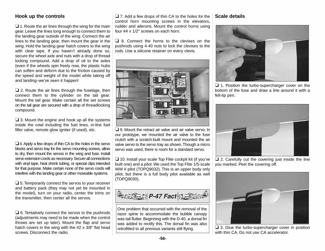
Hook up the controls
❏ 1. Route the air lines through the wing for the maingear. Leave the lines long enough to connect them tothe landing gear outside of the wing. Connect the airlines to the landing gear, then mount the gear in thewing. Hold the landing gear hatch covers to the wingwith clear tape. If you haven’t already done so,secure the wheel axle and nuts with a drop of threadlocking compound. Add a drop of oil to the axles(even if the wheels spin freely now, the plastic hubscan soften and deform due to the friction caused bythe speed and weight of the model while taking offand landing–we’ve seen it happen!
❏ 2. Route the air lines through the fuselage, thenconnect them to the cylinder on the tail gear.Mount the tail gear. Make certain all the set screwson the tail gear are secured with a drop of threadlockingcompound.
❏ 3. Mount the engine and hook up all the systemsinside the cowl including the fuel lines, in-line fuelfiller valve, remote glow igniter (if used), etc.
❏ 4. Apply a few drops of thin CA to the holes in the servoblocks and servo tray for the servo mounting screws, allowto dry, then mount the servos in the wing and fuse. Installservo extension cords as necessary.Secure all connectionswith vinyl tape, heat shrink tubing, or special clips intendedfor that purpose. Make certain none of the servo cords willinterfere with the landing gear or other moveable systems.
❏ 5. Temporarily connect the servos to your receiverand battery pack (they may not yet be mounted inthe model), turn on your radio, center the trims onthe transmitter, then center all the servos.
❏ 6. Tentatively connect the servos to the pushrods(adjustments may need to be made when the controlthrows are set up later). Mount the flap and servohatch covers in the wing with the #2 x 3/8" flat headscrews. Disconnect the radio.
❏ 7. Add a few drops of thin CA to the holes for thecontrol horn mounting screws in the elevators,rudder and ailerons. Mount the control horns usingfour #4 x 1/2" screws on each horn.
❏ 8. Connect the horns to the clevises on thepushrods using 4-40 nuts to lock the clevises to therods. Use a silicone retainer on every clevis.
❏ 9. Mount the retract air valve and air valve servo. Inour prototype, we mounted the air valve to the fusecrutch with a scratch-built mount and mounted the airvalve servo to the servo tray as shown.Though a microservo was used, there is room for a standard servo.
❏ 10. Install your scale Top Flite cockpit kit (if you’vebuilt one) and a pilot. We used the Top Flite 1/5-scaleWW II pilot (TOPQ9032). This is an upper body onlypilot, but there is a full body pilot available as well(TOPQ9030).
Scale details
❏ 1. Position the turbo-supercharger cover on thebottom of the fuse and draw a line around it with afelt-tip pen.
❏ 2. Carefully cut the covering just inside the lineyou marked. Peel the covering off.
❏ 3. Glue the turbo-supercharger cover in positionwith thin CA. Do not use CA accelerator.
One problem that occurred with the removal of therazor spine to accommodate the bubble canopywas tail flutter. Beginning with the D-40, a dorsal finwas added to rectify this. The dorsal fin was alsoretrofitted to all previous variants still flying.
-56-
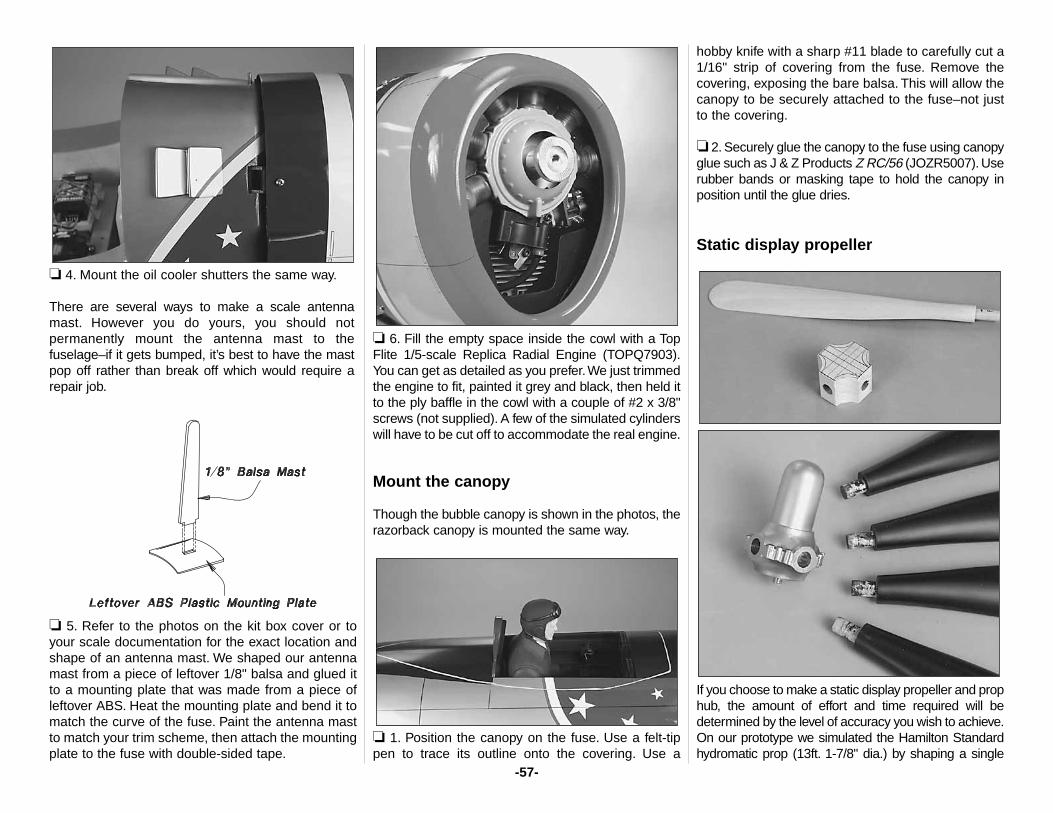
❏ 4. Mount the oil cooler shutters the same way.
There are several ways to make a scale antennamast. However you do yours, you should notpermanently mount the antenna mast to thefuselage–if it gets bumped, it’s best to have the mastpop off rather than break off which would require arepair job.
❏ 5. Refer to the photos on the kit box cover or toyour scale documentation for the exact location andshape of an antenna mast. We shaped our antennamast from a piece of leftover 1/8" balsa and glued itto a mounting plate that was made from a piece ofleftover ABS. Heat the mounting plate and bend it tomatch the curve of the fuse. Paint the antenna mastto match your trim scheme, then attach the mountingplate to the fuse with double-sided tape.
❏ 6. Fill the empty space inside the cowl with a TopFlite 1/5-scale Replica Radial Engine (TOPQ7903).You can get as detailed as you prefer.We just trimmedthe engine to fit, painted it grey and black, then held itto the ply baffle in the cowl with a couple of #2 x 3/8"screws (not supplied). A few of the simulated cylinderswill have to be cut off to accommodate the real engine.
Mount the canopy
Though the bubble canopy is shown in the photos, therazorback canopy is mounted the same way.
❏ 1. Position the canopy on the fuse. Use a felt-tippen to trace its outline onto the covering. Use a
hobby knife with a sharp #11 blade to carefully cut a1/16" strip of covering from the fuse. Remove thecovering, exposing the bare balsa. This will allow thecanopy to be securely attached to the fuse–not justto the covering.
❏ 2. Securely glue the canopy to the fuse using canopyglue such as J & Z Products Z RC/56 (JOZR5007). Userubber bands or masking tape to hold the canopy inposition until the glue dries.
Static display propeller
If you choose to make a static display propeller and prophub, the amount of effort and time required will bedetermined by the level of accuracy you wish to achieve.On our prototype we simulated the Hamilton Standardhydromatic prop (13ft. 1-7/8" dia.) by shaping a single
-57-
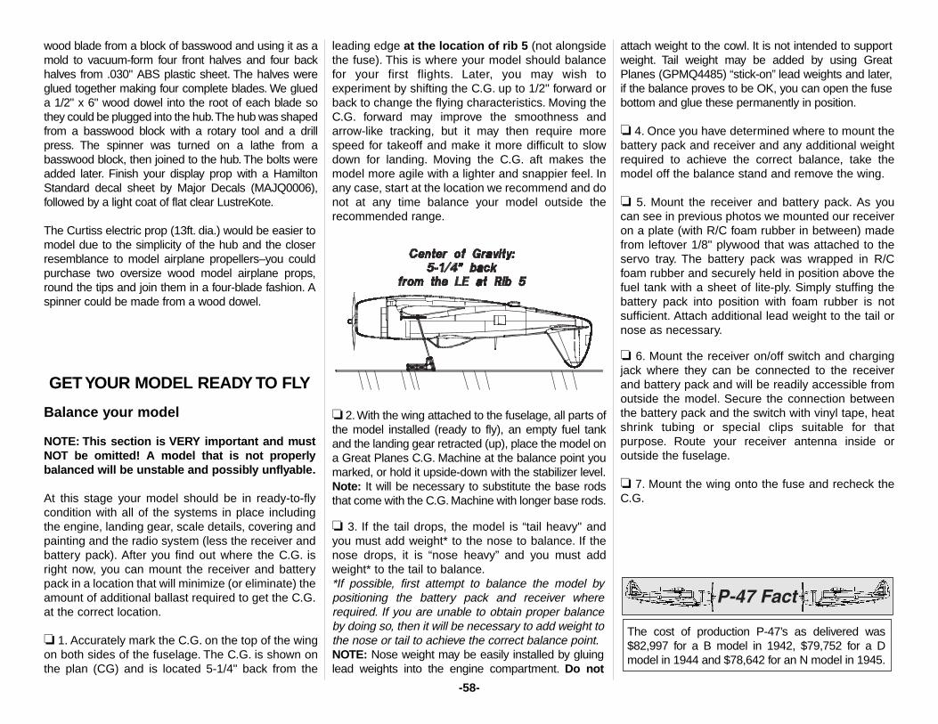
wood blade from a block of basswood and using it as amold to vacuum-form four front halves and four backhalves from .030" ABS plastic sheet. The halves wereglued together making four complete blades. We glueda 1/2" x 6" wood dowel into the root of each blade sothey could be plugged into the hub.The hub was shapedfrom a basswood block with a rotary tool and a drillpress. The spinner was turned on a lathe from abasswood block, then joined to the hub. The bolts wereadded later. Finish your display prop with a HamiltonStandard decal sheet by Major Decals (MAJQ0006),followed by a light coat of flat clear LustreKote.
The Curtiss electric prop (13ft. dia.) would be easier tomodel due to the simplicity of the hub and the closerresemblance to model airplane propellers–you couldpurchase two oversize wood model airplane props,round the tips and join them in a four-blade fashion. Aspinner could be made from a wood dowel.
GET YOUR MODEL READY TO FLY
Balance your model
NOTE: This section is VERY important and mustNOT be omitted! A model that is not properlybalanced will be unstable and possibly unflyable.
At this stage your model should be in ready-to-flycondition with all of the systems in place includingthe engine, landing gear, scale details, covering andpainting and the radio system (less the receiver andbattery pack). After you find out where the C.G. isright now, you can mount the receiver and batterypack in a location that will minimize (or eliminate) theamount of additional ballast required to get the C.G.at the correct location.
❏ 1. Accurately mark the C.G. on the top of the wingon both sides of the fuselage. The C.G. is shown onthe plan (CG) and is located 5-1/4" back from the
leading edge at the location of rib 5 (not alongsidethe fuse). This is where your model should balancefor your first flights. Later, you may wish toexperiment by shifting the C.G. up to 1/2" forward orback to change the flying characteristics. Moving theC.G. forward may improve the smoothness andarrow-like tracking, but it may then require morespeed for takeoff and make it more difficult to slowdown for landing. Moving the C.G. aft makes themodel more agile with a lighter and snappier feel. Inany case, start at the location we recommend and donot at any time balance your model outside therecommended range.
❏ 2.With the wing attached to the fuselage, all parts ofthe model installed (ready to fly), an empty fuel tankand the landing gear retracted (up), place the model ona Great Planes C.G. Machine at the balance point youmarked, or hold it upside-down with the stabilizer level.Note: It will be necessary to substitute the base rodsthat come with the C.G. Machine with longer base rods.
❏ 3. If the tail drops, the model is “tail heavy" andyou must add weight* to the nose to balance. If thenose drops, it is “nose heavy” and you must addweight* to the tail to balance.*If possible, first attempt to balance the model bypositioning the battery pack and receiver whererequired. If you are unable to obtain proper balanceby doing so, then it will be necessary to add weight tothe nose or tail to achieve the correct balance point.NOTE: Nose weight may be easily installed by gluinglead weights into the engine compartment. Do not
attach weight to the cowl. It is not intended to supportweight. Tail weight may be added by using GreatPlanes (GPMQ4485) “stick-on” lead weights and later,if the balance proves to be OK, you can open the fusebottom and glue these permanently in position.
❏ 4. Once you have determined where to mount thebattery pack and receiver and any additional weightrequired to achieve the correct balance, take themodel off the balance stand and remove the wing.
❏ 5. Mount the receiver and battery pack. As youcan see in previous photos we mounted our receiveron a plate (with R/C foam rubber in between) madefrom leftover 1/8" plywood that was attached to theservo tray. The battery pack was wrapped in R/Cfoam rubber and securely held in position above thefuel tank with a sheet of lite-ply. Simply stuffing thebattery pack into position with foam rubber is notsufficient. Attach additional lead weight to the tail ornose as necessary.
❏ 6. Mount the receiver on/off switch and chargingjack where they can be connected to the receiverand battery pack and will be readily accessible fromoutside the model. Secure the connection betweenthe battery pack and the switch with vinyl tape, heatshrink tubing or special clips suitable for thatpurpose. Route your receiver antenna inside oroutside the fuselage.
❏ 7. Mount the wing onto the fuse and recheck theC.G.
The cost of production P-47’s as delivered was$82,997 for a B model in 1942, $79,752 for a Dmodel in 1944 and $78,642 for an N model in 1945.
-58-
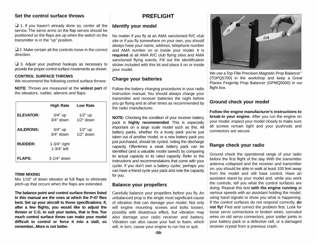
Set the control surface throws
❏ 1. If you haven’t already done so, center all theservos. The servo arms on the flap servos should bepositioned so the flaps are up when the switch on thetransmitter is in the “up” position.
❏ 2. Make certain all the controls move in the correctdirection.
❏ 3. Adjust your pushrod hookups as necessary toprovide the proper control surface movements as shown.
CONTROL SURFACE THROWSWe recommend the following control surface throws:
NOTE: Throws are measured at the widest part ofthe elevators, rudder, ailerons and flaps.
TRIM MIXINGMix 1/16" of down elevator at full flaps to eliminatepitch-up that occurs when the flaps are extended.
The balance point and control surface throws listedin this manual are the ones at which the P-47 fliesbest. Set up your aircraft to those specifications. If,after a few flights, you would like to adjust thethrows or C.G. to suit your tastes, that is fine. Toomuch control surface throw can make your modeldifficult to control or force it into a stall, soremember...More is not better.
PREFLIGHT
Identify your model
No matter if you fly at an AMA sanctioned R/C clubsite or if you fly somewhere on your own, you shouldalways have your name, address, telephone numberand AMA number on or inside your model. It isrequired at all AMA R/C club flying sites and AMAsanctioned flying events. Fill out the identificationsticker included with this kit and place it on or insideyour model.
Charge your batteries
Follow the battery charging procedures in your radioinstruction manual. You should always charge yourtransmitter and receiver batteries the night beforeyou go flying and at other times as recommended bythe radio manufacturer.
NOTE: Checking the condition of your receiver batterypack is highly recommended. This is especiallyimportant on a large scale model such as this. Allbattery packs, whether it’s a trusty pack you’ve justtaken out of another model, or a new battery pack youjust purchased, should be cycled, noting the dischargecapacity. Oftentimes a weak battery pack can beidentified (and a valuable model saved!) by comparingits actual capacity to its rated capacity. Refer to theinstructions and recommendations that come with yourcycler. If you don’t own a battery cycler, perhaps youcan have a friend cycle your pack and note the capacityfor you.
Balance your propellers
Carefully balance your propellers before you fly. Anunbalanced prop is the single most significant causeof vibration that can damage your model. Not onlywill engine mounting screws and bolts loosen,possibly with disastrous effect, but vibration mayalso damage your radio receiver and battery.Vibration can also cause your fuel to foam, whichwill, in turn, cause your engine to run hot or quit.
We use a Top Flite Precision Magnetic Prop Balancer™
(TOPQ5700) in the workshop and keep a GreatPlanes Fingertip Prop Balancer (GPMQ5000) in ourflight box.
Ground check your model
Follow the engine manufacturer’s instructions tobreak-in your engine. After you run the engine onyour model, inspect your model closely to make sureall screws remain tight and your pushrods andconnectors are secure.
Range check your radio
Ground check the operational range of your radiobefore the first flight of the day. With the transmitterantenna collapsed and the receiver and transmitteron, you should be able to walk at least 100 feet awayfrom the model and still have control. Have anassistant stand by your model and, while you workthe controls, tell you what the control surfaces aredoing. Repeat this test with the engine running atvarious speeds with an assistant holding the model,using hand signals to show you what is happening.If the control surfaces do not respond correctly, donot fly! Find and correct the problem first. Look forloose servo connections or broken wires, corrodedwires on old servo connectors, poor solder joints inyour battery pack or a defective cell, or a damagedreceiver crystal from a previous crash.
High Rate Low Rate
ELEVATOR: 3/4" up 1/2" up3/4" down 1/2" down
AILERONS: 3/4" up 1/2" up3/4" down 1/2" down
RUDDER: 1-3/4" right1-3/4" left
FLAPS: 3-1/4" down
-59-
ENGINE SAFETY PRECAUTIONS
Keep all engine fuel in a safe place, away from highheat, sparks or flames, as fuel is very flammable. Donot smoke near the engine or fuel; and rememberthat engine exhaust gives off a great deal of deadlycarbon monoxide. Therefore, do not run the enginein a closed room or garage.
Get help from an experienced pilot when learning tooperate engines.
Use safety glasses when starting or running engines.
Do not run the engine in an area of loose gravel orsand; the propeller may throw such material in yourface or eyes.
Keep your face and body as well as all spectatorsaway from the plane of rotation of the propeller asyou start and run the engine.
Keep these items away from the prop: looseclothing, shirt sleeves, ties, scarfs, long hair or looseobjects such as pencils or screwdrivers that may fallout of shirt or jacket pockets into the prop.
Use a “chicken stick” or electric starter to start theengine. Do not use your fingers to flip the propeller.Make certain the glow plug clip or connector issecure so that it will not pop off or otherwise get intothe running propeller.
Make all engine adjustments from behind therotating propeller.
The engine gets hot! Do not touch it during or rightafter operation. Make sure fuel lines are in goodcondition so fuel will not leak onto a hot engine,causing a fire.
To stop a glow engine, cut off the fuel supply byclosing off the fuel line or following the enginemanufacturer’s recommendations. Do not use hands,fingers or any other body part to try to stop theengine. To stop a gasoline powered engine an on/offswitch should be connected to the engine coil. Do notthrow anything into the propeller of a running engine.
AMA SAFETY CODE
Read and abide by the following Academy of ModelAeronautics Official Safety Code:
GENERAL (Excerpt)
1. I will not fly my model aircraft in sanctionedevents, air shows, or model flying demonstrationsuntil it has been proven to be airworthy by havingbeen previously successfully flight tested.
2. I will not fly my model aircraft higher thanapproximately 400 feet within 3 miles of an airportwithout notifying the airport operator. I will give rightof way to and avoid flying in the proximity of full scaleaircraft. Where necessary an observer shall be usedto supervise flying to avoid having models fly in theproximity of full scale aircraft.
3. Where established, I will abide by the safetyrules for the flying site I use and I will not willfully anddeliberately fly my models in a careless, recklessand/or dangerous manner.
7. I will not fly my model unless it is identified withmy name and address or AMA number, on or in themodel.
9. I will not operate models with pyrotechnics (anydevice that explodes, burns, or propels a projectileof any kind).
RADIO CONTROL
1. I will have completed a successful radioequipment ground check before the first flight of anew or repaired model.
2. I will not fly my model aircraft in the presence ofspectators until I become a qualified flier, unlessassisted by an experienced helper.
3. I will perform my initial turn after takeoff awayfrom the pit or spectator areas and I will notthereafter fly over pit or spectator areas, unlessbeyond my control.
4. I will operate my model using only radio controlfrequencies currently allowed by the FederalCommunications Commission.
IMAA SAFETY CODE (excerpts)
Definition:For the purpose of the following IMAA Safety Code,the term Giant Scale shall refer to radio controlledmodel aircraft, either scale or non-scale, which havea wingspan of 80 inches or more for monoplanesand 60 inches or more for multi-winged modelaircraft and have a ramp weight (fueled and ready tofly) of 55 lbs. or less.
Section 1.0: SAFETY STANDARD1.1 Adherence to Code: This safety code is to bestrictly followed
1.2 The most current AMA Safety Code in effect is tobe observed. However, the competition sections ofthe code may be disregarded.
Failure to follow these safety precautions mayresult in severe injury to yourself and others.
-60-
Section 3.0: Safety Check3.4 Flight Testing: All Giant Scale R/C aircraft are tohave been flight tested and flight trimmed with aminimum of six flights before the model is allowed tofly at an IMAA Sanctioned event.
3.5 Proof of Flight: The completing and signing ofthe Declaration section of the Safety Inspection formby the pilot (or owner) shall document as fact thateach aircraft has been successfully flight-tested andproven airworthy prior to an IMAA event.
Section 5.0: EMERGENCY ENGINE SHUT OFF(kill switch)5.1 All magneto spark ignition engines must have acoil grounding switch on the aircraft to stop theengine. This will also prevent accidental starting ofthe engine. This switch shall be readily available toboth pilot and helper. This switch is to be operatedmanually and without the use of the radio system.
5.2 Engines with battery power ignition systemsmust have a switch to turn off the power from thebattery pack to disable the engine from firing. Thiswill also prevent accidental starting of the engine.This switch shall be readily available to both pilotand helper. This switch shall be operated manuallyand without the use of the radio system.
5.3 There must also be a means to stop the enginefrom the transmitter. The most common method is toclose the carburetor throat completely using throttletrim; however, other methods are acceptable. Thisrequirement applies to all glow/gas ignition enginesregardless of size.
Section 6.0: RADIO REQUIREMENTS6.1 All transmitters must be FCC type certified.
6.2 FCC Technician or higher-class license requiredfor 6 meter band operation only.
Additional General Recommendations
Servos need to be of a rating capable to handle theloads that the control surfaces impose upon the servos.Standard servos are not recommended for controlsurfaces. Servos should be rated heavy-duty. For flight-critical control functions a minimum of 45 inch/ouncesof torque should be considered. This should beconsidered a minimum for smaller aircraft and highertorque servos are strongly encouraged for largeraircraft. The use of one servo for each aileron and onefor each elevator half is strongly recommended. Use ofdual servos is also recommended for larger aircraft.
On-board batteries shall be 1000 mAh up to 20 lbs.,1200 mAh to 30 lbs., 1800 mAh to 40 lbs. and 2000mAh over 40 lbs. flying weight.The number and size ofservos, size and loads on control surfaces and addedfeatures should be considered as an increase to theseminimums. Batteries should be able to sustain power tothe onboard radio components for a minimum of onehour total flying time before recharging.
Redundant and fail-safe battery systems isrecommended.
The use of anti-glitch devices for long leads arerecommended.
There is no maximum engine displacement limit, asit is the position of this body that an underpoweredaircraft presents a greater danger than anoverpowered aircraft. However, the selection ofengine size relative to airframe strength and powerloading mandates good discretionary judgement bythe designer and builder. Current AMA maximumsfor engine displacement are 6.0 cu. in. for two-strokeand 9.6 cu. in. for four-stroke engines. Thesemaximums apply only to AMA Sanctions concerningcompetition events (such as 511, 512, 515 and 520)and, as such, the maximums apply. All IMAA (noncompetition) events should be sanctioned as Class“C” events, in which these engine size maximums donot apply.
Generally, it is recommended that no attempt should bemade to fly a radio controlled model aircraft with agasoline engine in which the model aircraft weightwould exceed twelve (12) pounds (underpowered) percubic inch of engine displacement, or be less than five(5) pounds (overpowered) per cubic inch of enginedisplacement. Example: Using a 3 cu. in. engine, amodel would likely be underpowered at an aircraftweight greater than 36 pounds. With the same engine,an aircraft weighing less than 15 pounds would likelybe overpowered.
Servo arms and wheels should be rated heavy duty.
Glass-filled servo arms and control horns are highlyrecommended.
Control surfaces linkages are listed in order of preference:
1. Cable system (pull-pull). A tiller bar is highlyrecommended along with necessary bracing.
2. Arrow Shaft, fiberglass or aluminum, 1/4" or 5/16"O.D. bracing every six (6) to ten (10) inches is highly recommended.
3. Tube-in-tube (nyrod). Bracing every few inches ishighly recommended. Inner tube should be totallyenclosed in outer tube.
4. Hardwood dowel, 3/8" O.D. bracing every six (6)to ten (10) inches is highly recommended.
Hinges should be rated heavy duty and manufacturedfor Giant Scale use primarily. Homemade and originaldesign hinges are acceptable if determined to beadequate for the intended use.
Clevis (steel, excluding heavy-duty ball links) andattachment hardware should be heavy duty 4-40threaded rod type. 2-56 threaded size rod is acceptablefor some applications (e.g. throttle). Clevis is to havelock nuts and sleeve or spring keepers.
Propeller tips should be painted or colored in avisible and contrasting manner so as to increase thevisibility of the propeller tip arc.
- END OF IMAA SAFETY CODE -
-61-
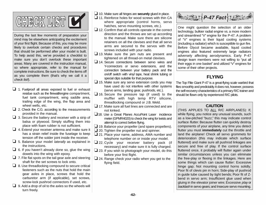
❏ 1. Fuelproof all areas exposed to fuel or exhaustresidue such as the firewall/engine compartment,fuel tank compartment, wing saddle area,trailing edge of the wing, the flap area andwheel wells, etc.
❏ 2. Check the C.G. according to the measurementsprovided in the manual.
❏ 3. Secure the battery and receiver with a strip ofbalsa or plywood. Simply stuffing them intoplace with foam rubber is not sufficient.
❏ 4. Extend your receiver antenna and make sure ithas a strain relief inside the fuselage to keeptension off the solder joint inside the receiver.
❏ 5. Balance your model laterally as explained inthe instructions.
❏ 6. If you haven’t already done so, glue the wingdowels into the wing with epoxy.
❏ 7. File flat spots on the tail gear axle and steeringshaft for the set screws to lock onto.
❏ 8. Use threadlocking compound to secure criticalfasteners such as the nuts that hold the maingear axles in place, screws that hold thecarburetor arm (if applicable), set screws,screw-lock pushrod connectors if used, etc.
❏ 9. Add a drop of oil to the axles so the wheels willturn freely.
❏ 10. Make sure all hinges are securely glued in place.❏ 11. Reinforce holes for wood screws with thin CA
where appropriate (control horns, servohatches, servo mounting screws, etc.).
❏ 12. Confirm that all controls operate in the correctdirection and the throws are set up accordingto the manual. Make sure there are siliconeretainers on all the clevises and that all servoarms are secured to the servos with thescrews included with your radio.
❏ 13. Make sure the jam nuts are present andtightened on all thread-on metal clevises.
❏ 14. Secure connections between servo wires andY-connectors or servo extensions, and theconnection between your battery pack and theon/off switch with vinyl tape, heat shrink tubing orspecial clips suitable for that purpose.
❏ 15. Make sure any servo extension cords you mayhave used do not interfere with other systems(servo arms, landing gear, pushrods, etc.).
❏ 16. Secure the pressure tap (if used) to themuffler with high temp RTV silicone,threadlocking compound or J.B. Weld.
❏ 17. Make sure all fuel lines are connected and arenot kinked.
❏18. Use a Great Planes AccuPoint Laser incidencemeter (GPMR4020) to check the wing for twists andattempt to correct before flying.
❏ 19. Balance your propeller (and spare propellers).❏ 20. Tighten the propeller nut and spinner.❏ 21. Place your name, address, AMA number and
telephone number on or inside your model.❏ 22. Cycle your receiver battery pack (if
necessary) and make sure it is fully charged.❏ 23. If you wish to photograph your model, do this
before your first flight.❏ 24. Range check your radio when you get to the
flying field.
FLYINGThe Top Flite Giant P-47 is a great-flying scale warbird thatflies smoothly and predictably.It does not, however, possessthe self-recovery characteristics of a primary R/C trainer andshould be flown only by experienced R/C pilots.
CAUTION(THIS APPLIES TO ALL R/C AIRPLANES): If,while flying, you notice any unusual sounds, suchas a low-pitched “buzz,” this may indicate controlsurface flutter. Because flutter can quickly destroycomponents of your airplane, any time you detectflutter you must immediately cut the throttle andland the airplane! Check all servo grommets fordeterioration (this may indicate which surfacefluttered) and make sure all pushrod linkages aresecure and free of play. If the control surfacefluttered once, it probably will flutter again undersimilar circumstances unless you can eliminatethe free-play or flexing in the linkages. Here aresome things which can cause flutter: Excessivehinge gap; Not mounting control horns solidly;Poor fit of clevis pin in horn; Side-play of pushrodin guide tube caused by tight bends; Poor fit of Z-bend in servo arm; Insufficient glue used whengluing in the elevator joiner wire; Excessive play orbacklash in servo gears;and Insecure servo mounting.
One might question the selection of an oldertechnology, bulkier radial engine vs. a more modernand streamlined “V” engine for the P-47. A problemof “V” engines is their liquid cooling systems(including a radiator) which is susceptible to gun fire.Before Glycol became available, liquid cooledengines also featured extremely large radiatorsadversely affecting aerodynamics. Early P-47design team members were not willing to “put alltheir eggs in one basket” and utilized “V” engines forsome of their other projects.
During the last few moments of preparation yourmind may be elsewhere anticipating the excitementof your first flight. Because of this, you may be morelikely to overlook certain checks and proceduresthat should be performed after your model is built.To help avoid this, we’ve provided a checklist tomake sure you don’t overlook these importantareas. Many are covered in the instruction manual,so where appropriate, refer to the manual forcomplete instructions.Be sure to check the items offas you complete them (that’s why we call it a check list!).
-62-
Fuel mixture adjustment
A fully cowled engine may run at a higher temperaturethan an un-cowled engine. For this reason, the fuelmixture should be richened so the engine runs atabout 200 rpm below peak. By running the engineslightly rich, you will help prevent dead stick landingscaused by overheating.
Takeoff
Before you get ready to takeoff, see how the modelhandles on the ground by doing a few practice runsat low speeds on the runway. Hold “up” elevator tokeep the tail wheel on the ground. If necessary,adjust the tail wheel or main wheels until the modelrolls straight down the runway. If you need to calmyour nerves before the maiden voyage, shut theengine down and bring the model back into the pits.Top off the fuel, then check all fasteners and controllinkages for peace of mind. Takeoff on highrates–especially if you are taking off into acrosswind. For your first few flights takeoff with theflaps retracted (up). Later, the takeoff roll can beshortened by taking off with half-flaps.
When you’re ready for takeoff, point the modelstraight down the runway, hold a bit of up elevator tokeep the tail on the ground to maintain tail wheelsteering, then gradually advance the throttle. As themodel gains speed decrease up elevator allowingthe tail to come off the ground. One of the mostimportant things to remember with a tail dragger is toalways be ready to apply right rudder to counteractthe torque of the engine, keeping the model headingstraight. Gain as much speed as your runway andflying site will safely allow before gently applying upelevator, lifting the model into the air. At this momentit is likely that you may need to apply more rightrudder to counteract engine torque. Be smooth onthe elevator stick, allowing the model to establish agentle climb to a safe altitude before turning into thetraffic pattern.
For reassurance and to keep an eye on other traffic,it is a good idea to have an assistant on the flight linewith you. Tell him to remind you to throttle back oncethe plane gets to a comfortable altitude. While fullthrottle is usually desirable for takeoff, most scalemodels fly more smoothly and more scale-like atreduced speeds.
FlightTake it easy with your P-47 for your first few flights,gradually getting acquainted with it as your enginebreaks in. Adjust the trims to maintain straight andlevel flight. After flying around for a while, and still ata safe altitude, execute practice landing approachesby reducing the throttle and extending the gear tosee how the model handles at slower speeds. If youplan to land with the flaps, practice slow flight andlanding approaches with the flaps extended whilestill at a comfortable altitude. Add power to see howshe climbs with flaps as well. Continue to fly around,executing various maneuvers and making mentalnotes (or having your assistant write them down) ofwhat trim or C.G. changes may be required to finetune the model so it flies the way you like. Mind yourfuel level, but use this first flight to become familiarwith your model before landing.
LandingLandings may be executed with or without flaps.Modelers unfamiliar with flaps usually make their firstfew landings without them, but learn to prefer landingwith flaps later on. If you are unsure, you couldalways land with the flaps set to half of their fullsetting. Mix down elevator with flaps as described inthe “Control Throws” section on page 59 of themanual. If you are landing without flaps, the nose ofthe model will pitch down slightly when the landinggear is extended. When you’re ready to land withflaps, maintain an engine R.P.M. that is slightlyhigher than normal to overcome the additional drag.Flaps should be extended after the throttle andairspeed have been reduced and the model is on thedownwind leg of the landing pattern.
To initiate a landing approach, make your final turntoward the runway (into the wind) keeping the nosedown to maintain airspeed and control. Level theattitude when the model reaches the runwaythreshold, modulating the throttle as necessary tomaintain your glide path and airspeed. If you aregoing to overshoot, smoothly advance the throttle(always ready on the right rudder to counteracttorque) and climb out to make another attempt.When you’re ready to make your landing flare andthe model is a foot or so off the deck, smoothlyincrease up elevator until it gently touches down.Once the model is on the runway and has lost flyingspeed, hold up elevator to place the tail on theground, regaining tail wheel control. Refrain fromusing flaps during dead-stick landings unless you’renear the runway and already lined-up. Withoutpower, flaps will reduce the model’s range causing itto land shorter than you may normally expect.
Have a ball! But always stay in control and fly ina safe manner.
GOOD LUCK AND GREAT FLYING!
-63-
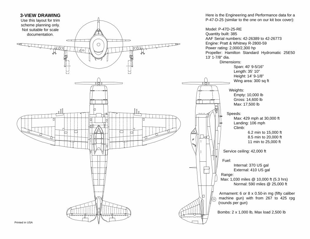
3-VIEW DRAWINGUse this layout for trimscheme planning only.Not suitable for scale
documentation.
Here is the Engineering and Performance data for aP-47-D-25 (similar to the one on our kit box cover):
Model: P-47D-25-REQuantity built: 385AAF Serial numbers: 42-26389 to 42-26773Engine: Pratt & Whitney R-2800-59Power rating: 2,000/2,300 hpPropeller: Hamilton Standard Hydromatic 25E5013' 1-7/8" dia.
Dimensions:Span: 40' 9-5/16"Length: 35' 10"Height: 14' 9-1/8"Wing area: 300 sq ft
Weights:Empty: 10,000 lbGross: 14,600 lbMax: 17,500 lb
Speeds:Max: 429 mph at 30,000 ftLanding: 106 mphClimb:
6.2 min to 15,000 ft8.5 min to 20,000 ft11 min to 25,000 ft
Service ceiling: 42,000 ft
Fuel:Internal: 370 US galExternal: 410 US gal
Range:Max: 1,030 miles @ 10,000 ft (5.3 hrs)
Normal: 590 miles @ 25,000 ft
Armament: 6 or 8 x 0.50-in mg (fifty calibermachine gun) with from 267 to 425 rpg(rounds per gun)
Bombs: 2 x 1,000 lb, Max load 2,500 lb
Printed in USA
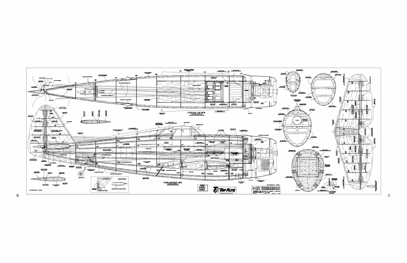
B C
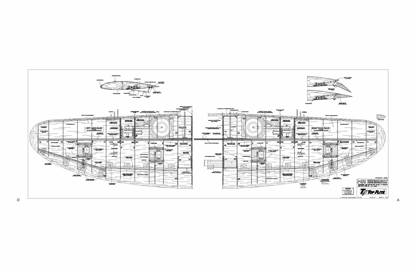
AD