Embed Size (px)
Citation preview
FILE COPY NO. I-W n
NATIONAL ADVISORy COMMITTEE FOR AERONAUTICS
WARTIME REPORT ORIGINALLY ISSUED
October l$kk as Advance Restricted Report IAE31
WIND-TUNNEL CALIBRATION AND CORRECTION PROCEDURES
FOR THREE-DIMENSIONAL MODELS
By Robert S. Swanson and Clarence L. (Jillis
Langley Memorial Aeronautical Laboratory Langley Field, Via.
G ASE FILE COPY
WASHINGTON
NACA WARTIME REPORTS are reprints of papers originally issued to provide rapid distribution of advance research results to an authorized group requiring them for the war effort. They were pre- viously held under a security status but are now unclassified. Some of these reports were not tech- nically edited. All have been reproduced without change in order to expedite general distribution.
L-l
NACA ARR No. L4E31 RESTRICTED
NATIONAL ADVISORY COMMITTEE FOR AERONAUTICS
ADVANCE. RESTRICTED REPORT
WIND-TUNNEL CALIBRATION AND CORRECTION PROCEDURES
FOR THREE-DIMENSIONAL MODELS
By Robert S. Swanson and Clarence L. GIllIs
SUMMARY
Detailed methods are presented for determining the corrections to result? from wind-tunnel tests of three- dimensional models for the effects of the model-support system, the nonuniform air flow in the tunnel, and the tunnel walls or jet boundaries. The procedures for determining the corrections are illustrated by equations and the required tests are discussed. Particular atten- tion" Is given to the parts of the procedures dealing with drag measurements. Two general methods that are used for determining and applying the corrections to force tests are discussed. Some discussion is also included of the correction procedures -to be used for wake survey tests. The methods described in this report apply only to tests at subcritical speeds.
INTRODUCTION
The purpose of the present report is to discuss methods for determining the air-flow conditions in wind tunnels designed for the testing of three-dimensional model? and to Indicate the procedure for applying the necessary corrections to the measured aerodynamic char- acteristics of the model. The various factors that affect the applicability of wind-tunnel tests to flight have been studied for many years. (See references and bibliography.) Recently, with the development of cleaner airplanes operating at high lift coefficients and of large high-speed low-turbulence wind tunnels, the problem of determining the corrections to the required degree of accuracy has become increasingly acute.
RESTRICTED

^ NACA ARR No. L4E31
The usual practice of predicting the flying qualities of airplanes from wind-tunnel tests of relatively small- scale models makes it imperative that the model test results he corrected to free-air conditions. In addition, the large number of wind tunnels in use makes it desirable that a more or less standard calibration and correction procedure be adopted in order to make data from different tunnels as nearly comparable as possible. Not much com- prehensive information has been published previously on the subject of wind-tunnel calibration and correction methods. The discussion contained in reference 1 is probably the be."t information to date. A discussion is given in the present report of the methods in use at the present time for calibrating a wind tunnel and determining the corrections to be applied to the measured model data. Some refinements to the usual procedures are suggested with special attention to those parts of the procedure that affect the drag measurements. The use of large models in order to more nearly approach the Reynolds numbers obtained in flight has increased the magnitude and thus the importance of the jet-boundary corrections. A detailed discussion of jet-boundary corrections is not given herein, however, because thi*1 subject, except for the effects of compressibility, has been treated rather thoroughly in previous publications. (See refer- ences 2 to 12.)
All the following discussion applies only to tests made at subcritical speeds and for arrangements giving fairly low restriction effects. The discussion is also limited to three-dimensional-model tests. The procedures described comprise only the part of the tunnel-testing technique concerned with determining the corrections to the model data necessitated by the differences between the air-flow conditions in the tunnel and those in an unlimited uniform air stream with the same Reynolds number, Mach number, turbulence, and other factors. For purposes of simplicity, only three components - lift, drag, and pitching moment - are considered in most of the discussion. Corrections to the other three components may be derived by procedures similar to those given herein. During the conversion of the data to final form, it will usually be necessary to apply some corrections for the deflections of the balance system and to transfer the forces and moments to other sets of axes but, since these corrections are essentially geometric and not aerodynamic problems, they are not dealt with in this report.
NACA ARR No. L4E21 :
SYMBOLS
CL lift coefficient
Cj section lift coefficient
L lift
I section lift
CD drag coefficient
C-n profile-drag coefficient
c^ section profile-drag coefficient
D drag
d section drag
C^ resultant-force coefficient
Cm pitching-moment coefficient
C7, rolling-moment coefficient
Cn yawing-moment coefficient
Cy lateral-force coefficient
K drag correction at zero lift
Pc compressibility factor
H total pressure
M Mach number
R gas constant
A cross-sectional area of body
A1 cross-sectional area of test section of tunnel
V free-stream velocity
v volume of body

4 KACA ARR No. L4S31
v' effective volume of body for static-pressure- gradient corrections (denoted by A' in references 2 and 3)
5 wing area
b wing span
c wing chord
y spanwise distance from center of tunnel
i^. angle of incidence of horizontal tail surface
T absolute stagnation temperature at low-speed section of tunnel
Ta absolute temperature at test section of tunnel
h static-orifice pressure difference
p static pressure
q dynami c pre ssure
a angle of attack
p air density
3 angle used in derivation of alinement-angle
( -l GDA correction [ ß = tan x -=~^- ) x °W Y ratio of specific heat at constant pressure to
specific heat at constant volume
e alinement angle, degrees (angle between air- stream direction and drag axis of balance system)
he. change in alinement angle
ratio of increment of dynamic pressure to clear- tunnel dynami c press ure
NACA ARR No. L4L31 5
Subscripts
In alinement-angle equations;
S scale reading
E erect-model test
I Inverted-model test
av average
w weighted according to span-load distribution
In tare equations:
1 test of model on tare support
2 test of model on tare support with dummy support In place
3 test of model on normal support
M model
T tare support
D dummy support
N normal support
I Interference
Combinations of these conditions (MT, MD, etc.) are also used as subscripts in the tare equations.
The NACA standard system of wind axes is used for all equations.
GENERAL DISCUSSION
Basic Corrections Necessary
Before the results of wind-tunnel tests on a model can be used to predict the flying qualities of an air- plane, correction? to the measured aerodynamic character- istics must be determined to account for the effects of
II AC A ARR No. L4E31
the model-support system, the nonuniform air-flow condi- tions in the tunnel, and the tunnel walls or jet bounda- ries.
Tares.- The corrections for the effects of the model-support system are usually determined In the form of increments of forces and moments or the corresponding coefficients and are called tares. The tares are com- posed of the direct air forces on the support system plus the mutual interference between the support system and the model. It could be expected, therefore, that the tares would be greatly dependent on the size and shape of supports, the configuration of the model, and the point of attachment of the supports to the model. The relatively great effect of the model configuration on the tares is illustrated in figure 1, which presents some tare values measured In the Langley 7- by 10-foot tunnel for two different models under several test con- ditions.
Because of their dependence upon the support and model configuration, the tares should be determined experimentally for each model. The tare tests should be made with the complete model including tail surfaces. This condition is necessary because the tail of the model may pass into or out of a region of reduced velocity behind the support struts as the model Is pitched or yawed and may thus affect the pitching moments and yawing moments. The tares should be deter- mined for all test conditions to be encountered, such as the conditions with the flap neutral and deflected, with the model yawed, with several power conditions, and with any model modification that might affect the tares. This requirement is particularly important when accurate drag measurements, are desired because, as indi- cated in figure 1, the drag tares may often be greater than the drag of the airfoil.
Nonuniform air-flow conditions.- The nonuniformi- ties In the air stream may be thought of as belonging in the three following categories:
(1) A change in the average airspeed along the longitudinal axis of the tunnel
(2) A variation in airspeed over a plane perpen- dicular to the longitudinal axis
MACA ARR No. L4531
(3) A variation In the air-flow angle In the region occupied by the model
. The change in the average airspeed along the axis of the tunnel is caused by any actual or effec- tive convergence or divergence of the air stream. This change in velocity along the axis of the tunnel causes a variation in the static pressure and a correc- tion must be applied to the drag to account for the buoyancy effect of any such static-pressure gradient. For an open-throat tunnel the possibility of having a diverging or converging air stream is obvious. For a closed-throat tunnel the formation of a boundary layer along the walls of the test section changes the effec- tive shape of the tunnel. Closed-throat tunnels are usually designed with a slightly divergent test section to counteract this effect but in any case the static- pressure gradient must be measured. The tunnel leakage conditions can have a very marked effect on the static- pressure gradient (references 2 and Z) because a leak in the tunnel changes its effective shape. All holes in the tunnel walls of the test section should therefore be sealed. If sealing is not possible, the amount of leakage should be maintained as nearly constant as pos- sible.
The airspeed generally varies slightly from point to point in a plane perpendicular to the tunnel axis. The usual procedure for correcting the test results for this variation in velocity is to use the average value of the dynamic pressure over the space occupied by the model in computing the model coefficients.
The deviation of the direction of the air velocity from the drag axis of the balance system over the region occupied by the model has a considerable effect on the measured model characteristics, particularly on the drag. Lift and drag are defined as the forces parallel and perpendicular, respectively, to the air- stream direction. If the average alinement angle f is not zero, the lift and drag forces measured by tie balance system will not be the true lift and drag as may easily be seen from the following derivation:
CL = CR cos (ß + 0
= CR (cos ß cos e - sin ß sin c)
8 NACA ARR No. L4E31
Inasmuch as e Is a small angle, cos e «1.0 and Therefore,
Cr = CR cos p - 5775 CR sin ß
sin € - ^Tr-^' Therefore,
(1)
Similarly,
GD = CR sin (ß + e)
= CR (sin ß cos e + cos 8 pin e)
= CR sin 3 + gTjr-j CR cos ß
~ CDS + 5773 GLS (2^
This derivation may be applied to either the erect-model or inverted-model condition as indicated in figure 2.
Because the alinement angle Is small and because the lift is generally many times greater than the drag, the lift is not appreciably affected by the alinement angle and is considered correct as read, insofar as the allne- ment angle is concerned. The drag, however, is appre- ciably affected and a correction must be applied as is explained in detail in the section entitled "Allnement- Angle Corrections." The angle of attack must also be corrected by the amount of the average alinement angle and, if there is a difference in the measured alinement angle at the wing and at the usual location of the tail surface1?, a correction to the model trim (pitching- moment) condition must be made.
Jet-boundary correction.?.- The tunnel walls, or jet boundaries, place certain restrictions on the air flow around the model and thus cause a change In the direction and curvature of the air stream and a change in the airspeed at the model. The amount of the restriction is, of course, dependent on the cross- sectional shape of the tunnel, the model configuration, the relative sizes of the model, and the tunnel, and the position and attitude of the model in the tunnel. For
NACA ARR No.
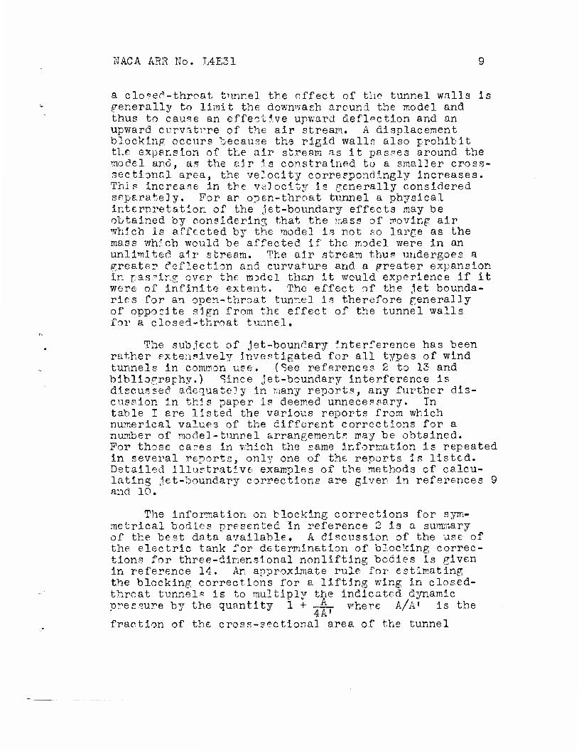
a clo^et^-throat tunr.el the offect of the tunnel walls is generally to limit the downwash around the model and thus to cause an effective upward deflection and an upward curvatrre of the air stream. A displacement clocking occurs because the rigid walls also prohibit the expansion of the air stream as it passes around the model and, as the air is constrained to a smaller cross- sectional area, the velocity correspondingly increases. This increase in the velocity is generally considered separately. For ar open-throat tunnel a physical interpretation of the jet-boundary effects may be obtained by considering that the mass of moving air which is affected by the model is not so large as the mass which would be affected if the model were in an unlimited air sbream. The air stream thus undergoes a greater deflection and curvature and a greater expansion in passing over the model than it would experience if it were of infinite extent. The effect of the jet bounda- ries for an open-throat tunnel is therefore generally of opposite sign from the effect of the tunnel walls for a closed-throat tunnel.
The subject of jet-boundary interference has been rather extensively investigated for all types of wind tunnels in common use. (See references 2 to 13 and bibliography.) Since jet-boundary interference is discussed adequately in many reports, any further dis- cussion in this paper is deemed unnecessary. In table I are listed the various reports from which numerical values of the different corrections for a number of model-tunnel arrangements may be obtained. For those ca?es in which the same information is repeated in several reports, only one of the reports is listed. Detailed illustrative examples of the methods of calcu- lating jet-boundary corrections are given in refei'ences 9 and 10.
The information on blocking corrections for sym- metrical bodies presented in reference 2 is a summary of the best data available, A discussion of the use of the electric tank for determination of blocking correc- tions for three-dimensional nonlifting bodies is given in reference 14. An approximate rule for- estimating the blocking corrections for a lifting wing in closed- throat tunnels is to multiply the indicated dynamic pressure by the quantity 1 + -JL- where A/A' IS the
4A1 fraction of the cross-sectional area of the tunnel

10 NACA ARR No. I4S31
blocked off by the model. This simple empirical factor was derived from the results of unpublished tests- to determine the blocking correction for the lift of two- dimensional-flow models as well as from results of a few tests to determine the corrections for three- dimensional wings. It should be noted that the data on blocking corrections for symmetrical bodies given in reference 2 indicate that the correction varies as the square of the area blocked off, whereas the experimental data on lifting wings indicate that the correction varies linearly as the area blocked off. The numerical values are roughly the sane, however, for the usual moderate-size models. The simple rule for estimating the correction Is fairly accurate for aerodynamlcally clean bodies such as plain wings. For bluff bodies or bodies of any other form that creates a large wake, such as a wing with a split flap, an additional correc- tion due to the static-pressure gradient generated by the wake should be made as outlined in reference 2. This additional correction is In good agreement v/ith the experimentally determined additional correction obtained from the tests with split flaps deflected.
The calculations of reference 2 indicate that for en open-throat tunnel the change In dynamic pressure caused by blocking effect for an aerodynamlcally clean body Is of the opposite sign and much smaller In magni- tude than that for a closed-throat tunnel. The addi- tional correction for the blocking effect caused by the wake static-pressure gradient of a bluff body is essen- tially zero In an open-throat tunnel.
Criterions of Similitude
The criterions of similitude that are of primary Importance to wind-tunnel testing are the air-stream turbulence, the Reynolds number, and the Mach number. It is rarely possible to satisfy these three criterions simultaneously on the model. The usual procedure Is to attempt to satisfy one or two. of the criterion? that would be expected to have the greatest effect for the tests under consideration.
Turbulence is defined as a rapid variation In velocity at a point with time. Although the qualitative effects of turbulence are fairly well known, the theory and data available are not sufficient to permit the

MCA ARR No. L4E31 U
determination of satisfactory corrections. For any tunnel, however, the numerical value of the turbulence should be known in order to facilitate a comparison of the data with data from other wind tunnels or from flight tests or to study further the turbulence effects. The Reynolds number and Mach number are also quantities for which no completely satisfactory methods of correction have been devised. For purposes of comparison with other data, their values should be known, however, and specified for all model tests for which they are likely to have an effect. Because the support system causes local changes in the air flow, it may be desirable for some tests, in which Mach number effects are especially critical, to specify not only the average Mach number of the air flow but also the local Mach numbers near the supports.
Correction Methods
The successful application of corrections to wind- tunnel data is dependent on the type of tunnel used for testing. Two methods are available for general use and for convenience are designated herein method A and method B. Method A, which is based on a clear-tunnel air-flow survey, is more straightforward and is believed, to be more accurate than method B, which is based on a survey with the model support struts in place. The main emphasis of the discus- sion contained herein is therefore placed on method A. Method B is recommended only for use in large open tunnels in which mechanical difficulties associated with mounting exact-image supports above the model for tare and aline- ment estimations become excessive.
Method A.- This method is based on an air-flow survey with no model or supports in the tunnel (to be called the clear-tunnel survey) and the tares are deter- mined in such a way as to include all the effects caused by the support struts or wires. The tares are ordinarily the first corrections to be applied to the measured data. If the tares are defined as the total effect of the support system, their subtraction from the measured data leaves the data in a condition representing the model in the tunnel with no support system. The effect of the dynamic-pressure change caused by the presence of the supports having been accounted for, the dynamic pressure to be used in computing the coefficients is that obtained from the clear-tunnel air-flow survey. The next correc- tions to be applied are the corrections to the angle of attack and drag to account for the alinement angle and the static-pressure gradient, also determined from the clear-tunnel survey. The data are now corrected for the

12 NAG A ARR No. L4E31
effects of the support system and the nonuniform!ties In the air stream. If the let-boundary corrections are applied along with the blocking corrections, the data then represent the model in an unlimited uniform air stream. Although, properly speaking, the blocking cor- rection Is an effect caused by the presence of the tunnel walls or jet boundaries, it Is most easily applied in the second step simply as a correction to the value of q used In computing the coefficients. One variation from this procedure, which is sometimes used, is to apply the let-boundary corrections before the tare corrections. The tares must then be corrected for jet-boundary Interference. The difference in the results from the two methods will generally be negligible. In this report the tares will be determined so that they may be applied first.
Method E.- As has been previously noted, method B is based on an air-flow survey with the support struts in place. The tares determined by use of this method Include any effects of the support system that have not been accounted for in the air-flow survey. If the basic . air-flow survey is made with the supports in place, the effect of the supports in causing changes in dynamic pressure and air-flow angularity has been accounted for. The tares for this system should then include only the air forces on the exposed parts of the support system plus the effects of the model on the supports. The procedure for determining the tares by this method is different from that of method A. After the tares have been applied, the coefficients are computed with a dynamic-pressure value for the supports in place. The correction procedure from this point on is the same for method E as for method A.
Wake-Shadow Effec t s
Some additional effects that should be accounted for in both correction methods are those caused by the "wake shadow.1' The wake shadow is defined as the loss In total pressure and dynamic pressure and the possible changes In air-flow angle, static pressure, and turbu- lence that occur when the wake of the model is carried around the return passages of the tunnel without being diffused or dissipated. The change in q caused by the wake is called wake blocking. The effect of wake block- ing on the model may be taken care of by applying a
NACÄ ÄRR No. L4E31 13
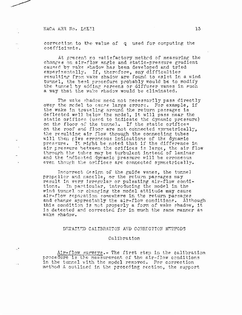
correction to the value of q used for computing the coefficients.
At present no satisfactory method of measuring the changes on air-flow angle and static-pressure gradient caused by wake shadow ha? been developed and tried experimentally. If, therefore, any difficulties resulting from wake shadow are found to exist in a wind tunnel, the best procedure probably would be to modify the tunnel by adding screens or diffuser vanes in such a way that the wake shadow would be eliminated.
The wake shadow need not necessarily pass directly over the model to cause large errors. For example, if the wake in traveling around the return passages is deflected well below the model, it will pass near the static orifices (used to indicate the dynamic pressure) on the floor of the tunnel. If the static orifices on th will then give erroneous indications of the dynamic pressure. It might be noted that if the difference in air pressure between the orifices is large, the air flow through the tubes may be turbulent instead of laminar and the indicated dynamic pressure will be erroneous even though the orifices are connected symmetrically.
n the floor of the tunnel. If the static orifices n the roof and floor are not connected symmetrically, he resulting air flow through the connecting tubes
Incorrect design of the guide vanes, the tunnel propeller and nacelle, or the return passages may result in very irregular or pulsating air-flow condi- tions. In particular, introducing the model in the wind tunnel or changing the model attitude may cause air-flow separation somewhere in the return passages and change appreciably the air-flow conditions. Although this condition is not properly a form of wake shadow, it is detected and corrected for in much the same manner as wake shadow.
DETAILS CALIBRATION AND CORRECTION METHODS
Calibration
Air-flow surveys.- The first step in the calibration procedure Is the measurement of the air-flow conditions in the tunnel with the model removed. For correction method A outlined in the preceding section, the support

14 NACA ARR No. L4E31
struts must also be removed from the tunnel. For correc- tion method E, the support struts must remain in the tunnel. The first source of inaccuracy of the second system may he mentioned here. It is difficult to measure the dynamic pressure near and at the support system because, in practice, part of the support system is enclosed in the model and any changes in velocity caused by these otherwise enclosed parts are thus errors.
The air-flow surveys should be made over a plane perpendicular to the air stream at the position to be occupied by the wing of a model to be tested. Usually this position is at, or very near, the support-strut location. The survey should be made at various points on a line across the tunnel at several heights to cover all possible model variations. This original tunnel survey should be made rather accurately and completely. Unless some alterations are made to the tunnel or unless some, change in the air-flow conditions has been indi- cated, only occasional check surveys will be necessary.
The measurements over this survey plane may be made with a combined pitch, yaw, and pitot-static tube and with manometers measuring total pressure, static pres- sure, and air-flow angularity with respect to the drag axis of the balance system. Some details on the con- struction and use of these instruments can be found in references 6, 15, and 16. The measurements are made for a constant reading h on the manometer connecting the two sets of static orifices, These orifices are static-pressure holes set into the walls of the tunnel at two sections upstream of the mode]. The difference in pressure between the two sets of orifices is a function of the dynamic pressure. The static orifices at each section should be connected in a symmetrical manner to minimize the effect on the pressure readings of any flow between the orifices caused by the model pressure field or by a wake shadow. Prom the total pressure and static pressure measured at each point in the survey plane, the impact pressure may be obtained. The measurements should be repeated several times to improve the accuracy.
The accurate measurement of the air-flow angularity (or alinement angle) with the yaw head is probably the most difficult part of the tunnel calibration. Most yaw heads cannot be expected to measure angles to a greater accuracy than 0.25° (reference 15). An error
MACA ARR No. L4E31 15
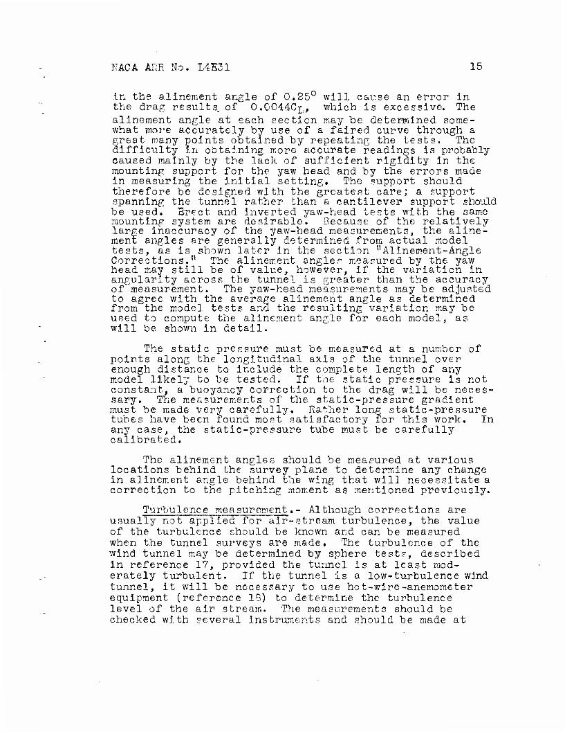
in the alinement angle of 0.25° will cause an error in the drag results, of O.0O44CJ;,, which is excessive. The alinement angle at each section may he determined some- what more accurately hy use of a faired curve through a great many points obtained by repeating the tests. The difficulty in obtaining more accurate readings is probably caused mainly by the lack of sufficient rigidity in the mounting support for the yaw head and by the errors made in measuring the initial setting. The support should therefore be designed with the greatest care; a support spanning the tunnel rather than a cantilever support should be used. Erect and inverted yaw-head tests with the same mounting system are desirable. Because of the relatively large inaccuracy of the yaw-head measurements, the aline- ment angles are'generally determined from actual model tests, as is shown later in the section "Alinement-Angle Corrections." The alinement angler measured by the yaw head may still be of value, however, if the variation in angularity across the tunnel is greater than the accuracy of measurement. The yaw-head measurements may be adjusted to agree with the average alinement angle as determined from the model tests and the resulting variation may be used to compute the alinement angle for each model, as will be shown in detail.
The static pressure must be measured at a number of points along the longitudinal axis of the tunnel over enough distance to include' the complete length of any model likely to be tested. If the static pressure is not constant, a buoyancy correction to the drag will be neces- sary. The measurements of the static-pressure gradient must be made very carefully. Rather long static-pressure tubes have been found most satisfactory for this work. In any case, the static-pressure tube must be carefully calibrated.
The alinement angles should be measured at various locations behind the survey plane to determine any change in alinement angle behind the wing that will necessitate a correction to the pitching moment as mentioned previously.
Turbulence measurement.- Although corrections are usually not applied for air-stream turbulence, the value of the turbulence should be known and can be measured when the tunnel surveys are made. The turbulence of the wind tunnel may be determined by sphere tests, described in reference 17, provided the tunnel is at least mod- erately turbulent. If the tunnel is a low-turbulence wind tunnel, it will be necessary to use hot-wire-anemometer equipment (reference 18) to determine the turbulence level of the air stream. The measurements should be checked with several instruments and should be made at
16 NACA ARR No. L4E31
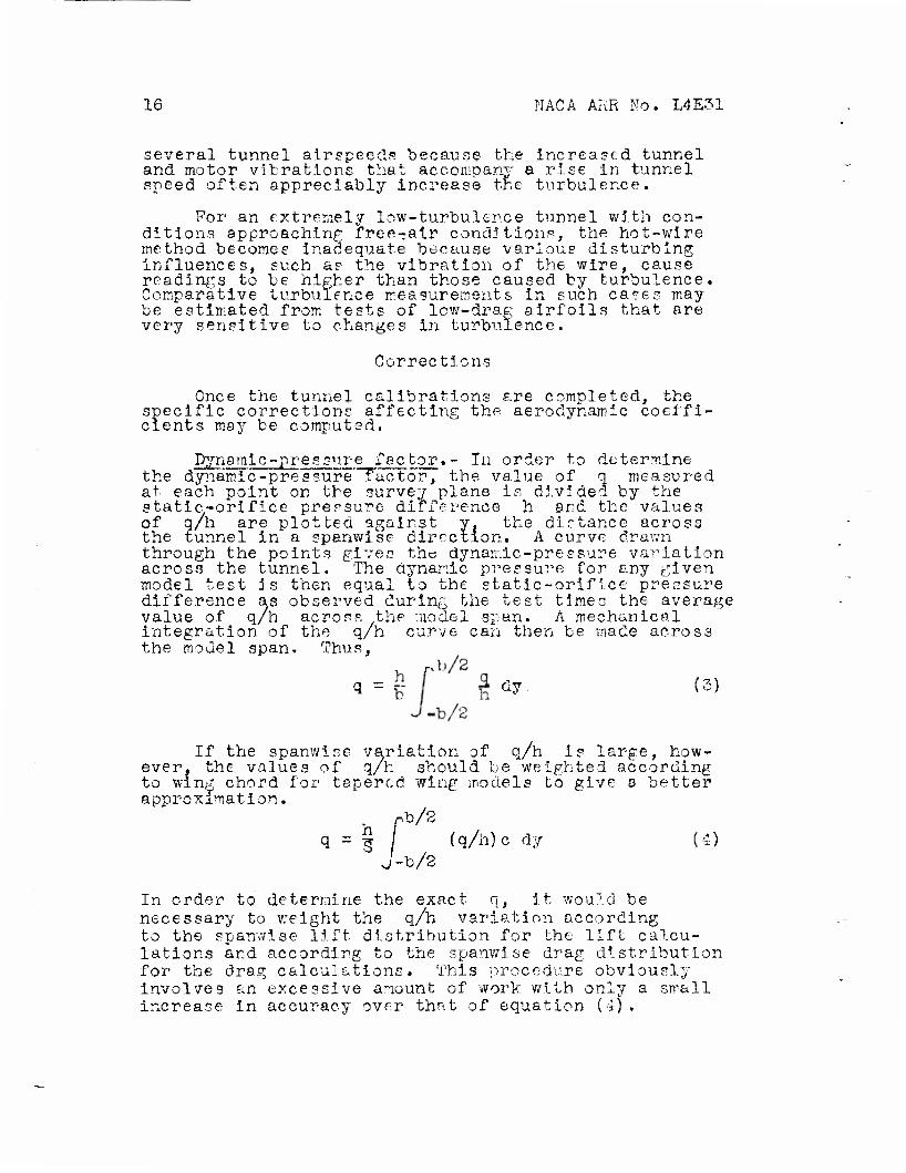
several tunnel airspeeds because the Increased tunnel and motor vibrations that accompany a rise in tunnel speed often appreciably increase the turbulence.
For an extremely low-turbulence tunnel with con- ditions approaching free-air condition.?, the hot-wire method becomes Inadequate "because various disturbing Influences, such as the vibration of the wire, cause readings to be higher than those caused by turbulence. Comparative turbulence measurements In such cases may be estimated from tests of low-drag airfoils that ere very sensitive to changes in turbulence.
Corrections
Once the tunnel calibrations are completed, the specific corrections affecting the aerodynamic coeffi- cients may he computed.
Dynamic-pressure factor.- In order to determine the dynamic-pressure factor, the value of q measured at each point on the survey plane is divided by the static-orifice pressure difference h and the values of q/h are plotted against y. the distance across the tunnel in a spanwise direction. A curve drawn through the points gives the dynamic-pressure variation across the tunnel. The dynamic pressure for any given model test is then equal to the static-orifice pressure difference as observed during the test times the average value of q/h across the model span. A mechanical integration of the q/h curve can then be made across the model span. Thus,
, r>h/2 dy. (5)
If the spanwise variation of q/h is large, how- ever, the values of q/h should be weighted according to wing chord for tapered wing models to give a better approximation.
, nb/2 q = § / (q/h)c dy (4)
J-b/2
In order to determine the exact q, it would be necessary to weight the q/h variation according to the spanwise lift distribution for the lift calcu- lations and according to the spanwise drag distribution for the drag calculations. This procedure obviously Involves an excessive amount of work with only a small increase In accuracy over that of equation (4).

NACA ARR No. L4E31 17
If the method of tunnel operation is such that it is possible to maintain a given h during a test run, this procedure may be reversed and the value of h to be used can be calculated for any desired q. Curves may be plotted of q against h as found from equa- tion (4) for a wide range of model spans and plan forms and the density of the manometer liquid should be taken into account. Use of these curves will save time, as they make it unnecessary to compute q or h for each test or each test point.
Corrections to the value of q for the effects of wake blocking and displacement blocking must be made if these effects are found to be appreciable. These cor- rections depend upon the model configuration, however, and are thus not concerned v/ith the clear-tunnel cali- bration.
At speeds in the compressible range, the impact pressure H - p, determined from the air-flow surveys, is larger than the true value of q. The corrected q may be found from the relation
H - p _ 1 (5)
where
= 1 + |M2 40 M
A (6)
In high-speed testing, the Mach number is of primary importance and should be known for all tests. The Mac number may be obtained from the equation
h
2 IT = V - 1 - 1 (7)
If the true velocity is desired for use in computing the Reynolds number or the advance-diameter ratio for power or propeller tests, the air density during the test must be known. In order to calculate this density, it Is necessary to know the temperature of the. air in the
18 KACA ARR No. L4E31
test section. The u^uel method is to measure the tem- perature at the low-speed section ahead of the entrance cone and to calculate the test-section temperature from the equation
V-l Ta ~h H - p\ r (8)
The correct density is then
_ 1 H A II P _ R T ' s*)
iA (9)
As the correct value of both q and p are now known, the velocity can be calculated. "The velocity may also he commuted from the formula
V - MV RT a (10)
If the model is large and near the static orifices, a further correction to q may be necessary to account for the influence of the model pressure field on the static pressure at the orifices. The correction may be calculated with satisfactory accuracy from the known fields of flow around airfoils and streamline bodies in wind tunnels and is generally fairly small.
Alinement-angle corrections.- The alinement angle, obtained from the"yaw-head surveys, is used in cor- recting the angle of attack and the drag. The angle used must be obtained from an Integration (mathematical, or experimental) across the model span. As mentioned previously, however, the angles obtained from the yaw- head surveys are usually not accurate enough for use when precise drag results are desired. For example, consider a low-drag airfoil with a design lift coeffi- cient of 0.4. An alinement-angle error of 0.1° causes an error of 0,0007 In the minimum drag coefficient. A more accurate alinement-angle correction, which may be
NACA ARR Ho. L4E31 19
used, only with correction method A, however, is usually determined from two tests on a model wing. One test is made with the model mounted erect and the other test with the model inverted. From figure 2(a) and the deri- vation of equation (2), the correct drag coefficient for the erect model is
CD = CDg + CL 5773 (11)
The signs of all coefficients and angles are taken with respect to the tunnel. For the inverted model (fig. 2(b)), the correct drag coefficient is
CD = CD„ + CL„ ^—• (12) ^ ^>T ^1 57.3
If all other effects have been accounted for except the alinement angle, the two drag coefficients must be equal at a given lift coefficient
CDQ + CLQ 57.3 -
CDc, + CL<, 57.3 SI SI SE SE
but, according to the sign convention,
CT = -CT LSl LsE
Thus,
CDo - CDo ~K
" = l 2C 'b7'?y (13)
The difference in drag between the value for the model erect and the model inverted is then plotted against lift coefficient and the slope of a straight
20 NACA ARR No. L4E31
line faired through the points is multiplied by 57.3/2 to obtain the average alinement angle In degrees. The accuracy of this procedure depends upon the fact that all other effects have been correctly accounted for. It is necessary therefore to account for the tares with the utrrost precision. In order to avoid actually determining and applying the tare corrections, however, the tests for both the erect and inverted models are made with an exact set of image supports (fig. 3) mounted on the opposite side of the wing from the normal supports. The tares are thus automatically accounted for by this test procedure. It is also very important that the leakage effects around the support strut or fairing be exactly reproduced In the dummies. Tests in two different wind tunnels have shown errors of as much as 0.25 In the alinement angle due to incorrect leakage reproduction. The average allne- ment angle determined In this way will be weighted according to the spanwise load distribution as can be seen from the following derivation:
At any section
Ad = le
- €Czcq dj
The total-drag correction is then
(14)
This correction Is applied to the wind-tunnel data In the form
*CD = eavwCL + K (15)
NACA ARR No. L4E31 21
where K is the drag correction at zero lift and will "be zero if the wing has no aerodynamic twist and the variation of e across the span is not great enough to result in an effective aerodynamic twist. If the alinemcnt angle varies appreciably across the model span, the average value will thus be different for dif- ferent wing configurations. For this reason, alinement- angle tests are frequently made individually for each model tested. It is believed that the extra time required with this procedure is unnecessary and that the accuracy may be increased if a little more time and care are taken in the original tunnel calibration to determine the alinement angle for different wing configurations. Several wings, of different spans and plan forms and preferably with transition fixed by means of transition strips, should be tested with and without partial-span flaps in order to determine the alinement-angle varia- tion with wing configuration. Because the drag coeffi- cients are compared at a constant lift for the erect and inverted model, the airfoil section used will have no effect on the results, unless the airfoil drag is unusually sensitive to transition, surface roughness, and so forth. In this case, much more care is required in the tests.
The alinement-angle measurements made with the yaw head may now be checked by the use of eOTr as deter- avw mined from the force tests," that is, by use of the span load distribution for the wings tested and the alinement- angle distributions from the yaw-head surveys, cavw may he calculated from equations (14) and (15). If the yaw-head determinations are correct, the calculated values of €„.. will agree with the force-test results
within the required accuracy. If they do not, the values of € at each point as determined from the yaw head may be raised or lowered slightly until the calculated and measured values of £av agree. This procedure Is of
use only when the variation of € from point to point across the tunnel is greater than the accuracy of the yaw-head readings. In such cases the yaw head will generally give a smaller percentage error In the varia- tion from point to point than in the absolute value at each point.
I: AC A ARR No. L4E31
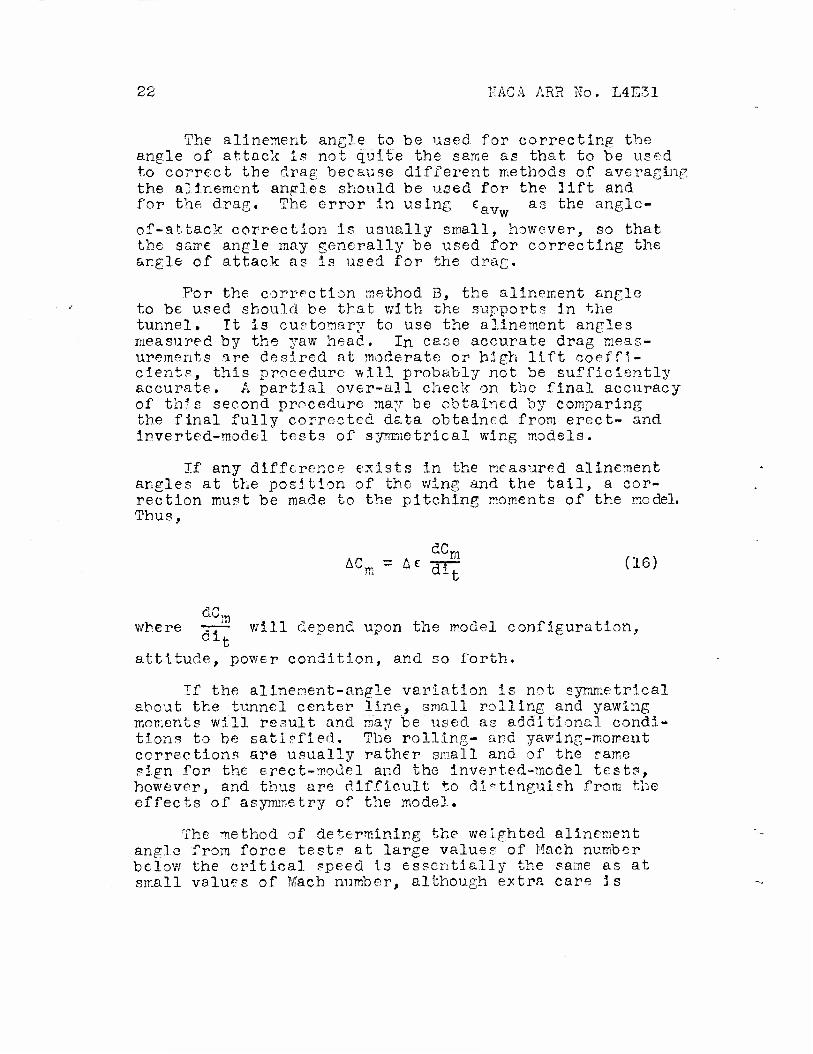
The alinernent angle to be used for correcting the angle of attack Is not quite the same as that to he used to correct the drag because different methods of averaging the alinernent angles should be used for the lift and for the drag. The error In using eav as the angle-
of-attack correction Is usually small, however, so that the same- angle may generally be used for correcting the angle of attack as is used for the drag.
Por the correction method B, the alinernent angle to be used should be that with the supports In the tunnel. It is customary to use the alinernent angles measured by the yaw head. In case accurate drag meas- urements are desired at moderate or high lift coeffi- cients, this procedure will probably not be sufficiently accurate. A partial over-all check on the final accuracy of this second procedure may be obtained by comparing the final fully corrected data obtained from erect- and Inverted-model tests of symmetrical wing models.
If any difference exists In the measured alinernent angles at the position of the wing and the tail, a cor- rection must be made to the pitching moments of the model. Thus,
ACm = Ac ^r-1 (16)
where -rr— will depend upon the model configuration, Glt
attitude, power condition, and so forth.
If the allnement-angle variation is not symmetrical about the tunnel center line, small rolling and yawing moments will result and may be used as additional condi- tions to be satisfied. The rolling- and yawing-moment corrections are usually rather small and of the same sign for the erect-model and the inverted-model tests, however, and thus are difficult to distinguish from the effects of asymmetry of the model.
The method of determining the weighted alinernent angle from force tests at large values of Mach number below the critical speed is essentially the same as at small values of Mach number, although extra care is
NACA ARR No. L4E31 23
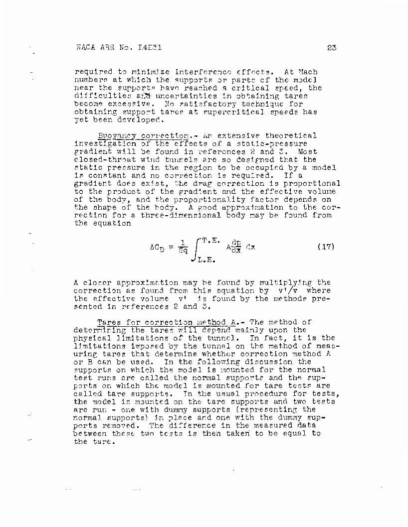
required to minimize interference effects. At Mach numbers at which the supports or parts of the model near the supports have reached a critical speed, the difficulties aj^ä- uncertainties in obtaining tares become excessive. No satisfactory technique for obtaining support tares at supercritical speeds has yet been developed.
Buoyancy correction.- Ar extensive theoretical investigation of the effects of a static-pressure gradient will be found in references 2 and 3. Most closed-throat wind tunnels are so designed that the static pressure in the region to be occupied by a model is constant and no correction is required. If a gradient does exist, the drag correction Is proportional to the product of the gradient and the effective volume of the body, and the proportionality factor depends on the shape of the bod;/. A good approximation to the cor- rection for a three-dimensional body may be found from the equation
JL.E.
A closer approximation ma:/ be found by multiplying the correction as found from, this equation by v'/v where the effective volume v' is found by the methods pre- sented in references 2 and 3.
Tares for correction method A.- The method of determining the tares will depend mainly upon the physical limitations of.the tunnel. In fact, It is the limitations imposed by the tunnel on the method of meas- uring tares that determine whether correction method A or B can be used. In the following discussion the supports on which the model is mounted for the normal test runs are called the normal supports and the sup- ports on which the model is mounted for tare tests are called tare supports. In the usual procedure for tests, the model is mounted on the tare supports and two tests are run - one with dummy supports (representing the normal supports) in place and one with the dummy sup- ports removed. The difference in the measured data between these two tests is then taken to be equal to the tare.
24 NACA ARR No. L4E31
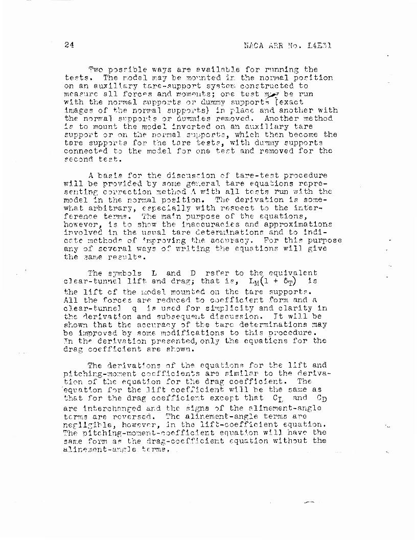
Two possible ways are available for running the tests. The model may be mounted in the normal position on an auxiliary tare-support system constructed to measure all forces and moments; ore test m>f be run with the normal supports or dummy supports [exact images of the normal supports) In place and another with the normal supports or dummies removed. Another method is to mount the model inverted on an auxiliary tare support or on the normal supports, which then become the tare supports for the tare tests, with dummy supports connected to the model for one test and removed for the second test.
A basis for the discussion of tare-test procedure will be provided by some general tare equations repre- senting correction method A with all tests run with the model in the normal position. The derivation Is some- what arbitrary, especially with resnect to the inter- ference terms. The main purpose of the equations, however, is to show the inaccuracies and approximations involved in the usual tare determinations and to indi- cate method? of Improving the accuracy. For this purpose any of several ways of writing the equations will give the same result".
The symbols L and D refer to the equivalent clear-tunnel lift and drag; that is, 1TVI(I + o-p) Is the lift of the model mounted on the tare supports. All the forces are redticed to coefficient form and a clear-tunnel q is used for simplicity and clarity in the derivation and subsequent discussion. Tt will be shown that the accuracy of the tare determinations may be improved by some modifications to this procedure. In th^ derivation presented; only the equations for the drag coefficient are shown.
The derivations of the equations for the lift and pltching-moment coefficients are similar to the deriva- tion of the equation for the drag coefficient. The equation for the .lift coefficient will be the same as that for the drag coefficient except that Cj, and Cn are Interchanged and the signs of the allnement-angle terms are reversed. The allnement-angle terms are negligible, however, in the lift-coefficient equation. The pitching-moment-coefficient equation will have the same form as the drag-coefficient equation without the alinement-angle terms.
NACA ARR No. 14331 25
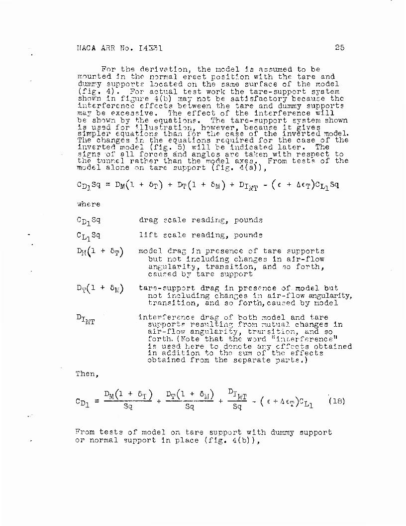
For the derivation, the model is assumed to be mounted in the normal erect position with the tare and dummy supports located on the same surface of the model (fig. 4). For actual test work the tare-support system shown in figure 4(b) may not be satisfactory because the interference effects between the tare and dummy supports ma3r be excessive. The effect of the interference will be shown by the equations. The tare-support system shown Is used for Illustration, however, because it gives simpler equations than for the case of the inverted model. The changes in the equations required for the case of the inverted model (fig. 5) will be Indicated later. The signs of all forces and angles are taken with respect to the tunnel rather than the model axes. From tests of the model alone on tare support (fig. 4(a)),
CD]Sq = DM(l + 5T) + DT(1 + 6M) + Djm - (e + AeT)cLlSq
where
Cj), Sq drag scale reading, pounds
C^ Sq lift scale reading, pounds
Dj/r^l + Sip) model drag in presence of tare supports but not including changes in air-flow angularity, transition, and so forth, caused by tare support
D.p(l + öjA tare-support drag in presence of. model but not Including changes in air-flow angularity, transition, and so forth, caused by model
Dj Interference drag of both model and tare M1 supports resulting from mutual changes in
air-flow angularity, transition, and so forth. (Note that the word "interference" Is used here to denote any effects obtained in addition to the sum of the effects obtained from the separate parts.)
Then,
DM(1 + 5T) DT(l + 6M) % MT °2i = —To + To + ^o~ - (e + A£T)CLI do)
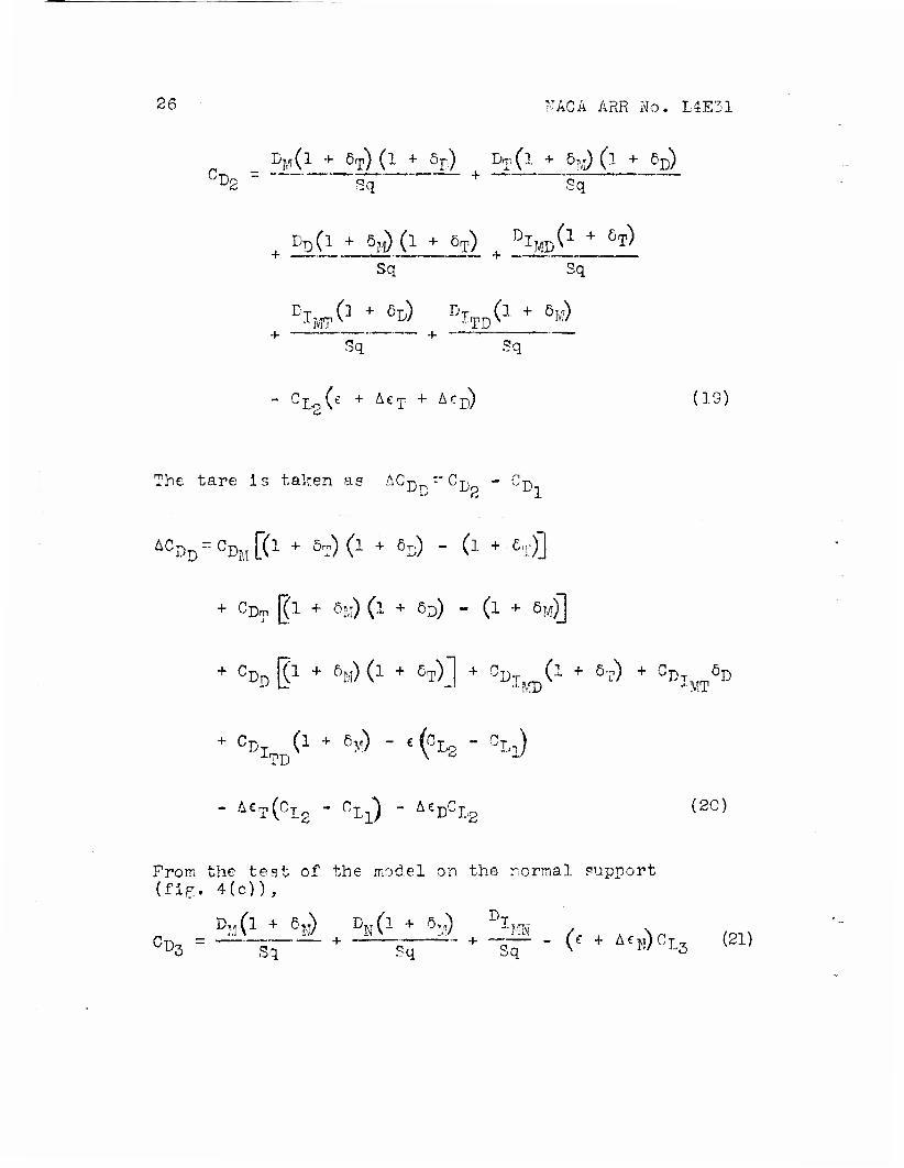
From tests of model on tare support with dummy support or normal support in place (fig. 4(b)),
26 FACä ARR No. L4E31
_ %(l + 6T) (lj- 5^ DT(l + 5M) (l + ÖD)
DD(l + 5F)(l + ÖT) Dl^C1 + 5T) Sq
i^_ +
PTMT(I + 5P) DlTD(l + 5M)
Sq Sq
- CLo(e + AeT + Acr) (19)
The tare is taken as ACD ~CD - GD
&CDD=CDM[(1 + öT)(l 4- 6D) - (l 4- 6T)]
+ CDT [(l 4- 6Iv-) (l 4- öD) - (i 4- 6M)]
+ CDD gl * 6M) (1 + 5T)j 4- cDlM)(l + 6T) + GDIMT5D
+ C%D(1 + 6M) - c(cL2-CLi)
- AcT(CI{3 - CLi) - &eDCL2 (20)
Prom the test of the model on the normal support (fig. 4(c)),
D„(l + 6?(T) Dw(l 4- 5TjT) DI?,W
D3 Sq Sq Sq v r,/ L3
NACA ARR No. L4E-31 27
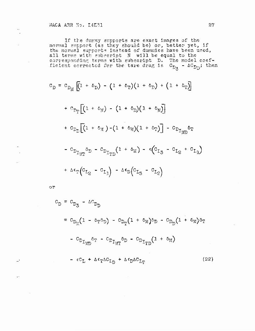
If the dummy supports are exact images of the normal support (as they should be) or, better yet, if the normal support" Instead of dummies have been used, all terms with subscript N will be equal to the corresponding terms with subscript D. The model coef- ficient corrected for the tare drag is Cp - ACD ; then
°D = % I1 + 5D) " C1 + MC1 + 5D) + (1 + 5T)]
+ ^ß1 + 6M) - C1 + 5
D)(] + 8M)]
- % *D " ^J1 + 5M) " <°L3 " CL2 + CLl) MT -LTD
+ Ac K°L2 " °Ll) " A£D(CL3 " CLS)
or
CD ~ CD3 " ACDD
= %(* " 5T5D) - ^(1 + 5
M)5D - CDD(I + eM)oT
- CD 5T - CD 6D - CD (1 + 5M) LMD JMT iTD
- eCL + AeTAClD + ^^CJjJ} (22)
28 MACA ÄRR No. L4E31
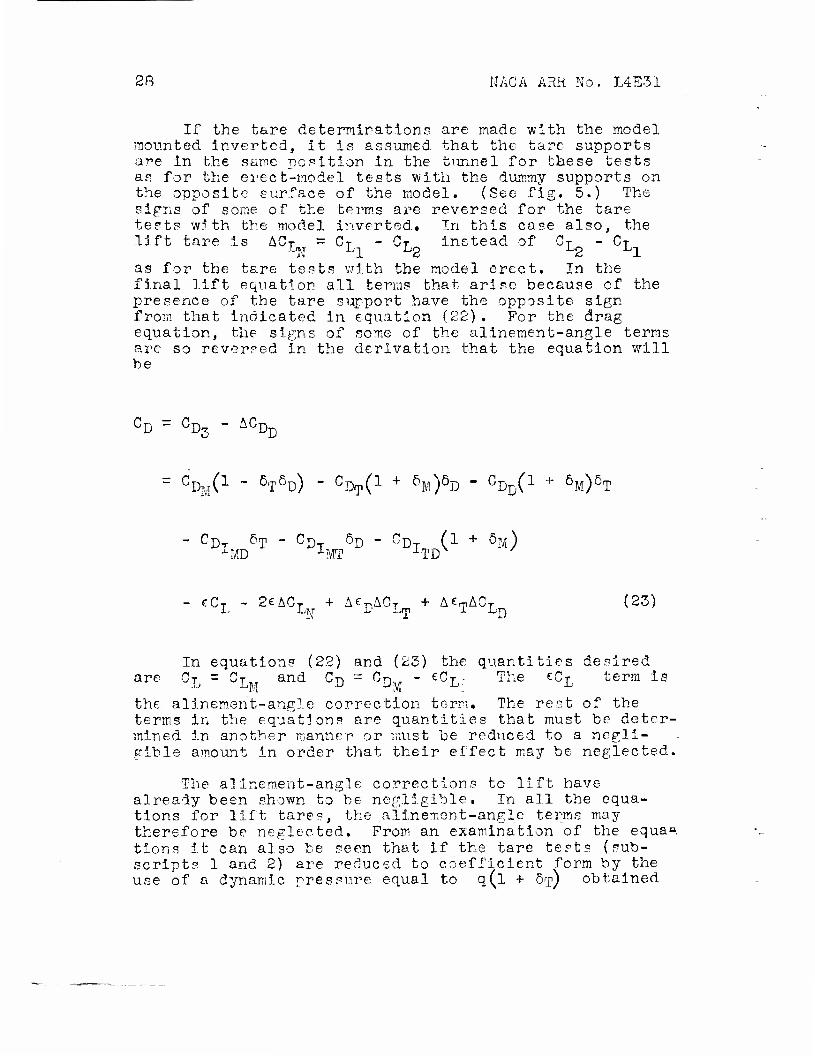
If the tare determinations are made with the model mounted inverted, it is assumed that the tare supports are in the sane position in the tunnel for these tests as for the erect-model tests with the dummy supports on the opposite surface of the model. (See fig. 5.) The signs of some of the terms are reversed for the tare tests with the model inverted. In this case also, the lift tare is ACT = CT - CT Instead of CT - CT hi Ll L2 L2 Ll as for the tare tests with the model erect. In the final lift equation all terms that arise because of the presence of the tare support have the opposite sign from that indicated in equation (22) . For the drag equation, the signs of some of the alinement-angle terms are so reversed in the derivation that the equation will he
CD - CDS " ACDD
= CDM0- - 5T5
D) ~ CDTC1
+ öM)ö
D " ^nC1 + 6M)5T
- CD 5T - CD 5D - CD (1 + 5M) iMD •LMT 1TD
- cCL - 2£ACL + AeDACT + AcTACL (23)
In equations (22) and (23) the quantities desired are CL = CIM
and CD = CDM " CCL:; The eCI term is
the alinement-angle correction term. The rest of the terms in the equations are quantities that must be deter- mined in another manner or must be reduced to a negli- gible amount In order that their effect may be neglected.
The alinement-angle corrections to lift have already been shown to be negligible. In all the equa- tions for lift tares, the alinement-angle terms may therefore be neglected. Prom an examination of the equa» tions It can also be seen that if the tare tests (sub- scripts 1 and 2) are reduced to coefficient form by the use of a dynamic pressure equal to q(l + öy) obtained

NACA ARR No. L4E31 29
from an air-flow survey with the tare supports in place, all terms multiplied by ö.p in the final equation will be eliminated. The factor 1 + 5<p will affect some of the other terms In the equation and the equation becomes
C1 + 5p)CI>n + CDT 1 J-MT
n + 6ivi\c
vi + 5Ty iTD
- eCL + A€TACID + ACDACLT (24)
with the same changes as previously noted for the tare tests of the Inverted model. The factors örp and 6^ will be of the order of 0.03 to 0.05 and all undesirable terms now remaining in the equation are second-order effects except the C-nT term, which is small if the J-TD tare and dummy supports are fairly far apart. Usually, these terms are neglected but If greater accuracy Is required an estimate of their magnitude may be worth while. The quantity 2eACL appearing in the equation
for the tare tests with the model Inverted may be accounted for by subtracting from the tare drag a quantity equal to the tare lift times twice the clear- tunnel alinement angle. The quantity (1
+ö^\CQ +CD \ iv / iji I MT
can be measured by mounting the model by means of some other system, such as wires or cables, In the usual position with relation to the tare supports but not connected to them. Measurement of the forces on the tare supports will In this case include the interference of the model on the supports. The main part of the Interference of the supports on the model is included in the terms 1 + 6y and A &p appearing in the equa- tions. If this method is not available, the quantity (l + 5^CC + C-n may be approximated. Measurement
•••/ T Ijfp of the forces on the tare support alone with the part of the support to be enclosed in the model well faired will give CT)T. The factor 6?vj can be estimated from pressure-distribution curves for the region where the
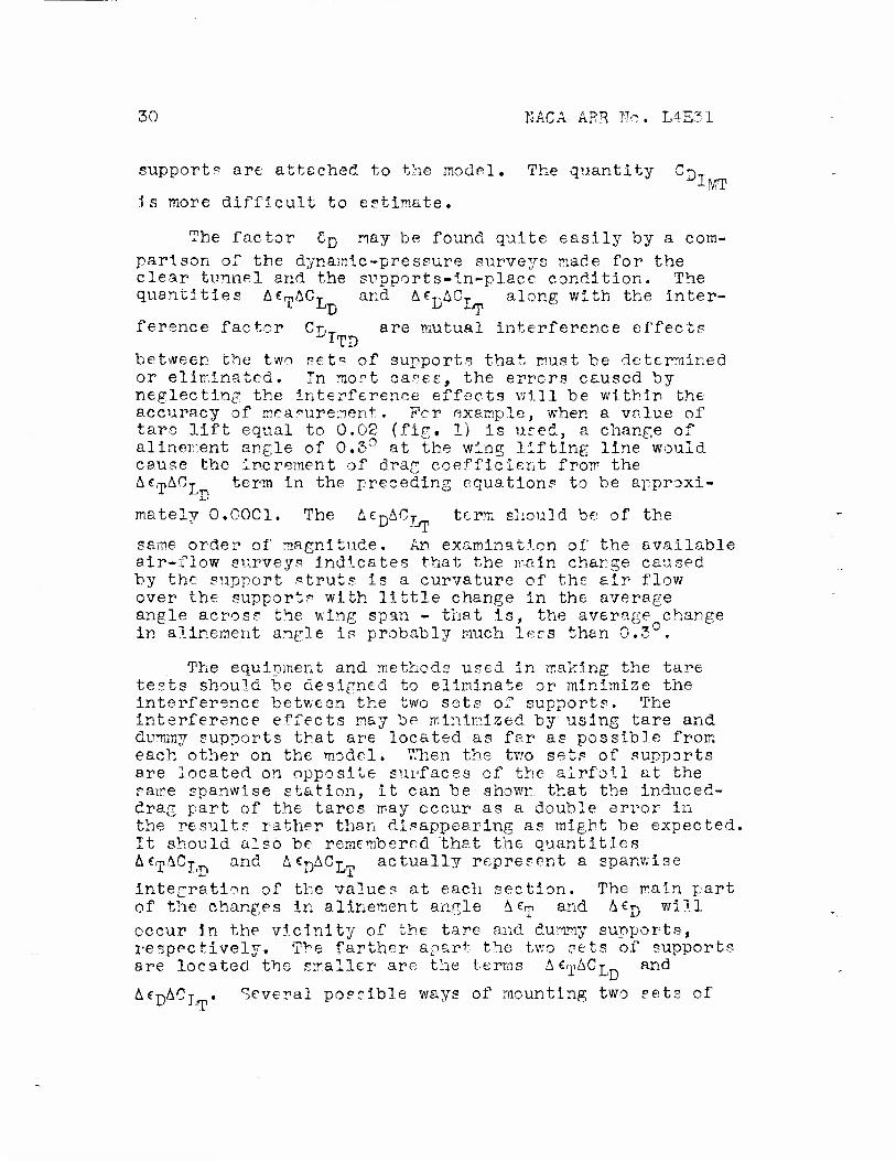
30 KÄCA ARR No. L4E31
support? are attached to the model. The quantity CT}_
is more difficult to estimate.
The factor Cn may be found quite easily by a com- parison of the dynamic-pressure surveys made for the clear tunnel and the supports-in-place condition. The quantities ACpAC-^ and AeDACT along with the inter-
ference factor Cr,~ are mutual interference effects TTD between the two sets of supports that must be determined or eliminated. In most cases, the errors caused by neglecting the interference effects will be within the accuracy of measurement. For example, when a value of tare lift equal to 0.02 (fig. 1) is used, a change of alinement angle of 0.3° at the wing lifting line would cause the Increment of drag coefficient from the AcrpAOj term in the preceding equations to be approxi-
mately 0.00C1. The AeDACj term should be of the
same order of magnitude. An examination of the available air-flow surveys indicates that the main charge caused by the support struts is a curvature of the air flow over the supports with little change in the average angle across the wing span - that is, the average^change in alinement angle is probably much less than \j. <^
70
The equipment and methods used in making the tare tests should be designed to eliminate or minimize the interference between the two sets of supports. The interference effects may be minimized by using tare and dummy supports that are located as far as possible from each other on the model. TEhen the two sets of supports are located on opposite surfaces of the airfoil at the same spanwise station, it can be shown that the induced- drag part of the tares may occur as a double error in the results rather than disappearing as might be expected. It should also be remembered that the quantities ae-pACj and A€j)ACj^ actually represent a spanwise
integration of the values at each section. The main part of the changes in alinement angle A trv and Mj} will occur in the vicinity of the tare and dummy supports, respectively. The farther apart the two sets of supports are located the smaller are the terms MytiCj and
AfpACj . Several possible ways of mounting two sets of
NACA ARE' No. L4E31 31
supports to reduce the mutual interference effects are shown In figure 6.
From aerodynamic considerations, a wire support system (fig. 6) satisfies rather well most of the requirements for a good tare-support system. Wire 'supports cause little change in air-flow angularity and little change in dynamic pressure. Several objections to a wire support system are evident: Not all tunnel- balance framea are so constructed that the wire system may be used; the wires must be preloaded the same for both tare tests in order to eliminate changes in wire drag due tu changes in wire tension; the large drag of the wires decreases the accuracy of determining the tare drag; and the installation of a model with a wire balance is difficult. Tn addition, the wire support system will probably have a low critical speed and cannot be used when high TIaoh numbers are required. The support system shown in the center of figure 6 will probably also be 'unsatisfactory from a compressibility*standpoint. It has been found that the wiug~tip supports must be designed to avoid appreciable lift taresj that is, the cross section must be circular or some similar shape. The critical speed of such a strut would then be low. If the two sets of supports are placed at a distance from each other, it can be assumed that, for all practical purposes, their mutual Interfereroe effects will be negligible. For tare determinations of complete models mounted on a single strut at the fuselage or for stability and control tests in which the absolute drag is not of prime importance, the method of mounting the model inverted on the normal support for tare tests is satisfactory. An additional point with regard to tere tests is the important effect that may result from any open slots on the suction side of the wing at the point of attachment of the tare supports. Experience has shown that any such slots should be sealed and faired smooth.
If the tare and dummy supports must be placed close together as in figure 3, the interference terms &
CT^LT)>
AeD^cLm> and ^DT may be determined by the use of a
third set of supports in conjunction with the usual tare and dummy supports. If this procedure is followed, results from three instead of two tests will be available for determining tares in order that the interference effects may be found. The use of this procedure would probably not be justified, however, unless the tares are very large or unless the interference effects are expected to be appreciable.
Tares for correction method B.- For correction method B, the original air-flow survey is made with the
32 NACA ARR NO. L4E31
normal support In place and Includes the effect of the supports on q and e. The tares should therefore not Include any changes in q and e caused by the supports. The tares" in this case are then defined as the direct air forces on the* supports plus the inter- ference of the model on the supports plus any local effects of the supports on the model not included In the air-flow survey, such as transition changes or separation effects on airfoils at the point of attach- ment of the support to the model.
The direct air forces on the supports and the inter- ference of the model on the supports can be measured by mounting the model independently of the balance by means of cables and measuring the forces on the balance. In order to measure the effects of the supports on transi- tion and separation changes on the airfoil, it is neces- sary to have a set of dummy supports. The model Is placed on the tare supports or normal supports and the dummies are placed close to, but not in contact with, the model. The difference between this test and one without the dummies gives the interference effect of the dummies. An example of this procedure in use in the Langley full-scalp tunnel Is shown in reference 19.
The foregoing procedure Is subject to several Inaccuracies. Any dummy supports placed near the model cause changes In q and e over the model. The effect of these changes will then be included In the tares. The tunnel surveys for the correction method B, however, already include the effect of the supports on q and e. Part of the effects of the supports is thus apparently accounted for twice. The errors caused by this condi- tion may be minimized by reproducing in the dummies only that part of the supports near the model.
In the correction method B the dynamic pressure obtained from the air-flow survey with the normal supports in place is used for computing the coefficients for all tests. By means of equations similar to equations (18) to (24) It can be shown that in method B the error In determining the tares will be Op times the total forces rather than op times the forces on the tare support as for the correction method A. In order to correct for this factor, it would be necessary to have a clear-tunnel air-flow survey to determine op. On the whole, it appears that the correction method B will seldom be as accurate as method A and should be used only when It is the only reasonable procedure available.
NACA ARR No. L4E31 33
Wake shadow.- A3 stated previously, the wake shadow may cause changes In total head, static-pressure gradient, dynamic pressure, alinement angle, and turbu- lence. The existence of a wake shadow may he determined quite easily from total-pressure surveys made at some section of the tunnel ahead of the model and compared with total-pressure surveys at the same section with no model In the tunnel. The survey should he made over the entire tunnel section at the survey plane, especially near the static orifices in case the wake is deflected from the center of the tunnel.
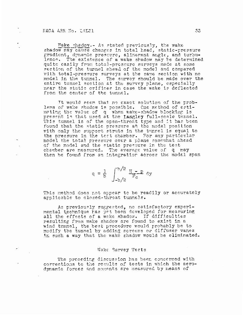
Tt would seem that no exact solution of the prob- lems of wake shadow is possible. One method of esti- mating the value of q when wake-shadow blocking Is present is that used at the Längley full-scale tunnel. This tunnel is of the open-throat type and it has been found that the static pressure at the model position with only the support struts In the tiinrel is equal to the pressure In the test chamber. For any particular model the total pressure over a plane somewhat ahead of the model and the static pressure in the test chamber are measured. The average value of q may then be found from an integration across the model span
This method does not appear to be readily or accurately applicable to closed-throat tunnels.
As previously suggested, no satisfactory experi- mental technique has yet been developed for measuring all the effects of a wake shadow. If difficulties resulting from wake shadow are found to exist in a wind tunnel, the best procedure would probably be to modify the tunnel by adding screens or diffuser vanes In such a way that the wake shadow would be eliminated.
Wake Survey Tests
The preceding discussion has been concerned with corrections to the results of tests in which the aero- dynamic forces and moments are measured by means of
34 NACA AHR No. L4E31
the balance system on which the model if mounted. In order to determine the variation of the profile drag along the wing span, wake survey test," are often made. These surveys have also been used to determine the com- bined drag tares and buoyancy corrections for some models (reference 20). This method of testing requires considerably more time than forc^ tests but is the only way of determining the variation of profile drag across the wing span.
For the wake surveys, the effect of the supports is accounted for by computing coefficients by use of a dynamic pressure determined for the air-flow surveys made with the supports in the tunnel. The actual q at each point along the span rather than the average value of q must be used for determining the local profile-drag coef- ficients. Of course, corrections for compressibility, wake shadow, displacement blocking, and so forth, must be made as for the force tests, but jet-boundary and allnement-angle corrections to the drag are unnecessary. Jet-boundary and alinement-angle corrections are applied to the angle of attack.
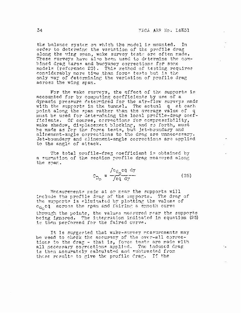
The total profile-drag coefficient is obtained by a summation of the section profile drag measured along the soar.
/cd cq dy •o
'D0 /cq dy (25)
Measurements made at or near the supports will include the profile drag of the supports. The drag of the supports is eliminated by plotting the values of CQ cq across the span and fairing a smooth curve
through the points, the values measured near the supports being ignored. The integration indicated in equation (25) is then performed for the faired curve.
It is suggested that wake-survey measurements may be used to check the accuracy of the over-all correc- tions to the drag - that is, force tests are made with all necessary corrections applied. The induced drag : is then accurately calculated and subtracted from these results to give the profile drag. If the
NACA ARR No. L4E31 35
corrections applied are accurate, this profile drag should check that determined from wake surveys across the entire wing. This procedure would also be expected to be most reliable at low lift coefficients because it depends upon the accurate calculation of the Induced drag. At high lift coefficients, an additional source of inaccuracy Is the difficulty of making profile-drag measurements In the region of the airfoil tip.
EXAMPLES OP CURRENT PRACTICE
Langley 19-foot pressure tunnel.- The calibration and correction procedure used in the Langley 19-foot pressure tunnel follows closely the procedure outlined as correction method A. Tare tests are made with the model mounted Inverted, the normal supports used as tare supports, and a set of exact-Image dummy supports mounted on the opposite side of the model.
Inasmuch as the static-pressure gradient at the position of the model is essentially zero, no buoyancy corrections are necessary. Total-pressure surveys ahead of a typical model failed to disclose any evidence of a wake shadow. The empirical formula given previously
1 + 7p£T is used to correct the dynamic pressure for displacement blocking.
The tunnel-wall-interference corrections are applied as the first corrections after the data are reduced to coefficient form and before any other corrections are applied. This procedure is used for all test runs, including tare tests.
Langley 7- by 10-foot tunnel.- In the Langley 7- by 10-foo'c tunnel, correction method A Is used and the order of applying the corrections is the same as. that given in the discussion. This tunnel is a low-speed high-turbulence tunnel used, chiefly for stability and control tests; therefore, most of the refinements suggested in the preceding discussion, particularly for precise drag determinations, are unnecessary.
Models In this tunnel are mounted on a single sup- port strut, which is sealed as it passes through the bottom of the tunnel. Tares are determined by mounting
36 NACA ARR No. L4E31
the model Inverted on this normal support strut and using a dummy strut that is an image of the lower strut. It Is unnecessary to convert the tares to coefficient form before their application to the model data because a constant predetermined dynamic pressure can be maintained. Tare moments must, however, be transferred through the model before they are applied.
Allnement-angle tests are not run for each model but are run with two standard wings of different spans and checked occasionally. Because the variation in e across the tunnel is not enough to show any difference for the two standard wings, the weighting procedure for different wing plan forms Is not necessary. Changes of the order of 0,2° in the allnement angle have been noted over a period of several years. The necessity of periodic check tests is thus indicated. The accuracy of the drag balance makes possible the determination of the allnement angle to within about 0.05°. The impor- tance of exactly reproducing the tunnel leakage condi- tions for alinement-angle and tare tests was demonstrated in the Langley 7- by 10-foot tunnel when alinement-angle tests were run after a new streamline fairing had been added to the support strut. Tests made with the lower end of the strut having about a ^-inch annular gap but
with the dummy sealed showed an allnement angle of 0.1°. When the gap was completely sealed, the allnement angle was changed to -0.1°.
In the region occupied by the model the static- pressure gradient Is substantially zero and no buoyancy correction is necessary.
Because relatively large models are often tested in such tunnels, a rather extensive investigation of the tunnel-wall interference has been conducted for 7- by 10-foot tunnels. The numerical results for tunnels of this size as well as general methods applicable to all tunnels will be found in references 8, 9, and 10.
Langley full-scale tunnel.- The large size and the open throat of the Langley full-scale tunnel have made the Installation of exact-image dummy supports difficult. For this tunnel, therefore, correction method B is used. All tests are computed from air-flow surveys made with the support struts in place. The allnement angle used
NACA ARR No. L4E31 57
in correcting the data is that obtained from the yaw- head surveys with supports in place.
Several methods are used for determining tares. One method used is that described previously for correction method B, in which the tares are determined in two parts (reference 19). Another method used fre- quently at present for measuring drag tares is the wake-curvey method. The normal support struts In this tunnel are usually attached to the under surface of the wing. VI alee-survey measurements of the profile drag are made at a number of spanwise stations and very small Intervals are used ne-cir the support-strut location. A smooth curve is obtained for the variation of profile drag along the wing at some distance from the support. As the support is approached, the drag rises considerably. It is assumed that the wing profile drag will show a uniform variation; therefore, a curve is arbitrarily faired, and those points near the support are neglected. The integrated difference between this curve and that drawn through the measured values of profile drag gives the tare.
It is in the Langley full-scale tunnel that the problems of the wake shadow have probably been investi- gated most extensively. The existence of the wake shadow was discovered during tests to check some calculated jet- boundary corrections (reference 4). Its effects were investigated on a full-size airplane by measuring the dynamic pressure and static pressure at several points , near the airplane in flight and then in the tunnel. A comparison of the results showed a decrease of about 6 percent In the average dynamic pressure around the airplane when placed in the tunnel. In addition, the static-pressure gradient was altered in such a way as to cause an Increase in drag of about 5 percent of the minimum drag when the airplane was placed in the tunnel. These figures were obtained for a biplane that was rather unclean aerodynamically. For airplanes of modern design the effects of wake blocking are considerably smaller. For plain airfoils, for which no flight tests were available, It was necessary to make a theoretical estimate of the undisturbed field around the airfoil. The effects of the airfoil field of flow were then sub- tracted from the measured total pressure, dynamic pressure, and static pressure at a point ahead of the airfoil to obtain the corrected values.
38 NACA ARR No. L4E31
The correction for wake blocking is now obtained by measuring the total pressure ahead of a model and the static pressure 5n the test chamber, which is equal to the static pressure at the model position, and applying Bernoulli's theorem to obtain the free-stream dynamic pressure.
Buoyancy corrections are not necessary for plain- wing models mounted in the usual position. If the model to be tested has a fuselage, however, buoyancy corrections are required.
Measurements have shown that the effect of the exit cone of this tunnel on the air flow behind a model is of approximately the same magnitude as and of opposite sign from that due to jet-boundary interference. The pitching-moment corrections that are required to account for the jet-boundary interference are thus usually negligible.
CONCLUDING RE'/;ARKC
Detailed methods have been presented for determining, to a high degree of accuracy, the corrections to wind- tunnel tests of three-dimensional models for the effects of the model-support system, the nonuniform air flow in the tunnel, and the tunnel walls or jet boundaries. It should be remembered, however, that the most reliable results are generally obtained in that condition for which the required corrections are the smallest. If, during the air-flow surveys and alin^ment-angle tests, any marked irregularity is evident in the air stream, the best procedure would probably be to modify the wind tunnel to eliminate the necessity of large corrections to the measured data. Screens and deflector vanes properly located can be used to adjust the air-flow conditions to obtain more uniform flow or to eliminate any serious effects of wake shadow. Sealing the support struts and fairings and any other openings in the tunnel will help to eliminate some of the uncertainty in deter- mining tare, alinement-angle, and static-pressure- gradient corrections. Careful design of the support struts and the5r means of attachment to the model will minimize the tare corrections.
NACA ARR No. L4E31 39
The accuracy to which the corrections must be deter- mined and the time to he spent in calibrating the tunnel must ultimately he decided by the tunnel operator from considerations of the purpose for which the tests are being conducted, the precision required in the final results, and the time available for determining and applying the corrections.
Langley Memorial Aeronautical Laboratory National Advisory Committee for Aeronautics
Langley Field, Va.
40 NACA ARR No. L4E31
REFERENCES
1. Klein, Arthur L., Serrell, Peter V. H., and Millikan, Clark P.: A New Two-Parameter Model Suspension System for the Galcit 10-Pt. Wind Tunnel. Jour. Aero. Sei., vol. 9, no. 8, June 1942, pp. 302-308.
2. dauert, H.: Wind Tunnel Interference on Wings, Bodies, and Airscrews. R. & M. No. 1566, A.R.G. (British), 1933.
3. dauert, H.: The Effect of the Static Pressure Gradient on the Drag of a Body Tested in a Wind Tunnel. R. & M. No. 1158, JUR.C- (British), 1928.
4. Theodorsen, Theodore, and Silverstein, Abe: Experi- mental Verification of the Theory of Wind-Tunnel Boundary Interference. NACA Rep. No. 478, 1934.
5. Knight, Montgomery, and Harris, Thomas A.: Experi- mental Determination of Jet Boundary Corrections for Airfoil Tests in Pour Open Wind Tunnel Jets of Different Shapes. NACA Rep. No. 361, 1930,
6. Silverstein, Abe, and Katzoff, S.: Experimental Investigation of Wind-Tunnel Interference on the Downwash behind an Airfoil. NACA Rep. No. 609, 1937.
7. Silverstein, Abe, and White, James A.: Wind-Tunnel Interference with Particular Reference to Off- Center Positions of the Wins; and to the Downwash at the Tail. NACA Rep. No.^547, 1935.
8. Swanson, Robert S., and Schuldenfrei, Marvin J.: Jet-Boundary Corrections to the Downwash behind Powered Models in Rectangular Wind Tunnels with Numerical Values for 7- by 10-Foot Closed Wind Tunnels. NACA ARR, Aug. 1942.
9. Swanson, Robert S.: Jet-Boundary Corrections to a Yawed Model in a Closed Rectangular Wind Tunnel. NACA ARR, T^eb. 1943.
10. Swanson, Robert S., and Toll, Thomas A.: Jet-Boundary Corrections for Reflection-Plane Models in Rectan- gular Wind Tunnels. NACA ARR No. 3E22, 1943.
NACA ARR No. L4E31 41
11. Lotz, Irmgard: Correction of Downwash in Wind Tunnels of Circular and Elliptic Sections. MACA TM No. 801, 1936.
12. Gavin, J. G., Jr., and Hensel, R. W.: Elliptic Tunnel-Wall Corrections on Drag and Stall. Jour. Aero. Sei., vol. 9, no. 14, Dec. 1942, pp. 533-537.
13. Stewart, H. J.: A Correction to the Yawing Moment Due to Ailerons for Circular Wind Tunnels. Jour. Aero. Sei., vol. 6, no. 8, June 1939, pp. 329-331.
14. Katzoff, S., and Finn, Robert S.: Determination of Jet-Boundary Corrections to Cowling-Flap-Outlet Pressures by an Electrical Analogy Method. NACA ARR No. 4B23, 1944.
15. Silverstein, Abe, Katzoff, S., and Bullivant, W. Kenneth: Downwash and -fake behind Plain and Flapped Airfoils. NACA Rep. No. 651, 1939.
16. Eckert, 3.: Experiences with Flow-Direction Instruments. NACA TM No. 969, 1941.
17. Platt, Robert C: Turbulence Factors of N.A.C.A. Wind Tunnels as Determined by Sphere Tests. NACA Rep. No. 558, 1936.
18. Mock, W. C, Jr.: Alternating-Current Equipment for the Measurement of Fluctuations of Air Speed in Turbulent Flow. NACA Rep. No. 598, 1937.
19. Goett, Earrv.J., and Bullivant, W. Kenneth: Tests of N.A.c'.A. 0009, 0012, and 0018 Airfoils in the Full-Scale Tunnel. NACA Rep. No. 647, 1938.
20. Bullivant, W. Kenneth: Tests of the NACA 0025 and 0035 Airfoils in the Full-Scale Wind Tunnel. NACA Rep. No. 708, 1941.
42 NACA ARR No. L4E31
BIBLIOGRAPHY
Bradfield, P. B.: The 5-Pt. Open Jet Wind Tunnel, R.A.E. R, & M. No. 1364, A.R.C« (British), 1931.
Cowley, W. L., and McMillan, G. A.: Effect of V/ind Tunnel Wall Interference on the Pitching Moments of Large Models in the Duplex Tunnel. R. & M. No. 1639, A.R.C. (British), 1935.
Cowley, W. L., and Jones, L. J.: An Experimental Test of the Prandtl Correction for Tunnel Wall Interfer- ence, R. Sr M, No. 898, A.R.C.i.(British), 1924.
Davison, B., and Rosenhead, L.; Wind Tunnel Correction for a Cii'cular Open Jet Tunnel with a Reflexion Plate. Proc. Roy. Soc. (London), ser. A, vol. 177, no. 970, Feb. 24, 1941, pp. 366-382.
Dryden, H. L., and Reald, R. H.; Investigation of Turbu- lence in Wind Tunnels by a Study of the Plow about Cylinders. NACA Rep. No. 231, 1926.
Dryden, H. L., and Kuethe, A. M.s Effect of Turbulence In Wind Tunnel Measurements. NACA Rep. No. 342, 1930.
Dryden, H. L-, and Kuethe, A. M.; The Measurement of Fluctuations of Air Speed by the Hot-Wire Anemometer. NACA Rep. No. 320, 1929.
Dryden, Hugh L., Schubauer, 0. B., Mock, W. C, Jr., and Skramstad, H. K.: Measurements of Intensity and Scale of Wind-Tunnel Turbulence and Their Relation to the Critical Reynolds Number of Spheres. NACA Rep. No. 581, 1937.
Glauert, H.: The Interference of Wind Channel Walls on the Aerodynamic Characteristics of an Aerofoil. R. & M. No. 867, A;R.CvnCBriti£h)^1923.
Glauert, H.: The Elements of Aerofoil and Airscrew Theory. Cambridge Univ. Press, 1926, chs. XII and XIV.
Glauert, H.: The Interference on the Characteristics of an Aerofoil In a Wind Tunnel of Circular Section. R. & M, No. 1453, A.R.C'.1" (British) ," 3932.
NACA ARR No. L4E31 43
Glauert, IT.: Some General Theorems Concerning Wind Tunnel Interference on Aerofoils. R. & M. No. 1470, A.R.C. (British), 1932.
Glauert, IT.:- The Interference on the Characteristics of an Aerofoil In a Wind Tunnel of Rectangular Section. R. & M. No. 1459, A.R.C. (British), 1932,
Glauert, H., and Hartshorn, A. S.: The Interference of Wind Channel Walls on the Downwash Angle and the Tail- setting to Trim. R, & M. No. 947, A.R.C. (British),
Harris, Thomas A.: The 7 by 10 Foot Wind Tunnel of the National Advisory Committee for Aeronautics. NACA Rep. No. 412, 1931.
Higgins, George J. : Wall Interference in Closed Type Wind Tunnels. NACA TN No. 256, 1927.
Jacobs, Eastman N.: Sphere Drag Tests In the Variable Density Wind Tunnel. NACA TN No. 312, 1929.
Jacobs, Eastman N., and Abbott, Ira F.: Airfoil Section Data Obtained in the N.A.C.A. Variable-Density Tunnel as Affected by Support Interference and Other Cor- rections. NACA Rep. No. 669, 1939.
Jacobs, Eastman N., and Abbott, Ira IT. : The N.A.C.A. Variable-Density Wind Tunnel. NACA Rep. No. 416, 1932.
Mock, W. C, Jr., and Dryden, H. L.: Improved Apparatus for the Measurement of Fluctuations of Air Speed in Turbulent Flow. NACA Rep. No. 448, 1932.
Prandtl, L.: Tragflügeltheorie, II. Mitteilung. From "Vier Abhandlungen zur Hydrodynamik und Aerodynamik" by L. Prandtl and A. Betz. Kaiser Wilhelm-Instituts für Strömungsforschung (GÖttingen), 1927, pp. 36-67.
Sanuki, Matao, and Tani, Itiro: The Wall Interference of a Wind Tunnel of Elliptic Cross-Section. Proc. Phys.-Math. Soc. of Japan, ser. 3, vol. 14, no. 10, Nov. 1932, pp. 592-603.

44 NACA AHR No. L4E31
Stewart, H. J.: The Effect of Wind Tunnel Wall Inter- ference on the Stalling Characteristics of Wings. Jour. Aero. Sei., vol. 8, no. 11, Sept. 1941, pp. 426-428.
Terazawa, Kwan-ichi: On the Interference of Wind Tunnel Walls of Rectangular Cross-Section on the Aerodynamical Characteristics "of a Wing. Rep. No. 44 (vol. IV), Aero. Res. Inst., Tokyo Imperial Univ., Oct. 1928, pp. 69-81.
Theodorsen, Theodore; The Theory of Wind-Tunnel Wall Interference. NACA Rep. No. 410, 1931.
Theodorsen, Theodore: Interference on an Airfoil of Finite Span In an Open Rectangular Wind Tunnel. NACA Rep. No. 461, 1933.
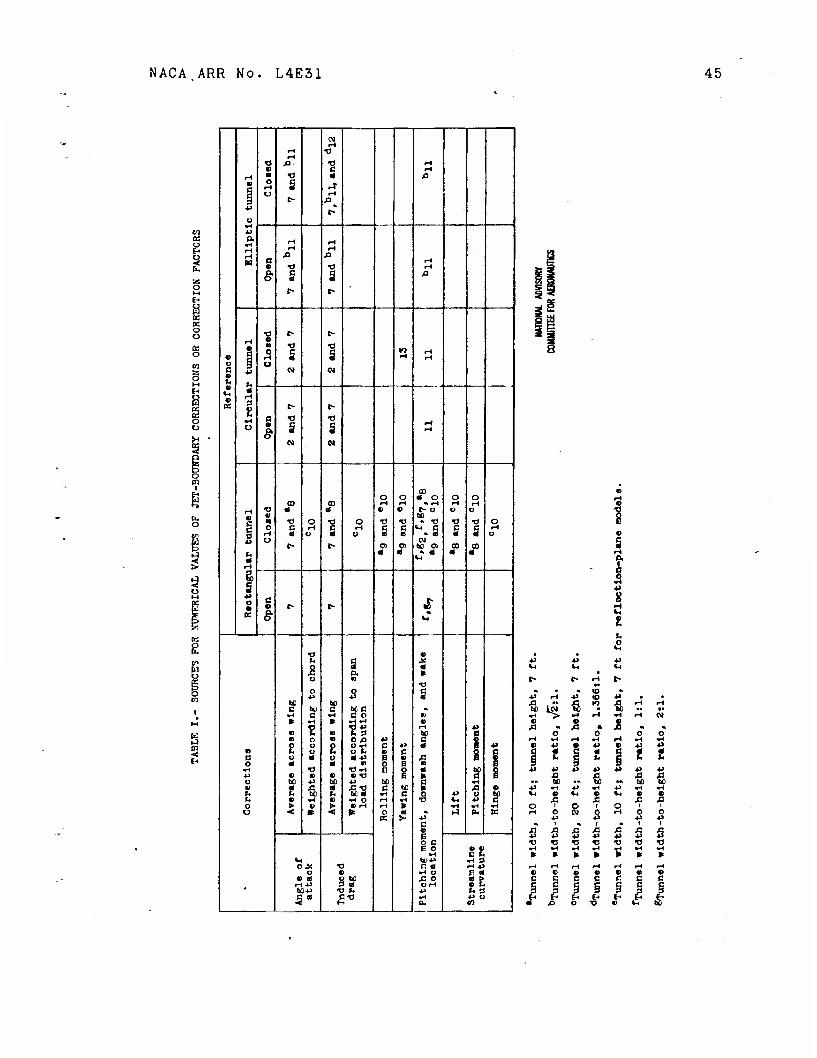
NACA ARR No. L4E31 45
<0 a o EH
6.
a:
s § EH
01 rH
»H •o rt *d e- •o rH « c rH
r4 B •a • x> 0 O
o s t-
rf r-l
0^ «u
t-
O •rH ** a. fH r-\
r-i rH r-l r-i A XI w a rH « •o •0 •-I
& c a s f
•0 t- c
• •
•o TJ
f> 5 s s n rl rH
o • o c • « 0) 01
rH
IS s R
t> t-
a "Ö « u • s s
04
•H
o o J°o O o OD CO •H rH » rH rH rH
t-i T> * a 0 0 C- O O Ü
0
§ 5
0 to «. •d o •Ö o •0 •a » TJ •d •O o o
rH a r-l O
c O § § Vi C
. 0 s s rH Ü
U 01 i> c- 0> o to 0> CO m
• 0 « c- 0 •
IH
O 0
d t- •> J
K S *H"
•a 0 u C it o a « Ä Q. * Ü n
Ü o o c *> « 0
u w c tu 0 uc •k
•r* c Ti C o B k •H » *4 «1 0
fj * m S3 to a B o n 0 ,c *> c 1 o o 2 • ? c *> 0 ••»
n r. o o ». • c 2 c e o 0 o • -p a 0 A 0 0 • • n o B m
•H o <0>H e $ 0 to g HJ • V • «-d » a o to *J 60 ±> to e *H 0 t A a ß « c Ml a 0 rl H) r. to« «H e o *> o 21 h c •H « •H O rH •H •o u 4J O • t> > £•-< H » «H «H «H o < * < tt O
K $ •p c 0 E
r-1 a. K
O C E o 0 0
•H C r. V, tUHJ »< a O* •a C «1 rH -P
o « •H O E « « « v to * o -St r-H-P 3 si OH bfi-P
58 -P •H
t< 3 •P Ü
ti OH m
•ti i
o. h o
•O . " be 10»
-0 o
*>
£1
6
•0 bC
"0 *H
0 <0
53
O 01
•o
I
c c i i
•a
0
I E-
0 •P
i
•0
c c c 3
fH

NACA ARR No, L4E31 Fig. la
CO o
2 o 5o.Jp 9~/0£ I
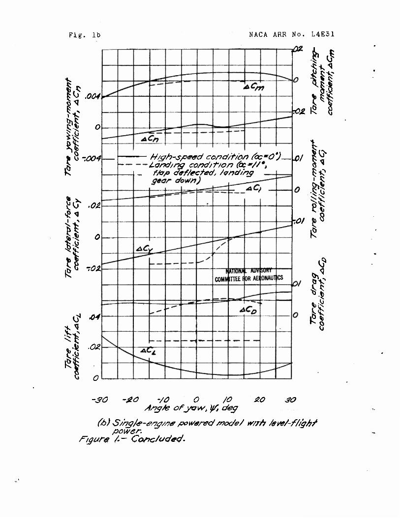
Fig. lb
h fcv» .004
1 It-
II ° 4
5^ .o&
II 0*
G1 •**
NACA ARR No. L4E31
•fig.
•£>Z
W/gh-speed cond/t/on (bcmö'J \p) Land/rh cond/t/on (oc//*, f/op def/ected, /vnd/njp gear down) i
-.01
1$
V
SO ~#0 -/O O /O 20 SO d/7g/e ofyo\A/> y/, deg
(6) s5/r?gfe-&/7g//7e powered mode/ w/rh /eve/-f/t'g/?f power.
r~i<jure /— Cortc/oded-
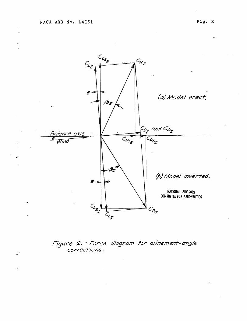
NACA ARR No. L4E31 Fig. 2
(q) Mode/ erect.
a/)c/Cox
*j~
(b)Model Inverted.
NATIONAL ADVISORY COMMITTEE FOR AERONAUTICS
Figure 2-- Force diagram for qtinement-ong/e corrections.
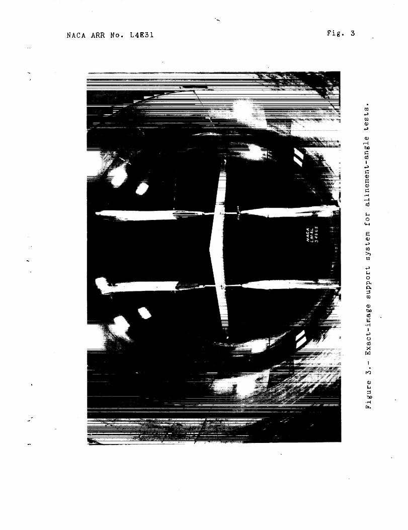
NACA ARR No. L4E31 Fig. 3
to CD
bo C cd i
+3 c CD e tu
o (•-I
e CD <J 03
>3 to
o (X (X
CD
CD bo cd E
I +-> u cd X w
CO
a)
00 •H Cx.
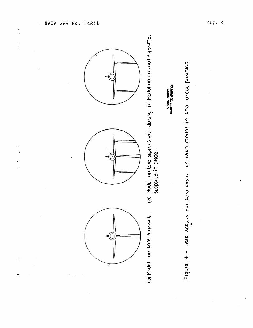
NACA ARR No. L4E31 Fig. 4
I o c
s
e
C o -p
o
.c -p
<u s
0) •u o E .c
i c 3
0}
43
8. a. r> o g) d
c o
O
o
a •-» *
2 .9*
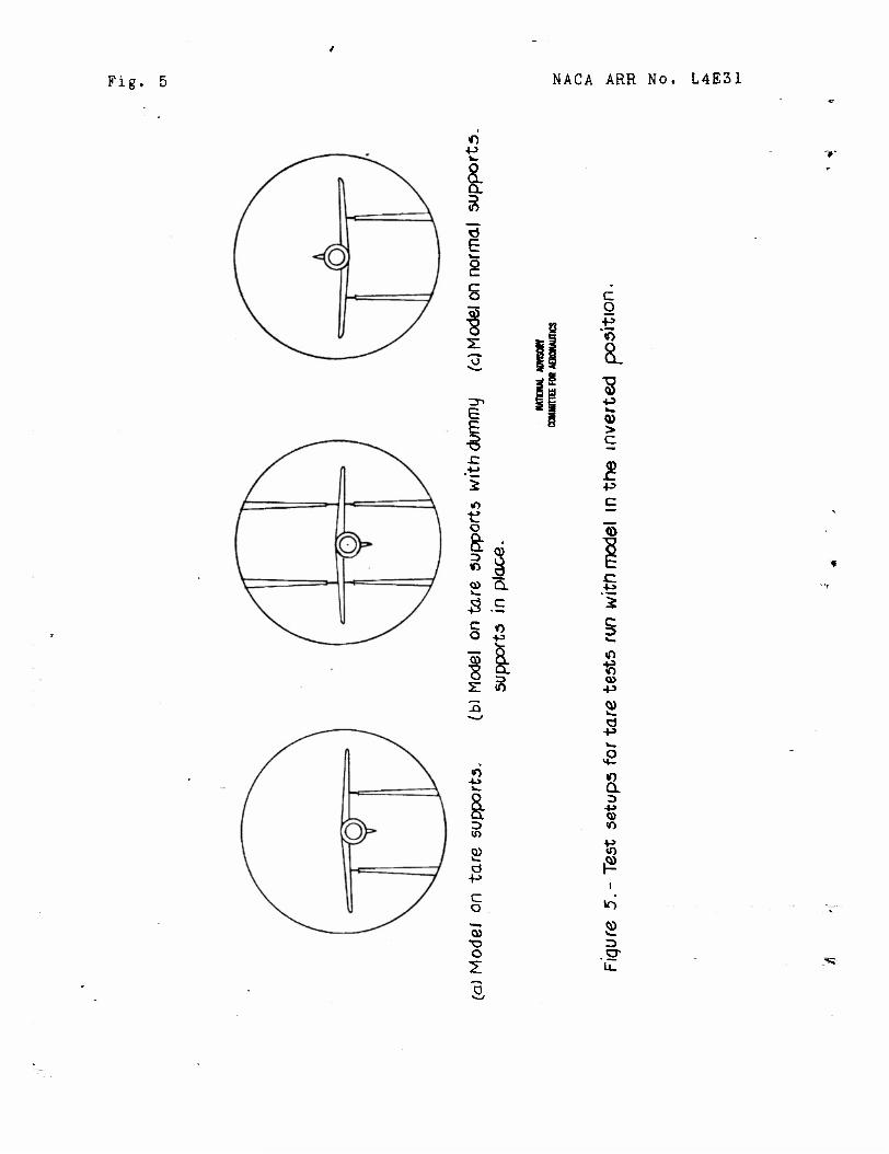
Fig. 5 NACA ARR No. L4E31
»0 +-> w
& 3
E o c c o
e E 3
tf o
*° a ä> 'S.
in
s +^ c o
03
o Z
c o
*«>
8.
V. Q) > c
l C
4-3
c
8. 0)
2 er
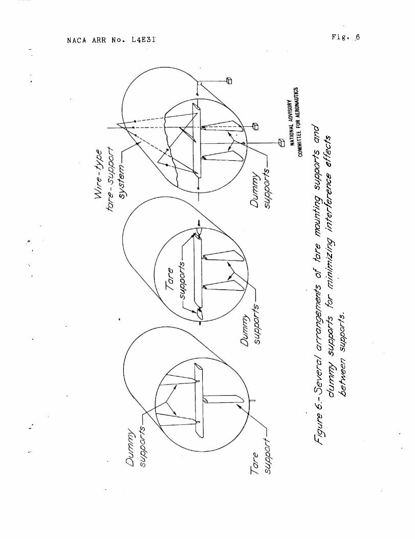
NACA ARR No. L4E3I Fig.
<9
ill * % ">
I
T1TU Wind-Tunnel Calibration and Correction Procedures for Tfcree-Dimenslonai Models
AUTHOR(S] OR1S. AGENCY PU8USHW BY
Swanson, R. S.; CUlls. C. L. Langley Memorial Aeronautical Lab.,Lt&gley Air Force Base, Va. National Advisory Committee for Aeronautics, Washington, D. C.
(None)
VST-fiESl ff.M8KIM HO (Nnno)
U.S. English lUimunotG
photos, table, diiRr, drwgs
Detailed methods are presented for determining wind-tunnel corrections for effects of model-support system, nonunilorm airflow In tunnel, and tunnel wall or let boundaries. Procedures are illustrated by equations. Required tests are discussed. Special atten- tion Is given to drag measurements. Two general methods used for determining and applying corrections to force tests, and correction procedures for walce survey tests are discussed. Methods apply only to tests at subcrltlcal speeds.
DISTRIBUTION: SPECIAL. All requests for copies must be addressed to Puhlishlng Agency DIVISION: SECTION: CaWOTanotr(2) (0
ATI SHEET NO.:
SUBJECT HEADINGS: Wind tunnels - Boundary effect (99110.3) Wind tunnel mounts • Effect on tests (99070)
Central Air DtfimHi OfflcQ WripS« Muni Air Nrca Oo*o, Ovjrron. Ohio %
\ INDEX
^Jä