Embed Size (px)
Citation preview
100
WASHING MACHINESERVICE MANUAL
READ THIS MANUAL CAREFULLY TO DIAGNOSE PROBLEMS CORRECTLY BEFORE SERVICING THE UNIT.
MODEL: WM2688H*M
CAUTION
Website: http: //www.LGEservice.comE-mail: http: //www.LGEservice.com/techsup.html
!

101
DEC. 2005 PRINTED IN KOREA P/No.:3828ER3048Q
2
CONTENTS
1. SPECIFICATIONS .........................................................................................................................3
2. FEATURES & TECHNICAL EXPLANATION ................................................................................ 4
3. PARTS IDENTIFICATION ............................................................................................................ 7
4. INSTALLATION & TEST ............................................................................................................... 8
5. OPERATION ................................................................................................................................11
6. WIRING DIAGRAM/PROGRAM CHART.....................................................................................14
7. TROUBLESHOOTING.................................................................................................................15
7-1. BEFORE PERFORMING SERVICE ...................................................................................15
7-2. QC TEST MODE.................................................................................................................15
7-3. HOW TO CHECK THE WATER LEVEL FREQUENCY ......................................................15
7-4. ERROR DISPLAY ...............................................................................................................16
8. ERROR DIAGNOSIS AND CHECK LIST ....................................................................................18
8-1. DIAGNOSIS AND SOLUTION FOR ABNORMAL OPERATION ........................................18
8-2. FAULT DIAGNOSIS AND TROUBLESHOOTING ..............................................................21
9. DISASSEMBLY INSTRUCTIONS ...............................................................................................29
10. EXPLODED VIEW .....................................................................................................................40
10-1. CABINET & CONTROL PANEL ASSEMBLY....................................................................40
10-2. DRUM & TUB ASSEMBLY................................................................................................41
10-3. DISPENSER ASSEMBLY .................................................................................................42

3
1. SPECIFICATIONS
ITEM WM2688H*M
COLOR W:BLUE WHITE, N:NAVY BLUE
POWER SUPPLY AC 120 V, 60 Hz
PRODUCT WEIGHT 192 lbs (87kg)
WASHING 280 W
DRAIN MOTOR 80 W
WASH HEATER 1000 W
WASH 46 rpm
SPIN 0-1320 rpm
CYCLES 9
WASH/RINSE TEMPERATURES 5
SPIN SPEEDS 5
OPTIONS Prewash, Rinse+Spin, Extra Rinse, Water Plus, Stain Cycle
WATER CIRCULATION Incorporated
OPERATIONAL WATER PRESSURE 14.5-116 psi (100-800 kPa)
CONTROL TYPE Electronic
WASH CAPACITY [cu.ft] 3.47 (4.0 IEC)
DIMENSIONS 27” (W) X 29 3/4” (D) X 3811/16” (H), 5013/16” (D, door open)
DELAY WASH up to 19 hours
DOOR SWITCH TYPE PTC + Solenoid
WATER LEVEL 10 steps (by sensor)
LAUNDRY LOAD SENSING Incorporated
ERROR DIAGNOSIS Incorporated
AUTO POWER OFF Incorporated
CHILD LOCK Incorporated
RLM ENABLE Incorporated
STEAM Incorporated
ELECTRIC POWER
CONSUMTION
REVOLUTION SPEED
4
2. FEATURES & TECHNICAL EXPLANATION
2-1. FEATURES
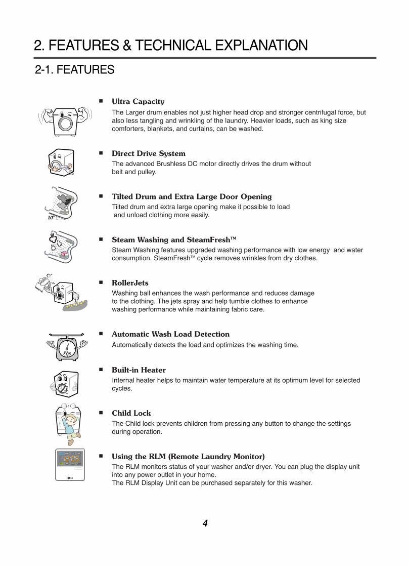
Ultra CapacityThe Larger drum enables not just higher head drop and stronger centrifugal force, butalso less tangling and wrinkling of the laundry. Heavier loads, such as king sizecomforters, blankets, and curtains, can be washed.
Direct Drive SystemThe advanced Brushless DC motor directly drives the drum without belt and pulley.
Tilted Drum and Extra Large Door OpeningTilted drum and extra large opening make it possible to loadand unload clothing more easily.
Steam Washing and SteamFreshTM
Steam Washing features upgraded washing performance with low energy and waterconsumption. SteamFreshTM cycle removes wrinkles from dry clothes.
RollerJets Washing ball enhances the wash performance and reduces damage to the clothing. The jets spray and help tumble clothes to enhance washing performance while maintaining fabric care.
Automatic Wash Load Detection Automatically detects the load and optimizes the washing time.
Built-in HeaterInternal heater helps to maintain water temperature at its optimum level for selectedcycles.
Child LockThe Child lock prevents children from pressing any button to change the settingsduring operation.
Using the RLM (Remote Laundry Monitor) The RLM monitors status of your washer and/or dryer. You can plug the display unitinto any power outlet in your home. The RLM Display Unit can be purchased separately for this washer.
추가선택 예약
추가선택 예약
5
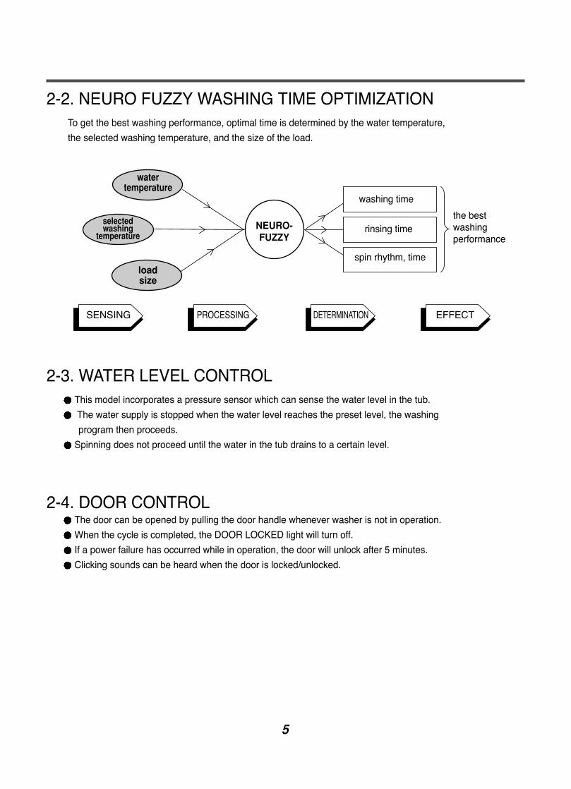
2-2. NEURO FUZZY WASHING TIME OPTIMIZATIONTo get the best washing performance, optimal time is determined by the water temperature,
the selected washing temperature, and the size of the load.
2-3. WATER LEVEL CONTROLThis model incorporates a pressure sensor which can sense the water level in the tub.
The water supply is stopped when the water level reaches the preset level, the washing
program then proceeds.
Spinning does not proceed until the water in the tub drains to a certain level.
2-4. DOOR CONTROLThe door can be opened by pulling the door handle whenever washer is not in operation.
When the cycle is completed, the DOOR LOCKED light will turn off.
If a power failure has occurred while in operation, the door will unlock after 5 minutes.
Clicking sounds can be heard when the door is locked/unlocked.
NEURO-FUZZY
loadsize
selectedwashing
temperature
watertemperature
washing time
rinsing time
spin rhythm, time
the bestwashingperformance
SENSING PROCESSING DETERMINATION EFFECT
6
2-5. THE DOOR CAN NOT BE OPENEDWhile program is operating
When a power failed and power plug is taken out in operation
While Door Lock lights turn on.
White the motor is in the process of intertial rotating, through the operation is paused.
2-6. DOOR LOCKED LAMP LIGHTSWhen the frequency of water level is lower than 22.9 kHz
(It can be canceled when the frequency is more than 23.8 kHz)
When the temperature inside the tub is higher than 45 °C and water level is not 25.5 kHz
(It can be canceled when the water level is 25.5 kHz or the temperature inside the tub is lower than 40 °C)
2-7. CHILD LOCKUse this option to prevent unwanted use of the washer. Press and hold PRE WASH button for 3 seconds to
lock/unlock control.
When Child lock is set, CHILD LOCK lights and all buttons are disabled except the Power button. You can
lock the washer while it is operating.
2-8. WATER CIRCULATION When Washing and Rinsing function of shower at the upper part of Gasket.
When Washing, it continuously operates for 3 minutes and intermittently.
When Rinsing, it continuously operates after completion of water supply.
2-9. STEAM For tough stained clothes, underwear, or baby clothes.
Steam Wash is available with Sanitary, Bulk/Large, Perm. Press, Cotton/Normal, and baby Wear cycles.
This option features upgraded washing performance with low energy and water consumption
Do not load delicates such as wool, silk, and easily discolored clothes.
2-10. DRUM LIGHT The Drum Light comes on when the Power button is pressed. It goes off when the door is closed and the
washer starts operation.
The Drum Light remains off when the door is locked.
The Drum Light can be turned on while the washer is in operation by pressing the Rinse+Spin button for 3
seconds. The light will turn off automatically 4 minutes later.
The Drum Light comes on when the washing cycle is finished and goes off 4 minutes later.
7
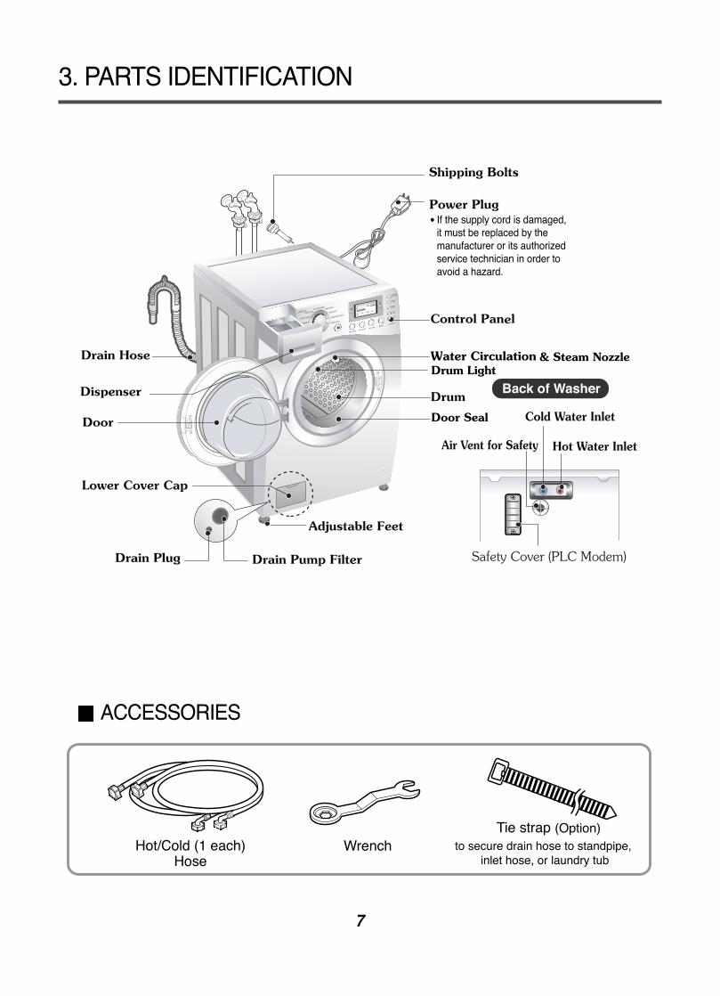
3. PARTS IDENTIFICATION
ACCESSORIES
& Steam NozzleDrum Light
Door Seal
HIGH
WASHINGHIGH
HOT/COLD
STEAM DOOR LOCKEST. TIME:
REMANING
5%
NORMAL
CHILD LOCK DELAY WASH
1:21
Safety Cover (PLC Modem)
8
Before servicing, ask the customer what the trouble is.Check the setup (power supply is 120 V AC, remove the transit bolts....).Check with the troubleshooting guide.Plan your service method by referring to the disassembly instructions.Service the unit.After servicing, operate the appliance to see whether it functions correctly.
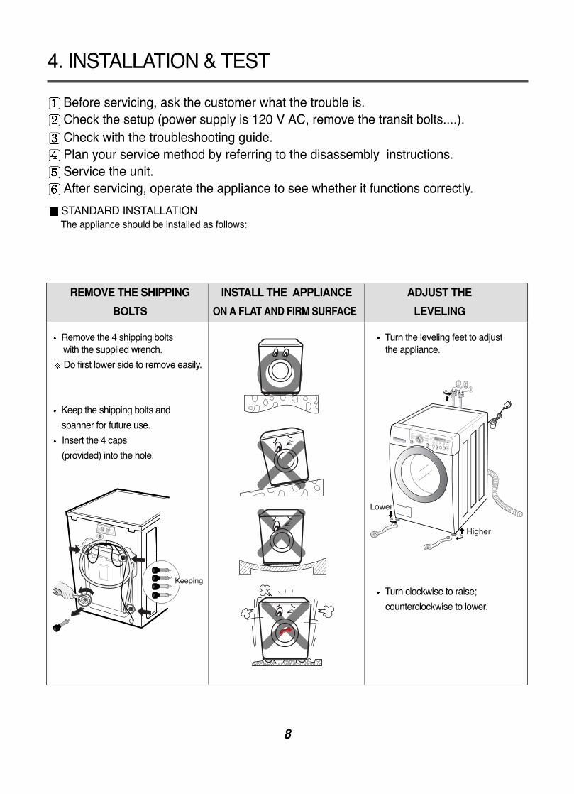
STANDARD INSTALLATIONThe appliance should be installed as follows:
REMOVE THE SHIPPING INSTALL THE APPLIANCE ADJUST THE
BOLTS ON A FLAT AND FIRM SURFACE LEVELING
Remove the 4 shipping bolts Turn the leveling feet to adjust with the supplied wrench. the appliance.
Do first lower side to remove easily.
Keep the shipping bolts and
spanner for future use.
Insert the 4 caps
(provided) into the hole.
Turn clockwise to raise;
counterclockwise to lower.
4. INSTALLATION & TEST
9
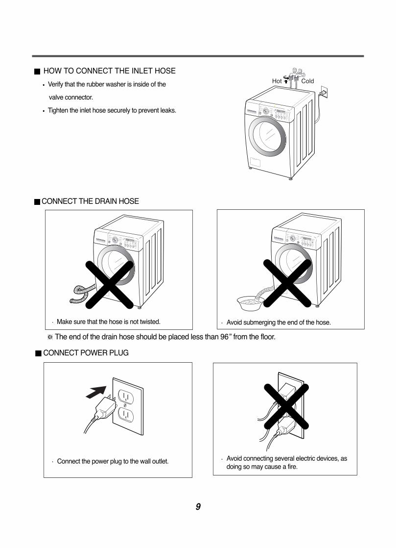
HOW TO CONNECT THE INLET HOSE
Verify that the rubber washer is inside of the
valve connector.
Tighten the inlet hose securely to prevent leaks.
CONNECT THE DRAIN HOSE
CONNECT POWER PLUG
The end of the drain hose should be placed less than 96” from the floor.
Connect the power plug to the wall outlet. Avoid connecting several electric devices, asdoing so may cause a fire.
Make sure that the hose is not twisted. Avoid submerging the end of the hose.
10
SOFTENER
MAX
HIGH
WASHING
HIGH
HOT/COLD
STEAM DOOR LOCK
EST. TIME:REMANING
5%
NORMAL
CHILD LOCK DELAY WASH
1:21
HIGH
WASHING
HIGH
HOT/COLD
STEAM DOOR LOCK
EST. TIME:REMANING
5%
NORMAL
CHILD LOCK DELAY WASH
1:21
HIGH
WASHING
HIGH
HOT/COLD
STEAM DOOR LOCK
EST. TIME:REMANING
5%
NORMAL
CHILD LOCK DELAY WASH
1:21
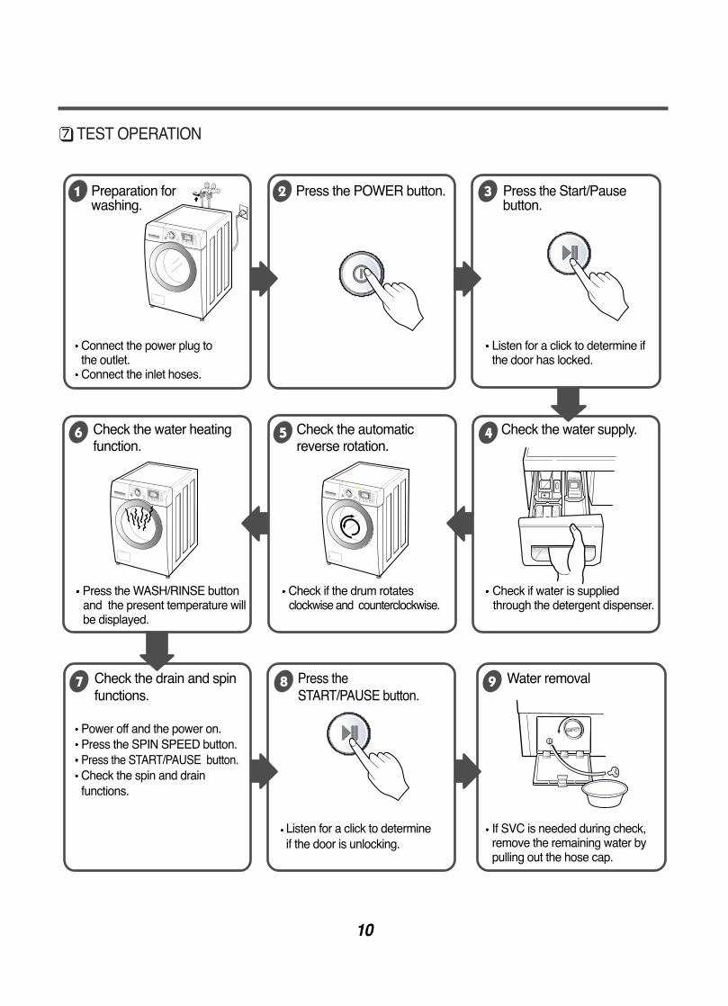
TEST OPERATION
Connect the power plug tothe outlet.Connect the inlet hoses.
Power off and the power on.Press the SPIN SPEED button.Press the START/PAUSE button.Check the spin and drainfunctions.
Listen for a click to determineif the door is unlocking.
Listen for a click to determine ifthe door has locked.
If SVC is needed during check,remove the remaining water bypulling out the hose cap.
Preparation for Press the POWER button. Press the Start/Pausewashing. button.
Press the WASH/RINSE button Check if the drum rotates Check if water is suppliedand the present temperature will clockwise and counterclockwise. through the detergent dispenser.be displayed.
Check the water heating Check the automatic Check the water supply.function. reverse rotation.
Check the drain and spin Press the Water removal functions. START/PAUSE button.
11
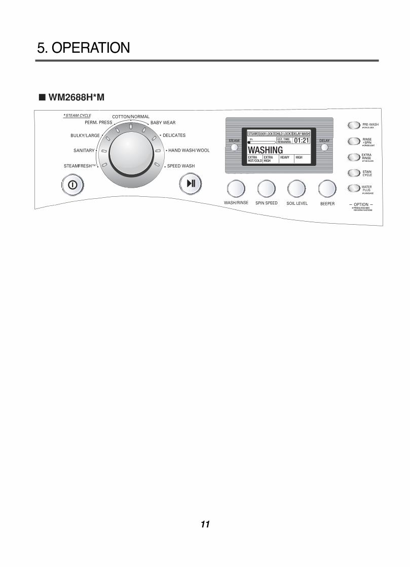
5. OPERATION
WM2688H*M
12
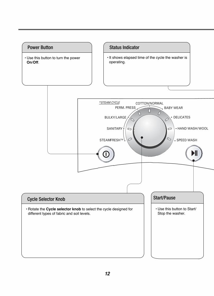
• Use this button to turn the power On/Off.
• Rotate the Cycle selector knob to select the cycle designed fordifferent types of fabric and soil levels.
• Use this button to Start/Stop the washer.
• It shows elapsed time of the cycle the washer isoperating.
Power Button Status Indicator
Start/PauseCycle Selector Knob
13
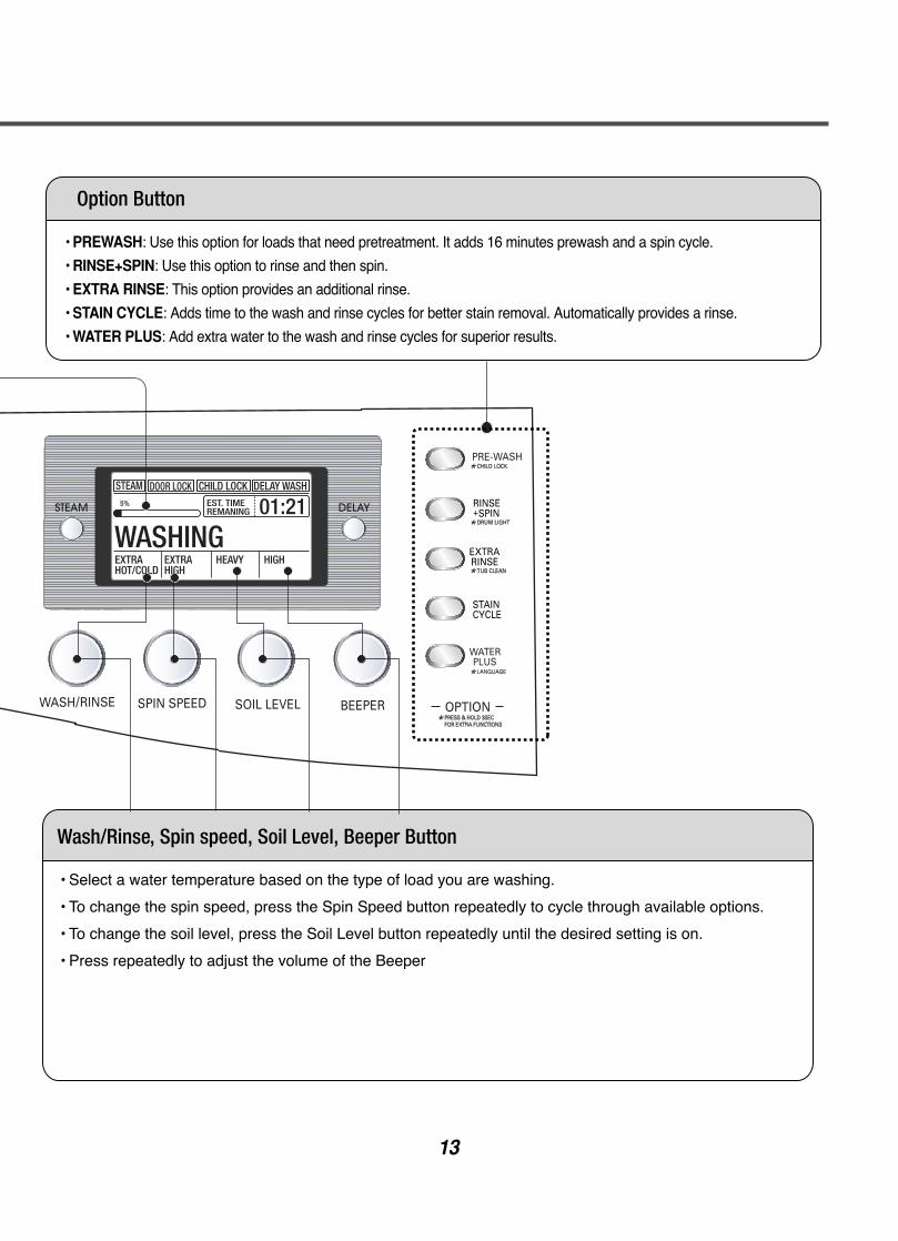
• PREWASH: Use this option for loads that need pretreatment. It adds 16 minutes prewash and a spin cycle.
• RINSE+SPIN: Use this option to rinse and then spin.
• EXTRA RINSE: This option provides an additional rinse.
• STAIN CYCLE: Adds time to the wash and rinse cycles for better stain removal. Automatically provides a rinse.
• WATER PLUS: Add extra water to the wash and rinse cycles for superior results.
• Select a water temperature based on the type of load you are washing.
• To change the spin speed, press the Spin Speed button repeatedly to cycle through available options.
• To change the soil level, press the Soil Level button repeatedly until the desired setting is on.
• Press repeatedly to adjust the volume of the Beeper
Option Button
Wash/Rinse, Spin speed, Soil Level, Beeper Button
14
* *
Cool-down**Approx.
(Minutes)
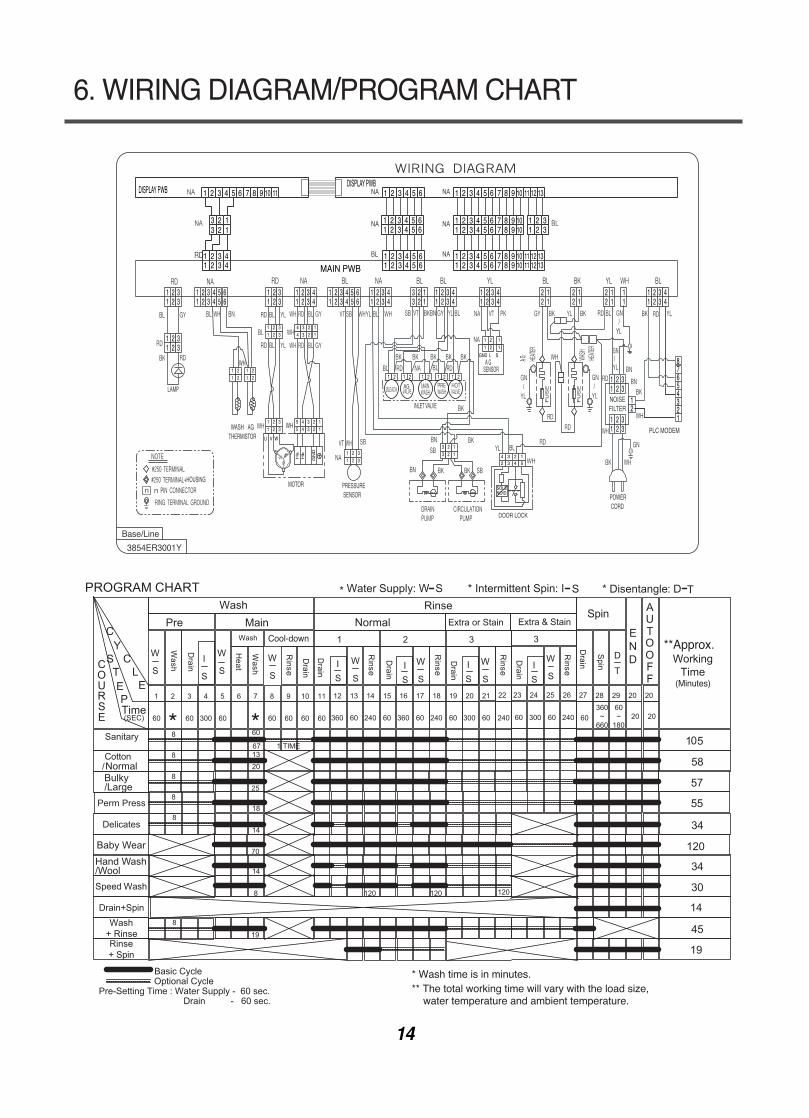
* Wash time is in minutes.** The total working time will vary with the load size, water temperature and ambient temperature.
NormalBulky/Large
Hand Wash/Wool
Baby Wear
25
120
14
19
70
6. WIRING DIAGRAM/PROGRAM CHART
INLET VALVE
DISPLAY PWBDISPLAY PWB
62 3 4 5162 3 4 51
62 3 4 5162 3 4 51
62 3 4 51
2 3 412 3 41 MAIN PWB
/YL
WASH AG WH
/
1 2 3 4 5 61 2 3
1 2 31 2 34
1 2 3 41 2 3 4
2 12 1
2 12 1
2 12 1
115 6
1 2 3 4 5 61 2 3 4
1 2 3 41 2 3 4
1 2 3 41 2 3 45 6
1 2 31 2 3
1 2 31 2 3
10 116 7 8 92 3 4 51
2 132 13
NA
NA
NA
NA
BL
NA
10 11 12 136 7 8 92 3 4 5110 11 12 136 7 8 92 3 4 51
10 11 12 136 7 8 92 3 4 51
106 7 8 92 3 4 51106 7 8 92 3 4 51
2 312 31
1 2 3 41 2 3 4
3 2 13 2 1
1 2 31 2 3
44
MOTOR
LAMP
PRESSURE SENSOR
THERMISTOR
POWER CORD
+HOUSING
3 23 2 1
1
1 21
GND L S
2 11
1 21
U V W
2
1 21 2
WH1 21 2
33
1 21 2 3
3 4 34 3 2
211
1 21 2 3
3
5 45 4 3
3 22 1
1
Ha
Hb
GN
D
FU
SE /
FU
SE
A G A GSENSOR
1 2 1 2 1 21 21 2
AG
/
NOISEFILTER
PLC MODEM
1 2 31 2 3
1 2 31 2 3
87654321
12
DOOR LOCK
4
SOLENOID
3 2 12 3 4 5
Base/Line
3854ER3001Y
15
7. TROUBLESHOOTING
7-1. BEFORE PERFORMING SERVICEBe careful of electric shock when disconnecting parts while troubleshooting.
The voltage of each terminal is 120 V AC and DC when the unit is plugged in.
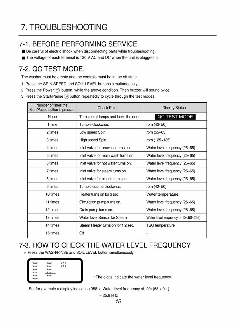
7-2. QC TEST MODE.The washer must be empty and the controls must be in the off state.
1. Press the SPIN SPEED and SOIL LEVEL buttons simultaneously.
2. Press the Power button, while the above condition. Then buzzer will sound twice.
3. Press the Start/Pause button repeatedly to cycle through the test modes.
7-3. HOW TO CHECK THE WATER LEVEL FREQUENCYPress the WASH/RINSE and SOIL LEVEL button simultaneously.
So, for example a display indicating 058: a Water level frequency of 20+(58 x 0.1)
= 25.8 kHz
• The digits indicate the water level frequency.
Check Point Display Status
None Turns on all lamps and locks the door.
1 time Tumble clockwise. rpm (42~50)
2 times Low speed Spin. rpm (55~65)
3 times High speed Spin. rpm (125~135)
4 times Inlet valve for prewash turns on. Water level frequency (25~65)
5 times Inlet valve for main wash turns on. Water level frequency (25~65)
6 times Inlet valve for hot water turns on. Water level frequency (25~65)
7 times Inlet valve for steam turns on. Water level frequency (25~65)
8 times Inlet valve for bleach turns on. Water level frequency (25~65)
9 times Tumble counterclockwise. rpm (42~50)
10 times Heater turns on for 3 sec. Water temperature
11 times Circulation pump turns on. Water level frequency (25~65)
12 times Drain pump turns on. Water level frequency (25~65)
13 times Water level Sensor for Steam Water level frequency of TSG(0~255)
14 times Steam Heater turns on for 1.2 sec. TSG temperature
15 times Off -
Number of times theStart/Pause button is pressed
QC TEST MODE
******************
************ ***
******
16
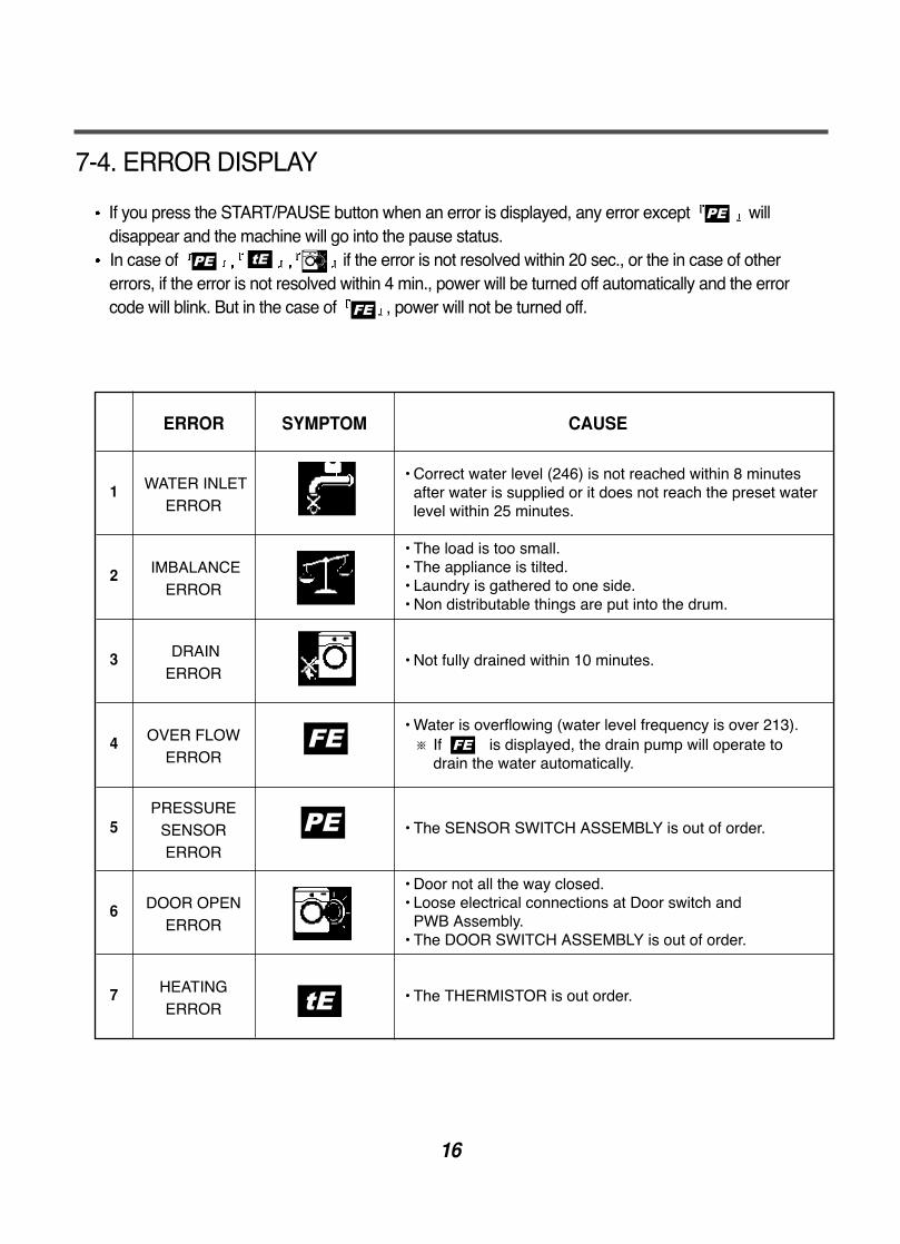
7-4. ERROR DISPLAY
If you press the START/PAUSE button when an error is displayed, any error except willdisappear and the machine will go into the pause status.In case of if the error is not resolved within 20 sec., or the in case of othererrors, if the error is not resolved within 4 min., power will be turned off automatically and the errorcode will blink. But in the case of , power will not be turned off.
ERROR SYMPTOM CAUSE
WATER INLETERROR
• Correct water level (246) is not reached within 8 minutesafter water is supplied or it does not reach the preset waterlevel within 25 minutes.
• The load is too small.• The appliance is tilted.• Laundry is gathered to one side.• Non distributable things are put into the drum.
1
2 IMBALANCEERROR
• Not fully drained within 10 minutes.3 DRAINERROR
• Water is overflowing (water level frequency is over 213).※ If is displayed, the drain pump will operate to
drain the water automatically.4 OVER FLOW
ERROR
• The SENSOR SWITCH ASSEMBLY is out of order.5PRESSURE
SENSOR ERROR
• Door not all the way closed.• Loose electrical connections at Door switch and
PWB Assembly.• The DOOR SWITCH ASSEMBLY is out of order.
6 DOOR OPENERROR
• The THERMISTOR is out order.7 HEATINGERROR
17
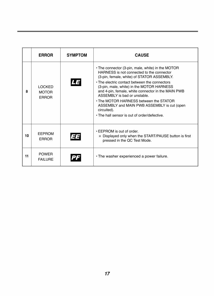
ERROR SYMPTOM CAUSE
• The connector (3-pin, male, white) in the MOTORHARNESS is not connected to the connector (3-pin, female, white) of STATOR ASSEMBLY.
• The electric contact between the connectors (3-pin, male, white) in the MOTOR HARNESS and 4-pin, female, white connector in the MAIN PWBASSEMBLY is bad or unstable.
• The MOTOR HARNESS between the STATORASSEMBLY and MAIN PWB ASSEMBLY is cut (opencircuited).
• The hall sensor is out of order/defective.
8LOCKEDMOTORERROR
• The washer experienced a power failure.11 POWERFAILURE
• EEPROM is out of order.※ Displayed only when the START/PAUSE button is first
pressed in the QC Test Mode.10 EEPROM
ERROR EE
F
18
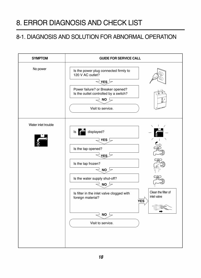
8-1. DIAGNOSIS AND SOLUTION FOR ABNORMAL OPERATION
8. ERROR DIAGNOSIS AND CHECK LIST
SYMPTOM GUIDE FOR SERVICE CALL
No power
Water inlet trouble
Is the power plug connected firmly to 120 V AC outlet?
Power failure? or Breaker opened?Is the outlet controlled by a switch?
Visit to service.
Is displayed?
Is the tap opened?
Is the tap frozen?
Is the water supply shut-off?
Is filter in the inlet valve clogged withforeign material?
Visit to service.
Clean the filter ofinlet valve
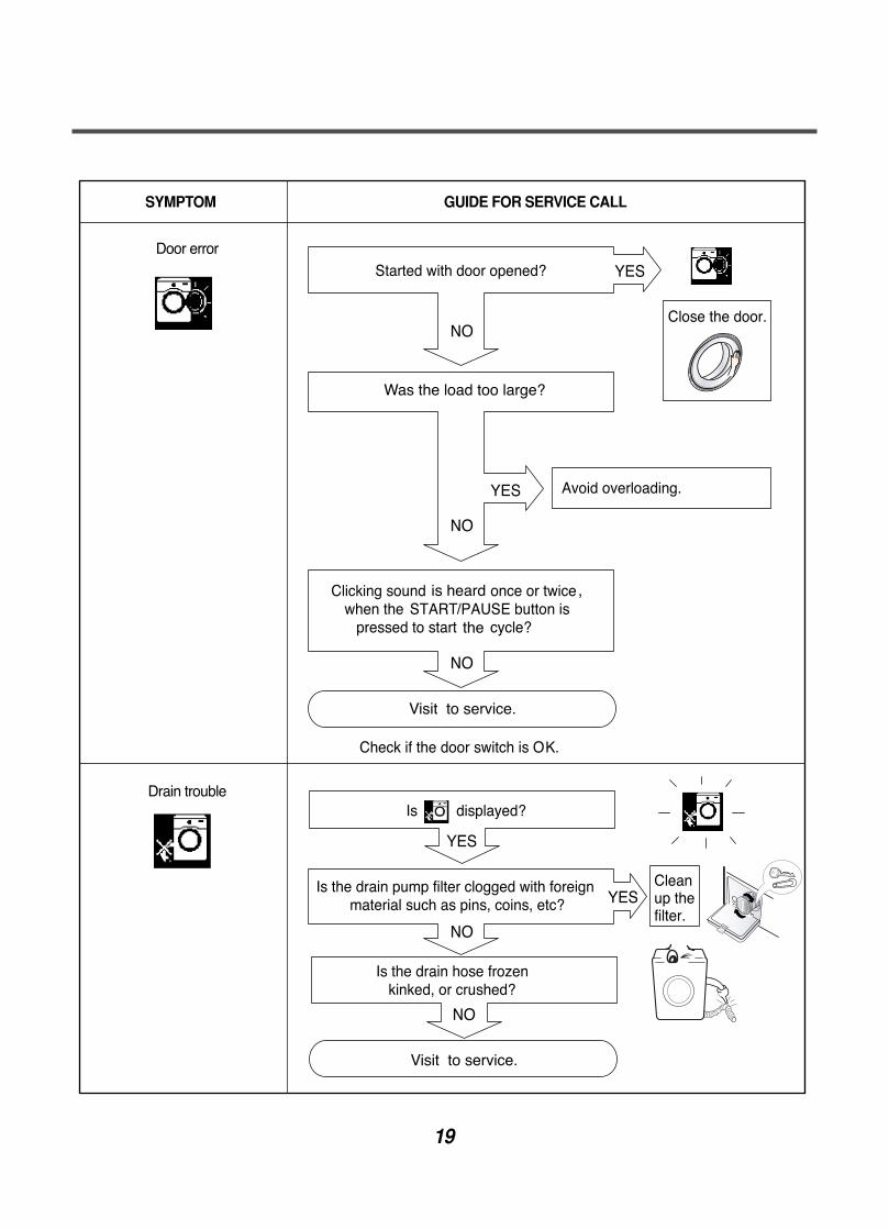
19
SYMPTOM GUIDE FOR SERVICE CALL
Door error
Drain trouble
Was the load too large?
Visit to service.
Visit to service.
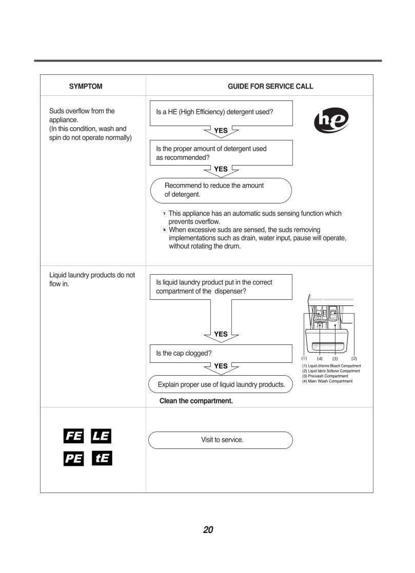
20
SYMPTOM GUIDE FOR SERVICE CALL
Suds overflow from theappliance.(In this condition, wash and spin do not operate normally)
YES
YES
YES
YES
SOFTENER
MAX
Is a HE (High Efficiency) detergent used?
Is the proper amount of detergent used as recommended?
Recommend to reduce the amount of detergent.
Is liquid laundry product put in the correctcompartment of the dispenser?
Is the cap clogged?
Explain proper use of liquid laundry products.
Clean the compartment.
Visit to service.
This appliance has an automatic suds sensing function whichprevents overflow.When excessive suds are sensed, the suds removingimplementations such as drain, water input, pause will operate,without rotating the drum.
Liquid laundry products do notflow in.
21
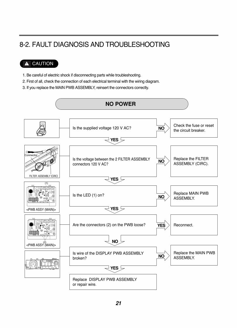
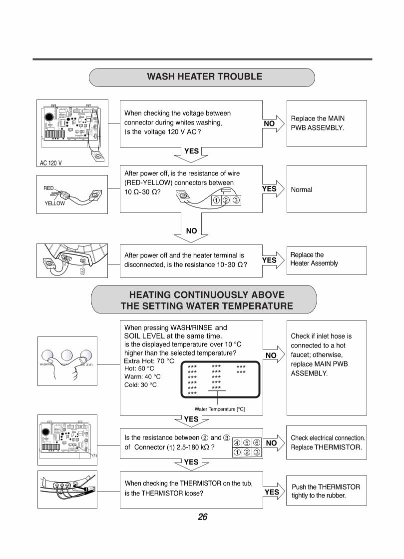
Is the supplied voltage 120 V AC?
Is the voltage between the 2 FILTER ASSEMBLYconnectors 120 V AC?
Is the LED (1) on?
Are the connectors (2) on the PWB loose?
Is wire of the DISPLAY PWB ASSEMBLY broken?
Replace DISPLAY PWB ASSEMBLY or repair wire.
Check the fuse or resetthe circuit breaker.
Replace the FILTERASSEMBLY (CIRC).
Replace MAIN PWBASSEMBLY.
Reconnect.
Replace the MAIN PWBASSEMBLY.
NO POWER
8-2. FAULT DIAGNOSIS AND TROUBLESHOOTING
1. Be careful of electric shock if disconnecting parts while troubleshooting.
2. First of all, check the connection of each electrical terminal with the wiring diagram.
3. If you replace the MAIN PWB ASSEMBLY, reinsert the connectors correctly.
CAUTION
22
Tighten
Tighten
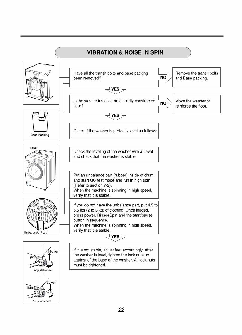
Have all the transit bolts and base packingbeen removed?
Remove the transit boltsand Base packing.
Move the washer orreinforce the floor.
Is the washer installed on a solidly constructedfloor?
Check if the washer is perfectly level as follows:
Check the leveling of the washer with a Leveland check that the washer is stable.
Put an unbalance part (rubber) inside of drumand start QC test mode and run in high spin(Refer to section 7-2). When the machine is spinning in high speed,verify that it is stable.
VIBRATION & NOISE IN SPIN
If it is not stable, adjust feet accordingly. Afterthe washer is level, tighten the lock nuts upagainst of the base of the washer. All lock nutsmust be tightened.
If you do not have the unbalance part, put 4.5 to6.5 lbs (2 to 3 kg) of clothing. Once loaded,press power, Rinse+Spin and the start/pausebutton in sequence.When the machine is spinning in high speed,verify that it is stable.
23
NO
YES
NO
NO
YES
NO
YES
YES
NO
NO
YES
YES
YES
NO
NO
NO
YES
SOFTENER
MAX
5
4
Bleach
Bleach
Steam
Steam
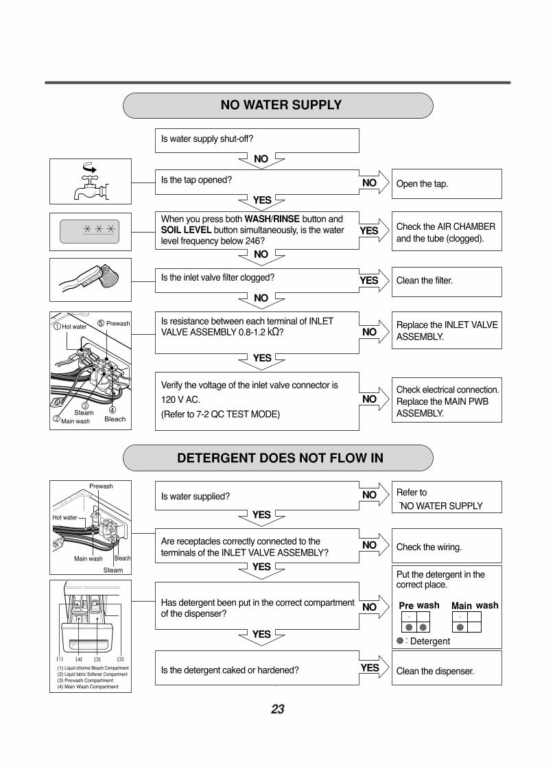
Is water supply shut-off?
Is the tap opened?
When you press both WASH/RINSE button andSOIL LEVEL button simultaneously, is the waterlevel frequency below 246?
Is the inlet valve filter clogged?
Is resistance between each terminal of INLETVALVE ASSEMBLY 0.8-1.2 kΩ?
Verify the voltage of the inlet valve connector is
120 V AC.
(Refer to 7-2 QC TEST MODE)
Is water supplied?
Are receptacles correctly connected to theterminals of the INLET VALVE ASSEMBLY?
Has detergent been put in the correct compartmentof the dispenser?
Is the detergent caked or hardened?
Open the tap.
Check the AIR CHAMBERand the tube (clogged).
Clean the filter.
Replace the INLET VALVEASSEMBLY.
Check electrical connection.Replace the MAIN PWBASSEMBLY.
Refer to NO WATER SUPPLY
Check the wiring.
Put the detergent in thecorrect place.
Clean the dispenser.
NO WATER SUPPLY
DETERGENT DOES NOT FLOW IN
24
SOFTENER
MAX
SOFTENER
MAX
ABNORMAL SOUND
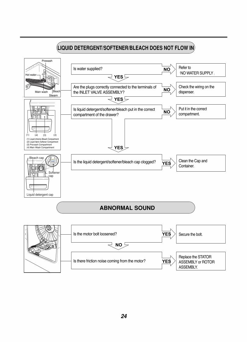
LIQUID DETERGENT/SOFTENER/BLEACH DOES NOT FLOW IN
Secure the bolt.
Replace the STATORASSEMBLY or ROTORASSEMBLY.
Refer toNO WATER SUPPLY
Check the wiring on the dispenser.
Put it in the correctcompartment.
Clean the Cap andContainer.
Is the motor bolt loosened?
Is there friction noise coming from the motor?
Is water supplied?
Are the plugs correctly connected to the terminals ofthe INLET VALVE ASSEMBLY?
Is liquid detergent/softener/bleach put in the correctcompartment of the drawer?
Is the liquid detergent/softener/bleach cap clogged?
25
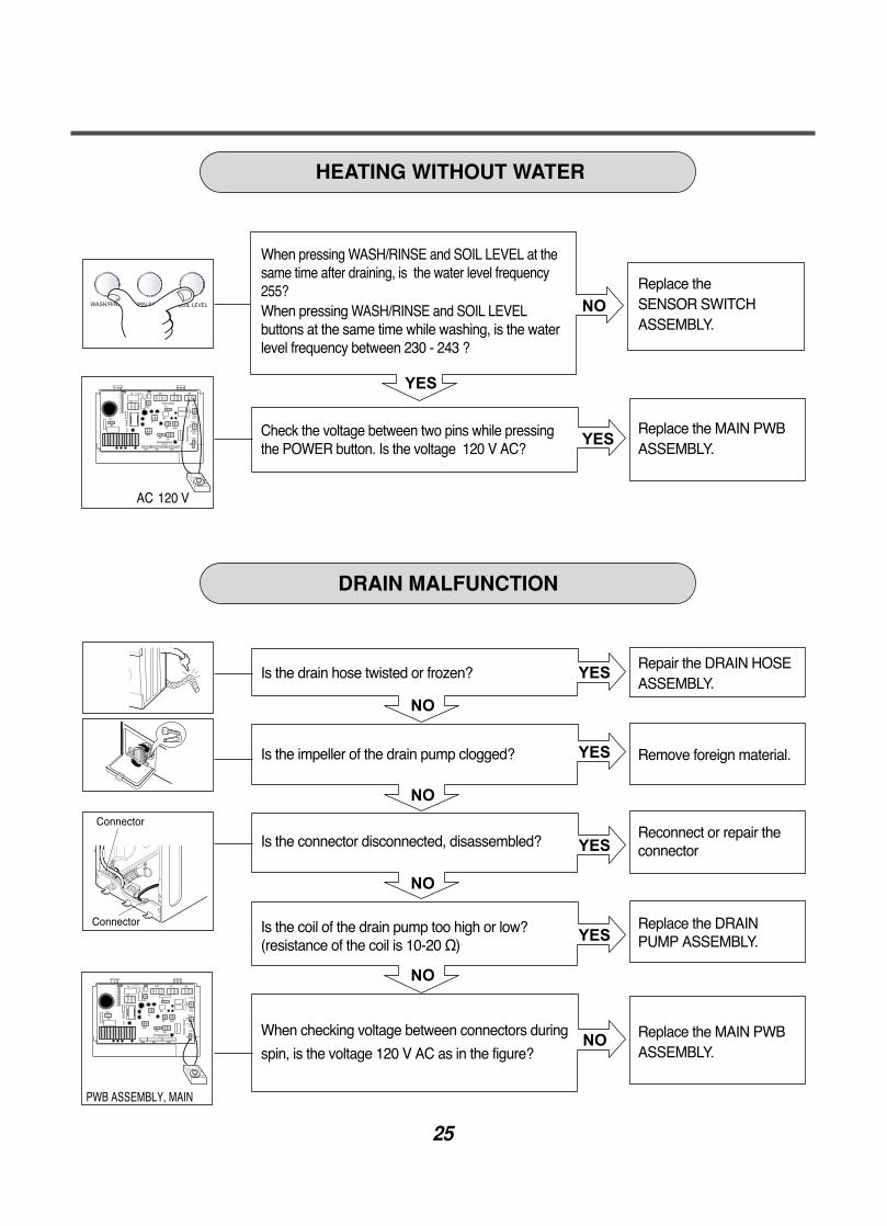
Replace theSENSOR SWITCHASSEMBLY.
Replace the MAIN PWBASSEMBLY.
Repair the DRAIN HOSE ASSEMBLY.
Remove foreign material.
Reconnect or repair theconnector
Replace the DRAINPUMP ASSEMBLY.
Replace the MAIN PWB ASSEMBLY.
When pressing WASH/RINSE and SOIL LEVEL at thesame time after draining, is the water level frequency255? When pressing WASH/RINSE and SOIL LEVELbuttons at the same time while washing, is the waterlevel frequency between 230 - 243 ?
Check the voltage between two pins while pressingthe POWER button. Is the voltage 120 V AC?
Is the drain hose twisted or frozen?
Is the impeller of the drain pump clogged?
Is the connector disconnected, disassembled?
Is the coil of the drain pump too high or low?(resistance of the coil is 10-20 Ω)
When checking voltage between connectors during
spin, is the voltage 120 V AC as in the figure?
HEATING WITHOUT WATER
DRAIN MALFUNCTION
26
(1)
Extra Hot: 70 °C
and SOIL LEVEL at the same time
SB
SB
BL
YL
BLBL
YL
WH WH
WH
WH
WH
SBRD
RD
BL
RD YL
BK
BK
WH
SB
SB
SB
BL
YL
BLBL
YL
WH WH
WH
WH
WH
SBRD
RD
BL
RD YL
BK
BK
WH
SB
Push the THERMISTORtightly to the rubber.
Replace theHeater Assembly
When checking the THERMISTOR on the tub, is the THERMISTOR loose?
Water Temperature [°C]
HEATING CONTINUOUSLY ABOVE THE SETTING WATER TEMPERATURE
WASH HEATER TROUBLE
******************
***************
******
27
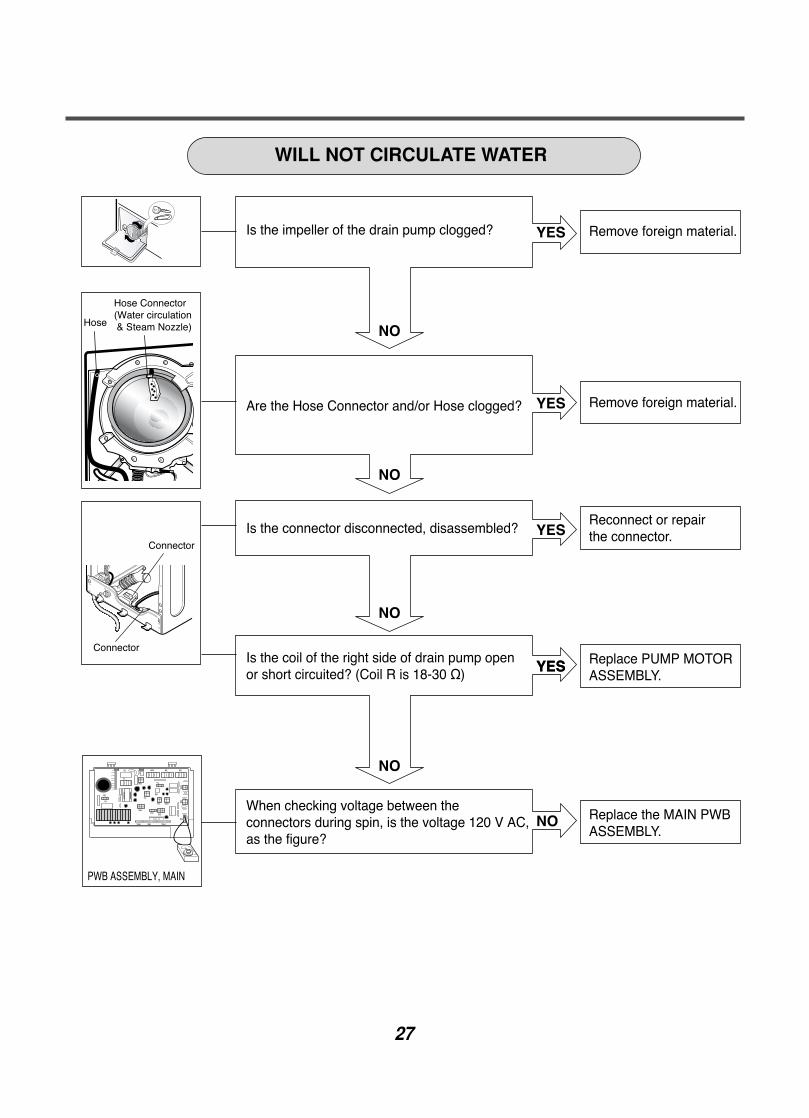
WILL NOT CIRCULATE WATER
Is the impeller of the drain pump clogged?
Are the Hose Connector and/or Hose clogged?
Is the connector disconnected, disassembled?
Is the coil of the right side of drain pump openor short circuited? (Coil R is 18-30 Ω)
When checking voltage between the connectors during spin, is the voltage 120 V AC,as the figure?
Remove foreign material.
Remove foreign material.
Reconnect or repair the connector.
Replace PUMP MOTORASSEMBLY.
Replace the MAIN PWBASSEMBLY.
28
(1) (2)
SB
SB
BL
YL
BLBL
YL
WH WH
WH
WH
WH
SBRD
RD
BL
RD YL
BK
BK
WH
SB
SB
SB
BL
YL
BLBL
YL
WH WH
WH
WH
WH
SBRD
RD
BL
RD YL
BK
BK
WH
SB
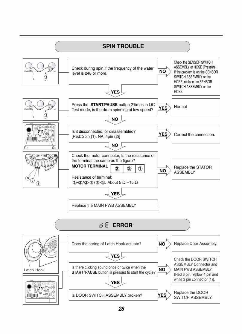
SPIN TROUBLE
Check the SENSOR SWITCHASSEMBLY or HOSE (Pressure). If the problem is on the SENSORSWITCH ASSEMBLY or theHOSE, replace the SENSORSWITCH ASSEMBLY or theHOSE.
Normal
Correct the connection.
Replace the STATORASSEMBLY
Check during spin if the frequency of the waterlevel is 248 or more.
Press the START/PAUSE button 2 times in QCTest mode, is the drum spinning at low speed?
Is it disconnected, or disassembled?[Red: 3pin (1), NA: 4pin (2)]
Check the motor connector, Is the resistance ofthe terminal the same as the figure?MOTOR TERMINAL
Resistance of terminal: ①-②/②-③/③-① About 5 Ω 15 Ω
Replace the MAIN PWB ASSEMBLY
Does the spring of Latch Hook actuate?
Is there clicking sound once or twice when theSTART/PAUSE button is pressed to start the cycle?
Is DOOR SWITCH ASSEMBLY broken?
Replace Door Assembly.
Check the DOOR SWITCHASSEMBLY Connector andMAIN PWB ASSEMBLY(Red 3 pin, Yellow 4 pin andwhite 3 pin connector (1)).
Replace the DOORSWITCH ASSEMBLY.
③ ② ①
29
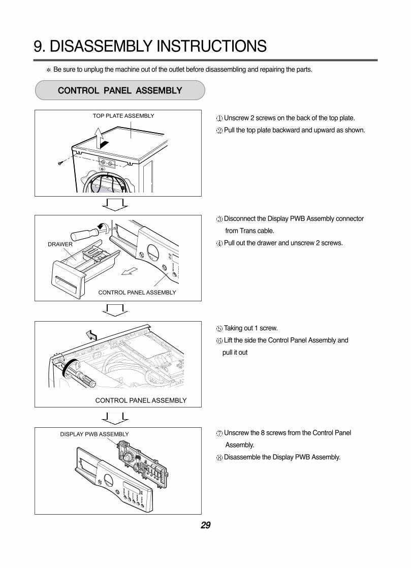
9. DISASSEMBLY INSTRUCTIONS
DISPLAY PWB ASSEMBLY
TOP PLATE ASSEMBLY
CONTROL PANEL ASSEMBLY
DRAWER
CONTROL PANEL ASSEMBLY
CONTROL PANEL ASSEMBLY
Be sure to unplug the machine out of the outlet before disassembling and repairing the parts.
Unscrew 2 screws on the back of the top plate.
Pull the top plate backward and upward as shown.
Disconnect the Display PWB Assembly connector
from Trans cable.
Pull out the drawer and unscrew 2 screws.
Taking out 1 screw.
Lift the side the Control Panel Assembly and
pull it out
Unscrew the 8 screws from the Control Panel
Assembly.
Disassemble the Display PWB Assembly.
30
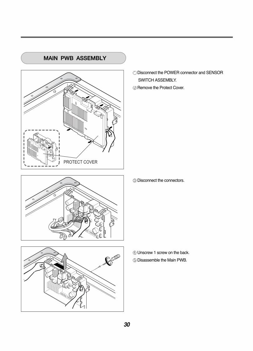
Disconnect the POWER connector and SENSOR
SWITCH ASSEMBLY.
Remove the Protect Cover.
Disconnect the connectors.
Unscrew 1 screw on the back.
Disassemble the Main PWB.
PROTECT COVER
MAIN PWB ASSEMBLY
31
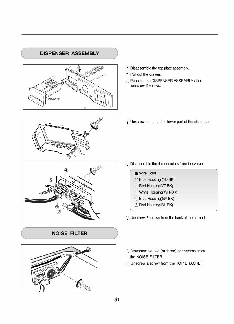
Disassemble the top plate assembly.
Pull out the drawer.
Push out the DISPENSER ASSEMBLY afterunscrew 2 screws.
Unscrew the nut at the lower part of the dispenser.
Disassemble the 4 connectors from the valves.
Unscrew 2 screws from the back of the cabinet.
Disassemble two (or three) connectors from
the NOISE FILTER.
Unscrew a screw from the TOP BRACKET.
Wire Color
Blue Housing (YL-BK)
Red Housing(VT-BK)
White Housing(WH-BK)
Blue Housing(GY-BK)
Red Housing(BL-BK)
5
DISPENSER ASSEMBLY
NOISE FILTER
32
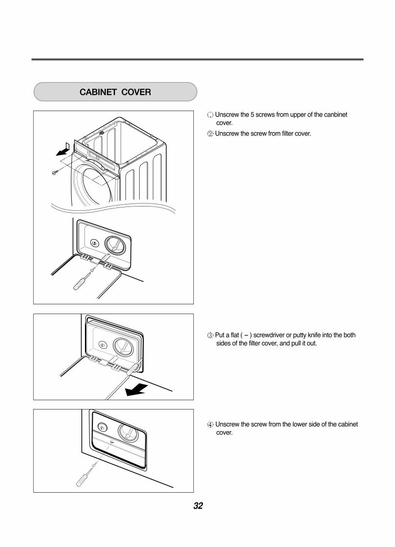
Unscrew the 5 screws from upper of the canbinetcover.
Unscrew the screw from filter cover.
Put a flat ( - ) screwdriver or putty knife into the bothsides of the filter cover, and pull it out.
Unscrew the screw from the lower side of the cabinetcover.
CABINET COVER
33
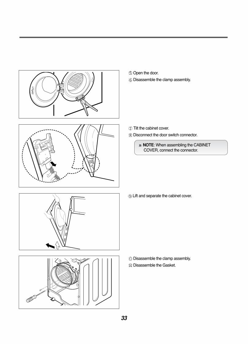
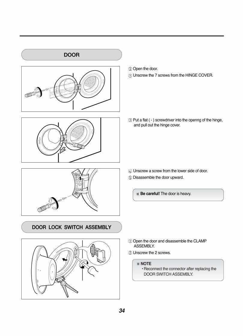
Open the door.
Disassemble the clamp assembly.
Tilt the cabinet cover.
Disconnect the door switch connector.
NOTE: When assembling the CABINETCOVER, connect the connector.
Lift and separate the cabinet cover.
Disassemble the clamp assembly.
Disassemble the Gasket.
34
Open the door.
Unscrew the 7 screws from the HINGE COVER.
Put a flat ( - ) screwdriver into the openng of the hinge,and pull out the hinge cover.
Unscrew a screw from the lower side of door.
Disassemble the door upward.
DOOR
Open the door and disassemble the CLAMPASSEMBLY.
Unscrew the 2 screws.
DOOR LOCK SWITCH ASSEMBLY
Be careful! The door is heavy.
NOTE • Reconnect the connector after replacing the
DOOR SWITCH ASSEMBLY.
35
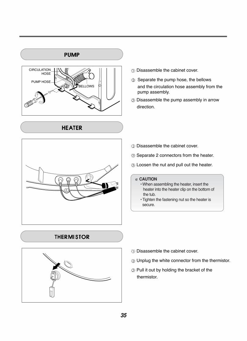
Disassemble the cabinet cover.
Separate the pump hose, the bellows
and the circulation hose assembly from thepump assembly.
Disassemble the pump assembly in arrow
direction.
Disassemble the cabinet cover.
Separate 2 connectors from the heater.
Loosen the nut and pull out the heater.
Disassemble the cabinet cover.
Unplug the white connector from the thermistor.
Pull it out by holding the bracket of the
thermistor.
CAUTION • When assembling the heater, insert the
heater into the heater clip on the bottom of the tub.
• Tighten the fastening nut so the heater issecure.
36
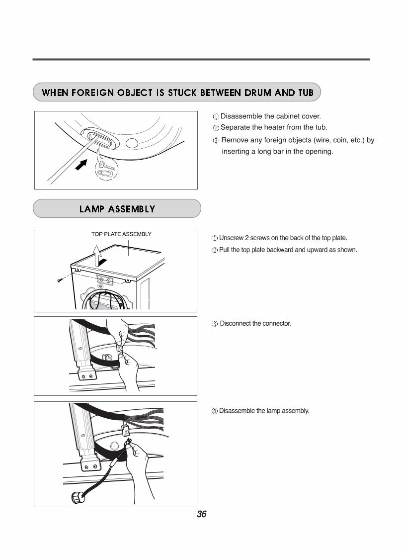
Disassemble the cabinet cover.
Separate the heater from the tub.
Remove any foreign objects (wire, coin, etc.) by
inserting a long bar in the opening.
TOP PLATE ASSEMBLYUnscrew 2 screws on the back of the top plate.
Pull the top plate backward and upward as shown.
Disconnect the connector.
Disassemble the lamp assembly.
37
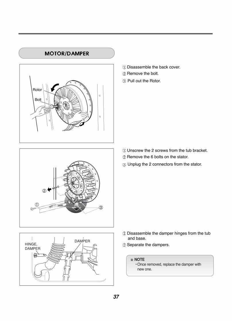
Disassemble the back cover.
Remove the bolt.
Pull out the Rotor.
Unscrew the 2 screws from the tub bracket.
Remove the 6 bolts on the stator.
Unplug the 2 connectors from the stator.
Disassemble the damper hinges from the tuband base.
Separate the dampers.
NOTE • Once removed, replace the damper with
new one.

38
To check out the fault diagnosis of TSG, in caseof removing the water inside, you can pull outthe plug and let the water drain away.
Be cautious in case of the TSG is hottemperature.
Remove the housing coupled the TSG (Heater, Water level frequency-sensor,Thermistor)
Taking out the screw of the TSG and BodyFrame.
39
Body Frame
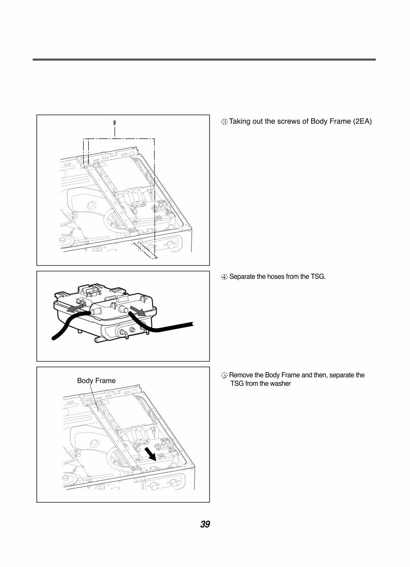
Taking out the screws of Body Frame (2EA)
Separate the hoses from the TSG.
Remove the Body Frame and then, separate theTSG from the washer
40
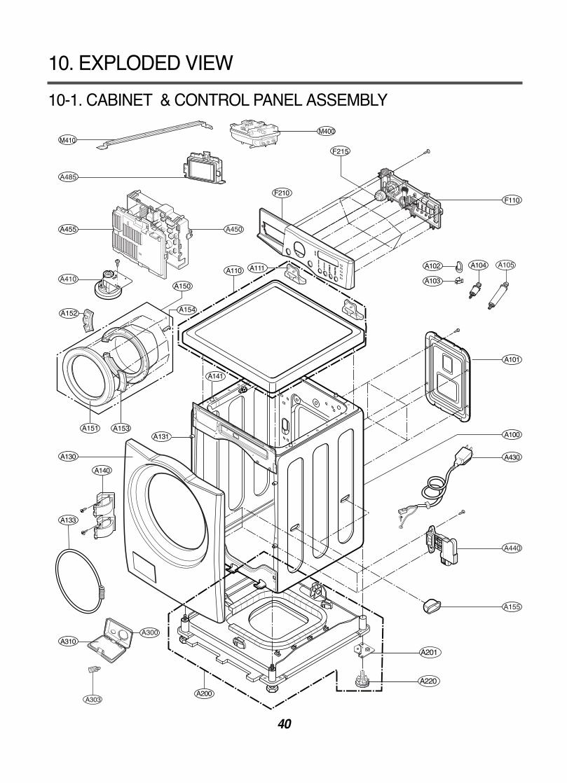
10-1. CABINET & CONTROL PANEL ASSEMBLY
10. EXPLODED VIEW
A105
A201
A220
A303
M410M400
41
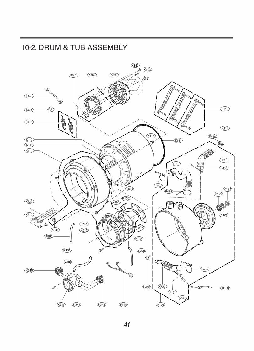
10-2. DRUM & TUB ASSEMBLY
K344K346 K345
K123K143
K115
K111
K340
K342
K131
K512
K560
K311
F315
F465
K125
F466
F467
F463
K130
F464
K121
K122
F145 K105
F468
K135
F328
K513
42
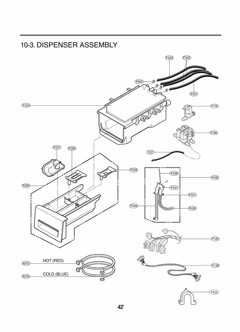
10-3. DISPENSER ASSEMBLY
HOT (RED)
COLD (BLUE)
F327


![Samsung Washing Machine [WA80U3] Manual](https://img.pdfslide.net/doc/110x75/5571ff6f49795991699d3a66/samsung-washing-machine-wa80u3-manual.jpg)