Embed Size (px)
Citation preview

WASHINGTON DULLES INTERNATIONAL AIRPORT IT1107INTERNATIONAL ARRIVALS BUILDING HVAC SYSTEM RENOVATION DECEMBER 02, 2011
SPECIFICATIONS TOC TOC - 1
TABLE OF CONTENTS
Licensed Professional Certification LPC- 01 to LPC- 03
VOLUME 1 OF 1
PROCUREMENT AND CONTRACTING REQUIREMENTS GROUP
DIVISION 00 - PROCUREMENT AND CONTRACTING REQUIREMENTS
007300 Supplementary Conditions
SPECIFICATIONS GROUP
GENERAL REQUIREMENTS SUBGROUP
DIVISION 01 – GENERAL REQUIREMENTS
011000 Summary012210 Measurement and Payment012300 Alternates012900 Application for Payment013100 Project Management and Coordination013200 Construction Progress Documentation013233 Photographic Documentation013300 Submittals014000 Quality Requirements014200 References015000 Temporary Facilities and Controls016000 Product Requirements017300 Execution017329 Cutting and Patching017700 Project Closeout017823 Operation and Maintenance Data017839 Project Record Documents
END OF GENERAL REQUIREMENTS SUBGROUP

WASHINGTON DULLES INTERNATIONAL AIRPORT IT1107INTERNATIONAL ARRIVALS BUILDING HVAC SYSTEM RENOVATION DECEMBER 02, 2011
SPECIFICATIONS TOC TOC - 2
FACILITY CONSTRUCTION SUBGROUP
DIVISION 02 – EXISTING CONDITIONS
Not Used
DIVISION 03 – CONCRETE
033000 Cast-In-Place Concrete
DIVISION 04 – MASONRY
042000 Unit Masonry, Reinforced
DIVISION 05 – METALS
055000 Metal Fabrications
DIVISION 06 – WOOD, PLASTICS, AND COMPOSITES
061053 Miscellaneous Rough Carpentry
DIVISION 07 – THERMAL AND MOISTURE PROTECTION
075423 Thermoplastic Polyolefin (TPO) Roofing078413 Penetration Firestopping079200 Joint Sealants
DIVISION 08 – OPENINGS
083113 Access Doors and Frames089000 Boxed Corner Louver Penthouses
DIVISION 09 – FINISHES
092116 Non-Structural Metal Framing092900 Gypsum Board095113 Acoustical Ceiling Tiles099123 Interior Painting
DIVISION 10 – SPECIALTIES
Not Used
DIVISION 11 – EQUIPMENT
Not Used
DIVISION 12 – FURNISHINGS
Not Used

WASHINGTON DULLES INTERNATIONAL AIRPORT IT1107INTERNATIONAL ARRIVALS BUILDING HVAC SYSTEM RENOVATION DECEMBER 02, 2011
SPECIFICATIONS TOC TOC - 3
DIVISION 13 – SPECIAL CONSTRUCTION
Not Used
DIVISION 14 – CONVEYING EQUIPMENT
Not Used
END OF FACILITY CONSTRUCTION SUBGROUP
FACILITY SERVICES SUBGROUP
DIVISION 21 – FIRE SUPPRESSION
210533 Heat Tracing for Fire-Suppression Piping211313 Wet-Pipe Sprinkler Systems
DIVISION 22 - PLUMBING
220513 Common Motor Requirements for Plumbing Equipment220523 General-Duty Valves for Plumbing Piping220529 Hangars and Supports for Plumbing Piping and Equipment220533 Heat Tracing for Plumbing Piping220553 Identification for Plumbing Piping and Equipment220719 Plumbing Piping Insulation221316 Sanitary Waste and Vent Piping221319 Sanitary Waste Piping Specialties221413 Storm Drainage Piping221429 Sump Pumps
DIVISION 23 – HEATING, VENTILATING, AND AIR CONDITIONING
230010 HVAC General Provisions230130.51 HVAC Air Distribution System Cleaning230513 Common Motor Requirements for HVAC Equipment230516 Expansion Fittings and Loops for HVAC Piping230517 Sleeves and Sleeve Seals for HVAC Piping230518 Escutcheons for HVAC Piping230519 Meters and Gages for HVAC Piping230523 General-Duty Valves for HVAC Piping230529 Hangers and Supports for HVAC Piping and Equipment230548 Vibration and Seismic Controls for HVAC Piping and Equipment230553 Identification for HVAC Piping and Equipment230593 Testing, Adjusting, and Balancing for HVAC230713 Duct insulation

WASHINGTON DULLES INTERNATIONAL AIRPORT IT1107INTERNATIONAL ARRIVALS BUILDING HVAC SYSTEM RENOVATION DECEMBER 02, 2011
SPECIFICATIONS TOC TOC - 4
DIVISION 23 – HEATING, VENTILATING, AND AIR CONDITIONING (continued)
230716 HVAC Equipment Insulation230719 HVAC Piping Insulation230900 Instrumentation and Control for HVAC232113 Hydronic Piping232123 Hydronic Pumps233113 Metal Ducts233300 Air Duct Accessories233416 Centrifugal HVAC Fans233600 Air Terminal Units234100 Particulate Air Filtration235700 Heat Exchangers for HVAC237323 Custom Indoor Central-Station Air-Handling Units238216 Air Coils238239 Unit Heaters238420 General-Service Compressed-Air Piping238421 General-Service Packaged Air Compressors and Receivers
DIVISION 25 – INTEGRATED AUTOMATION
Not Used
DIVISION 26 – ELECTRICAL
260500 Common Work Results for Electrical260519 Low-Voltage Electrical Power Conductors and Cables260526 Grounding and Bonding for Electrical Systems260529 Hangers and Supports for Electrical Systems260533 Raceway And Boxes for Electrical Systems260553 Identification for Electrical Systems 262416 Panelboards262726 Wiring Devices262816 Enclosed Switches and Circuit Breakers262923 Variable-Frequency Motor Controllers265100 Interior Lighting
DIVISION 27 - COMMUNICATIONS
Not Used
DIVISION 28 – ELECTRONIC SAFETY AND SECURITY
283111 Digital, Addressable Fire Alarm System
END OF FACILITY SERVICES SUBGROUP

WASHINGTON DULLES INTERNATIONAL AIRPORT IT1107INTERNATIONAL ARRIVALS BUILDING HVAC SYSTEM RENOVATION DECEMBER 02, 2011
SPECIFICATIONS TOC TOC - 5
SITE AND INFRASTRUCTURE SUBGROUP
DIVISION 31 - EARTHWORK
Not Used
DIVISION 32 – EXTERIOR IMPROVEMENTS
Not Used
DIVISION 33 - UTILITIES
Not Used
DIVISION 34 - TRANSPORTATION
Not Used
FAA SPECIFICATIONS
Not Used
END OF SITE AND INFRASTRUCTURE SUBGROUP
PROCESS EQUIPMENT SUBGROUP
DIVISION 44 – POLLUTION CONTROL EQUIPMENT
Not Used
END OF TABLE OF CONTENTS


WASHINGTON DULLES INTERNATIONAL AIRPORT IT1107INTERNATIONAL ARRIVALS BUILDING HVAC SYSTEM RENOVATION DECEMBER 02, 2011
SUPPLEMENTARY CONDITIONS 007300 - 1
SECTION 007300 — SUPPLEMENTARY CONDITIONS
PART 1 - GENERAL
1.1 RELATED DOCUMENTS
A. Drawings, Contract Provisions, Special Provisions, and other Division 01 Specification Sections, apply to this Section.
1.2 SUMMARY
A. The articles and paragraphs of this Section represent supplements or additions to the Contract Provisions or the Special Provisions.
1.3 WORK UNDER OTHER CONTRACTS
A. During the period of this Project, the Authority anticipates that other construction contracts may be underway at or near the site of work of this Contract. A list of adjacent construction activities follows:
1. Main Terminal East and West Baggage Basements EDS In-Line High Volume Baggage Screening.
2. International Arrivals Building (IAB) Secondary Inspection and Bag Re-Check Areas Improvements.
1.4 PERMITTING
A. Comply with all requirements set forth in the Authority's “Building Codes Manual”. This manual describes Building Codes organization, Building Code inspection process, Certificate of Occupancy requirements, and information regarding elevators, escalators, and moving walks. The Authority will file for and provide the construction permit.
1.5 MAINTENANCE OF PEDESTRIAN AND VEHICULAR TRAFFIC
A. Maintain adequate pedestrian and vehicular traffic flow and safety along the service roads, sidewalks, parking lots and other roadways on Airport property. In addition, this requirement applies to tug ramps and tug tunnels affected by the Work. Coordinate activities throughout the project in a manner that allows emergency access, without delays to emergency response vehicles, to all areas of the Project.
B. Prior to starting construction operations affecting pedestrian, vehicular, or tug and baggage cartmovement, submit and obtain the COTR's written approval of a Traffic Maintenance Plan. Develop plan in accordance with the safety requirements of the FAA, Airport Operations, and the Commonwealth of Virginia Department of Transportation’s “Manual of Uniform Traffic Control Devices”. Utilize the form indicated in the latest edition of the Virginia Department of Transportation’s “Virginia Work Area Protection Manual – Standards and Guidelines”.

WASHINGTON DULLES INTERNATIONAL AIRPORT IT1107INTERNATIONAL ARRIVALS BUILDING HVAC SYSTEM RENOVATION DECEMBER 02, 2011
SUPPLEMENTARY CONDITIONS 007300 - 2
C. Keep the portions of the project being used by public, pedestrian, aircraft, mobile lounges and vehicular traffic, whether it is through or local traffic, in such condition that traffic will beadequately accommodated.
1.6 AIRFIELD AND TERMINAL BUILDING OPERATIONAL REQUIREMENTS
A. The Work, or a portion thereof, will be performed within the public and non-public areas of the IAB facility. Normal airport operations and public activities will continue adjacent to the Work during all phases of the Project. These include:
1. Passenger baggage deposit/retrieval.2. Arriving International passenger processing by Customs and Border Protection (CBP)
agency.3. Inbound baggage conveyor and tug/cart delivery operations.4. CBP office and support area functions.5. Maintenance, custodial and support activities.
B. Phase construction activities as necessary, and as defined in the Drawings and Division 01 “Summary” Specification, to accommodate all airport operations without disruption. Adhere to all current Airport Orders and Instructions (O & Is), Airport Bulletins, and Airport Advisories. The Authority will provide relevant Orders and Instructions to Offerors in the Solicitation Package. Bulletins and Advisories will be provided to the offeror by the Authority as they are issued.
1.7 TENANT OPERATIONAL REQUIREMENTS
A. The Work of this Project will be performed in close proximity to CBP and other tenant-occupied areas. Coordinate and conduct work activities in such fashion that public circulation, tenant operations, and access to the tenant spaces will not be impaired in any manner except as detailed on Contractor's Work Plans. COTR will review and approve in writing all Work Plans.
B. See detailed construction phasing requirements and other operational constraints described in Division 01 Specification “Summary of Work”.
1.8 ENVIRONMENTAL PROTECTION
A. Comply with all Federal, state and local laws and regulations controlling pollution of the environment. Take necessary precautions to prevent pollution of streams, rivers, lakes, ponds, and reservoirs with fuels, oils, bitumens, chemicals, or other harmful materials and to prevent pollution of the atmosphere from particulate and gaseous matter.
B. Notify COTR immediately in the event that abnormalities, discolorations, odors, oil, or other signs of potential contamination by hazardous materials are encountered during excavation or other construction activities. Follow with written notice within 24 hours, indicating date, time, and location of potential contaminants encountered. The COTR will provide further direction to Contractor regarding disposition of materials encountered.

WASHINGTON DULLES INTERNATIONAL AIRPORT IT1107INTERNATIONAL ARRIVALS BUILDING HVAC SYSTEM RENOVATION DECEMBER 02, 2011
SUPPLEMENTARY CONDITIONS 007300 - 3
C. All painted surfaces are assumed to contain lead-based paint. The Contractor shall maintain the necessary health and safety requirements for all personnel in accordance with OSHA regulations to work in these conditions.
D. Aircraft deicing fluids will be encountered in the water (including utility manholes) and in the soils. Concentrations of aircraft deicing fluids in water and soils will range from non-detect to saturation. Aircraft deicing fluids are propylene based Type I and Type IV fluids. The fluids emit an unpleasant odor when the breakdown (biodegradation) is occurring. Follow OSHA requirements while working in aircraft deicing impacted areas. Coordinate with the COTR for obtaining Material Safety Data Sheet (MSDS) for aircraft deicing fluids.
1.9 DAMAGES AND PRE-EXISTING CONDITIONS
A. Be responsible for all damages caused by Contractor’s construction activities. Provide all labor, materials, etc. to return any damaged areas, systems or equipment to their original condition at no additional cost to the Authority.
B. Perform a survey of pre-existing conditions in the vicinity of Contractor’s construction activities, utilizing photographs and other means as necessary to document existing damage or conditions. Submit two copies of this survey to the Contracting Officer within 21 calendar days after Notice-to-Proceed. This survey will assist in resolving any damage claims against the Contractor during and after construction.
C. Preserve all roadways, pedestrian and directional signage. Deliver all signs removed and not required for reinstallation to the Authority as directed by the COTR.
D. Replace or repair lost or damaged signs at no cost to the Authority.
1.10 SECURITY DURING CONSTRUCTION
A. Maintain the integrity of the Airport Security fence. Maintain the integrity of doors and walls between public areas and Air Operations Area (AOA) at all times. Comply with Title 49 Code of Federal Regulations, Parts 1500, 1540, 1542 and 1544.
B. Possession of and display of a proper and current Airport Identification Badge, issued by Airport Operations is required for all Contractor personnel passing into the AOA. Refer to "Airport Orders and Instructions" attached as part of the Contract for specific requirements. Security requirements have increased significantly at Washington Dulles International Airport and Ronald Reagan Washington National Airport. Contractor can expect up to two hours waiting time to clear construction vehicles into the AOA. Offerors shall become intimately familiar with all TSA and Authority security requirements. No increase in contract price will be provided to the Contractor should the contractor not be aware of any security procedure in place at time of submitting their offer that leads to increased time and inconvenience to accomplish the work.
C. Under the requirements of Federal Security Directive 1542-04-8E, the Authority is submitting information from badge application forms to the Transportation Security Administration (TSA) through the Transportation Security Clearinghouse so the TSA can perform a Security Threat Assessment (STA) in addition to the fingerprint-based Criminal History Records Check (CHRC) the Authority is required to perform on all badge applicants. No badges are allowed to be issued to NEW applicants until final approval of the STA has been received.

WASHINGTON DULLES INTERNATIONAL AIRPORT IT1107INTERNATIONAL ARRIVALS BUILDING HVAC SYSTEM RENOVATION DECEMBER 02, 2011
SUPPLEMENTARY CONDITIONS 007300 - 4
1. TSA has estimated that the STA portion of this review may take as long as 3 to 14 days. 2. For specific questions contact the Pass and ID office at 703-572-2780.
D. In addition to the badge application requirements above, all workers shall obtain a U. S. Customs & Border Protection (CBP) seal on their airport ID badge. The process to obtain a Custom Seal is systematic and requires first for the company to get bonded, letters for each employee, a fee (currently estimated to be $45) that must be paid at the time of application, and fingerprint and background check by CBP which in itself could take 21 to 28 days to complete. Within all FIS restricted areas under its jurisdiction, CBP does not allow badged workers with the Custom seal to escort unbadged workers or badged workers without a Custom Seal.
E. The Contractor shall pay all fines levied by the Transportation Security Administration, U.S. Customs & Border Protection, or both, for penalties resulting from security infractions perpetrated by or caused by Contractor’s personnel or work forces of Contractor’s subcontractors or suppliers.
F. Establish and maintain the security of Contractor’s staging areas, equipment and materials.
G. Provide escort for delivery vehicles transporting materials and supplies to or from the Contractor's staging or work areas into the AOA, in accordance with requirements stated in "Airport Orders and Instructions" attached as part of the Contract.
H. Do not park within 300 feet of a terminal building unless specifically authorized by Airport Operations.
I. All workers in the sterile areas, which are defined as areas accessible to ticketed passengers only, may utilize tools in their work provided that:
1. Tools are essential and necessary to the Work.2. Keep tools controlled at all times.3. Do not leave tools unattended.4. Store tools in locked boxes.
J. No knives will be permitted in the sterile areas.
K. No firearms or weapons of any type are allowed on the airport.
L. No cartridge style nail guns, nor any tools that use a cartridge or any explosive charge, are allowed without prior written notification of COTR. Obtain written approval from the COTR before bringing such tools on the project.
M. Conform to all Orders and Instructions pertaining to vehicle inspection. Pertinent Orders and Instructions are provided with The Authority’s solicitation documents.
1.11 HAULING
A. Contractor shall use haul routes as designated on the drawings.

WASHINGTON DULLES INTERNATIONAL AIRPORT IT1107INTERNATIONAL ARRIVALS BUILDING HVAC SYSTEM RENOVATION DECEMBER 02, 2011
SUPPLEMENTARY CONDITIONS 007300 - 5
1.12 PORTABLE LIGHTING
A. If portable lighting is used for Contractor operations, aim and shield portable lighting at all times to eliminate glare that could impair runway, taxiway, apron, ground operations, baggage cart tug and Airport Traffic Control Tower operations. Equip portable lighting with reflectors and glare shields to prevent spillover of light into operational areas.
1.13 RADIO COMMUNICATIONS
A. Provide two-way radio communication between certain of the Contractor’s personnel on the job site. Provide radios with a minimum of 5 watts transmitting power. Select the frequency utilized for these transmissions. Submit proposed frequencies to COTR for approval in writing by the COTR. Frequencies shall not conflict with or overlay any of the Airports radio frequencies.
B. Provide, at a minimum, the following with radio equipment: The Project Superintendent, Foreman of all work groups physically separated from the general vicinity of the Project Superintendent, gate guards, and others who may be working in a separate and remote area. Provide two additional radios with the same frequencies to PMC for use by the COTR and the Lead Inspector.
1.14 SPECIAL AUTHORITY CONSULTANT
A. The Contractor is hereby advised of the involvement of Parsons Management Consultants (PMC) as Program Management Support Services Consultant to the Authority for the capital construction programs at Ronald Reagan Washington National Airport and Washington Dulles International Airport. PMC will have a continuing role in this project by assisting the Authority in specialized areas.
1. PMC will provide administrative support during design, solicitation, and construction.2. PMC will coordinate Contractor requests for technical information and receive, review
and manage all Contractor submittals.3. PMC has reviewed technical submittals during design, including drawings, specifications,
cost estimates, construction phasing plans, and technical reports. 4. PMC will be responsible for review of technical submittals during construction, including
selected shop drawings, certifications, test reports, calculations and samples. 5. PMC will conduct field inspections of the Work in progress and inspect for Substantial
Completion and Final Acceptance. PMC inspection does not relieve Contractor of responsibilities of performing Contract required inspections as required by contract documents.
B. All other contract management is the sole responsibility of the Authority.
1.15 SAFETY
A. Comply with all requirements set forth in the most current edition of the Authority Construction Safety Manual”. Offerors are provided with the most recent addition when obtaining contract documents prior to proposal. Requirements included in this Section are in addition to the Authority’s Construction Safety Manual. Comply with all local, State and Federal

WASHINGTON DULLES INTERNATIONAL AIRPORT IT1107INTERNATIONAL ARRIVALS BUILDING HVAC SYSTEM RENOVATION DECEMBER 02, 2011
SUPPLEMENTARY CONDITIONS 007300 - 6
requirements. Where conflicts or discrepancies exist between requirements, the more stringent requirement shall govern. For additional information see Division 01 Section “Quality Requirements”.
B. Contractor Safety Organization:
1. Safety Engineer.
a. Duties: Outlined in The Authority Construction Safety Manual.b. Qualifications: Outlined in The Authority Construction Safety Manual.
2. Provide a full-time on-site Contractor Safety Engineer for the duration of this Contract. The Safety Engineer shall be responsible for all safety and health requirements as included herein and as required by the Authority’s Construction Safety Manual.
C. Submit the résumés of individuals proposed to serve in the role of Contractor’s Safety Engineer to the COTR for approval in writing. In addition to indicating the qualifications in the Authority Construction Safety Manual résumés shall include but not be limited to such items as: work experience, education, safety and health training completed, memberships in professional associations, professional certifications, professional registrations and professional references confirming the qualifications and personal references of contacts for verification shall also be required.
D. Provide safe and healthful working conditions on each operation at all times during execution the work of this Contract. Conduct the various operations connected with the Work so that they will not be injurious to safety or health. Comply with all provisions, regulations and recommendations issued pursuant to the Occupational Safety and Health Act of 1970 and the Construction Safety Act of 1969, as well as amendments to these laws. Comply with laws, rules and regulations of other authorities having jurisdiction, with regard to all matters relating to the safety and health of workers and the general public. Compliance with government requirements is mandated by law and considered only a minimum level of safety performance. Perform all work in accordance with best safe work practices recognized by the construction industry. Stop work whenever a work procedure or a condition at a work site is deemed unsafe by the either of the following individuals: COTR, Program Safety Manager (PSM), the Contractor’s Project Manager, the Contractor’s Foreman or the Contractor’s Safety Engineer(s).
E. Comply with all requirements set forth in the Authority's "Construction Safety Manual." Provide during the Work the services of Safety Engineer(s) as outlined in the Authority’s “Construction Safety Manual” and in Division 01 Section “Quality Requirements”. The Safety Engineer shall undertake the duties and responsibilities as stated in the Authority's "Construction Safety Manual".
F. Prior to start of construction activities in the Air Operations Area (AOA), the Contractor’s Safety Engineers shall tour the AOA with the Authority Safety Program Manager.
G. Flagmen Training: The Authority will sponsor Flagman training sessions. Contractor's personnel who will be assigned flagmen duties on the Airport for this project shall attend training sessions.
H. Fire Safety: Conform to the following requirements:

WASHINGTON DULLES INTERNATIONAL AIRPORT IT1107INTERNATIONAL ARRIVALS BUILDING HVAC SYSTEM RENOVATION DECEMBER 02, 2011
SUPPLEMENTARY CONDITIONS 007300 - 7
1. Obtain a permit to perform any welding, cutting, or hot work from the Office of the Authority Fire Marshal.
2. Ensure adequate access to all construction areas for emergency response.3. Obtain a permit from the Office of the Authority Fire Marshal to store, handle, or use any
hazardous material, including but not limited to fuels for equipment. Complete an application prior to issuance.
4. Remove combustible debris from the site daily.5. Provide at least seven (7) days notice for any request for inspections, tests, permits, etc.,
required of personnel from the Office of the Authority Fire Marshal.6. Provide to the Office of the Authority Fire Marshal a list of emergency contact numbers
for the COTR and the Contractor prior to the commencement of Work.
I. Submit Site-Specific Safety and Health Plans to COTR within 15 calendar days of Notice to Proceed and prior to the start of any construction activities. Prepare this plan using the Authority’s Guidelines as defined in the Authority’s “Construction Safety Manual” and as supplemented by these specifications for each and every work zone as shown on the drawings or as anticipated by the Contractor. COTR must approve the Site-Specific Safety Plan prior to the start of any work.
J. Be responsible for the safe operation of all job site motor vehicles. Provide a “spotter” or flagman for all backing operations of construction vehicles with restricted rear vision.
K. All motorized equipment and vehicles working on or entering MWAA construction project work areas shall be equipped with functional audible backup alarms.
L. Crane Operators. On Airports Authority projects, Crane Operators shall be certified to operate the equipment by an approved independent certifying agency.
M. The Contract Work is not expected to be performed in the AOA, however hauling operations will be take place on the AOA and shall be addressed in the Contractor’s Safety Plan.
N. Comply with sample safety plan as designated in the MWAA Construction Safety Manual.
1.16 HEIGHT LIMITATION
A. For all demolition and construction within the Airport, limit the height of Contractor's equipment to a maximum of 120 feet. Submit to COTR, a list of equipment with heights greater than 35 feet.
B. Prior to beginning any work coordinate with the COTR the height of all cranes, boom trucks, scaffolds or similar vehicles of construction. Properly mark all construction equipment with safety flags and warning lights in accordance with current FAA and Airport Operations requirements. Submit FAA Form 7460, provided by COTR, for all variations on approved crane heights.
1.17 NOISE CONTROL
A. The Authority recognizes and can tolerate a normal level of noise created by a majority of construction activity. However, in the interest of the Authority's neighbors, the maximum acceptable noise level between the hours of 5:00 pm and 7:00 am the following morning is

WASHINGTON DULLES INTERNATIONAL AIRPORT IT1107INTERNATIONAL ARRIVALS BUILDING HVAC SYSTEM RENOVATION DECEMBER 02, 2011
SUPPLEMENTARY CONDITIONS 007300 - 8
limited to 55 decibels. During daytime hours of 7:00 am through 5:00 pm, the maximum acceptable noise level for sustained or repetitive noises is 72 decibels. Measure noise levels using an "A" scale at a point 4'-0" above ground at property line nearest noise source.
B. Secure advance written approval from the COTR prior to scheduling any activity that is anticipated to produce a sustained or repetitive noise level higher than the decibel limits indicated above.
C. In and around terminal facilities and buildings whose normal occupancy is from 7 a.m. to 7 p.m., perform work that causes noise that is disruptive to the airport’s tenants or the traveling public between the hours of 11:00 pm and 5:00 am. Measure noise for this situation using an “A” scale at a point 4’-0” above ground at the closest point to airport tenants or the traveling public.
1.18 EXAMINATION OF PLANS, SPECIFICATIONS AND SITE OF WORK
A. The offeror is expected to examine carefully the site of the proposed work, the proposal, plans, specifications, solicitation provisions, contract provisions, special provisions and contract forms before submitting a proposal. The submission of a proposal will be considered conclusive evidence that the offeror has made such examination and is satisfied as to the conditions to be encountered in performing the Work as to the requirements of the Contract.
1.19 AIRPORT SECURITY/VEHICLE INSPECTION PROCEDURE
A. The number of vehicular access points into secure areas at IAD has been reduced to an operational minimum. Those gates that remain open are divided into two categories:
1. Vehicular gates for approved vehicles and individuals who hold appropriate and valid airport access media and do not require escorts.
2. Vehicular gates for those vehicles that have invalid or no airport access authorization and/or the vehicle operator and passenger(s) do not have valid access authorization media and require escorts.
B. The access points for vehicle operator and passenger(s) who have appropriate and valid airport access media are Gates 141 and 127. Vehicles that require escorts of any type are prohibited at gate 127.
C. All vehicles and personnel that will require an escort shall enter the AOA via Gate 313, Gate 317, Gate 141, or Gate 118. The vehicle gates at Gate 118 and Gate 141 are designated as AOA entry points for vehicles and persons that require an escort and their primary work site is located on the north side of the airport. Gate 313 is designated as large equipment contractor/construction access point, and Gate 317 is to be used by contractors and employees whose primary work site is located on the south side of the airport. These access gates are as indicated.
D. The following procedures will be utilized for all escorted vehicles and AOA approved vehicles with non-badged passengers seeking entry to the AOA:
1. All vehicles are searched.

WASHINGTON DULLES INTERNATIONAL AIRPORT IT1107INTERNATIONAL ARRIVALS BUILDING HVAC SYSTEM RENOVATION DECEMBER 02, 2011
SUPPLEMENTARY CONDITIONS 007300 - 9
2. Coordinate all vehicle deliveries with the COTR in advance. Provide the vehicle license plate number and expected delivery time for all vehicle deliveries. Contractor may compile the expected daily delivery schedule on one sheet for submission to the COTR.
3. The vehicle operator shall have in his or her possession a commercial manifest, which identifies the contents of the vehicle and/or trailer.
4. An escort from the company for whom the shipment is intended shall respond to the vehicle access gate and remain with the vehicle until the vehicle exits the secured area.
5. A vehicle search will be conducted and once cleared; vehicles will be permitted escorted access to their delivery point.
6. Contractors should expect delays up to 1 hour at Gate 313 as a result of these security provisions. The longest waits are anticipated to be between 6:00 a.m. and 7:30 a.m.
7. Priority consideration may be offered to concrete trucks with resulting delays estimated to be 20 minutes. To receive priority consideration, schedule concrete deliveries with Airport Operations and COTR at time of batching.
8. When the new temporary AOA gate with guard is in place, coordinate oversize deliveries with COTR to occur during off hours. It is anticipated that this will be primarily during Phase 2.
E. Prior approval from the Manager of Airport Operations or his/her designated representative is required for any exceptions to the above procedures.
PART 2 - PRODUCTS (Not Used)
PART 3 - EXECUTION (Not Used)
END OF SECTION 007300
WASHINGTON DULLES INTERNATIONAL AIRPORT IT1107INTERNATIONAL ARRIVALS BUILDING HVAC SYSTEM RENOVATION DECEMBER 02, 2011
SUMMARY 011000 - 1
SECTION 011000 - SUMMARY
PART 1 - GENERAL
1.1 RELATED DOCUMENTS
A. Drawings, Contract Provisions, Special Provisions, Supplementary Conditions, and other Division 01 Specification Sections apply to this Section.
1.2 SUMMARY
A. This Section includes the following:
1. Work covered by the Contract Documents.
a. Base Contract Workb. Alternate Contract Work
2. Type of the Contract.3. Work phases.4. Work under other contracts.5. Authority-furnished products.6. Use of premises.7. The Authority's occupancy requirements.8. Contractor’s hours of operation.9. Specification formats and conventions.10. Marking utility services11. Utility Outages
B. Related Sections include the following:
1. Division 01 Section "Temporary Facilities and Controls" for limitations and procedures governing temporary use of the Authority's facilities.
1.3 WORK COVERED BY CONTRACT DOCUMENTS
A. Project Identification: Project consists of the replacement, refurbishment and new component installation associated with the original HVAC systems of the International Arrivals Building (IAB).
1. Project Name: IAB HVAC System Renovation2. Project Location: IAB, Main Terminal Washington Dulles International Airport.
B. Architect/Engineer Identification: The Contract Documents, dated September, 2010, were prepared for Project by:
1. HC Yu and Associates, 1013 Technology Drive, Glen Allen, VA 230592. PGAL, 201 North Union Street, Suite 500, Alexandria, VA 22314.

WASHINGTON DULLES INTERNATIONAL AIRPORT IT1107INTERNATIONAL ARRIVALS BUILDING HVAC SYSTEM RENOVATION DECEMBER 02, 2011
SUMMARY 011000 - 2
C. Construction Manager: Parsons Management Consultants has been engaged as Construction Manager for this Project to serve as an advisor to the Authority and to provide assistance in administering the Contract for Construction between the Authority and Contractor, according to a separate contract between the Authority and Construction Manager.
1. For additional functions of Parsons Management Consultants, see "Supplementary Conditions."
D. The Work generally consists of the replacement, refurbishment and new component installation associated with the original HVAC systems of the International Arrivals Building (IAB). See Division 01 Specification Section “Alternates” for more detailed requirements, definitions and descriptions associated with the Alternate Work.
1. The Base Contract Work generally includes, but not limited to, the following:
a. Replacement of existing air handler units (AHU). b. Replacement/reconfiguration of AHU piping and ductwork to facilitate AHU
replacement.c. Refurbishment of an existing heat exchanger; addition of a new heat exchanger;
replacement of associated pumps.d. Replacement of AHU control panels.e. Replacement of all control wiring and other elements between all terminal units
and new control panels.f. Replacement/reconfiguration of power, data and controls utilities serving AHU’s
to be replaced.g. Fabrication/installation of custom louvered penthouse boxes and supporting steel
reinforced concrete base.h. Replacement/relocation of below floor slab plumbing and drains; associated
concrete slab-on-grade removal/replacement.i. Removal of outside air plenum pre-heat coil system.j. Installation of gas phase filtration rack assemblies in the new air handlers.k. Replacement of return fan RF-1.l. Replacement of air compressor and setup with new duplex compressor, larger air
tank and duplex dryers. m. Replacement of 6 duplex sump pumps.n. Replacement of 2 Unit Heaters.o. Removal/Reconstruction/Reconfiguration of existing concrete masonry unit
(CMU) wall (partial).p. Temporary cooling/heating of occupied spaces during construction.q. Cleaning and balancing of existing original terminal units.r. Replacing/Replacement of “Auto-Flo” valves on existing original terminal units.s. Balancing of existing terminal units in public spaces (Installed in 2010-2011).t. Balancing of existing reheat coils and associated dampers for public space supply
air.u. Vacuum and cleaning of all supply, return and exhaust air ductwork including air
plenum.v. Flushing and cleaning all hot water piping systems.w. Temporary barricades and protection of furnishings and equipment to facilitate
work related to terminal units.x. Fan powered terminal unit in the basement mechanical room and associated
ductwork and controls.

WASHINGTON DULLES INTERNATIONAL AIRPORT IT1107INTERNATIONAL ARRIVALS BUILDING HVAC SYSTEM RENOVATION DECEMBER 02, 2011
SUMMARY 011000 - 3
2. The Alternate No. 1 Work generally includes, but is not limited to, the following:
a. Phased replacement of existing HVAC system terminal units and associated ductwork, hydronic piping, electrical and controls elements.
b. Two (2) variable air volume terminal units and associated supply air ductwork and controls.
c. Temporary and permanent relocation of existing light fixtures, sprinkler piping, speakers, smoke detectors, ductwork, electrical conduit and other utilities to facilitate replacement of the terminal units.
d. Replacement of acoustical lay-in tile and gypsum wall board ceiling systems to facilitate replacement of HVAC system terminal units.
e. Temporary barricades, furnishings relocations and protection of finishes to facilitate replacement of the terminal units.
3. For additional requirements for the examination of plans, specifications and Project site see Section “Supplementary Conditions.”
1.4 TYPE OF CONTRACT
A. Project will be constructed under a general construction contract.
1.5 WORK PHASES
A. Contractor shall perform the Work per the phases and sequences and within the constraints identified on the Drawings and Specifications.
Retain below for each phase required. Remove text enclosed in angle brackets and insert text to suit that phase. Repeat subparagraph, revised as appropriate, for each separate phase. See MASTERSPEC Evaluations for model text.
B. Schedule the execution of the Work according to the phasing and sequences indicated, and to avoid interference with normal functions of the Airport, the airlines and other tenants of the IAB facility.
C. Before commencing Work of each phase, submit a schedule to COTR showing the sequence, the commencement and completion dates, and the move-out and move-in dates of personnel for the various phases of the Work.
D. On completion, each phase of the Work shall be fully operational.
E. Contractor shall submit phasing schedule to COTR for review and approval.
F. The primary Work phases are directly related to the removal and replacement of each major air handling unit (AHU). See Mechanical (ME) Drawings for detailed phasing requirements and seasonal restrictions related to performing HVAC Work.

WASHINGTON DULLES INTERNATIONAL AIRPORT IT1107INTERNATIONAL ARRIVALS BUILDING HVAC SYSTEM RENOVATION DECEMBER 02, 2011
SUMMARY 011000 - 4
G. Additional detailed Work phasing and constraints related to maintaining on-going airport and airport tenant operations are described on the GN series Drawings and elsewhere in the Contract Documents.
H. See “Contractor Hours of Operation” and the Drawings for Contractor Work hours and specific work hour and calendar year restrictions and other requirements.
1.6 WORK UNDER OTHER CONTRACTS
A. General: Cooperate fully with separate contractors so work on those contracts may be carried out smoothly, without interfering with or delaying work under this Contract. Coordinate the Work of this Contract with work performed under separate contracts.
B. Concurrent Work: The Authority has separate contracts for the following construction projectsat the IAB. Those operations will be conducted simultaneously with work under this Contract.
1. Main Terminal East and West Baggage Basement EDS In-Line High Volume Baggage Screening
2. International Arrivals Building (IAB) Secondary Inspection and Bag Re-Check Areas Improvements.
1.7 AUTHORITY-FURNISHED PRODUCTS
A. The following items will be furnished by the Authority and installed by the Contractor:
1. N/A
1.8 USE OF PREMISES
A. Use of Site: Limit use of premises to work in areas indicated. Do not disturb portions of site beyond areas in which the Work is indicated.
1. Limits: Confine constructions operations to limits indicated on Drawings. Contractor shall use the designated haul routes and shall coordinate construction activities with the COTR. Interference with the Authority, airline, tenant or FAA operations or aircraft movements is prohibited.
2. Authority Occupancy: Allow for Authority occupancy of site and day-to-day use by tenants, air carriers, and the public.
3. Contractor shall have full use of premises for construction operations within the Contract Limit Lines indicated during construction period, during the hours indicated, and as directed by COTR. Contractor's use of premises is limited only by the Authority's right to perform work or to retain other contractors on portions of Project.
4. Driveways and Entrances: Keep driveways and entrances serving premises clear and available to the Authority, the Authority's employees, tenants, air carriers, and emergency vehicles at all times. Do not use driveways and entrances for parking or storage of materials.
5. Deliveries:
a. Schedule deliveries to minimize disruption of Airport operations

WASHINGTON DULLES INTERNATIONAL AIRPORT IT1107INTERNATIONAL ARRIVALS BUILDING HVAC SYSTEM RENOVATION DECEMBER 02, 2011
SUMMARY 011000 - 5
b. Schedule deliveries to minimize space and time requirements for storage of materials and equipment on-site.
c. Delivery of large construction elements shall be performed between the hours of 10:30PM and 5:30AM.
B. Utilize areas designated for Contractor staging, storage, and parking, as indicated. For additional requirements, see Section "Supplementary Conditions."
C. Use of Existing Buildings: Maintain existing buildings in a weather tight condition throughout construction period. Repair damage caused by construction operations. Protect buildings and their occupants during construction period.
1. Contractor shall not be allowed within limits of Customs and Border Protection (CBP)-controlled areas of facility without proper security badges. All Contractor personnel shall be required to maintain CBP-approved airport security badges. Escorting of personnel possessing a non-CBP-approved airport security badge, or personnel without badges, will not be allowed.
2. For additional requirements for airfield and terminal buildings, see Section "Supplementary Conditions."
1.9 OCCUPANCY REQUIREMENTS
A. Full Authority Occupancy: The Authority and/or its tenants will occupy site and existing building during entire construction period. Cooperate with COTR during construction operations to minimize conflicts and facilitate Authority usage, and perform the Work so as not to interfere with day-to-day Airport operations.
B. Partial Authority Occupancy: The Authority will occupy, and place and install equipment, in completed areas of building before Substantial Completion of each phase. Such placement of equipment and partial occupancy shall not constitute acceptance of the total Work. Partial Authority occupancy requirement are as follows:
1. COTR will prepare a Certificate of Substantial Completion for each specific portion of the Work to be occupied before Authority occupancy.
2. Obtain a Certificate of Occupancy from the Authority Building Codes/Environmental Department before Authority occupancy.
3. Before partial Authority occupancy, mechanical and electrical systems shall be fully operational, and required tests and inspections shall be successfully completed. On occupancy, the Authority will operate and maintain mechanical and electrical systems serving occupied portions of building.
4. On occupancy, the Authority will assume responsibility for maintenance and custodial service for occupied portions of building.
C. For additional requirements for tenant operational requirements, see Section "Supplementary Conditions.
1.10 CONTRACTOR HOURS OF OPERATION
A. Contractor Working Hours:

WASHINGTON DULLES INTERNATIONAL AIRPORT IT1107INTERNATIONAL ARRIVALS BUILDING HVAC SYSTEM RENOVATION DECEMBER 02, 2011
SUMMARY 011000 - 6
1. Work within the Basement Level of the IAB shall be generally allowed to be performed 24 hours a day, seven days a week, within in the constraints and per the phases of construction noted on the Drawings, unless otherwise approved by the COTR.
2. Work within the Ground Level of the IAB shall be performed at varying times as indicated on the GN series drawings.a. Night work within the Ground Level shall be performed between the hours of
10:30PM and 5:30AM, within the constraints and restrictions defined on the Drawings, unless otherwise noted or otherwise approved by the COTR.
b. Work above critical CBP functions shall be performed between the hours of 12:30AM and 5:30AM and can only be performed on Tuesdays and Wednesdays. See GN series Drawings.
c. Work in Public Areas and above critical CBP inspection areas shall not be performed between July 15 through September 15 of the calendar year. See GN series Drawings.
3. See restrictions on material delivery under “Use of Premises” in this Specification section.
4. Work is subject to restrictions of the Airport operational requirements.
B. Notify the COTR 72-hours in advance of any proposed change to approved work schedules.
1.11 SPECIFICATION FORMATS AND CONVENTIONS
A. Specification Format: With the exception of Federal Aviation Administration (FAA) standard specifications, the Specifications are organized into Divisions and Sections using the 34-Division format using the CSI/CSC's "MasterFormat 2004" numbering system.
1. Section Identification: The Specifications use Section titles to help with cross-referencing in the Contract Documents. Sections in the Project Manual are in numeric sequence; however, the sequence is incomplete as all available Sections and Section numbers are not used and the CSI numbering system is not sequentially complete. Consult the table of contents at the beginning of the Project Manual to determine numbers and names of sections in the Contract Documents.
B. Specification Content: The Specifications use certain conventions for the style of language and the intended meaning of certain terms, words, and phrases when used in particular situations. These conventions are as follows:
1. Abbreviated Language: Language used in the Specifications and other Contract Documents is abbreviated. Interpret words and meanings as appropriate. Infer words implied, but not stated, as the sense requires. Interpret singular words as plural, and plural words as singular where applicable as the context of the Contract Documents indicates.
2. Imperative mood and streamlined language are used in these Specifications. This imperative language is directed to the Contractor, unless specifically noted otherwise. Requirements expressed in the imperative mood are to be performed by Contractor. Occasionally, the indicative or subjunctive mood may be used in the Section Text for clarity to describe responsibilities that must be fulfilled indirectly by Contractor or by others when so noted.

WASHINGTON DULLES INTERNATIONAL AIRPORT IT1107INTERNATIONAL ARRIVALS BUILDING HVAC SYSTEM RENOVATION DECEMBER 02, 2011
SUMMARY 011000 - 7
a. The words "shall," "shall be," or "shall comply with," depending on the context, are implied where a colon (:) is used within a sentence or phrase.
1.12 MARKING UTILITY SERVICES
A. It is not anticipated that the Contract Work will require the location and identification of underground utilities.
1.13 UTILITY OUTAGES
A. Prior to any utility outage/interruption, prepare a schedule of such outage. Include in outage schedule duration, identification of the service affected, temporary utility service to be provided, identification of available service alternative, and the action to be taken in the ` of any emergency. Apply for all outages of utility systems in writing. Fully coordinate outage requests with COTR. Obtain approval in writing by COTR. Schedule all outages at least three (3) weeks in advance with a 96-hour notification provided by the Contractor confirming date, time, and duration. Outages will normally be scheduled to occur between the hours of 11:00PMand 5:30AM, Tuesday through Thursday.
PART 2 - PRODUCTS (Not Used)
PART 3 - EXECUTION (Not Used)
END OF SECTION 011000

WASHINGTON DULLES INTERNATIONAL AIRPORT IT1107INTERNATIONAL ARRIVALS BUILDING HVAC SYSTEM RENOVATION DECEMBER 02, 2011
MEASUREMENT AND PAYMENT 012210 - 1
SECTION 012210 - MEASUREMENT AND PAYMENT
PART 1 - GENERAL
1.1 RELATED DOCUMENTS
A. Drawings, Contract Provisions, Special Provisions, Supplementary Conditions, and other Division 01 Specification Sections apply to this Section.
1.2 SUMMARY
A. This Section includes administrative and procedural requirements governing methods of measurement and computations to be used in determination of quantities of material furnished and unit amount of Work performed under the Contract in order for Contractor to receive payment according to agreed-upon unit prices.
B. At the discretion of the COTR, payment may be reduced for any Work which is not in full compliance with the Contract Documents or which has been damaged or repaired by Contractor. Such action may be used when the end product may have a reduced service life or less than desirable aesthetic characteristics.
C. Descriptions of unit-price items, if required, will be specified in Division 01 Section "Unit Prices."
1.3 MEASUREMENT OF QUANITITES
A. All volumes or quantities used to determine unit-price payment will be measured by COTR, or by COTR’s authorized representatives, using methods generally recognized as conforming to good engineering practice. Unless otherwise indicated, measurement shall be in U.S. Customary Units of Measurement.
B. Unless otherwise indicated, longitudinal measurements for area computations will be made horizontally, and no deductions will be made for individual fixtures (or leave-outs) having an area of 9 sq. ft. or less. Unless otherwise indicated, transverse measurements for area computations will be the neat dimensions shown on Drawings.
1. Structures will be measured according to neat lines shown on the plans or as altered to fit field conditions.
2. Measure all Contract items measured by the linear foot, such as electrical ducts, conduits, pipe culverts, under drains, and similar items, parallel to the base of foundation on which such items are placed, unless otherwise indicated .
3. In computing volumes of excavation, use the average end area method or other acceptable method.
C. The thickness of plates and galvanized sheet used in the manufacture of corrugated metal pipe, metal plate pipe culverts and arches, and metal cribbing will be specified and measured in decimal fraction of inches.
D. Haul materials, to be measured by volume in the hauling vehicle, in approved vehicles and measured therein at the point of delivery. Vehicles for this purpose may be of any size or type

WASHINGTON DULLES INTERNATIONAL AIRPORT IT1107INTERNATIONAL ARRIVALS BUILDING HVAC SYSTEM RENOVATION DECEMBER 02, 2011
MEASUREMENT AND PAYMENT 012210 - 2
acceptable to and approved in advance by COTR, provided that the body is of such shape that the actual contents may be readily and accurately determined. Load all vehicles to at least their water-level capacity. Level loads when the vehicles arrive at the point of delivery.
1. When requested by Contractor and approved by COTR in writing, material specified to be measured by the cubic yard may be weighed, and such weights will be converted to cubic yards for payment purposes. Factors for conversion from weight measurement to volume measurement will be determined by COTR and agreed to by Contractor before such method of measurement of pay quantities is used.
2. The term "ton" will mean the short ton consisting of 2000-lb avoirdupois. Weigh all materials, which are measured or proportioned by weights, on accurate, approved scales by competent, qualified personnel at locations designated by COTR.
a. If material is shipped by rail, the car weight may be accepted, provided that only the actual weight of material will be paid for. However, car weights will not be acceptable for material to be passed through mixing plants.
b. Weigh trucks used to haul material being paid for by weight empty daily at such times as COTR directs. Each truck shall bear a plainly legible identification mark.
E. Measure bituminous materials by the gallon or ton. When measured by volume, measure such volumes at 60 deg F or measure corrected to the volume at 60 deg F, using ASTM D 1250 for asphalts or ASTM D 633 for tars.
1. Net certified scale weights or weights based on certified volumes in the case of rail shipments will be used as a basis of measurement, subject to correction when bituminous material has been lost from the car or the distributor, wasted, or otherwise not incorporated into the Work.
2. When bituminous materials are shipped by truck or transport, net certified weights by volume, subject to correction for loss or foaming, may be used for computing quantities.
F. Concrete will be measured by the cubic yard in place, unless otherwise indicated.
G. The term "each" when used as an item of payment shall mean complete payment for the work described in the Contract.
1. When a complete structure or structural unit is to be provided, and "each" is specified, as the unit of measurement, the unit will be construed to include all necessary fitting, accessories, and work incidental to the work item.
H. Rental of equipment will be measured by time in hours of actual working time and necessary traveling time of the equipment within the limits of the Work. Special equipment ordered by COTR in connection with "force account work" will be measured as agreed in Contract Modification authorizing such force account work as provided in the Contract Documents.
I. When standard manufactured items are specified such as fence, wire, plates, rolled shapes, pipe conduit, etc., and these items are identified by gage, unit weight, section dimensions, etc., such identification will be considered to be nominal weights or dimensions. Unless more stringently controlled by tolerances in cited Specifications, manufacturing tolerances established by the industries involved will be accepted.

WASHINGTON DULLES INTERNATIONAL AIRPORT IT1107INTERNATIONAL ARRIVALS BUILDING HVAC SYSTEM RENOVATION DECEMBER 02, 2011
MEASUREMENT AND PAYMENT 012210 - 3
J. When estimated quantities for a specific portion of the Work are designated as the pay quantities in the Contract, they shall be the final quantities for which payment for such specific portion of the Work will be made, unless the dimensions of said portions of the Work shown on Drawings are revised by Contract Modification signed by the Contracting Officer.
1. If revised dimensions result in an increase or decrease in quantities of such Work, final quantities for payment will be revised in the amount represented by the authorized changes in the dimensions.
1.4 PAYMENT FOR MATERIALS ON HAND
A. Partial payments may be made to the extent of the delivered cost of materials to be incorporated into the Work, provided that such materials meet the requirements of the Contract, Drawings, and Specifications and are delivered to acceptable sites on the Airport property or at other sites in the vicinity that are acceptable to COTR. Such delivered costs of stored or stockpiled materials may be included in the next partial payment application after the following conditions are met:
1. COTR accepts the manner in which the material has been stored at or on an approved site.
2. Contractor provides COTR with acceptable evidence of quantity and quality of the materials.
3. Contractor provides COTR with acceptable evidence that the material and transportation costs have been paid.
4. Contractor provides the Authority legal title, free of liens or encumbrances of any kind, to the material so stored and stockpiled.
5. Contractor provides the Authority evidence that the material so stored or stockpiled is insured against loss by damage to or disappearance of such materials at anytime before use in the Work.
6. Contractor provides the Authority with manufacturer’s installation and maintenance information.
B. It is understood and agreed that the transfer of title and the Authority's payment for such stored or stockpiled materials shall in no way relieve Contractor of responsibilities for furnishing and placing such materials according to the requirements of the Contract Documents.
C. In no case will the amount of partial payments of materials on hand exceed the Contract price for the materials or the Contract price for the Contract item in which the material is intended to be used.
D. No partial payment will be made for living or perishable plant materials.
E. Contractor bears all costs associated with the partial payment of stored or stockpiled materials according to the provisions of this Section.
PART 2 - PRODUCTS (Not Used)
PART 3 - EXECUTION (Not Used)
END OF SECTION 012210

WASHINGTON DULLES INTERNATIONAL AIRPORT IT1107INTERNATIONAL ARRIVALS BUILDING HVAC SYSTEM RENOVATION DECEMBER 02, 2011
ALTERNATES 012300 - 1
SECTION 012300 - ALTERNATES
PART 1 - GENERAL
1.1 RELATED DOCUMENTS
A. Drawings, Contract Provisions, Special Provisions, Supplementary Conditions, and other Division 01 Specification Sections apply to this Section.
1.2 SUMMARY
A. This Section includes administrative and procedural requirements for alternates.
1.3 DEFINITIONS
A. Alternate: An amount proposed by offerors and stated on the Proposal Form for certain work defined in the Proposal Requirements that may be added to or deducted from the Base Proposal amount if the Authority decides to accept a corresponding change either in the amount of construction to be completed or in the products, materials, equipment, systems, or installation methods described in the Contract Documents.
1. The cost or credit for each alternate is the net addition to or deduction from the Contract Price to incorporate alternate into the Work. No other adjustments are made to the Contract Price.
1.4 PROCEDURES
A. Coordination: Modify or adjust affected adjacent work as necessary to completely integrate work of the alternate into Project.
1. Include as part of each alternate, miscellaneous devices, accessory objects, and similar items incidental to or required for a complete installation whether or not indicated as part of alternate.
B. Notification: Immediately following award of the Contract, The Authority will notify each party involved, in writing, of the status of each alternate. Indicate if alternates have been accepted, rejected, or deferred for later consideration. Include a complete description of negotiated modifications to alternates.
C. Execute accepted alternates under the same conditions as other work of the Contract.
D. Schedule: A Schedule of Alternates is included at the end of this Section. Specification Sections referenced in schedule contain requirements for materials necessary to achieve the work described under each alternate.
PART 2 - PRODUCTS (Not Used)

WASHINGTON DULLES INTERNATIONAL AIRPORT IT1107INTERNATIONAL ARRIVALS BUILDING HVAC SYSTEM RENOVATION DECEMBER 02, 2011
ALTERNATES 012300 - 2
PART 3 - EXECUTION
3.1 SCHEDULE OF ALTERNATES
A. Alternate No. 1: Fan Powered/VAV Terminal Unit Replacement.
1. The Work included in Alternate No. 1 includes modifications to the existing IAB HVAC supply air distribution systems including the replacement of the terminal units identified on the drawings. The Alternate No. 1 Work includes:
a. Demolition of existing terminal units in the Ground and Basement Levels as indicated on the Drawings.
1) Demolition of supply and return hydronic piping from the terminal unit to the existing ball valve including removal and replacement of flow control valveand combination strainer-ball valve.
2) Disconnection and removal of all terminal unit electrical and control wiring.3) Disconnection and removal of all primary air supply air ducts from the
terminal unit, including removal of all flex connections to the ductwork.
b. Installation of new replacement terminal units in the Ground and Basement Levels as indicated on the Drawings.
1) Installation of new supply and return hydronic piping including flow control valve to new terminal units.
2) Installation of new electrical and controls.3) Installation of new flex connections and duct connections between new
terminal units and existing ductwork.
c. Relocation of existing electrical tel/com, fire alarm, duct work, sprinkler lines and other existing utilities to provide clearances to facilitate replacement of the terminal units.
d. Relocation of light fixtures, smoke detectors and other ceiling mounted elements to facilitate replacement of existing terminal units.
e. Removal and disassembly of acoustical tile ceiling and gypsum board ceiling systems.
f. Purchase and installation of new multiple manufacturers’ ceiling tiles and gypsum board construction components. Reuse and reinstall ceiling tiles at select locations.
g. Relocation of existing furnishings, equipment, storage boxes and other items to provide proper work areas to facilitate terminal unit replacement.
h. Protection of existing finishes, temporary barricades and other required safety measures during terminal unit replacement work.
2. If Alternate No. 1 is implemented, some items within the Base Contract Work would not be performed. Those items include, but are not limited to:

WASHINGTON DULLES INTERNATIONAL AIRPORT IT1107INTERNATIONAL ARRIVALS BUILDING HVAC SYSTEM RENOVATION DECEMBER 02, 2011
ALTERNATES 012300 - 3
a. Cleaning of existing terminal units that are scheduled for replacement in Alternate No.1, including, but not limited to, cleaning coils and filters.
3. Terminal Unit Work Clarification: There are Base Contract Work items that shall be required to be performed on the terminal units whether they are replaced or not. Those Base Contract Work items include, but are not limited to:
a. Airside and waterside testing and balancing of all equipment including all associated terminal units.
b. Vacuuming and cleaning of all supply, return and exhaust air ductwork including air plenum.
c. Flushing and cleaning of all hot water piping system.d. Replacement of control wiring between new panels and all terminal units.e. Replacement of combination strainer-ball valve.
4. See Contract Drawings and Specifications for detailed Work requirements.
END OF SECTION 012300

WASHINGTON DULLES INTERNATIONAL AIRPORT IT1107INTERNATIONAL ARRIVALS BUILDING HVAC SYSTEM RENOVATION DECEMBER 02, 2011
APPLICATION FOR PAYMENT 012900 - 1
SECTION 012900 – APPLICATION FOR PAYMENT
PART 1 - GENERAL
1.1 RELATED DOCUMENTS
A. Drawings, Contract Provisions, Special Provisions, Supplementary Conditions, and other Division 01 Specification Sections apply to this Section.
1.2 SUMMARY
A. This Section specifies administrative and procedural requirements necessary to prepare and process Applications for Payment.
1. Coordinate the Schedule of Values and Applications for Payment with Contract CPM Schedule, List of Subcontracts, and Submittal Log.
B. Related Sections include the following:
1. Division 01 Section "Construction Progress Documentation" for administrative requirements governing preparation and submittal of Contractor's Construction Schedule and Submittals Schedule.
2. Division 01 Section “Project Closeout” for submittal of items required before final payment.
3. Division 01 Section “Project Record Documents” for procedural requirements governing the submission of Project Record Documents.
4. Division 01 Section “Operation and Maintenance Data” for submittal of items required before final payment.
1.3 DEFINITIONS
A. Schedule of Values: A statement furnished by Contractor allocating portions of the Contract Price to various portions of the Work and once accepted, to be used as the basis for reviewing Contractor's Applications for Payment.
1.4 SCHEDULE OF VALUES
A. Coordination: Coordinate preparation of the Schedule of Values with preparation of Contractor's Construction Schedule.
1. Correlate line items in the Schedule of Values with other required administrative forms and schedules, including the following:
a. Application for Payment forms with Continuation Sheets.b. Submittals Schedule.c. Contract CPM Schedule.d. List of products.e. List of principal suppliers and fabricators.

WASHINGTON DULLES INTERNATIONAL AIRPORT IT1107INTERNATIONAL ARRIVALS BUILDING HVAC SYSTEM RENOVATION DECEMBER 02, 2011
APPLICATION FOR PAYMENT 012900 - 2
2. Submit the Schedule of Values to Contracting Officer at earliest possible date, but no later than 21 calendar days after the date of the Notice to Proceed.
a. On projects requiring cost-loaded CPM Schedules, the accepted cost loading will satisfy the requirements for the Schedule of Values.
B. Format and Content: Use the Project Manual table of contents as a guide to establish line items for the Schedule of Values. Provide at least one line item for each Specification Section.
1. Identification: Include the following Project identification on the Schedule of Values.
a. Project name and location.b. Name of COTR.c. Name of Architect/Engineer.d. The Authority’s Project number.e. Contractor's name and address.f. Date of submittal.
2. Arrange the Schedule of Values in tabular form with separate columns to indicate the following for each item listed:
a. Related Specification Section or Division.b. Description of the Work.c. Name of subcontractor.d. Name of manufacturer or fabricator.e. Name of supplier.f. Contract Modifications (numbers) that affect value.g. Dollar value.
1) Percentage of the Contract Price to nearest one-hundredth percent, adjusted to total 100 percent.
3. Provide a breakdown of the Contract Price in enough detail to facilitate continued evaluation of Applications for Payment and progress reports. Coordinate with the Project Manual table of contents. Provide several line items for principal subcontract amounts, where appropriate. Include separate line items under required principal subcontracts for the following items. The value assigned to the total of these line items shall be 5 percent of the Contract Price:
a. Testing and commissioning activities.b. Operation and Maintenance manuals.c. Punch list activities.d. Project Record Documents.e. Bonds and warranties.f. Demonstration and training.
4. Round amounts to nearest whole dollar. Total shall equal the Contract Price.5. Provide a separate line item in the Schedule of Values for each part of the Work where
Application for Payment may include materials or equipment purchased or fabricated and stored, but not yet installed.
WASHINGTON DULLES INTERNATIONAL AIRPORT IT1107INTERNATIONAL ARRIVALS BUILDING HVAC SYSTEM RENOVATION DECEMBER 02, 2011
APPLICATION FOR PAYMENT 012900 - 3
a. Differentiate between potential items stored on-site and items stored off-site. Include evidence of insurance or bonded warehousing if required.
6. Provide separate line items in the Schedule of Values for initial cost of materials, for each subsequent stage of completion, and for total installed value of that part of the Work.
7. Each item in the Schedule of Values and Application for Payment shall be complete. Include total cost and proportionate share of general overhead and profit for each item.
a. At COTR’s option, temporary facilities and other major cost items that are not direct cost of actual work-in-place may be shown either as separate line items in the Schedule of Values or distributed as general overhead expense.
8. Schedule Updating: Update and resubmit the Schedule of Values with the next Applications for Payment when Contract Modifications result in a change in the Contract Price.
a. Indicate each Contract modification as a new line item.
1.5 APPLICATION FOR PAYMENT
A. Each Application for Payment shall be consistent with previous applications and payments as certified by Contracting Officer and paid for by the Authority.
1. Initial Application for Payment, Application for Payment at time of Substantial Completion, and final Application for Payment involve additional requirements.
B. Payment Application Times: Application for Payment shall coincide with CPM schedule monthly update, or as otherwise indicated in the Agreement between the Authority and Contractor. The period covered by each Application for Payment starts on the day following the end of the preceding period and shall not exceed one calendar month, unless otherwise approved by COTR.
C. Payment Application Forms: Use forms provided by the Contracting Officer, but supplied by COTR, for Application for Payment.
D. Application Preparation: Complete every entry on form. Notarize and execute by a person authorized to sign legal documents on behalf of Contractor. The Authority will return incomplete applications without action.
1. Entries shall match data on the Schedule of Values and Contractor's Construction Schedule. Use updated schedules if revisions were made.
2. Include amounts of Contract Modifications issued before last day of construction period covered by application.
E. Transmittal: Submit one original and four copies of Application for Payment to the address indicated in the Section VII - Contract Provision, paragraph 0.4.B, each one signed and notarized. Include waivers of lien and similar attachments if required.

WASHINGTON DULLES INTERNATIONAL AIRPORT IT1107INTERNATIONAL ARRIVALS BUILDING HVAC SYSTEM RENOVATION DECEMBER 02, 2011
APPLICATION FOR PAYMENT 012900 - 4
1. Transmit Applications for Payment with a transmittal form listing attachments and recording appropriate information about application in a manner acceptable to Contracting Officer.
F. Waivers of Mechanic's Lien: With Final Application for Payment, submit waivers of mechanic's liens from subcontractors, sub-subcontractors, and suppliers.
1. The Authority reserves the right to designate which entities involved in the Work must submit waivers.
2. Waiver Forms: Submit waivers of lien on forms, executed in a manner acceptable to the Authority.
G. Initial Application for Payment: Administrative actions and submittals that shall precede or coincide with submittal of first Application for Payment include the following:
1. List of subcontractors.2. Schedule of Values.3. Contractor's Construction Schedule (preliminary if not final).4. Products list.5. Schedule of unit prices.6. Submittals Schedule (preliminary if not final).7. List of Contractor's staff assignments.8. List of Contractor's principal consultants.9. Copies of building permits.10. Copies of authorizations and licenses from authorities having jurisdiction for
performance of the Work.11. Initial progress report.12. Report of pre-construction conference.13. Performance and payment bonds.14. Initial settlement survey and damage report if required.15. Submittal and approval of Contractor Safety Plan.16. Subcontractor Payment Form: (Form J, "Contract Conditions," Section IX, "LDBE").
H. Monthly Application for Payment: Administrative actions and submittals that shall accompany the submittal of Contractor's monthly Application for Payment include the following:
1. Subcontractor Payment Form.2. Monthly Progress Report, prepared according to requirements specified in Division 01
Section "Construction Progress Documentation."3. Evidence of payment for material on-site if reimbursement for such material is being
requested.4. Updated Inspection Control Log. Highlight changes from previous month.5. Davis-Bacon verification if applicable.6. Update of Contract Record Documents.
I. Application for Payment at Substantial Completion: After issuance of the Certificate of Substantial Completion, submit an Application for Payment showing 100 percent completionfor portion of the Work claimed as substantially complete.
1. Include documentation supporting claim that the Work is substantially complete and a statement showing an accounting of changes to the Contract Price.

WASHINGTON DULLES INTERNATIONAL AIRPORT IT1107INTERNATIONAL ARRIVALS BUILDING HVAC SYSTEM RENOVATION DECEMBER 02, 2011
APPLICATION FOR PAYMENT 012900 - 5
2. This application shall reflect Certificates of Partial Substantial Completion issued previously for Authority occupancy of designated portions of the Work, if applicable.
3. Advise COTR of change-over in security provisions.
J. Final Payment Application: Submit final Application for Payment with releases and supporting documentation not previously submitted and accepted, including, but not limited, to the following:
1. Evidence of completion of Project closeout requirements.2. Insurance certificates for products and completed operations where required and proof
that taxes, fees, and similar obligations were paid.3. Updated final statement, accounting for final changes to the Contract Price.4. Evidence that claims have been settled.5. Final meter readings for utilities, a measured record of stored fuel, and similar data as of
date of Substantial Completion or when the Authority took possession of and assumed responsibility for corresponding elements of the Work.
6. Final, liquidated damages settlement statement.7. Return of all Airport identification badges and keys.
PART 2 - PRODUCTS (Not Used)
PART 3 - EXECUTION (Not Used)
END OF SECTION 012900

WASHINGTON DULLES INTERNATIONAL AIRPORT IT1107INTERNATIONAL ARRIVALS BUILDING HVAC SYSTEM RENOVATION DECEMBER 02, 2011
PROJECT MANAGEMENT AND COORDINATION 013100 - 1
SECTION 013100 - PROJECT MANAGEMENT AND COORDINATION
PART 1 - GENERAL
1.1 RELATED DOCUMENTS
A. Drawings, Contract Provisions, Special Provisions, Supplementary Conditions, and other Division 01 Specification Sections apply to this Section.
1.2 SUMMARY
A. This Section includes administrative provisions for coordinating construction operations on Project including, but not limited to, the following:
1. General project coordination procedures.2. Conservation.3. Coordination drawings.4. Administrative and supervisory personnel.5. Project meetings.
a. Pre-award conference.b. Pre-construction conference.c. Pre-installation conference.d. Progress meetings.e. Partnering meetings.
B. Related Sections include the following:
1. Division 01 Section "Construction Progress Documentation" for preparing and submitting Contractor's Construction Schedule.
2. Division 01 Section "Execution" for procedures for coordinating general installation and field-engineering services, including establishment of benchmarks and control points.
3. Division 01 Section "Project Closeout" for coordinating Contract closeout.
1.3 COORDINATION
A. Coordination: Coordinate construction operations included in various Sections of the Specifications to ensure efficient and orderly installation of each part of the Work. Coordinate construction operations, included in different Sections that depend on each other for proper installation, connection, and operation.
1. Schedule construction operations in sequence required to obtain the best results where installation of one part of the Work depends on installation of other components, before or after its own installation.
2. Coordinate installation of different components with other contractors to ensure maximum accessibility for required maintenance, service, and repair.
3. Where availability of space is limited, coordinate installation of different components to ensure maximum performance and accessibility for required maintenance, service, and repair of all components, mechanical, electrical, and otherwise. Contractor is cautioned that, where specific dimensions are not indicated or where Drawings are schematic in

WASHINGTON DULLES INTERNATIONAL AIRPORT IT1107INTERNATIONAL ARRIVALS BUILDING HVAC SYSTEM RENOVATION DECEMBER 02, 2011
PROJECT MANAGEMENT AND COORDINATION 013100 - 2
nature, as with most Electrical and Mechanical Drawings, Contractor shall have sole responsibility to coordinate the work to meet this requirement. Prepare and submit Coordination Drawings to COTR for review and approval as provided in "Coordination Drawings" Paragraph in "Submittals" Article of this Section.
4. Make adequate provisions to accommodate items scheduled for later installation.
B. Prepare memoranda for distribution to each party involved, outlining special procedures required for coordination. Include such items as required notices, reports, and list of attendees at meetings.
1. Prepare similar memoranda for COTR and separate contractors if coordination of their Work is required.
C. Administrative Procedures: Coordinate scheduling and timing of required administrative procedures with other construction activities and activities of other contractors to avoid conflicts and to ensure orderly progress of the Work and completion within the specified Contract duration. Such administrative activities include, but are not limited to, the following:
1. Preparation of Contractor's Construction Schedule.2. Preparation of the Schedule of Values.3. Installation and removal of temporary facilities and controls.4. Delivery and processing of submittals.5. Progress meetings.6. Pre-installation conferences.7. Start-up, check-out, and final acceptance of systems.8. Project closeout activities.9. Protection of existing and new work.
D. Conservation: Coordinate construction activities to ensure that operations are carried out with consideration given to conservation of energy, water, and materials.
1. Salvage materials and equipment involved in performance of, but not actually incorporated into, the Work. Refer to other sections for disposition of salvaged materials that are designated as the Authority's property.
E. Temporary Utility Outages: Comply with requirements in Division 01 Section "Summary."
1.4 SUBMITTALS
A. Coordination Drawings:
1. Prepare Coordination Drawings as specified under “Coordination Drawings” below.2. Submit Coordination Drawings within 120 days of Contract execution, but not less than
75 days prior to date required by Contractor so as not to delay the Work.
B. Key Personnel Names: At the pre-construction meeting, submit a list of Contractor's key personnel assignments. Key personnel shall include but not necessarily be limited to Project Manager, Project Superintendent, Safety Manager, Safety Engineer, Quality Control Manager, Project Scheduler, Soil Excavation Engineers, and other personnel in attendance at Project site along with alternates. Identify individuals and their duties and responsibilities; list addresses and telephone numbers, including home and office telephone numbers. Provide names,

WASHINGTON DULLES INTERNATIONAL AIRPORT IT1107INTERNATIONAL ARRIVALS BUILDING HVAC SYSTEM RENOVATION DECEMBER 02, 2011
PROJECT MANAGEMENT AND COORDINATION 013100 - 3
addresses, and telephone numbers of individuals assigned as standbys in the absence of individuals assigned to Project.
1. Post copies of list in Project meeting room, in temporary field office, and by each temporary telephone. Keep the list current at all times.
1.5 REQUESTS FOR INFORMATION (RFIs)
A. Procedure: Immediately on discovery of the need for interpretation of the Contract Documents, prepare and submit an RFI in the form specified.
1. RFIs shall originate with Contractor. RFIs submitted by entities other than Contractor will be returned with no response.
2. Coordinate and submit RFIs in a prompt manner so as to avoid delays in Contractor's work or work of subcontractors.
B. Content of the RFI: Include a detailed, legible description of item needing interpretation and the following:
1. Contract Name2. Contract Number3. Date.4. Name of Contractor.5. Name of Resident Engineer6. Name of Task Manager7. RFI number, numbered sequentially.8. Specification Section number and title and related paragraphs, as appropriate.9. Drawing number and detail references, as appropriate.10. Field dimensions and conditions, as appropriate.11. Contractor's suggested solution(s). If Contractor's solution(s) impact the Contract Time
or the Contract Sum, Contractor shall state impact in the RFI.12. Contractor's signature.13. Attachments: Include drawings, descriptions, measurements, color photos, Product Data,
Shop Drawings, and other information necessary to fully describe items needing interpretation.
a. Supplementary drawings prepared by Contractor shall include dimensions, thicknesses, structural grid references, and details of affected materials, assemblies, and attachments.
C. Hard-Copy RFIs:
1. Identify each page of attachments with the RFI number and sequential page number.
D. Software-Generated RFIs: Software-generated form with substantially the same content as indicated above.
1. Attachments shall be electronic files in Adobe Acrobat PDF format.2. RFI must be signed and scanned for electronic transmission.3. Hard-Copy RFI shall follow Software-Generated RFI for the record.

WASHINGTON DULLES INTERNATIONAL AIRPORT IT1107INTERNATIONAL ARRIVALS BUILDING HVAC SYSTEM RENOVATION DECEMBER 02, 2011
PROJECT MANAGEMENT AND COORDINATION 013100 - 4
E. COTR’s Action: COTR will review each RFI, determine action required, and return it. Allow fourteen (14) calendar days for COTR's response for each RFI. RFIs received after 1:00 p.m. will be considered as received the following working day.
1. The following RFIs will be returned without action:
a. Requests for approval of submittals.b. Requests for approval of substitutions.c. Requests for coordination information already indicated in the Contract
Documents.d. Requests for adjustments in the Contract Time or the Contract Sum.e. Requests for interpretation of Architect's actions on submittals.f. Incomplete RFIs or RFIs with numerous errors.
2. COTR's action may include a request for additional information, in which case COTR's time for response will start again.
3. COTR's action on RFIs that may result in a change to the Contract Time or the Contract Sum may be eligible for Contractor to submit Change Proposal.a. If Contractor believes the RFI response warrants change in the Contract Time or
the Contract Sum, notify COTR in writing within ten (10) days of receipt of the RFI response.
F. On receipt of COTR’s action, update the RFI log and immediately distribute the RFI response to affected parties. Review response and notify COTR within seven (7) days if Contractor disagrees with response.
G. RFI Log: Prepare, maintain, and submit a tabular log of RFIs organized by the RFI number. Submit log weekly prior to progress meeting for inclusion in progress meeting minutes. Include the following:
1. Project name.2. Name and address of Contractor.3. Name of COTR.4. RFI number including RFIs that were dropped and not submitted.5. RFI description.6. Date the RFI was submitted.7. Date COTR’s response was received.8. Identification of related Minor Change in the Work, Construction Change Directive, and
Proposal Request, as appropriate.9. Identification of related Field Order, Work Change Directive, and Proposal Request, as
appropriate.
1.6 COORDINATION DRAWINGS
A. General:
1. Submit Coordination Drawings for integration of different construction elements. Show sequences and relationships of separate components to avoid conflicts in use of space. Indicate relationship of components shown on separate Shop Drawings.
2. Indicate all dimensions provided on Contract Drawings and make specific note of dimensions that appear to be in conflict with submitted equipment, minimum clearance
WASHINGTON DULLES INTERNATIONAL AIRPORT IT1107INTERNATIONAL ARRIVALS BUILDING HVAC SYSTEM RENOVATION DECEMBER 02, 2011
PROJECT MANAGEMENT AND COORDINATION 013100 - 5
requirements, amounts of equipment and material to be installed, or other requirements. Provide alternate sketches for resolution of such conflicts to COTR for review. Minor dimension changes and difficult installations shall not be considered changes to the Contract.
3. Maintain Coordination Drawings at Project site available for reference to COTR.4. Keep reproducible originals of Coordination Drawings updated with revisions to reflect
actual construction. Make drawing revisions at time of change to construction.
B. Organize Coordination Drawing submittals as follows:
1. Floor plans: Provide Coordination Drawings for new HVAC equipment and utilities.
2. Reflected Ceiling Plans: Provide Coordination Drawings to properly coordinatehorizontal and vertical clearances at installed and existing components.
3. Sections: Provide Coordination Drawing sections as required to properly coordinate equipment and piping component installations.
C. Include signature of representative of each trade or Subcontractor affected on Coordination Drawings, verifying their review and approval that their respective Work has been coordinated with each other trade and with architectural and structural Work.
D. Format:
1. Prepare Coordination Drawings in uniform size on paper sheets. Print the Work of each trade as a different color.
2. Use reproducible copies for coordination between trades.3. Use scale not less than 1/8" = 1'-0". Detail complex areas at larger scale than typical
floor plans.4. Do not use Contract Drawings as Coordination Drawings.5. Use a common architectural layout as background.6. Indicate duct work and pipes with 6 inch diameter and greater by double lines. Use
single lines for smaller mechanical conduits and all electrical Work. Draw busways to scale.
7. Circle and clearly note deviations from Contract Documents with reason for deviation stated.
E. Content:
1. Air Handling Units (AHU), Heat Exchanger, Pumps and other HVAC system components fully coordinated with new and existing utilities; properly integrated withinexisting building elements.
2. New and existing mechanical system piping and ductwork.3. Existing adjacent physical elements of the building and existing and future baggage
conveyor equipment.4. Gypsum board and acoustical tile ceiling systems with building system components (i.e.
sprinkler heads, fire alarm devices, light fixtures, cameras, etc.) coordinated with the required replacement of mechanical equipment and associated utility relocations.

WASHINGTON DULLES INTERNATIONAL AIRPORT IT1107INTERNATIONAL ARRIVALS BUILDING HVAC SYSTEM RENOVATION DECEMBER 02, 2011
PROJECT MANAGEMENT AND COORDINATION 013100 - 6
1.7 ADMINISTRATIVE AND SUPERVISORY PERSONNEL
A. General: In addition to Project Superintendent, provide other administrative and supervisory personnel as required for proper performance of the Work.
1.8 PROJECT MEETINGS
A. Pre-award Conference:
1. General: At the request of the Contracting Officer, a pre-award conference with Contractor may be held before actual award of the Contract. The meeting will review Contractor's understanding of the Contract Documents, cost and pricing data, contractual requirements, and Contractor's capabilities, financial standing, and past experience prior to award.
a. Minutes: COTR will record and distribute meeting minutes to all attendees and all relevant parties.
2. Attendees: Contracting Officer, COTR, Authority Design Project Manager, Architect/Engineer, Contractor and its key personnel nominated for assignment to the Contract, and major subcontractors if so requested by the Contracting Officer. Concerned parties shall each be represented by persons thoroughly familiar with and authorized to conclude matters relating to the work described in the Contract Documents. The Contracting Officer will chair the pre-award meeting.
3. Agenda: Significant discussion items that could affect award include, but are not limited to, the following:
a. Provision and acceptability of payment and performance bonds.b. LDBE/MBE/WBE/DBE participation.c. Qualifications of key individuals.d. Quality-control experience.e. Percentage of work performed by own forces.f. Contractor's experience with similar work, including previous Authority contracts.g. Scheduling capabilities of Contractor.h. Financial standing of Contractor.i. Mobilization plan.j. Understanding of work described in the Contract Documents and the physical
constraints associated with work at the Airport.k. Equipment and manpower availability.l. Cost and pricing data.
4. Representations and commitments made by Contractor or its subcontractors shall be construed as binding to the Contract.
B. Pre-construction Conference:
1. General: COTR will schedule pre-construction conference and organizational meeting with Contractor after the Contracting Officer issues a notice of intent to award, or actually awards the Contract. The meeting will review the parties' responsibilities and personnel assignments.

WASHINGTON DULLES INTERNATIONAL AIRPORT IT1107INTERNATIONAL ARRIVALS BUILDING HVAC SYSTEM RENOVATION DECEMBER 02, 2011
PROJECT MANAGEMENT AND COORDINATION 013100 - 7
a. Minutes: COTR will record and distribute meeting minutes to all attendees and relevant parties.
2. Attendees: Contracting Officer, COTR, Architect/Engineer, and their sub-consultants; Contractor and its superintendent; major subcontractors; manufacturers; suppliers; and other concerned parties. All participants at the conference shall be familiar with Project and authorized to conclude matters relating to the Work.
3. Agenda: Discuss items of significance that could affect progress, including the following:
a. Airport security.b. LBDE/MBE/WBE/DBE participation and certifications.c. Authority-controlled wrap-up insurance program.d. Airport Operations coordination.e. Preliminary construction schedule.f. Phasing.g. Critical work sequencing.h. Designation of key personnel.i. Procedures for processing field decisions and Contract Modifications.j. Procedures for processing Applications for Payment.k. Distribution of the Contract Documents.l. Authority Construction guidelines.m. Submittal procedures.n. Preparation of Record Documents.o. Use of the premises.p. Responsibility for temporary facilities and controls.q. Parking availability.r. Office, work, and storage areas.s. Equipment deliveries and priorities.t. Safety procedures.u. Quality-control requirements.v. First aid.w. Progress cleaning.x. Working hours.y. Authority Building Code requirements/permits.z. Coordination with concurrent work of other contracts
4. Refer to Contract Provision "Pre-construction Requirements" for required submittals due at the pre-construction conference.
C. Pre-installation Conferences:
1. General: COTR will conduct a pre-installation conference at Project site before each construction activity that requires coordination with other construction.
a. Minutes: COTR will record and distribute meeting minutes.
2. Attendees: Contractor, Installer, and representatives of manufacturers and fabricators involved in or affected by the installation and its coordination or integration with other materials and installations that have proceeded, or will follow.

WASHINGTON DULLES INTERNATIONAL AIRPORT IT1107INTERNATIONAL ARRIVALS BUILDING HVAC SYSTEM RENOVATION DECEMBER 02, 2011
PROJECT MANAGEMENT AND COORDINATION 013100 - 8
3. Agenda: Review progress of other construction activities and preparations for the particular activity under consideration, including requirements for the following:
a. Contract Documents.b. Options.c. Related Contract Modifications.d. Purchases.e. Deliveries.f. Submittals.g. Review of mockups and sample panels.h. Possible conflicts.i. Compatibility problems.j. Time schedules.k. Weather limitations.l. Manufacturer's written recommendations.m. Warranty requirements.n. Compatibility of materials.o. Acceptability of substrates.p. Temporary facilities and controls.q. Space and access limitations.r. Governing regulations and permits.s. Safety.t. Testing and inspecting requirements.u. Required performance results.v. Recording requirements.w. Protection of construction and personnel.x. Review material selection.y. Fabrication and installation procedures.z. Coordination of involved trades.
4. Do not proceed with installation if the conference cannot be successfully concluded. Initiate whatever actions are necessary to resolve impediments to performance of the Work and reconvene the conference at earliest feasible date.
D. Project Closeout Conference: Construction Manager will schedule and conduct a Project closeout conference, at a time convenient to Owner and Architect, but no later than thirty (30)days prior to the scheduled date of Substantial Completion.
1. Conduct the conference to review requirements and responsibilities related to Project closeout.
2. Attendees: Authorized representatives of Owner, Construction Manager, Architect, and their consultants; Contractor and its superintendent; major subcontractors; suppliers; and other concerned parties shall attend the meeting. Participants at the meeting shall be familiar with Project and authorized to conclude matters relating to the Work.
3. Agenda: Discuss items of significance that could affect or delay Project closeout, including the following:
a. Preparation of record documents.b. Procedures required prior to inspection for Substantial Completion and for final
inspection for acceptance.c. Submittal of written warranties.

WASHINGTON DULLES INTERNATIONAL AIRPORT IT1107INTERNATIONAL ARRIVALS BUILDING HVAC SYSTEM RENOVATION DECEMBER 02, 2011
PROJECT MANAGEMENT AND COORDINATION 013100 - 9
d. Requirements for preparing sustainable design documentation.e. Requirements for preparing operations and maintenance data.f. Requirements for demonstration and training.g. Preparation of Contractor's punch list.h. Procedures for processing Applications for Payment at Substantial Completion and
for final payment.i. Submittal procedures.j. Coordination of separate contracts.k. Owner's partial occupancy requirements
4. Minutes: Entity conducting meeting will record and distribute meeting minutes.
E. Weekly Progress Meetings:
1. General: COTR will conduct progress meetings weekly at regularly scheduled times convenient for all parties involved. Progress meetings are in addition to specific meetings held for other purposes, such as coordination and special pre-installation meetings. Additionally, discussions will address administrative and technical issues of concern, determining resolutions, and development of deadlines for resolution within allowable time frames.
a. Minutes: COTR will record and distribute meeting minutes.
2. Attendees: As may be required by COTR, in addition to representatives of the Authority and Contractor, each subcontractor, supplier, Contractor’s Project Scheduler, and other entities concerned with current progress or involved in planning, coordination, or performance of future activities. All participants at the conference shall be familiar with Project and authorized to conclude matters relating to the Work.
3. Agenda: Review and correct or approve minutes of previous progress meeting. Review other items of significance that could affect progress. Include topics for discussion as appropriate to status of Project.
a. Contractor's Construction Schedule: Review progress since the last meeting. Determine whether each activity is on time, ahead of schedule, or behind schedule, in relation to Contractor's Construction Schedule. Determine how construction behind schedule will be expedited; secure commitments from parties involved to do so. Discuss whether schedule revisions are required to ensure that current and subsequent activities will be completed within the Contract Time.
b. Review present and future needs of each entity present, including the following:
1) Safety and Security.2) Interface requirements.3) Time.4) Sequence of operations.5) Status of submittals.6) Deliveries.7) Off-site fabrication.8) Storage Areas9) Access.10) Site utilization.11) Requests for information.

WASHINGTON DULLES INTERNATIONAL AIRPORT IT1107INTERNATIONAL ARRIVALS BUILDING HVAC SYSTEM RENOVATION DECEMBER 02, 2011
PROJECT MANAGEMENT AND COORDINATION 013100 - 10
12) Submittals. 13) Noncompliance notices.14) Temporary facilities and controls.15) Work hours.16) Resource allocation.17) Hazards and risks.18) Progress cleaning.19) Quality and work standards.20) Contract Modifications.21) Documentation of information for payment requests.22) Punch list items, as applicable with Project schedule.23) Utility outages.24) Changes in pedestriantraffic patterns and in vehiculat traffic patterns.25) Preparation of Record Documents.
4. Submit at the weekly progress meeting, a two-week look-ahead schedule. This schedule shall include a three-week period, one week showing actual progress from the previous week and two weeks showing planned work for the two weeks after the meeting date. Include in the schedule all activities in sufficient detail as approved by COTR. A two-week look-ahead schedule form will be distributed at the pre-construction conference. Submit a list of subcontractors identifying dates of when subcontractors will be on-site or off-site. A form for this information will be provided by COTR.
5. Schedule Updating: Revise Contractor's Construction Schedule after each progress meeting where revisions to the schedule have been made or recognized. Issue revised schedule concurrently with the report of each meeting.
F. Schedule Update Meetings:
1. Conduct schedule update meetings before submittal of Contractor's Application for Payment. Determine where each activity is, in relation to Contractor's CPM Schedule. Ensure the incorporation of all changes made to the sequence of work and all change notices issued by the Contracting Officer. Submit the narrative and information specified in Division 01 Section "Construction Progress Documentation" if applicable.
2. Attendees: COTR, Contractor's Project manager or superintendent, the Contractor’s Project Scheduler, and the Authority's representative.
3. Submit the updated schedule, as bilaterally agreed on, along with the Application for Payment.
4. Present delay claims for discussion and, when possible, resolution.
PART 2 - PRODUCTS (Not Used)
PART 3 - EXECUTION (Not Used)
END OF SECTION 013100

WASHINGTON DULLES INTERNATIONAL AIRPORT IT1107INTERNATIONAL ARRIVALS BUILDING HVAC SYSTEM RENOVATION DECEMBER 02, 2011
CONSTRUCTION PROGRESS DOCUMENTATION 013200 - 1
SECTION 013200 - CONSTRUCTION PROGRESS DOCUMENTATION
PART 1 - GENERAL
1.1 RELATED DOCUMENTS
A. Drawings, Contract Provisions, Special Provisions, Supplementary Conditions, and other Division 01 Specification Sections apply to this Section.
1.2 SUMMARY
A. This Section specifies administrative and procedural requirements for various CPM schedules and reports required for proper performance of the Work.
B. All costs incurred by Contractor to correctly implement and update the schedule shall be borne by Contractor and are part of this Contract.
C. Schedules required include the following:
1. Contract Construction Progress Schedule in CPM format and related narrative and cash flow projection curves.
2. Submittals Schedule.3. Schedule of Tests and Inspections.4. Record, As-Built CPM Schedule.
D. Reports required include the following:
1. Daily Construction Reports.2. Material Location Reports.3. Field Correction Reports.4. Special Reports.5. Monthly Progress Reports.6. Contractor Quality Control Reports.
E. Related Sections include the following:
1. Division 01 Section "Application for Payment" for Schedule of Values.2. Division 01 Section "Project Coordination and Meetings" for Project meeting minutes.3. Division 01 Section "Quality Requirements" for test and inspection reports.4. Division 01 Section "Product Requirements" for Product List.
1.3 DEFINITIONS
A. Activity: The fundamental unit of work in a Project plan and schedule. Each activity has defined geographical boundaries and a detailed estimate of resources required to construct the task. Each activity is assigned a unique description, activity number, activity codes, and dollar value.
WASHINGTON DULLES INTERNATIONAL AIRPORT IT1107INTERNATIONAL ARRIVALS BUILDING HVAC SYSTEM RENOVATION DECEMBER 02, 2011
CONSTRUCTION PROGRESS DOCUMENTATION 013200 - 2
B. CPM Network: The structure of the schedule. The network is the representation that defines the construction logic in terms of all the activities with their logical dependencies.
C. Contract CPM Schedule: A cost- and resource-loaded CPM schedule covering the entire Contract Duration from the Notice to Proceed through Final Acceptance of the Work.
D. Contract Duration/Time: The total time, in calendar days identified in Section III, "Schedule," representing the duration necessary for completion of all physical and administrative requirements under this Contract and any authorized extension thereof.
E. Critical Path: The critical path is the longest connected chain of interdependent activities in a CPM network that impacts the completion of the Project.
F. Excusable Delay: An unforeseeable delay, beyond the control of Contractor, experienced due to no fault or negligence by Contractor, its subcontractors, or suppliers.
G. Predecessor Activity: An activity that precedes another activity in the network.
H. Cost Loading: The allocation of the Schedule of Values for the completion of an activity as scheduled. The sum of costs for all activities shall equal the total Contract Price, unless otherwise approved by COTR.
I. Successor Activity: An activity that follows another activity in the network.
J. Total Float: The amount of time an activity can be delayed from its earliest start date without delaying the end of Project.
1. Float time is not for the exclusive use or benefit of either the Authority or Contractor, but is a jointly owned, expiring Project resource available to both parties as needed to meet schedule milestones and Contract completion date.
2. Free float is the amount of time an activity can be delayed without adversely affecting the early start of the successor activity.
1.4 PLANNING
A. The total Contract Duration and intermediate milestones if applicable, as indicated in Section III, "Schedule," are the Contract requirements.
B. Contractor shall prepare a practical work plan to complete the Work within the Contract Duration, and complete those portions of work relating to each intermediate milestone date and other Contract requirements. Contractor shall generate a computerized cost loaded CPM schedule in Precedence Diagram Method (PDM) format for the Work.
C. Failure to include any work item required for performance of this Contract shall not excuse Contractor from completing all work within applicable completion dates, regardless of COTR approval of the Schedule.
D. Failure of Contractor to comply with requirements of this Section may be considered cause for withholding progress payments or termination for default.

WASHINGTON DULLES INTERNATIONAL AIRPORT IT1107INTERNATIONAL ARRIVALS BUILDING HVAC SYSTEM RENOVATION DECEMBER 02, 2011
CONSTRUCTION PROGRESS DOCUMENTATION 013200 - 3
1.5 SUBMITTALS
A. General: Contractor shall provide all schedule submittals on computer disk media as well as tabular printouts, resource curves and histograms, and 24-by-36-inch time-scaled logic diagrams. The latest version of Primavera P3 or SureTrak scheduling software shall be used. All costs incurred by Contractor to correctly implement, computerize and update the CPM Schedule shall be borne by Contractor and are included in the Contract Price. The number of copies of each submittal shall be as described in this Section or as may be requested by COTR.
B. Contract CPM Schedule: The Contract CPM Schedule and its related narrative as described in this Section shall be submitted along with the projected cash-flow curve as early as practicable after the Notice to Proceed, but in no event later than 30 calendar days after the Notice to Proceed. Within 15 calendar days, COTR will respond with approval or direction to change and Contractor shall resubmit within 10 calendar days, if required.
C. Daily Progress Report: Submit duplicate copies to COTR by noon on the day following the date of actual progress.
D. Monthly Progress Report: All components of the Monthly Progress Report described in this Section shall be submitted as attachments to Contractor's monthly Application for Payment.
E. Record As-Built CPM Contract Schedule: A Record Contract Schedule accurately reflecting actual progress of Work shall be submitted, as part of this Contract's Record Documents. All activities shall have actual dates that are true and accurate.
F. Qualification Data: For Project Scheduler.
1.6 QUALITY ASSURANCE
A. Project Scheduler Qualifications: Minimum of three years experience and not less than one project of similar size and scope, with capability to produce CPM reports and diagrams within 24 hours of COTR's request. Project Scheduler shall be classified as one of Contractor's key personnel.
PART 2 - PRODUCTS (Not Used)
PART 3 - EXECUTION
3.1 PROJECT SCHEDULER
A. Engage a project scheduler, either as Contractor's employee or as Contractor's consultant, to provide planning, evaluation, and reporting using CPM scheduling, and to prepare required schedules.
1. Project Scheduler shall be an active participant at all meetings related to Project progress, alleged delays, and time impact.

WASHINGTON DULLES INTERNATIONAL AIRPORT IT1107INTERNATIONAL ARRIVALS BUILDING HVAC SYSTEM RENOVATION DECEMBER 02, 2011
CONSTRUCTION PROGRESS DOCUMENTATION 013200 - 4
3.2 CONTRACT CPM SCHEDULE
A. Scheduling Requirements: The Contract CPM Schedule shall be a computerized cost- and resource-loaded, time-scaled CPM Schedule in PDM format that includes the following:
1. The order, sequence, and interdependence of all significant work items including mobilization, demobilization, testing and commissioning, construction, procurement, fabrication, and delivery of critical or special materials and equipment; utility interruption coordination; submittals and approvals of critical Samples, Shop Drawings, procedures, or other reasonable requirements that may be requested by COTR.
2. Work by the Authority, or utility agencies, and other third parties that may affect or be affected by Contractor's activities.
3. Adequate referencing of all work items to identify subcontractors or other performing parties.
4. Activity Coding may be provided by the COTR to establish minimum requirements for structure and values for the first 5 code fields.
5. Activity durations not in excess of 14 calendar days, except nonconstruction activities such as procurement and fabrication. Activities shall be broken down in the level of detail prescribed by COTR.
6. Activities that are cost loaded to show the direct cost required to perform the Work, including work by subcontractors.
7. A narrative that explains the basis for Contractor's determination of construction logic, estimated durations, cost allocations, estimated quantities and production rates, hours per shift, workdays per week, and types, numbers, and capacities of major construction equipment to be used. A listing of nonworking days and holidays incorporated into the schedule shall be provided.
B. Critical Path Activities: The Contract CPM Schedule shall be prepared to include the data for the total Contract and the critical path activities shall be identified, including critical paths for interim completion dates. Scheduled start or completion dates imposed on the schedule by Contractor shall be consistent with Contract milestone dates. Milestone dates shall be the scheduled dates specified in Section III, "Schedule," if applicable, and shall be prominently identified. The Contract CPM Schedule shall accurately show all as-built activities completed from the issuance of the Notice to Proceed up to the submittal of this schedule.
C. Assignment of Costs to Activities for Progress Payments:
1. Contractor shall assign cost to construction activities on the Contract CPM Schedule. Costs shall not be assigned to submittal activities unless specified otherwise but may, with COTR's approval, be assigned to fabrication and delivery activities. Costs shall be assigned to testing and commissioning activities, O&M manuals, punchlist activities, andProject Record Documents.
2. Each activity cost shall reflect an accurate value subject to approval by COTR.3. The total cost assigned to activities shall equal the total Contract Price.4. Activities shall be cost coded as directed by COTR.
D. Required Submittals: On a monthly basis, Contractor shall submit five copies of each of the following components of the Contract CPM Schedule:

WASHINGTON DULLES INTERNATIONAL AIRPORT IT1107INTERNATIONAL ARRIVALS BUILDING HVAC SYSTEM RENOVATION DECEMBER 02, 2011
CONSTRUCTION PROGRESS DOCUMENTATION 013200 - 5
1. A time-scaled plot of the schedule network in PDM format showing logic ties for all activities including submittals and procurement activities.
2. Computer-generated CPM Schedule Reports that contain the following data for each work item: activity identification number, description, resource loading, duration, early start and early finish calendar dates, late start and late finish calendar dates, and total float in calendar days. The reports shall also show the logic ties of successor and predecessor work items. The reports shall be sorted as follows, or other sorts as required by COTR:
a. By activity identification.b. By total float x early start.c. By early start x early finish x total float.
3. The narrative described in Subparagraph 3.3-A-7 above.4. A cash-flow report showing monthly expenditures projected over the life of the Contract.
A cumulative cash-flow curve based on early and late schedule events shall also be submitted. These reports shall be derived from the Contract CPM Schedule.
3.3 DAILY CONSTRUCTION REPORTS
A. Prepare a daily construction report, recording the following information concerning events at the site, coordinate with requirements in Division 01 Section "Quality Requirements," and submit duplicate copies to COTR by noon of the day following day of actual progress:
1. List of subcontractors (by trade group) at the site.2. List of separate contractors at the site.3. Approximate count of personnel (by trade group) at the site.4. Equipment (by trade group) at the site.5. High and low temperatures, general weather conditions.6. Accidents (refer to accident reports).7. Meetings and significant decisions.8. Unusual events (refer to special reports).9. Stoppages, delays, shortages, losses.10. Meter readings and similar recordings.11. Emergency procedures.12. Orders and requests of governing authorities.13. Change Notices/Directives and Contract Modifications received, implemented.14. Services connected, disconnected.15. Equipment or system tests and startups.16. Partial Completions, occupancies.17. Substantial Completions authorized.18. Material deliveries.
3.4 MATERIAL LOCATION REPORTS
A. At weekly intervals, prepare a comprehensive list of materials delivered to and stored at the site. List shall be cumulative, showing materials previously reported plus items recently delivered. Include with list a statement of progress on and delivery dates for all materials or items of equipment being fabricated or stored away from the building site. Submit copies of list to COTR at weekly intervals.

WASHINGTON DULLES INTERNATIONAL AIRPORT IT1107INTERNATIONAL ARRIVALS BUILDING HVAC SYSTEM RENOVATION DECEMBER 02, 2011
CONSTRUCTION PROGRESS DOCUMENTATION 013200 - 6
3.5 FIELD CORRECTION REPORT
A. When the need to take corrective action that requires a departure from the Contract Documents arises, prepare a detailed report including a statement describing the problem and recommended changes. Indicate reasons the Contract Documents cannot be followed. Submit a copy to COTR immediately.
3.6 SPECIAL REPORTS
A. When an event of unusual or significant nature occurs at the site, prepare and submit a special report. List the chain of events, persons participating, response by Contractor's personnel, an evaluation of the results or effects, and similar pertinent information. Advise COTR in advance when such events are known or predictable.
1. Include tabular CPM reports, time-scaled logic diagrams, resource curves and histograms, and narratives as requested by COTR.
B. Submit special reports directly to COTR within three calendar days of an occurrence. Submit a copy to other parties affected by the occurrence.
3.7 MONTHLY PROGRESS REPORTING
A. General: Approval of Contractor's monthly Application for Payment shall be contingent, among other factors, on the submittal of a satisfactory monthly schedule update.
B. Monthly Schedule Update Meetings: Monthly schedule updates shall be the product of joint review meetings between Contractor, COTR, and major active subcontractors. The joint review shall focus on actual progress for the preceding month, planned progress for the upcoming month supported by a Contractor-prepared Four-Week Look-Ahead Schedule, impact to schedule if any due to change notices issued, adverse weather, and any effected changes to the Construction CPM Schedule. The agreed on progress, and changes, if any, shall be incorporated into the schedule update to be submitted. The update shall always represent the actual history of accomplishment of all activities, and will form the basis for Contractor's Application for Payment. Contractor's delay claims shall be presented for discussion and, when possible, resolution.
C. Required Submittals: On a monthly basis, Contractor shall submit two copies in electronic format of the updated CPM schedule and five copies of each of the following components of the Monthly Progress Report:
1. A monthly progress narrative, the content of which shall be prescribed by COTR, but shall include as a minimum a description of overall progress for the preceding month, a critical path analysis, a discussion of problems encountered and proposed solution thereof, delays experienced and proposed recovery measures, a monthly reconciliation of weather impact, the status and impact of contract modifications, documentation of any logic changes, and any other changes made to the schedule since the previous monthly update.

WASHINGTON DULLES INTERNATIONAL AIRPORT IT1107INTERNATIONAL ARRIVALS BUILDING HVAC SYSTEM RENOVATION DECEMBER 02, 2011
CONSTRUCTION PROGRESS DOCUMENTATION 013200 - 7
2. CPM schedule reports listing completed activities, activities in progress, and remaining activities in the format requested by COTR. For each activity, Contractor shall provide those details identified in Subparagraph 3.3-D-2.
3. Monthly and cumulative cash-flow curves that show actual vs. planned cash-flow status.4. Documentation of delivered material in the form of paid invoices or other evidence that
Contractor has clear title for the material delivered.
D. If critical activities of the schedule are delayed and such delay is not excusable as defined in this Section, the remaining sequence of activities and/or duration thereof shall be adjusted by Contractor through such measures as additional manpower, additional shifts, or the implementation of concurrent operations until the schedule produced indicates Work will be completed on schedule. Except as provided elsewhere in the Contract, all costs incurred by Contractor to recover from inexcusable delays shall be borne by Contractor.
E. The monthly schedule update shall form the basis for Contractor's Application for Payment. Theprogress payment for an activity shall be based on its agreed on percentage of completion. On unit-priced contracts, the approval of Contractor's monthly requisition is contingent on the submittal of a satisfactory monthly schedule update; however, the basis of payment will be the actual measurement of COTR-accepted, in-place units of work.
3.8 DELAYS AND REQUESTS FOR EXTENSION OF TIME
A. The determination for an extension of the Contract Time will be made by the Contracting Officer according to the Contract Provision "Default."
B. Contractor acknowledges and agrees that delays in activities, irrespective of the party causing the delay, which according to the computer mathematical analysis do not affect any critical activity or milestone dates on the CPM network at the time of the delay, shall not become the basis for an extension of the Contract Time. The only basis for any extension of time will be the demonstrated impact of an excusable delay on the critical path. In demonstrating such impact, Contractor shall provide adequate detail as required by the Contract, and Contractor shall prove that:
1. An event occurred.2. Contractor was not responsible for the event in that the event was beyond the control of
Contractor, and was without fault or negligence of Contractor, subcontractor, or supplier, and the event was unforeseeable.
3. The event was the type for which an excuse is granted according to the "Default" provision of this Contract.
4. Activities on the critical path of the Work were delayed.5. The event in fact caused the delay of the Work.6. The requested additional time is an appropriate and reasonable extension of the Contract
Time, given the actual delay encountered.
C. Time Extensions for Unusually Severe Weather:
1. If unusually severe weather conditions are the basis for a request for an extension of the Contract Time, such request shall be documented by data substantiating that weather conditions were abnormal for the period of time and could not have been reasonably

WASHINGTON DULLES INTERNATIONAL AIRPORT IT1107INTERNATIONAL ARRIVALS BUILDING HVAC SYSTEM RENOVATION DECEMBER 02, 2011
CONSTRUCTION PROGRESS DOCUMENTATION 013200 - 8
anticipated, and that weather conditions had an adverse effect on the critical activities of the scheduled construction.
2. The schedule of anticipated adverse weather below will constitute the base line for monthly (or a prorated portion thereof) weather/time evaluation by the Contracting Officer. On issuance of the Notice to Proceed and continuing throughout the Contract on a monthly basis, actual adverse weather days will be recorded by Contractor on a calendar day basis (include weekends and holidays) and compared to the monthly-anticipated adverse weather days set forth below.
a. For purposes of this clause, the term "actual adverse weather days" shall include days that can be demonstrated to have been impacted by adverse weather.
b. Monthly Anticipated Adverse Weather Calendar Days:
1) January - 7.2) February - 5.3) March - 6.4) April - 6.5) May - 8.6) June - 6.7) July - 6.8) August - 7.9) September - 5.10) October - 5.11) November - 5.12) December - 6.
c. The number of actual adverse weather days shall be calculated chronologically from the first to the last day in each month. Contractor shall not be entitled to any claim for time extension based on adverse weather unless the number of actual adverse weather days exceeds the number of anticipated adverse weather days, and unless such adverse weather days prevent work for 50 percent or more of Contractor's workday. In preparing the Contract Schedule, Contractor shall reflect the above anticipated adverse weather days on all weather-dependent activities. Weather-caused delays shall not result in any additional compensation to Contractor.
3. On days where adverse weather is encountered, Contractor shall list all critical activities under progress and shall indicate the impact adverse weather had, if any, on the progress of such activities. This information shall be presented at the end of the adverse weather day to COTR or its authorized representative for its review and approval.
4. If Contractor is found eligible for an extension of the Contract Time, the Contracting Officer will issue a modification extending the time for Contract completion. The extension of time will be made on a calendar day basis.
D. Required Submittals:
1. Provide time-impact analysis that illustrates impact during update period in which event occurred, that event has been mitigated to greatest possible extent, and that event still impacts overall completion of Project.
2. Include with request, two copies of submittal of impacted schedule, in electronic format, and photocopies of all relevant documents that support the claim.

WASHINGTON DULLES INTERNATIONAL AIRPORT IT1107INTERNATIONAL ARRIVALS BUILDING HVAC SYSTEM RENOVATION DECEMBER 02, 2011
CONSTRUCTION PROGRESS DOCUMENTATION 013200 - 9
3. Submit all required items within the following time periods:
a. 10 calendar days of event occurrence.b. 10 calendar days of Contractor's knowledge of impact.c. 14 calendar days of written request by COTR.
4. Expiration of time periods without submittal shall constitute forfeiture of rights for these specific impacts.
3.9 RECORD CPM SCHEDULE
A. After all Contract work items are complete, and as a condition of final payment, Contractor shall submit three copies of a Record, As-Built CPM Schedule showing actual start and finish dates for all work activities and milestones, based on the accepted monthly updates. These schedule submittals shall be in tabular and in time-scaled PDM plot formats.
END OF SECTION 013200

WASHINGTON DULLES INTERNATIONAL AIRPORT IT1107INTERNATIONAL ARRIVALS BUILDING HVAC SYSTEM RENOVATION DECEMBER 02, 2011
PHOTOGRAPHIC DOCUMENTATION 013233 - 1
SECTION 013233 - PHOTOGRAPHIC DOCUMENTATION
PART 1 - GENERAL
1.1 RELATED DOCUMENTS
A. Drawings, Contract Provisions, Special Provisions, Supplementary Conditions, and other Division 01 Specification Sections apply to this Section.
1.2 SUMMARY
A. This Section includes administrative and procedural requirements for the following:
1. Preconstruction photographs.2. Periodic construction photographs.3. Final Completion construction photographs.4. Demonstration and training videotapes.
B. Related Sections include the following:1. Division 01 Section "Submittals" for submitting construction photographs.2. Division 01 Section "Closeout Procedures" for submitting photographic negatives as
Project Record Documents at Project closeout.3. Division 01 Section “Demonstration and Training” for submitting videotapes of
demonstration of equipment and training of Authority’s personnel.
1.3 SUBMITTALS
A. Qualification Data: For firms and persons specified in "Quality Assurance" Article to demonstrate their capabilities and experience. Include lists of completed projects with project names and addresses, names and addresses of architects and owners, and other information specified.
B. Key Plan: Submit key plan of Project site and building including a detailed description of each project area with notation of vantage points marked for location and direction of each photograph. Indicate elevation or story of construction. Include the same label information as the corresponding set of photographs.
C. Digital Photographs: Submit image files within three days of taking photographs.
1. Digital Camera: Minimum sensor resolution of 10 megapixels. 2. Format: Minimum 3200 x 2400 pixels, in unaltered original files, with same aspect ratio
as the sensor, uncropped, date and time stamped, in folder named by date of photograph, accompanied by key plan file.
3. Identification: provide the following information with each image description in file metadata tag:
a. Name of Project.

WASHINGTON DULLES INTERNATIONAL AIRPORT IT1107INTERNATIONAL ARRIVALS BUILDING HVAC SYSTEM RENOVATION DECEMBER 02, 2011
PHOTOGRAPHIC DOCUMENTATION 013233 - 2
b. Name of Specific Project Areac. Name of Contractor. d. Date photograph was taken.e. Description of vantage point, indicating location, direction.f. Unique sequential identifier keyed to accompanying key plan.
D. Construction Photographs: Submit two prints of each photographic view within seven days of taking photographs.
1. Format: 8-by-10-inch smooth-surface matte prints on single-weight commercial-grade photographic paper mounted on card stock to allow a 1-inch-wide margin and enclosed back to back in clear plastic sleeves that are punched for standard 3-ring binder.
2. Identification: On back of each print, provide a computer generated applied label with the following information:
a. Name of Project.b. Name of specific Project area.c. Name of Contractor.d. Date photograph was taken.e. Description of vantage point, indicating location, direction.
1.4 QUALITY ASSURANCE
A. Photographer Qualifications:
1. Photographer: Individual of established reputation who has been regularly engaged in similar construction photography for not less than three years.
1.5 COORDINATION
A. Auxiliary Services: Cooperate with photographer. Provide auxiliary services requested, including access to Project site and use of temporary facilities including temporary lighting required to produce clear, well-lighted photographs without obscuring shadows.
1.6 USAGE RIGHTS
A. Obtain and transfer copyright usage rights from photographer to the Authority for unlimited reproduction of photographic and documentation.
PART 2 - PRODUCTS
2.1 PHOTOGRAPHIC MEDIA
A. Photographic Equipment: Digital Single Lens Reflex camera capable of no less than 10 megapixel photographs. Use lenses with focal length of 25 mm to accommodate “full wall” photographs in limited set back distance areas.

WASHINGTON DULLES INTERNATIONAL AIRPORT IT1107INTERNATIONAL ARRIVALS BUILDING HVAC SYSTEM RENOVATION DECEMBER 02, 2011
PHOTOGRAPHIC DOCUMENTATION 013233 - 3
B. Digital Images: Provide images in JPG format, produced by a digital camera with minimum sensor size of 10 megapixels, and at an image resolution of not less than 300 DPI and 3200 by 2400 pixels.
PART 3 - EXECUTION
3.1 PHOTOGRAPHS, GENERAL
A. Photographer: Engage a qualified commercial photographer to take construction photographs.
B. Date Stamp: Date and time stamp each photograph as it is being taken so stamp is integral to photograph.
C. Field Office Prints: Retain one set of prints of progress photographs in the field office at Project site, available at all times for reference. Identify photographs the same as for those submitted to COTR.
D. Provide auxiliary lighting as required to produce clear, well-lit photographs without obscuring shadows.
E. Depth of field is to be maximum range and within focus to clearly show Work. Photographs with blurry or out-of-focus areas will not be accepted.
F. Clean Work prior to photographing, so that dirt and other foreign matter does not obscure detail.”
3.2 CONSTRUCTION PHOTOGRAPHS
A. Preconstruction Photographs: Before starting construction, take color photographs of Project site and surrounding properties from different vantage points, as directed by COTR.
1. For each major HVAC system component take six (6) photographs to show existing conditions and utility connections.
2. For each terminal box scheduled for replacement take four (4) photographs to show existing conditions and utility connections.
3. Take an additional twenty four (24) photographs of existing conditions as directed by the COTR.
B. Periodic Construction Photographs: Take a minimum of thirty (30) color photographs monthly, coinciding with the cutoff date associated with each Application for Payment. The COTR will select vantage points to best show status of construction and progress since the last photographs were taken.
C. Final Completion Construction Photographs: Take fifty (50) color photographs after date of Substantial Completion for submission as Project Record Documents. COTR will direct photographer for desired vantage points.
D. Additional Photographs: COTR may issue requests for additional photographs, in addition to periodic photographs specified. Additional photographs will be paid for by Contract Modification and are not included in the Contract Price.

WASHINGTON DULLES INTERNATIONAL AIRPORT IT1107INTERNATIONAL ARRIVALS BUILDING HVAC SYSTEM RENOVATION DECEMBER 02, 2011
PHOTOGRAPHIC DOCUMENTATION 013233 - 4
1. Photographer will be given three days’ notice, where feasible.2. In emergency situations, photographer shall take additional photographs within 24 hours
of request.3. Circumstances that could require additional photographs include, but are not limited to,
the following:
a. Special events planned at Project site.b. Immediate follow-up when on-site events result in construction damage or losses.c. Photographs to be taken at fabrication locations away from Project site. These
photographs are not subject to unit prices or unit-cost allowances.d. Substantial Completion of a major phase or component of the Work.e. Extra record photographs at time of final acceptance.f. COTR's request for special publicity photographs.
END OF SECTION 013233
WASHINGTON DULLES INTERNATIONAL AIRPORT IT1107INTERNATIONAL ARRIVALS BUILDING HVAC SYSTEM RENOVATION DECEMBER 02, 2011
SUBMITTALS 013300 - 1
SECTION 013300 - SUBMITTALS
PART 1 - GENERAL
1.1 RELATED DOCUMENTS
A. Drawings, Contract Provisions, Special Provisions, Supplementary Conditions, and other Division 01 Specification Sections apply to this Section.
1.2 SUMMARY
A. This Section includes administrative and procedural requirements for submitting Shop Drawings, Product Data, Samples, and other miscellaneous submittals.
B. Related Sections include the following:
1. Division 01 Section "Project Closeout" for submitting warranties.2. Division 01 Section "Project Record Documents" for submitting Record Drawings,
Record Specifications, and Record Product Data.3. Divisions 02 through 34 Sections, if included for this project, for specific requirements
for submittals in those Sections.
1.3 DEFINITIONS
A. Action Submittals: Written and graphic information that requires COTR's responsive action.
B. Informational Submittals: Written information that does not require COTR's approval. Submittals may be rejected for not complying with requirements.
1.4 SUBMITTAL PROCEDURES
A. General: Electronic copies of CAD Drawings of the Contract Drawings will not be provided by Architect for Contractor's use in preparing submittals, unless approved by COTR. If approved by the COTR, the Contractor shall submit the CAD Hold Harmless and Indemnification Agreement, included following this Section.
B. Submit all submittals from each given Specification Section at the same time, unless sequenced submittals are specifically required.
C. Coordination: Coordinate preparation and processing of submittals with performance of construction activities.
1. Coordinate each submittal with fabrication, purchasing, testing, delivery, other submittals, and related activities that requires sequential activity.
2. Coordinate transmittal of different types of submittals for related parts of the Work so processing will not be delayed because of need to review submittals concurrently for coordination.
WASHINGTON DULLES INTERNATIONAL AIRPORT IT1107INTERNATIONAL ARRIVALS BUILDING HVAC SYSTEM RENOVATION DECEMBER 02, 2011
SUBMITTALS 013300 - 2
a. Without change to the Contract Duration, COTR reserves the right to withhold action on a submittal requiring coordination with other submittals until related submittals are received.
b. Coordinate each submittal to be complete as required by the specifications. Incomplete submittals will be returned without review
D. Submittals Schedule: Comply with requirements in Division 01 Section "Construction Progress Documentation" for list of submittals and time requirements for scheduled performance of related construction activities.
E. Contractor's Responsibilities: Contractor is responsible for the scheduling and submission of all submittals. Submit to COTR all submittals; the COTR will in turn forward submittals to the appropriate parties for review.
F. Processing Time: Allow enough time for submittal review, including time for re-submittals, as follows. Time for review shall commence on COTR’s receipt of submittal. No extension of the Contract Time will be authorized because of failure to transmit submittals enough in advance of the Work to permit processing, including re-submittals.1. Initial Review: Allow 21 calendar days for initial review of each submittal. Allow
additional time if coordination with subsequent submittals is required. COTR will advise Contractor when a submittal processed must be delayed for coordination. Allow an additional 45 calendar days for submittals related to fire-protection systems.
2. Intermediate Review: If intermediate submittal is necessary, process it in same manner as initial submittal.
3. Re-submittal Review: Allow 15 calendar days for review of each re-submittal.
4. No extension of the Contract Time will be authorized because of failure to transmit submittals to COTR enough in advance of the Work to permit processing. Processing of incomplete or unacceptable submissions by COTR shall not reduce the number of calendar days specified above for COTR's review. Resubmissions shall be treated the same as initial submissions relative to review time.
5. Notations on submittals that increase the Contract cost or time of completion shall be brought to COTR's attention before proceeding with the Work.
G. Identification: Place a permanent label or title block on each submittal for identification.
1. Indicate name of firm or entity that prepared each submittal on label or title block.2. Provide a space approximately 6 by 8 inches on label or beside title block to record
Contractor's review and approval markings and action taken by COTR and Architect.3. Include the following information on label for processing and recording action taken:
a. Contract name and number.b. Date.c. Name and address of Architect/Engineer.d. Name and address of Contractor.e. Name and address of subcontractor, if applicable.f. Name and address of supplier, if applicable.g. Name of manufacturer, if applicable.h. Submittal number or other unique identifier, including revision identifier.

WASHINGTON DULLES INTERNATIONAL AIRPORT IT1107INTERNATIONAL ARRIVALS BUILDING HVAC SYSTEM RENOVATION DECEMBER 02, 2011
SUBMITTALS 013300 - 3
1) Submittal number shall use Specification Section number followed by a dash and then a sequential number (e.g., 061000-001 or 070150.19-001). Re-submittals shall include an alphabetic suffix after another dash (e.g., 061000-001-A or 070150.19-001-A).
i. Alphanumeric project Identifier. Identifier is shown on the contract drawings cover sheet.
j. Number and title of appropriate Specification Section.k. Drawing number and detail references, as appropriate.l. Location(s) where product is to be installed, as appropriate.m. Transmittal number.
H. Resubmissions: Re-submittal procedure shall follow the same procedures and same number as the initial submittal with the following exceptions:
1. Transmittal shall contain the same information as the first transmittal and the submission number shall indicate second, third, etc., submission. The drawing number/description shall be identical to the initial submission and the date shall be the revised date for that submission.
2. No new material shall be included on the same transmittal for a resubmission.3. COTR rejection shall not warrant a claim by Contractor for additional time or cost.
I. Deviations: Highlight, encircle, or otherwise specifically identify deviations from the Contract Documents on submittals. Where significant deviations from the Contract requirements exist, follow the guidelines set forth in Division 01 Section "Product Requirements" for substitutions.
J. Additional Copies: Unless additional copies are required for final submittal, and unless COTR observes noncompliance with provisions of the Contract Documents, initial submittal may serve as final submittal.
1. Additional copies submitted for Operations and Maintenance manuals will be marked with action taken and will be returned.
K. Transmittal: Package each submittal individually and appropriately for transmittal and handling. Transmit each submittal from Contractor to COTR using the approved transmittal form provided by COTR. COTR will return submittals, without review, received from sources other than Contractor.
1. Transmittal Form: Use transmittal forms and follow other submittal procedures according to information provided to Contractor at the preconstruction meeting.
L. Distribution: Furnish copies of final submittals to manufacturers, subcontractors, suppliers, fabricators, installers, and authorities having jurisdiction, and others as necessary for performance of construction activities. Show distribution on transmittal forms.
1. Bear all costs incurred for such reproduction and distribution. Prints of all reviewed Shop Drawings may be made from transparencies that carry the appropriate review stamps.
M. Use for Construction: Use only final submittals with mark indicating “approved” by COTR in connection with construction.

WASHINGTON DULLES INTERNATIONAL AIRPORT IT1107INTERNATIONAL ARRIVALS BUILDING HVAC SYSTEM RENOVATION DECEMBER 02, 2011
SUBMITTALS 013300 - 4
1.5 SUBMITTAL LOG
A. Prepare a log that contains a complete listing of all submittals required by Contract. Submit the log at the preconstruction meeting. Organize the submittal log by Section number. Assign each submittal a sequential number for identification and tracking purposes.
1. Coordinate the submittal log with Division 01 Section "Construction Progress Documentation." The submittal log shall be submitted for COTR's review. Include the following information:
a. Title of submittal/description.b. Submittal number (sequential).c. Scheduled date for the first submittal.d. Drawing number, if applicable.e. Applicable Section number.f. Name of subcontractor/vendor.g. Scheduled date of COTR's final release or approval.
PART 2 - PRODUCTS
2.1 ACTION SUBMITTALS
A. General: Prepare and submit Action Submittals required by individual Specification Sections
B. Product Data: Collect information into a single submittal for each element of construction and type of product or equipment.
1. If information must be specially prepared for submittal because standard printed data are not suitable for use, submit as Shop Drawings, not as Product Data.
2. Mark each copy of each submittal to show which products and options are applicable.3. Include the following information, as applicable:
a. Manufacturer's written recommendations.b. Manufacturer's product specifications.c. Manufacturer's installation instructions.d. Standard color charts.e. Manufacturer's catalog cuts.f. Wiring diagrams showing factory-installed wiring.g. Printed performance curves.h. Operational range diagrams.i. Mill reports.j. Standard product operating and maintenance manuals.k. Compliance with recognized trade association standards.l. Compliance with recognized testing agency standards.m. Application of testing agency labels and seals.n. Notation of coordination requirements.
4. Submit Product Data before or concurrent with Samples.

WASHINGTON DULLES INTERNATIONAL AIRPORT IT1107INTERNATIONAL ARRIVALS BUILDING HVAC SYSTEM RENOVATION DECEMBER 02, 2011
SUBMITTALS 013300 - 5
5. Number of Copies: Submit six copies, in addition to the number of copies to be returned to Contractor. Provide one additional copy for submittals related to fire-protection system.
6. Do not submit Product Data until compliance with requirements of the Contract Documents has been confirmed.
C. Shop Drawings: Prepare Project-specific information, drawn accurately to scale. Do not base Shop Drawings on reproductions of the Contract Documents or standard printed data.
1. Preparation: Include the following information, as applicable:
a. Dimensions.b. Identification of products.c. Fabrication and installation drawings.d. Roughing-in and setting diagrams.e. Wiring diagrams showing field-installed wiring, including power, signal, and
control wiring. Differentiate between manufacturer-installed and field-installed wiring.
f. Shop work manufacturing instructions.g. Templates and patterns.h. Schedules.i. Design calculations.j. Compliance with specified standards.k. Notation of coordination requirements.l. Notation of dimensions established by field measurement.m. Relationship to adjoining construction clearly indicated.n. Seal and signature of professional engineer if specified.
2. Sheet Size: Except for templates, patterns, and similar full-size drawings, submit Shop Drawings on sheets at least 8-1/2 by 11 inches but no larger than 30 by 40 inches.
3. Number of Copies: Submit four opaque prints of each submittal. Provide one additional print for items related to fire-protection systems. COTR will return one marked up print for Contractor’s distribution.
a. Each print shall bear Contractor's approval stamp on each sheet.
D. Coordination Drawings:
1. Coordination Drawings, prepared by Contractor, detail the relationship and integration of different construction elements that require careful coordination during fabrication or installation. Preparation of Coordination Drawings is specified in Division 01 Section "Project Management and Coordination."
2. Submit Coordination Drawings for integration of different construction elements. Show sequences and relationships of separate components to avoid conflicts in use of space.
E. Samples: Submit Samples for review of kind, color, pattern, and texture for a check of these characteristics with other elements and for a comparison of these characteristics between submittal and actual component as delivered and installed.
1. Transmit Samples that contain multiple, related components such as accessories together in one submittal package.
WASHINGTON DULLES INTERNATIONAL AIRPORT IT1107INTERNATIONAL ARRIVALS BUILDING HVAC SYSTEM RENOVATION DECEMBER 02, 2011
SUBMITTALS 013300 - 6
2. Identification: Attach label on unexposed side of Samples that includes the following:
a. Generic description of Sample.b. Product name and name of manufacturer.c. Sample source.d. Color name and code designation or description.e. Number and title of appropriate Specification Section.
3. Disposition: Maintain sets of approved Samples at Project site, available for quality-control comparisons throughout the course of construction activity. Sample sets may be used to determine final acceptance of construction associated with each set.
a. Samples that may be incorporated into the Work are indicated in individual Specification Sections. Such Samples must be in an undamaged condition at time of use.
b. Samples not incorporated into the Work, or otherwise designated as the Authority’s property, are the property of Contractor.
4. Samples for Initial Selection: Submit manufacturer's color charts consisting of units or sections of units showing the full range of colors, textures, and patterns available.
a. Number of Samples: Submit three full set(s) of available choices where color, pattern, texture, or similar characteristics are required to be selected from manufacturer's product line. COTR will return submittal with options selected.
5. Samples for Verification: Submit full-size units or Samples of size indicated, prepared from same material to be used for the Work, cured and finished in manner specified, and physically identical with material or product proposed for use, and that show full range of color and texture variations expected. Samples include, but are not limited to, the following: partial sections of manufactured or fabricated components; small cuts or containers of materials; complete units of repetitively used materials; swatches showing color, texture, and pattern; color range sets; and components used for independent testing and inspection.
a. Number of Samples: Submit three sets of Samples. COTR will retain two Sample sets; remainder will be returned.
1) Submit a single Sample where assembly details, workmanship, fabrication techniques, connections, operation, and other similar characteristics are to be demonstrated.
2) If variation in color, pattern, texture, or other characteristic is inherent in material or product represented by a Sample, submit at least three sets of paired units that show approximate limits of variations.
F. Product Schedule or List: As required in individual Specification Sections, prepare a written summary indicating types of products required for the Work and their intended location. Include the following information in tabular form:
1. Type of product. Include unique identifier for each product.2. Number and name of room or space.3. Location within room or space.

WASHINGTON DULLES INTERNATIONAL AIRPORT IT1107INTERNATIONAL ARRIVALS BUILDING HVAC SYSTEM RENOVATION DECEMBER 02, 2011
SUBMITTALS 013300 - 7
4. Number of Copies: Submit three copies of product schedule or list, unless otherwise indicated. COTR will return two copies.
a. Mark up and retain one returned copy as a Project Record Document.
G. Submittals Schedule: Comply with requirements in Division 01 Section "Construction Progress Documentation."
H. Application for Payment: Comply with requirements in Division 01 Section "Application for Payment."
I. Schedule of Values: Comply with requirements in Division 01 Section "Application for Payment."
J. Subcontract List: Prepare a written summary identifying individuals or firms proposed for each portion of the Work, including those who are to furnish products or equipment fabricated to a special design. Include the following information in tabular form:
1. Name, address, and telephone number of entity performing subcontract or supplying products.
2. Number and title of related Specification Section(s) covered by subcontract.3. Drawing number and detail references, as appropriate, covered by subcontract.
K. Contractor Warranty Letter: Comply with requirements in Contract Provision "Warranty of Construction." Provide the dates of warranty coverage and provide point of contact information for warranty service.
L. Special Warranty Letters: Provide dates of warranty coverage and provide point of contact information for warranty service for special warranties required in Division 02 through 33 Sections.
2.2 INFORMATIONAL SUBMITTALS
A. General: Prepare and submit Informational Submittals required by other Specification Sections.
1. Number of Copies: Submit four copies of each submittal, unless otherwise indicated. COTR will not return copies.
2. Certificates and Certifications: Provide a notarized statement that includes signature of entity responsible for preparing certification. An officer shall sign certificates and certifications or other individual authorized to sign documents on behalf of that entity.
3. Test and Inspection Reports: Comply with requirements in Division 01 Section "Quality Requirements."
B. Contractor's Construction Schedule: Comply with requirements in Division 01 Section "Construction Progress Documentation."
C. Qualification Data: Prepare written information that demonstrates capabilities and experience of firm or person. Include lists of completed projects with project names and addresses, names and addresses of Architects and Owners, and other information specified.

WASHINGTON DULLES INTERNATIONAL AIRPORT IT1107INTERNATIONAL ARRIVALS BUILDING HVAC SYSTEM RENOVATION DECEMBER 02, 2011
SUBMITTALS 013300 - 8
D. Product Certificates: Prepare written statements on manufacturer's letterhead certifying that product complies with requirements.
E. Welding Certificates: Prepare written certification that welding procedures and personnel comply with requirements. Submit record of Welding Procedure Specification (WPS) and Procedure Qualification Record (PQR) on AWS forms. Include names of firms and personnel certified.
F. Installer Certificates: Prepare written statements on manufacturer's letterhead certifying that Installer complies with requirements and, where required, is authorized for this specific Project.
G. Manufacturer Certificates: Prepare written statements on manufacturer's letterhead certifying that manufacturer complies with requirements. Include evidence of manufacturing experience where required.
H. Material Certificates: Prepare written statements on manufacturer's letterhead certifying that material complies with requirements.
I. Material Test Reports: Prepare reports written by a qualified testing agency, on testing agency's standard form, indicating and interpreting test results of material for compliance with requirements.
J. Preconstruction Test Reports: Prepare reports written by a qualified testing agency, on testing agency's standard form, indicating and interpreting results of tests performed before installation of product, for compliance with performance requirements.
K. Compatibility Test Reports: Prepare reports written by a qualified testing agency, on testing agency's standard form, indicating and interpreting results of compatibility tests performed before installation of product. Include written recommendations for primers and substrate preparation needed for adhesion.
L. Field Test Reports: Prepare reports written by a qualified testing agency, on testing agency's standard form, indicating and interpreting results of field tests performed either during installation of product or after product is installed in its final location, for compliance with requirements.
M. Product Test Reports: Prepare written reports indicating current product produced by manufacturer complies with requirements. Base reports on evaluation of tests performed by manufacturer and witnessed by a qualified testing agency, or on comprehensive tests performed by a qualified testing agency.
N. Research/Evaluation Reports: Prepare written evidence from a model code organization acceptable to the Authority that product complies with USBC. Include the following information:
1. Name of evaluation organization.2. Date of evaluation.3. Time period when report is in effect.4. Product and manufacturers' names.5. Description of product.6. Test procedures and results.

WASHINGTON DULLES INTERNATIONAL AIRPORT IT1107INTERNATIONAL ARRIVALS BUILDING HVAC SYSTEM RENOVATION DECEMBER 02, 2011
SUBMITTALS 013300 - 9
7. Limitations of use.
O. Maintenance Data: Prepare written and graphic instructions and procedures for operation and normal maintenance of products and equipment. Comply with requirements in Division 01 Section "Operation and Maintenance Data."
P. Design Data: Prepare written and graphic information, including, but are not limited to, performance and design criteria, list of applicable codes and regulations, and calculations. Include list of assumptions and other performance and design criteria and a summary of loads. Include load diagrams if applicable. Provide name and version of software, if any, used for calculations. Include page numbers.
Q. Manufacturer's Instructions: Prepare written or published information that documents manufacturer's recommendations, guidelines, and procedures for installing or operating aproduct or equipment. Include name of product and name, address, and telephone number of manufacturer. Include the following, as applicable:
1. Preparation of substrates.2. Required substrate tolerances.3. Sequence of installation or erection.4. Required installation tolerances.5. Required adjustments.6. Recommendations for cleaning and protection.
R. Manufacturer's Field Reports: Prepare written information documenting factory-authorized service representative's tests and inspections. Include the following, as applicable:
1. Name, address, and telephone number of factory-authorized service representative making report.
2. Statement on condition of substrates and their acceptability for installation of product.3. Statement that products at Project site comply with requirements.4. Summary of installation procedures being followed, whether they comply with
requirements and, if not, what corrective action was taken.5. Results of operational and other tests and a statement of whether observed performance
complies with requirements.6. Statement on whether conditions, products, and installation will affect warranty.7. Other required items indicated in individual Specification Sections.
S. Bonds: Prepare written information indicating current status of bonding coverage. Include name of entity covered by insurance or bond, limits of the coverage, amounts of deductibles, if any and term of coverage.
T. Manufacturers' warranties.
U. Construction Photographs: Comply with requirements in Division 01 Section "Photographic Documentation."
V. Material Safety Data Sheets: Submit information directly to COTR.

WASHINGTON DULLES INTERNATIONAL AIRPORT IT1107INTERNATIONAL ARRIVALS BUILDING HVAC SYSTEM RENOVATION DECEMBER 02, 2011
SUBMITTALS 013300 - 10
2.3 DELEGATED DESIGN
A. Performance and Design Criteria: Where professional design services or certifications by a design professional are specifically required of Contractor by the Contract Documents, provide products and systems complying with specific performance and design criteria indicated.
1. If criteria indicated are not sufficient to perform services or certification required, submit a written request for additional information to Architect.
B. Delegated-Design Submittal: In addition to Shop Drawings, Product Data, and other required submittals, submit three copies of a statement, signed and sealed by the responsible design professional, for each product and system specifically assigned to Contractor to be designed or certified by a design professional.
1. Indicate that products and systems comply with performance and design criteria in the Contract Documents. Include list of codes, loads, and other factors used in performing these services.
PART 3 - EXECUTION
3.1 CONTRACTOR'S REVIEW
A. Review each submittal and check for compliance with the Contract Documents. Note corrections and field dimensions. Mark with approval stamp before submitting to COTR.
1. In checking Shop Drawings and Product Data, verify all dimensions and field conditions and check and coordinate Shop Drawings and Product Data of any Section or trade with the requirements of other sections or trades as related thereto, as required for proper and complete installation of the Work.
B. Approval Stamp: Stamp each submittal with a uniform, approval stamp. Include Project name and location, submittal number, Section title and number, name of reviewer, date of Contractor's approval, and statement certifying that submittal has been reviewed, checked, and approved for compliance with the Contract Documents, which shall include dimensions, clearances, compatibility, and coordination with Shop Drawings and Product Data submitted for other work.
C. If Contractor has not checked the submittals carefully, even though stamped as checked and approved, submittals shall be returned to Contractor for proper checking before further processing or review by COTR regardless of any urgency claimed by Contractor. In such a situation, Contractor will be responsible for any resulting delays to the scheduled Contract completion. Furthermore, Contracting Officer may hold Contractor responsible for increased Authority costs resulting from Contractor's failure to comply with the requirements set forth herein.

WASHINGTON DULLES INTERNATIONAL AIRPORT IT1107INTERNATIONAL ARRIVALS BUILDING HVAC SYSTEM RENOVATION DECEMBER 02, 2011
SUBMITTALS 013300 - 11
3.2 COTR’S ACTION
A. General: COTR will not review submittals that do not bear Contractor's approval stamp and will return them without action.
B. COTR Responsibilities: The review of Shop Drawings and other submittals by COTR will be for general conformance with the Contract only, and the review shall not be interpreted as a checking of detailed dimensions, quantities, or approval of deviations from the Contract Documents. COTR review shall not relieve Contractor of its responsibility for accuracy of Shop Drawings nor for the furnishing and installation of materials or equipment according to the Contract requirements.
1. Approval of Shop Drawings or other submittals is not to be interpreted as approval of a substitute material. Approval of substitutions will be accomplished according to requirements set forth in Division 01 Section "Product Requirements."
C. Action Submittals: COTR will review each submittal, make marks to indicate corrections or modifications required, and return it. COTR will stamp each submittal with an action stamp and will mark stamp appropriately to indicate action taken, as follows. Do not permit submittals marked "Revise and Resubmit" or "Not Reviewed" to be used at Project site, or elsewhere where Work is in progress.
1. No Exceptions Taken: Means fabrication/installation may be undertaken. Approval does not authorize changes to the Contract Price or the Contract Time.
2. Make Corrections as Noted: Same as "Approved," providing Contractor complies with corrections noted on submittal. Resubmission required only if Contractor is unable to comply with noted corrections.
3. Revise and Resubmit: Fabrication and/or installation MAY NOT be undertaken. Make appropriate revisions and resubmit, limiting corrections to items marked.
4. Not Reviewed: If comments note that submittal is not in proper condition for review, fabrication and/or installation may not be undertaken; prepare a new submittal according to requirements and submit without delay.
D. Informational Submittals: COTR will review each submittal and will not return it, or will reject and return it, if it does not comply with requirements. COTR will forward each submittal to appropriate party.
E. Partial submittals are not acceptable, will be considered non-responsive, and will be returned without review.
F. Submittals not required by the Contract Documents will not be reviewed and may be discarded.
END OF SECTION 013300

WASHINGTON DULLES INTERNATIONAL AIRPORT IT1107INTERNATIONAL ARRIVALS BUILDING HVAC SYSTEM RENOVATION DECEMBER 02, 2011
QUALITY REQUIREMENTS 014000 - 1
SECTION 014000 - QUALITY REQUIREMENTS
PART 1 - GENERAL
1.1 RELATED DOCUMENTS
A. Drawings and Contract Provisions, Special Provisions, Supplementary Conditions, and other Division 01 Specification Sections apply to this Section.
B. Related Sections:
1. Division 01 Section “Submittals” for process required to submit the Contractor’s Quality Control Plan.
2. Division 01 Section “Construction Progress Documentation” for developing a schedule of required tests and inspections.
3. Division 01 Section “Project Management and Coordination”4. Division 01 Section “Project Closeout”5. Division 01 Section “Cutting and Patching” for repair and restoration of construction
disturbed by testing and inspecting activities.6. Divisions 02 through 34 Sections, if included for this project, specifically for specific test
and inspection requirements.
1.2 SUMMARY
A. This Section includes the following:
1. Administrative and procedural requirements for Contractor to provide and maintain an effective Quality-Control Program that complies with this Section and with requirementsof the "Contract Provisions," Section VII, "Inspection of Construction and Final Inspection and Acceptance."
2. Establish a QC Program that consists of the following:
a. QC Organizationb. QC Planc. QC Plan Meetingd. Coordination and Mutual Understanding Meetinge. QC meetingsf. Phases of Controlg. Submittal review and approvalh. Operation & Maintenance data and Warranty receipt verification prior to product
deliveryi. Material verification at deliveryj. Testing, completion inspections, and QC certifications and documentation
necessary to provide materials, equipment, workmanship, fabrication, construction and operations that comply with the requirements of this Contract.
WASHINGTON DULLES INTERNATIONAL AIRPORT IT1107INTERNATIONAL ARRIVALS BUILDING HVAC SYSTEM RENOVATION DECEMBER 02, 2011
QUALITY REQUIREMENTS 014000 - 2
3. Contractor is not responsible for Special Inspections according to requirements of the current Virginia Uniform Statewide Building Code (USBC). The Authority’s agent shall provide these Special Inspection services. Special Inspections coordination should be discussed at weekly progress meetings and scheduled dates for Special Inspections carried on the two-week look ahead. Contractor shall be responsible for coordination of and notification to the Authority for the following Special Inspections.
a. Special inspections, as indicated in Section 1704, Special Inspections, of the Virginia Uniform Statewide Building Code (VUSBC) 2009, may include Special Inspections related to:
1) Concrete Construction
4. Specific quality-control requirements for individual construction activities are specified in the Sections that require those activities. Requirements in those Sections may also cover production of standard products.
5. Schedule of Values: Contractor shall include all test and inspection activities in its CPM and establish a Schedule of Values for all quality test and inspection activities; and all required reports, and procedures required in the Contract on a Section-by-Section basis. Additionally, Contractor shall include a pay line item specifically for CQC activities and QCM position(s) required by the General Conditions. CQC activities shall be reported per Division 01 Section "Applications for Payment."
6. Testing and inspecting services are required to verify compliance with requirements specified or indicated. These services do not relieve Contractor of its responsibilities for compliance with the Contract Document requirements.
7. Specified tests, inspections, and related actions do not limit Contractor's quality-control procedures that facilitate compliance with the Contract Document requirements.
8. The provisions of this Section shall not limit requirements for Contractor to provide quality-control services required by the Authority or other agencies having jurisdiction.
1.3 REFERENCES
A. The publications listed below form a part of this specification to the extent referenced. The publications are referred to in the text by the basic designation only.
1. AMERICAN SOCIETY FOR TESTING AND MATERIALS (ASTM)
a. ASTM C 1077 Laboratories Testing Concrete and Concrete Aggregates for Use in Construction and Criteria for Laboratory Evaluation latest edition.
b. ASTM D 3666 Minimum Requirements for Agencies Testing and Inspecting Road and Paving Materials latest edition.
c. ASTM D 3740 Minimum Requirements for Agencies Engaged in the Testing and/or Inspection of Soil and Rock as Used in Engineering Design and Construction latest edition.
d. ASTM E 329 Agencies engaged in the Testing and/or Inspection of Materials Used in Construction latest edition. ASTM E 543 Agencies Performing Nondestructive Testing latest edition.
e. ASTM E 543 Agencies performing Nondestructive Testing latest edition.
2. METROPOLITAN WASHINGTON AIRPORT AUTHORITY

WASHINGTON DULLES INTERNATIONAL AIRPORT IT1107INTERNATIONAL ARRIVALS BUILDING HVAC SYSTEM RENOVATION DECEMBER 02, 2011
QUALITY REQUIREMENTS 014000 - 3
a. Construction Safety Manual, most current edition.
1.4 DEFINITIONS
A. Quality: Conformance to the requirements established by the contract specifications and drawings.
B. Control: To guide and have influence over.
C. Contractor Quality Control (CQC): The construction contractor’s system to manage, control, and document their own, their supplier’s, and their subcontractor’s activities to comply with the contract requirements.
D. Contracting Officers Technical Representative (COTR). Primary on-site representative of the Contracting Officer for technical matters. Duties and responsibilities of the COTR will be transmitted to the contractor via letter from the Contracting Officer.
E. Quality-Assurance Services: Activities, actions, and procedures performed by the Authority before and during execution of the Work to guard against defects and deficiencies and substantiate that proposed construction will comply with requirement. Additionally, the Authority fulfills its responsibility to be certain that the CQC is functioning and the specified end product is achieved.
F. Definable Feature of Work: A definable feature of work (DFOW) is a task, which is separate and distinct from other tasks, has the same control requirements and work crews.
G. Experienced: When used with an entity, “experienced” means having successfully completed a minimum of 10 projects similar in size and scope to this Project; being familiar with special requirements indicated; and having complied with requirements of authorities having jurisdiction. Specific experience requirements enumerated in these specifications supersede this requirement.
1.5 CONFLICTING REQUIREMENTS
A. General: If compliance with two standards is specified and the standards establish different or conflicting requirements for minimum quantities or quality levels, comply with the most stringent requirement. Refer uncertainties and requirements that are different, but apparently equal, to the COTR for a decision before proceeding. This paragraph refers to industry and government standards. In case of a difference between drawings and the specifications, the specifications shall govern.
1.6 SUBMITTALS
A. Submit the following in accordance with Division 01 Section, "Submittals."
1. Action Submittals.
a. Quality Control (QC) Plan.

WASHINGTON DULLES INTERNATIONAL AIRPORT IT1107INTERNATIONAL ARRIVALS BUILDING HVAC SYSTEM RENOVATION DECEMBER 02, 2011
QUALITY REQUIREMENTS 014000 - 4
B. NOTE: Coordinate the submittal requirement dates with the submittal dates in Division 01Section “Construction Progress Documentation”.
C. Submit a QC plan within 20 calendar days after receipt of Notice to Proceed. The QC Plan shall include a preliminary submittal of the list of definable features of work that shall cover the first 90 calendar days of construction.
1. Submit at this time résumés of key personnel to be assigned to this contract and the limits of their authority. Show how this project management structure fits into the Contractor’s corporate management structure.
D. Any approval by the COTR of the QC Plan shall be treated as “accepted, predicated upon successful implementation.” Stop work if the QC Plan becomes disapproved. The exception is the work authorized in the paragraph entitled "Preliminary Work Authorized Prior to Approval," shall stop.
1.7 INFORMATION FOR THE CONTRACTING OFFICER
A. Provide a sample copy set of report forms to the Contracting Officer during the Pre-Construction Conference. The report forms shall consist of the Quality Control Daily Report, Preparatory Phase Report, Initial Phase Report, and Project Quality Control Monthly Summary. These forms may be edited to support the project. Other reports referenced below may be in formats customarily used by the Contractor, Testing Laboratories, etc. and shall contain the information required by this specification.
B. Deliver the following listed items to the COTR at the times specified:
1. Quality Control Daily Report: Original and 2 copies, by 12:00 noon the next working day after each day that work is performed.
2. Superintendent’s Daily Report: Original and 2, by 12:00 noon the next working day after each day that work is performed, attached to the Quality Control Daily Report.
3. Material Receiving Inspection Report: Original and 2 copies, by 12:00 noon the next working day after each day that work is performed, attached to the Quality Control Daily Report.
4. Preparatory Phase Report: Original attached to the original Quality Control Daily Report and 1 copy attached to each copy of the Quality Control Daily Report.
5. Initial Phase Report: Original attached to the original Quality Control Daily Report and 1 copy attached to each copy of the Quality Control Daily Report.
6. QC specialist Reports: Originals and 2 copies, by 12:00 noon the next working day after each day that work is performed, attached to the Quality Control Daily Report.
7. Field Test Reports: 2 copies, within 2 working days after the test is performed, do not attach to the Quality Control Daily Report.
8. Monthly Summary Report of Tests: 2 copies, do not attach to a Quality Control Daily Report.
9. Project Quality Control Monthly Summary Report: 2 copies, do not attach to a Quality Control Daily Report.
10. Inspection Log and Signoff Sheets: one copy, submitted daily within 1 day of the inspection.
11. Testing Plan and Log: 2 copies, submitted within 2 working days of the end of the month.

WASHINGTON DULLES INTERNATIONAL AIRPORT IT1107INTERNATIONAL ARRIVALS BUILDING HVAC SYSTEM RENOVATION DECEMBER 02, 2011
QUALITY REQUIREMENTS 014000 - 5
12. Deficiency List: 2 copies, submitted to the COTR weekly.13. Monthly Deficiency Report: 2 copies within two working days of the end of the month.14. QC Meeting Minutes: 2 copies, within 2 working days after the meeting.15. QC Certifications: As required by paragraph entitled "QC Certifications."
1.8 QC PROGRAM REQUIREMENTS
A. Establish and maintain a QC Program as described in this Section. The QC Program consists of but is not limited to the following:
1. QC Organization.2. QC Plan.3. QC Plan Meeting.4. Coordination and Mutual Understanding Meeting5. QC meetings.6. Phases of Control.7. Submittal review and approval.8. Operations and Maintenance data.9. Warranty receipt verification prior to product delivery.10. Material verification at delivery.11. Testing.12. Completion inspections.13. QC certifications and documentation necessary to provide materials, equipment,
workmanship, fabrication, construction and operations that comply with the requirements of this Contract.
14. The QC Program shall cover on-site and off-site work and shall be keyed to the work sequence.
15. No work or testing may be performed unless the QCM or a pre-approved alternate is on the work site.
16. The QCM shall report to an officer of the firm and shall not be subordinate to the Project Superintendent or the Project Manager.
17. Quality Control Manager is the primary individual responsible for quality control. The QCM, Project Superintendent and Project Manager shall be responsible for the quality of work on the job. Project Superintendent shall be held responsible for the quality of production.
B. Preliminary Work Authorized Prior to Approval: The only work that is authorized to proceed prior to the approval of the QC Plan is mobilization of storage and office trailers, temporary utilities, and surveying.
C. Approval: Approval of the QC Plan is required prior to the start of any construction. The Contracting Officer reserves the right to require changes in the QC Plan and operations as necessary, including but not limited to removal of personnel, to ensure the specified quality of work. The Contracting Officer reserves the right to interview any member of the QC organization at any time in order to verify the submitted qualifications. All QC organization personnel shall be subject to acceptance by the Contracting Officer. The Contracting Officer may require the removal of any individual for non-compliance with quality requirements specified in the contract.

WASHINGTON DULLES INTERNATIONAL AIRPORT IT1107INTERNATIONAL ARRIVALS BUILDING HVAC SYSTEM RENOVATION DECEMBER 02, 2011
QUALITY REQUIREMENTS 014000 - 6
D. Notification of Changes: Notify the COTR, in writing, of any proposed change, including changes in the QC organization personnel, a minimum of seven calendar days prior to a proposed change. Proposed changes shall be subject to acceptance by the Contracting Officer.
1.9 QC ORGANIZATION
A. Staffing Levels: Provide sufficient qualified quality-control personnel to monitor each work activity at all times. Scheduling and coordinating of all inspections and testing shall match the type and pace of work activity.
1. In cases where multiple trades, disciplines, or subcontractors are on site at same time, each activity shall be tested and inspected by personnel skilled in that portion of the work.
2. In cases where multiple shifts are employed, the quality-control staff shall be increased asrequired to monitor the work on each shift.
B. The following positions are key personnel as defined by the Authority in this and other Division 01 Specification Sections.
1. Project Manager: To enhance the effectiveness of the Quality Control Organization Project Manager shall be intimately involved in Quality Control. To this end, the Project manager shall have successfully completed the Army Corps of Engineers/NAVFAC Contractor Quality Control Course (details in Paragraph “Construction Quality Management Training” below).
2. Project Superintendent
a. Qualifications: Fifteen years of experience, with five years experience in a supervisory role coordinating various trades at multiple work areas.
3. Quality Control Manager (QCM):
a. Duties: Provide a QCM at the work site to implement and manage the QC program. The only duties and responsibilities of the QCM are to manage and implement the QC Program on this contract. The QCM shall not be designated as the safety competent person as defined by the Construction Safety manual. The QCM is required to attend the QC Plan Meeting, attend the Coordination and Mutual Understanding Meeting, conduct the QC meetings, perform the Phases Control except for those phases of control designated to be performed by QC specialists, perform submittal review and approval, ensure testing is performed and provide QC certifications and documentation required in this contract. The QCM is responsible for managing and coordinating the Phases Control and documentation performed by the QC specialists, Testing Laboratory personnel and any other inspection and testing personnel required by this Contract.
b. Qualifications: An individual with a minimum of 5 years experience as a superintendent, inspector, QCM, project manager, project engineer or construction manager on similar size and type construction contracts which included the major trades that are part of this Contract. The individual shall be familiar with the requirements of the Construction Safety Manual, and have experience in the areas

WASHINGTON DULLES INTERNATIONAL AIRPORT IT1107INTERNATIONAL ARRIVALS BUILDING HVAC SYSTEM RENOVATION DECEMBER 02, 2011
QUALITY REQUIREMENTS 014000 - 7
of hazard identification and safety compliance. The QCM shall be interviewed and approved by COTR.
c. In addition to the above experience and education requirements, the QCM shall have completed the course entitled “Construction Quality Management for Contractors.” If the QCM does not have a current certification, they shall obtain the QCM course certification within 60-calendar days of award. This short course is periodically offered in alternate months by: (1) the Maryland Chapter, Associated General Contractors (AGC), 410-321-7870; [email protected] and by (2) the Virginia Chapter, Associated Builders and Contractors (ABC), 703-968-6205, [email protected]; [email protected]. The training uses Army Corps of Engineers course content. The course is facilitated by instructors from Army Corps of Engineers, North Atlantic Division, Baltimore District, and by instructors from the Naval Facilities Engineering Command, Engineering Field Activity Chesapeake.
4. Alternate QCM Duties and Qualifications: Designate an alternate for the QCM at the work site to serve in the event of the designated QCM's absence. The period of absence may not exceed two weeks at one time, and not more than 30 workdays during a calendar year. The qualification requirements for the Alternate QCM shall be the same as for the QCM.
5. QC Specialists Duties and Qualifications
a. Provide a separate QC specialist at the work site for each of the areas ofresponsibilities, specified below, who shall assist and report to the QCM and who shall have no duties other than the assigned quality control duties. QC specialists are required to attend the Coordination and Mutual Understanding Meeting, QC meetings, and be physically present at the construction site to perform the Phases Control and prepare documentation for each definable feature of work in their area of responsibility at the frequency specified below.
Qualification/Experience in Area of Responsibility
Area of Responsibility Frequency
Registered Mechanical Engineer with minimum 5 years construction experience
Mechanical AHUEquipment and
Controls Systems
Weekly during installation and 100% during all testing and commissioning
6. Submittal Reviewer (s) Duties and Qualifications
a. For the specific submittals listed, provide a Submittal Reviewer, other than the QCM, with the qualifications indicated, to review and certify that the submittals meet the requirements of this Contract prior to certification or approval by the QCM.
b. Each of the following submittals shall be reviewed by individual(s) meeting the qualifications/experience specified below:
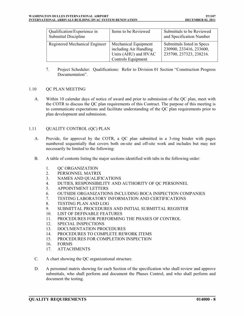
WASHINGTON DULLES INTERNATIONAL AIRPORT IT1107INTERNATIONAL ARRIVALS BUILDING HVAC SYSTEM RENOVATION DECEMBER 02, 2011
QUALITY REQUIREMENTS 014000 - 8
Qualification/Experience in Submittal Discipline
Items to be Reviewed Submittals to be Reviewed and Specification Number
Registered Mechanical Engineer Mechanical Equipment including Air Handling Units (AHU) and HVAC Controls Equipment
Submittals listed in Specs 230900, 233416, 233600, 235700, 237323, 238216.
7. Project Scheduler: Qualifications: Refer to Division 01 Section “Construction Progress Documentation”.
1.10 QC PLAN MEETING
A. Within 10 calendar days of notice of award and prior to submission of the QC plan, meet with the COTR to discuss the QC plan requirements of this Contract. The purpose of this meeting is to communicate expectations and facilitate understanding of the QC plan requirements prior to plan development and submission.
1.11 QUALITY CONTROL (QC) PLAN
A. Provide, for approval by the COTR, a QC plan submitted in a 3-ring binder with pages numbered sequentially that covers both on-site and off-site work and includes but may not necessarily be limited to the following:
B. A table of contents listing the major sections identified with tabs in the following order:
1. QC ORGANIZATION2. PERSONNEL MATRIX3. NAMES AND QUALIFICATIONS4. DUTIES, RESPONSIBILITY AND AUTHORITY OF QC PERSONNEL5. APPOINTMENT LETTERS6. OUTSIDE ORGANIZATIONS INCLUDING BOCA INSPECTION COMPANIES7. TESTING LABORATORY INFORMATION AND CERTIFICATIONS8. TESTING PLAN AND LOG9. SUBMITTAL PROCEDURES AND INITIAL SUBMITTAL REGISTER10. LIST OF DEFINABLE FEATURES11. PROCEDURES FOR PERFORMING THE PHASES OF CONTROL12. SPECIAL INSPECTIONS13. DOCUMENTATION PROCEDURES14. PROCEDURES TO COMPLETE REWORK ITEMS15. PROCEDURES FOR COMPLETION INSPECTION16. FORMS17. ATTACHMENTS
C. A chart showing the QC organizational structure.
D. A personnel matrix showing for each Section of the specification who shall review and approve submittals, who shall perform and document the Phases Control, and who shall perform and document the testing.

WASHINGTON DULLES INTERNATIONAL AIRPORT IT1107INTERNATIONAL ARRIVALS BUILDING HVAC SYSTEM RENOVATION DECEMBER 02, 2011
QUALITY REQUIREMENTS 014000 - 9
E. Names and qualifications, in résumé format, for each person in the QC organization. Include the CQM course certifications for the QCM and Alternate QCM as required by the paragraphs entitled "Construction Quality Management Training" and "Alternate QCM Duties and Qualifications".
F. Duties, responsibilities and authority of each person in the QC organization.
G. Letters signed by an officer of the firm appointing the QCM and Alternate QCM and stating that they are responsible for implementing and managing the QC Program as described in this contract. Include in this letter the responsibility of the QCM and Alternate QCM to implement and manage the three phases of quality control, and their authority to stop work that is not in compliance with the contract. The QCM shall issue letters of direction to QC specialists outlining their duties, authorities, and responsibilities. Copies of the letters shall be included in the QC plan.
H. A listing of outside organizations such as, architectural and consulting engineering firms that will be employed by the Contractor and a description of the services these firms will provide.
I. Testing laboratory information required by the paragraphs entitled "Accreditation Requirements" or "Construction Materials Testing Laboratory Requirements", as applicable.
J. A Testing Plan and Log that includes the tests required, referenced by the specification paragraph number requiring the test, the frequency, the desired results and the person responsible for each test and shall be identified as a scheduled (CPM) activity.
K. Procedures for reviewing, approving and managing submittals. Provide the name(s) of the person(s) in the QC organization authorized to review and certify submittals prior to approval. Provide the initial submittal of the Submittal Register as specified in Section entitled "Submittals."
L. List of definable features of work. The list shall be cross-referenced to the contractor's Construction Schedule and the specification sections. For projects requiring a Progress Chart, the list of definable features of work shall include but not be limited to all items of work on the schedule. For projects requiring a Network Analysis Schedule, the list of definable features of work shall include but not be limited to all critical path activities. Include a chart of common deficiencies for the Definable Feature of work. Detail the control procedures that shall be employed to eliminate this common deficiency.
M. Procedures for Performing the Phases of Control. The contractor shall develop a plan for incorporating each of the control phases into the work. The plan shall detail who shall be responsible for scheduling the phases, conducting the phase as well as documenting the phase. The use of project specific forms may be helpful. However, the entire plans and specifications establish the quality and not just the checklists. The Preparatory and Initial Phases and meetings shall be conducted with a view towards obtaining quality construction by planning ahead and identifying potential problems for each definable feature of work.
N. Include all activities for which this specification requires QC specialists or Specialty Inspection Personnel, and for any specific definable features of work as identified in the QC Plan.
O. Documentation procedures, including proposed report formats.

WASHINGTON DULLES INTERNATIONAL AIRPORT IT1107INTERNATIONAL ARRIVALS BUILDING HVAC SYSTEM RENOVATION DECEMBER 02, 2011
QUALITY REQUIREMENTS 014000 - 10
P. Procedures to identify, record, track and complete rework items.
Q. Procedures for Identifying and Documenting the Completion Inspection process. Include in these procedures the responsible party for punch out inspection, pre-final inspection, and final acceptance inspection.
R. A complete set of report forms to be utilized on this project.
S. All applicable subcontractors and suppliers Quality Control Plans complete with Contactor’s CQC planned involvement.
1.12 COORDINATION AND MUTUAL UNDERSTANDING MEETING
A. After submission of the QC Plan, and prior to the start of any physical construction, meet with the COTR to present the QC Program required by this Contract. The purpose of this meeting is to develop a mutual understanding of the QC details, including documentation, administration for on-site and off-site work, and the coordination of the Contractor's management, production and QC personnel. At the meeting, the Contractor shall be required to explain in detail how Phases Control shall be implemented for each definable feature of work. As a minimum, the Contractor's personnel required to attend shall include an officer of the firm, the project manager, project superintendent, QCM, Alternate QCM, QC Specialist and subcontractor representatives. Each subcontractor who shall be assigned QC responsibilities shall have a principal of the firm at the meeting. Minutes of the meeting shall be prepared by the QCM and signed by the Contractor. The Contractor shall provide a copy of the signed minutes to all attendees.
1.13 QC MEETINGS
A. After the start of construction, the QCM shall conduct QC meetings once every two weeks at the work site with the project superintendent. The QCM shall prepare the minutes of the meeting and provide a copy to the COTR within 2 working days after the meeting. The COTR may attend these meetings. The QCM shall notify the COTR at least 48 hours in advance of each meeting. These meetings shall be scheduled to precede or follow the regular weekly progress meeting. As a minimum, the following shall be accomplished at each meeting:
1. Review the minutes of the previous meeting2. Review the schedule and the status of work:
a. Work or testing accomplished since last meetingb. Rework items identified since last meetingc. Rework items completed since last meeting;
3. Review the status of submittals, O & M data and Warranty Manuals:
a. Submittals, O & M data and Warranties reviewed and approved since last meetingb. Submittals, O & M data and Warranties required in the near future;
4. Review the work to be accomplished in the next 2 week(s) and documentation required:

WASHINGTON DULLES INTERNATIONAL AIRPORT IT1107INTERNATIONAL ARRIVALS BUILDING HVAC SYSTEM RENOVATION DECEMBER 02, 2011
QUALITY REQUIREMENTS 014000 - 11
a. Establish completion dates for rework itemsb. Update the schedule showing planned and actual dates of the preparatory, initial
and follow-up phases, including testing and any other inspection required by this contract
c. Discuss construction methods and the approach that shall be used to provide quality construction by planning ahead and identifying potential problems for each definable feature of work
d. Discuss status of off-site work or testinge. Documentation required;f. Discuss upcoming Activity Hazard Analyses.
5. Resolve QC and production problems, assist in resolving Request for Information issues;6. Address items that may require revising the QC plan:
a. Changes in QC organization personnelb. Changes in procedures.
7. Review health and safety plan
1.14 PHASES OF CONTROL
A. The Phases of Control shall adequately cover both on-site and off-site work and shall include the following for each definable feature of work.
B. Material Receiving Inspection: Contractor shall establish a formal material receiving inspection program to verify material compliance to approved Shop Drawings, approved submittals, and the contract plans and specifications.
C. Preparatory Phase: Notify the COTR at least 2 workdays in advance of each preparatory phase. This phase shall include a meeting conducted by the QCM and attended by the superintendent, and the foreman responsible for the definable feature. Document the results of the preparatory phase actions in the daily Quality Control Daily Report and in the Preparatory Phase Report. As a minimum the following should be covered prior to beginning work on each definable feature of work:
1. Review each paragraph of the applicable specification sections.2. Review the Contract drawings.3. Verify that appropriate shop drawings, O & M data, Warranties, and submittals for
materials and equipment have been submitted and approved. Verify receipt of approved factory test results, when required.
4. Establish control to be utilized to assure work complies with the contract plans and specifications.
5. Review the testing plan and ensure that provisions have been made to provide the required QC testing.
6. Examine the work area to ensure that the required preliminary work has been completed.7. Examine the required materials, equipment and sample work to ensure that they are on
hand and conform to the approved shop drawings and submitted data.8. Discuss construction methods, construction tolerances, workmanship standards, and the
approach that shall be used to provide quality construction by planning ahead and identifying potential problems for each definable feature of work.

WASHINGTON DULLES INTERNATIONAL AIRPORT IT1107INTERNATIONAL ARRIVALS BUILDING HVAC SYSTEM RENOVATION DECEMBER 02, 2011
QUALITY REQUIREMENTS 014000 - 12
9. Review the safety plan and appropriate activity hazard analysis to ensure that applicable safety requirements are met, and that required Material Safety Data Sheets (MSDS) are submitted.
D. Initial Phase: Notify the COTR at least 2 workdays in advance of each initial phase. When construction crews are ready to start work on a definable feature of work, conduct the initial phase with the QC Specialist, the superintendent and the foreman responsible for that definable feature of work. Observe the initial segment of the definable feature of work to ensure that the work complies with Contract requirements. Document the results of the initial phase in the daily Quality Control Daily Report and in the Initial Phase Report. Repeat the initial phase for each new crew to work on-site, or when acceptable levels of specified quality are not being met. As a minimum the following should be covered for each definable feature of work:
1. Ensure controls established during Preparatory Phase are adequate to allow work to proceed in compliance with the plans and specifications.
2. Establish the quality of workmanship required.3. Resolve conflicts.4. Ensure that testing is performed by the approved laboratory.5. Check work procedures for compliance with the Safety Plan and the appropriate activity
hazard analysis to ensure that applicable safety requirements are met.
E. Follow-Up Phase: Perform the following for on-going work daily, or more frequently as necessary until the completion of each definable feature of work and document in the daily Quality Control Daily Report:
1. Ensure the work is in compliance with Contract requirements.2. Maintain the quality of workmanship required.3. Ensure that testing is performed by the approved laboratory.4. Ensure that rework items are being corrected.5. Perform safety inspections.
F. Code-Required Inspections:
1. Comply with current edition approved by the Commonwealth of Virginia of the USBC, "Special Inspections” or other agencies having jurisdiction. Special Inspections are to be performed by the Authority’s agent. Perform and document all tests, inspections, notifications to the Authority, coordination with the Authority’s agent and other activities listed in the USBC or other agencies having jurisdiction.
2. Notice to COTR: Notify COTR, in writing, at least 48 hours in advance of all code-required inspections. COTR should be apprised in advance of every preparatory and initial inspection. All preparatory, initial, and follow-up inspections shall be made a matter of record in Contractor's quality-control documentation.
G. Additional Preparatory and Initial Phases: Additional Preparatory and Initial Phases shall be conducted on the same definable features of work if the quality of on-going work is unacceptable, if there are changes in the applicable QC organization, if there are changes in the on-site production supervision or work crew, if work on a definable feature is resumed after substantial period of inactivity, or if other problems develop as directed by the COTR in writing.

WASHINGTON DULLES INTERNATIONAL AIRPORT IT1107INTERNATIONAL ARRIVALS BUILDING HVAC SYSTEM RENOVATION DECEMBER 02, 2011
QUALITY REQUIREMENTS 014000 - 13
H. Notification of Phases of Control for Off-Site Work: On determination by COTR that an item shall require surveillance by the Authority at the point of production, manufacture, or shipment, Contractor shall be notified, in writing, of such determination. Contractor shall furnish to COTR three copies of all purchase orders or subcontracts, for all tiers of subcontractors or suppliers for each item. In addition, copies of documented quality-control operations, tests, and inspections shall be made available to the Authority's representative at the point of production, manufacture, or shipment. The CQC shall notify the COTR at least two weeks prior to the start of the preparatory and initial phases.
1.15 SUBMITTAL REVIEW AND APPROVAL
A. Procedures for submission, review and approval of submittals are described in Division 01 Section “Submittals”.
1.16 TESTING
A. Except as stated otherwise in the technical specification sections, perform sampling and testing required under this Contract.
B. Independent Testing Laboratory: When tests are required by civil, electrical, USBC and other codes in effect, a corporately and financially independent testing organization that can function as an unbiased testing authority, professionally independent of manufacturers, suppliers, and installers of equipment, or systems evaluated by the testing organization shall be contracted by the Contractor to perform the contractually required tests. The various types of independent laboratories and their requirements are listed below:
C. Accreditation Requirements: Construction materials testing laboratories performing work for Authority construction contracts shall be accredited by one of the laboratory accreditation authorities. The laboratory's scope of accreditation shall include the ASTM standards listed in the paragraph titled "Construction Materials Testing Laboratory Requirements" as appropriate to the testing field. The policy applies to the specific laboratory performing the actual testing, not just the "Corporate Office".
D. Electrical testing of components, equipment and systems: The testing firm shall be regularly engaged in the testing of electrical equipment, devices, installations, and systems. The testing firm shall have at least five years experience in the testing of electrical equipment of the type, rating, and voltage used on this Project. The testing laboratories shall be a current full-member company of the International Electrical Testing Association (http://www.neta.org/). This independent testing firm shall perform duties as required under the terms of this Contract.
E. Structural and Pipe Welding: An independent testing firm shall perform all structural and pipe welding examinations as required by this Contract. The inspectors employed by the firm shall hold current certification as an AWS Certified Welding Inspector (CWI) for visual weld examinations and ASNT-TC-1A Certification for nondestructive examination of welds. ASNT-TC-1A certifications shall be by an ASNT-TC-1A ACCP Level III.
F. Construction Materials Testing Laboratory Requirements: Provide an independent construction material testing laboratory accredited by an acceptable laboratory accreditation authority to perform sampling and tests required by this Contract. Testing laboratories that have obtained

WASHINGTON DULLES INTERNATIONAL AIRPORT IT1107INTERNATIONAL ARRIVALS BUILDING HVAC SYSTEM RENOVATION DECEMBER 02, 2011
QUALITY REQUIREMENTS 014000 - 14
accreditation by an acceptable laboratory accreditation authority listed in the paragraph entitled "Laboratory Accreditation Authorities" submit with the Quality Control Plan, a copy of the Certificate of Accreditation and Scope of Accreditation. The scope of the laboratory's accreditation shall include the test methods required by the Contract. On-site testing facilities shall submit a certified statement by the Supervising Professional Engineer, licensed in the Commonwealth of Virginia, as meeting the requirements of the following minimum ASTM standards listed below as appropriate to the testing field.
1. Laboratories engaged in testing of construction materials shall meet the requirements of ASTM E 329.
2. Laboratories engaged in testing of concrete and concrete aggregates shall meet the requirements of ASTM C 1077.
3. Laboratories engaged in testing of bituminous paving materials shall meet the requirements of ASTM D 3666.
4. Laboratories engaged in testing of soil and rock, as used in engineering design and construction, shall meet the requirements of ASTM D 3740.
5. Laboratories engaged in nondestructive testing (NDT) shall meet the requirements of ASTM E 543.
6. Laboratories engaged in Hazardous Materials Testing shall meet the requirements of OSHA and EPA
G. Laboratory Accreditation Authorities: Laboratory Accreditation Authorities are the National Voluntary Laboratory Accreditation Program (NVLAP) administered by the National Institute of Standards and Technology, the American Association of State Highway and Transportation Officials (AASHTO) program, ICBO Evaluation Service, Inc. (ICBO ES), and the American Association for Laboratory Accreditation (A2LA) program and the Washington Area Council of Engineering Laboratories (WACEL). Furnish to the COTR, a copy of the current Certificate of Accreditation and Scope of Accreditation. The scope of the laboratory's accreditation shall include the test methods required by the Contract.
H. Capability Check: The COTR retains the right to check laboratory equipment in the proposed laboratory and the laboratory technician's testing procedures, techniques, and other items pertinent to testing, for compliance with the standards set forth in this Contract.
I. Capability Recheck: If non-conformities are discovered during the capability check or any succeeding recheck, Contractor shall be assessed a charge of $750.00 to reimburse the Authority for each recheck of the laboratory or the checking of a subsequently selected laboratory. These charges shall be deducted from the total amount due Contractor.
J. Test Results: Cite applicable Contract requirements, tests or analytical procedures used. Provide actual results and include a statement that the item tested or analyzed conforms or fails to conform to specified requirements. If the item fails to conform, notify COTR immediately. Conspicuously stamp the cover sheet for each report in large red letters "CONFORMS" or "DOES NOT CONFORM" to the specification requirements, whichever is applicable. A testing laboratory representative authorized to sign certified test reports shall sign test results. Furnish the signed reports, certifications, and other documentation to the COTR via the QCM. Furnish a summary report of field tests at the end of each month. Attach a copy of the summary report to the last daily Quality Control Daily Report of each month.
K. Test Reports and Monthly Summary Report of Tests:

WASHINGTON DULLES INTERNATIONAL AIRPORT IT1107INTERNATIONAL ARRIVALS BUILDING HVAC SYSTEM RENOVATION DECEMBER 02, 2011
QUALITY REQUIREMENTS 014000 - 15
1. The QCM shall furnish the signed reports, certifications, and a summary report of field tests at the end of each month to the COTR. Attach a copy of the summary report to the last daily Quality Control Daily Report of each month.
L. Control and Verification Tests: Control tests are those tests made for Contractor under the Quality Control Plan to assist Contractor in maintaining control of his operations. As described above, Contractor shall procure the services of an independent commercial laboratory to perform the required control tests. The Specifications contain the minimum of the following:
1. Testing criteria2. Frequency of testing3. Procedures4. Methods of construction5. Number of control tests to be made for each phase of the Work.6. Notify COTR a minimum of 24 hours in advance of the time samples shall be taken by
Contractor for quality control testing. COTR shall then notify its own testing laboratory contractor so that verification test samples may be taken.
M. Check Tests: Contractor shall furnish to COTR the quantities of materials to be used for check testing as required in the Specifications. Check testing shall be performed by the Authority at an independent laboratory at no cost to Contractor. No direct payment shall be made to Contractor for the furnishing of materials used for check testing.
N. Staffing: All laboratorys' personnel shall work under the supervision of a Professional Engineer licensed in the Commonwealth of Virginia.
1.17 QC CERTIFICATIONS
A. Quality Control Daily Report Certification
1. Each Quality Control Daily Report shall contain the following statement:
a. “On behalf of (Name of Contractor), I certify that this report and the Inspector's Daily Reports are complete and correct, and that all materials and equipment used, as well as work performed during this reporting period are in compliance with Drawings, Specifications, and Contract provisions, except as noted in this report orattached reports.”
B. Application for Payment Certification: Refer to Division 01 Section "Application for Payment" for address to which the Applications shall be sent.
C. Completion Certification:
1. Upon completion of work under this Contract, the QCM shall furnish a certificate to the Contracting Officer attesting that "the work has been completed, inspected, tested and is in compliance with the Contract."

WASHINGTON DULLES INTERNATIONAL AIRPORT IT1107INTERNATIONAL ARRIVALS BUILDING HVAC SYSTEM RENOVATION DECEMBER 02, 2011
QUALITY REQUIREMENTS 014000 - 16
1.18 COMPLETION INSPECTIONS
A. Punch-Out Inspection: Near the completion of all work or any increment thereof established by a completion time stated in the Contract Clause entitled "Commencement, Prosecution, and Completion of Work," or stated elsewhere in the specifications, the QCM shall conduct an inspection of the work and develop a "punch list" of items which do not conform to the approved drawings and specifications. Include in the punch list any remaining items on the "Rework Items List" which were not corrected prior to the Punch-Out Inspection. The punch list shall include the estimated date by which the deficiencies will be corrected. A copy of the punch list shall be provided to the COTR. The QCM or staff shall make follow-on inspections to ascertain that all deficiencies have been corrected. Once this is accomplished the Contractor shall notify the COTR that the facility is ready for the Authority "Pre-Final Inspection."
B. Pre-Final Inspection: The Authority will perform this inspection to verify that the facility is complete and ready to be occupied. An Authority "Pre-Final Punch List" may be developed as a result of this inspection. The QCM shall ensure that all items on this list are corrected prior to notifying the Authority that a "Final" inspection with the customer can be scheduled. Any items noted on the "Pre-Final" inspection shall be corrected in timely manner and shall be accomplished before the contract completion date for the work or any particular increment thereof if the project is divided into increments by separate completion dates.
C. Final Acceptance Inspection: The QCM, the QC specialists, the superintendent or other primary contractor management personnel shall be in attendance at this inspection. The COTR will be in attendance at this inspection. Additional Authority personnel may be in attendance. The Contracting Officer based upon results of the “Pre-Final” inspection will formally schedule the final acceptance inspection. Notice shall be given to the COTR at least 14 calendar days prior to the final inspection stating that all specific items previously identified to the Contractor, as being unacceptable, along with all the remaining work performed under the contract, shall be complete and acceptable by the date scheduled for the final acceptance inspection. Failure of the Contractor to have all contract work acceptably complete for this inspection shall be cause for the Contracting Officer to bill the Contractor for the Authority's additional inspection cost in accordance with the clause in the Contract Provisions entitled "Inspection of Construction." When the Contracting Officer takes possession of partially completed work, it shall be in accordance with clause in the Contract Provisions entitled "Use and Possession Prior to Completion".
1.19 DOCUMENTATION
A. Contractor shall maintain current quality control records, on approved forms, of all control activities, production, tests and inspections performed. These records shall include factual evidence that required tests or inspections have been performed, including type and number of tests or inspections involved; results of tests or inspections; nature of defects, causes for rejection, etc.; proposed remedial action; and corrective actions taken. These records shallcover both conforming and defective or deficient features (non-conforming) and shall include a statement that all supplies and materials incorporated into the Work are in full compliance with terms of the Contract. Legible copies of these records shall be furnished to COTR daily. The records shall cover all work placed subsequent to the previously furnished records and shall be verified by Contractor's QCM. Contractor shall document tests and inspections as specified in the technical provisions of the Specifications, and these records shall be available for review by COTR throughout the life of the Contract.

WASHINGTON DULLES INTERNATIONAL AIRPORT IT1107INTERNATIONAL ARRIVALS BUILDING HVAC SYSTEM RENOVATION DECEMBER 02, 2011
QUALITY REQUIREMENTS 014000 - 17
B. Maintain current and complete records of on-site and off-site QC Program operations and activities. Establish and maintain the following in a series of 3 ring binders. Binders shall be divided and tabbed as shown below. These binders shall be readily available to the Authority's Quality Assurance Team during normal business hours.
1. All completed Preparatory and Initial Phase Reports, arranged by specification Section.2. All milestone inspections, arranged by Activity/Event Number.3. A current up-to-date copy of the Testing Plan and Log with supporting field test reports,
arranged by specification section.4. Copies of all contract modifications, arranged in numerical order. Also include
documentation that modified work was accomplished.5. A current, up-to-date copy, of the Deficiency List.
C. Report Forms - The contractor shall design all forms to be used in the Quality Control Program. A copy of all forms shall be included with the Quality Control Plan. The forms shall be designed to assist in the control of the quality. The following minimum requirements are listed for specific reports:
1. Quality Control Daily Report: Reports are required for each day that work is performed and for every seven consecutive calendar days of no work and on the last day of a no-work period. Account for each calendar day throughout the life of the Contract. The reporting of work shall be identified by terminology consistent with the construction schedule. Quality Control Daily Reports are to be prepared, signed and dated by the QCM and shall contain the following information:
a. Date of report, report number, Contract Number, and Contract Title.b. Identify Schedule Activity No., Submittal # and list equipment/material received
each day that is incorporated into the job.c. Indicate if Preparatory Phase work was performed today (Yes/No checkboxes).d. If Preparatory Phase work was performed today (including on-site and off-site
work), identify its Schedule Activity Number and Definable Feature of Work. The Index number is a cross reference to the Preparatory Phase Checklist. An example of the Index number is: 0025-P01, where "0025" is the Quality Control Daily Report Number, "P" indicates Preparatory Phase, and "01" is the Preparatory Phase Checklist number(s) for this date. Each entry in this Section shall be accompanied with a corresponding Preparatory Phase Checklist.
e. Indicate if Initial Phase work was performed today (Yes/No checkboxes).f. If Initial Phase work was performed today (including on-site and off-site work),
identify its Schedule Activity Number and Definable Feature of Work. The Index Number is a cross reference to the Initial Phase Checklist. An example of the Index Number is: 0025-I01, where "0025" is the Quality Control Daily Report Number, "I" indicates Initial Phase, and "01" is the Initial Phase Checklist number(s) for this date. Each entry in this Section shall be accompanied with a corresponding Initial Phase Checklist.
g. Results of the Follow-up Phase inspections held today (including on-site and off-site work), including Schedule Activity Number, location of definable feature of work, Specification Sections, etc. Indicate in the report for this definable feature of work that the work complies with the Contract as approved in the Initial Phase, work complies with safety requirements, and that required testing has been performed. Include a list of who performed the tests.

WASHINGTON DULLES INTERNATIONAL AIRPORT IT1107INTERNATIONAL ARRIVALS BUILDING HVAC SYSTEM RENOVATION DECEMBER 02, 2011
QUALITY REQUIREMENTS 014000 - 18
h. List the rework items identified, but not corrected by close of business, along with its associated Schedule Activity Number.
i. List the rework items corrected from the rework items list along with the corrective action taken and its associated Schedule Activity Number.
j. Include a "remarks" section in this report that shall contain pertinent information including but not limited to:
1) Directions received.2) Quality control problem areas.3) Deviations from the QC plan.4) Construction deficiencies encountered.5) QC meetings held, acknowledgement that record drawings.6) Specifications, O & M data, and Warranty Manuals, have been updated.7) Corrective direction given by the QC Organization and corrective action
taken by the Contractor.8) For each remark given, identify the Schedule Activity Number that is
associated with the remark.
k. Quality Control Daily Report certification, signature and date.
2. Preparatory Phase Report: Each Definable Feature of Work that is in the Preparatory Phase shall have this report filled out for it. The report shall be identified by terminology consistent with the construction schedule. Attach this report to the Quality Control Daily Report of the same date.
a. Specification Section, date of report, and Contract number shall be filled out. Duplicate this information in the header of the second page of the report.
b. Definable Feature of Work, Schedule Activity Number and Index Number entry and format shall match entry in the Preparatory Phase section of the Quality Control Daily Report. Duplicate this information in the header of the second page of the report.
c. Personnel Present: Indicate the number of hours of advance notice that was given to the COTR and indicate (Yes/No checkboxes) whether or not the COTR was notified. Indicate the Names of Preparatory Phase Meeting attendees, their position and their company affiliation.
d. Submittals: Indicate if submittals have been approved (Yes/No checkboxes), if no indicate what has not been submitted. Are materials on hand (Yes/No checkboxes) and if not, what items are missing. Check delivered material/equipment against approved submittals and comment as required.
e. Material Storage: Indicate if materials/equipment is stored properly (Yes/No checkboxes) and if not, what action is/was taken.
f. Specifications: Review and comment on Specification Paragraphs that describe the material/equipment, procedure for accomplishing the work and clarify any differences.
g. Preliminary Work & Permits: Ensure preliminary work is in accordance with the contract documents and necessary permits are on file, if not, describe the action taken.
h. Testing: Identify who performs tests, the frequency, and where tests are to occur. Review the testing plan, report abnormalities, and if the test facilities have been approved.

WASHINGTON DULLES INTERNATIONAL AIRPORT IT1107INTERNATIONAL ARRIVALS BUILDING HVAC SYSTEM RENOVATION DECEMBER 02, 2011
QUALITY REQUIREMENTS 014000 - 19
i. Discuss Control Procedures that shall be employed to consistently obtain the required specified quality.
j. Safety: Indicate if the activity hazard analysis has been approved (Yes/No checkboxes) and comment on the review of the applicable portions of the Construction Safety Manual.
k. Meeting Comments: Note comments and remarks during the Preparatory Phase Meeting that was not addressed in previous sections of this checklist.
l. Other Items or Remarks: Note any other remarks or items that were a result of the Preparatory Phase.
m. QCM shall sign and date the report.
3. Initial Phase Report: Complete this report for each Definable Feature of Work that is in the Initial Phase. The report shall be identified by terminology consistent with the construction schedule. Attach this report to the Quality Control Daily Report of the same date.
a. Specification Section, date of report, and Contract number shall be entered.b. Definable Feature of Work, Schedule Activity Number and Index Number entry
and format shall match entry in the Initial Phase section of the Quality Control Daily Report.
c. Personnel Present: Indicate the number of hours of advance notice that was given to the COTR and indicate (Yes/No checkboxes) whether or not the COTR was notified. Indicate the Names of Initial Phase Meeting attendees, their position and company/Authority they are with.
d. Control Procedures: Comment on control procedures identified at Preparatory Phase of Control and assurance that work is in accordance with plans, specifications and submittals. Control procedures not producing the required compliance shall be adjusted until the procedures consistently obtain the required quality.
e. Preliminary Work: Ensure preliminary work being placed is in compliance and if not, what action is/was taken.
f. Workmanship: Identify where initial work is located; if a sample panel is required (Yes/No checkboxes); is the initial work the sample (Yes/No checkboxes); and if Yes, describe the panel location and precautions taken to preserve the sample.
g. Resolution: Comment on any differences and the resolutions reached.h. Check Safety: Comment on the safety review of the job conditions.i. Other: Note any other remarks or items that were a result of the Initial Phase.j. QCM shall sign and date the report.
D. Reports from the QC Specialist(s): Reports are required for each day that work is performed in their area of responsibility. QC specialist reports shall include the same documentation requirements as the Quality Control Daily Report for their area of responsibility. QC specialist reports are to be prepared, signed and dated by the QC specialists and shall be attached to the Quality Control Daily Report prepared for the same day.
E. Testing Log: As tests are performed, the QCM shall record on the "Testing Log" the date the test was conducted, the date the test results were forwarded to the COTR, remarks and acknowledgement that an accredited or Contracting Officer approved testing laboratory was used. Forward a copy of the updated "Testing Plan and Log" on the last day of each month. Do not attach to the Quality Control Daily Report.

WASHINGTON DULLES INTERNATIONAL AIRPORT IT1107INTERNATIONAL ARRIVALS BUILDING HVAC SYSTEM RENOVATION DECEMBER 02, 2011
QUALITY REQUIREMENTS 014000 - 20
F. Deficiency Log: The QCM shall maintain a list of work that does not comply with the Contract, identifying what items need to be reworked, the date the item was originally discovered, the date the item shall be corrected by, and the date the item was corrected. There is no requirement to report a rework item that is corrected the same day it is discovered. Provide a copy of the deficiency log to the COTR at the weekly progress meeting. The Contractor shall be responsible for including on this list items needing rework including those identified by the COTR.
G. Special Inspection Control Log: Contractor shall maintain a Special Inspection Control Log chronologically recording each Special test and inspection performed under the USBC, or other agencies having jurisdiction on-site, including the nature of the test or inspection, the date performed, the results, causes for rejection, corrective action taken, and dates of subsequent tests and final acceptance.
H. Test Reports: Contractor shall be responsible for establishing a system that shall record all tests results. Information on test designation, location, date of test, specification requirements,results and retest results, causes for rejection and recommended remedial actions shall be documented. A copy of the test results shall be sent directly from the Agency performing the testing services to COTR. A copy of any failing report shall be sent immediately. All test reports shall be reviewed and signed by a professional engineer, licensed in the Commonwealth of Virginia.
I. Signoff Sheets: Contractor shall be responsible for establishing a system of signoff sheets certifying that all work required before the construction or startup of critical work elements has been constructed and installed according to the plans and specifications.
J. Monthly Deficiency Report: Contractor shall submit a monthly deficiency report to COTR identifying all substandard tests and inspections taken during the month including the nature of the test or inspection, location and nature of defects, causes for rejection, and remedial actions taken or proposed for any open items on prior deficiency reports including the date scheduled for resolution of the item.
K. Record Drawings: The QCM is required to ensure the record drawings, required by Division 01 Section "Project Record Documents," are kept current on a daily basis and marked to show deviations which have been made from the Contract drawings. Ensure each deviation has been identified with the appropriate modifying documentation (e.g. CN No., Modification No., Request for Information No., etc.). The QCM or QC Specialist shall initial each deviation and each revision. Upon completion of work, the QCM shall furnish a certificate attesting to the accuracy of the record drawings prior to submission to the COTR.
L. Operation, Maintenance, and Warranty Manuals: The QCM shall ensure that the Operation and Maintenance data required by Division 01 Section “Operation and Maintenance Data” and the Warranties specified in Division 01 Section “Project Closeout” are inserted on a daily basis in the appropriate sections of the approved formatted manuals after they have been approved by the COTR.
1.20 NOTIFICATION ON NON-COMPLIANCE
A. The COTR will notify the Contractor of any detected non-compliance with the foregoing requirements. The Contractor shall take immediate corrective action after receipt of such

WASHINGTON DULLES INTERNATIONAL AIRPORT IT1107INTERNATIONAL ARRIVALS BUILDING HVAC SYSTEM RENOVATION DECEMBER 02, 2011
QUALITY REQUIREMENTS 014000 - 21
notice. Such notice, when delivered to the Contractor at the work site, shall be deemed sufficient for the purpose of notification. If the Contractor fails or refuses to comply promptly, the Contracting Officer may:
1. Issue an order stopping all or part of the work until satisfactory corrective action has been taken. The Contractor shall make no part of the time lost due to such stop orders the subject of a claim for extension of time for excess costs or damages.
2. Repair, replace or otherwise remedy the defective work at the Contractor’s expense. Cost incurred by the Authority to correct defective work shall be deducted from the total amount due the Contractor.
3. Withhold an amount from the payment due the Contractor as may be deemed necessary at the discretion of the Contracting Officer.
4. Terminate the Contractor’s right to proceed for Default after providing required notice.
B. In cases where implementation of the Quality Control Program does not comply with the Contractor’s Quality Control Plan or the contract provisions. Or Contractor fails to properlyoperate and maintain an effective Quality Control Program, the Contracting Officer may:
1. Order the Contractor to replace ineffective or unqualified Quality Control Personnel or subcontractors.
2. Issue an order stopping all or part of the work until acceptable personnel are on site and a new Quality Control Plan is approved by the COTR. The Contractor shall make no part of the time lost due to such stop orders the subject of claim for extension of time for excess costs or damages.
3. Take a credit from the contract for Quality Control Activities not performed.4. Terminate the Contractors right to proceed for Default after providing required notice.
C. The Contractor shall maintain a detailed record of every non-compliance and corrective action taken.
PART 2 - PRODUCTS (Not Used)
PART 3 - EXECUTION (Not Used)
END OF SECTION 014000
WASHINGTON DULLES INTERNATIONAL AIRPORT IT1107INTERNATIONAL ARRIVALS BUILDING HVAC SYSTEM RENOVATION DECEMBER 02, 2011
REFERENCES 014200 - 1
SECTION 014200 - REFERENCES
PART 1 - GENERAL
1.1 RELATED DOCUMENTS
A. Drawings, Contract Provisions, Special Provisions, Supplementary Conditions, and other Division 01 Specification Sections apply to this Section.
1.2 SUMMARY
A. This Section defines many of the terms used elsewhere in the Construction Documents and lists complete names and telephone numbers for many of the associations and agencies identified elsewhere in the Construction Documents by their acronym.
B. Abbreviations, where not defined in the Contract Documents, will be interpreted by the Contracting Officer to mean the normal construction industry terminology.
C. Plural words will be interpreted as singular and singular words will be interpreted as plural where applicable for context of the Contract Documents.
1.3 DEFINITIONS
A. General: Basic Contract definitions are included in Sections I and II of the Authority Solicitation Offer and Award. Certain terms used in the Contract Documents are defined generally in this Article. Definitions and explanations contained in this Section are not necessarily either complete or exclusive, but are general for the Work to the extent that they may not be stated more explicitly in another element of the Contract Documents.
B. Approve: The term "approved," where used in regard to COTR's action on Contractor's submittals, applications, and requests, is limited to COTR's duties and responsibilities as delegated by the Contracting Officer in the Contract and Special Provisions.
C. Architect/Engineer: For the purpose of this Project, the "Design Professional of Record." To distinguish from the Contracting Officer and Contracting Officer's Technical Representative (COTR).
D. Authority: Metropolitan Washington Airports Authority
E. Award: The acceptance, by the Authority, of the successful offeror's proposal.
F. Award Date: The date on which the Authority gives notice of acceptance to the successful offeror.

WASHINGTON DULLES INTERNATIONAL AIRPORT IT1107INTERNATIONAL ARRIVALS BUILDING HVAC SYSTEM RENOVATION DECEMBER 02, 2011
REFERENCES 014200 - 2
G. AOA (or A.O.A.): Air Operations Area. The area of the Airport used or intended to be used for landing, taking off, surface maneuvering, loading, unloading, or servicing aircraft. This security area requires security badging. Workers in this area are required to obtain and display an AOA photo I.D. credential. Drivers in this area are required to obtain an Airport Vehicle Operator's Permit for the Air Operations Area.
H. Beneficial Use: Use by the Authority prior to 100 percent completion and final acceptance.
I. Contract Documents: Documents containing requirements of the Work. These include all Contract provisions and attachments made thereto or referenced therein.
J. Contract Provisions: The administrative and procedural requirements starting at Award Date and ending at Final Acceptance, as provided for in Section VII, "Contract Provisions."
K. Contract Time or Duration (Time Limit): The number of calendar days established in Section III, "Schedule," indicating the time allowed for the completion of all physical and administrative work contemplated in the Contract, including any authorized extensions thereto.
L. Contracting Officer's Technical Representative (COTR): The Contracting Officer's designated representative, as defined in Section VII, "Contract Provisions."
M. Contractor: Individual, partnership, corporation or joint venture under Contract to the Authority for performance of prescribed Work.
N. Drawings: Erection/installation/construction plans, or any other supplementary plans or similar graphic data, illustrating work to be performed that are provided to Contractor as part of the Contract Documents.
O. Directed: A command or instruction by the Authority. Other terms including "requested," "authorized," "selected," "required," and "permitted" have the same meaning as "directed."
P. Final Acceptance: Refer to Division 01 Section "Project Closeout."
Q. "Indicated": Requirements expressed by graphic representations or in written form on drawings, in Specifications, and in other Contract Documents. Other terms including "shown," "noted," "scheduled," and "specified" have the same meaning as "indicated."
R. "Regulations": Laws, ordinances, statutes, and lawful orders issued by authorities having jurisdiction, and rules, conventions, and agreements within the construction industry that control performance of the Work.
S. "Furnish": Supply and deliver to Project site, ready for unloading, unpacking, assembly, installation, and similar operations.
T. "Install": Operations at Project site including unloading, temporarily storing, unpacking, assembling, erecting, placing, anchoring, applying, working to dimension, finishing, curing, protecting, cleaning, and similar operations.
U. "Provide": Furnish and install, complete and ready for the intended use.

WASHINGTON DULLES INTERNATIONAL AIRPORT IT1107INTERNATIONAL ARRIVALS BUILDING HVAC SYSTEM RENOVATION DECEMBER 02, 2011
REFERENCES 014200 - 3
V. "Installer": Contractor or another entity engaged by Contractor as an employee, Subcontractor, or Sub-subcontractor, to perform a particular construction operation, including installation, erection, application, and similar operations.
1. Using a term such as "carpentry" does not imply that certain construction activities must be performed by accredited or unionized individuals of a corresponding generic name, such as "carpenter." It also does not imply that requirements specified apply exclusively to trades people of the corresponding generic name.
W. "Experienced": When used with an entity, "experienced" means having successfully completed a minimum of ten previous projects similar in size and scope to this Project; being familiar with special requirements indicated; and having complied with requirements of authorities having jurisdiction.
X. "Project Site": Space available for performing construction activities. The extent of Project site is indicated.
Y. Punch list Work: Minor corrective actions required to achieve "Final Acceptance." Occurs after "Substantial Completion" of the Work in strict compliance with quality-control requirements.
Z. Roadway: General term denoting a public way for purposes of vehicular travel, including the entire area within the right-of-way.
AA. Special Provisions: For the purpose of this Contract, the directions and requirements provided for in Section VI of the Contract Documents.
BB. Shop Drawings: Refer to Division 01 Section "Submittals."
CC. Specifications: General term comprising all directions, provisions and requirements contained herein, together with any other contractual requirements such as may be added or adopted as the Contract Provisions, Special Provisions, or Supplementary Conditions, all of which are necessary for the proper performance of the Contract.
DD. Substantial Completion: Refer to Division 01 Section "Project Closeout."
1.4 INDUSTRY STANDARDS
A. Applicability of Standards: Unless the Contract Documents include more stringent requirements, applicable construction industry standards have the same force and effect as if bound or copied directly into the Contract Documents to the extent referenced. Such standards are made a part of the Contract Documents by reference.
B. Publication Dates: Comply with standards in effect as of date of the Contract Documents, unless otherwise indicated.
C. Conflicting Requirements: Refer to Division 01 Section "Quality Requirements" for additional information regarding conflicting requirements.

WASHINGTON DULLES INTERNATIONAL AIRPORT IT1107INTERNATIONAL ARRIVALS BUILDING HVAC SYSTEM RENOVATION DECEMBER 02, 2011
REFERENCES 014200 - 4
1. Minimum Quantity or Quality Levels: The quantity or quality level shown or specified shall be the minimum provided or performed. The actual installation may comply exactly with the minimum quantity or quality specified, or it may exceed the minimum within reasonable limits. To comply with these requirements, indicated numeric values are minimum or maximum, as appropriate, for the context of requirements. Refer uncertainties to COTR for a decision before proceeding.
D. Copies of Standards: Each entity engaged in construction on Project shall be familiar with industry standards applicable to its construction activity. Copies of applicable standards are not bound with the Contract Documents.
1. Where copies of standards are needed to perform a required construction activity, obtain copies directly from publication source and make them available on request.
E. Abbreviations and Acronyms for Standards and Regulations: Where abbreviations and acronyms are used in Specifications or other Contract Documents, they shall mean the recognized name of the standards and regulations in the following list. Names, telephone numbers, and Web site addresses are subject to change and are believed to be accurate and up-to-date as of the date of the Contract Documents.
ADAAG Americans with Disabilities Act (ADA) (800) 872-2253Accessibility Guidelines for Buildings and Facilities (202) 272-0080Available from Access Boardwww.access-board.gov
CFR Code of Federal Regulations (888) 293-6498Available from Government Printing Office (202) 512-1530www.access.gpo.gov/nara/cfr
CRD Handbook for Concrete and Cement (601) 634-2355Available from Army Corps of EngineersWaterways Experiment Stationwww.wes.army.mil
DOD Department of Defense Military Specifications and Standards (215) 697-6257Available from Department of Defense Single Stock Pointwww.dodssp.daps.mil
DSCC Defense Supply Center Columbus(See FS)
FED-STD Federal Standard(See FS)
FS Federal Specification (215) 697-6257Available from Department of Defense Single Stock Point. www.dodssp.daps.mil
Available from General Services Administrationwww.fss.gsa.gov
(202) 501-1021

WASHINGTON DULLES INTERNATIONAL AIRPORT IT1107INTERNATIONAL ARRIVALS BUILDING HVAC SYSTEM RENOVATION DECEMBER 02, 2011
REFERENCES 014200 - 5
Available from National Institute of Building Scienceswww.nibs.org
(202) 289-7800
FTMS Federal Test Method Standard(See FS)
ICC-ES ICC Evaluation Service, Inc. (800) 423-6587www.icc-es.org
MIL See MILSPEC
MS MIL See MILSPEC
MILSPEC Military Specification and Standards (215) 697-6257Available from Department of Defense Single Stock Pointwww.dodssp.daps.mil
MUTCD Manual on Uniform Traffic Control DevicesDepartment of TransportationFederal Highway Administration (See FHA. Located in Paragraph Federal Government Agencies").
UFAS Uniform Federal Accessibility Standards (800) 872-2253Available from Access Board (202) 272-0080www.access-board.gov
1.5 ABBREVIATIONS AND ACRONYMS
A. Industry Organizations: Where abbreviations and acronyms are used in Specifications or other Contract Documents, they shall mean the recognized name of the entities in the following list. Names, telephone numbers, and Web site addresses are subject to change and are believed to be accurate and up-to-date as of the date of the Contract Documents.
AA Aluminum Association, Inc. (The) (202) 862-5100www.aluminum.org
AAADM American Association of Automatic Door Manufacturers (216) 241-7333www.aaadm.com
AABC Associated Air Balance Council (202) 737-0202www.aabchq.com
AAMA American Architectural Manufacturers Association (847) 303-5664www.aamanet.org

WASHINGTON DULLES INTERNATIONAL AIRPORT IT1107INTERNATIONAL ARRIVALS BUILDING HVAC SYSTEM RENOVATION DECEMBER 02, 2011
REFERENCES 014200 - 6
AASHTO American Association of State Highway and (202) 624-5800Transportation Officialshttp://www.transportation.org
AATCC American Association of Textile Chemists and Colorists (The) (919) 549-8141www.aatcc.org
ABMA American Bearing Manufacturers Association (202) 367-1155www.abma-dc.org
ACI ACI International (248) 848-3700(American Concrete Institute)www.aci-int.org
ACPA American Concrete Pipe Association (972) 506-7216http://www.concrete-pipe.org
AEIC Association of Edison Illuminating Companies, Inc. (The) (205) 257-2530www.aeic.org
AGA American Gas Association (202) 824-7000www.aga.org
AGC Associated General Contractors of America (The) (703) 548-3118www.agc.org
AHA American Hardboard Association(Now part of CPA)
AHAM Association of Home Appliance Manufacturers (202) 872-5955www.aham.org
AI Asphalt Institute (859) 288-4960http://www.asphaltinstitute.org
AIA American Institute of Architects (The) (800) 242-3837www.aia.org (202) 626-7300
AISC American Institute of Steel Construction (800) 644-2400www.aisc.org (312) 670-2400
AISI American Iron and Steel Institute (202) 452-7100www.steel.org
AITC American Institute of Timber Construction (303) 792-9559http://www.aitc-glulam.org
ALCA Associated Landscape Contractors of America (800) 395-2522www.alca.org (703) 736-9666

WASHINGTON DULLES INTERNATIONAL AIRPORT IT1107INTERNATIONAL ARRIVALS BUILDING HVAC SYSTEM RENOVATION DECEMBER 02, 2011
REFERENCES 014200 - 7
ALSC American Lumber Standard Committee, Incorporated (301) 972-1700www.alsc.org
AMCA Air Movement and Control Association International, Inc. (847) 394-0150www.amca.org
ANSI American National Standards Institute (202) 293-8020www.ansi.org
AOSA Association of Official Seed Analysts (505) 522-1437Http://www.aosaseed.com
APA APA - The Engineered Wood Association (253) 565-6600http://www.apawood.org
APA Architectural Precast Association (239) 454-6989http://www.archprecast.org
API American Petroleum Institute (202) 682-8000www.api.org
ARI Air-Conditioning & Refrigeration Institute (703) 524-8800www.ari.org
ASCE American Society of Civil Engineers (800) 548-2723www.asce.org (703) 295-6300
ASHRAE American Society of Heating, Refrigerating and (800) 527-4723Air-Conditioning Engineerswww.ashrae.org (404) 636-8400
ASME ASME International (800) 843-2763(The American Society of Mechanical Engineers International) (212) 591-7722www.asme.org
ASSE American Society of Sanitary Engineering (440) 835-3040http://www.asphaltroofing.org
ASTM ASTM International (610) 832-9585(American Society for Testing and Materials International)www.astm.org
AWCI AWCI International (703) 534-8300(Association of the Wall and Ceiling Industries International)www.awci.org
AWCMA American Window Covering Manufacturers Association(See WCSC)
AWI Architectural Woodwork Institute (800) 449-8811www.awinet.org (703) 733-0600

WASHINGTON DULLES INTERNATIONAL AIRPORT IT1107INTERNATIONAL ARRIVALS BUILDING HVAC SYSTEM RENOVATION DECEMBER 02, 2011
REFERENCES 014200 - 8
AWPA American Wood-Preservers' Association (334) 874-9800www.awpa.com
AWS American Welding Society (800) 443-9353www.aws.org (305) 443-9353
AWWA American Water Works Association (800) 926-7337www.awwa.org (303) 794-7711
BHMA Builders Hardware Manufacturers Association (212) 297-2122http://www.asphaltroofing.org
BICSI BICSI (813) 979-1991www.bicsi.org
CCFSS Center for Cold-Formed Steel Structures (573) 341-4471http://www.asphaltroofing.org
CDA Copper Development Association Inc. (800) 232-3282www.copper.org (212) 251-7200
CEA Canadian Electricity Association (613) 230-9263www.canelect.ca
CFFA Chemical Fabrics & Film Association, Inc. (216) 241-7333http://www.asphaltroofing.org
CGA Compressed Gas Association (703) 788-2700www.cganet.com
CGSB Canadian General Standards Board (800) 665-2472http://www.asphaltroofing.org (819) 956-0425
CISCA Ceilings & Interior Systems Construction Association (630) 584-1919www.cisca.org
CISPI Cast Iron Soil Pipe Institute (423) 892-0137www.cispi.org
CLFMI Chain Link Fence Manufacturers Institute (301) 596-2583http://www.asphaltroofing.org
CPA Composite Panel Association (301) 670-0604www.pbmdf.com
CPPA Corrugated Polyethylene Pipe Association (800) 510-2772http://www.asphaltroofing.org (202) 462-9607
CRI Carpet & Rug Institute (The) (800) 882-8846http://www.asphaltroofing.org (706) 278-3176
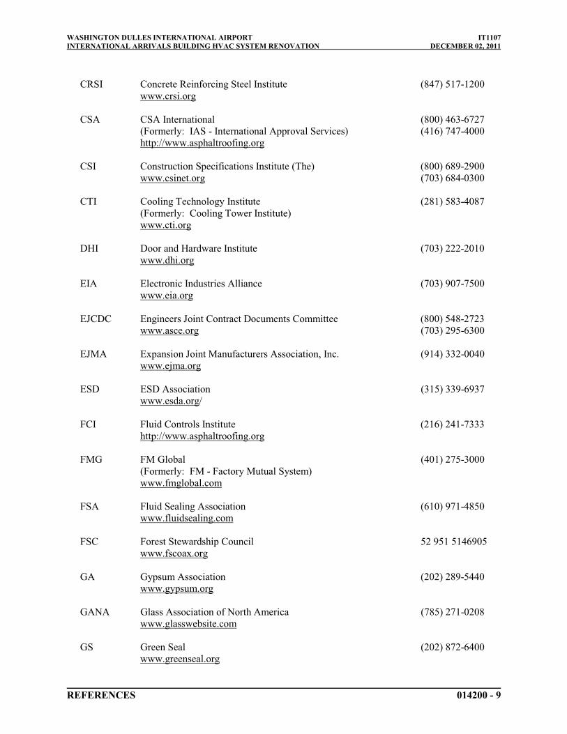
WASHINGTON DULLES INTERNATIONAL AIRPORT IT1107INTERNATIONAL ARRIVALS BUILDING HVAC SYSTEM RENOVATION DECEMBER 02, 2011
REFERENCES 014200 - 9
CRSI Concrete Reinforcing Steel Institute (847) 517-1200www.crsi.org
CSA CSA International (800) 463-6727(Formerly: IAS - International Approval Services) (416) 747-4000http://www.asphaltroofing.org
CSI Construction Specifications Institute (The) (800) 689-2900www.csinet.org (703) 684-0300
CTI Cooling Technology Institute (281) 583-4087(Formerly: Cooling Tower Institute)www.cti.org
DHI Door and Hardware Institute (703) 222-2010www.dhi.org
EIA Electronic Industries Alliance (703) 907-7500www.eia.org
EJCDC Engineers Joint Contract Documents Committee (800) 548-2723www.asce.org (703) 295-6300
EJMA Expansion Joint Manufacturers Association, Inc. (914) 332-0040www.ejma.org
ESD ESD Association (315) 339-6937www.esda.org/
FCI Fluid Controls Institute (216) 241-7333http://www.asphaltroofing.org
FMG FM Global (401) 275-3000(Formerly: FM - Factory Mutual System)www.fmglobal.com
FSA Fluid Sealing Association (610) 971-4850www.fluidsealing.com
FSC Forest Stewardship Council 52 951 5146905www.fscoax.org
GA Gypsum Association (202) 289-5440www.gypsum.org
GANA Glass Association of North America (785) 271-0208www.glasswebsite.com
GS Green Seal (202) 872-6400www.greenseal.org

WASHINGTON DULLES INTERNATIONAL AIRPORT IT1107INTERNATIONAL ARRIVALS BUILDING HVAC SYSTEM RENOVATION DECEMBER 02, 2011
REFERENCES 014200 - 10
GSI Geosynthetic Institute (610) 522-8440www.geosynthetic-institute.org
HI Hydraulic Institute (888) 786-7744www.pumps.org (973) 267-9700
HI Hydronics Institute (908) 464-8200www.gamanet.org
HMMA Hollow Metal Manufacturers Association(See NAAMM)
HPVA Hardwood Plywood & Veneer Association (703) 435-2900www.hpva.org
HPW H. P. White Laboratory, Inc. (410) 838-6550www.hpwhite.com
IAS International Approval Services(See CSA)
ICEA Insulated Cable Engineers Association, Inc. (770) 830-0369www.icea.net
ICRI International Concrete Repair Institute, Inc. (847) 827-0830www.icri.org
IEC International Electrotechnical Commission 41 22 919 02 11www.iec.ch
IEEE Institute of Electrical and Electronics Engineers, Inc. (The) (212) 419-7900www.ieee.org
IESNA Illuminating Engineering Society of North America (212) 248-5000www.iesna.org
IGCC Insulating Glass Certification Council (315) 646-2234www.igcc.org
IGMA Insulating Glass Manufacturers Alliance (The) (613) 233-1510www.igmaonline.org
ISO International Organization for Standardization 41 22 749 01 11www.iso.ch
ISSFA International Solid Surface Fabricators Association (702) 567-8150www.issfa.net
ITS Intertek (800) 345-3851www.intertek.com (607) 753-6711

WASHINGTON DULLES INTERNATIONAL AIRPORT IT1107INTERNATIONAL ARRIVALS BUILDING HVAC SYSTEM RENOVATION DECEMBER 02, 2011
REFERENCES 014200 - 11
ITU International Telecommunication Union 41 22 730 51 11www.itu.int/home
LMA Laminating Materials Association (201) 664-2700www.lma.org
LPI Lightning Protection Institute (800) 488-6864www.lightning.org (847) 577-7200
MFMA Metal Framing Manufacturers Association (312) 644-6610www.metalframingmfg.org
MH Material Handling Industry of America(See MHIA)
MHIA Material Handling Industry of America (800) 345-1815www.mhia.org (704) 676-1190
MPI Master Painters Institute (888) 674-8937www.paintinfo.com
MSS Manufacturers Standardization Society of The Valve and (703) 281-6613Fittings Industry Inc.www.mss-hq.com
NAAMM National Association of Architectural Metal Manufacturers (312) 332-0405www.naamm.org
NACE NACE International (281) 228-6200(National Association of Corrosion Engineers International)www.nace.org
NADCA National Air Duct Cleaners Association (202) 737-2926www.nadca.com
NAIMA North American Insulation Manufacturers Association (The) (703) 684-0084www.naima.org
NCMA National Concrete Masonry Association (703) 713-1900www.ncma.org
NCPI National Clay Pipe Institute (262) 248-9094www.ncpi.org
NCTA National Cable & Telecommunications Association (202) 775-3550www.ncta.com
NEBB National Environmental Balancing Bureau (301) 977-3698www.nebb.org
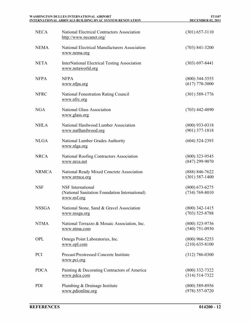
WASHINGTON DULLES INTERNATIONAL AIRPORT IT1107INTERNATIONAL ARRIVALS BUILDING HVAC SYSTEM RENOVATION DECEMBER 02, 2011
REFERENCES 014200 - 12
NECA National Electrical Contractors Association (301) 657-3110http://www.necanet.org/
NEMA National Electrical Manufacturers Association (703) 841-3200www.nema.org
NETA InterNational Electrical Testing Association (303) 697-8441www.netaworld.org
NFPA NFPA (800) 344-3555www.nfpa.org (617) 770-3000
NFRC National Fenestration Rating Council (301) 589-1776www.nfrc.org
NGA National Glass Association (703) 442-4890www.glass.org
NHLA National Hardwood Lumber Association (800) 933-0318www.natlhardwood.org (901) 377-1818
NLGA National Lumber Grades Authority (604) 524-2393www.nlga.org
NRCA National Roofing Contractors Association (800) 323-9545www.nrca.net (847) 299-9070
NRMCA National Ready Mixed Concrete Association (888) 846-7622www.nrmca.org (301) 587-1400
NSF NSF International (800) 673-6275(National Sanitation Foundation International) (734) 769-8010www.nsf.org
NSSGA National Stone, Sand & Gravel Association (800) 342-1415www.nssga.org (703) 525-8788
NTMA National Terrazzo & Mosaic Association, Inc. (800) 323-9736www.ntma.com (540) 751-0930
OPL Omega Point Laboratories, Inc. (800) 966-5253www.opl.com (210) 635-8100
PCI Precast/Prestressed Concrete Institute (312) 786-0300www.pci.org
PDCA Painting & Decorating Contractors of America (800) 332-7322www.pdca.com (314) 514-7322
PDI Plumbing & Drainage Institute (800) 589-8956www.pdionline.org (978) 557-0720

WASHINGTON DULLES INTERNATIONAL AIRPORT IT1107INTERNATIONAL ARRIVALS BUILDING HVAC SYSTEM RENOVATION DECEMBER 02, 2011
REFERENCES 014200 - 13
PGI PVC Geomembrane Institute (217) 333-3929Website Unavalible
RCSC Research Council on Structural Connections (800) 644-2400www.boltcouncil.org (312) 670-2400
RFCI Resilient Floor Covering Institute (301) 340-8580www.rfci.com
SAE SAE International (724) 776-4841www.sae.org
SDI Steel Deck Institute (847) 462-1930www.sdi.org
SDI Steel Door Institute (440) 899-0010www.steeldoor.org
SGCC Safety Glazing Certification Council (315) 646-2234www.sgcc.org
SIA Security Industry Association (703) 683-2075www.sefalabs.com
SIGMA Sealed Insulating Glass Manufacturers Association(See IGMA)
SMACNA Sheet Metal and Air Conditioning Contractors' (703) 803-2980National Associationwww.smacentral.org
SPIB Southern Pine Inspection Bureau (The) (850) 434-2611www.spib.org
SPRI SPRI (781) 647-7026(Single Ply Roofing Institute)www.spri.org
SSINA Specialty Steel Industry of North America (800) 982-0355www.ssina.com (202) 342-8630
SSPC SSPC: The Society for Protective Coatings (877) 281-7772www.sspc.org (412) 281-2331
STI Steel Tank Institute (847) 438-8265www.steeltank.com
SWRI Sealant, Waterproofing, & Restoration Institute (816) 472-7974www.swrionline.org

WASHINGTON DULLES INTERNATIONAL AIRPORT IT1107INTERNATIONAL ARRIVALS BUILDING HVAC SYSTEM RENOVATION DECEMBER 02, 2011
REFERENCES 014200 - 14
TCA Tile Council of America, Inc. (864) 646-8453www.tileusa.com
TIA/EIA Telecommunications Industry Association/Electronic (703) 907-7700Industries Alliancewww.tiaonline.org
TMS The Masonry Society (303) 939-9700www.masonrysociety.org
TPI Turfgrass Producers International (800) 405-8873www.turfgrasssod.org (847) 705-9898
UL Underwriters Laboratories Inc. (800) 285-4476www.ul.com (847) 272-8800
UNI Uni-Bell PVC Pipe Association (972) 243-3902www.uni-bell.org
WASTEC Waste Equipment Technology Association (800) 424-2869www.wastec.org (202) 244-4700
WCLIB West Coast Lumber Inspection Bureau (800) 283-1486www.wclib.org (503) 639-0651
WI Woodwork Institute (916) 372-9943www.wicnet.org
B. Code Agencies: Where abbreviations and acronyms are used in Specifications or other Contract Documents, they shall mean the recognized name of the entities in the following list. Names, telephone numbers, and Web site addresses are subject to change and are believed to be accurate and up-to-date as of the date of the Contract Documents.
IAPMO International Association of Plumbing and Mechanical Officials (909) 472-4100www.iapmo.org
ICBO International Conference of Building Officials(See ICC)
ICBO ES ICBO Evaluation Service, Inc.(See ICC-ES)
ICC International Code Council (703) 931-4533(Formerly: CABO - Council of American Building Officials)www.iccsafe.org
ICC-ES ICC Evaluation Service, Inc. (800) 423-6587www.icc-es.org (562) 699-0543

WASHINGTON DULLES INTERNATIONAL AIRPORT IT1107INTERNATIONAL ARRIVALS BUILDING HVAC SYSTEM RENOVATION DECEMBER 02, 2011
REFERENCES 014200 - 15
The Virginia Statewide Building Code (USBC)Virginia Department of Housing and Community DevelopmentDivision of Building and Fire Regulation501 North 2nd StreetRichmond, VA 23219-1321
C. Federal Government Agencies: Where abbreviations and acronyms are used in Specifications or other Contract Documents, they shall mean the recognized name of the entities in the following list. Names, telephone numbers, and Web site addresses are subject to change and are believed to be accurate and up-to-date as of the date of the Contract Documents.
CE Army Corps of Engineerswww.usace.army.mil
CPSC Consumer Product Safety Commission (800) 638-2772www.cpsc.gov (301) 504-0990
DOC Department of Commerce (202) 482-2000www.doc.gov
EPA Environmental Protection Agency (202) 260-2090www.epa.gov
FAA Federal Aviation Administration (202) 366-4000www.faa.gov
FCC Federal Communications Commission (202) 225-5322www.fcc.gov
FDA Food and Drug Administration (888) 463-6332www.fda.gov
FHA Federal Highway Administration (410) 962-0093www.fhwa.dot.gov
GSA General Services Administration (202) 708-5082www.gsa.gov
HUD Department of Housing and Urban Development (202) 708-1112www.hud.gov
LBL Lawrence Berkeley Laboratory National Laboratory (510) 486-4000www.lbl.gov
NIST National Institute of Standards and Technology (301) 975-6478www.nist.gov

WASHINGTON DULLES INTERNATIONAL AIRPORT IT1107INTERNATIONAL ARRIVALS BUILDING HVAC SYSTEM RENOVATION DECEMBER 02, 2011
REFERENCES 014200 - 16
OSHA Occupational Safety & Health Administration (800) 321-6742www.osha.gov (202) 693-1999
PBS Public Building Service(See GSA)
PHS Office of Public Health and Science (202) 690 7694phs.os.dhhs.gov
TRB Transportation Research Board (202) 334-2934www.nas.edu/trb
TSA Transportation Security Administration 1(866)-289-9673www.tsa.gov/public/index.jsp
USDA Department of Agriculture (202) 720-2791www.usda.gov
USPS United States Postal Service (202) 268-2000www.usps.com
D. State Government Agencies: Where abbreviations and acronyms are used in Specifications or other Contract Documents, they shall mean the recognized name of the entities in the following list. Names, telephone numbers, and Web site addresses are subject to change and are believed to be accurate and up-to-date as of the date of the Contract Documents.
DCR Virginia Department of Conservation and Recreation (804) 786-1712http://www.dcr.state.va.us
VDH Virginia Department of Health (540) 829-7340Culpepper Districtwww.vdh.state.va.us
(804) 371- 7160
VDOT Virginia Department of Transportation (703) 383-8368www.virginiadot.org
VDEQ Virginia Department of Environmental Quality 1-800-592-5482www.deq.state.va.us
PART 2 - PRODUCTS (Not Used)
PART 3 - EXECUTION (Not Used)
END OF SECTION 014200

WASHINGTON DULLES INTERNATIONAL AIRPORT IT1107INTERNATIONAL ARRIVALS BUILDING HVAC SYSTEM RENOVATION DECEMBER 02, 2011
TEMPORARY FACILITIES AND CONTROLS 015000 - 1
SECTION 015000 - TEMPORARY FACILITIES AND CONTROLS
PART 1 - GENERAL
1.1 RELATED DOCUMENTS
A. Drawings and Contract Provisions, Special Provisions, Supplementary Conditions, and other Division 01 Specification Sections apply to this Section.
1.2 SUMMARY
A. This Section includes requirements for temporary facilities and controls including the installation of temporary utilities, support facilities, security, and protection facilities for the Contractor’s field facilities at the Washington Dulles International Airport South Staging Area and the project area of Work.
1. For those items necessary to complete the Work they shall be installed as identified in this specification.
2. See Drawings for temporary heating, ventilating and air conditioning detailed requirements associated with removal of existing and installation of new air handling units.
B. Temporary utilities may include, but are not limited to, the following:
1. Sewers and drainage.2. Water service and distribution.3. Sanitary facilities, including toilets, wash facilities, and drinking-water facilities.4. Heating and cooling facilities.5. Ventilation.6. Electric power service.7. Telephone and other communication services.
C. Support facilities include, but are not limited to, the following:
1. Project identification and temporary signs.2. Waste disposal facilities.3. Field offices.4. Storage and fabrication sheds.5. Temporary elevator usage.6. Construction aids and miscellaneous services and facilities.
D. Security and protection facilities include, but are not limited to, the following:
1. Environmental protection.2. Security enclosure and lockup.3. Barricades, warning signs, and lights.4. Fire protection.

WASHINGTON DULLES INTERNATIONAL AIRPORT IT1107INTERNATIONAL ARRIVALS BUILDING HVAC SYSTEM RENOVATION DECEMBER 02, 2011
TEMPORARY FACILITIES AND CONTROLS 015000 - 2
E. Related Sections include the following:
1. Division 01 Section "Submittals" for procedures for submitting copies of implementation and termination schedule and utility reports.
2. Divisions 02 through 34 Sections for temporary heat, ventilation, and humidity requirements for products used in those Sections.
1.3 USE CHARGES
A. General: Temporary utilities are available from the Authority at no charge unless otherwise noted. Provide necessary labor and materials to connect to the Authority's utilities at points designated by COTR and extend utilities to trailers, offices, sheds, etc., if such facilities are utilized by the Contractor.
1. Provide COTR approved meters for water, natural gas, electricity, and each other utility used for Project. Supply utilities to Subcontractors' temporary facilities through Contractor's meters. The requirement to provide meters for utilities does not imply that the Contractor will be charged for these utilities, except under provisions outlined in this and other Sections.
2. Report consumption of each utility to COTR each month. Contractor is expected to consume reasonable amounts of each utility. Should Contractor, in COTR's opinion, use excessive amounts of any utility or waste a utility, Contractor may be required to pay for temporary utilities.
B. Allow other entities to use temporary services and facilities without cost, including, but are not limited to, the following:
1. The Authority’s construction forces.2. Occupants of Project.3. COTR.4. Architect/Engineer.5. Testing agencies.6. Personnel of authorities having jurisdiction.
1.4 SUBMITTALS
A. Shop Drawings: Submit to COTR, for the Authority's review and approval, site plans indicating all temporary facilities, including support and security; utility connections and traffic flows. Provide detailed drawings of utility connections and special facilities.
B. Temporary Utility Reports: Submit reports of tests, inspections, meter readings, and similar procedures performed on temporary utilities at both staging area and the Project site. Make all structures weather proof when heated and air-conditioned. Should Contractor, in COTR's opinion fail to keep the heated and cooled structures sealed and weather proof, Contractor may be required to pay for temporary utilities.
WASHINGTON DULLES INTERNATIONAL AIRPORT IT1107INTERNATIONAL ARRIVALS BUILDING HVAC SYSTEM RENOVATION DECEMBER 02, 2011
TEMPORARY FACILITIES AND CONTROLS 015000 - 3
C. Implementation and Termination Schedule: Within 15 calendar days of date established for submittal of Contractor's first Construction Schedule, submit a schedule indicating implementation and termination of each temporary utility.
1.5 QUALITY ASSURANCE
A. Regulations: Comply with industry standards and applicable laws and regulations of authorities having jurisdiction, including but are not limited to, the following:
1. Building Code requirements.2. Health and safety regulations.3. Police and Fire Department regulations.4. Environmental protection regulations.5. Accessibility Compliance: All temporary facilities shall comply with ICC ANSI 117.1.
B. Standards: Comply with ANSI A10.6, NECA's "Temporary Electrical Facilities," and NFPA 241.
1. Trade Jurisdictions: Assigned responsibilities for installation and operation of temporary utilities are not intended to interfere with trade regulations and union jurisdictions.
2. Electrical Service: Comply with NECA, NEMA, and UL standards and regulations for temporary electrical service. Install service to comply with NFPA 70.
C. Tests and Inspections: Arrange for the Authority's Building Codes/Environmental Department to test and inspect each temporary utility before use. Coordinate with the Authority’s BuildingCodes/Environmental Department for requirements for certifications, permits, and inspections.
1. Obtain permits from the Authority's Building Codes/Environmental Department for temporary construction and temporary utilities.
D. Fire-retardant and Flame Spread Requirements: Unless otherwise noted, fire – retardant treat all wood and wood composition products utilized in the Project and preservative treat all wood utilized on the exterior of any building. Preservative treat all wood utilized on other items indicated or specified with preservative treatment. Provide lumber and plywood with an Underwriters’ Laboratory (UL) stamp certifying a value of 25 or less flame spread and a value of 200 or less smoke development. Fire retardant lumber shall not be ripped or milled.
1.6 PROJECT CONDITIONS
A. Temporary Utilities: At earliest feasible time, when acceptable to COTR, change over from use of temporary service to use of permanent service.
1. Temporary Use of Permanent Facilities: Installer of each permanent service shall assume responsibility for operation, maintenance, and protection of each permanent service during its use as a construction facility before the Authority's acceptance, regardless of previously assigned responsibilities.
B. Conditions of Use: The following conditions apply to use of temporary and permanent services and facilities by all parties engaged in the Work:

WASHINGTON DULLES INTERNATIONAL AIRPORT IT1107INTERNATIONAL ARRIVALS BUILDING HVAC SYSTEM RENOVATION DECEMBER 02, 2011
TEMPORARY FACILITIES AND CONTROLS 015000 - 4
1. Keep temporary services and facilities clean and neat.2. Relocate temporary services and facilities as required by progress of the Work.3. Take necessary fire-prevention measures.4. Do not overload facilities.5. Do not allow hazardous, dangerous, or unsanitary conditions, or public nuisances to
develop or persist on-site.
1.7 CONTRACTOR PERSONNEL PARKING
A. The Contractor's personnel will be allowed to park their personal vehicles in staging areas. Such designated parking areas are not necessarily fenced or otherwise protected and temporary fencing for such parking areas is a requirement of this Contract.
B. Contractor is responsible for busing his employees from the off airport parking lot to the Contractor's Staging areas or work areas.
PART 2 - PRODUCTS
2.1 MATERIALS
A. General: Provide new materials. Undamaged, previously used materials in serviceable condition may be used if approved by COTR. Provide materials suitable for use intended.
B. Lumber and Plywood: Comply with requirements in Division 06 Section "Miscellaneous Rough Carpentry."
C. Gypsum Board: Minimum 1/2 inch thick by 48 inches wide by maximum available lengths; regular-type panels with tapered edges. Comply with ASTM C 36.
D. Insulation: Un-faced mineral-fiber blanket, manufactured from glass, slag wool, or rock wool; with maximum flame-spread and smoke-developed indices of 25 and 50, respectively.
E. Paint: Comply with requirements in Division 09 Section "Painting."
F. Tarpaulins: Fire-resistive labeled with flame-spread index of 15 or less.
G. Water: Potable.
2.2 EQUIPMENT
A. General: Provide new equipment suitable for use intended. If acceptable to COTR, undamaged, previously used equipment in serviceable condition may be used.
B. Field Offices: Prefabricated with lockable entrances, operable windows, and serviceable finishes; heated and air conditioned; on foundations adequate for normal loading, and provided with proper tie-downs.

WASHINGTON DULLES INTERNATIONAL AIRPORT IT1107INTERNATIONAL ARRIVALS BUILDING HVAC SYSTEM RENOVATION DECEMBER 02, 2011
TEMPORARY FACILITIES AND CONTROLS 015000 - 5
C. Self-Contained Toilet Units: Single-occupant units of chemical, aerated re-circulation, or combustion type; vented; fully enclosed with a glass-fiber-reinforced polyester shell or similar nonabsorbent material.
D. Drinking-Water Fixtures: Containerized, tap-dispenser, bottled-water drinking-water units, including paper cup supply.
1. Where power is accessible, provide electric water coolers to maintain dispensed water temperature at 45 to 55 deg F.
E. Heating Equipment: Unless COTR authorizes use of permanent heating system, provide temporary heating units with individual space thermostatic control.
1. Use of gasoline-burning space heaters, open-flame heaters, or salamander-type heating units is prohibited.
2. Heating Units: Listed and labeled, by a testing agency acceptable to authorities having jurisdiction, and marked for intended use for type of fuel being consumed.
F. Electrical Outlets: Properly configured, NEMA-polarized outlets that will prevent insertion of 110v or 120v plugs into higher-voltage outlets, and equipped with ground-fault circuit interrupters with reset button.
G. Power Distribution System Circuits: Where permitted, overhead, and visible wiring circuits, not exceeding 125-V ac, 20-A rating, and lighting circuits may be nonmetallic-sheathed cable.
H. Electrical Power Cords: Provide grounded extension cords; use hard-service as defined by NFPA 70, Article 400, where exposed to abrasion and traffic. If single lengths of extension cords will not reach areas where construction activities are in progress provide waterproof connectors to connect separate lengths of electrical extension cords.
PART 3 - EXECUTION
3.1 INSTALLATION, GENERAL
A. Prior to installation of temporary facilities and utilities, submit to the COTR a site layout providing locations and details of the facilities and utilities.
B. Use qualified personnel for installation of temporary facilities. Locate facilities where they will serve Project adequately and result in minimum interference with performance of the Work. Relocate and modify facilities as required.
C. Provide each facility ready for use when needed to avoid delay. Maintain and modify as required. Do not remove until facilities are no longer needed or are replaced by authorized use of completed permanent facilities.
3.2 CONTRACTOR STAGING AREA - GENERAL
A. Contractor will be allowed to store and stage his materials in the South Staging Area located on Airport property as designated by the COTR for such purposes. Space is limited to area

WASHINGTON DULLES INTERNATIONAL AIRPORT IT1107INTERNATIONAL ARRIVALS BUILDING HVAC SYSTEM RENOVATION DECEMBER 02, 2011
TEMPORARY FACILITIES AND CONTROLS 015000 - 6
indicated. COTR and Contractor will make a joint site visit to document condition of staging area prior to occupancy. Take photos for the record.
B. Erect and maintain an 8-foot high chain link fence topped with 3-strands of barbed wire around perimeter of staging area when the fence serves as an AOA barrier as required by the FAA/TSA. A 6-foot high fence as described above, including barbed wire will be acceptable for all other applications. Protect all stored equipment from the weather. The Authority accepts no responsibility for items stored in this area.
C. Upon completion of Construction, remove all temporary staging area facilities and return the areas to their original condition.
D. Park construction equipment in the storage site or storage area identified by the COTR when equipment is not engaged in construction activity.
E. Do not stockpile construction materials, spoils, debris or refuse in any area other than that specifically approved for such purpose by the COTR.
F. Constrain stockpiled material in a manner to prevent its movement by wind, jet blast or propeller wash.
3.3 TEMPORARY UTILITY INSTALLATION
A. General: Provide temporary service for each utility required. Comply with requirements of the Authority's Building Codes Manual, the Authority's Construction Safety Manual, and the requirements of all Sections of these specifications.
1. Arrange with COTR for time when service can be interrupted, if necessary, to make connections for temporary services. For additional information on utility outages see Division 01 Section, "Summary."
2. Provide adequate capacity at each stage of construction. Before temporary utility is available, provide trucked-in services.
3. Perform work associated with utilities owned by the Authority as approved by the Authority.
4. See additional information in Contract Provisions entitled "Availability and Use of Utility Service."
B. Sewers and Drainage: If sewers are available, provide temporary connections to remove effluent that can be discharged lawfully. If sewers are not available or cannot be used, provide drainage ditches, dry wells, stabilization ponds, and similar facilities. If neither sewers nor drainage facilities can be lawfully used for discharge of effluent, provide containers to remove and dispose of effluent off-site in a lawful manner.
C. When using Authority sewers:
1. Filter out excessive soil, construction debris, chemicals, oils, and similar contaminants that might clog sewers or pollute waterways before discharge.
2. Connect temporary sewers to the Authority's system as directed by COTR.3. Maintain temporary sewers and drainage facilities in a clean, sanitary condition. After
heavy use, restore normal conditions promptly.

WASHINGTON DULLES INTERNATIONAL AIRPORT IT1107INTERNATIONAL ARRIVALS BUILDING HVAC SYSTEM RENOVATION DECEMBER 02, 2011
TEMPORARY FACILITIES AND CONTROLS 015000 - 7
4. Provide temporary filter beds, settlement tanks, separators, and similar devices to purify effluent to levels acceptable to authorities having jurisdiction.
D. Water Service: Provide temporary water service and distribution piping in sizes and pressures adequate for construction until permanent water service is in use. Sterilize temporary water piping before use. Provide Badger Recordall, Turbo II Utility type water meter to meter all water usage for 2-inch water feed lines and above. Provide Badger Recordall bronze disc water meter for to meter all water usage for water feed lines under 2-inches. COTR will approve water meters, in writing prior to installation of water meters. Do not install water meters until written approval has been received from COTR. Provide Watts Model 909, Type RPZ backflow preventers. Do not install backflow preventers until written approval of backflow preventers has been received from the COTR.
E. Sanitary Facilities: Provide temporary toilets, wash facilities, and drinking-water fixtures. Comply with regulations and health codes for type, number, location, operation, and maintenance of fixtures and facilities.
1. Disposable Supplies: Provide toilet tissue, paper towels, paper cups, and similar disposable materials for each facility. Maintain adequate supply. Provide covered waste containers for disposal of used material.
2. Toilets: Install self-contained toilet units, located as approved by COTR. Shield toilets to ensure privacy. Provide separate facilities for male and female personnel. Use of theAuthority's existing toilet facilities will not be permitted.
3. Wash Facilities: Install wash facilities supplied with potable water at convenient locations for personnel who handle materials that require wash up. Dispose of drainage properly. Supply cleaning compounds appropriate for each type of material handled.
4. Drinking-Water Facilities: Provide bottled-water, drinking-water units.5. Locate toilets and drinking-water fixtures so personnel need not walk more than 2 stories
vertically or 200 feet horizontally to facilities.
F. Heating and Cooling: Provide temporary heating and cooling required by construction activities for curing or drying of completed installations or for protecting installed construction from adverse effects of low temperatures or high humidity. Select equipment from that specified that would not have a harmful effect on completed installations or elements being installed.
1. Maintain a minimum temperature of 50 deg F in permanently enclosed portions of building for normal construction activities, and 65 deg F for finishing activities and areas where finished Work has been installed.
G. Ventilation and Humidity Control: Provide temporary ventilation and humidity control required by construction activities for curing or drying of completed installations or for protecting installed construction from adverse effects of high humidity. Select equipment from that specified that would not have a harmful effect on completed installations or elements being installed. Coordinate ventilation requirements to produce ambient condition required and minimize energy consumption. Provide and operate either exhaust or supply fans/blowers, or both, sufficient to ventilate work areas adequately.
H. Electric Power Service: Provide weatherproof, grounded electric power service and distribution system of sufficient size, capacity, and power characteristics during construction period. Include meters, transformers, overload-protected disconnecting means, automatic ground-fault

WASHINGTON DULLES INTERNATIONAL AIRPORT IT1107INTERNATIONAL ARRIVALS BUILDING HVAC SYSTEM RENOVATION DECEMBER 02, 2011
TEMPORARY FACILITIES AND CONTROLS 015000 - 8
interrupters, and main distribution switchgear. Provide kilowatt-hour meters with demand capability.
1. Connect temporary service to the Authority's existing power source, as directed by COTR.
I. Electrical Distribution: Provide receptacle outlets adequate for connection of power tools and equipment.
1. Provide waterproof connectors to connect separate lengths of electrical power cords if single lengths will not reach areas where construction activities are in progress. Do not exceed safe length-voltage ratio.
2. Provide warning signs at power outlets other than 110 to 120 V.3. Provide metal conduit, tubing, or metallic cable for wiring exposed to possible damage.
Provide rigid steel conduits for wiring exposed on grades, floors, decks, or other traffic areas.
4. Provide metal conduit enclosures or boxes for wiring devices.5. Provide 4-gang outlets, spaced so 100-foot extension cord can reach each area for power
hand tools and task lighting. Provide a separate 125-V ac, 20-A circuit for each outlet.
J. Lighting: Provide temporary lighting with local switching that provides adequate illumination for construction operations and traffic conditions.
1. Provide and operate temporary lighting that fulfills security and protection requirements without operating entire system.
2. Provide exterior-yard site lighting that will provide adequate illumination for construction operations, parking lots, traffic conditions, and signage visibility when the Work is being performed. Provide exterior yard and site lighting aligned as directed by the COTR. Provide lighting so as not to interfere with ground, air traffic and air traffic control.
3. Install lighting for Project identification signs.
K. Telephone Service: Provide temporary telephone service for key personnel engaged in construction activities, throughout the construction period. Install telephones on separate lines for each temporary office and first aid station. Where an office has more than two occupants, install a telephone for each additional occupant or pair of occupants. Provide telephones with exchanges within the Metropolitan Washington service area. The Authority owns and operates an airport-wide Airport Communication System (ACS). This system accommodates all normal telecommunications service requirements, i.e., local, long distance, fax, data, etc. The Contractor may obtain information about and choose to utilize this service by contacting the ACS Help Desk at (703) 417-8300.
1. At each telephone, post a list of emergency telephone numbers approved by COTR.2. Provide a portable cellular telephone for superintendent's use in making and receiving
telephone calls when away from field office.
3.4 SUPPORT FACILITIES INSTALLATION
A. General: Comply with the following:

WASHINGTON DULLES INTERNATIONAL AIRPORT IT1107INTERNATIONAL ARRIVALS BUILDING HVAC SYSTEM RENOVATION DECEMBER 02, 2011
TEMPORARY FACILITIES AND CONTROLS 015000 - 9
1. Locate field offices, storage sheds, sanitary facilities, and other temporary construction and support facilities for easy access.
2. Provide incombustible construction for offices, shops, and sheds located within construction area or within 30 feet of building lines. Comply with NFPA 241 and USBC.
B. Project Identification and Temporary Signs: Prepare Project identification and other signs in sizes indicated. Install signs where indicated or where directed by COTR to inform public and persons seeking entrance to Project. Provide two Project signs.
1. Engage an experienced sign painter to apply graphics for Project identification signs. Comply with details indicated.
2. Prepare temporary signs to provide directional information to construction personnel and visitors.
3. Construct signs of exterior-type, Grade B-B, high-density concrete form overlay plywood in sizes and thickness indicated. Support on nominal 4-inch-by-4-inch-by-10-foot-long posts or framing of preservative-treated wood or steel.
4. Paint sign panel and applied graphics with exterior-grade alkyd gloss enamel over exterior primer.
5. The following signs will be allowed on the Project:
a. Identifying captions over offices.b. Other signs as required by the Contract Documents.
6. Take necessary steps to prevent installation of unauthorized signs and, should any appear, remove them immediately. Repair and repaint damage caused thereby at no additional cost to the Authority.
7. No more than two Project Identification Signs will be permitted. Project identification signs are the only signs on which the Contractors name and logo will be permitted.
C. Waste Disposal Facilities: Provide waste-collection containers in sizes adequate to handle waste from construction operations. Containerize and clearly label hazardous, dangerous, or unsanitary waste materials separately from other waste. Comply with Division 01 Section "Execution" for progress cleaning requirements.
1. If required by COTR, provide separate containers, clearly labeled, for each type of waste material to be deposited.
2. Develop a waste management plan for Work performed on Project. Indicate types of waste materials Project will produce and estimate quantities of each type. Provide detailed information for on-site waste storage and separation of recyclable materials. Provide information on destination of each type of waste material and means to be used to dispose of all waste materials.
D. Janitorial Services: Provide janitorial services on a daily basis for temporary offices, first-aid stations, toilets, wash facilities, lunchrooms, and similar areas.
E. Storage and Fabrication Sheds: Provide sheds sized, furnished, and equipped to accommodate materials and equipment involved, including temporary utility services. Sheds may be open shelters or, if permitted by COTR, fully enclosed spaces within building or elsewhere on-site subject to approval of COTR.

WASHINGTON DULLES INTERNATIONAL AIRPORT IT1107INTERNATIONAL ARRIVALS BUILDING HVAC SYSTEM RENOVATION DECEMBER 02, 2011
TEMPORARY FACILITIES AND CONTROLS 015000 - 10
1. Construct framing, sheathing, and siding using fire-retardant-treated lumber and plywood.
2. Paint exposed lumber and plywood with exterior-grade acrylic-latex emulsion over exterior primer.
3. Submit the design of storage structures of more than 150 sq. ft. to COTR for review and approval by the Authority's Building Codes/Environmental Department.
F. Existing Stair Usage: Use of the Authority's existing stairs will be permitted, as long as stairs are cleaned and maintained in a condition acceptable to COTR. At Substantial Completion, restore stairs to condition existing before initial use.
1. Provide protective coverings, barriers, devices, signs, or other procedures to protect stairs and to maintain means of egress. If, despite such protection, stairs become damaged, restore damaged areas so no evidence remains of correction work.
3.5 SECURITY AND PROTECTION FACILITIES INSTALLATION
A. Environmental Protection: Provide protection, operate temporary facilities, and conduct construction in ways and by methods that comply with environmental regulations and that minimize possible air, waterway, and subsoil contamination or pollution or other undesirable effects. Avoid using tools and equipment that produce harmful noise. Restrict use of noisemaking tools and equipment to hours of 11:00 p.m. to 5:00 a.m., unless directed otherwise by the COTR, which will minimize complaints from persons or firms near Project site.
B. Pest Control: Retain a local exterminator or pest-control company to recommend practices to minimize attraction and harboring of rodents, roaches, and other pests. Engage this pest-control service to perform extermination and control procedures at regular intervals so Project will be free of pests and their residues at Substantial Completion. Obtain extended warranty for the Authority. Perform control operations lawfully, using environmentally safe materials.
C. Security Fencing: Minimum 2-inch, 0.148-inch-thick, galvanized steel, chain-link fabric fencing; minimum 8 feet high with galvanized steel pipe posts; minimum 2-3/8-inch-OD line posts and 2-7/8-inch-OD corner and pull posts, with 3 galvanized barbed-wire top strands, unless otherwise indicated.
D. Security Enclosure and Lockup: Install substantial temporary enclosure around partially completed areas of construction. Provide lockable entrances to prevent unauthorized entrance, vandalism, theft, and similar violations of security.
E. Barricades, Warning Signs, and Lights: Comply with standards and code requirements for erecting structurally adequate barricades. Paint with appropriate colors, graphics, and warning signs to inform personnel and public of possible hazard. Where appropriate and needed, provide lighting, including flashing red or amber lights. See the Authority's Construction Safety Manual for additional requirements.
F. Temporary Enclosures: Provide temporary enclosures for protection of construction, in progress and completed, from exposure, foul weather, other construction operations, and similar activities.

WASHINGTON DULLES INTERNATIONAL AIRPORT IT1107INTERNATIONAL ARRIVALS BUILDING HVAC SYSTEM RENOVATION DECEMBER 02, 2011
TEMPORARY FACILITIES AND CONTROLS 015000 - 11
1. Use fire-retardant-treated wood and plywood for temporary enclosures. Use fire-retardant-treated material for framing and main sheathing.
G. Temporary Partitions: Erect and maintain dustproof partitions and temporary enclosures to limit dust and dirt migration and to separate areas from fumes and noise.
H. Temporary Barricades (Interior): Provide appropriately marked portable barricades to delineate temporary work areas in occupied areas of the building where permitted to be in place when the building is occupied. Provide barricades of construction that will not damage existing finishes.
I. Temporary Fire Protection: Until fire-protection needs are supplied by permanent facilities, install and maintain temporary fire-protection facilities of types needed to protect against reasonably predictable and controllable fire losses. Comply with NFPA 241 and VUSBC.
1. Provide fire extinguishers, installed on walls on mounting brackets, visible and accessible from space being served, with sign mounted above.
a. Field Offices: Class A, stored-pressure, water-type extinguishers.b. Other Locations: Class ABC, dry-chemical extinguishers or a combination of
extinguishers of NFPA-recommended classes for exposures.c. Locate fire extinguishers per NFPA 10 and where convenient and effective for
their intended purpose; provide not less than one extinguisher on each floor at or near each usable stairwell.
2. Store combustible materials in containers in fire-safe locations.3. Maintain unobstructed access to fire extinguishers, fire hydrants, temporary fire-
protection facilities, stairways, and other access routes for firefighting. Prohibit smoking in hazardous fire-exposure areas.
4. Supervise welding operations, combustion-type temporary heating units, and similar sources of fire ignition.
5. Permanent Fire Protection: At earliest feasible date in each area of Project, complete installation of permanent fire-protection facility, including connected services, and place into operation and use. Instruct key personnel on use of facilities.
6. Develop and supervise an overall fire-prevention and first-aid fire-protection program for personnel at Project site. Review needs with local fire department and establish procedures to be followed. Instruct personnel in methods and procedures. Post warnings and information.
7. Provide temporary standpipes with fire hose valve connections for fire protection.
J. Storage: Where materials and equipment are stored, and are of value or attractive for theft, provide secure lockup. Enforce discipline in connection with installation and release of material to minimize opportunity for theft and vandalism.
3.6 UTILITY PROVISIONS AT SOUTH STAGING AREA
A. Existing Conditions:
1. The Authority will provide at each lot in the South Staging area the following:
WASHINGTON DULLES INTERNATIONAL AIRPORT IT1107INTERNATIONAL ARRIVALS BUILDING HVAC SYSTEM RENOVATION DECEMBER 02, 2011
TEMPORARY FACILITIES AND CONTROLS 015000 - 12
a. Two 2” conduits from the utility sheds, to the limits of the lot, one electrical and one telecommunications. The conduits will be capped below grade and signified by a 4” x 4” x 4’ wood stake at the limits of the lot.
b. Each lot will be allocated 100 A, 480 v 3 phase, 3 wire power.c. The power is available at the utility shed. Provide necessary conductors as
indicated in the “TELECOMMUNICATIONS” and “ELECTRICAL POWER” paragraphs below.
d. Domestic water service will be available at the limit of the lot, identified with a blue painted stake.
B. General Requirements:
1. Contractor is responsible for subdividing telecommunications, electrical and water within their assigned lot in a coordinated fashion upon mobilization. Provide a site plan for COTR review and approval. Maintain site plan up-to-date throughout the Project. Indicate on site plan trailer locations, proposed conduit runs, proposed telecom and electrical backboards, proposed water distribution and any other pertinent information. Locate and indicate existing utilities on site plan.
2. Install fence around Contractors allotted area and remove fence upon completion of Contractor’s Work. Refer to other paragraphs of this section for fencing requirements.
3. Contractor employee parking will be limited to within the allotted staging area. Provide transportation for Contractor’s employees between the work site and the staging area.
4. Water tank fill station is located on the south side of the entrance road to the Staging Area. Do not use the fire hydrants along the main staging area road for obtaining water.
5. Restore lot to its original condition upon contract conclusion.
C. Telecommunications:
1. The Airport Communications System (ACS) vendor will provide a pedestal or telecom backboard at the limits of the Contractor’s lot. The pedestal or telecom backboard is supplied via a communications cable installed by the ACS from the nearest utility shed to the limits of the Contractor’s lot. As the electrical and telecommunications are adjacent, excavation at the lot limits for both utilities should be completed at the same time. Determining the routing of all conduits from the telecom pedestal at the lot limits to each subcontractor trailer to avoid future cut cables. Originate all feeds within a lot at the pedestal location. Contractor’s attention is called to the fact that all telecommunications work between the utility sheds and the lot limits is the responsibility of the ACS. Should the Contractor perform any telecommunications work between the utility sheds and the lot limits, the ACS will remove work and the ACS will charge the Contractor for any cost associated with this removal of the work.
2. Provide all conduit installations either above or below ground in accordance with the Virginia Uniform Statewide Building Code and the applicable Division 26 Sections of the specification.
a. Communications cable:
1) Cable must be 24 gauge with solid, annealed, bare copper conductors2) Conductors shall have polyolefin insulation, color coded to telephone
industry standards3) Cable must have a black polyethylene outer jacket4) Cable must have an aluminum or copper shield.

WASHINGTON DULLES INTERNATIONAL AIRPORT IT1107INTERNATIONAL ARRIVALS BUILDING HVAC SYSTEM RENOVATION DECEMBER 02, 2011
TEMPORARY FACILITIES AND CONTROLS 015000 - 13
5) Cable must be Gel filled6) Install in schedule 40 PVC conduits a minimum of 2” in diameter.7) Advise the COTR of the total number of required telecom cable pairs,
including his subcontractor’s requirements, prior to any communications cable work within the lot.
3. Special telecom provisions: T1 service is available in the South Contractors lot at the Contractor's expense. Telecom services can be ordered through the Airport Communications System vender. Please call the Authority at 703/417-8605 to order these services.
D. Electrical Power:
1. Conduit is provided from one of four sheds, to a location just inside each contractor lot. Extend the conduit, as required, to serve all facilities on Contractor’s site and provide cable back to shed. If power requirements greater than 100 ampere, at 480v, three phase, three – wire are required; requests for additional power will be considered on a case-by-case basis.
a. Transformers:
1) Suitable for outdoor use 2) Pad mounted with fused safety switches on the primary and secondary sides
of the transformer.
2. The Contractor is required to advise the COTR of the estimated electrical consumption including that of his subcontractors prior to provision of cable.
E. Plumbing: Provide a Watts Model 909, Type RPZ backflow prevention device at each trailer. Remove plumbing work in place upon contract completion. There are no sanitary sewer provisions, use above ground tanks specifically designed for sewage holding. The Contractor at his option may use chemical or electrical toilets. Clean, pump and haul sanitary waste. Maintain a clean and odor free lot.
F. Maintenance Requirements for Staging Area:
1. Unauthorized soil and concrete stockpiles are prohibited.2. Cover all containers and drums of any size that are stored on site and their required
secondary containment to prevent rainwater from coming in contact with the containers. Earthen berms are not permitted. Clearly label all drums and containers used to hold trash and debris “Trash”. Empty drums and containers when full. Remove all unused empty drums and containers from the site.
3. Include Contractor’s lot in the South Staging Area in the SPPP. 4. Store all fuel, petroleum based products and products potentially detrimental to the
environment in aboveground tanks. 5. Aboveground storage tanks:
a. Double walled and approved for the use intended.b. Submit manufacturer’s literature to COTR for approval in writing for each such
storage tank intended for use by Contractor.

WASHINGTON DULLES INTERNATIONAL AIRPORT IT1107INTERNATIONAL ARRIVALS BUILDING HVAC SYSTEM RENOVATION DECEMBER 02, 2011
TEMPORARY FACILITIES AND CONTROLS 015000 - 14
6. Store all trash, construction debris, and other debris in metal containers specifically designed for such use. Do not keep trash containers on the site for more than 90 calendar days.
7. Storage of used tires and batteries is prohibited.8. Storage of waste oil is prohibited.9. Only routine light equipment maintenance shall be permitted. Should Contractor require
more than routine maintenance to be performed on site, submit a work execution plan to COTR, for written approval, describing the type of maintenance and the procedures that will be implemented to protect the environment.
3.7 OPERATION, TERMINATION, AND REMOVAL
A. Supervision: Enforce strict discipline in use of temporary facilities. Limit availability of temporary facilities to essential and intended uses to minimize waste and abuse.
B. Maintenance: Maintain facilities in good operating condition until removal. Protect from damage caused by freezing temperatures and similar elements.
1. Maintain operation of temporary enclosures, heating, cooling, humidity control, ventilation, and similar facilities on a 24-hour basis where required to achieve indicated results and to avoid possibility of damage.
2. Prevent water-filled piping from freezing. Maintain markers for underground lines.Protect from damage during excavation operations.
C. Temporary Facility Changeover: Unless Contractor is able to utilize permanent fire protection, do not change over from using temporary security and protection facilities to permanent facilities until Substantial Completion.
D. Termination and Removal: Remove each temporary facility when need for its service has ended, when it has been replaced by authorized use of a permanent facility, or no later than Substantial Completion. Complete or, if necessary, restore permanent construction that may have been delayed because of interference with temporary facility. Repair damaged Work, clean exposed surfaces, and replace construction that cannot be satisfactorily repaired.
1. Properly recondition and restore those portions of the site occupied by temporary facilities and controls to condition acceptable to COTR, at least equal to condition at time of start of Work, unless otherwise authorized in writing by COTR.
2. Materials and facilities that constitute temporary facilities are the property of Contractor. Owner reserves right to take possession of Project identification signs.
3.8 At Substantial Completion, clean and renovate permanent facilities used during construction period. Comply with final cleaning requirements in Division 01 Section "Project Closeout."
END OF SECTION 015000

WASHINGTON DULLES INTERNATIONAL AIRPORT IT1107INTERNATIONAL ARRIVALS BUILDING HVAC SYSTEM RENOVATION DECEMBER 02, 2011
PRODUCT REQUIREMENTS 016000 - 1
SECTION 016000 - PRODUCT REQUIREMENTS
PART 1 - GENERAL
1.1 RELATED DOCUMENTS
A. Drawings, Contract Provisions, Special Provisions, Supplementary Conditions, and other Division 01 Specification Sections apply to this Section.
1.2 SUMMARY
A. This Section includes the following administrative and procedural requirements: selection of products for use in Project; product delivery, storage, and handling; manufacturers' standard warranties on products; special warranties; product substitutions; and comparable products.
1. This Section includes substitutions made for "or as approved by the Authority" items.
B. Related Sections include the following:
1. Division 01 Section "Allowances" for products selected under an allowance.2. Division 01 Section "Alternates" for products selected under an alternate.3. Division 01 Section "References" for applicable industry standards for products
specified.4. Divisions 02 through 34, if included in this project, Sections for specific requirements for
warranties on products and installations specified to be warranted.
1.3 DEFINITIONS
A. Products: Items purchased for incorporating into the Work, whether purchased for Project or taken from previously purchased stock. The term "product" includes the terms "material," "equipment," "system," and terms of similar intent.
1. Named Products: Items identified by manufacturer's product name, including make or model number or other designation, shown or listed in manufacturer's published product literature that is current as of date of the Contract Documents.
2. New Products: Items that have not previously been incorporated into another project or facility, except that products consisting of recycled-content materials are allowed, unless explicitly stated otherwise. Products salvaged or recycled from other projects are not considered new products.
3. Comparable Product: Product that is demonstrated and approved through submittal process, or where indicated as a product substitution, to have the indicated qualities related to type, function, dimension, in-service performance, physical properties, appearance, and other characteristics that equal or exceed those of specified product.
B. Substitutions: Changes in products, materials, equipment, and methods of construction from those required by the Contract Documents and proposed by Contractor.
WASHINGTON DULLES INTERNATIONAL AIRPORT IT1107INTERNATIONAL ARRIVALS BUILDING HVAC SYSTEM RENOVATION DECEMBER 02, 2011
PRODUCT REQUIREMENTS 016000 - 2
C. Basis-of-Design Product Specification: Where a specific manufacturer's product is named and accompanied by the words "basis of design," including make or model number or other designation, to establish the significant qualities related to type, function, dimension, in-service performance, physical properties, appearance, and other characteristics for purposes of evaluating comparable products of other named manufacturers.
1.4 SUBMITTALS
A. Product List: Submit a list, in tabular form acceptable to COTR, showing specified products. Include generic names of products required. Include manufacturer's name and proprietary product names for each product.
1. Coordinate product list with Contractor's Construction Schedule and Submittals Schedule.
2. Form: Tabulate information for each product under the following column headings:
a. Specification Section number and title.b. Generic name used in the Contract Documents.c. Proprietary name, model number, and similar designations.d. Manufacturer's name and address.e. Supplier's name and address.f. Installer's name and address.g. Projected delivery date or time span of delivery period.h. Identification of items that require early submittal approval for scheduled delivery
date.
3. Initial Submittal: Within 30 calendar days after the Notice to Proceed, submit 3 copies of initial product list. Include a written explanation for omissions of data and for variations from the Contract requirements.
4. Completed List: Within 60 calendar days after Notice to Proceed, submit 10 copies of completed product list. Include a written explanation for omissions of data and for variations from the Contract requirements.
5. COTR's Action: COTR will respond in writing to Contractor within 15 calendar days of receipt of completed product list. COTR's response will include a list of unacceptable product selections and a brief explanation of reasons for this action. COTR's response, or lack of response, does not constitute a waiver of requirement that products comply with the Contract Documents.
B. Substitution Requests: Submit six copies of each request for consideration. Identify product or fabrication or installation method to be replaced. Include Section number and title and Drawing numbers and titles.
1. Substitution Request Form: Submit requests in the form and according to procedures required for Contract Modification proposals supplied to Contractor at the pre-construction meeting or as directed by COTR. Do not submit requests for substitutions as "Requests for Information" (RFIs).

WASHINGTON DULLES INTERNATIONAL AIRPORT IT1107INTERNATIONAL ARRIVALS BUILDING HVAC SYSTEM RENOVATION DECEMBER 02, 2011
PRODUCT REQUIREMENTS 016000 - 3
2. Documentation: Show compliance with requirements for substitutions and the following, as applicable:
a. Statement indicating why specified material or product cannot be provided.b. Coordination information, including a list of changes or modifications needed to
other parts of the Work and to construction performed by the Authority and separate contractors that will be necessary to accommodate proposed substitution.
c. Detailed comparison of significant qualities of proposed substitution with those of the Work specified. Significant qualities may include attributes such as performance, weight, size, durability, visual effect, and specific features and requirements indicated.
d. Product Data, including drawings and descriptions of products and fabrication and installation procedures.
e. Samples, where applicable or requested.f. List of similar installations for completed projects with project names and
addresses and names and addresses of architects and owners.g. Material test reports from a qualified testing agency indicating and interpreting test
results for compliance with requirements indicated.h. Research/evaluation reports evidencing compliance with building code in effect for
Project, from a model code organization acceptable to authorities having jurisdiction.
i. Detailed comparison of Contractor's Construction Schedule using proposed substitution with products specified for the Work, including effect on the overall Contract Time. If specified product or method of construction cannot be provided within the Contract Time, include letter from manufacturer, on manufacturer's letterhead, stating lack of availability or delays in delivery.
j. Cost information, including a proposal of change, if any, in the Contract Price.k. Contractor's certification that proposed substitution complies with requirements in
the Contract Documents and is appropriate for applications indicated.l. Contractor's waiver of rights to additional payment or time that may subsequently
become necessary because of failure of proposed substitution to produce indicated results.
m. Failure by Contractor to include the above requirements in the submittal may cause rejection of the submittal in its entirety.
3. COTR's Action: If necessary, COTR will request additional information or documentation for evaluation within 15 calendar days of receipt of a request for substitution. COTR will notify Contractor of acceptance or rejection of proposed substitution within 15 calendar days of receipt of request, or two weeks of receipt of additional information or documentation, whichever is later.
a. Form of Acceptance: Change notice.b. Use product specified if COTR couldn’t make a decision on use of a proposed
substitution within time allocated.
C. Comparable Product Requests: Submit three copies of each request for consideration. Identify product or fabrication or installation method to be replaced. Include Specification Section number and title and Drawing numbers and titles.
1. COTR’s Action: If necessary, COTR will request additional information or documentation for evaluation within 7 working days of receipt of a comparable product
WASHINGTON DULLES INTERNATIONAL AIRPORT IT1107INTERNATIONAL ARRIVALS BUILDING HVAC SYSTEM RENOVATION DECEMBER 02, 2011
PRODUCT REQUIREMENTS 016000 - 4
request. COTR will notify Contractor of approval or rejection of proposed comparable product request within 15 calendar days of receipt of request, or 7 calendar days of receipt of additional information or documentation, whichever is later.
a. Form of Approval: As specified in Division 01 Section "Submittals."b. Use product specified if COTR couldn’t make a decision on use of a comparable
product request within time allocated.
D. Basis-of-Design Product Specification Submittal: Comply with requirements in Division 01 Section "Submittals." Show compliance with requirements.
1.5 QUALITY ASSURANCE
A. Compatibility of Options: If Contractor is given option of selecting between two or more products for use on Project, product selected shall be compatible with products previously selected, even if previously selected products were also options.
1.6 PRODUCT DELIVERY, STORAGE, AND HANDLING
A. Deliver, store, and handle products using means and methods that will prevent damage, deterioration, and loss, including theft. Comply with manufacturer's written instructions.
B. Delivery and Handling:
1. Schedule delivery of products that are scheduled to be installed within 48 hours of arrival.
2. Coordinate delivery with installation time to ensure minimum holding time for items that are flammable, hazardous, easily damaged, or sensitive to deterioration, theft, and other losses.
3. Deliver products to Project site in an undamaged condition in manufacturer's original sealed container or other packaging system, complete with labels and instructions for handling, storing, unpacking, protecting, and installing.
4. Inspect products on delivery to ensure compliance with the Contract Documents and to ensure that products are undamaged and properly protected.
C. Storage:
1. Store products to allow for inspection and measurement of quantity or counting of units.2. Store materials in a manner that will not endanger Project structure.3. Store products that are subject to damage by the elements, under cover in a weather tight
enclosure above ground, with ventilation adequate to prevent condensation.4. Comply with product manufacturers written instructions for temperature, humidity,
ventilation, and weather-protection requirements for storage.5. Store foam plastic from exposure to sunlight, except to extent necessary for period of
installation and concealment.6. Store cementitious products and materials on elevated platforms.7. Protect stored products from damage.

WASHINGTON DULLES INTERNATIONAL AIRPORT IT1107INTERNATIONAL ARRIVALS BUILDING HVAC SYSTEM RENOVATION DECEMBER 02, 2011
PRODUCT REQUIREMENTS 016000 - 5
8. Replace products and materials damaged by the elements due to improper storage at no additional cost to the Authority. This damage can be, but not limited to, oxidization, mold, mildew, warping, and rust.
1.7 PRODUCT WARRANTIES
A. Warranties specified in other Sections shall be in addition to, and run concurrent with, other warranties required by the Contract Documents. Manufacturer's disclaimers and limitations on product warranties do not relieve Contractor of obligations under requirements of the Contract Documents.
1. Manufacturer's Warranty: Preprinted written warranty published by individual manufacturer for a particular product and specifically endorsed by manufacturer to Authority.
2. Special Warranty: Written warranty required by or incorporated into the Contract Documents, either to extend time limit provided by manufacturer's warranty or to provide more rights for Authority.
B. Special Warranties: Prepare a written document that contains appropriate terms and identification, ready for execution. Submit a draft for approval before final execution.
1. Manufacturer's Standard Form: Modified to include Project-specific information and properly executed.
2. Specified Form: When specified forms are included with the Specifications, prepare a written document using appropriate form properly executed.
3. Refer to Divisions 02 through 33 Sections for specific content requirements and particular requirements for submitting special warranties.
C. Submittal Time: Comply with requirements in Division 01 Section "Project Closeout."
PART 2 - PRODUCTS
2.1 PRODUCT OPTIONS
A. General Product Requirements: Provide products that comply with the Contract Documents, that are undamaged and, unless otherwise indicated, that are new at time of installation.
1. Provide products complete with accessories, trim, finish, fasteners, and other items needed for a complete installation and indicated use and effect.
2. Standard Products: If available, and unless custom products or nonstandard options are specified, provide standard products of types that have been produced and used successfully in similar situations on other projects.
3. The Authority reserves the right to limit selection to products with warranties not in conflict with requirements of the Contract Documents.
4. Where products are accompanied by the term "as selected," COTR will make selection.5. Where products are accompanied by the term "match sample," sample to be matched is
COTR's.

WASHINGTON DULLES INTERNATIONAL AIRPORT IT1107INTERNATIONAL ARRIVALS BUILDING HVAC SYSTEM RENOVATION DECEMBER 02, 2011
PRODUCT REQUIREMENTS 016000 - 6
6. Descriptive, performance, and reference standard requirements in the Specifications establish "salient characteristics" of products.
7. "Or as approved by the Authority": Note that products submitted under an "or as approved by the Authority” provision are considered to be substitutions. Substitutions shall follow the requirements of Paragraph VII-42 of Contract Provisions and provisions in "Comparable Products" Article to obtain approval for use of an unnamed product.
B. Product Selection Procedures:
1. Product: Where Specifications name a single product and manufacturer, provide the named product that complies with requirements.
2. Manufacturer/Source: Where Specifications name a single manufacturer or source, provide a product by the named manufacturer or source that complies with requirements.
3. Products: Where Specifications include a list of names of both products and manufacturers, provide one of the products listed that complies with requirements.
4. Manufacturers: Where Specifications include a list of manufacturers' names, provide a product by one of the manufacturers listed that complies with requirements.
5. Available Products: Where Specifications include a list of names of both products and manufacturers, provide one of the products listed, or an unnamed product, that complies with requirements. Comply with provisions in Part 2 "Comparable Products" Article for consideration of an unnamed product.
6. Available Manufacturers: Where Specifications include a list of manufacturers, provide a product by one of the manufacturers listed, or an unnamed manufacturer, that complies with requirements. Comply with provisions in Part 2 "Comparable Products" Article for consideration of an unnamed product.
7. Product Options: Where Specifications indicate that sizes, profiles, and dimensional requirements on Drawings are based on a specific product or system, provide the specified product or system. Comply with provisions in Part 2 "Product Substitutions" Article for consideration of an unnamed product or system.
8. Basis-of-Design Product: Where Specifications name a product and include a list of manufacturers, provide the specified product or a comparable product by one of the other named manufacturers. Drawings and Specifications indicate sizes, profiles, dimensions, and other characteristics that are based on the product named. Comply with provisions in Part 2 "Comparable Products" Article for consideration of an unnamed product by the other named manufacturers.
9. Visual Matching Specification: Where Specifications require matching an established Sample, select a product that complies with requirements and matches COTR's sample. COTR's decision will be final on whether a proposed product matches.
a. If no product available within specified category matches and complies with other specified requirements, comply with provisions in Part 2 "Product Substitutions" Article for proposal of product.

WASHINGTON DULLES INTERNATIONAL AIRPORT IT1107INTERNATIONAL ARRIVALS BUILDING HVAC SYSTEM RENOVATION DECEMBER 02, 2011
PRODUCT REQUIREMENTS 016000 - 7
10. Visual Selection Specification: Where Specifications include the phrase "as selected from manufacturer's colors, patterns, textures" or a similar phrase, select a product that complies with other specified requirements.
a. Standard Range: Where Specifications include the phrase "standard range of colors, patterns, textures" or similar phrase, COTR will select color, pattern, density, or texture from manufacturer's product line that does not include premium items.
b. Full Range: Where Specifications include the phrase "full range of colors, patterns, textures" or similar phrase, COTR will select color, pattern, density, or texture from manufacturer's product line that includes both standard and premium items.
2.2 PRODUCT SUBSTITUTIONS
A. Timing: COTR will consider requests for substitution if received within 60 calendar days after issuance of the Notice to Proceed. Requests received after that time may be considered or rejected at the sole discretion of the Contracting Officer.
B. Conditions: COTR will consider Contractor's request for substitution when the following conditions are satisfied. If the following conditions are not satisfied, COTR will return requests without action, except to record noncompliance with these requirements:
1. Requested substitution does not require extensive revisions to the Contract Documents.2. Requested substitution is consistent with the Contract Documents and will produce
indicated results.3. Substitution request is fully documented and properly submitted.4. Requested substitution will not adversely affect Contractor's Construction Schedule.5. Requested substitution has received necessary approvals of authorities having
jurisdiction.6. Requested substitution is compatible with other portions of the Work.7. Requested substitution has been coordinated with other portions of the Work.8. Requested substitution provides specified warranty.9. If requested substitution involves more than one contractor, requested substitution has
been coordinated with other portions of the Work, is uniform and consistent, is compatible with other products, and is acceptable to all contractors involved.
C. Contractor's submittal and COTR's review or approval of Shop Drawings, Product Data, or Samples that relate to a substitute does not by itself constitute a final approval of the requested substitution, nor does it relieve Contractor from fulfilling existing Contract requirements.
D. If a substitution offers a substantial advantage to the Authority, in terms of cost, time, energy conservation, or other considerations of merit, after deducting offsetting responsibilities the Authority may be required to bear, the substitution shall be submitted as a Value Engineering Change Proposal.

WASHINGTON DULLES INTERNATIONAL AIRPORT IT1107INTERNATIONAL ARRIVALS BUILDING HVAC SYSTEM RENOVATION DECEMBER 02, 2011
PRODUCT REQUIREMENTS 016000 - 8
2.3 COMPARABLE PRODUCTS
A. Conditions: COTR will consider Contractor's request for comparable product when the following conditions are satisfied. If the following conditions are not satisfied, COTR will return requests without action, except to record noncompliance with these requirements:
1. Evidence that the proposed product does not require extensive revisions to the Contract Documents, that it is consistent with the Contract Documents and will produce the indicated results, and that it is compatible with other portions of the Work.
2. Detailed comparison of significant qualities of proposed product with those named in the Specifications. Significant qualities include attributes such as performance, weight, size, durability, visual effect, and specific features and requirements indicated.
3. Evidence that proposed product provides specified warranty.4. List of similar installations for completed projects with project names and addresses and
names and addresses of architects and owners, if requested.5. Samples, if requested.
PART 3 - EXECUTION (Not Used)
END OF SECTION 016000

WASHINGTON DULLES INTERNATIONAL AIRPORT IT1107INTERNATIONAL ARRIVALS BUILDING HVAC SYSTEM RENOVATION DECEMBER 02, 2011
EXECUTION 017300 - 1
SECTION 017300 - EXECUTION
PART 1 - GENERAL
1.1 RELATED DOCUMENTS
A. Drawings, Contract Provisions, Special Provisions, Supplementary Conditions, and other Division 01 Specification Sections apply to this Section.
1.2 SUMMARY
A. This Section includes general procedural requirements governing execution of the Work including, but not limited to, the following:
1. Examination of existing conditions.2. Preparation for work installation.3. Construction layout.4. General installation of products.5. Coordination of Authority-installed products.6. Progress cleaning.7. Starting and adjusting.8. Protection of installed construction.9. Correction of the Work.
B. Related Sections include the following:
1. Division 01 Section "Project Management and Coordination" for procedures for coordinating field engineering with other construction activities.
1.3 SUBMITTALS
A. Project Record Documents: Submit a record of Work performed (materials tests, inspections, acceptance tests, etc.) and record survey data as required under provisions in Division 01Sections "Submittals" and "Project Closeout."
PART 2 - PRODUCTS (Not Used)
PART 3 - EXECUTION
3.1 EXAMINATION
A. Existing Conditions: The existence and location of site improvements, utilities, and other construction indicated as existing are not guaranteed. Before beginning work, investigate and verify the existence and location of mechanical and electrical systems and other construction affecting the Work, including all site utility systems.
1. Before construction, verify the location and points of connection of utility services.

WASHINGTON DULLES INTERNATIONAL AIRPORT IT1107INTERNATIONAL ARRIVALS BUILDING HVAC SYSTEM RENOVATION DECEMBER 02, 2011
EXECUTION 017300 - 2
B. Existing Utilities: The existence and location of utilities and construction indicated as existing are not guaranteed. Before beginning work, investigate and verify the existence and location of utilities and other construction affecting the Work.
C. Acceptance of Conditions: Examine substrates, areas, and conditions, with Installer or Applicator present where indicated, for compliance with requirements for installation tolerances and other conditions affecting performance. Record observations.
1. Written Report: Where a written report listing conditions detrimental to performance of the Work is required by other Sections, include the following:
a. Description of the Work.b. List of detrimental conditions, including substrates.c. List of unacceptable installation tolerances.d. Recommended corrections.
2. Verify compatibility with and suitability of substrates, including compatibility with existing finishes or primers.
3. Examine roughing-in for mechanical and electrical systems to verify actual locations of connections before equipment and fixture installation.
4. Examine walls, floors, and roofs for suitable conditions where products and systems are to be installed.
5. Proceed with installation only after unsatisfactory conditions have been corrected. Proceeding with the Work indicates acceptance of surfaces and conditions.
3.2 PREPARATION
A. Existing Utility Information: Furnish information to COTR that is necessary to adjust, move, or relocate existing utility structures, utility poles, lines, services, or other utility appurtenances located in or affected by construction.
B. Field Measurements: Take field measurements as required to fit the Work properly. Recheck measurements before installing each product. Where portions of the Work are indicated to fit to other construction, verify dimensions of other construction by field measurements before fabrication. Coordinate fabrication schedule with construction progress to avoid delaying the Work.
C. Space Requirements: Verify space requirements and dimensions of items shown diagrammatically on Drawings.
D. Review of Contract Documents and Field Conditions: Immediately on discovery of the need for clarification of the Contract Documents, submit a request for information (RFI) to COTR. Include a detailed description of problem encountered, together with recommendations forchanging the Contract Documents.
3.3 CONSTRUCTION LAYOUT
A. Verification: Before proceeding to lay out the Work, verify layout information shown on Drawings. If discrepancies are discovered, notify COTR promptly.

WASHINGTON DULLES INTERNATIONAL AIRPORT IT1107INTERNATIONAL ARRIVALS BUILDING HVAC SYSTEM RENOVATION DECEMBER 02, 2011
EXECUTION 017300 - 3
3.4 INSTALLATION
A. Inspection of Conditions: Require Installer of each major component to inspect both the substrate and conditions under which Work is to be performed. Proceed only after unsatisfactory conditions have been corrected in a manner acceptable to COTR. Coordinate this requirement with Division 01 Section "Quality Requirements."
B. General: Locate the Work and components of the Work accurately, in correct alignment and elevation, as indicated.
1. Make vertical work plumb and make horizontal work level.2. Where space is limited, install components to maximize space available for maintenance
and ease of removal for replacement.3. Conceal pipes, ducts, and wiring in finished areas, unless otherwise indicated.4. Maintain minimum headroom clearance of 8’-2” in spaces without a suspended ceiling.5. Roughing-in of utilities in areas with vaulted or domed roofs shall follow contour of roof
lines.
C. Comply with manufacturer's written instructions and recommendations for installing products in applications indicated.
D. Install products at the time and under conditions that will ensure the best possible results. Maintain conditions required for product performance until Substantial Completion.
E. Conduct construction operations so no part of the Work is subjected to damaging operations or loading in excess of that expected during normal conditions of occupancy.
F. Tools and Equipment: Do not use tools or equipment that produce harmful noise levels. For additional requirements see Section "Supplementary Conditions."
G. Anchors and Fasteners: Provide anchors and fasteners as required to anchor each component securely in place, accurately located and aligned with other portions of the Work.
1. Mounting Heights: Where mounting heights are not indicated, mount components at heights directed by COTR.
2. Allow for building movement, including thermal expansion and contraction.
H. Joints: Make joints of uniform width. Where joint locations in exposed work are not indicated, arrange joints as directed by COTR. Fit exposed connections together to form hairline joints.
I. Hazardous Materials: Use products, cleaners, and installation materials that are not considered hazardous.
3.5 AUTHORITY-INSTALLED PRODUCTS
A. Site Access: Provide access to Project site for the Authority's construction forces.
B. Coordination: Coordinate construction and operations of the Work with work performed by the Authority's construction forces.

WASHINGTON DULLES INTERNATIONAL AIRPORT IT1107INTERNATIONAL ARRIVALS BUILDING HVAC SYSTEM RENOVATION DECEMBER 02, 2011
EXECUTION 017300 - 4
1. Construction Schedule: Inform COTR of Contractor's preferred construction schedule for the Authority's portion of the Work. Adjust construction schedule based on a mutually agreeable timetable. Notify COTR if changes to schedule are required due to differences in actual construction progress.
2. Pre-installation Conferences: Include the Authority's construction forces at pre-installation conferences covering portions of the Work that are to receive the Authority's work. Attend pre-installation conferences conducted by the Authority's construction forces if portions of the Work depend on the Authority's construction.
3.6 PROGRESS CLEANING
A. General: Clean Project site and work areas daily, including common areas. Coordinate progress cleaning for joint-use areas where more than one installer has worked. Enforce requirements strictly. Dispose of materials lawfully.
1. Comply with requirements in NFPA 241 for removal of combustible waste materials and debris.
2. Remove combustible debris from the site daily.3. Do not hold materials more than 7 days during normal weather or 3 days if the
temperature is expected to rise above 80 deg F.4. Containerize hazardous and unsanitary waste materials separately from other waste.
Mark containers appropriately and dispose of legally, according to regulations.
B. Site: Maintain Project site free of waste materials and debris.
C. Work Areas: Clean areas where work is in progress to the level of cleanliness necessary for proper execution of the Work.
1. Remove liquid spills promptly.2. Where dust would impair proper execution of the Work, broom-clean or vacuum the
entire work area, as appropriate.
D. Installed Work: Keep installed work clean. Clean installed surfaces according to written instructions of manufacturer or fabricator of product installed, using only cleaning materials specifically recommended. If specific cleaning materials are not recommended, use cleaning materials that are not hazardous to health or property and that will not damage exposed surfaces.
E. Concealed Spaces: Remove debris from concealed spaces before enclosing the space.
F. Exposed Surfaces: Clean exposed surfaces and protect as necessary to ensure freedom from damage and deterioration at time of Substantial Completion.
G. Cutting and Patching: Clean areas and spaces where cutting and patching are performed. Completely remove paint, mortar, oils, putty, and similar materials.
1. Thoroughly clean piping, conduit, and similar features before applying paint or other finishing materials. Restore damaged pipe covering to its original condition.
H. Waste Disposal: Burying or burning waste materials on-airport property will not be permitted. Washing waste materials down sewers or into waterways will not be permitted.

WASHINGTON DULLES INTERNATIONAL AIRPORT IT1107INTERNATIONAL ARRIVALS BUILDING HVAC SYSTEM RENOVATION DECEMBER 02, 2011
EXECUTION 017300 - 5
I. During handling and installation, clean and protect construction in progress and adjoining materials already in place. Apply protective covering where required to ensure protection from damage or deterioration at Substantial Completion.
J. Clean and provide maintenance on completed construction as frequently as necessary through the remainder of the construction period. Adjust and lubricate operable components to ensure operability without damaging effects.
K. Limiting Exposures: Supervise construction operations to ensure that no part of the construction completed or in progress, is subject to harmful, dangerous, damaging, or otherwise deleterious exposure during the construction period.
3.7 STARTING AND ADJUSTING
A. Follow equipment manufacturer's startup procedures, unless otherwise directed by COTR.
B. Start equipment and operating components to confirm proper operation. Remove malfunctioning units, replace with new units, and retest.
C. Adjust operating components for proper operation without binding. Adjust equipment for proper operation.
D. Test each piece of equipment to verify proper operation. Test and adjust controls and safeties. Replace damaged and malfunctioning controls and equipment.
E. Manufacturer's Field Service: If a factory-authorized service representative is required to inspect field-assembled components and equipment installation, comply with qualification requirements in Division 01 Section "Quality Requirements."
3.8 PROTECTION OF INSTALLED CONSTRUCTION
A. Provide final protection and maintain conditions that ensure that installed Work is without damage or deterioration at time of Substantial Completion.
B. Comply with manufacturer's written instructions for temperature and relative humidity.
3.9 CORRECTION OF THE WORK
A. Repair or remove and replace defective construction. Restore damaged substrates and finishes. Comply with requirements in Division 01 Section "Cutting and Patching."
1. Repairing includes replacing defective parts, refinishing damaged surfaces, touching up with matching materials, and properly adjusting operating equipment.
B. Restore permanent facilities used during construction to their specified condition.
C. Remove and replace damaged surfaces that are exposed to view if surfaces cannot be repaired without visible evidence of repair.

WASHINGTON DULLES INTERNATIONAL AIRPORT IT1107INTERNATIONAL ARRIVALS BUILDING HVAC SYSTEM RENOVATION DECEMBER 02, 2011
EXECUTION 017300 - 6
D. Repair components that do not operate properly. Remove and replace operating components that cannot be repaired.
E. Remove and replace chipped, scratched, and broken glass or reflective surfaces.
3.10 HEIGHT LIMITATIONS
A. For equipment height limitations see "Supplementary Conditions."
END OF SECTION 017300

WASHINGTON DULLES INTERNATIONAL AIRPORT IT1107INTERNATIONAL ARRIVALS BUILDING HVAC SYSTEM RENOVATION DECEMBER 02, 2011
CUTTING AND PATCHING 017329 - 1
SECTION 017329 - CUTTING AND PATCHING
PART 1 - GENERAL
1.1 RELATED DOCUMENTS
A. Drawings, Contract Provisions, Special Provisions, Supplementary Conditions, and other Division 01 Specification Sections apply to this Section.
1.2 SUMMARY
A. This Section includes procedural requirements for cutting and patching.
B. Related Sections include the following:
1. Divisions 02 through 34 Sections, if included for the project, for specific requirements and limitations applicable to cutting and patching individual parts of the Work.
2. Division 07 Section "Penetration Firestopping" for patching fire-rated construction.
1.3 DEFINITIONS
A. Cutting: Removal of in-place construction necessary to permit installation or performance of other Work.
B. Patching: Fitting and repair work required to restore surfaces to original conditions after installation of other Work.
1.4 SUBMITTALS
A. Cutting and Patching Proposal: Submit a proposal, requesting approval from COTR to proceed, describing procedures at least 10 days before the time cutting and patching will be performed. Include the following information:
1. Extent: Describe cutting and patching, show how they will be performed, and indicate why they cannot be avoided.
2. Changes to Existing Construction: Describe anticipated results. Include changes to structural elements and operating components as well as changes in building's appearance and other significant visual elements.
3. Products: List products to be used and firms or entities that will perform the Work.4. Dates: Indicate when cutting and patching will be performed.5. Utility Services, Mechanical/Electrical Systems, and Data Systems: List utilities that
cutting and patching procedures will disturb or affect. List utilities that will be relocated and those that will be temporarily out of service. Indicate how long service will be disrupted. Refer to Division 01 Section “Summary” for utility outage requirements.
6. Structural Elements: Where cutting and patching involve adding reinforcement to structural elements, submit details and engineering calculations showing integration of reinforcement with original structure. When cutting and patching involves welding or open flame cutting, obtain the approval of the Authority's Fire Marshal for such work prior to its start.

WASHINGTON DULLES INTERNATIONAL AIRPORT IT1107INTERNATIONAL ARRIVALS BUILDING HVAC SYSTEM RENOVATION DECEMBER 02, 2011
CUTTING AND PATCHING 017329 - 2
7. COTR's Approval: Obtain COTR’s approval in writing of cutting and patching proposal before cutting and patching. Approval does not waive COTR’s right to later require removal and replacement of unsatisfactory work.
1.5 QUALITY ASSURANCE
A. Structural Elements: Do not cut and patch structural elements in a manner that could change their load-carrying capacity or load-deflection ratio.
B. Operational Elements: Do not cut and patch the following operating elements and related components in a manner that results in reducing their capacity to perform as intended or that results in increased maintenance or decreased operational life or safety. Obtain COTR's written approval of the cutting and patching of the following operating elements or safety related items:
1. Primary operational systems and equipment.2. Air or smoke barriers.3. Fire-suppression systems.4. Control systems.5. Communication systems.6. Conveying systems.7. Electrical wiring systems.8. Data systems.9. Security systems including CCTV and duress alarms.
C. Miscellaneous Elements: Do not cut and patch miscellaneous elements or related components in a manner that could change their load-carrying capacity, that results in reducing their capacity to perform as intended, or that results in increased maintenance or decreased operational life or safety. Miscellaneous elements include the following:
1. Water, moisture, or vapor barriers.2. Membranes and flashings.3. Exterior curtain-wall construction.4. Equipment supports.5. Piping, ductwork, vessels, and equipment.6. Noise- and vibration-control elements and systems.7. Insulating systems.
D. Visual Requirements: Do not cut and patch construction in a manner that results in visual evidence of cutting and patching. Do not cut and patch construction exposed on the exterior or in occupied spaces in a manner that would, in COTR's opinion, reduce the building's aesthetic qualities. Remove and replace construction that has been cut and patched in a visually unsatisfactory manner.
E. Cutting and Patching Conference: Before proceeding, meet at Project site with parties involved in cutting and patching, including mechanical and electrical trades. Review areas of potential interference and conflict. Coordinate procedures and resolve potential conflicts before proceeding.

WASHINGTON DULLES INTERNATIONAL AIRPORT IT1107INTERNATIONAL ARRIVALS BUILDING HVAC SYSTEM RENOVATION DECEMBER 02, 2011
CUTTING AND PATCHING 017329 - 3
1.6 WARRANTY
A. Existing Warranties: Remove, replace, patch, and repair materials and surfaces cut or damaged during cutting and patching operations, by methods and with materials so as not to void existing warranties.
PART 2 - PRODUCTS
2.1 MATERIALS
A. General: Comply with requirements specified in other Sections of these Specifications.
B. Existing Materials: Use materials identical to existing materials. For exposed surfaces, use materials that visually match existing adjacent surfaces to the fullest extent possible.
1. If identical materials are unavailable or cannot be used, use materials that, when installed, will match the visual and functional performance of existing materials.
PART 3 - EXECUTION
3.1 EXAMINATION
A. Examine surfaces to be cut and patched and conditions under which cutting and patching are to be performed.
1. Compatibility: Before patching, verify compatibility with and suitability of substrates, including compatibility with existing finishes or primers.
2. Proceed with installation only after unsafe or unsatisfactory conditions have been corrected.
3.2 PREPARATION
A. Temporary Support: Provide temporary support of Work to be cut.
B. Protection: Protect existing construction during cutting and patching to prevent damage. Provide protection from adverse weather conditions for portions of Project that might be exposed during cutting and patching operations.
C. Adjoining Areas: Avoid interference with use of adjoining areas or interruption of free passage to adjoining areas.
D. Existing Utility Services and Mechanical/Electrical Systems: Where existing services/systems are required to be removed, relocated, or abandoned, bypass such services/systems before cutting to prevent interruption to occupied areas.
3.3 PERFORMANCE
A. General: Employ skilled workers to perform cutting and patching. Proceed with cutting and patching at the earliest feasible time, and complete without delay.

WASHINGTON DULLES INTERNATIONAL AIRPORT IT1107INTERNATIONAL ARRIVALS BUILDING HVAC SYSTEM RENOVATION DECEMBER 02, 2011
CUTTING AND PATCHING 017329 - 4
1. Cut existing construction to provide for installation of other components or performance of other construction, and subsequently patch as required to restore surfaces to their original condition.
B. Cutting: Cut existing construction by sawing, drilling, breaking, chipping, grinding, and similar operations, including excavation, using methods least likely to damage elements retained or adjoining construction. If possible, review proposed procedures with original Installer; comply with original Installer's written recommendations.
1. In general, use hand or small power tools designed for sawing and grinding, not hammering and chopping. Cut holes and slots as small as possible, neatly to size required, and with minimum disturbance of adjacent surfaces. Temporarily cover openings when not in use.
2. Existing Finished Surfaces: Cut or drill from the exposed or finished side into concealed surfaces.
3. Concrete and Masonry: Cut using a cutting machine, such as an abrasive saw or a diamond-core drill.
4. Excavating and Backfilling: Should excavating and backfilling be required by cutting and patching operations comply with requirements in applicable Division 31 Sections.
5. Mechanical and Electrical Services: Cut off pipe or conduit in walls or partitions to be removed. Cap, valve, or plug and seal remaining portion of pipe or conduit to prevent entrance of moisture or other foreign matter after cutting. Remove conductors back to source of supply.
6. Proceed with patching after construction operations requiring cutting are complete.
C. Patching: Patch construction by filling, repairing, refinishing, closing up, and similar operations following performance of other Work. Patch with durable seams that are as invisible as possible. Provide materials and comply with installation requirements specified in other Sections of these Specifications.
1. Inspection: Where feasible, test and inspect patched areas after completion to demonstrate integrity of installation.
2. Exposed Finishes: Restore exposed finishes of patched areas and extend finish restoration into retained adjoining construction in a manner that will eliminate evidence of patching and refinishing.
3. Floors and Walls: Where walls or partitions that are removed extend one finished area into another, patch and repair floor and wall surfaces in the new space. Provide an even surface of uniform finish, color, texture, and appearance. Remove existing floor and wall coverings and replace with new materials, if necessary, to achieve uniform color and appearance.
a. Where patching occurs in a painted surface, apply primer and intermediate paint coats over the patch and apply final paint coat over entire unbroken surface containing the patch. Provide additional coats until patch blends with adjacent surfaces.
4. Ceilings: Patch, repair, or re-hang existing ceilings as necessary to provide an even-plane surface of uniform appearance.
5. Exterior Building Enclosure: Patch components in a manner that restores enclosure to a weather tight condition.
END OF SECTION 017329
WASHINGTON DULLES INTERNATIONAL AIRPORT IT1107INTERNATIONAL ARRIVALS BUILDING HVAC SYSTEM RENOVATION DECEMBER 02, 2011
PROJECT CLOSEOUT 017700 - 1
SECTION 017700 - PROJECT CLOSEOUT
PART 1 - GENERAL
1.1 RELATED DOCUMENTS
A. Drawings, Contract Provisions, Special Provisions, Supplementary Conditions, and other Division 01 Specification Sections apply to this Section.
1.2 SUMMARY
A. This Section includes administrative and procedural requirements for Project closeout, including, but not limited to, the following:
1. Inspection procedures.2. Warranties.3. Final cleaning.
B. Related Sections include the following:
1. Division 01 Section “Quality Requirements” for final requirements of the Warranty Manual.
2. Division 01 Section "Photographic Documentation" for submitting Final Acceptance construction photographs and negatives.
3. Division 01 Section "Project Record Documents" for submitting Record Drawings, Record Specifications, Record Product Data, and other Record Documents.
4. Division 01 Section "Operation and Maintenance Data" for operation and maintenance manual requirements.
5. Divisions 02 through 34 Sections, if included for this project, for specific closeout and special cleaning requirements for products of those Sections.
1.3 SUBSTANTIAL COMPLETION
A. Definition: "Substantial Completion" is the stage in the progress of the work when COTR determines that all the Work, or a designated portion thereof, is sufficiently complete and functional according to the Contract Documents so that the Authority can occupy or utilize the Work for its intended use. The only remaining physical work shall be the completion of punch list work prior to Final Acceptance.
B. Preliminary Procedures: Before requesting inspection for determining date of Substantial Completion, complete the following. List items below that are incomplete in request.
1. Prepare a list of items to be completed and corrected (punch list), the value of items on the list, reasons why the Work is not complete, and a schedule for completing punch list work according to Section III of the Contract.
2. Ensure previously outstanding technical submittals and Shop Drawings have been submitted and approved.

WASHINGTON DULLES INTERNATIONAL AIRPORT IT1107INTERNATIONAL ARRIVALS BUILDING HVAC SYSTEM RENOVATION DECEMBER 02, 2011
PROJECT CLOSEOUT 017700 - 2
3. Advise COTR of pending insurance changeover requirements.4. Submit warranties required by Contract Documents, workmanship bonds, maintenance
service agreements, final certifications, and similar documents.
a. Submit Contractor Warranty Letter, for review and approval, a minimum of 60 days before requesting inspection for determining date of Substantial Completion. After date of Substantial Completion has been determined revise the Contractor’s Warranty Letter to include that date as start of Warranty period.
5. Obtain and submit releases permitting the Authority unrestricted use of the Work and access to services and utilities. Include occupancy permits, operating certificates, and similar releases.
6. Prepare and submit Project Record Documents except Record Contract CPM Schedule; also prepare and submit Operation and Maintenance manuals, Final Completion construction photographs and photographic negatives, damage or settlement surveys, and similar final record information.
7. Prepare and submit proof that specified testing and code inspections have been completed, accepted and certified, including, but not limited to, structural work, sprinkler piping systems, fire alarm and FPS systems, bacteriological testing of domestic lines, back-flow prevention, electrical system testing, and hydrostatic pressure testing of sanitary lines. Submit approvals of Health Department or the FDA as applicable.
8. Deliver tools, spare parts, extra materials, and similar items to location designated by COTR. Label with manufacturer's name and model number where applicable.
9. Furnish combined key cores to the Authority.10. Complete startup testing of systems.11. Submit test/adjust/balance records.12. Terminate and remove temporary facilities from Project site, along with mockups,
construction tools, and similar elements.13. Advise the Authority of changeover in utilities.14. Submit changeover information related to the Authority's occupancy, use, operation, and
maintenance.15. Instruct the Authority's personnel in operation, adjustment, and maintenance of products,
equipment, and systems, as required by Division 01 Section "Demonstration and Training." Submit demonstration and training videotapes.
16. Complete final cleaning requirements, including touchup painting.17. Touch up and otherwise repair and restore marred exposed finishes to eliminate visual
defects.
C. Inspection: Submit a written request for inspection for Substantial Completion. On receipt of request, COTR will either proceed with inspection or notify Contractor of unfulfilled requirements. COTR will prepare the Certificate of Substantial Completion after inspection or will notify Contractor of items, either on Contractor's list or additional items identified by COTR, that must be completed or corrected before certificate will be issued.
1. Re-inspection: Request re-inspection when the Work identified in previous inspections as incomplete is completed or corrected.
2. Punch list work must be completed within the duration specified in Section III, "Schedule." Failure to complete the punch list work within the duration specified may result in the Contracting Officer ordering the work to be completed by others at the cost to Contractor.
3. Results of completed inspection will form the basis of requirements for Final Acceptance.

WASHINGTON DULLES INTERNATIONAL AIRPORT IT1107INTERNATIONAL ARRIVALS BUILDING HVAC SYSTEM RENOVATION DECEMBER 02, 2011
PROJECT CLOSEOUT 017700 - 3
1.4 FINAL COMPLETION AND ACCEPTANCE
A. Definition: "Final Completion" is the stage in the Contract when the Contracting Officer determines that all Work has been 100 percent completed according to the terms and conditions of the Contract Documents, including administrative obligations. The date of Final Acceptance is the date of execution by the Contracting Officer of a Certificate of Final Acceptance.
B. Preliminary Procedures: Before requesting final inspection for determining date of Final Completion, complete the following:
1. Submit a final Application for Payment according to Division 01 Section "Application for Payment."
2. Submit certified copy of COTR's Substantial Completion inspection list of items to be completed or corrected (punch list), endorsed and dated by COTR. The certified copy of the list shall state that each item has been completed or otherwise resolved for acceptance.
3. Submit a Contractor/COTR joint statement evidencing that all Record Documents, Operation and Maintenance Manuals, warranties, and similar required submittals have been approved.
4. Complete demobilization and removal of temporary facilities from the site including construction equipment and facilities, mockups, and other similar elements. Restore areas to previously existing condition, if applicable.
5. Execute final Contract Modification and submit final Subcontractor Payment Form.6. Return all AOA badging and all Authority Ids.7. Submit evidence of final, continuing insurance coverage complying with insurance
requirements.8. Submit Record Contract CPM Schedule.9. Submit warranty book.10. Submit pest-control final inspection report and warranty.
C. Inspection: Submit a written request for final inspection for acceptance. On receipt of request, COTR will either proceed with inspection or notify Contractor of unfulfilled requirements. COTR will prepare a final Certificate for Payment after inspection or will notify Contractor of construction that must be completed or corrected before certificate will be issued.
1. Re-inspection: Request re-inspection when the Work identified in previous inspections as incomplete is completed or corrected.
1.5 LIST OF INCOMPLETE ITEMS (PUNCH LIST)
A. Preparation: Submit four copies of list. Include name and identification of each space and area affected by construction operations for incomplete items and items needing correction including, if necessary, areas disturbed by Contractor that are outside the limits of construction.
1. Organize list of spaces in sequential order, starting with exterior areas first andproceeding from lowest to highest floor.
2. Organize items applying to each space by major element, including categories for ceiling, individual walls, floors, equipment, and building systems.
3. Include the following information at the top of each page:

WASHINGTON DULLES INTERNATIONAL AIRPORT IT1107INTERNATIONAL ARRIVALS BUILDING HVAC SYSTEM RENOVATION DECEMBER 02, 2011
PROJECT CLOSEOUT 017700 - 4
a. Contract name and number.b. Date.c. Name of COTR.d. Name of Architect/Engineer.e. Name of Contractor.f. Page number.
1.6 WARRANTIES
A. Submittal Time: Submit one draft copy of proposed Warranty Manual Specified below within 90 days of Notice to Proceed. COTR will return comments to the Contractor no later than 30 calendar days after receipt.
1. Provide Manufacturer’s Standard Warranties, made out to the Authority, and statement of willingness to provide any applicable Special Warranties required by the Contract Documents 14 calendar days prior to shipping of materials and equipment. Products and Equipment shall not be considered delivered (for payment purposes) until the approved warranties have been received.
2. Submit written warranties on request of COTR for designated portions of the Work where commencement of warranties other than date of Substantial Completion is indicated.
B. Partial Occupancy: Submit properly executed warranties within 15 days of completion of designated portions of the Work that are completed and occupied or used by the Authority during construction period by separate agreement with Contractor.
C. Warranty Manual: Organize warranty documents into an orderly sequence based on the table of contents of the Contract Specifications. Warranty documents include Contractor and major subcontractors warranty letters, special warranty documents, and manufacturer's warranties.
1. Binders: Heavy-duty, 3-ring, vinyl-covered, loose-leaf binders, in thickness necessary to accommodate contents, sized to hold 8-1/2-by-11-inch paper; with clear plastic sleeve on spine to hold label describing contents. Binders shall not be filled beyond 75 percent of their rated capacity. Binders shall also have boomerang plastic sheet lifters, metal backbone, concealed rivet construction, and three-trigger position locking mechanism (lock, unlock, open) on top and bottom. Binder color shall be black unless another color is selected by COTR.
a. Provide maximum 3-inch binder thickness. b. Identify each binder on front and spine, with printed title "PROJECT
WARRANTIES," Contract number and name, and subject matter of contents. If identification cannot be attached to the front include it as the first page in the manual. Indicate volume number for multiple-volume sets. The use of business labels is prohibited.
2. Dividers: Provide three-hole, heavyweight, plastic tabbed dividers, (, or as approved by the Authority) for each separate section. Provide laser printed description for each tabbed section on the front and back of tabs. Tabs shall indicate the appropriate Specification Section. Provide a description of the warranty or heading for sub tabs using the same laser printed format on the dividers. Provide an index of the contents in each section on

WASHINGTON DULLES INTERNATIONAL AIRPORT IT1107INTERNATIONAL ARRIVALS BUILDING HVAC SYSTEM RENOVATION DECEMBER 02, 2011
PROJECT CLOSEOUT 017700 - 5
the first page behind each section divider. The index shall be generated using a word processor and printed on a laser printer. Include a matching master table of contents for each volume using the same indexing system. Install a colored sheet between each different warranty within a tabbed section.
D. Provide additional copies of each warranty that shall be include in Operation and Maintenance Manuals.
PART 2 - PRODUCTS
2.1 MATERIALS
A. Cleaning Agents: For final cleaning, use cleaning materials and agents recommended by manufacturer or fabricator of the surface to be cleaned. Do not use cleaning agents that are potentially hazardous to health or property or that might damage finished surfaces.
PART 3 - EXECUTION
3.1 FINAL CLEANING
A. General: Provide final cleaning. Conduct cleaning and waste-removal operations to comply with Authority requirements, local laws and ordinances and Federal and local environmental and antipollution regulations. General cleaning during construction is included in Division 01Section "Execution."
B. Cleaning: Employ experienced workers or professional cleaners for final cleaning. Clean each surface or unit to condition expected in an average commercial building cleaning and maintenance program. Comply with manufacturer's written instructions.
1. Complete the following cleaning operations before requesting inspection for certification of Substantial Completion for entire Project or for a portion of Project:
a. Clean Project site in areas disturbed by construction activities of rubbish, waste material, litter, and other foreign substances.
b. Sweep paved areas broom clean. Remove petrochemical spills, stains, and other foreign deposits.
c. Remove tools, construction equipment, machinery, and surplus material from Project site.
d. Clean exposed exterior and interior hard-surfaced finishes of newly installed itemsto a dirt-free condition, free of stains, films, and similar foreign substances.
e. Remove debris and surface dust from limited access spaces, including roofs, plenums, shafts, trenches, equipment vaults, manholes, attics, and similar spaces.
f. Vacuum carpet and similar soft surfaces, removing debris and excess nap; shampoo if visible soil or stains remain.
g. Remove labels that are not permanent.

WASHINGTON DULLES INTERNATIONAL AIRPORT IT1107INTERNATIONAL ARRIVALS BUILDING HVAC SYSTEM RENOVATION DECEMBER 02, 2011
PROJECT CLOSEOUT 017700 - 6
h. Touch up and otherwise repair and restore marred, exposed finishes and surfaces. Replace finishes and surfaces that cannot be satisfactorily repaired or restored or that already show evidence of repair or restoration.
1) Do not paint over "UL" and similar labels, including mechanical and electrical nameplates.
i. Wipe surfaces of mechanical and electrical equipment, elevator equipment, and similar equipment. Remove excess lubrication, paint and mortar droppings, and other foreign substances.
j. Replace parts subject to unusual operating conditions.k. Clean ducts, blowers, and coils.l. Leave Project clean and ready for occupancy.
C. Comply with safety standards for cleaning. Do not burn waste materials. Do not bury debris or excess materials on the Authority's property. Do not discharge volatile, harmful, or dangerous materials into drainage systems. Remove waste materials from Project site and dispose of lawfully.
1. Where extra materials of value remaining after completion of associated Work have become the Authority's property, arrange for disposition of these materials as directed by COTR.
END OF SECTION 017700

WASHINGTON DULLES INTERNATIONAL AIRPORT IT1107INTERNATIONAL ARRIVALS BUILDING HVAC SYSTEM RENOVATION DECEMBER 02, 2011
OPERATION AND MAINTENANCE DATA 017823 - 1
SECTION 017823 - OPERATION AND MAINTENANCE DATA
PART 1 - GENERAL
1.1 RELATED DOCUMENTS
A. Drawings, Contract Provisions, Special Provisions, Supplementary Conditions, and other Division 01 Specification Sections apply to this Section.
1.2 SUMMARY
A. This Section includes administrative and procedural requirements for preparing operation and maintenance manuals, including the following:
1. Operation and Maintenance Documentation Directory and formatting.2. Manuals, General and formatting3. Emergency Information Manuals and formatting.4. Operation Information Manuals and formatting for systems, subsystems, and equipment.5. Maintenance Information Manuals and formatting for the care and maintenance of
products, materials, finishes, systems, and equipment.
B. Related Sections include the following:1. Division 01 Section “Application for Payment” for values assigned to Operation and
Maintenance Manuals.2. Division 01 Section “Quality Requirements” for ensuring the development and
continuing update of the Operation and Maintenance Documentation Directory and Operation and Maintenance Manual.
3. Division 01 Section “Submittals” for submitting copies of submittals for operation and maintenance manuals.
4. Division 01 Section “Project Closeout” for submitting operation and maintenance manuals.
5. Division 01 Section “Project Record Documents” for preparing Record Drawings for operation and maintenance manuals.
6. Divisions 02 through 34, if included for this project, Sections for specific operation and maintenance manual requirements for products in those Sections.
C. For purposes of payment, O & M and Material and Finishes Manuals are to be valued at 3 percent of Contract. This amount is included in the 5 percent value specified in Division 01 Section “Application for Payment.”
D. Payment for materials and equipment will be withheld if complete O & M manual material is not received from the contractor at time of material or equipment delivery. Namely, instruction sheets, operation manuals, installation instructions, and other documents received from the manufacturer at the time of delivery.
1.3 DEFINITIONS
A. System: An organized collection of parts, equipment, or subsystems united by regular interaction.

WASHINGTON DULLES INTERNATIONAL AIRPORT IT1107INTERNATIONAL ARRIVALS BUILDING HVAC SYSTEM RENOVATION DECEMBER 02, 2011
OPERATION AND MAINTENANCE DATA 017823 - 2
B. Subsystem: A portion of a system with characteristics similar to a system.
C. Equipment: An instrument or appliance designed for a specific operation.
D. Product: Items purchased for incorporating into the Work, whether purchased for Project or taken from previously purchased stock. The term "product" includes the terms "material," "equipment," "system," and terms of similar intent.
E. Location: A defined area such as roof, room, hallway, ceiling, pavement, wall, or floor that has special maintenance requirements that are documented in the Operation and Maintenance Data.
1.4 SUBMITTALS
A. Operation and Maintenance Manual Format: Submit to COTR within 90 calendar days of Notice to Proceed one draft copy of the proposed Operation and Maintenance Manual Format. Format shall include a table of contents and be as specified in Part 2 of this Section. COTR will return comments regarding the Operation and Maintenance Manual Format and planned contents of the completed manual within 30 calendar days of receipt. Throughout the construction period of the project, Operation and Maintenance data shall be continually inserted in the appropriate sections/parts of the Manual as it is approved.
B. Operation and Maintenance Documentation Directory: Submit to COTR within 90 calendar days of Notice to Proceed one draft copy of the Operation and Maintenance Documentation Directory. Format shall be as specified in Part 2 of this section. COTR will return comments regarding the Directory and planned contents of the completed manual set within 30 calendar days of receipt of submittal. Throughout the construction period of the project, the Directory shall be updated to reflect changes resulting from other submittal approvals.
C. Operation and Maintenance Manuals Initial Submittal: Submit four draft copies of each Manual in the approved format at least 90 calendar days before requesting inspection for Substantial Completion. Include a complete Operations and Maintenance Directory. COTR will return a copy of draft within 30 calendar days of receipt, and mark whether general scope and content of Manuals are acceptable.
D. Operation and Maintenance Manuals Revised Submittals: Submit 4 revised copies of each manual in final form, including one CD containing electronic O & M documentation, at least 45 calendar days before substantial completion or training, whichever occurs first. COTR will return a copy with comments within 15 calendar days after receipt.
E. Operation and Maintenance Manuals Final Submittal: Correct or modify each manual to comply with COTR’s comments. Submit 6 copies of the Document Directory and each corrected manual at least 15 calendar days before substantial completion or training whichever occurs first.
1. Provide four copies of all Operation and Maintenance Data in electronic format on CD-ROM consistent with the organization and format in the “Manuals, General” section. All electronic files shall be in Adobe PDF format and limited to 10 megabytes in size per file.

WASHINGTON DULLES INTERNATIONAL AIRPORT IT1107INTERNATIONAL ARRIVALS BUILDING HVAC SYSTEM RENOVATION DECEMBER 02, 2011
OPERATION AND MAINTENANCE DATA 017823 - 3
1.5 COORDINATION
A. Where operation and maintenance documentation includes information on installations by more than one factory-authorized service representative, the General Contractor shall assemble and coordinate information furnished by representatives and prepare manuals.
PART 2 - PRODUCTS
2.1 OPERATION AND MAINTENANCE DOCUMENTATION DIRECTORY
A. Provide the Operation and Maintenance Documentation Directory in separate binder from operation and maintenance information. Binders, dividers and all portions of the Directory shall comply with requirements of “Manuals, General” as applicable. Size of binder for directory shall be appropriate for quantity of contents. Information in O & M Directory shall be in alphabetical order with references to contract Division and Specification Section.
B. Organization: Include a section in the directory for each of the following:
1. General Information.2. List of systems and subsystems.3. List of equipment.4. List of Products5. Table of contents.
C. General Information: Include documents that are pertinent to the project, including, but not limited to, a detailed description of the facility or project, general safety information and a users guide to the project operation and maintenance manuals.
D. List of Systems and Subsystems: List systems alphabetically. Include references to operation and maintenance manuals that contain information about each system.
E. List of Equipment: List equipment for each system, organized alphabetically by system. For pieces of equipment not part of system, list alphabetically in separate list. Include references to operation and maintenance manuals that contain information about each system.
F. List of Products: List products alphabetically to include all products not part of a system, subsystem, or component of equipment. Include references to operation and maintenance manuals that contain information about each product.
G. Tables of Contents: Include a complete table of contents for each volume of the Operation and Maintenance Manuals.
H. Identification: In the documentation directory and in each operation and maintenance manual, identify each system, subsystem, and piece of equipment and products with the same designation used by the Authority. If no designation is provided for equipment, systems, sub-systems, or equipment assign a designation according to ASHRAE Guideline 4, “Preparation of Operating and Maintenance Documentation for Building Systems.”

WASHINGTON DULLES INTERNATIONAL AIRPORT IT1107INTERNATIONAL ARRIVALS BUILDING HVAC SYSTEM RENOVATION DECEMBER 02, 2011
OPERATION AND MAINTENANCE DATA 017823 - 4
I. Provide a draft of the proposed “Operation and Maintenance Documentation Directory” at least 90 calendar days before requesting inspection for Substantial Completion. Submit draft to COTR for approval in writing.
2.2 MANUALS, GENERAL
A. Organization: Unless otherwise indicated, organize information by Division and then into a separate section for each system and subsystem, and a separate section for each piece of equipment not part of a system. Each manual shall contain the following in the order listed:
1. Title page.2. Table of contents.3. Manual contents.
B. Title Page: Enclose title page in transparent plastic sleeve. Include the following information on the title page:
1. Specific subject matter included in manual such as Division number and title, Specification Section number and title, equipment, systems and subsystems.
2. Name and number of the Contract.3. Date of submittal.4. Name, address, telephone number, and contact person of Contractor, Subcontractor, and
supplier.5. Name and address of Architect/Engineer.6. Cross-reference to related systems in other portions of the Operation and Maintenance
Manuals.
C. Table of Contents: Include a printed, printed by a laser printer, table of contents for each volume, arranged according to the specification format. List each product included in manual, identified by product name, indexed to the content of the volume, and cross-referenced to Specification Section number in the Contract Documents.
1. If operation or maintenance documentation requires more than one volume to accommodate data, include comprehensive table of contents for all volumes in each volume of the set.
D. Manual Contents: Organize into sets of manageable size. Arrange contents by Division then by system, subsystem, and equipment. If possible, assemble instructions for subsystems, equipment, and components of one system into a single binder.
1. Binders: Heavy-duty, 3-ring thermoplastic loose-leaf binders, in thickness necessary to accommodate contents, sized to hold 8-1/2-by-11-inch paper; with clear plastic sleeve on spine to hold label describing contents. Binders shall not be filled beyond 75 percent of their rated capacity. Binders shall also have boomerang plastic sheet lifters, concealed rivet construction, and three-trigger position Dublock mechanism (lock, unlock, open) on top and bottom of binders. Binder color shall be black unless another color is selected by COTR.
a. Provide maximum 3 inch binder thickness. Smaller binders are acceptable as long as 75 percent rated binder capacity is not exceeded.

WASHINGTON DULLES INTERNATIONAL AIRPORT IT1107INTERNATIONAL ARRIVALS BUILDING HVAC SYSTEM RENOVATION DECEMBER 02, 2011
OPERATION AND MAINTENANCE DATA 017823 - 5
b. If two or more binders are necessary to accommodate data for a system, organize data in each binder into groupings by subsystem and related components. Cross-reference other binders if necessary to provide essential information for proper operation or maintenance of equipment or system.
c. Identify each binder on front (If Identification cannot be placed on the front provide as the first page) and spine, with printed title “OPERATION AND MAINTENANCE MANUAL,” Contract number and name, and specific subject matter of contents, such as “Division 23,” to include Specification Section. Indicate volume number for multiple-volume sets. The use of business labels is prohibited.
2. Dividers: Provide three-hole, heavyweight, and plastic tabbed dividers, for each separate section. Provide laser printed description for each tab section (front and back of tabs), to indicate the appropriate Specification Section. Provide a description of the product or heading for sub tabs using the same laser printed format on the dividers.
3. Provide a typed index describing each product, equipment, and subject addressed in each section on the first page behind each section divider. Include a matching master table of contents for each volume using the same indexing system. Install a colored sheet between major topics and each different device within a tabbed section.
4. Protective Plastic Sleeves: Provide protective transparent plastic sheet protectors to enclose the Title Page, all Table of Content pages, and photographs.
a. For CD-ROMs, provide transparent plastic three-ring sleeves designed to accommodate CD-ROMs.
5. Text: Prepared on 8-1/2-by-11-inch, 20-lb/sq. ft. white bond paper. Copies of faxed materials may be rejected. Two-sided text shall be provided on 24-lb/sq. ft. white bond paper to eliminate “bleed through” of text with a minimum brightness of 96.
6. Drawings: Attach reinforced, punched binder tabs on drawings and bind with text.
a. If oversize drawings are necessary, fold drawings to same size as text pages and use as foldouts.
b. If drawings are too large to be used as foldouts, fold and place drawings in transparent envelopes and bind envelopes with text. Insert typewritten pages indicating drawing titles, descriptions of contents, in the transparent envelopes along with drawings. Drawings shall cross-reference the appropriate manual volume and Specification Section. Drawing holding envelopes are not acceptable.
c. Provide operation and maintenance material on CD-ROM.
E. Transfer Cases: Manuals shall be submitted in durable, multiple thickness fiberboard transfer boxes (legal-size boxes, 15 inches wide by 24 inches long by 10 inches high) with plastic tote handles string and button closures, reinforced poly edge, and a large labeling area that accurately describes the contents. Banker box, Fast Hold Liberty Plus P-12112 or as approved by the Authority.
2.3 EMERGENCY INFORMATION MANUAL
A. Content: Organize information by Division into a separate section for each of the following:
1. Type of emergency.

WASHINGTON DULLES INTERNATIONAL AIRPORT IT1107INTERNATIONAL ARRIVALS BUILDING HVAC SYSTEM RENOVATION DECEMBER 02, 2011
OPERATION AND MAINTENANCE DATA 017823 - 6
2. Emergency instructions.3. Emergency procedures.
B. Type of Emergency: Where applicable for each type of emergency indicated below, include instructions and procedures for each system, subsystem, piece of equipment, and component:
1. Fire.2. Flood.3. Gas leak.4. Water leak.5. Fuel leak.6. Power failure.7. Water outage.8. System, subsystem, or equipment failure.9. Chemical release or spill.10. Weather related events, thunderstorms, hurricanes, tornados, etc.
C. Emergency Instructions: Describe and explain warnings, trouble indications, error messages, and similar codes and signals. Include responsibilities of the Authority’s operating personnel for notification of Installer, supplier, and manufacturer to maintain warranties.
D. Emergency Procedures: Include the following, as applicable:
1. Instructions on stopping.2. Shutdown instructions for each type of emergency.3. Operating instructions for conditions outside normal operating limits.4. Required sequences for electric or electronic systems.5. Special operating instructions and procedures.
E. Provide a draft of the proposed Emergency Information Manual. Submit draft at least 90 calendar days before requesting inspection for Substantial Completion to COTR for approval in writing.
2.4 OPERATION INFORMATION MANUAL
A. Content: In addition to requirements in this Section, include operation data required in individual Specification Sections and the following information. Organize manuals into separate and distinct volumes by Division.
1. System, subsystem, and equipment descriptions.2. Safety instruction and related issues.3. Performance and design criteria if Contractor is delegated design responsibility.4. Operating standards.5. Operating procedures.6. Operating logs.7. Wiring diagrams, including color-coding and terminal designations. Include all factory
preset or field-set dip switch and jumper settings for all electronic equipment.8. Control diagrams.9. Piped system diagrams.10. Precautions against improper use.

WASHINGTON DULLES INTERNATIONAL AIRPORT IT1107INTERNATIONAL ARRIVALS BUILDING HVAC SYSTEM RENOVATION DECEMBER 02, 2011
OPERATION AND MAINTENANCE DATA 017823 - 7
11. License requirements including inspection and renewal dates.12. Material Safety Data Sheets.
B. Operating Procedures: Include the following, as applicable:
1. Startup procedures.2. Equipment or system break-in procedures.3. Routine and normal operating instructions.4. Regulation and control procedures.5. Instructions on stopping.6. Normal shutdown instructions.7. Seasonal and weekend operating instructions.8. Required sequences for electric or electronic systems.9. Special operating instructions and procedures.10. Procedures or operations that may void warranty.11. Copies of equipment warranties.
C. Systems and Equipment Controls: Describe the sequence of operation, and diagram controls as installed.
D. Piped Systems: Diagram piping as installed and color-coding shall be used where required for identification.
E. Provide a draft of the proposed Operation Information Manual. Submit draft at least 90 calendar days before requesting inspection for Substantial Completion to COTR for approval in writing.
2.5 PRODUCT MAINTENANCE INFORMATION MANUAL
A. This Section shall contain information for all products with the exception of Systems and Equipment, which shall be provided as indicated elsewhere in this Section.
B. Content: Organize information into a separate section for each product, material, and finish. Provide one section for architectural products, including applied materials and finishes, and a second for products designed for moisture protection and products exposed to the weather. Include source information, product information, maintenance procedures, repair materials and sources, schedule of products, location of products and warranties and bonds, as described below.
C. Source Information: List each product included in manual identified by product name and arranged to match manual’s table of contents. For each product, list name, address, and telephone number of Installer or supplier and maintenance service agent, and cross-reference Specification Section number and title in Project Manual.
D. Product Information: Include the following, as applicable:
1. Product name and model number.2. Manufacturer’s name.3. Color, pattern, and texture.4. Material and chemical composition.5. Reordering information for specially manufactured products.

WASHINGTON DULLES INTERNATIONAL AIRPORT IT1107INTERNATIONAL ARRIVALS BUILDING HVAC SYSTEM RENOVATION DECEMBER 02, 2011
OPERATION AND MAINTENANCE DATA 017823 - 8
6. Fire/flame-spread test certificates.7. Material Safety Data Sheets.
E. Maintenance Procedures: Include manufacturer’s written recommendations and the following:
1. Inspection procedures.2. Types of cleaning agents to be used and methods of cleaning.3. List of cleaning agents and methods of cleaning detrimental to product.4. Schedule for routine cleaning and maintenance.5. Repair instructions.
F. Repair Materials and Sources: Include lists of materials and local sources of materials and related services.
G. Schedule of Products and Locations: Provide complete information, including reference drawings, in the materials and finishes manual on all products specified in Divisions 02 through 34.
H. Warranties and Bonds: Provide copies of all applicable warranties and bonds and lists of circumstances and conditions that would affect validity of warranties or bonds.
1. Include procedures to follow and required notifications for warranty claims.2. Clearly indicate commencement and expiration dates.
I. Provide a draft of the proposed Product Maintenance Information Manual. Submit draft at least 90 calendar days before requesting inspection for Substantial Completion to COTR for approval in writing.
2.6 SYSTEMS AND EQUIPMENT MAINTENANCE INFORMATION MANUAL
A. Content: For each system, subsystem, and piece of equipment not part of a system, include source information, manufacturers’ maintenance documentation, preventative maintenance program, maintenance procedures, maintenance and service schedules, spare parts list and source information, maintenance service contracts, and warranty and bond information, as described below. Organize information into separate and distinct volumes by Division, and further divided into separate volumes by system (for example, HVAC systems and plumbing systems).
B. Source Information: List each system, subsystem, and piece of equipment included in manual identified by product name and arranged to match manual’s table of contents. For each product, list name, address, and telephone number of Installer or supplier and maintenance service agent, and cross-reference Specification Section number and title in Project Manual.
C. Descriptions: Include the following:
1. Product name, model number, and location.2. Manufacturer’s name.3. Equipment identification with serial number of each component.4. Equipment function.5. Operating characteristics.

WASHINGTON DULLES INTERNATIONAL AIRPORT IT1107INTERNATIONAL ARRIVALS BUILDING HVAC SYSTEM RENOVATION DECEMBER 02, 2011
OPERATION AND MAINTENANCE DATA 017823 - 9
6. Limiting conditions.7. Performance curves.8. Engineering data and tests.9. Complete nomenclature and number of replacement parts.10. Charts of valve tag numbers, with the room number location and function of each valve.11. Circuit directories of panelboards for electric and electronic systems, including the
following:
a. Electric service.b. Controls.c. Telecommunications.d. Computer network.e. Security.
D. Manufacturers’ Maintenance Documentation: Manufacturers’ maintenance documentation including the following information for each component part or piece of equipment:
1. Safety information.2. Standard printed maintenance instructions and bulletins.3. Drawings, diagrams, and instructions required for maintenance, including disassembly
and component removal, replacement, and assembly.4. Identification and nomenclature of parts and components.5. List of items recommended to be stocked as spare parts.
E. Preventative Maintenance Plan: Provide an annual preventative maintenance plan indicating when maintenance tasks should be performed, such that work is spread evenly as possible throughout the year. Preventative Maintenance should not be misconstrued as reconditioning, or major repairs or replacement of components, but designed to reveal through certain procedures and inspection the need for such actions in time to prevent malfunctions during operation.
F. Preventative Maintenance and Maintenance and Repair Procedures: Include the following information and items that detail essential preventative maintenance and maintenance and repair procedures:
1. Preventative Maintenance:
a. Provide instructions and location diagrams for the following:
1) Checking general condition of System and Components.2) Inspecting for accumulation of dust, dirt or any foreign matter, and clean as
needed.3) Cleaning or replacing all filters and screens and adjust packing for pumps,
valves, etc.4) Examining indicating lamps, gauges, thermometers, etc., and replace as
required.5) Checking electrical primary, secondary, terminal blocks and contacts, for
loose connections.6) Checking Operation of strainers, valves, instruments and control switches,
including their contacts.

WASHINGTON DULLES INTERNATIONAL AIRPORT IT1107INTERNATIONAL ARRIVALS BUILDING HVAC SYSTEM RENOVATION DECEMBER 02, 2011
OPERATION AND MAINTENANCE DATA 017823 - 10
7) Checking instrument transformers for proper condition and replace burned out fuses.
8) Removing dust from all electrical insulators and insulation and inspecting bus bars and connections for proper condition, loose connection, and overheating or overloads.
9) Examining safety interlocks, automatic shutters, dampers, valves, etc, and their operating mechanisms for proper operation.
10) Checking space heaters, thermostats, and all controls for proper operation11) Lubricating mechanisms, contacts, and other moving component parts. 12) Specific procedures applicable to specialized equipment and systems.
2. Maintenance and Repairs:
a. Include information and detailed diagnostic testing and inspection instructions, and procedures that detail essential system and equipment maintenance procedures including but not limited to:
1) Examination of shaft seal for excessive leakage.2) Monitoring of systems for excessive bearing noise.3) Checking equipment motor housing for excessive heat buildup.4) Measuring and recording suction and discharge pressures.5) Verifying lubrication requirements.6) Realignment of shaft coupling.7) Checking motor amperes drawn at full load.8) Checking motor shaft run-out9) Performing thermographic scanning of motor starters, motors, pumps and all
mechanical and electrical equipment that requires a connection.10) Proper cleaning and corrosion control of drip pan and drainage lines.11) Inspection of internal equipment components for unusual wear of failure.12) Procedures for maintenance including precautions against improper
maintenance.
b. Include the following information and items that detail essential system and equipment repair procedures:
1) Complete troubleshooting guide.2) Complete repair instructions including equipment and component removal,
disassembly, repair, and replacement; and reassembly instructions.3) Aligning, adjusting, and checking instructions including noise, vibration and
efficiency adjustments.4) Demonstration and training videotape, if such videotape, CD or DVD is
provided by the manufacturer.
G. Maintenance Service Schedules:
1. Provide recommended frequencies, inspections, service and lubrication requirements, list of required lubricants for equipment, and separate schedules for preventive and maintenance and service with standard time allotment.
a. Scheduled Maintenance and Service: Tabulate actions for daily, weekly, monthly, quarterly, semiannual, and annual frequencies.

WASHINGTON DULLES INTERNATIONAL AIRPORT IT1107INTERNATIONAL ARRIVALS BUILDING HVAC SYSTEM RENOVATION DECEMBER 02, 2011
OPERATION AND MAINTENANCE DATA 017823 - 11
b. Maintenance and Service Record: Include manufacturers’ forms for recording maintenance.
H. Spare Parts List, Recommended Inventory Requirements and Source Information: Include lists of replacement and repair parts, with parts identified and cross-referenced to manufacturers’ maintenance documentation and local sources of maintenance materials and related services.
I. Maintenance Service Contracts: Include copies of maintenance agreements with name and telephone number of service agent.
J. Schedule of Products and Locations: Provide complete information, including reference drawings if necessary, in the Equipment and Systems manual on all products specified in Divisions 02 through 34.
K. Warranties and Bonds: Include copies of all applicable warranties and bonds and lists of circumstances and conditions that would affect validity of warranties or bonds.
1. Include procedures to follow and required notifications for warranty claims.2. Clearly indicate commencement and expiration dates.
L. Provide a draft of the proposed Product Maintenance Information Manual. Submit draft at least 90 calendar days before requesting inspection for Substantial Completion to COTR for approval in writing.
2.7 WARRANTY INFORMATION MANUAL
A. Organize warranty documents into an orderly sequence based on the table of contents of the Contract Specifications. Warranty documents include Contractor and Major Subcontractors warranty letters, special warranty documents, and manufacturer's warranties.
B. Binders: Heavy-duty, 3-ring thermoplastic loose-leaf binders in thickness necessary to accommodate contents, sized to hold 8-1/2-by-11-inch paper; with clear plastic sleeve on spine to hold label describing contents. Binders shall not be filled beyond 75 percent of their rated capacity. Binders shall also have boomerang plastic sheet lifters, metal backbone, concealed rivet construction, and three-trigger position DublLock mechanism (lock, unlock, open) on top and bottom. Binder color shall be black unless another color is selected by COTR.
C. Identify each binder on front (If identification can not be attached to the front include it as the first page in the manual) and spine, with printed title "PROJECT WARRANTIES," Contract number and name. The use of business labels is prohibited.
D. Dividers: Provide three-hole, heavyweight, tabbed dividers, for each separate section. Provide laser printed description front and back of tabs, to indicate the appropriate Specification Section. Provide a typed index of the contents in each section on the first page behind each section divider. Include a matching master table of contents for the manual using the same indexing system. Install a colored sheet between each different warranty within a tabbed section.
E. Provide additional copies of each warranty to include in operation and maintenance manuals.

WASHINGTON DULLES INTERNATIONAL AIRPORT IT1107INTERNATIONAL ARRIVALS BUILDING HVAC SYSTEM RENOVATION DECEMBER 02, 2011
OPERATION AND MAINTENANCE DATA 017823 - 12
F. Provide a draft of the proposed Warranty Manual. Submit draft at least 90 calendar days before requesting inspection for Substantial Completion to COTR for approval in writing.
PART 3 - EXECUTION
3.1 MANUAL PREPARATION
A. Compile all required information, as it is approved, into volumes grouped first by specification Division and then by Section in accordance with the information requirements outlined in Part 2 of this specification section and the approved Operation and Maintenance Manual Format.
B. For the first Directory Submittal, prepare a separate manual that provides an organized reference to the complete manual set. Subsequent submittals of the Directory shall integrate this information by Division.
C. Emergency Information: Assemble a complete set of emergency information indicating procedures for use by emergency personnel and by the Authority’s operating personnel for types of emergencies indicated.
D. Product Maintenance Information: Assemble a complete set of maintenance data indicating manufacturer’s product information, part numbers, description and care and maintenance instructions for each product, material, and finish incorporated into the Work.
E. Operation and Maintenance Information: Assemble a complete set of operation and maintenance and repair data providing complete information for each system, subsystem and piece of equipment. Include complete operation, preventative maintenance, maintenance and repair instructions, and parts listing with sources indicated; recommended parts inventory listing, and similar information. Include all diagnostic and repair information available to manufacturer’s and Installer’s maintenance personnel..
1. Engage a factory-authorized service representative to assemble and prepare information for each system, subsystem, and piece of equipment not part of a system.
2. Prepare a separate manual for each system and subsystem, in the form of an instructional manual for use by the Authority’s operating personnel.
F. Manufacturers’ Data: Where manuals contain manufacturers’ standard printed data, include only sheets pertinent to product or component installed. Mark each sheet with black arrows to identify each product or component incorporated into the Work. If data include more than one item in a tabular format, identify each item using appropriate references from the Contract Documents. Identify data applicable to the Work and delete references to information not applicable.
1. Provide supplementary text if manufacturers’ standard printed data are not provided by the manufacturer. Provide supplementary text where the information is necessary for proper operation and maintenance of equipment or systems.
G. Drawings: Prepare drawings supplementing manufacturers’ printed data to illustrate the relationship of component parts of equipment and systems and to illustrate control sequence and flow diagrams and their relation to the structure or facility. Coordinate these drawings with

WASHINGTON DULLES INTERNATIONAL AIRPORT IT1107INTERNATIONAL ARRIVALS BUILDING HVAC SYSTEM RENOVATION DECEMBER 02, 2011
OPERATION AND MAINTENANCE DATA 017823 - 13
information contained in Record Drawings to ensure correct illustration of completed installation.
1. Do not use original Project Record Documents as part of Operation and Maintenance Manuals.
2. Comply with requirements of newly prepared Record Drawings in Division 01 Section “Project Record Documents.”
H. Comply with Division 01 Section “Project Closeout” for a schedule for submitting operation and maintenance documentation.
END OF SECTION 017823

WASHINGTON DULLES INTERNATIONAL AIRPORT IT1107INTERNATIONAL ARRIVALS BUILDING HVAC SYSTEM RENOVATION DECEMBER 02, 2011
PROJECT RECORD DOCUMENTS 017839 - 1
SECTION 017839 - PROJECT RECORD DOCUMENTS
PART 1 - GENERAL
1.1 RELATED DOCUMENTS
A. Drawings, Contract Provisions, Special Provisions, Supplementary Conditions and other Division 01 Specification Sections, apply to this Section.
1.2 SUMMARY
A. This Section includes administrative and procedural requirements for Project Record Documents, including the following:
1. Record Drawings.2. Record Specifications3. Record Product Data.4. Record Samples.5. Record Schedule.6. Miscellaneous Record Submittals.7. Computer Aided Design and Drafting (CADD) requirements for Record Drawings.
B. Related Sections include the following:
1. Division 01 Section “Construction Progress Documentation" for construction schedules as basis for Record Schedule.
2. Division 01 Section “Quality Requirements” for ensuring the record drawings and specifications are kept current on a daily basis and marked to show deviations which have been made from the original Contract documents
3. Division 01 Section "Project Closeout " for general closeout procedures4. Division 01 Section "Operation and Maintenance Data" for operation and maintenance
manual requirements.5. Divisions 02 through 34, if included for this project, Sections for specific requirements
for Project Record Documents of products in those Sections.
1.3 SUBMITTALS
A. CADD Record Drawings. Comply with the following:
1. Submit copies of CADD Record Drawings as follows:
a. Initial Submittal: Submit one set of complete, full-sized, CADD Record Drawings. Additional sets of drawings are not to be copied and submitted until after substantial completion to insure all changes are shown on the drawings. The COTR will facilitate review of drawings and indicate whether the CADD Record Drawings are acceptable. The COTR will return review comments indicating any corrections that need to be made to the drawings. The corrected CADD Record

WASHINGTON DULLES INTERNATIONAL AIRPORT IT1107INTERNATIONAL ARRIVALS BUILDING HVAC SYSTEM RENOVATION DECEMBER 02, 2011
PROJECT RECORD DOCUMENTS 017839 - 2
Drawings may then be reproduced, and organized into sets, printed, bound, and submitted as final submittal.
b. Final Submittal: After construction is complete and changes are recorded, submit six complete, full-sized, printed sets of CADD Record Drawings. Include each sheet, whether or not changes and additional information were recorded. Submit two copies of the CADD Record drawings in the approved electronic format. In addition, submit the original set of marked-up record drawings onto which the mark-ups were made.
B. Record Specifications: Submit two copies of Project Specifications, including addenda and contract modifications.
C. Record Product Data: Submit one copy of each Product Data submittal at the direction of the COTR.
1. Where Record Product Data is required as part of operation and maintenance manuals, submit marked-up Product Data as an insert in the manual instead of submittal as Record Product Data.
D. Record Samples: Submit Record Samples as specified.
E. Record Schedule: Submit three copies of Record Schedule.
F. Miscellaneous Record Submittals: Submit miscellaneous Record Submittals as specified.
PART 2 - PRODUCTS
2.1 RECORD DRAWINGS
A. Record Prints: During construction, maintain one complete, full sized, set of blue- or black-line prints of the Contract Drawings, applicable shop drawings, and coordination drawings for record purposes. These drawings shall be updated periodically, by the contractor, in CADD to replace the hand mark-ups. The mark-ups shall be preserved for the record. A complete set of Contract Drawings in CADD will be provided to the Contractor for his use in maintaining the CADD Record Drawings. The CADD files will be provided in Bentley Microstation Version 8, or Autodesk AutoCAD Version 2009, as applicable to the discipline.
1. Maintenance of Drawings: Maintain the drawings in a clean, dry, legible condition. Keep drawings available during normal working hours for inspection by the COTR.
2. Preparation: Routinely mark Record Prints to show the actual installation where installation varies from that shown originally. Require individual or entity who obtained record data, whether individual or entity is Installer, subcontractor, or similar entity, to prepare the mark-ups on the record set.
a. Give particular attention to information on concealed elements that would be difficult to identify or measure and record later especially underground structures.
b. Record information in an understandable drawing technique. Ensure mark-ups are legible and reproducible.
WASHINGTON DULLES INTERNATIONAL AIRPORT IT1107INTERNATIONAL ARRIVALS BUILDING HVAC SYSTEM RENOVATION DECEMBER 02, 2011
PROJECT RECORD DOCUMENTS 017839 - 3
c. Record data as soon as possible after obtaining it. Record and check markups before enclosing concealed installations.
3. Content: Types of items requiring marking include, but are not limited to, the following:
a. Dimensional changes to Drawings.b. Revisions to details shown on Drawings.c. Revisions to routing of piping and conduits.d. Revisions to electrical circuitry.e. Actual equipment locations.f. Duct size and routing.g. Locations of concealed internal utilities.h. Changes made by Change Notice and RFI.i. Changes made following COTR's written orders.j. Details not on the original Contract Drawings.k. Field records for variable and concealed conditions.l. Record information on the Work that is shown only schematically.
4. Mark the Contract Drawings or Shop Drawings, whichever is most capable of showing actual physical conditions, completely and accurately. If Shop Drawings are marked, insert them into drawing set and assign an appropriate sheet number (one that follows the number sequence of the contract drawings). Show cross-references to the new sheets on the Contract Drawings. Update drawing index as needed to reflect new sheets.
5. Mark record drawings with red pen that will reproduce clearly. Use different colors to distinguish between changes for different categories of the Work at the same location.
6. Mark important additional information that was either shown schematically or not indicated on the original Drawings.
7. Note applicable Construction Change Notices, Requests for Information, Technical Support Requests, and similar identification numbers, where applicable. Copies of change documentation shall be inserted into the set for clarification but are not a substitute for mark-ups. If identification numbers for documentation are marked on the drawing when no change resulted, indicate "No Change".
B. Newly Prepared Project Record Drawing Sheets: The contractor may add new sheets with supporting sketches and change documentation instead of marking original sheets when neither the original Contract Drawings nor Shop Drawings are suitable to show actual installation or if the new sheets can show the changes more clearly or additional space is required for markup information.
1. Assign a number to each new sheet and cross-reference on the appropriate related sheets.2. Consult with COTR for proper scale and scope of detailing and notations required to
record the actual physical installation and its relation to other construction. 3. Integrate newly prepared sheets into Record Drawing sets and update drawing index to
reflect new sheets.
C. Format:
1. Identify and date each Record Drawing. Include the designation “PROJECT RECORD DRAWING” in a prominent location on each sheet.
2. Cover Sheet shall have the designation “PROJECT RECORD DRAWINGS”, Date, Name of Contractor, and signature.

WASHINGTON DULLES INTERNATIONAL AIRPORT IT1107INTERNATIONAL ARRIVALS BUILDING HVAC SYSTEM RENOVATION DECEMBER 02, 2011
PROJECT RECORD DOCUMENTS 017839 - 4
3. Record CADD Drawings:
a. CADD files provided by COTR and utilized for recording of record mark-ups shall maintain the format of the files provided. Place electronic mark-ups in a newly created layer on each drawing.
b. CADD files created by Contractor: Organize CADD information into separate electronic files that correspond to each sheet of the Record Drawing set. Name each file with the sheet identification. Include identification in each CADD file.
4. Include the following identification on newly prepared Project Record Drawing Sheets:
a. Project name.b. Date.c. Designation "PROJECT RECORD DRAWING."d. Name of Architect/Engineer (if applicable).e. Name of Contractor.f. Initials of person incorporating the change.g. Drawing identification number. (Ixx/Dxx)
5. Organization of Newly Prepared Project Record Drawing Prints: Organize newly prepared Record Drawings into manageable sets. Include any contract required coordination drawings and applicable shop drawings. Bind each set with durable paper cover sheets. Include identification on cover sheets.
D. ADDITIONAL REQUIREMENTS FOR RECORD DRAWINGS
1. When there are multiple copies of the same sheet with different mark-ups on each copy, the General Contractor is responsible for consolidating all mark-ups onto a single copy of each individual sheet.
2. The information from all RFI's, Change Notices, Design Clarifications, field adjustments, or any other changes, must be noted on the appropriate drawing. These mark-ups must include enough information to clearly show the actual constructed conditions resulting from the change. The information may be drawn onto the drawing, copied onto the drawing or copied onto a new full size sheet. Every change in construction must have RFI’s, Change Orders or similar supplementary documents; therefore they must be copied in original size and attached to the back of the preceding drawing or at the end of the drawing set, as an appendix, as a full size sheet, same in size as the drawing set. Multiple RFI’s, CN’s and other supplemental documents may be copied in each single sheet.
3. All changes made on the drawings shall reference the appropriate RFI, Change Notices, Design Clarification, or details from the contractor prepared shop drawings. If the mark-up is due to a field adjustment, it shall be indicated as such.
4. Additional Sheets such as shop drawings and sheets showing copies of applicable change documentation must be inserted into the set as necessary. Such sheets shall have a title block.
5. All shop drawings showing information not on the construction drawings (with the exception of concrete embedded steel reinforcement bending drawings and steel reaction and fabrication drawings) shall be marked up and included in the record drawing set. They shall be the same size (changes in scale noted) as all other drawings, include a title block, and clearly indicate that they are record shop drawings. When the shop drawings more accurately show locations and conditions, they may be marked in lieu of referenced
WASHINGTON DULLES INTERNATIONAL AIRPORT IT1107INTERNATIONAL ARRIVALS BUILDING HVAC SYSTEM RENOVATION DECEMBER 02, 2011
PROJECT RECORD DOCUMENTS 017839 - 5
on the original drawings. This does not relieve the contractor from the shop drawing inclusion requirements in the Operation and Maintenance Manuals that are a separate item
6. Include contract required coordination drawings in the record drawing set.
2.2 RECORD SPECIFICATIONS
A. Preparation: Mark Specifications to indicate the actual product installation where installation varies from that indicated in Specifications, addenda, and contract modifications. These Specifications, addenda, and contract modifications shall be printed on paper any color but white. Use the same paper color throughout the Project. Use black font for these changes
1. Give particular attention to information on concealed products and installations that cannot be readily identified and recorded later.
2. Mark copy with the brand name and model number of products, materials, and equipment furnished, including substitutions and product options selected.
3. Record the name of the manufacturer, supplier, Installer, and other information necessary to provide a record of selections made.
4. For each principal product, indicate whether Record Product Data has been submitted in operation and maintenance manuals instead of submitted as Record Product Data.
5. Note related Change Orders, Record Drawings, and Product Data where applicable.
2.3 RECORD PRODUCT DATA
A. Preparation: Mark Product Data to indicate the actual product installation where installation varies substantially from that indicated in Product Data submittal.
1. Give particular attention to information on concealed products and installations that cannot be readily identified and recorded later.
2. Include significant changes in the product delivered to Project site and changes in manufacturer's written instructions for installation.
3. Note related Change Orders, Record Drawings, and Product Data where applicable.4. Upon completion of mark-up, submit a complete set of record Product Data to COTR for
the Authority's records.5. Where Record Product Data is required as part of maintenance manuals, submit
marked-up product data as an insert in the manual.
2.4 RECORD SAMPLE SUBMITTAL
A. Prior to date of Substantial Completion, the Contractor shall meet the Authority's personnel at the site to determine which of the samples maintained during the construction period shall be transmitted to the Authority for record purposes. Comply with the COTR's instructions for packaging, identification marking, and delivery to the Authority's sample storage space. Dispose of other samples in manner specified for disposal of surplus and waste materials.

WASHINGTON DULLES INTERNATIONAL AIRPORT IT1107INTERNATIONAL ARRIVALS BUILDING HVAC SYSTEM RENOVATION DECEMBER 02, 2011
PROJECT RECORD DOCUMENTS 017839 - 6
2.5 RECORD SCHEDULE
A. Record Schedule Submittal: Immediately prior to date of inspection for Final Acceptance, submit a copy of the As-built Contract CPM Schedule (if applicable) to the COTR.
B. Mark the Contractor’s Construction Schedule to show actual start and finish dates for all work activities and milestones, based on the accepted monthly updates. This Record Schedule shall be in same format as Contractor’s Construction Schedule. This Record Schedule shall be in tabular and in time-scaled PDM plot formats.
2.6 MISCELLANEOUS RECORD SUBMITTALS
A. Assemble miscellaneous records required by other Specification Sections for miscellaneous record keeping and submittal in connection with actual performance of the Work. Bind or file miscellaneous records and identify each, ready for continued use and reference. Submit to COTR.
1. Categories of requirements resulting in miscellaneous records include, but are not limited to the following:
a. Certifications received in lieu of labels on bulk products.b. Testing and qualification of tradesmen.c. Documented qualification of installation firms.d. Fire resistance and flame spread test results.e. Final inspection and correction procedures.f. Report of potable water testing.g. Backflow prevention certificates.h. Final inspections of all trades.i. Approvals of Health Department or FDA as applicable.
PART 3 - EXECUTION
3.1 RECORDING AND MAINTENANCE
A. Recording: Maintain one copy of each submittal during the construction period for Project Record Document purposes. Post changes and modifications to Project Record Documents as they occur.
B. Maintenance of Record Documents and Samples: Store Record Documents and Samples in the field office apart from the Contract Documents used for construction. Do not use Project Record Documents for construction purposes. Maintain Record Documents in good order and in a clean, dry, legible condition, protected from deterioration and loss. Repair or reproduce torn or dirty sheets. Provide access to Project Record Documents for COTR's reference during normal working hours.
END OF SECTION 017839
WASHINGTON DULLES INTERNATIONAL AIRPORT IT1107INTERNATIONAL ARRIVALS BUILDING HVAC SYSTEM RENOVATION DECEMBER 02, 2011
CAST-IN-PLACE CONCRETE 033000 - 1
SECTION 033000 - CAST-IN-PLACE CONCRETE
PART 1 - GENERAL
1.1 RELATED DOCUMENTS
A. Drawings and general provisions of the Contract, including General and Supplementary Conditions and Division 01 Specification Sections, apply to this Section.
1.2 SUMMARY
A. Section includes cast-in-place concrete, including formwork, reinforcement, concrete materials,mixture design, placement procedures, and finishes, for the following:
1. Air Intake Enclosure Concrete Base.2. Mechanical Equipment House Keeping Pads3. Floor Slab-on Grade Utility Trench Infill
1.3 DEFINITIONS
A. Cementitious Materials: Portland cement alone or in combination with one or more of the following: blended hydraulic cement, fly ash and other pozzolans, ground granulated blast-furnace slag, and silica fume; subject to compliance with requirements.
1.4 ACTION SUBMITTALS
A. Product Data: For each type of product indicated.
B. Design Mixtures: For each concrete mixture. Submit alternate design mixtures when characteristics of materials, Project conditions, weather, test results, or other circumstances warrant adjustments.
1. Indicate amounts of mixing water to be withheld for later addition at Project site.
C. Steel Reinforcement Shop Drawings: Placing drawings that detail fabrication, bending, and placement. Include bar sizes, lengths, material, grade, bar schedules, stirrup spacing, bent bar diagrams, bar arrangement, splices and laps, mechanical connections, tie spacing, hoop spacing, and supports for concrete reinforcement.
1.5 INFORMATIONAL SUBMITTALS
A. Qualification Data: For manufacturer and the testing agency.
B. Material Certificates: For each of the following, signed by manufacturers:
1. Cementitious materials.

WASHINGTON DULLES INTERNATIONAL AIRPORT IT1107INTERNATIONAL ARRIVALS BUILDING HVAC SYSTEM RENOVATION DECEMBER 02, 2011
CAST-IN-PLACE CONCRETE 033000 - 2
2. Admixtures.3. Steel reinforcement and accessories.4. Waterstops.5. Curing compounds.6. Bonding agents.7. Repair materials.
C. Material Test Reports
1.6 QUALITY ASSURANCE
A. Manufacturer Qualifications: A firm experienced in manufacturing ready-mixed concrete products and that complies with ASTM C 94/C 94M requirements for production facilities and equipment.
1. Manufacturer certified according to NRMCA's "Certification of Ready Mixed Concrete Production Facilities."
B. Testing Agency Qualifications: An independent agency, qualified according to ASTM C 1077 and ASTM E 329 for testing indicated.
1. Personnel conducting field tests shall be qualified as ACI Concrete Field Testing Technician, Grade 1, according to ACI CP-1 or an equivalent certification program.
2. Personnel performing laboratory tests shall be ACI-certified Concrete Strength Testing Technician and Concrete Laboratory Testing Technician - Grade I. Testing Agency laboratory supervisor shall be an ACI-certified Concrete Laboratory Testing Technician -Grade II.
C. ACI Publications: Comply with the following unless modified by requirements in the Contract Documents:
1. ACI 301, "Specifications for Structural Concrete."2. ACI 117, "Specifications for Tolerances for Concrete Construction and Materials."
D. Concrete Testing Service: Engage a qualified independent testing agency to perform material evaluation tests and to design concrete mixtures.
1.7 DELIVERY, STORAGE, AND HANDLING
A. Steel Reinforcement: Deliver, store, and handle steel reinforcement to prevent bending and damage.
B. Waterstops: Store waterstops under cover to protect from moisture, sunlight, dirt, oil, and other contaminants.

WASHINGTON DULLES INTERNATIONAL AIRPORT IT1107INTERNATIONAL ARRIVALS BUILDING HVAC SYSTEM RENOVATION DECEMBER 02, 2011
CAST-IN-PLACE CONCRETE 033000 - 3
PART 2 - PRODUCTS
2.1 FORM-FACING MATERIALS
A. Smooth-Formed Finished Concrete: Form-facing panels that will provide continuous, true, and smooth concrete surfaces. Furnish in largest practicable sizes to minimize number of joints.
1. Plywood, metal, or other approved panel materials.
B. Form-Release Agent: Commercially formulated form-release agent that will not bond with, stain, or adversely affect concrete surfaces and will not impair subsequent treatments of concrete surfaces.
1. Formulate form-release agent with rust inhibitor for steel form-facing materials.
C. Form Ties: Factory-fabricated, removable or snap-off metal or glass-fiber-reinforced plastic form ties designed to resist lateral pressure of fresh concrete on forms and to prevent spalling of concrete on removal.
1. Furnish units that will leave no corrodible metal closer than 1 inch to the plane of exposed concrete surface.
2. Furnish ties that, when removed, will leave holes no larger than 1 inch in diameter in concrete surface.
3. Furnish ties with integral water-barrier plates to walls indicated to receive dampproofing or waterproofing.
2.2 STEEL REINFORCEMENT
A. Reinforcing Bars: ASTM A 615/A 615M, Grade 60, deformed.
B. Reinforcing Bars – Epoxy Coated: ASTM A775.
2.3 REINFORCEMENT ACCESSORIES
A. Epoxy Repair Coating: Liquid, two-part, epoxy repair coating; compatible with epoxy coating on reinforcement and complying with ASTM A 775/A 775M.
B. Bar Supports: Bolsters, chairs, spacers, and other devices for spacing, supporting, and fastening reinforcing bars and welded wire reinforcement in place. Manufacture bar supports from steel wire, plastic, or precast concrete according to CRSI's "Manual of Standard Practice," of greater compressive strength than concrete and as follows:
1. For concrete surfaces exposed to view where legs of wire bar supports contact forms, use CRSI Class 1 plastic-protected steel wire or CRSI Class 2 stainless-steel bar supports.
2. For epoxy-coated reinforcement, use epoxy-coated or other dielectric-polymer-coated wire bar supports.
3. For zinc-coated reinforcement, use galvanized wire or dielectric-polymer-coated wire bar supports.

WASHINGTON DULLES INTERNATIONAL AIRPORT IT1107INTERNATIONAL ARRIVALS BUILDING HVAC SYSTEM RENOVATION DECEMBER 02, 2011
CAST-IN-PLACE CONCRETE 033000 - 4
2.4 CONCRETE MATERIALS
A. Portland Cement: ASTM C 150, Type I/II.
1. Use one brand of cement through Project, unless otherwise acceptable to the COTR. The alkali content shall not exceed 0.6 percent unless the manufacturer certifies that no alkali reactivity is produced with the proposed combination of materials when tested in accord-ance with ASTM C 227.
2. Cement shall be of a well known brand which has been in successful use for large engi-neering projects in the United States of America for at least 10 years, and which has an established reputation for uniform character, and which, by the manufacturer’s records, show a tendency to maintain high strength of mortar with increased age.
3. Cement shall be set aside in reserve bins or storage to be used exclusively for this Project.
B. Fly Ash: ASTM C618, Type C or F; fly ash shall not exceed 25% of cement content by weight. Blast furnace slag products, if proposed in a concrete mix, shall not exceed 25 percent of the cement content by weight. The combination of these two products, if proposed in a submitted mix design, shall not exceed 25% of the mix cement content by weight.
C. Normal Weight Aggregates: Unprocessed pit-run or naturally mixed aggregates will not be permitted. Naturally mixed aggregates must in every case be screened and washed, and all fine and coarse aggregates shall be stored and handled as specified herein. Combined aggregate gradation for slabs and other designated concrete shall be 8% - 18% for large top size aggre-gates (1 ½ in.) or 8% - 22% for smaller top size aggregates (1 in. or ¾ in.) retained on each sieve below the top size and above the No. 100.
1. Fine Aggregate shall be natural sand or stone screenings, or a combination thereof. All fine aggregate shall conform to the requirements of ASTM C 33.
a. Blending of manufactured sand fractions, manufactured sand and natural sand, or of two natural sands, when required to meet the gradation requirements or to obtain workable mixes, shall be performed at the batch plant.
b. The amount of deleterious substances in fine aggregate, each determined inde-pendently on samples complying with the grading requirements, shall not exceed the limits listed in Table 2.
TABLE 2
DELETERIOUS SUBSTANCES FINE AGGREGATE
Item by Weight Maximum Percent
Clay Lumps 1.00
Shale 1.00
Coal and Lignite 0.25
Material Finer than No. 200 Sieve 3.00Total Combined Deleterious Substances 5.00
2. Coarse Aggregate for concrete shall be crushed stone conforming to the requirements of ASTM C 33 and graded #57 stone.

WASHINGTON DULLES INTERNATIONAL AIRPORT IT1107INTERNATIONAL ARRIVALS BUILDING HVAC SYSTEM RENOVATION DECEMBER 02, 2011
CAST-IN-PLACE CONCRETE 033000 - 5
D. Water: ASTM C 94/C 94M and potable.
2.5 ADMIXTURES
A. Air-Entraining Admixture: ASTM C 260, certified by manufacturer to be compatible with other required admixtures. Provide one of the following:
1. “Air Mix” or “AEA 92” (Euclid Chemical Co.)2. “DARAVAIR” (W.R. Grace & Company)3. “MB-VR” (Master Builders Company)4. “Sika-AER” (Sika Chemical Corporation)
B. Water-Reducing Admixture: ASTM C 494, Type A. Structural concrete shall contain a water reducing (plasticizing) admixture. Subject to compliance with requirements, provide one of the following products:
1. “Eucon WR-75” “Eucon WR-91” or “Eucon MR” (Euclid Chemical Co.)2. “Pozzolith 200N” or “Polyheed 997” (Master Builders Co.)3. “Plastocrete 161” (Sika Chemical Corp.)
C. Non-Chloride, Non-Corrosive Accelerating Admixture: The admixture shall conform to ASTM C 494, Type C or E, and not contain more chloride ions than are present in municipal drinking water. The admixture manufacturer must have long-term non-corrosive test data from an inde-pendent testing laboratory (of at least a year’s duration) using an acceptable accelerated corro-sion test method such as that using electrical potential measures. Provide the following:
1. “Accelguard 80” “Accelguard 90” or “NCA” (Euclid Chemical Co.)2. “Daraset” (W.R. Grace)3. “Pozzutech” (Master Builders)
D. Water-Reducing, Retarding Admixture: ASTM C 494, Type D, and containing not more than 0.1 percent chloride ions. Subject to compliance with requirements, provide one of the follow-ing products:
1. “Daratard-17” (W.R. Grace)2. “Eucon Retarder 75” (Euclid Chemical Co.)3. “Plastiment” (Sika Chemical Co.)4. “Pozzolith 100XR” (Master Builders)
E. Prohibited Admixtures: Calcium chloride, thiocyanates or admixtures containing more than 0.05 percent chloride ions are not permitted.
F. Certification: Written conformance to the above-mentioned requirements and the chloride ion content of admixtures will be required from the admixture manufacturer prior to mix design re-view by the COTR.
G. Color Pigment: ASTM C 979, synthetic mineral-oxide pigments or colored water-reducing ad-mixtures; color stable, free of carbon black, non-fading, and resistant to lime and other alkalis.

WASHINGTON DULLES INTERNATIONAL AIRPORT IT1107INTERNATIONAL ARRIVALS BUILDING HVAC SYSTEM RENOVATION DECEMBER 02, 2011
CAST-IN-PLACE CONCRETE 033000 - 6
1. Manufacturers: Subject to compliance with requirements, provide products by one of the following:
a. ChemMasters.b. Davis Colors.c. Dayton Superior Corporation.d. Hoover Color Corporation.e. Lambert Corporation.
2. Color: Match adjacent existing concrete constructions as directed by COTR.
2.6 WATERSTOPS
H. Waterstops:
1. Bentonite Waterstop: Waterstop shall be 1 inch by ¾ inch of the Bentonite type, weigh-ing not less than 0.5 pounds per linear foot and as manufactured by Cetco, Waterstop RX, or as acceptable to the Authority.
2.7 CURING MATERIALS
A. Moisture-Retaining Cover: ASTM C 171, polyethylene film or white burlap-polyethylene sheet.
B. Water: Potable.
2.8 RELATED MATERIALS
A. Bonding Agent: ASTM C 1059/C 1059M, Type II, non-redispersible, acrylic emulsion or styrene butadiene.
2.9 REPAIR MATERIALS
A. Repair Overlayment: Cement-based, polymer-modified, self-leveling product that can be applied in thicknesses from 1/4 inch and that can be filled in over a scarified surface.
1. Cement Binder: ASTM C 150, portland cement or hydraulic or blended hydraulic cement as defined in ASTM C 219.
2. Primer: Product of topping manufacturer recommended for substrate, conditions, and application.
3. Aggregate: Well-graded, washed gravel, 1/8 to 1/4 inch or coarse sand as recommended by topping manufacturer.
4. Compressive Strength: Not less than 5000 psi at 28 days when tested according to ASTM C 109/C 109M.

WASHINGTON DULLES INTERNATIONAL AIRPORT IT1107INTERNATIONAL ARRIVALS BUILDING HVAC SYSTEM RENOVATION DECEMBER 02, 2011
CAST-IN-PLACE CONCRETE 033000 - 7
2.10 CONCRETE MIXTURES, GENERAL
A. Preparation of Design Mixes: Prepare design mixes for each type and strength of concrete by ei-ther laboratory trial batch or field experience methods as specified in ACI 301, Section 4.2.3.
B. Mix Design Report: Submit written reports to the COTR of each proposed mix of concrete at least 28 days prior to start of work. Do not begin concrete production until proposed mix de-signs have been reviewed by the COTR. Review by the COTR shall not be deemed to relieve any obligation to provide cast-in-place concrete in accordance with the Contract Documents.
C. Design of Mixes: Design mixes to produce concrete of proper workability, durability, strength, maximum density, minimum shrinkage, and permeability. Assume full responsibility for the strength, consistency, water-cement ratio, and handling of concrete.
1. Use approved chemical admixtures, air-entraining admixtures or suitable combinations thereof to improve workability, as well as to reduce water and cement content or mini-mize shrinkage and permeability of concrete, provided such admixtures do not adversely affect other specified properties of concrete.
2. Adjust the consistency of concrete mixes to allow for specific placing conditions. Meas-ure materials for concrete by weighing. Separately weigh cement and each size of aggre-gate, each accurate within 1%. Cement in sacks of ninety-four pounds need not be weighed. Weigh bulk cement and fractional packages. Measure mixing water by volume, and within 1% of quantity required.
3. Air entrain all concrete exposed to weathering in accordance with ACI 301, Section 4.2.2.4, determined by volume, as per ASTM C 173 or ASTM C 231.
D. Design Mixes: Design mixes to provide:
1. 4000 psi normal weight concrete
2. Provide air-entrainment for concrete exposed to freeze-thaw action in accordance with the following for freshly mixed normal weight concrete. Interior protected concrete may be air entrained for improved workability.
Size of Maximum Aggre-gate (inches) Minimum Air Content Per-
centage
1-1/2 to 2-1/2 5 + or – 1.5¾ to 1 6 + or – 1.5
3. Water-Cement Ratio: All 4000 psi concrete shall have a maximum water-cement ratio of 0.45.
E. Normal weight concrete shall have an air dry weight not exceeding 150 lbs. per cubic foot.
1. Design 28 day strengths as shown in the Drawings. Unless otherwise noted, all walls, footings, slabs on grade and housekeeping pads shall be 4000 psi.
F. Adjustment to Concrete Mixes: Mix design adjustments may be requested when characteristics of materials, job conditions, weather, test results, or other circumstances warrant and at no addi-tional cost to Authority and as accepted by the COTR.

WASHINGTON DULLES INTERNATIONAL AIRPORT IT1107INTERNATIONAL ARRIVALS BUILDING HVAC SYSTEM RENOVATION DECEMBER 02, 2011
CAST-IN-PLACE CONCRETE 033000 - 8
1. Laboratory test data for revised mix design and strength results shall be submitted to and accepted by the COTR before using in work.
G. Admixtures:
1. Use non-chloride accelerating admixture in concrete slabs placed at ambient temperatures below 50 degrees F.
2. Use air-entraining admixture in all exposed concrete above grade.3. If the entrained air content falls below the specified limit, add a sufficient quantity of ad-
mixture to bring the entrained air content within the specified limits.4. Uniformly distribute the admixture throughout the batch.
H. Slump Limits: Proportion and design mixes to result in concrete slump at point of placement as follows:
1. Slabs and Sloping Surfaces: Not more than 3 inches.2. Reinforced Foundation Systems: Not less than 1 inch and not more than 3 inches.3. Other Concrete: Not less than 1 inch nor more than 4 inches.
2.11 FABRICATING REINFORCEMENT
A. Fabricate steel reinforcement according to CRSI's "Manual of Standard Practice."
2.12 CONCRETE MIXING
A. Ready-Mixed Concrete: Measure, batch, mix, and deliver concrete according to ASTM C 94/C 94M and furnish batch ticket information.
1. Batch mixing to delivery time should not exceed 90 minutes. Truck deliveries that exceed this time limit shall be rejected at the site.
B. Batch Mixing at Site: Comply with ACI 301, Section 4.3.1.1, supplemented and amended as specified herein.
1. Excessive mixing, requiring the addition of water to preserve the required consistency shall not be permitted. Mix concrete to a consistency that can be readily placed without segregation. Where admixtures are specified, equip mixers with a device for measuring and dispensing the admixture.
2. Provide batch ticket for each batch discharged and used in work, indicating project identi-fication name and number, date, mix type, mix time, quantity, amount of water intro-duced, revolution counter readings, aggregate dial settings, the class of concrete deliv-ered, and mixer operator’s signature.
3. Delivery tickets shall also indicate the strength of the concrete being delivered, the type of coarse aggregate (i.e. lightweight or stone) and, the exact time the cement and aggre-gate were discharged into the delivery truck, and list of admixtures.

WASHINGTON DULLES INTERNATIONAL AIRPORT IT1107INTERNATIONAL ARRIVALS BUILDING HVAC SYSTEM RENOVATION DECEMBER 02, 2011
CAST-IN-PLACE CONCRETE 033000 - 9
PART 3 - EXECUTION
3.1 FORMWORK
A. Design, erect, shore, brace, and maintain formwork, according to ACI 301, to support vertical, lateral, static, and dynamic loads, and construction loads that might be applied, until structure can support such loads.
B. Construct formwork so concrete members and structures are of size, shape, alignment, elevation, and position indicated, within tolerance limits of ACI 117.
C. Fabricate forms for easy removal without hammering or prying against concrete surfaces. Provide crush or wrecking plates where stripping may damage cast concrete surfaces. Provide top forms for inclined surfaces steeper than 1.5 horizontal to 1 vertical.
1. Install keyways, reglets, recesses, and the like, for easy removal.2. Do not use rust-stained steel form-facing material.
D. Set edge forms, bulkheads, and intermediate screed strips for slabs to achieve required elevations and slopes in finished concrete surfaces. Provide and secure units to support screed strips; use strike-off templates or compacting-type screeds.
E. Chamfer exterior corners and edges of permanently exposed concrete.
F. Clean forms and adjacent surfaces to receive concrete. Remove chips, wood, sawdust, dirt, and other debris just before placing concrete.
G. Retighten forms and bracing before placing concrete, as required, to prevent mortar leaks and maintain proper alignment.
H. Coat contact surfaces of forms with form-release agent, according to manufacturer's written instructions, before placing reinforcement.
3.2 STEEL REINFORCEMENT
A. General: Comply with CRSI's "Manual of Standard Practice" for placing reinforcement.
B. Clean reinforcement of loose rust and mill scale, earth, ice, and other foreign materials that would reduce bond to concrete.
C. Accurately position, support, and secure reinforcement against displacement. Locate and support reinforcement with bar supports to maintain minimum concrete cover. Do not tack weld crossing reinforcing bars.
D. Set wire ties with ends directed into concrete, not toward exposed concrete surfaces.
E. Install welded wire reinforcement in longest practicable lengths on bar supports spaced to minimize sagging. Lap edges and ends of adjoining sheets at least one mesh spacing. Offset laps of adjoining sheet widths to prevent continuous laps in either direction. Lace overlaps with wire.

WASHINGTON DULLES INTERNATIONAL AIRPORT IT1107INTERNATIONAL ARRIVALS BUILDING HVAC SYSTEM RENOVATION DECEMBER 02, 2011
CAST-IN-PLACE CONCRETE 033000 - 10
3.3 JOINTS
A. General: Construct joints true to line with faces perpendicular to surface plane of concrete.
B. Construction Joints: Install so strength and appearance of concrete are not impaired, at locations indicated or as approved by COTR.
3.4 WATERSTOPS
A. Self-Expanding Strip Waterstops: Install in construction joints and at other locations indicated, according to manufacturer's written instructions, adhesive bonding, mechanically fastening, and firmly pressing into place. Install in longest lengths practicable.
3.5 CONCRETE PLACEMENT
A. Before placing concrete, verify that installation of formwork, reinforcement, and embedded items is complete and that required inspections have been performed.
B. Do not add water to concrete during delivery, at Project site, or during placement unless approved by COTR.
C. Before test sampling and placing concrete, water may be added at Project site, subject to limitations of ACI 301.
D. Deposit concrete continuously in one layer or in horizontal layers of such thickness that no new concrete will be placed on concrete that has hardened enough to cause seams or planes of weakness. If a section cannot be placed continuously, provide construction joints as indicated. Deposit concrete to avoid segregation.
E. Cold-Weather Placement: Comply with ACI 306.1 and as follows. Protect concrete work from physical damage or reduced strength that could be caused by frost, freezing actions, or low temperatures.
1. When average high and low temperature is expected to fall below 40 deg F for three successive days, maintain delivered concrete mixture temperature within the temperature range required by ACI 301.
2. Do not use frozen materials or materials containing ice or snow. Do not place concrete on frozen subgrade or on subgrade containing frozen materials.
3. Do not use calcium chloride, salt, or other materials containing antifreeze agents or chemical accelerators unless otherwise specified and approved in mixture designs.
F. Hot-Weather Placement: Comply with ACI 301 and as follows:
1. Maintain concrete temperature below 90 deg F at time of placement. Chilled mixing water or chopped ice may be used to control temperature, provided water equivalent of ice is calculated to total amount of mixing water. Using liquid nitrogen to cool concrete is Contractor's option.
2. Fog-spray forms, steel reinforcement, and subgrade just before placing concrete. Keep subgrade uniformly moist without standing water, soft spots, or dry areas.

WASHINGTON DULLES INTERNATIONAL AIRPORT IT1107INTERNATIONAL ARRIVALS BUILDING HVAC SYSTEM RENOVATION DECEMBER 02, 2011
CAST-IN-PLACE CONCRETE 033000 - 11
3.6 FINISHING FORMED SURFACES
A. Smooth-Formed Finish: As-cast concrete texture imparted by form-facing material, arranged in an orderly and symmetrical manner with a minimum of seams. Repair and patch tie holes and defects. Remove fins and other projections that exceed specified limits on formed-surface irregularities.
3.7 MISCELLANEOUS CONCRETE ITEMS
A. Filling In: Fill in holes and openings left in concrete structures after work of other trades is in place unless otherwise indicated. Mix, place, and cure concrete, as specified, to blend with in-place construction. Provide other miscellaneous concrete filling indicated or required to complete the Work.
B. Curbs: Provide monolithic finish to curbs by stripping forms while concrete is still green and by steel-troweling surfaces to a hard, dense finish with corners, intersections, and terminations slightly rounded.
C. Equipment Bases and Foundations: Provide machine and equipment bases and foundations as shown on Drawings. Set anchor bolts for machines and equipment at correct elevations, complying with diagrams or templates from manufacturer furnishing machines and equipment.
3.8 CONCRETE PROTECTING AND CURING
A. General: Protect freshly placed concrete from premature drying and excessive cold or hot temperatures. Comply with ACI 306.1 for cold-weather protection and ACI 301 for hot-weather protection during curing.
B. Evaporation Retarder: Apply evaporation retarder to unformed concrete surfaces if hot, dry, or windy conditions cause moisture loss approaching 0.2 lb/sq. ft. x h before and during finishing operations. Apply according to manufacturer's written instructions after placing, screeding, and bull floating or darbying concrete, but before float finishing.
C. Formed Surfaces: Cure formed concrete surfaces, including underside of beams, supported slabs, and other similar surfaces. If forms remain during curing period, moist cure after loosening forms. If removing forms before end of curing period, continue curing for the remainder of the curing period.
D. Cure concrete according to ACI 308.1, by one or a combination of the following methods:
1. Moisture Curing: Keep surfaces continuously moist for not less than seven days with the following materials:
a. Absorptive cover, water saturated, and kept continuously wet. Cover concrete surfaces and edges with 12-inch lap over adjacent absorptive covers.
2. Moisture-Retaining-Cover Curing: Cover concrete surfaces with moisture-retaining cover for curing concrete, placed in widest practicable width, with sides and ends lapped at least 12 inches, and sealed by waterproof tape or adhesive. Cure for not less than

WASHINGTON DULLES INTERNATIONAL AIRPORT IT1107INTERNATIONAL ARRIVALS BUILDING HVAC SYSTEM RENOVATION DECEMBER 02, 2011
CAST-IN-PLACE CONCRETE 033000 - 12
seven days. Immediately repair any holes or tears during curing period using cover material and waterproof tape.
3.9 CONCRETE SURFACE REPAIRS
A. Defective Concrete: Repair and patch defective areas when approved by COTR. Remove and replace concrete that cannot be repaired and patched to COTR's approval.
B. Patching Mortar: Mix dry-pack patching mortar, consisting of one part portland cement to two and one-half parts fine aggregate passing a No. 16 sieve, using only enough water for handling and placing.
C. Repairing Formed Surfaces: Surface defects include color and texture irregularities, cracks, spalls, air bubbles, honeycombs, rock pockets, fins and other projections on the surface, and stains and other discolorations that cannot be removed by cleaning.
1. Immediately after form removal, cut out honeycombs, rock pockets, and voids more than 1/2 inch in any dimension to solid concrete. Limit cut depth to 3/4 inch. Make edges of cuts perpendicular to concrete surface. Clean, dampen with water, and brush-coat holes and voids with bonding agent. Fill and compact with patching mortar before bonding agent has dried. Fill form-tie voids with patching mortar or cone plugs secured in place with bonding agent.
2. Repair defects on surfaces exposed to view by blending white portland cement and standard portland cement so that, when dry, patching mortar will match surrounding color. Patch a test area at inconspicuous locations to verify mixture and color match before proceeding with patching. Compact mortar in place and strike off slightly higher than surrounding surface.
3. Repair defects on concealed formed surfaces that affect concrete's durability and structural performance as determined by COTR.
D. Perform structural repairs of concrete, subject to COTR's approval, using epoxy adhesive and patching mortar.
E. Repair materials and installation not specified above may be used, subject to COTR's approval.
PART 4 - CONTRACTOR’S QUALITY CONTROL REQUIREMENTS
4.1 FIELD QUALITY CONTROL
A. Conform to all applicable provision of Division 01 Section, “Quality Requirements”.
B. The following describes the minimum inspection and testing required in the Contractor’s Quality Control (CQC) Plan and Program for the work of this section and is for CQC only. The implementation of the Contractor Quality Control Program does not relieve the Contractor from the responsibility to provide the work in accordance with the contract documents, applicable codes, regulations and governing authorities. The CQC plan and program shall include, but not be limited to, the following testing and inspection elements. These elements are provided only as a minimum starting point for the contractor to use to generate his complete CQC Program.

WASHINGTON DULLES INTERNATIONAL AIRPORT IT1107INTERNATIONAL ARRIVALS BUILDING HVAC SYSTEM RENOVATION DECEMBER 02, 2011
CAST-IN-PLACE CONCRETE 033000 - 13
The contractor shall engage an independent testing agency to perform the sampling, testing, and inspection specified herein, meeting requirements specified below.
C. Testing and Inspecting: Engage a qualified testing and inspecting agency to perform tests and inspections and to submit reports.
D. Inspections:
1. Steel reinforcement placement.2. Verification of use of required design mixture.3. Concrete placement, including conveying and depositing.4. Verification of concrete strength before removal of shores and forms from beams and
slabs.
E. Concrete Tests: Testing of composite samples of fresh concrete obtained according to ASTM C 172 shall be performed according to the following requirements:
1. Testing Frequency: Obtain at least one set of composite samples for each mixture placed on any given day.
2. Slump: ASTM C 143/C 143M; one test at point of placement for each composite sample, but not less than one test for each day's pour of each concrete mixture. Perform additional tests when concrete consistency appears to change.
3. Air Content: ASTM C 231, pressure method, for normal-weight concrete; one test for each composite sample, but not less than one test for each day's pour of each concrete mixture.
4. Concrete Temperature: ASTM C 1064/C 1064M; one test hourly when air temperature is 40 deg F and below and when 80 deg F and above, and one test for each composite sample.
5. Unit Weight: ASTM C 567, fresh unit weight of structural lightweight concrete; one test for each composite sample, but not less than one test for each day's pour of each concrete mixture.
6. Compression Test Specimens: ASTM C 31/C 31M.
a. Cast and laboratory-cure one set of five standard cylinder specimens for each composite sample.
7. Compressive-Strength Tests: ASTM C 39/C 39M; test one set of two laboratory-cured specimens at 7 days and one set of two specimens at 28 days.
a. Test two laboratory-cured specimens at 7 days and two specimens at 28 days.b. A compressive-strength test shall be the average compressive strength from a set of
two specimens obtained from same composite sample and tested at age indicated.
8. When strength of laboratory-cured cylinders is less than 85 percent of required design strength, Contractor shall evaluate operations and provide corrective procedures for protecting and curing in-place concrete.
9. Strength of each concrete mixture will be satisfactory if every average of any three consecutive compressive-strength tests equals or exceeds specified compressive strength and no compressive-strength test value falls below specified compressive strength by more than 500 psi.
WASHINGTON DULLES INTERNATIONAL AIRPORT IT1107INTERNATIONAL ARRIVALS BUILDING HVAC SYSTEM RENOVATION DECEMBER 02, 2011
CAST-IN-PLACE CONCRETE 033000 - 14
10. Test results shall be reported in writing to COTR, concrete manufacturer, and Contractor within 48 hours of testing. Reports of compressive-strength tests shall contain Project identification name and number, date of concrete placement, name of concrete testing and inspecting agency, location of concrete batch in Work, design compressive strength at 28 days, concrete mixture proportions and materials, compressive breaking strength, and type of break for both 7- and 28-day tests.
11. Nondestructive Testing: Impact hammer, sonoscope, or other nondestructive device may be permitted by COTR but will not be used as sole basis for approval or rejection of concrete.
12. Additional Tests: Testing and inspecting agency shall make additional tests of concrete when test results indicate that slump, air entrainment, compressive strengths, or other requirements have not been met, as directed by COTR. Testing and inspecting agency may conduct tests to determine adequacy of concrete by cored cylinders complying with ASTM C 42/C 42M or by other methods as directed by COTR.
13. Additional testing and inspecting, at Contractor's expense, will be performed to determine compliance of replaced or additional work with specified requirements.
14. Correct deficiencies in the Work that test reports and inspections indicate do not comply with the Contract Documents.
F. Special Inspections:
1. “Special Inspections” (as defined by Division 01 Specification “Quality”) may be required by the “Building Official” to secure approval of the Work.
2. Special Inspections shall be provided by the Authority.
END OF SECTION 033000

WASHINGTON DULLES INTERNATIONAL AIRPORT IT1107INTERNATIONAL ARRIVALS BUILDING HVAC SYSTEM RENOVATION DECEMBER 02, 2011
UNIT MASONRY, REINFORCED 042000 - 1
SECTION 042000 - UNIT MASONRY, REINFORCED
PART 1 - GENERAL
1.1 RELATED DOCUMENTS
A. Drawings, Contract Provisions, Special Provisions, Supplementary Provisions and Division 01Specification Sections, apply to the work of this Section.
1.2 SUMMARY
A. This Section includes the following:
1. Concrete unit masonry, reinforced, complete and in place
B. Related Work Specified Elsewhere:
1. Cast-in-Place Concrete, Section 033000.2. Joint Sealants, Section 079200.
C. Products installed but not furnished under this Section include:
1. Wood nailers.2. Hollow metal frames.
1.3 SUBMITTALS
A. See Part 4 “Contractor’s Quality Control Requirements” for additional submittal requirements.
B. General: Submit the following in accordance with Contract Provisions and Division 01Specification Sections:
1. Product data for concrete masonry units, accessories, and other manufactured products indicated.
2. Shop Drawings: Submit shop drawings for reinforcing detailing, fabrication, bending, and placement of unit masonry reinforcing bars. Comply with ACI 315 and 530.
3. Material certificates for the following signed by manufacturer and Contractor certifying that each material complies with requirements:
a. Each different cement product required for mortar and grout including name of manufacturer, brand, type, and weight slips at time of delivery.
b. Each material and grade indicated for reinforcing bars.c. Each type and size of joint reinforcement.d. Each type and size of anchors and ties.

WASHINGTON DULLES INTERNATIONAL AIRPORT IT1107INTERNATIONAL ARRIVALS BUILDING HVAC SYSTEM RENOVATION DECEMBER 02, 2011
UNIT MASONRY, REINFORCED 042000 - 2
4. Producer's Certification:
a. Submit concrete masonry unit(s) producer's certification, from an independent testing laboratory, stating that 8 in. thick or larger concrete masonry units comply with UL 618 or NCMA TEK 6A for two (2) hour or better (as required) referencing full scale fire test reports in conformance with ASTM E 119.
b. Submit producer's certification that the concrete masonry units oven dry density is less than 90 pcf and that the type aggregate utilized in the production of the CMU units are 100% lightweight aggregate.
5. Test Reports:
a. Submit preconstruction and field test reports for mortar indicating conformance of mortar materials to property specifications of ASTM C 270.
b. Submit preconstruction and field test reports of grout in conformance with ASTM C 476.
6. Additional Test Reports and Inspection Reports: Provide reports as necessary to ensure that the tests and inspections specified in paragraphs 4.1.D and 4.1.E have been executed.
1.4 QUALITY ASSURANCE
A. Unit Masonry Standard: Comply with ACI 530.1 "Specifications for Masonry Structures," except as otherwise indicated.
1. Revise ACI 530.1 to exclude Sections 1.4 and 1.7; Parts 2.1.2, 3.1.2, and 4.1.2; and Articles 1.5.1.2, 1.5.1.3, 2.1.1.1, 2.1.1.2, and 2.3.3.9 and to modify Article 2.1.1.4 by deleting requirement for installing vent pipes and conduits built into masonry.
B. Applicable Publications: The following publications listed below form a part of this Specification to the extent referenced:
1. American Concrete Institute (ACI) Publications:315 Details and Detailing of Concrete Reinforcement530 Building Code Requirements for Masonry Structures530.1 Specification for Masonry Structures
2. American Society for Testing and Materials (ASTM) Publications:A 36 Standard Specification for Carbon Structural SteelA 82 Standard Specification for Steel Wire, Plain, for
Concrete ReinforcementA 153 Standard Specification for Zinc Coating (Hot-Dip) on
Iron and Steel HardwareA 307 Standard Specification for Carbon Steel Bolts and Studs,
60,000 psi Tensile Strength

WASHINGTON DULLES INTERNATIONAL AIRPORT IT1107INTERNATIONAL ARRIVALS BUILDING HVAC SYSTEM RENOVATION DECEMBER 02, 2011
UNIT MASONRY, REINFORCED 042000 - 3
A 615 Standard Specification for Deformed and Plain Billet-Steel Bars for Concrete Reinforcement
C 90 Standard Specification for Load-Bearing Concrete Masonry Units
C 140 Standard Specification for Methods for Sampling and Testing Concrete Masonry Units and Related Units
C 144 Standard Specification for Aggregate for Masonry Mortar
C 150 Standard Specification for Portland CementC 207 Standard Specification for Hydrated Lime for Masonry
PurposesC 270 Standard Specification for Mortar for Unit MasonryC 331 Standard Specification for Lightweight Aggregates for
Masonry UnitsC 404 Standard Specification for Aggregates for Masonry
GroutC 476 Standard Specification for Grout for MasonryC 780 Standard Test Method for Preconstruction and
Construction Evaluation of Mortars for Plain and Reinforced Unit Masonry
C 1019 Standard Test Method of Sampling and Testing GroutD 2000 Standard Classification System for Rubber Products in
Automotive ApplicationsE 119 Standard Test Method for Fire Tests of Building
Construction and Materials
3. IBC 2009.4. Underwriters' Laboratories (UL) Standard Publication:
UL 618 Concrete Masonry Units
1.5 DELIVERY, STORAGE, AND HANDLING
A. Deliver masonry materials to Project Site in undamaged condition.
B. Store and handle masonry units off the ground, under cover, and in a dry location to prevent their deterioration or damage due to moisture, temperature changes, contaminants, corrosion, and other causes. If units become wet, do not place until units are in an air-dried condition.
C. Store cementitious materials off the ground, under cover, and in dry location.
D. Store aggregates where grading and other required characteristics can be maintained and contamination avoided.

WASHINGTON DULLES INTERNATIONAL AIRPORT IT1107INTERNATIONAL ARRIVALS BUILDING HVAC SYSTEM RENOVATION DECEMBER 02, 2011
UNIT MASONRY, REINFORCED 042000 - 4
E. Store masonry accessories including metal items to prevent corrosion and accumulation of dirt and oil.
1.6 PROJECT CONDITIONS
A. Protection of Masonry: During erection, cover tops of walls with waterproof sheeting at end of each day's work. Cover partially completed masonry when construction is not in progress. Extend cover a minimum of 24 inches down both sides and hold cover securely in place.
B. Stain Prevention: Prevent grout, mortar, and soil from staining the face of masonry to be left exposed or painted. Remove immediately any grout, mortar, and soil that come in contact with such masonry.
C. Cold-Weather Construction: Comply with ACI 530 for cold-weather construction.
D. Hot-Weather Construction: Comply with ACI 530.
PART 2 - PRODUCTS
2.1 MATERIALS, GENERAL
A. Comply with ACI 530 and other requirements specified in this Section applicable to each material indicated.
2.2 CONCRETE MASONRY UNITS
A. General: Comply with requirements indicated below applicable to each form of concrete masonry unit required.
1. Provide special shapes as required.
B. Size: Provide concrete masonry units complying with requirements indicated below for sizes that are manufactured to specified face dimensions within tolerances specified in the applicable referenced ASTM specification for concrete masonry units.
C. Provide Type I, moisture-controlled units.
D. Exposed Faces: Manufacturer's standard color and texture, unless otherwise indicated.
E. Hollow or Solid Load-Bearing Concrete Masonry Units: ASTM C 90, Grade N and as follows:
1. Unit Compressive Strength: Provide units with minimum average net area compressive strength of 1900 psi.
2. Weight Classification: Lightweight.
WASHINGTON DULLES INTERNATIONAL AIRPORT IT1107INTERNATIONAL ARRIVALS BUILDING HVAC SYSTEM RENOVATION DECEMBER 02, 2011
UNIT MASONRY, REINFORCED 042000 - 5
2.3 MORTAR AND GROUT MATERIALS
A. Portland Cement: ASTM C 150, Type I, except Type III may be used for cold-weather construction. Provide natural color or white cement as required to produce required mortar color.
B. Hydrated Lime: ASTM C 207, Type S.
C. Aggregate for Mortar: ASTM C 144, except for joints less than 1/4 inch use aggregate graded with 100 percent passing the No. 16 sieve.
1. White Mortar Aggregates: Natural white sand or ground white stone.
D. Aggregate for Grout: ASTM C 404.
E. Water: Clean and potable.
2.4 REINFORCING STEEL
A. General: Provide reinforcing steel complying with requirements of ACI 530 and this article.
B. Steel Reinforcing Bars: Grade 60 complying with ASTM A 615.
2.5 JOINT REINFORCEMENT
A. General: Provide joint reinforcement complying with requirements of ACI 530 and this article, formed from the following:
1. ASTM A 82 galvanized carbon steel wire, coating class as required by ACI 530 for application indicated.
B. Description: Welded-wire units prefabricated with deformed continuous side rods and plain cross rods into straight lengths of not less than 10 feet, with prefabricated corner and tee units, and complying with requirements indicated below:
1. Wire Diameter for Side Rods: 0.1483 inch (9 gage).2. Wire Diameter for Cross Rods: 0.1483 inch (9 gage).3. For single-wythe masonry provide type as follows with single pair of side rods:
a. Truss design with continuous diagonal cross rods spaced not more than 16 in. o.c.
2.6 MORTAR AND GROUT MIXES
A. General: Do not add admixtures, including air-entraining agents, accelerators, retarders, water repellent agents, antifreeze compounds, or other admixtures, unless otherwise indicated.
1. Do not use calcium chloride in mortar or grout.
B. Mortar for Unit Masonry: Type S. Comply with ASTM C 270.

WASHINGTON DULLES INTERNATIONAL AIRPORT IT1107INTERNATIONAL ARRIVALS BUILDING HVAC SYSTEM RENOVATION DECEMBER 02, 2011
UNIT MASONRY, REINFORCED 042000 - 6
C. Grout for Unit Masonry: Comply with ASTM C 476 portland cement grout and ACI 530.
2.7 MISCELLANEOUS ITEMS
A. Anchors and Ties: Steel, hot-dipped heavily galvanized steel in accordance with ASTM A 153, Class B2, complying with the following requirements:
1. Wire Ties: 10 gage, looped at both ends.2. Wire Mesh Ties: 16 gage, 1/2 in. mesh, 3 in. wide, length as required.3. Hardware Cloth: 16 ga. 1/2 in. mesh, size as required.4. Anchor Straps: 1-1/4 in. x 1/8 in. by length required, with ends turned up 2 in.5. Anchor Bolts: 1/2 in. dia., complying with ASTM A 307, Grade A, hot-dipped
galvanized in accordance with ASTM A 153, Class C; 12 in. long with a 2 in. turned leg, unless otherwise shown. Provide bolts with galvanized hex nuts and flat washers.
6. Column and Beam Anchors: ASTM A 36 steel, 1/4 in. minimum thickness; hot-dipped galvanized in accordance with ASTM A 153, Class B-1. Provide units of profiles and sizes as required for locations shown.
PART 3 - EXECUTION
3.1 INSTALLATION, GENERAL
A. A pre-installation meeting shall be held as required in PART 4, "CONTRACTOR QUALITY CONTROL”.
3.2 EXAMINATION
A. Examine conditions, with Installer present, for compliance with requirements for installation tolerances and other specific conditions, and other conditions affecting performance of unit masonry.
B. Do not proceed until unsatisfactory conditions have been corrected.
3.3 INSTALLATION, GENERAL
A. Comply with ACI 530 and other requirements indicated applicable to each type of installation included in Project.
B. Thickness: Build single-wythe walls to the actual thickness of the masonry units, using units of nominal thickness indicated.
C. Cut masonry units with motor-driven saws to provide clean, sharp, unchipped edges. Cut units as required to provide continuous pattern and to fit adjoining construction. Use full-size units without cutting where possible.
WASHINGTON DULLES INTERNATIONAL AIRPORT IT1107INTERNATIONAL ARRIVALS BUILDING HVAC SYSTEM RENOVATION DECEMBER 02, 2011
UNIT MASONRY, REINFORCED 042000 - 7
3.4 CONSTRUCTION TOLERANCES
A. Comply with construction tolerances of ACI 530.
3.5 REINFORCED UNIT MASONRY
A. Reinforcement Placement
1. Clean reinforcement of loose rust, mill scale, or other deleterious materials. Do not use reinforcement with kinks or reduced cross-section due to excessive rusting or other causes. Do not use reinforcement with bends other than those shown on final shop drawings.
2. Position reinforcement accurately at spacing shown. Support and secure bars against displacement.a. Provide laps of dimension shown; if not shown, as required by the COTR.
3. Anchoring: Anchor masonry work to supporting structure as indicated. At intersection of reinforced masonry walls with non-reinforced masonry, provide anchorage as shown.
B. Temporary Shoring: Provide temporary shoring as required to support masonry elements and to conform to masonry shapes, lines and dimensions shown.
C. Installation of Reinforced Concrete Unit Masonry.
1. Lay CMU units with full-face shell mortar beds. Use Type S mortar for all reinforced unit masonry. Fill vertical head joints (end joints between units) solidly with mortar from face of unit to a distance behind face equal to not less than the thickness of longitudinal face shells. Solidly bed cross-webs of starting courses in mortar. Maintain head and bed joint widths shown, or if not shown, provide 3/8 in. joints.
2. Walls:
a. Pattern Bond: Lay CMU wall units in half running bond with vertical joints in each course centered on units in courses above and below, unless otherwise indicated. Bond and interlock each course at corners and intersections. Use special-shaped units where shown, and as required for corners, jambs, sash, control joints, lintels, bond beams and other special conditions.
b. Maintain vertical continuity of core or cell cavities, which are to be reinforced and grouted, to provide minimum clear dimensions indicated and to provide minimum clearance and grout coverage for vertical reinforcement bars. Keep cavities free ofmortar. Solidly bed webs in mortar where adjacent to reinforced cores or cells.
c. Where horizontal reinforced beams (bond beams) are shown, use special units or modify regular units to allow for placement of continuous horizontal reinforcement bars. Place small mesh expanded metal lath or wire screening in mortar joints under bond beam courses over cores or cells of non-reinforced vertical cells, or provide units with solid bottoms.
3. Grouting: Install grout in accordance with ACI 530.1/ASCE 6.
a. Use "Fine Grout" for filling spaces less than 3 in. in both horizontal directions.b. Use "Coarse Grout" for filling 3 in. spaces or larger in both horizontal directions.
WASHINGTON DULLES INTERNATIONAL AIRPORT IT1107INTERNATIONAL ARRIVALS BUILDING HVAC SYSTEM RENOVATION DECEMBER 02, 2011
UNIT MASONRY, REINFORCED 042000 - 8
4. Low-Lift Grouting.
a. Provide minimum clear dimension of 2 in. and clear area of 8 sq. in. in vertical cores to be grouted.
b. Place vertical reinforcement prior to laying of CMU. Extend above elevation of maximum pour height as required to allow for splicing. Support in position utilizing metal supports, centering clips, spacers, ties or caging devices located near the ends of each bar and at intermediate vertical intervals not exceeding 192 bar diameters nor 10 ft.
c. Lay CMU to maximum pour height. Do not exceed 4 ft. height, or, if bond beam occurs below 4 ft. height, stop pour at course below bond beam.
d. Pour grout using container with spout or by chute. Rod or vibrate grout during placing. Place grout continuously; do not interrupt pouring of grout for more than one hour. Terminate grout pours 1-2 in. below top course of pour except at the finish course. Puddle or agitate grout thoroughly to eliminate voids. Remove masonry displaced by grouting operation and re-lay in alignment with fresh mortar.
e. Bond Beams: Stop grout in vertical cells 1-2 in. below bond beam course. Place horizontal reinforcement in bond beams; lap at corners and intersections as shown. Place grout in bond beam course before filling vertical cores above bond beam.
5. Set units with care around frames so as not to bulge the sides or change the position of the frames. Break joints in units set around the tops of door frames so as to minimize the danger of loosening the units due to door jarring. Set units tightly against metal frames and fill voids completely. Build frame anchors into joints. Cut units accurately to fit around pipes, ducts, openings, etc. and fill voids full. Fill jambs and head of hollow metal frames solid with mortar.
6. Build walls of thickness shown. Give sufficient opportunity to the various trades to install built-in work before proceeding with the walls, leaving openings where required for testing, etc.; such openings to be closed up later. Except where first course is shown to be laid on a concrete curb, lay first course directly on structural slab with cells vertical and fill cells with mortar to one-half the height of the unit. Construct masonry walls full height and terminate against underside of structure above unless otherwise shown.
a. Stop installation of wall, leaving a minimum gap of 2 inches at top, to allow for deflection of floor slab. Fill void with continuous compressible filler type 8, of minimum width 1 inch less than width of concrete masonry unit, centered unit leaving a 2 inch gap on each side. Seal gap on both sides with sealant type shown. Sealants and compressible fillers are specified under Section 07920, “Joint Sealants”.
b. In areas where walls are fire rated, stop installation of walls 2 inches from top of structure above and leave ready for firestopping.
7. Control Joints: Construct continuous control joints to provide an unbroken vertical separation through the entire thickness of walls, in the manner shown by the details, complying with referenced standards and at locations shown. All locations of control joints not shown shall be approved by the COTR prior to the start of construction. Where
WASHINGTON DULLES INTERNATIONAL AIRPORT IT1107INTERNATIONAL ARRIVALS BUILDING HVAC SYSTEM RENOVATION DECEMBER 02, 2011
UNIT MASONRY, REINFORCED 042000 - 9
locations are not shown, construct control joints throughout the unbroken length of walls as follows:
a. Not to exceed forty (40) feet on center in same plane as wall.b. Where joints occur in construction supporting masonry wall.c. Where masonry abuts dissimilar construction or a structural element such as a
column.d. At one jamb for major opening less than 6 ft. in width and at both jambs for wider
openings. e. Where a change occurs in masonry wall height or thickness, and at chases and
recesses in the masonry wall.
3.6 MORTAR BEDDING AND JOINTING
A. Lay hollow concrete masonry units as follows:
1. With full mortar coverage on horizontal and vertical face shells.2. Bed webs in mortar in starting course on footings and where adjacent to cells or cavities
to be filled with grout.
3.7 HORIZONTAL JOINT REINFORCEMENT
A. Joint Reinforcement: Place joint reinforcement in horizontal mortar joints on 16 inch centers unless otherwise shown. Make reinforcement continuous except at control joints and expansion joints. Lap reinforcement 6 inches at ends and use prefabricated “T” and “L” sections at corners and intersections to provide continuity. Place reinforcement to obtain minimum 5/8 inch mortar cover at side rods. Provide reinforcement in first and second bed joints above lintels and below sills extending 2 ft. beyond jamb openings.
3.8 PLACING VERTICAL REINFORCING STEEL
A. Preparatory Procedures: Prior to placing grout, clean all reinforcement of loose, flaky rust and scale, grease, mortar, grout, or other coating which might destroy or reduce its bond with the grout. Details of reinforcement shall be in conformance with ACI 315. Do not bend or straighten reinforcing in a manner injurious to the steel. Placement of reinforcement shall be inspected and approved by the COTR prior to placing grout.
B. Positioning Bars: Position vertical bars accurately at the position indicated. Hold vertical reinforcing in place using metal supports, centering clips, spacers, ties or caging devices located near the ends of each bar and at intermediate intervals of not more than 192 bar diameters nor 10 ft.
3.9 GROUT PLACEMENT
A. Place grout from the exterior side of walls, except as approved otherwise. Grout shall be well mixed to prevent segregation and shall be sufficiently fluid to flow into block voids and around

WASHINGTON DULLES INTERNATIONAL AIRPORT IT1107INTERNATIONAL ARRIVALS BUILDING HVAC SYSTEM RENOVATION DECEMBER 02, 2011
UNIT MASONRY, REINFORCED 042000 - 10
reinforcing without leaving voids. Place grout by pumping or pouring from buckets equipped with spouts in lifts not exceeding 4 feet. Keep pours at 1-1/2 inches below the top of masonry units in top course, except at the finish course. Puddle or agitate grout thoroughly to eliminate voids. Remove masonry displaced by grouting operation and re-lay in alignment with fresh mortar.
3.10 LINTELS
A. Install precast concrete lintels where indicated.
B. Provide minimum bearing of 8 inches at each jamb, unless otherwise indicated.
C. Adjust lintels as required to provide square, level, plumb and true openings for attachment and alignment of other work. Grout lintels fully.
1. Fill cores in hollow concrete masonry units with grout 3 courses (24 in.) under bearing plates, beams, lintels, posts, and similar items, unless otherwise shown.
3.11 REPAIRING, POINTING, AND CLEANING
A. Remove and replace masonry units that are loose, chipped, broken, stained, or otherwise damaged or if units do not match adjoining units. Install new units to match adjoining units and in fresh mortar or grout, pointed to eliminate evidence of replacement.
B. Pointing: During the tooling of joints, enlarge any voids or holes, and completely fill with mortar. Point-up all joints including adjacent construction to provide a neat and uniform appearance.
C. Cleaning: Mortar daubs or splashings, before setting or hardening, shall be completely removed from masonry unit surfaces that will be exposed or painted. Before completion of the work, all defects in joints of masonry to be exposed or painted shall be raked out as necessary, filled with mortar, and tooled to match existing joints. Masonry surfaces shall not be cleaned, other than removing excess surface mortar, until mortar in joints has hardened. Cleaning shall be accomplished with the use of stiff bristle fiber brushes, wooden paddles, wooden scrapers, or other suitable nonmetallic tools. Masonry surfaces shall be left clean, free of mortar daubs, dirt, stain, and discoloration, including scum from cleaning operations, and with tight mortar joints throughout.
1. Concrete masonry unit surfaces shall be dry-brushed at the end of each day's work after any required pointing has been done.
D. Protection: Provide final protection and maintain conditions, in a manner acceptable to Installer, that ensure unit masonry is without damage and deterioration at time of substantial completion.

WASHINGTON DULLES INTERNATIONAL AIRPORT IT1107INTERNATIONAL ARRIVALS BUILDING HVAC SYSTEM RENOVATION DECEMBER 02, 2011
UNIT MASONRY, REINFORCED 042000 - 11
PART 4 - CONTRACTOR’S QUALITY CONTROL REQUIREMENTS
4.1 FIELD QUALITY CONTROL
A. Comply with applicable provisions of Division 01 Section "Quality Requirements”.
B. The following describes the minimum inspection and testing required in the Contractor’s Quality Control (CQC) Plan and Program for the work of this section and is for CQC only. The implementation of the Contractor Quality Control Program does not relieve the Contractor from the responsibility to provide the work in accordance with the Contract Documents, or the applicable codes, regulations and governing authorities. The CQC plan and program shall include, but not be limited to, the following testing and inspection elements. These elements are provided only as a minimum starting point for the contractor to use to generate his complete CQC Program.
C. The contractor shall engage an independent testing agency to perform the sampling, testing, and inspection specified herein, meeting requirements specified below.
D. Testing:
1. Concrete Masonry Unit Tests: After the COTR's review of samples, test each type, class and grade of concrete masonry unit specified in accordance with ASTM C 140. Provide testing specimens from actual production batches. Perform the following tests:
a. Compressive strength.b. Absorption.c. Moisture content.d. Weight.e. Dimensions.
2. Prism Test: Provide a prism test in accordance with ASTM E 447, Method B, for each type of wall construction indicated.
3. Aggregate Testing: Test aggregate as follows:
a. Mortar Aggregate: ASTM C 144.b. Grout Aggregate: ASTM C 404.
4. Mortar Testing: Test mortar samples in accordance with ASTM C 780 for mortar composition and properties. Test each mortar type and color each week. Prior to commencement of work, provide preconstruction tests to establish a basis for comparison.
5. Grouting Testing: Test and submit test reports of grout samples in accordance with ASTM C 1019. Test grout during construction for each 5000 sq. ft. of wall area or portion thereof. Prior to commencement of work, provide preconstruction tests to establish a basis for comparison.
E. Inspections:
1. Verify if construction tolerances are held.
WASHINGTON DULLES INTERNATIONAL AIRPORT IT1107INTERNATIONAL ARRIVALS BUILDING HVAC SYSTEM RENOVATION DECEMBER 02, 2011
UNIT MASONRY, REINFORCED 042000 - 12
2. Inspect horizontal joint reinforcement.3. Inspect vertical bar placement.
4.2 PRE-INSTALLATION MEETING
A. Prior to the commencement of any work under this Section, and when directed by the COTR, meet at the Project Site to review installation and coordination procedures. Among other topics, the coordination meeting shall address scheduling, preparation of surfaces contiguous with this work, adjacent construction, and interferences, if any. This meeting shall be attended by any and all trades, manufacturer's representatives, and other interested parties whose work will be affected by the execution of the work under this Section.
B. Submittals:
1. Minutes of the meeting shall be recorded, typed, and printed by the contractor and distributed by him to all parties concerned within 5 days of the meeting.
END OF SECTION 042000
WASHINGTON DULLES INTERNATIONAL AIRPORT IT1107INTERNATIONAL ARRIVALS BUILDING HVAC SYSTEM RENOVATION DECEMBER 02, 2011
METAL FABRICATIONS 055000 - 1
SECTION 055000 – METAL FABRICATIONS
PART 1 - GENERAL
1.1 RELATED DOCUMENTS
A. Drawings, Contract Provisions, Special Provisions, Supplementary Conditions, and Division 01Specification Sections apply to this Section.
1.2 SUMMARY
A. This Section includes the following:
1. Steel framing and supports including but not limited to the following:
a. Louvered penthouse box supports.b. Mechanical, plumbing and electrical equipment supports.c. Steel framing and supports for applications where framing and supports are not
specified in other Sections.
B. Related Sections include the following:
1. Division 03 Section "Cast-in-Place Concrete" for installing anchor bolts, steel pipe sleeves, wedge-type inserts and other items indicated to be cast into concrete.
2. Division 04 Section "Unit Masonry" for installing steel lintels in CMU wall openings.
1.3 SUBMITTALS
A. Product Data: For the following:
1. Steel products.2. Paint products.3. Fasteners for mounting steel framing into concrete and CMU substrates.
B. Shop Drawings: Show fabrication and installation details for metal fabrications.
1. Include plans, elevations, sections, and details of metal fabrications and their connections. Show anchorage and accessory items.
2. Provide templates for anchors and bolts specified for installation under other Sections.3. For installed products indicated to comply with design loads, include structural analysis
data signed and sealed by the qualified professional engineer responsible for their preparation.
C. Welding certificates.
D. Qualification Data: For professional engineer.

WASHINGTON DULLES INTERNATIONAL AIRPORT IT1107INTERNATIONAL ARRIVALS BUILDING HVAC SYSTEM RENOVATION DECEMBER 02, 2011
METAL FABRICATIONS 055000 - 2
1.4 QUALITY ASSURANCE
A. Welding: Qualify procedures and personnel according to the following:
1. AWS D1.1, "Structural Welding Code--Steel."2. AWS D1.3, "Structural Welding Code--Sheet Steel."
B. Metal Bar Grating Standards: Comply with NAAMM MBG 531, "Metal Bar Grating Manual."
1.5 PROJECT CONDITIONS
A. Field Measurements: Verify actual locations of walls and other construction contiguous with metal fabrications by field measurements before fabrication and indicate measurements on Shop Drawings.
1. Established Dimensions: Where field measurements cannot be made without delaying the Work, establish dimensions and proceed with fabricating metal fabrications without field measurements. Coordinate wall and other contiguous construction to ensure that actual dimensions correspond to established dimensions.
2. Provide allowance for trimming and fitting at site.
1.6 COORDINATION
A. Coordinate installation of anchorages for metal fabrications. Furnish setting drawings, templates, and directions for installing anchorages, including sleeves, concrete inserts, anchor bolts, and items with integral anchors, that are to be embedded in concrete or masonry. Deliver such items to Project site in time for installation.
PART 2 - PRODUCTS
2.1 METALS, GENERAL
A. Metal Surfaces, General: Provide materials with smooth, flat surfaces, unless otherwise indicated. For metal fabrications exposed to view in the completed Work, provide materials without seam marks, roller marks, rolled trade names, or blemishes.
2.2 FERROUS METALS
A. Rolled-Steel Floor Plate: ASTM A 786/A 786M, rolled from plate complying with ASTM A 36/A 36M or ASTM A 283/A 283M, Grade C or D.
B. Steel Tubing: ASTM A 500, cold-formed steel tubing.
C. Steel Pipe: ASTM A 53/A 53M, standard weight (Schedule 40), unless another weight is indicated or required by structural loads.

WASHINGTON DULLES INTERNATIONAL AIRPORT IT1107INTERNATIONAL ARRIVALS BUILDING HVAC SYSTEM RENOVATION DECEMBER 02, 2011
METAL FABRICATIONS 055000 - 3
D. Slotted Channel Framing: Cold-formed metal channels with continuous slot complying with MFMA-3.
1. Size of Channels: 1-5/8 by 1-5/8 inches.2. Material: Galvanized steel complying with ASTM A 653/A 653M, structural steel,
Grade 33, with G90 coating; 0.108-inch nominal thickness.
E. Cast Iron: ASTM A 48/A 48M, Class 30, unless another class is indicated or required by structural loads.
2.3 FASTENERS
A. General: Unless otherwise indicated, provide Type 304 stainless-steel fasteners for exterior use and zinc-plated fasteners with coating complying with ASTM B 633, Class Fe/Zn 5, at exterior walls. Provide stainless-steel fasteners for fastening aluminum. Select fasteners for type, grade, and class required.
B. Expansion Anchors: Anchor bolt and sleeve assembly with capability to sustain, without failure, a load equal to six times the load imposed when installed in unit masonry and four times the load imposed when installed in concrete, as determined by testing according to ASTM E 488, conducted by a qualified independent testing agency.
1. Material for Anchors in Interior Locations: Carbon-steel components zinc-plated to comply with ASTM B 633, Class Fe/Zn 5.
2. Material for Anchors in Exterior Locations: Alloy Group stainless-steel bolts complying with ASTM F 593 and nuts complying with ASTM F 594.
2.4 MISCELLANEOUS MATERIALS
A. Welding Rods and Bare Electrodes: Select according to AWS specifications for metal alloy welded.
B. Universal Shop Primer: Fast-curing, lead- and chromate-free, universal modified-alkyd primer complying with MPI#79.
C. Galvanizing Repair Paint: High-zinc-dust-content paint for regalvanizing welds in steel, complying with SSPC-Paint 20.
D. Nonshrink, Nonmetallic Grout: Factory-packaged, nonstaining, noncorrosive, nongaseous grout complying with ASTM C 1107. Provide grout specifically recommended by manufacturer for interior and exterior applications.
E. Concrete Materials and Properties: Comply with requirements in Division 03 Section "Cast-in-Place Concrete" for normal-weight, air-entrained, ready-mix concrete with a minimum 28-day compressive strength of 4000 psi, unless otherwise indicated.

WASHINGTON DULLES INTERNATIONAL AIRPORT IT1107INTERNATIONAL ARRIVALS BUILDING HVAC SYSTEM RENOVATION DECEMBER 02, 2011
METAL FABRICATIONS 055000 - 4
2.5 FABRICATION, GENERAL
A. Shop Assembly: Preassemble items in the shop to greatest extent possible. Disassemble units only as necessary for shipping and handling limitations. Use connections that maintain structural value of joined pieces. Clearly mark units for reassembly and coordinated installation.
B. Cut, drill, and punch metals cleanly and accurately. Remove burrs and ease edges to a radius of approximately 1/32 inch, unless otherwise indicated. Remove sharp or rough areas on exposed surfaces.
C. Form bent-metal corners to smallest radius possible without causing grain separation or otherwise impairing work.
D. Form exposed work true to line and level with accurate angles and surfaces and straight edges.
E. Weld corners and seams continuously to comply with the following:
1. Use materials and methods that minimize distortion and develop strength and corrosion resistance of base metals.
2. Obtain fusion without undercut or overlap.3. Remove welding flux immediately.4. At exposed connections, finish exposed welds and surfaces smooth and blended so no
roughness shows after finishing and contour of welded surface matches that of adjacent surface; in accordance with National Ornamental & Miscellaneous Metals Association (NOMMA) Guideline 1, Finish 1: No evidence of a welded joint.
F. Form exposed connections with hairline joints, flush and smooth, using concealed fasteners where possible. Where exposed fasteners are required, use Phillips flat-head (countersunk) screws or bolts, unless otherwise indicated. Locate joints where least conspicuous.
G. Fabricate seams and other connections that will be exposed to weather in a manner to exclude water. Provide weep holes where water may accumulate.
H. Cut, reinforce, drill, and tap metal fabrications as indicated to receive finish hardware, screws, and similar items.
I. Provide for anchorage of type indicated; coordinate with supporting structure. Space anchoring devices to secure metal fabrications rigidly in place and to support indicated loads.
1. Where units are indicated to be cast into concrete or built into masonry, equip with integrally welded steel strap anchors, 1/8 by 1-1/2 inches, with a minimum 6-inchembedment and 2-inch hook, not less than 8 inches from ends and corners of units and 24inches o.c., unless otherwise indicated.
2.6 MISCELLANEOUS FRAMING AND SUPPORTS
A. General: Provide steel framing and supports not specified in other Sections as needed to complete the Work.
WASHINGTON DULLES INTERNATIONAL AIRPORT IT1107INTERNATIONAL ARRIVALS BUILDING HVAC SYSTEM RENOVATION DECEMBER 02, 2011
METAL FABRICATIONS 055000 - 5
B. Fabricate units from steel shapes, plates, and bars of welded construction, unless otherwise indicated. Fabricate to sizes, shapes, and profiles indicated and as necessary to receive adjacent construction retained by framing and supports. Cut, drill, and tap units to receive hardware, hangers, and similar items.
1. Furnish inserts if units are installed after concrete is placed.
C. Finishes:
1. Galvanize the following miscellaneous framing and supports, after fabrication:
a. Framing and supports indicated on Drawings to be galvanized, whether or not such framing and supports are specified as galvanized.
b. Exterior framing and supports.
2. Shop prime miscellaneous framing and supports not indicated to be galvanized,
2.7 STEEL WELD PLATES AND ANGLES
A. Provide steel weld plates and angles not specified in other Sections, for items supported from concrete construction as needed to complete the Work. Provide each unit with not less than two integrally welded steel strap anchors for embedding in concrete.
2.8 MISCELLANEOUS STEEL TRIM
A. Unless otherwise indicated, fabricate units from steel shapes, plates, and bars of profiles shown with continuously welded joints and smooth exposed edges. Miter corners and use concealed field splices where possible.
B. Provide cutouts, fittings, and anchorages as needed to coordinate assembly and installation with other work.
1. Provide with integrally welded steel strap anchors for embedding in concrete or masonry construction.
C. Galvanize miscellaneous steel trim.
2.9 FINISHES, GENERAL
A. Comply with NAAMM's "Metal Finishes Manual for Architectural and Metal Products" for recommendations for applying and designating finishes.
B. Finish metal fabrications after assembly.
2.10 STEEL AND IRON FINISHES
A. Galvanizing: Hot-dip galvanize items as indicated to comply with applicable standard listed below:

WASHINGTON DULLES INTERNATIONAL AIRPORT IT1107INTERNATIONAL ARRIVALS BUILDING HVAC SYSTEM RENOVATION DECEMBER 02, 2011
METAL FABRICATIONS 055000 - 6
1. ASTM A 123/A 123M, for galvanizing steel and iron products.2. ASTM A 153/A 153M, for galvanizing steel and iron hardware.
B. Preparation for Shop Priming: Prepare uncoated ferrous-metal surfaces to comply with minimum requirements indicated below for SSPC surface preparation specifications and environmental exposure conditions of installed metal fabrications:
1. Exteriors (SSPC Zone 1B): SSPC-SP 6/NACE No. 3, "Commercial Blast Cleaning."2. Interiors (SSPC Zone 1A): SSPC-SP 3, "Power Tool Cleaning."
C. Shop Priming: Apply shop primer to uncoated surfaces of metal fabrications, except those with galvanized finishes and those to be embedded in concrete, sprayed-on fireproofing, or masonry, unless otherwise indicated. Comply with SSPC-PA 1, "Paint Application Specification No. 1: Shop, Field, and Maintenance Painting of Steel," for shop painting.
1. Stripe paint corners, crevices, bolts, welds, and sharp edges.
PART 3 - EXECUTION
3.1 INSTALLATION, GENERAL
A. Cutting, Fitting, and Placement: Perform cutting, drilling, and fitting required for installing metal fabrications. Set metal fabrications accurately in location, alignment, and elevation; with edges and surfaces level, plumb, true, and free of rack; and measured from established lines and levels.
B. Fit exposed connections accurately together to form hairline joints. Weld connections that are not to be left as exposed joints but cannot be shop welded because of shipping size limitations. Do not weld, cut, or abrade surfaces of exterior units that have been hot-dip galvanized after fabrication and are for bolted or screwed field connections.
C. Field Welding: Comply with the following requirements:
1. Use materials and methods that minimize distortion and develop strength and corrosion resistance of base metals.
2. Obtain fusion without undercut or overlap.3. Remove welding flux immediately.4. At exposed connections, finish exposed welds and surfaces smooth and blended so no
roughness shows after finishing and contour of welded surface matches that of adjacent surface.
D. Fastening to In-Place Construction: Provide anchorage devices and fasteners where metal fabrications are required to be fastened to in-place construction. Provide threaded fasteners for use with concrete and masonry inserts, toggle bolts, through bolts, lag bolts, wood screws, and other connectors.
E. Provide temporary bracing or anchors in formwork for items that are to be built into concrete, masonry, or similar construction.

WASHINGTON DULLES INTERNATIONAL AIRPORT IT1107INTERNATIONAL ARRIVALS BUILDING HVAC SYSTEM RENOVATION DECEMBER 02, 2011
METAL FABRICATIONS 055000 - 7
3.2 INSTALLING MISCELLANEOUS FRAMING AND SUPPORTS
A. General: Install framing and supports to comply with requirements of items being supported, including manufacturers' written instructions and requirements indicated on Shop Drawings.
3.3 ADJUSTING AND CLEANING
A. Touchup Painting: Immediately after erection, clean field welds, bolted connections, and abraded areas. Paint uncoated and abraded areas with the same material as used for shop painting to comply with SSPC-PA 1 for touching up shop-painted surfaces.
1. Apply by brush or spray to provide a minimum 2.0-mil dry film thickness.
B. Galvanized Surfaces: Clean field welds, bolted connections, and abraded areas and repair galvanizing to comply with ASTM A 780.
PART 4 - CONTRACTOR’S QUALITY CONTROL REQUIREMENTS
4.1 GENERAL
A. Comply with applicable provisions of Division 01 Section "Quality Requirements" for requirements for Contractor’s Quality Control Program.
END OF SECTION 055000

WASHINGTON DULLES INTERNATIONAL AIRPORT IT1107INTERNATIONAL ARRIVALS BUILDING HVAC SYSTEM RENOVATION DECEMBER 02, 2011
MISCELLANEOUS ROUGH CARPENTRY 061053 - 1
SECTION 061053 - MISCELLANEOUS ROUGH CARPENTRY
PART 1 - GENERAL
1.1 RELATED DOCUMENTS
A. Drawings, Contract Provisions, Special Provisions, Supplementary Conditions, and Division 01Specification Sections apply to this Section.
1.2 SUMMARY
A. This Section includes the following:
1. Wood blocking, curbs, and nailers.2. Plywood backing panels.3. Temporary partition framing.
1.3 DEFINITIONS
A. Dimension Lumber: Lumber of 2 inches nominal or greater but less than 5 inches nominal in least dimension.
1.4 SUBMITTALS
A. Product Data: For each type of process and factory-fabricated product. Indicate component materials and dimensions and include construction and application details.
1. Include data for wood-preservative treatment from chemical treatment manufacturer and certification by treating plant that treated materials comply with requirements. Indicate type of preservative used and net amount of preservative retained.
2. Include data for fire-retardant treatment from chemical treatment manufacturer and certification by treating plant that treated materials comply with requirements. Include physical properties of treated materials based on testing by a qualified independent testing agency.
3. For products receiving a waterborne treatment, include statement that moisture content of treated materials was reduced to levels specified before shipment to Project site.
4. Include copies of warranties from chemical treatment manufacturers for each type of treatment.
B. Research/Evaluation Reports: For the following, showing compliance with building code in effect for Project:
1. Preservative-treated wood.2. Fire-retardant-treated wood.
WASHINGTON DULLES INTERNATIONAL AIRPORT IT1107INTERNATIONAL ARRIVALS BUILDING HVAC SYSTEM RENOVATION DECEMBER 02, 2011
MISCELLANEOUS ROUGH CARPENTRY 061053 - 2
1.5 DELIVERY, STORAGE, AND HANDLING
A. Stack lumber flat with spacers between each bundle to provide air circulation. Provide for air circulation around stacks and under coverings.
PART 2 - PRODUCTS
2.1 WOOD PRODUCTS, GENERAL
A. Lumber: DOC PS 20 and applicable rules of grading agencies indicated. If no grading agency is indicated, provide lumber that complies with the applicable rules of any rules-writing agency certified by the ALSC Board of Review. Provide lumber graded by an agency certified by the ALSC Board of Review to inspect and grade lumber under the rules indicated.
1. Factory mark each piece of lumber with grade stamp of grading agency.2. Where nominal sizes are indicated, provide actual sizes required by DOC PS 20 for
moisture content specified. Where actual sizes are indicated, they are minimum dressed sizes for dry lumber.
3. Provide dressed lumber, S4S, unless otherwise indicated.
2.2 FIRE-RETARDANT-TREATED MATERIALS
A. General: Comply with performance requirements in AWPA C20 (lumber) and AWPA C27 (plywood).
1. Use treatment that does not promote corrosion of metal fasteners.2. Use Exterior type.
B. Identify fire-retardant-treated wood with appropriate classification marking of testing and inspecting agency acceptable to authorities having jurisdiction.
C. Application: Treat all miscellaneous carpentry, except for items indicated to be wood-preservative-treated.
2.3 MISCELLANEOUS LUMBER
A. General: Provide miscellaneous lumber indicated and lumber for support or attachment of otherconstruction, including the following:
1. Blocking.2. Nailers.3. Curbs.
B. For items of dimension lumber size, provide Construction or No. 2 grade lumber with 19 percent maximum moisture content of any species.
C. For blocking and nailers used for attachment of other construction, select and cut lumber to eliminate knots and other defects that will interfere with attachment of other work.

WASHINGTON DULLES INTERNATIONAL AIRPORT IT1107INTERNATIONAL ARRIVALS BUILDING HVAC SYSTEM RENOVATION DECEMBER 02, 2011
MISCELLANEOUS ROUGH CARPENTRY 061053 - 3
2.4 PLYWOOD BACKING PANELS
A. Telephone Communications, and Electrical Equipment Backing Panels: DOC PS 1, Exposure 1, C-D Plugged, fire-retardant treated, in thickness indicated or, if not indicated, not less than 3/4-inch nominal thickness.
2.5 FASTENERS
A. General: Provide fasteners of size and type indicated that comply with requirements specified in this Article for material and manufacture.
1. Where carpentry is exposed to weather, in ground contact, pressure-preservative treated, or in area of high relative humidity, provide fasteners with hot-dip zinc coating complying with ASTM A 153/A 153M of Type 304 stainless steel.
B. Power-Driven Fasteners: NES NER-272.
C. Wood Screws: ASME B18.6.1.
D. Screws for Fastening to Cold-Formed Metal Framing: ASTM C 954, except with wafer heads and reamer wings, length as recommended by screw manufacturer for material being fastened.
E. Lag Bolts: ASME B18.2.1.
F. Bolts: Steel bolts complying with ASTM A 307, Grade A; with ASTM A 563 hex nuts and, where indicated, flat washers.
G. Expansion Anchors: Anchor bolt and sleeve assembly of material indicated below with capability to sustain, without failure, a load equal to 6 times the load imposed when installed in unit masonry assemblies and equal to 4 times the load imposed when installed in concrete as determined by testing per ASTM E 488 conducted by a qualified independent testing and inspecting agency.
1. Material: Carbon-steel components, zinc plated to comply with ASTM B 633, Class Fe/Zn 5.
PART 3 - EXECUTION
3.1 INSTALLATION
A. General:
1. Set carpentry to required levels and lines, with members plumb, true to line, cut, and fitted. Fit carpentry to other construction; scribe and cope as needed for accurate fit. Locate nailers, blocking, and similar supports to comply with requirements for attaching other construction.
2. Provide blocking as indicated and as required to support facing materials, fixtures, specialty items, and trim.

WASHINGTON DULLES INTERNATIONAL AIRPORT IT1107INTERNATIONAL ARRIVALS BUILDING HVAC SYSTEM RENOVATION DECEMBER 02, 2011
MISCELLANEOUS ROUGH CARPENTRY 061053 - 4
3. Sort and select lumber so that natural characteristics will not interfere with installation or with fastening other materials to lumber. Do not use materials with defects that interfere with function of member or pieces that are too small to use with minimum number ofjoints or optimum joint arrangement.
4. Comply with AWPA M4 for applying field treatment to cut surfaces of preservative-treated lumber. Use copper naphthenate.
B. Wood Blocking, Curb, and Nailer Installation:
1. Install where indicated and where required for attaching other work. Form to shapes indicated and cut as required for true line and level of attached work. Coordinate locations with other work involved.
2. Attach items to substrates to support applied loading. Recess bolts and nuts flush with surfaces, unless otherwise indicated.
C. Plywood Backing Panel Installation:
1. Install panels so that label for fire-retardant-treatment is visible.2. In communications rooms, provide plywood backing panels on all walls, from 6 inches
above finished floor to 8’-6” above finished floor.3. In other rooms, provide plywood backing panels as required for installation of telephone
and electrical equipment and devices, and as indicated.
PART 4 - CONTRACTOR’S QUALITY CONTROL REQUIREMENTS
4.1 GENERAL
A. Comply with applicable provisions of Division 01 Section "Quality Requirements" for requirements for Contractor’s Quality Control Program.
END OF SECTION 061053

WASHINGTON DULLES INTERNATIONAL AIRPORT IT1107INTERNATIONAL ARRIVALS BUILDING HVAC SYSTEM RENOVATION DECEMBER 02, 2011
THERMOPLASTIC POLYOLEFIN (TPO) ROOFING 075423 - 1
SECTION 075423 - THERMOPLASTIC POLYOLEFIN (TPO) ROOFING
PART 1 - GENERAL
1.1 RELATED DOCUMENTS
A. Drawings, Contract Provisions, Special Provisions, Supplementary Conditions, and Division 01Specification Sections apply to this Section.
1.2 SUMMARY
A. Section Includes:
1. Repair of adhered TPO membrane roofing system to accommodate mechanical piping penetration.
B. Related Sections:
1. Division 07 Section "Joint Sealants" for joint sealants, joint fillers, and joint preparation.2. Division 23 Section "Sleeves and Sleeves Seal for HVAC Piping".3. Division 23 Section "Hangars and Supports for HVAC Piping and Equipment."
1.3 DEFINITIONS
A. TPO: Thermoplastic polyolefin.
B. Roofing Terminology: See ASTM D 1079 and glossary in NRCA's "The NRCA Roofing and Waterproofing Manual" for definitions of terms related to roofing work in this Section.
1.4 PERFORMANCE REQUIREMENTS
A. General Performance: Installed membrane roofing and flashing repair systems shall withstand specified uplift pressures, thermally induced movement, and exposure to weather without failure due to defective manufacture, fabrication, installation, or other defects in construction. Membrane roofing and base flashings shall remain watertight.
B. Material Compatibility: Provide roofing materials that are compatible with the existing roofing system and as approved by membrane roofing manufacturer based on testing and field experience.
C. FM Approvals Listing: Provide membrane roofing, base flashings, and component materials that comply with requirements in FM Approvals 4450 and FM Approvals 4470 as part of a membrane roofing system, and that are listed in FM Approvals' "RoofNav" for Class 1 or noncombustible construction, as applicable. Identify materials with FM Approvals markings.
1. Fire Classification: Class 1A.2. Minimum Field of Roof Approval rating: 1-105, with 1-150 for roof perimeter areas and
1-225 for roof corner areas.3. Hail Resistance: SH.

WASHINGTON DULLES INTERNATIONAL AIRPORT IT1107INTERNATIONAL ARRIVALS BUILDING HVAC SYSTEM RENOVATION DECEMBER 02, 2011
THERMOPLASTIC POLYOLEFIN (TPO) ROOFING 075423 - 2
D. Existing TPO Roofing System Warranty: Use qualified installers, provide materials and employ membrane penetration and repair techniques that are acceptable to the manufacturer of the existing TPO roofing system such that the warranty conditions are met and warranty duration is not impacted.
1. Existing TPO roofing system installed and accepted, September 2009.2. Manufacturer: GAF.3. Product: Ever Guard TPO; 60mil; white.4. Installer: J+R Roofing Co., Inc.
1.5 SUBMITTALS
A. Product Data: For each type of product indicated.
B. Shop Drawings: For roofing repair system. Include plans, elevations, sections, details, and attachments to other work.
C. Qualification Data: For qualified Installer.
1.6 QUALITY ASSURANCE
A. Manufacturer Qualifications: A qualified manufacturer that is FM Approvals approved for membrane roofing system identical to that used for this Project.
B. Installer Qualifications: A qualified firm that is approved, authorized, or licensed by membrane roofing system manufacturer to install manufacturer's product and that is eligible to receive manufacturer's special warranty.
C. Source Limitations: Obtain components including roof insulation and fasteners for membrane roofing system from same manufacturer as membrane roofing or approved by membrane roofing manufacturer.
D. Preinstallation Roofing Conference: Conduct conference at Project site.
1. Review methods related to cutting existing roof membrane, coring roofing system substrate and structural slab.
2. Review methods and procedures related to roofing repair installation, including manufacturer's written instructions.
3. Review special roofing details, roof penetrations and condition of other construction that will affect roofing repair.
4. Review existing roof warranties as it relates to penetration repairs.
1.7 DELIVERY, STORAGE, AND HANDLING
A. Deliver roofing materials to Project site in original containers with seals unbroken and labeled with manufacturer's name, product brand name and type, date of manufacture, approval or listing agency markings, and directions for storing and mixing with other components.

WASHINGTON DULLES INTERNATIONAL AIRPORT IT1107INTERNATIONAL ARRIVALS BUILDING HVAC SYSTEM RENOVATION DECEMBER 02, 2011
THERMOPLASTIC POLYOLEFIN (TPO) ROOFING 075423 - 3
B. Store liquid materials in their original undamaged containers in a clean, dry, protected location and within the temperature range required by roofing system manufacturer. Protect stored liquid material from direct sunlight.
1. Discard and legally dispose of liquid material that cannot be applied within its stated shelf life.
C. Protect roof insulation materials from physical damage and from deterioration by sunlight, moisture, soiling, and other sources. Store in a dry location. Comply with insulation manufacturer's written instructions for handling, storing, and protecting during installation.
D. Handle and store roofing materials and place equipment in a manner to avoid permanent deflection of deck.
1.8 PROJECT CONDITIONS
A. Weather Limitations: Proceed with installation only when existing and forecasted weather conditions permit roofing system to be installed according to manufacturer's written instructions and warranty requirements.
PART 2 - PRODUCTS
2.1 TPO MEMBRANE ROOFING
A. Fabric-Reinforced Thermoplastic Polyolefin Sheet: ASTM D 6878, internally fabric or scrim reinforced, uniform, flexible TPO sheet.
1. Roofing System Manufacturers:
a. GAF Materials Corporation.
2. Product: Ever Guard3. Thickness: 60 mils, nominal.4. Exposed Face Color: White.
2.2 AUXILIARY MEMBRANE ROOFING MATERIALS
A. General: Auxiliary membrane roofing materials recommended by roofing system manufacturer for intended use, and compatible with membrane roofing.
1. Liquid-type auxiliary materials shall comply with VOC limits of authorities having jurisdiction.
B. Sheet Flashing:
1. Manufacturer's standard reinforced thermoplastic polyolefin sheet flashing, 55 mils thick, minimum, of same color as sheet membrane.

WASHINGTON DULLES INTERNATIONAL AIRPORT IT1107INTERNATIONAL ARRIVALS BUILDING HVAC SYSTEM RENOVATION DECEMBER 02, 2011
THERMOPLASTIC POLYOLEFIN (TPO) ROOFING 075423 - 4
C. Pre-formed Flashings:
1. Manufacturer’s pre-formed 24Ga. galvanized metal cylinder to form air space around high temperature heat vent to support sheet flashings for vent stack.
D. Pre-formed Stainless Steel Rain Hood: Manufacturer’s pre-formed stainless steel rain hood to be used over high temperature pre-formed vent stack.
E. Bonding Adhesive: Manufacturer's standard.
F. Stainless Steel Clamp: Manufacturer's standard, predrilled stainless-steel; approximately 1 by 1/8 inch thick; with anchors; to secure membrane against vent stack flashing.
G. Fasteners: Factory-coated steel fasteners and metal or plastic plates complying with corrosion-resistance provisions in FM Approvals 4470, designed for fastening membrane to substrate, and acceptable to membrane roofing system manufacturer.
H. Miscellaneous Accessories: Provide pourable sealers, lap sealants, termination reglets, and other accessories as required for complete installation.
2.3 ACCESSORIES
A. General: Furnish roof accessories recommended by insulation manufacturer for intended use and compatibility with membrane roofing.
B. Fasteners: Factory-coated steel fasteners and metal or plastic plates complying with corrosion-resistance provisions in FM Approvals 4470, designed for fastening roof insulation and cover boards to substrate, and acceptable to roofing system manufacturer.
C. Cover Board (Recovery Board): ASTM C 208, Type II, Grade 2, cellulosic-fiber insulation board, 1/2 inch thick.
PART 3 - EXECUTION
3.1 EXAMINATION
A. Examine substrates, areas, and conditions for compliance with the following requirements and other conditions affecting performance of roofing system:
1. Verify that roof openings and penetrations are in place, braced and are securely clamped in place.
B. Proceed with installation only after unsatisfactory conditions have been corrected.
3.2 PREPARATION
A. Clean substrate of dust, debris, moisture, and other substances detrimental to roofing repair installation according to roofing system manufacturer's written instructions. Remove sharp projections.

WASHINGTON DULLES INTERNATIONAL AIRPORT IT1107INTERNATIONAL ARRIVALS BUILDING HVAC SYSTEM RENOVATION DECEMBER 02, 2011
THERMOPLASTIC POLYOLEFIN (TPO) ROOFING 075423 - 5
B. Prevent materials from entering and clogging roof drains and conductors and from spilling or migrating onto surfaces of other construction.
3.3 HIGH TEMPERTURE VENT STACK INSTALLATION
A. Remove existing roof membrane, recovery board, insulation board to the extents indicated and as recommended by the manufacturer.
B. Install wood blocking to support pre-formed galvanized metal vent stack flashing system. Secure with specified fasteners into existing concrete roof construction. Adhere membrane roofing over area to receive roofing and install according to membrane roofing system manufacturer's written instructions.
C. Clean existing roofing membrane areas to receive new TPO target. Overlap target membrane roofing, and hot-air weld side and end laps of membrane roofing and sheet flashings asindicated and according to manufacturer's written instructions to ensure a watertight seam installation.
1. Test lap edges with probe to verify seam weld continuity. Apply lap sealant to seal cut edges of sheet membrane.
2. Repair tears, voids, and lapped seams in roofing that does not comply with requirements.
D. Install clamps, sealants and auxiliary vent stack materials as indicated and according to manufacturer's written instructions to ensure a watertight installation.
E. Perform all work with qualified installers to ensure not to void warranty for existing membrane roofing system.
3.4 PROTECTING AND CLEANING
A. Protect membrane roofing system from damage and wear during construction period.
B. Correct deficiencies that does not comply with requirements; repair substrates; and repair or reinstall vent stack roofing system components to a condition free of damage and deterioration at time of Substantial Completion and according to warranty requirements.
C. Clean overspray and spillage from adjacent construction using cleaning agents and procedures recommended by manufacturer of affected construction.
PART 4 - CONTRACTOR’S QUALITY CONTROL REQUIREMENTS
4.1 GENERAL
A. Conform to all applicable provisions of Division 01 Section "Quality Requirements."
END OF SECTION 075423

WASHINGTON DULLES INTERNATIONAL AIRPORT IT1107INTERNATIONAL ARRIVALS BUILDING HVAC SYSTEM RENOVATION DECEMBER 02, 2011
PENETRATION FIRESTOPPING 078413 - 1
SECTION 078413 - PENETRATION FIRESTOPPING
PART 1 - GENERAL
1.1 RELATED DOCUMENTS
A. Drawings, Contract Provisions, Special Provisions, Supplementary Conditions, and Division 01Specification Sections apply to this Section.
1.2 SUMMARY
A. This Section includes through-penetration firestop systems for penetrations through fire-resistance-rated constructions, including both empty openings and openings containing penetrating items.
B. Related Sections include the following:
1. Division 07 Section "Joint Sealants."2. Division 22 and 23 Sections specifying pipe penetrations.3. Division 26 and 27 Sections specifying cable and conduit penetrations.
1.3 PERFORMANCE REQUIREMENTS
A. General: For penetrations through fire-resistance-rated constructions, including both empty openings and openings containing penetrating items, provide through-penetration firestop systems that are produced and installed to resist spread of fire according to requirements indicated, resist passage of smoke and other gases, and maintain original fire-resistance rating of construction penetrated.
B. Rated Systems: Provide through-penetration firestop systems with the following ratings determined per ASTM E 814:
1. F-Rated Systems: Provide through-penetration firestop systems with F-ratings indicated, but not less than that equaling or exceeding fire-resistance rating of constructions penetrated.
C. For through-penetration firestop systems exposed to view, provide products with flame-spread and smoke-developed indexes of less than 25 and 450, respectively, as determined per ASTM E 84.
1.4 SUBMITTALS
A. Product Data: For each type of product indicated.
B. Product Certificates: For through-penetration firestop system products, signed by product manufacturer.

WASHINGTON DULLES INTERNATIONAL AIRPORT IT1107INTERNATIONAL ARRIVALS BUILDING HVAC SYSTEM RENOVATION DECEMBER 02, 2011
PENETRATION FIRESTOPPING 078413 - 2
1.5 QUALITY ASSURANCE
A. Installation Responsibility: Assign installation of through-penetration firestop systemsin Project to a single qualified installer.
B. Source Limitations: Obtain through-penetration firestop systems, for each kind of penetration and construction condition indicated, through one source from a single manufacturer.
C. Fire-Test-Response Characteristics: Provide through-penetration firestop systems that comply with the following requirements and those specified in Part 1 "Performance Requirements" Article:
1. Firestopping tests are performed by a qualified testing and inspecting agency. A qualified testing and inspecting agency is UL, or another agency performing testing and follow-up inspection services for firestop systems acceptable to authorities having jurisdiction.
2. Through-penetration firestop systems are identical to those tested per testing standard referenced in "Part 1 Performance Requirements" Article. Provide rated systems complying with the following requirements:
a. Through-penetration firestop system products bear classification marking of qualified testing and inspecting agency.
b. Through-penetration firestop systems correspond to those indicated by reference to through-penetration firestop system designations listed by UL in its "Fire Resistance Directory."
D. Preinstallation Conference: Conduct conference at Project site to comply with requirements in Division 01 Section "Project Management and Coordination."
1.6 DELIVERY, STORAGE, AND HANDLING
A. Deliver through-penetration firestop system products to Project site in original, unopened containers or packages with intact and legible manufacturers' labels identifying product and manufacturer, date of manufacture, lot number, shelf life if applicable, qualified testing and inspecting agency's classification marking applicable to Project, curing time, and mixing instructions for multicomponent materials.
B. Store and handle materials for through-penetration firestop systems to prevent their deterioration or damage due to moisture, temperature changes, contaminants, or other causes.
1.7 PROJECT CONDITIONS
A. Environmental Limitations: Do not install through-penetration firestop systems when ambient or substrate temperatures are outside limits permitted by through-penetration firestop system manufacturers or when substrates are wet due to rain, frost, condensation, or other causes.
B. Ventilate through-penetration firestop systems per manufacturer's written instructions by natural means or, where this is inadequate, forced-air circulation.

WASHINGTON DULLES INTERNATIONAL AIRPORT IT1107INTERNATIONAL ARRIVALS BUILDING HVAC SYSTEM RENOVATION DECEMBER 02, 2011
PENETRATION FIRESTOPPING 078413 - 3
1.8 COORDINATION
A. Coordinate construction of openings and penetrating items to ensure that through-penetration firestop systems are installed according to specified requirements.
B. Coordinate sizing of sleeves, openings, core-drilled holes, or cut openings to accommodate through-penetration firestop systems.
C. Notify the Authority at least seven days in advance of through-penetration firestop system installations; confirm dates and times on days preceding each series of installations.
D. Do not cover up through-penetration firestop system installations that will become concealed behind other construction until each installation has been examined by the Authority.
PART 2 - PRODUCTS
2.1 MANUFACTURERS
A. Available Products: Subject to compliance with requirements, through-penetration firestop systems that may be incorporated into the Work include, but are not limited to, those systems indicated in the Through-Penetration Firestop System Schedule at the end of Part 3.
2.2 FIRESTOPPING, GENERAL
A. Provide firestopping materials that have been approved by FMG.
B. Compatibility: Provide through-penetration firestop systems that are compatible with one another; with the substrates forming openings; and with the items, if any, penetrating through-penetration firestop systems, under conditions of service and application, as demonstrated by through-penetration firestop system manufacturer based on testing and field experience.
C. Accessories: Provide components for each through-penetration firestop system that are needed to install fill materials and to comply with Part 1 "Performance Requirements" Article. Use only components specified by through-penetration firestop system manufacturer and approved by qualified testing and inspecting agency for firestop systems indicated. Accessories include, but are not limited to, the following items:
1. Permanent forming/damming/backing materials, including the following:
a. Slag-/rock-wool-fiber insulation.b. Sealants used in combination with other forming/damming/backing materials to
prevent leakage of fill materials in liquid state.c. Fire-rated form board.d. Fillers for sealants.
2. Temporary forming materials.3. Substrate primers.4. Collars.5. Steel sleeves.

WASHINGTON DULLES INTERNATIONAL AIRPORT IT1107INTERNATIONAL ARRIVALS BUILDING HVAC SYSTEM RENOVATION DECEMBER 02, 2011
PENETRATION FIRESTOPPING 078413 - 4
2.3 FILL MATERIALS
A. General: Provide through-penetration firestop systems containing the types of fill materials indicated in the Through-Penetration Firestop System Schedule at the end of Part 3 by referencing the types of materials described in this Article. Fill materials are those referred to in directories of referenced testing and inspecting agencies as "fill," "void," or "cavity" materials.
B. Latex Sealants: Single-component latex formulations that after cure do not re-emulsify during exposure to moisture.
C. Intumescent Putties: Nonhardening dielectric, water-resistant putties containing no solvents, inorganic fibers, or silicone compounds.
D. Intumescent Wrap Strips: Single-component intumescent elastomeric sheets with aluminum foil on one side.
E. Mortars: Prepackaged dry mixes consisting of a blend of inorganic binders, hydraulic cement, fillers, and lightweight aggregate formulated for mixing with water at Project site to form a nonshrinking, homogeneous mortar.
F. Silicone Sealants: Single-component, silicone-based, neutral-curing elastomeric sealants of grade indicated below:
1. Grade: Pourable (self-leveling) formulation for openings in floors and other horizontal surfaces, and nonsag formulation for openings in vertical and other surfaces requiring a nonslumping, gunnable sealant, unless indicated firestop system limits use to nonsag grade for both opening conditions.
2.4 MIXING
A. For those products requiring mixing before application, comply with through-penetration firestop system manufacturer's written instructions for accurate proportioning of materials, water (if required), type of mixing equipment, selection of mixer speeds, mixing containers, mixing time, and other items or procedures needed to produce products of uniform quality with optimum performance characteristics for application indicated.
PART 3 - EXECUTION
3.1 EXAMINATION
A. Examine substrates and conditions, with Installer present, for compliance with requirements for opening configurations, penetrating items, substrates, and other conditions affecting performance of work.
1. Proceed with installation only after unsatisfactory conditions have been corrected.

WASHINGTON DULLES INTERNATIONAL AIRPORT IT1107INTERNATIONAL ARRIVALS BUILDING HVAC SYSTEM RENOVATION DECEMBER 02, 2011
PENETRATION FIRESTOPPING 078413 - 5
3.2 PREPARATION
A. Surface Cleaning: Clean out openings immediately before installing through-penetration firestop systems to comply with firestop system manufacturer's written instructions and with the following requirements:
1. Remove from surfaces of opening substrates and from penetrating items foreign materials that could interfere with adhesion of through-penetration firestop systems.
2. Clean opening substrates and penetrating items to produce clean, sound surfaces capable of developing optimum bond with through-penetration firestop systems. Remove loose particles remaining from cleaning operation.
3. Remove laitance and form-release agents from concrete.
B. Priming: Prime substrates where recommended in writing by through-penetration firestop system manufacturer using that manufacturer's recommended products and methods. Confine primers to areas of bond; do not allow spillage and migration onto exposed surfaces.
C. Masking Tape: Use masking tape to prevent through-penetration firestop systems from contacting adjoining surfaces that will remain exposed on completion of Work and that would otherwise be permanently stained or damaged by such contact or by cleaning methods used toremove smears from firestop system materials. Remove tape as soon as possible without disturbing firestop system's seal with substrates.
3.3 THROUGH-PENETRATION FIRESTOP SYSTEM INSTALLATION
A. General: Install through-penetration firestop systems to comply with Part 1 "Performance Requirements" Article and with firestop system manufacturer's written installation instructions and published drawings for products and applications indicated.
1. Install through-penetration firestop systems at elevated floor slab construction.2. Install through-penetration firestop systems at all electrical and telecommunications room
wall construction.
B. Install forming/damming/backing materials and other accessories of types required to support fill materials during their application and in the position needed to produce cross-sectional shapes and depths required to achieve fire ratings indicated.
1. After installing fill materials and allowing them to fully cure, remove combustible forming materials and other accessories not indicated as permanent components of firestop systems.
C. Install fill materials for firestop systems by proven techniques to produce the following results:
1. Fill voids and cavities formed by openings, forming materials, accessories, and penetrating items as required to achieve fire-resistance ratings indicated.
2. Apply materials so they contact and adhere to substrates formed by openings and penetrating items.
3. For fill materials that will remain exposed after completing Work, finish to produce smooth, uniform surfaces that are flush with adjoining finishes.
WASHINGTON DULLES INTERNATIONAL AIRPORT IT1107INTERNATIONAL ARRIVALS BUILDING HVAC SYSTEM RENOVATION DECEMBER 02, 2011
PENETRATION FIRESTOPPING 078413 - 6
3.4 FIELD QUALITY CONTROL
A. Inspecting Agency: The Authority may engage a qualified, independent inspecting agency to inspect through-penetration firestops. Independent inspecting agency shall comply with ASTM E 2174 requirements including those related to qualifications, conducting inspections, and preparing test reports.
B. Where deficiencies are found, repair or replace through-penetration firestop systems so they comply with requirements.
C. Proceed with enclosing through-penetration firestop systems with other construction only after inspection reports are issued and firestop installations comply with requirements.
3.5 CLEANING AND PROTECTING
A. Clean off excess fill materials adjacent to openings as Work progresses by methods and with cleaning materials that are approved in writing by through-penetration firestop system manufacturers and that do not damage materials in which openings occur.
B. Provide final protection and maintain conditions during and after installation that ensure that through-penetration firestop systems are without damage or deterioration at time of Substantial Completion. If, despite such protection, damage or deterioration occurs, cut out and remove damaged or deteriorated through-penetration firestop systems immediately and install new materials to produce systems complying with specified requirements.
3.6 THROUGH-PENETRATION FIRESTOP SYSTEM SCHEDULE
A. General:
1. Where UL-classified systems are indicated, they refer to alpha-alpha-numeric designations listed in UL's "Fire Resistance Directory" under product Category XHEZ.
2. Certain UL assembly designations are indicated on Drawings. Other UL assemblies may be proposed for use, consistent with required hourly rating, configuration and type of penetration to be firestopped, and other requirements of Contract Documents.
B. Firestop Systems for Metallic Pipes, Conduit, or Tubing:
1. Available UL-Classified Systems: C-AJ-1001-1999, C-BJ-1001-1999, C-BK-1001-1999,F-A-1001-1999, F-B-1001-1999, F-C-1001-1999, W-J-1001-1999, W-K-1001-1999, or W-L- 1001-1999.
2. Type of Fill Materials: One or more of the following:
a. Latex sealant.b. Silicone sealant.c. Intumescent putty.d. Mortar.
C. Firestop Systems for Nonmetallic Pipe, Conduit, or Tubing:
WASHINGTON DULLES INTERNATIONAL AIRPORT IT1107INTERNATIONAL ARRIVALS BUILDING HVAC SYSTEM RENOVATION DECEMBER 02, 2011
PENETRATION FIRESTOPPING 078413 - 7
1. Available UL-Classified Systems: C-AJ-2001-2999, C-BJ-2001-2999, F-A-2001-2999,F-B-2001-2999, F-C-2001-2999, W-J-2001-2999, or W-L-2001-2999.
2. Type of Fill Materials: One or more of the following:
a. Latex sealant.b. Silicone sealant.c. Intumescent putty.d. Intumescent wrap strips.e. Firestop device.
D. Firestop Systems for Miscellaneous Electrical Penetrants:
1. Available UL-Classified Systems: C-AJ-6001-6999, F-A-6001-6999, or W-L-6001-6999.
2. Type of Fill Materials: One or more of the following:
a. Latex sealant.b. Intumescent putty.c. Mortar.
PART 4 - CONTRACTOR’S QUALITY CONTROL REQUIREMENTS
4.1 GENERAL
A. Comply with applicable provisions of Division 01 Section "Quality Requirements" for requirements for Contractor’s Quality Control Program.
END OF SECTION 078413

WASHINGTON DULLES INTERNATIONAL AIRPORT IT1107INTERNATIONAL ARRIVALS BUILDING HVAC SYSTEM RENOVATION DECEMBER 02, 2011
JOINT SEALANTS 079200 - 1
SECTION 079200 - JOINT SEALANTS
PART 1 - GENERAL
1.1 RELATED DOCUMENTS
A. Drawings, Contract Provisions, Special Provisions, Supplementary Conditions, and Division 01Specification Sections apply to this Section.
1.2 SUMMARY
A. Section Includes:
1. Silicone joint sealants.2. Latex joint sealants.
B. Related Sections:
1. Division 04 Section "Unit Masonry" for masonry control fillers.2. Division 07 Section "Fire-Resistive Joint Systems" for sealing joints in fire-resistance-
rated construction.3. Division 09 Section "Gypsum Board" for sealing perimeter joints.4. Division 09 Section "Acoustical Ceiling Tiles" for sealing edge moldings at perimeters.
1.3 SUBMITTALS
A. Product Data: For each joint-sealant product indicated.
B. Joint-Sealant Schedule: Include the following information:
1. Joint-sealant application, joint location, and designation.2. Joint-sealant manufacturer and product name.3. Joint-sealant formulation.4. Joint-sealant color.
C. Qualification Data: For qualified Installer.
D. Product Certificates: For each kind of joint sealant and accessory, from manufacturer.
E. Product Test Reports: Based on evaluation of comprehensive tests performed by a qualified testing agency, indicating that sealants comply with requirements.
F. Adhesion Test Reports: From sealant manufacturer, indicating the following:
1. Materials forming joint substrates and joint-sealant backings have been tested for compatibility and adhesion with joint sealants.
G. Written recommendations for primers and substrate preparation needed for adhesion.

WASHINGTON DULLES INTERNATIONAL AIRPORT IT1107INTERNATIONAL ARRIVALS BUILDING HVAC SYSTEM RENOVATION DECEMBER 02, 2011
JOINT SEALANTS 079200 - 2
1.4 QUALITY ASSURANCE
A. Installer Qualifications: Manufacturer's authorized representative who is trained and approved for installation of units required for this Project.
B. Source Limitations: Obtain each kind of joint sealant from single source from single manufacturer.
C. Product Testing: Test joint sealants using a qualified testing agency.
1.5 PROJECT CONDITIONS
A. Do not proceed with installation of joint sealants under the following conditions:
1. When ambient and substrate temperature conditions are outside limits permitted by joint-sealant manufacturer or are below 40 deg F.
2. When joint substrates are wet.3. Where joint widths are less than those allowed by joint-sealant manufacturer for
applications indicated.4. Where contaminants capable of interfering with adhesion have not yet been removed
from joint substrates.
1.6 WARRANTY
A. Special Installer's Warranty: Manufacturer's standard form in which Installer agrees to repair or replace joint sealants that do not comply with performance and other requirements specified in this Section within specified warranty period.
1. Warranty Period: Two years from date of Substantial Completion.
B. Special Manufacturer's Warranty: Manufacturer's standard form in which joint-sealant manufacturer agrees to furnish joint sealants to repair or replace those that do not comply with performance and other requirements specified in this Section within specified warranty period.
1. Warranty Period:
a. Silicone sealants: 20 years years from date of Substantial Completion.b. Polyurethane sealants: 5 years years from date of Substantial Completion.
C. Special warranties specified in this article exclude deterioration or failure of joint sealants from the following:
1. Movement of the structure caused by structural settlement or errors attributable to design or construction resulting in stresses on the sealant exceeding sealant manufacturer's written specifications for sealant elongation and compression.
2. Disintegration of joint substrates from natural causes exceeding design specifications.3. Mechanical damage caused by individuals, tools, or other outside agents.4. Changes in sealant appearance caused by accumulation of dirt or other atmospheric
contaminants.

WASHINGTON DULLES INTERNATIONAL AIRPORT IT1107INTERNATIONAL ARRIVALS BUILDING HVAC SYSTEM RENOVATION DECEMBER 02, 2011
JOINT SEALANTS 079200 - 3
PART 2 - PRODUCTS
2.1 MATERIALS, GENERAL
A. Compatibility: Provide joint sealants, backings, and other related materials that are compatible with one another and with joint substrates under conditions of service and application, as demonstrated by joint-sealant manufacturer, based on testing and field experience.
B. Liquid-Applied Joint Sealants: Comply with ASTM C 920 and other requirements indicated for each liquid-applied joint sealant specified, including those referencing ASTM C 920 classifications for type, grade, class, and uses related to exposure and joint substrates.
2.2 SILICONE JOINT SEALANTS
A. Single-Component, Nonsag, Neutral-Curing Silicone Joint Sealant: ASTM C 920, Type S, Grade NS, Class 50, for Use NT.
1. Available Products: Subject to compliance with requirements, products that may be incorporated into the Work include, but are not limited to, the following:
a. Dow Corning Corporation; 795.b. GE Advanced Materials - Silicones; SilPruf SCS2000.c. Pecora Corporation; 864.d. Tremco Incorporated; Spectrem 3.
2. Joint-Sealant Colors: Custom colors to be selected by COTR; a different color may be required for each location.
3. Locations:
a. Exterior joints in vertical surfaces and in horizontal non-traffic surfaces.b. Perimeter joints between interior wall surfaces and exterior doors, windows, and
louvers.
2.3 LATEX JOINT SEALANTS
A. Latex Joint Sealant: Acrylic latex or siliconized acrylic latex, ASTM C 834, Type OP, Grade NF.
1. Available Products: Subject to compliance with requirements, products that may be incorporated into the Work include, but are not limited to, the following:
a. BASF Building Systems; Sonolac.b. Pecora Corporation; AC-20+.c. Tremco Incorporated; Tremflex 834.
2. Joint-Sealant Colors: As selected by COTR from manufacturer's full range; a different color may be required for each location.
3. Locations: Interior joints in vertical surfaces.

WASHINGTON DULLES INTERNATIONAL AIRPORT IT1107INTERNATIONAL ARRIVALS BUILDING HVAC SYSTEM RENOVATION DECEMBER 02, 2011
JOINT SEALANTS 079200 - 4
2.4 JOINT SEALANT BACKING
A. General: Provide sealant backings of material that are nonstaining; are compatible with joint substrates, sealants, primers, and other joint fillers; and are approved for applications indicated by sealant manufacturer based on field experience and laboratory testing.
B. Cylindrical Sealant Backings: ASTM C 1330, Type C (closed-cell material with a surface skin), and of size and density to control sealant depth and otherwise contribute to producing optimum sealant performance.
C. Bond-Breaker Tape: Polyethylene tape or other plastic tape recommended by sealant manufacturer for preventing sealant from adhering to rigid, inflexible joint-filler materials or joint surfaces at back of joint. Provide self-adhesive tape where applicable.
2.5 MISCELLANEOUS MATERIALS
A. Primer: Material recommended by joint-sealant manufacturer where required for adhesion of sealant to joint substrates indicated, as determined from preconstruction joint-sealant-substrate tests and field tests.
B. Cleaners for Nonporous Surfaces: Chemical cleaners acceptable to manufacturers of sealants and sealant backing materials, free of oily residues or other substances capable of staining or harming joint substrates and adjacent nonporous surfaces in any way, and formulated to promote optimum adhesion of sealants to joint substrates.
C. Masking Tape: Nonstaining, nonabsorbent material compatible with joint sealants and surfaces adjacent to joints.
PART 3 - EXECUTION
3.1 EXAMINATION
A. Examine joints indicated to receive joint sealants, with Installer present, for compliance with requirements for joint configuration, installation tolerances, and other conditions affecting joint-sealant performance.
B. Proceed with installation only after unsatisfactory conditions have been corrected.
3.2 PREPARATION
A. Surface Cleaning of Joints: Clean out joints immediately before installing joint sealants to comply with joint-sealant manufacturer's written instructions and the following requirements:
1. Remove all foreign material from joint substrates that could interfere with adhesion of joint sealant, including dust, paints (except for permanent, protective coatings tested and approved for sealant adhesion and compatibility by sealant manufacturer), old joint sealants, oil, grease, waterproofing, water repellents, water, surface dirt, and frost.

WASHINGTON DULLES INTERNATIONAL AIRPORT IT1107INTERNATIONAL ARRIVALS BUILDING HVAC SYSTEM RENOVATION DECEMBER 02, 2011
JOINT SEALANTS 079200 - 5
2. Clean porous joint substrate surfaces by brushing, grinding, mechanical abrading, or a combination of these methods to produce a clean, sound substrate capable of developing optimum bond with joint sealants. Remove loose particles remaining after cleaning operations above by vacuuming or blowing out joints with oil-free compressed air. Porous joint substrates include the following:
a. Concrete.b. Masonry.
3. Remove laitance and form-release agents from concrete.4. Clean nonporous joint substrate surfaces with chemical cleaners or other means that do
not stain, harm substrates, or leave residues capable of interfering with adhesion of joint sealants. Nonporous joint substrates include the following:
a. Metal.
B. Joint Priming: Prime joint substrates where recommended by joint-sealant manufacturer or as indicated by preconstruction joint-sealant-substrate tests or prior experience. Apply primer to comply with joint-sealant manufacturer's written instructions. Confine primers to areas of joint-sealant bond; do not allow spillage or migration onto adjoining surfaces.
C. Masking Tape: Use masking tape where required to prevent contact of sealant or primer with adjoining surfaces that otherwise would be permanently stained or damaged by such contact or by cleaning methods required to remove sealant smears. Remove tape immediately after tooling without disturbing joint seal.
3.3 INSTALLATION OF JOINT SEALANTS
A. General: Comply with joint-sealant manufacturer's written installation instructions for products and applications indicated, unless more stringent requirements apply.
B. Sealant Installation Standard: Comply with recommendations in ASTM C 1193 for use of joint sealants as applicable to materials, applications, and conditions indicated.
C. Install sealant backings of kind indicated to support sealants during application and at position required to produce cross-sectional shapes and depths of installed sealants relative to joint widths that allow optimum sealant movement capability.
1. Do not leave gaps between ends of sealant backings.2. Do not stretch, twist, puncture, or tear sealant backings.3. Remove absorbent sealant backings that have become wet before sealant application and
replace them with dry materials.
D. Install bond-breaker tape behind sealants where sealant backings are not used between sealants and backs of joints.
E. Install sealants using proven techniques that comply with the following and at the same time backings are installed:
1. Place sealants so they directly contact and fully wet joint substrates.

WASHINGTON DULLES INTERNATIONAL AIRPORT IT1107INTERNATIONAL ARRIVALS BUILDING HVAC SYSTEM RENOVATION DECEMBER 02, 2011
JOINT SEALANTS 079200 - 6
2. Completely fill recesses in each joint configuration.3. Produce uniform, cross-sectional shapes and depths relative to joint widths that allow
optimum sealant movement capability.
F. Tooling of Nonsag Sealants: Immediately after sealant application and before skinning or curing begins, tool sealants according to requirements specified in subparagraphs below to form smooth, uniform beads of configuration indicated; to eliminate air pockets; and to ensure contact and adhesion of sealant with sides of joint.
1. Remove excess sealant from surfaces adjacent to joints.2. Use tooling agents that are approved in writing by sealant manufacturer and that do not
discolor sealants or adjacent surfaces.3. Provide concave joint profile per Figure 8A in ASTM C 1193, unless otherwise
indicated.
3.4 FIELD QUALITY CONTROL
A. Field-Adhesion Testing: Field test joint-sealant adhesion to joint substrates as follows:
1. Extent of Testing: Test completed and cured sealant joints as follows:
a. Perform 10 tests for the first 1000 feet of joint length for each kind of sealant and joint substrate.
b. Perform 1 test for each 1000 feet of joint length thereafter or 1 test per each floor per elevation.
2. Test Method: Test joint sealants according to Method A, Field-Applied Sealant Joint Hand Pull Tab, in Appendix X1 in ASTM C 1193 or Method A, Tail Procedure, in ASTM C 1521.
a. For joints with dissimilar substrates, verify adhesion to each substrate separately; extend cut along one side, verifying adhesion to opposite side. Repeat procedure for opposite side.
3. Inspect tested joints and report on the following:
a. Whether sealants filled joint cavities and are free of voids.b. Whether sealant dimensions and configurations comply with specified
requirements.c. Whether sealants in joints connected to pulled-out portion failed to adhere to joint
substrates or tore cohesively. Include data on pull distance used to test each kind of product and joint substrate. Compare these results to determine if adhesion passes sealant manufacturer's field-adhesion hand-pull test criteria.
4. Record test results in a field-adhesion-test log. Include dates when sealants were installed, names of persons who installed sealants, test dates, test locations, whether joints were primed, adhesion results and percent elongations, sealant fill, sealant configuration, and sealant dimensions.

WASHINGTON DULLES INTERNATIONAL AIRPORT IT1107INTERNATIONAL ARRIVALS BUILDING HVAC SYSTEM RENOVATION DECEMBER 02, 2011
JOINT SEALANTS 079200 - 7
5. Repair sealants pulled from test area by applying new sealants following same procedures used originally to seal joints. Ensure that original sealant surfaces are clean and that new sealant contacts original sealant.
B. Evaluation of Field-Adhesion Test Results: Sealants not evidencing adhesive failure from testing or noncompliance with other indicated requirements will be considered satisfactory. Remove sealants that fail to adhere to joint substrates during testing or to comply with other requirements. Retest failed applications until test results prove sealants comply with indicated requirements.
3.5 CLEANING
A. Clean off excess sealant or sealant smears adjacent to joints as the Work progresses by methods and with cleaning materials approved in writing by manufacturers of joint sealants and of products in which joints occur.
3.6 PROTECTION
A. Protect joint sealants during and after curing period from contact with contaminating substances and from damage resulting from construction operations or other causes so sealants are without deterioration or damage at time of Substantial Completion. If, despite such protection, damage or deterioration occurs, cut out and remove damaged or deteriorated joint sealants immediately so installations with repaired areas are indistinguishable from original work.
PART 4 - CONTRACTOR’S QUALITY CONTROL REQUIREMENTS
4.1 GENERAL
A. Conform to all applicable provisions of Division 01 Section "Quality Requirements."
B. The following describes the minimum inspection and testing required in the Contractor’s Quality Control (CQC) Plan and Program for the work of this Section and is for CQC only. The implementation of the Contractor Quality Control Program does not relieve the Contractor from the responsibility to provide the work in accordance with the Contract Documents, applicable codes, regulations, and governing authorities. The CQC Plan and Program shall include, but not be limited to, the following testing and inspection elements. These elements are provided only as a minimum starting point for the Contractor to use to generate his complete CQC Program.
END OF SECTION 079200

WASHINGTON DULLES INTERNATIONAL AIRPORT IT1107INTERNATIONAL ARRIVALS BUILDING HVAC SYSTEM RENOVATION DECEMBER 02, 2011
ACCESS DOORS AND FRAMES 083113 - 1
SECTION 083113 - ACCESS DOORS AND FRAMES
PART 1 - GENERAL
1.1 RELATED DOCUMENTS
A. Drawings, Contract Provisions, Special Provisions, Supplementary Conditions, and Division 01Specification Sections apply to this Section.
1.2 SUMMARY
A. This Section includes the following:
1. Access doors and frames for interior gypsum board ceilings to replace existing access panels in gypsum board ceilings indicated to be removed to facilitate mechanical equipment replacement.
1.3 SUBMITTALS
A. Product Data: For each type of access door and frame indicated. Include construction details, fire ratings, materials, individual components and profiles, and finishes.
B. Shop Drawings: Show fabrication and installation details of access doors and frames for each type of substrate. Include plans, elevations, sections, details, and attachments to other work.
C. Access Door and Frame Schedule: Provide complete access door and frame schedule, including types, locations, sizes, latching or locking provisions, and other data pertinent to installation.
1.4 QUALITY ASSURANCE
A. Source Limitations: Obtain access doors and frames for walls and ceilings through one source from a single manufacturer.
1. Coordination: Provide inserts and anchoring devices that will be built into other Work for installation of access door assemblies. Coordinate delivery with other Work to avoid delay.
B. Size Variations: Obtain COTR's acceptance of manufacturer's standard-size units, which may vary slightly from sizes indicated.
1.5 LAYOUT
A. Verification: Determine specific locations in ceiling and soffits for access doors needed to gain access to installed mechanical and electrical work.
WASHINGTON DULLES INTERNATIONAL AIRPORT IT1107INTERNATIONAL ARRIVALS BUILDING HVAC SYSTEM RENOVATION DECEMBER 02, 2011
ACCESS DOORS AND FRAMES 083113 - 2
PART 2 - PRODUCTS
2.1 STEEL MATERIALS
A. Steel Plates, Shapes, and Bars: ASTM A 36/A 36M.
1. ASTM A 123/A 123M, for galvanizing steel and iron products.2. ASTM A 153/A 153M, for galvanizing steel and iron hardware.
B. Steel Sheet: Uncoated or electrolytic zinc-coated, ASTM A 591/A 591M with cold-rolled steel sheet substrate complying with ASTM A 1008/A 1008M, Commercial Steel (CS), exposed.
C. Steel Finishes: Comply with NAAMM's "Metal Finishes Manual for Architectural and Metal Products" for recommendations for applying and designating finishes.
1. Surface Preparation for Steel Sheet: Clean surfaces to comply with SSPC-SP 1, "Solvent Cleaning," to remove dirt, oil, grease, or other contaminants that could impair paint bond. Remove mill scale and rust, if present, from uncoated steel, complying with SSPC-SP 5/NACE No. 1, "White Metal Blast Cleaning," or SSPC-SP 8, "Pickling."
2. Surface Preparation for Metallic-Coated Steel Sheet: Clean surfaces with nonpetroleum solvent so surfaces are free of oil and other contaminants. After cleaning, apply a conversion coating suited to the organic coating to be applied over it. Clean welds, mechanical connections, and abraded areas, and apply galvanizing repair paint specified below to comply with ASTM A 780.
a. Galvanizing Repair Paint: High-zinc-dust-content paint for regalvanizing welds in steel, complying with SSPC-Paint 20.
3. Factory-Primed Finish: Apply shop primer immediately after cleaning and pretreating.
2.2 ACCESS DOORS AND FRAMES FOR CEILINGS
A. Basis of Design Manufacturer: Karp Associates, Inc.
B. Available Manufacturers: Subject to compliance with requirements, manufacturers offering products that may be incorporated into the Work include, but are not limited to, the following:
1. Babcock-Davis; A Cierra Products Co.2. Larsen's Manufacturing Company.3. Milcor Inc.4. Nystrom, Inc.
C. Flush Access Doors and Frames concealed by gypsum board joint compound; Karp No. KDW.
1. Access Door Opening Size: 24”x 24”.2. Locations: Ceiling soffit visible to the public.3. Door: Minimum 14 gauge sheet metal, set flush with drywall bead trim.4. Frame: One piece: minimum 16 gauge thick sheet metal with galvanized steel drywall
bead.

WASHINGTON DULLES INTERNATIONAL AIRPORT IT1107INTERNATIONAL ARRIVALS BUILDING HVAC SYSTEM RENOVATION DECEMBER 02, 2011
ACCESS DOORS AND FRAMES 083113 - 3
5. Hinges: Concealed continuous piano.6. Lock: Flush, screwdriver operated.7. Finish: Prime coat of rust inhibitive electrostatic powder grey enamel.
D. Flush Access Doors and Frames with exposed trim; Karp No. DSC-214M.
1. Access Door Opening Size: 24”x 24”.2. Locations: Gypsum board ceilings in tenant offices and restrooms.3. Door: Minimum 14 gauge sheet steel, set flush with exposed flange of frame.4. Frame: One piece construction; 16 gauge thick sheet steel with surface mounted trim.5. Hinges: Concealed continuous piano.6. Lock: Flush, screwdriver operated.7. Finish: Prime coat of rust inhibitive electrostatic powder grey enamel.
E. Security Flush Access Doors and Frames with exposed trim; Karp No. DSB-123SD-MS.
1. Access Door Opening Size: 36”x 24”.2. Locations: CBP Holdroom.3. Door: Minimum 12 gauge sheet steel, set flush with exposed flange of frame.4. Frame: 3/16” x 2” x 2” angle welded with joints ground smooth.5. Hinges: Heavy duty and welded to door frame.6. Lock: Key operated BEST cylinder lock with automatic dust shutter.7. Finish: Prime coat of rust inhibitive electrostatic powder grey enamel.
2.3 FABRICATION
A. General: Provide access door and frame assemblies manufactured as integral units ready for installation.
B. Metal Surfaces: For metal surfaces exposed to view in the completed Work, provide materials with smooth, flat surfaces without blemishes. Do not use materials with exposed pitting, seam marks, roller marks, rolled trade names, or roughness.
C. Doors and Frames: Grind exposed welds smooth and flush with adjacent surfaces. Furnish attachment devices and fasteners of type required to secure access panels to types of supports indicated.
1. Exposed Flanges: As indicated.2. For trimless frames with drywall bead, provide edge trim for gypsum board securely
attached to perimeter of frames.3. Provide mounting holes in frames for attachment of units to metal or wood framing.4. Provide mounting holes in frame for attachment of masonry anchors. Furnish adjustable
metal masonry anchors.
D. Latching Mechanisms: Furnish number required to hold doors in flush, smooth plane when closed.
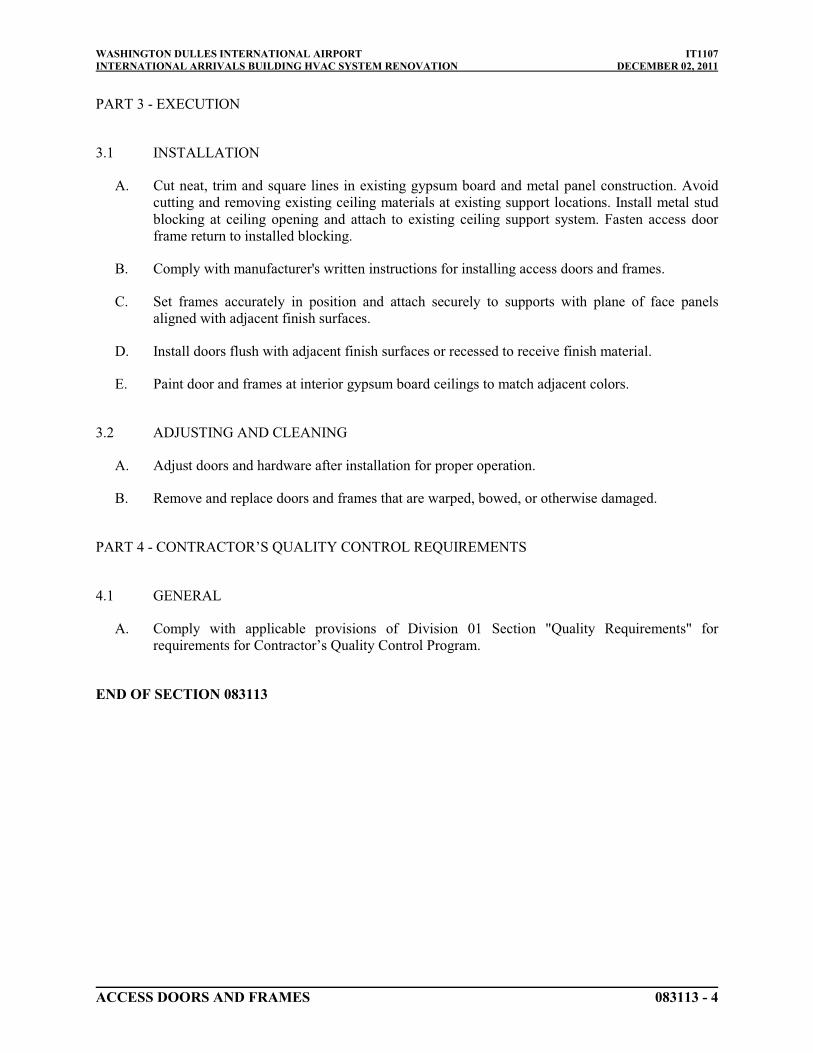
WASHINGTON DULLES INTERNATIONAL AIRPORT IT1107INTERNATIONAL ARRIVALS BUILDING HVAC SYSTEM RENOVATION DECEMBER 02, 2011
ACCESS DOORS AND FRAMES 083113 - 4
PART 3 - EXECUTION
3.1 INSTALLATION
A. Cut neat, trim and square lines in existing gypsum board and metal panel construction. Avoid cutting and removing existing ceiling materials at existing support locations. Install metal stud blocking at ceiling opening and attach to existing ceiling support system. Fasten access door frame return to installed blocking.
B. Comply with manufacturer's written instructions for installing access doors and frames.
C. Set frames accurately in position and attach securely to supports with plane of face panels aligned with adjacent finish surfaces.
D. Install doors flush with adjacent finish surfaces or recessed to receive finish material.
E. Paint door and frames at interior gypsum board ceilings to match adjacent colors.
3.2 ADJUSTING AND CLEANING
A. Adjust doors and hardware after installation for proper operation.
B. Remove and replace doors and frames that are warped, bowed, or otherwise damaged.
PART 4 - CONTRACTOR’S QUALITY CONTROL REQUIREMENTS
4.1 GENERAL
A. Comply with applicable provisions of Division 01 Section "Quality Requirements" for requirements for Contractor’s Quality Control Program.
END OF SECTION 083113

WASHINGTON DULLES INTERNATIONAL AIRPORT IT1107INTERNATIONAL ARRIVALS BUILDING HVAC SYSTEM RENOVATION DECEMBER 02, 2011
BOXED CORNER LOUVER PENTHOUSES 089000 - 1
SECTION 089000 – BOXED CORNER LOUVER PENTHOUSES
PART 1 - GENERAL
1.1 RELATED DOCUMENTS
A. Drawings, Contract Provisions, Special Provisions, Supplementary Conditions, and Division 01Specification Sections apply to this Section.
1.2 SUMMARY
A. Section Includes:
1. Exterior, fixed, extruded-aluminum louvers in aluminum box frame with customaluminum roof enclosure.
B. Related Sections:
1. Division 05 Section "Metal Fabrications" for steel framing and supports for louvers.2. Division 07 Section “Joint Sealants”.3. Division 23 Sections for louvers that are a part of mechanical equipment.
1.3 DEFINITIONS
A. Louver Terminology: Definitions of terms for metal louvers contained in AMCA 501 apply to this Section unless otherwise defined in this Section or in referenced standards.
B. Drainable-Blade Louver: Louver with blades having gutters that collect water and drain it to channels in jambs and mullions, which carry it to bottom of unit and away from opening.
1.4 PERFORMANCE REQUIREMENTS
A. Delegated Design: Design louvers, box frame, roof enclosure, roof supports andfastening/anchoring system including comprehensive engineering analysis by a qualified professional engineer, using structural performance requirements and design criteria indicated.
B. Structural Performance: Louvers shall withstand the effects of gravity loads, uplift loads and the following loads and stresses within limits and under conditions indicated without permanent deformation of louver components, noise or metal fatigue caused by louver blade rattle or flutter, permanent damage to fasteners and anchors or failure of the fastener and anchors to secure the louver to the substrate. Wind pressures shall be considered to act normal to the face of the building.
1. Wind Loads
a. Basic Wind Speed (3 second gust): 100MPHb. Wind Load Importance Factor: 1.15
WASHINGTON DULLES INTERNATIONAL AIRPORT IT1107INTERNATIONAL ARRIVALS BUILDING HVAC SYSTEM RENOVATION DECEMBER 02, 2011
BOXED CORNER LOUVER PENTHOUSES 089000 - 2
c. Wind Exposure Category: Cd. Building Occupancy Category: IIIe. Internal Pressure Coefficient: +/- 0.18f. FM Windstorm Resistance Rating: Class I-90g. Components and Cladding Pressure: Per IBC Table 1609.6.2 (2)h. Snow Load: 30psf
C. Windborne-Debris-Impact Resistance: Louvers located within 30 feet (9.1m) of grade shall pass enhanced-protection, large-missile testing requirements in ASTM E 1996 for Wind Zone 2 when tested according to ASTM E 1886. Test specimens shall be no smaller in width and length than louvers indicated for use on project.
D. Thermal Movements: Allow for thermal movements from ambient and surface temperature changes, without buckling, opening of joints, overstressing of components, failure of connections, or other detrimental effects.
1. Temperature Change (Range): 120 deg F, ambient; 180 deg F, material surfaces.
E. Louver Performance Ratings: Provide louvers complying with requirements specified, as demonstrated by testing manufacturer's stock units identical to those provided, except for length and width according to AMCA 500-L.
1.5 SUBMITTALS
A. Product Data: For each type of product indicated.
1. For louvers specified to bear AMCA seal, include printed catalog pages showing specified models with appropriate AMCA Certified Ratings Seals.
B. Shop Drawings: For boxed corner louver penthouse, louvers and accessories. Include plans, elevations, sections, details, and attachments to other work. Show frame profiles and blade profiles, angles, and spacing.
1. Show weep paths, gaskets, flashing, sealant, and other means of preventing water intrusion.
2. Show mullion profiles and locations.3. Design and indicate anchors required to fasten the louver assembly to the substrate.
Anchors shall be designed to meet the requirements identified in “Performance Requirements”.
C. Samples for Verification: For each type of metal finish required.
D. Warranty: Special warranty specified in this Section.
E. Delegated-Design Submittal: For louvers, box frame, roof enclosure, roof supports and fastening/anchoring system indicated to comply with structural performance requirements, including analysis data signed and sealed by the qualified professional engineer responsible for their preparation.
WASHINGTON DULLES INTERNATIONAL AIRPORT IT1107INTERNATIONAL ARRIVALS BUILDING HVAC SYSTEM RENOVATION DECEMBER 02, 2011
BOXED CORNER LOUVER PENTHOUSES 089000 - 3
1.6 QUALITY ASSURANCE
A. Source Limitations: Obtain penthouse and louvers from single source from a single manufacturer where indicated to be of same type, design, or factory-applied color finish.
B. SMACNA Standard: Comply with recommendations in SMACNA's "Architectural Sheet Metal Manual" for fabrication, construction details, and installation procedures.
1.7 PROJECT CONDITIONS
A. Field Measurements: Verify actual dimensions of openings by field measurements before fabrication.
1.8 WARRANTY
A. Special Finish Warranty for Fluoropolymer Finish: Manufacturer's standard form in which manufacturer agrees to repair or replace components on which finishes do not comply with requirements or that fail in materials or workmanship within specified warranty period. Warranty does not include normal weathering.
1. Warranty Period: 20 years from date of Substantial Completion.
PART 2 - PRODUCTS
2.1 MATERIALS
A. Aluminum Extrusions: ASTM B 221, Alloy 6063-T5, T-52, or T6.
B. Aluminum Sheet: ASTM B 209, Alloy 3003 or 5005 with temper as required for forming, or as otherwise recommended by metal producer for required finish.
C. Fasteners: Use types and sizes to suit unit installation conditions.
1. Use tamper resistant screws for exposed fasteners unless otherwise indicated. Exposed fasteners on exterior face (public side) of louvers will not be accepted.
2. Use fasteners with heads that match color of louvers.
D. Post-installed Fasteners for Concrete and Masonry: Torque-controlled expansion anchors, made from stainless-steel components, with capability to sustain, without failure, a load equal to 4 times the loads imposed, for concrete, or 6 times the load imposed, for masonry, as determined by testing per ASTM E 488, conducted by a qualified independent testing agency.
E. Bituminous Paint: Cold-applied asphalt emulsion complying with ASTM D 1187.
WASHINGTON DULLES INTERNATIONAL AIRPORT IT1107INTERNATIONAL ARRIVALS BUILDING HVAC SYSTEM RENOVATION DECEMBER 02, 2011
BOXED CORNER LOUVER PENTHOUSES 089000 - 4
2.2 FABRICATION, GENERAL
A. Assemble louvers in factory to minimize field splicing and assembly. Disassemble units as necessary for shipping and handling limitations. Clearly mark units for reassembly and coordinated installation.
B. Maintain equal louver blade spacing to produce uniform appearance.
C. Fabricate louver frames and penthouse box cornerss, including integral sills, to fit at openings of sizes indicated, with allowances made for fabrication and installation tolerances, adjoining material tolerances, and perimeter sealant joints.
1. Louver Frame Type: Channel unless otherwise indicated.2. Boxed Corners: Continuous seamless formed aluminum components.
D. Include supports, anchorages, and accessories required for complete assembly.
E. Provide continuous louver blade assemblies with no intermediate vertical mullions.
F. Provide subsills made of same material as louvers, and extended sills for recessed louvers, as indicated on Drawings.
G. Join frame members to each other and to fixed louver blades with fillet welds.
2.3 FIXED, EXTRUDED-ALUMINUM LOUVERS IN BOXED CORNER PENTHOUSE WITH CUSTOM ROOF
A. Products:
1. Basis-of-Design Product: Design for boxed corner louver penthouse is based on:
a. Model PHB with Model ELF6350DMP louvers by Ruskin Company; Tomkins PLC as modified to include a custom seamless roof enclosure as detailed on the Drawings.
2. Subject to compliance with requirements. Provide the Basis-of-Design Product or a comparable product with custom enclosure by one of the following:
a. Industrial Louvers, Inc.b. Reliable Architectural Louvers & Grilles.
3. Louver Depth: 6 inches.4. Frame and Blade Nominal Thickness: As required to comply with structural performance
requirements, but not less than 0.080 inch for blades and 0.125 inch for frames.5. Penthouse Box Corner Frames: Nominal Thickness: As required to comply with its
structural performance requirements, but not less than 0.125 inch.6. Mullion Type: Exposed but, concealed by penthouse box extrusion.7. Louver Performance Ratings:
a. 62% Free Area.

WASHINGTON DULLES INTERNATIONAL AIRPORT IT1107INTERNATIONAL ARRIVALS BUILDING HVAC SYSTEM RENOVATION DECEMBER 02, 2011
BOXED CORNER LOUVER PENTHOUSES 089000 - 5
b. Point of Beginning Water Penetration: Not less than 1,250 fpm.c. Air Performance: Not more than 0.15-inch wg static pressure drop at 900-fpm
free-area exhaust velocity and intake velocity.
8. AMCA Seal: Mark units with AMCA Certified Ratings Seal.
2.4 LOUVER SCREENS
A. General: Provide screen at each exterior louver.
1. Screen Location: Interior face.2. Screening Type: Bird screening.
B. Secure screen frames to louver frames with stainless-steel machine screws, spaced a maximum of 6 inches from each corner and at 12 inches o.c.
C. Louver Screen Frames: Fabricate with mitered corners to louver sizes indicated.
1. Metal: Reinforce extruded-aluminum screen frames at corners with clips.2. Finish: Same finish as louver frames to which louver screens are attached.3. Type: Removable and rewireable.
D. Louver Screening: Bird screen; aluminum, 1/2-inch- square mesh, 0.063-inch wire.
2.5 CUSTOM ALUMINUM ROOF
A. Fabricate roof panel from single continuous aluminum sheet with corners cut, welded, folded and formed as indicated on the drawings.
1. Thickness: 0.125in2. Finish: Fluoropolymer finish matching louvers.
B. Provide aluminum rafters and supports as required to meet structural performance requirements.
C. Provide roof assembly without water baffles or other added components.
2.6 ALUMINUM FINISHES
A. General:
1. Comply with NAAMM's "Metal Finishes Manual for Architectural and Metal Products" for recommendations for applying and designating finishes.
2. Finish louvers after assembly.
B. High-Performance Organic Finish: 2-coat fluoropolymer finish complying with AAMA 2605 and containing not less than 70 percent PVDF resin by weight in color coat. Prepare, pretreat, and apply coating to exposed metal surfaces to comply with coating and resin manufacturers' written instructions.

WASHINGTON DULLES INTERNATIONAL AIRPORT IT1107INTERNATIONAL ARRIVALS BUILDING HVAC SYSTEM RENOVATION DECEMBER 02, 2011
BOXED CORNER LOUVER PENTHOUSES 089000 - 6
1. Color and Gloss:
a. Custom color, K-48 (warm dark gray), in accordance with MWAA Design Manualstandards; matte.
PART 3 - EXECUTION
3.1 EXAMINATION
A. Examine substrates and openings, with Installer present, for compliance with requirements for installation tolerances and other conditions affecting performance.
B. Proceed with installation only after unsatisfactory conditions have been corrected.
3.2 PREPARATION
A. Coordinate setting drawings, diagrams, templates, instructions, and directions for installation of anchorages that are to be embedded in concrete or masonry construction. Coordinate delivery of such items to Project site.
3.3 INSTALLATION
A. Locate and place louvers level, plumb, and at indicated alignment with adjacent work.
B. Use concealed anchorages where possible. Provide brass or lead washers fitted to screws where required to protect metal surfaces and to make a weather tight connection.
C. Form closely fitted joints with exposed connections accurately located and secured.
D. Provide perimeter reveals and openings of uniform width for sealants and joint fillers, as indicated.
E. Repair finishes damaged by cutting, welding, soldering, and grinding. Restore finishes so no evidence remains of corrective work. Return items that cannot be refinished in the field to the factory, make required alterations, and refinish entire unit or provide new units.
F. Protect unpainted metal surfaces that will be in contact with concrete, masonry, or dissimilar metals from corrosion and galvanic action by applying a heavy coating of bituminous paint or by separating surfaces with waterproof gaskets or nonmetallic flashing.
G. Install concealed gaskets, flashings, joint fillers, and insulation as louver installation progresses, where weather tight louver joints are required. Comply with Division 07 Section "Joint Sealants" for sealants applied during louver installation.
WASHINGTON DULLES INTERNATIONAL AIRPORT IT1107INTERNATIONAL ARRIVALS BUILDING HVAC SYSTEM RENOVATION DECEMBER 02, 2011
BOXED CORNER LOUVER PENTHOUSES 089000 - 7
3.4 ADJUSTING AND CLEANING
A. Clean exposed surfaces of louvers that are not protected by temporary covering, to remove fingerprints and soil during construction period. Do not let soil accumulate during construction period.
B. Before final inspection, clean exposed surfaces with water and a mild soap or detergent not harmful to finishes. Thoroughly rinse surfaces and dry.
C. Restore louvers damaged during installation and construction so no evidence remains of corrective work. If results of restoration are unsuccessful, as determined by COTR, remove damaged units and replace with new units.
1. Touch up minor abrasions in finishes with air-dried coating that matches color and gloss of, and is compatible with, factory-applied finish coating.
PART 4 - CONTRACTOR’S QUALITY CONTROL REQUIREMENTS
4.1 GENERAL
A. Comply with applicable provisions of Division 01 Section "Quality Requirements" for requirements for Contractor’s Quality Control Program.
END OF SECTION 089000

WASHINGTON DULLES INTERNATIONAL AIRPORT IT1107INTERNATIONAL ARRIVALS BUILDING HVAC SYSTEM RENOVATION DECEMBER 02, 2011
NON-STRUCTURAL METAL FRAMING 092216 - 1
SECTION 092216 - NON-STRUCTURAL METAL FRAMING
PART 1 - GENERAL
1.1 RELATED DOCUMENTS
A. Drawings, Contract Provisions, Special Provisions, Supplementary Conditions, and Division 01Specification Sections apply to this Section.
1.2 SUMMARY
A. This Section includes non-load-bearing steel framing members for the following applications:
1. Interior framing systems (e.g., supports for partition walls, framed soffits, furring, etc.).2. Interior suspension systems (e.g., supports for ceilings, suspended soffits, etc.).
B. Related Sections include the following:
1. Division 05 Section "Cold-Formed Metal Framing" for exterior non-load-bearing wall framing.
2. Division 07 Section "Fire-Resistive Joint Systems" for head-of-wall joint systems installed with non-load-bearing steel framing.
3. Division 09 Section "Gypsum Board Shaft Wall Assemblies" for non-load-bearing metal shaft-wall framing, gypsum panels, and other components of shaft-wall assemblies.
4. Division 09 Section “Gypsum Board” for gypsum board panel applications.
1.3 SUBMITTALS
A. Product Data: For each type of product indicated.
1.4 QUALITY ASSURANCE
A. Fire-Test-Response Characteristics: For fire-resistance-rated assemblies that incorporate non-load-bearing steel framing, provide materials and construction identical to those tested in assembly indicated according to ASTM E 119 by an independent testing agency.
B. Preinstallation Conference: Conduct conference at Project site.
PART 2 - PRODUCTS
2.1 NON-LOAD-BEARING STEEL FRAMING, GENERAL
A. Framing Members, General: Comply with ASTM C 754 for conditions indicated.

WASHINGTON DULLES INTERNATIONAL AIRPORT IT1107INTERNATIONAL ARRIVALS BUILDING HVAC SYSTEM RENOVATION DECEMBER 02, 2011
NON-STRUCTURAL METAL FRAMING 092216 - 2
1. Steel Sheet Components: Comply with ASTM C 645 requirements for metal, except comply with ASTM A 1003/A 1003M where so indicated.
2. Protective Coating: ASTM A 653/A 653M, G40, hot-dip galvanized, unless otherwise indicated.
2.2 SUSPENSION SYSTEM COMPONENTS
A. Tie Wire: ASTM A 641/A 641M, Class 1 zinc coating, soft temper, 0.0625-inch- diameter wire, or double strand of 0.0475-inch- diameter wire.
B. Hanger Attachments to Concrete:
1. Anchors: Fabricated from corrosion-resistant materials with holes or loops for attaching wire hangers and capable of sustaining, without failure, a load equal to 5 times that imposed by construction as determined by testing according to ASTM E 488 by an independent testing agency.
a. Type: Postinstalled, expansion anchor.
2. Powder-Actuated Fasteners: Suitable for application indicated, fabricated from corrosion-resistant materials with clips or other devices for attaching hangers of type indicated, and capable of sustaining, without failure, a load equal to 10 times that imposed by construction as determined by testing according to ASTM E 1190 by an independent testing agency.
a. Obtain written approval from COTR before bringing cartridge style nail guns and other tools that use a cartridge or any explosive charge, on Project.
C. Flat Hangers: Steel sheet, 1 by 3/16 inch by length indicated.
D. Carrying Channels: Cold-rolled, commercial-steel sheet with a base-metal thickness of 0.0538 inch and minimum 1/2-inch- wide flanges.
1. Depth: 2-1/2 inches.
E. Furring Channels (Furring Members):
1. Hat-Shaped, Rigid Furring Channels: ASTM C 645, 7/8 inch deep.
a. Minimum Base Metal Thickness: 0.312 inch.
F. Grid Suspension System for Gypsum Board Ceilings: ASTM C 645, direct-hung system composed of main beams and cross-furring members that interlock.
1. Available Products: Subject to compliance with requirements, products that may be incorporated into the Work include, but are not limited to, the following:
a. Armstrong World Industries, Inc.; Drywall Grid Systems.b. Chicago Metallic Corporation; 660-C Drywall Furring System.c. USG Corporation; Drywall Suspension System.
WASHINGTON DULLES INTERNATIONAL AIRPORT IT1107INTERNATIONAL ARRIVALS BUILDING HVAC SYSTEM RENOVATION DECEMBER 02, 2011
NON-STRUCTURAL METAL FRAMING 092216 - 3
2.3 STEEL FRAMING FOR FRAMED ASSEMBLIES
A. Steel Studs and Runners:
1. ASTM A 1003/A 1003M, Structural Grade, Type H, metallic coated, of grade and coating weight as follows:
a. Grade: As required by structural performance.b. Coating: G60, A60, AZ50, or GF30.c. Minimum Base-Metal Thickness: 0.0428 inch.d. Depth: As indicated on Drawings.e. Locations: Framing around columns in Primary Inspection Hall, Baggage Claim,
Central Cart Staging, and Exit Circulation.
2. ASTM C 645:
a. Minimum Base-Metal Thickness: 0.0312 inch.b. Depth: As indicated on Drawings.c. Locations: Other than indicated to be framed with ASTM A 1003/A 1003M
framing as specified above.
B. Slip-Type Head Joints: Where indicated, provide the following:
1. Single Long-Leg Runner System: ASTM C 645 top runner with 2-inch- deep flanges in thickness not less than indicated for studs, installed with studs friction fit into top runner and with continuous bridging located within 12 inches of the top of studs to provide lateral bracing.
C. Flat Strap and Backing Plate: Steel sheet for blocking and bracing in length and width indicated.
1. Minimum Base-Metal Thickness: 0.0598 inch.
D. Hat-Shaped, Rigid Furring Channels: ASTM C 645.
1. Minimum Base Metal Thickness: 0.0312 inch.2. Depth: 7/8 inch.
2.4 AUXILIARY MATERIALS
A. General: Provide auxiliary materials that comply with referenced installation standards.
1. Fasteners for Metal Framing: Of type, material, size, corrosion resistance, holding power, and other properties required to fasten steel members to substrates.
B. Isolation Strip at Exterior Walls: Provide one of the following:
1. Asphalt-Saturated Organic Felt: ASTM D 226, Type I (No. 15 asphalt felt), nonperforated.

WASHINGTON DULLES INTERNATIONAL AIRPORT IT1107INTERNATIONAL ARRIVALS BUILDING HVAC SYSTEM RENOVATION DECEMBER 02, 2011
NON-STRUCTURAL METAL FRAMING 092216 - 4
2. Foam Gasket: Adhesive-backed, closed-cell vinyl foam strips that allow fastener penetration without foam displacement, 1/8 inch thick, in width to suit steel stud size.
PART 3 - EXECUTION
3.1 EXAMINATION
A. Examine areas and substrates, with Installer present, and including welded hollow-metal frames, cast-in anchors, and structural framing, for compliance with requirements and other conditions affecting performance.
1. Proceed with installation only after unsatisfactory conditions have been corrected.
3.2 INSTALLATION, GENERAL
A. Installation Standard: ASTM C 754, except comply with framing sizes and spacing indicated.
1. Also comply with requirements in ASTM C 840 that apply to framing installation.
B. Backing Plates and Blocking:
1. Provide backing plates, supplementary framing, and blocking, accurately positioned and firmly secured to metal studs, to support handrails, guardrails, fixtures, equipment, services, casework, lockers, gun lockers, heavy trim, grab bars, toilet accessories, furnishings, and similar work requiring attachment to framing, whether or not such backing plates supplementary framing, or blocking are indicated on Drawings.
2. Do not use wood blocking in fire-rated construction. 3. Coordinate with Division 06 Section “Miscellaneous Rough Carpentry” for wood
blocking installation.
C. At penetrations in fire-rated assemblies, provide supplementary steel framing around perimeter of penetrations and fire protection behind boxes containing wiring devices and similar items, to maintain fire-resistance rating of entire assembly.
D. Install bracing at terminations in assemblies.
E. Do not bridge building control and expansion joints with non-load-bearing steel framing members. Frame both sides of joints independently.
3.3 INSTALLING SUSPENSION SYSTEMS
A. Install suspension system components in sizes and spacings indicated on Drawings, but not less than those required by referenced installation standards for assembly types and other assembly components indicated.
B. Isolate suspension systems from building structure where they abut or are penetrated by building structure to prevent transfer of loading imposed by structural movement.

WASHINGTON DULLES INTERNATIONAL AIRPORT IT1107INTERNATIONAL ARRIVALS BUILDING HVAC SYSTEM RENOVATION DECEMBER 02, 2011
NON-STRUCTURAL METAL FRAMING 092216 - 5
C. Suspend hangers from building structure as follows:
1. Install hangers plumb and free from contact with insulation or other objects within ceiling plenum that are not part of supporting structural or suspension system.
a. Splay hangers only where required to miss obstructions and offset resulting horizontal forces by bracing, countersplaying, or other equally effective means.
2. Where width of ducts and other construction within ceiling plenum produces hanger spacings that interfere with locations of hangers required to support standard suspension system members, install supplemental suspension members and hangers in the form of trapezes or equivalent devices.
a. Size supplemental suspension members and hangers to support ceiling loads within performance limits established by referenced installation standards.
3. Flat Hangers: Secure to structure, including intermediate framing members, by attaching to inserts, eye screws, or other devices and fasteners that are secure and appropriate for structure and hanger, and in a manner that will not cause hangers to deteriorate or otherwise fail.
4. Do not attach hangers to steel roof deck without concrete fill.5. Do not attach hangers to permanent metal forms. Furnish cast-in-place hanger inserts
that extend through forms.6. Do not attach hangers to rolled-in hanger tabs of composite steel floor deck.7. Do not connect or suspend steel framing from ducts, pipes, or conduit.
D. Grid Suspension Systems: Attach perimeter wall track or angle where grid suspension systems meet vertical surfaces. Mechanically join main beam and cross-furring members to each other and butt-cut to fit into wall track.
E. Installation Tolerances: Install suspension systems that are level to within 1/8 inch in 12 feetmeasured lengthwise on each member that will receive finishes and transversely between parallel members that will receive finishes.
3.4 INSTALLING FRAMED ASSEMBLIES
A. Where studs are installed directly against exterior masonry walls or dissimilar metals at exterior walls, install isolation strip between studs and exterior wall.
B. Install studs so flanges within framing system point in same direction.
1. Space studs 16 inches o.c., unless closer spacing is indicated on Drawings.
C. Install tracks (runners) at floors and overhead supports. Extend framing full height to structural supports or substrates above suspended ceilings, except where partitions are indicated to terminate at suspended ceilings. Continue framing around ducts penetrating partitions above ceiling.

WASHINGTON DULLES INTERNATIONAL AIRPORT IT1107INTERNATIONAL ARRIVALS BUILDING HVAC SYSTEM RENOVATION DECEMBER 02, 2011
NON-STRUCTURAL METAL FRAMING 092216 - 6
1. Slip-Type Head Joints: Where framing extends to overhead structural supports, install to produce joints at tops of framing systems that prevent axial loading of finished assemblies.
2. Door Openings: Screw vertical studs at jambs to jamb anchor clips on door frames; install runner track section (for cripple studs) at head and secure to jamb studs.
a. Install two studs at each jamb, unless otherwise indicated.b. Where control joints are indicated at heads of doors, install cripple studs at head
adjacent to each jamb stud, with a minimum 1/2-inch clearance from jamb stud to allow for installation of control joint in finished assembly.
c. Extend jamb studs through suspended ceilings and attach to underside of overhead structure.
3. Other Framed Openings: Frame openings other than door openings the same as required for door openings, unless otherwise indicated. Install framing below sills of openings to match framing required above door heads.
4. Fire-Resistance-Rated Partitions: Install framing to comply with fire-resistance-rated assembly indicated and support closures and to make partitions continuous from floor to underside of solid structure.
5. Sound-Rated Partitions: Install framing to comply with sound-rated assembly indicated.
D. Direct Furring: Attach to concrete or masonry with screws designed for masonry attachment, or powder-driven fasteners spaced 24 inches o.c.
E. Installation Tolerance: Install each framing member so fastening surfaces vary not more than 1/8 inch from the plane formed by faces of adjacent framing.
PART 4 - CONTRACTOR’S QUALITY CONTROL REQUIREMENTS
4.1 GENERAL
A. Comply with applicable provisions of Division 01 Section "Quality Requirements" for requirements for Contractor’s Quality Control Program.
END OF SECTION 092216
WASHINGTON DULLES INTERNATIONAL AIRPORT IT1107INTERNATIONAL ARRIVALS BUILDING HVAC SYSTEM RENOVATION DECEMBER 02, 2011
GYPSUM BOARD 092900 - 1
SECTION 092900 - GYPSUM BOARD
PART 1 - GENERAL
1.1 RELATED DOCUMENTS
A. Drawings, Contract Provisions, Special Provisions, Supplementary Conditions, and Division 01Specification Sections apply to this Section.
1.2 SUMMARY
A. This Section includes the following:
1. Removal of existing gypsum board ceiling, soffit and wall assemblies to accommodate mechanical equipment replacement, and as indicated on the Drawings.
2. Installation of new gypsum board assemblies where existing assemblies were removed to accommodate equipment replacement, and where indicated on the Drawings.
B. Related Sections include the following:
1. Division 08 Section “Access Panels”.2. Division 09 Section “Non-Structural Metal Framing”.3. Division 09 Section "Interior Painting" for primers applied to gypsum board surfaces.
1.3 SUBMITTALS
A. Product Data: For each type of product indicated.
B. Samples: N/A
1.4 QUALITY ASSURANCE
A. Fire-Resistance-Rated Assemblies: N/A
1.5 STORAGE AND HANDLING
A. Store materials inside under cover and keep them dry and protected against damage from weather, condensation, direct sunlight, construction traffic, and other causes. Stack panels flat to prevent sagging.
1.6 PROJECT CONDITIONS
A. Environmental Limitations: Comply with ASTM C 840 requirements or gypsum board manufacturer's written recommendations, whichever are more stringent.
B. Do not install interior products until installation areas are enclosed and conditioned.

WASHINGTON DULLES INTERNATIONAL AIRPORT IT1107INTERNATIONAL ARRIVALS BUILDING HVAC SYSTEM RENOVATION DECEMBER 02, 2011
GYPSUM BOARD 092900 - 2
C. Do not install panels that are wet, those that are moisture damaged, and those that are mold damaged.
1. Indications that panels are wet or moisture damaged include, but are not limited to, discoloration, sagging, or irregular shape.
2. Indications that panels are mold damaged include, but are not limited to, fuzzy or splotchy surface contamination and discoloration.
PART 2 - PRODUCTS
2.1 INTERIOR GYPSUM BOARD
A. General: Complying with ASTM C 36/C 36M or ASTM C 1396/C 1396M, as applicable to type of gypsum board indicated and whichever is more stringent.
1. Moisture- and Mold-Resistant Type “X” gypsum board panel pieces, thickness to match existing panel thickness.
a. Design for moisture-and mold-resistant gypsum board is based on Sheetrock Brand Humitek Gypsum Panels by USG.
2. Available Manufacturers: Subject to compliance with requirements. Provide Basis-of-Design product or a comparable product by one of the manufacturers below:
a. American Gypsum Co.b. BPB America Inc.c. G-P Gypsum.d. Lafarge North America Inc.e. National Gypsum Company.f. PABCO Gypsum.g. Temple.h. USG Corporation.
2.2 TILE BACKING PANELS
1. Cementitious Backer Units: N/A
2.3 TRIM ACCESSORIES
A. Interior Trim: ASTM C 1047.
1. Location: Provide trim if required to be replaced at areas of removed gypsum board systems.
2. Material: Galvanized or aluminum-coated steel sheet or rolled zinc.3. Shapes:
a. Cornerbead.b. LC-Bead: J-shaped; exposed long flange receives joint compound.c. Expansion (control) joint.
B. Aluminum Trim: N/A

WASHINGTON DULLES INTERNATIONAL AIRPORT IT1107INTERNATIONAL ARRIVALS BUILDING HVAC SYSTEM RENOVATION DECEMBER 02, 2011
GYPSUM BOARD 092900 - 3
2.4 JOINT TREATMENT MATERIALS
A. General: Comply with ASTM C 475/C 475M.
B. Joint Tape:
1. Interior Gypsum Wallboard: Paper.
C. Joint Compound for Interior Gypsum Wallboard: For each coat use formulation that is compatible with other compounds applied on previous or for successive coats.
1. Prefilling: At damaged surface areas, use setting-type taping compound.2. Embedding and First Coat: For embedding tape and first coat on joints, fasteners, and
trim flanges, use setting-type taping or drying-type, all-purpose compound.3. Fill Coat: For second coat, use setting-type, sandable topping or drying-type, all-purpose
compound.4. Finish Coat: For third coat, use setting-type, sandable topping or drying-type, all-purpose
compound.5. Skim Coat: For final coat of Level 5 finish, use drying-type, all-purpose compound.
D. Joint Compound for Tile Backing Panels: N/A
2.5 AUXILIARY MATERIALS
A. General: Provide auxiliary materials that comply with referenced installation standards and manufacturer's written recommendations.
B. Laminating Adhesive: N/A
C. Steel Drill Screws: ASTM C 1002, unless otherwise indicated.
1. Use screws complying with ASTM C 954 for fastening panels to steel members from 0.033 to 0.112 inch thick.
2. For fastening cementitious backer units, use screws of type and size recommended by panel manufacturer.
D. Sound Attenuation Blankets: N/A
E. Acoustical Sealant: N/A
F. Thermal Insulation: N/A
PART 3 - EXECUTION
3.1 EXAMINATION
A. Examine areas and substrates, with Installer present for compliance with requirements and other conditions affecting performance.

WASHINGTON DULLES INTERNATIONAL AIRPORT IT1107INTERNATIONAL ARRIVALS BUILDING HVAC SYSTEM RENOVATION DECEMBER 02, 2011
GYPSUM BOARD 092900 - 4
B. Examine gypsum board components before installation. Reject replacement panel pieces that are wet, moisture damaged, and mold damaged.
C. Proceed with installation only after unsatisfactory conditions have been corrected.
3.2 REMOVING AND APPLYING PANELS, GENERAL
A. Cut existing gypsum board in neat and straight lines to extent required to facilitate HVAC equipment replacement work.
1. Remove ceiling system supports as required.2. Remove existing access panels.
B. Gypsum Board assembly installation: Comply with ASTM C 840.
1. Install panel suspension system per Division 09 “Non-Structural Metal Framing”.2. Install panels with face side out. 3. Locate edge and end joints over suspension substrate components.
3.3 APPLYING INTERIOR GYPSUM BOARD
A. Install interior gypsum board panels in the following locations:
1. Type X: All surfaces, unless otherwise indicated.2. Thickness: Match existing adjacent gypsum board thickness unless otherwise noted.
B. Single-Layer Application:
1. Fastening Methods: Apply gypsum panels to supports with steel drill screws.
C. Multilayer Application: N/A
D. Laminating to Substrate: N/A
3.4 INSTALLING TRIM ACCESSORIES
A. General: For trim with back flanges intended for fasteners, attach to framing with same fasteners used for panels. Otherwise, attach trim according to manufacturer's written instructions.
B. Control Joints: Restore control joint if damaged at removal locations.
C. Interior Trim: Install in the following locations:
1. Cornerbead: Use at outside corners.2. LC-Bead: N/A
D. Aluminum Trim: N/A

WASHINGTON DULLES INTERNATIONAL AIRPORT IT1107INTERNATIONAL ARRIVALS BUILDING HVAC SYSTEM RENOVATION DECEMBER 02, 2011
GYPSUM BOARD 092900 - 5
3.5 FINISHING GYPSUM BOARD
A. General: Treat gypsum board joints, interior angles, edge trim, control joints, penetrations, fastener heads, surface defects, and elsewhere as required to prepare gypsum board surfaces for decoration. Promptly remove residual joint compound from adjacent surfaces.
B. Prefill open joints and damaged surface areas.
C. Apply joint tape over gypsum board joints, except those with trim having flanges not intended for tape.
D. Gypsum Board Finish Levels: Finish panels to levels indicated below and according to ASTM C 840:
1. Level 1: Ceiling plenum areas, concealed areas, and where indicated.2. Level 2: Panels that are substrate for tile.3. Level 4: At panel surfaces that will be exposed to view, unless otherwise indicated.
a. Primer and its application to surfaces are specified in Division 09 Section "Interior Painting."
4. Level 5: N/A
E. Cementitious Backer Units: N/A
3.6 PROTECTION
A. Protect installed products from damage from weather, condensation, direct sunlight, construction, and other causes during remainder of the construction period.
B. Remove and replace panels that are wet, moisture damaged, and mold damaged.
1. Indications that panels are wet or moisture damaged include, but are not limited to, discoloration, sagging, or irregular shape.
2. Indications that panels are mold damaged include, but are not limited to, fuzzy or splotchy surface contamination and discoloration.
PART 4 - CONTRACTOR’S QUALITY CONTROL REQUIREMENTS
4.1 GENERAL
A. Comply with applicable provisions of Division 01 Section "Quality Requirements" for requirements for Contractor’s Quality Control Program.
END OF SECTION 092900

WASHINGTON DULLES INTERNATIONAL AIRPORT IT1107INTERNATIONAL ARRIVALS BUILDING HVAC SYSTEM RENOVATION DECEMBER 02, 2011
ACOUSTICAL CEILING TILES 095113 - 1
SECTION 095113 - ACOUSTICAL CEILING TILE
PART 1 - GENERAL
1.1 RELATED DOCUMENTS
A. Drawings, Contract Provisions, Special Provisions, Supplementary Conditions, and Division 01Specification Sections apply to this Section.
1.2 SUMMARY
A. This Section includes acoustical tiles and suspension system components for ceilings scheduled for removal to accommodate replacement of mechanical equipment and other required work.
1. Contractor shall provide new acoustical tiles as indicated on the Drawings.
2. Contractor shall provide new suspension systems components in a quantity equal to 20 percent of the total linear footage of the existing suspension system components, for each different type of existing suspension system, to replace pre-existing defective or damaged suspension system components.
1.3 DEFINITIONS
A. CAC: Ceiling Attenuation Class.
B. LR: Light Reflectance coefficient.
C. NRC: Noise Reduction Coefficient.
1.4 SUBMITTALS
A. Product Data: For each type of product indicated.
B. Samples for Verification: For each component indicated and for each exposed finish required, prepared on Samples of size indicated below.
1. Acoustical Tile: Set of Samples of each type, color, pattern, and texture.
a. Types ACT -1, ACT-2, ACT-3, ACT-4 and ACT- 5: Full-size tiles.
2. Exposed Suspension System Members, Moldings, and Trim: Set of 12-inch- long Samples of each type, finish, and color.

WASHINGTON DULLES INTERNATIONAL AIRPORT IT1107INTERNATIONAL ARRIVALS BUILDING HVAC SYSTEM RENOVATION DECEMBER 02, 2011
ACOUSTICAL CEILING TILES 095113 - 2
1.5 QUALITY ASSURANCE
A. Source Limitations:
1. Obtain each type of acoustical ceiling tile from manufacturer indicated.
2. Obtain each type of supporting suspension system, where required, from manufacturer indicated.
B. Fire-Test-Response Characteristics: Provide acoustical ceiling tiles that comply with the following requirements:
1. Surface-Burning Characteristics: Provide acoustical tiles with the following surface-burning characteristics complying with ASTM E 1264 for Class A materials as determined by testing identical products per ASTM E 84:
1.6 DELIVERY, STORAGE, AND HANDLING
A. Deliver acoustical tiles, suspension system components, and accessories to Project site in original, unopened packages and store them in a fully enclosed, conditioned space where they will be protected against damage from moisture, humidity, temperature extremes, direct sunlight, surface contamination, and other causes.
B. Before installing acoustical tiles, permit them to reach room temperature and a stabilizedmoisture content.
C. Handle acoustical tiles carefully to avoid chipping edges or damaging units in any way.
1.7 PROJECT CONDITIONS
A. Environmental Limitations: Do not install acoustical ceiling tiles until spaces are enclosed and weatherproof, wet work in spaces is complete and dry, work above ceilings is complete, and ambient temperature and humidity conditions are maintained at the levels indicated for Project when occupied for its intended use.
1.8 COORDINATION
A. Coordinate layout and installation of acoustical tiles and suspension system with other construction that penetrates ceilings or is supported by them, including light fixtures, HVAC equipment, fire-suppression system, and partition assemblies.
1.9 EXTRA MATERIALS
A. Furnish extra materials described below that match products installed and that are packaged with protective covering for storage and identified with labels describing contents.
1. Acoustical Ceiling Tiles: Full-size tiles equal for each tile type; 1 box unit of issue.
WASHINGTON DULLES INTERNATIONAL AIRPORT IT1107INTERNATIONAL ARRIVALS BUILDING HVAC SYSTEM RENOVATION DECEMBER 02, 2011
ACOUSTICAL CEILING TILES 095113 - 3
PART 2 - PRODUCTS
2.1 ACOUSTICAL TILES, GENERAL
A. Acoustical Tile Standard: Provide manufacturer's standard tiles of configuration indicated that comply with ASTM E 1264 classifications as designated by types, patterns, acoustical ratings, and light reflectances, unless otherwise indicated.
B. Acoustical Tile Colors and Patterns: Match appearance characteristics indicated for each product type.
2.2 ACOUSTICAL TILES FOR ACOUSTICAL CEILING TILES
A. Acoustical Ceiling Tile Type ACT-1:
1. Basis-of-Design Product:
a. Design for Type ACT-1 is based on “F” Fissured panels by USG Interiors, Inc.
2. Surface Texture: Medium
a. Composition:
1) Cast mineral fiber substrate with foil back (plenum) side of tile.
3. Classification: Per ASTM E1264: Type III, Form 4, Pattern D.4. Modular Size: 2’x2’x3/4”5. Edge profile: Square Lay-in; Provide profile to match existing panels and coordinate
with existing suspension grid6. Finish: factory-applied latex paint 7. Color: White.8. Light Reflectance (LR): .799. Flame spread: ASTM E84, 25.10. Noise-reduction coefficient (NRC): .7011. Ceiling Attenuation Class (CAC Range): 35 minimum.12. Broad Spectrum antimicrobial fungicide and bactericide treatment:
B. Acoustical Ceiling Tile Type ACT-2:
1. Basis-of-Design Product:
a. Design for Type ACT-2 is based on Eclipse Panels with ClimaPlus Superior Performance by USG Interiors, Inc.
2. Surface Texture: Fine 3. Composition: X-Technology mineral fiber4. Classification: Per ASTM E1264: Type III, Form 1, Pattern EI.5. Modular Size: 2’x2’x3/4”6. Edge profile: Square Lay-in; Provide profile to match existing panels and coordinate
with existing suspension grid

WASHINGTON DULLES INTERNATIONAL AIRPORT IT1107INTERNATIONAL ARRIVALS BUILDING HVAC SYSTEM RENOVATION DECEMBER 02, 2011
ACOUSTICAL CEILING TILES 095113 - 4
7. Finish: factory-applied latex paint 8. Color: White.9. Light Reflectance (LR): .8610. Flame spread: ASTM E84, 25.11. Noise-reduction coefficient (NRC): .70 12. Ceiling Attenuation Class (CAC Range): minimum 35.13. Broad Spectrum antimicrobial fungicide and bactericide treatment: “ClimaPlus” on Panel
Face and Back Surfaces.
C. Acoustical Ceiling Tile Type ACT-3:
1. Basis-of-Design Product:
a. Design for Type ACT-3 is based on Tundra by Armstrong World Industries, Inc.
2. Surface Texture: Medium3. Composition: Wet-formed high density mineral fiber4. Classification: Per ASTM E1264: Type III, Form 2, Pattern C E, Fire Class A.5. Modular Size: 6. Edge profile: Square Lay-in; Provide profile to match existing panels and coordinate
with existing suspension grid7. Finish: factory-applied latex paint with scuff-resistant spatter coat.8. Color: White.9. Light Reflectance (LR): .8710. Flame spread: ASTM E84, 25or less.11. Noise-reduction coefficient (NRC): .50 12. Ceiling Attenuation Class (CAC Range): 3313. Broad Spectrum antimicrobial fungicide and bactericide treatment: BioBlock Plus.
D. Acoustical Ceiling Tile Type ACT-4:
1. Basis-of-Design Product:
a. Design for Type ACT-4 is based on Cortega Beveled Tegular by Armstrong World Industries, Inc.
2. Surface Texture: Medium3. Composition: Wet-formed mineral fiber4. Classification: Per ASTM E1264: Type III, Form 2, Pattern C D.5. Modular Size: 2’x2’x5/8”6. Edge profile: 9/16” Beveled Tegular; Provide profile to match existing panels and
coordinate with existing suspension grid 7. Finish: Factory-applied latex paint.8. Color: White.9. Light Reflectance (LR): .8210. Flame spread: ASTM E84, 25 or less.11. Noise-reduction coefficient (NRC): .55 12. Ceiling Attenuation Class (CAC Range): 3313. Broad Spectrum antimicrobial fungicide and bactericide treatment: BioBlock Plus

WASHINGTON DULLES INTERNATIONAL AIRPORT IT1107INTERNATIONAL ARRIVALS BUILDING HVAC SYSTEM RENOVATION DECEMBER 02, 2011
ACOUSTICAL CEILING TILES 095113 - 5
E. Acoustical Ceiling Tile Type ACT-5:
1. Basis-of-Design Product:
a. Design for Type ACT-5 is based on Cirrus Square Lay-in by Armstrong World Industries, Inc.
2. Surface Texture: Fine 3. Composition: Wet-formed mineral fiber4. Classification: Per ASTM E1264: Type III, Form 1, Pattern E I, Fire Class A.5. Modular Size: 2’x2’x5/8”6. Edge profile: 9/16” Beveled Tegular; Provide profile to match existing panels and
coordinate with existing suspension grid7. Finish: Factory-applied latex paint.8. Color: White.9. Light Reflectance (LR): .8610. Flame spread: ASTM E84, 25 or less.11. Noise-reduction coefficient (NRC): .70 12. Ceiling Attenuation Class (CAC Range): 35-4013. Broad Spectrum antimicrobial fungicide and bactericide treatment: BioBlock Plus.
2.3 METAL SUSPENSION SYSTEMS, GENERAL
A. Generally, the existing suspension systems will be removed and reinstalled as indicated on the Drawings. However, the Contractor shall provide new suspension systems components in a quantity equal to 20 percent of the total linear footage of the existing suspension system components, for each different type of existing suspension system, to replace pre-existing defective or damaged suspension system components.
B. Metal Suspension System Standard: When required, provide manufacturer's standard direct-hung metal suspension systems of types, structural classifications, and finishes indicated that comply with applicable requirements in ASTM C 635.
C. Finishes and Colors, General: Comply with NAAMM's "Metal Finishes Manual for Architectural and Metal Products" for recommendations for applying and designating finishes. Provide manufacturer's standard factory-applied finish for type of system indicated.
D. Attachment Devices: Size for five times the design load indicated in ASTM C 635, Table 1, "Direct Hung," unless otherwise indicated. Comply with seismic design requirements.
1. Anchors in Concrete: Anchors of type and material indicated below, with holes or loops for attaching hangers of type indicated and with capability to sustain, without failure, a load equal to five times that imposed by ceiling construction, as determined by testing per ASTM E 488 or ASTM E 1512 as applicable, conducted by a qualified testing and inspecting agency.
a. Type: Postinstalled expansion anchors.b. Corrosion Protection: Carbon-steel components zinc plated to comply with
ASTM B 633, Class Fe/Zn 5 (0.005 mm) for Class SC 1 service condition.

WASHINGTON DULLES INTERNATIONAL AIRPORT IT1107INTERNATIONAL ARRIVALS BUILDING HVAC SYSTEM RENOVATION DECEMBER 02, 2011
ACOUSTICAL CEILING TILES 095113 - 6
2. Powder-Actuated Fasteners in Concrete: Fastener system of type suitable for application indicated, fabricated from corrosion-resistant materials, with clips or other accessory devices for attaching hangers of type indicated, and with capability to sustain, without failure, a load equal to 10 times that imposed by ceiling construction, as determined by testing per ASTM E 1190, conducted by a qualified testing and inspecting agency.
a. Obtain written approval from COTR before bringing cartridge style nail guns and other tools that use a cartridge or any explosive charge, on Project.
E. Wire Hangers, Braces, and Ties: Provide wires complying with the following requirements:
1. Zinc-Coated, Carbon-Steel Wire: ASTM A 641/A 641M, Class 1 zinc coating, soft temper.
2. Size: Select wire diameter so its stress at 3 times hanger design load (ASTM C 635, Table 1, "Direct Hung") will be less than yield stress of wire, but provide not less than 0.106-inch- diameter wire.
2.4 METAL SUSPENSION SYSTEMS FOR ACOUSTICAL CEILING TILES
A. Concealed Suspension System:
1. Ceiling tile manufacturer's steel grid suspension system, compatible with rabbeted and beveled edge acoustical ceiling tiles.
2. Main and cross runners roll formed from cold-rolled steel sheet, prepainted, electrolytically zinc coated, or hot-dip galvanized according to ASTM A 653/A 653M, not less than G30 coating designation, with prefinished 9/16-inch-wide or 15/16-inch-wide metal caps on flanges; matching existing systems
a. Structural Classification: Intermediate -duty system.b. End Condition of Cross Runners: Butt-edge type.c. Face Design: Flat, flush.d. Cap Material: Steel cold-rolled sheet.e. Cap Finish: Painted white.
2.5 METAL EDGE MOLDINGS AND TRIM
A. Available Manufacturers:
1. Provide edge moldings and trim, when required, by manufacturer of each corresponding suspension system.
2. Provide edge moldings and trim at removed gypsum board ceiling and acoustical ceiling tile system interfaces.
B. Roll-Formed, Sheet-Metal Edge Moldings and Trim: Type and profile indicated or, if not indicated, manufacturer's standard moldings for edges and penetrations that comply with seismic design requirements; formed from sheet metal of same material, finish, and color as that used for exposed flanges of suspension system runners.

WASHINGTON DULLES INTERNATIONAL AIRPORT IT1107INTERNATIONAL ARRIVALS BUILDING HVAC SYSTEM RENOVATION DECEMBER 02, 2011
ACOUSTICAL CEILING TILES 095113 - 7
1. Provide manufacturer's standard edge moldings that fit acoustical tile edge details and suspension systems indicated and that match width and configuration of exposed runners, unless otherwise indicated.
2. For circular penetrations of ceiling, provide edge moldings fabricated to diameter required to fit penetration exactly.
PART 3 - EXECUTION
3.1 EXAMINATION
A. Examine substrates, areas, and conditions, including structural framing to which acoustical ceiling tiles attach or abut, with Installer present, for compliance with requirements specified in this and other Sections that affect ceiling installation and anchorage and with requirements for installation tolerances and other conditions affecting performance of acoustical ceiling tiles.
1. Proceed with installation only after unsatisfactory conditions have been corrected.
3.2 INSTALLATION
A. General: Install acoustical ceiling tiles to comply with ASTM C 636 and seismic design requirements indicated, per manufacturer's written instructions and CISCA's "Ceiling Systems Handbook."
B. When required to add supplemental supports and hangars at areas of removed ceilings, suspend ceiling hangers from building's structural members as follows:
1. Install hangers plumb and free from contact with insulation or other objects within ceiling plenum that are not part of supporting structure or of ceiling suspension system.
2. Splay hangers only where required to miss obstructions; offset resulting horizontal forces by bracing, countersplaying, or other equally effective means.
3. Where width of ducts and other construction within ceiling plenum produces hanger spacings that interfere with location of hangers at spacings required to support standard suspension system members, install supplemental suspension members and hangers in form of trapezes or equivalent devices.
4. Secure wire hangers to ceiling suspension members and to supports above with a minimum of three tight turns. Connect hangers directly either to structures or to inserts, eye screws, or other devices that are secure and appropriate for substrate and that will not deteriorate or otherwise fail due to age, corrosion, or elevated temperatures.
5. Do not support ceilings directly from permanent metal forms or floor deck. Fasten hangers to cast-in-place hanger inserts, postinstalled mechanical or adhesive anchors, or power-actuated fasteners that extend through forms into concrete.
6. When steel framing does not permit installation of hanger wires at spacing required, install carrying channels or other supplemental support for attachment of hanger wires.
7. Do not attach hangers to steel deck tabs.8. Do not attach hangers to steel roof deck without concrete fill. Attach hangers to
structural members.

WASHINGTON DULLES INTERNATIONAL AIRPORT IT1107INTERNATIONAL ARRIVALS BUILDING HVAC SYSTEM RENOVATION DECEMBER 02, 2011
ACOUSTICAL CEILING TILES 095113 - 8
9. Space hangers not more than 48 inches o.c. along each member supported directly from hangers, unless otherwise indicated; provide hangers not more than 8 inches from ends of each member.
10. Size supplemental suspension members and hangers to support ceiling loads within performance limits established by referenced standards and publications.
C. Install edge moldings and trim of type indicated at perimeter of acoustical ceiling area and where necessary to conceal edges of acoustical tiles.
1. Screw attach moldings to substrate at intervals not more than 16 inches o.c. and not more than 3 inches from ends, leveling with ceiling suspension system to a tolerance of 1/8 inch in 12 feet. Miter corners accurately and connect securely.
2. Do not use exposed fasteners, including pop rivets, on moldings and trim.
D. Install suspension system runners so they are square and securely interlocked with one another. Remove and replace dented, bent, or kinked members.
E. Install acoustical tiles with undamaged edges and fit accurately into suspension system runnersand edge moldings. Scribe and cut tiles at borders and penetrations to provide a neat, precise fit.
1. For square-edged tiles, install tiles with edges fully hidden from view by flanges of suspension system runners and moldings.
2. For reveal-edged tiles on suspension system runners, install tiles with bottom of reveal in firm contact with top surface of runner flanges.
a. Where reveal edge tiles are cut, custom cut reveal profile on cut sides of tiles to match factory reveal edge.
3. Paint cut edges of tile remaining exposed after installation; match color of exposed tilesurfaces using coating recommended in writing for this purpose by acoustical tilemanufacturer.
3.3 CLEANING
A. Clean exposed surfaces of acoustical ceiling tiles, including trim, edge moldings, and suspension system members. Comply with manufacturer's written instructions for cleaning and touchup of minor finish damage. Remove and replace ceiling components that cannot be successfully cleaned and repaired to permanently eliminate evidence of damage.
PART 4 - CONTRACTOR’S QUALITY CONTROL REQUIREMENTS
4.1 GENERAL
A. Comply with applicable provisions of Division 01 Section "Quality Requirements" for requirements for Contractor’s Quality Control Program.
END OF SECTION 095113

WASHINGTON DULLES INTERNATIONAL AIRPORT IT1107INTERNATIONAL ARRIVALS BUILDING HVAC SYSTEM RENOVATION DECEMBER 02, 2011
INTERIOR PAINTING 099123 - 1
SECTION 099123 - INTERIOR PAINTING
PART 1 - GENERAL
1.1 RELATED DOCUMENTS
A. Drawings, Contract Provisions, Special Provisions, Supplementary Conditions, and Division 01Specification Sections apply to this Section.
1.2 SUMMARY
A. This Section includes surface preparation and the application of paint systems on the following interior substrates:
1. Concrete masonry units (CMU).2. Steel.3. Galvanized metal.4. Plywood.5. Mechanical, plumbing, fire protection and electrical Work.
B. Related Sections include the following:
1. Division 05 Sections for shop priming of metal substrates with primers specified in this Section.
1.3 SUBMITTALS
A. Product Data: For each type of product indicated.
B. Product List: For each product indicated, include the following:
1. Printout of current "MPI Approved Products List" for each product category specified in Part 2, with the proposed product highlighted.
1.4 QUALITY ASSURANCE
A. MPI Standards:
1. Preparation and Workmanship: Comply with requirements in "MPI Architectural Painting Specification Manual" and "MPI Maintenance Repainting Manual" for products and paint systems indicated.
B. Color Requirements:
1. Specified Paint Schedule lists basic painting systems.2. Prior to beginning painting Work, Contractor shall prepare and furnish a Color Schedule
accompanied by color chips to match existing painted surfaces.

WASHINGTON DULLES INTERNATIONAL AIRPORT IT1107INTERNATIONAL ARRIVALS BUILDING HVAC SYSTEM RENOVATION DECEMBER 02, 2011
INTERIOR PAINTING 099123 - 2
a. Multiple colors will be required; matching existing colors which are generally within a range of true white through bone white or ivory colors.
b. Colors may be special colors, not manufacturer's standard colors.
1.5 DELIVERY, STORAGE, AND HANDLING
A. Store materials not in use in tightly covered containers in well-ventilated areas with ambient temperatures continuously maintained at not less than 45 deg F.
1. Maintain containers in clean condition, free of foreign materials and residue.2. Remove rags and waste from storage areas daily.
1.6 PROJECT CONDITIONS
A. Apply paints only when temperature of surfaces to be painted and ambient air temperatures are between 50 and 95 deg F.
B. Do not apply paints when relative humidity exceeds 85 percent; at temperatures less than 5deg F above the dew point; or to damp or wet surfaces.
PART 2 - PRODUCTS
2.1 MANUFACTURERS
A. Available Manufacturers:
1. Basis-of-Design Products: Design for exterior paint is based on the scheduled products by Benjamin Moore & Co. as indicated.
2. Subject to compliance with requirements, provide the scheduled products or comparable products by other manufacturers including, but are not limited to, the following:
a. Duron, Inc.b. PPG Architectural Finishes, Inc.c. Sherwin-Williams Company (The).
2.2 PAINT, GENERAL
A. Material Compatibility:
1. Provide materials for use within each paint system that are compatible with one another and substrates indicated, under conditions of service and application as demonstrated by manufacturer, based on testing and field experience.
2. For each coat in a paint system, provide products recommended in writing by manufacturers of topcoat for use in paint system and on substrate indicated.

WASHINGTON DULLES INTERNATIONAL AIRPORT IT1107INTERNATIONAL ARRIVALS BUILDING HVAC SYSTEM RENOVATION DECEMBER 02, 2011
INTERIOR PAINTING 099123 - 3
2.3 MATERIALS
A. Coatings:
1. Provide "best quality grade" of various types of coatings as produced by acceptable paint manufacturers.
2. Materials not displaying manufacturer's identification as standard "best-grade" product will not be acceptable.
B. Thinners:
1. Water-thinned systems: Clean, potable water.2. Solvent-thinned systems: Pure linseed oil, turpentine, shellac and other materials of
highest quality with identifying labels intact and seals unbroken, as recommended by paint manufacturer as suitable for each type of paint.
C. Primers and Undercoats: As recommended by paint manufacturer, suitable for substrate and compatible with finish coat requirements.
D. Galvanizing Repair Paint: High zinc-dust content paint with dry film containing not less than 94 percent zinc dust by weight, complying with SSPC Paint 20.
E. Interior Paint: Withstand washing with mild detergent solution, without loss of color, sheen or pigments.
PART 3 - EXECUTION
3.1 EXAMINATION
A. Examine substrates and conditions, with Applicator present, for compliance with requirements for maximum moisture content and other conditions affecting performance of work.
B. Maximum Moisture Content of Substrates: When measured with an electronic moisture meter as follows:
1. Concrete: 12 percent.2. Masonry: 12 percent.3. Wood: 15 percent.4. Gypsum Board: 12 percent.
C. Verify suitability of substrates, including surface conditions and compatibility with existing finishes and primers.
D. Begin coating application only after unsatisfactory conditions have been corrected and surfaces are dry.
1. Beginning coating application constitutes Contractor's acceptance of substrates and conditions.

WASHINGTON DULLES INTERNATIONAL AIRPORT IT1107INTERNATIONAL ARRIVALS BUILDING HVAC SYSTEM RENOVATION DECEMBER 02, 2011
INTERIOR PAINTING 099123 - 4
3.2 PREPARATION
A. Comply with manufacturer's written instructions and recommendations in "MPI Architectural Painting Specification Manual" and "MPI Maintenance Repainting Manual" applicable to substrates indicated.
B. Remove plates, machined surfaces, and similar items already in place that are not to be painted. If removal is impractical or impossible because of size or weight of item, provide surface-applied protection before surface preparation and painting.
1. After completing painting operations, use workers skilled in the trades involved toreinstall items that were removed. Remove surface-applied protection if any.
2. Do not paint over labels of independent testing agencies or equipment name, identification, performance rating, or nomenclature plates.
C. Clean substrates of substances that could impair bond of paints, including dirt, oil, grease, and incompatible paints and encapsulants.
1. Remove incompatible primers and reprime substrate with compatible primers as required to produce paint systems indicated.
D. Concrete Masonry Substrates: Remove efflorescence and chalk. Do not paint surfaces if moisture content or alkalinity of surfaces to be painted exceeds that permitted in manufacturer's written instructions.
E. Steel Substrates: Remove rust and loose mill scale. Clean using methods recommended inwriting by paint manufacturer.
F. Galvanized-Metal Substrates:
1. Clean surfaces of oil, grease and other soluble contaminants in accordance with SSPC-SP1 "Solvent Cleaning".
a. Use solvent in hot 140 deg.F water, or as recommended by paint manufacturers, using power wash or rags. Change cleaning rags frequently so that contaminants are not re-deposited on steel.
b. Thoroughly rinse surfaces with clean water to remove solvent.
2. After solvent cleaning, clean surfaces of rust and other insoluble contaminants in accordance with SSPC-SP2 "Hand Tool Cleaning" or SSPC-SP3 "Power Tool Cleaning".
3. Test surfaces by wiping a clean white cloth across cleaned surfaces. If cloth remains clean, surfaces are ready for painting. If cloth becomes dirty, do not paint; provide additional cleaning and re-test until cloth remains clean.
G. Plywood Backing Panels: Clean surfaces of dirt, oil, and other foreign substances with scrapers, mineral spirits, and sandpaper, as required.
H. Gypsum Board Substrates: Do not begin paint application until finishing compound is dry and sanded smooth.

WASHINGTON DULLES INTERNATIONAL AIRPORT IT1107INTERNATIONAL ARRIVALS BUILDING HVAC SYSTEM RENOVATION DECEMBER 02, 2011
INTERIOR PAINTING 099123 - 5
3.3 APPLICATION
A. Apply paints according to manufacturer's written instructions.
1. Use applicators and techniques suited for paint and substrate indicated.2. Paint surfaces behind movable equipment and furniture same as similar exposed surfaces.
Before final installation, paint surfaces behind permanently fixed equipment or furniture with prime coat only.
3. Paint front and backsides of access panels, removable or hinged covers, and similar hinged items to match exposed surfaces.
B. Tint each undercoat a lighter shade to facilitate identification of each coat if multiple coats of same material are to be applied. Tint undercoats to match color of topcoat, but provide sufficient difference in shade of undercoats to distinguish each separate coat.
C. If undercoats or other conditions show through topcoat, apply additional coats until cured film has a uniform paint finish, color, and appearance.
D. Apply paints to produce surface films without cloudiness, spotting, holidays, laps, brush marks, roller tracking, runs, sags, ropiness, or other surface imperfections. Cut in sharp lines and color breaks.
E. Painting Mechanical, Plumbing, Fire Protection, and Electrical Work: Paint items exposed in equipment rooms and occupied spaces including, but not limited to, the following:
1. Mechanical Plumbing, Fire Protection, and Work in Occupied Spaces:
a. Uninsulated metal piping.b. Uninsulated plastic piping.c. Pipe hangers and supports.d. Visible portions of internal surfaces of metal ducts, without liner, behind air inlets
and outlets.
2. Mechanical Plumbing, Fire Protection, and Work in Equipment Rooms:
a. Tanks that do not have factory-applied final finishes.b. Mechanical equipment that is indicated to have a factory-primed finish for field
painting.
3. Electrical Work: Electrical equipment that is indicated to have a factory-primed finish for field painting.
3.4 CLEANING AND PROTECTION
A. At end of each workday, remove rubbish, empty cans, rags, and other discarded materials from Project site.
B. After completing paint application, clean spattered surfaces. Remove spattered paints by washing, scraping, or other methods. Do not scratch or damage adjacent finished surfaces.

WASHINGTON DULLES INTERNATIONAL AIRPORT IT1107INTERNATIONAL ARRIVALS BUILDING HVAC SYSTEM RENOVATION DECEMBER 02, 2011
INTERIOR PAINTING 099123 - 6
1. Protect work of other trades against damage from paint application. Correct damage to work of other trades by cleaning, repairing, replacing, and refinishing, as approved by COTR, and leave in an undamaged condition.
C. At completion of construction activities of other trades, touch up and restore damaged or defaced painted surfaces.
3.5 INTERIOR PAINTING SCHEDULE
A. Steel Substrates - Alkyd:
1. Primer: Rust inhibiting alkyd primer; touch up shop primed items.
a. Available product: Moorcraft SuperSpec DTM Alkyd Satin Z163 by Benjamin Moore.
2. Second coat: Alkyd enamel, high gloss.
a. Available product: Moorcraft SuperSpec Urethane Gloss Enamel Z22 by Benjamin Moore.
3. Third coat: Same as second coat.4. Locations:
a. Mechanical, plumbing, fire protection, and electrical Work.
B. Galvanized-Metal Substrates:
1. Primer: Acrylic primer.
a. Available product: DTM Acrylic Semi-Gloss M29 by Benjamin Moore.
2. Second coat: Alkyd enamel, gloss.
a. Available product: Moorcraft SuperSpec Urethane Gloss Enamel Z22 by Benjamin Moore.
3. Third coat: Same as second coat. 4. Locations:
a. Galvanized metal.b. Mechanical, plumbing, fire protection, and electrical Work.
C. CMU Substrates:
1. Primer: Vinyl acrylic latex block filler.
a. Available product: Moorcraft Super Craft Latex Block Filler No. 285 by Benjamin Moore.
2. Second coat: Acrylic latex enamel, semi-gloss.

WASHINGTON DULLES INTERNATIONAL AIRPORT IT1107INTERNATIONAL ARRIVALS BUILDING HVAC SYSTEM RENOVATION DECEMBER 02, 2011
INTERIOR PAINTING 099123 - 7
a. Available product: Regal AquaGlo 333 by Benjamin Moore.
3. Third coat: Same as second coat.
D. Plywood Backing Panel Substrates;
1. Primer: Alkyd enamel underbody; touch up shop primed items.
a. Available product: Moore's Alkyd Enamel Underbody 217 by Benjamin Moore.
2. Second coat: Alkyd enamel, high gloss.
a. Available product: Moorcraft SuperSpec Urethane Gloss Enamel Z22 by Benjamin Moore.
3. Third coat: Same as second coat.
E. Gypsum Board Substrates - Semi-Gloss:
1. First coat: Vinyl acrylic primer.
a. Available product: Regal FirstCoat Interior Latex Primer & Underbody 216 by Benjamin Moore.
2. Second coat: Vinyl acrylic latex, semi-gloss.
a. Available product: Regal AquaGlo 333 by Benjamin Moore.
3. Third coat: Same as second coat.4. Locations: Walls and ceilings in wet areas and mechanical rooms, including but not
limited to restrooms and breakrooms.
F. Gypsum Board Substrates - Flat:
1. First coat: Vinyl acrylic primer.
a. Available product: Regal FirstCoat Interior Latex Primer & Underbody 216 by Benjamin Moore.
2. Second coat: Vinyl acrylic latex, flat.
a. Available product: Regal Wall Satin 215 by Benjamin Moore.
3. Third coat: Same as second coat.4. Locations: Ceilings and soffits other than to receive semi-gloss.

WASHINGTON DULLES INTERNATIONAL AIRPORT IT1107INTERNATIONAL ARRIVALS BUILDING HVAC SYSTEM RENOVATION DECEMBER 02, 2011
INTERIOR PAINTING 099123 - 8
PART 4 - CONTRACTOR’S QUALITY CONTROL REQUIREMENTS
4.1 GENERAL
A. Comply with applicable provisions of Division 01 Section "Quality Requirements" for requirements for Contractor’s Quality Control Program.
END OF SECTION 099123

WASHINGTON DULLES INTERNATIONAL AIRPORT IT1107INTERNATIONAL ARRIVALS BUILDING HVAC SYSTEM RENOVATION DECEMBER 02, 2011
HEAT TRACING FOR FIRE-SUPPRESSION PIPING 210533 - 1
SECTION 210533 -
PART 1 - GENERAL
HEAT TRACING FOR FIRE-SUPPRESSION PIPING
1.1 RELATED DOCUMENTS
A. Drawings and general provisions of the Contract, including General and Supplementary Conditions and Division 01 Specification Sections, apply to this Section.
1.2 SUMMARY
A. This Section includes heat tracing with the following electric heating cables:
1. Self-regulating, parallel resistance.
B. Related Sections include the following:
1. Division 22 Section "Heat Tracing for Plumbing Piping."2. Division 23 Section "Heat Tracing for HVAC Piping."
1.3 ACTION SUBMITTALS
A. Product Data: Include rated capacities, operating characteristics, furnished specialties, and accessories for each type of product indicated.
1. Schedule heating capacity, length of cable, spacing, and electrical power requirement for each electric heating cable required.
B. Shop Drawings: For electric heating cable. Include plans, sections, details, and attachments to other work.
1. Wiring Diagrams: Power, signal, and control wiring.
1.4 INFORMATIONAL SUBMITTALS
A. Field quality-control test reports.
B. Warranty: Special warranty specified in this Section.
1.5 CLOSEOUT SUBMITTALS
A. Operation and Maintenance Data: For electric heating cables to include in operation and maintenance manuals.

WASHINGTON DULLES INTERNATIONAL AIRPORT IT1107INTERNATIONAL ARRIVALS BUILDING HVAC SYSTEM RENOVATION DECEMBER 02, 2011
HEAT TRACING FOR FIRE-SUPPRESSION PIPING 210533 - 2
1.6 QUALITY ASSURANCE
A. Electrical Components, Devices, and Accessories: Listed and labeled as defined in NFPA 70, Article 100, by a testing agency acceptable to authorities having jurisdiction, and marked for intended use.
1.7 WARRANTY
A. Special Warranty: Manufacturer's standard form in which manufacturer agrees to repair or replace electric heating cable that fails in materials or workmanship within specified warranty period.
1. Warranty Period: 10 years from date of Substantial Completion.
PART 2 - PRODUCTS
2.1 SELF-REGULATING, PARALLEL-RESISTANCE HEATING CABLES
A. Basis-of-Design Product: Subject to compliance with requirements, provide or a comparable product by one of the following:
1. Chromalox, Inc.; Wiegard Industrial Division; Emerson Electric Company.2. Pyrotenax; a division of Tyco Thermal Controls.3. Raychem; a division of Tyco Thermal Controls.4. Thermon Manufacturing Co.
B. Heating Element: Pair of parallel No. 16 AWG, nickel-coated stranded copper bus wires embedded in crosslinked conductive polymer core, which varies heat output in response to temperature along its length. Terminate with waterproof, factory-assembled nonheating leads with connectors at one end, and seal the opposite end watertight. Cable shall be capable of crossing over itself once without overheating.
C. Electrical Insulating Jacket: Flame-retardant polyolefin.
D. Cable Cover: Tinned-copper braid, and polyolefin outer jacket with UV inhibitor.
E. Maximum Operating Temperature (Power On): 150 deg F
F. Maximum Exposure Temperature (Power Off):
.
185 deg F
G. Capacities and Characteristics:
.
1. Maximum Heat Output: 5 W/ft.2. Spiral Wrap Pitch: Per manufacturer’s recommendations.3. Volts: 120V.4. Phase: Single.5. Hertz: 60.
WASHINGTON DULLES INTERNATIONAL AIRPORT IT1107INTERNATIONAL ARRIVALS BUILDING HVAC SYSTEM RENOVATION DECEMBER 02, 2011
HEAT TRACING FOR FIRE-SUPPRESSION PIPING 210533 - 3
2.2 CONTROLS
A. Remote bulb unit with adjustable temperature range from 30 to 50 deg F
B. Snap action; open-on-rise, single-pole switch with minimum current rating adequate for connected cable.
.
C. Remote bulb on capillary, resistance temperature device, or thermistor for directly sensing pipe-wall temperature.
D. Corrosion-resistant, waterproof control enclosure.
2.3 ACCESSORIES
A. Cable Installation Accessories: Fiberglass tape, heat-conductive putty, cable ties, silicone end seals and splice kits, and installation clips all furnished by manufacturer, or as recommended in writing by manufacturer.
B. Warning Tape: Continuously printed "Electrical Tracing"; vinyl, at least 3 mils
1. Width for markers on pipes with OD, including insulation, less than
thick, and with pressure-sensitive, permanent, waterproof, self-adhesive back.
6 inches: 3/4 inch
2. Width for markers on pipes with OD, including insulation, minimum.
6 inches or larger: 1-1/2 inches
PART 3 - EXECUTION
minimum.
3.1 EXAMINATION
A. Examine surfaces and substrates to receive electric heating cables for compliance with requirements for installation tolerances and other conditions affecting performance.
1. Ensure surfaces and pipes in contact with electric heating cables are free of burrs and sharp protrusions.
2. Proceed with installation only after unsatisfactory conditions have been corrected.
3.2 INSTALLATION
A. Install electric heating cable across expansion joints according to manufacturer's written recommendations using slack cable to allow movement without damage to cable.
B. Install electric heating cables after piping has been tested and before insulation is installed.
C. Install electric heating cables according to IEEE 515.1.
D. Install insulation over piping with electric cables according to Division 21 Section "Fire-Suppression Systems Insulation."
WASHINGTON DULLES INTERNATIONAL AIRPORT IT1107INTERNATIONAL ARRIVALS BUILDING HVAC SYSTEM RENOVATION DECEMBER 02, 2011
HEAT TRACING FOR FIRE-SUPPRESSION PIPING 210533 - 4
E. Install warning tape on piping insulation where piping is equipped with electric heating cables.
F. Set field-adjustable switches and circuit-breaker trip ranges.
G. Protect installed heating cables, including nonheating leads, from damage.
3.3 CONNECTIONS
A. Ground equipment according to Division 26 Section "Grounding and Bonding for Electrical Systems."
B. Connect wiring according to Division 26 Section "Low-Voltage Electrical Power Conductors and Cables."
3.4 FIELD QUALITY CONTROL
A. Testing: Perform tests after cable installation but before application of coverings such as insulation, wall or ceiling construction, or concrete.
1. Test cables for electrical continuity and insulation integrity before energizing.2. Test cables to verify rating and power input. Energize and measure voltage and current
simultaneously.
B. Repeat tests for continuity, insulation resistance, and input power after applying thermal insulation on pipe-mounting cables.
C. Remove and replace malfunctioning units and retest as specified above.
END OF SECTION 210533
WASHINGTON DULLES INTERNATIONAL AIRPORT IT1107INTERNATIONAL ARRIVALS BUILDING HVAC SYSTEM RENOVATION DECEMBER 02, 2011
WET-PIPE SPRINKLER SYSTEMS 211313 - 1
SECTION 211313 -
PART 1 - GENERAL
WET-PIPE SPRINKLER SYSTEMS
1.1 RELATED DOCUMENTS
A. Drawings and general provisions of the Contract, including General and Supplementary Conditions and Division 01 Specification Sections, apply to this Section.
1.2 SUMMARY
A. Section Includes:
1. Pipes, fittings, and specialties.2. Fire-protection valves.3. Fire-department connections.4. Sprinklers.5. Alarm devices.6. Manual control stations.7. Control panels.8. Pressure gages.
1.3 DEFINITIONS
A. Standard-Pressure Sprinkler Piping: Wet-pipe sprinkler system piping designed to operate at working pressure of 175 psig
1.4 SYSTEM DESCRIPTIONS
maximum.
A. Wet-Pipe Sprinkler System: Automatic sprinklers are attached to piping containing water and that is connected to water supply through alarm valve. Water discharges immediately from sprinklers when they are opened. Sprinklers open when heat melts fusible link or destroys frangible device. Hose connections are included if indicated.
1.5 PERFORMANCE REQUIREMENTS
A. Standard-Pressure Piping System Component: Listed for 175-psig
B. Delegated Design: Design sprinkler system(s), including comprehensive engineering analysis by a qualified designer, using performance requirements and design criteria indicated.
minimum working pressure.
1. Modify the existing sprinkler system to accommodate the HVAC work. 2. Remove existing sprinkler system components as necessary to facilitate HVAC
demolition, refurbishment and new work. 3. Cap, support and protect points of disconnected sprinkler piping during construction.

WASHINGTON DULLES INTERNATIONAL AIRPORT IT1107INTERNATIONAL ARRIVALS BUILDING HVAC SYSTEM RENOVATION DECEMBER 02, 2011
WET-PIPE SPRINKLER SYSTEMS 211313 - 2
4. Install and extend new sprinkler system components as necessary to provide complete sprinkler coverage in the area of work.
C. Sprinkler system design shall be approved by the Authority.
1. Margin of Safety for Available Water Flow and Pressure: 10 percent, including losses through water-service piping, valves, and backflow preventers.
2. Sprinkler Occupancy Hazard Classifications:
a. Mechanical Equipment Rooms: Ordinary Hazard, Group 1.b. Office and Public Areas: Light Hazard.
3. Minimum Density for Automatic-Sprinkler Piping Design:
a. Light-Hazard Occupancy: 0.10 gpm over 1500-sq. ft.b. Ordinary-Hazard, Group 1 Occupancy:
area.
4. Maximum Protection Area per Sprinkler:
0.15 gpm over 2500-sq. ft.
a. Office Spaces: 225 sq. ft.b. Mechanical Equipment Rooms:
.
5. Total Combined Hose-Stream Demand Requirement:
130 sq. ft.
a. Ordinary-Hazard Occupancies: 500 gpm
D. Seismic Performance: No seismic separation or seismic bracing is required for the sprinkler and standpipe systems, according to IBC 2006 1613.1, ASCE 7-05 11.7.1, and FM Global Data Sheets 2-8 1.0 and 1-2 Fig. 2A.
for 120 minutes.
1.6 ACTION SUBMITTALS
A. Product Data: For each type of product indicated.
B. Shop Drawings: For wet-pipe sprinkler systems. Include plans, elevations, sections, details, and attachments to other work.
C. Delegated-Design Submittal: For sprinkler systems indicated to comply with performance requirements and design criteria, including analysis data signed by the qualified designerresponsible for their preparation.
1.7 INFORMATIONAL SUBMITTALS
A. Coordination Drawings: Sprinkler systems, drawn to scale, on which the following items are shown and coordinated with each other, using input from installers of the items involved:
1. Baggage Handling Systems.2. Electrical Power and Lighting Systems.3. HVAC systems.

WASHINGTON DULLES INTERNATIONAL AIRPORT IT1107INTERNATIONAL ARRIVALS BUILDING HVAC SYSTEM RENOVATION DECEMBER 02, 2011
WET-PIPE SPRINKLER SYSTEMS 211313 - 3
4. Plumbing systems.
B. Qualification Data: For qualified installer.
C. Approved Sprinkler Piping Drawings: Working plans, prepared according to NFPA 13, that have been approved by the Authority, including hydraulic calculations as required.
D. Fire-hydrant flow test report.
E. Field Test Reports and Certificates: Indicate and interpret test results for compliance with performance requirements and as described in NFPA 13. Include "Contractor's Material and Test Certificate for Aboveground Piping."
F. Field quality-control reports.
1.8 CLOSEOUT SUBMITTALS
A. Operation and Maintenance Data: For sprinkler specialties to include in emergency, operation, and maintenance manuals.
1.9 QUALITY ASSURANCE
A. Installer Qualifications:
1. Installer's responsibilities include designing, fabricating, and installing sprinkler systems and providing design services needed to assume engineering responsibility. Base calculations on results of fire-hydrant flow test.
a. Engineering Responsibility: Preparation of working plans, calculations, and fieldtest reports by a qualified designer with a NICET level III or higher and signed and stamped by a registered PE.
B. NFPA Standards: Sprinkler system equipment, specialties, accessories, installation, and testing shall comply with the following:
1. NFPA 13, "Installation of Sprinkler Systems."
1.10 PROJECT CONDITIONS
A. Interruption of Existing Sprinkler Service: Do not interrupt sprinkler service to facilities occupied by Authority or others unless permitted under the following conditions and then only after arranging to provide temporary sprinkler service according to requirements indicated:
1. Notify COTR no fewer than four days in advance of proposed interruption of sprinkler service.
2. Do not proceed with interruption of sprinkler service without COTR's written permission.

WASHINGTON DULLES INTERNATIONAL AIRPORT IT1107INTERNATIONAL ARRIVALS BUILDING HVAC SYSTEM RENOVATION DECEMBER 02, 2011
WET-PIPE SPRINKLER SYSTEMS 211313 - 4
1.11 EXTRA MATERIALS
A. Furnish extra materials that match products installed and that are packaged with protective covering for storage and identified with labels describing contents.
1. Sprinkler Cabinets: Finished, wall-mounted, steel cabinet with hinged cover, and with space for minimum of six spare sprinklers plus sprinkler wrench. Include number of sprinklers required by NFPA 13 and sprinkler wrench. Include separate cabinet with sprinklers and wrench for each type of sprinkler used on Project.
PART 2 - PRODUCTS
2.1 PIPING MATERIALS
A. Comply with requirements in "Piping Schedule" Article for applications of pipe, tube, and fitting materials, and for joining methods for specific services, service locations, and pipe sizes.
2.2 STEEL PIPE AND FITTINGS
A. Standard Weight, Black-Steel Pipe: ASTM A 53/A 53M, Type E, Grade B. Threaded or grooved fittings to match existing system.
2.3 SPRINKLER SPECIALTY PIPE FITTINGS
A. Branch Outlet Fittings:
1. Manufacturers: Subject to compliance with requirements, provide products by one of the following:
a. Anvil International, Inc.b. Tyco Fire & Building Products LP.c. Victaulic Company.
2. Standard: UL 213.3. Pressure Rating: 175 psig4. Body Material: Ductile-iron housing with EPDM seals and bolts and nuts.
minimum.
5. Type: Mechanical-T fittings.6. Configurations: Snap-on and strapless, ductile-iron housing with branch outlets.7. Size: Of dimension to fit onto sprinkler main and with outlet connections as required to
match connected branch piping.8. Branch Outlets: Grooved or threaded.
2.4 SPRINKLERS
A. Manufacturers: Subject to compliance with requirements, provide products by one of the following:

WASHINGTON DULLES INTERNATIONAL AIRPORT IT1107INTERNATIONAL ARRIVALS BUILDING HVAC SYSTEM RENOVATION DECEMBER 02, 2011
WET-PIPE SPRINKLER SYSTEMS 211313 - 5
1. Reliable Automatic Sprinkler Co., Inc.2. Tyco Fire & Building Products LP.3. Victaulic Company.4. Viking Corporation.
B. General Requirements:
1. Standard: "Approval Guide," published by FM Global, listing.2. Pressure Rating for Automatic Sprinklers: 175 psig
C. Automatic Sprinklers with Heat-Responsive Element:
minimum.
1. UL 199.2. Standard coverage.3. Standard response.4. Temperature rating: Match existing sprinklers where possible, and nominal 160 degree F.5. K factor: Match existing sprinklers where possible, and size according to hydraulic
calculations.
D. Sprinkler Finishes:
1. Bronze upright sprinklers in areas without ceilings.
E. Sprinkler Guards:
1. Manufacturers: Subject to compliance with requirements, provide products by one of the following:
a. Reliable Automatic Sprinkler Co., Inc.b. Tyco Fire & Building Products LP.c. Victaulic Company.d. Viking Corporation.
2. Standard: UL 199.3. Type: Wire cage with fastening device for attaching to sprinkler.
PART 3 - EXECUTION
3.1 PREPARATION
A. Perform fire-hydrant flow test according to NFPA 13 and NFPA 291. Use results for system design calculations required in "Quality Assurance" Article.
B. Report test results promptly and in writing.
3.2 PIPING INSTALLATION
A. Locations and Arrangements: Drawing plans, schematics, and diagrams indicate general location and arrangement of piping. Install piping as indicated, as far as practical.

WASHINGTON DULLES INTERNATIONAL AIRPORT IT1107INTERNATIONAL ARRIVALS BUILDING HVAC SYSTEM RENOVATION DECEMBER 02, 2011
WET-PIPE SPRINKLER SYSTEMS 211313 - 6
1. Deviations from approved working plans for piping require written approval from the Authority. File written approval with Architect before deviating from approved working plans.
B. Piping Standard: Comply with requirements for installation of sprinkler piping in NFPA 13.
C. Use listed fittings to make changes in direction, branch takeoffs from mains, and reductions in pipe sizes.
D. Install sprinkler piping with drains for complete system drainage.
E. Install hangers and supports for sprinkler system piping according to NFPA 13. Comply with requirements for hanger materials in NFPA 13.
F. Fill sprinkler system piping with water.
G. Install electric heating cables and pipe insulation on sprinkler piping in areas subject to freezing. Comply with requirements for heating cables in Division 21 "Heat Tracing for Fire-Suppression Piping" and for piping insulation in Division 22 Section "Plumbing Systems Insulation."
3.3 JOINT CONSTRUCTION
A. Ream ends of pipes and tubes and remove burrs.
B. Remove scale, slag, dirt, and debris from inside and outside of pipes, tubes, and fittings before assembly.
C. Threaded Joints: Thread pipe with tapered pipe threads according to ASME B1.20.1. Cut threads full and clean using sharp dies. Ream threaded pipe ends to remove burrs and restore full ID. Join pipe fittings and valves as follows:
1. Apply appropriate tape or thread compound to external pipe threads.2. Damaged Threads: Do not use pipe or pipe fittings with threads that are corroded or
damaged.
D. Welded Joints: Construct joints according to AWS D10.12M/D10.12, using qualified processes and welding operators according to "Quality Assurance" Article.
1. Shop weld pipe joints where welded piping is indicated. Do not use welded joints for galvanized-steel pipe.
E. Steel-Piping, Cut-Grooved Joints: Cut square-edge groove in end of pipe according to AWWA C606. Assemble coupling with housing, gasket, lubricant, and bolts. Join steel pipe and grooved-end fittings according to AWWA C606 for steel-pipe joints.
F. Steel-Piping, Roll-Grooved Joints: Roll rounded-edge groove in end of pipe according to AWWA C606. Assemble coupling with housing, gasket, lubricant, and bolts. Join steel pipe and grooved-end fittings according to AWWA C606 for steel-pipe grooved joints.
WASHINGTON DULLES INTERNATIONAL AIRPORT IT1107INTERNATIONAL ARRIVALS BUILDING HVAC SYSTEM RENOVATION DECEMBER 02, 2011
WET-PIPE SPRINKLER SYSTEMS 211313 - 7
G. Dissimilar-Material Piping Joints: Make joints using adapters compatible with materials of both piping systems.
3.4 SPRINKLER INSTALLATION
A. Install sprinklers in suspended ceilings in center of narrow dimension of acoustical ceiling panels.
3.5 IDENTIFICATION
A. Install labeling and pipe markers on equipment and piping according to requirements in NFPA 13.
3.6 FIELD QUALITY CONTROL
A. Perform tests and inspections.
B. Tests and Inspections:
1. Leak Test: After installation, charge systems and test for leaks. Repair leaks and retest until no leaks exist.
2. Flush, test, and inspect sprinkler systems according to NFPA 13, "Systems Acceptance" Chapter.
3. Coordinate with fire-alarm tests. Operate as required.
C. Sprinkler piping system will be considered defective if it does not pass tests and inspections.
D. Prepare test and inspection reports.
3.7 CLEANING
A. Clean dirt and debris from sprinklers.
B. Remove and replace sprinklers with paint other than factory finish.
3.8 PIPING SCHEDULE
A. Standard-pressure, wet-pipe sprinkler system, , shall be the following:
1. NPS 2” or smaller Standard-weight, black-steel pipe with threaded ends; uncoated, gray-iron threaded fittings; and threaded joints.
2. NPS 4 to 2-1/2” Standard-weight, black-steel pipe with cut- or roll-grooved ends; uncoated, grooved-end fittings for steel piping; grooved-end-pipe couplings for steel piping; and grooved joints.

WASHINGTON DULLES INTERNATIONAL AIRPORT IT1107INTERNATIONAL ARRIVALS BUILDING HVAC SYSTEM RENOVATION DECEMBER 02, 2011
WET-PIPE SPRINKLER SYSTEMS 211313 - 8
3.9 SPRINKLER SCHEDULE
A. Use sprinkler types in subparagraphs below for the following applications:
1. Rooms without Ceilings: Upright sprinklers.2. Rooms with Suspended Ceilings: Pendent, recessed, flush, and concealed sprinklers as
required to match the existing sprinkler head installation.
B. Provide sprinkler types in subparagraphs below with finishes indicated.
1. Upright Sprinklers: Rough bronze in unfinished spaces not exposed to public view.2. All other sprinklers are to match the finish of the surrounding existing installation.
END OF SECTION 211313

WASHINGTON DULLES INTERNATIONAL AIRPORT IT1107INTERNATIONAL ARRIVALS BUILDING HVAC SYSTEM RENOVATION DECEMBER 02, 2011
COMMON MOTOR REQUIREMENTS FOR PLUMBING EQUIPMENT 220513 - 1
SECTION 220513 -
PART 1 - GENERAL
COMMON MOTOR REQUIREMENTS FOR PLUMBING EQUIPMENT
1.1 RELATED DOCUMENTS
A. Drawings and general provisions of the Contract, including General and Supplementary Conditions and Division 01 Specification Sections, apply to this Section.
1.2 SUMMARY
A. Section includes general requirements for single-phase and polyphase, general-purpose, horizontal, small and medium, squirrel-cage induction motors for use on ac power systems up to 600 V and installed at equipment manufacturer's factory or shipped separately by equipment manufacturer for field installation.
1.3 COORDINATION
A. Coordinate features of motors, installed units, and accessory devices to be compatible with the following:
1. Motor controllers.2. Torque, speed, and horsepower requirements of the load.3. Ratings and characteristics of supply circuit and required control sequence.4. Ambient and environmental conditions of installation location.
PART 2 - PRODUCTS
2.1 GENERAL MOTOR REQUIREMENTS
A. Comply with requirements in this Section except when stricter requirements are specified in plumbing equipment schedules or Sections.
B. Comply with NEMA MG 1 unless otherwise indicated.
C. Comply with IEEE 841 for severe-duty motors.
2.2 MOTOR CHARACTERISTICS
A. Duty: Continuous duty at ambient temperature of 40 deg C and at altitude of 3300 feet above sea level.
WASHINGTON DULLES INTERNATIONAL AIRPORT IT1107INTERNATIONAL ARRIVALS BUILDING HVAC SYSTEM RENOVATION DECEMBER 02, 2011
COMMON MOTOR REQUIREMENTS FOR PLUMBING EQUIPMENT 220513 - 2
B. Capacity and Torque Characteristics: Sufficient to start, accelerate, and operate connected loads at designated speeds, at installed altitude and environment, with indicated operating sequence, and without exceeding nameplate ratings or considering service factor.
2.3 POLYPHASE MOTORS
A. Description: NEMA MG 1, Design B, medium induction motor.
B. Efficiency: Energy efficient, as defined in NEMA MG 1.
C. Service Factor: 1.15.
D. Multispeed Motors: Variable torque.
1. For motors with 2:1 speed ratio, consequent pole, single winding.2. For motors with other than 2:1 speed ratio, separate winding for each speed.
E. Multispeed Motors: Separate winding for each speed.
F. Rotor: Random-wound, squirrel cage.
G. Bearings: Regreasable, shielded, antifriction ball bearings suitable for radial and thrust loading.
H. Temperature Rise: Match insulation rating.
I. Insulation: Refer to Division 26.
J. Code Letter Designation:
1. Motors 15 HP and Larger: NEMA starting Code F or Code G.2. Motors Smaller than 15 HP: Manufacturer's standard starting characteristic.
2.4 POLYPHASE MOTORS WITH ADDITIONAL REQUIREMENTS
A. Motors Used with Reduced-Voltage and Multispeed Controllers: Match wiring connection requirements for controller with required motor leads. Provide terminals in motor terminal box, suited to control method.
B. Motors Used with Variable Frequency Controllers: Ratings, characteristics, and features coordinated with and approved by controller manufacturer.
1. Windings: Copper magnet wire with moisture-resistant insulation varnish, designed and tested to resist transient spikes, high frequencies, and short time rise pulses produced by pulse-width modulated inverters.
2. Energy- and Premium-Efficient Motors: Class B temperature rise; Class F insulation.3. Inverter-Duty Motors: Class F temperature rise; Class H insulation.4. Thermal Protection: Comply with NEMA MG 1 requirements for thermally protected
motors.
C. Severe-Duty Motors: Comply with IEEE 841, with 1.15 minimum service factor.

WASHINGTON DULLES INTERNATIONAL AIRPORT IT1107INTERNATIONAL ARRIVALS BUILDING HVAC SYSTEM RENOVATION DECEMBER 02, 2011
COMMON MOTOR REQUIREMENTS FOR PLUMBING EQUIPMENT 220513 - 3
2.5 SINGLE-PHASE MOTORS
A. Motors larger than 1/20 hp shall be one of the following, to suit starting torque and requirements of specific motor application:
1. Permanent-split capacitor.2. Split phase.3. Capacitor start, inductor run.4. Capacitor start, capacitor run.
B. Multispeed Motors: Variable-torque, permanent-split-capacitor type.
C. Bearings: Prelubricated, antifriction ball bearings or sleeve bearings suitable for radial and thrust loading.
D. Motors 1/20 HP and Smaller: Shaded-pole type.
E. Thermal Protection: Internal protection to automatically open power supply circuit to motor when winding temperature exceeds a safe value calibrated to temperature rating of motor insulation. Thermal-protection device shall automatically reset when motor temperature returns to normal range.
PART 3 - EXECUTION (Not Applicable)
PART 4 - CONTRACTOR’S QUALITY CONTROL REQUIREMENTS
4.1 GENERAL
A. Comply with applicable provisions of Division 01 Section “Quality Requirements” for requirements for Contractor’s Quality Control Program.
END OF SECTION 220513

WASHINGTON DULLES INTERNATIONAL AIRPORT IT1107INTERNATIONAL ARRIVALS BUILDING HVAC SYSTEM RENOVATION DECEMBER 02, 2011
GENERAL-DUTY VALVES FOR PLUMBING PIPING 220523 - 1
SECTION 220523 -
PART 1 - GENERAL
GENERAL-DUTY VALVES FOR PLUMBING PIPING
1.1 RELATED DOCUMENTS
A. Drawings and general provisions of the Contract, including General and Supplementary Conditions and Division 01 Specification Sections, apply to this Section.
1.2 SUMMARY
A. Section Includes:
1. Bronze lift check valves.2. Bronze swing check valves.3. Bronze gate valves.
B. Related Sections:
1. Division 22 plumbing piping Sections for specialty valves applicable to those Sections only.
2. Division 22 Section "Identification for Plumbing Piping and Equipment" for valve tags and schedules.
1.3 DEFINITIONS
A. CWP: Cold working pressure.
B. EPDM: Ethylene propylene copolymer rubber.
C. NBR: Acrylonitrile-butadiene, Buna-N, or nitrile rubber.
D. NRS: Nonrising stem.
E. OS&Y: Outside screw and yoke.
F. RS: Rising stem.
G. SWP: Steam working pressure.
1.4 ACTION SUBMITTALS
A. Product Data: For each type of valve indicated.

WASHINGTON DULLES INTERNATIONAL AIRPORT IT1107INTERNATIONAL ARRIVALS BUILDING HVAC SYSTEM RENOVATION DECEMBER 02, 2011
GENERAL-DUTY VALVES FOR PLUMBING PIPING 220523 - 2
1.5 QUALITY ASSURANCE
A. Source Limitations for Valves: Obtain each type of valve from single source from single manufacturer.
B. ASME Compliance:
1. ASME B16.10 and ASME B16.34 for ferrous valve dimensions and design criteria.2. ASME B31.1 for power piping valves.3. ASME B31.9 for building services piping valves.
1.6 DELIVERY, STORAGE, AND HANDLING
A. Prepare valves for shipping as follows:
1. Protect internal parts against rust and corrosion.2. Protect threads, flange faces, grooves, and weld ends.3. Set gate valves closed to prevent rattling.4. Block check valves in either closed or open position.
B. Use the following precautions during storage:
1. Maintain valve end protection.2. Store valves indoors and maintain at higher than ambient dew point temperature. If
outdoor storage is necessary, store valves off the ground in watertight enclosures.
PART 2 - PRODUCTS
2.1 GENERAL REQUIREMENTS FOR VALVES
A. Refer to valve schedule articles for applications of valves.
B. Valve Pressure and Temperature Ratings: Not less than indicated and as required for system pressures and temperatures.
C. Valve Sizes: Same as upstream piping unless otherwise indicated.
D. Valve-End Connections:
1. Grooved: With grooves according to AWWA C606.2. Threaded: With threads according to ASME B1.20.1.
2.2 BRONZE LIFT CHECK VALVES
A. Class 125, Lift Check Valves with Bronze Disc:

WASHINGTON DULLES INTERNATIONAL AIRPORT IT1107INTERNATIONAL ARRIVALS BUILDING HVAC SYSTEM RENOVATION DECEMBER 02, 2011
GENERAL-DUTY VALVES FOR PLUMBING PIPING 220523 - 3
1. Manufacturers: Subject to compliance with requirements, available manufacturers offering products that may be incorporated into the Work include, but are not limited to, the following or acceptable to the Authority:
a. Crane Co.; Crane Valve Group; Crane Valves.b. Crane Co.; Crane Valve Group; Jenkins Valves.c. Crane Co.; Crane Valve Group; Stockham Division.
2. Description:
a. Standard: MSS SP-80, Type 1.b. CWP Rating: 200 psigc. Body Design: Vertical flow.
.
d. Body Material: ASTM B 61 or ASTM B 62, bronze.e. Ends: Threaded or grooved end.f. Disc: Bronze.
2.3 BRONZE SWING CHECK VALVES
A. Class 150, Bronze Swing Check Valves with Bronze Disc:
1. Manufacturers: Subject to compliance with requirements, available manufacturers offering products that may be incorporated into the Work include, but are not limited to, the following, or acceptable to the Authority:
a. Conbraco Industries, Inc.; Apollo Valves.b. Hammond Valve.c. Milwaukee Valve Company.
2. Description:
a. Standard: MSS SP-80, Type 3.b. CWP Rating: 300 psigc. Body Design: Horizontal flow.
.
d. Body Material: ASTM B 62, bronze.e. Ends: Threaded or grooved end.f. Disc: Bronze.
2.4 BRONZE GATE VALVES
A. Class 150, NRS Bronze Gate Valves:
1. Manufacturers: Subject to compliance with requirements, provide products by one of the following, or acceptable to the Authority:
a. Conbraco Industries, Inc.; Apollo Valves.b. Hammond Valve.c. Milwaukee Valve Company.
2. Description:

WASHINGTON DULLES INTERNATIONAL AIRPORT IT1107INTERNATIONAL ARRIVALS BUILDING HVAC SYSTEM RENOVATION DECEMBER 02, 2011
GENERAL-DUTY VALVES FOR PLUMBING PIPING 220523 - 4
a. Standard: MSS SP-80, Type 1.b. CWP Rating: 300 psigc. Body Material: ASTM B 62, bronze with integral seat and union-ring bonnet.
.
d. Ends: Threaded or grooved end.e. Stem: Bronze.f. Disc: Solid wedge; bronze.g. Packing: Asbestos free.h. Handwheel: Malleable iron.
B. Class 150, RS Bronze Gate Valves:
1. Manufacturers: Subject to compliance with requirements, provide products by one of the following, or acceptable to the Authority:
a. Conbraco Industries, Inc.; Apollo Valves.b. Hammond Valve.c. Milwaukee Valve Company.
2. Description:
a. Standard: MSS SP-80, Type 2.b. CWP Rating: 300 psigc. Body Material: ASTM B 62, bronze with integral seat and union-ring bonnet.
.
d. Ends: Threaded or grooved end.e. Stem: Bronze.f. Disc: Solid wedge; bronze.g. Packing: Asbestos free.h. Handwheel: Malleable iron.
PART 3 - EXECUTION
3.1 EXAMINATION
A. Examine valve interior for cleanliness, freedom from foreign matter, and corrosion. Remove special packing materials, such as blocks, used to prevent disc movement during shipping and handling.
B. Operate valves in positions from fully open to fully closed. Examine guides and seats made accessible by such operations.
C. Examine threads on valve and mating pipe for form and cleanliness.
D. Examine mating flange faces for conditions that might cause leakage. Check bolting for proper size, length, and material. Verify that gasket is of proper size, that its material composition is suitable for service, and that it is free from defects and damage.
E. Do not attempt to repair defective valves; replace with new valves.
WASHINGTON DULLES INTERNATIONAL AIRPORT IT1107INTERNATIONAL ARRIVALS BUILDING HVAC SYSTEM RENOVATION DECEMBER 02, 2011
GENERAL-DUTY VALVES FOR PLUMBING PIPING 220523 - 5
3.2 VALVE INSTALLATION
A. Install valves with unions or flanges at each piece of equipment arranged to allow service, maintenance, and equipment removal without system shutdown.
B. Locate valves for easy access and provide separate support where necessary.
C. Install valves in horizontal piping with stem at or above center of pipe.
D. Install valves in position to allow full stem movement.
E. Install check valves for proper direction of flow and as follows:
1. Swing Check Valves: In horizontal position with hinge pin level.2. Lift Check Valves: With stem upright and plumb.
3.3 ADJUSTING
A. Adjust or replace valve packing after piping systems have been tested and put into service but before final adjusting and balancing. Replace valves if persistent leaking occurs.
3.4 GENERAL REQUIREMENTS FOR VALVE APPLICATIONS
A. If valve applications are not indicated, use the following:
1. Pump-Discharge Check Valves:
a. NPS 2b.
and smaller: Bronze swing check valves with bronze disc.NPS 2-1/2
B. If valves with specified SWP classes or CWP ratings are not available, the same types of valves with higher SWP classes or CWP ratings may be substituted.
and larger for Sanitary Waste and Storm Drainage: Iron swing check valves with lever and weight or spring.
C. Select valves with the following end connections:
1. For Steel Piping, NPS 22. For Steel Piping,
and smaller: Threaded ends.NPS 2-1/2 to NPS 4
PART 4 - CONTRACTOR’S QUALITY CONTROL REQUIREMENTS
: Flanged ends.
4.1 GENERAL
A. Comply with applicable provisions of Division 01 Section “Quality Requirements” for requirements for Contractor’s Quality Control Program.
END OF SECTION 220523
WASHINGTON DULLES INTERNATIONAL AIRPORT IT1107INTERNATIONAL ARRIVALS BUILDING HVAC SYSTEM RENOVATION DECEMBER 02, 2011
HANGERS AND SUPPORTS FOR PLUMBING PIPING AND EQUIPMENT 220529 - 1
SECTION 220529 -
PART 1 - GENERAL
HANGERS AND SUPPORTS FOR PLUMBING PIPING AND EQUIPMENT
1.1 RELATED DOCUMENTS
A. Drawings and general provisions of the Contract, including General and Supplementary Conditions and Division 01 Specification Sections, apply to this Section.
1.2 SUMMARY
A. Section Includes:
1. Metal pipe hangers and supports.2. Fastener systems.
B. Related Sections:
1. Division 22 Section "Vibration and Seismic Controls for Plumbing Piping and Equipment" for vibration isolation devices.
1.3 DEFINITIONS
A. MSS: Manufacturers Standardization Society of the Valve and Fittings Industry Inc.
1.4 ACTION SUBMITTALS
A. Product Data: For each type of product indicated.
1. Pipe hangers.
PART 2 - PRODUCTS
2.1 METAL PIPE HANGERS AND SUPPORTS
A. Carbon-Steel Pipe Hangers and Supports:
1. Description: MSS SP-58, Types 1 through 58, factory-fabricated components.2. Galvanized Metallic Coatings: Pregalvanized or hot dipped.3. Nonmetallic Coatings: Plastic coating, jacket, or liner.4. Padded Hangers: Hanger with fiberglass or other pipe insulation pad or cushion to
support bearing surface of piping.5. Hanger Rods: Continuous-thread rod, nuts, and washer made of carbon steel.

WASHINGTON DULLES INTERNATIONAL AIRPORT IT1107INTERNATIONAL ARRIVALS BUILDING HVAC SYSTEM RENOVATION DECEMBER 02, 2011
HANGERS AND SUPPORTS FOR PLUMBING PIPING AND EQUIPMENT 220529 - 2
2.2 FASTENER SYSTEMS
A. Powder-Actuated Fasteners: Threaded-steel stud, for use in hardened portland cement concrete with pull-out, tension, and shear capacities appropriate for supported loads and building materials where used. Mechanical-Expansion Anchors: Insert-wedge-type, zinc-coated steel anchors, for use in hardened portland cement concrete; with pull-out, tension, and shear capacities appropriate for supported loads and building materials where used.
PART 3 - EXECUTION
3.1 HANGER AND SUPPORT INSTALLATION
A. Metal Pipe-Hanger Installation: Comply with MSS SP-69 and MSS SP-89. Install hangers, supports, clamps, and attachments as required to properly support piping from the building structure.
B. Fastener System Installation:
1. Verify the suitably and use of powder-actuated fasteners with existing building construction in areas of work and the COTR respectively, prior to implementation.
2. Install powder-actuated fasteners for use in lightweight concrete or concrete slabs less than 4 inches
3. Install mechanical-expansion anchors in concrete after concrete is placed and completely cured. Install fasteners according to manufacturer's written instructions.
thick in concrete after concrete is placed and completely cured. Use operators that are licensed by powder-actuated tool manufacturer. Install fasteners according to powder-actuated tool manufacturer's operating manual.
C. Install hangers and supports complete with necessary attachments, inserts, bolts, rods, nuts, washers, and other accessories.
D. Pipe Slopes: Install hangers and supports to provide indicated pipe slopes and to not exceed maximum pipe deflections allowed by ASME B31.9 for building services piping.
3.2 ADJUSTING
A. Hanger Adjustments: Adjust hangers to distribute loads equally on attachments and to achieve indicated slope of pipe.
B. Trim excess length of continuous-thread hanger and support rods to 1-1/2 inches
3.3 HANGER AND SUPPORT SCHEDULE
.
A. Specific hanger and support requirements are in Sections specifying piping systems and equipment.
B. Use hangers and supports with galvanized metallic coatings for piping and equipment that will not have field-applied finish.
WASHINGTON DULLES INTERNATIONAL AIRPORT IT1107INTERNATIONAL ARRIVALS BUILDING HVAC SYSTEM RENOVATION DECEMBER 02, 2011
HANGERS AND SUPPORTS FOR PLUMBING PIPING AND EQUIPMENT 220529 - 3
C. Use carbon-steel pipe hangers and supports and attachments for general service applications.
D. Horizontal-Piping Hangers and Supports: Unless otherwise indicated and except as specified in piping system Sections, install the following types:
1. Adjustable, Steel Clevis Hangers (MSS Type 1): For suspension of noninsulated or insulated, stationary pipes NPS 1/2 to NPS 30
E. Hanger-Rod Attachments: Unless otherwise indicated and except as specified in piping systemSections, install the following types:
.
1. Steel Turnbuckles (MSS Type 13): For adjustment up to 6 inches2. Steel Clevises (MSS Type 14): For
for heavy loads.120 to 450 deg F
3. Swivel Turnbuckles (MSS Type 15): For use with MSS Type 11, split pipe rings.piping installations.
4. Malleable-Iron Sockets (MSS Type 16): For attaching hanger rods to various types of building attachments.
F. Building Attachments: Unless otherwise indicated and except as specified in piping system Sections, install the following types:
1. Steel or Malleable Concrete Inserts (MSS Type 18): For upper attachment to suspend pipe hangers from concrete ceiling.
2. Top-Beam C-Clamps (MSS Type 19): For use under roof installations with bar-joist construction, to attach to top flange of structural shape.
3. Side-Beam or Channel Clamps (MSS Type 20): For attaching to bottom flange of beams, channels, or angles.
4. Center-Beam Clamps (MSS Type 21): For attaching to center of bottom flange of beams.5. C-Clamps (MSS Type 23): For structural shapes.6. Top-Beam Clamps (MSS Type 25): For top of beams if hanger rod is required tangent to
flange edge.7. Side-Beam Clamps (MSS Type 27): For bottom of steel I-beams.8. Linked-Steel Clamps with Eye Nuts (MSS Type 29): For attaching to bottom of steel I-
beams for heavy loads, with link extensions.9. Malleable-Beam Clamps with Extension Pieces (MSS Type 30): For attaching to
structural steel.
PART 4 - CONTRACTOR’S QUALITY CONTROL REQUIREMENTS
4.1 GENERAL
A. Comply with applicable provisions of Division 01 Section “Quality Requirements” for requirements for Contractor’s Quality Control Program.
END OF SECTION 220529

WASHINGTON DULLES INTERNATIONAL AIRPORT IT1107INTERNATIONAL ARRIVALS BUILDING HVAC SYSTEM RENOVATION DECEMBER 02, 2011
HEAT TRACING FOR PLUMBING PIPING 220533 - 1
SECTION 220533 - HEAT TRACING FOR PLUMBING PIPING
PART 1 - GENERAL
1.1 RELATED DOCUMENTS
A. Drawings and general provisions of the Contract, including General and Supplementary Conditions and Division 01 Specification Sections, apply to this Section.
1.2 SUMMARY
A. This Section includes plumbing piping heat tracing for freeze prevention, domestic hot-water-temperature maintenance, and snow and ice melting on roofs and in gutters and downspouts with the following electric heating cables:1. Self-regulating, parallel resistance.
B. Related Sections include the following:
1. Division 23 Section "Heat Tracing for HVAC Piping."
1.3 ACTION SUBMITTALS
A. Product Data: Include rated capacities, operating characteristics, furnished specialties, and accessories for each type of product indicated.
1. Schedule heating capacity, length of cable, spacing, and electrical power requirement for each electric heating cable required.
B. Shop Drawings: For electric heating cable. Include plans, sections, details, and attachments to other work.
1. Wiring Diagrams: Power, signal, and control wiring.
1.4 INFORMATIONAL SUBMITTALS
A. Field quality-control test reports.
B. Warranty: Special warranty specified in this Section.
1.5 CLOSEOUT SUBMITTALS
A. Operation and Maintenance Data: For electric heating cables to include in operation and maintenance manuals.
1.6 QUALITY ASSURANCE
A. Electrical Components, Devices, and Accessories: Listed and labeled as defined in NFPA 70, Article 100, by a testing agency acceptable to authorities having jurisdiction, and marked for intended use.

WASHINGTON DULLES INTERNATIONAL AIRPORT IT1107INTERNATIONAL ARRIVALS BUILDING HVAC SYSTEM RENOVATION DECEMBER 02, 2011
HEAT TRACING FOR PLUMBING PIPING 220533 - 2
1.7 WARRANTY
A. Special Warranty: Manufacturer's standard form in which manufacturer agrees to repair or replace electric heating cable that fails in materials or workmanship within specified warranty period.
1. Warranty Period: 10 years from date of Substantial Completion.
PART 2 - PRODUCTS
2.1 SELF-REGULATING, PARALLEL-RESISTANCE HEATING CABLES
A. Basis-of-Design Product: Subject to compliance with requirements, provide product by one of the following:
1. Chromalox, Inc.; Wiegard Industrial Division; Emerson Electric Company.2. Pyrotenax; a division of Tyco Thermal Controls.3. Raychem; a division of Tyco Thermal Controls.
B. Heating Element: Pair of parallel No. 16 AWG, nickel-coated stranded copper bus wires embedded in crosslinked conductive polymer core, which varies heat output in response to temperature along its length. Terminate with waterproof, factory-assembled nonheating leads with connectors at one end, and seal the opposite end watertight. Cable shall be capable of crossing over itself once without overheating.
C. Electrical Insulating Jacket: Flame-retardant polyolefin.
D. Cable Cover: Stainless-steel braid, and polyolefin outer jacket with UV inhibitor.
E. Maximum Operating Temperature (Power On): 150 deg F
F. Maximum Exposure Temperature (Power Off):
.
185 deg F
G. Maximum Operating Temperature:
.
300 deg F
H. Capacities and Characteristics:
.
1. Maximum Heat Output: 2. Spiral Wrap Pitch: Per manufacturer’s recommendations.
8 W/ft.
3. Volts: 120V.4. Phase: Single.5. Hertz: 60.
2.2 CONTROLS
A. Pipe-Mounting Thermostats for Freeze Protection:
1. Remote bulb unit with adjustable temperature range from 30 to 50 deg F2. Snap action; open-on-rise, single-pole switch with minimum current rating adequate for
connected cable.
.

WASHINGTON DULLES INTERNATIONAL AIRPORT IT1107INTERNATIONAL ARRIVALS BUILDING HVAC SYSTEM RENOVATION DECEMBER 02, 2011
HEAT TRACING FOR PLUMBING PIPING 220533 - 3
3. Remote bulb on capillary, resistance temperature device, or thermistor for directly sensing pipe-wall temperature.
4. Corrosion-resistant, waterproof control enclosure.
2.3 ACCESSORIES
A. Cable Installation Accessories: Fiberglass tape, heat-conductive putty, cable ties, silicone end seals and splice kits, and installation clips all furnished by manufacturer, or as recommended in writing by manufacturer.
B. Warning Labels: Refer to Division 22 Section "Identification for Plumbing Piping and Equipment."
C. Warning Tape: Continuously printed "Electrical Tracing"; vinyl, at least 3 mils
1. Width for Markers on Pipes with OD, Including Insulation, less than
thick, and with pressure-sensitive, permanent, waterproof, self-adhesive back.
6 inches: 3/4 inch
2. Width for Markers on Pipes with OD, Including Insulation, minimum.
6 inches or larger: 1-1/2 inches minimum.
PART 3 - EXECUTION
3.1 EXAMINATION
A. Examine surfaces and substrates to receive electric heating cables for compliance with requirements for installation tolerances and other conditions affecting performance.
1. Ensure surfaces and pipes in contact with electric heating cables are free of burrs and sharp protrusions.
2. Proceed with installation only after unsatisfactory conditions have been corrected.
3.2 APPLICATIONS
A. Install the following types of electric heating cable for the applications described:1. Freeze Protection: Self-regulating, parallel-resistance heating cable.
3.3 INSTALLATION
A. Install electric heating cable across expansion, construction, and control joints according to manufacturer's written recommendations using cable protection conduit and slack cable to allow movement without damage to cable.
.
B. Electric Heating Cable Installation for Freeze Protection for Piping:
1. Install electric heating cables after piping has been tested and before insulation is installed.
2. Install electric heating cables according to IEEE 515.1.

WASHINGTON DULLES INTERNATIONAL AIRPORT IT1107INTERNATIONAL ARRIVALS BUILDING HVAC SYSTEM RENOVATION DECEMBER 02, 2011
HEAT TRACING FOR PLUMBING PIPING 220533 - 4
3. Install insulation over piping with electric cables according to Division 22 Section "Plumbing Piping Insulation."
4. Install warning tape on piping insulation where piping is equipped with electric heating cables.
C. Set field-adjustable switches and circuit-breaker trip ranges.
D. Protect installed heating cables, including nonheating leads, from damage.
3.4 CONNECTIONS
A. Ground equipment according to Division 26 Section "Grounding and Bonding for Electrical Systems."
B. Connect wiring according to Division 26 Section "Low-Voltage Electrical Power Conductors and Cables."
3.5 FIELD QUALITY CONTROL
A. Testing: Perform tests after cable installation but before application of coverings such as insulation, wall or ceiling construction, or concrete.
1. Test cables for electrical continuity and insulation integrity before energizing.2. Test cables to verify rating and power input. Energize and measure voltage and current
simultaneously.
B. Repeat tests for continuity, insulation resistance, and input power after applying thermal insulation on pipe-mounting cables.
C. Remove and replace malfunctioning units and retest as specified above.
END OF SECTION 220533

WASHINGTON DULLES INTERNATIONAL AIRPORT IT1107INTERNATIONAL ARRIVALS BUILDING HVAC SYSTEM RENOVATION DECEMBER 02, 2011
IDENTIFICATION FOR PLUMBING PIPING AND EQUIPMENT 220553 - 1
SECTION 220553 -
PART 1 - GENERAL
IDENTIFICATION FOR PLUMBING PIPING AND EQUIPMENT
1.1 RELATED DOCUMENTS
A. Drawings and general provisions of the Contract, including General and Supplementary Conditions and Division 01 Specification Sections, apply to this Section.
1.2 SUMMARY
A. Section Includes:
1. Equipment labels.2. Warning signs and labels.3. Pipe labels.4. Stencils.5. Valve tags.6. Warning tags.
1.3 ACTION SUBMITTALS
A. Product Data: For each type of product indicated.
B. Samples: For color, letter style, and graphic representation required for each identification material and device.
C. Equipment Label Schedule: Include a listing of all equipment to be labeled with the proposed content for each label.
D. Valve numbering scheme.
E. Valve Schedules: For each piping system to include in maintenance manuals.
1.4 COORDINATION
A. Coordinate installation with the COTR.
B. Coordinate installation of identifying devices with completion of covering and painting of surfaces where devices are to be applied.
C. Coordinate installation of identifying devices with locations of access panels and doors.

WASHINGTON DULLES INTERNATIONAL AIRPORT IT1107INTERNATIONAL ARRIVALS BUILDING HVAC SYSTEM RENOVATION DECEMBER 02, 2011
IDENTIFICATION FOR PLUMBING PIPING AND EQUIPMENT 220553 - 2
PART 2 - PRODUCTS
2.1 EQUIPMENT LABELS
A. Metal Labels for Equipment:
1. Material and Thickness: Brass, 0.032-inch
2. Minimum Label Size: Length and width vary for required label content, but not less than
minimum thickness, and having predrilled or stamped holes for attachment hardware.
2-1/2 by 3/4 inch3. Minimum Letter Size:
.1/4 inch for name of units if viewing distance is less than 24
inches, 1/2 inch for viewing distances up to 72 inches
4. Fasteners: Stainless-steel rivets or tamperproof self-tapping screws.
, and proportionately larger lettering for greater viewing distances. Include secondary lettering two-thirds to three-fourths the size of principal lettering.
5. Adhesive: Contact-type permanent adhesive, compatible with label and with substrate.
B. Plastic Labels for Equipment:
1. Material and Thickness: Multilayer, multicolor, plastic labels for mechanical engraving, 1/8 inch
2. Letter Color: Black.thick, and having predrilled holes for attachment hardware.
3. Background Color: White.4. Maximum Temperature: Able to withstand temperatures up to 160 deg F5. Minimum Label Size: Length and width vary for required label content, but not less than
.
2-1/2 by 3/4 inch6. Minimum Letter Size:
.1/4 inch for name of units if viewing distance is less than 24
inches, 1/2 inch for viewing distances up to 72 inches
7. Fasteners: Stainless-steel rivets or tamperproof self-tapping screws.
, and proportionately larger lettering for greater viewing distances. Include secondary lettering two-thirds to three-fourths the size of principal lettering.
8. Adhesive: Contact-type permanent adhesive, compatible with label and with substrate.
C. Label Content: Include equipment's Drawing designation or unique equipment number, Drawing numbers where equipment is indicated (plans, details, and schedules), plus the Specification Section number and title where equipment is specified.
D. Equipment Label Schedule: For each item of equipment to be labeled, on 8-1/2-by-11-inch(A4)
2.2 WARNING SIGNS AND LABELS
bond paper. Tabulate equipment identification number and identify Drawing numbers where equipment is indicated (plans, details, and schedules), plus the Specification Section number and title where equipment is specified. Equipment schedule shall be included in operation and maintenance data.
A. Material and Thickness: Multilayer, multicolor, plastic labels for mechanical engraving, 1/16 inch (1.6 mm)
B. Letter Color: Red.
thick, and having predrilled holes for attachment hardware.

WASHINGTON DULLES INTERNATIONAL AIRPORT IT1107INTERNATIONAL ARRIVALS BUILDING HVAC SYSTEM RENOVATION DECEMBER 02, 2011
IDENTIFICATION FOR PLUMBING PIPING AND EQUIPMENT 220553 - 3
C. Background Color: White.
D. Maximum Temperature: Able to withstand temperatures up to 160 deg F
E. Minimum Label Size: Length and width vary for required label content, but not less than
.
2-1/2 by 3/4 inch
F. Minimum Letter Size:
.
1/2 inch for viewing distances up to 72 inches
G. Fasteners: Stainless-steel rivets or tamperproof self-tapping screws.
, and proportionately larger lettering for greater viewing distances. Include secondary lettering two-thirds to three-fourths the size of principal lettering.
H. Adhesive: Contact-type permanent adhesive, compatible with label and with substrate.
I. Label Content: Include caution and warning information, plus emergency notification instructions.
2.3 PIPE LABELS
A. General Requirements for Manufactured Pipe Labels: Preprinted, color-coded, with lettering indicating service, and showing flow direction.
B. Pretensioned Pipe Labels: Precoiled, semirigid plastic formed to cover full circumference of pipe and to attach to pipe without fasteners or adhesive.
C. Self-Adhesive Pipe Labels: Printed plastic with contact-type, permanent-adhesive backing.
D. Pipe Label Contents: Include identification of piping service using same designations or abbreviations as used on Drawings, pipe size, and an arrow indicating flow direction.
1. All pipe labeling shall match the existing facility standards both in color scheme and text height.
2. Flow-Direction Arrows: Integral with piping system service lettering to accommodate both directions or as separate unit on each pipe label to indicate flow direction.
3. Lettering Size: At least 1-1/2 inches4. Color coding of piping labels shall match ASME 13.1. Standard shall be verified and
approved with the COTR to confirm that standards pertaining to this project have not changed prior to purchase and installation of labeling. See Part 3, Section 3.3, Paragraph D, for Pipe Label Color Schedule.
high to be verified with the COTR standards.
2.4 VALVE TAGS
A. Valve Tags: Stamped or engraved with 1/4-inch letters for piping system abbreviation and 1/2-inch
1. Tag Material: Brass,
numbers.
0.032-inch
2. Fasteners: Brass wire-link or S-hook.
minimum thickness, and having predrilled or stamped holes for attachment hardware.

WASHINGTON DULLES INTERNATIONAL AIRPORT IT1107INTERNATIONAL ARRIVALS BUILDING HVAC SYSTEM RENOVATION DECEMBER 02, 2011
IDENTIFICATION FOR PLUMBING PIPING AND EQUIPMENT 220553 - 4
B. New valves replacing existing valves shall retain the existing valve tag number of the valve replaced.
PART 3 - EXECUTION
3.1 PREPARATION
A. Clean piping and equipment surfaces of substances that could impair bond of identification devices, including dirt, oil, grease, release agents, and incompatible primers, paints, and encapsulants.
3.2 EQUIPMENT LABEL INSTALLATION
A. Install or permanently fasten labels on each major item of mechanical equipment.
B. Locate equipment labels where accessible and visible.
3.3 PIPE LABEL INSTALLATION
A. Piping Color-Coding: Painting of piping is specified in Division 09 Section or acceptable to the COTR, prior to application.
B. Stenciled Pipe Label Option: Stenciled labels may be provided instead of manufactured pipe labels, at installer's option or acceptable to the COTR. Install stenciled pipe labels complying with ASME A13.1 on each piping system.
1. Identification Paint: Use for contrasting background.2. Stencil Paint: Use for pipe marking.
C. Locate pipe labels where piping is exposed or above accessible ceilings in finished spaces; machine rooms; accessible maintenance spaces such as shafts, tunnels, and plenums; and exterior exposed locations as follows:
1. Near each valve and control device.2. Near each branch connection, excluding short takeoffs for fixtures and terminal units.
Where flow pattern is not obvious, mark each pipe at branch.3. Near penetrations through walls, floors, ceilings, and inaccessible enclosures.4. At access doors, manholes, and similar access points that permit view of concealed
piping.5. Near major equipment items and other points of origination and termination.
D. Spaced at maximum intervals of 20 feet
1. Storm Sewer piping, gravity or pumped discharge:
along each run. Pipe Label Color Schedule:
a. Background Color: Greenb. Letter Color: White.

WASHINGTON DULLES INTERNATIONAL AIRPORT IT1107INTERNATIONAL ARRIVALS BUILDING HVAC SYSTEM RENOVATION DECEMBER 02, 2011
IDENTIFICATION FOR PLUMBING PIPING AND EQUIPMENT 220553 - 5
3.4 VALVE-TAG INSTALLATION
A. Install tags on valves and control devices in piping systems, except check valves; valves within factory-fabricated equipment units; shutoff valves; faucets; convenience and lawn-watering hose connections; and similar roughing-in connections of end-use fixtures and units. List tagged valves in a valve schedule.
B. Valve-Tag Application Schedule: Tag valves according to size, shape, and color scheme and with captions similar to those indicated in the following subparagraphs:
1. Valve-Tag Size and Shape:
a. Bilge and Sump Pump, pumped discharge isolation valves. 2” round.
3.5 WARNING-TAG INSTALLATION
A. Write required message on, and attach warning tags to, equipment and other items where required.
PART 4 - CONTRACTOR’S QUALITY CONTROL REQUIREMENTS
4.1 GENERAL
A. Comply with applicable provisions of Division 01 Section “Quality Requirements” for requirements for Contractor’s Quality Control Program.
END OF SECTION 220553

WASHINGTON DULLES INTERNATIONAL AIRPORT IT1107INTERNATIONAL ARRIVALS BUILDING HVAC SYSTEM RENOVATION DECEMBER 02, 2011
PLUMBING PIPING INSULATION 220719 - 1
SECTION 220719 - PLUMBING PIPING INSULATION
PART 1 - GENERAL
1.1 RELATED DOCUMENTS
A. Drawings and general provisions of the Contract, including General and Supplementary Conditions and Division 01 Specification Sections, apply to this Section.
1.2 SUMMARY
A. Section includes insulating the following plumbing piping services:
1. Domestic cold-water piping.2. Domestic hot-water piping.3. Domestic recirculating hot-water piping.4. Sanitary waste piping exposed to freezing conditions.5. Storm-water piping exposed to freezing conditions.6. Roof drains and rainwater leaders.
B. Related Sections:
1. Division 22 Section "Plumbing Equipment Insulation."
1.3 ACTION SUBMITTALS
A. Product Data: For each type of product indicated. Include thermal conductivity, water-vapor permeance thickness, and jackets (both factory- and field-applied, if any).
B. Shop Drawings: Include plans, elevations, sections, details, and attachments to other work.
1. Detail application of protective shields, saddles, and inserts at hangers for each type of insulation and hanger.
2. Detail attachment and covering of heat tracing inside insulation.3. Detail insulation application at pipe expansion joints for each type of insulation.4. Detail insulation application at elbows, fittings, flanges, valves, and specialties for each
type of insulation.5. Detail removable insulation at piping specialties, equipment connections, and access
panels.6. Detail application of field-applied jackets.7. Detail application at linkages of control devices.

WASHINGTON DULLES INTERNATIONAL AIRPORT IT1107INTERNATIONAL ARRIVALS BUILDING HVAC SYSTEM RENOVATION DECEMBER 02, 2011
PLUMBING PIPING INSULATION 220719 - 2
C. Samples: For each type of insulation and jacket indicated. Identify each Sample, describing product and intended use. Sample sizes are as follows:
1. Preformed Pipe Insulation Materials: 12 inches long by NPS 2.2. Jacket Materials for Pipe: 12 inches long by NPS 2.3. Sheet Jacket Materials: 12 inches square.4. Manufacturer's Color Charts: For products where color is specified, show the full range
of colors available for each type of finish material.
1.4 INFORMATIONAL SUBMITTALS
A. Qualification Data: For qualified Installer.
B. Material Test Reports: From a qualified testing agency acceptable to authorities having jurisdiction indicating, interpreting, and certifying test results for compliance of insulationmaterials, sealers, attachments, cements, and jackets, with requirements indicated. Include dates of tests and test methods employed.
C. Field quality-control reports.
1.5 QUALITY ASSURANCE
A. Installer Qualifications: Skilled mechanics who have successfully completed an apprenticeship program or another craft training program certified by the Department of Labor, Bureau of Apprenticeship and Training.
B. Surface-Burning Characteristics: For insulation and related materials, as determined by testing identical products according to ASTM E 84 by a testing agency acceptable to authorities having jurisdiction. Factory label insulation and jacket materials and adhesive, mastic, tapes, and cement material containers, with appropriate markings of applicable testing agency.
1. Insulation Installed Indoors: Flame-spread index of 25 or less, and smoke-developed index of 50 or less.
2. Insulation Installed Outdoors: Flame-spread index of 75 or less, and smoke-developed index of 150 or less.
C. Comply with the following applicable standards and other requirements specified for miscellaneous components:
1. Supply and Drain Protective Shielding Guards: ICC A117.1.
1.6 DELIVERY, STORAGE, AND HANDLING
A. Packaging: Insulation material containers shall be marked by manufacturer with appropriate ASTM standard designation, type and grade, and maximum use temperature.

WASHINGTON DULLES INTERNATIONAL AIRPORT IT1107INTERNATIONAL ARRIVALS BUILDING HVAC SYSTEM RENOVATION DECEMBER 02, 2011
PLUMBING PIPING INSULATION 220719 - 3
1.7 COORDINATION
A. Coordinate sizes and locations of supports, hangers, and insulation shields specified in Division 22 Section "Hangers and Supports for Plumbing Piping and Equipment."
B. Coordinate clearance requirements with piping Installer for piping insulation application. Before preparing piping Shop Drawings establish and maintain clearance requirements for installation of insulation and field-applied jackets and finishes and for space required for maintenance.
1.8 SCHEDULING
A. Schedule insulation application after pressure testing systems and, where required, after installing and testing heat tracing. Insulation application may begin on segments that have satisfactory test results.
B. Complete installation and concealment of plastic materials as rapidly as possible in each area of construction.
PART 2 - PRODUCTS
2.1 INSULATION MATERIALS
A. Comply with requirements in "Piping Insulation Schedule, General," "Indoor Piping Insulation Schedule," "Outdoor, Aboveground Piping Insulation Schedule," and "Outdoor, Underground Piping Insulation Schedule" articles for where insulating materials shall be applied.
B. Products shall not contain asbestos, lead, mercury, or mercury compounds.
C. Products that come in contact with stainless steel shall have a leachable chloride content of less than 50 ppm when tested according to ASTM C 871.
D. Insulation materials for use on austenitic stainless steel shall be qualified as acceptable according to ASTM C 795.
E. Flexible Elastomeric Insulation: Closed-cell, sponge- or expanded-rubber materials. Comply with ASTM C 534, Type I for tubular materials.
1. Products: Subject to compliance with requirements, available products that may be incorporated into the Work include, but are not limited to, the following:
a. Aeroflex USA, Inc.; Aerocel.b. Armacell LLC; AP Armaflex.c. K-Flex USA; Insul-Lock, Insul-Tube, and K-FLEX LS.
F. Mineral-Fiber Blanket Insulation: Mineral or glass fibers bonded with a thermosetting resin. Comply with ASTM C 553, Type II and ASTM C 1290, Type I. Factory-applied jacket requirements are specified in "Factory-Applied Jackets" Article.
WASHINGTON DULLES INTERNATIONAL AIRPORT IT1107INTERNATIONAL ARRIVALS BUILDING HVAC SYSTEM RENOVATION DECEMBER 02, 2011
PLUMBING PIPING INSULATION 220719 - 4
1. Products: Subject to compliance with requirements, provide one of the following:
a. CertainTeed Corp.; Duct Wrap.b. Johns Manville; Microlite.c. Knauf Insulation; Duct Wrap.d. Manson Insulation Inc.; Alley Wrap.e. Owens Corning; All-Service Duct Wrap.
G. Mineral-Fiber Board Insulation: Mineral or glass fibers bonded with a thermosetting resin. Comply with ASTM C 612, Type IA or Type IB. For equipment applications, provide insulation with factory-applied ASJ. Factory-applied jacket requirements are specified in "Factory-Applied Jackets" Article.
1. Products: Subject to compliance with requirements, provide one of the following:
a. CertainTeed Corp.; Commercial Board.b. Fibrex Insulations Inc.; FBX.c. Johns Manville; 800 Series Spin-Glas.d. Knauf Insulation; Insulation Board.e. Manson Insulation Inc.; AK Board.f. Owens Corning; Fiberglas 700 Series.
H. Mineral-Fiber, Preformed Pipe Insulation:
1. Products: Subject to compliance with requirements, provide one of the following:
a. Fibrex Insulations Inc.; Coreplus 1200.b. Johns Manville; Micro-Lok.c. Knauf Insulation; 1000 Pipe Insulation.d. Manson Insulation Inc.; Alley-K.e. Owens Corning; Fiberglas Pipe Insulation.
2. Type I, 850 deg F Materials: Mineral or glass fibers bonded with a thermosetting resin. Comply with ASTM C 547, Type I, Grade A, with factory-applied ASJ. Factory-applied jacket requirements are specified in "Factory-Applied Jackets" Article.
I. Mineral-Fiber, Pipe and Tank Insulation: Mineral or glass fibers bonded with a thermosetting resin. Semirigid board material with factory-applied ASJ complying with ASTM C 1393, Type II or Type IIIA Category 2, or with properties similar to ASTM C 612, Type IB. Nominal density is 2.5 lb/cu. ft. or more. Thermal conductivity (k-value) at 100 deg F is 0.29 Btu x in./h x sq. ft. x deg F or less. Factory-applied jacket requirements are specified in "Factory-Applied Jackets" Article.
1. Products: Subject to compliance with requirements, provide one of the following:
a. CertainTeed Corp.; CrimpWrap.b. Johns Manville; MicroFlex.c. Knauf Insulation; Pipe and Tank Insulation.d. Manson Insulation Inc.; AK Flex.e. Owens Corning; Fiberglas Pipe and Tank Insulation.

WASHINGTON DULLES INTERNATIONAL AIRPORT IT1107INTERNATIONAL ARRIVALS BUILDING HVAC SYSTEM RENOVATION DECEMBER 02, 2011
PLUMBING PIPING INSULATION 220719 - 5
2.2 INSULATING CEMENTS
A. Mineral-Fiber Insulating Cement: Comply with ASTM C 195.
1. Products: Subject to compliance with requirements, provide one of the following:
a. Insulco, Division of MFS, Inc.; Triple I.b. P. K. Insulation Mfg. Co., Inc.; Super-Stik.
B. Expanded or Exfoliated Vermiculite Insulating Cement: Comply with ASTM C 196.
1. Products: Subject to compliance with requirements, provide the following:
a. P. K. Insulation Mfg. Co., Inc.; Thermal-V-Kote.
C. Mineral-Fiber, Hydraulic-Setting Insulating and Finishing Cement: Comply with ASTM C 449/C 449M.
1. Products: Subject to compliance with requirements, provide one of the following:
a. Insulco, Division of MFS, Inc.; SmoothKote.b. P. K. Insulation Mfg. Co., Inc.; PK No. 127, and Quik-Cote.c. Rock Wool Manufacturing Company; Delta One Shot.
2.3 ADHESIVES
A. Materials shall be compatible with insulation materials, jackets, and substrates and for bonding insulation to itself and to surfaces to be insulated, unless otherwise indicated.
B. Flexible Elastomeric Adhesive: Comply with MIL-A-24179A, Type II, Class I.
1. Products: Subject to compliance with requirements, available products that may be incorporated into the Work include, but are not limited to, the following:
a. Aeroflex USA, Inc.; Aeroseal.b. Armacell LLC; Armaflex 520 Adhesive.c. Foster Brand, Specialty Construction Brands, Inc., a business of H. B. Fuller
Company; 85-75.d. K-Flex USA; R-373 Contact Adhesive.
2. For indoor applications, adhesive shall have a VOC content of 50 g/L or less when calculated according to 40 CFR 59, Subpart D (EPA Method 24).
3. Adhesive shall comply with the testing and product requirements of the California Department of Health Services' "Standard Practice for the Testing of Volatile Organic Emissions from Various Sources Using Small-Scale Environmental Chambers."
C. ASJ Adhesive, and FSK Jacket Adhesive: Comply with MIL-A-3316C, Class 2, Grade A for bonding insulation jacket lap seams and joints.
1. Products: Subject to compliance with requirements, available products that may be incorporated into the Work include, but are not limited to, the following:

WASHINGTON DULLES INTERNATIONAL AIRPORT IT1107INTERNATIONAL ARRIVALS BUILDING HVAC SYSTEM RENOVATION DECEMBER 02, 2011
PLUMBING PIPING INSULATION 220719 - 6
a. Childers Brand, Specialty Construction Brands, Inc., a business of H. B. Fuller Company; CP-82.
b. Eagle Bridges - Marathon Industries; 225.c. Foster Brand, Specialty Construction Brands, Inc., a business of H. B. Fuller
Company; 85-20.
2. For indoor applications, adhesive shall have a VOC content of 50 g/L or less when calculated according to 40 CFR 59, Subpart D (EPA Method 24).
3. Adhesive shall comply with the testing and product requirements of the California Department of Health Services' "Standard Practice for the Testing of Volatile Organic Emissions from Various Sources Using Small-Scale Environmental Chambers."
D. Mineral-Fiber Adhesive: Comply with MIL-A-3316C, Class 2, Grade A.
1. Products: Subject to compliance with requirements, provide one of the following:
a. Childers Products, Division of ITW; CP-82.b. Foster Products Corporation, H. B. Fuller Company; 85-20.c. ITW TACC, Division of Illinois Tool Works; S-90/80.d. Marathon Industries, Inc.; 225.e. Mon-Eco Industries, Inc.; 22-25.
2. For indoor applications, use adhesive that has a VOC content of 80 g/L or less when calculated according to 40 CFR 59, Subpart D (EPA Method 24).
2.4 MASTICS
A. Materials shall be compatible with insulation materials, jackets, and substrates; comply with MIL-PRF-19565C, Type II.
1. For indoor applications, use mastics that have a VOC content of 50 g/L or less when calculated according to 40 CFR 59, Subpart D (EPA Method 24).
B. Vapor-Barrier Mastic: Solvent based; suitable for indoor use on below-ambient services.
1. Products: Subject to compliance with requirements, available products that may be incorporated into the Work include, but are not limited to, the following:
a. Childers Brand, Specialty Construction Brands, Inc., a business of H. B. Fuller Company; CP-30.
b. Eagle Bridges - Marathon Industries; 501.c. Foster Brand, Specialty Construction Brands, Inc., a business of H. B. Fuller
Company; 30-35.
2. Water-Vapor Permeance: ASTM F 1249, 0.05 perm at 35-mil dry film thickness.3. Service Temperature Range: 0 to 180 deg F.4. Solids Content: ASTM D 1644, 44 percent by volume and 62 percent by weight.5. Color: White.
C. Vapor-Barrier Mastic: Solvent based; suitable for outdoor use on below-ambient services.

WASHINGTON DULLES INTERNATIONAL AIRPORT IT1107INTERNATIONAL ARRIVALS BUILDING HVAC SYSTEM RENOVATION DECEMBER 02, 2011
PLUMBING PIPING INSULATION 220719 - 7
1. Products: Subject to compliance with requirements, available products that may be incorporated into the Work include, but are not limited to, the following:
a. Childers Brand, Specialty Construction Brands, Inc., a business of H. B. Fuller Company; Encacel.
b. Eagle Bridges - Marathon Industries; 570.c. Foster Brand, Specialty Construction Brands, Inc., a business of H. B. Fuller
Company; 60-95/60-96.
2. Water-Vapor Permeance: ASTM F 1249, 0.05 perm at 30-mil dry film thickness.3. Service Temperature Range: Minus 50 to plus 220 deg F.4. Solids Content: ASTM D 1644, 33 percent by volume and 46 percent by weight.5. Color: White.
D. Breather Mastic: Water based; suitable for indoor and outdoor use on above-ambient services.
1. Products: Subject to compliance with requirements, available products that may be incorporated into the Work include, but are not limited to, the following:
a. Childers Brand, Specialty Construction Brands, Inc., a business of H. B. Fuller Company; CP-10.
b. Eagle Bridges - Marathon Industries; 550.c. Foster Brand, Specialty Construction Brands, Inc., a business of H. B. Fuller
Company; 46-50.
2. Water-Vapor Permeance: ASTM F 1249, 1.8 perms at 0.0625-inch dry film thickness.3. Service Temperature Range: Minus 20 to plus 180 deg F.4. Solids Content: 60 percent by volume and 66 percent by weight.5. Color: White.
2.5 LAGGING ADHESIVES
A. Description: Comply with MIL-A-3316C, Class I, Grade A, and shall be compatible with insulation materials, jackets, and substrates.
1. For indoor applications, use lagging adhesives that have a VOC content of 50 g/L or less when calculated according to 40 CFR 59, Subpart D (EPA Method 24).
2. Products: Subject to compliance with requirements, available products that may be incorporated into the Work include, but are not limited to, the following:
a. Childers Brand, Specialty Construction Brands, Inc., a business of H. B. Fuller Company; CP-50 AHV2.
b. Foster Brand, Specialty Construction Brands, Inc., a business of H. B. Fuller Company; 30-36.
c. Vimasco Corporation; 713 and 714.
3. Fire-resistant, water-based lagging adhesive and coating for use indoors to adhere fire-resistant lagging cloths over pipe insulation.
4. Service Temperature Range: 0 to plus 180 deg F.5. Color: White.

WASHINGTON DULLES INTERNATIONAL AIRPORT IT1107INTERNATIONAL ARRIVALS BUILDING HVAC SYSTEM RENOVATION DECEMBER 02, 2011
PLUMBING PIPING INSULATION 220719 - 8
2.6 SEALANTS
A. ASJ Flashing Sealants:
1. Products: Subject to compliance with requirements, available products that may be incorporated into the Work include, but are not limited to, the following:
a. Childers Brand, Specialty Construction Brands, Inc., a business of H. B. Fuller Company; CP-76.
2. Materials shall be compatible with insulation materials, jackets, and substrates.3. Fire- and water-resistant, flexible, elastomeric sealant.4. Service Temperature Range: Minus 40 to plus 250 deg F.5. Color: White.6. For indoor applications, sealants shall have a VOC content of 420 g/L or less when
calculated according to 40 CFR 59, Subpart D (EPA Method 24).7. Sealants shall comply with the testing and product requirements of the California
Department of Health Services' "Standard Practice for the Testing of Volatile Organic Emissions from Various Sources Using Small-Scale Environmental Chambers."
2.7 FACTORY-APPLIED JACKETS
A. Insulation system schedules indicate factory-applied jackets on various applications. When factory-applied jackets are indicated, comply with the following:
1. ASJ: White, kraft-paper, fiberglass-reinforced scrim with aluminum-foil backing; complying with ASTM C 1136, Type I.
2. ASJ-SSL: ASJ with self-sealing, pressure-sensitive, acrylic-based adhesive covered by a removable protective strip; complying with ASTM C 1136, Type I.
2.8 FIELD-APPLIED JACKETS
A. Underground Direct-Buried Jacket: 125-mil-thick vapor barrier and waterproofing membrane consisting of a rubberized bituminous resin reinforced with a woven-glass fiber or polyester scrim and laminated aluminum foil.
1. Products: Subject to compliance with requirements, available products that may be incorporated into the Work include, but are not limited to, the following:
a. Pittsburgh Corning Corporation; Pittwrap.b. Polyguard Products, Inc.; Insulrap No Torch 125.
2.9 TAPES
A. ASJ Tape: White vapor-retarder tape matching factory-applied jacket with acrylic adhesive, complying with ASTM C 1136.
1. Products: Subject to compliance with requirements, available products that may be incorporated into the Work include, but are not limited to, the following:
WASHINGTON DULLES INTERNATIONAL AIRPORT IT1107INTERNATIONAL ARRIVALS BUILDING HVAC SYSTEM RENOVATION DECEMBER 02, 2011
PLUMBING PIPING INSULATION 220719 - 9
a. ABI, Ideal Tape Division; 428 AWF ASJ.b. Avery Dennison Corporation, Specialty Tapes Division; Fasson 0836.c. Compac Corporation; 104 and 105.d. Venture Tape; 1540 CW Plus, 1542 CW Plus, and 1542 CW Plus/SQ.
2. Width: 3 inches.3. Thickness: 11.5 mils.4. Adhesion: 90 ounces force/inch in width.5. Elongation: 2 percent.6. Tensile Strength: 40 lbf/inch in width.7. ASJ Tape Disks and Squares: Precut disks or squares of ASJ tape.
2.10 SECUREMENTS
A. Bands:
1. Products: Subject to compliance with requirements, available products that may be incorporated into the Work include, but are not limited to, the following:
a. ITW Insulation Systems; Gerrard Strapping and Seals.b. RPR Products, Inc.; Insul-Mate Strapping and Seals.
2. Stainless Steel: ASTM A 167 or ASTM A 240/A 240M, Type 304; 0.015 inch thick, 1/2 inch wide with wing seal or closed seal.
B. Staples: Outward-clinching insulation staples, nominal 3/4-inch-wide, stainless steel or Monel.
C. Wire: 0.062-inch soft-annealed, galvanized steel.
1. Manufacturers: Subject to compliance with requirements, available manufacturers offering products that may be incorporated into the Work include, but are not limited to, the following:
a. C & F Wire.
2.11 CORNER ANGLES
A. Aluminum Corner Angles: 0.040 inch thick, minimum 1 by 1 inch, aluminum according to ASTM B 209, Alloy 3003, 3005, 3105 or 5005; Temper H-14.
B. Stainless-Steel Corner Angles: 0.024 inch thick, minimum 1 by 1 inch, stainless steel according to ASTM A 167 or ASTM A 240/A 240M, Type 304 or 316.
2.12 PROTECTIVE SHIELDING GUARDS
A. Protective Shielding Pipe Covers:

WASHINGTON DULLES INTERNATIONAL AIRPORT IT1107INTERNATIONAL ARRIVALS BUILDING HVAC SYSTEM RENOVATION DECEMBER 02, 2011
PLUMBING PIPING INSULATION 220719 - 10
1. Manufacturers: Subject to compliance with requirements, available manufacturers offering products that may be incorporated into the Work include, but are not limited to, the following:
a. McGuire Manufacturing.b. Plumberex.c. Truebro; a brand of IPS Corporation.d. Zurn Industries, LLC; Tubular Brass Plumbing Products Operation.
2. Description: Manufactured plastic wraps for covering plumbing fixture hot-water supply,hot- and cold-water supplies, and trap and drain piping. Comply with Americans with Disabilities Act (ADA) requirements.
B. Protective Shielding Piping Enclosures:
1. Manufacturers: Subject to compliance with requirements, available manufacturers offering products that may be incorporated into the Work include, but are not limited to, the following:
a. Truebro; a brand of IPS Corporation.b. Zurn Industries, LLC; Tubular Brass Plumbing Products Operation.
2. Description: Manufactured plastic enclosure for covering plumbing fixture hot- and cold-water supplies and trap and drain piping. Comply with ADA requirements.
PART 3 - EXECUTION
3.1 EXAMINATION
A. Examine substrates and conditions for compliance with requirements for installation tolerances and other conditions affecting performance of insulation application.
1. Verify that systems to be insulated have been tested and are free of defects.2. Verify that surfaces to be insulated are clean and dry.
B. Proceed with installation only after unsatisfactory conditions have been corrected.
3.2 PREPARATION
A. Surface Preparation: Clean and dry surfaces to receive insulation. Remove materials that will adversely affect insulation application.
B. Surface Preparation: Clean and prepare surfaces to be insulated. Before insulating, apply a corrosion coating to insulated surfaces as follows:
1. Stainless Steel: Coat 300 series stainless steel with epoxy primer 5 mils thick and an epoxy finish 5 mils thick if operating in a temperature range between 140 and 300 deg F.Consult coating manufacturer for appropriate coating materials and application methods for operating temperature range.
WASHINGTON DULLES INTERNATIONAL AIRPORT IT1107INTERNATIONAL ARRIVALS BUILDING HVAC SYSTEM RENOVATION DECEMBER 02, 2011
PLUMBING PIPING INSULATION 220719 - 11
2. Carbon Steel: Coat carbon steel operating at a service temperature between 32 and 300 deg F with an epoxy coating. Consult coating manufacturer for appropriate coating materials and application methods for operating temperature range.
C. Mix insulating cements with clean potable water; if insulating cements are to be in contact with stainless-steel surfaces, use demineralized water.
3.3 GENERAL INSTALLATION REQUIREMENTS
A. Install insulation materials, accessories, and finishes with smooth, straight, and even surfaces; free of voids throughout the length of piping including fittings, valves, and specialties.
B. Install insulation materials, forms, vapor barriers or retarders, jackets, and thicknesses required for each item of pipe system as specified in insulation system schedules.
C. Install accessories compatible with insulation materials and suitable for the service. Install accessories that do not corrode, soften, or otherwise attack insulation or jacket in either wet or dry state.
D. Install insulation with longitudinal seams at top and bottom of horizontal runs.
E. Install multiple layers of insulation with longitudinal and end seams staggered.
F. Do not weld brackets, clips, or other attachment devices to piping, fittings, and specialties.
G. Keep insulation materials dry during application and finishing.
H. Install insulation with tight longitudinal seams and end joints. Bond seams and joints with adhesive recommended by insulation material manufacturer.
I. Install insulation with least number of joints practical.
J. Where vapor barrier is indicated, seal joints, seams, and penetrations in insulation at hangers, supports, anchors, and other projections with vapor-barrier mastic.
1. Install insulation continuously through hangers and around anchor attachments.2. For insulation application where vapor barriers are indicated, extend insulation on anchor
legs from point of attachment to supported item to point of attachment to structure. Taper and seal ends at attachment to structure with vapor-barrier mastic.
3. Install insert materials and install insulation to tightly join the insert. Seal insulation to insulation inserts with adhesive or sealing compound recommended by insulation material manufacturer.
4. Cover inserts with jacket material matching adjacent pipe insulation. Install shields over jacket, arranged to protect jacket from tear or puncture by hanger, support, and shield.
K. Apply adhesives, mastics, and sealants at manufacturer's recommended coverage rate and wet and dry film thicknesses.
L. Install insulation with factory-applied jackets as follows:
1. Draw jacket tight and smooth.

WASHINGTON DULLES INTERNATIONAL AIRPORT IT1107INTERNATIONAL ARRIVALS BUILDING HVAC SYSTEM RENOVATION DECEMBER 02, 2011
PLUMBING PIPING INSULATION 220719 - 12
2. Cover circumferential joints with 3-inch-wide strips, of same material as insulation jacket. Secure strips with adhesive and outward clinching staples along both edges of strip, spaced 4 inches o.c.
3. Overlap jacket longitudinal seams at least 1-1/2 inches. Install insulation with longitudinal seams at bottom of pipe. Clean and dry surface to receive self-sealing lap. Staple laps with outward clinching staples along edge at 2 inches o.c.
a. For below-ambient services, apply vapor-barrier mastic over staples.
4. Cover joints and seams with tape, according to insulation material manufacturer's written instructions, to maintain vapor seal.
5. Where vapor barriers are indicated, apply vapor-barrier mastic on seams and joints and at ends adjacent to pipe flanges and fittings.
M. Cut insulation in a manner to avoid compressing insulation more than 75 percent of its nominal thickness.
N. Finish installation with systems at operating conditions. Repair joint separations and cracking due to thermal movement.
O. Replace damaged insulation facings by applying same facing material over damaged areas. Extend patches at least 4 inches beyond damaged areas. Adhere, staple, and seal patches similar to butt joints.
P. For above-ambient services, do not install insulation to the following:
1. Vibration-control devices.2. Testing agency labels and stamps.3. Nameplates and data plates.4. Cleanouts.
Q. New insulation shall be provided on existing piping where new connections are made, asbestosinsulation removed, or insulation damaged or missing. Fill all voids and seal joints between new and existing insulation.
R. Provide aluminum protective jacket for all insulated piping.
3.4 MINERAL-FIBER INSULATION INSTALLATION
A. Insulation Installation on Straight Pipes and Tubes:
1. Secure each layer of preformed pipe insulation to pipe with wire or bands and tighten bands without deforming insulation materials.
2. Where vapor barriers are indicated, seal longitudinal seams, end joints, and protrusions with vapor-barrier mastic and joint sealant.
3. For insulation with factory-applied jackets on above ambient surfaces, secure laps with outward clinched staples at 6 inches o.c.
4. For insulation with factory-applied jackets on below ambient surfaces, do not staple longitudinal tabs but secure tabs with additional adhesive as recommended by insulation material manufacturer and seal with vapor-barrier mastic and flashing sealant.

WASHINGTON DULLES INTERNATIONAL AIRPORT IT1107INTERNATIONAL ARRIVALS BUILDING HVAC SYSTEM RENOVATION DECEMBER 02, 2011
PLUMBING PIPING INSULATION 220719 - 13
B. Insulation Installation on Pipe Flanges:
1. Install preformed pipe insulation to outer diameter of pipe flange.2. Make width of insulation section same as overall width of flange and bolts, plus twice the
thickness of pipe insulation.3. Fill voids between inner circumference of flange insulation and outer circumference of
adjacent straight pipe segments with mineral-fiber blanket insulation.4. Install jacket material with manufacturer's recommended adhesive, overlap seams at least
1 inch, and seal joints with flashing sealant.
C. Insulation Installation on Pipe Fittings and Elbows:
1. Install preformed sections of same material as straight segments of pipe insulation when available.
2. When preformed insulation elbows and fittings are not available, install mitered sections of pipe insulation, to a thickness equal to adjoining pipe insulation. Secure insulation materials with wire or bands.
D. Insulation Installation on Valves and Pipe Specialties:
1. Install preformed sections of same material as straight segments of pipe insulation when available.
2. When preformed sections are not available, install mitered sections of pipe insulation to valve body.
3. Arrange insulation to permit access to packing and to allow valve operation without disturbing insulation.
4. Install insulation to flanges as specified for flange insulation application.
3.5 PENETRATIONS
A. Insulation Installation at Roof Penetrations: Install insulation continuously through roof penetrations.
1. Seal penetrations with flashing sealant.2. For applications requiring only indoor insulation, terminate insulation above roof surface
and seal with joint sealant. For applications requiring indoor and outdoor insulation, install insulation for outdoor applications tightly joined to indoor insulation ends. Seal joint with joint sealant.
3. Extend jacket of outdoor insulation outside roof flashing at least 2 inches below top of roof flashing.
4. Seal jacket to roof flashing with flashing sealant.
B. Insulation Installation at Underground Exterior Wall Penetrations: Terminate insulation flush with sleeve seal. Seal terminations with flashing sealant.
C. Insulation Installation at Aboveground Exterior Wall Penetrations: Install insulation continuously through wall penetrations.
1. Seal penetrations with flashing sealant.

WASHINGTON DULLES INTERNATIONAL AIRPORT IT1107INTERNATIONAL ARRIVALS BUILDING HVAC SYSTEM RENOVATION DECEMBER 02, 2011
PLUMBING PIPING INSULATION 220719 - 14
2. For applications requiring only indoor insulation, terminate insulation inside wall surface and seal with joint sealant. For applications requiring indoor and outdoor insulation, install insulation for outdoor applications tightly joined to indoor insulation ends. Seal joint with joint sealant.
3. Extend jacket of outdoor insulation outside wall flashing and overlap wall flashing atleast 2 inches.
4. Seal jacket to wall flashing with flashing sealant.
D. Insulation Installation at Interior Wall and Partition Penetrations (that are not fire rated): Install insulation continuously through walls and partitions.
E. Insulation Installation at Fire-Rated Wall and Partition Penetrations: Install insulation continuously through penetrations of fire-rated walls and partitions.
1. Comply with requirements in Division 07 Section "Penetration Firestopping" for firestopping and fire-resistive joint sealers.
F. Insulation Installation at Floor Penetrations:
1. Pipe: Install insulation continuously through floor penetrations.2. Seal penetrations through fire-rated assemblies. Comply with requirements in
Division 07 Section "Penetration Firestopping."
3.6 GENERAL PIPE INSULATION INSTALLATION
A. Requirements in this article generally apply to all insulation materials except where more specific requirements are specified in various pipe insulation material installation articles.
B. Insulation Installation on Fittings, Valves, Strainers, Flanges, and Unions:
1. Install insulation over fittings, valves, strainers, flanges, unions, and other specialties with continuous thermal and vapor-retarder integrity unless otherwise indicated.
2. Insulate pipe elbows using preformed fitting insulation or mitered fittings made from same material and density as adjacent pipe insulation. Each piece shall be butted tightly against adjoining piece and bonded with adhesive. Fill joints, seams, voids, and irregular surfaces with insulating cement finished to a smooth, hard, and uniform contour that is uniform with adjoining pipe insulation.
3. Insulate tee fittings with preformed fitting insulation or sectional pipe insulation of same material and thickness as used for adjacent pipe. Cut sectional pipe insulation to fit. Butt each section closely to the next and hold in place with tie wire. Bond pieces with adhesive.
4. Insulate valves using preformed fitting insulation or sectional pipe insulation of same material, density, and thickness as used for adjacent pipe. Overlap adjoining pipe insulation by not less than two times the thickness of pipe insulation, or one pipe diameter, whichever is thicker. For valves, insulate up to and including the bonnets, valve stuffing-box studs, bolts, and nuts. Fill joints, seams, and irregular surfaces with insulating cement.
5. Insulate strainers using preformed fitting insulation or sectional pipe insulation of same material, density, and thickness as used for adjacent pipe. Overlap adjoining pipe insulation by not less than two times the thickness of pipe insulation, or one pipe

WASHINGTON DULLES INTERNATIONAL AIRPORT IT1107INTERNATIONAL ARRIVALS BUILDING HVAC SYSTEM RENOVATION DECEMBER 02, 2011
PLUMBING PIPING INSULATION 220719 - 15
diameter, whichever is thicker. Fill joints, seams, and irregular surfaces with insulating cement. Insulate strainers so strainer basket flange or plug can be easily removed and replaced without damaging the insulation and jacket. Provide a removable reusable insulation cover. For below-ambient services, provide a design that maintains vapor barrier.
6. Insulate flanges and unions using a section of oversized preformed pipe insulation. Overlap adjoining pipe insulation by not less than two times the thickness of pipe insulation, or one pipe diameter, whichever is thicker.
7. Cover segmented insulated surfaces with a layer of finishing cement and coat with a mastic. Install vapor-barrier mastic for below-ambient services and a breather mastic for above-ambient services. Reinforce the mastic with fabric-reinforcing mesh. Trowel the mastic to a smooth and well-shaped contour.
8. Stencil or label the outside insulation jacket of each union with the word "union." Match size and color of pipe labels.
C. Insulate instrument connections for thermometers, pressure gages, pressure temperature taps, test connections, flow meters, sensors, switches, and transmitters on insulated pipes. Shape insulation at these connections by tapering it to and around the connection with insulating cement and finish with finishing cement, mastic, and flashing sealant.
D. Install removable insulation covers at locations indicated. Installation shall conform to the following:
1. Make removable flange and union insulation from sectional pipe insulation of same thickness as that on adjoining pipe. Install same insulation jacket as adjoining pipe insulation.
2. When flange and union covers are made from sectional pipe insulation, extend insulation from flanges or union long at least two times the insulation thickness over adjacent pipe insulation on each side of flange or union. Secure flange cover in place with stainless-steel or aluminum bands. Select band material compatible with insulation and jacket.
3. Construct removable valve insulation covers in same manner as for flanges, except divide the two-part section on the vertical center line of valve body.
4. When covers are made from block insulation, make two halves, each consisting of mitered blocks wired to stainless-steel fabric. Secure this wire frame, with its attached insulation, to flanges with tie wire. Extend insulation at least 2 inches over adjacent pipe insulation on each side of valve. Fill space between flange or union cover and pipe insulation with insulating cement. Finish cover assembly with insulating cement applied in two coats. After first coat is dry, apply and trowel second coat to a smooth finish.
5. Unless a PVC jacket is indicated in field-applied jacket schedules, finish exposed surfaces with a metal jacket.
3.7 INSTALLATION OF FLEXIBLE ELASTOMERIC INSULATION
A. Seal longitudinal seams and end joints with manufacturer’s recommended adhesive to eliminate openings in insulation that allow passage of air to surface being insulated.
B. Insulation Installation on Pipe Flanges:
1. Install pipe insulation to outer diameter of pipe flange.

WASHINGTON DULLES INTERNATIONAL AIRPORT IT1107INTERNATIONAL ARRIVALS BUILDING HVAC SYSTEM RENOVATION DECEMBER 02, 2011
PLUMBING PIPING INSULATION 220719 - 16
2. Make width of insulation section same as overall width of flange and bolts, plus twice the thickness of pipe insulation.
3. Fill voids between inner circumference of flange insulation and outer circumference of adjacent straight pipe segments with cut sections of sheet insulation of same thickness as pipe insulation.
4. Secure insulation to flanges and seal seams with manufacturer’s recommended adhesive to eliminate openings in insulation that allow passage of air to surface being insulated.
C. Insulation Installation on Pipe Fittings and Elbows:
1. Install mitered sections of pipe insulation.2. Secure insulation materials and seal seams with manufacturer's recommended adhesive to
eliminate openings in insulation that allow passage of air to surface being insulated.
D. Insulation Installation on Valves and Pipe Specialties:
1. Install preformed valve covers manufactured of same material as pipe insulation when available.
2. When preformed valve covers are not available, install cut sections of pipe and sheet insulation to valve body. Arrange insulation to permit access to packing and to allow valve operation without disturbing insulation.
3. Install insulation to flanges as specified for flange insulation application.4. Secure insulation to valves and specialties and seal seams with manufacturer's
recommended adhesive to eliminate openings in insulation that allow passage of air to surface being insulated.
3.8 PIPING INSULATION SCHEDULE, GENERAL
A. Acceptable preformed pipe and tubular insulation materials and thicknesses are identified for each piping system and pipe size range. If more than one material is listed for a piping system, selection from materials listed is Contractor's option.
B. Items Not Insulated: Unless otherwise indicated, do not install insulation on the following:
1. Drainage piping located in crawl spaces.2. Underground piping.3. Chrome-plated pipes and fittings unless there is a potential for personnel injury.
3.9 INDOOR PIPING INSULATION SCHEDULE
A. Domestic Cold Water:
1. All Pipe Sizes: Insulation shall be one of the following:
a. Flexible Elastomeric: 1 inch thick.b. Mineral-Fiber, Preformed Pipe Insulation, Type I: 1 inch thick.
B. Domestic Hot and Recirculated Hot Water:
1. All Pipe Sizes: Insulation shall be one of the following:
WASHINGTON DULLES INTERNATIONAL AIRPORT IT1107INTERNATIONAL ARRIVALS BUILDING HVAC SYSTEM RENOVATION DECEMBER 02, 2011
PLUMBING PIPING INSULATION 220719 - 17
a. Flexible Elastomeric: 1 inch thick.b. Mineral-Fiber, Preformed Pipe Insulation, Type I: 1 inch thick.
C. Stormwater and Overflow:
1. All Pipe Sizes: Insulation shall be one of the following:
a. Mineral-Fiber, Preformed Pipe Insulation, Type I: 1 inch thick.b. Flexible Elastomeric: 1 inch thick.
D. Roof Drain and Overflow Drain Bodies:
1. All Pipe Sizes: Insulation shall be one of the following:
a. Mineral-Fiber, Preformed Pipe Insulation, Type I: 1 inch thick.b. Flexible Elastomeric: 1 inch thick.
E. Exposed Sanitary Drains, Domestic Water, Domestic Hot Water, and Stops for Plumbing Fixtures for People with Disabilities:
1. All Pipe Sizes: Insulation shall be one of the following:
a. Flexible Elastomeric: 1 inch thick.
F. Sanitary Waste Piping where Heat Tracing is installed:
1. All Pipe Sizes: Insulation shall be one of the following:
a. Mineral-Fiber, Preformed Pipe Insulation, Type I: 2 inch thick.
G. Floor Drains, Traps, and Sanitary Drain Piping within 10 feet of Drain Receiving Condensate and Equipment Drain Water below 60 Deg F:
1. All Pipe Sizes: Insulation shall be one of the following:
a. Flexible Elastomeric: 3/4 inch thick.
3.10 METAL PROTECTIVE JACKETING
A. Install aluminum jacketing over insulated piping in all mechanical equipment rooms, baggage handling areas, tunnels, utility corridors, parking structures and in all other areas whereinsulation is exposed to physical damage or exposed to weather. Where piping is installed above ceilings or where the invert elevation of the exposed piping is 10’-0” or higher above the finished floor.
B. Piping, Exposed as mentioned above:
1. Aluminum, Smooth: 0.030 inch thick with matching bands at intervals suited from the diameter of pipe and thickness of insulation.

WASHINGTON DULLES INTERNATIONAL AIRPORT IT1107INTERNATIONAL ARRIVALS BUILDING HVAC SYSTEM RENOVATION DECEMBER 02, 2011
PLUMBING PIPING INSULATION 220719 - 18
3.11 FIELD QUALITY CONTROL
A. Testing Agency: Engage a qualified testing agency to perform tests and inspections.
B. Perform tests and inspections.
C. Tests and Inspections:
1. Inspect pipe, fittings, strainers, and valves, randomly selected by COTR, by removing field-applied jacket and insulation in layers in reverse order of their installation. Extent of inspection shall be limited to three locations of straight pipe, three locations of threaded fittings, three locations of welded fittings, two locations of threaded strainers, two locations of welded strainers, three locations of threaded valves, and three locations of flanged valves for each pipe service defined in the "Piping Insulation Schedule, General" Article.
PART 4 - CONTRACTOR’S QUALITY CONTROL REQUIREMENTS
4.1 GENERAL
A. Comply with applicable provisions of Division 01 Section “Quality Requirements” for requirements for Contractor’s Quality Control Program.
END OF SECTION 220719

WASHINGTON DULLES INTERNATIONAL AIRPORT IT1107INTERNATIONAL ARRIVALS BUILDING HVAC SYSTEM RENOVATION DECEMBER 02, 2011
SANITARY WASTE AND VENT PIPING 221316 - 1
SECTION 221316 -
PART 1 - GENERAL
SANITARY WASTE AND VENT PIPING
1.1 RELATED DOCUMENTS
A. Drawings and general provisions of the Contract, including General and Supplementary Conditions and Division 01 Specification Sections, apply to this Section.
1.2 SUMMARY
A. Section Includes:
1. Pipe and fittings.2. Specialty pipe fittings.
B. Related Sections:
1. Division 22 Section "Sanitary Waste Piping Specialties”.
1.3 PERFORMANCE REQUIREMENTS
A. Components and installation shall be capable of withstanding the following minimum working pressure unless otherwise indicated:
1. Soil, Waste, and Vent Piping: 10-foot head of water
B. Seismic Performance: Soil, waste, and vent piping and support and installation shall withstand the effects of earthquake motions determined according to ASCE/SEI 7.
1.4 ACTION SUBMITTALS
A. Product Data: For each type of product indicated.
1.5 INFORMATIONAL SUBMITTALS
A. Seismic Qualification Certificates: For waste and vent piping, accessories, and components, from manufacturer.
1. Basis for Certification: Indicate whether withstand certification is based on actual test of assembled components or on calculation.
2. Detailed description of piping anchorage devices on which the certification is based and their installation requirements.
B. Field quality-control reports.

WASHINGTON DULLES INTERNATIONAL AIRPORT IT1107INTERNATIONAL ARRIVALS BUILDING HVAC SYSTEM RENOVATION DECEMBER 02, 2011
SANITARY WASTE AND VENT PIPING 221316 - 2
1.6 QUALITY ASSURANCE
A. Piping materials shall bear label, stamp, or other markings of specified testing agency.
B. All cast iron soil pipe and fittings shall be marked with the collective trademark of the Cast Iron Soil Pipe Institute (CISPI) and be listed by NSF International.
1.7 PROJECT CONDITIONS
A. Interruption of Existing Sanitary Waste Service: Do not interrupt service to facilities occupied by the Authority unless permitted under the following conditions and then only after arranging to provide temporary service according to requirements indicated:
1. Notify the COTR fewer than ten business days in advance of proposed interruption of sanitary waste service.
2. Do not proceed with interruption of sanitary waste service without the COTR written permission.
PART 2 - PRODUCTS
2.1 PIPING MATERIALS
A. Comply with requirements in "Piping Schedule" Article for applications of pipe, tube, fitting materials, and joining methods for specific services, service locations, and pipe sizes.
2.2 HUB-AND-SPIGOT, CAST-IRON SOIL PIPE AND FITTINGS – BELOW GRADE
A. Pipe and Fittings: ASTM A 74, class. All pipe and fittings shall bear the collective trademark of the Cast Iron Soil Pipe Institute and be listed by NSF International.
B. Gaskets: ASTM C 564, rubber.
C. Calking Materials: ASTM B 29, pure lead and oakum or hemp fiber.
2.3 HUBLESS, CAST-IRON SOIL PIPE AND FITTINGS – ABOVE GRADE
A. Pipe and Fittings: ASTM A 888 or CISPI 301. All pipe and fittings shall bear the collective trademark of the Cast Iron Soil Pipe Institute and be listed by NSF International.
B. Heavy-Duty, Hubless-Piping Couplings:
1. Manufacturers: Subject to compliance with requirements, provide products by one of the following, or acceptable to the Authority:
a. ANACO-Husky.b. Mission Rubber.c. Ideal

WASHINGTON DULLES INTERNATIONAL AIRPORT IT1107INTERNATIONAL ARRIVALS BUILDING HVAC SYSTEM RENOVATION DECEMBER 02, 2011
SANITARY WASTE AND VENT PIPING 221316 - 3
2. Standards: ASTM C 1277 and ASTM C 1540.3. Description: 304 Stainless-steel shield with stainless-steel bands and tightening devices;
and ASTM C 564, rubber sleeve with integral, center pipe stop.
2.4 SPECIALTY PIPE FITTINGS
A. Transition Couplings:
1. General Requirements: Fitting or device for joining piping with small differences in OD's or of different materials. Include end connections same size as and compatible with pipes to be joined.
2. Fitting-Type Transition Couplings: Manufactured piping coupling or specified piping system fitting.
3. Unshielded, Nonpressure Transition Couplings:
a. Manufacturers: Subject to compliance with requirements, provide products by one of the following:
1) Dallas Specialty & Mfg. Co.2) Fernco Inc.3) Mission Rubber Company; a division of MCP Industries, Inc.
b. Standard: ASTM C 1173.c. Description: Elastomeric, sleeve-type, reducing or transition pattern. Include
shear ring and corrosion-resistant-metal tension band and tightening mechanism on each end.
d. Sleeve Materials:
1) For Cast-Iron Soil Pipes: ASTM C 564, rubber.2) For Plastic Pipes: ASTM F 477, elastomeric seal or ASTM D 5926, PVC.3) For Dissimilar Pipes: ASTM D 5926, PVC or other material compatible
with pipe materials being joined.
PART 3 - EXECUTION
3.1 PIPING INSTALLATION
A. Drawing plans, schematics, and diagrams indicate general location and arrangement of piping systems. Indicated locations and arrangements were used to size pipe and calculate friction loss, expansion, pump sizing, and other design considerations. Install piping as indicated unless deviations to layout are approved on coordination drawings.
B. Install piping in concealed locations unless otherwise indicated and except in equipment rooms and service areas.
C. Install piping indicated to be exposed and piping in equipment rooms and service areas at right angles or parallel to building walls. Diagonal runs are prohibited unless specifically indicated otherwise.

WASHINGTON DULLES INTERNATIONAL AIRPORT IT1107INTERNATIONAL ARRIVALS BUILDING HVAC SYSTEM RENOVATION DECEMBER 02, 2011
SANITARY WASTE AND VENT PIPING 221316 - 4
D. Install piping above accessible ceilings to allow sufficient space for ceiling panel removal.
E. Install piping to permit valve servicing.
F. Install piping at indicated slopes.
G. Install piping free of sags and bends.
H. Install fittings for changes in direction and branch connections.
I. Install piping to allow application of insulation.
J. Install seismic restraints on piping. Comply with requirements for seismic-restraint devices specified in Division 22 Section "Vibration and Seismic Controls for Plumbing Piping and Equipment."
K. Make changes in direction for soil and waste drainage and vent piping using appropriate branches, bends, and long-sweep bends. Sanitary tees and short-sweep 1/4 bends may be used on vertical stacks if change in direction of flow is from horizontal to vertical. Use long-turn, double Y-branch and 1/8-bend fittings if two fixtures are installed back to back or side by side with common drain pipe. Straight tees, elbows, and crosses may be used on vent lines. Do not change direction of flow more than 90 degrees. Use proper size of standard increasers and reducers if pipes of different sizes are connected. Reducing size of drainage piping in direction of flow is prohibited.
L. Lay buried building drainage piping beginning at low point of each system. Install true to grades and alignment indicated, with unbroken continuity of invert. Place hub ends of piping upstream. Install required gaskets according to manufacturer's written instructions for use of lubricants, cements, and other installation requirements. Maintain swab in piping and pull past each joint as completed.
M. Install soil and waste drainage and vent piping at the following minimum slopes unless otherwise indicated:
1. Building Sanitary Drain: 2 percent downward in direction of flow for piping NPS 3 and smaller; 1 percent downward in direction of flow for piping NPS 4
2. Horizontal Sanitary Drainage Piping: 2 percent downward in direction of flow for piping and larger.
NPS 3 and smaller; 1 percent downward in direction of flow for piping NPS 43. Vent Piping: 1 percent down toward vertical fixture vent or toward vent stack.
and larger.
N. Install cast-iron soil piping according to CISPI's "Cast Iron Soil Pipe and Fittings Handbook," Chapter IV, "Installation of Cast Iron Soil Pipe and Fittings."
O. Install steel piping according to applicable plumbing code.
P. Plumbing Specialties:
1. Install drains in sanitary drainage gravity-flow piping. Comply with requirements for drains specified in Division 22 Section "Sanitary Waste Piping Specialties."

WASHINGTON DULLES INTERNATIONAL AIRPORT IT1107INTERNATIONAL ARRIVALS BUILDING HVAC SYSTEM RENOVATION DECEMBER 02, 2011
SANITARY WASTE AND VENT PIPING 221316 - 5
Q. Do not enclose, cover, or put piping into operation until it is inspected and approved by authorities having jurisdiction.
3.2 JOINT CONSTRUCTION
A. Join hub-and-spigot, cast-iron soil piping with gasket joints according to CISPI's "Cast Iron Soil Pipe and Fittings Handbook" for compression joints.
B. Join hub-and-spigot, cast-iron soil piping with calked joints according to CISPI's "Cast Iron Soil Pipe and Fittings Handbook" for lead-and-oakum calked joints.
C. Join hubless, cast-iron soil piping according to CISPI 310 and CISPI's "Cast Iron Soil Pipe and Fittings Handbook" for hubless-piping coupling joints.
D. Threaded Joints: Thread pipe with tapered pipe threads according to ASME B1.20.1. Cut threads full and clean using sharp dies. Ream threaded pipe ends to remove burrs and restore full ID. Join pipe fittings and valves as follows:
1. Apply appropriate tape or thread compound to external pipe threads unless dry seal threading is specified.
2. Damaged Threads: Do not use pipe or pipe fittings with threads that are corroded or damaged. Do not use pipe sections that have cracked or open welds.
3.3 CONNECTIONS
A. Drawings indicate general arrangement of piping, fittings, and specialties.
B. Connect drainage and vent piping to the following:
1. Plumbing Specialties: Connect drainage and vent piping in sizes indicated, but not smaller than required by plumbing code.
2. Comply with requirements for cleanouts and drains specified inDivision 22 Section "Sanitary Waste Piping Specialties."
C. Where installing piping adjacent to equipment, allow space for service and maintenance of equipment.
3.4 IDENTIFICATION
A. Identify exposed sanitary waste and vent piping. Comply with requirements for identification specified in Division 22 Section "Identification for Plumbing Piping and Equipment."
3.5 FIELD QUALITY CONTROL
A. During installation, notify authorities having jurisdiction at least 24 hours before inspection must be made. Perform tests specified below in presence of authorities having jurisdiction.

WASHINGTON DULLES INTERNATIONAL AIRPORT IT1107INTERNATIONAL ARRIVALS BUILDING HVAC SYSTEM RENOVATION DECEMBER 02, 2011
SANITARY WASTE AND VENT PIPING 221316 - 6
1. Roughing-in Inspection: Arrange for inspection of piping before concealing or closing-in after roughing-in and before setting fixtures.
2. Final Inspection: Arrange for final inspection by authorities having jurisdiction to observe tests specified below and to ensure compliance with requirements.
B. Reinspection: If authorities having jurisdiction find that piping will not pass test or inspection, make required corrections and arrange for reinspection.
C. Reports: Prepare inspection reports and have them signed by authorities having jurisdiction.
D. Test sanitary drainage and vent piping according to procedures of authorities having jurisdiction or, in absence of published procedures, as follows:
1. Test for leaks and defects in new piping and parts of existing piping that have been altered, extended, or repaired. If testing is performed in segments, submit separate report for each test, complete with diagram of portion of piping tested.
2. Leave uncovered and unconcealed new, altered, extended, or replaced drainage and vent piping until it has been tested and approved. Expose work that was covered or concealed before it was tested.
3. Roughing-in Plumbing Test Procedure: Test drainage and vent piping except outside leaders on completion of roughing-in. Close openings in piping system and fill with water to point of overflow, but not less than 10-foot head of water
4. Finished Plumbing Test Procedure: After plumbing fixtures have been set and traps filled with water, test connections and prove they are gastight and watertight. Plug vent-stack openings on roof and building drains where they leave building. Introduce air into piping system equal to pressure of
. From 15 minutes before inspection starts to completion of inspection, water level must not drop. Inspect joints for leaks.
1-inch wg
5. Repair leaks and defects with new materials and retest piping, or portion thereof, until satisfactory results are obtained.
. Use U-tube or manometer inserted in trap of water closet to measure this pressure. Air pressure must remain constant without introducing additional air throughout period of inspection. Inspect plumbing fixture connections for gas and water leaks.
6. Prepare reports for tests and required corrective action.
3.6 CLEANING AND PROTECTION
A. Clean interior of piping. Remove dirt and debris as work progresses.
B. Protect drains during remainder of construction period to avoid clogging with dirt and debris and to prevent damage from traffic and construction work.
C. Place plugs in ends of uncompleted piping at end of day and when work stops.
3.7 PIPING SCHEDULE
A. Aboveground, vent piping NPS 4
1. Service class, cast-iron soil pipe and fittings; gaskets; and gasketed joints.
and smaller shall be the following:

WASHINGTON DULLES INTERNATIONAL AIRPORT IT1107INTERNATIONAL ARRIVALS BUILDING HVAC SYSTEM RENOVATION DECEMBER 02, 2011
SANITARY WASTE AND VENT PIPING 221316 - 7
2. Hubless, cast-iron soil pipe and fittings; CISPI heavy-duty hubless-piping couplings; and coupled joints.
3. Galvanized-steel pipe, drainage fittings, and threaded joints.
B. Underground, soil, waste, and vent piping NPS 4
1. Extra Heavy class, cast-iron soil piping; gaskets; and calking materials and calked joints.
and smaller shall be the following:
PART 4 - CONTRACTOR’S QUALITY CONTROL REQUIREMENTS
4.1 GENERAL
A. Comply with applicable provisions of Division 01 Section “Quality Requirements” for requirements for Contractor’s Quality Control Program.
END O F SECTION 221316
WASHINGTON DULLES INTERNATIONAL AIRPORT IT1107INTERNATIONAL ARRIVALS BUILDING HVAC SYSTEM RENOVATION DECEMBER 02, 2011
SANITARY WASTE PIPING SPECIALTIES 221319 - 1
SECTION 221319 -
PART 1 - GENERAL
SANITARY WASTE PIPING SPECIALTIES
1.1 RELATED DOCUMENTS
A. Drawings and general provisions of the Contract, including General and Supplementary Conditions and Division 01 Specification Sections, apply to this Section.
1.2 SUMMARY
A. Section Includes:
1. Cleanouts.2. Floor drains.
B. Related Requirements:
1. Division 22 Section "Storm Drainage Piping Specialties" for storm drainage piping inside the building, drainage piping specialties, and drains.
1.3 ACTION SUBMITTALS
A. Product Data: For each type of product indicated. Include rated capacities, operating characteristics, and accessories for the following:
1. Floor Drains.
1.4 INFORMATIONAL SUBMITTALS
A. Field quality-control test reports.
1.5 CLOSEOUT SUBMITTALS
A. Operation and Maintenance Data: For drainage piping specialties to include in emergency, operation, and maintenance manuals.
1.6 QUALITY ASSURANCE
A. Drainage piping specialties shall bear label, stamp, or other markings of specified testing agency.
WASHINGTON DULLES INTERNATIONAL AIRPORT IT1107INTERNATIONAL ARRIVALS BUILDING HVAC SYSTEM RENOVATION DECEMBER 02, 2011
SANITARY WASTE PIPING SPECIALTIES 221319 - 2
1.7 COORDINATION
A. Coordinate routing and installation with equipment served and area required for installation. Concrete, reinforcement, and formwork requirements are specified in Division 03.
PART 2 - PRODUCTS
2.1 CLEANOUTS
A. Exposed Metal Cleanouts CO:
1. Manufacturers: Subject to compliance with requirements, provide products by one of the following or acceptable by the Authority:
a. Josam Company; Josam Div.b. Smith, Jay R. Mfg. Co.; Division of Smith Industries, Inc.c. Tyler Pipe; Wade Div.
2. Standard: ASME A112.36.2M for cast iron for cleanout test tee.3. Size: Same as connected drainage piping4. Body Material: Hub-and-spigot, cast-iron soil pipe T-branch as required to match
connected piping.5. Closure: Countersunk cast-iron plug.6. Closure Plug Size: Same as or not more than one size smaller than cleanout size.7. Closure: Stainless-steel plug with seal.
B. Metal Floor Cleanouts FCO:
1. Manufacturers: Subject to compliance with requirements, provide products by one of the following or as acceptable to the Authority:
a. Josam Company; Josam Div.b. Smith, Jay R. Mfg. Co.; Division of Smith Industries, Inc.c. Tyler Pipe; Wade Div.
2. Standard: ASME A112.36.2M for cast-iron soil pipe with cast-iron ferrule, heavy-duty, adjustable housing cleanout.
3. Size: Same as connected branch.4. Type: Cast-iron soil pipe with cast-iron ferrule, Heavy-duty, adjustable housing..5. Body or Ferrule: Cast iron.6. Clamping Device: Not required.7. Outlet Connection: Inside calk.8. Closure: cast iron plug.9. Adjustable Housing Material: Cast iron set-screws or other device.10. Frame and Cover Material and Finish: Stainless steel.11. Frame and Cover Shape: Round.12. Top Loading Classification: Extra Heavy Duty.13. Riser: ASTM A 74, Extra-Heavy class, cast-iron drainage pipe fitting and riser to
cleanout.

WASHINGTON DULLES INTERNATIONAL AIRPORT IT1107INTERNATIONAL ARRIVALS BUILDING HVAC SYSTEM RENOVATION DECEMBER 02, 2011
SANITARY WASTE PIPING SPECIALTIES 221319 - 3
14. Standard: ASME A112.3.1.15. Size: Same as connected branch.16. Housing: Stainless steel.17. Closure: Stainless steel with seal.18. Riser: Stainless-steel drainage pipe fitting to cleanout.
2.2 FLOOR DRAINS
A. Cast-Iron Floor Drains FD-A:
1. Manufacturers: Subject to compliance with requirements, provide products by one of the following or acceptable by the Authority:
a. Josam Company; Josam Div.b. Smith, Jay R. Mfg. Co.; Division of Smith Industries, Inc.c. Tyler Pipe; Wade Div.
2. Standard: ASME A112.6.3.3. Pattern: Funnel floor drain.4. Body Material: Gray iron.5. Seepage Flange: Not required.6. Anchor Flange: Required.7. Clamping Device: Not required.8. Outlet: Bottom.9. Backwater Valve: Not required.10. Coating on Interior and Exposed Exterior Surfaces: Not required.11. Sediment Bucket: Removeable.12. Top or Strainer Material: Stainless steel.13. Top of Body and Strainer Finish: Stainless steel.14. Top Shape: Round.15. Top Loading Classification: Medium Duty.16. Funnel: Required.17. Inlet Fitting: Gray iron, with threaded inlet and threaded or spigot outlet, and trap-seal
primer valve connection.18. Trap Material: Cast iron.19. Trap Pattern: Deep-seal P-trap.20. Trap Features: Cleanout and trap-seal primer valve drain connection.
PART 3 - EXECUTION
3.1 INSTALLATION
A. Install cleanouts in aboveground piping and building drain piping according to the following, unless otherwise indicated:
1. Size same as drainage piping up to NPS 4. Use NPS 4
2. Locate at each change in direction of piping greater than 45 degrees.
for larger drainage piping unless larger cleanout is indicated.

WASHINGTON DULLES INTERNATIONAL AIRPORT IT1107INTERNATIONAL ARRIVALS BUILDING HVAC SYSTEM RENOVATION DECEMBER 02, 2011
SANITARY WASTE PIPING SPECIALTIES 221319 - 4
3. Locate at minimum intervals of 50 feet for piping NPS 4 and smaller and 100 feet
4. Locate at base of each vertical soil and waste stack.
forlarger piping.
B. For floor cleanouts for piping below floors, install cleanout deck plates with top flush with finished floor.
C. Install floor drains at low points of surface areas to be drained. Set grates of drains flush with finished floor, unless otherwise indicated.
1. Position floor drains for easy access and maintenance.2. Set floor drains below elevation of surrounding finished floor to allow floor drainage.
Set with grates depressed according to the following drainage area radii:
a. Radius, 30 inches or less: Equivalent to 1 percent slope, but not less than 1/4-inch
b. Radius, total depression.
30 to 60 inchesc. Radius,
: Equivalent to 1 percent slope.60 inches or larger: Equivalent to 1 percent slope, but not greater than 1-
inch
3. Install floor-drain flashing collar or flange so no leakage occurs between drain and adjoining flooring. Maintain integrity of waterproof membranes where penetrated.
total depression.
4. Install individual traps for floor drains connected to sanitary building drain, unless otherwise indicated.
D. Install deep-seal traps on floor drains and other waste outlets, if indicated.
E. Install floor-drain, trap-seal primer fittings on inlet to floor drains that require trap-seal primer connection.
1. Exception: Fitting may be omitted if trap has trap-seal primer connection.2. Size: Same as floor drain inlet.
3.2 CONNECTIONS
A. Piping installation requirements are specified in other Division 22 Sections. Drawings indicate general arrangement of piping, fittings, and specialties.
B. Install piping adjacent to equipment to allow service and maintenance.
3.3 FIELD QUALITY CONTROL
A. Tests and Inspections:
1. Leak Test: After installation, charge system and test for leaks. Repair leaks and retest until no leaks exist.
2. Test and adjust controls and safeties. Replace damaged and malfunctioning controls and equipment.

WASHINGTON DULLES INTERNATIONAL AIRPORT IT1107INTERNATIONAL ARRIVALS BUILDING HVAC SYSTEM RENOVATION DECEMBER 02, 2011
SANITARY WASTE PIPING SPECIALTIES 221319 - 5
3.4 PROTECTION
A. Protect drains during remainder of construction period to avoid clogging with dirt or debris and to prevent damage from traffic or construction work.
B. Place plugs in ends of uncompleted piping at end of each day or when work stops.
PART 4 - CONTRACTOR’S QUALITY CONTROL REQUIREMENTS
4.1 GENERAL
A. Comply with applicable provisions of Division 01 Section “Quality Requirements” for requirements for Contractor’s Quality Control Program.
END OF SECTION 221319

WASHINGTON DULLES INTERNATIONAL AIRPORT IT1107INTERNATIONAL ARRIVALS BUILDING HVAC SYSTEM RENOVATION DECEMBER 02, 2011
STORM DRAINAGE PIPING 221413 - 1
SECTION 221413 -
PART 1 - GENERAL
STORM DRAINAGE PIPING
1.1 RELATED DOCUMENTS
A. Drawings and general provisions of the Contract, including General and Supplementary Conditions and Division 01 Specification Sections, apply to this Section.
1.2 SUMMARY
A. Section Includes:
1. Pipe, tube, and fittings.2. Specialty pipe fittings.3. Encasement for underground metal piping.
B. Related Sections:
1. Division 22 Section "Sump Pumps" for storm drainage pumps.
1.3 PERFORMANCE REQUIREMENTS
A. Components and installation shall be capable of withstanding the following minimum working pressure unless otherwise indicated:
1. Storm Drainage Piping: 10-foot head of water2. Storm Drainage, Force-Main Piping:
.50 psig
B. Seismic Performance: Storm drainage piping and support and installation shall withstand the effects of earthquake motions determined according to ASCE/SEI 7.
.
1.4 ACTION SUBMITTALS
A. Product Data: For each type of product indicated.
1.5 INFORMATIONAL SUBMITTALS
A. Seismic Qualification Certificates: For storm drainage piping, accessories, and components, from manufacturer.
1. Basis for Certification: Indicate whether withstand certification is based on actual test of assembled components or on calculation.
2. Detailed description of equipment anchorage devices on which the certification is based and their installation requirements.

WASHINGTON DULLES INTERNATIONAL AIRPORT IT1107INTERNATIONAL ARRIVALS BUILDING HVAC SYSTEM RENOVATION DECEMBER 02, 2011
STORM DRAINAGE PIPING 221413 - 2
B. Field quality-control reports.
1.6 QUALITY ASSURANCE
A. Piping materials shall bear label, stamp, or other markings of specified testing agency.
B. Comply with NSF/ANSI 14, "Plastics Piping System Components and Related Materials," for plastic piping components. Include marking with "NSF-drain" for plastic drain piping and "NSF-sewer" for plastic sewer piping.
C. All cast iron soil pipe and fittings shall be marked with the collective trademark of the Cast Iron Soil Pipe Institute (CISPI) and be listed by NSF International.
1.7 PROJECT CONDITIONS
A. Interruption of Existing Storm-Drainage Service: Do not interrupt service to facilities occupied by COTR or others unless permitted under the following conditions and then only after arranging to provide temporary service according to requirements indicated:
1. COTR no fewer than ten business day in advance of proposed interruption of storm-drainage service.
2. Do not proceed with interruption of storm-drainage service without COTR's written permission.
PART 2 - PRODUCTS
2.1 PIPING MATERIALS
A. Comply with requirements in "Piping Schedule" Article for applications of pipe, tube, fitting materials, and joining methods for specific services, service locations, and pipe sizes.
2.2 HUB-AND-SPIGOT, CAST-IRON SOIL PIPE AND FITTINGS
A. Pipe and Fittings: ASTM A 74, Service and Extra Heavy classes. All cast iron soil pipe and fittings shall bear the collective trademark of the Cast Iron Soil Pipe Institute (CISPI) and be listed by NSF International.
B. Gaskets: ASTM C 564, rubber.
C. Calking Materials: ASTM B 29, pure lead and oakum or hemp fiber.
2.3 HUBLESS, CAST-IRON SOIL PIPE AND FITTINGS
A. Pipe and Fittings: ASTM A 888 or CISPI 301. All cast iron soil pipe and fittings shall be marked with the collective trademark of the Cast Iron Soil Pipe Institute (CISPI) and be listed by NSF International.

WASHINGTON DULLES INTERNATIONAL AIRPORT IT1107INTERNATIONAL ARRIVALS BUILDING HVAC SYSTEM RENOVATION DECEMBER 02, 2011
STORM DRAINAGE PIPING 221413 - 3
2.4 GALVANIZED-STEEL PIPE AND FITTINGS
A. Galvanized-Steel Pipe: ASTM A 53/A 53M, Type E, Standard Weight. Include square-cut-grooved or threaded ends matching joining method.
B. Galvanized-Cast-Iron Drainage Fittings: ASME B16.12 threaded.
C. Steel-Pipe Pressure Fittings:
1. Galvanized-Steel Pipe Nipples: ASTM A 733, made of ASTM A 53/A 53M or ASTM A 106/A 106M, Schedule 40, seamless steel pipe. Include ends matching joining method.
2. Malleable-Iron Unions: ASME B16.39; Class 150; hexagonal-stock body with ball-and-socket, metal-to-metal, bronze seating surface; and female threaded ends.
3. Galvanized or gray-Iron, Threaded Fittings: ASME B16.4, Class 125, standard pattern.
D. Grooved-Joint, Galvanized-Steel-Pipe Appurtenances:
1. Manufacturers: Subject to compliance with requirements, provide products by one of the following or as acceptable to the Authority:
a. Anvil International.b. Grinnell Mechanical Products.c. Victaulic Company.
2. Galvanized, Grooved-End Fittings for Galvanized-Steel Piping: ASTM A 536 ductile-iron castings, ASTM A 47/A 47M malleable-iron castings, ASTM A 234/A 234M forged-steel fittings, or ASTM A 106/A 106M steel pipes with dimensions matching ASTM A 53/A 53M steel pipe, and complying with AWWA C606 for grooved ends.
3. Grooved Mechanical Couplings for Galvanized-Steel Piping: ASTM F 1476, Type I. Include ferrous housing sections with continuous curved keys; EPDM-rubber gasket suitable for hot and cold water; and bolts and nuts.
PART 3 - EXECUTION
3.1 PIPING INSTALLATION
A. Drawing plans, schematics, and diagrams indicate general location and arrangement of piping systems. Indicated locations and arrangements were used to size pipe and calculate friction loss, expansion, pump sizing, and other design considerations. Install piping as indicated unless deviations from layout are approved on coordination drawings.
B. Install piping indicated to be exposed and piping in equipment rooms and service areas at right angles or parallel to building walls. Install piping above accessible ceilings to allow sufficient space for ceiling panel removal.
C. Install piping to permit valve servicing.
D. Install piping at indicated slopes.
WASHINGTON DULLES INTERNATIONAL AIRPORT IT1107INTERNATIONAL ARRIVALS BUILDING HVAC SYSTEM RENOVATION DECEMBER 02, 2011
STORM DRAINAGE PIPING 221413 - 4
E. Install piping free of sags and bends.
F. Install fittings for changes in direction and branch connections.
G. Make changes in direction for storm drainage piping using appropriate branches, bends, andlong-sweep bends. Do not change direction of flow more than 90 degrees. Use proper size of standard increasers and reducers if pipes of different sizes are connected. Reducing size of drainage piping in direction of flow is prohibited.
H. Install storm drainage piping at the following minimum slopes unless otherwise indicated:
1. Building Storm Drain: 1 percent downward in direction of flow for piping NPS 3 and smaller; 1 percent downward in direction of flow for piping NPS 4
I. Install cast-iron soil piping according to CISPI's "Cast Iron Soil Pipe and Fittings Handbook," Chapter IV, "Installation of Cast Iron Soil Pipe and Fittings."
and larger.
1. Install encasement on underground piping according to ASTM A 674 or AWWA C105.
J. Install steel piping according to applicable plumbing code.
K. Install force mains at elevations indicated.
L. Plumbing Specialties:
1. Install cleanouts at grade and extend to where building storm drains connect to building storm sewers in storm drainage gravity-flow piping. Install cleanout fitting with closure plug inside the building in storm drainage force-main piping. Comply with requirements for cleanouts specified in Division 22 Section "Storm Drainage Piping Specialties."
2. Install drains in storm drainage gravity-flow piping. Comply with requirements for drains specified in Division 22 Section "Storm Drainage Piping Specialties."
M. Do not enclose, cover, or put piping into operation until it is inspected and approved by authorities having jurisdiction.
3.2 JOINT CONSTRUCTION
A. Hub-and-Spigot, Cast-Iron Soil Piping Gasketed Joints: Join according to CISPI's "Cast Iron Soil Pipe and Fittings Handbook" for compression joints.
B. Hub-and-Spigot, Cast-Iron Soil Piping Calked Joints: Join according to CISPI's "Cast Iron Soil Pipe and Fittings Handbook" for lead-and-oakum calked joints.
C. Hubless, Cast-Iron Soil Piping Coupled Joints: Join according to CISPI 310 and CISPI's "Cast Iron Soil Pipe and Fittings Handbook" for hubless-piping coupling joints.
D. Threaded Joints: Thread pipe with tapered pipe threads according to ASME B1.20.1. Cut threads full and clean using sharp dies. Ream threaded pipe ends to remove burrs and restore full ID. Join pipe fittings and valves as follows:

WASHINGTON DULLES INTERNATIONAL AIRPORT IT1107INTERNATIONAL ARRIVALS BUILDING HVAC SYSTEM RENOVATION DECEMBER 02, 2011
STORM DRAINAGE PIPING 221413 - 5
1. Apply appropriate tape or thread compound to external pipe threads unless dry seal threading is specified.
2. Damaged Threads: Do not use pipe or pipe fittings with threads that are corroded or damaged. Do not use pipe sections that have cracked or open welds.
E. Grooved Joints: Cut groove ends of pipe according to AWWA C606. Lubricate and install gasket over ends of pipes or pipe and fittings. Install coupling housing sections, over gasket, with keys seated in piping grooves. Install and tighten housing bolts.
3.3 SPECIALTY PIPE FITTING INSTALLATION
3.4 VALVE INSTALLATION
A. General valve installation requirements are specified in Division 22 Section "General-Duty Valves for Plumbing Piping."
B. Shutoff Valves: Install shutoff valve on each sump pump discharge.
1. Install gate or full-port ball valve for piping NPS 22. Install gate valve for piping
and smaller.NPS 2-1/2
C. Check Valves: Install swing-check valve, between pump and shutoff valve, on each sumppump discharge.
and larger.
3.5 HANGER AND SUPPORT INSTALLATION
A. Comply with requirements for seismic-restraint devices specified in Division 22 Section "Vibration and Seismic Controls for Plumbing Piping and Equipment."
B. Comply with requirements for pipe hanger and support devices and installation specified in Division 22 Section "Hangers and Supports for Plumbing Piping and Equipment."
1. Install carbon-steel pipe hangers for horizontal piping in noncorrosive environments.2. Install stainless-steel pipe hangers for horizontal piping in corrosive environments.3. Install carbon-steel pipe support clamps for vertical piping in noncorrosive environments.4. Install stainless-steel pipe support clamps for vertical piping in corrosive environments.5. Vertical Piping: MSS Type 8 or Type 42, clamps.6. Individual, Straight, Horizontal Piping Runs:
a. 100 feet
7. Base of Vertical Piping: MSS Type 52, spring hangers.
and less: MSS Type 1, adjustable, steel clevis hangers.
C. Support horizontal piping and within 12 inches
D. Support vertical piping and tubing at base and at each floor.
of each fitting, valve, and coupling.
E. Rod diameter may be reduced one size for double-rod hangers, with 3/8-inch minimum rods.

WASHINGTON DULLES INTERNATIONAL AIRPORT IT1107INTERNATIONAL ARRIVALS BUILDING HVAC SYSTEM RENOVATION DECEMBER 02, 2011
STORM DRAINAGE PIPING 221413 - 6
F. Install hangers for cast-iron soil piping with the following maximum horizontal spacing and minimum rod diameters:
1. NPS 1-1/2 and NPS 2: 60 inches with 3/8-inch2.
rod.NPS 3: 60 inches with 1/2-inch
G. Install supports for vertical cast-iron soil piping every
rod.
15 feet
H. Install hangers for steel piping with the following maximum horizontal spacing and minimum rod diameters:
.
1. NPS 1-1/4: 12 feet with 3/8-inch2.
rod.NPS 1-1/2: 12 feet with 3/8-inch
3.rod.
NPS 2: 12 feet with 3/8-inch4.
rod.NPS 2-1/2: 12 feet with 1/2-inch
5.rod.
NPS 3: 12 feet with 1/2-inch
I. Install supports for vertical steel piping every
rod.
15 feet
J. Support piping and tubing not listed above according to MSS SP-69 and manufacturer's written instructions.
.
K. Provide rigid support sway bracing at changes in direction greater than 45 degrees for pipe sizes 4 inches and larger.
3.6 CONNECTIONS
A. Drawings indicate general arrangement of piping, fittings, and specialties.
B. Connect interior storm drainage piping to exterior storm drainage piping. Use transition fitting to join dissimilar piping materials.
C. Connect force-main piping to the following:
1. Storm Sewer: To exterior force main.2. Sump Pumps: To sump pump discharge.
D. Where installing piping adjacent to equipment, allow space for service and maintenance of equipment.
E. Make connections according to the following unless otherwise indicated:
1. Install unions, in piping NPS 2
2. Install flanges, in piping
and smaller, adjacent to each valve and at final connection to each piece of equipment.
NPS 2-1/2 and larger, adjacent to flanged valves and at final connection to each piece of equipment.

WASHINGTON DULLES INTERNATIONAL AIRPORT IT1107INTERNATIONAL ARRIVALS BUILDING HVAC SYSTEM RENOVATION DECEMBER 02, 2011
STORM DRAINAGE PIPING 221413 - 7
3.7 IDENTIFICATION
A. Identify exposed storm drainage piping. Comply with requirements for identification specified in Division 22 Section "Identification for Plumbing Piping and Equipment."
3.8 FIELD QUALITY CONTROL
A. During installation, notify authorities having jurisdiction at least 24 hours before inspection must be made. Perform tests specified below in presence of authorities having jurisdiction.
1. Roughing-in Inspection: Arrange for inspection of piping before concealing or closing-in after roughing-in.
2. Final Inspection: Arrange for final inspection by authorities having jurisdiction to observe tests specified below and to ensure compliance with requirements.
B. Reinspection: If authorities having jurisdiction find that piping will not pass test or inspection, make required corrections and arrange for reinspection.
C. Reports: Prepare inspection reports and have them signed by authorities having jurisdiction.
D. Test storm drainage piping according to procedures of authorities having jurisdiction or, in absence of published procedures, as follows:
1. Test for leaks and defects in new piping and parts of existing piping that have been altered, extended, or repaired. If testing is performed in segments, submit separate report for each test, complete with diagram of portion of piping tested.
2. Leave uncovered and unconcealed new, altered, extended, or replaced storm drainage piping until it has been tested and approved. Expose work that was covered or concealed before it was tested.
3. Test Procedure: Test storm drainage piping on completion of roughing-in. Close openings in piping system and fill with water to point of overflow, but not less than 10-foot head of water
4. Repair leaks and defects with new materials and retest piping, or portion thereof, until satisfactory results are obtained.
. From 15 minutes before inspection starts until completion of inspection, water level must not drop. Inspect joints for leaks.
5. Prepare reports for tests and required corrective action.
E. Test force-main piping according to procedures of authorities having jurisdiction or, in absence of published procedures, as follows:
1. Leave uncovered and unconcealed new, altered, extended, or replaced force-main piping until it has been tested and approved. Expose work that was covered or concealed before it was tested.
2. Cap and subject piping to static-water pressure of 50 psig
3. Repair leaks and defects with new materials and retest piping, or portion thereof, until satisfactory results are obtained.
above operating pressure, without exceeding pressure rating of piping system materials. Isolate test source and allow to stand for four hours. Leaks and loss in test pressure constitute defects that must be repaired.
4. Prepare reports for tests and required corrective action.
WASHINGTON DULLES INTERNATIONAL AIRPORT IT1107INTERNATIONAL ARRIVALS BUILDING HVAC SYSTEM RENOVATION DECEMBER 02, 2011
STORM DRAINAGE PIPING 221413 - 8
3.9 CLEANING
A. Clean interior of piping. Remove dirt and debris as work progresses.
B. Protect drains during remainder of construction period to avoid clogging with dirt and debris and to prevent damage from traffic and construction work.
C. Place plugs in ends of uncompleted piping at end of day and when work stops.
3.10 PIPING SCHEDULE
A. Flanges and unions may be used on aboveground pressure piping unless otherwise indicated.
B. Aboveground storm drainage piping NPS 6
1. Service class, cast-iron soil pipe and fittings; gaskets; and gasketed joints.
and smaller shall be the following or as acceptable to the Authority:
2. Hubless, cast-iron soil pipe and fittings; CISPI, heavy-duty, hubless-piping couplings; and coupled joints.
3. Galvanized-steel pipe, drainage fittings, and threaded joints.
C. Aboveground storm drainage force mains NPS 1-1/2 and NPS 2 shall be any of the following or a s acceptable to the Authority:
1. Galvanized-steel pipe, pressure fittings, and threaded joints.
D. Aboveground storm drainage force mains NPS 2-1/2 to NPS 6 shall be any of the following:
1. Galvanized-steel pipe, pressure fittings, and threaded joints.2. Grooved-end, galvanized-steel pipe; grooved-joint, galvanized-steel-pipe appurtenances;
and grooved joints.
PART 4 - CONTRACTOR’S QUALITY CONTROL REQUIREMENTS
4.1 GENERAL
A. Comply with applicable provisions of Division 01 Section “Quality Requirements” for requirements for Contractor’s Quality Control Program.
END OF SECTION 221413

WASHINGTON DULLES INTERNATIONAL AIRPORT IT1107INTERNATIONAL ARRIVALS BUILDING HVAC SYSTEM RENOVATION DECEMBER 02, 2011
SUMP PUMPS 221429 - 1
SECTION 221429 -
PART 1 - GENERAL
SUMP PUMPS
1.1 RELATED DOCUMENTS
A. Drawings and general provisions of the Contract, including General and Supplementary Conditions and Division 01 Specification Sections, apply to this Section.
1.2 SUMMARY
A. Section Includes:
1. Submersible sump pumps.2. Wet-pit-volute sump pumps.3. Sump-pump basin covers.
B. Related Section:
1. Division 22 Section "Storm Drainage Piping”
1.3 ACTION SUBMITTALS
A. Product Data: For each type of product indicated. Include construction details, material descriptions, dimensions of individual components and profiles. Include rated capacities, operating characteristics, electrical characteristics, and furnished specialties and accessories.
B. Wiring Diagrams: For power, signal, and control wiring.
1.4 CLOSEOUT SUBMITTALS
A. Operation and Maintenance Data: For pumps and controls, to include in operation and maintenance manuals.
1.5 QUALITY ASSURANCE
A. Electrical Components, Devices, and Accessories: Listed and labeled as defined in NFPA 70, by a qualified testing agency, and marked for intended location and application.
B. UL Compliance: Comply with UL 778 for motor-operated water pumps.
1.6 DELIVERY, STORAGE, AND HANDLING
A. Retain shipping flange protective covers and protective coatings during storage.

WASHINGTON DULLES INTERNATIONAL AIRPORT IT1107INTERNATIONAL ARRIVALS BUILDING HVAC SYSTEM RENOVATION DECEMBER 02, 2011
SUMP PUMPS 221429 - 2
B. Protect bearings and couplings against damage.
C. Comply with pump manufacturer's written rigging instructions for handling.
PART 2 - PRODUCTS
2.1 SUBMERSIBLE SUMP PUMPS
A. Submersible, Fixed-Position, Double-Seal Sump Pumps:
1. Manufacturers: Subject to compliance with requirements, provide products by one of the following or acceptable to the Authority:
a. ITT/Goulds Pumps.b. Tsurumni America, Inc.c. Weil Pump Company.d. PACO Pumps; Grundfos Pumps Corporation, U.S.A.
2. Description: Factory-assembled and -tested sump-pump unit.3. Pump Type: Submersible, end-suction, single-stage, close-coupled, overhung-impeller,
centrifugal sump pump as defined in HI 1.1-1.2 and HI 1.3.4. Pump Casing: Cast iron, with strainer inlet, legs that elevate pump to permit flow into
impeller, and vertical discharge for piping connection.5. Impeller: Statically and dynamically balanced, ASTM A 532/A 532M, abrasion-resistant
cast iron semi open design for clear wastewater handling, and keyed and secured to shaft.6. Pump and Motor Shaft: Stainless steel, with factory-sealed, grease-lubricated ball
bearings.7. Seals: Mechanical.8. Moisture-Sensing Probe: Internal moisture sensor and moisture alarm.9. Motor: Hermetically sealed capacitor-start type; with built-in overload protection; lifting
eye or lug; and three-conductor, waterproof power cable of length required and with grounding plug and cable-sealing assembly for connection at pump.
a. Motor Housing Fluid: Oil.
10. Controls:
a. UL listed Control Panel, Enclosure: NEMA 250, Type 4X; wall-mounted with local audible alarm with “silence” button and “power failure”, “high water”, “sensor failure”, “power available”, and pump status (“on”/”off”) LED type indicator lights.
b. Switch Type: Mercury-float type, in NEMA 250, Type 6 enclosures with mounting rod and electric cables.
c. Automatic Alternator: Start pumps on successive cycles and start multiple pumps if one cannot handle load.
d. High-Water Alarm: Rod-mounted, NEMA 250, Type 6 enclosure with mercury-float switch matching control and electric bell; 120-V ac, with transformer and contacts for remote alarm bell.

WASHINGTON DULLES INTERNATIONAL AIRPORT IT1107INTERNATIONAL ARRIVALS BUILDING HVAC SYSTEM RENOVATION DECEMBER 02, 2011
SUMP PUMPS 221429 - 3
e. Ultrasonic continuous level measurement controller: Wall mounted, 120-V ac, level sensing module.
f. Ultrasonic flow level transmitter with minimum of 4 programmable set points -high level alarm, high "pump start," low "pump stop" and spare complete with auxiliary contact sets for motor start/stop, alarm and spare.
g. Automatic alternator: Starts pumps on successive cycles and starts multiple pumps if one cannot handle the load.
11. Control-Interface Features:
a. Remote Alarm Contacts: For remote alarm interface.b. Building Automation System Interface: Auxiliary contacts in pump controls for
interface to building automation system and capable of providing the following:
1) On-off status of pump.2) Alarm status.3) Power failure.4) High water.5) Sensor failure.6) Ultrasonic continuous level measurement controller.
2.2 WET-PIT-VOLUTE SUMP PUMPS
A. Manufacturers: Subject to compliance with requirements, provide products by one of the following or acceptable by the Authority
1. Weil Pump Company, Inc.2. Weinman Division; Crane Pumps & Systems.3. PACO Pumps; Grundfos Pumps Corporation, U.S.A.
B. Description: Factory-assembled and -tested sump-pump unit.
C. Pump Type: Wet-pit-volute, single-stage, separately-coupled, overhung-impeller, centrifugal sump pump as defined in HI 1.1-1.2 and HI 1.3.
D. Pump Casing: Cast iron, with strainer inlet and threaded connection for NPS 2 and smaller and flanged connection for NPS 2-1/2
E. Impeller: Statically and dynamically balanced, ASTM A 532/A 532M, abrasion-resistant cast iron design for clear wastewater handling, and keyed and secured to shaft.
and larger discharge piping.
F. Sleeve Bearings: Bronze. Include oil-lubricated, intermediate sleeve bearings at 48-inchmaximum intervals if basin depth is more than 48 inches
G. Pump and Motor Shaft Coupling: Flexible, capable of absorbing torsional vibration and shaft misalignment.
, and grease-lubricated, ball-type thrust bearings.

WASHINGTON DULLES INTERNATIONAL AIRPORT IT1107INTERNATIONAL ARRIVALS BUILDING HVAC SYSTEM RENOVATION DECEMBER 02, 2011
SUMP PUMPS 221429 - 4
H. Pump Discharge Piping: Factory or field fabricated, galvanized, ASTM A 53/A 53M, Schedule 40, steel pipe with ASME B16.1, Class 125, cast-iron flanges and flanged fittings or ASME B16.4, Class 125, gray iron threaded fittings
I. Support Plate: Cast iron or coated steel and strong enough to support pumps, motors, and controls. Refer to Part 2 "Sump-Pump Basins and Basin Covers" Article for requirements.
J. Shaft Seal: Stuffing box, with graphite-impregnated braided-yarn rings and bronze packing gland.
K. Motor: Single-speed; grease-lubricated ball bearings and mounting on vertical, cast-iron pedestal.
L. Controls:
1. Enclosure: UL listed Control Panel, Enclosure: NEMA 250, Type 4X; wall-mounted with local audible alarm with “silence” button and “power failure”, “high water”, “sensor failure”, “power available”, and pump status (“on”/”off”) LED type indicator lights.
2. Switch Type: Pedestal-mounted float switch with float rods and rod buttons.3. Automatic Alternator: Start pumps on successive cycles and start multiple pumps if one
cannot handle load.4. Float Guides: Pipe or other restraint for floats and rods in basins of depth greater than 60
inches.
M. Control-Interface Features:
a. Remote Alarm Contacts: For remote alarm interface.b. Building Automation System Interface: Auxiliary contacts in pump controls for
interface to building automation system and capable of providing the following:
1) On-off status of pump.2) Alarm status.3) Power failure.4) High water.5) Sensor failure.6) Ultrasonic continuous level measurement controller.
2.3 SUMP PUMP CAPACITIES AND CHARACTERISTICS
A. As scheduled on drawings
2.4 SUMP-PUMP BASIN COVERS
A. Basin Covers: Fabricate metal cover from carbon steel with openings having gaskets, seals, and bushings; for access to pumps, pump shafts, control rods, discharge piping, vent connections, and power cables.

WASHINGTON DULLES INTERNATIONAL AIRPORT IT1107INTERNATIONAL ARRIVALS BUILDING HVAC SYSTEM RENOVATION DECEMBER 02, 2011
SUMP PUMPS 221429 - 5
1. Reinforcement: Steel or cast iron, capable of supporting foot traffic for basins installed in foot-traffic areas.
2.5 MOTORS
A. Comply with NEMA designation, temperature rating, service factor, enclosure type, and efficiency requirements for motors specified in Division 22 Section "Common Motor Requirements for Plumbing Equipment."
1. Motor Sizes: Minimum size as indicated. If not indicated, large enough so driven load will not require motor to operate in service factor range above 1.0.
2. Controllers, Electrical Devices, and Wiring: Comply with requirements for electrical devices and connections specified in Division 26 Sections.
B. Motors for submersible pumps shall be hermetically sealed.
2.6 ULTRASONIC CONTINUOUS LEVEL MONITORING SYSTEM
A. Manufacturers: Subject to compliance with requirements of Siemens Hydroranger 200.
1. Wall mount, standard enclosure.2. 120-V AC.3. Single point model level only.4. Remote I/O modules – pump start, pump stop, high water alarm, and spare.5. UL Listed.
PART 3 - EXECUTION
3.1 INSTALLATION
A. Pump Installation Standards: Comply with HI 1.4 for installation of sump pumps.
3.2 CONNECTIONS
A. Comply with requirements for piping specified in Division 22 Section "Storm Drainage Piping." Drawings indicate general arrangement of piping, fittings, and specialties.
B. Install piping adjacent to equipment to allow service and maintenance. Connect to existing pumped discharge piping at points indicated on drawings.
3.3 FIELD QUALITY CONTROL
A. Manufacturer's Field Service: Engage a factory-authorized service representative to inspect, test, and adjust components, assemblies, and equipment installations, including connections.
B. Perform tests and inspections.

WASHINGTON DULLES INTERNATIONAL AIRPORT IT1107INTERNATIONAL ARRIVALS BUILDING HVAC SYSTEM RENOVATION DECEMBER 02, 2011
SUMP PUMPS 221429 - 6
1. Manufacturer's Field Service: Engage a factory-authorized service representative to inspect components, assemblies, and equipment installations, including connections, and to assist in testing.
C. Tests and Inspections:
1. Perform each visual and mechanical inspection.2. Leak Test: After installation, charge system and test for leaks. Repair leaks and retest
until no leaks exist.3. Operational Test: After electrical circuitry has been energized, start units to confirm
proper motor rotation and unit operation.4. Test and adjust controls and safeties. Replace damaged and malfunctioning controls and
equipment.
D. Pumps and controls will be considered defective if they do not pass tests and inspections.
E. Prepare test and inspection reports.
3.4 STARTUP SERVICE
A. Engage a factory-authorized service representative to perform startup service.
1. Complete installation and startup checks according to manufacturer's written instructions.
3.5 ADJUSTING
A. Adjust pumps to function smoothly, and lubricate as recommended by manufacturer.
B. Adjust control set points.
3.6 DEMONSTRATION
A. Engage a factory-authorized service representative to train the Authority’s maintenance personnel to adjust, operate, and maintain controls and pumps.
PART 4 - CONTRACTOR’S QUALITY CONTROL REQUIREMENTS
4.1 GENERAL
A. Comply with applicable provisions of Division 01 Section “Quality Requirements” for requirements for Contractor’s Quality Control Program.
END OF SECTION 221429

WASHINGTON DULLES INTERNATIONAL AIRPORT IT1107INTERNATIONAL ARRIVALS BUILDING HVAC SYSTEM RENOVATION DECEMBER 02, 2011
HVAC GENERAL PROVISIONS 230010 - 1
SECTION 230010 –
PART 1 - GENERAL
HVAC GENERAL PROVISIONS
1.1 RELATED DOCUMENTS
A. Drawings and general provisions of the Contract, including General and Supplementary Conditions and Division 01 Specification Sections, apply to this Section.
1.2 SUMMARY
A. This Section includes the following:
1. Definitions.2. Permits, Fees and Notices.3. Applicable Publications.4. Code Compliance.5. Scope of Work.6. General Building Description.7. HVAC System Description.8. Integrated Automation System Description.9. Record Drawings.10. Intent of Drawings and Specifications.11. Quality Assurance.12. Submittals.13. Product Requirements, Equals and Substitutions.14. Manufacturer’s Instructions.15. Delivery, Storage and Handling.16. Coordination.17. Cutting, Patching and Demolition.18. Clean Up/Removal of Debris.19. Items to be Reused.20. Starting of Systems.21. Guarantee of Work.22. System Testing.
1.3 DEFINITIONS
A. Finished Spaces: Spaces other than mechanical and electrical equipment rooms, furred spaces, pipe and duct chases, unheated spaces immediately below roof, spaces above ceilings, unexcavated spaces, crawlspaces, and tunnels.
B. Exposed, Interior Installations: Exposed to view indoors. Examples include finished occupied spaces and mechanical equipment rooms.

WASHINGTON DULLES INTERNATIONAL AIRPORT IT1107INTERNATIONAL ARRIVALS BUILDING HVAC SYSTEM RENOVATION DECEMBER 02, 2011
HVAC GENERAL PROVISIONS 230010 - 2
C. Exposed, Exterior Installations: Exposed to view outdoors or subject to outdoor ambient temperatures and weather conditions. Examples include rooftop locations.
D. Concealed, Interior Installations: Concealed from view and protected from physical contact by building occupants. Examples include above ceilings and chases.
E. Concealed, Exterior Installations: Concealed from view and protected from weather conditions and physical contact by building occupants but subject to outdoor ambient temperatures. Examples include installations within unheated shelters.
F. The term "As indicated" means as shown on drawings by notes, graphics or schedules, or written into other portions of Contract Documents. Terms such as "shown", "noted", "scheduled" and "specified" have same meaning as "indicated", and are used to assist the reader in locating particular information.
G. The term "Provide", means furnish and install as part of the work covered in Division 23.
H. The term "Furnish" means furnish only, for installation, as part of this contract, by other Divisions.
I. The term "Install only" means to install under the work of Division 23 equipment furnished by other Divisions, or by the Authority.
J. The term “the Authority” when referenced herein shall be the Metropolitan Washington Airports Authority or their designated representative. the Contracting Officer’s Technical Representative (COTR), the Architect or the Engineer acting as his designated representative unless noted otherwise.
K. The term "COTR" when referenced herein shall be the Contracting Officer’s Technical Representative the Architect or the Engineer acting as his designated representative unless noted otherwise.
L. The term "design" as it pertains to the work of this division shall describe the basic intent, component sizing, component relationships and overall architecture of the HVAC, plumbing and fire protection system. The design is generally schematic in nature and will require specific detailing after the approved products are determined.
M. The term "detail" as it pertains to the work of this division shall describe the work required by the Contractor to assure a fully coordinated installation of the material and equipment supplied. When requested, the Contractor shall produce detailed shop drawings or sketchesindicating the actual placement of the equipment or material supplied; also including how the equipment or material interfaces with work of other sections or divisions within the Contract Documents.
N. The term "workman-like manner" as it pertains to the work of this division shall describe a neat well organized high quality installation system (duct, pipe, control wire or tube, conduit, etc.). Routing shall be well thought out providing adequate service clearance and maximum use of space. Equipment placement shall exhibit proper clearances for service. All lines (duct, pipe, control wire or tube, conduit, etc.) shall be run straight and true, parallel or perpendicular to building structure neatly supported.

WASHINGTON DULLES INTERNATIONAL AIRPORT IT1107INTERNATIONAL ARRIVALS BUILDING HVAC SYSTEM RENOVATION DECEMBER 02, 2011
HVAC GENERAL PROVISIONS 230010 - 3
O. For additional definitions refer to the General Conditions.
1.4 PERMITS, FEES AND NOTICES
A. Comply with the General Conditions
1.5 APPLICABLE PUBLICATIONS
A. Publications listed in each Section form a part of that Section to the extent referenced.
B. When a standard is specified by reference, comply with requirements of that standard, except when requirements are modified by the Contract Documents, or applicable codes establish stricter standards.
C. The Publication or Standard is the publication in effect as of the bid date, except when a specific date is listed.
1.6 CODE COMPLIANCE
A. Virginia Uniform Statewide Building Code, 2009 edition, including all adopted Model Codes and Standards.
B. ICC International Building Code 2009.
C. ICC International Mechanical Code 2009.
D. ICC International Plumbing Code 2009.
E. ICC Electrical Code 2009.
F. 2008 National Electrical Code (by reference).
G. International Fuel Gas Code 2009.
H. ICC International Energy Conservation Code 2009.
I. ASHRAE/IES 90.1-2007 Energy Code.
J. International Fire Code 2009.
K. MWAA Design Manual 2010.
1.7 SCOPE OF WORK
A. The work to be performed under this Division consists of the satisfactory completion of all HEATING VENTILATING AND AIR CONDITIONING as indicated in the Contract Documents.

WASHINGTON DULLES INTERNATIONAL AIRPORT IT1107INTERNATIONAL ARRIVALS BUILDING HVAC SYSTEM RENOVATION DECEMBER 02, 2011
HVAC GENERAL PROVISIONS 230010 - 4
1.8 HVAC SYSTEM DESCRIPTION
A. HVAC Cooling and Heating Design parameters (ASHRAE Fundamentals 2005):
1. Outdoor:
a. Summer 90.4 db 74.3 wb.b. Winter 14.5 db.c. Location based on MWAA Design Manual weather data i.e., Dulles, Virginia.
2. Indoor Cooling and Heating Design Conditions - General:
a. Cooling 75 db 50% rh. *b. Heating 70 db *** There is no direct control over space RH. The value listed is the estimated av-
erage RH. The space RH will be dictated by dry bulb temperature control but will not normally exceed the listed values by more than ±10%.
** Winter humidification is not provided.
3. Ventilation air quantity/basis (ASHRAE Standard 62-2007 Ventilation for Acceptable Indoor Air Quality).
4. For details, see HVAC System Design Parameters form to be included in operation and maintenance manuals.
1.9 RECORD DRAWINGS
A. Comply with the General Conditions.
1.10 INTENT OF DRAWINGS AND SPECIFICATIONS
A. The intent of the drawings and specifications is to establish minimum acceptable quality standards for materials, equipment and workmanship, and to provide operable mechanical systems complete in every respect.
B. The drawings are diagrammatic, intending to show general arrangement, capacity and location of system components, and are not intended to be rigid in detail. Final placement of equipment, other system components, and coordination of all related trades shall be the Contractor's responsibility.
C. Due to the small scale of the drawings, and to unforeseen job conditions, all required offsets and fittings may not be shown but shall be provided at no additional change in contract cost.
D. In the event of a conflict, the COTR will render an interpretation in accordance with the General Conditions.
WASHINGTON DULLES INTERNATIONAL AIRPORT IT1107INTERNATIONAL ARRIVALS BUILDING HVAC SYSTEM RENOVATION DECEMBER 02, 2011
HVAC GENERAL PROVISIONS 230010 - 5
1.11 QUALITY ASSURANCE
A. Material furnished under this Division shall be standard catalogued products of recognized manufacturers regularly engaged in the production of such material and shall be the latest design.
B. Materials shall be the best of their respective kinds. Materials shall be new; except where the specifications permit the reuse of certain existing materials.
C. Work provided for in these specifications shall be constructed and finished in every part in a workmanlike manner.
D. All items necessary for the completion of the work and the successful operation of a product shall be provided even though not fully specified or indicated on the drawings.
E. All work shall be performed by qualified, experienced personnel specifically trained in their respective field.
F. All work of this division shall be carefully interfaced with the work of other divisions to assure a complete, functioning system or systems.
1.12 SUBMITTALS
A. In addition to all other submittal requirements elsewhere in the Contract Documents, the Contractor shall comply with the following.
B. Submittal for approval is required only on those items specifically requested in the specification section that applies.
C. For products and equipment that do not require a submittal for approval, submit a separate letter for each specification section certifying that all products and equipment will be provided in compliance with the Contract Documents.
D. Provide submittal data in accordance with the General Conditions and/or as listed below.
E. Designate in the construction schedule, or in a separate coordinated schedule, the dates for submission and the dates that the submittals will be needed in order to meet construction schedule. This schedule shall be submitted prior to or in conjunction with the first submittal. Processing of submittals may be delayed pending the receipt of this schedule at the reviewer's discretion.
F. Submittal data shall be presented in a clear and thorough manner and referenced to the specification section.
1. Where applicable, data shall be identified by reference to sheet and detail, schedule or room numbers, equipment or unit number as shown on Contract Drawings.
G. Prepare performance and product data as follows:
1. Clearly mark each copy to identify pertinent products or models, delete non-pertinent data.
WASHINGTON DULLES INTERNATIONAL AIRPORT IT1107INTERNATIONAL ARRIVALS BUILDING HVAC SYSTEM RENOVATION DECEMBER 02, 2011
HVAC GENERAL PROVISIONS 230010 - 6
2. Show performance characteristic and capacities.3. Show dimensions and clearances required.4. Show wiring or piping diagrams and controls.5. Clearly list any deviation in the submittals from the requirements of the Contract
Documents.6. Include installation requirements.
H. Manufacturer's standard schematic drawings and diagrams:
1. Modify drawings and diagrams to delete information which is not applicable to the work of this project.
2. Supplement standard information to provide information specifically applicable to the work of this project.
I. Letter of Certification:
1. Where a submittal is not required, provide letter certifying that the work will be completed in strict accordance of the specified requirements. In the event the Contractor wishes to alter the requirements of the specification for whatever reason, this should be clearly explained in this letter noting that this alteration may require additional submittal requirements.
J. Schedules:
1. Where schedules are called for, submit schedule indicating which products will be usedand to what extent by system, location, size, etc.
K. Where samples are requested, samples shall be of sufficient size and quantity to clearly illustrate:
1. Functional characteristics of the product, with integral related parts and attachment devices.
2. Full range of color, texture and pattern.3. Where a mock-up is specified, erect at the Project site, in a location acceptable to the
COTR. Size or area shall be that specified or as agreed upon during pre-construction or other job site meetings.
4. Where mock-up is not a permanent part of the installation, remove mock-ups at conclusion of work or when acceptable to the COTR. The mockup shall be turned over to the COTR or the Authority upon request.
L. The Contractor shall:
1. Review Shop Drawings, Product Data and Samples prior to submission.2. Determine and verify:
a. Field measurements.b. Field construction criteria.c. Catalog numbers and similar data.d. Conformance with specifications.

WASHINGTON DULLES INTERNATIONAL AIRPORT IT1107INTERNATIONAL ARRIVALS BUILDING HVAC SYSTEM RENOVATION DECEMBER 02, 2011
HVAC GENERAL PROVISIONS 230010 - 7
e. All submittals have been properly interfaced with the requirements of this and other divisions of work so as to assure a complete, functioning system in accordance with the Contract Documents.
3. Coordinate each submittal with requirements of the work and of the Contract Documents.4. Clearly identify any deviations in the submittals from requirements of the Contract
Documents.5. Do not release equipment for shipment, begin fabrication or work on any item, which
requires submittal for approval until return of submittal with COTR’s approval.6. Make submittals promptly, and in such sequence as to cause no delay in the work or in
the work of any other Contractor.
M. Number of Submittals:
1. Comply with the General Conditions.
N. Submittals shall contain:
1. The date of submission and the dates of any previous submissions.2. The Project title and number.3. Contract identification.4. The names and phone numbers including personal contact of:
a. Contractor.b. Supplier.c. Manufacturer.
5. Identification of the product, with the specification section number and contract document description clearly indicated.
6. Field dimensions, clearly identified as such.7. Relation to adjacent or critical features of the work or materials.8. Applicable standards.9. Identification of deviations from Contract Documents.10. Identification of revisions on resubmittals.11. Contractor's stamp, initialed or signed, certifying to review of submittal, verification of
products, field measurements and field construction criteria, and coordination of the information within the submittal with requirements of the work and of Contract Documents.
12. Each submittal shall be limited to a single specification section. Submittals shall not be grouped with other sections in common binders or under common control sheets. Each submittal shall have a cover/ control sheet containing the information listed above (a thru k) and have a minimum of 8" x 3" clear space for the general contractors, engineers and architects review stamp.
13. Submittals which do not comply with these requirements may be returned with no action taken at the reviewers’ discretion.
O. The COTR will:
1. Review submittals promptly and where special attention is requested, review in accordance with the schedule required.
WASHINGTON DULLES INTERNATIONAL AIRPORT IT1107INTERNATIONAL ARRIVALS BUILDING HVAC SYSTEM RENOVATION DECEMBER 02, 2011
HVAC GENERAL PROVISIONS 230010 - 8
2. Review the submittal for general compliance with the Contract Documents. The Contractor is responsible for quantities, dimensions, placement of the product, coordination with all other trades occupying the space, maintain service clearance, function and compliance with the written installation instructions.
3. Determine the appropriate action for the submittal. Action codes will be as follows:
Action Description
a. A: No exceptions taken.b. B: Make corrections to exceptions noted. Resubmittal not required.c. C: Make corrections to exceptions noted and resubmit.d. D: Not in compliance with Contract Documents. Resubmit.e. N: Not required for review. No action taken. Copy retained for reference.
4. Turn around time will generally be within 14 calendar days on properly prepared submittals.
5. Review comments will generally be on a separate attached sheet.
P. Resubmission requirements for "as specified" products.
1. Make any corrections or changes in the submittals required by the COTR and resubmit until approved.
2. A submittal shall only be reviewed a maximum of 3 times. If upon the third resubmission an approved action cannot be rendered (A or B action), the Contractor shall supply the basis of design product and bear all costs incurred by the COTR during the review process until an approved submittal is achieved.
Q. The Contractor shall maintain one copy of all approved submittal data including letters of compliance in a job site file.
1.13 PRODUCT REQUIREMENTS, EQUALS AND SUBSTITUTIONS
A. In addition to all other requirements for submittals, equals and substitutions elsewhere in the Contract Documents, the Contractor shall comply with the following Product Requirements:
1. The specifications sections under Article 2.01 "ACCEPTABLE MANUFACTURER", lists suppliers found acceptable for this project. The names listed are manufacturers who meet the minimum acceptable standards that this project dictates. The list is furnished as a guide. Even though a manufacturer is named, he must still provide the type and quality of equipment specified as well as equipment that will fit within the allotted space and within the design weight allowance, etc. Being named does not imply permission for that manufacturer to provide an alternative product or design. Other manufacturers not named will be considered to be equal providing they furnish a product of the type and quality specified and submit detailed product descriptive data including a line-by-line comparison of his product compared to the specified product, at least 14 days prior to bid date so that the product can be reviewed. If found to be acceptable, the name can be added as acceptable by Addendum.
2. In certain cases, foundations and/or structural supports for equipment specified in this Division are provided under other divisions of the specifications. Where an alternate

WASHINGTON DULLES INTERNATIONAL AIRPORT IT1107INTERNATIONAL ARRIVALS BUILDING HVAC SYSTEM RENOVATION DECEMBER 02, 2011
HVAC GENERAL PROVISIONS 230010 - 9
acceptable manufacturer's product is provided, this Contractor shall coordinate the revised requirements and include an allowance for any cost differential.
3. If the list, under Article 2.01 "ACCEPTABLE MANUFACTURERS" names only one manufacturer followed by "No Substitutions" that product shall be supplied.
B. Substitutions.
1. A substitution is defined as any product which does not meet the requirements as outlined in PART 2 - PRODUCTS. A different design which accomplishes the same result will be considered a substitution. The same design which requires a larger motor, or more space or a structural change to accommodate larger weight, etc., will be considered a substitu-tion. If there is any question on the part of a manufacturer as to whether his product is considered as an equal or as a substitution, submit details to the COTR 10 days in advance of bid date and a decision will be rendered. If necessary, a clarification will be issued in the form of an Addendum. The Contractor may also request a substitution after award of the contract.
2. Submit a separate request for each product, supported with complete data, with drawings and samples as appropriate, including.
a. Comparison of the qualities of the proposed substitution with that specified in tabulated format.
b. Changes required in other elements of the work because of the substitution.c. Effect on the construction schedule.d. Cost, extra credit, or statement of no change in contract price.e. Any required license fees or royalties.f. Availability of maintenance service, and source of replacement materials.
3. The COTR shall determine the acceptability of the proposed substitution.4. A request for a substitution constitutes that the Contractor:
a. Has investigated the proposed product and determined that it is equal to or superior in all respects to that specified.
b. Will provide the same warranties for the substitution as for the product specified.c. Will coordinate the installation of the substitution into the work, and make such
other changes as may be required to make the work complete in all respects.d. Waives all claims for additional costs, under his responsibility, which may
subsequently become apparent.e. Will absorb all costs incurred by the substitution when affecting other trades
including but not limited to electrical, structural, architectural, etc.f. Will absorb any cost incurred by the COTR in review of the substituted product if
the acceptance of the substituted item creates the need for system modification and/or redesign, or if the substituting Contractor exhibits negligence in his substituting procedure thus submitting inferior, misapplied or miss-sized equipment. In the event of additional engineering costs the billing structure shall be agreed upon prior to review by all involved parties.
C. The COTR will review requests for substitutions with reasonable promptness, and will issue an addendum or notify Contractor, in writing, of the decision to accept or reject the requested substitution.

WASHINGTON DULLES INTERNATIONAL AIRPORT IT1107INTERNATIONAL ARRIVALS BUILDING HVAC SYSTEM RENOVATION DECEMBER 02, 2011
HVAC GENERAL PROVISIONS 230010 - 10
D. The COTR will review substitution submittals for compliance a maximum of two times. If the submittal or substituted product does not comply with the Contract Documents on the second submittal, the submittal and product will be rejected and the specified product will be required.
E. The Contractor may request further review of the substitution after the second submittal rejection if the Contractor agrees in writing to accept responsibility for the cost of additional review time and expenses by the COTR.
F. In the event a substitution is rejected, supply the products which constituted the basis of design at no change in the contract price.
1.14 MANUFACTURER’S INSTRUCTIONS
A. Installation of work shall comply with manufacturer's printed instructions.
B. Should job conditions or specified requirements conflict with manufacturer's instructions, consult with COTR for clarification. Do not proceed with work without clear instructions.
1.15 DELIVERY, STORAGE, AND HANDLING
A. Comply with General Conditions.
B. Store products in accord with manufacturer's instructions, with seals and labels intact and legible.
C. Store products to prevent damage by the elements. Space temperature shall be controlled as required to prevent condensation and metal corrosion or damage to electrical or electronic parts which are the result of condensation.
D. Arrange storage in a manner to provide easy access for inspection. Make periodic inspections of stored products to assure that products are maintained under specified conditions, and free from damage or deterioration.
E. Provide protection as necessary to prevent damage after installation.
F. Products which suffer damage due to improper storage shall not be installed and if found in place, shall be removed and replaced at the Contractors expense.
1.16 COORDINATION
A. Arrange for space, chases, slots, and openings in building structure during progress of construction, to allow for integrated automation installations.
B. Coordinate installation of required supporting devices and set sleeves in poured-in-place concrete and other structural components as they are constructed.

WASHINGTON DULLES INTERNATIONAL AIRPORT IT1107INTERNATIONAL ARRIVALS BUILDING HVAC SYSTEM RENOVATION DECEMBER 02, 2011
HVAC GENERAL PROVISIONS 230010 - 11
C. Coordinate requirements for access panels and doors for integrated automation items requiring access that are concealed behind finished surfaces. Access panels and doors are specified in Division 08 Section "Access Doors and Frames."
1.17 CUTTING, PATCHING AND DEMOLITION
A. Comply with the General Conditions.
1.18 CLEAN UP/REMOVAL OF DEBRIS
A. Comply with the General Conditions.
B. Maintain a clean work area. Construction debris shall be immediately removed from all newly erected work.
1.19 ITEMS TO BE REUSED
A. Certain items of equipment are to be reused. These are designated on the drawings.
1.20 STARTING OF SYSTEMS
A. Provide material and labor to perform start-up of each respective item of equipment andsystem prior to beginning of test, adjust and balance procedures.
B. Provide labor to assist the COTR in acceptance review.
C. Provide point-by-point system checkout. Submit results in tabulated form by system. Include this data as part of Operation and Maintenance Manuals.
D. Provide information and assistance and cooperate with test, adjust and balance services.
E. Comply strictly with manufacturer's recommended procedures in starting up mechanical systems.
F. Provide such periodic continuing adjustment services as necessary to ensure proper functioning of mechanical systems until acceptance and up to 1 full year after date of the Authority’s acceptance.
1.21 GUARANTEE OF WORK
A. Comply with the General Conditions.
B. Where applicable, furnish manufacturer's written warranty for materials and equipment.
C. Insert warranties in appropriate locations in operating and maintenance manuals.

WASHINGTON DULLES INTERNATIONAL AIRPORT IT1107INTERNATIONAL ARRIVALS BUILDING HVAC SYSTEM RENOVATION DECEMBER 02, 2011
HVAC GENERAL PROVISIONS 230010 - 12
D. Materials and equipment, which have seasonal operation limitations, shall be guaranteed for one year from date of seasonally appropriate test, and acceptance in writing by the Authority.
1.22 SYSTEM TESTING
A. Provide all necessary labor, materials and equipment to successfully complete all system testing necessary for building occupancy and COTR acceptance.
B. Provide all necessary labor, materials and equipment to assist Contractors of other division to complete system testing necessary for building occupancy and COTR acceptance, wherever an inter-relationship between Division 23 and the work of other divisions exists.
C. Tests shall be repeated as necessary until all occupancy and operation permits are granted andthe Authority accepts the project
PART 2 - PRODUCTS
2.1 NOT USED.
PART 3 - EXECUTION
3.1 NOT USED.
PART 4 - FIELD QUALITY CONTROL
4.1 Conform to all applicable provisions of Division 01 Section “Quality Requirements”.
END OF SECTION 230010

WASHINGTON DULLES INTERNATIONAL AIRPORT IT1107INTERNATIONAL ARRIVALS BUILDING HVAC SYSTEM RENOVATION DECEMBER 02, 2011
HVAC AIR DISTRIBUTION SYSTEM CLEANING 230130.51 - 1
SECTION 230130.51 -
PART 1 - GENERAL
HVAC AIR-DISTRIBUTION SYSTEM CLEANING
1.1 RELATED DOCUMENTS
A. Drawings and general provisions of the Contract, including General and Supplementary Conditions and Division 01 Specification Sections, apply to this Section.
1.2 SUMMARY
A. Section includes cleaning HVAC air-distribution equipment, ducts, plenums, and system components.
1.3 DEFINITIONS
A. ASCS: Air systems cleaning specialist.
B. NADCA: National Air Duct Cleaners Association.
1.4 INFORMATIONAL SUBMITTALS
A. Qualification Data: For an ASCS.
B. Strategies and procedures plan.
C. Cleanliness verification report.
1.5 QUALITY ASSURANCE
A. ASCS Qualifications: A certified member of NADCA.
1. Certification: Employ an ASCS certified by NADCA on a full-time basis.2. Supervisor Qualifications: Certified as an ASCS by NADCA.
B. UL Compliance: Comply with UL 181 and UL 181A for fibrous-glass ducts.
C. Cleaning Conference: Conduct conference at Project site.
1. Review methods and procedures related to HVAC air-distribution system cleaning including, but not limited to, review of the cleaning strategies and procedures plan.

WASHINGTON DULLES INTERNATIONAL AIRPORT IT1107INTERNATIONAL ARRIVALS BUILDING HVAC SYSTEM RENOVATION DECEMBER 02, 2011
HVAC AIR DISTRIBUTION SYSTEM CLEANING 230130.51 - 2
PART 2 - PRODUCTS (Not Used)
PART 3 - EXECUTION
3.1 EXAMINATION
A. Examine HVAC air-distribution equipment, ducts, plenums, and system components to determine appropriate methods, tools, and equipment required for performance of the Work.
B. Perform "Project Evaluation and Recommendation" according to NADCA ACR 2006.
C. Prepare written report listing conditions detrimental to performance of the Work.
D. Proceed with work only after unsatisfactory conditions have been corrected.
3.2 PREPARATION
A. Prepare a written plan that includes strategies and step-by-step procedures. At a minimum, include the following:
1. Supervisor contact information.2. Work schedule including location, times, and impact on occupied areas.3. Methods and materials planned for each HVAC component type.4. Required support from other trades.5. Equipment and material storage requirements.6. Exhaust equipment setup locations.
B. Use the existing service openings, as required for proper cleaning, at various points of the HVAC system for physical and mechanical entry and for inspection.
C. Comply with NADCA ACR 2006, "Guidelines for Constructing Service Openings in HVAC Systems" Section.
3.3 CLEANING
A. Comply with NADCA ACR 2006.
B. Remove visible surface contaminants and deposits from within the HVAC system.
C. Systems and Components to Be Cleaned: The following systems to be cleaned are limited to all distribution ductwork, equipment and components connected to existing Air Handling Units AHU-1, AHU-2, AHU-3 and AHU-4. Any new ductwork, equipment and components installed as part of IAB Expansion project is excluded from this scope
1. Air devices for supply, return and exhaust air.2. Air-terminal units.3. Ductwork:

WASHINGTON DULLES INTERNATIONAL AIRPORT IT1107INTERNATIONAL ARRIVALS BUILDING HVAC SYSTEM RENOVATION DECEMBER 02, 2011
HVAC AIR DISTRIBUTION SYSTEM CLEANING 230130.51 - 3
a. Supply-air ducts, including turning vanes and reheat coils, to the air-handling unit.b. Return-air ducts to the air-handling unit.c. Exhaust-air ducts.d. Ductwork mounted control devices.
4. Plenums:
a. Refer to Architectural documents for area to be cleaned in the ceiling space.b. Outside Air Plenum: Exterior of piping, ductwork, and all associated accessories
located within the plenum.
5. Filters and filter housings.
D. HTHW Heat Exchanger HX-2.
E. Provide water treatment and cleaning for Hot water piping system served by pumps HWP-1 and HWP-2. Clean hydronic hot water piping systems in accordance with Nalco 8349 pre-treatment procedure and flush hydronic piping systems with clean water; then remove and clean or replace strainer screens.
F. Collect debris removed during cleaning. Ensure that debris is not dispersed outside the HVAC system during the cleaning process.
G. Particulate Collection:
1. For particulate collection equipment, include adequate filtration to contain debris removed. Locate equipment downwind and away from all air intakes and other points of entry into the building.
2. HEPA filtration with 99.97 percent collection efficiency for particles sized 0.3 micrometer or larger shall be used where the particulate collection equipment is exhausting inside the building.
H. Control odors and mist vapors during the cleaning and restoration process.
I. Mark the position of manual volume dampers and air-directional mechanical devices inside the system prior to cleaning. Restore them to their marked position on completion of cleaning.
J. System components shall be cleaned so that all HVAC system components are visibly clean. On completion, all components must be returned to those settings recorded just prior to cleaning operations.
K. Clean all air-distribution devices, registers, grilles, and diffusers.
L. Clean visible surface contamination deposits according to NADCA ACR 2006 and the following:
1. Clean HVAC units, airstream surfaces, components, condensate collectors, and drains.2. Ensure that a suitable operative drainage system is in place prior to beginning wash-down
procedures.3. Clean evaporator coils, reheat coils, and other airstream components.

WASHINGTON DULLES INTERNATIONAL AIRPORT IT1107INTERNATIONAL ARRIVALS BUILDING HVAC SYSTEM RENOVATION DECEMBER 02, 2011
HVAC AIR DISTRIBUTION SYSTEM CLEANING 230130.51 - 4
M. Duct Systems:
1. Create service openings in the HVAC system as necessary to accommodate cleaning.2. Mechanically clean duct systems specified to remove all visible contaminants so that the
systems are capable of passing the HVAC System Cleanliness Tests (see NADCA ACR 2006).
N. Debris removed from the HVAC system shall be disposed of according to applicable Federal, state, and local requirements.
O. Mechanical Cleaning Methodology:
1. Source-Removal Cleaning Methods: The HVAC system shall be cleaned using source-removal mechanical cleaning methods designed to extract contaminants from within the HVAC system and to safely remove these contaminants from the facility. No cleaning method, or combination of methods, shall be used that could potentially damage components of the HVAC system or negatively alter the integrity of the system.
a. Use continuously operating vacuum-collection devices to keep each section being cleaned under negative pressure.
b. Cleaning methods that require mechanical agitation devices to dislodge debris that is adhered to interior surfaces of HVAC system components shall be equipped to safely remove these devices. Cleaning methods shall not damage the integrity of HVAC system components or damage porous surface materials such as duct and plenum liners.
2. Cleaning Mineral-Fiber Insulation Components:
a. Fibrous-glass thermal or acoustical insulation elements present in equipment or ductwork shall be thoroughly cleaned with HEPA vacuuming equipment while the HVAC system is under constant negative pressure and shall not be permitted to get wet according to NADCA ACR 2006.
b. Cleaning methods used shall not cause damage to fibrous-glass components and will render the system capable of passing the HVAC System Cleanliness Tests (see NADCA ACR 2006).
c. Fibrous materials that become wet shall be discarded and replaced.
P. Coil Cleaning:
1. Measure static-pressure differential across each coil.2. See NADCA ACR 2006, "Coil Surface Cleaning" Section. Type 1, or Type 1 and
Type 2, cleaning methods shall be used to render the coil visibly clean and capable of passing Coil Cleaning Verification (see applicable NADCA ACR 2006).
3. Coil drain pans shall be subject to NADCA ACR 2006, "Non-Porous Surfaces Cleaning Verification." Ensure that condensate drain pans are operational.
4. Electric-resistance coils shall be de-energized, locked out, and tagged before cleaning.5. Cleaning methods shall not cause any appreciable damage to, cause displacement of,
inhibit heat transfer, or cause erosion of the coil surface or fins, and shall comply with coil manufacturer's written recommendations when available.
6. Rinse thoroughly with clean water to remove any latent residues.

WASHINGTON DULLES INTERNATIONAL AIRPORT IT1107INTERNATIONAL ARRIVALS BUILDING HVAC SYSTEM RENOVATION DECEMBER 02, 2011
HVAC AIR DISTRIBUTION SYSTEM CLEANING 230130.51 - 5
Q. Antimicrobial Agents and Coatings:
1. Apply antimicrobial agents and coatings if active fungal growth is reasonably suspected or where unacceptable levels of fungal contamination have been verified. Apply antimicrobial agents and coatings according to manufacturer's written recommendations and EPA registration listing after the removal of surface deposits and debris.
2. When used, antimicrobial treatments and coatings shall be applied after the system is rendered clean.
3. Apply antimicrobial agents and coatings directly onto surfaces of interior ductwork.4. Sanitizing agent products shall be registered by the EPA as specifically intended for use
in HVAC systems and ductwork.
3.4 CLEANLINESS VERIFICATION
A. Verify cleanliness according to NADCA ACR 2006, "Verification of HVAC System Cleanliness" Section.
B. Verify HVAC system cleanliness after mechanical cleaning and before applying any treatment or introducing any treatment-related substance to the HVAC system, including biocidal agents and coatings.
C. Perform visual inspection for cleanliness. If no contaminants are evident through visual inspection, the HVAC system shall be considered clean. If visible contaminants are evident through visual inspection, those portions of the system where contaminants are visible shall be re-cleaned and subjected to re-inspection for cleanliness.
D. Additional Verification:
1. Perform surface comparison testing or NADCA vacuum test.2. Conduct NADCA vacuum gravimetric test analysis for nonporous surfaces.
E. Verification of Coil Cleaning:
1. Measure static-pressure differential across each coil.2. Coil will be considered clean if the coil is free of foreign matter and chemical residue,
based on a thorough visual inspection.
F. Prepare a written cleanliness verification report. At a minimum, include the following:
1. Written documentation of the success of the cleaning.2. Site inspection reports, initialed by supervisor, including notation on areas of inspection,
as verified through visual inspection.3. Surface comparison test results if required.4. Gravimetric analysis (nonporous surfaces only).5. System areas found to be damaged.

WASHINGTON DULLES INTERNATIONAL AIRPORT IT1107INTERNATIONAL ARRIVALS BUILDING HVAC SYSTEM RENOVATION DECEMBER 02, 2011
HVAC AIR DISTRIBUTION SYSTEM CLEANING 230130.51 - 6
3.5 RESTORATION
A. Restore and repair HVAC air-distribution equipment, ducts, plenums, and components according to NADCA ACR 2006, "Restoration and Repair of Mechanical Systems" Section.
B. Restore service openings capable of future reopening. Comply with requirements inDivision 23 Section "Metal Ducts." Include location of service openings in Project closeout report.
C. Replace fibrous-glass materials that cannot be restored by cleaning or resurfacing. Comply with requirements in Division 23 Sections "Metal Ducts" and "Nonmetal Ducts."
D. Replace damaged insulation according to Division 23 Section "HVAC Insulation."
E. Ensure that closures do not hinder or alter airflow.
F. New closure materials, including insulation, shall match opened materials and shall have removable closure panels fitted with gaskets and fasteners.
G. Reseal fibrous-glass ducts. Comply with requirements in Division 23 Section "Nonmetal Ducts."
PART 4 - CONTRACTOR’S QUALITY CONTROL REQUIREMENTS
4.1 GENERAL
A. Comply with applicable provisions of Division 01 Section “Quality Requirements” for requirements for Contractor’s Quality Control Program.
END OF SECTION 230130.51

WASHINGTON DULLES INTERNATIONAL AIRPORT IT1107INTERNATIONAL ARRIVALS BUILDING HVAC SYSTEM RENOVATION DECEMBER 02, 2011
COMMON MOTOR REQUIREMENTS FOR HVAC EQUIPMENT 230513 - 1
SECTION 230513 -
PART 1 - GENERAL
COMMON MOTOR REQUIREMENTS FOR HVAC EQUIPMENT
1.1 RELATED DOCUMENTS
A. Drawings and general provisions of the Contract, including General and Supplementary Conditions and Division 01 Specification Sections, apply to this Section.
1.2 SUMMARY
A. Section includes general requirements for single-phase and polyphase, general-purpose, horizontal, small and medium, squirrel-cage induction motors for use on ac power systems up to 600 V and installed at equipment manufacturer's factory or shipped separately by equipment manufacturer for field installation.
1.3 COORDINATION
A. Coordinate features of motors, installed units, and accessory devices to be compatible with the following:
1. Motor controllers.2. Torque, speed, and horsepower requirements of the load.3. Ratings and characteristics of supply circuit and required control sequence.4. Ambient and environmental conditions of installation location.
PART 2 - PRODUCTS
2.1 GENERAL MOTOR REQUIREMENTS
A. Comply with requirements in this Section except when stricter requirements are specified in HVAC equipment schedules or Sections.
B. Comply with NEMA MG 1 unless otherwise indicated.
C. Comply with IEEE 841 for severe-duty motors.
2.2 MOTOR CHARACTERISTICS
A. Duty: Continuous duty at ambient temperature of 40 deg C and at altitude of 3300 feet above sea level.

WASHINGTON DULLES INTERNATIONAL AIRPORT IT1107INTERNATIONAL ARRIVALS BUILDING HVAC SYSTEM RENOVATION DECEMBER 02, 2011
COMMON MOTOR REQUIREMENTS FOR HVAC EQUIPMENT 230513 - 2
B. Capacity and Torque Characteristics: Sufficient to start, accelerate, and operate connected loads at designated speeds, at installed altitude and environment, with indicated operating sequence, and without exceeding nameplate ratings or considering service factor.
2.3 POLYPHASE MOTORS
A. Description: NEMA MG 1, Design B, medium induction motor.
B. Efficiency: Premium efficient, as defined in NEMA MG 1.
C. Service Factor: 1.15.
D. Multispeed Motors: Variable torque.
1. For motors with 2:1 speed ratio, consequent pole, single winding.2. For motors with other than 2:1 speed ratio, separate winding for each speed.
E. Multispeed Motors: Separate winding for each speed.
F. Rotor: Random-wound, squirrel cage.
G. Bearings: Regreasable, shielded, antifriction ball bearings suitable for radial and thrust loading.
H. Temperature Rise: Match insulation rating.
I. Insulation: Class F.
J. Code Letter Designation:
1. Motors 15 HP and Larger: NEMA starting Code F or Code G.2. Motors Smaller than 15 HP: Manufacturer's standard starting characteristic.
K. Enclosure Material: Cast iron for motor frame sizes 324T and larger; rolled steel for motor frame sizes smaller than 324T.
2.4 POLYPHASE MOTORS WITH ADDITIONAL REQUIREMENTS
A. Motors Used with Reduced-Voltage and Multispeed Controllers: Match wiring connection requirements for controller with required motor leads. Provide terminals in motor terminal box, suited to control method.
B. Motors Used with Variable Frequency Controllers: Ratings, characteristics, and features coordinated with and approved by controller manufacturer.
1. Windings: Copper magnet wire with moisture-resistant insulation varnish, designed and tested to resist transient spikes, high frequencies, and short time rise pulses produced by pulse-width modulated inverters.
2. Energy- and Premium-Efficient Motors: Class B temperature rise; Class F insulation.3. Inverter-Duty Motors: Class F temperature rise; Class H insulation.

WASHINGTON DULLES INTERNATIONAL AIRPORT IT1107INTERNATIONAL ARRIVALS BUILDING HVAC SYSTEM RENOVATION DECEMBER 02, 2011
COMMON MOTOR REQUIREMENTS FOR HVAC EQUIPMENT 230513 - 3
4. Thermal Protection: Comply with NEMA MG 1 requirements for thermally protected motors.
2.5 SINGLE-PHASE MOTORS
A. Motors larger than 1/20 hp shall be one of the following, to suit starting torque and requirements of specific motor application:
1. Permanent-split capacitor.2. Split phase.3. Capacitor start, inductor run.4. Capacitor start, capacitor run.
B. Multispeed Motors: Variable-torque, permanent-split-capacitor type.
C. Bearings: Prelubricated, antifriction ball bearings or sleeve bearings suitable for radial and thrust loading.
D. Motors 1/20 HP and Smaller: Shaded-pole type.
E. Thermal Protection: Internal protection to automatically open power supply circuit to motor when winding temperature exceeds a safe value calibrated to temperature rating of motor insulation. Thermal-protection device shall automatically reset when motor temperature returns to normal range.
PART 3 - EXECUTION (Not Applicable)
PART 4 - CONTRACTOR’S QUALITY CONTROL REQUIREMENTS
4.1 GENERAL
A. Comply with applicable provisions of Division 01 Section “Quality Requirements” for requirements for Contractor’s Quality Control Program.
END OF SECTION 230513

WASHINGTON DULLES INTERNATIONAL AIRPORT IT1107INTERNATIONAL ARRIVALS BUILDING HVAC SYSTEM RENOVATION DECEMBER 02, 2011
EXPANSION FITTINGS AND LOOPS FOR HVAC PIPING 230516 - 1
SECTION 230516 -
PART 1 - GENERAL
EXPANSION FITTINGS AND LOOPS FOR HVAC PIPING
1.1 RELATED DOCUMENTS
A. Drawings and general provisions of the Contract, including General and Supplementary Conditions and Division 01 Specification Sections, apply to this Section.
1.2 SUMMARY
A. Section Includes:
1. Pipe loops and swing connections.2. Alignment guides and anchors.
1.3 PERFORMANCE REQUIREMENTS
A. Compatibility: Products shall be suitable for piping service fluids, materials, working pressures, and temperatures.
B. Capability: Products to absorb 200 percent of maximum axial movement between anchors.
1.4 ACTION SUBMITTALS
A. Product Data: For each type of product indicated.
B. Delegated-Design Submittal: For each anchor and alignment guide indicated to comply with performance requirements and design criteria, including analysis data signed and sealed by the qualified professional engineer responsible for their preparation.
1. Design Calculations: Calculate requirements for thermal expansion of piping systems and for selecting and designing expansion joints, loops, and swing connections.
2. Anchor Details: Detail fabrication of each anchor indicated. Show dimensions and methods of assembly and attachment to building structure.
3. Alignment Guide Details: Detail field assembly and attachment to building structure.4. Schedule: Indicate type, manufacturer's number, size, material, pressure rating, end
connections, and location for each expansion joint.
1.5 INFORMATIONAL SUBMITTALS
A. Welding certificates.
B. Product Certificates: For each type of expansion joint, from manufacturer.

WASHINGTON DULLES INTERNATIONAL AIRPORT IT1107INTERNATIONAL ARRIVALS BUILDING HVAC SYSTEM RENOVATION DECEMBER 02, 2011
EXPANSION FITTINGS AND LOOPS FOR HVAC PIPING 230516 - 2
1.6 CLOSEOUT SUBMITTALS
A. Maintenance Data: For expansion joints to include in maintenance manuals.
1.7 QUALITY ASSURANCE
A. Welding Qualifications: Qualify procedures and personnel according to the following:
1. AWS D1.1/D1.1M, "Structural Welding Code - Steel."2. ASME Boiler and Pressure Vessel Code: Section IX.
PART 2 - PRODUCTS
2.1 ALIGNMENT GUIDES AND ANCHORS
A. Alignment Guides:
1. Manufacturers: Subject to compliance with requirements, provide products by one of the following:
a. Adsco Manufacturing LLC.b. Advanced Thermal Systems, Inc.c. Flexicraft Industries.d. Hyspan Precision Products, Inc.e. Metraflex, Inc.f. Unisource Manufacturing, Inc.
2. Description: Steel, factory-fabricated alignment guide, with bolted two-section outer cylinder and base for attaching to structure; with two-section guiding spider for bolting to pipe.
B. Anchor Materials:
1. Steel Shapes and Plates: ASTM A 36/A 36M.2. Bolts and Nuts: ASME B18.10 or ASTM A 183, steel hex head.3. Washers: ASTM F 844, steel, plain, flat washers.4. Mechanical Fasteners: Insert-wedge-type stud with expansion plug anchor for use in
hardened portland cement concrete, with tension and shear capacities appropriate for application.
a. Stud: Threaded, zinc-coated carbon steel.b. Expansion Plug: Zinc-coated steel.c. Washer and Nut: Zinc-coated steel.
5. Chemical Fasteners: Insert-type-stud, bonding-system anchor for use with hardened portland cement concrete, with tension and shear capacities appropriate for application.

WASHINGTON DULLES INTERNATIONAL AIRPORT IT1107INTERNATIONAL ARRIVALS BUILDING HVAC SYSTEM RENOVATION DECEMBER 02, 2011
EXPANSION FITTINGS AND LOOPS FOR HVAC PIPING 230516 - 3
a. Bonding Material: ASTM C 881/C 881M, Type IV, Grade 3, two-component epoxy resin suitable for surface temperature of hardened concrete where fastener is to be installed.
b. Stud: ASTM A 307, zinc-coated carbon steel with continuous thread on stud unless otherwise indicated.
c. Washer and Nut: Zinc-coated steel.
PART 3 - EXECUTION
3.1 EXPANSION-JOINT INSTALLATION
A. Install expansion joints of sizes matching sizes of piping in which they are installed.
3.2 PIPE LOOP AND SWING CONNECTION INSTALLATION
A. Install pipe loops cold-sprung in tension or compression as required to partly absorb tension or compression produced during anticipated change in temperature.
B. Connect risers and branch connections to mains with at least five pipe fittings including tee in main.
C. Connect risers and branch connections to terminal units with at least four pipe fittings including tee in riser.
D. Connect mains and branch connections to terminal units with at least four pipe fittings including tee in main.
3.3 ALIGNMENT-GUIDE AND ANCHOR INSTALLATION
A. Install alignment guides to guide expansion and to avoid end-loading and torsional stress.
B. Install two guide(s) on each side of pipe expansion fittings and loops. Install guides nearest to expansion joint not more than four pipe diameters from expansion joint.
C. Attach guides to pipe and secure guides to building structure.
D. Install anchors at locations to prevent stresses from exceeding those permitted by ASME B31.9 and to prevent transfer of loading and stresses to connected equipment.
E. Anchor Attachments:
1. Anchor Attachment to Steel Pipe: Attach by welding. Comply with ASME B31.9 and ASME Boiler and Pressure Vessel Code: Section IX, "Welding and Brazing Qualifications."
2. Anchor Attachment to Copper Tubing: Attach with pipe hangers. Use MSS SP-69, Type 24, U-bolts bolted to anchor.

WASHINGTON DULLES INTERNATIONAL AIRPORT IT1107INTERNATIONAL ARRIVALS BUILDING HVAC SYSTEM RENOVATION DECEMBER 02, 2011
EXPANSION FITTINGS AND LOOPS FOR HVAC PIPING 230516 - 4
F. Fabricate and install steel anchors by welding steel shapes, plates, and bars. Comply with ASME B31.9 and AWS D1.1/D1.1M.
1. Anchor Attachment to Steel Structural Members: Attach by welding.2. Anchor Attachment to Concrete Structural Members: Attach by fasteners. Follow
fastener manufacturer's written instructions.
G. Use grout to form flat bearing surfaces for guides and anchors attached to concrete.
PART 4 - CONTRACTOR’S QUALITY CONTROL REQUIREMENTS
4.1 GENERAL
A. Comply with applicable provisions of Division 01 Section “Quality Requirements” for requirements for Contractor’s Quality Control Program.
END OF SECTION 230516

WASHINGTON DULLES INTERNATIONAL AIRPORT IT1107INTERNATIONAL ARRIVALS BUILDING HVAC SYSTEM RENOVATION DECEMBER 02, 2011
SLEEVES AND SLEEVE SEALS FOR HVAC PIPING 230517 - 1
SECTION 230517 -
PART 1 - GENERAL
SLEEVES AND SLEEVE SEALS FOR HVAC PIPING
1.1 RELATED DOCUMENTS
A. Drawings and general provisions of the Contract, including General and Supplementary Conditions and Division 01 Specification Sections, apply to this Section.
1.2 SUMMARY
A. Section Includes:
1. Sleeves.2. Grout.
1.3 ACTION SUBMITTALS
A. Product Data: For each type of product indicated.
PART 2 - PRODUCTS
2.1 SLEEVES
A. Galvanized-Steel-Pipe Sleeves: ASTM A 53/A 53M, Type E, Grade B, Schedule 40, zinc coated, with plain ends.
B. Galvanized-Steel-Sheet Sleeves: 0.0239-inch
2.2 GROUT
minimum thickness; round tube closed with welded longitudinal joint.
A. Standard: ASTM C 1107/C 1107M, Grade B, post-hardening and volume-adjusting, dry, hydraulic-cement grout.
B. Characteristics: Nonshrink; recommended for interior and exterior applications.
C. Design Mix: 5000-psi,
D. Packaging: Premixed and factory packaged.
28-day compressive strength.

WASHINGTON DULLES INTERNATIONAL AIRPORT IT1107INTERNATIONAL ARRIVALS BUILDING HVAC SYSTEM RENOVATION DECEMBER 02, 2011
SLEEVES AND SLEEVE SEALS FOR HVAC PIPING 230517 - 2
PART 3 - EXECUTION
3.1 SLEEVE INSTALLATION
A. Install sleeves for piping passing through penetrations in floors, partitions, roofs, and walls.
B. Install sleeves for pipes passing through interior partitions.
1. Cut sleeves to length for mounting flush with both surfaces.2. Seal annular space between sleeve and piping or piping insulation; use joint sealants
appropriate for size, depth, and location of joint. Comply with requirements for sealants specified in Division 07 Section "Joint Sealants."
C. Fire-Barrier Penetrations: Maintain indicated fire rating of walls, partitions, ceilings, and floors at pipe penetrations. Seal pipe penetrations with firestop materials. Comply with requirements for firestopping specified in Division 07 Section "Penetration Firestopping and the applicable UL assembly for the particular materials being utilized."
3.2 SLEEVE AND SLEEVE-SEAL SCHEDULE
A. Use sleeves and sleeve seals for the following piping-penetration applications:
1. Exterior Concrete Walls above Grade:
a. Piping smaller than NPS 6b. Piping
Galvanized-steel-pipe sleeves.NPS 6
2. Interior Partitions:
and larger: Galvanized-steel-pipe sleeves.
a. Piping smaller than NPS 6b. Piping
: Galvanized-steel-pipe sleeves.NPS 6
PART 4 - CONTRACTOR’S QUALITY CONTROL REQUIREMENTS
and larger: Galvanized-steel-sheet sleeves.
4.1 GENERAL
A. Comply with applicable provisions of Division 01 Section “Quality Requirements” for requirements for Contractor’s Quality Control Program.
END OF SECTION 230517

WASHINGTON DULLES INTERNATIONAL AIRPORT IT1107INTERNATIONAL ARRIVALS BUILDING HVAC SYSTEM RENOVATION DECEMBER 02, 2011
ESCUTCHEONS FOR HVAC PIPING 230518 - 1
SECTION 230518 -
PART 1 - GENERAL
ESCUTCHEONS FOR HVAC PIPING
1.1 RELATED DOCUMENTS
A. Drawings and general provisions of the Contract, including General and Supplementary Conditions and Division 01 Specification Sections, apply to this Section.
1.2 SUMMARY
A. Section Includes:
1. Escutcheons.2. Floor plates.
1.3 ACTION SUBMITTALS
A. Product Data: For each type of product indicated.
PART 2 - PRODUCTS
2.1 ESCUTCHEONS
A. One-Piece, Cast-Brass Type: With polished, chrome-plated finish and setscrew fastener.
B. One-Piece, Deep-Pattern Type: Deep-drawn, box-shaped brass with chrome-plated finish and spring-clip fasteners.
C. One-Piece, Stamped-Steel Type: With chrome-plated finish and spring-clip fasteners.
D. Split-Casting Brass Type: With polished, chrome-plated finish and with concealed hinge and setscrew.
E. Split-Plate, Stamped-Steel Type: With chrome-plated finish, concealed hinge, and spring-clip fasteners.
2.2 FLOOR PLATES
A. One-Piece Floor Plates: Cast-iron flange with holes for fasteners.
B. Split-Casting Floor Plates: Cast brass with concealed hinge.

WASHINGTON DULLES INTERNATIONAL AIRPORT IT1107INTERNATIONAL ARRIVALS BUILDING HVAC SYSTEM RENOVATION DECEMBER 02, 2011
ESCUTCHEONS FOR HVAC PIPING 230518 - 2
PART 3 - EXECUTION
3.1 INSTALLATION
A. Install escutcheons for piping penetrations of walls, ceilings, and finished floors.
B. Install escutcheons with ID to closely fit around pipe, tube, and insulation of piping and with OD that completely covers opening.
1. Escutcheons for New Piping:
a. Piping with Fitting or Sleeve Protruding from Wall: One-piece, deep-pattern type.b. Chrome-Plated Piping: One-piece, cast-brass or split-casting brass type with
polished, chrome-plated finish.c. Insulated Piping: One-piece, stamped-steel type or split-plate, stamped-steel type
with concealed hinge.d. Bare Piping at Wall and Floor Penetrations in Finished Spaces: One-piece, cast-
brass or split-casting brass type with polished, chrome-plated finish.e. Bare Piping at Ceiling Penetrations in Finished Spaces: One-piece, cast-brass type
with polished, chrome-plated finish.
2. Escutcheons for Existing Piping:
a. Chrome-Plated Piping: Split-casting brass type with polished, chrome-plated finish.
b. Insulated Piping: Split-plate, stamped-steel type with concealed hinge.c. Bare Piping at Wall and Floor Penetrations in Finished Spaces: Split-casting brass
type with polished, chrome-plated finish.d. Bare Piping at Ceiling Penetrations in Finished Spaces: Split-casting brass type
with polished, chrome-plated finish.
C. Install floor plates for piping penetrations of equipment-room floors.
D. Install floor plates with ID to closely fit around pipe, tube, and insulation of piping and with OD that completely covers opening.
1. New Piping: One-piece, floor-plate type.2. Existing Piping: Split-casting, floor-plate type.
3.2 FIELD QUALITY CONTROL
A. Replace broken and damaged escutcheons and floor plates using new materials.
WASHINGTON DULLES INTERNATIONAL AIRPORT IT1107INTERNATIONAL ARRIVALS BUILDING HVAC SYSTEM RENOVATION DECEMBER 02, 2011
ESCUTCHEONS FOR HVAC PIPING 230518 - 3
PART 4 - CONTRACTOR’S QUALITY CONTROL REQUIREMENTS
4.1 GENERAL
A. Comply with applicable provisions of Division 01 Section “Quality Requirements” for requirements for Contractor’s Quality Control Program.
B. Replace broken and damaged escutcheons and floor plates using new materials.
END OF SECTION 230518

WASHINGTON DULLES INTERNATIONAL AIRPORT IT1107INTERNATIONAL ARRIVALS BUILDING HVAC SYSTEM RENOVATION DECEMBER 02, 2011
METERS AND GAGES FOR HVAC PIPING 230519 - 1
SECTION 230519 -
PART 1 - GENERAL
METERS AND GAGES FOR HVAC PIPING
1.1 RELATED DOCUMENTS
A. Drawings and general provisions of the Contract, including General and Supplementary Conditions and Division 01 Specification Sections, apply to this Section.
1.2 SUMMARY
A. Section Includes:
1. Liquid-in-glass thermometers.2. Thermowells.3. Dial-type pressure gages.4. Gage attachments.5. Test plugs.6. Test-plug kits.
1.3 ACTION SUBMITTALS
A. Product Data: For each type of product indicated.
B. Wiring Diagrams: For power, signal, and control wiring.
1.4 INFORMATIONAL SUBMITTALS
A. Product Certificates: For each type of meter and gage, from manufacturer.
1.5 CLOSEOUT SUBMITTALS
A. Operation and Maintenance Data: For meters and gages to include in operation and maintenance manuals.
PART 2 - PRODUCTS
2.1 LIQUID-IN-GLASS THERMOMETERS
A. Metal-Case, Industrial-Style, Liquid-in-Glass Thermometers:
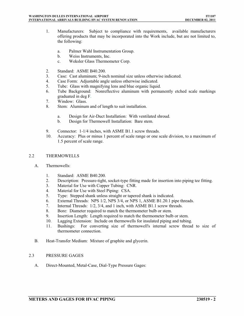
WASHINGTON DULLES INTERNATIONAL AIRPORT IT1107INTERNATIONAL ARRIVALS BUILDING HVAC SYSTEM RENOVATION DECEMBER 02, 2011
METERS AND GAGES FOR HVAC PIPING 230519 - 2
1. Manufacturers: Subject to compliance with requirements, available manufacturers offering products that may be incorporated into the Work include, but are not limited to, the following:
a. Palmer Wahl Instrumentation Group.b. Weiss Instruments, Inc.c. Weksler Glass Thermometer Corp.
2. Standard: ASME B40.200.3. Case: Cast aluminum; 9-inch4. Case Form: Adjustable angle unless otherwise indicated.
nominal size unless otherwise indicated.
5. Tube: Glass with magnifying lens and blue organic liquid.6. Tube Background: Nonreflective aluminum with permanently etched scale markings
graduated in deg F7. Window: Glass.
.
8. Stem: Aluminum and of length to suit installation.
a. Design for Air-Duct Installation: With ventilated shroud.b. Design for Thermowell Installation: Bare stem.
9. Connector: 1-1/4 inches10. Accuracy: Plus or minus 1 percent of scale range or one scale division, to a maximum of
1.5 percent of scale range.
, with ASME B1.1 screw threads.
2.2 THERMOWELLS
A. Thermowells:
1. Standard: ASME B40.200.2. Description: Pressure-tight, socket-type fitting made for insertion into piping tee fitting.3. Material for Use with Copper Tubing: CNR.4. Material for Use with Steel Piping: CSA.5. Type: Stepped shank unless straight or tapered shank is indicated.6. External Threads: NPS 1/2, NPS 3/4, or NPS 1,7. Internal Threads:
ASME B1.20.1 pipe threads.1/2, 3/4, and 1 inch
8. Bore: Diameter required to match the thermometer bulb or stem., with ASME B1.1 screw threads.
9. Insertion Length: Length required to match the thermometer bulb or stem.10. Lagging Extension: Include on thermowells for insulated piping and tubing.11. Bushings: For converting size of thermowell's internal screw thread to size of
thermometer connection.
B. Heat-Transfer Medium: Mixture of graphite and glycerin.
2.3 PRESSURE GAGES
A. Direct-Mounted, Metal-Case, Dial-Type Pressure Gages:

WASHINGTON DULLES INTERNATIONAL AIRPORT IT1107INTERNATIONAL ARRIVALS BUILDING HVAC SYSTEM RENOVATION DECEMBER 02, 2011
METERS AND GAGES FOR HVAC PIPING 230519 - 3
1. Manufacturers: Subject to compliance with requirements, available manufacturers offering products that may be incorporated into the Work include, but are not limited to, the following:
a. Ashcroft Inc.b. Palmer Wahl Instrumentation Group.c. Weiss Instruments, Inc.d. WIKA Instrument Corporation - USA.
2. Standard: ASME B40.100.3. Case: Sealed type(s); cast aluminum or drawn steel; 4-1/2-inch4. Pressure-Element Assembly: Bourdon tube unless otherwise indicated.
nominal diameter.
5. Pressure Connection: Brass, with NPS ¼,
6. Movement: Mechanical, with link to pressure element and connection to pointer.
ASME B1.20.1 pipe threads and bottom-outlet type unless back-outlet type is indicated.
7. Dial: Nonreflective aluminum with permanently etched scale markings graduated in psi8. Pointer: Dark-colored metal.
.
9. Window: Glass.10. Ring: Stainless steel.11. Accuracy: Grade A, plus or minus 1 percent of middle half of scale range.
2.4 GAUGE ATTACHMENTS
A. Snubbers: ASME B40.100, brass; with NPS 1/4
B. Siphons: Loop-shaped section of stainless-steel pipe with
, ASME B1.20.1 pipe threads and piston-type surge-dampening device. Include extension for use on insulated piping.
NPS 1/4
C. Valves: Brass or stainless-steel needle, with
pipe threads.
NPS 1/4
2.5 TEST PLUGS
, ASME B1.20.1 pipe threads.
A. Manufacturers: Subject to compliance with requirements, available manufacturers offering products that may be incorporated into the Work include, but are not limited to, the following:
1. Peterson Equipment Co., Inc.2. Weiss Instruments, Inc.3. Weksler Glass Thermometer Corp.
B. Description: Test-station fitting made for insertion into piping tee fitting.
C. Body: Brass or stainless steel with core inserts and gasketed and threaded cap. Include extended stem on units to be installed in insulated piping.
D. Thread Size: NPS 1/4
E. Minimum Pressure and Temperature Rating:
, ASME B1.20.1 pipe thread.
500 psig at 200 deg F
F. Core Inserts: EPDM self-sealing rubber.
.

WASHINGTON DULLES INTERNATIONAL AIRPORT IT1107INTERNATIONAL ARRIVALS BUILDING HVAC SYSTEM RENOVATION DECEMBER 02, 2011
METERS AND GAGES FOR HVAC PIPING 230519 - 4
2.6 TEST-PLUG KITS
A. Manufacturers: Subject to compliance with requirements, available manufacturers offering products that may be incorporated into the Work include, but are not limited to, the following:
1. Peterson Equipment Co., Inc.2. Weiss Instruments, Inc.3. Weksler Glass Thermometer Corp.
B. Furnish one test-plug kit(s) containing two thermometers, two pressure gages and adapter, and carrying case. Thermometer sensing elements, pressure gage, and adapter probes shall be of diameter to fit test plugs and of length to project into piping.
C. High-Range Thermometer: Small, bimetallic insertion type with 1- to 2-inch- diameter dial and tapered-end sensing element. Dial range shall be at least 0 to 220 deg F
D. Pressure Gage: Small, Bourdon-tube insertion type with
.
2- to 3-inch-diameter dial and probe. Dial range shall be at least 0 to 200 psig
E. Carrying Case: Metal or plastic, with formed instrument padding.
.
PART 3 - EXECUTION
3.1 INSTALLATION
A. Install thermowells with socket extending to center of pipe and in vertical position in piping tees.
B. Install thermowells of sizes required to match thermometer connectors. Include bushings if required to match sizes.
C. Install thermowells with extension on insulated piping.
D. Fill thermowells with heat-transfer medium.
E. Install direct-mounted thermometers in thermowells and adjust vertical and tilted positions.
F. Install remote-mounted thermometer bulbs in thermowells and install cases on panels; connect cases with tubing and support tubing to prevent kinks. Use minimum tubing length.
G. Install duct-thermometer mounting brackets in walls of ducts. Attach to duct with screws.
H. Install direct-mounted pressure gages in piping tees with pressure gage located on pipe at the most readable position.
I. Install remote-mounted pressure gages on panel.
J. Install valve and snubber in piping for each pressure gage for fluids (except steam).
K. Install valve and siphon fitting in piping for each pressure gage for steam.

WASHINGTON DULLES INTERNATIONAL AIRPORT IT1107INTERNATIONAL ARRIVALS BUILDING HVAC SYSTEM RENOVATION DECEMBER 02, 2011
METERS AND GAGES FOR HVAC PIPING 230519 - 5
L. Install test plugs in piping tees.
M. Install flow indicators in piping systems in accessible positions for easy viewing.
N. Assemble and install connections, tubing, and accessories between flow-measuring elements and flowmeters according to manufacturer's written instructions.
O. Install permanent indicators on walls or brackets in accessible and readable positions.
P. Install connection fittings in accessible locations for attachment to portable indicators.
Q. Install thermometers in the following locations:
1. Inlet and outlet of each hydronic zone.2. Inlet and outlet of each hydronic coil in air-handling units.3. Two inlets and two outlets of each hydronic heat exchanger.4. Inlet and outlet of each thermal-storage tank.
R. Install pressure gages in the following locations:
1. Discharge of each pressure-reducing valve.2. Suction and discharge of each pump.3. Two inlets and two outlets of each hydronic heat exchanger.4. Inlet and outlet of each hydronic coil in air handling units
3.2 CONNECTIONS
A. Install meters and gages adjacent to machines and equipment to allow service and maintenance of meters, gages, machines, and equipment.
3.3 ADJUSTING
A. Adjust faces of meters and gages to proper angle for best visibility.
3.4 THERMOMETER SCHEDULE
A. Thermometers at inlet and outlet of each hydronic zone shall be the following:
1. Industrial-style, liquid-in-glass type.2. Test plug with EPDM self-sealing rubber inserts.
B. Thermometers at inlet and outlet of each hydronic coil in air-handling units and built-up central systems shall be the following:
1. Industrial-style, liquid-in-glass type.2. Test plug with EPDM self-sealing rubber inserts.
C. Thermometers at inlets and outlets of each hydronic heat exchanger shall be the following:

WASHINGTON DULLES INTERNATIONAL AIRPORT IT1107INTERNATIONAL ARRIVALS BUILDING HVAC SYSTEM RENOVATION DECEMBER 02, 2011
METERS AND GAGES FOR HVAC PIPING 230519 - 6
1. Industrial-style, liquid-in-glass type.
D. Thermometer stems shall be of length to match thermowell insertion length.
3.5 THERMOMETER SCALE-RANGE SCHEDULE
A. Scale Range for Chilled-Water Piping: 0 to 100 deg F
B. Scale Range for Heating and glycol heating, Hot-Water Piping:
.
30 to 240 deg F
C. Scale Range for High Temperature Heating, Hot-Water Piping:
.
50 to 550 deg F
3.6 PRESSURE-GAGE SCHEDULE
.
A. Pressure gages at inlet and outlet of each hydronic coil connection shall be the following:
1. Sealed, direct-mounted, metal case.2. Test plug with EPDM self-sealing rubber inserts.
B. Pressure gages at suction and discharge of each pump shall be the following:
1. Sealed, direct-mounted, metal case.2. Test plug with EPDM self-sealing rubber inserts.
C. Pressure gages at inlet and outlet of each heat exchanger shall be the following:
1. Sealed, direct-mounted, metal case.2. Test plug with EPDM self-sealing rubber inserts.
3.7 PRESSURE-GAGE SCALE-RANGE SCHEDULE
A. Scale Range for Chilled-Water Piping: 0 to 100 psi
B. Scale Range for Heating and glycol heating, Hot-Water Piping:
.
0 to 100 psi
PART 4 - CONTRACTOR’S QUALITY CONTROL REQUIREMENTS
.
4.1 GENERAL
A. Comply with applicable provisions of Division 01 Section “Quality Requirements” for requirements for Contractor’s Quality Control Program.
END OF SECTION 230519

WASHINGTON DULLES INTERNATIONAL AIRPORT IT1107 INTERNATIONAL ARRIVALS BUILDING HVAC SYSTEM RENOVATION DECEMBER 02, 2011
GENERAL-DUTY VALVES FOR HVAC PIPING 230523 - 1
SECTION 230523 - GENERAL-DUTY VALVES FOR HVAC PIPING
PART 1 - GENERAL
1.1 RELATED DOCUMENTS
A. Drawings and general provisions of the Contract, including General and Supplementary Conditions and Division 01 Specification Sections, apply to this Section.
1.2 SUMMARY
A. Section Includes:
1. Bronze angle valves. 2. Bronze ball valves. 3. Iron, single-flange butterfly valves. 4. Bronze swing check valves. 5. Iron swing check valves. 6. Iron, plate-type check valves. 7. Bronze gate valves. 8. Carbon Steel gate valves. 9. Bronze globe valves. 10. Lubricated Plug Valves. 11. Chainwheels.
B. Related Sections:
1. Division 23 HVAC piping Sections for specialty valves applicable to those Sections only. 2. Division 23 Section "Identification for HVAC Piping and Equipment" for valve tags and
schedules.
1.3 DEFINITIONS
A. CWP: Cold working pressure.
B. EPDM: Ethylene propylene copolymer rubber.
C. NBR: Acrylonitrile-butadiene, Buna-N, or nitrile rubber.
D. NRS: Nonrising stem.
E. OS&Y: Outside screw and yoke.
F. RS: Rising stem.
G. SWP: Steam working pressure.

WASHINGTON DULLES INTERNATIONAL AIRPORT IT1107 INTERNATIONAL ARRIVALS BUILDING HVAC SYSTEM RENOVATION DECEMBER 02, 2011
GENERAL-DUTY VALVES FOR HVAC PIPING 230523 - 2
1.4 ACTION SUBMITTALS
A. Product Data: For each type of valve indicated.
1.5 QUALITY ASSURANCE
A. Source Limitations for Valves: Obtain each type of valve from single source from single manufacturer.
B. ASME Compliance:
1. ASME B16.10 and ASME B16.34 for ferrous valve dimensions and design criteria. 2. ASME B31.1 for power piping valves. 3. ASME B31.9 for building services piping valves.
1.6 DELIVERY, STORAGE, AND HANDLING
A. Prepare valves for shipping as follows:
1. Protect internal parts against rust and corrosion. 2. Protect threads, flange faces, grooves, and weld ends. 3. Set angle, gate, and globe valves closed to prevent rattling. 4. Set ball and plug valves open to minimize exposure of functional surfaces. 5. Set butterfly valves closed or slightly open. 6. Block check valves in either closed or open position.
B. Use the following precautions during storage:
1. Maintain valve end protection. 2. Store valves indoors and maintain at higher than ambient dew point temperature. If
outdoor storage is necessary, store valves off the ground in watertight enclosures.
C. Use sling to handle large valves; rig sling to avoid damage to exposed parts. Do not use handwheels or stems as lifting or rigging points.
PART 2 - PRODUCTS
2.1 GENERAL REQUIREMENTS FOR VALVES
A. Refer to HVAC valve schedule articles for applications of valves.
B. Valve Pressure and Temperature Ratings: Not less than indicated and as required for system pressures and temperatures.
C. Valve Sizes: Same as upstream piping unless otherwise indicated.
D. Valve Actuator Types:

WASHINGTON DULLES INTERNATIONAL AIRPORT IT1107 INTERNATIONAL ARRIVALS BUILDING HVAC SYSTEM RENOVATION DECEMBER 02, 2011
GENERAL-DUTY VALVES FOR HVAC PIPING 230523 - 3
1. Gear Actuator: For quarter-turn valves NPS 8and larger. 2. Handwheel: For valves other than quarter-turn types. 3. Handlever: For quarter-turn valves NPS 6and smaller except plug valves. 4. Wrench: For plug valves with square heads. Furnish 1 wrench for every 10 plug valves,
for each size square plug-valve head. 5. Chainwheel: Device for attachment to valve handwheel, stem, or other actuator; of size
and with chain for mounting height, as indicated in the "Valve Installation" Article.
E. Valves in Insulated Piping: With stem extensions suitable for piping insulation and the following features:
1. Gate Valves: With rising stem. 2. Ball Valves: With extended operating handle of non-thermal-conductive material, and
protective sleeve that allows operation of valve without breaking the vapor seal or disturbing insulation.
3. Butterfly Valves: With extended neck.
F. Valve-End Connections:
1. Flanged: With flanges according to ASME B16.1 for iron valves. 2. Threaded: With threads according to ASME B1.20.1.
G. Valve Bypass and Drain Connections: MSS SP-45.
2.2 BRONZE ANGLE VALVES
A. Class 150, Bronze Angle Valves with Bronze Disc:
1. Manufacturers: Subject to compliance with requirements, available manufacturers offering products that may be incorporated into the Work include, but are not limited to, the following:
a. Crane Co.; Crane Valve Group; Stockham Division. b. Kitz Corporation. c. Nibco Inc.
2. Description:
a. Standard: MSS SP-80, Type 1. b. CWP Rating: 300 psig c. Body Material: ASTM B 62, bronze with integral seat and union-ring bonnet. d. Ends: Threaded. e. Stem and Disc: Bronze. f. Packing: Asbestos free. g. Handwheel: Malleable iron.
2.3 BRONZE BALL VALVES
A. Three-Piece, Full-Port, Bronze Ball Valves with Stainless-Steel Trim:

WASHINGTON DULLES INTERNATIONAL AIRPORT IT1107 INTERNATIONAL ARRIVALS BUILDING HVAC SYSTEM RENOVATION DECEMBER 02, 2011
GENERAL-DUTY VALVES FOR HVAC PIPING 230523 - 4
1. Manufacturers: Subject to compliance with requirements, available manufacturers offering products that may be incorporated into the Work include, but are not limited to, the following:
a. Conbraco Industries, Inc.; Apollo Valves. b. Milwaukee Valve Company. c. NIBCO INC.
2. Description:
a. Standard: MSS SP-110. b. SWP Rating: 150 psig c. CWP Rating: 600 psig d. Body Design: Three piece. e. Body Material: Bronze. f. Ends: Threaded. g. Seats: PTFE or TFE. h. Stem: Stainless steel. i. Ball: Stainless steel, vented. j. Port: Full.
2.4 IRON, SINGLE-FLANGE BUTTERFLY VALVES
A. 150 CWP, Iron, Single-Flange Butterfly Valves with EPDM Seat and Aluminum-Bronze Disc:
1. Manufacturers: Subject to compliance with requirements, available manufacturers offering products that may be incorporated into the Work include, but are not limited to, the following:
a. Bray Controls; a division of Bray International. b. Conbraco Industries, Inc.; Apollo Valves. c. Crane Co.; Crane Valve Group; Stockham Division. d. Milwaukee Valve Company. e. NIBCO INC.
2. Description:
a. Standard: MSS SP-67, Type I. b. CWP Rating: 150 psig c. Body Design: Lug type; suitable for bidirectional dead-end service at rated
pressure without use of downstream flange. d. Body Material: ASTM A 126, cast iron or ASTM A 536, ductile iron. e. Seat: EPDM. f. Stem: One- or two-piece stainless steel. g. Disc: Aluminum bronze.
2.5 BRONZE SWING CHECK VALVES
A. Class 150, Bronze Swing Check Valves with Bronze Disc:

WASHINGTON DULLES INTERNATIONAL AIRPORT IT1107 INTERNATIONAL ARRIVALS BUILDING HVAC SYSTEM RENOVATION DECEMBER 02, 2011
GENERAL-DUTY VALVES FOR HVAC PIPING 230523 - 5
1. Manufacturers: Subject to compliance with requirements, available manufacturers offering products that may be incorporated into the Work include, but are not limited to, the following:
a. American Valve, Inc. b. Crane Co.; Crane Valve Group; Crane Valves. c. Milwaukee Valve Company. d. NIBCO INC.
2. Description:
a. Standard: MSS SP-80, Type 3. b. CWP Rating: 300 psig c. Body Design: Horizontal flow. d. Body Material: ASTM B 62, bronze. e. Ends: Threaded. f. Disc: Bronze.
2.6 IRON SWING CHECK VALVES
A. Class 250, Iron Swing Check Valves with Metal Seats:
1. Manufacturers: Subject to compliance with requirements, available manufacturers offering products that may be incorporated into the Work include, but are not limited to, the following:
a. Crane Co.; Crane Valve Group; Crane Valves. b. Crane Co.; Crane Valve Group; Stockham Division. c. Hammond Valve. d. Milwaukee Valve Company. e. NIBCO INC.
2. Description:
a. Standard: MSS SP-71, Type I. b. NPS 2-1/2 to NPS 12CWP Rating: 500 psig c. NPS 14 to NPS 24CWP Rating: 300 psig d. Body Design: Clear or full waterway. e. Body Material: ASTM A 126, gray iron with bolted bonnet. f. Ends: Flanged. g. Trim: Bronze. h. Gasket: Asbestos free.
2.7 IRON, PLATE-TYPE CHECK VALVES
A. Class 150, Iron, Dual-Plate Check Valves with Metal Seat:

WASHINGTON DULLES INTERNATIONAL AIRPORT IT1107 INTERNATIONAL ARRIVALS BUILDING HVAC SYSTEM RENOVATION DECEMBER 02, 2011
GENERAL-DUTY VALVES FOR HVAC PIPING 230523 - 6
1. Manufacturers: Subject to compliance with requirements, available manufacturers offering products that may be incorporated into the Work include, but are not limited to, the following:
a. APCO Willamette Valve and Primer Corporation. b. Crane Co.; Crane Valve Group; Crane Valves. c. Mueller Steam Specialty; a division of SPX Corporation. d. Val-Matic Valve & Manufacturing Corp.
2. Description:
a. Standard: API 594. b. NPS 2-1/2 to NPS 12, CWP Rating: 300 psig c. NPS 14 to NPS 24CWP Rating: 250 psig d. Body Design: Wafer, spring-loaded plates. e. Body Material: ASTM A 395/A 395M or ASTM A 536, ductile iron. f. Seat: Bronze.
B. Class 150, Iron, Dual-Plate Check Valves with Resilient Seat:
1. Manufacturers: Subject to compliance with requirements, available manufacturers offering products that may be incorporated into the Work include, but are not limited to, the following:
a. APCO Willamette Valve and Primer Corporation. b. Crane Co.; Crane Valve Group; Crane Valves. c. Crane Co.; Crane Valve Group; Jenkins Valves. d. Val-Matic Valve & Manufacturing Corp.
2. Description:
a. Standard: API 594. b. NPS 2-1/2 to NPS 12CWP Rating: 300 psig c. NPS 14 to NPS 24CWP Rating: 250 psig d. Body Design: Wafer, spring-loaded plates. e. Body Material: ASTM A 395/A 395M or ASTM A 536, ductile iron. f. Seat: EPDM.
2.8 BRONZE GATE VALVES
A. Class 150, NRS Bronze Gate Valves:
1. Manufacturers: Subject to compliance with requirements, available manufacturers offering products that may be incorporated into the Work include, but are not limited to, the following:
a. Hammond Valve. b. Milwaukee Valve Company. c. NIBCO INC.
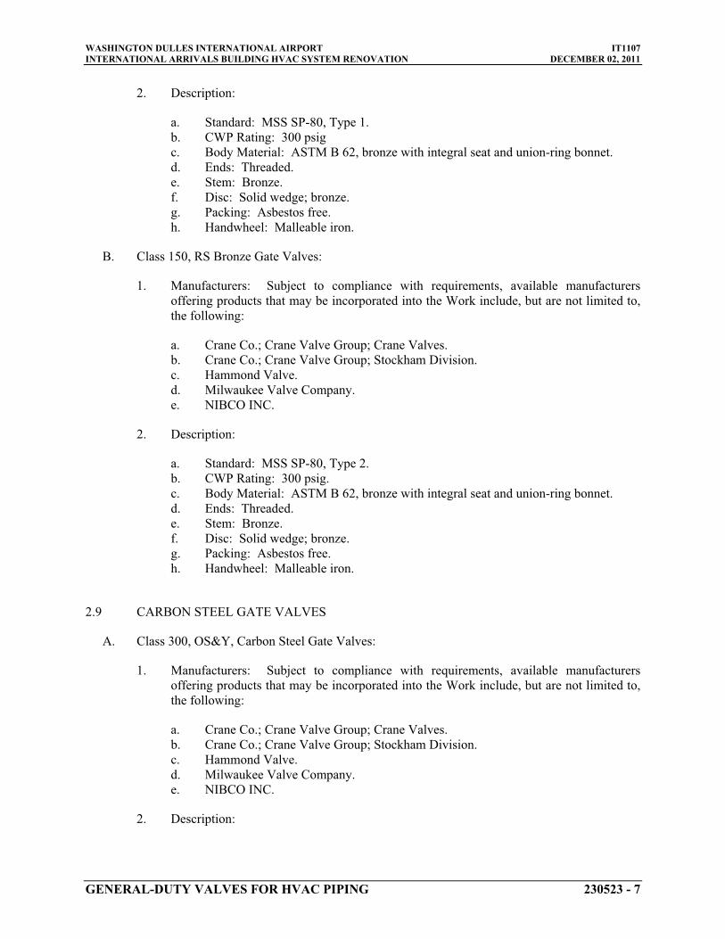
WASHINGTON DULLES INTERNATIONAL AIRPORT IT1107 INTERNATIONAL ARRIVALS BUILDING HVAC SYSTEM RENOVATION DECEMBER 02, 2011
GENERAL-DUTY VALVES FOR HVAC PIPING 230523 - 7
2. Description:
a. Standard: MSS SP-80, Type 1. b. CWP Rating: 300 psig c. Body Material: ASTM B 62, bronze with integral seat and union-ring bonnet. d. Ends: Threaded. e. Stem: Bronze. f. Disc: Solid wedge; bronze. g. Packing: Asbestos free. h. Handwheel: Malleable iron.
B. Class 150, RS Bronze Gate Valves:
1. Manufacturers: Subject to compliance with requirements, available manufacturers offering products that may be incorporated into the Work include, but are not limited to, the following:
a. Crane Co.; Crane Valve Group; Crane Valves. b. Crane Co.; Crane Valve Group; Stockham Division. c. Hammond Valve. d. Milwaukee Valve Company. e. NIBCO INC.
2. Description:
a. Standard: MSS SP-80, Type 2. b. CWP Rating: 300 psig. c. Body Material: ASTM B 62, bronze with integral seat and union-ring bonnet. d. Ends: Threaded. e. Stem: Bronze. f. Disc: Solid wedge; bronze. g. Packing: Asbestos free. h. Handwheel: Malleable iron.
2.9 CARBON STEEL GATE VALVES
A. Class 300, OS&Y, Carbon Steel Gate Valves:
1. Manufacturers: Subject to compliance with requirements, available manufacturers offering products that may be incorporated into the Work include, but are not limited to, the following:
a. Crane Co.; Crane Valve Group; Crane Valves. b. Crane Co.; Crane Valve Group; Stockham Division. c. Hammond Valve. d. Milwaukee Valve Company. e. NIBCO INC.
2. Description:

WASHINGTON DULLES INTERNATIONAL AIRPORT IT1107 INTERNATIONAL ARRIVALS BUILDING HVAC SYSTEM RENOVATION DECEMBER 02, 2011
GENERAL-DUTY VALVES FOR HVAC PIPING 230523 - 8
a. Standard: MSS SP-81. b. NPS 2-1/2 to NPS 12, CWP Rating: 500 psig. c. Body Material: Carbon Steel. d. Ends: Flanged. e. Trim: Bronze. f. Disc: Solid wedge. g. Packing and Gasket: Asbestos free. h. Additional Requirements: Valve shall withstand 400° F at 400 psig. Valve shall be
back seated for valve repacking while system is in service. Stem packings and lubricants for valves and gear operators that do not degrade at the maximum service temperature shall be provided.
2.10 BRONZE GLOBE VALVES
A. Class 150, Bronze Globe Valves with Nonmetallic Disc:
1. Manufacturers: Subject to compliance with requirements, available manufacturers offering products that may be incorporated into the Work include, but are not limited to, the following:
a. Crane Co.; Crane Valve Group; Crane Valves. b. Hammond Valve. c. Milwaukee Valve Company. d. NIBCO INC.
2. Description:
a. Standard: MSS SP-80, Type 2. b. CWP Rating: 300 psig c. Body Material: ASTM B 62, bronze with integral seat and union-ring bonnet. d. Ends: Threaded. e. Stem: Bronze. f. Disc: PTFE or TFE. g. Packing: Asbestos free. h. Handwheel: Malleable iron.
2.11 LUBRICATED PLUG VALVES
A. Class 300, Regular-Gland, Lubricated Plug Valves with Flanged Ends:
1. Manufacturers: Subject to compliance with requirements, provide product sole sourced from the following manufacturer:
a. Nordstrom Valves, Inc, Dynamic Balance Valve
2. Description: a. NPS 2-1/2 to NPS 12CWP Rating: 750 psig. b. Plug: Steel.
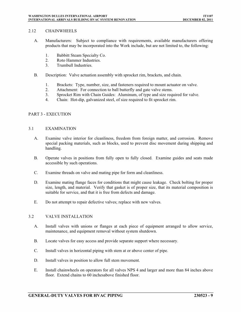
WASHINGTON DULLES INTERNATIONAL AIRPORT IT1107 INTERNATIONAL ARRIVALS BUILDING HVAC SYSTEM RENOVATION DECEMBER 02, 2011
GENERAL-DUTY VALVES FOR HVAC PIPING 230523 - 9
2.12 CHAINWHEELS
A. Manufacturers: Subject to compliance with requirements, available manufacturers offering products that may be incorporated into the Work include, but are not limited to, the following:
1. Babbitt Steam Specialty Co. 2. Roto Hammer Industries. 3. Trumbull Industries.
B. Description: Valve actuation assembly with sprocket rim, brackets, and chain.
1. Brackets: Type, number, size, and fasteners required to mount actuator on valve. 2. Attachment: For connection to ball butterfly and gate valve stems. 3. Sprocket Rim with Chain Guides: Aluminum, of type and size required for valve. 4. Chain: Hot-dip, galvanized steel, of size required to fit sprocket rim.
PART 3 - EXECUTION
3.1 EXAMINATION
A. Examine valve interior for cleanliness, freedom from foreign matter, and corrosion. Remove special packing materials, such as blocks, used to prevent disc movement during shipping and handling.
B. Operate valves in positions from fully open to fully closed. Examine guides and seats made accessible by such operations.
C. Examine threads on valve and mating pipe for form and cleanliness.
D. Examine mating flange faces for conditions that might cause leakage. Check bolting for proper size, length, and material. Verify that gasket is of proper size, that its material composition is suitable for service, and that it is free from defects and damage.
E. Do not attempt to repair defective valves; replace with new valves.
3.2 VALVE INSTALLATION
A. Install valves with unions or flanges at each piece of equipment arranged to allow service, maintenance, and equipment removal without system shutdown.
B. Locate valves for easy access and provide separate support where necessary.
C. Install valves in horizontal piping with stem at or above center of pipe.
D. Install valves in position to allow full stem movement.
E. Install chainwheels on operators for all valves NPS 4 and larger and more than 84 inches above floor. Extend chains to 60 inchesabove finished floor.

WASHINGTON DULLES INTERNATIONAL AIRPORT IT1107 INTERNATIONAL ARRIVALS BUILDING HVAC SYSTEM RENOVATION DECEMBER 02, 2011
GENERAL-DUTY VALVES FOR HVAC PIPING 230523 - 10
F. Install check valves for proper direction of flow and as follows:
1. Swing Check Valves: In horizontal position with hinge pin level. 2. Plate-Type Check Valves: In horizontal or vertical position, between flanges. 3. Lift Check Valves: With stem upright and plumb.
3.3 ADJUSTING
A. Adjust or replace valve packing after piping systems have been tested and put into service but before final adjusting and balancing. Replace valves if persistent leaking occurs.
3.4 GENERAL REQUIREMENTS FOR VALVE APPLICATIONS
A. If valve applications are not indicated, use the following:
1. Shutoff Service: Ball, butterfly valves. 2. Butterfly Valve Dead-End Service: Single-flange (lug) type. 3. Throttling Service except Steam: Globe, ball, or butterfly valves. 4. Pump-Discharge Check Valves:
a. NPS 2and smaller: Bronze swing check valves with bronze disc. b. NPS 2-1/2and larger: Iron swing check valves with lever and weight or with
spring or iron, center-guided, metal or resilient-seat check valves.
B. If valves with specified SWP classes or CWP ratings are not available, the same types of valves with higher SWP classes or CWP ratings may be substituted.
C. Select valves, except wafer types, with the following end connections:
1. For Copper Tubing, NPS 2and smaller: Threaded ends except where solder-joint valve-end option is indicated in valve schedules below.
2. For Steel Piping, NPS 2and smaller: Threaded ends. 3. For Steel Piping, NPS 2-1/2 to NPS 4Flanged ends except where threaded valve-end
option is indicated in valve schedules below. 4. For Steel Piping, NPS 5and larger: Flanged ends.
3.5 CHILLED-WATER VALVE SCHEDULE
A. Pipe NPS 2and smaller:
1. Bronze Angle Valves: Class 125, bronze disc. 2. Ball Valves: Two piece, full port, bronze with stainless-steel trim. 3. Bronze Swing Check Valves: Class 150, bronze disc.
B. Pipe NPS 2-1/2and larger:
1. Iron, Single-Flange Butterfly Valves, NPS 2-1/2 and larger: 200 CWP, EPDM seat, aluminum-bronze disc.
2. Iron Swing Check Valves: Class 250, metal seats.

WASHINGTON DULLES INTERNATIONAL AIRPORT IT1107 INTERNATIONAL ARRIVALS BUILDING HVAC SYSTEM RENOVATION DECEMBER 02, 2011
GENERAL-DUTY VALVES FOR HVAC PIPING 230523 - 11
3.6 HEATING-WATER VALVE SCHEDULE
A. Pipe NPS 2and smaller:
1. Bronze Angle Valves: Class 150, bronze disc. 2. Ball Valves Three piece, full port, brass or bronze with stainless-steel trim. 3. Bronze Swing Check Valves: Class 150, bronze disc. 4. Bronze Gate Valves: Class 150, NRS. 5. Bronze Globe Valves: Class 150, bronze disc.
B. Pipe NPS 2-1/2and larger:
1. Iron, Single-Flange Butterfly Valves, NPS 2-1/2 to NPS 12: 200 CWP, EPDM seat, aluminum-bronze disc.
2. Iron Swing Check Valves: Class 250, metal seats. 3. Iron, Plate-Type Check Valves: Class 150; single plate; metal seat.
3.7 HIGH TEMPERATURE HEATING-WATER VALVE SCHEDULE
A. All Pipe sizes:
1. Lubricated Plug Valve; Class 300; metal seats. 2. Carbon Steel, Gate Valve; Class 300; metal seats.
PART 4 - CONTRACTOR’S QUALITY CONTROL REQUIREMENTS
4.1 FIELD QUALITY CONTROL
A. Conform to all applicable provisions of Division 01 Section “Quality Requirements.”
END OF SECTION 230523

WASHINGTON DULLES INTERNATIONAL AIRPORT IT1107INTERNATIONAL ARRIVALS BUILDING HVAC SYSTEM RENOVATION DECEMBER 02, 2011
HANGERS AND SUPPORTS FOR HVAC PIPING AND EQUIPMENT 230529 - 1
SECTION 230529 -
PART 1 - GENERAL
HANGERS AND SUPPORTS FOR HVAC PIPING AND EQUIPMENT
1.1 RELATED DOCUMENTS
A. Drawings and general provisions of the Contract, including General and Supplementary Conditions and Division 01 Specification Sections, apply to this Section.
1.2 SUMMARY
A. Section Includes:
1. Metal pipe hangers and supports.2. Trapeze pipe hangers.3. Metal framing systems.4. Thermal-hanger shield inserts.5. Fastener systems.6. Pipe stands.7. Equipment supports.
B. Related Sections:
1. Division 05 Section "Metal Fabrications" for structural-steel shapes and plates for trapeze hangers for pipe and equipment supports.
2. Division 23 Section "Expansion Fittings and Loops for HVAC Piping" for pipe guides and anchors.
3. Division 23 Section "Vibration and Seismic Controls for HVAC Piping and Equipment" for vibration isolation devices.
4. Division 23 Section(s) "Metal Ducts" for duct hangers and supports.
1.3 DEFINITIONS
A. MSS: Manufacturers Standardization Society of The Valve and Fittings Industry Inc.
1.4 PERFORMANCE REQUIREMENTS
A. Delegated Design: Design pipe hangers and equipment supports, including comprehensive engineering analysis by a qualified professional engineer Licensed in the Commonwealth of Virginia, using performance requirements and design criteria indicated.
1.5 ACTION SUBMITTALS
A. Product Data: For each type of product indicated.
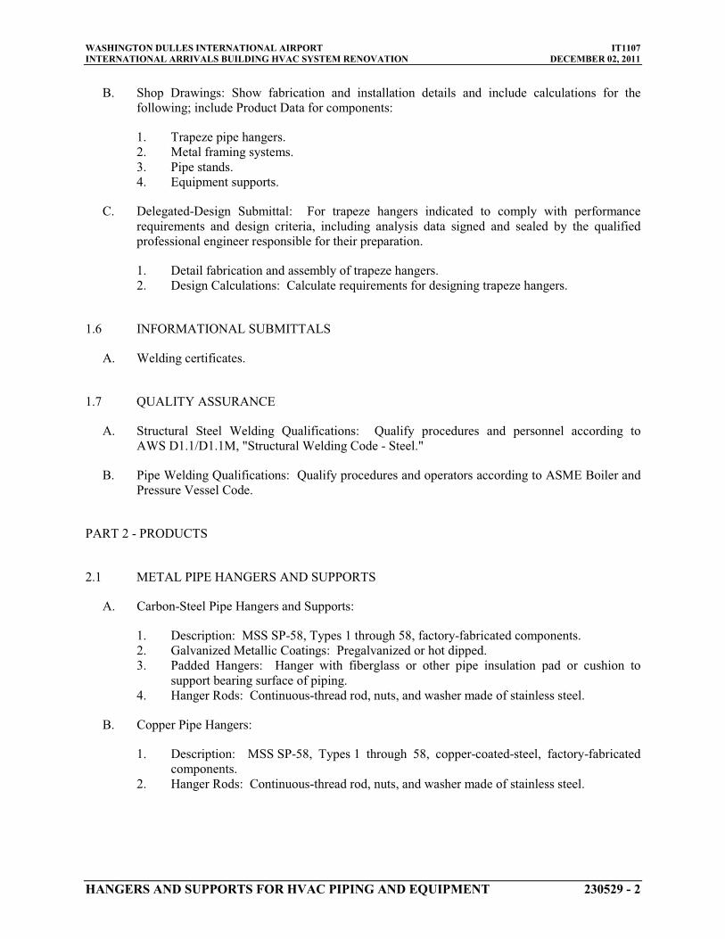
WASHINGTON DULLES INTERNATIONAL AIRPORT IT1107INTERNATIONAL ARRIVALS BUILDING HVAC SYSTEM RENOVATION DECEMBER 02, 2011
HANGERS AND SUPPORTS FOR HVAC PIPING AND EQUIPMENT 230529 - 2
B. Shop Drawings: Show fabrication and installation details and include calculations for the following; include Product Data for components:
1. Trapeze pipe hangers.2. Metal framing systems.3. Pipe stands.4. Equipment supports.
C. Delegated-Design Submittal: For trapeze hangers indicated to comply with performance requirements and design criteria, including analysis data signed and sealed by the qualified professional engineer responsible for their preparation.
1. Detail fabrication and assembly of trapeze hangers.2. Design Calculations: Calculate requirements for designing trapeze hangers.
1.6 INFORMATIONAL SUBMITTALS
A. Welding certificates.
1.7 QUALITY ASSURANCE
A. Structural Steel Welding Qualifications: Qualify procedures and personnel according to AWS D1.1/D1.1M, "Structural Welding Code - Steel."
B. Pipe Welding Qualifications: Qualify procedures and operators according to ASME Boiler and Pressure Vessel Code.
PART 2 - PRODUCTS
2.1 METAL PIPE HANGERS AND SUPPORTS
A. Carbon-Steel Pipe Hangers and Supports:
1. Description: MSS SP-58, Types 1 through 58, factory-fabricated components.2. Galvanized Metallic Coatings: Pregalvanized or hot dipped.3. Padded Hangers: Hanger with fiberglass or other pipe insulation pad or cushion to
support bearing surface of piping.4. Hanger Rods: Continuous-thread rod, nuts, and washer made of stainless steel.
B. Copper Pipe Hangers:
1. Description: MSS SP-58, Types 1 through 58, copper-coated-steel, factory-fabricated components.
2. Hanger Rods: Continuous-thread rod, nuts, and washer made of stainless steel.

WASHINGTON DULLES INTERNATIONAL AIRPORT IT1107INTERNATIONAL ARRIVALS BUILDING HVAC SYSTEM RENOVATION DECEMBER 02, 2011
HANGERS AND SUPPORTS FOR HVAC PIPING AND EQUIPMENT 230529 - 3
2.2 TRAPEZE PIPE HANGERS
A. Description: MSS SP-69, Type 59, shop- or field-fabricated pipe-support assembly made from structural carbon-steel shapes with MSS SP-58 carbon-steel hanger rods, nuts, saddles, and U-bolts.
2.3 METAL FRAMING SYSTEMS
A. MFMA Manufacturer Metal Framing Systems:
1. Basis-of-Design Product: Subject to compliance with requirements, provide product indicated on Drawings or comparable product by one of the following:
a. Cooper B-Line, Inc.b. Flex-Strut Inc.c. GS Metals Corp.d. Thomas & Betts Corporation.e. Unistrut Corporation; Tyco International, Ltd.f. Wesanco, Inc.
2. Description: Shop- or field-fabricated pipe-support assembly for supporting multiple parallel pipes.
3. Standard: MFMA-4.4. Channels: Continuous slotted steel channel with inturned lips.5. Channel Nuts: Formed or stamped steel nuts or other devices designed to fit into channel
slot and, when tightened, prevent slipping along channel.6. Hanger Rods: Continuous-thread rod, nuts, and washer made of carbon steel.7. Metallic Coating: Hot-dipped galvanized.8. Paint Coating: Epoxy.
2.4 THERMAL-HANGER SHIELD INSERTS
A. Manufacturers: Subject to compliance with requirements, available manufacturers offering products that may be incorporated into the Work include, but are not limited to, the following:
1. Carpenter & Paterson, Inc.2. Clement Support Services.3. ERICO International Corporation.4. National Pipe Hanger Corporation.5. PHS Industries, Inc.6. Pipe Shields, Inc.; a subsidiary of Piping Technology & Products, Inc.7. Piping Technology & Products, Inc.8. Rilco Manufacturing Co., Inc.9. Value Engineered Products, Inc.
B. Insulation-Insert Material for Cold Piping: ASTM C 552, Type II cellular glass with 100-psigminimum compressive strength and vapor barrier.
WASHINGTON DULLES INTERNATIONAL AIRPORT IT1107INTERNATIONAL ARRIVALS BUILDING HVAC SYSTEM RENOVATION DECEMBER 02, 2011
HANGERS AND SUPPORTS FOR HVAC PIPING AND EQUIPMENT 230529 - 4
C. Insulation-Insert Material for Hot Piping: Water-repellent treated, ASTM C 533, Type Icalcium silicate with 100-psig
D. For Trapeze or Clamped Systems: Insert and shield shall cover entire circumference of pipe.
minimum compressive strength.
E. For Clevis or Band Hangers: Insert and shield shall cover lower 180 degrees of pipe.
F. Insert Length: Extend 2 inches
2.5 FASTENER SYSTEMS
beyond sheet metal shield for piping operating below ambient air temperature.
A. Powder-Actuated Fasteners: Threaded-steel stud, for use in hardened portland cement concrete with pull-out, tension, and shear capacities appropriate for supported loads and building materials where used.
B. Mechanical-Expansion Anchors: Insert-wedge-type, zinc-coated steel anchors, for use in hardened portland cement concrete; with pull-out, tension, and shear capacities appropriate for supported loads and building materials where used.
2.6 PIPE STANDS
A. General Requirements for Pipe Stands: Shop- or field-fabricated assemblies made of manufactured corrosion-resistant components to support roof-mounted piping.
B. Compact Pipe Stand: One-piece plastic unit with integral-rod roller, pipe clamps, or V-shaped cradle to support pipe, for roof installation without membrane penetration.
C. Low-Type, Single-Pipe Stand: One-piece plastic base unit with plastic roller, for roof installation without membrane penetration.
D. High-Type, Single-Pipe Stand:
1. Description: Assembly of base, vertical and horizontal members, and pipe support, for roof installation without membrane penetration.
2. Base: Stainless steel.3. Vertical Members: Two or more cadmium-plated-steel or stainless-steel, continuous-
thread rods.4. Horizontal Member: Cadmium-plated-steel or stainless-steel rod with stainless-steel,
roller-type pipe support.
E. High-Type, Multiple-Pipe Stand:
1. Description: Assembly of bases, vertical and horizontal members, and pipe supports, for roof installation without membrane penetration.
2. Bases: One or more; plastic.3. Vertical Members: Two or more protective-coated-steel channels.4. Horizontal Member: Protective-coated-steel channel.5. Pipe Supports: Galvanized-steel, clevis-type pipe hangers.

WASHINGTON DULLES INTERNATIONAL AIRPORT IT1107INTERNATIONAL ARRIVALS BUILDING HVAC SYSTEM RENOVATION DECEMBER 02, 2011
HANGERS AND SUPPORTS FOR HVAC PIPING AND EQUIPMENT 230529 - 5
F. Curb-Mounted-Type Pipe Stands: Shop- or field-fabricated pipe supports made from structural-steel shapes, continuous-thread rods, and rollers, for mounting on permanent stationary roof curb.
2.7 EQUIPMENT SUPPORTS
A. Description: Welded, shop- or field-fabricated equipment support made from structural carbon-steel shapes.
2.8 MISCELLANEOUS MATERIALS
A. Structural Steel: ASTM A 36/A 36M, carbon-steel plates, shapes, and bars; black and galvanized.
B. Grout: ASTM C 1107, factory-mixed and -packaged, dry, hydraulic-cement, nonshrink and nonmetallic grout; suitable for interior and exterior applications.
1. Properties: Nonstaining, noncorrosive, and nongaseous.2. Design Mix: 5000-psi,
PART 3 - EXECUTION
28-day compressive strength.
3.1 HANGER AND SUPPORT INSTALLATION
A. Metal Pipe-Hanger Installation: Comply with MSS SP-69 and MSS SP-89. Install hangers, supports, clamps, and attachments as required to properly support piping from the building structure.
B. Metal Trapeze Pipe-Hanger Installation: Comply with MSS SP-69 and MSS SP-89. Arrange for grouping of parallel runs of horizontal piping, and support together on field-fabricated trapeze pipe hangers.
1. Pipes of Various Sizes: Support together and space trapezes for smallest pipe size or install intermediate supports for smaller diameter pipes as specified for individual pipe hangers.
2. Field fabricate from ASTM A 36/A 36M, carbon-steel shapes selected for loads being supported. Weld steel according to AWS D1.1/D1.1M.
C. Metal Framing System Installation: Arrange for grouping of parallel runs of piping, and support together on field-assembled metal framing systems.
D. Thermal-Hanger Shield Installation: Install in pipe hanger or shield for insulated piping.
E. Fastener System Installation:
1. Install powder-actuated fasteners for use in lightweight concrete or concrete slabs less than 4 inches thick in concrete after concrete is placed and completely cured. Use

WASHINGTON DULLES INTERNATIONAL AIRPORT IT1107INTERNATIONAL ARRIVALS BUILDING HVAC SYSTEM RENOVATION DECEMBER 02, 2011
HANGERS AND SUPPORTS FOR HVAC PIPING AND EQUIPMENT 230529 - 6
operators that are licensed by powder-actuated tool manufacturer. Install fasteners according to powder-actuated tool manufacturer's operating manual.
2. Install mechanical-expansion anchors in concrete after concrete is placed and completely cured. Install fasteners according to manufacturer's written instructions.
F. Pipe Stand Installation:
1. Pipe Stand Types except Curb-Mounted Type: Assemble components and mount on smooth roof surface. Do not penetrate roof membrane.
2. Curb-Mounted-Type Pipe Stands: Assemble components or fabricate pipe stand and mount on permanent, stationary roof curb. See Division 07 Section "Roof Accessories" for curbs.
G. Install hangers and supports complete with necessary attachments, inserts, bolts, rods, nuts, washers, and other accessories.
H. All hangers for piping within 25 feet of the heat exchangers shall be floor supported.
I. Equipment Support Installation: Fabricate from welded-structural-steel shapes.
J. Install hangers and supports to allow controlled thermal and seismic movement of piping systems, to permit freedom of movement between pipe anchors, and to facilitate action of expansion joints, expansion loops, expansion bends, and similar units.
K. Install lateral bracing with pipe hangers and supports to prevent swaying.
L. Install building attachments within concrete slabs or attach to structural steel. Install additional attachments at concentrated loads, including valves, flanges, and strainers, NPS 2-1/2
M. Load Distribution: Install hangers and supports so that piping live and dead loads and stresses from movement will not be transmitted to connected equipment.
and larger and at changes in direction of piping. Install concrete inserts before concrete is placed; fasten inserts to forms and install reinforcing bars through openings at top of inserts.
N. Pipe Slopes: Install hangers and supports to provide indicated pipe slopes and to not exceed maximum pipe deflections allowed by ASME B31.9 for building services piping.
O. Insulated Piping:
1. Attach clamps and spacers to piping.
a. Piping Operating above Ambient Air Temperature: Clamp may project through insulation.
b. Piping Operating below Ambient Air Temperature: Use thermal-hanger shield insert with clamp sized to match OD of insert.
c. Do not exceed pipe stress limits allowed by ASME B31.9 for building services piping.
2. Install MSS SP-58, Type 39, protection saddles if insulation without vapor barrier is indicated. Fill interior voids with insulation that matches adjoining insulation.

WASHINGTON DULLES INTERNATIONAL AIRPORT IT1107INTERNATIONAL ARRIVALS BUILDING HVAC SYSTEM RENOVATION DECEMBER 02, 2011
HANGERS AND SUPPORTS FOR HVAC PIPING AND EQUIPMENT 230529 - 7
a. Option: Thermal-hanger shield inserts may be used. Include steel weight-distribution plate for pipe NPS 4
3. Install MSS SP-58, Type 40, protective shields on cold piping with vapor barrier. Shields shall span an arc of 180 degrees.
and larger if pipe is installed on rollers.
a. Option: Thermal-hanger shield inserts may be used. Include steel weight-distribution plate for pipe NPS 4
4. Shield Dimensions for Pipe: Not less than the following:
and larger if pipe is installed on rollers.
a. NPS 1/4 to NPS 3-1/2: 12 inches long and 0.048 inchb.
thick.NPS 4: 12 inches long and 0.06 inch
c.thick.
NPS 5 and NPS 6: 18 inches long and 0.06 inch
5. Thermal-Hanger Shields: Install with insulation same thickness as piping insulation.
thick.
3.2 EQUIPMENT SUPPORTS
A. Fabricate structural-steel stands to suspend equipment from structure overhead or to support equipment above floor.
B. Grouting: Place grout under supports for equipment and make bearing surface smooth.
C. Provide lateral bracing, to prevent swaying, for equipment supports.
3.3 METAL FABRICATIONS
A. Cut, drill, and fit miscellaneous metal fabrications for trapeze pipe hangers and equipment supports.
B. Fit exposed connections together to form hairline joints. Field weld connections that cannot be shop welded because of shipping size limitations.
C. Field Welding: Comply with AWS D1.1/D1.1M procedures for shielded, metal arc welding; appearance and quality of welds; and methods used in correcting welding work; and with the following:
1. Use materials and methods that minimize distortion and develop strength and corrosion resistance of base metals.
2. Obtain fusion without undercut or overlap.3. Remove welding flux immediately.4. Finish welds at exposed connections so no roughness shows after finishing and so
contours of welded surfaces match adjacent contours.
3.4 ADJUSTING
A. Hanger Adjustments: Adjust hangers to distribute loads equally on attachments and to achieve indicated slope of pipe.

WASHINGTON DULLES INTERNATIONAL AIRPORT IT1107INTERNATIONAL ARRIVALS BUILDING HVAC SYSTEM RENOVATION DECEMBER 02, 2011
HANGERS AND SUPPORTS FOR HVAC PIPING AND EQUIPMENT 230529 - 8
B. Trim excess length of continuous-thread hanger and support rods to 1-1/2 inches
3.5 PAINTING
beyond bottom of nut.
A. Touchup: Clean field welds and abraded areas of shop paint. Paint exposed areas immediately after erecting hangers and supports. Use same materials as used for shop painting. Comply with SSPC-PA 1 requirements for touching up field-painted surfaces.
1. Apply paint by brush or spray to provide a minimum dry film thickness of 2.0 mils
B. Touchup: Cleaning and touchup painting of field welds, bolted connections, and abraded areas of shop paint on miscellaneous metal are specified in Division 09 painting Sections.
.
C. Galvanized Surfaces: Clean welds, bolted connections, and abraded areas and apply galvanizing-repair paint to comply with ASTM A 780.
3.6 HANGER AND SUPPORT SCHEDULE
A. Specific hanger and support requirements are in Sections specifying piping systems and equipment.
B. Comply with MSS SP-69 for pipe-hanger selections and applications that are not specified in piping system Sections.
C. Use hangers and supports with galvanized metallic coatings for piping and equipment that will not have field-applied finish.
D. Use nonmetallic coatings on attachments for electrolytic protection where attachments are in direct contact with copper tubing.
E. Use carbon-steel pipe hangers and supports, metal trapeze pipe hangers, and metal framing systems and attachments for general service applications.
F. Use copper-plated pipe hangers and copper or stainless-steel attachments for copper piping and tubing.
G. Use thermal-hanger shield inserts for insulated piping and tubing.
H. Horizontal-Piping Hangers and Supports: Unless otherwise indicated and except as specified in piping system Sections, install the following types:
1. Single-Pipe Rolls (MSS Type 41): For suspension of pipes NPS 1 to NPS 30,
2. Adjustable Roller Hangers (MSS Type 43): For suspension of pipes
from two rods if longitudinal movement caused by expansion and contraction might occur.
NPS 2-1/2 to NPS 24
3. Complete Pipe Rolls (MSS Type 44): For support of pipes
, from single rod if horizontal movement caused by expansion and contraction might occur.
NPS 2 to NPS 42 if longitudinal movement caused by expansion and contraction might occur but vertical adjustment is not necessary.
WASHINGTON DULLES INTERNATIONAL AIRPORT IT1107INTERNATIONAL ARRIVALS BUILDING HVAC SYSTEM RENOVATION DECEMBER 02, 2011
HANGERS AND SUPPORTS FOR HVAC PIPING AND EQUIPMENT 230529 - 9
4. Pipe Roll and Plate Units (MSS Type 45): For support of pipes NPS 2 to NPS 24
5. Adjustable Pipe Roll and Base Units (MSS Type 46): For support of pipes
if small horizontal movement caused by expansion and contraction might occur and vertical adjustment is not necessary.
NPS 2 to NPS 30
I. Vertical-Piping Clamps: Unless otherwise indicated and except as specified in piping system Sections, install the following types:
if vertical and lateral adjustment during installation might be required in addition to expansion and contraction.
1. Extension Pipe or Riser Clamps (MSS Type 8): For support of pipe risers NPS 3/4 to NPS 24
2. Carbon- or Alloy-Steel Riser Clamps (MSS Type 42): For support of pipe risers .
NPS 3/4 to NPS 24
J. Hanger-Rod Attachments: Unless otherwise indicated and except as specified in piping system Sections, install the following types:
if longer ends are required for riser clamps.
1. Steel Turnbuckles (MSS Type 13): For adjustment up to 6 inches2. Steel Clevises (MSS Type 14): For
for heavy loads.120 to 450 deg F
3. Swivel Turnbuckles (MSS Type 15): For use with MSS Type 11, split pipe rings.piping installations.
4. Malleable-Iron Sockets (MSS Type 16): For attaching hanger rods to various types of building attachments.
5. Steel Weldless Eye Nuts (MSS Type 17): For 120 to 450 deg F
K. Building Attachments: Unless otherwise indicated and except as specified in piping system Sections, install the following types:
piping installations.
1. Steel or Malleable Concrete Inserts (MSS Type 18): For upper attachment to suspend pipe hangers from concrete ceiling.
2. Top-Beam C-Clamps (MSS Type 19): For use under roof installations with bar-joist construction, to attach to top flange of structural shape.
3. Side-Beam or Channel Clamps (MSS Type 20): For attaching to bottom flange of beams,channels, or angles.
4. Center-Beam Clamps (MSS Type 21): For attaching to center of bottom flange of beams.5. Welded Beam Attachments (MSS Type 22): For attaching to bottom of beams if loads
are considerable and rod sizes are large.6. C-Clamps (MSS Type 23): For structural shapes.7. Top-Beam Clamps (MSS Type 25): For top of beams if hanger rod is required tangent to
flange edge.8. Side-Beam Clamps (MSS Type 27): For bottom of steel I-beams.9. Steel-Beam Clamps with Eye Nuts (MSS Type 28): For attaching to bottom of steel I-
beams for heavy loads. Steel Beam clamps shall be attached to both bottom edges of I-Beams.
10. Linked-Steel Clamps with Eye Nuts (MSS Type 29): For attaching to bottom of steel I-beams for heavy loads, with link extensions. Steel Beam clamps shall be attached to both bottom edges of I-Beams.
11. Malleable-Beam Clamps with Extension Pieces (MSS Type 30): For attaching to structural steel.
12. Welded-Steel Brackets: For support of pipes from below or for suspending from above by using clip and rod. Use one of the following for indicated loads:

WASHINGTON DULLES INTERNATIONAL AIRPORT IT1107INTERNATIONAL ARRIVALS BUILDING HVAC SYSTEM RENOVATION DECEMBER 02, 2011
HANGERS AND SUPPORTS FOR HVAC PIPING AND EQUIPMENT 230529 - 10
a. Light (MSS Type 31): 750 lbb. Medium (MSS Type 32):
.1500 lb
c. Heavy (MSS Type 33): .
3000 lb
13. Side-Beam Brackets (MSS Type 34): For sides of steel or wooden beams.
.
14. Plate Lugs (MSS Type 57): For attaching to steel beams if flexibility at beam is required.15. Horizontal Travelers (MSS Type 58): For supporting piping systems subject to linear
horizontal movement where headroom is limited.
L. Saddles and Shields: Unless otherwise indicated and except as specified in piping system Sections, install the following types:
1. Steel-Pipe-Covering Protection Saddles (MSS Type 39): To fill interior voids with insulation that matches adjoining insulation.
2. Protection Shields (MSS Type 40): Of length recommended in writing by manufacturer to prevent crushing insulation.
3. Thermal-Hanger Shield Inserts: For supporting insulated pipe.
M. Spring Hangers and Supports: Unless otherwise indicated and except as specified in piping system Sections, install the following types:
1. Restraint-Control Devices (MSS Type 47): Where indicated to control piping movement.2. Spring Cushions (MSS Type 48): For light loads if vertical movement does not exceed
1-1/4 inches. Spring-Cus
3. Spring Sway Braces (MSS Type 50): To retard sway, shock, vibration, or thermal expansion in piping systems.
hion Roll Hangers (MSS Type 49): For equipping Type 41, roll hanger with springs.
4. Variable-Spring Hangers (MSS Type 51): Preset to indicated load and limit variability factor to 25 percent to allow expansion and contraction of piping system from hanger.
5. Variable-Spring Base Supports (MSS Type 52): Preset to indicated load and limit variability factor to 25 percent to allow expansion and contraction of piping system from base support.
6. Variable-Spring Trapeze Hangers (MSS Type 53): Preset to indicated load and limit variability factor to 25 percent to allow expansion and contraction of piping system from trapeze support.
7. Constant Supports: For critical piping stress and if necessary to avoid transfer of stress from one support to another support, critical terminal, or connected equipment. Include auxiliary stops for erection, hydrostatic test, and load-adjustment capability. These supports include the following types:
a. Horizontal (MSS Type 54): Mounted horizontally.b. Vertical (MSS Type 55): Mounted vertically.c. Trapeze (MSS Type 56): Two vertical-type supports and one trapeze member.
N. Comply with MSS SP-69 for trapeze pipe-hanger selections and applications that are not specified in piping system Sections.
O. Comply with MFMA-103 for metal framing system selections and applications that are not specified in piping system Sections.

WASHINGTON DULLES INTERNATIONAL AIRPORT IT1107INTERNATIONAL ARRIVALS BUILDING HVAC SYSTEM RENOVATION DECEMBER 02, 2011
HANGERS AND SUPPORTS FOR HVAC PIPING AND EQUIPMENT 230529 - 11
P. Use powder-actuated fasteners or mechanical-expansion anchors instead of building attachments where required in concrete construction.
PART 4 - CONTRACTOR’S QUALITY CONTROL REQUIREMENTS
4.1 GENERAL
A. Comply with applicable provisions of Division 01 Section “Quality Requirements” for requirements for Contractor’s Quality Control Program.
END OF SECTION 230529

WASHINGTON DULLES INTERNATIONAL AIRPORT IT1107 INTERNATIONAL ARRIVALS BUILDING HVAC SYSTEM RENOVATION DECEMBER 02, 2011
VIBRATION AND SEISMIC CONTROLS FOR HVAC PIPING AND EQUIPMENT 230548 - 1
SECTION 230548 - VIBRATION AND SEISMIC CONTROLS FOR HVAC PIPING AND EQUIPMENT
PART 1 - GENERAL
1.1 RELATED DOCUMENTS
A. Drawings and general provisions of the Contract, including General and Supplementary Conditions and Division 01 Specification Sections, apply to this Section.
1.2 SUMMARY
A. This Section includes the following:
1. Isolation pads. 2. Isolation mounts. 3. Restrained elastomeric isolation mounts. 4. Restrained spring isolators. 5. Housed spring mounts. 6. Elastomeric hangers. 7. Spring hangers. 8. Spring hangers with vertical-limit stops. 9. Pipe riser resilient supports. 10. Resilient pipe guides.
1.3 DEFINITIONS
A. IBC: International Building Code.
B. ICC-ES: ICC-Evaluation Service.
1.4 ACTION SUBMITTALS
A. Product Data: For the following:
1. Include rated load, rated deflection, and overload capacity for each vibration isolation device.
2. Illustrate and indicate style, material, strength, fastening provision, and finish for each type and size of component used.
a. Annotate to indicate application of each product submitted and compliance with requirements.
3. Interlocking Snubbers: Include ratings for horizontal, vertical, and combined loads.

WASHINGTON DULLES INTERNATIONAL AIRPORT IT1107 INTERNATIONAL ARRIVALS BUILDING HVAC SYSTEM RENOVATION DECEMBER 02, 2011
VIBRATION AND SEISMIC CONTROLS FOR HVAC PIPING AND EQUIPMENT 230548 - 2
1.5 INFORMATIONAL SUBMITTALS
A. Coordination Drawings: Show coordination of bracing for HVAC piping and equipment with other systems and equipment in the vicinity, including other supports and restraints.
B. Welding certificates.
C. Field quality-control test reports.
1.6 PERFORMANCE REQUIREMENTS
A. Delegated Design: Design vibration isolators, including comprehensive engineering analysis by a qualified professional engineer Licensed in the Commonwealth of Virginia, using performance requirements and design criteria indicated.
1.7 CLOSEOUT SUBMITTALS
A. Operation and Maintenance Data: For air-mounting systems to include in operation and maintenance manuals.
1.8 QUALITY ASSURANCE
A. Testing Agency Qualifications: An independent agency, with the experience and capability to conduct the testing indicated, that is a nationally recognized testing laboratory (NRTL) as defined by OSHA in 29 CFR 1910.7, and that is acceptable to authorities having jurisdiction.
B. Welding: Qualify procedures and personnel according to AWS D1.1/D1.1M, "Structural Welding Code - Steel."
C. The vibration isolation materials manufacturer shall be responsible for the proper selection of spring rates to accomplish the specified minimum static deflections for all spring and pad type isolators based on the weight distribution of equipment to be isolated.
D. The vibration isolation materials manufacturer shall be responsible for the structural design of steel beam bases and concrete inertia bases to support mechanical equipment scheduled to receive a supplementary base.
E. Vibration isolation shop drawings shall show isolator locations, and load on each isolator, deflection, compressed spring height, solid spring height, spring diameters and color coding.
PART 2 - PRODUCTS
2.1 VIBRATION ISOLATORS
A. Manufacturers: Subject to compliance with requirements, provide the product indicated on Drawings or a comparable product by one of the following:

WASHINGTON DULLES INTERNATIONAL AIRPORT IT1107 INTERNATIONAL ARRIVALS BUILDING HVAC SYSTEM RENOVATION DECEMBER 02, 2011
VIBRATION AND SEISMIC CONTROLS FOR HVAC PIPING AND EQUIPMENT 230548 - 3
1. Ace Mountings Co., Inc. 2. Amber/Booth Company, Inc. 3. Isolation Technology, Inc. 4. Kinetics Noise Control. 5. Mason Industries. 6. Vibration Mountings & Controls, Inc.
B. Pads (type A): Arranged in single or multiple layers of sufficient stiffness for uniform loading over pad area, molded with a nonslip pattern and galvanized-steel baseplates, and factory cut to sizes that match requirements of supported equipment.
1. Resilient Material: Oil- and water-resistant neoprene and rubber.
C. Restrained Mounts (type B): All-directional .
1. Materials: Cast-ductile-iron or welded steel housing containing two separate and opposing, oil-resistant rubber or neoprene elements that prevent central threaded element and attachment hardware from contacting the housing during normal operation.
2. Neoprene: Shock-absorbing materials compounded according to the standard for bridge-bearing neoprene as defined by AASHTO.
D. Restrained Spring Isolators (type C): Freestanding, steel, open-spring isolators with limit-stop restraint.
1. Housing: Steel with resilient vertical-limit stops to prevent spring extension due to weight being removed; factory-drilled baseplate bonded to 1/4-inch-thick, neoprene or rubber isolator pad attached to baseplate underside; and adjustable equipment mounting and leveling bolt that acts as blocking during installation.
2. Restraint: Limit stop as required for equipment and authorities having jurisdiction. 3. Outside Spring Diameter: Not less than 80 percent of the compressed height of the
spring at rated load. 4. Minimum Additional Travel: 50 percent of the required deflection at rated load. 5. Lateral Stiffness: More than 80 percent of rated vertical stiffness. 6. Overload Capacity: Support 200 percent of rated load, fully compressed, without
deformation or failure.
E. Pipe Riser Resilient Support (type D): All-directional, acoustical pipe anchor consisting of 2 steel tubes separated by a minimum of 1/2-inch-thick neoprene. Include steel and neoprene vertical-limit stops arranged to prevent vertical travel in both directions. Design support for a maximum load on the isolation material of 500 psig and for equal resistance in all directions.
F. Resilient Pipe Guides (type E): Telescopic arrangement of 2 steel tubes or post and sleeve arrangement separated by a minimum of 1/2-inch-thick neoprene. Where clearances are not readily visible, a factory-set guide height with a shear pin to allow vertical motion due to pipe expansion and contraction shall be fitted. Shear pin shall be removable and reinsertable to allow for selection of pipe movement. Guides shall be capable of motion to meet location requirements.

WASHINGTON DULLES INTERNATIONAL AIRPORT IT1107 INTERNATIONAL ARRIVALS BUILDING HVAC SYSTEM RENOVATION DECEMBER 02, 2011
VIBRATION AND SEISMIC CONTROLS FOR HVAC PIPING AND EQUIPMENT 230548 - 4
2.2 VIBRATION ISOLATION EQUIPMENT BASES
A. Manufacturers: Subject to compliance with requirements, provide the product indicated on Drawings or a comparable product by one of the following:
1. Kinetics Noise Control. 2. Mason Industries. 3. Vibration Mountings & Controls, Inc. 4. Vibro-Acoustics.
B. Steel Base: Factory-fabricated, welded, structural-steel bases and rails.
1. Design Requirements: Lowest possible mounting height with not less than 1-inch clearance above the floor. Include equipment anchor bolts and auxiliary motor slide bases or rails.
a. Include supports for suction and discharge elbows for pumps.
2. Structural Steel: Steel shapes, plates, and bars complying with ASTM A 36/A 36M. Bases shall have shape to accommodate supported equipment.
3. Support Brackets: Factory-welded steel brackets on frame for outrigger isolation mountings and to provide for anchor bolts and equipment support.
C. Inertia Base: Factory-fabricated, welded, structural-steel bases and rails ready for placement of cast-in-place concrete.
1. Design Requirements: Lowest possible mounting height with not less than 1-inch clearance above the floor. Include equipment anchor bolts and auxiliary motor slide bases or rails.
2. Structural Steel: Steel shapes, plates, and bars complying with ASTM A 36/A 36M. Bases shall have shape to accommodate supported equipment.
3. Support Brackets: Factory-welded steel brackets on frame for outrigger isolation mountings and to provide for anchor bolts and equipment support
4. Fabrication: Fabricate steel templates to hold equipment anchor-bolt sleeves and anchors in place during placement of concrete. Obtain anchor-bolt templates from supported equipment manufacturer.
2.3 FACTORY FINISHES
A. Finish: Manufacturer's standard prime-coat finish ready for field painting.
B. Finish: Manufacturer's standard paint applied to factory-assembled and -tested equipment before shipping.
1. Powder coating on springs and housings. 2. All hardware shall be galvanized. Hot-dip galvanized metal components for exterior use. 3. Baked enamel or powder coat for metal components on isolators for interior use.

WASHINGTON DULLES INTERNATIONAL AIRPORT IT1107 INTERNATIONAL ARRIVALS BUILDING HVAC SYSTEM RENOVATION DECEMBER 02, 2011
VIBRATION AND SEISMIC CONTROLS FOR HVAC PIPING AND EQUIPMENT 230548 - 5
4. Color-code or otherwise mark vibration isolation control devices to indicate capacity range.
PART 3 - EXECUTION
3.1 EXAMINATION
A. Examine areas and equipment to receive vibration isolation control devices for compliance with requirements for installation tolerances and other conditions affecting performance.
B. Examine roughing-in of reinforcement and cast-in-place anchors to verify actual locations before installation.
C. Proceed with installation only after unsatisfactory conditions have been corrected.
3.2 APPLICATIONS
A. Multiple Pipe Supports: Secure pipes to trapeze member with clamps approved for application by an agency acceptable to authorities having jurisdiction.
B. Hanger Rod Stiffeners: Install hanger rod stiffeners where indicated or scheduled on Drawings to receive them and where required to prevent buckling of hanger rods.
3.3 VIBRATION-CONTROL
A. Equipment Restraints:
1. Install resilient bolt isolation washers on equipment anchor bolts where clearance between anchor and adjacent surface exceeds 0.125 inch.
B. Piping Restraints:
1. Comply with requirements in MSS SP-127. 2. Space lateral supports a maximum of 40 feet o.c., and longitudinal supports a maximum
of 80 feet o.c. 3. Brace a change of direction longer than 12 feet.
C. Install bushing assemblies for anchor bolts for floor-mounted equipment, arranged to provide resilient media between anchor bolt and mounting hole in concrete base.
D. Install bushing assemblies for mounting bolts for wall-mounted equipment, arranged to provide resilient media where equipment or equipment-mounting channels are attached to wall.
E. Attachment to Structure: If specific attachment is not indicated, anchor bracing to structure at flanges of beams, at upper truss chords of bar joists, or at concrete members.
F. Drilled-in Anchors:

WASHINGTON DULLES INTERNATIONAL AIRPORT IT1107 INTERNATIONAL ARRIVALS BUILDING HVAC SYSTEM RENOVATION DECEMBER 02, 2011
VIBRATION AND SEISMIC CONTROLS FOR HVAC PIPING AND EQUIPMENT 230548 - 6
1. Identify position of reinforcing steel and other embedded items prior to drilling holes for anchors. Do not damage existing reinforcing or embedded items during coring or drilling. Notify the COTR if reinforcing steel or other embedded items are encountered during drilling. Locate and avoid pre-stressed tendons, electrical and telecommunications conduit, and gas lines.
2. Do not drill holes in concrete or masonry until concrete, mortar, or grout has achieved full design strength.
3. Wedge Anchors: Protect threads from damage during anchor installation. Heavy-duty sleeve anchors shall be installed with sleeve fully engaged in the structural element to which anchor is to be fastened.
4. Adhesive Anchors: Clean holes to remove loose material and drilling dust prior to installation of adhesive. Place adhesive in holes proceeding from the bottom of the hole and progressing toward the surface in such a manner as to avoid introduction of air pockets in the adhesive.
5. Set anchors to manufacturer's recommended torque, using a torque wrench. 6. Install zinc-coated steel anchors for interior and stainless-steel anchors for exterior
applications.
3.4 FIELD QUALITY CONTROL
A. Testing Agency: Engage a qualified testing agency to perform tests and inspections.
B. Perform tests and inspections.
C. Tests and Inspections:
1. Provide evidence of recent calibration of test equipment by a testing agency acceptable to authorities having jurisdiction.
2. Schedule test with COTR before connecting anchorage device to restrained component (unless post-connection testing has been approved), and with at least seven days' advance notice.
3. Obtain COTR’s approval before transmitting test loads to structure. Provide temporary load-spreading members.
4. Test at least four of each type and size of installed anchors and fasteners selected by The Authority.
5. Test to 90 percent of rated proof load of device. 6. Measure isolator restraint clearance. 7. Measure isolator deflection. 8. Verify snubber minimum clearances. 9. If a device fails test, modify all installations of same type and retest until satisfactory
results are achieved.
D. Remove and replace malfunctioning units and retest as specified above.
E. Prepare test and inspection reports.
3.5 ADJUSTING
A. Adjust isolators after piping system is at operating weight.

WASHINGTON DULLES INTERNATIONAL AIRPORT IT1107 INTERNATIONAL ARRIVALS BUILDING HVAC SYSTEM RENOVATION DECEMBER 02, 2011
VIBRATION AND SEISMIC CONTROLS FOR HVAC PIPING AND EQUIPMENT 230548 - 7
B. Adjust limit stops on restrained spring isolators to mount equipment at normal operating height. After equipment installation is complete, adjust limit stops so they are out of contact during normal operation.
C. Adjust active height of spring isolators.
D. Adjust restraints to permit free movement of equipment within normal mode of operation.
3.6 DEMONSTRATION
A. Engage a factory-authorized service representative to train the Authority’s maintenance personnel to adjust, operate, and maintain air-mounting systems. Refer to Division 01 Section "Demonstration and Training."
3.7 VIBRATION ISOLATION SCHEDULE
A. Air Compressor
1. Restrained Spring Isolator Type: C 2. Deflection: 1½".
B. In-line Centrifugal Fans
1. Base Type: None required. 2. Isolator Type: C. 3. Deflection: 1½". 4. Accessories: Flexible duct connectors (see Section 233300 Air Duct Accessories).
C. In-line Centrifugal Toilet and Electrical Room Exhaust Fans
1. Base Type: None required. 2. Isolator Type: C. 3. Deflection: 1". 4. Accessories: Flexible duct connectors (see Section 233300 Air Duct Accessories).
D. Fan Powered Terminal Boxes
1. Base Type: None required. 2. Insulator Type: C. 3. Deflection: ¾". 4. Accessories: Flexible duct connectors (see Section 233300 Air Duct Accessories).
E. Piping
1. First Three Support Points Adjacent to Connected Pump
a. Base Type: None required. b. Isolator Type: D and E. c. Deflection: ¾".

WASHINGTON DULLES INTERNATIONAL AIRPORT IT1107 INTERNATIONAL ARRIVALS BUILDING HVAC SYSTEM RENOVATION DECEMBER 02, 2011
VIBRATION AND SEISMIC CONTROLS FOR HVAC PIPING AND EQUIPMENT 230548 - 8
2. All Other Pipe Supports within 100 Feet Pipe Lengths
a. Base Type: None required. b. Isolator Type: D and E. c. Deflection: ¼".
PART 4 - CONTRACTOR'S QUALITY CONTROL REQUIREMENTS
4.1 FIELD QUALITY CONTROL
A. Conform to all applicable provisions of Section 014000 "Quality Requirements".
B. Inspection:
1. The Contractor shall notify the local representative of the vibration isolation materials manufacturer prior to installing any vibration isolation devices. The Contractor shall seek the representative’s guidance in any installation procedures he is unfamiliar with.
2. The local representative of the vibration isolation materials manufacturer shall conduct periodic inspections of the installation of materials herein specified, and shall report in writing to the Contractor any deviations from good installation practice observed.
3. On completion of installation of all noise and vibration isolation devices herein specified, the local representative of the isolation materials manufacturer shall inspect the complete system and report in writing any installation errors, improperly selected isolation devices, or other fault in the system that could affect the performance of the system.
4. The Contractor shall submit a report to the COTR including the manufacturer's representative’s final report indicating all isolation reported as properly installed or requiring correction, and include a report by the Contractor on steps taken to properly complete the isolation work.
END OF SECTION 230548

WASHINGTON DULLES INTERNATIONAL AIRPORT IT1107INTERNATIONAL ARRIVALS BUILDING HVAC SYSTEM RENOVATION DECEMBER 02, 2011
IDENTIFICATION FOR HVAC PIPING AND EQUIPMENT 230553 - 1
SECTION 230553 -
PART 1 - GENERAL
IDENTIFICATION FOR HVAC PIPING AND EQUIPMENT
1.1 RELATED DOCUMENTS
A. Drawings and general provisions of the Contract, including General and Supplementary Conditions and Division 01 Specification Sections, apply to this Section.
1.2 SUMMARY
A. Section Includes:
1. Equipment labels.2. Warning signs and labels.3. Pipe labels.4. Duct labels.5. Stencils.6. Valve tags.7. Warning tags.
1.3 ACTION SUBMITTALS
A. Product Data: For each type of product indicated.
B. Samples: For color, letter style, and graphic representation required for each identification material and device.
C. Equipment Label Schedule: Include a listing of all equipment to be labeled with the proposed content for each label.
D. Valve numbering scheme.
E. Valve Schedules: For each piping system to include in maintenance manuals.
1.4 COORDINATION
A. Coordinate installation of identifying devices with completion of covering and painting of surfaces where devices are to be applied.
B. Coordinate installation of identifying devices with locations of access panels and doors.
C. Install identifying devices before installing acoustical ceilings and similar concealment.
WASHINGTON DULLES INTERNATIONAL AIRPORT IT1107INTERNATIONAL ARRIVALS BUILDING HVAC SYSTEM RENOVATION DECEMBER 02, 2011
IDENTIFICATION FOR HVAC PIPING AND EQUIPMENT 230553 - 2
PART 2 - PRODUCTS
2.1 EQUIPMENT LABELS
A. Plastic Labels for Equipment:
1. Material and Thickness: Multilayer, multicolor, plastic labels for mechanical engraving, 1/16 inch
2. Letter Color: White.thick, and having predrilled holes for attachment hardware.
3. Background Color: Black.4. Maximum Temperature: Able to withstand temperatures up to 160 deg F5. Minimum Label Size: Length and width vary for required label content, but not less than
.
2-1/2 by 4 inch6. Minimum Letter Size:
.1/4 inch for name of units if viewing distance is less than 24
inches
7. Fasteners: Stainless-steel rivets.
, and proportionately larger lettering for greater viewing distances. Include secondary lettering two-thirds to three-fourths the size of principal lettering.
8. Adhesive: Contact-type permanent adhesive, compatible with label and with substrate.
B. Label Content: Include equipment's Drawing designation, unique control system identifier, and space to affix a standard MWAA Operations and Maintenance equipment barcode tag (approximately 1 x 4 inch).
C. Equipment Label Schedule: For each item of equipment to be labeled, on 8-1/2-by-11-inch
2.2 PIPE LABELS
bond paper. Tabulate equipment identification number and identify Drawing numbers where equipment is indicated (plans, details, and schedules), plus the Specification Section number and title where equipment is specified. Equipment schedule shall be included in operation and maintenance data.
A. General Requirements for Manufactured Pipe Labels: Preprinted, color-coded, with lettering indicating service, and showing flow direction.
B. Pretensioned Pipe Labels: Precoiled, semirigid plastic formed to cover full circumference of pipe and to attach to pipe without fasteners or adhesive.
C. Self-Adhesive Pipe Labels: Printed plastic with contact-type, permanent-adhesive backing.
D. Pipe Label Contents: Include identification of piping service using same designations or abbreviations as used on Drawings, pipe size, and an arrow indicating flow direction.
1. Flow-Direction Arrows: Integral with piping system service lettering to accommodate both directions or as separate unit on each pipe label to indicate flow direction.
2. Lettering Size: At least 1-1/2 inches high.

WASHINGTON DULLES INTERNATIONAL AIRPORT IT1107INTERNATIONAL ARRIVALS BUILDING HVAC SYSTEM RENOVATION DECEMBER 02, 2011
IDENTIFICATION FOR HVAC PIPING AND EQUIPMENT 230553 - 3
2.3 STENCILS
A. Stencils: Prepared with letter sizes according to ASME A13.1 for piping; minimum letter height of 1-1/4 inches for ducts; and minimum letter height of 3/4 inch
1. Stencil Material: Fiberboard or metal.
for access panel and door labels, equipment labels, and similar operational instructions.
2. Stencil Paint: Exterior, gloss, acrylic enamel black unless otherwise indicated. Paint may be in pressurized spray-can form.
3. Identification Paint: Exterior, in colors according to ASME A13.1 unless otherwise indicated.
2.4 VALVE TAGS
A. Valve Tags: Stamped or engraved with 1/4-inch letters for piping system abbreviation and 1/2-inch
1. Tag Material: Brass,
numbers.
0.032-inch
2. Fasteners: Brass wire-link or beaded chain; or S-hook.
minimum thickness, and having predrilled or stamped holes for attachment hardware.
B. Valve Schedules: For each piping system, on 8-1/2-by-11-inch
1. Valve-tag schedule shall be included in operation and maintenance data.
bond paper. Tabulate valve number, piping system, system abbreviation (as shown on valve tag), location of valve (room or space), normal-operating position (open, closed, or modulating), and variations for identification. Mark valves for emergency shutoff and similar special uses.
2.5 WARNING TAGS
A. Warning Tags: Preprinted or partially preprinted, accident-prevention tags, of plasticized card stock with matte finish suitable for writing.
1. Size: 3 by 5-1/4 inches2. Fasteners: Brass grommet and wire.
minimum.
3. Nomenclature: Large-size primary caption such as "DANGER," "CAUTION," or "DO NOT OPERATE."
4. Color: Yellow background with black lettering.
PART 3 - EXECUTION
3.1 PREPARATION
A. Clean piping and equipment surfaces of substances that could impair bond of identification devices, including dirt, oil, grease, release agents, and incompatible primers, paints, and encapsulants.

WASHINGTON DULLES INTERNATIONAL AIRPORT IT1107INTERNATIONAL ARRIVALS BUILDING HVAC SYSTEM RENOVATION DECEMBER 02, 2011
IDENTIFICATION FOR HVAC PIPING AND EQUIPMENT 230553 - 4
3.2 EQUIPMENT LABEL INSTALLATION
A. Install or permanently fasten labels on each major item of mechanical equipment.
B. Locate equipment labels where accessible and visible.
3.3 PIPE LABEL INSTALLATION
A. Locate pipe labels where piping is exposed or above accessible ceilings in finished spaces; machine rooms; accessible maintenance spaces such as shafts, tunnels, and plenums; and exterior exposed locations as follows:
1. Near each valve and control device.2. Near each branch connection, excluding short takeoffs for fixtures and terminal units.
Where flow pattern is not obvious, mark each pipe at branch.3. Near penetrations through walls, floors, ceilings, and inaccessible enclosures.4. At access doors, manholes, and similar access points that permit view of concealed
piping.5. Near major equipment items and other points of origination and termination.6. Spaced at maximum intervals of 50 feet along each run. Reduce intervals to 25 feet
7. On piping above removable acoustical ceilings. Omit intermediately spaced labels.
in areas of congested piping and equipment.
B. Pipe Label Color Schedule:
1. Chilled-Water Piping:
a. Background Color: Green.b. Letter Color: White.
2. Heating and glycol heating Water Piping:
a. Background Color: Yellow.b. Letter Color: Black .
3. High-Temperature-Heating Water Piping:
a. Background Color: Yellow.b. Letter Color: Black.
4. Condensate Drain Piping:
a. Background Color: Green.b. Letter Color: White.
5. Compressed Air Piping:
a. Background Color: Yellow.b. Letter Color: Black.

WASHINGTON DULLES INTERNATIONAL AIRPORT IT1107INTERNATIONAL ARRIVALS BUILDING HVAC SYSTEM RENOVATION DECEMBER 02, 2011
IDENTIFICATION FOR HVAC PIPING AND EQUIPMENT 230553 - 5
3.4 DUCT LABEL INSTALLATION
A. Install plastic-laminated duct labels with permanent adhesive on air ducts in the following color codes:
1. Blue: For cold-air supply ducts.2. Green: For exhaust-, outside-, relief-, return-, and mixed-air ducts.
B. Locate labels near points where ducts enter into concealed spaces and at maximum intervals of 20 feet
3.5 VALVE-TAG INSTALLATION
in each space where ducts are exposed or concealed by removable ceiling system.
A. Install tags on valves and control devices in piping systems, except check valves; valves within factory-fabricated equipment units; shutoff valves; faucets; convenience and lawn-watering hose connections; and HVAC terminal devices and similar roughing-in connections of end-use fixtures and units. List tagged valves in a valve schedule.
B. Valve-Tag Application Schedule: Tag valves according to size, shape, and color scheme and with captions similar to those indicated in the following subparagraphs:
1. Valve-Tag Size and Shape: 1-1/2 inches,2. Valve-Tag Color: Natural.
round.
3. Letter Color: Black.
3.6 WARNING-TAG INSTALLATION
A. Write required message on, and attach warning tags to, equipment and other items where required.
PART 4 - CONTRACTOR’S QUALITY CONTROL REQUIREMENTS
4.1 GENERAL
A. Comply with applicable provisions of Division 01 Section “Quality Requirements” for requirements for Contractor’s Quality Control Program.
B. Inspection: Following installation and prior to concealing systems, visually inspect equipment, duct and piping systems for identification in compliance with the specifications. Make repairs and adjustments as required and provide report to the COTR.
END OF SECTION 230553

WASHINGTON DULLES INTERNATIONAL AIRPORT IT1107INTERNATIONAL ARRIVALS BUILDING HVAC SYSTEM RENOVATION DECEMBER 02, 2011
TESTING, ADJUSTING, AND BALANCING FOR HVAC 230593 - 1
SECTION 230593 -
PART 1 - GENERAL
TESTING, ADJUSTING, AND BALANCING FOR HVAC
1.1 RELATED DOCUMENTS
A. Drawings and general provisions of the Contract, including General and Supplementary Conditions and Division 01 Specification Sections, apply to this Section.
1.2 SUMMARY
A. Section Includes:
1. Balancing Air Systems:
a. Constant-volume air systems.b. Variable-air-volume systems.
2. Balancing Hydronic Piping Systems:
a. Constant-flow hydronic systems.b. Variable-flow hydronic systems.
1.3 DEFINITIONS
A. AABC: Associated Air Balance Council.
B. NEBB: National Environmental Balancing Bureau.
C. TAB: Testing, Adjusting, and Balancing.
D. TABB: Testing, Adjusting, and Balancing Bureau.
E. TAB Specialist: An entity engaged to perform TAB Work.
1.4 INFORMATIONAL SUBMITTALS
A. Qualification Data: Within 15 days of Contractor's Notice to Proceed, submit documentation that the TAB contractor and this Project's TAB team members meet the qualifications specified in "Quality Assurance" Article.
B. Contract Documents Examination Report: Within 30 days of Contractor's Notice to Proceed, submit the Contract Documents review report as specified in Part 3.
C. Strategies and Procedures Plan: Within 45 days of Contractor's Notice to Proceed, submit TAB strategies and step-by-step procedures as specified in "Preparation" Article.
WASHINGTON DULLES INTERNATIONAL AIRPORT IT1107INTERNATIONAL ARRIVALS BUILDING HVAC SYSTEM RENOVATION DECEMBER 02, 2011
TESTING, ADJUSTING, AND BALANCING FOR HVAC 230593 - 2
D. Certified TAB reports.
E. Sample report forms.
F. Instrument calibration reports, to include the following:
1. Instrument type and make.2. Serial number.3. Application.4. Dates of use.5. Dates of calibration.
1.5 QUALITY ASSURANCE
A. TAB Contractor Qualifications: Engage a TAB entity certified by AABC.
1. TAB Field Supervisor: Employee of the TAB contractor and certified by AABC
B. TAB Conference: Meet with COTR, Construction Manager, Commissioning Authority, on approval of the TAB strategies and procedures plan to develop a mutual understanding of the details. Require the participation of the TAB field supervisor and technicians. Provide sevendays' advance notice of scheduled meeting time and location.
1. Agenda Items:
a. The Contract Documents examination report.b. The TAB plan.c. Coordination and cooperation of trades and subcontractors.d. Coordination of documentation and communication flow.
C. Certify TAB field data reports and perform the following:
1. Review field data reports to validate accuracy of data and to prepare certified TAB reports.
2. Certify that the TAB team complied with the approved TAB plan and the procedures specified and referenced in this Specification.
D. TAB Report Forms: Use standard TAB contractor's forms approved by Architect.
E. Instrumentation Type, Quantity, Accuracy, and Calibration: As described in ASHRAE 111, Section 5, "Instrumentation."
F. ASHRAE Compliance: Applicable requirements in ASHRAE 62.1, Section 7.2.2 - "Air Balancing."
G. ASHRAE/IESNA Compliance: Applicable requirements in ASHRAE/IESNA 90.1, Section 6.7.2.3 - "System Balancing."

WASHINGTON DULLES INTERNATIONAL AIRPORT IT1107INTERNATIONAL ARRIVALS BUILDING HVAC SYSTEM RENOVATION DECEMBER 02, 2011
TESTING, ADJUSTING, AND BALANCING FOR HVAC 230593 - 3
1.6 PROJECT CONDITIONS
A. Full Owner Occupancy: The Authority will occupy the site and existing building during entire TAB period. Cooperate with COTR during TAB operations to minimize conflicts with the Authority’s operations.
B. Partial Owner Occupancy: Owner may occupy completed areas of building before Substantial Completion. Cooperate with Owner during TAB operations to minimize conflicts with Owner's operations.
1.7 COORDINATION
A. Notice: Provide seven business days advance notice for each test. Include scheduled test dates and times.
B. Perform TAB after leakage and pressure tests on air and water distribution systems have been satisfactorily completed.
PART 2 - PRODUCTS (Not Applicable)
PART 3 - EXECUTION
3.1 EXAMINATION
A. Examine the Contract Documents to become familiar with Project requirements and to discover conditions in systems' designs that may preclude proper TAB of systems and equipment.
B. Examine systems for installed balancing devices, such as test ports, gage cocks, thermometer wells, flow-control devices, balancing valves and fittings, and manual volume dampers. Verify that locations of these balancing devices are accessible.
C. Examine the approved submittals for HVAC systems and equipment.
D. Examine design data including HVAC system descriptions, statements of design assumptions for environmental conditions and systems' output, and statements of philosophies and assumptions about HVAC system and equipment controls.
E. Examine ceiling plenums and underfloor air plenums used for supply, return, or relief air to verify that they meet the leakage class of connected ducts as specified in Division 23 Section "Metal Ducts" and are properly separated from adjacent areas. Verify that penetrations in plenum walls are sealed and fire-stopped if required.
F. Examine equipment performance data including fan and pump curves.
1. Relate performance data to Project conditions and requirements, including system effects that can create undesired or unpredicted conditions that cause reduced capacities in all or part of a system.

WASHINGTON DULLES INTERNATIONAL AIRPORT IT1107INTERNATIONAL ARRIVALS BUILDING HVAC SYSTEM RENOVATION DECEMBER 02, 2011
TESTING, ADJUSTING, AND BALANCING FOR HVAC 230593 - 4
2. Calculate system-effect factors to reduce performance ratings of HVAC equipment when installed under conditions different from the conditions used to rate equipment performance. To calculate system effects for air systems, use tables and charts found in AMCA 201, "Fans and Systems," or in SMACNA's "HVAC Systems - Duct Design." Compare results with the design data and installed conditions.
G. Examine system and equipment installations and verify that field quality-control testing, cleaning, and adjusting specified in individual Sections have been performed.
H. Examine test reports specified in individual system and equipment Sections.
I. Examine HVAC equipment and filters and verify that bearings are greased, belts are aligned and tight, and equipment with functioning controls is ready for operation.
J. Examine terminal units; such as variable-air-volume boxes, and verify that they are accessible and their controls are connected and functioning.
K. Examine strainers. Verify that startup screens are replaced by permanent screens with indicated perforations.
L. Examine three-way valves for proper installation for their intended function of diverting or mixing fluid flows.
M. Examine heat-transfer coils for correct piping connections and for clean and straight fins.
N. Examine system pumps to ensure absence of entrained air in the suction piping.
O. Examine operating safety interlocks and controls on HVAC equipment.
P. Report deficiencies discovered before and during performance of TAB procedures. Observe and record system reactions to changes in conditions. Record default set points if different from indicated values.
3.2 PREPARATION
A. Prepare a TAB plan that includes strategies and step-by-step procedures.
B. Complete system-readiness checks and prepare reports. Verify the following:
1. Permanent electrical-power wiring is complete.2. Hydronic systems are filled, clean, and free of air.3. Automatic temperature-control systems are operational.4. Equipment and duct access doors are securely closed.5. Balance, smoke, and fire dampers are open.6. Isolating and balancing valves are open and control valves are operational.7. Ceilings are installed in critical areas where air-pattern adjustments are required and
access to balancing devices is provided.8. Windows and doors can be closed so indicated conditions for system operations can be
met.

WASHINGTON DULLES INTERNATIONAL AIRPORT IT1107INTERNATIONAL ARRIVALS BUILDING HVAC SYSTEM RENOVATION DECEMBER 02, 2011
TESTING, ADJUSTING, AND BALANCING FOR HVAC 230593 - 5
3.3 GENERAL PROCEDURES FOR TESTING AND BALANCING
A. Perform testing and balancing procedures on each system according to the procedures contained in AABC's "National Standards for Total System Balance", .
1. Comply with requirements in ASHRAE 62.1, Section 7.2.2 - "Air Balancing."
B. Cut insulation, ducts, pipes, and equipment cabinets for installation of test probes to the minimum extent necessary for TAB procedures.
1. After testing and balancing, patch probe holes in ducts with same material and thickness as used to construct ducts.
2. After testing and balancing, install test ports and duct access doors that comply with requirements in Division 23 Section "Air Duct Accessories."
3. Install and join new insulation that matches removed materials. Restore insulation, coverings, vapor barrier, and finish according to Division 23 Section "HVAC Insulation."
C. Mark equipment and balancing devices, including damper-control positions, valve position indicators, fan-speed-control levers, and similar controls and devices, with paint or other suitable, permanent identification material to show final settings.
D. Take and report testing and balancing measurements in inch-pound (IP) units.
3.4 GENERAL PROCEDURES FOR BALANCING AIR SYSTEMS
A. Prepare test reports for both fans and outlets. Obtain manufacturer's outlet factors and recommended testing procedures. Crosscheck the summation of required outlet volumes with required fan volumes.
B. Prepare schematic diagrams of systems' "as-built" duct layouts.
C. For variable-air-volume systems, develop a plan to simulate diversity.
D. Determine the best locations in main and branch ducts for accurate duct-airflow measurements.
E. Check airflow patterns from the outdoor-air louvers and dampers and the return- and exhaust-air dampers through the supply-fan discharge and mixing dampers.
F. Locate start-stop and disconnect switches, electrical interlocks, and motor starters.
G. Verify that motor starters are equipped with properly sized thermal protection.
H. Check dampers for proper position to achieve desired airflow path.
I. Check for airflow blockages.
J. Check condensate drains for proper connections and functioning.
K. Check for proper sealing of air-handling-unit components.
L. Verify that air duct system is sealed as specified in Division 23 Section "Metal Ducts."

WASHINGTON DULLES INTERNATIONAL AIRPORT IT1107INTERNATIONAL ARRIVALS BUILDING HVAC SYSTEM RENOVATION DECEMBER 02, 2011
TESTING, ADJUSTING, AND BALANCING FOR HVAC 230593 - 6
3.5 PROCEDURES FOR VARIABLE-AIR-VOLUME SYSTEMS
A. Compensating for Diversity: When the total airflow of all terminal units is more than the indicated airflow of the fan, place a selected number of terminal units at minimum set-point airflow with the remainder at maximum-airflow condition until the total airflow of the terminal units equals the indicated airflow of the fan. Select the reduced-airflow terminal units so they are distributed evenly among the branch ducts.
B. Pressure-Independent, Variable-Air-Volume Systems: After the fan systems have been adjusted, adjust the variable-air-volume systems as follows:
1. Set outdoor-air dampers at minimum, and set return- and exhaust-air dampers at a position that simulates full-cooling load.
2. Select the terminal unit that is most critical to the supply-fan airflow and static pressure. Measure static pressure. Adjust system static pressure so the entering static pressure for the critical terminal unit is not less than the sum of the terminal-unit manufacturer's recommended minimum inlet static pressure plus the static pressure needed to overcome terminal-unit discharge system losses.
3. Measure total system airflow. Adjust to within indicated airflow.4. Set terminal units at maximum airflow and adjust controller or regulator to deliver the
designed maximum airflow. Use terminal-unit manufacturer's written instructions to make this adjustment. When total airflow is correct, balance the air outlets downstream from terminal units the same as described for constant-volume air systems.
5. Set terminal units at minimum airflow and adjust controller or regulator to deliver the designed minimum airflow. Check air outlets for a proportional reduction in airflow the same as described for constant-volume air systems.
a. If air outlets are out of balance at minimum airflow, report the condition but leave outlets balanced for maximum airflow.
6. Remeasure the return airflow to the fan while operating at maximum return airflow and minimum outdoor airflow.
a. Adjust the fan and balance the return-air ducts and inlets the same as described for constant-volume air systems.
7. Measure static pressure at the most critical terminal unit and adjust the static-pressure controller at the main supply-air sensing station to ensure that adequate static pressure is maintained at the most critical unit.
8. Record final fan-performance data.
3.6 GENERAL PROCEDURES FOR HYDRONIC SYSTEMS
A. Prepare test reports with pertinent design data, and number in sequence starting at pump to end of system. Check the sum of branch-circuit flows against the approved pump flow rate. Correct variations that exceed plus or minus 5 percent.
B. Prepare schematic diagrams of systems' "as-built" piping layouts.

WASHINGTON DULLES INTERNATIONAL AIRPORT IT1107INTERNATIONAL ARRIVALS BUILDING HVAC SYSTEM RENOVATION DECEMBER 02, 2011
TESTING, ADJUSTING, AND BALANCING FOR HVAC 230593 - 7
C. Prepare hydronic systems for testing and balancing according to the following, in addition to the general preparation procedures specified above:
1. Open all manual valves for maximum flow.2. Check liquid level in expansion tank.3. Check makeup water-station pressure gage for adequate pressure for highest vent.4. Check flow-control valves for specified sequence of operation, and set at indicated flow.5. Set differential-pressure control valves at the specified differential pressure. Do not set at
fully closed position when pump is positive-displacement type unless several terminal valves are kept open.
6. Set system controls so automatic valves are wide open to heat exchangers.7. Check pump-motor load. If motor is overloaded, throttle main flow-balancing device so
motor nameplate rating is not exceeded.8. Check air vents for a forceful liquid flow exiting from vents when manually operated.
3.7 PROCEDURES FOR VARIABLE-FLOW HYDRONIC SYSTEMS
A. Balance systems with automatic two- and three-way control valves by setting systems at maximum flow through heat-exchange terminals and proceed as specified above for hydronic systems.
3.8 PROCEDURES FOR HEAT EXCHANGERS
A. Measure water flow through all circuits.
B. Adjust water flow to within specified tolerances.
C. Measure inlet and outlet water temperatures.
D. Measure inlet steam pressure.
E. Check settings and operation of safety and relief valves. Record settings.
3.9 PROCEDURES FOR MOTORS
A. Motors, 1/2 HP and Larger: Test at final balanced conditions and record the following data:
1. Manufacturer's name, model number, and serial number.2. Motor horsepower rating.3. Motor rpm.4. Efficiency rating.5. Nameplate and measured voltage, each phase.6. Nameplate and measured amperage, each phase.7. Starter thermal-protection-element rating.
B. Motors Driven by Variable-Frequency Controllers: Test for proper operation at speeds varying from minimum to maximum. Test the manual bypass of the controller to prove proper operation. Record observations including name of controller manufacturer, model number, serial number, and nameplate data.

WASHINGTON DULLES INTERNATIONAL AIRPORT IT1107INTERNATIONAL ARRIVALS BUILDING HVAC SYSTEM RENOVATION DECEMBER 02, 2011
TESTING, ADJUSTING, AND BALANCING FOR HVAC 230593 - 8
3.10 PROCEDURES FOR HEAT-TRANSFER COILS
A. Measure, adjust, and record the following data for each water coil:
1. Entering- and leaving-water temperature.2. Water flow rate.3. Water pressure drop.4. Dry-bulb temperature of entering and leaving air.5. Wet-bulb temperature of entering and leaving air for cooling coils.6. Airflow.7. Air pressure drop.
B. Measure, adjust, and record the following data for each electric heating coil:
1. Nameplate data.2. Airflow.3. Entering- and leaving-air temperature at full load.4. Voltage and amperage input of each phase at full load and at each incremental stage.5. Calculated kilowatt at full load.6. Fuse or circuit-breaker rating for overload protection.
C. Measure, adjust, and record the following data for each steam coil:
1. Dry-bulb temperature of entering and leaving air.2. Airflow.3. Air pressure drop.4. Inlet steam pressure.
D. Measure, adjust, and record the following data for each refrigerant coil:
1. Dry-bulb temperature of entering and leaving air.2. Wet-bulb temperature of entering and leaving air.3. Airflow.4. Air pressure drop.5. Refrigerant suction pressure and temperature.
3.11 PROCEDURES FOR TESTING, ADJUSTING, AND BALANCING EXISTING SYSTEMS
A. Before performing testing and balancing of existing systems, inspect existing equipment that isto remain and be reused to verify that existing equipment has been cleaned and refurbished. Verify the following:
1. New filters are installed.2. Coils are clean and fins combed.3. Drain pans are clean.4. Fans are clean.5. Bearings and other parts are properly lubricated.6. Deficiencies noted in the preconstruction report are corrected.

WASHINGTON DULLES INTERNATIONAL AIRPORT IT1107INTERNATIONAL ARRIVALS BUILDING HVAC SYSTEM RENOVATION DECEMBER 02, 2011
TESTING, ADJUSTING, AND BALANCING FOR HVAC 230593 - 9
B. Perform testing and balancing of existing systems to the extent that existing systems are affected by the renovation work.
1. Compare the indicated airflow of the renovated work to the measured fan airflows, and determine the new fan speed and the face velocity of filters and coils.
2. Verify that the indicated airflows of the renovated work result in filter and coil face velocities and fan speeds that are within the acceptable limits defined by equipment manufacturer.
3. If calculations increase or decrease the air flow rates and water flow rates by more than 5 percent, make equipment adjustments to achieve the calculated rates. If increase or decrease is 5 percent or less, equipment adjustments are not required.
4. Balance each air outlet.
3.12 TOLERANCES
A. Set HVAC system's air flow rates and water flow rates within the following tolerances:
1. Supply, Return, and Exhaust Fans and Equipment with Fans: Plus or minus 5 percent.2. Air Outlets and Inlets: Plus or minus 10 percent.3. Heating-Water Flow Rate: Plus or minus 5 percent.4. Cooling-Water Flow Rate: Plus or minus 5 percent.
3.13 REPORTING
A. Initial Construction-Phase Report: Based on examination of the Contract Documents as specified in "Examination" Article, prepare a report on the adequacy of design for systems' balancing devices. Recommend changes and additions to systems' balancing devices to facilitate proper performance measuring and balancing. Recommend changes and additions to HVAC systems and general construction to allow access for performance measuring and balancing devices.
B. Status Reports: Prepare weekly progress reports to describe completed procedures, procedures in progress, and scheduled procedures. Include a list of deficiencies and problems found in systems being tested and balanced. Prepare a separate report for each system and each building floor for systems serving multiple floors.
3.14 FINAL REPORT
A. General: Prepare a certified written report; tabulate and divide the report into separate sections for tested systems and balanced systems.
1. Include a certification sheet at the front of the report's binder, signed and sealed by the certified testing and balancing engineer.
2. Include a list of instruments used for procedures, along with proof of calibration.
B. Final Report Contents: In addition to certified field-report data, include the following:
1. Pump curves.

WASHINGTON DULLES INTERNATIONAL AIRPORT IT1107INTERNATIONAL ARRIVALS BUILDING HVAC SYSTEM RENOVATION DECEMBER 02, 2011
TESTING, ADJUSTING, AND BALANCING FOR HVAC 230593 - 10
2. Fan curves.3. Manufacturers' test data.4. Field test reports prepared by system and equipment installers.5. Other information relative to equipment performance; do not include Shop Drawings and
product data.
C. General Report Data: In addition to form titles and entries, include the following data:
1. Title page.2. Name and address of the TAB contractor.3. Project name.4. Project location.5. Architect's name and address.6. Engineer's name and address.7. Contractor's name and address.8. Report date.9. Signature of TAB supervisor who certifies the report.10. Table of Contents with the total number of pages defined for each section of the report.
Number each page in the report.11. Summary of contents including the following:
a. Indicated versus final performance.b. Notable characteristics of systems.c. Description of system operation sequence if it varies from the Contract
Documents.
12. Nomenclature sheets for each item of equipment.13. Data for terminal units, including manufacturer's name, type, size, and fittings.14. Notes to explain why certain final data in the body of reports vary from indicated values.15. Test conditions for fans and pump performance forms including the following:
a. Settings for outdoor-, return-, and exhaust-air dampers.b. Conditions of filters.c. Cooling coil, wet- and dry-bulb conditions.d. Face and bypass damper settings at coils.e. Fan drive settings including settings and percentage of maximum pitch diameter.f. Inlet vane settings for variable-air-volume systems.g. Settings for supply-air, static-pressure controller.h. Other system operating conditions that affect performance.
D. System Diagrams: Include schematic layouts of air and hydronic distribution systems. Present each system with single-line diagram and include the following:
1. Quantities of outdoor, supply, return, and exhaust airflows.2. Water and steam flow rates.3. Duct, outlet, and inlet sizes.4. Pipe and valve sizes and locations.5. Terminal units.6. Balancing stations.7. Position of balancing devices.

WASHINGTON DULLES INTERNATIONAL AIRPORT IT1107INTERNATIONAL ARRIVALS BUILDING HVAC SYSTEM RENOVATION DECEMBER 02, 2011
TESTING, ADJUSTING, AND BALANCING FOR HVAC 230593 - 11
E. Air-Handling-Unit Test Reports: For air-handling units with coils, include the following:
1. Unit Data:
a. Unit identification.b. Location.c. Make and type.d. Model number and unit size.e. Manufacturer's serial number.f. Unit arrangement and class.g. Discharge arrangement.h. Sheave make, size in inchesi. Center-to-center dimensions of sheave, and amount of adjustments in
, and bore.inches
j. Number, make, and size of belts..
k. Number, type, and size of filters.
2. Motor Data:
a. Motor make, and frame type and size.b. Horsepower and rpm.c. Volts, phase, and hertz.d. Full-load amperage and service factor.e. Sheave make, size in inchesf. Center-to-center dimensions of sheave, and amount of adjustments in
, and bore.inches
3. Test Data (Indicated and Actual Values):
.
a. Total air flow rate in cfmb. Total system static pressure in
.inches wg
c. Fan rpm..
d. Discharge static pressure in inches wge. Filter static-pressure differential in
.inches wg
f. Preheat-coil static-pressure differential in .
inches wgg. Cooling-coil static-pressure differential in
.inches wg
h. Heating-coil static-pressure differential in .
inches wgi. Outdoor airflow in
.cfm
j. Return airflow in .
cfmk. Outdoor-air damper position.
.
l. Return-air damper position.m. Vortex damper position.
F. Apparatus-Coil Test Reports:
1. Coil Data:
a. System identification.b. Location.c. Coil type.d. Number of rows.e. Fin spacing in fins per inchf. Make and model number.
o.c.

WASHINGTON DULLES INTERNATIONAL AIRPORT IT1107INTERNATIONAL ARRIVALS BUILDING HVAC SYSTEM RENOVATION DECEMBER 02, 2011
TESTING, ADJUSTING, AND BALANCING FOR HVAC 230593 - 12
g. Face area in sq. ft.h. Tube size in
.NPS
i. Tube and fin materials..
j. Circuiting arrangement.
2. Test Data (Indicated and Actual Values):
a. Air flow rate in cfmb. Average face velocity in
.fpm
c. Air pressure drop in .
inches wgd. Outdoor-air, wet- and dry-bulb temperatures in
.deg F
e. Return-air, wet- and dry-bulb temperatures in .
deg Ff. Entering-air, wet- and dry-bulb temperatures in
.deg F
g. Leaving-air, wet- and dry-bulb temperatures in .
deg Fh. Water flow rate in
.gpm
i. Water pressure differential in .
feet of head or psigj. Entering-water temperature in
.deg F
k. Leaving-water temperature in .
deg Fl. Refrigerant expansion valve and refrigerant types.
.
m. Refrigerant suction pressure in psign. Refrigerant suction temperature in
.deg F
o. Inlet steam pressure in .
psig
G. Fan Test Reports: For supply, return, and exhaust fans, include the following:
.
1. Fan Data:
a. System identification.b. Location.c. Make and type.d. Model number and size.e. Manufacturer's serial number.f. Arrangement and class.g. Sheave make, size in inchesh. Center-to-center dimensions of sheave, and amount of adjustments in
, and bore.inches
2. Motor Data:
.
a. Motor make, and frame type and size.b. Horsepower and rpm.c. Volts, phase, and hertz.d. Full-load amperage and service factor.e. Sheave make, size in inchesf. Center-to-center dimensions of sheave, and amount of adjustments in
, and bore.inches
g. Number, make, and size of belts..
3. Test Data (Indicated and Actual Values):
a. Total airflow rate in cfmb. Total system static pressure in
.inches wg
c. Fan rpm..

WASHINGTON DULLES INTERNATIONAL AIRPORT IT1107INTERNATIONAL ARRIVALS BUILDING HVAC SYSTEM RENOVATION DECEMBER 02, 2011
TESTING, ADJUSTING, AND BALANCING FOR HVAC 230593 - 13
d. Discharge static pressure in inches wge. Suction static pressure in
.inches wg
H. Round, Flat-Oval, and Rectangular Duct Traverse Reports: Include a diagram with a grid representing the duct cross-section and record the following:
.
1. Report Data:
a. System and air-handling-unit number.b. Location and zone.c. Traverse air temperature in deg Fd. Duct static pressure in
.inches wg
e. Duct size in .
inchesf. Duct area in
.sq. ft.
g. Indicated air flow rate in .
cfmh. Indicated velocity in
.fpm
i. Actual air flow rate in .
cfmj. Actual average velocity in
.fpm
k. Barometric pressure in .
psig
I. System-Coil Reports: For reheat coils and water coils of terminal units, include the following:
.
1. Unit Data:
a. System and air-handling-unit identification.b. Location and zone.c. Room or riser served.d. Coil make and size.e. Flowmeter type.
2. Test Data (Indicated and Actual Values):
a. Air flow rate in cfmb. Entering-water temperature in
.deg F
c. Leaving-water temperature in .
deg Fd. Water pressure drop in
.feet of head or psig
e. Entering-air temperature in .
deg Ff. Leaving-air temperature in
.deg F
J. Pump Test Reports: Calculate impeller size by plotting the shutoff head on pump curves and include the following:
.
1. Unit Data:
a. Unit identification.b. Location.c. Service.d. Make and size.e. Model number and serial number.f. Water flow rate in gpmg. Water pressure differential in
.feet of head or psig.

WASHINGTON DULLES INTERNATIONAL AIRPORT IT1107INTERNATIONAL ARRIVALS BUILDING HVAC SYSTEM RENOVATION DECEMBER 02, 2011
TESTING, ADJUSTING, AND BALANCING FOR HVAC 230593 - 14
h. Required net positive suction head in feet of head or psigi. Pump rpm.
.
j. Impeller diameter in inchesk. Motor make and frame size.
.
l. Motor horsepower and rpm.m. Voltage at each connection.n. Amperage for each phase.o. Full-load amperage and service factor.p. Seal type.
2. Test Data (Indicated and Actual Values):
a. Static head in feet of head or psigb. Pump shutoff pressure in
.feet of head or psig
c. Actual impeller size in .
inchesd. Full-open flow rate in
.gpm
e. Full-open pressure in .
feet of head or psigf. Final discharge pressure in
.feet of head or psig
g. Final suction pressure in .
feet of head or psigh. Final total pressure in
.feet of head or psig
i. Final water flow rate in .
gpmj. Voltage at each connection.
.
k. Amperage for each phase.
K. Instrument Calibration Reports:
1. Report Data:
a. Instrument type and make.b. Serial number.c. Application.d. Dates of use.e. Dates of calibration.
3.15 INSPECTIONS
A. Initial Inspection:
1. After testing and balancing are complete, operate each system and randomly check measurements to verify that the system is operating according to the final test and balance readings documented in the final report.
2. Check the following for each system:
a. Measure airflow of at least 10 percent of air outlets.b. Measure water flow of at least 5 percent of terminals.c. Measure room temperature at each thermostat/temperature sensor. Compare the
reading to the set point.d. Verify that balancing devices are marked with final balance position.e. Note deviations from the Contract Documents in the final report.

WASHINGTON DULLES INTERNATIONAL AIRPORT IT1107INTERNATIONAL ARRIVALS BUILDING HVAC SYSTEM RENOVATION DECEMBER 02, 2011
TESTING, ADJUSTING, AND BALANCING FOR HVAC 230593 - 15
B. Final Inspection:
1. After initial inspection is complete and documentation by random checks verifies that testing and balancing are complete and accurately documented in the final report, request that a final inspection be made by Architect.
2. The TAB contractor's test and balance engineer shall conduct the inspection in the presence of COTR.
3. COTR shall randomly select measurements, documented in the final report, to be rechecked. Rechecking shall be limited to either 10 percent of the total measurements recorded or the extent of measurements that can be accomplished in a normal 8-hour business day.
4. If rechecks yield measurements that differ from the measurements documented in the final report by more than the tolerances allowed, the measurements shall be noted as "FAILED."
5. If the number of "FAILED" measurements is greater than 10 percent of the total measurements checked during the final inspection, the testing and balancing shall be considered incomplete and shall be rejected.
C. TAB Work will be considered defective if it does not pass final inspections. If TAB Work fails, proceed as follows:
1. Recheck all measurements and make adjustments. Revise the final report and balancing device settings to include all changes; resubmit the final report and request a second final inspection.
2. If the second final inspection also fails, the Authority may contract the services of another TAB contractor to complete TAB Work according to the Contract Documents and deduct the cost of the services from the original TAB contractor's final payment.
D. Prepare test and inspection reports.
3.16 ADDITIONAL TESTS
A. Within 90 days of completing TAB, perform additional TAB to verify that balanced conditions are being maintained throughout and to correct unusual conditions.
B. Seasonal Periods: If initial TAB procedures were not performed during near-peak summer and winter conditions, perform additional TAB during both near-peak summer and winter conditions within 365 days of completion.
PART 4 - CONTRACTOR’S QUALITY CONTROL REQUIREMENTS
4.1 GENERAL
A. Comply with applicable provisions of Division 01 Section “Quality Requirements” for requirements for Contractor’s Quality Control Program.
END OF SECTION 230593

WASHINGTON DULLES INTERNATIONAL AIRPORT IT1107INTERNATIONAL ARRIVALS BUILDING HVAC SYSTEM RENOVATION DECEMBER 02, 2011
DUCT INSULATION 230713 - 1
SECTION 230713 -
PART 1 - GENERAL
DUCT INSULATION
1.1 RELATED DOCUMENTS
A. Drawings and general provisions of the Contract, including General and Supplementary Conditions and Division 01 Specification Sections, apply to this Section.
1.2 SUMMARY
A. Section includes insulating the following duct services:
1. Indoor, supply and primary air.2. Indoor, return located in unconditioned space.
B. Related Sections:
1. Division 23 Section "HVAC Equipment Insulation."2. Division 23 Section "HVAC Piping Insulation."3. Division 23 Section "Metal Ducts" for duct liners.
1.3 ACTION SUBMITTALS
A. Product Data: For each type of product indicated. Include thermal conductivity, water-vapor permeance thickness, and jackets (both factory- and field-applied if any).
B. Shop Drawings: Include plans, elevations, sections, details, and attachments to other work.
1. Detail application of protective shields, saddles, and inserts at hangers for each type of insulation and hanger.
2. Detail insulation application at elbows, fittings, dampers, specialties and flanges for each type of insulation.
3. Detail application of field-applied jackets.4. Detail application at linkages of control devices.
C. Samples: For each type of insulation and jacket indicated. Identify each Sample, describing product and intended use. Sample sizes are as follows:
1. Sheet Form Insulation Materials: 12 inches2. Sheet Jacket Materials:
square.12 inches
3. Manufacturer's Color Charts: For products where color is specified, show the full range of colors available for each type of finish material.
square.

WASHINGTON DULLES INTERNATIONAL AIRPORT IT1107INTERNATIONAL ARRIVALS BUILDING HVAC SYSTEM RENOVATION DECEMBER 02, 2011
DUCT INSULATION 230713 - 2
1.4 INFORMATIONAL SUBMITTALS
A. Qualification Data: For qualified Installer.
B. Material Test Reports: From a qualified testing agency acceptable to authorities having jurisdiction indicating, interpreting, and certifying test results for compliance of insulation materials, sealers, attachments, cements, and jackets, with requirements indicated. Include dates of tests and test methods employed.
C. Field quality-control reports.
1.5 QUALITY ASSURANCE
A. Installer Qualifications: Skilled mechanics who have successfully completed an apprenticeship program or another craft training program certified by the Department of Labor, Bureau of Apprenticeship and Training.
B. Surface-Burning Characteristics: For insulation and related materials, as determined by testing identical products according to ASTM E 84, by a testing agency acceptable to authorities having jurisdiction. Factory label insulation and jacket materials and adhesive, mastic, tapes, and cement material containers, with appropriate markings of applicable testing agency.
1. Insulation Installed Indoors: Flame-spread index of 25 or less, and smoke-developed index of 50 or less.
2. Insulation Installed Outdoors: Flame-spread index of 75 or less, and smoke-developed index of 150 or less.
1.6 DELIVERY, STORAGE, AND HANDLING
A. Packaging: Insulation material containers shall be marked by manufacturer with appropriate ASTM standard designation, type and grade, and maximum use temperature.
1.7 COORDINATION
A. Coordinate sizes and locations of supports, hangers, and insulation shields specified inDivision 23 Section "Hangers and Supports for HVAC Piping and Equipment."
B. Coordinate clearance requirements with duct Installer for duct insulation application. Before preparing ductwork Shop Drawings, establish and maintain clearance requirements for installation of insulation and field-applied jackets and finishes and for space required for maintenance.
1.8 SCHEDULING
A. Schedule insulation application after pressure testing systems and, where required, after installing and testing heat tracing. Insulation application may begin on segments that have satisfactory test results.

WASHINGTON DULLES INTERNATIONAL AIRPORT IT1107INTERNATIONAL ARRIVALS BUILDING HVAC SYSTEM RENOVATION DECEMBER 02, 2011
DUCT INSULATION 230713 - 3
B. Complete installation and concealment of plastic materials as rapidly as possible in each area of construction.
PART 2 - PRODUCTS
2.1 INSULATION MATERIALS
A. Comply with requirements in "Duct Insulation Schedule, General," "Indoor Duct and Plenum Insulation Schedule," and "Aboveground, Outdoor Duct and Plenum Insulation Schedule" articles for where insulating materials shall be applied.
B. Products shall not contain asbestos, lead, mercury, or mercury compounds.
C. Products that come in contact with stainless steel shall have a leachable chloride content of less than 50 ppm when tested according to ASTM C 871.
D. Foam insulation materials shall not use CFC or HCFC blowing agents in the manufacturing process.
E. Mineral-Fiber Board Insulation: Mineral or glass fibers bonded with a thermosetting resin. Comply with ASTM C 612, Type IA or Type IB. For duct and plenum applications, provide insulation with factory-applied ASJ. Factory-applied jacket requirements are specified in "Factory-Applied Jackets" Article.
1. Products: Subject to compliance with requirements, provide one of the following:
a. CertainTeed Corp.; Commercial Board.b. Johns Manville; 800 Series Spin-Glas.c. Knauf Insulation; Insulation Board.d. Manson Insulation Inc.; AK Board.e. Owens Corning; Fiberglas 700 Series.
2.2 ADHESIVES
A. Materials shall be compatible with insulation materials, jackets, and substrates and for bonding insulation to itself and to surfaces to be insulated unless otherwise indicated.
B. For indoor applications, adhesive shall have a VOC content of 50 g/L or less when calculated according to 40 CFR 59, Subpart D (EPA Method 24).
C. Adhesive shall comply with the testing and product requirements of the California Department of Health Services' "Standard Practice for the Testing of Volatile Organic Emissions from Various Sources Using Small-Scale Environmental Chambers."
D. Mineral-Fiber Adhesive: Comply with MIL-A-3316C, Class 2, Grade A.
1. Products: Subject to compliance with requirements, provide one of the following:

WASHINGTON DULLES INTERNATIONAL AIRPORT IT1107INTERNATIONAL ARRIVALS BUILDING HVAC SYSTEM RENOVATION DECEMBER 02, 2011
DUCT INSULATION 230713 - 4
a. Childers Brand, Specialty Construction Brands, Inc., a business of H. B. Fuller Company; CP-127.
b. Eagle Bridges - Marathon Industries; 225.c. Foster Brand, Specialty Construction Brands, Inc., a business of H. B. Fuller
Company; 85-60/85-70.d. Mon-Eco Industries, Inc.; 22-25.
2. Fire / smoke tested in accordance with ASTM E-84.3. ASTM C-916, Type 2.4. Service temperature range: -20 deg F to 200 deg F.
E. ASJ Adhesive and FSK Jacket Adhesive: Neoprene based contact adhesive for bonding insulation jacket lap seams and joints.
1. Products: Subject to compliance with requirements, provide one of the following:
a. Childers Brand, Specialty Construction Brands, Inc., a business of H. B. Fuller Company; CP-82.
b. Eagle Bridges - Marathon Industries; 225.c. Foster Brand, Specialty Construction Brands, Inc., a business of H. B. Fuller
Company; 85-50.
2. Surface burning characteristics in accordance with ASTM E-84.3. ASTM C-916 compliance.4. Service Temperature: -30 deg F to 200 deg F.5. Comply with MIL-A-3316C, Class 2, Grade A.
2.3 MASTICS
A. Materials shall be compatible with insulation materials, jackets, and substrates; comply with MIL-PRF-19565C, Type II.
1. For indoor applications, use mastics that have a VOC content of 50 g/L or less when calculated according to 40 CFR 59, Subpart D (EPA Method 24).
B. Vapor-Barrier Mastic: Water based; suitable for indoor use on below ambient services.
1. Products: Subject to compliance with requirements, provide one of the following:
a. Foster Brand, Specialty Construction Brands, Inc., a business of H. B. Fuller Company; 95-90.
b. Vimasco Corporation; 749.
2. Water-Vapor Permeance: ASTM E 96/E 96M, Procedure B, 0.013 perm at 43-mil
3. Service Temperature Range:
dry film thickness.
Minus 20 to plus 180 deg F4. Solids Content: ASTM D 1644, 58 percent by volume and 70 percent by weight.
.
5. Color: White.
C. Vapor-Barrier Mastic: Solvent based; suitable for outdoor use on below ambient services.

WASHINGTON DULLES INTERNATIONAL AIRPORT IT1107INTERNATIONAL ARRIVALS BUILDING HVAC SYSTEM RENOVATION DECEMBER 02, 2011
DUCT INSULATION 230713 - 5
1. Products: Subject to compliance with requirements, provide one of the following:
a. Childers Brand, Specialty Construction Brands, Inc., a business of H. B. Fuller Company; Encacel.
b. Eagle Bridges - Marathon Industries; 570.c. Foster Brand, Specialty Construction Brands, Inc., a business of H. B. Fuller
Company; 60-95/60-96.
2. Water-Vapor Permeance: ASTM F 1249, 0.05 perm at 30-mil3. Service Temperature Range:
dry film thickness.Minus 50 to plus 220 deg F
4. Solids Content: ASTM D 1644, 33 percent by volume and 46 percent by weight..
5. Color: White.
D. Breather Mastic: Water based; suitable for indoor and outdoor use on above ambient services.
1. Products: Subject to compliance with requirements, provide one of the following:
a. Childers Brand, Specialty Construction Brands, Inc., a business of H. B. Fuller Company; CP-10.
b. Eagle Bridges - Marathon Industries; 550.c. Foster Brand, Specialty Construction Brands, Inc., a business of H. B. Fuller
Company; 46-50.
2. Water-Vapor Permeance: ASTM F 1249, 1.8 perms at 0.0625-inch3. Service Temperature Range:
dry film thickness.Minus 20 to plus 180 deg F
4. Solids Content: 60 percent by volume and 66 percent by weight..
5. Color: White.
2.4 LAGGING ADHESIVES
A. Description: Comply with MIL-A-3316C, Class I, Grade A and shall be compatible with insulation materials, jackets, and substrates.
1. For indoor applications, use lagging adhesives that have a VOC content of 50 g/L or less when calculated according to 40 CFR 59, Subpart D (EPA Method 24).
2. Products: Subject to compliance with requirements, provide one of the following:
a. Childers Brand, Specialty Construction Brands, Inc., a business of H. B. Fuller Company; CP-50 AHV2.
b. Foster Brand, Specialty Construction Brands, Inc., a business of H. B. Fuller Company; 30-36.
c. Vimasco Corporation; 713 and 714.
3. Fire-resistant, water-based lagging adhesive and coating for use indoors to adhere fire-resistant lagging cloths over duct insulation.
4. Service Temperature Range: 0 to plus 180 deg F5. Color: White.
.

WASHINGTON DULLES INTERNATIONAL AIRPORT IT1107INTERNATIONAL ARRIVALS BUILDING HVAC SYSTEM RENOVATION DECEMBER 02, 2011
DUCT INSULATION 230713 - 6
2.5 SEALANTS
A. For indoor applications, sealants shall have a VOC content of 420 g/L or less when calculated according to 40 CFR 59, Subpart D (EPA Method 24).
B. Sealants shall comply with the testing and product requirements of the California Department of Health Services' "Standard Practice for the Testing of Volatile Organic Emissions from Various Sources Using Small-Scale Environmental Chambers."
C. FSK and Metal Jacket Flashing Sealants:
1. Products: Subject to compliance with requirements, provide one of the following:
a. Childers Brand, Specialty Construction Brands, Inc., a business of H. B. Fuller Company; CP-76.
b. Eagle Bridges - Marathon Industries; 405.c. Foster Brand, Specialty Construction Brands, Inc., a business of H. B. Fuller
Company; 95-44.
2. Materials shall be compatible with insulation materials, jackets, and substrates.3. Fire- and water-resistant, flexible, elastomeric sealant.4. Service Temperature Range: Minus 40 to plus 250 deg F5. Color: Aluminum.
.
D. ASJ Flashing Sealants, and Vinyl Flashing Sealants:
1. Products: Subject to compliance with requirements, provide one of the following:
a. Childers Brand, Specialty Construction Brands, Inc., a business of H. B. Fuller Company; CP-76.
2. Materials shall be compatible with insulation materials, jackets, and substrates.3. Fire- and water-resistant, flexible, elastomeric sealant.4. Service Temperature Range: Minus 40 to plus 250 deg F5. Color: White.
.
2.6 FACTORY-APPLIED JACKETS
A. Insulation system schedules indicate factory-applied jackets on various applications. When factory-applied jackets are indicated, comply with the following:
1. ASJ: White, kraft-paper, fiberglass-reinforced scrim with aluminum-foil backing; complying with ASTM C 1136, Type I.
2. ASJ-SSL: ASJ with self-sealing, pressure-sensitive, acrylic-based adhesive covered by a removable protective strip; complying with ASTM C 1136, Type I.
3. FSK Jacket: Aluminum-foil, fiberglass-reinforced scrim with kraft-paper backing; complying with ASTM C 1136, Type II.
4. FSP Jacket: Aluminum-foil, fiberglass-reinforced scrim with polyethylene backing; complying with ASTM C 1136, Type II.

WASHINGTON DULLES INTERNATIONAL AIRPORT IT1107INTERNATIONAL ARRIVALS BUILDING HVAC SYSTEM RENOVATION DECEMBER 02, 2011
DUCT INSULATION 230713 - 7
5. Vinyl Jacket: White vinyl with a permeance of 1.3 perms
2.7 FIELD-APPLIED FABRIC-REINFORCING MESH
when tested according to ASTM E 96/E 96M, Procedure A, and complying with NFPA 90A and NFPA 90B.
A. Woven Glass-Fiber Fabric: Approximately 4 oz./sq. yd. with a thread count of 5 strands by 5 strands/sq. in.
1. Products: Subject to compliance with requirements, provide one of the following:
for covering ducts or other large surfaces.
a. Childers Brand, Specialty Construction Brands, Inc., a business of H. B. Fuller Company; Chil-Glas No. 5.
B. Woven Polyester Fabric: Approximately 1 oz./sq. yd. with a thread count of 10 strands by 10 strands/sq. in.
1. Products: Subject to compliance with requirements, provide one of the following:
, in a Leno weave, for ducts.
a. Foster Brand, Specialty Construction Brands, Inc., a business of H. B. Fuller Company; Mast-A-Fab.
b. Vimasco Corporation; Elastafab 894.
2.8 FIELD-APPLIED CLOTHS
A. Woven Glass-Fiber Fabric: Comply with MIL-C-20079H, Type I, plain weave, and presized a minimum of
1. Products: Subject to compliance with requirements, provide one of the following:
8 oz./sq. yd.
a. Alpha Associates, Inc.; Alpha-Maritex 84215 and 84217/9485RW, Luben 59.
2.9 TAPES
A. FSK Tape: Foil-face, vapor-retarder tape matching factory-applied jacket with acrylic adhesive; complying with ASTM C 1136.
1. Width: 3 inches2. Thickness:
.6.5 mils
3. Adhesion: .
90 ounces force/inch4. Elongation: 2 percent.
in width.
5. Tensile Strength: 40 lbf/inch6. FSK Tape Disks and Squares: Precut disks or squares of FSK tape.
in width.
B. Aluminum-Foil Tape: Vapor-retarder tape with acrylic adhesive.
1. Width: 2 inches2. Thickness:
.3.7 mils
3. Adhesion: .
100 ounces force/inch4. Elongation: 5 percent.
in width.

WASHINGTON DULLES INTERNATIONAL AIRPORT IT1107INTERNATIONAL ARRIVALS BUILDING HVAC SYSTEM RENOVATION DECEMBER 02, 2011
DUCT INSULATION 230713 - 8
5. Tensile Strength: 34 lbf/inch
2.10 SECUREMENTS
in width.
A. Bands:
1. Products: Subject to compliance with requirements, available products that may be incorporated into the Work include, but are not limited to, the following:
a. ITW Insulation Systems; Gerrard Strapping and Seals.b. RPR Products, Inc.; Insul-Mate Strapping, Seals, and Springs.
2. Stainless Steel: ASTM A 167 or ASTM A 240/A 240M, Type 304; 0.015 inch thick, 3/4 inch
3. Aluminum: wide with wing seal.
ASTM B 209, Alloy 3003, 3005, 3105, or 5005; Temper H-14, 0.020 inchthick, 3/4 inch
4. Springs: Twin spring set constructed of stainless steel with ends flat and slotted to accept metal bands. Spring size determined by manufacturer for application.
wide with wing seal.
B. Insulation Pins and Hangers:
1. Capacitor-Discharge-Weld Pins: Copper- or zinc-coated steel pin, fully annealed for capacitor-discharge welding, 0.106-inch-
2. Cupped-Head, Capacitor-Discharge-Weld Pins: Copper- or zinc-coated steel pin, fully annealed for capacitor-discharge welding,
diameter shank, and length to suit depth of insulation indicated.
0.106-inch-diameter shank, and length to suit depth of insulation indicated with integral 1-1/2-inch
3. Insulation-Retaining Washers: Self-locking washers formed from galvanized carbon-steel washer.
0.016-inch- thick, galvanized-steel or stainless-steel sheet, matching duct material, with beveled edge sized as required to hold insulation securely in place but not less than 1-1/2 inches
a. Protect ends with capped self-locking washers incorporating a spring steel insert to ensure permanent retention of cap in exposed locations.
in diameter.
C. Staples: Outward-clinching insulation staples, nominal 3/4-inch-
D. Wire:
wide, stainless steel or Monel.
0.080-inch nickel-copper alloy or 0.062-inch
PART 3 - EXECUTION
soft-annealed, galvanized steel.
3.1 EXAMINATION
A. Examine substrates and conditions for compliance with requirements for installation tolerances and other conditions affecting performance of insulation application.
1. Verify that systems to be insulated have been tested and are free of defects.2. Verify that surfaces to be insulated are clean and dry.
B. Proceed with installation only after unsatisfactory conditions have been corrected.

WASHINGTON DULLES INTERNATIONAL AIRPORT IT1107INTERNATIONAL ARRIVALS BUILDING HVAC SYSTEM RENOVATION DECEMBER 02, 2011
DUCT INSULATION 230713 - 9
3.2 PREPARATION
A. Surface Preparation: Clean and dry surfaces to receive insulation. Remove materials that will adversely affect insulation application.
3.3 GENERAL INSTALLATION REQUIREMENTS
A. Install insulation materials, accessories, and finishes with smooth, straight, and even surfaces; free of voids throughout the length of ducts and fittings.
B. Install insulation materials, vapor barriers or retarders, jackets, and thicknesses required for each item of duct system as specified in insulation system schedules.
C. Install accessories compatible with insulation materials and suitable for the service. Install accessories that do not corrode, soften, or otherwise attack insulation or jacket in either wet or dry state.
D. Install insulation with longitudinal seams at top and bottom of horizontal runs.
E. Install multiple layers of insulation with longitudinal and end seams staggered.
F. Keep insulation materials dry during application and finishing.
G. Install insulation with tight longitudinal seams and end joints. Bond seams and joints with adhesive recommended by insulation material manufacturer.
H. Install insulation with least number of joints practical.
I. Where vapor barrier is indicated, seal joints, seams, and penetrations in insulation at hangers, supports, anchors, and other projections with vapor-barrier mastic.
1. Install insulation continuously through hangers and around anchor attachments.2. For insulation application where vapor barriers are indicated, extend insulation on anchor
legs from point of attachment to supported item to point of attachment to structure. Taper and seal ends at attachment to structure with vapor-barrier mastic.
3. Install insert materials and install insulation to tightly join the insert. Seal insulation to insulation inserts with adhesive or sealing compound recommended by insulation material manufacturer.
J. Apply adhesives, mastics, and sealants at manufacturer's recommended coverage rate and wet and dry film thicknesses.
K. Install insulation with factory-applied jackets as follows:
1. Draw jacket tight and smooth.2. Cover circumferential joints with 3-inch- wide strips, of same material as insulation
jacket. Secure strips with adhesive and outward clinching staples along both edges of strip, spaced 4 inches
3. Overlap jacket longitudinal seams at least o.c.
2 inches. Clean and dry surface to receive self-sealing lap. Staple laps with outward clinching staples along edge at 4 inches o.c.

WASHINGTON DULLES INTERNATIONAL AIRPORT IT1107INTERNATIONAL ARRIVALS BUILDING HVAC SYSTEM RENOVATION DECEMBER 02, 2011
DUCT INSULATION 230713 - 10
a. For below ambient services, apply vapor-barrier mastic over staples.
4. Cover joints and seams with tape, according to insulation material manufacturer's written instructions, to maintain vapor seal.
5. Where vapor barriers are indicated, apply vapor-barrier mastic on seams and joints and at ends adjacent to duct flanges and fittings.
L. Cut insulation in a manner to avoid compressing insulation more than 75 percent of its nominal thickness.
M. Finish installation with systems at operating conditions. Repair joint separations and cracking due to thermal movement.
N. Repair damaged insulation facings by applying same facing material over damaged areas. Extend patches at least 4 inches
3.4 PENETRATIONS
beyond damaged areas. Adhere, staple, and seal patches similar to butt joints.
A. Insulation Installation at Interior Wall and Partition Penetrations (That Are Not Fire Rated): Install insulation continuously through walls and partitions.
3.5 INSTALLATION OF MINERAL-FIBER INSULATION
A. Blanket Insulation Installation on Ducts and Plenums: Secure with insulation pins.
1. Apply adhesive to entire circumference of ducts and to all surfaces of fittings and transitions. Adhesive may be omitted from top surface of horizontal rectangular ducts and plenums.
2. Install either capacitor-discharge-weld pins and speed washers or cupped-head, capacitor-discharge-weld pins on sides and bottom of horizontal ducts and sides of vertical ducts as follows:
a. On duct sides with dimensions 18 inches and smaller, place pins along longitudinal centerline of duct. Space 3 inches maximum from insulation end joints, and 16inches
b. On duct sides with dimensions larger than o.c.
18 inches, place pins 16 inches o.c. each way and 3 inches
c. Pins may be omitted from top surface of horizontal, rectangular ducts and plenums.
maximum from insulation joints. Install additional pins to hold insulation tightly against surface at cross bracing.
d. Do not over compress insulation during installation.e. Impale insulation over pins and attach speed washers.f. Cut excess portion of pins extending beyond speed washers or bend parallel with
insulation surface. Cover exposed pins and washers with tape matching insulation facing.
3. For ducts and plenums with surface temperatures below ambient, install a continuous unbroken vapor barrier. Create a facing lap for longitudinal seams and end joints with insulation by removing 2 inches from one edge and one end of insulation segment.

WASHINGTON DULLES INTERNATIONAL AIRPORT IT1107INTERNATIONAL ARRIVALS BUILDING HVAC SYSTEM RENOVATION DECEMBER 02, 2011
DUCT INSULATION 230713 - 11
Secure laps to adjacent insulation section with 1/2-inch outward-clinching staples, 1 inch
a. Repair punctures, tears, and penetrations with tape or mastic to maintain vapor-barrier seal.
o.c. Install vapor barrier consisting of factory- or field-applied jacket, adhesive, vapor-barrier mastic, and sealant at joints, seams, and protrusions.
b. Install vapor stops for ductwork and plenums operating below 50 deg F at 18-footintervals. Vapor stops shall consist of vapor-barrier mastic applied in a Z-shaped pattern over insulation face, along butt end of insulation, and over the surface. Cover insulation face and surface to be insulated a width equal to two times the insulation thickness, but not less than 3 inches
4. Overlap unfaced blankets a minimum of
.
2 inches on longitudinal seams and end joints. At end joints, secure with steel bands spaced a maximum of 18 inches
5. Install insulation on rectangular duct elbows and transitions with a full insulation section for each surface. Install insulation on round and flat-oval duct elbows with individually mitered gores cut to fit the elbow.
o.c.
6. Insulate duct stiffeners, hangers, and flanges that protrude beyond insulation surface with 6-inch- wide strips of same material used to insulate duct. Secure on alternating sides of stiffener, hanger, and flange with pins spaced 6 inches
B. Board Insulation Installation on Ducts and Plenums: Secure with adhesive and insulation pins.
o.c.
1. Install either capacitor-discharge-weld pins and speed washers or cupped-head, capacitor-discharge-weld pins on sides and bottom of horizontal ducts and sides of vertical ducts as follows:
a. On duct sides with dimensions 18 inches and smaller, place pins along longitudinal centerline of duct. Space 3 inches maximum from insulation end joints, and 16inches
b. On duct sides with dimensions larger than o.c.
18 inches, space pins 16 inches o.c. each way, and 3 inches
c. Pins may be omitted from top surface of horizontal, rectangular ducts and plenums.
maximum from insulation joints. Install additional pins to hold insulation tightly against surface at cross bracing.
d. Do not over compress insulation during installation.e. Cut excess portion of pins extending beyond speed washers or bend parallel with
insulation surface. Cover exposed pins and washers with tape matching insulation facing.
2. For ducts and plenums with surface temperatures below ambient, install a continuous unbroken vapor barrier. Create a facing lap for longitudinal seams and end joints with insulation by removing 2 inches from one edge and one end of insulation segment. Secure laps to adjacent insulation section with 1/2-inch outward-clinching staples, 1 inch
a. Repair punctures, tears, and penetrations with tape or mastic to maintain vapor-barrier seal.
o.c. Install vapor barrier consisting of factory- or field-applied jacket, adhesive, vapor-barrier mastic, and sealant at joints, seams, and protrusions.
b. Install vapor stops for ductwork and plenums operating below 50 deg F at 18-footintervals. Vapor stops shall consist of vapor-barrier mastic applied in a Z-shaped pattern over insulation face, along butt end of insulation, and over the surface.

WASHINGTON DULLES INTERNATIONAL AIRPORT IT1107INTERNATIONAL ARRIVALS BUILDING HVAC SYSTEM RENOVATION DECEMBER 02, 2011
DUCT INSULATION 230713 - 12
Cover insulation face and surface to be insulated a width equal to two times the insulation thickness, but not less than 3 inches
3. Install insulation on rectangular duct elbows and transitions with a full insulation section for each surface. Groove and score insulation to fit as closely as possible to outside and inside radius of elbows. Install insulation on round and flat-oval duct elbows with individually mitered gores cut to fit the elbow.
.
4. Insulate duct stiffeners, hangers, and flanges that protrude beyond insulation surface with 6-inch- wide strips of same material used to insulate duct. Secure on alternating sides of stiffener, hanger, and flange with pins spaced 6 inches
3.6 FIELD-APPLIED JACKET INSTALLATION
o.c.
A. Where glass-cloth jackets are indicated, install directly over bare insulation or insulation with factory-applied jackets.
1. Draw jacket smooth and tight to surface with 2-inch2. Embed glass cloth between two
overlap at seams and joints.0.062-inch-
3. Completely encapsulate insulation with coating, leaving no exposed insulation.thick coats of lagging adhesive.
B. Where FSK jackets are indicated, install as follows:
1. Draw jacket material smooth and tight.2. Install lap or joint strips with same material as jacket.3. Secure jacket to insulation with manufacturer's recommended adhesive.4. Install jacket with 1-1/2-inch laps at longitudinal seams and 3-inch-
5. Seal openings, punctures, and breaks in vapor-retarder jackets and exposed insulation with vapor-barrier mastic.
wide joint strips at end joints.
3.7 FINISHES
A. Insulation with ASJ, Glass-Cloth, or Other Paintable Jacket Material: Paint jacket with paint system identified below and as specified in Division 09 painting Sections.
1. Flat Acrylic Finish: Two finish coats over a primer that is compatible with jacket material and finish coat paint. Add fungicidal agent to render fabric mildew proof.
a. Finish Coat Material: Interior, flat, latex-emulsion size.
B. Color: Final color as selected by Architect. Vary first and second coats to allow visual inspection of the completed Work.
C. Do not field paint aluminum or stainless-steel jackets.
3.8 FIELD QUALITY CONTROL
A. Testing Agency: Engage a qualified testing agency to perform tests and inspections.

WASHINGTON DULLES INTERNATIONAL AIRPORT IT1107INTERNATIONAL ARRIVALS BUILDING HVAC SYSTEM RENOVATION DECEMBER 02, 2011
DUCT INSULATION 230713 - 13
B. Perform tests and inspections.
C. Tests and Inspections:
1. Inspect ductwork, randomly selected by Architect, by removing field-applied jacket and insulation in layers in reverse order of their installation. Extent of inspection shall be limited to one location(s) for each duct system defined in the "Duct Insulation Schedule,General" Article.
D. All insulation applications will be considered defective Work if sample inspection reveals noncompliance with requirements. It shall be the responsibility of the Contractor to compensate retesting and reinspecting work until it is considered within compliance of the contract documents.
3.9 DUCT INSULATION SCHEDULE, GENERAL
A. Plenums and Ducts Requiring Insulation:
1. Indoor, exposed supply and outdoor air.2. Indoor, exposed return located in unconditioned space.3. Indoor, exposed exhaust between isolation damper and penetration of building exterior.
B. Items Not Insulated:
1. Fibrous-glass ducts.2. Metal ducts with duct liner of sufficient thickness to comply with energy code and
ASHRAE/IESNA 90.1.3. Factory-insulated flexible ducts.4. Factory-insulated plenums and casings.5. Flexible connectors.6. Vibration-control devices.7. Factory-insulated access panels and doors.
3.10 INDOOR DUCT AND PLENUM INSULATION SCHEDULE
A. Supply-air and primary-air duct insulation shall be one of the following:
1. Mineral-Fiber Board: 2 inches thick and 2-lb/cu. ft.
B. Return-air duct insulation shall be one of the following:
nominal density.
1. Mineral-Fiber Board: 1-1/2 inches thick and 2-lb/cu. ft. nominal density.

WASHINGTON DULLES INTERNATIONAL AIRPORT IT1107INTERNATIONAL ARRIVALS BUILDING HVAC SYSTEM RENOVATION DECEMBER 02, 2011
DUCT INSULATION 230713 - 14
PART 4 - CONTRACTOR’S QUALITY CONTROL REQUIREMENTS
4.1 GENERAL
A. Comply with applicable provisions of Division 01 Section “Quality Requirements” for requirements for Contractor’s Quality Control Program.
END OF SECTION 230713

WASHINGTON DULLES INTERNATIONAL AIRPORT IT1107INTERNATIONAL ARRIVALS BUILDING HVAC SYSTEM RENOVATION DECEMBER 02, 2011
HVAC EQUIPMENT INSULATION 230716 - 1
SECTION 230716 -
PART 1 - GENERAL
HVAC EQUIPMENT INSULATION
1.1 RELATED DOCUMENTS
A. Drawings and general provisions of the Contract, including General and Supplementary Conditions and Division 01 Specification Sections, apply to this Section.
1.2 SUMMARY
A. Section includes insulating the following HVAC equipment that is not factory insulated:1. Heat exchangers.2. Heating, hot-water pumps.3. Expansion/compression tanks.4. Air separators.
B. Related Sections:
1. Division 23 Section "Duct Insulation."2. Division 23 Section "HVAC Piping Insulation."
1.3 ACTION SUBMITTALS
A. Product Data: For each type of product indicated. Include thermal conductivity, water-vapor permeance thickness, and jackets (both factory- and field-applied if any).
B. Shop Drawings: Include plans, elevations, sections, details, and attachments to other work.
1. Detail application of protective shields, saddles, and inserts at hangers for each type of insulation and hanger.
2. Detail removable insulation at equipment connections.3. Detail application of field-applied jackets.4. Detail application at linkages of control devices.5. Detail field application for each equipment type.
1.4 INFORMATIONAL SUBMITTALS
A. Qualification Data: For qualified Installer.
B. Material Test Reports: From a qualified testing agency acceptable to authorities having jurisdiction indicating, interpreting, and certifying test results for compliance of insulation materials, sealers, attachments, cements, and jackets, with requirements indicated. Include dates of tests and test methods employed.
C. Field quality-control reports.

WASHINGTON DULLES INTERNATIONAL AIRPORT IT1107INTERNATIONAL ARRIVALS BUILDING HVAC SYSTEM RENOVATION DECEMBER 02, 2011
HVAC EQUIPMENT INSULATION 230716 - 2
1.5 QUALITY ASSURANCE
A. Installer Qualifications: Skilled mechanics who have successfully completed an apprenticeship program or another craft training program certified by the Department of Labor, Bureau of Apprenticeship and Training.
B. Surface-Burning Characteristics: For insulation and related materials, as determined by testing identical products according to ASTM E 84, by a testing agency acceptable to authorities having jurisdiction. Factory label insulation and jacket materials and adhesive, mastic, tapes, and cement material containers, with appropriate markings of applicable testing agency.
1. Insulation Installed Indoors: Flame-spread index of 25 or less, and smoke-developed index of 50 or less.
1.6 DELIVERY, STORAGE, AND HANDLING
A. Packaging: Insulation material containers shall be marked by manufacturer with appropriate ASTM standard designation, type and grade, and maximum use temperature.
1.7 COORDINATION
A. Coordinate sizes and locations of supports, hangers, and insulation shields specified inDivision 23 Section "Hangers and Supports for HVAC Piping and Equipment."
B. Coordinate clearance requirements with equipment Installer for equipment insulation application.
C. Coordinate installation and testing of heat tracing.
1.8 SCHEDULING
A. Schedule insulation application after pressure testing systems and, where required, after installing and testing heat tracing. Insulation application may begin on segments that have satisfactory test results.
B. Complete installation and concealment of plastic materials as rapidly as possible in each area of construction.
PART 2 - PRODUCTS
2.1 INSULATION MATERIALS
A. Comply with requirements in "Breeching Insulation Schedule" and "Equipment Insulation Schedule" articles for where insulating materials shall be applied.
B. Products shall not contain asbestos, lead, mercury, or mercury compounds.
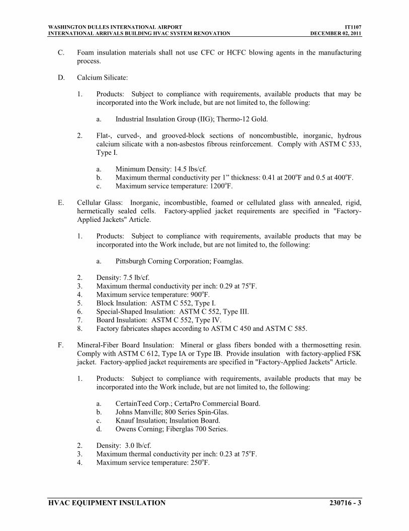
WASHINGTON DULLES INTERNATIONAL AIRPORT IT1107INTERNATIONAL ARRIVALS BUILDING HVAC SYSTEM RENOVATION DECEMBER 02, 2011
HVAC EQUIPMENT INSULATION 230716 - 3
C. Foam insulation materials shall not use CFC or HCFC blowing agents in the manufacturing process.
D. Calcium Silicate:
1. Products: Subject to compliance with requirements, available products that may be incorporated into the Work include, but are not limited to, the following:
a. Industrial Insulation Group (IIG); Thermo-12 Gold.
2. Flat-, curved-, and grooved-block sections of noncombustible, inorganic, hydrous calcium silicate with a non-asbestos fibrous reinforcement. Comply with ASTM C 533, Type I.
a. Minimum Density: 14.5 lbs/cf.b. Maximum thermal conductivity per 1” thickness: 0.41 at 200oF and 0.5 at 400o
c. Maximum service temperature: 1200F.
o
E. Cellular Glass: Inorganic, incombustible, foamed or cellulated glass with annealed, rigid, hermetically sealed cells. Factory-applied jacket requirements are specified in "Factory-Applied Jackets" Article.
F.
1. Products: Subject to compliance with requirements, available products that may be incorporated into the Work include, but are not limited to, the following:
a. Pittsburgh Corning Corporation; Foamglas.
2. Density: 7.5 lb/cf.3. Maximum thermal conductivity per inch: 0.29 at 75o
4. Maximum service temperature: 900F.
o
5. Block Insulation: ASTM C 552, Type I.F.
6. Special-Shaped Insulation: ASTM C 552, Type III.7. Board Insulation: ASTM C 552, Type IV.8. Factory fabricates shapes according to ASTM C 450 and ASTM C 585.
F. Mineral-Fiber Board Insulation: Mineral or glass fibers bonded with a thermosetting resin. Comply with ASTM C 612, Type IA or Type IB. Provide insulation with factory-applied FSK jacket. Factory-applied jacket requirements are specified in "Factory-Applied Jackets" Article.
1. Products: Subject to compliance with requirements, available products that may be incorporated into the Work include, but are not limited to, the following:
a. CertainTeed Corp.; CertaPro Commercial Board.b. Johns Manville; 800 Series Spin-Glas.c. Knauf Insulation; Insulation Board.d. Owens Corning; Fiberglas 700 Series.
2. Density: 3.0 lb/cf.3. Maximum thermal conductivity per inch: 0.23 at 75o
4. Maximum service temperature: 250F.
oF.

WASHINGTON DULLES INTERNATIONAL AIRPORT IT1107INTERNATIONAL ARRIVALS BUILDING HVAC SYSTEM RENOVATION DECEMBER 02, 2011
HVAC EQUIPMENT INSULATION 230716 - 4
G. High-Temperature, Mineral-Fiber Board Insulation: Mineral or glass fibers bonded with a thermosetting resin. Comply with ASTM C 612, Type III, without factory-applied jacket.
1. Products: Subject to compliance with requirements, available products that may be incorporated into the Work include, but are not limited to, the following:
a. Industrial Insulation Group (IIG); MinWool-1200 Industrial Board.b. Rock Wool; Delta Board.c. Roxul Inc.; RHT and RockBoard.d. Thermafiber, Inc.; Thermafiber Industrial Felt.
2. Density: 12.0 lb/cf.3. Maximum thermal conductivity per inch: 0.24 at 75o
4. Maximum service temperature: 1150F.
o
H. Mineral-Fiber, Preformed Pipe Insulation:
F.
1. Products: Subject to compliance with requirements, available products that may be incorporated into the Work include, but are not limited to, the following:
a. Johns Manville; Micro-Lok.b. Knauf Insulation; 1000-Degree Pipe Insulation.c. Owens Corning; Fiberglas Pipe Insulation.
2. Type I, 850 Deg F
a. Minimum density: 4.0 lb/cf.
Materials: Mineral or glass fibers bonded with a thermosetting resin. Comply with ASTM C 547, Type I, Grade A, with factory-applied ASJ. Factory-applied jacket requirements are specified in "Factory-Applied Jackets" Article.
b. Maximum thermal conductivity per 1” thickness: 0.27 at 75o
c. Puncture Resistance: 50 units.F mean temperature.
3. Type II, 1200 Deg F
a. Minimum density: 2.4 lb/cf.
Materials: Mineral or glass fibers bonded with a thermosetting resin. Comply with ASTM C 547, Type II, Grade A, without factory-applied jacket.
b. Maximum thermal conductivity per 1” thickness: 0.23 at 75o
I. Mineral-Fiber, Pipe and Tank Insulation: Mineral or glass fibers bonded with a thermosetting resin. Semirigid board material with factory-applied ASJ complying with ASTM C 1393, Type II or Type IIIA Category 2, or with properties similar to ASTM C 612, Type IB. Nominal density is
F mean temperature.
2.5 lb/cu. ft. or more. Thermal conductivity (k-value) at 100 deg F is 0.29 Btu x in./h x sq. ft. x deg F
1. Products: Subject to compliance with requirements, available products that may be incorporated into the Work include, but are not limited to, the following:
or less. Factory-applied jacket requirements are specified in "Factory-Applied Jackets" Article.
a. CertainTeed Corp.; CrimpWrap.b. Johns Manville; MicroFlex.c. Knauf Insulation; Pipe and Tank Insulation.

WASHINGTON DULLES INTERNATIONAL AIRPORT IT1107INTERNATIONAL ARRIVALS BUILDING HVAC SYSTEM RENOVATION DECEMBER 02, 2011
HVAC EQUIPMENT INSULATION 230716 - 5
d. Owens Corning; Fiberglas Pipe and Tank Insulation.
2.2 INSULATING CEMENTS
A. Mineral-Fiber Insulating Cement: Comply with ASTM C 195.
1. Products: Subject to compliance with requirements, available products that may be incorporated into the Work include, but are not limited to, the following:
a. Ramco Insulation, Inc.; Super-Stik.
B. Mineral-Fiber, Hydraulic-Setting Insulating and Finishing Cement: Comply with ASTM C 449.
1. Products: Subject to compliance with requirements, available products that may be incorporated into the Work include, but are not limited to, the following:
a. Ramco Insulation, Inc.; Ramcote 1200 and Quik-Cote.
2.3 ADHESIVES
A. Materials shall be compatible with insulation materials, jackets, and substrates and for bonding insulation to itself and to surfaces to be insulated unless otherwise indicated.
B. For indoor applications, adhesive shall have a VOC content of 80 g/L or less when calculated according to 40 CFR 59, Subpart D (EPA Method 24).
C. Adhesive shall comply with the testing and product requirements of the California Department of Health Services' "Standard Practice for the Testing of Volatile Organic Emissions from Various Sources Using Small-Scale Environmental Chambers."
D. Calcium Silicate Adhesive: Fibrous, sodium-silicate-based adhesive with a service temperature range of 50 to 800 deg F
1. Products: Subject to compliance with requirements, available products that may be incorporated into the Work include, but are not limited to, the following:
.
a. Childers Brand, Specialty Construction Brands, Inc., a business of H. B. Fuller Company; CP-97.
b. Eagle Bridges - Marathon Industries; 290.c. Foster Brand, Specialty Construction Brands, Inc., a business of H. B. Fuller
Company; 81-27.
E. Cellular-Glass Adhesive: Two-component, thermosetting urethane adhesive containing no flammable solvents, with a service temperature range of minus 100 to plus 200 deg F
1. Products: Subject to compliance with requirements, available products that may be incorporated into the Work include, but are not limited to, the following:
.
a. Foster Brand, Specialty Construction Brands, Inc., a business of H. B. Fuller Company; 81-84.

WASHINGTON DULLES INTERNATIONAL AIRPORT IT1107INTERNATIONAL ARRIVALS BUILDING HVAC SYSTEM RENOVATION DECEMBER 02, 2011
HVAC EQUIPMENT INSULATION 230716 - 6
F. Mineral-Fiber Adhesive: Water-based adhesive for bonding vapor-barrier jacketing to mineral-fiber insulation.
1. Products: Subject to compliance with requirements, provide one of the following:
a. Childers Brand, Specialty Construction Brands, Inc., a business of H. B. Fuller Company; CP-127.
b. Eagle Bridges - Marathon Industries; 225.c. Foster Brand, Specialty Construction Brands, Inc., a business of H. B. Fuller
Company; 85-60/85-70.
2. Fire / smoke tested in accordance with ASTM E-84.3. ASTM C-916, Type 2.4. Service temperature range: -20 deg F to 200 deg F.
2.4 MASTICS
A. Materials shall be compatible with insulation materials, jackets, and substrates; comply with MIL-PRF-19565C, Type II.
1. For indoor applications, use mastics that have a VOC content of 50 g/L or less when calculated according to 40 CFR 59, Subpart D (EPA Method 24).
B. Vapor-Barrier Mastic: Water based; suitable for indoor and outdoor use on below ambient services.
1. Products: Subject to compliance with requirements, provide one of the following:
a. Foster Brand, Specialty Construction Brands, Inc., a business of H .B. Fuller Company; 30-80/30-90.
b. Vimasco Corporation; 749.
2. Water-Vapor Permeance: ASTM E 96/E 96M, Procedure B, 0.013 perm at 43-mil
3. Service Temperature Range:
dry film thickness.
Minus 20 to plus 180 deg F4. Solids Content: ASTM D 1644, 58 percent by volume and 70 percent by weight.
.
5. Color: White.
C. Vapor-Barrier Mastic: Solvent based; suitable for indoor use on below ambient services.
1. Products: Subject to compliance with requirements, provide one of the following:
a. Childers Brand, Specialty Construction Brands, Inc., a business of H. B. Fuller Company; CP-30.
b. Eagle Bridges - Marathon Industries; 501.c. Foster Brand, Specialty Construction Brands, Inc., a business of H. B. Fuller
Company; 30-35.
2. Water-Vapor Permeance: ASTM F 1249, 0.05 perm at 35-mil3. Service Temperature Range:
dry film thickness.0 to 180 deg F.
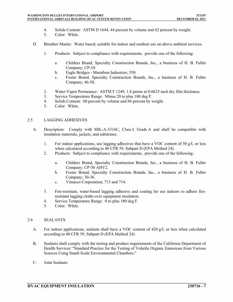
WASHINGTON DULLES INTERNATIONAL AIRPORT IT1107INTERNATIONAL ARRIVALS BUILDING HVAC SYSTEM RENOVATION DECEMBER 02, 2011
HVAC EQUIPMENT INSULATION 230716 - 7
4. Solids Content: ASTM D 1644, 44 percent by volume and 62 percent by weight.5. Color: White.
D. Breather Mastic: Water based; suitable for indoor and outdoor use on above ambient services.
1. Products: Subject to compliance with requirements, provide one of the following:
a. Childers Brand, Specialty Construction Brands, Inc., a business of H. B. Fuller Company; CP-10.
b. Eagle Bridges - Marathon Industries; 550.c. Foster Brand, Specialty Construction Brands, Inc., a business of H. B. Fuller
Company; 46-50.
2. Water-Vapor Permeance: ASTM F 1249, 1.8 perms at 0.0625-inch3. Service Temperature Range:
dry film thickness.Minus 20 to plus 180 deg F
4. Solids Content: 60 percent by volume and 66 percent by weight..
5. Color: White.
2.5 LAGGING ADHESIVES
A. Description: Comply with MIL-A-3316C, Class I, Grade A and shall be compatible with insulation materials, jackets, and substrates.
1. For indoor applications, use lagging adhesives that have a VOC content of 50 g/L or less when calculated according to 40 CFR 59, Subpart D (EPA Method 24).
2. Products: Subject to compliance with requirements, provide one of the following:
a. Childers Brand, Specialty Construction Brands, Inc., a business of H. B. Fuller Company; CP-50 AHV2.
b. Foster Brand, Specialty Construction Brands, Inc., a business of H. B. Fuller Company; 30-36.
c. Vimasco Corporation; 713 and 714.
3. Fire-resistant, water-based lagging adhesive and coating for use indoors to adhere fire-resistant lagging cloths over equipment insulation.
4. Service Temperature Range: 0 to plus 180 deg F5. Color: White.
.
2.6 SEALANTS
A. For indoor applications, sealants shall have a VOC content of 420 g/L or less when calculated according to 40 CFR 59, Subpart D (EPA Method 24).
B. Sealants shall comply with the testing and product requirements of the California Department of Health Services' "Standard Practice for the Testing of Volatile Organic Emissions from Various Sources Using Small-Scale Environmental Chambers."
C. Joint Sealants:
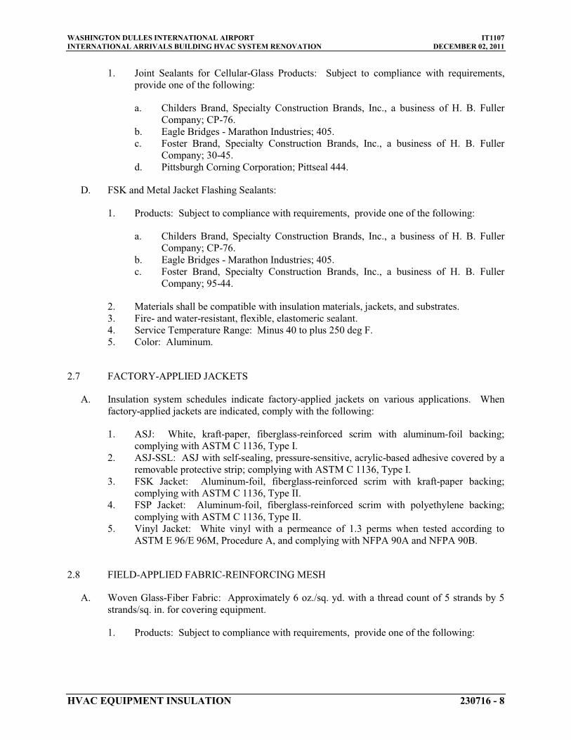
WASHINGTON DULLES INTERNATIONAL AIRPORT IT1107INTERNATIONAL ARRIVALS BUILDING HVAC SYSTEM RENOVATION DECEMBER 02, 2011
HVAC EQUIPMENT INSULATION 230716 - 8
1. Joint Sealants for Cellular-Glass Products: Subject to compliance with requirements, provide one of the following:
a. Childers Brand, Specialty Construction Brands, Inc., a business of H. B. Fuller Company; CP-76.
b. Eagle Bridges - Marathon Industries; 405.c. Foster Brand, Specialty Construction Brands, Inc., a business of H. B. Fuller
Company; 30-45.d. Pittsburgh Corning Corporation; Pittseal 444.
D. FSK and Metal Jacket Flashing Sealants:
1. Products: Subject to compliance with requirements, provide one of the following:
a. Childers Brand, Specialty Construction Brands, Inc., a business of H. B. Fuller Company; CP-76.
b. Eagle Bridges - Marathon Industries; 405.c. Foster Brand, Specialty Construction Brands, Inc., a business of H. B. Fuller
Company; 95-44.
2. Materials shall be compatible with insulation materials, jackets, and substrates.3. Fire- and water-resistant, flexible, elastomeric sealant.4. Service Temperature Range: Minus 40 to plus 250 deg F5. Color: Aluminum.
.
2.7 FACTORY-APPLIED JACKETS
A. Insulation system schedules indicate factory-applied jackets on various applications. When factory-applied jackets are indicated, comply with the following:
1. ASJ: White, kraft-paper, fiberglass-reinforced scrim with aluminum-foil backing; complying with ASTM C 1136, Type I.
2. ASJ-SSL: ASJ with self-sealing, pressure-sensitive, acrylic-based adhesive covered by a removable protective strip; complying with ASTM C 1136, Type I.
3. FSK Jacket: Aluminum-foil, fiberglass-reinforced scrim with kraft-paper backing; complying with ASTM C 1136, Type II.
4. FSP Jacket: Aluminum-foil, fiberglass-reinforced scrim with polyethylene backing; complying with ASTM C 1136, Type II.
5. Vinyl Jacket: White vinyl with a permeance of 1.3 perms
2.8 FIELD-APPLIED FABRIC-REINFORCING MESH
when tested according to ASTM E 96/E 96M, Procedure A, and complying with NFPA 90A and NFPA 90B.
A. Woven Glass-Fiber Fabric: Approximately 6 oz./sq. yd. with a thread count of 5 strands by 5 strands/sq. in.
1. Products: Subject to compliance with requirements, provide one of the following:
for covering equipment.

WASHINGTON DULLES INTERNATIONAL AIRPORT IT1107INTERNATIONAL ARRIVALS BUILDING HVAC SYSTEM RENOVATION DECEMBER 02, 2011
HVAC EQUIPMENT INSULATION 230716 - 9
a. Childers Brand, Specialty Construction Brands, Inc., a business of H. B. Fuller Company; Chil-Glas No. 5.
B. Woven Polyester Fabric: Approximately 1 oz./sq. yd. with a thread count of 10 strands by 10 strands/sq. in.
1. Products: Subject to compliance with requirements, provide one of the following:
, in a Leno weave, for equipment.
a. Foster Brand, Specialty Construction Brands, Inc., a business of H. B. Fuller Company; Mast-A-Fab.
b. Vimasco Corporation; Elastafab 894.
2.9 FIELD-APPLIED CLOTHS
A. Woven Glass-Fiber Fabric: Comply with MIL-C-20079H, Type I, plain weave, and presized a minimum of
1. Products: Subject to compliance with requirements, provide one of the following:
8 oz./sq. yd.
a. Alpha Associates, Inc.; Alpha-Maritex 84215 and 84217/9485RW, Luben 59.
2.10 FIELD-APPLIED JACKETS
A. Metal Jacket:
1. Products: Subject to compliance with requirements, provide one of the following:
a. Childers Brand, Specialty Construction Brands, Inc., a business of H. B. Fuller Company; Metal Jacketing Systems.
b. ITW Insulation Systems; Aluminum and Stainless Steel Jacketing.c. RPR Products, Inc.; Insul-Mate.
2. Aluminum Jacket: Comply with ASTM B 209
a. Sheet and roll stock ready for shop or field sizing or factory cut and rolled to size.
, Alloy 3003, 3005, 3105, or 5005, Temper H-14.
b. Finish and thickness are indicated in field-applied jacket schedules.c. Moisture Barrier for Outdoor Applications: 2.5-mil-d. Factory-Fabricated Fitting Covers:
thick polysurlyn.
1) Same material, finish, and thickness as jacket.2) Preformed two-piece or gore, 45- and 90-degree, short- and long-radius
elbows.3) Tee covers.4) Flange and union covers.5) End caps.6) Beveled collars.7) Valve covers.8) Field fabricate fitting covers only if factory-fabricated fitting covers are not
available.

WASHINGTON DULLES INTERNATIONAL AIRPORT IT1107INTERNATIONAL ARRIVALS BUILDING HVAC SYSTEM RENOVATION DECEMBER 02, 2011
HVAC EQUIPMENT INSULATION 230716 - 10
2.11 TAPES
A. ASJ Tape: White vapor-retarder tape matching factory-applied jacket with acrylic adhesive, complying with ASTM C 1136.
1. Width: 3 inches2. Thickness:
.11.5 mils
3. Adhesion: .
90 ounces force/inch4. Elongation: 2 percent.
in width.
5. Tensile Strength: 40 lbf/inch6. ASJ Tape Disks and Squares: Precut disks or squares of ASJ tape.
in width.
B. FSK Tape: Foil-face, vapor-retarder tape matching factory-applied jacket with acrylic adhesive; complying with ASTM C 1136.
1. Width: 3 inches2. Thickness:
.6.5 mils
3. Adhesion: .
90 ounces force/inch4. Elongation: 2 percent.
in width.
5. Tensile Strength: 40 lbf/inch6. FSK Tape Disks and Squares: Precut disks or squares of FSK tape.
in width.
C. Aluminum-Foil Tape: Vapor-retarder tape with acrylic adhesive.
1. Width: 2 inches2. Thickness:
.3.7 mils
3. Adhesion: .
100 ounces force/inch4. Elongation: 5 percent.
in width.
5. Tensile Strength: 34 lbf/inch
2.12 SECUREMENTS
in width.
A. Bands:
1. Stainless Steel: ASTM A 167 or ASTM A 240/A 240M, Type 304; 0.015 inch thick, 3/4 inch
2. Aluminum: wide with wing seal.
ASTM B 209, Alloy 3003, 3005, 3105, or 5005; Temper H-14, 0.020 inchthick, 3/4 inch
3. Springs: Twin spring set constructed of stainless steel with ends flat and slotted to accept metal bands. Spring size determined by manufacturer for application.
wide with wing seal.
B. Staples: Outward-clinching insulation staples, nominal 3/4-inch-
C. Wire:
wide, stainless steel or Monel.
0.080-inch nickel-copper alloy or 0.062-inch
2.13 CORNER ANGLES
soft-annealed, galvanized steel.
A. Aluminum Corner Angles: 0.040 inch thick, minimum 1 by 1 inch, aluminum according to ASTM B 209, Alloy 3003, 3005, 3105, or 5005; Temper H-14.

WASHINGTON DULLES INTERNATIONAL AIRPORT IT1107INTERNATIONAL ARRIVALS BUILDING HVAC SYSTEM RENOVATION DECEMBER 02, 2011
HVAC EQUIPMENT INSULATION 230716 - 11
PART 3 - EXECUTION
3.1 EXAMINATION
A. Examine substrates and conditions for compliance with requirements for installation tolerances and other conditions affecting performance of insulation application.
1. Verify that systems and equipment to be insulated have been tested and are free ofdefects.
2. Verify that surfaces to be insulated are clean and dry.
B. Proceed with installation only after unsatisfactory conditions have been corrected.
3.2 PREPARATION
A. Surface Preparation: Clean and dry surfaces to receive insulation. Remove materials that will adversely affect insulation application.
B. Surface Preparation: Clean and prepare surfaces to be insulated. Before insulating, apply a corrosion coating to insulated surfaces as follows:
1. Carbon Steel: Coat carbon steel operating at a service temperature between 32 and 300 deg F
C. Coordinate insulation installation with the trade installing heat tracing. Comply with requirements for heat tracing that applies to insulation.
with an epoxy coating. Consult coating manufacturer for appropriate coating materials and application methods for operating temperature range.
D. Mix insulating cements with clean potable water; if insulating cements are to be in contact with stainless-steel surfaces, use demineralized water.
3.3 GENERAL INSTALLATION REQUIREMENTS
A. Install insulation materials, accessories, and finishes with smooth, straight, and even surfaces; free of voids throughout the length of equipment.
B. Install insulation materials, forms, vapor barriers or retarders, jackets, and thicknesses required for each item of equipment as specified in insulation system schedules.
C. Install accessories compatible with insulation materials and suitable for the service. Install accessories that do not corrode, soften, or otherwise attack insulation or jacket in either wet or dry state.
D. Install insulation with longitudinal seams at top and bottom of horizontal runs.
E. Install multiple layers of insulation with longitudinal and end seams staggered.
F. Keep insulation materials dry during application and finishing.
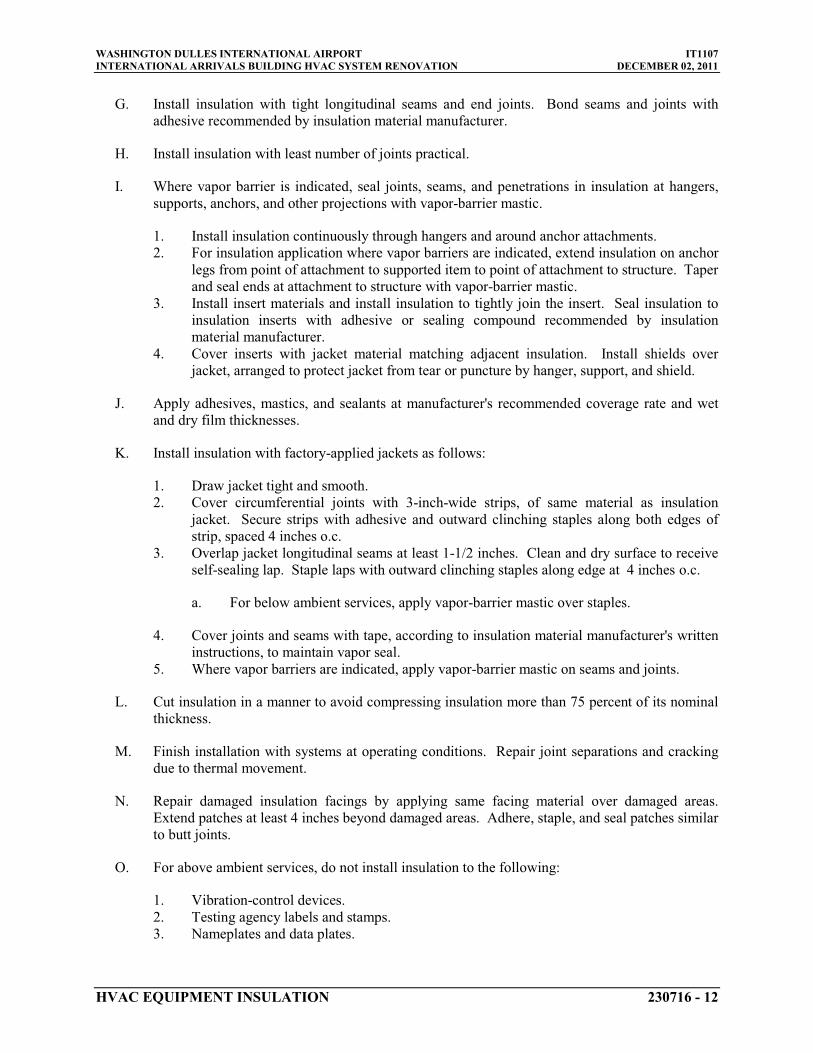
WASHINGTON DULLES INTERNATIONAL AIRPORT IT1107INTERNATIONAL ARRIVALS BUILDING HVAC SYSTEM RENOVATION DECEMBER 02, 2011
HVAC EQUIPMENT INSULATION 230716 - 12
G. Install insulation with tight longitudinal seams and end joints. Bond seams and joints with adhesive recommended by insulation material manufacturer.
H. Install insulation with least number of joints practical.
I. Where vapor barrier is indicated, seal joints, seams, and penetrations in insulation at hangers, supports, anchors, and other projections with vapor-barrier mastic.
1. Install insulation continuously through hangers and around anchor attachments.2. For insulation application where vapor barriers are indicated, extend insulation on anchor
legs from point of attachment to supported item to point of attachment to structure. Taper and seal ends at attachment to structure with vapor-barrier mastic.
3. Install insert materials and install insulation to tightly join the insert. Seal insulation to insulation inserts with adhesive or sealing compound recommended by insulation material manufacturer.
4. Cover inserts with jacket material matching adjacent insulation. Install shields over jacket, arranged to protect jacket from tear or puncture by hanger, support, and shield.
J. Apply adhesives, mastics, and sealants at manufacturer's recommended coverage rate and wet and dry film thicknesses.
K. Install insulation with factory-applied jackets as follows:
1. Draw jacket tight and smooth.2. Cover circumferential joints with 3-inch-wide strips, of same material as insulation
jacket. Secure strips with adhesive and outward clinching staples along both edges of strip, spaced 4 inches
3. Overlap jacket longitudinal seams at least o.c.
1-1/2 inches. Clean and dry surface to receive self-sealing lap. Staple laps with outward clinching staples along edge at 4 inches
a. For below ambient services, apply vapor-barrier mastic over staples.
o.c.
4. Cover joints and seams with tape, according to insulation material manufacturer's written instructions, to maintain vapor seal.
5. Where vapor barriers are indicated, apply vapor-barrier mastic on seams and joints.
L. Cut insulation in a manner to avoid compressing insulation more than 75 percent of its nominal thickness.
M. Finish installation with systems at operating conditions. Repair joint separations and cracking due to thermal movement.
N. Repair damaged insulation facings by applying same facing material over damaged areas. Extend patches at least 4 inches
O. For above ambient services, do not install insulation to the following:
beyond damaged areas. Adhere, staple, and seal patches similar to butt joints.
1. Vibration-control devices.2. Testing agency labels and stamps.3. Nameplates and data plates.

WASHINGTON DULLES INTERNATIONAL AIRPORT IT1107INTERNATIONAL ARRIVALS BUILDING HVAC SYSTEM RENOVATION DECEMBER 02, 2011
HVAC EQUIPMENT INSULATION 230716 - 13
4. Manholes.5. Handholes.6. Cleanouts.
3.4 INSTALLATION OF EQUIPMENT, TANK, AND VESSEL INSULATION
A. Mineral-Fiber, Pipe and Tank Insulation Installation for Tanks and Vessels: Secure insulation with adhesive and anchor pins and speed washers.
1. Apply adhesives according to manufacturer's recommended coverage rates per unit area of tank and vessel surfaces.
2. Groove and score insulation materials to fit as closely as possible to equipment, including contours. Bevel insulation edges for cylindrical surfaces for tight joints. Stagger end joints.
3. Protect exposed corners with secured corner angles.4. Install adhesively attached or self-sticking insulation hangers and speed washers on sides
of tanks and vessels as follows:
a. Do not weld anchor pins to ASME-labeled pressure vessels.b. Select insulation hangers and adhesive that is compatible with service temperature
and with substrate.c. On tanks and vessels, maximum anchor-pin spacing is 3 inches from insulation end
joints, and 16 inchesd. Do not overcompress insulation during installation.
o.c. in both directions.
e. Cut and miter insulation segments to fit curved sides and domed heads of tanks and vessels.
f. Impale insulation over anchor pins and attach speed washers.g. Cut excess portion of pins extending beyond speed washers or bend parallel with
insulation surface. Cover exposed pins and washers with tape matching insulation facing.
5. Secure each layer of insulation with stainless-steel or aluminum bands. Select band material compatible with insulation materials.
6. Where insulation hangers on equipment and vessels are not permitted or practical and where insulation support rings are not provided, install a girdle network for securing insulation. Stretch pre-stressed aircraft cable around the diameter of vessel and make taut with clamps, turnbuckles, or breather springs. Place one circumferential girdle around equipment approximately 6 inches from each end. Install wire or cable between two circumferential girdles 12 inches o.c. Install a wire ring around each end and around outer periphery of center openings, and stretch prestressed aircraft cable radially from the wire ring to nearest circumferential girdle. Install additional circumferential girdles along the body of equipment or tank at a minimum spacing of 48 inches
7. Stagger joints between insulation layers at least
o.c. Use this network for securing insulation with tie wire or bands.
3 inches8. Install insulation in removable segments on equipment access doors, manholes,
handholes, and other elements that require frequent removal for service and inspection.
.
9. Bevel and seal insulation ends around manholes, handholes, ASME stamps, and nameplates.
10. For equipment with surface temperatures below ambient, apply mastic to open ends, joints, seams, breaks, and punctures in insulation.

WASHINGTON DULLES INTERNATIONAL AIRPORT IT1107INTERNATIONAL ARRIVALS BUILDING HVAC SYSTEM RENOVATION DECEMBER 02, 2011
HVAC EQUIPMENT INSULATION 230716 - 14
B. Insulation Installation on Pumps:
1. Fabricate metal boxes lined with insulation. Fit boxes around pumps and coincide box joints with splits in pump casings. Fabricate joints with outward bolted flanges. Bolt flanges on 6-inch centers, starting at corners. Install 3/8-inch-
2. Fabricate boxes from aluminum, at least
diameter fasteners with wing nuts. Alternatively, secure the box sections together using a latching mechanism.
0.060 inch3. For below ambient services, install a vapor barrier at seams, joints, and penetrations.
Seal between flanges with replaceable gasket material to form a vapor barrier.
thick.
3.5 INSTALLATION OF CALCIUM SILICATE INSULATION
A. Insulation Installation on Boiler Breechings:
1. Secure single-layer insulation with stainless-steel bands at 12-inch
2. Install two-layer insulation with joints tightly butted and staggered at least
intervals and tighten bands without deforming insulation material.
3 inches.Secure inner layer with wire spaced at 12-inch intervals. Secure outer layer with stainless-steel bands at 12-inch
3. On exposed applications without metal jacket, finish insulation surface with a skim coat of mineral-fiber, hydraulic-setting cement. When cement is dry, apply flood coat of lagging adhesive and press on one layer of glass cloth. Overlap edges at least
intervals.
1 inch
3.6 FINISHES
.Apply finish coat of lagging adhesive over glass cloth. Thin finish coat to achieve smooth, uniform finish.
A. Equipment Insulation with ASJ, Glass-Cloth, or Other Paintable Jacket Material: Paint jacket with paint system identified below and as specified in Division 09 painting Sections.
1. Flat Acrylic Finish: Two finish coats over a primer that is compatible with jacket material and finish coat paint. Add fungicidal agent to render fabric mildew proof.
a. Finish Coat Material: Interior, flat, latex-emulsion size.
B. Color: Final color as selected by Architect. Vary first and second coats to allow visual inspection of the completed Work.
C. Do not field paint aluminum or stainless-steel jackets.
3.7 FIELD QUALITY CONTROL
A. Testing Agency: Engage a qualified testing agency to perform tests and inspections.
B. Perform tests and inspections.
C. Tests and Inspections: Inspect field-insulated equipment, randomly selected by Architect, by removing field-applied jacket and insulation in layers in reverse order of their installation. Extent of inspection shall be limited to one location(s) for each type of equipment defined in

WASHINGTON DULLES INTERNATIONAL AIRPORT IT1107INTERNATIONAL ARRIVALS BUILDING HVAC SYSTEM RENOVATION DECEMBER 02, 2011
HVAC EQUIPMENT INSULATION 230716 - 15
the "Equipment Insulation Schedule" Article. For large equipment, remove only a portion adequate to determine compliance.
D. All insulation applications will be considered defective Work if sample inspection reveals noncompliance with requirements. It shall be the responsibility of the Contractor to compensate retesting and reinspecting work until it is considered within compliance of the contract documents.
3.8 EQUIPMENT INSULATION SCHEDULE
A. Insulation materials and thicknesses are identified below. If more than one material is listed for a type of equipment, selection from materials listed is Contractor's option.
B. Insulate indoor and outdoor equipment that is not factory insulated.
C. Heat-exchanger (water-to-water for heating service) insulation shall be one of the following:
1. Calcium Silicate: 3 inches
D. Heating-hot-water expansion/compression tank insulation shall be one of the following:
thick.
1. Cellular Glass: 2 inches2. Mineral-Fiber Pipe and Tank:
thick.2 inch
E. Heating-hot-water air-separator insulation shall be one of the following:
thick.
1. Cellular Glass: 2 inches2. Mineral-Fiber Pipe and Tank:
thick.2 inches
3.9 INDOOR, FIELD-APPLIED JACKET SCHEDULE
thick.
A. Install jacket over insulation material. For insulation with factory-applied jacket, install the field-applied jacket over the factory-applied jacket.
B. If more than one material is listed, selection from materials listed is Contractor's option.
C. Equipment:
1. Aluminum, Stucco Embossed: 0.016 inch
PART 4 - CONTRACTOR’S QUALITY CONTROL REQUIREMENTS
thick.
4.1 GENERAL
A. Comply with applicable provisions of Division 01 Section “Quality Requirements” for requirements for Contractor’s Quality Control Program.
WASHINGTON DULLES INTERNATIONAL AIRPORT IT1107INTERNATIONAL ARRIVALS BUILDING HVAC SYSTEM RENOVATION DECEMBER 02, 2011
HVAC EQUIPMENT INSULATION 230716 - 16
END OF SECTION 230716

WASHINGTON DULLES INTERNATIONAL AIRPORT IT1107INTERNATIONAL ARRIVALS BUILDING HVAC SYSTEM RENOVATION DECEMBER 02, 2011
HVAC PIPING INSULATION 230719 - 1
SECTION 230719 -
PART 1 - GENERAL
HVAC PIPING INSULATION
1.1 RELATED DOCUMENTS
A. Drawings and general provisions of the Contract, including General and SupplementaryConditions and Division 01 Specification Sections, apply to this Section.
1.2 SUMMARY
A. Section includes insulating the following HVAC piping systems:
1. Condensate drain piping, indoors.2. Chilled-water piping, indoors and outdoors.3. Heating hot-water piping, indoors and outdoors.4. High-Temperature Heating hot-water, indoors.
B. Related Sections:
1. Division 23 Section "Duct Insulation."
1.3 ACTION SUBMITTALS
A. Product Data: For each type of product indicated. Include thermal conductivity, water-vapor permeance thickness, and jackets (both factory and field applied if any).
B. Shop Drawings: Include plans, elevations, sections, details, and attachments to other work.
1. Detail application of protective shields, saddles, and inserts at hangers for each type of insulation and hanger.
2. Detail attachment and covering of heat tracing inside insulation.3. Detail insulation application at pipe expansion joints for each type of insulation.4. Detail insulation application at elbows, fittings, flanges, valves, and specialties for each
type of insulation.5. Detail removable insulation at piping specialties.6. Detail application of field-applied jackets.7. Detail application at linkages of control devices.
1.4 INFORMATIONAL SUBMITTALS
A. Qualification Data: For qualified Installer.
B. Material Test Reports: From a qualified testing agency acceptable to authorities having jurisdiction indicating, interpreting, and certifying test results for compliance of insulation

WASHINGTON DULLES INTERNATIONAL AIRPORT IT1107INTERNATIONAL ARRIVALS BUILDING HVAC SYSTEM RENOVATION DECEMBER 02, 2011
HVAC PIPING INSULATION 230719 - 2
materials, sealers, attachments, cements, and jackets, with requirements indicated. Include dates of tests and test methods employed.
C. Field quality-control reports.
1.5 QUALITY ASSURANCE
A. Installer Qualifications: Skilled mechanics who have successfully completed an apprenticeship program or another craft training program certified by the Department of Labor, Bureau of Apprenticeship and Training.
B. Surface-Burning Characteristics: For insulation and related materials, as determined by testing identical products according to ASTM E 84, by a testing and inspecting agency acceptable to authorities having jurisdiction. Factory label insulation and jacket materials and adhesive, mastic, tapes, and cement material containers, with appropriate markings of applicable testing agency.
1. Insulation Installed Indoors: Flame-spread index of 25 or less, and smoke-developed index of 50 or less.
2. Insulation Installed Outdoors: Flame-spread index of 75 or less, and smoke-developed index of 150 or less.
1.6 DELIVERY, STORAGE, AND HANDLING
A. Packaging: Insulation material containers shall be marked by manufacturer with appropriate ASTM standard designation, type and grade, and maximum use temperature.
1.7 COORDINATION
A. Coordinate sizes and locations of supports, hangers, and insulation shields specified in Division 23 Section "Hangers and Supports for HVAC Piping and Equipment."
B. Coordinate clearance requirements with piping Installer for piping insulation application. Before preparing piping Shop Drawings establish and maintain clearance requirements for installation of insulation and field-applied jackets and finishes and for space required for maintenance.
C. Coordinate installation and testing of heat tracing.
1.8 SCHEDULING
A. Schedule insulation application after pressure testing systems and, where required, after installing and testing heat tracing. Insulation application may begin on segments that have satisfactory test results.
B. Complete installation and concealment of plastic materials as rapidly as possible in each area of construction.

WASHINGTON DULLES INTERNATIONAL AIRPORT IT1107INTERNATIONAL ARRIVALS BUILDING HVAC SYSTEM RENOVATION DECEMBER 02, 2011
HVAC PIPING INSULATION 230719 - 3
PART 2 - PRODUCTS
2.1 INSULATION MATERIALS
A. Comply with requirements in "Piping Insulation Schedule, General," "Indoor Piping Insulation Schedule," "Outdoor, Aboveground Piping Insulation Schedule," and "Outdoor, Underground Piping Insulation Schedule" articles for where insulating materials shall be applied.
B. Products shall not contain asbestos, lead, mercury, or mercury compounds.
C. Products that come in contact with stainless steel shall have a leachable chloride content of less than 50 ppm when tested according to ASTM C 871.
D. Insulation materials for use on austenitic stainless steel shall be qualified as acceptable according to ASTM C 795.
E. Foam insulation materials shall not use CFC or HCFC blowing agents in the manufacturing process.
F. Calcium Silicate:
1. Products: Subject to compliance with requirements, provide one of the following:
a. Industrial Insulation Group (IIG); Thermo-12 Gold.
2. Preformed Pipe Sections: Flat-, curved-, and grooved-block sections of noncombustible, inorganic, hydrous calcium silicate with a non-asbestos fibrous reinforcement. Comply with ASTM C 533, Type I.
3. Flat-, curved-, and grooved-block sections of noncombustible, inorganic, hydrous calcium silicate with a non-asbestos fibrous reinforcement. Comply with ASTM C 533, Type I.
4. Prefabricated Fitting Covers: Comply with ASTM C 450 and ASTM C 585 for dimensions used in performing insulation to cover valves, elbows, tees, and flanges.
5. Minimum Density: 14.5 lbs/cf.6. Maximum thermal conductivity per 1” thickness: 0.41 at 200oF and 0.5 at 400o
7. Maximum service temperature: 1200F.
o
G. Cellular Glass: Inorganic, incombustible, foamed or cellulated glass with annealed, rigid, hermetically sealed cells. Factory-applied jacket requirements are specified in "Factory-Applied Jackets" Article.
F.
1. Products: Subject to compliance with requirements, provide one of the following:
a. Pittsburgh Corning Corporation; Foamglass.
2. Density: 7.5 lb/cf.3. Maximum thermal conductivity per inch: 0.29 at 75o
4. Maximum service temperature: 900F.
o
5. Block Insulation: ASTM C 552, Type I.F.
6. Special-Shaped Insulation: ASTM C 552, Type III.

WASHINGTON DULLES INTERNATIONAL AIRPORT IT1107INTERNATIONAL ARRIVALS BUILDING HVAC SYSTEM RENOVATION DECEMBER 02, 2011
HVAC PIPING INSULATION 230719 - 4
7. Board Insulation: ASTM C 552, Type IV.8. Preformed Pipe Insulation without Jacket: Comply with ASTM C 552, Type II, Class 1.9. Factory fabricates shapes according to ASTM C 450 and ASTM C 585.
H. Flexible Elastomeric Insulation: Closed-cell, sponge- or expanded-rubber materials. Comply with ASTM C 534, Type I for tubular materials.
1. Products: Subject to compliance with requirements, provide one of the following:
a. Aeroflex USA, Inc.; Aerocel.b. Armacell LLC; AP Armaflex.c. K-Flex USA; Insul-Lock, Insul-Tube, and K-FLEX LS.
2. Density: 3.0 lb/cf.3. Maximum thermal conductivity per inch: 0.25 at 75o
4. Maximum service temperature: 220F.
o
I. Mineral-Fiber, Preformed Pipe Insulation:
F.
1. Products: Subject to compliance with requirements, provide one of the following:
a. Johns Manville; Micro-Lok.b. Knauf Insulation; 1000-Degree Pipe Insulation.c. Manson Insulation Inc.; Alley-K.d. Owens Corning; Fiberglas Pipe Insulation.
2. Type I, 850 deg F
2.2 INSULATING CEMENTS
Materials: Mineral or glass fibers bonded with a thermosetting resin. Comply with ASTM C 547, Type I, Grade A, with factory-applied ASJ. Factory-applied jacket requirements are specified in "Factory-Applied Jackets" Article.
A. Mineral-Fiber Insulating Cement: Comply with ASTM C 195.
1. Products: Subject to compliance with requirements, provide one of the following:
a. Ramco Insulation, Inc.; Super-Stik.
2.3 ADHESIVES
A. Materials shall be compatible with insulation materials, jackets, and substrates and for bonding insulation to itself and to surfaces to be insulated unless otherwise indicated.
B. For indoor applications, adhesive shall have a VOC content of 80 g/L or less when calculated according to 40 CFR 59, Subpart D (EPA Method 24).
C. Adhesive shall comply with the testing and product requirements of the California Department of Health Services' "Standard Practice for the Testing of Volatile Organic Emissions from Various Sources Using Small-Scale Environmental Chambers."

WASHINGTON DULLES INTERNATIONAL AIRPORT IT1107INTERNATIONAL ARRIVALS BUILDING HVAC SYSTEM RENOVATION DECEMBER 02, 2011
HVAC PIPING INSULATION 230719 - 5
D. Calcium Silicate Adhesive: Fibrous, sodium-silicate-based adhesive with a service temperature range of 50 to 800 deg F
1. Products: Subject to compliance with requirements, provide one of the following:
.
a. Childers Brand, Specialty Construction Brands, Inc., a business of H. B. Fuller Company; CP-97.
b. Eagle Bridges - Marathon Industries; 290.c. Foster Brand, Specialty Construction Brands, Inc., a business of H. B. Fuller
Company; 81-27.
E. Cellular-Glass Adhesive: Two-component, thermosetting urethane adhesive containing no flammable solvents, with a service temperature range of minus 100 to plus 200 deg F
1. Products: Subject to compliance with requirements, provide one of the following:
.
a. Foster Brand, Specialty Construction Brands, Inc., a business of H. B. Fuller Company; 81-84.
F. Flexible Elastomeric and Polyolefin Adhesive: Synthetic Rubber adhesive for joining seams and butt joints of elastomeric pipe and sheet insulation.
1. Products: Subject to compliance with requirements, provide one of the following:
a. Aeroflex USA, Inc.; Aeroseal.b. Armacell LLC; Armaflex 520 Adhesive.c. K-Flex USA; R-373 Contact Adhesive.
G. ASJ Adhesive, and FSK and PVDC Jacket Adhesive: Neoprene based contact adhesive for bonding insulation jacket lap seams and joints.
1. Products: Subject to compliance with requirements, provide one of the following:
a. Childers Brand, Specialty Construction Brands, Inc., a business of H. B. Fuller Company; CP-82.
b. Eagle Bridges - Marathon Industries; 225.c. Foster Brand, Specialty Construction Brands, Inc., a business of H. B. Fuller
Company; 85-50.
2.4 MASTICS
A. Materials shall be compatible with insulation materials, jackets, and substrates; comply with MIL-PRF-19565C, Type II.
1. For indoor applications, use mastics that have a VOC content of 50 g/L or less when calculated according to 40 CFR 59, Subpart D (EPA Method 24).
B. Vapor-Barrier Mastic: Water based; suitable for indoor use on below-ambient services.
1. Products: Subject to compliance with requirements, provide one of the following:

WASHINGTON DULLES INTERNATIONAL AIRPORT IT1107INTERNATIONAL ARRIVALS BUILDING HVAC SYSTEM RENOVATION DECEMBER 02, 2011
HVAC PIPING INSULATION 230719 - 6
a. Foster Brand, Specialty Construction Brands, Inc., a business of H. B. Fuller Company; 30-80/30-90.
b. Vimasco Corporation; 749.
2. Water-Vapor Permeance: ASTM E 96/E 96M, Procedure B, 0.013 perm at 43-mil
3. Service Temperature Range:
dry film thickness.
Minus 20 to plus 180 deg F4. Solids Content: ASTM D 1644, 58 percent by volume and 70 percent by weight.
.
5. Color: White.
2.5 LAGGING ADHESIVES
A. Description: Comply with MIL-A-3316C, Class I, Grade A and shall be compatible with insulation materials, jackets, and substrates.
1. For indoor applications, use lagging adhesives that have a VOC content of 50 g/L or less when calculated according to 40 CFR 59, Subpart D (EPA Method 24).
2. Products: Subject to compliance with requirements, provide one of the following:
a. Childers Brand, Specialty Construction Brands, Inc., a business of H. B. Fuller Company; CP-50 AHV2.
b. Foster Brand, Specialty Construction Brands, Inc., a business of H. B. Fuller Company; 30-36.
c. Vimasco Corporation; 713 and 714.
3. Fire-resistant, water-based lagging adhesive and coating for use indoors to adhere fire-resistant lagging cloths over pipe insulation.
4. Service Temperature Range: 0 to plus 180 deg F5. Color: White.
.
2.6 SEALANTS
A. For indoor applications, sealants shall have a VOC content of 420 g/L or less when calculated according to 40 CFR 59, Subpart D (EPA Method 24).
B. Sealants shall comply with the testing and product requirements of the California Department of Health Services' "Standard Practice for the Testing of Volatile Organic Emissions from Various Sources Using Small-Scale Environmental Chambers."
C. Joint Sealants:
1. Joint Sealants for Cellular-Glass Products: Subject to compliance with requirements, provide one of the following:
a. Childers Brand, Specialty Construction Brands, Inc., a business of H. B. Fuller Company; CP-76.
b. Eagle Bridges - Marathon Industries; 405.c. Foster Brand, Specialty Construction Brands, Inc., a business of H. B. Fuller
Company; 30-45.

WASHINGTON DULLES INTERNATIONAL AIRPORT IT1107INTERNATIONAL ARRIVALS BUILDING HVAC SYSTEM RENOVATION DECEMBER 02, 2011
HVAC PIPING INSULATION 230719 - 7
2. Materials shall be compatible with insulation materials, jackets, and substrates.3. Permanently flexible, elastomeric sealant.4. Service Temperature Range: Minus 100 to plus 300 deg F5. Color: White or gray.
.
D. FSK and Metal Jacket Flashing Sealants:
1. Products: Subject to compliance with requirements, provide one of the following:
a. Childers Brand, Specialty Construction Brands, Inc., a business of H. B. Fuller Company; CP-76.
b. Eagle Bridges - Marathon Industries; 405.c. Foster Brand, Specialty Construction Brands, Inc., a business of H. B. Fuller
Company; 95-44.
2. Materials shall be compatible with insulation materials, jackets, and substrates.3. Fire- and water-resistant, flexible, elastomeric sealant.4. Service Temperature Range: Minus 40 to plus 250 deg F5. Color: Aluminum.
.
2.7 FACTORY-APPLIED JACKETS
A. Insulation system schedules indicate factory-applied jackets on various applications. When factory-applied jackets are indicated, comply with the following:
1. ASJ: White, kraft-paper, fiberglass-reinforced scrim with aluminum-foil backing; complying with ASTM C 1136, Type I.
2.8 FIELD-APPLIED JACKETS
A. Field-applied jackets shall comply with ASTM C 921, Type I, unless otherwise indicated.
B. Metal Jacket:
1. Products: Subject to compliance with requirements, provide one of the following:
a. Childers Brand, Specialty Construction Brands, Inc., a business of H. B. Fuller Company; Metal Jacketing Systems.
b. ITW Insulation Systems; Aluminum and Stainless Steel Jacketing.c. RPR Products, Inc.; Insul-Mate.
2. Aluminum Jacket: Comply with ASTM B 209
a. Sheet and roll stock ready for shop or field sizing or factory cut and rolled to size.
, Alloy 3003, 3005, 3105, or 5005, and Temper H-14.
b. Finish and thickness are indicated in field-applied jacket schedules.c. Moisture Barrier for Outdoor Applications: 2.5-mil-d. Factory-Fabricated Fitting Covers:
thick polysurlyn.
1) Same material, finish, and thickness as jacket.

WASHINGTON DULLES INTERNATIONAL AIRPORT IT1107INTERNATIONAL ARRIVALS BUILDING HVAC SYSTEM RENOVATION DECEMBER 02, 2011
HVAC PIPING INSULATION 230719 - 8
2) Preformed 2-piece or gore, 45- and 90-degree, short- and long-radius elbows.
3) Tee covers.4) Flange and union covers.5) End caps.6) Beveled collars.7) Valve covers.8) Field fabricate fitting covers only if factory-fabricated fitting covers are not
available.
2.9 TAPES
A. ASJ Tape: White vapor-retarder tape matching factory-applied jacket with acrylic adhesive, complying with ASTM C 1136.
1. Width: 3 inches2. Thickness:
.11.5 mils
3. Adhesion: .
90 ounces force/inch4. Elongation: 2 percent.
in width.
5. Tensile Strength: 40 lbf/inch6. ASJ Tape Disks and Squares: Precut disks or squares of ASJ tape.
in width.
2.10 SECUREMENTS
A. Bands:
1. Products: Subject to compliance with requirements, provide one of the following:
a. ITW Insulation Systems; Gerrard Strapping and Seals.b. RPR Products, Inc.; Insul-Mate Strapping, Seals, and Springs.
2. Stainless Steel: ASTM A 167 or ASTM A 240/A 240M, Type 304 or Type 316; 0.015 inch thick, 3/4 inch
3. Aluminum: wide with wing seal.
ASTM B 209, Alloy 3003, 3005, 3105, or 5005; Temper H-14, 0.020 inchthick, 3/4 inch
4. Springs: Twin spring set constructed of stainless steel with ends flat and slotted to accept metal bands. Spring size determined by manufacturer for application.
wide with wing seal.
B. Staples: Outward-clinching insulation staples, nominal 3/4-inch-
C. Wire:
wide, stainless steel or Monel.
0.080-inch nickel-copper alloy or 0.062-inch
PART 3 - EXECUTION
soft-annealed, galvanized steel.
3.1 EXAMINATION
A. Examine substrates and conditions for compliance with requirements for installation tolerances and other conditions affecting performance of insulation application.

WASHINGTON DULLES INTERNATIONAL AIRPORT IT1107INTERNATIONAL ARRIVALS BUILDING HVAC SYSTEM RENOVATION DECEMBER 02, 2011
HVAC PIPING INSULATION 230719 - 9
1. Verify that systems to be insulated have been tested and are free of defects.2. Verify that surfaces to be insulated are clean and dry.3. Proceed with installation only after unsatisfactory conditions have been corrected.
3.2 PREPARATION
A. Surface Preparation: Clean and dry surfaces to receive insulation. Remove materials that will adversely affect insulation application.
B. Coordinate insulation installation with the trade installing heat tracing. Comply with requirements for heat tracing that applies to insulation.
C. Mix insulating cements with clean potable water; if insulating cements are to be in contact with stainless-steel surfaces, use demineralized water.
3.3 GENERAL INSTALLATION REQUIREMENTS
A. Install insulation materials, accessories, and finishes with smooth, straight, and even surfaces; free of voids throughout the length of piping including fittings, valves, and specialties.
B. Install insulation materials, forms, vapor barriers or retarders, jackets, and thicknesses required for each item of pipe system as specified in insulation system schedules.
C. Install accessories compatible with insulation materials and suitable for the service. Install accessories that do not corrode, soften, or otherwise attack insulation or jacket in either wet or dry state.
D. Install insulation with longitudinal seams at top and bottom of horizontal runs.
E. Install multiple layers of insulation with longitudinal and end seams staggered.
F. Do not weld brackets, clips, or other attachment devices to piping, fittings, and specialties.
G. Keep insulation materials dry during application and finishing.
H. Install insulation with tight longitudinal seams and end joints. Bond seams and joints with adhesive recommended by insulation material manufacturer.
I. Install insulation with least number of joints practical.
J. Where vapor barrier is indicated, seal joints, seams, and penetrations in insulation at hangers, supports, anchors, and other projections with vapor-barrier mastic.
1. Install insulation continuously through hangers and around anchor attachments.2. For insulation application where vapor barriers are indicated, extend insulation on anchor
legs from point of attachment to supported item to point of attachment to structure. Taper and seal ends at attachment to structure with vapor-barrier mastic.
3. Install insert materials and install insulation to tightly join the insert. Seal insulation to insulation inserts with adhesive or sealing compound recommended by insulation material manufacturer.

WASHINGTON DULLES INTERNATIONAL AIRPORT IT1107INTERNATIONAL ARRIVALS BUILDING HVAC SYSTEM RENOVATION DECEMBER 02, 2011
HVAC PIPING INSULATION 230719 - 10
4. Cover inserts with jacket material matching adjacent pipe insulation. Install shields over jacket, arranged to protect jacket from tear or puncture by hanger, support, and shield.
K. Apply adhesives, mastics, and sealants at manufacturer's recommended coverage rate and wet and dry film thicknesses.
L. Install insulation with factory-applied jackets as follows:
1. Draw jacket tight and smooth.2. Cover circumferential joints with 3-inch-wide strips, of same material as insulation
jacket. Secure strips with adhesive and outward clinching staples along both edges of strip, spaced 4 inches
3. Overlap jacket longitudinal seams at least o.c.
1-1/2 inches. Install insulation with longitudinal seams at bottom of pipe. Clean and dry surface to receive self-sealing lap. Staple laps with outward clinching staples along edge at 2 inches
a. For below-ambient services, apply vapor-barrier mastic over staples.
o.c.
4. Cover joints and seams with tape, according to insulation material manufacturer's written instructions, to maintain vapor seal.
5. Where vapor barriers are indicated, apply vapor-barrier mastic on seams and joints and at ends adjacent to pipe flanges and fittings.
M. Cut insulation in a manner to avoid compressing insulation more than 75 percent of its nominal thickness.
N. Finish installation with systems at operating conditions. Repair joint separations and cracking due to thermal movement.
O. Repair damaged insulation facings by applying same facing material over damaged areas. Extend patches at least 4 inches
P. For above-ambient services, do not install insulation to the following:
beyond damaged areas. Adhere, staple, and seal patches similar to butt joints.
1. Vibration-control devices.2. Testing agency labels and stamps.3. Nameplates and data plates.4. Manholes.5. Handholes.6. Cleanouts.
3.4 PENETRATIONS
A. Insulation Installation at Aboveground Exterior Wall Penetrations: Install insulation continuously through wall penetrations.
1. Seal penetrations with flashing sealant.2. For applications requiring only indoor insulation, terminate insulation inside wall surface
and seal with joint sealant. For applications requiring indoor and outdoor insulation,

WASHINGTON DULLES INTERNATIONAL AIRPORT IT1107INTERNATIONAL ARRIVALS BUILDING HVAC SYSTEM RENOVATION DECEMBER 02, 2011
HVAC PIPING INSULATION 230719 - 11
install insulation for outdoor applications tightly joined to indoor insulation ends. Seal joint with joint sealant.
3. Extend jacket of outdoor insulation outside wall flashing and overlap wall flashing at least 2 inches
4. Seal jacket to wall flashing with flashing sealant..
B. Insulation Installation at Interior Wall and Partition Penetrations (That Are Not Fire Rated): Install insulation continuously through walls and partitions.
C. Insulation Installation at Fire-Rated Wall and Partition Penetrations: Install insulation continuously through penetrations of fire-rated walls and partitions.
1. Comply with requirements in Division 07 Section "Penetration Firestopping" for firestopping and fire-resistive joint sealers.
D. Insulation Installation at Floor Penetrations:
1. Pipe: Install insulation continuously through floor penetrations.2. Seal penetrations through fire-rated assemblies. Comply with requirements in
Division 07 Section "Penetration Firestopping."
3.5 GENERAL PIPE INSULATION INSTALLATION
A. Requirements in this article generally apply to all insulation materials except where more specific requirements are specified in various pipe insulation material installation articles.
B. Insulation Installation on Fittings, Valves, Strainers, Flanges, and Unions:
1. Install insulation over fittings, valves, strainers, flanges, unions, and other specialties with continuous thermal and vapor-retarder integrity unless otherwise indicated.
2. Insulate pipe elbows using preformed fitting insulation or mitered fittings made from same material and density as adjacent pipe insulation. Each piece shall be butted tightly against adjoining piece and bonded with adhesive. Fill joints, seams, voids, and irregular surfaces with insulating cement finished to a smooth, hard, and uniform contour that is uniform with adjoining pipe insulation.
3. Insulate tee fittings with preformed fitting insulation or sectional pipe insulation of same material and thickness as used for adjacent pipe. Cut sectional pipe insulation to fit. Butt each section closely to the next and hold in place with tie wire. Bond pieces with adhesive.
4. Insulate valves using preformed fitting insulation or sectional pipe insulation of same material, density, and thickness as used for adjacent pipe. Overlap adjoining pipe insulation by not less than two times the thickness of pipe insulation, or one pipe diameter, whichever is thicker. For valves, insulate up to and including the bonnets, valve stuffing-box studs, bolts, and nuts. Fill joints, seams, and irregular surfaces with insulating cement.
5. Insulate strainers using preformed fitting insulation or sectional pipe insulation of same material, density, and thickness as used for adjacent pipe. Overlap adjoining pipe insulation by not less than two times the thickness of pipe insulation, or one pipe diameter, whichever is thicker. Fill joints, seams, and irregular surfaces with insulating cement. Insulate strainers so strainer basket flange or plug can be easily removed and

WASHINGTON DULLES INTERNATIONAL AIRPORT IT1107INTERNATIONAL ARRIVALS BUILDING HVAC SYSTEM RENOVATION DECEMBER 02, 2011
HVAC PIPING INSULATION 230719 - 12
replaced without damaging the insulation and jacket. Provide a removable reusable insulation cover. For below-ambient services, provide a design that maintains vapor barrier.
6. Insulate flanges and unions using a section of oversized preformed pipe insulation. Overlap adjoining pipe insulation by not less than two times the thickness of pipe insulation, or one pipe diameter, whichever is thicker.
7. Cover segmented insulated surfaces with a layer of finishing cement and coat with a mastic. Install vapor-barrier mastic for below-ambient services and a breather mastic for above-ambient services. Reinforce the mastic with fabric-reinforcing mesh. Trowel the mastic to a smooth and well-shaped contour.
8. For services not specified to receive a field-applied jacket except for flexible elastomeric and polyolefin, install fitted PVC cover over elbows, tees, strainers, valves, flanges, and unions. Terminate ends with PVC end caps. Tape PVC covers to adjoining insulation facing using PVC tape.
9. Stencil or label the outside insulation jacket of each union with the word "union." Match size and color of pipe labels.
C. Insulate instrument connections for thermometers, pressure gages, pressure temperature taps, test connections, flow meters, sensors, switches, and transmitters on insulated pipes. Shape insulation at these connections by tapering it to and around the connection with insulating cement and finish with finishing cement, mastic, and flashing sealant.
D. Install removable insulation covers at locations indicated. Installation shall conform to the following:
1. Make removable flange and union insulation from sectional pipe insulation of same thickness as that on adjoining pipe. Install same insulation jacket as adjoining pipe insulation.
2. When flange and union covers are made from sectional pipe insulation, extend insulation from flanges or union long at least two times the insulation thickness over adjacent pipe insulation on each side of flange or union. Secure flange cover in place with stainless-steel or aluminum bands. Select band material compatible with insulation and jacket.
3. Construct removable valve insulation covers in same manner as for flanges, except divide the two-part section on the vertical center line of valve body.
4. When covers are made from block insulation, make two halves, each consisting ofmitered blocks wired to stainless-steel fabric. Secure this wire frame, with its attached insulation, to flanges with tie wire. Extend insulation at least 2 inches
5. Unless a PVC jacket is indicated in field-applied jacket schedules, finish exposed surfaces with a metal jacket.
over adjacent pipe insulation on each side of valve. Fill space between flange or union cover and pipe insulation with insulating cement. Finish cover assembly with insulating cement applied in two coats. After first coat is dry, apply and trowel second coat to a smooth finish.
3.6 INSTALLATION OF CALCIUM SILICATE INSULATION
A. Insulation Installation on Straight Pipes and Tubes:
1. Secure single-layer insulation with stainless-steel bands at 12-inch intervals and tighten bands without deforming insulation materials.

WASHINGTON DULLES INTERNATIONAL AIRPORT IT1107INTERNATIONAL ARRIVALS BUILDING HVAC SYSTEM RENOVATION DECEMBER 02, 2011
HVAC PIPING INSULATION 230719 - 13
2. Install two-layer insulation with joints tightly butted and staggered at least 3 inches.Secure inner layer with wire spaced at 12-inch intervals. Secure outer layer with stainless-steel bands at 12-inch
3. Apply a skim coat of mineral-fiber, hydraulic-setting cement to insulation surface. When cement is dry, apply flood coat of lagging adhesive and press on one layer of glass cloth or tape. Overlap edges at least
intervals.
1 inch
B. Insulation Installation on Pipe Flanges:
. Apply finish coat of lagging adhesive over glass cloth or tape. Thin finish coat to achieve smooth, uniform finish.
1. Install preformed pipe insulation to outer diameter of pipe flange.2. Make width of insulation section same as overall width of flange and bolts, plus twice the
thickness of pipe insulation.3. Fill voids between inner circumference of flange insulation and outer circumference of
adjacent straight pipe segments with cut sections of block insulation of same material and thickness as pipe insulation.
4. Finish flange insulation same as pipe insulation.
C. Insulation Installation on Pipe Fittings and Elbows:
1. Install preformed sections of same material as straight segments of pipe insulation when available. Secure according to manufacturer's written instructions.
2. When preformed insulation sections of insulation are not available, install mitered sections of calcium silicate insulation. Secure insulation materials with wire or bands.
3. Finish fittings insulation same as pipe insulation.
D. Insulation Installation on Valves and Pipe Specialties:
1. Install mitered segments of calcium silicate insulation to valve body. Arrange insulation to permit access to packing and to allow valve operation without disturbing insulation.
2. Install insulation to flanges as specified for flange insulation application.3. Finish valve and specialty insulation same as pipe insulation.
3.7 INSTALLATION OF CELLULAR-GLASS INSULATION
A. Insulation Installation on Straight Pipes and Tubes:
1. Secure each layer of insulation to pipe with wire or bands and tighten bands without deforming insulation materials.
2. Where vapor barriers are indicated, seal longitudinal seams, end joints, and protrusions with vapor-barrier mastic and joint sealant.
3. For insulation with factory-applied jackets on above-ambient services, secure laps with outward-clinched staples at 6 inches
4. For insulation with factory-applied jackets on below-ambient services, do not staple longitudinal tabs. Instead, secure tabs with additional adhesive as recommended by insulation material manufacturer and seal with vapor-barrier mastic and flashing sealant.
o.c.
B. Insulation Installation on Pipe Flanges:
1. Install preformed pipe insulation to outer diameter of pipe flange.

WASHINGTON DULLES INTERNATIONAL AIRPORT IT1107INTERNATIONAL ARRIVALS BUILDING HVAC SYSTEM RENOVATION DECEMBER 02, 2011
HVAC PIPING INSULATION 230719 - 14
2. Make width of insulation section same as overall width of flange and bolts, plus twice the thickness of pipe insulation.
3. Fill voids between inner circumference of flange insulation and outer circumference of adjacent straight pipe segments with cut sections of cellular-glass block insulation of same thickness as pipe insulation.
4. Install jacket material with manufacturer's recommended adhesive, overlap seams at least 1 inch
C. Insulation Installation on Pipe Fittings and Elbows:
, and seal joints with flashing sealant.
1. Install preformed sections of same material as straight segments of pipe insulation when available. Secure according to manufacturer's written instructions.
2. When preformed sections of insulation are not available, install mitered sections of cellular-glass insulation. Secure insulation materials with wire or bands.
D. Insulation Installation on Valves and Pipe Specialties:
1. Install preformed sections of cellular-glass insulation to valve body.2. Arrange insulation to permit access to packing and to allow valve operation without
disturbing insulation.3. Install insulation to flanges as specified for flange insulation application.
3.8 INSTALLATION OF FLEXIBLE ELASTOMERIC INSULATION
A. Seal longitudinal seams and end joints with manufacturer's recommended adhesive to eliminate openings in insulation that allow passage of air to surface being insulated.
B. Insulation Installation on Pipe Flanges:
1. Install pipe insulation to outer diameter of pipe flange.2. Make width of insulation section same as overall width of flange and bolts, plus twice the
thickness of pipe insulation.3. Fill voids between inner circumference of flange insulation and outer circumference of
adjacent straight pipe segments with cut sections of sheet insulation of same thickness as pipe insulation.
4. Secure insulation to flanges and seal seams with manufacturer's recommended adhesive to eliminate openings in insulation that allow passage of air to surface being insulated.
C. Insulation Installation on Pipe Fittings and Elbows:
1. Install mitered sections of pipe insulation.2. Secure insulation materials and seal seams with manufacturer's recommended adhesive to
eliminate openings in insulation that allow passage of air to surface being insulated.
D. Insulation Installation on Valves and Pipe Specialties:
1. Install preformed valve covers manufactured of same material as pipe insulation when available.

WASHINGTON DULLES INTERNATIONAL AIRPORT IT1107INTERNATIONAL ARRIVALS BUILDING HVAC SYSTEM RENOVATION DECEMBER 02, 2011
HVAC PIPING INSULATION 230719 - 15
2. When preformed valve covers are not available, install cut sections of pipe and sheet insulation to valve body. Arrange insulation to permit access to packing and to allow valve operation without disturbing insulation.
3. Install insulation to flanges as specified for flange insulation application.4. Secure insulation to valves and specialties and seal seams with manufacturer's
recommended adhesive to eliminate openings in insulation that allow passage of air to surface being insulated.
3.9 INSTALLATION OF MINERAL-FIBER INSULATION
A. Insulation Installation on Straight Pipes and Tubes:
1. Secure each layer of preformed pipe insulation to pipe with wire or bands and tighten bands without deforming insulation materials.
2. Where vapor barriers are indicated, seal longitudinal seams, end joints, and protrusions with vapor-barrier mastic and joint sealant.
3. For insulation with factory-applied jackets on above-ambient surfaces, secure laps with outward-clinched staples at 6 inches
4. For insulation with factory-applied jackets on below-ambient surfaces, do not staple longitudinal tabs. Instead, secure tabs with additional adhesive as recommended by insulation material manufacturer and seal with vapor-barrier mastic and flashing sealant.
o.c.
B. Insulation Installation on Pipe Flanges:
1. Install preformed pipe insulation to outer diameter of pipe flange.2. Make width of insulation section same as overall width of flange and bolts, plus twice the
thickness of pipe insulation.3. Fill voids between inner circumference of flange insulation and outer circumference of
adjacent straight pipe segments with mineral-fiber blanket insulation.4. Install jacket material with manufacturer's recommended adhesive, overlap seams at least
1 inch
C. Insulation Installation on Pipe Fittings and Elbows:
, and seal joints with flashing sealant.
1. Install preformed sections of same material as straight segments of pipe insulation when available.
2. When preformed insulation elbows and fittings are not available, install mitered sections of pipe insulation, to a thickness equal to adjoining pipe insulation. Secure insulation materials with wire or bands.
D. Insulation Installation on Valves and Pipe Specialties:
1. Install preformed sections of same material as straight segments of pipe insulation when available.
2. When preformed sections are not available, install mitered sections of pipe insulation to valve body.
3. Arrange insulation to permit access to packing and to allow valve operation without disturbing insulation.
4. Install insulation to flanges as specified for flange insulation application.

WASHINGTON DULLES INTERNATIONAL AIRPORT IT1107INTERNATIONAL ARRIVALS BUILDING HVAC SYSTEM RENOVATION DECEMBER 02, 2011
HVAC PIPING INSULATION 230719 - 16
3.10 FIELD-APPLIED JACKET INSTALLATION
A. Where metal jackets are indicated, install with 2-inch overlap at longitudinal seams and end joints. Overlap longitudinal seams arranged to shed water. Seal end joints with weatherproof sealant recommended by insulation manufacturer. Secure jacket with stainless-steel bands 12 inches
3.11 FINISHES
o.c. and at end joints.
A. Flexible Elastomeric Thermal Insulation: After adhesive has fully cured, apply two coats of insulation manufacturer's recommended protective coating.
B. Color: Final color as selected by COTR. Vary first and second coats to allow visual inspection of the completed Work.
C. Do not field paint aluminum or stainless-steel jackets.
3.12 FIELD QUALITY CONTROL
A. Testing Agency: Engage a qualified testing agency to perform tests and inspections.
B. Perform tests and inspections.
C. Tests and Inspections:
1. Inspect pipe, fittings, strainers, and valves, randomly selected by COTR, by removing field-applied jacket and insulation in layers in reverse order of their installation. Extent of inspection shall be limited to three locations of straight pipe, three locations of threaded fittings, three locations of welded fittings, two locations of threaded strainers, two locations of welded strainers, three locations of threaded valves, and three locations of flanged valves for each pipe service defined in the "Piping Insulation Schedule, General" Article.
D. All insulation applications will be considered defective Work if sample inspection reveals noncompliance with requirements.
3.13 PIPING INSULATION SCHEDULE, GENERAL
A. Acceptable preformed pipe and tubular insulation materials and thicknesses are identified for each piping system and pipe size range. If more than one material is listed for a piping system, selection from materials listed is Contractor's option.
B. Items Not Insulated: Unless otherwise indicated, do not install insulation on the following:
1. Drainage piping located in crawl spaces.2. Underground piping.3. Chrome-plated pipes and fittings unless there is a potential for personnel injury.

WASHINGTON DULLES INTERNATIONAL AIRPORT IT1107INTERNATIONAL ARRIVALS BUILDING HVAC SYSTEM RENOVATION DECEMBER 02, 2011
HVAC PIPING INSULATION 230719 - 17
3.14 PIPING INSULATION SCHEDULE
A. Condensate and Equipment Drain Water below 60 Deg F
1. All Pipe Sizes: Insulation shall be the following:
:
a. Flexible Elastomeric: 1 inch
B. Chilled Water,
thick.
40 Deg F
1.
and below:
NPS 3
a. Cellular Glass:
and smaller: Insulation shall be the following:
2 inches
2.
thick.
NPS 4
a. Cellular Glass:
and larger: Insulation shall be the following:
3 inches
C. Hot-Water Supply and Return,
thick.
200 Deg F
1.
and Below:
NPS 12
a. Cellular Glass:
and smaller: Insulation shall be one of the following:
2 inches
b. Mineral fiber: 2 inches thick.
thick.
D. High Temperature Heating-Hot-Water Supply and Return and Heat Exchanger Pressure Relief piping , above 200 Deg F
1. Insulation shall be the following:
:
a. Calcium Silicate: 3 inches
E. Heat Exchanger Pressure Relief piping , above
thick.
200 Deg F
1. Insulation shall be the following:
:
a. Calcium Silicate: 2 inches
3.15 INDOOR, FIELD-APPLIED JACKET SCHEDULE
thick.
A. Install jacket over insulation material. For insulation with factory-applied jacket, install the field-applied jacket over the factory-applied jacket.
B. Piping:
1. Aluminum, Smooth: 0.016 inch thick.

WASHINGTON DULLES INTERNATIONAL AIRPORT IT1107INTERNATIONAL ARRIVALS BUILDING HVAC SYSTEM RENOVATION DECEMBER 02, 2011
HVAC PIPING INSULATION 230719 - 18
PART 4 - CONTRACTOR’S QUALITY CONTROL REQUIREMENTS
4.1 FIELD QUALITY CONTROL
A. Conform to all applicable provisions of Division 01 Section “Quality Requirements.”
B. Testing Agency: Engage a qualified independent inspecting agency to perform field inspections and prepare inspection reports.
C. Perform the following field tests and inspections and prepare test reports:
1. Inspect pipe, fittings, strainers, and valves, randomly selected by COTR, by removing field-applied jacket and insulation in layers in reverse order of their installation. Extent of inspection shall be limited to three locations of straight pipe, three locations of threaded fittings, three locations of welded fittings, two locations of threaded strainers, three locations of threaded valves, and three locations of flanged valves for each pipe service defined in the "Piping Insulation Schedule, General" Article.
D. All insulation applications will be considered defective Work if sample inspection reveals noncompliance with requirements. Remove defective Work.
E. Install new insulation and jackets to replace insulation and jackets removed for inspection. Repeat inspection procedures after new materials are installed.
END OF SECTION 230719

WASHINGTON DULLES INTERNATIONAL AIRPORT IT1107INTERNATIONAL ARRIVALS BUILDING HVAC SYSTEM RENOVATION DECEMBER 02, 2011
INSTRUMENTATION AND CONTROL FOR HVAC 230900 - 1
SECTION 230900 - INSTRUMENTATION AND CONTROL FOR HVAC
PART 1 - GENERAL
1.1 RELATED DOCUMENTS
A. Drawings and general provisions of the Contract, including General and Supplementary Conditions and Division 01 Specification Sections, apply to this Section.
B. See Specification Section 238420 “General-Service Compressed-Air Piping” for pneumatic control tubing.
C. See Specification Section 238421 “General-Service Packaged Air Compressors and Receivers” for control air compressor, refrigerant dryer, and receiver tank.
D. See Specification Section 230548 Vibration and Seismic controls for HVAC piping and equipment” for pneumatic control vibration isolation.
1.2 SUMMARY
A. This Section includes control equipment for HVAC systems and components, including control components for terminal heating and cooling units not supplied with factory-wired controls.
B. Related Sections include the following:
1. Division 23 Section "Meters and Gages for HVAC Piping" for measuring equipment that relates to this Section.
1.3 DEFINITIONS
A. DDC: Direct digital control.
B. I/O: Input/output.
C. MS/TP: Master slave/token passing.
D. PC: Personal computer.
E. PID: Proportional plus integral plus derivative.
F. RTD: Resistance temperature detector.
1.4 SYSTEM PERFORMANCE
A. Comply with the following performance requirements:

WASHINGTON DULLES INTERNATIONAL AIRPORT IT1107INTERNATIONAL ARRIVALS BUILDING HVAC SYSTEM RENOVATION DECEMBER 02, 2011
INSTRUMENTATION AND CONTROL FOR HVAC 230900 - 2
1. Graphic Display: Display graphic with minimum 20 dynamic points with current data within 10 seconds.
2. Graphic Refresh: Update graphic with minimum 20 dynamic points with current data within 8 seconds.
3. Object Command: Reaction time of less than two seconds between operator command of a binary object and device reaction.
4. Object Scan: Transmit change of state and change of analog values to control units or workstation within six seconds.
5. Alarm Response Time: Annunciate alarm at workstation within 45 seconds. Multiple workstations must receive alarms within five seconds of each other.
6. Program Execution Frequency: Run capability of applications as often as five seconds, but selected consistent with mechanical process under control.
7. Performance: Programmable controllers shall execute DDC PID control loops, and scan and update process values and outputs at least once per second.
8. Reporting Accuracy and Stability of Control: Report values and maintain measured variables within tolerances as follows:
a. Water Temperature: Plus or minus 1 deg F.b. Water Flow: Plus or minus 5 percent of full scale.c. Water Pressure: Plus or minus 2 percent of full scale.d. Space Temperature: Plus or minus 1 deg F.e. Ducted Air Temperature: Plus or minus 1 deg F.f. Outside Air Temperature: Plus or minus 2 deg F.g. Dew Point Temperature: Plus or minus 3 deg F.h. Temperature Differential: Plus or minus 0.25 deg F.i. Relative Humidity: Plus or minus 5 percent.j. Airflow (Pressurized Spaces): Plus or minus 3 percent of full scale.k. Airflow (Measuring Stations): Plus or minus 5 percent of full scale.l. Airflow (Terminal): Plus or minus 10 percent of full scale.m. Air Pressure (Space): Plus or minus 0.01-inch wg.n. Air Pressure (Ducts): Plus or minus 0.1-inch wg.o. Carbon Monoxide: Plus or minus 5 percent of reading.p. Carbon Dioxide: Plus or minus 50 ppm.q. Electrical: Plus or minus 5 percent of reading.
1.5 ACTION SUBMITTALS
A. Product Data: Include manufacturer's technical literature for each control device. Indicate dimensions, capacities, performance characteristics, electrical characteristics, finishes for materials, and installation and startup instructions for each type of product indicated.
1. DDC System Hardware: Bill of materials of equipment indicating quantity, manufacturer, and model number. Include technical data for operator workstation equipment, interface equipment, control units, transducers/transmitters, sensors, actuators, valves, relays/switches, control panels, and operator interface equipment.
2. Controlled Systems: Instrumentation list with element name, type of device, manufacturer, model number, and product data. Include written description of sequence of operation including schematic diagram.

WASHINGTON DULLES INTERNATIONAL AIRPORT IT1107INTERNATIONAL ARRIVALS BUILDING HVAC SYSTEM RENOVATION DECEMBER 02, 2011
INSTRUMENTATION AND CONTROL FOR HVAC 230900 - 3
B. Delegated design submittal: signed and sealed by a licensed professional engineer in the Commonwealth of Virginia. Provide full design for all compressed air piping and tubing. Submit drawings of the existing compressed air system showing all new connections with the demand factors as well as existing compressed air demands and calculations proving the system will provide sufficient compressed air to operate all existing and new pneumatic operators.
C. Shop Drawings: Detail equipment assemblies and indicate dimensions, weights, loads, required clearances, method of field assembly, components, and location and size of each field connection.
1. Bill of materials of equipment indicating quantity, manufacturer, and model number.2. Schematic flow diagrams showing fans, coils, dampers, valves, and control devices.3. Wiring Diagrams: Power, signal, and control wiring.4. Details of control panel faces, including controls, instruments, and labeling.5. Written description of sequence of operation.6. Schedule of dampers including size, leakage, and flow characteristics.7. Schedule of valves including flow characteristics.8. DDC System Hardware:
a. Wiring diagrams for control units with termination numbers.b. Schematic diagrams and floor plans for field sensors and control hardware.c. Schematic diagrams for control, communication, and power wiring, showing trunk
data conductors and wiring between operator workstation and control unit locations.
9. Control System Software: List of color graphics indicating monitored systems, data (connected and calculated) point addresses, output schedule, and operator notations.
10. Controlled Systems:
a. Schematic diagrams of each controlled system with control points labeled and control elements graphically shown, with wiring.
b. Scaled drawings showing mounting, routing, and wiring of elements including bases and special construction.
c. Written description of sequence of operation including schematic diagram.d. Points list.
1.6 INFORMATIONAL SUBMITTALS
A. Field quality-control test reports.
1.7 CLOSEOUT SUBMITTALS
A. Operation and Maintenance Data: For HVAC instrumentation and control system to include in emergency, operation, and maintenance manuals. In addition to items specified in Division 01 Section "Operation and Maintenance Data," include the following:
1. Maintenance instructions and lists of spare parts for each type of control device and compressed-air station.

WASHINGTON DULLES INTERNATIONAL AIRPORT IT1107INTERNATIONAL ARRIVALS BUILDING HVAC SYSTEM RENOVATION DECEMBER 02, 2011
INSTRUMENTATION AND CONTROL FOR HVAC 230900 - 4
2. Interconnection wiring diagrams with identified and numbered system components and devices.
3. Keyboard illustrations and step-by-step procedures indexed for each operator function.4. Inspection period, cleaning methods, cleaning materials recommended, and calibration
tolerances.5. Calibration records and list of set points.6. Fully updated energy management and control system architecture drawings
B. Software and Firmware Operational Documentation: Include the following:
1. Software operating and upgrade manuals.2. Program Software Backup: On a magnetic media or compact disc, complete with data
files.3. Device address list.4. Printout of software application and graphic screens.
1.8 MAINTENANCE MATERIAL SUBMITTALS
A. Furnish extra materials described below that match products installed and that are packaged with protective covering for storage and identified with labels describing contents.
1. Replacement Materials: One replacement diaphragm or relay mechanism for each unique pneumatic damper motor, valve motor, controller, thermostat and positioning relay.
1.9 QUALITY ASSURANCE
A. Installer Qualifications: Automatic control system manufacturer's authorized representative who is trained and approved for installation of system components required for this Project.
B. Electrical Components, Devices, and Accessories: Listed and labeled as defined in NFPA 70,Article 100, by a testing agency acceptable to authorities having jurisdiction, and marked for intended use.
C. Comply with ASHRAE 135 for DDC system components.
1.10 DELIVERY, STORAGE, AND HANDLING
A. Factory-Mounted Components: Where control devices specified in this Section are indicated to be factory mounted on equipment, arrange for shipping of control devices to equipment manufacturer.
B. System Software: Update to latest version of software at Project completion.
1.11 COORDINATION
A. Coordinate location of thermostats, humidistats, and other exposed control sensors with plans and room details before installation.

WASHINGTON DULLES INTERNATIONAL AIRPORT IT1107INTERNATIONAL ARRIVALS BUILDING HVAC SYSTEM RENOVATION DECEMBER 02, 2011
INSTRUMENTATION AND CONTROL FOR HVAC 230900 - 5
B. Coordinate equipment with Division 28 Section "Digital, Addressable Fire-Alarm System" to achieve compatibility with equipment that interfaces with that system.
C. Coordinate supply of conditioned electrical branch circuits for control units.
D. Coordinate equipment with Division 26 Sections “Enclosed Controllers” and "Variable Frequency Motor-Controllers" to achieve compatibility with motor starters and annunciation devices.
E. Coordinate size and location of concrete bases. Cast anchor-bolt inserts into bases. Concrete, reinforcement, and formwork requirements are specified in Division 03 Section "Cast-in-Place Concrete."
F. Coordinate location of fiber optic media converter and data switch with Division 27 Communications work.
PART 2 - PRODUCTS
2.1 MANUFACTURERS
A. In other Part 2 articles where titles below introduce lists, the following requirements apply to product selection:
1. Manufacturers: Subject to compliance with requirements, provide products by one of the manufacturers specified.
2.2 CONTROL SYSTEM
A. Manufacturers:
1. Siemens Building Technologies, Inc, no substitutions or exceptions.
B. Control system shall consist of sensors, indicators, actuators, final control elements, interface equipment, other apparatus, accessories, and software connected to distributed controllers operating in multiuser, multitasking environment on token-passing network and programmed to control mechanical systems. Existing workstations permits interface with the network via dynamic color graphics with each mechanical system, building floor plan, and control device depicted by point-and-click graphics. Extend the existing Siemens DDC system via the IAB network to connect all points for this project. Provide new graphics, database, and alarms for this project using the existing server and Apogee software; gateways or translation devices are not allowed.
2.3 DDC EQUIPMENT
A. Control Units: Modular, comprising processor board with programmable, nonvolatile, random-access memory; local operator access and display panel; integral interface equipment; and backup power source.

WASHINGTON DULLES INTERNATIONAL AIRPORT IT1107INTERNATIONAL ARRIVALS BUILDING HVAC SYSTEM RENOVATION DECEMBER 02, 2011
INSTRUMENTATION AND CONTROL FOR HVAC 230900 - 6
1. Units monitor or control each I/O point; process information; execute commands from other control units, devices, and operator stations; and download from or upload to operator workstation or diagnostic terminal unit.
2. Stand-alone mode control functions operate regardless of network status. Functions include the following:
a. Global communications.b. Discrete/digital, analog, and pulse I/O.c. Monitoring, controlling, or addressing data points.d. Software applications, scheduling, and alarm processing.e. Testing and developing control algorithms without disrupting field hardware and
controlled environment.
3. Standard Application Programs:
a. Electric Control Programs: Demand limiting, duty cycling, automatic time scheduling, start/stop time optimization, night setback/setup, on-off control with differential sequencing, staggered start, antishort cycling, PID control, DDC with fine tuning, and trend logging.
b. HVAC Control Programs: Optimal run time, supply-air reset, and enthalpy switchover.
c. Chiller Control Programs: Control function of condenser-water reset, chilled-water reset, and equipment sequencing.
d. Programming Application Features: Include trend point; alarm processing and messaging; weekly, monthly, and annual scheduling; energy calculations; run-time totalization; and security access.
e. Remote communications.f. Maintenance management.g. Units of Measure: Inch-pound and SI (metric).
4. Local operator interface provides for download from or upload to operator workstation or diagnostic terminal unit.
B. Local Control Units: Modular, comprising processor board with electronically programmable, nonvolatile, read-only memory; and backup power source.
1. Units monitor or control each I/O point, process information, and download from or upload to operator workstation or diagnostic terminal unit.
2. Stand-alone mode control functions operate regardless of network status. Functions include the following:
a. Global communications.b. Discrete/digital, analog, and pulse I/O.c. Monitoring, controlling, or addressing data points.
3. Local operator interface provides for download from or upload to operator workstation or diagnostic terminal unit.
C. I/O Interface: Hardwired inputs and outputs may tie into system through controllers. Protect points so that shorting will cause no damage to controllers.

WASHINGTON DULLES INTERNATIONAL AIRPORT IT1107INTERNATIONAL ARRIVALS BUILDING HVAC SYSTEM RENOVATION DECEMBER 02, 2011
INSTRUMENTATION AND CONTROL FOR HVAC 230900 - 7
1. Binary Inputs: Allow monitoring of on-off signals without external power.2. Pulse Accumulation Inputs: Accept up to 10 pulses per second.3. Analog Inputs: Allow monitoring of low-voltage (0- to 10-V dc), current (4 to 20 mA),
or resistance signals.4. Binary Outputs: Provide on-off or pulsed low-voltage signal, selectable for normally
open or normally closed operation.5. Analog Outputs: Provide modulating signal, either low voltage (0- to 10-V dc) or current
(4 to 20 mA).6. Tri-State Outputs: Provide two coordinated binary outputs for control of three-point,
floating-type electronic actuators.7. Universal I/Os: Provide software selectable binary or analog outputs.
D. Power Supplies: Transformers with Class 2 current-limiting type or overcurrent protection; limit connected loads to 80 percent of rated capacity. DC power supply shall match output current and voltage requirements and be full-wave rectifier type with the following:
1. Output ripple of 5.0 mV maximum peak to peak.2. Combined 1 percent line and load regulation with 100-mic.sec. response time for 50
percent load changes.3. Built-in overvoltage and overcurrent protection and be able to withstand 150 percent
overload for at least 3 seconds without failure.
E. Power Line Filtering: Internal or external transient voltage and surge suppression for workstations or controllers with the following:
1. Minimum dielectric strength of 1000 V.2. Maximum response time of 10 nanoseconds.3. Minimum transverse-mode noise attenuation of 65 dB.4. Minimum common-mode noise attenuation of 150 dB at 40 to 100 Hz.
2.4 UNITARY CONTROLLERS
A. Unitized, capable of stand-alone operation with sufficient memory to support its operating system, database, and programming requirements, and with sufficient I/O capacity for the application.
1. Configuration: Local keypad and display; diagnostic LEDs for power, communication, and processor; wiring termination to terminal strip or card connected with ribbon cable; memory with bios; and 72 -hour battery backup.
2. Operating System: Manage I/O communication to allow distributed controllers to share real and virtual object information and allow central monitoring and alarms. Perform scheduling with real-time clock. Perform automatic system diagnostics; monitor system and report failures.
3. Enclosure: Dustproof rated for operation at 32 to 120 deg F.4. Enclosure: Waterproof rated for operation at 40 to 150 deg F.

WASHINGTON DULLES INTERNATIONAL AIRPORT IT1107INTERNATIONAL ARRIVALS BUILDING HVAC SYSTEM RENOVATION DECEMBER 02, 2011
INSTRUMENTATION AND CONTROL FOR HVAC 230900 - 8
2.5 ELECTRONIC SENSORS
A. Description: Vibration and corrosion resistant; for wall, immersion, or duct mounting as required.
B. Thermistor Temperature Sensors and Transmitters:
1. Manufacturers:
a. BEC Controls Corporation.b. Ebtron, Inc.c. Heat-Timer Corporation.d. I.T.M. Instruments Inc.e. MAMAC Systems, Inc.f. RDF Corporation.g. Siemens
2. Accuracy: Plus or minus 0.5 deg F at calibration point.3. Wire: Twisted, shielded-pair cable.4. Insertion Elements in Ducts: Single point, 8 inches long; use where not affected by
temperature stratification or where ducts are smaller than 9 sq. ft.5. Averaging Elements in Ducts: 36 inches long, flexible; use where prone to temperature
stratification or where ducts are larger than 10 sq. ft.6. Insertion Elements for Liquids: Brass or stainless-steel socket with minimum insertion
length of 2-1/2 inches.7. Room Sensor Cover Construction: Manufacturer's standard locking covers.
a. Set-Point Adjustment: Concealed.b. Set-Point Indication: Concealed.c. Thermometer: Concealed.
8. Outside-Air Sensors: Watertight inlet fitting, shielded from direct sunlight.9. Room Security Sensors: Stainless-steel cover plate with insulated back and security
screws.
C. RTDs and Transmitters:
1. Manufacturers:
a. BEC Controls Corporation.b. MAMAC Systems, Inc.c. RDF Corporation.d. Siemens
2. Accuracy: Plus or minus 0.2 percent at calibration point.3. Wire: Twisted, shielded-pair cable.4. Insertion Elements in Ducts: Single point, 8 inches long; use where not affected by
temperature stratification or where ducts are smaller than 9 sq. ft.5. Averaging Elements in Ducts: 18 inches long, rigid; use where prone to temperature
stratification or where ducts are larger than 9 sq. ft.; length as required.
WASHINGTON DULLES INTERNATIONAL AIRPORT IT1107INTERNATIONAL ARRIVALS BUILDING HVAC SYSTEM RENOVATION DECEMBER 02, 2011
INSTRUMENTATION AND CONTROL FOR HVAC 230900 - 9
6. Insertion Elements for Liquids: Brass socket with minimum insertion length of 2-1/2 inches.
7. Room Sensor Cover Construction: Manufacturer's standard locking covers.
a. Set-Point Adjustment: Concealed.b. Set-Point Indication: Concealed.c. Thermometer: Concealed.
8. Outside-Air Sensors: Watertight inlet fitting, shielded from direct sunlight.9. Room Security Sensors: Stainless-steel cover plate with insulated back and security
screws.
D. Pressure Transmitters/Transducers:
1. Manufacturers:
a. BEC Controls Corporation.b. General Eastern Instruments.c. MAMAC Systems, Inc.d. ROTRONIC Instrument Corp.e. TCS/Basys Controls.f. Vaisala.g. Siemensh. Setrai. Ashcroft
2. Static-Pressure Transmitter: Nondirectional sensor with suitable range for expected input, and temperature compensated.
a. Accuracy: 2 percent of full scale with repeatability of 0.5 percent.b. Output: 4 to 20 mA.c. Building Static-Pressure Range: 0- to 0.25-inch wg.d. Duct Static-Pressure Range: 0- to 5-inch wg.
3. Water Pressure Transducers: Stainless-steel diaphragm construction, suitable for service; minimum 150-psig operating pressure; linear output 4 to 20 mA.
4. Water Differential-Pressure Transducers: Stainless-steel diaphragm construction, suitable for service; minimum 150-psig operating pressure and tested to 300-psig; linear output 4 to 20 mA.
5. Differential-Pressure Switch (Air or Water): Snap acting, with pilot-duty rating and with suitable scale range and differential.
6. Pressure Transmitters: Direct acting for gas, liquid, or steam service; range suitable for system; linear output 4 to 20 mA.
E. Room sensor accessories include the following:
1. Insulating Bases: For sensors located on exterior walls.2. Adjusting Key: As required for calibration and cover screws.

WASHINGTON DULLES INTERNATIONAL AIRPORT IT1107INTERNATIONAL ARRIVALS BUILDING HVAC SYSTEM RENOVATION DECEMBER 02, 2011
INSTRUMENTATION AND CONTROL FOR HVAC 230900 - 10
3. Differential-Pressure Transmitters: One pipe, direct acting for gas, liquid, or steam service; pressure sensor and transmitter of linear-output type; with range of 0 to 50 psig,and 3- to 15-psig output signal.
4. Differential-Air-Pressure Transmitters: One pipe, direct acting, double bell; unidirectional with suitable range for expected input; and temperature compensated.
a. Accuracy: 5 percent of full range and 2 percent of full scale at midrange.b. Output Signal: 3 to 15 psig.
F. Pneumatic Valve/Damper Position Indicator: Potentiometer mounted in enclosure with adjustable crank-arm assembly connected to damper to transmit 0 to 100 percent valve/damper travel.
2.6 STATUS SENSORS
A. Status Inputs for Fans: Differential-pressure switch with pilot-duty rating and with adjustable range of 0- to 5-inch wg.
B. Status Inputs for Pumps: Differential-pressure switch with pilot-duty rating and with adjustable pressure-differential range of 8 to 60 psig, piped across pump.
C. Status Inputs for Electric Motors: Comply with ISA 50.00.01, current-sensing fixed- or split-core transformers with self-powered transmitter, adjustable and suitable for 175 percent of rated motor current.
D. Voltage Transmitter (100- to 600-V ac): Comply with ISA 50.00.01, single-loop, self-powered transmitter, adjustable, with suitable range and 1 percent full-scale accuracy.
E. Power Monitor: 3-phase type with disconnect/shorting switch assembly, listed voltage and current transformers, with pulse kilowatt hour output and 4- to 20-mA kW output, with maximum 2 percent error at 1.0 power factor and 2.5 percent error at 0.5 power factor.
F. Current Switches: Self-powered, solid-state with adjustable trip current, selected to match current and system output requirements.
G. Electronic Valve/Damper Position Indicator: Visual scale indicating percent of travel and 2- to 10-V dc, feedback signal.
H. Water-Flow Switches: Bellows-actuated mercury or snap-acting type with pilot-duty rating, stainless-steel or bronze paddle, with appropriate range and differential adjustment, in NEMA 250, Type 1 enclosure.
1. Manufacturers:
a. BEC Controls Corporation.b. I.T.M. Instruments Inc.
2.7 GAS DETECTION EQUIPMENT
A. Provide following Manufacturers or as acceptable to the Authority.

WASHINGTON DULLES INTERNATIONAL AIRPORT IT1107INTERNATIONAL ARRIVALS BUILDING HVAC SYSTEM RENOVATION DECEMBER 02, 2011
INSTRUMENTATION AND CONTROL FOR HVAC 230900 - 11
1. MSA.
B. Carbon Monoxide and NO2 Detectors: Equal to Ultima XE
C. With analog (4-20ma, 0-10v, etc) output for connection to the Building automation system.Modbus connection is not acceptable.
2.8 FLOW MEASURING STATIONS
A. Duct Airflow Station: Combination of air straightener and multiport, self-averaging Pitot tube station.
1. Manufacturers:
a. Air Monitor Corporation.b. Wetmaster Co., Ltd.c. Tek-Aire
2. Casing: Galvanized-steel frame.3. Flow Straightener: Aluminum honeycomb, 3/4-inch parallel cell, 3 inches deep.4. Sensing Manifold: Copper manifold with bullet-nosed static pressure sensors positioned
on equal area basis.
2.9 THERMOSTATS
A. Manufacturers:
1. Erie Controls.2. Danfoss Inc.; Air-Conditioning and Refrigeration Div.3. Heat-Timer Corporation.4. Siemens
B. Electric, Low-Limit Duct Thermostat: Snap-acting, single-pole, single-throw, manual- or automatic- reset switch that trips if temperature sensed across any 12 inches of bulb length is equal to or below set point.
1. Bulb Length: Minimum 20 feet.2. Quantity: One thermostat for every 20 sq. ft. of coil surface.
C. Electric, High-Limit Duct Thermostat: Snap-acting, single-pole, single-throw, manual- or automatic- reset switch that trips if temperature sensed across any 12 inches of bulb length is equal to or above set point.
1. Bulb Length: Minimum 20 feet.2. Quantity: One thermostat for every 20 sq. ft. of coil surface.

WASHINGTON DULLES INTERNATIONAL AIRPORT IT1107INTERNATIONAL ARRIVALS BUILDING HVAC SYSTEM RENOVATION DECEMBER 02, 2011
INSTRUMENTATION AND CONTROL FOR HVAC 230900 - 12
2.10 ACTUATORS
A. Electric Motors: For use on dampers 2 square feet or less in area. Size to operate with sufficient reserve power to provide smooth modulating action or two-position action.
1. Comply with requirements in Division 23 Section "Common Motor Requirements for HVAC Equipment."
2. Permanent Split-Capacitor or Shaded-Pole Type: Gear trains completely oil immersed and sealed. Equip spring-return motors with integral spiral-spring mechanism in housings designed for easy removal for service or adjustment of limit switches, auxiliary switches, or feedback potentiometer.
3. Nonspring-Return Motors for Valves larger than NPS 2-1/2: Size for running torque of 150 in. x lbf and breakaway torque of 300 in. x lbf.
4. Spring-Return Motors for Valves larger than NPS 2-1/2: Size for running and breakaway torque of 150 in. x lbf.
5. Nonspring-Return Motors for Dampers larger than 25 Sq. Ft.: Size for running torque of 150 in. x lbf and breakaway torque of 300 in. x lbf.
6. Spring-Return Motors for Dampers larger than 25 Sq. Ft.: Size for running and breakaway torque of 150 in. x lbf.
B. Electronic Actuators: For use on valves less than 1.25” in diameter. Direct-coupled type designed for minimum 60,000 full-stroke cycles at rated torque.
1. Manufacturers:
a. Belimo Aircontrols (USA), Inc.b. Delta.c. Siemens
2. Valves: Size for torque required for valve close off at maximum pump differential pressure.
3. Dampers: Size for running torque calculated as follows:
a. Parallel-Blade Damper with Edge Seals: 7 inch-lb/sq. ft. of damper.b. Opposed-Blade Damper with Edge Seals: 5 inch-lb/sq. ft. of damper.c. Parallel-Blade Damper without Edge Seals: 4 inch-lb/sq. ft. of damper.d. Opposed-Blade Damper without Edge Seals: 3 inch-lb/sq. ft. of damper.e. Dampers with 2- to 3-Inch wg of Pressure Drop or Face Velocities of 1000 to 2500
fpm: Increase running torque by 1.5.f. Dampers with 3- to 4-Inch wg of Pressure Drop or Face Velocities of 2500 to 3000
fpm: Increase running torque by 2.0.
4. Coupling: V-bolt and V-shaped, toothed cradle.5. Overload Protection: Electronic overload or digital rotation-sensing circuitry.6. Fail-Safe Operation: Mechanical, spring-return mechanism. Provide external, manual
gear release on nonspring-return actuators.7. Power Requirements (Two-Position Spring Return): 24-V ac.8. Power Requirements (Modulating): Maximum 10 VA at 24-V ac or 8 W at 24-V dc.9. Proportional Signal: 2- to 10-V dc or 4 to 20 mA, and 2- to 10-V dc position feedback
signal.10. Temperature Rating: Minus 22 to plus 122 deg F.

WASHINGTON DULLES INTERNATIONAL AIRPORT IT1107INTERNATIONAL ARRIVALS BUILDING HVAC SYSTEM RENOVATION DECEMBER 02, 2011
INSTRUMENTATION AND CONTROL FOR HVAC 230900 - 13
11. Temperature Rating (Smoke Dampers): Minus 22 to plus 250 deg F.12. Run Time: 12 seconds open, 5 seconds closed.
C. Pneumatic Operators: For automatic valves and automatic dampers except for exterior applications, reheat valves for variable air volume terminal units, or where operators are provided in manufactured equipment.
D. Pneumatic Valve Operators: Rolling-diaphragm, spring-loaded, piston type with spring range as required and start-point adjustment and positioning relay. Provide pilot positioners for all valves 4” and greater in diameter. Operator shall maintain full shutoff at maximum pump differential pressure.
E. Pneumatic Damper Operators: Rolling-diaphragm, piston type with adjustable stops and spring return, sized to operate with sufficient reserve power to provide smooth modulating action or two-position action. Where actuators operate in sequence, provide pilot positioners.
F. Pilot Positioners: Pilot positioners shall have the following characteristics:
1. Start Point: Adjustable from 2 to 12 psig2. Operating Span: Adjustable from 5 to 13 psig.3. Linearity: Plus or minus 10 percent of output signal span.4. Hysteresis: 3 percent of span.5. Response: 0.25-psig input change.6. Maximum Pilot Signal Pressure: 20 psig.7. Maximum Control Air-Supply Pressure: 60 psig.8. Input signal: 40 to 20 mA 24-V ac or 2- to 10-V dc.
G. Actuator Housing: Molded or die-cast zinc or aluminum. Terminal unit actuators may be high-impact plastic with ambient temperature rating of 50 to 140 deg F unless located in return-air plenums.
H. Inlet-Vane Operators: High pressure, with pilot positioners.
2.11 CONTROL VALVES
A. Manufacturers:
1. Danfoss Inc.; Air Conditioning & Refrigeration Div.2. Erie Controls.3. Hayward Industrial Products, Inc.4. Magnatrol Valve Corporation.5. Neles-Jamesbury.6. Parker Hannifin Corporation; Skinner Valve Division.7. Pneuline Controls.8. Sauter Controls Corporation.9. Siemens
B. Control Valves: Factory fabricated, of type, body material, and pressure class based on maximum pressure and temperature rating of piping system, unless otherwise indicated.
WASHINGTON DULLES INTERNATIONAL AIRPORT IT1107INTERNATIONAL ARRIVALS BUILDING HVAC SYSTEM RENOVATION DECEMBER 02, 2011
INSTRUMENTATION AND CONTROL FOR HVAC 230900 - 14
C. Hydronic system globe valves shall have the following characteristics:
1. NPS 2 and Smaller: Class 150 bronze body, bronze trim, rising stem, renewable composition disc, and screwed ends with backseating capacity repackable under pressure.
2. NPS 2-1/2 and Larger: Class 125 iron body, bronze trim, rising stem, plug-type disc, flanged ends, and renewable seat and disc.
3. Internal Construction: Replaceable plugs and stainless-steel or brass seats.
a. Single-Seated Valves: Cage trim provides seating and guiding surfaces for plug on top and bottom.
b. Double-Seated Valves: Balanced plug; cage trim provides seating and guiding surfaces for plugs on top and bottom.
4. Sizing: 5-psig maximum pressure drop at design flow rate or the following:
a. Two Position: Line size.b. Modulating: Twice the load pressure drop, but not more than value specified
above.
5. Flow Characteristics: Two-way valves shall have equal percentage characteristics; three-way valves shall have linear characteristics.
6. Close-Off (Differential) Pressure Rating: Combination of actuator and trim shall provide minimum close-off pressure rating of 150 percent of total system (pump) head for two-way valves and 100 percent of pressure differential across valve or 100 percent of total system (pump) head.
D. Butterfly Valves: 200-psig, 150-psig maximum pressure differential, ASTM A 126 cast-iron or ASTM A 536 ductile-iron body and bonnet, extended neck, stainless-steel stem, field-replaceable EPDM or Buna N sleeve and stem seals.
1. Body Style: Wafer.2. 5-psig maximum pressure drop at design flow rate.
2.12 DAMPERS
A. Manufacturers:
1. Air Balance Inc.2. Don Park Inc.; Autodamp Div.3. TAMCO (T. A. Morrison & Co. Inc.).4. United Enertech Corp.5. Vent Products Company, Inc.6. Ruskin7. Greenheck
B. Dampers: AMCA-rated, opposed-blade design; 0.108-inch-minimum thick, galvanized-steel or 0.125-inch- minimum thick, extruded-aluminum frames with holes for duct mounting; damper blades shall not be less than 0.064-inch-thick galvanized steel with maximum blade width of 8inches and length of 48 inches.

WASHINGTON DULLES INTERNATIONAL AIRPORT IT1107INTERNATIONAL ARRIVALS BUILDING HVAC SYSTEM RENOVATION DECEMBER 02, 2011
INSTRUMENTATION AND CONTROL FOR HVAC 230900 - 15
1. Secure blades to 1/2-inch- diameter, zinc-plated axles using zinc-plated hardware, with oil-impregnated sintered bronze blade bearings, blade-linkage hardware of zinc-plated steel and brass, ends sealed against spring-stainless-steel blade bearings, and thrust bearings at each end of every blade.
2. Operating Temperature Range: From minus 40 to plus 200 deg F.3. Edge Seals, Standard Pressure Applications: Closed-cell neoprene.4. Edge Seals, Low-Leakage Applications: Use inflatable blade edging or replaceable
rubber blade seals and spring-loaded stainless-steel side seals, rated for leakage at less than 10 cfm per sq. ft. of damper area, at differential pressure of 4-inch wg when damper is held by torque of 50 in. x lbf; when tested according to AMCA 500D.
2.13 AIR SUPPLY
A. Manufacturers:
1. Drainview Products.2. Pneuline Controls.
B. Pressure Gages: Black letters on white background, 2-1/2 inches in diameter, flush or surface mounting, with front calibration screw to match sensor, and having a graduated scale in psig.
C. Instrument Pressure Gages: Black letters on white background, 1-1/2 inches in diameter, stem mounted, with suitable dial range.
D. Diaphragm Control and Instrument Valves: 1/4-inch forged-brass body with reinforced polytetrafluoroethylene diaphragm, stainless-steel spring, and color-coded phenolic handle.
E. Gage Cocks: Tee or level handle, bronze, rated for 125 psig.
F. Relays: For summing, reversing, and amplifying highest or lowest pressure selection; with adjustable I/O ratio.
G. Switches: With indicating plates and accessible adjustment; calibrated and marked.
H. Pressure Regulators: Zinc or aluminum castings with elastomeric diaphragm, balanced construction to automatically prevent pressure buildup, and producing flat reduced-pressure curve.
I. Particle Filters: Zinc or aluminum castings with 97 percent filtration efficiency at rated airflow, quick-disconnect service devices, and aluminum or plastic bowl with metal guard and manual drain cock.
J. Combination Filter/Regulators: Zinc or aluminum castings with elastomeric diaphragm, balanced construction to automatically prevent pressure buildup, and producing flat reduced-pressure curve; with threaded pipe connections, quick-disconnect service devices, and aluminum or plastic bowl with metal guard and manual drain cock.
K. Airborne Oil Filter: Filtration efficiency of 99.9 percent for airborne lubricating oil particles of 0.025 micron or larger.

WASHINGTON DULLES INTERNATIONAL AIRPORT IT1107INTERNATIONAL ARRIVALS BUILDING HVAC SYSTEM RENOVATION DECEMBER 02, 2011
INSTRUMENTATION AND CONTROL FOR HVAC 230900 - 16
L. Pressure Relief Valves: ASME rated and labeled.
1. High Pressure: Size for installed capacity.2. Low Pressure: Size for installed capacity of pressure regulators and set at 20 percent
above low pressure.
M. Pressure-Reducing Stations: Two parallel pressure regulators.
2.14 CONTROL CABLE
A. Electronic and fiber-optic cables for control wiring are specified in Division 27 Section "Communications Horizontal Cabling."
2.15 COMMUNICATIONS EQUIPMENT
A. Fiber Optic Media Converter: The media converter shall be TRNDnet models TFC-110-MSC.
1. Provide at telecom room the media converter to transmit and receive 10 or 100 MBPS data over multimode fiber. The media converter shall have following features:
a. Compliant with IEEE 802.3 10Base-T and IEEE 802.3u 100Base-TX / 100Base-FX standards.
b. One 10/100Base-TX auto-negotiation RJ-45 port.c. Auto-negotiation 10/100Mbps connection speed and Half/Full-duplex mode on TX
port.d. Auto MDIX for 10/100Base-TX port.e. One 100Mbps fiber port with Multi-mode SC-Type Connector.f. Half / Full-Duplex mode selector on Fiber port.g. Status LED indicators for Power, Link/Activity, Full-Duplex, and Speed.
2. The media converter shall be mounted on the equipment rack provided under the Division 27. Refer to the CO10 series for additional information concerning mounting method and location.
B. Data Switch: The data switch Cisco models SD2005, 5-port switch.
1. Provide at telecom room the switch, where more than one data cables form BAS panels enter the room. Connect data switch to the media converter. The data switch shall have following features:
a. Five (5) 10/100/1000 Base-TX ports.b. Flow control, full duplex capability and auto-negotiation features.c. Compliant with IEEE 802.3, 802.3u, 802.3x and 802.3ab Standards.d. Status LED indicators for port status and system status.
2. The data switch shall be mounted on the equipment rack provided under the Division 27. Refer to the CO10 series for additional information concerning mounting method and location.

WASHINGTON DULLES INTERNATIONAL AIRPORT IT1107INTERNATIONAL ARRIVALS BUILDING HVAC SYSTEM RENOVATION DECEMBER 02, 2011
INSTRUMENTATION AND CONTROL FOR HVAC 230900 - 17
2.16 Portable workstation: provide two
1. Intel Core i7-940xm extreme edition 2.13 GHz, 8MB. Windows 7 Ultimate 64 bit operating system, 17” widescreen UXGA RGBLED panel with integrated camera and microphone, 32 GB, 1333 MHz Dual Channel DDR3 Memory, 1.0 GB DDR3-1600 MHz SDRAM Video, backlit keyboard, 500 GB 7200 RPM hard drive, internal Blu-Ray re-writable optical disc, 9 cell battery, ac adapter, internal 802.11 a/b/g/n and 802.16e wireless LAN, internal Bluetooth 2.1, Microsoft Office professional 2010 with Adobe Acrobat, Contactless smart card reader, FIPS certified fingerprint reader, 5 year onsite and accidental damage replacement warranty, carrying case.
2. Include new license and Apogee software. Software shall be the latest version available at 30 days prior to delivery of the workstation to The Authority.
3. Datamate license for Each Laptop to access Terminal Equipment Controller points and Field Panels locally.
PART 3 - EXECUTION
3.1 EXAMINATION
A. Verify that power supply is available to control units and operator workstation.
B. Verify that pneumatic piping and duct-, pipe-, and equipment-mounted devices are installed before proceeding with installation.
3.2 INSTALLATION
A. Install software in control units and operator workstation(s). Implement all features of programs to specified requirements and as appropriate to sequence of operation.
B. Point naming convention and graphics shall be coordinated with and approved by MWAA controls group prior download to new apogee system.
C. Connect and configure equipment and software to achieve sequence of operation specified.
D. Verify location of thermostats, humidistats, and other exposed control sensors with Drawings and room details before installation. Install devices 48 inches above the floor.
1. Install averaging elements in ducts and plenums in crossing or zigzag pattern.
E. Install guards on thermostats in the following locations:
1. Entrances.2. Public areas.3. Where indicated.
F. Install automatic dampers according to Division 23 Section "Air Duct Accessories."

WASHINGTON DULLES INTERNATIONAL AIRPORT IT1107INTERNATIONAL ARRIVALS BUILDING HVAC SYSTEM RENOVATION DECEMBER 02, 2011
INSTRUMENTATION AND CONTROL FOR HVAC 230900 - 18
G. Install damper motors on outside of duct in warm areas, not in locations exposed to outdoor temperatures.
H. Install labels and nameplates to identify control components according to Division 23 Section "Identification for HVAC Piping and Equipment."
I. Install hydronic instrument wells, valves, and other accessories according to Division 23Section "Hydronic Piping."
J. Install duct volume-control dampers according to Division 23 Sections specifying air ducts.
K. Install electronic and fiber-optic cables according to Division 27 Section "Communications Horizontal Cabling."
L. Provide hard copper tubing or polyethylene tubing in electrical metallic tubing in mechanical equipment rooms and where exposed to view.
3.3 PNEUMATIC PIPING INSTALLATION
A. Install piping in mechanical equipment rooms inside mechanical equipment enclosures, in pipe chases, or suspended ceilings with easy access.
1. Install copper tubing with maximum unsupported length of 36 inches, for tubing exposed to view.
B. Do not reduce pneumatic tubing in the direction of flow from the connection point to the existing system to the new controller panels.
C. Install terminal single-line connections, less than 18 inches in length, with tubing run inside flexible steel protection.
D. In concealed locations such as pipe chases and suspended ceilings with easy access, install copper tubing in electrical metallic tubing. Electrical metallic tubing materials and installation requirements are specified in Division 26 Section "Raceway and Boxes for Electrical Systems."
E. In concrete slabs, furred walls, or ceilings with no access, install tubing in electrical metallic tubing or vinyl-jacketed polyethylene tubing.
1. Protect embedded tubing with electrical metallic tubing extending 6 inches above finished slab and 6 inches into slab. Pressure test tubing before and after pour for leak and pinch.
F. Install tubing with sufficient slack and flexible connections to allow for vibration of piping and equipment.
G. Purge tubing with dry, oil-free compressed air before connecting control instruments.
1. Bridge cabinets and doors with flexible connections fastened along hinge side; protect against abrasion. Tie and support tubing.

WASHINGTON DULLES INTERNATIONAL AIRPORT IT1107INTERNATIONAL ARRIVALS BUILDING HVAC SYSTEM RENOVATION DECEMBER 02, 2011
INSTRUMENTATION AND CONTROL FOR HVAC 230900 - 19
H. Number-code or color-code control air piping for future identification and service of control system, except local individual room control tubing.
3.4 Pressure Gages or Test Plugs: Install on branch lines at each receiver controller and on signal lines at each transmitter, except individual room controllersELECTRICAL WIRING AND CONNECTION INSTALLATION
A. Install raceways, boxes, and cabinets according to Division 26 Section "Raceway and Boxes for Electrical Systems."
B. Install building wire and cable according to Division 26 Section "Low-Voltage Electrical Power Conductors and Cables."
C. Install signal and communication cable according to Division 27 Section "Communications Horizontal Cabling."
1. Conceal cable, except in mechanical rooms and areas where other conduit and piping are exposed.
2. Install exposed cable in raceway.3. Install concealed cable in raceway.4. Bundle and harness multiconductor instrument cable in place of single cables where
several cables follow a common path.5. Fasten flexible conductors, bridging cabinets and doors, along hinge side; protect against
abrasion. Tie and support conductors.6. Number-code or color-code conductors for future identification and service of control
system, except local individual room control cables.7. Install wire and cable with sufficient slack and flexible connections to allow for vibration
of piping and equipment.
D. Connect manual-reset limit controls independent of manual-control switch positions. Automatic duct heater resets may be connected in interlock circuit of power controllers.
E. Connect hand-off-auto selector switches to override automatic interlock controls when switch is in hand position.
F. Connect fire alarm control relays and duct mounted smoke detector relays to override automatic interlock controls when switch is in hand or auto position.
3.5 FIELD QUALITY CONTROL
A. Manufacturer's Field Service: Engage a factory-authorized service representative to inspect, test, and adjust field-assembled components and equipment installation, including connections, and to assist in field testing. Report results in writing.
B. Perform the following field tests and inspections and prepare test reports:
1. Operational Test: After electrical circuitry has been energized, start units to confirm proper unit operation. Remove and replace malfunctioning units and retest.
2. Test and adjust controls and safeties.

WASHINGTON DULLES INTERNATIONAL AIRPORT IT1107INTERNATIONAL ARRIVALS BUILDING HVAC SYSTEM RENOVATION DECEMBER 02, 2011
INSTRUMENTATION AND CONTROL FOR HVAC 230900 - 20
3. Leak Test: After installation, charge system and test for leaks. Repair leaks and retest until no leaks exist.
4. Pressure test control air piping at 30 psig or 1.5 times the operating pressure for 24 hours, with maximum 5-psig loss.
5. Pressure test high-pressure control air piping at 150 psig and low-pressure control air piping at 30 psig for 2 hours, with maximum 1-psig loss.
6. Test each point through its full operating range to verify that safety and operating control set points are as required.
7. Test each control loop to verify stable mode of operation and compliance with sequence of operation. Adjust PID actions.
8. Test each system for compliance with sequence of operation.9. Test software and hardware interlocks.
C. DDC Verification:
1. Verify that instruments are installed before calibration, testing, and loop or leak checks.2. Check instruments for proper location and accessibility.3. Check instrument installation for direction of flow, elevation, orientation, insertion depth,
and other applicable considerations.4. Check instrument tubing for proper fittings, slope, material, and support.5. Check installation of air supply for each instrument.6. Check flow instruments. Inspect tag number and line and bore size, and verify that inlet
side is identified and that meters are installed correctly.7. Check pressure instruments, piping slope, installation of valve manifold, and self-
contained pressure regulators.8. Check temperature instruments and material and length of sensing elements.9. Check control valves. Verify that they are in correct direction.10. Check air-operated dampers. Verify that pressure gages are provided and that proper
blade alignment, either parallel or opposed, has been provided.11. Check DDC system as follows:
a. Verify that DDC controller power supply is from emergency power supply, if applicable.
b. Verify that wires at control panels are tagged with their service designation and approved tagging system.
c. Verify that spare I/O capacity has been provided.d. Verify that DDC controllers are protected from power supply surges.
D. Replace damaged or malfunctioning controls and equipment and repeat testing procedures.
3.6 ADJUSTING
A. Calibrating and Adjusting:
1. Calibrate instruments.2. Make single point calibration test for both linearity and accuracy for each analog
instrument.3. Calibrate equipment and procedures using manufacturer's written recommendations and
instruction manuals. Use test equipment with accuracy equal or more accurate than that of instrument being calibrated.

WASHINGTON DULLES INTERNATIONAL AIRPORT IT1107INTERNATIONAL ARRIVALS BUILDING HVAC SYSTEM RENOVATION DECEMBER 02, 2011
INSTRUMENTATION AND CONTROL FOR HVAC 230900 - 21
4. Control System Inputs and Outputs:
a. Check analog inputs at one point within operating range. b. Check analog outputs using milliampere meter at 0, 50, and 100 percent output.c. Check digital inputs using jumper wire.d. Check digital outputs using ohmmeter to test for contact making or breaking.
5. Flow:
a. Set flow and differential flow transmitters with point calibration accomplished at one point within operating range. TAB contractor to provide test instrument and verification of actual flow.
b. Manually operate flow switches to verify that they make or break contact.
6. Pressure:
a. Calibrate pressure transmitters at single point within operating range. TAB contractor to provide test instrument and verification of actual pressure.
b. Calibrate pressure switches to make or break contacts, with adjustable differential set at minimum.
7. Temperature:a. Calibrate resistance temperature transmitters at single point within operating range.
Using a precision resistance source. b. Calibrate temperature switches to make or break contacts.
8. Stroke and adjust control valves and dampers without positioners, following the manufacturer's recommended procedure, so that valve or damper is 100 percent open and closed.
9. Stroke and adjust control valves and dampers with positioners, following manufacturer's recommended procedure, so that valve and damper is 0, 50, and 100 percent closed.
10. Provide diagnostic and test instruments for calibration and adjustment of system.11. Provide written description of procedures and equipment for calibrating each type of
instrument. Submit procedures review and approval before initiating startup procedures.
B. Adjust initial temperature and humidity set points.
C. Occupancy Adjustments: Provide on-site assistance in adjusting system to suit actual occupied conditions. Provide up to two visits to Project during other than normal occupancy hours for this purpose.
3.7 DEMONSTRATION
A. Engage a factory-authorized service representative to train the Authority’s maintenance personnel to adjust, operate, and maintain HVAC instrumentation and controls.
B. Provide three (3) four hour training sessions on controls operation of new systems. Training session shall focus on new points and sequences and be repeated three times for different groups and shifts

WASHINGTON DULLES INTERNATIONAL AIRPORT IT1107INTERNATIONAL ARRIVALS BUILDING HVAC SYSTEM RENOVATION DECEMBER 02, 2011
INSTRUMENTATION AND CONTROL FOR HVAC 230900 - 22
3.8 Install Apogee software on provided notebook computers and fully configure for use.
A. Coordinate approved IP address and PC name with the COTR
PART 4 - CONTRACTOR’S QUALITY CONTROL REQUIREMENTS
4.1 FIELD QUALITY CONTROL
A. Conform to all applicable provisions of Section 014000 “Quality Requirements”.
4.2 ACCEPTANCE TEST
A. After start-up calibration, the building controls subcontractor shall submit to the COTR trend logs of all points on each system demonstrating stable and proper operation. The demonstration shall cover the following conditions:
1. Cooling Only (O.A. Temperature>70ºF).2. Cooling and Heating (O.A. Temperature 55ºF).3. Heating Only (O.A. Temperature <40ºF).
B. The trend logs shall be as follows:
1. 24-hour period at 15 minute intervals.2. 3-hour start-up period at 5 minute intervals.3. A total of two sets covering two days during each period are required.
C. After submission of the logs for any one of the periods, the COTR will review them for acceptability, and if acceptable, schedule a final walk-thru of the system for final acceptance and start of hardware warranty.
D. During the hardware warranty period, the controls subcontractor shall submit trend data covering the other two periods. Any adjustments or modifications to get acceptable results in each period shall be considered to be part of the warranty obligation.
END OF SECTION 230900

WASHINGTON DULLES INTERNATIONAL AIRPORT IT1107INTERNATIONAL ARRIVALS BUILDING HVAC SYSTEM RENOVATION DECEMBER 02, 2011
HYDRONIC PIPING 232113 - 1
SECTION 232113 -
PART 1 - GENERAL
HYDRONIC PIPING
1.1 RELATED DOCUMENTS
A. Drawings and general provisions of the Contract, including General and Supplementary Conditions and Division 01 Specification Sections, apply to this Section.
1.2 SUMMARY
A. This Section includes pipe and fitting materials, joining methods, special-duty valves, and specialties for the following:
1. Hot-water heating piping.2. High-temperature, hot-water heating piping and HX Pressure Relief Piping.3. Chilled-water piping.4. Makeup-water piping.5. Condensate-drain piping.6. Air-vent piping.7. Safety-valve-inlet and -outlet piping.
B. Related Sections include the following:
1. Division 23 Section "Hydronic Pumps" for pumps, motors, and accessories for hydronic piping.
1.3 PERFORMANCE REQUIREMENTS
A. Hydronic piping components and installation shall be capable of withstanding the following minimum working pressure and temperature:
1. Hot-Water Heating Piping: 150 psig at 250 deg F2. High-Temperature, Hot-Water Heating Piping: 450
.psig at 380 deg F
3. Chilled-Water Piping: 150 .
psig at 100 deg F4. Condensate-Drain Piping:
.150 deg F
5. Air-Vent Piping: .
200 deg F6. Safety-Valve-Inlet and -Outlet Piping: Equal to the pressure of the piping system to
which it is attached.
.
1.4 ACTION SUBMITTALS
A. Product Data: For each type of the following:
1. Pressure-seal fittings.

WASHINGTON DULLES INTERNATIONAL AIRPORT IT1107INTERNATIONAL ARRIVALS BUILDING HVAC SYSTEM RENOVATION DECEMBER 02, 2011
HYDRONIC PIPING 232113 - 2
2. Valves. Include flow and pressure drop curves based on manufacturer's testing for calibrated-orifice balancing valves and automatic flow-control valves.
3. Air control devices.4. Chemical treatment.5. Hydronic specialties.
B. Shop Drawings: Detail, at 1/4
1.5 INFORMATIONAL SUBMITTALS
scale, the piping layout, fabrication of pipe anchors, hangers, supports for multiple pipes, alignment guides, expansion joints and loops, and attachments of the same to the building structure. Detail location of anchors, alignment guides, and expansion joints and loops.
A. Qualification Data: For Installer.
B. Welding certificates.
C. Field quality-control test reports.
D. Water Analysis: Submit a copy of the water analysis to illustrate water quality available at Project site.
1.6 CLOSEOUT SUBMITTALS
A. Operation and Maintenance Data: For air control devices, hydronic specialties, and special-duty valves to include in emergency, operation, and maintenance manuals.
1.7 MAINTENANCE MATERIAL SUBMITTALS
A. Water-Treatment Chemicals: Furnish enough chemicals for initial system startup and for preventive maintenance for one year from date of Substantial Completion.
B. Differential Pressure Meter: For each type of balancing valve and automatic flow control valve, include flowmeter, probes, hoses, flow charts, and carrying case.
1.8 QUALITY ASSURANCE
A. Steel Support Welding: Qualify processes and operators according to AWS D1.1/D1.1M, "Structural Welding Code - Steel."
B. Welding: Qualify processes and operators according to ASME Boiler and Pressure Vessel Code: Section IX.
1. Comply with provisions in ASME B31 Series, "Code for Pressure Piping."2. Certify that each welder has passed AWS qualification tests for welding processes
involved and that certification is current.3. Welding inspections and non-destructive testing shall be performed by individuals that
are certified as AWS-QC1 Inspectors.

WASHINGTON DULLES INTERNATIONAL AIRPORT IT1107INTERNATIONAL ARRIVALS BUILDING HVAC SYSTEM RENOVATION DECEMBER 02, 2011
HYDRONIC PIPING 232113 - 3
C. Welding Acceptance Standards:
1. Visual: The contractor shall be responsible for visual inspection. Visual inspection shall meet the requirements of ASME B31.1, B31.9, and AWS-D1, as appropriate for the visual examination for the weldments.
2. Radiographic: When welds have been either identified in the Construction Documents or randomly selected by the Authority for radiographic examination, the acceptance criteria of ASME B31.1, B31.9 and AWSD1.1 as required for radiographic examination will take precedence over the visual examination requirements required for those welds as the basis of rejection.
3. Inspections and Tests by the Authority: The Authority may perform random inspection and supplemental non-destructive testing (NDT) throughout the project. The cost of supplemental NDT will be borne by the Authority. The contractor shall be responsible for all correction and repair of defects and the re-examination of weld repairs at no cost to the Authority.
D. ASME Compliance: Comply with ASME B31.9, "Building Services Piping," for materials, products, and installation. Safety valves and pressure vessels shall bear the appropriate ASME label. Fabricate and stamp air separators and expansion tanks to comply with ASME Boiler and Pressure Vessel Code: Section VIII, Division 01.
PART 2 - PRODUCTS
2.1 COPPER TUBE AND FITTINGS
A. Seamless Copper Tubing: ASTM B 88, Type L
B. Wrought-Copper Pressure Fittings: ASME B16.22.
.
1. Available Manufacturers: Subject to compliance with requirements, manufacturers offering products that may be incorporated into the Work include, but are not limited to, the following:
a. Anvil International, Inc.b. S. P. Fittings; a division of Star Pipe Products.c. Victaulic Company.
C. Wrought-Copper Unions: ASME B16.22.
2.2 STEEL PIPE AND FITTINGS
A. Steel Pipe: ASTM A 53/A 53M, black steel with plain ends; type, grade, and wall thickness as indicated in Part 3 "Piping Applications" Article.
B. Malleable-Iron Threaded Fittings: ASME B16.3, Classes 150 and 300 as indicated in Part 3"Piping Applications" Article.

WASHINGTON DULLES INTERNATIONAL AIRPORT IT1107INTERNATIONAL ARRIVALS BUILDING HVAC SYSTEM RENOVATION DECEMBER 02, 2011
HYDRONIC PIPING 232113 - 4
C. Malleable-Iron Unions: ASME B16.39; Classes 150, 250, and 300 as indicated in Part 3"Piping Applications" Article.
D. Wrought-Steel Fittings: ASTM A 234/A 234M, wall thickness to match adjoining pipe.
E. Wrought Cast- and Forged-Steel Flanges and Flanged Fittings: ASME B16.5, including bolts, nuts, and gaskets of the following material group, end connections, and facings:
1. Material Group: 1.1.2. End Connections: Butt welding.3. Facings: Raised face.
F. Steel Pipe Nipples: ASTM A 733, made of same materials and wall thicknesses as pipe in which they are installed.
2.3 JOINING MATERIALS
A. Pipe-Flange Gasket Materials: Suitable for chemical and thermal conditions of piping system contents.
1. ASME B16.21, nonmetallic, flat, asbestos free, 1/8-inch
a. Full-Face Type: For flat-face, Class 125, cast-iron and cast-bronze flanges.
maximum thickness unless thickness or specific material is indicated.
b. Narrow-Face Type: For raised-face, Class 250, cast-iron and steel flanges.
B. Flange Bolts and Nuts: ASME B18.2.1, carbon steel, unless otherwise indicated.
C. Solder Filler Metals: ASTM B 32, lead-free alloys. Include water-flushable flux according to ASTM B 813.
D. Brazing Filler Metals: AWS A5.8, BCuP Series, copper-phosphorus alloys for joining copper with copper; or BAg-1, silver alloy for joining copper with bronze or steel.
E. Welding Filler Metals: Comply with AWS D10.12/D10.12M for welding materials appropriate for wall thickness and chemical analysis of steel pipe being welded.
F. Gasket Material: Thickness, material, and type suitable for fluid to be handled and working temperatures and pressures.
2.4 DIELECTRIC FITTINGS
A. General Requirements: Assembly of copper alloy and ferrous materials with separating nonconductive insulating material. Include end connections compatible with pipes to be joined.
B. Dielectric Unions:
1. Manufacturers: Subject to compliance with requirements, available manufacturers offering products that may be incorporated into the Work include, but are not limited to, the following:

WASHINGTON DULLES INTERNATIONAL AIRPORT IT1107INTERNATIONAL ARRIVALS BUILDING HVAC SYSTEM RENOVATION DECEMBER 02, 2011
HYDRONIC PIPING 232113 - 5
a. Capitol Manufacturing Company.b. Central Plastics Company.c. Hart Industries International, Inc.d. Jomar International Ltd.e. Matco-Norca, Inc.f. McDonald, A. Y. Mfg. Co.g. Watts Regulator Co.; a division of Watts Water Technologies, Inc.h. Wilkins; a Zurn company.
2. Description:
a. Standard: ASSE 1079.b. Pressure Rating: 150 psigc. End Connections: Solder-joint copper alloy and threaded ferrous.
.
C. Dielectric Flanges:
1. Manufacturers: Subject to compliance with requirements, available manufacturers offering products that may be incorporated into the Work include, but are not limited to, the following:
a. Capitol Manufacturing Company.b. Central Plastics Company.c. Matco-Norca, Inc.d. Watts Regulator Co.; a division of Watts Water Technologies, Inc.e. Wilkins; a Zurn company.
2. Description:
a. Standard: ASSE 1079.b. Factory-fabricated, bolted, companion-flange assembly.c. Pressure Rating: 150 psigd. End Connections: Solder-joint copper alloy and threaded ferrous; threaded solder-
joint copper alloy and threaded ferrous.
.
D. Dielectric-Flange Insulating Kits:
1. Manufacturers: Subject to compliance with requirements, available manufacturers offering products that may be incorporated into the Work include, but are not limited to, the following:
a. Advance Products & Systems, Inc.b. Calpico, Inc.c. Central Plastics Company.d. Pipeline Seal and Insulator, Inc.
2. Description:
a. Nonconducting materials for field assembly of companion flanges.b. Pressure Rating: 150 psigc. Gasket: Neoprene or phenolic.
.
WASHINGTON DULLES INTERNATIONAL AIRPORT IT1107INTERNATIONAL ARRIVALS BUILDING HVAC SYSTEM RENOVATION DECEMBER 02, 2011
HYDRONIC PIPING 232113 - 6
d. Bolt Sleeves: Phenolic or polyethylene.e. Washers: Phenolic with steel backing washers.
E. Dielectric Nipples:
1. Manufacturers: Subject to compliance with requirements, available manufacturers offering products that may be incorporated into the Work include, but are not limited to, the following:
a. Elster Perfection.b. Grinnell Mechanical Products.c. Matco-Norca, Inc.d. Precision Plumbing Products, Inc.e. Victaulic Company.
2. Description:
a. Standard: IAPMO PS 66.b. Electroplated steel nipple; complying with ASTM F 1545.c. Pressure Rating: 300 psig at 225 deg Fd. End Connections: Male threaded or grooved.
.
e. Lining: Inert and noncorrosive, propylene.
2.5 VALVES
A. Gate, Globe, Check, Ball, and Butterfly Valves: Comply with requirements specified inDivision 23 Section "General-Duty Valves for HVAC Piping."
B. Automatic Temperature-Control Valves, Actuators, and Sensors: Comply with requirements specified in Division 23 Section "Instrumentation and Control for HVAC."
C. Bronze, Calibrated-Orifice, Balancing Valves:
1. Manufacturers: Subject to compliance with requirements, provide products by one of the following:
a. Armstrong Pumps, Inc.b. Bell & Gossett Domestic Pump; a division of ITT Industries.c. Flow Design Inc.d. Gerand Engineering Co.e. Griswold Controls.f. Taco.
2. Body: Bronze, ball or plug type with calibrated orifice or venturi.3. Ball: Brass or stainless steel.4. Plug: Resin.5. Seat: PTFE.6. End Connections: Threaded or socket.7. Pressure Gage Connections: Integral seals for portable differential pressure meter.8. Handle Style: Lever, with memory stop to retain set position.

WASHINGTON DULLES INTERNATIONAL AIRPORT IT1107INTERNATIONAL ARRIVALS BUILDING HVAC SYSTEM RENOVATION DECEMBER 02, 2011
HYDRONIC PIPING 232113 - 7
9. CWP Rating: Minimum 125 psig10. Maximum Operating Temperature:
.250 deg F
D. Cast-Iron or Steel, Calibrated-Orifice, Balancing Valves:
.
1. Manufacturers: Subject to compliance with requirements, provide products by one of the following:
a. Armstrong Pumps, Inc.b. Bell & Gossett Domestic Pump; a division of ITT Industries.c. Flow Design Inc.d. Gerand Engineering Co.e. Griswold Controls.f. Taco.
2. Body: Cast-iron or steel body, ball, plug, or globe pattern with calibrated orifice or venturi.
3. Ball: Brass or stainless steel.4. Stem Seals: EPDM O-rings.5. Disc: Glass and carbon-filled PTFE.6. Seat: PTFE.7. End Connections: Flanged.8. Pressure Gage Connections: Integral seals for portable differential pressure meter.9. Handle Style: Lever, with memory stop to retain set position.10. CWP Rating: Minimum 125 psig11. Maximum Operating Temperature:
.250 deg F
E. Diaphragm-Operated, Pressure-Reducing Valves:
.
1. Manufacturers: Subject to compliance with requirements, provide products by one of the following:
a. Amtrol, Inc.b. Armstrong Pumps, Inc.c. Bell & Gossett Domestic Pump; a division of ITT Industries.d. Conbraco Industries, Inc.e. Spence Engineering Company, Inc.f. Watts Regulator Co.; a division of Watts Water Technologies, Inc.
2. Body: Bronze or brass.3. Disc: Glass and carbon-filled PTFE.4. Seat: Brass.5. Stem Seals: EPDM O-rings.6. Diaphragm: EPT.7. Low inlet-pressure check valve.8. Inlet Strainer: stainless steel, removable without system shutdown.9. Valve Seat and Stem: Noncorrosive.10. Valve Size, Capacity, and Operating Pressure: Selected to suit system in which installed,
with operating pressure and capacity factory set and field adjustable.
F. Diaphragm-Operated Safety Valves:

WASHINGTON DULLES INTERNATIONAL AIRPORT IT1107INTERNATIONAL ARRIVALS BUILDING HVAC SYSTEM RENOVATION DECEMBER 02, 2011
HYDRONIC PIPING 232113 - 8
1. Manufacturers: Subject to compliance with requirements, provide products by one of the following:
a. Amtrol, Inc.b. Armstrong Pumps, Inc.c. Bell & Gossett Domestic Pump; a division of ITT Industries.d. Conbraco Industries, Inc.e. Spence Engineering Company, Inc.f. Watts Regulator Co.; a division of Watts Water Technologies, Inc.
2. Body: Bronze or brass.3. Disc: Glass and carbon-filled PTFE.4. Seat: Brass.5. Stem Seals: EPDM O-rings.6. Diaphragm: EPT.7. Wetted, Internal Work Parts: Brass and rubber.8. Inlet Strainer: stainless steel, removable without system shutdown.9. Valve Seat and Stem: Noncorrosive.10. Valve Size, Capacity, and Operating Pressure: Comply with ASME Boiler and Pressure
Vessel Code: Section IV, and selected to suit system in which installed, with operating pressure and capacity factory set and field adjustable.
G. Automatic Flow-Control Valves:
1. Manufacturers: Subject to compliance with requirements, provide products by one of thefollowing:
a. Flow Design Inc.b. Griswold Controls.
2. Body: Brass or ferrous metal.3. Piston and Spring Assembly: Stainless steel , tamper proof, self cleaning, and removable.4. Combination Assemblies: Include bonze or brass-alloy ball valve.5. Identification Tag: Marked with zone identification, valve number, and flow rate.6. Size: Same as pipe in which installed.7. Performance: Maintain constant flow, plus or minus 5 percent over system pressure
fluctuations.8. Minimum CWP Rating: 175 psig9. Maximum Operating Temperature:
.250 deg F
2.6 AIR CONTROL DEVICES
.
A. Manufacturers: Subject to compliance with requirements, provide products by one of the following:
1. Amtrol, Inc.2. Armstrong Pumps, Inc.3. Bell & Gossett Domestic Pump; a division of ITT Industries.
B. Manual Air Vents:

WASHINGTON DULLES INTERNATIONAL AIRPORT IT1107INTERNATIONAL ARRIVALS BUILDING HVAC SYSTEM RENOVATION DECEMBER 02, 2011
HYDRONIC PIPING 232113 - 9
1. Body: Bronze.2. Internal Parts: Nonferrous.3. Operator: Screwdriver or thumbscrew.4. Inlet Connection: NPS 1/25. Discharge Connection:
.NPS 1/8
6. CWP Rating: .
150 psig7. Maximum Operating Temperature:
.225 deg F
C. Automatic Air Vents:
.
1. Body: Bronze or cast iron.2. Internal Parts: Nonferrous.3. Operator: Noncorrosive metal float.4. Inlet Connection: NPS 1/25. Discharge Connection:
.NPS 1/4
6. CWP Rating: .
150 psig7. Maximum Operating Temperature:
.240 deg F
D. Bladder-Type Expansion Tanks:
.
1. Tank: Welded steel, rated for 125-psig working pressure and 375 deg F
2. Bladder: Securely sealed into tank to separate air charge from system water to maintain required expansion capacity.
maximum operating temperature. Factory test with taps fabricated and supports installed and labeled according to ASME Boiler and Pressure Vessel Code: Section VIII, Division 1.
3. Air-Charge Fittings: Schrader valve, stainless steel with EPDM seats.
E. Tangential-Type Air Separators:
1. Tank: Welded steel; ASME constructed and labeled for 125-psig minimum working pressure and 375 deg F
2. Air Collector Tube: Perforated stainless steel, constructed to direct released air into expansion tank.
maximum operating temperature.
3. Tangential Inlet and Outlet Connections: Threaded for NPS 2 and smaller; flanged connections for NPS 2-1/2
4. Blowdown Connection: Threaded.and larger.
5. Size: Match system flow capacity.
F. Air Purgers:
1. Body: Cast iron with internal baffles that slow the water velocity to separate the air from solution and divert it to the vent for quick removal.
2. Maximum Working Pressure: 150 psig3. Maximum Operating Temperature:
.250 deg F
2.7 CHEMICAL TREATMENT
.
A. Bypass Chemical Feeder: Welded steel construction; 125-psig working pressure; 5-gal.capacity; with fill funnel and inlet, outlet, and drain valves.

WASHINGTON DULLES INTERNATIONAL AIRPORT IT1107INTERNATIONAL ARRIVALS BUILDING HVAC SYSTEM RENOVATION DECEMBER 02, 2011
HYDRONIC PIPING 232113 - 10
1. Chemicals: Specially formulated, based on analysis of makeup water, to prevent accumulation of scale and corrosion in piping and connected equipment.
B. Water Treatment shall be supplied through Ondeo-Nalco.
2.8 HYDRONIC PIPING SPECIALTIES
A. Y-Pattern Strainers:
1. Body: ASTM A 126, Class B, cast iron with bolted cover and bottom drain connection.2. End Connections: Threaded ends for NPS 2 and smaller; flanged ends for NPS 2-1/2
3. Strainer Screen: 40 -mesh startup strainer, and perforated stainless-steel basket with 50 percent free area.
and larger.
4. CWP Rating: 125 psig
B. T-Pattern Strainers:
.
1. Body: Ductile or malleable iron with removable access coupling and end cap for strainer maintenance.
2. End Connections: Grooved ends.3. Strainer Screen: 40 -mesh startup strainer, and perforated stainless-steel basket with 57
percent free area.4. CWP Rating: 750 psig
C. Spherical, Rubber, Flexible Connectors:
.
1. Body: Fiber-reinforced rubber body.2. End Connections: Steel flanges drilled to align with Classes 150 and 300 steel flanges.3. Performance: Capable of misalignment.4. CWP Rating: 150 psig5. Maximum Operating Temperature:
.250 deg F
D. Expansion fittings are specified in Division 23 Section "Expansion Fittings and Loops for HVAC Piping."
.
E. Thermostatic Traps:
1. Manufacturers: Subject to compliance with requirements, provide products by one of the following:
a. Armstrong International, Inc.b. Barnes & Jones, Inc.c. Dunham-Bush, Inc.d. Hoffman Specialty.e. Spirax Sarco, Inc.f. Sterling.

WASHINGTON DULLES INTERNATIONAL AIRPORT IT1107INTERNATIONAL ARRIVALS BUILDING HVAC SYSTEM RENOVATION DECEMBER 02, 2011
HYDRONIC PIPING 232113 - 11
2. Body: Bronze angle-pattern body with integral union tailpiece and screw-in cap.3. Trap Type: Balanced-pressure.4. Bellows: Stainless steel.5. Head and Seat: Replaceable, hardened stainless steel.6. Pressure Class: 300.
PART 3 - EXECUTION
3.1 PIPING APPLICATIONS
A. Hot-water heating piping, aboveground, NPS 2 (DN 50) and smaller
1. ASTM A53 black steel pipe, Type S (seamless) or Type E (electric-resistance welded), Grade B, Schedule 40. Pipe joints shall be threaded in accordance with ANSI/ASME B1.20.1.
, shall be the following:
B. Hot-water heating piping, aboveground, NPS 2-1/2 (DN 65) and larger
1. ASTM A53 black steel pipe, Type S (seamless) or Type E (electric-resistance welded), Grade B, Schedule 40. Pipe joints shall be beveled and butt-welded.
, shall be the following:
C. High-Temperature, Hot-water heating piping, aboveground, NPS 2 (DN 50) and smaller
1. ASTM A 106 black steel pipe, Seamless, Grade B, Schedule XS. Provide double random length piping where possible. Pipe joints shall be socket-welded.
, shall be the following:
D. High-Temperature, Hot-water heating piping and Heat Exchanger Relief Vent piping,aboveground, NPS 2-1/2 (DN 65) and larger
1. ASTM A 106 black steel pipe, Seamless, Grade B, Schedule XS. Provide double random length piping where possible. Pipe joints shall be beveled and butt-welded.
, shall be the following:
E. Chilled-water piping, aboveground, NPS 2 (DN 50) and smaller
1. ASTM A53 black steel pipe, Type S (seamless) or Type E (electric-resistance welded), Grade B, Schedule 40. Pipe joints shall be threaded in accordance with ANSI/ASME B1.20.1.
, shall be the following:
F. Chilled-water piping, aboveground, NPS 2-1/2
1. ASTM A53 black steel pipe, Type S (seamless) or Type E (electric-resistance welded), Grade B, Schedule 40. Pipe joints shall be beveled and butt-welded.
and larger, shall be the following:
G. Makeup-water piping installed aboveground shall be the following:
1. ASTM B88 seamless copper tube, Type L. Wrought copper and copper alloy pressure fittings per ASME B16.22. Joints soldered with 95% tin -5% antimony filler metal.
WASHINGTON DULLES INTERNATIONAL AIRPORT IT1107INTERNATIONAL ARRIVALS BUILDING HVAC SYSTEM RENOVATION DECEMBER 02, 2011
HYDRONIC PIPING 232113 - 12
H. Condensate-Drain Piping installed aboveground shall be the following:
1. ASTM B88 seamless copper tube, Type L. Wrought copper and copper alloy pressure fittings per ASME B16.22. Joints soldered with 95% tin -5% antimony filler metal.
I. Air-Vent Piping:
1. Inlet: Same as service where installed.2. Outlet: Same as service where installed.
J. Safety-Valve-Inlet and -Outlet Piping for Hot-Water Piping: Same materials and joining methods as for piping specified for the service in which safety valve is installed with metal-to-plastic transition fittings for plastic piping systems according to the piping manufacturer's written instructions.
3.2 VALVE APPLICATIONS
A. Install shut off duty valves at each branch connection to supply mains, and at supply connection to each piece of equipment.
B. Install calibrated-orifice, balancing valves at each branch connection to return main.
C. Install auto-flow balancing valves in the return pipe of each heating or cooling terminal.
D. Install check valves at each pump discharge and elsewhere as required to control flow direction.
E. Install safety valves at hot-water generators and elsewhere as required by ASME Boiler and Pressure Vessel Code. Install drip-pan elbow on safety-valve outlet and pipe without valves to the outdoors; and pipe drain to nearest floor drain or as indicated on Drawings. Comply with ASME Boiler and Pressure Vessel Code: Section VIII, Division 1, for installation requirements.
F. Install pressure-reducing valves at makeup-water connection to regulate system fill pressure.
3.3 PIPING INSTALLATIONS
A. Drawing plans, schematics, and diagrams indicate general location and arrangement of piping systems. Indicate piping locations and arrangements if such were used to size pipe and calculate friction loss, expansion, pump sizing, and other design considerations. Install piping as indicated unless deviations to layout are approved on Coordination Drawings.
B. Install piping in concealed locations, unless otherwise indicated and except in equipment rooms and service areas.
C. Install piping indicated to be exposed and piping in equipment rooms and service areas at right angles or parallel to building walls. Diagonal runs are prohibited unless specifically indicated otherwise.
D. Install piping above accessible ceilings to allow sufficient space for ceiling panel removal.

WASHINGTON DULLES INTERNATIONAL AIRPORT IT1107INTERNATIONAL ARRIVALS BUILDING HVAC SYSTEM RENOVATION DECEMBER 02, 2011
HYDRONIC PIPING 232113 - 13
E. Install piping to permit valve servicing.
F. Install piping at indicated slopes.
G. Install piping free of sags and bends.
H. Install fittings for changes in direction and branch connections.
I. Install piping to allow application of insulation.
J. Select system components with pressure rating equal to or greater than system operating pressure.
K. Install groups of pipes parallel to each other, spaced to permit applying insulation and servicing of valves.
L. Install drains, consisting of a tee fitting, NPS 3/4 ball valve, and short NPS 3/4
M. Install piping at a uniform grade of 0.2 percent upward in direction of flow.
threaded nipple with cap, at low points in piping system mains and elsewhere as required for system drainage.
N. Reduce pipe sizes using eccentric reducer fitting installed with level side up.
O. Install branch connections to mains using tee fittings in main pipe, with the branch connected to the bottom of the main pipe. For up-feed risers, connect the branch to the top of the main pipe.
P. Install valves according to Division 23 Section "General-Duty Valves for HVAC Piping."
Q. Install unions in piping, NPS 2
R. Install flanges in piping,
and smaller, adjacent to valves, at final connections of equipment, and elsewhere as indicated.
NPS 2-1/2
S. Install strainers on inlet side of each control valve, pressure-reducing valve, solenoid valve, in-line pump, and elsewhere as indicated. Install
and larger, at final connections of equipment and elsewhere as indicated.
NPS 3/4 nipple and ball valve in blowdown connection of strainers NPS 2 and larger. Match size of strainer blow off connection for strainers smaller than NPS 2
T. Install expansion loops, expansion joints, anchors, and pipe alignment guides as specified inDivision 23 Section "Expansion Fittings and Loops for HVAC Piping."
.
U. Identify piping as specified in Division 23 Section "Identification for HVAC Piping and Equipment."
V. Install sleeves for piping penetrations of walls, ceilings, and floors. Comply with requirements for sleeves specified in Division 23 Section "Sleeves and Sleeve Seals for HVAC Piping."
W. Install escutcheons for piping penetrations of walls, ceilings, and floors. Comply with requirements for escutcheons specified in Division 23 Section "Escutcheons for HVAC Piping."
WASHINGTON DULLES INTERNATIONAL AIRPORT IT1107INTERNATIONAL ARRIVALS BUILDING HVAC SYSTEM RENOVATION DECEMBER 02, 2011
HYDRONIC PIPING 232113 - 14
3.4 HANGERS AND SUPPORTS
A. Hanger, support, and anchor devices are specified in Division 23 Section "Hangers and Supports for HVAC Piping and Equipment." Comply with the following requirements for maximum spacing of supports.
B. Install the following pipe attachments:
1. Adjustable steel clevis hangers for individual horizontal piping less than 20 feet2. Adjustable roller hangers and spring hangers for individual horizontal piping
long.20 feet
3. Pipe Roller: MSS SP-58, Type 44 for multiple horizontal piping
or longer.
20 feet
4. Spring hangers to support vertical runs.
or longer, supported on a trapeze.
5. Provide copper-clad hangers and supports for hangers and supports in direct contact with copper pipe.
C. Install hangers for steel piping with the following maximum spacing and minimum rod sizes:
1. NPS 3/4: Maximum span, 7 feet; minimum rod size, 1/4 inch2.
.(NPS 1): Maximum span, 7 feet; minimum rod size, 1/4 inch
3..
(NPS 1-1/2): Maximum span, 9 feet; minimum rod size, 3/8 inch4.
.(NPS 2): Maximum span, 10 feet; minimum rod size, 3/8 inch
5..
(NPS 2-1/2): Maximum span, 11 feet; minimum rod size, 3/8 inch6.
.(NPS 3): Maximum span, 12 feet; minimum rod size, 3/8 inch
7..
(NPS 4): Maximum span, 14 feet; minimum rod size, 1/2 inch8.
.(NPS 6): Maximum span, 17 feet; minimum rod size, 1/2 inch
9..
(NPS 8): Maximum span, 19 feet; minimum rod size, 5/8 inch10.
.(NPS 10): Maximum span, 20 feet; minimum rod size, 3/4 inch
D. Install hangers for drawn-temper copper piping with the following maximum spacing and minimum rod sizes:
.
1. NPS 3/4: Maximum span, 5 feet; minimum rod size, 1/4 inch2.
.(NPS 1): Maximum span, 6 feet; minimum rod size, 1/4 inch
3..
(NPS 1-1/2): Maximum span, 8 feet; minimum rod size, 3/8 inch4.
.(NPS 2): Maximum span, 8 feet; minimum rod size, 3/8 inch
5..
(NPS 2-1/2): Maximum span, 9 feet; minimum rod size, 3/8 inch6.
.(NPS 3): Maximum span, 10 feet; minimum rod size, 3/8 inch
E. Support vertical runs at roof, at each floor, and at
.
10-foot
3.5 PIPE JOINT CONSTRUCTION
intervals between floors.
A. Join pipe and fittings according to the following requirements and Division 23 Sections specifying piping systems.
B. Ream ends of pipes and tubes and remove burrs. Bevel plain ends of steel pipe.

WASHINGTON DULLES INTERNATIONAL AIRPORT IT1107INTERNATIONAL ARRIVALS BUILDING HVAC SYSTEM RENOVATION DECEMBER 02, 2011
HYDRONIC PIPING 232113 - 15
C. Remove scale, slag, dirt, and debris from inside and outside of pipe and fittings before assembly.
D. Soldered Joints: Apply ASTM B 813, water-flushable flux, unless otherwise indicated, to tube end. Construct joints according to ASTM B 828 or CDA's "Copper Tube Handbook," using lead-free solder alloy complying with ASTM B 32.
E. Brazed Joints: Construct joints according to AWS's "Brazing Handbook," "Pipe and Tube" Chapter, using copper-phosphorus brazing filler metal complying with AWS A5.8.
F. Threaded Joints: Thread pipe with tapered pipe threads according to ASME B1.20.1. Cut threads full and clean using sharp dies. Ream threaded pipe ends to remove burrs and restore full ID. Join pipe fittings and valves as follows:
1. Apply appropriate tape or thread compound to external pipe threads unless dry seal threading is specified.
2. Damaged Threads: Do not use pipe or pipe fittings with threads that are corroded or damaged. Do not use pipe sections that have cracked or open welds.
G. Welded Joints: Welded Joints: Comply with the requirements of ASME Codes B31.9 & B31.1 as required. Welded joints shall be inspected and radiographically tested as follows:
1. Contractor shall perform visual inspections of welds in accordance with ASME B31.1, B31.9 and AWS-D1.1 as required. Where radiographic inspections are required as specified below, radiographic examination will take precedence over visual examination requirements for acceptance and the acceptance standards of ASME B31.1 and 31.9 as required (even if radiography is not required by ASME B31.9.)
2. Pipe joints shall be radiographed in accordance with the following requirements. All radiographic examinations shall be performed by an independent inspector who is qualified and certified. Failure of any field joints will require cutting and re-welding of that joint. After the joint is re-welded, one additional weld will be selected by the COTR for a radiographic examination. All cutting, re-welding and additional radiographic examinations will be performed at no aditional expense to the Authority.
3. For heating hot water and chilled water: Two (2) of the first six (6) production welds of each qualified welder will be randomly selected by the COTR for radiographic testing. Ten percent (10) of the remaining shop and field welds will be randomly selelcted by the COTR for radiographic testing.
4. For high temperature hot water: All welds shall be radiographically tested.
5. Welding inspections and non-destructive testing shall be performed by individuals who are certified as AWS-QCI or SNT-TC-1A, level II inspectors.
6. Radiographing acceptance standards shall be as described in ASME B31.1 for high temperature hot water piping and ASME B31.9 for heating hot water and chilled water piping.
7. The Authority reserves the right to perform additional, random inspections and supplemental non-destructive testing (NDT) throughout the project. The cost of

WASHINGTON DULLES INTERNATIONAL AIRPORT IT1107INTERNATIONAL ARRIVALS BUILDING HVAC SYSTEM RENOVATION DECEMBER 02, 2011
HYDRONIC PIPING 232113 - 16
supplemental NDT will be borne by the Authority. The Contractor shall be responsible for correction and repair of all defects discovered by such testing. In addition the Contractor shall be responsible for the cost of re-examination of all repaired welds.
H. Flanged Joints: Select appropriate gasket material, size, type, and thickness for service application. Install gasket concentrically positioned. Use suitable lubricants on bolt threads.
3.6 HYDRONIC SPECIALTIES INSTALLATION
A. Install automatic air vents at high points of system piping in mechanical equipment rooms only. Manual vents at heat-transfer coils and elsewhere as required for air venting.
B. Install piping from boiler air outlet, air separator, or air purger to expansion tank with a 2 percent upward slope toward tank.
C. Install in-line air separators in pump suction. Install drain valve on air separators NPS 2
D. Install tangential air separator in pump suction. Install blowdown piping with gate or full-port ball valve; extend full size to nearest floor drain.
and larger.
E. Install bypass chemical feeders in each hydronic system where indicated, in upright position with top of funnel not more than 48 inches above the floor. Install feeder in minimum NPS 3/4bypass line, from main with full-size, full-port, ball valve in the main between bypass connections. Install NPS 3/4
F. Install expansion tanks above the air separator. Install tank fitting in tank bottom and charge tank. Use manual vent for initial fill to establish proper water level in tank.
pipe from chemical feeder drain, to nearest equipment drain and include a full-size, full-port, ball valve.
1. Install tank fittings that are shipped loose.2. Support tank from floor or structure above with sufficient strength to carry weight of
tank, piping connections, fittings, plus tank full of water. Do not overload building components and structural members.
G. Install expansion tanks on the floor. Vent and purge air from hydronic system, and ensure tank is properly charged with air to suit system Project requirements.
3.7 TERMINAL EQUIPMENT CONNECTIONS
A. Sizes for supply and return piping connections shall be the same as or larger than equipment connections. Piping size shall be greater of size listed on drawings or equipment connection size.
B. Install control valves in accessible locations close to connected equipment.
C. Install bypass piping with globe valve around control valve. If parallel control valves are installed, only one bypass is required.

WASHINGTON DULLES INTERNATIONAL AIRPORT IT1107INTERNATIONAL ARRIVALS BUILDING HVAC SYSTEM RENOVATION DECEMBER 02, 2011
HYDRONIC PIPING 232113 - 17
D. Install ports for pressure gages and thermometers at coil inlet and outlet connections according to Division 23 Section "Meters and Gages for HVAC Piping."
3.8 CHEMICAL TREATMENT
A. Perform an analysis of makeup water to determine type and quantities of chemical treatment needed to keep system free of scale, corrosion, and fouling, and to sustain the following water characteristics:
1. pH: 7.0 to 10.5.2. "P" Alkalinity: 100 to 500 ppm.3. Boron: 100 to 200 ppm.4. Chemical Oxygen Demand: Maximum 100 ppm.5. Corrosion Inhibitor:
a. Sodium Nitrate: 1000 to 1500 ppm.b. Molybdate: 200 to 300 ppm.c. Chromate: 200 to 300 ppm.d. Sodium Nitrate Plus Molybdate: 100 to 200 ppm each.e. Chromate Plus Molybdate: 50 to 100 ppm each.
6. Soluble Copper: Maximum 0.20 ppm.7. Tolyiriazole Copper and Yellow Metal Corrosion Inhibitor: Minimum 10 ppm.8. Total Suspended Solids: Maximum 10 ppm.9. Ammonia: Maximum 20 ppm.10. Free Caustic Alkalinity: Maximum 20 ppm.11. Microbiological Limits:
a. Total Aerobic Plate Count: Maximum 1000 organisms/ml.b. Total Anaerobic Plate Count: Maximum 100 organisms/ml.c. Nitrate Reducers: 100 organisms/ml.d. Sulfate Reducers: Maximum 0 organisms/ml.e. Iron Bacteria: Maximum 0 organisms/ml.
B. Fill system with fresh water and add liquid alkaline compound with emulsifying agents and detergents to remove grease and petroleum products from piping. Circulate solution for a minimum of 24 hours, drain, clean strainer screens, and refill with fresh water.
C. Add initial chemical treatment and maintain water quality in ranges noted above for the first year of operation.
3.9 FIELD QUALITY CONTROL
A. Prepare hydronic piping according to ASME B31.9 and as follows:
1. Leave joints, including welds, uninsulated and exposed for examination during test.2. Provide temporary restraints for expansion joints that cannot sustain reactions due to test
pressure. If temporary restraints are impractical, isolate expansion joints from testing.

WASHINGTON DULLES INTERNATIONAL AIRPORT IT1107INTERNATIONAL ARRIVALS BUILDING HVAC SYSTEM RENOVATION DECEMBER 02, 2011
HYDRONIC PIPING 232113 - 18
3. Flush hydronic piping systems with clean water; then remove and clean or replace strainer screens.
4. Isolate equipment from piping. If a valve is used to isolate equipment, its closure shall be capable of sealing against test pressure without damage to valve. Install blinds in flanged joints to isolate equipment.
5. Install safety valve, set at a pressure no more than one-third higher than test pressure, to protect against damage by expanding liquid or other source of overpressure during test.
B. Perform the following tests on hydronic piping:
1. Use ambient temperature water as a testing medium unless there is risk of damage due to freezing. Another liquid that is safe for workers and compatible with piping may be used.
2. While filling system, use vents installed at high points of system to release air. Use drains installed at low points for complete draining of test liquid.
3. Isolate expansion tanks and determine that hydronic system is full of water.4. Subject piping system to hydrostatic test pressure that is not less than 1.5 times the
system's working pressure, but not less than 100 psig. Test pressure shall not exceed maximum pressure for any vessel, pump, valve, or other component in system under test. Verify that stress due to pressure at bottom of vertical runs does not exceed 90 percent of specified minimum yield strength or 1.7 times "SE" value in Appendix A in ASME B31.9, "Building Services Piping."
5. After hydrostatic test pressure has been applied for at least 15 minutes, examine piping, joints, and connections for leakage. Eliminate leaks by tightening, repairing, or replacing components and repeat hydrostatic test until there are no leaks.
6. Prepare written report of testing.
C. Perform the following before operating the system:
1. Open manual valves fully.2. Inspect pumps for proper rotation.3. Set makeup pressure-reducing valves for required system pressure.4. Inspect air vents at high points of system and determine if all are installed and operating
freely (automatic type), or bleed air completely (manual type).5. Set temperature controls so all coils are calling for full flow.6. Inspect and set operating temperatures of hydronic equipment, such as boilers, chillers,
cooling towers, to specified values.7. Verify lubrication of motors and bearings.
PART 4 - CONTRACTOR’S QUALITY CONTROL REQUIREMENTS
4.1 GENERAL
A. Comply with applicable provisions of Division 01 Section “Quality Requirements” for requirements for Contractor’s Quality Control Program.
END OF SECTION 232113

WASHINGTON DULLES INTERNATIONAL AIRPORT IT1107INTERNATIONAL ARRIVALS BUILDING HVAC SYSTEM RENOVATION DECEMBER 02, 2011
HYDRONIC PUMPS 232123 - 1
SECTION 232123 -
PART 1 - GENERAL
HYDRONIC PUMPS
1.1 RELATED DOCUMENTS
A. Drawings and general provisions of the Contract, including General and Supplementary Conditions and Division 01 Specification Sections, apply to this Section.
1.2 SUMMARY
A. Section Includes:
1. Separately coupled, base-mounted, end-suction centrifugal pumps.
1.3 DEFINITIONS
A. Buna-N: Nitrile rubber.
B. EPT: Ethylene propylene terpolymer.
1.4 ACTION SUBMITTALS
A. Product Data: For each type of pump. Include certified performance curves and rated capacities, operating characteristics, furnished specialties, final impeller dimensions, and accessories for each type of product indicated. Indicate pump's operating point on curves.
B. Shop Drawings: For each pump.
1. Show pump layout and connections.2. Include setting drawings with templates for installing foundation and anchor bolts and
other anchorages.3. Include diagrams for power, signal, and control wiring.
1.5 CLOSEOUT SUBMITTALS
A. Operation and Maintenance Data: For pumps to include in emergency, operation, and maintenance manuals.
1.6 MAINTENANCE MATERIAL SUBMITTALS
A. Furnish extra materials described below that match products installed and that are packaged with protective covering for storage and identified with labels describing contents.

WASHINGTON DULLES INTERNATIONAL AIRPORT IT1107INTERNATIONAL ARRIVALS BUILDING HVAC SYSTEM RENOVATION DECEMBER 02, 2011
HYDRONIC PUMPS 232123 - 2
1. Mechanical Seals: One mechanical seal(s) for each pump.
PART 2 - PRODUCTS
2.1 SEPARATELY COUPLED, BASE-MOUNTED, DOUBLE-SUCTION CENTRIFUGAL PUMPS
A. Basis-of-Design Product: Subject to compliance with requirements, provide product indicated on Drawings or comparable product by one of the following:
1. Armstrong Pumps Inc.2. ITT Corporation; Bell & Gossett.3. Patterson Pump Co.; a subsidiary of the Gorman-Rupp Co.
B. Description: Factory-assembled and -tested, centrifugal, impeller-between-bearings, separately coupled, double-suction pump as defined in HI 1.1-1.2 and HI 1.3; designed for base mounting, with pump and motor shafts horizontal.
C. Pump Construction:
1. Casing: Horizontally split, cast iron, with threaded gage tappings at inlet and outlet, drain plug at bottom and air vent at top of volute, and ASME B16.1, Class 125 flanges. Casing supports shall allow removal and replacement of impeller without disconnecting piping.
2. Impeller: ASTM B 584, cast bronze; statically and dynamically balanced, and keyed to shaft. For pumps not frequency-drive controlled, trim impeller to match specified performance.
3. Pump Shaft: Stainless steel.4. Seal: Mechanical seal consisting of carbon rotating ring against a ceramic seat held by a
stainless-steel spring, and EPT bellows and gasket.5. Pump Bearings: Grease-lubricated ball bearings in cast-iron housing with grease fittings.
D. Shaft Coupling: Molded-rubber insert and interlocking spider capable of absorbing vibration. Couplings shall be drop-out type to allow disassembly and removal without removing pump shaft or motor.
E. Coupling Guard: Dual rated; ANSI B15.1, Section 8; OSHA 1910.219 approved; steel; removable; attached to mounting frame.
F. Mounting Frame: Welded-steel frame and cross members, factory fabricated from ASTM A 36/A 36M channels and angles. Fabricate to mount pump casing, coupling guard, and motor.
G. Motor: Single speed, secured to mounting frame, with adjustable alignment.
1. Electrical Components, Devices, and Accessories: Listed and labeled as defined in NFPA 70, by a qualified testing agency, and marked for intended location and application.

WASHINGTON DULLES INTERNATIONAL AIRPORT IT1107INTERNATIONAL ARRIVALS BUILDING HVAC SYSTEM RENOVATION DECEMBER 02, 2011
HYDRONIC PUMPS 232123 - 3
2. Comply with NEMA designation, temperature rating, service factor, and efficiency requirements for motors specified in Division 23 Section "Common Motor Requirements for HVAC Equipment."
2.2 PUMP SPECIALTY FITTINGS
A. Suction Diffuser:
1. Angle pattern.2. 175-psig3. Bronze startup and bronze or stainless-steel permanent strainers.
pressure rating, cast-iron body and end cap, pump-inlet fitting.
4. Bronze or stainless-steel straightening vanes.5. Drain plug.6. Factory-fabricated support.
PART 3 - EXECUTION
3.1 EXAMINATION
A. Examine equipment foundations and anchor-bolt locations for compliance with requirements for installation tolerances and other conditions affecting performance of the Work.
B. Examine roughing-in for piping systems to verify actual locations of piping connections before pump installation.
C. Proceed with installation only after unsatisfactory conditions have been corrected.
3.2 PUMP INSTALLATION
A. Comply with HI 1.4.
B. Install pumps to provide access for periodic maintenance including removing motors, impellers, couplings, and accessories.
C. Independently support pumps and piping so weight of piping is not supported by pumps and weight of pumps is not supported by piping.
D. Equipment Mounting: Install base-mounted pumps on cast-in-place concrete equipment base(s) using restrained spring isolators. Comply with requirements for equipment bases specified in Division 03. Comply with requirements for vibration isolation devices specified in Division 23Section "Vibration and Seismic Controls for HVAC Piping and Equipment."
1. Minimum Deflection: 1 inch2. Coordinate sizes and locations of concrete bases with actual equipment provided. Cast
anchor-bolt inserts into bases.
.
3. Install dowel rods to connect concrete base to concrete floor. Unless otherwise indicated, install dowel rods on 18-inch centers around full perimeter of concrete base.

WASHINGTON DULLES INTERNATIONAL AIRPORT IT1107INTERNATIONAL ARRIVALS BUILDING HVAC SYSTEM RENOVATION DECEMBER 02, 2011
HYDRONIC PUMPS 232123 - 4
4. For supported equipment, install epoxy-coated anchor bolts that extend through concrete base and anchor into structural concrete floor.
5. Place and secure anchorage devices. Use setting drawings, templates, diagrams, instructions, and directions furnished with items to be embedded.
6. Install anchor bolts to elevations required for proper attachment to supported equipment.7. Install on 4-inch-
3.3 ALIGNMENT
high concrete base.
A. Perform alignment service.
B. Comply with requirements in Hydronics Institute standards for alignment of pump and motor shaft. Add shims to the motor feet and bolt motor to base frame. Do not use grout between motor feet and base frame.
C. Comply with pump and coupling manufacturers' written instructions.
D. After alignment is correct, tighten foundation bolts evenly but not too firmly. Completely fill baseplate with nonshrink, nonmetallic grout while metal blocks and shims or wedges are in place. After grout has cured, fully tighten foundation bolts.
3.4 CONNECTIONS
A. Comply with requirements for piping specified in Division 23 Section "Steam and Condensate Heating Piping." Drawings indicate general arrangement of piping, fittings, and specialties.
B. Where installing piping adjacent to pump, allow space for service and maintenance.
C. Connect piping to pumps. Install valves that are same size as piping connected to pumps.
D. Install suction and discharge pipe sizes equal to or greater than diameter of pump nozzles.
E. Install check, shutoff, and throttling valves on discharge side of pumps.
F. Install Y-type strainer, suction diffuser and shutoff valve on suction side of pumps.
G. Install flexible connectors on suction and discharge sides of base-mounted pumps between pump casing and valves.
H. Install pressure gages on pump suction and discharge or at integral pressure-gage tapping, or install single gage with multiple-input selector valve.
I. Ground equipment according to Division 26 Section "Grounding and Bonding for Electrical Systems."
J. Connect wiring according to Division 26 Section "Low-Voltage Electrical Power Conductors and Cables."

WASHINGTON DULLES INTERNATIONAL AIRPORT IT1107INTERNATIONAL ARRIVALS BUILDING HVAC SYSTEM RENOVATION DECEMBER 02, 2011
HYDRONIC PUMPS 232123 - 5
3.5 STARTUP SERVICE
A. Perform startup service.
1. Complete installation and startup checks according to manufacturer's written instructions.2. Check piping connections for tightness.3. Clean strainers on suction piping.4. Perform the following startup checks for each pump before starting:
a. Verify bearing lubrication.b. Verify that pump is free to rotate by hand and that pump for handling hot liquid is
free to rotate with pump hot and cold. If pump is bound or drags, do not operate until cause of trouble is determined and corrected.
c. Verify that pump is rotating in the correct direction.
5. Prime pump by opening suction valves and closing drains, and prepare pump for operation.
6. Start motor.7. Open discharge valve slowly.
3.6 DEMONSTRATION
A. Engage a factory-authorized service representative to train Owner's maintenance personnel to adjust, operate, and maintain hydronic pumps.
PART 4 - CONTRACTOR’S QUALITY CONTROL REQUIREMENTS
4.1 GENERAL
A. Comply with applicable provisions of Division 01 Section “Quality Requirements” for requirements for Contractor’s Quality Control Program.
END OF SECTION 232123

WASHINGTON DULLES INTERNATIONAL AIRPORT IT1107INTERNATIONAL ARRIVALS BUILDING HVAC SYSTEM RENOVATION DECEMBER 02, 2011
METAL DUCTS 233113 - 1
SECTION 233113 -
PART 1 - GENERAL
METAL DUCTS
1.1 RELATED DOCUMENTS
A. Drawings and general provisions of the Contract, including General and Supplementary Conditions and Division 01 Specification Sections, apply to this Section.
1.2 SUMMARY
A. Section Includes:
1. Single-wall rectangular ducts and fittings.2. Single-wall round and flat-oval ducts and fittings.3. Sheet metal materials.4. Duct liner.5. Sealants and gaskets.6. Hangers and supports.
B. Related Sections:
1. Division 23 Section "Testing, Adjusting, and Balancing for HVAC" for testing, adjusting, and balancing requirements for metal ducts.
2. Division 23 Section "HVAC Casings" for factory- and field-fabricated casings for mechanical equipment.
3. Division 23 Section "Air Duct Accessories" for dampers, sound-control devices, duct-mounting access doors and panels, turning vanes, and flexible ducts.
4. Division 23 Section “HVAC Air Distribution System Cleaning”
1.3 PERFORMANCE REQUIREMENTS
A. Delegated Duct Design: Duct construction, including sheet metal thicknesses, seam and joint construction, reinforcements, and hangers and supports, shall comply with SMACNA's "HVAC Duct Construction Standards - Metal and Flexible" and performance requirements and design criteria indicated in "Duct Schedule" Article.
B. Structural Performance: Duct hangers and supports shall withstand the effects of gravity loads and stresses within limits and under conditions described in SMACNA's "HVAC Duct Construction Standards - Metal and Flexible"
C. Airstream Surfaces: Surfaces in contact with the airstream shall comply with requirements in ASHRAE 62.1.
WASHINGTON DULLES INTERNATIONAL AIRPORT IT1107INTERNATIONAL ARRIVALS BUILDING HVAC SYSTEM RENOVATION DECEMBER 02, 2011
METAL DUCTS 233113 - 2
1.4 ACTION SUBMITTALS
A. Product Data: For each type of the following products:
1. Liners and adhesives.2. Sealants and gaskets.
B. Shop Drawings:
1. Fabrication, assembly, and installation, including plans, elevations, sections, components, and attachments to other work.
2. Factory- and shop-fabricated ducts and fittings.3. Duct layout indicating sizes, configuration, liner material, and static-pressure classes.4. Elevation of top of ducts.5. Dimensions of main duct runs and structural penetrations from building grid lines.6. Fittings.7. Reinforcement and spacing.8. Seam and joint construction.9. Penetrations through fire-rated and other partitions.10. Equipment installation based on equipment being used on Project.11. Locations for duct accessories, including dampers, turning vanes, and access doors and
panels.12. Hangers and supports, including methods for duct and building attachment and vibration
isolation.
C. Delegated-Design Submittal:
1. Sheet metal thicknesses.2. Joint and seam construction and sealing.3. Reinforcement details and spacing.4. Materials, fabrication, assembly, and spacing of hangers and supports.5. Design Calculations: Calculations, including analysis data signed and sealed by the
qualified professional engineer responsible for their preparation for selecting hangers and supports.
D. Coordination Drawings: Plans, drawn to scale, on which the following items are shown and coordinated with each other, using input from installers of the items involved:
1. Duct installation in congested spaces, indicating coordination with general construction, building components, and other building services. Indicate proposed changes to duct layout.
2. Suspended ceiling components.3. Structural members to which duct will be attached.4. Size and location of initial access modules for acoustical tile.5. Penetrations of smoke barriers and fire-rated construction.6. Include items requiring coordination with other trades such as (but not limited to):
a. Connections to air towers.b. Baggage Handling Systems (including baggage claim carousel platform framing,
motors, baggage access/electrical clearances, and access doors).7. Items penetrating finished ceiling including the following:

WASHINGTON DULLES INTERNATIONAL AIRPORT IT1107INTERNATIONAL ARRIVALS BUILDING HVAC SYSTEM RENOVATION DECEMBER 02, 2011
METAL DUCTS 233113 - 3
a. Lighting fixtures.b. Air outlets and inlets.c. Speakers.d. Sprinklers.e. Access panels.f. Perimeter moldings.
E. Welding certificates.
F. Field quality-control reports.
1.5 QUALITY ASSURANCE
A. Welding Qualifications: Qualify procedures and personnel according to the following:
1. AWS D1.1/D1.1M, "Structural Welding Code - Steel," for hangers and supports.2. AWS D9.1M/D9.1, "Sheet Metal Welding Code," for duct joint and seam welding.
B. ASHRAE Compliance: Applicable requirements in ASHRAE 62.1, Section 5 - "Systems and Equipment" and Section 7 - "Construction and System Start-up."
C. ASHRAE/IESNA Compliance: Applicable requirements in ASHRAE/IESNA 90.1,Section 6.4.4 - "HVAC System Construction and Insulation."
PART 2 - PRODUCTS
2.1 SINGLE-WALL RECTANGULAR DUCTS AND FITTINGS
A. General Fabrication Requirements: Comply with SMACNA's "HVAC Duct Construction Standards - Metal and Flexible" based on indicated static-pressure class unless otherwise indicated.
B. Transverse Joints: Select joint types and fabricate according to SMACNA's "HVAC Duct Construction Standards - Metal and Flexible," Figure 2-1, "Rectangular Duct/Transverse Joints," for static-pressure class, applicable sealing requirements, materials involved, duct-support intervals, and other provisions in SMACNA's "HVAC Duct Construction Standards -Metal and Flexible."
C. Longitudinal Seams: Select seam types and fabricate according to SMACNA's "HVAC Duct Construction Standards - Metal and Flexible," Figure 2-2, "Rectangular Duct/Longitudinal Seams," for static-pressure class, applicable sealing requirements, materials involved, duct-support intervals, and other provisions in SMACNA's "HVAC Duct Construction Standards -Metal and Flexible."
D. Elbows, Transitions, Offsets, Branch Connections, and Other Duct Construction: Select types and fabricate according to SMACNA's "HVAC Duct Construction Standards - Metal and Flexible," Chapter 4, "Fittings and Other Construction," for static-pressure class, applicable sealing requirements, materials involved, duct-support intervals, and other provisions in SMACNA's "HVAC Duct Construction Standards - Metal and Flexible."
WASHINGTON DULLES INTERNATIONAL AIRPORT IT1107INTERNATIONAL ARRIVALS BUILDING HVAC SYSTEM RENOVATION DECEMBER 02, 2011
METAL DUCTS 233113 - 4
2.2 SINGLE-WALL ROUND AND FLAT-OVAL DUCTS AND FITTINGS
A. General Fabrication Requirements: Comply with SMACNA's "HVAC Duct Construction Standards - Metal and Flexible," Chapter 3, "Round, Oval, and Flexible Duct," based on indicated static-pressure class unless otherwise indicated.
1. Manufacturers: Subject to compliance with requirements, available manufacturers offering products that may be incorporated into the Work include, but are not limited to, the following:
a. Lindab Inc.b. McGill AirFlow LLC.c. SEMCO Incorporated.d. Sheet Metal Connectors, Inc.
B. Flat-Oval Ducts: Indicated dimensions are the duct width (major dimension) and diameter of the round sides connecting the flat portions of the duct (minor dimension).
C. Transverse Joints: Select joint types and fabricate according to SMACNA's "HVAC Duct Construction Standards - Metal and Flexible," Figure 3-1, "Round Duct Transverse Joints," for static-pressure class, applicable sealing requirements, materials involved, duct-support intervals, and other provisions in SMACNA's "HVAC Duct Construction Standards - Metal and Flexible."
1. Transverse joints in ducts larger than 60 inches
D. Longitudinal Seams: Select seam types and fabricate according to SMACNA's "HVAC Duct Construction Standards - Metal and Flexible," Figure 3-2, "Round Duct Longitudinal Seams," for static-pressure class, applicable sealing requirements, materials involved, duct-support intervals, and other provisions in SMACNA's "HVAC Duct Construction Standards - Metal and Flexible."
in diameter: Flanged.
1. Fabricate round ducts larger than 90 inches
2. Fabricate flat-oval ducts larger than
in diameter with butt-welded longitudinal seams.
72 inches
E. Tees and Laterals: Select types and fabricate according to SMACNA's "HVAC Duct Construction Standards - Metal and Flexible," Figure 3-5, "90 Degree Tees and Laterals," and Figure 3-6, "Conical Tees," for static-pressure class, applicable sealing requirements, materials involved, duct-support intervals, and other provisions in SMACNA's "HVAC Duct Construction Standards - Metal and Flexible."
in width (major dimension) with butt-welded longitudinal seams.
2.3 DOUBLE-WALL ROUND AND FLAT-OVAL DUCTS AND FITTINGS
A. Manufacturers: Subject to compliance with requirements, available manufacturers offering products that may be incorporated into the Work include, but are not limited to, the following:
1. Lindab Inc.2. McGill AirFlow LLC.
WASHINGTON DULLES INTERNATIONAL AIRPORT IT1107INTERNATIONAL ARRIVALS BUILDING HVAC SYSTEM RENOVATION DECEMBER 02, 2011
METAL DUCTS 233113 - 5
3. SEMCO Incorporated.4. Sheet Metal Connectors, Inc.
B. Flat-Oval Ducts: Indicated dimensions are the duct width (major dimension) and diameter of the round sides connecting the flat portions of the duct (minor dimension) of the inner duct.
C. Outer Duct: Comply with SMACNA's "HVAC Duct Construction Standards - Metal and Flexible," Chapter 3, "Round, Oval, and Flexible Duct," based on static-pressure class unless otherwise indicated.
1. Transverse Joints: Select joint types and fabricate according to SMACNA's "HVAC Duct Construction Standards - Metal and Flexible," Figure 3-1, "Round Duct Transverse Joints," for static-pressure class, applicable sealing requirements, materials involved, duct-support intervals, and other provisions in SMACNA's "HVAC Duct Construction Standards - Metal and Flexible."
a. Transverse joints in ducts larger than 60 Inches
2. Longitudinal Seams: Select seam types and fabricate according to SMACNA's "HVAC Duct Construction Standards - Metal and Flexible," Figure 3-2, "Round Duct Longitudinal Seams," for static-pressure class, applicable sealing requirements, materials involved, duct-support intervals, and other provisions in SMACNA's "HVAC Duct Construction Standards - Metal and Flexible."
in diameter: Flanged.
a. Fabricate round ducts larger than 90 inches
b. Fabricate flat-oval ducts larger than
in diameter with butt-welded longitudinal seams.
72 inches (1830 mm)
3. Tees and Laterals: Select types and fabricate according to SMACNA's "HVAC Duct Construction Standards - Metal and Flexible," Figure 3-5, "90 Degree Tees and Laterals," and Figure 3-6, "Conical Tees," for static-pressure class, applicable sealing requirements, materials involved, duct-support intervals, and other provisions in SMACNA's "HVAC Duct Construction Standards - Metal and Flexible."
in width (major dimension) with butt-welded longitudinal seams.
D. Inner Duct: Minimum 0.028-inch perforated galvanized sheet steel having 3/32-inch-
E. Interstitial Insulation: Fibrous-glass liner complying with ASTM C 1071, NFPA 90A, or NFPA 90B; and with NAIMA AH124, "Fibrous Glass Duct Liner Standard."
diameter perforations, with overall open area of 23 percent.
1. Maximum Thermal Conductivity: 0.27 Btu x in./h x sq. ft. x deg F at 75 deg F
2. Install spacers that position the inner duct at uniform distance from outer duct without compressing insulation.
mean temperature.
3. Coat insulation with antimicrobial coating.4. Cover insulation with polyester film complying with UL 181, Class 1.

WASHINGTON DULLES INTERNATIONAL AIRPORT IT1107INTERNATIONAL ARRIVALS BUILDING HVAC SYSTEM RENOVATION DECEMBER 02, 2011
METAL DUCTS 233113 - 6
2.4 SHEET METAL MATERIALS
A. General Material Requirements: Comply with SMACNA's "HVAC Duct Construction Standards - Metal and Flexible" for acceptable materials, material thicknesses, and duct construction methods unless otherwise indicated. Sheet metal materials shall be free of pitting, seam marks, roller marks, stains, discolorations, and other imperfections.
B. Galvanized Sheet Steel: Comply with ASTM A 653/A 653M.
1. Galvanized Coating Designation: G902. Finishes for Surfaces Exposed to View: Mill phosphatized.
.
C. Factory- or Shop-Applied Antimicrobial Coating:
1. Apply to the surface of sheet metal that will form the interior surface of the duct. An untreated clear coating shall be applied to the exterior surface.
2. Antimicrobial compound shall be tested for efficacy by an NRTL and registered by the EPA for use in HVAC systems.
3. Coating containing the antimicrobial compound shall have a hardness of 2H, minimum, when tested according to ASTM D 3363.
4. Surface-Burning Characteristics: Maximum flame-spread index of 25 and maximum smoke-developed index of 50 when tested according to UL 723; certified by an NRTL.
5. Shop-Applied Coating Color: Black.6. Antimicrobial coating on sheet metal is not required for duct containing liner treated with
antimicrobial coating.
D. Reinforcement Shapes and Plates: ASTM A 36/A 36M, steel plates, shapes, and bars; black and galvanized.
1. Where black- and galvanized-steel shapes and plates are used to reinforce aluminum ducts, isolate the different metals with butyl rubber, neoprene, or EPDM gasket materials.
E. Tie Rods: Galvanized steel, 1/4-inch minimum diameter for lengths 36 inches or less; 3/8-inchminimum diameter for lengths longer than 36 inches
F. Insulation Pins and Washers:
.
1. Cupped-Head, Capacitor-Discharge-Weld Pins: Copper- or zinc-coated steel pin, fully annealed for capacitor-discharge welding, 0.135-inch- diameter shank, length to suit depth of insulation indicated with integral 1-1/2-inch
2. Insulation-Retaining Washers: Self-locking washers formed from galvanized carbon-steel washer.
0.016-inch- thick galvanized steel ; with beveled edge sized as required to hold insulation securely in place but not less than 1-1/2 inches
2.5 SEALANT AND GASKETS
in diameter.
A. General Sealant and Gasket Requirements: Surface-burning characteristics for sealants and gaskets shall be a maximum flame-spread index of 25 and a maximum smoke-developed index of 50 when tested according to UL 723; certified by an NRTL.

WASHINGTON DULLES INTERNATIONAL AIRPORT IT1107INTERNATIONAL ARRIVALS BUILDING HVAC SYSTEM RENOVATION DECEMBER 02, 2011
METAL DUCTS 233113 - 7
B. Two-Part Tape Sealing System:
1. Tape: Woven cotton fiber impregnated with mineral gypsum and modified acrylic/silicone activator to react exothermically with tape to form hard, durable, airtight seal.
2. Tape Width: 6 inches3. Sealant: Modified styrene acrylic.
.
4. Water resistant.5. Mold and mildew resistant.6. Maximum Static-Pressure Class: 10-inch wg7. Service: Indoor and outdoor.
, positive and negative.
8. Service Temperature: Minus 40 to plus 200 deg F9. Substrate: Compatible with galvanized sheet steel.
.
10. For indoor applications, sealant shall have a VOC content of 250 g/L or less when calculated according to 40 CFR 59, Subpart D (EPA Method 24).
11. Sealant shall comply with the testing and product requirements of the California Department of Health Services' "Standard Practice for the Testing of Volatile Organic Emissions from Various Sources Using Small-Scale Environmental Chambers."
C. Water-Based Joint and Seam Sealant:
1. Application Method: Brush on.2. Solids Content: Minimum 65 percent.3. Shore A Hardness: Minimum 20.4. Water resistant.5. Mold and mildew resistant.6. VOC: Maximum 75 g/L (less water).7. Maximum Static-Pressure Class: 10-inch wg8. Service: Indoor or outdoor.
, positive and negative.
9. Substrate: Compatible with galvanized sheet steel.
D. Flanged Joint Sealant: Comply with ASTM C 920.
1. General: Single-component, acid-curing, silicone, elastomeric.2. Type: S.3. Grade: NS.4. Class: 25.5. Use: O.6. For indoor applications, sealant shall have a VOC content of 250 g/L or less when
calculated according to 40 CFR 59, Subpart D (EPA Method 24).7. Sealant shall comply with the testing and product requirements of the California
Department of Health Services' "Standard Practice for the Testing of Volatile Organic Emissions from Various Sources Using Small-Scale Environmental Chambers."
E. Flange Gaskets: Butyl rubber, neoprene, or EPDM polymer with polyisobutylene plasticizer.
F. Round Duct Joint O-Ring Seals:
1. Seal shall provide maximum leakage class of 3 cfm/100 sq. ft. at 1-inch wg and shall be rated for 10-inch wg
2. EPDM O-ring to seal in concave bead in coupling or fitting spigot.static-pressure class, positive or negative.

WASHINGTON DULLES INTERNATIONAL AIRPORT IT1107INTERNATIONAL ARRIVALS BUILDING HVAC SYSTEM RENOVATION DECEMBER 02, 2011
METAL DUCTS 233113 - 8
3. Double-lipped, EPDM O-ring seal, mechanically fastened to factory-fabricated couplings and fitting spigots.
2.6 HANGERS AND SUPPORTS
A. Hanger Rods: Electrogalvanized, all-thread rods or galvanized rods with threads painted with zinc-chromate primer after installation.
B. Strap and Rod Sizes: Comply with SMACNA's "HVAC Duct Construction Standards - Metal and Flexible," Table 5-1
C. Steel Cables for Galvanized-Steel Ducts: Galvanized steel complying with ASTM A 603.
, "Rectangular Duct Hangers Minimum Size," and Table 5-2, "Minimum Hanger Sizes for Round Duct."
D. Steel Cable End Connections: Galvanized steel assemblies with brackets, swivel, and bolts designed for duct hanger service; with an automatic-locking and clamping device.
E. Duct Attachments: Sheet metal screws, blind rivets, or self-tapping metal screws; compatible with duct materials.
F. Trapeze and Riser Supports:
1. Supports for Galvanized-Steel Ducts: Galvanized-steel shapes and plates.
PART 3 - EXECUTION
3.1 DUCT INSTALLATION
A. Drawing plans, schematics, and diagrams indicate general location and arrangement of duct system. Indicated duct locations, configurations, and arrangements were used to size ducts and calculate friction loss for air-handling equipment sizing and for other design considerations. Install duct systems as indicated unless deviations to layout are approved on Shop Drawings and Coordination Drawings.
B. Install ducts according to SMACNA's "HVAC Duct Construction Standards - Metal and Flexible" unless otherwise indicated.
C. Install round and flat-oval ducts in maximum practical lengths.
D. Install ducts with fewest possible joints.
E. Install factory- or shop-fabricated fittings for changes in direction, size, and shape and for branch connections.
F. Unless otherwise indicated, install ducts vertically and horizontally, and parallel and perpendicular to building lines.
G. Install ducts close to walls, overhead construction, columns, and other structural and permanent enclosure elements of building.

WASHINGTON DULLES INTERNATIONAL AIRPORT IT1107INTERNATIONAL ARRIVALS BUILDING HVAC SYSTEM RENOVATION DECEMBER 02, 2011
METAL DUCTS 233113 - 9
H. Install ducts with a clearance of 1 inch
I. Route ducts to avoid passing through transformer vaults and electrical equipment rooms and enclosures.
, plus allowance for insulation thickness.
J. Where ducts pass through non-fire-rated interior partitions and exterior walls and are exposed to view, cover the opening between the partition and duct or duct insulation with sheet metal flanges of same metal thickness as the duct. Overlap openings on four sides by at least 1-1/2 inches
K. Where ducts pass through fire-rated interior partitions and exterior walls, install fire dampers.Comply with requirements in Division 23 Section "Air Duct Accessories" for fire and smoke dampers.
.
L. Protect duct interiors from moisture, construction debris and dust, and other foreign materials. Comply with SMACNA's "IAQ Guidelines for Occupied Buildings Under Construction," Appendix G, "Duct Cleanliness for New Construction Guidelines."
3.2 INSTALLATION OF EXPOSED DUCTWORK
A. Protect ducts exposed in finished spaces from being dented, scratched, or damaged.
B. Trim duct sealants flush with metal. Create a smooth and uniform exposed bead. Do not use two-part tape sealing system.
C. Grind welds to provide smooth surface free of burrs, sharp edges, and weld splatter. When welding stainless steel with a No. 3 or 4 finish, grind the welds flush, polish the exposed welds, and treat the welds to remove discoloration caused by welding.
D. Maintain consistency, symmetry, and uniformity in the arrangement and fabrication of fittings, hangers and supports, duct accessories, and air outlets.
E. Repair or replace damaged sections and finished work that does not comply with these requirements.
3.3 DUCT SEALING
A. Seal ducts for duct static-pressure, seal classes, and leakage classes specified in "Duct Schedule" Article according to SMACNA's "HVAC Duct Construction Standards - Metal and Flexible."
B. Seal ducts to the following seal classes according to SMACNA's "HVAC Duct Construction Standards - Metal and Flexible":
1. Comply with SMACNA's "HVAC Duct Construction Standards - Metal and Flexible."2. Outdoor, Supply-Air Ducts: Seal Class A.3. Outdoor, Exhaust Ducts: Seal Class C.4. Outdoor, Return-Air Ducts: Seal Class C.5. Unconditioned Space, Supply-Air Ducts in Pressure Classes 2-Inch wg and Lower: Seal
Class B.

WASHINGTON DULLES INTERNATIONAL AIRPORT IT1107INTERNATIONAL ARRIVALS BUILDING HVAC SYSTEM RENOVATION DECEMBER 02, 2011
METAL DUCTS 233113 - 10
6. Unconditioned Space, Supply-Air Ducts in Pressure Classes Higher Than 2-Inch wg
7. Unconditioned Space, Exhaust Ducts: Seal Class C.
:Seal Class A.
8. Unconditioned Space, Return-Air Ducts: Seal Class B.9. Conditioned Space, Supply-Air Ducts in Pressure Classes 2-Inch wg
10. Conditioned Space, Supply-Air Ducts in Pressure Classes Higher Than
and Lower: Seal Class C.
2-Inch wg
11. Conditioned Space, Exhaust Ducts: Seal Class B.
: Seal Class B.
12. Conditioned Space, Return-Air Ducts: Seal Class C.
3.4 HANGER AND SUPPORT INSTALLATION
A. Comply with SMACNA's "HVAC Duct Construction Standards - Metal and Flexible," Chapter 5, "Hangers and Supports."
B. Building Attachments: Concrete inserts, powder-actuated fasteners, or structural-steel fasteners appropriate for construction materials to which hangers are being attached.
1. Where practical, install concrete inserts before placing concrete.2. Install powder-actuated concrete fasteners after concrete is placed and completely cured.3. Use powder-actuated concrete fasteners for standard-weight aggregate concretes or for
slabs more than 4 inches4. Do not use powder-actuated concrete fasteners for lightweight-aggregate concretes or for
slabs less than
thick.
4 inches
C. Hanger Spacing: Comply with SMACNA's "HVAC Duct Construction Standards - Metal and Flexible,"
thick.
Table 5-1, "Rectangular Duct Hangers Minimum Size," and Table 5-2, "Minimum Hanger Sizes for Round Duct," for maximum hanger spacing; install hangers and supports within 24 inches of each elbow and within 48 inches
D. Hangers Exposed to View: Threaded rod and angle or channel supports.
of each branch intersection.
E. Support vertical ducts with steel angles or channel secured to the sides of the duct with welds, bolts, sheet metal screws, or blind rivets; support at each floor and at a maximum intervals of 16feet
F. Install upper attachments to structures. Select and size upper attachments with pull-out, tension, and shear capacities appropriate for supported loads and building materials where used.
.
3.5 CONNECTIONS
A. Make connections to equipment with flexible connectors complying with Division 23 Section "Air Duct Accessories."
B. Comply with SMACNA's "HVAC Duct Construction Standards - Metal and Flexible" for branch, outlet and inlet, and terminal unit connections.

WASHINGTON DULLES INTERNATIONAL AIRPORT IT1107INTERNATIONAL ARRIVALS BUILDING HVAC SYSTEM RENOVATION DECEMBER 02, 2011
METAL DUCTS 233113 - 11
3.6 PAINTING
A. Paint interior of metal ducts that are visible through registers, grilles, or other air distribution devices and that do not have duct liner. Apply one coat of flat, black, latex paint over a compatible galvanized-steel primer. Paint materials and application requirements are specified in Division 09 painting Sections.
3.7 FIELD QUALITY CONTROL
A. Perform tests and inspections.
B. Leakage Tests:
1. Comply with SMACNA's "HVAC Air Duct Leakage Test Manual." Submit a test report for each test.
2. Test the following systems:
a. Ducts with a Pressure Class Higher Than 2-Inch wg
3. Disassemble, reassemble, and seal segments of systems to accommodate leakage testing and for compliance with test requirements.
: Test representative duct sections, selected by Architect from sections installed, totaling no less than 25 percent of total installed duct area for each designated pressure class.
4. Test for leaks before applying external insulation.5. Conduct tests at static pressures equal to maximum design pressure of system or section
being tested. If static-pressure classes are not indicated, test system at maximum system design pressure. Do not pressurize systems above maximum design operating pressure.
6. Give 10 business days advance notice for testing.
C. Duct System Cleanliness Tests:
1. Visually inspect duct system to ensure that no visible contaminants are present.2. Test sections of metal duct system, chosen randomly by Owner or Owner’s
Representative, for cleanliness according to "Vacuum Test" in NADCA ACR, "Assessment, Cleaning and Restoration of HVAC Systems."
a. Acceptable Cleanliness Level: Net weight of debris collected on the filter media shall not exceed 0.75 mg/100 sq. cm.
D. Duct system will be considered defective if it does not pass tests and inspections.
E. Prepare test and inspection reports.
3.8 DUCT CLEANING
A. Clean new and existing duct system(s) before testing, adjusting, and balancing.
B. Use service openings for entry and inspection.

WASHINGTON DULLES INTERNATIONAL AIRPORT IT1107INTERNATIONAL ARRIVALS BUILDING HVAC SYSTEM RENOVATION DECEMBER 02, 2011
METAL DUCTS 233113 - 12
1. Create new openings and install access panels appropriate for duct static-pressure class if required for cleaning access. Provide insulated panels for insulated or lined duct. Patch insulation and liner as recommended by duct liner manufacturer. Comply withDivision 23 Section "Air Duct Accessories" for access panels and doors.
2. Disconnect and reconnect flexible ducts as needed for cleaning and inspection.3. Remove and reinstall ceiling to gain access during the cleaning process.
C. Particulate Collection and Odor Control:
1. When venting vacuuming system inside the building, use HEPA filtration with 99.97 percent collection efficiency for 0.3-micron-size (or larger) particles.
2. When venting vacuuming system to outdoors, use filter to collect debris removed from HVAC system, and locate exhaust downwind and away from air intakes and other points of entry into building.
D. Clean the following components by removing surface contaminants and deposits:
1. Air outlets and inlets (registers, grilles, and diffusers).2. Supply, return, and exhaust fans including fan housings, plenums, scrolls, blades or
vanes, shafts, baffles, dampers, and drive assemblies.3. Air-handling unit internal surfaces and components including mixing box, coil section,
air wash systems, spray eliminators, condensate drain pans, humidifiers and dehumidifiers, filters and filter sections, and condensate collectors and drains.
4. Coils and related components.5. Return-air ducts, dampers, actuators, and turning vanes.6. Supply-air ducts, dampers, actuators, and turning vanes.7. Dedicated exhaust and ventilation components and makeup air systems.
E. Mechanical Cleaning Methodology:
1. Clean metal duct systems using mechanical cleaning methods that extract contaminants from within duct systems and remove contaminants from building.
2. Use vacuum-collection devices that are operated continuously during cleaning. Connect vacuum device to downstream end of duct sections so areas being cleaned are under negative pressure.
3. Use mechanical agitation to dislodge debris adhered to interior duct surfaces without damaging integrity of metal ducts, duct liner, or duct accessories.
4. Clean fibrous-glass duct liner with HEPA vacuuming equipment; do not permit duct linerto get wet. Replace fibrous-glass duct liner that is damaged, deteriorated, or delaminated or that has friable material, mold, or fungus growth.
5. Clean coils and coil drain pans according to NADCA 1992. Keep drain pan operational. Rinse coils with clean water to remove latent residues and cleaning materials; comb and straighten fins.
6. Provide drainage and cleanup for wash-down procedures.7. Antimicrobial Agents and Coatings: Apply EPA-registered antimicrobial agents if
fungus is present. Apply antimicrobial agents according to manufacturer's written instructions after removal of surface deposits and debris.
F. Comply with the requirements in Division 23 Section “HVAC Air Distribution System Cleaning”

WASHINGTON DULLES INTERNATIONAL AIRPORT IT1107INTERNATIONAL ARRIVALS BUILDING HVAC SYSTEM RENOVATION DECEMBER 02, 2011
METAL DUCTS 233113 - 13
3.9 START UP
A. Air Balance: Comply with requirements in Division 23 Section "Testing, Adjusting, and Balancing for HVAC."
3.10 DUCT SCHEDULE
A. Fabricate ducts with galvanized sheet steel except as otherwise indicated and as follows:
B. Supply Ducts:
1. Ducts Connected to Constant-Volume Air-Handling Units:
a. Pressure Class: Positive 4-inch wgb. SMACNA Leakage Class for Rectangular: 6.
.
c. SMACNA Leakage Class for Round and Flat Oval: 6.
2. Ducts Connected to Variable-Air-Volume Air-Handling Units:
a. Pressure Class: Positive 6-inch wgb. SMACNA Leakage Class for Rectangular: 6.
.
c. SMACNA Leakage Class for Round and Flat Oval: 6.
C. Return Ducts:
1. Ducts Connected to Air-Handling Units:
a. Pressure Class: Positive or negative 4-inch wgb. SMACNA Leakage Class for Rectangular: 6.
.
c. SMACNA Leakage Class for Round and Flat Oval: 6.
2. Ducts Connected to Equipment Not Listed Above:
a. Pressure Class: Positive or negative 2-inch wgb. SMACNA Leakage Class for Rectangular: 6.
.
c. SMACNA Leakage Class for Round and Flat Oval: 6.
D. Intermediate Reinforcement:
1. Galvanized-Steel Ducts: Galvanized steel.
E. Elbow Configuration:
1. Rectangular Duct: Comply with SMACNA's "HVAC Duct Construction Standards -Metal and Flexible," Figure 4-2, "Rectangular Elbows."
a. Velocity 1000 fpm
1) Radius Type RE 1 with minimum 1.0 radius-to-diameter ratio.
or Lower:
2) Mitered Type RE 4 without vanes.
WASHINGTON DULLES INTERNATIONAL AIRPORT IT1107INTERNATIONAL ARRIVALS BUILDING HVAC SYSTEM RENOVATION DECEMBER 02, 2011
METAL DUCTS 233113 - 14
b. Velocity 1000 or higher
1) Radius Type RE 1 with minimum 1.5 radius-to-diameter ratio.
:
2) Radius Type RE 3 with minimum 1.0 radius-to-diameter ratio and two vanes.
3) Mitered Type RE 2 with vanes complying with SMACNA's "HVAC Duct Construction Standards - Metal and Flexible," Figure 4-3, "Vanes and Vane Runners," and Figure 4-4, "Vane Support in Elbows."
2. Rectangular Duct: Comply with SMACNA's "HVAC Duct Construction Standards -Metal and Flexible," Figure 4-2, "Rectangular Elbows."
a. Radius Type RE 1 with minimum 1.5 radius-to-diameter ratio.b. Radius Type RE 3 with minimum 1.0 radius-to-diameter ratio and two vanes.c. Mitered Type RE 2 with vanes complying with SMACNA's "HVAC Duct
Construction Standards - Metal and Flexible," Figure 4-3, "Vanes and Vane Runners," and Figure 4-4, "Vane Support in Elbows."
3. Round Duct: Comply with SMACNA's "HVAC Duct Construction Standards - Metal and Flexible," Figure 3-4, "Round Duct Elbows."
a. Minimum Radius-to-Diameter Ratio and Elbow Segments: Comply with SMACNA's "HVAC Duct Construction Standards - Metal and Flexible," Table 3-1, "Mitered Elbows." Elbows with less than 90-degree change of direction have proportionately fewer segments.
1) Velocity 1000 fpm
2) Velocity
or Lower: 1.0 radius-to-diameter ratio and three segments for 90-degree elbow.
1000 fpm
3) Radius-to Diameter Ratio: 1.5.
or Higher: 1.5 radius-to-diameter ratio and five segments for 90-degree elbow.
b. Round Elbows, 12 Inchesc. Round Elbows,
and smaller in Diameter: Stamped or pleated.14 Inches
F. Branch Configuration:
and larger in Diameter: Standing seam.
1. Rectangular Duct: Comply with SMACNA's "HVAC Duct Construction Standards -Metal and Flexible," Figure 4-6, "Branch Connection."
a. Rectangular Main to Rectangular Branch: 45-degree entry.b. Rectangular Main to Round Branch: Spin in.
2. Round and Flat Oval: Comply with SMACNA's "HVAC Duct Construction Standards -Metal and Flexible," Figure 3-5, "90 Degree Tees and Laterals," and Figure 3-6, "Conical Tees." Saddle taps are permitted in existing duct.
a. Velocity 1000 fpmb. Velocity
or Lower: 90-degree tap.1000 fpm or Higher: 45-degree lateral.
WASHINGTON DULLES INTERNATIONAL AIRPORT IT1107INTERNATIONAL ARRIVALS BUILDING HVAC SYSTEM RENOVATION DECEMBER 02, 2011
METAL DUCTS 233113 - 15
PART 4 - CONTRACTOR’S QUALITY CONTROL REQUIREMENTS
4.1 GENERAL
A. Comply with applicable provisions of Division 01 Section “Quality Requirements” for requirements for Contractor’s Quality Control Program.
END OF SECTION 233113

WASHINGTON DULLES INTERNATIONAL AIRPORT IT1107INTERNATIONAL ARRIVALS BUILDING HVAC SYSTEM RENOVATION DECEMBER 02, 2011
AIR DUCT ACCESSORIES 233300 - 1
SECTION 233300 -
PART 1 - GENERAL
AIR DUCT ACCESSORIES
1.1 RELATED DOCUMENTS
A. Drawings and general provisions of the Contract, including General and Supplementary Conditions and Division 01 Specification Sections, apply to this Section.
1.2 SUMMARY
A. Section Includes:
1. Manual volume dampers.2. Control dampers.3. Flange connectors.4. Turning vanes.5. Duct-mounted access doors.6. Flexible connectors.7. Duct accessory hardware.
B. Related Sections:
1. Division 28 Section "Digital, Addressable Fire-Alarm System" for duct-mounted fire and smoke detectors.
1.3 ACTION SUBMITTALS
A. Product Data: For each type of product indicated.
B. Shop Drawings: For duct accessories. Include plans, elevations, sections, details and attachments to other work.
1. Detail duct accessories fabrication and installation in ducts and other construction. Include dimensions, weights, loads, and required clearances; and method of field assembly into duct systems and other construction. Include the following:
a. Special fittings.b. Manual volume damper installations.c. Control damper installations.d. Fire-damper, smoke-damper, combination fire- and smoke-damper, ceiling, and
corridor damper installations, including sleeves; and duct-mounted access doors and remote damper operators.
e. Wiring Diagrams: For power, signal, and control wiring.

WASHINGTON DULLES INTERNATIONAL AIRPORT IT1107INTERNATIONAL ARRIVALS BUILDING HVAC SYSTEM RENOVATION DECEMBER 02, 2011
AIR DUCT ACCESSORIES 233300 - 2
1.4 INFORMATIONAL SUBMITTALS
A. Coordination Drawings: Reflected ceiling plans, drawn to scale, on which ceiling-mounted access panels and access doors required for access to duct accessories are shown and coordinated with each other, using input from Installers of the items involved.
B. Source quality-control reports.
1.5 CLOSEOUT SUBMITTALS
A. Operation and Maintenance Data: For air duct accessories to include in operation and maintenance manuals.
1.6 MAINTENANCE MATERIAL SUBMITTALS
A. Furnish extra materials that match products installed and that are packaged with protective covering for storage and identified with labels describing contents.
1. Fusible Links: Furnish quantity equal to 5 percent of amount installed.
1.7 QUALITY ASSURANCE
A. Comply with NFPA 90A, "Installation of Air Conditioning and Ventilating Systems," and with NFPA 90B, "Installation of Warm Air Heating and Air Conditioning Systems."
B. Comply with AMCA 500-D testing for damper rating.
PART 2 - PRODUCTS
2.1 MATERIALS
A. Comply with SMACNA's "HVAC Duct Construction Standards - Metal and Flexible" for acceptable materials, material thicknesses, and duct construction methods unless otherwise indicated. Sheet metal materials shall be free of pitting, seam marks, roller marks, stains, discolorations, and other imperfections.
B. Galvanized Sheet Steel: Comply with ASTM A 653/A 653M.
1. Galvanized Coating Designation: G902. Exposed-Surface Finish: Mill phosphatized.
.
C. Reinforcement Shapes and Plates: Galvanized-steel reinforcement where installed on galvanized sheet metal ducts; compatible materials for aluminum and stainless-steel ducts.
D. Tie Rods: Galvanized steel, 1/4-inch minimum diameter for lengths 36 inches or less; 3/8-inchminimum diameter for lengths longer than 36 inches.

WASHINGTON DULLES INTERNATIONAL AIRPORT IT1107INTERNATIONAL ARRIVALS BUILDING HVAC SYSTEM RENOVATION DECEMBER 02, 2011
AIR DUCT ACCESSORIES 233300 - 3
2.2 MANUAL VOLUME DAMPERS
A. Low-Leakage, Steel, Manual Volume Dampers:
1. Manufacturers: Subject to compliance with requirements, provide products by one of the following:
a. Air Balance Inc.; a division of Mestek, Inc.b. American Warming and Ventilating; a division of Mestek, Inc.c. Flexmaster U.S.A., Inc.d. McGill AirFlow LLC.e. METALAIRE, Inc.f. Nailor Industries Inc.g. Pottorff; a division of PCI Industries, Inc.h. Ruskin Company.i. Vent Products Company, Inc.
2. Low-leakage rating, with linkage outside airstream, and bearing AMCA's Certified Ratings Seal for both air performance and air leakage.
3. Suitable for horizontal or vertical applications.4. Frames:
a. Hat shaped.b. Galvanized -steel channels, 0.064 inchc. Mitered and welded corners.
thick.
d. Flanges for attaching to walls and flangeless frames for installing in ducts.
5. Blades:
a. Multiple or single blade.b. Opposed-blade design.c. Stiffen damper blades for stability.d. Galvanized, roll-formed steel, 0.064 inch
6. Blade Axles: Galvanized steel.
thick.
7. Bearings:
a. Oil-impregnated bronze.b. Dampers in ducts with pressure classes of 3-inch wg
8. Blade Seals: Neoprene.
or less shall have axles full length of damper blades and bearings at both ends of operating shaft.
9. Jamb Seals: Cambered stainless steel.10. Tie Bars and Brackets: Galvanized steel.11. Accessories:
a. Include locking device to hold single-blade dampers in a fixed position without vibration.
B. Jackshaft:

WASHINGTON DULLES INTERNATIONAL AIRPORT IT1107INTERNATIONAL ARRIVALS BUILDING HVAC SYSTEM RENOVATION DECEMBER 02, 2011
AIR DUCT ACCESSORIES 233300 - 4
1. Size: 1-inch2. Material: Galvanized-steel pipe rotating within pipe-bearing assembly mounted on
supports at each mullion and at each end of multiple-damper assemblies.
diameter.
3. Length and Number of Mountings: As required to connect linkage of each damper in multiple-damper assembly.
C. Damper Hardware:
1. Zinc-plated, die-cast core with dial and handle made of 3/32-inch- thick zinc-plated steel, and a 3/4-inch
2. Include center hole to suit damper operating-rod size.hexagon locking nut.
3. Include elevated platform for insulated duct mounting.
2.3 CONTROL DAMPERS
A. Manufacturers: Subject to compliance with requirements, provide products by one of the following:
1. American Warming and Ventilating; a division of Mestek, Inc.2. Arrow United Industries; a division of Mestek, Inc.3. Cesco Products; a division of Mestek, Inc.4. Duro Dyne Inc.5. Flexmaster U.S.A., Inc.6. Greenheck Fan Corporation.7. Lloyd Industries, Inc.8. M&I Air Systems Engineering; Division of M&I Heat Transfer Products Ltd.9. McGill AirFlow LLC.10. METALAIRE, Inc.11. Metal Form Manufacturing, Inc.12. Nailor Industries Inc.13. NCA Manufacturing, Inc.14. Ruskin Company.15. Vent Products Company, Inc.16. Young Regulator Company.
B. Low-leakage rating, with linkage outside airstream, and bearing AMCA's Certified Ratings Seal for both air performance and air leakage.
C. Frames:
1. Hat shaped.2. Galvanized -steel channels, 0.064 inch3. Mitered and welded corners.
thick.
D. Blades:
1. Multiple blade with maximum blade width of 8 inches2. Opposed-blade design.
.
3. Galvanized steel.4. 0.064 inch thick.

WASHINGTON DULLES INTERNATIONAL AIRPORT IT1107INTERNATIONAL ARRIVALS BUILDING HVAC SYSTEM RENOVATION DECEMBER 02, 2011
AIR DUCT ACCESSORIES 233300 - 5
5. Blade Edging: Closed-cell neoprene edging.6. Blade Edging: Inflatable seal blade edging, or replaceable rubber seals.
E. Blade Axles: 1/2-inch-
1. Operating Temperature Range: From
diameter; galvanized steel; blade-linkage hardware of zinc-plated steel and brass; ends sealed against blade bearings.
minus 40 to plus 200 deg F
F. Bearings:
.
1. Oil-impregnated bronze.2. Dampers in ducts with pressure classes of 3-inch wg
3. Thrust bearings at each end of every blade.
or less shall have axles full length of damper blades and bearings at both ends of operating shaft.
2.4 FLANGE CONNECTORS
A. Manufacturers: Subject to compliance with requirements, provide products by one of the following:
1. Ductmate Industries, Inc.2. Nexus PDQ; Division of Shilco Holdings Inc.3. Ward Industries, Inc.; a division of Hart & Cooley, Inc.
B. Description: Add-on or roll-formed, factory-fabricated, slide-on transverse flange connectors, gaskets, and components.
C. Material: Galvanized steel.
D. Gage and Shape: Match connecting ductwork.
2.5 TURNING VANES
A. Manufactured Turning Vanes for Metal Ducts: Curved blades of galvanized sheet steel; support with bars perpendicular to blades set; set into vane runners suitable for duct mounting.
1. Acoustic Turning Vanes: Fabricate airfoil-shaped aluminum extrusions with perforated faces and fibrous-glass fill.
B. General Requirements: Comply with SMACNA's "HVAC Duct Construction Standards - Metal and Flexible"; Figures 4-3, "Vanes and Vane Runners," and 4-4, "Vane Support in Elbows."
C. Vane Construction: Single wall for ducts up to 24 inches
2.6 DUCT-MOUNTED ACCESS DOORS
wide and double wall for larger dimensions.
A. Manufacturers: Subject to compliance with requirements, provide products by one of the following:

WASHINGTON DULLES INTERNATIONAL AIRPORT IT1107INTERNATIONAL ARRIVALS BUILDING HVAC SYSTEM RENOVATION DECEMBER 02, 2011
AIR DUCT ACCESSORIES 233300 - 6
1. Cesco Products; a division of Mestek, Inc.2. Ductmate Industries, Inc.3. Nailor Industries Inc.4. Pottorff; a division of PCI Industries, Inc.
B. Duct-Mounted Access Doors: Fabricate access panels according to SMACNA's "HVAC Duct Construction Standards - Metal and Flexible"; Figures 7-2
1. Door:
, "Duct Access Doors and Panels," and 7-3, "Access Doors - Round Duct."
a. Double wall, rectangular.b. Galvanized sheet metal with insulation fill and thickness as indicated for duct
pressure class.c. Vision panel.d. Hinges and Latches: 1-by-1-inche. Fabricate doors airtight and suitable for duct pressure class.
butt or piano hinge and cam latches.
2. Frame: Galvanized sheet steel, with bend-over tabs and foam gaskets.3. Number of Hinges and Locks:
a. Access Doors less than 12 inchesb. Access Doors up to
square: No hinges and two sash locks.18 inches
c. Access Doors up to square: Two hinges and two sash locks.
24 by 48 inches
d. Access Doors larger than
: Three hinges and two compression latches with outside and inside handles.
24 by 48 inches
C. Pressure Relief Access Door:
: Four hinges and two compression latches with outside and inside handles.
1. Door and Frame Material: Galvanized sheet steel.2. Door: Double wall with insulation fill with metal thickness applicable for duct pressure
class.3. Operation: Open outward for positive-pressure ducts and inward for negative-pressure
ducts.4. Factory set at pressure indicated on duct schedule.5. Doors close when pressures are within set-point range.6. Hinge: Continuous piano.7. Latches: Cam.8. Seal: Neoprene or foam rubber.9. Insulation Fill: 1-inch-
2.7 DUCT ACCESS PANEL ASSEMBLIES
thick, fibrous-glass or polystyrene-foam board.
A. Manufacturers: Subject to compliance with requirements, provide products by one of the following:
1. Ductmate Industries, Inc.2. Flame Gard, Inc.3. 3M.
WASHINGTON DULLES INTERNATIONAL AIRPORT IT1107INTERNATIONAL ARRIVALS BUILDING HVAC SYSTEM RENOVATION DECEMBER 02, 2011
AIR DUCT ACCESSORIES 233300 - 7
B. Labeled according to UL 1978 by an NRTL.
C. Panel and Frame: Minimum thickness 0.0528-inch
D. Fasteners: Carbon steel. Panel fasteners shall not penetrate duct wall.
carbon steel.
E. Gasket: Comply with NFPA 96; grease-tight, high-temperature ceramic fiber, rated for minimum 2000 deg F
F. Minimum Pressure Rating:
.
10-inch wg
2.8 FLEXIBLE CONNECTORS
, positive or negative.
A. Manufacturers: Subject to compliance with requirements, provide products by one of the following:
1. Ductmate Industries, Inc.2. Duro Dyne Inc.3. Ventfabrics, Inc.4. Ward Industries, Inc.; a division of Hart & Cooley, Inc.
B. Materials: Flame-retardant or noncombustible fabrics.
C. Coatings and Adhesives: Comply with UL 181, Class 1.
D. Metal-Edged Connectors: Factory fabricated with a fabric strip 3-1/2 inches wide attached to 2 strips of 2-3/4-inch- wide, 0.028-inch- thick, galvanized sheet steel or 0.032-inch-
E. Indoor System, Flexible Connector Fabric: Glass fabric double coated with neoprene.
thick aluminum sheets. Provide metal compatible with connected ducts.
1. Minimum Weight: 26 oz./sq. yd.2. Tensile Strength:
.480 lbf/inch in the warp and 360 lbf/inch
3. Service Temperature: in the filling.
Minus 40 to plus 200 deg F
F. Thrust Limits: Combination coil spring and elastomeric insert with spring and insert in compression, and with a load stop. Include rod and angle-iron brackets for attaching to fan discharge and duct.
.
1. Frame: Steel, fabricated for connection to threaded rods and to allow for a maximum of 30 degrees of angular rod misalignment without binding or reducing isolation efficiency.
2. Outdoor Spring Diameter: Not less than 80 percent of the compressed height of the spring at rated load.
3. Minimum Additional Travel: 50 percent of the required deflection at rated load.4. Lateral Stiffness: More than 80 percent of rated vertical stiffness.5. Overload Capacity: Support 200 percent of rated load, fully compressed, without
deformation or failure.6. Elastomeric Element: Molded, oil-resistant rubber or neoprene.7. Coil Spring: Factory set and field adjustable for a maximum of 1/4-inch movement at
start and stop.

WASHINGTON DULLES INTERNATIONAL AIRPORT IT1107INTERNATIONAL ARRIVALS BUILDING HVAC SYSTEM RENOVATION DECEMBER 02, 2011
AIR DUCT ACCESSORIES 233300 - 8
2.9 FLEXIBLE DUCTS
A. Manufacturers: Subject to compliance with requirements, provide products by one of the following:
1. Flexmaster U.S.A., Inc.2. McGill AirFlow LLC.3. Ward Industries, Inc.; a division of Hart & Cooley, Inc.
B. Insulated, Flexible Duct: UL 181, Class 0, interlocking spiral of aluminum foil; fibrous-glass insulation; polyethylene vapor-barrier film.
1. Pressure Rating: 8-inch wg2. Maximum Air Velocity:
positive or negative.5000 fpm
3. Temperature Range: .
Minus 20 to plus 250 deg F4. Insulation R-value: Comply with ASHRAE/IESNA 90.1.
.
C. Flexible Duct Connectors:
1. Clamps: Stainless-steel band with cadmium-plated hex screw to tighten band with a worm-gear action in sizes 3 through 18 inches
2.10 DUCT ACCESSORY HARDWARE
, to suit duct size.
A. Instrument Test Holes: Cast iron or cast aluminum to suit duct material, including screw cap and gasket. Size to allow insertion of pitot tube and other testing instruments and of length to suit duct-insulation thickness.
B. Adhesives: High strength, quick setting, neoprene based, waterproof, and resistant to gasoline and grease.
PART 3 - EXECUTION
3.1 INSTALLATION
A. Install duct accessories according to applicable details in SMACNA's "HVAC Duct Construction Standards - Metal and Flexible" for metal ducts and in NAIMA AH116, "Fibrous Glass Duct Construction Standards," for fibrous-glass ducts.
B. Install volume dampers where necessary to test and properly balance the system.
C. Install duct accessories of materials suited to duct materials; use galvanized-steel accessories in galvanized-steel and fibrous-glass ducts, stainless-steel accessories in stainless-steel ducts, and aluminum accessories in aluminum ducts.
D. Install control dampers at inlet of exhaust fans or exhaust ducts as close as possible to exhaust fan unless otherwise indicated.

WASHINGTON DULLES INTERNATIONAL AIRPORT IT1107INTERNATIONAL ARRIVALS BUILDING HVAC SYSTEM RENOVATION DECEMBER 02, 2011
AIR DUCT ACCESSORIES 233300 - 9
E. Install volume dampers at points on supply, return, and exhaust systems where branches extend from larger ducts. Where dampers are installed in ducts having duct liner, install dampers with hat channels of same depth as liner, and terminate liner with nosing at hat channel.
1. Install steel volume dampers in steel ducts.2. Install aluminum volume dampers in aluminum ducts.
F. Set dampers to fully open position before testing, adjusting, and balancing.
G. Install test holes at fan inlets and outlets and elsewhere as indicated.
H. Install duct access doors on sides of ducts to allow for inspecting, adjusting, and maintaining accessories and equipment at the following locations:
1. On both sides of duct coils.2. Upstream and downstream from duct filters.3. At outdoor-air intakes and mixed-air plenums.4. At drain pans and seals.5. Downstream from manual volume dampers, control dampers, backdraft dampers, and
equipment.6. Adjacent to and close enough to fire or smoke dampers, to reset or reinstall fusible links.
Access doors for access to fire or smoke dampers having fusible links shall be pressure relief access doors and shall be outward operation for access doors installed upstream from dampers and inward operation for access doors installed downstream from dampers.
7. At each change in direction and at maximum 50-foot8. Upstream and downstream from turning vanes.
spacing.
9. Upstream or downstream from duct silencers.10. Control devices requiring inspection.11. Elsewhere as indicated.
I. Install access doors with swing against duct static pressure.
J. Access Door Sizes:
1. One-Hand or Inspection Access: 8 by 5 inches2. Two-Hand Access:
.12 by 6 inches
3. Head and Hand Access: .
18 by 10 inches4. Head and Shoulders Access:
.21 by 14 inches
5. Body Access: .
25 by 14 inches6. Body plus Ladder Access:
.25 by 17 inches
K. Label access doors according to Division 23 Section "Identification for HVAC Piping and Equipment" to indicate the purpose of access door.
.
L. Install flexible connectors to connect ducts to equipment.
M. For fans developing static pressures of 5-inch wg
N. Install duct test holes where required for testing and balancing purposes.
and more, cover flexible connectors with loaded vinyl sheet held in place with metal straps.

WASHINGTON DULLES INTERNATIONAL AIRPORT IT1107INTERNATIONAL ARRIVALS BUILDING HVAC SYSTEM RENOVATION DECEMBER 02, 2011
AIR DUCT ACCESSORIES 233300 - 10
O. Install thrust limits at centerline of thrust, symmetrical on both sides of equipment. Attach thrust limits at centerline of thrust and adjust to a maximum of 1/4-inch
3.2 FIELD QUALITY CONTROL
movement during start and stop of fans.
A. Tests and Inspections:
1. Operate dampers to verify full range of movement.2. Inspect locations of access doors and verify that purpose of access door can be
performed.3. Inspect turning vanes for proper and secure installation.4. Operate remote damper operators to verify full range of movement of operator and
damper.
PART 4 - CONTRACTOR’S QUALITY CONTROL REQUIREMENTS
4.1 GENERAL
A. Comply with applicable provisions of Division 01 Section “Quality Requirements” for requirements for Contractor’s Quality Control Program.
END OF SECTION 233300
WASHINGTON DULLES INTERNATIONAL AIRPORT IT1107INTERNATIONAL ARRIVALS BUILDING HVAC SYSTEM RENOVATION DECEMBER 02, 2011
CENTRIFUGAL HVAC FANS 233416 - 1
SECTION 233416 -
PART 1 - GENERAL
CENTRIFUGAL HVAC FANS
1.1 RELATED DOCUMENTS
A. Drawings and general provisions of the Contract, including General and Supplementary Conditions and Division 01 Specification Sections, apply to this Section.
1.2 SUMMARY
A. Section Includes: For each product.
1. Airfoil In-line fans.2. Forward-curved centrifugal fans.3. Plug fans.
1.3 ACTION SUBMITTALS
A. Product Data:
1. Include rated capacities, furnished specialties, and accessories for each fan.2. Certified fan performance curves with system operating conditions indicated.3. Certified fan sound-power ratings.4. Motor ratings and electrical characteristics, plus motor and electrical accessories.5. Material thickness and finishes, including color charts.6. Dampers, including housings, linkages, and operators.
B. Shop Drawings:
1. Include plans, elevations, sections, and attachment details.2. Include details of equipment assemblies. Indicate dimensions, weights, loads, required
clearances, method of field assembly, components, and location and size of each field connection.
3. Include diagrams for power, signal, and control wiring.4. Design Calculations: Calculate requirements for selecting vibration isolators and seismic
restraints and for designing vibration isolation bases.5. Vibration Isolation Base Details: Detail fabrication, including anchorages and
attachments to structure and to supported equipment. Include auxiliary motor slides and rails, and base weights.

WASHINGTON DULLES INTERNATIONAL AIRPORT IT1107INTERNATIONAL ARRIVALS BUILDING HVAC SYSTEM RENOVATION DECEMBER 02, 2011
CENTRIFUGAL HVAC FANS 233416 - 2
1.4 INFORMATIONAL SUBMITTALS
A. Coordination Drawings: Show fan room layout and relationships between components and adjacent structural and mechanical elements. Show support locations, type of support, and weight on each support. Indicate and certify field measurements.
B. Field quality-control reports.
1.5 CLOSEOUT SUBMITTALS
A. Operation and Maintenance Data: For centrifugal fans to include in emergency, operation, and maintenance manuals.
1.6 MAINTENANCE MATERIAL SUBMITTALS
A. Belts: One spare set for each belt-driven unit.
PART 2 - PRODUCTS
2.1 PERFORMANCE REQUIREMENTS
A. AMCA Compliance:
1. Comply with AMCA performance requirements and bear the AMCA-Certified Ratings Seal.
2. Operating Limits: Classify according to AMCA 99.
B. Electrical Components, Devices, and Accessories: Listed and labeled as defined in NFPA 70, by a qualified testing agency, and marked for intended location and application.
C. Capacities and Characteristics: Refer to schedule on drawings.
2.2 AIRFOIL IN-LINE FANS
A. Basis-of-Design Product: Subject to compliance with requirements, provide product indicated on Drawings or comparable product by one of the following:
1. Acme Engineering & Mfg. Corp.2. Chicago Blower Corporation.3. Howden Buffalo Inc.4. Loren Cook Company.5. Twin City Fan Companies, LTD.
B. Description:
1. Factory-fabricated, -assembled, -tested, and -finished, belt-driven fans consisting of housing, wheel, fan shaft, bearings, motor, drive assembly, and support structure.

WASHINGTON DULLES INTERNATIONAL AIRPORT IT1107INTERNATIONAL ARRIVALS BUILDING HVAC SYSTEM RENOVATION DECEMBER 02, 2011
CENTRIFUGAL HVAC FANS 233416 - 3
2. Deliver fans as factory-assembled units, to the extent allowable by shipping limitations.3. Factory-installed and -wired disconnect switch.
C. Housings:1. Welded and bolted construction utilizing corrosion resistant fasteners.2. Housing shall be minimum 14 gauge steel with integral inlet and outlet collars.3. Lifting lugs shall be provided for ease of installation.4. Electrostatically applied, baked polyester powder coating.
D. Airfoil Wheels:
1. Single-width-single-inlet and double-width-double-inlet construction with curved inletflange.
2. Heavy backplate.3. Hollow die-formed, airfoil-shaped blades continuously welded at tip flange and
backplate.4. Wheel shall be balanced in accordance with AMCA Standard 204-96, Balance Quality
and Vibration Levels for Fans.
E. Shafts:
1. Statically and dynamically balanced and selected for continuous operation at maximum rated fan speed and motor horsepower, with adjustable alignment and belt tensioning.
2. Turned, ground, and polished hot-rolled steel with keyway. Ship with protective coating of lubricating oil.
3. Designed to operate at no more than 125 percent of first critical speed at top of fan's speed range.
F. Prelubricated and Sealed Shaft Bearings:
1. Self-aligning, pillow-block-type bearings.2. Bearing Rating Life: , L50 at 200,000 hours.3. Copper extended lube lines shall be furnished for lubrication of fan bearings.
G. Belt Drives:
1. Factory mounted, with adjustable alignment and belt tensioning.2. Service Factor Based on Fan Motor Size: 1.5.3. Belts: Oil resistant, nonsparking, and nonstatic.
2.3 FORWARD-CURVED CENTRIFUGAL FANS
A. Basis-of-Design Product: Subject to compliance with requirements, provide product indicated on Drawings or a comparable product by one of the following:
1. Acme Engineering & Mfg. Corp.2. Howden Buffalo Inc.3. New York Blower Company (The).4. Twin City Fan Companies, LTD.

WASHINGTON DULLES INTERNATIONAL AIRPORT IT1107INTERNATIONAL ARRIVALS BUILDING HVAC SYSTEM RENOVATION DECEMBER 02, 2011
CENTRIFUGAL HVAC FANS 233416 - 4
B. Description:
1. Factory-fabricated, -assembled, -tested, and -finished, belt-driven centrifugal fans consisting of housing, wheel, fan shaft, bearings, motor, drive assembly, and support structure.
2. Deliver fans as factory-assembled units, to the extent allowable by shipping limitations.3. Factory-installed and -wired disconnect switch.
C. Housings:
1. Formed panels to make curved-scroll housings with shaped cutoff.2. Panel Bracing: Steel angle- or channel-iron member supports for mounting and
supporting fan scroll, wheel, motor, and accessories.3. Horizontally split, bolted-flange housing.4. Spun inlet cone with flange.5. Outlet flange.
D. Forward-Curved Wheels:
1. Black-enameled or galvanized-steel construction with inlet flange, backplate, shallow blades with inlet and tip curved forward in direction of airflow.
2. Mechanically secured to flange and backplate; cast-steel hub swaged to backplate and fastened to shaft with set screws.
E. Shafts:
1. Statically and dynamically balanced and selected for continuous operation at maximum rated fan speed and motor horsepower, with adjustable alignment and belt tensioning.
2. Turned, ground, and polished hot-rolled steel with keyway. Ship with protective coating of lubricating oil.
3. Designed to operate at no more than 70 percent of first critical speed at top of fan's speed range.
F. Prelubricated and Sealed Shaft Bearings:
1. Self-aligning, pillow-block-type ball bearings.2. Ball-Bearing Rating Life: ABMA 9, Ll0 at 120,000 hours.3. Roller-Bearing Rating Life: ABMA 11, Ll0 at 120,000 hours.
G. Grease-Lubricated Shaft Bearings:
1. Self-aligning, pillow-block-type, ball or roller bearings with adapter mount and two-piece, cast-iron housing.
2. Ball-Bearing Rating Life: ABMA 9, Ll0 at 120,000 hours.
H. Belt Drives:
1. Factory mounted, with adjustable alignment and belt tensioning.2. Service Factor Based on Fan Motor Size: 1.5.3. Fan Pulleys: Cast iron or cast steel with split tapered bushing; dynamically balanced at
factory.

WASHINGTON DULLES INTERNATIONAL AIRPORT IT1107INTERNATIONAL ARRIVALS BUILDING HVAC SYSTEM RENOVATION DECEMBER 02, 2011
CENTRIFUGAL HVAC FANS 233416 - 5
4. Motor Pulleys: Adjustable pitch for use with motors through 5 hp; fixed pitch for use with larger motors. Select pulley so pitch adjustment is at the middle of adjustment range at fan design conditions.
5. Belts: Oil resistant, nonsparking, and nonstatic; matched sets for multiple belt drives.6. Belt Guards: Fabricate to comply with OSHA and SMACNA requirements of diamond-
mesh wire screen welded to steel angle frame or equivalent, prime coated. Secure to fan or fan supports without short circuiting vibration isolation. Include provisions for adjustment of belt tension, lubrication, and use of tachometer with guard in place.
7. Motor Mount: Adjustable for belt tensioning.
I. Accessories:
1. Access for Inspection, Cleaning, and Maintenance: Comply with requirements in ASHRAE 62.1.
2. Scroll Drain Connection: NPS 13. Companion Flanges: Rolled flanges for duct connections of same material as housing.
steel pipe coupling welded to low point of fan scroll.
4. Variable Inlet Vanes: With blades supported at both ends with two permanently lubricated bearings of same material as housing. Variable mechanism terminating in single control lever with control shaft for double-width fans.
5. Discharge Dampers: Assembly with opposed blades constructed of two plates formed around and to shaft, channel frame, and sealed ball bearings; with blades linked outside of airstream to single control lever of same material as housing.
6. Inlet Screens: Grid screen of same material as housing.7. Shaft Cooler: Metal disk between bearings and fan wheel, designed to dissipate heat
from shaft.8. Spark-Resistant Construction: AMCA 99.9. Shaft Seals: Airtight seals installed around shaft on drive side of single-width fans.10. Weather Cover: Enameled-steel sheet with ventilation slots, bolted to housing.
2.4 PLUG FANS
A. Basis-of-Design Product: Subject to compliance with requirements, provide product indicated on Drawings or a comparable product by one of the following:
1. Aerovent; a Twin City Fan Company.2. Howden Buffalo Inc.3. Loren Cook Company.4. New York Blower Company (The).5. Twin City Fan Companies, LTD.
B. Description:
1. Factory-fabricated, -assembled, -tested, and -finished, belt-driven centrifugal fans consisting of wheel, fan shaft, bearings, motor, drive assembly, and support structure.
2. Deliver fans as factory-assembled units, to the extent allowable by shipping limitations.3. Factory-installed and -wired disconnect switch.
C. Airfoil Wheels:
1. Single-width-single-inlet construction with smooth-curved inlet flange.

WASHINGTON DULLES INTERNATIONAL AIRPORT IT1107INTERNATIONAL ARRIVALS BUILDING HVAC SYSTEM RENOVATION DECEMBER 02, 2011
CENTRIFUGAL HVAC FANS 233416 - 6
2. Heavy backplate.3. Hollow die-formed, airfoil-shaped blades continuously welded at tip flange and
backplate.4. Cast-iron or cast-steel hub riveted to backplate and fastened to shaft with set screws.
D. Shafts:
1. Statically and dynamically balanced and selected for continuous operation at maximum rated fan speed and motor horsepower, with adjustable alignment and belt tensioning.
2. Turned, ground, and polished hot-rolled steel with keyway. Ship with protective coating of lubricating oil.
3. Designed to operate at no more than 70 percent of first critical speed at top of fan's speed range.
E. Grease-Lubricated Shaft Bearings:
1. Self-aligning, pillow-block-type, ball or roller bearings with adapter mount and two-piece, cast-iron housing.
2. Ball-Bearing Rating Life: ABMA 9, Ll0 at 120,000 hours.
F. Belt Drives:
1. Factory mounted, with adjustable alignment and belt tensioning.2. Service Factor Based on Fan Motor Size: 1.5.3. Fan Pulleys: Cast iron or cast steel with split tapered bushing; dynamically balanced at
factory.4. Motor Pulleys: Adjustable pitch for use with motors through 5 hp; fixed pitch for use
with larger motors. Select pulley so pitch adjustment is at the middle of adjustment range at fan design conditions.
5. Belts: Oil resistant, nonsparking, and nonstatic; matched sets for multiple belt drives.6. Belt Guards: Fabricate to comply with OSHA and SMACNA requirements of diamond-
mesh wire screen welded to steel angle frame or equivalent, prime coated. Secure to fan or fan supports without short circuiting vibration isolation. Include provisions for adjustment of belt tension, lubrication, and use of tachometer with guard in place.
7. Motor Mount: Adjustable for belt tensioning.
G. Accessories:
1. Shaft Cooler: Metal disk between bearings and fan wheel, designed to dissipate heat from shaft.
2. Spark-Resistant Construction: AMCA 99.3. Shaft Seals: Airtight seals installed around shaft on drive side of single-width fans.
2.5 MOTORS
A. Comply with NEMA designation, temperature rating, service factor, and efficiency requirements for motors specified in Division 23 Section "Common Motor Requirements for HVAC Equipment."

WASHINGTON DULLES INTERNATIONAL AIRPORT IT1107INTERNATIONAL ARRIVALS BUILDING HVAC SYSTEM RENOVATION DECEMBER 02, 2011
CENTRIFUGAL HVAC FANS 233416 - 7
2.6 SOURCE QUALITY CONTROL
A. Sound-Power Level Ratings: Comply with AMCA 301, "Methods for Calculating Fan Sound Ratings from Laboratory Test Data." Factory test fans according to AMCA 300, "Reverberant Room Method for Sound Testing of Fans." Label fans with the AMCA-Certified Ratings Seal.
B. Fan Performance Ratings: Establish flow rate, pressure, power, air density, speed of rotation, and efficiency by factory tests and ratings according to AMCA 210/ASHRAE 51, "Laboratory Methods of Testing Fans for Certified Aerodynamic Performance Rating."
PART 3 - EXECUTION
3.1 INSTALLATION
A. Install centrifugal fans level and plumb.
B. Disassemble and reassemble units, as required for moving to the final location, according to manufacturer's written instructions.
C. Lift and support units with manufacturer's designated lifting or supporting points.
D. Equipment Mounting: Install continuous-thread hanger rods and spring hangers with vertical-limit stop of size required to support weight of dehumidification unit.
1. Comply with requirements for seismic-restraint devices specified in Division 23 Section "Vibration and Seismic Controls for HVAC Piping and Equipment."
2. Comply with requirements for hangers and supports specified in Division 23 Section "Hangers and Supports for HVAC Piping and Equipment."
E. Install units with clearances for service and maintenance.
F. Label fans according to requirements specified in Division 23 Section "Identification for HVAC Piping and Equipment."
3.2 CONNECTIONS
A. Duct installation and connection requirements are specified in other Division 23 Sections. Drawings indicate general arrangement of ducts and duct accessories. Make final duct connections with flexible connectors. Flexible connectors are specified in Division 23 Section "Air Duct Accessories."
B. Install ducts adjacent to fans to allow service and maintenance.
3.3 FIELD QUALITY CONTROL
A. Testing Agency: Engage a qualified testing agency to perform tests and inspections.

WASHINGTON DULLES INTERNATIONAL AIRPORT IT1107INTERNATIONAL ARRIVALS BUILDING HVAC SYSTEM RENOVATION DECEMBER 02, 2011
CENTRIFUGAL HVAC FANS 233416 - 8
B. Manufacturer's Field Service: Engage a factory-authorized service representative to test and inspect components, assemblies, and equipment installations, including connections.
C. Perform the following tests and inspections:
1. Verify that shipping, blocking, and bracing are removed.2. Verify that unit is secure on mountings and supporting devices and that connections to
ducts and electrical components are complete. Verify that proper thermal-overload protection is installed in motors, starters, and disconnect switches.
3. Verify that cleaning and adjusting are complete.4. Disconnect fan drive from motor, verify proper motor rotation direction, and verify fan
wheel free rotation and smooth bearing operation. Reconnect fan drive system, align and adjust belts, and install belt guards.
5. Adjust belt tension.6. Adjust damper linkages for proper damper operation.7. Verify lubrication for bearings and other moving parts.8. Verify that manual and automatic volume control and fire and smoke dampers in
connected ductwork systems are in fully open position.9. See Division 23 Section "Testing, Adjusting, and Balancing For HVAC" for testing,
adjusting, and balancing procedures.10. Remove and replace malfunctioning units and retest as specified above.
D. Test and adjust controls and safeties. Controls and equipment will be considered defective if they do not pass tests and inspections.
E. Prepare test and inspection reports.
3.4 DEMONSTRATION
A. Train Owner's maintenance personnel to adjust, operate, and maintain centrifugal fans.
PART 4 - CONTRACTOR’S QUALITY CONTROL REQUIREMENTS
4.1 GENERAL
A. Comply with applicable provisions of Division 01 Section “Quality Requirements” for requirements for Contractor’s Quality Control Program.
END OF SECTION 233416

WASHINGTON DULLES INTERNATIONAL AIRPORT IT1107INTERNATIONAL ARRIVALS BUILDING HVAC SYSTEM RENOVATION DECEMBER 02, 2011
AIR TERMINAL UNITS 233600 - 1
SECTION 233600 -
PART 1 - GENERAL
AIR TERMINAL UNITS
1.1 RELATED DOCUMENTS
A. Drawings and general provisions of the Contract, including General and Supplementary Conditions and Division 01 Specification Sections, apply to this Section.
1.2 SUMMARY
A. Section Includes:
1. Fan-powered air terminal units.2. Shutoff, single-duct air terminal units.
1.3 PERFORMANCE REQUIREMENTS
A. Structural Performance: Hangers and supports shall withstand the effects of gravity loads and stresses within limits and under conditions described in SMACNA's "HVAC Duct Construction Standards - Metal and Flexible".
1.4 ACTION SUBMITTALS
A. Product Data: For each type of the following products, including rated capacities, furnished specialties, sound-power ratings, and accessories.
1. Air terminal units.2. Liners and adhesives.3. Sealants and gaskets.
B. Shop Drawings: For air terminal units. Include plans, elevations, sections, details, and attachments to other work.
1. Detail equipment assemblies and indicate dimensions, weights, loads, required clearances, method of field assembly, components, and location and size of each field connection.
2. Wiring Diagrams: For power, signal, and control wiring.3. Hangers and supports, including methods for duct and building attachment and vibration
isolation.
C. Delegated-Design Submittal:
1. Materials, fabrication, assembly, and spacing of hangers and supports.

WASHINGTON DULLES INTERNATIONAL AIRPORT IT1107INTERNATIONAL ARRIVALS BUILDING HVAC SYSTEM RENOVATION DECEMBER 02, 2011
AIR TERMINAL UNITS 233600 - 2
2. Design Calculations: Calculations, including analysis data signed and sealed by the qualified professional engineer responsible for their preparation for selecting hangers and supports.
1.5 INFORMATIONAL SUBMITTALS
A. Coordination Drawings: Reflected ceiling plans, drawn to scale, on which the following items are shown and coordinated with each other, using input from Installers of the items involved:
1. Ceiling suspension assembly members.2. Size and location of initial access modules for acoustic tile.3. Ceiling-mounted items including lighting fixtures, diffusers, grilles, speakers, sprinklers,
access panels, and special moldings.
B. Field quality-control reports.
1.6 CLOSEOUT SUBMITTALS
A. Operation and Maintenance Data: For air terminal units to include in emergency, operation, and maintenance manuals. In addition to items specified in Division 01 Section "Operation and Maintenance Data," include the following:
1. Instructions for resetting minimum and maximum air volumes.2. Instructions for adjusting software set points.
1.7 MAINTENANCE MATERIAL SUBMITTALS
A. Furnish extra materials that match products installed and that are packaged with protective covering for storage and identified with labels describing contents.
1. Fan-Powered-Unit Filters: Furnish one spare filter(s) for each filter installed.
1.8 QUALITY ASSURANCE
A. Electrical Components, Devices, and Accessories: Listed and labeled as defined in NFPA 70, by a qualified testing agency, and marked for intended location and application.
B. ASHRAE Compliance: Applicable requirements in ASHRAE 62.1, Section 5 - "Systems and Equipment" and Section 7 - "Construction and System Start-Up."
PART 2 - PRODUCTS
2.1 PARALLEL FAN-POWERED AIR TERMINAL UNITS
A. Basis-of-Design Product: Subject to compliance with requirements, provide product indicated on Drawings or comparable product by one of the following:

WASHINGTON DULLES INTERNATIONAL AIRPORT IT1107INTERNATIONAL ARRIVALS BUILDING HVAC SYSTEM RENOVATION DECEMBER 02, 2011
AIR TERMINAL UNITS 233600 - 3
1. Price Industries.2. Titus.3. Trane; a business of American Standard Companies.4. Tuttle & Bailey.
B. Configuration: Volume-damper assembly and fan in parallel arrangement inside unit casing with control components inside a protective metal shroud.
C. Casing: 0.034-inch
1. Casing Lining: Adhesive attached,
steel, double wall.
1-inch-
2. Air Inlets: Round stub connections or S-slip and drive connections for duct attachment.
thick, polyurethane foam insulation complying with UL 181 erosion requirements, and having a maximum flame-spread index of 25 and a maximum smoke-developed index of 50, for both insulation and adhesive, when tested according to ASTM E 84.
3. Air Outlet: S-slip and drive connections.4. Access: Removable panels for access to parts requiring service, adjustment, or
maintenance; with airtight gasket and quarter-turn latches.5. Fan: Forward-curved centrifugal, located at plenum air inlet.6. Airstream Surfaces: Surfaces in contact with the airstream shall comply with
requirements in ASHRAE 62.1.
D. Volume Damper: Galvanized steel with flow-sensing ring and peripheral gasket and self-lubricating bearings.
1. Maximum Damper Leakage: ARI 880 rated, 2 percent of nominal airflow at 3-inch wg
2. Damper Position: Normally open.inlet static pressure.
E. Velocity Sensors: Multipoint array with velocity sensors in cold- and hot-deck air inlets and air outlets.
F. Motor:
1. Comply with NEMA designation, temperature rating, service factor, enclosure type, and efficiency requirements for motors specified in Division 23 Section "Common MotorRequirements for HVAC Equipment."
2. Type: Permanent-split capacitor with SCR for speed adjustment.3. Fan-Motor Assembly Isolation: Rubber isolators.4. Enclosure: Open drip proof.5. Enclosure Materials: Rolled steel.
6. Efficiency: Premium efficient.7. Service Factor: 1.5.8. Motor Speed: Single speed .
a. Speed Control: Infinitely adjustable with pneumatic-electric and electronic controls.
G. Filters: Minimum arrestance according to ASHRAE 52.1 and a minimum efficiency reporting value (MERV) according to ASHRAE 52.2.

WASHINGTON DULLES INTERNATIONAL AIRPORT IT1107INTERNATIONAL ARRIVALS BUILDING HVAC SYSTEM RENOVATION DECEMBER 02, 2011
AIR TERMINAL UNITS 233600 - 4
1. Material: 2 inches
2. Lining: Adhesive attached,
, pleated cotton-polyester media having 90 percent arrestance and 7 MERV.
1-inch-
a. Cover liner with nonporous foil.
thick, coated, fibrous-glass duct liner complying with ASTM C 1071, and having a maximum flame-spread index of 25 and a maximum smoke-developed index of 50, for both insulation and adhesive, when tested according to ASTM E 84.
b. Cover liner with nonporous foil and perforated metal.
3. Lining: Adhesive attached, 3/4-inch-
4. Airstream Surfaces: Surfaces in contact with the airstream shall comply with requirements in ASHRAE 62.1.
thick, polyurethane foam insulation complying with UL 181 erosion requirements, and having a maximum flame-spread index of 25 and a maximum smoke-developed index of 50, for both insulation and adhesive, when tested according to ASTM E 84.
H. Hydronic Coils: Copper tube, with mechanically bonded aluminum fins spaced no closer than 0.1 inch, and rated for a minimum working pressure of 200 psig and a maximum entering-water temperature of 220 deg F
1. Location: Plenum air inlet.
. Include manual air vent and drain valve.
I. Factory-Mounted and -Wired Controls: Electrical components mounted in control box with removable cover. Incorporate single-point electrical connection to power source.
1. Control Transformer: Factory mounted for control voltage on electric and electronic control units with terminal strip in control box for field wiring of thermostat and power source.
2. Wiring Terminations: Fan and controls to terminal strip. Terminal lugs to match quantities, sizes, and materials of branch-circuit conductors. Enclose terminal lugs in terminal box that is sized according to NFPA 70.
3. Disconnect Switch: Factory-mounted, fuse type.4. Provide factory installed and wired DDC controller and actuator furnished under Section
230900, Instrumentation and Control for HVAC.
J. Control Panel Enclosure: NEMA 250, Type 1, with access panel sealed from airflow and mounted on side of unit.
2.2 SERIES FAN-POWERED AIR TERMINAL UNITS
A. Basis-of-Design Product: Subject to compliance with requirements, provide product indicated on Drawings or comparable product by one of the following:
1. Price Industries.2. Titus.3. Trane; a business of American Standard Companies.4. Tuttle & Bailey.

WASHINGTON DULLES INTERNATIONAL AIRPORT IT1107INTERNATIONAL ARRIVALS BUILDING HVAC SYSTEM RENOVATION DECEMBER 02, 2011
AIR TERMINAL UNITS 233600 - 5
B. Configuration: Volume-damper assembly and fan in series arrangement inside unit casing with control components inside a protective metal shroud for installation above a ceiling.
C. Casing: 0.034-inch
1. Casing Lining: Adhesive attached,
steel, double wall.
1-inch-
2. Air Inlets: Round stub connections or S-slip and drive connections for duct attachment.
thick, polyurethane foam insulation complying with UL 181 erosion requirements, and having a maximum flame-spread index of 25 and a maximum smoke-developed index of 50, for both insulation and adhesive, when tested according to ASTM E 84.
3. Air Outlet: S-slip and drive connections.4. Access: Removable panels for access to parts requiring service, adjustment, or
maintenance; with airtight gasket and quarter-turn latches.5. Fan: Forward-curved centrifugal.6. Airstream Surfaces: Surfaces in contact with the airstream shall comply with
requirements in ASHRAE 62.1.
D. Volume Damper: Galvanized steel with flow-sensing ring, spring return closure, peripheral gasket, and self-lubricating bearings.
1. Maximum Damper Leakage: ARI 880 rated, 2 percent of nominal airflow at 3-inch wg
2. Damper Position: Normally closed.inlet static pressure.
3. Damper Closure: Motorized with fail-closed spring assist.
E. Velocity Sensors: Multipoint array with velocity sensors in cold- and hot-deck air inlets and air outlets.
F. Motor:
1. Comply with NEMA designation, temperature rating, service factor, enclosure type, and efficiency requirements for motors specified in Division 23 Section "Common Motor Requirements for HVAC Equipment."
2. Type: Permanent-split capacitor with SCR for speed adjustment .3. Fan-Motor Assembly Isolation: Rubber isolators.
G. Filters: Minimum arrestance according to ASHRAE 52.1 and a minimum efficiency reporting value (MERV) according to ASHRAE 52.2.
1. Material: 2 inches
H. Hydronic Coils: Copper tube, with mechanically bonded aluminum fins spaced no closer than
, pleated cotton-polyester media having 90 percent arrestance and 7 MERV.
0.1 inch, and rated for a minimum working pressure of 200 psig and a maximum entering-water temperature of 220 deg F
I. Factory-Mounted and -Wired Controls: Electrical components mounted in control box with removable cover. Incorporate single-point electrical connection to power source.
. Include manual air vent and drain valve.

WASHINGTON DULLES INTERNATIONAL AIRPORT IT1107INTERNATIONAL ARRIVALS BUILDING HVAC SYSTEM RENOVATION DECEMBER 02, 2011
AIR TERMINAL UNITS 233600 - 6
1. Control Transformer: Factory mounted for control voltage on electric and electronic control units with terminal strip in control box for field wiring of thermostat and power source.
2. Wiring Terminations: Fan and controls to terminal strip. Terminal lugs to match quantities, sizes, and materials of branch-circuit conductors. Enclose terminal lugs in terminal box that is sized according to NFPA 70.
3. Disconnect Switch: Factory-mounted, fuse type.4. Provide factory installed and wired DDC controller and actuator furnished under Section
230900, Instrumentation and Control for HVAC.
J. Control Panel Enclosure: NEMA 250, Type 1, with access panel sealed from airflow and mounted on side of unit.
2.3 SHUTOFF, SINGLE-DUCT AIR TERMINAL UNITS
A. Basis-of-Design Product: Subject to compliance with requirements, provide product indicated on Drawings or comparable product by one of the following:
1. Price Industries.2. Titus.3. Trane; a business of American Standard Companies.4. Tuttle & Bailey.
B. Configuration: Volume-damper assembly inside unit casing with control components inside a protective metal shroud.
C. Casing: 0.034-inch
1. Casing Lining: Adhesive attached,
steel, double wall.
1-inch-
2. Air Inlet: Round stub connection or S-slip and drive connections for duct attachment.
thick, polyurethane foam insulation complying with UL 181 erosion requirements, and having a maximum flame-spread index of 25 and a maximum smoke-developed index of 50, for both insulation and adhesive, when tested according to ASTM E 84.
3. Air Outlet: S-slip and drive connections.4. Access: Removable panels for access to parts requiring service, adjustment, or
maintenance; with airtight gasket.5. Airstream Surfaces: Surfaces in contact with the airstream shall comply with
requirements in ASHRAE 62.1.
D. Volume Damper: Galvanized steel with peripheral gasket and self-lubricating bearings.
1. Maximum Damper Leakage: ARI 880 rated, 2 percent of nominal airflow at 3-inch wg
2. Damper Position: Normally open.inlet static pressure.
E. Direct Digital Controls: Provide factory installed and wired DDC controller and actuator furnished under Section 230900, Instrumentation and Control for HVAC.

WASHINGTON DULLES INTERNATIONAL AIRPORT IT1107INTERNATIONAL ARRIVALS BUILDING HVAC SYSTEM RENOVATION DECEMBER 02, 2011
AIR TERMINAL UNITS 233600 - 7
2.4 HANGERS AND SUPPORTS
A. Hanger Rods for Noncorrosive Environments: Cadmium-plated steel rods and nuts.
B. Steel Cables: Galvanized steel complying with ASTM A 603.
C. Steel Cable End Connections: Cadmium-plated steel assemblies with brackets, swivel, and bolts designed for duct hanger service; with an automatic-locking and clamping device.
D. Air Terminal Unit Attachments: Sheet metal screws, blind rivets, or self-tapping metal screws; compatible with duct materials.
E. Trapeze and Riser Supports: Steel shapes and plates for units with steel casings; aluminum for units with aluminum casings.
2.5 SOURCE QUALITY CONTROL
A. Factory Tests: Test assembled air terminal units according to ARI 880.
1. Label each air terminal unit with plan number, nominal airflow, maximum and minimum factory-set airflows, coil type, neck size, balanced water flow, and ARI certification seal.
PART 3 - EXECUTION
3.1 INSTALLATION
A. Install air terminal units according to NFPA 90A, "Standard for the Installation of Air Conditioning and Ventilating Systems."
B. Install air terminal units level and plumb. Maintain sufficient clearance for normal service and maintenance.
3.2 HANGER AND SUPPORT INSTALLATION
A. Comply with SMACNA's "HVAC Duct Construction Standards - Metal and Flexible," Chapter 5, "Hangers and Supports."
B. Building Attachments: Concrete inserts, powder-actuated fasteners, or structural-steel fasteners appropriate for construction materials to which hangers are being attached.
1. Where practical, install concrete inserts before placing concrete.2. Install powder-actuated concrete fasteners after concrete is placed and completely cured.3. Use powder-actuated concrete fasteners for standard-weight aggregate concretes and for
slabs more than 4 inches4. Do not use powder-actuated concrete fasteners for lightweight-aggregate concretes and
for slabs less than
thick.
4 inches5. Do not use powder-actuated concrete fasteners for seismic restraints.
thick.

WASHINGTON DULLES INTERNATIONAL AIRPORT IT1107INTERNATIONAL ARRIVALS BUILDING HVAC SYSTEM RENOVATION DECEMBER 02, 2011
AIR TERMINAL UNITS 233600 - 8
C. Hangers Exposed to View: Threaded rod and angle or channel supports.
D. Install upper attachments to structures. Select and size upper attachments with pull-out, tension, and shear capacities appropriate for supported loads and building materials where used.
3.3 CONNECTIONS
A. Install piping adjacent to air terminal unit to allow service and maintenance.
B. Hot-Water Piping: In addition to requirements in Division 23 Section "Hydronic Piping," connect heating coils to supply with shutoff valve, strainer, and union or flange; and to return with control valve, balancing valve and union or flange.
C. Connect ducts to air terminal units according to Division 23 Section "Metal Ducts."
D. Make connections to air terminal units with flexible connectors complying with requirements inDivision 23 Section "Air Duct Accessories."
3.4 IDENTIFICATION
A. Label each air terminal unit with plan number, nominal airflow, and maximum and minimum factory-set airflows. Comply with requirements in Division 23 Section "Identification for HVAC Piping and Equipment" for equipment labels and warning signs and labels.
3.5 FIELD QUALITY CONTROL
A. Testing Agency: Engage a qualified testing agency to perform tests and inspections.
B. Perform tests and inspections.
1. Manufacturer's Field Service: Engage a factory-authorized service representative to inspect components, assemblies, and equipment installations, including connections, and to assist in testing.
C. Tests and Inspections:
1. After installing air terminal units and after electrical circuitry has been energized, test for compliance with requirements.
2. Leak Test: After installation, fill water coils and test for leaks. Repair leaks and retest until no leaks exist.
3. Operational Test: After electrical circuitry has been energized, start units to confirm proper motor rotation and unit operation.
4. Test and adjust controls and safeties. Replace damaged and malfunctioning controls and equipment.
D. Air terminal unit will be considered defective if it does not pass tests and inspections.
E. Prepare test and inspection reports.

WASHINGTON DULLES INTERNATIONAL AIRPORT IT1107INTERNATIONAL ARRIVALS BUILDING HVAC SYSTEM RENOVATION DECEMBER 02, 2011
AIR TERMINAL UNITS 233600 - 9
3.6 STARTUP SERVICE
A. Perform startup service.
1. Complete installation and startup checks according to manufacturer's written instructions.2. Verify that inlet duct connections are as recommended by air terminal unit manufacturer
to achieve proper performance.3. Verify that controls and control enclosure are accessible.4. Verify that control connections are complete.5. Verify that nameplate and identification tag are visible.6. Verify that controls respond to inputs as specified.
3.7 DEMONSTRATION
A. Train the Authority’s maintenance personnel to adjust, operate, and maintain air terminal units.
PART 4 - CONTRACTOR’S QUALITY CONTROL REQUIREMENTS
4.1 GENERAL
A. Comply with applicable provisions of Division 01 Section “Quality Requirements” for requirements for Contractor’s Quality Control Program.
END OF SECTION233600

WASHINGTON DULLES INTERNATIONAL AIRPORT IT1107INTERNATIONAL ARRIVALS BUILDING HVAC SYSTEM RENOVATION DECEMBER 02, 2011
PARTICULATE AIR FILTRATION 234100 - 1
SECTION 234100 -
PART 1 - GENERAL
PARTICULATE AIR FILTRATION
1.1 RELATED DOCUMENTS
A. Drawings and general provisions of the Contract, including General and Supplementary Conditions and Division 01 Specification Sections, apply to this Section.
1.2 SUMMARY
A. Section Includes:
1. Pleated panel filters.2. Supported bag filters.3. Front- and rear-access filter frames.4. Filter gages.
1.3 ACTION SUBMITTALS
A. Product Data: For each type of product indicated. Include dimensions; operating characteristics; required clearances and access; rated flow capacity, including initial and final pressure drop at rated airflow; efficiency and test method; fire classification; furnished specialties; and accessories for each model indicated.
B. Shop Drawings: For air filters. Include plans, elevations, sections, details, and attachments to other work.
1. Show filter rack assembly, dimensions, materials, and methods of assembly of components.
2. Include setting drawings, templates, and requirements for installing anchor bolts and anchorages.
1.4 CLOSEOUT SUBMITTALS
A. Operation and Maintenance Data: For each type of filter and rack to include in emergency, operation, and maintenance manuals.
1.5 MAINTENANCE MATERIAL SUBMITTALS
A. Furnish extra materials that match products installed and that are packaged with protective covering for storage and identified with labels describing contents.
1. Provide one complete set(s) of filters for each filter bank. If system includes prefilters, provide only prefilters.

WASHINGTON DULLES INTERNATIONAL AIRPORT IT1107INTERNATIONAL ARRIVALS BUILDING HVAC SYSTEM RENOVATION DECEMBER 02, 2011
PARTICULATE AIR FILTRATION 234100 - 2
2. Provide one container(s) of red oil for inclined manometer filter gage.
1.6 QUALITY ASSURANCE
A. Electrical Components, Devices, and Accessories: Listed and labeled as defined in NFPA 70, by a qualified testing agency, and marked for intended location and application.
B. ASHRAE Compliance:
1. Comply with applicable requirements in ASHRAE 62.1, Section 4 - "Outdoor Air Quality"; Section 5 - "Systems and Equipment"; and Section 7 - "Construction and Startup."
2. Comply with ASHRAE 52.1 for arrestance and ASHRAE 52.2 for MERV for methods of testing and rating air-filter units.
C. Comply with NFPA 90A and NFPA 90B.
1.7 COORDINATION
A. Coordinate sizes and locations of concrete bases. Cast anchor-bolt inserts into bases.
PART 2 - PRODUCTS
2.1 PLEATED PANEL FILTERS
A. Description: Factory-fabricated, self-supported, extended-surface, pleated, panel-type, disposable air filters with holding frames.
1. Manufacturers: Subject to compliance with requirements, provide products by one of the following:
a. AAF International.b. Camfil Farr.c. Flanders-Precisionaire.d. Koch Filter Corporation.
B. Filter Unit Class: UL 900, Class 1.
C. Media: Cotton and synthetic fibers coated with nonflammable adhesive.
1. Adhesive shall have a VOC content of 80 g/L or less when calculated according to 40 CFR 59, Subpart D (EPA Method 24).
2. Adhesive shall comply with the testing and product requirements of the California Department of Health Services' "Standard Practice for the Testing of Volatile Organic Emissions from Various Sources Using Small-Scale Environmental Chambers."
3. Media shall be coated with an antimicrobial agent.4. Separators shall be bonded to the media to maintain pleat configuration.5. Welded wire grid shall be on downstream side to maintain pleat.

WASHINGTON DULLES INTERNATIONAL AIRPORT IT1107INTERNATIONAL ARRIVALS BUILDING HVAC SYSTEM RENOVATION DECEMBER 02, 2011
PARTICULATE AIR FILTRATION 234100 - 3
6. Media shall be bonded to frame to prevent air bypass.7. Support members on upstream and downstream sides to maintain pleat spacing.
D. Filter-Media Frame: Cardboard frame with perforated metal retainer sealed or bonded to the media.
E. Mounting Frames: Welded galvanized steel, with gaskets and fasteners; suitable for bolting together into built-up filter banks.
F. Capacities and Characteristics:1. Initial Resistance: 0.25-inch wg at 500 fpm2. Recommended Final Resistance: 0.50
.inches wg
3. MERV Rating: 7 when tested according to ASHRAE 52.2..
2.2 FRONT- AND REAR-ACCESS FILTER FRAMES
A. Framing System: Galvanized-steel framing members with access for either upstream (front) or downstream (rear) filter servicing, cut to size and prepunched for assembly into modules. Vertically support filters to prevent deflection of horizontal members without interfering with either filter installation or operation.
1. Manufacturers: Subject to compliance with requirements, provide products by one of the following:
a. AAF International.b. Camfil Farr.c. Flanders-Precisionaire.d. Koch Filter Corporation.
B. Prefilters: Incorporate a separate track with spring clips, removable from front or back.
C. Include stiffener bars minimum 3/16 between sections of frames greater than 4’ wide.
D. Sealing: Factory-installed, positive-sealing device for each row of filters, to ensure seal between gasketed filter elements and to prevent bypass of unfiltered air.
2.3 FILTER GAGES
A. Diaphragm-type gage with dial and pointer in metal case, vent valves, black figures on white background, and front recalibration adjustment.
1. Manufacturers: Subject to compliance with requirements, provide products by one of the following or approved equal:
a. Airguard.b. Dwyer Instruments, Inc.
2. Diameter: 4-1/2 inches3. Scale Range for Filter Media Having a Recommended Final Resistance of
.0.5-Inch wg or
less: 0- to 0.5-inch wg.

WASHINGTON DULLES INTERNATIONAL AIRPORT IT1107INTERNATIONAL ARRIVALS BUILDING HVAC SYSTEM RENOVATION DECEMBER 02, 2011
PARTICULATE AIR FILTRATION 234100 - 4
4. Scale Range for Filter Media Having a Recommended Final Resistance of 0.5- to 1.0-Inch wg or less: 0- to 1.0-inch wg
5. Scale Range for Filter Media Having a Recommended Final Resistance of .
1.0- to 2.0-Inch wg or less: 0- to 2.0-inch wg
6. Scale Range for Filter Media Having a Recommended Final Resistance of .
2.0- to 3.0-Inch wg or less: 0- to 3.0-inch wg
7. Scale Range for Filter Media Having a Recommended Final Resistance of .
3.0- to 4.0-Inch wg or less: 0- to 4.0-inch wg
B. Manometer-Type Filter Gage: Molded plastic, with epoxy-coated aluminum scale and logarithmic-curve tube gage with integral leveling gage, graduated to read from
.
0- to 3.0-inch wg
C. Accessories: Static-pressure tips, tubing, gage connections, and mounting bracket.
, and accurate within 3 percent of the full scale range.
PART 3 - EXECUTION
3.1 INSTALLATION
A. Position each filter unit with clearance for normal service and maintenance. Anchor filter holding frames to substrate.
B. Install filters in position to prevent passage of unfiltered air.
C. Install filter gage for each filter bank.
D. Do not operate fan system until filters (temporary or permanent) are in place. Replace temporary filters used during construction and testing with new, clean filters.
E. Install filter-gage, static-pressure taps upstream and downstream from filters. Install filter gages on filter banks with separate static-pressure taps upstream and downstream from filters. Mount filter gages on outside of filter housing or filter plenum in an accessible position. Adjust and level inclined gages.
F. Coordinate filter installations with duct and air-handling-unit installations.
3.2 FIELD QUALITY CONTROL
A. Manufacturer's Field Service: Engage a factory-authorized service representative to inspect, test, and adjust components, assemblies, and equipment installations, including connections.
B. Perform tests and inspections.
1. Manufacturer's Field Service: Engage a factory-authorized service representative to inspect components, assemblies, and equipment installations, including connections, and to assist in testing.
C. Tests and Inspections:

WASHINGTON DULLES INTERNATIONAL AIRPORT IT1107INTERNATIONAL ARRIVALS BUILDING HVAC SYSTEM RENOVATION DECEMBER 02, 2011
PARTICULATE AIR FILTRATION 234100 - 5
1. Operate automatic roll filters to demonstrate compliance with requirements.2. Test for leakage of unfiltered air while system is operating.
D. Air filter will be considered defective if it does not pass tests and inspections.
E. Prepare test and inspection reports.
3.3 CLEANING
A. After completing system installation and testing, adjusting, and balancing of air-handling and air-distribution systems, clean filter housings and install new filter media.
PART 4 - CONTRACTOR’S QUALITY CONTROL REQUIREMENTS
4.1 GENERAL
A. Comply with applicable provisions of Division 01 Section “Quality Requirements” for requirements for Contractor’s Quality Control Program.
END OF SECTION 234100
WASHINGTON DULLES INTERNATIONAL AIRPORT IT1107INTERNATIONAL ARRIVALS BUILDING HVAC SYSTEM RENOVATION DECEMBER 02, 2011
HEAT EXCHANGERS FOR HVAC 235700 - 1
SECTION 235700 -
PART 1 - GENERAL
HEAT EXCHANGERS FOR HVAC
1.1 RELATED DOCUMENTS
A. Drawings and general provisions of the Contract, including General and Supplementary Conditions and Division 01 Specification Sections, apply to this Section.
1.2 SUMMARY
A. Section includes shell-and-tube heat exchangers.
1.3 DEFINITIONS
A. TEMA: Tubular Exchanger Manufacturers Association.
1.4 ACTION SUBMITTALS
A. Product Data: For each type of product.
1. Include rated capacities, operating characteristics, and furnished specialties and accessories.
B. Shop Drawings: Signed and sealed by a qualified professional engineer. Detail equipment assemblies and indicate dimensions, weights, loads, required clearances, method of field assembly, components, and location and size of each field connection.
1. Design Calculations: Calculate requirements for selecting seismic restraints and for designing bases.
2. Base Details: Detail fabrication including anchorages and attachments to structure and to supported equipment.
C. Delegated-Design Submittal: Details and design calculations for seismic restraints and supportsfor heat exchangers. No piping stress loads shall be transmitted to the heat exchanger shell.
1.5 INFORMATIONAL SUBMITTALS
A. Coordination Drawings: Equipment room, drawn to scale, on which the following items are shown and coordinated with each other, using input from installers of the items involved:
1. Tube-removal space.2. Structural members to which heat exchangers will be attached.
WASHINGTON DULLES INTERNATIONAL AIRPORT IT1107INTERNATIONAL ARRIVALS BUILDING HVAC SYSTEM RENOVATION DECEMBER 02, 2011
HEAT EXCHANGERS FOR HVAC 235700 - 2
B. Seismic Qualification Certificates: For heat exchanger, accessories, and components, from manufacturer.
1. Basis for Certification: Indicate whether withstand certification is based on actual test of assembled components or on calculation.
2. Dimensioned Outline Drawings of Heat Exchanger: Identify center of gravity and locate and describe mounting and anchorage provisions.
3. Detailed description of heat exchanger anchorage devices on which certification is based and their installation requirements.
C. Product Certificates: For each type of shell-and-tube heat exchanger. Documentation that shell-and-tube heat exchangers comply with "TEMA Standards."
D. Source quality-control reports.
E. Field quality-control reports.
F. Sample Warranty: For manufacturer's warranty.
1.6 CLOSEOUT SUBMITTALS
A. Operation and Maintenance Data: For heat exchangers to include in emergency, operation, and maintenance manuals.
B. Furnish extra materials that match products installed and that are packaged with protective covering for storage and identified with labels describing contents.
1. Gaskets: One complete set(s).
1.7 WARRANTY
A. Special Warranty: Manufacturer's standard form in which manufacturer agrees to repair or replace components of domestic-water heat exchangers that fail in materials or workmanship within specified warranty period.
1. Failures include, but are not limited to, the following:
a. Structural failures including heat exchanger, storage tank, and supports.b. Faulty operation of controls.c. Deterioration of metals, metal finishes, and other materials beyond normal use.
2. Warranty Periods: From date of Substantial Completion.
a. Shell-and-Tube, Heating Hot Water Heat Exchangers:
1) Tube Coil: One year.2) Other Components: One year.

WASHINGTON DULLES INTERNATIONAL AIRPORT IT1107INTERNATIONAL ARRIVALS BUILDING HVAC SYSTEM RENOVATION DECEMBER 02, 2011
HEAT EXCHANGERS FOR HVAC 235700 - 3
PART 2 - PRODUCTS
2.1 SHELL-AND-TUBE HEAT EXCHANGERS
A. Basis-of-Design Product: Subject to compliance with requirements, provide product indicated on Drawings or comparable product by one of the following:
1. API Heat Transfer Inc.2. Armstrong Pumps, Inc.3. ITT Corporation; Bell & Gossett.4. Thrush Company, Inc.
B. Description: Packaged assembly of tank, heat-exchanger coils, and specialties.
C. Construction:
1. Fabricate and label heat exchangers to comply with ASME Boiler and Pressure Vessel Code, Section VIII, "Pressure Vessels," Division 1.
D. Configuration: U-tube with removable bundle.
E. Shell:1. Materials: Steel.2. Working Pressure; 450 psig 3. Max Operating Temperature: 400 deg F.
F. Head:
1. Materials: Fabricated steel with removable cover.2. Working Pressure; 450 psig 3. Max Operating Temperature: 400 deg F .4. Flanged and bolted to shell.
G. Tube:
1. 9010 Copper-nickel tubes.2. Working Pressure; 450 psig3. Max Operating Temperature: 400 deg F .4. Tube diameter is determined by manufacturer based on service.
H. Tubesheet Materials: Steel.
I. Baffles: Steel.
J. Piping Connections: Factory fabricated of materials compatible with heat-exchanger shell. Attach tappings to shell before testing and labeling.1. NPS 2-1/2
K. Support Saddles:
and larger: Flanged ends according to ASME B16.5 for steel and stainless-steel flanges and according to ASME B16.24 for copper and copper-alloy flanges.

WASHINGTON DULLES INTERNATIONAL AIRPORT IT1107INTERNATIONAL ARRIVALS BUILDING HVAC SYSTEM RENOVATION DECEMBER 02, 2011
HEAT EXCHANGERS FOR HVAC 235700 - 4
1. Fabricated of material similar to shell.2. Fabricate foot mount with provision for anchoring to support.3. Fabricate attachment of saddle supports to pressure vessel with reinforcement strong
enough to resist heat-exchanger movement during seismic event when heat-exchanger saddles are anchored to building structure.
2.2 ACCESSORIES
A. Hangers and Supports:
1. Custom, steel supports for mounting on floor.
a. Minimum Number of Cradles: 2.
B. Shroud: Steel sheet.
C. Miscellaneous Components for High-Temperature Hot-Water Unit: Control valve, valves, and piping. Include components fitted for pneumatic control.
D. Pressure Relief Valves: Steel, ASME rated and stamped.
1. Pressure relief valve setting: 125 psig
2.3 SOURCE QUALITY CONTROL
A. Factory Tests: Test and inspect heat exchangers according to ASME Boiler and Pressure Vessel Code, Section VIII, "Pressure Vessels," Division 1. Affix ASME label.
B. Hydrostatically test heat exchangers to minimum of one and one-half times pressure rating before shipment.
C. Heat exchangers will be considered defective if they do not pass tests and inspections.
D. Prepare test and inspection reports.
PART 3 - EXECUTION
3.1 EXAMINATION
A. Examine areas for compliance with requirements for installation tolerances and for structural rigidity, strength, anchors, and other conditions affecting performance of heat exchangers.
B. Examine roughing-in for heat-exchanger piping to verify actual locations of piping connections before equipment installation.
C. Proceed with installation only after unsatisfactory conditions have been corrected.

WASHINGTON DULLES INTERNATIONAL AIRPORT IT1107INTERNATIONAL ARRIVALS BUILDING HVAC SYSTEM RENOVATION DECEMBER 02, 2011
HEAT EXCHANGERS FOR HVAC 235700 - 5
3.2 SHELL-AND-TUBE HEAT-EXCHANGER INSTALLATION
A. Equipment Mounting: Install heat exchangers on cast-in-place concrete equipment base(s). Comply with requirements for equipment bases specified in Division 03 Section "Cast-in-Place Concrete."
1. Coordinate sizes and locations of concrete bases with actual equipment provided.2. Construct bases to withstand, without damage to equipment, seismic force required by
code.3. Construct concrete bases 6 inches high and extend base not less than 6 inches
4. Minimum Compressive Strength:
in all directions beyond the maximum dimensions of heat exchangers unless otherwise indicated or unless required for seismic anchor support.
4000 psi5. Install dowel rods to connect concrete base to concrete floor. Unless otherwise indicated,
install dowel rods on
at 28 days.
18-inch6. For supported equipment, install epoxy-coated anchor bolts that extend through concrete
base, and anchor into structural concrete floor.
centers around the full perimeter of concrete base.
7. Place and secure anchorage devices. Use setting drawings, templates, diagrams, instructions, and directions furnished with items to be embedded.
8. Install anchor bolts to elevations required for proper attachment to supported equipment.
B. Install heat exchangers on saddle supports.
C. Heat-Exchanger Supports: Use factory-fabricated steel cradles and supports specifically designed for each heat exchanger.
3.3 CONNECTIONS
A. Comply with requirements for piping specified in other Division 23 Sections. Drawings indicate general arrangement of piping, fittings, and specialties.
B. Maintain manufacturer's recommended clearances for tube removal, service, and maintenance.
C. Install piping adjacent to heat exchangers to allow space for service and maintenance of heat exchangers. Arrange piping for easy removal of heat exchangers.
D. Install shutoff valves at heat-exchanger inlet and outlet connections.
E. Install relief valves on heat-exchanger heated-fluid connection and install pipe relief valves, full size of valve connection, to floor drain.
F. Install vacuum breaker at heat-exchanger steam inlet connection.
G. Install hose end valve to drain shell.
H. Install thermometer on heat-exchanger and inlet and outlet piping, and install thermometer on heating-fluid inlet and outlet piping. Comply with requirements for thermometers specified inDivision 23 Section "Meters and Gages for HVAC Piping."
WASHINGTON DULLES INTERNATIONAL AIRPORT IT1107INTERNATIONAL ARRIVALS BUILDING HVAC SYSTEM RENOVATION DECEMBER 02, 2011
HEAT EXCHANGERS FOR HVAC 235700 - 6
I. Install pressure gages on heat-exchanger and heating-fluid piping. Comply with requirements for pressure gages specified in Division 23 Section "Meters and Gages for HVAC Piping."
3.4 FIELD QUALITY CONTROL
A. Perform the following tests and inspections with the assistance of a factory-authorized service representative:
1. Leak Test: After installation, charge system and test for leaks. Repair leaks and retest until no leaks exist.
2. Test and adjust controls and safeties. Replace damaged and malfunctioning controls and equipment.
B. Heat exchanger will be considered defective if it does not pass tests and inspections.
C. Prepare test and inspection reports.
3.5 CLEANING
A. After completing system installation, including outlet fitting and devices, inspect exposed finish. Remove burrs, dirt, and construction debris and repair damaged finishes.
3.6 DEMONSTRATION
A. Engage a factory-authorized service representative to train Owner's maintenance personnel to adjust, operate, and maintain heat exchangers.
PART 4 - CONTRACTOR’S QUALITY CONTROL REQUIREMENTS
4.1 FIELD QUALITY CONTROL
A. Conform to all applicable provisions of Division 01Section “Quality Requirements”.
B. Perform the following field tests and inspections and prepare test reports:
1. Test and adjust controls and safeties. Replace damaged and malfunctioning controls and equipment.
END OF SECTION 235700

WASHINGTON DULLES INTERNATIONAL AIRPORT IT1107INTERNATIONAL ARRIVALS BUILDING HVAC SYSTEM RENOVATION DECEMBER 02, 2011
CUSTOM, INDOOR CENTRAL-STATION AIR-HANDLING UNITS 237323 - 1
SECTION 237323 –
PART 1 - GENERAL
CUSTOM, INDOOR CENTRAL-STATION AIR-HANDLING UNITS
1.1 RELATED DOCUMENTS
A. Drawings and general provisions of the Contract, including General and Supplementary Conditions and Division 01 Specification Sections, apply to this Section.
1.2 SUMMARY
A. Section Includes:
1. Variable-air-volume, single-zone air-handling units.
1.3 PERFORMANCE REQUIREMENTS
A. Structural Performance: Casing panels shall be self-supporting and capable of withstanding 133 percent of internal static pressures indicated, without panel joints exceeding a deflection of L/200 where "L" is the unsupported span length within completed casings.
1.4 ACTION SUBMITTALS
A. Product Data: For each air-handling unit indicated.
1. Unit dimensions and weight to include dimensioned plans, elevations, and details including motor starter and control cabinets required clearances and location of all fieldconnections.
2. Cabinet material, metal thickness, finishes, insulation, and accessories.3. Fans:
a. Certified fan-performance curves with system operating conditions indicated.b. Certified fan-sound power ratings.c. Fan construction and accessories.d. Motor ratings, electrical characteristics, and motor accessories.
4. Certified coil-performance ratings with system operating conditions indicated.5. Dampers, including housings, linkages, and operators.6. Filters with performance characteristics.
B. Delegated-Design Submittal: For vibration isolation indicated to comply with performance requirements and design criteria, including analysis data signed and sealed by the qualified professional engineer responsible for their preparation.
WASHINGTON DULLES INTERNATIONAL AIRPORT IT1107INTERNATIONAL ARRIVALS BUILDING HVAC SYSTEM RENOVATION DECEMBER 02, 2011
CUSTOM, INDOOR CENTRAL-STATION AIR-HANDLING UNITS 237323 - 2
C. Delegated-Design Submittal: Provide detailed design of gas phase filter racks and dusting filters signed and sealed by the qualified professional engineer responsible for their preparation.
D. . Coordinate with COTR for make, model and manufacturer of filter modules
1.5 INFORMATIONAL SUBMITTALS
A. Coordination Drawings: Floor plans and other details, drawn to scale, on which the following items are shown and coordinated with each other, using input from installers of the items involved:
1. Mechanical-room layout and relationships between components and adjacent structural and mechanical elements.
2. Support location, type, and weight.3. Field measurements.
B. Source quality-control reports.
C. Field quality-control reports.
1.6 CLOSEOUT SUBMITTALS
A. Operation and Maintenance Data: For air-handling units to include in emergency, operation, and maintenance manuals.
1.7 MAINTENANCE MATERIAL SUBMITTALS
A. Furnish extra materials that match products installed and that are packaged with protective covering for storage and identified with labels describing contents.
1. Filters: One set(s) for each air-handling unit.2. Gaskets: One set(s) for each access door.3. Fan Belts: One set(s) for each air-handling unit fan.
1.8 QUALITY ASSURANCE
A. Electrical Components, Devices, and Accessories: Listed and labeled as defined in NFPA 70, by a qualified testing agency, and marked for intended location and application.
B. NFPA Compliance: Comply with NFPA 90A for design, fabrication, and installation of air-handling units and components.
C. ARI Certification: Air-handling units and their components shall be factory tested according to ARI 430, "Central-Station Air-Handling Units," and shall be listed and labeled by ARI.
D. ASHRAE Compliance: Applicable requirements in ASHRAE 62.1, Section 5 - "Systems and Equipment" and Section 7 - "Construction and Startup."

WASHINGTON DULLES INTERNATIONAL AIRPORT IT1107INTERNATIONAL ARRIVALS BUILDING HVAC SYSTEM RENOVATION DECEMBER 02, 2011
CUSTOM, INDOOR CENTRAL-STATION AIR-HANDLING UNITS 237323 - 3
E. ASHRAE/IESNA 90.1 Compliance: Applicable requirements in ASHRAE/IESNA 90.1, Section 6 - "Heating, Ventilating, and Air-Conditioning."
F. Comply with NFPA 70.
1.9 COORDINATION
A. Coordinate sizes and locations of concrete bases with actual equipment provided.
B. Coordinate sizes and locations of structural-steel support members, if any, with actual equipment provided.
PART 2 - PRODUCTS
2.1 MANUFACTURERS
A. Basis-of-Design Product: Subject to compliance with requirements, provide product indicated on Drawings or comparable product by one of the following:
1. Buffalo Air Handling.2. Ventrol.3. YORK International Corporation.4. Trane.
2.2 UNIT CASINGS
A. General Fabrication Requirements for Casings: All panels shall be double wall. The unit casing shall be of no through metal construction using aluminum extrusions with a polyurethane resin thermal bridge. All panel seams will be externally caulked with sealant.
1. Construction: 3” foam injected double wall with no through metal construction.2. Outside Casing: .063 embossed aluminum outer shell 3. Inside Casing: 18 gauge solid galvanized steel upstream of cooling coil, 304L stainless
steel downstream of cooling coil and the cooling coil plenum.4. Floor Plate: 3/16” treaded aluminum.5. Insulation: 2” thick polyurethane foam.
a. UL Class 1 rated.b. R value = 6.8 ft2
6. Sealing: Seal all joints with water-resistant sealant.
-F-h/BTU.
7. Factory Finish for Steel and Galvanized-Steel Casings: Immediately after cleaning and pretreating, apply manufacturer's standard two-coat, baked-on enamel finish, consisting of prime coat and thermosetting topcoat.
8. Airstream Surfaces: Surfaces in contact with the airstream shall comply with requirements in ASHRAE 62.1.
9. Unit shall be factory designed for complete knockdown construction.

WASHINGTON DULLES INTERNATIONAL AIRPORT IT1107INTERNATIONAL ARRIVALS BUILDING HVAC SYSTEM RENOVATION DECEMBER 02, 2011
CUSTOM, INDOOR CENTRAL-STATION AIR-HANDLING UNITS 237323 - 4
B. Inspection and Access Panels and Access Doors:
1. Panel and Door Fabrication: Formed and reinforced double-wall and insulated panels of same materials and thicknesses as casing.
2. Inspection and Access Panels:
a. Fasteners: Two or more camlock type for panel lift-out operation. Arrangement shall allow panels to be opened against air-pressure differential.
b. Gasket: Neoprene, applied around entire perimeters of panel frames.c. Size: Large enough to allow inspection and maintenance of air-handling unit's
internal components.
3. Access Doors:
a. Hinges: A minimum of two ball-bearing hinges or stainless-steel piano hinge and two wedge-lever-type latches, operable from inside and outside. Arrange doors to be opened against air-pressure differential.
b. Gasket: Neoprene, applied around entire perimeters of panel frames.c. Fabricate windows in doors of double-glazed, wire-reinforced safety glass with an
air space between panes and sealed with interior and exterior rubber seals.
1) Minimum size: 9” x 9”.
d. Size: At least 24 inches wide by full height of unit casing up to a maximum height of 72 inches
4. Locations and Applications:
.
a. Fan Section: Doors.b. Access Sections: Doors.c. Coil Sections: Inspection and access panel.d. Damper Sections: Doors.e. Filter Sections: Doors large enough to allow periodic removal and installation of
filters.f. Mixing Section: Doors.
5. Service Light: 100-W vapor proof fixtures with switched junction box located outsideadjacent to door.
a. Locations: All accessible sections.
C. Condensate Drain Pans:
1. Fabricated with two percent slope in at least two planes to collect condensate from cooling coils (including coil piping connections, coil headers, and return bends) and direct water toward drain connection.
a. Length: Extend drain pan downstream from leaving face to comply with ASHRAE 62.1.
b. Depth: A minimum of 2 inches deep.

WASHINGTON DULLES INTERNATIONAL AIRPORT IT1107INTERNATIONAL ARRIVALS BUILDING HVAC SYSTEM RENOVATION DECEMBER 02, 2011
CUSTOM, INDOOR CENTRAL-STATION AIR-HANDLING UNITS 237323 - 5
2. Formed sections or Integral part of floor plating.3. Double-wall, stainless-steel sheet with space between walls filled with foam insulation
and moisture-tight seal.4. Drain Connection: Located at lowest point of pan and sized to prevent overflow.
Terminate with threaded nipple on both ends of pan.
a. Minimum Connection Size: NPS 2”
5. Units with stacked coils shall have an intermediate drain pan to collect condensate from top coil.
.
2.3 FAN, DRIVE, AND MOTOR SECTION
A. Fan and Drive Assemblies: Statically and dynamically balanced and designed for continuous operation at maximum-rated fan speed and motor horsepower.
1. Shafts: Designed for continuous operation at maximum-rated fan speed and motor horsepower, and with field-adjustable alignment.
a. Turned, ground, and polished hot-rolled steel with keyway. Ship with a protective coating of lubricating oil.
b. Designed to operate at no more than 70 percent of first critical speed at top of fan's speed range.
B. Plenum Fan Housings: Steel frame and panel; fabricated without fan scroll and volute housing.
C. Forward-Curved, Centrifugal Fan Wheels: Inlet flange, backplate, and shallow blades with inlet and tip curved forward in direction of airflow and mechanically fastened to flange and backplate; cast-steel hub swaged to backplate and fastened to shaft with set screws.
D. Fan Shaft Bearings:
1. Grease-Lubricated, Tapered-Roller Bearings: Self-aligning, pillow-block type with double-locking collars and 2-piece, cast-iron housing with grease lines extended to outside unit and a rated life of 200,000 hours according to ABMA 11.
E. Internal Vibration Isolation:
1. The fan and motor are to be mounted on all-welded structural steel, epoxy mastic coated, internal inertia isolation base with springs selected to provide 97% isolation efficiency. This isolation base shall be supplied with spring isolators in at least four appropriate points and attached to an independent inertia isolation base (cement shall be added in the field by an installing contractor). Each spring shall be seismic rated, housed, free-standing type, welded to a base plate with a 1/4” thick ribbed neoprene sound deadening pad and leveling bolt. Base plates shall be mounted on two threaded studs welded to unit floor for ease of spring replacement.
2. Thrust restraints shall be supplied on all fans which will travel horizontally more than ¼” when in operation. Isolators shall be sized and adjusted so that the assembly floats when operating at design conditions.

WASHINGTON DULLES INTERNATIONAL AIRPORT IT1107INTERNATIONAL ARRIVALS BUILDING HVAC SYSTEM RENOVATION DECEMBER 02, 2011
CUSTOM, INDOOR CENTRAL-STATION AIR-HANDLING UNITS 237323 - 6
F. Motor: Comply with NEMA designation, temperature rating, service factor, enclosure type, and efficiency requirements for motors specified in Division 23 Section "Common Motor Requirements for HVAC Equipment."
1. Enclosure Type: Totally enclosed, fan cooled.2. NEMA Premium (TM) efficient motors as defined in NEMA MG 1.3. Motor Sizes: Minimum size as indicated. If not indicated, large enough so driven load
will not require motor to operate in service factor range above 1.0.4. Controllers, Electrical Devices, and Wiring: Comply with requirements for electrical
devices and connections specified in Division 26 Sections.5. Mount unit-mounted disconnect switches on exterior of unit.
G. Variable Frequency Controllers: One per fan, comply with Variable Frequency Controllers in specified in Division 26 section “Variable-Frequency Motor Controllers”.
H. Motorized Fan Isolation Dampers: Provide one motorized fan isolation damper with airflow measuring station for each supply fan. Back draft dampers are not an acceptable alternative.
2.4 COIL SECTION
A. General Requirements for Coil Section:
1. Comply with ARI 410.2. Fabricate coil section to allow removal and replacement of coil for maintenance and to
allow in-place access for service and maintenance of coil(s).3. Coils shall not act as structural component of unit.
2.5 AIR FILTRATION SECTION
A. General Requirements for Air Filtration Section:
1. Comply with NFPA 90A.2. Provide minimum arrestance according to ASHRAE 52.1, and a minimum efficiency
reporting value (MERV) according to ASHRAE 52.2.3. Provide filter holding frames arranged for flat or angular orientation, with access doors
on both sides of unit. Filters shall be removable from one side or lifted out from access plenum.
4. Air filtration is specified in Division 23 section “Particulate Air Filtration”.
B. Extended-Surface, Disposable Panel Filters:
1. Factory-fabricated, dry, extended-surface type.2. Thickness: 4 inches3. Arrestance (ASHRAE 52.1): 90.
.
4. Merv (ASHRAE 52.2): 7.5. Media: Fibrous material formed into deep-V-shaped pleats with antimicrobial agent and
held by self-supporting wire grid.6. Media-Grid Frame: Nonflammable cardboard.

WASHINGTON DULLES INTERNATIONAL AIRPORT IT1107INTERNATIONAL ARRIVALS BUILDING HVAC SYSTEM RENOVATION DECEMBER 02, 2011
CUSTOM, INDOOR CENTRAL-STATION AIR-HANDLING UNITS 237323 - 7
7. Mounting Frames: Welded, galvanized steel, with gaskets and fasteners, suitable for bolting together into built-up filter banks.
C. Gas phase media
1. Provide filter rack to support 12” potassium permagnate gas-phase filtration and 2” dusting filters.
2. Mounting Frames: Welded, galvanized steel, with gaskets and fasteners, suitable for bolting together into built-up filter banks
D. Filter Gage:
1. 3-1/2-inch-2. Vent valves.
diameter, diaphragm-actuated dial in metal case.
3. Black figures on white background.4. Front recalibration adjustment.5. 2 percent of full-scale accuracy.6. Range: 0- to 2.0-inch wg7. Accessories: Static-pressure tips with integral compression fittings,
.1/4-inch
2.6 DAMPERS
aluminumtubing, and 2- or 3-way vent valves.
A. General Requirements for Dampers: Leakage rate, according to AMCA 500, "Laboratory Methods for Testing Dampers for Rating," shall not exceed 2 percent of air quantity at 2000-fpm face velocity through damper and 4-inch wg
B. Outdoor air, return air, and supply fan isolation dampers shall be UL555 rated.
pressure differential.
C. Damper Operators: Comply with requirements in Division 23 Section "Instrumentation and Control for HVAC."
D. Outdoor- and Return-Air Mixing Dampers: Parallel-blade, galvanized-steel dampers mechanically fastened to cadmium-plated steel operating rod in reinforced cabinet. Connect operating rods with common linkage to independent actuator so dampers operate independently.
E. Face and Bypass Heating Coil Dampers: Parallel-blade, galvanized-steel dampers mechanically fastened to cadmium-plated steel operating rod in reinforced cabinet. Connect operating rods with common linkage to common actuator so dampers actuate dependently.
2.7 SOURCE QUALITY CONTROL
A. Fan Sound-Power Level Ratings: Comply with AMCA 301, "Methods for Calculating Fan Sound Ratings from Laboratory Test Data." Test fans according to AMCA 300, "Reverberant Room Method for Sound Testing of Fans." Fans shall bear AMCA-certified sound ratings seal.
B. Fan Performance Rating: Factory test fan performance for airflow, pressure, power, air density, rotation speed, and efficiency. Rate performance according to AMCA 210, "Laboratory Methods of Testing Fans for Aerodynamic Performance Rating."
WASHINGTON DULLES INTERNATIONAL AIRPORT IT1107INTERNATIONAL ARRIVALS BUILDING HVAC SYSTEM RENOVATION DECEMBER 02, 2011
CUSTOM, INDOOR CENTRAL-STATION AIR-HANDLING UNITS 237323 - 8
C. Water Coils: Factory tested to 300 psig
D. Steam Coils: Factory tested to
according to ARI 410 and ASHRAE 33.
300 psig and to 200 psig
E. Refrigerant Coils: Factory tested to
under water according to ARI 410 and ASHRAE 33.
450 psig
PART 3 - EXECUTION
according to ARI 410 and ASHRAE 33.
3.1 EXAMINATION
A. Examine areas and conditions, with Installer present, for compliance with requirements for installation tolerances and other conditions affecting performance of the Work.
B. Examine casing insulation materials and filter media before air-handling unit installation. Reject insulation materials and filter media that are wet, moisture damaged, or mold damaged.
C. Examine roughing-in for steam, hydronic, and condensate drainage piping systems and electrical services to verify actual locations of connections before installation.
D. Proceed with installation only after unsatisfactory conditions have been corrected.
3.2 INSTALLATION
A. Equipment Mounting: Install air-handling units on concrete bases without vibration isolation devices. Secure units to anchor bolts installed in concrete bases. Comply with requirements for concrete bases specified in Division 03 Section "Cast-in-Place Concrete or Miscellaneous Cast-in-Place Concrete." Comply with requirements for vibration isolation devices specified inDivision 23 Section "Vibration and Seismic Controls for HVAC Piping and Equipment."
B. Arrange installation of units to provide access space around air-handling units for service and maintenance.
C. Do not operate fan system until filters (temporary or permanent) are in place. Replace temporary filters used during construction and testing, with new, clean filters.
D. Install filter-gage, static-pressure taps upstream and downstream of filters. Mount filter gages on outside of filter housing or filter plenum in accessible position. Provide filter gages on filter banks, installed with separate static-pressure taps upstream and downstream of filters.
3.3 CONNECTIONS
A. Comply with requirements for piping specified in other Division 23 Sections. Drawings indicate general arrangement of piping, fittings, and specialties.
B. Install piping adjacent to air-handling unit to allow service and maintenance.

WASHINGTON DULLES INTERNATIONAL AIRPORT IT1107INTERNATIONAL ARRIVALS BUILDING HVAC SYSTEM RENOVATION DECEMBER 02, 2011
CUSTOM, INDOOR CENTRAL-STATION AIR-HANDLING UNITS 237323 - 9
C. Connect condensate drain pans using NPS 1-1/4 minimum or connection size, ASTM B 88, Type M
D. Hot- and Chilled-Water Piping: Comply with applicable requirements in Division 23 Section "Hydronic Piping." Install shutoff valve and union or flange at each coil supply connection. Install balancing valve and union or flange at each coil return connection.
copper tubing. Extend to nearest equipment or floor drain. Construct deep trap at connection to drain pan and install cleanouts at changes in direction.
E. Connect duct to air-handling units with flexible connections. Comply with requirements inDivision 23 Section "Air Duct Accessories."
3.4 FIELD QUALITY CONTROL
A. Manufacturer's Field Service: Engage a factory-authorized service representative to inspect, test, and adjust components, assemblies, and equipment installations, including connections.
B. Perform tests and inspections.
1. Manufacturer's Field Service: Engage a factory-authorized service representative to inspect components, assemblies, and equipment installations, including connections, and to assist in testing.
C. Tests and Inspections:
1. Leak Test: After installation, fill water coils with water, and test coils and connections for leaks.
2. Fan Operational Test: After electrical circuitry has been energized, start units to confirm proper motor rotation and unit operation.
3. Test and adjust controls and safeties. Replace damaged and malfunctioning controls and equipment.
D. Air-handling unit or components will be considered defective if unit or components do not pass tests and inspections.
E. Prepare test and inspection reports.
3.5 STARTUP SERVICE
A. Engage a factory-authorized service representative to perform startup service.
1. Complete installation and startup checks according to manufacturer's written instructions.2. Verify that shipping, blocking, and bracing are removed.3. Verify that unit is secure on mountings and supporting devices and that connections to
piping, ducts, and electrical systems are complete. Verify that proper thermal-overload protection is installed in motors, controllers, and switches.
4. Verify proper motor rotation direction, free fan wheel rotation, and smooth bearing operations. Reconnect fan drive system, align belts, and install belt guards.
5. Verify that bearings, pulleys, belts, and other moving parts are lubricated with factory-recommended lubricants.

WASHINGTON DULLES INTERNATIONAL AIRPORT IT1107INTERNATIONAL ARRIVALS BUILDING HVAC SYSTEM RENOVATION DECEMBER 02, 2011
CUSTOM, INDOOR CENTRAL-STATION AIR-HANDLING UNITS 237323 - 10
6. Verify that outdoor- and return-air mixing dampers open and close, and maintain minimum outdoor-air setting.
7. Comb coil fins for parallel orientation.8. Verify that proper thermal-overload protection is installed for electric coils.9. Install new, clean filters.10. Verify that manual and automatic volume control and fire and smoke dampers in
connected duct systems are in fully open position.
3.6 ADJUSTING
A. Adjust damper linkages for proper damper operation.
B. Comply with requirements in Division 23 Section "Testing, Adjusting, and Balancing for HVAC" for air-handling system testing, adjusting, and balancing.
3.7 CLEANING
A. After completing system installation and testing, adjusting, and balancing air-handling unit and air-distribution systems and after completing startup service, clean air-handling units internally to remove foreign material and construction dirt and dust. Clean fan wheels, cabinets, dampers, coils, and filter housings, and install new, clean filters.
3.8 DEMONSTRATION
A. Train Owner's maintenance personnel to adjust, operate, and maintain air-handling units.
PART 4 - CONTRACTOR’S QUALITY CONTROL REQUIREMENTS
4.1 GENERAL
A. Comply with applicable provisions of Division 01 Section “Quality Requirements” for requirements for Contractor’s Quality Control Program.
END OF SECTION 237323

WASHINGTON DULLES INTERNATIONAL AIRPORT IT1107INTERNATIONAL ARRIVALS BUILDING HVAC SYSTEM RENOVATION DECEMBER 02, 2011
AIR COILS 238216 - 1
SECTION 238216 -
PART 1 - GENERAL
AIR COILS
1.1 RELATED DOCUMENTS
A. Drawings and general provisions of the Contract, including General and Supplementary Conditions and Division 01 Specification Sections, apply to this Section.
1.2 SUMMARY
A. This Section includes the following types of air coils that are not an integral part of air-handling units:
1. Hot-water.2. Chilled-water.
B. Related Sections include the following:
1. Division 23 Sections for air coils that are integral to air-handling units.
1.3 ACTION SUBMITTALS
A. Product Data: For each type of product indicated. Include construction details, material descriptions, dimensions of individual components and profiles, and finishes for each air coil. Include rated capacity and pressure drop for each air coil.
B. Shop Drawings: Diagram power, signal, and control wiring.
1.4 INFORMATIONAL SUBMITTALS
A. Coordination Drawings: Reflected ceiling plans, drawn to scale, on which coil location and ceiling-mounted access panels are shown and coordinated with each other.
B. Field quality-control test reports.
1.5 CLOSEOUT SUBMITTALS
A. Operation and Maintenance Data: For air coils to include in operation and maintenance manuals.
WASHINGTON DULLES INTERNATIONAL AIRPORT IT1107INTERNATIONAL ARRIVALS BUILDING HVAC SYSTEM RENOVATION DECEMBER 02, 2011
AIR COILS 238216 - 2
1.6 QUALITY ASSURANCE
A. Electrical Components, Devices, and Accessories: Listed and labeled as defined in NFPA 70,Article 100, by a testing agency acceptable to authorities having jurisdiction, and marked for intended use.
B. ASHRAE Compliance:
1. Comply with ASHRAE 33 for methods of testing cooling and heating coils.2. Comply with applicable requirements in ASHRAE 62.1, Section 5 - "Systems and
Equipment" and Section 7 - "Construction and Startup."
1.7 PROJECT CONDITIONS
A. Altitude above Mean Sea Level: 0
PART 2 - PRODUCTS
2.1 WATER COILS
A. Basis-of-Design Product: Subject to compliance with requirements, provide the product indicated on Drawings or a comparable product by one of the following:
1. Aerofin Corporation.2. Heatcraft Refrigeration Products LLC; Heat Transfer Division.3. Trane.
B. Performance Ratings: Tested and rated according to ARI 410 and ASHRAE 33.
C. Minimum Working-Pressure/Temperature Ratings: 200 psig, (325 deg F)
D. Source Quality Control: Factory tested to
.
300 psig
E. Tubes: ASTM B 743 copper, minimum
.
0.035 inch
F. Fins: Aluminum, minimum
thick.
0.010 inch
G. Headers: seamless copper tube with brazed joints, prime coated.
thick.
H. Frames: ASTM A 666, Type 304 stainless steel, minimum 0.0625 inch thick for flangedmounting.
WASHINGTON DULLES INTERNATIONAL AIRPORT IT1107INTERNATIONAL ARRIVALS BUILDING HVAC SYSTEM RENOVATION DECEMBER 02, 2011
AIR COILS 238216 - 3
PART 3 - EXECUTION
3.1 EXAMINATION
A. Examine ducts, plenums, and casings to receive air coils for compliance with requirements for installation tolerances and other conditions affecting coil performance.
B. Examine roughing-in for piping systems to verify actual locations of piping connections before coil installation.
C. Proceed with installation only after unsatisfactory conditions have been corrected.
3.2 INSTALLATION
A. Install coils level and plumb.
B. Install coils in metal ducts and casings constructed according to SMACNA's "HVAC Duct Construction Standards, Metal and Flexible."
C. Install stainless-steel drain pan under each cooling coil.
1. Construct drain pans with connection for drain; insulated and complying with ASHRAE 62.1.
2. Construct drain pans to extend beyond coil length and width and to connect to condensate trap and drainage.
3. Extend drain pan upstream and downstream from coil face.4. Extend drain pan under coil headers and exposed supply piping.
D. Install moisture eliminators for cooling coils. Extend drain pan under moisture eliminator.
E. Straighten bent fins on air coils.
F. Clean coils using materials and methods recommended in writing by manufacturers, and clean inside of casings and enclosures to remove dust and debris.
3.3 CONNECTIONS
A. Piping installation requirements are specified in other Division 23 Sections. Drawings indicate general arrangement of piping, fittings, and specialties.
B. Install piping adjacent to coils to allow service and maintenance.
C. Connect water piping with unions and shutoff valves to allow coils to be disconnected without draining piping. Control valves are specified in Division 23 Section "Instrumentation and Control for HVAC," and other piping specialties are specified in Division 23 Section "Hydronic Piping."
D. Ground equipment according to Division 26 Section "Grounding and Bonding for Electrical Systems."

WASHINGTON DULLES INTERNATIONAL AIRPORT IT1107INTERNATIONAL ARRIVALS BUILDING HVAC SYSTEM RENOVATION DECEMBER 02, 2011
AIR COILS 238216 - 4
E. Connect wiring according to Division 26 Section "Low-Voltage Electrical Power Conductors and Cables."
PART 4 - CONTRACTOR’S QUALITY CONTROL REQUIREMENTS
4.1 FIELD QUALITY CONTROL
A. Conform to all applicable provisions of Division 01Section “Quality Requirements”.
B. Perform the following field tests and inspections and prepare test reports:
1. Test and adjust controls and safeties. Replace damaged and malfunctioning controls and equipment.
END OF SECTION 238216

WASHINGTON DULLES INTERNATIONAL AIRPORT IT1107INTERNATIONAL ARRIVALS BUILDING HVAC SYSTEM RENOVATION DECEMBER 02, 2011
UNIT HEATERS 238239 - 1
SECTION 238239 -
PART 1 - GENERAL
UNIT HEATERS
1.1 RELATED DOCUMENTS
A. Drawings and general provisions of the Contract, including General and Supplementary Conditions and Division 01 Specification Sections, apply to this Section.
1.2 SUMMARY
A. Section Includes:
1. Propeller unit heaters with hot-water coils.
1.3 DEFINITIONS
A. BAS: Building automation system.
B. CWP: Cold working pressure.
C. PTFE: Polytetrafluoroethylene plastic.
D. TFE: Tetrafluoroethylene plastic.
1.4 ACTION SUBMITTALS
A. Product Data: Include rated capacities, operating characteristics, furnished specialties, and accessories for each product indicated.
B. Shop Drawings: Detail equipment assemblies and indicate dimensions, weights, loads, required clearances, method of field assembly, components, and location and size of each field connection.
1. Plans, elevations, sections, and details.2. Location and size of each field connection.3. Details of anchorages and attachments to structure and to supported equipment.4. Equipment schedules to include rated capacities, operating characteristics, furnished
specialties, and accessories.5. Location and arrangement of piping valves and specialties.6. Location and arrangement of integral controls.7. Wiring Diagrams: Power, signal, and control wiring.
C. Samples for Initial Selection: Finish colors for units with factory-applied color finishes.
WASHINGTON DULLES INTERNATIONAL AIRPORT IT1107INTERNATIONAL ARRIVALS BUILDING HVAC SYSTEM RENOVATION DECEMBER 02, 2011
UNIT HEATERS 238239 - 2
D. Samples for Verification: Finish colors for each type of cabinet unit heater and wall and ceiling heaters indicated with factory-applied color finishes.
1.5 INFORMATIONAL SUBMITTALS
A. Coordination Drawings: Floor plans, reflected ceiling plans, and other details, drawn to scale, on which the following items are shown and coordinated with each other, based on input from installers of the items involved:
1. Suspended ceiling components.2. Structural members to which unit heaters will be attached.3. Method of attaching hangers to building structure.4. Size and location of initial access modules for acoustical tile.5. Items penetrating finished ceiling, including the following:
a. Lighting fixtures.b. Air outlets and inlets.c. Speakers.d. Sprinklers.e. Access panels.
6. Perimeter moldings for exposed or partially exposed cabinets.
B. Manufacturer Seismic Qualification Certification: Submit certification that cabinet unit heaters, accessories, and components will withstand seismic forces defined in Division 23 Section "Vibration and Seismic Controls for HVAC Piping and Equipment." Include the following:
1. Basis for Certification: Indicate whether withstand certification is based on actual test of assembled components or on calculation.
a. The term "withstand" means "the unit will remain in place without separation of any parts from the device when subjected to the seismic forces specified."
b. The term "withstand" means "the unit will remain in place without separation of any parts from the device when subjected to the seismic forces specified and the unit will be fully operational after the seismic event."
2. Dimensioned Outline Drawings of Equipment Unit: Identify center of gravity and locate and describe mounting and anchorage provisions.
3. Detailed description of equipment anchorage devices on which the certification is based and their installation requirements.
C. Field quality-control test reports.
1.6 CLOSEOUT SUBMITTALS
A. Operation and Maintenance Data: For cabinet unit heaters to include in emergency, operation, and maintenance manuals.

WASHINGTON DULLES INTERNATIONAL AIRPORT IT1107INTERNATIONAL ARRIVALS BUILDING HVAC SYSTEM RENOVATION DECEMBER 02, 2011
UNIT HEATERS 238239 - 3
1.7 QUALITY ASSURANCE
A. Electrical Components, Devices, and Accessories: Listed and labeled as defined in NFPA 70, Article 100, by a testing agency acceptable to authorities having jurisdiction, and marked for intended use.
B. ASHRAE Compliance: Applicable requirements in ASHRAE 62.1, Section 5 - "Systems and Equipment" and Section 7 - "Construction and Startup."
C. ASHRAE/IESNA 90.1 Compliance: Applicable requirements in ASHRAE/IESNA 90.1, Section 6 - "Heating, Ventilating, and Air-Conditioning."
PART 2 - PRODUCTS
2.1 PROPELLER UNIT HEATERS
A. Basis-of-Design Product: Subject to compliance with requirements, provide the product indicated on Drawings or a comparable product by one of the following:
1. Berko Electric Heating; a division of Marley Engineered Products.2. Carrier Corporation.3. International Environmental Corporation.4. Markel Products; a division of TPI Corporation.5. Marley Electric Heating; a division of Marley Engineered Products.6. Reznor.7. QMark Electric Heating; a division of Marley Engineered Products.8. Trane.
B. Description: An assembly including casing, coil, fan, and motor in horizontal dischargeconfiguration with adjustable discharge louvers.
C. Comply with UL 2021.
D. Comply with UL 823.
E. Cabinet: Removable panels for maintenance access to controls.
F. Cabinet Finish: Manufacturer's standard baked enamel applied to factory-assembled and -tested propeller unit heater before shipping.
G. Airstream Surfaces: Surfaces in contact with the airstream shall comply with requirements in ASHRAE 62.1.
H. Discharge Louver: Adjustable fin diffuser for horizontal units and conical diffuser for vertical units.
I. General Coil Requirements: Test and rate hot-water propeller unit heater coils according to ASHRAE 33.

WASHINGTON DULLES INTERNATIONAL AIRPORT IT1107INTERNATIONAL ARRIVALS BUILDING HVAC SYSTEM RENOVATION DECEMBER 02, 2011
UNIT HEATERS 238239 - 4
J. Hot-Water Coil: Copper tube, minimum 0.035-inch wall thickness, with mechanically bonded aluminum fins spaced no closer than 0.1 inch and rated for a minimum working pressure of 200 psig and a maximum entering-water temperature of 325 deg F, with manual air vent. Test for leaks to 350 psig
K. Fan: Propeller type with aluminum wheel directly mounted on motor shaft in the fan venturi.
underwater.
L. Fan Motors: Comply with requirements in Division 23 Section "Common Motor Requirements for HVAC Equipment."
1. Motor Type: Permanently lubricated, variable speed.
M. Control Devices:
1. Wall-mounting thermostat.
PART 3 - EXECUTION
3.1 EXAMINATION
A. Examine areas to receive unit heaters for compliance with requirements for installation tolerances and other conditions affecting performance.
B. Examine roughing-in for piping and electrical connections to verify actual locations before unit heater installation.
C. Proceed with installation only after unsatisfactory conditions have been corrected.
3.2 INSTALLATION
A. Install propeller unit heaters level and plumb.
B. Suspend propeller unit heaters from structure with all-thread hanger rods and elastomeric hangers. Hanger rods and attachments to structure are specified in Division 23 Section "Hangers and Supports for HVAC Piping and Equipment." Vibration hangers are specified inDivision 23 Section "Vibration and Seismic Controls for HVAC Piping and Equipment."
C. Install wall-mounting thermostats and switch controls in electrical outlet boxes at heights to match lighting controls. The thermostat shall be provided by Siemens. Verify location of thermostats and other exposed control sensors with Drawings and room details before installation.
D. Install new filters in each fan-coil unit within two weeks of Substantial Completion.
3.3 CONNECTIONS
A. Piping installation requirements are specified in other Division 23 Sections. Drawings indicate general arrangement of piping, fittings, and specialties.

WASHINGTON DULLES INTERNATIONAL AIRPORT IT1107INTERNATIONAL ARRIVALS BUILDING HVAC SYSTEM RENOVATION DECEMBER 02, 2011
UNIT HEATERS 238239 - 5
B. Install piping adjacent to machine to allow service and maintenance.
C. Comply with safety requirements in UL 1995.
D. Unless otherwise indicated, install union and gate or ball valve on supply-water connection and union and calibrated balancing valve on return-water connection of unit heater. Hydronic specialties are specified in Division 23 Section "Hydronic Piping."
E. Unless otherwise indicated, install union and gate or ball valve on steam-supply connection and union, strainer, steam trap, and gate or ball valve on condensate-return connection of unitheater. Steam specialties are specified in Division 23 Section "Steam and Condensate Heating Piping."
F. Ground equipment according to Division 26 Section "Grounding and Bonding for Electrical Systems."
G. Connect wiring according to Division 26 Section "Low-Voltage Electrical Power Conductors and Cables."
3.4 FIELD QUALITY CONTROL
A. Perform the following field tests and inspections and prepare test reports:
1. Operational Test: After electrical circuitry has been energized, start units to confirm proper motor rotation and unit operation.
2. Operate electric heating elements through each stage to verify proper operation and electrical connections.
3. Test and adjust controls and safety devices. Replace damaged and malfunctioning controls and equipment.
B. Remove and replace malfunctioning units and retest as specified above.
3.5 ADJUSTING
A. Adjust initial temperature set points.
B. Occupancy Adjustments: When requested within 12 months of date of Substantial Completion, provide on-site assistance in adjusting system to suit actual occupied conditions. Provide up to two visits to Project during other-than-normal occupancy hours for this purpose.
3.6 DEMONSTRATION
A. Engage a factory-authorized service representative to train Owner's maintenance personnel to adjust, operate, and maintain cabinet unit heaters. Refer to Division 01 Section "Demonstration and Training."

WASHINGTON DULLES INTERNATIONAL AIRPORT IT1107INTERNATIONAL ARRIVALS BUILDING HVAC SYSTEM RENOVATION DECEMBER 02, 2011
UNIT HEATERS 238239 - 6
PART 4 - CONTRACTOR’S QUALITY CONTROL REQUIREMENTS
4.1 FIELD QUALITY CONTROL
A. Conform to all applicable provisions of Division 01 Section “Quality Requirements”.
END OF SECTION 238239

WASHINGTON DULLES INTERNATIONAL AIRPORT IT1107INTERNATIONAL ARRIVALS BUILDING HVAC SYSTEM RENOVATION DECEMBER 02, 2011
GENERAL-SERVICE COMPRESSED-AIR PIPING 238420 - 1
SECTION 238420 -
PART 1 - GENERAL
GENERAL-SERVICE COMPRESSED-AIR PIPING
1.1 SUMMARY
A. This Section includes piping and related specialties for general-service compressed-air systems operating at 200 psig
B. Related Sections include the following:
or less.
1. Division 23 Section "General-Service Packaged Air Compressors and Receivers" for general-service air compressors and accessories.
1.2 DEFINITIONS
A. ABS: Acrylonitrile-butadiene-styrene plastic.
B. CR: Chlorosulfonated polyethylene synthetic rubber.
C. EPDM: Ethylene-propylene-diene terpolymer rubber.
D. HDPE: High-density polyethylene plastic.
E. NBR: Acrylonitrile-butadiene rubber.
F. Low-Pressure Compressed-Air Piping: System of compressed-air piping and specialties operating at pressures of 150 psig
1.3 ACTION SUBMITTALS
or less.
A. Product Data: For the following:
1. Dielectric fittings.2. Flexible pipe connectors.3. Hose assemblies.
1.4 INFORMATIONAL SUBMITTALS
A. Brazing certificates.
B. Qualification Data: For Installers.
C. Field quality-control test reports.

WASHINGTON DULLES INTERNATIONAL AIRPORT IT1107INTERNATIONAL ARRIVALS BUILDING HVAC SYSTEM RENOVATION DECEMBER 02, 2011
GENERAL-SERVICE COMPRESSED-AIR PIPING 238420 - 2
1.5 CLOSEOUT SUBMITTALS
A. Operation and Maintenance Data: For general-service compressed-air piping specialties to include in emergency, operation, and maintenance manuals.
1.6 QUALITY ASSURANCE
A. Brazing: Qualify processes and operators according to ASME Boiler and Pressure Vessel Code: Section IX, "Welding and Brazing Qualifications," or to AWS B2.2, "Standard for Brazing Procedure and Performance Qualification."
B. Welding: Qualify processes and operators according to ASME Boiler and Pressure Vessel Code: Section IX.
C. ASME Compliance:
1. Comply with ASME B31.1, "Power Piping," for high-pressure compressed-air piping.2. Comply with ASME B31.9, "Building Services Piping," for low-pressure compressed-air
piping.
1.7 PROJECT CONDITIONS
A. Interruption of Existing Compressed-Air Service: Do not interrupt compressed-air service to facilities occupied by the Authority or others unless permitted under the following conditions and then only after arranging to provide temporary compressed-air service according to requirements indicated:
1. Notify COTR no fewer than two days in advance of proposed interruption ofcompressed-air service.
2. Do not proceed with interruption of compressed-air service without COTR's written permission.
PART 2 - PRODUCTS
2.1 PIPES, TUBES, AND FITTINGS
A. Copper Tube: ASTM B 88, Type L
1. Wrought-Copper Fittings: MSS SP-73, wrought copper with dimensions for brazed joints.
seamless, drawn-temper, water tube.
2. Copper Unions: ASME B16.22 or MSS SP-123.
B. Transition Couplings for Metal Piping: Metal coupling or other manufactured fitting same size as, with pressure rating at least equal to and ends compatible with, piping to be joined.

WASHINGTON DULLES INTERNATIONAL AIRPORT IT1107INTERNATIONAL ARRIVALS BUILDING HVAC SYSTEM RENOVATION DECEMBER 02, 2011
GENERAL-SERVICE COMPRESSED-AIR PIPING 238420 - 3
2.2 JOINING MATERIALS
A. Pipe-Flange Gasket Materials: Suitable for compressed-air piping system contents.
1. ASME B16.21, nonmetallic, flat, asbestos free, 1/8-inch
a. Full-Face Type: For flat-face, Class 125, cast-iron and cast-bronze flanges.
maximum thickness unless thickness or specific material is indicated.
b. Narrow-Face Type: For raised-face, Class 250, cast-iron and steel flanges.
B. Flange Bolts and Nuts: ASME B18.2.1, carbon steel, unless otherwise indicated.
C. Plastic Pipe-Flange Gasket, Bolts, and Nuts: Type and material recommended by piping system manufacturer, unless otherwise indicated.
D. Brazing Filler Metals: AWS A5.8/A5.8M, BCuP Series, copper-phosphorus alloys for general-duty brazing, unless otherwise indicated.
2.3 DIELECTRIC FITTINGS
A. General Requirements: Assembly of copper alloy and ferrous materials with separating nonconductive insulating material. Include end connections compatible with pipes to be joined.
B. Dielectric Unions:
1. Description:
a. Standard: ASSE 1079.b. Pressure Rating: 150 psigc. End Connections: Brazed-joint copper alloy and threaded ferrous.
.
2.4 FLEXIBLE PIPE CONNECTORS
A. Bronze-Hose Flexible Pipe Connectors: Corrugated-bronze tubing with bronze wire-braid covering and ends brazed to inner tubing.
1. Working-Pressure Rating: 200 psig2. End Connections,
minimum.NPS 2
2.5 SPECIALTIES
and smaller: Threaded copper pipe or plain-end copper tube.
A. Automatic Drain Valves: Stainless-steel body and internal parts, rated for 200-psig minimum working pressure, capable of automatic discharge of collected condensate.

WASHINGTON DULLES INTERNATIONAL AIRPORT IT1107INTERNATIONAL ARRIVALS BUILDING HVAC SYSTEM RENOVATION DECEMBER 02, 2011
GENERAL-SERVICE COMPRESSED-AIR PIPING 238420 - 4
2.6 HOSE ASSEMBLIES
A. Description: Compatible hose, clamps, couplings, and splicers suitable for compressed-air service, of nominal diameter indicated, and rated for 200-psig
1. Hose: Reinforced single- or double-wire-braid, CR-covered hose for compressed-air service.
minimum working pressure, unless otherwise indicated.
2. Hose Clamps: Stainless-steel clamps or bands.3. Hose Couplings: Two-piece, straight-through, threaded brass or stainless-steel O-ring or
gasket-seal swivel coupling with barbed ends for connecting two sections of hose.4. Hose Splicers: One-piece, straight-through brass or stainless-steel fitting with barbed
ends for connecting two sections of hose.
PART 3 - EXECUTION
3.1 PIPING APPLICATIONS
A. Compressed-Air Piping between Air Compressors and Receivers: Use the following piping materials for each size range:
1. NPS 2 and smaller: Type L
B. Compressed-Air Distribution Piping: Use the following piping materials for each size range:
, copper tube; wrought-copper fittings; and brazed joints.
1. NPS 2 and smaller: Type L
C. Drain Piping: Use the following piping materials:
, copper tube; wrought-copper fittings; and brazed joints.
1. NPS 2 and smaller: Type L
3.2 JOINT CONSTRUCTION
copper tube; wrought-copper fittings; and brazed joints.
A. Ream ends of pipes and tubes and remove burrs. Bevel plain ends of steel pipe.
B. Remove scale, slag, dirt, and debris from inside and outside of pipe and fittings before assembly.
C. Brazed Joints for Copper Tubing: Join according to AWS's "Brazing Handbook," "Pipe and Tube" Chapter.
D. Dissimilar Metal Piping Material Joints: Use dielectric fittings.
3.3 VALVE INSTALLATION
A. Install shutoff valves and unions or flanged joints at compressed-air piping to air compressors.

WASHINGTON DULLES INTERNATIONAL AIRPORT IT1107INTERNATIONAL ARRIVALS BUILDING HVAC SYSTEM RENOVATION DECEMBER 02, 2011
GENERAL-SERVICE COMPRESSED-AIR PIPING 238420 - 5
B. Install shutoff valve at inlet to each automatic drain valve, filter, lubricator, and pressure regulator.
C. Install check valves to maintain correct direction of compressed-air flow to and from compressed-air piping specialties and equipment.
3.4 DIELECTRIC FITTING INSTALLATION
A. Install dielectric fittings in piping at connections of dissimilar metal piping and tubing.
B. NPS 2
3.5 FLEXIBLE PIPE CONNECTOR INSTALLATION
and smaller: Use dielectric unions.
A. Install flexible pipe connectors in discharge piping of each air compressor.
B. Install bronze-hose flexible pipe connectors in copper compressed-air tubing.
3.6 SPECIALTY INSTALLATION
A. Install safety valves on receivers in quantity and size to relieve at least the capacity of connected air compressors.
B. Install automatic drain valves on aftercoolers, receivers, and dryers. Discharge condensate onto nearest floor drain.
C. Install hose assemblies at hose connections.
3.7 CONNECTIONS
A. Install unions, in piping NPS 2
3.8 HANGER AND SUPPORT INSTALLATION
and smaller, adjacent to each valve and at final connection to each piece of equipment and machine.
A. Vertical Piping: MSS Type 8 or 42 clamps.
B. Individual, Straight, Horizontal Piping Runs:
1. 100 feet
C. Base of Vertical Piping: MSS Type 52 spring hangers.
or less: MSS Type 1 adjustable, steel clevis hangers.
D. Support horizontal piping within 12 inches
E. Rod diameter may be reduced 1 size for double-rod hangers, with
of each fitting and coupling.
3/8-inch minimum rods.

WASHINGTON DULLES INTERNATIONAL AIRPORT IT1107INTERNATIONAL ARRIVALS BUILDING HVAC SYSTEM RENOVATION DECEMBER 02, 2011
GENERAL-SERVICE COMPRESSED-AIR PIPING 238420 - 6
F. Install hangers for copper tubing with the following maximum horizontal spacing and minimum rod diameters:
1. NPS 1: 72 inches with 3/8-inch2.
rod.NPS 1-1/2: 10 feet with 3/8-inch
G. Install supports for vertical copper tubing every
rod.
10 feet
PART 4 - CONTRACTOR’S QUALITY CONTROL REQUIREMENTS
.
4.1 PIPING INSTALLATION
A. Drawing plans, schematics, and diagrams indicate general location and arrangement of compressed-air piping. Indicated locations and arrangements were used to size pipe and calculate friction loss, expansion, air-compressor sizing, and other design considerations. Install piping as indicated unless deviations to layout are approved on Coordination Drawings.
B. Install piping concealed from view and protected from physical contact by building occupants, unless otherwise indicated and except in equipment rooms and service areas.
C. Install piping indicated to be exposed and piping in equipment rooms and service areas at right angles or parallel to building walls. Diagonal runs are prohibited, unless otherwise indicated.
D. Install piping above accessible ceilings to allow sufficient space for ceiling panel removal and to coordinate with other services occupying that space.
E. Install piping adjacent to equipment and machines to allow service and maintenance.
F. Install air and drain piping with 1 percent slope downward in direction of flow.
G. Install nipples, flanges, unions, transition and special fittings, and valves with pressure ratings same as or higher than system pressure rating, unless otherwise indicated.
H. Install eccentric reducers where compressed-air piping is reduced in direction of flow, with bottoms of both pipes and reducer fitting flush.
I. Install branch connections to compressed-air mains from top of main. Provide drain leg and drain trap at end of each main and branch and at low points.
J. Install thermometer and pressure gage on discharge piping from each air compressor and on each receiver. Comply with requirements on drawings.
K. Install piping to permit valve servicing.
L. Install piping free of sags and bends.
M. Install fittings for changes in direction and branch connections.
N. Install sleeves for piping penetrations of walls, ceilings, and floors. Comply with requirements for sleeves specified on drawings.

WASHINGTON DULLES INTERNATIONAL AIRPORT IT1107INTERNATIONAL ARRIVALS BUILDING HVAC SYSTEM RENOVATION DECEMBER 02, 2011
GENERAL-SERVICE COMPRESSED-AIR PIPING 238420 - 7
O. Install sleeve seals for piping penetrations of concrete walls and slabs. Comply with requirements for sleeve seals specified on drawings.
4.2 FIELD QUALITY CONTROL
A. Perform field tests and inspections.
B. Tests and Inspections:
1. Piping Leak Tests for Metal Compressed-Air Piping: Test new and modified parts of existing piping. Cap and fill general-service compressed-air piping with oil-free dry air or gaseous nitrogen to pressure of 150 psig
2. Repair leaks and retest until no leaks exist.
. Isolate test source and let stand for four hours to equalize temperature. Refill system, if required, to test pressure; hold for two hours with no drop in pressure.
3. Inspect existing pressure regulators for proper operation.
C. Prepare test reports.
4.3 LABELING AND IDENTIFICATION
A. Install identifying labels and devices for general-service compressed-air piping, valves, and specialties. Comply with requirements on drawings.
END OF SECTION 238420

WASHINGTON DULLES INTERNATIONAL AIRPORT IT1107INTERNATIONAL ARRIVALS BUILDING HVAC SYSTEM RENOVATION DECEMBER 02, 2011
GENERAL-SERVICE PACKAGED AIR COMPRESSORS AND RECEIVERS 238421 - 1
SECTION 238421 -
PART 1 - GENERAL
GENERAL-SERVICE PACKAGED AIR COMPRESSORS AND RECEIVERS
1.1 SUMMARY
A. Section Includes:
1. Lubricated, reciprocating air compressors.2. Desiccant compressed-air dryers.
1.2 DEFINITIONS
A. Actual Air: Air delivered from air compressors. Flow rate is delivered compressed air measured in acfm
B. Low Voltage: As defined in NFPA 70 for circuits and equipment operating at less than 50 V or for remote-control, signaling power-limited circuits.
.
C. Standard Air: Free air at 68 deg F and 1 atmosphere (29.92 in. Hg) before compression or expansion and measured in scfm
1.3 PERFORMANCE REQUIREMENTS
.
A. Delegated Design: Design compressed-air equipment mounting, including comprehensive engineering analysis by a qualified professional engineer, using performance requirements and design criteria indicated.
1.4 ACTION SUBMITTALS
A. Product Data: For each type of product indicated. Include rated capacities, operating characteristics, electrical characteristics, and furnished specialties and accessories.
1. Wiring Diagrams: For power, signal, and control wiring.
B. Delegated-Design Submittal: For compressed-air equipment mounting indicated to comply with performance requirements and design criteria, including analysis data signed and sealed by the qualified professional engineer responsible for their preparation.
1. Detail fabrication and assembly of supports.2. Design Calculations: Calculate requirements for selecting vibration isolators and for
designing vibration isolation bases.

WASHINGTON DULLES INTERNATIONAL AIRPORT IT1107INTERNATIONAL ARRIVALS BUILDING HVAC SYSTEM RENOVATION DECEMBER 02, 2011
GENERAL-SERVICE PACKAGED AIR COMPRESSORS AND RECEIVERS 238421 - 2
1.5 CLOSEOUT SUBMITTALS
A. Operation and Maintenance Data: For compressed-air equipment to include in emergency, operation, and maintenance manuals.
1.6 MAINTENANCE MATERIAL SUBMITTALS
A. Furnish extra materials that match products installed and that are packaged with protective covering for storage and identified with labels describing contents.
1. Air-Compressor, Inlet-Air-Filter Elements: Equal to 100 percent of amount installed.2. Belts: Two for each belt-driven compressor.
1.7 QUALITY ASSURANCE
A. Electrical Components, Devices, and Accessories: Listed and labeled as defined in NFPA 70, by a qualified testing agency, and marked for intended location and application.
B. ASME Compliance: Fabricate and label receivers to comply with ASME Boiler and Pressure Vessel Code.
1.8 PROJECT CONDITIONS
A. Interruption of Existing Compressed-Air Service: Do not interrupt service to facilities occupied by the Authority or others unless permitted under the following conditions and then only after arranging to provide temporary service according to requirements indicated:
1. Notify COTR no fewer than two days in advance of proposed interruption of compressed-air service.
2. Do not proceed with interruption of compressed-air service without COTR's written permission.
1.9 COORDINATION
A. Coordinate sizes and locations of concrete bases with actual equipment provided.
1.10 WARRANTY
A. Special Warranty: Manufacturer’s standard form in which manufacturer agrees to repair or replace components of compressors and dryers that fail in materials or workmanship within specified warranty period.
B. Warranty period: Five years from date of substantial completion.
WASHINGTON DULLES INTERNATIONAL AIRPORT IT1107INTERNATIONAL ARRIVALS BUILDING HVAC SYSTEM RENOVATION DECEMBER 02, 2011
GENERAL-SERVICE PACKAGED AIR COMPRESSORS AND RECEIVERS 238421 - 3
PART 2 - PRODUCTS
2.1 GENERAL REQUIREMENTS FOR PACKAGED AIR COMPRESSORS AND RECEIVERS
A. General Description: Factory-assembled, -wired, -piped, and -tested; electric-motor-driven; air-cooled; continuous-duty air compressors and receivers that deliver air of quality equal to intake air.
B. Control Panels: Automatic control station with load control and protection functions. Comply with NEMA ICS 2 and UL 508.
1. Enclosure: NEMA ICS 6, Type 12 control panel unless otherwise indicated.2. Motor Controllers: Full-voltage, combination magnetic type with undervoltage release
feature and motor-circuit-protector-type disconnecting means and short-circuit protective device.
3. Control Voltage: 120-V ac or less, using integral control power transformer.4. Motor Overload Protection: Overload relay in each phase.5. Starting Devices: Hand-off-automatic selector switch in cover of control panel, plus pilot
device for automatic control.6. Automatic control switches to alternate lead-lag compressors for duplex air compressors.7. Instrumentation: Include discharge-air pressure gage, air-filter maintenance indicator,
hour meter, compressor discharge-air and coolant temperature gages, and control transformer.
8. Alarm Signal Device: For connection to alarm system to indicate when backup air compressor is operating.
C. Receivers: Steel tank constructed according to ASME Boiler and Pressure Vessel Code: Section VIII, Division 1.
1. Pressure Rating: At least as high as highest discharge pressure of connected compressors, minimum of 200 psi, and bearing appropriate code symbols.
2. Interior Finish: Corrosion-resistant coating.3. Accessories: Include safety valve, pressure gage, and drain.
D. Mounting Frame: Fabricate mounting and attachment to pressure vessel with reinforcement strong enough to resist packaged equipment movement during a seismic event when base is anchored to building structure.
2.2 LUBRICATED, RECIPROCATING AIR COMPRESSORS
A. Manufacturers: Subject to compliance with requirements, provide products by the following :
1. Quincy Compressor; an EnPro Industries company.
B. Compressor(s): Lubricated, reciprocating-piston type with lubricated compression chamber and crankcase.
1. Submerged gear-type oil pump.2. Oil filter.

WASHINGTON DULLES INTERNATIONAL AIRPORT IT1107INTERNATIONAL ARRIVALS BUILDING HVAC SYSTEM RENOVATION DECEMBER 02, 2011
GENERAL-SERVICE PACKAGED AIR COMPRESSORS AND RECEIVERS 238421 - 4
3. Combined high discharge-air temperature and low lubrication-oil pressure switch.4. Belt guard totally enclosing pulleys and belts.
C. Control: Unit shall be capable of lead-lag with full duplex control.
D. Capacities and Characteristics: As scheduled on drawings.
2.3 NON- CYCLING REFRIGERANT COMPRESSED-AIR DRYERS
A. Manufacturers: Subject to compliance with requirements, provide product from same manufacturer as air compressor.
B. Description: Noncycling, air-cooled, electric-motor-driven unit with steel enclosure and capability to deliver 35 deg F, 100-psig
C. Capacities and Characteristics:
air at dew point. Include automatic ejection of condensate from airstream, step-down transformers, disconnect switches, inlet and outlet pressure gages, thermometers, automatic controls, and filters.
1. Standard-Air Capacity of Each Compressed-Air Dryer: 97 acfm free air.2. Pressure: 100 psig3. Entering-Air Temperature: 100
.deg F
4. Leaving-Air Dew Point Temperature: 37.
deg F5. Ambient-Air Temperature: 100
.deg F
6. Maximum Air-Pressure Drop: 3.6.
psig7. Inlet Filter: 5 micrometers.
.
8. Outlet Filter: 1 micrometer(s).9. Electrical Characteristics:
a. Volts: 120.b. Phase(s): Single.c. Hertz: 60 Hz.d. Full-Load Amperes: 7.5.e. Minimum Circuit Ampacity: 9.4f. Maximum Overcurrent Protection: 15.
2.4 MOTORS
A. Description: NEMA MG 1, Design B, medium induction motor.
B. Efficiency: Energy efficient, as defined in NEMA MG 1.
C. Service Factor: 1.15.
D. Rotor: Random-wound, squirrel cage.
E. Bearings: Regreasable, shielded, antifriction ball bearings suitable for radial and thrust loading.
F. Temperature Rise: Match insulation rating.

WASHINGTON DULLES INTERNATIONAL AIRPORT IT1107INTERNATIONAL ARRIVALS BUILDING HVAC SYSTEM RENOVATION DECEMBER 02, 2011
GENERAL-SERVICE PACKAGED AIR COMPRESSORS AND RECEIVERS 238421 - 5
G. Insulation: Refer to Division 26.
H. Code Letter Designation:
1. Motors 15 HP and Larger: NEMA starting Code F or Code G.
PART 3 - EXECUTION
3.1 EQUIPMENT INSTALLATION
A. Equipment Mounting: Install air compressors on vibration isolation inertia bases. Comply with requirements for vibration isolation devices specified in Division 23 Section "Vibration and Seismic Controls for HVAC Piping and Equipment."
B. Equipment Mounting: Install air dryers on concrete bases using elastomeric pads. Comply with requirements for vibration isolation devices specified in Division 23 Section "Vibration and Seismic Controls for HVAC Piping and Equipment."
1. Minimum Deflection: 1/4 inch2. Install dowel rods to connect concrete base to concrete floor. Unless otherwise indicated,
install dowel rods on
.
18-inch3. For supported equipment, install epoxy-coated anchor bolts that extend through concrete
base and anchor into structural concrete floor.
centers around the full perimeter of concrete base.
4. Place and secure anchorage devices. Use setting drawings, templates, diagrams, instructions, and directions furnished with items to be embedded.
5. Install anchor bolts to elevations required for proper attachment to supported equipment.
C. Equipment Mounting: Install remote air receivers on concrete bases.
1. Install dowel rods to connect concrete base to concrete floor. Unless otherwise indicated, install dowel rods on 18-inch
2. For supported equipment, install epoxy-coated anchor bolts that extend through concrete base and anchor into structural concrete floor.
centers around the full perimeter of concrete base.
3. Place and secure anchorage devices. Use setting drawings, templates, diagrams, instructions, and directions furnished with items to be embedded.
4. Install anchor bolts to elevations required for proper attachment to supported equipment.
D. Install compressed-air equipment anchored to substrate.
E. Install the following devices on compressed-air equipment:
1. Thermometer, Pressure Gage, and Safety Valve: Install on each compressed-air receiver.2. Automatic Drain Valves: Install on aftercoolers, receivers, and dryers. Discharge
condensate over nearest floor drain.
3.2 STARTUP SERVICE
A. Engage a factory-authorized service representative to perform startup service.

WASHINGTON DULLES INTERNATIONAL AIRPORT IT1107INTERNATIONAL ARRIVALS BUILDING HVAC SYSTEM RENOVATION DECEMBER 02, 2011
GENERAL-SERVICE PACKAGED AIR COMPRESSORS AND RECEIVERS 238421 - 6
1. Complete installation and startup checks according to manufacturer's written instructions.2. Check for lubricating oil in lubricated-type equipment.3. Check belt drives for proper tension.4. Verify that air-compressor inlet filters and piping are clear.5. Check for equipment vibration-control supports and flexible pipe connectors and verify
that equipment is properly attached to substrate.6. Check safety valves for correct settings. Ensure that settings are higher than air-
compressor discharge pressure but not higher than rating of system components.7. Check for proper seismic restraints.8. Drain receiver tanks.9. Operational Test: After electrical circuitry has been energized, start units to confirm
proper motor rotation and unit operation.10. Test and adjust controls and safeties.
PART 4 - CONTRACTOR’S QUALITY CONTROL REQUIREMENTS
4.1 GENERAL
A. Arrange equipment so controls and devices are accessible for servicing.
B. Maintain manufacturer's recommended clearances for service and maintenance.
4.2 CONNECTIONS
A. Comply with requirements for piping specified in Division 22 Section "General-Service Compressed-Air Piping." Drawings indicate general arrangement of piping, fittings, and specialties.
B. Install piping adjacent to machine to allow service and maintenance.
4.3 IDENTIFICATION
A. Identify general-service air compressors and components. Comply with requirements foridentification specified on drawings.
4.4 DEMONSTRATION
A. Engage a factory-authorized service representative to train Authority's maintenance personnel to adjust, operate, and maintain air compressors and air dryers.
END OF SECTION 221519

WASHINGTON DULLES INTERNATIONAL AIRPORT IT1107INTERNATIONAL ARRIVALS BUILDING HVAC SYSTEM RENOVATION DECEMBER 02, 2011
COMMON WORK RESULTS FOR ELECTRICAL 260500 - 1
SECTION 260500 - COMMON WORK RESULTS FOR ELECTRICAL
PART 1 - GENERAL
1.1 RELATED DOCUMENTS
A. Drawings and general provisions of the Contract, including General and Supplementary Conditions and Division 01 Specification Sections, apply to this Section.
1.2 SUMMARY
A. Section Includes:
1. Electrical equipment coordination and installation.2. Common electrical installation requirements.
1.3 COORDINATION
A. Coordinate arrangement, mounting, and support of electrical equipment:
1. To allow maximum possible headroom unless specific mounting heights that reduce headroom are indicated.
2. To provide for ease of disconnecting the equipment with minimum interference to other installations.
3. To allow right of way for piping and conduit installed at required slope.4. So connecting raceways, cables, wireways, cable trays, and busways will be clear of
obstructions and of the working and access space of other equipment.
B. Coordinate installation of required supporting devices and set sleeves in cast-in-place concrete, masonry walls, and other structural components as they are constructed.
C. Coordinate location of access panels and doors for electrical items that are behind finished surfaces or otherwise concealed. Access doors and panels are specified in Division 08 Section "Access Doors and Frames."
PART 2 - PRODUCTS (Not Used)
PART 3 - EXECUTION
3.1 COMMON REQUIREMENTS FOR ELECTRICAL INSTALLATION
A. Comply with NECA 1.
WASHINGTON DULLES INTERNATIONAL AIRPORT IT1107INTERNATIONAL ARRIVALS BUILDING HVAC SYSTEM RENOVATION DECEMBER 02, 2011
COMMON WORK RESULTS FOR ELECTRICAL 260500 - 2
B. Measure indicated mounting heights to bottom of unit for suspended items and to center of unit for wall-mounting items.
C. Headroom Maintenance: If mounting heights or other location criteria are not indicated, arrange and install components and equipment to provide maximum possible headroom consistent with these requirements.
D. Equipment: Install to facilitate service, maintenance, and repair or replacement of components of both electrical equipment and other nearby installations. Connect in such a way as to facilitate future disconnecting with minimum interference with other items in the vicinity.
E. Right of Way: Give to piping systems installed at a required slope.
3.2 FIRESTOPPING
A. Apply fire-stopping to penetrations of fire-rated floor and wall assemblies for electrical installations to restore original fire-resistance rating of assembly.
PART 4 - CONTRACTOR’S QUALITY CONTROL REQUIREMENTS
4.1 GENERAL
A. Comply with applicable provisions of Division 01 Section “Quality Requirements” for requirements for Contractor’s Quality Control Program.
END OF SECTION 260500

WASHINGTON DULLES INTERNATIONAL AIRPORT IT1107INTERNATIONAL ARRIVALS BUILDING HVAC SYSTEM RENOVATION DECEMBER 02, 2011
LOW-VOLTAGE ELECTRICAL POWER CONDUCTORS AND CLABLES 260519 - 1
SECTION 260519 -
PART 1 - GENERAL
LOW-VOLTAGE ELECTRICAL POWER CONDUCTORS AND CABLES
1.1 RELATED DOCUMENTS
A. Drawings and general provisions of the Contract, including General and Supplementary Conditions and Division 01 Specification Sections, apply to this Section.
1.2 SUMMARY
A. This Section includes the following:
1. Building wires and cables rated 600 V and less.2. Connectors, splices, and terminations rated 600 V and less.3. Sleeves for cables.4. Sleeve seals.
1.3 ACTION SUBMITTALS
A. Product Data: For each type of product indicated.
1.4 INFORMATIONAL SUBMITTALS
A. Qualification Data: For testing agency.
B. Field quality-control test reports.
1.5 QUALITY ASSURANCE
A. Testing Agency Qualifications: An independent agency, with the experience and capability to conduct the testing indicated, that is a member company of the InterNational Electrical Testing Association or is a nationally recognized testing laboratory (NRTL) as defined by OSHA in 29 CFR 1910.7, and that is acceptable to authorities having jurisdiction.
1. Testing Agency's Field Supervisor: Person currently certified by the InterNational Electrical Testing Association or the National Institute for Certification in Engineering Technologies to supervise on-site testing specified in Part 3.
B. Electrical Components, Devices, and Accessories: Listed and labeled as defined in NFPA 70, Article 100, by a testing agency acceptable to authorities having jurisdiction, and marked for intended use.
C. Comply with NFPA 70.
WASHINGTON DULLES INTERNATIONAL AIRPORT IT1107INTERNATIONAL ARRIVALS BUILDING HVAC SYSTEM RENOVATION DECEMBER 02, 2011
LOW-VOLTAGE ELECTRICAL POWER CONDUCTORS AND CLABLES 260519 - 2
1.6 COORDINATION
A. Set sleeves in cast-in-place concrete, masonry walls, and other structural components as they are constructed.
B. Match equipment lug and termination ratings for conductors.
PART 2 - PRODUCTS
2.1 CONDUCTORS AND CABLES
A. Manufacturers: Subject to compliance with requirements, provide products by one of thefollowing:
1. Cerro Wire & Cable.2. Encore Wire.3. Southwire Company.
B. Aluminum and Copper Conductors: Comply with NEMA WC 70.
C. Conductor Insulation: Comply with NEMA WC 70 for Types THHN-THWN.
1. Feeder and branch circuit conductor insulation shall be rated for 600V and 75 degrees C.2. Adjust conductor ampacity per NEC 310.16 for lugs and terminations rated below 75
degrees. Coordinate with equipment suppliers and other trades.
D. Multiconductor Cable with ground wire: Comply with NEMA WC 70 for:
1. Armored cable, Type AC.2. Metal-clad cable, Type MC.3. Mineral-insulated.4. Metal-sheathed cable, Type MI.5. Nonmetallic-sheathed cable, Type NM.
E. Use solid conductor for feeders and branch circuits 10 AWG and smaller.
F. Use conductor not smaller than 12 AWG for power and lighting circuits.
G. Use 10 AWG conductors for 20 ampere, 120 volt branch circuits longer than 75 feet.
H. Use 10 AWG conductors for 20 ampere, 277 volt branch circuits longer than 200 feet.
I. Conductor sizes are based on copper.
2.2 CONNECTORS AND SPLICES
A. Manufacturers: Subject to compliance with requirements, provide products by one of the following:

WASHINGTON DULLES INTERNATIONAL AIRPORT IT1107INTERNATIONAL ARRIVALS BUILDING HVAC SYSTEM RENOVATION DECEMBER 02, 2011
LOW-VOLTAGE ELECTRICAL POWER CONDUCTORS AND CLABLES 260519 - 3
1. Hubbell Power Systems, Inc.2. O-Z/Gedney; EGS Electrical Group LLC.3. 3M; Electrical Products Division.
B. Description: Factory-fabricated connectors and splices of size, ampacity rating, material, type, and class for application and service indicated.
PART 3 - EXECUTION
3.1 CONDUCTOR MATERIAL APPLICATIONS
A. Feeders: Copper . Solid for No. 10 AWG and smaller; stranded for No. 8 AWG and larger.
B. Branch Circuits: Copper. Solid for No. 10 AWG and smaller; stranded for No. 8 AWG and larger.
3.2 CONDUCTOR INSULATION AND MULTICONDUCTOR CABLE APPLICATIONS AND WIRING METHODS
A. Exposed Feeders: Type THHN-THWN, single conductors in raceway.
B. Feeders Concealed in Ceilings, Walls, Partitions, and Crawlspaces: Type THHN-THWN, single conductors in raceway .
C. Feeders Concealed in Concrete, below Slabs-on-Grade, and Underground: Type THHN-THWN, single conductors in raceway.
D. Exposed Branch Circuits, Including in Crawlspaces: Type THHN-THWN, single conductors in raceway.
E. Branch Circuits Concealed in Ceilings, Walls, and Partitions: Type THHN-THWN, single conductors in raceway.
F. Class 1 Control Circuits: Type THHN-THWN, in raceway.
G. Class 2 Control Circuits: Type THHN-THWN, in raceway.
3.3 INSTALLATION OF CONDUCTORS AND CABLES
A. Install wire and cable securely, in a neat and workmanlike manner, as specified in NECA 1.
B. Conceal cables in finished walls, ceilings, and floors, unless otherwise indicated.
C. Use manufacturer-approved pulling compound or lubricant where necessary; compound used must not deteriorate conductor or insulation. Do not exceed manufacturer's recommended maximum pulling tensions and sidewall pressure values.

WASHINGTON DULLES INTERNATIONAL AIRPORT IT1107INTERNATIONAL ARRIVALS BUILDING HVAC SYSTEM RENOVATION DECEMBER 02, 2011
LOW-VOLTAGE ELECTRICAL POWER CONDUCTORS AND CLABLES 260519 - 4
D. Use pulling means; including fish tape, cable, rope, and basket-weave wire/cable grips that will not damage cables or raceway.
E. Pull all conductors into raceway at the same time.
F. Install exposed cables parallel and perpendicular to surfaces of exposed structural members, and follow surface contours where possible.
G. Support cables according to Division 26 Section "Hangers and Supports for Electrical Systems"and NFPA 70.
H. Identify and color-code conductors and cables according to Division 26 Section "Identification for Electrical Systems" and NFPA 70.
I. Examination
1. Verify that the interior of building has been protected from weather.2. Verify that mechanical work likely to damage wire and cable has been completed.3. Verify that raceway installation is complete and supported.4. Verify that field measurements are as indicated.
J. Preparation
1. Completely and thoroughly swab raceway before installing wire.2. Clean conductor surfaces before installing lugs and connectors.
3.4 CONNECTIONS
A. Tighten electrical connectors and terminals according to manufacturer's published torque-tightening values. If manufacturer's torque values are not indicated, use those specified in UL 486A and UL 486B.
B. Make splices and taps that are compatible with conductor material and that possess equivalent or better mechanical strength and insulation ratings than unspliced conductors.
C. Wiring at Outlets: Install conductor at each outlet, with at least 8 inches of slack.
D. Provide compression connectors for all conductor splices and terminations #6 and larger.
3.5 FIRESTOPPING
A. Apply firestopping to electrical penetrations of fire-rated floor and wall assemblies to restore original fire-resistance rating of assembly according to Division 07 Section "Penetration Firestopping."
3.6 FIELD QUALITY CONTROL
A. Inspect wire and cable for physical damage and proper connection.

WASHINGTON DULLES INTERNATIONAL AIRPORT IT1107INTERNATIONAL ARRIVALS BUILDING HVAC SYSTEM RENOVATION DECEMBER 02, 2011
LOW-VOLTAGE ELECTRICAL POWER CONDUCTORS AND CLABLES 260519 - 5
B. Torque test conductor connections and terminations to manufacturer’s recommended values.
C. Verify proper phasing of connections.
D. Testing Agency: Engage a qualified testing agency to perform tests and inspections and prepare test reports.
E. Perform tests and inspections and prepare test reports.
F. Tests and Inspections:
1. Perform each visual and mechanical inspection and electrical test stated in NETA Acceptance Testing Specification. Certify compliance with test parameters.
2. Infrared Scanning: After Substantial Completion, but not more than 60 days after Final Acceptance, perform an infrared scan of each splice in cables and conductors No. 3 AWG and larger. Remove box and equipment covers so splices are accessible to portable scanner.
a. Follow-up Infrared Scanning: Perform an additional follow-up infrared scan of each splice 11 months after date of Substantial Completion.
b. Instrument: Use an infrared scanning device designed to measure temperature or to detect significant deviations from normal values. Provide calibration record for device.
c. Record of Infrared Scanning: Prepare a certified report that identifies splices checked and that describes scanning results. Include notation of deficiencies detected, remedial action taken and observations after remedial action.
G. Test Reports: Prepare a written report to record the following:
1. Test procedures used.2. Test results that comply with requirements.3. Test results that do not comply with requirements and corrective action taken to achieve
compliance with requirements.
H. Remove and replace malfunctioning units and retest as specified above.
PART 4 - CONTRACTOR’S QUALITY CONTROL REQUIREMENTS
4.1 GENERAL
A. Comply with applicable provisions of Division 01 Section “Quality Requirements” for requirements for Contractor’s Quality Control Program.
END OF SECTION 260519
WASHINGTON DULLES INTERNATIONAL AIRPORT IT1107INTERNATIONAL ARRIVALS BUILDING HVAC SYSTEM RENOVATION DECEMBER 02, 2011
GROUNDING AND BONDING FOR ELECTRICAL SYSTEMS 260526 - 1
SECTION 260526 -
PART 1 - GENERAL
GROUNDING AND BONDING FOR ELECTRICAL SYSTEMS
1.1 RELATED DOCUMENTS
A. Drawings and general provisions of the Contract, including General and Supplementary Conditions and Division 01 Specification Sections, apply to this Section.
1.2 SUMMARY
A. System Description:
1. Ground the electrical service system neutral at the service entrance equipment to the point of service ground (Grounding Electrodes).
2. Ground each separately derived system neutral to the nearest effectively grounded metal structural frame of the building or point of service entrance ground.
3. Provide communications system bonding conductor to point of service entrance ground.4. Bond together system neutrals, service equipment enclosures, exposed non-current
carrying metal parts of electrical equipment, metal raceway systems, grounding conductors in raceways and cables, receptacle ground connectors, and plumbing systems.
B. Section includes grounding systems and equipment, plus the following special applications:
1. Underground distribution grounding.2. Ground bonding common with lightning protection system.
1.3 ACTION SUBMITTALS
A. Product Data: For each type of product indicated.
1.4 INFORMATIONAL SUBMITTALS
A. Informational Submittals: Plans showing dimensioned as-built locations of grounding features specified in "Field Quality Control" Article, including the following:
1. Test wells.2. Ground rings.3. Grounding for sensitive electronic equipment.
B. Field quality-control reports.

WASHINGTON DULLES INTERNATIONAL AIRPORT IT1107INTERNATIONAL ARRIVALS BUILDING HVAC SYSTEM RENOVATION DECEMBER 02, 2011
GROUNDING AND BONDING FOR ELECTRICAL SYSTEMS 260526 - 2
1.5 CLOSEOUT SUBMITTALS
A. Operation and Maintenance Data: For grounding to include in emergency, operation, and maintenance manuals. In addition to items specified in Division 01 Section "Operation and Maintenance Data," include the following:
1. Instructions for periodic testing and inspection of grounding features at test wells, ground rings based on NETA MTS.
2. Tests shall determine if ground-resistance or impedance values remain within specified maximums, and instructions shall recommend corrective action if values do not.
a. Include recommended testing intervals.
1.6 QUALITY ASSURANCE
A. Conform to requirements of NFPA 70.
B. Testing Agency Qualifications: Member Company of NETA or a Nationally Recognized Testing Laboratory (NRTL) as defined by OSHA in 29 CFR 1910.7.
1. Testing Agency's Field Supervisor: Currently certified by NETA to supervise on-site testing.
C. Electrical Components, Devices, and Accessories: Listed and labeled as defined in NFPA 70, by a testing agency acceptable to authorities having jurisdiction, and marked for intended location and application.
D. Comply with UL 467 for grounding and bonding materials and equipment.
PART 2 - PRODUCTS
2.1 CONDUCTORS
A. Insulated Conductors: Copper wire or cable insulated for 600 V unless otherwise required by applicable Code or authorities having jurisdiction.
B. Bare Copper Conductors:
1. Solid Conductors: ASTM B 3.2. Stranded Conductors: ASTM B 8.3. Tinned Conductors: ASTM B 33.4. Bonding Cable: 28 kcmil, 14 strands of No. 17 AWG conductor, 1/4 inch5. Bonding Conductor: No. 4 or No. 6 AWG, stranded conductor.
in diameter.
6. Bonding Jumper: Copper tape, braided conductors terminated with copper ferrules; 1-5/8 inches wide and 1/16 inch
7. Tinned Bonding Jumper: Tinned-copper tape, braided conductors terminated with copper ferrules;
thick.
1-5/8 inches wide and 1/16 inch thick.

WASHINGTON DULLES INTERNATIONAL AIRPORT IT1107INTERNATIONAL ARRIVALS BUILDING HVAC SYSTEM RENOVATION DECEMBER 02, 2011
GROUNDING AND BONDING FOR ELECTRICAL SYSTEMS 260526 - 3
2.2 CONNECTORS
A. Listed and labeled by an NRTL acceptable to authorities having jurisdiction for applications in which used and for specific types, sizes, and combinations of conductors and other items connected.
B. Bolted Connectors for Conductors and Pipes: Copper or copper alloy, pressure type with at least two bolts.
1. Pipe Connectors: Clamp type, sized for pipe.
C. Welded Connectors: Exothermic-welding kits of types recommended by kit manufacturer for materials being joined and installation conditions.
D. Bus-bar Connectors: Mechanical type, cast silicon bronze, solderless compression-type wire terminals, and long-barrel, two-bolt connection to ground bus bar.
PART 3 - EXECUTION
3.1 APPLICATIONS
A. Conductors: Install solid conductor for No. 8 AWG and smaller, and stranded conductors for No. 6 AWG and larger unless otherwise indicated.
B. Compression connectors shall be provided for all conductor splices and terminations #6 and larger, except where a welded connection is required.
C. Underground Grounding Conductors: Install bare copper conductor, No. 6 AWG minimum.
1. Bury at least 24 inches
D. Bond equipment, raceway and building steel.
below grade.
E. Isolated Grounding Conductors: Green-colored insulation with continuous yellow stripe. On feeders with isolated ground, identify grounding conductor where visible to normal inspection, with alternating bands of green and yellow tape, with at least three bands of green and two bands of yellow.
F. Conductor Terminations and Connections:
1. Pipe and Equipment Grounding Conductor Terminations: Bolted connectors.2. Underground Connections: Welded connectors except at test wells and as otherwise
indicated.3. Connections to Ground Rods at Test Wells: Bolted connectors.4. Connections to Structural Steel: Welded connectors.

WASHINGTON DULLES INTERNATIONAL AIRPORT IT1107INTERNATIONAL ARRIVALS BUILDING HVAC SYSTEM RENOVATION DECEMBER 02, 2011
GROUNDING AND BONDING FOR ELECTRICAL SYSTEMS 260526 - 4
3.2 EQUIPMENT GROUNDING
A. Install insulated equipment grounding conductors with the following items, in addition to those required by NFPA 70:
1. Feeders and branch circuits.2. Lighting circuits.3. Receptacle circuits.4. Single-phase motor and appliance branch circuits.5. Three-phase motor and appliance branch circuits.6. Flexible raceway runs.7. Busway Supply Circuits: Install insulated equipment grounding conductor from
grounding bus in the switchgear, switchboard, or distribution panel to equipment grounding bar terminal on busway.
8. Computer and Rack-Mounted Electronic Equipment Circuits: Install insulated equipment grounding conductor in branch-circuit runs from equipment-area power panels and power-distribution units.
B. Air-Duct Equipment Circuits: Install insulated equipment grounding conductor to duct-mounted electrical devices operating at 120 V and more, including air cleaners, heaters, dampers, humidifiers, and other duct electrical equipment. Bond conductor to each unit and to air duct and connected metallic piping.
C. Water Heater, Heat-Tracing, and Antifrost Heating Cables: Install a separate insulated equipment grounding conductor to each electric water heater and heat-tracing cable. Bond conductor to heater units, piping, connected equipment, and components.
D. Signal and Communication Equipment: In addition to grounding and bonding required by NFPA 70, provide a separate grounding system complying with requirements in TIA/ATIS J-STD-607-A.
1. For telephone, alarm, voice and data, and other communication equipment, provide No. 4 AWG minimum insulated grounding conductor in raceway from grounding electrode system to each service location, terminal cabinet, wiring closet, and central equipment location.
2. Service and Central Equipment Locations and Wiring Closets: Terminate grounding conductor on a 1/4-by-4-by-24-inch
3. Terminal Cabinets: Terminate grounding conductor on cabinet grounding terminal.grounding bus.
3.3 INSTALLATION
A. Grounding Conductors: Route along shortest and straightest paths possible unless otherwise indicated or required by Code. Avoid obstructing access or placing conductors where they may be subjected to strain, impact, or damage.
B. Ground Bonding Common with Lightning Protection System: Comply with NFPA 780 and UL 96 when interconnecting with lightning protection system. Bond electrical power system ground directly to lightning protection system grounding conductor at closest point to electrical service grounding electrode. Use bonding conductor sized same as system grounding electrode conductor, and install in conduit.

WASHINGTON DULLES INTERNATIONAL AIRPORT IT1107INTERNATIONAL ARRIVALS BUILDING HVAC SYSTEM RENOVATION DECEMBER 02, 2011
GROUNDING AND BONDING FOR ELECTRICAL SYSTEMS 260526 - 5
C. Bonding Straps and Jumpers: Install in locations accessible for inspection and maintenance except where routed through short lengths of conduit.
1. Bonding to Structure: Bond straps directly to basic structure, taking care not to penetrate any adjacent parts.
2. Bonding to Equipment Mounted on Vibration Isolation Hangers and Supports: Install bonding so vibration is not transmitted to rigidly mounted equipment.
3. Use exothermic-welded connectors for outdoor locations; if a disconnect-type connection is required, use a bolted clamp.
D. Grounding and Bonding for Piping:
1. Metal Water Service Pipe: Install insulated copper grounding conductors, in conduit, from building's main service equipment, or grounding bus, to main metal water service entrances to building. Connect grounding conductors to main metal water service pipes; use a bolted clamp connector or bolt a lug-type connector to a pipe flange by using one of the lug bolts of the flange. Where a dielectric main water fitting is installed, connect grounding conductor on street side of fitting. Bond metal grounding conductor conduit or sleeve to conductor at each end.
2. Water Meter Piping: Use braided-type bonding jumpers to electrically bypass water meters. Connect to pipe with a bolted connector.
3. Bond each aboveground portion of gas piping system downstream from equipment shutoff valve.
E. Bonding Interior Metal Ducts: Bond metal air ducts to equipment grounding conductors of associated fans, blowers, electric heaters, and air cleaners. Install bonding jumper to bond across flexible duct connections to achieve continuity.
F. Install ground conductors in PVC conduit when transitioning from below grade to above grade.
G. Route exposed ground conductors in PVC conduit between connection points to protect conductors from damage.
3.4 FIELD QUALITY CONTROL
A. Perform tests and inspections.
B. Tests and Inspections:
1. After installing grounding system but before permanent electrical circuits have been energized, test for compliance with requirements.
2. Inspect physical and mechanical condition. Verify tightness of accessible, bolted, electrical connections with a calibrated torque wrench according to manufacturer's written instructions.
3. Test completed grounding system at each location where a maximum ground-resistance level is specified, at service disconnect enclosure grounding terminal, at ground test wells and at individual ground rods. Make tests at ground rods before any conductors are connected.

WASHINGTON DULLES INTERNATIONAL AIRPORT IT1107INTERNATIONAL ARRIVALS BUILDING HVAC SYSTEM RENOVATION DECEMBER 02, 2011
GROUNDING AND BONDING FOR ELECTRICAL SYSTEMS 260526 - 6
a. Measure ground resistance no fewer than two full days after last trace of precipitation and without soil being moistened by any means other than natural drainage or seepage and without chemical treatment or other artificial means of reducing natural ground resistance.
b. Perform tests by fall-of-potential method according to IEEE 81.
C. Grounding system will be considered defective if it does not pass tests and inspections.
D. Prepare test and inspection reports.
E. Report measured ground resistances that exceed the following values:
1. Power and Lighting Equipment or System with Capacity of 500 kVA and less: 10 ohms.2. Power and Lighting Equipment or System with Capacity of 500 to 1000 kVA: 5 ohms.3. Power and Lighting Equipment or System with Capacity More Than 1000 kVA: 3 ohms.4. Power Distribution Units or Panelboards Serving Electronic Equipment: 1 ohms.5. Substations and Pad-Mounted Equipment: 5 ohms.
F. Excessive Ground Resistance: If resistance to ground exceeds specified values, notify Architect promptly and include recommendations to reduce ground resistance.
PART 4 - CONTRACTOR’S QUALITY CONTROL REQUIREMENTS
4.1 GENERAL
A. Comply with applicable provisions of Division 01 Section “Quality Requirements” for requirements for Contractor’s Quality Control Program.
END OF SECTION 260526

WASHINGTON DULLES INTERNATIONAL AIRPORT IT1107INTERNATIONAL ARRIVALS BUILDING HVAC SYSTEM RENOVATION DECEMBER 02, 2011
HANGERS AND SUPPORTS FOR ELECTRICAL SYSTEMS 260529 - 1
SECTION 260529 -
PART 1 - GENERAL
HANGERS AND SUPPORTS FOR ELECTRICAL SYSTEMS
1.1 RELATED DOCUMENTS
A. Drawings and general provisions of the Contract, including General and Supplementary Conditions and Division 01 Specification Sections, apply to this Section.
1.2 SUMMARY
A. This Section includes the following:
1. Steel slotted support system.2. Non-metallic support system.3. Raceway and cable supports.4. Conduit and cable supports.5. Vertical conduit and conductor support.6. Structural stud support.7. Mounting, anchoring, and attachment components.8. Fabricated metal equipment support assemblies.9. Hangers and supports for electrical equipment and systems.10. Construction requirements for concrete bases.
1.3 DEFINITIONS
A. EMT: Electrical metallic tubing.
B. IMC: Intermediate metal conduit.
C. RMC: Rigid metal conduit.
1.4 PERFORMANCE REQUIREMENTS
A. Delegated Design: Design supports for multiple raceways, including comprehensive engineering analysis by a qualified professional engineer, using performance requirements and design criteria indicated.
B. Rated Strength: Adequate in tension, shear, and pullout force to resist maximum loads calculated or imposed for this Project, with a minimum structural safety factor of five times the applied force.
1.5 ACTION SUBMITTALS
A. Product Data: For the following:

WASHINGTON DULLES INTERNATIONAL AIRPORT IT1107INTERNATIONAL ARRIVALS BUILDING HVAC SYSTEM RENOVATION DECEMBER 02, 2011
HANGERS AND SUPPORTS FOR ELECTRICAL SYSTEMS 260529 - 2
1. Steel slotted support systems.
B. Shop Drawings: Show fabrication and installation details and include calculations for the following:
1. Trapeze hangers. Include Product Data for components.2. Steel slotted channel systems. Include Product Data for components.3. Equipment supports.
1.6 QUALITY ASSURANCE
A. Welding: Qualify procedures and personnel according to AWS D1.1/D1.1M, "Structural Welding Code - Steel."
B. Comply with NFPA 70.
1.7 COORDINATION
A. Coordinate size and location of concrete bases. Cast anchor-bolt inserts into bases. Concrete, reinforcement, and formwork requirements are specified in Division 03.
B. Coordinate installation of roof curbs, equipment supports, and roof penetrations. These items are specified in the Division 07 Section “Roof Accessories”.
PART 2 - PRODUCTS
2.1 SUPPORT, ANCHORAGE, AND ATTACHMENT COMPONENTS
A. Steel Slotted Support Systems: Comply with MFMA-4, factory-fabricated components for field assembly.
1. Manufacturers: Subject to compliance with requirements, provide products by one of the following:
a. Cooper B-Line, Inc.; a division of Cooper Industries.b. ERICO International Corporation.c. Thomas & Betts Corporation.d. Unistrut; Tyco International, Ltd.
2. Metallic Coatings: Hot-dip galvanized after fabrication and applied according to MFMA-4.
3. Channel Dimensions: Selected for applicable load criteria.
B. Raceway and Cable Supports: As described in NECA 1 and NECA 101.
C. Conduit and Cable Support Devices: Steel and malleable-iron hangers, clamps, and associated fittings, designed for types and sizes of raceway or cable to be supported.

WASHINGTON DULLES INTERNATIONAL AIRPORT IT1107INTERNATIONAL ARRIVALS BUILDING HVAC SYSTEM RENOVATION DECEMBER 02, 2011
HANGERS AND SUPPORTS FOR ELECTRICAL SYSTEMS 260529 - 3
D. Support for Conductors in Vertical Conduit: Factory-fabricated assembly consisting of threaded body and insulating wedging plug or plugs for non-armored electrical conductors or cables in riser conduits. Plugs shall have number, size, and shape of conductor gripping pieces as required to suit individual conductors or cables supported. Body shall be malleable iron.
E. Structural Steel for Fabricated Supports and Restraints: ASTM A 36/A 36M, steel plates, shapes, and bars; black and galvanized.
F. Mounting, Anchoring, and Attachment Components: Items for fastening electrical items or their supports to building surfaces include the following:
1. Powder-Actuated Fasteners: Threaded-steel stud, for use in hardened portland cement concrete, steel, or wood, with tension, shear, and pullout capacities appropriate for supported loads and building materials where used.
a. Manufacturers: Subject to compliance with requirements, provide products by one of the following:
1) Hilti Inc.2) MKT Fastening, LLC.3) Simpson Strong-Tie Co., Inc.; Masterset Fastening Systems Unit.
2. Mechanical-Expansion Anchors: Insert-wedge-type, zinc-coated steel, for use in hardened portland cement concrete with tension, shear, and pullout capacities appropriate for supported loads and building materials in which used.
a. Manufacturers: Subject to compliance with requirements, provide products by one of the following:
1) Cooper B-Line, Inc.; a division of Cooper Industries.2) Hilti Inc.3) MKT Fastening, LLC.
3. Concrete Inserts: Steel or malleable-iron, slotted support system units similar to MSS Type 18; complying with MFMA-4 or MSS SP-58.
4. Clamps for Attachment to Steel Structural Elements: MSS SP-58, type suitable for attached structural element.
5. Through Bolts: Structural type, hex head, and high strength. Comply with ASTM A 325.
6. Toggle Bolts: All-steel springhead type.7. Hanger Rods: Threaded steel.
2.2 FABRICATED METAL EQUIPMENT SUPPORT ASSEMBLIES
A. Description: Welded or bolted, structural-steel shapes, shop or field fabricated to fit dimensions of supported equipment.
WASHINGTON DULLES INTERNATIONAL AIRPORT IT1107INTERNATIONAL ARRIVALS BUILDING HVAC SYSTEM RENOVATION DECEMBER 02, 2011
HANGERS AND SUPPORTS FOR ELECTRICAL SYSTEMS 260529 - 4
PART 3 - EXECUTION
3.1 APPLICATION
A. Comply with NECA 1 and NECA 101 for application of hangers and supports for electrical equipment and systems except if requirements in this Section are stricter.
B. Maximum Support Spacing and Minimum Hanger Rod Size for Raceway: Space supports for EMT, IMC, and RMC as required by NFPA 70. Minimum rod size shall be 1/4 inch
C. Multiple Raceways or Cables: Install trapeze-type supports fabricated with steel slotted support system, sized so capacity can be increased by at least 25 percent in future without exceeding specified design load limits.
in diameter.
1. Secure raceways and cables to these supports with two-bolt conduit clamps.
D. Do not use spring-steel clamps.
3.2 SUPPORT INSTALLATION
A. Comply with NECA 1 and NECA 101 for installation requirements except as specified in this Article.
B. Raceway Support Methods: In addition to methods described in NECA 1, EMT, IMC, and RMC may be supported by openings through structure members, as permitted in NFPA 70.
C. Strength of Support Assemblies: Where not indicated, select sizes of components so strength will be adequate to carry present and future static loads within specified loading limits. Minimum static design load used for strength determination shall be weight of supported components plus 200 lb
D. Mounting and Anchorage of Surface-Mounted Equipment and Components: Anchor and fasten electrical items and their supports to building structural elements by the following methods unless otherwise indicated by code:
.
1. To Wood: Fasten with lag screws or through bolts.2. To New Concrete: Bolt to concrete inserts.3. To Masonry: Approved toggle-type bolts on hollow masonry units and expansion anchor
fasteners on solid masonry units.4. To Existing Concrete: Expansion anchor fasteners.5. Instead of expansion anchors, powder-actuated driven threaded studs provided with lock
washers and nuts may be used in existing standard-weight concrete 4 inches thick or greater. Do not use for anchorage to lightweight-aggregate concrete or for slabs less than 4 inches
6. To Steel: Welded threaded studs complying with AWS D1.1/D1.1M, with lock washersand nuts Beam clamps (MSS Type 19, 21, 23, 25, or 27) complying with MSS SP-69 .
thick.
7. To Light Steel: Sheet metal screws.
WASHINGTON DULLES INTERNATIONAL AIRPORT IT1107INTERNATIONAL ARRIVALS BUILDING HVAC SYSTEM RENOVATION DECEMBER 02, 2011
HANGERS AND SUPPORTS FOR ELECTRICAL SYSTEMS 260529 - 5
8. Items Mounted on Hollow Walls and Nonstructural Building Surfaces: Mount cabinets, panelboards, disconnect switches, control enclosures, pull and junction boxes, transformers, and other devices on slotted-channel racks attached to substrate .
E. Drill holes for expansion anchors in concrete at locations and to depths that avoid reinforcing bars.
3.3 INSTALLATION OF FABRICATED METAL SUPPORTS
A. Cut, fit, and place miscellaneous metal supports accurately in location, alignment, and elevation to support and anchor electrical materials and equipment.
B. Field Welding: Comply with AWS D1.1/D1.1M.
3.4 CONCRETE BASES/HOUSEKEEPING PADS
A. Construct concrete bases of dimensions indicated but not less than 4 inches
B. Use
larger in both directions than supported unit, and so anchors will be a minimum of 10 bolt diameters from edge of the base.
3000-psi
C. Anchor equipment to concrete base.
, 28-day compressive-strength concrete. Comply with architectural requirements for concrete materials, reinforcement, and placement.
1. Place and secure anchorage devices. Use supported equipment manufacturer's setting drawings, templates, diagrams, instructions, and directions furnished with items to be embedded.
2. Install anchor bolts to elevations required for proper attachment to supported equipment.3. Install anchor bolts according to anchor-bolt manufacturer's written instructions.
3.5 PAINTING
A. Touchup: Clean field welds and abraded areas of shop paint. Paint exposed areas immediately after erecting hangers and supports. Use same materials as used for shop painting. Comply with SSPC-PA 1 requirements for touching up field-painted surfaces.
1. Apply paint by brush or spray to provide minimum dry film thickness of 2.0 mils
PART 4 - CONTRACTOR’S QUALITY CONTROL REQUIREMENTS
.
4.1 GENERAL
A. Comply with applicable provisions of Division 01 Section “Quality Requirements” for requirements for Contractor’s Quality Control Program.
END OF SECTION 260529

WASHINGTON DULLES INTERNATIONAL AIRPORT IT1107INTERNATIONAL ARRIVALS BUILDING HVAC SYSTEM RENOVATION DECEMBER 02, 2011
RACEWAYS AND BOXES FOR ELECTRICAL SYSTEMS 260533 - 1
SECTION 260533 -
PART 1 - GENERAL
RACEWAYS AND BOXES FOR ELECTRICAL SYSTEMS
1.1 RELATED DOCUMENTS
A. Drawings and general provisions of the Contract, including General and Supplementary Conditions and Division 01 Specification Sections, apply to this Section.
1.2 SUMMARY
A. Section Includes:
1. Metal conduits, tubing, and fittings.2. Nonmetal conduits, tubing, and fittings.3. Metal wireways and auxiliary gutters.4. Surface raceways.5. Boxes, enclosures, and cabinets.6. Handholes and boxes for exterior underground cabling.
1.3 DEFINITIONS
A. EPDM: Ethylene-propylene-diene terpolymer rubber.
B. FMC: Flexible metal conduit.
C. GRC: Galvanized rigid steel conduit.
D. IMC: Intermediate metal conduit.
E. LFNC: Liquidtight flexible nonmetallic conduit.
1.4 ACTION SUBMITTALS
A. Product Data: For surface raceways, wireways and fittings, floor boxes, hinged-cover enclosures, and cabinets.
B. Shop Drawings: For custom enclosures and cabinets. Include plans, elevations, sections, and attachment details.
1.5 INFORMATIONAL SUBMITTALS
A. Coordination Drawings: Conduit routing plans, drawn to scale, on which the following items are shown and coordinated with each other, using input from installers of items involved:

WASHINGTON DULLES INTERNATIONAL AIRPORT IT1107INTERNATIONAL ARRIVALS BUILDING HVAC SYSTEM RENOVATION DECEMBER 02, 2011
RACEWAYS AND BOXES FOR ELECTRICAL SYSTEMS 260533 - 2
1. Structural members in paths of conduit groups with common supports.2. HVAC and plumbing items and architectural features in paths of conduit groups with
common supports.
B. Source quality-control reports.
PART 2 - PRODUCTS
2.1 METAL CONDUITS, TUBING, AND FITTINGS
A. Manufacturers: Subject to compliance with requirements, provide products by the following:
1. Allied Tube & Conduit; a Tyco International Ltd. Co.2. O-Z/Gedney; a brand of EGS Electrical Group.3. Robroy Industries.4. Thomas & Betts Corporation.
B. Listing and Labeling: Metal conduits, tubing, and fittings shall be listed and labeled as defined in NFPA 70, by a qualified testing agency, and marked for intended location and application.
C. GRC: Comply with ANSI C80.1 and UL 6.
D. IMC: Comply with ANSI C80.6 and UL 1242.
E. PVC-Coated Steel Conduit: PVC-coated rigid steel conduit.
1. Comply with NEMA RN 1.2. Coating Thickness: 0.040 inch
F. EMT: Comply with ANSI C80.3 and UL 797.
, minimum.
G. FMC: Comply with UL 1; zinc-coated steel.
H. LFMC: Flexible steel conduit with PVC jacket and complying with UL 360.
I. Fittings for Metal Conduit: Comply with NEMA FB 1 and UL 514B.
1. Conduit Fittings for Hazardous (Classified) Locations: Comply with UL 886 and NFPA 70.
2. Fittings for EMT:
a. Material: Steel.b. Type: Compression.
3. Expansion Fittings: PVC or steel to match conduit type, complying with UL 651, rated for environmental conditions where installed, and including flexible external bonding jumper.
4. Coating for Fittings for PVC-Coated Conduit: Minimum thickness of 0.040 inch, with overlapping sleeves protecting threaded joints.

WASHINGTON DULLES INTERNATIONAL AIRPORT IT1107INTERNATIONAL ARRIVALS BUILDING HVAC SYSTEM RENOVATION DECEMBER 02, 2011
RACEWAYS AND BOXES FOR ELECTRICAL SYSTEMS 260533 - 3
J. Joint Compound for IMC, or GRC: Approved, as defined in NFPA 70, by authorities having jurisdiction for use in conduit assemblies, and compounded for use to lubricate and protect threaded conduit joints from corrosion and to enhance their conductivity.
2.2 NONMETALLIC CONDUITS, TUBING, AND FITTINGS
A. Manufacturers: Subject to compliance with requirements, provide products by the following:
1. AFC Cable Systems, Inc.2. Electri-Flex Company.3. RACO; a Hubbell company.4. Thomas & Betts Corporation.
B. Listing and Labeling: Nonmetallic conduits, tubing, and fittings shall be listed and labeled as defined in NFPA 70, by a qualified testing agency, and marked for intended location and application.
C. ENT: Comply with NEMA TC 13 and UL 1653.
D. RNC: Type EPC-40-PVC, complying with NEMA TC 2 and UL 651 unless otherwise indicated.
E. LFNC: Comply with UL 1660.
F. Rigid HDPE: Comply with UL 651A.
G. RTRC: Comply with UL 1684A and NEMA TC 14.
H. Fittings for ENT and RNC: Comply with NEMA TC 3; match to conduit or tubing type and material.
I. Fittings for LFNC: Comply with UL 514B.
2.3 METAL WIREWAYS AND AUXILIARY GUTTERS
A. Manufacturers: Subject to compliance with requirements, provide products by the following:
1. Cooper B-Line, Inc.2. Hoffman; a Pentair company.3. Square D; a brand of Schneider Electric.
B. Description: Sheet metal, complying with UL 870 and NEMA 250, Type 1 Type 12 unless otherwise indicated, and sized according to NFPA 70.
1. Metal wireways installed outdoors shall be listed and labeled as defined in NFPA 70, by a qualified testing agency, and marked for intended location and application.
C. Fittings and Accessories: Include covers, couplings, offsets, elbows, expansion joints, adapters, hold-down straps, end caps, and other fittings to match and mate with wireways as required for complete system.
WASHINGTON DULLES INTERNATIONAL AIRPORT IT1107INTERNATIONAL ARRIVALS BUILDING HVAC SYSTEM RENOVATION DECEMBER 02, 2011
RACEWAYS AND BOXES FOR ELECTRICAL SYSTEMS 260533 - 4
D. Wireway Covers: Hinged type unless otherwise indicated.
E. Finish: Manufacturer's standard enamel finish.
1. Allied Moulded Products, Inc.2. Hoffman; a Pentair company.3. Lamson & Sessions; Carlon Electrical Products.
2.4 BOXES, ENCLOSURES, AND CABINETS
A. Manufacturers: Subject to compliance with requirements, provide products by the following:
1. Adalet.2. Cooper Technologies Company; Cooper Crouse-Hinds.3. EGS/Appleton Electric.4. Erickson Electrical Equipment Company.5. Hoffman; a Pentair company.6. Hubbell Incorporated; Killark Division.7. O-Z/Gedney; a brand of EGS Electrical Group.8. RACO; a Hubbell Company.9. Robroy Industries.10. Spring City Electrical Manufacturing Company.11. Thomas & Betts Corporation.12. Wiremold / Legrand.
B. General Requirements for Boxes, Enclosures, and Cabinets: Boxes, enclosures, and cabinets installed in wet locations shall be listed for use in wet locations.
C. Sheet Metal Outlet and Device Boxes: Comply with NEMA OS 1 and UL 514A.
D. Cast-Metal Outlet and Device Boxes: Comply with NEMA FB 1, ferrous alloy , Type FD, with gasketed cover.
E. Nonmetallic Outlet and Device Boxes: Comply with NEMA OS 2 and UL 514C.
F. Metal Floor Boxes:
1. Material: Cast metal.2. Type: Fully adjustable.3. Shape: Rectangular.4. Listing and Labeling: Metal floor boxes shall be listed and labeled as defined in
NFPA 70, by a qualified testing agency, and marked for intended location and application.
G. Nonmetallic Floor Boxes: Nonadjustable, rectangular.
1. Listing and Labeling: Nonmetallic floor boxes shall be listed and labeled as defined in NFPA 70, by a qualified testing agency, and marked for intended location and application.
WASHINGTON DULLES INTERNATIONAL AIRPORT IT1107INTERNATIONAL ARRIVALS BUILDING HVAC SYSTEM RENOVATION DECEMBER 02, 2011
RACEWAYS AND BOXES FOR ELECTRICAL SYSTEMS 260533 - 5
H. Small Sheet Metal Pull and Junction Boxes: NEMA OS 1.
I. Box extensions used to accommodate new building finishes shall be of same material as recessed box. Shall be used only with approval by COTR.
J. Device Box Dimensions: 4 inches square by 2-1/8 inches deep or 4 inches by 2-1/8 inches by 2-1/8 inches deep
K. Gangable boxes are allowed.
L. Hinged-Cover Enclosures: Comply with UL 50 and NEMA 250, Type 1 with continuous-hinge cover with flush latch unless otherwise indicated.
1. Metal Enclosures: Steel, finished inside and out with manufacturer's standard enamel.
M. Cabinets:
1. NEMA 250, Type 1 galvanized-steel box with removable interior panel and removable front, finished inside and out with manufacturer's standard enamel.
2. Hinged door in front cover with flush latch and concealed hinge.3. Key latch to match panelboards.4. Metal barriers to separate wiring of different systems and voltage.5. Accessory feet where required for freestanding equipment.6. Nonmetallic cabinets shall be listed and labeled as defined in NFPA 70, by a qualified
testing agency, and marked for intended location and application.
2.5 PATHWAYS
A. Communications System pathways:
1. General Requirements: Comply with TIA/EIA-569-A.2. The minimum size of conduit shall be 1”.3. Outlet boxes shall be no smaller than 4-11/16" square and 2-1/2" deep with a single gang
cover.
PART 3 - EXECUTION
3.1 RACEWAY APPLICATION
A. Outdoors: Apply raceway products as specified below unless otherwise indicated:
1. Exposed Conduit: GRC.2. Concealed Conduit, Aboveground: RNC, Type EPC-40-PVC.3. Underground Conduit: RNC, Type EPC-80-PVC, direct buried.4. Connection to Vibrating Equipment (Including Transformers and Hydraulic, Pneumatic,
Electric Solenoid, or Motor-Driven Equipment): LFMC.5. Boxes and Enclosures, Aboveground: NEMA 250, Type 3R.

WASHINGTON DULLES INTERNATIONAL AIRPORT IT1107INTERNATIONAL ARRIVALS BUILDING HVAC SYSTEM RENOVATION DECEMBER 02, 2011
RACEWAYS AND BOXES FOR ELECTRICAL SYSTEMS 260533 - 6
B. Indoors: Comply with the following indoor applications, unless otherwise indicated: Exposed, Electrical metallic tubing. Rigid metallic conduit within 8Ft. of floor as indicated.
1. Within communications rooms, EMT may be used for all work.2. Where conduits exit the top of electrical equipment at a height of 5’6” or higher, the 8
foot restriction above shall not apply.
C. Concealed: For above grade, provide electrical metallic tubing and fittings. For below concrete slab on grade, provide rigid galvanized steel or schedule 40 polyvinyl chloride conduit and fittings. For within concrete slab above grade or in concrete walls, conduit shall be schedule 40 polyvinyl chloride.
1. Concealed in Ceilings and Interior Walls and Partitions: EMT.2. Connection to Vibrating Equipment (Including Transformers and Hydraulic, Pneumatic,
Electric Solenoid, or Motor-Driven Equipment): FMC, except use LFMC in damp or wet locations.
3. Damp or Wet Locations: GRC.4. Boxes and Enclosures: NEMA 250, Type 1, except use NEMA 250, Type 4 stainless
steel in institutional and commercial kitchens and damp or wet locations.
D. Minimum Raceway Size: 3/4-inch except for final connection to equipment which cannot accept 3/4
E. Raceway Fittings: Compatible with raceways and suitable for use and location.
-inch conduit connection.
1. Rigid and Intermediate Steel Conduit: Use threaded rigid steel conduit fittings unless otherwise indicated.
3.2 EMT: Use compression, fittings. INSTALLATION
A. Comply with NECA 1 and NECA 101 for installation requirements except where requirements on Drawings or in this article are stricter. Comply with NECA 102 for aluminum conduits. Comply with NFPA 70 limitations for types of raceways allowed in specific occupancies and number of floors.
B. Keep raceways at least 6 inches
C. Complete raceway installation before starting conductor installation.
away from parallel runs of flues and steam or hot-water pipes. Install horizontal raceway runs above water and steam piping.
D. Arrange stub-ups so curved portions of bends are not visible above finished slab.
E. Support within 12 inches
F. Conceal conduit and EMT within finished walls, ceilings, and floors unless otherwise indicated. Install conduits parallel or perpendicular to building lines.
of changes in direction.
G. Support conduit within 12 inches
H. Raceways Embedded in Slabs:
of enclosures to which attached.

WASHINGTON DULLES INTERNATIONAL AIRPORT IT1107INTERNATIONAL ARRIVALS BUILDING HVAC SYSTEM RENOVATION DECEMBER 02, 2011
RACEWAYS AND BOXES FOR ELECTRICAL SYSTEMS 260533 - 7
1. Run conduit larger than 1-inch trade size, parallel or at right angles to main reinforcement. Where at right angles to reinforcement, place conduit close to slab support. Secure raceways to reinforcement at maximum10-foot
2. Arrange raceways to cross building expansion joints at right angles with expansion fittings.
intervals.
3. Arrange raceways to keep a minimum of 1 inch
I. Threaded Conduit Joints, Exposed to Wet, Damp, Corrosive, or Outdoor Conditions: Apply listed compound to threads of raceway and fittings before making up joints. Follow compound manufacturer's written instructions.
of concrete cover in all directions.
J. Raceway Terminations at Locations Subject to Moisture or Vibration: Use insulating bushings to protect conductors including conductors smaller than No. 4 AWG.
K. Install raceways square to the enclosure and terminate at enclosures with locknuts. Install locknuts hand tight plus 1/4 turn more.
L. Do not rely on locknuts to penetrate nonconductive coatings on enclosures. Remove coatings in the locknut area prior to assembling conduit to enclosure to assure a continuous ground path.
M. Cut conduit perpendicular to the length. For conduits 2-inch
N. Install pull wires in empty raceways. Use polypropylene or monofilament plastic line with not less than
trade size and larger, use roll cutter or a guide to make cut straight and perpendicular to the length.
200-lb tensile strength. Leave at least 12 inches
O. Raceways for Optical Fiber and Communications Cable: Install raceways, metallic and nonmetallic, rigid and flexible, as follows:
of slack at each end of pull wire. Cap underground raceways designated as spare above grade alongside raceways in use.
1. 1-Inch
2.
Trade Size minimum or as indicated on drawings.
P. Comply with manufacturer's written instructions for solvent welding RNC and fittings.
Install with a maximum of two 90-degree bends or equivalent for each length of raceway unless Drawings show stricter requirements. Separate lengths with pull or junction boxes or terminations at distribution frames or cabinets where necessary to comply with these requirements.
Q. Expansion-Joint Fittings:
1. Install in each run of aboveground RNC that is located where environmental temperature change may exceed 30 deg F and that has straight-run length that exceeds 25 feet. Install in each run of aboveground RMC and EMT conduit that is located where environmental temperature change may exceed 100 deg F and that has straight-run length that exceeds 100 feet
2. Install type and quantity of fittings that accommodate temperature change listed for each of the following locations:
.
a. Outdoor locations not exposed to direct sunlight: 125 deg Fb. Outdoor locations exposed to direct sunlight:
temperature change.155 deg F temperature change.

WASHINGTON DULLES INTERNATIONAL AIRPORT IT1107INTERNATIONAL ARRIVALS BUILDING HVAC SYSTEM RENOVATION DECEMBER 02, 2011
RACEWAYS AND BOXES FOR ELECTRICAL SYSTEMS 260533 - 8
c. Indoor spaces connected with outdoors without physical separation: 125 deg F
d. Attics: temperature change.
135 deg F3. Install expansion fittings at all locations where conduits cross building or structure
expansion joints.
temperature change.
4. Install each expansion-joint fitting with position, mounting, and piston setting selected according to manufacturer's written instructions for conditions at specific location at time of installation. Install conduit supports to allow for expansion movement.
R. Flexible Conduit Connections: Comply with NEMA RV 3. Use a maximum of 72 inches
1. Use LFMC in damp or wet locations subject to severe physical damage.
of flexible conduit for recessed and semirecessed luminaires, equipment subject to vibration, noise transmission, or movement; and for transformers and motors.
2. Use LFMC or LFNC in damp or wet locations not subject to severe physical damage.
S. Mount boxes at heights indicated on Drawings. If mounting heights of boxes are not individually indicated, give priority to ADA requirements. Install boxes with height measured to center of box unless otherwise indicated.
T. Recessed Boxes in Masonry Walls: Saw-cut opening for box in center of cell of masonry block, and install box flush with surface of wall. Prepare block surfaces to provide a flat surface for a rain tight connection between box and cover plate or supported equipment and box.
U. Horizontally separate boxes mounted on opposite sides of walls so they are not in the same vertical channel.
V. Locate boxes so that cover or plate will not span different building finishes.
W. Support boxes of three gangs or more from more than one side by spanning two framing members or mounting on brackets specifically designed for the purpose.
X. Fasten junction and pull boxes to or support from building structure. Do not support boxes by conduits.
Y. Set metal floor boxes level and flush with finished floor surface.
Z. Set nonmetallic floor boxes level. Trim after installation to fit flush with finished floor surface.
3.3 INSTALLATION OF UNDERGROUND CONDUIT
A. Direct-Buried Conduit:
1. Excavate trench bottom to provide firm and uniform support for conduit. 2. After installing conduit, backfill and compact. Start at tie-in point, and work toward end
of conduit run, leaving conduit at end of run free to move with expansion and contraction as temperature changes during this process. Firmly hand tamp backfill around conduit to provide maximum supporting strength. After placing controlled backfill to within 12 inches of finished grade, make final conduit connection at end of run. Install

WASHINGTON DULLES INTERNATIONAL AIRPORT IT1107INTERNATIONAL ARRIVALS BUILDING HVAC SYSTEM RENOVATION DECEMBER 02, 2011
RACEWAYS AND BOXES FOR ELECTRICAL SYSTEMS 260533 - 9
manufactured rigid steel conduit elbows for stub-ups at poles and equipment and at building entrances through floor.
a. For stub-ups at equipment mounted on outdoor concrete bases and where conduits penetrate building foundations, extend steel conduit horizontally a minimum of60 inches
3. Underground Warning Tape: Provide warning tape buried approximately 12 inches above direct-buried conduits.
from edge of foundation or equipment base. Install insulated grounding bushings on terminations at equipment.
3.4 INSTALLATION OF UNDERGROUND HANDHOLES AND BOXES
A. Install handholes and boxes level and plumb and with orientation and depth coordinated with connecting conduits to minimize bends and deflections required for proper entrances.
B. Unless otherwise indicated, support units on a level bed of crushed stone or gravel, graded from 1/2-inch sieve to No. 4
C. Elevation: In paved areas, set so cover surface will be flush with finished grade. Set covers of other enclosures
sieve and compacted to same density as adjacent undisturbed earth.
1 inch
D. Install handholes with bottom below frost line.
above finished grade.
E. Install removable hardware, including pulling eyes, cable stanchions, cable arms, and insulators, as required for installation and support of cables and conductors and as indicated. Select arm lengths to be long enough to provide spare space for future cables but short enough to preserve adequate working clearances in enclosure.
F. Field-cut openings for conduits according to enclosure manufacturer's written instructions. Cut wall of enclosure with a tool designed for material to be cut. Size holes for terminating fittings to be used, and seal around penetrations after fittings are installed.
3.5 FIRESTOPPING
A. Install firestopping at penetrations of fire-rated floor and wall assemblies. Comply with requirements for penetrations and firestopping.
3.6 PROTECTION
A. Protect coatings, finishes, and cabinets from damage and deterioration.
1. Repair damage to galvanized finishes with zinc-rich paint recommended by manufacturer.
2. Repair damage to PVC coatings or paint finishes with matching touchup coating recommended by manufacturer.

WASHINGTON DULLES INTERNATIONAL AIRPORT IT1107INTERNATIONAL ARRIVALS BUILDING HVAC SYSTEM RENOVATION DECEMBER 02, 2011
RACEWAYS AND BOXES FOR ELECTRICAL SYSTEMS 260533 - 10
PART 4 - CONTRACTOR’S QUALITY CONTROL REQUIREMENTS
4.1 GENERAL
A. Comply with applicable provisions of Division 01 Section “Quality Requirements” for requirements for Contractor’s Quality Control Program.
END OF SECTION 260533
WASHINGTON DULLES INTERNATIONAL AIRPORT IT1107INTERNATIONAL ARRIVALS BUILDING HVAC SYSTEM RENOVATION DECEMBER 02, 2011
IDENTIFICATION FOR ELECTRICAL SYSTEMS 260553 - 1
SECTION 260553 - IDENTIFICATION FOR ELECTRICAL SYSTEMS
PART 1 - GENERAL
1.1 RELATED DOCUMENTS
A. Drawings and general provisions of Contract, including General and Supplementary Conditions and Division 01 Specification Sections, apply to this Section.
1.2 SUMMARY
A. This Section specifies electrical identification materials and includes requirements for electrical identification including but not limited to the following:
1. Identification labeling for raceways, cables, and conductors.2. Operational instruction signs.3. Warning and caution signs.4. Equipment labels and signs.
B. Related Sections: The following Sections contain requirements that relate to this Section:
1. Refer to other Division 26 sections for additional specific electrical identification associated with specific items.
1.3 SUBMITTALS
A. Product Data for each type of product specified.
B.
1.4 QUALITY ASSURANCE
Schedule of all tags, markers, nameplates, signs, etc.
A. Electrical Component Standard: Components and installation shall comply with NFPA 70 "National Electrical Code."
B. Comply with manufacturers instructions.
PART 2 - PRODUCTS
2.1 MANUFACTURERS
A. Manufacturers: Subject to compliance with requirements, provide products by the following:
1. American Engraving Co.

WASHINGTON DULLES INTERNATIONAL AIRPORT IT1107INTERNATIONAL ARRIVALS BUILDING HVAC SYSTEM RENOVATION DECEMBER 02, 2011
IDENTIFICATION FOR ELECTRICAL SYSTEMS 260553 - 2
2. Seton Name Plate Co.3. Standard Signs, Inc.4. W.H. Brady, Co.5. Almetek Industries.6. Tech Products, Inc.7.8.
William Frick & Company.
2.2 ELECTRICAL IDENTIFICATION PRODUCTS
Thomas & Betts.
A. Engraved, Plastic Laminated Labels, Signs, and Instruction Plates: Engraving stock melamine plastic laminate, 1/16-inch minimum thick for signs up to 20 square inches, or 8 inches in length; 1/8-inch thick for larger sizes. Drill holes for mechanical fasteners when mounted indoors.
B. Baked Enamel Warning and Caution Signs for Interior Use: Preprinted aluminum signs, punched for fasteners, with colors, legend, and size appropriate to the location.
C. Exterior Metal Backed Butyrate Warning and Caution Signs: Weather resistant, nonfading, preprinted cellulose acetate butyrate signs with 20-gage galvanized steel backing, with colors, legend, and size appropriate to the location. Provide 1/4-inch grommets in corners for mounting.
D. Fasteners for Plastic Laminated and Metal Signs: Self tapping stainless steel screws or number 10/32 stainless steel machine screws with nuts and flat and lock washers.
E. Cable Ties: Fungus inert, self extinguishing, one piece, self locking nylon cable ties, 0.18-inch minimum width, 50-lb minimum tensile strength, and suitable for a temperature range from minus 50 deg F to 350 deg F.
F. Cable Markers: Provide "E-Z Tag" as manufactured by Almetek Industries Inc. or "Everlast" tags as manufactured by Tech Products Inc. Tags shall consist of 1.0 inch high numerals or letters placed in a tag holder. Tags and holder shall be manufactured from U.V. stabilized non-conductive, non-corrosive polyethylene or equal. Tag holder shall be black and numerals and letters shall be black on yellow background. Numerals and letters shall be oriented either horizontally or vertically depending on orientation of cable.
G. Pressure Sensitive Markers for Outdoor Equipment: Provide markers as manufactured by Almetek Industries or William Frick & Company or equal. Provide minimum 1.0 inch high numerals or letters. On medium voltage equipment provide markers that are black on reflective yellow background. On low voltage equipment provide markers which are black on reflective silver background. Markers shall be resistant to U.V. light.
2.3 UNDERGROUND-LINE WARNING TAPE
A. Description: Permanent, bright-colored red, continuous-printed, detectable magnetic plastic tapewith metal core, manufactured specifically for warning and identification of underground utilities.
1. Not less than 6 inches wide by 4 mils2. Detectable by an electronic detection instrument.
thick.
3. Compounded for permanent direct-burial service.

WASHINGTON DULLES INTERNATIONAL AIRPORT IT1107INTERNATIONAL ARRIVALS BUILDING HVAC SYSTEM RENOVATION DECEMBER 02, 2011
IDENTIFICATION FOR ELECTRICAL SYSTEMS 260553 - 3
4. Embedded continuous metallic strip or core.5. Printed legend shall indicate type of underground line.6. Warning and identification shall be imprinted in bold black letters continuously over the
entire length.7. Bury tape with the printed side up located 18” directly above the utility line being marked.
PART 3 - EXECUTION
3.1 INSTALLATION
A. Lettering and Graphics: Coordinate names, abbreviations, colors, and other designations with corresponding designations specified or indicated. Install numbers, lettering, and colors as approved in submittals and as required by code.
B. Install identification products in accordance with manufacturer's written instructions and requirements of NEC.
C. Sequence of Work: Where identification is to be applied to surfaces that require finish, install identification after completion of finish work.
D. Medium Voltage Cable Identification: In manholes indicate voltage, feeder number and phase letter on each cable. Inside equipment indicate phase letter on each cable. Install markers on cables after arc proofing is applied. Attach with cable ties.
E. Low Voltage Conductor Color-Coding: Provide color coding for as follows:
208/120 Volts Phase 480/277 Volts
Black A YellowRed B BrownBlue C OrangeWhite Neutral GrayGreen Ground Green
F.

WASHINGTON DULLES INTERNATIONAL AIRPORT IT1107INTERNATIONAL ARRIVALS BUILDING HVAC SYSTEM RENOVATION DECEMBER 02, 2011
IDENTIFICATION FOR ELECTRICAL SYSTEMS 260553 - 4
Use low voltage conductors with color factory-applied the entire length of the conductors except as follows:
1. The following color-coding methods may be used in lieu of factory color-coded wire for sizesNo. 4 AWG and Larger.
a. Apply colored, pressure-sensitive plastic tape in half lapped turns for a distance of 6 inches from terminal points and in boxes where splices or taps are made. Apply the last two laps of tape with no tension to prevent possible unwinding.
G. Provide warning, caution, and instruction signs as follows:
1. Install warning, caution, or instruction signs where required by NEC, where indicated, or where required for safe operation and maintenance of electrical systems. Install engraved plastic laminated instruction signs where instructions or explanations are needed for system or equipment operation. Install butyrate signs with metal backing for outdoor items. Attach signs to outdoor equipment using two-part epoxy cement.
2. Emergency Operating Signs: Where required provide engraved laminate signs with white legend on red background with minimum 3/8-inch high lettering for emergency instructions.
H. Provide equipment/system, circuit/device identification as follows:
1. Provide engraved plastic laminate identification markers on electrical equipment. For 240V systems and below provide white lettering on black background. For 480/277V systems, use black lettering on yellow background. Text shall match terminology and numbering of the Contract Documents and shop drawings. Apply markers on all of the following:
a. Panelboards, electrical cabinets, and enclosures.b. Electrical switchgear and switchboards.c. Electrical substations.d. Power transfer equipment.e. Relay cabinets. f. Transformers.g. Disconnect switches.h. Control equipment.i. Circuit breakers.
I. Circuit Schedules: For panelboards provide typed circuit schedules with identification of items controlled by each breaker.
J. Install labels, tags and markers at locations for best convenience of viewing without interference with operation and maintenance of equipment.
K. Pad Mounted Equipment: Place 1.0-inch high, black on reflective yellow marker indicating voltage and circuit number in upper left corner of exterior of door securing feeder compartment. Where twofeeders enter a compartment, place marker on exterior of door along top edge opposite respective feeder.
L. Pad Mounted Transformers: Using 3.0-inch high, black on reflective yellow pressure sensitive markers, identify transformer size (i.e., 45KVA). Centrally locate marker on exterior of high voltage compartment door. Identify feeders per paragraph "K" and "D" above.

WASHINGTON DULLES INTERNATIONAL AIRPORT IT1107INTERNATIONAL ARRIVALS BUILDING HVAC SYSTEM RENOVATION DECEMBER 02, 2011
IDENTIFICATION FOR ELECTRICAL SYSTEMS 260553 - 5
M. Raceway: Identify with pressure sensitive markers purpose of circuit (i.e., lighting, power, alarm, signal, PA, etc.). Place marker on junction boxes and along raceway on 150-foot centers. Markers shall be black on white background.
N. Pad Mounted Switches: Identify switch operating handles sequentially beginning with number 1. Use markers 1.0-inch high, pressure sensitive, black on reflective yellow background. Place marker adjacent to operating handle on exterior of enclosure.
O. Provide and label all equipment with Arc Fault warning labels as required by NEC.
PART 4 - CONTRACTOR’S QUALITY CONTROL REQUIREMENTS
4.1 GENERAL
A. Comply with applicable provisions of Division 1 Section “Quality Requirements” for requirements for Contractor’s Quality Control Program.
END OF SECTION 260553

WASHINGTON DULLES INTERNATIONAL AIRPORT IT1107INTERNATIONAL ARRIVALS BUILDING HVAC SYSTEM RENOVATION DECEMBER 02, 2011
PANELBOARDS 262416 - 1
SECTION 262416 -
PART 1 - GENERAL
PANELBOARDS
1.1 RELATED DOCUMENTS
A. Drawings and general provisions of the Contract, including General and Supplementary Conditions and Division 01 Specification Sections, apply to this Section.
1.2 SUMMARY
A. Section Includes:
1. Distribution panelboards.2. Lighting and appliance branch-circuit panelboards.
1.3 DEFINITIONS
A. SVR: Suppressed Voltage Rating.
B. SPD: Surge Protection Device.
C. VPR: Voltage Protective Rating
1.4 ACTION SUBMITTALS
A. Product Data: For each type of panelboard, switching and overcurrent protective device, surge protection device, accessory, and component indicated. Include dimensions and manufacturers' technical data on features, performance, electrical characteristics, ratings, and finishes.
B. Shop Drawings: For each panelboard and related equipment.
1. Include dimensioned plans, elevations, sections, and details. Show tabulations of installed devices, equipment features, and ratings.
2. Detail enclosure types and details for types other than NEMA 250, Type 1.3. Detail bus configuration, current, and voltage ratings.4. Short-circuit current rating of panelboards and overcurrent protective devices.5. Detail features, characteristics, ratings, and factory settings of individual overcurrent
protective devices and auxiliary components.6. Include wiring diagrams for power, signal, and control wiring.7. Include time-current coordination curves for each type and rating of overcurrent
protective device included in panelboards.

WASHINGTON DULLES INTERNATIONAL AIRPORT IT1107INTERNATIONAL ARRIVALS BUILDING HVAC SYSTEM RENOVATION DECEMBER 02, 2011
PANELBOARDS 262416 - 2
1.5 INFORMATIONAL SUBMITTALS
A. Qualification Data: For qualified testing agency.
B. Field Quality-Control Reports:
1. Test procedures used.2. Test results that comply with requirements.3. Results of failed tests and corrective action taken to achieve test results that comply with
requirements.
C. Panelboard Schedules: For installation in panelboards. Submit final versions after load balancing.
1.6 CLOSEOUT SUBMITTALS
A. Operation and Maintenance Data: For panelboards and components to include in emergency, operation, and maintenance manuals. In addition to items specified in Division 01 Section "Operation and Maintenance Data," include the following:
1. Manufacturer's written instructions for testing and adjusting overcurrent protective devices.
2. Time-current curves, including selectable ranges for each type of overcurrent protective device that allows adjustments.
1.7 QUALITY ASSURANCE
A. Testing Agency Qualifications: Member Company of NETA or an NRTL.
1. Testing Agency's Field Supervisor: Currently certified by NETA to supervise on-site testing.
B. Source Limitations: Obtain panelboards, overcurrent protective devices, components, and accessories from single source from single manufacturer.
C. Electrical Components, Devices, and Accessories: Listed and labeled as defined in NFPA 70, by a qualified testing agency, and marked for intended location and application.
D. Comply with NEMA PB 1.
E. Comply with NFPA 70.
1.8 DELIVERY, STORAGE, AND HANDLING
A. Remove loose packing and flammable materials from inside panelboards; install temporary electric heating (250 W per panelboard) to prevent condensation.
B. Handle and prepare panelboards for installation according to NECA 407 .

WASHINGTON DULLES INTERNATIONAL AIRPORT IT1107INTERNATIONAL ARRIVALS BUILDING HVAC SYSTEM RENOVATION DECEMBER 02, 2011
PANELBOARDS 262416 - 3
1.9 PROJECT CONDITIONS
A. Environmental Limitations:
1. Do not deliver or install panelboards until spaces are enclosed and weathertight, wet work in spaces is complete and dry, work above panelboards is complete, and temporary HVAC system is operating and maintaining ambient temperature and humidity conditions at occupancy levels during the remainder of the construction period.
2. Rate equipment for continuous operation under the following conditions unless otherwise indicated:
a. Ambient Temperature: Not exceeding 104 deg Fb. Altitude: Not exceeding
.6600 feet
B. Service Conditions: NEMA PB 1, usual service conditions, as follows:
.
1. Ambient temperatures within limits specified.2. Altitude not exceeding 6600 feet
C. Interruption of Existing Electric Service: Do not interrupt electric service to facilities occupied by the Authority or others unless permitted under the following conditions and then only after arranging to provide temporary electric service according to requirements indicated:
.
1. Notify COTR no fewer than seven days in advance of proposed interruption of electric service.
2. Do not proceed with interruption of electric service without COTR's written permission.3. Comply with NFPA 70E.
1.10 COORDINATION
A. Coordinate layout and installation of panelboards and components with other construction that penetrates walls or is supported by them, including electrical and other types of equipment, raceways, piping, encumbrances to workspace clearance requirements, and adjacent surfaces. Maintain required workspace clearances and required clearances for equipment access doors and panels.
B. Coordinate sizes and locations of concrete bases with actual equipment provided. Cast anchor-bolt inserts into bases. Concrete, reinforcement, and formwork requirements are specified in Division 03.
C. Dedicated Electrical Space above electrical equipment shall extend 6 feet above the equipment or to structural ceiling, whichever is lower per NEC 110.26F. Where Foreign Systems enter the area above the dedicated electrical space, the contractor shall provide drip protection for the electrical equipment. Coordinate Foreign Systems routing and locations with other trades.
WASHINGTON DULLES INTERNATIONAL AIRPORT IT1107INTERNATIONAL ARRIVALS BUILDING HVAC SYSTEM RENOVATION DECEMBER 02, 2011
PANELBOARDS 262416 - 4
PART 2 - PRODUCTS
2.1 GENERAL REQUIREMENTS FOR PANELBOARDS
A. Enclosures: Surface -mounted cabinets.
1. Rated for environmental conditions at installed location.
a. Indoor Dry and Clean Locations: NEMA 250, Type 1.b. Outdoor Locations: NEMA 250, Type 3R.c. Kitchen and Wash-Down Areas: NEMA 250, Type 4X, stainless steel.d. Other Wet or Damp Indoor Locations: NEMA 250, Type 4.
2. Hinged Front Cover: Entire front trim hinged to box and with standard door within hinged trim cover.
3. Finishes:
a. Panels and Trim: Steel, factory finished immediately after cleaning and pretreating with manufacturer's standard two-coat, baked-on finish consisting of prime coat and thermosetting topcoat.
b. Back Boxes: Galvanized steel.
4. Directory Card: Inside panelboard door, mounted in transparent card holder.
B. Phase, Neutral, and Ground Buses:
1. Material: Hard-drawn copper, 98 percent conductivity.2. Equipment Ground Bus: Adequate for feeder and branch-circuit equipment grounding
conductors; bonded to box.
C. Conductor Connectors: Suitable for use with conductor material and sizes.
1. All lugs shall be rated for 75 degree C or higher wire types.2. Main and Neutral Lugs: Compression type.3. Ground Lugs and Bus-Configured Terminators: Compression type.4. Feed-Through Lugs: Compression type, suitable for use with conductor material.
Locate at opposite end of bus from incoming lugs or main device.5. Subfeed (Double) Lugs: Compression type suitable for use with conductor material.
Locate at same end of bus as incoming lugs or main device.6. Extra-Capacity Neutral Lugs: Rated 200 percent of phase lugs mounted on extra-
capacity neutral bus.
D. Service Equipment Label: UL labeled for use as service equipment for panelboards or load centers with one or more main service disconnecting and overcurrent protective devices.
E. Future Devices: Mounting brackets, bus connections, filler plates, and necessary appurtenances required for future installation of devices.
F. Panelboard Short-Circuit Current Rating: Fully rated to interrupt symmetrical short-circuit current available at terminals.

WASHINGTON DULLES INTERNATIONAL AIRPORT IT1107INTERNATIONAL ARRIVALS BUILDING HVAC SYSTEM RENOVATION DECEMBER 02, 2011
PANELBOARDS 262416 - 5
G. Revise bus work as required, when adding a breaker to existing panelboards, as necessary for the panelboard to accept the new frame and breaker.
2.2 DISTRIBUTION PANELBOARDS
A. Manufacturers: Subject to compliance with requirements, provide products by one of the following:
1. Eaton Electrical Inc.; Cutler-Hammer Business Unit.2. General Electric Company; GE Consumer & Industrial - Electrical Distribution.3. Siemens Energy & Automation, Inc.4. Square D; a brand of Schneider Electric.
B. Panelboards: NEMA PB 1, power and feeder distribution type.
C. Doors: Secured with vault-type latch with tumbler lock; keyed alike.
1. For doors more than 36 inches
D. Mains: Circuit breaker or Lugs only as indicated on schedules on drawings.
high, provide two latches, keyed alike.
E. Branch Overcurrent Protective Devices for Circuit-Breaker Frame Sizes 125 A and smaller: Bolt-on circuit breakers.
F. Branch Overcurrent Protective Devices for circuit breaker frame sizes larger than 125 A: Bolt-on circuit breakers; plug-in circuit breakers where individual positive-locking device requires mechanical release for removal.
2.3 LIGHTING AND APPLIANCE BRANCH-CIRCUIT PANELBOARDS
A. Manufacturers: Subject to compliance with requirements, provide products by one of the following:
1. Eaton Electrical Inc.; Cutler-Hammer Business Unit.2. General Electric Company; GE Consumer & Industrial - Electrical Distribution.3. Siemens Energy & Automation, Inc.4. Square D; a brand of Schneider Electric.
B. Panelboards: NEMA PB 1, lighting and appliance branch-circuit type.
C. Mains: Circuit breaker or Lugs only as indicated on panel schedules on the drawings.
D. Branch Overcurrent Protective Devices: Bolt-on circuit breakers, replaceable without disturbing adjacent units.
E. Doors: Concealed hinges; secured with flush latch with tumbler lock; keyed alike.

WASHINGTON DULLES INTERNATIONAL AIRPORT IT1107INTERNATIONAL ARRIVALS BUILDING HVAC SYSTEM RENOVATION DECEMBER 02, 2011
PANELBOARDS 262416 - 6
2.4 DISCONNECTING AND OVERCURRENT PROTECTIVE DEVICES
A. Manufacturers: Subject to compliance with requirements, provide products by one of the following:
1. Eaton Electrical Inc.; Cutler-Hammer Business Unit.2. General Electric Company; GE Consumer & Industrial - Electrical Distribution.3. Siemens Energy & Automation, Inc.4. Square D; a brand of Schneider Electric.
B. Molded-Case Circuit Breaker (MCCB): Comply with UL 489, with interrupting capacity to meet available fault currents.
1. Thermal-Magnetic Circuit Breakers: Inverse time-current element for low-level overloads, and instantaneous magnetic trip element for short circuits. Adjustable magnetic trip setting for circuit-breaker frame sizes 250 A and larger.
2. GFCI Circuit Breakers: Single- and two-pole configurations with Class A ground-fault protection (6-mA trip).
3. Arc-Fault Circuit Interrupter (AFCI) Circuit Breakers: Comply with UL 1699; 120/240-V, single-pole configuration.
4. Molded-Case Circuit-Breaker (MCCB) Features and Accessories:
a. Standard frame sizes, trip ratings, and number of poles.b. Lugs: Compression style, suitable for number, size, trip ratings, and conductor
materials.c. Application Listing: Appropriate for application; Type SWD for switching
fluorescent lighting loads; Type HID for feeding fluorescent and high-intensity discharge (HID) lighting circuits.
d. Ground-Fault Protection: Integrally mounted relay and trip unit with adjustable pickup and time-delay settings, push-to-test feature, and ground-fault indicator.
e. Multi-pole units enclosed in a single housing or factory assembled to operate as a single unit.
C. Fused Switch: NEMA KS 1, Type HD; clips to accommodate specified fuses; lockable handle.
1. Fuses and Spare-Fuse Cabinet: Comply with requirements specified in Division 26Section "Fuses."
2. Fused Switch Features and Accessories: Standard ampere ratings and number of poles.
PART 3 - EXECUTION
3.1 EXAMINATION
A. Receive, inspect, handle, and store panelboards according to NEMA PB 1.1.
B. Examine panelboards before installation. Reject panelboards that are damaged or rusted or have been subjected to water saturation.

WASHINGTON DULLES INTERNATIONAL AIRPORT IT1107INTERNATIONAL ARRIVALS BUILDING HVAC SYSTEM RENOVATION DECEMBER 02, 2011
PANELBOARDS 262416 - 7
C. Examine elements and surfaces to receive panelboards for compliance with installation tolerances and other conditions affecting performance of the Work.
D. Proceed with installation only after unsatisfactory conditions have been corrected.
3.2 INSTALLATION
A. Install panelboards and accessories according to NEMA PB 1.1.
B. Mount top of trim 74 inches
C. Mount panelboard cabinet plumb and rigid without distortion of box. Mount recessed panelboards with fronts uniformly flush with wall finish and mating with back box.
above finished floor unless otherwise indicated.
D. Install overcurrent protective devices and controllers not already factory installed.
1. Set field-adjustable, circuit-breaker trip ranges.
E. Install filler plates in unused spaces.
F. Stub four 1-inch empty conduits from panelboard into accessible ceiling space or space designated to be ceiling space in the future. Stub four 1-inch empty conduits into raised floor space or below slab not on grade.
G. Arrange conductors in gutters into groups and bundle and wrap with wire ties after completing load balancing.
H. Comply with NECA 1.
3.3 IDENTIFICATION
A. Identify field-installed conductors, interconnecting wiring, and components; provide warning signs complying with Division 26 Section "Identification for Electrical Systems."
B. Create a directory to indicate installed circuit loads after balancing panelboard loads;incorporate final room designations. Obtain approval before installing. Use a computer or typewriter to create directory; handwritten directories are not acceptable. Provide an updated directory for any existing panels being modified. Use a computer or typewriter to create directory; handwritten directories are not acceptable.
C. Panelboard Nameplates: Label each panelboard with a nameplate complying with requirements for identification specified in Division 26 Section "Identification for Electrical Systems."
D. Device Nameplates: Label each branch circuit device in distribution panelboards with a nameplate complying with requirements for identification specified in Division 26 Section "Identification for Electrical Systems."

WASHINGTON DULLES INTERNATIONAL AIRPORT IT1107INTERNATIONAL ARRIVALS BUILDING HVAC SYSTEM RENOVATION DECEMBER 02, 2011
PANELBOARDS 262416 - 8
3.4 FIELD QUALITY CONTROL
A. Acceptance Testing Preparation:
1. Test insulation resistance for each panelboard bus, component, connecting supply, feeder,and control circuit.
2. Test continuity of each circuit.
B. Tests and Inspections:
1. Perform each visual and mechanical inspection and electrical test stated in NETA Acceptance Testing Specification. Certify compliance with test parameters.
2. Correct malfunctioning units on-site, where possible, and retest to demonstrate compliance; otherwise, replace with new units and retest.
3. Perform the following infrared scan tests and inspections and prepare reports:
a. Initial Infrared Scanning: After Substantial Completion, but not more than 60 days after Final Acceptance, perform an infrared scan of each panelboard. Remove front panels so joints and connections are accessible to portable scanner.
b. Follow-up Infrared Scanning: Perform an additional follow-up infrared scan of each panelboard 11 months after date of Substantial Completion.
c. Instruments and Equipment:
1) Use an infrared scanning device designed to measure temperature or to detect significant deviations from normal values. Provide calibration record for device.
C. Panelboards will be considered defective if they do not pass tests and inspections.
D. Prepare test and inspection reports; including a certified report that identifies panelboards included and that describes scanning results. Include notation of deficiencies detected, remedial action taken and observations after remedial action.
3.5 ADJUSTING
A. Adjust moving parts and operable component to function smoothly, and lubricate as recommended by manufacturer.
B. Set field-adjustable circuit-breaker trip ranges as specified in Division 26 Section "Overcurrent Protective Device Coordination Study."
C. Load Balancing: After Substantial Completion, but not more than 60 days after Final Acceptance, measure load balancing and make circuit changes.
1. Measure as directed during period of normal system loading.2. Perform load-balancing circuit changes outside normal occupancy/working schedule of
the facility and at time directed. Avoid disrupting critical 24-hour services such as fax machines and on-line data processing, computing, transmitting, and receiving equipment.
3. After circuit changes, recheck loads during normal load period. Record all load readings before and after changes and submit test records.
WASHINGTON DULLES INTERNATIONAL AIRPORT IT1107INTERNATIONAL ARRIVALS BUILDING HVAC SYSTEM RENOVATION DECEMBER 02, 2011
PANELBOARDS 262416 - 9
4. Tolerance: Difference exceeding 20 percent between phase loads, within a panelboard, is not acceptable. Rebalance and recheck as necessary to meet this minimum requirement.
3.6 PROTECTION
A. Temporary Heating: Apply temporary heat to maintain temperature according to manufacturer's written instructions.
PART 4 - CONTRACTOR’S QUALITY CONTROL REQUIREMENTS
4.1 GENERAL
A. Comply with applicable provisions of Division 01 Section “Quality Requirements” for requirements for Contractor’s Quality Control Program.
END OF SECTION 262416
WASHINGTON DULLES INTERNATIONAL AIRPORT IT1107INTERNATIONAL ARRIVALS BUILDING HVAC SYSTEM RENOVATION DECEMBER 02, 2011
WIRING DEVICES 262726 - 1
SECTION 262726 -
PART 1 - GENERAL
WIRING DEVICES
1.1 RELATED DOCUMENTS
A. Drawings and general provisions of the Contract, including General and Supplementary Conditions and Division 01 Specification Sections, apply to this Section.
1.2 SUMMARY
A. This Section includes the following:
1. Receptacles, receptacles with integral GFCI, and associated device plates.2. Twist-locking receptacles.3. Wall-box motion sensors.4. Snap switches and wall-box dimmers.5. Wall-switch and exterior occupancy sensors.6. Communications outlets.7. Cord and plug sets.
1.3 DEFINITIONS
A. EMI: Electromagnetic interference.
B. GFCI: Ground-fault circuit interrupter.
C. Pigtail: Short lead used to connect a device to a branch-circuit conductor.
D. RFI: Radio-frequency interference.
E. SPD: Surge Protection Device.
F. UTP: Unshielded twisted pair.
1.4 ACTION SUBMITTALS
A. Product Data: For each type of product indicated.
B. Shop Drawings: List of legends and description of materials and process used for pre-marking wall plates.
1.5 INFORMATIONAL SUBMITTALS
A. Field quality-control test reports.

WASHINGTON DULLES INTERNATIONAL AIRPORT IT1107INTERNATIONAL ARRIVALS BUILDING HVAC SYSTEM RENOVATION DECEMBER 02, 2011
WIRING DEVICES 262726 - 2
1.6 CLOSEOUT SUBMITTALS
A. Operation and Maintenance Data: For wiring devices to include in all manufacturers' packing label warnings and instruction manuals that include labeling conditions.
1.7 QUALITY ASSURANCE
A. Source Limitations: Obtain each type of wiring device and associated wall plate through one source from a single manufacturer. Insofar as they are available, obtain all wiring devices and associated wall plates from a single manufacturer and one source.
B. Electrical Components, Devices, and Accessories: Listed and labeled as defined in NFPA 70, Article 100, by a testing agency acceptable to authorities having jurisdiction, and marked for intended use.
C. Comply with NFPA 70.
1.8 COORDINATION
A. Receptacles for Authority-Furnished Equipment: Match plug configurations.
1. Cord and Plug Sets: Match equipment requirements.
PART 2 - PRODUCTS
2.1 MANUFACTURERS
A. Acceptable Wiring Device Manufacturers':
1. Cooper Wiring Devices; a division of Cooper Industries, Inc. (Cooper).2. Hubbell Incorporated; Wiring Device-Kellems (Hubbell).3. Leviton Mfg. Company Inc. (Leviton).4. Pass & Seymour/Legrand; Wiring Devices & Accessories (Pass & Seymour).
2.2 STRAIGHT BLADE RECEPTACLES
A. Convenience Receptacles, 125 V, 20 A, 2 Pole, 3 Wire, Heavy Duty/Industrial Grade: Comply with NEMA WD 1, NEMA WD 6 configuration 5-20R, and UL 498.
1. Install with ground socket up.2. Terminate at screw down terminals or with factory pre-wired plugs.3. Color: Selected by COTR.4. Style: Duplex .

WASHINGTON DULLES INTERNATIONAL AIRPORT IT1107INTERNATIONAL ARRIVALS BUILDING HVAC SYSTEM RENOVATION DECEMBER 02, 2011
WIRING DEVICES 262726 - 3
2.3 GFCI RECEPTACLES
A. General Description: Straight blade, feed or non-feed-through type. Comply with NEMA WD 1, NEMA WD 6, UL 498, and UL 943, Class A, and include indicator light that is lighted when device is tripped.
B. Duplex GFCI Convenience Receptacles, 125 V, 20 A, 2 Pole, 3 Wire, Heavy Duty/Industrial Grade:
1. Install with ground socket up.2. Terminate at screw down terminals or with factory pre-wired plugs.3. Color: Selected by COTR.4. Integral test and reset buttons.
2.4 TWIST-LOCKING RECEPTACLES
A. Single Convenience Receptacles, 125 V, 20 A, 2 Pole, 3 Wire, Heavy Duty/Industrial Grade:Comply with NEMA WD 1, NEMA WD 6 configuration L5-20R, and UL 498.
1. Terminate at screw down terminals or with factory pre-wired plugs.2. Color: Selected by COTR.
2.5 SNAP SWITCHES
A. Comply with NEMA WD 1 and UL 20.
B. Switches, 120/277 V, 20 A:
1. Install with off position down.2. Terminate at screw down terminals or with factory pre-wired plugs.3. Color: Selected by COTR.4. Style: Toggle .
C. Single-Pole, Double-Throw, Momentary Contact, Center-Off Switches, 120/277 V, 20 A; for use with mechanically held lighting contactors.
1. Install with off position down.2. Terminate at screw down terminals or with factory pre-wired plugs.3. Color: Selected by COTR.4. Style: Toggle .
2.6 OCCUPANCY SENSORS
A. Passive-infrared Wall-Switch Sensors:
1. Products: Subject to compliance with requirements, provide one of the followingmanufacturers: Hubbell, Leviton, Pass & Seymour, or Watt Stopper.
2. Description: Passive-infrared type, 120/277 V, adjustable time delay up to 30 minutes, 180-degree field of view, with a minimum coverage area of 900 sq. ft..

WASHINGTON DULLES INTERNATIONAL AIRPORT IT1107INTERNATIONAL ARRIVALS BUILDING HVAC SYSTEM RENOVATION DECEMBER 02, 2011
WIRING DEVICES 262726 - 4
B. Dual-technology Wall-Switch Sensors:
1. Products: Subject to compliance with requirements, provide one of the followingmanufacturers: Cooper, Hubbell, Leviton, Pass & Seymour, or Watt Stopper.
2. Description: Dual technology, with both passive-infrared- and ultrasonic-type sensing, 120/277 V, adjustable time delay up to 30 minutes, 180-degree field of view, with a minimum coverage area of 900 sq. ft
C. Two-relay Wall-Switch Sensors:
.
1. Products: Subject to compliance with requirements, provide one of the followingmanufacturers: Cooper, Hubbell, Leviton, Pass & Seymour, or Watt Stopper.
2. Description: Passive-infrared type, 120/277 V, adjustable time delay up to 30 minutes, 180-degree field of view, with a minimum coverage area of 900 sq. ft., two independent relays and manual switches for separate load control
D. Adaptive Technology Wall-Switch Sensors:
.
1. Products: Subject to compliance with requirements, provide one of the followingmanufacturers: Cooper, Hubbell, Leviton, Pass & Seymour, or Watt Stopper.
2. Description: Adaptive-technology type, 120/277 V, adjustable time delay up to 20 minutes, 180-degree field of view, with a minimum coverage area of
E. Long-Range Wall-Switch Sensors:
900 sq. ft.
1. Products: Subject to compliance with requirements, provide one of the followingmanufacturers: Cooper, Hubbell, Leviton, Pass & Seymour, or Watt Stopper.
2. Description: Dual technology, with both passive-infrared- and ultrasonic-type sensing, 120/277 V, adjustable time delay up to 30 minutes, 110-degree field of view, and a minimum coverage area of
F. Wide-Range Wall-Switch Sensors:
1200 sq. ft.
1. Products: Subject to compliance with requirements, provide one of the followingmanufacturers: Cooper, Hubbell, Leviton, Pass & Seymour, or Watt Stopper.
2. Description: Passive-infrared type, 120/277 V, adjustable time delay up to 30 minutes, 150-degree field of view, with a minimum coverage area of 1200 sq. ft.
2.7 WALL PLATES
A. Single and combination types to match corresponding wiring devices.
1. Plate-Securing Screws: Metal with head color to match plate finish.2. Material for Finished Spaces: 0.035-inch-3. Material for Unfinished Spaces: Galvanized steel.
thick, satin-finished stainless steel.
4. Material for Damp Locations: Cast aluminum with spring-loaded lift, in-use cover, and listed and labeled for use in "wet locations."
B. Wet-Location, Weatherproof Cover Plates: NEMA 250, complying with type 3R weather-resistant, cast aluminum with lockable, in-use cover.

WASHINGTON DULLES INTERNATIONAL AIRPORT IT1107INTERNATIONAL ARRIVALS BUILDING HVAC SYSTEM RENOVATION DECEMBER 02, 2011
WIRING DEVICES 262726 - 5
2.8 FINISHES
A. Color: Wiring device catalog numbers in Section Text do not designate device color.
1. Wiring Devices Connected to Normal Power System: As selected by COTR, unless otherwise indicated or required by NFPA 70 or device listing.
2. Wiring Devices Connected to Emergency Power System: Red.3. SPD Devices: Blue or selected finish with blue indicator.4. Isolated-Ground Receptacles: Orange or selected finish with orange indicator.
PART 3 - EXECUTION
3.1 INSTALLATION
A. Comply with NECA 1, including the mounting heights listed in that standard, unless otherwise noted.
B. Coordination with Other Trades:
1. Take steps to insure that devices and their boxes are protected. Do not place wall finish materials over device boxes and do not cut holes for boxes with routers that are guided by riding against outside of the boxes.
2. Keep outlet boxes free of plaster, drywall joint compound, mortar, cement, concrete, dust, paint, and other material that may contaminate the raceway system, conductors, and cables.
3. Install device boxes in brick or block walls so that the cover plate does not cross a joint unless the joint is troweled flush with the face of the wall.
4. Install wiring devices after all wall preparation, including painting, is complete.
C. Conductors:
1. Do not strip insulation from conductors until just before they are spliced or terminated on devices.
2. Strip insulation evenly around the conductor using tools designed for the purpose. Avoid scoring or nicking of solid wire or cutting strands from stranded wire.
3. The length of free conductors at outlets for devices shall meet provisions of NFPA 70, Article 300, without pigtails.
4. Existing Conductors:
a. Cut back and pigtail, or replace all damaged conductors.b. Straighten conductors that remain and remove corrosion and foreign matter.c. Pigtailing existing conductors is permitted provided the outlet box is large enough.
D. Device Installation:
1. Replace all devices that have been in temporary use during construction or that show signs that they were installed before building finishing operations were complete.
2. Keep each wiring device in its package or otherwise protected until it is time to connect conductors.

WASHINGTON DULLES INTERNATIONAL AIRPORT IT1107INTERNATIONAL ARRIVALS BUILDING HVAC SYSTEM RENOVATION DECEMBER 02, 2011
WIRING DEVICES 262726 - 6
3. Do not remove surface protection, such as plastic film and smudge covers, until the last possible moment.
4. Connect devices to branch circuits using pigtails that are not less than 6 inches5. Use side wiring with binding-head screw terminals. Wrap solid conductor tightly
clockwise, 2/3 to 3/4 of the way around terminal screw.
in length.
6. Use a torque screwdriver when a torque is recommended or required by the manufacturer.7. When conductors larger than No. 12 AWG are installed on 15- or 20-A circuits, splice
No. 12 AWG pigtails for device connections.8. Tighten unused terminal screws on the device.9. When mounting into metal boxes, remove the fiber or plastic washers used to hold device
mounting screws in yokes, allowing metal-to-metal contact.
E. Receptacle Orientation:
1. Install ground pin of vertically mounted receptacles up, and on horizontally mounted receptacles with the neutral blade at the top.
F. Device Plates: Do not use oversized or extra-deep plates. Repair wall finishes and remount outlet boxes when standard device plates do not fit flush or do not cover rough wall opening.
G. Dimmers:
1. Install dimmers within terms of their listing.2. Verify that dimmers used for fan speed control are listed for that application.3. Install unshared neutral conductors on line and load side of dimmers according to
manufacturers' device listing conditions in the written instructions.
H. Arrangement of Devices: Unless otherwise indicated, mount flush, with long dimension vertical and with grounding terminal of receptacles on top. Group adjacent switches under single, multigang wall plates.
I. Adjust locations of floor service outlets and service poles to suit arrangement of partitions and furnishings.
3.2 IDENTIFICATION
A. Comply with Division 26 Section "Identification for Electrical Systems."
1. Receptacles: Identify panelboard and circuit number from which served. Use hot, stamped or engraved machine printing with black-filled lettering on face of plate, and durable wire markers or tags inside outlet boxes.
3.3 FIELD QUALITY CONTROL
A. Perform tests and inspections and prepare test reports.
1. Test Instruments: Use instruments that comply with UL 1436.2. Test Instrument for Convenience Receptacles: Digital wiring analyzer with digital
readout or illuminated LED indicators of measurement.

WASHINGTON DULLES INTERNATIONAL AIRPORT IT1107INTERNATIONAL ARRIVALS BUILDING HVAC SYSTEM RENOVATION DECEMBER 02, 2011
WIRING DEVICES 262726 - 7
B. Tests for Convenience Receptacles:
1. Line Voltage: Acceptable range is 105 to 132 V.2. Percent Voltage Drop under 15-A Load: A value of 6 percent or higher is not acceptable.3. Ground Impedance: Values of up to 2 ohms are acceptable.4. GFCI Trip: Test for tripping values specified in UL 1436 and UL 943.5. Using the test plug, verify that the device and its outlet box are securely mounted.6. The tests shall be diagnostic, indicating damaged conductors, high resistance at the circuit
breaker, poor connections, inadequate fault current path, defective devices, or similar problems. Correct circuit conditions, remove malfunctioning units and replace with new ones, and retest as specified above.
C. Test straight blade convenience outlets in patient-care areas and hospital-grade convenience outlets for the retention force of the grounding blade according to NFPA 99. Retention force shall be not less than 4 oz
PART 4 - CONTRACTOR’S QUALITY CONTROL REQUIREMENTS
.
4.1 GENERAL
A. Comply with applicable provisions of Division 01 Section “Quality Requirements” for requirements for Contractor’s Quality Control Program.
END OF SECTION 262726

WASHINGTON DULLES INTERNATIONAL AIRPORT IT1107INTERNATIONAL ARRIVALS BUILDING HVAC SYSTEM RENOVATION DECEMBER 02, 2011
ENCLOSED SWITCHES AND CIRCUIT BREAKERS 262816 - 1
SECTION 262816 -
PART 1 - GENERAL
ENCLOSED SWITCHES AND CIRCUIT BREAKERS
1.1 RELATED DOCUMENTS
A. Drawings and general provisions of the Contract, including General and Supplementary Conditions and other Division 01 Specification Sections, apply to this Section.
1.2 SUMMARY
A. Section Includes:
1. Fusible switches.2. Nonfusible switches.3. Molded-case circuit breakers (MCCBs).4. Molded-case switches.5. Enclosures.
1.3 DEFINITIONS
A. NC: Normally closed.
B. NO: Normally open.
C. SPDT: Single pole, double throw.
1.4 ACTION SUBMITTALS
A. Product Data: For each type of enclosed switch, circuit breaker, accessory, and component indicated. Include dimensioned elevations, sections, weights, and manufacturers' technical data on features, performance, electrical characteristics, ratings, accessories, and finishes.
1. Enclosure types and details for types other than NEMA 250, Type 1.2. Current and voltage ratings.3. Short-circuit current ratings (interrupting and withstand, as appropriate).4. Detail features, characteristics, ratings, and factory settings of individual overcurrent
protective devices, accessories, and auxiliary components.
B. Shop Drawings: For enclosed switches and circuit breakers. Include plans, elevations, sections, details, and attachments to other work.
1. Wiring Diagrams: For power, signal, and control wiring.

WASHINGTON DULLES INTERNATIONAL AIRPORT IT1107INTERNATIONAL ARRIVALS BUILDING HVAC SYSTEM RENOVATION DECEMBER 02, 2011
ENCLOSED SWITCHES AND CIRCUIT BREAKERS 262816 - 2
1.5 INFORMATIONAL SUBMITTALS
A. Qualification Data: For qualified testing agency.
B. Field quality-control reports.
1. Test procedures used.2. Test results that comply with requirements.3. Results of failed tests and corrective action taken to achieve test results that comply with
requirements.
C. Manufacturer's field service report.
1.6 CLOSEOUT SUBMITTALS
A. Operation and Maintenance Data: For enclosed switches and circuit breakers to include in emergency, operation, and maintenance manuals. In addition to items specified in Division 01 Section "Operation and Maintenance Data," include the following:
1. Manufacturer's written instructions for testing and adjusting enclosed switches and circuit breakers.
1.7 QUALITY ASSURANCE
A. Testing Agency Qualifications: Member company of NETA or an NRTL.
1. Testing Agency's Field Supervisor: Currently certified by NETA to supervise on-site testing.
B. Source Limitations: Obtain enclosed switches and circuit breakers, overcurrent protective devices, components, and accessories, within same product category, from single source from single manufacturer.
C. Product Selection for Restricted Space: Drawings indicate maximum dimensions for enclosed switches and circuit breakers, including clearances between enclosures, and adjacent surfaces and other items. Comply with indicated maximum dimensions.
D. Electrical Components, Devices, and Accessories: Listed and labeled as defined in NFPA 70, by a qualified testing agency, and marked for intended location and application.
E. Comply with NFPA 70.
1.8 PROJECT CONDITIONS
A. Environmental Limitations: Rate equipment for continuous operation under the following conditions unless otherwise indicated:
1. Ambient Temperature: Not less than minus 22 deg F and not exceeding 104 deg F2. Altitude: Not exceeding
.6600 feet.

WASHINGTON DULLES INTERNATIONAL AIRPORT IT1107INTERNATIONAL ARRIVALS BUILDING HVAC SYSTEM RENOVATION DECEMBER 02, 2011
ENCLOSED SWITCHES AND CIRCUIT BREAKERS 262816 - 3
1.9 COORDINATION
A. Coordinate layout and installation of switches, circuit breakers, and components with equipment served and adjacent surfaces. Maintain required workspace clearances and required clearances for equipment access doors and panels.
PART 2 - PRODUCTS
2.1 FUSIBLE SWITCHES
A. Manufacturers: Subject to compliance with requirements, provide products by one of the following:
1. Eaton Electrical Inc.; Cutler-Hammer Business Unit.2. General Electric Company; GE Consumer & Industrial - Electrical Distribution.3. Siemens Energy & Automation, Inc.4. Square D; a brand of Schneider Electric.
B. Type HD, Heavy Duty, Single Throw, 600-V ac, 1200 A and smaller: UL 98 and NEMA KS 1, horsepower rated, with clips or bolt pads to accommodate indicated fuses, lockable handle with capability to accept three padlocks, and interlocked with cover in closed position.
C. Type HD, Heavy Duty, Six Pole, Single Throw, 600-V ac, 200 A and Smaller: UL 98 and NEMA KS 1, horsepower rated, with clips or bolt pads to accommodate specified fuses, lockable handle with capability to accept three padlocks, and interlocked with cover in closed position.
D. Accessories:
1. Equipment Ground Kit: Internally mounted and labeled for copper and aluminum ground conductors.
2. Neutral Kit: Internally mounted; insulated, capable of being grounded and bonded; labeled for copper and aluminum neutral conductors.
3. Auxiliary Contact Kit: One NO/NC (Form "C") auxiliary contact(s), arranged to activate before switch blades open.
2.2 NONFUSIBLE SWITCHES
A. Manufacturers: Subject to compliance with requirements, provide products by one of the following:
1. Eaton Electrical Inc.; Cutler-Hammer Business Unit.2. General Electric Company; GE Consumer & Industrial - Electrical Distribution.3. Siemens Energy & Automation, Inc.4. Square D; a brand of Schneider Electric.
WASHINGTON DULLES INTERNATIONAL AIRPORT IT1107INTERNATIONAL ARRIVALS BUILDING HVAC SYSTEM RENOVATION DECEMBER 02, 2011
ENCLOSED SWITCHES AND CIRCUIT BREAKERS 262816 - 4
B. Type HD, Heavy Duty, Single Throw, 600-V ac, 1200 A and smaller: UL 98 and NEMA KS 1, horsepower rated, lockable handle with capability to accept three padlocks, and interlocked with cover in closed position.
C. Accessories:
1. Equipment Ground Kit: Internally mounted and labeled for copper and aluminum ground conductors.
2. Neutral Kit: Internally mounted; insulated, capable of being grounded and bonded; labeled for copper and aluminum neutral conductors.
3. Auxiliary Contact Kit: One NO/NC (Form "C") auxiliary contact(s), arranged to activate before switch blades open.
2.3 MOLDED-CASE CIRCUIT BREAKERS
A. Manufacturers: Subject to compliance with requirements, provide products by one of the following:
1. Eaton Electrical Inc.; Cutler-Hammer Business Unit.2. General Electric Company; GE Consumer & Industrial - Electrical Distribution.3. Siemens Energy & Automation, Inc.4. Square D; a brand of Schneider Electric.
B. General Requirements: Comply with UL 489, NEMA AB 1, and NEMA AB 3, with interrupting capacity to comply with available fault currents.
C. Thermal-Magnetic Circuit Breakers: Inverse time-current element for low-level overloads and instantaneous magnetic trip element for short circuits. Adjustable magnetic trip setting for circuit-breaker frame sizes 250 A and larger.
D. Adjustable, Instantaneous-Trip Circuit Breakers: Magnetic trip element with front-mounted, field-adjustable trip setting.
E. Electronic Trip Circuit Breakers: Field-replaceable rating plug, rms sensing, with the following field-adjustable settings:
1. Instantaneous trip.2. Long- and short-time pickup levels.3. Long- and short-time time adjustments.4. Ground-fault pickup level, time delay, and I2
F. Current-Limiting Circuit Breakers: Frame sizes 400 A and smaller, and let-through ratings less than NEMA FU 1, RK-5.
t response.
G. Integrally Fused Circuit Breakers: Thermal-magnetic trip element with integral limiter-style fuse listed for use with circuit breaker and trip activation on fuse opening or on opening of fuse compartment door.
H. Ground-Fault, Circuit-Interrupter (GFCI) Circuit Breakers: Single- and two-pole configurations with Class A ground-fault protection (6-mA trip).

WASHINGTON DULLES INTERNATIONAL AIRPORT IT1107INTERNATIONAL ARRIVALS BUILDING HVAC SYSTEM RENOVATION DECEMBER 02, 2011
ENCLOSED SWITCHES AND CIRCUIT BREAKERS 262816 - 5
I. Ground-Fault, Equipment-Protection (GFEP) Circuit Breakers: With Class B ground-fault protection (30-mA trip).
J. Features and Accessories:
1. Standard frame sizes, trip ratings, and number of poles.2. Lugs: Compression type, suitable for number, size, trip ratings, and conductor material.3. Application Listing: Appropriate for application; Type SWD for switching fluorescent
lighting loads; Type HID for feeding fluorescent and high-intensity discharge lighting circuits.
4. Ground-Fault Protection: Comply with UL 1053; integrally mounted, self-powered type with mechanical ground-fault indicator; relay with adjustable pickup and time-delay settings, push-to-test feature, internal memory, and shunt trip unit; and three-phase, zero-sequence current transformer/sensor.
5. Shunt Trip: 120V trip coil energized from separate circuit, with coil-clearing contact.6. Undervoltage Trip: Set to operate at 35 to 75 percent of rated voltage without intentional
time delay.7. Auxiliary Contacts: Two SPDT switches with "a" and "b" contacts; "a" contacts mimic
circuit-breaker contacts, "b" contacts operate in reverse of circuit-breaker contacts.
2.4 ENCLOSURES
A. Enclosed Switches and Circuit Breakers: NEMA AB 1, NEMA KS 1, NEMA 250, and UL 50, to comply with environmental conditions at installed location.
1. Indoor, Dry and Clean Locations: NEMA 250, Type 1.2. Outdoor Locations: NEMA 250, Type 3R.3. Kitchen or Wash-Down Areas: NEMA 250, Type 4X, stainless steel.4. Other Wet or Damp, Indoor Locations: NEMA 250, Type 4.5. Indoor Locations Subject to Dust, Falling Dirt, and Dripping Noncorrosive Liquids:
NEMA 250, Type 12.
PART 3 - EXECUTION
3.1 EXAMINATION
A. Examine elements and surfaces to receive enclosed switches and circuit breakers for compliance with installation tolerances and other conditions affecting performance of the Work.
B. Proceed with installation only after unsatisfactory conditions have been corrected.
3.2 INSTALLATION
A. Install individual wall-mounted switches and circuit breakers with tops at uniform height unlessotherwise indicated.
B. Temporary Lifting Provisions: Remove temporary lifting eyes, channels, and brackets and temporary blocking of moving parts from enclosures and components.

WASHINGTON DULLES INTERNATIONAL AIRPORT IT1107INTERNATIONAL ARRIVALS BUILDING HVAC SYSTEM RENOVATION DECEMBER 02, 2011
ENCLOSED SWITCHES AND CIRCUIT BREAKERS 262816 - 6
C. Install fuses in fusible devices.
D. Comply with NECA 1.
3.3 IDENTIFICATION
A. Identify field-installed conductors, interconnecting wiring, and components; provide warning signs.
B. Label each enclosure with engraved metal or laminated-plastic nameplate.
3.4 FIELD QUALITY CONTROL
A. Testing Agency: Engage a qualified testing agency to perform tests and inspections.
B. Acceptance Testing Preparation:
1. Test insulation resistance for each enclosed switch and circuit breaker, component, connecting supply, feeder, and control circuit.
2. Test continuity of each circuit.
C. Tests and Inspections:
1. Perform each visual and mechanical inspection and electrical test stated in NETA Acceptance Testing Specification. Certify compliance with test parameters.
2. Correct malfunctioning units on-site, where possible, and retest to demonstrate compliance; otherwise, replace with new units and retest.
3. Perform the following infrared scan tests and inspections and prepare reports:
a. Initial Infrared Scanning: After Substantial Completion, but not more than 60 days after Final Acceptance, perform an infrared scan of each enclosed switch and circuit breaker. Remove front panels so joints and connections are accessible to portable scanner.
b. Follow-up Infrared Scanning: Perform an additional follow-up infrared scan of each enclosed switch and circuit breaker 11 months after date of Substantial Completion.
c. Instruments and Equipment: Use an infrared scanning device designed to measure temperature or to detect significant deviations from normal values. Provide calibration record for device.
4. Test and adjust controls, remote monitoring, and safeties. Replace damaged and malfunctioning controls and equipment.
D. Enclosed switches and circuit breakers will be considered defective if they do not pass tests and inspections.
E. Prepare test and inspection reports, including a certified report that identifies enclosed switches and circuit breakers and that describes scanning results. Include notation of deficiencies detected, remedial action taken and observations after remedial action.
WASHINGTON DULLES INTERNATIONAL AIRPORT IT1107INTERNATIONAL ARRIVALS BUILDING HVAC SYSTEM RENOVATION DECEMBER 02, 2011
ENCLOSED SWITCHES AND CIRCUIT BREAKERS 262816 - 7
3.5 ADJUSTING
A. Adjust moving parts and operable components to function smoothly, and lubricate as recommended by manufacturer.
B. Set field-adjustable circuit-breaker trip ranges.
PART 4 - CONTRACTOR’S QUALITY CONTROL REQUIREMENTS
4.1 GENERAL
A. Comply with applicable provisions of Division 01 Section “Quality Requirements” for requirements for Contractor’s Quality Control Program.
END OF SECTION 262816

WASHINGTON DULLES INTERNATIONAL AIRPORT IT1107INTERNATIONAL ARRIVALS BUILDING HVAC SYSTEM RENOVATION DECEMBER 02, 2011
VARIABLE-FREQUENCY MOTOR CONTROLLERS 262923 - 1
SECTION 262923 -
PART 1 - GENERAL
VARIABLE-FREQUENCY MOTOR CONTROLLERS
1.1 RELATED DOCUMENTS
A. Drawings and general provisions of the Contract, including General and Supplementary Conditions and Division 01 Specification Sections, apply to this Section.
1.2 SUMMARY
A. Section includes separately enclosed, pre-assembled, combination VFDs, rated 600 V and less, for speed control of three-phase, squirrel-cage induction motors.
B. Related Sections:
1. Division 26 Section "Motor-Control Centers" for VFDs installed in motor-control centers.
1.3 DEFINITIONS
A. AFD: Adjustable-frequency drive; synonymous with VFD.
B. BAS: Building automation system.
C. CE: Conformite Europeene (European Compliance).
D. CPT: Control power transformer.
E. EMI: Electromagnetic interference.
F. IGBT: Insulated-gate bipolar transistor.
G. LAN: Local area network.
H. LED: Light-emitting diode.
I. MCP: Motor-circuit protector.
J. NC: Normally closed.
K. NO: Normally open.
L. OCPD: Overcurrent protective device.
M. PCC: Point of common coupling.

WASHINGTON DULLES INTERNATIONAL AIRPORT IT1107INTERNATIONAL ARRIVALS BUILDING HVAC SYSTEM RENOVATION DECEMBER 02, 2011
VARIABLE-FREQUENCY MOTOR CONTROLLERS 262923 - 2
N. PID: Control action, proportional plus integral plus derivative.
O. PWM: Pulse-width modulated.
P. RFI: Radio-frequency interference.
Q. TDD: Total demand (harmonic current) distortion.
R. THD(V): Total harmonic voltage demand.
S. VFD: Variable-frequency drive; synonymous with VFC.
1.4 ACTION SUBMITTALS
A. Product Data: For each type and rating of VFC indicated. Include features, performance, electrical ratings, operating characteristics, shipping and operating weights, and furnished specialties and accessories.
B. Shop Drawings: For each VFC indicated. Include dimensioned plans, elevations, and sections; and conduit entry locations and sizes, mounting arrangements, and details, including required clearances and service space around equipment.
1. Show tabulations of installed devices, equipment features, and ratings. Include the following:
a. Each installed unit's type and details.b. Factory-installed devices.c. Enclosure types and details.d. Nameplate legends.e. Short-circuit current (withstand) rating of enclosed unit.f. Features, characteristics, ratings, and factory settings of each VFD and installed
devices.g. Specified modifications.
2. Schematic and Connection Wiring Diagrams: For power, signal, and control wiring.
1.5 INFORMATIONAL SUBMITTALS
A. Coordination Drawings: Floor plans, drawn to scale, showing dimensioned layout, required working clearances, and required area above and around VFDs. Show VFD layout and relationships between electrical components and adjacent structural and mechanical elements. Show support locations, type of support, and weight on each support. Indicate field measurements.
B. Qualification Data: For qualified testing agency.
C. Product Certificates: For each VFD, from manufacturer.
D. Source quality-control reports.

WASHINGTON DULLES INTERNATIONAL AIRPORT IT1107INTERNATIONAL ARRIVALS BUILDING HVAC SYSTEM RENOVATION DECEMBER 02, 2011
VARIABLE-FREQUENCY MOTOR CONTROLLERS 262923 - 3
E. Field quality-control reports.
F. Load-Current and Overload-Relay Heater List: Compile after motors have been installed, and arrange to demonstrate that selection of heaters suits actual motor nameplate, full-load currents.
1.6 CLOSEOUT SUBMITTALS
A. Operation and Maintenance Data: For VFDs to include in emergency, operation, and maintenance manuals. In addition to items specified in Division 01 Section "Operation and Maintenance Data," include the following:
1. Manufacturer's written instructions for testing and adjusting MCP trip settings.2. Manufacturer's written instructions for testing, adjusting, and reprogramming
microprocessor control modules.3. Manufacturer's written instructions for setting field-adjustable timers, controls, and status
and alarm points.
1.7 MAINTENANCE MATERIAL SUBMITTALS
A. Furnish extra materials described below that match products installed and that are packaged with protective covering for storage and identified with labels describing contents.
1. Power Fuses: Furnish one spare for every five installed, but no fewer than three of each size and type.
2. Control Power Fuses: Furnish one spare for every five installed, but no fewer than threeof each size and type.
3. Indicating Lights: Two of each type and color installed, for each controller being provided.
4. Auxiliary Contacts: Furnish one spare(s) for each size and type of magnetic controller installed.
5. Power Contacts: Furnish three spares for each size and type of magnetic contactor installed.
1.8 QUALITY ASSURANCE
A. Testing Agency Qualifications: Member Company of NETA or an NRTL.
1. Testing Agency's Field Supervisor: Currently certified by NETA to supervise on-site testing.
B. Electrical Components, Devices, and Accessories: Listed and labeled as defined in NFPA 70, by a qualified testing agency, and marked for intended location and application.
C. Comply with NFPA 70.

WASHINGTON DULLES INTERNATIONAL AIRPORT IT1107INTERNATIONAL ARRIVALS BUILDING HVAC SYSTEM RENOVATION DECEMBER 02, 2011
VARIABLE-FREQUENCY MOTOR CONTROLLERS 262923 - 4
1.9 DELIVERY, STORAGE, AND HANDLING
A. If stored in space that is not permanently enclosed and air conditioned, remove loose packing and flammable materials from inside controllers and connect factory-installed space heaters to temporary electrical service or install temporary electric heating, with at least 250 W per controller.
1.10 PROJECT CONDITIONS
A. Environmental Limitations: Rate equipment for continuous operation, capable of driving full load without derating, under the following conditions unless otherwise indicated:
1. Ambient Temperature: Not less than 14 deg F and not exceeding 104 deg F2. Ambient Storage Temperature: Not less than minus
.4 deg F and not exceeding 140 deg F
3. Humidity: Less than 95 percent (noncondensing).4. Altitude: Not exceeding 3300 feet
B. Product Selection for Restricted Space: Drawings indicate maximum dimensions for VFDs, including clearances between VFDs, and adjacent surfaces and other items.
.
1.11 COORDINATION
A. Coordinate features of motors, load characteristics, installed units, and accessory devices to be compatible with the following:
1. Torque, speed, and horsepower requirements of the load.2. Ratings and characteristics of supply circuit and required control sequence.3. Ambient and environmental conditions of installation location.
B. Coordinate sizes and locations of concrete bases with actual equipment provided. Cast anchor-bolt inserts into bases.
1.12 WARRANTY
A. Special Warranty: Manufacturer's standard form in which manufacturer agrees to repair or replace VFDs that fail in materials or workmanship within specified warranty period.
1. Warranty Period: Three years from date of Substantial Completion.
PART 2 - PRODUCTS
2.1 MANUFACTURED UNITS
A. Manufacturers: Subject to compliance with requirements, provide products by one of the following:
1. ABB.

WASHINGTON DULLES INTERNATIONAL AIRPORT IT1107INTERNATIONAL ARRIVALS BUILDING HVAC SYSTEM RENOVATION DECEMBER 02, 2011
VARIABLE-FREQUENCY MOTOR CONTROLLERS 262923 - 5
2. Eaton Electrical Inc.; Cutler-Hammer Business Unit.3. General Electric Company; GE Consumer & Industrial - Electrical Distribution.4. Siemens Energy & Automation, Inc.5. Square D; a brand of Schneider Electric.
B. General Requirements for VFDs: Comply with NEMA ICS 7, NEMA ICS 61800-2, and UL 508C.
C. Application: Constant torque and variable torque .
D. VFD Description: Variable-frequency drive (rectifier, dc bus, and IGBT, PWM inverter) factory packaged in an enclosure, with integral disconnecting means and overcurrent and overload protection; listed and labeled by an NRTL as a complete unit; arranged to provide self-protection, protection, and variable-speed control of one or more three-phase induction motors by adjusting output voltage and frequency.
1. Units suitable for operation of NEMA MG 1, Design A and Design B motors as defined by NEMA MG 1, Section IV, Part 30, "Application Considerations for Constant Speed Motors Used on a Sinusoidal Bus with Harmonic Content and General Purpose Motors Used with Adjustable-Voltage or Adjustable-Frequency Controls or Both."
2. Listed and labeled for integrated short-circuit current (withstand) rating by an NRTL acceptable to authorities having jurisdiction.
E. Design and Rating: Match load type, such as fans, blowers, and pumps; and type of connection used between motor and load such as direct or through a power-transmission connection.
F. Output Rating: Three-phase; 10 to 60 Hz, with torque constant as speed changes; maximum voltage equals input voltage.
G. Unit Operating Requirements:
1. Input AC Voltage Tolerance: Plus 10 and minus 10 percent of VFD input voltage rating.2. Input AC Voltage Unbalance: Not exceeding 5 percent.3. Input Frequency Tolerance: Plus or minus 3 percent of VFC frequency rating.4. Minimum Efficiency: 97 percent at 60 Hz, full load.5. Minimum Displacement Primary-Side Power Factor: 98 percent under any load or
speed condition.6. Minimum Short-Circuit Current (Withstand) Rating: Shall match the AIC rating of the
MCC used to house the VFD, or the source panel feeding the VFD when the VFD is housed in a stand-alone enclosure or as part of the air handling equipment.
7. Ambient Temperature Rating: Not less than 14 deg F and not exceeding 104 deg F8. Ambient Storage Temperature Rating: Not less than minus
.4 deg F and not exceeding
140 deg F.9. Humidity Rating: Less than 95 percent (noncondensing).10. Altitude Rating: Not exceeding 3300 feet11. Vibration Withstand: Comply with IEC 60068-2-6.
.
12. Overload Capability: 1.5 times the base load current for 60 seconds; minimum of 1.8 times the base load current for three seconds.
13. Speed Regulation: Plus or minus 5 percent.14. Output Carrier Frequency: Selectable; 0.5 to 15 kHz.15. Stop Modes: Programmable; includes fast, free-wheel, and dc injection braking.

WASHINGTON DULLES INTERNATIONAL AIRPORT IT1107INTERNATIONAL ARRIVALS BUILDING HVAC SYSTEM RENOVATION DECEMBER 02, 2011
VARIABLE-FREQUENCY MOTOR CONTROLLERS 262923 - 6
H. Inverter Logic: Microprocessor based, 32 bit, isolated from all power circuits.
I. Isolated Control Interface: Allows VFDs to follow remote-control signal over a minimum 40:1 speed range.
1. Signal: Electrical.
J. Internal Adjustability Capabilities:
1. Minimum Speed: 5 to 25 percent of maximum rpm.2. Maximum Speed: 80 to 105 percent of maximum rpm.3. Acceleration: 1.0 to 650 seconds.4. Deceleration: 1.0 to 650 seconds.5. Current Limit: 30 to minimum of 150 percent of maximum rating.
K. Self-Protection and Reliability Features:
1. Input transient protection by means of surge suppressors to provide three-phase protection against damage from supply voltage surges 10 percent or more above nominal line voltage.
2. Loss of Input Signal Protection: Selectable response strategy, including speed default to a percent of the most recent speed, a preset speed, or stop; with alarm.
3. Under- and overvoltage trips.4. Inverter overcurrent trips.5. VFD and Motor Overload/Overtemperature Protection: Microprocessor-based thermal
protection system for monitoring VFDs and motor thermal characteristics, and for providing VFD overtemperature and motor overload alarm and trip; settings selectable via the keypad; NRTL approved.
6. Critical frequency rejection, with three selectable, adjustable deadbands.7. Instantaneous line-to-line and line-to-ground overcurrent trips.8. Loss-of-phase protection.9. Reverse-phase protection.10. Short-circuit protection.11. Motor overtemperature fault.
L. Automatic Reset/Restart: Attempt three restarts after drive fault or on return of power after an interruption and before shutting down for manual reset or fault correction; adjustable delay time between restart attempts.
M. Power-Interruption Protection: To prevent motor from re-energizing after a power interruption until motor has stopped, unless "Bidirectional Autospeed Search" feature is available and engaged.
N. Bidirectional Autospeed Search: Capable of starting VFD into rotating loads spinning in either direction and returning motor to set speed in proper direction, without causing damage to drive, motor, or load.
O. Torque Boost: Automatically varies starting and continuous torque to at least 1.5 times the minimum torque to ensure high-starting torque and increased torque at slow speeds.

WASHINGTON DULLES INTERNATIONAL AIRPORT IT1107INTERNATIONAL ARRIVALS BUILDING HVAC SYSTEM RENOVATION DECEMBER 02, 2011
VARIABLE-FREQUENCY MOTOR CONTROLLERS 262923 - 7
P. Motor Temperature Compensation at Slow Speeds: Adjustable current fall-back based on output frequency for temperature protection of self-cooled, fan-ventilated motors at slow speeds.
Q. Integral Input Disconnecting Device and OCPD: NEMA AB 1, molded case switch, with power block and current limiting fuses, with pad lockable, door mounted handle mechanism.
1. Disconnect Rating: Not less than 115 percent of NFPA 70 motor full-load current rating or VFD input current rating, whichever is larger.
2. Auxiliary contacts "a" and "b" arranged to activate with circuit-breaker handle.3. NC alarm contact that operates only when circuit breaker has tripped.
2.2 CONTROLS AND INDICATION
A. Status Lights: Door-mounted LED indicators displaying the following conditions:
1. Power on.2. Run.3. Overvoltage.4. Line fault.5. Overcurrent.6. External fault.
B. Panel-Mounted Operator Station: Manufacturer's standard front-accessible, sealed keypad and plain-English language digital display; allows complete programming, program copying, operating, monitoring, and diagnostic capability.
1. Keypad: In addition to required programming and control keys, include keys for HAND, OFF, and AUTO modes.
2. Security Access: Provide electronic security access to controls through identification and password with at least three levels of access: View only; view and operate; and view, operate, and service.
a. Control Authority: Supports at least four conditions: Off, local manual control at VFD, local automatic control at VFD, and automatic control through a remote source.
C. Historical Logging Information and Displays:
1. Real-time clock with current time and date.2. Running log of total power versus time.3. Total run time.4. Fault log, maintaining last four faults with time and date stamp for each.
D. Indicating Devices: Digital readout display devices and selector switch mounted flush in VFDdoor and connected to display VFD parameters including, but not limited to:
1. Output frequency (Hz).2. Motor speed (rpm).3. Motor status (running, stop, fault).

WASHINGTON DULLES INTERNATIONAL AIRPORT IT1107INTERNATIONAL ARRIVALS BUILDING HVAC SYSTEM RENOVATION DECEMBER 02, 2011
VARIABLE-FREQUENCY MOTOR CONTROLLERS 262923 - 8
4. Motor current (amperes).5. Motor torque (percent).6. Fault or alarming status (code).7. PID feedback signal (percent).8. DC-link voltage (V dc).9. Set point frequency (Hz).10. Motor output voltage (V ac).
E. Control Signal Interfaces:
1. Electric Input Signal Interface:
a. A minimum of two programmable analog inputs: 0- to 10-V dc or 4- to 20-mA dcb. A minimum of six multifunction programmable digital inputs.
2. Remote Signal Inputs: Capability to accept any of the following speed-setting input signals from the BAS or other control systems:
a. 0- to 10-V dc.b. 4- to 20-mA dc.c. MODBUSd. RS485e. Fixed frequencies using digital inputs.f. Keypad display for local hand operation .
3. Output Signal Interface: A minimum of one programmable analog output signal(s) ( 4-to 20-mA dc ), which can be configured for any of the following:
a. Output frequency (Hz).b. Output current (load).c. DC-link voltage (V dc).d. Motor torque (percent).e. Motor speed (rpm).f. Set point frequency (Hz).
4. Remote Indication Interface: A minimum of two programmable dry-circuit relay outputs (120-V ac, 1 A) for remote indication of the following:
a. Motor running.b. Set point speed reached.c. Fault and warning indication (overtemperature or overcurrent).d. PID high- or low-speed limits reached.
F. PID Control Interface: Provides closed-loop set point, differential feedback control in response to dual feedback signals. Allows for closed-loop control of fans and pumps for pressure, flow, or temperature regulation.
1. Number of Loops: Two
G. BAS Interface: Factory-installed hardware and software to enable the BAS to monitor, control, and display VFC status and alarms and energy usage. Allows VFD to be used with an external

WASHINGTON DULLES INTERNATIONAL AIRPORT IT1107INTERNATIONAL ARRIVALS BUILDING HVAC SYSTEM RENOVATION DECEMBER 02, 2011
VARIABLE-FREQUENCY MOTOR CONTROLLERS 262923 - 9
system within a multidrop LAN configuration; settings retained within VFD's nonvolatile memory. Provide a P1 interface to allow digital communications with a Siemens EMCS system.
1. Network Communications Ports: Ethernet and RS-422/485.
2.3 LINE CONDITIONING AND FILTERING
A. Input Line Conditioning: Based on the harmonic analysis study and report, provide input filtering, as required, to limit TDD at input terminals of all VFDs to less than 5 percent and THD (V) to 3 percent.
B. EMI/RFI Filtering: CE marked; certify compliance with IEC 61800-3 for Category C2 .
2.4 BYPASS SYSTEMS
A. Bypass Mode: Manual operation only; requires local operator selection at VFD. Transfer between power converter and bypass contactor and retransfer shall only be allowed with the motor at zero speed.
B. Bypass Contactor Configuration: Full-voltage (across-the-line) type.
1. NORMAL/BYPASS selector switch.2. HAND/OFF/AUTO selector switch.3. NORMAL/TEST Selector Switch: Allows testing and adjusting of VFD while the motor
is running in the bypass mode.4. Contactor Coils: Pressure-encapsulated type with coil transient suppressors.
a. Operating Voltage: Depending on contactor NEMA size and line-voltage rating, manufacturer's standard matching control power or line voltage.
b. Power Contacts: Totally enclosed, double break, and silver-cadmium oxide; assembled to allow inspection and replacement without disturbing line or load wiring.
5. Control Circuits: 120 -V ac; obtained from integral CPT, with primary and secondary fuses , with CPT of sufficient capacity to operate all integral devices and remotely located pilot, indicating, and control devices.
a. CPT Spare Capacity: 50 VA.
6. Overload Relays: NEMA ICS 2.
a. Melting-Alloy Overload Relays:
1) Inverse-time-current characteristic.2) Class 10 tripping characteristic.3) Heaters in each phase matched to nameplate full-load current of actual
protected motor and with appropriate adjustment for duty cycle.
b. Bimetallic Overload Relays:

WASHINGTON DULLES INTERNATIONAL AIRPORT IT1107INTERNATIONAL ARRIVALS BUILDING HVAC SYSTEM RENOVATION DECEMBER 02, 2011
VARIABLE-FREQUENCY MOTOR CONTROLLERS 262923 - 10
1) Inverse-time-current characteristic.2) Class 10 tripping characteristic.3) Heaters in each phase matched to nameplate full-load current of actual
protected motor and with appropriate adjustment for duty cycle.4) Ambient compensated.5) Automatic resetting.
c. Solid-State Overload Relays:
1) Switch or dial selectable for motor-running overload protection.2) Sensors in each phase.3) Class 10 tripping characteristic selected to protect motor against voltage and
current unbalance and single phasing.
d. NC isolated overload alarm contact.e. External overload reset push button.
2.5 OPTIONAL FEATURES
A. Multiple-Motor Capability: VFD suitable for variable-speed service to multiple motors. Overload protection shuts down VFC and motors served by it generates fault indications when overload protection activates.
1. Configure to allow two or more motors to operate simultaneously at the same speed; separate overload relay for each controlled motor.
2.6 ENCLOSURES
A. VFD Enclosures: NEMA 250, Type 12 Enclosure where not installed inside the motor control center.
1. Indoor Locations Subject to Dust, Falling Dirt, and Dripping Noncorrosive Liquids: Type 12.
2.7 ACCESSORIES
A. General Requirements for Control-Circuit and Pilot Devices: NEMA ICS 5; factory installed in VFD enclosure cover unless otherwise indicated.
1. Push Buttons, Pilot Lights, and Selector Switches: Heavy -duty, oiltight type.
a. Push Buttons: Recessed types; momentary.b. Pilot Lights: LED types; push to test.c. Selector Switches: Rotary type.
B. NC bypass contactor auxiliary contact(s).
C. Control Relays: Auxiliary and adjustable solid-state time-delay relays.

WASHINGTON DULLES INTERNATIONAL AIRPORT IT1107INTERNATIONAL ARRIVALS BUILDING HVAC SYSTEM RENOVATION DECEMBER 02, 2011
VARIABLE-FREQUENCY MOTOR CONTROLLERS 262923 - 11
D. Phase-Failure, Phase-Reversal, and Undervoltage and Overvoltage Relays: Solid-state sensing circuit with isolated output contacts for hard-wired connections. Provide adjustableundervoltage, overvoltage, and time-delay settings.
1. Current Transformers: Continuous current rating, basic impulse insulating level (BIL) rating, burden, and accuracy class suitable for connected circuitry. Comply with IEEE C57.13.
E. Supplemental Digital Meters:
1. Elapsed-time meter.
F. Breather and drain assemblies, to maintain interior pressure and release condensation in NEMA 250, Type 12 enclosures installed outdoors or in unconditioned interior spaces subject to humidity and temperature swings.
G. Space heaters, with NC auxiliary contacts, to mitigate condensation in NEMA 250, Type 12enclosures installed outdoors or in unconditioned interior spaces subject to humidity and temperature swings.
H. Cooling Fan and Exhaust System: For NEMA 250, Type 12 ; UL 508 component recognized: Supply fan, with composite intake and exhaust grills and filters; 120 -V ac; obtained from integral CPT .
I. Sun shields installed on fronts, sides, and tops of enclosures installed outdoors and subject to direct and extended sun exposure.
2.8 SOURCE QUALITY CONTROL
A. Testing: Test and inspect VFCs according to requirements in NEMA ICS 61800-2 .
1. Test each VFC while connected to a motor that is comparable to that for which the VFDis rated.
2. Verification of Performance: Rate VFDs according to operation of functions and features specified.
B. VFDs will be considered defective if they do not pass tests and inspections.
C. Prepare test and inspection reports.
PART 3 - EXECUTION
3.1 EXAMINATION
A. Examine areas, surfaces, and substrates to receive VFDs, with Installer present, for compliance with requirements for installation tolerances, and other conditions affecting performance.
B. Examine VFD before installation. Reject VFDs that are wet, moisture damaged, or mold damaged.

WASHINGTON DULLES INTERNATIONAL AIRPORT IT1107INTERNATIONAL ARRIVALS BUILDING HVAC SYSTEM RENOVATION DECEMBER 02, 2011
VARIABLE-FREQUENCY MOTOR CONTROLLERS 262923 - 12
C. Examine roughing-in for conduit systems to verify actual locations of conduit connections before VFD installation.
D. Proceed with installation only after unsatisfactory conditions have been corrected.
3.2 HARMONIC ANALYSIS STUDY
A. Perform a harmonic analysis study to identify the effects of nonlinear loads and their associated harmonic contributions on the voltages and currents throughout the electrical system. Analyze designated operating scenarios, including recommendations for VFD input filtering to limit TDD and THD(V) at each VFC to specified levels.
3.3 INSTALLATION
A. Coordinate layout and installation of VFDs with other construction including conduit, piping, equipment, and adjacent surfaces. Maintain required workspace clearances and required clearances for equipment access doors and panels.
B. Coordinate layout and installation of VFD with existing MCC configuration where applicable and as required.
C. Wall-Mounting Controllers: Install VFDs on walls with tops at uniform height and with disconnect operating handles not higher than 79 inches
D. Temporary Lifting Provisions: Remove temporary lifting eyes, channels, and brackets andtemporary blocking of moving parts from enclosures and components.
above finished floor unless otherwise indicated, and by bolting units to wall or mounting on lightweight structural-steel channels bolted to wall. For controllers not on walls, provide freestanding racks complying with Division 26 Section "Hangers and Supports for Electrical Systems."
E. Install fuses in each fusible-switch VFD.
F. Install fuses in control circuits if not factory installed. Comply with requirements in Division 26 Section "Fuses."
G. Install heaters in thermal-overload relays. Select heaters based on actual nameplate full-load amperes after motors have been installed.
H. Install, connect, and fuse thermal-protector monitoring relays furnished with motor-driven equipment.
I. Comply with NECA 1.
3.4 IDENTIFICATION
A. Identify VFDs, components, and control wiring. Comply with requirements for identification specified in Division 26 Section "Identification for Electrical Systems."

WASHINGTON DULLES INTERNATIONAL AIRPORT IT1107INTERNATIONAL ARRIVALS BUILDING HVAC SYSTEM RENOVATION DECEMBER 02, 2011
VARIABLE-FREQUENCY MOTOR CONTROLLERS 262923 - 13
1. Identify field-installed conductors, interconnecting wiring, and components; provide warning signs.
2. Label each VFD with engraved nameplate.3. Label each enclosure-mounted control and pilot device.
B. Operating Instructions: Frame printed operating instructions for VFDs, including control sequences and emergency procedures. Fabricate frame of finished metal, and cover instructions with clear acrylic plastic. Mount on front of VFD units.
3.5 CONTROL WIRING INSTALLATION
A. Install wiring between VFDs and facility's central-control system. Comply with requirements in Division 26 Section "Control-Voltage Electrical Power Cables."
B. Bundle, train, and support wiring in enclosures.
C. Connect selector switches and other automatic control devices where applicable.
1. Connect selector switches to bypass only those manual- and automatic control devices that have no safety functions when switches are in manual-control position.
2. Connect selector switches with control circuit in both manual and automatic positions for safety-type control devices such as low- and high-pressure cutouts, high-temperature cutouts, and motor overload protectors.
3.6 FIELD QUALITY CONTROL
A. Testing Agency: Engage a qualified testing agency to perform tests and inspections.
B. Manufacturer's Field Service: Engage a factory-authorized service representative to inspect, test, and adjust components, assemblies, and equipment installations, including connections.
C. Perform tests and inspections.
1. Manufacturer's Field Service: Engage a factory-authorized service representative to inspect components, assemblies, and equipment installations, including connections, and to assist in testing.
D. Acceptance Testing Preparation:
1. Test insulation resistance for each VFD element, bus, component, connecting supply, feeder, and control circuit.
2. Test continuity of each circuit.
E. Tests and Inspections:
1. Inspect VFC, wiring, components, connections, and equipment installation. Test and adjust controllers, components, and equipment.
2. Test insulation resistance for each VFD element, component, connecting motor supply, feeder, and control circuits.
3. Test continuity of each circuit.

WASHINGTON DULLES INTERNATIONAL AIRPORT IT1107INTERNATIONAL ARRIVALS BUILDING HVAC SYSTEM RENOVATION DECEMBER 02, 2011
VARIABLE-FREQUENCY MOTOR CONTROLLERS 262923 - 14
4. Verify that voltages at VFD locations are within 10 percent of motor nameplate rated voltages. If outside this range for any motor, notify COTR before starting the motor(s).
5. Test each motor for proper phase rotation.6. Perform each electrical test and visual and mechanical inspection stated in
NETA Acceptance Testing Specification. Certify compliance with test parameters.7. Correct malfunctioning units on-site, where possible, and retest to demonstrate
compliance; otherwise, replace with new units and retest.8. Perform the following infrared (thermographic) scan tests and inspections and prepare
reports:
a. Initial Infrared Scanning: After Substantial Completion, but not more than 60 days after Final Acceptance, perform an infrared scan of each VFD. Remove front panels so joints and connections are accessible to portable scanner.
b. Follow-up Infrared Scanning: Perform an additional follow-up infrared scan of each VFD 11 months after date of Substantial Completion.
c. Instruments and Equipment: Use an infrared scanning device designed to measure temperature or to detect significant deviations from normal values. Provide calibration record for device.
9. Test and adjust controls, remote monitoring, and safeties. Replace damaged and malfunctioning controls and equipment.
F. VFDs will be considered defective if they do not pass tests and inspections.
G. Prepare test and inspection reports, including a certified report that identifies the VFC and describes scanning results. Include notation of deficiencies detected, remedial action taken, and observations made after remedial action.
3.7 STARTUP SERVICE
A. Engage a factory-authorized service representative to perform startup service.
1. Complete installation and startup checks according to manufacturer's written instructions.
3.8 ADJUSTING
A. Program microprocessors for required operational sequences, status indications, alarms, event recording, and display features. Clear events memory after final acceptance testing and prior to Substantial Completion.
B. Set field-adjustable switches, auxiliary relays, time-delay relays, timers, and overload-relay pickup and trip ranges.
C. Adjust the trip settings of MCPs and thermal-magnetic circuit breakers with adjustable, instantaneous trip elements. Initially adjust to six times the motor nameplate full-load amperes and attempt to start motors several times, allowing for motor cool-down between starts. If tripping occurs on motor inrush, adjust settings in increments until motors start without tripping. Do not exceed eight times the motor full-load amperes (or 11 times for NEMA Premium

WASHINGTON DULLES INTERNATIONAL AIRPORT IT1107INTERNATIONAL ARRIVALS BUILDING HVAC SYSTEM RENOVATION DECEMBER 02, 2011
VARIABLE-FREQUENCY MOTOR CONTROLLERS 262923 - 15
Efficient motors if required). Where these maximum settings do not allow starting of a motor, notify Architect, Construction Manager, Owner and Engineer before increasing settings.
3.9 PROTECTION
A. Temporary Heating: Apply temporary heat to maintain temperature according to manufacturer's written instructions until controllers are ready to be energized and placed into service.
B. Replace VFDs whose interiors have been exposed to water or other liquids prior to Substantial Completion.
3.10 DEMONSTRATION
A. Engage a factory-authorized service representative to train Authority’s maintenance personnel to adjust, operate, reprogram, and maintain VFDs.
PART 4 - CONTRACTOR’S QUALITY CONTROL REQUIREMENTS
4.1 GENERAL
A. Comply with applicable provisions of Division 01 Section “Quality Requirements” for requirements for Contractor’s Quality Control Program.
END OF SECTION 262923

WASHINGTON DULLES INTERNATIONAL AIRPORT IT1107INTERNATIONAL ARRIVALS BUILDING HVAC SYSTEM RENOVATION DECEMBER 02, 2011
INTERIOR LIGHTING 265100 - 1
SECTION 265100 -
PART 1 - GENERAL
INTERIOR LIGHTING
1.1 RELATED DOCUMENTS
A. Drawings and general provisions of the Contract, including General and Supplementary Conditions and Division 01 Specification Sections, apply to this Section.
1.2 SUMMARY
A. Section Includes:
1. Interior lighting fixtures, lamps, and ballasts.2. Emergency lighting units.3. Exit signs.4. Lighting fixture supports.5. Retrofit kits for fluorescent lighting fixtures.
1.3 DEFINITIONS
A. BF: Ballast factor.
B. CCT: Correlated color temperature.
C. CRI: Color-rendering index.
D. HID: High-intensity discharge.
E. LER: Luminaire efficacy rating.
F. Lumen: Measured output of lamp and luminaire, or both.
G. Luminaire: Complete lighting fixture, including ballast housing if provided.
H. RCR: Room Cavity Ratio
1.4 ACTION SUBMITTALS
A. Product Data: For each type of lighting fixture, arranged in order of fixture designation. Include data on features, accessories, finishes, and the following:
1. Physical description of lighting fixture including dimensions.2. Emergency lighting units including battery and charger.3. Ballast, including BF.4. Energy-efficiency data.

WASHINGTON DULLES INTERNATIONAL AIRPORT IT1107INTERNATIONAL ARRIVALS BUILDING HVAC SYSTEM RENOVATION DECEMBER 02, 2011
INTERIOR LIGHTING 265100 - 2
5. Air and Thermal Performance Data: For air-handling lighting fixtures. Furnish data required in "Action Submittals" Article in Division 23 Section "Diffusers, Registers, and Grilles."
6. Sound Performance Data: For air-handling lighting fixtures. Indicate sound power level and sound transmission class in test reports certified according to standards specified in Division 23 Section "Diffusers, Registers, and Grilles."
7. Life, output (lumens, CCT, and CRI), and energy-efficiency data for lamps.8. Photometric data and adjustment factors based on laboratory tests, complying with
IESNA Lighting Measurements Testing & Calculation Guides, of each lighting fixture type. The adjustment factors shall be for lamps, ballasts, and accessories identical to those indicated for the lighting fixture as applied in this Project.
a. Testing Agency Certified Data:
1) For indicated fixtures, photometric data shall be certified by a qualified independent testing agency. Photometric data for remaining fixtures shall be certified by manufacturer.
b. Manufacturer Certified Data: Photometric data shall be certified by a manufacturer's laboratory with a current accreditation under the National Voluntary Laboratory Accreditation Program for Energy Efficient Lighting Products.
B. Shop Drawings: For nonstandard or custom lighting fixtures. Include plans, elevations, sections, details, and attachments to other work.
1. Detail equipment assemblies and indicate dimensions, weights, loads, required clearances, method of field assembly, components, and location and size of each field connection.
2. Wiring Diagrams: For power, signal, and control wiring.
C. Installation instructions.
1.5 INFORMATIONAL SUBMITTALS
A. Coordination Drawings: Reflected ceiling plan(s) and other details, drawn to scale, on which the following items are shown and coordinated with each other, using input from installers of the items involved:
1. Lighting fixtures.2. Suspended ceiling components.3. Partitions and millwork that penetrate the ceiling or extends to within 12 inches
4. Ceiling-mounted projectors.
of the plane of the luminaires.
5. Structural members to which suspension systems for lighting fixtures will be attached.6. Other items in finished ceiling including the following:
a. Air outlets and inlets.b. Speakers.c. Sprinklers.

WASHINGTON DULLES INTERNATIONAL AIRPORT IT1107INTERNATIONAL ARRIVALS BUILDING HVAC SYSTEM RENOVATION DECEMBER 02, 2011
INTERIOR LIGHTING 265100 - 3
d. Smoke and fire detectors.e. Occupancy sensors.f. Access panels.
7. Perimeter moldings.
B. Qualification Data: For qualified agencies providing photometric data for lighting fixtures.
C. Product Certificates: For each type of ballast for bi-level and dimmer-controlled fixtures, from manufacturer.
D. Field quality-control reports.
1.6 CLOSEOUT SUBMITTALS
A. Operation and Maintenance Data: For lighting equipment and fixtures to include in emergency, operation, and maintenance manuals.
1. Provide a list of all lamp types used on Project; use ANSI and manufacturers' codes.
1.7 QUALITY ASSURANCE
A. Luminaire Photometric Data Testing Laboratory Qualifications:
1. Provided by manufacturers' laboratories that are accredited under the National Volunteer Laboratory Accreditation Program for Energy Efficient Lighting Products.
2. Provided by an independent agency, with the experience and capability to conduct the testing indicated, that is an NRTL as defined by OSHA in 29 CFR 1910.
B. Electrical Components, Devices, and Accessories: Listed and labeled as defined in NFPA 70, by a qualified testing agency, and marked for intended location and application.
C. Comply with NFPA 70.
D. FM Global Compliance: Lighting fixtures for hazardous locations shall be listed and labeled for indicated class and division of hazard by FM Global.
1.8 COORDINATION
A. Coordinate layout and installation of lighting fixtures and suspension system with other construction that penetrates ceilings or is supported by them, including HVAC equipment, fire-suppression system, and partition assemblies.
1.9 WARRANTY
A. Special Warranty for Ballasts: Manufacturer's standard form in which ballast manufacturer agrees to repair or replace ballasts that fail in materials or workmanship within specified warranty period.

WASHINGTON DULLES INTERNATIONAL AIRPORT IT1107INTERNATIONAL ARRIVALS BUILDING HVAC SYSTEM RENOVATION DECEMBER 02, 2011
INTERIOR LIGHTING 265100 - 4
1. Warranty Period for Electronic Ballasts: Five years from date of Substantial Completion.
B. Special Warranty for T5 and T8 Fluorescent Lamps: Manufacturer's standard form made out to the Authority and signed by lamp manufacturer agreeing to replace lamps that fail in materials or workmanship, f.o.b. the nearest shipping point to Project site, within specified warranty period.
1. Warranty Period: Two year(s) from date of Substantial Completion.
1.10 EXTRA MATERIALS
A. Furnish extra materials described below that match products installed and that are packaged with protective covering for storage and identified with labels describing contents.
1. Lamps: 1 box or standard unit of issue for each type of lamp installed.2. Ballasts: 1 for each type and rating installed.
B. Provide an allowance in the bid price for 40 additional 8’ Industrial Strip Fixtures (Type E8 as shown in the Lighting Fixture Schedule) to provide additional lighting as required for construction phasing.
PART 2 - PRODUCTS
2.1 GENERAL REQUIREMENTS FOR LIGHTING FIXTURES AND COMPONENTS
A. Recessed Fixtures: Comply with NEMA LE 4 for ceiling compatibility for recessed fixtures.
B. Incandescent Fixtures: Comply with UL 1598. Where LER is specified, test according to NEMA LE 5A.
C. Fluorescent Fixtures: Comply with UL 1598. Where LER is specified, test according to NEMA LE 5 and NEMA LE 5A as applicable.
D. HID Fixtures: Comply with UL 1598. Where LER is specified, test according to NEMA LE 5B.
E. Metal Parts: Free of burrs and sharp corners and edges.
F. Sheet Metal Components: Steel unless otherwise indicated. Form and support to prevent warping and sagging.
G. Doors, Frames, and Other Internal Access: Smooth operating, free of light leakage under operating conditions, and designed to permit relamping without use of tools. Designed to prevent doors, frames, lenses, diffusers, and other components from falling accidentally during relamping and when secured in operating position.
H. Reflecting surfaces shall have minimum reflectance as follows, unless otherwise indicated:
1. White Surfaces: 85 percent.

WASHINGTON DULLES INTERNATIONAL AIRPORT IT1107INTERNATIONAL ARRIVALS BUILDING HVAC SYSTEM RENOVATION DECEMBER 02, 2011
INTERIOR LIGHTING 265100 - 5
2. Specular Surfaces: 83 percent.3. Diffusing Specular Surfaces: 75 percent.4. Laminated Silver Metalized Film: 90 percent.
I. Diffusers and Globes:
1. Acrylic Lighting Diffusers: 100 percent virgin acrylic plastic. High resistance to yellowing and other changes due to aging, exposure to heat, and UV radiation.
a. Lens Thickness: At least 0.125 inchb. UV stabilized.
minimum unless otherwise indicated.
2. Glass: Annealed crystal glass unless otherwise indicated.
J. Factory-Applied Labels: Comply with UL 1598. Include recommended lamps and ballasts. Labels shall be located where they will be readily visible to service personnel, but not seen from normal viewing angles when lamps are in place.
1. Label shall include the following lamp and ballast characteristics:
a. "USE ONLY" and include specific lamp type.b. Lamp diameter code (T-4, T-5, T-8, T-12, etc.), tube configuration (twin, quad,
triple, etc.), base type, and nominal wattage for fluorescent and compact fluorescent luminaires.
c. Lamp type, wattage, bulb type (ED17, BD56, etc.) and coating (clear or coated) for HID luminaires.
d. Start type (preheat, rapid start, instant start, etc.) for fluorescent and compact fluorescent luminaires.
e. ANSI ballast type (M98, M57, etc.) for HID luminaires.f. CCT and CRI for all luminaires.
K. Electromagnetic-Interference Filters: Factory installed to suppress conducted electromagnetic interference as required by MIL-STD-461E. Fabricate lighting fixtures with one filter on eachball as indicated to require a filter.
L. Air-Handling Fluorescent Fixtures: For use with plenum ceiling for air return and heat extraction and for attaching an air-diffuser-boot assembly specified in Division 23 Section "Diffusers, Registers, and Grilles."
1. Air-Supply Units: Slots in one or both side trims join with air-diffuser-boot assemblies.2. Heat-Removal Units: Air path leads through lamp cavity.3. Combination Heat-Removal and Air-Supply Unit: Heat is removed through lamp cavity
at both ends of the fixture door with air supply same as for air-supply units.4. Dampers: Operable from outside fixture for control of return-air volume.5. Static Fixture: Air-supply slots are blanked off, and fixture appearance matches active
units.
2.2 BALLASTS FOR LINEAR FLUORESCENT LAMPS
A. General Requirements for Electronic Ballasts:

WASHINGTON DULLES INTERNATIONAL AIRPORT IT1107INTERNATIONAL ARRIVALS BUILDING HVAC SYSTEM RENOVATION DECEMBER 02, 2011
INTERIOR LIGHTING 265100 - 6
1. Comply with UL 935 and with ANSI C82.11.2. Designed for type and quantity of lamps served.3. Ballasts shall be designed for full light output unless another BF, dimmer, or bi-level
control is indicated.4. Sound Rating: Class A .5. Total Harmonic Distortion Rating: Less than 10 percent.6. Transient Voltage Protection: IEEE C62.41.1 and IEEE C62.41.2, Category A or better.7. Operating Frequency: 20 kHz or higher.8. Lamp Current Crest Factor: 1.7 or less.9. BF: 0.85 or higher.10. Power Factor: 0.95 or higher.11. Parallel Lamp Circuits: Multiple lamp ballasts shall comply with ANSI C82.11 and shall
be connected to maintain full light output on surviving lamps if one or more lamps fail.
B. Electronic Programmed-Start Ballasts for T5and T8 Lamps: Comply with ANSI C82.11 and the following:
1. Lamp end-of-life detection and shutdown circuit for T5 diameter lamps.2. Automatic lamp starting after lamp replacement.
C. Electromagnetic Ballasts: Comply with ANSI C82.1; energy saving, high-power factor, Class P, and having automatic-reset thermal protection. Electromagnetic ballasts shall not be used indoors, except in low temperature environments (see below).
1. Ballast Manufacturer Certification: Indicated by label.
D. Single Ballasts for Multiple Lighting Fixtures: Factory wired with ballast arrangements and bundled extension wiring to suit final installation conditions without modification or rewiring in the field.
E. Ballasts for Low-Temperature Environments:
1. Temperatures 0 Deg F and higher: Electronic type rated for 0 deg F
2. Temperatures
starting and operating temperature with indicated lamp types.
minus 20 Deg F
F. Ballasts for Low Electromagnetic-Interference Environments: Comply with 47 CFR 18, Ch. 1, Subpart C, for limitations on electromagnetic and radio-frequency interference for consumer equipment.
and higher: Electromagnetic type designed for use with indicated lamp types.
G. Ballasts for Dimmer-Controlled Lighting Fixtures: Electronic type.
1. Dimming Range: 100 to 5 percent of rated lamp lumens.2. Ballast Input Watts: Can be reduced to 50 percent of normal.3. Compatibility: Certified by manufacturer for use with specific dimming control system
and lamp type indicated.4. Control: Coordinate wiring from ballast to control device to ensure that the ballast,
controller, and connecting wiring are compatible.
WASHINGTON DULLES INTERNATIONAL AIRPORT IT1107INTERNATIONAL ARRIVALS BUILDING HVAC SYSTEM RENOVATION DECEMBER 02, 2011
INTERIOR LIGHTING 265100 - 7
H. Ballasts for Bi-Level Controlled Lighting Fixtures: Electronic type.
1. Operating Modes: Ballast circuit and leads provide for remote control of the light output of the associated lamp between high- and low-level and off.
a. High-Level Operation: 100 percent of rated lamp lumens.b. Low-Level Operation: 30 percent of rated lamp lumens.
2. Ballast shall provide equal current to each lamp in each operating mode.3. Compatibility: Certified by manufacturer for use with specific bi-level control system
and lamp type indicated.
2.3 BALLASTS FOR COMPACT FLUORESCENT LAMPS
A. Description: Electronic-programmed rapid-start type, complying with UL 935 and with ANSI C 82.11, designed for type and quantity of lamps indicated. Ballast shall be designed for full light output unless dimmer or bi-level control is indicated:
1. Lamp end-of-life detection and shutdown circuit.2. Automatic lamp starting after lamp replacement.3. Sound Rating: Class A.4. Total Harmonic Distortion Rating: Less than 20 percent.5. Transient Voltage Protection: IEEE C62.41.1 and IEEE C62.41.2, Category A or better.6. Operating Frequency: 20 kHz or higher.7. Lamp Current Crest Factor: 1.7 or less.8. BF: 0.95 or higher unless otherwise indicated.9. Power Factor: 0.98 or higher.10. Interference: Comply with 47 CFR 18, Ch. 1, Subpart C, for limitations on
electromagnetic and radio-frequency interference for non-consumer equipment.
B. Ballasts for Dimmer-Controlled Lighting Fixtures: Electronic type.
1. Dimming Range: 100 to 5 percent of rated lamp lumens.2. Ballast Input Watts: Can be reduced to 50 percent of normal.3. Compatibility: Certified by manufacturer for use with specific dimming control system
and lamp type indicated.
2.4 EXIT SIGNS
A. General Requirements for Exit Signs: Comply with UL 924; for sign colors, visibility, luminance, and lettering size, comply with authorities having jurisdiction.
B. Internally Lighted Signs:
1. Lamps for AC Operation: LEDs, 50,000 hours minimum rated lamp life.
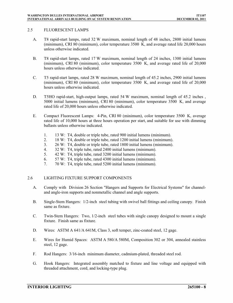
WASHINGTON DULLES INTERNATIONAL AIRPORT IT1107INTERNATIONAL ARRIVALS BUILDING HVAC SYSTEM RENOVATION DECEMBER 02, 2011
INTERIOR LIGHTING 265100 - 8
2.5 FLUORESCENT LAMPS
A. T8 rapid-start lamps, rated 32 W maximum, nominal length of 48 inches
B. T8 rapid-start lamps, rated 17 W maximum, nominal length of
, 2800 initial lumens (minimum), CRI 80 (minimum), color temperature 3500 K, and average rated life 20,000 hours unless otherwise indicated.
24 inches
C. T5 rapid-start lamps, rated 28 W maximum, nominal length of
, 1300 initial lumens (minimum), CRI 80 (minimum), color temperature 3500 K, and average rated life of 20,000 hours unless otherwise indicated.
45.2 inches
D. T5HO rapid-start, high-output lamps, rated 54 W maximum, nominal length of
, 2900 initial lumens (minimum), CRI 80 (minimum), color temperature 3500 K, and average rated life of 20,000 hours unless otherwise indicated.
45.2 inches
E. Compact Fluorescent Lamps: 4-Pin, CRI 80 (minimum), color temperature 3500 K, average rated life of 10,000 hours at three hours operation per start, and suitable for use with dimming ballasts unless otherwise indicated.
,5000 initial lumens (minimum), CRI 80 (minimum), color temperature 3500 K, and average rated life of 20,000 hours unless otherwise indicated.
1. 13 W: T4, double or triple tube, rated 900 initial lumens (minimum).2. 18 W: T4, double or triple tube, rated 1200 initial lumens (minimum).3. 26 W: T4, double or triple tube, rated 1800 initial lumens (minimum).4. 32 W: T4, triple tube, rated 2400 initial lumens (minimum).5. 42 W: T4, triple tube, rated 3200 initial lumens (minimum).6. 57 W: T4, triple tube, rated 4300 initial lumens (minimum).7. 70 W: T4, triple tube, rated 5200 initial lumens (minimum).
2.6 LIGHTING FIXTURE SUPPORT COMPONENTS
A. Comply with Division 26 Section "Hangers and Supports for Electrical Systems" for channel-and angle-iron supports and nonmetallic channel and angle supports.
B. Single-Stem Hangers: 1/2-inch
C. Twin-Stem Hangers: Two,
steel tubing with swivel ball fittings and ceiling canopy. Finish same as fixture.
1/2-inch
D. Wires: ASTM A 641/A 641M, Class 3, soft temper, zinc-coated steel,
steel tubes with single canopy designed to mount a single fixture. Finish same as fixture.
12 gage
E. Wires for Humid Spaces: ASTM A 580/A 580M, Composition 302 or 304, annealed stainless steel,
.
12 gage
F. Rod Hangers:
.
3/16-inch
G. Hook Hangers: Integrated assembly matched to fixture and line voltage and equipped with threaded attachment, cord, and locking-type plug.
minimum diameter, cadmium-plated, threaded steel rod.

WASHINGTON DULLES INTERNATIONAL AIRPORT IT1107INTERNATIONAL ARRIVALS BUILDING HVAC SYSTEM RENOVATION DECEMBER 02, 2011
INTERIOR LIGHTING 265100 - 9
2.7 PREWIRED WHIPS:
A. Prewired whips for fluorescent light fixtures may be used at the contractor’s option for fixtures with Class P ballasts. Whips shall be six feet of ½” flex and No. 14 AWG minimum, or whips direct from the fixture’s manufacturer with conductors sized by code for the specified lamp load, one or two circuit as indicated on the drawings.
PART 3 - EXECUTION
3.1 INSTALLATION
A. Lighting fixtures:
1. Set level, plumb, and square with ceilings and walls unless otherwise indicated.2. Install lamps in each luminaire.
B. Temporary Lighting: If it is necessary, and approved by COTR, to use permanent luminaires for temporary lighting, install and energize the minimum number of luminaires necessary. When construction is sufficiently complete, remove the temporary luminaires, disassemble, clean thoroughly, install new lamps, and reinstall.
C. Remote Mounting of Ballasts: Distance between the ballast and fixture shall not exceed that recommended by ballast manufacturer. Verify, with ballast manufacturers, maximum distance between ballast and luminaire.
D. Lay-in Ceiling Lighting Fixtures Supports: Use grid as a support element.
1. Install ceiling support system rods or wires, independent of the ceiling suspension devices, for each fixture. Locate not more than 6 inches
2. Support Clips: Fasten to lighting fixtures and to ceiling grid members at or near each fixture corner with clips that are UL listed for the application.
from lighting fixture corners.
3. Fixtures of Sizes Less Than Ceiling Grid: Install as indicated on reflected ceiling plans or center in acoustical panel, and support fixtures independently with at least two 3/4-inch
4. Install at least one independent support rod or wire from structure to a tab on lighting fixture. Wire or rod shall have breaking strength of the weight of fixture at a safety factor of 3.
metal channels spanning and secured to ceiling tees.
E. Suspended Lighting Fixture Support:
1. Pendants and Rods: Where longer than 48 inches2. Stem-Mounted, Single-Unit Fixtures: Suspend with twin-stem hangers.
, brace to limit swinging.
3. Continuous Rows: Use tubing or stem for wiring at one point and tubing or rod for suspension for each unit length of fixture chassis, including one at each end.
4. Do not use grid as support for pendant luminaires. Connect support wires or rods to building structure.
5. Provide one power drop per row unless directed otherwise. Coordinate multiple row power drops together.

WASHINGTON DULLES INTERNATIONAL AIRPORT IT1107INTERNATIONAL ARRIVALS BUILDING HVAC SYSTEM RENOVATION DECEMBER 02, 2011
INTERIOR LIGHTING 265100 - 10
F. Support surface-mounted luminaires directly from the building structure.
G. Install recessed luminaires to permit removal from below.
H. Air-Handling Lighting Fixtures: Install with dampers closed and ready for adjustment.
I. Connect wiring according to Division 26 Section "Low-Voltage Electrical Power Conductors and Cables."
3.2 IDENTIFICATION
A. Install labels with panel and circuit numbers on concealed junction and outlet boxes. Comply with requirements for identification specified in Division 26 Section "Identification for Electrical Systems."
3.3 FIELD QUALITY CONTROL
A. Test for Emergency Lighting: Interrupt power supply to demonstrate proper operation. Verify transfer from normal power to battery and retransfer to normal.
B. Verify that self-luminous exit signs are installed according to their listing and the requirements in NFPA 101.
C. Prepare a written report of tests, inspections, observations, and verifications indicating and interpreting results. If adjustments are made to lighting system, retest to demonstrate compliance with standards.
3.4 STARTUP SERVICE
A. Burn-in all lamps that require specific aging period to operate properly, prior to occupancy.Burn-in fluorescent and compact fluorescent lamps intended to be dimmed, for at least 100 hours at full voltage.
3.5 ADJUSTING
A. Align luminaires, clean lenses and diffusers at completion of work. Clean paint splatters, dirt, and debris from installed luminaires.
PART 4 - CONTRACTOR’S QUALITY CONTROL REQUIREMENTS
4.1 GENERAL
A. Comply with applicable provisions of Division 01 Section “Quality Requirements” for requirements for Contractor’s Control Program.

WASHINGTON DULLES INTERNATIONAL AIRPORT IT1107INTERNATIONAL ARRIVALS BUILDING HVAC SYSTEM RENOVATION DECEMBER 02, 2011
INTERIOR LIGHTING 265100 - 11
END OF SECTION 265100

WASHINGTON DULLES INTERNATIONAL AIRPORT IT1107INTERNATIONAL ARRIVALS BUILDING HVAC SYSTEM RENOVATION DECEMBER 02, 2011
DIGITAL, ADDRESSABLE FIRE-ALARM SYSTEM 283111 - 1
SECTION 283111 -
PART 1 - GENERAL
DIGITAL, ADDRESSABLE FIRE-ALARM SYSTEM
1.1 RELATED DOCUMENTS
A. Drawings and general provisions of the Contract, including General and Supplementary Conditions and Division 01 Specification Sections, apply to this Section.
1.2 SUMMARY
A. Section Includes:
1. Fire alarm control panel.2. Smoke detectors.3. Heat detectors.4. Notification appliances.5. Addressable interface device.
1.3 DEFINITIONS
A. LED: Light-emitting diode.
B. NICET: National Institute for Certification in Engineering Technologies.
C. CD: Candela rating.
1.4 SYSTEM DESCRIPTION
A. Non-coded, UL-certified/listed and FM approved addressable system components, with automatic sensitivity control of certain smoke detectors and multiplexed signal transmission, dedicated to fire alarm service only.
1.5 ACTION SUBMITTALS
A. Product Data: For each type of product indicated.
B. Shop Drawings: For fire alarm system. Include plans, elevations, sections, details, and attachments to other work.
1. Comply with recommendations in the "Documentation" Section of the "Fundamentals of Fire Alarm Systems" Chapter in the most current edition of NFPA 72.
2. Include voltage drop calculations for notification appliance circuits.3. Include battery-size calculations.

WASHINGTON DULLES INTERNATIONAL AIRPORT IT1107INTERNATIONAL ARRIVALS BUILDING HVAC SYSTEM RENOVATION DECEMBER 02, 2011
DIGITAL, ADDRESSABLE FIRE-ALARM SYSTEM 283111 - 2
4. Include performance parameters and installation details for each detector, verifying that each detector is listed for complete range of air velocity, temperature, and humidity possible when air-handling system is operating.
5. Include plans, sections, and elevations of heating, ventilating, and air-conditioning ducts, drawn to scale and coordinating installation of duct smoke detectors and access to them. Show critical dimensions that relate to placement and support of sampling tubes, detector housing, and remote status and alarm indicators. Locate detectors according to manufacturer's written recommendations.
6. Include floor plans to indicate final outlet locations showing address of each addressable device. Show size and route of cable and conduits.
C. General Submittal Requirements:
1. Submittals shall be approved by COTR prior to submitting them to the authorities having jurisdiction.
2. Shop Drawings shall be prepared by persons with the following qualifications:
a. Trained and certified by manufacturer in fire alarm system design.b. NICET-certified fire alarm technician, Level III minimum.c. Licensed or certified by authorities having jurisdiction.d. All fire alarm systems drawings and calculations shall be stamped by a
Professional Fire Protection Engineer who is registered in the Commonwealth of Virginia.
D. Delegated-Design Submittal: For smoke and heat detectors indicated to comply with performance requirements and design criteria, including analysis data signed and sealed by the qualified professional engineer responsible for their preparation.
1. Drawings showing the location of each smoke and heat detector, ratings of each, and installation details as needed to comply with listing conditions of the detector.
2. Design Calculations: Calculate requirements for selecting the spacing and sensitivity of detection, complying with the most current edition of NFPA 72.
1.6 INFORMATIONAL SUBMITTALS
A. Qualification Data: For qualified Installer.
B. Field quality-control reports.
1.7 CLOSEOUT SUBMITTALS
A. Operation and Maintenance Data: For fire alarm systems and components to include in emergency, operation, and maintenance manuals. In addition to items specified in Division 01 Section "Operation and Maintenance Data, "deliver copies to authorities having jurisdiction andinclude the following:
1. Comply with the "Records" Section of the "Inspection, Testing and Maintenance" Chapter in the most current edition of NFPA 72.

WASHINGTON DULLES INTERNATIONAL AIRPORT IT1107INTERNATIONAL ARRIVALS BUILDING HVAC SYSTEM RENOVATION DECEMBER 02, 2011
DIGITAL, ADDRESSABLE FIRE-ALARM SYSTEM 283111 - 3
2. Provide "Record of Completion Documents" according to the most current edition ofNFPA 72 article "Permanent Records" in the "Records" Section of the "Inspection, Testing and Maintenance" Chapter.
3. Record copy of site-specific software.4. Provide "Maintenance, Inspection and Testing Records" according to the most current
edition of NFPA 72 article of the same name and include the following:
a. Frequency of testing of installed components.b. Frequency of inspection of installed components.c. Requirements and recommendations related to results of maintenance.d. Manufacturer's user training manuals.
5. Manufacturer's required maintenance related to system warranty requirements.6. Abbreviated operating instructions for mounting at fire alarm control panel.
B. Software and Firmware Operational Documentation:
1. Device address list.2. Printout of software application and graphic screens.
C. Acceptance Test
1. Provide Certificate of Completion of all Acceptance Testing to the COTR.
1.8 MAINTENANCE MATERIAL SUBMITTALS
A. Furnish extra materials that match products installed and that are packaged with protective covering for storage and identified with labels describing contents.
1. Smoke Detectors: Quantity equal to 5 percent of amount of each type installed, but no less than 1 unit of each type.
2. Detector Bases: Quantity equal to 2 percent of amount of each type installed, but no lessthan 1 unit of each type.
3. Keys and Tools: One extra set for access to locked and tamperproofed components.4. Audible and Visual Notification Appliances: One of each type installed.5. Fuses: Two of each type installed in the system.
1.9 QUALITY ASSURANCE
A. Installer Qualifications: Personnel shall be trained and certified by manufacturer for installation of units required for this Project.
B. Installer Qualifications: Installation shall be by personnel certified by NICET as fire alarmLevel III technician.
C. Source Limitations for Fire Alarm System and Components: Obtain fire alarm system from single source from single manufacturer. Components shall be compatible with, and operate as, an extension of existing system.
WASHINGTON DULLES INTERNATIONAL AIRPORT IT1107INTERNATIONAL ARRIVALS BUILDING HVAC SYSTEM RENOVATION DECEMBER 02, 2011
DIGITAL, ADDRESSABLE FIRE-ALARM SYSTEM 283111 - 4
D. Electrical Components, Devices, and Accessories: Listed and labeled as defined in the most current edition of NFPA 70, by a qualified testing agency, and marked for intended location and application.
E. NFPA Certification: Obtain certification according to the most current edition of NFPA 72 by an NRTL.
F. NFPA Certification: Obtain certification according to the most current edition of NFPA 72 by a UL-listed alarm company.
G. NFPA Certification: Obtain certification according to the most current edition of NFPA 72 in the form of a placard by an FMG-approved alarm company.
1.10 PROJECT CONDITIONS
A. Interruption of Existing Fire Alarm Service: Do not interrupt fire alarm service to facilities occupied by the Authority or others unless permitted under the following conditions and then only after arranging to provide temporary guard service according to requirements indicated:
1. Notify the COTR, no fewer than three days in advance of proposed interruption of fire alarm service.
2. Do not proceed with interruption of fire alarm service without the COTR’s written permission.
1.11 SEQUENCING AND SCHEDULING
A. Existing Fire Alarm Equipment: Maintain existing equipment fully operational until new equipment has been tested and accepted. As new equipment is installed, label it "NOT IN SERVICE" until it is accepted. Remove labels from new equipment when put into service and label existing fire alarm equipment "NOT IN SERVICE" until removed from the building.
B. Equipment Removal: After acceptance of new fire alarm system, remove existing disconnected fire alarm equipment and wiring. The contractor will be responsible for all programming and decommissioning of removed devices from the existing system.
PART 2 - PRODUCTS
2.1 MANUFACTURERS
A. Manufacturers: Subject to compliance with requirements, provide products by the following:
1. Siemens Building Technologies, Inc.; Fire Safety Division.
2.2 SYSTEMS OPERATIONAL DESCRIPTION
A. Fire alarm signal initiation shall be by one or more of the following devices :

WASHINGTON DULLES INTERNATIONAL AIRPORT IT1107INTERNATIONAL ARRIVALS BUILDING HVAC SYSTEM RENOVATION DECEMBER 02, 2011
DIGITAL, ADDRESSABLE FIRE-ALARM SYSTEM 283111 - 5
1. Manual stations.2. Heat detectors.3. Smoke detectors.4. Duct smoke detectors.5. Verified automatic alarm operation of smoke detectors.6. Automatic sprinkler system water flow.7. Heat detectors in elevator shaft.8. Fire-extinguishing system operation.9. Fire standpipe system.
B. Fire alarm signal shall initiate the following actions:
1. Continuously operate alarm notification appliances.2. Identify alarm at fire alarm control panel.3. Transmit an alarm signal to the main alarm receiving station.4. Unlock electric door locks in designated egress paths.5. Release fire and smoke doors held open by magnetic door holders.6. Switch heating, ventilating, and air-conditioning equipment controls to fire alarm mode.7. Activate smoke-control system (smoke management) at firefighter smoke-control system
panel.8. Activate stairwell and elevator-shaft pressurization systems.9. Close smoke dampers in air ducts of designated air-conditioning duct systems.10. Recall elevators to primary or alternate recall floors.11. Activate emergency lighting control.12. Activate emergency shutoffs for gas and fuel supplies.13. Record events in the system memory.
C. Supervisory signal initiation shall be by one or more of the following devices and actions:
1. Valve supervisory switch.2. Low-air-pressure switch of a dry-pipe sprinkler system.3. Elevator shunt-trip supervision.
D. System trouble signal initiation shall be by one or more of the following devices and actions:
1. Open circuits, shorts, and grounds in designated circuits.2. Opening, tampering with, or removing alarm-initiating and supervisory signal-initiating
devices.3. Loss of primary power at fire alarm control panel.4. Ground or a single break in fire alarm control panel internal circuits.5. Abnormal ac voltage at fire alarm control panel.6. Break in standby battery circuitry.7. Failure of battery charging.8. Abnormal position of any switch at fire alarm control panel or annunciator.9. Fire-pump power failure, including a dead-phase or phase-reversal condition.10. Low-air-pressure switch operation on a dry-pipe or preaction sprinkler system.
E. System Trouble and Supervisory Signal Actions: Initiate notification appliance and annunciate at fire alarm control panel. Record the event in system memory.
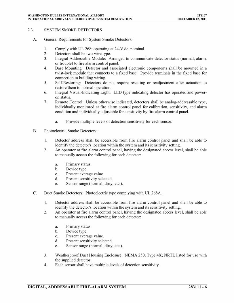
WASHINGTON DULLES INTERNATIONAL AIRPORT IT1107INTERNATIONAL ARRIVALS BUILDING HVAC SYSTEM RENOVATION DECEMBER 02, 2011
DIGITAL, ADDRESSABLE FIRE-ALARM SYSTEM 283111 - 6
2.3 SYSTEM SMOKE DETECTORS
A. General Requirements for System Smoke Detectors:
1. Comply with UL 268; operating at 24-V dc, nominal.2. Detectors shall be two-wire type.3. Integral Addressable Module: Arranged to communicate detector status (normal, alarm,
or trouble) to fire alarm control panel.4. Base Mounting: Detector and associated electronic components shall be mounted in a
twist-lock module that connects to a fixed base. Provide terminals in the fixed base for connection to building wiring.
5. Self-Restoring: Detectors do not require resetting or readjustment after actuation to restore them to normal operation.
6. Integral Visual-Indicating Light: LED type indicating detector has operated and power-on status.
7. Remote Control: Unless otherwise indicated, detectors shall be analog-addressable type, individually monitored at fire alarm control panel for calibration, sensitivity, and alarm condition and individually adjustable for sensitivity by fire alarm control panel.
a. Provide multiple levels of detection sensitivity for each sensor.
B. Photoelectric Smoke Detectors:
1. Detector address shall be accessible from fire alarm control panel and shall be able to identify the detector's location within the system and its sensitivity setting.
2. An operator at fire alarm control panel, having the designated access level, shall be able to manually access the following for each detector:
a. Primary status.b. Device type.c. Present average value.d. Present sensitivity selected.e. Sensor range (normal, dirty, etc.).
C. Duct Smoke Detectors: Photoelectric type complying with UL 268A.
1. Detector address shall be accessible from fire alarm control panel and shall be able to identify the detector's location within the system and its sensitivity setting.
2. An operator at fire alarm control panel, having the designated access level, shall be able to manually access the following for each detector:
a. Primary status.b. Device type.c. Present average value.d. Present sensitivity selected.e. Sensor range (normal, dirty, etc.).
3. Weatherproof Duct Housing Enclosure: NEMA 250, Type 4X; NRTL listed for use with the supplied detector.
4. Each sensor shall have multiple levels of detection sensitivity.

WASHINGTON DULLES INTERNATIONAL AIRPORT IT1107INTERNATIONAL ARRIVALS BUILDING HVAC SYSTEM RENOVATION DECEMBER 02, 2011
DIGITAL, ADDRESSABLE FIRE-ALARM SYSTEM 283111 - 7
5. Sampling Tubes: Design and dimensions as recommended by manufacturer for specific duct size, air velocity, and installation conditions where applied.
6. Relay Fan Shutdown: Rated to interrupt fan motor-control circuit. For connection to HVAC equipment under Division 23.
2.4 DUCT DETECTOR TEST SWITCH
A. General Requirements for Detector Test Switch:
1. The test switch module is a key activated device that will functionally test a detector. 2. The test switch module includes a red LED that illuminates when the corresponding duct
detector is in alarm. The switch operates in conjunction with an interface module with relay. Either that relay or the relay in the duct detector can be used for control of building equipment such as HVAC fans and elevators.
3. When the switch is operated, a signal is transmitted to the appropriate detector forcing it to alarm. That alarm will activate all functions programmed to follow that detector.
B. Specifications
1. T-45 key Operated.2. LED indicates detector in Alarm.3. Mounts in a single gang box.
2.5 HEAT DETECTORS
A. General Requirements for Heat Detectors: Comply with UL 521.
B. Heat Detector, Combination Type: Actuated by a fixed temperature of 135 deg F.
1. Mounting: Twist-lock base interchangeable with smoke-detector bases.2. Integral Addressable Module: Arranged to communicate detector status (normal, alarm,
or trouble) to fire alarm control panel.
C. Heat Detector, Fixed-Temperature Type: Actuated by temperature that exceeds a fixed temperature of 135 deg F
1. Mounting: Twist-lock base interchangeable with smoke-detector bases.
.
2. Integral Addressable Module: Arranged to communicate detector status (normal, alarm,or trouble) to fire alarm control panel.
2.6 NOTIFICATION APPLIANCES
A. General Requirements for Notification Appliances: Individually addressed, connected to a signaling line circuit, equipped for mounting as indicated and with screw terminals for system connections.
B. General Requirements for Notification Appliances: Connected to notification appliance signal circuits, zoned as indicated, equipped for mounting as indicated and with screw terminals for system connections.

WASHINGTON DULLES INTERNATIONAL AIRPORT IT1107INTERNATIONAL ARRIVALS BUILDING HVAC SYSTEM RENOVATION DECEMBER 02, 2011
DIGITAL, ADDRESSABLE FIRE-ALARM SYSTEM 283111 - 8
1. Combination Devices: Factory-integrated audible and visible devices in a single-mounting assembly, equipped for mounting as indicated and with screw terminals for system connections.
C. Horns: Electric-vibrating-polarized type, 24-V dc; with provision for housing the operating mechanism behind a grille. Comply with UL 464. Horns shall produce a sound-pressure level of 90 dBA, measured 10 feet
D. Visible Notification Appliances: Xenon strobe lights comply with UL 1971, with clear or nominal white polycarbonate lens mounted on an aluminum faceplate. The word "FIRE" is engraved in minimum
from the horn, using the coded signal prescribed in UL 464 test protocol.
1-inch
1. Rated Light Output:
high letters on the lens.
a. 15/30/75/110 cd, selectable in the field.
2. Mounting: Wall mounted unless otherwise indicated.3. For units with guards to prevent physical damage, light output ratings shall be determined
with guards in place.4. Flashing shall be in a temporal pattern, synchronized with other units.5. Strobe Leads: Factory connected to screw terminals.6. Mounting Faceplate: Factory finished red .
2.7 ADDRESSABLE INTERFACE DEVICE
A. Description: Microelectronic monitor module, NRTL listed for use in providing a system address for alarm-initiating devices for wired applications with normally open contacts.
B. Integral Relay: Capable of providing a direct signal to elevator controller to initiate elevator recall and to circuit-breaker shunt trip for power shutdown .
2.8 DEVICE GUARDS
A. Description: Welded wire mesh of size and shape for the manual station, smoke detector, gong, or other device requiring protection.
1. Factory fabricated and furnished by manufacturer of device.2. Finish: Paint of color to match the protected device.
PART 3 - EXECUTION
3.1 EQUIPMENT INSTALLATION
A. Comply with the most current edition of NFPA 72 for installation of fire alarm equipment.

WASHINGTON DULLES INTERNATIONAL AIRPORT IT1107INTERNATIONAL ARRIVALS BUILDING HVAC SYSTEM RENOVATION DECEMBER 02, 2011
DIGITAL, ADDRESSABLE FIRE-ALARM SYSTEM 283111 - 9
B. Equipment Mounting: Install fire alarm control panel on concrete base with tops of cabinets not more than 72 inches above the finished floor. Comply with requirements for concrete base specified in Division 03 Section "Cast-in-Place Concrete ."
1. Install dowel rods to connect concrete base to concrete floor. Unless otherwise indicated, install dowel rods on 18-inch
2. For supported equipment, install epoxy-coated anchor bolts that extend through concrete base and anchor into structural concrete floor.
centers around the full perimeter of concrete base.
3. Place and secure anchorage devices. Use setting drawings, templates, diagrams, instructions, and directions furnished with items to be embedded.
4. Install anchor bolts to elevations required for proper attachment to supported equipment.
C. Install wall-mounted equipment, with tops of cabinets not more than 72 inches
D. Connecting to Existing Equipment: Verify that existing fire alarm system is operational before making changes or connections.
above the finished floor.
1. Connect new equipment to existing control panel in existing part of the building.2. Connect new equipment to existing monitoring equipment at the supervising station.3. Expand, modify, and supplement existing control equipment as necessary to extend
existing monitoring functions to the new points. New components shall be capable of merging with existing configuration without degrading the performance of either system.
E. Smoke- or Heat-Detector Spacing:
1. Comply with the most current edition of MWAA Design Guidelines, "Smoke-Sensing Fire Detectors" Section in the "Initiating Devices" Chapter, for smoke-detector spacing.
2. Comply with the most current edition of MWAA Design Guidelines, "Heat-Sensing Fire Detectors" Section in the "Initiating Devices" Chapter, for heat-detector spacing.
3. Smooth ceiling spacing shall not exceed 26.5 feet4. Spacing of detectors for irregular areas, for irregular ceiling construction, and for high
ceiling areas shall be determined according to Appendix A in the most current edition of NFPA 72.
.
5. HVAC: Locate detectors not closer than 3 feet
6. Lighting Fixtures: Locate detectors not closer than
from air-supply diffuser or return-air opening.
12 inches
F. Duct Smoke Detectors: Comply with the most current edition of NFPA 72 and the most current edition of NFPA 90A. Install sampling tubes so they extend the full width of duct.
from any part of a lighting fixture.
G. Heat Detectors in Elevator Shafts: Coordinate temperature rating and location with sprinkler rating and location.
H. Single-Station Smoke Detectors: Where more than one smoke alarm is installed within a dwelling or suite, they shall be connected so that the operation of any smoke alarm causes the alarm in all smoke alarms to sound.
I. Remote Status and Alarm Indicators: Install near each smoke detector and each sprinkler water-flow switch and valve-tamper switch that is not readily visible from normal viewing position.

WASHINGTON DULLES INTERNATIONAL AIRPORT IT1107INTERNATIONAL ARRIVALS BUILDING HVAC SYSTEM RENOVATION DECEMBER 02, 2011
DIGITAL, ADDRESSABLE FIRE-ALARM SYSTEM 283111 - 10
J. Audible Alarm-Indicating Devices: Install not less than 6 inches
K. Visible Alarm-Indicating Devices: Install adjacent to each alarm bell or alarm horn and at least
below the ceiling. Install bells and horns on flush-mounted back boxes with the device-operating mechanism concealed behind a grille.
6 inches
L. Device Location-Indicating Lights: Locate in public space near the device they monitor.
below the ceiling.
3.2 CONNECTIONS
A. For fire-protection systems related to doors in fire-rated walls and partitions and to doors in smoke partitions, comply with requirements in Division 08 Section "Door Hardware." Connect hardware and devices to fire alarm system.
1. Verify that hardware and devices are NRTL listed for use with fire alarm system in this Section before making connections.
B. Make addressable connections with a supervised interface device to the following devices and systems. Install the interface device less than 3 feet
1. Alarm-initiating connection to smoke-control system (smoke management) at firefighter smoke-control system panel.
from the device controlled. Make an addressable confirmation connection when such feedback is available at the device or system being controlled.
2. Alarm-initiating connection to stairwell and elevator-shaft pressurization systems.3. Smoke dampers in air ducts of designated air-conditioning duct systems.4. Alarm-initiating connection to elevator recall system and components.5. Alarm-initiating connection to activate emergency lighting control.6. Alarm-initiating connection to activate emergency shutoffs for gas and fuel supplies.7. Supervisory connections at valve supervisory switches.8. Supervisory connections at low-air-pressure switch of each dry-pipe sprinkler system.9. Supervisory connections at elevator shunt trip breaker.10. Supervisory connections at fire-pump power failure including a dead-phase or phase-
reversal condition.
3.3 IDENTIFICATION
A. Identify system components, wiring, cabling, and terminals. Comply with requirements for identification specified in Division 26 Section "Identification for Electrical Systems."
B. Install framed instructions in a location visible from fire alarm control panel.
3.4 FIELD QUALITY CONTROL
A. Field tests shall be witnessed by authorities having jurisdiction .
B. Manufacturer's Field Service: Engage a factory-authorized service representative to inspect, test, and adjust components, assemblies, and equipment installations, including connections.

WASHINGTON DULLES INTERNATIONAL AIRPORT IT1107INTERNATIONAL ARRIVALS BUILDING HVAC SYSTEM RENOVATION DECEMBER 02, 2011
DIGITAL, ADDRESSABLE FIRE-ALARM SYSTEM 283111 - 11
C. An acceptance test, as described in the FMG Performance Checklist for New or Modified Fire Alarm System Installations (refer to FMG table 1below), shall be performed on the fire alarm system upon completion of the installation. A copy of the certificate of completion shall be provided to FM Global or maintained on file for review.
D. Perform tests and inspections.
1. Manufacturer's Field Service: Engage a factory-authorized service representative to inspect components, assemblies, and equipment installations, including connections, and to assist in testing.
E. Tests and Inspections:
1. Visual Inspection: Conduct visual inspection prior to testing.
a. Inspection shall be based on completed Record Drawings and system documentation that is required by the most current edition of NFPA 72 in its "Completion Documents, Preparation" Table in the "Documentation" Section of the "Fundamentals of Fire Alarm Systems" Chapter.
b. Comply with "Visual Inspection Frequencies" Table in the "Inspection" Section of the "Inspection, Testing and Maintenance" Chapter in the most current edition of NFPA 72; retain the "Initial/Reacceptance" column and list only the installed components.
2. System Testing: Comply with "Test Methods" Table in the "Testing" Section of the "Inspection, Testing and Maintenance" Chapter in the most current edition of NFPA 72.
3. Test audible appliances for the public operating mode according to manufacturer's written instructions. Perform the test using a portable sound-level meter complying with Type 2requirements in ANSI S1.4.
4. Test audible appliances for the private operating mode according to manufacturer's written instructions.

WASHINGTON DULLES INTERNATIONAL AIRPORT IT1107INTERNATIONAL ARRIVALS BUILDING HVAC SYSTEM RENOVATION DECEMBER 02, 2011
DIGITAL, ADDRESSABLE FIRE-ALARM SYSTEM 283111 - 12
5. Test visible appliances for the public operating mode according to manufacturer's written instructions.
6. Factory-authorized service representative shall prepare the "Fire Alarm System Record of Completion" in the "Documentation" Section of the "Fundamentals of Fire Alarm Systems" Chapter in the most current edition of NFPA 72 and the "Inspection and Testing Form" in the "Records" Section of the "Inspection, Testing and Maintenance" Chapter in the most current edition of NFPA 72.
F. Reacceptance Testing: Perform reacceptance testing to verify the proper operation of added or replaced devices and appliances.
G. Fire alarm system will be considered defective if it does not pass tests and inspections.
H. Prepare test and inspection reports.
I. Maintenance Test and Inspection: Perform tests and inspections listed for weekly, monthly, quarterly, and semiannual periods. Use forms developed for initial tests and inspections.
J. Engage a factory-authorized service representative to train Owner's maintenance personnel to adjust, operate, and maintain fire alarm system.
PART 4 - CONTRACTOR’S QUALITY CONTROL REQUIREMENTS
4.1 FIELD QUALITY CONTROL
A. Conform to all applicable provisions of Division 01 Section “Quality Requirements”.
END OF SECTION 283111