Embed Size (px)
Citation preview
8/6/2019 Waste Water Treatment Notes
http://slidepdf.com/reader/full/waste-water-treatment-notes 1/75
BIOLOGICAL
K.GOPALAKRISHNA
1
8/6/2019 Waste Water Treatment Notes
http://slidepdf.com/reader/full/waste-water-treatment-notes 2/75
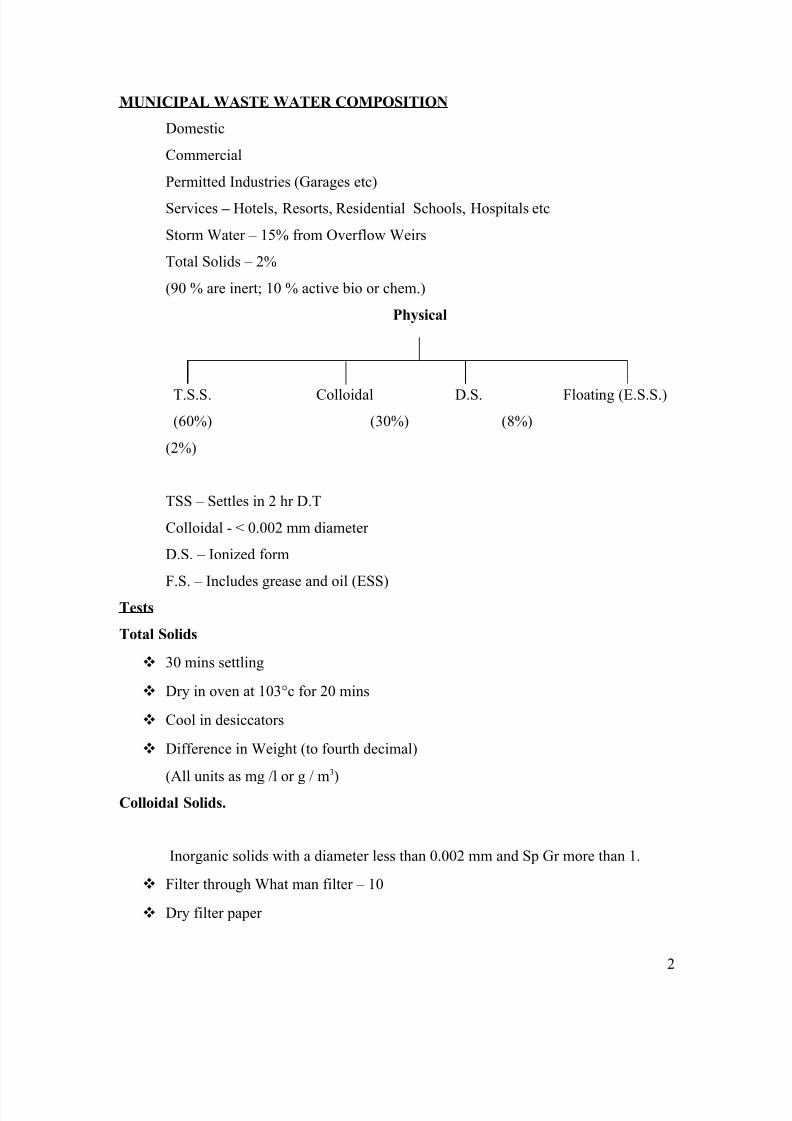
MUNICIPAL WASTE WATER COMPOSITION
Domestic
Commercial
Permitted Industries (Garages etc)
Services – Hotels, Resorts, Residential Schools, Hospitals etc
Storm Water – 15% from Overflow Weirs
Total Solids – 2%
(90 % are inert; 10 % active bio or chem.)
Physical
T.S.S. Colloidal D.S. Floating (E.S.S.)(60%) (30%) (8%)
(2%)
TSS – Settles in 2 hr D.T
Colloidal - < 0.002 mm diameter
D.S. – Ionized form
F.S. – Includes grease and oil (ESS)
Tests
Total Solids
30 mins settling
Dry in oven at 103°c for 20 mins
Cool in desiccators
Difference in Weight (to fourth decimal)
(All units as mg /l or g / m3)
Colloidal Solids.
Inorganic solids with a diameter less than 0.002 mm and Sp Gr more than 1.
Filter through What man filter – 10
Dry filter paper
2
8/6/2019 Waste Water Treatment Notes
http://slidepdf.com/reader/full/waste-water-treatment-notes 3/75
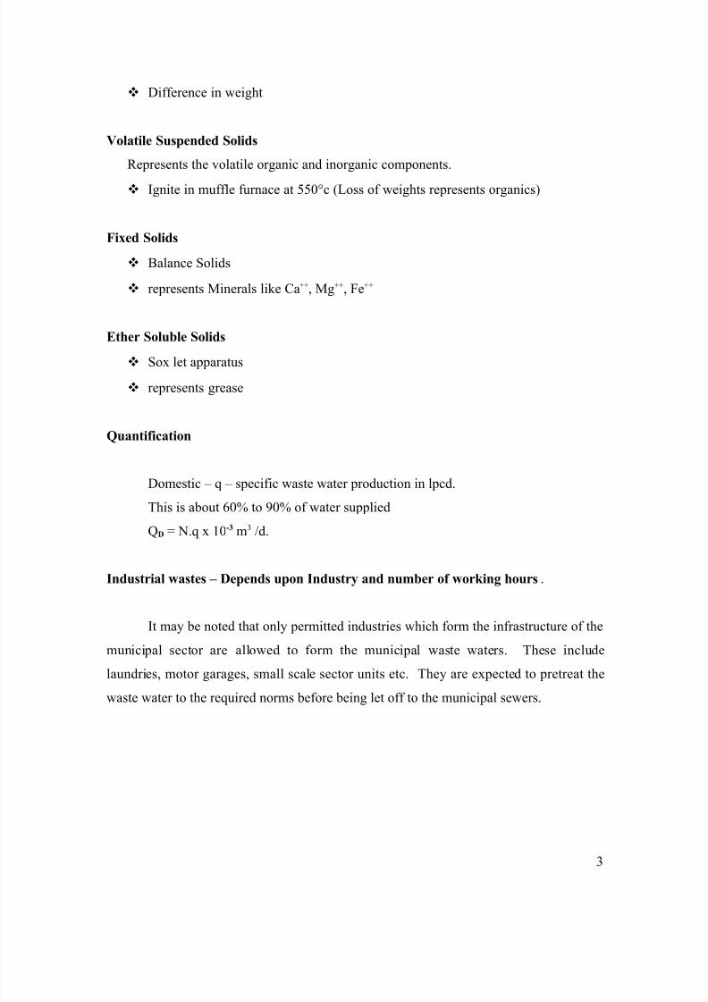
Difference in weight
Volatile Suspended Solids
Represents the volatile organic and inorganic components.
Ignite in muffle furnace at 550°c (Loss of weights represents organics)
Fixed Solids
Balance Solids
represents Minerals like Ca++, Mg++, Fe++
Ether Soluble Solids
Sox let apparatus
represents grease
Quantification
Domestic – q – specific waste water production in lpcd.
This is about 60% to 90% of water supplied
QD = N.q x 10-3 m3 /d.
Industrial wastes – Depends upon Industry and number of working hours.
It may be noted that only permitted industries which form the infrastructure of the
municipal sector are allowed to form the municipal waste waters. These include
laundries, motor garages, small scale sector units etc. They are expected to pretreat the
waste water to the required norms before being let off to the municipal sewers.
3
8/6/2019 Waste Water Treatment Notes
http://slidepdf.com/reader/full/waste-water-treatment-notes 4/75
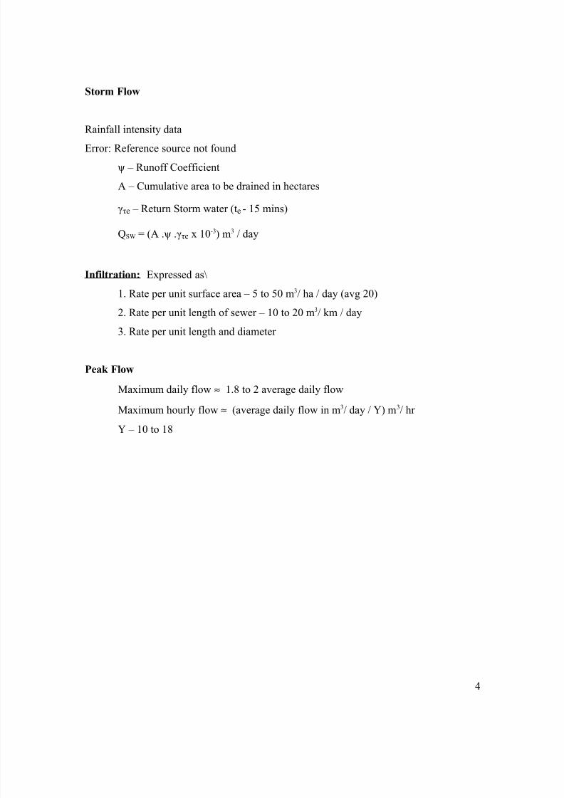
Storm Flow
Rainfall intensity data
Error: Reference source not found
ψ – Runoff Coefficient
A – Cumulative area to be drained in hectares
γτe – Return Storm water (te - 15 mins)
QSW = (A .ψ .γτe x 10-3) m3 / day
Infiltration: Expressed as\1. Rate per unit surface area – 5 to 50 m3/ ha / day (avg 20)
2. Rate per unit length of sewer – 10 to 20 m3/ km / day
3. Rate per unit length and diameter
Peak Flow
Maximum daily flow ≈ 1.8 to 2 average daily flow
Maximum hourly flow ≈ (average daily flow in m3/ day / Y) m3/ hr
Y – 10 to 18
4
8/6/2019 Waste Water Treatment Notes
http://slidepdf.com/reader/full/waste-water-treatment-notes 5/75
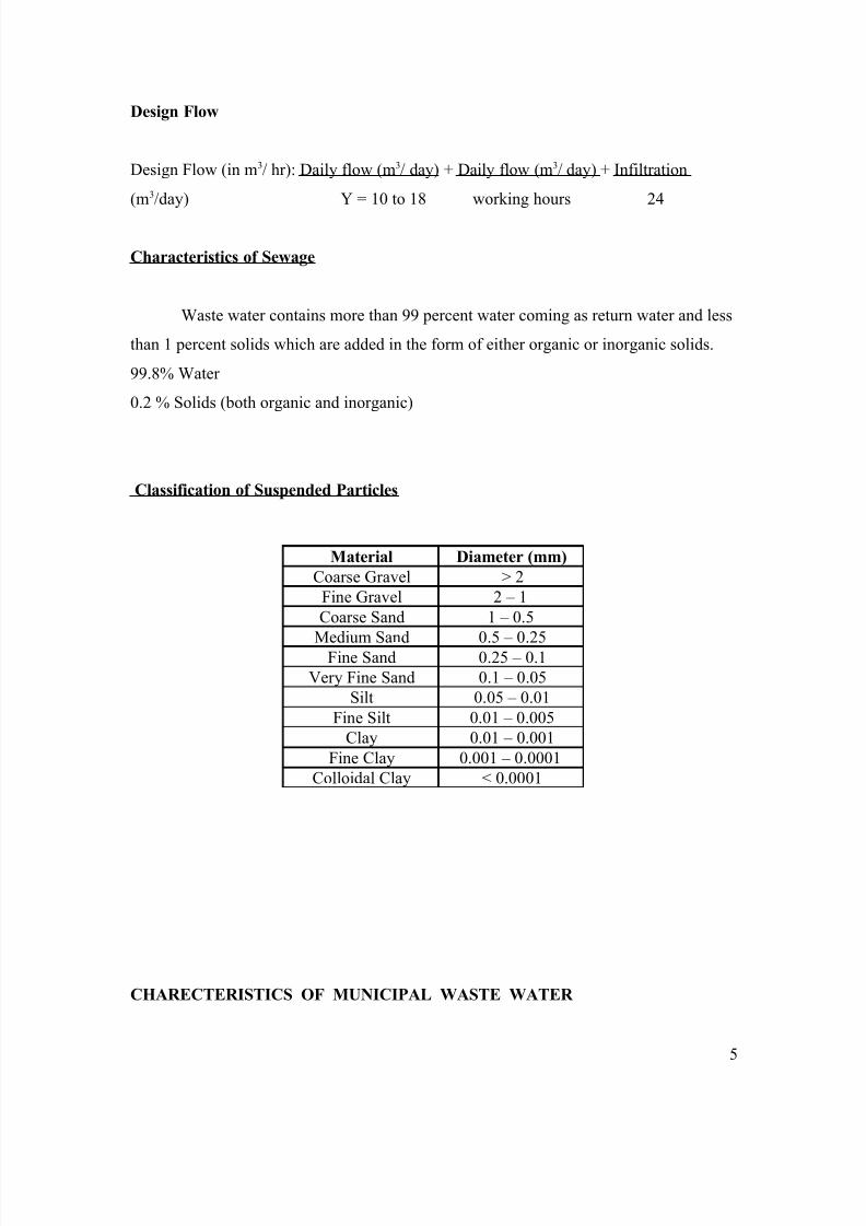
Design Flow
Design Flow (in m3/ hr): Daily flow (m3/ day) + Daily flow (m3/ day) + Infiltration
(m3/day) Y = 10 to 18 working hours 24
Characteristics of Sewage
Waste water contains more than 99 percent water coming as return water and less
than 1 percent solids which are added in the form of either organic or inorganic solids.
99.8% Water
0.2 % Solids (both organic and inorganic)
Classification of Suspended Particles
CHARECTERISTICS OF MUNICIPAL WASTE WATER
Material Diameter (mm)
Coarse Gravel > 2Fine Gravel 2 – 1Coarse Sand 1 – 0.5
Medium Sand 0.5 – 0.25Fine Sand 0.25 – 0.1Very Fine Sand 0.1 – 0.05
Silt 0.05 – 0.01Fine Silt 0.01 – 0.005
Clay 0.01 – 0.001Fine Clay 0.001 – 0.0001
Colloidal Clay < 0.0001
5
8/6/2019 Waste Water Treatment Notes
http://slidepdf.com/reader/full/waste-water-treatment-notes 6/75
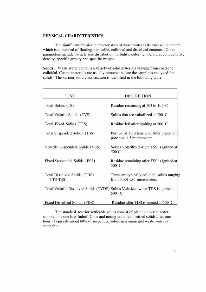
PHYSICAL CHARECTERISTICS
The significant physical characteristics of waste water is its total solid content
which is composed of floating, settleable, colloidal and dissolved contents. Other parameters include particle size distribution, turbidity, color, temperature, conductivity,density, specific gravity and specific weight.
Solids : Waste water contains a variety of solid materials varying from coarse tocolloidal. Coarse materials are usually removed before the sample is analyzed for solids. The various solid classification is identified in the following table.
TEST DESCRIPTION
Total Solids (TS)
Total Volatile Solids (TVS)
Total Fixed Solids (TFS)
Total Suspended Solids (TSS)
Volatile Suspended Solids (VSS)
Fixed Suspended Solids (FSS)
Total Dissolved Solids (TDS)( TS-TSS)
Total Volatile Dissolved Solids (TVDS)
Fixed Dissolved Solids (FDS)
Residue remaining at 103 to 105 C
Solids that are volatilized at 500 C
Residue left after igniting at 500 C
Portion of TS retained on filter paper with pore size 1.5 micrometers
Solids Volatilized when TSS is ignited at
500 CResidue remaining after TSS is ignited at500 C
These are typically colloidal solids rangingfrom 0.001 to 1 micrometers
Solids Volatized when TDS is ignited at500 C
Residue after TDS is ignited at 500 C
The standard test for settleable solids consist of placing a waste water sample on a one liter Imhoff Cone and noting volume of settled solids after onehour. Typically about 60% of suspended solids in a municipal waste water issettleable.
6

8/6/2019 Waste Water Treatment Notes
http://slidepdf.com/reader/full/waste-water-treatment-notes 7/75
Turbidity : Turbidity is a measure of the light transmitting property of thewater, is another test used to indicate the quality of waste water. The results of turbidity are reported in Nephelometric turbidity units (NTU). It should be notedthat the presence of air bubbles in the fluid will cause erroneous readings.
There is reasonable relationship between turbidity and total suspendedsolids (TSS) for the settled and filtered secondary effluents from activated sludge process. The general relationship is as follows:
TSS (mg/l) = (TSS f ) (T)TSS – Total suspended solids in mg/lTSS f - Conversion factor T – Turbidity in NTUTSS f – 2.3 to 2.4 for secondary settled effluent
1.3 to 1.6 for secondary filtered effluent
COLOUR : Condition refers to the age of the waste water, which is determinedqualitatively by its color. Fresh waste water is usually light brownish grey. Assepticity increases it tends to dark grey and finally to black. In most cases thecolor is due to metallic sulphides reacting with metals, which is formed by thesulphides reacting with metals under anaerobic conditions. Some industrialeffluents can also add color to domestic waste water.
CHLORIDES : Chloride is a constituent of concern in waste water as it canimpact the final reuse application of treated waste water. Chloride in naturalwater result from leaching from rocks and soils, salt water intrusion. In additionagricultural, industrial and domestic waste water discharges act as a source of chlorides. Human excreta contain about 6 grams of chloride per person.Conventional biological treatments do not remove chloride as they are non biodegradable.
NITROGEN: Total nitrogen comprises of organic nitrogen, ammonia. Nitriteand nitrate nitrogen. The organic fraction consists of a complex mixture of compounds including amino acid, amino sugars and proteins. These could besoluble or particulate. Organic nitrogen is determined analytically using theKjeldhal method. The aqueous sample is first boiled to drive off the ammonia andthen it is digested. During digestion organic nitrogen is converted to ammoniumthrough the action of heat and acid. Total Kjeldhal nitrogen (TKN) is determinedin the same manner as organic nitrogen, except that the ammonia is not driven off before digestion step. TKN is therefore sum of total organic nitrogen andammonia nitrogen. Nitrate nitrogen determined calorimetrically is relativelyunstable and is easily oxidized to nitrate form. Although present in lowconcentrations, nitrate can be very important as it is extremely toxic to fish andother aquatic species. Nitrites present in treated effluents are oxidized by chlorineand this increases the cost of disinfection. Nitrate nitrogen is the end product of
7
8/6/2019 Waste Water Treatment Notes
http://slidepdf.com/reader/full/waste-water-treatment-notes 8/75
nitrification and is typically found in treated effluents from 15 to 20 mg/l. Nitratenitrogen is determined by colorimetric tests or with specific-ion electrodes.
PHOSPHOROUS : Municipal waste waters may contain 4 to 16 mg/l P as total phosphorous which may comprise of ortho-phosphate, poly-phosphate and
organic phosphate. The ortho-phosphates are available for biological metabolismwithout further breakdown. The poly-phosphates include molecules with two or more phosphorous atoms, oxygen atoms and in some cases hydrogen atomscombined in a complex molecule. Poly-phosphates undergo hydrolysis inaqueous solutions and revert to ortho-phosphate from. Ortho-phosphate can bedetermined by adding ammonium molybdate which will form a color complex.The poly-phosphates and organic phosphates must be converted to ortho- phosphates using an acid digestion step before they can be determined in a similar manner.
SULFUR : Sulphates are reduced biologically to sulphide under anaerobic
conditions which in turn can combine with hydrogen to form hydrogen sulphide.The accumulated hydrogen sulphide can then be oxidized biologically to sulfuricacid which is corrosive. Sulphates are reduced to sulphides in sludge digestersand may upset the biological process if sulphide concentration exceeds 200 mg/l.
GASES : The gases commonly found in untreated waste water are compoundsof nitrogen, carbon di oxide, hydrogen sulphide, ammonia and methane. Thelatter three are derived from the decomposition of organic matter and are of concern to health and safety. The actual quantity of these gases that can be present depend upon (a) the solubility of gas defined by Henry’s law (b) the partial pressure (c) the temperature (d) the concentration.
Hydrogen sulphide is formed from the anaerobic decomposition of organicmatter containing sulfur or from the reduction of mineral sulphites or Sulphates.The blackening of waste water and sludge usually results from the formation of hydrogen sulphide that has combined with the iron present to form ferroussulphide (FeS). Various other metallic sulphides are also formed. Althoughhydrogen sulphide is the most important gas formed from the odor point, other volatile compounds such as indol, skatol, mercaptans may cause odor moreoffensive than hydrogen sulphide.
METALIC CONSTITUENTS : Trace quantities of metals such as cadmium.Chromium. Copper, zinc, iron, lead, manganese, nickel are present generally inwaste water. Most of these of these metals are necessary for the growth of biological life and the absence of sufficient quantity of these could limit themicrobial and algal growth. However metals in excessive quantities will interferewith the beneficial uses because of their toxicity. Sources of these metals includeresidential sectors, ground water infiltration, commercial and industrialdischarges.
8
8/6/2019 Waste Water Treatment Notes
http://slidepdf.com/reader/full/waste-water-treatment-notes 9/75
Metals are determined typically by flame atomic adsorption, electrothermal adsorption, inductively coupled plasma or IPC/mass spectrometry.Metals can be classified as (a) dissolved metals present in unacidified samples (b)suspended metals present in unacidified samples that are retained on a membranefilter (c) total metals – a sum of the above two determined after digestion (d) acid
extractable metals after present unfiltered sample is treated with a hot dilutemineral acid.
ORGANIC CONSTITUENTS : Organic constituents are normally composedof a combination of carbon, hydrogen and oxygen together with nitrogen in somecases. In waste water it typically consists of proteins (40 to 60%), carbohydrates(25 to 50%) and oils and fats (8 to 12%). Urea the major constituent in urine tsalso present in fresh waste water. However it quickly decomposes due to ureahydrolysis leading to ammonia.
Laboratory investigations for organics include (1) Biochemical Oxygen
Demand (BOD) (2) Chemical Oxygen Demand (COD) (3) Total OrganicCarbon (TOC). The TOC test, done instrumentally is used to determine the totalorganic carbon in an aqueous samples. The test methods for TOC utilize heat andoxygen, ultra violet radiation, chemical oxidants or some combination of thesemethods to convert organic carbon to carbon di oxide which is then measuredwith an infrared analyzer or by other means. The TOC tests are gaining favor, because it takes only 5 to 10 minutes to complete.
INDIVIUAL ORGANIC COMPONDS : Individual organic compounds aredetermined to assess the presence of priority pollutants identified by USEPA.Priority pollutants both organic and inorganic are selected on the basis of their carcinogenicity, mutagenecity, tetrogenecity or high acute toxicity. The analyticalmethods used to determine these require the use of sophisticated instrumentscapable of measuring trace concentration in the range of 10 -12 to 10 -13 mg/l. Gaschromatograph (GC) and high performance liquid chromatograph (HPLC)methods are most commonly used to detect these compounds. Typical detectorsused in conjunction with gas chromatography include electrolytic conductivity,electron capture (ECD), flame ionization (FID), photo ionization (PID) and massspectrometer (GCMS). Typical detectors for high performance liquidchromatography include photo iodide array (PDAD) and post column reactor (PCR). Over 180 individual organic compounds can be determined by using theabove one of two methods.
VOLATILE ORGANIC COMPOUNDS (VOC) : Organic compounds thathave a boiling point less than or equal to 100 C and / or a vapor pressure morethan 1mm Hg at 25 C are generally considered to be volatile organic compounds(VOC). Vinyl Chloride which has a boiling point of minus 13 C and a vapor pressure of 2548 mm of Hg at 20 C is an example of a highly volatile organiccompound. These are of common concern because (1) Once such compounds are
9
8/6/2019 Waste Water Treatment Notes
http://slidepdf.com/reader/full/waste-water-treatment-notes 10/75
in Vapor state, they are much more mobile and therefore more likely to bereleased to the atmosphere(2) the presence of some of these compounds in the atmosphere may pose a
significant health risk (3) they contribute to the general increase in thereactive hydrocarbons in the atmosphere, which can lead to the formation of
photochemical oxidants. The release of these compounds in sewers andtreatment plants especially at head works is of concern with respect of healthof personnel involved.
DISINFECTION BYPRODUCTS : It has been found that when chlorine isadded to waste water, variety of organic compounds containing chlorine areformed. Collectively these compounds are known as disinfection byproducts(DBP). Although present in low concentrations, they are of concern because of suspected carcinogenicity. Typical classes of these compounds includetrihalomethane (THM), halo acetic acid (HAA), trichlorophenol and aldehydes.Because of the concerns, considerable attention has been focused over the past
few years on the use of ultra violet (UV) disinfection as a replacement tochlorination. In addition considerable attention has been focused on themodifications to the conventional treatment processes to improve the treatment of these compounds and to advanced processes for the removal of these.
PESTICIDES AND AGRICULTURAL CHEMICALS : Pesticides,herbicides and other agricultural chemicals are toxic to many organisms andtherefore can be significant contaminants to surface of waters. These chemicalsare not common constituents of domestic waste water, but result primarily fromsurface run off from agricultural, vacant and park lands. Concentration of thesemay retard the treatment process, result in fish kills or may result in toxic foodchain to humans.
BIOLOGICAL CHARECTERISTICS : The biological characteristics of waste water are of fundamental importance in the control of diseases caused by pathogenic organisms of human origin, and because of their fundamental role played in the stabilization and decomposition of organic matter. The se include bacteria, fungi, algae, protozoa and viruses.
Bacteria are single celled prokaryotic organisms. The interior of the cellcontains a colloidal suspension of proteins, carbohydrates etc called cytoplasm.This contains ribonucleic acid (RNA) which plays a major role in synthesis of proteins. It also contains deoxyribonucleic acid (DNA) which contains all thenecessary information for reproduction.
Protozoa are motile microscopic eukaryotes that are usually single celled.The majority of protozoa are aerobic heterotrophes and often consume bacteria asan energy source.
10
8/6/2019 Waste Water Treatment Notes
http://slidepdf.com/reader/full/waste-water-treatment-notes 11/75
Viruses are composed of a nucleic acid core ( either DNA or RNA)surrounded by an outer shell of proteins called a capsid. Viruses are intracellular parasites that multiply only within a host cell. Bacteriophages are viruses thatinfect a bacteria as a host cell. They have not been implicated in humaninfections.
Algae are unicellular or multicellular autotrophic photosyntheticeukaryotes. The blue green algae cyanobacter is a prokaryotic organism.
Fungi are multicellular non photosynthetic, heterotrophic eukaryotes.Most fungi are strict or facultative aerobes which reproduce sexually or asexually, by binary fission, budding or spore formation. Molds produce microscopic unitswhich collectively form a filamentous mass called mycelium. Yeasts are fungithat cannot form mycelium and are therefore unicellular.
Many types of harmless bacteria colonize in the human intestinal tract and
are routinely shed in feces. They contain a large number of bacillus collectivelyknown as coli form bacteria. Each person discharges from 100 to 400 billion coliform bacteria per day which are taken as indicator microorganisms for the presence of pathogens.
Typical Sewage Analysis
Total Solids
Total Suspended Solids
Total Volatile Solids
Total Fixed Solids
Dissolved Oxygen
Biological Oxygen Demand
Chemical Oxygen Demand
Total Nitrogen
Ammonia Nitrogen
Organic Nitrogen
Nitrite Nitrogen
Nitrate Nitrogen
Sulphates or Sulphides
Chlorides
Ether Soluble Solids
11
8/6/2019 Waste Water Treatment Notes
http://slidepdf.com/reader/full/waste-water-treatment-notes 12/75
Living Organisms
Macro – Worms
Micro – Bacteria, Virus, Protozoa, Algae and Fungus
Dissolved Oxygen
Fresh Water will have DO depending upon water temperature and ambient
pressure
At 10° C and 1 atm – 11.3 mg/l
At 30° C and 1 atm – 7.8 mg/l
(atm – atmosphere)
DO is determined by Winkler’s modification method or probes.
Winkler’s Azide modification Method ( D.O)
Sample (BOD bottle) + 2ml MnSO4 + 2ml Alkali Iodide azide
Brown precipitate – Presence of DO
White precipitate – Absence of DO
+ 2ml H2SO4 (fixing)
Starch Indicator – Blue Color
Titrate 0.02 Sodium thiosulphate – disappearance of blue color
Mn++ + 2OH- MnOH (white precipitate)
Mn++ + 2OH- + O MnO2 + H2O (brown precipitate)
MnO2 + 2I- + 4H+ Mn++ + I2 + 2H2O
2Na2 S2O3 5H2O + I 2 Na 2 S4 O6 + 2 NaI + 10 H2O
or 2S2O3- + I2 S4O6
2- + 2I-
12
8/6/2019 Waste Water Treatment Notes
http://slidepdf.com/reader/full/waste-water-treatment-notes 13/75
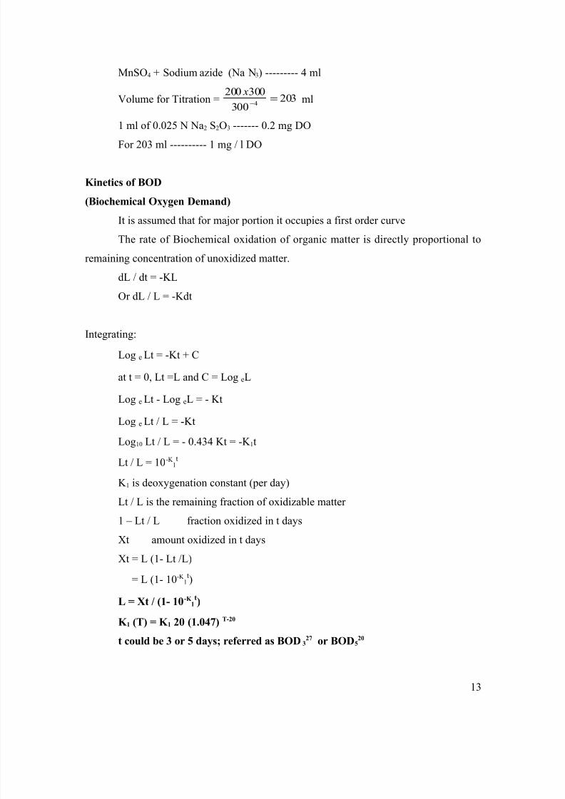
MnSO4 + Sodium azide (Na N3) --------- 4 ml
Volume for Titration = 203300
3002004
=−
xml
1 ml of 0.025 N Na2 S2O3 ------- 0.2 mg DO
For 203 ml ---------- 1 mg / l DO
Kinetics of BOD
(Biochemical Oxygen Demand)
It is assumed that for major portion it occupies a first order curve
The rate of Biochemical oxidation of organic matter is directly proportional to
remaining concentration of unoxidized matter.
dL / dt = -KLOr dL / L = -Kdt
Integrating:
Log e Lt = -Kt + C
at t = 0, Lt =L and C = Log eL
Log e Lt - Log eL = - Kt
Log e Lt / L = -KtLog10 Lt / L = - 0.434 Kt = -K 1t
Lt / L = 10-K 1t
K 1 is deoxygenation constant (per day)
Lt / L is the remaining fraction of oxidizable matter
1 – Lt / L fraction oxidized in t days
Xt amount oxidized in t days
Xt = L (1- Lt /L)= L (1- 10-K
1t)
L = Xt / (1- 10-K 1t)
K 1 (T) = K 1 20 (1.047) T-20
t could be 3 or 5 days; referred as BOD327 or BOD5
20
13
8/6/2019 Waste Water Treatment Notes
http://slidepdf.com/reader/full/waste-water-treatment-notes 14/75
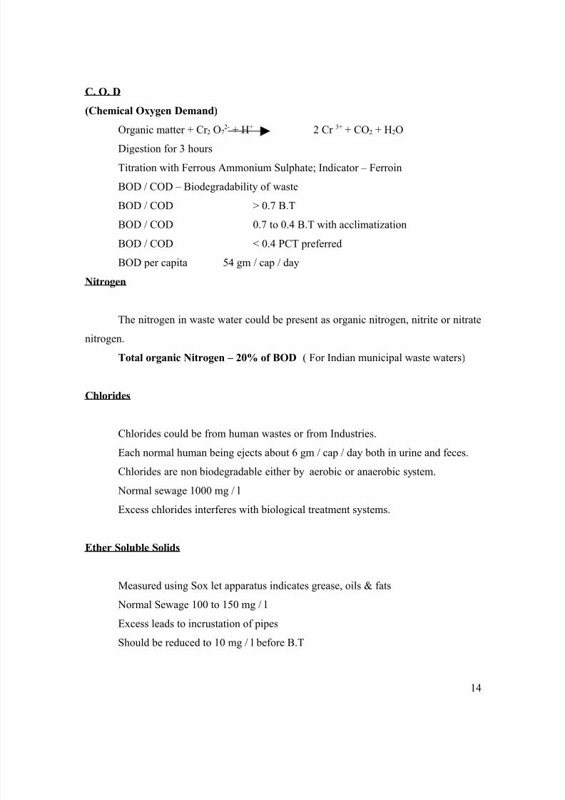
C. O. D
(Chemical Oxygen Demand)
Organic matter + Cr 2 O72- + H+ 2 Cr 3+ + CO2 + H2O
Digestion for 3 hours
Titration with Ferrous Ammonium Sulphate; Indicator – Ferroin
BOD / COD – Biodegradability of waste
BOD / COD > 0.7 B.T
BOD / COD 0.7 to 0.4 B.T with acclimatization
BOD / COD < 0.4 PCT preferred
BOD per capita 54 gm / cap / day
Nitrogen
The nitrogen in waste water could be present as organic nitrogen, nitrite or nitrate
nitrogen.
Total organic Nitrogen – 20% of BOD ( For Indian municipal waste waters)
Chlorides
Chlorides could be from human wastes or from Industries.
Each normal human being ejects about 6 gm / cap / day both in urine and feces.
Chlorides are non biodegradable either by aerobic or anaerobic system.
Normal sewage 1000 mg / l
Excess chlorides interferes with biological treatment systems.
Ether Soluble Solids
Measured using Sox let apparatus indicates grease, oils & fats
Normal Sewage 100 to 150 mg / l
Excess leads to incrustation of pipes
Should be reduced to 10 mg / l before B.T
14
8/6/2019 Waste Water Treatment Notes
http://slidepdf.com/reader/full/waste-water-treatment-notes 15/75
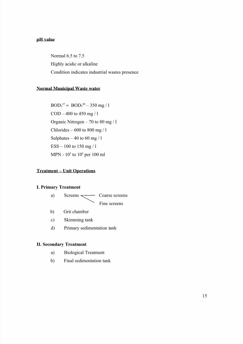
pH value
Normal 6.5 to 7.5
Highly acidic or alkaline
Condition indicates industrial wastes presence
Normal Municipal Waste water
BOD327 ≈ BOD5
20 – 350 mg / l
COD – 400 to 450 mg / l
Organic Nitrogen – 70 to 80 mg / lChlorides – 600 to 800 mg / l
Sulphates – 40 to 60 mg / l
ESS – 100 to 150 mg / l
MPN - 105 to 106 per 100 ml
Treatment – Unit Operations
I. Primary Treatment
a) Screens Coarse screens
Fine screens
b) Grit chamber
c) Skimming tank
d) Primary sedimentation tank
II. Secondary Treatment
a) Biological Treatment
b) Final sedimentation tank
15
8/6/2019 Waste Water Treatment Notes
http://slidepdf.com/reader/full/waste-water-treatment-notes 16/75
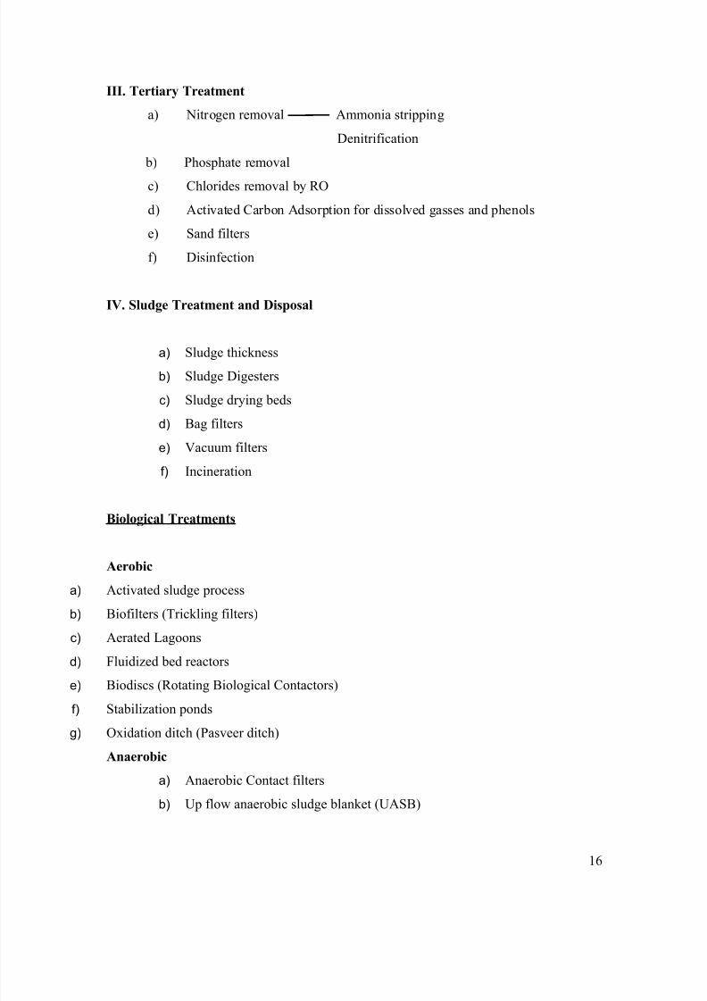
III. Tertiary Treatment
a) Nitrogen removal Ammonia stripping
Denitrification
b) Phosphate removal
c) Chlorides removal by RO
d) Activated Carbon Adsorption for dissolved gasses and phenols
e) Sand filters
f) Disinfection
IV. Sludge Treatment and Disposal
a) Sludge thicknessb) Sludge Digesters
c) Sludge drying beds
d) Bag filters
e) Vacuum filters
f) Incineration
Biological Treatments
Aerobic
a) Activated sludge process
b) Biofilters (Trickling filters)
c) Aerated Lagoons
d) Fluidized bed reactors
e) Biodiscs (Rotating Biological Contactors)
f) Stabilization ponds
g) Oxidation ditch (Pasveer ditch)
Anaerobic
a) Anaerobic Contact filters
b) Up flow anaerobic sludge blanket (UASB)
16
8/6/2019 Waste Water Treatment Notes
http://slidepdf.com/reader/full/waste-water-treatment-notes 17/75
c) Anaerobic Lagoons
d) Septic tanks
e) Imhoff tanks
In the aerobic system the organic matter is bio oxidized in the presence of dissolved
oxygen. In the anaerobic system the organic matter is bio reduced in the absence of
dissolved oxygen. The amount energy evolved in an aerobic oxidation for microbial
sustain is 16 to 20 times the amount of energy evolved in an anaerobic reduction. Hence
aerobic degradation is 16 to 20 times faster than an anaerobic degradation making aerobic
treatment more compact.
Error: Reference source not found
Flow Sheet – Municipal Wastewater Treatment System
Theory of Settling
A particle in a still fluid of lesser density will move to settle. It will accelerate
initially until the frictional resistance of the fluid equals the impelling force and
there on it reaches a constant settling velocity (HSV).
Discrete Settling No change in shape or size of particle and HSV remains constant. Depth is no
criteria for efficiency. It is applicable for plain sedimentation.
Hindered Settling
Shape and size increases with settling. There is acceleration with depth. It is
applicable for flocculent settling.
Frictional Resistance or Drag
FD = CD*A*ρ*(υ2/2)…………. (Kg.m/Sec2)
Where,
CD = Coefficient of drag. (Relative to viscosity)
A = Projected surface area (πd2/4)
υ = HSV m/sec
ρ = Mass density of fluid
17
Sludge
Digester
8/6/2019 Waste Water Treatment Notes
http://slidepdf.com/reader/full/waste-water-treatment-notes 18/75
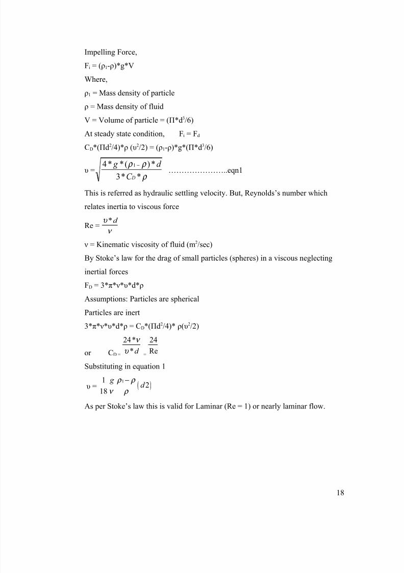
Impelling Force,
Fi = (ρ1-ρ)*g*V
Where,
ρ1 = Mass density of particle
ρ = Mass density of fluid
V = Volume of particle = (Π*d3/6)
At steady state condition, Fi = Fd
CD*(Πd2/4)*ρ (υ2/2) = (ρ1-ρ)*g*(Π*d3/6)
υ = ρ
ρ ρ
**3
*)(**4 1
DC
d g −
…………………..eqn1
This is referred as hydraulic settling velocity. But, Reynolds’s number which
relates inertia to viscous force
Re =*d υ
ν
ν = Kinematic viscosity of fluid (m2/sec)
By Stoke’s law for the drag of small particles (spheres) in a viscous neglecting
inertial forces
FD = 3*π*ν*υ*d*ρ
Assumptions: Particles are sphericalParticles are inert
3*π*ν*υ*d*ρ = CD*(Πd2/4)* ρ(υ2/2)
or CD =
24*
* d
ν
υ =
24
Re
Substituting in equation 1
υ = ( )11
218
g d
ρ ρ
ν ρ
−
As per Stoke’s law this is valid for Laminar (Re = 1) or nearly laminar flow.
18
8/6/2019 Waste Water Treatment Notes
http://slidepdf.com/reader/full/waste-water-treatment-notes 19/75
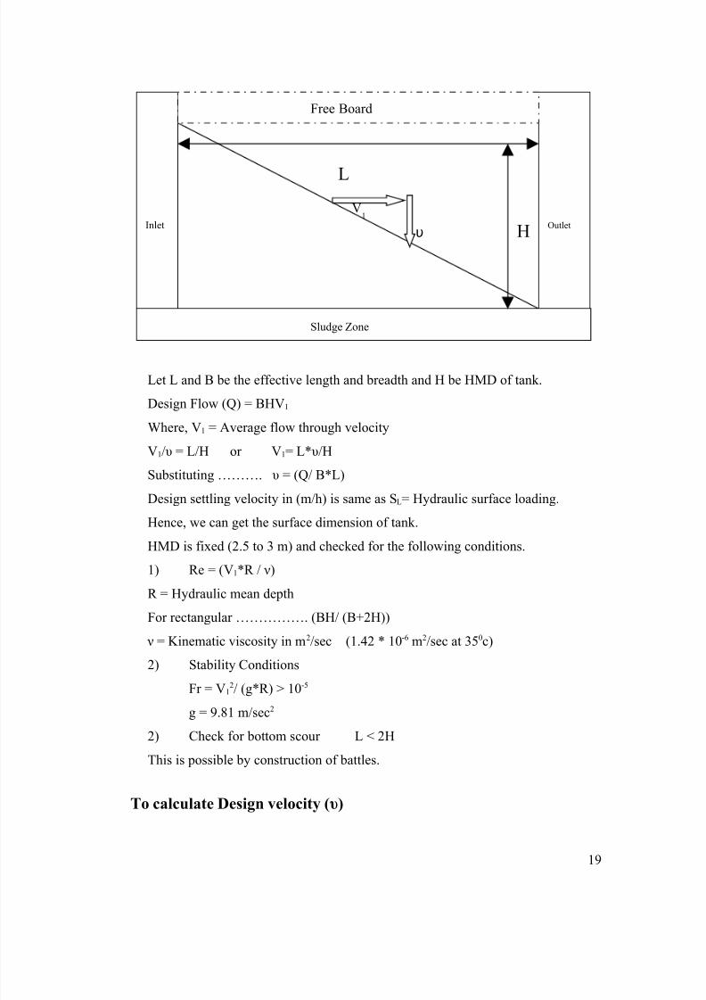
Let L and B be the effective length and breadth and H be HMD of tank.
Design Flow (Q) = BHV1
Where, V1 = Average flow through velocity
V1/υ = L/H or V1= L*υ/H
Substituting ………. υ = (Q/ B*L)
Design settling velocity in (m/h) is same as SL= Hydraulic surface loading.
Hence, we can get the surface dimension of tank.HMD is fixed (2.5 to 3 m) and checked for the following conditions.
1) Re = (V1*R / ν)
R = Hydraulic mean depth
For rectangular ……………. (BH/ (B+2H))
ν = Kinematic viscosity in m2/sec (1.42 * 10-6 m2/sec at 350c)
2) Stability Conditions
Fr = V12/ (g*R) > 10-5
g = 9.81 m/sec2
2) Check for bottom scour L < 2H
This is possible by construction of battles.
To calculate Design velocity (υ)
LV
1
υ H
Sludge Zone
Inlet Outlet
Free Board
19

8/6/2019 Waste Water Treatment Notes
http://slidepdf.com/reader/full/waste-water-treatment-notes 20/75
Example: Total wt of suspended particle = 200 gms/m3
% Net Cum% withwith velocity<= υ (p)
90 gms/m3 with υ = 2.5 m/h 45 10060 gms/m3 with υ = 1.2 m/h 30 5530 gms/m3 with υ = 0.6 m/h 15 2520 gms/m3 with υ = 0.2 m/h 10 10
Removal ratio (r) =Ci
CeCi −
Ci and Ce in mg/l or gm/m3
Based on this υ is determined. Re for Laminar Re<= 1
Transient Re= 1-2000
DT υ ρ1
Grit Chamber 3 to 5 minutes 36m/h 2650Aerated Grit Chamber 6 minutes 25m/h 2650PST 2.5 hrs 1.5m/h 1650SST 3.5hrs 0.6m/h 1350
r
10
0
80
40
20 1-r
υ
υ m/day or 10-3 m/sec
P
20

8/6/2019 Waste Water Treatment Notes
http://slidepdf.com/reader/full/waste-water-treatment-notes 21/75
21

8/6/2019 Waste Water Treatment Notes
http://slidepdf.com/reader/full/waste-water-treatment-notes 22/75
Activated Sludge Proces s
The biological systems are classified as either suspended growth system where
the bioflocs are kept in suspension either in aerobic or anaerobic condition. Activated
sludge process, aerated lagoons, anaerobic lagoons etc fall under this category. In an
attached growth system the bioflocs are adsorbed over an inert media, examples are
biofilters, RBC, Anaerobic contact filter etc.
In an activated sludge process, the wastewater (refilled as mixed liquor) is kept
agitated leading to bioflocs. The bioflocs which are in an activated state are settled in the
final sedimentation tank. Parts of the bioflocs are returned as return sludge to increase the
acclimatized micro-organisms in the mixed liquor.
S PST S2* ∞ FST Se
QD M QD
Activities
1. Agitation leads to better contact between M.O. and colloidal BOD
2. Agitation sets M.O. in virulent action
3. Agitation leads to adsorption forming bioflocs
4. Agitation of DO in MLSS
Design features
1. Sludge loading or F/M ratio2. Volume of reactor
3. Excess sludge produced
4. Recirculation
5. Aeration required
6. Design of aerators
22
QR
8/6/2019 Waste Water Treatment Notes
http://slidepdf.com/reader/full/waste-water-treatment-notes 23/75
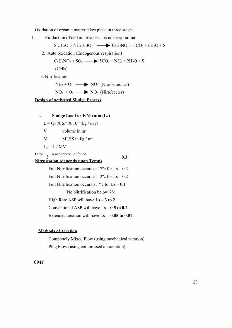
Oxidation of organic matter takes place in three stages
1. Production of cell material + substrate respiration
8 CH2O + NH3 + 3O2 C5H7 NO2 + 3CO2 + 6H2O + S
2. Auto oxidation (Endogenous respiration)
C5H7 NO2 + 5O2 5CO2 + NH3 + 2H2O + S
(Cells)
3. Nitrification
NH3 + O2 NO2- (Nitrosomonas)
NO2- + O2 NO3
- (Nirtobacter)
Design of activated Sludge Process
I. Sludge Load or F/M ratio (LS)
L = QD X Si* X 10-3 (kg / day)
V volume in m3
M MLSS in kg / m3
LS = L / MV
Error: Reference source not found
Nitrification (depends upon Temp)
Full Nitrification occurs at 17ºc for Ls – 0.3
Full Nitrification occurs at 12ºc for Ls – 0.2
Full Nitrification occurs at 7ºc for Ls – 0.1
(No Nitrification below 7ºc)
High Rate ASP will have Ls – 3 to 2
Conventional ASP will have Ls – 0.5 to 0.2
Extended aeration will have Ls – 0.05 to 0.01
Methods of aeration
Completely Mixed Flow (using mechanical aeration)
Plug Flow (using compressed air aeration)
CMF
23
0.33
8/6/2019 Waste Water Treatment Notes
http://slidepdf.com/reader/full/waste-water-treatment-notes 24/75
1. Mechanical aeration by rotors
2. Instant dispersion, Less concentration of reactants, longer aeration period
required
3. Larger Tank volume
4. Less efficiency (actual DT – 0.7 Theoretical DT)
5. Better agitation, hence suited for industrial wastes.
PF
1. Compressed air aeration
2. Flow is laminar, better efficiency, hence lesser tank volume (actual DT =
Theoretical DT)
3. No mixing, hence suited for uniform (municipal wastes)
Compressed air aeration
1. Fine bubble aeration: Bubble size is 2mm to 8mm diameter, through
porous material. Ridge & Furrow systems, Porous Plate, aeration dome etc.
2. Course bubble aeration: Bubble size greater than 8mm, Better agitation,
but poorer oxygenation effect through perforated pipes.
24
8/6/2019 Waste Water Treatment Notes
http://slidepdf.com/reader/full/waste-water-treatment-notes 25/75
OC ( Oxygenation Capacity)
Oxygenation capacity of a given system is defined as the rate of increase of
oxygen concentration with time at STP [1atm & 10ºc] in kg O2 / hour
OR ( Oxygenation Rate )
Oxygenation rate of a given system is defined as the rate of increase of oxygen
concentration under design Temp and pressure in kg / hour
OC = K 2 Cs*
OR = K T (CST – CL)
K2 Reaeration constant at STP
K T Reaeration constant at DTP
CL Minimum O2 Concentration in tank [≈ 2 mg / l]
Design details:
Data: QD , QH , Min working temperature (Design)Si , Se ,M, Ls and SVI
L = Si* QD X 10-3 (Kgs/day)
Se = 20mg/l
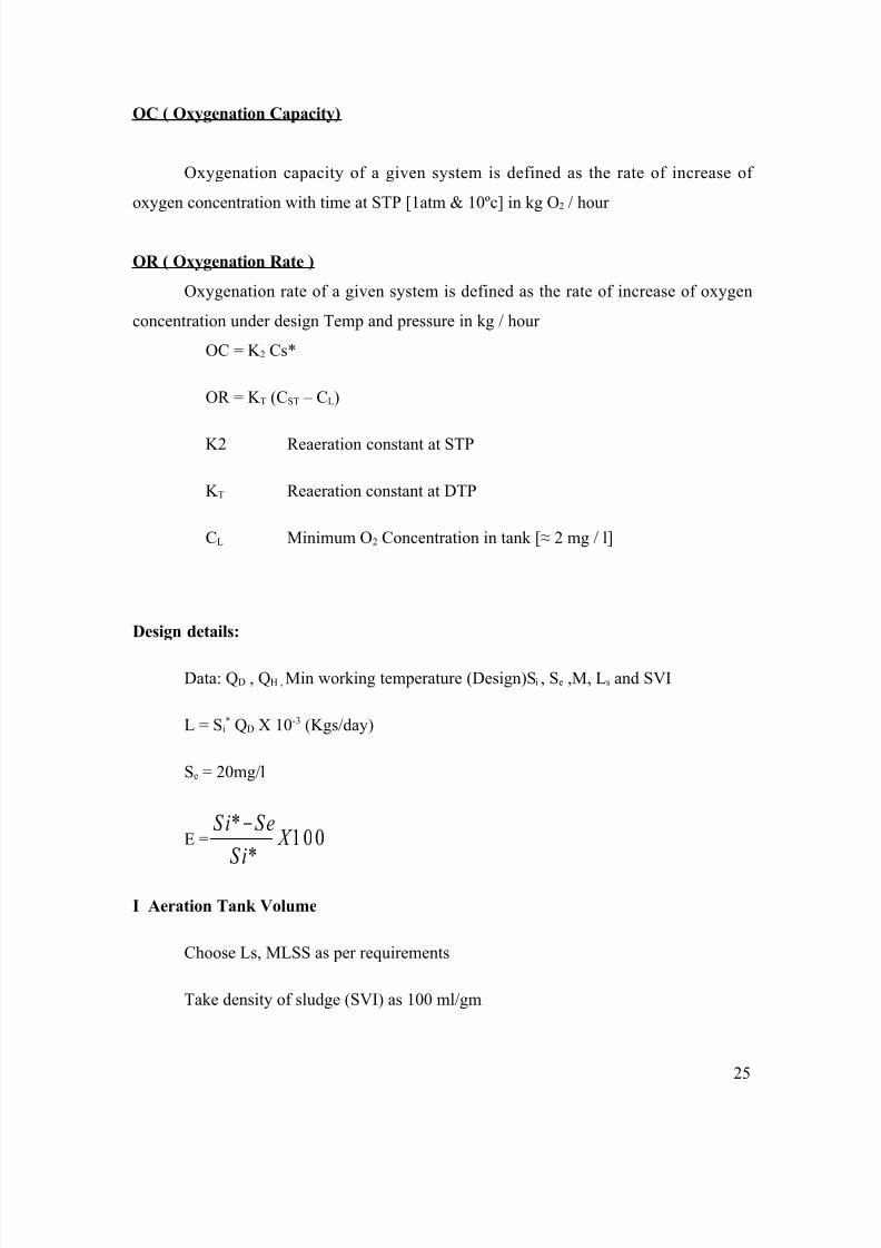
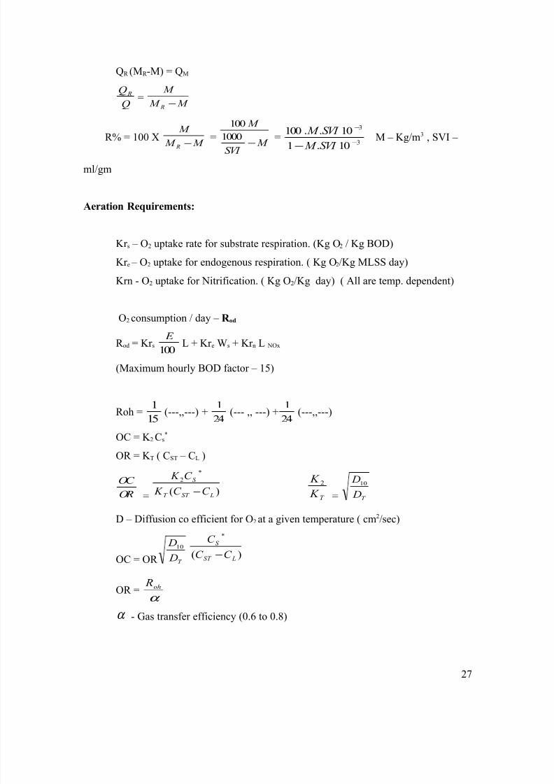
E = 100*
* X
S i
SeS i −
I Aeration Tank Volume
Choose Ls, MLSS as per requirements
Take density of sludge (SVI) as 100 ml/gm
25
8/6/2019 Waste Water Treatment Notes
http://slidepdf.com/reader/full/waste-water-treatment-notes 26/75
Total dry weight of ASP – Ws
Ws - s L
L(kgs)
VAT -M W s (m3) or M L
L s
(m3)
Check for tAT =
D
AT
Q
V
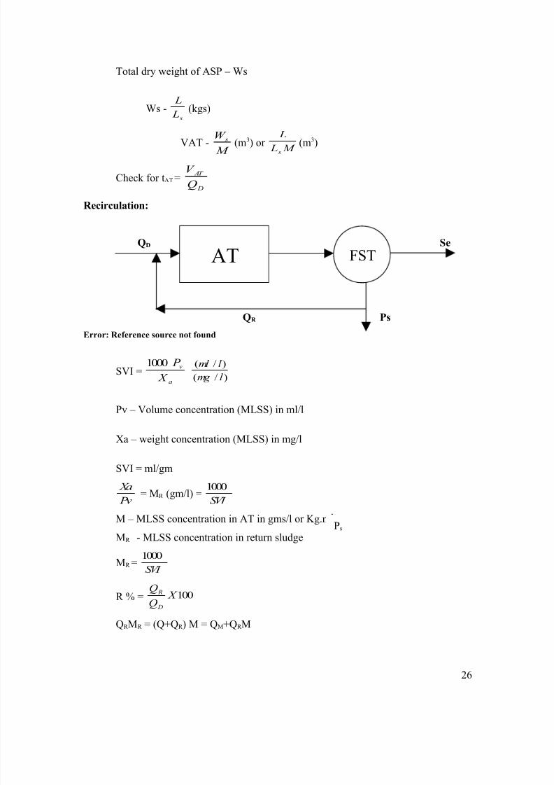
Recirculation:
QD Se
QR Ps
Error: Reference source not found
SVI =a
v
X
P 1000
)/(
)/(
l mg
l ml
Pv – Volume concentration (MLSS) in ml/l
Xa – weight concentration (MLSS) in mg/l
SVI = ml/gm
Pv
Xa= MR (gm/l) =
SVI
1000
M – MLSS concentration in AT in gms/l or Kg.m3
MR - MLSS concentration in return sludge
MR =SVI
1000
R % = 100 X Q
Q
D
R
QR MR = (Q+QR ) M = QM+QR M
26
Ps
FSTAT
8/6/2019 Waste Water Treatment Notes
http://slidepdf.com/reader/full/waste-water-treatment-notes 27/75
QR (MR -M) = QM
Q
Q R =M M
M
R −
R% = 100 X M M
M
R − = M SVI
M
−1000
100
= 3
3
10.1
10..100−
−
− SVI M
SVI M
M – Kg/m3 , SVI –
ml/gm
Aeration Requirements:
Kr s – O2 uptake rate for substrate respiration. (Kg O2 / Kg BOD)
Kr e – O2 uptake for endogenous respiration. ( Kg O2/Kg MLSS day)
Krn - O2 uptake for Nitrification. ( Kg O2/Kg day) ( All are temp. dependent)
O2 consumption / day – R od
R od = Kr s 100
E L + Kr e Ws + Kr n L NOx
(Maximum hourly BOD factor – 15)
Roh = 15
1
(---,,---) + 24
1
(--- ,, ---) + 24
1
(---,,---)
OC = K 2 Cs*
OR = K T ( CST – CL )
OR
OC
= )(
*
2
LST T
S
C C K
C K
− T K
K 2
= T D
D10
D – Diffusion co efficient for O2 at a given temperature ( cm2/sec)
OC = OR T D
D10 )(
*
LST
S
C C
C
−
OR =α
oh R
α - Gas transfer efficiency (0.6 to 0.8)
27
8/6/2019 Waste Water Treatment Notes
http://slidepdf.com/reader/full/waste-water-treatment-notes 28/75
OC (Kgs/hr) = α
oh R
T D
D10)(
*
LST
S
C C
C
−
HP =2.1
oh R (hp)…………… empirical
For Municipal wastes:
Kr s –0.1 to 0.5
Kr e – 0.15 to 0.2
Krn – 3.5 to 4.5
Excess sludge production:
Ps (Excess sludge) Kg MLSS/day = [1.2 Ls0.23 100
E
L] Kgs/ day
[1.2 takes care of the unit per day]
Sludge age or Mean cell residence time = s
s
P
W
days
For conventional ASP – 3 – 4 days
For Extended Aeration – 20 – 25 days
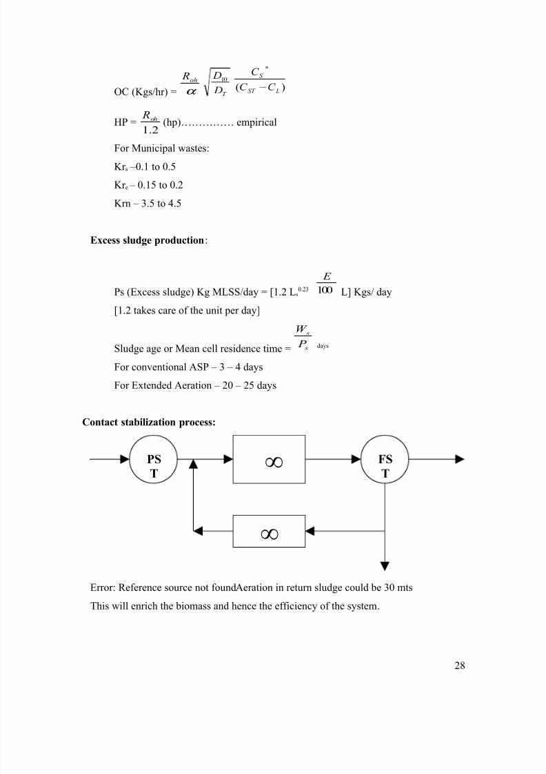
Contact stabilization process:
Error: Reference source not foundAeration in return sludge could be 30 mts
This will enrich the biomass and hence the efficiency of the system.
28
PS
T
FS
T ∞
∞
8/6/2019 Waste Water Treatment Notes
http://slidepdf.com/reader/full/waste-water-treatment-notes 29/75
Operational problems:
(i) Rising of sludge:
This is due to excessive nitrification in aeration tank and denitrification in AT or
FST. If the sludge in FST is not removed in six hours, it may lead to sludge overshooting.
This could also happen due to dead pockets in the aeration tank due to improper working
of aerators or voltage fluctuation.
(ii) Bulking of sludge:
This is due to growth of filamentous protozoa in activated sludge resulting inincrease of SVI (> 300 ml/gm). This is due to toxic shock loads from industries (mainly
heavy metals) or substrate shock loads. This can be controlled temporarily by
chlorinating the return sludge with 5 to 10 mg/l chlorine. On long term the shock loads
should be controlled.
(iii) Foaming:
Foams occur in the aeration tank due to excess grease (>10 mg/l). The foam may
create in aerosols and carried for long distances with pathogens. On short term this could
be controlled by spraying defoamers ( like Alkyl benzynesulphonate) and by proper
grease removal.
Monitoring of ASP:
1. BOD
2. MLSS
3. SVI
29
8/6/2019 Waste Water Treatment Notes
http://slidepdf.com/reader/full/waste-water-treatment-notes 30/75
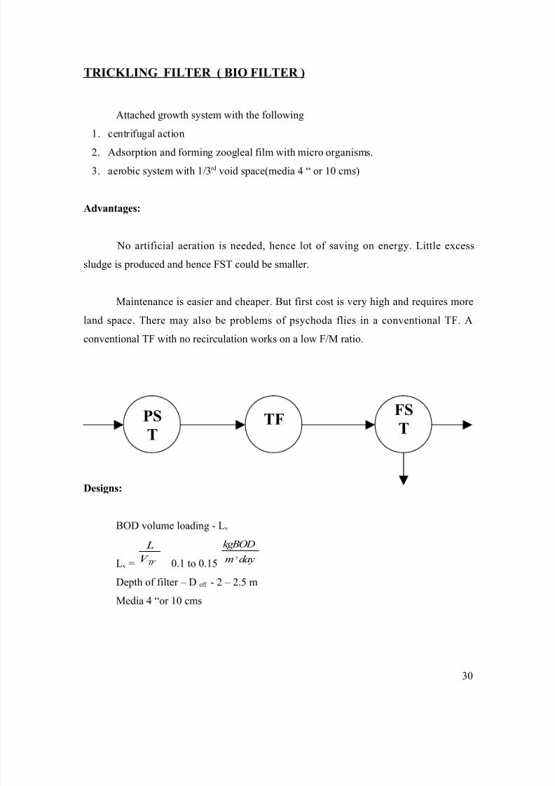
TRICKLING FILTER ( BIO FILTER )
Attached growth system with the following
1. centrifugal action2. Adsorption and forming zoogleal film with micro organisms.
3. aerobic system with 1/3rd void space(media 4 “ or 10 cms)
Advantages:
No artificial aeration is needed, hence lot of saving on energy. Little excess
sludge is produced and hence FST could be smaller.
Maintenance is easier and cheaper. But first cost is very high and requires more
land space. There may also be problems of psychoda flies in a conventional TF. A
conventional TF with no recirculation works on a low F/M ratio.
Designs:
BOD volume loading - Lv
Lv = TF V
L
0.1 to 0.15 daym
kgBOD3
Depth of filter – D eff - 2 – 2.5 m
Media 4 “or 10 cms
30
PST
TF FST
8/6/2019 Waste Water Treatment Notes
http://slidepdf.com/reader/full/waste-water-treatment-notes 31/75
Vitrified clay rings of 10 cms have also been used. Hydraulic head need for
distribution is 0.6 m above TF surface. These may have occasional psychoda flushing.
Ponding is due to clogging of the filters. Ponding leads to anaerobic conditions in the
filters, odour problems and reduction in efficiencies. If the influent BOD (pre settled)
exceeds 400 mg/l, it may lead to clogging needing dilution by recirculation.
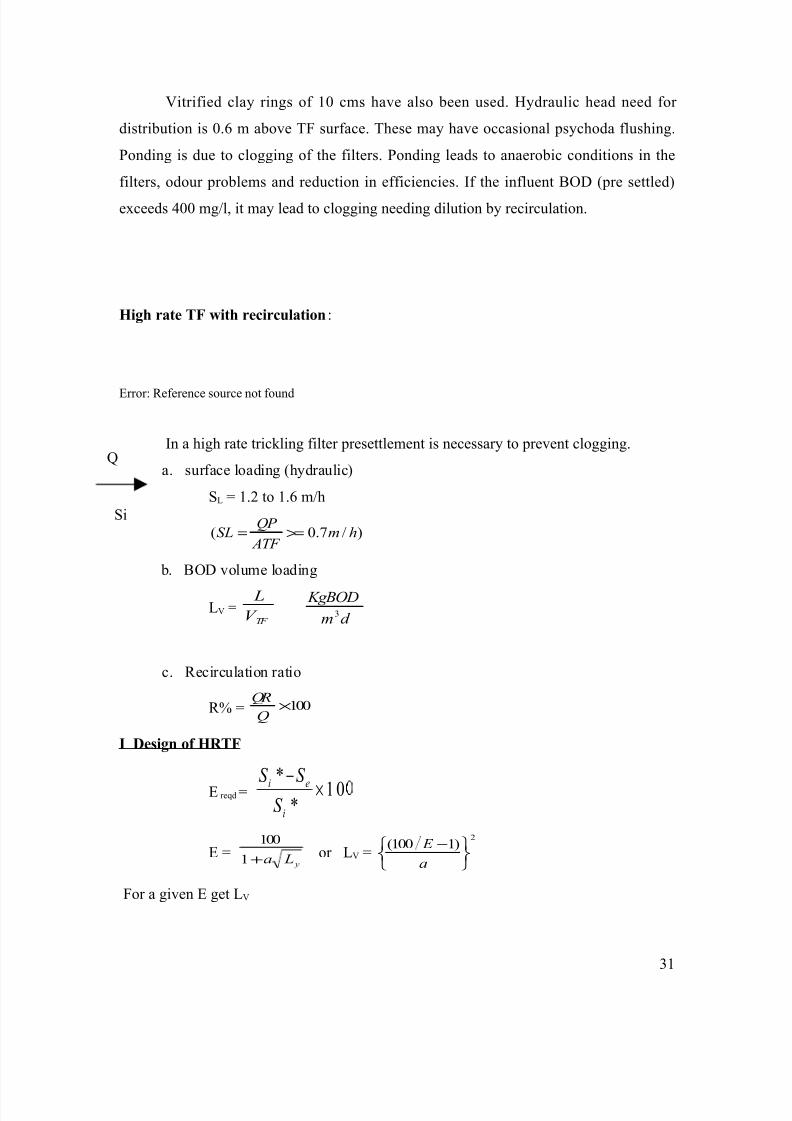
High rate TF with recirculation:
Error: Reference source not found
In a high rate trickling filter presettlement is necessary to prevent clogging.
a. surface loading (hydraulic)
SL = 1.2 to 1.6 m/h
)/7.0( hm ATF
QP SL >==
b. BOD volume loading
LV =TF V
L
d m
KgBOD3
c. Recirculation ratio
R% = 100×Q
QR
I Design of HRTF
E reqd = 10*
*×
−
i
ei
S
S S
E = y La+1
100or LV =
2)1100(
−
a
E
For a given E get LV
31
Q
Si

8/6/2019 Waste Water Treatment Notes
http://slidepdf.com/reader/full/waste-water-treatment-notes 32/75
a Si (mg/L)0.4
4
0.4
0
0.3
7
<= 300
~ 350
- 350-400
Given L, calculate VTF
Choosing DH varying from 2.5 to 4m
Get ATF - check
LATF daym
KgBOD2
4≤
SL hm /7.0≥ < 1.6 m/h
Operation problems:
i. Bulking – spray chlorine in return flow, control shock loads.
ii. Psychoda flies – check recirculation and anaerobic condition due
to clogging.
iii. Maintenance of arms and nozzles.iv. Cleaning media once in six months and replacement of media once
in five years.
The TF works similar to extended aeration system with sludge age as 30 to 45 days.
32

8/6/2019 Waste Water Treatment Notes
http://slidepdf.com/reader/full/waste-water-treatment-notes 33/75
STABILIZATION PONDS (OXIDATION PONDS )
Types of ponds:
i. Fully aerobic (shallow ponds) meant for algal cultivation – 30 cm.ii. Facultative – depth 1.2 m to 1.5 m with 30 cm to 40 cm anaerobic.
–waste stabilization.
iii. Maturation ponds – depth 1m used as polishing pond.
lato Visible radiation (langlays)Max min
50
4030
20
10
26
66126
182
225
07
2470
120
162
Error: Reference source not found
33
Performance of Stabilization Pond
Influent
Waste water
Inorganic
+organic
AerobicAnaerobic
Bacteria Algae
NO3
, PO4
, CO2 NH
4, CH
4, CO
2
8/6/2019 Waste Water Treatment Notes
http://slidepdf.com/reader/full/waste-water-treatment-notes 34/75
Algae – C106H180O45 N16P1
(Euglema, spirogyra and blue green algae)
By dry weight – 52.5% C, 9.2% N, 1.3% P.
So the waste should have this minimum CNP.
106 CO2 + 90 H2O + 16 NO3 + PO4 C106H180O45 N16P +154O2
So theoretically for every gm of algae 2 Gms of oxygen is produced.
In practice for every gm of algae 1.7 Gms of oxygen is produced.
Average radiation = min + [(max – min) x SCF]
(Cals/cm2/day)
Conversion efficiency – 4 to 6% of visible light energy.
Energy in algae – 6000 cal/gm.
Designs:
Si – INF BOD gm/m3
Se - eff BOD gm/m3 [60 mg/L]
BOD (ult) removed – (Si – Se) gm/m3
O2 required (Si – Se) QD gm/day.
QD - average design flow.
P1 = wt of oxygen released
Wt of associated algae
Total weight of algae required = (Si – Se) QD = (al) gms/day
P1
Energy for algal formation – 6 K Cals/gm
Total energy required = [(al) 6000] cals/day
= [E] cals/day
Average radiation received in Dec-Jan – {min + (max-min) SCF} cals /cm2/day
(This is in the northern hemisphere and it should be taken as may-June if it is
northern hemisphere).
34
8/6/2019 Waste Water Treatment Notes
http://slidepdf.com/reader/full/waste-water-treatment-notes 35/75
SCF – sky clearance factor in Dec-Jan
= [x] x 10 cals/hac/day
Consider energy conversion 6 to 8%
Net effective radiation – 0.06 [x] 108 cals/hac/day.
Area of pond required =
810[x]0.06
/)( daycals E hectares.
Volume of pond =
× 75.1
[x]0.06
E m3
DT (Days) =Volume of pond
DQ
Min DT = 1/0.11 say 8 to 10 days(for avoiding flushing of cells.)
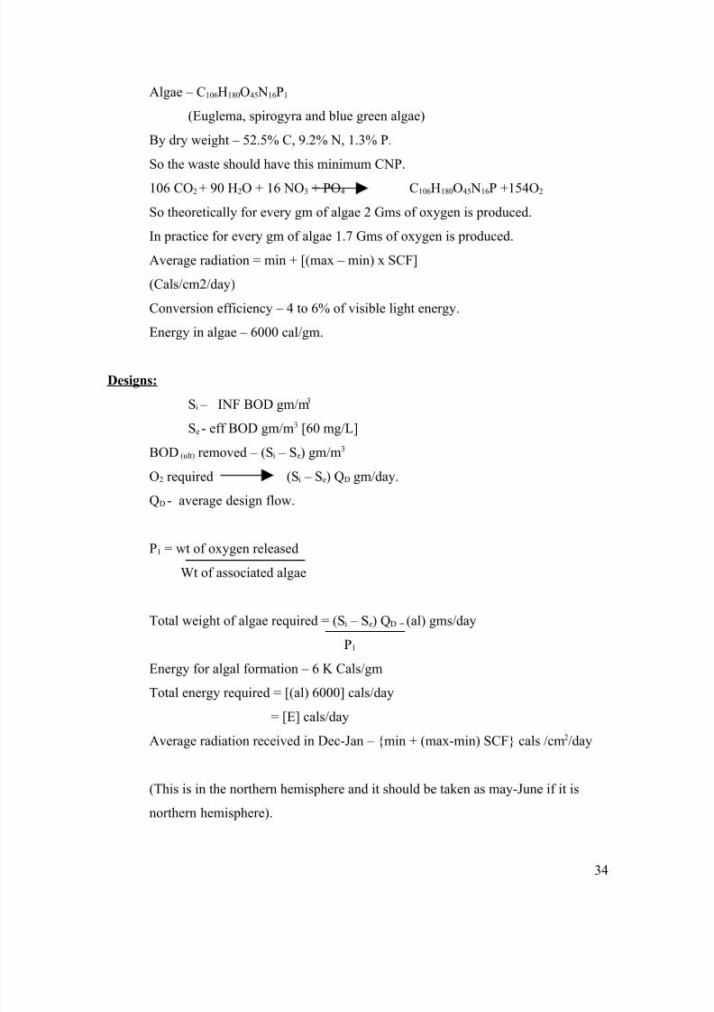
CONSTRUCTIONAL FEATURES OF STABILIZATION POND
USING PUDDLE CLAY BED
35
Puddle Clay : Clay + Coarse aggregate
Puddle Clay Bed (70 cm)
1.75 m
F.B - 0.25 m
1 m
1 : 2.5 1 : 1.5
Slope
Sand Cushion (30 cm)
Grass
Turfin
g
Pre Cast Slabs
8/6/2019 Waste Water Treatment Notes
http://slidepdf.com/reader/full/waste-water-treatment-notes 36/75
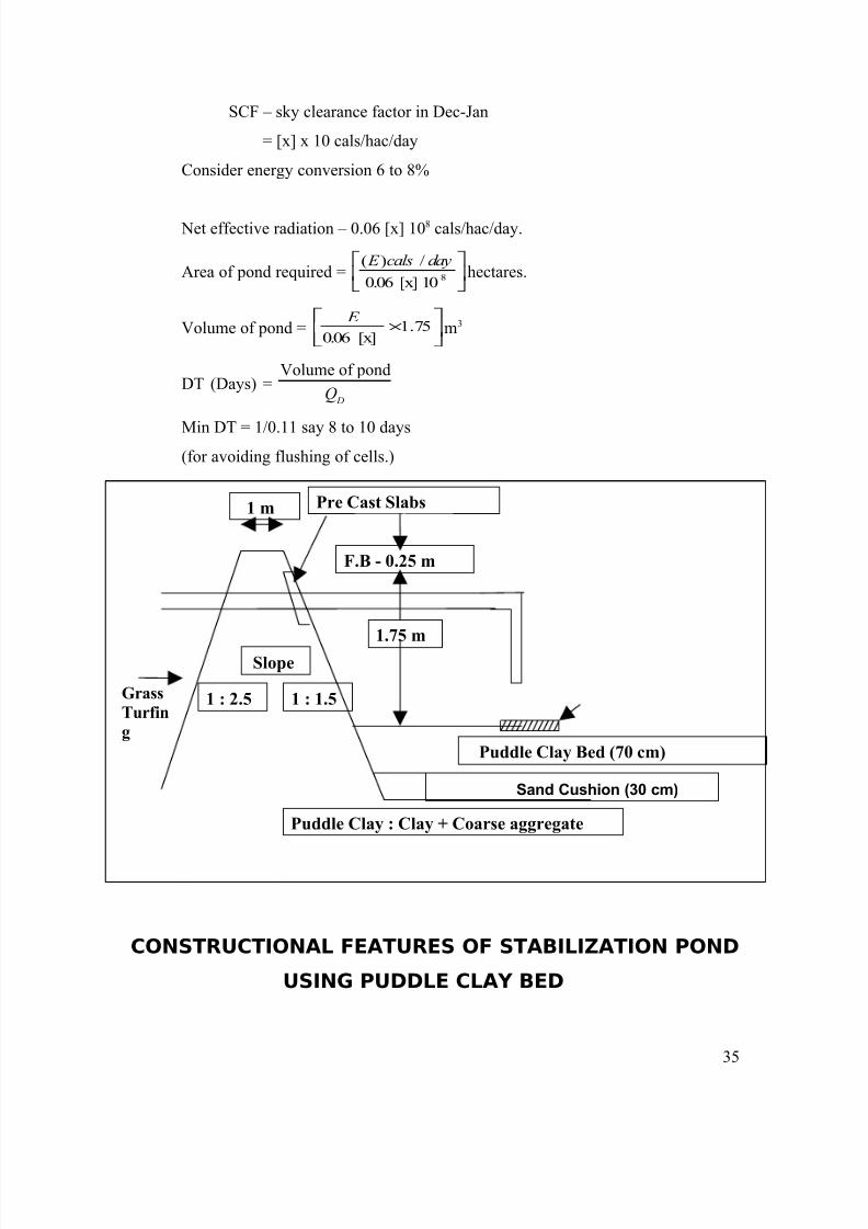
CONSTUCTIONAL FEATURES OF STABILIZATION POND
USING LDPE ( LOW DENSITY POLYETHYLENE) SHEETS
OPERATIONAL PROBLEMS
Sulphides in ponds:
Due to anaerobic condition at the bottom of the pond, Sulphates are reduced to sulphides
by desulpho vibrio. By this algal inhibition takes place if S2- > 4 mg/L. Further S2- will
consume DO in the pond with excess of S2- algae will disappear and pink sulphur bacteria
(Beggiatora) will appear which give no oxygen.
Average S2- in mg/l at25oc = [0.000158(Kg BOD 5 / ha day)- 0.001655(t days) =0.0553] x
S2- mg/L
(Ref: JWPCF- Feb 79)
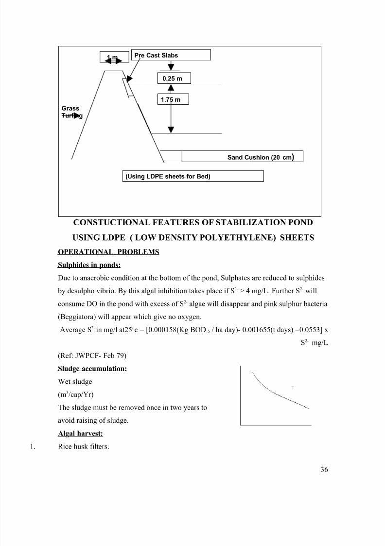
Sludge accumulation:
Wet sludge(m3/cap/Yr)
The sludge must be removed once in two years to
avoid raising of sludge.
Algal harvest:
1. Rice husk filters.
36
(Using LDPE sheets for Bed)
1.75 m
1 m
Sand Cushion (20 cm)
GrassTurfing
Pre Cast Slabs
0.25 m
8/6/2019 Waste Water Treatment Notes
http://slidepdf.com/reader/full/waste-water-treatment-notes 37/75
2. Coagulation
3. Centrifugation
4. Coagulation using natural coagulants likes nirmali, red sorella seeds.
Other Operation problems in stabilization ponds:
. Heavy metals.
2. Sulphides in ponds.
. Raising of sludge.
4. Grease and oil
Maturation ponds
Polishing ponds with one meter depth where water hyacinth (eichornea crassipes)
is cultivated. This is a water weed with 95% water by volume. Hence it may lead to loss
of water. Under favourable conditions, each hectare of hyacinth can remove 30 to 40 Kgs
of nitrogen and potassium, 10 to15 Kgs of phosphorous, and 3 to 4 Kgs of magnesium
from effluents. In Indian conditions 250 to 400 tons (dry weight) per hectare of hyacinth
could be cultivated. Hyacinth could be harvested (mechanically or labor intensive
means), comminuted (chopped or crushed) and bio digested with nitrogen supplement for
60 to 80% CH4 which has a calorific value of 5300 Kcals/m3 and this could be upgraded
to 7900 Kcals/m3 by lime scrubbing.
One hectare under ideal conditions can yield 900 – 1800 Kg/day which can be a calorific
equivalent to 400 to 500 liters of petrol. The sludge is a good fertilizer.
37
8/6/2019 Waste Water Treatment Notes
http://slidepdf.com/reader/full/waste-water-treatment-notes 38/75
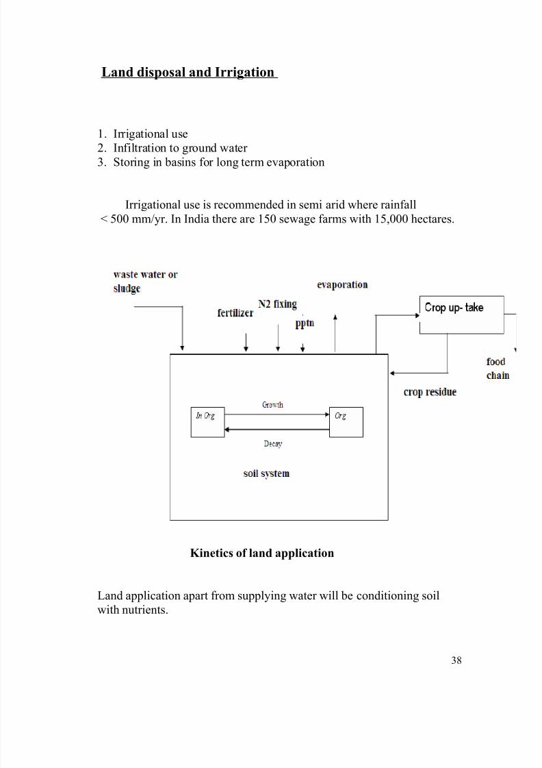
Land disposal and Irrigation
1. Irrigational use2. Infiltration to ground water 3. Storing in basins for long term evaporation
Irrigational use is recommended in semi arid where rainfall< 500 mm/yr. In India there are 150 sewage farms with 15,000 hectares.
Kinetics of land application
Land application apart from supplying water will be conditioning soilwith nutrients.
38

8/6/2019 Waste Water Treatment Notes
http://slidepdf.com/reader/full/waste-water-treatment-notes 39/75
Disadvantages:
1. Health hazard both direct (farmers) and indirect (food chain).2. If waste water does not match with soil condition, may result in
damage to soil ( N2 robbing due to excess carbon, soil build up).3. Heavy metal etc are phyto- toxic.4. Excessive land requirements.5. Odour and fly problem.6. The water demand may be seasonal.
Salt build up:
I – effective field capacity in mmCi – average salt concentrationin effluent
Cs – concentration in leachate and soilC p – concentration in ppt (negligible)
P – ppt , L – leachate
39
8/6/2019 Waste Water Treatment Notes
http://slidepdf.com/reader/full/waste-water-treatment-notes 40/75
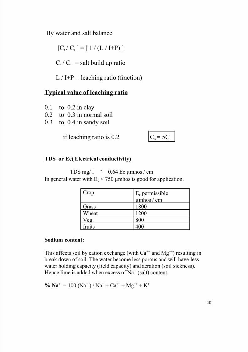
By water and salt balance
[Cs / Ci ] = [ 1 / (L / I+P) ]
Cs / Ci = salt build up ratio
L / I+P = leaching ratio (fraction)
Typical value of leaching ratio
0.1 to 0.2 in clay0.2 to 0.3 in normal soil
0.3 to 0.4 in sandy soil
if leaching ratio is 0.2 Cs = 5Ci
TDS or Ec( Electrical conductivity)
TDS mg/ l 0.64 Ec µmhos / cmIn general water with Ec < 750 µmhos is good for application.
Crop Ec permissibleµmhos / cm
Grass 1800Wheat 1200Veg. 800fruits 400
Sodium content:
This affects soil by cation exchange (with Ca++ and Mg++) resulting in break down of soil. The water become less porous and will have lesswater holding capacity (field capacity) and aeration (soil sickness).Hence lime is added when excess of Na+ (salt) content.
% Na+ = 100 (Na+ ) / Na+ + Ca++ + Mg++ + K +
40

8/6/2019 Waste Water Treatment Notes
http://slidepdf.com/reader/full/waste-water-treatment-notes 41/75
R.S.C = Residential sodium carbonate
(defined alkalinity)
RSC = (CO3
--
+ HCO3) – (Ca++
+ Mg++
) all in mg/l
RSC Condition
< 1.25 Safe1.25-2.5 Marginal> 2.5 unsuitable
Sodium Absorption Ratio (SAR)
SAR = Na+ / √(Ca++ + Mg++) /2 (all in meq.)
SAR (meq./l) Hazard to soil0-10 Low
10-18 Medium18-26 High> 26 Very high
Thus we can find suitability of application of these wastes. For correctionwe can add lime gypsum.
% NaCondition
20 Very good20-40 Good40-60 Medium> 60 unsuitable
41

8/6/2019 Waste Water Treatment Notes
http://slidepdf.com/reader/full/waste-water-treatment-notes 42/75
Anaerobic Lagoons
Anaerobic lagoons generally provided prior to aerobic unit in case
of high BOD loadings. They help reducing BOD by 40 – 60%. Anaerobicactivity also helps in nurturing the nature of solids by liquid fraction.
Disadvantages:
Odour, high start-up period, highly sensitive to inhibitors likeheavy metals. A buffer zone of 1000 m is recommended for habitation.
Stages:
1. liquefaction and acid formation by acedogens.Acetic, butyric, propionic and volaric acids.
2. Methane formation by methanogens.
These are obligate anaerobes. Any trace of pH is inhibitive. Highlysensitive for temp. they are thermophillic bacteria and no methane takes
place below 150 C.
K s at T 0C = 0.002 (1.035) T-20
K s - system rate coefficient
Methanogens are highly sensitive to pH.
Below pH 7.5 no methane formation occurs.
(Ks (per day) at 30 0C = 0.145 / day)
DT =(loge (Si /Se)) / Ks
Ex. Si – 1000 mg / l, Se – 500 mg / l, (50% removal)
DT = (loge (1000/500)) / 0.145= 4.5 day
For 40% removal
42
8/6/2019 Waste Water Treatment Notes
http://slidepdf.com/reader/full/waste-water-treatment-notes 43/75
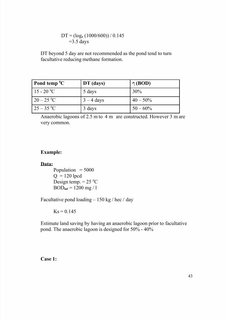
DT = (loge (1000/600)) / 0.145=3.5 days
DT beyond 5 day are not recommended as the pond tend to turnfacultative reducing methane formation.
Pond temp 0C DT (days) ף (BOD)
15 - 20 0C 5 days 30%
20 – 25 0C 3 – 4 days 40 – 50%
25 – 35 0C 3 days 50 – 60%
Anaerobic lagoons of 2.5 m to 4 m are constructed. However 3 m arevery common.
Example:
Data:
Population = 5000Q = 120 lpcdDesign temp. = 25 0CBODinf = 1200 mg / l
Facultative pond loading – 150 kg / hec / day
Ks = 0.145
Estimate land saving by having an anaerobic lagoon prior to facultative pond. The anaerobic lagoon is designed for 50% - 40%
Case 1:
43

8/6/2019 Waste Water Treatment Notes
http://slidepdf.com/reader/full/waste-water-treatment-notes 44/75
BODinf = 1200 mg / lBODeff = 600 mg / l
DT = (loge (1200/500)) / 0.145=5 days
Volume of lagoon = 5000 x 120 x 10-3 x 5= 3000 m2
Depth = 3mArea = 1000 m2 = 0.1 hectares
Area of stabilization pond alone = ( 5000 x 120 x 10-3
x 1200 x 10-3
) / 150= 4.8 hectares
Stab. pond + anae. lagoon = ( 5000 x 120 x 10-3 x 1200 x 10-3 x 0.5) / 150
= 2.4 hectares
Total = 2.4 + 0.1 + 2.5 hectares
Land savings = 48%
Xxx
Aerated Lagoons
44
8/6/2019 Waste Water Treatment Notes
http://slidepdf.com/reader/full/waste-water-treatment-notes 45/75
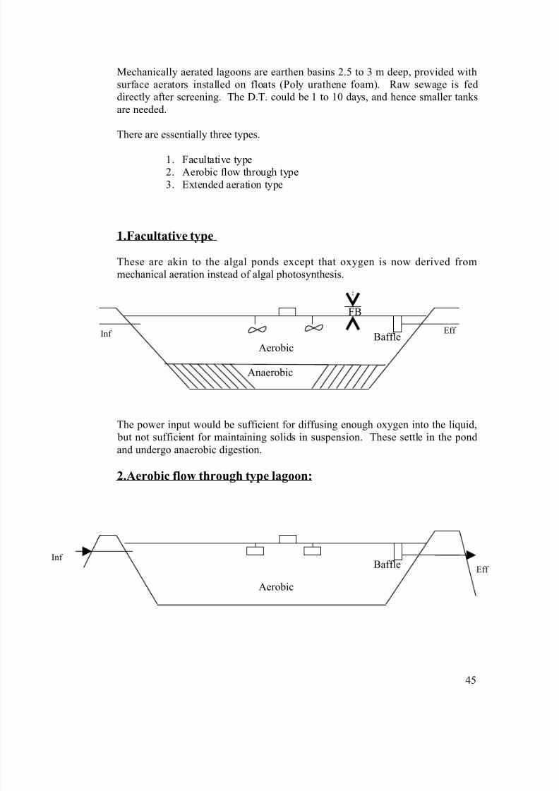
Mechanically aerated lagoons are earthen basins 2.5 to 3 m deep, provided withsurface aerators installed on floats (Poly urathene foam). Raw sewage is feddirectly after screening. The D.T. could be 1 to 10 days, and hence smaller tanksare needed.
There are essentially three types.1. Facultative type2. Aerobic flow through type3. Extended aeration type
1.Facultative type
These are akin to the algal ponds except that oxygen is now derived from
mechanical aeration instead of algal photosynthesis.
FB
Baffle
The power input would be sufficient for diffusing enough oxygen into the liquid, but not sufficient for maintaining solids in suspension. These settle in the pondand undergo anaerobic digestion.
2.Aerobic flow through type lagoon:
Baffle
45
Anaerobic
Aerobic
Eff Inf
Aerobic
Eff Inf
8/6/2019 Waste Water Treatment Notes
http://slidepdf.com/reader/full/waste-water-treatment-notes 46/75
Here the power input is high enough to keep all the solids in suspension as in anactivated sludge process, but no attempts are made to hold back the solids andthey flow through the effluent. Efficiency is not very high unless attempts are
made to hold back solids in SST.
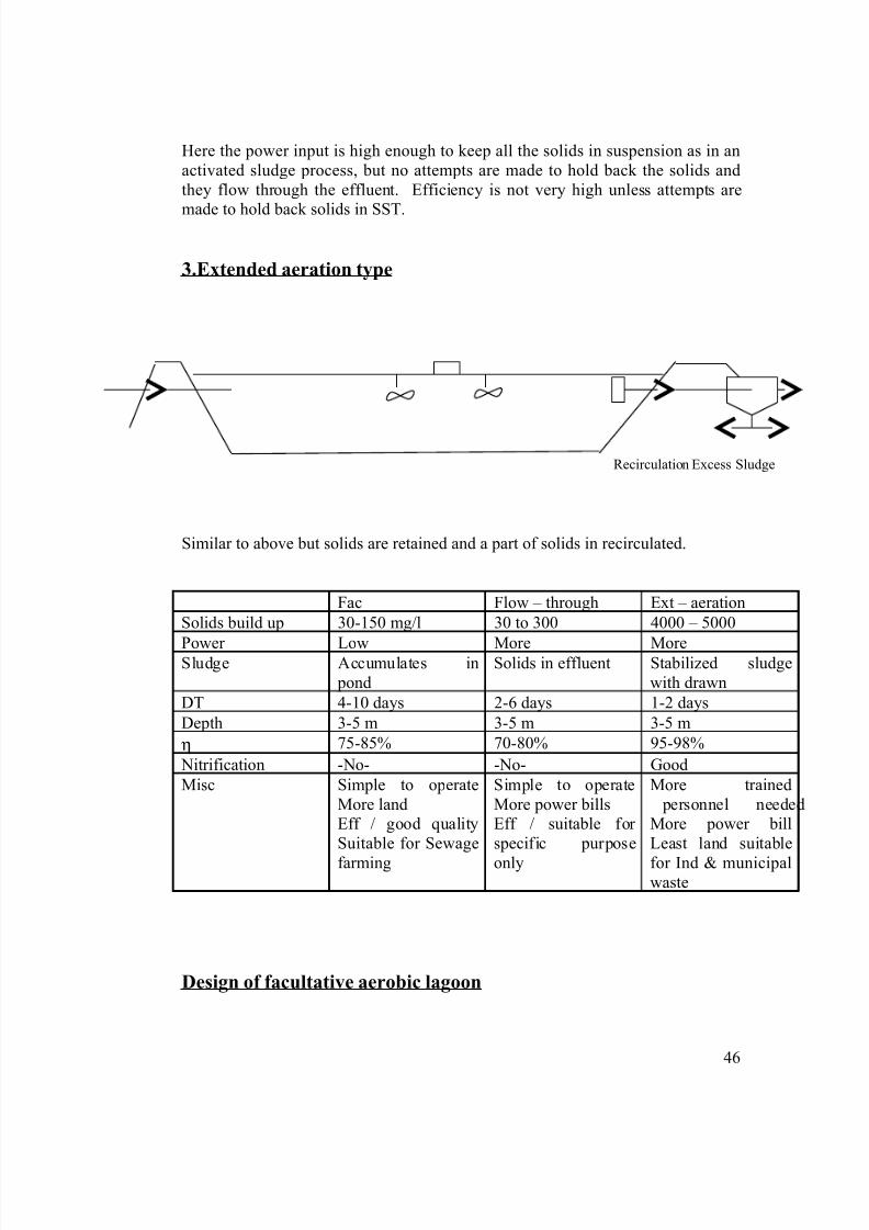
3.Extended aeration type
Similar to above but solids are retained and a part of solids in recirculated.
Fac Flow – through Ext – aerationSolids build up 30-150 mg/l 30 to 300 4000 – 5000
Power Low More MoreSludge Accumulates in pond
Solids in effluent Stabilized sludgewith drawn
DT 4-10 days 2-6 days 1-2 daysDepth 3-5 m 3-5 m 3-5 mη 75-85% 70-80% 95-98% Nitrification -No- -No- GoodMisc Simple to operate
More landEff / good qualitySuitable for Sewage
farming
Simple to operateMore power billsEff / suitable for specific purpose
only
More trained personnel neededMore power billLeast land suitable
for Ind & municipalwaste
Design of facultative aerobic lagoon
46
Recirculation Excess Sludge
8/6/2019 Waste Water Treatment Notes
http://slidepdf.com/reader/full/waste-water-treatment-notes 47/75
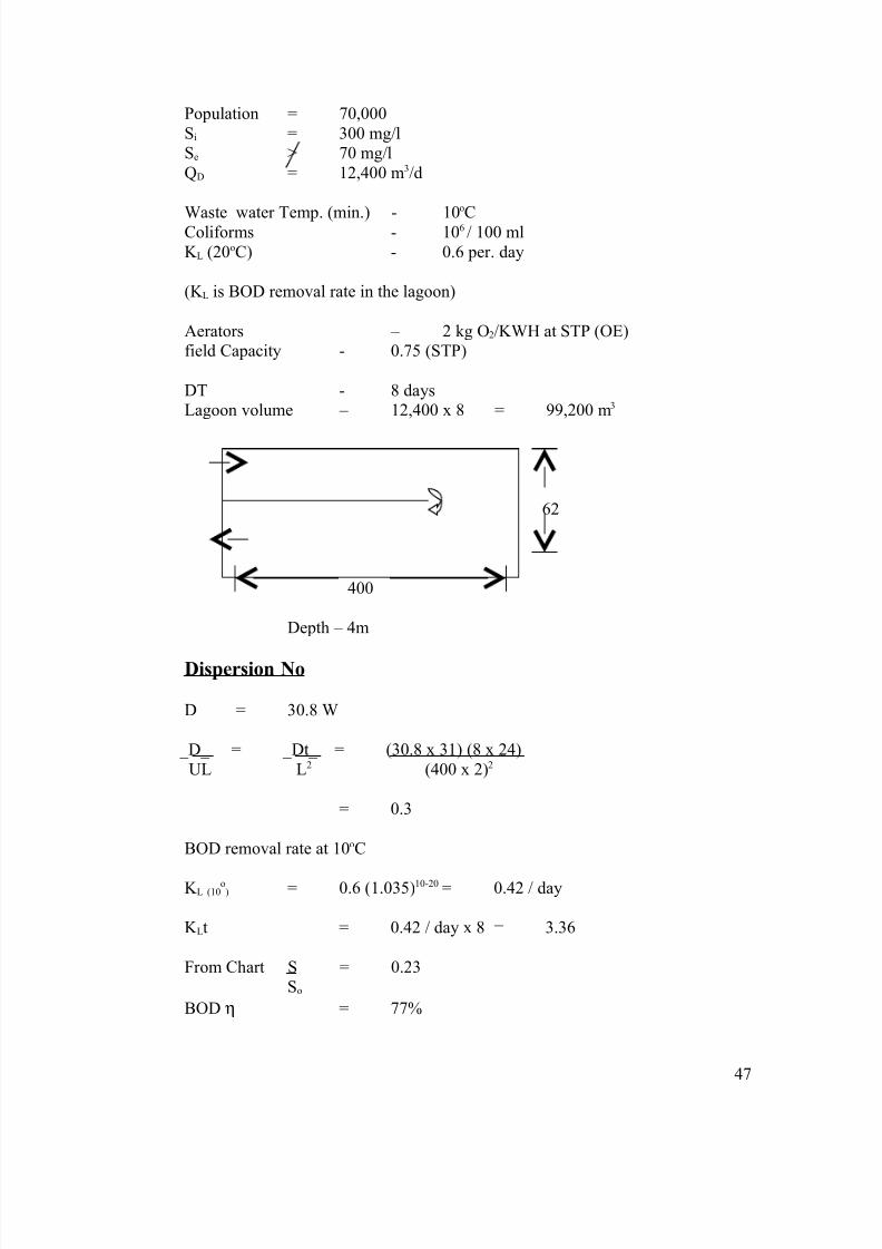
Population = 70,000Si = 300 mg/lSe > 70 mg/lQD = 12,400 m3/d
Waste water Temp. (min.) - 10o
CColiforms - 106 / 100 mlK L (20oC) - 0.6 per. day
(K L is BOD removal rate in the lagoon)
Aerators – 2 kg O2/KWH at STP (OE)field Capacity - 0.75 (STP)
DT - 8 daysLagoon volume – 12,400 x 8 = 99,200 m3
62
400
Depth – 4m
Dispersion No
D = 30.8 W
_D_ = _Dt_ = (30.8 x 31) (8 x 24)UL L2 (400 x 2)2
= 0.3
BOD removal rate at 10oC
K L (10o) = 0.6 (1.035)10-20 = 0.42 / day
K Lt = 0.42 / day x 8 = 3.36
From Chart S = 0.23So
BOD η = 77%
47
8/6/2019 Waste Water Treatment Notes
http://slidepdf.com/reader/full/waste-water-treatment-notes 48/75
Actual BOD in eff = 0.23 x 300= 69 mg/l
Power required in winter:
O2 required per day= 0.77 [1.4 (300) x 12,400 x 10-3]
= 4010 Kg / day
= 334 Kg / hr
Power required = _______334________ = 220 KW0.75 (2 Kg O2/KWH)
= 165 HPIn summer power required will be more due to more BOD removal. This has to
be calculated winter criteria is important for Lagoon size. Summer criteria isimportant for power calculations.
Sludge accumulation:
Cleaning Period - 5 yearsSludge Vol - 0.05 m3 / cap / yr x 5 x 70,000
= 17,500 m3
Provide additional 1m for sludge.
Land required
Net area = 400 x 62 = 24,800 m 2
Gross area will be 30% more.= 31,000 m2 (3.1 hectares)
= 31,000 = 0.478 m2/cap70,000
(Stab. pond – 3.7 m2 / cap. (ASP – 0.2 m2 / cap)
Coliform removal
K b = 1.2 at 20oC or 0.21 at 10oCK bt = 0.21 x 8 = 1.68from chart Removal = 70%Hence for MPN (103) chlorination is required.
48
8/6/2019 Waste Water Treatment Notes
http://slidepdf.com/reader/full/waste-water-treatment-notes 49/75
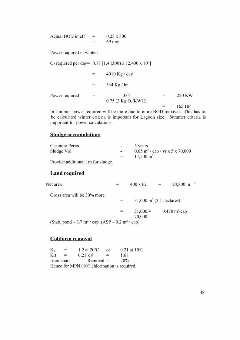
Design of aerobic flow through lagoon:
Q, So Solids – X mg/l Q, S, XVol - V
θc = t = V (mean cell residence time)Q
At steady state:
Y (So-S) Q - K d (XV) = XQ (Kg/hr) Net solids produced Solids leaving
Y - Yield coefficientK d - BOD degradation rate (Per day)
K’ = deoxygenation constant (per day)
Data
Population - 70,000Si - 300 mg/l
Se > 70 mg/l
QD - 12,400 m3/dWaste temp (Min) - 15oCK 1 - 0.015 per day at 20oCY - 0.5
49
Y (So-S)X = 1 + K dt
1 + K dtS = YK’t
8/6/2019 Waste Water Treatment Notes
http://slidepdf.com/reader/full/waste-water-treatment-notes 50/75
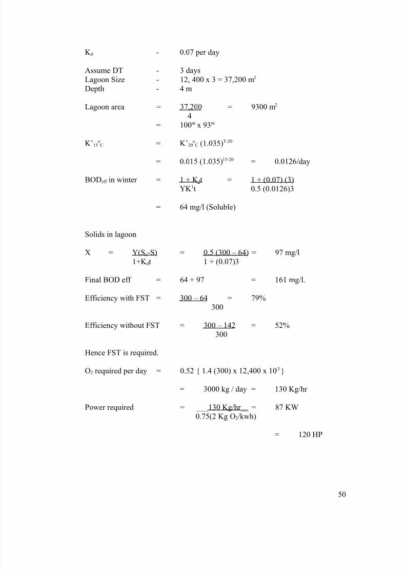
K d - 0.07 per day
Assume DT - 3 daysLagoon Size - 12, 400 x 3 = 37,200 m3
Depth - 4 m
Lagoon area = 37,200 = 9300 m2
4= 100m x 93m
K’15oC = K’20
oC (1.035)T-20
= 0.015 (1.035)15-20 = 0.0126/day
BODeff in winter = 1 + K dt = 1 + (0.07) (3)YK 1t 0.5 (0.0126)3
= 64 mg/l (Soluble)
Solids in lagoon
X = Y(So-S) = 0.5 (300 – 64) = 97 mg/l1+K dt 1 + (0.07)3
Final BOD eff = 64 + 97 = 161 mg/l.
Efficiency with FST = 300 – 64 = 79%300
Efficiency without FST = 300 – 142 = 52%300
Hence FST is required.
O2 required per day = 0.52 { 1.4 (300) x 12,400 x 10-3 }
= 3000 kg / day = 130 Kg/hr
Power required = ___130 Kg/hr__ = 87 KW0.75(2 Kg O2/kwh)
= 120 HP
50

8/6/2019 Waste Water Treatment Notes
http://slidepdf.com/reader/full/waste-water-treatment-notes 51/75
ROTATING BIOLOGICAL CONTACTORS (BIODISCS)
These are attached growth system where in pretreated wastewater for grit and
grease removal is treated in a facultative tank with 3 to 4 hours hydraulic retention
period. Large size discs made of inert material rotate at a slow speed of 3 to 4 rpm
wherein adsorption of the colloidal matter taken place forming zoogleal media. The
adsorbed media slough off as bioflocs which are sedimented either in the same tank or in
a final sedimentation. The discs are kept 2/3 submerged so that air is drawn is to keep the
system aerobic
There are over 2000 installations in Europe. Could be plain surfaced, corrugated
or slotted. Relatively low power and land requirement. But has more mechanical parts
and so operation and maintenance is difficult. More suited as a package unit for
recirculation with tube settlers.
51
8/6/2019 Waste Water Treatment Notes
http://slidepdf.com/reader/full/waste-water-treatment-notes 52/75
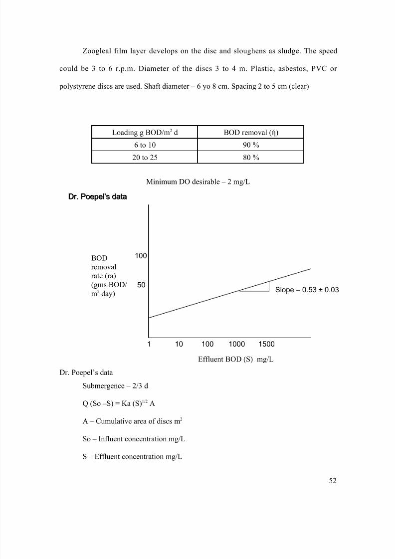
Zoogleal film layer develops on the disc and sloughens as sludge. The speed
could be 3 to 6 r.p.m. Diameter of the discs 3 to 4 m. Plastic, asbestos, PVC or
polystyrene discs are used. Shaft diameter – 6 yo 8 cm. Spacing 2 to 5 cm (clear)
Loading g BOD/m2 d BOD removal (ή)
6 to 10 90 %
20 to 25 80 %
Minimum DO desirable – 2 mg/L
Effluent BOD (S) mg/L
Dr. Poepel’s data
Submergence – 2/3 d
Q (So –S) = Ka (S)1/2 A
A – Cumulative area of discs m2
So – Influent concentration mg/L
S – Effluent concentration mg/L
Dr. Poepel’s dataDr. Poepel’s data
Slope – 0.53 ± 0.03
1 10 100 1000 1500
50
100BODremovalrate (ra)(gms BOD/
m2
day)
52
8/6/2019 Waste Water Treatment Notes
http://slidepdf.com/reader/full/waste-water-treatment-notes 53/75
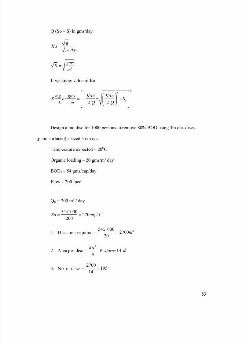
Q (So – S) in gms/day
g Ka
daym=
3
gmsS
m=
If we know value of Ka
22
3 2 2 o
mg gms KaA KaAS or S
L m Q Q
= − ± +
Design a bio disc for 1000 persons to remove 80% BOD using 3m dia. discs
(plain surfaced) spaced 5 cm c/c.
Temperature expected – 20OC
Organic loading – 20 gms/m3 day
BOD5 – 54 gms/cap/day
Flow – 200 lpcd
QD = 200 m3 / day
54 1000270 /
200
xSo mg L= =
1. Disc area required = 254 10002700
20
xm=
2. Area per disc =2
22 144
d x sides m
π =
3. No. of discs =2700
19514
=
53
8/6/2019 Waste Water Treatment Notes
http://slidepdf.com/reader/full/waste-water-treatment-notes 54/75
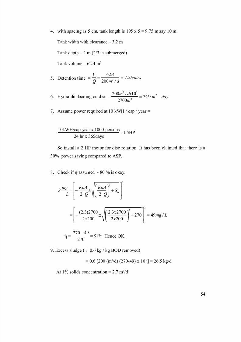
4. with spacing as 5 cm, tank length is 195 x 5 = 9.75 m say 10 m.
Tank width with clearance – 3.2 m
Tank depth – 2 m (2/3 is submerged)
Tank volume – 62.4 m3
5. Detention time = 3
62.47.5
200 /
V hours
Q m d = =
6. Hydraulic loading on disc =3 3
2
2
200 / 1074 /
2700
m dxl m day
m= −
7. Assume power required at 10 kWH / cap / year =
10kWH/cap-year x 1000 persons=1.5HP
24 hr x 365days
So install a 2 HP motor for disc rotation. It has been claimed that there is a
30% power saving compared to ASP.
8. Check if ή assumed - 80 % is okay.
22
2 2 o
mg KaA KaAS S
L Q Q
= − ± +
22
(2.3)2700 2.3 2700270 49 /
2 200 2 200
xmg L
x x
= − ± + =
ή =270 49
81%
270
−= Hence OK.
9. Excess sludge ( ; 0.6 kg / kg BOD removed)
= 0.6 [200 (m3/d) (270-49) x 10-3] = 26.5 kg/d
At 1% solids concentration = 2.7 m3/d
54
8/6/2019 Waste Water Treatment Notes
http://slidepdf.com/reader/full/waste-water-treatment-notes 55/75
SLUDGE TREATMENT AND DISPOSAL
The cost of sludge disposal is about 30 to 40% of total cost of treatment. It involves involume reduction by dewatering, stabilization and destruction of pathogens.
Origins of sludge are (1) primary sludge (2) secondary sludge from biological or chemical treatment
The quantity varies as per 1. domestic and social habits2. dietary habits – vegetarian system gives for more sludge than protein based3. Sewerage system: combined system produces more sludge than separate.4. Industrial wastes.
Quantity of secondary sludge depends on the process
Conventional ASP per kg BOD: 0.8-0.9 kg DSConventional TF per kg BOD: 0.3 – 0.5 kg DSHigh rate TF per kg BOD: 0.8 – 0.95 kg DSEAP per kg BOD: 0.3 – 0.5 kg DS
Sludge Analysis:
1. Dry residue or total dry solids.2. volatile solids3. percentage ash (metals)
55

8/6/2019 Waste Water Treatment Notes
http://slidepdf.com/reader/full/waste-water-treatment-notes 56/75
4. Settling rate: in a graduated cylinder of 6 cms diameter, the volumetric measuresof settled sludge per liter after 6 hrs.
Characterization of sludge:
1. pH should be about 7 or slightly alkaline.2. volatile acids calorimetric tests3. Alkyl benzene sulphonate test: to measure detergents. More than 1.5 % ABS will
impair digester performance.4. Heavy metals such as Cd, Ni, Cr, Cu, Zn, Hg, Pb can interface with performance.5. NPK and Ca values for fertilizer value6. pathogen including worms7. calorific value – important if to be incinerated8. centrifugability for dewatering
Disposal of sludge:
1. Agricultural use: by spraying digested wet sludge or flesh activated sludge.Alternatively sludge is dried and mixed with soil as cakes. Domestic sludge may be more suitable. Industrial sludge should be checked for toxicity in particular heavy metals.
2. Land Filling: sludge should be fairly dry or mixed with refuse. Care should be
taken about leaching and general ground water pollution. It can also be mixedwith fly ash from thermal power station.3. sludge can be incinerated, but air pollution should be controlled.4. Marine discharge; widely practiced in many countries including UK. But if toxic
chemicals like Hg are discharged, it may accumulate in fish etc and end up infood chain. Further, the reduction in DO level in water due to discharge should bewatched.
Anaerobic Sludge Digesters: Acid formers-acidogensMethane formers - strict anaerobes.Reproduction rate of acid formers is very fast (one to two hours) compared to methaneformers (two to three hours)
Cysteine is the first stage of acid production
4C3H7O2 NS + 8H2O 4CH3COOH + 4CO2 + 4NH3 + 4H2S + 8H(cysteine)
56
8/6/2019 Waste Water Treatment Notes
http://slidepdf.com/reader/full/waste-water-treatment-notes 57/75
CH3COOH 5CH4 + CO2 + H2O +8H
Overall reaction4C3H7O2 NS + 6H2O 5CH4 + 7H2O + 4NH3 + 4H2S
70C to 200C – psychrophilic – 12 to 25 weeks200C to 400C – mesophilic – 20 to 30 days400C to 650C – thermophilic – 3 to 5 days
There are four important parameters in digestion1. temperature2. time of digestion3. correct feeding (no inhibitors)4. proper seeding and mixing
Digesters are designed for Kg VSS/ m3 of tank. (in the mesophilic range – 2.5 KgVSS/m3 ). If the total contribution of sludge is 80 gm/cap/day with 65% VSS and 95%m/c (5% DS), we will have 1.5 l/cap/day and a detention time of 30 days.
Heating and mixing if necessary:
Steam injection: efficient but expensive internal heating with hot water coils. Mixingwill be convection (not an efficient method)
Stirrer with heating coils: efficient, but we have to depend upon many mechanical parts.
Recirculation of gas: we can have an external heating by heat exchangers outside.We can combine external heating with gas circulation for mixing. Advantage is easier mixing and maintenance.
Sludge thickeners: dewatering is generally done by agitation and sedimentation.
Gravity thickening:
1. Fill and draw: three to four tanks in series, we can hopper buttons and desludgewith hydrostatic pressure.
2. Continue thickeners: provided with a stirrer and a scrapper (one revolution per hour) detention time is about 15 hours.
3. Flotation method; used for secondary sludge like ASP. Fine bubble aeration liftssludge to surface. Final m/c – 5% with detention time (DT) 30 mts to 60 mts.
4. Dewatering on sludge drying beds: more suitable for tropical countries and whereland is not expensive. Coarse gravel 5 to 10 cms, coarse sand – 2 to 5 cms and
57
8/6/2019 Waste Water Treatment Notes
http://slidepdf.com/reader/full/waste-water-treatment-notes 58/75
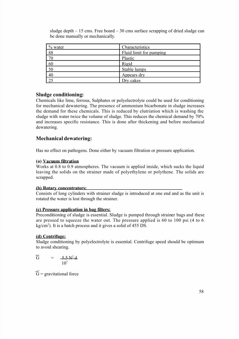
sludge depth – 15 cms. Free board – 30 cms surface scrapping of dried sludge can be done manually or mechanically.
% water Characteristics88 Fluid limit for pumping
70 Plastic60 Rigid50 Stable lumps40 Appears dry25 Dry cakes
Sludge conditioning:Chemicals like lime, ferrous, Sulphates or polyelectrolyte could be used for conditioningfor mechanical dewatering. The presence of ammonium bicarbonate in sludge increasesthe demand for these chemicals. This is reduced by elutriation which is washing the
sludge with water twice the volume of sludge. This reduces the chemical demand by 70%and increases specific resistance. This is done after thickening and before mechanicaldewatering.
Mechanical dewatering:
Has no effect on pathogens. Done either by vacuum filtration or pressure application.
(a) Vacuum filtration
Works at 0.8 to 0.9 atmospheres. The vacuum is applied inside, which sucks the liquidleaving the solids on the strainer made of polyethylene or polythene. The solids are
scrapped.
(b) Rotary concentrators:
Consists of long cylinders with strainer sludge is introduced at one end and as the unit isrotated the water is lost through the strainer.
(c) Pressure application in bag filters:
Preconditioning of sludge is essential. Sludge is pumped through strainer bags and theseare pressed to squeeze the water out. The pressure applied is 60 to 100 psi (4 to 6kg/cm2). It is a batch process and it gives a solid of 455 DS.
(d) Centrifuge:Sludge conditioning by polyelectrolyte is essential. Centrifuge speed should be optimumto avoid shearing.
G = 5.5 N2 d107
G = gravitational force
58
8/6/2019 Waste Water Treatment Notes
http://slidepdf.com/reader/full/waste-water-treatment-notes 59/75
N= rpmD= av Φ in mm
G should be less than 10,000 to avoid shearing.
Sludge digesters:
The organic solids are liquefied and gasified by acid formers and methane formers. Thedigested sludge with about 40% m/c is further dried.
The optimum temperature for digestion (mesophilic) is 30OC to 35OC and it takes 30 to50 days for digestion. In thermophilic range it takes less than 10 days.
Mixing is done thoroughly in digesters to distribute the incoming sludge, to reduce scum,to maintain uniform temperature. Power drivers mechanical mixing devices are used.
General circular tanks of 6 to 12 m depth with hopper bottom are designed. In India, theaverage sludge production is taken as 35 to 60 l/c. it could be fixed or floating dome type.
Loading Factors:
Based on1. kg volatile solids added per day per m3 digester capacity or 2. kg volatile solids added per day per kg volatile solids in the digester.
For conventional digesters 0.5 to 1.6 kg/m3 d of volatile solids could be used.For high rate digesters it could be 1.6 to 6.4 kg/m3 d.
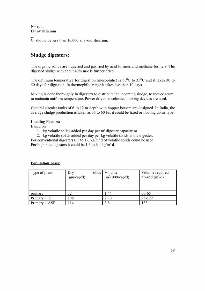
Population basis:
Type of plant Dry solids(gm/cap/d)
Volume(m3/1000cap/d)
Volume required35-45d (m3/d)
primary 72 1.44 50-65Primary + TF 108 2.70 95-122
Primary + ASP 114 3.8 133
59
8/6/2019 Waste Water Treatment Notes
http://slidepdf.com/reader/full/waste-water-treatment-notes 60/75
OPERATION AND MAINTENANCE OF BIOLOGICAL
TREATMENT PLANTS
INTRODUCTION
Studies of waste treatment facilities have shown that any inadequacy in the
design, staff organization, or operation and maintenance (O and M) has invariably led to
a waste of capital, man-power and energy. Wise use of personnel according to well
organized O and M program can conserve treatment efficiency at a minimum total cost.
(1) The basic requirements of successful operation and maintenance of wastewater
treatment plants are:
(i) a thorough knowledge of the processes and equipments,
(ii) proper and adequate tools,
(iii) assignment of specific maintenance responsibilities to operating staff,
(iv) training of all operating staff in proper operating procedures and
maintenance practices,(v) efficient quality control through laboratory tests,
(vi) maintenance of records on operating efficiency of different units.
(2) The importance of plant operation comes into focus when we realize that it is the
culmination of all preceding efforts aimed at for control of water pollution. A
60
8/6/2019 Waste Water Treatment Notes
http://slidepdf.com/reader/full/waste-water-treatment-notes 61/75
plant which may be over loaded or has other short comings can produce its best
results if competent and careful operating techniques are applied. The word
“Operator” is applied to anyone charged with the responsibility of the operation
of the treat5ment plant. Operation of wastewater treatment plants is greatly
affected by the motivation and training of the individual operator.
This training must include basic knowledge of unit processes, the plant
equipments, how to recognize potential trouble, now to diagnose, and to make
temporary repairs, and finally to know as to where to obtain additional assistance.
“Voluntary Certification” and “Mandatory Certification” is required for rating the
operators ability in operation of plants and at the same time classifying plants as
to the grade of operator ability required.
(3) The certificate is indicative of the knowledge, experience, and competency of theoperator. Certification programs give the operator improved status, greater
flexibility in changing jobs, and opportunity for higher wages. Certification
usually provides benefits to the municipal or industrial employer by increased
efficiency in plant operators and maintenance, more reliable reports and record,
and more confidence in the operator’s recommendations for repairs and
improvements.
To prevent our wastewater treatment system from being perpetuated as
“Monuments to inefficiency” the key of operation and maintenance gap must be
closed.
(4) Availability of operation and maintenance manuals for each facility enables the
plant operators to check for specific problems and apply corrective measures.
In this article the problems associated with the operation and maintenance of
different wastewater treatment units are described.
(a) Activated Sludge Process
“Activated sludge” describes a continuous flow, biological treatment systems
characterized by a suspension of aerobic micro-organisms (MLSS) maintained in a
relatively homogenous state y the mixing and turbulence induced in conjunction with the
aeration process. Basically, the activated sludge process (ASP) used micro-organisms in
61

8/6/2019 Waste Water Treatment Notes
http://slidepdf.com/reader/full/waste-water-treatment-notes 62/75
suspension to oxidize soluble and colloidal organics in the presence of molecular oxygen.
During oxidation process, a portion of the organic materials is synthesized into new cells.
A part of the synthesized cells then undergo auto oxidation (self-oxidation or endogenous
respiration) in the aeration tank. Oxygen is required to support the synthesis and auto-
oxidation reaction. To operate the process in a continuous basis, the solids generated
must be separated in a clarifier, the major portion is recycled to the aeration tank an
excess sludge is withdrawn, from the clarifier under flow for additional handli8ng an
disposal, and there are different modifications in the ASP system viz, conventional, high-
rate, extended serration and contact stabilization process. The operational variables in an
ASP include, rate of water flow, air supply, MLSS, aeration period, DO in aeration tank
and clarifiers, rate of sludge return and condition of sludge.
The most important control parameters in activated sludge system are the DO inthe aeration tank and the MLSS. It is desirable to maintain a minimum aeration tank DO
of about 1 to 2 mg/L. If the DO levels are not controlled, localized regions may become
saturated with oxygen or super saturated with nitrogen or carbon dioxide. These
conditions lead to adsorption of fine bubbles on the flock, causing poor setting and
possible flotation. Activated sludge can have poor settling characteristics because of (1)
poor bio-flocculation, (2) excessive bound water, (3) small gas bubble entrainments in the
floc, (4) growth of type of bacteria or fungi (filamentous organisms) that have a large
surface area compared to their mass, (5) excessive amounts of hexane soluble oils and
grease. To maintain the required MLSS in the aeration tank the sludge settled in the
clarifier is returned to the aeration tank through sludge return pumps. The return flow is
to be adjusted such that it is approximately equal to the percentage ratio of the volume
occupied by the settleable solids from the aeration tanks effluent to the volume of the
clarified liquid (supernatant) after settling for 30 min. in a 1000 ml graduated cylinder.
This ratio should not be less than 15 percent at any time. For example, if after 30 min of
settling, the settleable solids occupied a volume of 150 ml, the percentage would be equal
to 17.7 percent [(150ml/850 ml) x 100]. Another method often used to control the rate of
return sludge pumping as well as plant operation I based on an empirical measurement
known as the sludge volume index (SVI). This index is defined as the volume in
62
8/6/2019 Waste Water Treatment Notes
http://slidepdf.com/reader/full/waste-water-treatment-notes 63/75
milliliters occupied by one gram of activated sludge (MLSS), dry weight, after settling
for 30 min in a 1000 ml graduated cylinder.
MLSSof ml/l
1000xsludgesettledof ml.SVI =
Sludge under 100 SVI will settle well. Sludge which does not settle well or settles andcompacts poorly, leaving a small amount of clear supernatant is called bulking sludge. (6)
Bulking sludge is an operational problem that occurs in higher loaded plants with
insufficient aeration, presence of toxic substances in the influent, frequent organic shock
loads containing exceptionally high amount of carbohydrates. Bulking results from
increased growth of filamentous bacteria and with resultant poor settling of the MLSS in
the final clarifier. To correct this condition rapidly, the filamentous organisms, because of
their large surface area to volume ratio, can be selectively destroyed by large doses of chlorine or hydrogen peroxide. The latter is more effective because it has less deleterious
effect on the desirable organisms. Sludge bulking can be controlled by cutting off
aeration tank in-flow and re-aeration the sludge for at least 6 to 8 hours before re-
commencing the plant flow.
(b) Trickling filter
Biological process used for the treatment of wastewater can be classified as
suspended growth system of fixed film systems. Fixed film systems provide surface area
for the growth of a zooglean slime. This slime or film contains the major portion of
micro-organisms that provide treatment. The fixed film systems with stationary media are
known as tricking filters, trickling filters contain a stationary medium providing surface
are and void space allows air and wastewater to pass through the medium and co me in
contact with the micro-organisms in the film. The organisms utilize the oxygen and
material in the wastewater for their metabolism. Developments in the design and
operation of trickling filters, historically, have been popular because of their ability torecover from shock loads and perform well with a minimum of skilled technical
supervision. The problems associated with trickling filters are mainly distribution,
clogging, ponding under drains, odour and filter files.
63
8/6/2019 Waste Water Treatment Notes
http://slidepdf.com/reader/full/waste-water-treatment-notes 64/75
All clogged spray nozzles or orifices in the revolving distributors should be
cleaned as soon as clogging is noticed. Dosing tanks should be kept free from
accumulation of deposits. All parts of the filter bed should receive equal loading.
Periodical tests should be carried out using water tight pans of standard size 90 cm X 120
cm set flush with the top of filter media and end to end along the radius. The media
surface shall be dived into two concentric circles with the area of the inner being 10
percent of the total area covered by the distributor. The sewage collection in the pan for
10 revolutions of the distributor when the air is still is measured*. The rate of distribution
should not vary ±5 percent from the mean rate of distribution in the inner 10 percent area.
Pools or ponds some times form on the surface of the filter. This is due to organic growth
or retained organic matter from poorly settled waste. Some times, this is due to careless
dumping of fine materials in one place at the time of placing filter media. In many cases,forking or raking the media to a depth of 20 to 30 cm will effectively remove ponding.
Washing the filter media with a jet of water or giving rest to the filter for 2 or 3 days may
also be effective. Pre-chlorination of the waste or application of caustic soda up 10 mg/L
has also been tried with success to eliminate clogging and ponding problems. When using
chemicals treatment may be given for 8 hours period on alternate days.
Filters under drains should be inspected frequently for clogging. If clogging
evidenced by reduced flow from any drain, this should be flushed and cleaned with sewer
rods.
Psychoda filter flies sometimes infest the filter and cause not only nuisance to the
workers but also clog the beds.* Application of chlorine at a rate of 3 to 5 mg/L or
gammexane at a rate of 180 gm/ha or DDT at a rate of 3 to 10 kg/ha of wall surface once
in a week are the methods available for the flushing of the larvae. Adult flies are
controlled by pyrethrum spray.
(c) Sludge Digestion Tanks
For startup, the digester tanks with fixed covers should be filled initially with
water, sludge or sewage to expel air. In tanks with floating cover, the cover should be
brought down to the lowest point before filling of the tank is commenced. In order to
64
8/6/2019 Waste Water Treatment Notes
http://slidepdf.com/reader/full/waste-water-treatment-notes 65/75
reduce initial lag period, raw sludge mixed with digested sludge in the ratio of 2:1 to 4:1
may be pumped into the digester so that alkaline digestion starts within few days after
loading. The addition of fresh sludge should commence only after this stage. If digested
sludge is not available, raw sludge along should be pumped and kept for 2 to 3 weeks
before the digester can be loaded. Open digester can be charged directly.
The raw sludge feeding rate should be such that the volatile solids in the digester
should not exceed 3 to 5 percent so that digestion is not inhibited. Generally a loading
rate of 1 to 2 kg of fresh solids to every 40 to 50 kg of digesting volatile solids should be
the ratio to maintain a uniform digestion rate.
Where the digesters are equipped with mixing devices they should be operated in
accordance with the manufacturer’s instructions, where facilities for recirculation by
pumping exists, they should be used for mixing digester contents breaking down scum,mixing lime with sludge for pH adjustment etc., where there is no mixing and re-
circulation facility, the operator has to rely upon natural mixing of raw and digested
sludge in the digestion tank.
Digestion is generally carried out in the mesophilic range and the temperature of
the sludge generally varies from 25OC to 35OC. Thermometers, to record temperature,
should be dept in order and reading noted twice or thrice a day.
Sludge should be withdrawn from the digesters only when it is fully digested,
judged by the dark grayish brown color without visible raw sewage sludge solids. Sludge
should be sampled and tested to find out the condition before withdrawing. Generally not
more than 10 percent of the capacity of digester should be drawn at a time, sludge
withdrawn being limited by the capacity of the sludge drying beds.
Frequent pH test of the sludge should be made and this should be correlated with
the alkalinity of the supernatant of the sludge which may range from 1500 to 3000 kg/L.
This affords an excellent check on operation. Digestion proceeds most favorably at pH
values of 7.0, it is usually desirable to raise the pH be adding lime to the sludge as it is
enters the digester. The alkalinity of the supernatant is a useful guide to control the
dosage. A start may be made using 20 to 40 kg of lime per m 3 of sludge, with more added
if the pH value or alkalinity does not rise appreciable in a few days.
65
8/6/2019 Waste Water Treatment Notes
http://slidepdf.com/reader/full/waste-water-treatment-notes 66/75
Difficulties in the digestion tanks such as foaming due to overloading or
accumulation of acid sludge or excessive formation of H2S have to be corrected by
neutralization an adjustment of pH. H2S in moist gas leads to corrosion of meters piping
and flame trap through which the digester gas is drawn. This can be overcome by the
removal of the H2S by passing the gas through iron oxide or other scrubbers or by heating
the gas to a high temperature to eliminate moisture in it
Gas pipes should be kept free from sediments, gas meters being periodically
lubricated and fusible plugs in the flame traps frequently checked.
(d) Anaerobic lagoons
Anaerobic digestion in lagoons is a mixed culture bacteria process consisting of
two phases (a) oxidation of organic matter to organic acids like acetic, butryc and proponic acid and (b) fermentation of these organic acids into methane and other gases.
The former process is accomplished in the digester by facultative anaerobic bacteria
which are abundant in nature. The second phase, methane formation is brought about by
methane bacteria, which are strict anaerobes. Anaerobic lagooning, as applied in the
treatment of wastewater represents the controlling application of a process which occurs
under natural conditions when organic matter decays in the presence of water but absence
of air. If the object is to operate the lagoons at the maximum efficiency, it is necessary tokeep the environment ideal for the bacteria to grow and oxidize the organic matter.
Operation and Maintenance – Anaerobic lagoons
1. The anaerobic lagoons should be filled with fresh water and fresh cow dung
should be added and allowed to digest for a period of 30 days. The quantity of
cow dung (4 percent suspension) required is about 10 percent by volume of the
lagoon. Slowly waste may be fed and pH maintained between 6.8 and 7.8. In
about a months time lagoon will be ready for regular operation. This
commissioning of the anaerobic lagoon should be started one month before
starting of the prior units.
66
8/6/2019 Waste Water Treatment Notes
http://slidepdf.com/reader/full/waste-water-treatment-notes 67/75
8/6/2019 Waste Water Treatment Notes
http://slidepdf.com/reader/full/waste-water-treatment-notes 68/75
(e) Extended Aeration (ASP) plants
1. The first step in order to put the aeration tank into regular operation is to build up
enough microbial solids. Mixed liquor suspended solids (MLSS) concentration
desired to be maintained in the tank will be between 3000 to 5000 mg/L with an
average of 4000 mg/L. The steps to be followed for developing the solids are
given below.
2. The tank may be filled with wastewater up to the operation level. Once the tank is
filled up to that level the aerators will be switched on to aerate the tank contents
for 24 hours. After aeration for this period, the aerators will be cut off and the
tank contents will be allowed to settle in the tank for about 2 hours. The
supernatant, in the tank, will then be drawn off. Therefore, raw wastewater will be
admitted to the tank to the operational level and the process described above will be repeated every day till such time that the MLSS concentration in the tank is
attained to a level of about 4000 mg/L. This process of building up the solids in
the tank will take 2 to 4 weeks.
3. Once the solids level is reached to about 4000 mg/L, the tank is then ready for
continuous inflow of wastewater enters, there will be overflow from the tank
entering into the settling tank. Depending upon the design of the settling tank, it
may take abut 2 to 3 hours to fill the tank. The sludge in the settling tank will betaken to the return sludge pump through a valve. Opening of the valve should be
controlled to effect an average flow of the incoming of wastewater. The return
sludge is pumped continuously and put back into the tank. While this process is
on, the liquid level in the settling tank will rise up slowly as the wastewater
continuously flows into the aeration tank. The overflow from the settling tank will
constitute the treated effluent. As stated earlier aerators and the return sludge
pumps in the treatment plant should be operated continuously even when there is
an intermittent flow of wastewater into the aeration tank.
4. With continued operation of the aeration tank and the return sludge, the MLSS
concentration will increased until the capacity of the system to settle and retain
the solids is exceeded. For this reason, it is necessary to withdraw a small fraction
of the solids in the mixed liquor and dispose of it separately. This excess sludge is
68
8/6/2019 Waste Water Treatment Notes
http://slidepdf.com/reader/full/waste-water-treatment-notes 69/75
withdrawn from the settled sludge which is normally returned to the aeration tank.
The volume of the excess sludge to be wasted per day is usually between 0.26 and
0.43 percent of the wastewater inflow. Instead of wasting sludge everyday. It may
be accumulated for 3 to 4 days and then wasted in one lot.
5. The excess sludge should be spread to a depth of 8 to 12 inches and allowed to
day for sufficient time. Generally about 10 days drying period is required before it
can be spaded out. If experience indicates more time for drying, then additional
drying beds will have to be provided. The sludge, after it is dried sufficiently, will
be collected and used as manure. Just prior to rainy season, some extra sludge
may be wasted from the system so as to provide a buffer capacity for storage of
excess sludge during monsoon season when the sludge on the drying beds may
not loose moisture readily.6. The day to day operational requirements may range from regular lubrication of
bearings and greasing of reduction gear units of aerators. Also the recording of
such parameters as flow measurements, suspended solids and other characteristic
may be carried out regularly.
7. Occasional samples may be withdrawn and got analyzed at a convenient
laboratory to help to maintain records of performance of the installation.
Representative samples should be taken, preserved properly during transport and
tested.
8. Tests for BOD on the influent and effluent, and for suspended solids on the
influent and effluent, mixed liquor suspended solids and return sludge should be
carried out regularly once in a week. Frequency of sampling can be increased if
desired. Occasional samples may be collected and analyzed for the nutrients
(Phosphates, ammonia, nitrates, nitrite etc.) in the influent and effluent.
9. It is always necessary to maintain proper records. This would help to evaluate
performance of the aeration tank and help to furnish useful date when further
expansion of the plant is contemplated.
10. W well maintained plant with properly cleared surroundings and a small patch of
garden with appropriate landscaping can convert a waste disposal plant into a
pleasant spot, which would be a credit to the authorities. Plants like coconut, palm
69
8/6/2019 Waste Water Treatment Notes
http://slidepdf.com/reader/full/waste-water-treatment-notes 70/75
and eucalyptus may also be planted so that it can be natural screen or filter for any
unpleasant odors.
(f) Oxidation ponds or Waste stabilization ponds
Oxidation ponds or waste stabilization ponds are no longer a novelty.
Considerable experience has accumulated over the last three decades in the design,
operation and maintenance of these ponds and the Public Health Engineers are now able
to use them with confidence as a simple and reliable means of treatment of sewage and
certain industrial wastes at a fraction of cost of conventional waste treatment plants
hereto used.
As simple as a septic tank, and yet as effective as a complete sewage treatment
plant it is relatively a new tool in the hand of Public Health Engineers awaiting wider application of these ponds, particularly in the tropics where sunshine is plentiful and
money is scarce, for the treatment of industrial waste also. The term “Waste Stabilization
Ponds” has been more widely adopted as it is more descriptive of the real function, and
includes aerobic as well as anaerobic modes of stabilization. The word “waste” includes
both sewage as well as industrial wastes. Neither the term “Oxidation Pond” nor the term
“sewage lagoons” include all these aspects.
This process involves two steps in the decomposition of the organic matter present in the wastewater. The carbonaceous matter in the effluents is first broken down
by the aerobic organisms with the formation of carbon dioxide. The carbon dioxide so
formed is utilized by algae during photosynthesis which liberate oxygen. This oxygen
dissolved in water is used by the aerobic bacteria for further oxidation of organic matter.
Operation and Maintenance
After the stabilization pond is construction is completed and the pond bottom is
cleared of all loose debris and vegetation, raw waste may be gradually allowed to enter
and fill the pond upto a depth of 15 to 30 cm (6 to 12 inches) only. Each day thereafter
only a small quantity of raw wastewater may be admitted to maintain the above level, till
such time as algal growth establishes itself naturally. Soils generally harbor the spores of
various algae and spontaneous growth of algae is likely t take place within a week or two
70
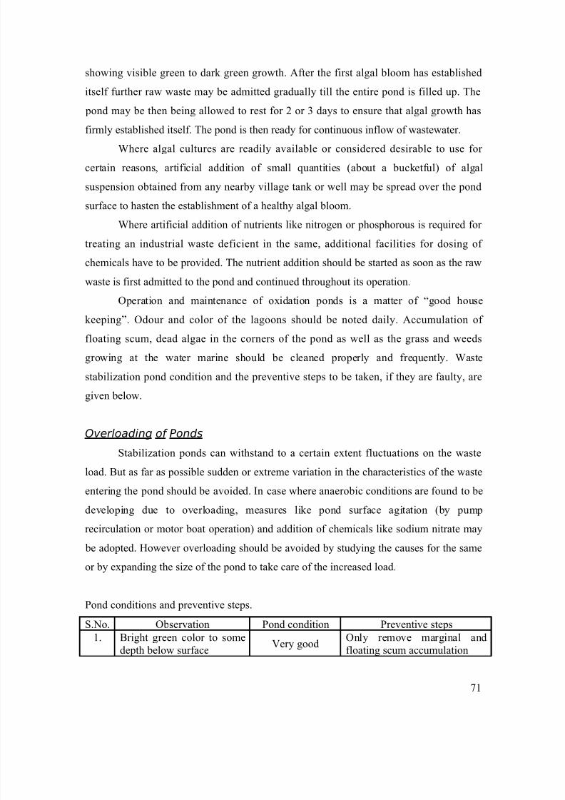
8/6/2019 Waste Water Treatment Notes
http://slidepdf.com/reader/full/waste-water-treatment-notes 71/75
showing visible green to dark green growth. After the first algal bloom has established
itself further raw waste may be admitted gradually till the entire pond is filled up. The
pond may be then being allowed to rest for 2 or 3 days to ensure that algal growth has
firmly established itself. The pond is then ready for continuous inflow of wastewater.
Where algal cultures are readily available or considered desirable to use for
certain reasons, artificial addition of small quantities (about a bucketful) of algal
suspension obtained from any nearby village tank or well may be spread over the pond
surface to hasten the establishment of a healthy algal bloom.
Where artificial addition of nutrients like nitrogen or phosphorous is required for
treating an industrial waste deficient in the same, additional facilities for dosing of
chemicals have to be provided. The nutrient addition should be started as soon as the raw
waste is first admitted to the pond and continued throughout its operation.Operation and maintenance of oxidation ponds is a matter of “good house
keeping”. Odour and color of the lagoons should be noted daily. Accumulation of
floating scum, dead algae in the corners of the pond as well as the grass and weeds
growing at the water marine should be cleaned properly and frequently. Waste
stabilization pond condition and the preventive steps to be taken, if they are faulty, are
given below.
Overloading of Ponds
Stabilization ponds can withstand to a certain extent fluctuations on the waste
load. But as far as possible sudden or extreme variation in the characteristics of the waste
entering the pond should be avoided. In case where anaerobic conditions are found to be
developing due to overloading, measures like pond surface agitation (by pump
recirculation or motor boat operation) and addition of chemicals like sodium nitrate may
be adopted. However overloading should be avoided by studying the causes for the same
or by expanding the size of the pond to take care of the increased load.
Pond conditions and preventive steps.
S.No. Observation Pond condition Preventive steps1. Bright green color to some
depth below surfaceVery good
Only remove marginal andfloating scum accumulation
71
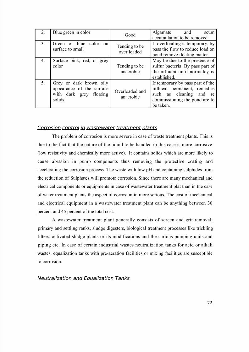
8/6/2019 Waste Water Treatment Notes
http://slidepdf.com/reader/full/waste-water-treatment-notes 72/75
2. Blue green in color Good
Algamats and scumaccumulation to be removed
3. Green or blue color onsurface to small
Tending to beover loaded
If overloading is temporary, by pass the flow to reduce load on pond remove floating matter
4. Surface pink, red, or greycolor Tending to beanaerobic
May be due to the presence of sulfur bacteria. By pass part of the influent until normalcy isestablished.
5. Grey or dark brown oilyappearance of the surfacewith dark grey floatingsolids
Overloaded andanaerobic
If temporary by pass part of theinfluent permanent, remediessuch as cleaning and recommissioning the pond are to be taken.
Corrosion control in wastewater treatment plants
The problem of corrosion is more severe in case of waste treatment plants. This is
due to the fact that the nature of the liquid to be handled in this case is more corrosive
(low resistivity and chemically more active). It contains solids which are more likely to
cause abrasion in pump components thus removing the protective coating and
accelerating the corrosion process. The waste with low pH and containing sulphides from
the reduction of Sulphates will promote corrosion. Since there are many mechanical and
electrical components or equipments in case of wastewater treatment plat than in the caseof water treatment plants the aspect of corrosion in more serious. The cost of mechanical
and electrical equipment in a wastewater treatment plant can be anything between 30
percent and 45 percent of the total cost.
A wastewater treatment plant generally consists of screen and grit removal,
primary and settling ranks, sludge digesters, biological treatment processes like trickling
filters, activated sludge plants or its modifications and the carious pumping units and
piping etc. In case of certain industrial wastes neutralization tanks for acid or alkaliwastes, equalization tanks with pre-aeration facilities or mixing facilities are susceptible
to corrosion.
Neutralization and Equalization Tanks
72
8/6/2019 Waste Water Treatment Notes
http://slidepdf.com/reader/full/waste-water-treatment-notes 73/75
Where there are batch process discharging acidic or alkaline wastes are required
to be equalilsed to balance out fluctuations in quality and quantity. These equalized
wastes have to be mixed continuously throughout the period will the effluents are to next
process of neutralization. In such cases the equalization as well as neutralization tanks
may have to be provided with acid resistant lining of tiles or bricks. The chemicals used
for neutralizing should be stored in acid or alkali resistant containers and fed to the tanks
through PVC piping.
Sedimentation tanks
The primary sedimentation tanks handle raw waste which is allowed to settle at
the bottom. The settling tanks are generally provided with mechanical scrapers to divert
the sludge to a zone to facilitate continuously or periodical withdrawal of sludge. The
scraper arms are constantly immersed in wastewater and are subjected to corrosion.
Since, sewage and most of the industrial wastes have much lower resistivity that water,
the parts are likely to corrode much faster than in the case of water. The specifications for the steel used for the under-water mechanisms should be carefully drawn to ensure
maximum protection from corrosion. It is normally specified that all the steel below the
liquid level shall be at least 1/4” thick. It is a good practice to keep all chains, bearings or
brackets above the liquid surface. All castings in the driving mechanism should be high
grade cast iron.
It is possible to give cathodic protection to the scraper mechanism of the clarifier
either by sacrificial anode or by impressed current. The choice of either of the method or
cathodic protection will depend upon the comparative costs. In any case, the cost of such
protective measures will not be higher than the cost of good quality acid resistant paint.
Sludge digestion tank
73
8/6/2019 Waste Water Treatment Notes
http://slidepdf.com/reader/full/waste-water-treatment-notes 74/75
In the sludge digestion tanks, digestion is carried under anaerobic conditions. The
wastes containing appreciable contents of Sulphates, under anaerobic conditions will be
reduced to sulphides forming hydrogen sulphide. The corrosion due to hydrogen sulphide
is in fact due to sulphuric acid formed in presence of moisture. This will attack digester
walls, digester dome and mechanical equipment to such an extent that breakdown may
occur, ultimately. It is recommended that the cement resistant to attack by H2S, such as
blast furnace slag cement, should be used in the construction of digesters.
It is observed that the draft tubes inside the digesters are sometimes provided of
mild steel. This is not a good practice since the life of such metallic tubes is limited in
highly corrosive interior. Hume or concrete pipes of thicker cross section are re
commended for use as draft tubes. Use of guy rods inside the digester should be
discouraged.
Activated sludge plants
In the activated sludge plant oxygen is provided to the waste either by compressed
air system or by surface aeration system. In the compressed aeration system the clogging
of porous filter material is or frequent occurrence. Clogging can be on either side of the
filter. Air side clogging may be due to corrosion inside the compressed air supply line or
dust drawn by the compressors. Dust in air can be eliminated by provision of proper air filters. Clogging due to corrosion can be minimized only by the use of air supply
pipelines of non-corrosive material.
In the surface aeration system, the conditions in the aeration tank are more
conductive to corrosion since in addition to the corrosiveness of the liquid, oxygen I
present to aggravate the situation. Proper material selection and coating are therefore
necessary for protection of the exposed parts of the rotor. It may be mentioned here that
the protective coating has to be applied at regular intervals since it is found such coatings
have very short life. If floating aerators are provided, it is desirable to have corrosion
resistant lining, such as fiberglass, for the floats.
Trickling filters
74
8/6/2019 Waste Water Treatment Notes
http://slidepdf.com/reader/full/waste-water-treatment-notes 75/75
In trickling filters the mechanical components include the header, the distribution
arm and distribution nozzles, the header and distribution arms are normally of mild steel
and should be protected from corrosion by proper painting etc. The corrosion and
resulting blockage of distribution nozzles are of common occurrences. This can be voided
by selection of proper corrosion resistant material such as brass or PVC for nozzles.
Sewage and wastewater pumps
For pumps and pumping equipment, painting is the usual protective measure.
Both the interior and exterior surface or pumps should be painted after rust scale and
deposits are removed by and blasting, wire brushing or rubbing with sand paper.
Preventive maintenance
It will be seen from the above discussion that anticorrosive paints, coatings
linings have to be used in various equipments to prevent corrosion. The paints, coatings
and linings require periodical renewal. Proper maintenance demands that a scheduling be
drawn up in each paint so that the operator may abide by it and undertake repainting or cleaning at appropriate intervals without waiting for corrosion to become obvious. The
accent should be on preventive maintenance rather than just maintenance in the form of
repairs, and replacements of broken down parts.
No doubt, proper design and specifications at the tendering stage would go a long
way in ensuring long life. However, once the plant is built it is entirely in the hands of the
operator or the supervisor to ensure proper preventive maintenance and carry out
judicious replacement of spare parts piping etc. bearing in mind the requirements