Embed Size (px)
Citation preview

ITT
Wastewater Technical Manual
Goulds Pumpswww.goulds.com
Red Jacket Water Productswww.redjacketwaterproducts.com
Bell & Gossettwww.bellgossett.com
CentriProwww.centripro.com
Goulds Pumps, Red Jacket Water Products, Bell & Gossett and CentriPro are brands of ITT Residential and Commercial Water.
Engineered for life
Wastewater
�
WastewaterITT
Friction loss
Plastic............................................................................ 3Steel.............................................................................. 4Fittings.......................................................................... 5
pipe volume and velocity
Storage.of.Water.in.Various.Size.Pipes........................... 5Minimum.Flow.to.Maintain.2.Ft./Sec.............................. 5
seWaGe pump
Sizing.and.Selection....................................................... 6
electrical data
Agency.Listing./.Removing.Plug.Letters........................ 10Transformer.Sizes......................................................... 10Three.Phase.Unbalance................................................ 11NEMA.Panel.Enclosures............................................... 12
determininG FloW rates
Full.Pipe.Flow.............................................................. 13Pipe.Not.Running.Full.................................................. 13Discharge.Rate.in.Gallons.per.Minute.......................... 13
terms and usable Formulas
Definitions................................................................... 14Basic.Formulas............................................................. 14
typical installations
Sump........................................................................... 16Effluent.and.Sewage.................................................... 17
variable speed drives
Wastewater.Pumps...................................................... 18
panel layouts and WirinG diaGrams
Duplex.Single.Phase.................................................... 19Duplex.Three.Phase..................................................... 21Simplex.Single.Phase................................................... 23Switch.Diagrams.......................................................... 25Sewage.Control.Panels.and.Switches........................... 26
Index
�
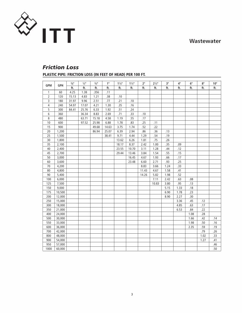
WastewaterITTFriction Lossplastic pipe: Friction loss (in Feet oF head) per 100 Ft.
GPM GPH
3⁄8" ½" ¾" 1" 1¼" 1½" 2" 2½" 3" 4" 6" 8" 10" ft. ft. ft. ft. ft. ft. ft. ft. ft. ft. ft. ft. ft.. 1. 60. 4.25. 1.38. .356. .11. 2. 120. 15.13. 4.83. 1.21. .38. .10. 3. 180. 31.97. 9.96. 2.51. .77. .21. .10. 4. 240. 54.97. 17.07. 4.21. 1.30. .35. .16. 5. 300. 84.41. 25.76. 6.33. 1.92. .51. .24. 6. 360. . 36.34. 8.83. 2.69. .71. .33. .10. 8. 480. . 63.71. 15.18. 4.58. 1.19. .55. .17. 10. 600. . 97.52. 25.98. 6.88. 1.78. .83. .25. .11. 15. 900. . . 49.68. 14.63. 3.75. 1.74. .52. .22. 20. 1,200. . . 86.94. 25.07. 6.39. 2.94. .86. .36. .13. 25. 1,500. . . . 38.41. 9.71. 4.44. 1.29. .54. .19. 30. 1,800. . . . . 13.62. 6.26. 1.81. .75. .26. 35. 2,100. . . . . 18.17. 8.37. 2.42. 1.00. .35. .09. 40. 2,400. . . . . 23.55. 10.70. 3.11. 1.28. .44. .12. 45. 2,700. . . . . 29.44. 13.46. 3.84. 1.54. .55. .15. 50. 3,000. . . . . . 16.45. 4.67. 1.93. .66. .17. 60. 3,600. . . . . . 23.48. 6.60. 2.71. .93. .25. 70. 4,200. . . . . . . 8.83. 3.66. 1.24. .33. 80. 4,800. . . . . . . 11.43. 4.67. 1.58. .41. 90. 5,400. . . . . . . 14.26. 5.82. 1.98. .52. 100. 6,000. . . . . . . . 7.11. 2.42. .63. .08. 125. 7,500. . . . . . . . 10.83. 3.80. .95. .13. 150. 9,000. . . . . . . . . 5.15. 1.33. .18. 175. 10,500. . . . . . . . . 6.90. 1.78. .23. 200. 12,000. . . . . . . . . 8.90. 2.27. .30. 250. 15,000. . . . . . . . . . 3.36. .45. .12. 300. 18,000. . . . . . . . . . 4.85. .63. .17. 350. 21,000. . . . . . . . . . 6.53. .84. .22. 400. 24,000. . . . . . . . . . . 1.08. .28. 500. 30,000. . . . . . . . . . . 1.66. .42. .14. 550. 33,000. . . . . . . . . . . 1.98. .50. .16. 600. 36,000. . . . . . . . . . . 2.35. .59. .19. 700. 42,000. . . . . . . . . . . . .79. .26. 800. 48,000. . . . . . . . . . . . 1.02. .33. 900. 54,000. . . . . . . . . . . . 1.27. .41. 950. 57,000. . . . . . . . . . . . . .46. 1000. 60,000. . . . . . . . . . . . . .50
�
WastewaterITT
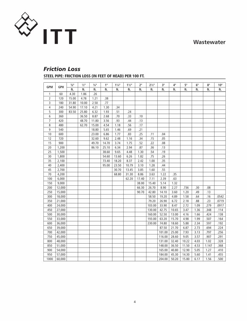
steel pipe: Friction loss (in Feet oF head) per 100 Ft.
GPM GPH
3⁄8" ½" ¾" 1" 1¼" 1½" 2" 2½" 3" 4" 5" 6" 8" 10" ft. ft. ft. ft. ft. ft. ft. ft. ft. ft. ft. ft. ft. ft.. 1. 60. 4.30. 1.86. .26. 2. 120. 15.00. 4.78. 1.21. .38. 3. 180. 31.80. 10.00. 2.50. .77. 4. 240. 54.90. 17.10. 4.21. 1.30. .34. 5. 300. 83.50. 25.80. 6.32. 1.93. .51. .24. 6. 360. . 36.50. 8.87. 2.68. .70. .33. .10. 7. 420. . 48.70. 11.80. 3.56. .93. .44. .13. 8. 480. . 62.70. 15.00. 4.54. 1.18. .56. .17. 9. 540. . . 18.80. 5.65. 1.46. .69. .21. 10. 600. . . 23.00. 6.86. 1.77. .83. .25. .11. .04. 12. 720. . . 32.60. 9.62. 2.48. 1.16. .34. .15. .05. 15. 900. . . 49.70. 14.70. 3.74. 1.75. .52. .22. .08. 20. 1,200. . . 86.10. 25.10. 6.34. 2.94. .87. .36. .13. 25. 1,500. . . . 38.60. 9.65. 4.48. 1.30. .54. .19. 30. 1,800. . . . 54.60. 13.60. 6.26. 1.82. .75. .26. 35. 2,100. . . . 73.40. 18.20. 8.37. 2.42. 1.00. .35. 40. 2,400. . . . 95.00. 23.50. 10.79. 3.10. 1.28. .44. 45. 2,700. . . . . 30.70. 13.45. 3.85. 1.60. .55. 70. 4,200. . . . . 68.80. 31.30. 8.86. 3.63. 1.22. .35. 100. 6,000. . . . . . 62.20. 17.40. 7.11. 2.39. .63. 150. 9,000. . . . . . . 38.00. 15.40. 5.14. 1.32. 200. 12,000. . . . . . . 66.30. 26.70. 8.90. 2.27. .736. .30. .08. 250. 15,000. . . . . . . 90.70. 42.80. 14.10. 3.60. 1.20. .49. .13. 300. 18,000. . . . . . . . 58.50. 19.20. 4.89. 1.58. .64. .16. .0542. 350. 21,000. . . . . . . . 79.20. 26.90. 6.72. 2.18. .88. .23. .0719. 400. 24,000. . . . . . . . 103.00. 33.90. 8.47. 2.72. 1.09. .279. .0917. 450. 27,000. . . . . . . . 130.00. 42.75. 10.65. 3.47. 1.36. .348. .114. 500. 30,000. . . . . . . . 160.00. 52.50. 13.00. 4.16. 1.66. .424. .138. 550. 33,000. . . . . . . . 193.00. 63.20. 15.70. 4.98. 1.99. .507. .164. 600. 36,000. . . . . . . . 230.00. 74.80. 18.60. 5.88. 2.34. .597. .192. 650. 39,000. . . . . . . . . 87.50. 21.70. 6.87. 2.73. .694. .224. 700. 42,000. . . . . . . . . 101.00. 25.00. 7.93. 3.13. .797. .256. 750. 45,000. . . . . . . . . 116.00. 28.60. 9.05. 3.57. .907. .291. 800. 48,000. . . . . . . . . 131.00. 32.40. 10.22. 4.03. 1.02. .328. 850. 51,000. . . . . . . . . 148.00. 36.50. 11.50. 4.53. 1.147. .368. 900. 54,000. . . . . . . . . 165.00. 40.80. 12.90. 5.05. 1.27. .410. 950. 57,000. . . . . . . . . 184.00. 45.30. 14.30. 5.60. 1.41. .455. 1000. 60,000. . . . . . . . . 204.00. 50.20. 15.80. 6.17. 1.56. .500
Friction Loss
�
WastewaterITT
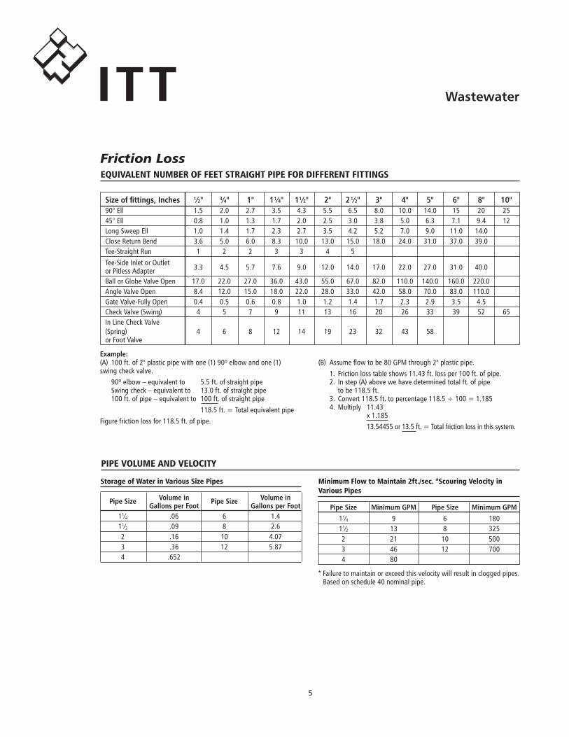
storage of Water in various size pipes
PipeSize Volumein PipeSize Volumein GallonsperFoot GallonsperFoot. 11⁄4. .06. 6. 1.4. 11⁄2. .09. 8. 2.6. 2. .16. 10. 4.07. 3. .36. 12. 5.87. 4. .652.
minimum Flow to maintain 2ft./sec. *scouring velocity in various pipes
PipeSize MinimumGPM PipeSize MinimumGPM. 11⁄4. 9. 6. 180. 11⁄2. 13. 8. 325. 2. 21. 10. 500. 3. 46. 12. 700. 4. 80
*.Failure.to.maintain.or.exceed.this.velocity.will.result.in.clogged.pipes..Based.on.schedule.40.nominal.pipe.
pipe volume and velocity
equivalent number oF Feet straiGht pipe For diFFerent FittinGs
Sizeoffittings,Inches ½" ¾" 1" 1¼" 1½" 2" 2½" 3" 4" 5" 6" 8" 10". 90°.Ell. 1.5. 2.0. 2.7. 3.5. 4.3. 5.5. 6.5. 8.0. 10.0. 14.0. 15. 20. 25. 45°.Ell. 0.8. 1.0. 1.3. 1.7. 2.0. 2.5. 3.0. 3.8. 5.0. 6.3. 7.1. 9.4. 12. Long.Sweep.Ell. 1.0. 1.4. 1.7. 2.3. 2.7. 3.5. 4.2. 5.2. 7.0. 9.0. 11.0. 14.0. Close.Return.Bend. 3.6. 5.0. 6.0. 8.3. 10.0. 13.0. 15.0. 18.0. 24.0. 31.0. 37.0. 39.0. Tee-Straight.Run. 1. 2. 2. 3. 3. 4. 5. Tee-Side.Inlet.or.Outlet.
3.3. 4.5. 5.7. 7.6. 9.0. 12.0. 14.0. 17.0. 22.0. 27.0. 31.0. 40.0. or.Pitless.Adapter. Ball.or.Globe.Valve.Open. 17.0. 22.0. 27.0. 36.0. 43.0. 55.0. 67.0. 82.0. 110.0. 140.0. 160.0. 220.0. Angle.Valve.Open. 8.4. 12.0. 15.0. 18.0. 22.0. 28.0. 33.0. 42.0. 58.0. 70.0. 83.0. 110.0. Gate.Valve-Fully.Open. 0.4. 0.5. 0.6. 0.8. 1.0. 1.2. 1.4. 1.7. 2.3. 2.9. 3.5. 4.5. Check.Valve.(Swing). 4. 5. 7. 9. 11. 13. 16. 20. 26. 33. 39. 52. 65. In.Line.Check.Valve. (Spring). 4. 6. 8. 12. 14. 19. 23. 32. 43. 58. or.Foot.Valve
Example:(A). 100.ft..of.2".plastic.pipe.with.one.(1).90º.elbow.and.one.(1)..swing.check.valve.. 90º.elbow.–.equivalent.to. 5.5.ft..of.straight.pipe. Swing.check.–.equivalent.to. 13.0.ft..of.straight.pipe. 100.ft..of.pipe.–.equivalent.to. 100.ft..of.straight.pipe. . 118.5.ft..=.Total.equivalent.pipeFigure.friction.loss.for.118.5.ft..of.pipe.
(B). Assume.flow.to.be.80.GPM.through.2".plastic.pipe.. 1.. Friction.loss.table.shows.11.43.ft..loss.per.100.ft..of.pipe.. 2.. In.step.(A).above.we.have.determined.total.ft..of.pipe.. .. . to.be.118.5.ft.. 3.. Convert.118.5.ft..to.percentage.118.5.÷.100.=.1.185. 4.. Multiply. 11.43. . . x.1.185. . . 13.54455.or.13.5.ft..=.Total.friction.loss.in.this.system.
Friction Loss
�
WastewaterITT
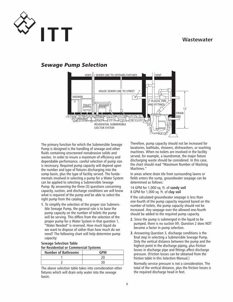
The.primary.function.for.which.the.Submersible.Sewage.Pump.is.designed.is.the.handling.of.sewage.and.other.fluids.containing.unscreened.nonabrasive.solids.and.wastes..In.order.to.insure.a.maximum.of.efficiency.and.dependable.performance,.careful.selection.of.pump.size.is.necessary..Required.pump.capacity.will.depend.upon.the.number.and.type.of.fixtures.discharging.into.the.sump.basin,.plus.the.type.of.facility.served..The.funda-mentals.involved.in.selecting.a.pump.for.a.Water.System.can.be.applied.to.selecting.a.Submersible.Sewage.Pump..By.answering.the.three.(3).questions.concerning.capacity,.suction,.and.discharge.conditions.we.will.know.what.is.required.of.the.pump.and.be.able.to.select.the.right.pump.from.the.catalog.1..To.simplify.the.selection.of.the.proper.size.Submers-
ible.Sewage.Pump,.the.general.rule.is.to.base.the.pump.capacity.on.the.number.of.toilets.the.pump.will.be.serving..This.differs.from.the.selection.of.the.proper.pump.for.a.Water.System.in.that.question.1,.“Water.Needed”.is.reversed..How.much.liquid.do.we.want.to.dispose.of.rather.than.how.much.do.we.need?.The.following.chart.will.help.determine.pump.capacity:
SewageSelectionTableforResidentialorCommercialSystems NumberofBathrooms GPM. 1. 20. 2. 30The.above.selection.table.takes.into.consideration.other.fixtures.which.will.drain.only.water.into.the.sewage.basin..
Therefore,.pump.capacity.should.not.be.increased.for.lavatories,.bathtubs,.showers,.dishwashers,.or.washing.machines..When.no.toilets.are.involved.in.the.facility.served,.for.example,.a.laundromat,.the.major.fixture.discharging.waste.should.be.considered..In.this.case,.the.chart.should.read.“Maximum.Number.of.Washing.Machines.”In.areas.where.drain.tile.from.surrounding.lawns.or.fields.enters.the.sump,.groundwater.seepage.can.be.determined.as.follows:14.GPM.for.1,000.sq..ft..of.sandysoil8.GPM.for.1,000.sq..ft..of.claysoilIf.the.calculated.groundwater.seepage.is.less.than.one-fourth.of.the.pump.capacity.required.based.on.the.number.of.toilets,.the.pump.capacity.should.not.be.increased..Any.seepage.over.the.allowed.one-fourth.should.be.added.to.the.required.pump.capacity.2..Since.the.pump.is.submerged.in.the.liquid.to.be.
pumped,.there.is.no.suction.lift..Question.2.does.NOT.become.a.factor.in.pump.selection.
3..Answering.Question.3,.discharge.conditions.is.the.final.step.in.selecting.a.Submersible.Sewage.Pump..Only.the.vertical.distance.between.the.pump.and.the.highest.point.in.the.discharge.piping,.plus.friction.losses.in.discharge.pipe.and.fittings.affect.discharge.pressure..(Friction.losses.can.be.obtained.from.the.friction.table.in.this.Selection.Manual.)Normally.service.pressure.is.not.a.consideration..The.total.of.the.vertical.distance,.plus.the.friction.losses.is.the.required.discharge.head.in.feet.
SHOWER
TOILET WASHER
VENT SEWER.LINE.TO.UPSTAIRS.FIXTURES VENT
HOUSE.SEWER.LINE.TO.STREET
RESIDENTIAL.SUBMERSIBLE..EJECTOR.SYSTEM
DRAINPIPE
12'
2".PLASTIC.PIPEAND.FITTINGS
Sewage Pump Selection
�
WastewaterITT
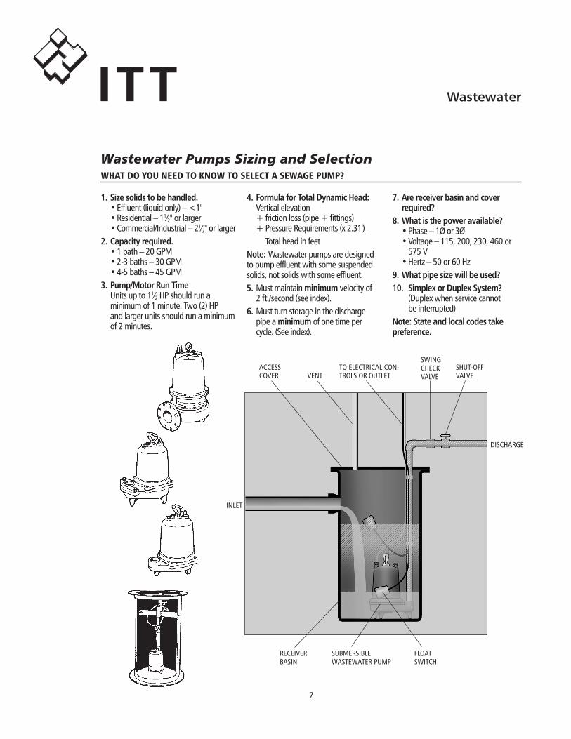
What do you need to knoW to select a seWaGe pump?
4.FormulaforTotalDynamicHead:. Vertical.elevation. +.friction.loss.(pipe.+.fittings). +.Pressure.Requirements.(x.2.31'). . Total.head.in.feetNote:Wastewater.pumps.are.designed.to.pump.effluent.with.some.suspended.solids,.not.solids.with.some.effluent.5.Must.maintain.minimumvelocity.of.. 2.ft./second.(see.index).6.Must.turn.storage.in.the.discharge... pipe.a.minimumof.one.time.per... cycle..(See.index).
7.Arereceiverbasinandcover required?8.Whatisthepoweravailable?. •.Phase.–.1Ø.or.3Ø. •.Voltage.–.115,.200,.230,.460.or... . 575.V. •.Hertz.–.50.or.60.Hz9.Whatpipesizewillbeused?10. SimplexorDuplexSystem?. . (Duplex.when.service.cannot.. . be.interrupted)Note:Stateandlocalcodestakepreference.
FLOATSWITCH
ACCESSCOVER VENT
TO.ELECTRICAL.CON-TROLS.OR.OUTLET
SWING.CHECK.VALVE
SHUT-OFF.VALVE
DISCHARGE
INLET
RECEIVER.BASIN
SUBMERSIBLEWASTEWATER.PUMP
1.Sizesolidstobehandled.. •.Effluent.(liquid.only).–.<1". •.Residential.–.11⁄2".or.larger. •.Commercial/Industrial.–.21⁄2".or.larger2.Capacityrequired.. •.1.bath.–.20.GPM. •.2-3.baths.–.30.GPM. •.4-5.baths.–.45.GPM3.Pump/MotorRunTime. Units.up.to.11⁄2.HP.should.run.a.. .. minimum.of.1.minute..Two.(2).HP... and.larger.units.should.run.a.minimum... of.2.minutes.
Wastewater Pumps Sizing and Selection
�
WastewaterITT
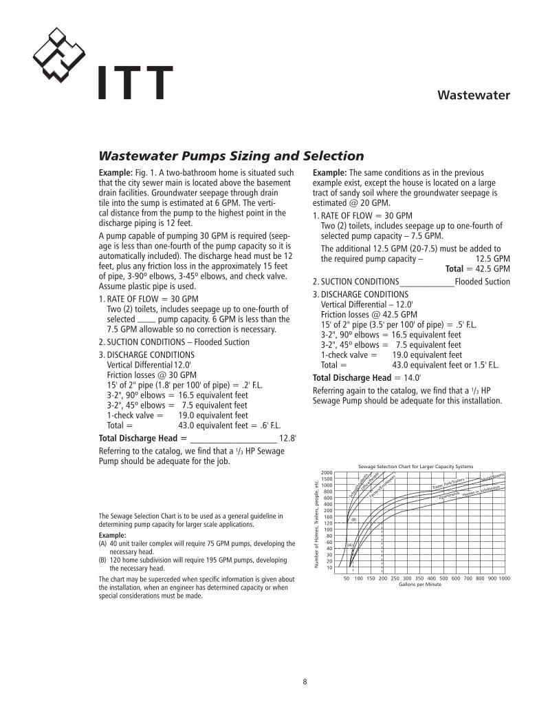
Example:.Fig..1..A.two-bathroom.home.is.situated.such.that.the.city.sewer.main.is.located.above.the.basement.drain.facilities..Groundwater.seepage.through.drain.tile.into.the.sump.is.estimated.at.6.GPM..The.verti-cal.distance.from.the.pump.to.the.highest.point.in.the.discharge.piping.is.12.feet.A.pump.capable.of.pumping.30.GPM.is.required.(seep-age.is.less.than.one-fourth.of.the.pump.capacity.so.it.is.automatically.included)..The.discharge.head.must.be.12.feet,.plus.any.friction.loss.in.the.approximately.15.feet.of.pipe,.3-90º.elbows,.3-45º.elbows,.and.check.valve.Assume.plastic.pipe.is.used.1..RATE.OF.FLOW.=.30.GPM. Two.(2).toilets,.includes.seepage.up.to.one-fourth.of... selected.____.pump.capacity..6.GPM.is.less.than.the... 7.5.GPM.allowable.so.no.correction.is.necessary.2..SUCTION.CONDITIONS.–.Flooded.Suction3..DISCHARGE.CONDITIONS. Vertical.Differential.12.0'. [email protected]. 15'.of.2".pipe.(1.8'.per.100'.of.pipe).=..2'.F.L.. 3-2",.90º.elbows.=.16.5.equivalent.feet. 3-2",.45º.elbows.=. 7.5.equivalent.feet. 1-check.valve.=. 19.0.equivalent.feet. Total.=. 43.0.equivalent.feet.=..6'.F.L.TotalDischargeHead=.___________________ 12.8'Referring.to.the.catalog,.we.find.that.a.1/3.HP.Sewage.Pump.should.be.adequate.for.the.job.
Example:.The.same.conditions.as.in.the.previous.example.exist,.except.the.house.is.located.on.a.large.tract.of.sandy.soil.where.the.groundwater.seepage.is.estimated.@.20.GPM.1..RATE.OF.FLOW.=.30.GPM. Two.(2).toilets,.includes.seepage.up.to.one-fourth.of... selected.pump.capacity.–.7.5.GPM... The.additional.12.5.GPM.(20-7.5).must.be.added.to. the.required.pump.capacity.–. 12.5.GPM
Total.=.42.5.GPM2..SUCTION.CONDITIONS.____________Flooded.Suction3..DISCHARGE.CONDITIONS. Vertical.Differential.–.12.0'. [email protected]. 15'.of.2".pipe.(3.5'.per.100'.of.pipe).=..5'.F.L.. 3-2",.90º.elbows.=.16.5.equivalent.feet. 3-2",.45º.elbows.=. 7.5.equivalent.feet. 1-check.valve.=. 19.0.equivalent.feet. Total.=. 43.0.equivalent.feet.or.1.5'.F.L.TotalDischargeHead.=.14.0'Referring.again.to.the.catalog,.we.find.that.a.1/3.HP..Sewage.Pump.should.be.adequate.for.this.installation.
The.Sewage.Selection.Chart.is.to.be.used.as.a.general.guideline.in.. .determining.pump.capacity.for.larger.scale.applications.Example:(A). 40.unit.trailer.complex.will.require.75.GPM.pumps,.developing.the... necessary.head..(B). 120.home.subdivision.will.require.195.GPM.pumps,.developing.. .. the.necessary.head.The.chart.may.be.superceded.when.specific.information.is.given.about..the.installation,.when.an.engineer.has.determined.capacity.or.when.special.considerations.must.be.made.
10�0�0�0�0�0
100
1�0�00�00�00�00
�0001�001000
1�0
�0 100 1�0 �00 ��0 �00 ��0 �00 �00 �00 �00 �00 �00 1000Gallons per Minute
Num
ber
of H
omes
, Tra
ilers
, peo
ple,
etc
.
Sewage Selection Chart for Larger Capacity Systems
Scho
ol/S
tude
nts
Office
/Peop
le
Motel/Rooms
Facto
ry/Em
ployees
Trailer Park/Trailers
Apartments Homes in Subdivision
(A)
(B)
Wastewater Pumps Sizing and Selection
�
WastewaterITT
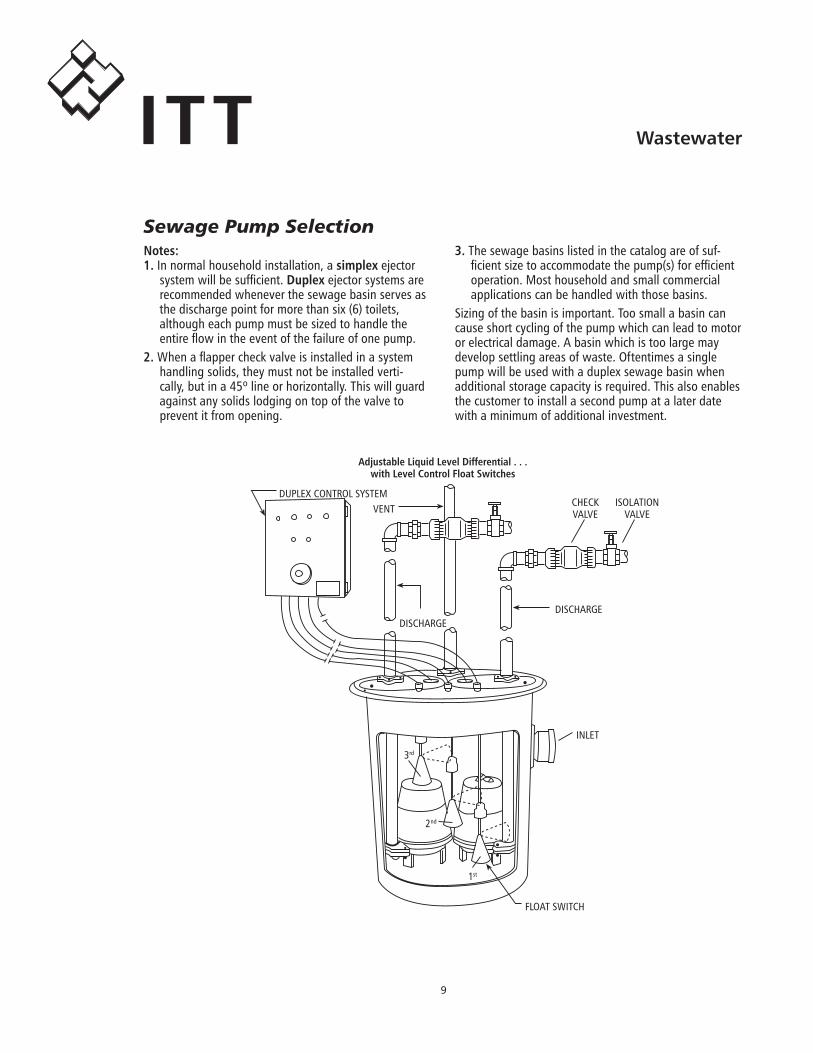
Notes:1..In.normal.household.installation,.a.simplex.ejector.
system.will.be.sufficient..Duplex.ejector.systems.are.recommended.whenever.the.sewage.basin.serves.as.the.discharge.point.for.more.than.six.(6).toilets,..although.each.pump.must.be.sized.to.handle.the.entire.flow.in.the.event.of.the.failure.of.one.pump.
2..When.a.flapper.check.valve.is.installed.in.a.system.handling.solids,.they.must.not.be.installed.verti-cally,.but.in.a.45º.line.or.horizontally..This.will.guard.against.any.solids.lodging.on.top.of.the.valve.to.prevent.it.from.opening.
3..The.sewage.basins.listed.in.the.catalog.are.of.suf-ficient.size.to.accommodate.the.pump(s).for.efficient.operation..Most.household.and.small.commercial.applications.can.be.handled.with.those.basins..
Sizing.of.the.basin.is.important..Too.small.a.basin.can.cause.short.cycling.of.the.pump.which.can.lead.to.motor.or.electrical.damage..A.basin.which.is.too.large.may.develop.settling.areas.of.waste..Oftentimes.a.single.pump.will.be.used.with.a.duplex.sewage.basin.when.additional.storage.capacity.is.required..This.also.enables.the.customer.to.install.a.second.pump.at.a.later.date.with.a.minimum.of.additional.investment.
DUPLEX.CONTROL.SYSTEMVENT
DISCHARGE
CHECKVALVE
ISOLATIONVALVE
INLET
DISCHARGE
FLOAT.SWITCH
3rd
2nd
1st
AdjustableLiquidLevelDifferential...withLevelControlFloatSwitches
Sewage Pump Selection
10
WastewaterITT
transFormer sizes
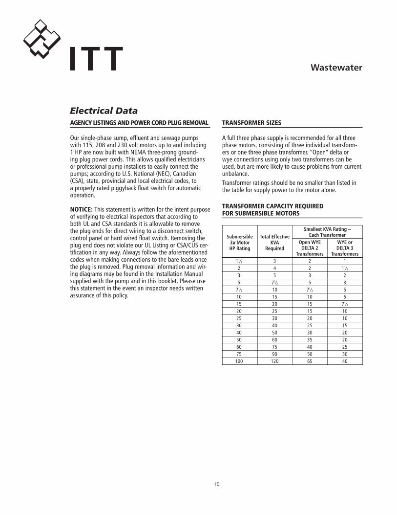
A.full.three.phase.supply.is.recommended.for.all.three.phase.motors,.consisting.of.three.individual.transform-ers.or.one.three.phase.transformer..“Open”.delta.or.wye.connections.using.only.two.transformers.can.be.used,.but.are.more.likely.to.cause.problems.from.current.unbalance.Transformer.ratings.should.be.no.smaller.than.listed.in.the.table.for.supply.power.to.the.motor.alone.
transFormer capacity required For submersible motors
SmallestKVARating– EachTransformer OpenWYE WYEor DELTA2 DELTA3 Transformers Transformers. 11⁄2. 3. 2. 1. 2. 4. 2. 11⁄2. 3. 5. 3. 2. 5. 71⁄2. 5. 3. 71⁄2. 10. 71⁄2. 5. 10. 15. 10. 5. 15. 20. 15. 71⁄2. 20. 25. 15. 10. 25. 30. 20. 10. 30. 40. 25. 15. 40. 50. 30. 20. 50. 60. 35. 20. 60. 75. 40. 25. 75. 90. 50. 30. 100. 120. 65. 40
Submersible3øMotorHPRating
TotalEffectiveKVA
Required
aGency listinGs and poWer cord pluG removal
Our.single-phase.sump,.effluent.and.sewage.pumps.with.115,.208.and.230.volt.motors.up.to.and.including.1.HP.are.now.built.with.NEMA.three-prong.ground-ing.plug.power.cords..This.allows.qualified.electricians.or.professional.pump.installers.to.easily.connect.the.pumps;.according.to.U.S..National.(NEC),.Canadian.(CSA),.state,.provincial.and.local.electrical.codes,.to.a.properly.rated.piggyback.float.switch.for.automatic.operation.
notice:.This.statement.is.written.for.the.intent.purpose.of.verifying.to.electrical.inspectors.that.according.to.both.UL.and.CSA.standards.it.is.allowable.to.remove.the.plug.ends.for.direct.wiring.to.a.disconnect.switch,.control.panel.or.hard.wired.float.switch..Removing.the.plug.end.does.not.violate.our.UL.Listing.or.CSA/CUS.cer-tification.in.any.way..Always.follow.the.aforementioned.codes.when.making.connections.to.the.bare.leads.once.the.plug.is.removed..Plug.removal.information.and.wir-ing.diagrams.may.be.found.in.the.Installation.Manual.supplied.with.the.pump.and.in.this.booklet..Please.use.this.statement.in.the.event.an.inspector.needs.written.assurance.of.this.policy.
Electrical Data
11
WastewaterITT
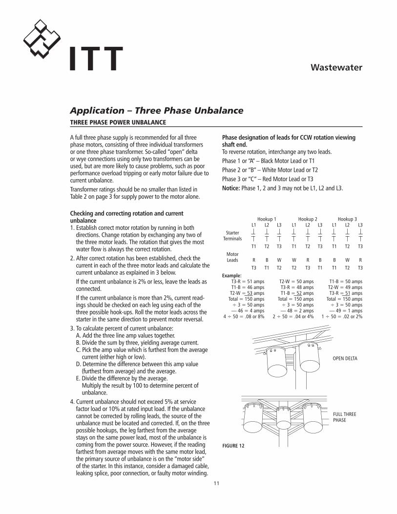
. . . Hookup.1. . . Hookup.2. . . Hookup.3
. . L1. L2. L3. L1. L2. L3. L1. L2. L3
. Starter
.Terminals
. . T1. T2. T3. T1. T2. T3. T1. T2. T3
. Motor
. Leads. R. B. W. W. R. B. B. W. R
. . T3. T1. T2. T2. T3. T1. T1. T2. T3Example:. T3-R.=.51.amps. T2-W.=.50.amps. T1-B.=.50.amps. T1-B.=.46.amps. T3-R.=.48.amps. T2-W.=.49.amps. T2-W.=.53.amps. T1-B.=.52.amps. T3-R.=.51.amps. Total.=.150.amps. Total.=.150.amps. Total.=.150.amps. ÷.3.=.50.amps. ÷.3.=.50.amps. ÷.3.=.50.amps. —.46.=.4.amps. —.48.=.2.amps. —.49.=.1.amps.4.÷.50.=..08.or.8%. 2.÷.50.=..04.or.4%. 1.÷.50.=..02.or.2%
three phase poWer unbalance
A.full.three.phase.supply.is.recommended.for.all.three.phase.motors,.consisting.of.three.individual.transformers.or.one.three.phase.transformer..So-called.“open”.delta.or.wye.connections.using.only.two.transformers.can.be.used,.but.are.more.likely.to.cause.problems,.such.as.poor.performance.overload.tripping.or.early.motor.failure.due.to.current.unbalance.Transformer.ratings.should.be.no.smaller.than.listed.in.Table.2.on.page.3.for.supply.power.to.the.motor.alone.
PhasedesignationofleadsforCCWrotationviewingshaftend.To.reverse.rotation,.interchange.any.two.leads.Phase.1.or.“A”.–.Black.Motor.Lead.or.T1Phase.2.or.“B”.–.White.Motor.Lead.or.T2Phase.3.or.“C”.–.Red.Motor.Lead.or.T3Notice:.Phase.1,.2.and.3.may.not.be.L1,.L2.and.L3.
Checkingandcorrectingrotationandcurrent unbalance1..Establish.correct.motor.rotation.by.running.in.both..
directions..Change.rotation.by.exchanging.any.two.of.the.three.motor.leads..The.rotation.that.gives.the.most.water.flow.is.always.the.correct.rotation.
2..After.correct.rotation.has.been.established,.check.the.current.in.each.of.the.three.motor.leads.and.calculate.the.current.unbalance.as.explained.in.3.below.If.the.current.unbalance.is.2%.or.less,.leave.the.leads.as.connected.If.the.current.unbalance.is.more.than.2%,.current.read-ings.should.be.checked.on.each.leg.using.each.of.the.three.possible.hook-ups..Roll.the.motor.leads.across.the.starter.in.the.same.direction.to.prevent.motor.reversal.
3..To.calculate.percent.of.current.unbalance:A..Add.the.three.line.amp.values.together.B..Divide.the.sum.by.three,.yielding.average.current.C..Pick.the.amp.value.which.is.furthest.from.the.average.
current.(either.high.or.low).D..Determine.the.difference.between.this.amp.value.
(furthest.from.average).and.the.average.E..Divide.the.difference.by.the.average.
Multiply.the.result.by.100.to.determine.percent.of.. .unbalance.
4..Current.unbalance.should.not.exceed.5%.at.service.factor.load.or.10%.at.rated.input.load..If.the.unbalance.cannot.be.corrected.by.rolling.leads,.the.source.of.the.unbalance.must.be.located.and.corrected..If,.on.the.three.possible.hookups,.the.leg.farthest.from.the.average.stays.on.the.same.power.lead,.most.of.the.unbalance.is.coming.from.the.power.source..However,.if.the.reading.farthest.from.average.moves.with.the.same.motor.lead,.the.primary.source.of.unbalance.is.on.the.“motor.side”.of.the.starter..In.this.instance,.consider.a.damaged.cable,.leaking.splice,.poor.connection,.or.faulty.motor.winding.
FIGURE12
OPEN.DELTA
FULL.THREE.PHASE
Application – Three Phase Unbalance
1�
WastewaterITT
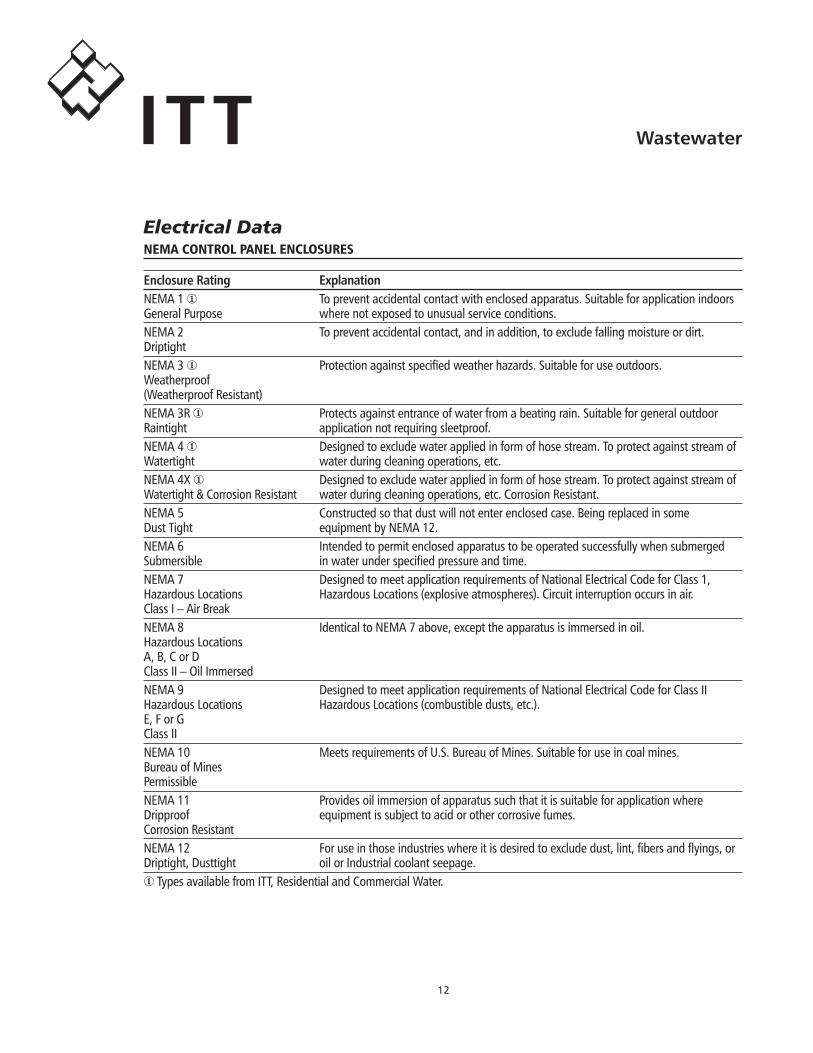
nema control panel enclosures
EnclosureRating ExplanationNEMA.1.①. To.prevent.accidental.contact.with.enclosed.apparatus..Suitable.for.application.indoors.General.Purpose. where.not.exposed.to.unusual.service.conditions..NEMA.2. To.prevent.accidental.contact,.and.in.addition,.to.exclude.falling.moisture.or.dirt.. .DriptightNEMA.3.①. Protection.against.specified.weather.hazards..Suitable.for.use.outdoors.. . .Weatherproof. . . . . . . . . . .(Weatherproof.Resistant)NEMA.3R.①. Protects.against.entrance.of.water.from.a.beating.rain..Suitable.for.general.outdoor..Raintight. application.not.requiring.sleetproof.NEMA.4.①. Designed.to.exclude.water.applied.in.form.of.hose.stream..To.protect.against.stream.of.Watertight. water.during.cleaning.operations,.etc.NEMA.4X.①. Designed.to.exclude.water.applied.in.form.of.hose.stream..To.protect.against.stream.of.Watertight.&.Corrosion.Resistant. water.during.cleaning.operations,.etc..Corrosion.Resistant.NEMA.5. Constructed.so.that.dust.will.not.enter.enclosed.case..Being.replaced.in.some.. .Dust.Tight. equipment.by.NEMA.12.NEMA.6. Intended.to.permit.enclosed.apparatus.to.be.operated.successfully.when.submerged.Submersible. in.water.under.specified.pressure.and.time.NEMA.7. Designed.to.meet.application.requirements.of.National.Electrical.Code.for.Class.1,.Hazardous.Locations. Hazardous.Locations.(explosive.atmospheres)..Circuit.interruption.occurs.in.air.. .Class.I.–.Air.BreakNEMA.8. Identical.to.NEMA.7.above,.except.the.apparatus.is.immersed.in.oil.. . .Hazardous.Locations. . . . . . . . . . .A,.B,.C.or.D. . . . . . . . . . .Class.II.–.Oil.ImmersedNEMA.9. Designed.to.meet.application.requirements.of.National.Electrical.Code.for.Class.II..Hazardous.Locations... Hazardous.Locations.(combustible.dusts,.etc.)... . . . .E,.F.or.G. . . . . . . . . . .Class.IINEMA.10. Meets.requirements.of.U.S..Bureau.of.Mines..Suitable.for.use.in.coal.mines.. .Bureau.of.Mines. . . . . . . . . . .PermissibleNEMA.11. Provides.oil.immersion.of.apparatus.such.that.it.is.suitable.for.application.where.Dripproof. equipment.is.subject.to.acid.or.other.corrosive.fumes.. . . .Corrosion.ResistantNEMA.12. For.use.in.those.industries.where.it.is.desired.to.exclude.dust,.lint,.fibers.and.flyings,.or.Driptight,.Dusttight. oil.or.Industrial.coolant.seepage.①.Types.available.from.ITT,.Residential.and.Commercial.Water.
Electrical Data
1�
WastewaterITT
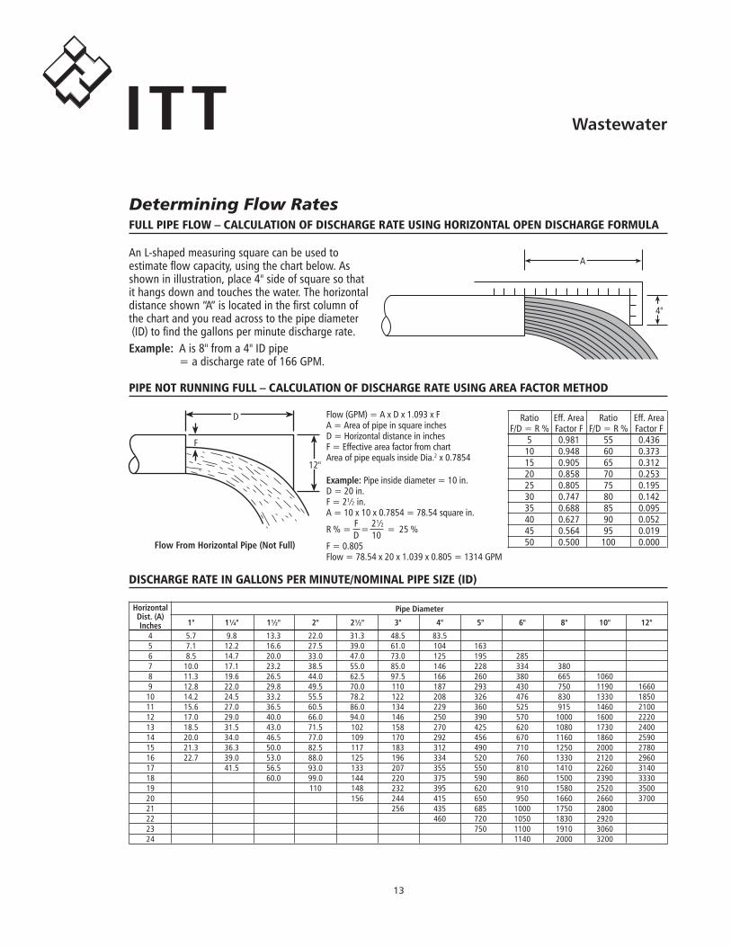
An.L-shaped.measuring.square.can.be.used.to...estimate.flow.capacity,.using.the.chart.below..As.shown.in.illustration,.place.4".side.of.square.so.that.it.hangs.down.and.touches.the.water..The.horizontal.distance.shown.“A”.is.located.in.the.first.column.of..the.chart.and.you.read.across.to.the.pipe.diameter..(ID).to.find.the.gallons.per.minute.discharge.rate.Example:. A.is.8".from.a.4".ID.pipe.. =.a.discharge.rate.of.166.GPM.
Full pipe FloW – calculation oF discharGe rate usinG horizontal open discharGe Formula
Flow.(GPM).=.A.x.D.x.1.093.x.FA.=.Area.of.pipe.in.square.inchesD.=.Horizontal.distance.in.inchesF.=.Effective.area.factor.from.chartArea.of.pipe.equals.inside.Dia.2.x.0.7854
Example:Pipe.inside.diameter.=.10.in.D.=.20.in.F.=.2½.in.A.=.10.x.10.x.0.7854.=.78.54.square.in.
R.%.=.F.
=..2½
. =. 25.%. . D.. 10F.=.0.805Flow.=.78.54.x.20.x.1.039.x.0.805.=.1314.GPM
pipe not runninG Full – calculation oF discharGe rate usinG area Factor method
FlowFromHorizontalPipe(NotFull)
. Ratio. Eff..Area. Ratio. Eff..Area
.F/D.=.R.%. Factor.F. F/D.=.R.%. Factor.F
. 5. 0.981. 55. 0.436
. 10. 0.948. 60. 0.373
. 15. 0.905. 65. 0.312
. 20. 0.858. 70. 0.253
. 25. 0.805. 75. 0.195
. 30. 0.747. 80. 0.142
. 35. 0.688. 85. 0.095
. 40. 0.627. 90. 0.052
. 45. 0.564. 95. 0.019
. 50. 0.500. 100. 0.000
discharGe rate in Gallons per minute/nominal pipe size (id)
Horizontal PipeDiameter Dist.(A)
1" 1¼" 1½" 2" 2½" 3" 4" 5" 6" 8" 10" 12" Inches. 4. 5.7. 9.8. 13.3. 22.0. 31.3. 48.5. 83.5. 5. 7.1. 12.2. 16.6. 27.5. 39.0. 61.0. 104. 163. 6. 8.5. 14.7. 20.0. 33.0. 47.0. 73.0. 125. 195. 285. 7. 10.0. 17.1. 23.2. 38.5. 55.0. 85.0. 146. 228. 334. 380. 8. 11.3. 19.6. 26.5. 44.0. 62.5. 97.5. 166. 260. 380. 665. 1060. 9. 12.8. 22.0. 29.8. 49.5. 70.0. 110. 187. 293. 430. 750. 1190. 1660. 10. 14.2. 24.5. 33.2. 55.5. 78.2. 122. 208. 326. 476. 830. 1330. 1850. 11. 15.6. 27.0. 36.5. 60.5. 86.0. 134. 229. 360. 525. 915. 1460. 2100. 12. 17.0. 29.0. 40.0. 66.0. 94.0. 146. 250. 390. 570. 1000. 1600. 2220. 13. 18.5. 31.5. 43.0. 71.5. 102. 158. 270. 425. 620. 1080. 1730. 2400. 14. 20.0. 34.0. 46.5. 77.0. 109. 170. 292. 456. 670. 1160. 1860. 2590. 15. 21.3. 36.3. 50.0. 82.5. 117. 183. 312. 490. 710. 1250. 2000. 2780. 16. 22.7. 39.0. 53.0. 88.0. 125. 196. 334. 520. 760. 1330. 2120. 2960. 17. . 41.5. 56.5. 93.0. 133. 207. 355. 550. 810. 1410. 2260. 3140. 18. . . 60.0. 99.0. 144. 220. 375. 590. 860. 1500. 2390. 3330. 19. . . . 110. 148. 232. 395. 620. 910. 1580. 2520. 3500. 20. . . . . 156. 244. 415. 650. 950. 1660. 2660. 3700. 21. . . . . . 256. 435. 685. 1000. 1750. 2800. 22. . . . . . . 460. 720. 1050. 1830. 2920. 23. . . . . . . . 750. 1100. 1910. 3060. 24. . . . . . . . . 1140. 2000. 3200
A
4"
F
D
12"
Determining Flow Rates
1�
WastewaterITT
basic Formulas and symbols
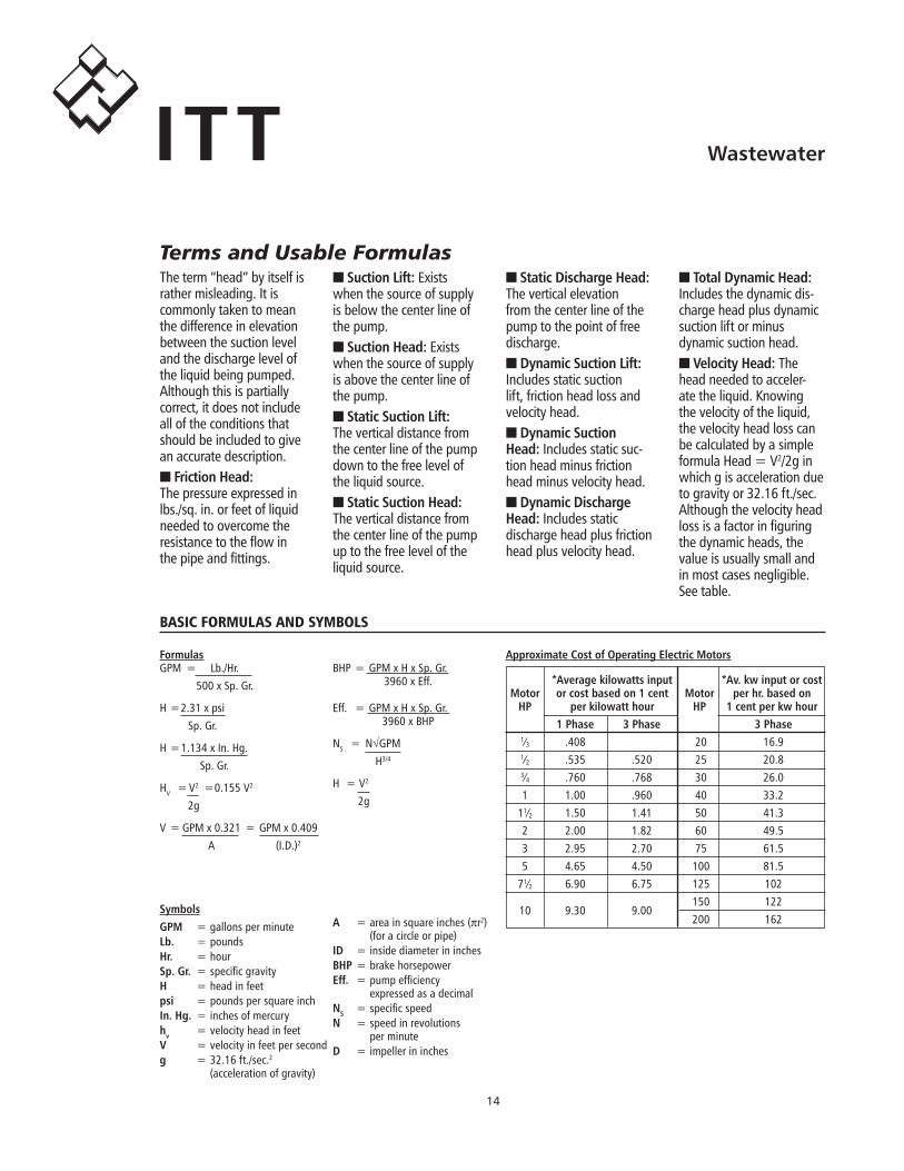
The.term.“head”.by.itself.is.rather.misleading..It.is..commonly.taken.to.mean.the.difference.in.elevation..between.the.suction.level.and.the.discharge.level.of.the.liquid.being.pumped..Although.this.is.partially.correct,.it.does.not.include.all.of.the.conditions.that.should.be.included.to.give.an.accurate.description.■.FrictionHead:.. .The.pressure.expressed.in.lbs./sq..in..or.feet.of.liquid.needed.to.overcome.the.resistance.to.the.flow.in.the.pipe.and.fittings.
■.SuctionLift:.Exists.when.the.source.of.supply.is.below.the.center.line.of.the.pump.■.SuctionHead:.Exists.when.the.source.of.supply.is.above.the.center.line.of.the.pump.■.StaticSuctionLift:..The.vertical.distance.from..the.center.line.of.the.pump.down.to.the.free.level.of.the.liquid.source.■.StaticSuctionHead:..The.vertical.distance.from.the.center.line.of.the.pump.up.to.the.free.level.of.the.liquid.source.
■.StaticDischargeHead:.The.vertical.elevation.from.the.center.line.of.the.pump.to.the.point.of.free.discharge.■.DynamicSuctionLift:..Includes.static.suction.lift,.friction.head.loss.and.velocity.head.■.DynamicSuctionHead:.Includes.static.suc-tion.head.minus.friction.head.minus.velocity.head.■.DynamicDischargeHead:.Includes.static.discharge.head.plus.friction.head.plus.velocity.head.
■.TotalDynamicHead:..Includes.the.dynamic.dis-charge.head.plus.dynamic.suction.lift.or.minus.dynamic.suction.head.■.VelocityHead:.The.head.needed.to.acceler-ate.the.liquid..Knowing.the.velocity.of.the.liquid,.the.velocity.head.loss.can.be.calculated.by.a.simple.formula.Head.=.V2/2g.in.which.g.is.acceleration.due.to.gravity.or.32.16.ft./sec..Although.the.velocity.head.loss.is.a.factor.in.figuring.the.dynamic.heads,.the.value.is.usually.small.and.in.most.cases.negligible...See.table.
FormulasGPM. =. Lb./Hr.. . 500.x.Sp..Gr.
H.=.2.31.x.psi. . Sp..Gr.
H.=.1.134.x.In..Hg.. . Sp..Gr.
HV. =.V2. =.0.155.V2
. . 2g
V.=.GPM.x.0.321. =.GPM.x.0.409. . A. . (I.D.)2
BHP.=.GPM.x.H.x.Sp..Gr.. . 3960.x.Eff.
Eff.. =.GPM.x.H.x.Sp..Gr.. . 3960.x.BHP
NS. =. N√GPM. . H3/4
H. =.V2
. . 2g
SymbolsGPM. =.gallons.per.minuteLb.. =.poundsHr.. =.hourSp.Gr.. =.specific.gravityH. =.head.in.feetpsi. =.pounds.per.square.inchIn.Hg.. =.inches.of.mercuryhv. =.velocity.head.in.feetV. =.velocity.in.feet.per.secondg. =.32.16.ft./sec.2.. .. . (acceleration.of.gravity)
A. =.area.in.square.inches.(πr2). .. . (for.a.circle.or.pipe)ID. =.inside.diameter.in.inchesBHP.=.brake.horsepowerEff.. =.pump.efficiency.. .. . expressed.as.a.decimalNS. =.specific.speedN. =.speed.in.revolutions.. .. . per.minuteD. =.impeller.in.inches
ApproximateCostofOperatingElectricMotors
*Averagekilowattsinput *Av.kwinputorcostMotor orcostbasedon1cent Motor perhr.basedon HP perkilowatthour HP. 1centperkwhour 1Phase 3Phase 3Phase. 1⁄3. .408. . 20. 16.9. 1⁄2. .535. .520. 25. 20.8. 3⁄4. .760. .768. 30. 26.0. 1. 1.00. .960. 40. 33.2. 11⁄2. 1.50. 1.41. 50. 41.3. 2. 2.00. 1.82. 60. 49.5. 3. 2.95. 2.70. 75. 61.5. 5. 4.65. 4.50. 100. 81.5. 71⁄2. 6.90. 6.75. 125. 102.
10. 9.30. 9.00. 150. 122
. . . . 200. 162
Terms and Usable Formulas
1�
WastewaterITT
basic Formulas and symbols
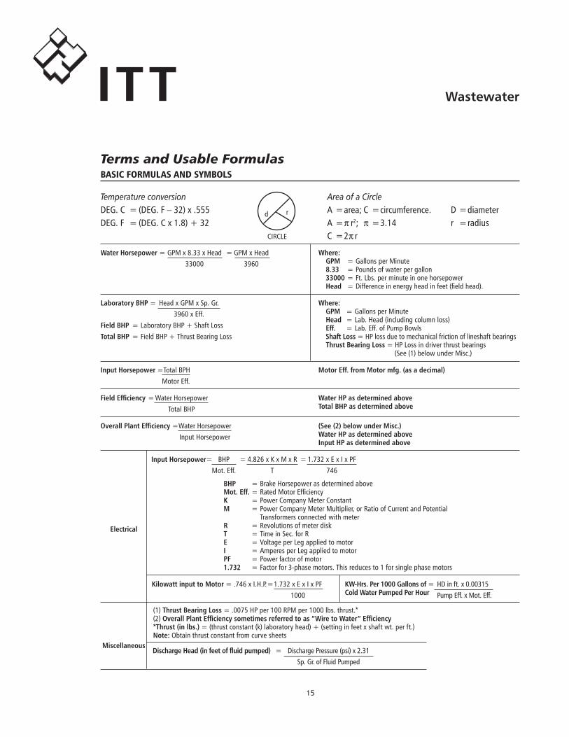
WaterHorsepower=.GPM.x.8.33.x.Head. =.GPM.x.Head. . 33000. . 3960
Temperature conversionDEG..C. =.(DEG..F.–.32).x..555DEG..F. =.(DEG..C.x.1.8).+.32
Area of a CircleA.=.area;.C. =.circumference.A.=.π r2;. π.=.3.14C. =.2π r
r
CIRCLE
d
Where:. GPM. =.Gallons.per.Minute. 8.33. =.Pounds.of.water.per.gallon. 33000.=.Ft..Lbs..per.minute.in.one.horsepower. Head. =.Difference.in.energy.head.in.feet.(field.head).
LaboratoryBHP=. Head.x.GPM.x.Sp..Gr.. . 3960.x.Eff.FieldBHP. =.Laboratory.BHP.+.Shaft.LossTotalBHP. =.Field.BHP.+.Thrust.Bearing.Loss
Where:. GPM. =.Gallons.per.Minute. Head. =.Lab..Head.(including.column.loss). Eff.. =.Lab..Eff..of.Pump.Bowls. ShaftLoss.=.HP.loss.due.to.mechanical.friction.of.lineshaft.bearings. ThrustBearingLoss.=.HP.Loss.in.driver.thrust.bearings. . . .(See.(1).below.under.Misc.)
InputHorsepower.=.Total.BPH. . Motor.Eff.
MotorEff.fromMotormfg.(asadecimal)
FieldEfficiency.=.Water.Horsepower. . Total.BHP
WaterHPasdeterminedaboveTotalBHPasdeterminedabove
OverallPlantEfficiency=.Water.Horsepower. . Input.Horsepower
(See(2)belowunderMisc.)WaterHPasdeterminedaboveInputHPasdeterminedabove
InputHorsepower=. BHP. =.4.826.x.K.x.M.x.R. =.1.732.x.E.x.I.x.PF. . Mot..Eff.. . T. . 746
BHP. =.Brake.Horsepower.as.determined.aboveMot.Eff..=.Rated.Motor.EfficiencyK. =.Power.Company.Meter.ConstantM. =.Power.Company.Meter.Multiplier,.or.Ratio.of.Current.and.Potential.. .. . Transformers.connected.with.meterR. =.Revolutions.of.meter.diskT. =.Time.in.Sec..for.RE. =.Voltage.per.Leg.applied.to.motorI. =.Amperes.per.Leg.applied.to.motorPF. =.Power.factor.of.motor1.732. =.Factor.for.3-phase.motors..This.reduces.to.1.for.single.phase.motors
Electrical
Miscellaneous
KilowattinputtoMotor=...746.x.I.H.P..=.1.732.x.E.x.I.x.PF. . . . 1000
KW-Hrs.Per1000Gallonsof=. HD.in.ft..x.0.00315ColdWaterPumpedPerHour. .Pump.Eff..x.Mot..Eff.
(1)ThrustBearingLoss.=..0075.HP.per.100.RPM.per.1000.lbs..thrust.*(2)OverallPlantEfficiencysometimesreferredtoas“WiretoWater”Efficiency*Thrust(inlbs.).=.(thrust.constant.(k).laboratory.head).+.(setting.in.feet.x.shaft.wt..per.ft.)Note:.Obtain.thrust.constant.from.curve.sheets
DischargeHead(infeetoffluidpumped) =. Discharge.Pressure.(psi).x.2.31. . Sp..Gr..of.Fluid.Pumped
D.=.diameterr. =.radius
Terms and Usable Formulas
1�
WastewaterITT
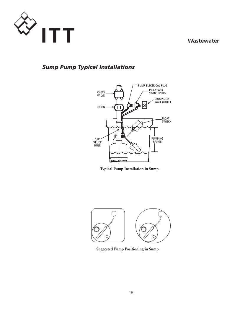
Typical Pump Installation in Sump
Suggested Pump Positioning in Sump
PUMP.ELECTRICAL.PLUG
CHECK.VALVE
PIGGYBACK.SWITCH.PLUG
GROUNDEDWALL.OUTLET
FLOAT.SWITCH
UNION
1/8''."RELIEF".
HOLE
PUMPING.RANGE
Sump Pump Typical Installations
1�
WastewaterITT
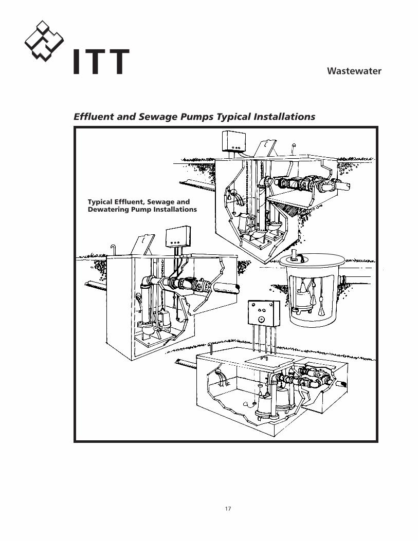
Typical Goulds Effluent, Sewageand Dewatering Pump InstallationsTypical Effluent, Sewage and Dewatering Pump Installations
Effluent and Sewage Pumps Typical Installations
1�
WastewaterITT
It.is.acceptable.and.increasingly.more.common.to.operate.three-phase.wastewater.pumps.using.VFD’s.or.variable.frequency.(speed).drives..We.have.successfully.tested.and.operated.all.our.premium.cast.iron.construc-tion,.three-phase.pumps.between.30.and.60.hertz.operation..The.pumps.should.never.be.operated.below.30.hertz.(the.VFD.must.be.programmed.for.a.minimum.speed.of.30.hertz.to.prevent.continuous.operation).or.above.60.hertz.due.to.increased.motor.HP.loading,.higher.amperage.and.the.resultant.heat.rise.(see.HP.in.70.hertz.Performance.Multipliers).
The.“Affinity.Laws”.state.that.for.a.given.pump,.the.capacity.will.vary.directly.with.a.change.in.speed,.the.head.will.vary.as.the.square.of.the.speed.change.and.the.required.power.will.vary.as.the.cube.of.the.speed.change..(The.Affinity.Law.formulas.can.be.found.in.the.Water.Products.Technical.Manual,.TTECHWP)..The.Performance.Multiplier.Chart.provides.shortcut.multi-pliers.that.eliminate.having.to.solve.the.Affinity.Law.equations.
To.calculate.a.pump’s.total.performance.range.when.using.a.VFD,.use.the.30.hertz.data.to.create.a.minimum.speed.curve,.the.VFD.controlled.pump.should.always.be.operated.between.30.hertz.and.the.published.60.hertz.curve..Where.it.operates.at.any.given.moment.is.irrelevant..Q1,.H1.and.BHP1.are.determined.at.the.pump’s.rated.speed.N1.(rpm)..Q2,.H2.and.BHP2.are.determined.at.speed.N2.(rpm).
Use.the.multipliers.with.a.minimum.of.3.data.points.taken.from.any.standard,.60.Hz.curve.to.determine.the.performance.of.that.pump.at.a.new.speed.
WasteWater pumps and variable speed drives
Hertz PerformanceMultipliers70.–.Q2.=.Q1.x.1.17. H2.=.H1.x.1.37. BHP2..=.BHP1.x.1.660.–.Use.the.standard.published.curve.data50.–.Q2.=.Q1.x..83. H2.=.H1.x..69. BHP2.=.BHP1.x..57..........40.–.Q2.=.Q1.x..67. H2.=.H1.x..45. BHP2.=.BHP1.x..330.–.Q2.=.Q1.x..5. H2.=.H1.x..25. BHP2.=.BHP1.x..125
An.example.would.be,.solve.for.Q2,.H2.and.BHP2.for.a.60.Hz.pump.that.produces.100.gpm.(Q1)[email protected]’.tdh.(H1).using.5.hp.(BHP1).when.it.is.operated.at.30.Hz.:..Answers:.100.gpm.x..5.=.50.gpm,.100’.TDH.x..25.=.25’.TDH.and.5.hp.x..125.=..63.hp.
VFD’s.save.energy.while.reducing.the.thrust.on.the.motor.bearings.and.the.starting.torque.on.the.shaft.and.impeller..
Contact.Customer.Service.for.details,.pricing.and.availability.of.our.full.line.of.VFD.products.
Variable Speed Drives
1�
WastewaterITT
L1
L2
N
GND
25.A
25.A
S1
S2
1T
1
2
2T
1
2
PUMP.NO..2
PUMP.NO..1
WHITE
CONTROLON-OFF
BLACK
BLACK
YELLOW
ORANGE
HAND
OFF
AUTO
BLUES2
RUN
HAND
OFF
AUTO
PURPLES1
RUN
RED
TEST
RED
YELYELLOW
BRWBROWN
TEST
MUTE
RESET
SILENCE
RESET
HORN
FLASH
PINK
WHITE
REDFLASHING
SONALERT
OFF LEAD LAG ALARM
R1
R2
C
L1 N
BLACK
H L1 N 1 2 3 4 5 6 7 8 9 10 11
J1➀
OFF.FLOAT➁
LEAD.FLOAT
LAG.FLOAT(OPTIONAL)③
ALARM.FLOAT
J2
DRY.CONTACTS
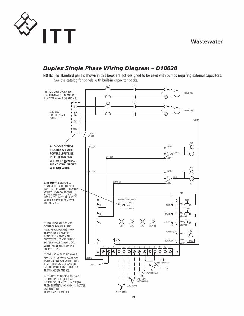
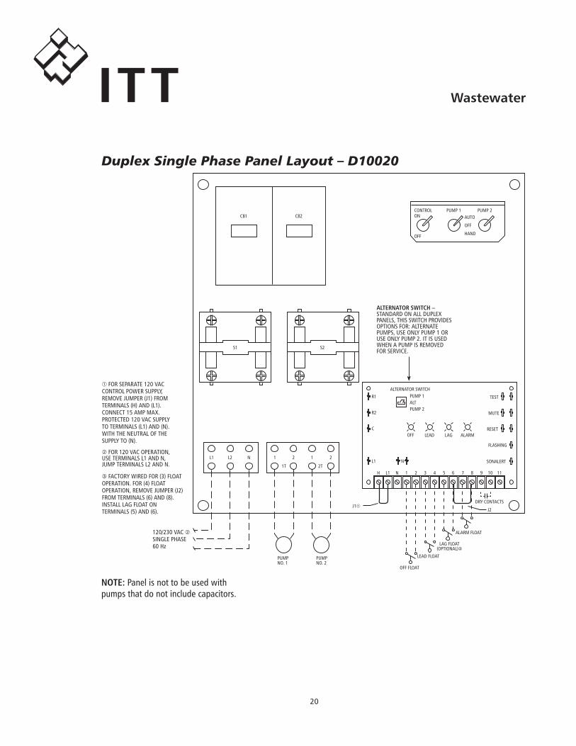
③.FACTORY.WIRED.FOR.(3).FLOATOPERATION..FOR.(4).FLOATOPERATION,.REMOVE.JUMPER.(J2)FROM.TERMNALS.(6).AND.(8)..INSTALLLAG.FLOAT.ONTERMINALS.(5).AND.(6).
➀.FOR.SEPARATE.120.VACCONTROL.POWER.SUPPLY,REMOVE.JUMPER.(J1).FROMTERMINALS.(H).AND.(L1).CONNECT.15.AMP.MAX.PROTECTED.120.VAC.SUPPLYTO.TERMINALS.(L1).AND.(N).WITH.THE.NEUTRAL.OF.THESUPPLY.TO.(N).
➁.FOR.USE.WITH.WIDE.ANGLEFLOAT.SWITCH.(ONE.FLOAT.FORBOTH.ON.AND.OFF.OPERATION).JUMP.TERMINALS.(3).AND.(4),INSTALL.WIDE.ANGLE.FLOAT.TOTERMINALS.(1).AND.(2).
FOR.120.VOLT.OPERATIONUSE.TERMINALS.(L1).AND.(N)JUMP.TERMINALS.(N).AND.(L2)
230.VACSINGLE.PHASE60.Hz
A230VOLTSYSTEMREQUIRESA4WIREPOWERSUPPLYLINEL1,L2,NANDGND.WITHOUTANEUTRALTHECONTROLCIRCUITWILLNOTWORK.
ALTERNATOR.SWITCHPUMP.1ALTPUMP.2
ALTERNATORSWITCH–STANDARD.ON.ALL.DUPLEXPANELS,.THIS.SWITCH.PROVIDESOPTIONS.FOR:.ALTERNATEPUMPS,.USE.ONLY.PUMP.1.ORUSE.ONLY.PUMP.2..IT.IS.USEDWHEN.A.PUMP.IS.REMOVED.FOR.SERVICE.
NOTE:.The.standard.panels.shown.in.this.book.are.not.designed.to.be.used.with.pumps.requiring.external.capacitors...See.the.catalog.for.panels.with.built-in.capacitor.packs.
Duplex Single Phase Wiring Diagram – D10020
�0
WastewaterITT
OFF
CONTROL PUMP.1 PUMP.2ON AUTO
OFF
HAND
CB1 CB2
S1 S2
1 2 1 2
1T 2T
L1 L2 N
120/230.VAC.➁SINGLE.PHASE60.Hz
➁.FOR.120.VAC.OPERATION,USE.TERMINALS.L1.AND.N,JUMP.TERMINALS.L2.AND.N.
PUMPNO..1
PUMPNO..2
J1➀
➀.FOR.SEPARATE.120.VACCONTROL.POWER.SUPPLY,REMOVE.JUMPER.(J1).FROMTERMINALS.(H).AND.(L1).CONNECT.15.AMP.MAX.PROTECTED.120.VAC.SUPPLYTO.TERMINALS.(L1).AND.(N).WITH.THE.NEUTRAL.OF.THESUPPLY.TO.(N).
R1
R2
C
L1
OFF LEAD LAG ALARM
TEST
MUTE
RESET
FLASHING
SONALERTN
H L1 N 1 2 3 4 5 6 7 8 9 10 11
J2
DRY.CONTACTS
OFF.FLOAT
LEAD.FLOAT
LAG.FLOAT(OPTIONAL)③
ALARM.FLOAT
③.FACTORY.WIRED.FOR.(3).FLOATOPERATION..FOR.(4).FLOATOPERATION,.REMOVE.JUMPER.(J2)FROM.TERMINALS.(6).AND.(8).INSTALL.LAG.FLOAT.ONTERMINALS.(5).AND.(6).
ALTERNATOR.SWITCHPUMP.1ALTPUMP.2
ALTERNATORSWITCH–STANDARD.ON.ALL.DUPLEXPANELS,.THIS.SWITCH.PROVIDESOPTIONS.FOR:.ALTERNATEPUMPS,.USE.ONLY.PUMP.1.ORUSE.ONLY.PUMP.2..IT.IS.USEDWHEN.A.PUMP.IS.REMOVED.FOR.SERVICE.
NOTE:.Panel.is.not.to.be.used.with.pumps.that.do.not.include.capacitors.
Duplex Single Phase Panel Layout – D10020
�1
WastewaterITT
L1
L3
S1
1
21
2 PUMPNO..2
WHITE
CONTROLON-OFF
BLACK
BLACK
YELLOW
ORANGE
HAND
OFF
AUTO
BLUES2
RUN
HAND
OFF
AUTO
PURPLES1
RUN
RED
TEST
RED
YELYELLOW
BRWBROWN
TEST
MUTE
RESET
SILENCE
RESET
HORN
FLASH
PINK
WHITE
REDFLASHING
SONALERT
OFF LEAD LAG ALARM
R1
R2
C
L1 N
BLACK
H L1 N 1 2 3 4 5 6 7 8 9 10 11
J1➀
OFF.FLOAT➁
LEAD.FLOAT
LAG.FLOAT(OPTIONAL)③
ALARM.FLOAT
J2
DRY.CONTACTS
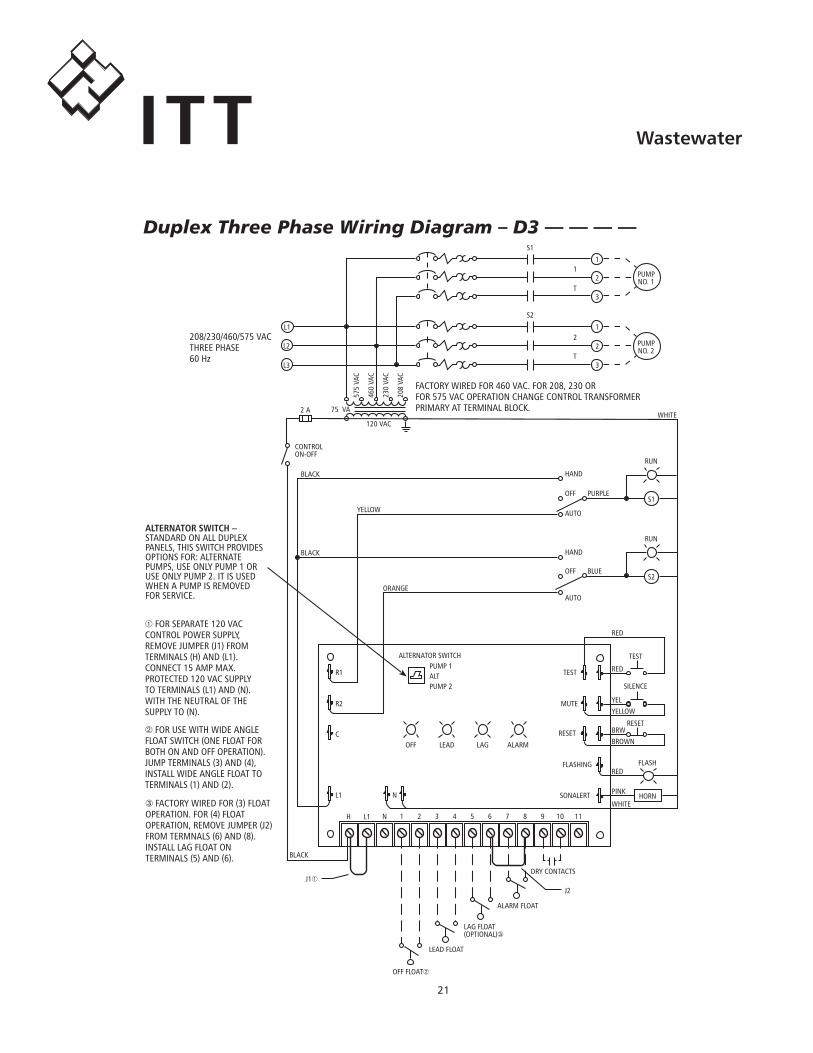
③.FACTORY.WIRED.FOR.(3).FLOATOPERATION..FOR.(4).FLOATOPERATION,.REMOVE.JUMPER.(J2)FROM.TERMNALS.(6).AND.(8).INSTALL.LAG.FLOAT.ONTERMINALS.(5).AND.(6).
➀.FOR.SEPARATE.120.VACCONTROL.POWER.SUPPLY,REMOVE.JUMPER.(J1).FROMTERMINALS.(H).AND.(L1).CONNECT.15.AMP.MAX.PROTECTED.120.VAC.SUPPLYTO.TERMINALS.(L1).AND.(N).WITH.THE.NEUTRAL.OF.THESUPPLY.TO.(N).
➁.FOR.USE.WITH.WIDE.ANGLEFLOAT.SWITCH.(ONE.FLOAT.FORBOTH.ON.AND.OFF.OPERATION).JUMP.TERMINALS.(3).AND.(4),INSTALL.WIDE.ANGLE.FLOAT.TOTERMINALS.(1).AND.(2).
208/230/460/575.VACTHREE.PHASE60.Hz
2.A
3T
S2
L2
1
2 PUMPNO..1
3T
FACTORY.WIRED.FOR.460.VAC..FOR.208,.230.ORFOR.575.VAC.OPERATION.CHANGE.CONTROL.TRANSFORMERPRIMARY.AT.TERMINAL.BLOCK.75..VA
120.VAC
575.
VAC
460.
VAC
230.
VAC
208.
VAC
ALTERNATOR.SWITCHPUMP.1ALTPUMP.2
ALTERNATORSWITCH–STANDARD.ON.ALL.DUPLEXPANELS,.THIS.SWITCH.PROVIDESOPTIONS.FOR:.ALTERNATEPUMPS,.USE.ONLY.PUMP.1.ORUSE.ONLY.PUMP.2..IT.IS.USEDWHEN.A.PUMP.IS.REMOVED.FOR.SERVICE.
Duplex Three Phase Wiring Diagram – D3 — — — —
��
WastewaterITT
CB1 CB2
L1 L2
208/230/460/575.VACTHREE.PHASE60.Hz
PUMPNO..1
PUMPNO..2
J1➀
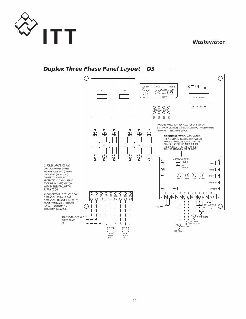
➀.FOR.SEPARATE.120.VACCONTROL.POWER.SUPPLY,REMOVE.JUMPER.(J1).FROMTERMINALS.(H).AND.(L1).CONNECT.15.AMP.MAX.PROTECTED.120.VAC.SUPPLYTO.TERMINALS.(L1).AND.(N).WITH.THE.NEUTRAL.OF.THESUPPLY.TO.(N).
H L1 N 1 2 3 4 5 6 7 8 9 10 11
J2
DRY.CONTACTS
OFF.FLOAT
LEAD.FLOAT
LAG.FLOAT(OPTIONAL)③
ALARM.FLOAT
③.FACTORY.WIRED.FOR.(3).FLOATOPERATION..FOR.(4).FLOATOPERATION,.REMOVE.JUMPER.(J2)FROM.TERMINALS.(6).AND.(8).INSTALL.LAG.FLOAT.ONTERMINALS.(5).AND.(6).
R1
R2
C
L1
ALARMLAGOFF LEAD
TEST
MUTE
RESET
FLASHING
SONALERTN
L3 1T1 1T2 1T3 2T1 2T2 2T3
S1 S1
OFF
CONTROL PUMP.1 PUMP.2ON AUTO
OFF
HAND
TERMINAL.BLOCK
208
230
460
575
TRANSFORMER
2..A
FACTORY.WIRED.FOR.460.VAC..FOR.208,230.OR575.VAC.OPERATION,.CHANGE.CONTROL.TRANSFORMERPRIMARY.AT.TERMINAL.BLOCK.
ALTERNATOR.SWITCHPUMP.1ALTPUMP.2
ALTERNATORSWITCH–.STANDARD.ON.ALL.DUPLEX.PANELS,.THIS.SWITCHPROVIDES.OPTIONS.FOR:.ALTERNATEPUMPS,.USE.ONLY.PUMP.1.OR.USE.ONLY.PUMP.2..IT.IS.USED.WHEN.A.PUMP.IS.REMOVED.FOR.SERVICE.
Duplex Three Phase Panel Layout – D3 — — — —
��
WastewaterITT
L1
L2
N
GND
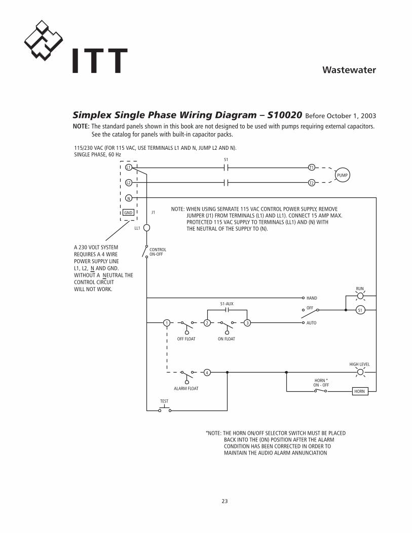
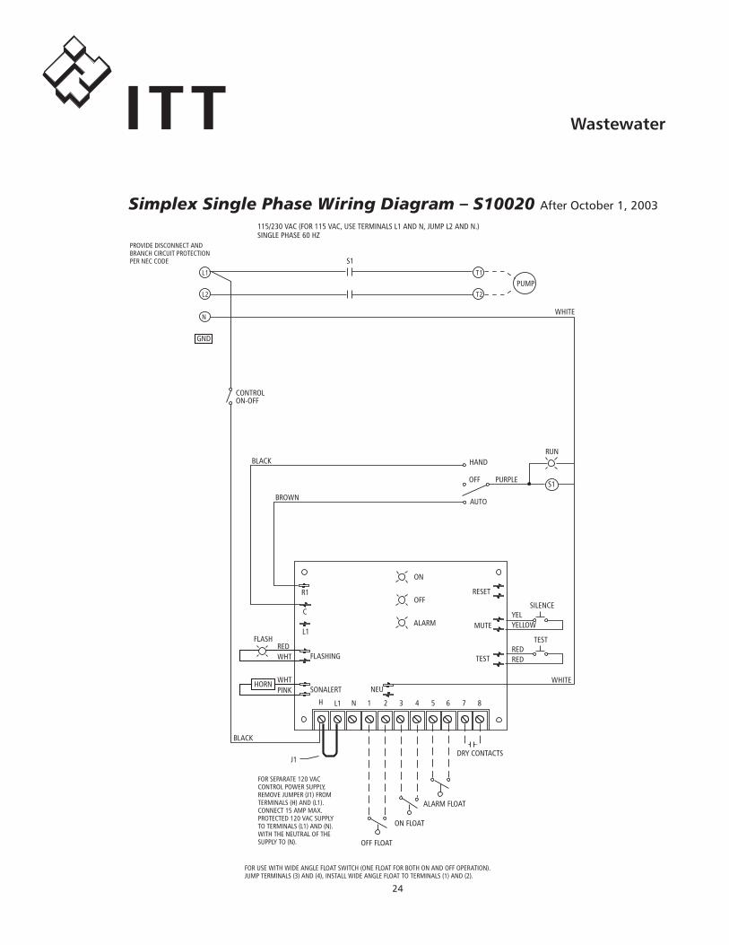
115/230.VAC.(FOR.115.VAC,.USE.TERMINALS.L1.AND.N,.JUMP.L2.AND.N).SINGLE.PHASE,.60.Hz
S1
J1NOTE:.WHEN.USING.SEPARATE.115.VAC.CONTROL.POWER.SUPPLY,.REMOVE...........JUMPER.(J1).FROM.TERMINALS.(L1).AND.LL1)..CONNECT.15.AMP.MAX............PROTECTED.115.VAC.SUPPLY.TO.TERMINALS.(LL1).AND.(N).WITH...........THE.NEUTRAL.OF.THE.SUPPLY.TO.(N).LL1
CONTROLON-OFF
1 2 3
OFF.FLOAT ON.FLOAT
ALARM.FLOAT
4
TEST
S1-AUX
RUN
AUTO
OFF
HAND
S1
HIGH.LEVEL
HORN.*ON.-.OFF
HORN
A.230.VOLT.SYSTEMREQUIRES.A.4.WIREPOWER.SUPPLY.LINEL1,.L2,. N.AND.GND.WITHOUT.A. NEUTRAL.THECONTROL.CIRCUITWILL.NOT.WORK.
T1
T2
PUMP
*NOTE:.THE.HORN.ON/OFF.SELECTOR.SWITCH.MUST.BE.PLACEDBACK.INTO.THE.(ON).POSITION.AFTER.THE.ALARMCONDITION.HAS.BEEN.CORRECTED.IN.ORDER.TOMAINTAIN.THE.AUDIO.ALARM.ANNUNCIATION
NOTE:.The.standard.panels.shown.in.this.book.are.not.designed.to.be.used.with.pumps.requiring.external.capacitors...See.the.catalog.for.panels.with.built-in.capacitor.packs.
Simplex Single Phase Wiring Diagram – S10020 Before October 1, �00�
��
WastewaterITT
GND
S1T1
PUMP
WHITE
CONTROLON-OFF
BLACK
BROWN
HAND
OFF
AUTO
PURPLE S1
RUN
REDTEST
YELYELLOW
TEST
MUTE
RESET
WHITE
OFF
ALARM
R1
C
L1
BLACK
H L1 N 1 2 3 4 5 6 7 8
J1
OFF.FLOAT
ON.FLOAT
ALARM.FLOAT
DRY.CONTACTS
FOR.SEPARATE.120.VACCONTROL.POWER.SUPPLY,REMOVE.JUMPER.(J1).FROMTERMINALS.(H).AND.(L1).CONNECT.15.AMP.MAX.PROTECTED.120.VAC.SUPPLYTO.TERMINALS.(L1).AND.(N).WITH.THE.NEUTRAL.OF.THESUPPLY.TO.(N).
FOR.USE.WITH.WIDE.ANGLE.FLOAT.SWITCH.(ONE.FLOAT.FOR.BOTH.ON.AND.OFF.OPERATION).JUMP.TERMINALS.(3).AND.(4),.INSTALL.WIDE.ANGLE.FLOAT.TO.TERMINALS.(1).AND.(2).
PROVIDE.DISCONNECT.ANDBRANCH.CIRCUIT.PROTECTIONPER.NEC.CODE
115/230.VAC.(FOR.115.VAC,.USE.TERMINALS.L1.AND.N,.JUMP.L2.AND.N.)SINGLE.PHASE.60.HZ
T2
L1
L2
N
ON
NEU
WHT
WHTPINK
FLASH
HORN
FLASHING
SONALERT
SILENCE
REDRED
Simplex Single Phase Wiring Diagram – S10020 After October 1, �00�
��
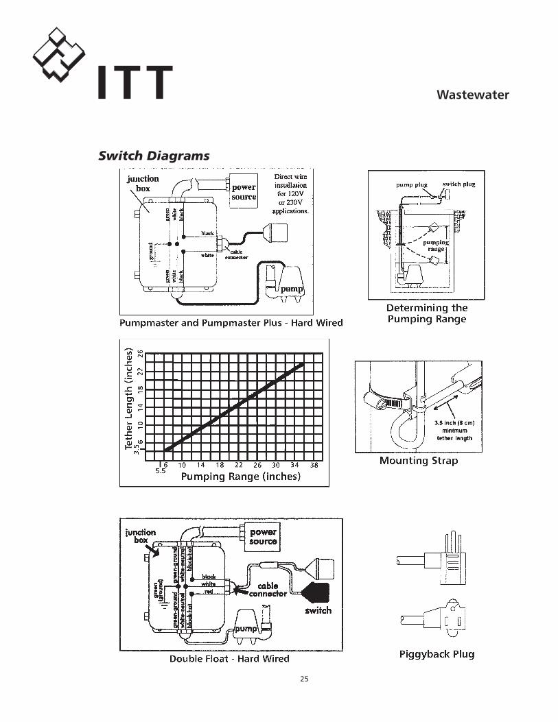
WastewaterITTSwitch Diagrams
��
WastewaterITT
There.are.two.basic.switches.used.in.sewage.and.effluent.systems..Single-action.or.narrow-angle.float.switches.perform.one.function.(on.or.off)..They.operate.over.a.range.of.15º..Wide-angle,.or.double-action.float.and.diaphragm.switches.perform.two.functions.(on.and.off)..Wide-angle.float.switches.operate.over.a.90º.range.and.diaphragm.switches.on.a.6”.rise.in.water.level..
Control.panel.wiring.diagrams.refer.to.3.float.and.4.float.systems,.this.terminology.refers.to.the.use.of.single-action.switches..The.following.chart.shows.how.many.of.either.type.switch.to.use.with.different.control.panels.
DuplexControlPanelsTypical.Duplex.panels.use.the.following.switch.set-ups.depending.on.the.switch.type.you.use..Most.Duplex.control.panels.have.a.standard.high.level.alarm.circuit.with.a.flashing.light,.most.have.a.horn.or.bell..Once.it.turns.On.-.the.alarm.must.be.manually.reset.(turned.off).on.Duplex.panels.
Using.a.Single-action.or.Narrow-angle.Switch.requires:ThreeFloatPanelWiring FourFloatPanelWiring#1.Bottom. Pumps.Off. #1.Bottom. Pumps.Off.#2.Middle. 1st.Pump.On. #2.2nd. 1st.Pump.On#3.Top. 2nd.Pump.&.Alarm.On. #3.3rd. 2nd.Pump.On. . #4.Top. Alarm.On
Using.Double-Action.or.Wide-Angle.Switches;.A2D23W,.A2E21,.A2E22,.A2E23,..A2D11,.A2D31.or.A2S23.requires:ThreeFloatPanelWiring FourFloatPanelWiring#1.Bottom. 1st.Pump.On/Both.Off. #1.Bottom. 1st.Pump.On/Both.Off#2.Top. 2nd.Pump.and.Alarm.On. #2.Middle. 2nd.Pump.On. . #3.Top. Alarm.On
SimplexControlPanelsOnly.some.Simplex.panels.have.alarms..This.is.why.the.switch.quantity.requirements.vary.by.simplex.panel.model...All.of.our.SES.panels.have.high.level.alarms...
Using.a.Single-action.or.Narrow-angle.Switch.requires:SimplexPanelwithAlarm SimplexPanelwithNoAlarm#1.Bottom. Pump.Off.. ............ .. #1.Bottom... Pump.Off#2.Middle......... Pump.On.......................... . #2.Top. . Pump.On#3.Top. ............. Alarm.On/Off
Using.Double-Action.or.Wide-angle.Switches.requires:SimplexPanelwithAlarm SimplexPanelwithNoAlarm#1.Bottom. Pump.On/Off. . .. #1..Bottom. Pump.On/Off#2.Top. . Alarm.On/Off NOTE:.1st.pump.may.also.be.referred.to.as.“Lead”.pump,...2nd.pump.may.be.called.“Lag”.pump.
Sewage Control Panels and Switches

��
WastewaterITTWe sell and stock a complete line of wastewater float switches. The most up-to-date information is found in the wastewater catalog Electrical Section. The switch bulletin is coded as BCPFS, i.e. Bulletin CentriPro Float Switches.
It may be found on our websites:www.goulds.comwww.redjacketwaterproducts.comwww.centripro.comwww.bellgossett.com
Goulds Pumpswww.goulds.com
Red Jacket Water Productswww.redjacketwaterproducts.com
Bell & Gossettwww.bellgossett.com
CentriProwww.centripro.com
Goulds Pumps, Red Jacket Water Products, Bell & Gossett, CentriPro and the ITT Engineered Blocks Symbol are registered trademarks and tradenames of ITT Corporation.
SPECIFICATIONS ARE SUBJECT TO CHANGE WITHOUT NOTICE.
TTECHS R0 October, 2006© 2006 ITT Corporation
Engineered for life
WastewaterITT