Embed Size (px)
Citation preview
Water Cooled ChillerInstallation Manual

2
Introduction
•ThisMULTISTACKInc.INSTALLATIONMANUALhasbeenpreparedtoserveasaguidetoassistintheproperinstallationoftheMULTISTACKModularChiller.ThisisaninstallationguideONLY.SeparatedocumentsandinstructionsareavailableforOperationandMaintenance.
•Reviewthismanualcarefullybeforebeginningtheinstallation.
•Theinformationandillustrationscontainedinthismanualaregeneralized.YourinstallationmaybecustomizedtoanextentthatconsultationwithaMULTISTACKrepresentativemaybenecessaryinordertoprovidespecificdetailsnotcoveredinthismanual.
•GoodelectricalandpipingpracticesmustbefollowedandtheMULTISTACKInc.INSTALLATIONMANUALmustbestrictlyadheredtoasitpertainstothisinstallationandallapplicablelocalcodes.
•Manufactureanduseofthisequipmentmeetsallexistinglegislatedruleswhichpertain.
•ThisequipmentshouldnotbeinstallednearanopenflameperlocalcodesandASHRAEspecifications.
•PersonnelservicingMULTISTACKequipmentmusthaveaminimumClassIIEPAcertification.
•AnyquestionsregardingthecontentofthisInstallationManual,thehandlingorinstallationoftheMULTISTACKChillercomponentsshouldbedirectedimmediatelytoyourauthorizedMULTISTACKrepresentativeortotheMULTISTACKServiceDepartmentat(608)366-2400orFAX(608)366-2450.
3
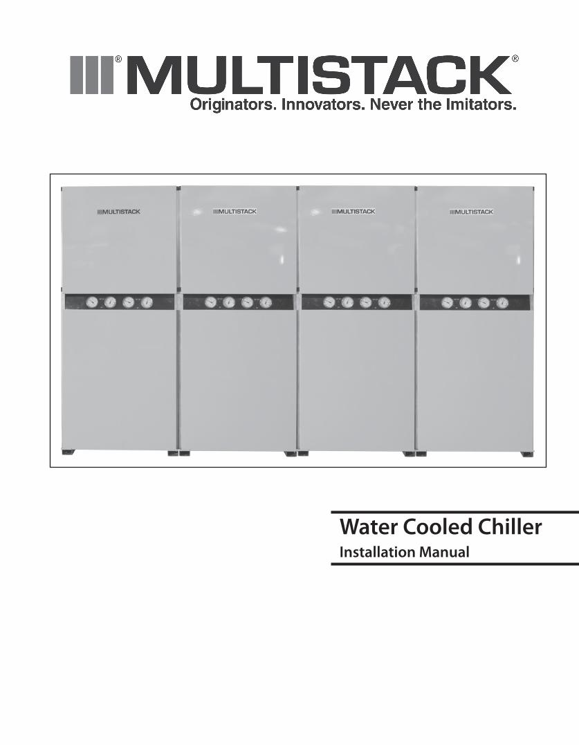
ModuleShipmentPackage
MULTISTACK Module (shown with optional removable wheels and standard filter strainers installed)
Pallet #1 (Cabinetry)
1. Top Front Panel 2. Bottom Front Panel 3. Rear Panel/End Panel4. Side End Panel5. Master Controller Top Panel6. Frame Pieces 7. Frame Connectors, Fasteners, Clips & Magnetic Tape
Pallet#2(BussConnections)8. Bussbar9. Bussbarinsulation10.Groundstrap11.JunctionBoxleg
12
3
45
6
7
8
910
11
4
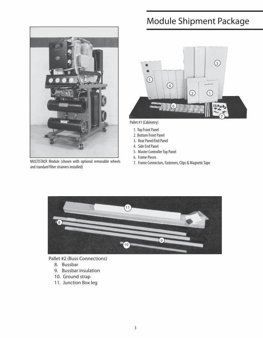
ModuleShipmentPackage,Cont’d
Pallet#3(Piping&Electrical)18. Master Control (*a)19. Junction Box20. Junction Box Cover21. Sensors / Cables22. Junction Box Connector (Throat)23. Power Phase Monitor24. Bussbar Connector25. Power Phase Monitor Wire26. Bussbar Insulation Overlap27. Phase Monitor Wire28. Bussbar End Caps29. Drain Valves & Fittings30. Module Joining Bolts
31. End Cap for DDRS-210A (upper)32. End Caps (evap)33. Couplings34. DDRS-210A35. Auto Solenoid for DDRS36. Pipe Stubs37. End Cap DDRS (lower)38. Filter Stops39. Pet Cock Valves40. Drain Valves & Fittings41. Sensor Wells42. 30 Mesh Filter Strainer
*a. Maybe shipped separately to sales office or job site. *b. Shipped inside #19 - Junction Box
NOTE: Before accepting delivery of the MULTISTACK Chiller, check the overall condition of the equipment for any visible damage. Items to be looked for may include broken copper lines, oil leaks, damaged controls and/or electrical component housing, or any major component torn loose from its mounting.
If the MULTISTACK Modular Chiller is damaged during transportation or handling by the transportation company or its agent, the installing contractor MUST promptly file a claim with the transportation company and advise MULTISTACK Inc. Any discrepancy must be noted on the bill of lading.
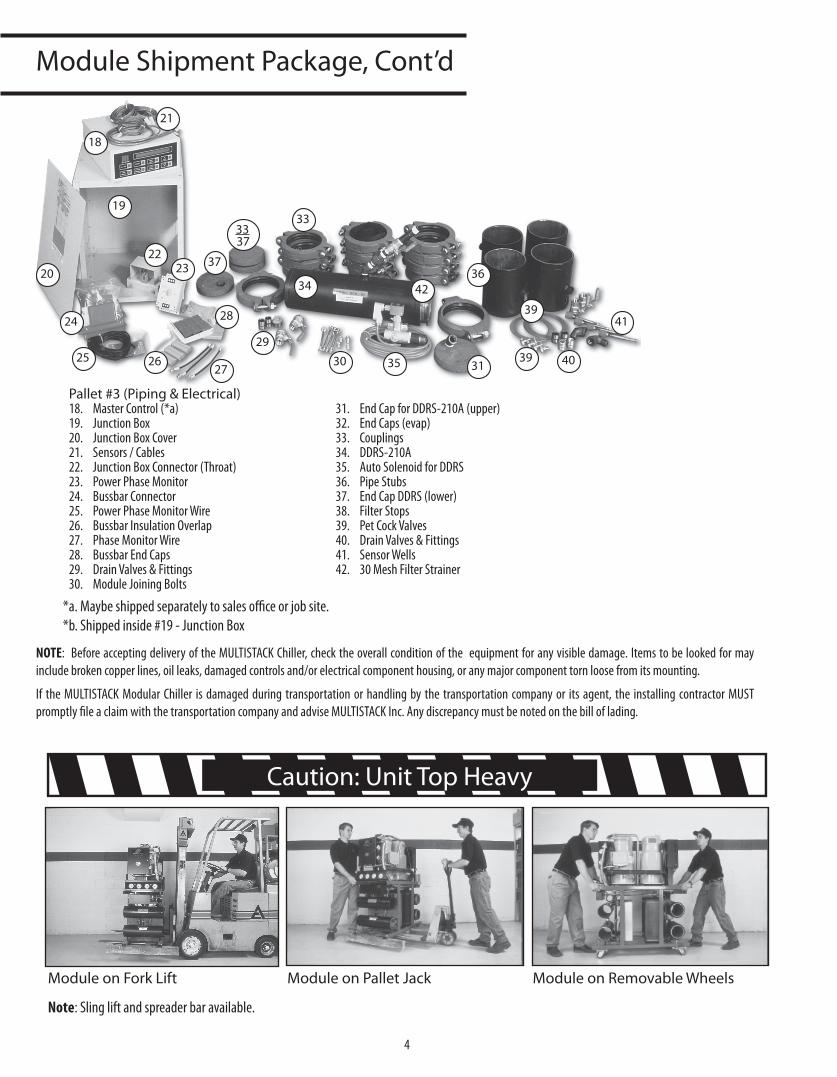
ModuleonForkLift ModuleonPalletJack ModuleonRemovableWheels
Note: Sling lift and spreader bar available.
Caution:UnitTopHeavy
18
19
20
21
2223
24
25 2627
28
2930 31
3337
33
34
35
3637
39
39 40
41
42
5
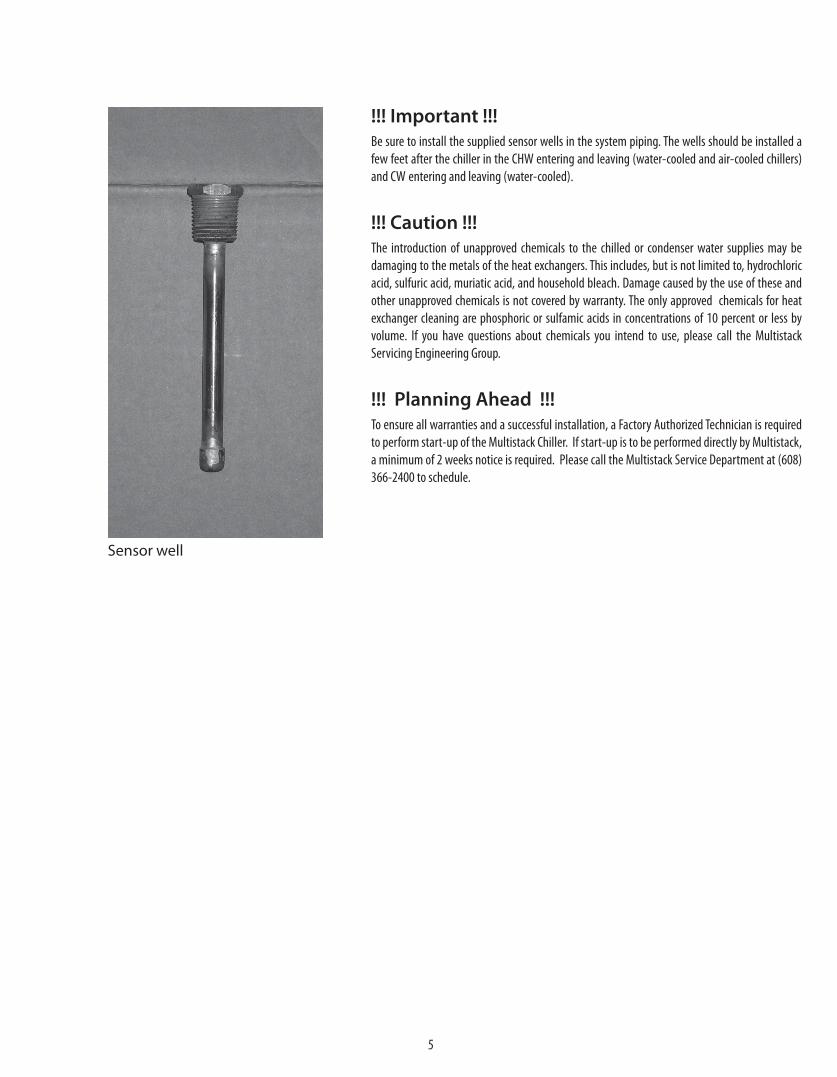
Sensorwell
!!! Important !!!Be sure to install the supplied sensor wells in the system piping. The wells should be installed a few feet after the chiller in the CHW entering and leaving (water-cooled and air-cooled chillers) and CW entering and leaving (water-cooled).
!!! Caution !!!The introduction of unapproved chemicals to the chilled or condenser water supplies may be damaging to the metals of the heat exchangers. This includes, but is not limited to, hydrochloric acid, sulfuric acid, muriatic acid, and household bleach. Damage caused by the use of these and other unapproved chemicals is not covered by warranty. The only approved chemicals for heat exchanger cleaning are phosphoric or sulfamic acids in concentrations of 10 percent or less by volume. If you have questions about chemicals you intend to use, please call the Multistack Servicing Engineering Group.
!!! Planning Ahead !!!To ensure all warranties and a successful installation, a Factory Authorized Technician is required to perform start-up of the Multistack Chiller. If start-up is to be performed directly by Multistack, a minimum of 2 weeks notice is required. Please call the Multistack Service Department at (608) 366-2400 to schedule.
6
SitePreparation
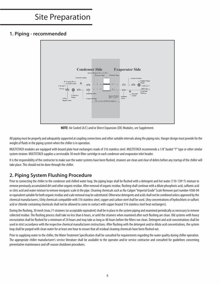
NOTE: Air Cooled (A/C) and/or Direct Expansion (DX) Modules, see Supplement.
All piping must be properly and adequately supported at coupling connections and other suitable intervals along the piping runs. Hanger design must provide for the weight of fluids in the piping system when the chiller is in operation.
MULTISTACK modules are equipped with brazed plate heat exchangers made of 316 stainless steel. MULTISTACK recommends a 1/8” basket “Y” type or other similar system strainer. MULTISTACK supplies a serviceable 30 mesh filter cartridge in each condenser and evaporator inlet header.
It is the responsibility of the contractor to make sure the water systems have been flushed, strainers are clean and clear of debris before any startup of the chiller will take place. This should not be done through the chiller.
2. Piping System Flushing ProcedurePrior to connecting the chiller to the condenser and chilled water loop, the piping loops shall be flushed with a detergent and hot water (110-130º F) mixture to remove previously accumulated dirt and other organic residue. After removal of organic residue, flushing shall continue with a dilute phosphoric acid, sulfamic acid or citric acid and water mixture to remove inorganic scale in the pipe. Cleaning chemicals such as Nu-Calgon “Imperial Grade” Scale Remover part number 4360-84 or equivalent suitable for both organic residue and scale removal may be substituted. Otherwise detergents and acids shall not be combined unless approved by the chemical manufacturers.) Only chemicals compatible with 316 stainless steel, copper and carbon steel shall be used. (Any concentrations of hydrochloric or sulfuric acid or chloride containing chemicals shall not be allowed to come in contact with copper brazed 316 stainless steel heat exchangers).
During the flushing, 30 mesh (max.) Y-strainers (or acceptable equivalent) shall be in place in the system piping and examined periodically as necessary to remove collected residue. The flushing process shall take no less than 6 hours, or until the strainers when examined after each flushing are clean. Old systems with heavy encrustation shall be flushed for a minimum of 24 hours and may take as long as 48 hours before the filters run clean. Detergent and acid concentrations shall be used in strict accordance with the respective chemical manufacturers instructions. After flushing with the detergent and/or dilute acid concentrations, the system loop shall be purged with clean water for at least one hour to ensure that all residual cleaning chemicals have been flushed out.
Prior to supplying water to the chiller, the Water Treatment Specification shall be consulted for requirements regarding the water quality during chiller operation. The appropriate chiller manufacturer’s service literature shall be available to the operator and/or service contractor and consulted for guidelines concerning preventative maintenance and off-season shutdown procedures.
1. Piping - recommended
7
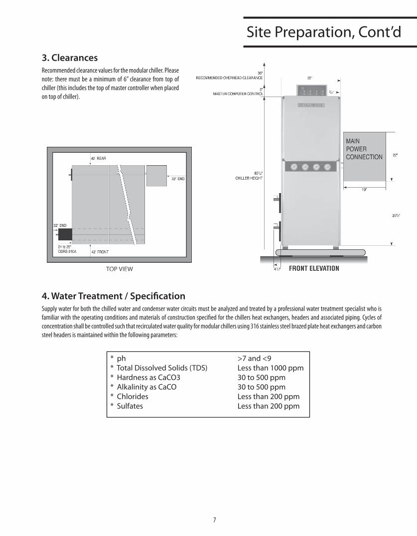
SitePreparation,Cont’d3. ClearancesRecommended clearance values for the modular chiller. Please note: there must be a minimum of 6” clearance from top of chiller (this includes the top of master controller when placed on top of chiller).
4. Water Treatment / SpecificationSupply water for both the chilled water and condenser water circuits must be analyzed and treated by a professional water treatment specialist who is familiar with the operating conditions and materials of construction specified for the chillers heat exchangers, headers and associated piping. Cycles of concentration shall be controlled such that recirculated water quality for modular chillers using 316 stainless steel brazed plate heat exchangers and carbon steel headers is maintained within the following parameters:
*ph >7and<9*TotalDissolvedSolids(TDS) Lessthan1000ppm*HardnessasCaCO3 30to500ppm*AlkalinityasCaCO 30to500ppm*Chlorides Lessthan200ppm*Sulfates Lessthan200ppm
8
SitePreparation,Cont’d
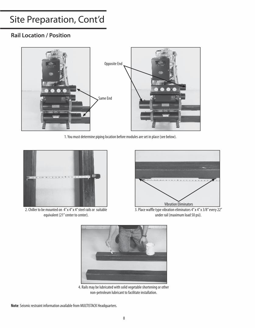
Rail Location / Position
2. Chiller to be mounted on 4” x 4” x 4” steel rails or suitable equivalent (21” center to center).
3. Place waffle type vibration eliminators 4” x 4” x 3/8” every 22” under rail (maximum load 50 psi).
4. Rails may be lubricated with solid vegetable shortening or other non-petroleum lubricant to facilitate installation.
Note: Seismic restraint information available from MULTISTACK Headquarters.
Same End
Opposite End
Vibration Eliminators
1. You must determine piping location before modules are set in place (see below).
9
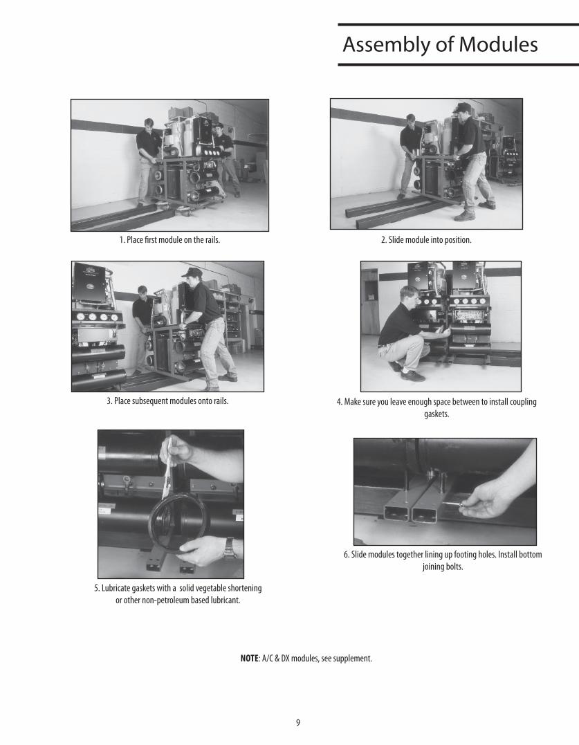
AssemblyofModules
1. Place first module on the rails. 2. Slide module into position.
3. Place subsequent modules onto rails. 4. Make sure you leave enough space between to install coupling gaskets.
5. Lubricate gaskets with a solid vegetable shortening or other non-petroleum based lubricant.
6. Slide modules together lining up footing holes. Install bottom joining bolts.
NOTE: A/C & DX modules, see supplement.
10
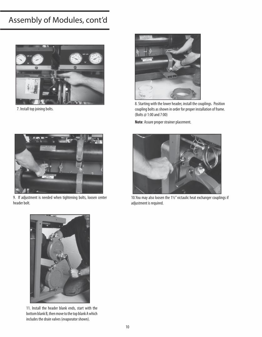
AssemblyofModules,cont’d
7. Install top joining bolts.8. Starting with the lower header, install the couplings. Position coupling bolts as shown in order for proper installation of frame. (Bolts @ 1:00 and 7:00)
Note: Assure proper strainer placement.
9. If adjustment is needed when tightening bolts, loosen center header bolt.
10.You may also loosen the 11⁄2” victaulic heat exchanger couplings if adjustment is required.
11. Install the header blank ends, start with the bottom blank B, then move to the top blank A which includes the drain valves (evaporator shown).
11
Assembly
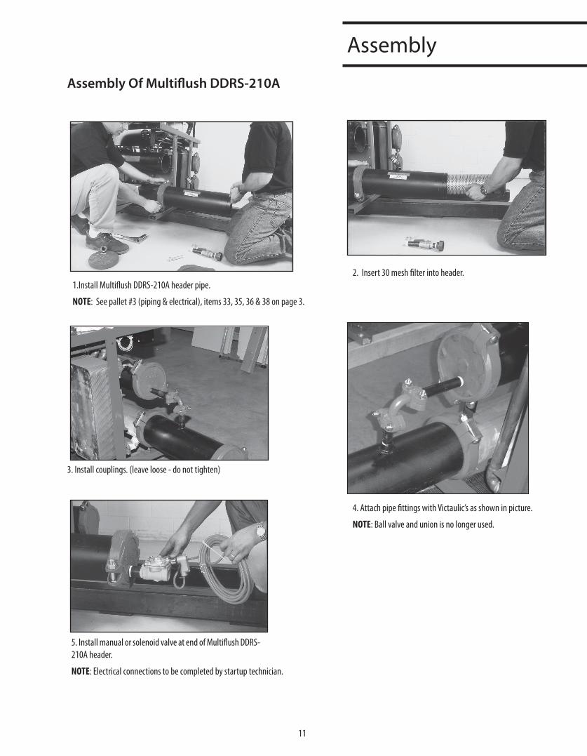
1.Install Multiflush DDRS-210A header pipe.
NOTE: See pallet #3 (piping & electrical), items 33, 35, 36 & 38 on page 3.
2. Insert 30 mesh filter into header.
3. Install couplings. (leave loose - do not tighten)
4. Attach pipe fittings with Victaulic’s as shown in picture.
NOTE: Ball valve and union is no longer used.
5. Install manual or solenoid valve at end of Multiflush DDRS-210A header.
NOTE: Electrical connections to be completed by startup technician.
Assembly Of Multiflush DDRS-210A
12
Assembly
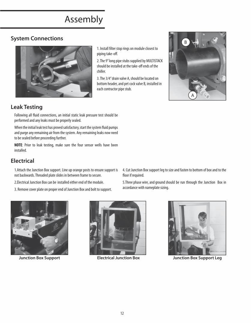
System Connections
Leak Testing
Electrical
1. Install filter stop rings on module closest to piping take-off.
2. The 9” long pipe stubs supplied by MULTISTACK should be installed at the take-off ends of the chiller.
3. The 3/4” drain valve A, should be located on bottom header, and pet cock valve B, installed in each contractor pipe stub.
A
B
Following all fluid connections, an initial static leak pressure test should be performed and any leaks must be properly sealed.
When the initial leak test has proved satisfactory, start the system fluid pumps and purge any remaining air from the system. Any remaining leaks now need to be sealed before proceeding further.
NOTE: Prior to leak testing, make sure the four sensor wells have been installed.
1.Attach the Junction Box support. Line up orange posts to ensure support is not backwards. Threaded plate slides in between frame to secure.
2.Electrical Junction Box can be installed either end of the module.
3. Remove cover plate on proper end of Junction Box and bolt to support.
4. Cut Junction Box support leg to size and fasten to bottom of box and to the floor if required.
5.Three phase wire, and ground should be run through the Junction Box in accordance with nameplate sizing.
Junction Box Support Electrical Junction Box Junction Box Support Leg
13
BussbarInstallation
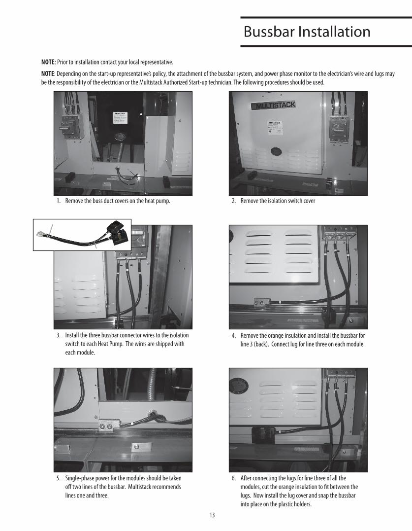
NOTE: Prior to installation contact your local representative.
NOTE: Depending on the start-up representative’s policy, the attachment of the bussbar system, and power phase monitor to the electrician’s wire and lugs may be the responsibility of the electrician or the Multistack Authorized Start-up technician. The following procedures should be used.
1. Remove the buss duct covers on the heat pump. 2. Remove the isolation switch cover
3. Install the three bussbar connector wires to the isolation switch to each Heat Pump. The wires are shipped with each module.
4. Remove the orange insulation and install the bussbar for line 3 (back). Connect lug for line three on each module.
5. Single-phase power for the modules should be taken off two lines of the bussbar. Multistack recommends lines one and three.
6. After connecting the lugs for line three of all the modules, cut the orange insulation to fit between the lugs. Now install the lug cover and snap the bussbar into place on the plastic holders.
14
BussbarInstallation,Cont’d
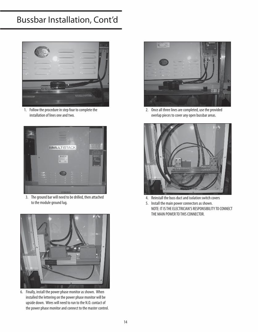
1. Follow the procedure in step four to complete the installation of lines one and two.
2. Once all three lines are completed, use the provided overlap pieces to cover any open bussbar areas.
3. The ground bar will need to be drilled, then attached to the module ground lug.
4. Reinstall the buss duct and isolation switch covers5. Install the main power connectors as shown.
NOTE: IT IS THE ELECTRICIAN’S RESPONSIBILITY TO CONNECT THE MAIN POWER TO THIS CONNECTOR.
6. Finally, install the power phase monitor as shown. When installed the lettering on the power phase monitor will be upside down. Wires will need to run to the N.O. contact of the power phase monitor and connect to the master control.
15
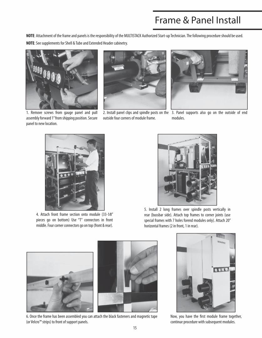
Frame&PanelInstallNOTE: Attachment of the frame and panels is the responsibility of the MULTISTACK Authorized Start-up Technician. The following procedure should be used.
NOTE: See supplements for Shell & Tube and Extended Header cabinetry.
1. Remove screws from gauge panel and pull assembly forward 1” from shipping position. Secure panel to new location.
2. Install panel clips and spindle posts on the outside four corners of module frame.
3. Panel supports also go on the outside of end modules.
4. Attach front frame section onto module (33-1⁄8” pieces go on bottom) Use “T” connectors in front middle. Four corner connectors go on top (front & rear).
5. Install 2 long frames over spindle posts vertically in rear (bussbar side). Attach top frames to corner joints (use special frames with 7 holes forend modules only). Attach 20” horizontal frames (2 in front, 1 in rear).
6. Once the frame has been assembled you can attach the black fasteners and magnetic tape (or Velcro™ strips) to front of support panels.
Now, you have the first module frame together, continue procedure with subsequent modules.

16
Pageleftintentionallyblank.
Start-UpDataLog
17
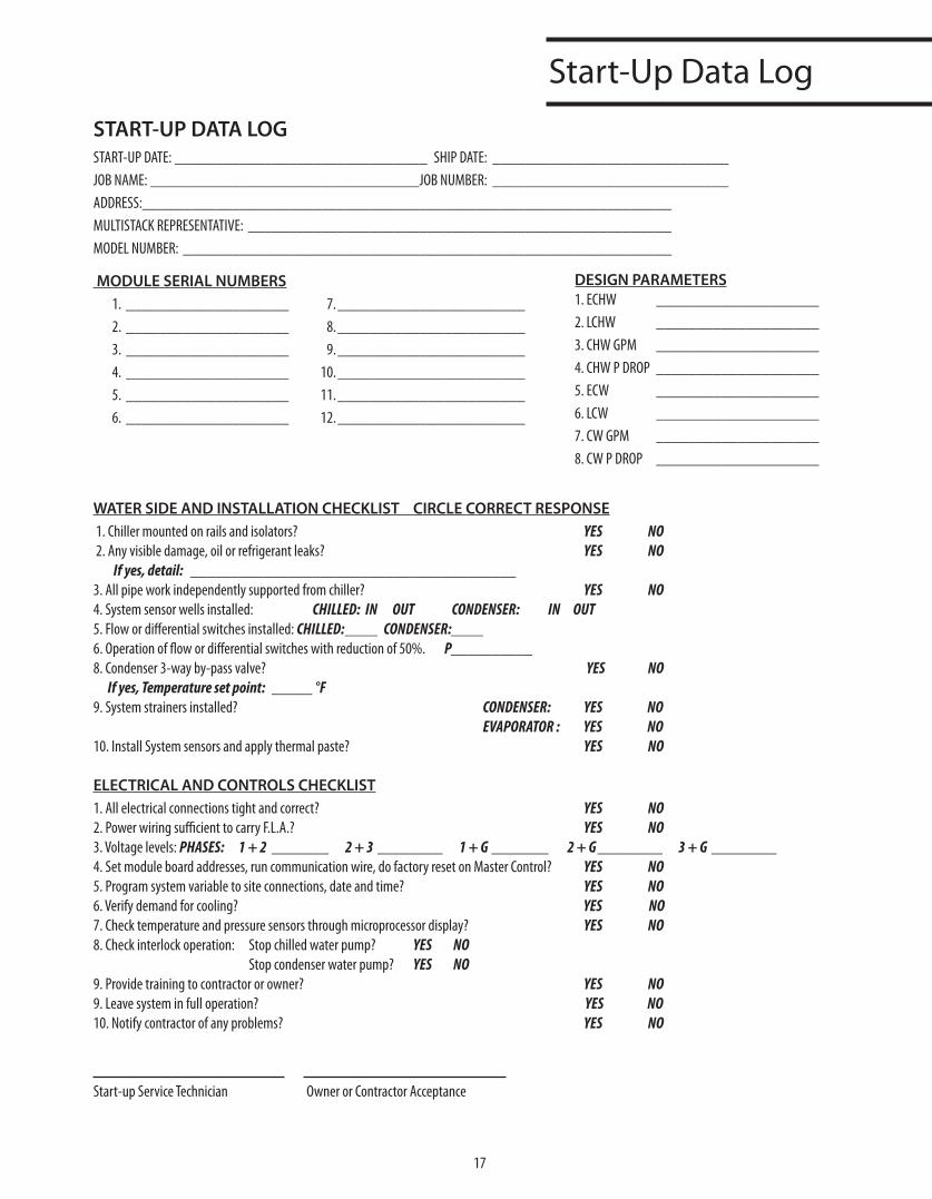
START-UP DATA LOGSTART-UP DATE: _______________________________ SHIP DATE: _____________________________JOB NAME: _________________________________JOB NUMBER: _____________________________ADDRESS:_________________________________________________________________MULTISTACK REPRESENTATIVE: ____________________________________________________MODEL NUMBER: ____________________________________________________________
MODULE SERIAL NUMBERS 1. ____________________ 7. _______________________ 2. ____________________ 8. _______________________ 3. ____________________ 9. _______________________ 4. ____________________ 10. _______________________ 5. ____________________ 11. _______________________ 6. ____________________ 12. _______________________
WATER SIDE AND INSTALLATION CHECKLIST CIRCLE CORRECT RESPONSE 1. Chiller mounted on rails and isolators? YES NO 2. Any visible damage, oil or refrigerant leaks? YES NO
Ifyes,detail: ________________________________________3. All pipe work independently supported from chiller? YES NO 4. System sensor wells installed: CHILLED:IN OUT CONDENSER: IN OUT5. Flow or differential switches installed: CHILLED:____ CONDENSER:____6. Operation of flow or differential switches with reduction of 50%. P__________8. Condenser 3-way by-pass valve? YES NO Ifyes,Temperaturesetpoint: _____ °F9. System strainers installed? CONDENSER: YES NO
EVAPORATOR: YES NO10. Install System sensors and apply thermal paste? YES NO
ELECTRICAL AND CONTROLS CHECKLIST1. All electrical connections tight and correct? YES NO2. Power wiring sufficient to carry F.L.A.? YES NO3. Voltage levels: PHASES: 1+2 _______ 2+3 ________ 1+G _______ 2+G________ 3+G ________4. Set module board addresses, run communication wire, do factory reset on Master Control? YES NO 5. Program system variable to site connections, date and time? YES NO 6. Verify demand for cooling? YES NO7. Check temperature and pressure sensors through microprocessor display? YES NO8. Check interlock operation: Stop chilled water pump? YES NO Stop condenser water pump? YES NO9. Provide training to contractor or owner? YES NO9. Leave system in full operation? YES NO10. Notify contractor of any problems? YES NO
Start-up Service Technician Owner or Contractor Acceptance
DESIGN PARAMETERS1. ECHW ____________________2. LCHW ____________________3. CHW GPM ____________________4. CHW P DROP ____________________5. ECW ____________________6. LCW ____________________7. CW GPM ____________________8. CW P DROP ____________________
18
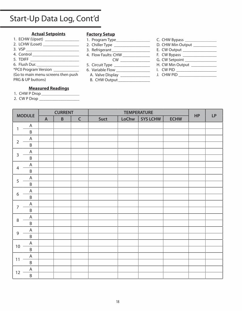
Start-UpDataLog,Cont’d
MODULE CURRENT TEMPERATURE
HP LPA B C Suct LoChw SYS LCHW ECHW
1AB
2AB
3AB
4AB
5AB
6AB
7AB
8AB
9AB
10AB
11AB
12AB
Actual Setpoints1. ECHW(Upset) ________________2. LCHW(Loset)_________________3. VSP_________________________4. Control______________________5. TDIFF _______________________6. FlushDur.____________________*PC0ProgramVersion ____________(GotomainmenuscreensthenpushPRG&UPbuttons)
Measured Readings1. CHWPDrop__________________2. CWPDrop___________________
Factory Setup1. ProgramType________________2. ChillerType _________________3. Refrigerant__________________4. FlowFaults:CHW_____________
CW ______________5. CircuitType _________________6. VariableFlow________________
A. ValveDisplay ______________B. CHWOutput_______________
C. CHWBypass_______________D. CHWMinOutput ___________E. CWOutput________________F. CWBypass ________________G. CWSetpoint_______________H. CWMinOutput ____________I. CWPID ___________________J. CHWPID__________________
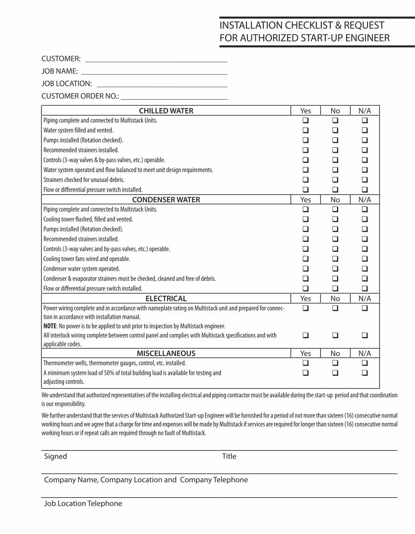
INSTALLATIONCHECKLIST&REQUESTFORAUTHORIZEDSTART-UPENGINEER
CUSTOMER: ____________________________________
JOBNAME:_____________________________________
JOBLOCATION: _________________________________
CUSTOMERORDERNO.:___________________________
CHILLED WATER Yes No N/APiping complete and connected to Multistack Units. q q qWater system filled and vented. q q qPumps installed (Rotation checked). q q qRecommended strainers installed. q q qControls (3-way valves & by-pass valves, etc.) operable. q q qWater system operated and flow balanced to meet unit design requirements. q q qStrainers checked for unusual debris. q q qFlow or differential pressure switch installed. q q q
CONDENSER WATER Yes No N/APiping complete and connected to Multistack Units. q q qCooling tower flushed, filled and vented. q q qPumps installed (Rotation checked). q q qRecommended strainers installed. q q qControls (3-way valves and by-pass valves, etc.) operable. q q qCooling tower fans wired and operable. q q qCondenser water system operated. q q qCondenser & evaporator strainers must be checked, cleaned and free of debris. q q qFlow or differential pressure switch installed. q q q
ELECTRICAL Yes No N/APower wiring complete and in accordance with nameplate rating on Multistack unit and prepared for connec-tion in accordance with installation manual.
q q q
NOTE: No power is to be applied to unit prior to inspection by Multistack engineer.All interlock wiring complete between control panel and complies with Multistack specifications and with applicable codes.
q q q
MISCELLANEOUS Yes No N/AThermometer wells, thermometer gauges, control, etc. installed. q q qA minimum system load of 50% of total building load is available for testing and adjusting controls.
q q q
We understand that authorized representatives of the installing electrical and piping contractor must be available during the start-up period and that coordination is our responsibility.
We further understand that the services of Multistack Authorized Start-up Engineer will be furnished for a period of not more than sixteen (16) consecutive normal working hours and we agree that a charge for time and expenses will be made by Multistack if services are required for longer than sixteen (16) consecutive normal working hours or if repeat calls are required through no fault of Multistack.
Signed Title
CompanyName,CompanyLocationandCompanyTelephone
JobLocationTelephone

1064MapleAvenueSparta,WI•P608-366-2400•F608-366-2450
www.multistack.com
F119IUM0810