Embed Size (px)
Citation preview

www.lg.com
INSTALLATION MANUAL
Water-Cooled SCREW Chiller
Model : RCWW*******
Please read this installation manual completely for safety before installing the product.The purpose of this manual is to keep the user safe and to prevent any property damage. After reading this installation manual, please retain it for future refer-ence thoroughly.Installation work must be performed in accordance with this installation manual by authorized personnel only.
ENG
LISH
2
ENG
LISH
For your recordsStaple your receipt to this page in case you need it to prove the date of purchase or for warranty purposes. Write the model number and the serial number here:
Model number :
Serial number :
You can find them on a label on the side of each unit.
Dealer’s name :
Date of purchase :
1. CAUTIONS FOR SAFETY _ WARNING/CAUTION 3
1. CAUTIONS FOR SAFETY _ WARNING/CAUTIONIt can be dangerous when moving, installing and placing the system for its high pressure, electricdevices and heavy weight especially when lifting the unit in a limited space(rooftop, lifted struc-ture, etc.).Please read carefully the warnings and cautions on this manual and the labels attached on theunit, and follow the instructions.Please follow the following instructions to prevent any injury or property damage
• It may result in an injury or damages when neglecting the instructions on in this manual. The seriousness of the result can be classified as the following signs.
• Please note that any failure of system resulted by user’s careless maintenance, natural disasteror the failure of the power cable shall not be warranted regardless of the warranty period.
• Please note that any part of this manual can be revised without notice for the product improve-ment.
WARNINGIt can result in serious injury or death when the directions are ignored
CAUTIONIt can result in minor injury or product damage when the directions are ignored
The meanings of the symbols used in this manual are as follows.
Be sure not to do.
Be sure to follow the instruction.
1-1. Warning• Have all electric work done by a licensed electrician according to "Electric Facility Engineering Standard" and "Interior
Wire Regulations" and the instructions given in this manual and always use a special circuit.
- If the power source capacity is inadequate or electric work is performed improperly, electric shock or fire may re-sult.
• Ask the dealer or an authorized technician to install the chiller unit.
- Improper installation by the user may result in water leakage, electric shock, or fire.
• For re-installation of the installed product, always contact a dealer or an Authorized Service Center.
- There is risk of fire, electric shock, explosion, or injury.
• Make sure to equip the circuit breaker and fuse.
- Improper wiring or installation may cause fire or electric shock.
• Do not disassemble, repair or reconfigure the unit.
- LG Electronics is not responsible for the any damage or loss from the arbitrary disassembly, repair or reconfigura-tion of the unit.
• Make sure to ground the unit properly.
- There is risk of fire or electric shock.
• Do not store or use flammable gas or combustibles near the chiller unit
!
!
!
ENG
LISH
4 1. CAUTIONS FOR SAFETY _ WARNING/CAUTION
ENG
LISH
- There is risk of fire or failure of product.
• Do not reconstruct to change the settings of the protection devices.
- If the pressure switch, thermal switch, or other protection device is shorted and operated forcibly, or parts otherthan those specified by LGE are used, fire or explosion may result.
• Install the unit on a foundation where the heavy weight can be supported.
- Insufficient strength of the foundation to support the chiller operation may cause the unit failure or injury.
• Installing the product in small space requires separate measures to keep the leakage of the refrigerant within thesafety limits in case of any leakage.
- Consult the authorized dealer for appropriate measures to prevent the refrigerant leakage from exceeding thesafety limits. The leakage of refrigerant exceeding the safety limit may result in dangerous situations due to thelack of oxygen level in the room.
• Securely install the cover of control box and the panel.
- If the cover and panel are not installed securely, dust or water may enter the unit and fire or electric shock may re-sult.
• Do not operate the unit arbitrarily.
- Incorrect operation of the unit may cause dangerous situations such as unit defects, leakage or electric shock. Al-ways consult the authorized dealer.
• Do not use damaged circuit breaker or fuse works correctly all the time.
- It may cause fire, electric shock or injury.
• Keep the control panel from any water getting in. Do not wash the control panel with water.
- It can cause electric shock or defects.
• When the product is soaked (flooded or submerged), contact an Authorized Service Center.
- There is risk of fire or electric shock.
• Use a dedicated outlet for this unit.
- There is risk of fire or electric shock.
• When installing and moving the chiller unit to another site, do not charge it with a different refrigerant from the re-frigerant specified on the unit.
- If a different refrigerant or air is mixed with the original refrigerant, the refrigerant cycle may malfunction and theunit may be damaged.
• Do not touch the power switch with wet hands.
- There is risk of fire, electric shock, explosion, or injury.
• Ventilate before operating the chiller unit when gas leaked out.
- Do not use a phone or operate the power switch at this time. It may cause fire or explosion.
• Do not put any heavy object on the top of the unit or climb on the unit.
- It may cause defects or injury.
• Use fuse and circuit breaker with rated capacity.
- Do not put your finger or a stick in the rotating part. It may cause injury.
• Use fuse and leakage breaker of rated capacity.
- It may cause fire and defects.
• Redesigning the control box is prohibited.
- Lock the control box with possible locking device and if you need to open the control box inevitably, turn off themain power first.
• Do not touch the wiring or a parts inside the panel.
- It may cause electric shock, fire or defects.
PRECAUTIONS BEFORE INSTALLATION• Follow the permitted pressure level
- Follow the regulated pressure for cold water, cooling water, refrigerant etc.
• Do not change the set values.
1. CAUTIONS FOR SAFETY _ WARNING/CAUTION 5
- Do not change the set values of the controller and safety devices. Operating with inappropriate setting can causedamages. When changing the setting values, please consult with the specialist.
• Be careful of fire, earthquake and lightening.
- In case of any natural disaster such as fire, earthquake or lightening, immediately stop operating the unit. If youcontinue to operate the unit, it can cause a fire or electronic shock.
• Follow all safety code.
- When operate the chiller, follow the precautions on the manual, tag, sticker and label.
• Use of undesignated refrigerant and oil is prohibited.
- Do not use undesignated refrigerant, freezer oil and brine. It may cause serious effect to the compressor andparts defect.
• During the installation and service, shut down the power supply.
- Electric shock can cause injury and death. Mark and check all switches so that the power is not recovered untilthe work is completed.
• Wear safety equipment
- Wear safety glasses and work gloves. Be careful when installing or operating the chiller and operating the electri-cal components.
• Always run fluid through heat exchangers when adding or removing refrigerant charge.
- Potential damage of the tube within the heat exchanger can be prevented. Use Appropriate brine solution incooler fluid loops to prevent the freezing of heat exchangers when equipment is exposed to temperature below0°C.
• Do not vent refrigerant relief valves within a building.
- Outlet from relief valves must be vented outdoors in accordance with the latest edition of ANSI/ASHRAE(Ameri-can National Standards Institute/American Society of Heating, Refrigeration and Air Conditioning Engineers) 15(Safety Code for Mechanical Refrigeration). The accumulation of refrigerant in an enclosed space can displace oxy-gen and cause asphyxiation. Provide adequate ventilation in enclosed or low overhead areas. Inhalation of highconcentrations of refrigerant gas is harmful and may cause heart irregularities, unconsciousness or death. Misusecan be critical. Refrigerant gas is heavier than air and reduces the level of oxygen. It can cause irritation to eyesand skin.
• Be careful of water leakage.
- In case of any water leakage in the pump or pipe, immediately stop operating the unit. It may cause electricshock, electricity leakage or defects.
• Be careful of electric shock.
- Always ground the chiller during installation. It may cause electric shock.
• Do not leave refrigerant system open to air any longer than necessary.
- If the repair cannot be completed, seal the circuits to prevent any contamination or rust within the product, andcharge dry nitrogen.
• Do not reuse compressor oil.
- It can damage the product.
1-2. CautionInstallation• Always check for gas(refrigerant) leakage after installation or repair of product.
- Low refrigerant levels may cause failure of product.
• Do not install the unit where combustible gas may leak.
- There is risk of fire or failure of product
• Keep level even when installing the product.
- Unleveled refrigerant can cause problems to the product.
• Do not use the product for special usage or location such as preserving animal/plant, precision machine, artifact,etc.
- It may cause property damage.
ENG
LISH

6 1. CAUTIONS FOR SAFETY _ WARNING/CAUTION
ENG
LISH
• Use exclusive wire for the product. Use power cables of sufficient current carring capacity and rating.
- It may cause fire and electric shock.
• When installing the unit in a hospital, communication station, or similar place, provide sufficient protection againstnoise.
- The inverter equipment, private power generator, high-frquency medical equipment, or radio communicationequipment may cause the chiller to operate erroreously, or fail to operate. On the other hand, the chiller may af-fect such equipment by creating noise that disturbs medical treatment or image broadcasting.
• To protect the product from corrosion, do not install the product where it is exposed to sea wind(salt spray) directly.If necessary, please install shield.
- It may cause product deformation and defects.
• Make the connections securely so that the outside force of the cable may not be applied to the termianls.
- Inadequate connetion and fastening may generate heat and cause fire. If the power cable got damaged, do not di-rectly replace it, but call the service center for replacement first.
• Do not use the product in special environments.
- Oil, steam and sulfuric steam can deteriorate the product performance or cause damage to the parts.
• Be careful when transporting the product.
- When carrying the chiller, always consult with the specialized expert.
• When transporting the chiller, always follow the methods described in the manual.
- If not, it can cause overturn, fall etc.
• Be sure the installation area does not deteriorate with age
- If the base collapses, the chiller could fall with it, causing property damage, product failure, or personal injury.
• Be sure to dispose the packing materials safely.
- Packing materials, such as nails and other metal or wooden parts, may cause stabs or other injuries. Tear apartand throw away plastic packing bags so that children may not play with them. If children play with a plastic bagwhich was not torn apart, they face the risk of suffocation.
• Do not touch any of the refrigerant piping during and after operation.
- Pipe during and after the operation can be hot or cold depending on the condition of the refrigerant flowingthrough the refrigerant pipe, compressor and refrigerant cycle parts. Touching the pipes at this time can causeburns or frostbites.
• Turn on the main power 12 hours before starting to operate the product.
- If you operate the product immediately after turning on the main power, it can severely damage the internal parts.Keep the main power on while operating.
• Do not immediately turn off the main power after the product stops operating.
- Wait at least 5 minutes before turning off the main power. If not, it may cause water leakage or other problems.
• Do not operate the product with the panel or safety devices removed.
- Rotating parts or high temperature/pressure parts can cause safety accidents.
• Be careful when disposing the product.
- When disposing the chiller, request to the specialized expert.
• Use a firm stool or ladder when cleaning or maintaining the chiller.
- It may cause an injury.
• Be careful of high temperature.
- Be careful not to make body contact to the parts of the chiller in high temperature. It may cause a burn.
• Be careful of high voltage.
- Install separate wiring for the power and always install and use dedicated power supply and circuit breaker. It cancause electric shock and fire.
• Be careful of chiller installation.
- Keep enough clearance around the product for service and especially for air cooling type, install the product at wellventilated location where there is no obstacle.
• Harsh chemical, household bleach or acid cleaner should not used to clean outdoor or indoor coils of any kind.

1. CAUTIONS FOR SAFETY _ WARNING/CAUTION 7EN
GLIS
H
- These cleaners can be very difficult to rinse out of the coil and can accelerate corrosion at the fin/tube interfacewhere dissimilar materials are in contact. Use environment friendly cleaner.
• Be careful when restarting the product.
- When a safety device is triggered, remove the cause and then restart the product. Repeating the operation arbi-trarily can cause fire and defect.
• Use appropriate tools.
- Use tools appropriate for the repair work and calibrate the measuring devices accurately before using. Using inap-propriate tools can cause an accident.
• Be careful of sound and odor.
- If you hear a weird sound or smell an odor, immediately stop operating the system and contact the service center.It may cause fire, explosion or injury.
• Be careful of injury.
- Check the safety label of the safety device. Follow the above precautions and the contents in the label. It maycause fire and injury. To prevent the formation of the condensed water, the pipe connected to the evaporator aswell as the evaporator itself should be well insulated.
• Check.
- Perform periodic checks. If any problem occurs, stop the operation and contact the service center. Insufficientcheck may cause fire, explosion or error.
• Do not attempt to bypass or alter any of the factory wiring.
- Any compressor operation in the reverse direction will result in a compressor failure that will require compressorreplacement.
• Do not use jumpers or other tools to short out components, or bypass the parts differently from recommended pro-cedures.
- Short-circuiting the control board ground line with other wires can damage the electric module or electric compo-nents.
• Water must be within design flow limits, and should be treated cleanly.
- This make it possible to ensure proper machine performance and reduce the potential of tubing damage due tocorrosion, scaling, erosion and algae. LG Electronics is not responsible for any damage caused by cooling waternot treated or improperly treated.
• Consult a water treatment specialist for proper treatment procedures.
- Hard scale may require chemical treatment for its prevention or remove.
• Do not overcharge refrigerant to the system.
- Refrigerant overcharging results in higher discharge pressure with higher cooling fluid consumption. Also it candamage the compressor and increase the power consumption. Also it can damage the compressor and increasethe power consumption.
• Do not add different type of oil.
- It may cause abnormal operation of chiller.
• Turn controller power off before service work.
- It secures safety and prevents damage to the controller.
• Maintain the compressor oil pressure to normal level.
- Use proper safety precautions when relieving pressure.
• Welding the evaporator head or nozzle part is not recommended.
- If the part requires welding, remove the chilled water flow switch and entering/leaving fluid thermistors beforewelding. After the welding is completed, reinstall the flow switch and thermistors. Failure to remove these de-vices may cause component damage.

8 TABLE OF CONTENTS
ENG
LISH
3 1. CAUTIONS FOR SAFETY_ WARNING/CAUTION
3 1-1. Warning
5 1-2. Caution
9 2. INTRODUCTION9 2-1. General Information
9 2-2. System structure
10 2-3. Nomenclature
10 2-4. Name plate
11 3. PREPARATION FOR IN-STALLATION
11 3-1. Checking of the site information
11 3-2. The environmental condition of installa-tion site
12 3-3. Securing service space
13 3-4. Long term storage and proper place
13 3-4-1. Condition for storage place
13 3-4-2. Check points when storing chillerlong term
13 3-4-3. Check after long term storage
14 4. PRODUCT RECEIPT14 4-1. Check item list and product condition
14 4-2. Product inspection
14 4-3. Product protection
15 5. TRANSPORTATION15 5-1. Considerations for carrying in the prod-
uct
17 5-2. Transportation method
17 5-2-1. Moving by crane
18 5-2-2. Moving using roller
19 6. INSTALLATION19 6-1. Requirements
20 6-2. Unit Leveling
20 6-3. Unit Isolation
20 6-3-1. Isolation pad
21 6-4. Cautions for the unit charged with re-frigerant
21 6-4-1. Things to check before movingand installation
21 6-4-2. Cautions during carring and in-stallation
21 6-4-3. Cautions after installation
21 6-4-4. Actions for refrigerant leakage
22 7. PIPE INSTALLATION22 7-1. Considerations on connecting water
pipes
23 7-2. Bolt-tightening sequence for water pip-ing connection
24 7-3. Installing relief value and refrigerantvent line
24 7-3-1. Installation based on High Pres-sure Gas Safety Control Act(variesby region/country law)
24 7-3-2. Cautions in connection the refrig-erant vent line
25 7-4. Water treatment
26 8. THERMAL INSULATION
27 9. ELECTRIC WIRING27 9-1. Caution for electric installation
29 9-2. Other cautions
30 9-3. Power supply connection
TABLE OF CONTENTS
Thank you for purchasing the Water Cooled Screw Chiller of LG Electronics.
Installation as instructed after reading this manual will ensure the safety, convenience and long lifetime of the unit.
• Please read this manual carefully for the correct installation and proper operation of the Screw Chiller unit.
• Once the installation completed, please run the commissioning and inspect according to the operating & mainte-nance manual.
h This manual describes safety cautions for installation, general information, carrying and installation and wiring infor-mation of the Water Cooled Screw Chiller.

2. INTRODUCTION 9EN
GLIS
H2-1. General InformationThis manual describes the installation of water cooled screw chiller with X30 controller applied.
2-2. System structureFigure 1 shows the general parts location and components of the water cooled screw chiller.
The location of control panel, type of waterbox, directions of inlet and outlet of the chilled water and cooling waterand some pipes may vary by model or customer order. Please check the approved drawings for the details.
* Prepare and check the approved drawing that fits the site.
1
2
10
4
5
6
7
8
3
9
12 11
13
15
14
16
18
17
19
Part Name
1. Screw compressor
2. Relief valve for condenser
3. Relief valve for evaporator
4. Air vent for cooling water
5. Air vent for chilled water
6. Drain for cooling water
7. Drain for chilled water
8. Lifting hole(4 holes) for condenser
9. Lifting hole(4 holes) for evaporator
10. Sight glass for evaporator
11. Control panel
12. Starter panel
13. Flow switch (Chilled water)
14. Flow switch (Cooling water)
15. Temperature sensor (Chilled water outlet)
16. Temperature sensor (Cooling water outlet)
17. Temperature sensor (Chilled water inlet)
18. Temperature sensor (Cooling water inlet)
19. Sight glass for condenser
Front view
Rear view
Figure 1. General structure of screw chiller
2. INTRODUCTION

10 2. INTRODUCTION
ENG
LISH
2-4. Name plateName plate for the unit is attached on the control panel. General information of the chiller unit can be obtained fromthe plate and the information of the unit history can be used for quicker service.
R C W W 030 A A 1 1
R : R-134a
CompressorquantityC:Chiller
Develop-ment se-quenceorder
W : Screw compressor
A : Flooded typeB : Direct expansion typeC : Falling film systemM : Ice Storage High EfficiencyR : Heat recoveryN : Nuclear PJT, High EfficiencyW : W type condenserV : V type CondenserS : Special
W : Water-cooledcooling only
K : Water-cooledheat pump
A : Air-cooled cool-ing only
Compressor nominalcapacity in Tons(usRT)
10RT ⇨ 001
100RT ⇨ 010
130RT ⇨ 013
1000RT ⇨ 100
Cooling/chilled water maxi-mum working pressuresA : Chilled water 10kg/cm2,
Cooling water 10kg/cm2
B : Chilled water 16kg/cm2,Cooling water 16kg/cm2
C : Chilled water 20kg/cm2,Cooling water 20kg/cm2
D : Chilled water 8kg/cm2,Cooling water 8kg/cm2
E : ETC
Figure 2. Nomenclature
Fig. 3. Product plate
①Model name
② Refrigerant
③ Cooling capacity
④ Power and current required for motor
⑤Manufacture's serial number
⑥ Internal pressure test pressure
⑦Maximum working pressure (Design pressure)
⑧ Volume of Evaporator
⑨ Volume of Condenser
⑩ Power electricity
⑪ Control electricity
⑫ Temperatures of Chilled water inlet/outlet
⑬ Temperatures of Cooling water inlet/outlet
⑭Maximum pressure of chilled water and cooling water
2-3. NomenclatureThe model name of the screw chiller is as shown in Fig. 2.

3. PREPARATION FOR INSTALLATION 11
3. PREPARATION FOR INSTALLATION3-1. Checking of the site information• Before installing the chiller unit, check the site in advance, review the necessary details and coordinate the follow-
ings with the site personnel so that the installation can be performed safely and accurately.
1) Work scope and unit data: Check the site installation work scope and approved document
2) Installation location: Check the environmental condition to install according to the article 3-2.
3) Check the entrance size (width, length and height) to the installing site in advance not to have any trouble inmoving. Then check and review the detail method and order for moving the unit.
3-2. The environmental condition of installation site• The site space to install or store the product along with the following environmental condition should be consid-
ered.
1) Be careful not to damage the piping, insulation materials and wires of the chiller unit when storing and installing.The site should have ventilation measures for the refrigerant leakage.
2) Select site where the temperature is below 40 °C all the time with good ventilation. When the unit is to be storedfor long term, pay a close attention to the temperature of the site to be maintained below 40 °C all the time. If thechiller unit is charged with refrigerant and the pressure of the unit exceeds the limit, the pressure relief valve willbe operated and discharge the refrigerant gas resulting in the loss of refrigerant gas along with potential loss oflives. If the machine room temperature is over 40 °C, the pressure vessel should be reconfigured. Check the setpressure for the relief valve of the chiller unit and maintain the room below the relief valve operating temperatureconsulting the authorized service engineer of LG Electronics.
3) Store the chiller unit in dry and safe location without any vibration.
4) The floor surface to install the chiller unit should be flat and of sufficient strength and mass to support the chilleroperating weight.
5) Avoid place of any fire or flammable materials near. When installed in parallel to the heating object such as a boiler, sufficient care to the radiation heat is required.
6) Be careful with high humidity as it causes the electric error and the corrosion of the chiller unit.
7) Select the site where less dust are as the dust cause electric error.
8) Provide enough space around the unit to allow the installation and maintenance personnel access to all servicepoints such as replacing heat exchanger tubes and waterbox to open.
9) Secure maximum or safe height to fit to the crane for easy lifting and lowering of the chiller unit.
10) Secure good drainage from the machine room.
11) Secure sufficient lighting considering the repair and maintenance.
12) This chiller unit is manufactured for indoor use. Therefore avoid installing outdoors or a place under direct sun-light.
13) Protect the unit by vinyl cover form dust and rains.
14) When installing the chiller unit, plan appropriately in accordance with the installation of High Pressure Gas SafetyControl Act. (Local standard)
ENG
LISH

12 3. PREPARATION FOR INSTALLATION
ENG
LISH
3-3. Securing service space1) Before installation, provide enough space for the service and maintenance as indicated on the foundation drawing.
This is the minimum required space for the maintenance.
2) The foundation to install the chiller unit should be of sufficient strength and mass to support the chiller operatingweight.
3) Prepare a good drainage path to drain out the chilled water and cooling water when cleaning the heat exchangertubes or before shutting down.
4) To ensure stable operation of the chiller, level the chiller by adjusting the level plate within 1/16”
5) Floor foundation construction is out of scope of LG Electronics.Please work according to the approved foundation drawings. LG Electronics is not responsible for any unit failurecaused by the inappropriate design and construction of the foundation.
Ceiling
UNIT
UNIT
E
Floor
Provide space at either side of heatexchanger for service of exchanging tubes.
C:Front side
B:Right sideA:Left side
D: Reverse side
A B C D E
RCWW008AA11~RCWW020AA11 1,500 2,500 1,500 1,500 1,000
RCWW020AA21~RCWW039AA21 2,500 2,500 2,000 1,500 1,500
Figure 4. Minimum space requirement for installation
3. PREPARATION FOR INSTALLATION 13
3-4-3. Check after long term storage1) When operating after a long term storage of the unit, check the oil condition through sight glass along with any
mechanical and electrical problem before operation. If any problem exists, have a LG engineer checked.If the unit has been stored long term, it is recommended to have the chiller unit checked by specialized servicecompany. LG Electronics shall not be responsible for any issue occurred if it is not checked by LG Electronics orLG authorized service company.
2) If the unit has been left with no nitrogen pressure or no refrigerant for a long period, operate after the inspectionby LG or a specialized service engineer. LG Electronics shall not be responsible for any issue occurred if it is notchecked by LG Electronics or LG authorized service company.
3) Checking electric systemCheck for any defect on parts and wiring, and measure the resistance value of the motor insulation.About the checking procedure and judgment criteria, proceed according to the operation & maintenance manual.
4) Checking water systemAfter long term shutdown of the unit, the chilled water/cooling water system is expected to have contaminationfrom dust and inflow of external particles.Clean the water system and check the filter.Chilled water/cooling water system needs special care because it is generally an open type piping system.
5) Perform the commissioning according to the operation & maintenance manual.
ENG
LISH
Check item Check timing Check points
Check chillerstatus
Upon arrival atsite
Check the exterior of the unit for any damage or leakage of refrigerant.Check for any leakage on pipe connections,
Protecting elec-tric parts
Upon arrival atsite
Cover up the control panel and control motor by vinyl cover tightly with a desiccantlike Silica gel inside.For other electric systems, cover with vinyl to keep them from collecting dust.
Periodic check Once a week
Check for any damage or leakage on the piping connecting part visually.Check the pressure of the condenser. And record the changes in pressure level.In case of refrigerant leakage, take action according to the installation manual.If no refrigerant is charged, keep it charged with nitrogen in vacuum condition, andcheck the pressure level daily.
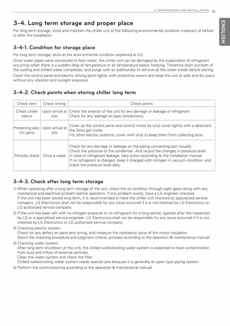
3-4. Long term storage and proper placeFor long term storage, store and maintain the chiller unit at the following environmental condition irrelevant of beforeor after the installation.
3-4-1. Condition for storage placeFor long term storage, store at the environmental condition explained at 3-2.
Once water pipes were connected to flow water, the chiller unit can be damaged by the evaporation of refrigerantoccurring when there is a sudden drop of temperature or air temperature below freezing. Therefore drain out both ofthe cooling and chilled water completely, and purge with air additionally to remove all the water inside before storing.
Cover the control panel and electric driving parts tightly with protective covers and keep the unit at safe and dry placewithout any vibration and sunlight exposure.
3-4-2. Check points when storing chiller long term

14 4. PRODUCT RECEIPT
ENG
LISH
4. PRODUCT RECEIPT4-1. Check item list and product condition• Depending on the condition of the installation site, chiller is shipped as a single unit or as separated unit, and as
charged with refrigerant or with nitrogen. If shipped as separated units, contact the authorized LG Electronics deal-ers or LG Electronics directly.
1) Shipment as single or separated unitFor single unit type, the unit will be delivered to the site as preassembled. Separated unit type will be deliveredas 2 or 3 separated main pieces. Confirm and record cthat it is the correct unit and that it is properly equipped asthe invoice list especially for the shipment as separated.
2) Charged with refrigerant or nitrogenFor single unit type, the unit will be shipped after charging refrigerant or nitrogen depending on the request fromthe customer. When refrigerant is charged, refrigerant and oil are charged together according to the specificationof the chiller unit. It needs special attention to high pressure inside since the saturated refrigerant pressure is de-cided by the external air temperature. When nitrogen is charged, the unit is charged with 0.5kg/cm2 before ship-ment from the factory. If the pressure is “0”, please record the condition and check for any leakage, since thereis leak possibility.
4-2. Product inspection1) Check all the components shipped are the same as in the delivery list.
2) Check the information on the product nameplate with the project information. Refer to article 2-4 for reading the nameplate in detail.
3) Check all exterior components for visible damage or leakage.Any apparent damage is found, first check whether the damaged part affects to safety (such as refrigerant leak-age). Take photos of the damage and notify the LG service representative for service.
4-3. Product protection• When the chiller unit is delivered, check and complete the following pre-commissioning checklist.
1) Before shipment from the factory, the chiller unit is charged with refrigerant or nitrogen to prevent corrosion bymoisture penetration.Be careful not to open or operate the valves and connectors.The refrigerant inside can be leaked resulting an injury. If the water box is sealed with the flange, nitrogen is charged at the pressure 0.5 kg/cm2. Therefore first purgethe nitrogen out and then open the flange.Caution) Never open service valve once nitrogen or refrigerant are charged.
If the nitrogen is lost by the opening the valve, the chiller unit can be damaged.
2) When receiving the unit, inspect and record exterior components and pipes condition for any visible damage andleakage by loosened bolts.
3) If the unit is charged with refrigerant, check and record if oil is normally charged through the sight glass on theside of the compressor.If the oil level is not observed on the sight glass, contact the LG Electronics representative.
4) For any loss, damage or failure of parts, bring up the problem to the delivery personnel and contact the LG Elec-tronics representative. Do not install the unit with damage without an approval from LG Electronics.
! CAUTION
Before unloading the chiller unit upon delivery to the site, check the condition of the unit for any damage duringthe transportation.

5. TRANSPORTATION 15
5. TRANSPORTATION5-1. Considerations for carrying in the productBefore moving the unit to the site to install, check the size and weight of the chiller unit and whether the opening tothe site is large enough. After checking the environmental condition of the site, prepare moving device and methodappropriate for the heavy object.
Secure the minimum required receiving dock space and be careful not to damage the unit when moving.
The dimension on Table 1 is only a reference for the standard model. Check the approved drawing for actual dimen-sion, and proceed the installation coordinating with LG Electronics or expert authorized by LG Electronics for the sitecondition.
ENG
LISH
! WARNING
If the disassembly of the unit is required to move to the site, the disassembly and reassembly of the chiller unitmust be performed under the supervision of the LG Electronics or expert authorized by LG Electronics.If not, LG Electronics is not responsible for any issues occurring after.
A
BC
DE
F
Figure 4 Product carring
Table 1. Minimum carring dimension and product size
(Unit : mm)
Note) Model (A): Standard model_Chilled water inlet/outlet temperature 12°C/7°C, cooling water inlet/outlet temperature 32/37°CModel (B): Standard model_Chilled water inlet/outlet temperature 10°C/5°C, cooling water inlet/outlet temperature 32/37°C
Length(mm) A B C D E F
RCWW008AA11~RCWW012AA11 3,540 1,880 2,115 3,040 1,380 1,815
RCWW014AA11~RCWW016AA11 3,605 2,020 2,135 3,105 1,520 1,835
RCWW018AA11 3,605 2,020 2,285 3,105 1,520 1,985
RCWW020AA11 3,635 2,130 2,380 3,135 1,630 2,080
RCWW020AA21~RCWW022AA21 4,930 2,041 2,410 4,430 1,541 2,110
RCWW024AA21~RCWW028AA21 4,960 2,165 2,560 4,460 1,665 2,260
RCWW032AA21~RCWW039AA21 5,300 2,225 2,560 4,800 1,725 2,260

16 5. TRANSPORTATION
ENG
LISH
Product weight
Following weight data are for those of standard products from LG Electronics. The actual weight of the unit can bedifferent per the site condition. Please refer to the weight and size of the chiller unit on the approved drawing.
Note) Model (A): Standard model_Chilled water inlet/outlet temperature 12°C/7°C, cooling water inlet/outlet temperature 32/37°CModel (B): Standard model_Chilled water inlet/outlet temperature 10°C/5°C, cooling water inlet/outlet temperature 32/37°C
Table 2. Product weight
Model Product Weight Operating Weight Compressor Weight
RCWW008AA11 2,900 3,200 620
RCWW010AA11 3,300 3,600 740
RCWW011AA11 3,500 3,800 810
RCWW012AA11 3,800 4,100 780
RCWW014AA11 4,100 4,500 840
RCWW016AA11 4,600 5,000 1,099
RCWW018AA11 5,000 5,400 1,180
RCWW020AA11 5,500 5,900 1,215
RCWW020AA21 5,800 6,200 1,480
RCWW022AA21 6,400 6,800 1,620
RCWW024AA21 6,700 7,100 1,560
RCWW026AA21 6,800 7,300 1,700
RCWW028AA21 7,000 7,500 1,680
RCWW032AA21 7,300 7,800 2,198
RCWW037AA21 7,800 8,300 2,360
RCWW039AA21 8,200 8,700 2,430
(Unit : kg)
5. TRANSPORTATION 17EN
GLIS
H
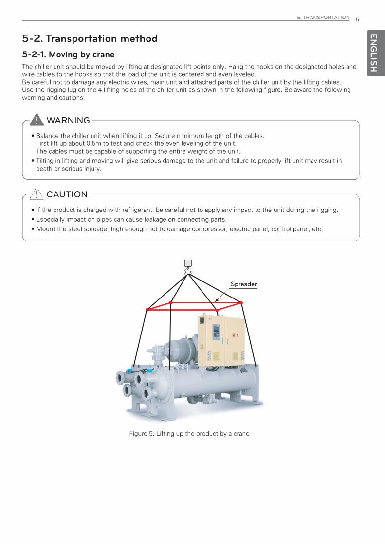
5-2. Transportation method5-2-1. Moving by craneThe chiller unit should be moved by lifting at designated lift points only. Hang the hooks on the designated holes andwire cables to the hooks so that the load of the unit is centered and even leveled.Be careful not to damage any electric wires, main unit and attached parts of the chiller unit by the lifting cables.Use the rigging lug on the 4 lifting holes of the chiller unit as shown in the following figure. Be aware the followingwarning and cautions.
! WARNING
• Balance the chiller unit when lifting it up. Secure minimum length of the cables. First lift up about 0.5m to test and check the even leveling of the unit.The cables must be capable of supporting the entire weight of the unit.
• Tilting in lifting and moving will give serious damage to the unit and failure to properly lift unit may result indeath or serious injury.
! CAUTION
• If the product is charged with refrigerant, be careful not to apply any impact to the unit during the rigging.
• Especially impact on pipes can cause leakage on connecting parts.
• Mount the steel spreader high enough not to damage compressor, electric panel, control panel, etc.
Figure 5. Lifting up the product by a crane
Spreader
18 5. TRANSPORTATION
ENG
LISH
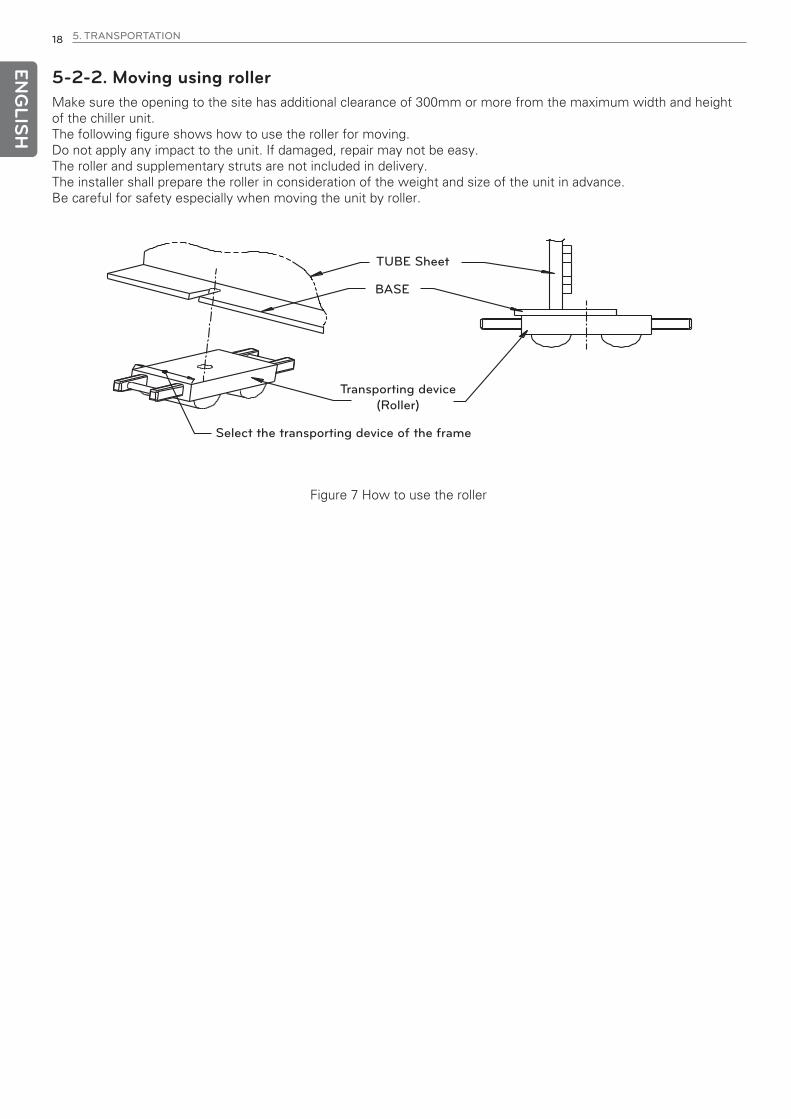
5-2-2. Moving using rollerMake sure the opening to the site has additional clearance of 300mm or more from the maximum width and heightof the chiller unit.The following figure shows how to use the roller for moving.Do not apply any impact to the unit. If damaged, repair may not be easy. The roller and supplementary struts are not included in delivery. The installer shall prepare the roller in consideration of the weight and size of the unit in advance.Be careful for safety especially when moving the unit by roller.
TUBE Sheet
BASE
Transporting device(Roller)
Select the transporting device of the frame
Figure 7 How to use the roller
6. INSTALLATION 19EN
GLIS
H
6. INSTALLATION6-1. Requirements
1) Provide enough space around the unit to allow installation, of attached equipment, wiring, piping and mainte-nance access. Check the level and strength of the foundation surface. For the part to lift the chiller, mounting, unit weight and operating weight, refer to the specification, dimensionand foundation drawing of the unit.
2) Service clearance for the chillers varies by the model. Secure sufficient service clearance to provide service tothe chiller. Refer to 3-3.
3) When installing multiple chillers in the same site, secure appropriate service clearance.
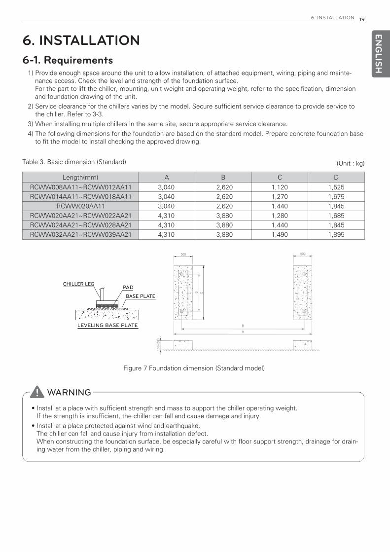
4) The following dimensions for the foundation are based on the standard model. Prepare concrete foundation baseto fit the model to install checking the approved drawing.
Table 3. Basic dimension (Standard)
Figure 7 Foundation dimension (Standard model)
(Unit : kg)
CHILLER LEGPAD
BASE PLATE
LEVELING BASE PLATE
! WARNING
• Install at a place with sufficient strength and mass to support the chiller operating weight. If the strength is insufficient, the chiller can fall and cause damage and injury.
• Install at a place protected against wind and earthquake. The chiller can fall and cause injury from installation defect.When constructing the foundation surface, be especially careful with floor support strength, drainage for drain-ing water from the chiller, piping and wiring.
Length(mm) A B C D
RCWW008AA11~RCWW012AA11 3,040 2,620 1,120 1,525
RCWW014AA11~RCWW018AA11 3,040 2,620 1,270 1,675
RCWW020AA11 3,040 2,620 1,440 1,845
RCWW020AA21~RCWW022AA21 4,310 3,880 1,280 1,685
RCWW024AA21~RCWW028AA21 4,310 3,880 1,440 1,845
RCWW032AA21~RCWW039AA21 4,310 3,880 1,490 1,895
20 6. INSTALLATION
6-2. Unit LevelingTo ensure the refrigerant leveled and the reliability of the chiller unit, the chiller should be installed even leveled.Level the unit within 1/16 inch over its length and width considering all the direction front/back/left/right.
** How to ensure the unit leveled
1) Use the level gauge: For length direction, use the shell length direction or the base surface of compressor to level the unit.For width direction, level the chiller using the base surface of the unit.
2) Use the water head difference (Use transparent vinyl hose): Use transparent vinyl hose and mark at same location from base on the pipe plate in both sides in length direc-tion of the unit and fixate the vinyl hose. Add water and level the product by aligning the water levels.Width direction can be done in the same way.
6-3. Unit IsolationTo minimize sound and vibration transmission through the building structure, install isolation pads or optional springisolators under the chiller feet.
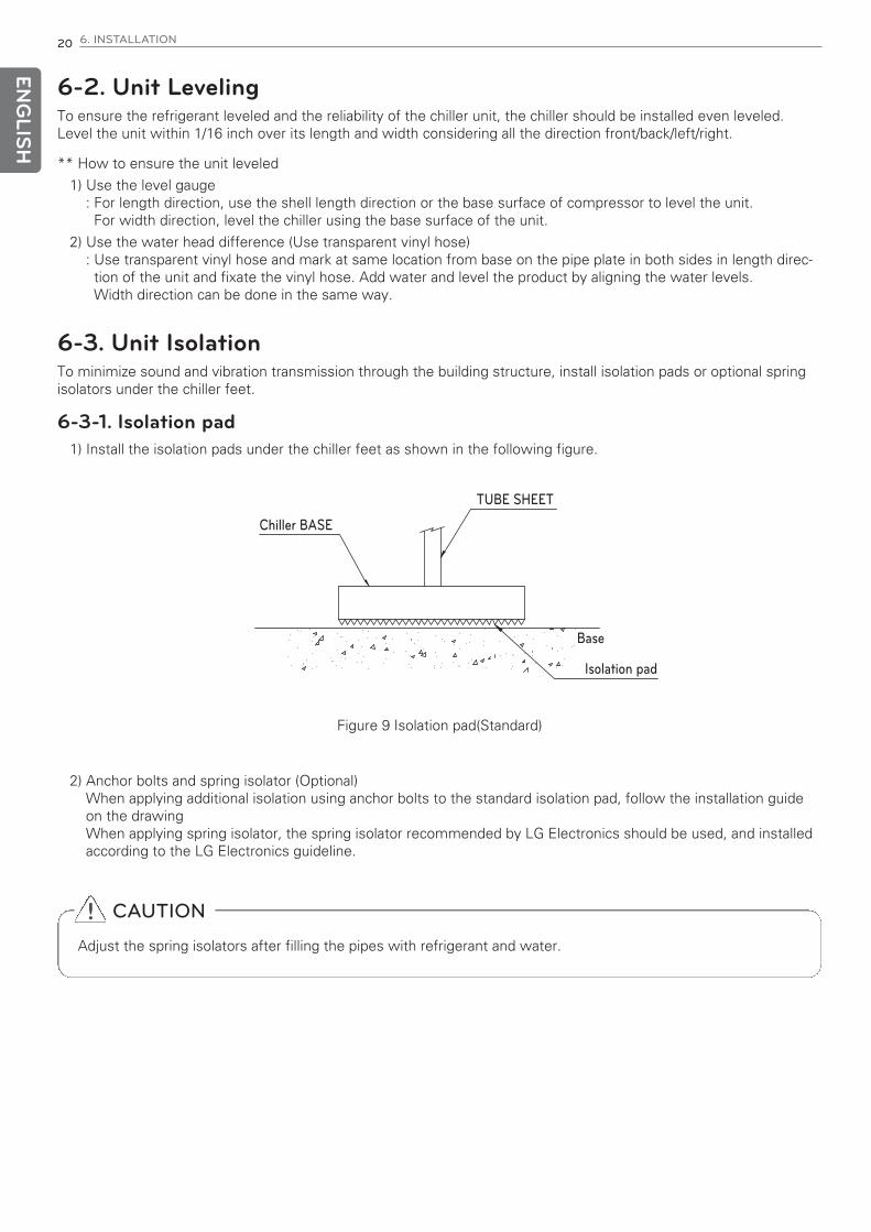
6-3-1. Isolation pad1) Install the isolation pads under the chiller feet as shown in the following figure.
2) Anchor bolts and spring isolator (Optional)When applying additional isolation using anchor bolts to the standard isolation pad, follow the installation guideon the drawing When applying spring isolator, the spring isolator recommended by LG Electronics should be used, and installedaccording to the LG Electronics guideline.
Figure 9 Isolation pad(Standard)
ENG
LISH
Chiller BASE
TUBE SHEET
Base
Isolation pad
! CAUTION
Adjust the spring isolators after filling the pipes with refrigerant and water.
6. INSTALLATION 21
6-4. Cautions for the unit charged with refrigerantFor the chiller unit delivered after charging refrigerant, a special care is demanded as the following details. And followthe following precautions for any refrigerant leakage while carring, installing and after installation.
LG electronics is not responsible for any equipment problems occurred by neglecting the cautions.
6-4-1. Things to check before moving and installation1) Check for the ventilation system in the room to install.
Without ventilation system, the leakage of refrigerant can cause serious injury or death from suffocation.
6-4-2. Cautions during carring and installation1) Move the chiller unit after evenly leveled.
Tilting or any impact to the chiller can cause the refrigerant to leak and damage the unit. Therefore special care isrequired.
2) When lifting the screw chiller, be careful with the wire not to get hooked on the valve and pipe of the screwchiller, etc.
3) When lifting up or lowering the screw chiller, be careful with the pipes and valves not to hit any column or obsta-cle.
4) Weight includes the weight of the charged refrigerant and oil on top of the weight of the screw chiller. Always take into consideration the extra weight.
6-4-3. Cautions after installation1) During the work of the water pipe connection, vent line connection for relief valve and thermal insulation, be
careful not to damage any valve and pipe of the chiller unit.
2) After connecting water pipes, be careful not to let hot water pass to the chiller.
3) For long term storage, please consult with the service agent.
4) Always operate the ventilation system. If the refrigerant leaks, it can cause shortage of oxygen.
6-4-4. Actions for refrigerant leakage1) If the leaking part is clearly identified and can be handled without any risk, close the joints and valves before re-
solving the leakage.
2) If the leakage does not stop from the chiller and the chiller can be moved, move the unit to an open locationwithout any risk to fully discharge the refrigerant.If it is impossible to move the screw chiller, open the installation room and adequately ventilate the room.
3) If the leakage is big, evacuate the area and limit the access to the area by putting ropes around the leaked loca-tion. Always wear a breathing device.
4) If the refrigerant goes into the eye, wash the eye immediately with clean flowing water for more than 15 min-utes and then promptly consult the doctor.
5) If the refrigerant contacts skin, take off any wet clothes, shoes and socks to avoid any chance of frostbite.After taking first aid, promptly consult the doctor.
6) When highly dense gas is inhaled, immediately move to fresh air, cover with blanket to warm body, and take firstaid. And then promptly consult the doctor.
ENG
LISH

22 7. PIPE INSTALLATION
7. PIPE INSTALLATION7-1. Considerations on connecting water pipesInstall the water pipes to chiller unit considering the following details.Water piping is not included in the scope of system delivery from LG Electronics. When installing the chiller, check if the considerations are appropriately applied.
1) Based on the outline drawiing (Installation drawing), install the inlet/outlet piping of the chilled water/cooing water.Always check the direction of inlet/outlet, the specification of connecting flanges and the pressure applied.
2) Separate support must be installed aside form that for the chiller so that the load and the vibration of the pipes ofthe chilled water and cooling water do not transfer to the evaporator and condenser. Also provide ample space forservice.
3) Install strainer of 10 mesh or higher on the front side of the inlet pipe of the chilled water and cooing water, so thatthe heat exchanger tubes of the heat exchanger not to be blocked by sludge which cause pipe damage (Freezingor damage).
4) Provide a device on the outlet side of the chiller to control the flow of the chilled water and cooling water.
5) Provide a device to prevent pressure hunting which may cause malfunction to the flow switch of the chilled waterand cooling water.
6) The waterbox must be easy to open to clean the heat exchanger tubes of the heat exchanger. Install the pipe con-nectors so as to be separated easily without interfering with other pipes when extracting the heat exchangertubes.
7) Please avoid using a pump with 3,550/2,950rpm(60/50Hz) for chilled water and cooing water, since it is the rpm ofthe chiller motor, which possibly resulte in resonance. If unavoidable, install an anti-vibration device.
8) Install accurate thermometer and pressure gauge on the pipe to check the status of the chilled water and cooingwater to the chiller.
9) Install air vent valve, drain valve and pipe in the chilled water and cooling water waterboxes.Also install automatic air vent valve on the pipe.
10) Use of inappropriate water can cause sediments, corrosion and scaling which can damage the chiller. Thereforecheck and manage the water quality as standard.LG Electronics is not responsible for any results from use of the water out of the guaranteed quality.
11) Install the discharge pipe of the relief valve.
ENG
LISH
Supplier Scope
Air vent Air vent
Load sideLoad side(Chilled water pump)
Chilled water drain Cooling water drain
Pressure guage
Flexible joint
Thermometer
Stop valveStrainer
Cooling towerCooling tower(Cooling water pump)
Stop valve
Figure 9 Piping to chiller unit (User installation scope)
7. PIPE INSTALLATION 23EN
GLIS
H
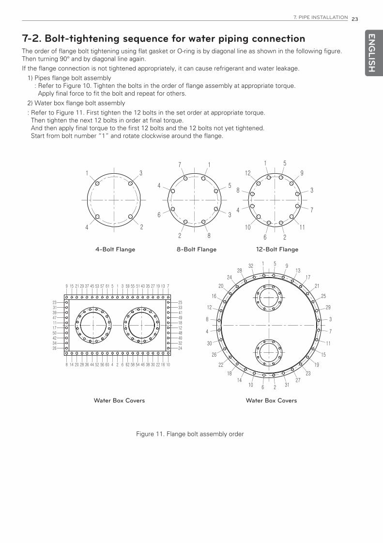
7-2. Bolt-tightening sequence for water piping connectionThe order of flange bolt tightening using flat gasket or O-ring is by diagonal line as shown in the following figure.Then turning 90° and by diagonal line again.
If the flange connection is not tightened appropriately, it can cause refrigerant and water leakage.
1) Pipes flange bolt assembly: Refer to Figure 10. Tighten the bolts in the order of flange assembly at appropriate torque.Apply final force to fit the bolt and repeat for others.
2) Water box flange bolt assembly
: Refer to Figure 11. First tighten the 12 bolts in the set order at appropriate torque.Then tighten the next 12 bolts in order at final torque.And then apply final torque to the first 12 bolts and the 12 bolts not yet tightened.Start from bolt number “1” and rotate clockwise around the flange.
4-Bolt Flange 8-Bolt Flange 12-Bolt Flange
Water Box Covers Water Box Covers
Figure 11. Flange bolt assembly order

24 7. PIPE INSTALLATION
7-3. Installing relief value and refrigerant vent lineRelief valve is a device to prevent the chiller unit from high pressure. It discharges the refrigerant when the pressureis increased to set level by abnormally hot temperature in the room by fire or other.
Install the refrigerant vent line to outdoors from the relief valve discharge.
7-3-1. Installation based on High Pressure Gas Safety Control Act(varies by region/country law)
1) When installing the chiller, discharging pipe must be guided from the relief valve to outdoor.
2) Refrigerant applied in this product is non-flammable and non-toxic Freon gas. Discharging pipe from the reliefvalve must be installed to a safe location on outdoor.
7-3-2. Cautions in connection the refrigerant vent line1) When connecting the discharging vent line to the relief valve, do not apply excessive force so that the force does
not transfer to the connecting part of the relief valve.Fixate the screws on the relief valve side using tools and then tighten the screws on reverse side. Leakage of re-frigerant can cause the failure of the chiller unit.
2) When connecting the discharging vent line, connect the pipes perpendicular way as shown in the figure belowfor easy replacement of the relief valve.
ENG
LISH
Flange or union
Discharge pipe
Safety valve
Safety valve
Scope of generalcontractor
Figure 12. How to install the outdoor discharge line of the relief valve
7. PIPE INSTALLATION 25EN
GLIS
H
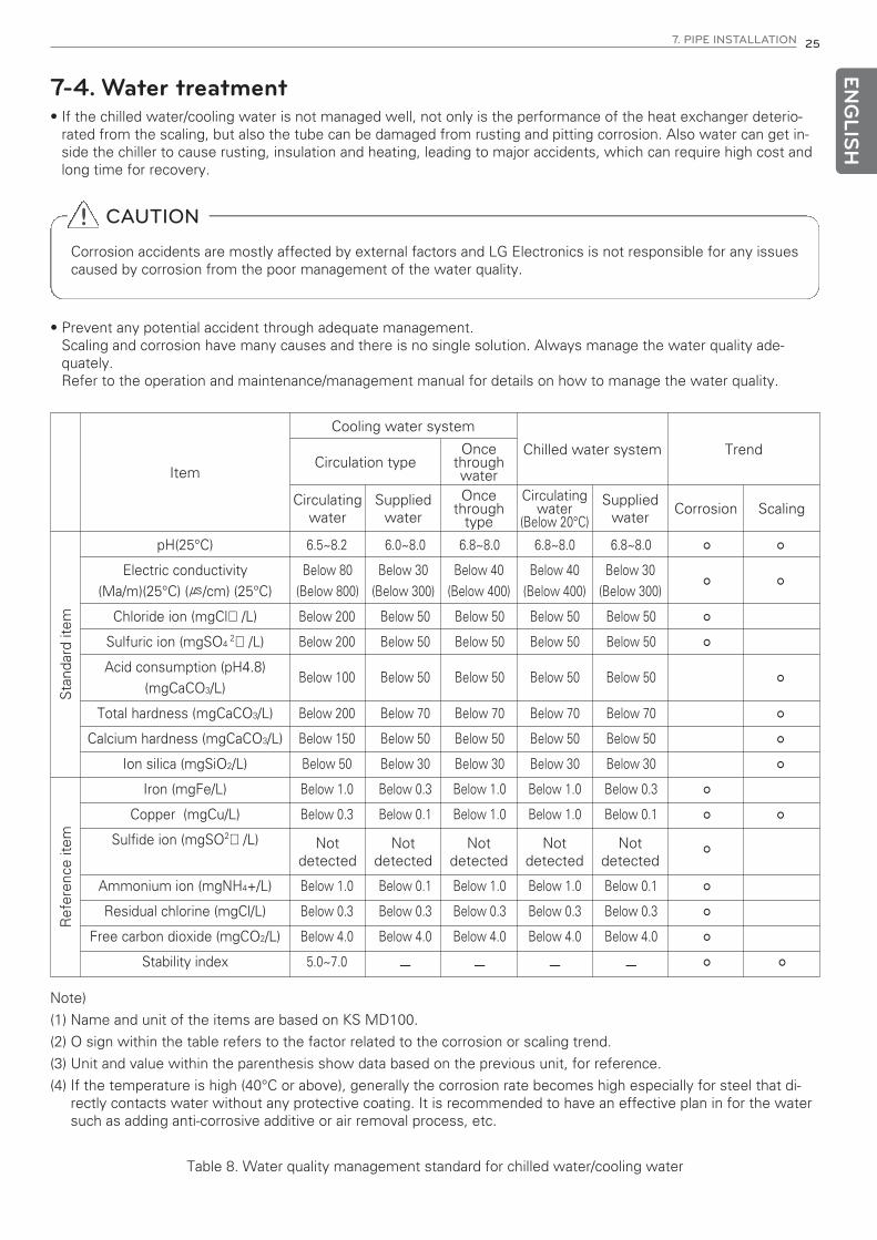
7-4. Water treatment• If the chilled water/cooling water is not managed well, not only is the performance of the heat exchanger deterio-
rated from the scaling, but also the tube can be damaged from rusting and pitting corrosion. Also water can get in-side the chiller to cause rusting, insulation and heating, leading to major accidents, which can require high cost andlong time for recovery.
! CAUTION
Corrosion accidents are mostly affected by external factors and LG Electronics is not responsible for any issuescaused by corrosion from the poor management of the water quality.
• Prevent any potential accident through adequate management.Scaling and corrosion have many causes and there is no single solution. Always manage the water quality ade-quately.Refer to the operation and maintenance/management manual for details on how to manage the water quality.
Note)
(1) Name and unit of the items are based on KS MD100.
(2) O sign within the table refers to the factor related to the corrosion or scaling trend.
(3) Unit and value within the parenthesis show data based on the previous unit, for reference.
(4) If the temperature is high (40°C or above), generally the corrosion rate becomes high especially for steel that di-rectly contacts water without any protective coating. It is recommended to have an effective plan in for the watersuch as adding anti-corrosive additive or air removal process, etc.
Item
Cooling water system
Chilled water system TrendCirculation type
Oncethroughwater
Circulatingwater
Suppliedwater
Oncethrough
type
Circulatingwater
(Below 20°C)
Suppliedwater
Corrosion Scaling
Sta
ndar
d ite
m
Below 80 (Below 800)
Below 30(Below 300)
Below 40(Below 400)
Below 40(Below 400)
Below 30(Below 300)
Ref
eren
ce it
em Not detected
Not detected
Not detected
Not detected
Not detected
pH(25°C)
Electric conductivity (Ma/m)(25°C) (㎲/cm) (25°C)
Chloride ion (mgCl ̄/L)
Sulfuric ion (mgSO4 2 ̄/L)
Acid consumption (pH4.8)(mgCaCO3/L)
Total hardness (mgCaCO3/L)
Calcium hardness (mgCaCO3/L)
Ion silica (mgSiO2/L)
Iron (mgFe/L)
Copper (mgCu/L)
Sulfide ion (mgSO2 ̄/L)
Ammonium ion (mgNH4+/L)
Residual chlorine (mgCl/L)
Free carbon dioxide (mgCO2/L)
Stability index
Table 8. Water quality management standard for chilled water/cooling water
6.5~8.2 6.0~8.0 6.8~8.0 6.8~8.0 6.8~8.0 ㅇ ㅇ
ㅇ ㅇ
Below 200 Below 50 Below 50 Below 50 Below 50 ㅇ
Below 200 Below 50 Below 50 Below 50 Below 50 ㅇ
Below 100 Below 50 Below 50 Below 50 Below 50 ㅇ
Below 200 Below 70 Below 70 Below 70 Below 70 ㅇ
Below 150 Below 50 Below 50 Below 50 Below 50 ㅇ
Below 50 Below 30 Below 30 Below 30 Below 30 ㅇ
Below 1.0 Below 0.3 Below 1.0 Below 1.0 Below 0.3 ㅇ
Below 0.3 Below 0.1 Below 1.0 Below 1.0 Below 0.1 ㅇ ㅇ
ㅇ
Below 1.0 Below 0.1 Below 1.0 Below 1.0 Below 0.1 ㅇ
Below 0.3 Below 0.3 Below 0.3 Below 0.3 Below 0.3 ㅇ
Below 4.0 Below 4.0 Below 4.0 Below 4.0 Below 4.0 ㅇ
5.0~7.0 ㅡ ㅡ ㅡ ㅡ ㅇ ㅇ

26 8. THERMAL INSULATION
8. THERMAL INSULATIONThe standard chiller unit from LG Electronics is shipped from factory without thermal insulation. Install thermal insula-tion over the chiller unit before commissioning test after leakage test on the site. Thermal insulation work should fol-low the standard insulation guideline.
Cautions for thermal insulation work
1) Make sure the operating parts (valves, handles, etc.) are not to be thermal insulated or not to be touched by ther-mal insulation material.
2) Make sure the fixing bolts for waterbox not to be covered by insulation material to be able to open the waterboxwhen cleaning the tubes in the Heat Exchanger.Also when working thermal insulation, consider the flanges of the water pipes as well as the waterbox to be eas-ily detached. (Also install the flange for the water pipe so that it is easy to separate.)
3) Make sure the insulation material covering the service parts such as compressor and main pipe bolts area to beremoved easily when overhaulling or in inspection service.
4) Make sure that thermal insulation material does not block the view of the sight glass.
5) Make sure the water temperature sensor and others to be remained accessible for service.
6) Use only thermal insulation materials with equal or higher in thermal conductivity and quality than those specifiedby LG Electronics.
7) Install the thermal insulation material firmly using adhesive and completely close the gap between insulation ma-terial and the insulating part so that air does not get in.
8) About the thickness and specification of the thermal insulation material follow the drawing of insulation approvedby LG Electronics and the standard design condition is as follows.
- Dry bulb temperature
- Relative humidity
9) After the insulation, make sure not to expose to excessive sunlight or cause damage while working. Dew condensation may occur by the deformed or damaged part, and it should be reworked.
ENG
LISH
Thermal Insulationwork scope
Figure 13. Locations requiring thermal insulation
No. Item Insulation material
and Thickness
① Compressor motor (suction side) Rubber Insulation,
More than t20
② Compressor suction refrigerant pipe
③ Evaporator
④ Water box
⑤ Chilled water inlet/out nozzles
⑥ Low pressure liquid refrigerant pipe
⑦ Oil reclaim pipe
⑧ Refrigerant charging pipe
9. ELECTRIC WIRING 27EN
GLIS
H
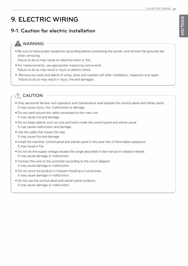
9. ELECTRIC WIRING9-1. Caution for electric installation
! WARNING
• Be sure to have proper equipment grounding before connecting the power, and remove the grounds lastwhen removing. Failure to do so may cause an electrical short or fire.
• For measurements, use appropriate measuring instruments. Failure to do so may result in injury or electric shock.
• Remove any tools and debris of wires, bolts and washers left after installation, inspection and repair. Failure to do so may result in injury, fire and damages.
! CAUTION
• Only personnel familiar with operation and maintenance shall operate the control panel and starter panel.It may cause injury, fire, malfunction or damage.
• Do not weld around the cable connected to the main unit.It may cause fire and damage.
• Do not keep objects such as nuts and bolts inside the control panel and starter panel.It may cause malfunction and damage.
• Use the cable that meets the rate.It may cause fire and damage.
• Install the machine, control panel and starter panel in the area free of flammable substance.It may cause a fire.
• Do not let the supply voltage exceed the range described in the manual or related material.It may cause damage or malfunction.
• Connect the wire to the controller according to the circuit diagram.It may cause damage or malfunction.
• Do not store the product in frequent flooding or humid area.It may cause damage or malfunction.
• Do not use the control panel and starter panel outdoors.It may cause damage or malfunction.

28 9. ELECTRIC WIRING
Inspection
Inspect the parts or controllers attached on the chiller unit for any damage in transporting or moving process. Check the reserved parts and parts in separate package for any loss.
Environment condition
Check if the installation condition and environment are within the following criteria.
ENG
LISH
Item Specification Remarks
Motor power380Vac,440Vac,3300Vac,6
600VacUser option
Power frequency 50/60Hz User option
Power constant 3Phase
Control power 220Vac,1PH User option
Controller power 20Vac,1PH,50/60Hz
Storage temperature -10 °C ~ 60 °C
Use temperature 5 °C ~ 40 °C
Use humidity25 °C, 20% ~80%RH, No dew condensation
Surrounding environmentNo corrosive gas, flammable gas, oil
residue or dust
Altitude/VibrationAbove sea level 1000m or less -
5.9m/sec2 (=0.6g) or less
Controller contact point1. 250VAC, 3A or less load
2. Load connecting capability below of30VDC, 0.3A
- Zero-voltage “A” contact output
Input capacity ofController contact
Zero-voltage contact point input- Power is connected from controller(20VDC, 10mA)
- Do not connect power externally
Instant power outagecompensation
Controller: 100mS or less
Voltage fluctuation Rated voltage ±10%

9. ELECTRIC WIRING 29EN
GLIS
H
9-2. Other cautions• Have a qualified licensed electrician by LG Electronics handle controllers and tools.
• Shutdown all the power before connecting power cables and control signal cables.
• Be aware the safety devices and their functions on this manual and keep the safety requirements.
• Be aware operation method, features and setting values of the system.
• Make sure not to leave any tools or parts on top or inside the control panel and the starter panel during the opera-tion.
• Maintain the control panel and starter panel always clean.
• Do not open the protection covers of the control panel and the starter panel once power is on or the system isrunning.
• Do not to touch hot surface like heater.
• Do the periodic check on the signal connection parts, protective devices and structures.
• Consult an expert for any suspicious part or problems.
• Keep the panel doors closed for the controller and the starter panel during operation.
• Block every holes or pits with barrier completely to prevent short circuit by rats, snakes or insects. Keep thestarter panel door closed unless required otherwise. Inspect the wiring and related devices after repair or parts change.

30 9. ELECTRIC WIRING
ENG
LISH
9-3. Power supply connection
3 phase motor power
1) Confirm that the starter nameplate ratings are compatible with the power supply characteristics and with theelectrical data on the chiller unit nameplate.
2) If the starter panel enclosure must be cut to provide electrical access, exercise care to prevent metal debris fromfalling inside the enclosure.
3) Use copper(Cu) conductors to connect the 3-phase power supply to the separate or single unit type starter panel.
4) Make sure that the incoming power wiring is properly phased.
5) Make sure that the power supply conduit does not interfere with the serviceability, nor with structural membersand equipment.
Remove debris inside the starter panel.
Failure to do so may cause a short circuit or serious damages to the starter components.
9. ELECTRIC WIRING 31EN
GLIS
H
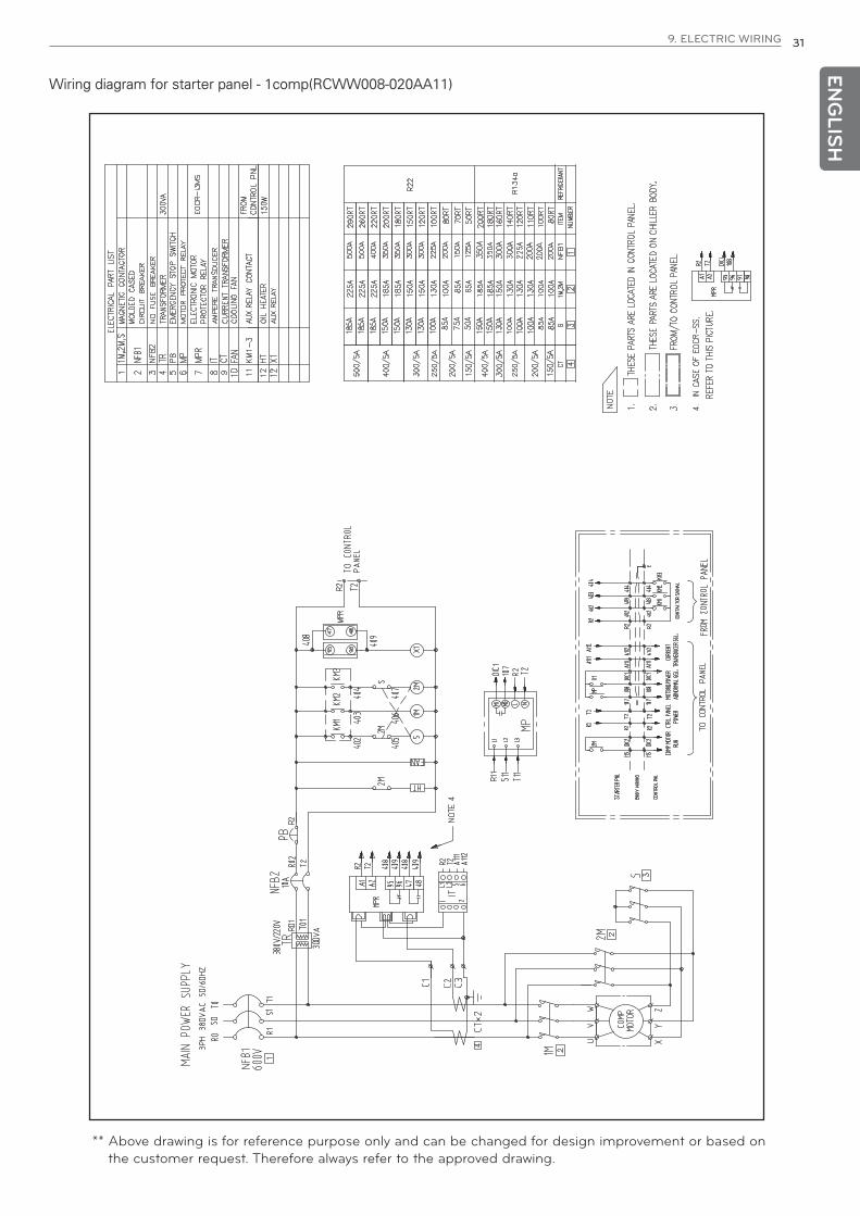
Wiring diagram for starter panel - 1comp(RCWW008-020AA11)
** Above drawing is for reference purpose only and can be changed for design improvement or based onthe customer request. Therefore always refer to the approved drawing.
32 9. ELECTRIC WIRING
ENG
LISH
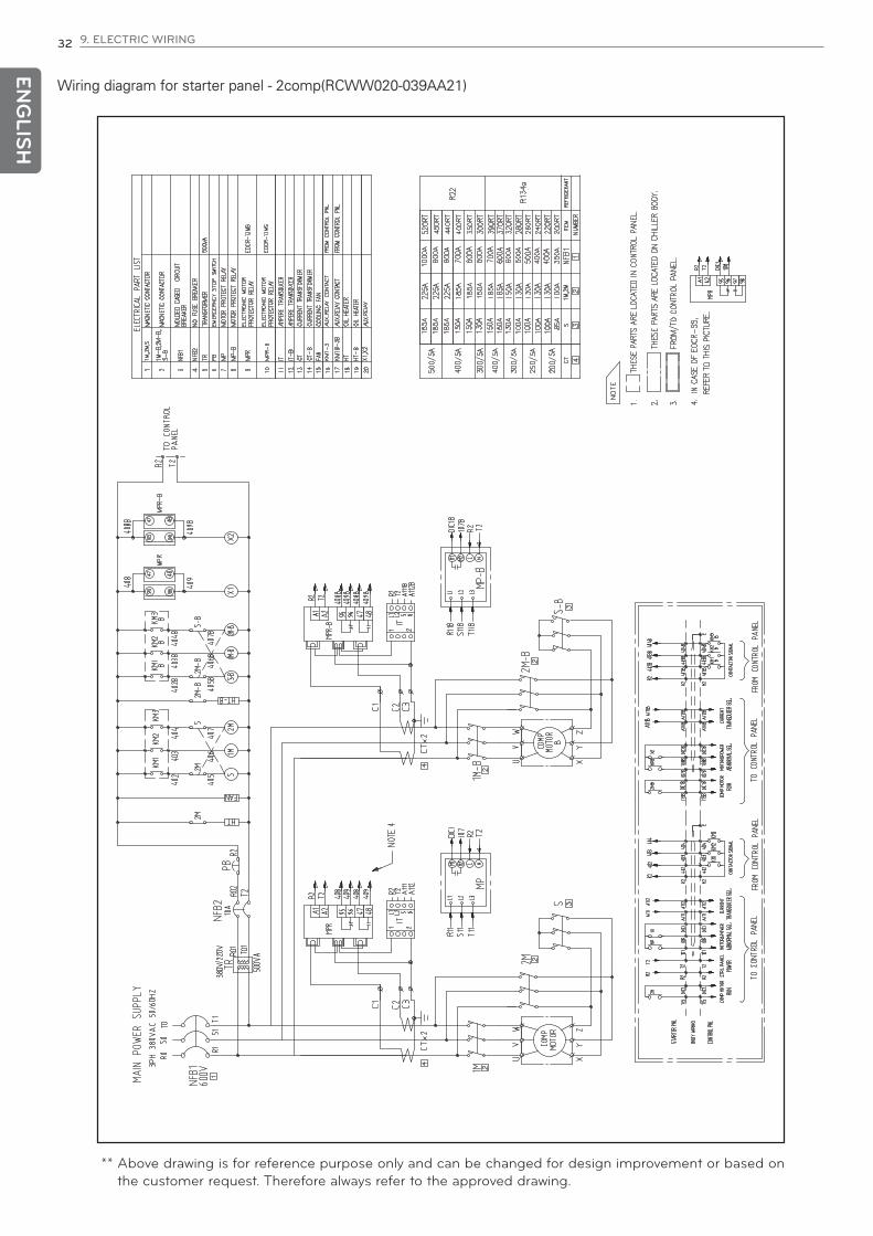
** Above drawing is for reference purpose only and can be changed for design improvement or based onthe customer request. Therefore always refer to the approved drawing.
Wiring diagram for starter panel - 2comp(RCWW020-039AA21)

9. ELECTRIC WIRING 33
Wiring diagram for control panel - 1comp(RCWW008-020AA11)
** Above drawing is for reference purpose only and can be changed for design improvement or based oncustomer request. Therefore refer to the approved drawing.
ENG
LISH

34 9. ELECTRIC WIRING
ENG
LISH
** Above drawing is for reference purpose only and can be changed for design improvement or based oncustomer request. Therefore refer to the approved drawing.
Wiring diagram for control panel - 2comp(RCWW020-039AA21)
Appendix 35
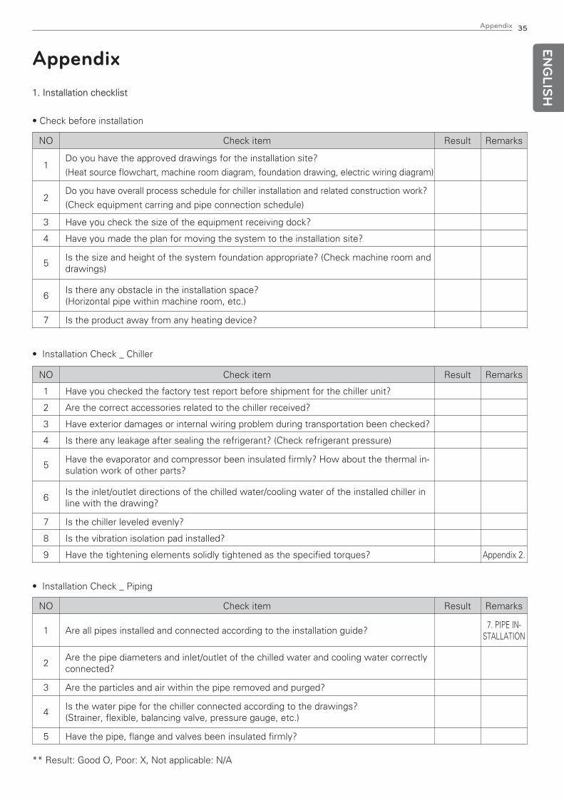
Appendix1. Installation checklist
• Check before installation
NO Check item Result Remarks
1Do you have the approved drawings for the installation site?
(Heat source flowchart, machine room diagram, foundation drawing, electric wiring diagram)
2Do you have overall process schedule for chiller installation and related construction work?
(Check equipment carring and pipe connection schedule)
3 Have you check the size of the equipment receiving dock?
4 Have you made the plan for moving the system to the installation site?
5Is the size and height of the system foundation appropriate? (Check machine room anddrawings)
6Is there any obstacle in the installation space? (Horizontal pipe within machine room, etc.)
7 Is the product away from any heating device?
NO Check item Result Remarks
1 Have you checked the factory test report before shipment for the chiller unit?
2 Are the correct accessories related to the chiller received?
3 Have exterior damages or internal wiring problem during transportation been checked?
4 Is there any leakage after sealing the refrigerant? (Check refrigerant pressure)
5Have the evaporator and compressor been insulated firmly? How about the thermal in-sulation work of other parts?
6Is the inlet/outlet directions of the chilled water/cooling water of the installed chiller inline with the drawing?
7 Is the chiller leveled evenly?
8 Is the vibration isolation pad installed?
9 Have the tightening elements solidly tightened as the specified torques? Appendix 2.
• Installation Check _ Chiller
NO Check item Result Remarks
1 Are all pipes installed and connected according to the installation guide?7. PIPE IN-
STALLATION
2Are the pipe diameters and inlet/outlet of the chilled water and cooling water correctlyconnected?
3 Are the particles and air within the pipe removed and purged?
4Is the water pipe for the chiller connected according to the drawings?(Strainer, flexible, balancing valve, pressure gauge, etc.)
5 Have the pipe, flange and valves been insulated firmly?
• Installation Check _ Piping
** Result: Good O, Poor: X, Not applicable: N/A
ENG
LISH

36
ENG
LISH
NO Check item Result Remarks
1Do the cables and accessories meet the specifications and dimensions in accordanceto the drawing and specification?
2 Has the wire pipe been checked to make sure it is cleaned before inserting the wires?
3 Is the curved radius of the cable satisfactory to the regulation?
4Has the cable sheath been peeled off properly and wired without damaging the con-ductor using proper tools?
5 When wire needs to be supported or tied, are the wires neatly arranged?
6When external layer of the cable needs grounding, has it been grounded properlythrough appropriate connection?
7 Have the permitted wires within the pull box and joint box been arranged neatly?
8 Have all unused holes within the box been blocked appropriately?
9 Is there any wire within the wire pipe connected?
10 Is the connector appropriately flame resistant in appropriate size?
11 Are the wires color coded?
12Have the wires well wired not to deteriorate electric resistance, insulation resistanceand tensile strength?
13 Is the circuit tags appropriately attached based on the permitted method?
14 Is the insulation resistance of the wire measured after inserting the wire?
15After the installation and measurement completed, are the wire coatings and conduc-tive materials appropriately protected to avoid damages?
16Is the clearance between high voltage cable and low voltage cable or low electricitycable in compliance with the standard?
17When the cable is inserted, did it comply with the standard of not using vehicle or otherheavy equipment?
18 Is the cable inserting device used in the site approved?
19 Are appropriate accessories used for connecting the cable tray?
20 Are the support interval and material for the cable tray appropriate?
21 Are any sharp parts that can damage the cable removed?
22 Are the bonding and jumper installed at the connecting part of the cable tray installed?
23Are the 2nd wiring construction (starter pane to control panel) cable connection termi-nals aligned?
24 Is the motor current signal wiring according to the drawing?
25 Are the chilled water/cooling water pump interlock cable wiring terminals aligned?
26 Has the control valve of the chiller unit been wired according to the drawings?
27 Is every terminal tightened well?
• Installation Check _ Electricity
** Result: Good O, Poor: X, Not applicable: N/A
Appendix
37EN
GLIS
H
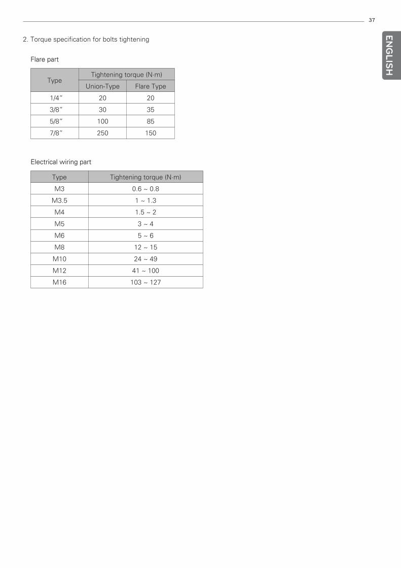
2. Torque specification for bolts tightening
Flare part
Electrical wiring part
Type Tightening torque (N·m)
Union-Type Flare Type
1/4” 20 20
3/8” 30 35
5/8” 100 85
7/8” 250 150
Type Tightening torque (N·m)
M3 0.6 ~ 0.8
M3.5 1 ~ 1.3
M4 1.5 ~ 2
M5 3 ~ 4
M6 5 ~ 6
M8 12 ~ 15
M10 24 ~ 49
M12 41 ~ 100
M16 103 ~ 127