Embed Size (px)
Citation preview
Maintenance manualWater cooledvacuum pumps
PR150 · PR200 · PR250GB
3
Introduction
Please follow carefully the instructions of the manual for a cor-rect installation, use and maintenance of your vacuum pump.
Important issues
StartingStart off the pump slowly. Forced engagement may causedamage to the transmission.
StoppingDisengage the pump transmission before stopping the drive.Do not stop the engine while the pump is operating.
Operating• Do not block or alter the relief valves adjustment, in order toavoid damage or explosion.• Do not splash the pump with water or other liquid while thepump is running.• Keep the rotation speed withing the given limits.In case of any obstruction along the suction line stop thepump and remove the cause.Do not adjust the flow by means of gate valves or relief valveswhich are not suitable for such purpose. The flow and thevacuum rate can be adjusted changing the speed of thepump.
Weekly maintenance
Suction filterThe pump must be stopped while cleaning the suction filter.The filter can be cleaned using detergent liquid, diesel fueland a high pressure jet of air.
Safety relief valveBoth pressure or vacuum relief valves must be cleaned andchecked periodically
Non-return valveIn case of vibrations the check valve must be replaced.
We suggest that expert personnel must check the pumponce a year. Wear parts must be replaced within threeyears.
The pump must be installed according to local safetyrequirements. In the countries of the comun market according to standard n° 89/392 CEE.
Contents
1 Dimensions and performances
2 Installation2.1 Initial check2.2 Protection of the inlet port2.3 Protection against intake of liquids2.4 Non-return check valve2.5 4 way valve2.6 Exhauster/Oil separator2.7 Cooling of the pump2.8 Pressure relief valve2.9 Vacuum relief valve
3 Running of the pump3.1-3.6 Check of the start-off and running of the pump
4 Maintenance of the vacuum pump4.1 Lubrication
4.2 Performance control4.3 Temperature of the cooling liquid4.4 Intake of liquids4.5 Checking of the wear of the vanes4.6 Replacement of the vanes4.7 Cleaning of filter4.8 Preliminary maintenance4.9 Trouble shooting
5 Spare parts list5.1 How to order the spare parts5.2 Spare parts list of P150R5.3 Spare parts list of P200R5.4 Spare parts list of P250R
4
Performances
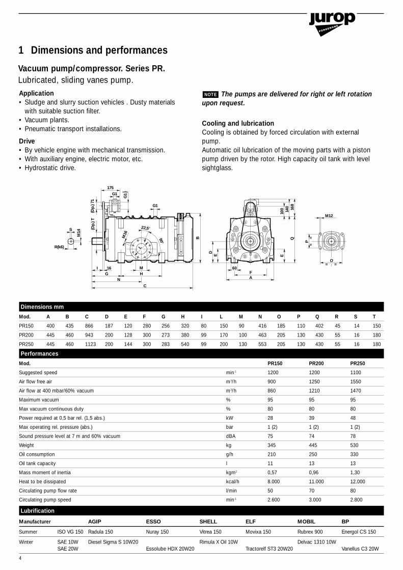
Mod. PR150 PR200 PR250
Suggested speed min-1 1200 1200 1100
Air flow free air m3/h 900 1250 1550
Air flow at 400 mbar/60% vacuum m3/h 860 1210 1470
Maximum vacuum % 95 95 95
Max vacuum continuous duty % 80 80 80
Power required at 0,5 bar rel. (1,5 abs.) kW 28 39 48
Max operating rel. pressure (abs.) bar 1 (2) 1 (2) 1 (2)
Sound pressure level at 7 m and 60% vacuum dBA 75 74 78
Weight kg 345 445 530
Oil consumption g/h 210 250 330
Oil tank capacity l 11 13 13
Mass moment of inertia kgm2 0,57 0,96 1,30
Heat to be dissipated kcal/h 8.000 11.000 12.000
Circulating pump flow rate l/min 50 70 80
Circulating pump speed min-1 2.600 3.000 2.800
Dimensions mm
Mod. A B C D E F G H I L M N O P Q R S T
PR150 400 435 866 187 120 280 256 320 80 150 90 416 185 110 402 45 14 150
PR200 445 460 943 200 128 300 273 380 99 170 100 463 205 130 430 55 16 180
PR250 445 460 1123 200 144 300 283 540 99 200 130 553 205 130 430 55 16 180
S
R(k6)
I 16G H F
O= =
M12
A
60
N
C
G1
175G1
(Dp.
) 71
G1
1 2
(Dp.
) T
B
DE E
100 140 168
Q
P=
=M14
22,5°
90°
M16
M
L
Application• Sludge and slurry suction vehicles . Dusty materials
with suitable suction filter.• Vacuum plants.• Pneumatic transport installations.
Drive• By vehicle engine with mechanical transmission.• With auxiliary engine, electric motor, etc.• Hydrostatic drive.
The pumps are delivered for right or left rotationupon request.
Cooling and lubricationCooling is obtained by forced circulation with externalpump.Automatic oil lubrication of the moving parts with a pistonpump driven by the rotor. High capacity oil tank with levelsightglass.
NOTE
Lubrification
Manufacturer AGIP ESSO SHELL ELF MOBIL BP
Summer ISO VG 150 Radula 150 Nuray 150 Vitrea 150 Movixa 150 Rubrex 900 Energol CS 150
Winter SAE 10W Diesel Sigma S 10W20 Rimula X Oil 10W Delvac 1310 10WSAE 20W Essolube HDX 20W20 Tractorelf ST3 20W20 Vanellus C3 20W
Vacuum pump/compressor. Series PR.Lubricated, sliding vanes pump.
1 Dimensions and performances
5
2 1,5 1 0,8 0,6 0,4 0,2 0
400
600
800
1000
300
500
700
900
1100
PR 150
2 1,5 1 0,8 0,6 0,4 0,2 0
400
800
1200
1600
200
600
1000
1400
1800
PR 200
2 1,5 1 0,8 0,6 0,4 0,2 0
600
1000
1400
1800
400
800
1200
1600
2000
PR 250
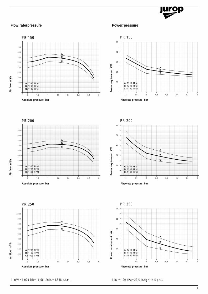
A: 1300 RPMB: 1200 RPMC: 1100 RPM
A: 1300 RPMB: 1200 RPMC: 1100 RPM
AB
C
AB
C
A: 1200 RPMB: 1100 RPMC: 1000 RPM
AB
C
2 1,5 1 0,8 0,6 0,4 0,2 0
10
30
20
40
50
PR 150
2 1,5 1 0,8 0,6 0,4 0,2 0
30
50
20
40
60
PR 200
2 1,5 1 0,8 0,6 0,4 0,2 0
30
50
40
60
70
PR 250
A: 1200 RPMB: 1100 RPMC: 1000 RPM
A
B
C
A: 1300 RPMB: 1200 RPMC: 1100 RPM
A
B
C
A: 1300 RPMB: 1200 RPMC: 1100 RPM
ABC
Flow rate/pressure Power/pressure
Absolute pressure bar
Air
flow
m3 /h
Absolute pressure bar
Pow
er r
equi
rem
ent
kW
Absolute pressure bar
Air
flow
m3 /h
Absolute pressure bar
Pow
er r
equi
rem
ent
kW
Absolute pressure bar
1 m3/h=1.000 l /h =16,66 l /min.= 0,588 c. f.m. 1 bar =100 kPa =29,5 in.Hg = 14,5 p.s.i.
Air
flow
m3 /h
Absolute pressure bar
Pow
er r
equi
rem
ent
kW
6
dB
31,5
50
60
70
80
90
63125
250500
10002000
40008000
16000 Hz
N 50
N 55
N 60
N 65
N 70
N 75
N 80
N 85
N 90
N 95
A
PR 150 fig. 1
B
A: 1200 RPMB: 1100 RPM
dB
31,5
50
60
70
80
90
63125
250500
10002000
40008000
16000 Hz
N 50
N 55
N 60
N 65
N 70
N 75
N 80
N 85
N 90
N 95
PR 200 fig. 2
A
A: 1200 RPMB: 1100 RPM
B
dB
31,5
50
60
70
80
90
63125
250500
10002000
40008000
16000 Hz
N 50
N 55
N 60
N 65
N 70
N 75
N 80
N 85
N 90
N 95
PR 250 fig. 3
A
B
A: 1100 RPMB: 1000 RPM
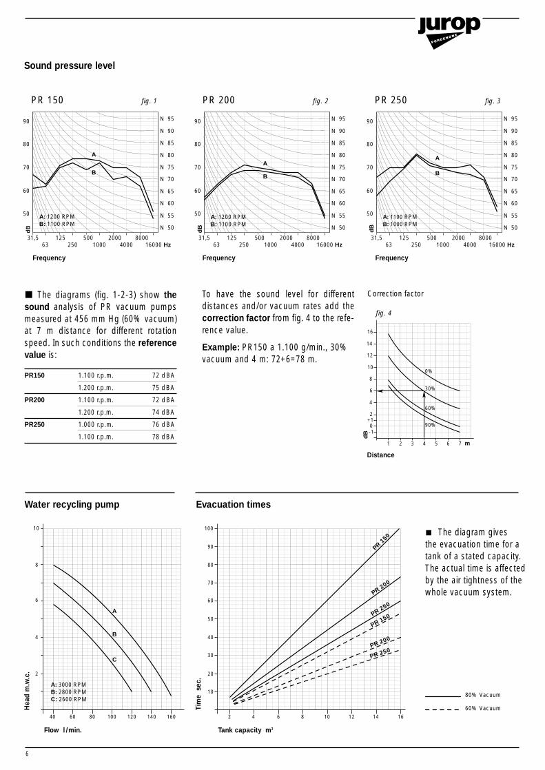
Sound pressure level
1 2 4
dB
53
2
4
80%
30%
60%
90%
10
6 7 m
0-1
+1
6
12
14
16
fig. 4
Correction factor
40 60 80 100 120 140 160
4
8
10
2
6
2 4 6 8 10 12 14 16
30
40
50
60
70
80
90
100
10
20
PR 150
PR 200
PR 250
PR 150
PR 200
PR 250
A: 3000 RPMB: 2800 RPMC: 2600 RPM
A
B
C
80% Vacuum
60% Vacuum
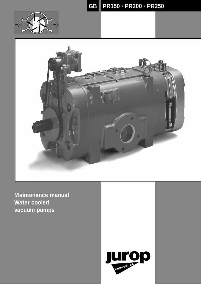
Water recycling pump Evacuation times
The diagrams (fig. 1-2-3) show thesound analysis of PR vacuum pumpsmeasured at 456 mm Hg (60% vacuum)at 7 m distance for different rotationspeed. In such conditions the referencevalue is:
PR150 1.100 r.p.m. 72 dBA
1.200 r.p.m. 75 dBA
PR200 1.100 r.p.m. 72 dBA
1.200 r.p.m. 74 dBA
PR250 1.000 r.p.m. 76 dBA
1.100 r.p.m. 78 dBA
To have the sound level for differentdistances and/or vacuum rates add thecorrection factor from fig. 4 to the refe-rence value.
Example: PR150 a 1.100 g/min., 30%vacuum and 4 m: 72+6=78 m.
The diagram gives the evacuation time for atank of a stated capacity. The actual time is affectedby the air tightness of thewhole vacuum system.
Flow l /min. Tank capacity m3
Distance
Frequency Frequency Frequency
Hea
d m
.w.c
.
Tim
ese
c.
7
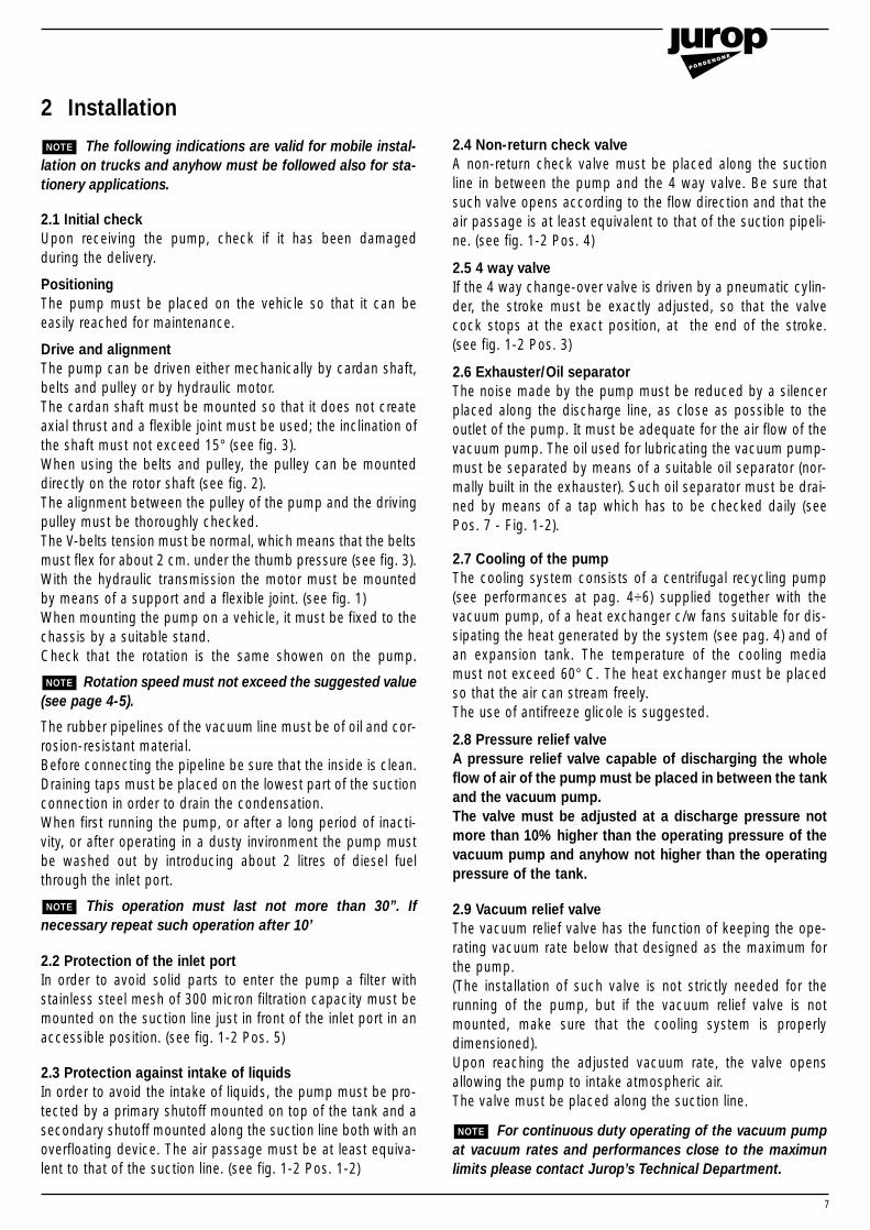
2 Installation
The following indications are valid for mobile instal-lation on trucks and anyhow must be followed also for sta-tionery applications.
2.1 Initial checkUpon receiving the pump, check if it has been damagedduring the delivery.
PositioningThe pump must be placed on the vehicle so that it can beeasily reached for maintenance.
Drive and alignmentThe pump can be driven either mechanically by cardan shaft,belts and pulley or by hydraulic motor.The cardan shaft must be mounted so that it does not createaxial thrust and a flexible joint must be used; the inclination ofthe shaft must not exceed 15° (see fig. 3).When using the belts and pulley, the pulley can be mounteddirectly on the rotor shaft (see fig. 2).The alignment between the pulley of the pump and the drivingpulley must be thoroughly checked.The V-belts tension must be normal, which means that the beltsmust flex for about 2 cm. under the thumb pressure (see fig. 3).With the hydraulic transmission the motor must be mountedby means of a support and a flexible joint. (see fig. 1)When mounting the pump on a vehicle, it must be fixed to thechassis by a suitable stand.Check that the rotation is the same showen on the pump.
Rotation speed must not exceed the suggested value(see page 4-5).
The rubber pipelines of the vacuum line must be of oil and cor-rosion-resistant material.Before connecting the pipeline be sure that the inside is clean.Draining taps must be placed on the lowest part of the suctionconnection in order to drain the condensation.When first running the pump, or after a long period of inacti-vity, or after operating in a dusty invironment the pump mustbe washed out by introducing about 2 litres of diesel fuelthrough the inlet port.
This operation must last not more than 30”. Ifnecessary repeat such operation after 10’
2.2 Protection of the inlet portIn order to avoid solid parts to enter the pump a filter withstainless steel mesh of 300 micron filtration capacity must bemounted on the suction line just in front of the inlet port in anaccessible position. (see fig. 1-2 Pos. 5)
2.3 Protection against intake of liquidsIn order to avoid the intake of liquids, the pump must be pro-tected by a primary shutoff mounted on top of the tank and asecondary shutoff mounted along the suction line both with anoverfloating device. The air passage must be at least equiva-lent to that of the suction line. (see fig. 1-2 Pos. 1-2)
NOTE
NOTE
NOTE 2.4 Non-return check valveA non-return check valve must be placed along the suctionline in between the pump and the 4 way valve. Be sure thatsuch valve opens according to the flow direction and that theair passage is at least equivalent to that of the suction pipeli-ne. (see fig. 1-2 Pos. 4)
2.5 4 way valveIf the 4 way change-over valve is driven by a pneumatic cylin-der, the stroke must be exactly adjusted, so that the valvecock stops at the exact position, at the end of the stroke. (see fig. 1-2 Pos. 3)
2.6 Exhauster/Oil separatorThe noise made by the pump must be reduced by a silencerplaced along the discharge line, as close as possible to theoutlet of the pump. It must be adequate for the air flow of thevacuum pump. The oil used for lubricating the vacuum pump-must be separated by means of a suitable oil separator (nor-mally built in the exhauster). Such oil separator must be drai-ned by means of a tap which has to be checked daily (seePos. 7 - Fig. 1-2).
2.7 Cooling of the pumpThe cooling system consists of a centrifugal recycling pump(see performances at pag. 4÷6) supplied together with thevacuum pump, of a heat exchanger c/w fans suitable for dis-sipating the heat generated by the system (see pag. 4) and ofan expansion tank. The temperature of the cooling mediamust not exceed 60° C. The heat exchanger must be placedso that the air can stream freely.The use of antifreeze glicole is suggested.
2.8 Pressure relief valveA pressure relief valve capable of discharging the wholeflow of air of the pump must be placed in between the tankand the vacuum pump. The valve must be adjusted at a discharge pressure notmore than 10% higher than the operating pressure of thevacuum pump and anyhow not higher than the operatingpressure of the tank.
2.9 Vacuum relief valveThe vacuum relief valve has the function of keeping the ope-rating vacuum rate below that designed as the maximum forthe pump.(The installation of such valve is not strictly needed for therunning of the pump, but if the vacuum relief valve is notmounted, make sure that the cooling system is properlydimensioned).Upon reaching the adjusted vacuum rate, the valve opensallowing the pump to intake atmospheric air.The valve must be placed along the suction line.
For continuous duty operating of the vacuum pumpat vacuum rates and performances close to the maximunlimits please contact Jurop’s Technical Department.
NOTE
8
1413
8 9 10
11
12
7
34
6515
1"
2
1
11/2"
1"
A
Filling of heatexchanger
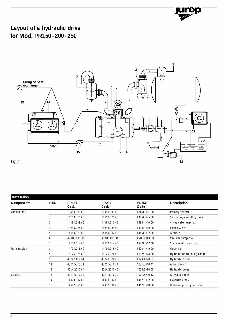
Installation
Components Pos. PR150 PR200 PR250 DescriptionCode Code Code
Vacuum line 1 18450.001.00 18450.001.00 18450.001.00 Primary shutoff
2 14450.020.00 14450.025.00 14450.025.00 Secondary shutoff cyclone
3 14881.009.00 14881.010.00 14881.010.00 4 way valve pneum.
4 14933.008.00 14933.009.00 14933.009.00 Check valve
5 14450.029.00 14450.032.00 14450.032.00 Air filter
6 A2908.001.30 A2708.001.30 A2808.001.30 Vacuum pump c.w.
7 15470.014.00 15470.014.00 15470.017.00 Silencer /Oil separator
Transmission 8 14701.018.00 14701.019.00 14701.019.00 Coupling
9 16125.025.00 16125.024.00 16125.024.00 Hydromotor mounting flange
10 4024.1070.04 40241.070.03 4024.1070.07 Hydraulic motor
11 4021.5010.31 4021.5010.31 4021.5010.41 Air-oil cooler
12 4024.2050.04 4024.2050.09 4024.2050.03 Hydraulic pump
Cooling 13 4021.5010.22 4021.5010.22 4021.5010.12 Air-water cooler
14 14873.002.00 14873.002.00 14873.002.00 Expansion tank
15 14072.008.00 14072.008.00 14072.008.00 Water recycling pump c.w.
Layout of a hydraulic drive for Mod. PR150-200-250
Fig. 1
9
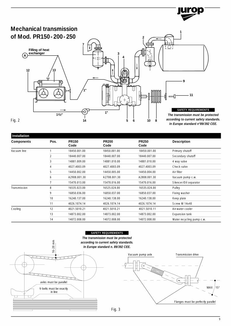
Installation
Components Pos. PR150 PR200 PR250 DescriptionCode Code Code
Vacuum line 1 18450.001.00 18450.001.00 18450.001.00 Primary shutoff
2 18440.007.00 18440.007.00 18440.007.00 Secondary shutoff
3 14881.009.00 14881.010.00 14881.010.00 4 way valve
4 4027.4003.09 4027.4003.09 4027.4003.09 Check valve
5 14450.002.00 14450.005.00 14450.004.00 Air filter
6 A2908.001.30 A2708.001.30 A2808.001.30 Vacuum pump c.w.
7 15470.013.00 15470.016.00 15470.016.00 Silencer /Oil separator
Transmission 8 16535.023.00 16525.024.00 16535.024.00 Pulley
9 16850.036.00 16850.037.00 16850.037.00 Fixing washer
10 16240.137.00 16240.138.00 16240.138.00 Keep plate
11 4026.1074.14 4026.1074.14 4026.1074.14 Screw M 14x40
Cooling 12 4021.5010.21 4021.5010.21 4021.5010.11 Air-water cooler
13 14873.002.00 14873.002.00 14873.002.00 Expansion tank
14 14072.008.00 14072.008.00 14072.008.00 Water recycling pump c.w.
1312
7
34
6514
1"
2
1
11/2"
1"
A
Filling of heatexchanger
810
9
11
Mechanical transmissionof Mod. PR150-200-250
axles must be parallel
V-belts must be exactly in line
16-2
0 m
m
MAX 15°
Flanges must be perfectly parallel
Vacuum pump axle Transmission drive
The transmission must be protected according to current safety standards.
In Europe standard n°89/392 CEE.
SAFETY REQUIREMENTS
The transmission must be protectedaccording to current safety standards.
In Europe standard n. 89/392 CEE.
SAFETY REQUIREMENTS
Fig. 3
Fig. 2
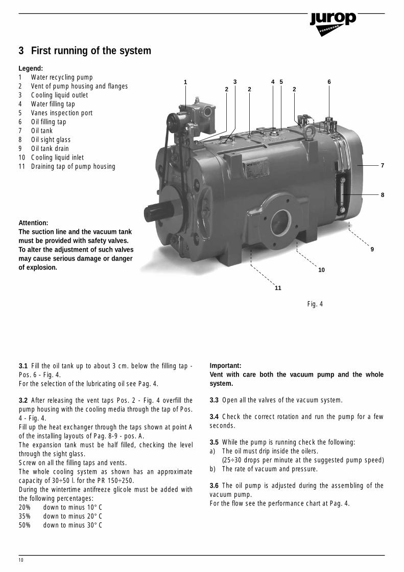
3 First running of the system
Legend:1 Water recycling pump2 Vent of pump housing and flanges3 Cooling liquid outlet4 Water filling tap5 Vanes inspection port6 Oil filling tap 7 Oil tank8 Oil sight glass9 Oil tank drain10 Cooling liquid inlet11 Draining tap of pump housing
Attention:The suction line and the vacuum tank must be provided with safety valves. To alter the adjustment of such valves may cause serious damage or danger of explosion.
10
Important: Vent with care both the vacuum pump and the wholesystem.
3.3 Open all the valves of the vacuum system.
3.4 Check the correct rotation and run the pump for a fewseconds.
3.5 While the pump is running check the following:a) The oil must drip inside the oilers.
(25÷30 drops per minute at the suggested pump speed)b) The rate of vacuum and pressure.
3.6 The oil pump is adjusted during the assembling of thevacuum pump. For the flow see the performance chart at Pag. 4.
3.1 Fill the oil tank up to about 3 cm. below the filling tap -Pos. 6 - Fig. 4.For the selection of the lubricating oil see Pag. 4.
3.2 After releasing the vent taps Pos. 2 - Fig. 4 overfill thepump housing with the cooling media through the tap of Pos.4 - Fig. 4.Fill up the heat exchanger through the taps shown at point Aof the installing layouts of Pag. 8-9 - pos. A.The expansion tank must be half filled, checking the levelthrough the sight glass.Screw on all the filling taps and vents.The whole cooling system as shown has an approximatecapacity of 30÷50 l. for the PR 150÷250.During the wintertime antifreeze glicole must be added withthe following percentages:20% down to minus 10° C35% down to minus 20° C50% down to minus 30° C
11
10
9
8
7
6542 2
32
1
Fig. 4
11
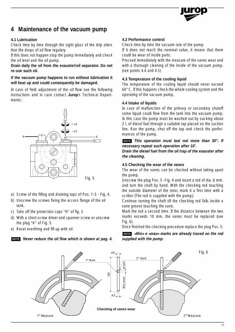
a) Screw of the filling and draining taps of Pos. 1-3 - Fig. 4.
b) Unscrew the screws fixing the access flange of the oil tank.
c) Take off the protection caps “H” of fig. 5
d) With a short screw driver and spanner screw or unscrew the plug “K” of Fig. 5.
e) Reset everthing and fill up with oil.
Never reduce the oil flow which is shown at pag. 4.NOTE
4.1 LubricationCheck time by time through the sight glass of the drip oilersthat the drops of oil flow regulary.If this does not happen stop the pump immediately and checkthe oil level and the oil pump.Drain daily the oil from the exauster/oil separator. Do notre-use such oil.
If the vacuum pump happens to run without lubrication itwill heat up and could consequently be damaged.
In case of field adjustment of the oil flow see the followinginstructions and in case contact Jurop’s Technical Depart-ments:
4.2 Performance controlCheck time by time the vacuum rate of the pump.If it does not reach the nominal value, it means that therecould be wear of inside parts.Proceed immediately with the measure of the vanes wear andwith a thorough cleaning of the inside of the vacuum pump.(see points 4.4 and 4.5)
4.3 Temperature of the cooling liquidThe temperature of the cooling liquid should never exceed 60° C. If this happens check the whole cooling system and theoperating of the vacuum pump.
4.4 Intake of liquidsIn case of malfunction of the primary or secondary shutoffsome liquid could flow from the tank into the vacuum pump.In this case the pump must be washed out by sucking about2 l. of diesel fuel through a suitable tap placed on the suctionline. Run the pump, shut off the tap and check the perfor-mances of the pump.
This operation must last not more than 30”. Ifnecessary repeat such operation after 10’.Drain the diesel fuel from the oil trap of the exauster afterthe cleaning.
4.5 Checking the wear of the vanesThe wear of the vanes can be checked without taking apartthe pump.Unscrew the plug Pos. 5 -Fig. 4 and insert a rod of dia. 6 mm.and turn the shaft by hand. With the checking rod touchingthe outside diameter of the rotor, mark it a first time with ascriber (The rod is supplied with the pump).Continue turning the shaft till the checking rod falls inside avane groove touching the vane.Mark the rod a second time. If the distance between the twomarks exceeds 10 mm. the vanes must be replaced (see Fig. 6). Once finished the checking procedure replace the plug Pos. 5.
«Min» e «max» marks are already traced on the rodsupplied with the pump.NOTA
NOTE
4 Maintenance of the vacuum pump
+ oil
KH
– oil
180
10 m
mM
ax w
ear
ø 6
ø 5
1ST Mark2ND Mark
1ST Measure 2ND Measure
Checking of vanes wear
Fig. 5
Fig. 6
12
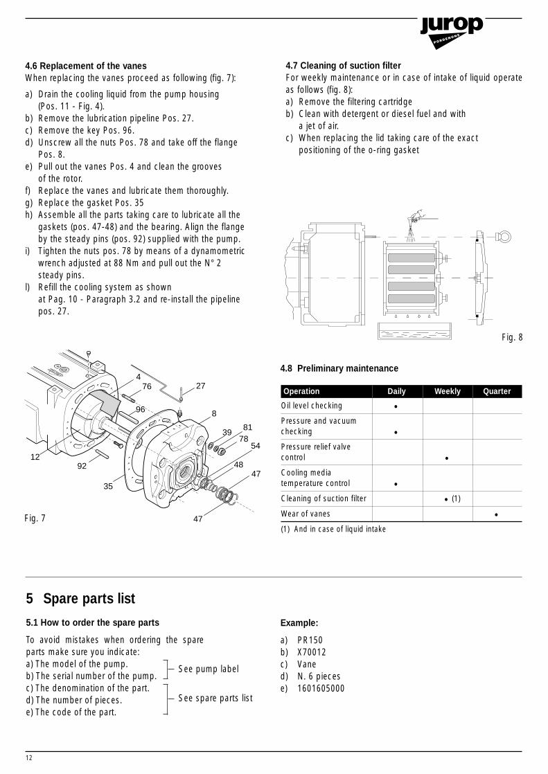
4.7 Cleaning of suction filterFor weekly maintenance or in case of intake of liquid operateas follows (fig. 8):a) Remove the filtering cartridgeb) Clean with detergent or diesel fuel and with
a jet of air.c) When replacing the lid taking care of the exact
positioning of the o-ring gasket
Operation Daily Weekly Quarter
Oil level checking •Pressure and vacuumchecking •Pressure relief valvecontrol •Cooling mediatemperature control •Cleaning of suction filter • (1)
Wear of vanes •(1) And in case of liquid intake
5 Spare parts list
5.1 How to order the spare parts
To avoid mistakes when ordering the spareparts make sure you indicate:a) The model of the pump.b) The serial number of the pump.c) The denomination of the part.d) The number of pieces.e) The code of the part.
Example:
a) PR150b) X70012c) Vaned) N. 6 piecese) 1601605000
See spare parts list
See pump label
4.8 Preliminary maintenance
8
3981
7854
4847
35
9212
96
764
47
27
Fig. 7
Fig. 8
4.6 Replacement of the vanesWhen replacing the vanes proceed as following (fig. 7):
a) Drain the cooling liquid from the pump housing (Pos. 11 - Fig. 4).
b) Remove the lubrication pipeline Pos. 27.c) Remove the key Pos. 96.d) Unscrew all the nuts Pos. 78 and take off the flange
Pos. 8.e) Pull out the vanes Pos. 4 and clean the grooves
of the rotor.f) Replace the vanes and lubricate them thoroughly.g) Replace the gasket Pos. 35h) Assemble all the parts taking care to lubricate all the
gaskets (pos. 47-48) and the bearing. Align the flange by the steady pins (pos. 92) supplied with the pump.
i) Tighten the nuts pos. 78 by means of a dynamometric wrench adjusted at 88 Nm and pull out the N° 2 steady pins.
l) Refill the cooling system as shown at Pag. 10 - Paragraph 3.2 and re-install the pipeline pos. 27.
13
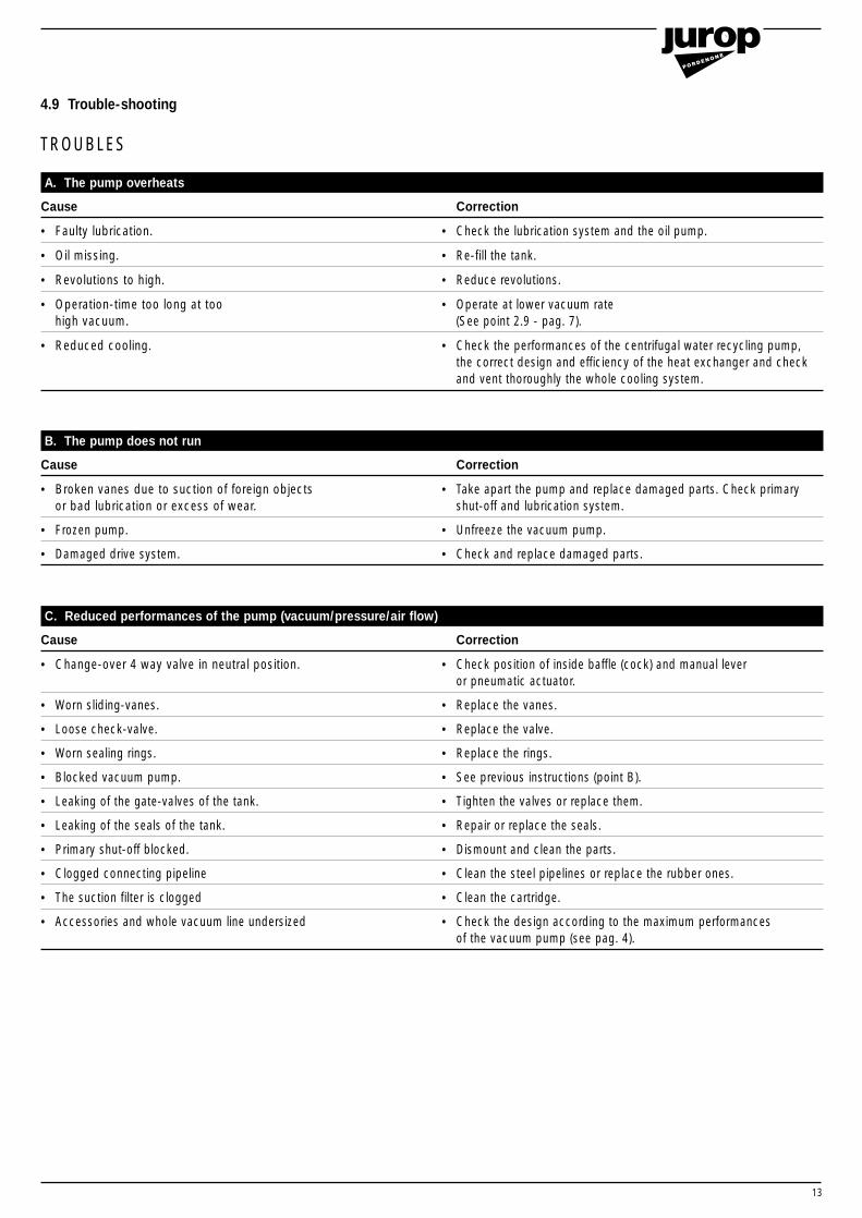
A. The pump overheats
Cause Correction
• Faulty lubrication. • Check the lubrication system and the oil pump.
• Oil missing. • Re-fill the tank.
• Revolutions to high. • Reduce revolutions.
• Operation-time too long at too • Operate at lower vacuum ratehigh vacuum. (See point 2.9 - pag. 7).
• Reduced cooling. • Check the performances of the centrifugal water recycling pump,the correct design and efficiency of the heat exchanger and checkand vent thoroughly the whole cooling system.
B. The pump does not run
Cause Correction
• Broken vanes due to suction of foreign objects • Take apart the pump and replace damaged parts. Check primary or bad lubrication or excess of wear. shut-off and lubrication system.
• Frozen pump. • Unfreeze the vacuum pump.
• Damaged drive system. • Check and replace damaged parts.
C. Reduced performances of the pump (vacuum/pressure/air flow)
Cause Correction
• Change-over 4 way valve in neutral position. • Check position of inside baffle (cock) and manual lever or pneumatic actuator.
• Worn sliding-vanes. • Replace the vanes.
• Loose check-valve. • Replace the valve.
• Worn sealing rings. • Replace the rings.
• Blocked vacuum pump. • See previous instructions (point B).
• Leaking of the gate-valves of the tank. • Tighten the valves or replace them.
• Leaking of the seals of the tank. • Repair or replace the seals.
• Primary shut-off blocked. • Dismount and clean the parts.
• Clogged connecting pipeline • Clean the steel pipelines or replace the rubber ones.
• The suction filter is clogged • Clean the cartridge.
• Accessories and whole vacuum line undersized • Check the design according to the maximum performances of the vacuum pump (see pag. 4).
4.9 Trouble-shooting
TROUBLES
14
2-3
74
828
13146
56-5
786
7585
25
103
102
71232473
1
100
5
100
4010
8
18
3037
234132
46
43
668775
86
33
17 51
72 8868
34
48
749
44
80
3842
62
50
11
95
20
94
4910
8274
65
8391
979 63
8274
5397 60
59
65
83
22
8
3981 78
9954
4816
4798
55
98
35
67
21
9245
2912
104
70
31
106
35
28
9915
19
26
27
984798
4752
9010
5 77 101
105
90
107
69
84
9661
764
93 89
109-
110
106
47
58
7482
91
36
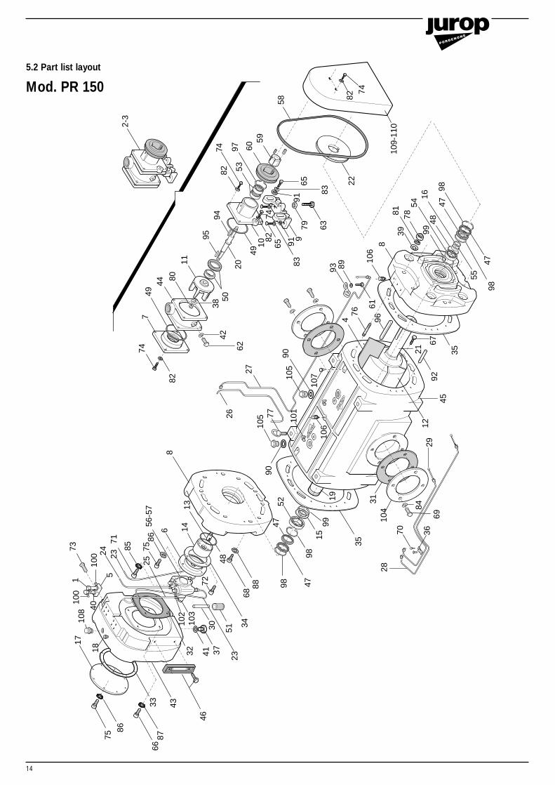
5.2 Part list layout
Mod. PR 150
15
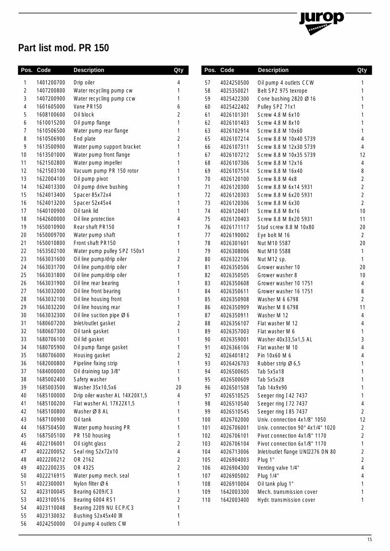
Part list mod. PR 150
Pos. Code Description Qty Pos. Code Description Qty
57 4024250500 Oil pump 4 outlets CCW 158 4025350021 Belt SPZ 975 texrope 159 4025422300 Cone bushing 2820 Ø 16 160 4025422402 Pulley SPZ 71x1 161 4026101301 Screw 4.8 M 6x10 162 4026101403 Screw 4.8 M 8x10 163 4026102914 Screw 8.8 M 10x60 165 4026107214 Screw 8.8 M 10x40 5739 466 4026107311 Screw 8.8 M 12x30 5739 4 67 4026107212 Screw 8.8 M 10x35 5739 1268 4026107306 Screw 8.8 M 12x16 469 4026107514 Screw 8.8 M 16x40 870 4026120100 Screw 8.8 M 4x8 2 71 4026120300 Screw 8.8 M 6x14 5931 272 4026120303 Screw 8.8 M 6x20 5931 2 73 4026120306 Screw 8.8 M 6x30 274 4026120401 Screw 8.8 M 8x16 1075 4026120403 Screw 8.8 M 8x20 5931 1176 4026171117 Stud screw 8.8 M 10x80 2077 4026190002 Eye bolt M 16 278 4026301601 Nut M10 5587 2079 4026308006 Nut M10 5588 180 4026322106 Nut M12 sp. 1 81 4026350506 Grower washer 10 2082 4026350505 Grower washer 8 1083 4026350608 Grower washer 10 1751 484 4026350611 Grower washer 16 1751 8 85 4026350908 Washer M 6 6798 286 4026350909 Washer M 8 6798 1187 4026350911 Washer M 12 4 88 4026356107 Flat washer M 12 4 89 4026357003 Flat washer M 6 190 4026359001 Washer 40x33,5x1,5 AL 391 4026366106 Flat washer M 10 492 4026401812 Pin 10x60 M 6 493 4026426703 Rubber strip Ø 6,5 194 4026500605 Tab 5x5x18 195 4026500609 Tab 5x5x28 196 4026501508 Tab 14x9x90 197 4026510525 Seeger ring I 42 7437 198 4026510540 Seeger ring I 72 7437 4 99 4026510545 Seeger ring I 85 7437 2
100 4026702000 Univ. connection 4x1/8” 1050 12101 4026706001 Univ. connection 90° 4x1/4” 1020 2102 4026706101 Pivot connection 4x1/8” 1170 2103 4026706104 Pivot connection 6x1/8” 1170 1104 4026713006 Inlet/outlet flange UNI2276 DN 80 2105 4026904003 Plug 1” 2106 4026904300 Venting valve 1/4” 4107 4026905002 Plug 1/4” 4108 4026910004 Oil tank plug 1” 1109 1642003300 Mech. transmission cover 1110 1642003400 Hydr. transmission cover 1
1 1401200700 Drip oiler 42 1407200800 Water recycling pump cw 13 1407200900 Water recycling pump ccw 14 1601605000 Vane PR150 65 1608100600 Oil block 26 1610015200 Oil pump flange 17 1610506500 Water pump rear flange 18 1610506900 End plate 2 9 1613500900 Water pump support bracket 1
10 1613501000 Water pump front flange 1 11 1621502800 Water pump impeller 112 1621503100 Vacuum pump PR 150 rotor 113 1622004100 Oil pump pivot 114 1624013300 Oil pump drive bushing 115 1624013400 Spacer 85x72x4 116 1624013200 Spacer 52x45x4 117 1640100900 Oil tank lid 118 1642600000 Oil line protection 4 19 1650010900 Rear shaft PR150 120 1650009700 Water pump shaft 1 21 1650010800 Front shaft PR150 122 1653502100 Water pump pulley SPZ 150x1 123 1663031600 Oil line pump/drip oiler 224 1663031700 Oil line pump/drip oiler 1 25 1663031800 Oil line pump/drip oiler 1 26 1663031900 Oil line rear bearing 127 1663032000 Oil line front bearing 128 1663032100 Oil line housing front 129 1663032200 Oil line housing rear 130 1663032300 Oil line suction pipe Ø 6 131 1680607200 Inlet/outlet gasket 232 1680607300 Oil tank gasket 133 1680706100 Oil lid gasket 134 1680705900 Oil pump flange gasket 135 1680706000 Housing gasket 236 1682000800 Pipeline fixing strip 137 1684000000 Oil draining tap 3/8” 138 1685002400 Safety washer 139 1685003500 Washer 35x10,5x6 2040 1685100000 Drip oiler washer AL 14X20X1,5 441 1685100200 Flat washer AL 17X22X1,5 142 1685100800 Washer Ø 8 AL 143 1687100900 Oil tank 144 1687504500 Water pump housing PR 145 1687505100 PR 150 housing 146 4022106001 Oil sight glass 247 4022200052 Seal ring 52x72x10 448 4022200212 OR 2162 249 4022200235 OR 4325 250 4022216915 Water pump mech. seal 151 4022300001 Nylon filter Ø 6 152 4023100045 Bearing 6209/C3 153 4023100516 Bearing 6004 RS1 254 4023110048 Bearing 2209 NU ECP/C3 155 4023130032 Bushing 52x45x40 IR 156 4024250000 Oil pump 4 outlets CW 1
16
2-3
74
828
13146
56-5
786
7585
25
103
102
71232473
1
100
5
100
4010
8
18
3037
234132
46
43
668775
86
33
17 51
72 8868
34
48
749
44
80
3842
62
50
11
95
20
94
4910
8274
65
8391
979 63
8274
5397 60
59
65
83
22
8
3981 78
9954
4816
4798
55
98
35
67
21
9245
2912
104
70
31
106
35
28
9915
19
26
27
984798
4752
9010
5 77 101
105
90
107
69
84
9661
764
93 89
109-
110
106
47
58
7482
91
36
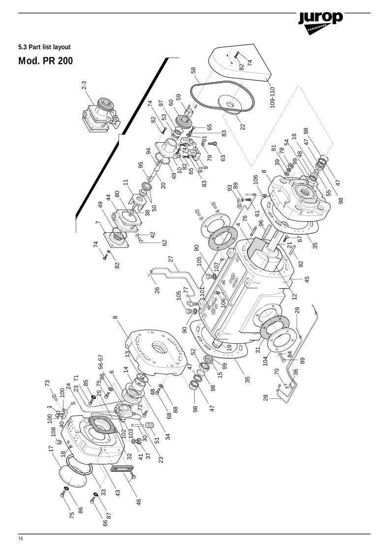
5.3 Part list layout
Mod. PR 200

17
Part list mod. PR 200
Pos. Code Description Qty Pos. Code Description Qty
57 402425050058 402535002459 402542230060 402542240261 402610130162 402610140363 402610291465 402610721466 402610731167 402610731268 402610730669 402610751470 402612010071 402612030072 402612030373 402612030674 402612040175 402612040376 402617121177 402619000278 402630160379 402630800680 402632210681 402635050882 402635050583 402635060884 402635061185 402635090886 402635090987 402635091188 402635610789 402635700390 402635900191 402635610692 402640181293 402642670394 402650060595 402650060996 402650121297 402651052598 402651054799 4026510551
100 4026702000101 4026706001102 4026706101103 4026706104104 4026713007105 4026904003106 4026904300107 4026905002108 4026910004109 1642003500110 1642003600
1 14012007002 14072008003 14072009004 16016049005 16081006006 16100150007 16105065008 16105066009 1613500900
10 1613501000 11 162150280012 162150290013 162200410014 162400960015 162400970016 162401030017 164010080018 164260000019 165000680020 165000970021 165001070022 165350200023 166303040024 166303060025 166303070026 166303080027 166303090028 166303100029 166303110030 166303150031 168060470032 168060710033 168070560034 168070570035 168070580036 168200080037 168400000038 168500240039 168500270040 168510000041 168510020042 168510080043 168710080044 168750450045 168750470046 402210600147 402220007248 402220021249 402220023550 402221691551 402230000152 402310006053 402310051654 402311007055 402313005056 4024250000
Drip oilerWater recycling pump cwWater recycling pump ccwVane PR 200Oil blockOil pump flangeWater pump rear flangeEnd plate Water pump support bracket Water pump front flangeWater pump impellerVacuum pump PR 200 rotorOil pump pivotOil pump drive bushingSpacer 100x84x3,9Spacer 65x55x10Oil tank lidOil line protectionRear shaft PR200/PR250Water pump shaftFront shaft PR200/PR250Water pump pulley SPZ 180x1Oil line pump/drip oilerOil line pump/drip oilerOil line pump/drip oilerOil line rear bearingOil line front bearingOil line housing frontOil line housing rearOil line suction pipe Ø 6Inlet/outlet gasketOil tank gasketOil lid gasketOil pump flange gasketHousing gasketPipeline fixing stripOil draining tap 3/8”Safety washerWasher 35x13x6Drip oiler washer AL 14x20x1,5Flat washer AL 17x22x1,5Washer Ø 8 ALOil tankWater pump housingPR 200 housingOil sight glassSeal ring 65x90x10OR 2162OR 4325Water pump mech. sealNylon filter Ø 6Bearing 6211/C3Bearing 6004 RS1Bearing 2211 NU ECP/C3Bushing 65x55x28 IROil pump 4 outlets CW
Oil pump 4 outlets CCWBelt SPZ 1060 texrope Cone bushing 2820 Ø 16Pulley SPZ 71x1Screw 4.8 M 6x10Screw 4.8 M 8x10Screw 8.8 M 10x60Screw 8.8 M 10x40 5739Screw 8.8 M 12x30 5739Screw 8.8 M 12x35 5739Screw 8.8 M 12x16Screw 8.8 M 16x40Screw 8.8 M 4x8Screw 8.8 M 6x14 5931Screw 8.8 M 6x20 5931Screw 8.8 M 6x30Screw 8.8 M 8x16Screw 8.8 M 8x20 5931 Stud screw 8.8 M 12x80Eye bolt M 16Nut M12 5587Nut M10 5588Nut M12 sp.Grower washer 12Grower washer 8Grower washer 10 1751 Grower washer 16 1751Washer M 6 6798Washer M 8 6798Washer M 12Flat washer M 12Flat washer M 6Washer 40x33,5x1,5 ALFlat washer M 10Pin 10x60 M 6Rubber strip Ø 6,5Tab 5x5x18Tab 5x5x28Tab 16x10x110Seeger ring I 42 7437Seeger ring I 90 7437Seeger ring I 100 7437Univ. connection 4x1/8” 1050Univ. connection 90° 4x1/4” 1020Pivot connection 4x1/8” 1170Pivot connection 6x1/8” 1170Inlet/outlet flange UNI2276 DN 125Plug 1”Venting valve 1/4”Plug 1/4”Oil tank plug 1”Mech. transmission coverHydr. transmission cover
41162112 11 11111114 11 1121 1 1111121112111
2041111124221112111
111111144
12482222
1011202
2011
2010482
114413441111142
122212244111
18
2-3
74
828
13146
56-5
786
7585
25
103
102
71232473
1
100
5
100
4010
8
18
3037
234132
46
43
668775
86
33
17 51
72 8868
34
48
749
44
80
3842
62
50
11
95
20
94
4910
8274
65
8391
979 63
8274
5397 60
59
65
83
22
8
3981 78
9954
4816
4798
55
98
35
67
21
9245
2912
104
70
31
106
35
28
9915
19
26
27
984798
4752
9010
5 77 101
105
90
107
69
84
9661
764
93 89
106
47
58
91
36
109-
110
7482
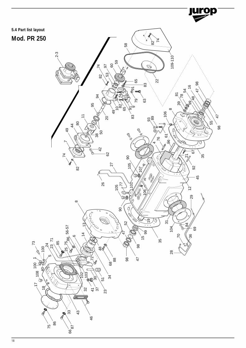
5.4 Part list layout
Mod. PR 250

19
Part list mod. PR 250
Pos. Code Description Qty Pos. Code Description Qty
57 402425050058 402535002459 402542230060 402542240261 402610130162 402610140363 402610291465 402610721466 402610731167 402610731268 402610730669 402610751470 402612010071 402612030072 402612030373 402612030674 402612040175 402612040376 402617121177 402619000278 402630160379 4026308006 80 402632210681 402635050882 402635050583 402635060884 402635061185 402635090886 402635090987 402635091188 402635610789 402635700390 402635900191 402635610692 402640181293 402642670394 402650060595 402650060996 402650121297 402651052598 402651054799 4026510551
100 4026702000101 4026706001102 4026706101103 4026706104104 4026713008105 4026904003106 4026904300107 4026905002108 4026910004109 1642003500110 1642003600
1 14012007002 14072008003 14072009004 16016051005 16081006006 16100150007 16105065008 16105066009 1613500900
10 161350100011 162150280012 162150300013 162200410014 162400960015 162400970016 162401030017 164010080018 164260000019 165000680020 165000970021 165001070022 165350200023 166303040024 166303060025 166303070026 166303080027 166303120028 166303130029 166303140030 166303150031 168060480032 168060710033 168070560034 168070570035 168070580036 168200080037 168400000038 168500240039 168500270040 168510000041 168510020042 168510080043 168710080044 168750450045 168750460046 402210600147 402220007248 402220021249 402220023550 402221691551 402230000152 402310006053 402310051654 402311007055 402313005056 4024250000
Drip oilerWater recycling pump cwWater recycling pump ccwVane PR250Oil blockOil pump flangeWater pump rear flangeEnd plate Water pump support bracket Water pump front flangeWater pump impellerVacuum pump PR 250 rotorOil pump pivotOil pump drive bushingSpacer 100x84x3,9Spacer 65x55x10Oil tank lidOil line protectionRear shaft PR200/PR250Water pump shaftFront shaft PR200/PR250Water pump pulley SPZ 180x1Oil line pump/drip oilerOil line pump/drip oilerOil line pump/drip oilerOil line rear bearingOil line front bearingOil line housing frontOil line housing rearOil line suction pipe Ø 6Inlet/outlet gasketOil tank gasketOil lid gasketOil pump flange gasketHousing gasketPipeline fixing stripOil draining tap 3/8”Safety washerWasher 35x13x6Drip oiler washer AL 14x20x1,5Flat washer AL 17x22x1,5Washer Ø 8 ALOil tankWater pump housingPR 250 housingOil sight glassSeal ring 65x90x10OR 2162OR 4325Water pump mech. sealNylon filter Ø 6Bearing 6211/C3Bearing 6004 RS1Bearing 2211 NU ECP/C3Bushing 65x55x28 IROil pump 4 outlets CW
Oil pump 4 outlets CCWBelt SPZ 1060 texrope Cone bushing 2820 Ø 16Pulley SPZ 71x1Screw 4.8 M 6x10Screw 4.8 M 8x10Screw 8.8 M 10x60Screw 8.8 M 10x40 5739Screw 8.8 M 12x30 5739Screw 8.8 M 12x35 5739Screw 8.8 M 12x16Screw 8.8 M 16x40Screw 8.8 M 4x8Screw 8.8 M 6x14 5931Screw 8.8 M 6x20 5931Screw 8.8 M 6x30Screw 8.8 M 8x16Screw 8.8 M 8x20 5931 Stud screw 8.8 M 12x80Eye bolt M 16Nut M12 5587Nut M10 5588Nut M12 sp.Grower washer 12Grower washer 8Grower washer 10 1751 Grower washer 16 1751Washer M 6 6798Washer M 8 6798Washer M 12Flat washer M 12Flat washer M 6Washer 40x33,5x1,5 ALFlat washer M 10Pin 10x60 M 6Rubber strip Ø 6,5Tab 5x5x18Tab 5x5x28Tab 16x10x110Seeger ring I 42 7437Seeger ring I 90 7437Seeger ring I 100 7437Univ. connection 4x1/8” 1050Univ. connection 90° 4x1/4” 1020Pivot connection 4x1/8” 1170Pivot connection 6x1/8” 1170Inlet/outlet flange UNI2276 DN 125Plug 1”Venting valve 1/4”Plug 1/4”Oil tank plug 1”Mech. transmission coverHydr. transmission cover
41162112 11 11111114 11 1121 1 1111121112111
2041111124221112111
111111144
12482222
1011202
2011
2010482
114413441111142
122212244111

Jurop spaVia Crosera, 5033082 Azzano Decimo/PN · Italy
Telefono ++39 · 434/636811Telefax ++39 · 434/636812
http: //www.jurop.ite-mail: [email protected]
Jurop s.p.a. si riserva di apportare senza preavviso eventuali modifiche ai prodotti descritti.
Jurop s.p.a. reserves the right of modifyng the products described abovewithout notice.
Die Firma Jurop s.p.a. behält sich das Recht vor, Änderungen an den o.g. Geräten ohneVoranmeldung anzubringen.
La Société Jurop s.p.a. se réserve le droit de modifier à tout moment et sans préavisles produits illustrés ci-dessus.
Rev
. 01
- 15
/04/
’01