Embed Size (px)
Citation preview
WATER DISTRIBUTION
SYSTEM
STANDARDS & SPECIFICATIONS MANUAL
MOORE COUNTY PUBLIC WORKS DEPARTMENT
AMENDED: June 2017
October 2017
March 2018
PREFACE
This Manual is for the Moore County Public Utilities and the East Moore Water District water
and sewer systems, all of which are operated by the Moore County Public Works Department
(MCPW).
These standards are for design and construction of water distribution facilities which will come
under the jurisdiction of MCPW. These standards alone do not constitute a complete set of
construction documents. The owner’s or developer’s Professional Engineer is responsible
for design and compilation of complete construction and contract documents. These
standards are set forth as the minimal requirements to achieve a suitable quality level for utilities
which will become the property of MCPW.
The standards do not include a complete commentary on methods of installation and detailed
information or quality of workmanship in place. The owner’s or developer’s Professional
Engineer must include detailed information on methods of construction and should expand on
the testing and any of the special requirements to the engineer’s satisfaction, subject to the
approval of MCPW.
From time to time, these standards will be amended and/or expanded at the request of the
MCPW Engineering Division with approval of the Director. It will be the responsibility of the
owner or developer to contact the MCPW to obtain updated standards.
There may be circumstances whereby the design engineer may wish to propose changes or
modifications to these standards, when this occurs permission from the County Engineer shall be
obtained prior to submission to the North Carolina Department of Environmental Quality
(NCDEQ).
Disclaimer
To the best of its ability, the County has ensured that the material presented in this manual is
accurate and reliable. However, the design of engineered facilities requires considerable
judgment on the part of the designer. It is the responsibility of the design professional to ensure
that techniques utilized are appropriate for a given situation. Therefore, neither the County of
Moore nor any officer, employee, or agent of the County accepts any responsibility for improper
design, loss, damage, or injury as a result of the use of this manual.
TABLE OF CONTENTS
1.0 DESIGN 1
A. General
B. Size of Mains
C. Fire Flow
D. Needed Fire flow Calculations
2.0 UTILITIES LOCATION 2
A. Easements
B. Sewer Mains Separation
C. Storm Sewer and Gas Mains Separation
D. NCDOT Right-of-Way
E. Railroad Right-of-Way
3.0 EROSION CONTROL 4
4.0 PIPE MATERIAL 4
A. Pipe Size and Type
B. Ductile Iron Pipe
C. PVC Pipe - C900 & C905
D. PVC Pipe – Sch. 40
E. PVC Pipe - SDR21
F. HDPE Pipe
G. Steel Encasement Pipe
5.0 FITTINGS 7
A. Ductile Cast Iron Fittings
A. Gaskets
B. Iron Fittings
6.0 VALVES 8
A. Valve Location
B. Gate Valve
C. Tapping Valve
D. Butterfly Valve
E. Valve Marker
F. Valve Box
G. Air Release and Combination Valve
H. Blow-Off Assembly
7.0 HYDRANTS 11
A. Hydrant Installation
B. Hydrant Types
8.0 TAPPING EXISTING WATER MAINS 12
A. Tapping Sleeve
B. Corporation Stop
C. Service Tubing
D. Water Meter
E. Master Meter
F. Check Valve
G. Meter Box
H. Service Saddle
I. Dual Branch Assembly
J. Lockable Valve for Irrigations (Customer with Septic Tanks)
K. Services Across Roads Wider Than Two (2) Lanes
9.0 ABANDONMENT OF EXISTING MAINS AND SERVICES 16
10.0 METER VAULT 16
11.0 TRENCH EXCAVATION 17
12.0 PIPE INSTALLATION 17
A. General
B. Tracer Wire and Tape
C. Thrust Restraint
D. Unfinished Streets
13.0 BACKFILLING 19
A. General
B. Backfilling
C. Final Backfill - All Pipes
14.0 PRELIMINARY FILLING AND FLUSHING 19
15.0 HYDROSTATIC TESTING 20
16.0 DISINFECTION 21
17.0 BACTERIOLOGICAL SAMPLING 22
18.0 OPERATION OF EXISTING VALVES 22
19.0 WATER USE DURING CONSTRUCTION 23
DETAIL DRAWINGS Attached
PW 1 Storm Sewer and Gas Crossing
PW 2 Large Pipe Crossing
PW 3 Valve and Valve Box Installation
PW 4 Valve Marker
PW 5 Valve Box Standard
PW 6 Concrete Protector Ring
PW 7 Air Release Valve Manhole over Water Main
PW 8 2” Blow Off Assembly
PW 9 Fire Hydrant Assembly
PW 10 Tapping Sleeve & Valve Assembly
PW 11 Standard Water Tap
PW 12 Single 3/4” or 1” Water Meter Service
PW 13 Dual 3/4” Water Meter Services
PW 14 2” Water Meter Service
PW 15 Meter Vault – 3” or Larger
PW 16 Typical Meter Box
PW 17 Lockable Irrigation Valve – Lots with Septic Systems Only
PW 18 Fire Department Connection
PW 19 Water Main Pipe Bedding
PW 20 Thrust Blocking
PW 21 AC Pipe to DIP/PVC Pipe Transition
Page 1 of 23
STANDARD & SPECIFICATIONS MANUAL - WATER DISTRIBUTION SYSTEM
1.0 DESIGN
A. General
Moore County Public Works (MCPW) distribution system design and construction
shall be in accordance with the requirements of Title 15A 18C, .0900 “Distribution
System” of the North Carolina Administrative Code, Department of Environmental
Quality.
B. Size of Mains
Water mains shall be sized to provide a minimum system pressure of 20 psi and
minimum residual pressure of 20 psi at all points of the distribution system during a
fire flow condition with peak system demands a minimum 30 psi at all points under
Average Daily Demand conditions. If higher pressures are required, it is the
responsibility of the water customer to provide the necessary booster pumping
equipment and facilities at their expense. If booster pumps are required on the fire
suppression system, the designer shall contact the County Engineer to determine the
additional requirements (back-flow, etc.) that will apply. The booster pumps should
be clearly noted on the construction plans if they are required. If lower pressures are
required, it is the responsibility of the water customer to provide the necessary
pressure reducer at their expense.
(1) The C-factor to be used shall be C = 120 for DIP, 130 for HDPE and 130 for
PVC. Pipe Flow velocities shall be limited to a maximum of 10 fps under design
flow conditions. The County Engineer may require design conditions to be met
with higher pipe velocities and/or pipe segment head losses on a case-by-case
basis.
(2) The design shall include:
a. Fire Flow Demand.
b. Any other background flow that will contribute to demand on the main.
(3) For projects designed with more than one phase, the design analysis shall check
each phase to ensure that these guidelines are satisfied during each phase of
construction as well as after final completion of all phases.
(4) The size of main to be installed shall be based on the existing and future needs of
the County’s water system.
(5) The length of mains, developed in streets, subdivisions, commercial or industrial
complex, shall be based on the following principles:
Page 2 of 23
a. The terminal point of extension shall be the last user’s property line to be
served by the extension;
b. The extension shall include all services connections required to cover users to
be served by the extension;
c. If the last user is adjacent to a roadway or easement that contains a water
main, the water line shall be connected to that line to increase water pressure
and improve water quality.
Note: Additional easements may be required by the County Engineer to provide a
loop system with existing proposed extensions to future proposed water lines.
C. Fire Flow
Refer to the MCPW Development Policy for fire flow requirements. In all cases, the
required fire flow shall not be less than the amounts listed below with greater
amounts where required by the ISO equation and the State of North Carolina Fire
Code tables unless otherwise modified by the Fire Marshal.
DISTANCE BETWEEN BUILDINGS NEEDED FIRE FLOW
More than 31 feet 750 gpm
11 feet to 30 feet 1,000 gpm
10 feet or less 1,500 gpm
The calculated (required) fire flow shall be reviewed by the County Engineer and Fire
Marshal and the flows may be adjusted as determined appropriate by the Fire Marshal
for site specific conditions.
2.0 UTILITIES LOCATION
A. Easements
See the County’s Water and Wastewater Systems Development Policy, Section II.E.
B. Sewer Main Separation
(1) Parallel Installation: Water mains shall be installed at least 10 feet laterally from
existing or proposed sewers, unless local conditions or barriers prevent a 10 feet
lateral separation, in which case:
a. The water main is installed in a separate trench, with the elevation of the
bottom of the water main at least 18 inches above the top of the sewer; or
b. The water main is laid in the same trench as the sewer with the water main
located at one side of a bench of undisturbed earth, and with the elevation of
the bottom of the water main at least 18 inches above the top of the sewer.
Page 3 of 23
(2) Water Main over a Sewer: The water main shall be laid at such an elevation that
the bottom of the water main is at least 18 inches above the top of the sewer,
unless local conditions or barriers prevent an 18 inch vertical separation—in
which case both the water main and sewer shall be constructed of ferrous
materials and with joints that are equivalent to water main standards for a distance
of 10 feet on each side of the point of crossing.
(3) Water Main under a Sewer: This type of installation shall be approved by the
County Engineer prior to installation. The water main shall be laid at such an
elevation that the top of the water main is at least 18 inches below the bottom of
the sewer. Both the water main and the sewer shall be constructed of ductile iron
pipe and with joints equivalent to water main standards for a distance of 10 feet
each side of the point of crossing. A section of water main pipe shall be centered
at the point of crossing.
C. Storm Sewer and Gas Main Separation
(1) Water Main over Storm and Gas: Water mains shall be of Ductile Iron Pipe at all
areas where 24” clearance above the storm or gas line cannot be obtained. (See
STD. NO. PW-1)
Water Main under Storm and Gas: This type of installation must be approved by
the County Engineer prior to installation. Water mains shall be of Ductile Iron
Pipe at all areas where 24 inches clearance below the storm or gas line cannot be
obtained. Install at least one joint of DIP centered under the storm sewer line and
backfill to 24 inches above the water main with suitable backfill. (See STD. NO.
PW-1)
(2) Parallel lines shall have a 10 feet separation from storm sewer only. Gas main
separation shall be approved by County Engineer.
D. NCDOT Right-of-Way
(1) Utilities to be constructed within NCDOT right-of-way will require a NC
DOT Encroachment Permit.
(2) All distribution systems within NCDOT right-of-way shall be designed as
outlined in NCDOT manual “Policies and Procedures for Accommodating
Utilities on Highway Right-of-ways”.
(3) Crossings under ditch to be 24 inches below bottom of ditch to top of pipe.
Crossings under roadways to be 3 feet below top of roadway to top of pipe or
encasement pipe.
Page 4 of 23
E. Railroad Right-of-Way
(1) Utilities to be constructed within Railroad right-of-way will require an
Encroachment Permit from the Railway management.
(2) Railroad crossings shall be perpendicular, ductile iron pipe and encased.
(3) Crossing from top of rail to top of encasement pipe shall meet the Railroad
standard.
3.0 EROSION CONTROL
All water main construction plans, regardless of project size shall include measures
and/or devices to prevent soil erosion and to prevent sedimentation of streams and
drainage ways. This requirement is waived for water mains in subdivision projects where
the project erosion control plans includes water main construction and where
enforcement of erosion control requirements is not under MCPW control. Design of
Erosion and Sediment Control devices shall be in accordance with MCPW “General
Construction Standards and Specifications” Section: “Seeding/Turfing and Erosion
Control” and North Carolina “Sediment Control Planning and Design Manual”.
4.0 PIPE MATERIAL
A. Pipe Size & Type
Pipe Type Pipe Size
DIP Ductile Iron Pipe, 250 psi 18” & larger
DIP Ductile Iron Pipe, 350 psi 12” & smaller
PVC C-900, 235 psi, DR 18 4” to 12”
PVC C-900, Fusible, 200 psi, DR 18 4” to 12”
PVC C-905, 200 psi, DR 21 14” to 36”
PVC SDR-21, 200 psi (Water Main) 2” to 10”
PEP Tubing, 200 psi (Water Service) 1”
Sch. 40 PVC, 200 psi (Water Service) 2”
SP Steel Pipe, 35,000 psi (Encasement) all sizes
HDPE, 250 psi, DR 9 all sizes
a. Encasement is required for all main and service crossing on Interstate Standards
roads.
b. Encasement is required for all mains crossing under non Interstate Standards
roads.
c. Encasement is not required for roads with 2,000 vpd or less.
d. Encasement is required for all Railroad crossings.
Page 5 of 23
B. Ductile Iron Pipe
All ductile iron pipes shall be designed as per ANSI/AWWA C151/A21.50. Pipe wall
thickness shall conform to ANSI/AWWA C150/A21.50. Pipe up to and including 12
inch diameter pipe shall be Pressure Class 350 (min.), while pipe greater than 12 inch
diameter shall be at least Pressure Class 250. The County Engineer may require
heavier class pipe on a case-by-case bases.
Pipe joints shall be of the push-on type with rubber gaskets as per ANSI/AWWA
C111/A21.11. Mechanical or special joints may be used as project requirements
dictate or as required by the Engineer. Pipe lining shall be cement-mortar, on the
interior, with an external coat of bituminous material, all in accordance with
ANSI/AWWA C104/A21.4. All mechanical joints shall be restrained by Mega-Lugs
or Grip Rings.
The class or nominal thickness, net weight without lining, and casting period shall be
clearly marked on each length of pipe. Additionally, the manufacturer’s mark,
country where cast, year in which the pipe was produced, and the letters “DI” or
“Ductile” shall be cast or stamped on the pipe.
Ductile iron pipe shall be manufactured by U.S. Pipe, American, or Clow, and shall
be furnished in 20 foot and 18 foot lengths.
C. PVC Pipe (C-900 & C-905)
PVC pipe shall be rigid polyvinyl chloride with integrally formed, factory fabricated
bell with “slip” joints rubber gaskets conforming to AWWA C-111. It shall be
suitable for all conditions imposed by Plan locations and for a maximum working
pressure of 200 psi. Pipe shall be Type 1, Grade 1, made from clear virgin material
and shall conform to the requirements of ANSI/AWWA C-900 & C-905. All pipes
shall bear the National Sanitation Foundation Seal of Approval for potable water, the
manufacturer’s name, and class of pipe.
Provision must be made for expansion and contraction at each joint, through the
rubber gasket and pipe bell. All mechanical joints shall be restrained by Mega-Lugs
or Grip Rings.
Contractor shall not use pipe that is brittle or sun bleached which shall compromise
its use.
Pipe to conform to ANSI/AWWA C-900 for C-900, DR-18 or C-905, DR-21 pipe
within municipal boundaries and extra-territorial jurisdiction, and within residential
subdivisions, shopping centers and industrial complexes within rural areas, for all
new construction.
Page 6 of 23
D. PVC Pipe (Sch. 40)
All PVC Schedule 40 pipe shall be manufactured from virgin rigid PVC (polyvinyl
chloride) vinyl compounds with a cell class of 12454 as identified in ASTM D 1784.
Pipe shall be Iron Pipe Size (IPS) conforming to ASTM D 1785. Pipe shall be
manufactured as a system and be the product of one manufacturer. Pipe shall be
manufactured in the United States. Pipe shall conform to NSF International Standard
61 or the health-effects portion of NSF Standard 14.
E. PVC Pipe (SDR-21)
All PVC SDR21 pipe shall be manufactured from a Type I, Grade I Polyvinyl
Chloride (PVC) compound per ASTM D1784. The pipe shall be manufactured in
strict compliance with ASTM D2241, consistently meeting and/or exceeding the
Quality Assurance test requirements of this standard with regard to pressure rating,
material, workmanship, burst pressure, flattening, impact resistance, and extrusion
quality. The pipe shall be manufactured in the USA, using domestic materials. All
pipes shall be stored indoors after production at the manufacturing site until shipped
from factory. This pipe shall carry the National Sanitation Foundation (NSF) seal of
approval for potable water applications.
Use SDR-21 pipe for 10 inches and less in rural areas which are less populated
and C-900 pipe for 12 inches and less in urban areas unless special needs require
other type as approved by the County Engineer. All mechanical joints shall be
restrained by Mega-Lugs or Grip Rings.
F. HDPE - High Density Polyethylene Pipe
HDPE pipe for directional drilling shall be DR-9, 250 psi, and sized to have the
minimum inside diameter the same as the connecting Force Main. Connection of
HDPE to Ductile Iron pipe shall be horizontal and made to prevent binding of HDPE.
All pipes shall be labeled ANSI/AWWA C906 or C901. Pipe material is to conform
to ASTM D2737. Design of pipeline shall meet PPI Handbook of Polyethylene Pipe
on Performance Pipe website. Maximum bending radius shall meet the PPI
Handbook requirements, which is 20 times the pipe diameter for DR 9 pipe.
Installation of HDPE pipe shall meet ASTM D-2774 Standard Practice for
Underground Installation of Thermoplastic Pressure Pipe.
After directional drilling, HDPE pipe shall be allowed to retract(release) for 30 days
after which connection shall be made to three joints of DIP with restrained
mechanical joints, gate valves and reducers. A valve shall be placed between the first
and second joint of DIP at each end of the HDPE. Alternately, if less retraction time
is desired, the Design Engineer may submit calculations and data referenced in the
PPI Manual, including Pulling-in calculations, pullout prevention technique,
horizontal drilling records, and allowable tensile load calculations for the County
Engineer’s review.
Page 7 of 23
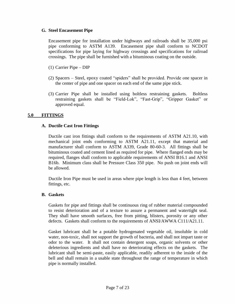
G. Steel Encasement Pipe
Encasement pipe for installation under highways and railroads shall be 35,000 psi
pipe conforming to ASTM A139. Encasement pipe shall conform to NCDOT
specifications for pipe laying for highway crossings and specifications for railroad
crossings. The pipe shall be furnished with a bituminous coating on the outside.
(1) Carrier Pipe – DIP
(2) Spacers – Steel, epoxy coated “spiders” shall be provided. Provide one spacer in
the center of pipe and one spacer on each end of the same pipe stick.
(3) Carrier Pipe shall be installed using boltless restraining gaskets. Boltless
restraining gaskets shall be “Field-Lok”, “Fast-Grip”, “Gripper Gasket” or
approved equal.
5.0 FITTINGS
A. Ductile Cast Iron Fittings
Ductile cast iron fittings shall conform to the requirements of ASTM A21.10, with
mechanical joint ends conforming to ASTM A21.11, except that material and
manufacturer shall conform to ASTM A339, Grade 80-60-3. All fittings shall be
bituminous coated and cement lined as required for pipe. Where flanged ends may be
required, flanges shall conform to applicable requirements of ANSI B16.1 and ANSI
B16b. Minimum class shall be Pressure Class 350 pipe. No push on joint ends will
be allowed.
Ductile Iron Pipe must be used in areas where pipe length is less than 4 feet, between
fittings, etc.
B. Gaskets
Gaskets for pipe and fittings shall be continuous ring of rubber material compounded
to resist deterioration and of a texture to assure a permanent and watertight seal.
They shall have smooth surfaces, free from pitting, blisters, porosity or any other
defects. Gaskets shall conform to the requirements of ANSI/AWWA C111/A21.11.
Gasket lubricant shall be a potable hydrogenated vegetable oil, insoluble in cold
water, non-toxic, shall not support the growth of bacteria, and shall not impart taste or
odor to the water. It shall not contain detergent soaps, organic solvents or other
deleterious ingredients and shall have no deteriorating effects on the gaskets. The
lubricant shall be semi-paste, easily applicable, readily adherent to the inside of the
bell and shall remain in a usable state throughout the range of temperature in which
pipe is normally installed.
Page 8 of 23
C. Iron Fittings
Iron fittings shall be manufactured in accordance with ANSI/AWWA C-110/A21.10,
latest revision and addendum. The fittings shall be tested and the manufacturer shall
provide certified test results upon request by the Engineer. This testing shall include
hydrostatic proof testing of the fittings.
All fittings shall be cast iron or ductile iron and shall have a minimum working
pressure rating of 250 psi and a minimum iron strength of 25,000 psi. Iron fittings
shall be all-bell mechanical joint conforming to ANSI/AWWA C-115/A21.15-05. On
all fittings Mega-Lugs or Grip Rings shall be used. Male compression restrained
joints to be used on 2 inch PVC.
All fitting interiors shall be cement mortar lined, with bituminous seal cast in
accordance with ANSI/AWWA C-104/A21.4 and the outside shall be bituminous
coated.
6.0 VALVES
A. Valve Location
Valves shall be installed on all branches from mains and on hydrant branches
according to the following schedule:
3 valves at cross intersections
2 valves at tee intersections
4 valves at cross intersections near water towers
3 valves at tee intersections near water towers
1 valve on hydrant branches
1 valve at “stub outs” for future extensions
1 valve at change in pipe size
1 valve at each end of directional bore line
Additional valves may be required as needed
Main line valves should coincide with fire hydrants. Valves deeper than 4 feet should
have operation nut extended to 4 feet from surface. See STD. NO. PW 3 for detail.
Main line valves on straight runs between intersections shall be spaced at interval
distances not to exceed the following:
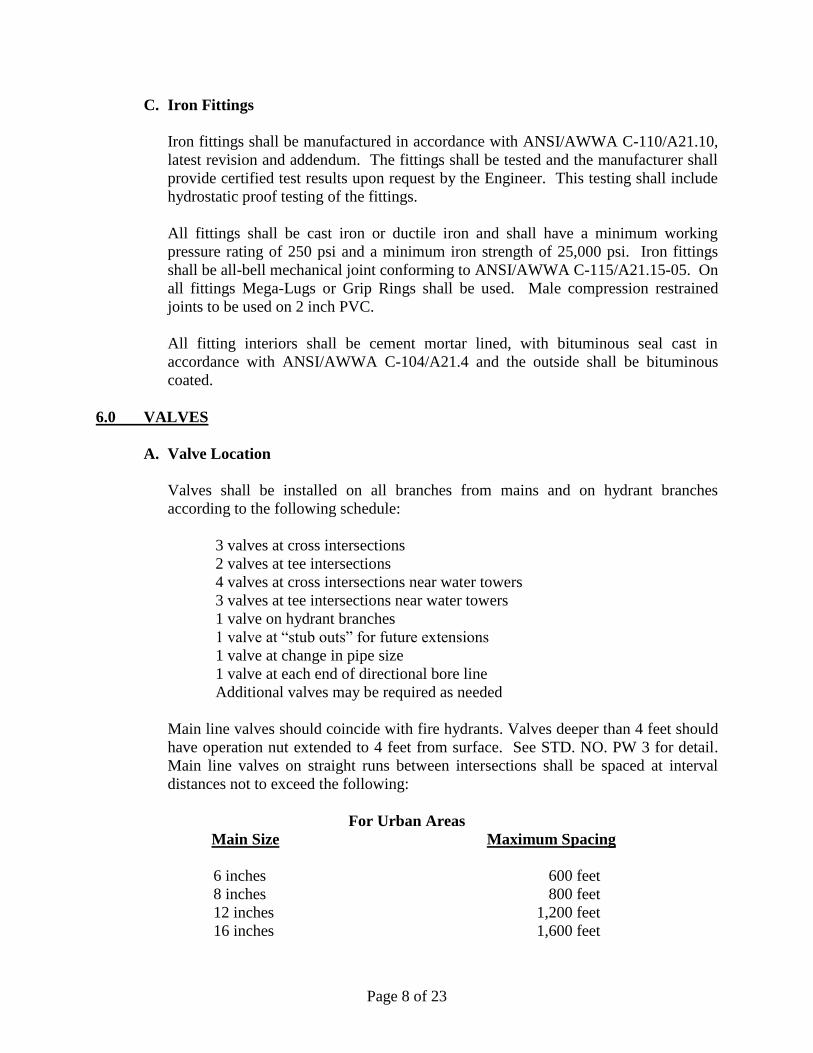
For Urban Areas
Main Size Maximum Spacing
6 inches 600 feet
8 inches 800 feet
12 inches 1,200 feet
16 inches 1,600 feet
Page 9 of 23
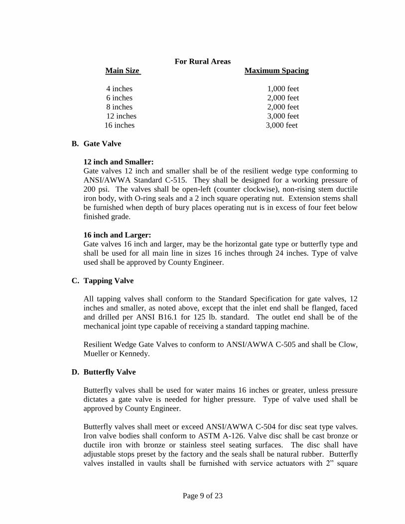
For Rural Areas
Main Size Maximum Spacing
4 inches 1,000 feet
6 inches 2,000 feet
8 inches 2,000 feet
12 inches 3,000 feet
16 inches 3,000 feet
B. Gate Valve
12 inch and Smaller:
Gate valves 12 inch and smaller shall be of the resilient wedge type conforming to
ANSI/AWWA Standard C-515. They shall be designed for a working pressure of
200 psi. The valves shall be open-left (counter clockwise), non-rising stem ductile
iron body, with O-ring seals and a 2 inch square operating nut. Extension stems shall
be furnished when depth of bury places operating nut is in excess of four feet below
finished grade.
16 inch and Larger:
Gate valves 16 inch and larger, may be the horizontal gate type or butterfly type and
shall be used for all main line in sizes 16 inches through 24 inches. Type of valve
used shall be approved by County Engineer.
C. Tapping Valve
All tapping valves shall conform to the Standard Specification for gate valves, 12
inches and smaller, as noted above, except that the inlet end shall be flanged, faced
and drilled per ANSI B16.1 for 125 lb. standard. The outlet end shall be of the
mechanical joint type capable of receiving a standard tapping machine.
Resilient Wedge Gate Valves to conform to ANSI/AWWA C-505 and shall be Clow,
Mueller or Kennedy.
D. Butterfly Valve
Butterfly valves shall be used for water mains 16 inches or greater, unless pressure
dictates a gate valve is needed for higher pressure. Type of valve used shall be
approved by County Engineer.
Butterfly valves shall meet or exceed ANSI/AWWA C-504 for disc seat type valves.
Iron valve bodies shall conform to ASTM A-126. Valve disc shall be cast bronze or
ductile iron with bronze or stainless steel seating surfaces. The disc shall have
adjustable stops preset by the factory and the seals shall be natural rubber. Butterfly
valves installed in vaults shall be furnished with service actuators with 2” square
Page 10 of 23
operating nuts and open by turning counter clockwise, if required by the County
Engineer. Extension stems shall be furnished when the depth of the operating nut is in
excess of four (4) feet below finished grade. Butterfly valves shall have mechanical
joint ends conforming to ANSI/AWWA C111/A21.11. Butterfly valves shall have a
design working water pressure of 200 psi and be hydrostatically tested to 300 psi.
Valves shall be Mueller, Kennedy, Pratt, or equal.
E. Valve Marker
Valve Markers are to be installed in rural areas, near the right-of-way line, to better
identify their location. All in-line valves shall have a valve marker. Fire hydrant
valves shall not have a valve marker.
In urban areas, valve markers are to be installed only as recommended by the County
Engineer.
Valve markers shall be placed 1 foot inside right-of-way line or property easement.
Markers must have distance to valve stamped on top with arrow pointing in the right
direction. See STD. NO. PW 4 for detail.
F. Valve Box
Valves shall be set at locations shown on the plans with care being taken to support
the valve properly and to accurately position the valve box over the operating nut of
the valve. Valve boxes shall be set on brick for stability and not sit directly on the
valve or water main. Where located within paved areas, the box shall be adjusted to
finished street grade. When valves are located in street right-of-way, but out of
pavement, the boxes shall be adjusted to finish grade and a concrete protector ring
shall be placed around the box one inch above the street right-of-way grade. See
STD. NO. PW 6 for detail.
All valve boxes shall be of the adjustable type. Valve boxes shall be cast from close-
grained gray iron, in three pieces consisting of a lower base piece, upper part and
cover. The lower base piece shall be flanged at the bottom to fit around the valve and
shall also be flanged on the lower end and of such size as to telescope over the lower
part with upper end cast on the upper surface in raised letters the word “WATER”.
Valve box covers shall be painted a blue after installation. Valve boxes shall be
painted prior to shipment with a coat of protecting asphaltic paint.
For Valve Box Cover protection provide a concrete protector ring. See STD. NO.
PW 5 for detail.
G. Air Release and Combination Air Valve
Combination Air Valves shall be provided at high points on all 12 inch and larger
water mains where the change in vertical grade crest to sag is 2 feet or greater. An
Page 11 of 23
Air Release Valve shall be provided at high points on 2 inch to 8 inch water mains
where air cannot be adequately released from the main through service connections.
On pumped lines or in any other application where the potential for water column
separation exists, the County Engineer shall evaluate the need for Combination Air
Valves and shall recommend specific valve configurations for approval.
Air release valves shall be contained within a (5 feet minimum diameter) Doghouse
Manhole with grave bottom and no drain to ensure that the vacuum relief port cannot
allow outside water to enter the waterline. The manhole cover shall have “WATER”
stamped on the cover with raised letters.
Air release valves shall be equivalent to ARI, ClaVal or approved equal and conform
to ANSI/AWWA C-512. See STD. NO. PW 7 for detail.
H. Blow-Off Assembly
All transmission mains 12 inches and larger must be designed such that they can be
dewatered completely within four hours through blow off assembly or fire hydrants.
Dead end lines 4 inch and less shall be terminated with a 2 inch blow off valve and
lines 6 inch and larger are to be terminated with a fire hydrant. Flushing sites shall
have adequate drainage areas. See STD No. PW- 8 for detail.
7.0 HYDRANTS
A. Hydrant Installation
Hydrants shall be set plumb, properly located with the pumper nozzle facing the
closest curb of a fire lane or street, but not a parking space. Hydrant tees shall be
used. Restraining couplings are to be installed. A minimum of 8 cubic feet of #57
stone shall be placed around the drains. The backfill around the hydrants shall be
thoroughly compacted. Hydrants shall be placed 1 foot inside the back of right-of-
way or property line. Fine grade shall be to the bury line. See STD. No PW- 9 for
detail.
No one except MCPW personnel authorized agents of MCPW and qualified Fire
Department personnel are authorized to operate any of the distribution system fire
hydrants.
B. Hydrant Types
Fire hydrants shall be of the compression type meeting ANSI/AWWA C502
standards, designed for a minimum working pressure of 200 psi and a hydrostatic test
pressure of 300 psi with the valve in both the open and closed positions.
Page 12 of 23
All hydrants shall be equipped with two 2 1/2 inch nozzles and one 4 1/2 inch pumper
nozzle. Each nozzle shall be bronze with cast iron caps secured thereto with a suitable
steel chain. Nozzles shall have National Standard Threads.
The hydrants shall be open-left and equipped with a pentagon-type operating nut
(National Standard) measuring 1 1/2 inches from point to flat. Hydrants shall be of
the “dry top” type with the upper rod threads completely enclosed in a sealed grease
or oil chamber, equipped with “O” ring seals and Teflon thrust bearing.
The hydrants shall have a 6 inch shoe or boot, mechanical joint. Hydrants shall have
bronze to bronze threads provided between the hydrant seat or seat ring and the seat
attaching assembly. The hydrant shall be of the “safety” type so that, if the upper
barrel is broken off, the hydrant valve will remain closed and reasonable tight. All
hydrants shall be furnished with barrel and stem extensions as required by the final
field location to provide a nominal minimum bury of 3 feet and 6 inches, or greater, if
indicated on the drawings.
All hydrants shall have a thrust block behind the hydrant, below the weep holes
allowing the weep holes to still be operational.
Hydrants connected to 12 inches and larger water mains shall have 5 1/4 inch barrel
diameter or as approved by the County Engineer.
Hydrants shall be Mueller “Super Centurion”, Clow “Medallion” or equal.
Hydrants color shall be red and factory painted (Field Painting will not be Allowed)
All hydrants shall have permanent 5 inch, rigid, male National Standard threads
STORZ connections installed on the 4 1/2 inch pumper nozzle with a lockable cap.
All STORZ connections shall be manufactured out of 6061-T6 Aluminum with a hard
coat anodized to Mil-A-8625f, Type 3, and dark gray finish. All STORZ connections
shall comply with NFPA 1963 (Corrosion Resistance), UL listed and FM approved.
MCPW shall not be responsible for any cost associated with the STORZ connections.
8.0 TAPPING EXISTING WATER MAINS
A. Tapping Sleeve
Tapping sleeves shall be used on all taps greater than 4 inches. Tapping sleeves shall
be a two piece type, stainless steel suitable for bolting and air testing. The body is to
consist of a gasket of Virgin SBR rubber compound. Tapping sleeves as
manufactured by Mueller, Romac, JCM and Smith-Blair are acceptable. See STD.
NO. PW 10 & 11 for detail.
Tapping Sleeves shall meet the appropriate length listed in the table below:
Page 13 of 23
Main and Tap (inches nominal) Length (along run)
6x6, 6x3, 6x4, 6x2 18 inches
8x2, 8x3, 8x4, 8x6 19 inches
8x8 21 inches
10x2, 10x3, 10x4, 10x6 19 inches
10x8, 10x10 23 inches
12x2, 12x3, 12x5, 12x6 19 inches
12x8 21 inches
12x10, 12x12 25 inches
Sleeves shall meet all the requirements of ASNI/AWWA C110/A21.10 and
C111/A21.11. Tapping sleeves shall have a full circumferential gasket. For tapping
sleeves with an outlet diameter greater than 12 inches, the sleeve shall have an outlet
seal gasket. Lubricate pipe and face of gasket with water or soap-water. Do not use
petroleum based products such as grease or pipe lubricant.
When installing, the existing main shall be carefully and completely cleaned prior to
installing the tapping sleeve or saddle. All surfaces of the existing main encompassed
by the sleeve, along with the inside of the sleeve and the inside of the tapping valve,
shall be disinfected during installation by swabbing with a chlorine solution or
dusting with calcium hypochlorite (HTH) powder. Once these surfaces are
disinfected, the Contractor shall not allow dirt, mud, trench water or any other
contaminants to come in contact with these surfaces.
Once the tapping sleeve and valve are installed on the main, a pressure test shall be
performed by applying 100 psi compressed air to the test port for a period of at least
15 minutes, with no drop. During this period, all joints shall be mopped with a soap-
water solution to locate leaks. This test shall be performed in the presence of the
County Engineer or his representative.
Upon satisfactory completion of the installation and pressure testing of the tapping
sleeve and valve, the existing main shall then be tapped using a tapping device
equipped with a pilot drill and shell type cutter which retains the pipe coupon. Once
the tap is complete and the tapping machine removed, the tapping valve shall be
cleaned of any cuttings and then kept plugged until the water main is installed. A
thrust block shall be placed behind the wet tap with plastic wrap between the pipe and
thrust block.
B. Corporation Stop
Corporation stops shall be designed and manufactured in accordance with
ANSI/AWWA C-800 latest revision. Corporation stops shall be equipped with an
AWWA standard tapered thread on the inlet end and a compression connector on the
outlet end for connection of polyethylene pipe. The stops shall be fully shop tested
for leaks with air pressure under water. The stop shall have a minimum rated
working pressure of at least 300 psi, with a safety factor of at least 2 times the rated
Page 14 of 23
working pressure. No ‘ground key’ corporations shall be used. The corporation stops
shall be as manufactured by Mueller, Ford or equal.
C. Service Tubing
Service Tubing shall be Polyethylene SIDR 7 and meet ANSI/AWWA C-901 and be
clearly marked with nominal size, rated operating pressure at 73.4 degrees F, type of
pipe, material designation code, date code (month, year, day), manufacturer’s brand
name, National Sanitation Foundation logo indicating approval for potable water
usage and compliance with ASTM specifications, plant location code and ASTM D-
2239 approval.
D. Water Meter
Moore County has standardized on Badger radio read water meters. Water meters
will be furnished and installed by Moore County. 2 inch services shall have a meter
setter. See STD. NO. PW 12 &13 for ¾ and 1 inch meter service. See Detail STD.
NO. PW 14 for 2 inch meter service. See Detail STD. NO. PW 15 for 3 inch and
larger Water Meter Service and Vault.
Contractor shall provide and install a Lockseal Assembly for all meters. Both the
stud and Lockseal head shall be case hardened steel with plating for corrosion
protection. The Lockseal Assembly shall be installed per manufactures
recommendations. The Lockseal Assembly shall be as manufactured by Highfield or
equal.
Multiple occupancy building may be master metered or the individual units metered
separately. Where “gang” meters are installed, permanent placards shall be provided
inside the meter box to indicate the unit served by each meter. The only exception to
this metering requirement shall be in the case of building fire sprinkler systems,
where such services shall be equipped with a detector meter on the backflow
prevention device. Where other service connections are requested a separate meter
shall be installed.
E. Master Meter
Master meters may be permitted to serve single ownership, single lot properties in the
following categories:
i. Apartments/Condominiums
ii. Hotels/Motels
iii. Hospitals
iv. Warehouses/Industrial Buildings
v. Schools
vi. Mobile Home Parks
vii. Shopping Centers
Page 15 of 23
viii. Churches
ix. Rest Homes
Plans for these properties shall meet all building and fire code requirements. All
water mains, valves, and fire hydrants shall meet the County’s standards and
specifications. Master meters shall be installed in vaults that have positive drainage
provided from bottom (preferred) or sump pump.
2 inch and larger Domestic Services Meters and Irrigation Meters shall be Compound
Type unless approved otherwise by the County Engineer.
F. Check Valve
3/4 inch and 2 inch check valves shall be incorporated into the meter. 3 inch and
larger check valves shall be ClaVal or approved equal.
G. Meter Box
For 3/4 inch meter water services with a single meter and 3/4 inch meter water
services with double meters, the meter box shall be rectangular with minimum
nominal dimensions in inches of 21-3/8x14-7/8x12” (l-w-d). Lids shall plastic and be
labeled “WATER METER”, containing a cast iron reader lid with no holes. Boxes
may be plastic except for traffic bearing installations, which shall be traffic rated and
approved by the County Engineer. Meter boxes shall have at least a 3 feet allowance
from any obstructions. All meter boxes shall have at least 4 inches of washed stone
installed to allow for proper drainage. Meter Box with Lid provided by NDS, DFW
or equal. See STD. NO. PW 16 for detail.
H. Service Saddle
Service Saddles shall be wide body style for PVC water mains (Ford S-70, Mueller
H-134 or equal) or double strap style for ductile iron water mains (Ford S-90, Mueller
BR2B or equal). Body shall be stainless steel, bronze or brass with O-ring seal,
manufactured to meet AWWA C800. Saddles shall be used for 1” and 2” service
outlet diameter types. See STD. NO. PW 11 for detail.
I. Dual Branch Assembly
The County Engineer shall determine if dual or single assembly is needed. See STD.
No. PW 13 for detail.
L. Lockable Valve for Irrigations
Lockable Valves shall be installed on all irrigation services that are allowed to
connect to the domestic water service (see NCGS 143-355.4 (a)). Lockable Valves
shall be brass and conform to AWWA Standard C800. The letters “NL” shall be cast
Page 16 of 23
into the main body for lead-free identification and certified to NSF/ANSI Standard 61
and NSF/ANSI Standard 372 where applicable. Valve shall be non-directional and
watertight with flow in either direction. Ends shall be integral or secured with
adhesive to prevent unintentional disassemble. Hole shall be provided for attaching
curb box rod or handle in tee-head. Valve shall be rated for 300 PSI working
pressure and have a padlock wing for locking valve in closed position. See STD. No.
PW 17 for detail.
K. Services Across Roads Wider Than Two (2) Lanes
Services across roads wider than two (2) lanes shall have a casing installed by the
customer, in addition to the Tap Fee, in order for Moore County to install the service
tubing inside the casing across the road. The casing shall be installed by Bore & Jack
or Directional Drilling and shall meet the standards in the General Construction
section of these specifications and extend from R/W to R/W.
9.0 ABANDONMENT OF EXISTING MAINS AND SERVICES
All water mains AND SERVICES shall be abandoned as per below.
A. Water Services: All water services shall be demolished and disposed of that
are within the R/W back to the existing corporation stop and the corporation
stop shall be shut off.
B. Water Main: All water mains shall be demolished and disposed of that are
within the R/W back to the suppling water main connection and capped at the
tee. If a gate valve is located on the abandoned water main at the tee, it shall
be removed and delivered to Moore County or disposed of (decided by Moore
County). Any active water main isolation shall be coordinated with Moore
County.
10.0 METER VAULT
Meter Vaults are used for the primary purpose of housing Pressure Reducers, Flexible
Connections, Water Meters and Strainers. The vault can contain supplementary items
such as bottom drain to daylight (preferred), 1/2 HP Stainless Steel Submersible Sump
Pumps, two 4 inch “goose neck” vent pipes, Aluminum Door(s) AASHTO H-20 wheel
load, JD-AL-H2O, Bilco or equal all contained in or on a 4,000 psi reinforced concrete
box. The hatch needs to have the capability of draining to daylight. See STD. NO. PW
15 for detail.
The vault shall have a valve at each outside end of the vault to shut off the meters and for
maintenance. A by-pass line parallel to the vault shall be installed with a valve to close if
the meters are in use and to open if meters are not in use. The top of the vault should be
approximately 8 inches above the natural ground surface and should be coated on the
underground outside surface with exterior water proofing.
Page 17 of 23
11.0 TRENCH EXCAVATION
Water main trenches shall be excavated to such depth that the pipe will have a minimum
cover of at least 3 feet as measured from final, finished grade, based on the approved
typical sections and/or grading plans to the crown of the installed pipe. In general,
installation depth shall be limited to a maximum of 5 feet in depth unless it conflicts with
other subsurface structures. See STD. NO. PW 26 for detail.
Trench width shall be a minimum of 16 inches plus the outside diameter of pipe barrel up
to 10" and a maximum of 24 inches plus the outside diameter of pipe barrel from
12inches and larger, unless trenching is approved.
Where water main trench excavation is in rock, the rock shall be excavated to a minimum
depth of 6 inches below the bottom of the pipe. This space shall be filled with selective
material approved by the Engineer.
In trenches where water is present or where dewatering is required, the trench bottom
shall be stabilized with selective material approved by the Engineer. When material of
poor supporting value (i.e. “muck”) is encountered in the trench, it shall be removed and
replaced with selective material approved by the Engineer.
All water main trenches shall be protected from entrance of surface water. Any water
observed in the trench shall be promptly removed by pumping, or other means, provided
that water disposal is directed to suitable erosion control devices to prevent deposition of
sediment into nearby streams, ponds, etc. The Contractor shall use all means necessary
to prevent the entrance of water, including the construction of temporary berms or dikes.
12.0 PIPE INSTALLATION
A. General
All water main pipes shall be clean before installation. Any dirty pipe shall be
thoroughly swabbed by the Contractor. Pipe showing evidence of oil or grease
contamination shall not be used.
Pipe laying and jointing shall be accomplished in strict accordance with the
recommendations of the pipe manufacturer. Care shall be taken during pipe installation
so as not to exceed the maximum joint deflection.
Open ends of the pipe shall be plugged at all times that pipe installation is not in progress.
Bell ends shall generally face the direction of flow source. Where water mains are
installed on an appreciable slope, the Engineer may require that the bell ends face
upgrade.
Page 18 of 23
The barrel of the pipe shall bear the pressure uniformly upon a firm and stable flat bottom
trench at all times. The trench bottom will be excavated for the bell ends such that the
pipe rest uniformly on its entire barrel length.
B. Tracer Wire and Tape
Tracer wire shall be installed along the top of water main pipe and services and secured
(i.e. Duct tape) to the pipe every 10 feet. Tracer wire shall be number 12 gauge, color
blue, rated for underground installation with a minimum breaking strength of 450 lbs. and
a coating of 15 mils. After installation, the Contractor is responsible for the testing of the
tracer wire in the presence of the County Engineer or a designee after the roadway has
been installed. During testing, the water main shall be located so the County Engineer or
a designee can see the spacing between the water main and the Edge of Pavement to
make sure it meets the spacing requirement.
All spliced or repaired wire connections in the tracer wire system shall be made using a
Wing Nut Wire Connector (for two to four number ten wires), or approved equivalent,
and made waterproof using an approved buried service wire closure. The buried service
wire closure shall be Frame Gel Closure or equivalent.
Detectable Warning Tape shall be installed from 18 inches to 24 inches above the pipe
line. See STD. NO. PW 26 for detail.
C. Thrust Restraint
Thrust restraint for water mains shall be provided at all tees, bends and plugs. Restraints
shall be restrained type mechanical joint and concrete blocking. Concrete thrust blocking
shall be poured in place. The bearing area for thrust blocks shall be based on the required
test pressure of 200 psi and a field determination of the load bearing capacity of the soil.
Conservative estimates of soil load bearing capacities by experienced and qualified
inspectors are normally allowed. However, analysis may be required by the County
Engineer. See STD. NO. PW 27 for detail.
For lines that end with a valve for future extension, there shall be added to the valve one
full pipe stick, plug and concrete blocking.
D. Unfinished Streets
Where main extensions are laid in unfinished streets, the developer shall be fully
responsible for damages to the main and all fixtures and appurtenances, such as hydrants,
gate valve boxes, blow-off boxes, etc., including the location thereof. If, after the mains
are installed, the surface grade is lowered with the result that the required minimum cover
of the mains, fixtures, or appurtenances is not maintained, then the developer shall pay
for cost of lowering the mains to the structural level required to correct this deficiency.
This responsibility shall remain in force until such time as the street is structurally
complete.
Page 19 of 23
13.0 BACKFILLING
A. General
Backfilling shall be completed as soon as possible, so as to minimize the length of
time that the trench or any part thereof is left open. Material classification for backfill
materials, as may be noted hereinafter, shall conform to the Engineer's requirement.
B. Backfilling
All trash, forms, debris and other foreign material shall be cleared from around all
pipes and structures before backfilling. The pipe shall be backfilled with suitable
materials. The initial backfill to a point 12 inches above top of the pipe shall be
placed in shallow 6 inch layers, individually compacted, with emphases on the
“hunching” area (up to the spring-line of the pipe). See STD. No. PW 26 for detail.
C. Final Backfill
The remaining or final backfill for all pipe materials shall be suitable material. No
rocks, boulders, or stones shall be included in the backfill material for at least 2 feet
above the top of the pipe. In non-traffic areas, the backfill shall be placed in lifts not
exceeding 12 inches and compacted to 90% of maximum dry density per AASHTO
T-99. In traffic areas the final backfill shall be placed and compacted in 6 inch layers,
and compacted to 95% of maximum dry density per AASHTO T-99 to a point 12
inches below subgrade. The top 12 inches shall be compacted to 100% of maximum
dry density (AASHTO T-99).
Where deemed necessary, the Engineer may require compaction test on any or all lifts
of backfill placed in trenches under roadways. The cost for such test shall be borne
by the Contractor.
14.0 PRELIMINARY FILLING AND FLUSHING
No valve shall be operated without giving a minimum 24 hour notice to the MCPW. No
Contractor or other non-MCPW personnel shall at any time operate any valve. MCPW
must be contacted for information on purchasing water, account setup for construction
water, and for approved hydrant meter arrangements.
The Contractor, first, shall pump dry and dispose of all extraneous ground water and
sand, gravel and foreign objects within the water main. The new or empty water mains
now shall be slowly filled with water at a rate that will allow complete evacuation of air
from the line.
Each valve section of the completed main shall be flushed prior to chlorination as
thoroughly as possible with water pressure and outlets available. If no hydrant is
Page 20 of 23
provided at the end of the main section, a tap shall be installed at the main section
extremity, large enough to develop a velocity in the main of at least 2 fps. The flushing
operations shall be done after the pressure test has been made. Each valve section of the
newly laid pipe shall be flushed separately. Flushing sites shall have adequate drainage
and shall be approved by the Engineer. The Contractor shall provide hoses, pipe, etc. to
divert water from flushing operations into drainage ways to avoid damage to yards and
erosion.
Disposal of flushed water shall meet the requirements of NCDEQ. Provide
dechlorination as required.
Pigging is to be at the discretion of the County Engineer.
15.0 HYDROSTATIC TESTING
No valve in the existing water system shall be operated by any party other than MCPW
employees.
The line shall be tested to a pressure of 200 psi for a duration of 24 hours. The pressure
gauge used in the hydrostatic test shall be calibrated in increments of 5 psi or less. At the
end of the test period, the leakage shall be measured with an accurate water meter,
supplied by the contractor.
No pressure pipe installation will be accepted until leakage is less than the number of
gallons per hour for each section tested, as determined by the following formula:
Q = LD√P
148,000
Q = Allowable leakage, in gallons per hour
L = Length of pipe tested, in feet
D = Nominal diameter of the pipe, in inches
P = Testing Pressure, in pounds per square inch
All visible leaks at pipe joints, services, and at any appurtenances are to be repaired
regardless of the amount of leakage. After testing, remove service line from testing
point.
Pressure testing is the responsibility of the Contractor. All pressure tests must be
witnessed by the Engineer, or designee, for approval.
Water for testing and blow-off may be obtained from existing water main. The contractor
is responsible for any cost of water used during testing. Air testing is not allowed.
Page 21 of 23
16.0 DISINFECTION
All new, cleaned or repaired water mains shall be disinfected, by the Continuous Feed
method, in accordance with AWWA Standard C651.
Chlorination of a completed line shall be carried out in the following manner:
(1) Taps will be made at the control valve at the upstream end of the line and at all
extremities of the line including valves. The taps shall be strategically located so as
to allow High-Test Hypochlorite (HTH) solution to be fed into all parts of the line.
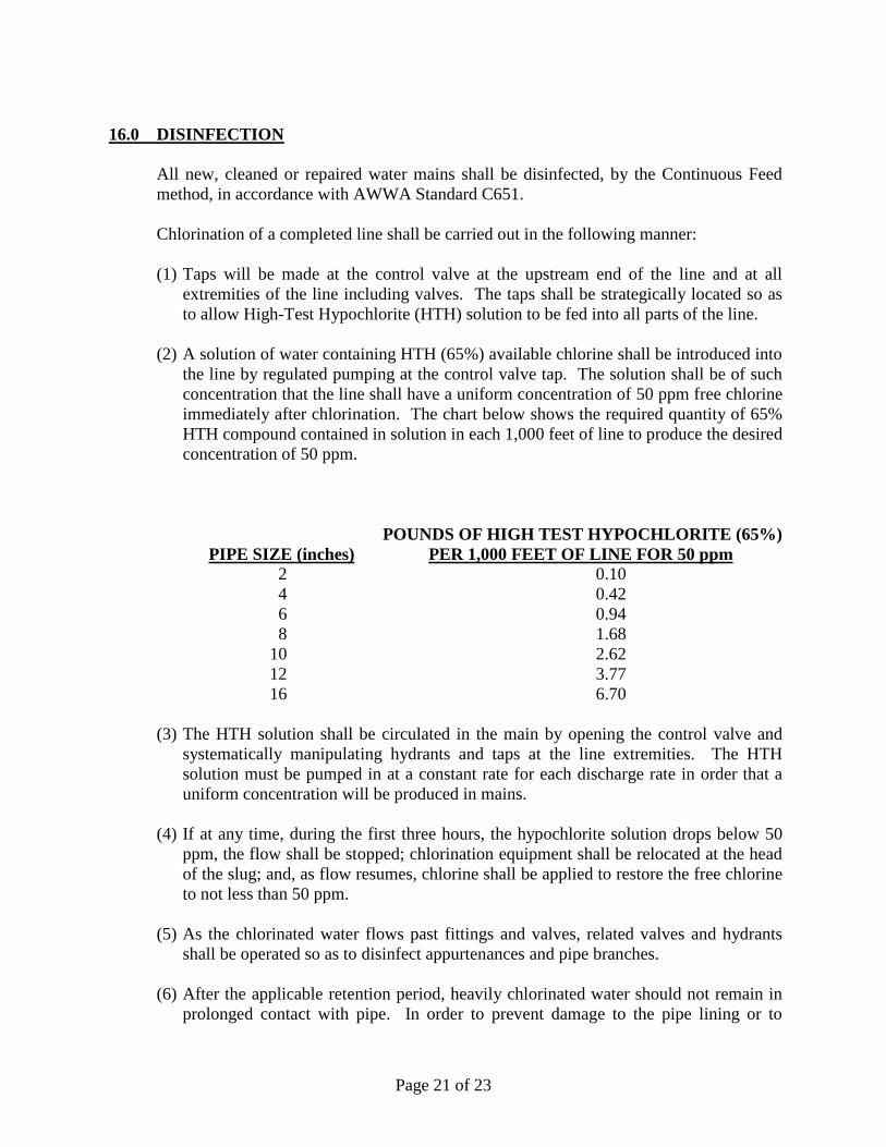
(2) A solution of water containing HTH (65%) available chlorine shall be introduced into
the line by regulated pumping at the control valve tap. The solution shall be of such
concentration that the line shall have a uniform concentration of 50 ppm free chlorine
immediately after chlorination. The chart below shows the required quantity of 65%
HTH compound contained in solution in each 1,000 feet of line to produce the desired
concentration of 50 ppm.
POUNDS OF HIGH TEST HYPOCHLORITE (65%)
PIPE SIZE (inches) PER 1,000 FEET OF LINE FOR 50 ppm 2 0.10
4 0.42
6 0.94
8 1.68
10 2.62
12 3.77
16 6.70
(3) The HTH solution shall be circulated in the main by opening the control valve and
systematically manipulating hydrants and taps at the line extremities. The HTH
solution must be pumped in at a constant rate for each discharge rate in order that a
uniform concentration will be produced in mains.
(4) If at any time, during the first three hours, the hypochlorite solution drops below 50
ppm, the flow shall be stopped; chlorination equipment shall be relocated at the head
of the slug; and, as flow resumes, chlorine shall be applied to restore the free chlorine
to not less than 50 ppm.
(5) As the chlorinated water flows past fittings and valves, related valves and hydrants
shall be operated so as to disinfect appurtenances and pipe branches.
(6) After the applicable retention period, heavily chlorinated water should not remain in
prolonged contact with pipe. In order to prevent damage to the pipe lining or to
Page 22 of 23
prevent corrosion damage to the pipe itself, the heavily chlorinated water shall be
flushed, by the Contractor, from the main fittings, valves, and branches until chlorine
measurements show that the concentration in the water leaving the main in no higher
than 2 ppm. Chlorine residual must be verified using an EPA approved method
utilizing the chemical DPD, by the Contractor, in the presence of the Engineer or
representative.
17.0 BACTERIOLOGICAL SAMPLING
Flushing of lines may proceed after 24 hours, provided the free residual chlorine analysis
is satisfactory. Flushing shall be continued until a check, by the Contractor with an EPA
approved method utilizing the chemical DPD, shows that the lines contain only the
normal chlorine residual of 2 ppm. Chlorine residual shall be checked in the presence of
the Engineer or representative before bacteriological samples are taken. The flushing
operation shall be monitored at all times by the Contractor.
Within 24 hours after flushing is complete, the contractor shall collect samples in the
presence of the Engineer, or designee, for bacteriological analysis testing by an
independent laboratory approved by the NC Department of Environmental Quality. The
sampling points shall be identified on the Record Drawings and the sample ID indicate.
Samples shall be taken every 2,000 feet, at the end of the line and on each branch. The
Engineer or representative shall observe the collection of samples. Copies of the results
shall be mailed directly to the County Engineer.
In the event that three successive bacteriological tests fail, that section of the main shall
be re-chlorinated by the Contractor and new test performed prior to moving to the next
section of the main.
No new water lines may be placed into service until such time as final approval to place
into service has been granted by the County. Services will not be granted until all of the
following items are completed and approved: construction punch list items, record
drawings, required certifications testing, final inspection, Deed of Dedication and
Releases of Liens and Wavers.
18.0 OPERATION OF EXISTING VALVES
No valve shall be operated by any party other than MCPW. This includes the operation
of tapping valves installed as part of the improvements.
New water mains valves shall remain off unless filling or flushing operations are under
way. No more than one valve shall be opened at any time between the new and existing
mains. Valves shall be closed immediately upon completion of filling and flushing
operations and shall remain closed until the new mains have been accepted by MCPW.
Page 23 of 23
19.0 WATER USE DURING CONSTRUCTION
The Contractor shall make arrangements with the MCPW for water to be used for the
filling, testing, flushing, etc. of newly installed water mains. All work requiring water
shall be carried out in a manner which will minimize the volume of water required.
MCPW will furnish water equal to two times the water main volume. If lines have to be
filled three or more times the Contractor will purchase the water at bulk prices.


![Margaret moore [warrior] - 14 - guerreiro em missão - margaret moore](https://img.pdfslide.net/doc/110x75/55905a821a28ab7a208b459c/margaret-moore-warrior-14-guerreiro-em-missao-margaret-moore.jpg)