Embed Size (px)
Citation preview

Water Main
WM

SECTION
Water Main WMNO. DATE TITLE
WM-101 10-18-16 Thrust BlocksWM-102 10-18-16 Tracer SystemWM-201 04-18-17 Fire Hydrant Assembly
04-18-17

Bends
Fitting
Thrust Block
18'' min.
45 90
MINIMUM BEARING SURFACE (sf)Water Main
D
TEES
CROSSES DEAD ENDS
BENDS
SHEET 1 O
F 2
5010.10
1
TYPICAL SECTION
TYPICAL PLAN
FIG
UR
E
(See Table)
Bearing Surface
(inches)
Pipe, D
Diameter of
WM-101
REVISION
10-18-16
SHEET 1 of 2
REVISIONS:Replaced Iowa DOT and SUDAS logos with new logos.
1
THRUST BLOCKS
STANDARD PLANROADFIGURE 5010.101
SUDAS DIRECTOR DESIGN METHODS ENGINEER
joints or fitting bolts.
Encase all fittings in polyethylene wrap. Do not allow concrete to directly contact
Form vertical surfaces of poured concrete thrust blocks except on bearing surface.
necessary.
Extend thrust blocks to undisturbed soil. Excavation into trench wall may be
Dead Ends
Tees and
41
11 21
22
allowable soil pressure of 1,000 psf.
Minimum surface area based on water pressure of 150 psi and
36
30
24
20
18
16
14
12
10
8
6
4
173
120
78
55
45
36
28
21
15
10
6
3
34
24
15
11
9
7
5
4
3
2
1
1
67
47
31
21
17
14
11
8
6
4
2
1
132
92
60
42
34
27
21
16
11
7
4
2
244
171
111
78
63
50
39
29
21
14
8
4
Undisturbed Soil

DEAD ENDS (ALTERNATE METHOD)
Trench
Hook
D
5010.10
1SHEET 2 OF 2
SECTION B-B
ELEVATION
SECTION A-A
PLAN
FIG
UR
E WM-101
REVISION
10-18-16
SHEET 2 of 2
REVISIONS:Replaced Iowa DOT and SUDAS logos with new logos.
1
THRUST BLOCKS
STANDARD PLANROADFIGURE 5010.101
SUDAS DIRECTOR DESIGN METHODS ENGINEER
A
A
B
B
documents.
Use only when allowed by the Engineer, or when specified in the contract
CHANGES IN PIPE DEPTH
or Structure
Possible Pipe
Restrained Joints
Elbows with
Straps
18'' min.
min.
24''
Thrust Block
Anchor Block
Restrained Cap
Mechanical Joint
Retainer Gland
Valve
Possible
18'' min.
Min. 1.5 x D
Retainer Gland
Depth of Concrete43
Turnbuckle
Min. 1.5 X D
Min. 1.5 X D
5010.10
2SHEET 1 O
F 1
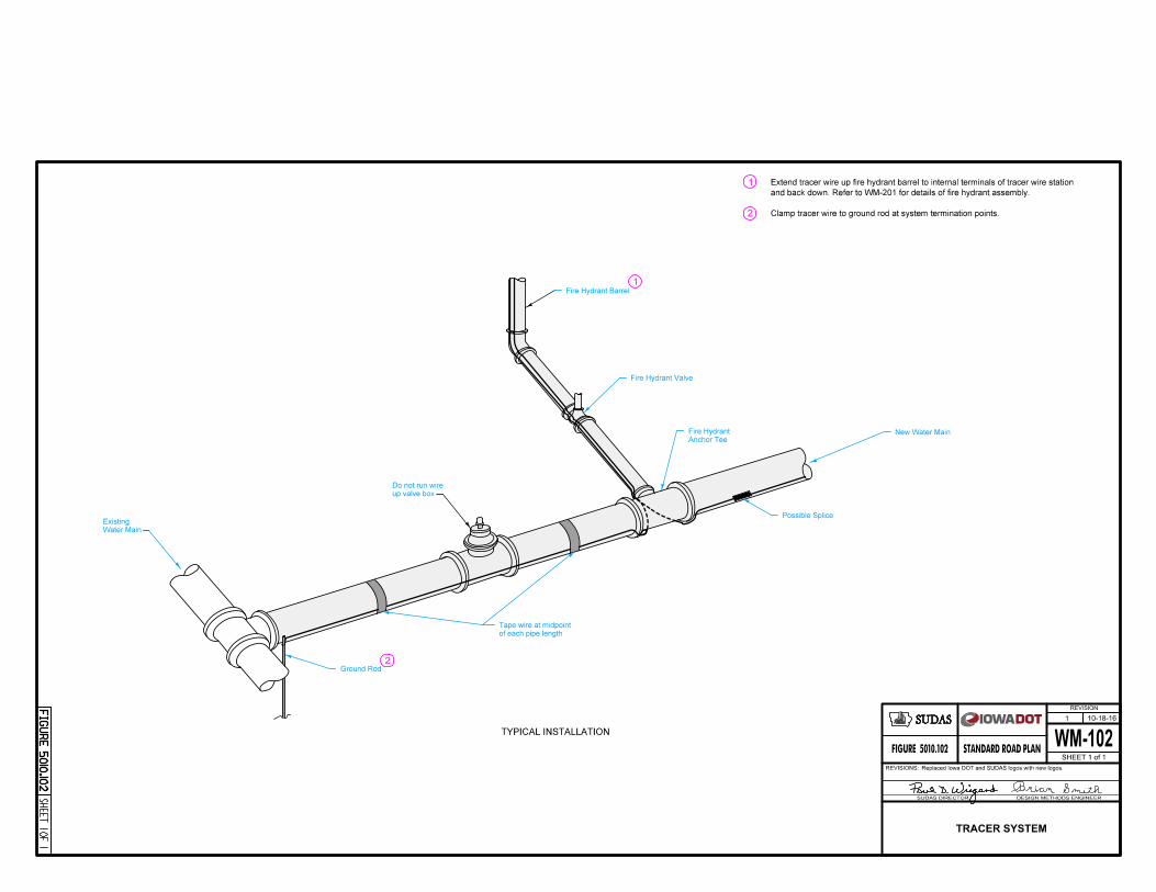
TYPICAL INSTALLATION
FIG
UR
E WM-102
REVISION
10-18-16
SHEET 1 of 1
REVISIONS:Replaced Iowa DOT and SUDAS logos with new logos.
1
TRACER SYSTEM
STANDARD PLANROADFIGURE 5010.102
SUDAS DIRECTOR DESIGN METHODS ENGINEER
1
2
1
2
Anchor Tee
Fire Hydrant New Water Main
Fire Hydrant Valve
Possible Splice
of each pipe length
Tape wire at midpoint
up valve box
Do not run wire
Ground Rod
Water Main
Existing
Clamp tracer wire to ground rod at system termination points.
and back down. Refer to WM-201 for details of fire hydrant assembly.
Extend tracer wire up fire hydrant barrel to internal terminals of tracer wire station
Fire Hydrant Barrel

5020.2
01
SHEET 1 O
F 1
REVISION
04-18-17
SHEET 1 of 1
WM-201STANDARD PLANROADFIGURE 5020.201
DESIGN METHODS ENGINEERSUDAS DIRECTOR
FIG
UR
E
2
Station Tracer Wire
FlangeBreakaway
Finish Grade
WiresTracer
12'' min.
Thrust Block1
BlockConcrete
Solid Anchor Pipe
18'' min.
NozzleLowest
20'' to 23''
Valve Box
LOCATION STATION
Min. depth as
specified for
water main
ShoeValveGate
TYPICAL SECTIONPorous Backfill
Pea Gravel or
Valve
GateFire Hydrant
Fire Hydrant Assembly
Anchor Tee
18'' min.
TYPICAL PLAN
ALTERNATE PLAN
Assembly
Hydrant
Fire
Anchor Tee
Pipe
Anchor
18'' min.
Pipe
Anchor
Valve
Gate
1
and anchor tee.mechanical joints for fire hydrant assembly Use ductile iron pipe with restrained
Do not cover drain holes or tracer wire.
FIRE HYDRANT ASSEMBLY
REVISIONS:
(typ.)Fire Hydrant
2'' to 5''
Tee
Anchor
Anchor Pipe
90° Bend
Fire Hydrant
Updated SUDAS and DOT logos.