Embed Size (px)
Citation preview

Water Mixing
Operating Principle
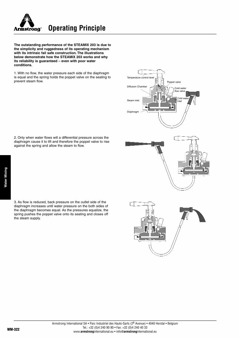
The outstanding performance of the STEAMIX 203 is due tothe simplicity and ruggedness of its operating mechanismwith its intrinsic fail safe construction. The illustrationsbelow demonstrate how the STEAMIX 203 works and whyits reliability is guaranteed – even with poor waterconditions.
1. With no flow, the water pressure each side of the diaphragmis equal and the spring holds the poppet valve on the seating toprevent steam flow.
2. Only when water flows will a differential pressure across thediaphragm cause it to lift and therefore the poppet valve to riseagainst the spring and allow the steam to flow.
3. As flow is reduced, back pressure on the outlet side of thediaphragm increases until water pressure on the both sides ofthe diaphragm becomes equal. As the pressures equalize, thespring pushes the poppet valve onto its seating and closes offthe steam supply.
Temperature control level
Poppet valve
Cold waterflow valve
Cold waterinlet
Diffusion Chamber
Steam inlet
Diaphragm
Armstrong International SA • Parc Industriel des Hauts-Sarts (2e Avenue) • 4040 Herstal • BelgiumTel.: +32 (0)4 240 90 90 • Fax: +32 (0)4 240 40 33
www.armstronginternational.eu • [email protected]
Wat
er M
ixin
g
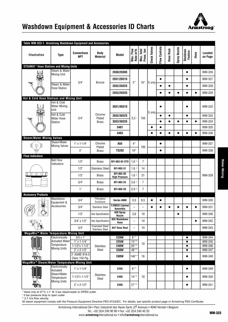
Washdown Equipment & Accessories ID Charts
Table WM-323-1. Armstrong Washdown Equipment and Accessories
Illustration Type ConnectionsNPT
BodyMaterial Model Located
on Page
STEAMIX ® Hose Stations and Mixing UnitsSteam & WaterMixing Unit
3/4" Bronze
2030/2030S
2* 10* S only
l WM-326
2031/2031S l l WM-327
Steam & WaterHose Station
2032/2032S l l l WM-328
2033/2033S l l l l l WM-329
Hot & Cold Hose Stations and Mixing UnitHot & ColdWater MixingUnit
3/4"Chrome Plated Brass
3031/3031S
5,5 † 150
S only
l l WM-333
Hot & ColdWater HoseStation
3032/3032S l l l WM-333
3033/3033S l l l l l WM-334
3401 l l WM-335
3403 l l l l l l WM-336
Steam/Water Mixing ValvesSteam/WaterMixing Valves
1" x 1-1/4" Chrome Plated Brass
A55 4*100
l WM-337
2" TS202 19* l WM-338
Flow IndicatorsBall FlowIndicators
1/2" Brass BFI-003-02-STD 1,6 †† 7
WM-339
1/2" Stainless Steel BFI-003-31 1,6 †† 14
1/2" Brass BFI-003-30 High Pressure 1,6 †† 21
3/4" Brass BFI-003-25 3,6 †† 7
1" Brass BFI-003-28 5,9 †† 7
Accessory ProductsWashdownEquipment &Accessories
3/4" FiberglassEnclosure Series 4000 0,5 8,5 l l WM-330
3/4" Stainless Steel F/SMCD CabinetAssembly – – l l l l l l WM-331
1/2" See Specification 038 SprayNozzle 3,6 10 l WM-340
3/4" x 1/2" See Specification 035 WashdownHose – 10 l WM-342
3/4" Enameled Steel/Stainless Steel 047 Hose Reel – 10 WM-343
MagaMixTM Water Temperature Mixing UnitElectronicallyActuated WaterTemperatureMixing Units
3/4 x 1"
Stainless Steal
E20W 8**
10
l WM-3441" x 1-1/4" E25W 13** l WM-345
1-1/2"x 1-1/2" E40W 20** l WM-3462" x 2-1/2" E50W 48** l WM-347
3" ASME B16.5Class 150 Flg. E80W 146** 16 l WM-348
MagaMixTM Steam/Water Temperature Mixing UnitElectronicallyActuatedSteam/WaterTemperatureMixing Units
1" x 1-1/4"
Stainless Steal
E25S 8**
10
l WM-349
1-1/2"x 1-1/2" E40S 14** l WM-350
2" x 2-1/2" E50S 27** l WM-351
Max
. Flo
wRa
te m
³/h
Max
. Inl
etPr
ess.
bar
Chec
k Va
lves
Flow
Con
trols
Hose
Rac
k
Spra
y No
zzle
Shut
dow
nFe
atur
e
Hose
* Valve only at 37°C ∆ t° @ 4 bar steam/water to OPEN outlet.† 3 bar pressure drop to open outlet†† 2,7 m/s flow velocityAll steam equipment comply with the Pressure Equipment Directive PED 97/23/EC. For details, see specific product page or Armstrong PED Certificate.
Armstrong International SA • Parc Industriel des Hauts-Sarts (2e Avenue) • 4040 Herstal • BelgiumTel.: +32 (0)4 240 90 90 • Fax: +32 (0)4 240 40 33
www.armstronginternational.eu • [email protected] WM-323
Water M
ixing
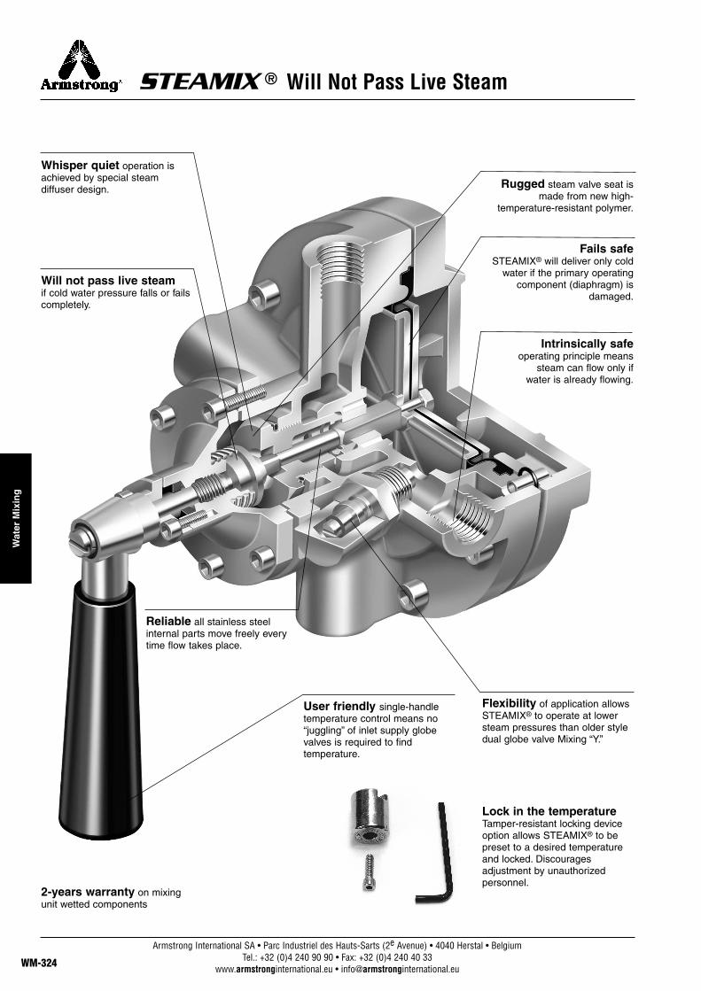
® Will Not Pass Live Steam
Whisper quiet operation isachieved by special steam diffuser design.
Will not pass live steamif cold water pressure falls or failscompletely.
Reliable all stainless steelinternal parts move freely everytime flow takes place.
User friendly single-handle temperature control means no “juggling” of inlet supply globe valves is required to findtemperature.
2-years warranty on mixingunit wetted components
Rugged steam valve seat ismade from new high-
temperature-resistant polymer.
Fails safeSTEAMIX® will deliver only cold
water if the primary operatingcomponent (diaphragm) is
damaged.
Flexibility of application allowsSTEAMIX® to operate at lowersteam pressures than older styledual globe valve Mixing “Y.”
Intrinsically safeoperating principle means
steam can flow only if water is already flowing.
Lock in the temperatureTamper-resistant locking deviceoption allows STEAMIX® to bepreset to a desired temperatureand locked. Discouragesadjustment by unauthorizedpersonnel.
Armstrong International SA • Parc Industriel des Hauts-Sarts (2e Avenue) • 4040 Herstal • BelgiumTel.: +32 (0)4 240 90 90 • Fax: +32 (0)4 240 40 33
www.armstronginternational.eu • [email protected]
Wat
er M
ixin
g
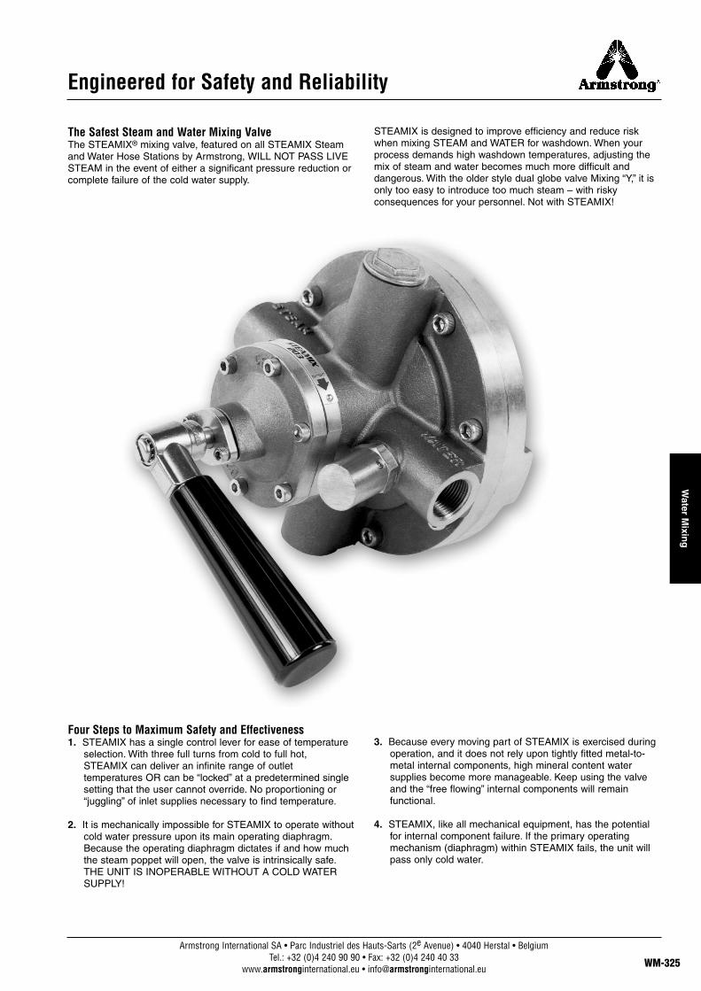
Engineered for Safety and Reliability
The Safest Steam and Water Mixing Valve The STEAMIX® mixing valve, featured on all STEAMIX Steamand Water Hose Stations by Armstrong, WILL NOT PASS LIVESTEAM in the event of either a significant pressure reduction orcomplete failure of the cold water supply.
STEAMIX is designed to improve efficiency and reduce riskwhen mixing STEAM and WATER for washdown. When yourprocess demands high washdown temperatures, adjusting themix of steam and water becomes much more difficult anddangerous. With the older style dual globe valve Mixing “Y,” it isonly too easy to introduce too much steam – with riskyconsequences for your personnel. Not with STEAMIX!
Four Steps to Maximum Safety and Effectiveness1. STEAMIX has a single control lever for ease of temperature
selection. With three full turns from cold to full hot,STEAMIX can deliver an infinite range of outlettemperatures OR can be “locked” at a predetermined singlesetting that the user cannot override. No proportioning or“juggling” of inlet supplies necessary to find temperature.
2. It is mechanically impossible for STEAMIX to operate withoutcold water pressure upon its main operating diaphragm.Because the operating diaphragm dictates if and how muchthe steam poppet will open, the valve is intrinsically safe.THE UNIT IS INOPERABLE WITHOUT A COLD WATERSUPPLY!
3. Because every moving part of STEAMIX is exercised duringoperation, and it does not rely upon tightly fitted metal-to-metal internal components, high mineral content watersupplies become more manageable. Keep using the valveand the “free flowing” internal components will remainfunctional.
4. STEAMIX, like all mechanical equipment, has the potentialfor internal component failure. If the primary operatingmechanism (diaphragm) within STEAMIX fails, the unit willpass only cold water.
Armstrong International SA • Parc Industriel des Hauts-Sarts (2e Avenue) • 4040 Herstal • BelgiumTel.: +32 (0)4 240 90 90 • Fax: +32 (0)4 240 40 33
www.armstronginternational.eu • [email protected] WM-325
Water M
ixing

Assembly 2030 – StandardSTEAMIX 2030 comprises a STEAMIX Steam/Water MixingValve of brass/stainless steel (SS) construction.
STEAMIX 2030 is a steam/water heater and is recommendedfor use in various washing machines, vessel filling, container“top off,” barrel washing and other similar applications.
STEAMIX 2030 and is designed for a horizontal(temperature control handle at top) installationand is supplied as standard with a SS wallmounting bracket. Consult drawing below forsuggested installation/mounting orientation.
Assembly 2030S – PremiumAs above, with corrosion-resistant industrial nickel-plated finish.
Safety• In the event of either a complete failure of the inlet cold
water supply or a reduction in cold water pressure tobelow 1,3 bar (+/- 0,3 bar) STEAMIX will respond with acomplete shutdown of outlet flow.
• In the event of a structural failure of the primaryoperating component (diaphragm), STEAMIX will “fail-safe” to cold water.
• To prevent over-temperature selection by the user andthe potential for overheated water and flash steampresentation common with other types of hose stations,STEAMIX can be provided with either a singletemperature lock-out or maximum temperature limitingoption.
Technical Specifications• 3/4'' NPT inlets and outlet(s)• Brass and stainless steel construction with double-sided
ultra-durable EPDM diaphragm• Operating pressures for steam and water:
Maximum: 10 barMinimum: 1,4 bar†
• Inlet check valves strongly recommended; not supplied• Shipping weight: 12,7 kg
† IMPORTANT NOTE: Lower steam pressures significantly reduce outletflow rates.
Flow RatesThe capacity charts indicate STEAMIX 203 flow rates at steamand water pressures commonly available in the averagemanufacturing plant. The STEAMIX 203 can handle a widediversity of pressures and temperatures. Three typical outlettemperatures shown in the flow tables were selected todemonstrate the valve’s flow rate at:
A) “User safe” temperature (approx. 48°C)B) “Hot hose down” temperature (approx. 65/71°C) C) “Common bacteria kill” temperature (approx. 82°C)**
Note: All flow rates shown are with open outlet, and a reduction of flow is tobe expected depending on the length and diameter of outlet pipework,washdown hose, spray nozzle, etc.
** The phrase “common bacteria kill” is not meant to imply sterilizationcapability but to indicate the ability of STEAMIX 203 to handle the highertemperatures required in food, beverage, pharmaceutical plants, etc.
This model comply with the article 3.3 of the PED (97/23/EC).
® Steam & Water Hose Stations & Mixing Units
Table WM-326-1.A) 31°C Temperature Rise
SteamWater 1,4 3 5 7 bar
1,5 bar 26,1 38,6 38,6 38,6 l/min3 bar 26,1 49,9 49,9 49,9 l/min4 bar 26,1 52,2 59,4 59,4 l/min
A) 56°C Temperature RiseSteam
Water 1,4 3 5 7 bar
1,5 bar 13,6 26,1 31,4 32,1 l/min3 bar 13,6 26,1 35,5 37,4 l/min4 bar 13,6 26,1 35,5 39,7 l/min
A) 75°C Temperature RiseSteam
Water 1,4 3 5 7 bar
1,5 bar 9,4 18,9 24,9 37,2 l/min3 bar 9,4 18,9 27,2 30,2 l/min4 bar 9,4 18,9 27,2 30,2 l/min
148 mm
140 mm
165 mm
241 mm
140 mm
210 mm
13 mm
13 mm
61 mm
241 mm
4x Ø 1/2"
ColdWater
Locking Set
Steam
Lever Boss
Base
Handle
Bracket
Bonnet
Body
HotWater
All dimensions and weights are approximate. Use certified print for exact dimensions. Design and materials are subject to change without notice.
Armstrong International SA • Parc Industriel des Hauts-Sarts (2e Avenue) • 4040 Herstal • BelgiumTel.: +32 (0)4 240 90 90 • Fax: +32 (0)4 240 40 33
www.armstronginternational.eu • [email protected]
Wat
er M
ixin
g
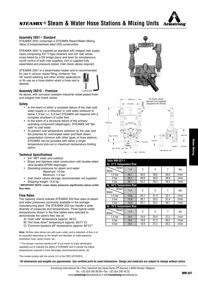
Assembly 2031 – StandardSTEAMIX 2031 comprises a STEAMIX Steam/Water MixingValve of brass/stainless steel (SS) construction.
STEAMIX 2031 is supplied as standard with integral inlet supplyrisers comprising 3/4" Y-Type strainers and 3/4" ball valvescross-linked by a SS bridge piece and lever for simultaneouson/off control of both inlet supplies. Unit is supplied fullyassembled and pressure tested. Inlet check valves required.
STEAMIX 2031 is a steam/water heater and is recommendedfor use in various vessel filling, container “topoff,” barrel washing and other similar applicationsor for use as a hose station when a hose reel isdesired.
Assembly 2031S – PremiumAs above, with corrosion-resistant industrial nickel-plated finishand integral inlet check valves.
Safety• In the event of either a complete failure of the inlet cold
water supply or a reduction in cold water pressure tobelow 1,3 bar (+/- 0,3 bar) STEAMIX will respond with acomplete shutdown of outlet flow.
• In the event of a structural failure of the primaryoperating component (diaphragm), STEAMIX will “fail-safe” to cold water.
• To prevent over-temperature selection by the user andthe potential for overheated water and flash steampresentation common with other types of hose stations,STEAMIX can be provided with either a singletemperature lock-out or maximum temperature limitingoption.
Technical Specifications• 3/4'' NPT inlets and outlet(s)• Brass and stainless steel construction with double-sided
ultra-durable EPDM diaphragm• Operating pressures for steam and water:
Maximum: 10 barMinimum: 1,4 bar†
• Inlet check valves strongly recommended; not supplied• Shipping weight: 13,6 kg
† IMPORTANT NOTE: Lower steam pressures significantly reduce outletflow rates.
Flow RatesThe capacity charts indicate STEAMIX 203 flow rates at steamand water pressures commonly available in the averagemanufacturing plant. The STEAMIX 203 can handle a widediversity of pressures and temperatures. Three typical outlettemperatures shown in the flow tables were selected todemonstrate the valve’s flow rate at:
A) “User safe” temperature (approx. 48°C)B) “Hot hose down” temperature (approx. 65/71°C) C) “Common bacteria kill” temperature (approx. 82°C)**
Note: All flow rates shown are with open outlet, and a reduction of flow is tobe expected depending on the length and diameter of outlet pipework,washdown hose, spray nozzle, etc.
** The phrase “common bacteria kill” is not meant to imply sterilizationcapability but to indicate the ability of STEAMIX 203 to handle the highertemperatures required in food, beverage, pharmaceutical plants, etc.
This model comply with the article 3.3 of the PED (97/23/EC).
258 mm
433 mm 140 mm
Typ. 15 mm
165 mm
4x ø1/2"140 mm
148 mm
64 mm
165 mmTyp. 15 mm
213 mm
2x Check valvesrequired (not supplied)(Supplied with 2031S)
® Steam & Water Hose Stations & Mixing Units
Water
Steam
HotWater
Table WM-327-1.A) 31°C Temperature Rise
SteamWater 1,4 3 5 7 bar
1,5 bar 26,1 38,6 38,6 38,6 l/min3 bar 26,1 49,9 49,9 49,9 l/min4 bar 26,1 52,2 59,4 59,4 l/min
A) 56°C Temperature RiseSteam
Water 1,4 3 5 7 bar
1,5 bar 13,6 26,1 31,4 32,1 l/min3 bar 13,6 26,1 35,5 37,4 l/min4 bar 13,6 26,1 35,5 39,7 l/min
A) 75°C Temperature RiseSteam
Water 1,4 3 5 7 bar
1,5 bar 9,4 18,9 24,9 37,2 l/min3 bar 9,4 18,9 27,2 30,2 l/min4 bar 9,4 18,9 27,2 30,2 l/min
All dimensions and weights are approximate. Use certified print for exact dimensions. Design and materials are subject to change without notice.
Locking Set
Armstrong International SA • Parc Industriel des Hauts-Sarts (2e Avenue) • 4040 Herstal • BelgiumTel.: +32 (0)4 240 90 90 • Fax: +32 (0)4 240 40 33
www.armstronginternational.eu • [email protected] WM-327
Water M
ixing
® Steam & Water Hose Stations & Mixing Units
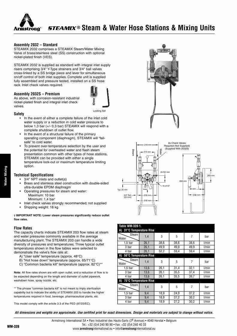
Assembly 2032 – StandardSTEAMIX 2032 comprises a STEAMIX Steam/Water MixingValve of brass/stainless steel (SS) construction with optionalnickel-plated finish (VES).
STEAMIX 2032 is supplied as standard with integral inlet supplyrisers comprising 3/4" Y-Type strainers and 3/4" ball valvescross-linked by a SS bridge piece and lever for simultaneouson/off control of both inlet supplies. Complete unit is suppliedfully assembled and pressure tested, installed on a SS hoserack. Inlet check valves required.
Assembly 2032S – PremiumAs above, with corrosion-resistant industrialnickel-plated finish and integral inlet checkvalves.
Safety• In the event of either a complete failure of the inlet cold
water supply or a reduction in cold water pressure tobelow 1,3 bar (+/- 0,3 bar) STEAMIX will respond with acomplete shutdown of outlet flow.
• In the event of a structural failure of the primaryoperating component (diaphragm), STEAMIX will “fail-safe” to cold water.
• To prevent over-temperature selection by the user andthe potential for overheated water and flash steampresentation common with other types of hose stations,STEAMIX can be provided with either a singletemperature lock-out or maximum temperature limitingoption.
Technical Specifications• 3/4'' NPT inlets and outlet(s)• Brass and stainless steel construction with double-sided
ultra-durable EPDM diaphragm• Operating pressures for steam and water:
Maximum: 10 barMinimum: 1,4 bar†
• Inlet check valves strongly recommended; not supplied• Shipping weight: 18 kg
† IMPORTANT NOTE: Lower steam pressures significantly reduce outletflow rates.
Flow RatesThe capacity charts indicate STEAMIX 203 flow rates at steamand water pressures commonly available in the averagemanufacturing plant. The STEAMIX 203 can handle a widediversity of pressures and temperatures. Three typical outlettemperatures shown in the flow tables were selected todemonstrate the valve’s flow rate at:
A) “User safe” temperature (approx. 48°C)B) “Hot hose down” temperature (approx. 65/71°C) C) “Common bacteria kill” temperature (approx. 82°C)**
Note: All flow rates shown are with open outlet, and a reduction of flow is tobe expected depending on the length and diameter of outlet pipework,washdown hose, spray nozzle, etc.
** The phrase “common bacteria kill” is not meant to imply sterilizationcapability but to indicate the ability of STEAMIX 203 to handle the highertemperatures required in food, beverage, pharmaceutical plants, etc.
This model comply with the article 3.3 of the PED (97/23/EC).
2x102 mm
278 mm
Typ. 25 mm
213 mm
318 mm
3/4" Ref.(20 mm)
318 mm
4x ø1/2"
858 mm
238 mm
90 mm
203 mm
2x Check ValvesRequired (Not Supplied)(Supplied With 2032S)
Locking Set
Water
Steam
Hot
Water
Table WM-328-1.A) 31°C Temperature Rise
SteamWater 1,4 3 5 7 bar
1,5 bar 26,1 38,6 38,6 38,6 l/min3 bar 26,1 49,9 49,9 49,9 l/min4 bar 26,1 52,2 59,4 59,4 l/min
A) 56°C Temperature RiseSteam
Water 1,4 3 5 7 bar
1,5 bar 13,6 26,1 31,4 32,1 l/min3 bar 13,6 26,1 35,5 37,4 l/min4 bar 13,6 26,1 35,5 39,7 l/min
A) 75°C Temperature RiseSteam
Water 1,4 3 5 7 bar
1,5 bar 9,4 18,9 24,9 37,2 l/min3 bar 9,4 18,9 27,2 30,2 l/min4 bar 9,4 18,9 27,2 30,2 l/min
All dimensions and weights are approximate. Use certified print for exact dimensions. Design and materials are subject to change without notice.
Armstrong International SA • Parc Industriel des Hauts-Sarts (2e Avenue) • 4040 Herstal • BelgiumTel.: +32 (0)4 240 90 90 • Fax: +32 (0)4 240 40 33
www.armstronginternational.eu • [email protected]
Wat
er M
ixin
g

Assembly 2033 – StandardSTEAMIX 2033 comprises a STEAMIX Steam/Water MixingValve of brass/stainless steel (SS) construction.
STEAMIX 2033 is supplied as standard with integral inlet supplyrisers comprising 3/4" Y-Type strainers and 3/4" ball valvescross-linked by a SS bridge piece and lever for simultaneouson/off control of both inlet supplies. Unit is supplied fullyassembled and pressure tested, installed on a SS Hose rack.
STEAMIX 2033 also includes SS dual scale outlet thermometer,7,5 m of “Safety Yellow” washdown hose rated for 28 bar and88°C, low heat transfer polymer spray nozzle with trigger guard,swivel adapter and SS nozzle hook. Inlet check valves required.
Assembly 2033S – PremiumAs above, with corrosion-resistant industrialnickel-plated finish and integral inlet checkvalves.
Safety• In the event of either a complete failure of the inlet cold
water supply or a reduction in cold water pressure tobelow 1,3 bar (+/- 0,3 bar) STEAMIX will respond with acomplete shutdown of outlet flow.
• In the event of a structural failure of the primaryoperating component (diaphragm), STEAMIX will “fail-safe” to cold water.
• To prevent over-temperature selection by the user andthe potential for overheated water and flash steampresentation common with other types of hose stations,STEAMIX can be provided with either a singletemperature lock-out or maximum temperature limitingoption.
Technical Specifications• 3/4'' NPT inlets and outlet(s)• Brass and stainless steel construction with double-sided
ultra-durable EPDM diaphragm• Operating pressures for steam and water:
Maximum: 10 barMinimum: 1,4 bar†
• Inlet check valves strongly recommended; not supplied• Shipping weight: 29 kg
† IMPORTANT NOTE: Lower steam pressures significantly reduce outletflow rates.
Flow RatesThe capacity charts indicate STEAMIX 203 flow rates at steamand water pressures commonly available in the averagemanufacturing plant. The STEAMIX 203 can handle a widediversity of pressures and temperatures. Three typical outlettemperatures shown in the flow tables were selected todemonstrate the valve’s flow rate at:
A) “User safe” temperature (approx. 48°C)B) “Hot hose down” temperature (approx. 65/71°C) C) “Common bacteria kill” temperature (approx. 82°C)†††
Note: All flow rates shown are with open outlet, and a reduction of flow is tobe expected depending on the length and diameter of outlet pipework,washdown hose, spray nozzle, etc.††† The phrase “common bacteria kill” is not meant to imply sterilizationcapability but to indicate the ability of STEAMIX 203 to handle the highertemperatures required in food, beverage, pharmaceutical plants, etc.This model comply with the article 3.3 of the PED (97/23/EC).
213 mm
334 mm
2x 102 mm
203 mm
90 mm
238 mm
858 mm
278 mm
318 mm
4x 1/2"
2x Check ValveRequired (Not
Supplied) (SuppliedWith 2033S)
Nozzle &Mounting Hook(Hook not shown)
Top-Mounted
Thermometer
2033A Standard.
Outlet-Mounted 2033B
Also Available.
4x Nipple
2x StreetElbow
Typ. 25 mmRef. 20 mm
Hose
Base
Bonnet
Handle
LeverBoss
Body
2x Strainer
2x Ball Valve
Bridge/LeverControl
Hose Rack/Mounting Plate
Water
Steam
HotWater
Locking Set
Table WM-329-1.A) 31°C Temperature Rise
SteamWater 1,4 3 5 7 bar
1,5 bar 26,1 38,6 38,6 38,6 l/min3 bar 26,1 49,9 49,9 49,9 l/min4 bar 26,1 52,2 59,4 59,4 l/min
A) 56°C Temperature RiseSteam
Water 1,4 3 5 7 bar
1,5 bar 13,6 26,1 31,4 32,1 l/min3 bar 13,6 26,1 35,5 37,4 l/min4 bar 13,6 26,1 35,5 39,7 l/min
A) 75°C Temperature RiseSteam
Water 1,4 3 5 7 bar
1,5 bar 9,4 18,9 24,9 37,2 l/min3 bar 9,4 18,9 27,2 30,2 l/min4 bar 9,4 18,9 27,2 30,2 l/min
® Steam & Water Hose Stations & Mixing Units
All dimensions and weights are approximate. Use certified print for exact dimensions. Design and materials are subject to change without notice.
Armstrong International SA • Parc Industriel des Hauts-Sarts (2e Avenue) • 4040 Herstal • BelgiumTel.: +32 (0)4 240 90 90 • Fax: +32 (0)4 240 40 33
www.armstronginternational.eu • [email protected] WM-329
Water M
ixing
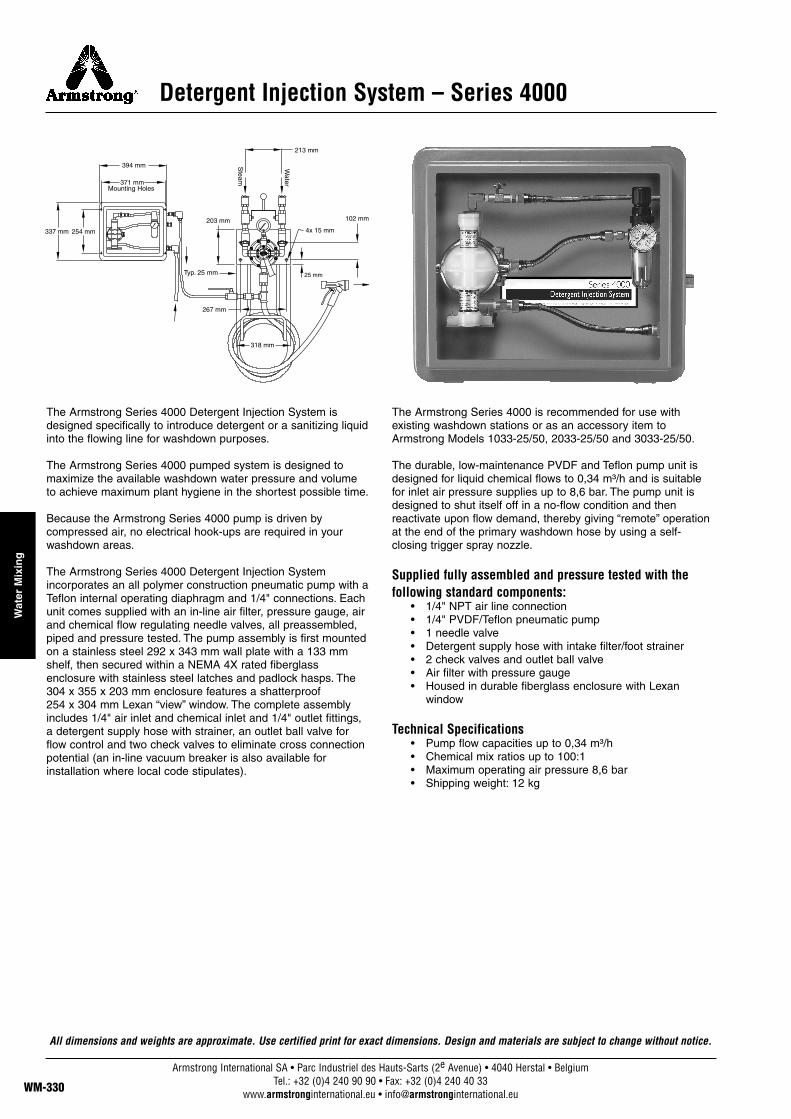
Detergent Injection System – Series 4000
The Armstrong Series 4000 Detergent Injection System isdesigned specifically to introduce detergent or a sanitizing liquidinto the flowing line for washdown purposes.
The Armstrong Series 4000 pumped system is designed tomaximize the available washdown water pressure and volumeto achieve maximum plant hygiene in the shortest possible time.
Because the Armstrong Series 4000 pump is driven bycompressed air, no electrical hook-ups are required in yourwashdown areas.
The Armstrong Series 4000 Detergent Injection Systemincorporates an all polymer construction pneumatic pump with aTeflon internal operating diaphragm and 1/4" connections. Eachunit comes supplied with an in-line air filter, pressure gauge, airand chemical flow regulating needle valves, all preassembled,piped and pressure tested. The pump assembly is first mountedon a stainless steel 292 x 343 mm wall plate with a 133 mmshelf, then secured within a NEMA 4X rated fiberglassenclosure with stainless steel latches and padlock hasps. The304 x 355 x 203 mm enclosure features a shatterproof254 x 304 mm Lexan “view” window. The complete assemblyincludes 1/4" air inlet and chemical inlet and 1/4" outlet fittings,a detergent supply hose with strainer, an outlet ball valve forflow control and two check valves to eliminate cross connectionpotential (an in-line vacuum breaker is also available forinstallation where local code stipulates).
The Armstrong Series 4000 is recommended for use withexisting washdown stations or as an accessory item toArmstrong Models 1033-25/50, 2033-25/50 and 3033-25/50.
The durable, low-maintenance PVDF and Teflon pump unit isdesigned for liquid chemical flows to 0,34 m³/h and is suitablefor inlet air pressure supplies up to 8,6 bar. The pump unit isdesigned to shut itself off in a no-flow condition and thenreactivate upon flow demand, thereby giving “remote” operationat the end of the primary washdown hose by using a self-closing trigger spray nozzle.
Supplied fully assembled and pressure tested with thefollowing standard components:
• 1/4" NPT air line connection• 1/4" PVDF/Teflon pneumatic pump• 1 needle valve• Detergent supply hose with intake filter/foot strainer• 2 check valves and outlet ball valve• Air filter with pressure gauge• Housed in durable fiberglass enclosure with Lexan
window
Technical Specifications• Pump flow capacities up to 0,34 m³/h• Chemical mix ratios up to 100:1• Maximum operating air pressure 8,6 bar• Shipping weight: 12 kg
102 mm
371 mm
394 mm
203 mm
267 mm
318 mm
25 mm
4x 15 mm
213 mm
337 mm 254 mm
Typ. 25 mm
Mounting Holes
Water
Steam
All dimensions and weights are approximate. Use certified print for exact dimensions. Design and materials are subject to change without notice.
Armstrong International SA • Parc Industriel des Hauts-Sarts (2e Avenue) • 4040 Herstal • BelgiumTel.: +32 (0)4 240 90 90 • Fax: +32 (0)4 240 40 33
www.armstronginternational.eu • [email protected]
Wat
er M
ixin
g

Hose Station Cabinet Assembly
FMCD The FMCD (Flush Mount Cabinet with Doors) is designed forrecessed installation. A type 304 stainless steel, two-doorcabinet with a 50 mm flange. Cabinet doors feature a recessed“toggle” handle. All exposed surfaces have a #4 brushed finish.The bottom of the cabinet is crosscut to drain any wateraccidentally discharged within the cabinet via a 1/2” NPT holeand plug, which is provided for optional connection to anexternal drain.
The FMCD is designed specifically to house the following hose stations:
• 1033-25/50• 2033-25/50 (shown above)• 3033-25/50
FMCD cabinets include, as standard, integral check valves(039V-S), union connections on each inlet supply, a separate3/8" utility tapping and a utility inlet/inspection port.
To specify, tag the model number of the hose station selectedwith FMCD. For example, 2033 FMCD. Maximum hose lengththat can be installed within FMCD is 15 m.
FMCD cabinets are manufactured to order and can be modifiedto include custom requirements such as increased dimensions,vacuum breakers, compressed air and/or fluid lines, pressurereducing valves and gauges, extra hose lengths, and more.
SMCDSMCD (Surface Mounted Cabinet with Doors) is the same asFMCD except it is designed for surface installation and issupplied without the 2" flange, utility line tapping and utilityinlet/inspection port.
Please consult your local Representative.
Dimensions supplied are approximate for design purposes only.Dimensions may vary dependent upon mixing unit selected.Check with factory prior to installation.
Shipping weight (cabinet only): 68 kg
1 219 mm
965 mm
711 mm
Typ. 610 mm
203 mm
508 mm
508 mm
305 mm
213 mm
CheckValve
Nipple
StreetElbow
Hose
1/2" NPTDrain
Blended
Water
Union
Both Sides
Both Sides
Strainer
Ball Valve
3/4" NPT2 Places
ø 1/2" Mounting Holes
Hinged DoorsRemoved forClarity
Water
Steam
All dimensions and weights are approximate. Use certified print for exact dimensions. Design and materials are subject to change without notice.
Armstrong International SA • Parc Industriel des Hauts-Sarts (2e Avenue) • 4040 Herstal • BelgiumTel.: +32 (0)4 240 90 90 • Fax: +32 (0)4 240 40 33
www.armstronginternational.eu • [email protected] WM-331
Water M
ixing
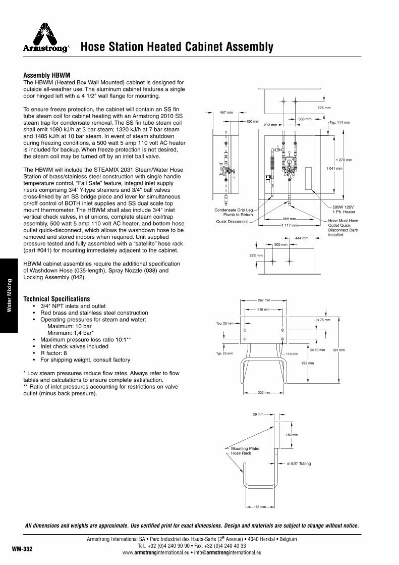
Hose Station Heated Cabinet Assembly
Assembly HBWMThe HBWM (Heated Box Wall Mounted) cabinet is designed foroutside all-weather use. The aluminum cabinet features a singledoor hinged left with a 4 1/2" wall flange for mounting.
To ensure freeze protection, the cabinet will contain an SS fintube steam coil for cabinet heating with an Armstrong 2010 SSsteam trap for condensate removal. The SS fin tube steam coilshall emit 1090 kJ/h at 3 bar steam; 1320 kJ/h at 7 bar steamand 1485 kJ/h at 10 bar steam. In event of steam shutdownduring freezing conditions, a 500 watt 5 amp 110 volt AC heateris included for backup. When freeze protection is not desired,the steam coil may be turned off by an inlet ball valve.
The HBWM will include the STEAMIX 2031 Steam/Water HoseStation of brass/stainless steel construction with single handletemperature control, “Fail Safe” feature, integral inlet supplyrisers comprising 3/4" Y-type strainers and 3/4" ball valvescross-linked by an SS bridge piece and lever for simultaneouson/off control of BOTH inlet supplies and SS dual scale topmount thermometer. The HBWM shall also include 3/4" inletvertical check valves, inlet unions, complete steam coil/trapassembly, 500 watt 5 amp 110 volt AC heater, and bottom hoseoutlet quick-disconnect, which allows the washdown hose to beremoved and stored indoors when required. Unit suppliedpressure tested and fully assembled with a “satellite” hose rack(part #041) for mounting immediately adjacent to the cabinet.
HBWM cabinet assemblies require the additional specificationof Washdown Hose (035-length), Spray Nozzle (038) andLocking Assembly (042).
Technical Specifications• 3/4" NPT inlets and outlet• Red brass and stainless steel construction• Operating pressures for steam and water:
Maximum: 10 barMinimum: 1,4 bar*
• Maximum pressure loss ratio 10:1**• Inlet check valves included• R factor: 8• For shipping weight, consult factory
* Low steam pressures reduce flow rates. Always refer to flowtables and calculations to ensure complete satisfaction.** Ratio of inlet pressures accounting for restrictions on valveoutlet (minus back pressure).
267 mm
2x 75 mm
2x 50 mm110 mm
381 mm
229 mm
232 mm
150 mm
165 mm
29 mm
216 mm
Typ. 25 mm
Typ. 25 mm
338 mm
1 270 mm
1 041 mm
889 mm
1 117 mm
305 mm
444 mm
226 mm
213 mm
457 mm
150 mm Typ. 114 mm
226 mm
Mounting Plate/Hose Rack
ø 5/8" Tubing
Condensate Drip LegPlumb to Return
Quick Disconnect
500W 120V1 Ph. Heater
Hose Must HaveOutlet QuickDisconnect BarbInstalled
All dimensions and weights are approximate. Use certified print for exact dimensions. Design and materials are subject to change without notice.
Armstrong International SA • Parc Industriel des Hauts-Sarts (2e Avenue) • 4040 Herstal • BelgiumTel.: +32 (0)4 240 90 90 • Fax: +32 (0)4 240 40 33
www.armstronginternational.eu • [email protected]
Wat
er M
ixin
g
Armstrong International SA • Parc Industriel des Hauts-Sarts (2e Avenue) • 4040 Herstal • BelgiumTel.: +32 (0)4 240 90 90 • Fax: +32 (0)4 240 40 33
www.armstronginternational.eu • [email protected] WM-333
Water M
ixing
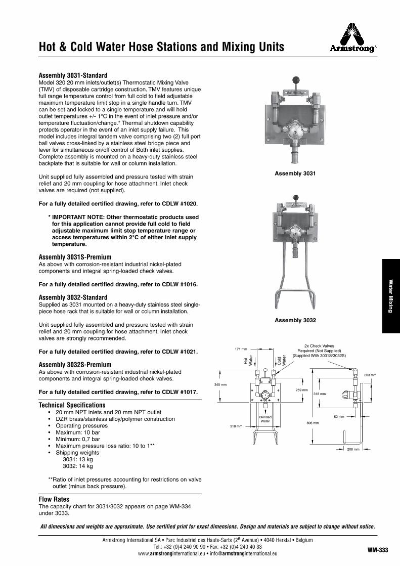
Hot & Cold Water Hose Stations and Mixing Units
Assembly 3031-StandardModel 320 20 mm inlets/outlet(s) Thermostatic Mixing Valve(TMV) of disposable cartridge construction. TMV features uniquefull range temperature control from full cold to field adjustablemaximum temperature limit stop in a single handle turn. TMVcan be set and locked to a single temperature and will holdoutlet temperatures +/- 1°C in the event of inlet pressure and/ortemperature fluctuation/change.* Thermal shutdown capabilityprotects operator in the event of an inlet supply failure. Thismodel includes integral tandem valve comprising two (2) full portball valves cross-linked by a stainless steel bridge piece andlever for simultaneous on/off control of Both inlet supplies.Complete assembly is mounted on a heavy-duty stainless steelbackplate that is suitable for wall or column installation.
Unit supplied fully assembled and pressure tested with strainrelief and 20 mm coupling for hose attachment. Inlet checkvalves are required (not supplied).
For a fully detailed certified drawing, refer to CDLW #1020.
* IMPORTANT NOTE: Other thermostatic products usedfor this application cannot provide full cold to fieldadjustable maximum limit stop temperature range oraccess temperatures within 2°C of either inlet supplytemperature.
Assembly 3031S-PremiumAs above with corrosion-resistant industrial nickel-plated components and integral spring-loaded check valves.
For a fully detailed certified drawing, refer to CDLW #1016.
Assembly 3032-StandardSupplied as 3031 mounted on a heavy-duty stainless steel single-piece hose rack that is suitable for wall or column installation.
Unit supplied fully assembled and pressure tested with strainrelief and 20 mm coupling for hose attachment. Inlet checkvalves are strongly recommended.
For a fully detailed certified drawing, refer to CDLW #1021.
Assembly 3032S-PremiumAs above with corrosion-resistant industrial nickel-plated components and integral spring-loaded check valves.
For a fully detailed certified drawing, refer to CDLW #1017.
Technical Specifications• 20 mm NPT inlets and 20 mm NPT outlet• DZR brass/stainless alloy/polymer construction • Operating pressures • Maximum: 10 bar• Minimum: 0,7 bar• Maximum pressure loss ratio: 10 to 1**• Shipping weights
3031: 13 kg 3032: 14 kg
**Ratio of inlet pressures accounting for restrictions on valve outlet (minus back pressure).
Flow RatesThe capacity chart for 3031/3032 appears on page WM-334under 3033.
Assembly 3031
Assembly 3032
318 mm
345 mm
259 mm
806 mm
203 mm
52 mm
206 mm
318 mm
171 mm
All dimensions and weights are approximate. Use certified print for exact dimensions. Design and materials are subject to change without notice.
2x Check ValvesRequired (Not Supplied)
(Supplied With 3031S/3032S)
Col
dW
ater
BlendedWater
Hot
Wat
er
Armstrong International SA • Parc Industriel des Hauts-Sarts (2e Avenue) • 4040 Herstal • BelgiumTel.: +32 (0)4 240 90 90 • Fax: +32 (0)4 240 40 33
www.armstronginternational.eu • [email protected]
Wat
er M
ixin
g
Hot & Cold Water Hose Stations and Mixing Units
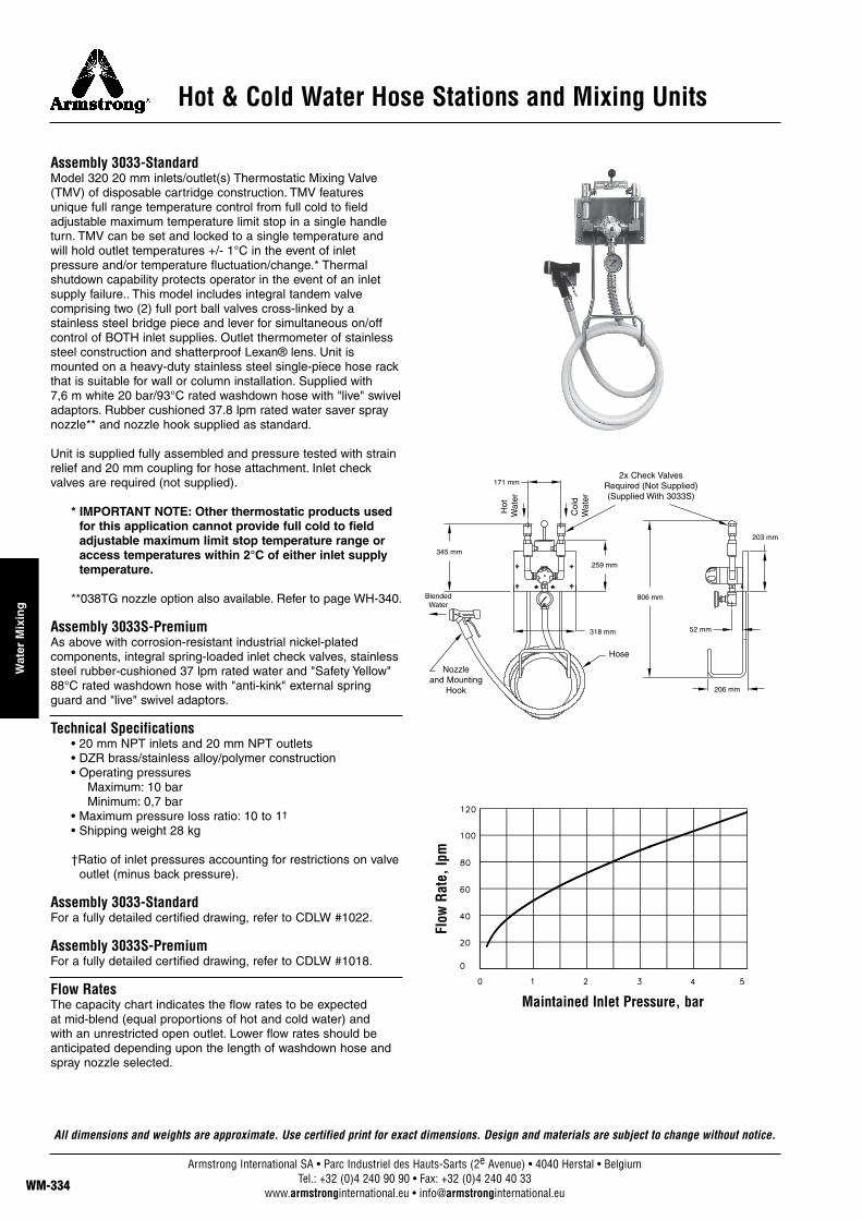
Assembly 3033-StandardModel 320 20 mm inlets/outlet(s) Thermostatic Mixing Valve(TMV) of disposable cartridge construction. TMV featuresunique full range temperature control from full cold to fieldadjustable maximum temperature limit stop in a single handleturn. TMV can be set and locked to a single temperature andwill hold outlet temperatures +/- 1°C in the event of inletpressure and/or temperature fluctuation/change.* Thermalshutdown capability protects operator in the event of an inletsupply failure.. This model includes integral tandem valvecomprising two (2) full port ball valves cross-linked by astainless steel bridge piece and lever for simultaneous on/offcontrol of BOTH inlet supplies. Outlet thermometer of stainlesssteel construction and shatterproof Lexan® lens. Unit ismounted on a heavy-duty stainless steel single-piece hose rackthat is suitable for wall or column installation. Supplied with 7,6 m white 20 bar/93°C rated washdown hose with "live" swiveladaptors. Rubber cushioned 37.8 lpm rated water saver spraynozzle** and nozzle hook supplied as standard.
Unit is supplied fully assembled and pressure tested with strainrelief and 20 mm coupling for hose attachment. Inlet checkvalves are required (not supplied).
* IMPORTANT NOTE: Other thermostatic products usedfor this application cannot provide full cold to fieldadjustable maximum limit stop temperature range oraccess temperatures within 2°C of either inlet supplytemperature.
**038TG nozzle option also available. Refer to page WH-340.
Assembly 3033S-PremiumAs above with corrosion-resistant industrial nickel-plated components, integral spring-loaded inlet check valves, stainlesssteel rubber-cushioned 37 lpm rated water and "Safety Yellow"88°C rated washdown hose with "anti-kink" external springguard and "live" swivel adaptors.
Technical Specifications• 20 mm NPT inlets and 20 mm NPT outlets• DZR brass/stainless alloy/polymer construction • Operating pressures
Maximum: 10 barMinimum: 0,7 bar
• Maximum pressure loss ratio: 10 to 1†
• Shipping weight 28 kg
†Ratio of inlet pressures accounting for restrictions on valveoutlet (minus back pressure).
Assembly 3033-StandardFor a fully detailed certified drawing, refer to CDLW #1022.
Assembly 3033S-PremiumFor a fully detailed certified drawing, refer to CDLW #1018.
Flow RatesThe capacity chart indicates the flow rates to be expected at mid-blend (equal proportions of hot and cold water) and with an unrestricted open outlet. Lower flow rates should beanticipated depending upon the length of washdown hose andspray nozzle selected.
345 mm
171 mm
318 mm
259 mm
806 mm
206 mm
52 mm
203 mm
All dimensions and weights are approximate. Use certified print for exact dimensions. Design and materials are subject to change without notice.
2x Check ValvesRequired (Not Supplied)(Supplied With 3033S)
Nozzle and Mounting
Hook
Hose
Col
dW
ater
BlendedWater
Hot
Wat
er
Maintained Inlet Pressure, bar
Flow
Rat
e, lp
m

Armstrong International SA • Parc Industriel des Hauts-Sarts (2e Avenue) • 4040 Herstal • BelgiumTel.: +32 (0)4 240 90 90 • Fax: +32 (0)4 240 40 33
www.armstronginternational.eu • [email protected] WM-335
Water M
ixing
Hot & Cold Water Hose Stations and Mixing Units
Model 3401Model 3401 features a Model 320 20 mm thermostatic mixingvalve (TMV) of disposable cartridge construction. TMV featuresunique full-range temperature control from full cold to field-adjustable maximum temperature limit stop in a singlehandle turn. TMV can be set and locked to a single temperatureand will hold outlet temperatures +/-1°C in the event of inletpressure and/or temperature fluctuation/change. Thermalshutdown capability protects operator in the event of an inletsupply failure.
Model 3401 is designed for wall-recessed installation and includescombination inlet isolation/strainer/check valves and stainless steelpanel-mount thermometer. TMV, pipe work and associatedcomponents are secured within a rugged steel mounting frameand concealed behind a 336,55 mm x 590,55 mm polishedstainless steel "easy service access" cover panel.
Model 3401 includes an exposed polished chrome temperature-control-handle and stainless steel flow-control ball valve. Idealfor clean rooms, pharmaceutical mixing rooms, research labs orsimilar locations where temperature-controlled hot water isrequired, but where surface-mount piping and fixtures areundesirable.
Technical Specifications• 20 mm inlet/outlet• Operating pressures
Maximum: 10 barMinimum: 0,7 bar
• Max pressure loss ratio: 10 to 1*• Integral check valves• Integral strainers• Integral unions• Panel-mount thermometer• Maximum temperature stop• Single temperature lock• 1°C control• Full range temperature control**
* Ratio of inlet pressures accounting for restrictions on valveoutlet (minus back pressure).
**IMPORTANT NOTE: Other thermostatic products usedfor this application cannot provide full cold to fieldadjustable maximum limit stop temperature range oraccess temperatures within 2°C of either inlet supplytemperature.
For a fully detailed certified drawing, refer to CDLW #1069.
127 mm
337 mm
232 mm
590 mm
232 mm
64 mm
32 mm 273 mm
540 mm
127 mm
148 mm
86 mm
All dimensions and weights are approximate. Use certified print for exact dimensions. Design and materials are subject to change without notice.
Thermometer
Mixing Valve
Not Provided

Armstrong International SA • Parc Industriel des Hauts-Sarts (2e Avenue) • 4040 Herstal • BelgiumTel.: +32 (0)4 240 90 90 • Fax: +32 (0)4 240 40 33
www.armstronginternational.eu • [email protected]
Wat
er M
ixin
g
Hot & Cold Water Hose Stations and Mixing Units
Model 3403Model 3403 features a Model 320 20 mm thermostatic mixingvalve (TMV) of disposable cartridge construction. TMV featuresunique full-range temperature control from full cold to field-adjustable maximum temperature limit stop in a single handleturn. TMV can be set and locked to a single temperature andwill hold outlet temperatures +/-1°C in the event of inletpressure and/or temperature fluctuation/change.*
Model 3403 is designed for wall-recessed installation and includescombination inlet isolation/strainer/check valves and stainless steelpanel mount thermometer. TMV, pipe work and associatedcomponents are secured within a rugged steel mounting frameand concealed behind a 336,55 mm x 590,55 mm polishedstainless-steel "easy service access" cover panel.
Model 3403 includes an exposed polished-chrometemperature-control handle and stainless steel flow-control ballvalve. Ideal for clean rooms, pharmaceutical mixing rooms,research labs or similar locations where temperature-controlledhot water is required, but where surface-mount piping andfixtures are undesirable.
Model 3403 supplied with "satellite" hose rack, 635 mm "SafetyYellow" washdown hose with "live" swivel adapters andArmstrong 038TG spray nozzle with integral trigger guard andnozzle mounting hook.**
* IMPORTANT NOTE: Other thermostatic products usedfor this application cannot provide full cold to fieldadjustable maximum limit stop temperature range oraccess temperatures within 2°C of either inlet supplytemperature.
**Model 3403 specifies 635 mm hose. Also available with 1 270 mm (3403-50) or 1 905 mm (3403-75) hose.
Technical Specifications• 20 mm inlets/outlets• Operating Pressures
Maximum: 10 barMinimum: 0,7 bar
• Max pressure loss ratio: 10 to 1†• Integral check valves• Integral strainers• Integral unions• Panel mount thermometer• Maximum temperature stop• Single temperature lock• 1°C control• Full range temperature control*
†Ratio of inlet pressures accounting for restrictions on valveoutlet (minus back pressure).
For a fully detailed certified drawing, refer to CDLW #1072.
127 mm
337 mm
273 mm
27 mm232 mm
232 mm
232 mm
64 mm127 mm
29 mm
152 mm
540 mm
100 mm
25 mm
254 mm
15 mm
15 mm
380 mm
165 mm
216 mm
83 mm
590 mm
148 mm
Nozzle & Mounting Hook
(Hook Not Shown)
Hose
HotWater
Hose Rack/Mounting Plate
Thermometer
Mixing Valve
Not Provided
Hose Not Shownfor Clarity
All dimensions and weights are approximate. Use certified print for exact dimensions. Design and materials are subject to change without notice.

Armstrong International SA • Parc Industriel des Hauts-Sarts (2e Avenue) • 4040 Herstal • BelgiumTel.: +32 (0)4 240 90 90 • Fax: +32 (0)4 240 40 33
www.armstronginternational.eu • [email protected] WM-337
Water M
ixing
Thermostatic Steam & Water Mixing Valve
TS202TS202 Thermostatic Mixing Valve of chrome-plated brassconstruction with stainless alloy internal operating mechanism.The TS202 uses bimetal thermostatic technology toautomatically proportion inlet steam and water supplies toachieve and maintain a desired outlet temperature. The TS202is equipped with an integral, site adjustable, maximumtemperature (∆T) fix point. With flow rates up to 265 lpm*, theTS202 is an economical alternative to hot water storage orcentral heat exchange systems by using existing plant steam toheat water instantly at the point of use. The TS202 has 50 mmNPT inlets and a 50 mm NPT outlet, and is supplied with 50 mm ball valves for inlet flow control. Check valvesrecommended.
* Based upon 4 bar equal inlet steam and water supplieswith a 55°C temperature rise.
Important: For optimum performance the TS202 should beallowed to operate at maximum flow with nominally equal inletsupply pressures and should not be installed with either outletflow control or an outlet restriction (spray nozzle, washdownhose, etc).
Warning: The TS202 is designed for industrial processapplications only and may pass live steam under certaincircumstances.
Technical Specifications• 50 mm NPT inlets. 50 mm NPT outlet• DZR brass/stainless alloy construction• Operating pressures for steam and water
Maximum: 7 barMinimum: 1,4 bar†
• Inlet check valves recommended• Shipping weight 17 kg
† Low steam pressures reduce flow rates. Always refer toflow tables and calculations to ensure completesatisfaction.
For a fully detailed certified drawing, refer to CDLW #1045.
584 mm
206 mm
BlendedWater
Steam Water
Table WH-337-1. TS202 Flow Rates (lpm)Temperature
Rise °CMaintained Equal Inlet Pressure, bar
1,3 2,7 4,1 5,5 6,812 291 412 481 552 59023 211 303 352 405 43537 159 227 265 303 32557 117 151 197 227 242
All dimensions and weights are approximate. Use certified print for exact dimensions. Design and materials are subject to change without notice.
Armstrong International SA • Parc Industriel des Hauts-Sarts (2e Avenue) • 4040 Herstal • BelgiumTel.: +32 (0)4 240 90 90 • Fax: +32 (0)4 240 40 33
www.armstronginternational.eu • [email protected]
Wat
er M
ixin
g
Thermostatic Steam & Water Mixing Valve
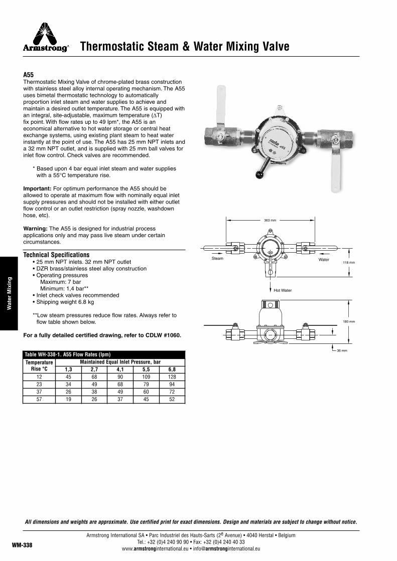
A55 Thermostatic Mixing Valve of chrome-plated brass constructionwith stainless steel alloy internal operating mechanism. The A55uses bimetal thermostatic technology to automaticallyproportion inlet steam and water supplies to achieve andmaintain a desired outlet temperature. The A55 is equipped withan integral, site-adjustable, maximum temperature (∆T) fix point. With flow rates up to 49 lpm*, the A55 is aneconomical alternative to hot water storage or central heatexchange systems, using existing plant steam to heat waterinstantly at the point of use. The A55 has 25 mm NPT inlets anda 32 mm NPT outlet, and is supplied with 25 mm ball valves forinlet flow control. Check valves are recommended.
* Based upon 4 bar equal inlet steam and water supplieswith a 55°C temperature rise.
Important: For optimum performance the A55 should beallowed to operate at maximum flow with nominally equal inletsupply pressures and should not be installed with either outletflow control or an outlet restriction (spray nozzle, washdownhose, etc).
Warning: The A55 is designed for industrial processapplications only and may pass live steam under certaincircumstances.
Technical Specifications• 25 mm NPT inlets. 32 mm NPT outlet• DZR brass/stainless steel alloy construction• Operating pressures
Maximum: 7 barMinimum: 1,4 bar**
• Inlet check valves recommended• Shipping weight 6.8 kg
**Low steam pressures reduce flow rates. Always refer toflow table shown below.
For a fully detailed certified drawing, refer to CDLW #1060.
363 mm
118 mm
180 mm
36 mmTable WH-338-1. A55 Flow Rates (lpm)Temperature
Rise °CMaintained Equal Inlet Pressure, bar
1,3 2,7 4,1 5,5 6,812 45 68 90 109 12823 34 49 68 79 9437 26 38 49 60 7257 19 26 37 45 52
Hot Water
Steam Water
All dimensions and weights are approximate. Use certified print for exact dimensions. Design and materials are subject to change without notice.
Flow Indicator
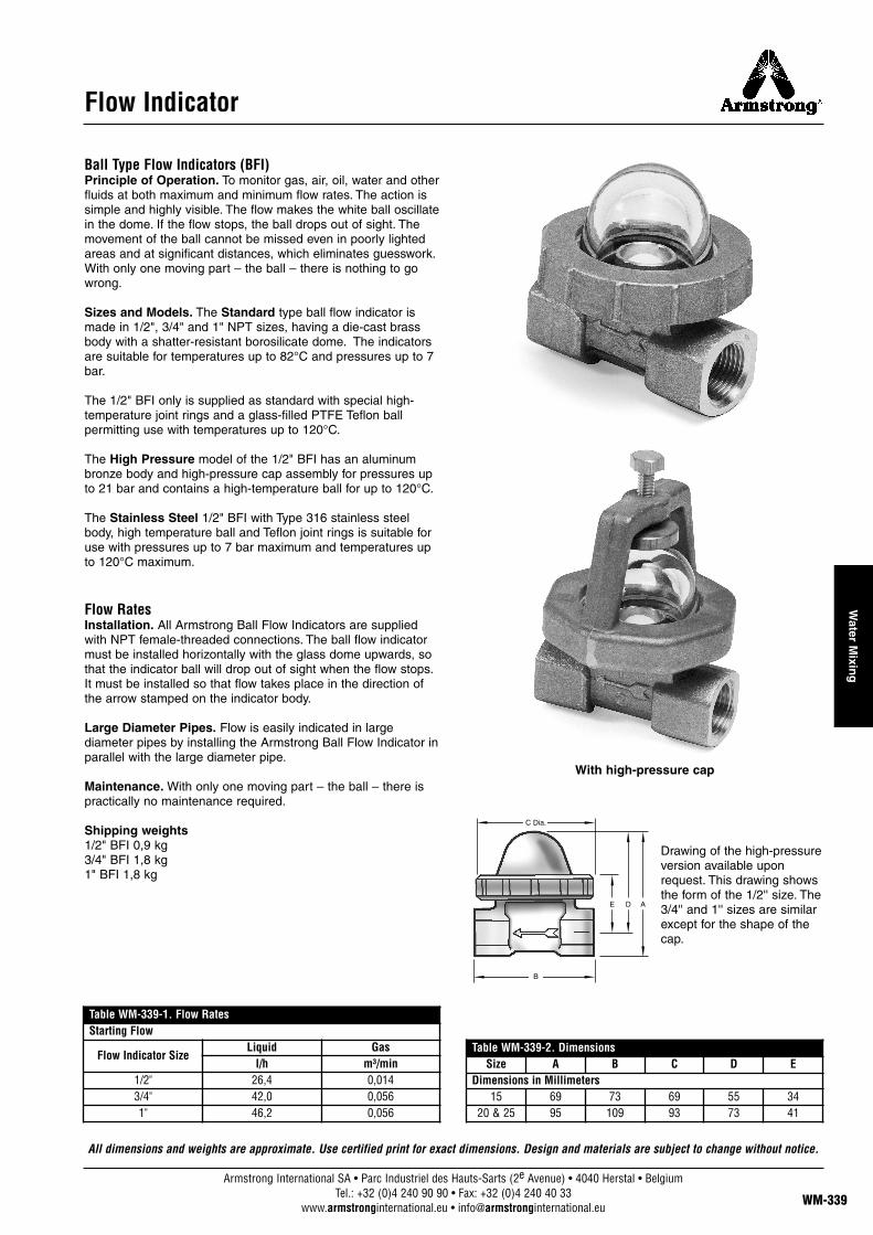
Ball Type Flow Indicators (BFI)Principle of Operation. To monitor gas, air, oil, water and otherfluids at both maximum and minimum flow rates. The action issimple and highly visible. The flow makes the white ball oscillatein the dome. If the flow stops, the ball drops out of sight. Themovement of the ball cannot be missed even in poorly lightedareas and at significant distances, which eliminates guesswork.With only one moving part – the ball – there is nothing to gowrong.
Sizes and Models. The Standard type ball flow indicator ismade in 1/2", 3/4" and 1" NPT sizes, having a die-cast brassbody with a shatter-resistant borosilicate dome. The indicatorsare suitable for temperatures up to 82°C and pressures up to 7bar.
The 1/2" BFI only is supplied as standard with special high-temperature joint rings and a glass-filled PTFE Teflon ballpermitting use with temperatures up to 120°C.
The High Pressure model of the 1/2" BFI has an aluminumbronze body and high-pressure cap assembly for pressures upto 21 bar and contains a high-temperature ball for up to 120°C.
The Stainless Steel 1/2" BFI with Type 316 stainless steelbody, high temperature ball and Teflon joint rings is suitable foruse with pressures up to 7 bar maximum and temperatures upto 120°C maximum.
Flow RatesInstallation. All Armstrong Ball Flow Indicators are suppliedwith NPT female-threaded connections. The ball flow indicatormust be installed horizontally with the glass dome upwards, sothat the indicator ball will drop out of sight when the flow stops.It must be installed so that flow takes place in the direction ofthe arrow stamped on the indicator body.
Large Diameter Pipes. Flow is easily indicated in largediameter pipes by installing the Armstrong Ball Flow Indicator inparallel with the large diameter pipe.
Maintenance. With only one moving part – the ball – there ispractically no maintenance required.
Shipping weights1/2" BFI 0,9 kg3/4" BFI 1,8 kg1" BFI 1,8 kg
Drawing of the high-pressureversion available uponrequest. This drawing showsthe form of the 1/2'' size. The3/4'' and 1'' sizes are similarexcept for the shape of thecap.
C Dia.
B
E D A
Table WM-339-1. Flow RatesStarting Flow
Flow Indicator SizeLiquid Gas
l/h m³/min1/2" 26,4 0,0143/4" 42,0 0,0561" 46,2 0,056
With high-pressure cap
Table WM-339-2. DimensionsSize A B C D E
Dimensions in Millimeters15 69 73 69 55 34
20 & 25 95 109 93 73 41
All dimensions and weights are approximate. Use certified print for exact dimensions. Design and materials are subject to change without notice.
Armstrong International SA • Parc Industriel des Hauts-Sarts (2e Avenue) • 4040 Herstal • BelgiumTel.: +32 (0)4 240 90 90 • Fax: +32 (0)4 240 40 33
www.armstronginternational.eu • [email protected] WM-339
Water M
ixing

Washdown Equipment
038TG Spray NozzleThe Series 038TG (Trigger Guard) was designed to addressseveral high-temperature washdown issues and concerns.
Heat: Nozzle is rated to 93°C. Washdown water does not passthrough the handgrip, increasing user comfort and protection.
Operation: “Lock out” lever and trigger guard minimize thepossibility of unintentional operation. Spray nozzle cannot belocked open, which prevents inadvertent discharge when waterflow is controlled upstream.
Spray Direction: Well-defined nozzle and ergonomicallydesigned trigger guard and handgrip reduce the potential forself-directed discharge.
Spray Volume: Designed to deliver up to 3,6 m³/h, the 038TGis ideal for the typical industrial washdown application.
Durability: Rugged, shatter-resistant polymer housing resistschemicals and heat better than standard rubber-coveredequipment, for longer service life.
Technical Specifications• 1/2" inlet• 10 bar maximum operating pressure• 93°C maximum operating temperature• Weight: 0,6 kg• Black polymer construction with brass/stainless steel
internal wetted parts
038 Spray NozzleWeight: 1,1 kg
Replaced by 038TG on STEAMIX Hose Stations, 038 issuggested for washdown applications below 60°C. It comes witha black, heavy-duty, field-replaceable cover. The rear triggerreduces operator fatigue, and the unit conforms to thelongstanding spray nozzle design common in many facilities.
Also available in White. Consult factory for details.
038SSWeight: 1,1 kg
As above in 316 stainless steel with grey rubber cover.Note: design/style difference in photograph.
038AL (not shown)Weight: 0,7 kg
As above in “lightweight” aluminum with light blue rubber cover.
Note: Armstrong recommends the use of heat-protective gloves, garmentsand safety glasses at all times during the washdown procedure.
036-038-001
036-038-10
038TG Spray Nozzle
038TG Spray Nozzle
Stainless Steel Model – 038SS
All dimensions and weights are approximate. Use certified print for exact dimensions. Design and materials are subject to change without notice.
038 Spray Nozzle
Armstrong International SA • Parc Industriel des Hauts-Sarts (2e Avenue) • 4040 Herstal • BelgiumTel.: +32 (0)4 240 90 90 • Fax: +32 (0)4 240 40 33
www.armstronginternational.eu • [email protected]
Wat
er M
ixin
g

Washdown Equipment
038TG-EX Spray NozzleThe Series 038TG-EX (Trigger Guard-Extension) was designedto address several high-temperature washdown issues andconcerns.
Heat: Nozzle is rated to 93°C. Washdown water does not passthrough the handgrip, increasing user comfort and protection.
Operation: “Lock out” lever and trigger guard minimize thepossibility of unintentional operation. Spray nozzle cannot belocked open, which prevents inadvertent discharge when waterflow is controlled upstream.
Spray Management: The 914 mm extension helps the operatorclean hard-to-reach areas. Jet-spray and fan-spray tips(included) offer a choice of spray patterns.
Safety and Ease of Use: The 038TG-EX comes fullyassembled with two barrel insulators, trigger guard, trigger lock,and support handgrip.
Durability: Rugged, shatter-resistant polymer housing resistschemicals and heat better than standard rubber-coveredequipment, for longer service life.
Technical Specifications• 1/2" inlet• 10 bar maximum operating pressure• 93°C maximum operating temperature• Weight: 2 kg• Black polymer construction with brass/stainless steel
internal wetted parts• 914 mm extension wand with two barrel insulators and
support hand grip• 1,8 m³/h @ 3 bar
Note: Armstrong recommends the use of heat-protective gloves, garmentsand safety glasses at all times during the washdown procedure.
1 143 mm
All dimensions and weights are approximate. Use certified print for exact dimensions. Design and materials are subject to change without notice.
Armstrong International SA • Parc Industriel des Hauts-Sarts (2e Avenue) • 4040 Herstal • BelgiumTel.: +32 (0)4 240 90 90 • Fax: +32 (0)4 240 40 33
www.armstronginternational.eu • [email protected] WM-341
Water M
ixing

Washdown Equipment
Assembly 035 Washdown HoseHeavy duty Washdown Hose is recommended for watertemperatures up to 87,7°C and working pressure up to 28 bar.Designed to withstand the intensities of the industrialenvironment. Hose is supplied as standard in 7,5 m and 15 mlengths with custom lengths available on demand. Each hoseassembly is provided as standard with a 3/4" live male swivelfitting at supply/inlet and a 1/2" live male swivel at thespray/outlet. Each fitting has a one-piece hose barb with ferrule,which is pressure-crimped to resist detachment during use. Thesupply/inlet end is protected by an anti-kink spring guard toreduce hose fatigue at a primary stress point.
Supplied in Armstrong “Safety Yellow” as standard but may beordered in differing specifications that alter temperature andpressure ratings in Red, Black, Green or White“Creamery/Packing House” style hose.
Note: Industrial washdown can be a rigorous procedure, andthere is a fine relationship between weight and flexibility toreduce user fatigue, and strength and durability, which promoteuser safety. Armstrong Washdown Hose should not beconsidered functionally infallible. However, provided that thehose is installed as supplied, the users correctly trained, andthe hose is then commissioned, operated, routinely inspectedand maintained, the risk of injury because of product failure,while never eliminated, is substantially reduced.
Technical Specifications• Recommended maximum temperature 87,7°C• Maximum working pressure 28 bar• “Safety Yellow” smooth MSHA approved finish • Anti-kink spring guard and pressure-crimped ferrule• 4:1 safety factor• Live swivel connectors at each end• Lightweight• Shipping weight
7,5 m: 7 kg15 m: 12 kg
All dimensions and weights are approximate. Use certified print for exact dimensions. Design and materials are subject to change without notice.
Armstrong International SA • Parc Industriel des Hauts-Sarts (2e Avenue) • 4040 Herstal • BelgiumTel.: +32 (0)4 240 90 90 • Fax: +32 (0)4 240 40 33
www.armstronginternational.eu • [email protected]
Wat
er M
ixin
g
Washdown Equipment
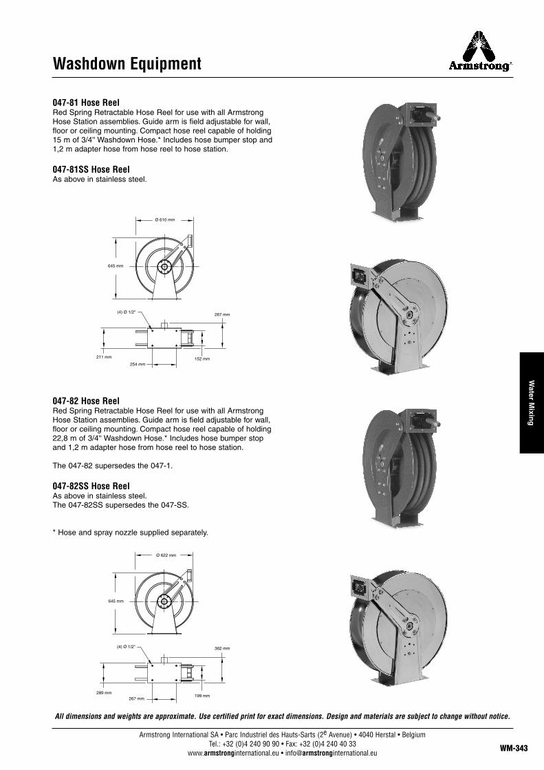
047-81 Hose ReelRed Spring Retractable Hose Reel for use with all ArmstrongHose Station assemblies. Guide arm is field adjustable for wall,floor or ceiling mounting. Compact hose reel capable of holding15 m of 3/4'' Washdown Hose.* Includes hose bumper stop and1,2 m adapter hose from hose reel to hose station.
047-81SS Hose ReelAs above in stainless steel.
047-82 Hose ReelRed Spring Retractable Hose Reel for use with all ArmstrongHose Station assemblies. Guide arm is field adjustable for wall,floor or ceiling mounting. Compact hose reel capable of holding22,8 m of 3/4'' Washdown Hose.* Includes hose bumper stopand 1,2 m adapter hose from hose reel to hose station.
The 047-82 supersedes the 047-1.
047-82SS Hose ReelAs above in stainless steel.The 047-82SS supersedes the 047-SS.
* Hose and spray nozzle supplied separately.
All dimensions and weights are approximate. Use certified print for exact dimensions. Design and materials are subject to change without notice.
Ø 610 mm
645 mm
(4) Ø 1/2"267 mm
152 mm254 mm
211 mm
Ø 622 mm
645 mm
(4) Ø 1/2" 362 mm
199 mm267 mm
289 mm
Armstrong International SA • Parc Industriel des Hauts-Sarts (2e Avenue) • 4040 Herstal • BelgiumTel.: +32 (0)4 240 90 90 • Fax: +32 (0)4 240 40 33
www.armstronginternational.eu • [email protected] WM-343
Water M
ixing
Armstrong International SA • Parc Industriel des Hauts-Sarts (2e Avenue) • 4040 Herstal • BelgiumTel.: +32 (0)4 240 90 90 • Fax: +32 (0)4 240 40 33
www.armstronginternational.eu • [email protected]
Wat
er M
ixin
g
WM-344
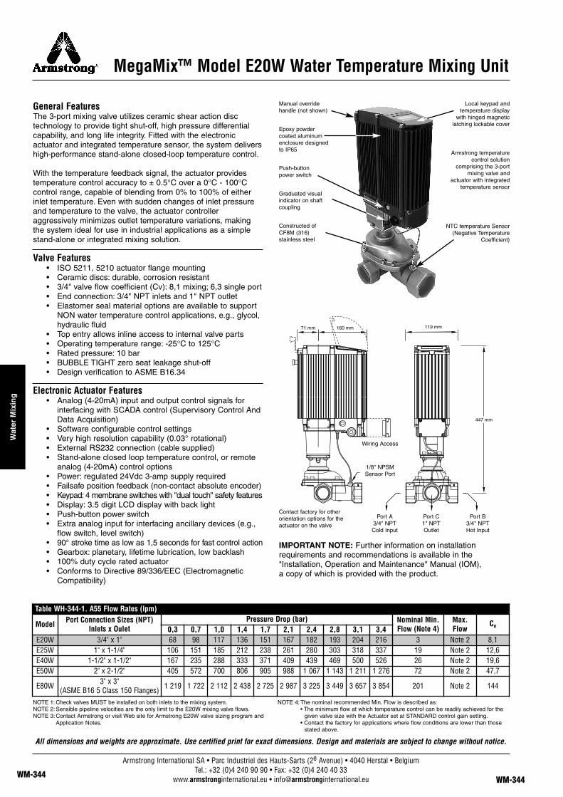
MegaMix™ Model E20W Water Temperature Mixing Unit
General FeaturesThe 3-port mixing valve utilizes ceramic shear action disc technology to provide tight shut-off, high pressure differentialcapability, and long life integrity. Fitted with the electronicactuator and integrated temperature sensor, the system delivershigh-performance stand-alone closed-loop temperature control.
With the temperature feedback signal, the actuator providestemperature control accuracy to ± 0.5°C over a 0°C - 100°Ccontrol range, capable of blending from 0% to 100% of eitherinlet temperature. Even with sudden changes of inlet pressureand temperature to the valve, the actuator controlleraggressively minimizes outlet temperature variations, makingthe system ideal for use in industrial applications as a simplestand-alone or integrated mixing solution.
Valve Features• ISO 5211, 5210 actuator flange mounting• Ceramic discs: durable, corrosion resistant• 3/4" valve flow coefficient (Cv): 8,1 mixing; 6,3 single port• End connection: 3/4" NPT inlets and 1" NPT outlet• Elastomer seal material options are available to support
NON water temperature control applications, e.g., glycol,hydraulic fluid
• Top entry allows inline access to internal valve parts• Operating temperature range: -25°C to 125°C• Rated pressure: 10 bar• BUBBLE TIGHT zero seat leakage shut-off • Design verification to ASME B16.34
Electronic Actuator Features• Analog (4-20mA) input and output control signals for
interfacing with SCADA control (Supervisory Control AndData Acquisition)
• Software configurable control settings• Very high resolution capability (0.03° rotational)• External RS232 connection (cable supplied)• Stand-alone closed loop temperature control, or remote
analog (4-20mA) control options• Power: regulated 24Vdc 3-amp supply required• Failsafe position feedback (non-contact absolute encoder)• Keypad: 4 membrane switches with "dual touch" safety features• Display: 3.5 digit LCD display with back light• Push-button power switch• Extra analog input for interfacing ancillary devices (e.g.,
flow switch, level switch)• 90° stroke time as low as 1,5 seconds for fast control action• Gearbox: planetary, lifetime lubrication, low backlash• 100% duty cycle rated actuator• Conforms to Directive 89/336/EEC (Electromagnetic
Compatibility)
IMPORTANT NOTE: Further information on installation requirements and recommendations is available in the"Installation, Operation and Maintenance" Manual (IOM), a copy of which is provided with the product.
All dimensions and weights are approximate. Use certified print for exact dimensions. Design and materials are subject to change without notice.
NOTE 1: Check valves MUST be installed on both inlets to the mixing system.NOTE 2:Sensible pipeline velocities are the only limit to the E20W mixing valve flows.NOTE 3:Contact Armstrong or visit Web site for Armstrong E20W valve sizing program and
Application Notes.
NOTE 4:The nominal recommended Min. Flow is described as:• The minimum flow at which temperature control can be readily achieved for the
given valve size with the Actuator set at STANDARD control gain setting.• Contact the factory for applications where flow conditions are lower than those
stated above.
Manual override handle (not shown)
Epoxy powder coated aluminum enclosure designed to IP65
Push-button power switch
Contact factory for otherorientation options for theactuator on the valve
Port A3/4" NPT Cold Input
1/8" NPSM Sensor Port
Wiring Access
Port C1" NPT Outlet
Port B3/4" NPT Hot Input
Local keypad and temperature display
with hinged magnetic latching lockable cover
Armstrong temperature control solution
comprising the 3-port mixing valve and
actuator with integrated temperature sensor
NTC temperature Sensor(Negative Temperature
Coefficient)
Graduated visual indicator on shaft coupling
Constructed of CF8M (316) stainless steel
Table WH-344-1. A55 Flow Rates (lpm)
Model Port Connection Sizes (NPT)Inlets x Oulet
Pressure Drop (bar) Nominal Min.Flow (Note 4)
Max.Flow
Cv0,3 0,7 1,0 1,4 1,7 2,1 2,4 2,8 3,1 3,4E20W 3/4" x 1" 68 98 117 136 151 167 182 193 204 216 3 Note 2 8,1E25W 1" x 1-1/4" 106 151 185 212 238 261 280 303 318 337 19 Note 2 12,6E40W 1-1/2" x 1-1/2" 167 235 288 333 371 409 439 469 500 526 26 Note 2 19,6E50W 2" x 2-1/2" 405 572 700 806 905 988 1 067 1 143 1 211 1 276 72 Note 2 47,7
E80W 3" x 3"(ASME B16 5 Class 150 Flanges) 1 219 1 722 2 112 2 438 2 725 2 987 3 225 3 449 3 657 3 854 201 Note 2 144

Armstrong International SA • Parc Industriel des Hauts-Sarts (2e Avenue) • 4040 Herstal • BelgiumTel.: +32 (0)4 240 90 90 • Fax: +32 (0)4 240 40 33
www.armstronginternational.eu • [email protected] WM-345
Water M
ixing
MegaMix™ Model E25W Water Temperature Mixing Unit
General FeaturesThe 3-port mixing valve utilizes ceramic shear action disc technology to provide tight shut-off, high pressure differentialcapability, and long life integrity. Fitted with the electronicactuator and integrated temperature sensor, the system delivershigh-performance stand-alone closed-loop temperature control.
With the temperature feedback signal, the actuator providestemperature control accuracy to ± 0.5°C over a 0°C - 100°Ccontrol range, capable of blending from 0% to 100% of eitherinlet temperature. Even with sudden changes of inlet pressureand temperature to the valve, the actuator controller aggressivelyminimizes outlet temperature variations, making the system idealfor use in industrial applications as a simple stand-alone orintegrated mixing solution.
Valve Features• ISO 5211, 5210 actuator flange mounting• Ceramic discs: durable, corrosion resistant• 1" valve flow coefficient (Cv): 12,6 mixing; 10,0 single port• End connection: 1" NPT inlets and 1-1/4" NPT outlet• Elastomer seal material options are available to support
NON water temperature control applications, e.g., glycol,hydraulic fluid
• Top entry allows inline access to internal valve parts• Operating temperature range: -25°C to 125°C• Rated pressure: 10 bar• BUBBLE TIGHT zero seat leakage shut-off • Design verification to ASME B16.34
Electronic Actuator Features• Analog (4-20mA) input and output control signals for
interfacing with SCADA control (Supervisory Control AndData Acquisition)
• Software configurable control settings• Very high resolution capability (0.03° rotational)• External RS232 connection (cable supplied)• Stand-alone closed loop temperature control, or remote
analog (4-20mA) control options• Power: regulated 24Vdc 3-amp supply required• Failsafe position feedback (non-contact absolute encoder)• Keypad: 4 membrane switches with "dual touch" safety features• Display: 3.5 digit LCD display with back light• Push-button power switch• Extra analog input for interfacing ancillary devices (e.g.,
flow switch, level switch)• 90° stroke time as low as 1,5 seconds for fast control action• Gearbox: planetary, lifetime lubrication, low backlash• 100% duty cycle rated actuator• Conforms to Directive 89/336/EEC (Electromagnetic
Compatibility)
IMPORTANT NOTE: Further information on installation requirements and recommendations is available in the"Installation, Operation and Maintenance" Manual (IOM), a copy of which is provided with the product.
NOTE 1: Check valves MUST be installed on both inlets to the mixing system.NOTE 2:Sensible pipeline velocities are the only limit to the E25W mixing valve flows.NOTE 3:Contact Armstrong or visit Web site for Armstrong E25W valve sizing program and
Application Notes.
NOTE 4:The nominal recommended Min. Flow is described as:• The minimum flow at which temperature control can be readily achieved for the
given valve size with the Actuator set at STANDARD control gain setting.• Contact the factory for applications where flow conditions are lower than those
stated above.
Manual override handle (not shown)
Epoxy powder coated aluminum enclosure designed to IP65
Push-button power switch
Contact factory for otherorientation options for theactuator on the valve
Port A1" NPT
Cold Input
1/8" NPSM Sensor Port
Wiring Access
Port C1-1/4" NPT
Outlet
Port B1" NPT
Hot Input
Local keypad and temperature display
with hinged magnetic latching lockable cover
Armstrong temperature control solution
comprising the 3-port mixing valve and
actuator with integrated temperature sensor
NTC temperature Sensor(Negative Temperature
Coefficient)
Graduated visual indicator on shaft coupling
Constructed of CF8M (316) stainless steel
Table WH-345-1. A55 Flow Rates (lpm)
Model Port Connection Sizes (NPT)Inlets x Oulet
Pressure Drop (bar) Nominal Min.Flow (Note 4)
Max.Flow
Cv0,3 0,7 1,0 1,4 1,7 2,1 2,4 2,8 3,1 3,4E20W 3/4" x 1" 68 98 117 136 151 167 182 193 204 216 3 Note 2 8,1E25W 1" x 1-1/4" 106 151 185 212 238 261 280 303 318 337 19 Note 2 12,6E40W 1-1/2" x 1-1/2" 167 235 288 333 371 409 439 469 500 526 26 Note 2 19,6E50W 2" x 2-1/2" 405 572 700 806 905 988 1 067 1 143 1 211 1 276 72 Note 2 47,7
E80W 3" x 3"(ASME B16 5 Class 150 Flanges) 1 219 1 722 2 112 2 438 2 725 2 987 3 225 3 449 3 657 3 854 201 Note 2 144
All dimensions and weights are approximate. Use certified print for exact dimensions. Design and materials are subject to change without notice.
Armstrong International SA • Parc Industriel des Hauts-Sarts (2e Avenue) • 4040 Herstal • BelgiumTel.: +32 (0)4 240 90 90 • Fax: +32 (0)4 240 40 33
www.armstronginternational.eu • [email protected]
Wat
er M
ixin
g
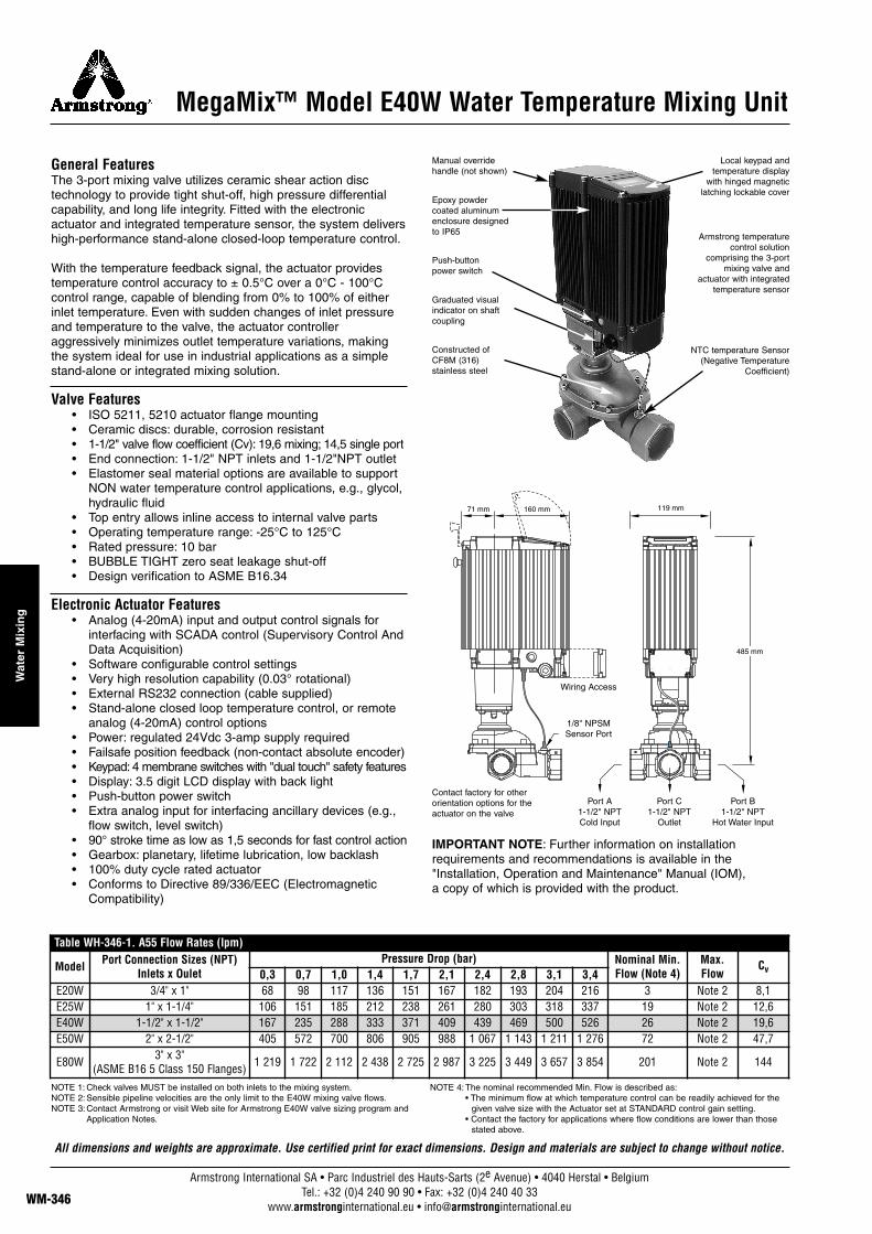
MegaMix™ Model E40W Water Temperature Mixing Unit
General FeaturesThe 3-port mixing valve utilizes ceramic shear action disc technology to provide tight shut-off, high pressure differentialcapability, and long life integrity. Fitted with the electronicactuator and integrated temperature sensor, the system delivershigh-performance stand-alone closed-loop temperature control.
With the temperature feedback signal, the actuator providestemperature control accuracy to ± 0.5°C over a 0°C - 100°Ccontrol range, capable of blending from 0% to 100% of eitherinlet temperature. Even with sudden changes of inlet pressureand temperature to the valve, the actuator controlleraggressively minimizes outlet temperature variations, makingthe system ideal for use in industrial applications as a simplestand-alone or integrated mixing solution.
Valve Features• ISO 5211, 5210 actuator flange mounting• Ceramic discs: durable, corrosion resistant• 1-1/2" valve flow coefficient (Cv): 19,6 mixing; 14,5 single port• End connection: 1-1/2" NPT inlets and 1-1/2"NPT outlet• Elastomer seal material options are available to support
NON water temperature control applications, e.g., glycol,hydraulic fluid
• Top entry allows inline access to internal valve parts• Operating temperature range: -25°C to 125°C• Rated pressure: 10 bar• BUBBLE TIGHT zero seat leakage shut-off • Design verification to ASME B16.34
Electronic Actuator Features• Analog (4-20mA) input and output control signals for
interfacing with SCADA control (Supervisory Control AndData Acquisition)
• Software configurable control settings• Very high resolution capability (0.03° rotational)• External RS232 connection (cable supplied)• Stand-alone closed loop temperature control, or remote
analog (4-20mA) control options• Power: regulated 24Vdc 3-amp supply required• Failsafe position feedback (non-contact absolute encoder)• Keypad: 4 membrane switches with "dual touch" safety features• Display: 3.5 digit LCD display with back light• Push-button power switch• Extra analog input for interfacing ancillary devices (e.g.,
flow switch, level switch)• 90° stroke time as low as 1,5 seconds for fast control action• Gearbox: planetary, lifetime lubrication, low backlash• 100% duty cycle rated actuator• Conforms to Directive 89/336/EEC (Electromagnetic
Compatibility)
IMPORTANT NOTE: Further information on installation requirements and recommendations is available in the"Installation, Operation and Maintenance" Manual (IOM), a copy of which is provided with the product.
All dimensions and weights are approximate. Use certified print for exact dimensions. Design and materials are subject to change without notice.
NOTE 1: Check valves MUST be installed on both inlets to the mixing system.NOTE 2:Sensible pipeline velocities are the only limit to the E40W mixing valve flows.NOTE 3:Contact Armstrong or visit Web site for Armstrong E40W valve sizing program and
Application Notes.
NOTE 4:The nominal recommended Min. Flow is described as:• The minimum flow at which temperature control can be readily achieved for the
given valve size with the Actuator set at STANDARD control gain setting.• Contact the factory for applications where flow conditions are lower than those
stated above.
Manual override handle (not shown)
Epoxy powder coated aluminum enclosure designed to IP65
Push-button power switch
Contact factory for otherorientation options for theactuator on the valve
Port A1-1/2" NPT Cold Input
1/8" NPSM Sensor Port
Wiring Access
Port C1-1/2" NPT
Outlet
Port B1-1/2" NPT
Hot Water Input
Local keypad and temperature display
with hinged magnetic latching lockable cover
Armstrong temperature control solution
comprising the 3-port mixing valve and
actuator with integrated temperature sensor
NTC temperature Sensor(Negative Temperature
Coefficient)
Graduated visual indicator on shaft coupling
Constructed of CF8M (316) stainless steel
Table WH-346-1. A55 Flow Rates (lpm)
Model Port Connection Sizes (NPT)Inlets x Oulet
Pressure Drop (bar) Nominal Min.Flow (Note 4)
Max.Flow
Cv0,3 0,7 1,0 1,4 1,7 2,1 2,4 2,8 3,1 3,4E20W 3/4" x 1" 68 98 117 136 151 167 182 193 204 216 3 Note 2 8,1E25W 1" x 1-1/4" 106 151 185 212 238 261 280 303 318 337 19 Note 2 12,6E40W 1-1/2" x 1-1/2" 167 235 288 333 371 409 439 469 500 526 26 Note 2 19,6E50W 2" x 2-1/2" 405 572 700 806 905 988 1 067 1 143 1 211 1 276 72 Note 2 47,7
E80W 3" x 3"(ASME B16 5 Class 150 Flanges) 1 219 1 722 2 112 2 438 2 725 2 987 3 225 3 449 3 657 3 854 201 Note 2 144
Armstrong International SA • Parc Industriel des Hauts-Sarts (2e Avenue) • 4040 Herstal • BelgiumTel.: +32 (0)4 240 90 90 • Fax: +32 (0)4 240 40 33
www.armstronginternational.eu • [email protected] WM-347
Water M
ixing
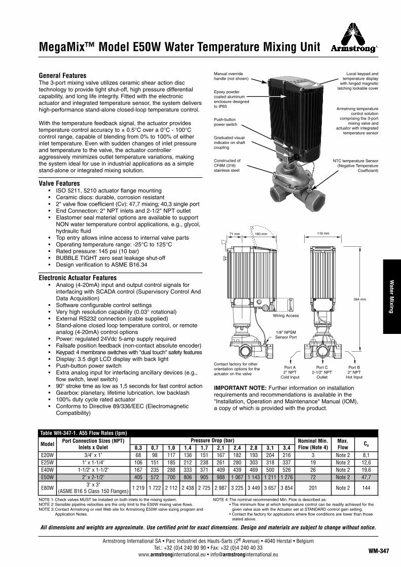
MegaMix™ Model E50W Water Temperature Mixing Unit
General FeaturesThe 3-port mixing valve utilizes ceramic shear action disc technology to provide tight shut-off, high pressure differentialcapability, and long life integrity. Fitted with the electronicactuator and integrated temperature sensor, the system delivershigh-performance stand-alone closed-loop temperature control.
With the temperature feedback signal, the actuator providestemperature control accuracy to ± 0.5°C over a 0°C - 100°Ccontrol range, capable of blending from 0% to 100% of eitherinlet temperature. Even with sudden changes of inlet pressureand temperature to the valve, the actuator controlleraggressively minimizes outlet temperature variations, makingthe system ideal for use in industrial applications as a simplestand-alone or integrated mixing solution.
Valve Features• ISO 5211, 5210 actuator flange mounting• Ceramic discs: durable, corrosion resistant• 2" valve flow coefficient (Cv): 47,7 mixing; 40,3 single port• End Connection: 2" NPT inlets and 2-1/2" NPT outlet• Elastomer seal material options are available to support
NON water temperature control applications, e.g., glycol,hydraulic fluid
• Top entry allows inline access to internal valve parts• Operating temperature range: -25°C to 125°C• Rated pressure: 145 psi (10 bar)• BUBBLE TIGHT zero seat leakage shut-off • Design verification to ASME B16.34
Electronic Actuator Features• Analog (4-20mA) input and output control signals for
interfacing with SCADA control (Supervisory Control AndData Acquisition)
• Software configurable control settings• Very high resolution capability (0.03° rotational)• External RS232 connection (cable supplied)• Stand-alone closed loop temperature control, or remote
analog (4-20mA) control options• Power: regulated 24Vdc 5-amp supply required• Failsafe position feedback (non-contact absolute encoder)• Keypad: 4 membrane switches with "dual touch" safety features• Display: 3.5 digit LCD display with back light• Push-button power switch• Extra analog input for interfacing ancillary devices (e.g.,
flow switch, level switch)• 90° stroke time as low as 1,5 seconds for fast control action• Gearbox: planetary, lifetime lubrication, low backlash• 100% duty cycle rated actuator• Conforms to Directive 89/336/EEC (Electromagnetic
Compatibility)
IMPORTANT NOTE: Further information on installation requirements and recommendations is available in the"Installation, Operation and Maintenance" Manual (IOM), a copy of which is provided with the product.
NOTE 1: Check valves MUST be installed on both inlets to the mixing system.NOTE 2:Sensible pipeline velocities are the only limit to the E50W mixing valve flows.NOTE 3:Contact Armstrong or visit Web site for Armstrong E50W valve sizing program and
Application Notes.
NOTE 4:The nominal recommended Min. Flow is described as:• The minimum flow at which temperature control can be readily achieved for the
given valve size with the Actuator set at STANDARD control gain setting.• Contact the factory for applications where flow conditions are lower than those
stated above.
Manual override handle (not shown)
Epoxy powder coated aluminum enclosure designed to IP65
Push-button power switch
Contact factory for otherorientation options for theactuator on the valve
Port A2" NPT
Cold Input
1/8" NPSM Sensor Port
Wiring Access
Port C2-1/2" NPT
Outlet
Port B2" NPT
Hot Input
Local keypad and temperature display
with hinged magnetic latching lockable cover
Armstrong temperature control solution
comprising the 3-port mixing valve and
actuator with integrated temperature sensor
NTC temperature Sensor(Negative Temperature
Coefficient)
Graduated visual indicator on shaft coupling
Constructed of CF8M (316) stainless steel
Table WH-347-1. A55 Flow Rates (lpm)
Model Port Connection Sizes (NPT)Inlets x Oulet
Pressure Drop (bar) Nominal Min.Flow (Note 4)
Max.Flow
Cv0,3 0,7 1,0 1,4 1,7 2,1 2,4 2,8 3,1 3,4E20W 3/4" x 1" 68 98 117 136 151 167 182 193 204 216 3 Note 2 8,1E25W 1" x 1-1/4" 106 151 185 212 238 261 280 303 318 337 19 Note 2 12,6E40W 1-1/2" x 1-1/2" 167 235 288 333 371 409 439 469 500 526 26 Note 2 19,6E50W 2" x 2-1/2" 405 572 700 806 905 988 1 067 1 143 1 211 1 276 72 Note 2 47,7
E80W 3" x 3"(ASME B16 5 Class 150 Flanges) 1 219 1 722 2 112 2 438 2 725 2 987 3 225 3 449 3 657 3 854 201 Note 2 144
All dimensions and weights are approximate. Use certified print for exact dimensions. Design and materials are subject to change without notice.

General FeaturesThe 3-port valve utilizes a unique shear action disc technology andswirl-mix body geometry to provide high performance dynamic fluidmixing. The nature of the valve seat design minimizes disc wear,outperforming conventionally seated valves, minimizing sealreplacement and plant downtime. Fitted with the electronic actuator anda temperature sensor inserted into the outlet pipe, the system delivershigh-performance stand-alone closed-loop temperature control.
The calibrated temperature feedback signal in combination with the fast acting actuator provides temperature control accuracy to ± 1°Cover a 0°C - 100°C control range, capable of blending from 0% to 100% ofeither inlet temperature. Even with sudden changes of inlet pressure andtemperature to the valve, the actuator controller aggressively minimizesoutlet temperature variations, making the system ideal for use in industrialapplications as a simple stand-alone or integrated mixing solution.
Valve Features• ISO 5211, 5210 actuator flange mounting• Shear Action Discs and Valve constructed of CF8M
(316) stainless steel• 3" valve flow coefficient (Cv): 144 • End connection: 3" ASME B16.5 Class 150 standard
(Cl. 300 option available)• Port size: 3" nominal bore• Calibrated NTC temperature probe assembly requires fitting into
pipework 12" downstream of the outlet port• Elastomer seal material options are available to support NON
water temperature control applications, e.g., glycol, hydraulic fluid• Top entry allows inline access to internal valve parts• Operating temperature range: -25°C to 125°C• Rated pressure: 16 bar at 100°C• Valve is non shutoff with seat leakage being less than 0.05% of Cv• Design verification to ASME B16.34• U.S. and EU patent pending
Electronic Actuator Features• Analog (4-20mA) input and output control signals for interfacing
with SCADA control (Supervisory Control And Data Acquisition)• Software configurable control settings• Very high resolution capability (0.03° rotational)• External RS232 connection (cable supplied)• Stand-alone closed loop temperature control, or remote analog
(4-20mA) control options• Power: regulated 24Vdc 5-amp supply required• Failsafe position feedback (non-contact absolute encoder)• Keypad: 4 membrane switches with "dual touch" safety features• Display: 3.5 digit LCD display with back light• Push-button power switch• Extra analog input for interfacing ancillary devices (e.g., flow
switch, level switch)• 90° stroke time as low as 1.5 seconds for fast control action• Gearbox: planetary, lifetime lubrication, low backlash• 100% duty cycle rated actuator• Conforms to Directive 89/336/EEC (Electromagnetic Compatibility)
Important Notes: Consult the "Installation, Operation and Maintenance"Manual (IOM) to review key requirements, recommendations andconsiderations when planning your installation. Failure to do so may affect theperformance of the product. A copy of the IOM is provided with the product.
• Illustration shows standard system format for actuator/valveorientation, installed calibrated NTC temperature probe withinstallation tap kit and ASME B16.5 Class 150 end connectionson the valve.
• Hot and cold input ports can be interchanged, and alternativeorientations of the actuator on the valve can be specified.
• Class 300 flange option is available on indent, but not pressurerated to ASME CI 300.
• Please consult with the Armstrong factory at time of orderplacement if you require non standard format product for yourinstallation.r a fully detailed certified drawing, refer to CDLW #1172.
Armstrong International SA • Parc Industriel des Hauts-Sarts (2e Avenue) • 4040 Herstal • BelgiumTel.: +32 (0)4 240 90 90 • Fax: +32 (0)4 240 40 33
www.armstronginternational.eu • [email protected]
Wat
er M
ixin
g
MegaMix™ Model E80W Water Temperature Mixing Unit
NOTE 1: Check valves MUST be installed on both inlets to the mixing system.NOTE 2:Sensible pipeline velocities are the only limit to the E80W mixing valve flows.NOTE 3:Contact Armstrong or visit Web site for Armstrong E80W valve sizing program and
Application Notes.
NOTE 4:The nominal recommended Min. Flow is described as:• The minimum flow at which temperature control can be readily achieved for the
given valve size with the Actuator set at STANDARD control gain setting.• Contact the factory for applications where flow conditions are lower than those
stated above.
Manual override handle
Epoxy powder coated aluminum enclosure designed to IP65
Push-button power switch
Contact factory for otherorientation options for theactuator on the valve
Port ACold Input
ASME Class 150 andconnections shown
NOTE : The assembly can be changed tohave either port A or port B as hot or cold
1/2" tap installation kit and 1/8" NPStemerature sensorassemnly
Port C Outlet
Port B Hot Input
Local keypad and temperature display
with hinged magnetic latching lockable cover
Armstrong temperature control solution
comprising the 3-port mixing valve and
actuator with integrated temperature sensor
Graduated visual indicator on shaft coupling
Constructed of CF8M (316) stainless steel
Table WH-348-1. A55 Flow Rates (lpm)
Model Port Connection Sizes (NPT)Inlets x Oulet
Pressure Drop (bar) Nominal Min.Flow (Note 4)
Max.Flow
Cv0,3 0,7 1,0 1,4 1,7 2,1 2,4 2,8 3,1 3,4E20W 3/4" x 1" 68 98 117 136 151 167 182 193 204 216 3 Note 2 8,1E25W 1" x 1-1/4" 106 151 185 212 238 261 280 303 318 337 19 Note 2 12,6E40W 1-1/2" x 1-1/2" 167 235 288 333 371 409 439 469 500 526 26 Note 2 19,6E50W 2" x 2-1/2" 405 572 700 806 905 988 1 067 1 143 1 211 1 276 72 Note 2 47,7
E80W 3" x 3"(ASME B16 5 Class 150 Flanges) 1 219 1 722 2 112 2 438 2 725 2 987 3 225 3 449 3 657 3 854 201 Note 2 144
All dimensions and weights are approximate. Use certified print for exact dimensions. Design and materials are subject to change without notice.
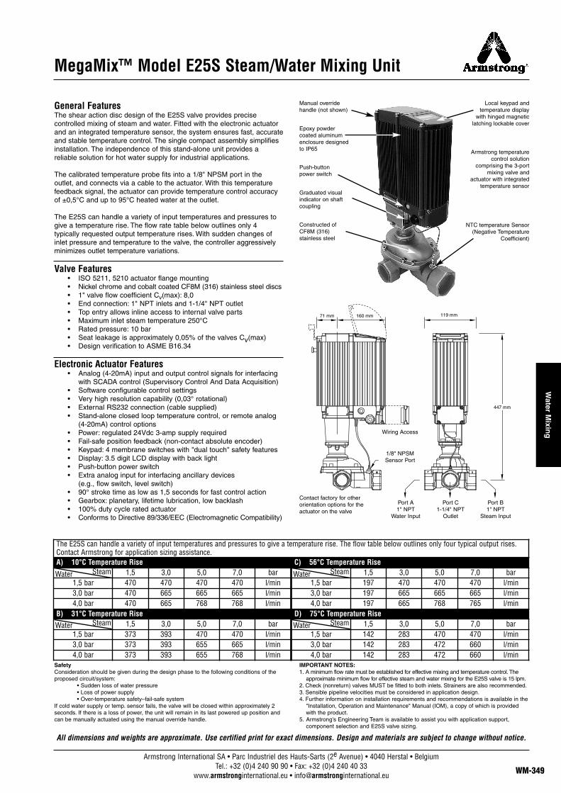
Armstrong International SA • Parc Industriel des Hauts-Sarts (2e Avenue) • 4040 Herstal • BelgiumTel.: +32 (0)4 240 90 90 • Fax: +32 (0)4 240 40 33
www.armstronginternational.eu • [email protected] WM-349
Water M
ixing
MegaMix™ Model E25S Steam/Water Mixing Unit
General FeaturesThe shear action disc design of the E25S valve provides precisecontrolled mixing of steam and water. Fitted with the electronic actuatorand an integrated temperature sensor, the system ensures fast, accurateand stable temperature control. The single compact assembly simplifiesinstallation. The independence of this stand-alone unit provides areliable solution for hot water supply for industrial applications.
The calibrated temperature probe fits into a 1/8" NPSM port in theoutlet, and connects via a cable to the actuator. With this temperaturefeedback signal, the actuator can provide temperature control accuracyof ±0,5°C and up to 95°C heated water at the outlet.
The E25S can handle a variety of input temperatures and pressures togive a temperature rise. The flow rate table below outlines only 4typically requested output temperature rises. With sudden changes ofinlet pressure and temperature to the valve, the controller aggressivelyminimizes outlet temperature variations.
Valve Features• ISO 5211, 5210 actuator flange mounting• Nickel chrome and cobalt coated CF8M (316) stainless steel discs• 1" valve flow coefficient Cv(max): 8,0• End connection: 1" NPT inlets and 1-1/4" NPT outlet• Top entry allows inline access to internal valve parts• Maximum inlet steam temperature 250°C• Rated pressure: 10 bar• Seat leakage is approximately 0,05% of the valves Cv(max)• Design verification to ASME B16.34
Electronic Actuator Features• Analog (4-20mA) input and output control signals for interfacing
with SCADA control (Supervisory Control And Data Acquisition)• Software configurable control settings• Very high resolution capability (0,03° rotational)• External RS232 connection (cable supplied)• Stand-alone closed loop temperature control, or remote analog
(4-20mA) control options• Power: regulated 24Vdc 3-amp supply required• Fail-safe position feedback (non-contact absolute encoder)• Keypad: 4 membrane switches with "dual touch" safety features• Display: 3.5 digit LCD display with back light• Push-button power switch• Extra analog input for interfacing ancillary devices
(e.g., flow switch, level switch)• 90° stroke time as low as 1,5 seconds for fast control action• Gearbox: planetary, lifetime lubrication, low backlash• 100% duty cycle rated actuator • Conforms to Directive 89/336/EEC (Electromagnetic Compatibility)
SafetyConsideration should be given during the design phase to the following conditions of theproposed circuit/system:
• Sudden loss of water pressure• Loss of power supply • Over-temperature safety–fail-safe system
If cold water supply or temp. sensor fails, the valve will be closed within approximately 2seconds. If there is a loss of power, the unit will remain in its last powered up position andcan be manually actuated using the manual override handle.
IMPORTANT NOTES:1. A minimum flow rate must be established for effective mixing and temperature control. The
approximate minimum flow for effective steam and water mixing for the E25S valve is 15 lpm.2. Check (nonreturn) valves MUST be fitted to both inlets. Strainers are also recommended.3. Sensible pipeline velocities must be considered in application design.4. Further information on installation requirements and recommendations is available in the
"Installation, Operation and Maintenance" Manual (IOM), a copy of which is providedwith the product.
5. Armstrong's Engineering Team is available to assist you with application support,component selection and E25S valve sizing.
Manual override handle (not shown)
Epoxy powder coated aluminum enclosure designed to IP65
Push-button power switch
Contact factory for otherorientation options for theactuator on the valve
Port A1" NPT
Water Input
1/8" NPSM Sensor Port
Wiring Access
Port C1-1/4" NPT
Outlet
Port B1" NPT
Steam Input
Local keypad and temperature display
with hinged magnetic latching lockable cover
Armstrong temperature control solution
comprising the 3-port mixing valve and
actuator with integrated temperature sensor
NTC temperature Sensor(Negative Temperature
Coefficient)
Graduated visual indicator on shaft coupling
Constructed of CF8M (316) stainless steel
All dimensions and weights are approximate. Use certified print for exact dimensions. Design and materials are subject to change without notice.
The E25S can handle a variety of input temperatures and pressures to give a temperature rise. The flow table below outlines only four typical output rises. Contact Armstrong for application sizing assistance.A) 10°C Temperature Rise C) 56°C Temperature Rise
1,5 3,0 5,0 7,0 bar 1,5 3,0 5,0 7,0 bar1,5 bar 470 470 470 470 l/min 1,5 bar 197 470 470 470 l/min3,0 bar 470 665 665 665 l/min 3,0 bar 197 665 665 665 l/min4,0 bar 470 665 768 768 l/min 4,0 bar 197 665 768 765 l/min
B) 31°C Temperature Rise D) 75°C Temperature Rise1,5 3,0 5,0 7,0 bar 1,5 3,0 5,0 7,0 bar
1,5 bar 373 393 470 470 l/min 1,5 bar 142 283 470 470 l/min3,0 bar 373 393 655 665 l/min 3,0 bar 142 283 472 660 l/min4,0 bar 373 393 655 768 l/min 4,0 bar 142 283 472 660 l/min
SteamWater
SteamWater
SteamWater
SteamWater
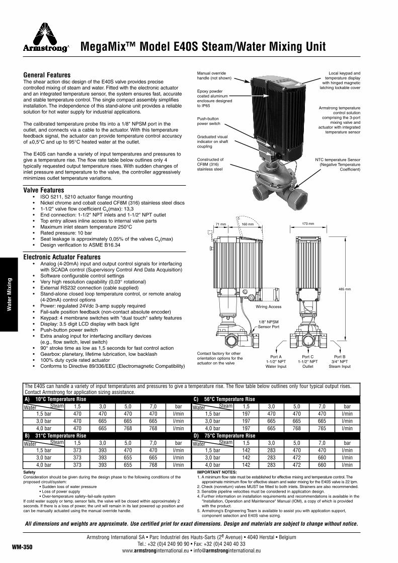
Armstrong International SA • Parc Industriel des Hauts-Sarts (2e Avenue) • 4040 Herstal • BelgiumTel.: +32 (0)4 240 90 90 • Fax: +32 (0)4 240 40 33
www.armstronginternational.eu • [email protected]
Wat
er M
ixin
g
MegaMix™ Model E40S Steam/Water Mixing Unit
General FeaturesThe shear action disc design of the E40S valve provides precisecontrolled mixing of steam and water. Fitted with the electronic actuatorand an integrated temperature sensor, the system ensures fast, accurateand stable temperature control. The single compact assembly simplifiesinstallation. The independence of this stand-alone unit provides a reliablesolution for hot water supply for industrial applications.
The calibrated temperature probe fits into a 1/8" NPSM port in theoutlet, and connects via a cable to the actuator. With this temperaturefeedback signal, the actuator can provide temperature control accuracyof ±0,5°C and up to 95°C heated water at the outlet.
The E40S can handle a variety of input temperatures and pressures togive a temperature rise. The flow rate table below outlines only 4typically requested output temperature rises. With sudden changes ofinlet pressure and temperature to the valve, the controller aggressivelyminimizes outlet temperature variations.
Valve Features• ISO 5211, 5210 actuator flange mounting• Nickel chrome and cobalt coated CF8M (316) stainless steel discs• 1-1/2" valve flow coefficient Cv(max): 13,3• End connection: 1-1/2" NPT inlets and 1-1/2" NPT outlet• Top entry allows inline access to internal valve parts• Maximum inlet steam temperature 250°C• Rated pressure: 10 bar• Seat leakage is approximately 0,05% of the valves Cv(max)• Design verification to ASME B16.34
Electronic Actuator Features• Analog (4-20mA) input and output control signals for interfacing
with SCADA control (Supervisory Control And Data Acquisition)• Software configurable control settings• Very high resolution capability (0,03° rotational)• External RS232 connection (cable supplied)• Stand-alone closed loop temperature control, or remote analog
(4-20mA) control options• Power: regulated 24Vdc 3-amp supply required• Fail-safe position feedback (non-contact absolute encoder)• Keypad: 4 membrane switches with "dual touch" safety features• Display: 3.5 digit LCD display with back light• Push-button power switch• Extra analog input for interfacing ancillary devices
(e.g., flow switch, level switch)• 90° stroke time as low as 1,5 seconds for fast control action• Gearbox: planetary, lifetime lubrication, low backlash• 100% duty cycle rated actuator • Conforms to Directive 89/336/EEC (Electromagnetic Compatibility)
SafetyConsideration should be given during the design phase to the following conditions of theproposed circuit/system:
• Sudden loss of water pressure• Loss of power supply • Over-temperature safety–fail-safe system
If cold water supply or temp. sensor fails, the valve will be closed within approximately 2seconds. If there is a loss of power, the unit will remain in its last powered up position andcan be manually actuated using the manual override handle.
IMPORTANT NOTES:1. A minimum flow rate must be established for effective mixing and temperature control. The
approximate minimum flow for effective steam and water mixing for the E40S valve is 22 lpm.2. Check (nonreturn) valves MUST be fitted to both inlets. Strainers are also recommended.3. Sensible pipeline velocities must be considered in application design.4. Further information on installation requirements and recommendations is available in the
"Installation, Operation and Maintenance" Manual (IOM), a copy of which is providedwith the product.
5. Armstrong's Engineering Team is available to assist you with application support,component selection and E40S valve sizing.
160 mm71 mm
485 mm
173 mm
Manual override handle (not shown)
Epoxy powder coated aluminum enclosure designed to IP65
Push-button power switch
Contact factory for otherorientation options for theactuator on the valve
Port A1-1/2" NPT Water Input
1/8" NPSM Sensor Port
Wiring Access
Port C1-1/2" NPT
Outlet
Port B3/4" NPT
Steam Input
Local keypad and temperature display
with hinged magnetic latching lockable cover
Armstrong temperature control solution
comprising the 3-port mixing valve and
actuator with integrated temperature sensor
NTC temperature Sensor(Negative Temperature
Coefficient)
Graduated visual indicator on shaft coupling
Constructed of CF8M (316) stainless steel
All dimensions and weights are approximate. Use certified print for exact dimensions. Design and materials are subject to change without notice.
The E40S can handle a variety of input temperatures and pressures to give a temperature rise. The flow table below outlines only four typical output rises. Contact Armstrong for application sizing assistance.A) 10°C Temperature Rise C) 56°C Temperature Rise
1,5 3,0 5,0 7,0 bar 1,5 3,0 5,0 7,0 bar1,5 bar 470 470 470 470 l/min 1,5 bar 197 470 470 470 l/min3,0 bar 470 665 665 665 l/min 3,0 bar 197 665 665 665 l/min4,0 bar 470 665 768 768 l/min 4,0 bar 197 665 768 765 l/min
B) 31°C Temperature Rise D) 75°C Temperature Rise1,5 3,0 5,0 7,0 bar 1,5 3,0 5,0 7,0 bar
1,5 bar 373 393 470 470 l/min 1,5 bar 142 283 470 470 l/min3,0 bar 373 393 655 665 l/min 3,0 bar 142 283 472 660 l/min4,0 bar 373 393 655 768 l/min 4,0 bar 142 283 472 660 l/min
SteamWater
SteamWater
SteamWater
SteamWater

Armstrong International SA • Parc Industriel des Hauts-Sarts (2e Avenue) • 4040 Herstal • BelgiumTel.: +32 (0)4 240 90 90 • Fax: +32 (0)4 240 40 33
www.armstronginternational.eu • [email protected] WM-351
Water M
ixing
MegaMix™ Model E50S Steam/Water Mixing Unit
General FeaturesThe shear action disc design of the E50S valve provides precise controlled mixing of steam and water. Fitted with the electronic actuatorand an integrated temperature sensor, the system ensures fast, accurateand stable temperature control. The single compact assembly simplifiesinstallation. The independence of this stand- alone unit provides areliable solution for hot water supply for industrial applications.
The calibrated temperature probe fits into a 1/8" NPSM port in theoutlet, and connects via a cable to the actuator. With this temperaturefeedback signal, the actuator can provide temperature control accuracyof ±0,5°C and up to 95°C heated water at the outlet.
The E50S can handle a variety of input temperatures and pressures togive a temperature rise. The flow rate table below outlines only 4typically requested output temperature rises. With sudden changes ofinlet pressure and temperature to the valve, the controller aggressivelyminimizes outlet temperature variations.
Valve Features• ISO 5211, 5210 actuator flange mounting• Nickel chrome and cobalt coated CF8M (316) stainless steel discs• 2" valve flow coefficient Cv(max): 26,6• End connection: 2" NPT inlets and 2-1/2" NPT outlet• Top entry allows inline access to internal valve parts• Maximum inlet steam temperature 250°C• Rated pressure: 10 bar• Seat leakage is approximately 0,05% of the valves Cv(max)• Design verification to ASME B16.34
Electronic Actuator Features• Analog (4-20mA) input and output control signals for interfacing
with SCADA control (Supervisory Control And Data Acquisition)• Software configurable control settings• Very high resolution capability (0.03° rotational)• External RS232 connection (cable supplied)• Stand-alone closed loop temperature control, or remote analog
(4-20mA) control options• Power: regulated 24Vdc 5-amp supply required• Fail-safe position feedback (non-contact absolute encoder)• Keypad: 4 membrane switches with "dual touch" safety features• Display: 3.5 digit LCD display with back light• Push-button power switch• Extra analog input for interfacing ancillary devices
(e.g., flow switch, level switch)• 90° stroke time as low as 1.5 seconds for fast control action• Gearbox: planetary, lifetime lubrication, low backlash• 100% duty cycle rated actuator• Conforms to Directive 89/336/EEC (Electromagnetic Compatibility)
SafetyConsideration should be given during the design phase to the following conditions of theproposed circuit/system:
• Sudden loss of water pressure• Loss of power supply • Over-temperature safety–fail-safe system
If cold water supply or temp. sensor fails, the valve will be closed within approximately 2seconds. If there is a loss of power, the unit will remain in its last powered up position andcan be manually actuated using the manual override handle.
IMPORTANT NOTES:1. A minimum flow rate must be established for effective mixing and temperature control. The
approximate minimum flow for effective steam and water mixing for the E50S valve is 75 lpm.2. Check (nonreturn) valves MUST be fitted to both inlets. Strainers are also recommended.3. Sensible pipeline velocities must be considered in application design.4. Further information on installation requirements and recommendations is available in the
"Installation, Operation and Maintenance" Manual (IOM), a copy of which is providedwith the product.
5. Armstrong's Engineering Team is available to assist you with application support,component selection and E50S valve sizing.
160 mm71 mm
564 mm
173 mm
Manual override handle (not shown)
Epoxy powder coated aluminum enclosure designed to IP65
Push-button power switch
Contact factory for otherorientation options for theactuator on the valve
Port A2" NPT
Water Input
1/8" NPSM Sensor Port
Wiring Access
Port C2-1/2" NPT
Outlet
Port B2" NPT
Steam Input
Local keypad and temperature display
with hinged magnetic latching lockable cover
Armstrong temperature control solution
comprising the 3-port mixing valve and
actuator with integrated temperature sensor
NTC temperature Sensor(Negative Temperature
Coefficient)
Graduated visual indicator on shaft coupling
Constructed of CF8M (316) stainless steel
All dimensions and weights are approximate. Use certified print for exact dimensions. Design and materials are subject to change without notice.
The E50S can handle a variety of input temperatures and pressures to give a temperature rise. The flow table below outlines only four typical output rises. Contact Armstrong for application sizing assistance.A) 10°C Temperature Rise C) 56°C Temperature Rise
1,5 3,0 5,0 7,0 bar 1,5 3,0 5,0 7,0 bar1,5 bar 470 470 470 470 l/min 1,5 bar 197 470 470 470 l/min3,0 bar 470 665 665 665 l/min 3,0 bar 197 665 665 665 l/min4,0 bar 470 665 768 768 l/min 4,0 bar 197 665 768 765 l/min
B) 31°C Temperature Rise D) 75°C Temperature Rise1,5 3,0 5,0 7,0 bar 1,5 3,0 5,0 7,0 bar
1,5 bar 373 393 470 470 l/min 1,5 bar 142 283 470 470 l/min3,0 bar 373 393 655 665 l/min 3,0 bar 142 283 472 660 l/min4,0 bar 373 393 655 768 l/min 4,0 bar 142 283 472 660 l/min
SteamWater
SteamWater
SteamWater
SteamWater