Embed Size (px)
Citation preview

WATER-PAM
Chlorophyll Fluorometer
Instrument Description and
Information for Users
2.137 / 11.00 2. Edition: May 2013
waterp3e.doc
© Heinz Walz GmbH, 2013
Heinz Walz GmbH • Eichenring 6 • 91090 Effeltrich • Germany Telefon +49-(0)9133/7765-0 • Telefax +49-(0)9133/5395
E-mail [email protected] • Internet www.walz.com
Printed in Germany


CONTENTS
1 Safety instructions ........................................................................ 1 1.1 General safety instructions .......................................................... 1 1.2 Special safety instruction ............................................................ 1
2 Introduction .................................................................................. 2 3 Components of the WATER-PAM ............................................. 3
3.1 PAM-CONTROL Universal Control Unit .................................. 4 3.2 WinControl software ................................................................... 5
3.2.1 Emitter-Detector Units: .......................................................... 7 3.2.2 WATER-ED Emitter-Detector Unit CUVETTE Version: ..... 7 3.2.3 WATER-EDF Emitter-Detector Unit FIBER Version:.......... 9 3.2.4 WATER-FT Emitter-Detector Unit FLOW THROUGH
Version: ................................................................................ 11 3.3 Accessories (optional) ............................................................... 13
3.4.1 Spherical Micro Quantum Sensor US-SQS/WB .................. 13 3.4.2 Mini Quantum Sensor US-MQS/WB................................... 14 3.4.3 Stirring Device WATER-S (optional) .................................. 15
4 First WATER-PAM Measurements ......................................... 17 4.1 How to get started ..................................................................... 17 4.2 Some practical advice for first measurements........................... 19 4.3 Assessment of photosynthetic activity ...................................... 20 4.4 Specific Aspects of FIBER version WATER-EDF1.5R/B ....... 22 4.5 Measurements under WinControl ............................................. 23
5 Internal PAR-List and Light Calibration ................................ 25 5.1 Light Calibration using a Spherical Micro Quantum Sensor US-
SQS/WB for WATER-PAM CUVETTE Version .................... 26 5.2 Light Calibration using a Mini Quantum Sensor US-SQS/WB
for WATER-PAM FIBER Version ........................................... 28 6 Practical Advices ........................................................................ 29
6.1 Relevant points for noise reduction........................................... 29
I
CONTENTS
II
6.2 Limitation by sample noise ....................................................... 30 6.3 Limitation by excess light scattering......................................... 31 6.4 Making use of Far-Red illumination ......................................... 33
7 Technical Specifications............................................................. 36 7.1 Emitter-Detector Unit WATER-ED/B ...................................... 36 7.2 Emitter-Detector Unit WATER-EDF1.5R/B ............................ 37 7.3 Emitter-Detector Unit WATER-FT/R....................................... 38 7.4 Accessories (optional) ............................................................... 38
8 Warranty conditions .................................................................. 41

CHAPTER 1 SAFETY INSTRUCTIONS
1 Safety instructions
1.1 General safety instructions 1. Read the safety instructions and the operating instructions first.
2. Pay attention to all the safety warnings.
3. Keep the device away from water or high moisture areas.
4. Keep the device away from dust, sand and dirt.
5. Always ensure there is sufficient ventilation.
6. Do not put the device anywhere near sources of heat.
7. Connect the device only to the power source indicated in the operating instructions or on the device.
8. Clean the device only according to the manufacturer’s recommendations.
9. If the device is not in use, remove the mains plug from the socket.
10. Ensure that no liquids or other foreign bodies can find their way inside the device.
11. The device should only be repaired by qualified personnel.
1.2 Special safety instruction The WATER-PAM is a highly sensitive research instrument which should be used only for research purposes, as specified in this manual. Please follow the instructions of this manual in order to avoid potential harm to the user and damage to the instrument.
1

CHAPTER 2 INTRODUCTION
2 Introduction The WATER-PAM Chlorophyll Fluorometer is specialized for the study of highly diluted suspensions of unicellular algae, cyanobacteria, isolated chloroplasts and protoplasts. It is ideally suited for assessment of content and photosynthetic activity of phytoplankton in natural surface waters. In conjunction with the WinControl-software it allows a profound analysis of photosynthetic performance of the phytoplankton, including determination of effective quantum yield, relative electron transport rates and Light Response Curves (see WinControl manual).
While the PAM-CONTROL and WinControl manuals outline in detail the instrument parameters and functions, as well as data acquisition and analysis in conjunction with a PC, the Instructions for Users presented here specifically relate to the WATER-PAM, i.e. the PAM-CONTROL combined with the special Emitter-Detector Units WATER-ED, WATER-ED/B, WATER-EDF1.5R and WATER-EDF1.5B.
2

CHAPTER 3 COMPONENTS OF THE WATER-PAM
3 Components of the WATER-PAM The WATER-PAM Chlorophyll Fluorometer consists of
• PAM-CONTROL Universal Control Unit
• WinControl Windows-software for operation in conjunction with PC
• Emitter-Detector Unit:
1. CUVETTE Version
2. FIBER Version
3. FLOW THROUGH Version
• Optional Accessories:
1. Spherical Micro Quantum Sensor US-SQS/WB or Mini Quantum Sensor US-MQS/WB
2. Stirring Device WATER-S
3

CHAPTER 3 COMPONENTS OF THE WATER-PAM
3.1 PAM-CONTROL Universal Control Unit
Fig. 1: PAM-CONTROL Universal Control Unit
In its outer appearance, the PAM-CONTROL Universal Control Unit strongly resembles the MINI-PAM Chlorophyll Fluorometer, which has proven quite successful as a highly portable device for field studies. Likewise the PAM-CONTROL constitutes a compact and robust battery-powered instrument, which in combination with the WATER-PAM Emitter-Detector Unit is ideally suited for field and on-deck work.
The PAM-CONTROL as such is specialized for programming and generating defined pulse programs for fluorescence excitation and actinic illumination, as well as for the selective processing of the fluorescence signals. Unlike the MINI-PAM, it does not contain any optical components, all of which are contained in the WATER-ED Emitter-Detector Unit (or alternative emitter-detector units). At the core of the PAM-CONTROL are a Microcontroller (CMOS 80C52), a RAM Data Memory (CMOS RAM 128kB) and an Flash-EPROM in which the program for instrument operation is stored. It features an 8-key tactile keypad and a LC-display which allow a wide range
4

CHAPTER 3 COMPONENTS OF THE WATER-PAM
of applications independent of a PC. An extensive MODE-menu is provided for off-line control of all instrument parameters and functions. Up to 4000 data sets can be saved.
A separate Handbook of Operation is provided for the PAM-CONTROL Universal Control Unit. The PAM-CONTROL Handbook describes not only the various components, modes and functions of the instrument in detail, but also gives helpful information on chlorophyll fluorescence measurements with PAM-CONTROL based instruments.
3.2 WinControl software The WinControl software allows to operate the WATER-PAM via a PC in a most comfortable and efficient way. When a PC is connected via a RS 232 interface cable to the PAM-CONTROL unit, all instrument settings and functions are accessible by mouse click. The user is free to give commands either using the PC- or the PAM-CONTROL-keypad. Any change of parameter settings via PC results in a corresponding change of settings in the PAM-CONTROL MODE-menu and vice versa. Data are automatically written into the “Report file“ under WinControl as well as into the MEMORY of PAM-CONTROL. Data collected during stand-alone operation of the PAM-CONTROL can be readily transferred to the PC under WinControl.
The WinControl software offers a number of additional functions which are not possible with the PAM-CONTROL in the stand-alone mode, as e.g. Chart-recording, Curve Averaging and display of Light Response Curves. Applications like the Chlorophyll Determination routine are available as batch-exercise for WinControl3. The WinControl software is continuously improved
5

CHAPTER 3 COMPONENTS OF THE WATER-PAM
and extended for new applications. The most recent version of the software is always available via the Walz-homepage www.walz.com.
For proper functioning of the WATER-PAM it is essential that Meas+Act/Sat (PAM-CONTROL MODE-menu point 6) is not active (Settings Window, System Pars, see Fig. 2). Otherwise the measuring light LEDs would be overpowered during actinic illumination and Saturation Pulses which might result in some artifactual signal decrease.
Fig. 2: For proper functioning of WATER-PAM inactivate Meas+Act/Sat
6

CHAPTER 3 COMPONENTS OF THE WATER-PAM
3.2.1 Emitter-Detector Units: Three Emitter-Detector Units (CUVETTE, FIBER and FLOW THROUGH Version) with miscellaneous specifications are available.
3.2.2 WATER-ED Emitter-Detector Unit CUVETTE Version:
Fig. 3: WATER-ED CUVETTE Version
The WATER-ED Emitter-Detector Unit was conceived for ultrasensitive measurements of chlorophyll fluorescence at very low chlorophyll concentrations, i.e. in particular for assessment of phytoplankton in natural surface waters. The CUVETTE Version features a cylindrical holder for a 15 mm diameter quartz glass cuvette (WATER-K). The cuvette is surrounded by light-emitting diodes (LED) delivering PAM measuring light and actinic illumination to the sample. The WATER-ED CUVETTE Version is available with two different light colors. The blue LED version (WATER-ED/B) exhibits lowest stray light interference. This WATER-ED/B has additional far-red LEDs light source for fast PS I-driven opening of PS II reaction centers required for evaluations of
7

CHAPTER 3 COMPONENTS OF THE WATER-PAM
Fo’ fluorescence levels. The red LED version (WATER-ED) is frequently used to analyze cyanobacteria which tend to absorb inefficiently in the blue: this version is available with far-red or blue photosystem I light.
The WATER-ED and WATER-ED/B CUVETTE Versions consist of the following parts:
• Waterproof cast-aluminium housing with two cables (PM and AUX Output) to be connected to the corresponding sockets of the PAM-CONTROL unit
• Measuring Head with port for sample cuvette which protrudes at the top side of the housing, featuring an o-ring which seals against the housing
• Perspex cup-shaped inset which seals against an inner o-ring of the Measuring Head, thus protecting the opto-electronical components from spilled water samples
• PVC centering ring with o-ring sealing against the inner wall of the Measuring Head, serving as a guide for the cuvette and as an adapter for mounting the optional Miniature Stirring Motor WATER-S and Spherical Micro Quantum Sensor US-SQS/WB
• Quartz Cuvette (WATER-K) with 15 mm outer and 13 mm inner diameter; height 46 mm
• Darkening Hood covering the part of the Measuring Head which protrudes from the housing
• Two LED Versions are available:
Red LED Version WATER-ED: Circular LED-Array featuring 3 Measuring Light LEDs (peak 650 nm), 12 Actinic LEDs (peak 660 nm) and 3 Far-Red LEDs (peak 740 nm),
8
CHAPTER 3 COMPONENTS OF THE WATER-PAM
mounted in the bottom part of the Measuring Head). Alternative to far-red light, blue LEDs (460 nm) can be build in for preferential PS I excitation in cyanobacteria.
Blue LED Version WATER-ED/B: Circular LED-Array featuring 3 Measuring Light LEDs (peak 460 nm), 10 Actinic LEDs (peak 460 nm) and 3 Far-Red LEDs (peak 740 nm), mounted in the bottom part of the Measuring Head).
The actinic intensity achieves up to 2000 µmol quanta m-2s-1 of photosynthetically active radiation (PAR). Saturation pulse intensity reaches up to 4000 µmol quanta m-2s-1.
• Photomultiplier Detector based on Photosensor Module H-6779-01 (Hamamatsu) with collimating optics and optical filter set passing wavelengths above 710 nm optimized for low background signal.
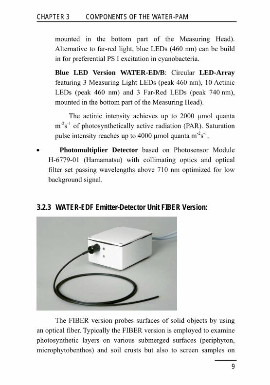
3.2.3 WATER-EDF Emitter-Detector Unit FIBER Version:
The FIBER version probes surfaces of solid objects by using an optical fiber. Typically the FIBER version is employed to examine photosynthetic layers on various submerged surfaces (periphyton, microphytobenthos) and soil crusts but also to screen samples on
9

CHAPTER 3 COMPONENTS OF THE WATER-PAM
microwell plates. As in the case of the CUVETTE version, the emitter-detector unit of the FIBER version can be equipped with different-colored LEDs: the WATER-EDF1.5R uses red measuring and actinic light but these light sources are replaced by blue LEDs in the WATER-EDF1.5B. Furthermore the WATER-EDF1.5R is configured with an additional blue light source to selectively excite the photosystem I in cyanobacteria or, alternatively, with a far-red light source for photosystem I excitation in many other photosynthetic organisms.
The FIBER version is less sensitive than the CUVETTE and FLOW THROUGH version so that for toxicity biotest systems a chlorophyll concentrations around 100 - 500 µg chlorophyll/liter is recommended.
The WATER-EDF consists of the following parts:
• Waterproof cast-aluminium housing containing LED-light sources, photomultiplier detector, pulse preamplifier, a port with a lateral plastic screw for fixation of fiber optics and two permanently attached cables (PM and AUX Output) to be connected to the corresponding sockets of the PAM-CONTROL unit. A mounting rod for fixing the housing and on the stand ST-101 is located on the bottom side of the housing.
• Optical Fiber: Three 1.5 mm diameter plastic fiber optics (lengths 200, 600 and 1200 mm).
• Two LED Versions are available:
Red LED Version WATER-EDF1.5R : 2 red LEDs as measuring light sources (peak 620 nm), 2 Actinic LEDs (peak 635 nm) and 1 blue LED (peak 460 nm, under control of the FR switch in the WinControl software); Alternative to blue light, a far-red LED (730 nm) can be build in for preferential
10
CHAPTER 3 COMPONENTS OF THE WATER-PAM
PS I excitation in non-cyanobacterial photosynthetic organisms.
Blue LED Version WATER-EDF1.5B: 2 blue LEDs as measuring light sources (peak 460 nm), 2 Actinic LEDs (peak 460 nm) and 1 far-red LED (peak 740 nm)
Actinic intensity reaches up to 1500 µmol quanta m-2s-1 of photosynthetically active radiation (PAR). Saturation pulse intensity is achieved up to 3000 µmol quanta m-2s-1
• Photomultiplier Detector based on Photosensor Module H-6779-01 (Hamamatsu) with collimating optics and optical filter set passing wavelengths above 710 nm optimized for low background signal
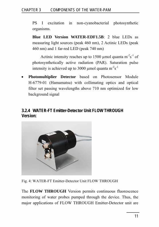
3.2.4 WATER-FT Emitter-Detector Unit FLOW THROUGH Version:
Fig. 4: WATER-FT Emitter-Detector Unit FLOW THROUGH
The FLOW THROUGH Version permits continuous fluorescence monitoring of water probes pumped through the device. Thus, the major applications of FLOW THROUGH Emitter-Detector unit are
11

CHAPTER 3 COMPONENTS OF THE WATER-PAM
in the field of limnology, oceanography, water management and drinking water monitoring.
The FLOW THROUGH version of the WATER-PAM has a water-proof emitter-detector unit exhibiting a transparent window through which measuring and actinic light is emitted. Fluorescence detection occurs through another transparent window at right angles with the window for light emission. The optical windows are positioned within a black cylinder with inlet and outlet connections.
The FLOW THROUGH version is equipped with either red (WATER-FT/R) or blue LEDs (WATER-FT). The former configuration is suited for detection of cyanobacteria with weak absorption in the blue, the latter one exhibits particularly low background signals and can be used when green algae or diatoms are to be analyzed. Additional light sources for specific excitation of photosystem I are omitted because of too short residence times of samples in front of the emission detection window.
For further information please visit walz.com.
12

CHAPTER 3 COMPONENTS OF THE WATER-PAM
3.3 Accessories (optional)
3.4.1 Spherical Micro Quantum Sensor US-SQS/WB
Fig. 5: Spherical Micro Quantum Sensor US-SQS/WB
The Spherical Micro Quantum Sensor US-SQS/WB is an optional accessory of the WATER-PAM CUVETTE and FLOW THROUGH Version which is required for quantitative assessment of the quantum flux density of photosynthetically active radiation (PAR) at the very site of the sample where fluorescence is measured. It features a 3 mm ∅ white diffusing plastic sphere connected via a 1 mm ∅ plastic fiber to a blue-enhanced silicon photodiode which is protected by a special filter set for selection of photosynthetically active radiation (380-710 nm).. The sensed light signal is preamplified (amplifier board contained in 25 mm ∅ cylindrical black-anodized aluminium housing) before it is fed into the PAM-CONTROL unit via the AUX INPUT socket.
13

CHAPTER 3 COMPONENTS OF THE WATER-PAM
3.4.2 Mini Quantum Sensor US-MQS/WB
Fig. 6: Mini Quantum Sensor US-MQS/WB
The Mini Quantum Sensor US-MQS/WB is an optional acceessory for the WATER-PAM FIBER Version. The cosine-corrected US-MQS/WB serves for PAR measurement at sample level and for calibration of the internal actinic light list. As with the spherical quantum sensor US-SQS/WB the sensed light signal is preamplified (amplifier board contained in 25 mm ∅ cylindrical black-anodized aluminium housing) before it is fed into the PAM-CONTROL unit via the AUX INPUT socket. Sensed Light PAR data are collected by the PAM-CONTROL unit
14
CHAPTER 3 COMPONENTS OF THE WATER-PAM
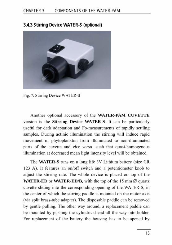
3.4.3 Stirring Device WATER-S (optional)
Fig. 7: Stirring Device WATER-S
Another optional accessory of the WATER-PAM CUVETTE version is the Stirring Device WATER-S. It can be particularly useful for dark adaptation and Fo-measurements of rapidly settling samples. During actinic illumination the stirring will induce rapid movement of phytoplankton from illuminated to non-illuminated parts of the cuvette and vice versa, such that quasi-homogenous illumination at decreased mean light intensity level will be obtained.
The WATER-S runs on a long life 3V Lithium battery (size CR 123 A). It features an on/off switch and a potentiometer knob to adjust the stirring rate. The whole device is placed on top of the WATER-ED or WATER-ED/B, with the top of the 15 mm ∅ quartz cuvette sliding into the corresponding opening of the WATER-S, in the center of which the stirring paddle is mounted on the motor axis (via split brass-tube adapter). The disposable paddle can be removed by gentle pulling. The other way around, a replacement paddle can be mounted by pushing the cylindrical end all the way into holder. For replacement of the battery the housing has to be opened by
15

CHAPTER 3 COMPONENTS OF THE WATER-PAM
16
pulling the white and grey halves apart. Separation of the two halves is facilitated by gentle forcing a thin flat body into the slit (like finger nail or thin screw driver).
It should be noted that at very high sensitivity the paddle of the WATER-S causes some increase of noise. Due to measuring light reflected from the paddle of the WATER-S towards the photodetector, the background signal is approximately doubled and electronic noise is correspondingly increased. Furthermore, there is an increase of sample noise caused by movement of cells or cell groups.

CHAPTER 5 INTERNAL PAR-LIST AND LIGHT CALIBRATION
4 First WATER-PAM Measurements 4.1 How to get started In order to get started, the WATER-PAM Emitter Detector Unit just has to be connected to the PAM-CONTROL via the two cables which plug into the AUX OUTPUT and PM sockets at the right hand side of the PAM-CONTROL. After switching ON the PAM-CONTROL, the fluorometer is ready for use.
CUVETTE Version: If the Darkening Hood is not covering the opening of the Measuring Head, the red LED-indicator-lamp will light up, thus warning that the Photomultiplier Detector receives excess light. There is no risk of damage by the excess light, as the photomultiplier voltage automatically is turned down. As soon as the hood covers the opening, a reliable fluorescence signal is measured. Samples are measured in the 15 mm diameter quartz glass cuvette (WATER-K). Best results are achieved using sample volumes between 2 and 3 ml.
FIBER Version: The FIBER version is less sensitive than the CUVETTE and FLOW THROUGH version so that for toxicity biotest systems a chlorophyll concentrations around 100 - 500 µg chlorophyll/liter is recommended.
The fluorescence signal is displayed at the start of the second line of the LC-display of the PAM-CONTROL. The amplitude of this signal depends on
• chlorophyll content of the sample
• photomultiplier gain (MODE-menu point 54: PM-GAIN)
• signal output gain (MODE-menu point 53: OUT-GAIN)
17

CHAPTER 5 INTERNAL PAR-LIST AND LIGHT CALIBRATION
For getting started, it may be best to first carry out a Reset of all instrument parameters to Standard Settings using MODE-menu point 38: RES.SETTINGS (press SET and confirm by ∧). Instead of pressing the arrow keys in order to reach menu point 38 in single steps, it is also possible to reach this menu point by 7x MODE+SET, jumping from one functional block to the next. It is recommended that the user familiarizes himself with the various keypad functions by consulting the PAM-CONTROL manual. The reset of all instrument parameters to Standard Settings can also be obtained by pushing the Reset button at the top of the Settings Window in WinControl (see Fig. 8).
Fig. 8: Reset Button, System Parmeters Gain and PM-Gain
18

CHAPTER 5 INTERNAL PAR-LIST AND LIGHT CALIBRATION
4.2 Some practical advice for first measurements After Reset, PM-GAIN 15 and OUT-GAIN 2 are effective. At these standard settings the fluorescence signal should be close to zero (not more than 5-10 units) when the cuvette is filled with pure water. If this is not the case, the cuvette should be carefully cleaned with alcohol. Also in case of using the FIBER Version WATER-EDF ensure the absence of a sample! Any residual signal primarily results from traces of scattered measuring light which reaches the detector. It can be suppressed by MODE-menu point 2: AUTO-ZERO. Please note that the AUTO-ZERO value is valid only for the particular settings of PM-GAIN and OUT-GAIN at which it was determined. After AUTO-ZERO the signal fluctuates around 0.
After determination of AUTO-ZERO the pure water in the cuvette can be exchanged against a water sample containing phytoplankton, the obtained signal reflects chlorophyll fluorescence and after proper calibration the fluorescence yield can be taken as a quantitative measure of the chlorophyll content. At the standard gain settings (PM 15 and OUT 2) a signal of 500 units represents a chlorophyll content in the order of 50 μg Chl l-1. Much lower chlorophyll contents can be assessed after increasing the gain. Increasing PM-GAIN from standard setting 15 to maximal setting 30 leads to an effective increase of gain by a factor of 25-30. However, it should be noted that with increasing gain there is not only a parallel increase of the unavoidable background signal, but also of the random electronic noise. The noise can be considerably reduced by increasing the setting of the frequency of measuring light pulses (MODE-menu point 52: MEAS-FRQ) from it’s standard setting 3 to higher values. The maximal setting 12 can be also reached directly by switching under MODE-menu point 4: MEAS-FRQ from LOW to HIGH. While a high measuring frequency will have some actinic effect on dark-adapted samples and, hence, may cause some fluorescence
19

CHAPTER 5 INTERNAL PAR-LIST AND LIGHT CALIBRATION
increase, it normally does not have much effect on light adapted phytoplankton samples. In any case, for quantitative determination of chlorophyll content (WinControl, batch-application), the chlorophyll calibration should be carried out under the same conditions (and with similar types of samples) as the actual measurements). For Determination of Chlorophyll concentration using WATER-PAM FIBER Version see notes in chapter 4.4.
4.3 Assessment of photosynthetic activity While determination of chlorophyll content just involves the measurement of stationary fluorescence yield, the WATER-PAM also allows to assess the photosynthetic properties and the physiological state of the phytoplankton via measurement of light-induced changes in fluorescence yield. When the START-key is pressed a so-called Saturation Pulse is triggered. Then on the display, for example, the following information is shown:
1: 445F 1739M ..C
F: 448 745Y ..E ..L
The meaning of the various displayed parameters is as follows:
1: Number denoting the standard MODE-menu position 1 which is automatically installed whenever the PAM-CONTROL is switched on or a YIELD-determination is carried out via START.
445F Fluorescence yield (F) measured briefly before the last saturating light pulse triggered by START.
1739M Maximal fluorescence yield (M = Fm or Fm') measured during the last saturating light pulse triggered by START.
20

CHAPTER 5 INTERNAL PAR-LIST AND LIGHT CALIBRATION
..C Temperature in degree Celsius, display of which requires optional temperature sensor.
F:448 Momentary fluorescence yield displaying small fluctuations.
745Y The most relevant YIELD-parameter determined by the last saturating light pulse triggered by START, calculated as follows:
Y/1000 = YIELD = (M-F)/M = (Fm'-F)/Fm' = ΔF/M = ΔF/Fm' (Genty-parameter)
With a dark-adapted sample: ΔF/Fm = (Fm-Fo)/F = Fv/Fm, corresponding to the maximal yield of photochemical energy conversion.
..E Relative rate of electron transport (ETR), display of which requires optional micro quantum sensor. It is calculated by the formula:
ETR = E = YIELD x PAR x 0.5 x ETR-factor
..L Light intensity in terms of PAR (quantum flux density of photosynthetically active radiation), display of which requires optional micro quantum sensor.
The YIELD-measurement by the Saturation Pulse method is the basis for assessment of the photosynthetic performance of the sample. Valuable information is obtained by YIELD-measurements both after dark-adaptation (maximal quantum yield reflected by Fv/Fm) and during illumination (effective quantum yield reflected by ΔF/Fm’). Automated recordings of Light Response Curves (MODE-menu point 19: LIGHT CURVE) provide information on photosynthetic capacity and light adaptation state. Standard induction curves with repetitive YIELD-measurements (MODE-menu point 23: IND.CURVE) give insight into the dynamic
21

CHAPTER 5 INTERNAL PAR-LIST AND LIGHT CALIBRATION
interplay of various partial reactions of the complex photosynthetic process.
Note: Coefficients of photochemical quenching, qP, and non-photochemical quenching, qN are defined in PAM-CONTROL (MODE-menu point 28) by the equations qP=(M-F)/(M-Fo) and qN=(Fm-M)/(Fm-Fo). Wincontrol calculates the coefficients qP and qN according to Schreiber et al. (1986) as formulated by van Kooten and Snel (1990): qP = (Fm'-F')/(Fm'-F0') and qN = 1-((Fm'-F0')/(Fm-F0)).
4.4 Specific Aspects of FIBER version WATER-EDF1.5R/B
There are some specific points concerning the WATER-EDF1.5R/B measurements with periphyton/microphyto-benthos, which shall be briefly outlined here:
Determination of chlorophyll concentration
Accurate determination of chlorophyll concentration is limited by the following factors:
a ) The detection limit of the WATER-EDF is lower than that of the standard WATER-ED specially designed for low chlorophyll suspensions.
b ) Non-linearity of fluorescence versus chlorophyll concentration at high chlorophyll levels.
c ) The presence of components like sand, debris or mud that may absorb measuring light as well as chlorophyll fluorescence.
22

CHAPTER 5 INTERNAL PAR-LIST AND LIGHT CALIBRATION
d ) The presence of a background signal caused by measuring light reflected/scattered towards the detector and by non-chlorophyll fluorescence.
e ) determination of the chlorophyll concentration should always be performed on the basis of the Fo level of a dark acclimated sample.
Periphyton and microphytobenthos often display relatively high concentrations of chlorophyll/area, such that the measuring light is already absorbed in the top layer and also chlorophyll fluorescence is reabsorbed. Any light-absorbing material in optical contact with the sample will decrease the fluorescence signal if it absorbs measuring light or chlorophyll fluorescence and, hence, lowers the apparent chlorophyll concentration. In this case correct calibration and chlorophyll determination becomes difficult if not impossible.
4.5 Measurements under WinControl In order to become familiar with the numerous functions of the WATER-PAM, including recording of Light Curves and Induction Curves, it is advisable to connect the PAM-CONTROL to a PC via the RS 232 interface cable and to run the instrument online under the WinControl3-software (please consult the WinControl Users Manual for information on software installation and the numerous features of the user surface). In particular, the Chart-recording is very helpful for beginners to become familiar with the properties of chlorophyll fluorescence changes. After start of the WinControl program just the Chart-window has to be selected and a recording can be started (Start Onl. Rec.). Viewing the online fluorescence trace the effect of the various light qualities (Meas.-Light, SAT.-Pulse, Actinic Light, Far-Red LED) can be most readily followed and
23
CHAPTER 5 INTERNAL PAR-LIST AND LIGHT CALIBRATION
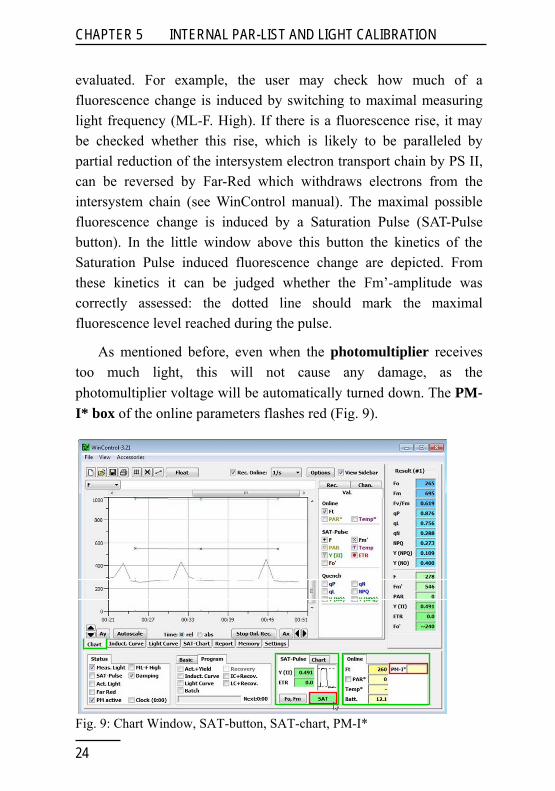
evaluated. For example, the user may check how much of a fluorescence change is induced by switching to maximal measuring light frequency (ML-F. High). If there is a fluorescence rise, it may be checked whether this rise, which is likely to be paralleled by partial reduction of the intersystem electron transport chain by PS II, can be reversed by Far-Red which withdraws electrons from the intersystem chain (see WinControl manual). The maximal possible fluorescence change is induced by a Saturation Pulse (SAT-Pulse button). In the little window above this button the kinetics of the Saturation Pulse induced fluorescence change are depicted. From these kinetics it can be judged whether the Fm’-amplitude was correctly assessed: the dotted line should mark the maximal fluorescence level reached during the pulse.
As mentioned before, even when the photomultiplier receives too much light, this will not cause any damage, as the photomultiplier voltage will be automatically turned down. The PM-I* box of the online parameters flashes red (Fig. 9).
Fig. 9: Chart Window, SAT-button, SAT-chart, PM-I*
24

CHAPTER 5 INTERNAL PAR-LIST AND LIGHT CALIBRATION
5 Internal PAR-List and Light Calibration In the WATER-PAM, like in all PAM-CONTROL based instruments, only internal LED light sources are used, such that the photon flux density of photosynthetically active radiation, PAR, is fully controlled (see PAM-CONTROL manual). Each intensity setting of actinic light corresponds to a defined LED intensity which in the given optical geometry results in a defined PAR-value. A list of the PAR-values as a function of intensity settings is stored in the instrument (Internal PAR-List) and can be viewed and edited under WinControl3 (Settings Window, Box Int. Par List, Fig. 10). The Internal PAR-List applies whenever no external PAR-sensor is connected to the PAM-CONTROL (at AUX-INPUT) and the PAR* checkbox under Online parameters (or Ext. PAR-Sensor check box under Settings Window/System Settings) is not activated.
A valid internal light list is certified for WATER-ED and WATER-ED/B. In most practical applications it is not feasible to have the US-SQS in place during the fluorescence measurement, as this gives rise to a substantial background signal equivalent to ca. 100 μg Chl/l.
Both LED-versions of the WATER-EDF are delivered without standard PAR values or valid internal light lists. However, the light output of the instruments are very reproducible. Therefore, it is worthwhile to establish an internal light list with a (optional) Mini Quantum Sensor US-MQS/WB for a given experiment to predict the PAR at the sample surface.
25

CHAPTER 5 INTERNAL PAR-LIST AND LIGHT CALIBRATION
5.1 Light Calibration using a Spherical Micro Quantum Sensor US-SQS/WB for WATER-PAM CUVETTE Version
The US-SQS/WB is fixed on top of the WATER-ED or WATER-ED/B with the help of a hood-like holder which substitutes for the standard Darkening Hood. The vertical depth of the sensor sphere (ca. 5 mm from the cuvette bottom) is critical for correct PAR-readings. It can be optimized by maximizing the PAR-reading while actinic illumination is switched on. The correct vertical position can be first fixed using the hand screw and then permanently marked by the stop-ring (using hex-screw). When not in use, the sensor sphere should be protected by the provided perspex tube.
Display of the online measured PAR must be enabled either via Mode-menu point 7 (EXT.LIGHT-S: ON) of PAM-CONTROL or via under WinControl using the checkbox PAR* of the Online parameters or the Ext. PAR-Sensor (Active) checkbox under Setting Window/System Settings. Then the measured PAR-value is shown on the PAM-CONTROL LC-display (right corner of second line) and also displayed as Online Parameter under WinControl (see Fig. 10) .
The calibration is started by PAM-CONTROL (MODE-menu point 8: LIGHT CALIB) or via Wincontrol Settings Window / Box Int. PAR-List by pushing the Read button.
26
CHAPTER 5 INTERNAL PAR-LIST AND LIGHT CALIBRATION
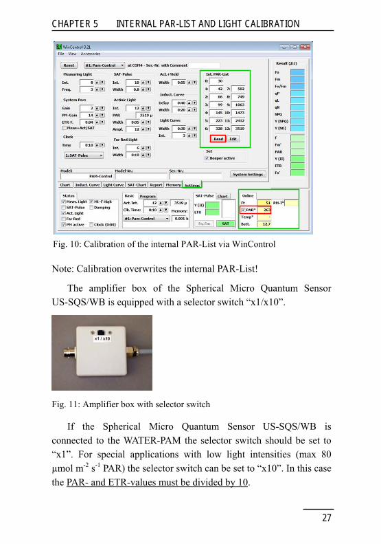
Fig. 10: Calibration of the internal PAR-List via WinControl
Note: Calibration overwrites the internal PAR-List!
The amplifier box of the Spherical Micro Quantum Sensor US-SQS/WB is equipped with a selector switch “x1/x10”.
Fig. 11: Amplifier box with selector switch
If the Spherical Micro Quantum Sensor US-SQS/WB is connected to the WATER-PAM the selector switch should be set to “x1”. For special applications with low light intensities (max 80 µmol m-2 s-1 PAR) the selector switch can be set to “x10”. In this case the PAR- and ETR-values must be divided by 10.
27

CHAPTER 5 INTERNAL PAR-LIST AND LIGHT CALIBRATION
28
5.2 Light Calibration using a Mini Quantum Sensor US-SQS/WB for WATER-PAM FIBER Version The quantum flux density of photosynthetically active radiation (PAR) is an important factor for the assessment of photosynthetic activity and capacity of a sample. Its knowledge is required for calculation of the ETR-parameter.
This list can be established by the user for any particular optical geometry with the help of a quantum sensor which is calibrated for the particular environment of the sample (air or water) and takes into account that, at narrow distance between fiber tip and sensor, only part of the quantum sensor will be illuminated.
To establish a valid internal PAR list, enter manually the PAR values recorded for the different instrument settings under WinControl in the Settings Window by pushing the Edit button of the Int. PAR-List Box (Fig. 12).
Fig. 12: Editing the internal PAR-List via WinControl

CHAPTER 6 PRACTICAL ADVICES
6 Practical Advices Due to its exceptionally high sensitivity, the WATER-PAM provides accurate readings of chlorophyll fluorescence yield down to chlorophyll contents amounting to less than 1/1000 of what can be noticed by bare eye (ca. 500 μg Chl/l). Disturbance of chlorophyll determination by electronic noise can be equivalent to only 0.002 μg Chl/l.
6.1 Relevant points for noise reduction For optimal results the following points should be observed:
(1) The electronic noise can be considerably reduced by increasing Measuring Light. The resulting actinic effect in most cases can be considered negligible, even at maximal frequency (ML-F. High), particularly when the sample previously had been exposed to daylight.
(2) Any background signal will increase the electronic noise and, if possible, should be avoided. Hence, an absolutely clean cuvette (including outer surface) should be used.
(3) It should be made sure that no particles (e.g. dust) are drifting in the sample and no air bubbles are deposited on the cuvette walls. In both cases the background signal would be increased and time dependent changes could occur.
(4) The presence in the cuvette of the Spherical Micro Quantum Sensor or of the stirring paddle should be avoided, as these will cause a background signal.
(5) Before starting a measurement, the sample should be given some time for settling in the cuvette; the “sample noise” will decline with settling time.
29

CHAPTER 6 PRACTICAL ADVICES
6.2 Limitation by sample noise Unfortunately, not all types of samples allow to take full advantage of the intrinsic accuracy of the WATER-PAM as such. In many practical cases the overall signal stability is limited by “sample noise”, i.e. by the movement of the phytoplankton within the cuvette. At very low chlorophyll content, the signal originates from a relatively small number of individual alga cells which may change their distances to the Photomultiplier Detector and the Measuring Light LEDs. Depending on the cell size, the same amount of chlorophyll is distributed over a more or less large number of cells. The relative contribution of sample noise to the overall noise increases with increasing cell size and decreasing overall chlorophyll content.
Fig. 13: Comparison of traces with pure water, plus Synechococcus and Ankistrodesmus.
In Fig. 13 typical fluorescence traces are compared which are measured starting with a pure water sample (background) to which first a very small amount of the cyanobacterium Synechococcus (cell size ca. 0.5 μm) and then of the green alga Ankistrodesmus (cell size ca. 15 μm) is added. After addition of Synechococcus there is only a slow signal decline without any significant change in noise. On the other hand, in presence of Ankistrodesmus after a phase of almost
30

CHAPTER 6 PRACTICAL ADVICES
constant signal level there is an unexpected transient signal increase, which is typical for random sample noise.
It should be noted that sample noise is characterized by rather slow signal changes (half-times in the order of 10-20 sec). Therefore, it does not affect the assessment of Fv/Fm and ΔF/Fm’, where two signal amplitudes are measured within 1 sec and due to ratio-calculation the absolute amplitude is not essential. Likewise, also Light Response Curves, which rely on measurements of Fv/Fm and ΔF/Fm’, are not affected by sample noise.
In practice, maximal sensitivity settings of the WATER-PAM are applied in investigations of open ocean water which primarily contains picoplankton. In this case even at very low chlorophyll content the cell number may be rather large. If such a sample contains single cells of larger alga species, which would cause excessive sample noise, there is the possibility of separating the picoplankton by filtering with a suitable pore size.
6.3 Limitation by excess light scattering The optical geometry of the WATER-ED is optimized for maximal sensitivity and minimal background signal using clear water samples and algae suspensions. With such samples, chlorophyll fluorescence is at least in the same order of magnitude as stray light reaching the photodetector originating from scattered measuring and actinic light. The ratio between fluorescence and stray light, however, can be dramatically decreased by scattering particles. Above a certain limit not only the background signal becomes excessive, but also the photomultiplier detector may become saturated upon application of Saturation Pulses. Fortunately, however, in practice high turbidity normally coincides with high chlorophyll content which again requires low PM-Gain, such that detector saturation is avoided.
31

CHAPTER 6 PRACTICAL ADVICES
When excess turbidity is artificially induced, as e.g. by adding traces of milk to a water sample, at high PM-Gain upon application of a Saturation Pulse a distinct artefact is induced (see data in Fig. 14).
Fig. 14: Artefact induced by Saturation Pulse (setting 10) at high turbidity
In Fig. 14 first the normal background signal of a cuvette filled with clear water is measured at maximal PM-Gain (setting 30), then the turbidity arteficially is increased in two steps by adding small amounts of milk. In each situation a Saturation Pulse is applied (intensity setting 10, 0.6 sec). While there is no Saturation Pulse induced signal change with clear water and at moderate turbidity, at higher turbidity there is a distinct SP-induced signal increase which simulates a PS II quantum yield of 0.154. This artefact disappears again when PM-Gain is lowered to setting 20 and the same signal level is established by increasing Output-Gain to setting 12.
As already stated above, normally a high level of turbidity coincides with a high chlorophyll content, such that there is no need for high PM-Gain. If, however, turbid samples are investigated at high sensitivity, first Output-Gain should be increased before PM-Gain is turned high. Besides PM-Gain also Saturation Pulse Intensity (standard setting 10) and Actinic Light Amplitude (standard setting
32

CHAPTER 6 PRACTICAL ADVICES
12) stimulate the Saturation Pulse artefact. Hence, when investigating turbid samples, it is important to make sure that unnecessarily high intensity settings are avoided.
Similar considerations also apply to the use of Far-red light with turbid samples at high PM-Gain (see next chapter).
6.4 Making use of Far-Red illumination The LED-Array of the WATER-ED features three Far-Red LEDs with peak emission around 740 nm, providing strong PS I excitation while PS II excitation is weak. Application of Far-Red (FR) light has been of considerable analytical value in photosynthesis investigations. Upon FR-illumination, the electron transport chain between the two photosystems, is depleted of electrons. Consequently, the acceptor side of PS II is oxidized, leading to a corresponding increase of the quantum yield of energy conversion at PS II reaction centers. Furthermore, triggered by the shift from the partially reduced to the oxidized state, there is a shift in energy distribution between the two photosystems at the pigment level (pigment shift from State 2 to state 1). Such pigment shifts are particularly pronounced in algae and, hence, particular efforts were made in the development of the WATER-PAM to make FR-illumination possible. This is not an easy task, as the FR-light spectrally overlaps with the measured chlorophyll fluorescence and, hence, can freely pass the optical filters in front of the photomultiplier. The problem was partially solved with the help of a special modulation technique (see PAM-CONTROL manual). While this technique allows use of FR-light over a wide range of intensities and practical applications, it also has it limits. When too much FR-light reaches the photomultiplier, this may lead to an artefactual increase or decrease of signal, depending on the particular conditions. The following parameters increase the probability of such artefacts:
33

CHAPTER 6 PRACTICAL ADVICES
(1) Presence of scattering or reflecting particles in the cuvette (high turbidity)
(2) High setting of FR-Intensity
(3) High setting of PM-Gain
Hence, in principle the same considerations apply as in the case of the Saturation Pulse artefacts described above.
It is not always easy to decide whether a signal change induced by FR is a genuine fluorescence change or an artefact. If it is an artefact, it is likely to be modified or even disappear when the PM-Gain is decreased and the same signal level is reestablished with the help of the Output-Gain. A typical Chart-recording depicting such FR-artefact and its disappearance upon PM-Gain lowering is presented in Fig. 15.
Fig. 15: Chart-recording of FR-artefact in water sample after an increase of scattering (trace of milk) and its disappearance when PM-Gain is lowered and same signal established by Output-Gain
34

CHAPTER 6 PRACTICAL ADVICES
35
In the experiment of Fig. 15 maximal FR-intensity (setting 12) is applied for 20 sec under 3 different conditions:
(1) First the pure water background signal is monitored which is not affected by the FR-illumination, although maximal PM-Gain (setting 30) is applied.
(2) After adding a trace of milk, the background signal is increased and now the FR-illumination induces a clear-cut artefact consisting in a ca. 30% signal increase.
(3) Then the PM-Gain is lowered to setting 20 and by increasing the Output-Gain from 1 to 12 the same signal level as before is established. At the lowered PM-Gain under otherwise identical conditions the FR-artefact is disappeared again.
It may be mentioned that in the experiment of Fig. 15 the FR-artefact in the scattering sample also disappeared at PM-Gain 30 when FR-intensity setting 9 instead of 12 was applied. In most practical applications even lower FR-intensity settings are effective in inducing physiological effects.

CHAPTER 7 TECHNICAL SPECIFICATIONS
7 Technical Specifications Technical specifications are subject to change without prior notice.
7.1 Emitter-Detector Unit WATER-ED/B Design: Metal housing with cables connecting to Photomultiplier (PM) and AUX sockets of PAM-CONTROL Universal Control Unit; featuring measuring chamber with 15 mm ∅ quartz cuvette; housing LED Array, Photomultiplier Detector and pulse signal preamplifier
LED Array WATER-ED: Total of 18 LEDs for pulse modulated Measuring Light (3 LEDs peaking at 650 nm), Actinic Light/Saturation Pulses (12 LEDs peaking at 660 nm) and Far Red Light (3 LEDs peaking at 740 nm) alternatively blue light (3 LEDs peaking at 460 nm); actinic intensity up to 2000 μmol quanta m-2s-1 of photosynthetically active radiation (PAR); Saturation Pulse intensity up to 4000 μmol quanta m-2s-1
LED Array WATER-ED/B: Total of 16 LEDs for pulse modulated blue measuring Light (3 LEDs peaking at 460 nm), Actinic Light/Saturation Pulses (10 LEDs peaking at 460 nm) and Far Red Light (3 LEDs peaking at 740 nm);
Signal detection: Photomultiplier detector based on Photosensor Module H-6779-01 (Hamamatsu) with high red sensitivity; featuring pulse preamplifier and automatic overload switch-off; fluorescence detection at wavelengths > 710 nm
Dimensions: 115 mm x 90 mm x 80 mm (L x W x H)
Weight: approx. 500 g (incl. cable 0.6 m long)
36

CHAPTER 7 TECHNICAL SPECIFICATIONS
7.2 Emitter-Detector Unit WATER-EDF1.5R/B Design: Metal housing, containing LED-light sources, photomultiplier detector, pulse preamplifier, and port with lateral plastic screw for fixation of fiber optics. Permanently attached data cables connecting to photomultiplier (PM) and AUX output sockets of PAM-CONTROL unit. Equipped with mounting rod for fixing the housing and on the stand ST-101.
Fiber optics: Three 1.5 mm diameter plastic fiber optics (lengths 200, 600 and 1200 mm).
LED Sources WATER-EDF1.5R: LED-array for pulse modulated, red fluorescence measuring light (620 nm), red actinic light and saturation pulses (635 nm), as well as blue actinic light (460 nm) for preferential PS I excitation in cyanobacteria. Alternative to blue light, far-red LEDs (730 nm) can be build in for preferential PS I excitation in non-cyanobacterial photosynthetic organisms. Actinic intensity up to 1500 µmol quanta m-2s-1 of photosynthetically active radiation (PAR). Saturation pulse intensity up to 3000 µmol quanta m-2s-1
LED Sources WATER-EDF1.5B: LED-array for pulse modulated, blue fluorescence measuring light (460 nm), blue actinic light and saturation pulses (460 nm), as well as far-red light (740 nm) for preferential PS I excitation
Signal detection: Photomultiplier detector based on photosensor module H-6779-01 (Hamamatsu) with high red sensitivity, featuring pulse preamplifier and automatic overload switch-off; fluorescence detection at wavelengths > 710 nm
Dimensions: 11.5 cm x 9 cm x 5.5 cm (L x W x H)
Weight: 550 g (incl. cable 0.6 m long)
37
CHAPTER 7 TECHNICAL SPECIFICATIONS
7.3 Emitter-Detector Unit WATER-FT/R Design: Cylindrical housing made of black polyoxymethylene plastic (POM) consisting of water-tight emitter-detector compartment and measuring compartment. The measuring compartment is equipped with in-/out connectors for externally pumped water and a port for the spherical PAR sensor US-SQS/WB. The unit is mounted on an angle metal for fixation on solid surface.
LED Sources WATER-FT: LED-array for pulse modulated fluorescence excitation with blue light (460 nm) as well as for actinic illumination with blue light.
LED Sources WATER-FT/R: LED-array for pulse modulated fluorescence excitation with red light (635 nm) as well as for actinic illumination with actinic light intensity up to 2000 µmol quanta m-2s-1
Signal detection: Photomultiplier detector based on photosensor module H-6779-01 (Hamamatsu) with high red sensitivity, featuring pulse preamplifier and automatic overload switch-off. Fluorescence detection is at wavelengths > 710 nm
Dimensions: 15 cm x 12.5 cm x 13 cm (L x W x H)
Weight: 1450 g (incl. cable 1.5 m long)
7.4 Accessories (optional)
Spherical Micro Quantum Sensor US-SQS/WB
Design: 3 mm ∅ white plastic diffusing sphere connected via 1 mm ∅ plastic fiber to a blue-enhanced silicon photodiode protected by special filter set for exclusive transmission of photosynthetically active radiation PAR, 380-710 nm). Stainless steel tube protecting fiber between diffusing sphere and detector. Electrical cable
38

CHAPTER 7 TECHNICAL SPECIFICATIONS
connecting sensor head with preamplifier contained in 25 mm ∅ cylindrical black-anodized aluminium housing. Electrical cable connecting preamplifier to AUX-Input socket of PAM-CONTROL. Special holder for fixing sensor head on opening of WATER-ED and depth adjustment of diffusing sphere.
Signal output: 0…2.5 V DC / 0…1000 μmol m-2 s-1 or 0…2.5 V DC / 0…20.000 μmol m-2 s-1. Power provided by connected instrument
Size: Sensor: Diameter 1 cm, length: 11 cm; Hood: Diameter 3.4 cm height: 3.2 cm; Amplifier: 5 x 5 x 5 cm (W x L x H)
Weight: 100 g (incl. cable)
Mini Quantum Sensor US-MQS/WB
Design of sensor: Mini quantum sensor for selective PAR (photosynthetically active radiation) measurement, cosine corrected for PPFD (photosynthetical photon flux density) measurement.
Sensor housing: Black anodized aluminium housing
Diffuser material: Perspex
Signal detection: High stability silicon photovoltaic detector with filter set for PAR correction (to learn more about the typical sensitivity see “General Features”). Signal output typically -2 μA / (1000 μmol m-2 s-1)
Temperature coefficient of photodiode: 0.01 %/K
Absolute calibration: ± 5 %
Angular dependence: error < 4 % between angles from -80° to +80° from normal axis
Immersion coefficient: Typically 1.32
39

CHAPTER 7 TECHNICAL SPECIFICATIONS
40
Operating temperature: - 5 °C … + 45 °C
Cable length: 3 m
Connector: BNC
Power supply: Not required
Size: Height: 16 mm; diameter: 14 mm; Diffuser diameter: 5.5 mm
Weight: 32 g
Stirring Device WATER-S
Design: Miniature stirring motor in plastic housing with adapter to mount on top of the cuvette in the Emitter-Detector Unit WATER-ED; equipped with disposable perspex stirring paddle; self-contained unit featuring long-life 3 V Lithium Battery; potentiometer for adjustment of stirring rate
Dimensions: 80 mm x 50 mm x 30 mm (L x W x H)
Weight: 95 g (incl. battery)

CHAPTER 8 WARRANTY CONDITIONS
8 Warranty conditions All products supplied by the Heinz Walz GmbH, Germany, are
warranted by Heinz Walz GmbH, Germany to be free from defects in material and workmanship for one (1) year from the shipping date (date on invoice). The warranty is subject to the following conditions: 1. This warranty applies if the defects are called to the attention of
Heinz Walz GmbH, Germany, in writing within one year (1) of the shipping date of the product.
2. This warranty shall not apply to any defects or damage directly or indirectly caused by or resulting from the use of unauthorized replacement parts and/or service performed by unauthorized personnel.
3. This warranty shall not apply to any product supplied by the Heinz Walz GmbH, Germany which has been subjected to misuse, abuse, abnormal use, negligence, alteration or accident. Note: Water damage to non-submersible or water-proof instruments constitutes misuse.
4. This warranty does not apply to damage caused from improper packaging during shipment or any natural acts of God.
5. This warranty does not apply to underwater cables, connectors, batteries, fiberoptic cables, lamps, gas filters, thermocouples, fuses or calibrations.
6. All submersible instruments are tested and certified water-tight at Walz facility prior to shipment. Thus Warranty shall not apply to submersible/water-tight instruments that are damaged by leakage, interior flooding of the instrument housing or uncapped/improperly sealed port connections.
To obtain warranty service, please follow the instructions below: 1. The Warranty Registration form must be completed and returned
to Heinz Walz GmbH, Germany. 2. The product must be returned to Heinz Walz GmbH, Germany,
within 30 days after Heinz Walz GmbH, Germany has received written notice of the defect. Postage, insurance, custom duties,
41

CHAPTER 8 WARRANTY CONDITIONS
42
and/or shipping costs incurred in returning equipment for warranty service are at customer expense.
3. All products being returned for warranty service must be carefully packed and sent freight prepaid.
4. Heinz Walz GmbH, Germany is not responsible or liable, for missing components or damage to the unit caused by handling during shipping. All claims or damage should be directed to the shipping carrier.